Embed Size (px)
Citation preview
SEMINAR TOPIC:
Development of Machine Vision and Laser
Radar Based Autonomous Vehicle Guidance
System for Citrus Grove Navigation
Speaker :Ghotekar Ravikant Sainath (M.Tech 1st year)
Roll No. :13AG61R16
Author:
Thomos F. Burks & V. Subramainan
(Computer and Electronics in Agriculture, June 2006)

• Content
Introduction
Objectives
Material & Methods
Results & Discussion
Conclusions
References
2

• INTRODUCTION
Florida: 80 % citrus supply to United States
Citrus harvesting: lack of manpower
Citrus Industry: facing increased competition from overseas markets
Need of automation & robotics in agriculture for citrus grove
Current advanced navigation system in agricultural operation :GPS
GPS Limitations in citrus orchard: tree canopy blocks the satellite signals
Alley width is about 2.1-2.4m
Tree heights vary from 4.5m-6m depending on their age (Brown, 2002)
3

Potential applications of
autonomous vehicle guidance
• Relieve operator from steering responsibility
• Relieve operator from speed control responsibilities
• reduce operator fatigue
• Improve cycle rate by reducing re-positioning efficiencies
Other applications of autonomous
vehicle guidance in orchards
• Harvesting
• Spraying
• Mowing
• Disease or nutritional deficiency monitoring
• INTRODUCTION ......continued
4

Modify the hydraulic steering circuit of the vehicle to control the vehicle
Develop a PID ( proportional integral derivative) control system for steering control
Develop two algorithms for path finding, one using machine vision and another using laser radar
Evaluate the performance of the machine vision guidance and the ladar guidance systems in a test path
• Objectives
5

Vehicle: John Deere 6410
Machine Vision Hardware
Laser Radar
Computer
Microcontroller
Encoder
Servo Valve
GPS Receiver
Power Supply (Inverter)
RS 232 Protocol
• Material & Methods
To send error info from PC to microcontroller 6
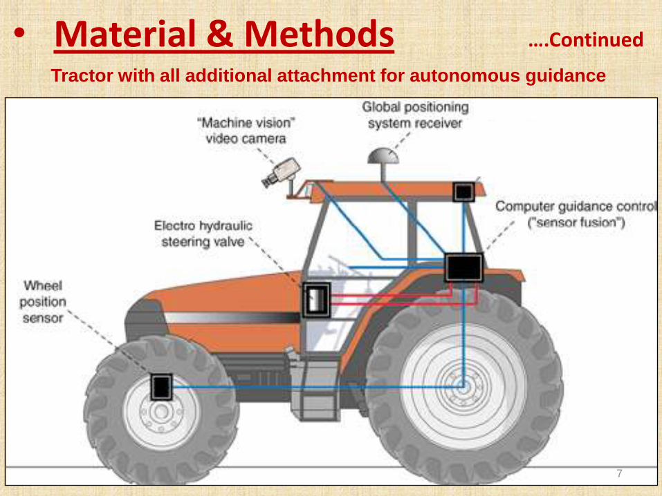
• Material & Methods ….Continued
Tractor with all additional attachment for autonomous guidance
7

• Material & Methods ….Continued
System overall working
8

Machine Vision
Ability of a computer to "see”
Includes one or more video cameras
for obtaining images for the computer
to interpret
With computer vision, there is always
a need of physical feature like colour
difference for the vision system to be
able to sense effectively
Vision involves many complicated
algorithms for image processing and
recognition
Camera mounted at the front
Threshold image 9
• Material & Methods ….Continued

Laser Radar (Ladar)
Principle: Time-of-flight Measurement
Remote sensing technology that measures distance by illuminating a
target with a laser and analysing the reflected light
Distance = (Speed of Light x Time of Flight) / 2
used for ranging and obstacle avoidance
10
• Material & Methods ….Continued
Ladar Mounted on top of the tractor

An artificial testing path of hay bales was made
Algorithms for processing the image and ladar information
had developed for citrus orchard environment & hay bales
environment
Experiment were conducted on both testing path & Citrus
orchard environment by both below guidance system
A) Vehicle Guidance System by Machine Vision
B) Autonomous Guidance System by Laser Radar
System
• Material & Methods ….Continued
EXPERIMENTAL PROCEDURE
11

• Material & Methods ….Continued
EXPERIMENTAL PROCEDURE ON ARTIFICIAL TESTING PATH
•Two types of paths: Straight path & Curved path•The hay bale width was 45 cm, length of the straight path was 70 feet & an extension of 30 feet was given to form a curved path•The path width was 3.5 m throughout the length. •Experiments conducted for three different speeds i.e. 1.8m/s, 3.1m/s, 4.4m/s•A rotating blade was attached to drawbar, which marked a line on the ground as the vehicle moved (path center traveled by the tractor)•Manually error was measured•Above procedure repeated to calculate the path root mean square error, standard deviation, maximum error and average error
12

• Material & Methods ….Continued
VEHICLE GUIDANCE SYSTEM BY MACHINE VISION
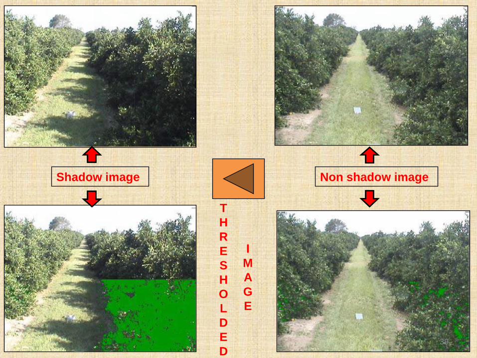
•Color: discriminator for segmenting the path•Camera calibration: To convert pixel distance to true distance •To account for the varying weather conditions: images collected over a period of 6 days in 2 months from morning to evening at half an hour intervals•Three types of conditions observed Cloudy days: trees are darker than the path Bright sunny days: trees are darker than the path but all
pixel intensity values are elevated Early morning and evening: when the sunlight causes the
trees on one side of the row to be brighter than the path and the trees on the other side to be darker than the path
• Based on this database of images, a segmentation algorithm was developed
13

Flowchart : Algorithm for path finding for
adaptive RGB threshold value using
machine vision14
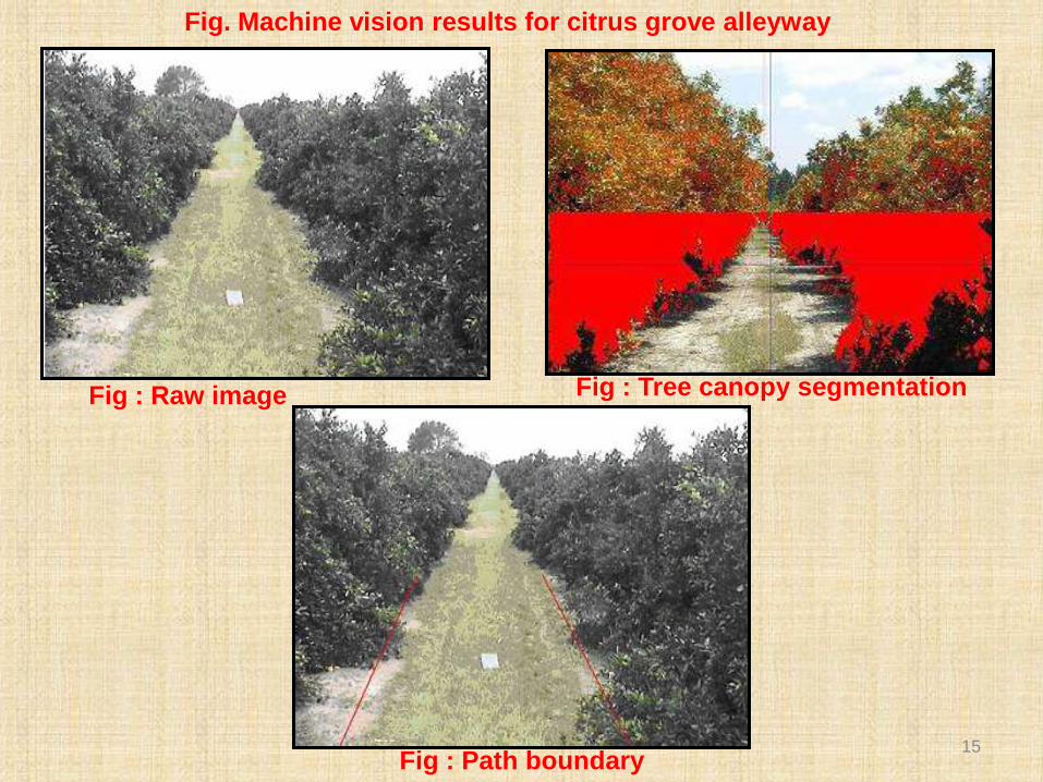
Fig : Path boundary
Fig : Tree canopy segmentationFig : Raw image
Fig. Machine vision results for citrus grove alleyway
15
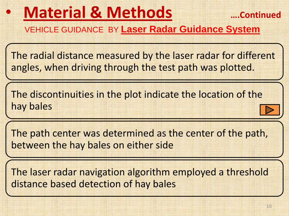
The radial distance measured by the laser radar for different angles, when driving through the test path was plotted.
The discontinuities in the plot indicate the location of the hay bales
The path center was determined as the center of the path, between the hay bales on either side
The laser radar navigation algorithm employed a threshold distance based detection of hay bales
• Material & Methods ….Continued
VEHICLE GUIDANCE BY Laser Radar Guidance System
16

PID: Proportional integral derivative controller:
attempts to minimise the error by adjusting the process control inputs
• Material & Methods ….Continued
DESIGN OF PID CONTROL FOR STEERING CONTROL
17

Error Calculation
Desired position = (Right side tree boundary + Left side tree boundary) / 2
Error = Desired position – current position
• Material & Methods ….Continued
FORMULAE USED
Line fitting: Least square method
Pixel Distance to actual Distance
Conversion
100 cm = 177 pixels
Distance of the tractor centre from the hay bales
Distance = Radial Distance at the hay bale * cosine (Angle at that point)18

• Results & Discussion
19
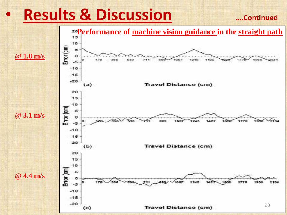
• Results & Discussion ….Continued
Performance of machine vision guidance in the straight path
@ 1.8 m/s
@ 3.1 m/s
@ 4.4 m/s
20

• Results & Discussion ….Continued
Performance of laser radar guidance in the straight path
@ 4.4 m/s
@ 3.1 m/s
@ 1.8 m/s
21
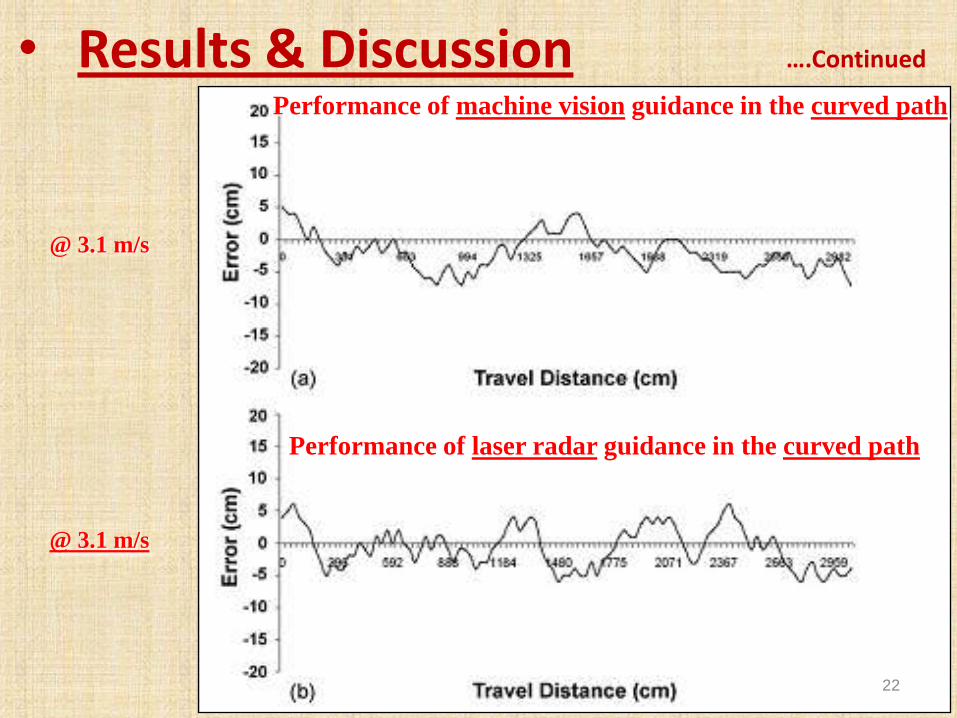
• Results & Discussion ….Continued
Performance of laser radar guidance in the curved path
Performance of machine vision guidance in the curved path
@ 3.1 m/s
@ 3.1 m/s
22
• Conclusions
•Machine vision and laser radar based guidance systems were developed to navigate a tractor through the alleyway of a citrus grove•A PID controller was developed and tested to control the tractor using the information from the machine vision system and laser radar•It was found that the ladar-based guidance was the better guidance sensor for straight and curved paths at speeds of up to 3.1 m/s•Machine vision-based guidance showed acceptable performance at all speeds and conditions•The average errors were below 3 cm in most cases. The maximum error was not more than 6 cm in any test run•Experiments demonstrated the accuracy of the guidance system under test path conditions and successful guidance of the tractor in a citrus orchard alleyway• Additional testing is needed to improve the performance in the citrus orchard
23
• References• Subramanian, V., Burks, T.F., Singh, S., 2004. Autonomous greenhouse
sprayer vehicle using machine vision and ladar for steering control.
Appl.Eng. Agric. 21 (5), 935–943.
• Bell, T., Bevly, D., Biddinger, E., Parkinson, B.W., Rekow, A., 1998.
Automatic tractor row and contour control on sloped terrain using
Carrier-Phase Differential GPS. In: Proceedings of the Fourth
International Conference on Precision Agriculture.
• Misao, Y., 2001. An image processing based automatic steering power
system. In: Proceedings of the ASAE Meeting, California, USA.
• http://www.deere.com/en_US/careers/midcareer_jobs/field_robotics.html
• www.wikipaedia.com
• Gordon, G.P., Holmes, R.G., 1988. Laser positioning system for off-road
vehicles.
24

25

26

Camera
Camera and its mount
Camera mounted on the tractor
• Specification: Sony FCBEX780S CCD camera with analog video output format
in NTSC (National Television System Committee standard)
• Camera was mounted at an angle
of 45 degree to the horizontal
27

Frame Grabber
It converts the analog NTSC video signal to a digital
640 x 480 RGB bitmap image
28

Laser Radar (Ladar)• Sick LMS-200 ladar sensor
• It is a 180 degree one-dimensional
sweeping laser which can measure at
1.0/0.5/0.25 degree increments with
maximum range of up to 80 m
• Mounted on top of the tractor cab just
below the camera positioned at 45
degree to the horizontal
Laser radar
Laser mounted on top of the tractor
29

Computer• 4 GHz Pentium4 processor
running Windows 2000 pro
operating system
• Software (to develop
algorithms): Microsoft Visual
C++
Computer, monitor and keyboard mounted in the cabin
Computer
30

Microcontroller• 586 Engine controller board with a P50 expansion board from TERN
Inc.
• It is a C++ programmable controller board based on a 32-bit system
• Function: For executing Real time-time control of the Servo valve &
Encoder feedback loop.
31
Amplifier:
• To scale the control
voltage from the
microcontroller to the
servo valve
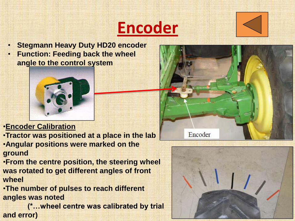
Encoder• Stegmann Heavy Duty HD20 encoder
• Function: Feeding back the wheel
angle to the control system
•Encoder Calibration
•Tractor was positioned at a place in the lab
•Angular positions were marked on the
ground
•From the centre position, the steering wheel
was rotated to get different angles of front
wheel
•The number of pulses to reach different
angles was noted
(*…wheel centre was calibrated by trial
and error)32

Servo Valve
33

GPS Receiver• A GPS receiver was used to measure the vehicle displacement
while conducting tests to determine the dynamics of the vehicle
• John Deere Starfire SF2000R Differential GPS receiver was used
GPS mounted at the top of the tractor
34

Power Supply
• Inverter:
It supply required voltage to PC, the
monitor and the laser radar
• Cigarette lighter power source
The supply for the microcontroller and
the hydraulic valve is taken from it
Provided in tractor cabin
35
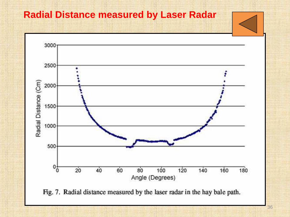
Radial Distance measured by Laser Radar
36

(a) (b)
EXPERIMENTAL PROCEDURE ON ARTIFICIAL TESTING PATH
Guidance system test path
Fig. Curved pathFig. Straight path
37

Fig. Device used to mark the tractor route on
the ground
Fig. Marks on the ground
indicating the path
traversed
EXPERIMENTAL PROCEDURE ON ARTIFICIAL TESTING PATH
Path traced by the rotating blade
38
T
H
R
E
S
H
O
L
D
E
D
I
M
A
G
E
Shadow image Non shadow image
39