Embed Size (px)
Citation preview
J Electron TestDOI 10.1007/s10836-010-5155-x
A New Built-in TPG Based on Berlekamp–MasseyAlgorithm
Cleonilson Protásio de Souza · Francisco Marcos de Assis ·Raimundo Carlos Silvério Freire
Received: 4 October 2007 / Accepted: 14 April 2010© Springer Science+Business Media, LLC 2010
Abstract In this work, a new method to design a mixed-mode Test Pattern Generator (TPG) based only ona simple and single Linear Feedback Shift Register(LFSR) is described. Such an LFSR is synthesized byBerlekamp–Massey algorithm (BMA) and is capableof generating pre-computed deterministic test patternswhich detect the hard-to-detect faults of the circuit.Moreover, the LFSR generates residual patterns whichare sufficient to detect the remaining easy-to-detectfaults. In this way, the BMA-designed LFSR is a mixed-mode TPG which achieves total fault coverage withshort testing length and low hardware overhead com-pared with previous schemes according to the experi-mental results.
Keywords BIST · Mixed-mode TPG · LFSR ·Berlekamp–Massey algorithm
Responsible Editor: C. E. Stroud
C. P. de Souza (B)Department of Electrical Engineering,Federal University of Paraíba,João Pessoa, Paraíba, Brazile-mail: [email protected]
F. Marcos de Assis · R. C. Silvério FreireDepartment of Electrical Engineering,Federal University of Campina Grande,Campina Grande, Paraíba, Brazil
1 Introduction
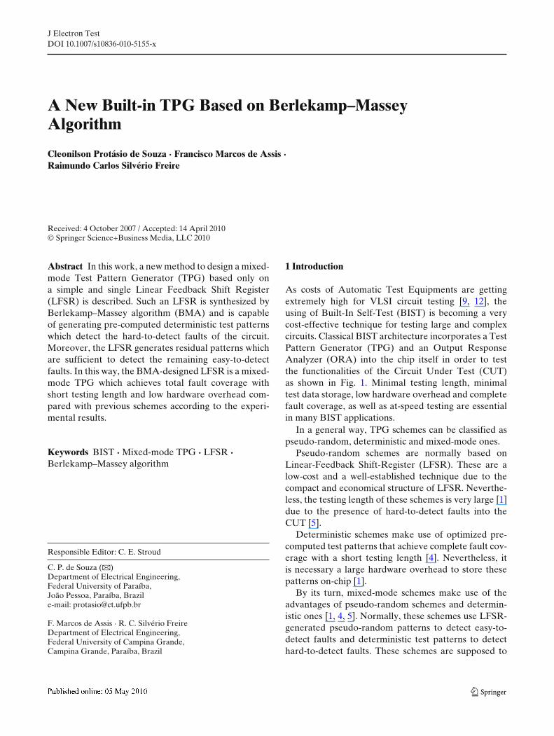
As costs of Automatic Test Equipments are gettingextremely high for VLSI circuit testing [9, 12], theusing of Built-In Self-Test (BIST) is becoming a verycost-effective technique for testing large and complexcircuits. Classical BIST architecture incorporates a TestPattern Generator (TPG) and an Output ResponseAnalyzer (ORA) into the chip itself in order to testthe functionalities of the Circuit Under Test (CUT)as shown in Fig. 1. Minimal testing length, minimaltest data storage, low hardware overhead and completefault coverage, as well as at-speed testing are essentialin many BIST applications.
In a general way, TPG schemes can be classified aspseudo-random, deterministic and mixed-mode ones.
Pseudo-random schemes are normally based onLinear-Feedback Shift-Register (LFSR). These are alow-cost and a well-established technique due to thecompact and economical structure of LFSR. Neverthe-less, the testing length of these schemes is very large [1]due to the presence of hard-to-detect faults into theCUT [5].
Deterministic schemes make use of optimized pre-computed test patterns that achieve complete fault cov-erage with a short testing length [4]. Nevertheless, itis necessary a large hardware overhead to store thesepatterns on-chip [1].
By its turn, mixed-mode schemes make use of theadvantages of pseudo-random schemes and determin-istic ones [1, 4, 5]. Normally, these schemes use LFSR-generated pseudo-random patterns to detect easy-to-detect faults and deterministic test patterns to detecthard-to-detect faults. These schemes are supposed to
J Electron Test
CUTTPG ORA
Fig. 1 Classical BIST architecture
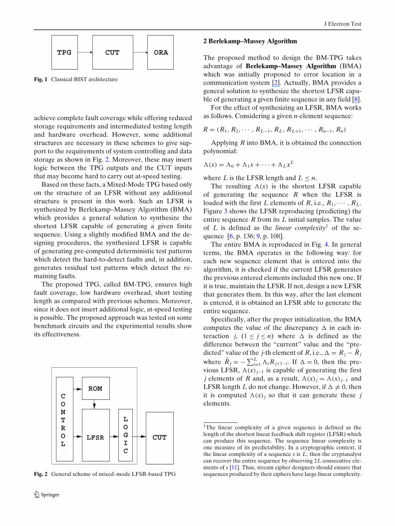
achieve complete fault coverage while offering reducedstorage requirements and intermediated testing lengthand hardware overhead. However, some additionalstructures are necessary in these schemes to give sup-port to the requirements of system controlling and datastorage as shown in Fig. 2. Moreover, these may insertlogic between the TPG outputs and the CUT inputsthat may become hard to carry out at-speed testing.
Based on these facts, a Mixed-Mode TPG based onlyon the structure of an LFSR without any additionalstructure is present in this work. Such an LFSR issynthesized by Berlekamp–Massey Algorithm (BMA)which provides a general solution to synthesize theshortest LFSR capable of generating a given finitesequence. Using a slightly modified BMA and the de-signing procedures, the synthesized LFSR is capableof generating pre-computed deterministic test patternswhich detect the hard-to-detect faults and, in addition,generates residual test patterns which detect the re-maining faults.
The proposed TPG, called BM-TPG, ensures highfault coverage, low hardware overhead, short testinglength as compared with previous schemes. Moreover,since it does not insert additional logic, at-speed testingis possible. The proposed approach was tested on somebenchmark circuits and the experimental results showits effectiveness.
LFSRIGOL
C
LORTNO
ROM
C
CUT
Fig. 2 General scheme of mixed–mode LFSR-based TPG
2 Berlekamp–Massey Algorithm
The proposed method to design the BM-TPG takesadvantage of Berlekamp–Massey Algorithm (BMA)which was initially proposed to error location in acommunication system [2]. Actually, BMA provides ageneral solution to synthesize the shortest LFSR capa-ble of generating a given finite sequence in any field [8].
For the effect of synthesizing an LFSR, BMA worksas follows. Considering a given n-element sequence:
R = (R1, R2, · · · , RL−1, RL, RL+1, · · · , Rn−1, Rn)
Applying R into BMA, it is obtained the connectionpolynomial:
�(x) = �0 + �1x + · · · + �LxL
where L is the LFSR length and L ≤ n.The resulting �(x) is the shortest LFSR capable
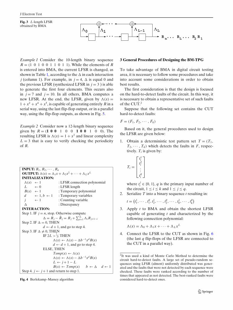
of generating the sequence R when the LFSR isloaded with the first L elements of R, i.e., R1, · · · , RL.Figure 3 shows the LFSR reproducing (predicting) theentire sequence R from its L initial samples. The valueof L is defined as the linear complexity1 of the se-quence [6, p. 136; 9, p. 108].
The entire BMA is reproduced in Fig. 4. In generalterms, the BMA operates in the following way: foreach new sequence element that is entered into thealgorithm, it is checked if the current LFSR generatesthe previous entered elements included this new one. Ifit is true, maintain the LFSR. If not, design a new LFSRthat generates them. In this way, after the last elementis entered, it is obtained an LFSR able to generate theentire sequence.
Specifically, after the proper initialization, the BMAcomputes the value of the discrepancy � in each in-teraction j, (1 ≤ j ≤ n) where � is defined as thedifference between the “current” value and the “pre-dicted” value of the j-th element of R, i.e., � = R j − R̂ j
where R̂ j = − ∑Li=1 �i R j+1−i. If � = 0, then the pre-
vious LFSR, �(x) j−1 is capable of generating the firstj elements of R and, as a result, �(x) j = �(x) j−1 andLFSR length L do not change. However, if � �= 0, thenit is computed �(x) j so that it can generate these jelements.
1The linear complexity of a given sequence is defined as thelength of the shortest linear feedback shift register (LFSR) whichcan produce this sequence. The sequence linear complexity isone measure of its predictability. In a cryptographic context, ifthe linear complexity of a sequence s is L, then the cryptanalystcan recover the entire sequence by observing 2L consecutive ele-ments of s [11]. Thus, stream cipher designers should ensure thatsequences produced by their ciphers have large linear complexity.
J Electron Test
Fig. 3 L-length LFSRobtained by BMA
10
n L 2 1R ... R ... R R...LL–1
...
Example 1 Consider the 10-length binary sequenceR = (1 0 1 0 0 1 1 0 1 1). While the elements of Ris entered into BMA, the current LFSR is changed, asshown in Table 1, according to the � in each interactionj (column 1). For example, in j = 4, � is equal 0 andthe previous LFSR (synthesized LFSR in j = 3 ) is ableto generate the first four elements. This occurs alsoin j = 7 and j = 10. In all others, BMA computes anew LFSR. At the end, the LFSR, given by �(x) =1 + x2 + x4 + x5, is capable of generating entirely R in aserial way, using the last flip-flop output, or in a parallelway, using the flip-flop outputs, as shown in Fig. 5.
Example 2 Consider now a 12-length binary sequencegiven by R = (1 0 0 1 0 0 1 0 0 1 0 0). Theresulting LFSR is �(x) = 1 + x3 and linear complexityL = 3 that is easy to verify checking the periodicityof R.
Fig. 4 Berlekamp–Massey algorithm
3 General Procedures of Designing the BM-TPG
To take advantage of BMA in digital circuit testingarea, it is necessary to follow some procedures and takeinto account some considerations in order to obtainbest results.
The first consideration is that the design is focusedon the hard-to-detect faults of the circuit. In this way, itis necessary to obtain a representative set of such faultsof the CUT.2
Suppose that the following set contains the CUThard-to-detect faults:
F = (F1, F2, · · · , Fk)
Based on it, the general procedures used to designthe LFSR are given below:
1. Obtain a deterministic test pattern set T = (T1,
T2, · · · , Tk) which detects the faults in F, respec-tively. Ti is given by:
Ti =
⎡
⎢⎢⎢⎣
t1i
t2i...
tqi
⎤
⎥⎥⎥⎦
where t ji ∈ {0, 1}, q is the primary input number of
the circuit, 1 ≤ i ≤ k and 1 ≤ j ≤ q.2. Serialize T into a binary sequence t resulting in:
t = (t11, · · · , tq
1 , t12, · · · , tq
2 , · · · , t1k, · · · , tq
k
)
3. Apply t to BMA and obtain the shortest LFSRcapable of generating t and characterized by thefollowing connection polynomial:
�(x) = �0 + �1x + · · · + �LxL
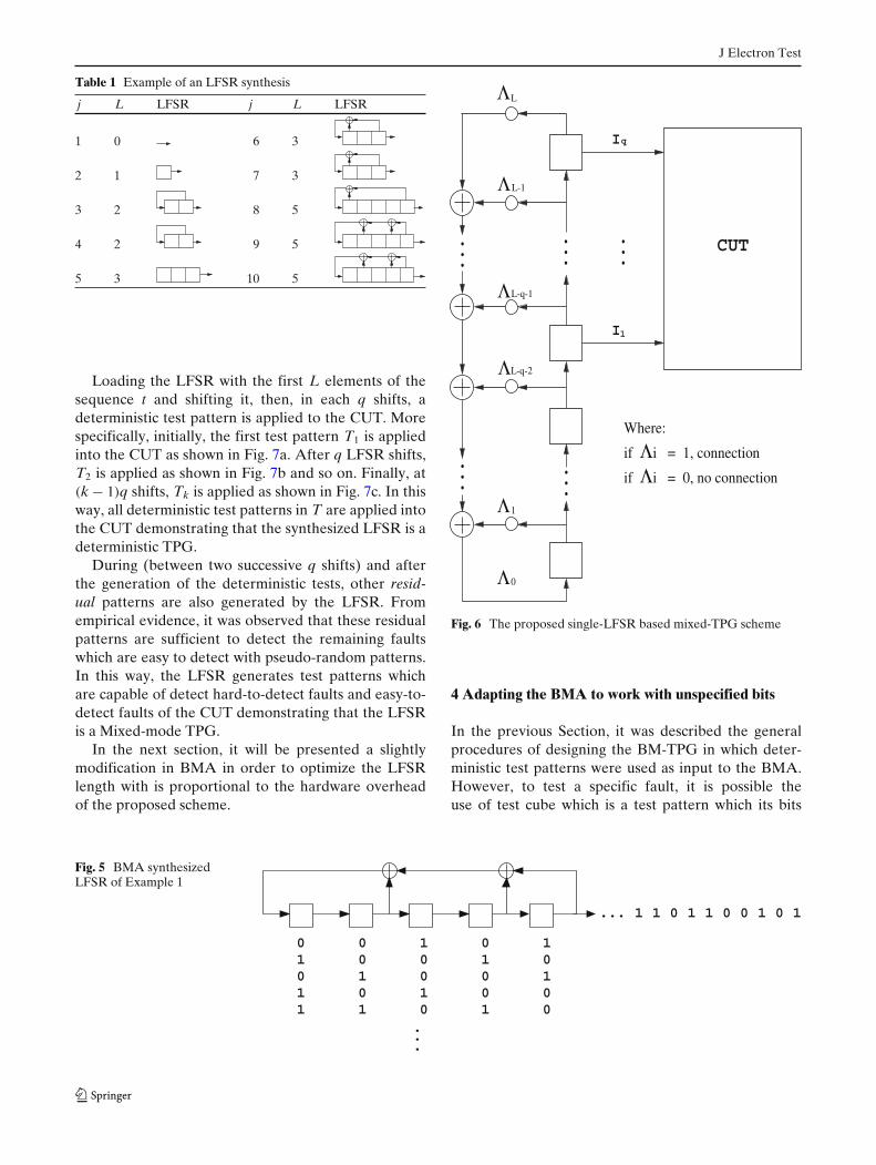
4. Connect the LFSR to the CUT as shown in Fig. 6(the last q flip-flops of the LFSR are connected tothe CUT in a parallel way).
2It was used a kind of Monte Carlo Method to determine thecircuit hard-to-detect faults. A large set of pseudo-random se-quences using LFSR (almost) uniformly distributed was gener-ated and the faults that were not detected by each sequence werechecked. These faults were ranked according to the number oftimes that appeared as not detected. The best-ranked faults wereconsidered hard-to-detect ones.
J Electron Test
Table 1 Example of an LFSR synthesis
j L LFSR j L LFSR
1 0 6 3
2 1 7 3
3 2 8 5
4 2 9 5
5 3 10 5
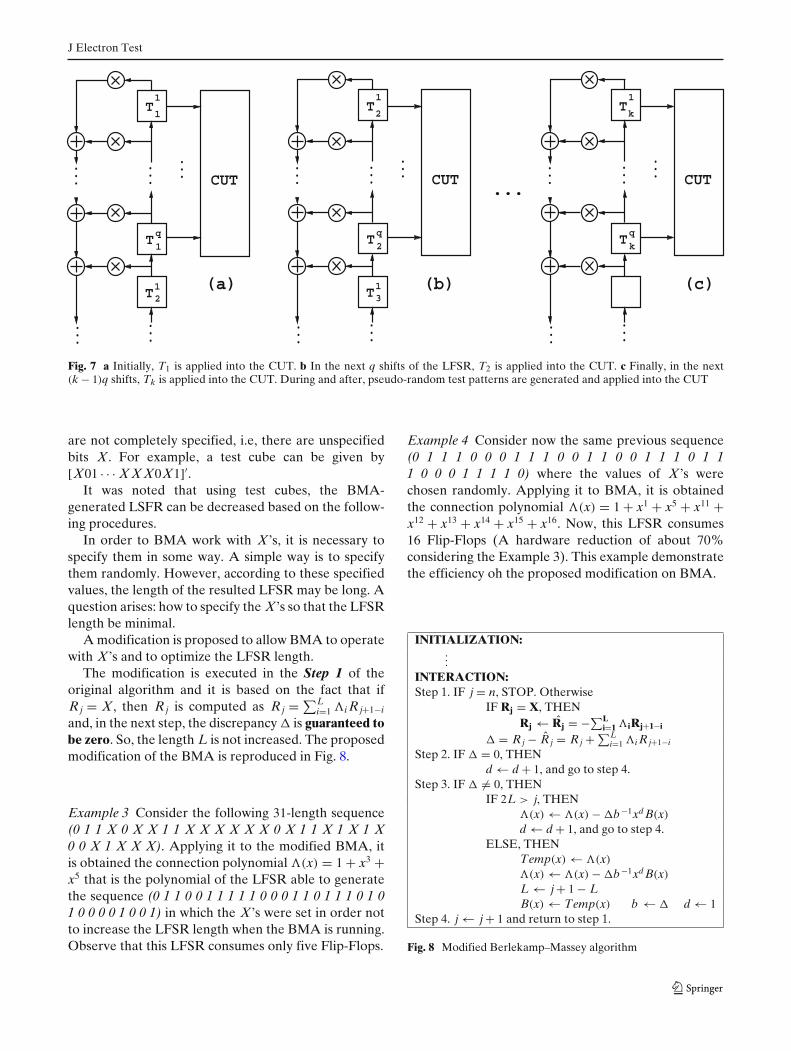
Loading the LFSR with the first L elements of thesequence t and shifting it, then, in each q shifts, adeterministic test pattern is applied to the CUT. Morespecifically, initially, the first test pattern T1 is appliedinto the CUT as shown in Fig. 7a. After q LFSR shifts,T2 is applied as shown in Fig. 7b and so on. Finally, at(k − 1)q shifts, Tk is applied as shown in Fig. 7c. In thisway, all deterministic test patterns in T are applied intothe CUT demonstrating that the synthesized LFSR is adeterministic TPG.
During (between two successive q shifts) and afterthe generation of the deterministic tests, other resid-ual patterns are also generated by the LFSR. Fromempirical evidence, it was observed that these residualpatterns are sufficient to detect the remaining faultswhich are easy to detect with pseudo-random patterns.In this way, the LFSR generates test patterns whichare capable of detect hard-to-detect faults and easy-to-detect faults of the CUT demonstrating that the LFSRis a Mixed-mode TPG.
In the next section, it will be presented a slightlymodification in BMA in order to optimize the LFSRlength with is proportional to the hardware overheadof the proposed scheme.
...
...
...
...
...
Where:
if Λi = 1, connection
if Λi = 0, no connection
CUT
q
1
I
I
ΛL
Λ
Λ
Λ
Λ
Λ
L-1
L-q-1
L-q-2
1
0
Fig. 6 The proposed single-LFSR based mixed-TPG scheme
4 Adapting the BMA to work with unspecified bits
In the previous Section, it was described the generalprocedures of designing the BM-TPG in which deter-ministic test patterns were used as input to the BMA.However, to test a specific fault, it is possible theuse of test cube which is a test pattern which its bits
Fig. 5 BMA synthesizedLFSR of Example 1
.
.
.
... 1 1 0 1 1 0 0 1 0 1
0 0 1 0 11 0 0 1 0 0 1 0 0 1 1 0 1 0 0 1 1 0 1 0
J Electron Test
CUT
(c)(b)(a) T
T
T
...
12
q
1
1
1
...
...
...
...
...CUT
T
T
T
...
13
q
2
2
1
...
...
...
...
CUT
T
T
...
q
k
k
1
...
...
...
...
Fig. 7 a Initially, T1 is applied into the CUT. b In the next q shifts of the LFSR, T2 is applied into the CUT. c Finally, in the next(k − 1)q shifts, Tk is applied into the CUT. During and after, pseudo-random test patterns are generated and applied into the CUT
are not completely specified, i.e, there are unspecifiedbits X. For example, a test cube can be given by[X01 · · · X X X0X1]′.
It was noted that using test cubes, the BMA-generated LSFR can be decreased based on the follow-ing procedures.
In order to BMA work with X’s, it is necessary tospecify them in some way. A simple way is to specifythem randomly. However, according to these specifiedvalues, the length of the resulted LFSR may be long. Aquestion arises: how to specify the X’s so that the LFSRlength be minimal.
A modification is proposed to allow BMA to operatewith X’s and to optimize the LFSR length.
The modification is executed in the Step 1 of theoriginal algorithm and it is based on the fact that ifR j = X, then R j is computed as R j = ∑L
i=1 �i R j+1−i
and, in the next step, the discrepancy � is guaranteed tobe zero. So, the length L is not increased. The proposedmodification of the BMA is reproduced in Fig. 8.
Example 3 Consider the following 31-length sequence(0 1 1 X 0 X X 1 1 X X X X X X 0 X 1 1 X 1 X 1 X0 0 X 1 X X X). Applying it to the modified BMA, itis obtained the connection polynomial �(x) = 1 + x3 +x5 that is the polynomial of the LFSR able to generatethe sequence (0 1 1 0 0 1 1 1 1 1 0 0 0 1 1 0 1 1 1 0 1 01 0 0 0 0 1 0 0 1) in which the X’s were set in order notto increase the LFSR length when the BMA is running.Observe that this LFSR consumes only five Flip-Flops.
Example 4 Consider now the same previous sequence(0 1 1 1 0 0 0 1 1 1 0 0 1 1 0 0 1 1 1 0 1 11 0 0 0 1 1 1 1 0) where the values of X’s werechosen randomly. Applying it to BMA, it is obtainedthe connection polynomial �(x) = 1 + x1 + x5 + x11 +x12 + x13 + x14 + x15 + x16. Now, this LFSR consumes16 Flip-Flops (A hardware reduction of about 70%considering the Example 3). This example demonstratethe efficiency oh the proposed modification on BMA.
Fig. 8 Modified Berlekamp–Massey algorithm
J Electron Test
(1)
(2)
...,01010,01111,...
...,010101111,...
Overlap
t
t*
i+1iT T
Fig. 9 Overlapping process, overlap = 1
5 Overlapping Process
As shown in Section 3, BMA works on a serializedsequence t that contains deterministic test cubes. Thelonger the number of elements of t, the longer theLFSR length synthesized by the modified BMA maybe. Based on this fact, it is proposed an overlappingprocess in order to decrease the length of t. This processcauses no detrimental effect on the testing, i.e., thedeterministic test cubes will still be in the overlappedserialized sequence t∗.
The proposed overlapping process is based on thefollowing facts. It was observed that in t, a portion of aprecedent serialized Ti may be equal to a portion of thefollowing serialized Ti+1 (1 ≤ i < k). When it occurs,then t can be reduced.
For example, suppose that t is as shown in line (1)of Fig. 9. The last element of the serialized Ti is equalto the first element of the serialized Ti+1. In this case,the overlap is 1. After the overlapping, we have theoverlapped sequence t∗ as shown in line (2). Note thatthe hard-to-detect faults capable of being detected byTi and Ti+1 are detected by the overlapped sequencebecause Ti and Ti+1 are still in t∗. In another example,shown in Fig. 10, the last three elements of T j “match”to the first 3 elements of T j+1. So, the overlap is 3.Observe that in this case, there are substitutions of X’s.
As t∗ still contains all of the deterministic test cubes,then all hard-to-detect faults in F are still detected.However, applying t∗ into the modified BMA, a shorterLFSR is possibly to obtain depending on the number ofoverlaps achieved. An additional advantage using thisprocess is that the testing time is decreased since it isnecessary less LFSR shifts to generate two consecutive
(1)
(2)
Overlap
t
t*
...,001XX,100X1,...
...,00100X1,...
TTjj+1
Fig. 10 Overlapping process, overlap = 3
111x00xxx0xxx0xxx0xxx0xxx0xxx0xxx0xxx0x1x11x00xxx0xxx0xxx0xxx0xxx0xxx0xxx0xxx0xxx0xxx0xxx0x1x11x00xxx0xxx0xxx0xxx0x1x11x00xxx0xxx0xxx0xxx0xxx0xxx0xxx0xxx0xxx0xxx0xxx0xxx0xxx0x1x110x0xxx0xxx0xxx0xxx0xxx0xxx0x1x11x00xxx0xxx0xxx0xxx0x1x11x00xxx0xxx0xxx0xxx0xxx0xxx0xxx0xxx0xxx0xxx0xxx0x1x100x0xxx0xxx0xxx0xxx0xxx0x1x11x00xxx0xxx0xxx0xxx0x1x11x00xxx0xxx0xxx0xxx0xx1101010x00xxx0xxx0xxx0xxx0xxx0xxx0xxx0xxx0xxx0xxx0xxx0xxx0xxx0x1x10x00xx
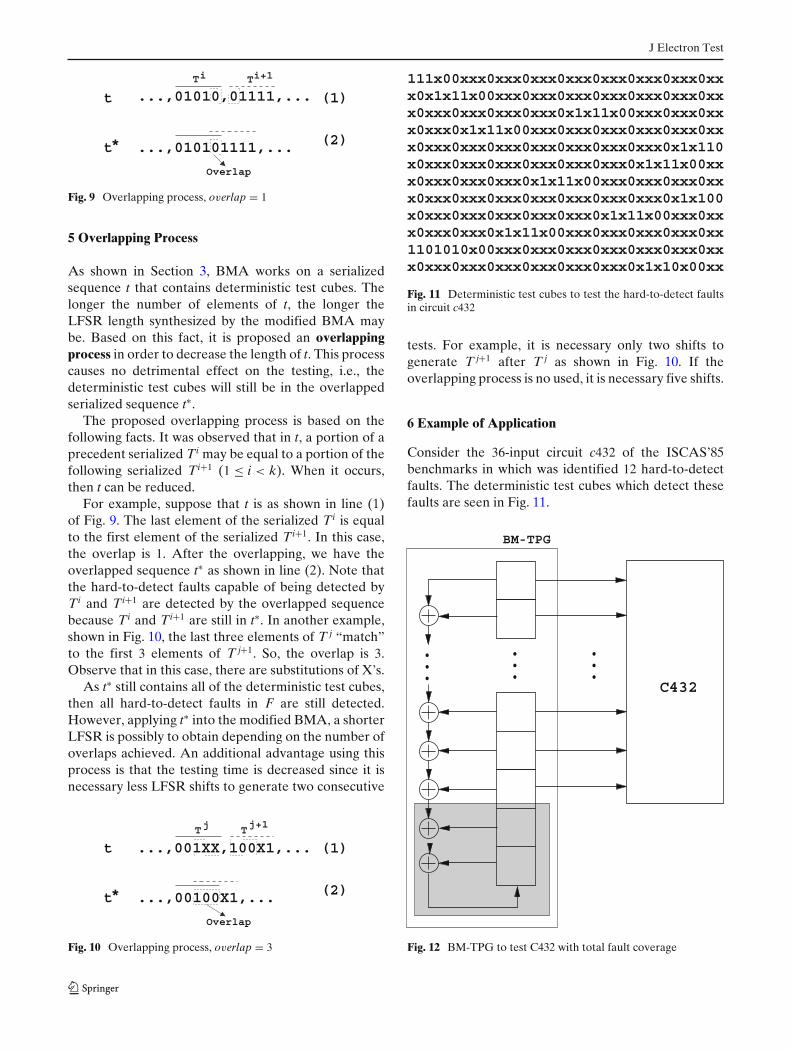
Fig. 11 Deterministic test cubes to test the hard-to-detect faultsin circuit c432
tests. For example, it is necessary only two shifts togenerate T j+1 after T j as shown in Fig. 10. If theoverlapping process is no used, it is necessary five shifts.
6 Example of Application
Consider the 36-input circuit c432 of the ISCAS’85benchmarks in which was identified 12 hard-to-detectfaults. The deterministic test cubes which detect thesefaults are seen in Fig. 11.
C432
BM-TPG
...
...
...
Fig. 12 BM-TPG to test C432 with total fault coverage
J Electron Test
These test cubes compose the set T = (T1, ..., T12)
which is serialized into the serial binary sequence t.After this, t is applied in overlapping process thatproduce t∗. At last, t∗ is applied in the modified-BMAin order to synthesized the BM-TPG. It was obtained a38-length LFSR with connection polynomial given by:
�(x) = 1 + x + x5 + x9 + x10 + x16 + x18 + x23 + x24
+ x25 + x26 + x27 + x28 + x30 + x31 + x34
+ x35 + x36 + x38
It is important to note that the LFSR has onlytwo more stages that the default LFSR-based pseudo-random TPG which has 36 stages (the number of inputsof c432 circuit). In literature of the area, this basicLFSR is not considered on computation of the hard-ware overhead. In this way, the hardware overhead ofthe designed BM-TPG is only this additional two stagesas shown in the shared area of Fig. 12.
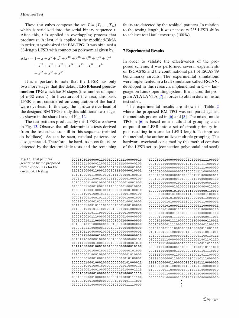
The test patterns produced by this LFSR are shownin Fig. 13. Observe that all deterministic tests derivedfrom the test cubes are still in this sequence (printedin boldface). As can be seen, residual patterns arealso generated. Therefore, the hard-to-detect faults aredetected by the deterministic tests and the remaining
faults are detected by the residual patterns. In relationto the testing length, it was necessary 235 LFSR shiftsto achieve total fault coverage (100%).
7 Experimental Results
In order to validate the effectiveness of the pro-posed scheme, it was performed several experimentson ISCAS’85 and the combinational part of ISCAS’89benchmarks circuits. The experimental simulationswere implemented in a fault simulation called FSCAN,developed in this research, implemented in C++ lan-guage on Linux operating system. It was used the pro-gram ATALANTA [7] in order to obtain deterministictest cubes.
The experimental results are shown in Table 2where the proposed BM-TPG was compared againstthe methods presented in [6] and [3]. The mixed-modeTPG in [6] is based on a method of grouping eachoutput of an LFSR into a set of circuit primary in-puts resulting in a smaller LFSR length. To improvethe method, the author utilizes multiple grouping. Thehardware overhead consumed by this method consistsof the LFSR setups (connection polynomial and seed)
Fig. 13 Test patternsgenerated by the proposedmixed-mode TPG for thecircuit c432 testing
...
001101010000011000100010111000000100011010100000110001000101110000001000
101010000011000100010111000000100010 010100000110001000101110000001000100101000001100010001011100000010001000010000011000100010111000000100010001100000110001000101110000001000100010000001100010001011100000010001000100000011000100010111000000100010001000000110001000101110000001000100010000001100010001011100000010001000100000011000100010111000000100010001000000110001000101110000001000100010000000100010001011100000010001000100000000
001000101110000001000100010000000000010001011100000010001000100000000000100010111000000100010001000000000001
001011100000010001000100000000000101010111000000100010001000000000001010
011100000010001000100000000000101000111000000100010001000000000001010000110000001000100010000000000010100001
000110101000001100010001011100000010
000000100010001000000000001010000111000001000100010000000000010100001111
000100010001000000000001010000111100001000100010000000000010100001111000010001000100000000000101000011110000
000100010111000000100010001000000000
000101110000001000100010000000000010
101110000001000100010000000000010100
100000010001000100000000000101000011
000010001000100000000000101000011110
000100010000000000010100001111000000001000100000000000101000011110000000010001000000000001010000111100000001100010000000000010100001111000000011000100000000000101000011110000000110001000000000001010000111100000001100010000000000010100001111000000011000
000000000001010000111100000001100000000000000010100001111000000011000000000000000101000011110000000110000001
000000010100001111000000011000000110000000101000011110000000110000001100000001010000111100000001100000011001
000101000011110000000110000001100110001010000111100000001100000011001101010100001111000000011000000110011011101000011110000000110000001100110111010000111100000001100000011001101110100001111000000011000000110011011100000011110000000110000001100110111000000111100000001100000011001101110000001111000000011000000110011011100000011110000000110000001100110111000000
111000000011000000110011011100000000110000000110000001100110111000000000100000001100000011001101110000000001000000011000000110011011100000000010
100010001000000000001010000111100000
100000000000101000011110000000110000
000000001010000111100000001100000011
000010100001111000000011000000110011
111100000001100000011001101110000000
110101000001100010001011100000010001
J Electron Test
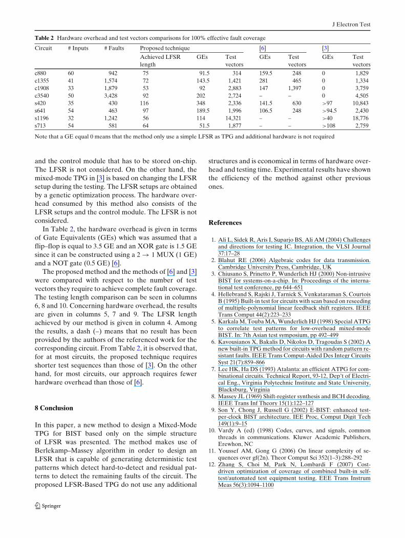
Table 2 Hardware overhead and test vectors comparisons for 100% effective fault coverage
Circuit # Inputs # Faults Proposed technique [6] [3]
Achieved LFSR GEs Test GEs Test GEs Testlength vectors vectors vectors
c880 60 942 75 91.5 314 159.5 248 0 1,829c1355 41 1,574 72 143.5 1,421 281 465 0 1,334c1908 33 1,879 53 92 2,883 147 1,397 0 3,759c3540 50 3,428 92 202 2,724 – – 0 4,505s420 35 430 116 348 2,336 141.5 630 >97 10,843s641 54 463 97 189.5 1,996 106.5 248 >94.5 2,430s1196 32 1,242 56 114 14,321 – – >40 18,776s713 54 581 64 51.5 1,877 – – >108 2,759
Note that a GE equal 0 means that the method only use a simple LFSR as TPG and additional hardware is not required
and the control module that has to be stored on-chip.The LFSR is not considered. On the other hand, themixed-mode TPG in [3] is based on changing the LFSRsetup during the testing. The LFSR setups are obtainedby a genetic optimization process. The hardware over-head consumed by this method also consists of theLFSR setups and the control module. The LFSR is notconsidered.
In Table 2, the hardware overhead is given in termsof Gate Equivalents (GEs) which was assumed that aflip–flop is equal to 3.5 GE and an XOR gate is 1.5 GEsince it can be constructed using a 2 → 1 MUX (1 GE)and a NOT gate (0.5 GE) [6].
The proposed method and the methods of [6] and [3]were compared with respect to the number of testvectors they require to achieve complete fault coverage.The testing length comparison can be seen in columns6, 8 and 10. Concerning hardware overhead, the resultsare given in columns 5, 7 and 9. The LFSR lengthachieved by our method is given in column 4. Amongthe results, a dash (–) means that no result has beenprovided by the authors of the referenced work for thecorresponding circuit. From Table 2, it is observed that,for at most circuits, the proposed technique requiresshorter test sequences than those of [3]. On the otherhand, for most circuits, our approach requires fewerhardware overhead than those of [6].
8 Conclusion
In this paper, a new method to design a Mixed-ModeTPG for BIST based only on the simple structureof LFSR was presented. The method makes use ofBerlekamp–Massey algorithm in order to design anLFSR that is capable of generating deterministic testpatterns which detect hard-to-detect and residual pat-terns to detect the remaining faults of the circuit. Theproposed LFSR-Based TPG do not use any additional
structures and is economical in terms of hardware over-head and testing time. Experimental results have shownthe efficiency of the method against other previousones.
References
1. Ali L, Sidek R, Aris I, Suparjo BS, Ali AM (2004) Challengesand directions for testing IC. Integration, the VLSI Journal37:17–28
2. Blahut RE (2006) Algebraic codes for data transmission.Cambridge University Press, Cambridge, UK
3. Chiusano S, Prinetto P, Wunderlich HJ (2000) Non-intrusiveBIST for systems-on-a-chip. In: Proceedings of the interna-tional test conference, pp 644–651
4. Hellebrand S, Rajski J, Tarnick S, Venkataraman S, CourtoisB (1995) Built-in test for circuits with scan based on reseedingof multiple-polynomial linear feedback shift registers. IEEETrans Comput 44(2):223–233
5. Karkala M, Touba MA, Wunderlich HJ (1998) Special ATPGto correlate test patterns for low-overhead mixed-modeBIST. In: 7th Asian test symposium, pp 492–499
6. Kavousianos X, Bakalis D, Nikolos D, Tragoudas S (2002) Anew built-in TPG method for circuits with random pattern re-sistant faults. IEEE Trans Comput-Aided Des Integr CircuitsSyst 21(7):859–866
7. Lee HK, Ha DS (1993) Atalanta: an efficient ATPG for com-binational circuits. Technical Report, 93-12, Dep’t of Electri-cal Eng., Virginia Polytechnic Institute and State University,Blacksburg, Virginia
8. Massey JL (1969) Shift-register synthesis and BCH decoding.IEEE Trans Inf Theory 15(1):122–127
9. Son Y, Chong J, Russell G (2002) E-BIST: enhanced test-per-clock BIST architecture. IEE Proc, Comput Digit Tech149(1):9–15
10. Vardy A (ed) (1998) Codes, curves, and signals, commonthreads in communications. Kluwer Academic Publishers,Erewhon, NC
11. Youssef AM, Gong G (2006) On linear complexity of se-quences over gf(2n). Theor Comput Sci 352(1–3):288–292
12. Zhang S, Choi M, Park N, Lombardi F (2007) Cost-driven optimization of coverage of combined built-in self-test/automated test equipment testing. EEE Trans InstrumMeas 56(3):1094–1100

J Electron Test
Cleonilson Protásio de Souza is currently a professor at FederalUniversity of Paraíba, Brazil. He graduated in Electrical Engi-neering in 1989 and received the M.Sc. degree in Electrical Engi-neering in 2001 from Federal University of Maranhão, Brazil. Hereceived the doctorate degree in 2005 from Federal Universityof Campina Grande, Brazil. His research interests include VLSItesting and intelligent systems.
Francisco Marcos de Assis is currently a professor at FederalUniversity of Campina Grande (UFCG), Paraíba, Brazil. Hereceived the B.Sc. degree in Electrical Engineering (1984) fromMilitary Institute of Engineering (IME), Rio de Janeiro, Brazil;M.Sc. degree (1992) from Military Institute of Engineering, Riode Janeiro, Brazil,and doctorate degree (1994) from Pontifical
Catholic University of Rio de Janeiro (PUC-RJ), Rio de Janeiro,Brazil. His research interests include coding and informationtheory.
Raimundo Carlos Silvério Freire is currently a professor at Fed-eral University of Campina Grande (UFCG), Paraíba, Brazil. Hereceived the B.Sc. degree in Electrical Engineering (1979) fromFederal University of Maranhão (UFMA), Maranhão, Brazil;M.Sc. degree (1982) from Federal University of Paraíba (UFPB),Paraíba, Brazil; and PhD degree (1988) from Institute NationalePolytechnique de Loraine, Nancy, França. His research interestsinclude VLSI, and analog and digital circuit design for use inbiomedical and communications.


