Embed Size (px)
Citation preview

English Français EspañolDeutsch Italiano
IOM ADVANCE 01-N-3GBPart number / Code / Teil Nummer / Codice / Código : 3990608GBSupersedes / Annule et remplace / Annulliert und ersetzt / Annulla e sostituisce / Anula y sustituye : IOM ADVANCE 01-N-2GB
3.5 kWÜ
18 kW
Aqu@Scop Advance DCI
6 ÷ 16
Air-water Heat PumpPompe à Chaleur air-eauWärmepumpe Luft-WasserPompa di Calore aria-acquaBomba de Calor aire-agua
Installation and maintenance manualManuel d’installation et de maintenanceInstallations- und WartungshandbuchManuale di installazione e di manutenzioneManual de instalación y de mantenimiento
IOM ADVANCE 01-N-3Part number / Code / Teil Nummer / Codice / Código : 3990608Supersedes / Annule et remplace / Annulliert und ersetzt / Annulla e sostituisce / Anula y sustituye : IOM ADVANCE 01-N-2


INSTALLATION INSTRUCTION
NOTICE D’INSTALLATION
INSTALLATIONSHANDBUCH
ISTRUZIONI INSTALLAZIONE
INSTRUCCIONES DE INSTALACIÓN
2
CONTENTS1. GENERAL RECOMMENDATIONS ................................................................................................................................3
1.1. SAFETY DIRECTIONS .................................................................................................................................................................................... 31.2. WARNING .................................................................................................................................................................................................... 31.3. EqUIpmENT SAFETY DATA ............................................................................................................................................................................ 4
2. INSPECTION AND STORAGE .....................................................................................................................................53. WARRANTY................................................................................................................................................................54. CONTENTS OF PACKAGE ..........................................................................................................................................55. PRODUCT PRESENTATION .........................................................................................................................................56. ACCESSORIES ............................................................................................................................................................67. DIMENSIONS .............................................................................................................................................................68. HANDLING ................................................................................................................................................................6
8.1. NET WEIGHT ................................................................................................................................................................................................ 69. TECHNICAL SPECIFICATIONS ....................................................................................................................................7
9.1. pHYSICAL CHARACTERISTICS ........................................................................................................................................................................ 79.2. ELECTRICAL CHARACTERISTICS ..................................................................................................................................................................... 79.3. OpERATING LImITS ....................................................................................................................................................................................... 7
10. REFRIGERATION AND HYDRAULIC DIAGRAM ..........................................................................................................811. INSTALLATION .........................................................................................................................................................8
11.1. SITING THE INSTALLATION .......................................................................................................................................................................... 811.2. CLEARANCE ............................................................................................................................................................................................... 911.3. ATTACHmENT TO THE GROUND ................................................................................................................................................................ 9
12. HYDRAULIC LINKS .................................................................................................................................................1012.1. GENERAL RECOmmENDATIONS ............................................................................................................................................................... 1012.2. STANDARD CIRCUITS ................................................................................................................................................................................ 1112.3. ANTI-FREEZE pROTECTION ....................................................................................................................................................................... 1312.4. WATER TREATmENT WARNING .................................................................................................................................................................. 1312.5. CONNECTION TO THE CENTRAL HEATING LOOp .................................................................................................................................... 1412.6. HEAT INSULATION .................................................................................................................................................................................... 1412.7. FILLING THE SYSTEm WITH WATER ............................................................................................................................................................ 1412.8. WATER FLOW CONTROLLER ..................................................................................................................................................................... 1412.9. DETERmINING WATER FLOW .................................................................................................................................................................... 15
13. WIRING DIAGRAM AND LEGEND ..........................................................................................................................1613.1. WIRING DIAGRAm .................................................................................................................................................................................... 1613.2. LEGEND ................................................................................................................................................................................................... 16
14. ELECTRICAL CONNECTIONS .................................................................................................................................1814.1. CONNECTIONS ....................................................................................................................................................................................... 19
15. COMMISSIONING .................................................................................................................................................2015.1. pRE-START CHECK LIST ............................................................................................................................................................................. 20
16. REGULATION .........................................................................................................................................................2116.1. USER INTERFACE ...................................................................................................................................................................................... 2116.2. pRINCIpLE ................................................................................................................................................................................................ 25
17. STARTING THE APPLIANCE ....................................................................................................................................2717.1. SImpLIFIED START-Up pROCEDURE ............................................................................................................................................................ 27
18. AqU@ SCOP ADVANCE DCI EMERGENCY OPERATION SWITCH ............................................................................3019. DOMESTIC HOT WATER .........................................................................................................................................30
19.1. CONNECTION TO THE CENTRAL HEATING LOOp .................................................................................................................................... 3019.2. ELECTRICAL CONNECTIONS .................................................................................................................................................................... 3119.3. DOmESTIC HOT WATER pRODUCTION mODES ........................................................................................................................................ 31
20. OPERATING CHECK LIST ........................................................................................................................................3220.1. GENERAL ................................................................................................................................................................................................. 3220.2. OpERATING vOLTAGE: ............................................................................................................................................................................. 3220.3. CONTROL ................................................................................................................................................................................................ 3220.4. FAN & DRIvE ............................................................................................................................................................................................. 3220.5. COmpRESSOR AND REFRIGERATION SYSTEm ........................................................................................................................................... 3220.6. FINAL CHECK ........................................................................................................................................................................................... 32
21. FINAL TASKS ..........................................................................................................................................................3222. IN CASE OF WARRANTY - MATERIAL RETURN PROCEDURE ...................................................................................3223. ORDERING SERVICE AND SPARE PARTS ORDER .....................................................................................................3224. MAINTENANCE .....................................................................................................................................................33
24.1. REGULAR mAINTENANCE ......................................................................................................................................................................... 3324.2. GENERAL INSpECTION ............................................................................................................................................................................. 3324.3. REFRIGERATION CIRCUIT.......................................................................................................................................................................... 3324.4. ELECTRICAL SECTION ............................................................................................................................................................................... 3324.5. SERvICING CHECKLIST ............................................................................................................................................................................. 3424.6. RESET SAFETY DEvICE ............................................................................................................................................................................... 34
25. LIST OF SETTINGS ..................................................................................................................................................3526. ALARM LIST AVAILABLE ON THE AqU@ SCOP ADVANCE DCI DISPLAY .................................................................38

3
1. GENERAL RECOMMENDATIONSThe purpose of this manual is to provide users with instructions for installing, commissioning, using and maintaining the units.
It does not contain the complete description of all the maintenance operations guaranteeing the unit’s long life and reliability. Only the services of a qualified technician can guarantee the unit’s safe operation over a long service life.
please read the following safety precautions very carefully before installing the unit.
1.1. SAFETY DIRECTIONS
Follow the safety rules in forces when you are working on your appliance.
The installation, commissioning and maintenance of these units should be performed by qualified personnel having a good knowledge of standards and local regulations, as well as experience of this type of equipment.
This appliance has not been designed for use by persons (including children) with reduced physical, sensorial or mental faculties or by persons without any experience or knowledge of heating systems, unless they act under the safety and supervision of a responsible person or have received prior training concerning the use of the appliance.
Children should be supervised to ensure that they do not play with the appliance.
The unit should be handled using lifting and handling equipment appropriate to the unit's size and weight.
Any wiring produced on site must comply with the corresponding national electrical regulations.
make sure that the power supply and its frequency are adapted to the required electric current of operation, taking into account specific conditions of the location and the current required for any other appliance connected to the same circuit.
The unit must be EARTHED to avoid any risks caused by insulation defects.
It is forbidden to start any work on the electrical components if water or high humidity is present on the installation site.
1.2. WARNING
Cutoff power supply before starting to work on the appliance.
When making the hydraulic connections, ensure that no impurities are introduced into the pipe work.
The manufacturer declines any responsibility and the warrantly becomes void if these instructions are not respected.
If you meet a problem, please call the Technical Department of your area.
If possible, assemble the compulsory or optional accessories before placing the appliance on its final location. (see instructions provided with each accessory).
In order to become fully familiar with the appliance, we suggest to read also our Technical Instructions.
The information contained in these Instructions are subject to modification without advance notice.
POWER SUPPLY MUST BE SWITCHED OFF
BEFORE STARTING WORK IN THE ELECTRICCONTROL BOX

4
1.3. EqUIPMENT SAFETY DATA
Safety Data R410A
Toxicity Low
In contact with skin Skin contact with the rapidly evaporating liquid may cause tissue chilblains. In case of skin contact with the liquid, warm the frozen tissue with water and call a doctor. Remove contaminated clothing and footwear. Wash the clothing prior to re-use.
In contact with eyes vapours have no effect. Liquid splashes or sprays may cause freeze burns. In these cases rinse your eyes with running water or with a solution for eye lavages for at least 10 minutes. Immediately apply to a doctor.
Ingestion In this case, burns may result. Do not attempt to make the patient vomit. If the patient is conscious, rinse the mouth with water. Call a doctor immediately.
Inhalation In case of inhalation, move the patient to an area with fresh air and provide oxygen if ne-cessary. perform artificial respiration if the patient has stopped breathing or lacks air. In case of cardiac arrest, perform external cardiac massage. Call a doctor immediately.
Further medical Advice Exposure to high concentrations can be dangerous for individuals with cardiac problems, as the presence of catecholamines such as adrenalin in the bloodstream may lead to increased arrhyth-mia and possible cardiac arrest.
Occupational exposure limits
R410A: Recommended limits: 1,000 ppm v/v 8 hours TWA.
Stability Stable product
Conditions to avoid Increased pressure due to high temperatures may cause the container to explode. Keep out of the sun and do not expose to a temperature >50°C.
Hazardous reactions possibility of dangerous reactions in case of fire due to the presence of F and/or CI radicals
General precautions Avoid the inhalation of high concentrations of vapours. The concentration in the atmosphere shall be kept at the minimum value and anyway below the occupational limits. Since vapours are heavier than air and they tend to stagnate and to build up in closed areas, any opening for ventilation shall be made at the lowest level.
Breathing protection In case of doubt about the actual concentration, wear breathing apparatus. It should be self-contained and approved by the bodies for safety protection.
Storage preservation Refrigerant containers shall be stored in a cool place, away from fire risk, direct sunlight and all heat sources, such as radiators. The maximum temperature shall never exceed 50°C in the storage place.
protection clothes Wear boots, safety gloves and glasses or masks for facial protection.
Behaviour in case of leaks or escapes
Never forget to wear protection clothes and brething apparatus. Isolate the source of the leakage, provided that this operation may be performed in safety conditions. Any small quantity of refrigerant which may have escaped in its liquid state may evaporate provided that the room is well ventilated.In case of a large leakage, ventilate the room immediately. Stop the leakage with sand, earth or any suitable absorbing material. prevent the liquid refrigerant from flowing into drains, sewers, foundations or absorbing wells since its vapours may create an asphyxiating atmosphere.
Disposal The best procedure involves recovery and recycle. If this is not possible, the refrigerant shall be given to a plant which is well equipped to destroy and neutralise any acid and toxic by-product which may derive from its disposal.
Combustibility features R410A: Non-inflammable at ambient temperatures and atmospheric pressures.Containers If they are exposed to the fire, they shall be constantly cooled down by water sprays.
Containers may explode if they are overheated.
Behaviour in case of fire In case of fire wear protection clothes and self-contained breathing apparatus.

5
2. INSPECTION AND STORAGEAt the time of receiving the equipment carefully cross check all the elements against the shipping documents in order to ensure that all the crates and boxes have been received. Inspect all the units for any visible or hidden damage.
In the event of shipping damage, write precise details of the damage on the shipper’s delivery note and send immediately a registered letter to the shipper within 48 hours, clearly stating the damage caused. Forward a copy of this letter to the manufacturer or his representative.
Never store or transport the unit upside down. It must be stored indoors, completely protected from rain, snow etc. The unit must not be damaged by changes in the weather (high and low temperatures). Excessively high temperatures (above 60 °C) can harm certain plastic materials and cause permanent damage. moreover, the performance of certain electrical or electronic components can be impaired.
3. WARRANTYThe units are delivered fully assembled and tested.
Any modification to the units without the manufacturer’s prior approval, shall automatically render the warranty null and void.
The following conditions must be respected in order to maintain the validity of the warranty:
² Commissioning shall be performed by specialised technicians from technical services approved by the manufacturer.
² maintenance shall be performed by technicians trained for this purpose.
² Only Original Equipment spare parts shall be used.
² All the operations listed in the present manual shall be performed within the required time limits.
THE WARRANTY SHALL BE NULL AND VOID IN THE EVENT OF NON-COMPLIANCE WITH ANY OF THE ABOVE CONDITIONS.
1 HEAT Pump Aqu@ Scop Advance DCI
1 Documentation pouch
4 Anti-vibration pads
1 Water filter kit
1 stop cock
The distinguishing feature of this Aqu@ Scop Advance DCI Air/water heat pump range is its power variation capability, provided by its inverter compressor technology.
This technology provides remarkable "power output / heating requirement" adaptability. Depending on the heating power demand and the working temperature of the heat emitters, the regulator of the Aqu@ Scop Advance DCI chooses the compressor frequency to be used.
4. CONTENTS OF PACKAGE
5. PRODUCT PRESENTATION

6
SEE APPENDIX
6. ACCESSORIES
² Set of stop cocks with pressure tap
² Set of 2 flexible pipes (length 1m)
² Hydraulic connection kit
² Water flow adjustment kit (requires the stop cocks with pressure take-off kit)
² Domestic Hot Water (DHW) tank
² 3 way valve Domestic Hot Water tank
² 140 litre buffer tank
² Anti-vibration pads
² 6 kW in-line electric heater (compatible with the boiler back-up version)
² Wired programmable ambiance terminal
² Wireless programmable ambiance terminal
Take care to avoid any rough handling or impacts when unloading and moving the appliance. Only push or pull the appliance by its base. place a safety wedge between the unit base and the fork lift truck to avoid damaging the unit’s structure and casing.
Transit holes Ø30mm
The handles present on the appliance's panels are intended for the removal/refitting of the latter and must not be used for handling the complete appliance (too heavy to be supported by the panels).
Wedge required along the entire length of the unit.
6 12 16
125 190
7. DIMENSIONS
8. HANDLING
8.1. NET WEIGHT

7
9. TECHNICAL SPECIFICATIONS9.1. PHYSICAL CHARACTERISTICS
9.2. ELECTRICAL CHARACTERISTICS
This equipment contains fluorinated gas with greenhouse gas effects covered by the Kyoto agreement.
9.3. OPERATING LIMITS
20
25
30
35
40
45
50
55
60
65
70
-25 -20 -15 -10 -5 0 5 10 15 20 25
Ou
tlet
wate
r te
mp
eratu
re (
°C)
Outdoor air temperature (°C)
Aqu@scop Advance DCI
Aqu@scop Advance DCI-R
Aqu@ Scop Advance DCI heat pumps have a wide power range.
When heating requirements are low and when the necessary starting temperature is low, the Aqu@ Scop Advance DCI operates at reduced power. Otherwise the Aqu@ Scop Advance DCI uses a higher power rating to supply the heating needs up to the selected point.
The outlet water temperature is automatically adjusted to the water rule (heating curve) up to a maximum temperature of 55° C.
6 12 16REFRIGERANT
Type R410AFactory charge g SEE NAmE pLATE
HYDRAULIC LINKSInlet water gas 1" FemaleOutlet water gas 1" Female
WATER FLOWNominal l/h 1100 1850 2600minimum l/h 850 1300 1500maximum l/h 1500 2300 3100
FANSNumber of fan 1 2ACOUSTIC PRESSUREAcoustic pressure dB(A) 63.5 65 65.5
6 12 16SUPPLY VOLTAGE 230v / 1 ph / 50Hz
maximum current (without electric heater) A 18 26 27maximum current (with electric heater) A 37 58 59
FULL HEATING CAPACITY

8
SEE APPENDIX
The unit is not designed to withstand weights or stresses from adjacent equipment, pipe work or constructions. Any foreign weight or stress on the unit structure could lead to a malfunction or a collapse with dangerous consequences for personnel and property. In such an event, the warranty shall be null and void.
Unit operation depends on air temperature. Any recycling of air extracted by the fan lowers the air intake temperature across the exchanger fins and alters the standard operating conditions.
The outdoor unit must be installed outdoors with sufficient surrounding clearance to enable unobstructed air circulation through the appliance and access for maintenance work.
In the case of the unit being sited in areas exposed to high winds, you must avoid the wind hitting the fan blowing surface areas directly to avoid any risk of recycling cooled air. Strong wind can disrupt exchanger ventilation and create de-frosting problems.
The arrows show the direction of air circulation through the appliance. (Refer to Fig. § Floor location).
Depending on temperature and outdoor air humidity conditions, water vapour contained in the air can condense on the finned heat exchanger and even form ice under low outdoor temperature conditions (around < 5°C). This condensate water and defrosted water runs off via outlets provided under the exchanger. To assist drainage and to prevent frozen water remaining in the appliance in winter, we recommend that the unit is installed at a height of around 10cm off the ground and placed on plastic blocks or other suitable supports (damper feet proposed as an accessory). In this way, condensate and defrosted water can run off freely and be absorbed into the ground or channelled to a basin built under the appliance in order to protect the environment.
In areas where outdoor temperatures fall below 1°C, the system can be equipped with a condensate anti-freeze protection system (e.g. a heated pipe sheath).
To reduce the noise level, our machines are equipped with quiet fans and a soundproofed compressor.However, noise levels can be reduced even further by following a few installation precautions:
² Do not install the appliance near a bedroom window. Avoid locating the appliance in a corner (increased reverberated noise).
² Install the rubber pads supplied or anti-vibration pads (available as an option) under the appliance.
² Use flexible hoses (available as options) for connections between the appliance and the mains water network.
² Do not join the concrete slab supporting the appliance to the structure of the dwelling (structure- borne noise transmission)
10. REFRIGERATION AND HYDRAULIC DIAGRAM
11. INSTALLATION
11.1. SITING THE INSTALLATION
11.1.1. PREVAILING WIND
11.1.2. CONDENSATE WATER MANAGEMENT
11.1.3. HOW TO REDUCE NOISE POLLUTION

9
11.2. CLEARANCE
REF. DIMENSION
A 800mm
B 500mm
C 500mm
D 400mm
E 800mm
F 100mm
The unit location dimensions are indicated on the figure below. A slope of 1 cm/m should be created to assist rainwater drainage.
vibration dampers must be fitted during installation to overcome any risks of vibration being transmitted due to direct contact with a rigid support surface.
THE UNIT MUST NEVER BE INSTALLED ON A WALL BRACKET.
The appliance must be sited on a level and solid floor and preferably on a masonry surface.
When choosing the location for the appliance, take care to leave sufficient free clearance on all sides to ensure easy access for maintenance work. The minimum free clearance dimensions indicated must be observed to ensure both proper system operation and allow access for maintenance and cleaning.
A
BD
EC F
349
1192.61%
AIR FLOW
11.3. ATTACHMENT TO THE GROUND

10
12. HYDRAULIC LINKSWhen choosing and installing water pipes, you must consult and observe all current local standards, regulations and instructions.
12.1. GENERAL RECOMMENDATIONS ² You must design the pipe network with the minimum number of bends and keep the number of changes in height to the strict minimum. This will reduce installation costs and ensure optimum system performance. The pipe network must include:
² A vibration elimination system (e.g.: link hoses available as an accessory) on all pipes connected to the appliance in order to reduce vibrations and noise transmitted to the building fabric.
² Stop cocks to isolate the hydraulic circuit during maintenance.
² manual or automatic bleed valves at the highest point on the water circuit.
² A suitable system for maintaining water pressure in the circuit (all Aqu@ Scop Advance DCI models have an internal expansion tank).
² The installation of thermometers and pressure gauges on the heat exchanger inlet and outlet to facilitate day-to-day controls and system maintenance.
When installing Aqu@ Scop Advance DCI appliances in existing water circuits, a sludge trap and a removable mesh filter should be installed upstream of the appliance.
To avoid all risks of foreign object ingress and to preserve the performance of the machine, IT IS NECESSARY TO INSTALL THE WATER FILTER ACCESSORY (supplied) at the inlet of the machine.
To ensure that the system operates correctly you must use suitably sized and properly routed pipes for the hydraulic links between the Heat pump and the mains network.
The volume of water in the installation must be sufficient to avoid short defrosting cycles and to operate without any loss of comfort. To ensure the Aqu@ Scop Advance DCI functions efficiently, available installation water volume must be:
12.1.1. EXPANSION TANKAqu@ Scop Advance DCI units are equipped with an expansion tank with the following volumes and pre-pressurisation pressures:
6 12 16volume l 3 5pre-pressurisation pressure bar 0.5 2
It is important to make sure that the pressure in the water supply system is sufficient to enable the installation to be filled correctly. It is necessary to ensure that the expansion tank is sufficiently large for the installation.
1. Check of the required volume
2. Adjustment of the pressurisation pressure
6 12 16available water volume l 140 190 250
When water circulation through heat emitters can be interrupted (thermostatic radiator valves closed) or the heating supply halted, you must ensure that:
² The heat pump maintains its nominal water flow.
² The heat pump works in a loop with a useful volume that complies with the required minima.
The use of a 3-speed circulation pump enables water flow through the appliance to be adapted to pressure losses in the system. Pump delivered set to position MV for model 6 and to GV for models 12 and 16). Refer to water flow graph.
12.1.2. ANTI-CLOGGING PROTECTION
12.1.3. MINIMUM HEATED WATER VOLUME REqUIREMENTS – BUFFER TANK.

11
Layout 1: underfloor heating application without individual room regulation
This layout is recommended when the Aqu@ Scop Advance DCI water flow is continuous and close to the nominal value (no thermostatic valves).
The buffer tank (2) provides extra circulating water volume to maintain the minimum volume.
12.2. STANDARD CIRCUITS
1
3
2
1 1
1
1
1 1
31
5
6
7
8
1
1
12
1. Stop cocks
2. Buffer tank (optional)
3. Filter or sludge trap
4. Relief valve
5. 3-way valve – Domestic Hot Water
6. Domestic Hot Water tank
7. Safety devices
8. Recycling circulation pump (optional)
9. Circulation pump
10. mixing tank
11. Flow regulating valve
12. Additional expansion tank (if required)
This drawing is not applicable to Aqu@ Scop Advance DCI 16 if heating water circuit pressure drop is higher than 20kpA.

12
Layout 2: underfloor heating application without individual room regulation
This layout is recommended for heating installations with wide operating water flow variations (radiator thermostatic valves present in the system). We strongly recommend including the buffer tank (2) as it guarantees that the heating loop capacity is higher than the minimum volume when the maximum number of thermostatic valves are closed.
The flow regulating valve (11) is used to balance the flow in heating mode and domestic hot water production mode to always ensure optimum Aqu@ Scop Advance DCI operation.
1
3
2
4
1 1
1
1
1 1
31
5
6
7
8
9
1
1
11
12

13
12.3. ANTI-FREEZE PROTECTION
We recommend that the installation is protected against freezing by adding anti-freeze.
The chart below indicates the concentration of anti-freeze to be used relative to the minimum outdoor temperature reached.
Using untreated or inadequately treated water in this appliance can lead to a build-up of limescale, algae or sludge deposits and cause corrosion and erosion. As the manufacturer is not aware of the components used in the hydraulic network, or of the quality of water used, the installer or the owner should contact a specialised water treatment company. This issue is particularly important and every care should be taken to ensure that circuit water is properly treated in order to avoid problems associated with incorrect water distribution. A clogged water network will systematically lead to premature wear of the appliance's components.
Layout 3: radiator application or underfloor heating application with individual room regulation
This layout is also recommended for heating installations with wide operating water flow variations (radiator thermostatic valves present in the system). minimum system volume is guaranteed by a mixing tank (10). Take care when calculating the volume of water in the installation and only take account of 50% of the mixing tank's volume.
Example: For a useful volume of 100 litres the actual mixing tank volume will be 200 litres.
The flow regulating valve (11) is used to balance the flow in heating mode and domestic hot water production mode to always ensure optimum Aqu@ Scop Advance DCI operation.
1
3
10
4
1 1
1
1 1
31
5
6
7
8
9
1 1
1
1
1
11
12
The mixture considerably alters the installation's performances, particularly in terms of pressure losses.
Concentration propylene glycol % 10 20 30
minimum outdoor temperature °C -3 -7 -13
12.4. WATER TREATMENT WARNING

14
12.5. CONNECTION TO THE CENTRAL HEATING LOOP
You must check water tightness and the cleanliness of the installation before connecting the Aqu@ Scop Advance DCI.
For the Aqu@ Scop Advance DCI's WATER INLET and OUTLET connections, you must install manual stop cocks with the same diameter as the main pipe work. This will enable maintenance work to be carried out on the Aqu@ Scop Advance DCI without having to bleed the entire system.
A link valve with pressure tap kit is available.
The Aqu@ Scop Advance DCI must be protected by a water filter. Connect this subassembly to the water inlet of the unit, taking care to maintain the strainer of the water filter downwards. A sludge trap should be fitted in the event of high sludge build-ups.
WARNING!
Take care not to damage the hydraulic pipe links by applying too much tightening pressure. Use a second wrench to compensate for the tightening torque.
You should always use a counter-wrench for tightening valves.
12.6. HEAT INSULATION
To guarantee proper energy efficiency and compliance with current standards, water pipes passing through uninhabited zones should be properly lagged to retain heat.
To achieve correct insulation with conductivity of 0.04 W/mK, lag the pipes with insulating material with a radial thickness between 25mm and 30 mm.
12.7. FILLING THE SYSTEM WITH WATER
All installation works must be completed and the system cleaned and drained, before filling the water circuit in accordance with current best practices. The system should be filled to obtain a service pressure not exceeding 2.5 bars.
The water supply should come either from the mains network or from the Heat pump or from any other point on the installation.
Check that the automatic bleed valve operates correctly.
You must completely bleed the circuit of all air to ensure efficient operation.
Close the inlet water valve once the hydraulic circuit is filled correctly.
12.8. WATER FLOW CONTROLLER
A paddle type water flow controller is fitted to the water circuit connected to the condenser. The purpose of this safety component is to ensure that a minimum water flow is established before the unit is started up.
The appliance is equipped with a set of safety devices including a safety valve set at 3 bars and a manual pressure relief valve.
THE MANUFACTURER'S WARRANTY IS VOID IF THE FILTER SUPPLIED WITH THE Aqu@ Scop Advance DCI IS NOT INSTALLED TO PROTECT THE APPLIANCE

15
12.9. DETERMINING WATER FLOW
² p1 = Aqu@ Scop Advance DCI outlet water pressure.
² p2 = Aqu@ Scop Advance DCI inlet water pressure.
Reminder:
1bar = 100kpa = 10m water column
AVAILABLE PRESSURE = P1-P2
WATER FLOW CALCULATION GRAPH
pump output (flow) is adjustable in relation to the system's pressure losses, by means of the internal pump speed selector.
SEE APPENDIX
P1P2
WATER OUTLET
WATER INLET (RETURN)
When you have measured the available pressure, expressed in kpa, refer to the graph corresponding to the appliance installed and read the flow value at the point where the pressure value crosses the speed curve for the pump.
To ensure that the Aqu@ Scop Advance DCI operates properly and to attain the required outlet water temperatures, the water flow through the appliance has to be within specifications. The water flow through the Aqu@ Scop Advance DCI can be controlled and regulated by measuring the difference between:
² Both the outlet water and inlet water pressures.
12.9.1. METHOD BASED ON WATER PRESSURES
12.9.2. WATER FLOW REGULATION

16
13. WIRING DIAGRAM AND LEGEND
N 776
13.1. WIRING DIAGRAM
SEE APPENDIX
Connection to the qG main disconnect switch
230V +/-10% 50Hz
² L : phase
² N : neutral
² : ground
This supply comes from a CIRCUIT BREAKER or a FUSE HOLDER equipped with am type fuses supplied by the installer. Fuse sizes are indicated on the charts on the following page.
The appliance's electrical installation and wiring must comply with the country's current standards.
SE3870 Aqu@ Scop Advance DCI 6 Control 1-phase 230v +/-10% 50Hz
SE3869 Aqu@ Scop Advance DCI 6 power 1-phase 230v +/-10% 50Hz
SE3872 Aqu@ Scop Advance DCI 12/16 Control 1-phase 230v +/-10% 50Hz
SE3871 Aqu@ Scop Advance DCI 12/16 power 1-phase 230v +/-10% 50Hz
SE3888 Aqu@ Scop Advance DCI R 6 Control 1-phase 230v +/-10% 50Hz
SE3887 Aqu@ Scop Advance DCI R 6 power 1-phase 230v +/-10% 50Hz
SE3884 Aqu@ Scop Advance DCI R 12/16 Control 1-phase 230v +/-10% 50Hz
SE3883 Aqu@ Scop Advance DCI R 12/16 power 1-phase 230v +/-10% 50Hz
qG : main cut-out switch
M1 : Compressor
FM1 : Internal safety device of the refrigeration compressor
RV : 4-way cycle changeover valves
RAG : Anti-freezing protection electric resistance
FFC : Control circuit protection fuse
T1 : Ambience terminal 230/24v power supply transformer
FER : Ferrite
LF : Supply filter
HF : Heater supply filter
CD : Compressor driver
CC : Coil
µPC : Controller
FFT : T1 transformer protection fuse (24v secondary circuit)
EEV : Electronic pressure relief valve
ST1(EWT) : Entering water temperature
ST2(LWT) : Leaving water temperature
ST3(OCT) : Outdoor coil temperature
ST4(OAT) : Outdoor air temperature
ST5(CDT) : Compressor discharge temperature
ST6(CST) : Compressor suction temperature
ST8(DHWT) : Domestic hot water temperature (option)
ST9(DZLWT) : Dual-zone leaving water temperature (option)
13.2. LEGEND
13.2.1. POWER SUPPLY
13.2.2. WIRING DIAGRAM KEY DESCRIPTIONS
13.2.2.1. POWER
13.2.2.2. COMMAND AND REGULATION

17
13.2.2.3. VENTILATION - FAN
13.2.2.4. WATER CIRCUIT
* These values are provided for information purposes only and must be checked and adjusted in relation to currently applicable standards. They vary depending on the type of installation and the choice of conductors.
OF1 : Lower air exchanger fan motor
OF2 : Upper air exchanger fan motor
FOF1 : OF1 motor internal safety
FOF2 : OF2 motor internal safety
EP : Evaporating pressure transducer
HP1/2 : Automatic reset high pressure switch
CF : Fan motor speed controller
K2 : Start-up relay
COF1 : OF1 motor capacitor
COF2 : OF2 motor capacitor
KOF1 : OF1 fan motor relay
KOF2 : OF2 fan motor relay
FS : Water flow switch
WP : Water pump
KWP : Wp water pump relay
CWP : Water pump capacitor
FFEH1 : power circuit protection fuse (stage 1)
FFEH2 : power circuit protection fuse (stage 2)
KEH1 : Heater element power relay (stage 1)
KEH2 : Heater element power relay (stage 2)
FCM : Heater safety device with manual reset
FCA : Heater safety device with automatic reset
KFCM : power cut-off contactor (controlled by the "safety device with manual reset")
EH : Heater elements
EMH : Back-up heating switch
Supply voltages 230V +/-10% 50HzAqu@ Scop Advance DCI Aqu@ Scop Advance DCI R6 12 16 6 12 16
General protection fuse rating am type (not supplied)
40A 63A 63A 25A 32A 32A
Fuse ratingsFFC am type 4A 4A 4A 4A 4A 4AFFEH1 Gg type 10A 10A 10A / / /FFEH2 Gg type 10A 20A 20A / / /FF T type T 0.6A 0.6A 0.6A 0.6A 0.6A 0.6A
Contactors and power relaysKFCm 12A 12A 12A / / /K5 30A 30A 30A / / /K6 30A 30A 30A / / /
WP2 : Water pump N°2
DHWV : Domestic hot water valve
DHWEH : Domestic hot water electric heater
DHWWP : Domestic hot water pump
DZWP : Dual-zone water pump (zone 1)
BOILER : Hot water boiler
BRV : Boiler relief valve
ON/OFF : Remote ON/OFF switch
DAY/NIGHT : DHW off-peak hours switch
EJP : Off-peak days switch
13.2.2.5. ELECTRIC HEATER
13.2.2.6. OPTIONS
13.2.3. FUSE VALUES, NOMINAL CURRENT OF CONTACTORS AND POWER RELAYS
18
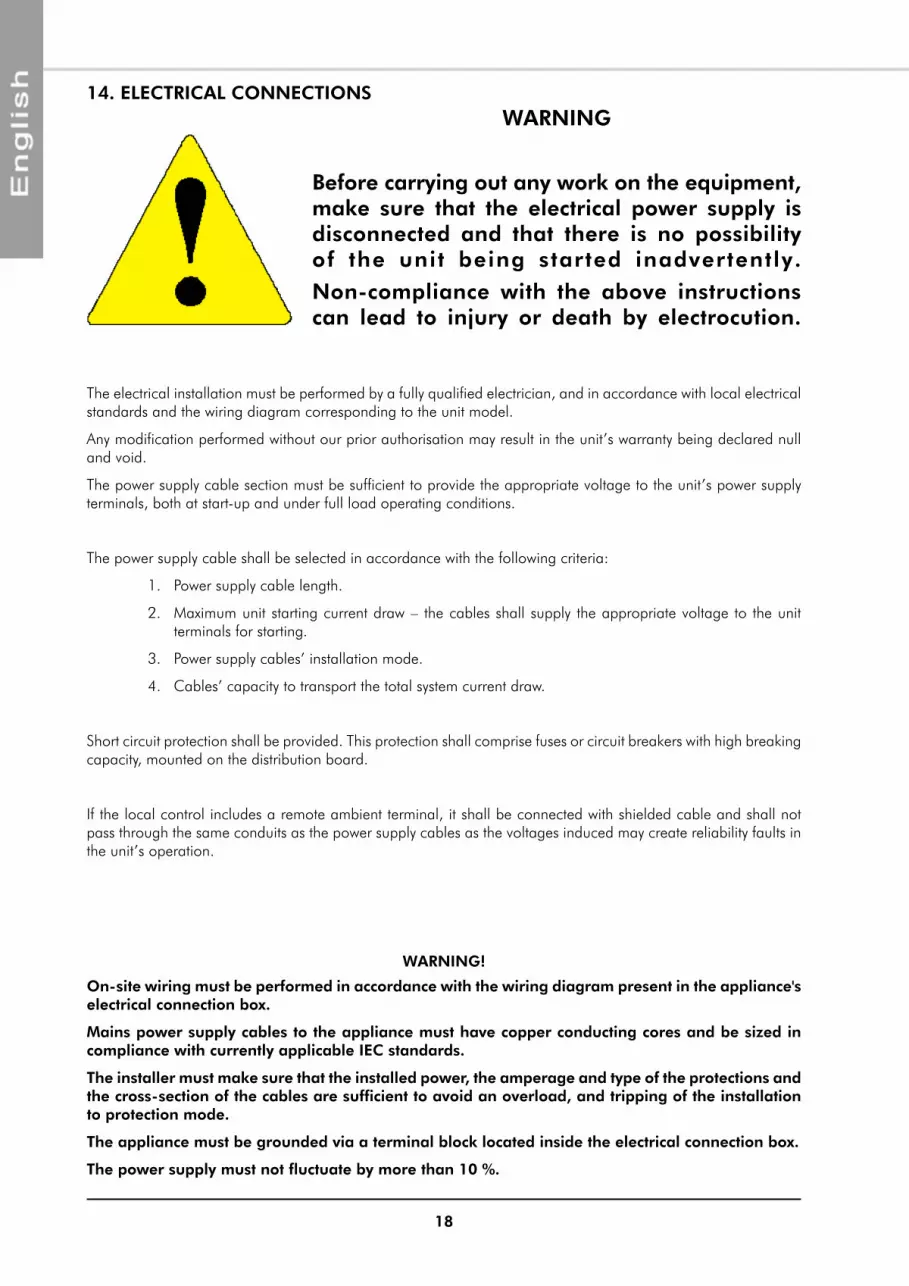
14. ELECTRICAL CONNECTIONSWARNING
Before carrying out any work on the equipment, make sure that the electrical power supply is disconnected and that there is no possibility of the unit being started inadvertently.
Non-compliance with the above instructions can lead to injury or death by electrocution.
The electrical installation must be performed by a fully qualified electrician, and in accordance with local electrical standards and the wiring diagram corresponding to the unit model.
Any modification performed without our prior authorisation may result in the unit’s warranty being declared null and void.
The power supply cable section must be sufficient to provide the appropriate voltage to the unit’s power supply terminals, both at start-up and under full load operating conditions.
The power supply cable shall be selected in accordance with the following criteria:
1. power supply cable length.
2. maximum unit starting current draw – the cables shall supply the appropriate voltage to the unit terminals for starting.
3. power supply cables’ installation mode.
4. Cables’ capacity to transport the total system current draw.
Short circuit protection shall be provided. This protection shall comprise fuses or circuit breakers with high breaking capacity, mounted on the distribution board.
If the local control includes a remote ambient terminal, it shall be connected with shielded cable and shall not pass through the same conduits as the power supply cables as the voltages induced may create reliability faults in the unit’s operation.
WARNING!
On-site wiring must be performed in accordance with the wiring diagram present in the appliance's electrical connection box.
Mains power supply cables to the appliance must have copper conducting cores and be sized in compliance with currently applicable IEC standards.
The installer must make sure that the installed power, the amperage and type of the protections and the cross-section of the cables are sufficient to avoid an overload, and tripping of the installation to protection mode.
The appliance must be grounded via a terminal block located inside the electrical connection box.
The power supply must not fluctuate by more than 10 %.

19
These appliances are equipped with a disconnect switch, fitted and wired at the factory.
press to unclip and withdraw the disconnect switch.
The switch can be padlocked.
A circuit breaker or fuse holder ( not supplied ) must be installed on the main power supply of the unit in accordance with the circuit diagram; for the ratings, refer to the electrical specifications.Remove the inspection cover to gain access to the electrical connection box.
pass the power supply cable through the cable passage provided on the appliance.
Install end fittings suitable for the cable section to ensure a good contact. make the connections as shown.
14.1. CONNECTIONS
COmmUNICATION
pOWER SUppLY
2 separate cables for power supply (24v) and communication (A-B-GND).
power supply: Single pair cable: 1 mm²
MAINS POWER SUPPLY
ROOM TERMINAL CONNECTION
A
B
1
2
GND
{{
MAINS POWER SUPPLY
Communication: Shielded twisted single pair cable with screen 0.33 mm² to 0.5mm² (AWG 20/22)
CABLE RUN
20
15. COMMISSIONING15.1. PRE-START CHECK LIST
² Electrical installation has been carried out according to unit wiring diagram and the Supply Authority Regulations.
² Check the circuit breaker setting or the fuse rating on the mains power supply.
² Supply voltages as specified on unit wiring diagram.
² Check the tightness of wire to component connections.
² The cables and wires are clear of or protected from pipework and sharp edges.
² Check the electrical grounding of the appliance.
Before commissioning the system, you must carry out a certain number of installation checks to ensure that the appliance will operate in the best possible conditions. The following list of checks is not exhaustive and only serves as a minimum reference guide.
15.1.1. APPLIANCE POSITIONING
² Check free clearances around the unit, including the exchanger air intake and outlet, and access for maintenance work.
² Check unit assembly in accordance with specifications.
² Check presence and tightness of all screws and bolts.
² Check that the rubber anti-vibration pads are in place.
² Check that the unit is level and that condensates drain freely away from the unit.
² Check that there is no possibility of blown air being recycled through the fans due to wind exposure.
² In arduous climates (sub-zero temperature, snow, high humidity), check that the appliance is raised 10 cm off ground.
² Check that the ambience terminal is located correctly (frequently occupied area, 1.5 m above ground level, etc.).
² Check the presence, direction and position of the water filter upstream of the appliance. Rinse the filter after the first 2 hours of operation.
² Check that the external water circuit components are installed correctly in accordance with manufacturer's recommendations and that the water inlet and outlet connections have been made correctly.
² Check that the water quality complies with stated standards.
² Check that the hydraulic circuit is filled properly and that the fluid flows freely without any signs of leakage or air bubbles.
² Adjust water flow in accordance with the specifications.
² Check the presence and position of the stop cocks to isolate the appliance for maintenance.
² Check the presence of the air bleed valve. Check that it has been opened.
² Check the protection of the installation against freezing conditions (thermal insulation, percentage of anti-freeze in the water circuit if required...).
15.1.2. ELECTRICAL CHECK
15.1.3. HYDRAULIC CHECKS

21
The display acts as a system interface to perform all the operations associated with its use, and notably to:
² Set the operating values.
² manage alarm situations.
² Check the state of the inputs/outputs
In normal display mode, the following information is available:
² Entering (return) water temperature, in tenths of a degree Celsius, with one decimal point.
² The alarm code, if at least one alarm is active. In the case of several active alarms, the first alarm is displayed based on Alarm Chart hierarchy.
² OFF if the heating is in Off mode or there is no need for hot water.
² dEg if the unit is de-icing.
² In mENU mode, the data displayed depends on the device's status. Labels and codes are used to help the user identify a pre-programmed function.
Access to the inputs/outputs and datum points menu
In the "menu" mode:
² Navigate downwards in the menu (level sub-level value)
² Exit and save the new values
In the "menu" mode:
² Scroll the settings
² Increase the value.
In the "menu" mode:
² Scroll the settings
² Reduce the value.
In the "menu" mode:
² Navigate upwards in the menu (value sub-level level)
² Exit without saving the new values
+
16. REGULATION
16.1. USER INTERFACE
16.1.1. KEYPAD

22
The display comprises several menus. Some have unrestricted access and one (the Installation menu) is password protected.
16.1.2. INDICATOR LIGHT
On = heating by resistance or boiler operating
Flashing = back-up heating
On = alarm active, check the alarm codes
Flashing = back-up heating
On = compressor operating
Flashing = compressor waiting to start
16.1.3. ALARMS
The red alarm indicator light is on and the beep sounds if one or several alarms is/are active.
press the alarm button to stop the audible warning and reset the alarm. Check the presence of other alarms in the Err menu.
OHr
PSS
PAr
LOG
Err
I-0
tP
SEt+
LWT / OFF
16.1.4. MENUS
16.1.4.1. GENERAL MENU

23
16.1.4.2. SET MENU - SETPOINTS AND ON/OFF
VALUEECVALUEO-FVALUEHERVALUEHEA
+ Exits without changing the value
Stores the new value
Decreases the value
Increases the value+
SEt+
LWT / OFF
16.1.4.3. TP MENU - TEMPERATURE / PRESSURE
VALUEt08 VALUEP07VALUERTVALUEt06VALUEt05VALUEt04VALUEt03VALUEt02VALUEt01
CONSULTATION
+
}+tP
+LWT / OFF
16.1.4.4. I-0 MENU - INPUT / OUTPUT
CONSULTATION
+}VALUEVal
VALUESta+
ECS
VALUEELEVALUEdFrVALUETHVALUEFAN
CONSULTATION
+
}CONSULTATION
+}VALUECUr
VALUESPd+
DCI
CONSULTATION
+}VALUESH
VALUEpos+
EEV
StatusID10ID..
StatusID1+ Change input}
dI
StatusNO12NO..
NO1 Status+ Change output}
dO+
I-0+
LWT / OFF
16.1.4.5. ERR MENU - ALARM / ERROR
Alarm code ..Alarm code ..
Alarm code 1 Cancel alarm code+
Err+
LWT / OFF
16.1.4.6. LOG MENU - ALARM LOG HISTORY
t04t03t02t01
YYearMMonthDDayMMinutesHHours
+
Alarm code ..Alarm code ..
Alarm code 1+
LOG+
LWT / OFF

24
16.1.4.7. PAR MENU - SETTINGS
VALUEo13VALUEo12VALUEo11VALUEo10VALUEo09VALUEo08VALUEo07VALUEo06VALUEo05VALUEo04VALUEo03VALUEo02VALUEo01
Increases the value
Decreases the value
Stores the new value
+ Exits without changing the value
+ECS
VALUEH06VALUEH05VALUEH04VALUEH03VALUEH01
CONSULTATION
+
}+CnF
+PAr
+LWT / OFF
16.1.4.8. PSS MENU - INSTALLER ADJUSTMENTS
VALUEL08VALUEL07VALUEL06VALUEL05VALUEL04VALUEL03VALUEL02VALUEL01
+ Exits without changing the value
Stores the new value
Decreases the value
Increases the value
+
+DHU
VALUEChHVALUEChd
VALUEDatVALUEHR
+ Exits without changing the value
Stores the new value
Decreases the value
Increases the value
+
CONSULTATION}+RTC
VALUED05VALUED04VALUED03VALUED02VALUED01
+ Exits without changing the value
Stores the new value
Decreases the value
Increases the value
+
+dFr
VALUEP06VALUEP05VALUEP04VALUEP03VALUEP02VALUEP01
+ Exits without changing the value
Stores the new value
Decreases the value
Increases the value
+
+PuP
VALUEH28VALUEH27VALUEH26VALUEH25VALUEH24VALUEH23VALUEH22VALUEH21VALUEH20VALUEH19VALUEH16VALUEH15VALUEH14VALUEH12VALUEH11VALUEH10VALUEH09VALUEH08
+ Exits without changing the value
Stores the new value
Decreases the value
Increases the value
+
+CnF
+0
+PSS
+LWT / OFF
16.1.4.9. OHR MENU - OPERATING TIME / STARTS
PSPHCSCH
HundredsThousands
++OHr
+LWT / OFF

25
16.2. PRINCIPLE
Regulation will ensure optimal operation of the Aqu@ Scop Advance DCI in accordance with user comfort requirements. Two factory-configured versions are available:
² Aqu@ Scop Advance DCI with electric heater
² Aqu@ Scop Advance DCI with boiler back-up
An ambience thermostat, which includes the start command, is used for regulation as a function of the temperature in the room and as a limiter. It comes into action for fine adjustment of the ambient temperature proposed by the electronic regulator, and it switches off the heating if there is a lot of sunshine or if a fireplace is used at the same time, for example. It must be installed in a main room..
16.2.1. AqU@ SCOP ADVANCE DCI WITH ELECTRIC HEATER
The Aqu@ Scop Advance DCI produces hot water for conveyance to the floor via its heat pump and its integrated back-up electrical heating functions,.
The electronic regulator has two regulation stages:
² The first stage governs the production of thermodynamic energy (compressor operation control).
² The second stage governs the back-up electrical heating. The back-up electrical heating resistances themselves comprise two stages.
In order to maximise energy savings, the regulator always gives priority to running the compressor rather than to running the back-up electrical heating, irrespective of outdoor temperature conditions.
The regulator only moves up to the second stage if the thermodynamic capacity is not capable of maintaining the water at the temperature required by the water logic.
16.2.2. AqU@ SCOP ADVANCE DCI WITH BOILER BACK-UP
Generally, on its own, the Aqu@ Scop Advance DCI is not capable of meeting all heating needs for extremely low outdoor temperatures, either due to a lack of capacity or due to systems shut-downs caused by excessively high inlet (return) water temperatures. The lowest temperature at which the Aqu@ Scop Advance DCI can heat the building without back-up heating is known as the balance point. This balance point depends of the building's heat losses and the Aqu@ Scop Advance DCI's capacity. This outdoor temperature value is vital for managing the installation and is used as the set temperature point on the parameter H21.
Accordingly, the regulation has to manage three different regimes, i.e.:
A Aqu@ Scop Advance DCI only- Outdoor temperature above the balance point.
B Aqu@ Scop Advance DCI and the boiler - Outdoor temperature below the balance point and radiator return water temperature below 42°C.
C Boiler only - Outside air temperature less than the equilibrium point and radiator return temperature higher than 47 °C, or outside air temperature less than the compressor shut-down setting.

26
16.2.2.1. A) OUTDOOR TEMPERATURE ABOVE THE BALANCE POINT
In this case, the Aqu@ Scop Advance DCI operates on its own:
² The existing circulation pump is switched to continuous operation.
² In order not to supply the boiler, the zone valve, if it exists, must be placed in the 100% open position on the by-pass.
² If possible, the boiler will be switched to "no heating" or "hot water only" depending on the type of boiler. The system is then regulated via the ambience thermostat (open position) or another contact device.
COMMENTS: The zone valve placed in the 100% by-pass position prohibits any despatch of hot water from the boiler to the radiators. In this way, the boiler burner is restricted to simply maintaining the temperature of the boiler casing and possibly to producing hot water for cooking and washing purposes.
² The Aqu@ Scop Advance DCI starts and stops to maintain its leaving water temperature at the value required by the water logic relative to the factory-set outdoor temperature. This logic is adapted to operation with a radiator circuit. If used on a network of low-temperature heat emitters such as fan-convectors or underfloor heating, it is simply necessary to change the H09 setting (refer to the § WATER LAW TYpE ADJUSTmENT).
² The ambience terminal stops the Aqu@ Scop Advance DCI if the ambient temperature rises more than 0.6 °C above the setpoint (H27 setting).
16.2.2.2. B) OUTDOOR TEMPERATURE BELOW THE BALANCE POINT AND RADIATOR RETURN WATER TEMPERATURE BELOW 42°C
In this case, the Aqu@ Scop Advance DCI and the boiler operate at the same time:
² The zone valve will be in the 100% open position on the boiler.
² Boiler operation will be authorised.
² The Aqu@ Scop Advance DCI operates in exactly the same manner as described in the preceding paragraph for as long as the radiator return temperature remains lower than 42° C.
16.2.2.3. C) OUTDOOR TEMPERATURE BELOW THE BALANCE POINT AND RADIATOR RETURN WATER TEMPERATURE ABOVE 47°C OR OUTSIDE AIR TEMPERATURE LESS THAN THE COMPRESSOR SHUT-DOWN SETTING.
In this case, only the boiler operates and the Aqu@ Scop Advance DCI is shut down by the integrated regulator. In this configuration, the Aqu@ Scop Advance DCI can support return water temperatures up to 90°C without its safety systems being triggered.

27
17. STARTING THE APPLIANCEAfter checking all the electrical connections and making any rectifications as required, proceed with starting up the installation.
On the display of the Aqu@ Scop Advance DCI, check the coherence of the temperature probes on the tp screen, and also check that communication is correctly established with the ambience terminal. It is preferable to adjust the settings of the water law before starting up the Aqu@ Scop Advance DCI.
17.1. SIMPLIFIED START-UP PROCEDURE
17.1.1. CHECKS
17.1.2. ADJUSTMENT OF THE TYPE OF HEAT CURVE
The H09 setting is used to pre-adjust the heat curve.
² 0 = radiator or fan-coil
² 1 = underfloor heating
² 2 = fixed, no change in the temperature as a function of the outside air temperature.
Operation in fixed mode can result in a much higher electricity consumption than with the heat curve.
VALUEH09
+ Exits without changing the value
Stores the new value
Decreases the value
Increases the value
+CnF
+0
+PSS
+LWT / OFF

28
17.1.3. HEATING CURVE SETTING..
17.1.3.1. COMPENSATION FOR RADIATOR OPERATION
FACTORY SETTINGS
HEA Set point before correction 38°C
H16 maximum HEA correction D = 12°C
H14 Foot of temperature slope 15°C
H15 proportional correction band D = 15°C
25
30
35
40
45
50
-20 -15 -10 -5 0 5 10 15 20
Outdoor temperature [°C]
H15=15
H16=12
H14=15
H23=-5
Leaving watertemperature
HEA=38
Leavi
ng
wate
r te
mp
eratu
re H
Er [
°C]
The HEA dynamic set temperature point is equal to 38°C.
With this mode of regulation, the leaving water temperature is capped as a function of the outside air temperature.
If the HEA is set at 38°C, the leaving water temperature is at the maximum of 50°C, and the entering water temperature is 47°C, being the maximum operating limit for the Aqu@ Scop Advance DCI for this application.
The Aqu@ Scop Advance DCI must be sized to have a balance point within 4°C and 0°C of the outdoor temperature.
VALUEH28VALUEH27VALUEH26VALUEH25VALUEH24VALUEH23VALUEH22VALUEH21VALUEH20VALUEH19VALUEH16VALUEH15VALUEH14VALUEH12VALUEH11VALUEH10VALUEH09VALUEH08
+ Exits without changing the value
Stores the new value
Decreases the value
Increases the value
+
+CnF
+0
+PSS
VALUEECVALUEO-FVALUEHERVALUEHEA
+ Exits without changing the value
Stores the new value
Decreases the value
Increases the value+
SEt+
LWT / OFF
HEAT CURVE
The water outlet temperature is calculated by the compensation curve and is then corrected by the inside air temperature and limited by the outside air temperature.

29
FACTORY SETTINGS
HEA Set point before correction 27.5°C
H16 maximum HEA correction D = 10°C
H14 Foot of temperature slope 15°C
H15 proportional correction band D = 25°C
17.1.3.2. COMPENSATION FOR UNDER-FLOOR HEATING OPERATION
20
25
30
35
40
45
-20 -15 -10 -5 0 5 10 15 20
Outdoor temperature[°C]
H15=25
H16=10
H14=15
H23=-20
Leaving watertemperature
HEA=27.5
Leavi
ng
wate
r te
mp
eratu
re H
Er [
°C]
The minimum operating temperature for the Aqu@ Scop Advance DCI for this application is limited by the parameter H23 to -20°C. The leaving water temperature is always below the limit and the appliance can operate with the boiler down to temperatures of -20°C. The boiler start-up temperature is determined by Aqu@ Scop Advance DCI's capacity (balance point).
17.1.4. WATER PUMP ADJUSTMENT, IF NECESSARY
The p01 setting is used to adjust the operation of the water pump.
² 0 = continuous operation even when the unit is in off mode.
² 1 = continuous operation except when the unit is in off mode.
² 2 = continuous operation on demand. The water pump stops when the ambient temperature exceeds the setpoint.
VALUEP06VALUEP05VALUEP04VALUEP03VALUEP02VALUEP01
+ Exits without changing the value
Stores the new value
Decreases the value
Increases the value
+
+PuP
+0
+PSS
+LWT / OFF

30
18. AqU@ SCOP ADVANCE DCI EMERGENCY OPERATION SWITCHSwitch situated on the outdoor module control panel.
IMPORTANT: This function should only be used in the event of a fault in the Aqu@ Scop Advance DCI's thermodynamic systems that has caused the compressor to stop running.
The change-over of the switch to its back-up position cancels the switch-on conditions for the extra electric heating or of the boiler.
In the emergency position, the triggering of the back-up electrical heating resistances or the boiler depends on demand for back-up heating from the regulator in accordance with the water logic and the ambient temperature.
If the back-up heating is switched on, alarm E36 is displayed on the screen of the ambience terminal.
Using the back-up heating mode when the Aqu@ Scop Advance DCI is not in a failed state will result in excess electrical power consumption.
19. DOMESTIC HOT WATER
Fit the valve in accordance with the flow direction marks etched on the valve.
THE CONNECTIONS MUST CORRESPOND EXACTLY WITH THE FLOW DIRECTIONS INDICATED ON THE LAYOUT DIAGRAM FOR THE TYPE OF INSTALLATION.
19.1. CONNECTION TO THE CENTRAL HEATING LOOP
An On-Off 3-way valve directs hot water produced by the Aqu@ Scop Advance DCI to either the heating circuit or the domestic hot water tank. Hydraulic connections must be made in accordance with the circuit layout diagrams provided.
Warning: You must ensure that the 3-way valve orifices (marked A, B and AB) are connected correctly to the circuit in order for the valve to operate in accordance with the electrical diagram provided.
position the flow changeover control in the Y1 position.
AB
AB
motor disengagement
DOmESTIC HOT WATER TANK
Aqu@ Scop Advance DCI
HEATING CIRCUIT
19.1.1. 3-WAY HEATING / DOMESTIC HOT WATER VALVE
31
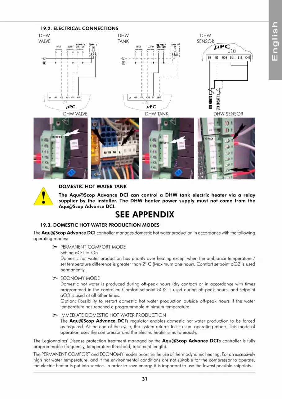
19.2. ELECTRICAL CONNECTIONS
DHW vALvE
DHW TANK
DHW SENSOR
DHW vALvE DHW TANK DHW SENSOR
The Aqu@ Scop Advance DCI controller manages domestic hot water production in accordance with the following operating modes:
² pERmANENT COmFORT mODE Setting oO1 = On Domestic hot water production has priority over heating except when the ambiance temperature / set temperature difference is greater than 2° C (maximum one hour). Comfort setpoint oO2 is used permanently.
² ECONOmY mODE Domestic hot water is produced during off-peak hours (dry contact) or in accordance with times programmed in the controller. Comfort setpoint oO2 is used during off-peak hours, and setpoint oO3 is used at all other times. Option: possibility to restart domestic hot water production outside off-peak hours if the water temperature has reached a programmable minimum temperature.
² ImmEDIATE DOmESTIC HOT WATER pRODUCTION The Aqu@ Scop Advance DCI's regulator enables domestic hot water production to be forced as required. At the end of the cycle, the system returns to its usual operating mode. This mode of operation uses the compressor and the electric heater simultaneously.
The Legionnaires' Disease protection treatment managed by the Aqu@ Scop Advance DCI's controller is fully programmable (frequency, temperature threshold, treatment length).
19.3. DOMESTIC HOT WATER PRODUCTION MODES
µPC µPC
µPC
The pERmANENT COmFORT and ECONOmY modes prioritise the use of thermodynamic heating. For an excessively high hot water temperature, and if the environmental conditions are not suitable for the compressor to operate, the electric heater is put into service. In order to save energy, it is important to use the lowest possible setpoints.
DOMESTIC HOT WATER TANK
The Aqu@ Scop Advance DCI can control a DHW tank electric heater via a relay supplier by the installer. The DHW heater power supply must not come from the Aqu@ Scop Advance DCI.
SEE APPENDIX

32
20. OPERATING CHECK LIST20.1. GENERAL
Check for any unusual noises or vibration in the running components, particularly the indoor fan drive system.
1. Check that the fans rotate freely without rubbing.
1. Checking operation: Start the Aqu@ Scop Advance DCI. Check for any abnormal noises or vibrations.
2. Suction superheat should be 6K ±2K at outdoor temperatures less than 10°C.(*)
* These checks can be performed at the time of commissioning with the help of qualified technical personnel.
20.2. OPERATING VOLTAGE:
1. Recheck voltage at unit supply terminals.
20.3. CONTROL
1. verify all sensor inputs, using the controller display.
20.4. FAN & DRIVE
20.5. COMPRESSOR AND REFRIGERATION SYSTEM
1. All panels and fan guards are in place and secured.
2. The ground wires of the panels are correctly connected.
3. Unit clean and free of remainder installation material.
20.6. FINAL CHECK
If needed, fix the cables and the pipes on the wall with clamping collars.
Operate the heat pump in the presence of the user and explain all functions.
21. FINAL TASKS
material must not be returned without permission of our After Sales Department.
To return the material, contact your nearest sales office and ask for a "return voucher". The return voucher shall be sent with the returned material and shall contain all necessary information concerning the problem encountered.
The return of the part is not an order for replacement. Therefore, a purchase order must be entered through your nearest distributor or regional sales office. The order should include part name, part number, model number and serial number of the unit involved.
Following our personal inspection of the returned part, and if it is determined that the failure is due to faulty material or workmanship, and in warranty, credit will be issued on customer's purchase order. All parts shall be returned to our factory, transportation charges prepaid.
22. IN CASE OF WARRANTY - MATERIAL RETURN PROCEDURE
The part number, the order confirmation and the unit serial number indicated on the name plate must be provided whenever service works or spare parts are ordered.
For any spare part order, indicate the date of unit installation and date of failure. Use the part number provided by our service spare parts, if it not available, provide full description of the part required.
23. ORDERING SERVICE AND SPARE PARTS ORDER

33
24. MAINTENANCE
24.1. REGULAR MAINTENANCE
These units have been designed for minimum maintenance through the use of permanently lubricated components. However, there are operational maintenance requirements that require regular attention to ensure optimum performance.
maintenance must be performed by appropriately experienced personnel only.
WARNING : Isolate unit from power supply before working on unit.
24.2. GENERAL INSPECTION
Carry out a visual inspection of the complete installation in service.
Check the general cleanness of the installation, and check if the condensate evacuation is not blocked.
The user is responsible for ensuring that the appliance is in a proper working condition and that technical installation as well as the regular maintenance operations are performed by properly trained technicians and in accordance with the instructions contained in this manual.
CAUTION
BEFORE CARRYING OUT ANY OPERATION ON THE EqUIPMENT, CHECK THAT THE ELECTRICAL POWER SUPPLY IS SWITCHED OFF AND THAT IT CANNOT BE SWITCHED ON INADVERTENTLY.
Check that the main power supply cable is not damaged or altered in such a way as to affect the insulation.
The contact surfaces of relays and contactors should be inspected regularly by an electrician and replaced as judged necessary. On these occasions the control box should be blown out with compressed air to remove any accumulation of dust or other contaminants.
Check the earth grounding connection.
24.3. REFRIGERATION CIRCUIT
Clean the heat exchanger using a special product for aluminium-copper heat exchangers, and rinse with water. Do not use hot water or steam, as this could cause the pressure of the refrigerant to rise.
Check that the surface of the aluminium fins of the heat exchanger is not damaged by impacts or scratches, and clean with an appropriate tool if necessary.
The refrigeration system is hermetically sealed and should require no regular maintenance. However, it is recommended to leak test the refrigerant system and check the general operating conditions and control devices on a regular basis. The operating pressures should be checked particularly as they are an excellent guide for maintenance.
IT IS RECOMMENDED THAT THE DISCONNECT SWITCH BE PADLOCKED
Some alarms can only be cancelled by switching the Aqu@ Scop Advance DCI to OFF.
Generally, an alarm means that there is an anomaly present on the appliance. We strongly recommend that you refrain from repeatedly resetting an alarm without rectifying its cause in order to avoid the risk of causing irrevocable damage to one or several components.
24.4. ELECTRICAL SECTION

34
24.5. SERVICING CHECKLIST
24.5.1. CASING
1. Clean the outer panels.
2. Remove the panels.
3. Check that the insulation is not damaged. Repair as required.
24.5.2. REFRIGERATION CIRCUIT
1. Check the absence of gas leaks. This equipment must be subjected to regular tightness checks conducted by qualified personnel. please refer to national requirements to determine the frequency of these checks.
2. Check that the copper tubes or the capillary tubes do not rub against any metal or vibrate.
3. Check that the compressors do not generate any abnormal noises or vibrations.
4. Check the compressor discharge temperature.
24.5.3. COILS
1. Clean the fin surfaces as required.
2. Check the condition of the fans and the fan motors.
24.5.5. HYDRAULIC CIRCUIT
1. Check that the hydraulic circuit is filled properly and that the fluid flows freely without any signs of leakage or air bubbles.
2. Check the cleanness of the filter.
24.5.4. ELECTRICAL EqUIPMENT
1. Check nominal current draw and the condition of the fuses.
2. Check the tightness of the screw terminals.
3. perform a visual check of the condition of the contacts.
4. Check the general tightness of all cable connections.
Replace the panels and add any missing screws.
24.6. RESET SAFETY DEVICE
The electric heating system is equipped with 1 SAFETY DEVICE with automatic reset and 1 SAFETY DEVICE with manual reset. It cuts off electrical supply to the heating resistances as soon as an operating anomaly is detected.

35
25. LIST OF SETTINGSPARAMETRE UNIT MIN MAX DEFAULT TYPE
SEt
HEA Initial setpoint for the heating law °C20 °C underfloor
or 30 °C radiator
40°C underfloor or 50°C radiator
27.5/38 modifiable
HEr Water setpoint after correction °C read only
O-F ON OFF On/ OFF On Off OFF modifiable
EC ECS comfort setpoint °C 10 60 48 modifiable
tp
t01 Water inlet temperature B1 °C -50°C 90 °C read only
t02 Water outlet temperature B2 °C -50°C 90 °C read only
t03 Outside coil temperature B3 °C -50°C 90 °C read only
t04 Outside air temperature B4 °C -50°C 90 °C read only
t05 Discharge temperature B5 °C 0 120 °C read only
t06 Sunction temperature B6 °C -50°C 90 °C read only
RT Ambience temperature °C 0°C 40°C read only
p07 Sunction pressure B7 bar 0 15 read only
t08 Hot water temperature B8 °C -50°C 90°c read only
I-0 /dO
1 - Status of output NO1 0 = output open1 = output energised
read only
2 - Status of output NO2 0 = output open1 = output energised
read only
3 0 = output open1 = output energised
read only
et....12 …..Status of output NO12 0 = output open1 = output energised
read only
I-0 / Dl1 - Status of input ID1 0 or 1
0 = output not energised
1 = output energised
read only
etc....10 ….. Status of input ID10 0 or 10 = output not
energised1 = output energised
read only
I-0 / EEvpos position of expansion valve pitch 0 480 read only
SH Superheating K 0 40 read only
I-0 / DCISpd Compressor speed Hz 0 80 read only
CUr Current A 0 30 read only
I-0
FAN Fan speed % 0 100 read only
TH Thermostat setpoint °C 0 30 read only
dFr Time until next defrost minutes 0 60 read only
ELE Estimated consumption in kWh. kWh 0 999999 read only
I-O / ECSSta Hot water status
"Off" = DHW stopped "On" = DHW operating
"LEg" = anti-legionellosis operatingread only
val Current value of hot water setpoint °C 10 65 read only
Err Alarms code read only
LOG Alarm LOG code read only
pAr / CnF
H01 Software version read only
H03 Type of water CURvE0 = radiator
1 = underfloor 2 = no heat curve
read only
H04 Type of DCI model 6, 12 or 16 read only
H05 SpH or DCICompressor configuration
0 = fixed 1 = variable
read only
pAr / ECS
o01 permanent comf. modeOn = permanent comfort mode
Off = dry contact or programmed mode
On modifiable
o02 comfort period setpoint °C 10 60 48 modifiable
o03 eco period setpoint °C 10 55 45 modifiable
o04 Start time for comfort period 1 Hr 0 23 23:00 modifiable

36
PARAMETRE UNIT MIN MAX DEFAULT TYPE
pAr / ECS
o05 Stop time 1 Hr 0 23 03:00 modifiable
o06 Start time for comfort period 2 Hr 0 23 0 modifiable
o07 Stop time 2 Hr 0 23 0 modifiable
o08 Anti-legionellosis function On/OFF On Off Off modifiable
o09 Water setpoint in anti-legionellosis mode °C 0 70 60 modifiable
o10 day of anti-legionellosis cycle day 1 (monday) 7 1 modifiable
o11 Start time of anti-legionellosis cycle Hr 0 23 01:00 modifiable
o12 Duration of anti-legionellosis cycle min 0 90 30 modifiable
o13 manual rapid chargeOn = hot water tank heated by compressor and
resistance Off = normal
modifiable
pSS / CnF
H08 Activation of Hot WaterOn = DHW activated
Off = no DHW OFF modifiable
H09 Selection of heat curve0 = radiator
1 = underfloor 2 = fixed (no heat curve))
1 modifiable
H10 Selection of unit0 = Electric heater 1 = Boiler back-up
2 = no additional heatingmodifiable
H11Activation of outside air temperature sensor
OFF = use inside sensor ON = use a wall-mounted air
temperature sensorOFF modifiable
H12 Activation of ambience remote controlON = room terminal activated
(recommended) OFF = no room terminal
ON modifiable
H14Heat curve Outside air temperature setpoint
°C 0 25 15°C modifiable
H15Heat curve Outside air delta temperature setpoint
°C 0 40
15 °C underfloor
25 °C radiator
modifiable
H16Heat curve max compensation of water temperature
°C 0 20
10° underfloor
12° radiator
modifiable
H19 Electric heater differential °C 0 6 3 modifiable
H20 Electric heater hysteresis °C 0 3 1 modifiable
H21Outside air temperature for shut-down of EH1 or boiler
°C 5 modifiable
H22Outside air temperature for shut-down of EH2
°C 2 modifiable
H23Outside air temperature for shut-down of compressor
°C -20 20
-5°C (back-up)
20°C (resistance)
modifiable
H24 Reversal of boiler bypass outlet direction
0 = The bypass valve is energised when the boiler is off.
1 = The bypass valve is energised when the boiler is on
0 modifiable
H25 Reversal of "EJp" tariff intake logic
dir = Input closed = "EJp" tariff mode ON
inv = Input open = "EJp" tariff mode ON
0 modifiable
H26 Supply voltage used for kWh estimation v 200 250 225 modifiable
H27 DT for compressor restart °C 0.2°C modifiable
H28 DT for compressor shut-down °C 0.6°C modifiable
H29Input 9 selection On / Off or Electric heat load shedding
OF = On / Off LS = Electric heat load shedding
OF modifiable

37
PARAMETRE UNIT MIN MAX DEFAULT TYPE
pSS / CnF
H30 Reverse Input 9 (On/Off or load shedding)dir = Input closed = On inv = Input open = On
inv modifiable
H31maximum possible water temperature for floor heating
°C 30 55 45 modifiable
pSS / pup
p01 Type of water pump operation
0 = Continuous operation even when in off mode.
1 = Continuous operation except when in off mode.
2 = Operation on demand from compressor
2 modifiable
p02 Interval between anti-seize cycles hours 0 99 24 modifiable
p03 Length of anti-seize cycle s 0 999 60 modifiable
p04 Configuration of water pump Wp2
0 = Used with a mixing tank. On /
Off as a function of DT below. 1 = Operation as boiler back-up.
On with bypass valve.
0 modifiable
p05 Restart water pump Wp2 °C -2.0 2.0 0.2 modifiable
p06 Shut-down of water pump Wp2 °C -2.0 2.0 0.6 modifiable
pSS / dFr
D01 Time remaining until defrost min read only
D02Corrected temperature at start of defrost timer
°C read only
D03Temperature at start of de-ice timer before correction
°C -2 read only
D04 Interval between de-icing cycles min 40 60 50 modifiable
D05 End of de-ice °C 16 read only
pSS / RTC
HR Time used Hr / min read only
Dat Date useddd / mm
/ yyread only
Chd Update the date modifiableChH Update the time modifiable
pSS / DHU
L01Selection of switch-over mode between comfort and eco
prg = Uses hour programming In = Uses day / night INpUT
prg modifiable
L02 DHW cycle start time if DT< 2 min 0 240 60 modifiable
L03 Type of DHW kit 0 = DHW tank1 = DHW
module with pump
0 modifiable
L04 DHW module pump cycle time interval min 10 300 120 modifiable
L05Use the internal elec heat for DHW additional heat
ON = Internal elec heat OFF = DHWEH used
OFF modifiable
L06Compressor can be used for DHW for boiler relief and low OAT
ON = Compressor used OFF = compresseur not used
OFF modifiable
L07Comp and DHWEH used for boiler back-up config only
ON = DHW by comp and DHWEH OFF = DHW by comp and boiler
OFF modifiable
L08 Reverse input 10 (Day / Night)dir = Input closed = night mode inv = Input open = night mode
dir modifiable
OHr
CH Compressor operating hours hours 0 999999 read onlyCS Nbr of compressor starts. 0 999999 read onlypH pump operating hours hours 0 999999 read onlypS Nbr of pump starts. 0 999999 read only

38
26. ALARM LIST AVAILABLE ON THE AqU@ SCOP ADVANCE DCI DISPLAYRe
f.A
larm
des
crip
tion
Aq
u@
Scop
Ad
van
ce D
CI
act
ion
Ala
rm c
an
cella
tion
Tim
e d
elay
Poss
ible
cau
se(s
)Re
com
men
ded
act
ion
(s)
E0C
omm
unic
atio
n er
ror
betw
een
disp
lay
and
boar
dN
orm
al o
pera
tion
Auto
mat
icIn
terc
onne
ctio
n
Boar
d no
t sta
rted
upN
orm
al fo
r the
firs
t 30
seco
nds
afte
r pow
er-u
p.
E01
Ente
riIN
G w
ater
se
nsor
EW
T di
scon
nect
ed o
r da
mag
ed
Redu
ced
capa
city
ope
ratio
nAu
tom
atic
10 s
Dis
conn
ecte
d or
faul
ty s
enso
rC
heck
the
wiri
ng o
f sen
sor,
repl
ace
if de
fect
ive
E02
Leav
ing
wat
er s
enso
r LW
T di
scon
nect
ed o
r da
mag
edC
ompl
ete
shut
dow
nAu
tom
atic
10 s
E03
Out
door
te
mpe
ratu
re s
enso
r O
AT d
isco
nnec
ted
or
dam
aged
Redu
ced
capa
city
ope
ratio
nAu
tom
atic
10 s
E04
Dom
estic
hot
wat
er
sens
or d
isco
nnec
ted
or d
amag
edSh
ut-d
own
of E
CS
func
tion
10 s
E05
Out
door
coi
l sen
sor
OC
T di
scon
nect
ed
or d
amag
ed
Redu
ced
capa
city
or
stop
if
coil
con
freez
eAu
tom
atic
10 s
E06
Lack
of w
ater
flow
, ris
k of
free
zing
Com
plet
e sh
utdo
wn
Auto
mat
ic o
nce
then
m
anua
l
26s
afte
r st
art o
f ci
rcul
atio
n pu
mp
Seiz
ed w
ater
pum
pC
heck
wat
er p
ump
oper
atio
n
Wat
er f
low
too
low
or
air
in t
he
syst
em
Che
ck t
he p
AC
's te
mpe
ratu
re d
iffer
ence
in
oper
atio
n. In
crea
se th
e flo
w (c
hang
e th
e w
ater
pu
mp
spee
d)
E08
Fan
faul
tAu
to tw
ice
then
man
ual
2 s
Inte
rnal
tem
pera
ture
pro
tect
ion
cut-
out i
n on
e of
the
fans
Rese
t th
e al
arm
afte
r al
low
ing
the
mot
ors
to
cool
. C
heck
whi
ch fa
n is
ove
rhea
ting.
Rep
lace
th
e de
fect
ive
fan.
E11
Hig
h pr
essu
re s
afet
y tri
pped
Com
plet
e sh
utdo
wn
Auto
mat
ic o
nce
then
m
anua
lN
one
Refe
r to
the
fau
lt di
agno
sis
guid
e in
the
Inst
alla
tion
and
mai
nten
ance
m
anua
l
Refe
r to
the
fau
lt di
agno
sis
guid
e in
the
In
stal
latio
n an
d m
aint
enan
ce m
anua
l
Wat
er f
low
too
low
or
air
in t
he
syst
emRe
-est
ablis
h no
min
al w
ater
flo
w o
r bl
eed
the
syst
em
E12
Low
pre
ssur
e sa
fety
tri
psC
ompl
ete
shut
dow
nAu
to tw
ice
then
man
ual
5 s
Refe
r to
the
fau
lt di
agno
sis
guid
e in
the
Inst
alla
tion
and
mai
nten
ance
m
anua
l
Refe
r to
the
fau
lt di
agno
sis
guid
e in
the
In
stal
latio
n an
d m
aint
enan
ce m
anua
l
Coi
l blo
cked
Cle
an th
e fin
ned
coil
nco
mp
lete
d
e-i
cin
g
(la
ck
of
refri
gera
nt c
harg
e)C
heck
the
amou
nt o
f ref
riger
ant c
harg
e
Fan
faul
tC
heck
the
fans

39
Ref.
Ala
rm d
escr
iptio
nA
qu
@ Sc
op
Ad
van
ce D
CI
act
ion
Ala
rm c
an
cella
tion
Tim
e d
elay
Poss
ible
cau
se(s
)Re
com
men
ded
act
ion
(s)
E16
pAC
/Ter
min
al
com
mun
icat
ion
failu
re
Switc
hove
r to
forc
ed
Hea
ting
mod
em
anua
l
varia
ble
depe
ndin
g on
the
caus
e of
th
e pr
oble
m
(cle
an tr
ip
or tr
ip d
ue
to e
lect
rical
in
terfe
renc
e)
Ambi
ance
term
inal
is n
ot c
onne
cted
Dea
ctiv
ate
it vi
a th
e A
qu@
Scop
Adva
nce
DC
I ke
ypad
One
of t
he c
omm
unic
atio
n ca
bles
is
disc
onne
cted
Ch
ec
k
the
c
on
ne
cti
on
s o
n
the
Aq
u@
Scop
Ad
van
ce D
CI
and
the
term
inal
as
wel
l as
the
pola
ritie
s (A
and
B)
Too
mu
ch i
nter
fere
nce
on
the
com
mun
icat
ion
bus
Use
shi
elde
d ca
ble
as r
ecom
men
ded
E22
De-
icin
g en
ded
abno
rmal
ly b
y m
axim
um ti
me
limit.
De-
icin
g st
oppe
dAu
to. A
larm
dis
play
ed fo
r 2
min
utes
for
info
rmat
ion
purp
oses
Non
eD
e-ic
ing
has l
aste
d ov
er 1
0 m
inut
es.
This
is a
bnor
mal
as
de-ic
ing
usua
lly
take
s be
twee
n 3
and
4 m
inut
es
mon
itor t
he a
pplia
nce
to se
e if
this
faul
t is a
one
-of
f occ
urre
nce,
If n
ot, c
heck
all
poss
ible
cau
ses
of p
oor
de-ic
ing
(lack
of r
efrig
eran
t cha
rge)
E23
De-
icin
g en
ded
abno
rmal
ly b
y lo
w o
utle
t wat
er
tem
pera
ture
De-
icin
g st
oppe
dAu
to. A
larm
dis
play
ed fo
r 2
min
utes
for
info
rmat
ion
purp
oses
Non
eO
utle
t wat
er te
mpe
ratu
re d
urin
g de
-ic
ing
has
falle
n be
low
10°
C
Che
ck t
hat
ther
e is
suf
ficie
nt w
ater
vol
ume
in
the
syst
em, a
s re
com
men
ded
in th
e In
stal
latio
n an
d m
aint
enan
ce m
anua
l
E24
Com
pres
sor
disc
harg
e te
mpe
ratu
re
ther
mos
tat
Com
plet
e sh
utdo
wn
man
ual
Non
eTr
ipp
ed o
ut b
y th
e co
mp
ress
or
disc
harg
e te
mpe
ratu
re th
erm
osta
t
mon
itor
the
appl
ianc
e to
see
if
this
fau
lt is
a
one-
off o
ccur
renc
e, if
not
che
ck th
e ch
arge
or
for c
ompr
esso
r sup
erhe
atin
g (p
erha
ps to
o hi
gh)
E25
Com
pres
sor
over
heat
th
erm
osta
t Fm
1Sh
ut-d
own
by c
ompr
esso
r di
scha
rge
tem
pera
ture
sen
sor
mon
itor
the
appl
ianc
e to
see
if
this
fau
lt is
a
one-
off
occu
rren
ce,
if no
t che
ck th
e ch
arge
or
for c
ompr
esso
r sup
erhe
atin
g (p
erha
ps to
o hi
gh)
E32
Inle
t /ou
tlet w
ater
se
nsor
s in
verte
dC
ompl
ete
shut
dow
nm
anua
l (A
qu@
Scop A
dva
nce
DC
I O
FF v
ia k
eypa
d)90
sAu
tom
atic
det
ectio
n by
man
agem
ent
syst
em i
f th
e w
ater
tem
pera
ture
se
nsor
s ar
e in
verte
d
Inve
rt th
e se
nsor
s at
the
leve
l of t
he c
ontro
ller.
Che
ck t
he s
enso
r va
lues
dur
ing
oper
atio
n of
co
mpr
esso
r
E33
EWT/
LWT
tem
pera
ture
di
ffere
nce
too
high
Info
rmat
ion
only
Auto
mat
icLo
w w
ater
flow
.C
heck
wat
er fl
ow

40
Ref.
Ala
rm d
escr
iptio
nA
qu
@ Sc
op
Ad
van
ce D
CI
act
ion
Ala
rm c
an
cella
tion
Tim
e d
elay
Poss
ible
cau
se(s
)Re
com
men
ded
act
ion
(s)
E36
--In
form
atio
n--
Boile
r/El
ectri
c he
at.
back
up a
ctiv
ated
Info
rmat
ion
Stop
bac
kup
mod
eN
one
Emer
genc
y he
at s
witc
h is
ON
(se
e §
Aq
u@
Sco
p A
dva
nce
DC
I E
mE
RG
EN
CY
O
pE
RA
TIO
NS
SWIT
CH
)
E37
Fros
t pro
tect
ion
Wat
er te
mpe
ratu
re
belo
w li
mit
Com
pres
sor
stop
H
eate
rs O
NAu
tom
atic
Reve
rsin
g va
lve
stuc
k U
nit i
n O
ff m
ode
Che
ck r
ever
sing
val
ve
Hea
t wat
er u
sing
aux
ilary
hea
t
E50
Com
pres
sor
disc
harg
e te
mpe
ratu
re s
enso
r C
DT
disc
onne
cted
or
dam
aged
Redu
ced
capa
city
ope
ratio
nAu
tom
atic
10 s
Dis
conn
ecte
d or
faul
ty s
enso
rC
heck
the
wiri
ng o
f th
e se
nsor
, re
plac
e th
e se
nsor
if it
is fa
ulty.
E51
Com
pres
sor
suct
ion
tem
pera
ture
sen
sor
CST
dis
conn
ecte
d or
da
mag
ed
Com
plet
e sh
utdo
wn
Auto
mat
ic10
sD
isco
nnec
ted
or fa
ulty
sen
sor
Che
ck t
he w
iring
of
the
sens
or,
repl
ace
the
sens
or if
it is
faul
ty.
E52
Com
pres
sor
suct
ion
pres
sure
tran
sduc
er
Ep d
isco
nnec
ted
or
dam
aged
Com
plet
e sh
utdo
wn
Auto
mat
ic10
sTr
ansd
ucer
dis
conn
ecte
d or
faul
tyC
heck
the
wiri
ng o
f the
tran
sduc
er, r
epla
ce th
e tra
nsdu
cer
if it
is fa
ulty.
E53
The
com
pres
sor
does
no
t sta
rtC
ompl
ete
shut
dow
ntw
ice
then
then
man
ual
Driv
er p
robl
em
Com
pres
sor
wiri
ng
Com
pres
sor
unse
rvic
eabl
e
Switc
h th
e po
wer
sup
ply
off a
nd th
en o
n
Che
ck th
e vo
ltage
C
heck
the
wiri
ng b
etw
een
the
driv
er a
nd th
e co
mpr
esso
r Re
plac
e th
e co
mpr
esso
r
E54
EC
S
wa
ter
retu
rn
tem
pera
ture
too
high
Info
rmat
ion
ECS
tem
pera
ture
sen
sor
inco
rrec
tly
loca
ted
or h
eat e
xcha
nger
und
ersiz
ed
E55
Ove
rhea
ting
of e
lect
ric
heat
er r
esis
tanc
eRe
sist
ance
shu
t-dow
nAu
to tw
ice
then
man
ual
Insu
ffici
ent
wat
er fl
ow
Exce
ssiv
e w
ater
tem
pera
ture
E60
DC
I driv
er te
mpe
ratu
re
too
high
Com
plet
e sh
utdo
wn
Auto
mat
icD
irty
heat
sin
k O
pera
ting
cond
ition
s ou
tsid
e lim
itsC
lean
the
heat
sin
k C
heck
the
oper
atin
g co
nditi
ons
E61
DC
I driv
er v
olta
ge to
o lo
wC
ompl
ete
shut
dow
nAu
tom
atic
Supp
ly v
olta
geC
heck
the
pow
er s
uppl
y
E62
DC
I driv
er v
olta
ge to
o hi
ghC
ompl
ete
shut
dow
nAu
tom
atic
Supp
ly v
olta
geC
heck
the
pow
er s
uppl
y
E63
DC
I cur
rent
too
high
Com
plet
e sh
utdo
wn
Auto
mat
icSu
pply
vol
tage
Che
ck th
e po
wer
sup
ply

41
Gen
eral
ly, a
n al
arm
mea
ns t
hat
ther
e is
an
anom
aly
with
the
app
lianc
e. W
e st
rong
ly a
dvi
se a
gain
st r
epea
tedl
y re
setti
ng a
n al
arm
at
the
risk
of
caus
ing
irre
para
ble
dam
ag
e to
one
or
seve
ral c
ompo
nent
s.
Ref.
Ala
rm d
escr
iptio
nA
qu
@ Sc
op
Ad
van
ce D
CI
act
ion
Ala
rm c
an
cella
tion
Tim
e d
elay
Poss
ible
cau
se(s
)Re
com
men
ded
act
ion
(s)
E64
DC
I co
mm
unic
atio
n er
ror
with
driv
erC
ompl
ete
shut
dow
nAu
tom
atic
Com
mun
icat
ion
prob
lem
bet
wee
n th
e dr
iver
and
the
NpC
boa
rd
Che
ck t
he c
omm
unic
atio
n ca
ble
betw
een
the
driv
er a
nd th
e bo
ard.
Che
ck th
e co
mm
unic
atio
n bo
ard
J6
E65
DC
I4 p
ow
er s
uppl
y fre
quen
cy (Z
X)Au
tom
atic
Uns
tabl
e po
wer
sup
ply
Che
ck t
he p
ower
sup
ply
and
the
freq
uenc
y (5
0 H
z)
E66
DC
I4 Ip
m fa
ult (
pIN
)Au
tom
atic
Ove
rhea
ted
driv
er
Faul
ty c
ompo
nent
Repl
ace
the
driv
er if
seve
ral a
larm
s are
trig
gere
d
E67
DC
I4 c
omp
trans
duce
r fa
ult (
CS)
Auto
mat
icO
verh
eate
d dr
iver
Fa
ulty
com
pone
ntRe
plac
e th
e dr
iver
if se
vera
l ala
rms a
re tr
igge
red
E68
DC
I4 r
adia
tor
sens
or
faul
t (H
SB)
Auto
mat
icO
verh
eate
d dr
iver
Fa
ulty
com
pone
ntRe
plac
e th
e dr
iver
if se
vera
l ala
rms a
re tr
igge
red
E69
DC
I4 I
pm o
n cu
rren
t (Ip
m)
Auto
mat
icC
ompr
esso
r cu
rren
t too
hig
h Fa
ulty
com
pone
nts
Che
ck th
e op
erat
ing
cond
ition
s Re
plac
e th
e dr
iver
E70
DC
I4 p
FC s
enso
r fau
lt (p
S)Au
tom
atic
Repl
ace
the
driv
er if
seve
ral a
larm
s are
trig
gere
d
E71
DC
I6 IC
faul
tAu
tom
atic
Repl
ace
the
driv
er if
seve
ral a
larm
s are
trig
gere
d
E72
DC
I6 c
urre
nt s
enso
r fa
ult
Auto
mat
icRe
plac
e th
e dr
iver
if se
vera
l ala
rms a
re tr
igge
red
E73
DC
I6 s
hort
cur
rent
cu
t-out
Auto
mat
icm
icro
pow
er c
utC
heck
the
pow
er s
uppl
y
E74
DC
I6 m
icro
res
tart
Auto
mat
icU
nsta
ble
pow
er s
uppl
yC
heck
the
pow
er s
uppl
y
E75
DC
I6
los
s
of
sync
hron
isat
ion
Auto
mat
icC
ompr
esso
r w
iring
Ex
cess
ive
cool
ant c
harg
e
Che
ck th
e w
iring
bet
wee
n th
e co
mpr
esso
r an
d th
e dr
iver
C
heck
the
cool
ant c
harg
eco
mre
fer
to E
16Au
tom
atic
No
com
mun
icat
ion
with
the
term
inal
Che
ck th
e w
iring
RFLo
ss o
f co
m b
etw
een
rec
eiv
er
an
d
RF
ther
mos
tat
Auto
mat
icN
o co
mm
unic
atio
n be
twee
n th
e re
ceiv
er a
nd th
e tra
nsm
itter
.
Brin
g th
e tw
o el
emen
ts c
lose
r to
geth
er.
Repl
ace
the
batte
ries
New
com
pone
nts
not m
atch
ed

42

APPENDIX / ANNEXE / ANLAGE / ALLEGATO / ANEXO
APPENDIXANNEXEANLAGE
ALLEGATOANEXO

II
APPENDIX / ANNEXE / ANLAGE / ALLEGATO / ANEXO
ANLAGE
APPENDIX
ANNEXE
ALLEGATO
ANEXO
DIMENSIONS ...........................................................................................................................................IIISCHéMA FRIGORIFIqUE ET HYDRAULIqUE ..............................................................................................VABAqUE DE CALCUL DE DéBIT D'EAU .................................................................................................... VIISCHEMAS ELECTRIqUES ..........................................................................................................................IX
AqU@ SCOp ADvANCE DCI 6 ..................................................................................................................................................XAqU@ SCOp ADvANCE DCI 12 / 16 ....................................................................................................................................... XIIAqU@ SCOp ADvANCE DCI R 6 ............................................................................................................................................ XIvAqU@ SCOp ADvANCE DCI R 12 / 16 ................................................................................................................................... XvIBALLON ECS ........................................................................................................................................................................ XvIII
ABMESSUNGEN .......................................................................................................................................IIIKüHL- UND HYDRAULIKDIAGRAMM .........................................................................................................VBERECHNUNGSKURVE DER WASSERDURCHFLUSSMENGE .................................................................... VIISTROMLAUFPLANS ...................................................................................................................................IX
AqU@ SCOp ADvANCE DCI 6 ..................................................................................................................................................XAqU@ SCOp ADvANCE DCI 12 / 16 ....................................................................................................................................... XIIAqU@ SCOp ADvANCE DCI R 6 ............................................................................................................................................ XIvAqU@ SCOp ADvANCE DCI R 12 / 16 ................................................................................................................................... XvISpEICHER WARmWASSER ..................................................................................................................................................... XvIII
DIMENSIONI ............................................................................................................................................IIISCHEMA FRIGORIFERO ED IDRAULICO .....................................................................................................VABACO DI CALCOLO DELLA PORTATA DELL'ACqUA .............................................................................. VIISCHEMA ELETRICO ..................................................................................................................................IX
AqU@ SCOp ADvANCE DCI 6 ..................................................................................................................................................XAqU@ SCOp ADvANCE DCI 12 / 16 ....................................................................................................................................... XIIAqU@ SCOp ADvANCE DCI R 6 ............................................................................................................................................ XIvAqU@ SCOp ADvANCE DCI R 12 / 16 ................................................................................................................................... XvIpALLA ACS ........................................................................................................................................................................... XvIII
DIMENSIONES .........................................................................................................................................IIIESqUEMA FRIGORÍFICO E HIDRÁULICO ...................................................................................................VÁBACO DE CÁLCULO DE CAUDAL DE AGUA ......................................................................................... VIIESqUEMA ELECTRICO ..............................................................................................................................IX
AqU@ SCOp ADvANCE DCI 6 ..................................................................................................................................................XAqU@ SCOp ADvANCE DCI 12 / 16 ....................................................................................................................................... XIIAqU@ SCOp ADvANCE DCI R 6 ............................................................................................................................................ XIvAqU@ SCOp ADvANCE DCI R 12 / 16 ................................................................................................................................... XvIACUmULADOR DE ACS........................................................................................................................................................ XvIII
DIMENSIONS ...........................................................................................................................................IIIREFRIGERATION AND HYDRAULIC LINKS DIAGRAM .................................................................................VWATER FLOW CALCULATION GRAPH ..................................................................................................... VIIWIRING DIAGRAM ...................................................................................................................................IX
AqU@ SCOp ADvANCE DCI 6 ..................................................................................................................................................XAqU@ SCOp ADvANCE DCI 12 / 16 ....................................................................................................................................... XIIAqU@ SCOp ADvANCE DCI R 6 ............................................................................................................................................ XIvAqU@ SCOp ADvANCE DCI R 12 / 16 ................................................................................................................................... XvIDHW TANK .......................................................................................................................................................................... XvIII

III
APPENDIX / ANNEXE / ANLAGE / ALLEGATO / ANEXODIMENSIONS
DIMENSIONS
ABMESSUNGEN
DIMENSIONI
DIMENSIONES
Amain power supply Alimentation
électriqueStromversorgung Alimentazione
elettricaAlimentación eléctrica
BWater inlet 1" female gas
Entrée eau 1"gaz femelle
Wassereintritt 1" Innengewinde Gas
Ingresso acqua 1" gas femmina
Entrada agua 1" gas hembra
CWater outlet 1" female gas
Sortie eau 1"gaz femelle
Wasseraustritt 1" Innengewinde Gas
Uscita acqua 1" gas femmina
Salida agua 1" gas hembra
E Display Afficheur Display Display DisplayF Circuit breaker Sectionneur Trennschalter Sezionatore Seccionador
GWater pressure gauge
manomètre pression d'eau
manometer Wasserdruck manometro pressione dell’acqua
manómetro presión de agua
H High pressure tap prise haute pression Hochdruckanschluss presa alta pressione Toma de alta presión I Low pressure tap prise basse pression Niederdruckanschluss presa bassa pressione Toma de baja presión
JRemote control Commande à
distanceFernbetätigung Comando a distanza mando a distancia
KAnti-vibration device Dispositif anti
vibrationsSchwingungsdämpfende vorrichtungen
Dispositivo antivibrazioni
Dispositivo antivibraciones
1090
6.5
E
G
H
I
228.
5
136.5147
A
B C
F
J
K
1150
400.
5
349
1236.6
1192.6

IV
APPENDIX / ANNEXE / ANLAGE / ALLEGATO / ANEXO
1013
08.5
F
G
H
I
E
A
584
100.5 185
B
C
J
K
1236.6
1192.6
349
400.
5
1150
Amain power supply Alimentation
électriqueStromversorgung Alimentazione
elettricaAlimentación eléctrica
BWater inlet 1" female gas
Entrée eau 1"gaz femelle
Wassereintritt 1" Innengewinde Gas
Ingresso acqua 1" gas femmina
Entrada agua 1" gas hembra
CWater outlet 1" female gas
Sortie eau 1"gaz femelle
Wasseraustritt 1" Innengewinde Gas
Uscita acqua 1" gas femmina
Salida agua 1" gas hembra
E Display Afficheur Display Display DisplayF Circuit breaker Sectionneur Trennschalter Sezionatore Seccionador
GWater pressure gauge
manomètre pression d'eau
manometer Wasserdruck manometro pressione dell’acqua
manómetro presión de agua
H High pressure tape prise haute pression Hochdruckanschluss presa alta pressione Toma de alta presión I Low pressure tape prise basse pression Niederdruckanschluss presa bassa pressione Toma de baja presión
JRemote control Commande à
distanceFernbetätigung Comando a distanza mando a distancia
KAnti-vibration device Dispositif anti
vibrationsSchwingungsdämpfende vorrichtungen
Dispositivo antivibrazioni
Dispositivo antivibraciones

V
APPENDIX / ANNEXE / ANLAGE / ALLEGATO / ANEXOREFRIGERATION AND HYDRAULIC LINKS DIAGRAM
SCHéMA FRIGORIFIqUE ET HYDRAULIqUE
KüHL- UND HYDRAULIKDIAGRAMM
SCHEMA FRIGORIFERO ED IDRAULICO
ESqUEMA FRIGORÍFICO E HIDRÁULICO
IN
4
1C
DT
OFF
P1
2
6
V1
35
V2
EWT
LWT
OC
T
OA
T
P2C
ST
P3
S
7O
UT
P4
V3
FS
Aq
u@
Scop
Ad
van
ce D
CI
12/1
6
8
10
9
7O
UT
P4
V3
FS
Aq
u@
Scop
Ad
van
ce D
CI-
R 1
2/1
6
8
10
7O
UT
P4
V3
FS
Aq
u@
Scop
Ad
van
ce D
CI
68
10
9
7O
UT
P4
V3
FS
Aq
u@
Scop
Ad
van
ce D
CI-
R 6
8
10

VI
APPENDIX / ANNEXE / ANLAGE / ALLEGATO / ANEXO
1 Compressor2 plate heat exchangers. Counter-current
heating3 Dryer filter4 Liquid tank5 Liquid sight glass6 Finned coil and fans V1 Four-way valveV2 Electronic expansion valveCDT Discharge temperatureCST Suction temperatureP1 High pressure pressostatP2 Defrost system high pressure control
pressostatP3 Suction pressureOCT Outdoor coil temperature sensorOAT Air temperature sensor LWT Water temperature sensor (leaving)EWT Water temperature sensor (entering) 7 Water pump8 Expansion tank9 Electric heaters10 Automatic bleedFS Flow switchV3 Safety valve (3.5 bar)P4 Water pressure gauge
1 Compresseur2 Echangeur à plaques Contre courant
chauffage3 Filtre déshydrateur4 Réservoir liquide5 voyant liquide6 Echangeur à ailettes et ventilateursV1 vanne 4 voiesV2 Détendeur électroniqueCDT Temperature de refoulementCST Temperature d'aspirationP1 pressostat haute pressionP2 pressostat contrôle haute pression
dégivrageP3 pression d'évaporation OCT Sonde contrôle de condensationOAT Sonde de température d'air LWT Sonde de température d'eau (sortie)EWT Sonde de température d'eau (entrée) 7 Circulateur8 vase d'expansion9 Chauffage électrique10 purgeur automatiqueFS Détecteur de débitV3 Soupape sécurité (3.5 bar)P4 manomètre pression d’eau
1 Kompressor2 plattenwärmeaustauscher. Gegenstrom
Heizung3 Filtertrockner4 Flüssigkeitsbehälter 5 Anzeigelampe Flüssigkeit6 Lamellenwärmetauscher und ventilatorenV1 vierwegventilV2 Elektronisches minderventilCDT FördertemperaturCST AnsaugtemperaturP1 Hochdruck-pressostatP2 Hochdruckkontrollpressostat Abtauen P3 verdampfungsdruckOCT messfühler verflüssigungskontrolleOAT Lufttemperaturfühler LWT Wassertemperaturfühler (Austritt)EWT Wassertemperaturfühler (Eintritt) 7 Umlaufpumpe8 Expansionsgefäß9 Elektroheizung10 Automatischer AblasshahnFS WassermelderV3 Sicherheitsventil (3.5 Bar)P4 Wasserdruckmesser
1 Compressore2 Intercambiador térmico de placas
Controcorrente riscaldamento3 Filtro disidratante4 Serbatoio liquido5 Indicador luminoso líquido6 Scambiatore ad alette e ventilatoriV1 válvula de cuatro viasV2 Reductor electrónicoCDT Temperatura de descargaCST Temperatura de aspiraciónP1 pressostato alta pressioneP2 pressostato controllo alta pressione
sbrinamentoP3 presión de evaporaciónOCT Sonda de control de condensaciónOAT Sonda di temperatura aria LWT Sonda di temperatura acqua (uscita)EWT Sonda di temperatura acqua (ingresso) 7 Circolatore8 vaso de expansión9 Calentamiento eléctrico10 valvola di scarico automaticaFS Detector del flujoV3 valvola di sicurezza (3.5 bar)P4 manometro pressione acqua
1 Compresor2 Scambia to r i d i ca lo re a p ias t re
Contracorriente calefacción3 Filtro deshidratador4 Depósito líquido5 Spia liquido6 Intercambiador de aletas y ventiladoresV1 valvola a quattro vieV2 Riduttore di pressione elettronicoCDT Temperatura di espulsioneCST Temperatura di aspirazioneP1 presostato alta presiónP2 presostato de control alta presión
descongelación P3 pressione di evaporazioneOCT Sonda controllo di condensazioneOAT Sonda de temperatura de aire LWT Sonda de temperatura de agua (salida)EWT Sonda de temperatura de agua (entrada) 7 Circulador8 vaso di espansione9 Riscaldamento elettrico10 purgador automáticoFS Rilevatore del flussoV3 válvula de seguridad (3.5 bares)P4 manómetro de presión de agua

VII
APPENDIX / ANNEXE / ANLAGE / ALLEGATO / ANEXOWATER FLOW CALCULATION GRAPH
ABAqUE DE CALCUL DE DéBIT D'EAU
BERECHNUNGSKURVE DER WASSERDURCHFLUSSMENGE
ABACO DI CALCOLO DELLA PORTATA DELL'ACqUA
ÁBACO DE CÁLCULO DE CAUDAL DE AGUA
Aqu@ Scop Advance DCI 6
Aqu@ Scop Advance DCI 12
A Nominal flow
A Débit nominal
A Nenndurchflussmenge
A portata nominale
A Caudal nominal
Aqu@ Scop Advance DCI 16
0
0.1
0.2
0.3
0.4
0.5
0.6
800
GV
A
Water flow / Débit d'eau / Wasserdurchflussmenge / Portata dell’acqua / Caudal de agua (l/h)
kPa bar
Ava
ilab
le p
ress
ure
/ P
ress
ion
dis
po
nib
le /
ver
füg
ba
re D
ruck
/
Pres
sio
ne
dis
po
nib
ile /
Pre
sió
n d
isp
on
ible
0
10
20
30
40
50
60
1000 1200 1400 1600 1800 2000
MV
PV
0
0.1
0.2
0.3
0.4
0.5
0.6
1300
GV
A
Water flow / Débit d'eau / Wasserdurchflussmenge / Portata dell’acqua / Caudal de agua (l/h)
kPa bar
Ava
ilab
le p
ress
ure
/ P
ress
ion
dis
po
nib
le /
ver
füg
ba
re D
ruck
/
Pres
sio
ne
dis
po
nib
ile /
Pre
sió
n d
isp
on
ible
0
10
20
30
40
50
60
1500 1700 1900 2100 2300 2500
MV
0
0.1
0.2
0.3
0.4
0.5
0.6
1300
GV
A
Water flow / Débit d'eau / Wasserdurchflussmenge / Portata dell’acqua / Caudal de agua (l/h)
kPa bar
Ava
ilab
le p
ress
ure
/ P
ress
ion
dis
po
nib
le /
ver
füg
ba
re
Dru
ck /
Pre
ssio
ne
dis
po
nib
ile /
Pre
sió
n d
isp
on
ible
0
10
20
30
40
50
60
1500 1700 1900 2100 2300 2500 2700 2900
This drawing is not applicable if heating water circuit pressure drop is higher than 20kpA.
Ce schéma ne s'applique pas si les pertes de charges du circuit de chauffage sont supérieures à 20kpA.

VIII
APPENDIX / ANNEXE / ANLAGE / ALLEGATO / ANEXO

IX
APPENDIX / ANNEXE / ANLAGE / ALLEGATO / ANEXOWIRING DIAGRAM
SCHEMAS ELECTRIqUES
STROMLAUFPLANS
SCHEMA ELETRICO
ESqUEMA ELECTRICO
TAKE CARE!
These wiring diagrams are correct at the time of publication. manufacturing changes can lead to modifications. Always refer to the diagram supplied with the product.
ATTENTION
Ces schémas sont corrects au moment de la publication. Les variantes en fabrication peuvent entraîner des modifications. Reportez-vous toujours au schéma livré avec le produit.
ACHTUNG!
Diese Stromlaufplans sind zum Zeitpunkt der veröffentlichung gültig. In Herstellung befindliche varianten können Änderungen mit sich bringen. In jedem Fall den mit dem produkt gelieferten Stromlaufplan hinzuziehen.
ATTENZIONE !
questi schemi sono corretti al momento della pubblicazione. Le varianti apportate nel corso della fabbricazione possono comportare modifiche. Far sempre riferimento allo schema fornito con il prodotto.
ATENCIÓN !
Esto esquemas son correctos en el momento de la publicación. pero las variantes en la fabricación pueden ser motivo de modificaciones. Remítase siempre al esquema entregado con el producto.
PUESTA FUERA DE TNESIÓN OBLIGATORIA ANTES DE CUALqUIER INTERVENCIÓN EN LAS CAJAS ELéCTRICAS!
PRIMA DI OGNI INTERVENTO SULLE CASSETTE ELETTRICHE ESCLUDERE TASSATIVAMENTE L’ALIMENTAZIONE !
VOR JEDEM EINGRIFF AN DEN ANSCHLUßKÄSTEN UNBEDINGT DAS GERÄT STROMLOS SCHALTEN!
MISE HORS TENSION OBLIGATOIRE AVANT TOUTE INTERVENTION DANS LES BOITIERS ELECTRIqUES.
POWER SUPPLY MUST BE SWITCHED OFF BEFORE STARTING TO WORK IN THE ELECTRIC CONTROL BOX!

X
APPENDIX / ANNEXE / ANLAGE / ALLEGATO / ANEXOAqU@ SCOP ADVANCE DCI 6
CO
NTR
OL
WIR
ING
DIA
GRA
M
N 7
76
AQ
U@
SCO
P A
DVA
NC
E D
CI 0
06
3991
123
SE 3
870
>>
µPC
>
>

XI
APPENDIX / ANNEXE / ANLAGE / ALLEGATO / ANEXO
POW
ER W
IRIN
G D
IAG
RAM
N 7
76
AQ
U@
SCO
P A
DVA
NC
E D
CI
006
3991
122
SE 3
869

XII
APPENDIX / ANNEXE / ANLAGE / ALLEGATO / ANEXOAqU@ SCOP ADVANCE DCI 12 / 16
CO
NTR
OL
WIR
ING
DIA
GRA
M
N 7
76
AQ
U@
SCO
P A
DVA
NC
E D
CI 0
12-0
16
399
112
5
SE 3
872
>>
µPC
>
>

XIII
APPENDIX / ANNEXE / ANLAGE / ALLEGATO / ANEXO
POW
ER W
IRIN
G D
IAG
RAM
N 7
76
AQ
U@
SCO
P A
DVA
NC
E D
CI 0
12-0
16
39
91
12
4
SE 3
871
A
+-

XIV
APPENDIX / ANNEXE / ANLAGE / ALLEGATO / ANEXOAqU@ SCOP ADVANCE DCI R 6
CO
NTR
OL
WIR
ING
DIA
GRA
M
N 7
76
AQ
U@
SCO
P A
DVA
NC
E D
CI-
R 0
06
39
91
12
9
SE 3
88
8
>>
µPC

XV
APPENDIX / ANNEXE / ANLAGE / ALLEGATO / ANEXO
POW
ER W
IRIN
G D
IAG
RAM
N 7
76
AQ
U@
SCO
P A
DVA
NC
E D
CI-
R 00
6
3991
128
SE 3
887

XVI
APPENDIX / ANNEXE / ANLAGE / ALLEGATO / ANEXOAqU@ SCOP ADVANCE DCI R 12 / 16
CO
NTR
OL
WIR
ING
DIA
GRA
M
N 7
76
AQU
@SC
OP
ADVA
NC
E D
CI-
R 01
2-01
6
3991
127
SE 3
884
>>
µPC

XVII
APPENDIX / ANNEXE / ANLAGE / ALLEGATO / ANEXO
POW
ER W
IRIN
G D
IAG
RAM
N 7
76
AQ
U@
SCO
P A
DVA
NC
E D
CI-
R 0
12-0
16
3991
126
SE 3
883
A
+-

XVIII
APPENDIX / ANNEXE / ANLAGE / ALLEGATO / ANEXO
>
>
2 x 1mm²FOURNITURE CLIENTCUSTOMER SUPPLY
EXISTING INSTALLATION INSTALLATION EXISTANTEBESTEHENDE ANLAGE IMPIANTO ESISTENTE
INSTALACIÓN EXISTENTE
LIEFERUNG KUNDEFORNITURA CLIENTEABASTECIMIENTO CLIENTE
relay relais Relais rel relé
AQU@SCOP ADVANCE DCI
DHW TANK BALLON ECS SPEICHER WARMWASSER PALLA ACS ACUMULADOR DE ACS


The meaning of the above logo representing a crossed-out wheeled bin is that this unit must not be disposed of as unsorted municipal waste but should be collected separately as WEEE (Waste Electrical and Electronic Equipment).The presence of hazardous substances in electr ical and e lec t ronic equipment or an improper use of such equipments or of parts thereof as well as the hazards of not separating WEEE from unsorted domestic waste, may affect the environment and human health.As an End User, you are required to place WEEE in a collection separate from that for unsorted domestic waste. please contact a point of sale or installer to find out the collection system available at your local community. You may return your old air conditioning unit for free to the point of sale or the installer when purchasing a new one.As an End User, it is your role to contribute to the reuse, recycling and other forms of recovery of such wastes so as to reduce the disposal of waste. This will help preserve your environment.
Le logo ci-dessus représentant une "poubelle barrée" signifie qu’il ne faut pas se débarrasser de cet appareil comme d’un déchet classique mais que celui-ci doit être collecté séparément en tant que DEEE (Déchet d’Equipement Electrique et Electronique).La présence de subs tances dangereuses dans les équipements électr iques et électroniques, l’utilisation inappropriée de tels équipements ou partie de tels équipements ainsi que le danger représentant la collecte non centralisée de matériels DEEE peuvent être préjudiciables à l’environnement et à la santé publique.En tant qu’utilisateur final, il vous est demandé de collecter les DEEE séparément des déchets ordinaires.vous êtes priés de prendre contact avec votre revendeur ou votre installateur pour qu’il vous indique le mode de collecte de votre commune. Lors du renouvellement de votre appareil, vous avez la possibilité de rendre votre ancien appareil gratuitement à votre installateur ou votre revendeur qui se chargera d’en assurer la collecte.En tant qu’utilisateur final, il est de votre devoir de participer à la réutilisation, au recyclage, et à toute autre forme de récupération de tels déchets afin d’en diminuer la quantité. Cela contribuera à la préservation de l’environnement.
Die Bedeutung des Logos mit der durchgestrichenen mülltonne besteht darin, dass es sich bei diesem Gerät nicht um Hausmüll (Wertstoffmüll oder Restmüll) handelt.Dieses Gerät ist nach der Elektro- und E lek t ron i kge rä tegese t z ElektroG (WEEE) zu sammeln und zu entsorgen.Durch das vorhandensein von ge fähr l i chen Subs tanzen in elektrischen oder elektronischen Bauteilen kann die missbräuchliche verwendung solcher Teile oder das Entsorgen solcher Geräte über den Hausmüll zu nicht unerhebliche Umwelt- und/ oder Gesundheitsschäden führen.Sie als Endkunde sind angehalten, Geräte, welche unter die ElektroG (WEEE) fallen, separat vom Hausmüll zu entsorgen. Bitte informieren Sie den Händler, Installateur oder Ihre Stadt- oder Gemeindeverwaltung, um einen Entsorgungsbetrieb in Ihrer Nähe ausfindig zu machen. Eine möglichkeit besteht darin, das Gerät kostenlos bei Ihrem Händler oder Installateur abzugeben, wenn Sie sich ein neues Gerät kaufen. Als Endkunde beteiligen Sie sich so an der Wiederverwendung, R ü c k g e w i n n u n g o d e r Wiederverwertung von derartigen Rohstoffen. Sie helfen, müll zu vermeiden und leisten so Ihren Beitrag zu einer sauberen Umwelt.
Il significato del logo qui sopra rappresentato indica che i l apparecchio non deve essere rottamato come ri f iuto nella spazzatura indifferenziata, ma deve essere smaltito separatamente in base alle direttive WEEE (Waste Electrical and Electronic Equipment – rifiuti elettrici ed elettronici), in accordo con il decreto legislativo n.151/2005.A causa della presenza di sostanze tossiche nella componentistica e le t t r ica o e le t t ron ica, uno smaltimentodi queste o di parti di esse nei rifiuti non riciclabili, può avere effetti nocivi sull’ambiente e sulla salute umana. Il Cliente è tenuto a separare i prodotti o parte di essi etichettati in base alle normative WEEE dai rifiuti domestici solidi. per ulteriori informazioni si contatti un punto vendita o un installatore per conoscere il punto di raccolta più vicino alla propria città. Il Cliente può smaltire gratuitamente il vecchio apparecchio presso il punto vendita o l’installatore contestualmente all’acquisto di un nuovo apparecchio.qualora i l punto vendi ta o l’installatore non si prendano carico delle incombenze necessarie allo smaltimento del vecchio apparecchio secondo la normativa prevista, potranno essere soggetti ad un’ammenda compresa tra i 150 ed i 400 euro per ogni unità. E’ compito del Cliente provvedere al riutilizzo, al riciclo e ad altre forme di riduzione degli sprechi in modo tale da ridurre la quantità di rifiuti da smaltire. questa normativa viene introdotta a sostegno di politiche ambientali. Il mancato rispetto della legislazione vigente prevede quattro sanzioni pecuniarie comprese tra 25,82 euri e 619.74 euro.
El significado de este logo que representa un cubo de basura con ruedas tachado, es que esta unidad no debe ser desechada como residuo doméstico sin clasificar, sino que deberá ser recogida de forma separada como RAEE (residuos aparatos eléctricos y electrónicos).La presenc ia de sus tanc ias peligrosas en los aparatos eléctricos y electrónicos o un uso impropio de tales aparatos o de partes de los mismos, así como los peligros de no separar RAEE de los residuos domésticos sin clasificar, puede afectar al medio ambiente y a la salud.Como usuario final, se le requiere para que ponga los RAEE en una recogida distinta de los residuos domésticos sin clasificar. por favor, contacte con un punto de venta o instalador para averiguar el sistema de recogida disponible en su comunidad. puede devolver gratis su antigua unidad al punto de venta o instalador cuando compre una unidad.Como usuario final, su papel es contribuir a la reutilización, reciclado y otras formas de recuperación de dichos residuos para reducir la eliminación de basura. Esto ayudará a mantener el medio ambiente.

And that the following paragraphs of the harmonised standards have been applied.Et que les paragraphes suivants les normes harmonisées ont été appliqués.
Und dass die folgenden Paragraphen der vereinheitlichten Normen Angewandt wurden.E che sono stati applicati i seguenti paragraphi delle norme armonnizzate.
Y que se han aplicado los siguientes apartados de las normas armonizadas.
Aqu@Scop Advance DCI PAC 6 - 12 - 16
MACHINERY DIRECTIVE 2006 / 42 / EECLOW VOLTAGE DIRECTIVE (DBT) 2006 / 95 / EEC
ELECTROMAGNETIC COMPATIBILITY DIRECTIVE 2004 / 108 / EECPRESSURISE EqUIPMENT DIRECTIVE (DESP) 97 / 23 / EEC
SUB-MODULE A CATEGORY I
DIRECTIVE MACHINES 2006 / 42 / C.E.E.DIRECTIVE BASSE TENSION (DBT) 2006 / 95 / C.E.E.
DIRECTIVE COMPATIBILITE ELECTROMAGNETIqUE 2004 / 108 / C.E.EDIRECTIVE DES EqUIPEMENTS SOUS PRESSION (DESP) 97 / 23 /C.E.E.
SOUS-MODULE A CATEGORIE I
RICHTLINIE MASCHINEN 2006 / 42 / EGRICHTLINIE NIERDERSPANNUNG (DBT) 2006 / 95 / EG
RICHTLINIE ELEKTROMAGNETISHE VERTRÄGLICHKEIT 2004 / 108 / EGRICHTLINIE FüR AUSRüSTUNGEN UNTER DRUCK (DESP) 97 / 23 / EG
UNTER MODUL A, KATEGORIE I
DIRETTIVA MACHINE 2006 / 42 / CEEDIRETTIVA BASSA TENSIONE (DBT) 2006 / 95 / CEE
DIRETTIVA COMPATIBILITA ELETTROMAGNATICA 2004 / 108 / CEEDIRETTIVA DEGLI IMPIANTI SOTTO PRESSIONE (DESP) 97 / 23 / CEE
SOTTOMODULO A, CATEGORIA I
DIRECTIVA MAqUIAS 2006 / 42 / CEEDIRECTIVA BAJA TENSION (DBT) 2006 / 95 / CEE
DIRECTIVA COMPATIBILIDAD ELECTROMAGNETICA 2004 / 108 / CEEDIRECTIVA DE LOS EqUIPOS A PRESION (DESP) 97 / 23 / CEE
BAJA MODULO A, CATEGORIA I
Déclaration CE de conformitéNous déclarons sous notre responsabilité que les produits désignés dans la présente notice sont conformes aux dispositions des directives CEE énoncées
ci- après et aux législations nationales les transposant.
EC Compliance declarationUnder our own responsibility, we declare that the product designated in this manual comply with the provisions of the EEC directives listed hereafter
and with the national legislation into which these directives have been transposed.
EG-KonformitätserklärungWir erklarën in eigener Verantwortung, das die in der vorliegenden Beschreibung angegebenen Produkte den Bestimungen der nachstehend
erwähnten EG-Richtlinien und den nationalen Gesetzesvorschriffen entsprechen, in denen diese Richtinien umgesetz sind.
Dichiarazione CE di conformitàDichiariamo, assurmendone la responsasabilità, che i prodotti descritti nel presente manuale sono conformi alle disposizioni delle direttive CEE di cui
sott e alle lagislazionni nazionali che li recepiscono
Declaramos, bajo nuestra responsabilidad, que los productos designados en este manual son conformes a las disposiciones de las directivas CEE enunuciadas a continuacion, asi como a las legislaciones nacionales que las contemplan.
Declaración CE de conformidad
EN 378-2:2002 EN 61000-6-3:2007 EN 61000-6-1:2007 EN 61000-3-2:2006 EN 61000-3-3:1995 EN 60 335-2-21 EN 60 335-1: 2003+A1 2005+A2 2006+A11 2004+A12 2006 EN 60 335-2-40:2005+A11 2005+A12 2005+A1 2006
A Tillières sur Avre27570 - FRANCELe: 01/07/2010Sébastien Blardquality managerAIRWELL Industrie France

As part of our ongoing product improvement programme, our products are subject to change without prior notice. Non contractual photos.
Dans un souci d’amélioration constante, nos produits peuvent être modifiés sans préavis. Photos non contractuelles.
In dem Bemühen um ständige Verbesserung können unsere Erzeugnisse ohne vorherige Ankündigung geändert werden. Fotos nicht vertraglich bindend.
A causa della politica di continua miglioria posta in atto dal costruttore, questi prodotti sono soggetti a modifiche senza alcun obbligo di preavviso. Le foto pubblicate non danno luogo ad alcun vincolo contrattuale.
Con objeto de mejorar constantemente, nuestros productos pueden ser modificados sin previo aviso. Fotos no contractuales.
AIRWELL IndustrIe France
Route de Verneuil27570 Tillières-sur-AvreFRANCE& : +33 (0)2 32 60 61 006 : +33 (0)2 32 32 55 13