Embed Size (px)
Citation preview
Cooling Control System of Chemical Process/Plant in Matlab/Simulink using PID Controller
Sir Abdul Rehman Chishti, Ali Husnain (11-TC-61)
Department of Telecommunication, University College of Engineering &Technology,
The Islamia University of Bahawalpur, Punjab, Pakistan.
[email protected]___ Chemical plants areused all over the world onIndustrial level to manufacturedchemicals & new materials on a largescale through chemical/ biologicaltransformation. Chemical plants havespecial kind of instrument, unitsand technology (controller) in theirprocess. There are Some popularplants other than that chemicalplants are Power plant, Wastewaterplant, Biochemical plant, Pollutioncontrol plant, Petrochemical plant,Natural gas processing and Oilrefineries etc. During the chemicalprocess a Convective heat transferphenomenon occurred then temperatureof the plant increased. Atemperature(cooling) sensor is usedas feedback. This kept the heat orcooling of plant stable at desiredset point. To maintain thetemperature of plant at desiredlevel is the key factor of thispaper. For this purpose, we designcooling of the plant exchangersystem and PID controller. Coolingsystem stabilizes the temperaturewhen heat transfer occurred and PID
controller set the temperature atdesired value. By using PIDcontroller & set its parameter likeProportional control (KP), Integralcontrol (Ki) & Derivative control(Kd), we can improve the efficiencyof chemical plant, controltemperature, see step response andother parameters like Rise time(TR), Settling time (TS), Timeconstant (TC), % Overshoot andsteady state error etc.
Keywords__Temperature control, Heatcontrol of the Chemical process.
I – INTRODUCTION
When a chemical reactionoccurred then heat produced duringthe reaction. This heat energy
transfer from one place to anotherdue to the movement of fluids. This
type of heat transfer is
called Convective heat transfer orconvection. If we talk aboutchemical reaction occurred onindustrial scale then large size ofchemical plants are needed. In
chemical plants large amount of heattransferred by the bulk motion offluids. There for, temperature ofthe plant increased at high level.To overcome this temperature atmoderate level temperature sensor isused as feedback. After settingtemperature level on PID controllerwhen temperature of the plant fallsbelow at set point then temperaturein sence of cooling sensor turnsplant on and when temperature of theplant is reached at set point thencooling sensor turns plant off. Thewhole chemical process is controlledby PID controller. In the construction ofchemical plants there are followingparts are used. Units, special kindof equipments, heat exchanger andtechnology (controller) in theirprocess. A chemical plant hasusually large size of vessels orsections called Units. These unitsare interconnected with pipe lines(tubes) or other moving equipmentswhich have different size ofdiameters. The input fluid flowthese pipe lines and falling in theunits called Unit Operations. Afterthat input fluid is converted intooutput fluid by biologicaltransformation or separation ofmaterial called feedstock or simplyfeed.
Fig.1. Chemical Plant
Cooling system
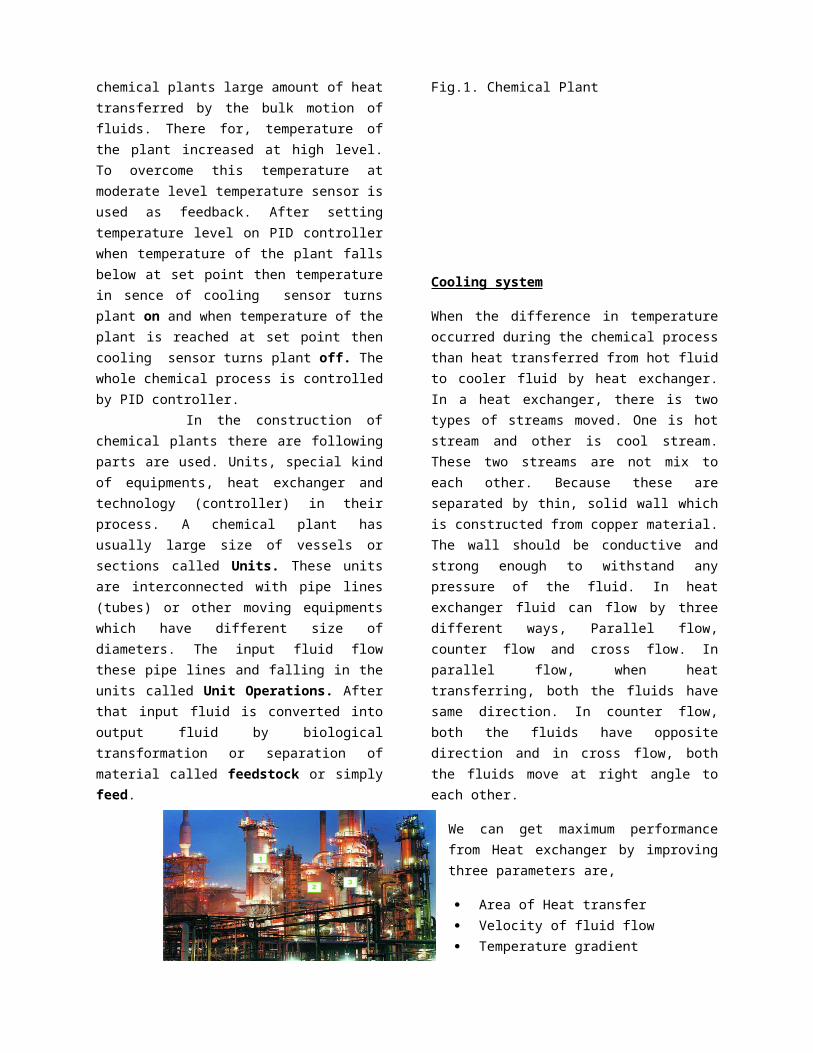
When the difference in temperatureoccurred during the chemical processthan heat transferred from hot fluidto cooler fluid by heat exchanger.In a heat exchanger, there is twotypes of streams moved. One is hotstream and other is cool stream.These two streams are not mix toeach other. Because these areseparated by thin, solid wall whichis constructed from copper material.The wall should be conductive andstrong enough to withstand anypressure of the fluid. In heatexchanger fluid can flow by threedifferent ways, Parallel flow,counter flow and cross flow. Inparallel flow, when heattransferring, both the fluids havesame direction. In counter flow,both the fluids have oppositedirection and in cross flow, boththe fluids move at right angle toeach other.
We can get maximum performancefrom Heat exchanger by improvingthree parameters are,
Area of Heat transfer Velocity of fluid flow Temperature gradient
These improvements are depends uponthe Equation of Heat exchanger forheat transfer rate. This is,
Q=U*A*dTlmWhere,
Q = Heat transfer rate between thefluidsU = Overall heat transfercoefficientA = Heat transfer areadTlm = Log mean temperaturedifference of the system
Fig.2. Heat Exchanger System
Heat transfer rate (Q) is dependsupon the heat transfer area (A)because both are directlyproportional to each other. If weincreased the area of heat transferthan heat transfer rate alsoincreased as well. The velocity ofthe cooler fluid (V) is directlyproportional to the overall transfercoefficient (U). It is very usefulpoint in heat exchanger that if thevelocity of cooler fluid increasedoverall heat transfer rate alsoincreased. In this way, heat willdissipate more effectively andrapidly. Temperature gradient also
has a important role in heattransfer. Actually, it is a drivingforce for heat transfer just likevoltage (V) in electric circuit. Inheat exchanger system, if fluidshave greater temperature differencethan heat transfer rate also greateras well. It is observed that drivingforce (temperature gradient) is morein counter flow than in parallelflow (co-current flow).
III –PID CONTROLLER
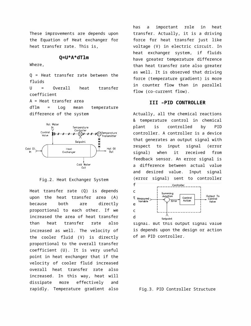
Actually, all the chemical reactions& temperature control in chemicalplant is controlled by PIDcontroller. A controller is a devicethat generates an output signal withrespect to input signal (errorsignal) when it received fromfeedback sensor. An error signal isa difference between actual valueand desired value. Input signal(error signal) sent to controllerfrom feedback sensor. It told thecontroller after measured the actualtemperature of the system about thaterror. After that controllercompared the error value withdesired value and gives an outputsignal. But this output signal valueis depends upon the design or actionof an PID controller.
Fig.3. PID Controller Structure
Actual TemperatureDesire Temperature
(K) Gv(S)
H(S)
Gp(S)Gc(S)
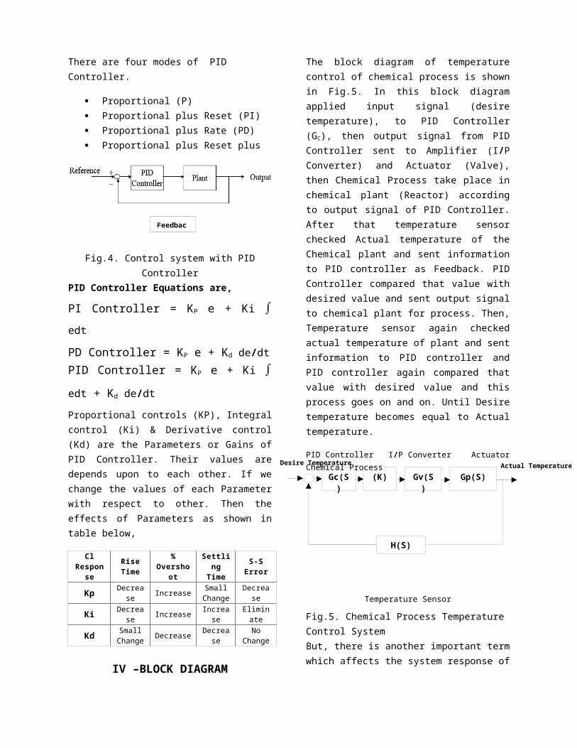
There are four modes of PID Controller.
Proportional (P) Proportional plus Reset (PI) Proportional plus Rate (PD) Proportional plus Reset plus
Rate (PID)
Fig.4. Control system with PIDController
PID Controller Equations are,
PI Controller = KP e + Ki
edt
PD Controller = KP e + Kd de/dtPID Controller = KP e + Ki
edt + Kd de/dt Proportional controls (KP), Integralcontrol (Ki) & Derivative control(Kd) are the Parameters or Gains ofPID Controller. Their values aredepends upon to each other. If wechange the values of each Parameterwith respect to other. Then theeffects of Parameters as shown intable below,
ClRespon
se
RiseTime
%Oversho
ot
Settling
Time
S-SError
Kp Decrease Increase Small
ChangeDecrea
se
Ki Decrease Increase Increa
seEliminate
Kd SmallChange Decrease Decrea
seNo
Change
IV –BLOCK DIAGRAM
The block diagram of temperaturecontrol of chemical process is shownin Fig.5. In this block diagramapplied input signal (desiretemperature), to PID Controller(GC), then output signal from PIDController sent to Amplifier (I/PConverter) and Actuator (Valve),then Chemical Process take place inchemical plant (Reactor) accordingto output signal of PID Controller.After that temperature sensorchecked Actual temperature of theChemical plant and sent informationto PID controller as Feedback. PIDController compared that value withdesired value and sent output signalto chemical plant for process. Then,Temperature sensor again checkedactual temperature of plant and sentinformation to PID controller andPID controller again compared thatvalue with desired value and thisprocess goes on and on. Until Desiretemperature becomes equal to Actualtemperature.
PID Controller I/P Converter ActuatorChemical Process
Temperature Sensor
Fig.5. Chemical Process Temperature Control SystemBut, there is another important termwhich affects the system response of
Feedbac
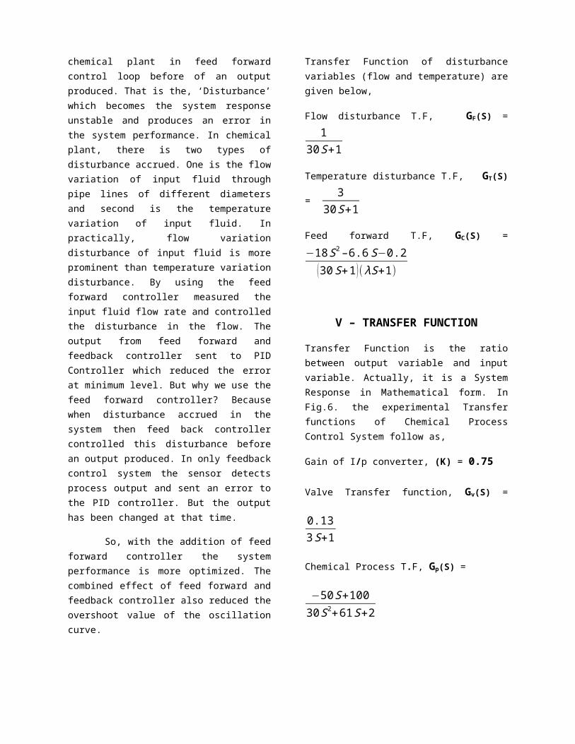
chemical plant in feed forwardcontrol loop before of an outputproduced. That is the, ‘Disturbance’which becomes the system responseunstable and produces an error inthe system performance. In chemicalplant, there is two types ofdisturbance accrued. One is the flowvariation of input fluid throughpipe lines of different diametersand second is the temperaturevariation of input fluid. Inpractically, flow variationdisturbance of input fluid is moreprominent than temperature variationdisturbance. By using the feedforward controller measured theinput fluid flow rate and controlledthe disturbance in the flow. Theoutput from feed forward andfeedback controller sent to PIDController which reduced the errorat minimum level. But why we use thefeed forward controller? Becausewhen disturbance accrued in thesystem then feed back controllercontrolled this disturbance beforean output produced. In only feedbackcontrol system the sensor detectsprocess output and sent an error tothe PID controller. But the outputhas been changed at that time.
So, with the addition of feedforward controller the systemperformance is more optimized. Thecombined effect of feed forward andfeedback controller also reduced theovershoot value of the oscillationcurve.
Transfer Function of disturbancevariables (flow and temperature) aregiven below,
Flow disturbance T.F, GF(S) =1
30S+1
Temperature disturbance T.F, GT(S)
= 3
30S+1
Feed forward T.F, GC(S) =−18S2–6.6S−0.2
(30S+1)(λS+1)
V – TRANSFER FUNCTION
Transfer Function is the ratiobetween output variable and inputvariable. Actually, it is a SystemResponse in Mathematical form. InFig.6. the experimental Transferfunctions of Chemical ProcessControl System follow as,
Gain of I/p converter, (K) = 0.75
Valve Transfer function, Gv(S) =
0.133S+1
Chemical Process T.F, Gp(S) =
−50S+10030S2+61S+2
Combined T.F, G(S) =
−4.875S+9.7590S3+213S2+67S+2
Temperature Sensor T.F, H(S) =0.1610S+1
Fig.6. Block Diagram TransferFunction of Chemical Plant
VI– STEP RESPONSE WITHOUT USINGPID CONTROLLER
First of all, see that Step Responseof the Process without using PIDController as well as addition ofDisturbance. Actually, we want todifferentiate the Step Responsesboth of them (without PID Controller& with PID Controller) & comparedthem also.
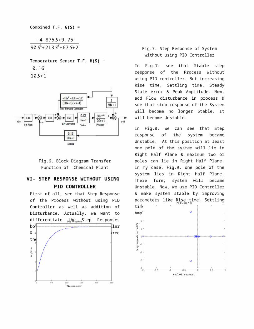
Fig.7. Step Response of Systemwithout using PID Controller
In Fig.7. see that Stable stepresponse of the Process withoutusing PID controller. But increasingRise time, Settling time, SteadyState error & Peak Amplitude. Now,add Flow disturbance in process &see that step response of the Systemwill become no longer Stable. Itwill become Unstable.
In Fig.8. we can see that Stepresponse of the system becameUnstable. At this position at leastone pole of the system will lie inRight Half Plane & maximum two orpoles can lie in Right Half Plane.In my case, Fig.9. one pole of thesystem lies in Right Half Plane.There fore, system will becameUnstable. Now, we use PID Controller& make system stable by improvingparameters like Rise time, Settlingtime, Steady state error & peakAmplitude.
0 50 100 150 200 250-1
0
1
2
3
4
5Step Response
Tim e (seconds)
Amplitud
e
-2 -1.5 -1 -0.5 0 0.5 1-4
-3
-2
-1
0
1
2
3
4Pole-Zero M ap
Real Axis (seconds-1)
Imagina
ry Axis
(seconds-
1 )
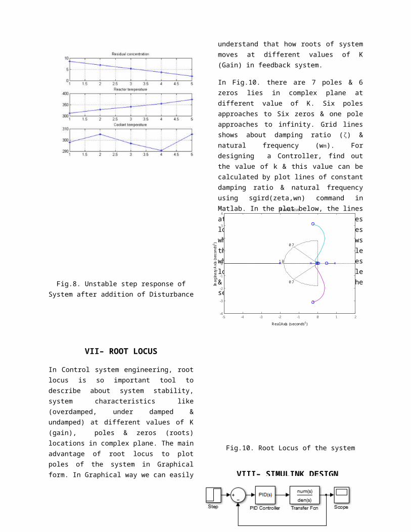
Fig.8. Unstable step response ofSystem after addition of Disturbance
VII– ROOT LOCUS
In Control system engineering, rootlocus is so important tool todescribe about system stability,system characteristics like(overdamped, under damped &undamped) at different values of K(gain), poles & zeros (roots)locations in complex plane. The mainadvantage of root locus to plotpoles of the system in Graphicalform. In Graphical way we can easily
understand that how roots of systemmoves at different values of K(Gain) in feedback system.
In Fig.10. there are 7 poles & 6zeros lies in complex plane atdifferent value of K. Six polesapproaches to Six zeros & one poleapproaches to infinity. Grid linesshows about damping ratio (ζ) &natural frequency (wn). Fordesigning a Controller, find outthe value of k & this value can becalculated by plot lines of constantdamping ratio & natural frequencyusing sgird(zeta,wn) command inMatlab. In the plot below, the linesat 45 degree angle shows that poleslocations in between these lineswhen zeta= 0.7, & semicircle showsthat poles locations on semicirclewhen wn=1.8, if wn<1.8 then poleslocations are inside the semicircle& poles locations are outside thesemicircle when wn>1.8.
Fig.10. Root Locus of the system
VIII– SIMULINK DESIGN
-5 -4 -3 -2 -1 0 1 2-4
-3
-2
-1
0
1
2
3
4
0.7
0.7
1.8
Root Locus
Real Axis (seconds-1)
Imaginary A
xis (seconds-
1 )
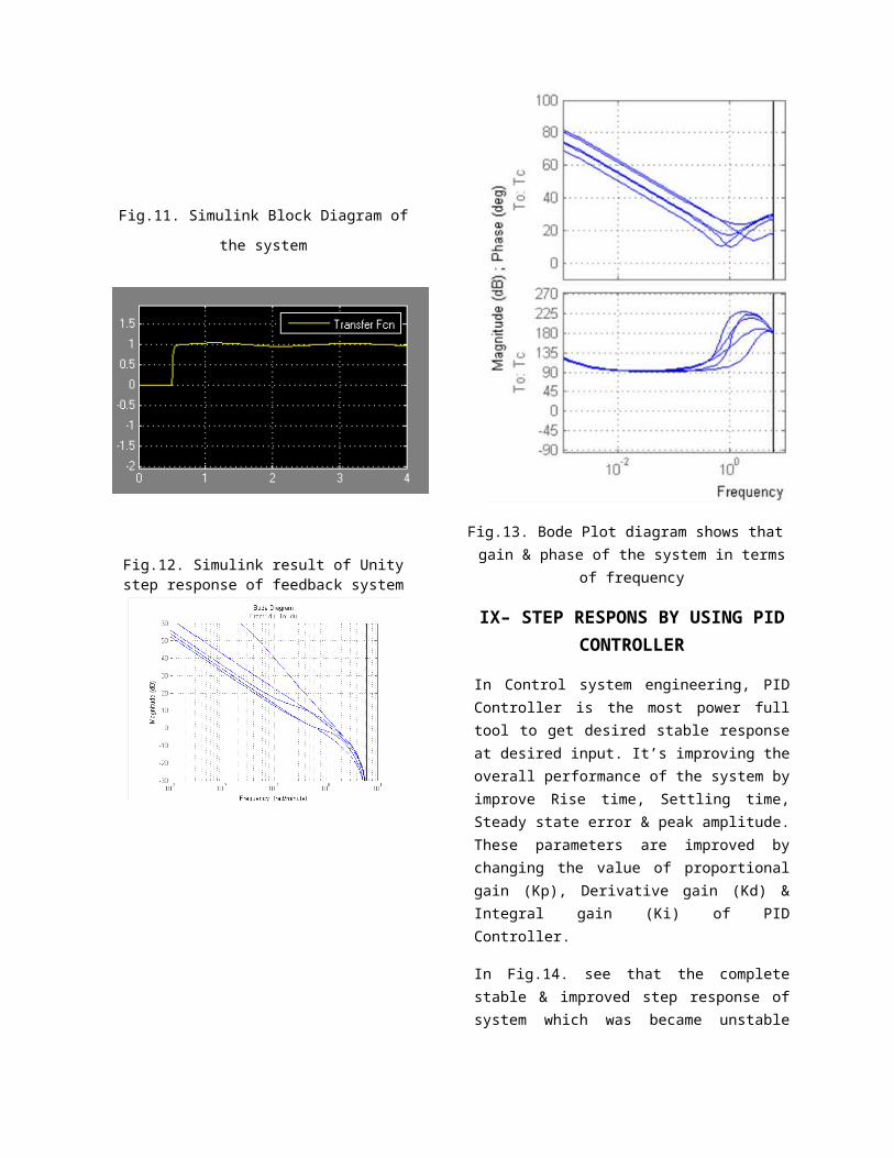
Fig.11. Simulink Block Diagram of
the system
Fig.12. Simulink result of Unitystep response of feedback system
Fig.13. Bode Plot diagram shows thatgain & phase of the system in terms
of frequency
IX– STEP RESPONS BY USING PIDCONTROLLER
In Control system engineering, PIDController is the most power fulltool to get desired stable responseat desired input. It’s improving theoverall performance of the system byimprove Rise time, Settling time,Steady state error & peak amplitude.These parameters are improved bychanging the value of proportionalgain (Kp), Derivative gain (Kd) &Integral gain (Ki) of PIDController.
In Fig.14. see that the completestable & improved step response ofsystem which was became unstable
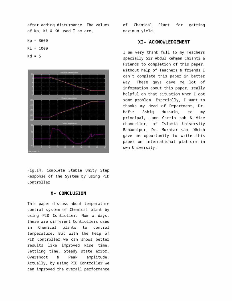
after adding disturbance. The valuesof Kp, Ki & Kd used I am are,
Kp = 3600
Ki = 1000
Kd = 5
Fig.14. Complete Stable Unity StepResponse of the System by using PIDController
X– CONCLUSION
This paper discuss about temperaturecontrol system of Chemical plant byusing PID Controller. Now a days,there are different Controllers usedin Chemical plants to controltemperature. But with the help ofPID Controller we can shows betterresults like improved Rise time,Settling time, Steady state error,Overshoot & Peak amplitude.Actually, by using PID Controller wecan improved the overall performance
of Chemical Plant for gettingmaximum yield.
XI– ACKNOWLEDGEMENT
I am very thank full to my Teachersspecially Sir Abdul Rehman Chishti &Friends to completion of this paper.Without help of Teachers & friends Ican’t complete this paper in betterway. These guys gave me lot ofinformation about this paper, reallyhelpful on that situation when I gotsome problem. Especially, I want tothanks my Head of Department, Dr.Hafiz Ashiq Hussain, to myprincipal, Jann Carrio sab & Vicechancellor, of Islamia UniversityBahawalpur, Dr. Mukhtar sab. Whichgave me opportunity to write thispaper on international platform inown University.


