Embed Size (px)
Citation preview
Design of Input and Output Modules for aSafety-Critical Wayside Train Control System
A Thesis
Presented to
the faculty of the School of Engineering and Applied Science
University of Virginia
In Partial Fulfillment
of the requirements for the Degree
Master of Science in Electrical Engineering
by
Anees A. Shaikh
August 1994
Approval Sheet
This thesis is submitted in partial fulfillment of the
requirements for the degree of
Master of Science in Electrical Engineering
Anees A. Shaikh
This thesis has been read and approved by the Examining Committee:
Dr. Barry W. Johnson (Advisor)
Dr. Ronald D. Williams (Chairman)
Dr. W. Bernard Carlson (Humanities)
Accepted for the School of Engineering and Applied Science:
Dean, School of Engineering andApplied Science
August 1994
Abstract
The use of complex microprocessors in systems where the safety of persons or
equipment are at risk is troublesome. In safety-critical applications it is often necessary to
fully analyze all failure modes of a system to prove its safety. This is a daunting task
where microprocessors are concerned. Train control is such an application, in which safe
operation must be guaranteed for perhaps one hundred thousand years. The Next Genera-
tion Architecture is a study of the design and implementation of a safety-critical distrib-
uted computing platform for real-time automatic train control.
An input and output module architecture for wayside train control is developed for
incorporation in the Next Generation Architecture. The input and output modules are
designed to support a global safety assurance methodology that ensures input-to-output
system safety. An input and output module emulator is designed and implemented in soft-
ware for a prototype based on a simplex processing configuration and its associated safety
assurance scheme. A prototyping environment is developed as an experimental testbed for
design and evaluation of distributed safety-critical control systems. The wayside train con-
trol prototype system serves as a proof-of-concept for this environment. The input and
output module designs represent the first version of an architecture that is evolving from
the wayside application to more advanced systems. The emulator is adaptable to other
safety assurance schemes which rely on information redundancy techniques to protect
control algorithm operands.

Acknowledgment
This research is sponsored by the Advanced Technology Group of Union Switch
and Signal, Inc. (A member of the Ansaldo Group). I am grateful for their financial sup-
port of this work.
Any success that I have had in my educational endeavors I owe to my parents,
Abdul Quader and Fatema Shaikh. I can only hope that I am able to repay them for all that
they have provided and done for me. My sister Tasneem also has continually and uncondi-
tionally supported me with her kindness and cheerful disposition. Thanks also to my cous-
ins Taher and Yusuf for their support at home and the good times we’ve had.
This thesis would not have been possible without the dedication and commitment
of my advisor, Dr. Barry Johnson. He has provided me with a role model throughout my
graduate studies and I cannot imagine working with anyone more understanding or sup-
portive. Thanks also to Dr. Ron Williams and Dr. Bernie Carlson for their presence on my
Examining Committee and their suggestions.
Many people contributed their valuable time and ideas to this work. I wish to espe-
cially thank Anup Ghosh and Todd Smith who helped me in very different ways, with a lot
of patient guidance. Thanks also to Paul Perrone and Todd DeLong who were very helpful
in my graduate work. All the members of the Next Generation Architecture and DRAMP
research teams have my gratitude for their assistance throughout my research.
Thank you to Saquib, Steve, Roz, Mark, PaulK, and friends in the MSA. All of my
friends at Virginia have shown a lot of faith in me and made me loosen up enough to have
some fun. I will miss them.
A special thank you goes to Zakia for her understanding, support, and love that
helped to make this possible. I can hardly wait for our life together to begin.
Finally, and most importantly, I thank God, most beneficent and merciful.
i
Table of Contents
Chapter 1 Introduction . . . . . . . . . . . . . . . . . . . . . . . . . . . . . . . . . . . . . . . . . . . . . . . . . 1
Chapter 2 Application Description and Requirements Definition. . . . . 5
2.1 Elements of an Automatic Train Control System . . . . . . . . . . . . . . . . . . . . . . . . . . . 5
2.2 Requirements for a Safety-Critical Automatic Train Control System . . . . . . . . . . 8
2.2.1 Safety in Automatic Train Control Systems. . . . . . . . . . . . . . . . . . . . . . . . . . . . . . . 92.2.2 Qualitative Requirements . . . . . . . . . . . . . . . . . . . . . . . . . . . . . . . . . . . . . . . . . . . . 112.2.3 Quantitative Requirements . . . . . . . . . . . . . . . . . . . . . . . . . . . . . . . . . . . . . . . . . . . 13
2.3 Chapter Summary. . . . . . . . . . . . . . . . . . . . . . . . . . . . . . . . . . . . . . . . . . . . . . . . . . . . . 15
Chapter 3 Safety-Critical Design and Fault-TolerantArchitectures . . . . . . . . . . . . . . . . . . . . . . . . . . . . . . . . . . . . . . . . . . . . . . . 16
3.1 Design for Safety-Critical Systems . . . . . . . . . . . . . . . . . . . . . . . . . . . . . . . . . . . . . . 16
3.2 Fault-Tolerant Architectures. . . . . . . . . . . . . . . . . . . . . . . . . . . . . . . . . . . . . . . . . . . . 28
3.3 Safety-Critical Architectures for Railway Control . . . . . . . . . . . . . . . . . . . . . . . . . 40
3.4 Chapter Summary. . . . . . . . . . . . . . . . . . . . . . . . . . . . . . . . . . . . . . . . . . . . . . . . . . . . . 49
Chapter 4 Next Generation Architecture for AutomaticTrain Control . . . . . . . . . . . . . . . . . . . . . . . . . . . . . . . . . . . . . . . . . . . . . . . 51
4.1 Next Generation Architecture. . . . . . . . . . . . . . . . . . . . . . . . . . . . . . . . . . . . . . . . . . . 51
4.2 Communications Facilities in a Distributed ATC System . . . . . . . . . . . . . . . . . . . 53
4.3 Safety-Critical Software Executive. . . . . . . . . . . . . . . . . . . . . . . . . . . . . . . . . . . . . . 54
4.4 Global Safety Assurance Concepts . . . . . . . . . . . . . . . . . . . . . . . . . . . . . . . . . . . . . . 58
4.5 Chapter Summary. . . . . . . . . . . . . . . . . . . . . . . . . . . . . . . . . . . . . . . . . . . . . . . . . . . . . 62
Chapter 5 Input and Output Module Architectures . . . . . . . . . . . . . . . . . . 64
5.1 Role of Input Modules in Automatic Train Control Systems . . . . . . . . . . . . . . . . 64
5.1.1 Input Module Functional Requirements . . . . . . . . . . . . . . . . . . . . . . . . . . . . . . . . . 645.1.2 Input Module Safety Assurance Functions. . . . . . . . . . . . . . . . . . . . . . . . . . . . . . . 66
5.2 Role of Output Modules in Automatic Train Control Systems. . . . . . . . . . . . . . . 71
5.2.1 Output Module Functional Requirements . . . . . . . . . . . . . . . . . . . . . . . . . . . . . . . 725.2.2 Output Module Safety Assurance Functions . . . . . . . . . . . . . . . . . . . . . . . . . . . . . 73
5.3 Chapter Summary. . . . . . . . . . . . . . . . . . . . . . . . . . . . . . . . . . . . . . . . . . . . . . . . . . . . . 77
Chapter 6 Development of a Software Prototype andInput and Output Module Emulator . . . . . . . . . . . . . . . . . . . . . . 80
6.1 Implementation of Global Safety Assurance for a Wayside ATP. . . . . . . . . . . . . 80
6.2 A Software-Based Prototype for the Next Generation Architecture. . . . . . . . . . . 87
6.2.1 Prototype Environment Details. . . . . . . . . . . . . . . . . . . . . . . . . . . . . . . . . . . . . . . . 89
ii
6.2.2 Prototype Sample Application and Physical Plant Model . . . . . . . . . . . . . . . . . . . 916.2.3 Initial Version of a Safety-Critical Software Executive. . . . . . . . . . . . . . . . . . . . . 936.2.4 Software Emulation of the Watchdog Checker . . . . . . . . . . . . . . . . . . . . . . . . . . . 956.2.5 Fault Injection for Prototype Evaluation . . . . . . . . . . . . . . . . . . . . . . . . . . . . . . . . 96
6.3 Design and Implementation of Input and Output ModuleSoftware Emulators . . . . . . . . . . . . . . . . . . . . . . . . . . . . . . . . . . . . . . . . . . . . . . . . . . . 97
6.3.1 Implementation of Input Module Emulator . . . . . . . . . . . . . . . . . . . . . . . . . . . . . . 986.3.2 Implementation of Output Module Emulator . . . . . . . . . . . . . . . . . . . . . . . . . . . . 1046.3.3 Serial Communications Facilities . . . . . . . . . . . . . . . . . . . . . . . . . . . . . . . . . . . . . 1076.3.4 Input and Output Emulation Program Flow . . . . . . . . . . . . . . . . . . . . . . . . . . . . . 109
6.4 Hardware Description of Prototype Input and Output Modules . . . . . . . . . . . . . 110
6.5 Chapter Summary. . . . . . . . . . . . . . . . . . . . . . . . . . . . . . . . . . . . . . . . . . . . . . . . . . . . 114
Chapter 7 Methods for Safety Evaluation of AutomaticTrain Control Systems . . . . . . . . . . . . . . . . . . . . . . . . . . . . . . . . . . . . 116
7.1 Safety Modeling and Evaluation Techniques. . . . . . . . . . . . . . . . . . . . . . . . . . . . . 116
7.2 An Application of Simulation-Based Fault Injection for theEvaluation of Input and Output Modules . . . . . . . . . . . . . . . . . . . . . . . . . . . . . . . . 121
7.2.1 Simulation Model . . . . . . . . . . . . . . . . . . . . . . . . . . . . . . . . . . . . . . . . . . . . . . . . . 1217.2.2 Input and Output PCB Structure and Modeling . . . . . . . . . . . . . . . . . . . . . . . . . . 1227.2.3 Input and Output PCB Operation and Intelligent Simulation. . . . . . . . . . . . . . . . 1257.2.4 Extent of Simulation Stimulus . . . . . . . . . . . . . . . . . . . . . . . . . . . . . . . . . . . . . . . 1277.2.5 Simulation Exclusions . . . . . . . . . . . . . . . . . . . . . . . . . . . . . . . . . . . . . . . . . . . . . 1287.2.6 Fault Behavior Simulation and Categorization Results . . . . . . . . . . . . . . . . . . . . 1297.2.7 Digital Model Validation . . . . . . . . . . . . . . . . . . . . . . . . . . . . . . . . . . . . . . . . . . . 1317.2.8 Conclusions of Fault Injection Analysis. . . . . . . . . . . . . . . . . . . . . . . . . . . . . . . . 132
7.3 Chapter Summary. . . . . . . . . . . . . . . . . . . . . . . . . . . . . . . . . . . . . . . . . . . . . . . . . . . . 133
Chapter 8 Results and Conclusions. . . . . . . . . . . . . . . . . . . . . . . . . . . . . . . . . . . 135
8.1 Prototype Performance . . . . . . . . . . . . . . . . . . . . . . . . . . . . . . . . . . . . . . . . . . . . . . . 135
8.2 Conclusions and Extensions. . . . . . . . . . . . . . . . . . . . . . . . . . . . . . . . . . . . . . . . . . . 137
References. . . . . . . . . . . . . . . . . . . . . . . . . . . . . . . . . . . . . . . . . . . . . . . . . . . . . . . . . . . . . . . 141
Appendix A Utilities for Input and Ouput ModuleEmulator Development. . . . . . . . . . . . . . . . . . . . . . . . . . . . . . . . . . . . 145
A.1 Code Matrix to C Language Transformation. . . . . . . . . . . . . . . . . . . . . . . . . . . . . 145
A.2 Identification Codeword Generation. . . . . . . . . . . . . . . . . . . . . . . . . . . . . . . . . . . . 146
A.3 Serial Communications Port Configuration. . . . . . . . . . . . . . . . . . . . . . . . . . . . . . 151
A.4 Parity Check Matrix Generation . . . . . . . . . . . . . . . . . . . . . . . . . . . . . . . . . . . . . . . 151
Appendix B Software Emulation of Input and Output Modules . . . . . . 153
iii
Appendix C Sample Hardware Descriptions of Inputand Output Modules . . . . . . . . . . . . . . . . . . . . . . . . . . . . . . . . . . . . . . 179
C.1 Dynamic Encoder. . . . . . . . . . . . . . . . . . . . . . . . . . . . . . . . . . . . . . . . . . . . . . . . . . . . 179
C.2 Dynamic Decoder and Error Signal Generator . . . . . . . . . . . . . . . . . . . . . . . . . . . 185
C.3 Static Decoder and Error Signal Generator . . . . . . . . . . . . . . . . . . . . . . . . . . . . . . 190
C.4 Timestamp Generation State Machine . . . . . . . . . . . . . . . . . . . . . . . . . . . . . . . . . . 197
C.5 Ones Counter for Berger Check Symbol Generation . . . . . . . . . . . . . . . . . . . . . . 198
C.6 Code Matrix to Behavioral VHDL Conversion. . . . . . . . . . . . . . . . . . . . . . . . . . . 199
iv
List of Figures
Figure 2.1 Elements of an ATC System . . . . . . . . . . . . . . . . . . . . . . . . . . . . . . . . . . . . . . . . 6
Figure 4.1 Architecture of a Distributed ATC System (adapted from [24]). . . . . . . . . . 52
Figure 4.2 Communication System of Next Generation Architecture(adapted from [6]) . . . . . . . . . . . . . . . . . . . . . . . . . . . . . . . . . . . . . . . . . . . . . . . . 54
Figure 4.3 Frame-based Timing for the Software Executive (adapted from [26]) . . . . 57
Figure 4.4 Finite State Machine Representation of the Control Algorithm . . . . . . . . . . 59
Figure 5.1 MICROLOK Vital Input Circuit Example (from [31]) . . . . . . . . . . . . . . . . 67
Figure 5.2 Input Module Voting Configurations with a Simplex Processor(adapted from [2]) . . . . . . . . . . . . . . . . . . . . . . . . . . . . . . . . . . . . . . . . . . . . . . . . 68
Figure 5.3 Input Module Voting Configuration with Duplex Processors(adapted from [2]) . . . . . . . . . . . . . . . . . . . . . . . . . . . . . . . . . . . . . . . . . . . . . . . . 69
Figure 5.4 High-Level View of a Single Channel for an Input Module . . . . . . . . . . . . . 70
Figure 5.5 MICROLOK Vital Output Circuit Example (from [32]). . . . . . . . . . . . . . . 74
Figure 5.6 Output Module Voting Configurations with Duplex Processors(adapted from [2]) . . . . . . . . . . . . . . . . . . . . . . . . . . . . . . . . . . . . . . . . . . . . . . . . 75
Figure 5.7 High-Level View of a Single Channel for an Output Module. . . . . . . . . . . . 77
Figure 6.1 Codeword Arrangement in Next Generation Architecture Prototype. . . . . . 87
Figure 6.2 Next Generation Architecture Prototype Environment Setup. . . . . . . . . . . . 88
Figure 6.3 Graphical View of Prototype Sample Application . . . . . . . . . . . . . . . . . . . . . 91
Figure 6.4 Single Channel of a Prototype Input Module. . . . . . . . . . . . . . . . . . . . . . . . . . 98
Figure 6.5 Message Format for Encoding Dynamic Codewords. . . . . . . . . . . . . . . . . . 101
Figure 6.6 Single Channel of a Prototype Output Module . . . . . . . . . . . . . . . . . . . . . . . 104
Figure 6.7 Flow Diagram of Input and Output Module Emulator. . . . . . . . . . . . . . . . . 111
Figure 7.1 Simple Three-State Markov Model for Safety Modeling (from [10]) . . . . 117
Figure 7.2 High-Level Layout of Input and Output PCB Digital Circuitry . . . . . . . . . 126

v
List of Tables
Table 2.1 Quantitative Reliability and Maintainability Requirements . . . . . . . . . . . . . . . 14
Table 6.1 Hardware Complexity for Dynamic Code Encoder. . . . . . . . . . . . . . . . . . . . . 113
Table 7.1 Number of Simulated Faults in Input and Output PCBs . . . . . . . . . . . . . . . . . 129
Table 8.1 Timing Data for Estimating Prototype Performance . . . . . . . . . . . . . . . . . . . . 136
vi
List of Symbols
A/D analog-to-digital conversion
AIPS Advanced Information Processing System
ANSI American National Standards Institute
AP applications processor
ATC automatic train control
ATCS Advanced Train Control System
ATP automatic train protection
AutoLogic trademark of Mentor Graphics Corporation
BCH Bose, Ray-Chaudhuri, and Hocquenghem code
BI-BB bus interface building block
BIS basic interlocking system
C fault or error coverage
C-BB core building block
COTS commercial off-the-shelf
CSDL Charles Stark Draper Laboratory
CSU critical safety unavailability
DMA direct memory access
Design Architect trademark of Mentor Graphics Corporation
∆tskew time skew for signal propagation
EDA electronic design automation
EEPROM electrically erasable programmable read-only memory
FAA Federal Aviation Administration
FCR fault containment region
FDDI Fiber Distributed Data Interface
FIRM failsafe interlocking system for railways using microprocessors
FMEA failure modes and effects analysis
FMECA failure modes, effects, and criticality analysis
FTMP Fault-Tolerant Multiprocessor
G generator matrix
GSA global safety assurance
H parity check matrix

vii
HT transposed parity check matrix
I identity matrix
IC integrated circuit
IEEE Institute of Electrical and Electronics Engineers
IO-BB input-output building block
ISA instruction set architecture
ISO International Standards Organization
L level of performance
MAFT Multicomputer Architecture for Fault-Tolerance
MI-BB memory interface building block
MICROLOK registered trademark of Union Switch and Signal, Incorporated
MTBF mean time between failures
MTBHE mean time between hazardous events
MTBSF mean time between service failures
MTBUF mean time between unsafe failures
MTTR mean time to repair
MTTSF mean time to service failure
NASA National Aeronautics and Space Administration
NISAL numerically integrated safety assurance logic
NIU network interface unit
OC operations controller
P parity matrix
PCB printed circuit board
PLC programmable logic controller
PROM programmable read-only memory
Quicksim II trademark of Mentor Graphics Corporation
RAM random access memory
S(t) safety as a function of time
SAS safety assurance system
SC input and output scanner
SCC serial communications controller
SIFT Software-Implemented Fault-Tolerance
SQC sequence controller
viii
SUIT Simple User Interface Toolkit
TAP IEEE P1149.1 standard test access port
TIPS train inertial position system
TMR triple modular redundancy
UNIX registered trademark of AT&T Bell Laboratories
VHDL Very High-Speed Integrated Circuit Hardware Description Language
VHSIC Very High-Speed Integrated Circuit
VME Versamodule Eurocard
VPI Vital Processor Interlocking
XOFF transmit off
XON transmit on
Z result of a logical operation
Zc Berger check symbol for result of a logical operation
dmin minimum Hamming distance of a code
f number of arbitrary faults
g(X) generator polynomial for a cyclic code
j number of checkbits in a Berger check symbol
k number of message or information bits in a block code
l number of bits removed in a shortened code
λ component failure rate
maglev magnetically levitated
n block length of a block code
q(X) quotient polynomial for a cyclic code
r(X) received codeword polynomial for a cyclic code
rm(X) remainder polynomial for a cyclic code
s(X) syndrome polynomial for a cyclic code
s binary syndrome vector
t measured time
t0 start time
u(X) message polynomial for a cyclic code
u binary message vector
v(X) codeword polynomial for a cyclic code
v binary codeword vector
1
Chapter 1Introduction
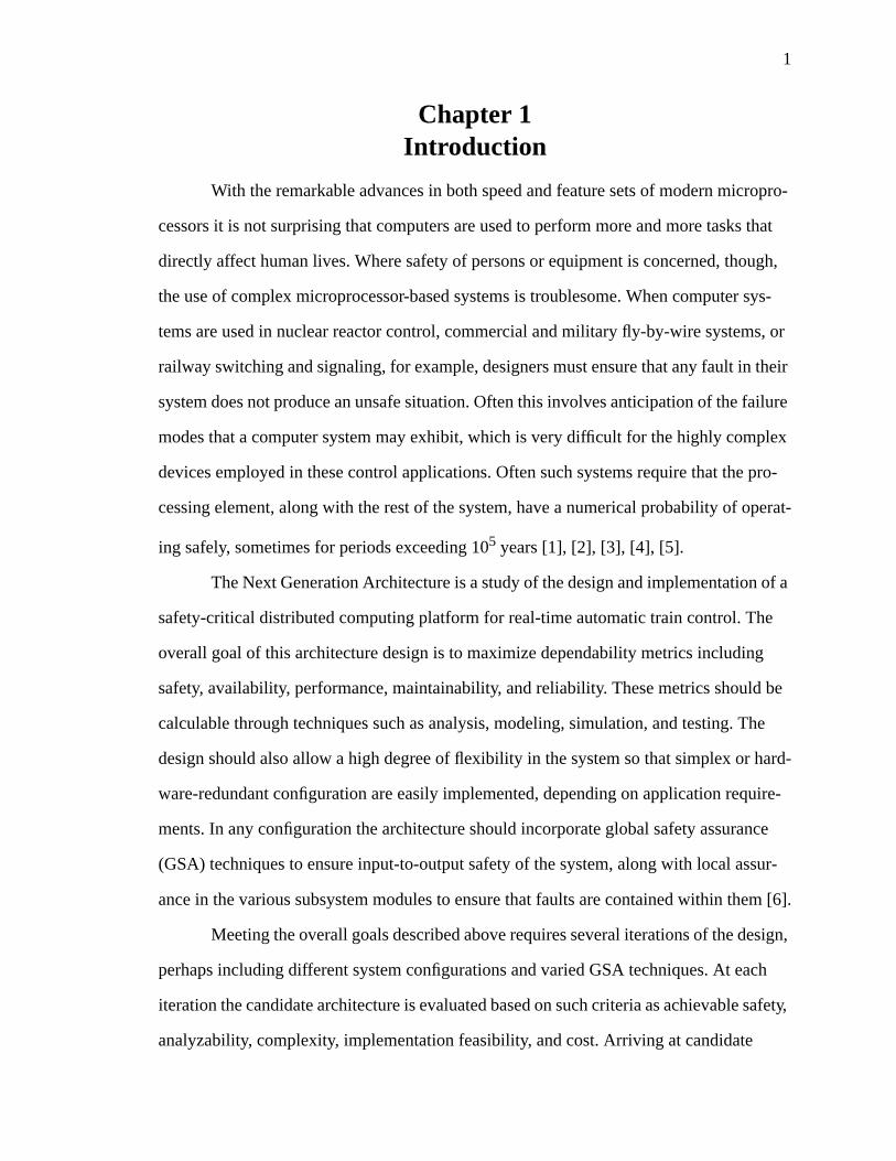
With the remarkable advances in both speed and feature sets of modern micropro-
cessors it is not surprising that computers are used to perform more and more tasks that
directly affect human lives. Where safety of persons or equipment is concerned, though,
the use of complex microprocessor-based systems is troublesome. When computer sys-
tems are used in nuclear reactor control, commercial and military fly-by-wire systems, or
railway switching and signaling, for example, designers must ensure that any fault in their
system does not produce an unsafe situation. Often this involves anticipation of the failure
modes that a computer system may exhibit, which is very difficult for the highly complex
devices employed in these control applications. Often such systems require that the pro-
cessing element, along with the rest of the system, have a numerical probability of operat-
ing safely, sometimes for periods exceeding 105 years [1], [2], [3], [4], [5].
The Next Generation Architecture is a study of the design and implementation of a
safety-critical distributed computing platform for real-time automatic train control. The
overall goal of this architecture design is to maximize dependability metrics including
safety, availability, performance, maintainability, and reliability. These metrics should be
calculable through techniques such as analysis, modeling, simulation, and testing. The
design should also allow a high degree of flexibility in the system so that simplex or hard-
ware-redundant configuration are easily implemented, depending on application require-
ments. In any configuration the architecture should incorporate global safety assurance
(GSA) techniques to ensure input-to-output safety of the system, along with local assur-
ance in the various subsystem modules to ensure that faults are contained within them [6].
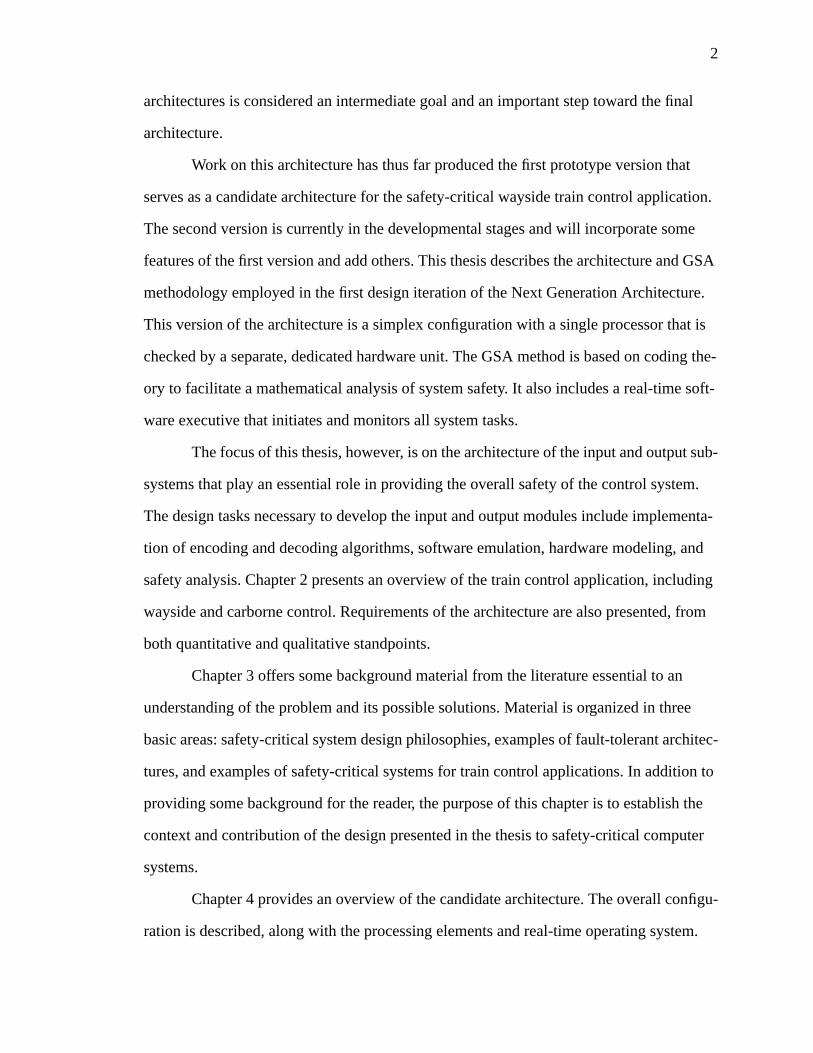
Meeting the overall goals described above requires several iterations of the design,
perhaps including different system configurations and varied GSA techniques. At each
iteration the candidate architecture is evaluated based on such criteria as achievable safety,
analyzability, complexity, implementation feasibility, and cost. Arriving at candidate
2
architectures is considered an intermediate goal and an important step toward the final
architecture.
Work on this architecture has thus far produced the first prototype version that
serves as a candidate architecture for the safety-critical wayside train control application.
The second version is currently in the developmental stages and will incorporate some
features of the first version and add others. This thesis describes the architecture and GSA
methodology employed in the first design iteration of the Next Generation Architecture.
This version of the architecture is a simplex configuration with a single processor that is
checked by a separate, dedicated hardware unit. The GSA method is based on coding the-
ory to facilitate a mathematical analysis of system safety. It also includes a real-time soft-
ware executive that initiates and monitors all system tasks.
The focus of this thesis, however, is on the architecture of the input and output sub-
systems that play an essential role in providing the overall safety of the control system.
The design tasks necessary to develop the input and output modules include implementa-
tion of encoding and decoding algorithms, software emulation, hardware modeling, and
safety analysis. Chapter 2 presents an overview of the train control application, including
wayside and carborne control. Requirements of the architecture are also presented, from
both quantitative and qualitative standpoints.
Chapter 3 offers some background material from the literature essential to an
understanding of the problem and its possible solutions. Material is organized in three
basic areas: safety-critical system design philosophies, examples of fault-tolerant architec-
tures, and examples of safety-critical systems for train control applications. In addition to
providing some background for the reader, the purpose of this chapter is to establish the
context and contribution of the design presented in the thesis to safety-critical computer
systems.
Chapter 4 provides an overview of the candidate architecture. The overall configu-
ration is described, along with the processing elements and real-time operating system.
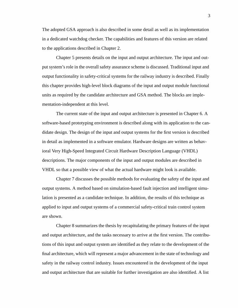
3
The adopted GSA approach is also described in some detail as well as its implementation
in a dedicated watchdog checker. The capabilities and features of this version are related
to the applications described in Chapter 2.
Chapter 5 presents details on the input and output architecture. The input and out-
put system’s role in the overall safety assurance scheme is discussed. Traditional input and
output functionality in safety-critical systems for the railway industry is described. Finally
this chapter provides high-level block diagrams of the input and output module functional
units as required by the candidate architecture and GSA method. The blocks are imple-
mentation-independent at this level.
The current state of the input and output architecture is presented in Chapter 6. A
software-based prototyping environment is described along with its application to the can-
didate design. The design of the input and output systems for the first version is described
in detail as implemented in a software emulator. Hardware designs are written as behav-
ioral Very High-Speed Integrated Circuit Hardware Description Language (VHDL)
descriptions. The major components of the input and output modules are described in
VHDL so that a possible view of what the actual hardware might look is available.
Chapter 7 discusses the possible methods for evaluating the safety of the input and
output systems. A method based on simulation-based fault injection and intelligent simu-
lation is presented as a candidate technique. In addition, the results of this technique as
applied to input and output systems of a commercial safety-critical train control system
are shown.
Chapter 8 summarizes the thesis by recapitulating the primary features of the input
and output architecture, and the tasks necessary to arrive at the first version. The contribu-
tions of this input and output system are identified as they relate to the development of the
final architecture, which will represent a major advancement in the state of technology and
safety in the railway control industry. Issues encountered in the development of the input
and output architecture that are suitable for further investigation are also identified. A list
4
of references, along with annotated source code for the software emulator and the behav-
ioral VHDL descriptions appear at the end of the thesis.
The end result of this thesis is an important step toward a final input and output
architecture that implements a GSA technique. This version of the architecture follows
through on a candidate technique to provide a basis for further design iterations. In addi-
tion the methods and design philosophy employed in this version are useful in the devel-
opment of future versions of the architecture. These methods include software prototyping
and analysis as well as hardware modeling. Design philosophies of this version include
the use of a code-based approach to GSA, the use of a dedicated checker, and the incorpo-
ration of safety assurance features at the input and output modules. Equally important are
the safety evaluation techniques presented in the thesis which are necessary to analyze any
safety-critical architecture to provide some numerical representation of its safety.
5
Chapter 2Application Description and Requirements Definition
The automatic train control (ATC) system application may be divided into two
general categories of functionality, wayside control and carborne (or on-board) control.
Most railway systems in use today are based on a fixed block paradigm, but future systems
will likely shift to a moving block system, introducing a new set of functional require-
ments. In a moving block system trains must keep account of their own position, relative
to other trains, and adjust speed, acceleration, and braking to maintain safe distances from
other trains. The fixed block application requires only that a train does not enter a track
segment already reserved for use by another train’s route. The fixed block approach is
more conservative and does not allow trains to travel as close together as they otherwise
might in a safe manner. In either model, requirements for the ATC system appear both as
qualitative requirements which define desirable characteristics of the system, and quantita-
tive requirements which numerically express necessary levels for dependability metrics
such as safety, reliability, and maintainability.
2.1 Elements of an Automatic Train Control System
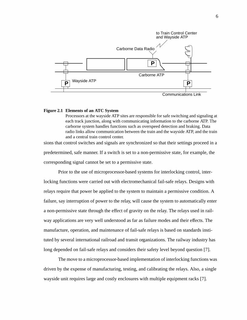
The primary functions required by an ATC system are usually divided into two
sections of automatic train protection (ATP), namely wayside ATP and carborne ATP. A
high-level view of the overall system is shown in Figure 2.1.
The wayside ATP controller is responsible for safety interlocking of switches and
signals at each railway track junction. Switching functions control track switch positions
which allow a train to proceed forward on a track segment or redirect it to an alternate seg-
ment. Redirection occurs when some track segment is unavailable because it is already
occupied, or part of another train’s locked route. Signaling is a control function that uses
signal lamps to advise a train operator whether the train may proceed into the next track
segment or whether it must stop and wait for the segment to become available. These
functions are collectively referred to as interlocking control because the logical expres-
6
sions that control switches and signals are synchronized so that their settings proceed in a
predetermined, safe manner. If a switch is set to a non-permissive state, for example, the
corresponding signal cannot be set to a permissive state.
Prior to the use of microprocessor-based systems for interlocking control, inter-
locking functions were carried out with electromechanical fail-safe relays. Designs with
relays require that power be applied to the system to maintain a permissive condition. A
failure, say interruption of power to the relay, will cause the system to automatically enter
a non-permissive state through the effect of gravity on the relay. The relays used in rail-
way applications are very well understood as far as failure modes and their effects. The
manufacture, operation, and maintenance of fail-safe relays is based on standards insti-
tuted by several international railroad and transit organizations. The railway industry has
long depended on fail-safe relays and considers their safety level beyond question [7].
The move to a microprocessor-based implementation of interlocking functions was
driven by the expense of manufacturing, testing, and calibrating the relays. Also, a single
wayside unit requires large and costly enclosures with multiple equipment racks [7].
Figure 2.1 Elements of an ATC SystemProcessors at the wayside ATP sites are responsible for safe switching and signaling ateach track junction, along with communicating information to the carborne ATP. Thecarborne system handles functions such as overspeed detection and braking. Dataradio links allow communication between the train and the wayside ATP, and the trainand a central train control center.
P
Carborne ATP
P PWayside ATP
Communications Link
Carborne Data Radio
to Train Control Centerand Wayside ATP
7
Finally, any change in the interlocking logic may require a redesign of the relay system. A
computer-based interlocking system, however, can easily perform the necessary functions
since relay-based interlocking may be completely described with a series of Boolean logic
expressions, ideal for implementation on a processor. A change in the logic requires only a
change in the application program running on the processor. While safety was virtually
taken for granted in the relay system, it is the major concern in using computers for rail-
way control.
Although interlocking control is the primary function of the wayside ATP, it may
also be responsible for other functions in advanced train systems. It may be responsible
for train detection on track segments or for communicating speed commands to the car-
borne units on the train. The speed commands serve as speed limits for a track segment so
that carborne systems can monitor the train speed, and take appropriate action if the train
is traveling too fast on a particular portion of the track. On subway and other similar sys-
tems, the wayside ATP may also be responsible for controlling the heading, or direction,
of trains.
The carborne functions of the ATC system are generally more complex than those
residing on the wayside ATP. While the wayside controllers may be limited to Boolean
operations to describe switching and signaling, the carborne ATP often requires arithmetic
operations which place a larger burden on the computing platform.
The primary carborne function is to regulate speed. This may involve receiving
and decoding speed limit information from the wayside ATP or accurately determining the
vehicle speed to provide overspeed detection. In some applications, such as driverless
trains in public transit systems, the carborne ATP may also control propulsion, heading,
opening doors, and emergency braking [8]. In advanced applications, the computer system
may also be responsible for maintaining proper positional information in moving block
systems or correct levitation distance in magnetic levitation (maglev) systems.
8
Moving block systems are different from traditional fixed block systems in that
they do not necessarily reserve entire blocks of track for use by one route. Instead the
decision on whether or not a train may move forward at its current speed is based on the
proximity of other trains. Each train must maintain its own position and convey this infor-
mation to other trains. Rather than concerning itself with segments of track, the train con-
siders intertrain spacing and actual stopping distance through what is called a braking
parabola [9]. A train inertial position system (TIPS) senses such parameters as velocity
and acceleration, and with a known starting position, determines train positions. In addi-
tion, beacons along the railway provide trains with absolute reference information so that
they may correct any errors [6].
Control functions governing speed regulation, position calculation, and braking
may be described with state variable equations in matrix form. Just as with Boolean oper-
ations for the wayside ATP, the carborne functions are appropriate for implementation on
a microprocessor [6].
The Next Generation Architecture with its safety assurance techniques provides a
computing platform that supports fail-stop and fault-tolerant operations necessary for car-
borne and wayside ATP functions. The prototype version described in this thesis currently
has full support for the wayside interlocking functions with much of the safety assurance
implemented in the input and output modules.
2.2 Requirements for a Safety-Critical Automatic Train ControlSystem
Clearly from the discussion in Section 2.1, the primary feature of any ATC system
is its safety assurance. Thus, the requirements of an ATC design place highest priority on
safety over all other dependability metrics. Other metrics, such as performance and avail-
ability, are analyzed and maximized as much as possible while maintaining the required
safety level. The tradeoffs between the remaining requirements depend largely on cus-
tomer requirements.
9
The system requirements may be partitioned between qualitative and quantitative
requirements. Qualitative measures, while subjective, are very useful in comparing bene-
fits of one candidate design against another. Flexibility of the design and transparency of
fault-tolerance techniques to the end-user are examples of common qualitative measures.
Quantitative evaluation techniques provide specific numbers that may be used to compare
designs. Common quantitative measures are dependability metrics such as reliability,
maintainability, and availability [10].
2.2.1 Safety in Automatic Train Control Systems
The definition of system safety is the probability that the system willeither behave
correctlyor fail in a safe manner [10]. The definition of safe failure, however, varies
widely in safety-critical applications. Even in the railway application, what is called a safe
failure depends on the portion of the ATC system being discussed. Defining safety also
requires consideration of the consequences of various failures. Consequences of unsafe (or
wrong-side) failures include loss of human life, injuries to or illness of persons, pollution
of surrounding environment, and loss of, or damage to equipment or property.
In switching and signaling systems safety requirements exist to prevent derail-
ments or collisions. In this application the safe state is non-permissive, or de-energized. It
may also be defined as “stay at last set” which allows no output changes. The wayside
ATP system is usually considered fail-stop, where the safe state is to stop the trains. It has
been proposed, however, that stopping trains may no longer be an acceptable fail-safe
response because safety must include consequences of shutting down the system, includ-
ing operator confusion or danger to passengers. Furthermore, stopping trains on any fail-
ure is a severe detriment to the reliability and availability of the system [11].
Depending on the application technology, stopping trains in the carborne ATP may
or may not be an acceptable fail-safe response. In non-magnetic applications, stopping the
ATP system and the trains may handle most failures. A maglev system, however, demands
10
some degree of fault-tolerance in the ATP system to prevent a sudden shutdown which
could cause injury or damage.
The elements of railway control systems are traditionally partitioned into “vital”
and “non-vital” functions to isolate the safety-critical functions from the rest of the sys-
tem. Vital elements are those that are directly concerned with the safety of the system
while non-vital elements do not necessarily have to be fail-safe. In microprocessor-based
ATC systems, the hardware and software used to implement each function is divided into
categories to indicate its relationship to system safety. Hardware is designated Class I, II,
and III, and software is classified as vital or non-vital.
Class I hardware, often called vital hardware, usually consists of discrete elec-
tronic components whose failure modes and characteristics are well known and may be
fully tested. Assuring that Class I hardware safely implements vital functions requires a
failure modes and effects analysis (FMEA) of the circuit. Requirements of an FMEA anal-
ysis for Class I hardware include the following:
• no single failure mode causes an unsafe condition
• all failure modes are either self-revealing or not self-revealing
• combinations of failures do not produce unsafe conditions, except for combi-nations of independent, self-revealing component failures
Self-revealing failures are component failures which cause the circuit to behave
differently than in the case of no failure. The FMEA method is a pass/fail classification;
the circuit under test either meets FMEA requirements or it does not. Examples of Class I
hardware include vital current threshold detectors, vital signaling relays, and four-terminal
capacitors [12].
Class II hardware is described as non-vital hardware used to perform vital func-
tions. This includes elements of a computer platform such as the microprocessor, memory,
and address decoding logic. Failures of Class II hardware might compromise system
safety, but such hardware is generally not analyzable to the extent of Class I hardware
[12]. The faults leading to failures in integrated digital circuits may be innumerable and
11
impossible to analyze. Since it is generally impractical to analyze all of the failure modes
in digital hardware, use of Class II hardware requires an analysis of the probability that its
failure will produce an unsafe effect [11].
Class III hardware is defined as hardware used only for non-vital functions. Class
III hardware does not affect safe implementation of vital functions [12].
Software used in processor-based ATC systems is also classified into vital and
non-vital portions. Vital software is software required to implement some vital function.
Non-vital software has no effect on vital functions under normal operation. Analyzing the
safety of software, however, requires consideration of both vital and non-vital parts since
both presumably execute on the same processor. An error in non-vital software could con-
ceivably affect the execution of a vital function. Demonstration of absolute software cor-
rectness for non-trivial programs is considered a practical impossibility. Vital software,
therefore, must be shown to achieve an acceptably low probability of error causing an
unsafe failure. Even this task is considered formidable and indeed infeasible by some
members of the software engineering community [13].
It is a well established fact that hardware and software systems invariably fail.
Unfortunately, it is often impossible to characterize all of the faults that cause these fail-
ures. The railway industry, in recognition of this impracticality, does not require a com-
plete fault characterization of digital ATC systems; instead it requires a valid and
comprehensive analysis of the system that assigns a probability of safe operation to the
overall system [11].
2.2.2 Qualitative Requirements
Although safety is the guiding principle in the design of ATC systems, other quali-
tative features are desirable to meet system goals. An important feature of the Next Gener-
ation Architecture is a modular, building block approach. Building blocks are architectural
modules that are designed with inherent fault tolerance. The modules serve as fault con-
tainment regions (FCRs) so that hardware faults are detected and isolated to prevent prop-
12
agation to the rest of the system. In addition, faults and errors that occur outside FCRs are
not allowed to affect the correct operation inside the modules. Building blocks for each
module should be identical and independent to facilitate analysis of dependability metrics.
Finally, the modular approach provides an easy way to replace components in case of fail-
ure, or to expand the architecture for additional capabilities.
Another desirable feature is flexibility. A flexible architecture permits different
fault-tolerance techniques and configurations to be implemented without a complete rede-
sign. This implies that fail-stop applications (such as the wayside ATP) and fault-tolerant
applications (carborne ATP) could be implemented on the same architecture with simplex
or hardware-redundant configurations. A software executive that supports multiprocessing
also facilitates flexibility by easily allowing redundant building block schemes [6].
Another characteristic of system flexibility is the ability to use different types of proces-
sors in the architecture with minimal modifications.
Simplicity in design is a desirable characteristic of the architecture that facilitates
analysis of dependability metrics. Avoiding excessive complexity allows construction of
models and testing procedures to evaluate the system. Simplicity of design is an important
feature to allow analysis of the system. Any railway control system must demonstrate its
dependability, most preferably through mathematical analysis techniques. In addition, the
design should require a minimum amount of custom hardware. If possible, most hardware
components and software routines should be common and field-tested with proven reli-
ability and safety. Use of commercial off-the-shelf (COTS) hardware is desirable to avoid
excessive development costs. In using COTS hardware, however, the issue of qualified
components must also be considered. Qualified hardware in the aircraft industry, for
example, is five to ten year-old technology to ensure the removal of design flaws and to
prove the hardware has a proven reliability and safety record [10].
Users of a system typically do not wish to be concerned with the techniques used
to achieve fault-tolerance. Transparency of such techniques as information or hardware
13
redundancy is important to make the system convenient to the end-user. If the user’s appli-
cation or programming is affected by redundancy techniques, then inclusion of fault-toler-
ance is a burden [10].
Other desirable properties of the system are resilience to harsh environments and
cost-effectiveness. Railway controllers are often exposed to strong electromagnetic fields,
noise, vibration, extreme temperatures, and lightning. The system should be designed with
consideration of these effects. Reliance on COTS hardware or simplex configurations help
to make the system more cost-effective, which is important if the technology is to be com-
mercialized [6].
2.2.3 Quantitative Requirements
The purpose of quantitative evaluation is to assign numerical values to dependabil-
ity attributes so that candidate designs may be directly compared. Typically each charac-
teristic, or metric, is expressed as a probability and analyzed to arrive at an upper or lower
bound.
The system safety, as mentioned previously, is a measure of the probability that the
system will fail in a safe manner. The railway industry quantifies safety in terms of mean
time between hazardous events (MTBHE), where a hazardous event is defined as the
occurrence of some unsafe condition that may cause injury or damage. An example of a
quantitative safety requirement is that each individual ATP system have an MTBHE
greater than 107 years. The overall ATC system must have an MTBHE greater than 105
years. An individual ATP system may be a single wayside interlocking controller or a sin-
gle carborne unit. These requirements are comparable to the requirements for other transit
applications, including commercial avionics systems. A system MTBHE of 105 years
translates to a one in 10,000 probability of unsafe failure in the first ten years of operation,
assuming a constant failure rate [8], [12].
System reliability is a measure of the probability that the system will operate cor-
rectly over some time interval. More precisely, it is defined as the conditional probability
14
that a system will perform correctly over time interval [t0, t], given that it was performing
correctly at timet0 [10]. The primary reliability measurements used in train applications
are mean time between failures (MTBF) and mean time between service failures
(MTBSF). The difference between these two is that MTBSF relates to a failure causing
disruption of ATC service while MTBF relates simply to any failure requiring repair. Both
of these metrics measure the expected time between failures that the ATC system will
operate correctly. Other useful reliability metrics are mean time to failure (MTTF) and
mean time to service failure (MTTSF), which measure the expected time the ATC system
will operate correctly before experiencing its first failure.
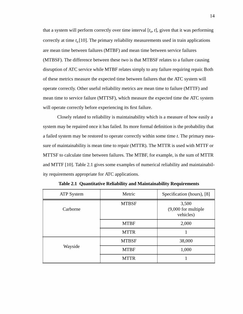
Closely related to reliability is maintainability which is a measure of how easily a
system may be repaired once it has failed. Its more formal definition is the probability that
a failed system may be restored to operate correctly within some timet. The primary mea-
sure of maintainability is mean time to repair (MTTR). The MTTR is used with MTTF or
MTTSF to calculate time between failures. The MTBF, for example, is the sum of MTTR
and MTTF [10]. Table 2.1 gives some examples of numerical reliability and maintainabil-
ity requirements appropriate for ATC applications.
Table 2.1 Quantitative Reliability and Maintainability Requirements
ATP System Metric Specification (hours), [8]
CarborneMTBSF 3,500
(9,000 for multiplevehicles)
MTBF 2,000
MTTR 1
WaysideMTBSF 38,000
MTBF 1,000
MTTR 1
15
Availability measures the amount of time the system is available to perform its
functions correctly. It is defined as the probability that a system is operating correctly at
some instance of time,t. Steady state availability is generally calculated by taking the ratio
of MTTF to MTBF [10]. Availability requirements for railway applications are between
99.99% and 99.999% which translates roughly to about 10 to 30 minutes of downtime per
year [6].
Aside from the dependability metrics mentioned above, the Next Generation
Architecture must meet demanding performance-related requirements. The real-time
nature of the application requires that the wayside ATP complete its operations every 1.5
seconds and the carborne ATP on the order of tens of milliseconds. Although these
requirements may seem modest at first glance, they represent at least an order of magni-
tude increase in performance over current technology. One measure of the system’s ability
to meet its performance goals is performability, defined as the probability that the system
is performing at, or above, some levelL at timet [10].
2.3 Chapter Summary
This chapter presented the different functions expected in a computer-based ATC
system. They are partitioned into the wayside ATP, responsible primarily for switch and
signal interlocking control, and the carborne ATP, responsible for such functions as over-
speed assurance and emergency braking. The foremost requirement in any ATC system is
safety, which imposes strict qualitative and quantitative requirements on the system.
Desired features of a safety-critical ATC architecture include a modular design and trans-
parence of the safety assurance techniques to the end-user. Quantitative requirements
allow evaluation of such dependability metrics as reliability, maintainability and availabil-
ity. Both of these categories of requirements are useful in evaluating candidate designs,
and adherence to these requirements must be proven before any architecture is considered
acceptable for industrial use.

16
Chapter 3Safety-Critical Design and Fault-Tolerant Architectures
This chapter presents background material in three key areas: safety-critical sys-
tem design and issues, fault-tolerant architectures and principles, and examples of archi-
tectures used for ATC systems. The design of safety-critical systems is an active area of
research in which much effort has been exerted to develop a theory or general set of rules
to govern design for microprocessor-based safety systems. These efforts are important
given the rise of computer systems used to control avionics systems, nuclear reactors,
chemical processes, and railway switching, for example.
Along with these design approaches have come several examples of successfully
implemented fault-tolerant architectures. These have been developed primarily for aero-
space applications for control of stable and unstable aircraft. Some classic examples are
presented in this chapter to provide a survey of different techniques used in fault-tolerant
design. Finally, several examples of the use of microprocessors in the specific area of ATC
systems are presented.
The material here is intended to identify important issues in designing safety-criti-
cal systems and provide examples of different solutions used to address those issues. It is
not meant to be a comprehensive literature survey but should assist in establishing the
context for the work presented in this thesis.
3.1 Design for Safety-Critical Systems
Authors who attempt to define guidelines for safety-critical design often begin
with a set of general requirements that must be considered in such systems. One proposed
series of steps in requirements development is:
• identify the tasks of the system which are critical to safety and assign a level ofcriticality to each task
• quantify the minimum safety performance for each task
• assign safety performance measures to each subsystem in the overall system
17
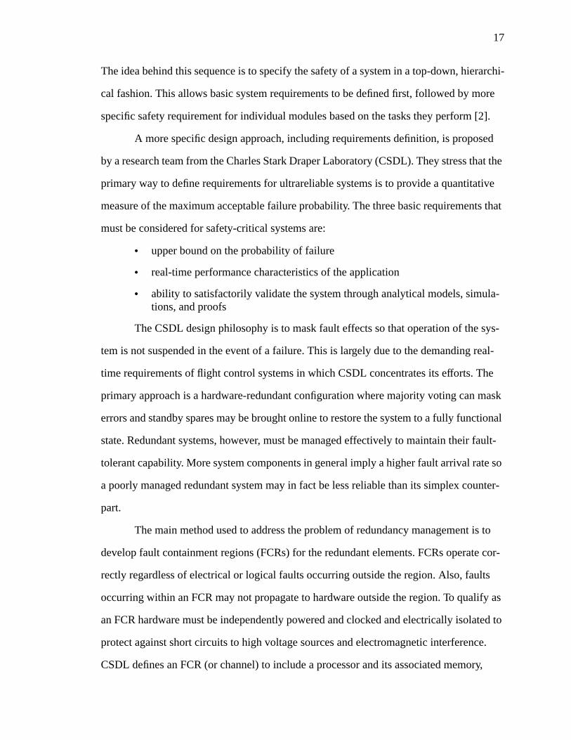
The idea behind this sequence is to specify the safety of a system in a top-down, hierarchi-
cal fashion. This allows basic system requirements to be defined first, followed by more
specific safety requirement for individual modules based on the tasks they perform [2].
A more specific design approach, including requirements definition, is proposed
by a research team from the Charles Stark Draper Laboratory (CSDL). They stress that the
primary way to define requirements for ultrareliable systems is to provide a quantitative
measure of the maximum acceptable failure probability. The three basic requirements that
must be considered for safety-critical systems are:
• upper bound on the probability of failure
• real-time performance characteristics of the application
• ability to satisfactorily validate the system through analytical models, simula-tions, and proofs
The CSDL design philosophy is to mask fault effects so that operation of the sys-
tem is not suspended in the event of a failure. This is largely due to the demanding real-
time requirements of flight control systems in which CSDL concentrates its efforts. The
primary approach is a hardware-redundant configuration where majority voting can mask
errors and standby spares may be brought online to restore the system to a fully functional
state. Redundant systems, however, must be managed effectively to maintain their fault-
tolerant capability. More system components in general imply a higher fault arrival rate so
a poorly managed redundant system may in fact be less reliable than its simplex counter-
part.
The main method used to address the problem of redundancy management is to
develop fault containment regions (FCRs) for the redundant elements. FCRs operate cor-
rectly regardless of electrical or logical faults occurring outside the region. Also, faults
occurring within an FCR may not propagate to hardware outside the region. To qualify as
an FCR hardware must be independently powered and clocked and electrically isolated to
protect against short circuits to high voltage sources and electromagnetic interference.
CSDL defines an FCR (or channel) to include a processor and its associated memory,
18
input and output interfaces, and interface to other channels. Enforcing the FCR require-
ments allows the argument that random hardware failures in FCRs are independent events,
which make the analysis of failure probability feasible [14].
FCRs may be able to contain faults but the data errors that occur as a result of a
fault can propagate outside the region. To protect against this CSDL proposes the method
of voting planes throughout the system to mask errors between stages. An ultrareliable
control system might have three major operations: reading redundant sensors, performing
control law operations, and delivering outputs to actuators. In this example, input voting
planes mask errors in sensors and prevent the propagation of incorrect values. Internal
computer voting prevents an error in one computer channel’s operations from altering the
outputs. Output voting planes prevent failed output channels from affecting the actuators.
This type of fault and error masking eliminates the need for immediate fault isolation and
reconfiguration which may take too long in a high-performance system.
Masking errors requires that results from different channels be compared and
voted upon. The voting may be of two types, exact and approximate consensus. Exact
consensus demands that results match bit-by-bit when there is no fault. Approximate con-
sensus allows results to agree within some threshold. The problem with thresholds, how-
ever, is that they are a function of the process and may change during operation. In
addition, accurate calculation of fault-coverage for a given threshold is extremely difficult.
Exact consensus, in contrast, allows application of formal methods and analytical valida-
tion [14]. Exact consensus is achievable if the following conditions are met:
• redundant hardware components are initialized identically so that they start ina known initial state
• each hardware component receives an identical sequence of inputs
• each redundant channel performs identical operations on the same inputs
• some upper bound is placed on the time skew,∆tskew, so that the time of taskcompletion for the slowest channel differs from the time of completion for thefastest channel by at most∆tskew
19
Under the above requirements, each non-faulty channel will provide exact bitwise consen-
sus by a predefined point in time. Processes which meet the above requirements are called
congruent processes.
An important issue in achieving congruency among processes is input agreement.
This occurs when each redundant channel is operating with an identical set of inputs and
all channels agree on the input value. Closely related is input validity which occurs when
all channels have a correct copy of the input. Congruency does not imply validity, as all
channels may have identical copies of incorrect input data. Input congruency is necessary
for exact consensus while input validity is necessary for correct outputs.
The conditions for input congruency are identified in a theory called the Byzantine
Generals’ problem. This theory, first developed by Lamport, Shostak, and Pease [15],
applies to redundant computer systems in which faulty components may provide conflict-
ing data to other elements of the system. An abstract expression of such a scenario is a
group of generals of the Byzantine army who can communicate with each other only by
messenger to agree on a battle plan. One or more of the generals may be traitorous, how-
ever, and try to confuse the others. The Byzantine Generals’ problem, then, is to find an
algorithm that will allow loyal generals to reach an agreement. The traitors correspond to
faulty processors while the loyal generals correspond to non-faulty processors. Messen-
gers are communications links between processors. Byzantine fault resilience is achieved
in the presence off arbitrary faults by meeting the following conditions [15]:
• system has a minimum of 3f + 1 FCRs
• FCRs are interconnected through 2f + 1 disjoint paths
• inputs are exchanged between FCRsf + 1 times
• FCRs are synchronized to provide a bounded time skew
Thus, a system that can tolerate one arbitrary fault must have four cross-strapped FCRs
that exchange information in two rounds to provide Byzantine resilience.
20
The design approach adopted by CSDL concentrates on achieving fault-tolerance
through redundant hardware configurations while also providing some level of redun-
dancy management. They have applied this philosophy to the design of a fault-tolerant
computing platform for aerospace applications, called the Advanced Information Process-
ing System (AIPS) [14]. While the CSDL philosophy provides a good example of a well-
defined approach to designing ultrareliable systems it does not address some important
issues. The redundancy management services in the architecture, for example, are pro-
vided by software building blocks. Errors in the software are not explicitly handled in the
architecture and proving software correctness is an exceedingly difficult validation prob-
lem.
An argument against the use of high redundancy in ultrareliable systems is given
in a paper by Bodsberg and Hokstad [2]. They claim that physical replication of hardware
modules provides only moderate gains in reliability. This is because the effectiveness of
hardware redundancy depends on the nature of faults in the system. Faults generally have
four different causes which include the following [10]:
• specification mistakes which might include incorrect algorithms or hardwareand software specifications
• implementation mistakes due to poor design, poor component selection, orsoftware coding errors
• component defects including random device defects, manufacturing imperfec-tions, and component wear-out
• external disturbances such as radiation, electromagnetic interference, or envi-ronmental extremes
While hardware redundancy is effective protection against component defects (typically
independent faults), it is not as effective against specification and implementation mis-
takes or external disturbances. These tend to be correlated faults that cause redundant
hardware modules to fail in the same way [2]. Although CSDL proposed rigorous isola-
tion requirements for redundant FCRs in their system, it is very difficult to prove that the
redundant modules achieve a high degree of independence.
21
Bodsberg and Hokstad also provide a study of the impact of redundant input and
output card configurations on the safety of computer-based control systems. Their quanti-
tative measure of safety is called critical safety unavailability (CSU), and is defined as the
probability that a safety system fails to automatically complete a safety action when an
abnormal operating condition occurs. Comparisons are made for different sensor and actu-
ator configurations in conjunction with one-out-of-one, one-out-of-two, two-out-of-two,
and two-out-of-three voting. According to their findings, input and output cards have bet-
ter safety performance than processor modules in general. A single input card, for exam-
ple, has a lower CSU than a duplex processor with one-out-of-two voting and self test.
Though the authors do not attempt to explain this, it seems reasonable that the higher
safety performance of input and output modules is due to their lower complexity.
The optimal configuration of input cards and sensors is to distribute redundant sen-
sors to different input cards and perform one-out-of-two voting. Input card redundancy is
generally not necessary. One-out-of-two voting for actuators and distributing these among
different output cards provides the best safety performance in most processor module con-
figurations (simplex or duplex). The conclusion of this study is that single input or output
cards with redundant sensors and actuators is an optimal safety configuration. As far as
processor configuration, the study concludes that duplex processors with one-out-of-two
voting and self-test is optimal in applications where the cost of false trips is low or
medium [2]. Although this study provides some useful comparisons of hardware redun-
dancy configurations, it does not address the issue of input congruency and the Byzantine
Generals’ problem. Also, the CSU achieved in the different configurations was on the
order of 10-5 to 10-8 which may not meet the stringent failure probability requirements of
train control applications.
While it is generally accepted that microprocessors in safety-critical systems per-
mit a greater degree of performance and functionality than relays for example, the risks
associated with programmable devices are also well-known despite the lack of detailed
22
knowledge of failure modes. Paques offers a set of prioritized safety rules that should be
applied when using programmable devices in safety systems. He assumes that the system
is controlled by a simplex programmable logic controller (PLC). Eight basic measures are
considered minimum precautions in PLC-controlled systems [3]. Examples of the rules
are given below:
• use of a master safety relay such that when it is de-energized, it cuts power tooutput modules which then shut down safely
• a watchdog timer mechanism which ensures that the control program isscanned at the proper rate; if the timer is not reset after two or three programscan times, the safety relay should be shut off
• internal fault detection mechanisms provided by a PLC manufacturer shouldbe connected to the safety relay to shut it down in the event of an internal fail-ure; such mechanisms may include parity checks, checksums, or divide by zeroindications
• since the PLC is basically a state machine with potentially volatile informa-tion, some mechanism must be included to dictate the startup state of themachine, allowing the outputs to be set in a known safe manner on system ini-tialization or restart
The second tier of measures are termed highly recommended to improve opera-
tion, reduce accident risk, and enhance maintainability. One of these measures is the mon-
itoring of output faults by means of some additional writing of outputs. This provides a
check that the outputs react correctly to directives from the PLC. While this type of feed-
back is considered a recommendation by Paques, it is generally a requirement of safety-
critical transit applications. Other recommended measures include strict control of pro-
gram modifications, conscientious updating of system documentation, and modular devel-
opment of control programs. Although Paques initially claims that reliability of control
systems using PLCs is equal or even greater than the reliability of relay-based systems, he
concludes that personal safety cannot be guaranteed with only one PLC. Some form of
redundancy (with perhaps two-out-of-three voting) must be used. Even with the additional
redundancy some minimum of hardwired (or vital Class I) safety devices is necessary [3].
23
Fisher takes a similar view on the use of PLC devices in fail-safe applications.
Standard, off-the-shelf hardware is inherently unsafe, he claims, because of the potential
for unknown and uncountable internal PLC failures. He also mentions feedback monitor-
ing loops from field devices and use of electromechanical relays for output devices as sug-
gested precautions when using PLCs. Fisher also examines safe design of input and output
devices. Output devices often use triacs to control the state of the field devices. In many
applications the safe state is for outputs to be turned off (or de-energized) or to maintain
the last state in the event of a fault. When triacs fail, however, they often fail turned on [1].
To protect against such failures several manufacturers introduced output modules
that make triacs fail-safe. One of these is the Allen-Bradley Protected Output Module.
This module incorporates specialized circuitry that detects a shorted triac and forces the
output off. Another example is the Texas Instruments Redundant Output Module. Here
each output circuit is duplicated so that a short or open-circuit condition causes the mod-
ule to switch to a secondary output. If the second output also fails, all outputs are forced
off. The Triplex Guarded Digital Output Module provides two driver circuits which both
must pass current to the load to control it. Each second the drivers are tested to check for
failures. If there is a discrepancy a fault is signaled. If two fail-safe modules are connected
in parallel, the output device may be controlled on and off even in the presence of a fail-
ure. The type of connection used, serial or parallel, depends on the application. In some
cases it might be important to turn outputs off if there is any failure, but some applications
might require the ability to maintain the output in an on state. Maintaining the flow of
cooling water to prevent overheating in a nuclear power plant is an example in which the
flexibility afforded by a parallel connection is desirable [1].
Input interface device failures typically include broken wires, broken switches, or
contacts that fail to close. These types of failures should cause a PLC system to fail safely.
The fail-safe state of input devices must be carefully considered, similar to that of output
devices. Some input switches may be either normally open or normally closed, with the
24
latter state generally the safest. Some input switches such as limit switches or level
switches, however, are normally closed. Thus, a loss of power for example would not indi-
cate a failure to the PLC for such devices. In any case the most hazardous input conditions
must be identified so that proper sensors can be used in these locations. The default signal
should indicate a hazard to the PLC in the case of power loss or wire breakage.
For emergency shut-down systems, Fisher recommends fault-tolerant configura-
tions with redundant PLCs, watchdog timers, and redundant input and output modules.
Single PLCs, he adds, are not suitable for safety-critical systems even if equipped with
external watchdog timers and fail-safe outputs [1]. Despite the recommendation to use
redundant systems, Fisher does not address the issues of voter dependability or input con-
gruence.
Turneret. al. offer an overview of fail-safe design for microprocessor-based sys-
tems used in transit applications including railway, commercial and military avionics, and
spaceborne applications [4]. Safety architectures in these applications always include
redundancy but in contrast to the discussion above, the redundancy may take several
forms. Additional hardware, calculations or processing, information, time, or control actu-
ation, are examples of different types of redundancy.
The suitability of a particular type or level of redundancy depends on the applica-
tion, which the authors break into three categories -- fail-safe, fail-passive, and fail-opera-
tional. A fail-safe application, such as a nuclear reactor or train control system, continues
to provide control outputs as long as processors indicate that the system is operating cor-
rectly. If any fault is detected the system is disconnected from control outputs and is
forced into a safe state. Fail-safe systems are effective only when a safe state can be
defined. A fail-passive controller usually requires some hardware redundancy and voting.
A disagreement causes control of the system to revert to manual control or some pre-
defined state. Automatic landing systems for stable aircraft are an example of a fail-pas-
sive application. Fail-operational systems must continue to operate even in the presence of
25
faults. Again, control is based on a majority vote of multiple processor outputs. The sys-
tem continues to operate despite a predefined number of disagreements, after which it
might switch over to a fail-passive mode. Fail-operational applications include advanced
and unstable aircraft and spacecraft control.
Features common to all three types of safety-critical architectures include com-
mand feedback, modular software design, and assurance of suitable fault detection laten-
cies. Command feedback is an output-to-input wraparound in which delivered outputs are
fed back into an input terminal. This allows the controller to verify that the outputs at the
field device match those that were in fact specified by the controller. Modular software
design with high-level languages ease the problems of software verification, readability,
and maintainability. High-level languages also introduce the problem of compiler valida-
tion, however. Care must be taken to ensure that random failure modes are not introduced
by compiler optimizations, for example. Finally, fault-detection time is a critical parame-
ter. In a duplex system, for example, protection is lost if the second controller fails before
a fault in the first is detected and handled. The necessary fault detection time is a function
of the system architecture, application dynamics, and acceptable risk [4].
As mentioned above, the major safety-critical applications examined by Turneret.
al. include railway, aircraft, and spacecraft control. Appropriate definitions of safety along
with requirements for the railway application were discussed in detail in Chapter 2.
Safety in aviation requires that failures of the control system do not prevent the air-
craft crew from recovering and regaining control manually. All aircraft control systems in
the United States must be certified as safe by the Federal Aviation Administration (FAA).
Fail-safe systems in aviation are certified for use at cruising altitudes down to where the
crew can still recover safely from a worst-case failure (100 feet). Fail-passive systems are
certified down to 50 feet and sometimes for automatic landings with crew supervision.
Fail-operational systems may be certified for fully automatic landings but usually require
at least triplex redundancy. FAA certification requirements are very specific. It must be
26
shown that no single failure can affect the system during approach and landing and that
the autopilot system will operate in fail-passive mode after the first fault. All three catego-
ries of control systems must protect against the same basic set of catastrophic failures but
differ in the number, type, and duration of hazards to which the autopilot is exposed. In all
cases, however, the probability of unsafe failure must be limited to 10-9 per hour of opera-
tion, or a mean time between unsafe failures (MTBUF) of 1 billion hours [1].
In spacecraft applications, microprocessor-based controllers handle booster con-
trol and spacecraft control. Booster controllers provide guidance during launch and must
operate correctly without interruption for five to ten minutes. After launch a spacecraft
controller maintains the attitude of the vehicle for five to ten years, but occasional inter-
ruptions are tolerable as long as they are limited to seconds or minutes. Booster controllers
generally require large-scale replication, with entire computers replicated rather than just
processors. Long-term spacecraft control uses smaller-scale redundancy to avoid disabling
an entire computer because of a single faulty component. Fault recovery is handled by
local modules or by some central test and repair unit. The suitability of microprocessors
for spacecraft control is still unknown, however. The radiation and electromagnetic fields
in space may prove harmful to the new generation of smaller, more sensitive devices [1].
Regardless of the application, creating a safety-critical architecture requires a gen-
eral sequence of steps, briefly described below [1]:
• definition of safety requirements and hazards that must be handled safely
• choice of an acceptable MTBUF for the application
• detailed specification of the system, including safety features and methods forvalidation
• candidate design
• safety evaluation to show that the system meets the required MTBUF
• software validation
• testing
• system maintenance
27
The discussion of rules and guidelines for safety-critical computer system design
has thus far focused on issues dealing with redundancy, in particular hardware redun-
dancy. Rutherford, however, provides an overview of some alternative methods for
achieving safety in the specific area of ATC systems [5].
Hardware redundancy is identified as one option to ensure safety. The pitfalls asso-
ciated with hardware redundancy are also discussed. Software errors are a primary con-
cern in hardware redundant systems. Errors may cause erroneous outputs or the negation
of some important test in all modules. Also, if voting occurs only over the final result pro-
duced by redundant modules, it is possible that intermediate results differ but produce the
same end result. This could eventually cause erroneous outputs in one or more modules
because of incorrect intermediate decisions.
An alternative safety assurance method is N-version programming in which differ-
ent versions of the software are developed to perform the same function. The results of the
different software programs are compared or voted upon to activate a permissive output.
The key in this method is independent generation of the different versions. The hardware
on which the different versions execute may or may not be identical or they may run on
the same processor. The main problem with N-version programming is in constructing
completely independent software versions that meet a given set of specifications. There is
often the possibility of collusion between software development teams when comparable
results must be produced within some time limit. The depth of results comparison is more
difficult for this method than for hardware redundancy. Comparison of intermediate
results may be impossible because different software versions may perform operations in
different orders. Consensus among different software versions may also be problematic
when mathematical computations are used. Round-off errors may cause the N versions to
produce different numerical values.
The third method identified is the use of a single processor performing diverse
operations. That is, a permissive output requires agreement among diverse processing
28
paths. All critical operations are performed with diverse software operations or by using
different parts of the processor hardware. The decision as to whether the diverse opera-
tions agree must be verified by some outside agent. It is considered risky to allow the pro-
cessor performing the operations and making the concurrence decision to also judge
whether the decision was made correctly.
A final option is called numerical assurance. In this scheme a permissive output
requires that some unique numerical representation be verified to contain an indication of
permissive conditions. The numerical representation is generated and operated upon by a
single processor. Often the representation is changed on alternating cycles to exercise the
storage hardware so that permissive results are not stored indefinitely due to some fault.
The numerical values tend to be very large and are constructed by combining values repre-
senting the critical constituents of a permissive output. As with other single processor sys-
tems, the verification of correct numerical value must be assured by some external device
[5]. Numerical assurance is basically an information redundancy technique where code-
words for permissive outputs are generated by the processor and must be correct for oper-
ation to continue. An ATC system based on numerical assurance is presented later in this
chapter.
3.2 Fault-Tolerant Architectures
A large portion of the available literature addressing real-time fault-tolerant con-
trol systems is in the context of avionics applications. The aerospace industry demands
ultrareliable systems that are required to operate in the presence of faults since emergency
shutdown is not a viable option in fly-by-wire systems. Control systems must have the
capability not only to detect faults, but also to isolate them and reconfigure the system to
properly handle them. As discussed in Chapter 2, some advanced ATC control applica-
tions may demand fail-operational capability to which fault-tolerant architectures are par-
ticularly applicable. As a result, this section presents some classic architectures which
29
introduced important design philosophies and illustrated solutions to problems in fault-tol-
erant computer systems.
The idea of using standard building blocks to construct fault-tolerant systems is
certainly not new. Rennelset. al. introduce a set of four building blocks that can be used
with off-the-shelf hardware including processors and memories [16]. The memory inter-
face (MI-BB), bus interface (BI-BB), input and output (IO-BB), and core (C-BB) circuits
comprise the four basic building blocks. The basic architectural unit is the self-checking
computer module (SCCM) which is able to detect internal faults concurrently during nor-
mal operation. The four building blocks are used with off-the-shelf processors and memo-
ries to construct SCCM modules. The SCCMs may be used alone in simplex
configurations or may be replicated for voting or hybrid configurations. Since the SCCM
is self-checking, it is able to signal a fault occurrence to other SCCMs in the system which
can then begin fault recovery procedures.
The designers of this building-block approach felt that flexibility in the use of dif-
ferent processors was very important. As a result, a simple and standard interface is speci-
fied by the building blocks. The primary physical interface is a 16-bit tristate bus and all
interfacing is done through memory-mapped input and output. The only requirement of
processors used in the system is that they are compatible with 16-bit tristate address and
data buses and capable of handling common memory and direct memory access (DMA)
signals. As their names imply, the building blocks handle control, interfacing, and inter-
communications between processor, memory, and input and output functions. In addition,
each building block is responsible for detecting internal faults and indicating a fault occur-
rence to the C-BB. When the C-BB detects an error, it isolates its SCCM from the bus.
Other optional recovery techniques are to halt the processor in the faulty SCCM until it is
externally reset, attempt to rollback or reset the processor, or initiate a reload of the mem-
ory from some nonvolatile source and then restart the processor. If the SCCM fails repeat-
edly it is permanently disabled by the C-BB.
30
The memory interface performs its self-checking in a variety of ways. It provides
Hamming error correction on faulty memory data and parity encoding and decoding on
the SCCM bus. It also contains a bit replacement element that can replace any one faulty
bit plane in the memory with a standby spare. The bus interface provides the information
transfer mechanism between SCCMs or from SCCMs to input and output devices. The BI-
BB may be configured to act either as a bus controller or bus adaptor. As a controller, it
initiates data transfers and produces the correct sequence of commands to complete a
transfer. As an adaptor the BI-BB passively monitors the external bus for read or write
commands. Fault detection in this building block is based on parity coding to protect
information and duplicated logic circuitry with comparison. Input and Output modules
have several built-in standard functions including 16-bit parallel and serial data interfaces,
a pulse counter, an adjustable frequency generator, and an analog-to-digital converter.
Fault detection in IO-BBs is accomplished the same way as in BI-BB modules with parity
coding and duplex circuitry. The core building block is responsible for SCCM-wide fault
detection and handling. Some of its specific functions are comparison of CPU signals,
encoding of CPU outputs for transmission on the internal bus, allocation of the internal
bus to bus controllers and adaptors, detection of internal faults, and disabling of faulty
SCCMs.
SCCMs may be configured in several redundant configurations which allow imple-
mentation of distributed processing or local redundant operation. The building block
approach allows a system designer to adjust the level of redundancy to suit the criticality
of the application. In addition, this particular approach has the advantage of allowing the
use of field-tested off-the-shelf processors and software [16].
MAFT (Multicomputer Architecture for Fault-Tolerance) is an example which was
designed with the goals of high performance and reliability by logically and physically
partitioning the system overhead tasks and the applications tasks. The system achieves
fault-tolerance by assuring that system functions are observable, globally verified, self-
31
testable, and employ Byzantine agreement among critical parameters [17]. The computer
system must meet the typical flight control requirement of a 10-10 failure probability over
a ten hour mission. In addition, the system designers had to handle errors in both hardware
and software, or prove that the hardware and software were free of any design errors.
Given the burden of proving a complex microprocessor-based system is error-free, the
designers developed novel methods to detect and handle errors in the system.
The MAFT design defines its utility by two factors, programmability and flexibil-
ity. Programmability is the ease with which an application may be implemented and flexi-
bility assures that an architecture may be used for different applications. Other desirable
features are high performance and intelligent redundancy management.
The architecture of MAFT is based on two basic modules, the applications proces-
sors (AP) and operations controllers (OC). A system node consists of an AP connected to
an OC which in turn is connected to the other nodes via dedicated serial broadcast buses.
The overall system is comprised of any number of such nodes. The network of OCs han-
dles all overhead tasks such as communication with other nodes, task scheduling for the
AP, system synchronization, data voting, error detection and handling, and reconfigura-
tion. The APs are responsible for executing the application program and for communicat-
ing with devices used in the application such as sensors, actuators, and displays. Since the
OC acts as a simple I/O device from the perspective of the AP, the overhead functions,
including fault-tolerance, are transparent to the processor and thus the applications pro-
grammer.
The fault-tolerance philosophy employed in MAFT is called global verification. A
globally verified function is one whose outputs are checked by every healthy system node.
Each node must therefore broadcast messages throughout the system regarding its local
actions. Whether or not a message is correct is measured relative either to some global
standard, or to a consensus among processes known previously to be healthy. An inherent
32
assumption in the use of consensus is that the number of nodes that can fail between
checks is bounded.
The fault-tolerance tasks in the MAFT global verification paradigm are performed
by the OC. Communication of messages is implemented by a transmitter, several receiv-
ers, and a message checker. The transmitter is the only device with access to the OC serial
link and each receiver monitors one of several links with another OC at the other end. The
message checker monitors received messages and if they are correct, it forwards them to
other subsystems for continued processing. When voting is required for some output, the
OC receives the data message from another node and performs limit checks and on-the-fly
voting with the currently held copies of that data. When voted data is required, the AP
issues a request to its OC and the OC broadcasts data to all other nodes in the system. The
actual voting process is transparent from the AP perspective.
The multiple nodes of MAFT synchronize themselves by exchanging messages
which contain data indicating the local clock time. Each node uses an approximate agree-
ment algorithm to adjust local clocks based on the received timestamps. This exchange is
performed both during re-synchronization and initial startup. Error detection and handling
in MAFT is performed in the same round-robin format as synchronization and voting.
When an OC detects an error, it generates an error message. At fixed intervals each OC
broadcasts its own error report. Each node must then reach Byzantine agreement on an
error condition and then initiate reconfiguration procedures. To prevent extended fault
latencies, each node broadcasts a stream of erroneous data at a predetermined time. This
stream is meant to exercise specific error detection mechanisms. A node with faulty error
detection mechanisms may be identified by its mismatch with the consensus error report.
When a node is determined to be faulty, the reconfiguration algorithm provides graceful
degradation and also graceful restoration as nodes are readmitted into the system if they
perform error-free for some time.
33
The MAFT system introduces many useful techniques for real-time fault-tolerant
control systems. The partitioned approach allows the processors to concentrate on applica-
tion tasks and leave fault-tolerance and other overhead tasks to alternate, dedicated hard-
ware. The system is highly flexible, allowing N-way voting and task replication with
distributed synchronization and Byzantine agreement algorithms. Finally, the system sup-
ports graceful restoration and degradation and global enabling and disabling of tasks to
facilitate distributed processing [17].
The Software Implemented Fault Tolerance (SIFT) system uses programs rather
than hardware to achieve its goal of probability of failure less then 10-9 per hour for a ten
hour flight mission. Testing is ruled out as a means to demonstrate SIFT reliability; the
designers instead attempt to prove the correctness of SIFT with formal mathematical
methods. Another important concept employed in SIFT is the disregard for low-level
faults. Only the resulting data corruption or errors are of interest. The primary feature,
however, is that all error detection and correction, diagnosis, reconfiguration, and isolation
is performed by software routines [18].
Computations in SIFT are performed by main processing modules which consist
of a processor and its associated memory. Input and output functions are carried out by
special input and output processors and their associated memories. Main processing mod-
ules and input-output processing modules are connected via a multiple bus system that
forms point-to-point links.
SIFT executes a set of tasks that each contain a sequence of iterations. Each itera-
tion has input data that is the output data produced by some collection of tasks on the pre-
vious iteration. Execution of a task iteration requires each processor to compute results
and store them in its own memory. A processor that uses the result determines the value by
examining outputs generated by all of the processors which computed that iteration. The
value is typically chosen as a two-out-of-three vote. If all three values are not identical an

34
error has occurred. Voting is done on the aircraft state data only at the beginning of an iter-
ation to reduce the amount of voting and the data flow along the buses.
One of the main functions of the executive software is to provide fault isolation in
the system. A faulty unit must not be able to corrupt the data or control signals of a non-
faulty unit. Fault isolation is built into the communication methodology. Processor mod-
ules may read from any other processor module memory but is only allowed to write to its
own local memory. To prevent control signal corruptions from other units, each module is
autonomous with its own control. Improper control signals are ignored and watchdog tim-
ers are used to prevent a unit from waiting indefinitely for a control signal. Even though
processor modules may not be able to write incorrect data, they may still read erroneous
data from another module. To prevent such data from causing incorrect results, processors
receive multiple copies of data and use a majority vote to mask the erroneous data.
When a module is recognized as faulty, the system is reconfigured to remove that
module from the rest of the system. If the faulty unit is a processor, the tasks that it was
performing are reassigned to other modules. If the fault is in a bus, processors must then
request their data over alternate buses. The number of processors assigned to a given task
may vary dynamically to provide added flexibility.
The executive software that assures reliable application execution, implements
error detection, and reconfigures the system, is divided into three main parts: the global
executive, the local executive, and the local-global communications executive. The global
executive is executed on several processors and results are voted on at each iteration. The
global executive is responsible for diagnosing errors and allocating tasks to non-faulty
processors.
A local executive runs in each of the processor modules. It is responsible for run-
ning each task allocated to that processor at its proper iteration rate, providing the proper
inputs and receiving the proper outputs for each iteration, and reporting errors to the local
executive task. The specific routines of the local executive are the error handler, scheduler,
35
buffer interface, and voter. The communications executive also runs on each processor
module. It is responsible primarily for reporting errors detected by the local executive to
the global executive.
To analyze the SIFT system, designers rely on Markov reliability models. It is
assumed that hardware faults and electrical transient faults are uncorrelated with constant
failure rates. It is also assumed that the software is error-free because it is formally speci-
fied and rigorously proven. The proof of correctness is performed first by proving that
abstract hierarchical models of the system have the correct attributes. The next step is to
prove that the models accurately describe the SIFT system.
The SIFT system is a departure from other architectures in that it relies heavily on
software to perform fault-tolerance functions. SIFT’s primary advantage is that it allows
the use of off-the-shelf hardware in the processor modules. In addition, any change to the
application or to the fault-tolerance techniques is easy to implement because only a soft-
ware change is required [18]. The primary disadvantage of SIFT is that much of the sys-
tem’s processing power is consumed by the overhead involved in task scheduling and
fault-tolerance functions. This leaves significantly less processing capability for use by the
application program [17].
Another example of a fault-tolerant control system for critical aerospace applica-
tions is FTMP (Fault-Tolerant Multiprocessor) which was designed for a failure rate of 10-
9 failures per hour on a ten-hour flight mission. The FTMP conducts all information pro-
cessing and transmission in triplicate so that voters in each separate node can correct
errors. In addition, each node, or module, may be reassigned or retired in any combination
[19].
The overall structure of FTMP consists of an arbitrary number of these modules
which include processors with local cache memories connected to any number of memory
modules via a triply redundant serial bus. The processor and memory modules are placed
in groups of three to perform redundant functions. All data in the system is transmitted in
36
triplicate with each module having a voting element and special bus-isolation gates which
halt the propagation of faults outside a single module.
Each module relies on a bus guardian unit which monitors power status, selects
memory bus triads, and selects self-test configurations. The bus guardian is designed so
that failure modes are biased toward safe-side failures which are typically to remove
power or disconnect from the bus. This bias is achieved by duplicating guardians in each
module and requiring agreement between them before power or transmission is enabled.
Bus isolation gates disconnect a triad module from the bus if a fault is detected.
One key feature of FTMP is that any three processors in the system can form a pro-
cessing triad. A failed processor in one triad may be replaced by a spare processor to
restore the triad group. In the event that a spare is not available, the failed triad is retired
and the two healthy processors are labeled as spares. Processor triads use four-line buses
to communicate with main memory. The lines include a clock, poll line, processor trans-
mit, and processor receive. The clock line distributes the system clock to each unit. The
poll line is used to request access to the bus. The transmit and receive lines are used to
issue commands. Buses are grouped together to form a triad so that each unit receiving
information actually receives three copies and can vote to mask errors.
FTMP employs tight synchronization so that all outputs may be voted on bit-by-
bit. Maintenance of a continuous timing reference is achieved by a fault-tolerant clocking
arrangement. Clock receivers in each guardian determine the correct clock by examining
the clock signals from all other processors.
Similar to the MAFT system, FTMP exposes latent faults by systematically “flex-
ing” its logic elements. Processor modules can test their own voters, along with those on
buses or memories by purposely producing erroneous data. Each bus and module, includ-
ing voters, guardians, isolation gates, clock receivers, and interfaces must be exercised in
this fashion. Without the “flexing”, the error detection mechanisms may not be exercised
for extended periods of error-free operation, resulting in undesirably long fault latencies.
37
A multiprocessor executive schedules error diagnostics, latent fault test routines,
and error recovery routines. The fault-tolerance related tasks run concurrently with the
application program but use different sets of processor triads. The executive also handles
traditional tasks such as application task scheduling, input and output interfacing, and
main memory to local memory data transfers.
Hopkinset. al. refer to the redundancy structure used in FTMP as “parallel-
hybrid” redundancy in which TMR (triple modular redundancy) triads are placed in paral-
lel with a pool of spares that may be activated in the case of a failure. The fault contain-
ment capability depends on the assumption that the bus-isolation gates are highly
independent of one another. It is recognized that the bus guardian element is critical in that
a failure could cause degradation of other modules and eventual malfunction of the entire
system. FTMP designers were able to show through Markov and combinatorial modeling
that the system meets its requirements for random hard faults. Furthermore, maintenance
at 200-hour intervals is generally adequate. The FTMP system introduced several fault
detection, isolation, and recovery techniques that are applicable in a system that relies on
hardware to provide the fault-tolerance features.
The specific systems so far, MAFT, SIFT, and FTMP, rely on complex hardware
and software to meet their high reliability requirements. An alternative approach is pre-
sented by Markas and Kanopoulos in which a bus monitor unit detects and masks errors in
modular redundant systems with the advantage that fault isolation and recovery is per-
formed in real time without software intervention. It is claimed that the implementation
cost of the bus monitor is significantly lower than for other systems while still retaining
high reliability [20].
The bus monitor is intended primarily for use in standard processor-memory con-
figurations where most faults are assumed to manifest themselves as errors on the address
bus, data bus, or a memory-related control line. The monitor can operate in a triple modu-
lar redundant (TMR) configuration with the ability to switch over to a simplex setup when
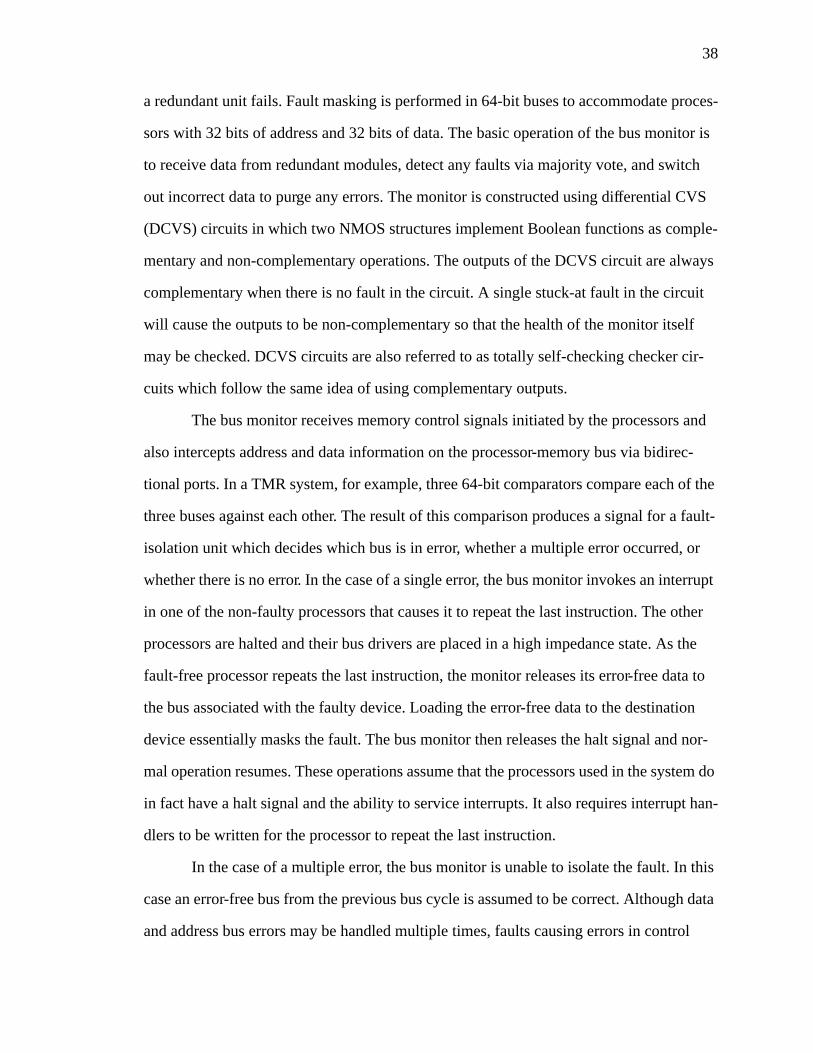
38
a redundant unit fails. Fault masking is performed in 64-bit buses to accommodate proces-
sors with 32 bits of address and 32 bits of data. The basic operation of the bus monitor is
to receive data from redundant modules, detect any faults via majority vote, and switch
out incorrect data to purge any errors. The monitor is constructed using differential CVS
(DCVS) circuits in which two NMOS structures implement Boolean functions as comple-
mentary and non-complementary operations. The outputs of the DCVS circuit are always
complementary when there is no fault in the circuit. A single stuck-at fault in the circuit
will cause the outputs to be non-complementary so that the health of the monitor itself
may be checked. DCVS circuits are also referred to as totally self-checking checker cir-
cuits which follow the same idea of using complementary outputs.
The bus monitor receives memory control signals initiated by the processors and
also intercepts address and data information on the processor-memory bus via bidirec-
tional ports. In a TMR system, for example, three 64-bit comparators compare each of the
three buses against each other. The result of this comparison produces a signal for a fault-
isolation unit which decides which bus is in error, whether a multiple error occurred, or
whether there is no error. In the case of a single error, the bus monitor invokes an interrupt
in one of the non-faulty processors that causes it to repeat the last instruction. The other
processors are halted and their bus drivers are placed in a high impedance state. As the
fault-free processor repeats the last instruction, the monitor releases its error-free data to
the bus associated with the faulty device. Loading the error-free data to the destination
device essentially masks the fault. The bus monitor then releases the halt signal and nor-
mal operation resumes. These operations assume that the processors used in the system do
in fact have a halt signal and the ability to service interrupts. It also requires interrupt han-
dlers to be written for the processor to repeat the last instruction.
In the case of a multiple error, the bus monitor is unable to isolate the fault. In this
case an error-free bus from the previous bus cycle is assumed to be correct. Although data
and address bus errors may be handled multiple times, faults causing errors in control
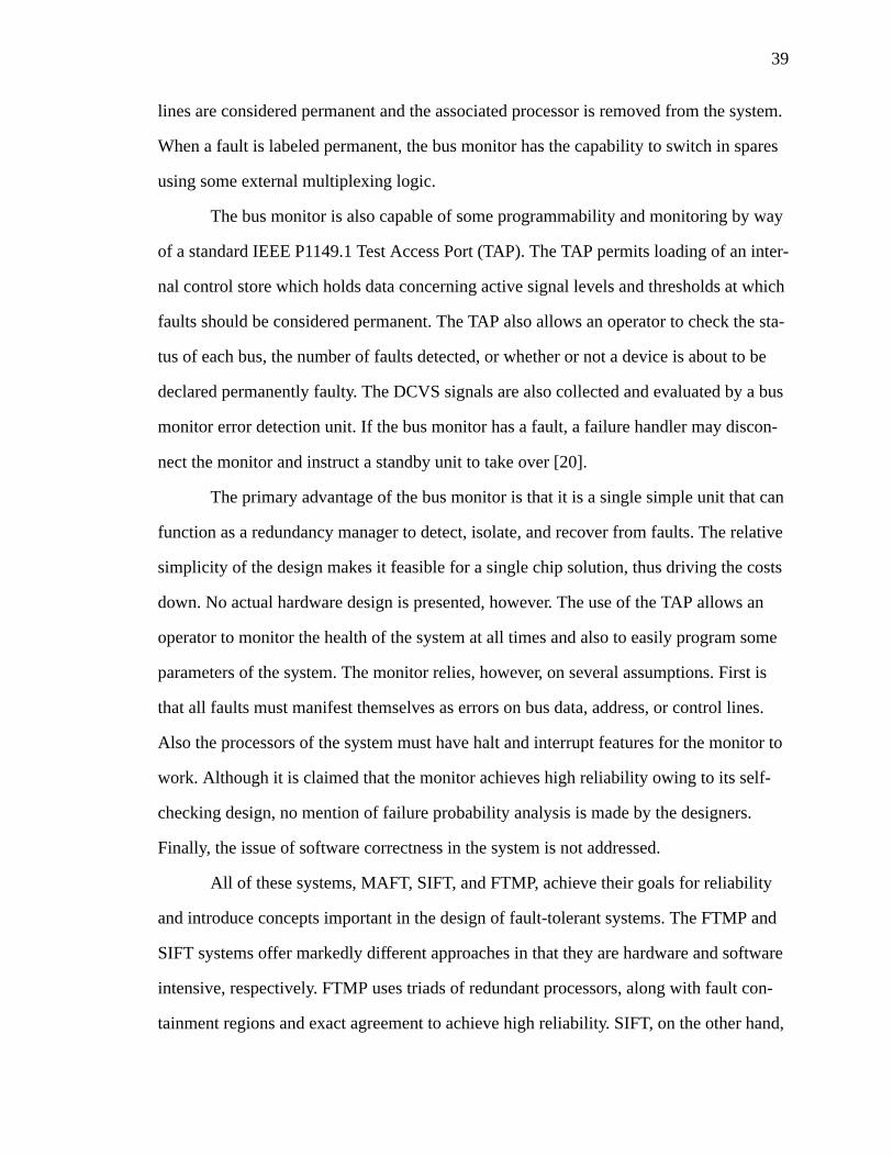
39
lines are considered permanent and the associated processor is removed from the system.
When a fault is labeled permanent, the bus monitor has the capability to switch in spares
using some external multiplexing logic.
The bus monitor is also capable of some programmability and monitoring by way
of a standard IEEE P1149.1 Test Access Port (TAP). The TAP permits loading of an inter-
nal control store which holds data concerning active signal levels and thresholds at which
faults should be considered permanent. The TAP also allows an operator to check the sta-
tus of each bus, the number of faults detected, or whether or not a device is about to be
declared permanently faulty. The DCVS signals are also collected and evaluated by a bus
monitor error detection unit. If the bus monitor has a fault, a failure handler may discon-
nect the monitor and instruct a standby unit to take over [20].
The primary advantage of the bus monitor is that it is a single simple unit that can
function as a redundancy manager to detect, isolate, and recover from faults. The relative
simplicity of the design makes it feasible for a single chip solution, thus driving the costs
down. No actual hardware design is presented, however. The use of the TAP allows an
operator to monitor the health of the system at all times and also to easily program some
parameters of the system. The monitor relies, however, on several assumptions. First is
that all faults must manifest themselves as errors on bus data, address, or control lines.
Also the processors of the system must have halt and interrupt features for the monitor to
work. Although it is claimed that the monitor achieves high reliability owing to its self-
checking design, no mention of failure probability analysis is made by the designers.
Finally, the issue of software correctness in the system is not addressed.
All of these systems, MAFT, SIFT, and FTMP, achieve their goals for reliability
and introduce concepts important in the design of fault-tolerant systems. The FTMP and
SIFT systems offer markedly different approaches in that they are hardware and software
intensive, respectively. FTMP uses triads of redundant processors, along with fault con-
tainment regions and exact agreement to achieve high reliability. SIFT, on the other hand,
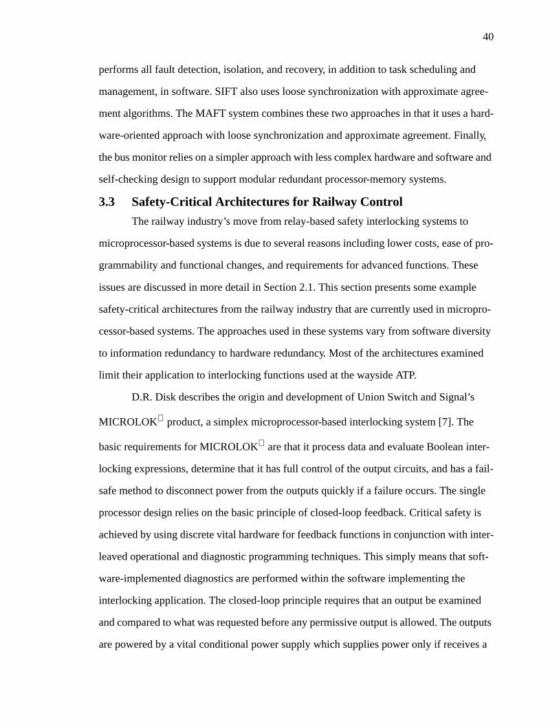
40
performs all fault detection, isolation, and recovery, in addition to task scheduling and
management, in software. SIFT also uses loose synchronization with approximate agree-
ment algorithms. The MAFT system combines these two approaches in that it uses a hard-
ware-oriented approach with loose synchronization and approximate agreement. Finally,
the bus monitor relies on a simpler approach with less complex hardware and software and
self-checking design to support modular redundant processor-memory systems.
3.3 Safety-Critical Architectures for Railway Control
The railway industry’s move from relay-based safety interlocking systems to
microprocessor-based systems is due to several reasons including lower costs, ease of pro-
grammability and functional changes, and requirements for advanced functions. These
issues are discussed in more detail in Section 2.1. This section presents some example
safety-critical architectures from the railway industry that are currently used in micropro-
cessor-based systems. The approaches used in these systems vary from software diversity
to information redundancy to hardware redundancy. Most of the architectures examined
limit their application to interlocking functions used at the wayside ATP.
D.R. Disk describes the origin and development of Union Switch and Signal’s
MICROLOK product, a simplex microprocessor-based interlocking system [7]. The
basic requirements for MICROLOK are that it process data and evaluate Boolean inter-
locking expressions, determine that it has full control of the output circuits, and has a fail-
safe method to disconnect power from the outputs quickly if a failure occurs. The single
processor design relies on the basic principle of closed-loop feedback. Critical safety is
achieved by using discrete vital hardware for feedback functions in conjunction with inter-
leaved operational and diagnostic programming techniques. This simply means that soft-
ware-implemented diagnostics are performed within the software implementing the
interlocking application. The closed-loop principle requires that an output be examined
and compared to what was requested before any permissive output is allowed. The outputs
are powered by a vital conditional power supply which supplies power only if receives a
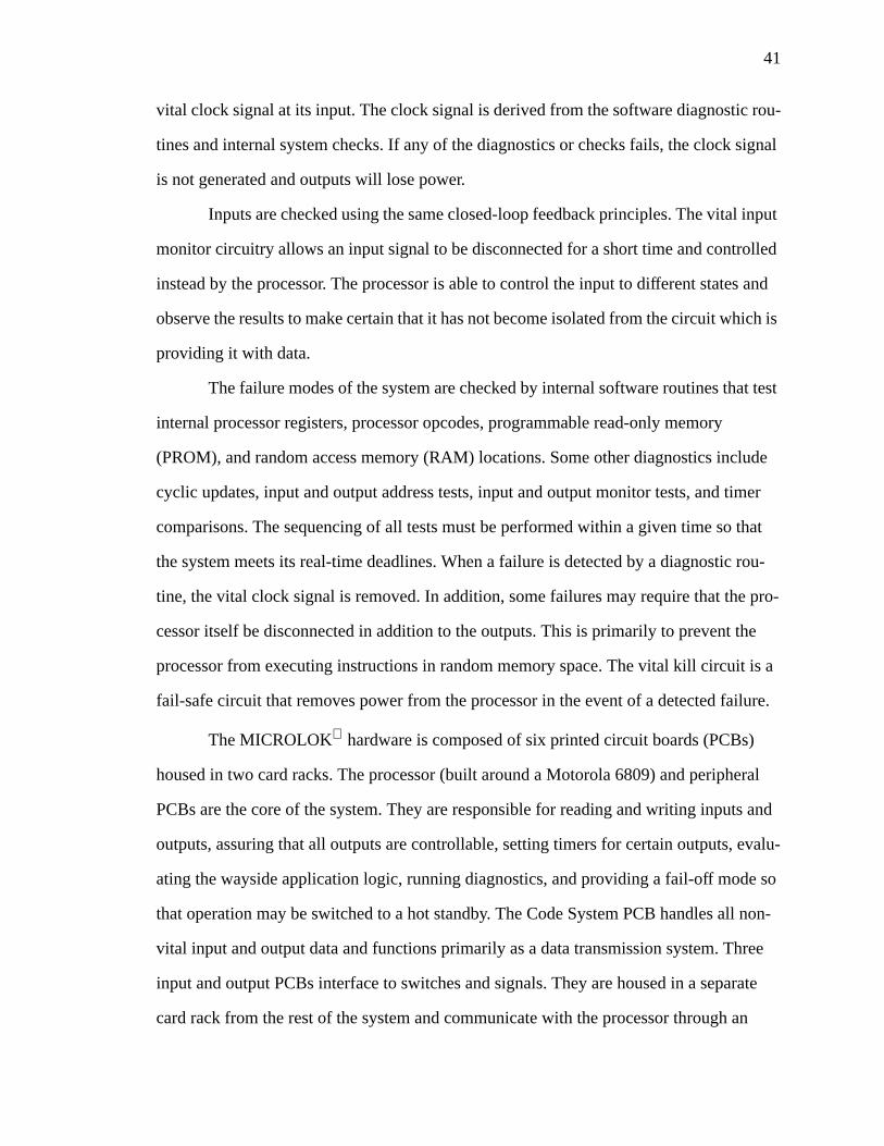
41
vital clock signal at its input. The clock signal is derived from the software diagnostic rou-
tines and internal system checks. If any of the diagnostics or checks fails, the clock signal
is not generated and outputs will lose power.
Inputs are checked using the same closed-loop feedback principles. The vital input
monitor circuitry allows an input signal to be disconnected for a short time and controlled
instead by the processor. The processor is able to control the input to different states and
observe the results to make certain that it has not become isolated from the circuit which is
providing it with data.
The failure modes of the system are checked by internal software routines that test
internal processor registers, processor opcodes, programmable read-only memory
(PROM), and random access memory (RAM) locations. Some other diagnostics include
cyclic updates, input and output address tests, input and output monitor tests, and timer
comparisons. The sequencing of all tests must be performed within a given time so that
the system meets its real-time deadlines. When a failure is detected by a diagnostic rou-
tine, the vital clock signal is removed. In addition, some failures may require that the pro-
cessor itself be disconnected in addition to the outputs. This is primarily to prevent the
processor from executing instructions in random memory space. The vital kill circuit is a
fail-safe circuit that removes power from the processor in the event of a detected failure.
The MICROLOK hardware is composed of six printed circuit boards (PCBs)
housed in two card racks. The processor (built around a Motorola 6809) and peripheral
PCBs are the core of the system. They are responsible for reading and writing inputs and
outputs, assuring that all outputs are controllable, setting timers for certain outputs, evalu-
ating the wayside application logic, running diagnostics, and providing a fail-off mode so
that operation may be switched to a hot standby. The Code System PCB handles all non-
vital input and output data and functions primarily as a data transmission system. Three
input and output PCBs interface to switches and signals. They are housed in a separate
card rack from the rest of the system and communicate with the processor through an
42
interface PCB. The interface PCB also provides a vital serial link to other MICROLOK
units over an RS-432 link. The information is transmitted using a vital serial protocol
whose fail-safe properties depend on correct operation of the software and agreement
among multiple transmissions of the same permissive data.
The interlocking logic in MICROLOK is designed using a high-level compiler
which transforms symbolic terms familiar to a signaling engineer to processor machine
language. The system designer is able to rapidly enter and manipulate logic equations and
view the results as a symbol table after compilation. The use of the special compiler
allows the assumption that the logic is correct and the program which executes the equa-
tions can be relatively simple. The drawback to this diverse software approach is the
extensive testing necessary to validate the executive. Some of the methods used to vali-
date the system are fault tree analysis, reliability and maintainability analysis, fail-safe
testing, and failure modes, effects, and criticality analysis [7].
Another approach to providing safety in an microprocessor-based interlocking sys-
tem is presented by D. Rutherford. The techniques used in the system appear in the Gen-
eral Railway Signal Company’s Vital Processor Interlocking (VPI). As with the
MICROLOK system, the VPI is based around a general purpose Boolean processor. It
vitally evaluates logic expressions by encoding and checking the terms of each expression
[21].
Solid-state circuits are used to vitally sense input states and set output states which
control switches, signals, relays, and line circuits. If a system failure occurs such that an
improper permissive state is sent to the output, it will be detected and power to the output
is disabled before the field device has time to respond. The VPI is capable of generating
any number or vital time delays for outputs requiring them and can also handle non-vital
inputs and outputs for control panels or indicators, for example. Support for distributed
interlocking is provided by a vital serial link that connects several VPI systems and the
43
interlocking application may be expanded by adding additional vital input and output
groups.
Vital data in the VPI is processed in two alternating software channels which con-
tain the data encoded in diverse forms. The two encoded forms must correspond exactly
for a permissive output to be delivered. The system cycle lasts one second during which
input data is sensed and encoded. The Boolean expressions are then evaluated using the
current inputs, and output circuits are driven to the appropriate state. During the system
cycle, the vital outputs are checked every 50 milliseconds (ms) to ensure that no incorrect
permissive states exist.
Vital inputs are represented using a polynomial code such that permissive inputs
are encoded as members of the code set and non-permissive inputs are false codewords.
This encoding is done for the two channels so that each input is represented twice, by two
different sets of codewords. The input codewords are encoded with information that
uniquely identifies them as belonging to a particular input channel and are stored in an
identity-sensitive location in memory. Codewords belonging to the code sets are not stored
in the system where they may be inadvertently read and used; they must be constructed
during each system cycle and then vitally erased.
A vital recheck cycle, occurring every 50 ms during a system cycle, verifies that
outputs are non-permissive unless specifically allowed to be permissive by results from
evaluating logic expressions in both channels. The recheck program makes use of an
absence-of-current detector circuit which vitally establishes the state of an output and
appropriately constructs checkwords based on the polynomial codewords. A complete set
of checkwords validates the states of the outputs where a correct set indicates that only
outputs which were evaluated to be true are in their permissive states. A correct set of
checkwords delivered every 50 ms allows the vital driver circuit to generate a dynamic
signal with a particular form and frequency. Only if the signal content is correct will
power be supplied to the outputs by the vital driver. In addition, at the end of each system
44
cycle the data buffers containing inputs are vitally erased to ensure that stale data is not
used in the system. The vital erasure process produces another checkword set which is
also delivered to the vital driver at the beginning of each system cycle. This set is used
with the 50 ms frequency recheck checkwords to enable the vital driver to deliver its
dynamic output.
Application equations are constructed through the use of a computer-aided assem-
bly package. The output of the package is a vital data base of checkwords and Boolean
expressions for the application. An additional feature of the system is the provision for a
dual redundant system in which one unit drives the outputs and the other acts as a hot
standby spare. The philosophy of the VPI system is called numerically integrated safety
assurance logic (NISAL). The codewords are not generated in parallel with data process-
ing; they are integrated directly into the data itself so that any data corruption will affect
the codeword [21].
A fail-safe microprocessor-based system based on partitioning and diverse redun-
dancy is currently in use in a station near Nanjing, China. The system consists of a basic
interlocking system and a separate safety assurance system, implemented diversely. Fault
tree analysis is used to analyze the fail-safety which is evaluated at a behavioral level for
30 critical conditions. The system is also equipped to deliver a variety of error reports and
logs to provide maintainability [22].
The basic philosophy of the system is the separation of the interlocking system and
safety assurance system. The designers claim that such a partitioning allows a flexible
configuration and gains four orders of magnitude in safety for this system. As with most
other interlocking systems, the safe condition is to keep all switches stable and change sig-
nals to red or least permissive. When the system is evaluated for safety a behavioral fault
model is used in which complex failures are described by some erroneous behavior.
Examples of behavioral faults are incorrect values representing state or timing, or faulty
interlocking behavior descriptions. Designers also claim that the use of diverse redun-
45
dancy validates the assumption of independent faults between modules, whether hardware
or software.
The basic interlocking system (BIS) is responsible for setting switches and signals
and can do so without the safety assurance system (SAS). The SAS supervises the BIS and
must approve of any control command issued by the BIS. If the SAS detects an error, it
drives a safety relay to cut power to switches and signals. The basic system cycle during
which outputs are checked and delivered has a one second duration. The BIS is an Intel
iSBC 80/24A processor. It executes an executive which consists of three primary modules.
The clock module synchronizes the system each second. The input and output scanner
(SC) receives and sends control signals and checks their validity. The inputs and outputs
are two-rail encoded so that a single value is represented by two complementary values.
The SC is also responsible for communicating with displays and the SAS system through
a communications interface. The third module is the locking release which monitors the
state changes in the system.
The SAS system is run on an Intel 286-based computer. Information received from
the BIS through the communications interface is analyzed in data structures stored in a
buffer analysis module. Any state change or output change is considered an event and is
analyzed by a software-implemented event-driven sequential machine. An error detection
unit gathers information from the communications interface, buffer analysis module, and
sequential machine and detects any errors. The error detection unit classifies errors
according to their preestablished criticality. If a critical error occurs, the error detection
unit stops the pulse output to the relay driver.
It is assumed that any hardware or software fault in the BIS is manifested at the
behavioral level. A fault tree is constructed for thirty behavioral conditions under which
the safety relay should be released. The system should guarantee safety when any one of
these conditions occurs. Most of the safety assurance is done in software. The BIS runs
self-test routines every second and sends the results to the SAS for evaluation. The SAS
46
compares the self-test results with a stored, correct response. In addition, the SAS and BIS
incorporate watchdog timers to prevent either processor from hanging up. Faults on an
input or output port are detected when non-codewords are produced.
The designers of this system go to great lengths to justify the assumption of inde-
pendence between the SAS and the BIS. The two systems are developed on different pro-
cessors, using different programming languages, by teams with completely different
backgrounds. They claim that the probability of unsafe failure may be expressed as the
product of the probability that the BIS will issue an incorrect control command and the
probability that the SAS will approve the incorrect command. It is assumed that the prob-
ability of the SAS incorrectly approving a command is 10-4, thus the probability of unsafe
failure is the probability of the BIS multiplied by 10-4. From this analysis, the designers
claim a safety improvement of four orders of magnitude by using the separate SAS [22].
Although the designers make many assumptions in analyzing the system, it has
operated continuously for over 61,000 hours without any failure or switchover to a cold
standby BIS.
Designers of the fail-safe interlocking system for railways using microprocessors
(FIRM) architecture adopt a philosophy in which only critical functions are implemented
in a fail-safe manner. They dismiss systems designed around a global safety standard as
too costly with unnecessary hardware and software complexity. The FIRM architecture,
developed for use on Indian Railways, implements only those functions critical to system
safety at a high safety standard. Routine functions which do not affect the safety are not
designed to the same safety standard [23].
The basic FIRM architecture consists of a pair of processing modules operating in
a duplex mode with one or more pairs standing by. A sequence controller module (SQC)
supplies power to the active pair of processors as long as no fault is detected. In the event
of a detected fault, power is discontinued by the SQC and is routed to a standby pair. Other
modules of FIRM control the major tasks of the system which include fail-safe compari-
47
son of outputs from each processor, checks of the signals that are critical to safety, and
storage of system state and outputs so that a standby pair can update itself if it must be
activated.
The different functions of the FIRM system are divided into four categories based
on their safety criticality, each having its own appropriate design techniques. Data logging
and maintenance functions are implemented on a single processor with routine software
having no special safety characteristics. The display panel processor is implemented using
software diversity where outputs are calculated in separate functional channels and
checked for inconsistency, similar to the NISAL technique described earlier. Vital func-
tions such as route locking and signal clearing are implemented with specialized fail-safe
electronic hardware (vital hardware) and dual hardware and software diversity. The high-
est level of safety is reserved for the output data conditioners which are implemented with
traditional electromechanical safety relays.
The processor pair used in FIRM operates in what is called a see-saw mode. At
any instant one processor is in control of the communications bus and shared resources.
This processor performs the input and output operations during this time. The other pro-
cessor performs the control tasks. In the next phase of a system cycle, the processors
switch functions. Synchronization is avoided by using a handshaking algorithm to move
from one phase to the other. It is claimed that the asynchronous operation allows both
hardware and software diversity and eliminates the risk of common-mode failures in
which both processors fail in the same way. Also, errors due to design faults in computer
hardware and software are handled by the use of distributed functional modules imple-
mented in different ways to perform specific tasks, as outlined above. Thus the safety is
not wholly dependent on processor hardware or software. Each module may be designed,
validated, and tested independently.
The SQC acts as the watchdog for the active pair of processors. Each processor is
required to perform self-check and cross-check operations and then set a flag in the SQC.
48
If a processor fails to set the flag within a certain time, the SQC kills its power supply and
initiates recovery and switchover to a standby pair. Recovery briefly interrupts the system
but the functional modules maintain their outputs and state. This allows the spare proces-
sors to resume operation from the last state. This configuration is designed for slow real-
time systems where it is assumed that a brief interruption is permissible.
The processor modules themselves consist of a microprocessor and local memory.
They are connected to their companions through a local communications bus which
allows the exchange of data during cross-check. Each module also has an input and output
port through which handshaking signals are sent and received.
The see-saw operation is between two modes, namely communication and compu-
tation. The processor in communications mode controls the global bus and facilitates com-
munication with functional modules and the local bus for cross-check purposes. Specific
communications mode operations include reading vital results of the companion proces-
sor, polling the input and output devices to receive or deliver control signals, and execut-
ing self-check until interrupted by the companion processor. When this interrupt is
received, the processor shifts to computation mode whose operations include execution of
the control tasks and storage of the results in RAM, comparison of vital results with those
generated by the companion, and checking of bus buffers to ensure that bus contention is
not possible.
Functional modules in the FIRM architecture are assigned tasks that include rout-
ing, reading inputs, driving relays, or providing panel indications. Each functional module
consists of four basic circuits: an interface controller, a module ID, a data-loop-test, and
the module circuit itself. The interface controller provides addressing and control func-
tions to interface the module to a processor. The module ID is a hardwired value that the
processor accesses during its self-check to ensure that it is connected to the global bus and
that its addressing circuitry is functional. The data-loop-test verifies the health of the data
bus. Finally, the module circuit performs the appropriate function [23].
49
The FIRM architecture employs a design approach which identifies different levels
of safety for each function of the system. The implementation technique used to carry out
each function then depends on its assigned safety level. The system uses a combination of
simplex, hardware redundancy, and software diversity techniques depending on the safety
level required.
3.4 Chapter Summary
This chapter provided a brief overview of techniques used in safety-critical and
fault-tolerant architectures. Background was provided in three basic areas: safety-critical
design principles, example fault-tolerant architectures, and current examples of micropro-
cessor-based ATC systems. The discussion of safety-critical design approaches addressed
such issues as proper requirements definition, effective redundancy management, achiev-
ing input congruency, and the use of command feedback. This section also gives a brief
description of various techniques used in fault-tolerant and safety-critical systems, along
with some discussion of the drawbacks associated with each of them.
The second portion of this chapter provided an overview of several classic fault-
tolerant architectures used in avionics applications. The examples were chosen to demon-
strate approaches that concentrate on hardware replication, software diagnostics and loose
synchronization, or a combination of these. In addition, an early example of the use of a
building block approach to construct fault-tolerant systems was presented. A final exam-
ple was presented which relies on a low-complexity bus monitor unit to achieve high reli-
ability in simple processor-memory systems. The final section provided four examples of
microprocessor-based ATC systems currently used or being tested in the field in various
environments. The examples were chosen to illustrate different approaches to achieving
high safety including software diversity, coded processing in a simplex system, and
duplex hardware redundancy.
The goals of this chapter were twofold. The first was to provide background in ter-
minology and techniques used in the design of safety-critical systems. The second goal

50
was to establish a perspective of the field of safety-critical design from which the contri-
bution and applicability of the Next Generation Architecture and its input and output mod-
ules may be evaluated.

51
Chapter 4Next Generation Architecture for
Automatic Train Control
This chapter presents an overview of the Next Generation Architecture developed
to meet the requirements outlined in Chapter 2. Elements of the architecture, including
processors, network interfaces, and a safety-critical software executive are described. In
addition, this chapter contains some discussion of the possible configurations of the sys-
tem to illustrate its flexibility. The concepts behind global safety assurance, along with a
candidate method for achieving it, are also presented.
It should be recognized that the development of this architecture is a large project
with many contributors. The purpose of this chaper is to describe the work of the entire
research group so that the context of the input and output module development is appar-
ent. As a result, this chapter summarizes work that is described in full detail elsewhere.
Where appropriate, references to theses or technical reports are provided.
4.1 Next Generation Architecture
Figure 4.1 shows a high-level view of the system architecture. Modularity is a
prominent feature of the architecture, as building blocks are used for the processors, input
and output modules, and the network interface unit (NIU). These three elements are inter-
connected over a parallel backplane bus which forms a node in the distributed system.
Each building block is an error containment region which prevents the propagation of
fault effects (errors) into or out from the error containment boundary. Error containment
regions are analogous to fault containment regions used in highly reliable systems (see
Section 3.1). Processors communicate with local input and output modules over the paral-
lel bus. Control outputs for other nodes in the network are communicated over the serial
link through the NIU which serves as an adaptor between the high-speed serial network
and the parallel bus. The main function of the processors is to execute the control algo-
rithm. Input modules sense vital field data such as switch position or track occupancy and
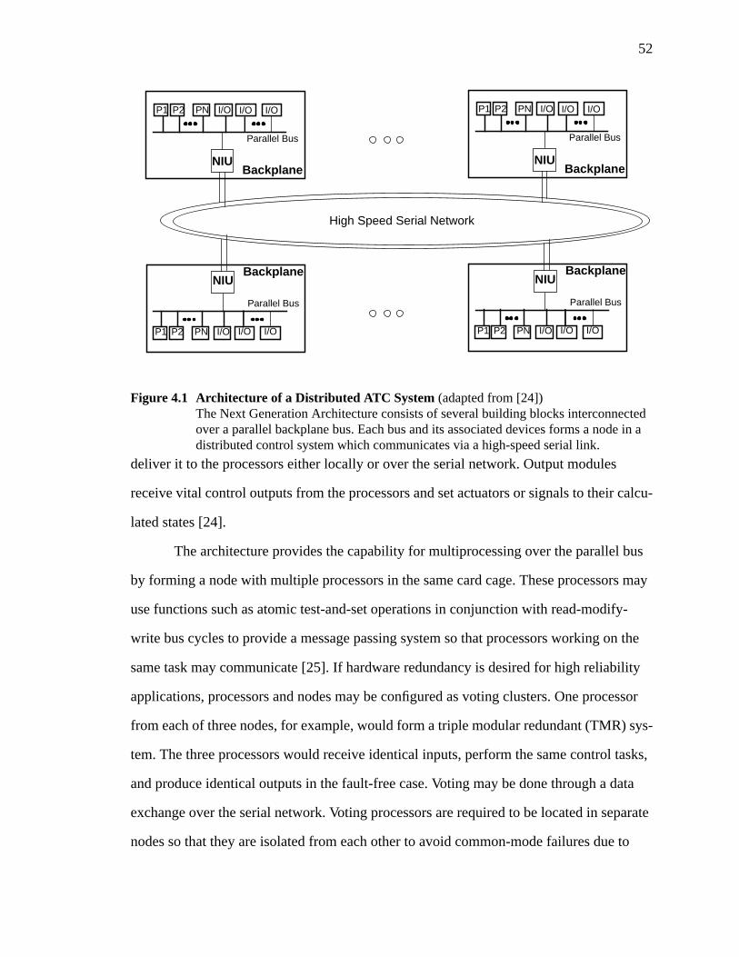
52
deliver it to the processors either locally or over the serial network. Output modules
receive vital control outputs from the processors and set actuators or signals to their calcu-
lated states [24].
The architecture provides the capability for multiprocessing over the parallel bus
by forming a node with multiple processors in the same card cage. These processors may
use functions such as atomic test-and-set operations in conjunction with read-modify-
write bus cycles to provide a message passing system so that processors working on the
same task may communicate [25]. If hardware redundancy is desired for high reliability
applications, processors and nodes may be configured as voting clusters. One processor
from each of three nodes, for example, would form a triple modular redundant (TMR) sys-
tem. The three processors would receive identical inputs, perform the same control tasks,
and produce identical outputs in the fault-free case. Voting may be done through a data
exchange over the serial network. Voting processors are required to be located in separate
nodes so that they are isolated from each other to avoid common-mode failures due to
P1 P2 PN I/O
NIUBackplane
Parallel Bus
NIUBackplane
Parallel Bus
High Speed Serial Network
I/O I/O
P1 P2 PN I/O I/O I/O
P1 P2 PN I/O
NIUBackplane
Parallel Bus
NIUBackplane
Parallel Bus
I/O I/O
P1 P2 PN I/O I/O I/O
Figure 4.1 Architecture of a Distributed ATC System(adapted from [24])The Next Generation Architecture consists of several building blocks interconnectedover a parallel backplane bus. Each bus and its associated devices forms a node in adistributed control system which communicates via a high-speed serial link.
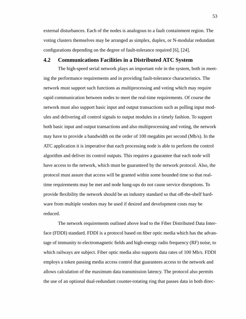
53
external disturbances. Each of the nodes is analogous to a fault containment region. The
voting clusters themselves may be arranged as simplex, duplex, or N-modular redundant
configurations depending on the degree of fault-tolerance required [6], [24].
4.2 Communications Facilities in a Distributed ATC System
The high-speed serial network plays an important role in the system, both in meet-
ing the performance requirements and in providing fault-tolerance characteristics. The
network must support such functions as multiprocessing and voting which may require
rapid communication between nodes to meet the real-time requirements. Of course the
network must also support basic input and output transactions such as polling input mod-
ules and delivering all control signals to output modules in a timely fashion. To support
both basic input and output transactions and also multiprocessing and voting, the network
may have to provide a bandwidth on the order of 100 megabits per second (Mb/s). In the
ATC application it is imperative that each processing node is able to perform the control
algorithm and deliver its control outputs. This requires a guarantee that each node will
have access to the network, which must be guaranteed by the network protocol. Also, the
protocol must assure that access will be granted within some bounded time so that real-
time requirements may be met and node hang-ups do not cause service disruptions. To
provide flexibility the network should be an industry standard so that off-the-shelf hard-
ware from multiple vendors may be used if desired and development costs may be
reduced.
The network requirements outlined above lead to the Fiber Distributed Data Inter-
face (FDDI) standard. FDDI is a protocol based on fiber optic media which has the advan-
tage of immunity to electromagnetic fields and high-energy radio frequency (RF) noise, to
which railways are subject. Fiber optic media also supports data rates of 100 Mb/s. FDDI
employs a token passing media access control that guarantees access to the network and
allows calculation of the maximum data transmission latency. The protocol also permits
the use of an optional dual-redundant counter-rotating ring that passes data in both direc-
54
tions around the network. When this structure is present, a faulty node may be bypassed
through an optical bypass switch which isolates the node from the rest of the network. The
standard also uses run-length and cyclic redundancy check encoding to protect the data
from random communications channel errors.
A complete view of the proposed communication system is illustrated in Figure
4.2. Multiple FDDI rings may be distributed along the railway and connected through
communications bridges. Nodes on the rings may be input and output modules sending
and receiving data from wayside ATP controllers also located on the network. The input
and output modules are geographically distributed along the network and generally will
outnumber the required wayside ATP processing sites. Wireless transmission through
gateways allows the carborne ATP systems to communicate data such as velocity or iden-
tification to the wayside units [6], [24].
4.3 Safety-Critical Software Executive
As discussed in Section 3.1, the use of software in a safety critical systems is prob-
lematic. Eradicating a complex software system of all bugs is virtually impossible and it is
also extremely difficult to quantify the probability that software is error-free [13]. In a
microprocessor-based system, however, software is unavoidable. A software executive
w w w w w w w w w
FDDI Ring
WC
BridgeGW
GW GW
wwwwwwwww
FDDI Ring
WC
GW
GWGW
c c
WC - wayside ATP controllerw - wayside input and output
c - carborne ATP controlGW - network gateway
Figure 4.2 Communication System of Next Generation Architecture(adapted from [6])The envisioned communications system consists of multiple FDDI rings connected toinput and output modules and wayside ATP controllers. Carborne ATP systems com-municate information to the wayside via radio transmission through gateways.
55
kernel is necessary to schedule and complete tasks safely and within the real-time require-
ments of the system. The overriding design goal in developing the executive, therefore, is
simplicity. In addition to being easier to develop, simple systems facilitate performance of
some sort of validation. General requirements for the software executive in the Next Gen-
eration Architecture include the following [26]:
• execution of all tasks in a safe and deterministic fashion
• communication with input and output modules to read sensor values anddeliver actuator outputs
• management and mediation of resource allocation where exclusive access isrequired
• scheduling and handling of system diagnostic tasks
• distribution of tasks among possibly heterogeneous processors and provisionsfor reconfiguration in the case of processing site failure
In light of the above requirements the choice of language in which to implement
the executive is an important issue. The types of features required from the language, such
as concurrency or time-bounded task execution, are very similar to those used in avionics
or military applications. The National Aeronautics and Space Administration (NASA) and
the United States military support Ada for use in ultrareliable applications, and Ada is also
chosen for the Next Generation Architecture. While languages such as C or C++ are gen-
erally considered the most efficient, Ada possesses unique characteristics that make it suit-
able for real-time safety-critical applications. In contrast to C, Ada does have an inherent
notion of time, which is absolutely necessary for a real-time system. Other useful features
supported in Ada include concurrent processing, recognition of task deadlines, exceptions,
built-in scheduling and task switching, strong type checking, and separate compilation of
program modules with parameter checking. In addition, Ada is a standard of the American
National Standards Institute (ANSI) and the International Standards Organization (ISO).
The standards promote predictable compiler behavior and consistency and Ada is the only
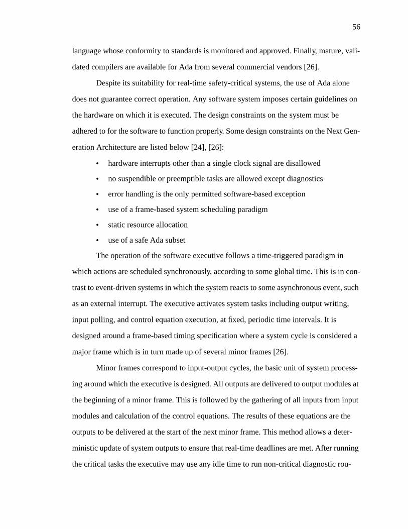
56
language whose conformity to standards is monitored and approved. Finally, mature, vali-
dated compilers are available for Ada from several commercial vendors [26].
Despite its suitability for real-time safety-critical systems, the use of Ada alone
does not guarantee correct operation. Any software system imposes certain guidelines on
the hardware on which it is executed. The design constraints on the system must be
adhered to for the software to function properly. Some design constraints on the Next Gen-
eration Architecture are listed below [24], [26]:
• hardware interrupts other than a single clock signal are disallowed
• no suspendible or preemptible tasks are allowed except diagnostics
• error handling is the only permitted software-based exception
• use of a frame-based system scheduling paradigm
• static resource allocation
• use of a safe Ada subset
The operation of the software executive follows a time-triggered paradigm in
which actions are scheduled synchronously, according to some global time. This is in con-
trast to event-driven systems in which the system reacts to some asynchronous event, such
as an external interrupt. The executive activates system tasks including output writing,
input polling, and control equation execution, at fixed, periodic time intervals. It is
designed around a frame-based timing specification where a system cycle is considered a
major frame which is in turn made up of several minor frames [26].
Minor frames correspond to input-output cycles, the basic unit of system process-
ing around which the executive is designed. All outputs are delivered to output modules at
the beginning of a minor frame. This is followed by the gathering of all inputs from input
modules and calculation of the control equations. The results of these equations are the
outputs to be delivered at the start of the next minor frame. This method allows a deter-
ministic update of system outputs to ensure that real-time deadlines are met. After running
the critical tasks the executive may use any idle time to run non-critical diagnostic rou-
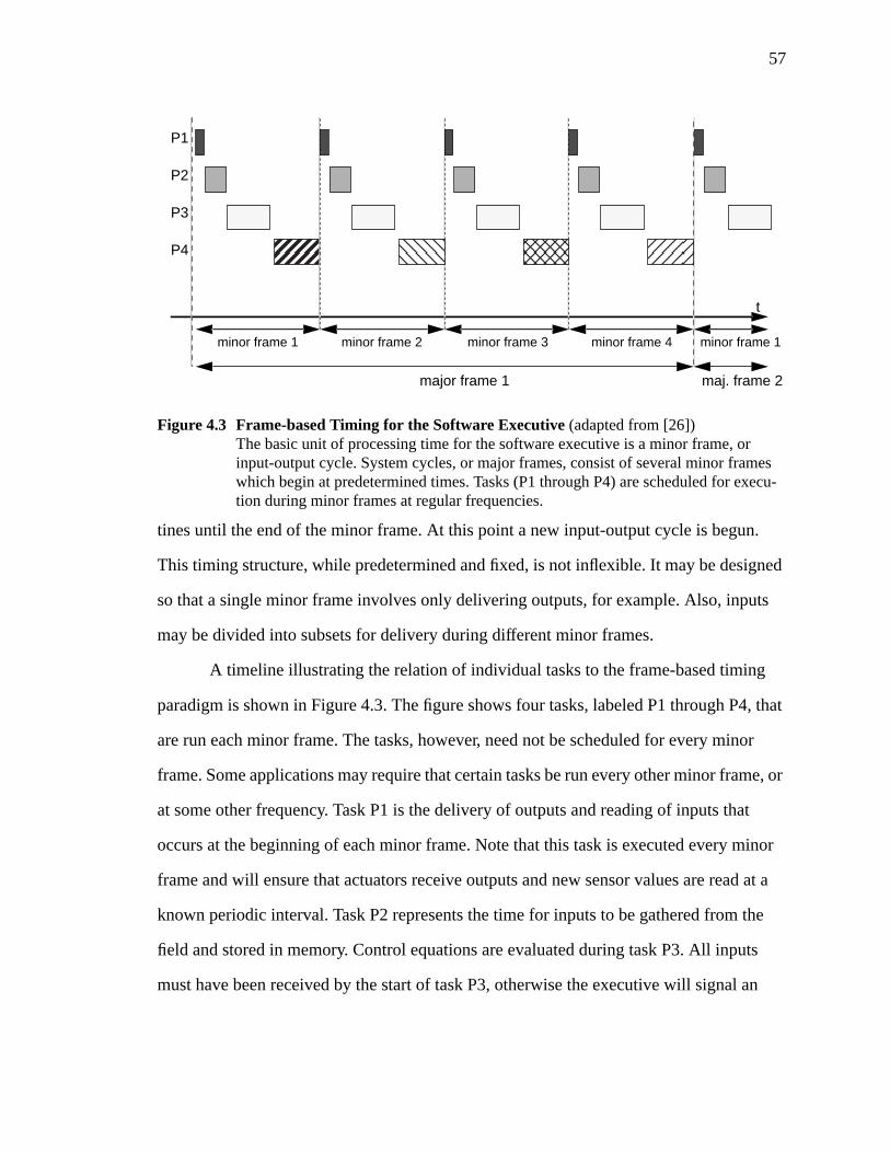
57
tines until the end of the minor frame. At this point a new input-output cycle is begun.
This timing structure, while predetermined and fixed, is not inflexible. It may be designed
so that a single minor frame involves only delivering outputs, for example. Also, inputs
may be divided into subsets for delivery during different minor frames.
A timeline illustrating the relation of individual tasks to the frame-based timing
paradigm is shown in Figure 4.3. The figure shows four tasks, labeled P1 through P4, that
are run each minor frame. The tasks, however, need not be scheduled for every minor
frame. Some applications may require that certain tasks be run every other minor frame, or
at some other frequency. Task P1 is the delivery of outputs and reading of inputs that
occurs at the beginning of each minor frame. Note that this task is executed every minor
frame and will ensure that actuators receive outputs and new sensor values are read at a
known periodic interval. Task P2 represents the time for inputs to be gathered from the
field and stored in memory. Control equations are evaluated during task P3. All inputs
must have been received by the start of task P3, otherwise the executive will signal an
P1
P2
P3
P4
minor frame 1
major frame 1 maj. frame 2
Figure 4.3 Frame-based Timing for the Software Executive(adapted from [26])The basic unit of processing time for the software executive is a minor frame, orinput-output cycle. System cycles, or major frames, consist of several minor frameswhich begin at predetermined times. Tasks (P1 through P4) are scheduled for execu-tion during minor frames at regular frequencies.
t
minor frame 2 minor frame 3 minor frame 4 minor frame 1
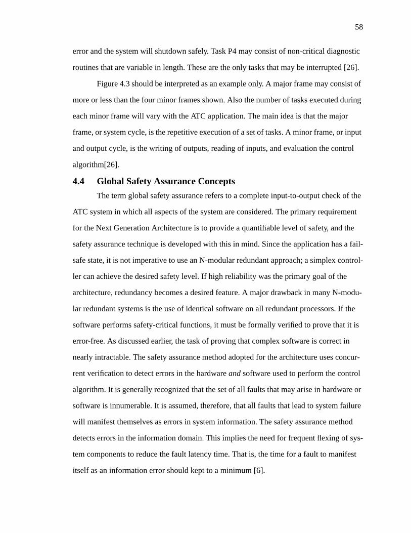
58
error and the system will shutdown safely. Task P4 may consist of non-critical diagnostic
routines that are variable in length. These are the only tasks that may be interrupted [26].
Figure 4.3 should be interpreted as an example only. A major frame may consist of
more or less than the four minor frames shown. Also the number of tasks executed during
each minor frame will vary with the ATC application. The main idea is that the major
frame, or system cycle, is the repetitive execution of a set of tasks. A minor frame, or input
and output cycle, is the writing of outputs, reading of inputs, and evaluation the control
algorithm[26].
4.4 Global Safety Assurance Concepts
The term global safety assurance refers to a complete input-to-output check of the
ATC system in which all aspects of the system are considered. The primary requirement
for the Next Generation Architecture is to provide a quantifiable level of safety, and the
safety assurance technique is developed with this in mind. Since the application has a fail-
safe state, it is not imperative to use an N-modular redundant approach; a simplex control-
ler can achieve the desired safety level. If high reliability was the primary goal of the
architecture, redundancy becomes a desired feature. A major drawback in many N-modu-
lar redundant systems is the use of identical software on all redundant processors. If the
software performs safety-critical functions, it must be formally verified to prove that it is
error-free. As discussed earlier, the task of proving that complex software is correct in
nearly intractable. The safety assurance method adopted for the architecture uses concur-
rent verification to detect errors in the hardwareand software used to perform the control
algorithm. It is generally recognized that the set of all faults that may arise in hardware or
software is innumerable. It is assumed, therefore, that all faults that lead to system failure
will manifest themselves as errors in system information. The safety assurance method
detects errors in the information domain. This implies the need for frequent flexing of sys-
tem components to reduce the fault latency time. That is, the time for a fault to manifest
itself as an information error should kept to a minimum [6].
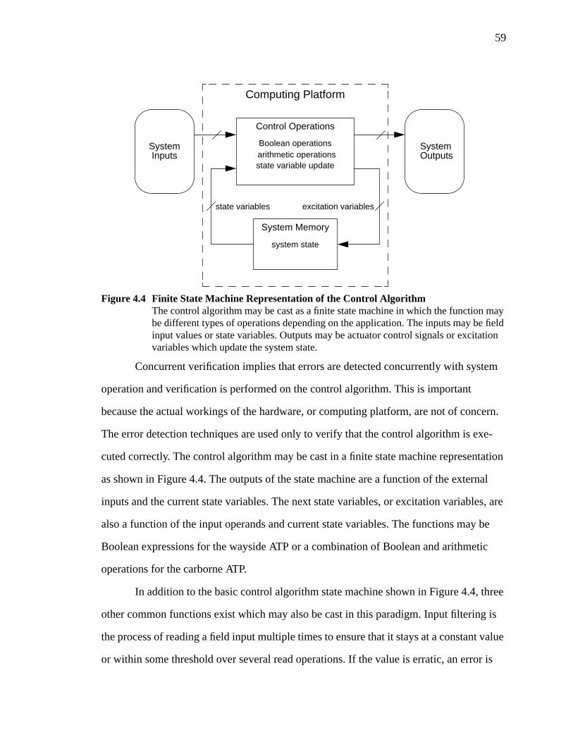
59
Concurrent verification implies that errors are detected concurrently with system
operation and verification is performed on the control algorithm. This is important
because the actual workings of the hardware, or computing platform, are not of concern.
The error detection techniques are used only to verify that the control algorithm is exe-
cuted correctly. The control algorithm may be cast in a finite state machine representation
as shown in Figure 4.4. The outputs of the state machine are a function of the external
inputs and the current state variables. The next state variables, or excitation variables, are
also a function of the input operands and current state variables. The functions may be
Boolean expressions for the wayside ATP or a combination of Boolean and arithmetic
operations for the carborne ATP.
In addition to the basic control algorithm state machine shown in Figure 4.4, three
other common functions exist which may also be cast in this paradigm. Input filtering is
the process of reading a field input multiple times to ensure that it stays at a constant value
or within some threshold over several read operations. If the value is erratic, an error is
Control Operations
Boolean operationsarithmetic operationsstate variable update
System Memory
system state
SystemOutputs
excitation variables
SystemInputs
state variables
Computing Platform
Figure 4.4 Finite State Machine Representation of the Control AlgorithmThe control algorithm may be cast as a finite state machine in which the function maybe different types of operations depending on the application. The inputs may be fieldinput values or state variables. Outputs may be actuator control signals or excitationvariables which update the system state.
60
detected and the input is read as a non-permissive value. Here, the state variable is simply
the input which is updated after each read operation. The control operation may be to
compare the new field input with the previously read state variable.
The second function is command feedback, discussed in Chapter 3. Command
feedback is used to check that the output signal at the output modules in fact matches the
signal requested by the processor. The output value may be read back into the processor
through an input module. A comparison similar to that used in input filtering may be used
to verify that the current state of the output matches the value requested on the previous
minor frame. If they match, the processor delivers the new output for the current minor
frame. Command feedback is an integral part of the Global Safety Assurance concept.
The third function is output filtering, which is similar to input filtering in opera-
tion. Here the output signal is delayed for some fixed number of minor frames to facilitate
staggered settings of interlocking switches, for example. The output may be calculated but
instead of being sent to an output actuator, it is assigned to some state variable. This state
variable is simply copied over several frames until it is ready to be delivered at which
point it is sent to an output module.
All of the functions discussed here are part of the control algorithm and have a
clear sequence of operation using a certain set of operands, whether they are state vari-
ables or input operands or a combination. The safety assurance algorithm is based on the
fact that knowledge of input identities, operation sequence, and output identities is avail-
ablea priori. If the processor is constrained to operate in this predetermined manner, it is
possible for the algorithm checker to ensure that correct, uncorrupted operands were used
at the correct times and that calculations were made without error [24].
The safety assurance method adopts a code-based approach for detecting errors
that arise in all portions of the system, including input modules, communications chan-
nels, processing elements, and output modules. The building blocks used in the architec-
61
ture correspond to these system elements and as such are treated as error containment
regions.
The code-based approach is chosen to facilitate analysis of the probability of unde-
tected errors, which is very important to quantifying the safety of the system. Different
types of information are encoded with data to allow checking of six general classes of
errors, including [27]:
• noisy data symbol errors, including random, burst, and unidirectional errors
• data symbol reference errors in which the incorrect operand is referenced andused in an operation
• instruction control symbol selection errors where the incorrect operation isspecified
• data symbol manipulation errors where an operation is performed incorrectly
• excessive timing error in which operations are not completed on time or staledata is used
• symbol creation errors in which the processor or an input card creates a cor-rupted operand codeword
Input operands from the field are vitally sensed by the input modules and then
encoded with a timestamp and unique identity in a cyclic code. The identity and times-
tamp are used to detect referencing errors and excessive timing errors, respectively. The
cyclic code provides good random and burst error detection to protect against noisy data
errors. Operation checking at the processor is used to protect against operation and manip-
ulation errors. The serial network media is also considered an error containment region.
Before data is transmitted over the network, it is encoded in a cyclic code and checked at
its destination. The output modules verify that the data arrives uncorrupted, the timestamp
is correct, and the codeword’s unique identity matches that of the output channel to which
it is sent.
The safety assurance concept is designed for a simplex processor executing the
ATC control algorithm. The checking algorithm may be implemented in a number of
ways. A number of semicustom devices could be designed and implemented to passively
62
monitor the processor-memory bus and analyze the required operands. Also, the checking
algorithm could be implemented by another processor which receives the data to be
checked from the processor performing the control algorithm. In any case, when the
checker detects an error, it must signal a vital circuit which can safely remove power from
the outputs. As discussed in Section 3.3, standard fail-safe technology exists for this pur-
pose. The use of a separate checker assumes that the probability of a simultaneous failure
in the checker and the processor performing the control algorithm is insignificant. If the
checker is implemented in semicustom circuits this assumption has more merit than the
case where another processor serves as the checker. Since the processors are executing
completely different algorithms, however, the probability of near-coincident failure is con-
sidered remote [24].
4.5 Chapter Summary
This chapter has presented an overview of the Next Generation Architecture devel-
oped to meet the requirements for the ATC application described in Chapter 2. The main
features of the architecture are hardware building blocks which form error containment
regions through which errors in the information domain may not propagate. Processing
elements, input and output modules, and network interface units are the primary building
blocks. The distributed architecture consists of parallel backplane nodes connected
through the network interface units to a high-speed FDDI network. The nodes may house
several processing or input and output modules. These nodes communicate information to
interlocking elements along the railway and to carborne ATP controllers via data radio
links. This architecture is adaptable to multiprocessing or voting arrangements if the
application demands it.
In addition, a safety-critical software executive was presented which follows a
frame-based timing specification. Events in the system are time-triggered so that all tasks
occur periodically, at predetermined times. The executive has simplicity as its primary
design goal to allow easier validation and lower development cost. Safety in the system is
63
provided by a dedicated watchdog checker which detects errors in information used by the
control algorithm without regard to the hardware on which the algorithm is executed. The
checker passively monitors the processor-memory bus of the processor executing the con-
trol algorithm, and signals an error to a vital circuit which implements a safe shutdown of
the system. The checker is designed to provide global safety assurance which ensures
safety from system input to system output. The actual checking mechanisms are based on
an error model which considers errors arising from communication channel noise or incor-
rect operation execution, for example. The implementation of the checker may be done in
separate semicustom hardware or in software on another processor.
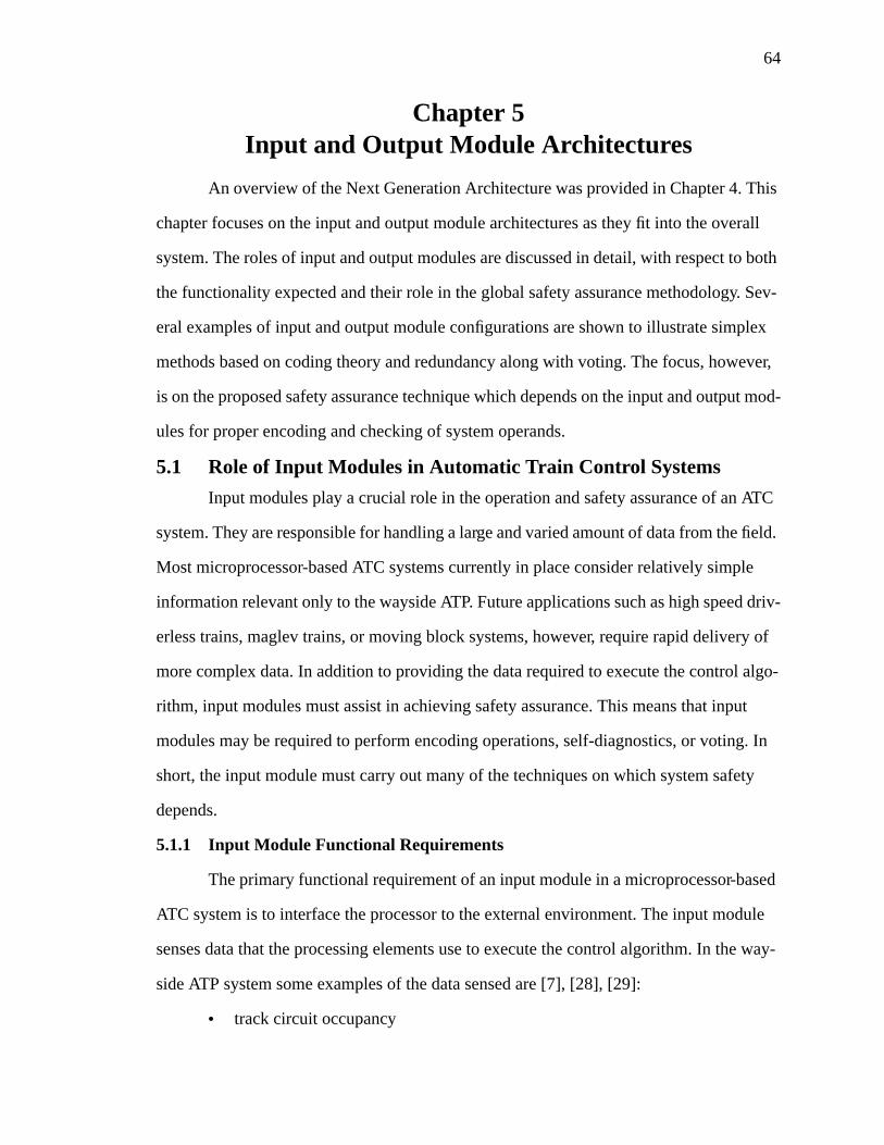
64
Chapter 5Input and Output Module Architectures
An overview of the Next Generation Architecture was provided in Chapter 4. This
chapter focuses on the input and output module architectures as they fit into the overall
system. The roles of input and output modules are discussed in detail, with respect to both
the functionality expected and their role in the global safety assurance methodology. Sev-
eral examples of input and output module configurations are shown to illustrate simplex
methods based on coding theory and redundancy along with voting. The focus, however,
is on the proposed safety assurance technique which depends on the input and output mod-
ules for proper encoding and checking of system operands.
5.1 Role of Input Modules in Automatic Train Control Systems
Input modules play a crucial role in the operation and safety assurance of an ATC
system. They are responsible for handling a large and varied amount of data from the field.
Most microprocessor-based ATC systems currently in place consider relatively simple
information relevant only to the wayside ATP. Future applications such as high speed driv-
erless trains, maglev trains, or moving block systems, however, require rapid delivery of
more complex data. In addition to providing the data required to execute the control algo-
rithm, input modules must assist in achieving safety assurance. This means that input
modules may be required to perform encoding operations, self-diagnostics, or voting. In
short, the input module must carry out many of the techniques on which system safety
depends.
5.1.1 Input Module Functional Requirements
The primary functional requirement of an input module in a microprocessor-based
ATC system is to interface the processor to the external environment. The input module
senses data that the processing elements use to execute the control algorithm. In the way-
side ATP system some examples of the data sensed are [7], [28], [29]:
• track circuit occupancy

65
• switch point contacts or switch states
• signal relay contacts or signal states
• signal lamp filament integrity
• track integrity
• highway grade crossing warning states
• high water, high wind, and rock slide warning signal states
• temperature
• defect indicators including high or wide load, dragging equipment, hot wheels,broken wheels, or loose wheels
It is evident that the type of information that is gathered by the input module varies
widely. Some of the detectors and indicators may be represented simply as an on or off
voltage or current level. A sensor that checks for track or lamp filament integrity, for
example, may be on if no problem is detected and off if something is wrong with the
device. In these cases the input module might have a simple threshold device that sends a
logic-1 or logic-0 depending on the voltage level at the detector. Temperature information,
on the other hand, requires a more sophisticated analog to digital (A/D) conversion device
on the input module.
Input modules in the carborne ATP generally require more advanced sensor inter-
faces than in the wayside ATP. Some typical data in forthcoming carborne ATP applica-
tions such as the North American Advanced Train Control System (ATCS) are [28]:
• train speed
• throttle position
• brake settings
• acceleration
• train position
• locomotive health
As trains progress the carborne ATP must determine train location using axle-mounted
odometers and checks using data obtained from transponders buried in the roadbed. The
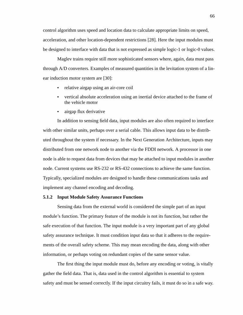
66
control algorithm uses speed and location data to calculate appropriate limits on speed,
acceleration, and other location-dependent restrictions [28]. Here the input modules must
be designed to interface with data that is not expressed as simple logic-1 or logic-0 values.
Maglev trains require still more sophisticated sensors where, again, data must pass
through A/D converters. Examples of measured quantities in the levitation system of a lin-
ear induction motor system are [30]:
• relative airgap using an air-core coil
• vertical absolute acceleration using an inertial device attached to the frame ofthe vehicle motor
• airgap flux derivative
In addition to sensing field data, input modules are also often required to interface
with other similar units, perhaps over a serial cable. This allows input data to be distrib-
uted throughout the system if necessary. In the Next Generation Architecture, inputs may
distributed from one network node to another via the FDDI network. A processor in one
node is able to request data from devices that may be attached to input modules in another
node. Current systems use RS-232 or RS-432 connections to achieve the same function.
Typically, specialized modules are designed to handle these communications tasks and
implement any channel encoding and decoding.
5.1.2 Input Module Safety Assurance Functions
Sensing data from the external world is considered the simple part of an input
module’s function. The primary feature of the module is not its function, but rather the
safe execution of that function. The input module is a very important part of any global
safety assurance technique. It must condition input data so that it adheres to the require-
ments of the overall safety scheme. This may mean encoding the data, along with other
information, or perhaps voting on redundant copies of the same sensor value.
The first thing the input module must do, before any encoding or voting, is vitally
gather the field data. That is, data used in the control algorithm is essential to system
safety and must be sensed correctly. If the input circuitry fails, it must do so in a safe way.
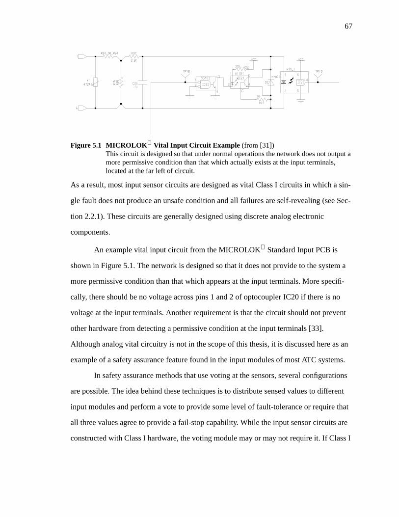
67
As a result, most input sensor circuits are designed as vital Class I circuits in which a sin-
gle fault does not produce an unsafe condition and all failures are self-revealing (see Sec-
tion 2.2.1). These circuits are generally designed using discrete analog electronic
components.
An example vital input circuit from the MICROLOK Standard Input PCB is
shown in Figure 5.1. The network is designed so that it does not provide to the system a
more permissive condition than that which appears at the input terminals. More specifi-
cally, there should be no voltage across pins 1 and 2 of optocoupler IC20 if there is no
voltage at the input terminals. Another requirement is that the circuit should not prevent
other hardware from detecting a permissive condition at the input terminals [33].
Although analog vital circuitry is not in the scope of this thesis, it is discussed here as an
example of a safety assurance feature found in the input modules of most ATC systems.
In safety assurance methods that use voting at the sensors, several configurations
are possible. The idea behind these techniques is to distribute sensed values to different
input modules and perform a vote to provide some level of fault-tolerance or require that
all three values agree to provide a fail-stop capability. While the input sensor circuits are
constructed with Class I hardware, the voting module may or may not require it. If Class I
Figure 5.1 MICROLOK Vital Input Circuit Example (from [31])This circuit is designed so that under normal operations the network does not output amore permissive condition than that which actually exists at the input terminals,located at the far left of circuit.
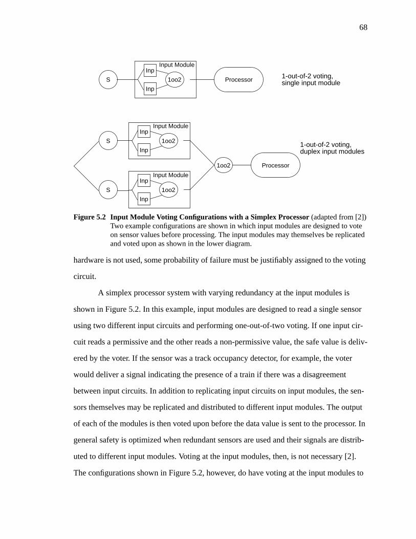
68
hardware is not used, some probability of failure must be justifiably assigned to the voting
circuit.
A simplex processor system with varying redundancy at the input modules is
shown in Figure 5.2. In this example, input modules are designed to read a single sensor
using two different input circuits and performing one-out-of-two voting. If one input cir-
cuit reads a permissive and the other reads a non-permissive value, the safe value is deliv-
ered by the voter. If the sensor was a track occupancy detector, for example, the voter
would deliver a signal indicating the presence of a train if there was a disagreement
between input circuits. In addition to replicating input circuits on input modules, the sen-
sors themselves may be replicated and distributed to different input modules. The output
of each of the modules is then voted upon before the data value is sent to the processor. In
general safety is optimized when redundant sensors are used and their signals are distrib-
uted to different input modules. Voting at the input modules, then, is not necessary [2].
The configurations shown in Figure 5.2, however, do have voting at the input modules to
Figure 5.2 Input Module Voting Configurations with a Simplex Processor(adapted from [2])Two example configurations are shown in which input modules are designed to voteon sensor values before processing. The input modules may themselves be replicatedand voted upon as shown in the lower diagram.
1oo2
Inp
Inp
Input Module
ProcessorS
1oo2
Inp
Inp
Input Module
1oo2
Inp
Inp
Input Module
S
1oo2 Processor
1-out-of-2 voting,single input module
1-out-of-2 voting,duplex input modules
S
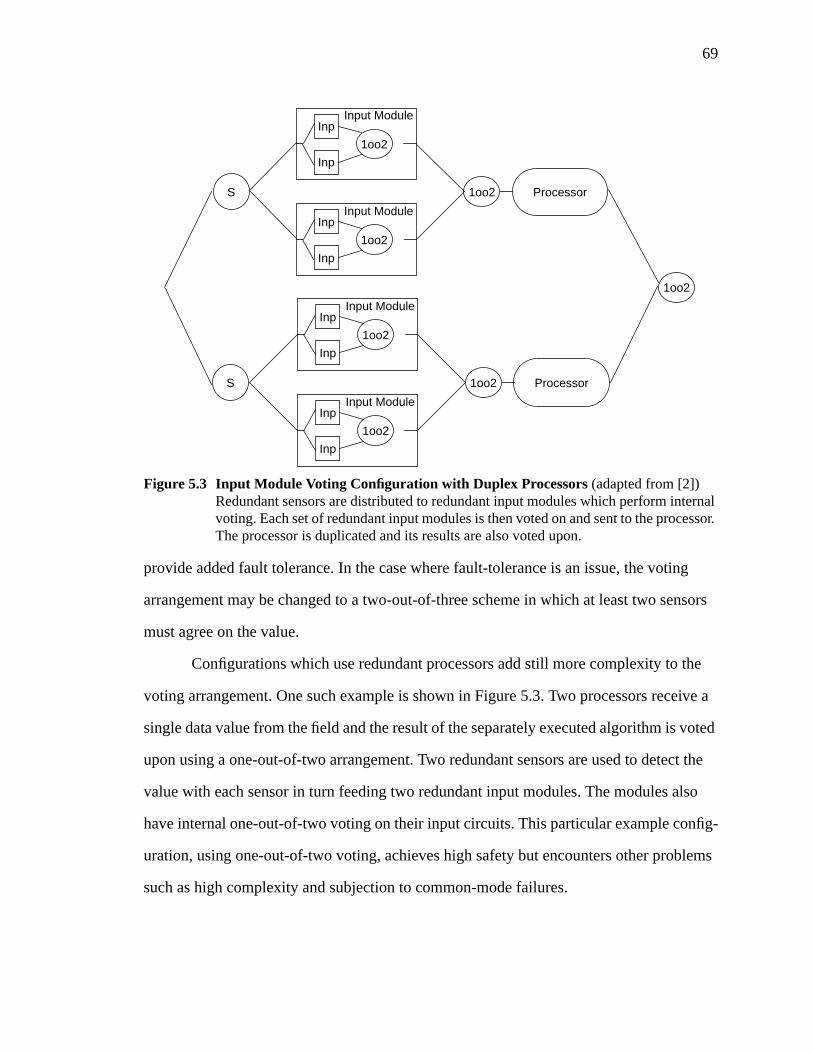
69
provide added fault tolerance. In the case where fault-tolerance is an issue, the voting
arrangement may be changed to a two-out-of-three scheme in which at least two sensors
must agree on the value.
Configurations which use redundant processors add still more complexity to the
voting arrangement. One such example is shown in Figure 5.3. Two processors receive a
single data value from the field and the result of the separately executed algorithm is voted
upon using a one-out-of-two arrangement. Two redundant sensors are used to detect the
value with each sensor in turn feeding two redundant input modules. The modules also
have internal one-out-of-two voting on their input circuits. This particular example config-
uration, using one-out-of-two voting, achieves high safety but encounters other problems
such as high complexity and subjection to common-mode failures.
Figure 5.3 Input Module Voting Configuration with Duplex Processors(adapted from [2])Redundant sensors are distributed to redundant input modules which perform internalvoting. Each set of redundant input modules is then voted on and sent to the processor.The processor is duplicated and its results are also voted upon.
1oo2
Inp
Inp
Input Module
1oo2
Inp
Inp
Input Module
1oo2 ProcessorS
1oo2
Inp
Inp
Input Module
1oo2
Inp
Inp
Input Module
S 1oo2 Processor
1oo2
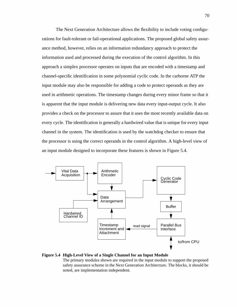
70
The Next Generation Architecture allows the flexibility to include voting configu-
rations for fault-tolerant or fail-operational applications. The proposed global safety assur-
ance method, however, relies on an information redundancy approach to protect the
information used and processed during the execution of the control algorithm. In this
approach a simplex processor operates on inputs that are encoded with a timestamp and
channel-specific identification in some polynomial cyclic code. In the carborne ATP the
input module may also be responsible for adding a code to protect operands as they are
used in arithmetic operations. The timestamp changes during every minor frame so that it
is apparent that the input module is delivering new data every input-output cycle. It also
provides a check on the processor to assure that it uses the most recently available data on
every cycle. The identification is generally a hardwired value that is unique for every input
channel in the system. The identification is used by the watchdog checker to ensure that
the processor is using the correct operands in the control algorithm. A high-level view of
an input module designed to incorporate these features is shown in Figure 5.4.
Figure 5.4 High-Level View of a Single Channel for an Input ModuleThe primary modules shown are required in the input module to support the proposedsafety assurance scheme in the Next Generation Architecture. The blocks, it should benoted, are implementation independent.
Vital DataAcquisition
HardwiredChannel ID
Parallel BusInterface
to/from CPU
ArithmeticEncoder
read signalTimestampIncrement andAttachment
DataArrangement
Cyclic CodeGenerator
Buffer
71
The vital data acquisition block represents the vital input circuit which interfaces
to the external sensors. An example of such a circuit was shown in Figure 5.1. The block
labeled data arrangement represents the function of positioning the sensor value, channel
identification, and timestamp in the proper format before encoding the entire information
word in the cyclic code. The timestamp incrementer shown responds to a read signal from
the processor as an input poll. The poll causes the timestamp to be incremented and new
data is constructed and placed in the buffer. Data for the current poll is delivered from the
buffer to the processor via the bus interface.
The blocks shown are generic pieces of the input module designed to meet the
requirements of the candidate global safety assurance method. Figure 5.4 shows only the
functions necessary in the input module; the blocks themselves are implementation inde-
pendent. The actual codes used, for example, are based on issues such as application
requirements, feasibility, and analyzability. The bus interface may be a commercially
available chip set, or a specialized semicustom design. The timestamp unit may be a sim-
ple single-chip state machine or a more elaborate circuit employing some self-checking
capability. The proposed scheme addresses the functions necessary in the input module
but does not restrict the implementation.
5.2 Role of Output Modules in Automatic Train Control Systems
Like the input modules, output modules play an important role in the ATC system,
primarily from a safety assurance viewpoint. Functionally, their only requirement is to
deliver data calculated during control algorithm processing to the field in a timely manner.
Generally the types of output signals delivered by the modules are vital in nature; they
must be correct for continued safe operation of the system. In currently installed micro-
processor-based ATC systems, output modules must deliver signals vital to the wayside
ATP functions. Future, more advanced systems will undoubtedly require a more varied set
of output signals, both vital and non-vital. The output modules are also key components of
the safety assurance of the system. They serve as the last defense against delivering unsafe
72
outputs, and are thus designed to incorporate a number of safety-related functions depend-
ing on the global safety assurance methodology.
5.2.1 Output Module Functional Requirements
The output modules in a microprocessor-based ATC system serve to interface dig-
ital representations of control signals from the processing elements to actuators and exter-
nal devices. Some output modules are also specially designed to interface to other
elements in the systems so that processors may share information necessary for proper
execution of the control algorithm. In addition, the set of outputs is often partitioned into a
vital and non-vital set. Signals controlling railway switches or braking, for example, are
considered vital, while some panel indications may be non-vital. In the wayside ATP out-
put signals may include [7], [28]:
• signal mechanism drive
• signal lamp drive
• switch control
• traffic and track circuit control
• bridge control on movable bridges
• railway grade crossings
• highway grade crossing warning controls
• switch heaters for melting snow
Wayside control outputs are as varied as sensor inputs. Many of the outputs may be repre-
sented with a single bit output value while others may require more variability.
The carborne ATP system also requires a mixture of different types of outputs,
including [28],[29]:
• throttle control
• brake setting or emergency braking
• directions to wayside ATP devices
• panel displays of calculated location or speed information
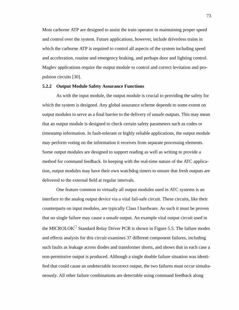
73
Most carborne ATP are designed to assist the train operator in maintaining proper speed
and control over the system. Future applications, however, include driverless trains in
which the carborne ATP is required to control all aspects of the system including speed
and acceleration, routine and emergency braking, and perhaps door and lighting control.
Maglev applications require the output module to control and correct levitation and pro-
pulsion circuits [30].
5.2.2 Output Module Safety Assurance Functions
As with the input module, the output module is crucial to providing the safety for
which the system is designed. Any global assurance scheme depends to some extent on
output modules to serve as a final barrier to the delivery of unsafe outputs. This may mean
that an output module is designed to check certain safety parameters such as codes or
timestamp information. In fault-tolerant or highly reliable applications, the output module
may perform voting on the information it receives from separate processing elements.
Some output modules are designed to support reading as well as writing to provide a
method for command feedback. In keeping with the real-time nature of the ATC applica-
tion, output modules may have their own watchdog timers to ensure that fresh outputs are
delivered to the external field at regular intervals.
One feature common to virtually all output modules used in ATC systems is an
interface to the analog output device via a vital fail-safe circuit. These circuits, like their
counterparts on input modules, are typically Class I hardware. As such it must be proven
that no single failure may cause a unsafe output. An example vital output circuit used in
the MICROLOK Standard Relay Driver PCB is shown in Figure 5.5. The failure modes
and effects analysis for this circuit examines 37 different component failures, including
such faults as leakage across diodes and transformer shorts, and shows that in each case a
non-permissive output is produced. Although a single double failure situation was identi-
fied that could cause an undetectable incorrect output, the two failures must occur simulta-
neously. All other failure combinations are detectable using command feedback along
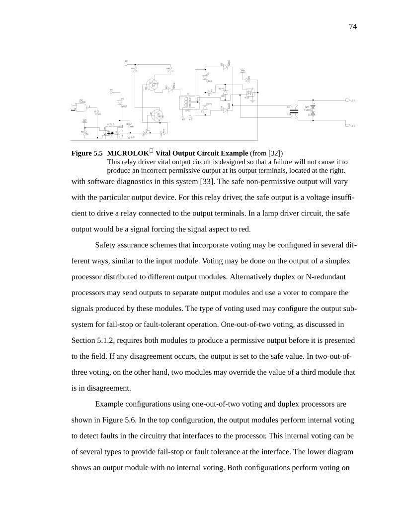
74
with software diagnostics in this system [33]. The safe non-permissive output will vary
with the particular output device. For this relay driver, the safe output is a voltage insuffi-
cient to drive a relay connected to the output terminals. In a lamp driver circuit, the safe
output would be a signal forcing the signal aspect to red.
Safety assurance schemes that incorporate voting may be configured in several dif-
ferent ways, similar to the input module. Voting may be done on the output of a simplex
processor distributed to different output modules. Alternatively duplex or N-redundant
processors may send outputs to separate output modules and use a voter to compare the
signals produced by these modules. The type of voting used may configure the output sub-
system for fail-stop or fault-tolerant operation. One-out-of-two voting, as discussed in
Section 5.1.2, requires both modules to produce a permissive output before it is presented
to the field. If any disagreement occurs, the output is set to the safe value. In two-out-of-
three voting, on the other hand, two modules may override the value of a third module that
is in disagreement.
Example configurations using one-out-of-two voting and duplex processors are
shown in Figure 5.6. In the top configuration, the output modules perform internal voting
to detect faults in the circuitry that interfaces to the processor. This internal voting can be
of several types to provide fail-stop or fault tolerance at the interface. The lower diagram
shows an output module with no internal voting. Both configurations perform voting on
Figure 5.5 MICROLOK Vital Output Circuit Example (from [32])This relay driver vital output circuit is designed so that a failure will not cause it toproduce an incorrect permissive output at its output terminals, located at the right.
75
the results generated by the two processors. The one-out-of-two voting after the output
modules may also be incorporated into the output module. The advantage of internal vot-
ing within the output module is that it provides a means for error containment; discrepan-
cies in processor outputs are detected before reaching the module outputs. This comes at
the cost of increased hardware overhead and complexity, however. Still another possibility
is to use redundant actuators rather than redundant output modules. This requires that the
actuators have the ability to vote in a fail-safe, or vital, manner.
Just as the Next Generation Architecture allows the use of hardware redundancy
and voting in the input modules, the same flexibility is allowed in the output modules. The
proposed global safety assurance method, as discussed in Section 5.1.2, uses a simplex
processor and a code-based approach which must be supported by the output modules.
Recall that data at the system inputs is encoded with a timestamp and unique identifica-
tion, in addition to a channel code to protect against corruptions due to noise. In some
applications arithmetic coding is also used.
Figure 5.6 Output Module Voting Configurations with Duplex Processors(adapted from [2])These configurations use varied internal voting structures in a duplex processing sys-tem with some external one-out-of-two voting device.
1oo2
Inp
Inp
Output Module
1oo2
Processor
1oo2
Inp
Inp
Output Module
Processor
Inp
Output Module
Processor
Processor Inp
Output Module
1-out-of-2 voting,
no internal voting,duplex output modules
duplex output modules
1oo2
76
When the processor computes a set of control outputs, it attaches a timestamp indi-
cating the current minor frame and an identification that is unique for every output channel
in the system. This information is also encoded in a cyclic code to protect it as it moves
through communication channels. When the output module receives an output it must per-
form several checks. The cyclic code is checked to ensure no data corruptions took place
en route to the module. The identification, which also may be encoded, is checked to
ensure that the output was indeed intended for the output channel at which it arrived. The
timestamp is verified as updated to the current input-output cycle value to prevent the use
of stale data. The output module may also include a watchdog timer that times out and
indicates an error if it is not updated at a regular frequency. This prevents a hung processor
from causing control outputs to remain unchanged for too long as dictated by the real-time
requirements of the system.
The high-level block diagram of a channel in an output module is shown in Figure
5.7. Consistent with the design of the input module, the output module uses the write sig-
nal from the processor as a poll. When it is polled each input-output cycle the output mod-
ule compares the timestamp in the received data with its own copy and then increments its
copy to get ready for the next cycle. The watchdog timer uses the poll to reset its count-
down timer. If the poll is not received at specified intervals, the timer will time out and
generate an error signal. All of the checking blocks generate a signal that indicates
whether the check was successful. These signals may be different for each block.
The task of the error signal generators is to convert these varied signals into a form
compatible with a vital Class I circuit called the vital power supply in the diagram. An
example of such a signal is a waveform with a particular frequency and duty cycle. The
vital power supply receives the analog error signals and, if they match the predetermined
pattern, power to the external output devices is maintained. A detected failure causes
power to be dropped which would result in a safe output for an electromechanical relay-
based switch or signal lamp, for example. In this respect, vital power supply may be better
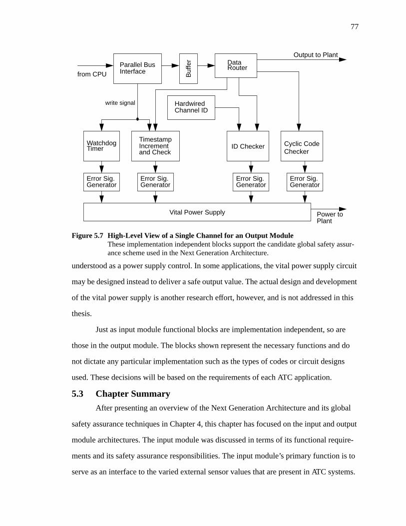
77
understood as a power supply control. In some applications, the vital power supply circuit
may be designed instead to deliver a safe output value. The actual design and development
of the vital power supply is another research effort, however, and is not addressed in this
thesis.
Just as input module functional blocks are implementation independent, so are
those in the output module. The blocks shown represent the necessary functions and do
not dictate any particular implementation such as the types of codes or circuit designs
used. These decisions will be based on the requirements of each ATC application.
5.3 Chapter Summary
After presenting an overview of the Next Generation Architecture and its global
safety assurance techniques in Chapter 4, this chapter has focused on the input and output
module architectures. The input module was discussed in terms of its functional require-
ments and its safety assurance responsibilities. The input module’s primary function is to
serve as an interface to the varied external sensor values that are present in ATC systems.
Figure 5.7 High-Level View of a Single Channel for an Output ModuleThese implementation independent blocks support the candidate global safety assur-ance scheme used in the Next Generation Architecture.
HardwiredChannel ID
Parallel BusInterface
Cyclic CodeChecker
Buf
fer
from CPU
DataRouter
TimestampIncrementand Check
WatchdogTimer
write signal
ID Checker
Error Sig.Generator
Error Sig.Generator
Error Sig.Generator
Error Sig.Generator
Vital Power Supply Power toPlant
Output to Plant
78
The types of input values differ between the wayside ATP, carborne ATP, and advanced
maglev applications. Some sensors may be represented in the microprocessor-based sys-
tem as single-bit values while others may require complex A/D conversion at the inter-
face.
As far as safety assurance is concerned, the input module must support whatever
scheme is used by the system. A common feature of most input modules, however, is the
inclusion of a vital Class I circuit that actually senses and converts the data from the field.
An example of such a circuit was discussed in this chapter. Various voting schemes were
also presented in which input modules may be replicated, redundant sensors may be used,
or the system may employ some combination of these. The final input module architecture
presented is designed to support the proposed global safety assurance scheme presented in
Chapter 4. To this end, the input module must perform several functions that include
encoding for arithmetic processing and channel transmission, attaching a unique identifi-
cation to each value, and attaching a timestamp to data to provide some assurance that the
data is fresh. Each of these functions is completely implementation independent; the can-
didate safety assurance method does not restrict the types of codes used or the techniques
used in designing the circuits, for example. These issues are dependent on the particular
ATC application and its requirements.
The discussion of output module architecture follows closely with that of the input
module. The output module’s main function is to interface to various external output
devices. Typically, the output may be represented as a single logic value that activates or
de-activates an output device. This is true for the carborne and wayside ATPs, but the
maglev application may require that the output module handle more complex devices. As
with the input module, the output module plays a crucial role in the global safety assur-
ance scheme. The output module is the last defense against the delivery of an unsafe out-
put to the system. Most output modules must have a fail-safe Class I circuit which will not
produce an unsafe output in the case of a component failure. An example from an actual
79
system is presented. Voting arrangements are also possible at the output module with sim-
ilar options to those at the input module. The proposed safety assurance method uses a
simplex processor and information redundancy which must be handled by the output mod-
ule. An architecture to meet these requirements was presented in which the output module
performs several checks on incoming data including examination of the channel code,
identification, timestamp, and time of delivery through a watchdog timer. It is envisioned
that these checks will feed a vital power supply which will cut power to the output device
if all of the checks are not successful. The design of this circuit is not presented in this the-
sis. The decision on which checks are necessary is based on the adopted error model [27].
The intent of the checking scheme is to best meet the requirements imposed by the error
model in the simplest way.
80
Chapter 6Development of a Software Prototype and Input and
Output Module Emulator
To provide a proof-of-concept and demonstration of the Next Generation Architec-
ture and the candidate global safety assurance method, a prototype environment and
design was developed. This required that a specific implementation be adopted for the
functional blocks presented in Chapter 5. This chapter presents the current state of the
architecture as developed for prototype purposes. The prototype is designed for the way-
side ATP application and includes a small sample railway application. Also discussed here
are details of the safety assurance scheme including the specific codes and checking tech-
niques used for this first version. The prototype is also the result of the efforts of many
individuals. Section 6.2 describes briefly the implementation of each component of the
prototype and provides references to documents with the full details where possible.
In addition, some discussion of the prototyping environment developed for evalu-
ating the system is provided. The primary focus of this chapter, however, is the design and
implementation of a software emulation of the input and output modules for the prototype.
The input and output emulation was designed to execute on a single processor and uses a
workstation to simulate the external field input and output values. Hardware descriptions
of major functional blocks of the input and output modules are also presented. These
descriptions are written in VHDL so that some view of the hardware structure is available.
6.1 Implementation of Global Safety Assurance for a Wayside ATP
The first version of the Next Generation Architecture prototype includes a safety
assurance scheme modeled closely after the method described in Section 4.4. It is
designed for use with a simplex processing system and uses information redundancy as its
primary safety assurance technique. Features such as channel codes, timestamps, and
operand identification are included in the prototype scheme.
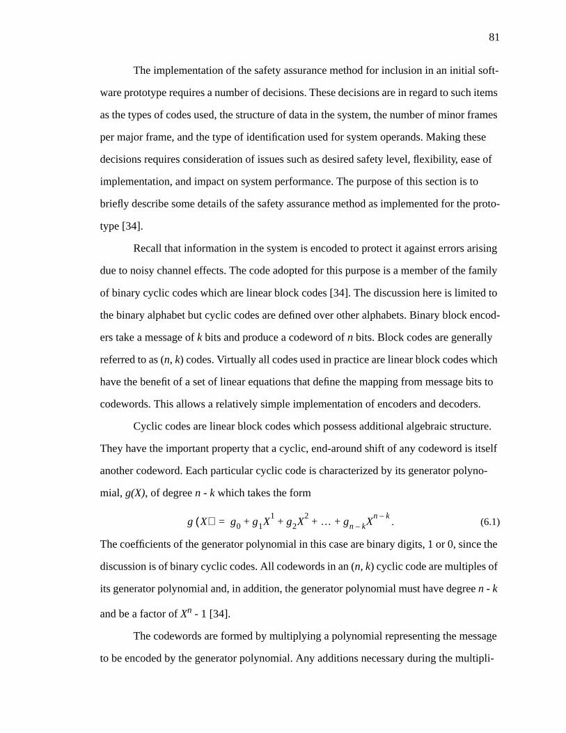
81
The implementation of the safety assurance method for inclusion in an initial soft-
ware prototype requires a number of decisions. These decisions are in regard to such items
as the types of codes used, the structure of data in the system, the number of minor frames
per major frame, and the type of identification used for system operands. Making these
decisions requires consideration of issues such as desired safety level, flexibility, ease of
implementation, and impact on system performance. The purpose of this section is to
briefly describe some details of the safety assurance method as implemented for the proto-
type [34].
Recall that information in the system is encoded to protect it against errors arising
due to noisy channel effects. The code adopted for this purpose is a member of the family
of binary cyclic codes which are linear block codes [34]. The discussion here is limited to
the binary alphabet but cyclic codes are defined over other alphabets. Binary block encod-
ers take a message ofk bits and produce a codeword ofn bits. Block codes are generally
referred to as (n, k) codes. Virtually all codes used in practice are linear block codes which
have the benefit of a set of linear equations that define the mapping from message bits to
codewords. This allows a relatively simple implementation of encoders and decoders.
Cyclic codes are linear block codes which possess additional algebraic structure.
They have the important property that a cyclic, end-around shift of any codeword is itself
another codeword. Each particular cyclic code is characterized by its generator polyno-
mial, g(X), of degreen - k which takes the form
. (6.1)
The coefficients of the generator polynomial in this case are binary digits, 1 or 0, since the
discussion is of binary cyclic codes. All codewords in an (n, k) cyclic code are multiples of
its generator polynomial and, in addition, the generator polynomial must have degreen - k
and be a factor ofXn - 1 [34].
The codewords are formed by multiplying a polynomial representing the message
to be encoded by the generator polynomial. Any additions necessary during the multipli-
g X( ) g0 g1X1
g2X2 … gn k– X
n k–+ + + +=
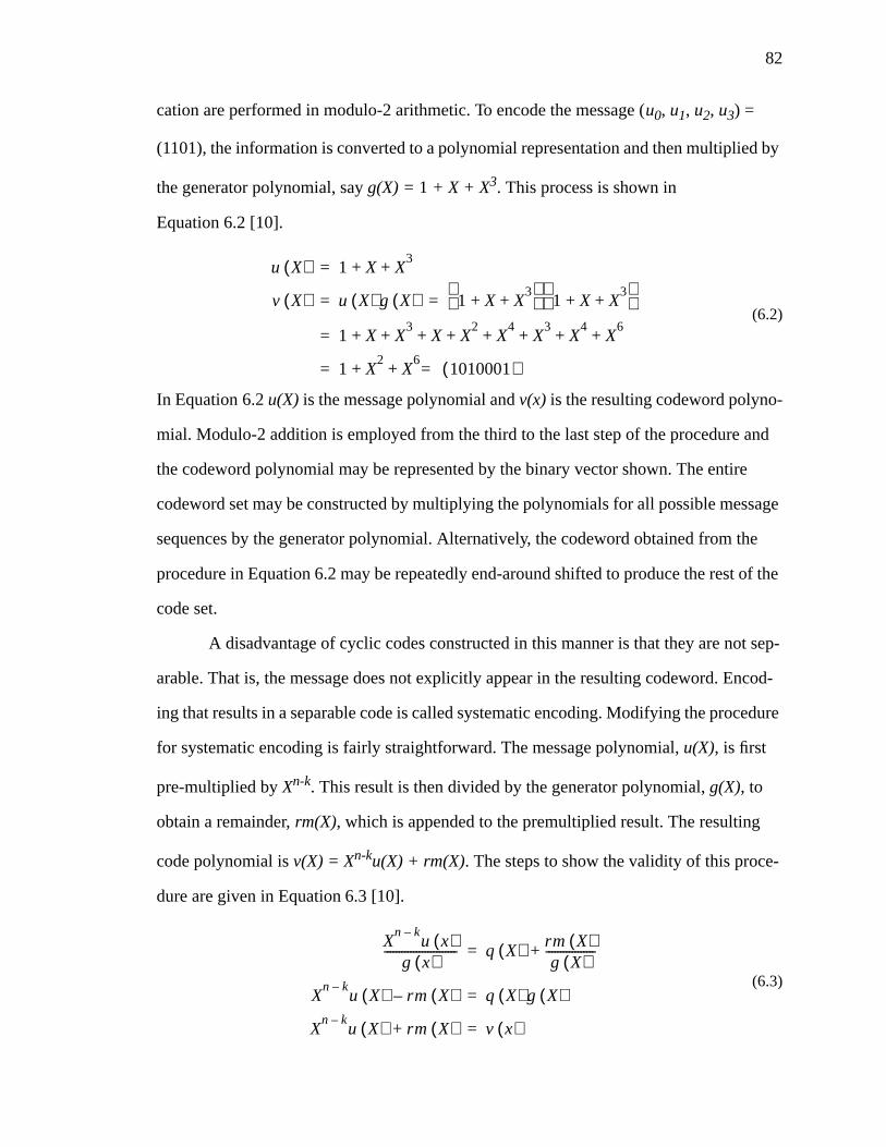
82
cation are performed in modulo-2 arithmetic. To encode the message (u0, u1, u2, u3) =
(1101), the information is converted to a polynomial representation and then multiplied by
the generator polynomial, sayg(X) = 1 + X + X3. This process is shown in
Equation 6.2 [10].
(6.2)
In Equation 6.2u(X) is the message polynomial andv(x) is the resulting codeword polyno-
mial. Modulo-2 addition is employed from the third to the last step of the procedure and
the codeword polynomial may be represented by the binary vector shown. The entire
codeword set may be constructed by multiplying the polynomials for all possible message
sequences by the generator polynomial. Alternatively, the codeword obtained from the
procedure in Equation 6.2 may be repeatedly end-around shifted to produce the rest of the
code set.
A disadvantage of cyclic codes constructed in this manner is that they are not sep-
arable. That is, the message does not explicitly appear in the resulting codeword. Encod-
ing that results in a separable code is called systematic encoding. Modifying the procedure
for systematic encoding is fairly straightforward. The message polynomial,u(X), is first
pre-multiplied byXn-k. This result is then divided by the generator polynomial,g(X), to
obtain a remainder,rm(X), which is appended to the premultiplied result. The resulting
code polynomial isv(X) = Xn-ku(X) + rm(X). The steps to show the validity of this proce-
dure are given in Equation 6.3 [10].
(6.3)
u X( ) 1 X X3
+ +=
v X( ) u X( ) g X( ) 1 X X3
+ +
1 X X3
+ +
= =
1 X X3
X X2
X4
X3
X4
X6
+ + + + + + + +=
1 X2
X6
1010001( )=+ +=
Xn k–
u x( )g x( )
------------------------- q X( ) rm X( )g X( )
-----------------+=
Xn k–
u X( ) rm X( )– q X( ) g X( )=
Xn k–
u X( ) rm X( )+ v x( )=
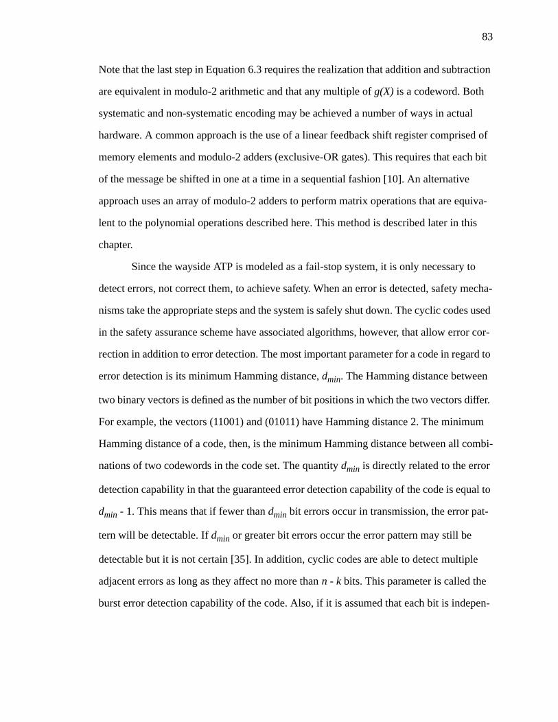
83
Note that the last step in Equation 6.3 requires the realization that addition and subtraction
are equivalent in modulo-2 arithmetic and that any multiple ofg(X) is a codeword. Both
systematic and non-systematic encoding may be achieved a number of ways in actual
hardware. A common approach is the use of a linear feedback shift register comprised of
memory elements and modulo-2 adders (exclusive-OR gates). This requires that each bit
of the message be shifted in one at a time in a sequential fashion [10]. An alternative
approach uses an array of modulo-2 adders to perform matrix operations that are equiva-
lent to the polynomial operations described here. This method is described later in this
chapter.
Since the wayside ATP is modeled as a fail-stop system, it is only necessary to
detect errors, not correct them, to achieve safety. When an error is detected, safety mecha-
nisms take the appropriate steps and the system is safely shut down. The cyclic codes used
in the safety assurance scheme have associated algorithms, however, that allow error cor-
rection in addition to error detection. The most important parameter for a code in regard to
error detection is its minimum Hamming distance,dmin. The Hamming distance between
two binary vectors is defined as the number of bit positions in which the two vectors differ.
For example, the vectors (11001) and (01011) have Hamming distance 2. The minimum
Hamming distance of a code, then, is the minimum Hamming distance between all combi-
nations of two codewords in the code set. The quantitydmin is directly related to the error
detection capability in that the guaranteed error detection capability of the code is equal to
dmin - 1. This means that if fewer thandmin bit errors occur in transmission, the error pat-
tern will be detectable. Ifdmin or greater bit errors occur the error pattern may still be
detectable but it is not certain [35]. In addition, cyclic codes are able to detect multiple
adjacent errors as long as they affect no more thann - k bits. This parameter is called the
burst error detection capability of the code. Also, if it is assumed that each bit is indepen-
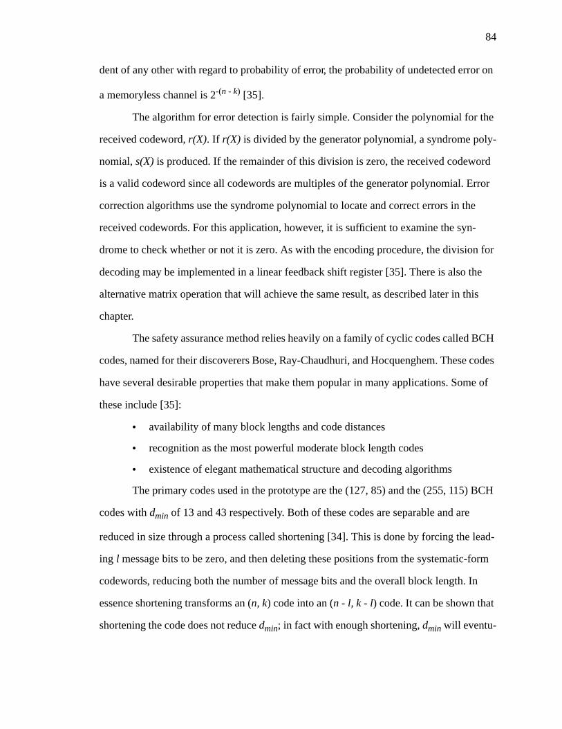
84
dent of any other with regard to probability of error, the probability of undetected error on
a memoryless channel is 2-(n - k) [35].
The algorithm for error detection is fairly simple. Consider the polynomial for the
received codeword,r(X). If r(X) is divided by the generator polynomial, a syndrome poly-
nomial,s(X) is produced. If the remainder of this division is zero, the received codeword
is a valid codeword since all codewords are multiples of the generator polynomial. Error
correction algorithms use the syndrome polynomial to locate and correct errors in the
received codewords. For this application, however, it is sufficient to examine the syn-
drome to check whether or not it is zero. As with the encoding procedure, the division for
decoding may be implemented in a linear feedback shift register [35]. There is also the
alternative matrix operation that will achieve the same result, as described later in this
chapter.
The safety assurance method relies heavily on a family of cyclic codes called BCH
codes, named for their discoverers Bose, Ray-Chaudhuri, and Hocquenghem. These codes
have several desirable properties that make them popular in many applications. Some of
these include [35]:
• availability of many block lengths and code distances
• recognition as the most powerful moderate block length codes
• existence of elegant mathematical structure and decoding algorithms
The primary codes used in the prototype are the (127, 85) and the (255, 115) BCH
codes withdmin of 13 and 43 respectively. Both of these codes are separable and are
reduced in size through a process called shortening [34]. This is done by forcing the lead-
ing l message bits to be zero, and then deleting these positions from the systematic-form
codewords, reducing both the number of message bits and the overall block length. In
essence shortening transforms an (n, k) code into an (n - l, k - l) code. It can be shown that
shortening the code does not reducedmin; in fact with enough shortening,dmin will eventu-
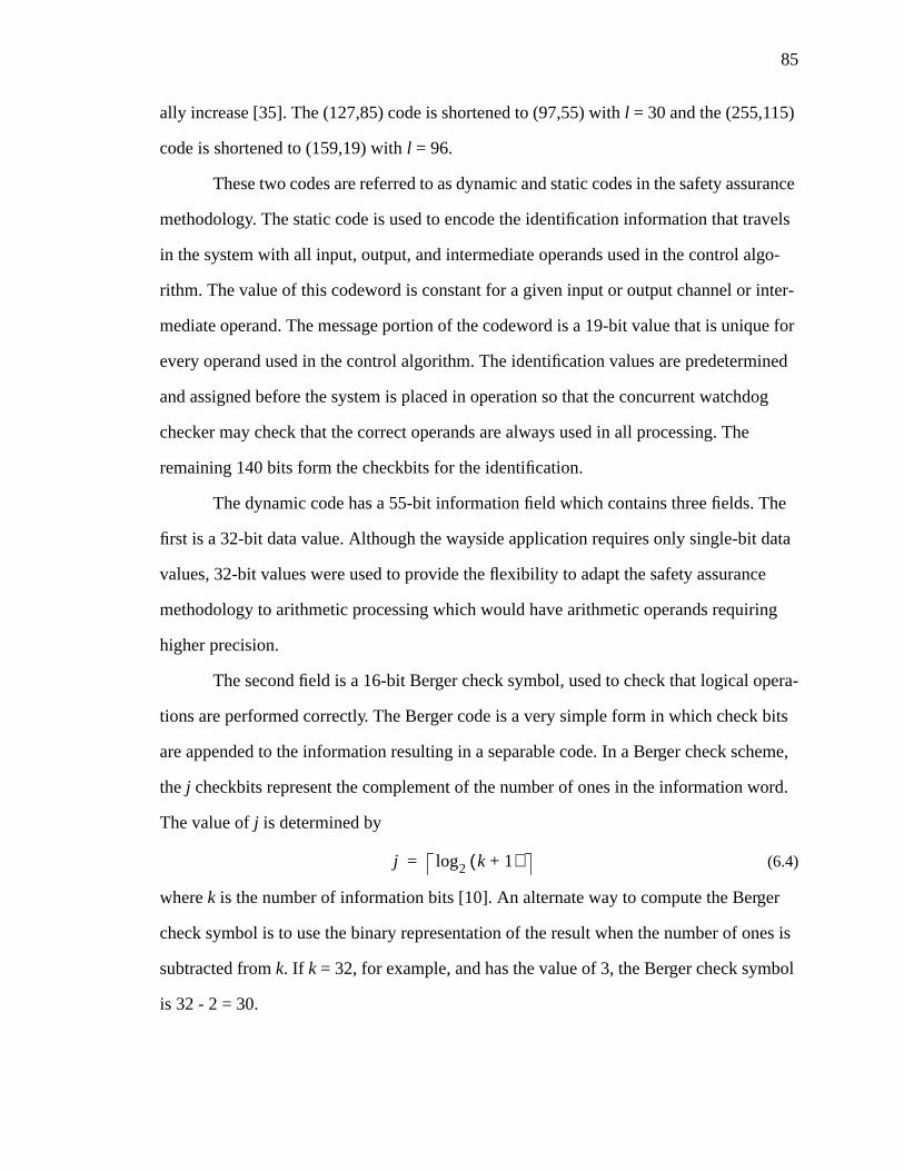
85
ally increase [35]. The (127,85) code is shortened to (97,55) withl = 30 and the (255,115)
code is shortened to (159,19) withl = 96.
These two codes are referred to as dynamic and static codes in the safety assurance
methodology. The static code is used to encode the identification information that travels
in the system with all input, output, and intermediate operands used in the control algo-
rithm. The value of this codeword is constant for a given input or output channel or inter-
mediate operand. The message portion of the codeword is a 19-bit value that is unique for
every operand used in the control algorithm. The identification values are predetermined
and assigned before the system is placed in operation so that the concurrent watchdog
checker may check that the correct operands are always used in all processing. The
remaining 140 bits form the checkbits for the identification.
The dynamic code has a 55-bit information field which contains three fields. The
first is a 32-bit data value. Although the wayside application requires only single-bit data
values, 32-bit values were used to provide the flexibility to adapt the safety assurance
methodology to arithmetic processing which would have arithmetic operands requiring
higher precision.
The second field is a 16-bit Berger check symbol, used to check that logical opera-
tions are performed correctly. The Berger code is a very simple form in which check bits
are appended to the information resulting in a separable code. In a Berger check scheme,
the j checkbits represent the complement of the number of ones in the information word.
The value ofj is determined by
(6.4)
wherek is the number of information bits [10]. An alternate way to compute the Berger
check symbol is to use the binary representation of the result when the number of ones is
subtracted fromk. If k = 32, for example, and has the value of 3, the Berger check symbol
is 32 - 2 = 30.
j log2 k 1+( )=
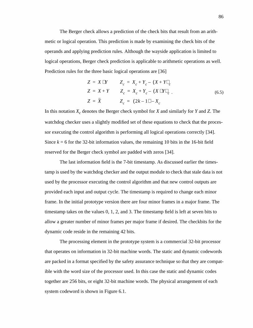
86
The Berger check allows a prediction of the check bits that result from an arith-
metic or logical operation. This prediction is made by examining the check bits of the
operands and applying prediction rules. Although the wayside application is limited to
logical operations, Berger check prediction is applicable to arithmetic operations as well.
Prediction rules for the three basic logical operations are [36]
. (6.5)
In this notationXc denotes the Berger check symbol forX and similarly forY andZ. The
watchdog checker uses a slightly modified set of these equations to check that the proces-
sor executing the control algorithm is performing all logical operations correctly [34].
Sincek = 6 for the 32-bit information values, the remaining 10 bits in the 16-bit field
reserved for the Berger check symbol are padded with zeros [34].
The last information field is the 7-bit timestamp. As discussed earlier the times-
tamp is used by the watchdog checker and the output module to check that stale data is not
used by the processor executing the control algorithm and that new control outputs are
provided each input and output cycle. The timestamp is required to change each minor
frame. In the initial prototype version there are four minor frames in a major frame. The
timestamp takes on the values 0, 1, 2, and 3. The timestamp field is left at seven bits to
allow a greater number of minor frames per major frame if desired. The checkbits for the
dynamic code reside in the remaining 42 bits.
The processing element in the prototype system is a commercial 32-bit processor
that operates on information in 32-bit machine words. The static and dynamic codewords
are packed in a format specified by the safety assurance technique so that they are compat-
ible with the word size of the processor used. In this case the static and dynamic codes
together are 256 bits, or eight 32-bit machine words. The physical arrangement of each
system codeword is shown in Figure 6.1.
Z X Y⋅= Zc Xc Yc X Y+( ) c–+=
Z X Y+= Zc Xc Yc X Y⋅( ) c–+=
Z X= Zc 2k 1–( ) Xc–=
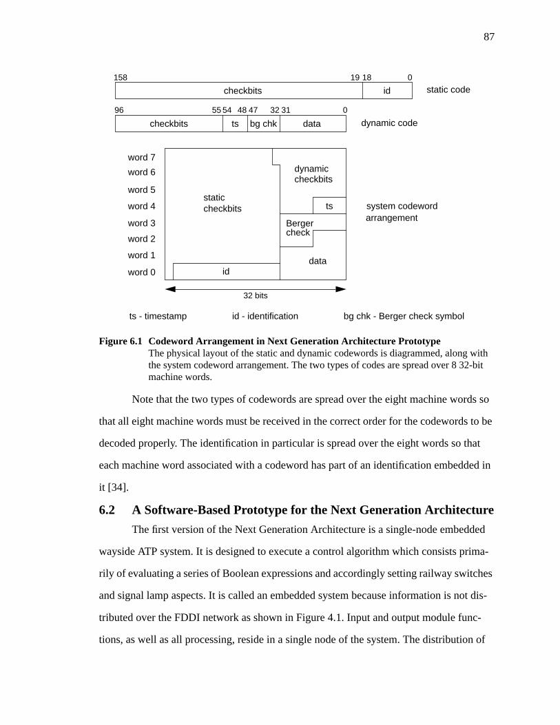
87
Note that the two types of codewords are spread over the eight machine words so
that all eight machine words must be received in the correct order for the codewords to be
decoded properly. The identification in particular is spread over the eight words so that
each machine word associated with a codeword has part of an identification embedded in
it [34].
6.2 A Software-Based Prototype for the Next Generation Architecture
The first version of the Next Generation Architecture is a single-node embedded
wayside ATP system. It is designed to execute a control algorithm which consists prima-
rily of evaluating a series of Boolean expressions and accordingly setting railway switches
and signal lamp aspects. It is called an embedded system because information is not dis-
tributed over the FDDI network as shown in Figure 4.1. Input and output module func-
tions, as well as all processing, reside in a single node of the system. The distribution of
Figure 6.1 Codeword Arrangement in Next Generation Architecture PrototypeThe physical layout of the static and dynamic codewords is diagrammed, along withthe system codeword arrangement. The two types of codes are spread over 8 32-bitmachine words.
018158 19
static codeidcheckbits
0313247485496 55
dynamic codedatabg chktscheckbits
32 bits
word 7
word 6
word 5
word 4
word 3
word 2
word 1
word 0
dynamiccheckbits
ts
dataid
staticcheckbits system codeword
arrangementBergercheck
ts - timestamp id - identification bg chk - Berger check symbol
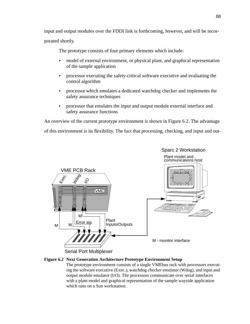
88
input and output modules over the FDDI link is forthcoming, however, and will be incor-
porated shortly.
The prototype consists of four primary elements which include:
• model of external environment, or physical plant, and graphical representationof the sample application
• processor executing the safety-critical software executive and evaluating thecontrol algorithm
• processor which emulates a dedicated watchdog checker and implements thesafety assurance techniques
• processor that emulates the input and output module external interface andsafety assurance functions
An overview of the current prototype environment is shown in Figure 6.2. The advantage
of this environment is its flexibility. The fact that processing, checking, and input and out-
Figure 6.2 Next Generation Architecture Prototype Environment SetupThe prototype environment consists of a single VMEbus rack with processors execut-ing the software executive (Exec.), watchdog checker emulator (Wdog), and input andoutput module emulator (I/O). The processors communicate over serial interfaceswith a plant model and graphical representation of the sample wayside applicationwhich runs on a Sun workstation.
VME
Serial Port Multiplexer
VME PCB Rack
Sparc 2 WorkstationPlant model andcommunications host
M M
M
Error sig. PlantInputs/Outputs
M - monitor interface
Exec
.
Wdo
g
I/O
89
put interfacing is done in software implies that the system may be modified rapidly as the
design progresses. The use of multiple parallel backplane buses connected via FDDI links
allow the simulation and testing of distributed fail-safe and fault-tolerant schemes, as well
as multiprocessing. The choice of a standard parallel backplane means that many different
types of COTS processor or network interface PCBs may be used. This environment does
not tie the user to any particular processor family, for example.
Although the current version of the prototype is intended to be a proof-of-concept
for a simplex processing system with a code-based approach to safety assurance, there is
no reason why redundant processing and voting could not be implemented and evaluated.
The rapid prototyping capability arises from the fact that modules may be emulated in
software and the elements for multiple system configurations exist and need only be cus-
tomized through software. If the intent is to build semicustom hardware for input and out-
put modules, for example, this environment may not provide an entirely accurate estimate
of performance parameters or hardware complexity. It is, however, extremely useful to
gauge the feasibility of safety assurance and functional algorithms and provides an envi-
ronment for gathering statistical data to estimate dependability parameters.
6.2.1 Prototype Environment Details
This section is intended to give a brief description of some details of the prototype
environment developed for the initial version of the Next Generation Architecture. Some
specifics regarding such items as the types of processors, development software, and inter-
facing devices used are provided, along with some vendor information.
Figure 4.1 showed a high level view of the architecture in which each node con-
sists of a parallel backplane bus. The prototype architecture adopts the Versamodule Euro-
card bus (VMEbus) as its parallel backplane. The VMEbus is a mature, popular standard
adopted by both the Institute of Electrical and Electronics Engineers (IEEE) and ANSI. It
is a non-multiplexed bus designed to be a fairly generic and flexible standard for commu-
nication between 8-, 16-, and 32-bit devices. VMEbus data transfers are asynchronous and
90
most use an interlocking protocol where all data transfers require acknowledgments. In
addition to normal read and write operations (up to 32 bits at a time), VMEbus also sup-
ports block reads and writes (one to 256 bytes at a time), and read-modify-write bus cycles
which are very useful in multiprocessing applications. Bus arbitration occurs at two levels.
The first is a priority scheme which may be fixed or dynamic. In addition a module’s slot
position also defines its priority since the bus grant signal is daisy-chained. Interrupts are
supported on seven interrupt request lines and the bus may have multiple interrupt han-
dlers so that processors executing different tasks may handle different types of interrupts
[37]. The primary reasons for choosing the VMEbus standard are its maturity and the wide
variety of COTS hardware available. A multitude of COTS processing modules, network
interfaces, and development tools currently exist for the VMEbus. The VMEbus back-
plane used in the prototype is a 12-slot rack manufactured by Electronic Solutions.
Each processor module on the VMEbus is a Motorola 68040 running at 25 mega-
hertz (MHz). The processor resides on a commercial processor PCB manufactured by
Heurikon Corporation. The Heurikon processor PCB is a single board computer that
includes two RS-232 serial interfaces, a built-in real-time clock, and a corebus expansion
connector for custom modules. Its memory facilities include 2 megabytes (MB) of parity-
checking RAM, 8 kilobytes (KB) of electrically erasable programmable read-only mem-
ory (EEPROM), and space for a 1 MB programmable read-only memory (PROM) chip
[38]. Interfacing and development is done through a PROM monitor which provides an
environment for downloading and executing programs. The PROM monitor communi-
cates via one of the serial interfaces to a host terminal.
Interaction and monitoring of the prototype is done through a Sun SPARCstation 2
workstation which communicates over several serial lines to the various processor PCBs.
The workstation serves as the development platform for all programs including the safety-
critical real-time executive, watchdog checker emulator, and input and output module
emulator. Software development for the executive is done on the workstation using a vali-
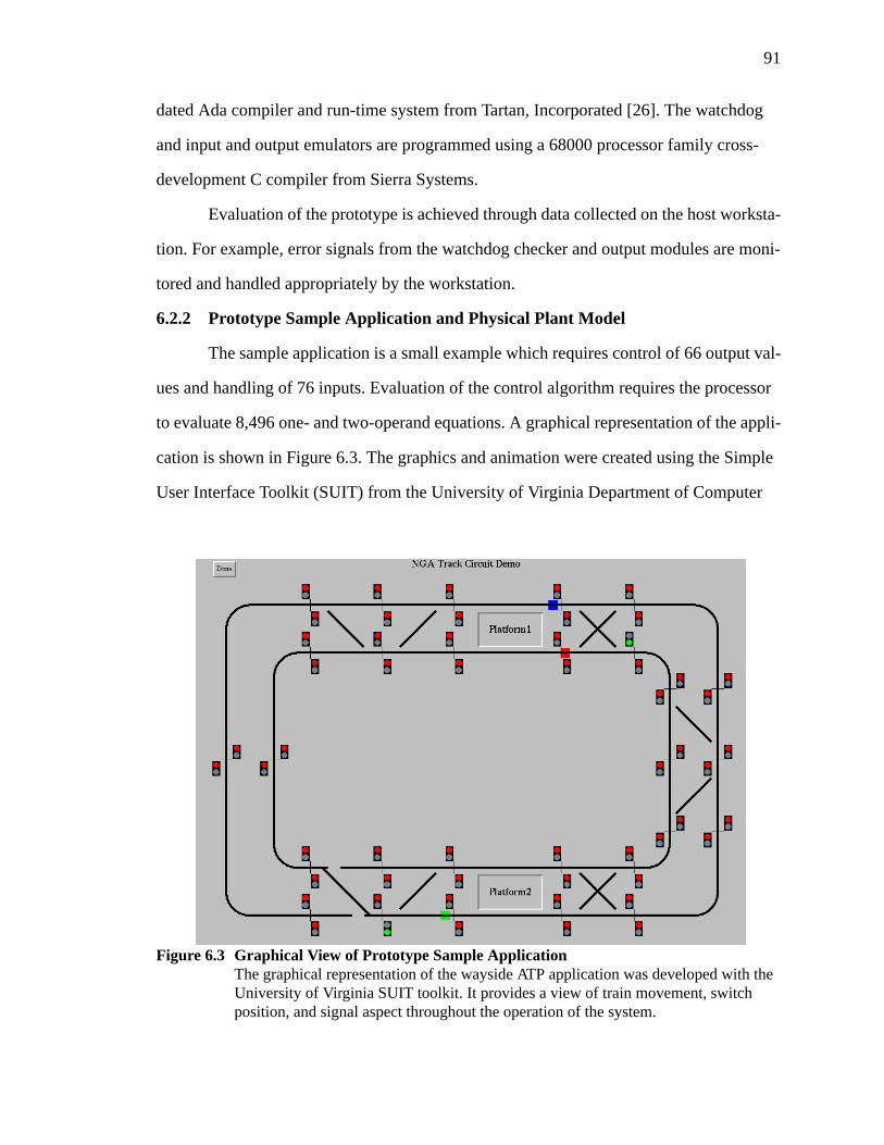
91
dated Ada compiler and run-time system from Tartan, Incorporated [26]. The watchdog
and input and output emulators are programmed using a 68000 processor family cross-
development C compiler from Sierra Systems.
Evaluation of the prototype is achieved through data collected on the host worksta-
tion. For example, error signals from the watchdog checker and output modules are moni-
tored and handled appropriately by the workstation.
6.2.2 Prototype Sample Application and Physical Plant Model
The sample application is a small example which requires control of 66 output val-
ues and handling of 76 inputs. Evaluation of the control algorithm requires the processor
to evaluate 8,496 one- and two-operand equations. A graphical representation of the appli-
cation is shown in Figure 6.3. The graphics and animation were created using the Simple
User Interface Toolkit (SUIT) from the University of Virginia Department of Computer
Figure 6.3 Graphical View of Prototype Sample ApplicationThe graphical representation of the wayside ATP application was developed with theUniversity of Virginia SUIT toolkit. It provides a view of train movement, switchposition, and signal aspect throughout the operation of the system.

92
Science [39]. The application consists of three trains, represented by colored blocks, trav-
eling on two track loops1. The trains lock in routes from one platform to another and the
control algorithm sets the control points to assure that no more than one train ever occu-
pies a block of track. Thus, the system is a fixed-block application where track segments
are divided by the small vertical lines. The graphical interface was developed by the
research group solely for demonstration purposes. It allows an observer to view the move-
ment of trains in the system and the dynamic setting of switches and signals as the trains
progress. Braking and acceleration are not simulated in the graphical representation. It is
simplified so that trains will stop as soon as they reach a signal that is red and will start
again at their maximum speed when permitted to proceed. The system is modeled to allow
trains to have different relative velocities, however.
The physical plant model communicates with the prototype through a serial inter-
face as shown in Figure 6.2. Input and output values from the model are stored in text files
on the workstation such that logical values are represented by ‘0’ and ‘1’ characters.
When the plant model is ready to communicate with the control system, it sends a signal
to the input module emulator and then waits for the control outputs to be delivered. Imme-
diately after receiving the outputs, the plant model sends a new set of inputs to the input
module emulator which are then processed by the input module and sent to the executive
for use in the control algorithm.
The plant model has a component called an oracle which is the set of outputs that
is expected for each set of inputs as dictated by the application equations. The oracle is
developed using a different representation of the Boolean expressions than that used in the
control system executive. It is considered perfect and is used by the plant model as a check
that a correct set of outputs was received. The oracle check is analogous to early tests that
were performed on microprocessor-based interlocking control systems. The microproces-
1. The graphical interface and physical plant model was developed and implemented by D.T.Smith. Boolean expressions for the wayside sample application were derived by T.A. DeLong.Formal documentation of these efforts is not available.
93
sor-based system was set up alongside a traditional relay-based system which was actually
driving the switches and signals. This allowed an easy comparison of the control outputs
generated by each system to ensure that they were equivalent [7]. The relay-driven system
in this example is the oracle. The plant model compares the oracle results against the out-
puts received from the control system and indicates any discrepancies. The outputs are
then applied to the physical plant and train, switch, and signal positions are updated.
The physical plant also incorporates a feature that roughly emulates the function of
the vital power supply discussed in Section 5.2.2. When the watchdog emulator detects an
error, it sends an error signal to the plant model through its dedicated serial link. This link
is continuously monitored by the plant model and when an error signal is detected, all sig-
nals are turned red (non-permissive) and the last switch positions are retained until the
simulation is restarted. This function may be viewed as the removal of power by a vital
power supply. Although the vital power supply was discussed in the context of the output
modules in Section 5.2.2, it is simulated here as part of the watchdog checker since it
would have a similar circuit.
6.2.3 Initial Version of a Safety-Critical Software Executive
The first version of the safety-critical software executive incorporates many of the
features envisioned for the final architecture (see Section 4.3). It essentially serves as the
engine for the overall control system. The basic frame-based timing specification is imple-
mented with each task executed at a fixed, predetermined frequency. In addition, the exec-
utive is implemented in Ada using such guidelines as static memory allocation and static
distribution of tasks [26]. The major tasks of the executive follow a set sequence during
each input-output cycle, or minor frame, that includes:
• delivery of output codewords calculated during the previous minor frame overthe VMEbus to the output module emulator
• reading of input codewords over the VMEbus from the input module emulator
• calculating application equations with new inputs to produce new encodedcontrol outputs
94
• delivery of results array which includes all input operands, intermediate oper-ands, output results, and operations performed, to the watchdog checker emu-lator
• repeat cycle
Each of the emulation devices contains fixed-size memory buffers which are memory-
mapped in the extended VMEbus address space from the viewpoint of the executive. Thus
input modules, output modules, and the watchdog checker appear simply as memory-
mapped devices allowing some degree of transparency.
The output codewords are encoded by the executive as they are calculated in the
same format shown in Figure 6.1. The timestamp attached reflects the cycle in which the
output should be delivered, not the current cycle. Also, outputs that are delayed through
output filtering are stored and queued for delivery in a later cycle. This storage is not an
explicit function of the executive. Such outputs are delayed in the control algorithm equa-
tions by multiple state variable assignments. Before reading inputs, the executive must
update its global timestamp value and it is also responsible for initializing the watchdog
checker before executing the calculations. The delivery of the results array is somewhat a
departure from truly concurrent error detection. A hardware-based watchdog checker
could check each operation as it is performed by the executive processor. The software
implementation forces some concession due to performance limitation; checking is done
every minor frame in the prototype system, instead of every operation.
The prototype executive uses its on-board real-time clock to assure that all tasks
are completed in their allotted time. If all tasks are not finished by the time the executive
receives the next timing interrupt from the processor PCB, the executive indicates that a
frame overrun has occurred [26]. In an actual system a violation of the static cycle would
indicate failure to meet the real-time deadline and would result in a safe shutdown. The
current implementation does not cause a system shutdown in the ATC simulation but does
provide a visual indication of frame overrun occurrence.
95
The main features not included in the initial version of the executive are the tasks
that handle distributed processing and non-critical tasks. The distributed processing tasks
handle communication of input and output codewords over the FDDI network and will be
included in the next version of the executive. Also diagnostic and other non-critical tasks
have not yet been identified for inclusion in the executive [26].
6.2.4 Software Emulation of the Watchdog Checker
The watchdog checker is intended to be a dedicated hardware unit that concur-
rently checks the execution of the executive processor after each operation it performs. As
discussed in Section 4.4, the watchdog is responsible for checking codeword validity, data
identification, and timestamp information to detect errors in classes dictated by a given
error model [27]. The prototype version of the architecture implements the watchdog in
software using the C language. The primary reasons for developing a software emulator
were that it could be done far more rapidly than a hardware module and that a software
program is much more easily modified, if necessary. In addition, the use of a software
emulator is consistent with the use of the environment for rapid prototyping.
The watchdog checker emulator behaves as much as possible like a hardware
equivalent within the limitation of performance. That is, some concession is made as far as
attempting to parallel the hardware operation in order to improve performance [34]. It
behaves as a passive device in the system except that instead of retrieving results from the
executive processor-memory bus, it relies on the executive to deliver a results array each
input-output cycle. The results array contains all operand and operation information nec-
essary to perform the checking. It occupies approximately 720 KB of memory and is
transferred by the executive processor over the VMEbus to the processor emulating the
watchdog.
The memory transfer is a loosely synchronized process in which the watchdog
emulator signals its readiness for processing through the setting of a semaphore which
resides in the emulator memory. Before transmitting the results array, the executive pro-
96
cessor checks that the semaphore has been cleared by the watchdog emulator. If clear, the
results array is sent and the semaphore is set. The watchdog waits for the semaphore to be
set and then begins its processing. Upon completion the watchdog clears the semaphore
and the process is repeated on the next cycle.
The watchdog emulator uses a variety of techniques to check codewords represent-
ing information used in the control algorithm, some of which were discussed in
Section 6.1. If all checks are successful for every one of the 8,496 operations, the watch-
dog sends a ‘0’ character on its serial interface line indicating no error. If an error is
detected, however, the watchdog sends a coded error signal which consists of eight char-
acters. A decoding program called from the physical plant model program examines the
error signal and displays an explanation of the error. The explanation identifies the cycle
and operation on which the error occurred along with the mechanisms responsible for
detecting the error. After displaying the message the plant model proceeds to force the
system into a safe state.
6.2.5 Fault Injection for Prototype Evaluation
The method used to experimentally evaluate the safety assurance techniques used
in the prototype is currently software-based error injection. The executive keeps a list of
error injection records which contain the following information [34]:
• cycle number on which to activate the error (0, 1, 2, or 3)
• on which of the 8,496 operations to activate the error
• an error type field which dictates how to corrupt the operand
• operand field indicating which of the three operands in an equation to corrupt
• variable name of the operand to corrupt
• an offset index to easily move to and use an alternate codeword
• 256-bit mask to change selected portions of a codeword, if desired
Each piece of information described above is a field in the error injection record. In order
to incorporate the fault injection feature, the software executive was modified slightly to
97
correctly corrupt the specified operand before the results array is sent to the watchdog
checker and outputs are sent to the output module emulator. For demonstration purposes a
short list of error injection experiments was created as a proof-of-concept of the method.
An example is a data reference error for an output operand during a specified operation.
The executive simply substitutes an alternate output operand for the correct one as it per-
forms the specified operation.
In the current implementation, the executive must be halted, an error is injected,
and then the system is restarted. Then, at the specified minor frame, the error is injected. A
future version of the executive will allow automated error injection so that many experi-
ments may be performed without having to halt the simulation. In addition, a hardware
fault injection module is under development to inject stuck-at or open-circuit faults at the
pins of the executive processor, on the data, address, or control signal lines. The goal is to
use the hardware fault injector to automatically inject many pin level faults to gather sta-
tistics to evaluate the capability of the safety assurance technique.
6.3 Design and Implementation of Input and Output Module SoftwareEmulators
The general architecture of input and output modules to support a simplex proces-
sor safety assurance method was presented in Chapter 5. In that description, functional
blocks were identified and described at a high level, but it was stressed that the blocks are
implementation independent. In this section, however, the implementation chosen for the
prototype version is described in detail. The focus of this section is on the software emula-
tor developed for demonstration and evaluation of the prototype. The results and perfor-
mance of the emulators are discussed in detail in Chapter 8. Some discussion on hardware
structure is provided at the end of this section.
The input and output emulator executes on a third 68040-based processor PCB
housed in the same VMEbus rack as the executive processor and watchdog checker emu-
lator. All operations, therefore, are local on a single VMEbus. The input and output mod-
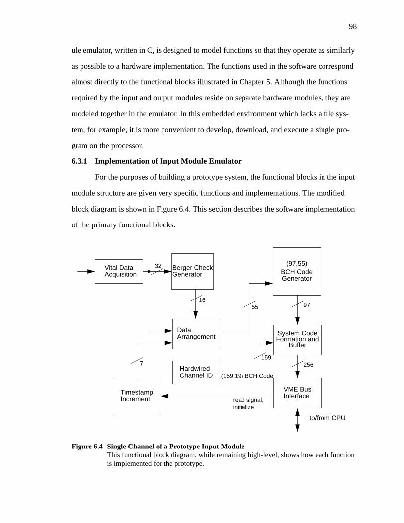
98
ule emulator, written in C, is designed to model functions so that they operate as similarly
as possible to a hardware implementation. The functions used in the software correspond
almost directly to the functional blocks illustrated in Chapter 5. Although the functions
required by the input and output modules reside on separate hardware modules, they are
modeled together in the emulator. In this embedded environment which lacks a file sys-
tem, for example, it is more convenient to develop, download, and execute a single pro-
gram on the processor.
6.3.1 Implementation of Input Module Emulator
For the purposes of building a prototype system, the functional blocks in the input
module structure are given very specific functions and implementations. The modified
block diagram is shown in Figure 6.4. This section describes the software implementation
of the primary functional blocks.
Figure 6.4 Single Channel of a Prototype Input ModuleThis functional block diagram, while remaining high-level, shows how each functionis implemented for the prototype.
Vital DataAcquisition
HardwiredChannel ID
VME BusInterface
to/from CPU
Berger CheckGenerator
read signal,TimestampIncrement
DataArrangement
BCH CodeGenerator
Buffer
(97,55)
97
System CodeFormation and
256
5516
32
(159,19) BCH Code
1597
initialize
99
The software input module emulator controls and stores data for all 76 input chan-
nels in the prototype. The data is structured around the use of the 32-bit processor. Bit vec-
tors are generally stored as groups of 32-bit unsigned integers so that the processor may
operate directly on the different parts of the bit vector without having to perform addi-
tional manipulations. The 256-bit system codeword, for example, is implemented as an
array of eight unsigned 32-bit integers.
Recall that BCH codes are a family of cyclic codes, all of which have an underly-
ing mathematical structure. Separable codewords may be generated by a series of polyno-
mial multiplication operations, first with a premultiplier that logically shifts the message,
followed by multiplication by the generator polynomial,g(X) (see Section 6.1). An alter-
native method is to use the fact that any linear code may be formed by the linear transfor-
mation shown in Equation 6.6.
(6.6)
In this expression,G is ak x n matrix comprised of binary digits andv andu are binary
vectors with dimension 1 xn and 1 xk, respectively. Recall thatk is the number of mes-
sage bits andn is the block length of the codeword.G is called the generator matrix and
the code set is formed by linear combinations of rows of this matrix. That is, the modulo-2
addition of any number of rows of the generator matrix will produce a valid codeword.
Also, multiple generator matrices may be used to produce the same set of codewords. This
is useful when separable codes are desired. The generator polynomial for a cyclic code
may be used to produce a generator matrix by using then - k coefficients of the generator
polynomial as shown in Equation 6.7.
v uG=
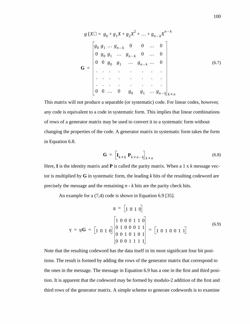
100
(6.7)
This matrix will not produce a separable (or systematic) code. For linear codes, however,
any code is equivalent to a code in systematic form. This implies that linear combinations
of rows of a generator matrix may be used to convert it to a systematic form without
changing the properties of the code. A generator matrix in systematic form takes the form
in Equation 6.8.
(6.8)
Here,I is the identity matrix andP is called the parity matrix. When a 1 xk message vec-
tor is multiplied byG in systematic form, the leadingk bits of the resulting codeword are
precisely the message and the remainingn - k bits are the parity check bits.
An example for a (7,4) code is shown in Equation 6.9 [35].
(6.9)
Note that the resulting codeword has the data itself in its most significant four bit posi-
tions. The result is formed by adding the rows of the generator matrix that correspond to
the ones in the message. The message in Equation 6.9 has a one in the first and third posi-
tion. It is apparent that the codeword may be formed by modulo-2 addition of the first and
third rows of the generator matrix. A simple scheme to generate codewords is to examine
g X( ) g0 g1X g2X2 … gn k– X
n k–+ + + +=
G
g0 g1 … gn k– 0 0 … 0
0 g0 g1 … gn k– 0 … 0
0 0 g0 g1 … gn k– … 0
. . . . . . . .
. . . . . . . .
. . . . . . . .
0 0 … 0 g0 g1 … gn k– k n×
=
G I k k× Pk n k–× k n×=
u 1 0 1 0=
v uG 1 0 1 0
1 0 0 0 1 1 0
0 1 0 0 0 1 1
0 0 1 0 1 0 1
0 0 0 1 1 1 1
1 0 1 0 0 1 1= = =
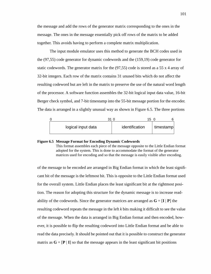
101
the message and add the rows of the generator matrix corresponding to the ones in the
message. The ones in the message essentially pick off rows of the matrix to be added
together. This avoids having to perform a complete matrix multiplication.
The input module emulator uses this method to generate the BCH codes used in
the (97,55) code generator for dynamic codewords and the (159,19) code generator for
static codewords. The generator matrix for the (97,55) code is stored as a 55 x 4 array of
32-bit integers. Each row of the matrix contains 31 unused bits which do not affect the
resulting codeword but are left in the matrix to preserve the use of the natural word length
of the processor. A software function assembles the 32-bit logical input data value, 16-bit
Berger check symbol, and 7-bit timestamp into the 55-bit message portion for the encoder.
The data is arranged in a slightly unusual way as shown in Figure 6.5. The three portions
of the message to be encoded are arranged in Big Endian format in which the least signifi-
cant bit of the message is the leftmost bit. This is opposite to the Little Endian format used
for the overall system. Little Endian places the least significant bit at the rightmost posi-
tion. The reason for adopting this structure for the dynamic message is to increase read-
ability of the codewords. Since the generator matrices are arranged asG = [I | P] the
resulting codeword repeats the message in the leftk bits making it difficult to see the value
of the message. When the data is arranged in Big Endian format and then encoded, how-
ever, it is possible to flip the resulting codeword into Little Endian format and be able to
read the data precisely. It should be pointed out that it is possible to construct the generator
matrix asG = [P | I ] so that the message appears in the least significant bit positions
Figure 6.5 Message Format for Encoding Dynamic CodewordsThis format assembles each piece of the message opposite to the Little Endian formatadopted for the system. This is done to accommodate the format of the generatormatrices used for encoding and so that the message is easily visible after encoding.
0 31 0 15 0 6
logical input data identification timestamp
102
according to Little Endian notation. Shortening the code from (127,85) to (97,55) is much
easier, however, when the generator matrix is in theG = [I | P] format. Flipping the code-
word as described above in no way changes the properties of the code.
The encoding function logically shifts left the message and masks off the bit at the
leftmost position. This bit is examined and if it is a logic-1, the corresponding row of the
generator matrix array is exclusive-ORed (modulo-2 added) into a running sum. After the
entire message vector has been shifted and each bit examined, the running sum contains
the 97-bit codeword.
The channel identification (static codeword) for each of the 76 input channels is
generated in an identical fashion to the dynamic codewords. Since the 19-bit identification
values are known for each channel beforehand, the static codewords are generated by a
separate program and stored as 159-bit codewords in the emulation program. This avoids
the overhead associated with generating long codewords during the program execution
and is also analogous to a hardware implementation in which the codeword for each chan-
nel would be hardwired and always available. The identification codewords are stored in
an array in a predetermined order to correspond with the agreed upon order for the input
channels. That is, each of the 76 input channels corresponds to some particular input sen-
sor signal, whether it is a track occupancy sensor, switch sensor, or direction indicator.
The system code formation and buffer functional block corresponds to a software
routine that arranges the static and dynamic codewords in the format shown in Figure 6.1.
Note that the dynamic codeword must be flipped before storage. The 256-bit codewords
for all 76 input channels are stored together in a contiguous memory buffer in the pre-
defined order.
The Berger check symbol generator is implemented in a very simple software rou-
tine. The 32-bit logical input data value is logically shifted so that a single bit is masked
off after each shift. Each bit is examined and if it is a logic-1 it is added to a running count.
After all bits have been shifted the running count contains the number of ones in the input
103
data word. This number is subtracted from 32 to generate the Berger check symbol. Note
that for the wayside application all input data values are either logic-0 or logic-1 and
therefore the Berger check symbols will always be 32 or 31.
The vital data acquisition block may be thought of as the retrieval of field data
from the serial interface and subsequent conversion to the proper representation. The
serial interface communicates data a single byte at a time, corresponding to a character in
the processor. The plant model sends a set of 76 input values as ‘0’ and ‘1’ characters,
each occupying a single byte. The entire set of inputs is transmitted together and stored in
a memory buffer called the raw input buffer. The software reads this buffer and creates a
32-bit data value for each input channel based on the character in the corresponding raw
input buffer position. This function might be considered analogous to an A/D function on
a hardware-implemented input module.
The timestamp increment and generate function uses a semaphore approach very
similar to that described in section 6.2.4 for the watchdog checker emulator. The input
module is a polled device which implies that it responds to actions taken by some outside
device, specifically the executive processor. The input module encodes the field inputs and
creates the set of input codewords. These are stored in an agreed upon location in one con-
tiguous memory block. At the end of this block is one extra memory location that is a 32-
bit semaphore. After encoding and storing the input codewords in the buffer, the input
emulator clears the semaphore to indicate that the inputs are ready for retrieval by the
executive processor. When the executive processor is ready to read input data it checks the
semaphore. If it is clear then the processor reads input codewords and then sets the sema-
phore. This indicates to the input module that it has been polled and the timestamp is
incremented. The timestamp is stored as a global variable in the emulator and cycles from
zero to four corresponding to the number of minor frames per major frame.
To facilitate a known starting state for the executive processor and watchdog
checker, the input module initializes the raw input buffer with ‘0’ characters for every
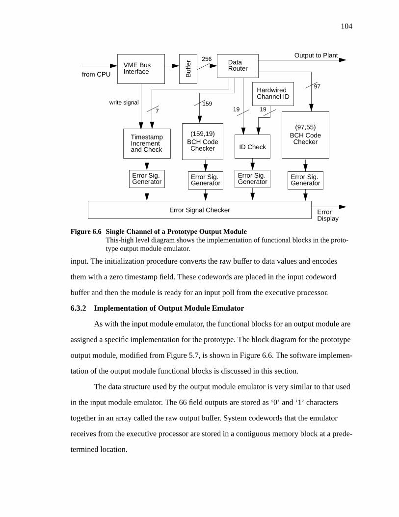
104
input. The initialization procedure converts the raw buffer to data values and encodes
them with a zero timestamp field. These codewords are placed in the input codeword
buffer and then the module is ready for an input poll from the executive processor.
6.3.2 Implementation of Output Module Emulator
As with the input module emulator, the functional blocks for an output module are
assigned a specific implementation for the prototype. The block diagram for the prototype
output module, modified from Figure 5.7, is shown in Figure 6.6. The software implemen-
tation of the output module functional blocks is discussed in this section.
The data structure used by the output module emulator is very similar to that used
in the input module emulator. The 66 field outputs are stored as ‘0’ and ‘1’ characters
together in an array called the raw output buffer. System codewords that the emulator
receives from the executive processor are stored in a contiguous memory block at a prede-
termined location.
VME BusInterface B
uffe
r
from CPU
DataRouter
TimestampIncrementand Check
write signal
Error Sig.Generator
Error Sig.Generator
Error Sig.Generator
Error Signal Checker ErrorDisplay
Output to Plant
Figure 6.6 Single Channel of a Prototype Output ModuleThis-high level diagram shows the implementation of functional blocks in the proto-type output module emulator.
BCH CodeChecker
(97,55)
BCH CodeChecker
(159,19)
HardwiredChannel ID
Error Sig.Generator
ID Check
159
97
7 19
256
19
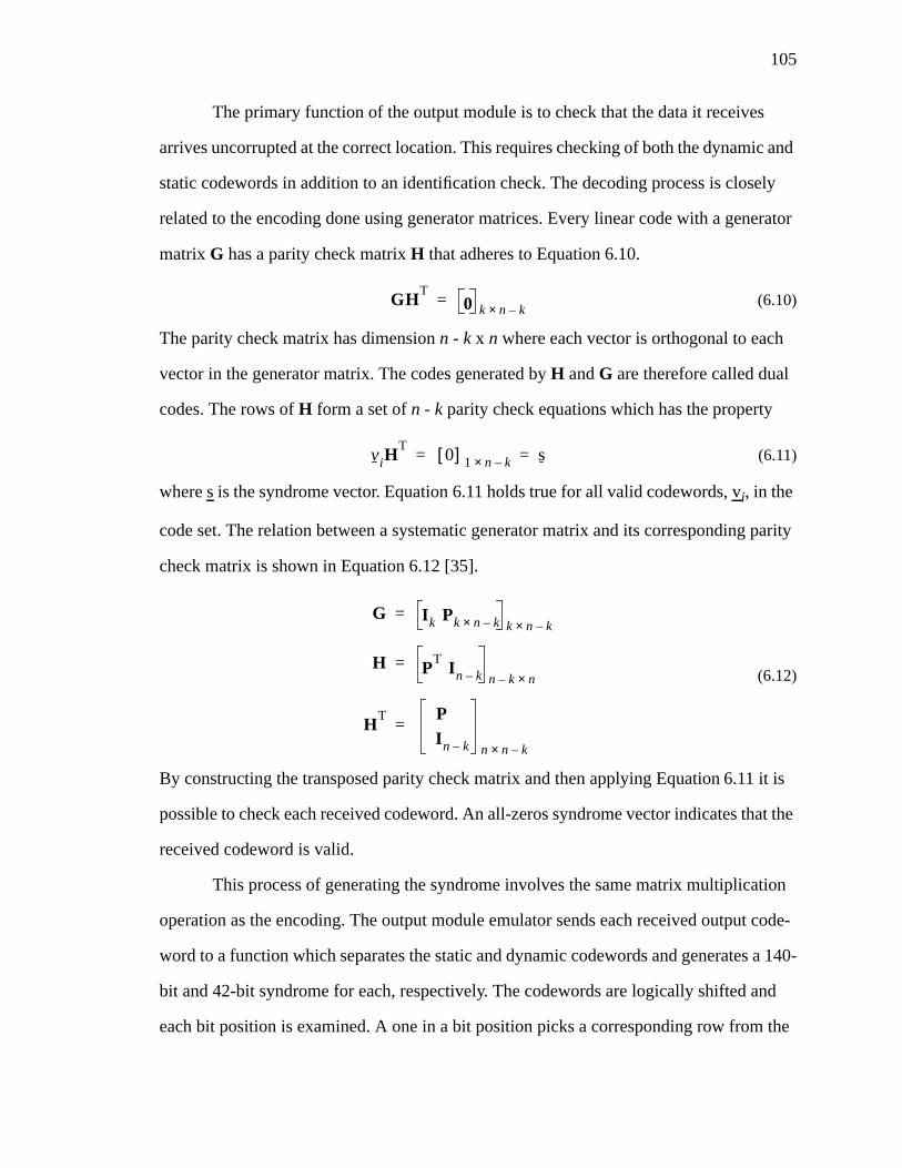
105
The primary function of the output module is to check that the data it receives
arrives uncorrupted at the correct location. This requires checking of both the dynamic and
static codewords in addition to an identification check. The decoding process is closely
related to the encoding done using generator matrices. Every linear code with a generator
matrixG has a parity check matrixH that adheres to Equation 6.10.
(6.10)
The parity check matrix has dimensionn - k x n where each vector is orthogonal to each
vector in the generator matrix. The codes generated byH andG are therefore called dual
codes. The rows ofH form a set ofn - k parity check equations which has the property
(6.11)
wheres is the syndrome vector. Equation 6.11 holds true for all valid codewords,vi, in the
code set. The relation between a systematic generator matrix and its corresponding parity
check matrix is shown in Equation 6.12 [35].
(6.12)
By constructing the transposed parity check matrix and then applying Equation 6.11 it is
possible to check each received codeword. An all-zeros syndrome vector indicates that the
received codeword is valid.
This process of generating the syndrome involves the same matrix multiplication
operation as the encoding. The output module emulator sends each received output code-
word to a function which separates the static and dynamic codewords and generates a 140-
bit and 42-bit syndrome for each, respectively. The codewords are logically shifted and
each bit position is examined. A one in a bit position picks a corresponding row from the
GHT
0 k n k–×=
viHT
0[ ] 1 n k–× s= =
G I k Pk n k–× k n k–×=
H PT
I n k– n k– n×=
HT P
I n k– n n k–×
=
106
transposed parity check matrix and adds it to a running sum using modulo-2 addition.
After the entire codeword is shifted and examined, the running sum contains the syn-
drome. If the syndrome is a zero-vector the codeword is valid. As with the generator
matrices, transposed parity check matrices are generated and stored in the emulator pro-
gram as arrays of 32-bit machine integers.
The decoding process checks that the static and dynamic codewords were not cor-
rupted en route from the executive processor or perhaps generated incorrectly. An addi-
tional checking function compares the 19-bit message portion of each static codeword
against a stored set of identification values for each output channel. These must match to
ensure that the correct output value was sent to the correct output channel. The ordering of
the received codewords and stored identification values is important since it corresponds
to a predetermined order for the output signals. Each one of the 66 output channels drives
a particular signal or switch in the sample application.
The timestamp increment and check functional block uses the same type of sema-
phore scheme as the input module emulator. The output module is also a polled device
such that a write operation from the executive processor to the output module is consid-
ered a poll. The output module has a memory buffer set aside into which the executive
processor deposits output codewords. At the end of the buffer is an additional memory
location that contains a 32-bit semaphore. Before delivering outputs the executive proces-
sor checks this semaphore to make sure that it is clear indicating that the output module is
ready to receive a new set of outputs. After depositing all 66 output codewords, the execu-
tive processor sets the semaphore to let the output module emulator know that it may
begin its processing. After decoding and checking the outputs, the output module emulator
clears the semaphore and waits for the executive processor’s next poll. The output module
emulator uses a different global timestamp than the input module emulator since the deliv-
ered outputs are encoded with a timestamp from the previous minor frame, that is one
cycle behind the input module timestamp. The increment of this timestamp is performed
107
each time the output module receives a new set of outputs. Part of the checking function of
the output module is to ensure that the timestamp in each received codeword matches its
own global timestamp.
Each of the checking functions described above produces an error signal that is
gathered by an overall error indication routine. If any of the three types of checks fails, i.e.
syndrome, identification, or timestamp, the error indication routine displays a message on
the simulation console identifying which checking function detected the error and on
which output codeword. In an actual system a detected error would cause the output mod-
ule to set its outputs to a safe value, perhaps by removing power from the output devices.
Field outputs are delivered from the output module emulator to the plant model via
the same serial interface used by the input module emulator. After receiving the set of out-
put codewords, each 32-bit logical output is extracted and converted to a ‘0’ or ‘1’ charac-
ter for storage in a raw output buffer. When the plant model signals that it is ready to
receive a new set of outputs, the characters in the raw buffer are transmitted over the serial
line.
6.3.3 Serial Communications Facilities
From the discussion of the input and output module emulators it is apparent that
serial communication is a very important element of the prototype. The input and output
module emulators use one of two serial ports available on the Heurikon processor PCB for
their connection to the plant model. Both emulators use the same serial line. The second
port on the processor PCB is configured for use with the monitor program for download-
ing and executing the emulation program.
The monitor port is connected to a separate line on the host workstation which in
turn displays data in a dedicated console window. The emulation program is able to use
the console to display status and error messages during the simulation. Access to monitor
routines such as printing to the console, enabling and disabling cache, and accessing the
real-time clock, is provided through pointers to specific locations in PROM memory. Once

108
these pointers are linked to the desired monitor functions, they may be called like any
other function in the program.
Both serial ports reside on a Zilog Z85C30 Serial Communication Controller
(SCC) integrated circuit. If the ports are used for console or download purposes they may
be easily configured using the Heurikon monitor. Using them within the emulation pro-
gram, however, required the development of a set of functions to perform basic tasks such
as sending and receiving single characters. One serial port was set aside for use by the pro-
gram and the other was configured to work with the monitor.
To best emulate an external environment, the SCC is operated in an asynchronous
mode since input and output reception and delivery are not expected from the plant model
at any particular frequency. Also, a polled scheme was adopted to avoid the added com-
plexity of using interrupts and interrupt service routines. The difference between these two
approaches is that an interrupt scheme will raise an interrupt when a character is received,
for example. A polled scheme, on the other hand, requires that the SCC be polled to check
if a character has been received. The SCC is operated using standard RS-232 data parame-
ters with eight data bits, one stop bit, and no parity bits. It is programmed to communicate
at a rate of 38,400 bits per second. The functions necessary for interrupt-driven operation
are included in the emulation program if they should be required later.
The SCC behaves as a memory-mapped device. All operations regarding the SCC
are done in two steps. The first is to assign the SCC register pointer to a control register
and then issue the desired command. Checking if a character is available in the SCC
buffer, for example, requires that the pointer be set to control register zero and the least
significant bit be examined.
The emulator uses the XON/XOFF protocol for flow control. This is a software
protocol in which the flow of information is controlled by special characters transmitted
by either of the communicating devices. When one device finds that its buffer is in danger
of being overrun, it transmits an XOFF character to prevent the second device from send-

109
ing any more information. When it is ready to receive more information, the device sends
an XON character to resume communications. This scheme is used because it is fairly
simple to program and is hardware independent.
When the output emulator sends the set of outputs to the plant model it checks the
receive buffer before transmitting each character to check if an XOFF has been received.
If the plant sends an XOFF during output transmission, the output emulator continuously
polls the receive buffer until an XON character is received. Otherwise, the output charac-
ter sequence is sent without interruption. The input emulator works in a similar way.
When expecting data the input emulator continuously polls the receive buffer until a char-
acter is received. When a character appears in the buffer, it sends an XOFF character to
prevent the plant model from sending any subsequent characters. After retrieving the char-
acter from the SCC buffer and placing it in the raw input buffer, it sends an XON character
and waits for the next input to arrive. This is not the most efficient method of receiving
data; it is likely not necessary to send an XOFF after receiving every input character. It
does, however, result in reliable communications perhaps at the expense of some through-
put.
6.3.4 Input and Output Emulation Program Flow
The input and output emulator work together in two main software routines. The
first is a startup cycle in which the executive processor writes and then reads an initial set
of output and input codewords, respectively. The second is the main processing loop
which the emulator executes once during each input-output cycle.
The startup cycle takes place before any communications with the plant model.
The first step is to set the input and output semaphores and reset global timestamps for the
emulators to zero. The raw input buffer is then initialized with all ‘0’ characters for all 76
inputs, encoded into the 256-bit system codewords, and deposited in the input codeword
buffer. At this point the emulator is ready for the executive processor to deliver initial out-
put codewords and read the encoded initial input codewords. The emulator enters two sub-

110
sequent loops in which it waits for the executive processor to deliver outputs and then read
inputs. The input global timestamp is incremented and the raw input buffer is re-encoded
and re-deposited in the input codeword buffer. The inputs must be re-encoded because
when the normal operation begins the executive processor will read input codewords
again before the emulator has the opportunity to receive new inputs from the plant model.
Although not actually a part of the startup cycle, the monitor functions must be linked and
the SCC initialized prior to the emulator start.
The normal emulation cycle consists of two sets of operations. The first of these is
receiving and checking output codewords and delivering input codewords. The second is
the delivery of outputs to the plant and retrieval of inputs from the plant. The emulation
begins by waiting for an output poll from the executive processor which takes the form of
a semaphore operation. The executive processor delivers output codewords and then sets
the output semaphore to indicate that it has done so. The emulation program then waits for
an input poll, similar to the output poll. After the executive processor has retrieved the
new input codewords and begins processing, the output emulator decodes and checks the
received output codewords. It also increments the global timestamps and re-encodes the
raw input buffer. The output values are placed in the raw output buffer. Finally, the two
semaphores are cleared. At this point the emulator checks the SCC receive buffer for a
special character indicating that the plant model is ready to receive data. If the character is
in the buffer, plant outputs are sent and plant inputs are received through the serial inter-
face. The new plant inputs are encoded with the current timestamp and placed in the input
codeword buffer and the cycle is restarted. This basic emulation cycle is executed during
each minor frame in the system. A flow diagram of the operation of the emulation cycle is
shown in Figure 6.7.
6.4 Hardware Description of Prototype Input and Output Modules
Although the software emulation of the input and output modules is the focus of
this research, it is appropriate to discuss the hardware implementation. The emulator
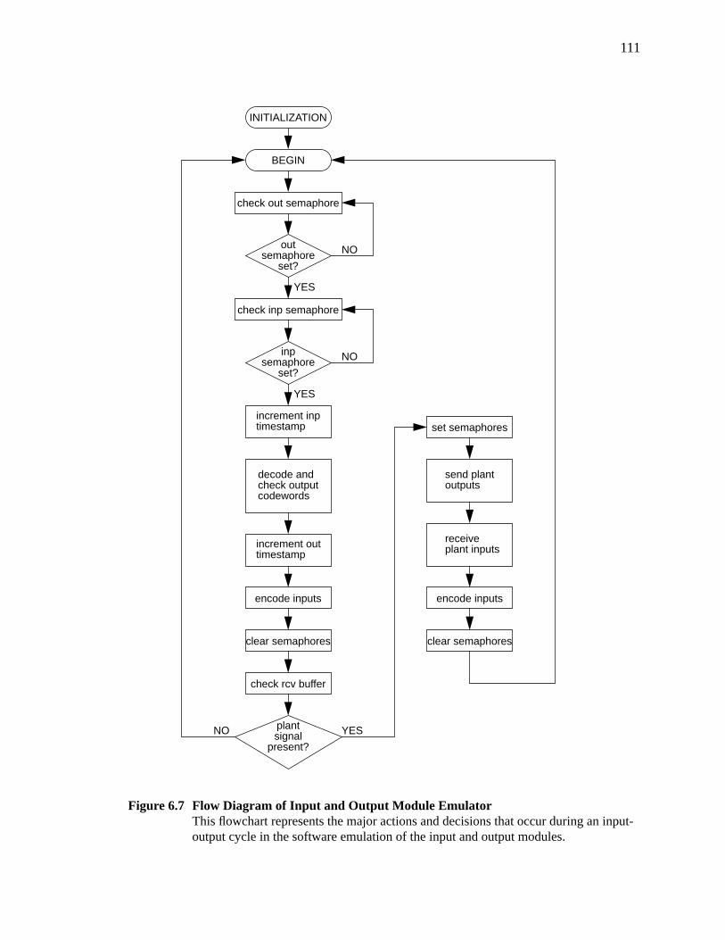
111
Figure 6.7 Flow Diagram of Input and Output Module EmulatorThis flowchart represents the major actions and decisions that occur during an input-output cycle in the software emulation of the input and output modules.
INITIALIZATION
BEGIN
check out semaphore
outsemaphore
set?
NO
check inp semaphore
NO
YES
decode and
YES
encode inputs
check outputcodewords
increment inptimestamp
clear semaphores
inpsemaphore
set?
NO
YES
check rcv buffer
plantsignal
present?
set semaphores
send plantoutputs
receiveplant inputs
encode inputs
clear semaphores
increment outtimestamp
112
offers a satisfactory view of the functionality of the input and output modules but does not
provide a view of the possible hardware structure. As a result, some of the primary func-
tional blocks, particularly encoders and decoders, identified in Figure 6.4 and Figure 6.6,
were described in the Very High-Speed Integrated Circuit (VHSIC) Hardware Description
Language (VHDL). Recognized as a standard by the United States Department of
Defense, ANSI, and the IEEE, VHDL is a formal notation for describing electronic
designs [40]. It is based on the Ada programming language, also adopted by the Depart-
ment of Defense. Since many tools exist which can read VHDL descriptions, it is useful
for all phases of design, synthesis, testing, and analysis of digital hardware.
Wherever possible the prototype VHDL descriptions are programmed as combina-
tional designs. The BCH encoders and decoders, for example, may be designed as combi-
national exclusive-OR (XOR) tree circuits or sequential linear feedback shift registers
which require that the entire message vector be shifted through the circuit. The descrip-
tions adopt the combinational design, however, in order to reduce the complexity and
increase speed of the input and output module functions. The sequential design requires
that an additional clock be available to each encoding and decoding circuit, perhaps one
for each input or output channel. Clocking each message or codeword bit through a feed-
back shift register is obviously a relatively slow process. The combinational implementa-
tion avoids this but at the expense of increased size of the resulting circuit.
To reduce the possibility of error in programming the large XOR circuits, a small
script is used which converts a code matrix, generator or parity check, into an equivalent
behavioral VHDL description. The VHDL descriptions are programmed and compiled for
simulation with the Mentor Graphics Design Architect design automation tool. In addi-
tion to encoding and decoding functions, designs for the input module timestamp genera-
tion function and a module for use in a Berger check symbol generator were also
developed and programmed. The timestamp generator is the lone sequential circuit on the
input and output modules. It is a very simple state machine which uses a read or write sig-
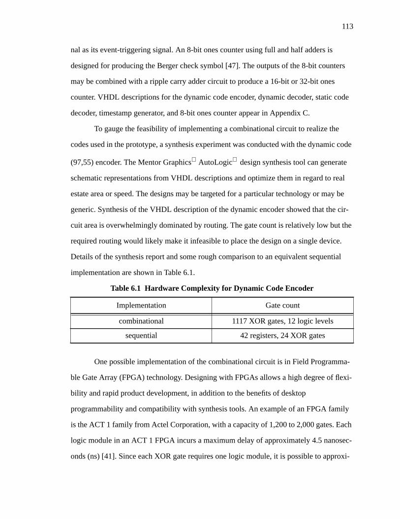
113
nal as its event-triggering signal. An 8-bit ones counter using full and half adders is
designed for producing the Berger check symbol [47]. The outputs of the 8-bit counters
may be combined with a ripple carry adder circuit to produce a 16-bit or 32-bit ones
counter. VHDL descriptions for the dynamic code encoder, dynamic decoder, static code
decoder, timestamp generator, and 8-bit ones counter appear in Appendix C.
To gauge the feasibility of implementing a combinational circuit to realize the
codes used in the prototype, a synthesis experiment was conducted with the dynamic code
(97,55) encoder. The Mentor Graphics AutoLogic design synthesis tool can generate
schematic representations from VHDL descriptions and optimize them in regard to real
estate area or speed. The designs may be targeted for a particular technology or may be
generic. Synthesis of the VHDL description of the dynamic encoder showed that the cir-
cuit area is overwhelmingly dominated by routing. The gate count is relatively low but the
required routing would likely make it infeasible to place the design on a single device.
Details of the synthesis report and some rough comparison to an equivalent sequential
implementation are shown in Table 6.1.
One possible implementation of the combinational circuit is in Field Programma-
ble Gate Array (FPGA) technology. Designing with FPGAs allows a high degree of flexi-
bility and rapid product development, in addition to the benefits of desktop
programmability and compatibility with synthesis tools. An example of an FPGA family
is the ACT 1 family from Actel Corporation, with a capacity of 1,200 to 2,000 gates. Each
logic module in an ACT 1 FPGA incurs a maximum delay of approximately 4.5 nanosec-
onds (ns) [41]. Since each XOR gate requires one logic module, it is possible to approxi-
Table 6.1 Hardware Complexity for Dynamic Code Encoder
Implementation Gate count
combinational 1117 XOR gates, 12 logic levels
sequential 42 registers, 24 XOR gates
114
mate the total delay in the combinational implementation as the single level delay
multiplied by the number of levels. This calculation gives a delay of 54 ns without consid-
eration of routing delays which may be substantial for a very large XOR tree.
It is naive to assume, however, that the 1,117-gate circuit may be easily imple-
mented in a 2,000-gate FPGA. The 2,000-gate ACT 1 FPGA provides only 547 logic
modules and 69 input-output pins, for example. The routing required for the circuit must
be taken into account along with the number of input-output pins necessary to support the
long codeword block lengths.
Despite the proof-of-concept shown by the software emulation of the input and
output modules, it is apparent that a hardware implementation of this design is difficult.
The sheer size of the codewords used makes their implementation in anything but soft-
ware problematic. An additional concern is the possibility that the encoding and decoding
circuitry on input and output modules is required to be vital. Designing an implementation
using discrete analog components for the codes used in the prototype poses a serious prob-
lem. The next iteration of the Next Generation Architecture design will no doubt use this
experience to aid in the decisions regarding the types and amounts of information redun-
dancy in the next candidate safety assurance scheme.
6.5 Chapter Summary
An overview of the software prototype and a detailed view of the input and output
module emulation was presented in this chapter. The code-based safety assurance scheme,
relying on cyclic codes and arithmetic codes, was discussed with some background on the
mathematical structure behind each code that lends itself to implementation and analysis.
A software-based prototyping environment serves as the development and evaluation plat-
form for the architecture prototype. The main components of the wayside ATP system are
a physical plant model, an executive processor, a watchdog checker emulation, and the
input and output module emulation. The executive and each of the emulators are imple-
mented with COTS processor PCBs communicating over a standard VMEbus. A Sun
115
workstation monitors and controls the physical plant model and any error signals from the
watchdog checker. Special functions included in the input and output module emulators
are discussed in some detail, including cyclic encoding and decoding algorithms and serial
communications facilities. The last section of this chapter is a discussion of possible hard-
ware implementations of the major functions of the input and output modules.
116
Chapter 7Methods for Safety Evaluation of Automatic Train
Control Systems
Despite the safeguards taken in the design of a safety-critical ATC system it must
still be proven safe to the ultimate user or customer. The requirements definition for most
ATC systems includes numerical values for dependability parameters such as safety, reli-
ability, and maintainability (see Section 2.2.3). The most important of these obviously is
safety. Estimating the safety of a microprocessor-based ATC system is a difficult task that
sometimes involves unpalatable assumptions to determine the parameters necessary to
calculate the safety. This chapter discusses some of the methods of proving safety that are
accepted in the railway industry. In particular the methods of fault injection and simulation
are examined. An example of the application of fault injection and simulation as applied
to the evaluation of a commercial wayside input and output subsystem is also provided.
7.1 Safety Modeling and Evaluation Techniques
As defined in Chapter 2, safety is the probability that a system behaves correctly or
fails in a safe manner. This implies that safe failures are defined for the system. A safe fail-
ure is generally considered to be a failure that is detected by the system in some manner.
The detection mechanisms may include self-diagnostic routines, error detection codes, or
hardware voting. The ability of detection mechanisms to detect a fault and initiate fault
recovery is related to fault coverage. The general definition of fault coverage is the sys-
tem’s ability to detect, locate, contain, and recover from faults that occur in the system.
The fault coverage is sometimes broken down into separate values for fault detection cov-
erage, fault location coverage, fault containment coverage, and fault recovery coverage
[10]. In this discussion, however, fault coverage refers to fault detection coverage which
simply measures the ability of a system to detect faults. Since the prototype safety assur-
ance scheme is developed based on protection of information used by the control algo-
rithm, it is more appropriate, however, to discuss error coverage. The definition is
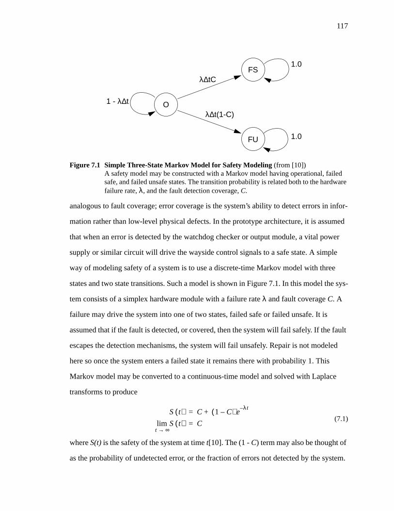
117
analogous to fault coverage; error coverage is the system’s ability to detect errors in infor-
mation rather than low-level physical defects. In the prototype architecture, it is assumed
that when an error is detected by the watchdog checker or output module, a vital power
supply or similar circuit will drive the wayside control signals to a safe state. A simple
way of modeling safety of a system is to use a discrete-time Markov model with three
states and two state transitions. Such a model is shown in Figure 7.1. In this model the sys-
tem consists of a simplex hardware module with a failure rateλ and fault coverageC. A
failure may drive the system into one of two states, failed safe or failed unsafe. It is
assumed that if the fault is detected, or covered, then the system will fail safely. If the fault
escapes the detection mechanisms, the system will fail unsafely. Repair is not modeled
here so once the system enters a failed state it remains there with probability 1. This
Markov model may be converted to a continuous-time model and solved with Laplace
transforms to produce
(7.1)
whereS(t) is the safety of the system at timet[10]. The (1 - C) term may also be thought of
as the probability of undetected error, or the fraction of errors not detected by the system.
Figure 7.1 Simple Three-State Markov Model for Safety Modeling(from [10])A safety model may be constructed with a Markov model having operational, failedsafe, and failed unsafe states. The transition probability is related both to the hardwarefailure rate,λ, and the fault detection coverage,C.
O
FS
FU
λ∆tC
λ∆t(1-C)
1.0
1.0
1 - λ∆t
S t( ) C 1 C–( ) eλt–
+=
S t( )t ∞→lim C=
118
A more common measure of the system safety used in the railway industry is the
mean time between hazardous events (MTBHE) discussed in Chapter 2. For this simple
simplex model the MTBHE is calculated as shown in Equation 7.2 [42].
(7.2)
It is apparent that the safety of the system depends directly on the error detection cover-
age. The primary problem in designing and analyzing microprocessor-based safety-critical
systems is to design for high error detection coverage and prove that the coverage require-
ment is met. The approach generally used is to estimate the failure rate and use the
required MTBHE to calculate the necessary coverage. Estimates for the failure rate are
commonly available in the United States Department of Defense MIL-HDBK-217 stan-
dard. This handbook provides a model for the failure rates for electronic components
through experimental data collected via failure analysis [10].
Several methods of analysis are recognized and accepted as means of proving the
safety of an ATC system [11]. Each has its own limitation as far as applicability and level
of completeness in regard to microprocessor-based systems. The first of these is the failure
modes, effect and criticality analysis (FMECA). Similar to the FMEA method, this is a
systematic study of each well-defined system failure mode in various operating condi-
tions. The goal of this method is to determine whether or not unsafe conditions arise from
any single failure. In the case of combinations of failures leading to unsafe conditions, it
must be shown that the first failure is detected early enough to negate the effect of the sec-
ond assuming they do not occur simultaneously [11]. The obvious problem is the enumer-
ation of all of the failure modes in a complex digital design. This is generally considered
an unbounded problem where a microprocessor is concerned. Software analysis poses a
similar problem; it is nearly impossible to account for all of the states and interactions of a
complex software design. The notion of estimating coverage, however, is a simple task
when FMECA or FMEA methods are used. Assuming that a satisfactory list of failure
MTBHE1
λ 1 C–( )-----------------------=
119
modes can be developed, the coverage is a ratio of the number of failure modes detected
by the system to the total number of failure modes examined.
Another common method is fault tree analysis. This is a deductive method which
begins with an unsafe top event and attempts to establish all of the intermediate events that
could have caused the top event. The intermediate events form the nodes of the fault tree.
Combinations of intermediate events are combined logically with AND and OR opera-
tions. This requires consideration of combination faults, similar to the FMECA [11]. Cov-
erage is estimated by assigning a probability to the unsafe top events by combining the
probability of intermediate events leading to the top event. Fault trees also rely on the abil-
ity to identify and enumerate all unsafe conditions in the system. It is clear that this
method is unwieldy at low levels of abstraction such as gate-level hardware descriptions
or software source code simply because the number of nodes in the tree is very large.
Perhaps the most attractive technique for determining system coverage is to ana-
lytically calculate it and arrive at some closed-form mathematical solution. The use of
structured information redundancy to assure safety is the only practical way to facilitate
analysis. Recall from Section 6.1 that the probability of undetected error for a cyclic code
on a memoryless channel is 2-(n - k) for an (n, k) code. Some would argue that information
used by the control algorithm, if encoded, is protected in digital hardware with this proba-
bility (assuming vital hardware is used at input and output interfaces) [21]. Although this
is extremely convenient, it requires some assumptions about the nature of errors arising in
the system. These cyclic codes are generally designed for use on communications chan-
nels in which it is common to assume each transmitted bit is independent of any other with
regard to its error probability and all bits are identically distributed. The probability of
error for each bit is assumed to be 0.5, a worst case assumption that results in the expres-
sion for undetected error probability being an upper bound. In a communications channel
with a reasonable error probability, the probability of undetected error is expected to be
much lower than 2-(n - k) [35].
120
In a computer system where information is passed through logic networks, how-
ever, it is easy to imagine faults which could cause correlated errors. If a single logic gate
affects more than one primary output of a circuit, for example, those outputs could experi-
ence dependent errors. Although the analysis is simple, it requires the acceptance of ques-
tionable assumptions when dealing with a microprocessor-based system.
An alternative technique to determine the fault coverage of a safety-critical system
is via fault injection. Fault injection techniques may be broken down into three broad cat-
egories: physical hardware fault injection, software fault injection, and fault injection into
a simulation model of the system. Hardware fault injection is an experimental technique in
which logic stuck-at or open-circuit conditions are placed on the pins of integrated circuits
or data, control, and address lines of the microprocessor bus. Since it is virtually impossi-
ble to inject all possible faults under any fault model into a complex system, methods to
automatically inject many faults are used to allow statistical estimation of the system cov-
erage. For a safety-critical system, however, a statistical sample on the order of 106 fault
injection experiments is necessary to provide the desired confidence on the coverage esti-
mate. The hardware injection methods developed thus far do not meet these requirements
[43]. Software fault injection is used to inject faults into the data or control flow of the
program executing the application. This method requires the assumption that all hardware
or software faults will manifest themselves as errors in data or control flow.
Simulation-based approaches use a model of the system under test to inject faults
and evaluate coverage. The simulation model may exist at various levels of abstraction,
from transistor- or gate-level to instruction set architecture level. Simulation models may
allow the relatively rapid performance and analysis of large numbers of fault injection
experiments. Depending on the level of abstraction employed, simulation models may
provide observability of all parts of the system and also the selective injection of faults
that will exercise the safety assurance features [43].
121
7.2 An Application of Simulation-Based Fault Injection for theEvaluation of Input and Output Modules
This section describes a study done to evaluate the fault detection and fault han-
dling of the MICROLOK controller developed and produced by Union Switch and Sig-
nal, Incorporated. The MICROLOK is a wayside ATP system that serves as a vital
interlocking controller for railway switches and signals. The safety evaluation is con-
ducted on a simulation model which is created and validated, and then simulated with a
variety of fault injection experiments.
7.2.1 Simulation Model
The simulation model exists on two levels. The first is a VHDL instruction set
architecture (ISA) model which incorporates the core 8-bit microprocessor, watchdog
timer, and surrounding hardware. The VHDL ISA model describes the system using an
information-flow approach that abstracts away the underlying logic gates or transistors.
Fault injection experiments inject faults into representations of the devices through which
information travels in the system with a specialized VHDL fault injection module. A very
useful feature of the model is its ability to execute the actual application program allowing
faults to be injected in the model while it is running actual MICROLOK code [44].
The second model used in the safety evaluation is a gate-level model of the input
and output subsystems. Although the VHDL ISA model is adequate for modeling the
complex processor and its surrounding hardware, its representation of the input and output
subsystems is at a very high level where each input or output channel is modeled as a sin-
gle memory-mapped bit location. Given the criticality of the input and output modules to
system safety, the lower level models were created to develop a characterization of the
input-output subsystem in the presence of faults.
The fault model adopted for this characterization is the logical stuck-at fault
model. In this model it is assumed that any fault will cause the logic module to respond as
if one of its input or output pins is stuck at a logic-1 or logic-0. Furthermore it is assumed
122
that the module’s functionality remains unchanged (an AND gate still performs the correct
operation) and that the faults are permanent [10]. Other fault models exist which account
for stuck-open faults due to broken lines or transistor stuck-at faults which descend to a
lower level of abstraction. The logical stuck-at model is adopted for this work due to its
simplicity and relative effectiveness.
In addition to performing the fault injection experiments on the input and output
modules the resulting fault behavior characterization must be compatible with the higher-
level VHDL ISA model. It is important that the results be presented in a way that may be
incorporated into the VHDL fault injection module. The characterization will be used to
inject the proper faults into the VHDL to account for all faulty behavior that may occur in
the input or output subsystem.
7.2.2 Input and Output PCB Structure and Modeling
The MICROLOK input and output PCBs modeled for fault behavior character-
ization are the Standard Input PCB and the Standard Relay Driver PCB. Both circuit
boards have well-defined analog and digital sections. Because the electronic design auto-
mation (EDA) tools available are not well suited to modeling both analog and digital hard-
ware together, the strategy adopted was to separate the analog and digital sections and
model them separately using different EDA tools. The efforts discussed here are limited to
the analysis of the digital portion of both PCBs.
The Standard Input PCB is a circuit that interfaces external signal, relay contact
and coil, and switch inputs to the MICROLOK system. The board has eight separate
input channels available with different ground references if necessary. Digital logic on the
board controls addressing, reading and writing bits, generating echo (acknowledgment)
signals, and providing board type information. The analog input circuitry receives and
converts input states. It also provides checks for verifying the input states.
The Standard Relay Driver PCB handles the delivery of outputs from the processor
to large relays which control switches on the railway. The board provides six vital analog
123
output channels driven by the digital portion. The digital logic is very similar to the Stan-
dard Input PCB; it also contains hardware for addressing, reading and writing bits, board
type signaling, and echo generation. One of the most important features of the board is a
command feedback path that allows the processor to read back the outputs to ensure that
they match what was sent to the field.
The primary inputs for both the Standard Input and Standard Relay Driver PCBs
include the data bus, board and program addressing, block, read/write, echo strobe, and
data strobe. These are described in more detail below.
• Data bus These are the read or write data bits that are delivered orread from the field or fed back from the boards for diagnos-tic purposes.
• Board address This address is set by the CPU to indicate with which of the15 input or output boards the CPU wishes to communicate.
• Program address This is a hardwired address for each board that is dictatedby its slot position.
• Block This signal effectively connects or disconnects the input-output subsystem from the CPU subsystem.
• Read/write This is a single line that places the board in a read or writemode.
• Echo strobe When this signal is pulsed, the addressed board deliversecho, type, and read data information.
• Data strobe When this signal is pulsed, the addressed board latches thewrite data presented by the CPU.
The primary outputs are:
• Data bus In the context of outputs, the data bus signals are the controloutputs to the field devices or the command feedback fromthe processor to the input PCB.
• Board type This is an acknowledge signal sent by an addressed boardback to the processor so that the processor may ensure thatit has addressed an appropriate board.
• Echo signals All boards return a single echo bit acknowledge signal butonly one of the bits should be in an active state during nor-mal operation.
124
The digital modeling of the Standard Input and Standard Relay Driver PCBs was
done with the Mentor Graphics logic synthesis and logic simulation tools. Design Archi-
tect, with its associated component libraries, was used to develop schematic representa-
tions of the boards. Simulation for fault behavior was done using Quicksim II which
provides high speed simulation results and simple application of desired input vectors. An
advantage of using the Mentor Graphics suite of tools is the extensive component library
available for use in the PCB model. A component model complete with functionality and
timing information was available for every digital integrated circuit (IC) on the actual
boards.
The schematic models contain no hierarchy; that is they are not top-down designs.
They were developed to resemble as closely as possible the flat hard-copy schematics of
the circuit boards provided by Union Switch and Signal, Inc. [31], [32]. Although alter-
nate organizations of the schematic model were possible and perhaps preferable, the close
resemblance of the model to the hard-copy schematic allowed easy visual validation of the
model.
Since Quicksim II is a digital simulator only, the few analog components in the
digital sections of the board were replaced with a digital equivalent or simulated as a null
model. For example all of the pullup and pulldown resistors are replaced with Mentor
Graphics components that model the same behavior. Capacitors and LEDs, if any, are
replaced with null symbols that have no meaning for the simulator. Note that the null
model replacement was necessary only for the Standard Input PCB in a portion of the cir-
cuit which does not affect any primary board outputs.
Digital fault simulation in Quicksim II is done by manually forcing gate pins to
digital values and then running the simulation. That is, the input vector is set and a fixed
(or stuck-at) logic-1 or logic-0 is applied to a gate or IC input or output pin starting at time
zero. The simulation is then run and the behavior is recorded. Note that this method mod-
125
els permanent stuck-at faults only. Transient faults are not considered in these experi-
ments.
The primary output signals of interest when running a simulation are the control or
status signals and data signals. Data signals are the eight bits that are sent from the digital
portion of the board to the analog portion (field outputs) or data signals that are sent to the
processor (field inputs). On the Standard Input PCB, command feedback signals are sent
to its analog portion for diagnostic purposes and data bus values are sent to the processor
from the field inputs. On the Standard Relay Driver PCB control bits drive its analog por-
tion to deliver the field outputs and data bus values are returned to the processor for diag-
nostic purposes. During a read operation, the data bus values on each board are monitored
for fault effects. On a write operation, the command feedback and control bits are moni-
tored on the input and output boards, respectively. The board type signals and echo signals
are the control signals of interest for both boards. In addition, the Standard Relay Driver
PCB has a FREQ signal used to activate field outputs which is also monitored. Faults that
corrupt any of the signals described above must be represented in the VHDL fault injec-
tion experiment set. A general diagram of the digital PCB layout is given in Figure 7.2.
7.2.3 Input and Output PCB Operation and Intelligent Simulation
The input sequences used for fault simulation are determined by a study of the nor-
mal operation of the boards during a read or write operation. The input signals from the
processor must go through a predetermined sequence during normal operations. It is this
sequence plus some variations that is used as stimulus in the simulation. The normal oper-
ation input set was developed and verified in accordance with Union Switch and Signal,
Inc. internal documentation on the workings of the MICROLOK system [45].
The significance of using input sequences from normal board operation is that it
reduces the amount of time and input combinations necessary for simulation. For exam-
ple, no invalid input sequences are used. The board’s program address, which is dependent
on its location in the backplane, remains constant. In actual operation, once a board is
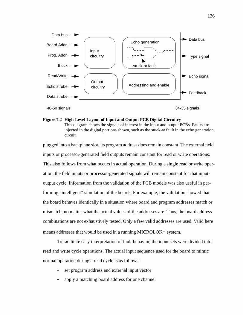
126
plugged into a backplane slot, its program address does remain constant. The external field
inputs or processor-generated field outputs remain constant for read or write operations.
This also follows from what occurs in actual operation. During a single read or write oper-
ation, the field inputs or processor-generated signals will remain constant for that input-
output cycle. Information from the validation of the PCB models was also useful in per-
forming “intelligent” simulation of the boards. For example, the validation showed that
the board behaves identically in a situation where board and program addresses match or
mismatch, no matter what the actual values of the addresses are. Thus, the board address
combinations are not exhaustively tested. Only a few valid addresses are used. Valid here
means addresses that would be used in a running MICROLOK system.
To facilitate easy interpretation of fault behavior, the input sets were divided into
read and write cycle operations. The actual input sequence used for the board to mimic
normal operation during a read cycle is as follows:
• set program address and external input vector
• apply a matching board address for one channel
Addressing and enable
Input
Outputcircuitry
circuitry x
Data bus
Board Addr.
Prog. Addr.
Block
Read/Write
Echo strobe
Data strobe
48-50 signals
Echo generation
stuck-at fault
Data bus
Type signal
Echo signal
Feedback
34-35 signals
Figure 7.2 High-Level Layout of Input and Output PCB Digital CircuitryThis diagram shows the signals of interest in the input and output PCBs. Faults areinjected in the digital portions shown, such as the stuck-at fault in the echo generationcircuit.
127
• set read/write signal to 1
• set block signal to 1
• set echo strobe to 1 and then 0
• input data, echo, and type signals should be available to the processor
• set block back to 0 and the board is disconnected from the input-output bus
The input sequence and its normal result used for a write cycle is as follows:
• set program address, data bus, and external input vector (for input PCB)
• apply a matching board address for one channel
• set read/write signal to 1
• set block signal to 1
• set echo strobe to 1 and then 0
• echo and type signals are available to processor
• set read/write signal to 0 (for write)
• set data strobe to 1 and then 0 -- data from processor is written to the board
• set read/write signal back to 1
• set block to 0 to disconnect board from the input-output bus
7.2.4 Extent of Simulation Stimulus
Both the Standard Input and Standard Relay Driver PCB are equipped to be used
in a MICROLOK failover system. In this type of system two separate processor sub-
systems share one input-output subsystem by attaching to one of the two available chan-
nels (A and B) on each input or output PCB. Only one of the processors communicates
with the input and output PCBs at any given time. The other, failover processor remains
powered off. In this simulation, no assumption is made about which of the two channels is
considered the primary (or active) one. Therefore, the input sequences described in
Section 7.2.3 are set up to exercise both channels in the same way. The reason for this is
that some injected faults may corrupt one channel’s outputs but not the other. Faults such
as this, no matter which channel they affect, must be taken into account in the VHDL fault
128
injections. Another reason for identifying faults that affect only one channel is that these
faults appear latent (cause no perceptible corruption) to the other channel, and must be so
noted.
It is also important to take into account fault modes in which an unaddressed board
responds to processor stimulus. These cases may produce situations in which more than
one board attempts to drive the input-output bus causing a contention condition. To reveal
such faults, both channels are stimulated with matching and non-matching board
addresses. Such a stimulus simulates the situation where the processor communicates with
the board being tested, and then changes the board address and attempts to communicate
with some other board in the system. If the board being simulated responds to stimulus in
both situations, a possible contention condition is created. Both of the above stimulus
types, dual channel and addressed/unaddressed, were applied for both the read and write
cycles for each board.
7.2.5 Simulation Exclusions
Each board was simulated with stuck-at faults for every pertinent digital gate and
IC input and output pin. Faults on resistors were omitted for several reasons. First, the
fault modes for resistors are such that a digital simulator cannot properly apply them (such
as resistance variances). Second, many of the resistive nets in these PCB serve only to
change a signal strength. That is, they do not act in a fashion to affect any of the informa-
tion flow in the boards. Finally, most of the pullup and pulldown resistive nets are at the
interface of the board to the processor. This is so that when the processor is not driving the
boards, the value seen by the board is known. In these simulations, however, the board is
always receiving signals from the processor.
In addition, gates which do not affect signals as seen from the processor viewpoint
are not simulated. This includes the gates which form the small sub-circuit on each board
that drives the visual indicators. Also excluded are gates which are not accessed during a
read or write operation. For example, some of the data buffers are used only during a read
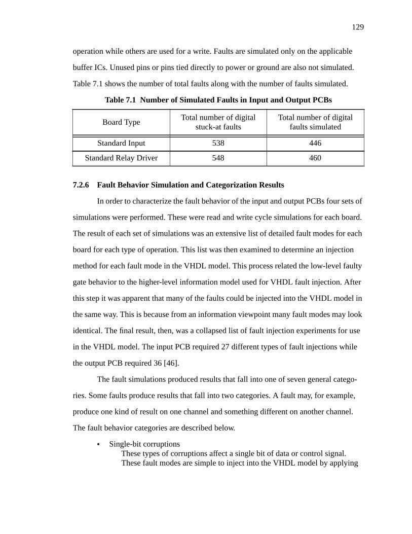
129
operation while others are used for a write. Faults are simulated only on the applicable
buffer ICs. Unused pins or pins tied directly to power or ground are also not simulated.
Table 7.1 shows the number of total faults along with the number of faults simulated.
7.2.6 Fault Behavior Simulation and Categorization Results
In order to characterize the fault behavior of the input and output PCBs four sets of
simulations were performed. These were read and write cycle simulations for each board.
The result of each set of simulations was an extensive list of detailed fault modes for each
board for each type of operation. This list was then examined to determine an injection
method for each fault mode in the VHDL model. This process related the low-level faulty
gate behavior to the higher-level information model used for VHDL fault injection. After
this step it was apparent that many of the faults could be injected into the VHDL model in
the same way. This is because from an information viewpoint many fault modes may look
identical. The final result, then, was a collapsed list of fault injection experiments for use
in the VHDL model. The input PCB required 27 different types of fault injections while
the output PCB required 36 [46].
The fault simulations produced results that fall into one of seven general catego-
ries. Some faults produce results that fall into two categories. A fault may, for example,
produce one kind of result on one channel and something different on another channel.
The fault behavior categories are described below.
• Single-bit corruptionsThese types of corruptions affect a single bit of data or control signal.These fault modes are simple to inject into the VHDL model by applying
Table 7.1 Number of Simulated Faults in Input and Output PCBs
Board TypeTotal number of digital
stuck-at faultsTotal number of digital
faults simulated
Standard Input 538 446
Standard Relay Driver 548 460

130
single, stuck-at faults in the interface ICs between the processor and mem-ory subsystems.
• All signals to high impedanceThese faults effectively disconnect the input or output board from the pro-cessor. In most cases the resulting signal values observed by the CPU aredeterministic because of pullup or pulldown resistors on the I/O Bus Inter-face PCB that serves to connect the input and output subsystem to the pro-cessor subsystem.
• Indeterminate valuesThese faults have an effect such that the values on signal lines are unstableor cannot be determined absolutely because of a fault. In these cases, theprocessor will read some value, either logic-1 or logic-0, but this value isnot deterministic. Random values may be inserted in the VHDL model tosimulate these faults.
• Timing or SequencingThis behavior is the improper delivery of signals. That is, signals may beavailable earlier than they should be or signals do not respond properly tocertain stimulus. In most cases, however, no fault need be injected becausewhen the CPU reads the signals they are correct.
• Contention on busThis behavior is produced if a board responds to stimulus when it is notaddressed. This may cause a contention condition if it responds differentlyfrom the addressed board. If it responds identically to an addressed board,however, the fault may cause no bus contention. In the case of contention,random bit patterns are injected in the VHDL model to represent the valuesread by the processor.
• Some signals to high impedanceThese faults do not disconnect the board from the processor but cause somesignals to be turned off. In most cases pullup or pulldown resistors on the I/O Bus Interface PCB will cause the signal to take on some deterministicvalue when read by the processor.
• Possible latent faultsThese are faults that do not perceptibly corrupt the outputs of the I/Oboards. These do not include faults that produce no corruption onlybecause the entire input vector set was not exhaustively applied. A latentfault is defined to be one that causes no corruption for all input combina-tions.
The latent faults required further study. The analysis of each latent fault described
why the fault is latent and analyzed the possibility of interaction with other faults that
could cause a fault behavior mode not accounted for in the collapsed fault injection lists.
The analysis showed that all but two of the latent faults for both boards do not produce
131
additional, previously unseen, fault behavior. Most were dominated by faults in the cir-
cuitry with which they interact. Others were such that interaction with other faults pro-
duced a fault equivalent to one that was already studied in the initial fault behavior
analysis. One of the two new fault modes was the case of a board, addressed or not, having
a stuck-at logic-1 echo signal. The other case was the event where an addressed and unad-
dressed board both return indeterminate type and echo signals but only the addressed
board latches the write data. Note that these additional fault modes are very similar to
some of those produced in the initial fault experiments. Therefore, they were easily incor-
porated into the fault injection scheme used for the VHDL CPU model along with the
other faults modes.
7.2.7 Digital Model Validation
The procedure used to validate the models as accurate representations of the actual
boards was done in two parts. First, since the schematics were carefully created to resem-
ble the actual board schematics a visual validation was performed.
A more thorough validation was completed using the Union Switch and Signal,
Inc. Engineering Specifications (EU specification) for both boards. The EU specification
for each board includes a general description of the board, a procedure for visual inspec-
tion of the board, a test procedure for verifying correct operation of the board, and a burn-
in procedure. Functional testing of the boards is done using a MICROLOK I/O test box
provided by Union Switch and Signal. The procedures for the Standard Input PCB (EU-
6763) are divided into two sections, one to test the basic addressing and echo logic of the
board, and another to test the input circuitry and input monitors. The Standard Relay
Driver procedures (EU-6795) are similarly divided.
The basic logic tests were fully completed for each board. The EU specification
requires only that visual indicators be checked for each of the input vectors. This is appro-
priate for testing that an actual board works off of the assembly line, but for model valida-
tion purposes it is superficial. Therefore all test points on the actual board were also
132
monitored and compared to the corresponding areas of the schematic model. The models
were deemed accurate when all indicators and test points on the schematics matched the
actual hardware for all inputs.
Both boards support two channels, “A” or “B”, which actually use the same basic
circuitry. That is, the presence of the two channels does not imply the existence of a fully
redundant circuit. The EU specifications require identical tests to be run on both channels
to verify operation. This was also done for the model validation.
To perform the tests, the schematics were altered slightly to facilitate easy applica-
tion of input vectors and viewing of applicable output signals. For example, the test points
were gathered onto a test point bus for quick verification. Also the test box itself has some
circuitry that altered the behavior slightly (such as inverting tristate buffers). In complet-
ing the tests for the Standard Input PCB some of this circuitry was included although not
part of the model for the board alone.
The criteria for model validation, as mentioned earlier, was correct simulation
using all applicable test points for all inputs as dictated by the EU specification tests. The
number of digital simulations for the Standard Input PCB was 110. The model performed
as expected on all simulations. On the model of the Standard Relay Driver, 92 simulations
were run with the model behaving correctly for all of them. Note that these results are only
for the digital portions of each board. The successful results permitted the conclusion that
the digital gate-level models of the MICROLOK® Standard Input and Standard Relay
Driver circuit boards were valid and accurate.
7.2.8 Conclusions of Fault Injection Analysis
The objective of this work was to develop a behavioral description of the
MICROLOK input and output system in the presence of gate-level stuck-at faults on dig-
ital pins. The fact that the CPU VHDL model is developed at the instruction-set architec-
ture (ISA) level makes the direct application of gate-level fault behavior impossible. The
end result of this study was a comprehensive list of fault modes that were used in the CPU
133
VHDL model to properly account for faults in the input-output subsystem that may not
otherwise be represented. In addition, faults that were initially labeled latent were ana-
lyzed to investigate the possibility of new fault modes due to the interaction of latent faults
with other faults.
This study serves as a good example of an application of simulation-based fault
injection to determine the fault behavior of a system. Unlike more complex systems, the
MICROLOK digital input-output subsystem is simple enough to allow a fully compre-
hensive simulation. No statistical methods were necessary in this case to develop an esti-
mate of coverage. All of the fault modes identified were injected into the VHDL model to
determine the input-output subsystem coverage with complete confidence.
The methods discussed in this study may also be extended to general digital sys-
tems. The fault mode characterization provides a general model of fault effects at proces-
sor-to-module or module-to-bus interfaces. Most system modules do require similar
transceiver, addressing, and echo circuitry in one form or another, and it is often useful to
know interface attributes for analyzing fault propagation.
7.3 Chapter Summary
This chapter presented several approaches for analyzing a system to determine
whether or not it meets its specified safety requirements. The safety model presented was
a simple three-state Markov model for a simplex system consistent with the Next Genera-
tion Architecture prototype design. When this Markov model is solved it is apparent that
the safety of the system is directly dependent on the system coverage, in this case the error
detection coverage. The primary goal in any safety analysis is to determine within some
specified confidence level the coverage of the system. Several methods are presented in
this chapter to meet this goal.
The FMECA method leads to a definitive value for system error coverage but
requires the enumeration of all of the failure modes in the system. Clearly coming up with
a list of all faults that might lead to an unsafe condition is very difficult for a computer sys-
134
tem with any complexity. Fault tree analysis has the advantage of being able to represent
failure conditions at several levels of abstraction. It suffers a similar drawback to the
FMECA method, however, in that a complete list of unsafe failure conditions and the indi-
vidual failures leading to those conditions must be generated. A goal of many coded pro-
cessing techniques is to produce a closed-form mathematical expression for the system
coverage. This often requires assumptions about the nature of errors in a computer system
that may not be justifiable since many error-detecting codes are designed using a commu-
nications channel model rather than a logic network model. The final method presented
was fault injection which could be based on hardware, software, or a simulation model.
While this method is a useful way of experimentally determining system coverage, it is
difficult to perform enough fault injection experiments to statistically estimate the cover-
age for a safety-critical system with a reasonable confidence level.
The last section of this chapter presented an application of the use of simulation-
based fault injection to evaluate system safety. The input and output modules of a com-
mercial wayside ATP were studied to determine their fault behavior characteristics experi-
mentally. The result of this study was a generalized list of expected fault modes at the
interface of an input-output subsystem and a processing subsystem. In addition, these fault
characteristics were presented such that they were compatible with a higher level ISA
model of the entire system so that overall coverage could be estimated.
135
Chapter 8Results and Conclusions
This thesis has presented a snapshot of an ongoing research effort to develop a
highly dependable computing platform for automatic train control. The Next Generation
Architecture is a flexible environment that can support several configurations geared
toward high safety, high reliability, or a combination of both attributes. The efforts pre-
sented in this thesis, though, adopt one version of the architecture and an associated global
safety assurance method to develop into a operational prototype. The input and output
module architectures critical to the safety assurance scheme are discussed and developed
in detail. The end result of this work is a software emulator of the input and output sub-
system which incorporates the important safety assurance features necessary to support
the architecture. This chapter briefly presents results of the input and output module proto-
type development, including its individual performance and the overall performance of the
prototype. Refinements of the prototype and future related research topics are suggested.
Also included is a discussion of contributions of this work to the field of automatic train
control and safety-critical microprocessor-based systems.
8.1 Prototype Performance
The current prototype configuration as implemented in a software-based environ-
ment was illustrated in Figure 6.2. Performance of the prototype was measured by execut-
ing the sample wayside ATP application and performing each task required in a single
input-output cycle, or minor frame (see Section 6.2). The minor frame interval was repeat-
edly modified until frame overruns detected by the software executive were eliminated.
The final frame rate was approximately one second giving consideration to the run-time
breakpoint processing by the Ada system. Recall that the discussion of the application
requirements in Chapter 2 specified that all control outputs be updated every 1.5 seconds
for the wayside application. The prototype performance meets this requirement but only
for the very simple application with a limited number of input and output control signals.
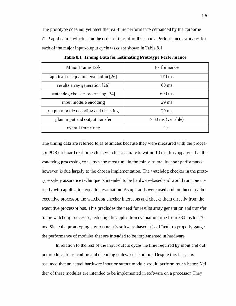
136
The prototype does not yet meet the real-time performance demanded by the carborne
ATP application which is on the order of tens of milliseconds. Performance estimates for
each of the major input-output cycle tasks are shown in Table 8.1.
The timing data are referred to as estimates because they were measured with the proces-
sor PCB on-board real-time clock which is accurate to within 10 ms. It is apparent that the
watchdog processing consumes the most time in the minor frame. Its poor performance,
however, is due largely to the chosen implementation. The watchdog checker in the proto-
type safety assurance technique is intended to be hardware-based and would run concur-
rently with application equation evaluation. As operands were used and produced by the
executive processor, the watchdog checker intercepts and checks them directly from the
executive processor bus. This precludes the need for results array generation and transfer
to the watchdog processor, reducing the application evaluation time from 230 ms to 170
ms. Since the prototyping environment is software-based it is difficult to properly gauge
the performance of modules that are intended to be implemented in hardware.
In relation to the rest of the input-output cycle the time required by input and out-
put modules for encoding and decoding codewords is minor. Despite this fact, it is
assumed that an actual hardware input or output module would perform much better. Nei-
ther of these modules are intended to be implemented in software on a processor. They
Table 8.1 Timing Data for Estimating Prototype Performance
Minor Frame Task Performance
application equation evaluation [26] 170 ms
results array generation [26] 60 ms
watchdog checker processing [34] 690 ms
input module encoding 29 ms
output module decoding and checking 29 ms
plant input and output transfer > 30 ms (variable)
overall frame rate 1 s

137
will most likely appear on separate PCBs that include vital interfacing and possibly encod-
ing circuits. The time to communicate field inputs and outputs to the plant model is listed
as variable because of the indeterminate nature of the UNIX environment. Theoretically
the transfer of 76 input and 66 output characters should require only about 30 ms at 38,400
baud. Since the Sun workstation uses a multitasking and multi-user operating system, it is
difficult to guarantee timely completion of any task, including serial transfers. Although it
is certain that the plant communications nearly achieved the expected performance on
occasion, it was evident that it was not consistent. Since the entire prototype was con-
trolled by the workstation, including the graphical plant model, Heurikon monitor func-
tions, and the Ada run-time environment, the load placed on it was very high at times.
The safety assurance functions of the output module in particular were exercised
using a software-based error injection method. Several of the error injection records cre-
ated for demonstration purposes were corruptions of output operands. They included noisy
random errors, data reference errors, and excessive timing errors. All of these were
detected by the dynamic code checker, identification checker, and timestamp checker on
the output module emulator. Note that these are the main types of errors that the output
module is responsible for checking. Further exercises of the checking mechanisms in the
emulator are planned and will be implemented when automated error injection is in place.
8.2 Conclusions and Extensions
The design and implementation of the prototype input and output module emulator
was an important step in the development of the input-output subsystem and the prototype
architecture. The software emulator in its current form includes many of the features criti-
cal to a safety assurance method based on information redundancy, regardless of the codes
used. As the input and output module designs evolve in subsequent versions of the proto-
type, some of the current features and algorithms will be useful, including:
• cyclic code encoding and decoding algorithms
• serial communications library for plant model communication
138
• codeword packing and unpacking methods
• monitor function incorporation
• timestamp generation and update methods
• semaphore usage for memory buffer access control
• methodology for simulation-based fault injection and characterization
The next version of the architecture design is already underway and the features described
above remain intact in the new input and output module emulators. So, in addition to pro-
ducing a proof-of-concept for the input and output architectures, the software emulator is a
solid foundation from which to develop future prototype designs. Beyond the software
emulator, the VHDL descriptions provide a starting point for synthesizing some of the
major input and output functions into actual hardware realizations.
Future versions of the architecture will benefit from the experience gained in
implementing this first version. It is already realized, for example, that the prototype per-
formance could be enhanced by choosing a less conservative codeword format. The use of
32-bit data operands probably provides numerical precision that is not required even in the
carborne ATP system. Reducing the codeword size would improve performance both in
the watchdog checker and the input and output module emulators. The use of such
unwieldy codewords also makes hardware realization extremely difficult.
Another immediate refinement of the prototype is the evolution to a distributed
system which included multiple VMEbus nodes communicating via FDDI links. This
would require that the input and output module emulators be modified to handle the addi-
tional communications tasks. The added tasks may also have some impact on performance
although the time added by sending input and output codewords over the FDDI network
should be minimal.
Changes or at least experiments with different safety assurance schemes are also
anticipated. The prototyping environment has the capability to support hardware-redun-
dant schemes, for example. In this case much of the input and output module emulator
139
functions related to coding would likely change. They would be replaced with software
routines that implement voting or comparison among possibly several processors execut-
ing the emulation.
Finally, the automated software and hardware-based error and fault injection
schemes discussed in Section 6.2.5 are under development and must be implemented
before a complete evaluation of the system safety is possible.
The issues discussed thus far are short term refinements to the architecture proto-
type or input-output subsystem. There are, in addition, long term issues to be studied and
resolved for the input and output architecture. One of these is the design and implementa-
tion of vital Class I interface circuitry. Work on the input and output modules has concen-
trated on the digital (or Class II) hardware that implements the encoding and decoding
functions. It would be extremely useful, for example, to develop design rules or guidelines
for digital hardware that would qualify it as vital. The railway industry currently considers
any digital hardware as non-vital and requires that any digital devices be proven safe
through some method. This problem is best understood by trying to imagine the encoders
and decoders used in the current input and output modules implemented using discrete
analog components. Furthermore, even if such a circuit could be designed, performing an
FMEA on it would be an arduous task.
Another issue that bears further investigation is the appropriateness of information
redundancy and coded processing to assure safety. The main reason for using coding the-
ory is its mathematical structure and analyzability. Using it in a computer system, how-
ever, requires assumptions that may or may not be justified. The validity of using a code-
based approach in a safety-critical microprocessor-based system requires a closer inspec-
tion.
At the outset of this thesis it was stated that arriving at a version of the Next Gen-
eration Architecture that meets all of the requirements for wayside and carborne ATP, in
addition to advanced applications, would require several design iterations. The work pre-
140
sented here is the first iteration in this process. It has proven that the concept of a simplex
coded processor for a safety-critical application is indeed feasible to implement albeit with
modifications. Though the prototype design does not incorporate all of the necessary fea-
tures of the architecture it does lay a solid foundation for subsequent designs. Eventually,
after a number of iterations, a final architecture will exist that dictates the next state-of-
the-art in safety-critical computer-based automatic train control. The prototype developed
and described in this thesis is the starting point.
141
References[1] T.G. Fisher, “Are Programmable Controllers Suitable for Emergency Shutdown Sys-
tems?,”ISA Transactions, Vol. 29, No. 2, 1990, pp. 1-11.
[2] L. Bodsberg and P. Hokstad, “Balancing Reliability Requirements for Field Devices andControl Logic Modules in Safety Systems,”Proceedings of the IFAC/IFIP/EWICS/SRE Symposium on Safety, Security and Reliability of Computer Based Systems(SAFECOMP ‘91), Trondheim, Norway, October 30, 1991, pp. 89-94.
[3] J. Paques, “Basic Safety Rules for Using Programmable Controllers,”ISA Transactions,Vol. 29, No. 2, 1990, pp. 17-22.
[4] D.B. Turner, R.D. Burns, and H. Hecht, “Designing Micro-Based Systems for Fail-SafeTravel,” IEEE Spectrum, Vol. 24, February 1987, pp. 58-63.
[5] D.B. Rutherford, “What Do You Mean -- It’s Fail-Safe?,”1990 Rapid Transit Conference,American Public Transit Association, June 1990.
[6] A.K. Ghosh, “A Distributed Parallel Processing System for Wayside and Carborne TrainControl,” M.S.E.E. Thesis, University of Virginia, Charlottesville, Virginia, May1993.
[7] D.R. Disk, “A Unique Application of a Microprocessor to Vital Controls,”Proceedings ofInternational Conference on Railway Safety Control and Automation, 1984, pp. 97-104.
[8] “Volume II - Technical Specifications,” Metro Green Line Contract Documents, ContractNo. R23-T07-H1100, Los Angeles County Transportation Commission, February 20,1991.
[9] H. Kirrmann, “Train Control Systems,”IEEE Micro, Vol. 10 , No. 4, August 1990, pp. 79-80.
[10] B.W. Johnson,Design and Analysis of Fault-Tolerant Digital Systems, Addison-WesleyPublishing Company, Reading, Massachusetts, 1989.
[11] “Safety System Validation with Regard to Cross-Acceptance of Signalling Systems by theRailways,” Report No. 1, Institution of Railway Signal Engineers, International Tech-nical Committee, January 14, 1992.
[12] D.B. Rutherford, “What Do You Mean -- It’s Fail-Safe? Part II,”1990 Rapid Transit Con-ference, American Public Transit Association, June 1990.
[13] R.W. Butler and G.B. Finelli, “The Infeasibility of Quantifying the Reliability of Life-Critical Real-Time Software,”IEEE Transactions on Software Engineering, vol. 19,No. 1, January 1993, pp. 3-12.
[14] J.H. Lala, R.E. Harper, and L.S. Alger, “A Design Approach for Ultrareliable Real-TimeSystems,”IEEE Computer, Vol. 24, No. 5, May 1991, pp. 12-22.
142
[15] L. Lamport, R. Shostak, and M. Pease, “The Byzantine Generals’ Problem,”ACM Trans-actions on Programming Languages and Systems, Vol. 4, No. 3, July 1982, pp. 382-401.
[16] D.A. Rennels, A. Avizienis, and M., “A Study of Standard Building Blocks for the Designof Fault-Tolerant Distributed Computer Systems,”Proceedings of Eighth Interna-tional Symposium on Fault-Tolerant Computing, Toulouse, France, June 1978, pp.144-149.
[17] C.J. Walter, R.M. Kieckhafer, and R.M. Finn, “MAFT: A Multicomputer Architecture forFault-Tolerance in Real-Time Control Systems”,IEEE Real-Time Systems Sympo-sium, December 1985, pp. 133-140.
[18] J.H. Wensley,et. al., “SIFT: Design and Analysis of a Fault-Tolerant Computer for Air-craft Control,”Proceedings of the IEEE, Vol. 66, No. 10, October 1978, pp. 1240-1255.
[19] A.L. Hopkins, T.B. Smith, and J.H. Lala, “FTMP - A Highly Reliable Fault-Tolerant Mul-tiprocessor for Aircraft”,Proceedings of the IEEE, Vol. 66, No. 10, October 1978, pp.1221-1239.
[20] T. Markas and N. Kanopoulos, “A Bus-Monitor Unit for Fault-Tolerant System Configu-rations,”Microprocessing and Microprogamming 30, 1990, pp. 521-528.
[21] D.B. Rutherford, “Fail-Safe Microprocessor Interlocking -- An Application of Numeri-cally Integrated Safety Assurance Logic,”Proceedings of Institution of Railway Sig-nal Engineers, London, September 1983.
[22] Y. Min, Y. Zhou, Z. Li, and C. Ye, “A Fail-Safe Microprocessor-Based System for Inter-locking on Railways,”Proceedings of the Annual Reliability and Maintainability Sym-posium, 1994, pp. 415-420.
[23] V. Chandra and M.R. Verma, “A Fail-Safe Interlocking System for Railways,”IEEEDesign &Test of Computers, Vol. 8, March 1991, pp. 58-66.
[24] A. K. Ghosh,et. al., “A Distributed Safety-Critical System for Real-Time Train Control,”pre-publication draft, Center for Semicustom Integrated Systems, University of Vir-ginia, July 1994.
[25] S. Heath, “Multiprocessing with VMEbus,”Electronics & Wireless World, Vol. 93,November 1987, pp. 1106-1109.
[26] D.T. Lamb, “A Dependable Computing Platform: A Software Executive for Real-TimeSafety-Critical Control,” M.S.E.E. Thesis, University of Virginia, Charlottesville, Vir-ginia, May 1994.
[27] P.J. Perrone and B.W. Johnson, “System Level Error Modeling for Information Systems,”Technical Report 931101.0, Center for Semicuston Integrated Systems, University ofVirginia, November 1993.
[28] D.C. Coll,et. al., “The Communications System Architecture of the North AmericanAdvanced Train Control System,”IEEE Transactions on Vehicular Technology, Vol.39, No. 3, August 1990, pp. 244-255.
143
[29] R.G. Ayers, “Selection of a Forward Error Correcting Code for the Data CommunicationRadio Link of the Advanced Train Control System,”IEEE Transactions on VehicularTechnology, Vol. 38, No. 4, November 1989, pp. 247-254.
[30] I. Boldea, et. al., “Field Tests on a MAGLEV with Passive Guideway Linear InductorMotor Transportation System,”IEEE Transactions on Vehicular Technolgy, Vol. 37,No. 4, November 1988, pp. 213-219.
[31] Standard Input PCB, sheet 88A, drawing no. 451441,Standard Circuit Diagrams of Plug-In Printed Circuit Boards, Union Switch and Signal, Inc.
[32] Standard Relay Driver PCB, sheet 86B, drawing no. 451441,Standard Circuit Diagramsof Plug-In Printed Circuit Boards, Union Switch and Signal, Inc.
[33] D.J. Mitchell,et. al., “Examination of the MICROLOK Interlocking System,”FinalReport, Battelle, Columbus, Ohio, October 20, 1989.
[34] P.J. Perrone, “Global Safety Assurance: Concepts and Application to Train Control Sys-tems,” M.S.E.E. Thesis, University of Virginia, Charlottesville, Virginia, to be pub-lished January 1995.
[35] S.G. Wilson,Digital Modulation and Coding, pre-publication manuscript, Prentice Hall,Englewood Cliffs, New Jersey, 1994.
[36] J. Lo, S. Thanawastien, and T.R.N. Rao, “Concurrent Error Detection in Arithmetic andLogical Operations Using Berger Codes,”Proceedings of the Ninth Symposium onComputer Arithmetic, September 1989, pp. 233-240.
[37] The VMEbus Specification, published by VMEbus International Trade Association,Scottsdale, Arizona, 1987.
[38] HK68/V4F User’s Manual, Revision C, Heurikon Corporation, Madison, Wisconsin,1991.
[39] M.J. Conway,et. al., “The SUIT Version 2.3 Reference Manual,” Department of Com-puter Science, University of Virginia, 1992.
[40] ANSI/IEEE Std. 1076-1993 IEEE Standard VHDL Language Reference Manual, pub-lished by the IEEE, New York, New York, June 6, 1994.
[41] FPGA Data Book and Design Guide, Actel Corporation, Sunnyvale, California, 1994.
[42] H. Choi and K.S. Trivedi, “Conditional MTTF and its Computation in Markov ReliabilityModels,”Proceedings of the Annual Reliability and Maintainability Symposium,1993, pp. 56-63.
[43] D.T. Smith, “A Malicious Fault List Generation Algorithm for the Evaluation of SystemCoverage,” Ph.D. Disstertation, University of Virginia, Charlottesville, Virginia,August 1993.
[44] T.A. Delong, “Performance and Safety Analysis of a Microprocessor-Based EmbeddedControl System Using VHDL,” M.S.E.E. Thesis, University of Virginia, Charlottes-ville, Virginia, January 1994.
144
[45] J. Rabel, “Use of 6821 Programmable Interface Adapter in MICROLOK,” company docu-mentation, Union Switch and Signal, Inc., March 6, 1992.
[46] A.A. Shaikh and B.W. Johnson, “MICROLOK Input/Output Hardware Fault Dictio-nary,” Technical Report 940201.0, Center for Semicustom Integrated Systems, Uni-versity of Virginia, February 1994.
[47] M.A. Marouf and A.D. Friedman, “Design of Self-Checking Checkers for Berger Codes,”Proceedings of Eighth International Symposium on Fault-Tolerant Computing, Tou-louse, France, June 1978, pp. 179-184.
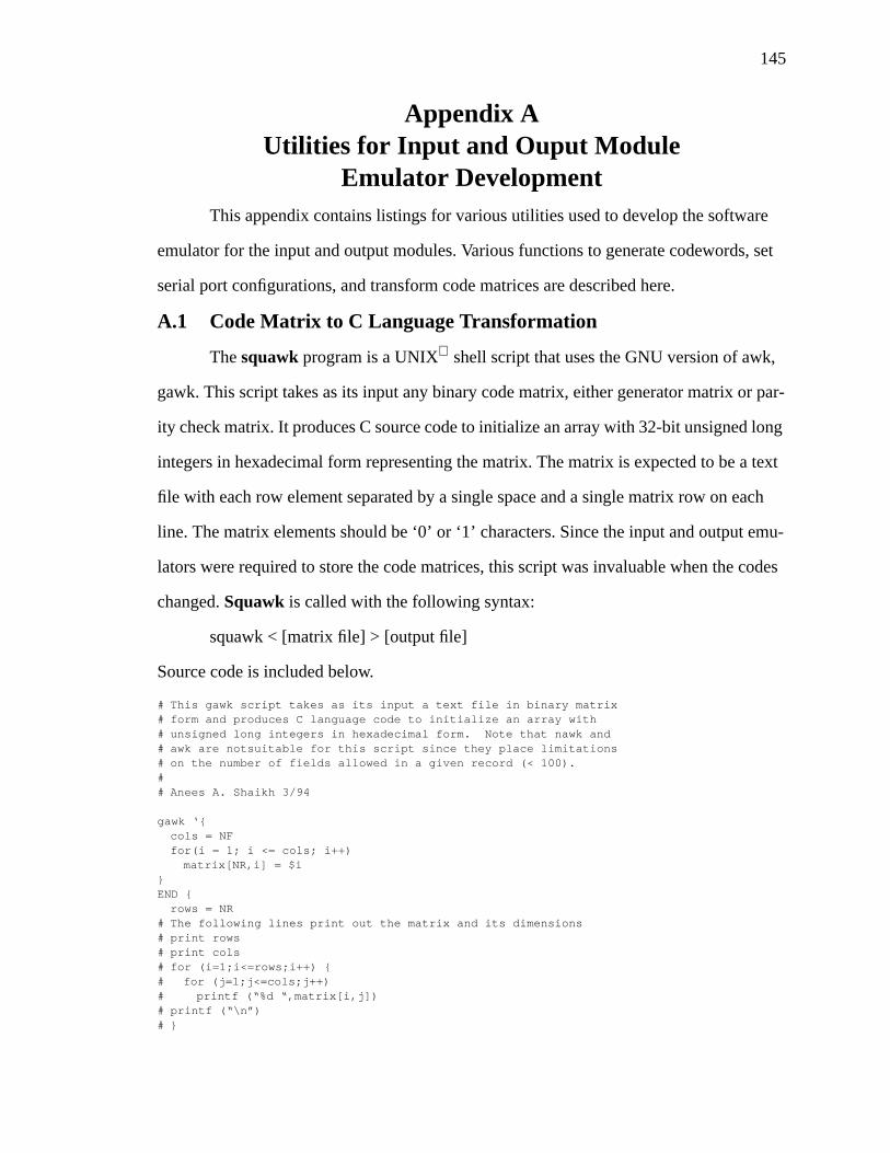
145
Appendix AUtilities for Input and Ouput Module
Emulator DevelopmentThis appendix contains listings for various utilities used to develop the software
emulator for the input and output modules. Various functions to generate codewords, set
serial port configurations, and transform code matrices are described here.
A.1 Code Matrix to C Language Transformation
Thesquawk program is a UNIX shell script that uses the GNU version of awk,
gawk. This script takes as its input any binary code matrix, either generator matrix or par-
ity check matrix. It produces C source code to initialize an array with 32-bit unsigned long
integers in hexadecimal form representing the matrix. The matrix is expected to be a text
file with each row element separated by a single space and a single matrix row on each
line. The matrix elements should be ‘0’ or ‘1’ characters. Since the input and output emu-
lators were required to store the code matrices, this script was invaluable when the codes
changed.Squawk is called with the following syntax:
squawk < [matrix file] > [output file]
Source code is included below.
# This gawk script takes as its input a text file in binary matrix# form and produces C language code to initialize an array with# unsigned long integers in hexadecimal form. Note that nawk and# awk are notsuitable for this script since they place limitations# on the number of fields allowed in a given record (< 100).## Anees A. Shaikh 3/94
gawk ‘{cols = NFfor(i = 1; i <= cols; i++)
matrix[NR,i] = $i}END {
rows = NR# The following lines print out the matrix and its dimensions# print rows# print cols# for (i=1;i<=rows;i++) {# for (j=1;j<=cols;j++)# printf (“%d “,matrix[i,j])# printf (“\n”)# }
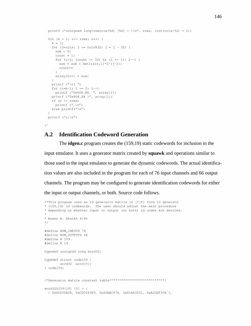
146
printf (“unsigned long\tmatrix[%d] [%d] = {\n”, rows, (int(cols/32) + 1))
for (n = 1; n<= rows; n++) {k = 1;for (j=cols; j >= cols%32; j = j - 32) {
sum = 0;count = 1;for (i=j; (count <= 32) && (i >= 1); i--) {
sum = sum + matrix[n,i]*2^(j-i);count++
}array[k++] = sum;
}printf (“\t{ “)for (i=k-1; i >= 2; i--)
printf (“0x%08.8X, “, array[i])printf (“0x%08.8X }”, array[1])if (n != rows)
printf (“,\n”)else printf(“\n”)
}printf (“};\n”)
}’
A.2 Identification Codeword Generation
The idgen.c program creates the (159,19) static codewords for inclusion in the
input emulator. It uses a generator matrix created bysquawk and operations similar to
those used in the input emulator to generate the dynamic codewords. The actual identifica-
tion values are also included in the program for each of 76 input channels and 66 output
channels. The program may be configured to generate identification codewords for either
the input or output channels, or both. Source code follows.
/*This program uses an id generator matrix in [I|P] form to generate* (159,19) id codewords. The user should adjust the main procedure* depending on whether input or output (or both) id codes are desired.** Anees A. Shaikh 4/94*/
#define NUM_INPUTS 76#define NUM_OUTPUTS 66#define N 159#define K 19
typedef unsigned long word32;
typedef struct code159 { word32 word[5];} code159;
/*Generator matrix constant table****************************/
word32G159[19] [5] = {{ 0x40000A08, 0xCDC56389, 0x60AAC978, 0x01A63031, 0xA20DF3CA },
147
{ 0x20000504, 0x66E2B1C4, 0xB05564BC, 0x00D31818, 0xD106F9E5 },{ 0x10000D38, 0xD43DB5B5, 0x66AAD649, 0x9E021808, 0x3655A653 },{ 0x08000926, 0x8D52378D, 0x8DD50F33, 0x516A9800, 0x45FC0988 },{ 0x04000493, 0x46A91BC6, 0xC6EA8799, 0xA8B54C00, 0x22FE04C4 },{ 0x02000249, 0xA3548DE3, 0x637543CC, 0xD45AA600, 0x117F0262 },{ 0x01000124, 0xD1AA46F1, 0xB1BAA1E6, 0x6A2D5300, 0x08BF8131 },{ 0x00800F28, 0x8F99CE2F, 0xE65D34E4, 0xAB7D3D84, 0x5A891A39 },{ 0x0040082E, 0xA0800A40, 0xCDAEFE65, 0xCBD50AC6, 0x739257BD },{ 0x00200BAD, 0xB70CE877, 0x58571B25, 0x7B811167, 0x671FF17F },{ 0x00100A6C, 0x3CCA996C, 0x92ABE985, 0x23AB1CB7, 0xED59221E },{ 0x00080536, 0x1E654CB6, 0x4955F4C2, 0x91D58E5B, 0xF6AC910F },{ 0x00040D21, 0xE87E4B0C, 0x1A2A9E76, 0xD6815329, 0xA5809226 },{ 0x00020690, 0xF43F2586, 0x0D154F3B, 0x6B40A994, 0xD2C04913 },{ 0x00010CF2, 0x9D537F94, 0x380AC38A, 0x2BCBC0CE, 0x37B6FE28 },{ 0x00008679, 0x4EA9BFCA, 0x1C0561C5, 0x15E5E067, 0x1BDB7F14 },{ 0x0000433C, 0xA754DFE5, 0x0E02B0E2, 0x8AF2F033, 0x8DEDBF8A },{ 0x0000219E, 0x53AA6FF2, 0x87015871, 0x45797819, 0xC6F6DFC5 },{ 0x00001F75, 0xCE99DAAE, 0x7D00C82F, 0x3CD72808, 0xBDADB543 }
};
/*ID information array for inputs and outputs************/
word32idin[NUM_INPUTS] = {0x0000002B,0x0000002C,0x0000002D,0x0000002E,0x0000002F,0x00000030,0x00000031,0x00000032,0x00000033,0x00000034,0x00000035,0x00000036,0x00000037,0x00000038,0x0000001D,0x0000001E,0x0000001F,0x00000020,0x00000021,0x00000022,0x00000023,0x00000024,0x00000025,0x00000026,0x00000027,0x00000028,0x00000029,0x0000002A,0x0000003A,0x0000003C,0x0000003E,0x00000041,0x00000043,0x00000047,0x0000004A,0x0000004D,0x0000004F,0x00000052,0x00000001,0x00000002,0x00000003,0x00000004,
148
0x00000005,0x00000006,0x00000007,0x00000008,0x00000009,0x0000000A,0x0000000B,0x0000000C,0x0000000D,0x0000000E,0x0000000F,0x00000010,0x00000011,0x00000012,0x00000013,0x00000014,0x00000015,0x00000016,0x00000017,0x00000018,0x00000019,0x0000001A,0x0000001B,0x0000001C,0x00000056,0x00000058,0x0000005A,0x0000005D,0x0000005F,0x00000063,0x00000066,0x00000069,0x0000006B,0x0000006E
};
word32idout[NUM_OUTPUTS] = {0x0000040A,0x0000040B,0x0000040C,0x0000040D,0x0000040E,0x0000040F,0x00000410,0x00000411,0x00000412,0x00000413,0x00000414,0x00000415,0x00000416,0x00000417,0x00000418,0x00000419,0x0000041A,0x0000041B,0x0000041C,0x0000041D,0x0000041E,0x0000041F,0x00000420,0x00000421,0x00000422,0x00000423,0x00000424,0x00000425,
149
0x00000426,0x00000427,0x00000428,0x00000429,0x0000042A,0x0000042B,0x0000042C,0x0000042D,0x0000042E,0x0000042F,0x00000430,0x00000431,0x00000432,0x00000433,0x00000434,0x00000435,0x00000436,0x00000437,0x00000438,0x00000439,0x0000043A,0x0000043B,0x0000043C,0x0000043D,0x0000043E,0x0000043F,0x00000440,0x00000441,0x00000400,0x00000401,0x00000402,0x00000403,0x00000404,0x00000405,0x00000406,0x00000407,0x00000408,0x00000409
};
/********************************************************************/
word32 flip32 (word32 info)
{word32retval;word32mask, temp;int i;
mask = 0x00000001;temp = 0;for (i=0; i <= 31; i++)
temp |= ((info << i) >> (31 - i)) & (mask << i);retval = temp;return (retval);
}
code159 encodeID (word32 info)
{code159 retval;code159 sum;int i,j, shifts;word32 mask;
150
mask = 0x80000000;for (i = 0; i <= 4; i++)
sum.word[i] = 0;for (i = K-1; i >= 0; i--) {
shifts = K-1 - i;if (( (info << shifts) & mask) != 0x00000000)
for (j = 4; j >= 0; j--)sum.word[j] ^= G159[K-1-i][4-j];
}for (i = 0; i<= 4; i++)
retval.word[i] = sum.word[i];return(retval);
}
code159 flipCode159 (code159 info)
{code159retval;word32ltemp1, ltemp2;int i;
for (i = 4; i >= 1; i--) {ltemp1 = flip32 (info.word[i]) >> 1;ltemp2 = flip32 (info.word[i-1]) << 31;retval.word[4-i] = ltemp1 | ltemp2;
}retval.word[4] = flip32 (info.word[0]) >> 1;return (retval);
}
void genInputId (void)
{
int i, j;word32info;code159 precode, code;
printf (“word32\tinarray[%d] [%d] = {\n”, NUM_INPUTS, N/32 + 1);for (i = 0; i <= NUM_INPUTS-1; i++) {
info = flip32(idin[i]);precode = encodeID (info);code = flipCode159 (precode);printf (“\t{ “);for (j = 4; j >= 1; j--)
printf (“0x%.8lX, “, code.word[j]);printf (“0x%.8lX }”, code.word[0]);if (i < NUM_INPUTS-1)
printf (“,\n”);else
printf (“\n”);}printf (“};\n”);
}
void genOutputId (void)
{
int i, j;word32info;code159 precode, code;
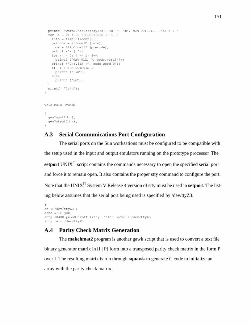
151
printf (“word32\toutarray[%d] [%d] = {\n”, NUM_OUTPUTS, N/32 + 1);for (i = 0; i <= NUM_OUTPUTS-1; i++) {
info = flip32(idout[i]);precode = encodeID (info);code = flipCode159 (precode);printf (“\t{ “);for (j = 4; j >= 1; j--)
printf (“0x%.8lX, “, code.word[j]);printf (“0x%.8lX }”, code.word[0]);if (i < NUM_OUTPUTS-1)
printf (“,\n”);else
printf (“\n”);}printf (“};\n”);
}
void main (void)
{genInputId ();genOutputId ();
}
A.3 Serial Communications Port Configuration
The serial ports on the Sun worksations must be configured to be compatible with
the setup used in the input and output emulators running on the prototype processor. The
setport UNIX script contains the commands necessary to open the specified serial port
and force it to remain open. It also contains the proper stty command to configure the port.
Note that the UNIX System V Release 4 version of stty must be used insetport. The list-
ing below assumes that the serial port being used is specified by /dev/ttyZ3.
:sh 1>/dev/ttyZ3 &echo $! > jobstty 38400 pass8 ixoff ixany -onlcr -echo < /dev/ttyZ3stty -a < /dev/ttyZ3
A.4 Parity Check Matrix Generation
Themakehmat2 program is another gawk script that is used to convert a text file
binary generator matrix in [I | P] form into a transposed parity check matrix in the form P
over I. The resulting matrix is run throughsquawk to generate C code to initialize an
array with the parity check matrix.
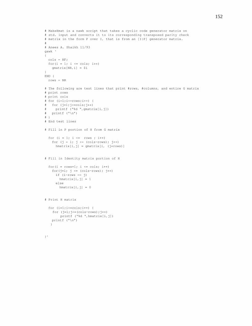
152
# MakeHmat is a nawk script that takes a cyclic code generator matrix on# std. input and converts it to its corresponding transposed parity check# matrix in the form P over I, that is from an [I|P] generator matrix.## Anees A. Shaikh 11/93gawk ‘{
cols = NF;for(i = 1; i <= cols; i++)
gmatrix[NR,i] = $i}END {
rows = NR
# The following are test lines that print #rows, #columns, and entire G matrix# print rows# print cols# for (i=1;i<=rows;i++) {# for (j=1;j<=cols;j++)# printf (“%d “,gmatrix[i,j])# printf (“\n”)# }# End test lines
# Fill in P portion of H from G matrix
for (i = 1; i <= rows ; i++)for (j = 1; j <= (cols-rows); j++)
hmatrix[i,j] = gmatrix[i, (j+rows)]
# Fill in Identity matrix portion of H
for(i = rows+1; i <= cols; i++)for(j=1; j <= (cols-rows); j++)
if (i-rows == j)hmatrix[i,j] = 1
elsehmatrix[i,j] = 0
# Print H matrix
for (i=1;i<=cols;i++) {for (j=1;j<=(cols-rows);j++)
printf (“%d “,hmatrix[i,j])printf (“\n”)
}
}’
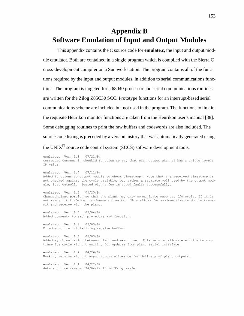
153
Appendix BSoftware Emulation of Input and Output Modules
This appendix contains the C source code foremulate.c, the input and output mod-
ule emulator. Both are contained in a single program which is compiled with the Sierra C
cross-development compiler on a Sun workstation. The program contains all of the func-
tions required by the input and output modules, in addition to serial communications func-
tions. The program is targeted for a 68040 processor and serial communications routines
are written for the Zilog Z85C30 SCC. Prototype functions for an interrupt-based serial
communications scheme are included but not used in the program. The functions to link in
the requisite Heurikon monitor functions are taken from the Heurikon user’s manual [38].
Some debugging routines to print the raw buffers and codewords are also included. The
source code listing is preceded by a version history that was automatically generated using
the UNIX source code control system (SCCS) software development tools.
emulate.c Ver. 1.8 07/21/94Corrected comment in checkId function to say that each output channel has a unique 19-bitID value
emulate.c Ver. 1.7 07/12/94Added functions to output module to check timestamp. Note that the received timestamp isnot checked against the cycle variable, but rather a separate poll used by the output mod-ule, i.e. outpoll. Tested with a few injected faults successfully.
emulate.c Ver. 1.6 05/25/94Changed plant portion so that the plant may only communicate once per I/O cycle. If it isnot ready, it forfeits the chance and waits. This allows for maximum time to do the trans-mit and receive with the plant.
emulate.c Ver. 1.5 05/04/94Added comments to each procedure and function.
emulate.c Ver. 1.4 05/03/94Fixed error in initializing receive buffer.
emulate.c Ver. 1.3 05/03/94Added synchronization between plant and executive. This version allows executive to con-tinue its cycle without waiting for updates from plant serial interface.
emulate.c Ver. 1.2 04/26/94Working version without asynchronous allowance for delivery of plant outputs.
emulate.c Ver. 1.1 04/22/94date and time created 94/04/22 10:56:35 by aas9e
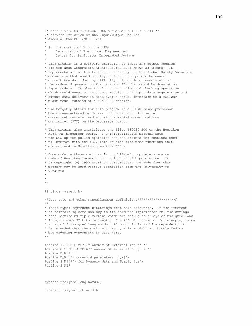
154
/* %Z%%M% VERSION %I% >LAST DELTA %E% EXTRACTED %D% %T% *//*Software Emulation of NGA Input/Output Modules* Anees A. Shaikh 1/94 - 7/94** (c University of Virginia 1994* Department of Electrical Engineering* Center for Semicustom Integrated Systems** This program is a software emulation of input and output modules* for the Next Generation Architecture, also known as VFrame. It* implements all of the functions necessary for the Global Safety Assurance* mechanisms that would usually be found on separate hardware* circuit boards. More specifically this emulator models all of* the codeword generation for data and IDs that would be done at an* input module. It also handles the decoding and checking operations* which would occur at an output module. All input data acquisition and* output data delivery is done over a serial interface to a railway* plant model running on a Sun SPARCstation.** The target platform for this program is a 68040-based processor* board manufactured by Heurikon Corporation. All serial* communications are handled using a serial communications* controller (SCC) on the processor board.** This program also initializes the Zilog Z85C30 SCC on the Heurikon* HK68/V4F processor board. The initialization process sets* the SCC up for polled operation and and defines the routines used* to interact with the SCC. This routine also uses functions that* are defined in Heurikon’s monitor PROM.** Some code in these routines is unpublished proprietary source* code of Heurikon Corporation and is used with permission. It* is Copyright (c) 1990 Heurikon Corporation. No code from this* program may be used without permission from the University of* Virginia.***/
#include <assert.h>
/*Data type and other miscellaneous definitions*******************//** These types represent bitstrings that hold codewords. In the interest* of maintaining some analogy to the hardware implementation, the strings* that require multiple machine words are set up as arrays of unsigned long* integers each 32 bits in length. The 256-bit codeword, for example, is an* array of 8 unsigned long words. Although it is machine-dependent, it* is intended that the unsigned char type is an 8-bits. Little Endian* bit ordering convention is used here.*/
#define IN_BUF_SIZE76/* number of external inputs */#define OUT_BUF_SIZE66/* number of external outputs */#define D_N97#define D_K55/* codeword parameters (n,k)*/#define S_N159/* for Dynamic data and Static ids*/#define S_K19
typedef unsigned long word32;
typedef unsigned int word16;
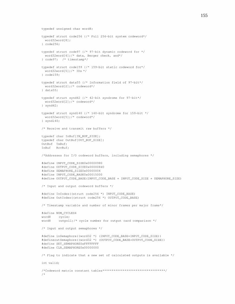
155
typedef unsigned char word8;
typedef struct code256 {/* Full 256-bit system codeword*/word32word[8];
} code256;
typedef struct code97 {/* 97-bit dynamic codeword for */word32word[4];/* data, Berger check, and*/
} code97; /* timestamp*/
typedef struct code159 {/* 159-bit static codeword for*/word32word[5];/* IDs */
} code159;
typedef struct data55 {/* Information field of 97-bit*/word32word[2];/* codeword*/
} data55;
typedef struct synd42 {/* 42-bit syndrome for 97-bit*/word32word[2];/* codeword*/
} synd42;
typedef struct synd140 {/* 140-bit syndrome for 159-bit */word32word[5];/* codeword*/
} synd140;
/* Receive and transmit raw buffers */
typedef char InBuf[IN_BUF_SIZE];typedef char OutBuf[OUT_BUF_SIZE];OutBuf TxBuf;InBuf RcvBuf;
/*Addresses for I/O codeword buffers, including semaphores */
#define INPUT_CODE_SIZE0x00000980#define OUTPUT_CODE_SIZE0x00000840#define SEMAPHORE_SIZE0x00000004#define INPUT_CODE_BASE0x00015000#define OUTPUT_CODE_BASE(INPUT_CODE_BASE + INPUT_CODE_SIZE + SEMAPHORE_SIZE)
/* Input and output codeword buffers */
#define InCodes((struct code256 *) INPUT_CODE_BASE)#define OutCodes((struct code256 *) OUTPUT_CODE_BASE)
/* Timestamp variable and number of minor frames per major frame*/
#define NUM_CYCLES4word8 cycle;word8 outpoll;/* cycle number for output card comparison */
/* Input and output semaphores */
#define inSemaphore((word32 *) (INPUT_CODE_BASE+INPUT_CODE_SIZE))#defineoutSemaphore((word32 *) (OUTPUT_CODE_BASE+OUTPUT_CODE_SIZE))#define SET_SEMAPHORE0xFFFFFFFF#define CLR_SEMAPHORE0x00000000
/* Flag to indicate that a new set of calculated outputs is available */
int valid;
/*Codeword matrix constant tables**********************************//*
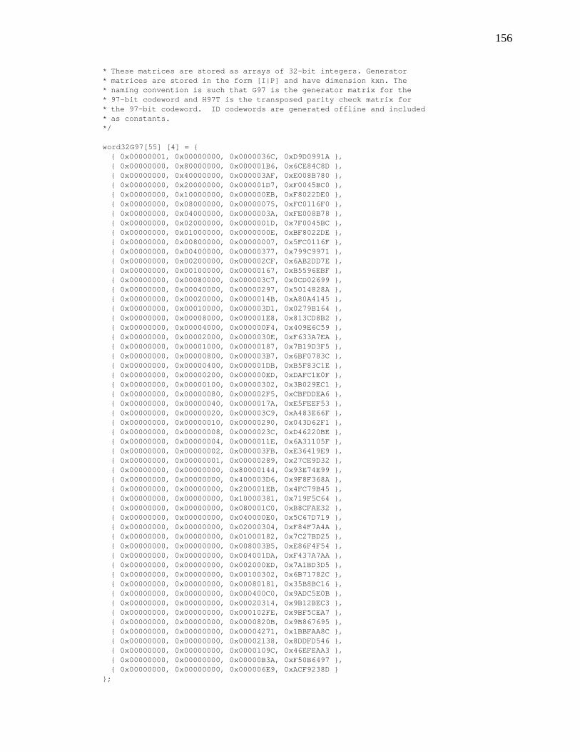
156
* These matrices are stored as arrays of 32-bit integers. Generator* matrices are stored in the form [I|P] and have dimension kxn. The* naming convention is such that G97 is the generator matrix for the* 97-bit codeword and H97T is the transposed parity check matrix for* the 97-bit codeword. ID codewords are generated offline and included* as constants.*/
word32G97[55] [4] = {{ 0x00000001, 0x00000000, 0x0000036C, 0xD9D0991A },{ 0x00000000, 0x80000000, 0x000001B6, 0x6CE84C8D },{ 0x00000000, 0x40000000, 0x000003AF, 0xE008B780 },{ 0x00000000, 0x20000000, 0x000001D7, 0xF0045BC0 },{ 0x00000000, 0x10000000, 0x000000EB, 0xF8022DE0 },{ 0x00000000, 0x08000000, 0x00000075, 0xFC0116F0 },{ 0x00000000, 0x04000000, 0x0000003A, 0xFE008B78 },{ 0x00000000, 0x02000000, 0x0000001D, 0x7F0045BC },{ 0x00000000, 0x01000000, 0x0000000E, 0xBF8022DE },{ 0x00000000, 0x00800000, 0x00000007, 0x5FC0116F },{ 0x00000000, 0x00400000, 0x00000377, 0x799C9971 },{ 0x00000000, 0x00200000, 0x000002CF, 0x6AB2DD7E },{ 0x00000000, 0x00100000, 0x00000167, 0xB5596EBF },{ 0x00000000, 0x00080000, 0x000003C7, 0x0CD02699 },{ 0x00000000, 0x00040000, 0x00000297, 0x5014828A },{ 0x00000000, 0x00020000, 0x0000014B, 0xA80A4145 },{ 0x00000000, 0x00010000, 0x000003D1, 0x0279B164 },{ 0x00000000, 0x00008000, 0x000001E8, 0x813CD8B2 },{ 0x00000000, 0x00004000, 0x000000F4, 0x409E6C59 },{ 0x00000000, 0x00002000, 0x0000030E, 0xF633A7EA },{ 0x00000000, 0x00001000, 0x00000187, 0x7B19D3F5 },{ 0x00000000, 0x00000800, 0x000003B7, 0x6BF0783C },{ 0x00000000, 0x00000400, 0x000001DB, 0xB5F83C1E },{ 0x00000000, 0x00000200, 0x000000ED, 0xDAFC1E0F },{ 0x00000000, 0x00000100, 0x00000302, 0x3B029EC1 },{ 0x00000000, 0x00000080, 0x000002F5, 0xCBFDDEA6 },{ 0x00000000, 0x00000040, 0x0000017A, 0xE5FEEF53 },{ 0x00000000, 0x00000020, 0x000003C9, 0xA483E66F },{ 0x00000000, 0x00000010, 0x00000290, 0x043D62F1 },{ 0x00000000, 0x00000008, 0x0000023C, 0xD46220BE },{ 0x00000000, 0x00000004, 0x0000011E, 0x6A31105F },{ 0x00000000, 0x00000002, 0x000003FB, 0xE36419E9 },{ 0x00000000, 0x00000001, 0x00000289, 0x27CE9D32 },{ 0x00000000, 0x00000000, 0x80000144, 0x93E74E99 },{ 0x00000000, 0x00000000, 0x400003D6, 0x9F8F368A },{ 0x00000000, 0x00000000, 0x200001EB, 0x4FC79B45 },{ 0x00000000, 0x00000000, 0x10000381, 0x719F5C64 },{ 0x00000000, 0x00000000, 0x080001C0, 0xB8CFAE32 },{ 0x00000000, 0x00000000, 0x040000E0, 0x5C67D719 },{ 0x00000000, 0x00000000, 0x02000304, 0xF84F7A4A },{ 0x00000000, 0x00000000, 0x01000182, 0x7C27BD25 },{ 0x00000000, 0x00000000, 0x008003B5, 0xE86F4F54 },{ 0x00000000, 0x00000000, 0x004001DA, 0xF437A7AA },{ 0x00000000, 0x00000000, 0x002000ED, 0x7A1BD3D5 },{ 0x00000000, 0x00000000, 0x00100302, 0x6B71782C },{ 0x00000000, 0x00000000, 0x00080181, 0x35B8BC16 },{ 0x00000000, 0x00000000, 0x000400C0, 0x9ADC5E0B },{ 0x00000000, 0x00000000, 0x00020314, 0x9B12BEC3 },{ 0x00000000, 0x00000000, 0x000102FE, 0x9BF5CEA7 },{ 0x00000000, 0x00000000, 0x0000820B, 0x9B867695 },{ 0x00000000, 0x00000000, 0x00004271, 0x1BBFAA8C },{ 0x00000000, 0x00000000, 0x00002138, 0x8DDFD546 },{ 0x00000000, 0x00000000, 0x0000109C, 0x46EFEAA3 },{ 0x00000000, 0x00000000, 0x00000B3A, 0xF50B6497 },{ 0x00000000, 0x00000000, 0x000006E9, 0xACF9238D }
};
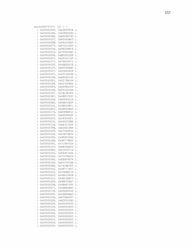
157
word32H97T[97] [2] = {{ 0x0000036C, 0xD9D0991A },{ 0x000001B6, 0x6CE84C8D },{ 0x000003AF, 0xE008B780 },{ 0x000001D7, 0xF0045BC0 },{ 0x000000EB, 0xF8022DE0 },{ 0x00000075, 0xFC0116F0 },{ 0x0000003A, 0xFE008B78 },{ 0x0000001D, 0x7F0045BC },{ 0x0000000E, 0xBF8022DE },{ 0x00000007, 0x5FC0116F },{ 0x00000377, 0x799C9971 },{ 0x000002CF, 0x6AB2DD7E },{ 0x00000167, 0xB5596EBF },{ 0x000003C7, 0x0CD02699 },{ 0x00000297, 0x5014828A },{ 0x0000014B, 0xA80A4145 },{ 0x000003D1, 0x0279B164 },{ 0x000001E8, 0x813CD8B2 },{ 0x000000F4, 0x409E6C59 },{ 0x0000030E, 0xF633A7EA },{ 0x00000187, 0x7B19D3F5 },{ 0x000003B7, 0x6BF0783C },{ 0x000001DB, 0xB5F83C1E },{ 0x000000ED, 0xDAFC1E0F },{ 0x00000302, 0x3B029EC1 },{ 0x000002F5, 0xCBFDDEA6 },{ 0x0000017A, 0xE5FEEF53 },{ 0x000003C9, 0xA483E66F },{ 0x00000290, 0x043D62F1 },{ 0x0000023C, 0xD46220BE },{ 0x0000011E, 0x6A31105F },{ 0x000003FB, 0xE36419E9 },{ 0x00000289, 0x27CE9D32 },{ 0x00000144, 0x93E74E99 },{ 0x000003D6, 0x9F8F368A },{ 0x000001EB, 0x4FC79B45 },{ 0x00000381, 0x719F5C64 },{ 0x000001C0, 0xB8CFAE32 },{ 0x000000E0, 0x5C67D719 },{ 0x00000304, 0xF84F7A4A },{ 0x00000182, 0x7C27BD25 },{ 0x000003B5, 0xE86F4F54 },{ 0x000001DA, 0xF437A7AA },{ 0x000000ED, 0x7A1BD3D5 },{ 0x00000302, 0x6B71782C },{ 0x00000181, 0x35B8BC16 },{ 0x000000C0, 0x9ADC5E0B },{ 0x00000314, 0x9B12BEC3 },{ 0x000002FE, 0x9BF5CEA7 },{ 0x0000020B, 0x9B867695 },{ 0x00000271, 0x1BBFAA8C },{ 0x00000138, 0x8DDFD546 },{ 0x0000009C, 0x46EFEAA3 },{ 0x0000033A, 0xF50B6497 },{ 0x000002E9, 0xACF9238D },{ 0x00000200, 0x00000000 },{ 0x00000100, 0x00000000 },{ 0x00000080, 0x00000000 },{ 0x00000040, 0x00000000 },{ 0x00000020, 0x00000000 },{ 0x00000010, 0x00000000 },{ 0x00000008, 0x00000000 },{ 0x00000004, 0x00000000 },
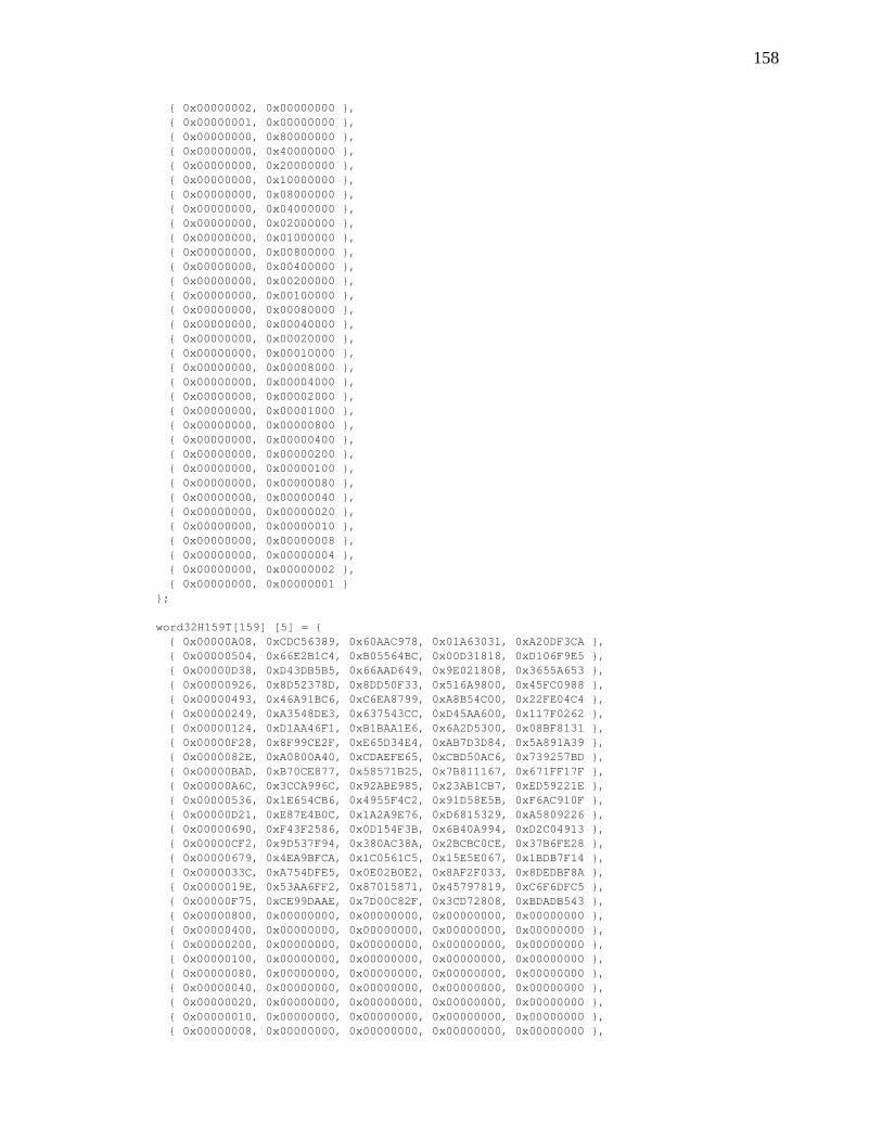
158
{ 0x00000002, 0x00000000 },{ 0x00000001, 0x00000000 },{ 0x00000000, 0x80000000 },{ 0x00000000, 0x40000000 },{ 0x00000000, 0x20000000 },{ 0x00000000, 0x10000000 },{ 0x00000000, 0x08000000 },{ 0x00000000, 0x04000000 },{ 0x00000000, 0x02000000 },{ 0x00000000, 0x01000000 },{ 0x00000000, 0x00800000 },{ 0x00000000, 0x00400000 },{ 0x00000000, 0x00200000 },{ 0x00000000, 0x00100000 },{ 0x00000000, 0x00080000 },{ 0x00000000, 0x00040000 },{ 0x00000000, 0x00020000 },{ 0x00000000, 0x00010000 },{ 0x00000000, 0x00008000 },{ 0x00000000, 0x00004000 },{ 0x00000000, 0x00002000 },{ 0x00000000, 0x00001000 },{ 0x00000000, 0x00000800 },{ 0x00000000, 0x00000400 },{ 0x00000000, 0x00000200 },{ 0x00000000, 0x00000100 },{ 0x00000000, 0x00000080 },{ 0x00000000, 0x00000040 },{ 0x00000000, 0x00000020 },{ 0x00000000, 0x00000010 },{ 0x00000000, 0x00000008 },{ 0x00000000, 0x00000004 },{ 0x00000000, 0x00000002 },{ 0x00000000, 0x00000001 }
};
word32H159T[159] [5] = {{ 0x00000A08, 0xCDC56389, 0x60AAC978, 0x01A63031, 0xA20DF3CA },{ 0x00000504, 0x66E2B1C4, 0xB05564BC, 0x00D31818, 0xD106F9E5 },{ 0x00000D38, 0xD43DB5B5, 0x66AAD649, 0x9E021808, 0x3655A653 },{ 0x00000926, 0x8D52378D, 0x8DD50F33, 0x516A9800, 0x45FC0988 },{ 0x00000493, 0x46A91BC6, 0xC6EA8799, 0xA8B54C00, 0x22FE04C4 },{ 0x00000249, 0xA3548DE3, 0x637543CC, 0xD45AA600, 0x117F0262 },{ 0x00000124, 0xD1AA46F1, 0xB1BAA1E6, 0x6A2D5300, 0x08BF8131 },{ 0x00000F28, 0x8F99CE2F, 0xE65D34E4, 0xAB7D3D84, 0x5A891A39 },{ 0x0000082E, 0xA0800A40, 0xCDAEFE65, 0xCBD50AC6, 0x739257BD },{ 0x00000BAD, 0xB70CE877, 0x58571B25, 0x7B811167, 0x671FF17F },{ 0x00000A6C, 0x3CCA996C, 0x92ABE985, 0x23AB1CB7, 0xED59221E },{ 0x00000536, 0x1E654CB6, 0x4955F4C2, 0x91D58E5B, 0xF6AC910F },{ 0x00000D21, 0xE87E4B0C, 0x1A2A9E76, 0xD6815329, 0xA5809226 },{ 0x00000690, 0xF43F2586, 0x0D154F3B, 0x6B40A994, 0xD2C04913 },{ 0x00000CF2, 0x9D537F94, 0x380AC38A, 0x2BCBC0CE, 0x37B6FE28 },{ 0x00000679, 0x4EA9BFCA, 0x1C0561C5, 0x15E5E067, 0x1BDB7F14 },{ 0x0000033C, 0xA754DFE5, 0x0E02B0E2, 0x8AF2F033, 0x8DEDBF8A },{ 0x0000019E, 0x53AA6FF2, 0x87015871, 0x45797819, 0xC6F6DFC5 },{ 0x00000F75, 0xCE99DAAE, 0x7D00C82F, 0x3CD72808, 0xBDADB543 },{ 0x00000800, 0x00000000, 0x00000000, 0x00000000, 0x00000000 },{ 0x00000400, 0x00000000, 0x00000000, 0x00000000, 0x00000000 },{ 0x00000200, 0x00000000, 0x00000000, 0x00000000, 0x00000000 },{ 0x00000100, 0x00000000, 0x00000000, 0x00000000, 0x00000000 },{ 0x00000080, 0x00000000, 0x00000000, 0x00000000, 0x00000000 },{ 0x00000040, 0x00000000, 0x00000000, 0x00000000, 0x00000000 },{ 0x00000020, 0x00000000, 0x00000000, 0x00000000, 0x00000000 },{ 0x00000010, 0x00000000, 0x00000000, 0x00000000, 0x00000000 },{ 0x00000008, 0x00000000, 0x00000000, 0x00000000, 0x00000000 },
159
{ 0x00000004, 0x00000000, 0x00000000, 0x00000000, 0x00000000 },{ 0x00000002, 0x00000000, 0x00000000, 0x00000000, 0x00000000 },{ 0x00000001, 0x00000000, 0x00000000, 0x00000000, 0x00000000 },{ 0x00000000, 0x80000000, 0x00000000, 0x00000000, 0x00000000 },{ 0x00000000, 0x40000000, 0x00000000, 0x00000000, 0x00000000 },{ 0x00000000, 0x20000000, 0x00000000, 0x00000000, 0x00000000 },{ 0x00000000, 0x10000000, 0x00000000, 0x00000000, 0x00000000 },{ 0x00000000, 0x08000000, 0x00000000, 0x00000000, 0x00000000 },{ 0x00000000, 0x04000000, 0x00000000, 0x00000000, 0x00000000 },{ 0x00000000, 0x02000000, 0x00000000, 0x00000000, 0x00000000 },{ 0x00000000, 0x01000000, 0x00000000, 0x00000000, 0x00000000 },{ 0x00000000, 0x00800000, 0x00000000, 0x00000000, 0x00000000 },{ 0x00000000, 0x00400000, 0x00000000, 0x00000000, 0x00000000 },{ 0x00000000, 0x00200000, 0x00000000, 0x00000000, 0x00000000 },{ 0x00000000, 0x00100000, 0x00000000, 0x00000000, 0x00000000 },{ 0x00000000, 0x00080000, 0x00000000, 0x00000000, 0x00000000 },{ 0x00000000, 0x00040000, 0x00000000, 0x00000000, 0x00000000 },{ 0x00000000, 0x00020000, 0x00000000, 0x00000000, 0x00000000 },{ 0x00000000, 0x00010000, 0x00000000, 0x00000000, 0x00000000 },{ 0x00000000, 0x00008000, 0x00000000, 0x00000000, 0x00000000 },{ 0x00000000, 0x00004000, 0x00000000, 0x00000000, 0x00000000 },{ 0x00000000, 0x00002000, 0x00000000, 0x00000000, 0x00000000 },{ 0x00000000, 0x00001000, 0x00000000, 0x00000000, 0x00000000 },{ 0x00000000, 0x00000800, 0x00000000, 0x00000000, 0x00000000 },{ 0x00000000, 0x00000400, 0x00000000, 0x00000000, 0x00000000 },{ 0x00000000, 0x00000200, 0x00000000, 0x00000000, 0x00000000 },{ 0x00000000, 0x00000100, 0x00000000, 0x00000000, 0x00000000 },{ 0x00000000, 0x00000080, 0x00000000, 0x00000000, 0x00000000 },{ 0x00000000, 0x00000040, 0x00000000, 0x00000000, 0x00000000 },{ 0x00000000, 0x00000020, 0x00000000, 0x00000000, 0x00000000 },{ 0x00000000, 0x00000010, 0x00000000, 0x00000000, 0x00000000 },{ 0x00000000, 0x00000008, 0x00000000, 0x00000000, 0x00000000 },{ 0x00000000, 0x00000004, 0x00000000, 0x00000000, 0x00000000 },{ 0x00000000, 0x00000002, 0x00000000, 0x00000000, 0x00000000 },{ 0x00000000, 0x00000001, 0x00000000, 0x00000000, 0x00000000 },{ 0x00000000, 0x00000000, 0x80000000, 0x00000000, 0x00000000 },{ 0x00000000, 0x00000000, 0x40000000, 0x00000000, 0x00000000 },{ 0x00000000, 0x00000000, 0x20000000, 0x00000000, 0x00000000 },{ 0x00000000, 0x00000000, 0x10000000, 0x00000000, 0x00000000 },{ 0x00000000, 0x00000000, 0x08000000, 0x00000000, 0x00000000 },{ 0x00000000, 0x00000000, 0x04000000, 0x00000000, 0x00000000 },{ 0x00000000, 0x00000000, 0x02000000, 0x00000000, 0x00000000 },{ 0x00000000, 0x00000000, 0x01000000, 0x00000000, 0x00000000 },{ 0x00000000, 0x00000000, 0x00800000, 0x00000000, 0x00000000 },{ 0x00000000, 0x00000000, 0x00400000, 0x00000000, 0x00000000 },{ 0x00000000, 0x00000000, 0x00200000, 0x00000000, 0x00000000 },{ 0x00000000, 0x00000000, 0x00100000, 0x00000000, 0x00000000 },{ 0x00000000, 0x00000000, 0x00080000, 0x00000000, 0x00000000 },{ 0x00000000, 0x00000000, 0x00040000, 0x00000000, 0x00000000 },{ 0x00000000, 0x00000000, 0x00020000, 0x00000000, 0x00000000 },{ 0x00000000, 0x00000000, 0x00010000, 0x00000000, 0x00000000 },{ 0x00000000, 0x00000000, 0x00008000, 0x00000000, 0x00000000 },{ 0x00000000, 0x00000000, 0x00004000, 0x00000000, 0x00000000 },{ 0x00000000, 0x00000000, 0x00002000, 0x00000000, 0x00000000 },{ 0x00000000, 0x00000000, 0x00001000, 0x00000000, 0x00000000 },{ 0x00000000, 0x00000000, 0x00000800, 0x00000000, 0x00000000 },{ 0x00000000, 0x00000000, 0x00000400, 0x00000000, 0x00000000 },{ 0x00000000, 0x00000000, 0x00000200, 0x00000000, 0x00000000 },{ 0x00000000, 0x00000000, 0x00000100, 0x00000000, 0x00000000 },{ 0x00000000, 0x00000000, 0x00000080, 0x00000000, 0x00000000 },{ 0x00000000, 0x00000000, 0x00000040, 0x00000000, 0x00000000 },{ 0x00000000, 0x00000000, 0x00000020, 0x00000000, 0x00000000 },{ 0x00000000, 0x00000000, 0x00000010, 0x00000000, 0x00000000 },{ 0x00000000, 0x00000000, 0x00000008, 0x00000000, 0x00000000 },{ 0x00000000, 0x00000000, 0x00000004, 0x00000000, 0x00000000 },
160
{ 0x00000000, 0x00000000, 0x00000002, 0x00000000, 0x00000000 },{ 0x00000000, 0x00000000, 0x00000001, 0x00000000, 0x00000000 },{ 0x00000000, 0x00000000, 0x00000000, 0x80000000, 0x00000000 },{ 0x00000000, 0x00000000, 0x00000000, 0x40000000, 0x00000000 },{ 0x00000000, 0x00000000, 0x00000000, 0x20000000, 0x00000000 },{ 0x00000000, 0x00000000, 0x00000000, 0x10000000, 0x00000000 },{ 0x00000000, 0x00000000, 0x00000000, 0x08000000, 0x00000000 },{ 0x00000000, 0x00000000, 0x00000000, 0x04000000, 0x00000000 },{ 0x00000000, 0x00000000, 0x00000000, 0x02000000, 0x00000000 },{ 0x00000000, 0x00000000, 0x00000000, 0x01000000, 0x00000000 },{ 0x00000000, 0x00000000, 0x00000000, 0x00800000, 0x00000000 },{ 0x00000000, 0x00000000, 0x00000000, 0x00400000, 0x00000000 },{ 0x00000000, 0x00000000, 0x00000000, 0x00200000, 0x00000000 },{ 0x00000000, 0x00000000, 0x00000000, 0x00100000, 0x00000000 },{ 0x00000000, 0x00000000, 0x00000000, 0x00080000, 0x00000000 },{ 0x00000000, 0x00000000, 0x00000000, 0x00040000, 0x00000000 },{ 0x00000000, 0x00000000, 0x00000000, 0x00020000, 0x00000000 },{ 0x00000000, 0x00000000, 0x00000000, 0x00010000, 0x00000000 },{ 0x00000000, 0x00000000, 0x00000000, 0x00008000, 0x00000000 },{ 0x00000000, 0x00000000, 0x00000000, 0x00004000, 0x00000000 },{ 0x00000000, 0x00000000, 0x00000000, 0x00002000, 0x00000000 },{ 0x00000000, 0x00000000, 0x00000000, 0x00001000, 0x00000000 },{ 0x00000000, 0x00000000, 0x00000000, 0x00000800, 0x00000000 },{ 0x00000000, 0x00000000, 0x00000000, 0x00000400, 0x00000000 },{ 0x00000000, 0x00000000, 0x00000000, 0x00000200, 0x00000000 },{ 0x00000000, 0x00000000, 0x00000000, 0x00000100, 0x00000000 },{ 0x00000000, 0x00000000, 0x00000000, 0x00000080, 0x00000000 },{ 0x00000000, 0x00000000, 0x00000000, 0x00000040, 0x00000000 },{ 0x00000000, 0x00000000, 0x00000000, 0x00000020, 0x00000000 },{ 0x00000000, 0x00000000, 0x00000000, 0x00000010, 0x00000000 },{ 0x00000000, 0x00000000, 0x00000000, 0x00000008, 0x00000000 },{ 0x00000000, 0x00000000, 0x00000000, 0x00000004, 0x00000000 },{ 0x00000000, 0x00000000, 0x00000000, 0x00000002, 0x00000000 },{ 0x00000000, 0x00000000, 0x00000000, 0x00000001, 0x00000000 },{ 0x00000000, 0x00000000, 0x00000000, 0x00000000, 0x80000000 },{ 0x00000000, 0x00000000, 0x00000000, 0x00000000, 0x40000000 },{ 0x00000000, 0x00000000, 0x00000000, 0x00000000, 0x20000000 },{ 0x00000000, 0x00000000, 0x00000000, 0x00000000, 0x10000000 },{ 0x00000000, 0x00000000, 0x00000000, 0x00000000, 0x08000000 },{ 0x00000000, 0x00000000, 0x00000000, 0x00000000, 0x04000000 },{ 0x00000000, 0x00000000, 0x00000000, 0x00000000, 0x02000000 },{ 0x00000000, 0x00000000, 0x00000000, 0x00000000, 0x01000000 },{ 0x00000000, 0x00000000, 0x00000000, 0x00000000, 0x00800000 },{ 0x00000000, 0x00000000, 0x00000000, 0x00000000, 0x00400000 },{ 0x00000000, 0x00000000, 0x00000000, 0x00000000, 0x00200000 },{ 0x00000000, 0x00000000, 0x00000000, 0x00000000, 0x00100000 },{ 0x00000000, 0x00000000, 0x00000000, 0x00000000, 0x00080000 },{ 0x00000000, 0x00000000, 0x00000000, 0x00000000, 0x00040000 },{ 0x00000000, 0x00000000, 0x00000000, 0x00000000, 0x00020000 },{ 0x00000000, 0x00000000, 0x00000000, 0x00000000, 0x00010000 },{ 0x00000000, 0x00000000, 0x00000000, 0x00000000, 0x00008000 },{ 0x00000000, 0x00000000, 0x00000000, 0x00000000, 0x00004000 },{ 0x00000000, 0x00000000, 0x00000000, 0x00000000, 0x00002000 },{ 0x00000000, 0x00000000, 0x00000000, 0x00000000, 0x00001000 },{ 0x00000000, 0x00000000, 0x00000000, 0x00000000, 0x00000800 },{ 0x00000000, 0x00000000, 0x00000000, 0x00000000, 0x00000400 },{ 0x00000000, 0x00000000, 0x00000000, 0x00000000, 0x00000200 },{ 0x00000000, 0x00000000, 0x00000000, 0x00000000, 0x00000100 },{ 0x00000000, 0x00000000, 0x00000000, 0x00000000, 0x00000080 },{ 0x00000000, 0x00000000, 0x00000000, 0x00000000, 0x00000040 },{ 0x00000000, 0x00000000, 0x00000000, 0x00000000, 0x00000020 },{ 0x00000000, 0x00000000, 0x00000000, 0x00000000, 0x00000010 },{ 0x00000000, 0x00000000, 0x00000000, 0x00000000, 0x00000008 },{ 0x00000000, 0x00000000, 0x00000000, 0x00000000, 0x00000004 },{ 0x00000000, 0x00000000, 0x00000000, 0x00000000, 0x00000002 },
161
{ 0x00000000, 0x00000000, 0x00000000, 0x00000000, 0x00000001 }};
word32idIn[76] [5] = {{ 0x51C008F2, 0x4A345110, 0xEE43FD3E, 0x620B4250, 0xE310002B },{ 0x4EDAB5A3, 0x0832266C, 0x36ACA808, 0xEDF86E2F, 0xF530002C },{ 0x673D6D81, 0xCE3414AC, 0x39E5028B, 0xA51B3FF6, 0x7D18002D },{ 0x1D1505E6, 0x843E43EC, 0x283FFD0E, 0x7C3ECD9C, 0xE560002E },{ 0x34F2DDC4, 0x4238712C, 0x2776578D, 0x34DD9C45, 0x6D48002F },{ 0x32B040E6, 0x002BFB9F, 0x5511FCD2, 0xD234DFD3, 0xADB00030 },{ 0x1B5798C4, 0xC62DC95F, 0x5A585651, 0x9AD78E0A, 0x25980031 },{ 0x617FF0A3, 0x8C279E1F, 0x4B82A9D4, 0x43F27C60, 0xBDE00032 },{ 0x48982881, 0x4A21ACDF, 0x44CB0357, 0x0B112DB9, 0x35C80033 },{ 0x578295D0, 0x0827DBA3, 0x9C245661, 0x84E201C6, 0x23E80034 },{ 0x7E654DF2, 0xCE21E963, 0x936DFCE2, 0xCC01501F, 0xABC00035 },{ 0x044D2595, 0x842BBE23, 0x82B70367, 0x1524A275, 0x33B80036 },{ 0x2DAAFDB7, 0x422D8CE3, 0x8DFEA9E4, 0x5DC7F3AC, 0xBB900037 },{ 0x3A785F37, 0x002750DA, 0x3369A90A, 0x0AC2FA8B, 0x1FF80038 },{ 0x558D2D67, 0xCE1FEF33, 0x6CF4FE59, 0x772FE025, 0xD0A8001D },{ 0x2FA54500, 0x8415B873, 0x7D2E01DC, 0xAE0A124F, 0x48D0001E },{ 0x06429D22, 0x42138AB3, 0x7267AB5F, 0xE6E94396, 0xC0F8001F },{ 0x23207F44, 0x0032AD15, 0x99E15763, 0x63D89562, 0xC9200020 },{ 0x0AC7A766, 0xC6349FD5, 0x96A8FDE0, 0x2B3BC4BB, 0x41080021 },{ 0x70EFCF01, 0x8C3EC895, 0x87720265, 0xF21E36D1, 0xD9700022 },{ 0x59081723, 0x4A38FA55, 0x883BA8E6, 0xBAFD6708, 0x51580023 },{ 0x4612AA72, 0x083E8D29, 0x50D4FDD0, 0x350E4B77, 0x47780024 },{ 0x6FF57250, 0xCE38BFE9, 0x5F9D5753, 0x7DED1AAE, 0xCF500025 },{ 0x15DD1A37, 0x8432E8A9, 0x4E47A8D6, 0xA4C8E8C4, 0x57280026 },{ 0x3C3AC215, 0x4234DA69, 0x410E0255, 0xEC2BB91D, 0xDF000027 },{ 0x2BE86095, 0x003E0650, 0xFF9902BB, 0xBB2EB03A, 0x7B680028 },{ 0x020FB8B7, 0xC6383490, 0xF0D0A838, 0xF3CDE1E3, 0xF3400029 },{ 0x7827D0D0, 0x8C3263D0, 0xE10A57BD, 0x2AE81389, 0x6B38002A },{ 0x69B7EF72, 0x8C2B355A, 0x2DFAFC0C, 0x9B045938, 0x0FA8003A },{ 0x5F4A8A01, 0x082B70E6, 0xFA5C03B9, 0x5C14249E, 0x91A0003C },{ 0x0C853A44, 0x84271566, 0xE4CF56BF, 0xCDD2872D, 0x81F0003E },{ 0x6FA726AA, 0xC66368EB, 0x3C8B0445, 0x8F527B1C, 0x1A680041 },{ 0x3C6896EF, 0x4A6F0D6B, 0x22185143, 0x1E94D8AF, 0x0A380043 },{ 0x595A43D9, 0x42632D57, 0xEB2DFBF0, 0x484206BA, 0x84600047 },{ 0x1D47511C, 0x8C6594EE, 0x4B29AE18, 0x8E81AC2E, 0x3058004A },{ 0x025DEC4D, 0xCE63E392, 0x93C6FB2E, 0x01728051, 0x2678004D },{ 0x51925C08, 0x426F8612, 0x8D55AE28, 0x90B423E2, 0x3628004F },{ 0x041F716F, 0x8C706921, 0xE1A15071, 0xE79BC3C7, 0xE6800052 },{ 0x29E7D822, 0xC60632C0, 0x0F49AA83, 0x48E351D9, 0x88280001 },{ 0x53CFB045, 0x8C0C6580, 0x1E935506, 0x91C6A3B3, 0x10500002 },{ 0x7A286867, 0x4A0A5740, 0x11DAFF85, 0xD925F26A, 0x98780003 },{ 0x6532D536, 0x080C203C, 0xC935AAB3, 0x56D6DE15, 0x8E580004 },{ 0x4CD50D14, 0xCE0A12FC, 0xC67C0030, 0x1E358FCC, 0x06700005 },{ 0x36FD6573, 0x840045BC, 0xD7A6FFB5, 0xC7107DA6, 0x9E080006 },{ 0x1F1ABD51, 0x4206777C, 0xD8EF5536, 0x8FF32C7F, 0x16200007 },{ 0x08C81FD1, 0x000CAB45, 0x667855D8, 0xD8F62558, 0xB2480008 },{ 0x212FC7F3, 0xC60A9985, 0x6931FF5B, 0x90157481, 0x3A600009 },{ 0x5B07AF94, 0x8C00CEC5, 0x78EB00DE, 0x493086EB, 0xA218000A },{ 0x72E077B6, 0x4A06FC05, 0x77A2AA5D, 0x01D3D732, 0x2A30000B },{ 0x6DFACAE7, 0x08008B79, 0xAF4DFF6B, 0x8E20FB4D, 0x3C10000C },{ 0x441D12C5, 0xCE06B9B9, 0xA00455E8, 0xC6C3AA94, 0xB438000D },{ 0x3E357AA2, 0x840CEEF9, 0xB1DEAA6D, 0x1FE658FE, 0x2C40000E },{ 0x17D2A280, 0x420ADC39, 0xBE9700EE, 0x57050927, 0xA468000F },{ 0x11903FA2, 0x0019568A, 0xCCF0ABB1, 0xB1EC4AB1, 0x64900010 },{ 0x3877E780, 0xC61F644A, 0xC3B90132, 0xF90F1B68, 0xECB80011 },{ 0x425F8FE7, 0x8C15330A, 0xD263FEB7, 0x202AE902, 0x74C00012 },{ 0x6BB857C5, 0x4A1301CA, 0xDD2A5434, 0x68C9B8DB, 0xFCE80013 },{ 0x74A2EA94, 0x081576B6, 0x05C50102, 0xE73A94A4, 0xEAC80014 },{ 0x5D4532B6, 0xCE134476, 0x0A8CAB81, 0xAFD9C57D, 0x62E00015 },{ 0x276D5AD1, 0x84191336, 0x1B565404, 0x76FC3717, 0xFA980016 },{ 0x0E8A82F3, 0x421F21F6, 0x141FFE87, 0x3E1F66CE, 0x72B00017 },
162
{ 0x19582073, 0x0015FDCF, 0xAA88FE69, 0x691A6FE9, 0xD6D80018 },{ 0x30BFF851, 0xC613CF0F, 0xA5C154EA, 0x21F93E30, 0x5EF00019 },{ 0x4A979036, 0x8C19984F, 0xB41BAB6F, 0xF8DCCC5A, 0xC688001A },{ 0x63704814, 0x4A1FAA8F, 0xBB5201EC, 0xB03F9D83, 0x4EA0001B },{ 0x7C6AF545, 0x0819DDF3, 0x63BD54DA, 0x3FCCB1FC, 0x5880001C },{ 0x612DA459, 0x847C491D, 0x2894FAC2, 0xB14D1DD2, 0x68D80056 },{ 0x5F18DEFB, 0x0070A7E4, 0x994A50AF, 0xAEAB452C, 0x44980058 },{ 0x0CD76EBE, 0x8C7CC264, 0x87D905A9, 0x3F6DE69F, 0x54C8005A },{ 0x13CDD3EF, 0xCE7AB518, 0x5F36509F, 0xB09ECAE0, 0x42E8005D },{ 0x400263AA, 0x4276D098, 0x41A50599, 0x21586953, 0x52B8005F },{ 0x1F48E9AB, 0x4A5DA07E, 0xBBF90620, 0x7D4C4DCD, 0xC3180063 },{ 0x539DE4BF, 0x8457B282, 0x7D850610, 0x6379C201, 0xC5680066 },{ 0x444F463F, 0xC65D6EBB, 0xC31206FE, 0x347CCB26, 0x61000069 },{ 0x1780F67A, 0x4A510B3B, 0xDD8153F8, 0xA5BA6895, 0x7150006B },{ 0x5B55FB6E, 0x845B19C7, 0x1BFD53C8, 0xBB8FE759, 0x7720006E }
};
word32idOut[66] [5] = {{ 0x6725E2CF, 0x7A9CA427, 0x2820EA7A, 0xD27C2F75, 0xB930040A },{ 0x4EC23AED, 0xBC9A96E7, 0x276940F9, 0x9A9F7EAC, 0x3118040B },{ 0x51D887BC, 0xFE9CE19B, 0xFF8615CF, 0x156C52D3, 0x2738040C },{ 0x783F5F9E, 0x389AD35B, 0xF0CFBF4C, 0x5D8F030A, 0xAF10040D },{ 0x021737F9, 0x7290841B, 0xE11540C9, 0x84AAF160, 0x3768040E },{ 0x2BF0EFDB, 0xB496B6DB, 0xEE5CEA4A, 0xCC49A0B9, 0xBF40040F },{ 0x2DB272F9, 0xF6853C68, 0x9C3B4115, 0x2AA0E32F, 0x7FB80410 },{ 0x0455AADB, 0x30830EA8, 0x9372EB96, 0x6243B2F6, 0xF7900411 },{ 0x7E7DC2BC, 0x7A8959E8, 0x82A81413, 0xBB66409C, 0x6FE80412 },{ 0x579A1A9E, 0xBC8F6B28, 0x8DE1BE90, 0xF3851145, 0xE7C00413 },{ 0x4880A7CF, 0xFE891C54, 0x550EEBA6, 0x7C763D3A, 0xF1E00414 },{ 0x61677FED, 0x388F2E94, 0x5A474125, 0x34956CE3, 0x79C80415 },{ 0x1B4F178A, 0x728579D4, 0x4B9DBEA0, 0xEDB09E89, 0xE1B00416 },{ 0x32A8CFA8, 0xB4834B14, 0x44D41423, 0xA553CF50, 0x69980417 },{ 0x257A6D28, 0xF689972D, 0xFA4314CD, 0xF256C677, 0xCDF00418 },{ 0x0C9DB50A, 0x308FA5ED, 0xF50ABE4E, 0xBAB597AE, 0x45D80419 },{ 0x76B5DD6D, 0x7A85F2AD, 0xE4D041CB, 0x639065C4, 0xDDA0041A },{ 0x5F52054F, 0xBC83C06D, 0xEB99EB48, 0x2B73341D, 0x5588041B },{ 0x4048B81E, 0xFE85B711, 0x3376BE7E, 0xA4801862, 0x43A8041C },{ 0x69AF603C, 0x388385D1, 0x3C3F14FD, 0xEC6349BB, 0xCB80041D },{ 0x1387085B, 0x7289D291, 0x2DE5EB78, 0x3546BBD1, 0x53F8041E },{ 0x3A60D079, 0xB48FE051, 0x22AC41FB, 0x7DA5EA08, 0xDBD0041F },{ 0x1F02321F, 0xF6AEC7F7, 0xC92ABDC7, 0xF8943CFC, 0xD2080420 },{ 0x36E5EA3D, 0x30A8F537, 0xC6631744, 0xB0776D25, 0x5A200421 },{ 0x4CCD825A, 0x7AA2A277, 0xD7B9E8C1, 0x69529F4F, 0xC2580422 },{ 0x652A5A78, 0xBCA490B7, 0xD8F04242, 0x21B1CE96, 0x4A700423 },{ 0x7A30E729, 0xFEA2E7CB, 0x001F1774, 0xAE42E2E9, 0x5C500424 },{ 0x53D73F0B, 0x38A4D50B, 0x0F56BDF7, 0xE6A1B330, 0xD4780425 },{ 0x29FF576C, 0x72AE824B, 0x1E8C4272, 0x3F84415A, 0x4C000426 },{ 0x00188F4E, 0xB4A8B08B, 0x11C5E8F1, 0x77671083, 0xC4280427 },{ 0x17CA2DCE, 0xF6A26CB2, 0xAF52E81F, 0x206219A4, 0x60400428 },{ 0x3E2DF5EC, 0x30A45E72, 0xA01B429C, 0x6881487D, 0xE8680429 },{ 0x44059D8B, 0x7AAE0932, 0xB1C1BD19, 0xB1A4BA17, 0x7010042A },{ 0x6DE245A9, 0xBCA83BF2, 0xBE88179A, 0xF947EBCE, 0xF838042B },{ 0x72F8F8F8, 0xFEAE4C8E, 0x666742AC, 0x76B4C7B1, 0xEE18042C },{ 0x5B1F20DA, 0x38A87E4E, 0x692EE82F, 0x3E579668, 0x6630042D },{ 0x213748BD, 0x72A2290E, 0x78F417AA, 0xE7726402, 0xFE48042E },{ 0x08D0909F, 0xB4A41BCE, 0x77BDBD29, 0xAF9135DB, 0x7660042F },{ 0x0E920DBD, 0xF6B7917D, 0x05DA1676, 0x4978764D, 0xB6980430 },{ 0x2775D59F, 0x30B1A3BD, 0x0A93BCF5, 0x019B2794, 0x3EB00431 },{ 0x5D5DBDF8, 0x7ABBF4FD, 0x1B494370, 0xD8BED5FE, 0xA6C80432 },{ 0x74BA65DA, 0xBCBDC63D, 0x1400E9F3, 0x905D8427, 0x2EE00433 },{ 0x6BA0D88B, 0xFEBBB141, 0xCCEFBCC5, 0x1FAEA858, 0x38C00434 },{ 0x424700A9, 0x38BD8381, 0xC3A61646, 0x574DF981, 0xB0E80435 },{ 0x386F68CE, 0x72B7D4C1, 0xD27CE9C3, 0x8E680BEB, 0x28900436 },{ 0x1188B0EC, 0xB4B1E601, 0xDD354340, 0xC68B5A32, 0xA0B80437 },{ 0x065A126C, 0xF6BB3A38, 0x63A243AE, 0x918E5315, 0x04D00438 },
163
{ 0x2FBDCA4E, 0x30BD08F8, 0x6CEBE92D, 0xD96D02CC, 0x8CF80439 },{ 0x5595A229, 0x7AB75FB8, 0x7D3116A8, 0x0048F0A6, 0x1480043A },{ 0x7C727A0B, 0xBCB16D78, 0x7278BC2B, 0x48ABA17F, 0x9CA8043B },{ 0x6368C75A, 0xFEB71A04, 0xAA97E91D, 0xC7588D00, 0x8A88043C },{ 0x4A8F1F78, 0x38B128C4, 0xA5DE439E, 0x8FBBDCD9, 0x02A0043D },{ 0x30A7771F, 0x72BB7F84, 0xB404BC1B, 0x569E2EB3, 0x9AD8043E },{ 0x1940AF3D, 0xB4BD4D44, 0xBB4D1698, 0x1E7D7F6A, 0x12F0043F },{ 0x7A62B3D3, 0xF6F930C9, 0x63094462, 0x5CFD835B, 0x89680440 },{ 0x53856BF1, 0x30FF0209, 0x6C40EEE1, 0x141ED282, 0x01400441 },{ 0x3C224D5B, 0xF69C6AE2, 0x50CBEAA4, 0x9B4CA99E, 0x1B280400 },{ 0x15C59579, 0x309A5822, 0x5F824027, 0xD3AFF847, 0x93000401 },{ 0x6FEDFD1E, 0x7A900F62, 0x4E58BFA2, 0x0A8A0A2D, 0x0B780402 },{ 0x460A253C, 0xBC963DA2, 0x41111521, 0x42695BF4, 0x83500403 },{ 0x5910986D, 0xFE904ADE, 0x99FE4017, 0xCD9A778B, 0x95700404 },{ 0x70F7404F, 0x3896781E, 0x96B7EA94, 0x85792652, 0x1D580405 },{ 0x0ADF2828, 0x729C2F5E, 0x876D1511, 0x5C5CD438, 0x85200406 },{ 0x2338F00A, 0xB49A1D9E, 0x8824BF92, 0x14BF85E1, 0x0D080407 },{ 0x34EA528A, 0xF690C1A7, 0x36B3BF7C, 0x43BA8CC6, 0xA9600408 },{ 0x1D0D8AA8, 0x3096F367, 0x39FA15FF, 0x0B59DD1F, 0x21480409 }
};
/*ID information array for outputs************//** These are actual uncoded ID values.*/
word32outChanId[OUT_BUF_SIZE] = {0x0000040A,0x0000040B,0x0000040C,0x0000040D,0x0000040E,0x0000040F,0x00000410,0x00000411,0x00000412,0x00000413,0x00000414,0x00000415,0x00000416,0x00000417,0x00000418,0x00000419,0x0000041A,0x0000041B,0x0000041C,0x0000041D,0x0000041E,0x0000041F,0x00000420,0x00000421,0x00000422,0x00000423,0x00000424,0x00000425,0x00000426,0x00000427,0x00000428,0x00000429,0x0000042A,0x0000042B,0x0000042C,0x0000042D,0x0000042E,0x0000042F,
164
0x00000430,0x00000431,0x00000432,0x00000433,0x00000434,0x00000435,0x00000436,0x00000437,0x00000438,0x00000439,0x0000043A,0x0000043B,0x0000043C,0x0000043D,0x0000043E,0x0000043F,0x00000440,0x00000441,0x00000400,0x00000401,0x00000402,0x00000403,0x00000404,0x00000405,0x00000406,0x00000407,0x00000408,0x00000409
};
/*SCC port definitions*******************************************//** These definitions, except the last 6, are taken from the Heurikon* user’s manual.*/
#define SCC_REG_SPREAD 0x07#define SCC_PORT_SPREAD 0x10
struct SCCPort{unsigned char Control;unsigned char Dummy[SCC_REG_SPREAD];unsigned char Data;
} SCCPort;
#define SCC_PORTB ((struct SCCPort *) 0xFF010000)#define SCC_PORTA ((struct SCCPort *) ((int) SCC_PORTB + SCC_PORT_SPREAD))
#define XON 0x11#define XOFF 0x13#define CTS 0x79/* Clear to send to plant (arbitrary) */#define LF 0x0A#define EOT 0x04#define SCC_VEC_NUMBER 0xE2
/*VIC068A VME controller definitions*******************************//** These are not used in polling but are necessary for an interrupt-based* SCC scheme. Also taken from Heurikon.*/
#define VIC 0xFF000000#define SCC_INT_CNTRL((unsigned char *) 0xFF00002B)#define LOC_INT_VEC_BASE((unsigned char *) 0xFF000057)#define VIC_BASE_VECTOR0xE0
165
/*EntryPt function and monitor function links**********************//** These declarations allow access to the Heurikon monitor functions from* within this program. The EntryPt function returns the address of the* function in its argument. This code was taken from the Heurikon users* manual. The xprintf functions is essentially identical to printf except* that it prints to the console window.*/
unsigned long (* EntryPt) () = (unsigned long (*) ()) 0xFC000008;
int(* xprintf) (),(* ConnectHandler) (),(* date) (),(* DisDataCache) (),(* EnbDataCache) (),(* StartMonitor) ();
void LinkMonitor (void){
xprintf =(int (*) ()) EntryPt(“xprintf”);ConnectHandler =(int (*) ()) EntryPt(“ConnectHandler”);date = (int (*) ()) EntryPt(“date”);DisDataCache =(int (*) ()) EntryPt(“DisDataCache”);EnbDataCache =(int (*) ()) EntryPt(“EnbDataCache”);StartMonitor =(int (*) ()) EntryPt(“StartMonitor”);
}
void printDate (void){
date ();xprintf (“\n”);
}
/******************************************************************************************************************************************/
/*Set up and initialize SCC for polling*********************/
SCCSetup (volatile struct SCCPort *Port)
{Port->Control = 0x00;Port->Control = 0x09;if (Port=SCC_PORTA) {
Port->Control = 0x80;xprintf (“Channel A has been reset\n”);
}else {
Port->Control = 0x40;xprintf (“Channel B has been reset\n”);
}Port->Control = 0x00;Port->Control = 0x10;/* Reset ext/status ints */Port->Control = 0x10;/* Needs two commands to work correctly */Port->Control = 0x04;Port->Control = 0x44;/* Async mode, x16 clock, 1 stop, no parity */Port->Control = 0x0B;Port->Control = 0x56;/* Tx/Rcv clk from BRG, TRxC = BRG out */Port->Control = 0x0C;Port->Control = 0x0B;/* Lower baud time const = 11, for 38400 baud */Port->Control = 0x0D;Port->Control = 0x00;/* Upper baud time const = 0 */Port->Control = 0x0E;
166
Port->Control = 0x03;/* BRG enable */Port->Control = 0x05;Port->Control = 0xEA;/* Tx 8 bit, DTR, RTS, Tx enable */Port->Control = 0x03;Port->Control = 0xC1;/* Rcv 8 bit, Rcv enable */Port->Control = 0x01;Port->Control = 0x00;/* No interrupts -- polled */Port->Control = 0x0F;Port->Control = 0xC0;/* Int on break and Tx underrun*/Port->Control = 0x09;Port->Control = 0x00;/* Mast. Int. disabled */xprintf (“Completed SCC port setup\n”);
}
/*Miscellaneous SCC-related functions************************/
ResetPort (struct SCCPort *Port)/*Reset one channel*/{
Port->Control = 0x00;Port->Control = 0x09;if (Port=SCC_PORTA) {
Port->Control = 0x80;xprintf (“Channel A has been reset\n”);
}else {
Port->Control = 0x40;xprintf (“Channel B has been reset\n”);
}Port->Control = 0x00;Port->Control = 0x10;/* Reset ext/status ints */Port->Control = 0x10;/* Needs two commands to work correctly */
}
unsigned char GetIntStatus (struct SCCPort *Port)/*Read Int pending status register*/{
unsigned char retval;
Port->Control = 0x03;retval = Port->Control;return(retval);
}
DisableInts (struct SCCPort *Port)/*Disable interrupts*/{
Port->Control = 0x09;Port->Control = 0x02;
}
EnableInts (struct SCCPort *Port)/*Enable interrupts*/{
Port->Control = 0x09;Port->Control = 0x0A;
}
167
ResetIUS (struct SCCPort *Port)/*Reset highest int. under service*/{
Port->Control = 0;Port->Control = 0x38;
}
ResetTxIP (struct SCCPort *Port)/*Reset Tx interrupt pending*/{
Port->Control = 0;Port->Control = 0x28;
}
unsigned char GetChar (struct SCCPort *Port)/* Read the receive buffer*/{
charretval;
retval = Port->Data;Port->Control = 0;if (Port->Control & 0x80)
xprintf (“Found BREAK/ABORT\n”);return (retval);
}
SendChar (struct SCCPort *Port, char c)/* Send a character to xmit buffer*/{
Port->Control = 0;while (!(Port->Control & 0x04));Port->Data = c;
}
int CharAvail (struct SCCPort *Port)/*Check for a character in the receive buffer*/{
int retval;
Port->Control = 0;retval = (Port->Control & 0x01);return (retval);
}
int TxEmpty (struct SCCPort *Port)/* Check if transmit buffer is empty*/{
int retval;
Port->Control = 0;retval = (Port->Control & 0x04);return (retval);
}
int ChkOverrun (struct SCCPort *Port)/*Check for an overrun in the recieve buffer*/{
168
int retval;
Port->Control = 0x01;retval = (Port->Control & 0x20);if (retval == 1) {
Port->Control = 0;Port->Control = 0x30;
}return (retval);
}
/*::::::::::::::::::::::::::::::::::::::::::::::::::::::::::::::::::::::::::::::::::::::::::::::::::::::::::::::::::::*/
/*Input functions *************************************/
void InitRcvBuf (void)/*Initializes raw input buffer to all zero*/
{
int i;
for (i = 0; i <= IN_BUF_SIZE-1; i++)RcvBuf[i] = ‘0’;
}
word32 flip32 (word32 info)/*Flips a 32-bit value; most significant bit becomes least* significant.*/
{word32retval;word32mask, temp;int i;
mask = 0x00000001;temp = 0;for (i=0; i <= 31; i++)
temp |= ((info << i) >> (31 - i)) & (mask << i);retval = temp;return (retval);
}
word32 getData (int index)/*Returns a single value from the raw input buffer as a* 32-bit value.*/
{word32retval;charinput;
input = RcvBuf[index];assert ((input == ‘1’) || (input == ‘0’));if (input == ‘1’)
retval = 0x00000001;else
retval = 0x00000000;return (retval);
}
169
word16 getBCheck (word32 data)/*Returns a 16-bit Berger check symbol created over a* 32-bit data word.*/
{int i;int numOnes = 0;word32mask = 0x00000001;word16retval;
for (i = 0; i <= 31; i++)numOnes += (data >> i) & mask;
retval = (word16) (32 - numOnes);return (retval);
}
data55 makeInfo (word32 value, word16 check, word8 tstamp)/*Assembles and returns a 55-bit data word which is the information* field for the 97-bit dynamic codeword. The word is arranged as:* data(0-31)|Berger check (0-15)|timestamp(0-6)*/
{data55retval;word32ltemp1, ltemp2;
retval.word[1] = flip32(value);ltemp1 = flip32((unsigned) check);ltemp2 = flip32((unsigned) tstamp) >> 16;retval.word[0] = ltemp1 | ltemp2;return (retval);
}
code97 encodeData (data55 info)/*Creates 97-bit dynamic data codeword using 55-bit information word.* Encoding is done by finding 1s in the information word and adding* (mod 2) the corresponding row from the generator matrix.*/
{code97retval;code97sum;int i, j, shifts, wordsel;word32mask;
mask = 0x80000000;for (i = 0; i <= 3; i++)
sum.word[i] = 0;for (i = D_K-1; i >= 0; i--) {
wordsel = (22+i)/45;shifts = (D_K-1) - !(wordsel)*32 - i;if (((info.word[wordsel] << shifts) & mask) != 0)
for (j = 3; j >= 0; j--)sum.word[j] ^= G97[D_K-1-i][3-j];
}retval = sum;return (retval);
}
code97 flipCode97 (code97 code)/*Flips the 97-bit codeword for storage in 256-bit system codeword.*/
{
170
code97retval;word32ltemp1, ltemp2;int i;
retval.word[3] = flip32(code.word[0]) >> 31;for (i=0; i <= 2; i++) {
ltemp1 = flip32(code.word[i]) << 1;ltemp2 = flip32(code.word[i+1]) >> 31;retval.word[2-i] = ltemp1 | ltemp2;
}return (retval);
}
code256 makePhysCode (code97 dynamic, int index)/*Assembles and returns the 256-bit system codeword using the 97-bit* dynamic codeword and the the correct 159-bit ID codeword for the indexed* input channel.*/
{code256retval;code159id;int i;word32mword[8], ltemp1;
for (i = 4; i >= 0; i--)id.word[i] = idIn[index][4-i];
mword[0] = (dynamic.word[0] << 20) >> 20;mword[1] = (dynamic.word[0] << 8) >> 20;mword[2] = (dynamic.word[0] >> 24) | ((dynamic.word[1] << 28) >> 20);mword[3] = (dynamic.word[1] << 16) >> 20;mword[4] = (dynamic.word[1] << 4) >> 20;mword[5] = (dynamic.word[1] >> 28) | ((dynamic.word[2] << 24) >> 20);mword[6] = (dynamic.word[2] << 12) >> 20;mword[7] = (dynamic.word[2] >> 20) | (dynamic.word[3] << 12);retval.word[0] = mword[0] | (id.word[0] << 12);ltemp1 = (id.word[0] >> 20) | ((id.word[1] << 24) >> 12);retval.word[1] = mword[1] | (ltemp1 << 12);ltemp1 = (id.word[1] << 4) >> 12;retval.word[2] = mword[2] | (ltemp1 << 12);ltemp1 = (id.word[1] >> 28) | ((id.word[2] << 16) >> 12);retval.word[3] = mword[3] | (ltemp1 << 12);ltemp1 = (id.word[2] >> 16) | ((id.word[3] << 28) >> 12);retval.word[4] = mword[4] | (ltemp1 << 12);ltemp1 = (id.word[3] << 8) >> 12;retval.word[5] = mword[5] | (ltemp1 << 12);ltemp1 = (id.word[3] >> 24) | ((id.word[4] << 20) >> 12);retval.word[6] = mword[6] | (ltemp1 << 12);ltemp1 = id.word[4] >> 12;retval.word[7] = mword[7] | (ltemp1 << 13);
return (retval);}
void encodeInputs (void)/*This procedure encodes all of the inputs in the raw input* buffer with the current value of the cycle variable as the* timestamp.*/
{
int index;word32data;
171
word8 tstamp;word16check;data55info;code97code, codeflipped;
for (index = 0; index <= IN_BUF_SIZE-1; index ++) {data = getData (index);check = getBCheck (data);tstamp = cycle;info = makeInfo (data, check, tstamp);codeflipped = encodeData(info);code = flipCode97(codeflipped);*(InCodes+index) = makePhysCode (code,index);
}/*xprintf (“cy=%d,ts=%d\n”,cycle, tstamp);*/
}
/*::::::::::::::::::::::::::::::::::::::::::::::::::::::::::::::::::::::::::::::::::::::::::::::::::::::::::::::::::::::*/
/*Output Functions**************************************/
void InitTxBuf (void)/*Initializes the raw transmit buffer to all zeros.*/
{int index;
for (index = 0; index <= OUT_BUF_SIZE-1; index++)TxBuf[index] = ‘0’;
}
word32 extractData (int index)/*Extracts the 32-bit data field from the indexed 256-bit* system codeword.*/
{word32retval;code256*code;word32ltemp1, ltemp2, ltemp3;
code = OutCodes+index;ltemp1 = (code->word[0] << 20) >> 20;ltemp2 = (code->word[1] << 20) >> 8;ltemp3 = code->word[2] << 24;retval = ltemp1 | ltemp2 | ltemp3;return (retval);
}
word8 extractTimestamp (int index)/*Extracts the 7-bit timestamp field from the indexed 256-bit* system codeword.*/
{word8retval;code256*code;word32ltemp1;
code = OutCodes+index;ltemp1 = (code->word[4] << 25) >> 25;
172
retval = (word8) ltemp1;return (retval);
}
synd42 decodeDynamic (int index)/*Returns a computed syndrome for the 97-bit dynamic codeword* to check that it is a valid codeword. Syndrome computation is* done exactly the same way as codeword generation using the* transposed parity check matrix. Again, 1s in the codeword* pick off rows from the transposed H matrix to be added together* to form the syndrome.*/
{synd42retval, sum;code256*code;word32mask;int i, j, k;
code = OutCodes+index;mask = 0x00000001;for (i = 0; i <= 1; i++)
sum.word[i] = 0;
for (j = 0; j <= 6; j++)for (i = 0; i <= 11; i++)
if (((code->word[j] >> i) & mask) != 0)for (k = 1; k >= 0; k--)
sum.word[k] ^= H97T[j*12 + i][1-k];for (i = 0; i <= 12; i++)
if (((code->word[7] >> i) & mask) != 0)for (k = 1; k >= 0; k--)
sum.word[k] ^= H97T[7*12 + i][1-k];
retval = sum;return (retval);
}
synd140 decodeStatic (int index)/*This function computes and returns the syndrome for the 159-bit* static codeword. It’s general workings are identical to those used* in the the decodeDynamic function.*/
{synd140retval, sum;code256*code;word32mask;int i, j, k;
code = OutCodes+index;mask = 0x00000001;for (i=0; i <= 4; i++)
sum.word[i] = 0;for (j = 0; j <= 6; j++)
for (i = 12; i <= 31; i++)if (((code->word[j] >> i) & mask) != 0)
for (k = 4; k >= 0; k--)sum.word[k] ^= H159T[(20*j) + i - 12] [4 - k];
for (i = 13; i <= 31; i++)if (((code->word[7] >> i) & mask) != 0)
for (k = 4; k >= 0; k--)sum.word[k] ^= H159T[(20*7) + i - 13] [4 - k];
retval = sum;return (retval);
173
}
int checkCode (int index)/*This function checks the indexed codeword by computing the* syndromes for the dynamic and static portions of the codeword.* If both syndromes are zero, indicating valid codewords, this* function returns a 1, otherwiseit returns 0.*/
{int retval;int i, scheck, dcheck;synd140statsyndrome;synd42dynsyndrome;
scheck = 0;dcheck = 0;statsyndrome = decodeStatic (index);dynsyndrome = decodeDynamic (index);for (i = 0; i <= 4; i++)
if (statsyndrome.word[i] != 0)scheck = 1;
for (i = 0; i <= 1; i++)if (dynsyndrome.word[i] != 0)
dcheck = 1;if ((dcheck | scheck) != 0)
retval = 0;else
retval = 1;return (retval);
}
int checkTimestamp (int index)/*This function checks that the received timestamp matches* the current cycle timestamp. If correct, the function returns* 1, otherwise it returns 0.*/
{int retval;word8tstamprcvd;
tstamprcvd = extractTimestamp (index);if ((tstamprcvd ^ outpoll) != 0)
retval = 0;else
retval = 1;return (retval);
}
int checkId (int index)/*This function checks that the ID _value_ associated with the indexed* codeword is correct. Each output channel is supposed to have a* unique 19-bit ID value. If the ID is correct, this function* returns 1, otherwise 0.*/
{int retval;code256*code;word32idval, received;
code = OutCodes+index;received = (code->word[0] << 1) >> 13;idval = outChanId[index];
174
if ((idval ^ received) != 0)retval = 0;
elseretval = 1;
return (retval);}
void decodeOutputs (void)/*This procedure decodes all of the outputs, placing the* output values in the raw output buffer.*/
{int index;word32data;
for (index = 0; index <= OUT_BUF_SIZE-1; index ++) {data = extractData (index);if (data == 1)
TxBuf[index] = ‘1’;else
if (data == 0)TxBuf[index] = ‘0’;
elseTxBuf[index] = ‘X’;
}}
void checkOutputs (void)/*This procedure checks all of the output codewords to verify* that their syndromes are valid. Upon discovering an error,* a message is printed to the console.*/
{int index;
for (index = 0; index <= OUT_BUF_SIZE-1; index ++) {if (!(checkCode (index)))
xprintf (“FAILED syndrome check at codeword [%d]\n”, index);if (!(checkId (index)))
xprintf (“FAILED ID check at codeword [%d]\n”, index);if (!(checkTimestamp (index)))
xprintf (“FAILED timestamp check at codeword [%d]\n”, index);}
}
/*::::::::::::::::::::::::::::::::::::::::::::::::::::::::::::::::::::::::::::::::::::::::::::::::::::::::::::::::::::::*/
/*Serial Communications to Plant************************/
void sendToPlant (struct SCCPort *Port)/*This procedure sends the contents of the the raw output* buffer to the plant model through the SCC.*/
{int i, index;charc;
index = 0;xprintf (“S\n”);while (index <= OUT_BUF_SIZE-1) {
if (!CharAvail(Port))
175
SendChar (Port, TxBuf[index++]);else {
c = GetChar(Port);if (c == (char)XOFF) {
xprintf (“Received XOFF\n”);while (c != (char) XON) {
while (!CharAvail(Port));c = GetChar(Port);
}}
}}SendChar(Port, (char) LF);SendChar(Port, (char) EOT);
}
void getFromPlant (struct SCCPort *Port)/*This procedure receives raw inputs from the plant and places* the values in the raw input buffer.*/
{int index, flag;charc;
xprintf (“R\n”);while ( !CharAvail(Port) );index = 0;while (CharAvail(Port) && (index <= IN_BUF_SIZE-1)) {
SendChar (Port, XOFF);while (CharAvail(Port)) {
c = GetChar(Port);if ((c == ‘1’) || (c == ‘0’))
RcvBuf[index++] = c;}SendChar (Port, XON);if (index <= IN_BUF_SIZE-1)
while (!CharAvail(Port));}flag = 0;while (CharAvail(Port) && flag == 0) {
c = GetChar(Port);if (c == (char) EOT)
flag = 1;}
}
/*::::::::::::::::::::::::::::::::::::::::::::::::::::::::::::::::::::::::::::::::::::::::::::::::::::::::::::::::::::::*/
/*Miscellaneous functions*********************************/
/*All the printing routines are debug routines that print the* contents of the i/o codeword buffers or the i/o raw buffers.*/
void printInputs (void)
{int index;word32data;code256*code;
xprintf (“Printing inputs...\n”);
176
for (index = 0; index <= IN_BUF_SIZE-1; index ++) {code = InCodes+index;xprintf (“codeword: %.8lX %.8lX %.8lX %.8lX %.8lX %.8lX %.8lX %.8lX\n”, code->word[7],
code->word[6], code->word[5], code->word[4], code->word[3], code->word[2], code->word[1],code->word[0]);
}
}
void printOutputs (void)
{int index;word32data;code256*code;
xprintf (“Printing outputs...\n”);for (index = 0; index <= OUT_BUF_SIZE-1; index ++) {
code = OutCodes+index;xprintf (“codeword: %.8lX %.8lX %.8lX %.8lX %.8lX %.8lX %.8lX %.8lX\n”, code->word[7],
code->word[6], code->word[5], code->word[4], code->word[3], code->word[2], code->word[1],code->word[0]);
}
}
void printOutbuf (void)
{int index;
xprintf (“Printing plant output buffer contents ...\n”);for (index = 0; index <= OUT_BUF_SIZE-1; index++)
xprintf (“%c”, TxBuf[index]);xprintf(“\n”);
}
void printInbuf (void)
{int index;
xprintf (“Printing plant input buffer contents ...\n”);for (index = 0; index <= IN_BUF_SIZE-1; index++)
xprintf (“%c”, RcvBuf[index]);xprintf(“\n”);
}
void startup (struct SCCPort *Port)/*This procedure runs through the intialization cycle of the* i/o subsystem. Raw buffers and the input codewords are* initialized here. This routine also waits for the first* output codeword delivery and input codeword read from the* executive.*/
{xprintf (“Beginning initialization cycle ...\n\n”);DisDataCache ();*inSemaphore = SET_SEMAPHORE;*outSemaphore = SET_SEMAPHORE;cycle = 0;outpoll = 0;InitRcvBuf ();EnbDataCache ();
177
encodeInputs ();DisDataCache ();*inSemaphore = CLR_SEMAPHORE;InitTxBuf ();xprintf (“Input codeword and transmit buffers initialized\n\n”);*outSemaphore = CLR_SEMAPHORE;while (*outSemaphore == 0);*outSemaphore = CLR_SEMAPHORE;while (*inSemaphore == 0);cycle = (cycle+1) % NUM_CYCLES;valid = 0;encodeInputs();*inSemaphore = CLR_SEMAPHORE;
}
void runEmulation (struct SCCPort *Port)/*This procedure runs through a basic emulation cycle. The system* waits for an output codeword delivery from the executive. After* the executive writes and reads codewords, the outputs are checked and* inputs are re-encoded. Then the routine checks for* a signal from the plant indicating that it is ready for more data.* Outputs are delivered and inputs are read from the plant only after* the executive has delivered a new set of output codeword values.*/
{charc;
/* Wait for outputs to be written */while ((*outSemaphore == 0));xprintf(“[%d]\n\n”, cycle);while (*inSemaphore == 0);cycle = (cycle+1) % NUM_CYCLES;EnbDataCache ();decodeOutputs ();checkOutputs ();encodeInputs ();DisDataCache ();*inSemaphore = CLR_SEMAPHORE;*outSemaphore = CLR_SEMAPHORE;outpoll = (outpoll+1) % NUM_CYCLES;if (CharAvail(Port)) {
c = GetChar(Port);if (c == (char) CTS) {
DisDataCache ();*outSemaphore = SET_SEMAPHORE;sendToPlant (Port);while (!(TxEmpty (Port)));getFromPlant (Port);EnbDataCache ();encodeInputs ();DisDataCache ();*outSemaphore = CLR_SEMAPHORE;
}else {
xprintf(“Error receiving from plant: received %d\n”, c);}
}}
/*::::::::::::::::::::::::::::::::::::::::::::::::::::::::::::::::::::::::::::::::::::::::::::::::::::::::::::::::::::::*/
178
int main (void){
struct SCCPort*Port;int i, index;
Port = SCC_PORTA;LinkMonitor ();SCCSetup (Port);i = 0;startup (Port);xprintf (“\nInitialization cycle complete. Beginning normal emulation ...\n\n”);while (i == 0)
runEmulation (Port);StartMonitor ();
return(0);}
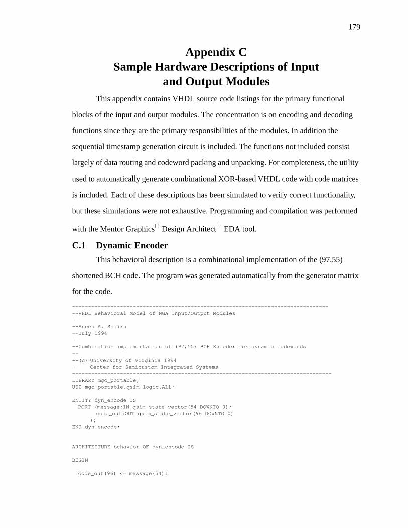
179
Appendix CSample Hardware Descriptions of Input
and Output ModulesThis appendix contains VHDL source code listings for the primary functional
blocks of the input and output modules. The concentration is on encoding and decoding
functions since they are the primary responsibilities of the modules. In addition the
sequential timestamp generation circuit is included. The functions not included consist
largely of data routing and codeword packing and unpacking. For completeness, the utility
used to automatically generate combinational XOR-based VHDL code with code matrices
is included. Each of these descriptions has been simulated to verify correct functionality,
but these simulations were not exhaustive. Programming and compilation was performed
with the Mentor Graphics Design Architect EDA tool.
C.1 Dynamic Encoder
This behavioral description is a combinational implementation of the (97,55)
shortened BCH code. The program was generated automatically from the generator matrix
for the code.
----------------------------------------------------------------------------------VHDL Behavioral Model of NGA Input/Output Modules----Anees A. Shaikh--July 1994----Combination implementation of (97,55) BCH Encoder for dynamic codewords----(c) University of Virginia 1994-- Center for Semicustom Integrated Systems---------------------------------------------------------------------------------LIBRARY mgc_portable;USE mgc_portable.qsim_logic.ALL;
ENTITY dyn_encode ISPORT (message:IN qsim_state_vector(54 DOWNTO 0);
code_out:OUT qsim_state_vector(96 DOWNTO 0));
END dyn_encode;
ARCHITECTURE behavior OF dyn_encode IS
BEGIN
code_out(96) <= message(54);
180
code_out(95) <= message(53);code_out(94) <= message(52);code_out(93) <= message(51);code_out(92) <= message(50);code_out(91) <= message(49);code_out(90) <= message(48);code_out(89) <= message(47);code_out(88) <= message(46);code_out(87) <= message(45);code_out(86) <= message(44);code_out(85) <= message(43);code_out(84) <= message(42);code_out(83) <= message(41);code_out(82) <= message(40);code_out(81) <= message(39);code_out(80) <= message(38);code_out(79) <= message(37);code_out(78) <= message(36);code_out(77) <= message(35);code_out(76) <= message(34);code_out(75) <= message(33);code_out(74) <= message(32);code_out(73) <= message(31);code_out(72) <= message(30);code_out(71) <= message(29);code_out(70) <= message(28);code_out(69) <= message(27);code_out(68) <= message(26);code_out(67) <= message(25);code_out(66) <= message(24);code_out(65) <= message(23);code_out(64) <= message(22);code_out(63) <= message(21);code_out(62) <= message(20);code_out(61) <= message(19);code_out(60) <= message(18);code_out(59) <= message(17);code_out(58) <= message(16);code_out(57) <= message(15);code_out(56) <= message(14);code_out(55) <= message(13);code_out(54) <= message(12);code_out(53) <= message(11);code_out(52) <= message(10);code_out(51) <= message(9);code_out(50) <= message(8);code_out(49) <= message(7);code_out(48) <= message(6);code_out(47) <= message(5);code_out(46) <= message(4);code_out(45) <= message(3);code_out(44) <= message(2);code_out(43) <= message(1);code_out(42) <= message(0);code_out(41) <= message(54) XOR message(52) XOR message(44) XOR message(43) XOR
message(41) XOR message(40) XOR message(38) XOR message(35) XOR message(33) XORmessage(30) XOR message(29) XOR message(27) XOR message(26) XOR message(25) XORmessage(23) XOR message(22) XOR message(20) XOR message(18) XOR message(15) XORmessage(13) XOR message(10) XOR message(7) XOR message(6) XOR message(5) XOR message(4)XOR message(1) XOR message(0);
code_out(40) <= message(54) XOR message(53) XOR message(52) XOR message(51) XORmessage(44) XOR message(42) XOR message(41) XOR message(39) XOR message(38) XORmessage(37) XOR message(35) XOR message(34) XOR message(33) XOR message(32) XORmessage(30) XOR message(28) XOR message(27) XOR message(24) XOR message(23) XORmessage(21) XOR message(20) XOR message(19) XOR message(18) XOR message(17) XOR
181
message(15) XOR message(14) XOR message(13) XOR message(12) XOR message(10) XORmessage(9) XOR message(7) XOR message(3) XOR message(1);
code_out(39) <= message(53) XOR message(52) XOR message(51) XOR message(50) XORmessage(43) XOR message(41) XOR message(40) XOR message(38) XOR message(37) XORmessage(36) XOR message(34) XOR message(33) XOR message(32) XOR message(31) XORmessage(29) XOR message(27) XOR message(26) XOR message(23) XOR message(22) XORmessage(20) XOR message(19) XOR message(18) XOR message(17) XOR message(16) XORmessage(14) XOR message(13) XOR message(12) XOR message(11) XOR message(9) XORmessage(8) XOR message(6) XOR message(2) XOR message(0);
code_out(38) <= message(54) XOR message(51) XOR message(50) XOR message(49) XORmessage(44) XOR message(43) XOR message(42) XOR message(41) XOR message(39) XORmessage(38) XOR message(37) XOR message(36) XOR message(32) XOR message(31) XORmessage(29) XOR message(28) XOR message(27) XOR message(23) XOR message(21) XORmessage(20) XOR message(19) XOR message(17) XOR message(16) XOR message(12) XORmessage(11) XOR message(8) XOR message(6) XOR message(4) XOR message(0);
code_out(37) <= message(54) XOR message(53) XOR message(52) XOR message(50) XORmessage(49) XOR message(48) XOR message(44) XOR message(42) XOR message(37) XORmessage(36) XOR message(33) XOR message(31) XOR message(29) XOR message(28) XORmessage(25) XOR message(23) XOR message(19) XOR message(16) XOR message(13) XORmessage(11) XOR message(6) XOR message(4) XOR message(3) XOR message(1) XOR message(0);
code_out(36) <= message(53) XOR message(51) XOR message(49) XOR message(48) XORmessage(47) XOR message(44) XOR message(40) XOR message(38) XOR message(36) XORmessage(33) XOR message(32) XOR message(29) XOR message(28) XOR message(26) XORmessage(25) XOR message(24) XOR message(23) XOR message(20) XOR message(13) XORmessage(12) XOR message(7) XOR message(6) XOR message(4) XOR message(3) XOR message(2)XOR message(1);
code_out(35) <= message(54) XOR message(52) XOR message(50) XOR message(48) XORmessage(47) XOR message(46) XOR message(43) XOR message(39) XOR message(37) XORmessage(35) XOR message(32) XOR message(31) XOR message(28) XOR message(27) XORmessage(25) XOR message(24) XOR message(23) XOR message(22) XOR message(19) XORmessage(12) XOR message(11) XOR message(6) XOR message(5) XOR message(3) XOR message(2)XOR message(1) XOR message(0);
code_out(34) <= message(54) XOR message(53) XOR message(52) XOR message(51) XORmessage(49) XOR message(47) XOR message(46) XOR message(45) XOR message(44) XORmessage(43) XOR message(42) XOR message(41) XOR message(40) XOR message(36) XORmessage(35) XOR message(34) XOR message(33) XOR message(31) XOR message(29) XORmessage(25) XOR message(24) XOR message(21) XOR message(20) XOR message(15) XORmessage(13) XOR message(11) XOR message(7) XOR message(6) XOR message(2);
code_out(33) <= message(53) XOR message(52) XOR message(51) XOR message(50) XORmessage(48) XOR message(46) XOR message(45) XOR message(44) XOR message(43) XORmessage(42) XOR message(41) XOR message(40) XOR message(39) XOR message(35) XORmessage(34) XOR message(33) XOR message(32) XOR message(30) XOR message(28) XORmessage(24) XOR message(23) XOR message(20) XOR message(19) XOR message(14) XORmessage(12) XOR message(10) XOR message(6) XOR message(5) XOR message(1);
code_out(32) <= message(52) XOR message(51) XOR message(50) XOR message(49) XORmessage(47) XOR message(45) XOR message(44) XOR message(43) XOR message(42) XORmessage(41) XOR message(40) XOR message(39) XOR message(38) XOR message(34) XORmessage(33) XOR message(32) XOR message(31) XOR message(29) XOR message(27) XORmessage(23) XOR message(22) XOR message(19) XOR message(18) XOR message(13) XORmessage(11) XOR message(9) XOR message(5) XOR message(4) XOR message(0);
code_out(31) <= message(54) XOR message(52) XOR message(51) XOR message(50) XORmessage(49) XOR message(48) XOR message(46) XOR message(42) XOR message(39) XORmessage(37) XOR message(35) XOR message(32) XOR message(31) XOR message(29) XORmessage(28) XOR message(27) XOR message(25) XOR message(23) XOR message(21) XORmessage(20) XOR message(17) XOR message(15) XOR message(13) XOR message(12) XORmessage(8) XOR message(7) XOR message(6) XOR message(5) XOR message(3) XOR message(1)XOR message(0);
code_out(30) <= message(54) XOR message(53) XOR message(52) XOR message(51) XORmessage(50) XOR message(49) XOR message(48) XOR message(47) XOR message(45) XORmessage(44) XOR message(43) XOR message(40) XOR message(36) XOR message(35) XORmessage(34) XOR message(33) XOR message(31) XOR message(29) XOR message(28) XORmessage(25) XOR message(24) XOR message(23) XOR message(19) XOR message(18) XORmessage(16) XOR message(15) XOR message(14) XOR message(13) XOR message(12) XORmessage(11) XOR message(10) XOR message(2) XOR message(1);
182
code_out(29) <= message(53) XOR message(52) XOR message(51) XOR message(50) XORmessage(49) XOR message(48) XOR message(47) XOR message(46) XOR message(44) XORmessage(43) XOR message(42) XOR message(39) XOR message(35) XOR message(34) XORmessage(33) XOR message(32) XOR message(30) XOR message(28) XOR message(27) XORmessage(24) XOR message(23) XOR message(22) XOR message(18) XOR message(17) XORmessage(15) XOR message(14) XOR message(13) XOR message(12) XOR message(11) XORmessage(10) XOR message(9) XOR message(1) XOR message(0);
code_out(28) <= message(54) XOR message(51) XOR message(50) XOR message(49) XORmessage(48) XOR message(47) XOR message(46) XOR message(45) XOR message(44) XORmessage(42) XOR message(40) XOR message(35) XOR message(34) XOR message(32) XORmessage(31) XOR message(30) XOR message(25) XOR message(21) XOR message(20) XORmessage(18) XOR message(17) XOR message(16) XOR message(15) XOR message(14) XORmessage(12) XOR message(11) XOR message(9) XOR message(8) XOR message(7) XOR message(6)XOR message(5) XOR message(4) XOR message(1);
code_out(27) <= message(54) XOR message(53) XOR message(50) XOR message(49) XORmessage(48) XOR message(47) XOR message(46) XOR message(45) XOR message(44) XORmessage(43) XOR message(41) XOR message(39) XOR message(34) XOR message(33) XORmessage(31) XOR message(30) XOR message(29) XOR message(24) XOR message(20) XORmessage(19) XOR message(17) XOR message(16) XOR message(15) XOR message(14) XORmessage(13) XOR message(11) XOR message(10) XOR message(8) XOR message(7) XORmessage(6) XOR message(5) XOR message(4) XOR message(3) XOR message(0);
code_out(26) <= message(53) XOR message(49) XOR message(48) XOR message(47) XORmessage(46) XOR message(45) XOR message(42) XOR message(41) XOR message(35) XORmessage(32) XOR message(28) XOR message(27) XOR message(26) XOR message(25) XORmessage(22) XOR message(20) XOR message(19) XOR message(16) XOR message(14) XORmessage(12) XOR message(9) XOR message(3) XOR message(2) XOR message(1) XOR message(0);
code_out(25) <= message(48) XOR message(47) XOR message(46) XOR message(45) XORmessage(43) XOR message(38) XOR message(35) XOR message(34) XOR message(33) XORmessage(31) XOR message(30) XOR message(29) XOR message(24) XOR message(23) XORmessage(22) XOR message(21) XOR message(20) XOR message(19) XOR message(11) XORmessage(10) XOR message(8) XOR message(7) XOR message(6) XOR message(5) XOR message(4)XOR message(2);
code_out(24) <= message(54) XOR message(47) XOR message(46) XOR message(45) XORmessage(44) XOR message(42) XOR message(37) XOR message(34) XOR message(33) XORmessage(32) XOR message(30) XOR message(29) XOR message(28) XOR message(23) XORmessage(22) XOR message(21) XOR message(20) XOR message(19) XOR message(18) XORmessage(10) XOR message(9) XOR message(7) XOR message(6) XOR message(5) XOR message(4)XOR message(3) XOR message(1);
code_out(23) <= message(54) XOR message(53) XOR message(46) XOR message(45) XORmessage(44) XOR message(43) XOR message(41) XOR message(36) XOR message(33) XORmessage(32) XOR message(31) XOR message(29) XOR message(28) XOR message(27) XORmessage(22) XOR message(21) XOR message(20) XOR message(19) XOR message(18) XORmessage(17) XOR message(9) XOR message(8) XOR message(6) XOR message(5) XOR message(4)XOR message(3) XOR message(2) XOR message(0);
code_out(22) <= message(54) XOR message(53) XOR message(45) XOR message(42) XORmessage(41) XOR message(38) XOR message(33) XOR message(32) XOR message(31) XORmessage(29) XOR message(28) XOR message(25) XOR message(23) XOR message(22) XORmessage(21) XOR message(19) XOR message(17) XOR message(16) XOR message(15) XORmessage(13) XOR message(10) XOR message(8) XOR message(6) XOR message(3) XOR message(2)XOR message(0);
code_out(21) <= message(53) XOR message(43) XOR message(38) XOR message(37) XORmessage(35) XOR message(33) XOR message(32) XOR message(31) XOR message(29) XORmessage(28) XOR message(26) XOR message(25) XOR message(24) XOR message(23) XORmessage(21) XOR message(16) XOR message(14) XOR message(13) XOR message(12) XORmessage(10) XOR message(9) XOR message(6) XOR message(4) XOR message(2) XOR message(0);
code_out(20) <= message(54) XOR message(44) XOR message(43) XOR message(42) XORmessage(41) XOR message(40) XOR message(38) XOR message(37) XOR message(36) XORmessage(35) XOR message(34) XOR message(33) XOR message(32) XOR message(31) XORmessage(29) XOR message(28) XOR message(26) XOR message(24) XOR message(18) XORmessage(12) XOR message(11) XOR message(10) XOR message(9) XOR message(8) XORmessage(7) XOR message(6) XOR message(4) XOR message(3) XOR message(0);
code_out(19) <= message(53) XOR message(52) XOR message(44) XOR message(42) XORmessage(39) XOR message(38) XOR message(37) XOR message(36) XOR message(34) XORmessage(32) XOR message(31) XOR message(29) XOR message(28) XOR message(26) XORmessage(22) XOR message(20) XOR message(18) XOR message(17) XOR message(15) XOR
183
message(13) XOR message(11) XOR message(9) XOR message(8) XOR message(4) XOR message(3)XOR message(2) XOR message(1) XOR message(0);
code_out(18) <= message(51) XOR message(44) XOR message(40) XOR message(37) XORmessage(36) XOR message(31) XOR message(29) XOR message(28) XOR message(26) XORmessage(23) XOR message(22) XOR message(21) XOR message(20) XOR message(19) XORmessage(18) XOR message(17) XOR message(16) XOR message(15) XOR message(14) XORmessage(13) XOR message(12) XOR message(8) XOR message(6) XOR message(5) XOR message(4)XOR message(3) XOR message(2);
code_out(17) <= message(50) XOR message(43) XOR message(39) XOR message(36) XORmessage(35) XOR message(30) XOR message(28) XOR message(27) XOR message(25) XORmessage(22) XOR message(21) XOR message(20) XOR message(19) XOR message(18) XORmessage(17) XOR message(16) XOR message(15) XOR message(14) XOR message(13) XORmessage(12) XOR message(11) XOR message(7) XOR message(5) XOR message(4) XOR message(3)XOR message(2) XOR message(1);
code_out(16) <= message(49) XOR message(42) XOR message(38) XOR message(35) XORmessage(34) XOR message(29) XOR message(27) XOR message(26) XOR message(24) XORmessage(21) XOR message(20) XOR message(19) XOR message(18) XOR message(17) XORmessage(16) XOR message(15) XOR message(14) XOR message(13) XOR message(12) XORmessage(11) XOR message(10) XOR message(6) XOR message(4) XOR message(3) XOR message(2)XOR message(1) XOR message(0);
code_out(15) <= message(54) XOR message(52) XOR message(48) XOR message(44) XORmessage(43) XOR message(40) XOR message(38) XOR message(37) XOR message(35) XORmessage(34) XOR message(30) XOR message(29) XOR message(28) XOR message(27) XORmessage(22) XOR message(19) XOR message(17) XOR message(16) XOR message(14) XORmessage(12) XOR message(11) XOR message(9) XOR message(7) XOR message(6) XOR message(4)XOR message(3) XOR message(2);
code_out(14) <= message(53) XOR message(51) XOR message(47) XOR message(43) XORmessage(42) XOR message(39) XOR message(37) XOR message(36) XOR message(34) XORmessage(33) XOR message(29) XOR message(28) XOR message(27) XOR message(26) XORmessage(21) XOR message(18) XOR message(16) XOR message(15) XOR message(13) XORmessage(11) XOR message(10) XOR message(8) XOR message(6) XOR message(5) XOR message(3)XOR message(2) XOR message(1);
code_out(13) <= message(52) XOR message(50) XOR message(46) XOR message(42) XORmessage(41) XOR message(38) XOR message(36) XOR message(35) XOR message(33) XORmessage(32) XOR message(28) XOR message(27) XOR message(26) XOR message(25) XORmessage(20) XOR message(17) XOR message(15) XOR message(14) XOR message(12) XORmessage(10) XOR message(9) XOR message(7) XOR message(5) XOR message(4) XOR message(2)XOR message(1) XOR message(0);
code_out(12) <= message(54) XOR message(52) XOR message(51) XOR message(49) XORmessage(45) XOR message(44) XOR message(43) XOR message(38) XOR message(37) XORmessage(34) XOR message(33) XOR message(32) XOR message(31) XOR message(30) XORmessage(29) XOR message(24) XOR message(23) XOR message(22) XOR message(20) XORmessage(19) XOR message(18) XOR message(16) XOR message(15) XOR message(14) XORmessage(11) XOR message(10) XOR message(9) XOR message(8) XOR message(7) XOR message(5)XOR message(3);
code_out(11) <= message(54) XOR message(53) XOR message(51) XOR message(50) XORmessage(48) XOR message(44) XOR message(43) XOR message(42) XOR message(37) XORmessage(36) XOR message(33) XOR message(32) XOR message(31) XOR message(30) XORmessage(29) XOR message(28) XOR message(23) XOR message(22) XOR message(21) XORmessage(19) XOR message(18) XOR message(17) XOR message(15) XOR message(14) XORmessage(13) XOR message(10) XOR message(9) XOR message(8) XOR message(7) XOR message(6)XOR message(4) XOR message(2);
code_out(10) <= message(53) XOR message(52) XOR message(50) XOR message(49) XORmessage(47) XOR message(43) XOR message(42) XOR message(41) XOR message(36) XORmessage(35) XOR message(32) XOR message(31) XOR message(30) XOR message(29) XORmessage(28) XOR message(27) XOR message(22) XOR message(21) XOR message(20) XORmessage(18) XOR message(17) XOR message(16) XOR message(14) XOR message(13) XORmessage(12) XOR message(9) XOR message(8) XOR message(7) XOR message(6) XOR message(5)XOR message(3) XOR message(1);
code_out(9) <= message(52) XOR message(51) XOR message(49) XOR message(48) XORmessage(46) XOR message(42) XOR message(41) XOR message(40) XOR message(35) XORmessage(34) XOR message(31) XOR message(30) XOR message(29) XOR message(28) XORmessage(27) XOR message(26) XOR message(21) XOR message(20) XOR message(19) XORmessage(17) XOR message(16) XOR message(15) XOR message(13) XOR message(12) XOR
184
message(11) XOR message(8) XOR message(7) XOR message(6) XOR message(5) XOR message(4)XOR message(2) XOR message(0);
code_out(8) <= message(54) XOR message(52) XOR message(51) XOR message(50) XORmessage(48) XOR message(47) XOR message(45) XOR message(44) XOR message(43) XORmessage(39) XOR message(38) XOR message(35) XOR message(34) XOR message(28) XORmessage(23) XOR message(22) XOR message(19) XOR message(16) XOR message(14) XORmessage(13) XOR message(12) XOR message(11) XOR message(3) XOR message(0);
code_out(7) <= message(53) XOR message(52) XOR message(51) XOR message(50) XORmessage(49) XOR message(47) XOR message(46) XOR message(42) XOR message(41) XORmessage(40) XOR message(37) XOR message(35) XOR message(34) XOR message(30) XORmessage(29) XOR message(26) XOR message(25) XOR message(23) XOR message(21) XORmessage(20) XOR message(12) XOR message(11) XOR message(7) XOR message(6) XORmessage(5) XOR message(4) XOR message(2) XOR message(1) XOR message(0);
code_out(6) <= message(51) XOR message(50) XOR message(49) XOR message(48) XORmessage(46) XOR message(45) XOR message(44) XOR message(43) XOR message(39) XORmessage(38) XOR message(36) XOR message(35) XOR message(34) XOR message(30) XORmessage(28) XOR message(27) XOR message(26) XOR message(24) XOR message(23) XORmessage(19) XOR message(18) XOR message(15) XOR message(13) XOR message(11) XORmessage(7) XOR message(3);
code_out(5) <= message(50) XOR message(49) XOR message(48) XOR message(47) XORmessage(45) XOR message(44) XOR message(43) XOR message(42) XOR message(38) XORmessage(37) XOR message(35) XOR message(34) XOR message(33) XOR message(29) XORmessage(27) XOR message(26) XOR message(25) XOR message(23) XOR message(22) XORmessage(18) XOR message(17) XOR message(14) XOR message(12) XOR message(10) XORmessage(6) XOR message(2);
code_out(4) <= message(54) XOR message(49) XOR message(48) XOR message(47) XORmessage(46) XOR message(44) XOR message(43) XOR message(42) XOR message(41) XORmessage(37) XOR message(36) XOR message(34) XOR message(33) XOR message(32) XORmessage(28) XOR message(26) XOR message(25) XOR message(24) XOR message(22) XORmessage(21) XOR message(17) XOR message(16) XOR message(13) XOR message(11) XORmessage(9) XOR message(5) XOR message(1);
code_out(3) <= message(54) XOR message(53) XOR message(48) XOR message(47) XORmessage(46) XOR message(45) XOR message(43) XOR message(42) XOR message(41) XORmessage(40) XOR message(36) XOR message(35) XOR message(33) XOR message(32) XORmessage(31) XOR message(27) XOR message(25) XOR message(24) XOR message(23) XORmessage(21) XOR message(20) XOR message(16) XOR message(15) XOR message(12) XORmessage(10) XOR message(8) XOR message(4) XOR message(0);
code_out(2) <= message(53) XOR message(47) XOR message(46) XOR message(45) XORmessage(43) XOR message(42) XOR message(39) XOR message(38) XOR message(34) XORmessage(33) XOR message(32) XOR message(31) XOR message(29) XOR message(27) XORmessage(25) XOR message(24) XOR message(19) XOR message(18) XOR message(14) XORmessage(13) XOR message(11) XOR message(10) XOR message(9) XOR message(6) XORmessage(5) XOR message(4) XOR message(3) XOR message(1) XOR message(0);
code_out(1) <= message(54) XOR message(46) XOR message(45) XOR message(43) XORmessage(42) XOR message(40) XOR message(37) XOR message(35) XOR message(32) XORmessage(31) XOR message(29) XOR message(28) XOR message(27) XOR message(25) XORmessage(24) XOR message(22) XOR message(20) XOR message(17) XOR message(15) XORmessage(12) XOR message(9) XOR message(8) XOR message(7) XOR message(6) XOR message(3)XOR message(2) XOR message(1);
code_out(0) <= message(53) XOR message(45) XOR message(44) XOR message(42) XORmessage(41) XOR message(39) XOR message(36) XOR message(34) XOR message(31) XORmessage(30) XOR message(28) XOR message(27) XOR message(26) XOR message(24) XORmessage(23) XOR message(21) XOR message(19) XOR message(16) XOR message(14) XORmessage(11) XOR message(8) XOR message(7) XOR message(6) XOR message(5) XOR message(2)XOR message(1) XOR message(0);
END behavior;
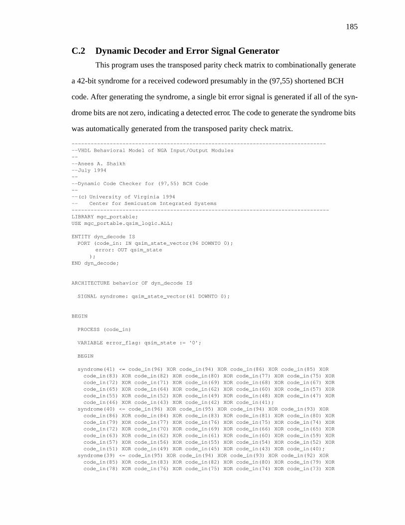
185
C.2 Dynamic Decoder and Error Signal Generator
This program uses the transposed parity check matrix to combinationally generate
a 42-bit syndrome for a received codeword presumably in the (97,55) shortened BCH
code. After generating the syndrome, a single bit error signal is generated if all of the syn-
drome bits are not zero, indicating a detected error. The code to generate the syndrome bits
was automatically generated from the transposed parity check matrix.
----------------------------------------------------------------------------------VHDL Behavioral Model of NGA Input/Output Modules----Anees A. Shaikh--July 1994----Dynamic Code Checker for (97,55) BCH Code----(c) University of Virginia 1994-- Center for Semicustom Integrated Systems---------------------------------------------------------------------------------LIBRARY mgc_portable;USE mgc_portable.qsim_logic.ALL;
ENTITY dyn_decode ISPORT (code_in: IN qsim_state_vector(96 DOWNTO 0);
error: OUT qsim_state);
END dyn_decode;
ARCHITECTURE behavior OF dyn_decode IS
SIGNAL syndrome: qsim_state_vector(41 DOWNTO 0);
BEGIN
PROCESS (code_in)
VARIABLE error_flag: qsim_state := ‘0’;
BEGIN
syndrome(41) <= code_in(96) XOR code_in(94) XOR code_in(86) XOR code_in(85) XORcode_in(83) XOR code_in(82) XOR code_in(80) XOR code_in(77) XOR code_in(75) XORcode_in(72) XOR code_in(71) XOR code_in(69) XOR code_in(68) XOR code_in(67) XORcode_in(65) XOR code_in(64) XOR code_in(62) XOR code_in(60) XOR code_in(57) XORcode_in(55) XOR code_in(52) XOR code_in(49) XOR code_in(48) XOR code_in(47) XORcode_in(46) XOR code_in(43) XOR code_in(42) XOR code_in(41);
syndrome(40) <= code_in(96) XOR code_in(95) XOR code_in(94) XOR code_in(93) XORcode_in(86) XOR code_in(84) XOR code_in(83) XOR code_in(81) XOR code_in(80) XORcode_in(79) XOR code_in(77) XOR code_in(76) XOR code_in(75) XOR code_in(74) XORcode_in(72) XOR code_in(70) XOR code_in(69) XOR code_in(66) XOR code_in(65) XORcode_in(63) XOR code_in(62) XOR code_in(61) XOR code_in(60) XOR code_in(59) XORcode_in(57) XOR code_in(56) XOR code_in(55) XOR code_in(54) XOR code_in(52) XORcode_in(51) XOR code_in(49) XOR code_in(45) XOR code_in(43) XOR code_in(40);
syndrome(39) <= code_in(95) XOR code_in(94) XOR code_in(93) XOR code_in(92) XORcode_in(85) XOR code_in(83) XOR code_in(82) XOR code_in(80) XOR code_in(79) XORcode_in(78) XOR code_in(76) XOR code_in(75) XOR code_in(74) XOR code_in(73) XOR
186
code_in(71) XOR code_in(69) XOR code_in(68) XOR code_in(65) XOR code_in(64) XORcode_in(62) XOR code_in(61) XOR code_in(60) XOR code_in(59) XOR code_in(58) XORcode_in(56) XOR code_in(55) XOR code_in(54) XOR code_in(53) XOR code_in(51) XORcode_in(50) XOR code_in(48) XOR code_in(44) XOR code_in(42) XOR code_in(39);
syndrome(38) <= code_in(96) XOR code_in(93) XOR code_in(92) XOR code_in(91) XORcode_in(86) XOR code_in(85) XOR code_in(84) XOR code_in(83) XOR code_in(81) XORcode_in(80) XOR code_in(79) XOR code_in(78) XOR code_in(74) XOR code_in(73) XORcode_in(71) XOR code_in(70) XOR code_in(69) XOR code_in(65) XOR code_in(63) XORcode_in(62) XOR code_in(61) XOR code_in(59) XOR code_in(58) XOR code_in(54) XORcode_in(53) XOR code_in(50) XOR code_in(48) XOR code_in(46) XOR code_in(42) XORcode_in(38);
syndrome(37) <= code_in(96) XOR code_in(95) XOR code_in(94) XOR code_in(92) XORcode_in(91) XOR code_in(90) XOR code_in(86) XOR code_in(84) XOR code_in(79) XORcode_in(78) XOR code_in(75) XOR code_in(73) XOR code_in(71) XOR code_in(70) XORcode_in(67) XOR code_in(65) XOR code_in(61) XOR code_in(58) XOR code_in(55) XORcode_in(53) XOR code_in(48) XOR code_in(46) XOR code_in(45) XOR code_in(43) XORcode_in(42) XOR code_in(37);
syndrome(36) <= code_in(95) XOR code_in(93) XOR code_in(91) XOR code_in(90) XORcode_in(89) XOR code_in(86) XOR code_in(82) XOR code_in(80) XOR code_in(78) XORcode_in(75) XOR code_in(74) XOR code_in(71) XOR code_in(70) XOR code_in(68) XORcode_in(67) XOR code_in(66) XOR code_in(65) XOR code_in(62) XOR code_in(55) XORcode_in(54) XOR code_in(49) XOR code_in(48) XOR code_in(46) XOR code_in(45) XORcode_in(44) XOR code_in(43) XOR code_in(36);
syndrome(35) <= code_in(96) XOR code_in(94) XOR code_in(92) XOR code_in(90) XORcode_in(89) XOR code_in(88) XOR code_in(85) XOR code_in(81) XOR code_in(79) XORcode_in(77) XOR code_in(74) XOR code_in(73) XOR code_in(70) XOR code_in(69) XORcode_in(67) XOR code_in(66) XOR code_in(65) XOR code_in(64) XOR code_in(61) XORcode_in(54) XOR code_in(53) XOR code_in(48) XOR code_in(47) XOR code_in(45) XORcode_in(44) XOR code_in(43) XOR code_in(42) XOR code_in(35);
syndrome(34) <= code_in(96) XOR code_in(95) XOR code_in(94) XOR code_in(93) XORcode_in(91) XOR code_in(89) XOR code_in(88) XOR code_in(87) XOR code_in(86) XORcode_in(85) XOR code_in(84) XOR code_in(83) XOR code_in(82) XOR code_in(78) XORcode_in(77) XOR code_in(76) XOR code_in(75) XOR code_in(73) XOR code_in(71) XORcode_in(67) XOR code_in(66) XOR code_in(63) XOR code_in(62) XOR code_in(57) XORcode_in(55) XOR code_in(53) XOR code_in(49) XOR code_in(48) XOR code_in(44) XORcode_in(34);
syndrome(33) <= code_in(95) XOR code_in(94) XOR code_in(93) XOR code_in(92) XORcode_in(90) XOR code_in(88) XOR code_in(87) XOR code_in(86) XOR code_in(85) XORcode_in(84) XOR code_in(83) XOR code_in(82) XOR code_in(81) XOR code_in(77) XORcode_in(76) XOR code_in(75) XOR code_in(74) XOR code_in(72) XOR code_in(70) XORcode_in(66) XOR code_in(65) XOR code_in(62) XOR code_in(61) XOR code_in(56) XORcode_in(54) XOR code_in(52) XOR code_in(48) XOR code_in(47) XOR code_in(43) XORcode_in(33);
syndrome(32) <= code_in(94) XOR code_in(93) XOR code_in(92) XOR code_in(91) XORcode_in(89) XOR code_in(87) XOR code_in(86) XOR code_in(85) XOR code_in(84) XORcode_in(83) XOR code_in(82) XOR code_in(81) XOR code_in(80) XOR code_in(76) XORcode_in(75) XOR code_in(74) XOR code_in(73) XOR code_in(71) XOR code_in(69) XORcode_in(65) XOR code_in(64) XOR code_in(61) XOR code_in(60) XOR code_in(55) XORcode_in(53) XOR code_in(51) XOR code_in(47) XOR code_in(46) XOR code_in(42) XORcode_in(32);
syndrome(31) <= code_in(96) XOR code_in(94) XOR code_in(93) XOR code_in(92) XORcode_in(91) XOR code_in(90) XOR code_in(88) XOR code_in(84) XOR code_in(81) XORcode_in(79) XOR code_in(77) XOR code_in(74) XOR code_in(73) XOR code_in(71) XORcode_in(70) XOR code_in(69) XOR code_in(67) XOR code_in(65) XOR code_in(63) XORcode_in(62) XOR code_in(59) XOR code_in(57) XOR code_in(55) XOR code_in(54) XORcode_in(50) XOR code_in(49) XOR code_in(48) XOR code_in(47) XOR code_in(45) XORcode_in(43) XOR code_in(42) XOR code_in(31);
syndrome(30) <= code_in(96) XOR code_in(95) XOR code_in(94) XOR code_in(93) XORcode_in(92) XOR code_in(91) XOR code_in(90) XOR code_in(89) XOR code_in(87) XORcode_in(86) XOR code_in(85) XOR code_in(82) XOR code_in(78) XOR code_in(77) XORcode_in(76) XOR code_in(75) XOR code_in(73) XOR code_in(71) XOR code_in(70) XORcode_in(67) XOR code_in(66) XOR code_in(65) XOR code_in(61) XOR code_in(60) XORcode_in(58) XOR code_in(57) XOR code_in(56) XOR code_in(55) XOR code_in(54) XORcode_in(53) XOR code_in(52) XOR code_in(44) XOR code_in(43) XOR code_in(30);
187
syndrome(29) <= code_in(95) XOR code_in(94) XOR code_in(93) XOR code_in(92) XORcode_in(91) XOR code_in(90) XOR code_in(89) XOR code_in(88) XOR code_in(86) XORcode_in(85) XOR code_in(84) XOR code_in(81) XOR code_in(77) XOR code_in(76) XORcode_in(75) XOR code_in(74) XOR code_in(72) XOR code_in(70) XOR code_in(69) XORcode_in(66) XOR code_in(65) XOR code_in(64) XOR code_in(60) XOR code_in(59) XORcode_in(57) XOR code_in(56) XOR code_in(55) XOR code_in(54) XOR code_in(53) XORcode_in(52) XOR code_in(51) XOR code_in(43) XOR code_in(42) XOR code_in(29);
syndrome(28) <= code_in(96) XOR code_in(93) XOR code_in(92) XOR code_in(91) XORcode_in(90) XOR code_in(89) XOR code_in(88) XOR code_in(87) XOR code_in(86) XORcode_in(84) XOR code_in(82) XOR code_in(77) XOR code_in(76) XOR code_in(74) XORcode_in(73) XOR code_in(72) XOR code_in(67) XOR code_in(63) XOR code_in(62) XORcode_in(60) XOR code_in(59) XOR code_in(58) XOR code_in(57) XOR code_in(56) XORcode_in(54) XOR code_in(53) XOR code_in(51) XOR code_in(50) XOR code_in(49) XORcode_in(48) XOR code_in(47) XOR code_in(46) XOR code_in(43) XOR code_in(28);
syndrome(27) <= code_in(96) XOR code_in(95) XOR code_in(92) XOR code_in(91) XORcode_in(90) XOR code_in(89) XOR code_in(88) XOR code_in(87) XOR code_in(86) XORcode_in(85) XOR code_in(83) XOR code_in(81) XOR code_in(76) XOR code_in(75) XORcode_in(73) XOR code_in(72) XOR code_in(71) XOR code_in(66) XOR code_in(62) XORcode_in(61) XOR code_in(59) XOR code_in(58) XOR code_in(57) XOR code_in(56) XORcode_in(55) XOR code_in(53) XOR code_in(52) XOR code_in(50) XOR code_in(49) XORcode_in(48) XOR code_in(47) XOR code_in(46) XOR code_in(45) XOR code_in(42) XORcode_in(27);
syndrome(26) <= code_in(95) XOR code_in(91) XOR code_in(90) XOR code_in(89) XORcode_in(88) XOR code_in(87) XOR code_in(84) XOR code_in(83) XOR code_in(77) XORcode_in(74) XOR code_in(70) XOR code_in(69) XOR code_in(68) XOR code_in(67) XORcode_in(64) XOR code_in(62) XOR code_in(61) XOR code_in(58) XOR code_in(56) XORcode_in(54) XOR code_in(51) XOR code_in(45) XOR code_in(44) XOR code_in(43) XORcode_in(42) XOR code_in(26);
syndrome(25) <= code_in(90) XOR code_in(89) XOR code_in(88) XOR code_in(87) XORcode_in(85) XOR code_in(80) XOR code_in(77) XOR code_in(76) XOR code_in(75) XORcode_in(73) XOR code_in(72) XOR code_in(71) XOR code_in(66) XOR code_in(65) XORcode_in(64) XOR code_in(63) XOR code_in(62) XOR code_in(61) XOR code_in(53) XORcode_in(52) XOR code_in(50) XOR code_in(49) XOR code_in(48) XOR code_in(47) XORcode_in(46) XOR code_in(44) XOR code_in(25);
syndrome(24) <= code_in(96) XOR code_in(89) XOR code_in(88) XOR code_in(87) XORcode_in(86) XOR code_in(84) XOR code_in(79) XOR code_in(76) XOR code_in(75) XORcode_in(74) XOR code_in(72) XOR code_in(71) XOR code_in(70) XOR code_in(65) XORcode_in(64) XOR code_in(63) XOR code_in(62) XOR code_in(61) XOR code_in(60) XORcode_in(52) XOR code_in(51) XOR code_in(49) XOR code_in(48) XOR code_in(47) XORcode_in(46) XOR code_in(45) XOR code_in(43) XOR code_in(24);
syndrome(23) <= code_in(96) XOR code_in(95) XOR code_in(88) XOR code_in(87) XORcode_in(86) XOR code_in(85) XOR code_in(83) XOR code_in(78) XOR code_in(75) XORcode_in(74) XOR code_in(73) XOR code_in(71) XOR code_in(70) XOR code_in(69) XORcode_in(64) XOR code_in(63) XOR code_in(62) XOR code_in(61) XOR code_in(60) XORcode_in(59) XOR code_in(51) XOR code_in(50) XOR code_in(48) XOR code_in(47) XORcode_in(46) XOR code_in(45) XOR code_in(44) XOR code_in(42) XOR code_in(23);
syndrome(22) <= code_in(96) XOR code_in(95) XOR code_in(87) XOR code_in(84) XORcode_in(83) XOR code_in(80) XOR code_in(75) XOR code_in(74) XOR code_in(73) XORcode_in(71) XOR code_in(70) XOR code_in(67) XOR code_in(65) XOR code_in(64) XORcode_in(63) XOR code_in(61) XOR code_in(59) XOR code_in(58) XOR code_in(57) XORcode_in(55) XOR code_in(52) XOR code_in(50) XOR code_in(48) XOR code_in(45) XORcode_in(44) XOR code_in(42) XOR code_in(22);
syndrome(21) <= code_in(95) XOR code_in(85) XOR code_in(80) XOR code_in(79) XORcode_in(77) XOR code_in(75) XOR code_in(74) XOR code_in(73) XOR code_in(71) XORcode_in(70) XOR code_in(68) XOR code_in(67) XOR code_in(66) XOR code_in(65) XORcode_in(63) XOR code_in(58) XOR code_in(56) XOR code_in(55) XOR code_in(54) XORcode_in(52) XOR code_in(51) XOR code_in(48) XOR code_in(46) XOR code_in(44) XORcode_in(42) XOR code_in(21);
syndrome(20) <= code_in(96) XOR code_in(86) XOR code_in(85) XOR code_in(84) XORcode_in(83) XOR code_in(82) XOR code_in(80) XOR code_in(79) XOR code_in(78) XORcode_in(77) XOR code_in(76) XOR code_in(75) XOR code_in(74) XOR code_in(73) XORcode_in(71) XOR code_in(70) XOR code_in(68) XOR code_in(66) XOR code_in(60) XORcode_in(54) XOR code_in(53) XOR code_in(52) XOR code_in(51) XOR code_in(50) XORcode_in(49) XOR code_in(48) XOR code_in(46) XOR code_in(45) XOR code_in(42) XORcode_in(20);
188
syndrome(19) <= code_in(95) XOR code_in(94) XOR code_in(86) XOR code_in(84) XORcode_in(81) XOR code_in(80) XOR code_in(79) XOR code_in(78) XOR code_in(76) XORcode_in(74) XOR code_in(73) XOR code_in(71) XOR code_in(70) XOR code_in(68) XORcode_in(64) XOR code_in(62) XOR code_in(60) XOR code_in(59) XOR code_in(57) XORcode_in(55) XOR code_in(53) XOR code_in(51) XOR code_in(50) XOR code_in(46) XORcode_in(45) XOR code_in(44) XOR code_in(43) XOR code_in(42) XOR code_in(19);
syndrome(18) <= code_in(93) XOR code_in(86) XOR code_in(82) XOR code_in(79) XORcode_in(78) XOR code_in(73) XOR code_in(71) XOR code_in(70) XOR code_in(68) XORcode_in(65) XOR code_in(64) XOR code_in(63) XOR code_in(62) XOR code_in(61) XORcode_in(60) XOR code_in(59) XOR code_in(58) XOR code_in(57) XOR code_in(56) XORcode_in(55) XOR code_in(54) XOR code_in(50) XOR code_in(48) XOR code_in(47) XORcode_in(46) XOR code_in(45) XOR code_in(44) XOR code_in(18);
syndrome(17) <= code_in(92) XOR code_in(85) XOR code_in(81) XOR code_in(78) XORcode_in(77) XOR code_in(72) XOR code_in(70) XOR code_in(69) XOR code_in(67) XORcode_in(64) XOR code_in(63) XOR code_in(62) XOR code_in(61) XOR code_in(60) XORcode_in(59) XOR code_in(58) XOR code_in(57) XOR code_in(56) XOR code_in(55) XORcode_in(54) XOR code_in(53) XOR code_in(49) XOR code_in(47) XOR code_in(46) XORcode_in(45) XOR code_in(44) XOR code_in(43) XOR code_in(17);
syndrome(16) <= code_in(91) XOR code_in(84) XOR code_in(80) XOR code_in(77) XORcode_in(76) XOR code_in(71) XOR code_in(69) XOR code_in(68) XOR code_in(66) XORcode_in(63) XOR code_in(62) XOR code_in(61) XOR code_in(60) XOR code_in(59) XORcode_in(58) XOR code_in(57) XOR code_in(56) XOR code_in(55) XOR code_in(54) XORcode_in(53) XOR code_in(52) XOR code_in(48) XOR code_in(46) XOR code_in(45) XORcode_in(44) XOR code_in(43) XOR code_in(42) XOR code_in(16);
syndrome(15) <= code_in(96) XOR code_in(94) XOR code_in(90) XOR code_in(86) XORcode_in(85) XOR code_in(82) XOR code_in(80) XOR code_in(79) XOR code_in(77) XORcode_in(76) XOR code_in(72) XOR code_in(71) XOR code_in(70) XOR code_in(69) XORcode_in(64) XOR code_in(61) XOR code_in(59) XOR code_in(58) XOR code_in(56) XORcode_in(54) XOR code_in(53) XOR code_in(51) XOR code_in(49) XOR code_in(48) XORcode_in(46) XOR code_in(45) XOR code_in(44) XOR code_in(15);
syndrome(14) <= code_in(95) XOR code_in(93) XOR code_in(89) XOR code_in(85) XORcode_in(84) XOR code_in(81) XOR code_in(79) XOR code_in(78) XOR code_in(76) XORcode_in(75) XOR code_in(71) XOR code_in(70) XOR code_in(69) XOR code_in(68) XORcode_in(63) XOR code_in(60) XOR code_in(58) XOR code_in(57) XOR code_in(55) XORcode_in(53) XOR code_in(52) XOR code_in(50) XOR code_in(48) XOR code_in(47) XORcode_in(45) XOR code_in(44) XOR code_in(43) XOR code_in(14);
syndrome(13) <= code_in(94) XOR code_in(92) XOR code_in(88) XOR code_in(84) XORcode_in(83) XOR code_in(80) XOR code_in(78) XOR code_in(77) XOR code_in(75) XORcode_in(74) XOR code_in(70) XOR code_in(69) XOR code_in(68) XOR code_in(67) XORcode_in(62) XOR code_in(59) XOR code_in(57) XOR code_in(56) XOR code_in(54) XORcode_in(52) XOR code_in(51) XOR code_in(49) XOR code_in(47) XOR code_in(46) XORcode_in(44) XOR code_in(43) XOR code_in(42) XOR code_in(13);
syndrome(12) <= code_in(96) XOR code_in(94) XOR code_in(93) XOR code_in(91) XORcode_in(87) XOR code_in(86) XOR code_in(85) XOR code_in(80) XOR code_in(79) XORcode_in(76) XOR code_in(75) XOR code_in(74) XOR code_in(73) XOR code_in(72) XORcode_in(71) XOR code_in(66) XOR code_in(65) XOR code_in(64) XOR code_in(62) XORcode_in(61) XOR code_in(60) XOR code_in(58) XOR code_in(57) XOR code_in(56) XORcode_in(53) XOR code_in(52) XOR code_in(51) XOR code_in(50) XOR code_in(49) XORcode_in(47) XOR code_in(45) XOR code_in(12);
syndrome(11) <= code_in(96) XOR code_in(95) XOR code_in(93) XOR code_in(92) XORcode_in(90) XOR code_in(86) XOR code_in(85) XOR code_in(84) XOR code_in(79) XORcode_in(78) XOR code_in(75) XOR code_in(74) XOR code_in(73) XOR code_in(72) XORcode_in(71) XOR code_in(70) XOR code_in(65) XOR code_in(64) XOR code_in(63) XORcode_in(61) XOR code_in(60) XOR code_in(59) XOR code_in(57) XOR code_in(56) XORcode_in(55) XOR code_in(52) XOR code_in(51) XOR code_in(50) XOR code_in(49) XORcode_in(48) XOR code_in(46) XOR code_in(44) XOR code_in(11);
syndrome(10) <= code_in(95) XOR code_in(94) XOR code_in(92) XOR code_in(91) XORcode_in(89) XOR code_in(85) XOR code_in(84) XOR code_in(83) XOR code_in(78) XORcode_in(77) XOR code_in(74) XOR code_in(73) XOR code_in(72) XOR code_in(71) XORcode_in(70) XOR code_in(69) XOR code_in(64) XOR code_in(63) XOR code_in(62) XORcode_in(60) XOR code_in(59) XOR code_in(58) XOR code_in(56) XOR code_in(55) XORcode_in(54) XOR code_in(51) XOR code_in(50) XOR code_in(49) XOR code_in(48) XORcode_in(47) XOR code_in(45) XOR code_in(43) XOR code_in(10);
syndrome(9) <= code_in(94) XOR code_in(93) XOR code_in(91) XOR code_in(90) XORcode_in(88) XOR code_in(84) XOR code_in(83) XOR code_in(82) XOR code_in(77) XOR
189
code_in(76) XOR code_in(73) XOR code_in(72) XOR code_in(71) XOR code_in(70) XORcode_in(69) XOR code_in(68) XOR code_in(63) XOR code_in(62) XOR code_in(61) XORcode_in(59) XOR code_in(58) XOR code_in(57) XOR code_in(55) XOR code_in(54) XORcode_in(53) XOR code_in(50) XOR code_in(49) XOR code_in(48) XOR code_in(47) XORcode_in(46) XOR code_in(44) XOR code_in(42) XOR code_in(9);
syndrome(8) <= code_in(96) XOR code_in(94) XOR code_in(93) XOR code_in(92) XORcode_in(90) XOR code_in(89) XOR code_in(87) XOR code_in(86) XOR code_in(85) XORcode_in(81) XOR code_in(80) XOR code_in(77) XOR code_in(76) XOR code_in(70) XORcode_in(65) XOR code_in(64) XOR code_in(61) XOR code_in(58) XOR code_in(56) XORcode_in(55) XOR code_in(54) XOR code_in(53) XOR code_in(45) XOR code_in(42) XORcode_in(8);
syndrome(7) <= code_in(95) XOR code_in(94) XOR code_in(93) XOR code_in(92) XORcode_in(91) XOR code_in(89) XOR code_in(88) XOR code_in(84) XOR code_in(83) XORcode_in(82) XOR code_in(79) XOR code_in(77) XOR code_in(76) XOR code_in(72) XORcode_in(71) XOR code_in(68) XOR code_in(67) XOR code_in(65) XOR code_in(63) XORcode_in(62) XOR code_in(54) XOR code_in(53) XOR code_in(49) XOR code_in(48) XORcode_in(47) XOR code_in(46) XOR code_in(44) XOR code_in(43) XOR code_in(42) XORcode_in(7);
syndrome(6) <= code_in(93) XOR code_in(92) XOR code_in(91) XOR code_in(90) XORcode_in(88) XOR code_in(87) XOR code_in(86) XOR code_in(85) XOR code_in(81) XORcode_in(80) XOR code_in(78) XOR code_in(77) XOR code_in(76) XOR code_in(72) XORcode_in(70) XOR code_in(69) XOR code_in(68) XOR code_in(66) XOR code_in(65) XORcode_in(61) XOR code_in(60) XOR code_in(57) XOR code_in(55) XOR code_in(53) XORcode_in(49) XOR code_in(45) XOR code_in(6);
syndrome(5) <= code_in(92) XOR code_in(91) XOR code_in(90) XOR code_in(89) XORcode_in(87) XOR code_in(86) XOR code_in(85) XOR code_in(84) XOR code_in(80) XORcode_in(79) XOR code_in(77) XOR code_in(76) XOR code_in(75) XOR code_in(71) XORcode_in(69) XOR code_in(68) XOR code_in(67) XOR code_in(65) XOR code_in(64) XORcode_in(60) XOR code_in(59) XOR code_in(56) XOR code_in(54) XOR code_in(52) XORcode_in(48) XOR code_in(44) XOR code_in(5);
syndrome(4) <= code_in(96) XOR code_in(91) XOR code_in(90) XOR code_in(89) XORcode_in(88) XOR code_in(86) XOR code_in(85) XOR code_in(84) XOR code_in(83) XORcode_in(79) XOR code_in(78) XOR code_in(76) XOR code_in(75) XOR code_in(74) XORcode_in(70) XOR code_in(68) XOR code_in(67) XOR code_in(66) XOR code_in(64) XORcode_in(63) XOR code_in(59) XOR code_in(58) XOR code_in(55) XOR code_in(53) XORcode_in(51) XOR code_in(47) XOR code_in(43) XOR code_in(4);
syndrome(3) <= code_in(96) XOR code_in(95) XOR code_in(90) XOR code_in(89) XORcode_in(88) XOR code_in(87) XOR code_in(85) XOR code_in(84) XOR code_in(83) XORcode_in(82) XOR code_in(78) XOR code_in(77) XOR code_in(75) XOR code_in(74) XORcode_in(73) XOR code_in(69) XOR code_in(67) XOR code_in(66) XOR code_in(65) XORcode_in(63) XOR code_in(62) XOR code_in(58) XOR code_in(57) XOR code_in(54) XORcode_in(52) XOR code_in(50) XOR code_in(46) XOR code_in(42) XOR code_in(3);
syndrome(2) <= code_in(95) XOR code_in(89) XOR code_in(88) XOR code_in(87) XORcode_in(85) XOR code_in(84) XOR code_in(81) XOR code_in(80) XOR code_in(76) XORcode_in(75) XOR code_in(74) XOR code_in(73) XOR code_in(71) XOR code_in(69) XORcode_in(67) XOR code_in(66) XOR code_in(61) XOR code_in(60) XOR code_in(56) XORcode_in(55) XOR code_in(53) XOR code_in(52) XOR code_in(51) XOR code_in(48) XORcode_in(47) XOR code_in(46) XOR code_in(45) XOR code_in(43) XOR code_in(42) XORcode_in(2);
syndrome(1) <= code_in(96) XOR code_in(88) XOR code_in(87) XOR code_in(85) XORcode_in(84) XOR code_in(82) XOR code_in(79) XOR code_in(77) XOR code_in(74) XORcode_in(73) XOR code_in(71) XOR code_in(70) XOR code_in(69) XOR code_in(67) XORcode_in(66) XOR code_in(64) XOR code_in(62) XOR code_in(59) XOR code_in(57) XORcode_in(54) XOR code_in(51) XOR code_in(50) XOR code_in(49) XOR code_in(48) XORcode_in(45) XOR code_in(44) XOR code_in(43) XOR code_in(1);
syndrome(0) <= code_in(95) XOR code_in(87) XOR code_in(86) XOR code_in(84) XORcode_in(83) XOR code_in(81) XOR code_in(78) XOR code_in(76) XOR code_in(73) XORcode_in(72) XOR code_in(70) XOR code_in(69) XOR code_in(68) XOR code_in(66) XORcode_in(65) XOR code_in(63) XOR code_in(61) XOR code_in(58) XOR code_in(56) XORcode_in(53) XOR code_in(50) XOR code_in(49) XOR code_in(48) XOR code_in(47) XORcode_in(44) XOR code_in(43) XOR code_in(42) XOR code_in(0);
FOR i IN 0 to 41 LOOPIF syndrome(i) /= ‘0’ THEN
error_flag := ‘1’;

190
ELSE error_flag := ‘0’;END IF;
END LOOP;
END PROCESS;
END behavior;
C.3 Static Decoder and Error Signal Generator
The function of this program is identical to that of the dynamic decoder. In this
case, however, the generated syndrome is 140 bits from a 159-bit codeword. This decoder
is used to verify that the identification codeword is not corrupted in transit to the output
module.
----------------------------------------------------------------------------------VHDL Behavioral Model of NGA Input/Output Modules----Anees A. Shaikh--July 1994----Static (identification) Code Checker for (159,19) BCH Code----(c) University of Virginia 1994-- Center for Semicustom Integrated Systems---------------------------------------------------------------------------------LIBRARY mgc_portable;USE mgc_portable.qsim_logic.ALL;
ENTITY stat_decode ISPORT (code_in: IN qsim_state_vector(158 DOWNTO 0);
error: OUT qsim_state);
END stat_decode;
ARCHITECTURE behavior OF stat_decode IS
SIGNAL syndrome: qsim_state_vector(139 DOWNTO 0);
BEGIN
PROCESS (code_in)
VARIABLE error_flag: qsim_state := ‘0’;
BEGIN
syndrome(139) <= code_in(158) XOR code_in(156) XOR code_in(155) XOR code_in(151) XORcode_in(150) XOR code_in(149) XOR code_in(148) XOR code_in(146) XOR code_in(144) XORcode_in(140) XOR code_in(139);
syndrome(138) <= code_in(157) XOR code_in(156) XOR code_in(154) XOR code_in(151) XORcode_in(147) XOR code_in(146) XOR code_in(145) XOR code_in(144) XOR code_in(143) XORcode_in(140) XOR code_in(138);
syndrome(137) <= code_in(158) XOR code_in(153) XOR code_in(151) XOR code_in(149) XORcode_in(148) XOR code_in(145) XOR code_in(143) XOR code_in(142) XOR code_in(140) XORcode_in(137);
191
syndrome(136) <= code_in(157) XOR code_in(156) XOR code_in(155) XOR code_in(152) XORcode_in(151) XOR code_in(149) XOR code_in(147) XOR code_in(146) XOR code_in(142) XORcode_in(141) XOR code_in(140) XOR code_in(136);
syndrome(135) <= code_in(154) XOR code_in(149) XOR code_in(145) XOR code_in(144) XORcode_in(141) XOR code_in(135);
syndrome(134) <= code_in(153) XOR code_in(148) XOR code_in(144) XOR code_in(143) XORcode_in(140) XOR code_in(134);
syndrome(133) <= code_in(156) XOR code_in(155) XOR code_in(152) XOR code_in(151) XORcode_in(150) XOR code_in(149) XOR code_in(148) XOR code_in(147) XOR code_in(146) XORcode_in(144) XOR code_in(143) XOR code_in(142) XOR code_in(140) XOR code_in(133);
syndrome(132) <= code_in(156) XOR code_in(154) XOR code_in(147) XOR code_in(145) XORcode_in(144) XOR code_in(143) XOR code_in(142) XOR code_in(141) XOR code_in(140) XORcode_in(132);
syndrome(131) <= code_in(158) XOR code_in(156) XOR code_in(153) XOR code_in(151) XORcode_in(150) XOR code_in(149) XOR code_in(148) XOR code_in(143) XOR code_in(142) XORcode_in(141) XOR code_in(131);
syndrome(130) <= code_in(157) XOR code_in(155) XOR code_in(152) XOR code_in(150) XORcode_in(149) XOR code_in(148) XOR code_in(147) XOR code_in(142) XOR code_in(141) XORcode_in(140) XOR code_in(130);
syndrome(129) <= code_in(155) XOR code_in(154) XOR code_in(150) XOR code_in(147) XORcode_in(144) XOR code_in(141) XOR code_in(129);
syndrome(128) <= code_in(154) XOR code_in(153) XOR code_in(149) XOR code_in(146) XORcode_in(143) XOR code_in(140) XOR code_in(128);
syndrome(127) <= code_in(158) XOR code_in(156) XOR code_in(155) XOR code_in(153) XORcode_in(152) XOR code_in(151) XOR code_in(150) XOR code_in(149) XOR code_in(146) XORcode_in(145) XOR code_in(144) XOR code_in(142) XOR code_in(140) XOR code_in(127);
syndrome(126) <= code_in(158) XOR code_in(157) XOR code_in(156) XOR code_in(154) XORcode_in(152) XOR code_in(146) XOR code_in(145) XOR code_in(143) XOR code_in(141) XORcode_in(140) XOR code_in(126);
syndrome(125) <= code_in(157) XOR code_in(153) XOR code_in(150) XOR code_in(149) XORcode_in(148) XOR code_in(146) XOR code_in(145) XOR code_in(142) XOR code_in(125);
syndrome(124) <= code_in(156) XOR code_in(152) XOR code_in(149) XOR code_in(148) XORcode_in(147) XOR code_in(145) XOR code_in(144) XOR code_in(141) XOR code_in(124);
syndrome(123) <= code_in(158) XOR code_in(155) XOR code_in(151) XOR code_in(148) XORcode_in(147) XOR code_in(146) XOR code_in(144) XOR code_in(143) XOR code_in(140) XORcode_in(123);
syndrome(122) <= code_in(158) XOR code_in(157) XOR code_in(156) XOR code_in(155) XORcode_in(154) XOR code_in(151) XOR code_in(149) XOR code_in(148) XOR code_in(147) XORcode_in(145) XOR code_in(144) XOR code_in(143) XOR code_in(142) XOR code_in(140) XORcode_in(122);
syndrome(121) <= code_in(157) XOR code_in(154) XOR code_in(153) XOR code_in(151) XORcode_in(149) XOR code_in(147) XOR code_in(143) XOR code_in(142) XOR code_in(141) XORcode_in(140) XOR code_in(121);
syndrome(120) <= code_in(158) XOR code_in(155) XOR code_in(153) XOR code_in(152) XORcode_in(151) XOR code_in(149) XOR code_in(144) XOR code_in(142) XOR code_in(141) XORcode_in(120);
syndrome(119) <= code_in(158) XOR code_in(157) XOR code_in(154) XOR code_in(152) XORcode_in(151) XOR code_in(150) XOR code_in(148) XOR code_in(143) XOR code_in(141) XORcode_in(140) XOR code_in(119);
syndrome(118) <= code_in(158) XOR code_in(157) XOR code_in(155) XOR code_in(153) XORcode_in(148) XOR code_in(147) XOR code_in(146) XOR code_in(144) XOR code_in(142) XORcode_in(118);
syndrome(117) <= code_in(157) XOR code_in(156) XOR code_in(154) XOR code_in(152) XORcode_in(147) XOR code_in(146) XOR code_in(145) XOR code_in(143) XOR code_in(141) XORcode_in(117);
syndrome(116) <= code_in(156) XOR code_in(155) XOR code_in(153) XOR code_in(151) XORcode_in(146) XOR code_in(145) XOR code_in(144) XOR code_in(142) XOR code_in(140) XORcode_in(116);
syndrome(115) <= code_in(156) XOR code_in(154) XOR code_in(152) XOR code_in(151) XORcode_in(149) XOR code_in(148) XOR code_in(146) XOR code_in(145) XOR code_in(143) XORcode_in(141) XOR code_in(140) XOR code_in(115);
syndrome(114) <= code_in(158) XOR code_in(156) XOR code_in(153) XOR code_in(149) XORcode_in(147) XOR code_in(146) XOR code_in(145) XOR code_in(142) XOR code_in(114);
syndrome(113) <= code_in(157) XOR code_in(155) XOR code_in(152) XOR code_in(148) XORcode_in(146) XOR code_in(145) XOR code_in(144) XOR code_in(141) XOR code_in(113);
192
syndrome(112) <= code_in(158) XOR code_in(156) XOR code_in(154) XOR code_in(151) XORcode_in(147) XOR code_in(145) XOR code_in(144) XOR code_in(143) XOR code_in(140) XORcode_in(112);
syndrome(111) <= code_in(157) XOR code_in(156) XOR code_in(153) XOR code_in(151) XORcode_in(149) XOR code_in(148) XOR code_in(143) XOR code_in(142) XOR code_in(140) XORcode_in(111);
syndrome(110) <= code_in(158) XOR code_in(152) XOR code_in(151) XOR code_in(149) XORcode_in(147) XOR code_in(146) XOR code_in(144) XOR code_in(142) XOR code_in(141) XORcode_in(140) XOR code_in(110);
syndrome(109) <= code_in(158) XOR code_in(157) XOR code_in(156) XOR code_in(155) XORcode_in(149) XOR code_in(145) XOR code_in(144) XOR code_in(143) XOR code_in(141) XORcode_in(109);
syndrome(108) <= code_in(157) XOR code_in(156) XOR code_in(155) XOR code_in(154) XORcode_in(148) XOR code_in(144) XOR code_in(143) XOR code_in(142) XOR code_in(140) XORcode_in(108);
syndrome(107) <= code_in(154) XOR code_in(153) XOR code_in(151) XOR code_in(150) XORcode_in(149) XOR code_in(148) XOR code_in(147) XOR code_in(146) XOR code_in(144) XORcode_in(143) XOR code_in(142) XOR code_in(141) XOR code_in(140) XOR code_in(107);
syndrome(106) <= code_in(156) XOR code_in(155) XOR code_in(153) XOR code_in(152) XORcode_in(151) XOR code_in(147) XOR code_in(145) XOR code_in(144) XOR code_in(143) XORcode_in(142) XOR code_in(141) XOR code_in(106);
syndrome(105) <= code_in(158) XOR code_in(155) XOR code_in(154) XOR code_in(152) XORcode_in(151) XOR code_in(150) XOR code_in(146) XOR code_in(144) XOR code_in(143) XORcode_in(142) XOR code_in(141) XOR code_in(140) XOR code_in(105);
syndrome(104) <= code_in(158) XOR code_in(157) XOR code_in(156) XOR code_in(155) XORcode_in(154) XOR code_in(153) XOR code_in(148) XOR code_in(146) XOR code_in(145) XORcode_in(144) XOR code_in(143) XOR code_in(142) XOR code_in(141) XOR code_in(104);
syndrome(103) <= code_in(158) XOR code_in(157) XOR code_in(156) XOR code_in(155) XORcode_in(154) XOR code_in(153) XOR code_in(152) XOR code_in(147) XOR code_in(145) XORcode_in(144) XOR code_in(143) XOR code_in(142) XOR code_in(141) XOR code_in(140) XORcode_in(103);
syndrome(102) <= code_in(157) XOR code_in(154) XOR code_in(153) XOR code_in(152) XORcode_in(150) XOR code_in(149) XOR code_in(148) XOR code_in(143) XOR code_in(142) XORcode_in(141) XOR code_in(102);
syndrome(101) <= code_in(156) XOR code_in(153) XOR code_in(152) XOR code_in(151) XORcode_in(149) XOR code_in(148) XOR code_in(147) XOR code_in(142) XOR code_in(141) XORcode_in(140) XOR code_in(101);
syndrome(100) <= code_in(156) XOR code_in(152) XOR code_in(149) XOR code_in(147) XORcode_in(144) XOR code_in(141) XOR code_in(100);
syndrome(99) <= code_in(158) XOR code_in(155) XOR code_in(151) XOR code_in(148) XORcode_in(146) XOR code_in(143) XOR code_in(140) XOR code_in(99);
syndrome(98) <= code_in(157) XOR code_in(156) XOR code_in(155) XOR code_in(154) XORcode_in(151) XOR code_in(149) XOR code_in(148) XOR code_in(147) XOR code_in(146) XORcode_in(145) XOR code_in(144) XOR code_in(142) XOR code_in(140) XOR code_in(98);
syndrome(97) <= code_in(154) XOR code_in(153) XOR code_in(151) XOR code_in(149) XORcode_in(147) XOR code_in(145) XOR code_in(143) XOR code_in(141) XOR code_in(140) XORcode_in(97);
syndrome(96) <= code_in(158) XOR code_in(156) XOR code_in(155) XOR code_in(153) XORcode_in(152) XOR code_in(151) XOR code_in(149) XOR code_in(142) XOR code_in(96);
syndrome(95) <= code_in(157) XOR code_in(155) XOR code_in(154) XOR code_in(152) XORcode_in(151) XOR code_in(150) XOR code_in(148) XOR code_in(141) XOR code_in(95);
syndrome(94) <= code_in(158) XOR code_in(156) XOR code_in(154) XOR code_in(153) XORcode_in(151) XOR code_in(150) XOR code_in(149) XOR code_in(147) XOR code_in(140) XORcode_in(94);
syndrome(93) <= code_in(158) XOR code_in(157) XOR code_in(156) XOR code_in(153) XORcode_in(152) XOR code_in(151) XOR code_in(144) XOR code_in(140) XOR code_in(93);
syndrome(92) <= code_in(157) XOR code_in(152) XOR code_in(149) XOR code_in(148) XORcode_in(146) XOR code_in(144) XOR code_in(143) XOR code_in(140) XOR code_in(92);
syndrome(91) <= code_in(155) XOR code_in(150) XOR code_in(149) XOR code_in(147) XORcode_in(146) XOR code_in(145) XOR code_in(144) XOR code_in(143) XOR code_in(142) XORcode_in(140) XOR code_in(91);
syndrome(90) <= code_in(156) XOR code_in(155) XOR code_in(154) XOR code_in(151) XORcode_in(150) XOR code_in(145) XOR code_in(143) XOR code_in(142) XOR code_in(141) XORcode_in(140) XOR code_in(90);
193
syndrome(89) <= code_in(156) XOR code_in(154) XOR code_in(153) XOR code_in(151) XORcode_in(148) XOR code_in(146) XOR code_in(142) XOR code_in(141) XOR code_in(89);
syndrome(88) <= code_in(155) XOR code_in(153) XOR code_in(152) XOR code_in(150) XORcode_in(147) XOR code_in(145) XOR code_in(141) XOR code_in(140) XOR code_in(88);
syndrome(87) <= code_in(158) XOR code_in(156) XOR code_in(155) XOR code_in(154) XORcode_in(152) XOR code_in(150) XOR code_in(148) XOR code_in(87);
syndrome(86) <= code_in(157) XOR code_in(155) XOR code_in(154) XOR code_in(153) XORcode_in(151) XOR code_in(149) XOR code_in(147) XOR code_in(86);
syndrome(85) <= code_in(158) XOR code_in(156) XOR code_in(154) XOR code_in(153) XORcode_in(152) XOR code_in(150) XOR code_in(148) XOR code_in(146) XOR code_in(85);
syndrome(84) <= code_in(157) XOR code_in(155) XOR code_in(153) XOR code_in(152) XORcode_in(151) XOR code_in(149) XOR code_in(147) XOR code_in(145) XOR code_in(84);
syndrome(83) <= code_in(158) XOR code_in(156) XOR code_in(154) XOR code_in(152) XORcode_in(151) XOR code_in(150) XOR code_in(148) XOR code_in(146) XOR code_in(144) XORcode_in(83);
syndrome(82) <= code_in(157) XOR code_in(155) XOR code_in(153) XOR code_in(151) XORcode_in(150) XOR code_in(149) XOR code_in(147) XOR code_in(145) XOR code_in(143) XORcode_in(82);
syndrome(81) <= code_in(158) XOR code_in(156) XOR code_in(154) XOR code_in(152) XORcode_in(150) XOR code_in(149) XOR code_in(148) XOR code_in(146) XOR code_in(144) XORcode_in(142) XOR code_in(81);
syndrome(80) <= code_in(157) XOR code_in(155) XOR code_in(153) XOR code_in(151) XORcode_in(149) XOR code_in(148) XOR code_in(147) XOR code_in(145) XOR code_in(143) XORcode_in(141) XOR code_in(80);
syndrome(79) <= code_in(158) XOR code_in(156) XOR code_in(154) XOR code_in(152) XORcode_in(150) XOR code_in(148) XOR code_in(147) XOR code_in(146) XOR code_in(144) XORcode_in(142) XOR code_in(140) XOR code_in(79);
syndrome(78) <= code_in(158) XOR code_in(157) XOR code_in(156) XOR code_in(153) XORcode_in(150) XOR code_in(148) XOR code_in(147) XOR code_in(145) XOR code_in(144) XORcode_in(143) XOR code_in(141) XOR code_in(140) XOR code_in(78);
syndrome(77) <= code_in(157) XOR code_in(152) XOR code_in(151) XOR code_in(150) XORcode_in(148) XOR code_in(147) XOR code_in(143) XOR code_in(142) XOR code_in(77);
syndrome(76) <= code_in(156) XOR code_in(151) XOR code_in(150) XOR code_in(149) XORcode_in(147) XOR code_in(146) XOR code_in(142) XOR code_in(141) XOR code_in(76);
syndrome(75) <= code_in(158) XOR code_in(155) XOR code_in(150) XOR code_in(149) XORcode_in(148) XOR code_in(146) XOR code_in(145) XOR code_in(141) XOR code_in(140) XORcode_in(75);
syndrome(74) <= code_in(157) XOR code_in(156) XOR code_in(155) XOR code_in(154) XORcode_in(151) XOR code_in(150) XOR code_in(147) XOR code_in(146) XOR code_in(145) XORcode_in(74);
syndrome(73) <= code_in(156) XOR code_in(155) XOR code_in(154) XOR code_in(153) XORcode_in(150) XOR code_in(149) XOR code_in(146) XOR code_in(145) XOR code_in(144) XORcode_in(73);
syndrome(72) <= code_in(158) XOR code_in(155) XOR code_in(154) XOR code_in(153) XORcode_in(152) XOR code_in(149) XOR code_in(148) XOR code_in(145) XOR code_in(144) XORcode_in(143) XOR code_in(72);
syndrome(71) <= code_in(157) XOR code_in(154) XOR code_in(153) XOR code_in(152) XORcode_in(151) XOR code_in(148) XOR code_in(147) XOR code_in(144) XOR code_in(143) XORcode_in(142) XOR code_in(71);
syndrome(70) <= code_in(158) XOR code_in(156) XOR code_in(153) XOR code_in(152) XORcode_in(151) XOR code_in(150) XOR code_in(147) XOR code_in(146) XOR code_in(143) XORcode_in(142) XOR code_in(141) XOR code_in(70);
syndrome(69) <= code_in(158) XOR code_in(157) XOR code_in(155) XOR code_in(152) XORcode_in(151) XOR code_in(150) XOR code_in(149) XOR code_in(146) XOR code_in(145) XORcode_in(142) XOR code_in(141) XOR code_in(140) XOR code_in(69);
syndrome(68) <= code_in(158) XOR code_in(157) XOR code_in(155) XOR code_in(154) XORcode_in(146) XOR code_in(145) XOR code_in(141) XOR code_in(68);
syndrome(67) <= code_in(158) XOR code_in(157) XOR code_in(156) XOR code_in(154) XORcode_in(153) XOR code_in(145) XOR code_in(144) XOR code_in(140) XOR code_in(67);
syndrome(66) <= code_in(157) XOR code_in(153) XOR code_in(152) XOR code_in(151) XORcode_in(150) XOR code_in(149) XOR code_in(148) XOR code_in(146) XOR code_in(143) XORcode_in(140) XOR code_in(66);
syndrome(65) <= code_in(155) XOR code_in(152) XOR code_in(147) XOR code_in(146) XORcode_in(145) XOR code_in(144) XOR code_in(142) XOR code_in(140) XOR code_in(65);
194
syndrome(64) <= code_in(156) XOR code_in(155) XOR code_in(154) XOR code_in(150) XORcode_in(149) XOR code_in(148) XOR code_in(145) XOR code_in(143) XOR code_in(141) XORcode_in(140) XOR code_in(64);
syndrome(63) <= code_in(156) XOR code_in(154) XOR code_in(153) XOR code_in(151) XORcode_in(150) XOR code_in(147) XOR code_in(146) XOR code_in(142) XOR code_in(63);
syndrome(62) <= code_in(155) XOR code_in(153) XOR code_in(152) XOR code_in(150) XORcode_in(149) XOR code_in(146) XOR code_in(145) XOR code_in(141) XOR code_in(62);
syndrome(61) <= code_in(154) XOR code_in(152) XOR code_in(151) XOR code_in(149) XORcode_in(148) XOR code_in(145) XOR code_in(144) XOR code_in(140) XOR code_in(61);
syndrome(60) <= code_in(156) XOR code_in(155) XOR code_in(153) XOR code_in(149) XORcode_in(147) XOR code_in(146) XOR code_in(143) XOR code_in(140) XOR code_in(60);
syndrome(59) <= code_in(156) XOR code_in(154) XOR code_in(152) XOR code_in(151) XORcode_in(150) XOR code_in(149) XOR code_in(145) XOR code_in(144) XOR code_in(142) XORcode_in(140) XOR code_in(59);
syndrome(58) <= code_in(156) XOR code_in(153) XOR code_in(146) XOR code_in(143) XORcode_in(141) XOR code_in(140) XOR code_in(58);
syndrome(57) <= code_in(156) XOR code_in(152) XOR code_in(151) XOR code_in(150) XORcode_in(149) XOR code_in(148) XOR code_in(146) XOR code_in(145) XOR code_in(144) XORcode_in(142) XOR code_in(57);
syndrome(56) <= code_in(158) XOR code_in(155) XOR code_in(151) XOR code_in(150) XORcode_in(149) XOR code_in(148) XOR code_in(147) XOR code_in(145) XOR code_in(144) XORcode_in(143) XOR code_in(141) XOR code_in(56);
syndrome(55) <= code_in(158) XOR code_in(157) XOR code_in(154) XOR code_in(150) XORcode_in(149) XOR code_in(148) XOR code_in(147) XOR code_in(146) XOR code_in(144) XORcode_in(143) XOR code_in(142) XOR code_in(140) XOR code_in(55);
syndrome(54) <= code_in(157) XOR code_in(155) XOR code_in(153) XOR code_in(151) XORcode_in(150) XOR code_in(147) XOR code_in(145) XOR code_in(144) XOR code_in(143) XORcode_in(142) XOR code_in(141) XOR code_in(140) XOR code_in(54);
syndrome(53) <= code_in(158) XOR code_in(155) XOR code_in(154) XOR code_in(152) XORcode_in(151) XOR code_in(148) XOR code_in(143) XOR code_in(142) XOR code_in(141) XORcode_in(53);
syndrome(52) <= code_in(157) XOR code_in(154) XOR code_in(153) XOR code_in(151) XORcode_in(150) XOR code_in(147) XOR code_in(142) XOR code_in(141) XOR code_in(140) XORcode_in(52);
syndrome(51) <= code_in(155) XOR code_in(153) XOR code_in(152) XOR code_in(151) XORcode_in(148) XOR code_in(144) XOR code_in(141) XOR code_in(51);
syndrome(50) <= code_in(158) XOR code_in(154) XOR code_in(152) XOR code_in(151) XORcode_in(150) XOR code_in(147) XOR code_in(143) XOR code_in(140) XOR code_in(50);
syndrome(49) <= code_in(158) XOR code_in(157) XOR code_in(156) XOR code_in(155) XORcode_in(153) XOR code_in(148) XOR code_in(144) XOR code_in(142) XOR code_in(140) XORcode_in(49);
syndrome(48) <= code_in(157) XOR code_in(154) XOR code_in(152) XOR code_in(151) XORcode_in(150) XOR code_in(149) XOR code_in(148) XOR code_in(147) XOR code_in(146) XORcode_in(144) XOR code_in(143) XOR code_in(141) XOR code_in(140) XOR code_in(48);
syndrome(47) <= code_in(155) XOR code_in(153) XOR code_in(147) XOR code_in(145) XORcode_in(144) XOR code_in(143) XOR code_in(142) XOR code_in(47);
syndrome(46) <= code_in(154) XOR code_in(152) XOR code_in(146) XOR code_in(144) XORcode_in(143) XOR code_in(142) XOR code_in(141) XOR code_in(46);
syndrome(45) <= code_in(158) XOR code_in(153) XOR code_in(151) XOR code_in(145) XORcode_in(143) XOR code_in(142) XOR code_in(141) XOR code_in(140) XOR code_in(45);
syndrome(44) <= code_in(158) XOR code_in(157) XOR code_in(156) XOR code_in(155) XORcode_in(152) XOR code_in(151) XOR code_in(149) XOR code_in(148) XOR code_in(146) XORcode_in(142) XOR code_in(141) XOR code_in(44);
syndrome(43) <= code_in(157) XOR code_in(156) XOR code_in(155) XOR code_in(154) XORcode_in(151) XOR code_in(150) XOR code_in(148) XOR code_in(147) XOR code_in(145) XORcode_in(141) XOR code_in(140) XOR code_in(43);
syndrome(42) <= code_in(154) XOR code_in(153) XOR code_in(151) XOR code_in(148) XORcode_in(147) XOR code_in(42);
syndrome(41) <= code_in(153) XOR code_in(152) XOR code_in(150) XOR code_in(147) XORcode_in(146) XOR code_in(41);
syndrome(40) <= code_in(152) XOR code_in(151) XOR code_in(149) XOR code_in(146) XORcode_in(145) XOR code_in(40);
syndrome(39) <= code_in(151) XOR code_in(150) XOR code_in(148) XOR code_in(145) XORcode_in(144) XOR code_in(39);
195
syndrome(38) <= code_in(150) XOR code_in(149) XOR code_in(147) XOR code_in(144) XORcode_in(143) XOR code_in(38);
syndrome(37) <= code_in(158) XOR code_in(149) XOR code_in(148) XOR code_in(146) XORcode_in(143) XOR code_in(142) XOR code_in(37);
syndrome(36) <= code_in(158) XOR code_in(157) XOR code_in(148) XOR code_in(147) XORcode_in(145) XOR code_in(142) XOR code_in(141) XOR code_in(36);
syndrome(35) <= code_in(157) XOR code_in(156) XOR code_in(147) XOR code_in(146) XORcode_in(144) XOR code_in(141) XOR code_in(140) XOR code_in(35);
syndrome(34) <= code_in(151) XOR code_in(150) XOR code_in(149) XOR code_in(148) XORcode_in(145) XOR code_in(144) XOR code_in(143) XOR code_in(34);
syndrome(33) <= code_in(150) XOR code_in(149) XOR code_in(148) XOR code_in(147) XORcode_in(144) XOR code_in(143) XOR code_in(142) XOR code_in(33);
syndrome(32) <= code_in(158) XOR code_in(149) XOR code_in(148) XOR code_in(147) XORcode_in(146) XOR code_in(143) XOR code_in(142) XOR code_in(141) XOR code_in(32);
syndrome(31) <= code_in(158) XOR code_in(157) XOR code_in(148) XOR code_in(147) XORcode_in(146) XOR code_in(145) XOR code_in(142) XOR code_in(141) XOR code_in(140) XORcode_in(31);
syndrome(30) <= code_in(157) XOR code_in(155) XOR code_in(151) XOR code_in(150) XORcode_in(149) XOR code_in(148) XOR code_in(147) XOR code_in(145) XOR code_in(141) XORcode_in(30);
syndrome(29) <= code_in(158) XOR code_in(156) XOR code_in(154) XOR code_in(150) XORcode_in(149) XOR code_in(148) XOR code_in(147) XOR code_in(146) XOR code_in(144) XORcode_in(140) XOR code_in(29);
syndrome(28) <= code_in(157) XOR code_in(156) XOR code_in(153) XOR code_in(151) XORcode_in(150) XOR code_in(147) XOR code_in(145) XOR code_in(144) XOR code_in(143) XORcode_in(140) XOR code_in(28);
syndrome(27) <= code_in(152) XOR code_in(151) XOR code_in(148) XOR code_in(143) XORcode_in(142) XOR code_in(140) XOR code_in(27);
syndrome(26) <= code_in(156) XOR code_in(155) XOR code_in(149) XOR code_in(148) XORcode_in(147) XOR code_in(146) XOR code_in(144) XOR code_in(142) XOR code_in(141) XORcode_in(140) XOR code_in(26);
syndrome(25) <= code_in(158) XOR code_in(156) XOR code_in(154) XOR code_in(151) XORcode_in(150) XOR code_in(149) XOR code_in(147) XOR code_in(145) XOR code_in(144) XORcode_in(143) XOR code_in(141) XOR code_in(25);
syndrome(24) <= code_in(157) XOR code_in(155) XOR code_in(153) XOR code_in(150) XORcode_in(149) XOR code_in(148) XOR code_in(146) XOR code_in(144) XOR code_in(143) XORcode_in(142) XOR code_in(140) XOR code_in(24);
syndrome(23) <= code_in(155) XOR code_in(154) XOR code_in(152) XOR code_in(151) XORcode_in(150) XOR code_in(147) XOR code_in(146) XOR code_in(145) XOR code_in(144) XORcode_in(143) XOR code_in(142) XOR code_in(141) XOR code_in(140) XOR code_in(23);
syndrome(22) <= code_in(156) XOR code_in(155) XOR code_in(154) XOR code_in(153) XORcode_in(148) XOR code_in(145) XOR code_in(143) XOR code_in(142) XOR code_in(141) XORcode_in(22);
syndrome(21) <= code_in(155) XOR code_in(154) XOR code_in(153) XOR code_in(152) XORcode_in(147) XOR code_in(144) XOR code_in(142) XOR code_in(141) XOR code_in(140) XORcode_in(21);
syndrome(20) <= code_in(156) XOR code_in(155) XOR code_in(154) XOR code_in(153) XORcode_in(152) XOR code_in(150) XOR code_in(149) XOR code_in(148) XOR code_in(144) XORcode_in(143) XOR code_in(141) XOR code_in(20);
syndrome(19) <= code_in(158) XOR code_in(155) XOR code_in(154) XOR code_in(153) XORcode_in(152) XOR code_in(151) XOR code_in(149) XOR code_in(148) XOR code_in(147) XORcode_in(143) XOR code_in(142) XOR code_in(140) XOR code_in(19);
syndrome(18) <= code_in(158) XOR code_in(157) XOR code_in(156) XOR code_in(155) XORcode_in(154) XOR code_in(153) XOR code_in(152) XOR code_in(149) XOR code_in(147) XORcode_in(144) XOR code_in(142) XOR code_in(141) XOR code_in(140) XOR code_in(18);
syndrome(17) <= code_in(157) XOR code_in(154) XOR code_in(153) XOR code_in(152) XORcode_in(150) XOR code_in(149) XOR code_in(144) XOR code_in(143) XOR code_in(141) XORcode_in(17);
syndrome(16) <= code_in(158) XOR code_in(156) XOR code_in(153) XOR code_in(152) XORcode_in(151) XOR code_in(149) XOR code_in(148) XOR code_in(143) XOR code_in(142) XORcode_in(140) XOR code_in(16);
syndrome(15) <= code_in(158) XOR code_in(157) XOR code_in(156) XOR code_in(152) XORcode_in(149) XOR code_in(147) XOR code_in(146) XOR code_in(144) XOR code_in(142) XORcode_in(141) XOR code_in(140) XOR code_in(15);
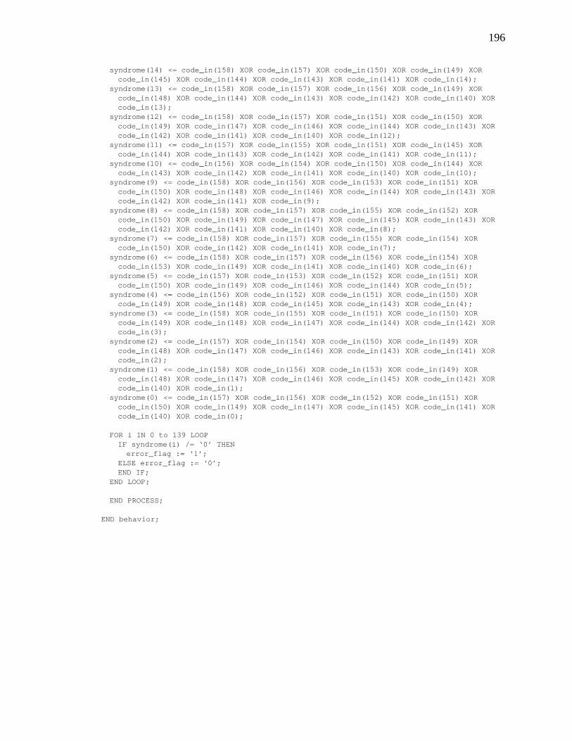
196
syndrome(14) <= code_in(158) XOR code_in(157) XOR code_in(150) XOR code_in(149) XORcode_in(145) XOR code_in(144) XOR code_in(143) XOR code_in(141) XOR code_in(14);
syndrome(13) <= code_in(158) XOR code_in(157) XOR code_in(156) XOR code_in(149) XORcode_in(148) XOR code_in(144) XOR code_in(143) XOR code_in(142) XOR code_in(140) XORcode_in(13);
syndrome(12) <= code_in(158) XOR code_in(157) XOR code_in(151) XOR code_in(150) XORcode_in(149) XOR code_in(147) XOR code_in(146) XOR code_in(144) XOR code_in(143) XORcode_in(142) XOR code_in(141) XOR code_in(140) XOR code_in(12);
syndrome(11) <= code_in(157) XOR code_in(155) XOR code_in(151) XOR code_in(145) XORcode_in(144) XOR code_in(143) XOR code_in(142) XOR code_in(141) XOR code_in(11);
syndrome(10) <= code_in(156) XOR code_in(154) XOR code_in(150) XOR code_in(144) XORcode_in(143) XOR code_in(142) XOR code_in(141) XOR code_in(140) XOR code_in(10);
syndrome(9) <= code_in(158) XOR code_in(156) XOR code_in(153) XOR code_in(151) XORcode_in(150) XOR code_in(148) XOR code_in(146) XOR code_in(144) XOR code_in(143) XORcode_in(142) XOR code_in(141) XOR code_in(9);
syndrome(8) <= code_in(158) XOR code_in(157) XOR code_in(155) XOR code_in(152) XORcode_in(150) XOR code_in(149) XOR code_in(147) XOR code_in(145) XOR code_in(143) XORcode_in(142) XOR code_in(141) XOR code_in(140) XOR code_in(8);
syndrome(7) <= code_in(158) XOR code_in(157) XOR code_in(155) XOR code_in(154) XORcode_in(150) XOR code_in(142) XOR code_in(141) XOR code_in(7);
syndrome(6) <= code_in(158) XOR code_in(157) XOR code_in(156) XOR code_in(154) XORcode_in(153) XOR code_in(149) XOR code_in(141) XOR code_in(140) XOR code_in(6);
syndrome(5) <= code_in(157) XOR code_in(153) XOR code_in(152) XOR code_in(151) XORcode_in(150) XOR code_in(149) XOR code_in(146) XOR code_in(144) XOR code_in(5);
syndrome(4) <= code_in(156) XOR code_in(152) XOR code_in(151) XOR code_in(150) XORcode_in(149) XOR code_in(148) XOR code_in(145) XOR code_in(143) XOR code_in(4);
syndrome(3) <= code_in(158) XOR code_in(155) XOR code_in(151) XOR code_in(150) XORcode_in(149) XOR code_in(148) XOR code_in(147) XOR code_in(144) XOR code_in(142) XORcode_in(3);
syndrome(2) <= code_in(157) XOR code_in(154) XOR code_in(150) XOR code_in(149) XORcode_in(148) XOR code_in(147) XOR code_in(146) XOR code_in(143) XOR code_in(141) XORcode_in(2);
syndrome(1) <= code_in(158) XOR code_in(156) XOR code_in(153) XOR code_in(149) XORcode_in(148) XOR code_in(147) XOR code_in(146) XOR code_in(145) XOR code_in(142) XORcode_in(140) XOR code_in(1);
syndrome(0) <= code_in(157) XOR code_in(156) XOR code_in(152) XOR code_in(151) XORcode_in(150) XOR code_in(149) XOR code_in(147) XOR code_in(145) XOR code_in(141) XORcode_in(140) XOR code_in(0);
FOR i IN 0 to 139 LOOPIF syndrome(i) /= ‘0’ THEN
error_flag := ‘1’;ELSE error_flag := ‘0’;END IF;
END LOOP;
END PROCESS;
END behavior;
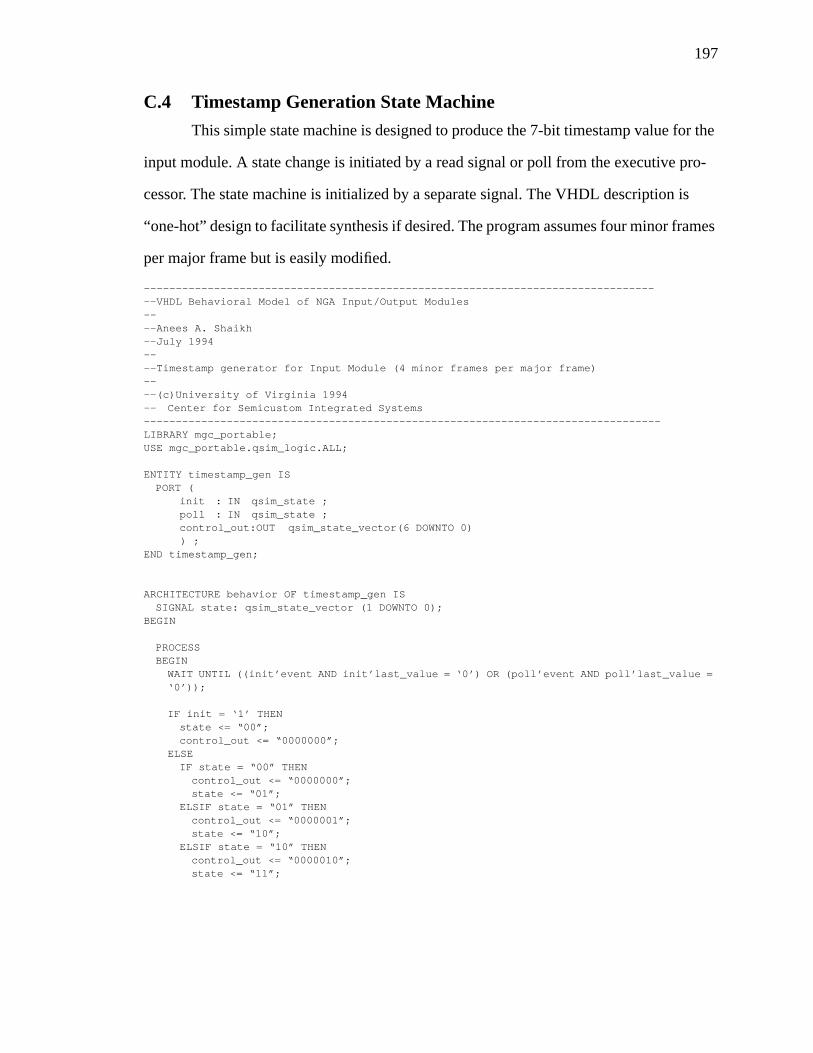
197
C.4 Timestamp Generation State Machine
This simple state machine is designed to produce the 7-bit timestamp value for the
input module. A state change is initiated by a read signal or poll from the executive pro-
cessor. The state machine is initialized by a separate signal. The VHDL description is
“one-hot” design to facilitate synthesis if desired. The program assumes four minor frames
per major frame but is easily modified.
----------------------------------------------------------------------------------VHDL Behavioral Model of NGA Input/Output Modules----Anees A. Shaikh--July 1994----Timestamp generator for Input Module (4 minor frames per major frame)----(c)University of Virginia 1994-- Center for Semicustom Integrated Systems---------------------------------------------------------------------------------LIBRARY mgc_portable;USE mgc_portable.qsim_logic.ALL;
ENTITY timestamp_gen ISPORT (
init : IN qsim_state ;poll : IN qsim_state ;control_out:OUT qsim_state_vector(6 DOWNTO 0)
) ;END timestamp_gen;
ARCHITECTURE behavior OF timestamp_gen ISSIGNAL state: qsim_state_vector (1 DOWNTO 0);
BEGIN
PROCESSBEGIN
WAIT UNTIL ((init’event AND init’last_value = ‘0’) OR (poll’event AND poll’last_value =‘0’));
IF init = ‘1’ THENstate <= “00”;control_out <= “0000000”;
ELSEIF state = “00” THEN
control_out <= “0000000”;state <= “01”;
ELSIF state = “01” THENcontrol_out <= “0000001”;state <= “10”;
ELSIF state = “10” THENcontrol_out <= “0000010”;state <= “11”;
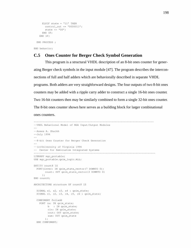
198
ELSIF state = “11” THENcontrol_out <= “0000011”;state <= “00”;
END IF;END IF;
END PROCESS ;
END behavior;
C.5 Ones Counter for Berger Check Symbol Generation
This program is a structural VHDL description of an 8-bit ones counter for gener-
ating Berger check symbols in the input module [47]. The program describes the intercon-
nections of full and half adders which are behaviorally described in separate VHDL
programs. Both adders are very straighforward designs. The four outputs of two 8-bit ones
counters may be added with a ripple carry adder to construct a single 16-bit ones counter.
Two 16-bit counters then may be similarly combined to form a single 32-bit ones counter.
The 8-bit ones counter shown here serves as a building block for larger combinational
ones counters.
----------------------------------------------------------------------------------VHDL Behavioral Model of NGA Input/Output Modules----Anees A. Shaikh--July 1994----8-bit Ones Counter for Berger Check Generation----(c)University of Virginia 1994-- Center for Semicustom Integrated Systems---------------------------------------------------------------------------------LIBRARY mgc_portable;USE mgc_portable.qsim_logic.ALL;
ENTITY count8 ISPORT(invec: IN qsim_state_vector(7 DOWNTO 0);
count: OUT qsim_state_vector(3 DOWNTO 0));
END count8;
ARCHITECTURE structure OF count8 IS
SIGNAL s1, s2, s3, s4 : qsim_state;SIGNAL c1, c2, c3, c4, c5, c6 : qsim_state;
COMPONENT fulladdPORT (a: IN qsim_state;
b : IN qsim_state;cin: IN qsim_state;cout: OUT qsim_state;sum: OUT qsim_state
);END COMPONENT;
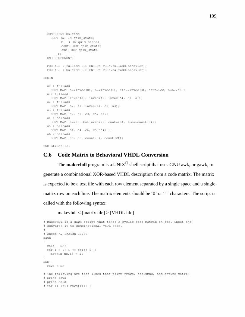
199
COMPONENT halfaddPORT (a: IN qsim_state;
b : IN qsim_state;cout: OUT qsim_state;sum: OUT qsim_state
);END COMPONENT;
FOR ALL : fulladd USE ENTITY WORK.fulladd(behavior);FOR ALL : halfadd USE ENTITY WORK.halfadd(behavior);
BEGIN
u0 : fulladdPORT MAP (a=>invec(0), b=>invec(1), cin=>invec(3), cout=>c2, sum=>s2);
u1: fulladdPORT MAP (invec(3), invec(4), invec(5), c1, s1);
u2 : fulladdPORT MAP (s2, s1, invec(6), c3, s3);
u3 : fulladdPORT MAP (c2, c1, c3, c5, s4);
u4 : halfaddPORT MAP (a=>s3, b=>invec(7), cout=>c4, sum=>count(0));
u5 : halfaddPORT MAP (s4, c4, c6, count(1));
u6 : halfaddPORT MAP (c5, c6, count(3), count(2));
END structure;
C.6 Code Matrix to Behavioral VHDL Conversion
Themakevhdl program is a UNIX shell script that uses GNU awk, or gawk, to
generate a combinational XOR-based VHDL description from a code matrix. The matrix
is expected to be a text file with each row element separated by a single space and a single
matrix row on each line. The matrix elements should be ‘0’ or ‘1’ characters. The script is
called with the following syntax:
makevhdl < [matrix file] > [VHDL file]
# MakeVHDL is a gawk script that takes a cyclic code matrix on std. input and# converts it to combinational VHDL code.## Anees A. Shaikh 11/93gawk ‘{
cols = NF;for(i = 1; i <= cols; i++)
matrix[NR,i] = $i}END {
rows = NR
# The following are test lines that print #rows, #columns, and entire matrix# print rows# print cols# for (i=1;i<=rows;i++) {
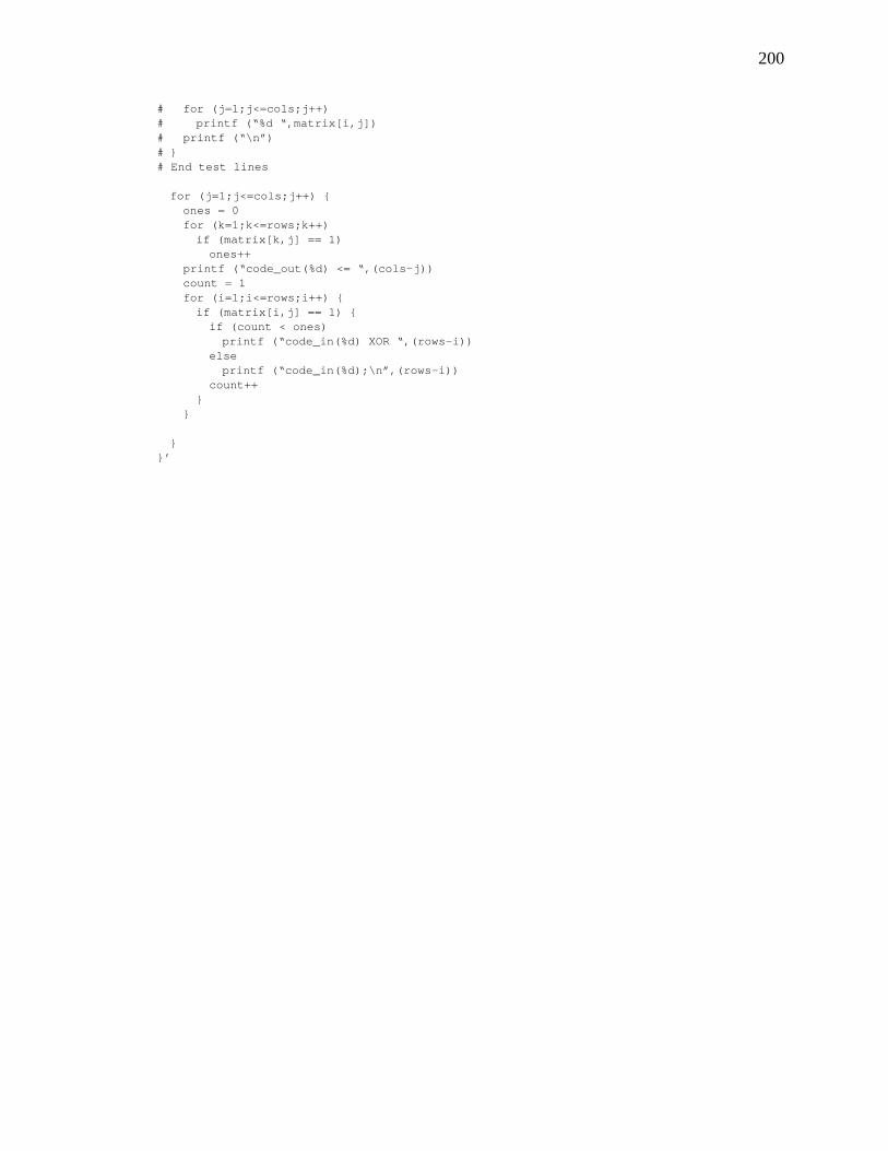
200
# for (j=1;j<=cols;j++)# printf (“%d “,matrix[i,j])# printf (“\n”)# }# End test lines
for (j=1;j<=cols;j++) {ones = 0for (k=1;k<=rows;k++)
if (matrix[k,j] == 1)ones++
printf (“code_out(%d) <= “,(cols-j))count = 1for (i=1;i<=rows;i++) {
if (matrix[i,j] == 1) {if (count < ones)
printf (“code_in(%d) XOR “,(rows-i))else
printf (“code_in(%d);\n”,(rows-i))count++
}}
}}’


