Embed Size (px)
Citation preview
Progress In Electromagnetics Research M, Vol. 103, 197–207, 2021
Dual-element Multiple-Input-Multiple-Output System for Sub-6GHz(5G) and WLAN Applications with Enhanced Isolation
Anupa Chatterjee1, *, Manas Midya2, Laxmi P. Mishra3, and Monojit Mitra1
Abstract—A dual-band two-port MIMO antenna with very high isolation is proposed for 5G/WLANapplication. The overall size of the MIMO antenna is (18 × 44 × 0.8) mm3. The unequal arm of theInverted-F Antenna (IFA) is the reason for the dual bands. Bending and extending one of the arms withthe staircase shape is responsible for the proposed dual-bands having resonant frequency at 3.45 GHz(3.3 GHz–3.65 GHz) and 5.1 GHz (4.8 GHz–5.5 GHz) respectively with percentage impedance bandwidthof 10% and 13.6%, respectively. The proposed antenna uses a simple decoupling structure based on awide inverted T-shaped slot to achieve good isolation (better than 18 dB and 34 dB respectively for thedual-bands) between the ports. The envelope correlation coefficient (ECC) and channel capacity loss(CCL) are within the acceptable limits.
1. INTRODUCTION
The fifth generation wireless system, known as 5G, could be 100 times faster than 4G and will power theInternet Of Things (IOT). The 5G wireless communication system supports spectrum below 6 GHz andmillimeter wave above 24 GHz. The “Sub-6” spectrum is used for many purposes because of its longerrange. The Telecom Regulatory Authority of India (TRAI) and Department of Telecommunication(DOT) are expected to hold the first phase of 5G spectrum. Country’s telecom operator would acquire3.3 GHz (n78) bands in the first phase [1, 2]. The characteristics of the wireless communication systemscan be improved with multiple-input-multiple-output systems. These systems have multiple inputand output elements to increase the capacity of the system, even the signal fading in the multipathenvironment can be decreased. The key element in a MIMO system is the antenna structure. However,the close placement of the antenna elements leads to mutual coupling, thus resulting in performancedegradation. The minimum distance between the antenna elements should be half of the operatingwavelength for desirable isolation, but due to need of compactness, the spacing between the antennaelements is decreased. Thus, the main challenge is to achieve high isolation between closely spacedantenna elements having shared ground plane for MIMO applications.
Designing dual-band MIMO antenna is a challenging task since same isolation mechanism does notwork for both the dual frequencies. In literature, several dual-band MIMO antennas have been reported.A dual-element antenna for WLAN application is studied in [3], and here the antenna elements havetwo radiating parts, a driven monopole, and a shorting branch. A high isolation higher than 20 dB isachieved for both the bands, and the decoupling structure consists of a protruded ground and a narrowslot etched on the ground plane. But the size of the antenna is very large. In [4], a compact dualband MIMO antenna for WLAN application is studied, where a wide slot and a pair of narrow slots
Received 10 May 2021, Accepted 16 July 2021, Scheduled 22 July 2021* Corresponding author: Anupa Chatterjee ([email protected]).1 Department of Electronics & Telecommunication Engineering, Indian Institute of Engineering Science & Technology, Shibpur,India. 2 Electronics & Communication Engineering Department, Institute of Engineering and Management, Gurukul Campus,Kolkata, India. 3 Department of Electronics & Communication Engineering, Siksha ‘O’ Anusandhan (deemed to be University),Bhubaneswar, India.
198 Chatterjee et al.
are used as a decoupling network. A multiantenna system based on two Planar Inverted-F Antennas(PIFAs) for a dual-band is proposed in [5], and two slots are inserted on the Printed Circuit Board(PCB) for proper isolation. In [6], a dual-band inverted-F MIMO antenna is studied. By involvingtwo meandering monopoles, and WLAN bands are achieved. High isolation is achieved by etching aninverted T-slot on the ground plane and a meandering resonant branch. This meandering line techniqueis also proved to be effective for good isolation as studied in [7]. A compact dual-band two elementsMIMO antenna for WLAN application is presented in [8], but the dimension is 30 × 70 × 0.8 mm3.Two slots are etched in the ground plane together with two transmission lines at the top surface forisolation. A two-element dual-band MIMO antenna for WLAN is studied in [9] but again with a longerdimension of 38× 43× 1.6 mm3. A 2× 2 MIMO to cover 700 MHz and 2.4 GHz bands is studied in [10]with an overall dimension 58 × 110 × 1.56 mm3. A metamaterial inspired MIMO for LTE and Wi-MAX applications is studied in [11] with an overall dimension of 43 × 26 × 0.8 mm3. A bent T-shapedresonator embedded between two C-shaped monopole antennas increases isolation higher than 15 dBas studied in [12]. Protruded ground plane technique is proposed in [13, 14]. But all the above designoccupies large space which is not suitable for smaller compact devices. A compact two-element MIMOantenna for 5G application is studied in [15], where the radiating elements are rhombus shaped withtapered microstrip line feed and a remodeled T-shaped ground stub for improved isolation. A compactwideband dual/quad element MIMO antenna for Wi-MAX and 5G application is proposed in [16] usingjeans textile material, where for isolation improvement meandered line structures are integrated betweenthe antenna elements. A PIFA pair based MIMO antenna for 5G (New Radio) bands and LTE band 46is studied in [17]. However, the above discussed two-element MIMO antennas were mostly designed forWLAN application with large dimension and moderate isolation.
In this paper, the proposed MIMO geometry consists of two T-shaped monopole antennas, eachhaving two unequal arms with the longer arm shorted to the ground to form the IFA structure. Theother arm is bent and then further extended with the staircase structure for the desired 5G and WLANbands. The simulation and design performance steps are presented and discussed. FR-4 is used asthe dielectric substrate with relative permittivity of 4.4, thickness of 0.8 mm, and loss tangent of 0.02.In Section 2, single element analysis is done with the design evolution steps. Later, 2 × 2 MIMOdesign is analyzed with isolation improvement and diversity performance shown. The result shows goodagreement between the simulation and measured results. In Section 3, equivalent circuit analysis withADS keysight software of the proposed antenna is shown. The results of the simulated, measured andfor the equivalent circuit are in good agreement. Experimental results are explained in Section 4, andlastly the paper is concluded.
2. MIMO ANTENNA DESIGN AND ANALYSIS
2.1. Single Element Antenna
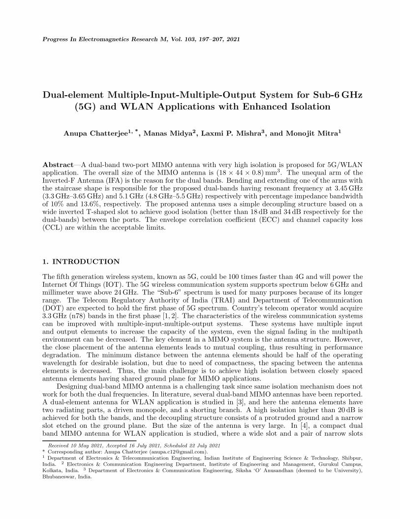
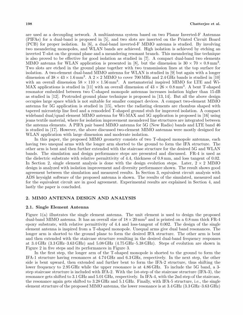
Figure 1(a) illustrates the single element antenna. The unit element is used to design the proposeddual-band MIMO antenna. It has an overall size of 18× 20 mm2 and is printed on a 0.8 mm thick FR-4epoxy substrate, with relative permittivity of 4.4 and loss-tangent of 0.002. The design of the singleelement antenna is inspired from a T-shaped monopole. Unequal arms give dual band resonances. Thelonger arm is shorted to the ground plane to form the desired IFA structure. The other arm is bentand then extended with the staircase structure resulting in the desired dual-band frequency responsesat 3.4 GHz (3.3 GHz–3.63 GHz) and 5.08 GHz (4.75 GHz–5.38 GHz). Steps of evolution are shown inFigure 2 in five steps and its performances in Figure 3.
In the first step, the longer arm of the T-shaped monopole is shorted to the ground to form theIFA-1 structure having resonances at 4.74 GHz and 6.3 GHz, respectively. In the next step, the otherside is bent upward, then extended and further bent to form the IFA-2 structure, thus shifting thelower frequency to 2.95 GHz while the upper resonance is at 4.86 GHz. To include the 5G band, a 3-step staircase structure is included with IFA-2. With the 1st-step of the staircase structure (IFA-3), theresonance gets shifted to 3.1 GHz and 5.01 GHz, respectively. In IFA-4, with the 2nd step of the staircase,the resonance again gets shifted to 3.28 GHz and 5.1 GHz. Finally, with IFA-5 structure, i.e., the singleelement structure of the proposed MIMO antenna, the lower resonance is at 3.4 GHz (3.3 GHz–3.63 GHz)
Progress In Electromagnetics Research M, Vol. 103, 2021 199
(a) (b)
Figure 1. (a) Top view of the antenna. (b) Proposed 2 × 2 MIMO structure. (W = 18, W1 = 8,W2 = 12, W3 = 3, W4 = W5 = 2, W6 = W7 = W8 = W9 = 1, W10 = 0.5, W11 = 7.5, L1 = 20, L2 = 3,L3 = 1, L4 = L5 = 0.5, L6 = 15, L7 = 2, L8 = L9 = L10 = 4, L11 = 2, W = 18, L = 44, L12 = 7.6,L13 = 4, L14 = 8, W12 = 3, W13 = 0.5) (unit: millimeters).
Figure 2. Evolution steps of the antenna.
Figure 3. Reflection coefficient versus frequency for the evolution steps of the antenna.
200 Chatterjee et al.
and 5.08 GHz (4.75 GHz–5.38 GHz), respectively. Including these three steps reduces the current path,thereby shifting the lower frequency to the right side [18–20].
2.2. Proposed Two Element Quad-Band MIMO Antenna Design and IsolationImprovement
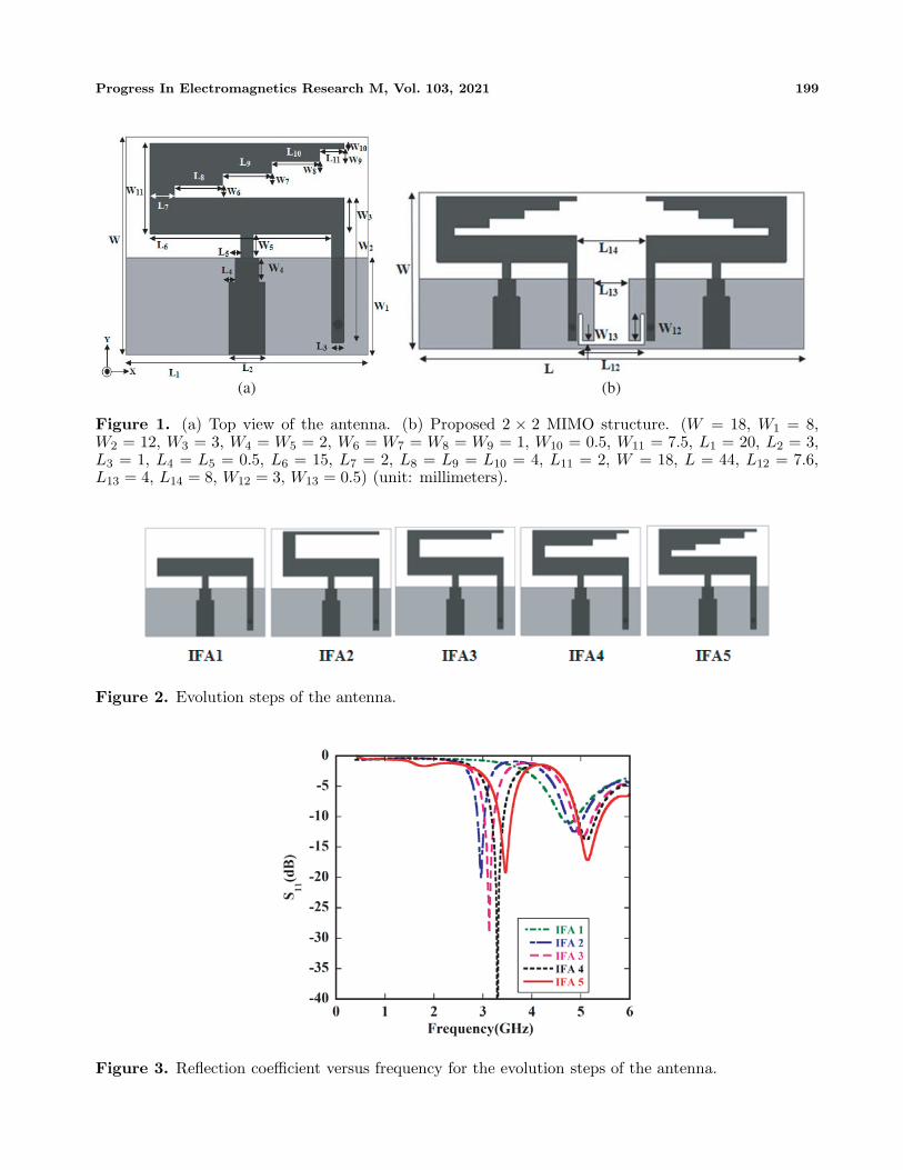
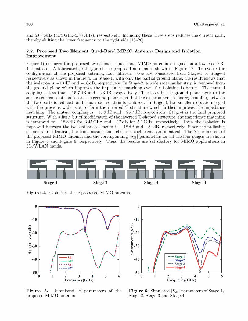
Figure 1(b) shows the proposed two-element dual-band MIMO antenna designed on a low cost FR-4 substrate. A fabricated prototype of the proposed antenna is shown in Figure 12. To evolve theconfiguration of the proposed antenna, four different cases are considered from Stage-1 to Stage-4respectively as shown in Figure 4. In Stage-1, with only the partial ground plane, the result shows thatthe isolation is −13 dB and −16 dB, respectively. In Stage-2, a wide rectangular strip is removed fromthe ground plane which improves the impedance matching even the isolation is better. The mutualcoupling is less than −15.7 dB and −23 dB, respectively. The slots in the ground plane perturb thesurface current distribution at the ground plane such that the electromagnetic energy coupling betweenthe two ports is reduced, and thus good isolation is achieved. In Stage-3, two smaller slots are mergedwith the previous wider slot to form the inverted T-structure which further improves the impedancematching. The mutual coupling is −16.9 dB and −25.7 dB, respectively. Stage-4 is the final proposedstructure. With a little bit of modification of the inverted T-shaped structure, the impedance matchingis improved to −18.8 dB for 3.45 GHz and −17 dB for 5.1 GHz, respectively. Even the isolation isimproved between the two antenna elements to −18 dB and −34 dB, respectively. Since the radiatingelements are identical, the transmission and reflection coefficients are identical. The S-parameters ofthe proposed MIMO antenna and the corresponding |S21|-parameters for all the four stages are shownin Figure 5 and Figure 6, respectively. Thus, the results are satisfactory for MIMO applications in5G/WLAN bands.
Stage-1 Stage-2 Stage-3 Stage-4
Figure 4. Evolution of the proposed MIMO antenna.
Figure 5. Simulated |S|-parameters of theproposed MIMO antenna
Figure 6. Simulated |S21| parameters of Stage-1,Stage-2, Stage-3 and Stage-4.
Progress In Electromagnetics Research M, Vol. 103, 2021 201
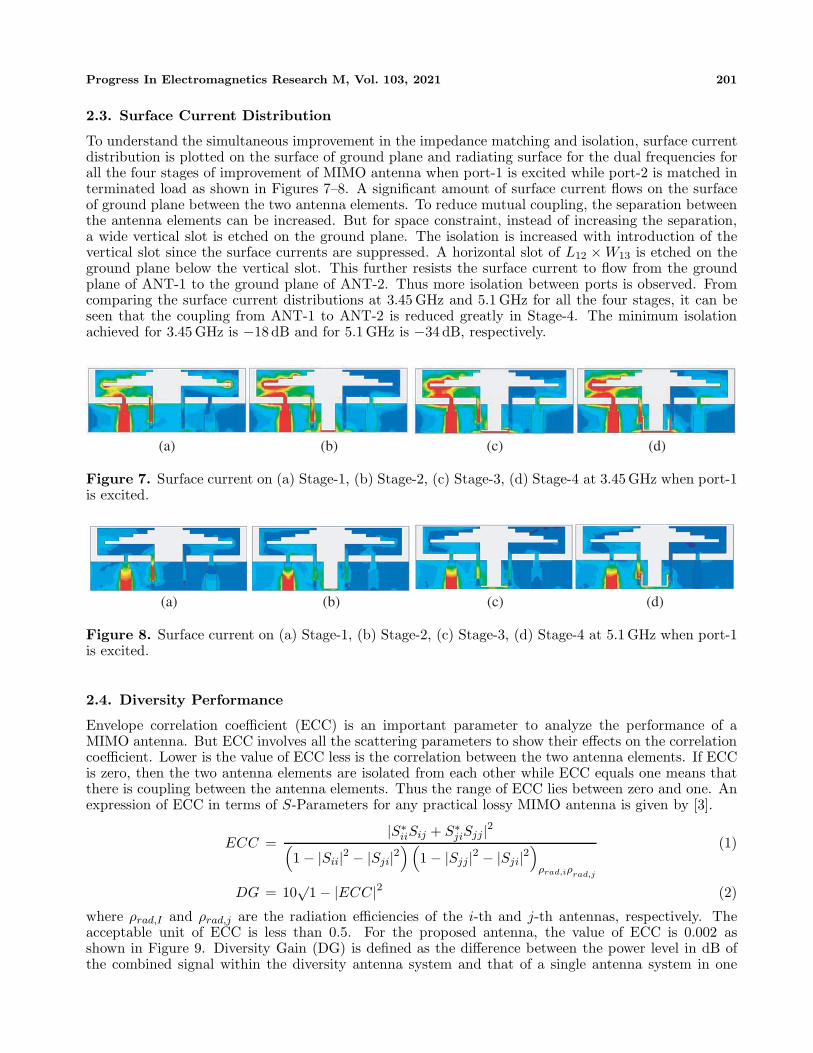
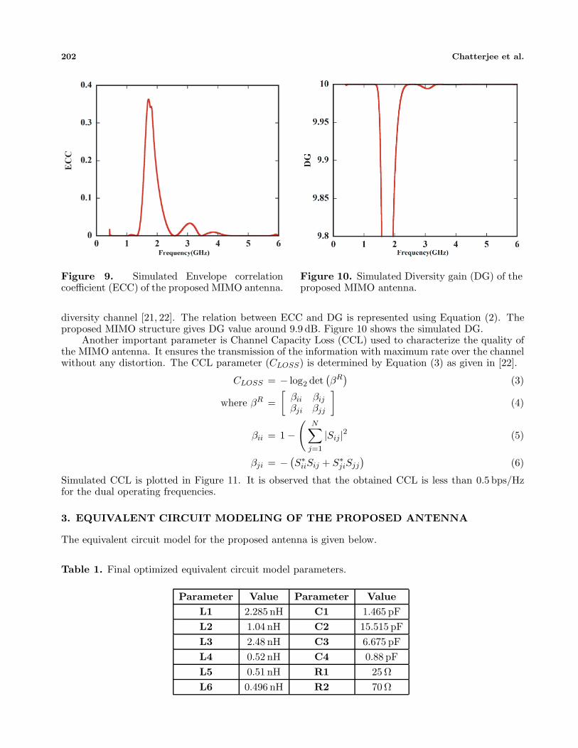
2.3. Surface Current Distribution
To understand the simultaneous improvement in the impedance matching and isolation, surface currentdistribution is plotted on the surface of ground plane and radiating surface for the dual frequencies forall the four stages of improvement of MIMO antenna when port-1 is excited while port-2 is matched interminated load as shown in Figures 7–8. A significant amount of surface current flows on the surfaceof ground plane between the two antenna elements. To reduce mutual coupling, the separation betweenthe antenna elements can be increased. But for space constraint, instead of increasing the separation,a wide vertical slot is etched on the ground plane. The isolation is increased with introduction of thevertical slot since the surface currents are suppressed. A horizontal slot of L12 × W13 is etched on theground plane below the vertical slot. This further resists the surface current to flow from the groundplane of ANT-1 to the ground plane of ANT-2. Thus more isolation between ports is observed. Fromcomparing the surface current distributions at 3.45 GHz and 5.1 GHz for all the four stages, it can beseen that the coupling from ANT-1 to ANT-2 is reduced greatly in Stage-4. The minimum isolationachieved for 3.45 GHz is −18 dB and for 5.1 GHz is −34 dB, respectively.
(a) (b) (c) (d)
Figure 7. Surface current on (a) Stage-1, (b) Stage-2, (c) Stage-3, (d) Stage-4 at 3.45 GHz when port-1is excited.
(a) (b) (c) (d)
Figure 8. Surface current on (a) Stage-1, (b) Stage-2, (c) Stage-3, (d) Stage-4 at 5.1 GHz when port-1is excited.
2.4. Diversity Performance
Envelope correlation coefficient (ECC) is an important parameter to analyze the performance of aMIMO antenna. But ECC involves all the scattering parameters to show their effects on the correlationcoefficient. Lower is the value of ECC less is the correlation between the two antenna elements. If ECCis zero, then the two antenna elements are isolated from each other while ECC equals one means thatthere is coupling between the antenna elements. Thus the range of ECC lies between zero and one. Anexpression of ECC in terms of S-Parameters for any practical lossy MIMO antenna is given by [3].
ECC =|S∗
iiSij + S∗jiSjj|2(
1 − |Sii|2 − |Sji|2)(
1 − |Sjj|2 − |Sji|2)
ρrad,iρrad,j
(1)
DG = 10√
1 − |ECC|2 (2)
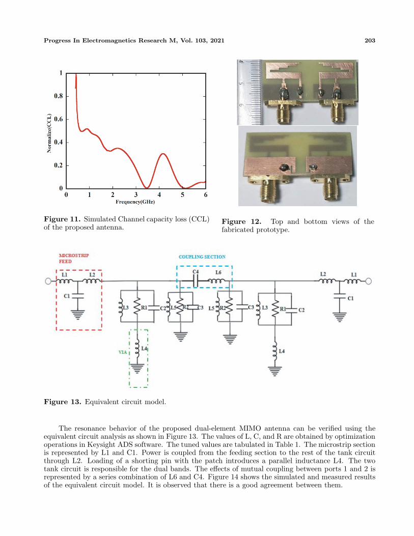
where ρrad,I and ρrad,j are the radiation efficiencies of the i-th and j-th antennas, respectively. Theacceptable unit of ECC is less than 0.5. For the proposed antenna, the value of ECC is 0.002 asshown in Figure 9. Diversity Gain (DG) is defined as the difference between the power level in dB ofthe combined signal within the diversity antenna system and that of a single antenna system in one
202 Chatterjee et al.
Figure 9. Simulated Envelope correlationcoefficient (ECC) of the proposed MIMO antenna.
Figure 10. Simulated Diversity gain (DG) of theproposed MIMO antenna.
diversity channel [21, 22]. The relation between ECC and DG is represented using Equation (2). Theproposed MIMO structure gives DG value around 9.9 dB. Figure 10 shows the simulated DG.
Another important parameter is Channel Capacity Loss (CCL) used to characterize the quality ofthe MIMO antenna. It ensures the transmission of the information with maximum rate over the channelwithout any distortion. The CCL parameter (CLOSS) is determined by Equation (3) as given in [22].
CLOSS = − log2 det(βR)
(3)
where βR =[
βii βij
βji βjj
](4)
βii = 1 −(
N∑j=1
|Sij|2 (5)
βji = − (S∗iiSij + S∗
jiSjj
)(6)
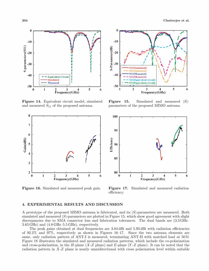
Simulated CCL is plotted in Figure 11. It is observed that the obtained CCL is less than 0.5 bps/Hzfor the dual operating frequencies.
3. EQUIVALENT CIRCUIT MODELING OF THE PROPOSED ANTENNA
The equivalent circuit model for the proposed antenna is given below.
Table 1. Final optimized equivalent circuit model parameters.
Parameter Value Parameter ValueL1 2.285 nH C1 1.465 pFL2 1.04 nH C2 15.515 pFL3 2.48 nH C3 6.675 pFL4 0.52 nH C4 0.88 pFL5 0.51 nH R1 25 ΩL6 0.496 nH R2 70 Ω
Progress In Electromagnetics Research M, Vol. 103, 2021 203
Figure 11. Simulated Channel capacity loss (CCL)of the proposed antenna.
Figure 12. Top and bottom views of thefabricated prototype.
Figure 13. Equivalent circuit model.
The resonance behavior of the proposed dual-element MIMO antenna can be verified using theequivalent circuit analysis as shown in Figure 13. The values of L, C, and R are obtained by optimizationoperations in Keysight ADS software. The tuned values are tabulated in Table 1. The microstrip sectionis represented by L1 and C1. Power is coupled from the feeding section to the rest of the tank circuitthrough L2. Loading of a shorting pin with the patch introduces a parallel inductance L4. The twotank circuit is responsible for the dual bands. The effects of mutual coupling between ports 1 and 2 isrepresented by a series combination of L6 and C4. Figure 14 shows the simulated and measured resultsof the equivalent circuit model. It is observed that there is a good agreement between them.
204 Chatterjee et al.
Figure 14. Equivalent circuit model, simulatedand measured S11 of the proposed antenna.
Figure 15. Simulated and measured |S|-parameters of the proposed MIMO antenna.
Figure 16. Simulated and measured peak gain. Figure 17. Simulated and measured radiationefficiency.
4. EXPERIMENTAL RESULTS AND DISCUSSION
A prototype of the proposed MIMO antenna is fabricated, and its |S|-parameters are measured. Bothsimulated and measured |S|-parameters are plotted in Figure 15, which show good agreement with slightdiscrepancies due to SMA connector loss and fabrication tolerances. The dual bands are (3.3 GHz–3.65 GHz) and (4.8 GHz–5.5 GHz), respectively.
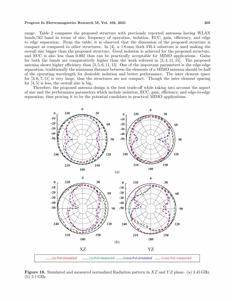
The peak gains obtained at dual frequencies are 3.84 dBi and 5.93 dBi with radiation efficienciesof 92.2% and 97%, respectively as shown in Figures 16–17. Since the two antenna elements aresame, only radiation pattern of ANT-I is measured, terminating ANT-II with matched load at 50 Ω.Figure 18 illustrates the simulated and measured radiation patterns, which include the co-polarizationand cross-polarization, in the H-plane (X-Z plane) and E-plane (Y -Z plane). It can be noted that theradiation pattern in X-Z plane is nearly omnidirectional with cross polarization level within suitable
Progress In Electromagnetics Research M, Vol. 103, 2021 205
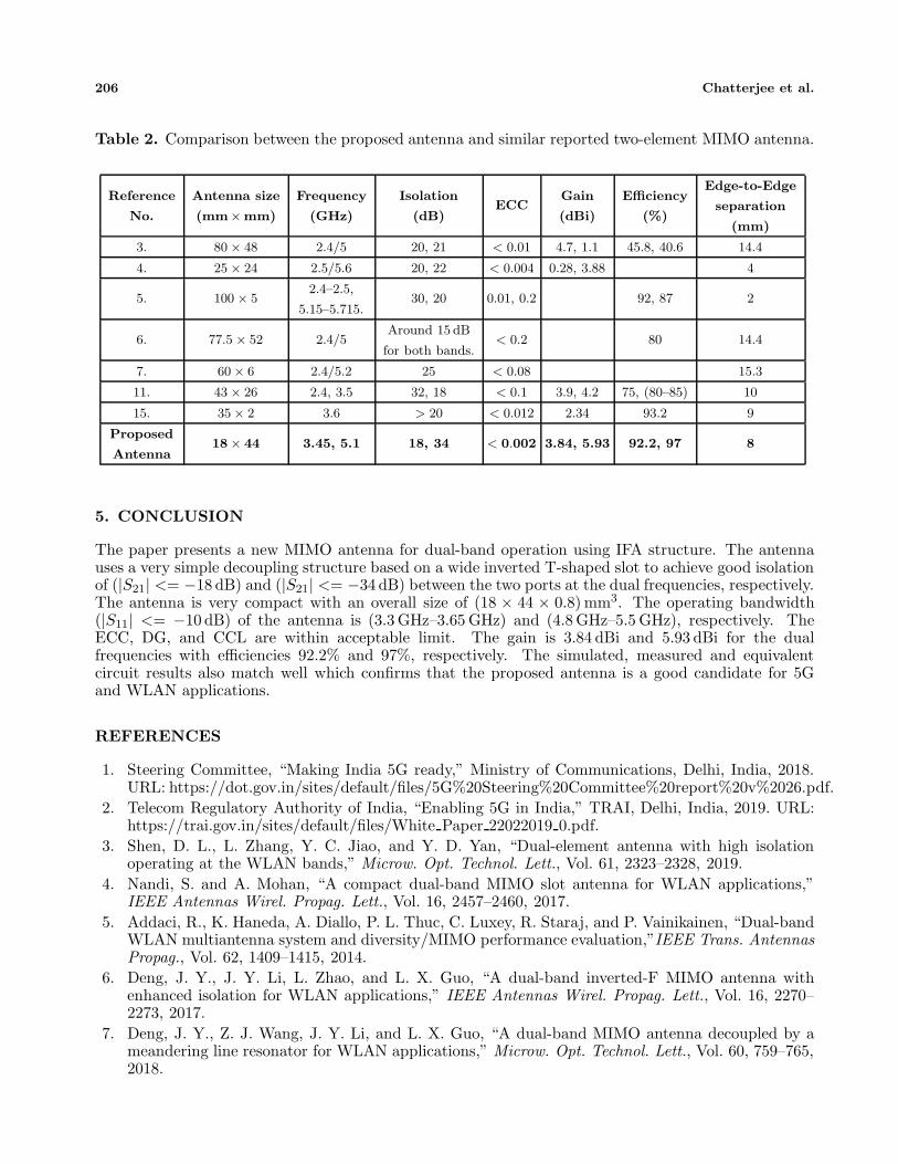
range. Table 2 compares the proposed structure with previously reported antennas having WLANbands/5G band in terms of size, frequency of operation, isolation, ECC, gain, efficiency, and edgeto edge separation. From the table, it is observed that the dimension of the proposed structure iscompact as compared to other structures. In [4], a 1.6 mm thick FR-4 substrate is used making theoverall size bigger than the proposed structure. Good isolation is achieved for the proposed structure,and ECC is also less than 0.002 thus can be practically acceptable for MIMO applications. Gainsfor both the bands are comparatively higher than the work referred in [3, 4, 11, 15]. The proposedantenna shows higher efficiency than [3, 5, 6, 11, 15]. One of the important parameters is the edge-edgeseparation; traditionally the minimum distance between the elements of a MIMO antenna should be halfof the operating wavelength for desirable isolation and better performance. The inter element spacefor [3, 6, 7, 11] is very large, thus the structures are not compact. Though the inter element spacingfor [4, 5] is less, the overall size is big.
Therefore, the proposed antenna design is the best trade-off while taking into account the aspectof size and the performance parameters which include isolation, ECC, gain, efficiency, and edge-to-edgeseparation, thus proving it to be the potential candidate in practical MIMO applications.
YZXZ
(a)
(b)
Figure 18. Simulated and measured normalized Radiation pattern in XZ and Y Z plane. (a) 3.45 GHz.(b) 5.1 GHz.
206 Chatterjee et al.
Table 2. Comparison between the proposed antenna and similar reported two-element MIMO antenna.
Reference
No.
Antenna size
(mm×mm)
Frequency
(GHz)
Isolation
(dB)ECC
Gain
(dBi)
Efficiency
(%)
Edge-to-Edge
separation
(mm)
3. 80 × 48 2.4/5 20, 21 < 0.01 4.7, 1.1 45.8, 40.6 14.4
4. 25 × 24 2.5/5.6 20, 22 < 0.004 0.28, 3.88 4
5. 100 × 52.4–2.5,
5.15–5.715.30, 20 0.01, 0.2 92, 87 2
6. 77.5 × 52 2.4/5Around 15 dB
for both bands.< 0.2 80 14.4
7. 60 × 6 2.4/5.2 25 < 0.08 15.3
11. 43 × 26 2.4, 3.5 32, 18 < 0.1 3.9, 4.2 75, (80–85) 10
15. 35 × 2 3.6 > 20 < 0.012 2.34 93.2 9
Proposed
Antenna18 × 44 3.45, 5.1 18, 34 < 0.002 3.84, 5.93 92.2, 97 8
5. CONCLUSION
The paper presents a new MIMO antenna for dual-band operation using IFA structure. The antennauses a very simple decoupling structure based on a wide inverted T-shaped slot to achieve good isolationof (|S21| <= −18 dB) and (|S21| <= −34 dB) between the two ports at the dual frequencies, respectively.The antenna is very compact with an overall size of (18 × 44 × 0.8) mm3. The operating bandwidth(|S11| <= −10 dB) of the antenna is (3.3 GHz–3.65 GHz) and (4.8 GHz–5.5 GHz), respectively. TheECC, DG, and CCL are within acceptable limit. The gain is 3.84 dBi and 5.93 dBi for the dualfrequencies with efficiencies 92.2% and 97%, respectively. The simulated, measured and equivalentcircuit results also match well which confirms that the proposed antenna is a good candidate for 5Gand WLAN applications.
REFERENCES
1. Steering Committee, “Making India 5G ready,” Ministry of Communications, Delhi, India, 2018.URL: https://dot.gov.in/sites/default/files/5G%20Steering%20Committee%20report%20v%2026.pdf.
2. Telecom Regulatory Authority of India, “Enabling 5G in India,” TRAI, Delhi, India, 2019. URL:https://trai.gov.in/sites/default/files/White Paper 22022019 0.pdf.
3. Shen, D. L., L. Zhang, Y. C. Jiao, and Y. D. Yan, “Dual-element antenna with high isolationoperating at the WLAN bands,” Microw. Opt. Technol. Lett., Vol. 61, 2323–2328, 2019.
4. Nandi, S. and A. Mohan, “A compact dual-band MIMO slot antenna for WLAN applications,”IEEE Antennas Wirel. Propag. Lett., Vol. 16, 2457–2460, 2017.
5. Addaci, R., K. Haneda, A. Diallo, P. L. Thuc, C. Luxey, R. Staraj, and P. Vainikainen, “Dual-bandWLAN multiantenna system and diversity/MIMO performance evaluation,”IEEE Trans. AntennasPropag., Vol. 62, 1409–1415, 2014.
6. Deng, J. Y., J. Y. Li, L. Zhao, and L. X. Guo, “A dual-band inverted-F MIMO antenna withenhanced isolation for WLAN applications,” IEEE Antennas Wirel. Propag. Lett., Vol. 16, 2270–2273, 2017.
7. Deng, J. Y., Z. J. Wang, J. Y. Li, and L. X. Guo, “A dual-band MIMO antenna decoupled by ameandering line resonator for WLAN applications,” Microw. Opt. Technol. Lett., Vol. 60, 759–765,2018.
Progress In Electromagnetics Research M, Vol. 103, 2021 207
8. Cui, S., Y. Liu, W. Jiang, S. X. Gong, Y. Guan, and S. T. Yu, “A novel compact dualband MIMOantenna with high port isolation,” Journal of Electromagnetic Waves and Applications, Vol. 25,Nos. 11–12, 1645–1655, 2011.
9. Qin, H. and Y. F. Liu, “Compact dual-band MIMO antenna with high port isolation for WLANapplications,” Progress In Electromagnetics Research C, Vol. 49, 97–104, 2014.
10. Sharawi, M. S., M. A. Jan, and D. N. Aloi, “Four-shaped 2 × 2 multi-standard compact multiple-input-multiple-output antenna system for long-term evolution mobile handsets,” IET Microw.Antennas Propag., Vol. 6, No. 6, 685–696, 2012.
11. Panda, A. K., S. Sahu, and R. K. Mishra, “A compact dual-band 2×1 metamaterial inspired mimoantenna system with high port isolation for LTE and WiMax applications,” Int. J. RF Microw.Comput. Aided Eng., Vol. 00, e21122, 2017.
12. Liu, Y., Y. Wang, and Z. Du, “A broadband dual-antenna system operating at the WLAN/WiMaxbands for laptop computers,” IEEE Antennas Wirel. Propag. Lett., Vol. 14, 1060–1063, 2015.
13. Guo, L., Y. Wang, Z. Du, Y. G. Gao, and D. Shi, “A compact uniplanar printed dual-antennaoperating at the 2.4/5.2/5.8 GHz WLAN bands for laptop computers,” IEEE Antennas Wirel.Propag. Lett., Vol. 13, 229–232, 2014.
14. Liu, Y., L. Yang, Y. Liu, J. Ren, J. Wang, and X. Li, “Dual-band planar MIMO antenna for WLANapplication,” Microw. Opt. Technol. Lett., Vol. 57, 2257–2262, 2015.
15. Saurabh, A. K. and M. K. Meshram, “Compact sub-6GHz 5G-multipleinput-multiple-outputantenna system with enhanced isolation,” Int. J. RF Microw. Comput. Aided Eng., e22246, 2020.
16. Roy, S., A. K. Biswas, S. Ghosh, U. Chakraborty, and A. Sarkhel, “Isolation improvement of dual-/quad-element textile MIMO antenna for 5G application,” Journal of Electromagnetic Waves andApplications, Vol. 35, No. 10, 1337–1353, 2021.
17. Yuan, X. T., Z. Chen, T. Gu, and T. Yuan, “A wideband PIFA-pair-based MIMO antenna for 5Gsmartphones,” IEEE Antennas Wirel. Propag. Lett., Vol. 20, 371–375, 2021.
18. Bartwal, P., A. K. Gautam, A. K. Singh, B. K. Kanaujia, and K. Rambabu, “Design ofcompact multi-band meander-line antenna for global positioning system/wireless local areanetwork/worldwide interoperability for microwave access band applications in laptops/tablets,”IET Microw. Antennas Propag., Vol. 10, 1618–1624, 2016.
19. Chatterjee, A., M. Midya, L. Prasad Mishra, and M. Mitra, “Branch line strip loadedcompact printed Inverted-F Antenna (IFA) for penta-band applications,” International Journalof Electronics and Communications, 2020, doi: https://doi.org/10.1016/j.aeue.2020.153340.
20. Kuo, Y. L. and K. L. Wong, “Coplanar waveguide-fed folded inverted-F antenna for UMTSapplications,” Microw. Opt. Technol. Lett., Vol. 32, No. 5, 364–366, 2002.
21. Thakur, E., N. Jaglan, and S. D. Gupta, “Design of compact UWB MIMO antenna with enhancedbandwidth,” Progress In Electromagnetics Research C, Vol. 97, 83–94, 2019.
22. Gurjar, R., D. K. Upadhyay, B. K. Kanaujia, and K. Sharma, “A novel compact self-similar fractalUWB MIMO antenna,” Int. J. RF Microw. Comput. Aided Eng., Vol. 29, No. 3, e21632, 2019.


