Embed Size (px)
Citation preview


I. BID DOCUMENTS ADVERTISEMENT FOR BIDS AND EVALUATION QUESTIONNAIRE ADDENDA BIDDERS PROPOSAL AND BID SCHEDULE AGREEMENT AND INFORMATION FORM CONFLICT OF INTEREST QUESTIONNAIRE VENDOR COMPLIANCE CERTIFICATION REQUIRED BY TEXAS GOVERNMENT CODE SECTION
2270.001 STANDARD TERMS AND CONDITIONS CONTRACTOR INSURANCE REQUIREMENTS & AGREEMENT INDEMNIFICATION AGREEMENT LIQUIDATED DAMAGES CITY COUNCIL POLICY DOCUMENTS
o OPNS-4 o OPNS-28
BIDDERS QUALIFICATION STATEMENT BID BOND
II. CONTRACT AND BONDS
STANDARD FORM OF CONTRACT PERFORMANCE BOND PAYMENT BOND MAINTENANCE BOND CONTRACTOR'S AFFIDAVIT OF BILLS PAID CERTIFICATES OF INSURANCE CITY PURCHASE ORDER
III. GENERAL SPECIFICATIONS AND SPECIAL CONDITIONS IV. TECHNICAL SPECIFICATIONS V. GEOTECHNICAL REPORT

SECTION I
BID DOCUMENTS

A1-1
ADVERTISEMENT FOR BIDS
1. Request for bids for construction of the Garland Power & Light (GP&L) Apollo Substation including all labor, specified materials, and incidentals. The work generally consists of erosion control, foundations, cable trench and conduit systems, grounding, drainage systems, structure erection, equipment installation, high and medium voltage bus and conductor installation, electrical service systems, control cabling including terminations, fiber optic and coaxial cable including terminations, overhead lightning shielding, emergency generator system, site landscaping and irrigation, flexible base restoration, yard surfacing and all labor, equipment, miscellaneous materials and incidentals necessary to construct the project.
The project construction under this contract is the third phase of the overall substation project. Phase 1 work is complete and involved construction of onsite temporary power distribution transformer and autotransformer substation facilities and permanent underground distribution feeder systems. The temporary substation facilities will remain in service for the duration of this contract. Phase 2 work currently being performed under a separate contract generally consists of principal civil site improvements including demolition, grading, drainage, water utilities, paving, fencing, limited ground grid installation, limited conduit installation, and construction of a flexible base subgrade pad. The Phase 2 contractor’s work will be complete prior to mobilization under this contract. The anticipated mobilization date for this contract is March 27, 2020. The breaker and a half configuration substation is configured for five (5) incoming 138kV three phase transmission lines. These transmission lines will be brought into the substation by others and are not a part of this contract. Transmission line terminations by others will end at the line side of high voltage switches on the substation transmission line termination structures. All steel structures, including dead end structures, bus supports, switch stands, distribution bays, and all other substation equipment support structures (other than foundations) indicated on the drawings, will be furnished by GP&L and installed by the Contractor on foundations constructed by the Contractor. A complete substation ground grid, including connection to structures and equipment will be installed by the Contractor. All materials for grounding system construction, except Ground Enhancement Material (GEM), will be provided by GP&L. All foundations indicated on the drawings shall be constructed by the Contractor as part of the contract. This includes but is not limited to all necessary surveying, excavation, temporary casing, slurry, removal of spoils, forming materials, reinforcing steel (rebar), concrete, backfilling, material testing, and all labor and equipment to construct the foundations in accordance with the drawings. Anchor bolts will be provided to the Contractor by GP&L. Civil site improvements indicated on the drawings shall be constructed by the Contractor as part of the contract. This includes but is not limited to all necessary

A1-2
surveying, removal of spoils, grounding system, conduit systems, cable trench systems, cable trench drainage systems, transformer containment stormwater drainage systems, testing, trench safety, temporary excavation shoring, flexible base restoration, backfilling, gravel surfacing, vegetative stabilization, erosion control measures during construction, landscaping, irrigation, and all other work required to provide a completed site in accordance with the project plans, details, and specifications. Staking for construction shall be provided by the Contractor in accordance with these specifications. All electrical components and substation steel structures indicated on the drawings will be installed by the Contractor on foundations provided by the Contractor. GP&L will provide all materials for high and medium voltage conductors, substation power service conductors, substation control cabling, and site lighting conductors; all to be installed and terminated by the Contractor. Fiber optic cable and innerduct will be installed and terminated by the Contractor. All conduit systems including pull boxes pull strings, testing, and terminations shall be installed by the Contractor. Control house installation, installation and dressout of 138kV/13.2kV power transformers, substation commissioning, substation energizing and related testing activities, SCADA; and items related to substation startup will be performed by GP&L or their designated subcontractor. Drawings provided by GP&L are not to scale. It shall be the responsibility of the Contractor to verify all dimensions on the drawings, and construct facilities accordingly. Bidders shall have a minimum of 5 years of experience in substations construction prior to the current bid, and shall be able to provide at least 3 references from previous substation contracts.
Bids shall be provided in accordance with this specification and in accordance with the specification drawings and documents.
2. Sealed bids addressed to the Honorable Mayor and City Council of the City of Garland, Texas for GP&L Apollo Substation Construction, for the City of Garland, Texas, hereinafter called "City" in accordance with plans, specifications, and contract documents adopted by the City Council of the City of Garland, Texas, and which may be obtained from the Purchasing Agent of the City of Garland, Texas, City Hall, Garland, Texas. Bids will be received at the office of the City Purchasing Agent of the City of Garland, Texas until 3:00 p.m. on the 9th Day of January, 2020. Any bids received after closing time may be returned unopened. The Bid Number for this project is 0241-20. This number shall be placed on all correspondence including the sealed bid proposal. Bids will be publicly opened and read aloud by the City Purchasing Agent of the City of Garland at 3:00 p.m. on the 9th Day of January, 2020.

A1-3
3. The contractor shall identify his bid on the outside of the envelope by writing the words “addressed to the Honorable Mayor and City Council of the City of Garland, Texas for GP&L Apollo Substation Construction”.
4. A pre-bidders conference will be held at 2:00 p.m. in the Garland Power & Light
TE&C Conference Room located at 510 West Avenue B, Garland, Texas 75040 on the 19th day of December, 2019. If you submit a bid without attending the pre-bid conference, your bid may be non-responsive and you risk having your bid rejected as non-conforming.
All questions concerning the plans, specifications, or bid documents shall be submitted to the Buyer at [email protected] no less than five days prior to the bid opening. All questions must come through the Buyer.
5. Plans, specifications and bidding documents may be secured from the office of the
City Purchasing Agent, City Hall, Garland, Texas, on payment of $25 dollars per CD or free via download on Ion Wave (https://garlandtx.ionwave.net).
6. Bids shall be accompanied with a Bid Bond in the amount not less than five percent
(5%) of the total maximum bid price payable with recourse to the City of Garland, from a reliable surety company as a guarantee that the bidder will enter into a contract and execute Performance Bond, Payment Bond, and Maintenance Bond within ten (10) days after notice of award of contract to him.
7. All contracts less than $50,000.00 (fifty thousand dollars) will not require
Performance, Payment or Maintenance Bonds. 8. The right is reserved by the Mayor and City Council as the interest of the City may
require to reject any and all bids and to waive any informality in bids received. 9. The City of Garland reserves the right to determine which bid(s) will best meet its
requirements. Said determination will be made in the City’s best interest and shall therefore be considered final. The bids will be evaluated using the following GP&L Construction Contractor Questionnaire and Grading Sheet.


ADDENDA
THIS PAGE INTENTIONALLY LEFT BLANK DURING THE BIDDING PROCESS AS A PLACE HOLDER FOR ADDENDUMS

PBS-1
PROPOSAL TO: The Honorable Mayor and City Council City of Garland, Texas GENTLEMEN: The undersigned bidder, having examined the plans, specifications and contract documents, the location of the proposed work and being fully advised as to the extent and character of the work, propose to furnish all equipment and to perform all labor and work necessary for the completion of the work described by and in accordance with the plans, specifications, and contracts for the following prices to wit. No City of Garland employee shall have a direct or indirect financial interest in any contract with the City or be directly or indirectly financially interested in the sale of land, materials, supplies or services to the City. By the execution and submission of this bid, bidder acknowledges that bidder has received a copy of City Council Policy OPNS-04 & OPNS-28 and bidder represents and warrants that bidder complies with the requirements of the City Council Policy OPNS-04 and is in no manner disqualified from doing business with the City under that policy.
P&BS-2
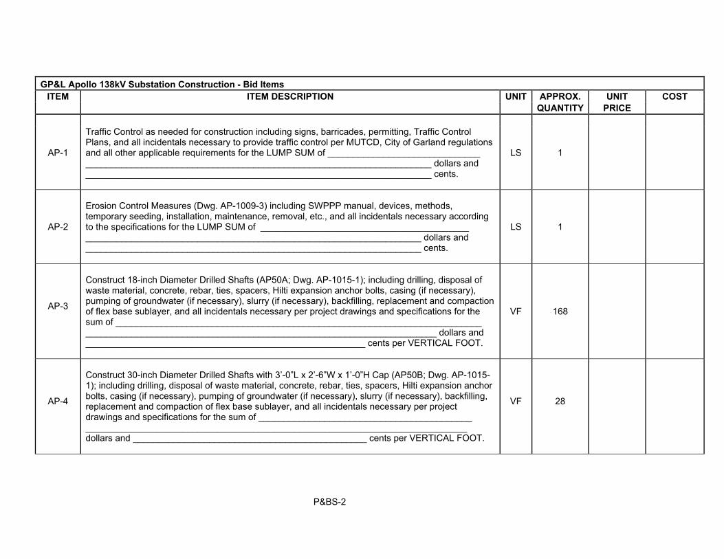
GP&L Apollo 138kV Substation Construction - Bid Items ITEM ITEM DESCRIPTION UNIT APPROX. UNIT COST
QUANTITY PRICE
AP-1
Traffic Control as needed for construction including signs, barricades, permitting, Traffic Control Plans, and all incidentals necessary to provide traffic control per MUTCD, City of Garland regulations and all other applicable requirements for the LUMP SUM of ______________________________ ____________________________________________________________________ dollars and ____________________________________________________________________ cents.
LS
1
AP-2
Erosion Control Measures (Dwg. AP-1009-3) including SWPPP manual, devices, methods, temporary seeding, installation, maintenance, removal, etc., and all incidentals necessary according to the specifications for the LUMP SUM of _________________________________________ __________________________________________________________________ dollars and __________________________________________________________________ cents.
LS 1
AP-3
Construct 18-inch Diameter Drilled Shafts (AP50A; Dwg. AP-1015-1); including drilling, disposal of waste material, concrete, rebar, ties, spacers, Hilti expansion anchor bolts, casing (if necessary), pumping of groundwater (if necessary), slurry (if necessary), backfilling, replacement and compaction of flex base sublayer, and all incidentals necessary per project drawings and specifications for the sum of ________________________________________________________________________ _____________________________________________________________________ dollars and _______________________________________________________ cents per VERTICAL FOOT.
VF
168
AP-4
Construct 30-inch Diameter Drilled Shafts with 3’-0”L x 2’-6”W x 1’-0”H Cap (AP50B; Dwg. AP-1015-1); including drilling, disposal of waste material, concrete, rebar, ties, spacers, Hilti expansion anchor bolts, casing (if necessary), pumping of groundwater (if necessary), slurry (if necessary), backfilling, replacement and compaction of flex base sublayer, and all incidentals necessary per project drawings and specifications for the sum of __________________________________________ ___________________________________________________________________________ dollars and ______________________________________________ cents per VERTICAL FOOT.
VF
28

P&BS-3
GP&L Apollo 138kV Substation Construction - Bid Items ITEM ITEM DESCRIPTION UNIT APPROX. UNIT COST
QUANTITY PRICE
AP-5
Construct 30-inch Diameter Drilled Shafts (AP53 thru AP66, and AP71B; Dwgs. AP-1015-3 & AP-1015-7); including drilling, disposal of waste material, concrete, rebar, ties, spacers, casing (if necessary), pumping of groundwater (if necessary), slurry (if necessary), backfilling, replacement and compaction of flex base sublayer, and all incidentals necessary per project drawings and specifications for the sum of ___________________________________________________ _________________________________________________________________ dollars and __________________________________________________ cents per VERTICAL FOOT.
VF
2,140
AP-6
Construct 36” Diameter Drilled Shafts (AP71A; Dwg. AP-1015-7); including drilling, disposal of waste material, concrete, rebar, ties, spacers, casing (if necessary), pumping of groundwater (if necessary), slurry (if necessary), backfilling, replacement and compaction of flex base sublayer, and all incidentals necessary per project drawings and specifications for the sum of ________ ___________________________________________________________________________ _________________________________________________________________ dollars and __________________________________________________ cents per VERTICAL FOOT.
VF 112
AP-7
Construct 42” Diameter Drilled Shafts (AP72; Dwg. AP-1015-7); including drilling, disposal of waste material, concrete, rebar, ties, spacers, casing (if necessary), pumping of groundwater (if necessary), slurry (if necessary), backfilling, replacement and compaction of flex base sublayer, and all incidentals necessary per project drawings and specifications for the sum of ______ _________________________________________________________________________ _________________________________________________________________ dollars and __________________________________________________ cents per VERTICAL FOOT.
VF 52

P&BS-4
GP&L Apollo 138kV Substation Construction - Bid Items ITEM ITEM DESCRIPTION UNIT APPROX. UNIT COST
QUANTITY PRICE
AP-8
Construct 48” Diameter Drilled Shafts (AP52A thru AP52E; Dwg. AP-1015-2); including drilling, disposal of waste material, concrete, rebar, ties, spacers, casing (if necessary), pumping of groundwater (if necessary), slurry (if necessary), backfilling, replacement and compaction of flex base sublayer, and all incidentals necessary per project drawings and specifications for the sum of _______________________________________________________________________ __________________________________________________________________ dollars and ___________________________________________________ cents per VERTICAL FOOT.
VF 376
AP-9
Construct 54” Diameter Drilled Shafts (AP67; Dwg. AP-1015-3); including drilling, disposal of waste material, concrete, rebar, ties, spacers, casing (if necessary), pumping of groundwater (if necessary), slurry (if necessary), backfilling, replacement and compaction of flex base sublayer, and all incidentals necessary per project drawings and specifications for the sum of _____ ________________________________________________________________________ ________________________________________________________________ dollars and ___________________________________________________ cents per VERTICAL FOOT.
VF 64
AP-10
Construct Equipment Enclosure Foundation Landings (Large), 8’-10”L x 8’-6”W x 10” thick Pad (AP51; Dwg. AP-1015-2); including all excavation, base preparation, disposal of waste material, concrete, rebar, ties, stands, pumping of groundwater (if necessary), backfilling, replacement and compaction of flex base sublayer, and all incidentals necessary per project drawings and specifications for the sum of __________________________________________________ _________________________________________________________________ dollars and ___________________________________________________ cents per CUBIC YARD.
CY 4.7

P&BS-5
GP&L Apollo 138kV Substation Construction - Bid Items ITEM ITEM DESCRIPTION UNIT APPROX. UNIT COST
QUANTITY PRICE
AP-11
Construct 145kV Circuit Breaker Foundations, 8’-0”L x 8’-0”W x 32” thick Pad (AP68; Dwg. AP-1015-4); including overexcavation, disposal of waste material, placement of compacted flexible base, concrete, rebar, ties, stands, pumping of groundwater (if necessary), backfilling, replacement and compaction of flex base sublayer, and all incidentals necessary per project drawings and specifications for the sum of ____________________________________________________ _________________________________________________________________ dollars and ___________________________________________________ cents per CUBIC YARD.
CY 69.7
AP-12
Construct 15kV 1200A Circuit Breaker Foundations, 5’-0”L x 5’-0”W x 18” thick Pad (AP69A; Dwg. AP-1015-4); including overexcavation, disposal of waste material, placement of compacted flexible base, concrete, rebar, ties, stands, pumping of groundwater (if necessary), backfilling, replacement and compaction of flex base sublayer, and all incidentals necessary per project drawings and specifications for the sum of ____________________________________________________ _________________________________________________________________ dollars and ___________________________________________________ cents per CUBIC YARD.
CY 8.4
AP-13
Construct 15kV 2000A Circuit Breaker Foundation, 5’-0”L x 5’-0”W x 18” thick Pad (AP69B; Dwg. AP-1015-4); including overexcavation, disposal of waste material, placement of compacted flexible base, concrete, rebar, ties, stands, pumping of groundwater (if necessary), backfilling, replacement and compaction of flex base sublayer, and all incidentals necessary per project drawings and specifications for the sum of _____________________________________________________ _________________________________________________________________ dollars and ___________________________________________________ cents per CUBIC YARD.
CY 1.4

P&BS-6
GP&L Apollo 138kV Substation Construction - Bid Items ITEM ITEM DESCRIPTION UNIT APPROX. UNIT COST
QUANTITY PRICE
AP-14
Construct Standby Generator Foundation, 11’-0”L x 5’-0”W x 12” thick Pad (AP73; Dwg. AP-1015-8); including overexcavation, disposal of waste material, placement of compacted flexible base, concrete, rebar, ties, stands, Hilti anchor bolts, embedded PVC conduits, PVC gas line stub-up, pumping of groundwater (if necessary), backfilling, replacement and compaction of flex base sublayer, and all incidentals necessary per project drawings and specifications for the sum of _________________________________________________________________________ ________________________________________________________________ dollars and ___________________________________________________ cents per CUBIC YARD.
CY 2.1
AP-15
Construct Propane Fuel Tank Foundation, 17’-6”L x 5’-5”W x 12” thick Pad (AP74; Dwg. AP-1015-8); including overexcavation, disposal of waste material, placement of compacted flexible base, concrete, rebar, ties, stands, Hilti anchor bolts, pumping of groundwater (if necessary), backfilling, replacement and compaction of flex base sublayer, and all incidentals necessary per project drawings and specifications for the sum of ____________________________________ _________________________________________________________________ dollars and ___________________________________________________ cents per CUBIC YARD.
CY 3.6
AP-16
Construct 138/13.2kV Transformer Foundation, 20’-0”L x 14’-0”W with integral oil containment moat (AP70; Dwg. AP-1015-5); including excavation, disposal of waste material, concrete, rebar, ties, stands, galvanized grating and framing, waterstops, pumping of groundwater (if necessary), replacement and compaction of flex base sublayer, and all incidentals necessary to complete in place all according to the plans, details and specifications for the sum of _______________ _____________________________________________________________________ dollars and ________________________________________________________ cents per EACH.
EA 2

P&BS-7
GP&L Apollo 138kV Substation Construction - Bid Items ITEM ITEM DESCRIPTION UNIT APPROX. UNIT COST
QUANTITY PRICE
AP-17
Construct 30-inch Diameter Drilled Shaft Yard Light Foundations (AP75A thru AP75D; Dwg. AP-1016-1); including drilling, disposal of waste material, concrete, rebar, ties, spacers, casing (if necessary), pumping of groundwater (if necessary), slurry (if necessary), backfilling, replacement and compaction of flex base sublayer, and all incidentals necessary per project drawings and specifications for the sum of _______________________________________________________ ___________________________________________________________________________ dollars and ______________________________________________ cents per VERTICAL FOOT.
VF
90
AP-18
Installation of #4/0 Copper Ground Conductor (Dwg. AP-1030 – 12 Sheets); including any excavation, placement, backfill, disposal of waste material, pumping of groundwater (if necessary), replacement and compaction of flex base sublayer, and all incidentals necessary per project drawings and specifications for the sum of ____________________________________ ______________________________________________________________ dollars and _________________________________________________ cents per LINEAR FOOT.
LF
9,930
AP-19
Installation of (19) #9 DSA Copperweld Steel Ground Conductor (Dwg. AP-1030 – 12 Sheets); including any excavation, placement, backfill, disposal of waste material, pumping of groundwater (if necessary), replacement and compaction of flex base sublayer, and all incidentals necessary per project drawings and specifications for the sum of _____________________________________ ____________________________________________________________________ dollars and _________________________________________________ cents per LINEAR FOOT.
LF
6,850
AP-20
Installation of #2 Copper Ground Conductor (Dwg. AP-1030 – 12 Sheets); including any excavation, base preparation, placement, backfill, disposal of waste material, pumping of groundwater (if necessary), replacement and compaction of flex base sublayer, and all incidentals necessary per project drawings and specifications for the sum of ________________________________ ___________________________________________________________________ dollars and _________________________________________________ cents per LINEAR FOOT.
LF
302

P&BS-8
GP&L Apollo 138kV Substation Construction - Bid Items ITEM ITEM DESCRIPTION UNIT APPROX. UNIT COST
QUANTITY PRICE
AP-21
Installation of Copper-Clad Steel Ground Rods, 10-foot lengths (Dwg. AP-1030 – 12 Sheets); including any drilling, backfill, disposal of waste material, pumping of groundwater (if necessary), replacement and compaction of flex base sublayer, and all incidentals necessary per project drawings and specifications for the LUMP SUM of _______________________________ __________________________________________________________________ dollars and ________________________________________________________________ cents.
LS
1
AP-22
Construction of Ground Well (Dwg. AP-1030 – 12 Sheets); including drilling, backfill, steel framed cover, disposal of waste material, pumping of groundwater (if necessary), replacement and compaction of flex base sublayer, and all incidentals necessary per project drawings and specifications for the sum of ___________________________________________________ _________________________________________________________________ dollars and _______________________________________________________ cents per EACH.
EA 2
AP-23
Furnish and install Ground Enhancement Material, 25 Pound Bag (Dwg. AP-1030 – 12 Sheets); including all incidentals necessary to place ground enhancement material per project drawings and specifications for the sum of _______________________________________________________ ___________________________________________________________________ dollars and _______________________________________________________ cents per EACH.
EA 2,587
AP-24
Install All Below Grade Grounding Connections (Dwg. AP-1030 – 12 Sheets); including any miscellaneous hardware necessary to install a complete grounding system below grade for the LUMP SUM of ________________________________________________________________ ____________________________________________________________________ dollars and _________________________________________________________________ cents.
LS 1

P&BS-9
GP&L Apollo 138kV Substation Construction - Bid Items ITEM ITEM DESCRIPTION UNIT APPROX. UNIT COST
QUANTITY PRICE
AP-25
Install Conduit System (Dwgs. AP-1012 – 7 Sheets & AP-1013 – 5 Sheets) with all materials required to install any size PVC (schedule 40) or GRC conduit with conduit fittings, unistrut, junction boxes, and terminal boxes including trenching, backfill, connections, terminations, pull string, replacement and compaction of flex base sublayer, disposal of waste material, etc. in any type of soil conditions to make a complete installation per project drawings and specifications for the LUMP SUM of ____ ____________________________________________________________________ dollars and ___________________________________________________________________ cents.
LS 1
AP-26
Install Vehicle Rated/Road Crossing Grade Cable Trench (A-29A) (Dwg. AP-1012 – 7 Sheets); including excavation, embedment materials, backfilling, grounding, replacement and compaction of disturbed flex base sublayer, and all materials required to make a complete installation per project drawings and specifications for the sum of ___________________________________________ ___________________________________________________________________ dollars and __________________________________________________ cents per LINEAR FOOT.
LF
688
AP-27
Install Multipurpose Grade Cable Trench (A-29B) (Dwg. AP-1012 – 7 Sheets); including excavation, embedment materials, backfilling, grounding, replacement and compaction of disturbed flex base sublayer, and all materials required to make a complete installation per project drawings and specifications for the sum of ______________________________________________________ __________________________________________________________________ dollars and __________________________________________________ cents per LINEAR FOOT.
LF
222
AP-28
Construct 3” Sch. 80 PVC Conduit for Transformer Sump Drainage (Dwg. AP-1008-4); pressure rated, solvent cemented joints, including pipe, fittings, connections, placement by trenching in any type of soil conditions, backfilling, and all incidentals necessary to make a complete installation per project drawings and specifications for the sum of ___________________________________ ______________________________________________________________________________ ___________________________________________________________________ dollars and __________________________________________________ cents per LINEAR FOOT.
LF 100
P&BS-10
GP&L Apollo 138kV Substation Construction - Bid Items ITEM ITEM DESCRIPTION UNIT APPROX. UNIT COST
QUANTITY PRICE
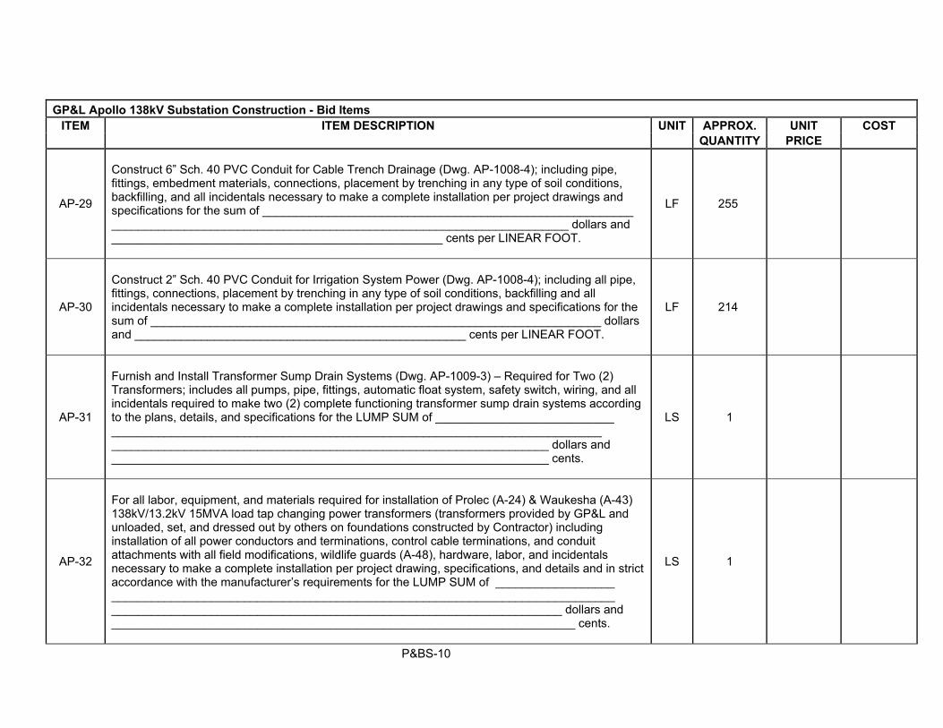
AP-29
Construct 6” Sch. 40 PVC Conduit for Cable Trench Drainage (Dwg. AP-1008-4); including pipe, fittings, embedment materials, connections, placement by trenching in any type of soil conditions, backfilling, and all incidentals necessary to make a complete installation per project drawings and specifications for the sum of ________________________________________________________ _____________________________________________________________________ dollars and __________________________________________________ cents per LINEAR FOOT.
LF 255
AP-30
Construct 2” Sch. 40 PVC Conduit for Irrigation System Power (Dwg. AP-1008-4); including all pipe, fittings, connections, placement by trenching in any type of soil conditions, backfilling and all incidentals necessary to make a complete installation per project drawings and specifications for the sum of ____________________________________________________________________ dollars and __________________________________________________ cents per LINEAR FOOT.
LF 214
AP-31
Furnish and Install Transformer Sump Drain Systems (Dwg. AP-1009-3) – Required for Two (2) Transformers; includes all pumps, pipe, fittings, automatic float system, safety switch, wiring, and all incidentals required to make two (2) complete functioning transformer sump drain systems according to the plans, details, and specifications for the LUMP SUM of ___________________________ __________________________________________________________________________ __________________________________________________________________ dollars and __________________________________________________________________ cents.
LS 1
AP-32
For all labor, equipment, and materials required for installation of Prolec (A-24) & Waukesha (A-43) 138kV/13.2kV 15MVA load tap changing power transformers (transformers provided by GP&L and unloaded, set, and dressed out by others on foundations constructed by Contractor) including installation of all power conductors and terminations, control cable terminations, and conduit attachments with all field modifications, wildlife guards (A-48), hardware, labor, and incidentals necessary to make a complete installation per project drawing, specifications, and details and in strict accordance with the manufacturer’s requirements for the LUMP SUM of __________________ ____________________________________________________________________________ ____________________________________________________________________ dollars and ______________________________________________________________________ cents.
LS 1

P&BS-11
GP&L Apollo 138kV Substation Construction - Bid Items ITEM ITEM DESCRIPTION UNIT APPROX. UNIT COST
QUANTITY PRICE
AP-33
Install 138kV A-frame Deadend Structure (BOM Item S-01, Dwg. AP-3000 - 4 Sheets). Erection of the structure to include any field modifications, additional hardware, and all incidentals necessary to make a complete installation per project drawings and specifications for the sum of _______ _________________________________________________________________________ _________________________________________________________________ dollars and _________________________________________________________ cents per EACH.
EA 5
AP-34
Install 138kV 1-Phase Bus Support Stand - Tall (BOM Item S-02, Dwg. AP-3001). Erection of the structure to include any field modifications, additional hardware, and all incidentals necessary to make a complete installation per project drawings and specifications for the sum of _______ ____________________________________________________________________________ ___________________________________________________________________ dollars and _________________________________________________________ cents per EACH.
EA 12
AP-35
Install 138kV 3-Phase 12’ Bus Support Stand - Short (BOM Item S-03, Dwg. AP-3002). Erection of the structure to include any field modifications, additional hardware, and all incidentals necessary to make a complete installation per project drawings and specifications for the sum of _____ _________________________________________________________________________ dollars and ________________________________________________________ cents per EACH.
EA
24
AP-36
Install 138kV 3-Phase 12’ Bus Support Stand - Tall (BOM Item S-04, Dwg. AP-3003). Erection of the structure to include any field modifications, additional hardware, and all incidentals necessary to make a complete installation per project drawings and specifications for the sum of ________ ____________________________________________________________________ dollars and ________________________________________________________ cents per EACH.
EA 4

P&BS-12
GP&L Apollo 138kV Substation Construction - Bid Items ITEM ITEM DESCRIPTION UNIT APPROX. UNIT COST
QUANTITY PRICE
AP-37
Install 138kV 3-Phase 8’ Bus Support Stand - Tall (BOM Item S-05, Dwg. AP-3004). Erection of the structure to include any field modifications, additional hardware, and all incidentals necessary to make a complete installation per project drawings and specifications for the sum of _______ ____________________________________________________________________ dollars and ________________________________________________________ cents per EACH.
EA 12
AP-38
Install 138kV 3-Phase Air Switch Stand - Short (BOM Item S-06, Dwg. AP-3005). Erection of the structure to include any field modifications, additional hardware, and all incidentals necessary to make a complete installation per project drawings and specifications for the sum of _________ __________________________________________________________________ dollars and ________________________________________________________ cents per EACH.
EA 18
AP-39
Install 138kV 3-Phase Air Switch Stand - Tall (BOM Item S-07, Dwg. AP-3006). Erection of the structure to include any field modifications, additional hardware, and all incidentals necessary to make a complete installation per project drawings and specifications for the sum of _________ ______________________________________________________________________ dollars and ________________________________________________________ cents per EACH.
EA
4
AP-40
Install 138kV 1-Phase Potential Transformer Stand - Short (BOM Item S-08, Dwg. AP-3007). Erection of the structure to include any field modifications, additional hardware, and all incidentals necessary to make a complete installation per project drawings and specifications for the sum of ____________________________________________________________________ dollars and ________________________________________________ cents per EACH.
EA 14
AP-41
Install 138kV 1-Phase Potential Transformer Stand – Short (BOM Item S-08A, Dwg. AP-3007A) with Junction Box (A-12). Erection of the structure to include any field modifications, additional hardware, and all incidentals necessary to make a complete installation per project drawings and specifications for the sum of _________________________________________________________ dollars and ________________________________________________________________ cents per EACH.
EA 7

P&BS-13
GP&L Apollo 138kV Substation Construction - Bid Items ITEM ITEM DESCRIPTION UNIT APPROX. UNIT COST
QUANTITY PRICE
AP-42
Install 138kV 1-Phase Potential Transformer Stand - Tall (BOM Item S-09, Dwg. AP-3008). Erection of the structure to include any field modifications, additional hardware, and all incidentals necessary to make a complete installation per project drawings and specifications for the sum of _________ ____________________________________________________________________ dollars and ________________________________________________ cents per EACH.
EA 4
AP-43
Install 138kV 1-Phase Potential Transformer Stand - Tall (BOM Item S-09A, Dwg. AP-3008A) with Junction Box (A-12). Erection of the structure to include any field modifications, additional hardware, and all incidentals necessary to make a complete installation per project drawings and specifications for the sum of ___________________________________________________________ dollars and _________________________________________________________________ cents per EACH.
EA 2
AP-44
Install 138kV 1-Phase Station Service Transformer Stand - Tall (BOM Item S-10, Dwg. AP-3009). Erection of the structure to include any field modifications, additional hardware, and all incidentals necessary to make a complete installation per project drawings and specifications for the sum of ___________________________________________________________________ dollars and _______________________________________________________________ cents per EACH.
EA 1
AP-45
Install 138kV 1-Phase C.V.T. Stand - Short (BOM Item S-11, Dwg. AP-3010). Erection of the structure to include Fused Junction Box (A30), Line Tuner Box (A-31), and any field modifications, additional hardware, and all incidentals necessary to make a complete installation per project drawings and specifications for the sum of ____________________________________________ ____________________________________________________________________ dollars and ______________________________________________________ cents per EACH.
EA 1
AP-46
Install 138kV 1-Phase Wave Trap Stand - Short (BOM Item S-12, Dwg. AP-3011). Erection of the structure to include any field modifications, additional hardware, and all incidentals necessary to make a complete installation per project drawings and specifications for the sum of ________ __________________________________________________________________ dollars and ______________________________________________________ cents per EACH.
EA 1

P&BS-14
GP&L Apollo 138kV Substation Construction - Bid Items ITEM ITEM DESCRIPTION UNIT APPROX. UNIT COST
QUANTITY PRICE
AP-47
Install 65-Foot Tall Shield Pole With Lighting Fixture Mounting (BOM Item S-13, Dwg. AP-3012). Erection of the structure to include any field modifications, additional hardware, and all incidentals necessary to make a complete installation per project drawings and specifications for the sum of _________________________________________________________________ dollars and _______________________________________________________ cents per EACH.
EA 4
AP-48
Install 34kV 3-Phase Air Switch Stand - Tall (BOM Item S-14, Dwg. AP-3020 - 2 Sheets). Erection of the structure to include any field modifications, additional hardware, and all incidentals necessary to make a complete installation per project drawings and specifications for the sum of ______________ ______________________________________________________________________ dollars and ________________________________________________________ cents per EACH.
EA 2
AP-49
Install 34kV Distribution Structure - South (BOM Item S-15A, Dwg. AP-3021 - 4 Sheets). Erection of the structure to include junction box (A-12), any field modifications, additional hardware, and all incidentals necessary to make a complete installation per project drawings and specifications for the sum of _____________________________________________________________________ ___________________________________________________________________ dollars and ________________________________________________________ cents per EACH.
EA 1
AP-50
Install 34kV Distribution Structure - North (BOM Item S-15B, Dwg. AP-3021 - 4 Sheets). Erection of the structure to include junction box (A-12), any field modifications, additional hardware, and all incidentals necessary to make a complete installation per project drawings and specifications for the sum of ___________________________________________________________________ ____________________________________________________________________ dollars and ________________________________________________________ cents per EACH.
EA 1

P&BS-15
GP&L Apollo 138kV Substation Construction - Bid Items ITEM ITEM DESCRIPTION UNIT APPROX. UNIT COST
QUANTITY PRICE
AP-51
Install 34kV 3-Phase Distribution Riser Structure (BOM Item S-16, Dwg. AP-3022 - 2 Sheets). Erection of the structure to include any field modifications, additional hardware, and all incidentals necessary to make a complete installation per project drawings and specifications for the sum of ___________________________________________________________________ dollars and _______________________________________________________________ cents per EACH.
EA 6
AP-52
Install Switch Operator Platform, 4’-0”L x 2’-6”W (Dwg. AP-1030 – 12 Sheets); including any field modifications, additional hardware, grounding, replacement and compaction of flex base sublayer, and all incidentals necessary per project drawings and specifications for the sum of __________________________________________________________________ dollars and _________________________________________________________ cents per EACH.
EA 32
AP-53
Install All Above Grade Grounding Connections (Dwg. AP-1030 – 12 Sheets); including any miscellaneous hardware necessary to install a complete grounding system above grade for the LUMP SUM of _________________________________________________________________ ____________________________________________________________________ dollars and _________________________________________________________________ cents.
LS 1
AP-54
Install 120/240V 100kVA Station Service Voltage Transformer (A-09) on Structure S-10 (Dwg. AP-3009); including conductor attachments, any field modifications, additional hardware, grounding, and all incidentals necessary to make a complete installation per project drawings and specifications for the sum of _______________________________________________________________ dollars and _____________________________________________________________ cents per EACH.
EA
1

P&BS-16
GP&L Apollo 138kV Substation Construction - Bid Items ITEM ITEM DESCRIPTION UNIT APPROX. UNIT COST
QUANTITY PRICE
AP-55
Install 100kVA Pad Mount Transformer (A-23); including conductor attachments, any field modifications, additional hardware, grounding, and all incidentals necessary to make a complete installation per project drawings and specifications for the sum of ____________________ ____________________________________________________________________ dollars and __________________________________________________________ cents per EACH.
EA
1
AP-56
Install 145kV 3000A SF6 Circuit Breaker (A-01) on Foundation AP68 (Dwg. AP-1015-4); including equipment stand assembly, conductor attachments, additional hardware, gas filling, and all incidentals necessary to make a complete installation per project drawings and specifications for the sum of ______________________________________________________________________ ___________________________________________________________________ dollars and _________________________________________________________ cents per EACH.
EA 11
AP-57
Install 138kV 1200A Circuit Switcher with Vertical Interrupters (A-10); including mounting pedestal, conductor attachments, additional hardware, gas filling, and all incidentals necessary to make a complete installation per project drawings and specifications for the sum of __________ ____________________________________________________________________ dollars and ______________________________________________________________ cents per EACH.
EA 2
AP-58
Install 80.5kV Capacitor Voltage Transformer (A-28) on Structure S-11 (Dwg. AP-3010); including conductor attachments, any field modifications, additional hardware, grounding, and all incidentals necessary to make a complete installation per project drawings and specifications for the sum of ____________________________________________________________________ dollars and _______________________________________________________________ cents per EACH.
EA 1

P&BS-17
GP&L Apollo 138kV Substation Construction - Bid Items ITEM ITEM DESCRIPTION UNIT APPROX. UNIT COST
QUANTITY PRICE
AP-59
Install 138kV 3000A Line Trap with Tuning Pack (A-27) on Structure S-12 (Dwg. AP-3011); including conductor attachments, any field modifications, additional hardware, grounding, and all incidentals necessary to make a complete installation per project drawings and specifications for the sum of ____________________________________________________________________ dollars and ________________________________________________________________ cents per EACH.
EA 1
AP-60
Install 120kV Station Class Surge Arrester (A-07) on Structure S-01 (Dwg. AP-3000 – 4 Sheets); including conductor attachments, any field modifications, additional hardware, grounding, and all incidentals necessary to make a complete installation per project drawings and specifications for the sum of _______________________________________________________________ dollars and ________________________________________________________________ cents per EACH.
EA 15
AP-61
Install 145kV Group Operated Air Break Switch (A-02) on Structure S-01 (Dwg. AP-3000 – 4 Sheets); including any field modifications, additional hardware, proper setting of the swing handle operator and auxiliary contacts, conductor attachments, and all incidentals necessary to make a complete installation per project drawings and specifications for the sum of ___________________________ _____________________________________________________________________ dollars and ________________________________________________________________ cents per EACH.
EA
5
AP-62
Install 145kV Group Operated Air Break Switch (A-03) on Structure S-06 (Dwg. AP-3005); including any field modifications, additional hardware, proper setting of the swing handle operator, conductor attachments, and all incidentals necessary to make a complete installation per project drawings and specifications for the sum of ________________________________________________________ _____________________________________________________________________ dollars and ______________________________________________________ cents per EACH.
EA 18

P&BS-18
GP&L Apollo 138kV Substation Construction - Bid Items ITEM ITEM DESCRIPTION UNIT APPROX. UNIT COST
QUANTITY PRICE
AP-63
Install 145kV Group Operated Air Break Switch (A-04) on Structure S-07 (Dwg. AP-3006); including any field modifications, additional hardware, proper setting of the swing handle operator, conductor attachments, and all incidentals necessary to make a complete installation per project drawings and specifications for the sum of ______________________________________________________ ______________________________________________________________________ dollars and ______________________________________________________ cents per EACH.
EA 4
AP-64
Install 15.5kV Group Motor Operated Air Break Switch (A-06) on Structure S-14 (Dwg. AP-3020); including motor operator (A-11), Vac-rupter attachment (A-42), any field modifications, additional hardware, proper setting of the motor operator and auxiliary contacts, conductor attachments, and all incidentals necessary to make a complete installation per project drawings and specifications for the sum of __________________________________________________________________ dollars and _______________________________________________________ cents per EACH.
EA
2
AP-65
Install NEMA 3R 400A Fused Safety Switch (A-13A) on Structure S-10 (Dwg. AP-3009); including 200A fuses (A-13B) any field modifications, additional hardware, grounding, and all incidentals necessary to make a complete installation per project drawings and specifications for the sum of _____________________________________________________________________ dollars and __________________________________________________________________ cents per EACH.
EA
1
AP-66
Install 38kV Single Pole Air Break Switch (A-32) on Structure S-15A/B (Dwg. AP-3021); including any field modifications, additional hardware, proper alignment of the switch blade stops, conductor attachments, and all incidentals necessary to make a complete installation per project drawings and specifications for the sum of ________________________________________________________ _____________________________________________________________________ dollars and ______________________________________________________ cents per EACH.
EA 18

P&BS-19
GP&L Apollo 138kV Substation Construction - Bid Items ITEM ITEM DESCRIPTION UNIT APPROX. UNIT COST
QUANTITY PRICE
AP-67
Install 38kV Single Pole Tandem Transfer Switch (A-33) on Structure S-15A/B (Dwg. AP-3021); including any field modifications, additional hardware, proper alignment of the switch blade stops, conductor attachments, and all incidentals necessary to make a complete installation per project drawings and specifications for the sum of ________________________________________ _____________________________________________________________________ dollars and ______________________________________________________ cents per EACH.
EA 18
AP-68
Install 38kV Single Pole Underhung Air Switch (A-34) on Structure S-15A/B (Dwg. AP-3021); including any field modifications, additional hardware, proper alignment of the switch blade stops, conductor attachments, and all incidentals necessary to make a complete installation per project drawings and specifications for the sum of ____________________________________________ _____________________________________________________________________ dollars and ______________________________________________________ cents per EACH.
EA 6
AP-69
Install 38kV Single Pole Disconnect Switch (A-36) with Power Fuses (A-37) on Structure S-15A/B (Dwg. AP-3021); including any field modifications, additional hardware, proper alignment of the switch blade stops, conductor attachments, and all incidentals necessary to make a complete installation per project drawings and specifications for the sum of _________________________ ____________________________________________________________________ dollars and ____________________________________________________________ cents per EACH.
EA 6
AP-70
Install 17.5kV 1200A Vacuum Circuit Breaker (A-25) on Foundation AP69A (Dwg. AP-1015-4); including equipment stand assembly, conductor attachments, wildlife guards (A-44), additional hardware, and all incidentals necessary to make a complete installation per project drawings and specifications for the sum of ____________________________________________________ ___________________________________________________________________ dollars and _________________________________________________________ cents per EACH.
EA 6

P&BS-20
GP&L Apollo 138kV Substation Construction - Bid Items ITEM ITEM DESCRIPTION UNIT APPROX. UNIT COST
QUANTITY PRICE
AP-71
Install 17.5kV 2000A Vacuum Circuit Breaker (A-26) on Foundation AP69B (Dwg. AP-1015-4); including equipment stand assembly, conductor attachments, wildlife guards (A-44), additional hardware, and all incidentals necessary to make a complete installation per project drawings and specifications for the sum of ___________________________________________________ ____________________________________________________________________ dollars and _________________________________________________________ cents per EACH.
EA 1
AP-72
Install 138kV 650kV BIL Voltage Transformer (A-08) on Structures S-08, S-08A, S-09, & S-09A (Dwgs. AP-3007, AP-3007A, AP-3008, & AP-3008A); including conductor attachments, any field modifications, additional hardware, grounding, and all incidentals necessary to make a complete installation per project drawings and specifications for the sum of _________________________ ____________________________________________________________________ dollars and __________________________________________________________ cents per EACH.
EA
27
AP-73
Install 15kV 110kV BIL Potential Transformer (A-38) on Structures S-15 & S-15B (Dwgs. AP-3021); including conductor attachments, any field modifications, additional hardware, grounding, and all incidentals necessary to make a complete installation per project drawings and specifications for the sum of ___________________________________________________________________ ____________________________________________________________________ dollars and __________________________________________________________ cents per EACH.
EA
6
AP-74
Dressout of Equipment Enclosure (A-15) (Dwg. AP-2008 – 10 Sheets). This item includes coordination with the Equipment Enclosure manufacturer during their delivery and onsite erection activities, termination of power service and grounding conductors, and final cleaning of the Equipment Enclosure for the LUMP SUM of _____________________________________________ ______________________________________________________________________ dollars and _________________________________________________________________ cents.
LS 1

P&BS-21
GP&L Apollo 138kV Substation Construction - Bid Items ITEM ITEM DESCRIPTION UNIT APPROX. UNIT COST
QUANTITY PRICE
AP-75
Installation of 100kW LP Standby Engine Generator (A-21) on Foundation AP73 (Dwg. AP-1015-8) including all engine operation & gas fuel line terminations, and all incidentals necessary to provide a complete, functioning backup power system all according to the plans, details, and specifications for the LUMP SUM of _____________________________________________________________ ____________________________________________________________________ dollars and __________________________________________________________________ cents.
LS 1
AP-76
Install all 138kV Bus Work and Station Post Insulators (Dwgs. AP-1019-1 thru AP-1019-4, AP-1020 & AP-1021); including fittings, conductors, vibration dampening cable, and any miscellaneous hardware necessary to construct a complete system of bus work per project drawings and specifications for the LUMP SUM of _________________________________________________________________ ____________________________________________________________________ dollars and _________________________________________________________ cents.
LS 1
AP-77
Install all 34kV Bus Work and Station Post Insulators (Dwgs. AP-1019-1 thru AP-1019-4, AP-1020 & AP-1021); including fittings, conductors, vibration dampening cable, and any miscellaneous hardware necessary to construct a complete system of bus work per project drawings and specifications for the LUMP SUM of ________________________________________________________________ ___________________________________________________________________ dollars and _________________________________________________________ cents.
LS 1
AP-78
Install all Substation Power and Control Cables (Dwg’s AP-2050-1 thru AP-2020-4 Cable Schedules) including all termination materials, cable terminations, cable and wire markings, and all incidentals necessary to provide a complete, functioning power and control system all according to the plans, details, and specifications for the LUMP SUM of _______________________________________ ___________________________________________________________________ dollars and __________________________________________________________________ cents.
LS 1

P&BS-22
GP&L Apollo 138kV Substation Construction - Bid Items ITEM ITEM DESCRIPTION UNIT APPROX. UNIT COST
QUANTITY PRICE
AP-79
Install Fiber Optic Cable, Innerduct, and Coaxial Cable (Dwg’s AP-2050-1 thru AP-2020-4 Cable Schedules) including all termination materials, cable terminations, cable all according to the plans, details, and specifications for the LUMP SUM of _______________________________________ ____________________________________________________________________ dollars and __________________________________________________________________ cents.
LS 1
AP-80
Install Overhead Lightning Protection (Dwgs. AP-1018-1 & AP-1018-2); including any miscellaneous hardware necessary to construct a complete system of overhead lightning protection per project drawings and specifications for the LUMP SUM of ___________________________________ ___________________________________________________________________ dollars and ____________________________________________________________ cents.
LS
1
AP-81
Construct Traffic Bollards (A-19), 6” Diameter (Dwgs. AP-1001 & AP-1014); including all materials, excavation, backfill, disposal of waste material, backfilling, replacement and compaction of flex base sublayer, and all incidentals necessary per project drawings and specifications for the sum of ____________________________________________________________________ _________________________________________________________________dollars and ___________________________________________________________cents per EACH.
EA 39
AP-82
Install Guard Lights (A-17), Twenty-One (21) Total (Dwgs. AP-1001 & AP-1016). This item includes all work and incidentals necessary to install the guard lights; three (3) on A-frame Deadend Structures, three (3) on 65’ Shield Poles, and fifteen (15) on composite poles with breakaway transformer base installed by Contractor (A16 & A18); including wiring, connections, terminations and all incidentals necessary to provide a functioning site illumination system for the LUMP SUM of _____________________________________________________________________________ ____________________________________________________________________ dollars and __________________________________________________________________ cents.
LS 1

P&BS-23
GP&L Apollo 138kV Substation Construction - Bid Items ITEM ITEM DESCRIPTION UNIT APPROX. UNIT COST
QUANTITY PRICE
AP-83
Install Security Terminal Box (A-20) with Pipe Stand (Dwgs. AP-1001 & AP-1014); including all materials, excavation, backfill, disposal of waste material, backfilling, replacement and compaction of flex base sublayer, and all incidentals necessary per project drawings and specifications for the sum of _____________________________________________________________________ ____________________________________________________________________dollars and ___________________________________________________________cents per EACH.
EA 4
AP-84
Soil Sterilant (Dwgs. AP-1007-1 & AP-1007-2) on all areas to receive crushed rock surfacing, including all incidentals necessary to complete, in place, according to the plans and specifications for the sum of ___________________________________________________ __________________________________________________________________ dollars and _______________________________________________________ cents per ACRE.
AC
3.6
AP-85
Construct Crushed Limestone Surfacing (Dwgs. AP-1007-1 & AP-1007-2) to the thickness and limits shown in the project Plans and Details including all materials, placement, sprinkling, compaction and all incidentals necessary to complete, in place per the specifications for the sum of ___________ __________________________________________________________________________ ____________________________________________________________________ dollars and _____________________________________________________ cents per SQUARE YARD.
SY
17,199
AP-86
Four (4) inch thick Top Soil (AP-1009-3) for areas disturbed by construction activities, as required, and according to specifications for the sum of ________________________________ _____________________________________________________________________ dollars and ________________________________________________________ cents per SQUARE YARD.
SY
434

P&BS-24
GP&L Apollo 138kV Substation Construction - Bid Items ITEM ITEM DESCRIPTION UNIT APPROX. UNIT COST
QUANTITY PRICE
AP-87
Hydromulch Bermuda Seed and Fertilizer including all materials and maintenance required to establish permanent vegetative stabilization at areas disturbed by construction activities per project drawings, specifications, and manufacturer’s recommendations for the sum of _________________ _____________________________________________________________________ dollars and ___________________________________________________ cents per SQUARE YARD.
SY
434
AP-88
Construct Landscape Irrigation System including controller, electrical system, materials, and all incidentals necessary to complete, in place, all according to the plans and specifications for the LUMP SUM of ___________________________________________________________________ ______________________________________________________________________dollars and ______________________________________________________________________ cents.
LS
1
AP-89
Nellie R. Stevens Holly Shrub (Dwgs. LP-1.0 & LP-1.1); including all materials necessary to complete, in place, all according to the plans and specifications for the sum of ____________ ___________________________________________________________________ dollars and ___________________________________________________ cents per EACH.
EA
40
AP-90
Furnish and plant Hillspire Juniper Shrub (Dwgs. LP-1.0 & LP-1.1); including all materials necessary to complete, in place, all according to the plans and specifications for the sum of ___________ ___________________________________________________________________ dollars and ___________________________________________________ cents per EACH.
EA
56

P&BS-25
GP&L Apollo 138kV Substation Construction - Bid Items ITEM ITEM DESCRIPTION UNIT APPROX. UNIT COST
QUANTITY PRICE
AP-91
Amendments for Landscaping Beds (Dwgs. LP-1.0 & LP-1.1) according to the plans and specifications for the sum of _______________________________________________________ ____________________________________________________________________ dollars and ___________________________________________ cents per SQUARE FEET.
SF
2,350
AP-92
4” Hardwood Mulch (Dwgs. LP-1.0 & LP-1.1) according to the plans and specifications for the sum of ______________________________________________________________________________ __________________________________________________________________ dollars and ___________________________________________ cents per SQUARE FEET.
SF
2,350
AP-93
Furnish and Install 6” Steel Edging, 14 Ga. (Dwgs. LP-1.0 & LP-1.1) according to the plans and specifications for the sum of ____________________________________________________ ___________________________________________________________________ dollars and ___________________________________________ cents per LINEAR FOOT.
LF
400
AP-94
For mobilization and move in for construction (maximum of five percent of total bid) in accordance with Special Condition SC50 of these Specifications for the LUMP SUM of ___________________ ______________________________________________________________________________ _____________________________________________________________________ dollars and ________________________________________________________________ cents.
LS 1

P&BS-26
GP&L APOLLO 138kV SUBSTATION CONSTRUCTION TOTAL BID: $___________________________________________________________________
Note: Construction Bid Items are not intended to be an all-encompassing summary of the work and materials to be provided under this Contract. The price bid for the various items shall include all labor, Contractor furnished materials, and incidentals necessary to provide a complete substation installation in accordance with the plans, details, and these specifications

P&BS- 27
Unless otherwise indicated, there will be no separate pay items for the following miscellaneous items. Costs for these items shall be considered incidental to other contract bid items: – Staking for construction – Temporary casing and/or dewatering of drilled shaft excavations – Trench safety or temporary shoring of excavations – Hauling and disposal of all excess excavation spoils – Material and compliance testing (furnished by CONTRACTOR) – Protection of existing utilities – Safety measures for working on or adjacent to energized high and medium voltage facilities – Right-of-Way Work Permit (City of Garland) – Building Permits (City of Garland Building Inspection) – Incidentals necessary to complete all work in plans, details and specifications – Final cleanup

P&BS- 28
GP&L APOLLO SUBSTATION CONSTRUCTION
BID SUBMITTAL AND SCHEDULE
The undersigned bidder, having examined the plans, specifications, contract documents and the location of the proposed work and being fully advised as to the extent and character of the work, proposes to perform all labor and work necessary for the completion of the work described by and in accordance with the plans, specifications and contracts for the following prices to wit. PRICE BID for all labor, equipment, materials, and incidentals to provide all required construction for the project in accordance with the project plans and according to the project specifications for the LUMP SUM of _________________________________________________________________________________ _______________________________________________________________________________________________________________________________________________________________dollars and __________________________________________________________cents. (Detailed bid summary to be completed by bidder) CALENDAR days for this project are One Hundred Eighty (180). Bidders are advised that the anticipated mobilization date for this project is March 27, 2020. The above TOTAL BID does include ALL staking for alignment and grade by the CONTRACTOR. The undersigned further agrees that the proposal guaranty may be retained by the City of Garland, Texas, provided the undersigned is one of three lowest and most advantageous bidders, and that said proposal guaranty shall remain with the City of Garland until the contract has been signed, and the bond required for the faithful performance of the contract has been made by one of the three lowest responsible bidders; otherwise, proposal guaranty may be obtained upon request from the Purchasing Department. The undersigned hereby declares that he has visited the sites, has had sufficient time to make all tests and investigations to arrive at an intelligent estimate of the cost of doing the work, and has carefully examined the plans, specifications, and contract documents relating to the work covered by his bid or bids, that he agrees to do the work, and that no representation made by the City are in any sense a warranty, but are mere estimates for guidance of the Contractor. Upon receipt of notice of the acceptance of the bid, we will execute the formal contract attached in quintuplicate, within ten days, and will deliver a Surety Bond for the faithful performance of the contract, and such other bonds as may have been required in the specifications. The bid security attached in the sum of 5% of the greatest amount of the total bid ($5%) is to become the property of the City of Garland in the event the contract and bond are not executed within the time set forth, and to be considered as liquidated damages because the delay and additional work caused thereby are incapable of accurate ascertainment. The Work Order may be issued on the date of a fully executed contract requiring the undersigned to commence work not later than ten (10) days thereafter. The undersigned further declares that he will provide all necessary tools and apparatus, do all work, and furnish all materials, and do everything required to carry out the above mentioned work covered by this proposal, in strict accordance with the contract documents, and the requirements pertaining thereto, for the sum of sums above set forth.

P&BS- 29
RESPECTFULLY SUBMITTED ____________________________________________________ BY: ____________________________________________________ ADDRESS ____________________________________________________ CITY STATE ZIP ___________________________ TELEPHONE NO. ___________________________ TAX ID NO. Seal - (If Bidder is a Corporation) NOTE: DO NOT DETACH BID FROM OTHER PAPERS. Fill in with ink and submit complete with
attached papers.

P&BS- 30
STATE OF TEXAS § COUNTY OF DALLAS § The (Corporate Name), a corporation authorized to do business in the State of Texas, by and through (Individual Name), its (Office), has requested a bond to be approved by the City of Garland. The above-named person is the officer indicated and is authorized to sign the bond as such official of the company. CERTIFIED this day of , 20 . Secretary of the Corporation

AI-1
Agreement and Information Form
Responses That Do Not Contain This Completed Form Will Not Be Compliant Section I Company Profile Name of Business: _______________________ Business Address: _______________________ ________________________ ________________________ Contact Name: ____________________ Phone#: _______________ Fax#: _________________ Email#: _______________ Name(s) Title of Authorized Company Officers: ______________________________ ______________________________ ______________________________ Federal ID #: _______________ DUN #: ____________________ Remit Address: If different than your physical address: ____________________ ____________________ ____________________ Section II Historically Underutilize Businesses (HUB) The City of Garland supports the opportunity of HUBs to be considered for all levels of purchases of goods and services through the competitive procurement process. The City of Garland accepts HUB certification from the State of Texas. The City of Garland may accept certifications from other sources on a case by case basis. Visit www.garlandpurchasing.com for further information. HUB Owned Business Yes No Include a current copy of your HUB certification with your response. Identify type of material, Goods, Supplies and Services your company provides. (Determines 1099 status)
A. Products/Goods: __________________________________________ E. Construction: __________________________________________ F. Professional Services: __________________________________________ J. Other Services: __________________________________________
Historically Underutilized Business (HUB): It is the policy of the City of Garland to involve HUBs in the procurement of goods, equipment, services and construction projects. Prime Contractors/Suppliers are encouraged to provide HUBs the opportunity to compete for sub-contracting and other procurement opportunities. A listing of HUBs in this area may be accessed at the following State of Texas Website. http://www.window.state.tx.us/procurement/cmbl/cmblhub.html.

AI-2
Section III Instructions to Bidders Electronic Bids: The City of Garland uses ionWave to distribute and receive bids and proposals. There will be NO COST to the Contractor/Supplier for Standard bids or proposals. Contractor/Supplier Responsibility: It is the contractor/suppliers responsibility to check for any addenda or questions and answers that might have been issued before bid closing date and time. Contractors/Suppliers will be notified of any addenda and Q&A if they are on the invited list, they view the bid, or add themselves to the watch list. Acknowledgement of Addenda: #1 #2 #3 #4 #5 Delivery of Bids: For delivery of paper bids our physical address is: City of Garland 200 N. Fifth Street, Garland TX 75040 Attn: Purchasing Department Contractor/Supplier Employees: No Contractor/Supplier employee shall have a direct or indirect financial interest in any contract with the city or be directly or indirectly financially interested in the sale of land, materials, supplies or services to the city. Fraud Policy: The City of Garland is committed to preventing Fraud, Waste and Abuse and Unethical conduct by its employees. Suppliers and potential suppliers should become familiar with City of Garland’s Fraud Policy located on our website at www.garlandtx.gov, City Hall/Internal Audit/Fraud Policy. Contractors/Suppliers have a responsibility to report any known or suspected fraudulent activities, or unethical conducts by calling the City Hot Line at 972-205-2739 or writing to Fraud Hot Line P.O. Box 469002 Garland TX, 75046. All contacts will be held in strict confidence. Payment Terms: A Prompt Payment Discount of _____% is offered for Payment Made Within ____ Days of Acceptance of Goods or Services. If Prompt Payments are not offered or accepted, payments shall be made 30 days after receipt and acceptance of goods or services or after the date of receipt of the invoice whichever is later. Delivery Dates: Delivery Dates are to be specified in Calendar Days from the Date of Order. ______ Bid Prices: Pre-Award bid prices shall remain Firm and Irrevocable for a Period of ____ Days. Exceptions: Contractor/Supplier does not take Exception to Bid Specifications or Other Requirements of this Solicitation. Contractor/Supplier take the following Exception(s) to the Bid Specifications or Other Requirements of this Solicitation (Explain in Detail). ______________________________________________________________________________________________________________________________________________________________________________________________________________________________________________________________________________________________________________________________________________________________________________________________________________________________________________________________________________________________________________________________________________________________________________ _____________________________________________________________________________________________ Other Government Entities: Would bidder be willing to allow other local governmental entities to participate in this contract, if awarded under the same Terms and Conditions? Yes No Bid Bond: Is Bid Bond attached if applicable? Yes No Termination: The city at any time after issuance of this agreement, by 30 days written notice, has the absolute right to terminate this agreement for cause or convenience. Cause shall be the contractor/supplier’s refusal or failure to satisfactorily perform or complete the work within the time specified, or failure to meet the specifications,
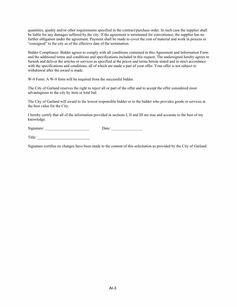
AI-3
quantities, quality and/or other requirements specified in the contract/purchase order. In such case the supplier shall be liable for any damages suffered by the city. If the agreement is terminated for convenience, the supplier has no further obligation under the agreement. Payment shall be made to cover the cost of material and work in process or “consigned” to the city as of the effective date of the termination. Bidder Compliance: Bidder agrees to comply with all conditions contained in this Agreement and Information Form and the additional terms and conditions and specifications included in this request. The undersigned hereby agrees to furnish and deliver the articles or services as specified at the prices and terms herein stated and in strict accordance with the specifications and conditions, all of which are made a part of your offer. Your offer is not subject to withdrawal after the award is made. W-9 Form: A W-9 form will be required from the successful bidder. The City of Garland reserves the right to reject all or part of the offer and to accept the offer considered most advantageous to the city by item or total bid. The City of Garland will award to the lowest responsible bidder or to the bidder who provides goods or services at the best value for the City. I hereby certify that all of the information provided in sections I, II and III are true and accurate to the best of my knowledge. Signature: _______________________ Date: ________________ Title: ___________________________ Signature certifies no changes have been made to the content of this solicitation as provided by the City of Garland.
CI - 1
COG Conflict of Interest Questionnaire
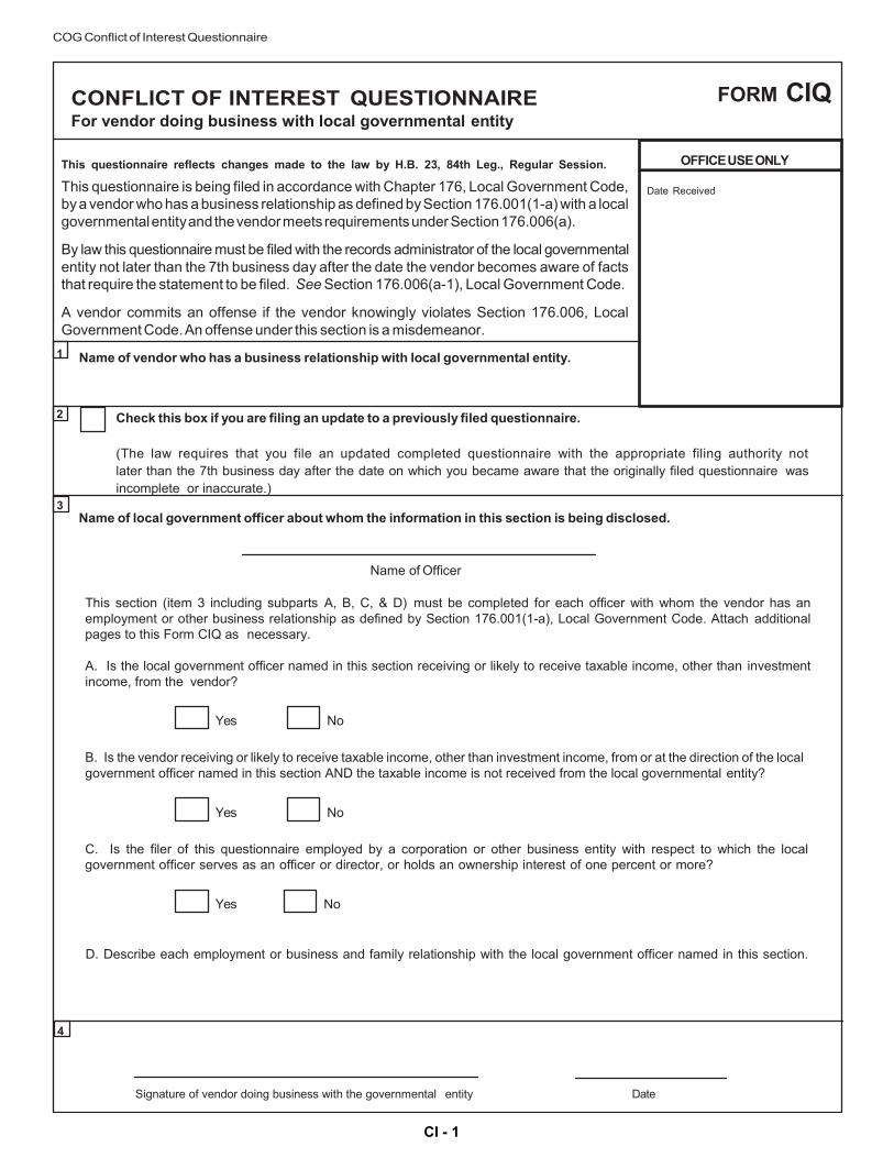
CONFLICT OF INTEREST QUESTIONNAIRE For vendor doing business with local governmental entity
FORM CIQ
This questionnaire reflects changes made to the law by H.B. 23, 84th Leg., Regular Session.
This questionnaire is being filed in accordance with Chapter 176, Local Government Code, by a vendor who has a business relationship as defined by Section 176.001(1-a) with a local governmental entity and the vendor meets requirements under Section 176.006(a).
By law this questionnaire must be filed with the records administrator of the local governmental entity not later than the 7th business day after the date the vendor becomes aware of facts that require the statement to be filed. See Section 176.006(a-1), Local Government Code.
A vendor commits an offense if the vendor knowingly violates Section 176.006, Local Government Code. An offense under this section is a misdemeanor.
OFFICE USE ONLY
Date Received
1 Name of vendor who has a business relationship with local governmental entity.
2 Check this box if you are filing an update to a previously filed questionnaire.
(The law requires that you file an updated completed questionnaire with the appropriate filing authority not later than the 7th business day after the date on which you became aware that the originally filed questionnaire was incomplete or inaccurate.)
3 Name of local government officer about whom the information in this section is being disclosed.
Name of Officer
This section (item 3 including subparts A, B, C, & D) must be completed for each officer with whom the vendor has an employment or other business relationship as defined by Section 176.001(1-a), Local Government Code. Attach additional pages to this Form CIQ as necessary.
A. Is the local government officer named in this section receiving or likely to receive taxable income, other than investment income, from the vendor?
Yes No
B. Is the vendor receiving or likely to receive taxable income, other than investment income, from or at the direction of the local government officer named in this section AND the taxable income is not received from the local governmental entity?
Yes No
C. Is the filer of this questionnaire employed by a corporation or other business entity with respect to which the local government officer serves as an officer or director, or holds an ownership interest of one percent or more?
Yes No
D. Describe each employment or business and family relationship with the local government officer named in this section.
4
Signature of vendor doing business with the governmental entity Date

VC - 1
COG Vendor Compliance
VENDOR COMPLIANCE WITH RECIPROCITY ON NON-RESIDENT BIDDERS
Government Code 2252.002 provides that, in order to be awarded a contract as low bidder, a nonresident bidder must bid projects for construction, improvements, supplies or services in Texas at an amount lower than the lowest Texas resident bidder by the same amount that a Texas resident bidder would be required to underbid a non-resident bidder in order to obtain a comparable contract in the state in which the non-resident’s principal place of business is located. A non-resident bidder is a contractor whose corporate offices or principal place of business is outside of the state of Texas. This requirement does not apply to a contract involving Federal funds. The appropriate blanks in Section A must be filled out by all out-of-state or non-resident bidders in order for your bid to meet specifications. The failure of out-of-state or non-resident contractors to do so will automatically disqualify that bidder. Resident bidders must check the blank in Section B.
A. Non-resident vendors in (give state), our principal place of business, are required to be
percent lower than resident bidders by state law. A copy of the statute is attached.
Non-resident vendors in (give state), our principal place of business, are not required to underbid resident bidders.
B. Our principal place of business or corporate offices are in the State of Texas: .
BIDDER:
Company
City State Zip
By (please print)
Signature
Title (please print)
THIS FORM MUST BE RETURNED WITH THE BID

IS-1
CERTIFICATION REQUIRED BY TEXAS GOVERNMENT CODE SECTION 2270.001
By signing below, Company hereby certifies the following:
1. Company does not boycott Israel; and
2. Company will not boycott Israel during the term of the contract.
Signed By:
Print Name & Title:
Date Signed: The following definitions apply to this state statute:
(1) "Boycott Israel" means refusing to deal with, terminating business activities with, or otherwise taking any action that is intended to penalize, inflict economic harm on, or limit commercial relations specifically with Israel, or with a person or entity doing business in Israel or in an Israeli-controlled territory, but does not include an action made for ordinary business purposes; and
(2) "Company" means a for-profit sole proprietorship, organization, association, corporation, partnership, joint venture, limited partnership, limited liability partnership, or limited liability company, including a wholly owned subsidiary, majority-owned subsidiary, parent company, or affiliate of those entities or business associations that exists to make a profit. State law requires certification from a Company for contracts (which includes contracts formed through purchase orders) involving goods or services regardless of the amount.


LIQUIDATED DAMAGES FOR FAILURE TO COMPLETE PROJECT ON TIME The time to completion is the essence of this contract. The Contractor shall have adequate personnel and equipment to ensure timely completion of the project. The Contractor is permitted a maximum of one-hundred eighty (180) calendar days from commencement to complete construction of this project.
For each calendar day in excess of one-hundred eighty from commencement that any work associated with the substation construction shall remain uncompleted and as adjusted to reflect increased time granted by the OWNER, or as equitably increased by additional work or materials ordered after the contract is signed, the sum of Five Thousand Dollars ($5,000.00) per day shall be deducted from the monies due the CONTRACTOR.
For each calendar day that any work associated with demobilization and cleanup shall remain uncompleted after an additional thirty (30) calendar days and as adjusted to reflect increased time granted by the OWNER, or as equitably increased by additional work or materials ordered after the contract is signed, the sum of Five Hundred Dollars ($500.00) per day shall be deducted from the monies due the CONTRACTOR. The sum of money thus deducted for such delay, failure or non-completion is not to be considered as a penalty, but shall be deemed, taken and treated as reasonable liquidated damages, per calendar day that the CONTRACTOR shall be in default after the time stipulated in the contract for completing the work. The said amounts are fixed and agreed upon by and between OWNER and CONTRACTOR because of the impracticability and extreme difficulty of fixing and ascertaining the actual damages the OWNER in such event would sustain; and said amounts are agreed to be the amount of damages which the OWNER would sustain and which shall be retained from the monies due, or that may become due, the CONTRACTOR under this contract; and if said monies be insufficient to cover the amount owing, then the CONTRACTOR or his surety shall pay any additional amounts due.

CITY COUNCIL POLICY
OPNS-04 – Qualifications for Doing Business with the City
I. Purpose and Need for Policy
The purpose of this policy is to foster the public’s trust in the conduct of City business and to further ensure the expenditures of public funds is beyond reproach.
II. Policy Other than the exceptions cited below, it is the policy of the City Council to not enter into or renew a contract to purchase, sell, or lease property or services to or from any entity described in this policy.
III. Procedure to Accomplish Policy
A. The City of Garland shall not, except as provided herein, enter into or renew a contract to purchase, sell, or lease property or services to or from any person or entity who has been:
1) Convicted of any state or federal felony offense. Conviction includes a final
probation, deferred adjudication or similar disposition. 2) Convicted or fined in excess of $50,000 on certain state or federal
discrimination offenses. Discrimination charges include only those brought for discrimination against the race, sex, or religion or an individual or class of individuals.
B. Persons or entities doing business with the City include:
1) Individuals, corporations, partnerships, associations, or limited liability
companies. 2) Owner or principal operators of entities referenced in paragraph B(1).
3) Principal officers of entities referenced in paragraph B(1).
4) Shareholders in corporations or limited liabilities companies if there are five or
fewer shareholders.
5) Majority owned affiliates of any entity referenced in paragraph B(1). C. This policy shall not apply when:

1) Three (3) years have elapsed between the conviction and the approval of the contract.
2) The contract does not require City Council approval.
3) Anything of value is paid or given to informants or participants in a crime
stopper program, or
4) The City Council determines this policy could cause grave injury or impose a severe financial hardship to the City of Garland by its application, and is waived by an affirmative vote of not less than six (6) Council members.
D. On bid applications that may result in a contract award by the City Council, the City
shall require a representation by bidders that the bidder is not disqualified by the application of this policy.
E. After contract award, but prior to the commencement of the project or the delivery
of the service or property, a determination that the bidder is in violation of this policy shall be cause for terminating the contract. By the execution and submission of this bid, bidder acknowledges that bidder has received a copy of City Council Policy OPNS-04 and bidder represents and warrants that bidder complies with the requirements of the City Council Policy OPNS-04 and is in no manner disqualified from doing business with the City under that policy.

CITY COUNCIL POLICY
OPNS-28 – Business Conduct with Delinquent Account Holders and Litigants
I. Purpose and Need for Policy The City conducts business with its citizens and the public at-large. In so doing, there are instances where the City may be asked to conduct business with those who are delinquent in their payment(s) to the City on various accounts or who may be involved in litigation with the City. Examples of the types of delinquent accounts which can be substantial in nature are impact fees, property taxes (generally person property), utility bills, EMS fees, and damage claims to City property. A policy is needed to ensure that the City does not conduct business with those individuals.
II. Policy It is the policy of the City Council to forbid any individual or business entity to conduct business with the City if such person(s) currently owe(s) the City money which is past due or delinquent on property taxes, impact fees, utility bills, Municipal Court fees, EMS fees, or damage claims to City property. Unless prohibited by law, it shall further be the policy of the City Council to forbid any individual or business entity who files meritless litigation against the City from conducting business with the City.
III. Procedure to Accomplish Policy On a monthly basis, the Managing Director of Customer Services shall produce a delinquent accounts list containing the names of those businesses and/or individuals who are delinquent in paying the City for property taxes, impact fees, utility bills, EMS fees, or damage claims. Copies of the delinquent tax history shall be distributed to the City Manager’s office, Purchasing, Engineering, Planning, and Building Inspection Departments. The delinquent accounts list relating to impact fees, utility bills, EMS fees, and/or damage claims shall be housed in the Customer Service Department. These lists will be available to the City Manager, Assistant City Manager’s, and other departments upon request, to be checked prior to permit issuance or other conduct of business by the City with any business or individual. The City will not do business with any business or individual until the delinquent account is paid in full. The City shall not award any contracts for services and/or goods to any business, firm, and/or individual(s) who are delinquent or have demonstrated that they are not the most responsible bidder.

IV. Responsibility and Authority 1. The Managing Director of Customer Service shall be responsible for
producing and distributing a delinquent accounts list containing names of businesses and/or individuals who are delinquent in paying their property taxes, impact fees, utility bills, EMS fees, or damage claims to the City.
2. The Purchasing Manager shall be responsible for the reporting and removal
of any bids submitted by any business(es), firm(s), and/or individual(s) who are delinquent in payment(s) of their utility bills, EMS fees, property taxes, impact fees, or have damage claims to the City.
3. The City Manager is responsible to ensure that this policy is upheld and that
the Council is kept abreast of its effectiveness. By the execution and submission of this bid, bidder acknowledges that bidder has received a copy of City Council Policy OPNS-28 and bidder represents and warrants that bidder complies with the requirements of the City Council Policy OPNS-28 and is in no manner disqualified from doing business with the City under that policy.

BQS - 1
ALL BIDDERS ARE NOTIFIED THAT THE FOLLOWING QUALIFICATION STATEMENT MUST BE COMPLETED AND SUBMITTED WITH THE BID PROPOSAL. SC.37 CONTRACTORS QUALIFICATIONS The Contractor shall show that he has experience with projects of similar type, scale, and schedule. The Contractor shall submit a list of Projects successfully completed demonstrating their ability to construct the proposed improvements in a timely and defect free fashion. This list shall include the names of supervisors and Owner contacts.

BQS - 2

BQS - 3

BQS - 4
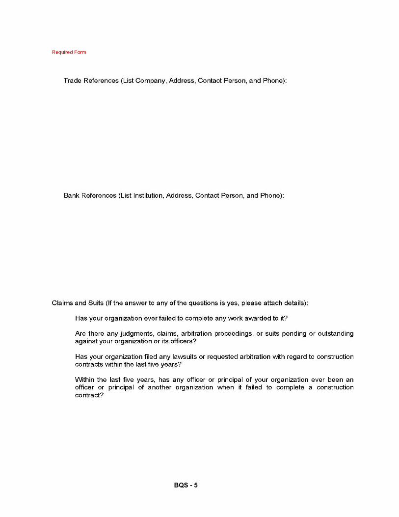
BQS - 5

BQS - 6
I, , being duly sworn deposes and says that the information provided herein is true and sufficiently complete so as not to be misleading. Dated this day of , 2___ Name of Organization:____________________________________________________________ By:_________________________________________________________________________ Title:________________________________________________________________________ STATE OF TEXAS COUNTY OF DALLAS BEFORE ME the undersigned authority, on this day personally appeared , known to me to be the person whose name subscribed to the foregoing instrument, and acknowledged to me that he executed the same for the purposes and considerations therein expressed. GIVEN UNDER MY HAND AND SEAL OF OFFICE this day of , 2___ _________________________________________ Notary Public in and for Dallas County, Texas

BID BOND
THIS PAGE INTENTIONALLY LEFT BLANK DURING THE BIDDING PROCESS AS A PLACE HOLDER FOR THE BIDDER
TO INSERT THE BID BOND

SECTION II CONTRACT AND BONDS

NOTICE THE FOLLOWING BLANK SPACES IN THE CONTRACT ARE NOT TO BE FILLED IN BY THE BIDDER AT THE TIME OF SUBMITTING HIS PROPOSAL. THE CONTRACT FORMS ARE SUBMITTED AT THIS TIME TO FAMILIARIZE THE BIDDER WITH THE FORM OF CONTRACT WHICH THE SUCCESSFUL BIDDER WILL BE REQUIRED TO EXECUTE.

CONTRACT THIS CONTRACT is made and entered into by and between the CITY OF GARLAND, TEXAS (the “City”), a municipal corporation located in Dallas County, Texas, and ____________________________a Texas corporation, herein referred to as “Contractor.”
RECITALS: WHEREAS, the City requested bids for GP&L Apollo Substation Construction and WHEREAS, Contractor submitted the lowest responsible bid in response to the City’s request for bids, NOW THEREFORE, in consideration of the mutual covenants contained herein, the sufficiency of which is acknowledged, the City and the Contractor hereby agree as follows: 1. Services Provided. The Contractor undertakes, covenants, and agrees to provide the services required by the City in accordance with the requirements, terms and conditions contained in the City’s request for bids in connection with Bid Number 0241-20 (entitled “GP&L Apollo Substation Construction”). 2. Incorporation by Reference. All terms and conditions contained in the City’s request for bids in connection with Bid Number 0241-20 are incorporated into this Contract by reference as if full set forth at length. 3. Price and Payment. The Contractor shall be entitled to receive (amount in words)____________________ ___________________________________________________________________________________________________________________________________dollars ($______________________.00) for performance of the services contemplated by this Contract. Payment shall be governed by the terms and conditions set forth in the request for bid in connection with Bid Number 0241-20. 4. Additional Security. It is mutually agreed that should it appear to the City of Garland, or to the Authorized Agent in charge, at any time during the existence of this Contract, that the sureties on the Contractor’s bond have become insolvent, bankrupt, or otherwise financially unable to protect the City under the terms of the Contract, the City may demand the Contractor to furnish additional security in some approved surety company satisfactory to the City. The acts of the City or the Agent with reference to demanding new or additional security shall never be construed to relieve the original sureties of their obligations under the Contract, or to relieve the Contractor. The City may stop performance under the Contract until additional security has been furnished by the Contractor, and the City shall in no case be liable to the Contractor on account thereof. In the event of the refusal or failure of the Contractor to comply with the demands of the City with reference to furnishing additional security, the City may exercise its right as provided herein to stop all payments under the Contract and to arrange for completion of the Contract requirements obligating the Contractor for any and all additional expenses incurred. 5. Entire Agreement. It is understood and agreed that this contract contains the entire agreement between the parties and supersedes any and all prior agreements, arrangements or understandings between and parties relating to the subject matter. No oral understandings, statements, promises or inducements contrary to the terms of this contract exist. This contract cannot be changed or terminated orally and no written modification of this contract shall be effective unless executed by both parties.

EXECUTED on this the ____________ day of ___________________________, 2___ By: ___________________________ (City/Owner) Name:_________________________ ________________________________ Party of the Second Part (Contractor) Title: __________________________ Title: ___________________________ Date: _________________________ Date:___________________________ Party of the Second Part (Contractor) Before me this day personally appeared the person whose signature appears above, who after being by me duly sworn upon oath says that he/she is _________________________________________________________________________, (title and name of company) and is authorized to sign as an act of the corporation. Subscribed and sworn to before me on this the ______ day of ________________, 2___.
________________________________
Notary Public in and for the State of Texas ___________________________________
Printed Name of Notary My Commission Expires ______________
PERFORMANCE BOND STATE OF TEXAS COUNTY OF DALLAS WHEREAS, ________________________________________ as principal ("Contractor") and ___________________________________________________________________________, a corporation organized under the laws of _____________________________________ and being duly authorized to do business in the State of Texas, as surety ("Surety")(whether one or more), do hereby expressly acknowledge themselves to he held and bound to pay to the City of Garland, Texas, a home-rule municipality organized and operating under the Constitution and laws of the State of Texas (the "City"), its successors and assigns, and to all persons, firms, subcontractors and corporations who may furnish materials or labor under the contract as more fully described below, the sum of _______________________________________ Dollars in the lawful currency of the United States of America ($ _________________ ) for the payment of which Contractor and Surety are liable to the City, jointly and severally; and WHEREAS, Contractor has this day entered into a written contract with the City for GP&L Apollo Substation Construction which contract and the plans and specifications therein mentioned (collectively referred to hereinafter as the "Contract") are hereby expressly incorporated into and made a part hereof as though set forth at length; and WHEREAS, this bond is given pursuant to Chapter 2253 of the Texas Government Code; NOW, THEREFORE, if Contractor shall well, truly and faithfully perform all of the undertakings, duties, terms, conditions and agreements of the Contract; shall satisfy all claims and demands incurred under the Contract; shall fully indemnify and hold the City harmless; shall reimburse and repay the City for any outlay or expense which the City may incur in making good any default, and shall promptly make payment to all persons, firms, subcontractors and corporations who may furnish materials or labor under the Contract, then this obligation shall be void; otherwise to remain in full force and effect. The obligations of Contractor and Surety under this bond apply both to the original Contract and to any extension or modification of the Contract and Surety agrees that no change, extension of time, addition, expansion or other modification of the Contract, the work to be done under the Contract, or the plans and specifications which are a part of the Contract shall in any manner affect the obligations of Surety under this bond, and Surety waives notice of any such change, extension of time, addition, expansion or other modification. The obligations of Contractor and Surety under this bond are performable and payable in Dallas County, Texas such that exclusive venue for any legal action pertaining to this bond shall lie in Dallas County, Texas. By their signatures below, the persons signing this bond warrant and represent that they are, respectively, duly authorized to sign on behalf of Contractor and Surety. EXECUTED this the _____ day of _______________, 2___. CONTRACTOR: SURETY: By: Title: _______
By: Title: _________
ACKNOWLEDGMENTS [Contractor] STATE OF TEXAS COUNTY OF DALLAS Before me _______________________________ (insert the name of the officer) on this day ___________________ personally appeared ______________________________ known to me (or proved to me on the oath of __________________ or through _______________________) (description of identity card or other document) to be the person whose name is subscribed to the foregoing instrument and acknowledged to me that he/she executed the same for the purpose and consideration therein expressed. Given under my hand and seal of office this ________ day of _____________, 2_____. Notary Public in and for the State of Texas My Commission Expires:
Typed or Printed Name of Notary
[Surety] STATE OF TEXAS COUNTY OF DALLAS This instrument was acknowledged before me on the ____day of _______________________, 2___ by _____________________________________________ who is the _________________________ of the Surety, on behalf of Surety. GIVEN UNDER MY HAND AND SEAL OF OFFICE this the ____ day of _____________, 2___.
_________________ Typed or Printed Name of Notary

PAYMENT BOND STATE OF TEXAS COUNTY OF DALLAS WHEREAS, ________________________________________ as principal ("Contractor") and __________________________________, a corporation organized under the laws of _____________________________________ and being duly authorized to do business in the State of Texas, as surety ("Surety")(whether one or more), do hereby expressly acknowledge themselves to he held and bound to pay to the City of Garland, Texas, a home-rule municipality organized and operating under the Constitution and laws of the State of Texas (the "City"), its successors and assigns, and to all persons, firms, subcontractors and corporations who may furnish materials or labor under the contract as more fully described below, the sum of _____________________________________________ Dollars in the lawful currency of the United States of America ($ ________________) for the payment of which Contractor and Surety are liable to the City, jointly and severally; and WHEREAS, Contractor has this day entered into a written contract with the City for GP&L Apollo Substation Construction which contract and the plans and specifications therein mentioned (collectively referred to hereinafter as the "Contract") are hereby expressly incorporated into and made a part hereof as though set forth at length; and WHEREAS, this bond is given pursuant to Chapter 2253 of the Texas Government Code; NOW, THEREFORE, if Contractor shall promptly make payment to all persons, firms, subcontractors and corporations who may furnish materials or labor under the Contract, then this obligation shall be void; otherwise to remain in full force and effect. The obligations of Contractor and Surety under this bond apply both to the original Contract and to any extension of time or modification of the Contract and Surety agrees that no change, extension of time, addition, expansion or other modification of the Contract, the work to be done under the Contract, or the plans and specifications which are a part of the Contract shall in any manner affect the obligations of Surety under this bond, and Surety waives notice of any such change, extension of time, addition, expansion or other modification. The obligations of Contractor and Surety under this bond are performable and payable in Dallas County, Texas such that exclusive venue for any legal action pertaining to this bond shall lie in Dallas County, Texas. By their signatures below, the persons signing this bond warrant and represent that they are, respectively, duly authorized to sign on behalf of Contractor and Surety. EXECUTED this the __________ day of _________________________, 2___. CONTRACTOR: SURETY: By:__________________________________ Title:________________________________
By:_________________________________ Title:________________________________

ACKNOWLEDGMENTS [Contractor]
STATE OF TEXAS COUNTY OF DALLAS Before me _______________________________ (insert the name of the officer) on this day ___________________ personally appeared ______________________________ known to me (or proved to me on the oath of __________________ or through _______________________) (description of identity card or other document) to be the person whose name is subscribed to the foregoing instrument and acknowledged to me that he/she executed the same for the purpose and consideration therein expressed. Given under my hand and seal of office this ________ day of _____________, 2_____. ___________________________________ Notary Public in and for the State of Texas My Commission Expires:_______________
_____________________________________ Typed or Printed Name of Notary
[Surety]
STATE OF TEXAS COUNTY OF DALLAS This instrument was acknowledged before me on the ___________ day of ______________________, 2___ by ________________________________________ who is the ____________________________________ of the Surety, on behalf of Surety. GIVEN UNDER MY HAND AND SEAL OF OFFICE this the ________ day of _______________________, 2___. __________________________________ Notary Public in and for the State of Texas My Commission Expires:______________
____________________________________ Typed or Printed Name of Notary

MAINTENANCE BOND
STATE OF TEXAS COUNTY OF DALLAS WHEREAS, _____________________________________________________________as principal ("Contractor") and ____________________________________________________________________________________________ ______________________, a corporation organized under the laws of _______________________ and being duly authorized to do business in the State of Texas, as surety ("Surety")(whether one or more), do hereby expressly acknowledge themselves to he held and bound to pay to the City of Garland, Texas, a home-rule municipality organized and operating under the Constitution and laws of the State of Texas (the "City"), its successors and assigns the sum of ______________________________________Dollars in the lawful currency of the United States of America ($_______________) for the payment of which Contractor and Surety are liable to the City, jointly and severally; and WHEREAS, Contractor has this day entered into a written contract with the City for GP&L Apollo Substation Construction which contract and the plans and specifications therein mentioned (collectively referred to hereinafter as the "Contract") are hereby expressly incorporated into and made a part hereof as though set forth at length; and WHEREAS, under the Contract it is provided that the Contractor will maintain and keep in good repair all work to be performed and done under the Contract for a period of two (2) years from the date of acceptance of the completed work by the City, and to do and perform all necessary work and repair any defective condition, it being understood that the purpose of this maintenance bond is to insure all warranties, express or implied, made or given by the Contractor to the City and to cover all defective, inadequate or non-conforming conditions arising by reason of any materials or labor installed, provided, constructed or performed by the Contractor and in case the Contractor shall fail to correct any such conditions it is agreed that the City may make such corrections and charge the cost of making those corrections against the Contractor and the Surety on this obligation, and the Contractor and Surety shall be subject to the liquidated damages provided in the contract, the plans and the specifications for each day's failure on its part to comply with the terms and provisions of the Contract; NOW, THEREFORE, if the Contractor shall keep and perform its obligation to maintain the work and keep the work in repair for the full maintenance period of two (2) years as herein provided, then these presents shall be null and void and have no further effect, but if default shall be made by Contractor in the performance of its obligations, then these presents shall have full force and effect, and the City shall have and recover from the Contractor and its Surety damages in the premises as provided and it is further understood and agreed that this obligation shall be a continuing one against the Contractor and the Surety and that successive recoveries may be had hereon for successive breaches until the full amount of this bond shall have been exhausted; and it is further understood that the obligation under this bond to maintain the work shall continue throughout the maintenance period and shall not be changed, diminished, or in any other manner affected during the term of this bond. The obligations of Contractor and Surety under this bond apply both to the original Contract and to any extension or modification of the Contract and Surety agrees that no change, extension of time, addition, expansion or other modification of the Contract, the work to be done under the Contract, or the plans and specifications which are a part of the Contract shall in any manner affect the obligations of Surety under this bond, and Surety waives notice of any such change, extension of time, addition, expansion or other modification. The obligations of Contractor and Surety under this bond are performable and payable in Dallas County, Texas such that exclusive venue for any legal action pertaining to this bond shall lie in Dallas County, Texas. By their signatures below, the persons signing this bond warrant and represent that they are, respectively, duly authorized to sign on behalf of Contractor and Surety. EXECUTED this the _______ day of __________________, 2____.

CONTRACTOR: SURETY: By: Printed Name: Title:
Address of Principal:
By: Printed Name: Title:
Address of Surety:
ACKNOWLEDGMENTS
[Contractor] STATE OF TEXAS COUNTY OF DALLAS Before me _______________________________ (insert the name of the officer) on this day ___________________ personally appeared ______________________________ known to me (or proved to me on the oath of __________________ or through _______________________) (description of identity card or other document) to be the person whose name is subscribed to the foregoing instrument and acknowledged to me that he/she executed the same for the purpose and consideration therein expressed. Given under my hand and seal of office this ________ day of _____________, 2_____. Notary Public in and for the State of Texas My Commission Expires: _________________
Typed or Printed Name of Notary

CONTRACTOR'S AFFIDAVIT OF BILLS PAID (To be executed prior to acceptance of project) STATE OF TEXAS COUNTY OF DALLAS Personally, before me the undersigned authority, on this day appeared _________ ______ ____ , who, being duly sworn, on oath, says that he is a legal representative of ______________________________________________________________ (Full name of Contractor as in Contract) and that the contract to construct the project designated as GP&L Apollo Substation Construction has been satisfactorily completed and that all bills for materials, apparatus, fixture, machinery and labor used in connection with the construction of this project have, to the best of my knowledge and belief, been fully paid. Signature Title Sworn to and subscribed before me this day of , 2___ Notary Public in and for County, Texas Instructions: If the Contractor is an individual, he shall sign the affidavit. If the Contractor is a partnership, any partner may sign the affidavit. If the Contractor is a corporation, a person authorized by the by-laws or by the Board of Directors shall sign the affidavit. If the Contractor is a joint venture of individuals, any of the individuals may sign the affidavit. If the Contractor is a joint venture of partnerships, or of individuals and partnerships, the individual or any partner of any partnership may sign the affidavit. If the contractor is a joint venture in which a corporation is a party, separate affidavits must be executed in the name of the joint-venture; one by each corporation and one by each individual or partnership. Signatures for corporations should be by a duly authorized officer. If signature is by another, a showing of authority to sign must accompany the affidavit.

CERTIFICATES OF INSURANCE
THIS PAGE INTENTIONALLY LEFT BLANK DURING THE BIDDING PROCESS AS A PLACE HOLDER FOR THE BIDDER TO INSERT THE CERTIFICATES OF
INSURANCE

PURCHASE ORDER
THIS PAGE INTENTIONALLY LEFT BLANK DURING THE BIDDING PROCESS AS A PLACE HOLDER FOR THE PURCHASE ORDER FOR THE BID AWARDEE

SECTION III
GENERAL SPECIFICATIONS AND SPECIAL CONDITIONS

APPLICABLE SPECIFICATIONS The following specifications apply as stated unless specifically shown as not applicable by plans or this specification. STANDARD SPECIFICATIONS FOR PUBLIC WORKS CONSTRUCTION – NORTH CENTRAL TEXAS, Third Edition, 1998 (and subsequent amendments), North Texas Council of Governments. NATIONAL ELECTRICAL SAFETY CODE C2- (LATEST EDITION). GARLAND POWER & LIGHT STANDARD CONSTRUCTION DETAILS (LATEST REVISIONS) CITY OF GARLAND STANDARD CONSTRUCTION DETAILS (LATEST REVISIONS) The above documents shall be obtained by bidders at their own expense.

SUPPLEMENT TO THE STANDARD SPECIFICATIONS FOR PUBLIC WORKS CONSTRUCTION NORTH CENTRAL TEXAS Third Edition 1998 PART I GENERAL AND SPECIAL PROVISIONS, DIVISION I Note: The City of Garland will furnish to all prospective bidders its own special conditions, instructions to bidders, contract, and bond forms. The City of Garland has adopted Section I, "Specifications", of the Standard Specifications for Public Works Construction in North Central Texas (Third Edition) by North Central Texas Council of Governments. Section II, "Standard Drawings" of that document is not adopted by the City of Garland. All other sections, except as modified herein, shall be followed during the construction of this project. A copy of these specifications may be obtained from the North Central Texas Council of Governments at P.O. Box 5888, Arlington, Texas 76005-5888 or (817) 695-9140. A copy is on file in the office of the Purchasing Agent of the City of Garland, located at City Hall, Garland, Texas. 1. The successful bidder shall furnish all alignment and construction staking and shall employ a
Registered Professional Land Surveyor (RPLS) to supervise and direct this work. The City of Garland reserves the right to check progress and accuracy of same at any time during the life of the contract.
2. All material tests of concrete, densities or any other material that is required to complete the
project shall be furnished and paid for by the Contractor, and shall be made in accordance with the latest methods of the American Society for Testing and Materials. All tests shall be performed in accordance with Special Conditions Paragraph 17. Contractor is responsible for scheduling and coordinating the required testing with the Material Testing Laboratory. The Contractor shall provide access and cooperate with Material Testing Laboratory personnel in performing required material tests.
3. The items listed below as found in Division I of the specifications shall be amended as follows: 1.0 DEFINITIONS: Working Day or Days – Refer to City of Garland Standard Terms and
Conditions. Work on the legal holidays listed in the Terms and Conditions shall not be permitted except in cases of extreme emergency and then only with written permission of the City of Garland.
1.20.2 SUPPLEMENTAL DRAWINGS AND SPECIFICATIONS: Supplemental Drawings and
Specifications are considered part of this contract. These project documents may include all, or part, but not limited to, the Supplemental Standard Specifications, Special Conditions, Geotechnical Report, Technical Specifications, City Standard Construction Details and Project Specific Details.

1.22.1 INDEPENDENT CONTRACTOR: While engaged in carrying out and complying with the terms and conditions of this contract, the contractor is, and shall be, an Independent Contractor and shall not, with respect to its acts or omissions, be deemed an officer, employee or agent of the City. The Contractor shall not at any time or in any manner represent that it or any of its agents or employees are in any manner agents or employees of the City. The Contractor is, and shall remain, an Independent Contractor, with full, complete and exclusive power and authority to direct, supervise, and control his own employees and to determine the method of the performance of the work covered hereby. The fact that the OWNER or OWNER’s representative shall have the right to observe the Contractor's work during his performance and to carry out the other prerogatives which are expressly reserved to and vested in the OWNER or OWNER’s representative hereunder, is not intended to and shall not at any time change or affect the status of the Contractor as an Independent Contractor with respect to either the OWNER or OWNER’s representative or to the Contractor's own employees or to any other person, firm or corporation.
1.22.5 PROGRESS SCHEDULE: The Contractor, upon the execution and delivery of the contract,
shall prepare and submit for the OWNER’S approval a Critical Path Method (CPM) progress schedule showing the manner of prosecution of the work in order to complete the contract within the allocated time and to meet the intermediate milestones. The schedule shall contain activities for all significant work items necessary to complete the project. In addition to project completion, the schedule shall contain two intermediate milestones. Each milestone will be the completion of a major critical work item or phase of construction, such as the completion of security fencing. These intermediate milestones will approximately divide the project into thirds, i.e.: 1st milestone scheduled after approximately 1/3 of project time, 2nd milestone after approximately 2/3 of project time. The intent of establishing the milestones is to help assure that the Contractor diligently pursues the project schedule from the beginning. The OWNER will review the proposed progress schedule, within a reasonable time, and present the Contractor any concerns or problems they see with the proposed schedule. The Contractor will cooperate with the OWNER in resolving any concerns the OWNER may have and to develop a mutually agreeable schedule. This approved schedule shall clearly establish the two intermediate milestones and completion time and be mutually agreeable to both the OWNER and Contractor. The schedule shall be approved before the notice to proceed date and start of construction. Throughout the course of the project, the progress schedule shall be revised if, in the opinion of the OWNER, the scheduled progress of the work is not being maintained. This revised schedule will address the methods by which time lost shall be made up.
1.51.1 MONTHLY ESTIMATE: As this is a separated contract (as that term is defined in Texas
Comptroller's Rule 3.291, as amended) between the OWNER and the Contractor, all invoices

for payment presented by the Contractor including the estimate or invoice for which final payment is requested, shall be separated into three components as follows: (a) billings attributable to materials, supplies, equipment and other tangible personal property physically incorporated into the work done; (b) billings attributable to materials, supplies, equipment and other tangible personal property purchased or leased for use in the work, but not physically incorporated into the work; (c) billings attributable to other costs and fees allowable under the contract, including labor, overhead, profit and other reasonable, incidental allowable costs related to the work. The Contractor's invoice may include acceptable, non-perishable materials delivered to the work site; payment shall be allowed on the same percentage basis of the net invoice value as provided hereinafter.
Except as otherwise provided by the contract, between the 25th day and the last day of each month the OWNER shall make an approximate confirming estimate of the value of the work done through the 25th of the month under the specifications. The monthly confirming estimate shall then be used to verify the Contractor's invoice. The OWNER shall verify that the sum total of the Contractor’s invoice matches the total value of work done and acceptable, non-perishable materials delivered to the work site, based upon the bid proposal prices and quantities measured by the OWNER. In the event of a discrepancy between quantities of work as shown in the Contractor’s invoice and measured quantities as shown in the OWNER 'S confirming estimate the OWNER 'S determination or measurement shall be final, and the Contractor’s invoice shall be adjusted to reflect the quantities of work as shown by the OWNER 'S confirming estimate. Whenever the said confirming estimate or estimates of the completed work, since the last previous estimate, exceeds $100 in amount a percentage of such estimate sum shall be paid to the Contractor no later than 30 days from receipt of the Contractor’s invoice. The Contractor's invoice and all required supporting documents shall be submitted to the OWNER no later than the 26th of the month or the next working day if the 26th falls on a weekend or recognized holiday.
The Contractor shall furnish to the OWNER such detailed information as he may request to assist him in the preparation of monthly confirming estimates. It is understood that the monthly confirming estimates shall be approximate only, and all monthly confirming estimates and partial payments shall be subject to correction in the confirming estimate rendered following the discovery of an error in any previous confirming estimate, and such estimate shall not in any respect be taken as an admission of the OWNER of the amount of work done or of its quality or sufficiency nor as an acceptance of the work or the release of the Contractor of any of his responsibility under the contract. If the Contractor is not in compliance with the approved work progress schedule or the approved revised schedule at the end of the monthly estimate period, payment for work performed during the period of noncompliance will be reduced by 30% of the work performed. All withheld moneys will be paid to the Contractor with the next regular monthly estimate when the work progress returns to compliance with the approved progress schedule.
1.51.2 RETAINAGE: As security for the faithful completion of the work by the Contractor, the
OWNER shall retain ten percent (10%) of the total dollar amount of work done on all contracts

less than $200,000.00; five percent (5%) of the total dollar amount of work done on all contracts of $200,000.00 or more.
On all contracts in excess of $200,000.00, the following shall apply:
(a) when work progress is fifty percent (50%) complete, retainage may at the OWNER’S
option be reduced to two percent (2%) of the dollar value of all work satisfactorily completed to date (not to include material on hand) provided that the Contractor is on or ahead of the approved progress schedule and there is no cause for greater retainage as determined by the OWNER;
(b) when work progress is substantially complete, the retainage may be further reduced to
only that amount necessary to assure completion as determined by the OWNER; (c) if the OWNER determines that the Contractor is not making satisfactory progress or if
there is other specific cause, the OWNER may, at his discretion, reinstate up to the five percent (5%) retainage.
1.58 STATE AND LOCAL SALES AND USE TAX: The OWNER qualifies for exemption from state and local sales and use taxes, pursuant to the provisions of Section 151.309 of the Texas Tax Code, as amended. Therefore, the OWNER shall not be liable for, or pay the Contractor's cost of, such sales and use taxes which would otherwise be payable in connection with the purchase of tangible personal property furnished and incorporated into the real property being improved under the contract. This contract is a separated contract (as that term is defined in Texas comptroller's Rule 3.291, as amended) between the OWNER and the Contractor. A Contractor performing work under these specifications is a seller of tangible personal property furnished and incorporated into the real property being improved, pursuant to Section 151.056(b) of the Texas Tax Code, as amended. All invoices or estimates submitted by the Contractor to the OWNER shall be separated into three categories: (a) billings attributable to materials, supplies, equipment and other tangible personal property physically incorporated into the work; (b) billings attributable to materials, supplies, equipment and other tangible personal property purchased or leased for use in the work, but no physically incorporated into the work; and (c) billings attributable to other costs and fees allowable under the contract, including labor, overhead, profit and other reasonable, incidental costs related to the work. The Contractor must obtain a Texas Sales Tax Permit prior to commencement of work and shall file appropriate returns with the Comptroller of Public Accounts of the State of Texas, as required from time to time by rules and regulations of the Comptroller. The Contractor shall issue a resale certificate in lieu of the tax on the purchase of all materials, supplies, equipment and other tangible personal property to be incorporated into the real property being improved under the contract. Supplies, tools, materials, equipment and other tangible personal property that are purchased or leased merely for use in the performance of the contract, and not for incorporation into the improved real property, are not exempted from sales or use tax and are not covered by this Item.
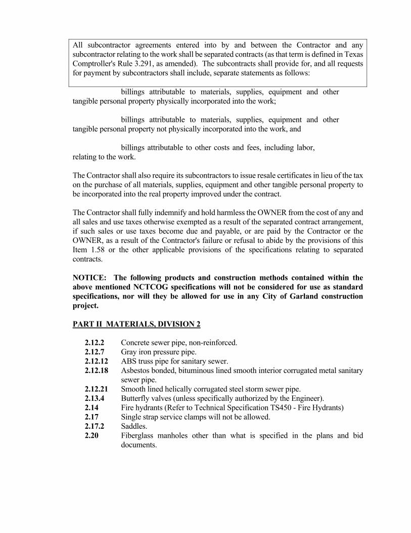
All subcontractor agreements entered into by and between the Contractor and any subcontractor relating to the work shall be separated contracts (as that term is defined in Texas Comptroller's Rule 3.291, as amended). The subcontracts shall provide for, and all requests for payment by subcontractors shall include, separate statements as follows: billings attributable to materials, supplies, equipment and other tangible personal property physically incorporated into the work; billings attributable to materials, supplies, equipment and other tangible personal property not physically incorporated into the work, and billings attributable to other costs and fees, including labor, relating to the work. The Contractor shall also require its subcontractors to issue resale certificates in lieu of the tax on the purchase of all materials, supplies, equipment and other tangible personal property to be incorporated into the real property improved under the contract. The Contractor shall fully indemnify and hold harmless the OWNER from the cost of any and all sales and use taxes otherwise exempted as a result of the separated contract arrangement, if such sales or use taxes become due and payable, or are paid by the Contractor or the OWNER, as a result of the Contractor's failure or refusal to abide by the provisions of this Item 1.58 or the other applicable provisions of the specifications relating to separated contracts. NOTICE: The following products and construction methods contained within the above mentioned NCTCOG specifications will not be considered for use as standard specifications, nor will they be allowed for use in any City of Garland construction project.
PART II MATERIALS, DIVISION 2
2.12.2 Concrete sewer pipe, non-reinforced. 2.12.7 Gray iron pressure pipe. 2.12.12 ABS truss pipe for sanitary sewer. 2.12.18 Asbestos bonded, bituminous lined smooth interior corrugated metal sanitary
sewer pipe. 2.12.21 Smooth lined helically corrugated steel storm sewer pipe. 2.13.4 Butterfly valves (unless specifically authorized by the Engineer). 2.14 Fire hydrants (Refer to Technical Specification TS450 - Fire Hydrants) 2.17 Single strap service clamps will not be allowed. 2.17.2 Saddles. 2.20 Fiberglass manholes other than what is specified in the plans and bid
documents.

DIVISION 4 SUBBASE AND BASE COURSES 4.6.4 Dry placement for lime subgrade will not be allowed. 4.7 Portland cement treatment for base (only by special approval by the Engineer). 4.8 Asphalt treatment. DIVISION 5 PAVEMENT AND SURFACE COURSES
Refer to City of Garland Special Conditions for concrete batch designs. 5.8.6 Pavement testing (refer to City of Garland Special Conditions). DIVISION 6 UNDERGROUND CONDUIT CONSTRUCTION 6.2.8 Blasting or use of explosives not allowed. 6.2.9(c) For embedment refer to project Details. 6.2.12 Backfill and embedment no pay item. 6.3.2 Foundation material no pay item. 6.5 Street cut excavation (refer to City of Garland Standard Details). 6.7.3(f) Use City of Garland specifications for hydrostatic test for all water conduit.
(See Technical Specifications TS-400 – Ordinary Water Works Service) 6.7.3(j)(5) Direct tapping of PVC water pipe will not be allowed. Taps, or tapping
saddles, or service clamps are not a pay item. 6.7.3(n) Fittings and pipe special for reinforced concrete steel cylinder pipe will not be
measured and paid for as a separate item. 6.7.3(s) Purging and sterilization of water mains shall be performed by the contractor
at his expense. 7.4.5(b) The City of Garland shall designate its own strength requirements for concrete
for structures. DIVISION 8 MISC. CONSTRUCTION 8.3.2 Reinforcement for drive approaches - refer to City of Garland Standard
Construction Details. BONDS: The successful bidder must furnish Performance and Payment Bonds upon the form provided in the amount of 100% of the total contract price from an approved bank or surety company holding a permit from the State of Texas to act as surety, or other surety or sureties acceptable to the OWNER. The Contractor shall furnish a Maintenance Bond for an amount equal to ten percent (10%) of the contract price for improvements and shall be for two (2) years from and after the date of the OWNER’s acceptance of the work. AMERICANS WITH DISABILITIES ACT The contractor agrees that they will comply with the terms of the "Americans With Disabilities Act"

SC-i
TABLE OF CONTENTS FOR
SPECIAL CONDITIONS
Page 1. PERMITS AND RIGHT-OF-WAY. SC-1 2. TRADE NAMES AND MATERIALS. SC-1 3. PROPERTY LINES AND MONUMENTS. SC-1 4. CITY PROVIDED SERVICES. SC-1 5. DURING CONSTRUCTION. SC-1 6. PROJECT MAINTENANCE. SC-1 7. PROTECTION OF IMPROVEMENTS. SC-2 8. ACCIDENTS. SC-2 9. ARRANGEMENTS FOR WATER FURNISHED BY THE CITY. SC-2 10. USE OF FIRE HYDRANTS. SC-2 11. LIGHTS AND POWER. SC-2 12. PROTECTION OF TREES. SC-2 13. REMOVAL OF TREES, FENCES, ETC. SC-3 14. POLES, SIGNS, GUY WIRES, ETC. SC-3 15. EXISTING UTILITIES AND SERVICE LINES. SC-3 16. EXISTING STRUCTURES. SC-3 17. TESTING, INSPECTION AND CONTROL. SC-3 18. BORINGS. SC-4 19. DRAINAGE. SC-4 20. CONSTRUCTION IN CITY STREETS AND PRIVATE DRIVES. SC-4 21. BOND PROJECT SIGNS. SC-4 22. RAILWAY CROSSINGS. SC-4 23. CONSTRUCTION IN TEXAS HIGHWAY DEPARTMENT RIGHT-OF-WAY. SC-5 24. MAINTENANCE OF STORM SEWER AND UTILITIES THAT CROSS5 EXISTING ROADWAY. SC-5 25. BARRICADES, LIGHTS AND WATCHMEN. SC-5 26. PROTECTION AND ADJUSTMENT OF EXISTING WATER VALVE BOXES. SC-5 27. ADJUSTMENT OF TOPS OF EXISTING SANITARY SEWER MANHOLES. SC-5 28. CONCRETE STRENGTH. SC-5 29. SUBGRADE IN ROCK SC-6 30. CONCRETE TESTING & PENALTIES SC-6 31. SURPLUS MATERIALS. SC-7 32. SALVAGED MATERIALS. SC-7 33. FINAL CLEAN-UP. SC-7 34. WAGE RATES. SC-7 35. LABOR PREFERENCE. SC-8 36. SALES TAX EXEMPTION FOR CONSTRUCTION MATERIALS. SC-8 37. LIENS. SC-8 38. STEEL RAILINGS. SC-9 39. UNDERGROUND MARKING FOR WATER AND SEWER. SC-9 40. PRIVATE PROPERTY ACCESS. SC-9 41. COMPANY LOGO . SC-9 42. CONSTRUCTION SEQUENCING. SC-9 43. TRENCH SAFETY SYSTEM. SC-9 44. EROSION CONTROL. SC-9 45. PERMIT-REQUIRED CONFINED SPACES. SC-10 46. DISCHARGE OF HEAVILY CHLORINATED WATER FROM WATER LINES. SC-10

SC-ii
47. AIR QUALITY MONITORING AND ACTION. SC-10 48. RIGHT TO AUDIT. SC-11 49. DISPOSAL OF MATERIALS SC-11 50. MOBILIZATION SC-12 51. CONSTRUCTION CONTINGENCY SC-12 52. REGULATION OF IRRIGATION SYSTEMS AND IRRIGATORS SC-12

SC-1
SPECIAL CONDITIONS 1. PERMITS AND RIGHT-OF-WAY.
The City of Garland (CITY) will provide rights-of-way for the purpose of construction without cost to the contractor by securing permits in areas of public dedication or by obtaining easements across privately owned property. It shall be the responsibility of the Contractor, prior to the initiation of construction on easements through private property, to inform the property owner of his intent to begin construction. Before beginning construction in areas of public dedication, the CONTRACTOR shall inform the agency having jurisdiction in the area forty-eight (48) hours prior to initiation of the work.
2. TRADE NAMES AND MATERIALS. No material, which has been used by the Contractor for any temporary purpose whatsoever, is to be incorporated in the permanent structure without written consent of the CITY.
Where materials or equipment are specified by a trade or brand name, it is not the intention of the CITY to discriminate against an equal product or another manufacturer, but rather to set a definite standard or equality or performance, and to establish an equal basis for the evaluation of bids. Where the words "equivalent", "proper", or "equal to" are used, they shall be understood to mean that the thing referred to shall be proper, the equivalent of, or equal to some other thing, in the opinion of judgment of the Engineer. Unless otherwise specified, all materials shall be the best of their respective kinds and shall be in all cases fully equal to approved sample. Notwithstanding that the words "or equal to" or other such expressions may be used in the specifications in connections with the materials, manufactured article or process, the material, article or process specifically designated shall be used, unless a substitute shall be approved in writing by the CITY and the CITY shall have the right to require the use of such specifically designated material, article or process.
3. PROPERTY LINES AND MONUMENTS. The CONTRACTOR shall protect all property corner markers, and when any such marker or monuments are in danger of being disturbed, they shall be properly referenced and if disturbed shall be reset at the expense of the Contractor.
4. CITY PROVIDED SERVICES The contractor, or any sub-contractor or vendor shall use only city provided services in performing this contract, when available, including but not limited to: electric, water, sanitation and solid waste services. The rate charged by the city shall be the same as charged for the same or similar services. Commercial solid waste rates may be obtained from city of Garland solid waste, commercial rates, 972-205-3500.
5. DURING CONSTRUCTION During construction of the work, the CONTRACTOR shall at all times, keep the site of the work and adjacent premises as free from material, debris, and rubbish, as is practicable, shall remove same from any portion of the site, if in the opinion of the CITY, such material debris, or rubbish constitutes a nuisance or is objectionable.
The CONTRACTOR shall remove from the site all of his surplus materials and temporary structures when no further need therefore develops .
6. PROJECT MAINTENANCE. The CONTRACTOR shall maintain and keep in good repair the work contemplated under these plans, specifications, drawings, etc., and shall perform for a period as set forth in the

SC-2
Maintenance Bond from the date of acceptance all necessary repair, reconstruction and renewal of any part of said construction and shall furnish the labor and materials to make good and to repair any defective condition growing out of or on the account of the breakage or failure of any substance or the improper function of same. Said maintenance contemplates the complete restoration to a functional use during the said period as set forth in the Maintenance Bond.
7. PROTECTION OF IMPROVEMENTS. The CONTRACTOR shall be entirely responsible for the protection of all existing improvements that are not designated by the CITY to be removed for proper construction of the project. The CONTRACTOR shall be entirely responsible for the protection of all pavements adjacent to the project.
8. ACCIDENTS. The CONTRACTOR must report in writing to the CITY all accidents whatsoever arising out of, or in connections with the performance of the work, whether on, or adjacent to, the site, which caused death, personal injury, or property damages, giving full details and statements of witnesses. In addition, if death or serious injuries or serious damages are caused, the accident shall be reported immediately by telephone or messenger to the CITY. If any claim is made by anyone against the CONTRACTOR or any subcontractor on account of any accident, the CONTRACTOR shall promptly report the facts in writing to the CITY giving full details of the claim.
9. ARRANGEMENTS FOR WATER FURNISHED BY THE CITY. Water used for mixing and curing concrete may be obtained from the CITY water mains. The CONTRACTOR shall make all necessary arrangements with the CITY Water Department for metering and payment for all water used on this project. CITY issues fire hydrant meters and it is the responsibility of the CONTRACTOR to install the meter. If it becomes necessary to move the meter to a different site, the CONTRACTOR shall be responsible for moving the meter to the new site.
Water used for jetting or flooding trenches, sprinkling, testing and flushing of pipe lines, or any other purpose incidental to this project, will be furnished by the CONTRACTOR. The CONTRACTOR shall make the necessary arrangements for securing the transporting of such water and shall take such water in a manner and at such time that will not produce a harmful drain or decrease of pressure in the CITY'S WATER SYSTEM. Water shall not be used in a wasteful manner.
10. USE OF FIRE HYDRANTS. No person shall open, turn off, interfere with, attach any pipe or hose to, or connect anything with any fire hydrant, stop valve or stop cock, or tap any existing water main, unless duly authorized to do so by the owner of said utility appurtenance.
11. LIGHTS AND POWER.
The CONTRACTOR shall provide, at his own expense, temporary lighting and facilities required for the proper prosecution and inspection of the work.
12. PROTECTION OF TREES. No trees shall be cut except upon the specific authority of the CITY. Trees adjacent to the work shall be protected from all damage by the construction operations.

SC-3
13. REMOVAL OF TREES, FENCES, ETC. Mot applicable to this contract.
14. POLES, SIGNS, GUY WIRES, ETC. All utility poles and guy wires, private sign posts, signs and guy wires, and similar private obstructions which interfere with the construction of this project will be removed and replaced, or moved to new permanent locations by the owners thereof without cost to the CONTRACTOR.
The CONTRACTOR shall be responsible for all damage to street signposts and signs within the limits of his operations that remain in place or are removed and replaced. In the event street sign posts and signs are injured or destroyed by the CONTRACTOR'S operations, they shall be replaced by the CONTRACTOR. No separate compensation will be paid for this work, but the costs thereof shall be included in such contract pay items as are provided.
15. EXISTING UTILITIES AND SERVICE LINES. In the preparation of the plans, the CITY has indicated the location of certain underground utility lines known to the CITY. It is probable that some utility lines have not been shown, and no attempt has been made to show service lines. Hence, it is not guaranteed that all utility lines or structures as shown on the plans. Prior to the start of construction, the CONTRACTOR shall communicate with the proper representative of all the utility systems included but not limited to the water and sewer department, the gas company, electric company, telephone company and any other private utility companies and advise said representative of the route of the proposed construction, in order to obtain the assistance of the utility in the location of and in the avoidance of conflicting with utility lines.
The CONTRACTOR shall be responsible for the protection of all existing utilities or service lines crossed or exposed by his construction operations. Where existing utilities or service lines are cut, broken, or damaged, the CONTRACTOR shall replace or repair the utilities or service lines with the same type of original material and construction, or better, at his own cost and expense, with the exception of those items included in the bid schedule.
16. EXISTING STRUCTURES.
The plans show the locations of all known surface and subsurface structures. However, the CITY assumes no responsibility for failure to show any or all of these structures on the plans, or to show them in their exact location. It is mutually agreed that such failure shall not be considered sufficient basis for claims for additional compensation for extra work or for increasing the pay quantities in any manner whatsoever, unless the obstruction encountered is such as to necessitate changes in the lines or grades, or requires the building of special work, provisions for which are not made in the plans and proposal, in which case the provisions in these specifications for extra work shall apply.
17. TESTING, INSPECTION AND CONTROL. Testing and field control of concrete and other materials used in the work shall be done by
an approved local commercial laboratory employed and paid directly by the CONTRACTOR. There shall be no extra pay item for testing. The cost for testing shall be included in the price bid for project pay items.
The contractor shall coordinate with the Material Testing firm during construction of the project for all testing required. Coordination shall consist of the following items:

SC-4
Contractor to notify the Material Testing firm and the City inspector 24 hours in advance of all required testing.
Provide access to project and testing areas sufficient to perform the required tests. Furnish incidental labor and facilities as required for testing. Provide a secure onsite storage area for test samples. Provide necessary Traffic Control for testing performed in traffic areas.
18. BORINGS. Wherever certain test borings are made on the site, the locations of such test borings and the information revealed by them is indicated on the plans for the project. These borings shall not be construed as a warranty on the part of the CITY of the exact nature of the subsurface conditions that will be encountered during the construction of the work. The information thus furnished is intended only as a guide to the CONTRACTOR in making his own investigations preliminary to submitting a bid for the work.
19. DRAINAGE. The CONTRACTOR shall provide at his own cost and expense all methods for adequately draining the work. No separate measurement or compensation will be paid for sub-drains or other methods of draining, but the cost thereof shall be included in such contract pay items as are provided in the Proposal and Contract.
20. CONSTRUCTION IN CITY STREETS AND PRIVATE DRIVES. It shall be the responsibility of the CONTRACTOR to build and maintain all weather bypasses and detours, if necessary, and to properly light, barricade, and mark all bypasses and detours that might be required on and across the streets involved in the work included in this contract.
Roadways and alleys shall remain open to traffic at all times unless special permission for closing is given by the CITY. After permission is given for closing any portion of the street, the CONTRACTOR shall be responsible for notifying the Police and Fire Department six (6) hours in advance of such closing.
During wet weather the CONTRACTOR shall construct temporary gravel crossings and wooden walkways to allow ingress and egress across excavated areas at no expense to the CITY and as directed by the CITY.
The CONTRACTOR shall at all times, keep a sufficient width of the roadway clear of dirt and other materials to allow the free flow of traffic. The CONTRACTOR shall assume any and all responsibility for damage, person or otherwise, that may be caused by the construction along City streets or private drives. If it becomes apparent that barricades do not sufficiently protect the general public and the CONTRACTOR'S workmen from traffic hazards, the CONTRACTOR may be required to furnish such flagmen and/or watchmen as may be deemed necessary to properly direct traffic.
21. BOND PROJECT SIGNS.
Not applicable to this Contract.
22. RAILWAY CROSSINGS. Not applicable to this Contract.

SC-5
23. CONSTRUCTION IN TEXAS HIGHWAY DEPARTMENT RIGHT-OF-WAY. Not applicable to this contract. 24. MAINTENANCE OF STORM SEWER AND UTILITIES THAT CROSS EXISTING
ROADWAY. Not applicable to this contract.
25. BARRICADES, LIGHTS AND WATCHMEN.
Where the work is carried on in or adjacent to any street, alley or public place, the CONTRACTOR shall at his own cost and expense furnish and erect such barricades, fences, battery type flasher-markers and danger signals, shall provide such watchmen, and shall provide such other precautionary measures for the protection of persons or property and of the work as are necessary. UNLESS OTHERWISE INDICATED, ALL SIGNS, BARRICADES, AND TRAFFIC CONTROL DEVICES SHALL BE PLACED AND MAINTAINED IN ACCORDANCE WITH THE LATEST EDITION OF THE TEXAS MANUAL FOR UNIFORM TRAFFIC CONTROL DEVICES (MUTCD). From sunset to sunrise, the CONTRACTOR shall furnish and maintain at least one battery type flasher-marker at each barricade and sufficient number of barricades shall be erected to keep vehicles from being drive on or into any work under construction. The CONTRACTOR shall furnish watchmen in sufficient numbers to protect the work.
The CONTRACTOR will be held responsible for all damage to the work due to failure of barricades, signs, lights, and watchmen to protect it, and whenever evidence is found of such damage, the CITY may order the damaged portion immediately removed and replaced by the CONTRACTOR at his cost and expense. The CONTRACTOR'S responsibility for the maintenance of barricades, signs, and lights, and for providing watchmen shall not cease until the project shall have been accepted by the CITY.
During the prosecution of the work, the CONTRACTOR shall obstruct public travel as little as possible and in no case shall there be less than one lane in each direction of unobstructed roadway for the use of traffic in public right-of-way. Materials and equipment stored in or near the path of traffic shall be protected with red flags during the day and with lights during the night.
26. PROTECTION AND ADJUSTMENT OF EXISTING WATER VALVE BOXES. Not applicable to this contract.
27. ADJUSTMENT OF TOPS OF EXISTING SANITARY SEWER MANHOLES. Not applicable to this contract.
28. CONCRETE STRENGTH. Minimum requirements for various batch design shall be as follows:
A. Class A and Class C Concrete
Refer to Section I, "Specifications", of the Standard Specifications for Public Works Construction in North Central Texas (Third Edition) by North Central Texas Council of Governments.

SC-6
B. 4,200 PSI Compressive Strength Concrete Minimum 28-day Compressive Strength - 4,200 PSI Minimum Sacks of Cement per Cubic Yards - 6.5 Maximum Water/Cement Ratio – 5.5 Course Aggregate No. [NCTCOG Item 2.1.1.(c)(4)] - 1 - 2 - 3 No Fly ash Allowed One (1) Sack of Cement = 94 lbs. C. 6000 psi Compressive Strength Concrete Cement Content: 7.5 sack Type I Cement per Cubic Yard Strength: 6000 psi compressive at 28 days Water Content: 4.0 gal/sack (0.354 lb/lb) Air Content: 3%-6% Slump: 3”-4” before addition of admixture Admixtures: ASTM C-494 Type F of G Coarse Aggregate: Max 1” - No. 4 Crushed Stone 29. SUBGRADE IN ROCK Not applicable to this contract.
30. CONCRETE TESTING & PENALTIES I. Testing: concrete shall be tested as required in the Technical Specifications.
Coordination between contractor and testing agency is required 24 hours in advance of scheduled concrete pours.
II. Deficient Thickness: Where the measured thickness of pavement is less than
specified, the Director of Engineering will make a determination of it's acceptability. If the Director determines the deficient thickness pavement may remain in place, then payment will be made at an adjusted price as specified in the following table:
Deficiency in Thickness Proportional Part Determined by Cores of Contract Price Inches Allowed 0.00 to 0.005 100 percent 0.005 to 0.20 90 percent 0.21 to 0.30 80 percent 0.31 to 0.40 72 percent 0.41 to 0.50 68 percent 0.51 to 0.75 57 percent
Any area of pavement found deficient in thickness by more than 0.75 of an inch shall be removed and replaced, at the CONTRACTOR'S entire expense, with concrete of the thickness shown on the plans.
III. Deficient Strength: Refer to Technical Specifications. IV. No additional payment over the contract unit price will be made for any concrete of a
thickness or strength exceeding that required by plans.

SC-7
31. SURPLUS MATERIALS. Surplus materials shall be disposed of by the CONTRACTOR at his own cost and expense. All excavated earth in excess of that required for backfilling shall be removed from the job site and disposed of in a satisfactory manner.
32. SALVAGED MATERIALS. All materials removed during the construction of the project and designated on the plans or by the CITY as salvaged materials shall be removed, cleaned, hauled to and stacked on the Garland Power and Light material storage area located at 1710 Commerce Street in Garland, Texas. All salvaged materials shall be the property of the CITY.
33. FINAL CLEAN-UP. Upon completion of the work and before acceptance and final payment, the CONTRACTOR shall clean, remove rubbish, unused materials and temporary structures from the limits of the project and restore in a manner acceptable to the Engineer, all property, both public and private, that has been damaged during the prosecution of the work, and shall level and grade all portions of the work where the surface of the natural ground or street surface has been disturbed during construction and shall leave the site of the work in a neat and presentable condition, free from ruts or holes.
Material cleared from the limits of the project and deposited on adjacent property will not be considered satisfactory unless prior approval is obtained from the property owner involved, and the work is accomplished to the satisfaction of the CITY.
34. WAGE RATES.
Requirements:
Pay not less than the minimum wage scale and benefits indicated on the “Minimum Wage Rates” provided here. This determination of prevailing wages shall not be construed to prohibit the payment of more than the rates named. Under no condition shall any laborer, workman or mechanic employed on this job be paid less than the minimum wage scale.
No claims for additional compensation shall be considered by the Owner because of payments of wage rates in excess of the applicable rate contained in this contract.
In execution of this contract, the contractor shall comply with all applicable state and
federal laws, including but not limited to laws concerned with labor, equal employment opportunity, safety and minimum wage.
Penalty for Violations – Texas Government Code section 2258.023(b) states as follows: “A contractor or subcontractor who violates this section shall pay to the state or a political subdivision of the state on whose behalf the contract is made, $60 for each worker employed for each calendar day or part of the day that he worker is paid less than the wage rates stipulated in the contract.” Payroll Records – Texas Government Code section 2258.024 requires the contractor and subcontractor to keep the records showing: (a) the name and occupation of each worker employed by the contractor or subcontractor in the construction of the public work; and (b) the actual per diem wage paid to each worker. The records shall be open at all reasonable hours to inspection by the officers and agents of the public body.
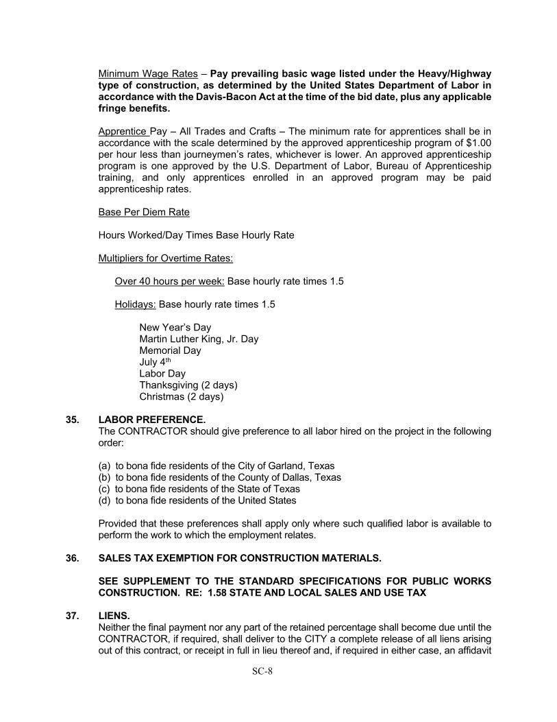
SC-8
Minimum Wage Rates – Pay prevailing basic wage listed under the Heavy/Highway type of construction, as determined by the United States Department of Labor in accordance with the Davis-Bacon Act at the time of the bid date, plus any applicable fringe benefits.
Apprentice Pay – All Trades and Crafts – The minimum rate for apprentices shall be in accordance with the scale determined by the approved apprenticeship program of $1.00 per hour less than journeymen’s rates, whichever is lower. An approved apprenticeship program is one approved by the U.S. Department of Labor, Bureau of Apprenticeship training, and only apprentices enrolled in an approved program may be paid apprenticeship rates. Base Per Diem Rate Hours Worked/Day Times Base Hourly Rate Multipliers for Overtime Rates:
Over 40 hours per week: Base hourly rate times 1.5 Holidays: Base hourly rate times 1.5
New Year’s Day Martin Luther King, Jr. Day Memorial Day July 4th Labor Day Thanksgiving (2 days) Christmas (2 days)
35. LABOR PREFERENCE. The CONTRACTOR should give preference to all labor hired on the project in the following order:
(a) to bona fide residents of the City of Garland, Texas (b) to bona fide residents of the County of Dallas, Texas (c) to bona fide residents of the State of Texas (d) to bona fide residents of the United States
Provided that these preferences shall apply only where such qualified labor is available to perform the work to which the employment relates.
36. SALES TAX EXEMPTION FOR CONSTRUCTION MATERIALS.
SEE SUPPLEMENT TO THE STANDARD SPECIFICATIONS FOR PUBLIC WORKS CONSTRUCTION. RE: 1.58 STATE AND LOCAL SALES AND USE TAX
37. LIENS. Neither the final payment nor any part of the retained percentage shall become due until the CONTRACTOR, if required, shall deliver to the CITY a complete release of all liens arising out of this contract, or receipt in full in lieu thereof and, if required in either case, an affidavit

SC-9
that so far as he has knowledge or information the releases and receipts include all the labor and material for which a lien could be filed; but the CONTRACTOR may, if any subcontractor refuses to furnish a release or receipt in full, furnish a bond satisfactory to the CITY, to indemnify the CITY against any lien. If any lien remains unsatisfied after all payments are made, the CONTRACTOR shall refund to the CITY all moneys that the latter may be compelled to pay in discharging such a lien, including all costs and a reasonable attorney's fee.
38. STEEL RAILINGS Not applicable for this Contract.
39. UNDERGROUND MARKING FOR WATER AND SEWER Not applicable for this Contract. 40. PRIVATE PROPERTY ACCESS.
The contractor shall not enter upon or use private property except as allowed by easements shown on the contract documents or if the contractor obtains specific written permission from the property owner.
41. COMPANY LOGO . All equipment used on the project shall be clearly marked with the contractor’s name and LOGO. Subcontractor equipment shall also be similarly marked.
42. CONSTRUCTION SEQUENCING. Not applicable for this contract.
43. TRENCH SAFETY SYSTEM Trench safety drawings and details are not provided within the plans. Trench safety and
shoring shall conform to all Codes, Regulations, Specifications and Laws of the City of Garland, State of Texas, and United States governments, with particular emphasis on all applicable requirements of Occupational Safety Health Administration (OSHA) Standards, OSHA 2207, Part 1926 and OSHA 2226.
The contractor shall provide trench shoring design. Such design shall be prepared, signed
and sealed by a Registered Professional Engineer (State of Texas). Such engineer shall carry liability insurance against errors and omission in the amount of $500,000 minimum. A copy of the policy binder shall be furnished to the City. Four (4) copies of the final report shall be provided to the City prior to the issuance of the notice to proceed for this project. The Trench Support System shall cover all excavations more than five feet (5') in depth. Such excavations shall be provided with a support system or some equivalent means of protection which will provide a safe environment for workmen. The minimum such support shall be a trench box consisting of a pre-fabricated movable trench shield composed of steel plates welded to a heavy steel frame. Other systems may consist of sheet-piling, shoring or bracing and must be approved by the City. All work, reports, and plans required herein shall be included in the price bid for other work. There shall be no extra pay item for trench safety design and implementation..
44. EROSION CONTROL. A Storm Water Pollution Prevention Plan (SWP3) shall be prepared by the Contractor. The Contractor and the City will be co-operators for the site as defined in the Texas Pollution

SC-10
Discharge Elimination System (TPDES) General Permit issued for storm water discharges from construction sites. Both the Contractor and the City will submit a Notice of Intent (NOI) as co-permitees to discharge storm water from sites that disturb more than 5 acres in compliance with the General Permit. Both the City and the Contractor will generate a construction site notice to discharge storm water from sites that disturb more than 1 acre in compliance with the General Permit.
All additional contractors and/or subcontractors whose activities impact the (SWP3) shall
sign a certification stating that they understand their responsibilities under the Plan. The SWP3 shall be prepared in accordance with the most current North Central Texas
Council of Governments (NCTCOG) best practices for construction activities manual (the BMP Manual) which has been adopted by the City of Garland as a means for compliance with the TPDES General Permit. All other SWP3's that may be prepared in relation to this project must comply with the BMP Manual and, ultimately, the TPDES General Permit. Copies of the BMP Manual are available at the offices of the North Central Texas Council of Governments and on the NCTCOG website.
All Site Operators/Contractors shall become familiar with and comply with all requirements
detailed in the NCTCOG BMP manual. 45. PERMIT-REQUIRED CONFINED SPACES.
The Contractor shall comply with the Occupational Safety and Health Administration (OSHA) Standards for permit- required spaces.
Title 29 Code of Federal Regulations Part 1910.146
Prior to construction, the Contractor shall provide a copy of a written program for permit-
required confined spaces. The program should be developed in accordance with OSHA standards.
46. DISCHARGE OF HEAVILY CHLORINATED WATER FROM WATER LINES
Not applicable for this contract. 47. AIR QUALITY MONITORING AND ACTION.
In cooperation with a region-wide effort, the City of Garland is attempting to decrease the amount of Volatile Organic Compounds released. The City will receive an Air Pollution Watch from TCEQ when a particular day is predicted to be a public health risk. An Air Pollution Warning is issued when air pollution levels reach unhealthy levels. When the Air Quality Index (AQI) is above 100 or noted as orange, red or purple an Air Pollution Warning is issued. This information will be relayed to the contractor as quickly as practical. The following steps will be taken by the contractor on designated Air Pollution watch or Warning days: - Utilize mass transit services or car pool if possible. - Use low emission diesel fuels. - Purchase low emission equipment by 2004. - Ban early morning use of heavy equipment by 2005. - Demonstrate emission reductions by 2002 in lieu of early morning ban and new
equipment purchase .

SC-11
- Limit driving or fueling of gasoline-powered vehicles whenever possible by rescheduling meetings and inspections until after 10:00 a.m. or until another working days.
- Limit the use of two-cycle gasoline powered engines until after 10:00 a.m. from May 1 to October 31.
- Refrain from using oil-based paints, paint thinners, and solvents until after 10:00 a.m. or until another working day.
In all cases, through discussions with the contractor, the City will make the final determination as to what activities should be limited, delayed, or deleted during unhealthy AQI days. Through these discussions, the City will also determine whether a working day should be charged if any limitations, delays or deletions are utilized in order to reduce emissions.
48. RIGHT TO AUDIT. The City shall have the right to examine and audit after reasonable notice any and all books and records of Seller/Contractor that may relate to this agreement including, without limitation, the performance of Seller/Contractor, its employees, agents, and subcontractors. Such books and records will be maintained in accordance with generally accepted accounting principles and shall, upon request and at Purchaser’s request, be made available at a location designated by Purchaser. Seller-Contractor shall, except for copying costs, otherwise bear all costs of producing such records for examination and copying by Purchaser. Unless otherwise agreed by the parties, such records must be made available to Purchaser within five business days. The provisions of this paragraph shall survive the termination of this agreement.
49. DISPOSAL OF MATERIAL. Excavated or surplus material may be disposed of at the City Landfill located at 3175 Elm Grove Road, Rowlett, TX 75089 based on the following fees and stipulations: Fill Dirt that is very clean and free of debris No Charge * Other Excavated or Surplus Material $35.00 Per Ton *
No Liquids No Hazardous Material No Tires All Material must be contained within typical 7-9 yard or smaller dump truck bed.
THE CONTRACTORS IS RESPONSIBLE FOR ALL COSTS (INCLUDING TIPPING FEES) ASSOCIATED WITH THE LEGAL DISPOSAL OF SURPLUS MATERIAL. THESE RATES AND FEES ARE PROVIDED FOR THE CONTRACTOR FOR USE ON THIS PROJECT ONLY.
PRIOR TO THE START OF CONSTRUCTION, THE CONTRACTOR SHALL IDENTIFY THE TRUCKS THAT WILL BE INVOLVED IN THE PROJECT. THIS IDENTIFICATION SHALL CONSIST OF LICENSE NUMBERS, IDENTIFICATIONS NUMBERS, ETC. THAT WILL FACILITATE THEIR ASSOCIATION WITH THIS PROJECT. TRUCKS THAT ARE NOT OR CANNOT BE IDENTIFIED WILL PAY FULL PRICE AT THE LANDFILL.
*THE PRICE INDICATED IS THE CURRENT RATE AT THE TIME OF ADVERTISEMENT
OF THE PROJECT. THE RATE IS SUBJECT TO CHANGE ON OCTOBER 1, ANNUALLY. CONTACT THE CITY LANDFILL AT (972) 205-3670 FOR RATE VERIFICATION.

SC-12
50. MOBILIZATION
A. Description: This item shall consist of the mobilization of personnel, equipment and supplies at the project site in preparation for commencing work on other contract items. Mobilization shall include, but is not limited to, the movement of equipment, personnel, material, supplies, etc., to the project site and the establishment of necessary field facilities.
B. Measurement: Measurement of the item “Mobilization” as specified herein, will be by the
“lump sum”, as the work progresses.
C. Payment: The price bid for mobilization may not exceed five (5) percent of the total contract amount for the project. Partial payments of the lump sum bid for mobilization will be as follows:
(1) When ten (10) days of contract time have elapsed, fifty (50) percent of the
mobilization lump sum bid will be paid on the following monthly payment. (2) When thirty (30) days of contract time have elapsed, one hundred (100)
percent of the mobilization lump sum bid will be paid on the following monthly payment, minus retainage.
(3) Upon completion of all work under this contract, payment for the remainder of the lump sum bid for mobilization will be made.
51. CONSTRUCTION CONTINGENCY Not applicable for this Contract. 52. REGULATION OF IRRIGATION SYSTEMS AND IRRIGATORS
Any new irrigation system, any extension to an existing irrigation system, and/or any replacement of an existing irrigation system must be installed by an irrigator who is licensed as such by the Texas Commission on Environmental Quality. Prior to installing a new irrigation system or installing/replacing a backflow device, the irrigator shall obtain a permit from the Building Inspection Department. Permit fees are waived for city projects. To obtain a permit, the irrigator must register with Building Inspections. The irrigator must present his/her TCEQ irrigator’s license and a government issued picture ID. A registration fee must be paid even when the work is for the city. It is the irrigator’s responsibility to design and install the system in conformance with the currently adopted TCEQ “Standards for Landscape Irrigation” as published in the TCEQ rules. Additionally, the irrigation system shall meet the City of Garland Water Conservation Plan, as published as Article VIII, Chapter 51 of the City of Garland Code of Ordinances.

SECTION IV
TECHNICAL SPECIFICATIONS
LIST OF TECHNICAL SPECIFICATIONS DIVISION 1 GENERAL REQUIREMENTS DIVISION 2 SITE WORK DIVISION 3 CONCRETE DIVISION 4 STEEL STRUCTURES DIVISION 5 WIRE, CABLE, AND ACCESSORIES DIVISION 6 ELECTRICAL RACEWAY SYSTEMS DIVISION 8 GROUNDING DIVISION 9 INSTALLATION OF MAJOR SUBSTATION EQUIPMENT

01000-1
DIVISION 1 - GENERAL REQUIREMENTS PART 1 - SUMMARY PROJECT DESCRIPTION: All labor, specified materials, and incidentals necessary for construction of the Garland Power & Light (GP&L) Apollo Substation. The work generally consists of erosion control, foundations, cable trench and conduit systems, grounding, drainage systems, structure erection, equipment installation, high and medium voltage bus and conductor installation, electrical service systems, control cabling including terminations, fiber optic and coaxial cable including terminations, overhead lightning shielding, emergency generator system, site landscaping and irrigation, flexible base restoration, yard surfacing and all labor, equipment, miscellaneous materials and incidentals necessary to construct the project. The project construction under this contract is the third phase of the overall substation project. Phase 1 work is complete and involved construction of temporary onsite power distribution transformer and autotransformer substation facilities and permanent underground distribution feeder systems. The temporary substation facilities will remain in service for the duration of this contract. Phase 2 work currently being performed under a separate contract generally consists of principal civil site improvements including demolition, grading, drainage, water utilities, paving, fencing, limited ground grid installation, limited conduit installation, and construction of a flexible base subgrade pad. The Phase 2 contractor’s work will be complete prior to mobilization under this contract. The anticipated mobilization date for this contract is March 27, 2020. The breaker and a half configuration substation is configured for five (5) incoming 138kV three phase transmission lines. These transmission lines will be brought into the substation by others and are not a part of this contract. Transmission line terminations by others will end at the line side of high voltage switches on the substation transmission line termination structures. All steel structures, including dead end structures, bus supports, switch stands, instrument transformer stands, distribution bays, and all other substation equipment support structures (other than foundations) indicated on the drawings, will be furnished by GP&L and installed by the Contractor on foundations constructed by the Contractor. A complete substation ground grid, including connection to structures and equipment will be installed by the Contractor. All materials for grounding system construction, except Ground Enhancement Material (GEM), will be provided by GP&L. All foundations indicated on the drawings shall be constructed by the Contractor as part of the contract. This includes but is not limited to all necessary surveying, excavation, temporary casing, slurry, removal of spoils, forming materials, reinforcing steel (rebar), concrete, backfilling, material testing, and all labor and equipment to construct the foundations in accordance with the drawings. Anchor bolts will be provided to the Contractor by GP&L. Civil site improvements indicated on the drawings shall be constructed by the Contractor as part of the contract. This includes but is not limited to all necessary surveying, removal of spoils, grounding system, conduit systems, cable trench systems, cable trench drainage systems, transformer containment stormwater drainage systems, testing, trench safety, temporary excavation shoring, flexible base restoration, backfilling, gravel surfacing, vegetative stabilization, erosion control measures during construction, landscaping, irrigation, and all other work required to provide a

DIVISION 1 - GENERAL REQUIREMENTS: continued
01000-2
completed site in accordance with the project plans, details, and specifications. Staking for construction shall be provided by the Contractor in accordance with these specifications. All electrical components and substation steel structures indicated on the drawings will be installed by the Contractor on foundations provided by the Contractor. GP&L will provide all materials for high and medium voltage conductors, substation power service conductors, substation control cabling, and site lighting conductors; all to be installed and terminated by the Contractor. Fiber optic cable and innerduct to be installed and terminated by the Contractor. All conduit systems including pull boxes pull strings, testing, and terminations shall be installed by the Contractor. Control house installation (except stairs/landings), installation and dressout of 138kV/13.2kV power transformers, substation commissioning, substation energizing and related testing activities, SCADA; and items related to substation startup will be performed by GP&L or their designated subcontractor. Drawings provided by GP&L are not to scale. It shall be the responsibility of the Contractor to verify all dimensions on the drawings, and construct facilities accordingly. Bidders shall have a minimum of 5 years of experience in substations construction prior to the current bid and shall be able to provide at least 3 references from previous substation contracts. PART 2 – SPECIFICATION DRAWING LIST
The list of Specification drawings is shown below:
DWG. NO. TITLE AP-900-1 BILL OF MATERIALS (SHEET 1 OF 4) AP-900-2 BILL OF MATERIALS (SHEET 2 OF 4) AP-900-3 BILL OF MATERIALS (SHEET 3 OF 4) AP-900-4 BILL OF MATERIALS (SHEET 4 OF 4) AP-1000 SUBSTATION SITE LAYOUT AP-1001-1 EQUIPMENT LAYOUT (SHEET 1 OF 6) AP-1001-2 EQUIPMENT LAYOUT (SHEET 2 OF 6) AP-1001-3 EQUIPMENT LAYOUT (SHEET 3 OF 6) AP-1001-4 EQUIPMENT LAYOUT (SHEET 4 OF 6) AP-1001-5 EQUIPMENT LAYOUT (SHEET 5 OF 6) AP-1001-6 EQUIPMENT LAYOUT (SHEET 6 OF 6) AP-1002-1 SUBSTATION EQUIPMENT ELEVATION SECTIONS & DETAILS (SHEET 1 OF 10) AP-1002-2 SUBSTATION EQUIPMENT ELEVATION SECTIONS & DETAILS (SHEET 2 OF 10) AP-1002-3 SUBSTATION EQUIPMENT ELEVATION SECTIONS & DETAILS (SHEET 3 OF 10) AP-1002-4 SUBSTATION EQUIPMENT ELEVATION SECTIONS & DETAILS (SHEET 4 OF 10) AP-1002-5 SUBSTATION EQUIPMENT ELEVATION SECTIONS & DETAILS (SHEET 5 OF 10) AP-1002-6 SUBSTATION EQUIPMENT ELEVATION SECTIONS & DETAILS (SHEET 6 OF 10) AP-1002-7 SUBSTATION EQUIPMENT ELEVATION SECTIONS & DETAILS (SHEET 7 OF 10) AP-1002-8 SUBSTATION EQUIPMENT ELEVATION SECTIONS & DETAILS (SHEET 8 OF 10) AP-1002-9 SUBSTATION EQUIPMENT ELEVATION SECTIONS & DETAILS (SHEET 9 OF 10) AP-1002-10 SUBSTATION EQUIPMENT ELEVATION SECTIONS & DETAILS (SHEET 10 OF 10) AP-1004-1 PLAT (SHEET 1 OF 2) AP-1004-2 PLAT (SHEET 2 OF 2) AP-1005-1A LEGEND, PROJECT CONTROL & PROJECT NOTES - PHASE 2 AP-1005-3B ESTIMATED QUANTITY SUMMARY - PHASE 2 AP-1007-1 GRADING AND YARD SURFACING PLAN

DIVISION 1 - GENERAL REQUIREMENTS: continued
01000-3
DWG. NO. TITLE AP-1007-2 DETAILED GRADING & YARD SURFACE PLAN AP-1007-3 DRIVEWAY PAVING & DETAILED GRADING PLAN AP-1007-4 WATER PLAN AP-1008-1 PROPOSED CONDITIONS DRAINAGE AREA MAP AP-1008-2 STORM CULVERT SD-1 PLAN & PROFILE AP-1008-4 TRANSFORMER SUMP & CABLE TRENCH DRAINS PLAN AP-1008-7 TRANSFORMER SUMP PUMP DETAILS L-1.0 LANDSCAPE PLAN L-1.1 LANDSCAPE DETAILS IR-1.0 IRRIGATION PLAN IR-1.1 IRRIGATION DETAILS AP-1012-1 CONDUIT & CABLE TRENCH LAYOUT & DETAILS (SHEET 1 OF 7) AP-1012-2 CONDUIT & CABLE TRENCH LAYOUT & DETAILS (SHEET 2 OF 7) AP-1012-3 CONDUIT & CABLE TRENCH LAYOUT & DETAILS (SHEET 3 OF 7) AP-1012-3A SOUTHWEST GATE CONDUIT LAYOUT & DETAILS (PHASE 1) AP-1012-4 CONDUIT & CABLE TRENCH LAYOUT & DETAILS (SHEET 4 OF 7) AP-1012-5 CONDUIT & CABLE TRENCH LAYOUT & DETAILS (SHEET 5 OF 7) AP-1012-6 CONDUIT & CABLE TRENCH LAYOUT & DETAILS (SHEET 6 OF 7) AP-1012-7 CONDUIT & CABLE TRENCH LAYOUT & DETAILS (SHEET 7 OF 7) AP-1013-1 CONDUIT SCHEDULE (SHEET 1 OF 5) AP-1013-2 CONDUIT SCHEDULE (SHEET 2 OF 5) AP-1013-3 CONDUIT SCHEDULE (SHEET 3 OF 5) AP-1013-4 CONDUIT SCHEDULE (SHEET 4 OF 5) AP-1013-5 CONDUIT SCHEDULE (SHEET 5 OF 5) AP-1014-1 FOUNDATION LAYOUT (SHEET 1 OF 6) AP-1014-2 FOUNDATION LAYOUT (SHEET 2 OF 6) AP-1014-3 FOUNDATION LAYOUT (SHEET 3 OF 6) AP-1014-4 FOUNDATION LAYOUT (SHEET 4 OF 6) AP-1014-5 FOUNDATION LAYOUT (SHEET 5 OF 6) AP-1014-6 FOUNDATION LAYOUT (SHEET 6 OF 6) AP-1014D-1 EXISTING SUBSTATION FOUNDATIONS DEMOLITION PLAN (SHEET 1 OF 3) AP-1014D-2 EXISTING SUBSTATION FOUNDATIONS DEMOLITION PLAN (SHEET 2 OF 3) AP-1014D-3 EXISTING SUBSTATION FOUNDATIONS DEMOLITION PLAN (SHEET 3 OF 3) AP-1015-1 FOUNDATION DETAILS (SHEET 1 OF 9) AP-1015-2 FOUNDATION DETAILS (SHEET 2 OF 9) AP-1015-3 FOUNDATION DETAILS (SHEET 3 OF 9) AP-1015-4 FOUNDATION DETAILS (SHEET 4 OF 9) AP-1015-5 FOUNDATION DETAILS (SHEET 5 OF 9) AP-1015-6 FOUNDATION DETAILS (SHEET 6 OF 9) AP-1015-7 FOUNDATION DETAILS (SHEET 7 OF 9) AP-1015-8 FOUNDATION DETAILS (SHEET 8 OF 9) AP-1015-9 FOUNDATION DETAILS (SHEET 9 OF 9) AP-1015-AB FOUNDATION ANCHOR BOLT DETAILS & SCHEDULE AP-1016-1 LUMINAIRE & LIGHTING DETAILS (SHEET 1 OF 2) AP-1016-2 LUMINAIRE & LIGHTING DETAILS (SHEET 2 OF 2) AP-1017-1 ELECTRICAL EQUIPMENT CONDUIT CONNECTION DETAILS (SHEET 1 OF 3) AP-1017-2 ELECTRICAL EQUIPMENT CONDUIT CONNECTION DETAILS (SHEET 2 OF 3)

DIVISION 1 - GENERAL REQUIREMENTS: continued
01000-4
DWG. NO. TITLE AP-1017-3 ELECTRICAL EQUIPMENT CONDUIT CONNECTION DETAILS (SHEET 2 OF 3) AP-1018-1 DIRECT LIGHTNING STRIKE SHIELDING PLAN (SHEET 1 OF 2) AP-1018-2 DIRECT LIGHTNING STRIKE SHIELDING PLAN (SHEET 2 OF 2) AP-1019-1 BUS LAYOUT (SHEET 1 OF 4) AP-1019-2 BUS LAYOUT (SHEET 2 OF 4) AP-1019-3 BUS LAYOUT (SHEET 3 OF 4) AP-1019-4 BUS LAYOUT (SHEET 4 OF 4) AP-1020-1 SUBSTATION BUS INSTALLATION SPECIFICATIONS AP-1021-1 BUS CUTTING TABLE (SHEET 1 OF 2) AP-1021-2 BUS CUTTING TABLE (SHEET 2 OF 2) AP-1030-1 PHASE 2 GROUNDING LAYOUT & DETAILS (SHEET 1 OF 12) AP-1030-2 PHASE 2 GROUNDING LAYOUT & DETAILS (SHEET 2 OF 12) AP-1030-2A PHASE 1 GROUNDING LAYOUT (SHEET 2A OF 10) AP-1030-2B PHASE 1 GROUNDING SLEEVE LAYOUT & BILL OF MATERIALS (SHEET 2B OF
10) AP-1030-3 PHASE 2 GROUNDING LAYOUT & DETAILS (SHEET 3 OF 12) AP-1030-4 PHASE 2 GROUNDING LAYOUT & DETAILS (SHEET 4 OF 12) AP-1030-5 PHASE 2 GROUNDING LAYOUT & DETAILS (SHEET 5 OF 12) AP-1030-6 PHASE 2 GROUNDING LAYOUT & DETAILS (SHEET 6 OF 12) AP-1030-7 PHASE 2 GROUNDING LAYOUT & DETAILS (SHEET 7 OF 12) AP-1030-8 PHASE 2 GROUNDING LAYOUT & DETAILS (SHEET 8 OF 12) AP-1030-9 PHASE 2 GROUNDING LAYOUT & DETAILS (SHEET 9 OF 12) AP-1030-10 PHASE 2 GROUNDING LAYOUT & DETAILS (SHEET 10 OF 12) AP-1030-11 PHASE 2 GROUNDING LAYOUT & DETAILS (SHEET 11 OF 12) AP-1030-12 PHASE 2 GROUNDING LAYOUT & DETAILS (SHEET 12 OF 12) AP-2000-1 TOPOLOGY SKETCH (FINAL) AP-2000-2 TOPOLOGY SKETCH (FINAL WITH AUTO) AP-2001-1 SIMPLIFIED ONE-LINE DIAGRAM AP-2001-2 SIMPLIFIED ONE-LINE DIAGRAM AP-2002-1 DETAILED ONE-LINE DIAGRAM SHEET 1 AP-2002-2 DETAILED ONE-LINE DIAGRAM SHEET 2 AP-2002-3 DETAILED ONE-LINE DIAGRAM SHEET 3 AP-2003-1 STATION SERVICE ONE-LINE DIAGRAM AP-2003-2 DC PANELS 1 & 2 AP-2003-3 DC PANELS 1A & 2A AP-2003-4 AC PANEL SCHEDULES AP-2004-1 THREE-LINE DIAGRAM, XFMR T1 FEEDER, GCB1910 & GCB1920 BF AP-2004-2 THREE-LINE DIAGRAM, XFMR T2 FEEDER, GCB1930 BF AP-2004-3 THREE-LINE DIAGRAM, AP-NA LINE, GCB1935 & GCB1940 BF AP-2004-4 THREE-LINE DIAGRAM, AP-JU (FUTURE) LINE, GCB1955 BF AP-2004-5 THREE-LINE DIAGRAM, AP-LK LINE, GCB1960, GCB1955 BF AP-2004-6 THREE-LINE DIAGRAM, AP-ER LINE & METERING, GCB1975 BF AP-2004-7 THREE-LINE DIAGRAM, AP-HF LINE, GCB1980 & GCB1975 BF AP-2004-8 THREE-LINE DIAGRAM, 138kV SOUTH BUS AP-2004-9 THREE-LINE DIAGRAM, 138KV NORTH BUS AP-2004-10 THREE-LINE DIAGRAM, XFMR T1 AP-2004-11 THREE-LINE DIAGRAM, 13.2kV BUS DIFFERENTIALS

DIVISION 1 - GENERAL REQUIREMENTS: continued
01000-5
DWG. NO. TITLE AP-2004-12 THREE-LINE DIAGRAM, 13.2KV FEEDERS AP-1 & AP-3 AP-2004-13 THREE-LINE DIAGRAM, 13.2KV FEEDERS AP-5, APBT-1 & AP-2 AP-2004-14 THREE-LINE DIAGRAM, 13.2KV FEEDERS AP-4 & AP-6 AP-2004-15 THREE-LINE DIAGRAM, XFMR T2 AP-2006-1 PANEL ELEVATIONS AP-2006-2 PANEL ELEVATIONS AP-2006-3 PANEL ELEVATIONS AP-2006-4 PANEL ELEVATIONS AP-2006-5 PANEL ELEVATIONS AP-2007-1 SCADA DIAGRAM 138kV CONTROL ENCLOSURE AP-2007-2 SCADA DIAGRAM 12.47kV CONTROL ENCLOSURE AP-2007-3 SCADA DIAGRAM IRIG-B SCHEDULES & BOM AP-2007-4 SCADA DIAGRAM FIBER OPTIC SCHEDULES & BOM AP-2007-5 SCADA DIAGRAM MISC CABLES & PARTS SCHEDULES & BOM AP-2008-1 MODULAR EQUIPMENT ENCLOSURE PLAN AP-2008-2 MODULAR EQUIPMENT ENCLOSURE CABLE TRAY PLAN AP-2008-3 MODULAR EQUIPMENT ENCLOSURE LIGHTING PLAN AP-2008-4 MODULAR EQUIPMENT ENCLOSURE FLOOR PENETRATIONS AP-2008-5 MODULAR EQUIPMENT ENCLOSURE WALL ELEVATIONS AP-2008-6 MODULAR EQUIPMENT ENCLOSURE EXTERIOR ELEVATIONS AP-2008-7 MODULAR EQUIPMENT ENCLOSURE EXTERIOR ELEVATIONS AP-2008-8 MODULAR EQUIPMENT ENCLOSURE WIRING TRAY & GROUNDING AP-2008-9 MODULAR EQUIPMENT ENCLOSURE STAIRS & PLATFORM DETAILS AP-2008-10 MODULAR EQUIPMENT ENCLOSURE BoM AP-2009-1 TYPICAL RELAY PANEL STRUCTURE AP-2009-2 TERMINATION CABINET STRUCTURE AP-2010-1 RELAY PANEL BILL OF MATERIALS AP-2010-2 RELAY PANEL BILL OF MATERIALS AP-2010-3 RELAY PANEL BILL OF MATERIALS AP-2011-1 BUS DIFFERENTIAL RELAY PANEL NO. 1 138KV BUS NO. 1 SHEET 1 OF 8 AP-2011-2 BUS DIFFERENTIAL BUS NO. 1 RELAY PANEL #1 WIRING SHEET 2 OF 8 AP-2011-3 BUS DIFFERENTIAL BUS NO. 1 RELAY PANEL #1 WIRING SHEET 3 OF 8 AP-2011-4 BUS DIFFERENTIAL BUS NO. 1 RELAY PANEL #1 WIRING SHEET 4 OF 8 AP-2011-5 BUS DIFFERENTIAL 138kV BUS NO. 1 PRI. DIFF SCHEMATICS SHEET 5 OF 8 AP-2011-6 BUS DIFFERENTIAL 138kV BUS NO. 1 BU. DIFF SCHEMATICS SHEET 6 OF 8 AP-2011-7 BUS DIFFERENTIAL 138kV BUS NO. 1 PRI. TRIP SCHEMATICS SHEET 7 OF 8 AP-2011-8 BUS DIFFERENTIAL 138kV BUS NO. 1 BU. TRIP SCHEMATICS SHEET 8 OF 8 AP-2012-1 DBDB XFMR FDR RELAY PANEL NO. 2 XFMR. NO. 1 FDR SHEET 1 OF 12 AP-2012-2 CB1.5 XFMR FDR XFMR. NO. 1 FDR PANEL NO. 2 WIRING SHEET 2 OF 12 AP-2012-3 CB1.5 XFMR FDR XFMR. NO. 1 FDR PANEL NO. 2 WIRING SHEET 3 OF 12 AP-2012-4 CB1.5 XFMR FDR XFMR. NO. 1 FDR PANEL NO. 2 WIRING SHEET 4 OF 12 AP-2012-5 CB1.5 XFMR FDR XFMR. NO. 1 FDR SCHEMATICS SHEET 5 OF 12 AP-2012-6 CB1.5 XFMR FDR XFMR. NO. 1 FDR SCHEMATICS SHEET 6 OF 12 AP-2012-7 CB1.5 XFMR FDR GCB 1910 BREAKER FAILURE SCHEMATICS SHEET 7 OF 12 AP-2012-8 CB1.5 XFMR FDR GCB 1910 BREAKER FAILURE SCHEMATICS SHEET 8 OF 12 AP-2012-9 CB1.5 XFMR FDR GCB 1910 TRIP 1 SCHEMATIC SH 9 OF 12 AP-2012-10 CB1.5 XFMR FDR GCB 1910 TRIP 2 SCHEMATIC SH 10 OF 12

DIVISION 1 - GENERAL REQUIREMENTS: continued
01000-6
DWG. NO. TITLE AP-2012-11 CB1.5 XFMR FDR GCB 1910 CLOSE SCHEMATIC SH 11 OF 12 AP-2012-12 CB1.5 XFMR FDR GCB 1910 SEL-2515 & MISC SCHEM SH 12 OF 12 AP-2013-1 DBDB TIE RELAY PANEL NO. 3 TIE GCB 1920 SHEET 1 OF 9 AP-2013-2 DBDB TIE GCB 1920 RELAY PANEL NO. 3 WIRING SHEET 2 OF 9 AP-2013-3 DBDB TIE GCB 1920 RELAY PANEL NO. 3 WIRING SHEET 3 OF 9 AP-2013-4 DBDB TIE GCB 1920 BREAKER FAILURE SCHEMATICS SHEET 4 OF 9 AP-2013-5 DBDB TIE GCB 1920 BREAKER FAILURE SCHEMATICS SHEET 5 OF 9 AP-2013-6 DBDB TIE GCB 1920 TRIP 1 SCHEMATIC SH 6 OF 9 AP-2013-7 DBDB TIE GCB 1920 TRIP 2 SCHEMATIC SH 7 OF 9 AP-2013-8 DBDB TIE GCB 1920 CLOSE SCHEMATIC SH 8 OF 9 AP-2013-9 DBDB TIE GCB 1920 CONTACTS, HTR, LT, & MOTOR CKTS SH 9 OF 9 AP-2014-1 CB1.5 XFMR FDR RELAY PANEL NO. 4 XFMR. NO. 2 FDR SHEET 1 OF 12 AP-2014-2 CB1.5 XFMR FDR XFMR. NO. 2 FDR PANEL NO. 4 WIRING SHEET 2 OF 12 AP-2014-3 CB1.5 XFMR FDR XFMR NO. 2 FDR PANEL NO. 4 WIRING SHEET 3 OF 12 AP-2014-4 CB1.5 XFMR FDR XFMR. NO. 2 FDR PANEL NO. 4 WIRING SHEET 4 OF 12 AP-2014-5 CB1.5 XFMR FDR XFMR. NO. 2 FDR SCHEMATICS SHEET 5 OF 12 AP-2014-6 CB1.5 XFMR FDR XFMR. NO. 2 FDR SCHEMATICS SHEET 6 OF 12 AP-2014-7 CB1.5 XFMR FDR GCB 1930 BREAKER FAILURE SCHEMATICS SHEET 7 OF 12 AP-2014-8 CB1.5 XFMR FDR GCB 1930 BREAKER FAILURE SCHEMATICS SHEET 8 OF 12 AP-2014-9 CB1.5 XFMR FDR GCB 1930 TRIP 1 SCHEMATICS SHEET 9 OF 12 AP-2014-10 CB1.5 XFMR FDR GCB 1930 TRIP 2 SCHEMATIC SH 10 OF 12 AP-2014-11 CB1.5 XFMR FDR GCB 1930 CLOSE SCHEMATIC SH 11 OF 12 AP-2014-12 CB1.5 XFMR FDR GCB 1930 CONTACTS, HTR, LT, & MOTOR CKTS SH 12 OF 12 AP-2015-1 SINGLE CB TIE RELAY PANEL NO. 5 TIE GCB 1935 SHEET 1 OF 9 AP-2015-2 SINGLE CB TIE GCB 1935 RELAY PANEL NO. 5 WIRING SHEET 2 OF 9 AP-2015-3 SINGLE CB TIE GCB 1935 RELAY PANEL NO. 5 WIRING SHEET 3 OF 9 AP-2015-4 SINGLE CB TIE GCB 1935 BREAKER FAILURE SCHEMATICS SHEET 4 OF 9 AP-2015-5 SINGLE CB TIE GCB 1935 BREAKER FAILURE SCHEMATICS SHEET 5 OF 9 AP-2015-6 SINGLE CB TIE GCB 1935 TRIP 1 SCHEMATIC SH 6 OF 9 AP-2015-7 SINGLE CB TIE GCB 1935 TRIP 2 SCHEMATIC SH 7 OF 9 AP-2015-8 SINGLE CB TIE GCB 1935 CLOSE SCHEMATIC SH 8 OF 9 AP-2015-9 SINGLE CB TIE GCB 1935 CONTACTS, HTR, LT, & MOTOR CKTS SH 9 OF 9 AP-2016-1 CB1.5 D87L RELAY PANEL NO. 6 AP-NA LINE SHEET 1 OF 11 AP-2016-2 CB1.5 D87L AP-NA LINE RELAY PANEL NO. 6 WIRING SHEET 2 OF 11 AP-2016-3 CB1.5 D87L AP-NA LINE RELAY PANEL NO. 6 WIRING SHEET 3 OF 11 AP-2016-4 CB1.5 D87L AP-NA LINE RELAY PANEL NO. 6 WIRING SHEET 4 OF 11 AP-2016-5 CB1.5 D87L AP-NA LINE RELAY SCHEMATICS SHEET 5 OF 11 AP-2016-6 CB1.5 D87L GCB 1940 BREAKER FAILURE SCHEMATICS SHEET 6 OF 11 AP-2016-7 CB1.5 D87L GCB 1940 BREAKER FAILURE SCHEMATICS SHEET 7 OF 11 AP-2016-8 CB1.5 D87L GCB 1940 TRIP 1 SCHEMATIC SH 8 OF 11 AP-2016-9 CB1.5 D87L GCB 1940 TRIP 2 SCHEMATIC SH 9 OF 11 AP-2016-10 CB1.5 D87L GCB 1940 CLOSE SCHEMATIC SH 10 OF 11 AP-2016-11 CB1.5 D87L GCB 1940 CONTACTS, HTR, LT, & MOTOR CKTS SH 11 OF 11 AP-2017-1 CB1.5 D87L RELAY PANEL NO. 7 AP-JU LINE SHEET 1 OF 11 AP-2017-2 CB1.5 D87L AP-JU LINE RELAY PANEL NO. 7 WIRING SHEET 2 OF 11 AP-2017-3 CB1.5 D87L AP-JU LINE RELAY PANEL NO. 7 WIRING SHEET 3 OF 11 AP-2017-4 CB1.5 D87L AP-JU LINE RELAY PANEL NO. 7 WIRING SHEET 4 OF 11
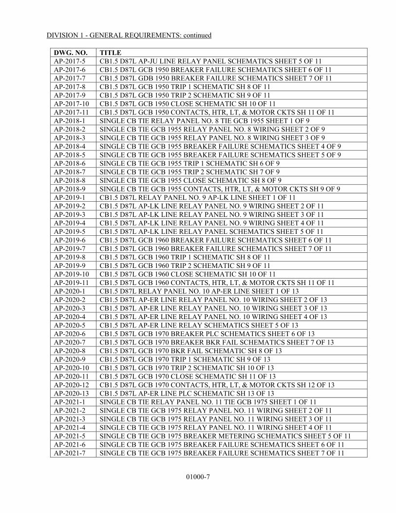
DIVISION 1 - GENERAL REQUIREMENTS: continued
01000-7
DWG. NO. TITLE AP-2017-5 CB1.5 D87L AP-JU LINE RELAY PANEL SCHEMATICS SHEET 5 OF 11 AP-2017-6 CB1.5 D87L GCB 1950 BREAKER FAILURE SCHEMATICS SHEET 6 OF 11 AP-2017-7 CB1.5 D87L GDB 1950 BREAKER FAILURE SCHEMATICS SHEET 7 OF 11 AP-2017-8 CB1.5 D87L GCB 1950 TRIP 1 SCHEMATIC SH 8 OF 11 AP-2017-9 CB1.5 D87L GCB 1950 TRIP 2 SCHEMATIC SH 9 OF 11 AP-2017-10 CB1.5 D87L GCB 1950 CLOSE SCHEMATIC SH 10 OF 11 AP-2017-11 CB1.5 D87L GCB 1950 CONTACTS, HTR, LT, & MOTOR CKTS SH 11 OF 11 AP-2018-1 SINGLE CB TIE RELAY PANEL NO. 8 TIE GCB 1955 SHEET 1 OF 9 AP-2018-2 SINGLE CB TIE GCB 1955 RELAY PANEL NO. 8 WIRING SHEET 2 OF 9 AP-2018-3 SINGLE CB TIE GCB 1955 RELAY PANEL NO. 8 WIRING SHEET 3 OF 9 AP-2018-4 SINGLE CB TIE GCB 1955 BREAKER FAILURE SCHEMATICS SHEET 4 OF 9 AP-2018-5 SINGLE CB TIE GCB 1955 BREAKER FAILURE SCHEMATICS SHEET 5 OF 9 AP-2018-6 SINGLE CB TIE GCB 1955 TRIP 1 SCHEMATIC SH 6 OF 9 AP-2018-7 SINGLE CB TIE GCB 1955 TRIP 2 SCHEMATIC SH 7 OF 9 AP-2018-8 SINGLE CB TIE GCB 1955 CLOSE SCHEMATIC SH 8 OF 9 AP-2018-9 SINGLE CB TIE GCB 1955 CONTACTS, HTR, LT, & MOTOR CKTS SH 9 OF 9 AP-2019-1 CB1.5 D87L RELAY PANEL NO. 9 AP-LK LINE SHEET 1 OF 11 AP-2019-2 CB1.5 D87L AP-LK LINE RELAY PANEL NO. 9 WIRING SHEET 2 OF 11 AP-2019-3 CB1.5 D87L AP-LK LINE RELAY PANEL NO. 9 WIRING SHEET 3 OF 11 AP-2019-4 CB1.5 D87L AP-LK LINE RELAY PANEL NO. 9 WIRING SHEET 4 OF 11 AP-2019-5 CB1.5 D87L AP-LK LINE RELAY PANEL SCHEMATICS SHEET 5 OF 11 AP-2019-6 CB1.5 D87L GCB 1960 BREAKER FAILURE SCHEMATICS SHEET 6 OF 11 AP-2019-7 CB1.5 D87L GCB 1960 BREAKER FAILURE SCHEMATICS SHEET 7 OF 11 AP-2019-8 CB1.5 D87L GCB 1960 TRIP 1 SCHEMATIC SH 8 OF 11 AP-2019-9 CB1.5 D87L GCB 1960 TRIP 2 SCHEMATIC SH 9 OF 11 AP-2019-10 CB1.5 D87L GCB 1960 CLOSE SCHEMATIC SH 10 OF 11 AP-2019-11 CB1.5 D87L GCB 1960 CONTACTS, HTR, LT, & MOTOR CKTS SH 11 OF 11 AP-2020-1 CB1.5 D87L RELAY PANEL NO. 10 AP-ER LINE SHEET 1 OF 13 AP-2020-2 CB1.5 D87L AP-ER LINE RELAY PANEL NO. 10 WIRING SHEET 2 OF 13 AP-2020-3 CB1.5 D87L AP-ER LINE RELAY PANEL NO. 10 WIRING SHEET 3 OF 13 AP-2020-4 CB1.5 D87L AP-ER LINE RELAY PANEL NO. 10 WIRING SHEET 4 OF 13 AP-2020-5 CB1.5 D87L AP-ER LINE RELAY SCHEMATICS SHEET 5 OF 13 AP-2020-6 CB1.5 D87L GCB 1970 BREAKER PLC SCHEMATICS SHEET 6 OF 13 AP-2020-7 CB1.5 D87L GCB 1970 BREAKER BKR FAIL SCHEMATICS SHEET 7 OF 13 AP-2020-8 CB1.5 D87L GCB 1970 BKR FAIL SCHEMATIC SH 8 OF 13 AP-2020-9 CB1.5 D87L GCB 1970 TRIP 1 SCHEMATIC SH 9 OF 13 AP-2020-10 CB1.5 D87L GCB 1970 TRIP 2 SCHEMATIC SH 10 OF 13 AP-2020-11 CB1.5 D87L GCB 1970 CLOSE SCHEMATIC SH 11 OF 13 AP-2020-12 CB1.5 D87L GCB 1970 CONTACTS, HTR, LT, & MOTOR CKTS SH 12 OF 13 AP-2020-13 CB1.5 D87L AP-ER LINE PLC SCHEMATIC SH 13 OF 13 AP-2021-1 SINGLE CB TIE RELAY PANEL NO. 11 TIE GCB 1975 SHEET 1 OF 11 AP-2021-2 SINGLE CB TIE GCB 1975 RELAY PANEL NO. 11 WIRING SHEET 2 OF 11 AP-2021-3 SINGLE CB TIE GCB 1975 RELAY PANEL NO. 11 WIRING SHEET 3 OF 11 AP-2021-4 SINGLE CB TIE GCB 1975 RELAY PANEL NO. 11 WIRING SHEET 4 OF 11 AP-2021-5 SINGLE CB TIE GCB 1975 BREAKER METERING SCHEMATICS SHEET 5 OF 11 AP-2021-6 SINGLE CB TIE GCB 1975 BREAKER FAILURE SCHEMATICS SHEET 6 OF 11 AP-2021-7 SINGLE CB TIE GCB 1975 BREAKER FAILURE SCHEMATICS SHEET 7 OF 11

DIVISION 1 - GENERAL REQUIREMENTS: continued
01000-8
DWG. NO. TITLE AP-2021-8 SINGLE CB TIE GCB 1975 TRIP 1 SCHEMATIC SH 8 OF 11 AP-2021-9 SINGLE CB TIE GCB 1975 TRIP 2 SCHEMATIC SH 9 OF 11 AP-2021-10 SINGLE CB TIE GCB 1975 CLOSE SCHEMATIC SH 10 OF 11 AP-2021-11 SINGLE CB TIE GCB 1975 CONTACTS, HTR, LT, & MOTOR CKTS SH 11 OF 11 AP-2022-1 CB1.5 D87L RELAY PANEL NO. 12 AP-FUT. LINE SHEET 1 OF 11 AP-2022-2 CB1.5 D87L AP-FUT. LINE RELAY PANEL NO. 12 WIRING SHEET 2 OF 11 AP-2022-3 CB1.5 D87L AP-FUT. LINE RELAY PANEL NO. 12 WIRING SHEET 3 OF 11 AP-2022-4 CB1.5 D87L AP-FUT. LINE RELAY PANEL NO. 12 WIRING SHEET 4 OF 11 AP-2022-5 CB1.5 D87L AP-FUT. LINE RELAY SCHEMATICS SHEET 5 OF 11 AP-2022-6 CB1.5 D87L GCB 1980 BREAKER FAILURE SCHEMATICS SHEET 6 OF 11 AP-2022-7 CB1.5 D87L GCB 1980 BREAKER FAILURE SCHEMATICS SHEET 7 OF 11 AP-2022-8 CB1.5 D87L GCB 1980 TRIP 1 SCHEMATIC SH 8 OF 11 AP-2022-9 CB1.5 D87L GCB 1980 TRIP 2 SCHEMATIC SH 9 OF 11 AP-2022-10 CB1.5 D87L GCB 1980 CLOSE SCHEMATIC SH 10 OF 11 AP-2022-11 CB1.5 D87L GCB 1980 CONTACTS, HTR, LT, & MOTOR CKTS SH 11 OF 11 AP-2023-1 BUS DIFFERENTIAL RELAY PANEL NO. 13 138kV BUS NO. 2 SHEET 1 OF 8 AP-2023-2 BUS DIFFERENTIAL BUS NO. 2 RELAY PANEL #13 WIRING SHEET 2 OF 8 AP-2023-3 BUS DIFFERENTIAL BUS NO. 2 RELAY PANEL #13 WIRING SHEET 3 OF 8 AP-2023-4 BUS DIFFERENTIAL BUS NO. 2 RELAY PANEL #13 WIRING SHEET 4 OF 8 AP-2023-5 BUS DIFFERENTIAL 138kV BUS NO. 2 PRI. DIFF SCHEMATICS SHEET 5 OF 8 AP-2023-6 BUS DIFFERENTIAL 138kV BUS NO. 2 BU. DIFF SCHEMATICS SHEET 6 OF 8 AP-2023-7 BUS DIFFERENTIAL 138kV BUS NO. 2 PRI. TRIP SCHEMATICS SHEET 7 OF 8 AP-2023-8 BUS DIFFERENTIAL 138kV BUS NO. 2 BU. TRIP SCHEMATICS SHEET 8 OF 8 AP-2024-1 TRANSFORMER NO. 1 RELAY PANEL NO. 14 ELEVATION SHEET 1 OF 9 AP-2024-2 TRANSFORMER NO. 1 RELAY PANEL #14 WIRING SHEET 2 OF 9 AP-2024-3 TRANSFORMER NO. 1 RELAY PANEL #14 WIRING SHEET 3 OF 9 AP-2024-4 TRANSFORMER NO. 1 RELAY PANEL #14 WIRING SHEET 4 OF 9 AP-2024-5 TRANSFORMER NO. 1 PRI. DIFF SCHEMATICS SHEET 5 OF 9 AP-2024-6 TRANSFORMER NO. 1 BU. DIFF SCHEMATICS SHEET 6 OF 9 AP-2024-7 TRANSFORMER NO. 1 PRI. TRIP SCHEMATICS SHEET 7 OF 9 AP-2024-8 TRANSFORMER NO. 1 BU. TRIP SCHEMATICS SHEET 8 OF 9 AP-2024-9 CIRCUIT SWITCHER 1913 TRIP & CLOSE SCHEMATICS SHEET 9 OF 9 AP-2025-1 BUS DIFFERENTIAL RELAY PANEL NO. 15 12.5kV BUS NO. 1 SHEET 1 OF 7 AP-2025-2 BUS DIFFERENTIAL RELAY PANEL NO. 15 12.5kV BUS NO. 1 SHEET 2 OF 7 AP-2025-3 BUS DIFFERENTIAL RELAY PANEL NO. 15 12.5kV BUS NO. 1 SHEET 3 OF 7 AP-2025-4 BUS DIFFERENTIAL RELAY PANEL NO. 15 12.5kV BUS NO. 1 SHEET 4 OF 7 AP-2025-5 BUS DIFFERENTIAL 12.5kV BUS NO. 1 PRI. DIFF SCHEMATICS SHEET 5 OF 7 AP-2025-6 BUS DIFFERENTIAL 12.5kV BUS NO. 1 BU. DIFF SCHEMATICS SHEET 6 OF 7 AP-2025-7 BUS DIFFERENTIAL 12.5kV BUS NO. 1 MOTOR OPERATED DISC SHEET 7 OF 7 AP-2026-1 RELAY PANEL NO. 16 FEEDER AP-1 SHEET 1 OF 10 AP-2026-2 FEEDER AP-1 RELAY PANEL NO. 16 WIRING SHEET 2 OF 10 AP-2026-3 FEEDER AP-1 RELAY PANEL NO. 16 WIRING SHEET 3 OF 10 AP-2026-4 FEEDER AP-1 RELAY PANEL NO. 16 WIRING SHEET 4 OF 10 AP-2026-5 FEEDER AP-1 RELAY PANEL NO. 16 SCHEMATICS SHEET 5 OF 10 AP-2026-6 FEEDER AP-1 RELAY PANEL 16 SCHEMATICS SHEET 6 OF 10 AP-2026-7 FEEDER AP-1 TRIP COIL 1 SCHEMATIC SHEET 7 OF 10 AP-2026-8 FEEDER AP-1 TRIP COIL 2 SCHEMATIC SHEET 8 OF 10
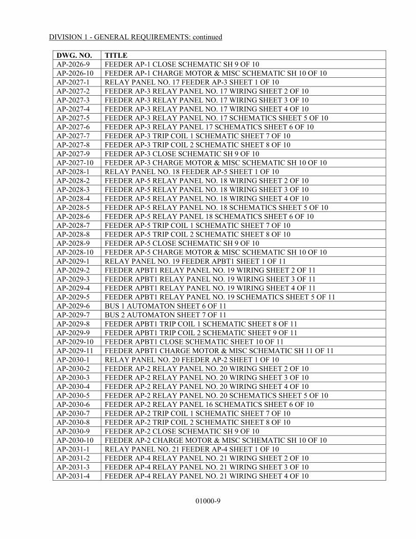
DIVISION 1 - GENERAL REQUIREMENTS: continued
01000-9
DWG. NO. TITLE AP-2026-9 FEEDER AP-1 CLOSE SCHEMATIC SH 9 OF 10 AP-2026-10 FEEDER AP-1 CHARGE MOTOR & MISC SCHEMATIC SH 10 OF 10 AP-2027-1 RELAY PANEL NO. 17 FEEDER AP-3 SHEET 1 OF 10 AP-2027-2 FEEDER AP-3 RELAY PANEL NO. 17 WIRING SHEET 2 OF 10 AP-2027-3 FEEDER AP-3 RELAY PANEL NO. 17 WIRING SHEET 3 OF 10 AP-2027-4 FEEDER AP-3 RELAY PANEL NO. 17 WIRING SHEET 4 OF 10 AP-2027-5 FEEDER AP-3 RELAY PANEL NO. 17 SCHEMATICS SHEET 5 OF 10 AP-2027-6 FEEDER AP-3 RELAY PANEL 17 SCHEMATICS SHEET 6 OF 10 AP-2027-7 FEEDER AP-3 TRIP COIL 1 SCHEMATIC SHEET 7 OF 10 AP-2027-8 FEEDER AP-3 TRIP COIL 2 SCHEMATIC SHEET 8 OF 10 AP-2027-9 FEEDER AP-3 CLOSE SCHEMATIC SH 9 OF 10 AP-2027-10 FEEDER AP-3 CHARGE MOTOR & MISC SCHEMATIC SH 10 OF 10 AP-2028-1 RELAY PANEL NO. 18 FEEDER AP-5 SHEET 1 OF 10 AP-2028-2 FEEDER AP-5 RELAY PANEL NO. 18 WIRING SHEET 2 OF 10 AP-2028-3 FEEDER AP-5 RELAY PANEL NO. 18 WIRING SHEET 3 OF 10 AP-2028-4 FEEDER AP-5 RELAY PANEL NO. 18 WIRING SHEET 4 OF 10 AP-2028-5 FEEDER AP-5 RELAY PANEL NO. 18 SCHEMATICS SHEET 5 OF 10 AP-2028-6 FEEDER AP-5 RELAY PANEL 18 SCHEMATICS SHEET 6 OF 10 AP-2028-7 FEEDER AP-5 TRIP COIL 1 SCHEMATIC SHEET 7 OF 10 AP-2028-8 FEEDER AP-5 TRIP COIL 2 SCHEMATIC SHEET 8 OF 10 AP-2028-9 FEEDER AP-5 CLOSE SCHEMATIC SH 9 OF 10 AP-2028-10 FEEDER AP-5 CHARGE MOTOR & MISC SCHEMATIC SH 10 OF 10 AP-2029-1 RELAY PANEL NO. 19 FEEDER APBT1 SHEET 1 OF 11 AP-2029-2 FEEDER APBT1 RELAY PANEL NO. 19 WIRING SHEET 2 OF 11 AP-2029-3 FEEDER APBT1 RELAY PANEL NO. 19 WIRING SHEET 3 OF 11 AP-2029-4 FEEDER APBT1 RELAY PANEL NO. 19 WIRING SHEET 4 OF 11 AP-2029-5 FEEDER APBT1 RELAY PANEL NO. 19 SCHEMATICS SHEET 5 OF 11 AP-2029-6 BUS 1 AUTOMATON SHEET 6 OF 11 AP-2029-7 BUS 2 AUTOMATON SHEET 7 OF 11 AP-2029-8 FEEDER APBT1 TRIP COIL 1 SCHEMATIC SHEET 8 OF 11 AP-2029-9 FEEDER APBT1 TRIP COIL 2 SCHEMATIC SHEET 9 OF 11 AP-2029-10 FEEDER APBT1 CLOSE SCHEMATIC SHEET 10 OF 11 AP-2029-11 FEEDER APBT1 CHARGE MOTOR & MISC SCHEMATIC SH 11 OF 11 AP-2030-1 RELAY PANEL NO. 20 FEEDER AP-2 SHEET 1 OF 10 AP-2030-2 FEEDER AP-2 RELAY PANEL NO. 20 WIRING SHEET 2 OF 10 AP-2030-3 FEEDER AP-2 RELAY PANEL NO. 20 WIRING SHEET 3 OF 10 AP-2030-4 FEEDER AP-2 RELAY PANEL NO. 20 WIRING SHEET 4 OF 10 AP-2030-5 FEEDER AP-2 RELAY PANEL NO. 20 SCHEMATICS SHEET 5 OF 10 AP-2030-6 FEEDER AP-2 RELAY PANEL 16 SCHEMATICS SHEET 6 OF 10 AP-2030-7 FEEDER AP-2 TRIP COIL 1 SCHEMATIC SHEET 7 OF 10 AP-2030-8 FEEDER AP-2 TRIP COIL 2 SCHEMATIC SHEET 8 OF 10 AP-2030-9 FEEDER AP-2 CLOSE SCHEMATIC SH 9 OF 10 AP-2030-10 FEEDER AP-2 CHARGE MOTOR & MISC SCHEMATIC SH 10 OF 10 AP-2031-1 RELAY PANEL NO. 21 FEEDER AP-4 SHEET 1 OF 10 AP-2031-2 FEEDER AP-4 RELAY PANEL NO. 21 WIRING SHEET 2 OF 10 AP-2031-3 FEEDER AP-4 RELAY PANEL NO. 21 WIRING SHEET 3 OF 10 AP-2031-4 FEEDER AP-4 RELAY PANEL NO. 21 WIRING SHEET 4 OF 10
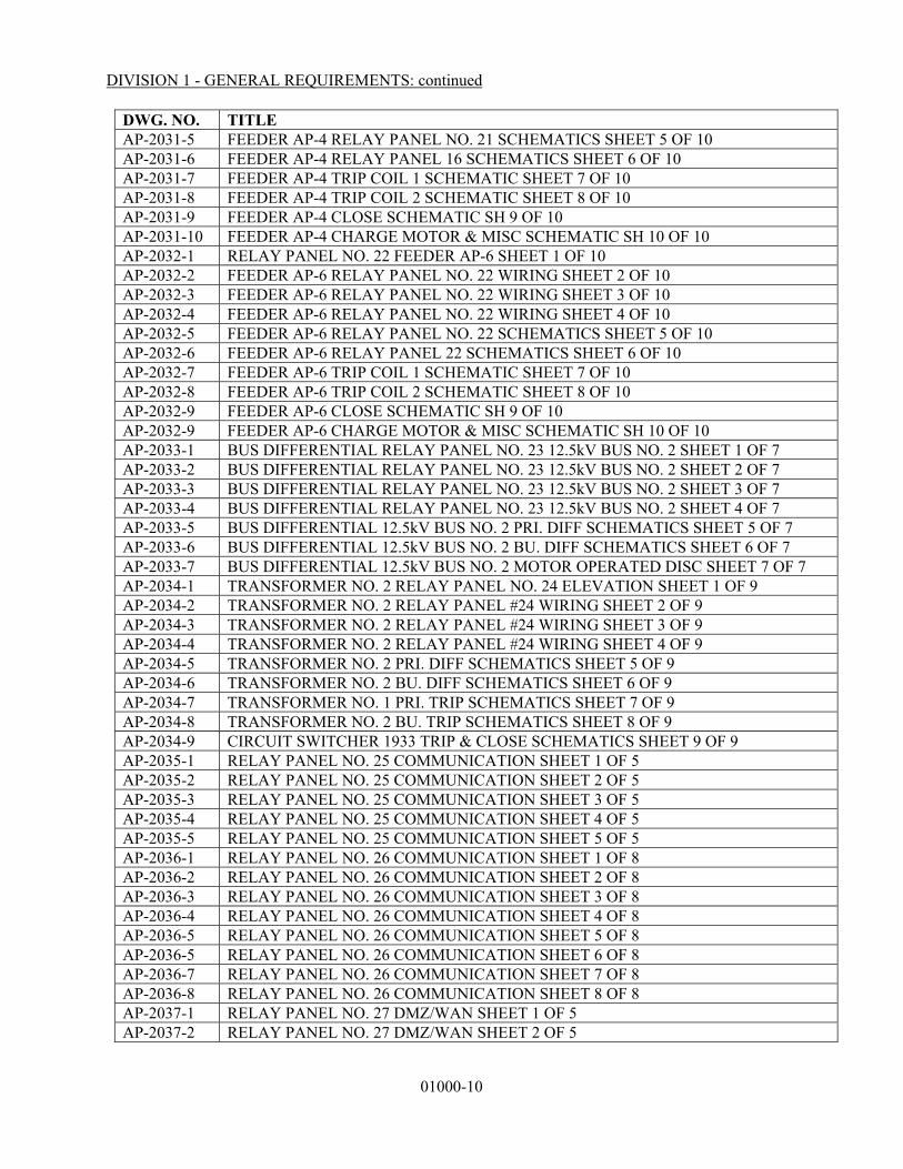
DIVISION 1 - GENERAL REQUIREMENTS: continued
01000-10
DWG. NO. TITLE AP-2031-5 FEEDER AP-4 RELAY PANEL NO. 21 SCHEMATICS SHEET 5 OF 10 AP-2031-6 FEEDER AP-4 RELAY PANEL 16 SCHEMATICS SHEET 6 OF 10 AP-2031-7 FEEDER AP-4 TRIP COIL 1 SCHEMATIC SHEET 7 OF 10 AP-2031-8 FEEDER AP-4 TRIP COIL 2 SCHEMATIC SHEET 8 OF 10 AP-2031-9 FEEDER AP-4 CLOSE SCHEMATIC SH 9 OF 10 AP-2031-10 FEEDER AP-4 CHARGE MOTOR & MISC SCHEMATIC SH 10 OF 10 AP-2032-1 RELAY PANEL NO. 22 FEEDER AP-6 SHEET 1 OF 10 AP-2032-2 FEEDER AP-6 RELAY PANEL NO. 22 WIRING SHEET 2 OF 10 AP-2032-3 FEEDER AP-6 RELAY PANEL NO. 22 WIRING SHEET 3 OF 10 AP-2032-4 FEEDER AP-6 RELAY PANEL NO. 22 WIRING SHEET 4 OF 10 AP-2032-5 FEEDER AP-6 RELAY PANEL NO. 22 SCHEMATICS SHEET 5 OF 10 AP-2032-6 FEEDER AP-6 RELAY PANEL 22 SCHEMATICS SHEET 6 OF 10 AP-2032-7 FEEDER AP-6 TRIP COIL 1 SCHEMATIC SHEET 7 OF 10 AP-2032-8 FEEDER AP-6 TRIP COIL 2 SCHEMATIC SHEET 8 OF 10 AP-2032-9 FEEDER AP-6 CLOSE SCHEMATIC SH 9 OF 10 AP-2032-9 FEEDER AP-6 CHARGE MOTOR & MISC SCHEMATIC SH 10 OF 10 AP-2033-1 BUS DIFFERENTIAL RELAY PANEL NO. 23 12.5kV BUS NO. 2 SHEET 1 OF 7 AP-2033-2 BUS DIFFERENTIAL RELAY PANEL NO. 23 12.5kV BUS NO. 2 SHEET 2 OF 7 AP-2033-3 BUS DIFFERENTIAL RELAY PANEL NO. 23 12.5kV BUS NO. 2 SHEET 3 OF 7 AP-2033-4 BUS DIFFERENTIAL RELAY PANEL NO. 23 12.5kV BUS NO. 2 SHEET 4 OF 7 AP-2033-5 BUS DIFFERENTIAL 12.5kV BUS NO. 2 PRI. DIFF SCHEMATICS SHEET 5 OF 7 AP-2033-6 BUS DIFFERENTIAL 12.5kV BUS NO. 2 BU. DIFF SCHEMATICS SHEET 6 OF 7 AP-2033-7 BUS DIFFERENTIAL 12.5kV BUS NO. 2 MOTOR OPERATED DISC SHEET 7 OF 7 AP-2034-1 TRANSFORMER NO. 2 RELAY PANEL NO. 24 ELEVATION SHEET 1 OF 9 AP-2034-2 TRANSFORMER NO. 2 RELAY PANEL #24 WIRING SHEET 2 OF 9 AP-2034-3 TRANSFORMER NO. 2 RELAY PANEL #24 WIRING SHEET 3 OF 9 AP-2034-4 TRANSFORMER NO. 2 RELAY PANEL #24 WIRING SHEET 4 OF 9 AP-2034-5 TRANSFORMER NO. 2 PRI. DIFF SCHEMATICS SHEET 5 OF 9 AP-2034-6 TRANSFORMER NO. 2 BU. DIFF SCHEMATICS SHEET 6 OF 9 AP-2034-7 TRANSFORMER NO. 1 PRI. TRIP SCHEMATICS SHEET 7 OF 9 AP-2034-8 TRANSFORMER NO. 2 BU. TRIP SCHEMATICS SHEET 8 OF 9 AP-2034-9 CIRCUIT SWITCHER 1933 TRIP & CLOSE SCHEMATICS SHEET 9 OF 9 AP-2035-1 RELAY PANEL NO. 25 COMMUNICATION SHEET 1 OF 5 AP-2035-2 RELAY PANEL NO. 25 COMMUNICATION SHEET 2 OF 5 AP-2035-3 RELAY PANEL NO. 25 COMMUNICATION SHEET 3 OF 5 AP-2035-4 RELAY PANEL NO. 25 COMMUNICATION SHEET 4 OF 5 AP-2035-5 RELAY PANEL NO. 25 COMMUNICATION SHEET 5 OF 5 AP-2036-1 RELAY PANEL NO. 26 COMMUNICATION SHEET 1 OF 8 AP-2036-2 RELAY PANEL NO. 26 COMMUNICATION SHEET 2 OF 8 AP-2036-3 RELAY PANEL NO. 26 COMMUNICATION SHEET 3 OF 8 AP-2036-4 RELAY PANEL NO. 26 COMMUNICATION SHEET 4 OF 8 AP-2036-5 RELAY PANEL NO. 26 COMMUNICATION SHEET 5 OF 8 AP-2036-5 RELAY PANEL NO. 26 COMMUNICATION SHEET 6 OF 8 AP-2036-7 RELAY PANEL NO. 26 COMMUNICATION SHEET 7 OF 8 AP-2036-8 RELAY PANEL NO. 26 COMMUNICATION SHEET 8 OF 8 AP-2037-1 RELAY PANEL NO. 27 DMZ/WAN SHEET 1 OF 5 AP-2037-2 RELAY PANEL NO. 27 DMZ/WAN SHEET 2 OF 5

DIVISION 1 - GENERAL REQUIREMENTS: continued
01000-11
DWG. NO. TITLE AP-2037-3 RELAY PANEL NO. 27 DMZ/WAN SHEET 3 OF 5 AP-2037-4 RELAY PANEL NO. 27 DMZ/WAN SHEET 4 OF 5 AP-2037-5 RELAY PANEL NO. 27 DMZ/WAN SHEET 5 OF 5 AP-2038 RELAY PANEL NO. 28 FIBER RACK AP-2040-1 TERMINATION CABINET #1 ELEVATIONS (SHEET 1 OF 12) AP-2040-2 TERMINATION CABINET #1 LEFT-HAND SIDE (SHEET 2 OF 12) AP-2040-3 TERMINATION CABINET #1 RIGHT-HAND SIDE (SHEET 3 OF 12) AP-2040-4 TERMINATION CABINET #2 ELEVATION (SHEET 4 OF 12) AP-2040-5 TERMINATION CABINET #2 LEFT-HANDN SIDE (SHEET 5 OF 12) AP-2040-6 TERMINATION CABINET #2 RIGHT-HAND SIDE (SHEET 6 OF 12) AP-2040-7 TERMINATION CABINET #3 ELEVATION (SHEET 7 OF 12) AP-2040-8 TERMINATION CABINET #3 LEFT-HAND SIDE (SHEET 8 OF 12) AP-2040-9 TERMINATION CABINET #3 RIGHT-HAND SIDE (SHEET 9 OF 12) AP-2040-10 TERMINATION CABINET #4 ELEVATION (SHEET 10 OF 12) AP-2040-11 TERMINATION CABINET #4 LEFT-HAND SIDE (SHEET 11 OF 12) AP-2040-12 TERMINATION CABINET #4 RIGHT-HAND SIDE (SHEET 12 OF 12) AP-2041-1 PT-1 SOUTH BUS CONNECTION DIAGRAM AP-2041-2 PT-2 NORTH BUS CONNECTION DIAGRAM AP-2041-3 PT-3 XFMR T1 FEEDER CONNECTION DIAGRAM AP-2041-4 PT-4 XFMR T2 FEEDER CONNECTION DIAGRAM AP-2041-5 PT-5 NAAMAN LINE CONNECTION DIAGRAM AP-2041-6 PT-6 JUPITER LINE CONNECTION DIAGRAM AP-2041-7 PT-7 LOOKOUT LINE CONNECTION DIAGRAM AP-2041-8 PT-8 E. RICHARDSON LINE CONNECTION DIAGRAM AP-2041-9 PT-9 FUTURE LINE CONNECTION DIAGRAM AP-2041-10 CVT-8A EAST RICHARDSON LINE CONNECTION DIAGRAM AP-2041-11 PT-11 XFMR T1 SECONDARY CONNECTION DIAGRAM AP-2041-12 PT-12 XFMR T2 SECONDARY CONNECTION DIAGRAM AP-2042-1 GCB 1910 CONNECTION DIAGRAM AP-2042-2 GCB 1920 CONNECTION DIAGRAM AP-2042-3 GCB 1930 CONNECTION DIAGRAM AP-2042-4 GCB 1935 CONNECTION DIAGRAM AP-2042-5 GCB 1940 CONNECTION DIAGRAM AP-2042-6 GCB 1950 CONNECTION DIAGRAM AP-2042-7 GCB 1955 CONNECTION DIAGRAM AP-2042-8 GCB 1960 CONNECTION DIAGRAM AP-2042-9 GCB 1970 CONNECTION DIAGRAM AP-2042-10 GCB 1975 CONNECTION DIAGRAM AP-2042-11 GCB 1980 CONNECTION DIAGRAM AP-2043-1 TRANSFORMER NO. 1 WIRING DIAGRAM AP-2043-2 TRANSFORMER NO. 2 WIRING DIAGRAM AP-2044-1 VCB AP1 CONNECTION DIAGRAM AP-2044-2 VCB AP2 CONNECTION DIAGRAM AP-2044-3 VCB AP3 CONNECTION DIAGRAM AP-2044-4 VCB APBT1 CONNECTION DIAGRAM AP-2044-5 VCB AP4 CONNECTION DIAGRAM AP-2044-6 VCB AP5 CONNECTION DIAGRAM

DIVISION 1 - GENERAL REQUIREMENTS: continued
01000-12
DWG. NO. TITLE AP-2044-7 VCB AP6 CONNECTION DIAGRAM AP-2045-1 CIRCUIT SWITCHER CS 1913 CONNECTION DIAGRAM AP-2045-2 CIRCUIT SWITCHER CS 1933 CONNECTION DIAGRAM AP-2046-1 MOTOR OPERATED LOAD SWITCH MOLS 1913 CONNECTION DIAGRAM AP-2046-2 MOTOR OPERATED LOAD SWITCH MOLS 1933 CONNECTION DIAGRAM AP-2047-1 STAND. LINE/BUS SWITCH 138kV AIR SWITCH AUXILIARY CONTACTS AP-2047-2 STAND. LINE/BUS SWITCH 138kV AIR SWITCH AUXILIARY CONTACTS AP-2050-1 CABLE SCHEDULE SHEET 1 OF 4 AP-2050-2 CABLE SCHEDULE SHEET 2 OF 4 AP-2050-3 CABLE SCHEDULE SHEET 3 OF 4 AP-2050-4 CABLE SCHEDULE SHEET 4 OF 4 AP-3000-1 138kV A-FRAME DEADEND STRUCTURE DETAILS (PERFORMANCE DESIGN)
(SHEET 1 OF 3) AP-3000-2 138kV A-FRAME DEADEND STRUCTURE DETAILS (PERFORMANCE DESIGN)
(SHEET 2 OF 3) AP-3000-3 138kV A-FRAME DEADEND STRUCTURE DETAILS (PERFORMANCE DESIGN)
(SHEET 3 OF 3) AP-3001 138kV 1-PHASE BUS SUPPORT STAND (TALL) STRUCTURE DETAILS AP-3002 138kV 3-PHASE 12' SPACING BUS SUPPORT STAND (SHORT) STRUCTURE
DETAILS AP-3003 138kV 3-PHASE 12' SPACING BUS SUPPORT STAND (TALL) STRUCTURE DETAILS AP-3004 138kV 3-PHASE 8' SPACING BUS SUPPORT STAND (TALL) STRUCTURE DETAILS AP-3005 138kV 3-PHASE AIR SWITCH STAND (SHORT) STRUCTURE DETAILS AP-3006 138kV 3-PHASE AIR SWITCH STAND (TALL) STRUCTURE DETAILS AP-3007 138kV 1-PHASE P.T. STAND (SHORT) STRUCTURE DETAILS AP-3007A 138kV 1-PHASE P.T. STAND (SHORT) WITH JUNCTION BOX STRUCTURE DETAILS AP-3008 138kV 1-PHASE P.T. STAND (TALL) STRUCTURE DETAILS AP-3008A 138kV 1-PHASE P.T. STAND (TALL) WITH JUNCTION BOX STRUCTURE DETAILS AP-3009 138kV 1-PHASE STATION SERVICE TRANSFORMER STAND STRUCTURE
DETAILS AP-3010 138kV 1-PHASE C.V.T. STAND (XTRA SHORT) WITH JUNCTION BOX STRUCTURE
DETAILS AP-3011 138kV 1-PHASE 3000A WAVE TRAP STAND (SHORT) STRUCTURE DETAILS AP-3012 65' SHIELD POLE STRUCTURE DETAILS AP-3020-1 34kV 3-PHASE AIR SWITCH STAND DETAILS (SHEET 1 OF 2) AP-3020-2 34kV 3-PHASE AIR SWITCH STAND DETAILS (SHEET 2 OF 2) AP-3021-1 34kV DISTRIBUTION STRUCTURE DETAILS (MFR DETAILING & CONNECTION
DESIGN) (SHEET 1 OF 4) AP-3021-2 34kV DISTRIBUTION STRUCTURE DETAILS (MFR DETAILING & CONNECTION
DESIGN) (SHEET 2 OF 4) AP-3021-3 34kV DISTRIBUTION STRUCTURE DETAILS (MFR DETAILING & CONNECTION
DESIGN) (SHEET 3 OF 4) AP-3021-4 34kV DISTRIBUTION STRUCTURE DETAILS (MFR DETAILING & CONNECTION
DESIGN) (SHEET 4 OF 4) AP-3022-1 34kV DISTRIBUTION RISER STRUCTURE DETAILS (SHEET 1 OF 2) AP-3022-2 34KV DISTRIBUTION RISER STRUCTURE DETAILS (SHEET 2 OF 2)

DIVISION 1 - GENERAL REQUIREMENTS: continued
01000-13
In addition to the project Specification Drawings, Bidders are provided a set of the Phase 1 Civil Site Construction Plans (City of Garland Bid No. 0042-20) for informational purposes as well as a set of fabrication drawings prepared by Klute Steel (Klute Steel Job No. 2198) for select substation steel structures. PART 3 - PROJECT LABOR AND MATERIAL RESPONSIBILITIES (PROJECT RESPONSIBILITY MATRIX) The Contractor shall receive all materials provided by GP&L and shall maintain a record to account for all materials received. This record of materials received shall be available to GP&L’s representative at any time upon request. The Contractor is solely responsible for the security of materials and shall replace any materials lost, stolen, or damaged after receipt from GP&L at no additional cost to GP&L. All equipment and materials provided to the Contractor by GP&L for this project are staged at the C.E. Newman Power Plant, 525 East Avenue B, Garland, Texas, 75040 and shall be transported to the project site by the Contractor. 3.01 Equipment and Materials Provided by GP&L:
Eleven (11) 145kV SF6 Gas Circuit Breakers Two (2) 138kV Circuit Switchers Two (2) 138kV-13.2kV 15MVA Power Transformers (3-Phase) (1 new, 1 re-used existing) Twenty-seven (27) 145kV Air Break Switches (3-Phase) Two (2) 15.5kV Vertical Break Switches (3-Phase) Fifteen (15) Surge Arresters, polymer housed, 98 kV MCOV, 120 kV duty, three (3) per line Twenty-seven (27) 138kV Potential Transformers (PT’s) One (1) 650kV BIL Station Service Voltage Transformer (SSVT) Two (2) Motor Operators for 15.5kV Vertical Break Switches Terminal Boxes for the 138kV PT’s Safety Switch & Fuses for the SSVT One hundred thirty-three (133) 650kV BIL Station Post Insulators One (1) 2-Section Prefabricated Modular Equipment Enclosure with Transmission and Distribution
Relay Panels Fifteen (15) 138kV Combined Instrument Transformers Light Poles, Pole Bases, Arms and Fixtures Poles, Junction Boxes, and Cameras for the security system One (1) 100kW LP Standby Engine Generator One (1) 1,000 gallon Liquid Propane Fuel Storage Tank (above ground) and associated fuel line,
regulator and hardware One (1) 100kVA Pad Mounted Station Service Transformer Six (6) 17.5kV, 1,200A Vacuum Circuit Breaker (VCB) (3-Phase) One (1) 17.5kV, 2,000A Vacuum Circuit Breaker (VCB) (3-Phase) One (1) 138kV, 3,000A Air Core Line Trap with Tuning Pack One (1) 80.5kV Current Voltage Transformer (CVT) Pre-cast Trench Components Junction Box for the CVT Line Tuner Box for the CVT Forty-two (42) 38kV Vertical Break Air Switches Seventy-two (72) 34.5kV 200kV BIL Station Post Insulators

DIVISION 1 - GENERAL REQUIREMENTS: continued
01000-14
Six (6) 38kV Disconnect Switches with Fuse Refill Units Six (6) 15kV Potential Transformers (PT’s) Six (6) 12.47kV Vac-Rupters for 15kV Vertical Air Break Switches Wildlife Protective Boots for VCB’s and Power Transformer Bushings Aluminum Bus Tubing, Connectors, and Fasteners ACSR 1590 kcmil and ACSR 266.8 kcmil Conductor for Bus Vibration Mitigation AAC 2250 kcmil, ACSR 4/0 AWG Conductor and Covered Line Wire for Equipment
Conductor/Jumper Connections Connectors and Fittings for Cables/Conductors/Jumpers PVC, Steel and Metallic/Non-Metallic Flexible Conduit and Fittings 3/8” EHS Shield Wire, Connectors, and Hardware for overhead substation shielding 4/0 Bare CU, #2 Bare CU, and 19#9 CU Clad Steel Ground Grid Wire, Ground Fittings, Ground Rods,
and Ground Connectors (Material only) Steel Structures Anchor Bolts Power & Control Cable. Fiber Optic, Innerduct, and Coaxial Cable. Prefabricated Metal Stairs for building entrances Grounding Mats for switch stands
3.02 Equipment, Tools, Materials, and Reports to be provided by the Contractor:
The Contractor shall provide all tools and equipment required to complete the contract. High temperature joint compound as needed to complete installation per all drawings Foundations, including excavation, temporary casing or slurry where needed, concrete, reinforcing
steel, forming materials, anchor bolt placement, and backfilling Steel grating and framing at transformer containment moats All materials and equipment for transformer sump drain pump systems All materials for cable trench and transformer sump drain lines Miscellaneous conduit fittings and accessories as shown in Bill of Materials All material and construction testing (testing cost shall be paid by the Contractor) in accordance with
these specifications. Flexible base as necessary for restoration in excavated or trenched areas Crushed limestone for yard surfacing All tools required for installation of ground grid components Ground Enhancement Material (GEM) for grounding system All materials associated with vegetative site stabilization (seeding or sodding) including maintenance
until acceptance per construction drawings All materials associated with site landscaping including maintenance until acceptance per construction
drawings and specifications All materials associated with landscape irrigation systems per construction drawings All materials associated with landscape irrigation pump system The Contractor shall provide and install all fasteners required for the project not specifically noted as
being provided by GP&L. This includes galvanized, stainless steel, and all other fasteners indicated on the drawings and in the Bill of Material.
All tools and materials required for termination of control cable and low voltage electrical conductors All other materials and components listed in the Bill of Materials or shown on the drawings, but not
specifically identified as provided by GP&L in this document.

DIVISION 1 - GENERAL REQUIREMENTS: continued
01000-15
3.03 Special Instructions and Notes Regarding Equipment and Material Provided by GP&L: The 145kV gas breakers will be provided by GP&L and transported to the site by the Contractor. The
Contractor shall unload, set, and secure each breaker on a foundation installed by the Contractor. Each 145kV breaker weighs approximately 10,000 pounds.
The 138kV Circuit Switchers will be provided by GP&L and transported to the site by the Contractor. The Contractor shall unload, set, and secure each circuit switcher on a foundation installed by the Contractor. Each circuit switcher weighs approximately 6,500 pounds.
Air break switches will be provided by GP&L and transported to the site by the Contractor. The Contractor shall mount the switches and install switch control assemblies per the provided
drawings. Install switch position auxiliary contact switches. Each switch shall be adjusted by the Contractor to the satisfaction of GP&L.
The Control House will be provided by GP&L and transported to the project site by the manufacturer. The Control House will be set and secured by the manufacturer on foundations built by the Contractor per the construction drawings. The manufacturer will install prefabricated metal stairs and landings on foundations constructed by the Contractor.
All structural steel is detailed in the drawing set and all structural steel shall be installed per the drawings and specifications to the satisfaction of GP&L. The Contractor shall provide all tools and equipment required for installation. The Contractor shall transport all structural steel to the site.
The Contractor shall receive and install anchor bolts provided by GP&L. The Contractor shall adequately support and install the anchor bolts per the foundation detail drawings so that structural steel and equipment may be properly secured to anchor bolts. The Contractor shall transport all anchor bolts to the site.
Contractor shall transport twenty-seven (27) 138kV potential transformers (PT’s) to the site and shall install these PT’s on the structures with required terminal boxes and conduit per the construction drawings.
Contractor shall transport one (1) SSVT and terminal box to the site and shall install same on a support structure with required conduit per the construction drawings
Contractor shall transport one (1) emergency generator to the site and install the generator on a foundation with required conduit and sleeves per the construction drawings. Materials and installation for propane tank, fuel line, and regulator will be furnished by the GP&L propane tank supplier. Contractor shall coordinate with the GP&L propane tank supplier to ensure necessary fuel line has been installed prior to construction of the propane tank foundation.
The Contractor shall transport and install all conduit system materials provided by GP&L, below grade and above grade. All conduits shall be installed per the construction drawings to the satisfaction of GP&L. The trenching, excavating, trench safety, compacted backfill, and restoration of flexible base necessary for installation of conduits are a part of the contract. All conduit construction shall include pull strings secured at each end and mandrel testing to verify they are free of damage and are not obstructed by dirt, rock, debris, etc. All conduit construction shall include extension to and terminations at electrical devices as shown in the project plans and details. Contractor shall remove any trench spoils not used for cover of conduits from the site and shall dispose of spoils as part of the contract.
The Contractor shall transport and install all precast cable trench materials provided by GP&L per the conduit plan and detail drawings. Trenching, excavating for installation of the cable trench, backfilling, and restoration of flexible base are a part of the contract.
The Contractor shall transport and install all porcelain station post insulators according to the drawings. The Contractor shall transport and install all 6063-T6, Schedule 40 aluminum alloy bus tubing,
connectors, fittings, and bus vibration dampening components provided by GP&L and shall provide all tools and equipment to install all bus and connectors to the satisfaction of GP&L.

DIVISION 1 - GENERAL REQUIREMENTS: continued
01000-16
The Contractor shall provide labor to install a grounding system per the design drawings. GP&L will provide 4/0 bare copper wire, 19 #9 DSA copper clad steel conductor, fittings, ground rods, ground switch mats, ground tails, and mechanical connectors for securing above; and any other materials required for installation per the drawings except Ground Enhancement Material (GEM). Trenching, excavating, backfilling and restoration of flexible base for installation of ground grid conductors, trench components, foundations, or other subsurface facilities are part of the contract. Ground Enhancement Material (GEM) shall be furnished and placed by the Contractor where necessary for grounding components in rock. Spoils not used for cover of subsurface facilities shall be removed from the site by the Contractor and properly disposed of as part of the contract. The Contractor shall receive all grounding components provided by GP&L at the C.E. Newman Power Plant, 525 East Avenue B, Garland, Texas, 75040 and transport these components to the site.
The Contractor shall transport and install three (3) high voltage surge arresters (provided by GP&L) on each dead-end structure (15 total) per the drawings. All arresters shall be grounded in accordance with the drawings and to the satisfaction of GP&L.
The Contractor shall transport and install all substation overhead shielding including static poles, 3/8” EHS shield wire, associated hardware, and terminations.
The Contractor shall transport and install all junction boxes and conduit for security systems. The Contractor shall install and terminate all power and control cables and wiring for yard lighting
and security poles. The Contractor shall install and terminate fiber optic and coaxial cables in underground conduit
systems all installed by the Contractor. GP&L will provide all lighting and security poles and the Contractor shall transport and set same on
foundations constructed by the Contractor. GP&L will provide and set the 100kVA pad mounted station service transformer. The Contractor shall
install conduit stubups above the transformer pad and install and terminate all wiring as directed by GP&L.
3.04 Special Instructions and Notes Regarding Equipment, Tools, and Materials Provided by the Contractor: Prior to any digging or excavation at the site, the Contractor shall call DIGTESS with at least 48 hours lead time.
A Foundation Plan and Foundation Details are provided in the drawings. The Contractor shall provide the specified excavation, any necessary temporary casing or slurry, forming, concrete, reinforcing steel, anchor bolt placement, backfilling, restoration of flexible base, and other materials per the drawings and shall install all foundations in strict accordance with the drawings and specifications.
The Contractor shall provide, install, and maintain vegetative stabilization (seed or sod) at all areas disturbed by construction outside of the proposed substation gravel yard surfacing and paving in accordance with the project SWPPP and project specifications. The Contractor shall remove and dispose of any stockpiled topsoil not used for stabilization activities or landscaping as part of the contract.
The Contractor shall provide all barricading, signage, and incidentals for traffic control and safety in accordance with these specifications.
The Contractor shall provide all materials and labor associated with the project landscape plantings, irrigation system, maintenance, and all incidentals necessary to provide a complete landscape package with a properly functioning irrigation system in accordance with the plans, details, and specifications.
The Contractor shall provide and install all fasteners and wire terminators required for the project not specifically noted as being provided by GP&L. This includes galvanized, stainless steel, and all other fasteners indicated on the drawings and in the Bill of Material.

DIVISION 1 - GENERAL REQUIREMENTS: continued
01000-17
The Contractor shall provide portable toilets at the construction site. The Contractor shall provide adequate potable water to ensure that all workers at the site may remain hydrated throughout each workday.
These notes are not all-inclusive of everything the Contractor shall provide and install. No attempt has been made to detail all tools, materials, equipment, and labor that may be needed and shall be provided by the Contractor in performing this work.
PART 4 – ADMINISTRATIVE 4.01 CONTRACTOR’S USE OF PREMISES: Exclusive Use: During the construction period, Contractor shall have full use of the premises for execution of the Work. Use of premises is limited only by Owner’s and their designee’s right to perform duties and functions as stated in the GENERAL CONDITIONS and in this Section.
4.02 MEASUREMENT AND PAYMENT: All Work indicated and specified in the Contract Documents shall be paid at the unit prices multiplied by plan quantities. The unit prices shall include all work and incidentals necessary to complete the project as shown in the project plans, details and specification.
4.03 COPIES OF DOCUMENTS:
A. Furnished Copies: After execution of Agreement, Contractor will be furnished at no cost, a maximum of five (5) sets of Contract Documents consisting of full-size Contract Drawings including revised Drawings, and the Project Manual, in addition to those used in execution of the Agreement.
B. Additional Copies: Additional copies of above documents will be supplied by GP&L upon request at $ 75.00 per one set of Drawings and one copy of Project Manual.
4.04 COORDINATION:
A. The Contractor shall perform the activities necessary to properly coordinate the following: 1. Equipment and work provided by him and his subcontractors. 2. The work within and between his various subcontractors. 3. The scheduling and expediting delivery of equipment and materials supplied under this
Contract. 4. Special construction stages of coordination. 5. Notification of TxDOT prior to working in right-of-way
Contractor’s coordination shall include providing site access as necessary to accommodate work performed by the civil site contractor, GP&L personnel, radio tower contractor, or other personnel as authorized by GP&L during project construction.
4.05 INITIAL COORDINATION SUBMITTALS: Within 5 days after the date of Notice to Proceed, Contractor shall submit in writing to GP&L for review and acceptance the following:
1. A Work Progress Schedule including: a. A construction progress schedule. b. A procurement schedule. 2. A list of proposed Subcontractors and equipment and material suppliers. 3. A schedule of Compliance Submittals. 4. A cash flow tabulation by month.

DIVISION 1 - GENERAL REQUIREMENTS: continued
01000-18
5. A listing of wage rates, fringe benefits, payroll tax and insurance and equipment use rate tabulation for use in calculating the cost of construction units not included in the Proposal.
6. Complete list of tools and equipment for use in this project. 7. Superintendents name and resume. 8. Listing of all proposed subcontractors including addresses and telephone numbers.
4.06 INITIAL COORDINATION CONFERENCE: Within 5 days after the date of Notice to Proceed, a conference will be held in the Owner’s office to review and take action on initial coordination submittals, establish procedures for handling Compliance Submittals, correspondence and communications, review procedures for payment of Contractor, and establish a working understanding between the parties as to their relationships during conduct of the Work. The conference shall be attended by:
1. GP&L 2. Contractor.
2. Representatives of principal Subcontractors, suppliers and manufacturers. 3. Engineer. 4. Owner or his representative.
4.07 WORK PROGRESS SCHEDULE: 1. Within 5 days of the date of initial coordination conference, the Contractor shall submit to
Owner for acceptance a detailed work progress schedule. 2. The schedule shall show the Work in a format suitable for displaying scheduled and actual
progress and shall be submitted on a reproducible media. 3. The schedule shall show the Work broken down into major phases and key items. The
dates that Work is expected to begin and be completed shall be shown for each item listed. 4. The schedule shall include the monthly percents of work to be completed for each of the following items: a. Erosion control measures b. Trench and conduit c. Grounding d. Foundation construction e. Structure erection f. Installation of major substation equipment g. Installation of buswork h. Overhead lightning shielding
i. Fence j. Gravel surfacing k. Irrigation system l. Landscaping m. Final stabilization n. Final cleanup
Engineer and Owner will review and comment on schedule and, upon agreement with Contractor on any necessary changes, Contractor will furnish Owner prints of the accepted schedule. Contractor shall not change the accepted work progress schedule without prior concurrence of Owner.
Contractor shall submit to Owner for acceptance an updated schedule at least once every month, which shall show actual progress and any proposed changes in the schedule of remaining Work.

DIVISION 1 - GENERAL REQUIREMENTS: continued
01000-19
4.08 WORK PROGRESS REPORTS: Contractor shall submit at least twice each month to the Owner a report on actual progress of the Work. Weekly reports may be required should the Work fall behind the accepted schedule. Work progress reports shall consist of marked prints of the accepted work progress schedule, and a narrative report including but not limited to the following:
a. A description of current and anticipated delaying factors, if any, including causes and past efforts by Contractor to correct these.
b. Effect of these delays on work progress. c. Proposed corrective action.
In addition to the above reports the Contractor shall report to the Owner immediately upon becoming aware of any circumstance which might result in a deviation from the approved Work schedules. A work progress report shall accompany each application for partial payment. Work reported complete but not readily apparent to Owner must be substantiated with supporting data.
4.09 COORDINATION CONFERENCES: A coordination conference will be held as requested by the Owner. Contractor, Owner, Subcontractors, and other Contractors active on the site shall be represented at each conference. Contractor may at his discretion request attendance by representatives of his suppliers, manufacturers and other Subcontractors. Contractor and each Subcontractor shall be prepared to discuss work anticipated during the next week, and shall be prepared to discuss the current Work progress report as well as any anticipated future changes to the schedule. When Contractor’s Work affects, or is affected by, the work of other contractors, Owner may hold coordination conferences to be attended by those involved. Contractor shall participate in such conferences accompanied by his Subcontractors as requested.
4.10 COMPLIANCE SUBMITTALS: Compliance Submittals shall include all drawings, catalogs or parts thereof, manufacturer’s specifications and data, samples, instructions, written guarantees, concrete mix designs, and other information specified or necessary for the Owner to determine that the equipment and materials conform with the design concept and comply with the intent of the Contract Documents. Data submitted shall be complete with respect to dimensions, design criteria, and materials of construction to enable Owner to review the information effectively. Where standard drawings are furnished which cover a number of variations of the general class of equipment or material, each drawing shall be individually annotated to describe exactly which parts of the drawing apply to the equipment or material being furnished. Such annotation shall also include proper identification of the submittal permanently attached to the drawing. Reproduction or copies of Contract Drawings or portions thereof will not be accepted as complete fabrication or erection drawings. Required miscellaneous submittals are comprised of Technical Reports, Administrative Submittals and Guarantees which relate to the Work, but do not require Owner approval prior to proceeding with the Work. If these submittals indicate compliance with the Contract Documents, no action normally will be taken by the Owner, but submittals which indicate deficiencies or unacceptable administrative submittals will be responded to by letter. These submittals will not be logged, stamped, and distributed as Compliance Submittals since response is normally required only for unsatisfactory conditions represented by the submittals.

DIVISION 1 - GENERAL REQUIREMENTS: continued
01000-20
Miscellaneous submittals include: (a) Cement tests. (b) Aggregate tests. (2) Shipping and/or packing lists. (3) Work progress schedules. (4) Procurement schedules. (5) Work progress reports. (6) Welding procedure qualification tests. (7) Warranties and guarantees. (8) Equipment and material test reports. (9) Grounding tests.
(10) Bus Meggering reports.
Transmittal of Test Reports: Responsibilities of Contractor, Owner and Engineer regarding tests and inspections of equipment, materials, and completed Work are set forth in the Bid Documents. The party responsible for testing or inspection shall arrange for the testing laboratory or reporting agency to distribute inspection and test reports and certificates as follows:
Owner …………………………………. 3 copies Engineer ………………………………. 1 copy Manufacturer or supplier ……………… 1 copy Contractor ……………………………... 1 copy
Transmittal of Guarantees: Written guarantees shall be submitted as follows: Owner …………………………………. 3 copies
Contractor shall prepare for Owner’s concurrence a schedule for submission of all Compliance Submittals. The schedule shall accompany the procurement schedule and Work progress schedule submitted. Submission of all Compliance Submittals shall be scheduled to permit review, fabrication and delivery in time to cause no delay in the Work of Contractor or his Subcontractors or any other contractors as described herein. Contractor in establishing his schedule for Compliance Submittals shall allow 7 days in Owner’s office for reviewing original submittals and 5 days in Owner’s office for reviewing resubmittals. The schedule shall indicate the anticipated dates of original submission for each item and Owner acceptance thereof, and shall be based upon at least one resubmission of each item.
It is the Contractor’s responsibility to schedule Compliance Submittals to allow for the normal exchange time.
All Compliance Submittals of equipment and materials furnished by Subcontractors, manufacturers and suppliers shall be submitted to Owner by Contractor.
Compliance Submittals shall be resubmitted the number of times required for “Submittal Accepted.” However, any need for resubmittals in excess of the number set forth in the accepted schedule, or any other delay in obtaining acceptance of submittals, will not be grounds for extension of the Contract Time provided the Owner completes his review within the times stated above.

DIVISION 1 - GENERAL REQUIREMENTS: continued
01000-21
The following instructions shall be followed in identification of Compliance Submittals transmitted for acceptance:
a. Each submittal shall have a “Compliance Submittal Information Block” placed as near as
possible to the drawing title in the lower right corner. Information blocks format will be provided by the Owner.
b. Decals are to be used on all drawings prepared by the Contractor, his Subcontractors, or Suppliers. The paper stock information blocks are to be affixed to all product data type or standard drawing submittals.
c. Contract number, contract title and where required for positive identification, the specification Division and Article Number must be completed by the Contractor. d. All submittals from Subcontractors or Suppliers must be approved by the Contractor on
the information block. Contractor’s approval shall constitute a representation to Owner that Contractor has determined and verified all quantities, dimension, materials, catalog numbers and similar data; he assumes full responsibility for doing so; and that he has coordinated each Compliance Submittal with the requirements of the Work and the Contract Documents. Contractor’s submittals without the above specified approval shall be interpreted as not having Contractor’s approval, representation, and coordination specified above, and may be returned unapproved to the Contractor for Contractor’s approval at the option of the Owner.
e. Where standard drawings are furnished, each drawing shall be individually marked to indicate exactly which parts of the drawing apply to the equipment being furnished. f. A complete set of compliance submittals shall be furnished for each individual substation.
No common drawings for different substations will be allowed. g. Reproductions of the Contract Drawings will not be accepted as compliance submittals.
h. At the time of each submission, call to the attention of Owner in the letter of transmittal any deviations from the requirements of the Contract Documents.
i. At the time of each resubmission, call to the attention of Owner in the letter of transmittal any changes made in addition to changes requested by Engineer.
Owner will review and return Compliance Submittals to Contractor with appropriate notations. Written guarantees and similar submittals received by Owner will be reviewed and returned by Owner. Instruction books and similar submittals will be reviewed by Owner for general content but not for substance. The approval for use of a separate item as such will not indicate approval for use of the assembly in which the item functions. Contractor shall make all modifications noted or indicated by Owner and shall return revised prints, copies or samples until accepted. After submittals have been accepted, Contractor shall submit copies thereof for final distribution. Prints of accepted drawings transmitted for final distribution will not be further reviewed and are not to be revised. If errors are discovered during manufacture or fabrication, the submittal shall be corrected and resubmitted for review.
No item requiring compliance submittals shall be considered for payment until “Distribution Copy” compliance submittals have been received by the Owner. Following completion of the Work and prior to final payment, Contractor shall furnish those drawings necessary to indicate “as constructed” conditions, including field modifications, in the number of copies specified and furnish additional copies for insertion in equipment instruction books as required. All such copies shall be clearly marked “AS CONSTRUCTED.”
No Work requiring a Compliance Submittal shall be commenced until the receipt by Contractor of the Submittal stamped “Submittal Accepted,” or “Submittal Accepted as Noted.” In proceeding with

DIVISION 1 - GENERAL REQUIREMENTS: continued
01000-22
manufacturing or fabrication of work covered by a Submittal stamped “Submittal Accepted as Noted” the Contractor shall so advise the Owner immediately upon his decision to proceed. Owner’s acceptance of Compliance Submittals will not relieve Contractor from his responsibility for any deviations from the requirements of the Contract Documents unless Contractor has in writing called attention to such deviation at the time of submission and Owner has given written approval to the specific deviation, nor shall any acceptance by Owner relieve Contractor from responsibility for errors or omissions in Compliance Submittals. Such deviation will be made a part of a contract amendment.
A copy or sample of each Compliance Submittal shall be kept in good order by Contractor at the site.
4.11 TRANSMITTAL AND REVIEW OF COMPLIANCE SUBMITTALS: 1. Transmittal letters and correspondence shall be submitted as follows: a. Owner – original plus 3 copies. 2. Except as otherwise specified all drawings and catalog cuts shall be transmitted as follows: a. Initial submittal - Owner 4 copies, 1 copy returned to Contractor. b. Resubmittals - Owner 4 copies, 1 copy returned to Contractor. c. Submittal for final distribution - Owner 4 copies, 1 copy returned to
Contractor. d. As- constructed – Owner 4 copies 4. A review action stamp, appropriately completed, will appear on all Compliance Submittals
when returned to Contractor by Owner. 5. Review status designations listed on the review action stamp are defined as follows: APPROVED signifies equipment or material represented by the submittal conforms with the
design concept and complies with the intent of the Contract Documents and is approved for incorporation in the Work. Contractor is to proceed with fabrication or procurement of the items and with related work. Copies of the submittal are to be transmitted to Owner for final distribution.
FURNISH AS CORRECTED AS NOTED (RESUBMIT) signifies equipment or material
represented by the submittal conforms with the design concept and complies with the intent of the Contract Documents and is approved for incorporation in the Work in accordance with written notations. Contractor is to proceed with the Work in accordance with written notations and is to submit a revised submittal responsive to notations marked on the returned submittal or written in the letter of transmittal.
REVISE AND SUBMIT (RESUBMIT) signifies equipment or material represented by the
submittal appears to conform with the design concept and comply with the intent of the Contract Documents but information is either insufficient in detail or contains discrepancies which prevent completion of review. Contractor is to resubmit revised information responsive to written annotations on the returned submittal or written in the letter of transmittal. Fabrication or procurement of items represented by the submittal and related Work is not to proceed until the submittal is acceptable.
REJECTED (SUBMIT ANEW) signifies equipment or material represented by the submittal
does not conform with the design concept or comply with the intent of the Contract Documents and is disapproved for use in the Work. Contractor is to submit compliance submittals responsive to the Contract Documents.

DIVISION 1 - GENERAL REQUIREMENTS: continued
01000-23
4.12 ENGINEER’S AND OWNER’S STATUS DURING PERFORMANCE OF THE WORK: A. OWNERS CONSULTANT: Engineer as the design professional will be Owner’s consultant
during the performance of the Work. The duties and responsibilities and the limitations of authority of Engineer as Owner’s consultant during this period are set forth in these Contract Documents and will not be extended without written consent of Owner and Engineer. In the event of extension of Engineer’s duties and responsibilities, Contractor will be provided with written notice of such amendment.
B. ROLE AS INTERPRETER: The Owner will be the interpreter of the initial terms and conditions of the Contract Documents
and will be the judge of the performance there under. All matters relating to the execution and progress of the Work, or the interpretation of or performance under the Contract Documents, shall be referred initially to the Owner for decision. The Owner will issue such written interpretations of the Contract Documents (in the form of Drawings or otherwise) as he may determine necessary which will be consistent with or reasonably inferable from the overall intent of the Contract Documents.
C. LIMITATIONS ON RESPONSIBILITIES: Neither Engineer’s authority to act under these Contract Documents nor any decision made by
him in good faith either to exercise or not exercise such authority will give rise to any duty or responsibility of Engineer to Contractor, any Subcontractor, supplier or manufacturer, any of their agents or employees, or any other person performing any of the Work.
Engineer and Owner are not responsible for construction, safety precautions, and programs incident thereto. Neither are they responsible for Contractor’s failure to perform the Work in accordance with the Contract Documents.
Engineer and Owner are not responsible for the acts or omissions of any Contractor or any
Subcontractor, Contractor’s supplier or manufacturer, or any of his or their agents or employees.
The presence or absence of the Engineer and Owner will not relieve Contractor of any
responsibility or of any guarantee of his performance. Neither will observation by the Engineer and Owner in any way be understood to relieve Contractor of any responsibility for proper supervision of the Work at all times.
The review and acceptance of Contractor’s Compliance Submittals by Engineer or Owner will
be understood to be only for conformance with the design concept, for compliance with the intent of the Contract Documents, and to assist Contractor in interpreting the Contract Documents so as to preclude delivery of equipment or materials not acceptable for the Work. Engineer’s or Owner’s acceptance of Compliance Submittals will not place upon him any responsibility for any deviations from the requirements of the Contract Documents unless Contractor has in writing called attention to such deviation at the time of the submission and has been given written concurrence on the specific deviation. Such deviations so concurred with will be included in a Contract Amendment.
4.13 SHIPMENT OF EQUIPMENT AND MATERIALS:
A. PREPARATION: Contractor shall require manufacturers and suppliers to prepare equipment and materials for shipment in a manner to facilitate unloading and handling, and to protect against damage or unnecessary exposure in transit and storage. Provisions for protection shall include the following:
1. Covers and other means to prevent corrosion, moisture damage, mechanical injury and accumulation of dirt.

DIVISION 1 - GENERAL REQUIREMENTS: continued
01000-24
2. Suitable rust-preventive compound on exposed machined surfaces and unpainted iron and steel.
B. MARKING: Each item of equipment and material shall be tagged or marked as identified in the delivery schedule or on Compliance Submittals and complete packing lists and bills of material shall be included with each shipment. Each piece of every item need not be marked separately provided that all pieces of each item are packed or bundled together and the packages or bundles are properly tagged or marked.
C. STORAGE OF EQUIPMENT AND MATERIALS: 1. Contractor shall provide all temporary buildings or trailers needed for storage of
equipment and materials installed under this Contract which require indoor storage at the site prior to their installation. Temporary buildings and trailers and stored materials shall be in locations acceptable to Owner and will be removed when the Work is completed.
2. Owner shall be advised of any arrangements made for storage of equipment or materials in a place other than Owner’s site, and evidence of insurance coverage shall be furnished with any application for payment therefore in conformance with the General Conditions.
3. Contractor shall assume responsibility for and protect all equipment and materials during the storage period in accordance with the manufacturer’s or supplier’s recommendations including the following:
a. Protection of exposed machined surfaces and unpainted iron and steel as necessary with suitable rust-preventive compounds. b. Handling and storing of steel plate, sheet metal work and similar items in a manner to prevent deformation. 4. Equipment and materials shall not show any pitting, rust, decay, or other deleterious effects
of storage prior to final acceptance of Work. D. RECEIPT AND UNLOADING OF EQUIPMENT AND MATERIALS FURNISHED BY OTHERS: 1. The equipment contractors will mail duplicate bills of material to Owner’s office prior to
the delivery of each shipment of equipment or material. 2. Contractor shall receive, check, unload, inventory, and accept all equipment and materials
delivered to the site in accordance with proper notice. He shall report any damage to Owner prior to or during unloading and advise the Owner of any shortage at time of delivery. Owner will verify such reports and so notify the equipment contractor.
3. Contractor shall be responsible for demurrage charges and substantiated claims for damage to cars or trucks resulting from his unloading operations.
4. Items furnished by others for installation under this Contract will be delivered to the site complete with packing lists and bills of material. Contractor shall furnish receipts to shipper and Owner upon delivery.
5. At conclusion of the project, all excess Owner-furnished materials, if any, shall be delivered to the Owner’s warehouse located in Garland, Texas at no additional cost.
4.14 CONSTRUCTION PROCEDURES:
A. UNDERGROUND OBSTRUCTIONS: 1. Underground obstructions known to Engineer are indicated on the Contract Drawings.
The locations and elevations thereof are generally correct but are not guaranteed. Contractor shall notify owning utilities of his approach to any of their facilities and conform to their requirements.
2. Contractor shall perform exploratory operations as necessary to verify the location, elevation and dimensions of all known or suspected underground obstructions ahead of any Work affected thereby and shall use care to avoid damage to them.

DIVISION 1 - GENERAL REQUIREMENTS: continued
01000-25
3. Contractor shall be responsible for the relocation or removal and replacement of all obstructions. 4. Any underground obstructions not indicated on the Contract Drawings and which could
not be reasonably anticipated by Contractor will be relocated or removed and replaced by the owning utility at no expense to Contractor, or by Contractor if so instructed by Owner, in which case a Contract Amendment will be issued to cover the additional cost.
4.15 CONSTRUCTION FACILITIES:
A. TEMPORARY BUILDINGS: 1. Field Office: Contractor shall provide a field office with telephone service and other
necessary utilities which shall be his superintendent’s headquarters for supervising Work at the project site. It shall be located where directed by the Owner in a manner to avoid interference with construction. A minimum of one (1) copy of all project plans and contract documents shall be on file at the Field Office at all times for GP&L use and review.
2. Storage Buildings: Contractor may provide temporary buildings or trailers for protection of equipment and materials during the period between delivery at site and installation of same by Contractor. Facilities to be for both Contractor’s material and equipment, and Owner’s material and equipment under control of Contractor for installation. These buildings shall be located where directed by the Owner and shall be removed from site upon completion of Work.
B. UTILITIES: 1. Water:
a. Potable water for construction is available at the construction site. Contractor shall make all necessary provisions and arrangements for water as needed for construction at his own expense.
2. Electric Power: a. Electric Service: Construction power will not be provided by the Owner and must
be furnished by contractor at his own expense. Contractor shall furnish and install service and wiring from delivery point to points of usage as approved by Owner.
3. Sanitary Facilities: a. Contractor shall provide his own sanitary facilities and maintain them at his own
expense. Toilets shall be of the chemically-treated type obscured from public view and shall be maintained in a manner approved by the Owner.
4. Telephone Service: a. The Contractor shall provide and maintain his own telephone service at the
project site. 5. Heating:
a. Contractor shall provide cold-weather protection and temporary heat when temperature falls below 40 degrees F as required to protect all work, equipment and materials against injury from dampness and cold, or to provide proper conditions for the installation and curing of materials.
b. Method of heating and fuel shall be suitable for the particular purpose. Combustion- type heaters shall be properly vented.
4.16 PERFORMANCE REMEDY: In the event any of the equipment furnished under this Contract fails to operate as required, or in case of failure to meet any of the guarantees provided for in this Contract, the Owner shall have the right to operate the equipment until such defects have been remedied, and guarantees complied with, without cost to the Owner. Removal of rejected equipment shall be scheduled at the Owner’s convenience and discretion. In

DIVISION 1 - GENERAL REQUIREMENTS: continued
01000-2
the event that serious defects necessitate the rejection of equipment, the Owner shall have the right to operate the equipment until such time as new equipment is provided to replace the rejected equipment.

02100-1
DIVISION 2- SITE WORK
SECTION 02100- SITE PREPARATION AND EARTHWORK
PART I - GENERAL
1.01 DESCRIPTION:
A. This Section includes earthwork activities related to site preparation and installation of
structures, drainage pipes, and underground electric utilities, including:
1. Clearing and Grubbing.
2. Disposal of Waste Materials.
3. Stripping.
4. Excavation and Trenching.
5. Stockpiling.
6. Embankment.
7. Site Grading.
8. Subgrade Preparation.
9. Backfilling.
10. Borrow.
11. Granular Fill.
12. Soil Sterilant.
13. Topsoiling.
14. Riprap.
15. Maintenance and Repair.
B. Related Work Specified Elsewhere:
a. Crushed Rock Surface: SECTION 02300
b. Flexible Base: SECTION 02350
c. Landscape Planting: SECTION 02400
d. Turf Establishment: SECTION 02500
e. Landscape Irrigation System: SECTION 02600
f. Chain-Link Fences and Gates: SECTION 02820
g. Concrete: DIVISION 3
C. Definitions: Refer to PART - 2 for detailed definitions and included materials.
1. Backfilling: Material placed in an excavation for a structure or in a trench for underground utilities.
2. Borrow: Earth materials obtained from sources other than excavations or stockpiles within the area
to be graded by Contractor.
3. Clearing: The removal of trees, shrubs, and other vegetation above the existing grade surface.
DIVISION 2 - SITE WORK: continued
02100-2
4. Demolition: The removal of improvements without regard to class and type of construction or
material.
5. Excavation: Material removed (cut) below the elevation of the stripped ground surface, or material
removed for trenching or structure foundations.
6. Embankment: Material placed above the elevation of the original (existing) ground surface after
stripping.
7. Grubbing: The removal of roots, shrubs, and other vegetation to a depth below the ground surface.
8. Stabilize: Placement of sod, seed, riprap or crushed rock in order to prevent the erosion of soil.
9. Stripping: Excavation of an overlying layer of material to expose material of a different type, use,
or class.
10. Subgrade: The surface layer of earth on which structures, pavements, flexible base, or other
surfacing materials, except topsoil, are to be placed.
11. Topsoil: The final surface layer of earth material intended to support vegetation.
1.02 OUALITY ASSURANCE:
A. Applicable Standards:
1. American Society of State Highway and Transportation Officials (AASHTO):
a. M80 - Coarse Aggregate for Portland Cement Concrete.
b. T99 - The Moisture-Density Relations of Soils Using a 5.5-Pound (2.5-kg) Rammer and a 12-
Inch (305-mm) Drop.
c. T104 - Soundness of Aggregate by Use of Sodium Sulfate or Magnesium Sulfate.
2. American Society for Testing and Materials (ASTM):
a. C131 - Resistance to Degradation of Small-Size Coarse Aggregate by Abrasion and Impact in
the Los Angeles Machine.
b. D1556 - Density of Soil In Place by Sand Cone Method.
c. D2167 - Test for Density and Unit Weight of Soil In-Place by Rubber Balloon Method.
d. D2922 - Test Method for Density of Soil and Soil-Aggregate In Place by Nuclear Methods.
e. D3017 - Test Method for Moisture Content of Soil and Rock In Place by Nuclear Methods
(Shallow Depth).
f. D4253 - Test Method for Maximum Index Density and Unit Weight of Soils Using a Vibratory
Table.
g. D4254 - Test Method for Minimum Index Density and Unit Weight of Soils and Calculation
of Relative Density.
h. D4313 - Test Method for Liquid Limit, Plastic Limit, and Plasticity Index of Soils.
i. D4546 - One-Dimensional Swell/Settlement Potential of Cohesive Soils.

DIVISION 2 - SITE WORK: continued
02100-3
B. Sampling and Testing:
1. Owner will, through the services of an independent laboratory, perform all testing of Owner-
furnished materials.
2. Tests to determine conformance with all requirements of this specification for quality and properties
of all Contractor-secured materials, including borrow materials (both on or off-site) proposed for
use, shall be performed by an independent, commercial laboratory retained and compensated by the
Contractor, and approved by Owner.
3. Copies of reports and certificates regarding tests and inspection of equipment, materials and
completed Work shall be distributed as specified in DIVISION 1. Furnish specific schedule for
sampling to provide Owner with the opportunity to observe sampling.
1.03 SUBMITTALS:
A. Submit as specified in DIVISION 1.
B. Includes, but not limited to manufacturer’s certification of materials compliance with the specifications.
1.04 JOB CONDITIONS:
A. Lines and grades shall be as indicated. Owner will furnish benchmarks and property monuments as
indicated. Contractor shall use these benchmarks and reference points and any other points that Contractor
may have to establish the layout and construct the work properly.
B. Carefully maintain all benchmarks and monuments and replace as directed if disturbed or destroyed at no
additional cost to Owner.
C. Disposition of Existing Facilities, Structures and Property:
1. Adequately protect from damage all existing utilities, structures and property and remove or relocate
only as indicated, specified or as directed by Owner.
2. It shall be the Contractor’s responsibility to have existing underground utilities located and verified
prior to earth moving activities.
3. Report inactive and abandoned utilities encountered in excavating and grading operations. Remove,
plug, or cap as directed by Owner.
D. Protection of Trees: Protect tops, trunks, and roots of existing trees on project site and borrow
sites which are to remain, as follows:
1. Box, fence around, or otherwise protect trees before any construction work is started.
2. Do not permit heavy equipment or stockpiles within branch spread.
3. Trim or prune to obtain working space in lieu of complete removal when possible. Conduct operation as follows:
a. With experienced personnel.

DIVISION 2 - SITE WORK: continued
02100-4
b. Conform with good horticultural practice.
c. Preserve natural shape and character.
d. Protect cuts with approved tree paint.
4. Grade around trees as follows:
a. Trenching: Where trenching is required around trees which are to remain avoid cutting the tree
roots by careful hand tunneling under or around the roots. Avoid injury to or prolonged
exposure of roots.
b. Raising Grades: Where existing grade at a tree is below the new finished grade and fill not
exceeding 16 inches is required, place 1 to 2 inches of clean, washed gravel directly around
the tree trunk. Extend gravel out from trunk on all sides at least 18 inches and finish 2 inches
above finished grade at tree. Install gravel before earth fill is placed. Do not leave new earth
fill in contact with any tree trunks.
c. Lowering Grades: Regrade by hand to elevation required around existing trees in areas where
new finished grade is to be lower. As required, cut the roots cleanly 3 inches below finished
grade, and cover scars with tree paint.
5. Remove when damage occurs and survival is doubtful.
6. Replace with similar item when damaged through carelessness and so requested.
E. Environmental Protection:
1. It is mandatory that the Contractor employ construction methods and techniques that will result in
the least detrimental impact upon the environment. Actions taken by the Contractor shall include,
but are not limited to the following:
a. Silt fences shall be placed in accordance with the project SWPPP and as required to protect
the surrounding area from silt laden runoff due to construction of embankment, stockpiling
material and laydown areas.
b. During dry and windy weather conditions, watering trucks shall be used to lessen wind erosion
and dusting problems on areas not surfaced with turf or crushed rock that are subject to wind
erosion.
c. Contractor shall repair ruts before leaving the area. At the conclusion of each working day the
site shall be left in a condition to prevent soil erosion due to a possible rainfall event.
d. Areas that are damaged by construction activities shall be regraded to their original condition
and resurfaced as specified or as directed at no extra cost to Owner.
e. Care should be taken to avoid oil or fuel spills and other pollution. Areas polluted shall be
cleaned and restored to their original condition at no extra cost to Owner.
f. The removal of trees and other vegetation on the project site shall be limited to that required

DIVISION 2 - SITE WORK: continued
02100-5
by the new grading as indicated.
PART 2- PRODUCTS AND EXECUTION
2.01 CLEARING AND GRUBBING:
A. Clear and grub all areas where earthwork is to be performed, including borrow areas, and any other areas
beyond the earthwork limits where indicated.
B. Clearing:
1. Clearing includes felling and disposal of trees, brush, and all other vegetation found on or above the
existing ground surface inside the clearing limits.
2. Remove existing fence to limits shown on project plans.
3. Conduct work in a manner to prevent damage to property and to provide for the safety of employees
and others.
4. Keep operations within construction limits indicated.
C. Grubbing:
1. Grubbing includes the removal and disposal of all tree stumps and roots where embankment is to be
placed and when the excavated material is to be used as embankment. Removal and disposal of tree
stumps and roots larger than 3 inches in diameter will be required at all other locations.
2. Backfill all excavated depressions with approved material and grade to drain.
2.02 DISPOSAL OF WASTE MATERIALS:
A. Waste Materials:
1. Waste material includes all excess suitable materials and materials unsuitable for use in the Work.
2. Remove unsuitable materials from work area as excavated.
3. Dispose of waste materials off the jobsite, at a location arranged for by the Contractor, at no
additional cost to Owner.
2.03 STRIPPING:
A. Stripping shall consist of scraping areas clean of all brush, grass, weeds, roots and other materials.
B. Remove topsoil from areas within limits of excavation, trenching, borrow and areas designated to receive
embankment.
C. Strip to a minimum depth of three (3) inches, but to a sufficient depth to remove excessive roots in heavy
vegetation, unsuitable material, or brush areas and as required to remove all soil containing organic
material or segregate topsoil.
D. Stockpile topsoil where it will not interfere with construction operations. Stockpiled topsoil shall be
reasonably free of subsoil, debris, and stones larger than 2-inch diameter.

DIVISION 2 - SITE WORK: continued
02100-6
E. Dispose of waste at a location off the jobsite, as arranged for by the Contractor, at no additional cost to
Owner.
2.04 EXCAVATION AND TRENCHING:
A. General:
1. Excavate all materials found within the limits for excavation.
2. Perform excavation by any recognized method of good practice to complete the job in the most
expeditious manner in conformance with specified requirements.
3. Take precautions to ensure no damage to existing facilities or equipment, or other work.
4. All materials encountered, regardless of type, character composition and condition thereof, shall be
considered “unclassified” for the purpose of payment. Determine quantity of various materials to be
excavated prior to submitting Proposal. Rock encountered shall be handled at no additional cost to
Owner.
5. Blasting will not be allowed.
B. Structures:
1. Make excavation area adequate to permit efficient erection and removal of forms and to provide
minimum clearances for backfilling around structure as required to meet specified compaction.
2. Trim to neat lines where details call for concrete to be deposited against earth.
3. Excavate by hand in areas where space and access will not permit use of machines.
4. Notify Owner immediately when excavation has reached the depth indicated.
5. Where rock is encountered in a portion of a structural excavation and a nonrock material is
encountered in an adjacent area of the same structural excavation, remove the rock to a minimum
of 18 inches below the depth indicated for the structure’s base and replace with embankment
material as specified.
6. Restore over-excavation as follows at no extra cost to Owner:
a. For mat or slab foundations, with granular fill or flexible base.
b. For drilled shafts, with concrete.
C. Trench Side Walls:
1. Make vertical or slope within specified trench width limitations below a horizontal plane 12 inches above top of pipe.
2. Make vertical or sloped (stepped) as required for stability, above a horizontal plane 12 inches above
top of pipe.
3. Excavate without undercutting.
D. Trench Depth:
1. Ground Wires and Electrical Conduits:
a. Remove material required for alignment and elevation, or minimum depth of installation.

DIVISION 2 - SITE WORK: continued
02100-7
2. Drainage Pipes:
a. Depth shall be sufficient to provide the minimum bedding requirements for the pipe being
placed.
b. Do not exceed that indicated where conditions of bottom are satisfactory.
c. Increase depth as necessary to remove unsuitable supporting materials. Unsuitable materials
shall be defined as mud, frozen earth, and material that is not free of debris, roots, organic
matter, refuse, ashes, and cinders.
E. Trench Bottom:
1. Protect and maintain when suitable natural materials are encountered.
2. Remove rock fragments and materials disturbed during excavation or dislodged from trench walls.
F. Trench Width:
1. Excavate trench to a width which will permit satisfactory work clearances and thorough tamping of
the bedding.
2. For single pipe installation maintain trench widths below a plane 12 inches above top of pipe as
follows:
Trench Width
Nominal Pipe Size Minimum Maximum Less Than 24” Pipe od + 1’ Pipe od + 2’ 24” to 60” Pipe od + 2’ Pipe od + 4’
3. Above plane defined in (b), no maximum limit.
4. Maximum trench width limitations shall apply beginning 3 feet from manhole or structure walls.
5. Maximum width shall be as near the minimum specified as can be controlled by construction
equipment and methods utilized.
6. Correct when over-excavated at no additional cost to Owner.
a. Restore over-excavation with granular fill.
b. Obtain approval of Owner before proceeding.
G. Trenching in Embankment Areas: Perform after compacted embankment has reached an elevation of not
less than one foot above the top of the pipe.
H. Sheeting and Bracing: Use where required by the specifications or drawings and where resulting slopes
from excavation or trenching might endanger in-place or proposed structures or utilities.
I. Dewatering:
1. Control grading around excavations to prevent surface water from flowing into excavation areas.
2. Drain or pump as required to continually maintaining, including days not normally worked, all
excavations free of water or mud from any source, and discharging to approved drains or channels.

DIVISION 2 - SITE WORK: continued
02100-8
Commence when water first appears and continue as required to keep excavation free of standing
water during entire time excavation is open.
3. Use pumps of adequate capacity to ensure rapid drainage of area, and construct and use drainage
channels and subdrains with sumps as required by quantity of inflow.
4. When water is found in the excavation due to Contractor negligence, remove unsuitable excessively
wet subgrade materials and replace with approved compacted embankment material as directed by
Owner and at no additional cost to Owner.
2.05 STOCKPILING:
A. Stockpile in amounts sufficient for and in a manner to segregate materials suitable for the following:
1. Topsoiling.
2. Constructing embankments.
B. Do not obstruct or prevent access to the following:
1. Roads and driveways.
2. Utility control devices.
3. Ditches or natural drainage channels.
4. Material storage (lay-down) areas.
5. Indicated utility lines and poles.
C. Perform in a manner to avoid endangering the work, stability of banks or structures, or health of trees and
shrubs to be saved.
D. Maintain safe distance between toe of stockpile and edge of excavation or trench.
E. Stockpile in other areas or off site when adjacent structures, easement limitations, or other restrictions
prohibit sufficient storage adjacent to the Work. Off-site areas shall be arranged for by Contractor at no
additional cost to Owner.
2.06 EMBANKMENT:
A. General:
1. The construction of embankment shall consist of obtaining suitable materials and placing these
materials in compacted lifts.
2. Suitable embankment materials include material from excavations and borrow areas that is free of
debris, roots, organic matter, refuse, ashes, cinders, frozen earth and which is free of rock with any
dimension greater than one-half the specified loose layer thickness.
3. Unsuitable embankment materials include material that does not conform to the above or other
materials that are determined by Owner as too wet or otherwise unsuitable for providing a stable
earth structure.
DIVISION 2 - SITE WORK: continued
02100-9
4. That portion of material passing the No. 40 sieve shall have a liquid limit not exceeding 40 and a
plastic index not exceeding 25 when tested in accordance with ASTM D4313.
B. Earthen (Cohesive) Embankment:
1. Material shall be friable sandy or silty clay containing sufficient fine material to provide a dense
mass free of voids when compacted. When impact compacted, these materials will produce a well-
defined moisture-density relationship curve.
2. Material shall not contain more than 10 percent by volume of rock and gravel and not contain
particles with maximum dimension greater than four (4) inches in any direction.
C. Sand and Gravel (Cohesionless) Embankment:
1. Include gravels, gravel-sand mixtures, sands and gravelly sands exclusive of clayey and silty
components. These materials have the following properties:
a. Free-draining.
b. Impact compaction will not produce a well-defined moisture-density relationship curve.
c. The maximum density by impact methods will generally be less than by vibratory methods.
D. Placement:
1. Place to the contours and elevations indicated.
2. Place embankment material in 8-inch maximum layers (uncompacted depth).
3. Obtain materials for embankment construction in the following order of priority:
a. From on-site excavation.
b. From borrow areas secured by the Contractor.
4. If the slope bounding the embankment area is steeper than six horizontal to one vertical, step existing
grade prior to placing material.
5. Perform wetting or drying of embankment material as required to obtain specified density. The
moisture content at time of placement shall be within the following specified range: Lower Limit: at optimum moisture content. Upper Limit: 4 percent above optimum moisture content. Moisture content shall be determined by AASHTO T99.
6. Do not place snow, ice or frozen earth in embankment and do not place embankment on a frozen
surface.
7. Prior to constructing embankment, the ground surface shall be proof rolled with a minimum 25-ton
roller or other suitable equipment. Contractor shall identify the location of soft or yielding materials.
8. Place embankment material only on ground surfaces which conforms to the following:
a. Scarified to 6 inches deep prior to placement of first lift.
b. Compacted prior to placement of second or succeeding lifts.
c. Wetted or dried as required to obtain correct moisture content.

DIVISION 2 - SITE WORK: continued
02100-10
d. Soft spots over-excavated and compacted as specified.
e. Approved by Owner.
9. All slopes and embankments shall be constructed 1 foot wider than indicated and then dressed to
final grade.
E. Compaction:
1. Cohesive material and cohesionless material smaller than the No. 4 sieve in embankment shall be
compacted to 95 percent of the maximum dry density as determined by AASHTO T99.
2. Cohesionless material in embankment shall be compacted to 85 percent of relative density as
determined by ASTM D4253 and D4254.
3. Obtain compaction specified by normal methods and equipment.
4. Embankment failing to meet specified densities shall be removed or scarified and recompacted to
meet specified densities.
5. Exercise caution in the use of heavy equipment in areas adjacent to existing structures.
6. The method of in-place compaction testing shall be in accordance with ASTM D2 161, D2922 or
D3017 at Engineer’s option.
7. Frequency of compaction (density and moisture content) testing shall be as follows:
a. At least one test for every lift or 100 cubic yards, whichever occurs first, of material placed in
a mass embankment.
b. At least one test every 100 feet per lift along access road.
c. At least one test for every 50 cubic yards of material placed in trenches or around structures.
d. At least one test for every shift of compaction operation on a mass embankment.
e. At least one test when Owner suspects the quality of moisture control or effectiveness of
compaction.
2.07 SITE GRADING:
A. Excavate, construct embankments, and rough grade to bring project area to subgrades as
follows:
1. To underside of respective surfacing or base course for surfaced areas as indicated.
2. As indicated on grading sections for seeded areas, ditches and slopes.
B. Finish Grading:
1. Grade and compact all areas within the project, including excavated and filled sections, and adjacent
transition areas reasonably smooth and free from irregular surface changes.
2. Degree of finish shall be that ordinarily obtained from blade grader or scraper operations, except as
otherwise specified.
3. Finished subgrades for paving and surfaced areas shall not be higher than indicated, nor lower than

DIVISION 2 - SITE WORK: continued
02100-11
0.1-foot below that indicated.
4. Finish all ditches and swales to drain readily.
5. Provide roundings at top and bottom of banks and at other breaks in grade.
2.08 YARD AND PAVING SUBGRADE PREPARATION:
A. General:
1. Excavate or construct embankment as specified and as required to construct subgrades to the
elevations and grades indicated.
2. Prepare subgrade by:
a. Scarify to 6 inches deep.
b. Perform wetting or drying of subgrade material as required to obtain specified density. The
moisture content at time of compaction shall be within the following specified range: Lower Limit: at optimum moisture content. Upper Limit: 4 percent above optimum moisture content. Moisture content shall be determined by AASHTO T99.
c. Extend subgrade the full width of the surfaced area plus, where possible, one foot outside the
edges of the overlying course to be placed.
3. Compact subgrade as follows:
a. Cohesive material and cohesionless material smaller than the No. 4 sieve shall be compacted
to 95 percent of maximum dry density as determined by AASHTO T99.
b. The method of in place compaction testing shall be in accordance with ASTM D2161, D2922
or D3017 at Engineer’s option.
c. Frequency of compaction (density and moisture content) testing shall be as follows:
(1) At least one test for every 10,000 square feet in substation yard.
(2) At least one test every 100 feet along access road.
(3) At least one test when Owner suspects the quality of moisture control or effectiveness
of compaction.
2.09 BACKFILLING:
A. Refers to material used in the backfilling of trenches and around structures.
B. Includes suitable approved material from excavations and borrow area(s).
C. Shall be friable sandy or silty clay containing fine material sufficient to provide a dense mass free of voids
and capable of satisfactory compaction.
D. Shall be free of roots or other organic matter, refuse, cinders ice, snow, frozen earth or other unsuitable
matter.

DIVISION 2 - SITE WORK: continued
02100-12
E. Do not use material containing gravel, stones, or shale particles with any dimension greater than four (4)
inches in any direction, one (1) inch maximum for grounding conductor trenches.
F. Perform wetting or drying of backfill material as required to obtain specified density. The moisture
content at time of placement shall be within the following specified range: Lower Limit: optimum moisture content. Upper Limit: 4 percent above optimum moisture content. Moisture content shall be determined by AASHTO T99.
G. Compaction:
1. Cohesive material and cohesionless material smaller than the No. 4 sieve in embankment shall be
compacted to 95 percent of the maximum dry density as determined by AASHTO T99.
H. Trenches:
1. Place backfill to the elevations indicated in lifts no greater than 8-inches (uncompacted depth).
2. Do not place on frozen earth.
3. Backfill storm drainage pipes in 6-inch lifts deposited alternately on opposite sides of pipe to a plane
12-inch above pipe.
4. Obtain compaction specified by normal methods and equipment without flooding.
5. Complete promptly after approval to proceed.
6. Backfill failing to meet specified densities shall be removed or scarified and recompacted to meet
specified densities.
I. Structures: Perform as specified for “Trenches” and as follows:
1. Backfill only after concrete has attained 70 percent of its design strength.
2. Backfill adjacent to structure(s) only after, in the opinion of the Engineer, a sufficient portion of the
structure has been completed to resist the imposed load.
3. Remove all forms and debris from excavation prior to placing backfill.
4. Backfill within one foot of structure to be free of gravel, rock or shale particles larger than 2 inches.
5. Perform backfilling simultaneously on all sides of structure.
6. Exercise caution in the use of heavy equipment in areas adjacent to structure.
2.10 BORROW:
A. Borrow materials refers to all embankment materials and topsoil obtained from approved locations either
on or off the jobsite.
B. Borrow material shall be as described for Earthen (Cohesive) Embankment under “Embankment” this
Section.
C. Borrow shall include all clearing, grubbing, excavating, handling, and final disposal of materials as
specified. Borrow, if required, to bring embankment areas to the lines and grades indicated, shall be
DIVISION 2 - SITE WORK: continued
02100-13
furnished by the Contractor, as specified, without additional compensation.
D. Borrow areas shall be:
1. Arranged for by Contractor at no additional cost to Owner.
2. Subject to approval by Owner.
E. Material removed from borrow areas shall be as approved by Owner. Excavate borrow material in uniform
lifts not greater than 2 feet in thickness.
2.11 GRANULAR FILL:
A. Material shall be crushed limestone conforming to Item 241, Type D, Grade 1, Texas Department of
Transportation Standards for flexible base
B. Material shall not have a loss of more than 12 percent after 5 cycles when tested for soundness with
sodium sulfate as described in AASHTO T104.
C. Percentage of wear shall not exceed 40 after 500 revolutions as determined by ASTM C131.
D. Use:
1. Under slabs on grade.
2. To correct over excavation in trenches.
3. As pipe embedment material.
E. Place on subgrades where indicated prior to placing concrete slabs on grade.
F. Place in trench bottom to spring line of pipe.
G. Compact as specified under “Embankment” in this Section.
2.12 SOIL STERILANT: NOT APPLICABLE FOR THIS CONTRACT
2.13 TOPSOILING:
A. Shall be material excavated from within the upper 6 inches to 1 foot; and be obtained from site areas
having healthy plant growth prior to stripping.
B. Contractor may furnish topsoil from off-site borrow areas at his option and without additional charge to
Owner provided these materials are:
1. From that portion of the soil profile defined as the “A” horizon by the Soil Science Society of
America.
2. Fertile, friable, and loamy soil of uniform quality without admixture of subsoil materials, gravel,
hardpan, debris, or other similar impurities.
3. Demonstrate healthy plant growth prior to stripping.
4. From areas from which topsoil has not been previously removed by erosion or mechanical methods.
C. Place topsoil on all areas to receive sod or seed.
DIVISION 2 - SITE WORK: continued
02100-14
D. Placement:
1. Clear site of vegetation heavy enough to interfere with proper grading and tillage operations.
2. Clear surfaces of all stones or other objects larger than 3 inches in thickness or diameter, all roots,
brush, wire, grade stakes, or other objectionable material.
3. Loosen subgrade by discing or scarifying to a depth of 2 inches wherever compacted by traffic or other causes to permit bonding of the topsoil to the subgrade.
4. Distribute topsoil over required areas without compaction other than that obtained with spreading
equipment.
5. Place material within following limits:
a. Not less than 4 inches in depth.
b. Do not exceed 6 inches in depth.
6. Shape cuts, fills and embankments to contours indicated.
7. Grade to match contours of adjacent areas and permit proper natural drainage.
8. Grade a gentle mound over trenches.
E. After spreading topsoil, clear surface of stones or other objects larger than 2 inches in thickness or
diameter and of objects that might interfere with planting and maintenance operations.
F. Protect areas from the elements until grass is established. Repair eroded areas as required.
2.14 MAINTENANCE AND REPAIR:
A. Maintenance:
1. Protect newly graded areas from actions of the elements.
2. Settling or erosion shall be filled, repaired and grades reestablished to elevations and slopes
indicated.
B. Correction of Settlement:
1. Contractor is responsible for correcting any excessive settlement as determined by Owner, for the
specific areas of embankments or backfill and damages created thereby within one year after
acceptance of the Work.
2. Make repairs within 10 days from and after due notification by Owner of embankment or backfill
settlement and resulting damage.
3. Make own arrangements for access to the site for purposes of repair.
END OF SECTION 02100

DIVISION 2 - SITE WORK: continued
02300-1
SECTION 02300 - CRUSHED ROCK SURFACE PART 1 - GENERAL 1.01 DESCRIPTION:
A. This Section includes procurement and method of depositing of crushed rock surface.
B. Related Work Specified Elsewhere:
1. Site Preparation and Earthwork: SECTION 02100.
2. Soil Sterilant: SECTION 02100. 1.02 OUALITY ASSURANCE:
A. Applicable Standards:
1. American Society for Testing and Materials (ASTM):
a. C88 - Soundness of Aggregate by Use of Sodium Sulfate or Magnesium Sulfate.
b. C117 - Test Method for Materials Finer than No. 200 (76 mm) Sieve in Mineral Aggregate by
Washing.
c. C131 - Test Method for Resistance to Degradation of Small Size Coarse Aggregate by
Abrasion and Impact in the Los Angeles Machine.
d. C136 - Test Method for Sieve Analysis of Fine and Coarse Aggregates.
e. D2922 - Density of Soil and Soil-Aggregate in Place by Nuclear Methods (Shallow Depth).
Test Method and Moisture Content.
f. D3017 - Water Content of Soil and Rock in Place by Nuclear Methods (Shallow Depth).
g. D4318 - Test Method for Liquid Limit, Plastic Limit and Plasticity Index of Soils.
h. D75 - Practice for Sampling Aggregates.
i. D4253 - Test Method for Maximum Index Density and Unit Weight of Soils Using a Vibratory
Table.
j. D4254 - Test Method for Minimum Index Density and Unit Weight of Soils and Calculation
of Relative Density.
1.03 SUBMITTALS:
A. Submit as specified in DIVISION I.
B. Certification of conformance with the specifications.
PART 2- PRODUCTS
2.01 AGGREGATE:
A. Crushed Rock

DIVISION 2 - SITE WORK: continued
02300-2
1. Crushed rock shall be placed within the designated limits as indicated on the drawings.
2. Aggregate for Crushed Rock (Substation Yard) shall be washed, crushed limestone conforming to
the specifications of ASTM C33, No. 57.
B. Crushed limestone or crushed natural gravel, free from lumps or balls of clay or other objectionable
matter, and reasonably free from thin and elongated pieces of dirt. Aggregates shall consist of angular
fragments, durable and sound, and shall be reasonably uniform in density and quality.
C. Percentage of wear on that portion retained on a No. 10 sieve shall not exceed 40 after 500 revolutions as
determined by ASTM C 131.
D. The aggregate shall not have a loss of weight more than 12 percent after 5 cycles when tested with sodium
sulfate or magnesium sulfate solution as determined by ASTM C88.
E. Aggregate shall contain 75 percent by weight of pieces with two or more fractured surfaces if material is
crushed gravel.
F. Portion of aggregate passing No. 40 sieve shall be as follows:
1. Liquid Limit: Not more than 25 determined by ASTM D4318.
2. Plastic Index: Not more than 6 determined by ASTM D4318.
G. Gradation as determined by ASTM C136 and ASTM C117 shall not vary from low limit on one sieve to
high limit on adjacent sieve or vice versa.
2.03 EOUIPMENT:
A. General Requirements:
1. Maintain all equipment, tools, and machines used in the performance of the work required by this
Section in a satisfactory working condition at all times.
2. Equipment shall be subject to the approval of Owner.
PART 3- EXECUTION
3.01 GENERAL REOUIREMENTS:
A. Stockpiles:
1. Only with approval of Owner.
2. Clear and level storage sites prior to stockpiling.
3. Place in a manner and at locations designated by Owner, providing separate stockpiles for materials
from separate sources.
B. Cold-Weather Limitations:
1. Crushed rock surfacing shall be prohibited when atmospheric temperature is below 35 degrees F.
2. Do not place crushed rock surface on frozen subgrade.
3. Protect subgrade in freezing weather and repair areas damaged by freezing by reshaping and

DIVISION 2 - SITE WORK: continued
02300-3
recompacting prior to placing crushed rock.
C. Preparation of Subgrade:
1. Clean of all foreign substances.
2. Correct any ruts, depressions, or soft yielding spots and areas with inadequate compaction as
specified for SECTION 02100.
3. Treat all subgrade with soil sterilant as specified in SECTION 02100.
4. Owner will inspect, prior to placing crushed rock surface, for adequate compaction and surface
tolerances.
D. Grade Control: Establish and maintain by means of grade stakes spaced so string lines may be stretched
between stakes.
3.02 PLACING. SHAPING AND COMPACTION OF MATERIALS:
A. Placing:
1. Deposit and spread material in a uniform layer and compact to the thickness indicated and as
specified. Spread material uniformly on the prepared subgrade from moving vehicles or spreader
boxes.
2. Level material to the required contour and grades.
3. Remove those portions of the layer which become segregated or mixed with subgrade material in
spreading and replace with new material as requested by Owner.
4. Hauling which may damage the subgrade or surfacing will be restricted by Owner.
5. Remove and repair subgrade damaged during application of the crushed rock surface when directed
by Owner.
B. Shaping and Compacting Materials:
1. Compact in layers no less than three nor more than six inches thick.
2. Roll to specified compaction requirements throughout full depth of layer with power rollers, rubber-
tired rollers or combination.
3. Shape and smooth by blading and rolling with power roller, rubber-tired roller, or both.
4. Hand tamp in places not accessible to rolling equipment.
5. Degree of compaction shall be as follows:
a. A minimum of two passes with a roller to obtain a minimum of 70% relative density as
determined by ASTM D-4253 and D-4254.
b. Determine and control compaction and moisture content in accordance with ASTM D2922
and D3017.
c. The minimum frequency of tests will be as follows:

DIVISION 2 - SITE WORK: continued
02300-4
(1) At least one test every 2,500 square feet in the substation yard.
(2) At least one test when Owner suspects the quality of moisture control or effectiveness
of compaction.
6. Smoothness test shall be as follows:
a. Surface shall show no deviation in excess of 3/8-inch in any 10 feet when tested with a 10-
foot straightedge applied parallel with and at right angles to the center lines of the paved area.
b. Correct any deviation in excess of this amount by loosening, adding or removing material,
reshaping, watering, and compacting as requested by Owner.
3.03 MAINTENANCE:
A. Maintain finished surface course in a condition satisfactory to Owner.
B. Replace crushed rock surface deemed unsatisfactory as directed by Owner.
3.04 WAYBILLS AND DELIVERY TICKETS: Submit project total to Owner upon completion of work for
field verification.
END OF SECTION 02300

DIVISION 2 - SITE WORK: continued
02350-1
SECTION 02350 – FLEXIBLE BASE PART 1 - GENERAL 1.01 DESCRIPTION:
A. This Section includes procurement and method of depositing of flexible base surfacing.
B. Related Work Specified Elsewhere:
1. Site Preparation and Earthwork: SECTION 02100. OUALITY ASSURANCE:
A. Applicable Standards:
1. American Society for Testing and Materials (ASTM):
a. C88 - Soundness of Aggregate by Use of Sodium Sulfate or Magnesium Sulfate.
b. C117 - Test Method for Materials Finer than No. 200 (76 mm) Sieve in Mineral Aggregate by
Washing.
c. C131 - Test Method for Resistance to Degradation of Small Size Coarse Aggregate by
Abrasion and Impact in the Los Angeles Machine.
d. C136 - Test Method for Sieve Analysis of Fine and Coarse Aggregates.
e. D2922 - Density of Soil and Soil-Aggregate in Place by Nuclear Methods (Shallow Depth).
Test Method and Moisture Content.
f. D3017 - Water Content of Soil and Rock in Place by Nuclear Methods (Shallow Depth).
g. D4318 - Test Method for Liquid Limit, Plastic Limit and Plasticity Index of Soils.
h. D75 - Practice for Sampling Aggregates.
i. D4253 - Test Method for Maximum Index Density and Unit Weight of Soils Using a Vibratory
Table.
j. D4254 - Test Method for Minimum Index Density and Unit Weight of Soils and Calculation
of Relative Density.
1.03 SUBMITTALS:
A. Submit as specified in DIVISION I.
B. Certification of conformance with the specifications.
PART 2- PRODUCTS
2.01 AGGREGATE:
A. Flexible Base Surfacing
1. Flexible Base Surfacing shall be placed within the designated limits as indicated on the drawings.
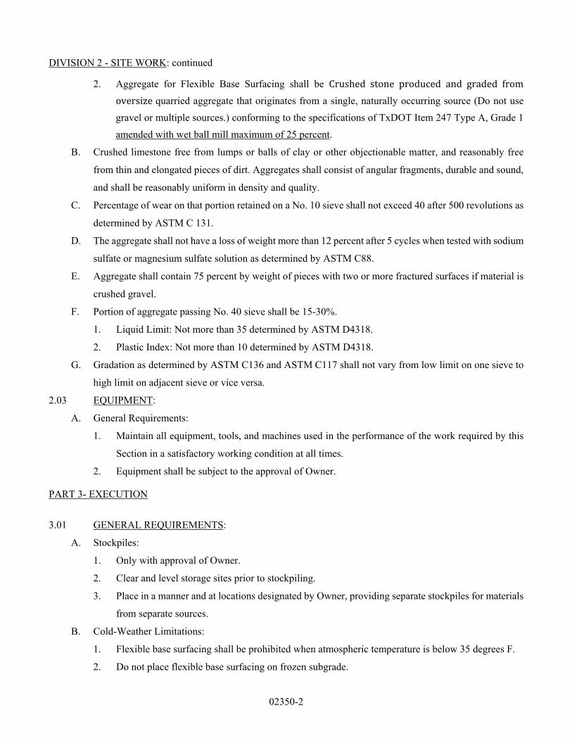
DIVISION 2 - SITE WORK: continued
02350-2
2. Aggregate for Flexible Base Surfacing shall be Crushed stone produced and graded from
oversizequarried aggregate that originates from a single, naturally occurring source (Do not use
gravel or multiple sources.) conforming to the specifications of TxDOT Item 247 Type A, Grade 1
amended with wet ball mill maximum of 25 percent.
B. Crushed limestone free from lumps or balls of clay or other objectionable matter, and reasonably free
from thin and elongated pieces of dirt. Aggregates shall consist of angular fragments, durable and sound,
and shall be reasonably uniform in density and quality.
C. Percentage of wear on that portion retained on a No. 10 sieve shall not exceed 40 after 500 revolutions as
determined by ASTM C 131.
D. The aggregate shall not have a loss of weight more than 12 percent after 5 cycles when tested with sodium
sulfate or magnesium sulfate solution as determined by ASTM C88.
E. Aggregate shall contain 75 percent by weight of pieces with two or more fractured surfaces if material is
crushed gravel.
F. Portion of aggregate passing No. 40 sieve shall be 15-30%.
1. Liquid Limit: Not more than 35 determined by ASTM D4318.
2. Plastic Index: Not more than 10 determined by ASTM D4318.
G. Gradation as determined by ASTM C136 and ASTM C117 shall not vary from low limit on one sieve to
high limit on adjacent sieve or vice versa.
2.03 EQUIPMENT:
A. General Requirements:
1. Maintain all equipment, tools, and machines used in the performance of the work required by this
Section in a satisfactory working condition at all times.
2. Equipment shall be subject to the approval of Owner.
PART 3- EXECUTION
3.01 GENERAL REQUIREMENTS:
A. Stockpiles:
1. Only with approval of Owner.
2. Clear and level storage sites prior to stockpiling.
3. Place in a manner and at locations designated by Owner, providing separate stockpiles for materials
from separate sources.
B. Cold-Weather Limitations:
1. Flexible base surfacing shall be prohibited when atmospheric temperature is below 35 degrees F.
2. Do not place flexible base surfacing on frozen subgrade.

DIVISION 2 - SITE WORK: continued
02350-3
3. Protect subgrade in freezing weather and repair areas damaged by freezing by reshaping and
recompacting prior to placing crushed rock.
C. Preparation of Subgrade:
1. Clean of all foreign substances.
2. Prepare subgrade in accordance with SECTION 02100.2.08
3. Owner will inspect, prior to placing crushed rock surface, for adequate compaction and surface
tolerances.
D. Grade Control: Establish and maintain by means of grade stakes spaced so string lines may be stretched
between stakes.
3.02 PLACING. SHAPING AND COMPACTION OF MATERIALS:
A. Placing:
1. Deposit and spread material in a uniform layer and compact to the thickness indicated and as
specified. Spread material uniformly on the prepared subgrade from moving vehicles or spreader
boxes.
2. Level material to the required contour and grades.
3. Remove those portions of the layer which become segregated or mixed with subgrade material in
spreading and replace with new material as requested by Owner.
4. Hauling which may damage the subgrade or surfacing will be restricted by Owner.
5. Remove and repair subgrade damaged during application of the crushed rock surface when directed
by Owner.
B. Shaping and Compacting Materials:
1. Compact in layers no less than three nor more than six inches thick.
2. Roll to specified compaction requirements throughout full depth of layer with power rollers, rubber-
tired rollers or combination.
3. Shape and smooth by blading and rolling with power roller, rubber-tired roller, or both.
4. Hand tamp in places not accessible to rolling equipment.
5. Compaction shall be as follows:
a. A minimum of two passes with a roller to obtain a minimum of 95 percent maximum standard
proctor dry density (ASTM D 698) in the range of -2 to +2 percentage points of optimum
moisture content.
b. c. The minimum frequency of tests will be as follows:
(1) At least one test every 10,000 square feet in the substation yard.
(2) At least one test every 100 linear feet of access drives
(3) At least one test when Owner suspects the quality of moisture control or effectiveness

DIVISION 2 - SITE WORK: continued
02350-4
of compaction.
6. Smoothness test shall be as follows:
a. Surface shall show no deviation in excess of 3/8-inch in any 10 feet when tested with a 10-
foot straightedge applied parallel with and at right angles to the center lines of the paved area.
b. Correct any deviation in excess of this amount by loosening, adding or removing material,
reshaping, watering, and compacting as requested by Owner.
3.03 MAINTENANCE:
A. Maintain finished surface course in a condition satisfactory to Owner.
B. Replace crushed rock surface deemed unsatisfactory as directed by Owner.
3.04 WAYBILLS AND DELIVERY TICKETS: Submit project total to Owner upon completion of work for
field verification.
END OF SECTION 02350

02400 - 1
DIVISION 2 - SITE WORK: continued
SECTION 02400 – FINE GRADING: LANDSCAPE PART 1 - GENERAL
1.1 SECTION INCLUDES:
A Furnish all labor, material, equipment, related services and supervision necessary for or incidental to fine
grading all disturbed areas within the limits of work as shown or indicated on the Drawings and/or as specified.
1.2 RELATED DOCUMENTS:
All other Divisions of the Contract Documents. Refer to each Division’s specifications and drawings for all requirements, including but not limited to the following:
1. Landscape Planting – Section 02450 2. Turf Establishment – Section 02500 3. Landscape Irrigation – Section 02600
PART 2 - PRODUCTS
2.1 LIMITS OF WORK:
A. The areas to be fine graded are all those turf and landscape areas as delineated on the construction
documents.
2.2 SEQUENCE OF WORK:
A. Fine grading of returf and landscape areas shall not commence until the Owner’s Representative has reviewed the subgrade and granted separate written permission for the placement of the topsoil, if required. Permission to proceed with the placement of the topsoil neither constitutes approval of the subgrade nor alleviates the Contractor of his responsibility.
B. Fine grading will not be attempted until all construction involving heavy equipment and vehicles is complete.
C. Fine grading shall be performed in compliance with the specifications. All elevations must be within 0.1 feet of the grades indicated on the plans, if a grading plan is provided. The surface shall have a consistent unwavering slope in all aspects/directions of the plane. Visual dips, depressions, ridges, rils, humps, etc. are not acceptable. The General Contractor, Landscape Architect and Owner’s Representative will conduct an on-site visual inspection after the Contractor has indicated that fine grade has been achieved. Any deficiencies noted must be corrected by the Contractor.
D. After fine grading is accomplished, it shall be the Contractor’s responsibility to protect all fine graded areas from vehicular traffic or other disruptive activities. Damages to the fine graded surfaces will be restored to a satisfactory condition as prescribed herein until the job is completed and accepted by the Architect and the Owner.
E. It is critical that all of the above outlined earthwork procedures be strictly followed to ensure an acceptable surface in the turf and landscape areas; therefore, work progressing without proper approval as delineated for each phase shall be subject to complete removal with no adjustment in price or contract time.

02400 - 2
DIVISION 2 - SITE WORK: continued
2.3 FINE GRADING OPERATIONS:
A. The following measures will be executed in the accomplishment of fine grading areas to be planted in turfgrass. The Contractor may elect to use additional or supplemental measures to accomplish fine grading. 1. Fine grading will be executed with any or all of the following or other appropriate machinery:
lightweight road grader, tractor box blade, discing machinery, weighted spike harrow, and weighted drags. Bulldozer blades or front end loader buckets are not acceptable devices for fine grading operations.
2. It is anticipated that some areas of earth embankment and high traffic areas may become overcompacted and resistant to proper grading. Such areas will be loosened and pulverized with discing machinery and will then be recompacted to normal density before fine grading. The use of a watering truck to moisten dried and hardened areas may be necessary.
2.4 ACCEPTABILITY:
A. The Architect will determine if fine graded areas are acceptable. Areas deemed unacceptable will be
corrected and re-graded until they are acceptable. Architect’s acceptance of the finish surface does not alleviate the Contractor of his responsibility to comply with the specifications.
B. Work progressing without proper approval for each phase of the earthwork operations shall be subject to complete removal.
PART 3 - EXECUTION
3.1 INSPECTION:
A. Examine areas and conditions under which fine grading is to be performed and notify Owner/Architect of
conditions detrimental to the proper and timely completion of the work.
3.2 PREPARATION:
A. Provide adequate protective measures of shoring, bracing, piling, planking and cribbing to protect existing adjacent construction.
1. Protect all reference points, benchmarks and monuments from dislocation or damage. Replace or repair immediately any points damaged, destroyed, or dislocated.
2. Sprinkle and dampen all dusty material from the beginning of work to its completion. 3. Protect and maintain all conduits, drains, inlets, sewers, pipes and wires that are to remain. 4. Provide, erect and maintain all lights, barricades, warning signs and guards as necessary.
B. The Contractor shall layout all work required and is responsible for all elevations, dimensions and verification of actual conditions. Refer discrepancies to the Architect for interpretation or required modifications.
C. Remove grass, weeds, trees, shrubbery, roots and other vegetation from the areas to be fine graded. Tree roots of protected trees shall not be disturbed. Contractor shall remove vegetation and organic matter by hand labor in tree root zone areas. Coordinate work with Architect in tree root zone areas.

02400 - 3
DIVISION 2 - SITE WORK: continued
3.3 PUMPING AND DRAINAGE:
A. Keep fine graded areas free from water, ice and snow at all times. Prevent water from interfering with progress or quality of the work.
3.4 RECONDITIONING FINISHED GRADE:
A. Where approved grades are compacted or disturbed by Contractor's subsequent operations or adverse
weather, the finished grades shall be scarified and re-graded as specified herein prior to further construction thereon.
3.5 GRADING:
A. Establish grades, if grading plan is provided, by means of grade stakes placed as required. Hold down
subgrade to allow depths required for approved topsoil and compost placement, if required. B. Fine grade to the elevations required by the drawings and specifications. C. Imported topsoil, if required, will be furnished by the Contractor and installed in the areas as indicated on
the plans. D. Finish grade to the elevations required by the drawings and for proper drainage. At intermediate points,
for which finish grades are not indicated, the finish grade shall be of uniform level of slope between points for which elevations are given. Provide a smooth gradient transition at any abrupt changes in elevation.
3.6 ADJUSTMENTS AND CLEANING:
A. Settlement or washing that occurs in fine graded areas prior to acceptance of work shall be repaired and grades re-established to the required elevations and slopes.
B. Cleanup all debris caused by the work of this section, keep the site clean and neat at all times. (End of Section)

DIVISION 2 - SITE WORK: continued
02450 - 1
SECTION 02420 -- LANDSCAPE PLANTING PART 1 - GENERAL 1.1 SCOPE: The work covered by this part of these specifications entitled "Planting Specifications" consists
of furnishing all plants and other materials, labor, equipment and appliances, and performing all operations in connection with the planting of trees, shrubs, ground covers, and other such materials in strict accordance with these specifications and the applicable drawings, and subject to the terms and conditions of the Contract.
1.2 APPLICABLE STANDARDS:
A. American Standard for Nursery Stock Edition approved May 2, 1986 B. American Joint Committee on Horticulture: Latest Edition of Standardized Plant Names.
1.3 CERTIFICATE OF INSPECTION: All necessary Inspection Certificates shall accompany the invoice for
each shipment or order of stock, as may be required by law for the necessary transportation, and such certificates shall be filed, prior to the acceptance of such material, at the office of Dunkin Sims Stoffels, Inc.
PART 2 - PRODUCTS 2.1 MATERIALS:
A. COMMERCIAL FERTILIZER: Fertilizer shall be a complete organic fertilizer, uniform in composition, dry and free-flowing. It should be delivered mixed as specified in standard-sized bags showing weight, analysis, and name of manufacturer, and stored in a weatherproof storage area where it will be kept dry. Fertilizer provided shall meet one or more of the following requirements to be approved: 1. Fifteen percent (15%) Nitrogen, five percent (5%) Phosphorous, ten percent (10%) Potash. Other
analysis may be used only upon approval of Owner’s Representative. B. SAND: Clean, washed sand; fine to coarse sizes C. PEAT MOSS: Peat Moss is to be of Canadian origin and is to be low in content of woody material and
free of minerals harmful to plant life; it shall have a pH of from four (4) to six (6), a moisture content of not more than thirty percent (30%), and a water absorbing capacity from one thousand one hundred to two thousand percent (1100% - 2000%). It may be natural or shredded.
D. MULCH: Mulch shall consist of peat moss, composted hardwood, redwood bark, well-rotted cotton seed or cotton boll hulls, free of any spray, residue, or other collected humus, or as specified on planting plan, and shall be of such character as not to be easily displaced by wind. Mulch shall be completely composted and have a pH of 8.2 or higher.
E. MATERIALS FOR STAKING: Refer to typical tree planting detail in the provided plans. F. PLANT MATERIALS: The Owner may inspect plants at place of growth but such inspection does not
preclude the right to rejection on the site. All plant materials shall meet the approval of the Landscape Architect. 1. Plant List - A plant list is shown on the planting plan. 2. Nomenclature - The scientific and common names of plants herein specified conform with the
approved names given in "Standardized Plant Names." Names of varieties not included therein conform generally with names accepted in the nursery trade.
3. Quantities necessary to complete the planting as shown and located on the drawings shall be furnished. Dimensions for ground cover beds have, in many instances, been established from scaled drawings. It is the Contractor's responsibility to check these dimensions on the site and allow for quantity of plants accordingly.
4. Quality and Size a. Plants shall have a habit of growth which is normal for the species and shall be sound, healthy,
vigorous, and free from insect pests, plant diseases, injuries, and aftereffects thereof. b. All plants shall equal or exceed the measurements specified in the Plant List, which are
minimum acceptable sizes. They shall be measured before pruning, with branches in normal

DIVISION 2 - SITE WORK: continued
02450 - 2
position. Any necessary pruning shall be done at the time of planting. c. Requirements for the measurement, branching, grading, quality, balling, and burlapping of
plants generally follow the code of standards currently recommended by the American Association of Nurserymen, Inc., in the "American Standard for Nursery Stock." (1) Minimum Ball Sizes for Trees
Ball Depth Ball Diameter Tree Size Minimum Minimum 12" - 2" cal. 20" 24" 2" - 22" cal. 22" 28" 22" - 3" cal. 24" 36" 4" cal. 30" 48" 5' - 6' High 18" 30" 6' - 8' High 24" 36"
(2) Tree ball shapes shall be truncated cones.
d. Plants in containers specified in the Plant List shall have been acclimated to outside conditions. e. Divisions shall be parts of plants suitable for transplanting, guaranteed to grow.
5. Substitutions will be permitted only upon submission of proof that a plant is not reasonably obtainable and authorization by the Landscape Architect of a change directive providing for use of the nearest equivalent obtainable size and variety of plant having the same essential characteristics with an equitable adjustment of contract price.
2.2 DIGGING, WRAPPING AND HANDLING A. BALLED PLANTS: Plants designated "B&B", balled and burlapped, in the Plant List, shall be adequately
balled with firm, natural balls wrapped with burlap. No balled plant shall be planted if the ball is cracked or broken, either before or during the planting process. Any plant which is loose in the ball shall be removed from the site and another plant conforming to the specifications of the plant removed shall be planted in its place at the expense of the Contractor.
B. BARE ROOT PLANTS: Plants designated "BR", bare root, in the Plant List, shall be dug with substantially all the root system intact, but with the soil carefully removed from the roots without injury to the fibrous root system necessary for the full recovery of the plant. Roots shall be covered with a thick coating of mud by puddling, or wrapped in wet straw, moss, or other suitable packing material immediately after they are dug, for protection until delivery.
C. CONTAINER-GROWN PLANTS: Plants designated in various size and type containers in the Plant List shall be of a reasonable age and state of development for the size container in which they are specified. They shall have been growing in their containers sufficiently long to develop a good sound root system capable of holding the soil intact after removal from the container, but not so long as to have become pot bound.
D. OPTION AS TO METHODS: Any plant may be furnished container-grown in lieu of other methods desig-nated in the Plant List if all other requirements are met. Any substitutions shall be made only with the approval of the Landscape Architect and at no change in price.
E. PROTECTION: 1. All plants shall be handled in such a manner as to avoid unnecessary damages of any kind. Roots
shall be especially protected at all times from drying. The balls of balled plants which cannot be planted immediately upon delivery shall be covered with moist soil or mulch, or other protection from drying wind and sun. Bare root plants shall be planted or heeled-in immediately upon delivery. All plants shall receive expert attention and shall be watered as necessary until planted.
2. Do not bind plants with wire or rope so as to damage bark or break branches.

DIVISION 2 - SITE WORK: continued
02450 - 3
F. SPECIAL HANDLING OF SPECIMEN PLANTS: Specimen plants, intended for isolated positions in the planting, shall be selected for shape and for branching habit, which at maturity will produce a strong full-foliaged specimen. Particular care should be exercised in the digging, wrapping and binding of such specimen plants to assure safe loading, shipment, and handling for the entire operation of transportation from growing location to the replanting locations shown on the Drawings.
PART 3 - EXECUTION 3.1 GENERAL:
A. TIME OF PLANTING: Planting operations shall be conducted under favorable weather conditions during the seasons which are normal for such work as determined by accepted practice in the locality. At the option of and on the full responsibility of the Contractor, planting operations may be conducted under unreasonable conditions without additional compensation to the Contractor.
B. PREPARATION FOR PLANTING OPERATIONS: Before planting operations are begun, all existing turf areas which are to be trucked over or upon which soil is to be temporarily stacked, pending its reuse or removal, or turf areas which may be subject to abuse of any other kind shall be covered in a manner which will satisfactorily protect such areas from serious damage. Existing trees, shrubs, and beds that are to be preserved shall be barricaded in a manner, approved by the Landscape Architect, that will effectively protect them during planting operations.
C. OBSTRUCTION BELOW GRADE OR OVERHEAD: 1. Any nominal size rock or other underground obstruction shall be removed to the depth necessary to
permit proper planting according to Plans and Specifications. If underground construction, unusually large rock, or other serious obstructions are encountered in planting areas, other locations for the planting may be selected by the Landscape Architect. Explosives may not be used for the removal of rock or old foundation structures.
2. The Landscape Contractor shall secure from the General Contractor copies of layout drawings showing the location of all underground utility lines and other structures in order to minimize conflict with same during excavation operations. If any such lines or structures are uncovered during operations, the Contractor shall notify the Owner at once so that arrangements may be made either to move the structure or relocate the planting.
3. Slight changes may also be made in plant locations which conflict with overhead utility lines, such relocation is subject to the approval of the Landscape Architect.
3.02 EXCAVATION FOR PLANTING: Excavation shall include stripping and stacking of all acceptable topsoil
encountered within the areas to be excavated. All excavated material unacceptable for reuse shall be disposed of off-site.
3.03 MISCELLANEOUS MATERIALS: A. TOP DRESSING: Completely Composted Hardwood Bark Mulch with a pH of 8.2 or higher.
3.04 SOIL PREPARATION AND FERTILIZING:
A. GENERAL: Inspect all sub-grade conditions and other items of work previously completed and report any deficiencies to Owner's Representative for correction.
B. SHRUB AND GROUNDCOVER BEDS: 1. Install all material in layers as prescribed (no premixing) and obtain the approval of Owner's
Representative before tilling.
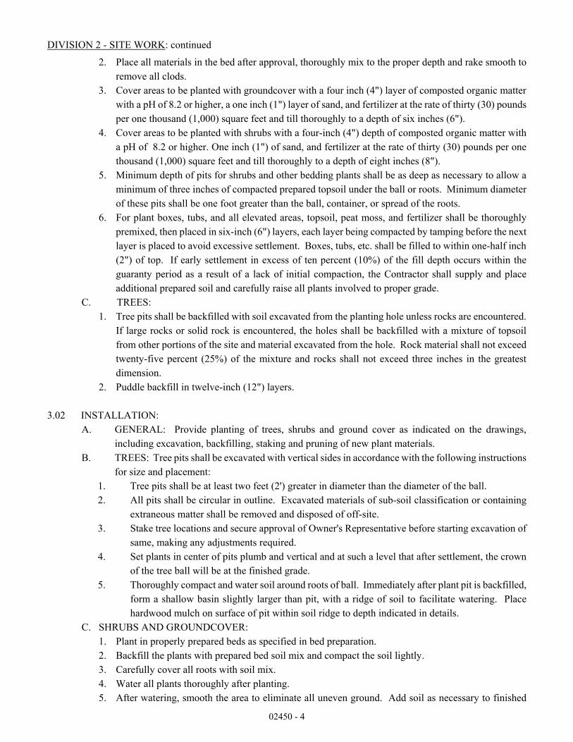
DIVISION 2 - SITE WORK: continued
02450 - 4
2. Place all materials in the bed after approval, thoroughly mix to the proper depth and rake smooth to remove all clods.
3. Cover areas to be planted with groundcover with a four inch (4") layer of composted organic matter with a pH of 8.2 or higher, a one inch (1") layer of sand, and fertilizer at the rate of thirty (30) pounds per one thousand (1,000) square feet and till thoroughly to a depth of six inches (6").
4. Cover areas to be planted with shrubs with a four-inch (4") depth of composted organic matter with a pH of 8.2 or higher. One inch (1") of sand, and fertilizer at the rate of thirty (30) pounds per one thousand (1,000) square feet and till thoroughly to a depth of eight inches (8").
5. Minimum depth of pits for shrubs and other bedding plants shall be as deep as necessary to allow a minimum of three inches of compacted prepared topsoil under the ball or roots. Minimum diameter of these pits shall be one foot greater than the ball, container, or spread of the roots.
6. For plant boxes, tubs, and all elevated areas, topsoil, peat moss, and fertilizer shall be thoroughly premixed, then placed in six-inch (6") layers, each layer being compacted by tamping before the next layer is placed to avoid excessive settlement. Boxes, tubs, etc. shall be filled to within one-half inch (2") of top. If early settlement in excess of ten percent (10%) of the fill depth occurs within the guaranty period as a result of a lack of initial compaction, the Contractor shall supply and place additional prepared soil and carefully raise all plants involved to proper grade.
C. TREES: 1. Tree pits shall be backfilled with soil excavated from the planting hole unless rocks are encountered.
If large rocks or solid rock is encountered, the holes shall be backfilled with a mixture of topsoil from other portions of the site and material excavated from the hole. Rock material shall not exceed twenty-five percent (25%) of the mixture and rocks shall not exceed three inches in the greatest dimension.
2. Puddle backfill in twelve-inch (12") layers. 3.02 INSTALLATION:
A. GENERAL: Provide planting of trees, shrubs and ground cover as indicated on the drawings, including excavation, backfilling, staking and pruning of new plant materials.
B. TREES: Tree pits shall be excavated with vertical sides in accordance with the following instructions for size and placement:
1. Tree pits shall be at least two feet (2') greater in diameter than the diameter of the ball. 2. All pits shall be circular in outline. Excavated materials of sub-soil classification or containing
extraneous matter shall be removed and disposed of off-site. 3. Stake tree locations and secure approval of Owner's Representative before starting excavation of
same, making any adjustments required. 4. Set plants in center of pits plumb and vertical and at such a level that after settlement, the crown
of the tree ball will be at the finished grade. 5. Thoroughly compact and water soil around roots of ball. Immediately after plant pit is backfilled,
form a shallow basin slightly larger than pit, with a ridge of soil to facilitate watering. Place hardwood mulch on surface of pit within soil ridge to depth indicated in details.
C. SHRUBS AND GROUNDCOVER: 1. Plant in properly prepared beds as specified in bed preparation. 2. Backfill the plants with prepared bed soil mix and compact the soil lightly. 3. Carefully cover all roots with soil mix. 4. Water all plants thoroughly after planting. 5. After watering, smooth the area to eliminate all uneven ground. Add soil as necessary to finished

DIVISION 2 - SITE WORK: continued
02450 - 5
grade and water. 6. Cover all bed areas with a layer of mulch as previously stated.
D. SETTING PLANTS: 1. General: All plants shall be set one and one half inches (12") to two inches (2") above existing grade
so that after settlement they bear the same relation to the finished grade of the surrounding soil that they bore to the grade of the soil from which they were dug.
2. Ground Cover Areas: Plants used as ground cover and spaced less than twenty-four inches (24") o.c. shall be planted in beds of prepared soil as herein before specified. Plants used as ground cover and spaced twenty-four inches (24") o.c. or greater shall be planted in individual pits as herein before specified; the entire area accommodating such plants, however, shall be roto-tilled and cleared of all grass, weed etc. before pits are dug and sand raked clean of all rocks and other debris.
3. Balled Plants and Container Grown Plants: After pits have been dug as herein before specified a minimum of three inches (3") of compacted prepared soil, or as much more as is needed to allow the ball to rest firmly on such compacted soil at the proper level, shall be placed in the bottom of the pit. Soil shall then be placed around the ball and compacted carefully to avoid injury to roots and to fill all voids. Burlap, rope, wire and other wrapping materials shall be cut away from the top of the ball and removed from the pit, but no burlap shall be pulled from under the ball. All broken or frayed roots shall be cut off clean. When the pit is nearly filled with soil, add water and allow it to soak away. Fill the pit to finished grade. After the ground settles, additional soil shall be filled in the level of the finished grade. Container grown plants shall be set in similar manner and shall remain in their containers until just before setting in place.
4. Bare Root Plants: All broken or frayed roots shall be cut off clean. Set plants at slightly above finished grade, spread roots in a natural soak away. After settlement, add soil as necessary to finished grade and water.
5. Plants in Beds: Carefully insert plants into prepared soil beds at slightly above finished grade. When all plants are in place, rake the entire bed area smooth, water and allow to soak away. After settlement, add soil as necessary to finished grade and water. Place mulch layer as per details.
6. Plants in Boxes, Tubs, and Elevated Areas: Make sure plants in deep fills are resting on well compacted soil to avoid excessive settlement. Set plants as herein before specified, fill boxes and tubs to within one half inch (1/2”) of top water thoroughly.
E. PRUNING: 1. Remove dead wood, suckers and broken or badly bruised branches. 2. Pruning shall be limited to the minimum necessary to remove injured twigs and branches, and to
compensate for the loss of roots during transplanting, but never to exceed one-third (1/3) of the branching structure.
3. Perform all pruning with clean, sharp tools. 4. Paint cuts of three-fourths inches (3/4") or greater in diameter with an approved tree paint. Cover
all exposed cambium as well as other exposed living tissue. Paint shall be waterproof, adhesive and elastic, antiseptic, free form kerosene, coal tar, creosote of any other material injurious to the life of the tree.
F. MULCHING: Plants shall be mulched within two (2) days after planting. Trees shall receive a three-inch (3") deep (after settlement) layer of mulch material, entirely covering the area around each plant. In case of ground cover areas, the entire bed shall receive a two-inch (2") deep (after settlement) layer of mulch material.
G. SOAKING: All plants to be soaked in with Carl Pool's Root Activator, as suggested by manufacturer, immediately after planting.

DIVISION 2 - SITE WORK: continued
02450 - 6
H. CLEAN-UP: As planting operations proceed, all rope, wire, burlap, empty containers, rocks, clods
and all other debris shall not be stored on-site. The site shall be kept as tidy as possible at all times. I. PLANT GUARANTY AND REPLACEMENT:
1. Warranty period begins after inspection and final acceptance of the work by the Owner and continues for a period of one (1) year for all trees, shrubs, ground cover and turf. Acceptance will be given only if plant materials meet specifications and have been installed strictly according to Contract Documents.
2. From planting to final acceptance of the project, the Landscape Contractor shall be responsible for all plant material. Any plant that dies or is not in satisfactory growth prior to final inspection shall be promptly replaced. This replacement will not be considered as a warranty replacement.
3. The Landscape Contractor shall warranty all plantings as stated above except when damaged or killed as a result of hail, wind, lightning, fire, freeze, Owner's neglect.
4. At the option of the Owner, plants which die during the warranty may be replaced before the end of this one year period. The landscape Contractor shall be responsible for all plants and their replacements during the one year warranty period. Should the warranty replacement plants die or are not in a satisfactory condition before the end of the warranty replacement period, these plants shall also be replaced. All replacements for which the Landscape Contractor is responsible shall be made with plants of the same size and kind, and in the same manner as specified for original planting and at no additional cost to the Owner.
5. At the end of warranty period, any plant that is dead or has fifty percent (50%) or more of main branch structure dead, or not in satisfactory growth, as determined by the Owner's Representative, shall be removed from the site and shall be replaced as soon as normal conditions for planting permits. Plants which die as no fault of the Landscape Contractor shall be replaced at a price agreed upon with the Owner prior to replacement.
6. Contractor shall replace and/or relocate and reinstall all piping, paving, walls, fences, wiring, lighting, plumbing, planting, or other material he disrupts while making any replacement called for the above warranty.
J. NOTIFICATION RESPONSE: Response to notification of work to be done under the warranty must be within thirty (30) days from the date of notification and work must be started within this time to repair or replace necessary plants unless prevented by weather. If the Landscape Contractor does not make repairs and acknowledges notification within this time, Owner, without further notice, may provide materials and labor to make needed repairs or replacements at the expense of the Landscape Contractor.
END OF SECTION

DIVISION 2 - SITE WORK: continued
02500-1
SECTION 02500 -- TURF ESTABLISHMENT PART 1 - GENERAL 1.1 DESCRIPTION: Work included: This work involves various operations necessary to provide
and establish a Bermuda grass turf-bed in accordance with the plans and specification contained herein. The plans shall determine areas to receive seed and/or sod.
1.2 RELATED WORK SPECIFIED ELSEWHERE: 1.3 QUALITY ASSURANCE:
A. Qualifications of workmen: Provide at least one person who shall be present at all times during execution of this portion of the Work, who shall be thoroughly familiar with the type of materials being installed and the proper materials and methods for their installation, and who shall direct all work performed under this section.
B. Standards: All plants and planting material shall meet or exceed the specifications of Federal, State, and County laws requiring inspection for plant disease and insect control.
1.4 SUBMITTALS:
A. Materials lists: Within 45 days after award of the Contract, submit a complete list of all materials proposed to be furnished and installed under this Section, demonstrating complete conformance with the requirements specified.
B. Certificates: Deliver certificates for all materials to be used to the Landscape Architect. 1.5 PRODUCT HANDLING
A. Deliver all items to the job site in their original containers with all labels intact and legible at time of Landscape Architect's inspection.
B. Immediately remove from the site all materials which do not comply with the specified requirements.
C. Use all means necessary to protect plant materials/seeds before, during, and after installation and to protect the work and materials of all other trades.
D. Replacements: In the event of damage, immediately make all repairs and replacements necessary to the approval of the Landscape Architect and at no additional cost to the Owner.
PART 2 - PRODUCTS 2.1 MATERIALS:
A. HERBICIDE - "Round Up" or approved equal B. GRASS SOD: Common Bermuda grass - Sod shall be free of all debris, weeds, and have
been regularly maintained prior to cutting. Within one hour after being cut, the sod shall be rolled or stacked. Precautions shall be taken to prevent damage from heat or inadequate moisture. Sod cut more than 18 hours shall not be used and shall be discarded offsite. Sod shall be cut at a sufficient thickness to allow 3" to 2" of soil to remain intact on each piece of sod.
C. GRASS SEED: Common Bermuda grass (Cynodon Dactylon), hulled, 82% pure live seed or rye grass seed (Lolium perenne). See plan for type of seed. All grass seed shall be free from noxious weeds, grade A recent crop, recleaned, and treated with appropriate fungicide at time of mixing. Seed shall be furnished in sealed, standard containers, which shall be retained by the Contractor for inspection. Copies of the official seed analysis or official seed tags shall be furnished to the Landscape Architect.
D. MULCH: Conwed regular wood fiber mulch or approved equal

DIVISION 2 - SITE WORK: continued
02500-2
E. FERTILIZER: Mississippi Chemical 18-18-5, water soluble, or an approved equal F. FIBER TACK: Apply with hydromulch on properly prepared seed beds in all areas
indicated on the plans at the rate of one and one-half (12) pounds of Fiber Tack per one thousand (1,000) square feet.
PART 3 - EXECUTION 3.1 INSPECTION:
A. Examine the areas and conditions under which the work of this Section will be performed. Correct conditions detrimental to the proper and timely completion of the work. Do not proceed until unsatisfactory conditions have been corrected.
B. Areas to be solid sodded and hydromulched/seeded are under automatic or manual irrigation. Locations of irrigation heads, valves, electric junction boxes, etc. shall be determined by the Contractor and flagged to prevent damage.
3.2 CLEARING:
A. Prior to grading and tilling, vegetation that may interfere with operations shall be mowed, grubbed, and raked. The surface on the entire area to be turfed shall be cleared of stumps, stones, roots, debris, wire, and other materials that might hinder the work or subsequent maintenance. The collected material shall be removed from the site.
3.3 SPREADING OF TOP SOIL
A. Fine grading: Perform all fine grading required in the planting areas, using top soil obtained from the site or imported when necessary.
B. During the fine grading operations, all swales shown on the grading plan and additional swales that may be required to drain areas shall be completed. In general, all grade adjustments shall be made so there are no areas that will have standing water.
C. Immediately install the lawn upon the completed and accepted fine grade. 3.04 PLANTING BED PREPARATION (BERMUDA OR RYE):
A. Two weeks prior to application, the areas to be sodded, hydromulched and/or drill seeded is to be treated with a post emergent herbicide at a rate recommended by the manufacturer.
B. Disk area to be sodded, hydromulched and/or drill seeded to a 4" min. depth, then cultivate with weighted spike tooth harrow or rake. Drag area till level and smooth, removing high areas and filling depressions. If area becomes compacted during harrowing and smoothing process, it shall be retilled to the specified depth and reharrowed to achieve an acceptable soil bed.
C. Remove debris and rocks. Clods of soil in excess of 12" which have not been softened by irrigation or broken by the afore described cultivation practices shall be removed from the seed bed.
D. When preparation is complete, Contractor will request Landscape Architect to make inspection of site to determine acceptability before starting hydromulch, sodding, and/or drill seeding application.
3.5 SOLID SODDING APPLICATION
A. Prior to placing the solid sod, the turf bed shall be sufficiently watered to wet the soil surface and eliminate scalding of the roots at the base of the solid sod.
B. Sod shall be placed in rows or strips. On slopes and in swales, the strips shall be placed at right angles to the flow of water. Sod pieces shall be placed tightly against each other with joints staggered at least one foot.
C. Contractor shall roll the sodded area with a hand pulled roller to ensure that all gaps and

DIVISION 2 - SITE WORK: continued
02500-3
spaces are eliminated between sod bed and sod. D. Set frequency and duration of water times to completely wet the sod and sod bed without
hampering future or existing operations. 3.6 SEEDING APPLICATION:
A. Bermuda grass hydromulch or drill seeding shall neither be applied prior to May 1 nor after August 15 or at anytime the soil temperature is less than 70 degrees F. Rye seed shall not be applied prior to November 15 nor after January 1.
B. Application Rates 1. Application Rate: Hydromulch (Bermuda)
a) Common Bermuda grass @ 22 lbs/1000 S.F. b) Mulch @ 60 lbs./1000 S.F. c) Fertilizer @ 25 lbs./1000 S.F.
Typical mix for 800 gallon tank with coverage not to exceed 6,000 S.F. shall consist of 15 lbs. of common Bermuda grass seed, 360 lbs. of Conwed mulch, and 150 lbs. of 18-18-5 fertilizer.
2. Application Rate: Drill Seed (Bermuda) a) Common Bermuda grass @ 22 lbs/1000 S.F. b) 15-5-10 Granular Fertilizer @ 25 lbs./1000 S.F.
3. Application Rate: Broadcast (Rye) a) Common Rye grass @ 4 lbs/1000 S.F. b) 15-5-10 Granular Fertilizer @ 25 lbs./1000 S.F.
4. Apply in a uniform manner over all areas to be seeded. C. Set frequency and duration of watering times to provide water to newly seeded areas
without hampering future operations. D. Reserved E. Drill Seeding - Seed shall be uniformly distributed over area shown on the plans. Seed
shall be applied with mechanical methods. The Contractor must provide seed coverage as provided under 3.8.
3.7 CLEAN-UP:
A. Remove all debris from site, clean walkways, repair ruts, and any other damage resulting from turf establishment operations.
3.8 COVERAGE:
A. Contractor shall be responsible for total coverage of all areas delineated on the plans for turf establishment. Bare areas in excess of twelve square inches (i.e. 3" X 4") resulting from unequal seed distribution, lack of germination, erosion, or other causes shall be reseeded per the original specifications.
3.9 GUARANTEE:
A. Coverage will be complete; areas of ungerminated seed twelve square inches (i.e. 3" X 4") and larger will be reseeded.
B. Repair any damage made during reseeding immediately. 3.10 MAINTENANCE:
A. After solid sodding, hydromulching or drill seeding maintain the lawn area and keep constantly moist until a stand of grass is present. Maintenance shall consist of watering, replanting, mowing, maintaining existing grades, and repair of erosion damage.
B. Maintenance watering shall consist of daily watering. Maintenance watering shall be applied each day over the entire planted area until the soil is thoroughly wet to a depth of

DIVISION 2 - SITE WORK: continued
02500-4
two (2) inches as determined by the Landscape Architect. During periods of effective rainfall, watering shall be discontinued but shall be promptly resumed when required.
C. Vegetation in lawn areas shall be kept under control by mowing. Any time that the vegetation growth reaches a height of three (3) inches, the areas shall be mowed. Mowing shall be done with approved mowing machines in such manner that will leave a vegetation height of two (2) inches.
D. Areas on which a stand of growing grass is not present within four weeks of planting shall be resodded or reseeded as specified for the original planting. These said areas shall continue to be replanted until a viable stand is obtained. For seed application purposes, a stand shall be defined as live specified grass plants from seed occurring at the rate of not less than forty (40) growing plants per square foot. The aforementioned forty growing plants must be evenly distributed throughout the square foot area. For solid sod, any strip of solid sod in which 50% or more of the roughly 18" x 24" area has died shall be replaced.
END OF SECTION

DIVISION 2 - SITE WORK: continued
02600-1
SECTION 02600 -- LANDSCAPE IRRIGATION SYSTEM PART 1 - SPECIAL CONDITIONS 1.1 QUALIFICATIONS
A. Qualifications of Bidder: In order to qualify as a Contractor for any portion of this work, the Contractor shall be a registered Contractor in the State of Texas, regularly engaged in the business of installing turf irrigation systems and shall have satisfactorily completed a minimum of three (3) comparable medium turf projects of this size. List of references may be required.
1.2 RESPONSIBILITIES OF CONTRACTOR
A. All materials and equipment shall be installed in a neat and workman-like manner following the recommendations of the manufacturers of the materials.
B. The Owner's Authorized Representative retains the right to order removal or replacement of any items which, in his opinion, do not present a reasonably neat and workman-like appearance. Any removal and replacing of materials shall be done when directed in writing at no additional expense to the Owner.
C. The Contractor's superintendent shall supervise the Contractor's employees on the job site and be responsible for their actions and conduct on the job site. No one under the age of eighteen (18) will be allowed to work on this project.
D. All plot dimensions on the irrigation design are approximate. Prior to proceeding with the work, the Contractor shall carefully check and verify all dimensions and shall report all variations from those indicated in the irrigation plan to the Owner in writing. If changes are to be made, they will be made in accordance with previous provisions.
E. If the Contractor does not respond to the Owner's request for repair work within a period of seven (7) calendar days, the Owner may proceed with such necessary repairs and charge the Contractor for all expenses incurred in the repair work.
F. AS-BUILT RECORD DRAWING: The Contractor shall provide and keep up to date a complete set of as-built drawings which shall be corrected daily to show changes in sprinkler locations, controller locations, pump locations, piping locations, and other deviations from the original irrigation design drawing as provided to him. All isolation valves, quick coupler valves, control valves, etc. locations shall be shown with actual measurements to physically visible reference points so they may be located easily in the field. Upon completion of the work, the Contractor shall furnish the Owner with a complete set of reproducible (mylar sepia or vellum) as-built drawings showing the sprinkler system as installed. This is the responsibility of the Irrigation Contractor and shall not be construed to be the responsibility of any other party.
G. Upon completion of the work and acceptance by the Owner, the Contractor shall be responsible for the training of Owner’s Personnel in the operation, maintenance, and repair of the system. The Contractor shall furnish copies of all available parts lists, trouble shooting lists, specification sheets, and catalog sheets to the Owner prior to final payment.
H. The Contractor shall set the initial watering schedules and programming of the automatic controllers in accordance with the specifications or irrigation plan as furnished by the Owner. Changes in the schedules and programming and instructions on how to make such changes shall be the responsibility of the system operator.
PART 2 - GENERAL SPECIFICATIONS 2.1 SCOPE OF WORK: The furnishing and installing of the sprinkler components as shown on the
plans, ready for operation, shall include the following:

DIVISION 2 - SITE WORK: continued
02600-2
A. All piping; trenching; back-flow prevention devices; remote electric valves; automatic sprinkler controllers, etc.; installed as shown on the plans and required to provide distribution of sprinkler water to all sprinkler heads indicated and/or specified.
B. All electrical material and labor required to connect to primary electrical service. 2.2 DEFINITIONS:
A. "SPRINKLER MAINS" are that portion of piping from water source to operating valves. This portion of the piping is subject to surges, being a closed portion of the sprinkler systems and considered as pressure lines.
B. "LATERAL PIPING" is that portion of piping from operating valves to the sprinkler heads. This portion of the piping is not subject to surges, being an "open end" portion of the sprinkler system.
C. "QUICK COUPLING VALVE LINES" are considered a part of the sprinkler main. 2.3 SUBSTITUTIONS:
A. Material shall be as specified or equal. Substitutions must have the approval of the Owner's Representative in writing before installation of the irrigation system.
PART 3 - MATERIAL SPECIFICATIONS 3.1 POLYVINYL CHLORIDE PIPE: Polyvinyl chloride pipe (hereinafter referred to as PVC pipe)
shall have been manufactured in accordance with the Product Standards as follows: A. Product Standard PS-22-70 shall apply and be the governing authority as applicable to
mainline piping and shall be SDR-21 (Class 200) specification. B. Product Standard PS-22-70 shall apply and be the governing authority as applicable to
lateral piping and shall be per SDR-21 (class 200) specification. One half inch (2") PVC piping shall be 315 PSI. Three quarter inches (3/4") and larger PVC shall be 200 PSI.
C. Marking and Identification: All PVC pipe shall be continuously and permanently marked with the following information: manufacturer's name, pipe size, type of pipe and material, SDR number, Commercial Standard Number and NSF (National Sanitation Foundation) seal.
3.2 PVC PIPE FITTINGS:
A. All PVC fittings shall be schedule 40 solvent weld type which are compatible with the PVC pipe. All fittings shall conform to ASTM #D2464 for plastic pipe fittings, D2466 for plastic pipe fittings.
B. All solvent shall conform to ASTM #D2564 solvent cement for PVC plastic pipe fittings. Solvent shall also be as recommended by the manufacturers of the plastic pipe and fittings.
3.3 COPPER TUBE:
A. All copper tube shall be type "M", hard, straight lengths, of domestic manufacture only. Soft tube may be required for special applications, in which case these special applications will be covered by the specifications elsewhere.
B. No copper tube of foreign extrusion or any so-called irrigation tubing (thin wall) shall be used.
3.4 COPPER TUBE FITTINGS:
A. All copper tube fittings shall be cast brass or wrought copper, sweat-solder type. B. Fittings shall be attached to the tubing in approved manner, using 50-50 soft solder, except
where special application may require another method of attachment, in which case these special applications will be covered by the specifications elsewhere.

DIVISION 2 - SITE WORK: continued
02600-3
3.5 SWING JOINT NIPPLES: All swing joint nipples shall be unplasticized polyvynl chloride,
Schedule 80, threaded pipe. Fittings on swing joints shall be P.V.C. Schedule 40 threaded elbows or street elbows.
3.6 ROTARY POP-UP GEAR-DRIVEN HEADS:
A. All rotary heads shall be gear-driven rotary pop-up units with a sealed power train. Heads shall be of plastic construction with a positive gear drive for full and part-circle heads. Part-circle heads shall be adjustable to provide the arc of coverage as shown on the plan.
B. Rotary heads shall be so constructed as to allow removal of the drive train and nozzle assembly from above ground without removal of the body from the riser. Drive train shall be equipped with a strainer around the impeller and a wiper seal between the cover and the nozzle assembly. The cover will be screwed to the body of the head.
C. Nozzle shall pop-up a minimum of one and one half inches (12") during operation and will be attached to the riser with teflon tape on pipe threads.
D. All heads will have rubber cover. E. Manufacturer and type shall be as indicated on the irrigation plan or an approved equal.
3.7 ROTARY HEAD PERFORMANCE: Gear drive, ball drive, full circle and adjustable part circle
type. 3.8 QUICK COUPLER VALVES: Shall be installed as specified in plans. Quick coupler valves
shall be installed on swing-joints as specified in 2.5 swing joint nipples. Quick couplers will be staked with one half inch (2) diameter rebar two (2) feet long and clamped with stainless steel worm-gear type clamp.
3.9 DOUBLE GATE DOUBLE CHECK VALVE ASSEMBLY: Double gate double check valve
assembly shall be located and sized as shown on the plan. Construction shall be all brass. This assembly shall be installed in a suitable box approved by the Owner and shall conform to the City Plumbing Codes.
3.10 ELECTRIC VALVES: Remote control electric valves shall be located and sized as shown on
the plan. Valves shall be as specified on the plan or approved equal. Operation shall be accomplished by means of an integrally mounted heavy duty 24-V AC solenoid. Solenoid coil shall be potted in epoxy resin with a plastic coated stainless steel housing. Solenoids shall be completely waterproof, suitable for direct underground burial. A flow stem adjustment shall be included in valve. All valves will be placed in a ten (10) inch plastic Amtex valve box or approved equal.
3.11 AUTOMATIC SPRINKLER CONTROLLERS: Automatic sprinkler controllers shall be of the
quantity and type shown on the irrigation plan. Controller(s) shall be mounted and located as indicated on the irrigation plan.
3.12 WIRING (115 VOLT ELECTRIC WIRING): All 115 volt AC wiring shall be installed in
accordance with electric codes. 115 volt service to controllers shall consist of one black and one white wire. All wiring shall be buried to minimum depth of eighteen inches (18"). Wire shall be furnished in minimum two thousand, five hundred feet (2500') reels and spliced only at connections or tee locations and will be placed in a valve box for easy location and service. All wiring shall be 14 gauge. All splices in wiring shall be made watertight using approved methods.
3.13 CONTROL LINES:

DIVISION 2 - SITE WORK: continued
02600-4
A. Twenty-four (24) Volt Electric: Electric control lines from controller to automatic valves shall be direct burial UF wire of a different color than the 110 volt service to controllers. The 24 volt common ground shall be of one continual color and a different color than the other 24 volt lines and the 100 volt service.
B. All wire shall be furnished in minimum two thousand, five hundred (2500) reels and splicing shall be minimized, with such splices made waterproof with the use of waterproof Scotchlok or Pen-Tite kits. All splices shall be placed in a 6” valve box for easy location & service. All 24 volt wiring shall be done in accordance with existing codes.
3.14 ITEMS TO BE FURNISHED:
A. The Irrigation Contractor shall furnish the following items, in addition to the installation, and shall deliver them to the Owner upon completion:
3 each - 1" coupler keys with hose bibs 4 each - 12" pop-up spray heads 4 each - 4" pop-up spray heads (of each type) 1 each - Key to lock control boxes
PART 4: INSTALLATION SPECIFICATIONS 4.1 INSTALLATION, GENERAL:
A. Inspection of Work in Progress: The Owner's Authorized Representative shall be responsible for inspection of the Contractor's work while such work is in progress. Said Representative shall bring to the attention of the Contractor any work which does not meet the specifications of this contract and the Contractor shall correct such work as brought to his attention.
B. Staking of Sprinkler Locations: Staking of sprinkler locations shall be done by the Contractor and approved by the Owner's Representative.
C. Before installation is started, the Contractor shall insure the head spacing will cover on a fifty percent (50%) (head to head coverage) overlap and every sprinkler is to be located in accordance with the plans. The inspection shall be approved in writing by the Owner before installation is started. Should a discrepancy in the plans become apparent at this time, in regard to size and shape of areas to be watered, such discrepancy shall be pointed out to the Owner. Work must not proceed until the Owner approves and any necessary engineering changes are made. Should such changes create extra cost to the Contractor, approval for an agreed upon extra compensation must be obtained in writing from the Owner before commencing work. Should such changes create a savings in cost to the Contractor, a written reduction in the contract price shall be approved by the Owner in writing before commencing work.
D. Holes and trenches cannot be left open for more than twenty-four (24) hours. 4.02 EXCAVATION, BACKFILL AND PROTECTION OF SHRUBBERY, GENERAL:
A. All excavation in this contract shall be unclassified and is to include earth, loose rock, rock, or any combination thereof, in wet or dry state.
B. All trenches shall be backfilled with the material removed, except where rock is encountered. In this case, the backfill shall consist of existing on-site soils free of rocks in excess of one inch (1") in their longest dimension. If the soil is extremely rocky or the trench is cut into solid rock, the trench shall be over-excavated and padded with two inches of soil or sand.
C. All trench backfill shall be flooded and compacted in order to prevent after-settling. D. All trenches and adjoining areas shall be hand-raked to leave grade in as good or better
condition than before installation.

DIVISION 2 - SITE WORK: continued
02600-5
4.3 CLEAN-UP PREMISES: The Contractor shall continuously keep a neat and orderly area in
which he is installing the system. Disposal of rubbish and waste material resulting from the installation shall be continual. Upon completion of the system, the Contractor shall remove from the Owner's property, at his own expense, all temporary structures, rubbish, and waste materials resulting from the installation of said system.
4.4 ELECTRICAL WORK: Electrical service to the automatic controllers will be provided by the
Contractor. 4.5 PIPE INSTALLATION:
A. GENERAL: 1. Sprinkler mains shall be installed in an eight-inch (8") wide (minimum) trench with a
minimum of eighteen inches (18") cover. 2. Lateral piping shall be installed in a six-inch (6") wide (minimum) trench, deep enough
to allow for installation of sprinkler heads and valves as per detailed installation instructions for each appurtenance, but in no case shall lateral piping be installed with less than fourteen inches (14") of coverage.
B. PVC PIPE: 1. All lumber, rubbish and large rocks shall be removed from the trenches. Pipe shall
have a firm, uniform bearing for the entire length of each pipe line to prevent uneven settlement. Wedging or blocking of pipe will not be permitted. Pad the trenches with dirt or sand, if the soil is extremely rocky.
2. Never lay PVC pipe when there is water in the trench. Never lay PVC pipe when the temperature is forty (40) degrees or below. PVC pipe will expand or contract one inch (1") per ten (10) degrees change in temperature. Therefore, pipe shall be snaked from side to side of trench bottom to allow for expansion and contraction.
3. All foreign matter or dirt shall be removed from inside of the pipe before welding. Piping shall be kept clean by approved means during and after laying of pipe.
4. Backfilling of Trenches: Because of the expansion and contraction of PVC pipe, backfilling shall be done in the cool part of the day. If this is not possible or practical, water flooding of trenches is necessary before and during backfill. Selected fill dirt or sand shall be used if soil condition is rocky or contains large clods. Tamping or water settling shall be done to the satisfaction of the Owner.
5. Handling of PVC Pipe: The Contractor is cautioned to exercise care in handling, loading, unloading, and storing PVC pipe. Any section of pipe that has been dented or damaged will be discarded until said section of pipe is cut out and rejoined with a coupling.
C. PVC PIPE AND FITTING ASSEMBLY: Contractor shall use only the solvent supplied and recommended by the manufacturer to make solvent-welded joints. The pipe and fittings shall be thoroughly cleaned of dirt, dust and moisture before applying solvent. The Contractor shall make solvent welds with a non-synthetic bristle brush in the following sequence:
1. Apply an even coat of solvent to the outside of the pipe. Then apply solvent to the inside of the fitting and reapply a light coat of solvent to the outside of the pipe, making sure that coated area on the pipe is equal to the depth of the fitting socket.
2. Insert pipe quickly into the fitting and turn the pipe approximately one fourth (1/4) turn to distribute the solvent and remove air bubbles. Check all tees and ells for correct position; then hold joint for approximately fifteen (15) seconds so that pipe does not push out from the fitting.
3. Allow at least fifteen (15) minutes set-up time for each welded joint before moving.

DIVISION 2 - SITE WORK: continued
02600-6
4. On PVC to metal connection, the Contractor shall work the metal connections first. A non-hardening pipe dope such as Permatix #2, or equal, shall be used on all threaded PVC to metal joints and light wrench pressure is all that should be used or use teflon tape with light wrench pressure.
5. Where threaded PVC connections are required, use threaded PVC adapters into which the pipe may be welded. Teflon tape will be used on threads.
CAUTION: All pipes and fittings two and one half inches (22") and larger shall be sanded to remove the glaze on the surface of the pipe and fittings BEFORE solvent is applied. If sanding does no remove the glaze, then the pipe and fittings shall be wiped with thinner prior to the application of the solvent. Several PVC joints shall be chosen at random and will be removed from the piping system for physical inspection. The joint will be sawed in half lengthwise so a cross section of the solvent weld can be inspected. It shall be the Irrigation Contractor's responsibility to remake the joint removed for inspection as part of this contract. The number of joints removed will depend upon the number of joints found which are not properly bonded. A minimum of one joint per section will be made.
CAUTION: The Irrigation Contractor is cautioned to inspect the pipe and fittings carefully to assure conformance with the standards as outlined in these specifications. Fittings and piping that do not have a friction fit before the pipe "bottoms" into the fitting will NOT be accepted under the terms of this contract. Rejected pipe and fittings will be removed from the site daily to prevent accidental use of this material.
4.6 HEAD INSTALLATION:
A. HEAD BACKFILL COMPACTION: Backfill shall be specially tamped under the head flange and around the head for a distance of one foot by a suitable means, after trench backfill has dried from flooding. The purpose is to eliminate heads being loose in the ground, which would allow heads to move when run over with mowers, creating a possible source of damage.
B. WARRANTY REFERENCE: Refer to warranty regarding importance of backfill. C. ALL SPRINKLER HEADS:
1. All sprinklers shall be installed on swing joints as shown in detailed drawings. The sprinkler head shall be installed so that the top is the finished grade level. If finished grade has not been established, the sprinkler will be extended a minimum of four (4) inches above existing level and marked with a stake to prevent damage by equipment. Back fill around the swing joint and sprinkler shall be free of large rocks, roots or foreign debris.
2. All sprinklers shall be checked for proper operation and proper alignment for direction of throw.
3. After system is thoroughly flushed and ready for operation, each section of sprinklers must be adjusted to control pressure at heads. Use the following method, one section per time: Remove last head on section and install a temporary riser above grade. Install tee with pressure gauge attached on top and reinstall head with nipple onto tee.
D. POP-UP ROTARY SPRINKLERS: 1. Install all rotary heads as per the detail on the plan. 2. Install pop-up rotary heads on a suitable and functional swing joint consisting of not
less than three ninety (90) degrees threaded PVC ells and nipples with teflon tape on all threaded joints. Use of street ells is prohibited.
3. Pipe lines for sections of rotary heads must be flushed with heads removed. Replace heads, being careful not to get dirty water or debris in the riser.
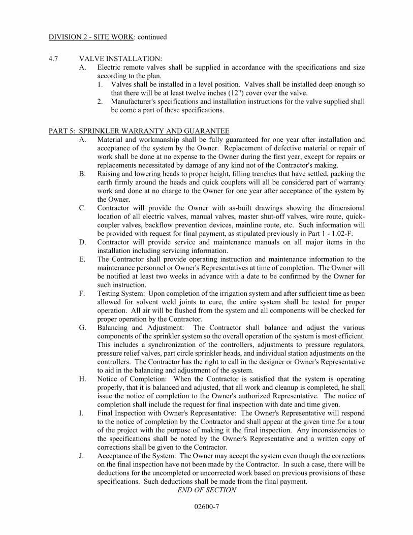
DIVISION 2 - SITE WORK: continued
02600-7
4.7 VALVE INSTALLATION: A. Electric remote valves shall be supplied in accordance with the specifications and size
according to the plan. 1. Valves shall be installed in a level position. Valves shall be installed deep enough so
that there will be at least twelve inches (12") cover over the valve. 2. Manufacturer's specifications and installation instructions for the valve supplied shall
be come a part of these specifications.
PART 5: SPRINKLER WARRANTY AND GUARANTEE
A. Material and workmanship shall be fully guaranteed for one year after installation and acceptance of the system by the Owner. Replacement of defective material or repair of work shall be done at no expense to the Owner during the first year, except for repairs or replacements necessitated by damage of any kind not of the Contractor's making.
B. Raising and lowering heads to proper height, filling trenches that have settled, packing the earth firmly around the heads and quick couplers will all be considered part of warranty work and done at no charge to the Owner for one year after acceptance of the system by the Owner.
C. Contractor will provide the Owner with as-built drawings showing the dimensional location of all electric valves, manual valves, master shut-off valves, wire route, quick-coupler valves, backflow prevention devices, mainline route, etc. Such information will be provided with request for final payment, as stipulated previously in Part 1 - 1.02-F.
D. Contractor will provide service and maintenance manuals on all major items in the installation including servicing information.
E. The Contractor shall provide operating instruction and maintenance information to the maintenance personnel or Owner's Representatives at time of completion. The Owner will be notified at least two weeks in advance with a date to be confirmed by the Owner for such instruction.
F. Testing System: Upon completion of the irrigation system and after sufficient time as been allowed for solvent weld joints to cure, the entire system shall be tested for proper operation. All air will be flushed from the system and all components will be checked for proper operation by the Contractor.
G. Balancing and Adjustment: The Contractor shall balance and adjust the various components of the sprinkler system so the overall operation of the system is most efficient. This includes a synchronization of the controllers, adjustments to pressure regulators, pressure relief valves, part circle sprinkler heads, and individual station adjustments on the controllers. The Contractor has the right to call in the designer or Owner's Representative to aid in the balancing and adjustment of the system.
H. Notice of Completion: When the Contractor is satisfied that the system is operating properly, that it is balanced and adjusted, that all work and cleanup is completed, he shall issue the notice of completion to the Owner's authorized Representative. The notice of completion shall include the request for final inspection with date and time given.
I. Final Inspection with Owner's Representative: The Owner's Representative will respond to the notice of completion by the Contractor and shall appear at the given time for a tour of the project with the purpose of making it the final inspection. Any inconsistencies to the specifications shall be noted by the Owner's Representative and a written copy of corrections shall be given to the Contractor.
J. Acceptance of the System: The Owner may accept the system even though the corrections on the final inspection have not been made by the Contractor. In such a case, there will be deductions for the uncompleted or uncorrected work based on previous provisions of these specifications. Such deductions shall be made from the final payment.
END OF SECTION

03100-1
DIVISION 3- CONCRETE
SECTION 03100 - CONCRETE FORMWORK
PART 1 - GENERAL
1.01 DESCRIPTION:
A. This Section includes formwork for concrete.
B. Related Work Specified Elsewhere:
1. Concrete Reinforcement: SECTION 03200.
2. Concrete: SECTION 03300.
1.02 OUALITY ASSURANCE:
A. Applicable Standards:
1. American Concrete Institute (ACI):
a. 318 - Building Code Requirements for Structural Concrete.
b. 347 - Guide to Formwork for Concrete.
PART 2- PRODUCTS
2.01 MATERIALS FOR FACING:
A. Where concrete will be exposed to view after construction:
1. Smooth finish exterior grade plywood at least 5/8-inch thick.
2. Steel.
B. Where concrete will not be exposed to view after construction:
1. Exterior grade plywood at least 5/8-inch thick.
2. Steel.
3. Wood fiberboard.
4. Dressed lumber free of loose knots.
C. Treat forms with lacquer, form oil or other acceptable material to prevent bonding to concrete. Material
shall not stain, cause injury to exposed concrete surfaces or affect bonding of specified surface finishes.
D. Clean forms of sawdust, dust, dirt, and other foreign materials.
2.02 FORM TIES:
A. Break-back, coil, or screw-type, except where otherwise specified.

03100-2
B. Water seal coil type in walls below grade and walls of water-bearing structures.
C. Coil-type shall leave conical depression in concrete.
D. Space as required against pressure of fresh concrete.
2.03 CHAMFER STRIPS:
A. 3/4-inch chamfer except where otherwise indicated.
B. Place in all forms to provide chamfer where concrete will have exposed projecting corners.
PART 3- EXECUTION
3.01 FORM CONSTRUCTION:
A. Conform to ACI 318 and ACI 347.
B. Adequately brace, stiffen and support forms to prevent perceptible deflection or settlement, and to hold
plumb or level and true to line.
C. Construct sufficiently tight to prevent mortar leakage.
D. Avoid offsets between adjacent forms and construct so that shores, braces and stiffening members are in
line with those below.
E. Space studs and stringers as required to support facing against concrete pressure but not more than 12
inches for 5/8-inch plywood or 16 inches for 3/4-inch plywood.
F. Use wales, strongbacks, shores and bracing as required.
G. Form all necessary openings or chases for piping, ductwork and similar items where indicated or as
required for the Work.
H. Construct forms to be removable in sections without marring concrete surface.
I. Surface of forms shall provide smooth, dense, plane surface to finished concrete where exposed to view.
J. Contractor shall be responsible for structural adequacy of formwork.
3.02 TIME IN PLACE FOR FORMS:
A. No shores, bracing, supports or other formwork shall be loosened or removed until the concrete members
supported thereby have acquired sufficient strength to support safely their own weight and any other
possible loads.
B. The minimum time between concrete placement and form removal shall be determined either by field-
cured test specimens or in accordance with the time specified for the member involved.
C. if Contractor elects to determine the required time by means of test specimens, all costs in connection
therewith shall be his responsibility.
D. Test specimens shall be made, field-cured and tested as specified in SECTION 03300. No forms or supports
shall be loosened or removed until tests indicate strength of members as follows:
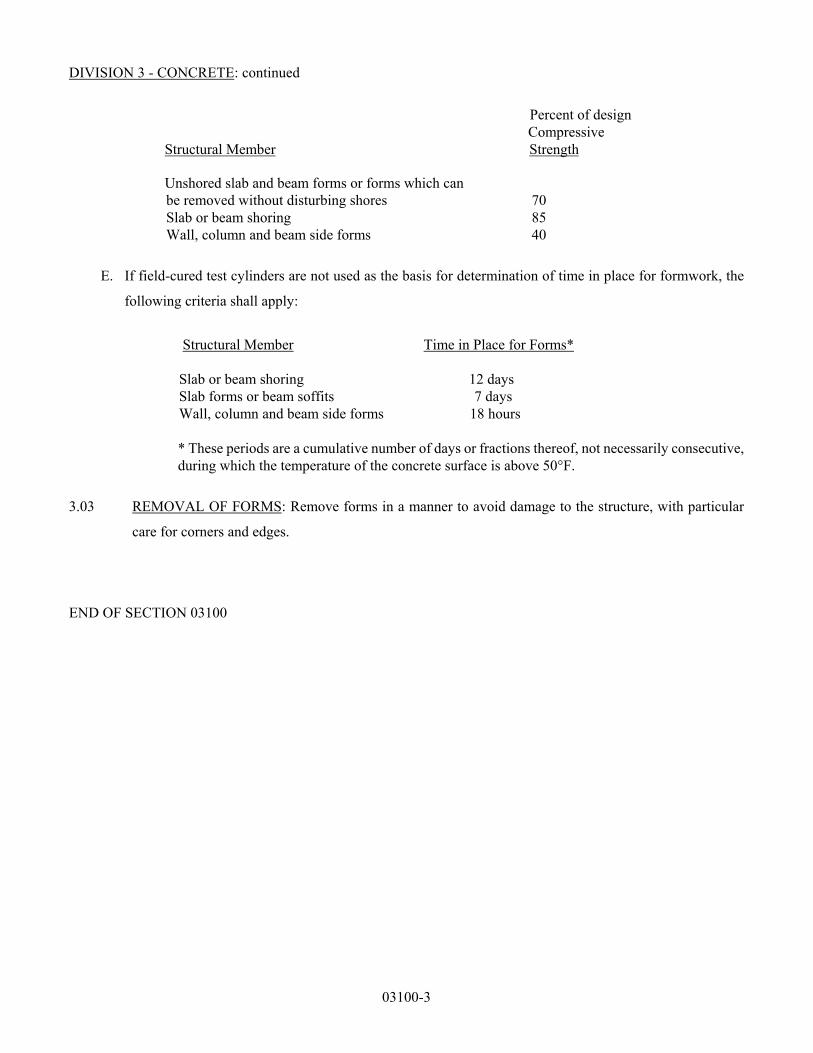
DIVISION 3 - CONCRETE: continued
03100-3
Percent of design
Compressive Structural Member Strength
Unshored slab and beam forms or forms which can
be removed without disturbing shores 70 Slab or beam shoring 85 Wall, column and beam side forms 40
E. If field-cured test cylinders are not used as the basis for determination of time in place for formwork, the
following criteria shall apply:
Structural Member Time in Place for Forms* Slab or beam shoring 12 days Slab forms or beam soffits 7 days Wall, column and beam side forms 18 hours
* These periods are a cumulative number of days or fractions thereof, not necessarily consecutive, during which the temperature of the concrete surface is above 50°F.
3.03 REMOVAL OF FORMS: Remove forms in a manner to avoid damage to the structure, with particular
care for corners and edges.
END OF SECTION 03100

03200-1
SECTION 03200 - CONCRETE REINFORCEMENT PART 1 - GENERAL 1.01 DESCRIPTION:
A. This Section includes steel reinforcement bars, ties, welded wire fabric, bolsters, chairs supports and
accessories.
B. Related Work Specified Elsewhere: 1. Concrete Formwork: SECTION 03100. 2. Concrete: SECTION 03300.
1.02 OUALITY ASSURANCE:
A. Applicable Standards: 1. American Society for Testing and Materials (ASTM):
a. A185 - Welded Steel Wire Fabric for Concrete Reinforcement b. A615 - Deformed and Plain Carbon-Steel Bars for Concrete Reinforcement c. A1064 – Carbon-Steel Wire and Welded Wire Reinforcement, Plain and Deformed, for
Concrete 2. American Concrete Institute (ACI):
a. 315 - Details and Detailing of Concrete Reinforcement b. 318 - Building Code Requirements for Structural Concrete
3. American Welding Society (AWS): a. D1.4 - Structural Welding Code - Reinforcing Steel b. B2.1 – Base Metal Grouping for Welding Procedure and Performance Qualification
1.03 SUBMITTALS:
A. Submit as specified in DIVISION 1.
B. Include, but not limited to, the following: 1. Complete bar schedule, bar details and erection drawings to conform to ACI 315. 2. Drawing with each group of like bars labeled with a mark number. 3. Erection drawings shall be clear, easily legible and to a minimum scale of:
a. 1/4-inch = 1 foot. b. 1/8-inch = 1 foot if bars in each face are shown in separate views.
4. Size and location of all openings.
1.04 DELIVERY. STORAGE AND HANDLING:
A. Store steel reinforcement blocked up off the ground and in orderly stacks.
B. Store only bars with the same identifying label in the same stack.
1.05 TESTING:
A. Perform at the mill for each heat.
B. Submit certified test results to Engineer upon request.

DIVISION 3 - CONCRETE: continued
03200-2
PART 2- PRODUCTS
2.01 REINFORCEMENT BARS, TIES AND STIRRUPS:
A. Materials:
1. Conform to ASTM A615, Grade 60 except as otherwise specified.
2. Drilled shaft ties and stirrups of any size shall conform to ASTM A615, Grade 60 unless otherwise
indicated.
B. Fabrication of Bars:
1. Fabricate with cold bends conforming to the recommended dimensions shown in ACI 318.
2. Field fabrication will be allowed only if Contractor has equipment to properly fabricate steel and
must be approved by the Engineer/Owner.
3. Attach metal or plastic tags with identifying mark corresponding to mark number on drawing.
4. Contractor may, at his option, continue steel reinforcement through openings in walls and slabs,
then field-cut the opening.
2.02 WELDED WIRE FABRIC:
A. Conform to ASTM A185 using bright basic wire conforming to ASTM A1064.
B. Wire gauges No. 11 and smaller shall be galvanized.
2.03 BOLSTERS. CHAIRS AND ACCESSORIES:
A. Conform to ACI 315 and the Manual of Standard Practices of the Concrete Reinforcing Steel Institute.
B. Provide all spacers, bolsters, chairs, ties, and other devices necessary to properly space, place, support
and fasten steel reinforcement in place during the concrete placement.
C. Metal accessories shall be galvanized or plastic coated where legs will be exposed in finished concrete
surfaces.
D. Do not use rocks, broken bricks, wood blocks, or concrete fragments for support of steel reinforcement.
2.04 PRECAST CONCRETE BLOCK BAR SUPPORTS:
A. May be used only for bar supports in slabs on ground.
B. Blocks shall be made with a minimum of nine sacks of cement per cubic yard and have a compressive
strength of 6,000 psi in seven days.
C. Each block shall have a minimum of 9 square inches of bearing area. Space as required by the particular
condition of weight, bearing surface and rigidity of the steel reinforcement.

DIVISION 3 - CONCRETE: continued
03200-3
PART 3- EXECUTION
3.01 PLACEMENT OF STEEL REINFORCEMENT:
A. Place in accordance with Chapters 7 and 12 of ACI 318 and the Manual of Standard Practice of the
Concrete Reinforcing Steel Institute.
B. Tie securely with 16-gauge or larger annealed iron wire.
C. Place to maintain concrete cover to conform to ACI 318 unless otherwise indicated.
D. Splice steel to conform to Chapter 12 of ACI 318.
1. Unless otherwise indicated, the minimum length of lap for tension lap splices shall be as required
for Class B splices as defined by ACI 318.
E. Lap welded wire fabric not less than the length of one mesh plus 2 inches unless otherwise indicated.
END OF SECTION 03200
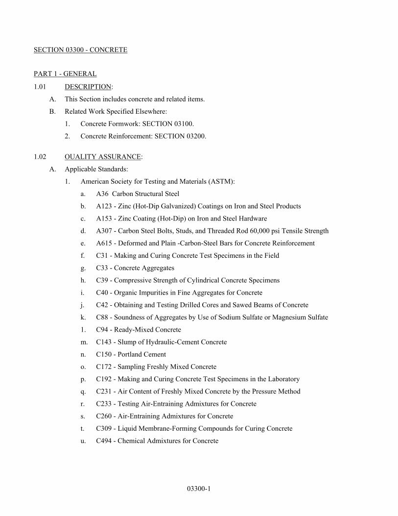
03300-1
SECTION 03300 - CONCRETE
PART 1 - GENERAL
1.01 DESCRIPTION:
A. This Section includes concrete and related items.
B. Related Work Specified Elsewhere:
1. Concrete Formwork: SECTION 03100.
2. Concrete Reinforcement: SECTION 03200.
1.02 OUALITY ASSURANCE:
A. Applicable Standards:
1. American Society for Testing and Materials (ASTM):
a. A36 Carbon Structural Steel
b. A123 - Zinc (Hot-Dip Galvanized) Coatings on Iron and Steel Products
c. A153 - Zinc Coating (Hot-Dip) on Iron and Steel Hardware
d. A307 - Carbon Steel Bolts, Studs, and Threaded Rod 60,000 psi Tensile Strength
e. A615 - Deformed and Plain -Carbon-Steel Bars for Concrete Reinforcement
f. C31 - Making and Curing Concrete Test Specimens in the Field
g. C33 - Concrete Aggregates
h. C39 - Compressive Strength of Cylindrical Concrete Specimens
i. C40 - Organic Impurities in Fine Aggregates for Concrete
j. C42 - Obtaining and Testing Drilled Cores and Sawed Beams of Concrete
k. C88 - Soundness of Aggregates by Use of Sodium Sulfate or Magnesium Sulfate
1. C94 - Ready-Mixed Concrete
m. C143 - Slump of Hydraulic-Cement Concrete
n. C150 - Portland Cement
o. C172 - Sampling Freshly Mixed Concrete
p. C192 - Making and Curing Concrete Test Specimens in the Laboratory
q. C231 - Air Content of Freshly Mixed Concrete by the Pressure Method
r. C233 - Testing Air-Entraining Admixtures for Concrete
s. C260 - Air-Entraining Admixtures for Concrete
t. C309 - Liquid Membrane-Forming Compounds for Curing Concrete
u. C494 - Chemical Admixtures for Concrete

DIVISION 3 - CONCRETE: continued
03300-2
v. D1752 - Preformed Sponge Rubber Cork and Recycled PVC Expansion Joint Fillers for
Concrete Paving and Structural Construction
w. E96 - Test Methods for Water Vapor Transmission of Materials
2. American Concrete Institute (ACI):
a. 211.1 - Standard Practice for Selecting Proportions for Normal, Heavyweight, and Mass
Concrete
b. 304 - Guide for Measuring, Mixing, Transporting and Placing Concrete
c. 305 – Guide to Hot Weather Concreting
d. 306 – Guide to Cold Weather Concreting
e. 309 - Guide for Consolidation of Concrete
f. 318 - Building Code Requirements for Structural Concrete and Commentary.
3. American National Standards Institute (ANSI):
a. B18.2.1 - Square and Hex Bolts and Screws (Inch Series)
b. B18.2.2 - Square and Hex Nuts (Inch Series)
4. National Institute of Standards and Technology, “Specifications, Tolerances, and Other Technical
Requirements for Weighing and Measuring Devices”
5. National Ready-Mix Concrete Association, “Truck Mixer, and Agitator Standards of the Truck
Mixer Manufacturers’ Bureau”
1.03 SUBMITTALS:
A. Submit as specified in DIVISION 1.
B. Include, but not limited to, the following:
1. Grouts
2. Expansion joint materials
3. Sealants
4. Waterstops
5. Concrete aggregates
6. Concrete mixture
7. Concrete mix design for each slump specified in SECTION 03300.
C. Test Reports: Submit as specified in DIVISION 1 and SECTION 03300.
PART 2- PRODUCTS
2.01 CONCRETE:
A. Materials:
Portland Cement Type I:

DIVISION 3 - CONCRETE: continued
03300-3
a. Shall conform to ASTM C150.
2. Fine Aggregate:
a. Conform to ASTM C33.
b. Maintain fine aggregate free of ice and frozen lumps.
3. Coarse Aggregate:
a. Conform to ASTM C33.
b. Blast furnace slag will not be permitted.
c. Maintain coarse aggregate free of ice and frozen lumps.
d. Grading Requirements:
(1) From 1-inch to No. 4 for all concrete unless otherwise specified.
4. Mixing Water:
a. Only potable water will be acceptable without testing. Expense of testing water shall be paid
by Contractor.
b. Nonpotable water may be used if it produces concrete with at least 95 percent of the strength
of similar specimens of the same mix design made with potable water, subject to approval of
qualitative analysis.
5. Admixtures:
a. Water-Reducing Type:
(1) Conform to ASTM C494, Type A.
(2) Conform to manufacturer’s recommendations for use.
(3) Technical assistance of the manufacturer’s field representative shall be furnished upon
request.
b. Air-Entraining Type:
(1) Conform to ASTM C260.
(2) Conform to manufacturer’s recommendations for use.
(3) Technical assistance of the manufacturer’s field representative shall be furnished upon
request.
(4) Testing of air-entraining admixtures shall conform to ASTM C233.
c. Other Admixtures: Used only with Owner’s written concurrence.
(1) Water Reducing and Retarding Type: Conform to ASTM C494, Type D and shall not
contain any chloride ions added during manufacture.
B. Laboratory Testing of Materials for Use in Concrete:
1. An approved independent testing laboratory shall be selected and paid by Contractor to perform all
required laboratory tests of materials proposed for use in the production of concrete and to determine
mix proportions when laboratory trial batches are required.

DIVISION 3 - CONCRETE: continued
03300-4
2. The laboratory shall report the results of the testing and mix designs as follows:
a. Engineer (1 copy).
b. Resident Project Representative, Field Office (1 copy).
c. Contractor (copies as required).
d. Concrete supplier (copies as required).
3. Contractor shall deliver representative samples of all proposed concrete materials to the laboratory
for the following testing:
a. Fine Aggregate:
(1) ASTM C33 as amended by PART 2, paragraph 2.01.A.
(2) ASTM C40.
(3) ASTM C88.
b. Coarse Aggregate:
(1) ASTM C33 as amended by PART 2, paragraph 2.01.A.
(2) ASTM C88.
c. Mixing water, if other than potable water is proposed for use and in the opinion of Engineer
there is reason to suspect its acceptability:
(1) With the design mix the laboratory shall make two concrete test cylinders using
proposed water and two concrete test cylinders using potable water conforming to
ASTM C192.
(2) All cylinders shall be tested conforming to ASTM C39. Age of cylinders at test shall be
28 days unless an earlier age is authorized.
d. Air-entraining admixture shall be tested conforming to ASTM C233.
C. Concrete Qualities Required:
1. Compressive Strength:
a. Minimum 28-day strength = 3600 psi for all construction unless otherwise indicated.
2. Slump of concrete shall be 3 inches plus or minus 1 inch unless noted otherwise. Concrete slump
for drilled shafts shall be as indicated for each method of construction:
a. Dry and Uncased Excavation: 5 inches ± 1 inch.
b. Cased Excavation with Casing Withdrawn: 7 inches ± 1 inch.
c. Slurry Construction (Underwater Placement): 8 inches ± 1 inch.
3. Air Content: 5 to 7 percent.
D. Mix Proportions:
1. Concrete shall be homogeneous, readily placeable and uniformly workable; proportioned to
conform to ACI 211.1.
2. Mix proportions for all concrete unless otherwise specified shall be selected preferably on the basis

DIVISION 3 - CONCRETE: continued
03300-5
of field experience; but in the case where sufficient or suitable strength test data is not available,
concrete shall be proportioned on the basis of laboratory trial mix design.
a. Field experience using test results within the preceding 90 days with the materials and plant to
be employed may be the basis of mix proportioning provided that not less than 30 consecutive
satisfactory compressive strength tests on concrete using the proposed materials with a similar
mix are available. A compressive strength test is defined as the average 28-day compressive
strength of two companion cylinders made conforming to ASTM C172 and ASTM C31 and
tested conforming to ASTM C39. The standard deviation of such tests shall be computed as a
basis for design of the mix. The design average strength shall exceed the specified strength in
accordance with the following formulae:
(1) When standard deviation is less than 500 psi, Design Average Strength = Specified
Minimum Strength + 1.343 x Standard Deviation.
(2) When standard deviation is greater than 500 psi, Design Average Strength = Specified
Minimum Strength -500 + 2.326 x Standard Deviation.
(3) Submit previous test data, calculated standard deviation, and the proposed mix
proportions to Engineer for approval prior to placing concrete.
b. When laboratory trial batches are used as a basis for determining mix proportions, all such
work shall be performed by the laboratory as specified in this PART “Laboratory Testing of
Materials for Use in Concrete.”
(1) Laboratory trial batches shall be used to establish a water-cement ratio compression
strength curve with at least three points, each representing the strength of a separate trial
batch. At least one point shall be above and one below the strength required. Each point
on the curve shall represent the average of at least three specimens tested at 28 days or
an earlier age when approved by Engineer. The slump and air content shall be at the
maximum limits specified in this PART “Concrete Qualities Required.”
(2) A point on the water-cement ratio compressive strength curve shall be selected that will
provide an average strength at least 1200 psi greater than the specified minimum
strength.
(3) Laboratory reports establishing mix proportions shall be sent to Engineer, and his
approval obtained prior to placing all concrete.
3. Mix Proportions for Concrete for Underwater Placing (special requirements):
a. Fine aggregate - not less than 40 percent natural sand.
b. Coarse aggregate - 3/4-inch maximum size natural gravel.
c. Cement - 7 sacks minimum per cubic yard.
d. Water - Minimum required for slump between 7 and 9 inches.

DIVISION 3 - CONCRETE: continued
03300-6
e. Water reducing and retarding admixture - Conform to ASTM C494 Type D and use in
sufficient amount to delay the setting time to not less than six hours.
f. Air entrainment - Conform to ASTM C260 and use in sufficient amount to entrain 4 percent
air plus or minus 1 percent.
g. 28-day compressive strength:
(1) Not less than 4,000 psi when tested conforming to ASTM C31 and ASTM C39.
(2) Not less than 3,400 psi when tested conforming to ASTM C42.
E. Measurement of Materials:
1. General Requirements:
a. Conform to ACI 304.
b. Measure materials within one percent by weight for aggregates and cement, and within 1-1/2
percent by volume or weight for water.
2. Apparatus:
a. Beam or springless dial-type scale conforming with NIST - “Specifications, Tolerances, and
Other Technical Requirements for Weighing and Measuring Devices”
b. Volumetric measurement of water shall be performed with an approved automatic valve.
F. Mixing and Delivery:
1. Conform to ACI 304.
2. Cement temperature when added to mix shall not exceed 170 degrees F.
3. Batch Plant Mixer:
a. Charge with 5 percent to 10 percent of the mixing water both in advance and after the addition
of aggregates and cement.
b. Charge with remaining water uniformly with the other materials.
c. Avoid charging in excess of manufacturer’s rating.
d. Discharge mixed concrete completely prior to recharging.
e. Mixing Time:
(1) Start immediately when all ingredients except the last of the water are in the mixer.
(2) Minimum mixing time shall conform with mixer manufacturer’s instructions, but not be
less than the following: Capacity of Mixer Minimum Time of (Cubic Yards) Mixing
1 or less 1 minute 2 1 minute, 15 seconds 3 1 minute, 30 seconds 4 1 minute, 45 seconds 5 2 minutes 6 2 minutes, 15 seconds

DIVISION 3 - CONCRETE: continued
03300-7
**Add 15 seconds mixing time for each additional cubic yard of concrete.
4. Mixing of Concrete at Plant Off Jobsite:
a. Mix concrete in central mixer or truck mixer. Transport in truck mixer turning at agitation
speeds only.
b. Water added to concrete having a slump below the specified minimum shall be at Contractor’s
risk. If the water added produces a slump greater than the specified maximum, the concrete
will be rejected. If water is added the concrete shall be remixed for a minimum of 25
revolutions.
c. Truck mixer shall conform to “Truck Mixer and Agitator Standards of the Truck Mixer
Manufacturers Bureau,” of the National Ready-Mix Concrete Association.
d. Ready-mixed concrete shall be produced and delivered conforming to ASTM C94 as
applicable.
e. Contractor shall furnish Owner with a concrete delivery ticket for each load of concrete. The
ticket shall have the following information recorded:
(1) Ticket number
(2) Time batched
(3) Time arrived on jobsite
(4) Amount of concrete (by volume)
(5) Mix number
(6) Amount of all water added at jobsite by Contractor.
(7) Number of revolutions on the truck’s revolution counter before batching and after
placement is completed.
(8) Truck number
(9) Truck driver’s name
(10) Types and quantities of admixtures added to the batch.
(11) Slump of concrete
2.02 GROUT:
A. Plain Grout:
1. 1 part Portland Cement to 2 parts sand by volume.
2. Keep water to a minimum as required for placing by the dry packing method.
3. Place after the mixed grout has been allowed to stand for two hours.
4. The sand and cement shall be as specified for concrete.
B. Nonshrinking Grout:

DIVISION 3 - CONCRETE: continued
03300-8
1. Required for setting sleeved anchor bolts, for setting equipment recommended by the manufacturer
to be set with nonshrinking grout, and in other places indicated.
2. Grout shall be nonmetallic, as manufactured by one of the following:
a. Crystex, L and M Construction Chemicals, Inc.
b. Five Star grout, U. S. Grout Corporation.
c. Masterfiow 713 grout, Master Builder’s Company.
d. Sauereisen F-100, Sauereisen Cements Company.
e. Supreme Grout, Gifford-Hill & Company.
3. Prepare and place conforming to manufacturer’s printed instructions.
C. Grout for Bonding:
1. 1 part cement to 1-1/2 parts sand by weight.
2. Keep water to a minimum.
2.03 CONCRETE ACCESSORIES:
A. Water Stops:
1. Serrated polyvinyl chloride equal to one of the following.
a. Servicized/Durajoint Type 13, W. R. Grace Company.
b. 6-inch heavy-duty Flextrip, Water Seals, Inc.
c. Vulco VP 8044 Heavy, Vulcan Metal Products Company.
B. Expansion Joints:
1. Expansion Joint Filler: Premolded cork of thickness indicated and conforming to ASTM D1752,
Type II, cork or Type III, self-expanding cork.
2. Bond Breaker: Polyethelene strip.
3. Joint Sealant: Two component polysulfide system as manufactured by one of the following:
a. Hornilex L, A. C. Horn, Inc.
b. Synthacalk GC-2, Pecora, Inc.
C. Igas Joint: Single component mastic waterstop, Sika Chemical Corporation.
2.04 CURING AGENT:
A. Liquid membrane forming compound conforming to ASTM C309, Type 1. ASTM C309 Type 2 shall be
used as specified in PART 3 “Hot Weather Concreting.”
B. Curing compound used on floors to be painted, tiled or covered with resilient floor covering shall be
guaranteed not to interfere with application of paint, tile mortar or tile adhesive after a 28-day curing
period.

DIVISION 3 - CONCRETE: continued
03300-9
2.05 MISCELLANEOUS ITEMS:
A. Anchor Bolts:
1. Provide all anchor bolts required for complete installation as indicated.
2. Anchor bolts and accessories shall conform to ASTM F1554 (55 ksi) steel unless otherwise
specified. 2-1/4-inch diameter anchor bolts shall conform to ASTM A615, Grade 75. These 2-1/4-
inch anchor bolts shall be made from deformed rebar.
3. Use hexagonal bolts and nuts conforming to ANSI B 18.2.1 and B18.2.2.
4. All anchor bolts and nuts shall be hot-dip galvanized in accordance with ASTM A123 except for 2-
1/4-inch anchor bolts which shall have the top 18 inches galvanized only.
5. et to elevations and alignment indicated, or as required for proper anchorage, with template and
other devices to align and hold bolts in place top and bottom during placement of concrete.
B. Moisture Barrier:
1. Provide Kraft Paper - Polyethylene Sheet:
a. Water-resistant barrier consisting of heavy Kraft paper and asphalt, glass fiber reinforcement
and polyethylene film. Layers shall be laminated under heat and pressure. Perm rating of 0.15
or less per ASTM E96, Procedure A.
b. Manufacturers:
(1) Fortifther Corporation, Moistop I.
(2) Glas-Kraft Inc., Plybar Plus H.
2. Provide adhesive or tape as recommended by moisture barrier manufacturer.
C. Structural Metals:
1. Steel:
a. Steel shall conform to ASTM A36 unless otherwise specified.
b. Fabricate to conform to American Institute of Steel Construction (AISC) specifications, codes
and standards.
c. Galvanize to conform to ASTM A123 and ASTM A153 after all drilling, bending, welding or
other forms of fabrication have been completed.
PART 3- EXECUTION
3.01 PREPARATION FOR CONCRETE PLACEMENT:
A. Openings Through Concrete: Provide openings through concrete as indicated and for the proper
installation of all equipment, piping, wiring, ductwork and similar items, installed under this contract.
B. Installation of Embedded Items:
1. Provide for accurate installation of embedded items installed under this Contract.
2. Securely fix floor drains in place to prevent floatation while placing concrete. Uniformly and

DIVISION 3 - CONCRETE: continued
03300-10
accurately slope finish floor slab toward the drains.
3. Embedded items shall be as indicated or specified, or as selected by Contractor and approved by
Engineer.
4. Protect pipe sleeves from moisture during cold weather.
5. Grease anchor bolt threads to protect from concrete splatter.
C. Installation of Joints:
1. Construction Joints:
a. Location:
(1) Locate joints, which are not indicated or specified, in conformance with ACI 318.
(2) Obtain Engineer’s approval of joints located by Contractor prior to preparation of
reinforcing steel drawings.
b. Preparation and Installation:
(1) Clean and break laitance or other foreign material from bonding surface.
(2) Tighten forms remaining in place (where applicable) to prevent seepage between forms
and hardened concrete.
(3) Provide water stops and shear keys as indicated or specified and as required in any new
construction joint requested by Contractor.
c. Waterstops:
(1) Install in all construction joints where indicated.
(2) Install conforming to manufacturer’s printed instructions.
(3) All joints and splices of PVC waterstop shall be 100 percent fused.
(4) Metal waterstops shall be welded with a continuous watertight weld or bolted with a
minimum contact lap of 12 inches.
2. Expansion Joints:
a. Install as indicated.
b. Completely cover the top surface of the joint filler with a polyethelene strip bond breaker prior
to sealing joint.
c. Seal top of expansion joint with joint sealant applied conforming to manufacturer’s
instructions. Depth of sealant shall be 1/2 the joint width unless otherwise indicated. During
cold weather protect joint from moisture prior to installation of joint sealant.
3. Contraction Joints: As specified in this PART “Finishing.”
D. Cutting and Bonding to Existing Concrete:
1. Cutting Existing Concrete:
a. Use methods and equipment that will avoid damage to adjacent parts of the structure from

DIVISION 3 - CONCRETE: continued
03300-11
heavy blows or vibration.
b. Cut existing concrete with power concrete saw where possible to prevent spalling and chipping
and to form neat straight edge.
c. Remove all loose or cracked pieces resulting from cutting existing concrete, leaving only
sound, undamaged concrete adjacent to new work.
d. Leave access opening edges with a neat, true grout surface to the opening size indicated.
e. Cut reinforcing steel with sufficient length remaining (approximately 30-bar diameters) for
bending and lapping into new construction.
2. Bonding to Existing Concrete:
a. Roughen concrete by use of a pneumatic chipping hammer or other approved means.
b. Thoroughly clean the concrete surface and apply the bonding agent. Place the fresh concrete
after the bonding agent becomes tacky.
3.02 PLACING OF CONCRETE:
A. Conventional Placing:
1. General Requirements:
a. Conform to ACI 304.
b. Bonding surfaces shall be clean, free of laitance and foreign materials.
c. Face horizontal bonding surfaces with 1-inch-thick coat of fresh “grout for bonding.” Wet all
other surfaces.
d. Place concrete on properly prepared and unfrozen subgrade and only in dewatered excavation
and forms.
e. Use forms for all concrete except where otherwise indicated or specified.
f. Do not place concrete that has partially hardened or has been contaminated by foreign
materials.
g. Prevent mud or foreign materials from entering the concrete or forms during placement
operations.
2. Conveying:
a. Convey concrete from the mixer and deposit in place by methods which will prevent the
segregation or loss of materials.
b. Equipment for chuting, pumping, and pneumatically conveying concrete shall be of such size
and design as to provide a practically continuous flow of concrete at the delivery end.
c. Aluminum conveying equipment shall not be used.
3. Depositing:
a. Place concrete in continuous horizontal lifts not to exceed 2 feet, and place concrete against

DIVISION 3 - CONCRETE: continued
03300-12
bulkheads and keyways at vertical joints.
b. Maximum free drop of concrete shall be 5 feet in walls 10 inches or less in thickness with 1-
foot additional drop allowed for each inch of wall thickness over 10 inches, with a maximum
drop of 10’-0”.
c. When moisture barrier is used, keep lapped joints closed and take precautions to avoid
puncturing the barrier.
4. Consolidation of Concrete:
a. Consolidate concrete in conformance with ACI 309. Characteristics and application of
concrete vibrators shall be as set forth in Table 5.1.4.
b. Provide an adequate number of vibrators of sufficient capacity to keep up with the maximum
rate of concrete placement. Keep on hand adequate standby equipment in good operating
condition.
c. Vibrate concrete only until the concrete is thoroughly consolidated and the voids filled as
evidenced by the leveled appearance of the concrete at the exposed surface and the embedment
of the surface aggregate.
d. Insert internal vibrators vertically to the full depth of the layer being placed and into the
previous layer. Do not drag vibrators through the concrete. Insert and withdraw vibrator slowly
with the vibrator running continuously so that no hole will be left in the concrete. Do not flow
concrete from one location to another by use of a vibrator.
e. Consolidate concrete layer to full depth when using a surface vibrator. Use thinner layers or
more powerful vibrator if necessary to achieve complete consolidation.
f. Vibrate the top 10 feet of drilled shaft foundations.
g. Use form vibrators only where sections are too thin or where sections are inaccessible for
internal vibrators.
5. Time Requirements:
a. Place concrete at a sufficient rate to assure that lifts below have not taken initial set before
fresh concrete is deposited.
b. Place concrete within 45 minutes after mixing. This period may be extended to 1 hour and 30
minutes provided that the combined air temperature, relative humidity and wind velocity are
such that the plasticity of the fresh concrete is satisfactory for placement and consolidation and
that the specified mixing water is not exceeded. Concrete which has partially set shall not be
retempered but shall be discarded.
6. Placing Concrete at Joints:
a. Bed horizontal joints with 1 inch of grout for bonding.
b. Take precautions to ensure tight, well-bonded construction joints with no air pockets or voids.

DIVISION 3 - CONCRETE: continued
03300-13
c. Take special precautions to avoid bending or displacing waterstop while placing concrete
around it.
d. Delay construction at a joint a minimum of 16 hours where placement is continued past joint
except where otherwise indicated.
B. Underwater Placing of Concrete:
1. General Requirements:
a. Do not place concrete under water except where indicated or authorized in writing by Engineer.
b. Do not place concrete under water which has a temperature below 40 degrees F or when there
is a flow of water in or out of the form or excavation. Dewatering shall be prohibited for a
minimum of 24 hours after completion of concrete placement.
c. Use concrete mix as specified under PART 2, paragraph 2.01.D.3 “Mix Proportions for
Concrete for Underwater Placing.”
d. Design formwork for increased pressure due to the use of retarding admixture. Clean inside of
forms with water jets where necessary to remove mud or debris from the bottom of sides.
2. Depositing: As specified in Drilled Shaft Foundations - SECTION 03500.
3.03 FINISHING:
A. Unformed Surfaces:
1. Screed Finish:
a. Use as first stage for all concrete finishes.
b. Use as final finish on surfaces that will be covered by additional concrete, grout placement,
mortar setting bed except as otherwise specified, or earth backfill.
c. Immediately after screeding, use a wood float, darby or bullfloat to eliminate high and low
spots and to embed large aggregate. This shall be done in a manner to produce even, uniform
surfaces so that surface irregularities do not exceed 3/8-inch in 10 feet when used as final
finish.
2. Floated Finish:
a. Use as second stage of broomed, troweled or magnesium-troweled finish.
b. Float with mechanical float. Hand floating will be permitted only in areas inaccessible to
mechanical float.
c. On surfaces not to receive troweled or magnesium-troweled finish, finish with wood or cork
float after mechanical floating to a true uniform surface so that surface irregularities do not
exceed 1/8-inch in 10 feet, except at floor drains.
3. Broomed Finish:
a. Use as final finish on all outdoor slabs including door stoops and equipment pads.

DIVISION 3 - CONCRETE: continued
03300-14
b. After floated finish draw a stiff bristle broom across the surface making uniform corrugations,
perpendicular to the direction of traffic, not more than 1/16-inch deep.
4. Troweled Finish:
a. Use as final finish on inside floors and on all other unformed surface not otherwise indicated
or specified.
b. Trowel with steel trowel, mechanical or hand, to obtain a smooth, dense finish. The final
troweling shall be done after the concrete has become hard enough so that no mortar adheres
to the edge of trowel and a ringing sound is produced as the trowel passes over the surface.
c. Do not trowel before surface water has evaporated or been removed with a squeegee.
d. Finish to a true uniform surface so that surface irregularities do not exceed 1/8-inch in 10 feet,
except at floor drains.
e. Do not add sand or cement to the floor surface.
5. Magnesium-Troweled Finish:
a. Perform as specified for “Troweled Finish” except use a magnesium trowel by hand instead of
a steel trowel to obtain a dense, but not slick, finish.
b. Use where floor will receive protective coating after curing.
6. Concrete Floor Hardener:
a. Furnish and install concrete floor hardener where indicated.
b. Contractor shall apply in strict accordance with the manufacturer’s written recommendations.
c. Apply Lapidolith in three (3) applications. Coverage shall be 100 square feet per gallon.
d. Contractor shall apply the hardener as soon as possible after placement of concrete to prevent
concrete damage during construction.
7. Stair-Tread Finish:
a. Apply to all interior and exterior concrete stair treads and landings that do not have abrasive
nosings.
b. Spread fine abrasive aggregate uniformly on concrete before it has set, in the amount not less
than 1/4-pound aggregate per square foot, and steel trowel into surface of concrete.
c. Expose abrasive aggregate slightly by rubbing with an abrasive brush after concrete finish has
set and cured.
d. Aggregate and application shall conform to Specification “A” of the Norton Company.
8. Contraction Joints:
a. Locate as indicated.
b. Maintain true alignment with straightedge.
c. Joints shall be grooved except where sawed joints or preformed joints are indicated.
d. Grooved Joints:

DIVISION 3 - CONCRETE: continued
03300-15
(1) Perform during the finishing process.
(2) Width of groove shall not exceed 1/4-inch.
(3) Depth of groove shall be at least 1 inch.
e. Sawed Joints:
(1) Cut joints with power blade as soon as concrete surface is firm enough to resist tearing
or damage by the blade and before random shrinkage cracks can occur. (Usually
required 4 to 12 hours after finishing.)
(2) Make joints approximately 1/8-inch wide with depth as indicated.
(3) Seal with the same type sealant specified for expansion joint sealant.
f. Install preformed joints as recommended by manufacturer.
B. Formed Surfaces:
1. Repair surface defects as specified in this PART “Repair of Defective Surfaces,” except for surfaces
against which fill material or concrete is to be placed.
2. Stoned Finish:
a. Use as a final finish on all formed surfaces that will be exposed to view after all work has been
completed.
b. To obtain surface finish, patch defective surfaces immediately upon removal of forms with
mortar as specified in this PART “Repair of Defective Surfaces.”
c. Immediately before starting this work, keep concrete thoroughly saturated with water for a
minimum period of three hours.
d. Rub surfaces to be finished with a medium coarse carborundum stone, using a small amount
of mortar on its face. The mortar shall be composed of cement and fine sand mixed in
proportions used in the concrete being finished. Continue rubbing until all form marks,
projections and irregularities have been removed, all voids filled, and a uniform surface has
been obtained. Leave paste produced by this rubbing in place at this time.
e. After all concrete above the surface being treated has been cast, obtain final finish by rubbing
with a fine carborundum stone and water. Continue rubbing until the entire surface is of a
smooth texture and uniform color.
f. After the final rubbing is completed and the surface has dried, rub with burlap to remove loose
powder and unsound patches, paste, and objectionable marks.
g. Cure as specified in this PART “Curing.”
C. Repair of Defective Surfaces:
1. Defined as any concrete surface showing misalignment, rock pockets, poor joints, holes from ties,
voids, honeycomb, or any other defective area.
2. Repairing:

DIVISION 3 - CONCRETE: continued
03300-16
a. Repair as soon as forms have been removed.
b. Chip surface back to minimum depth of 1/2-inch, chip edges perpendicular to surface, prewet
depression and brush with neat cement immediately before patching.
c. Patch surfaces using stiff mortar with same sand-cement ratio as original concrete and with
minimum water for placing. Blend with white cement to match concrete color.
d. Compact mortar into depressions so that after curing, hole is filled and mortar is flush with
surface. Use hammer and ramming rod for compacting the holes.
e. Moist-cure for three days or use curing compound.
f. Engineer shall be notified of areas containing major defects or where reinforcing steel is
exposed prior to determination of repair method.
3.04 CURING: Cure all concrete by one of the following methods:
A. Leaving in forms for a minimum of seven days. Keep formwork wet to prevent drying of concrete
surfaces.
B. Use of saturated bats, soaker hoses, or sprinkler for a minimum of seven days. Keep concrete continuously
wet.
C. Using one coat of a liquid membrane forming compound conforming to ASTM C309, Type I. Apply
immediately after removal of forms (which have been continuously wet); or in case of a slab, after the
concrete has been finished and is hardened sufficiently to walk on.
D. Using polyethylene sheets applied in full contact with surfaces.
E. Curing of concrete during hot or cold weather shall conform to this PART “Hot Weather Concreting’ and
“Cold Weather Concreting.”
3.05 HOT WEATHER CONCRETING:
A. When the temperature is 90 degrees F or above, or is likely to rise above 90 degrees F within the 24-hour
period after concrete placement; or when there is any combination of high air temperature, low relative
humidity and wind velocity which would impair concrete strength or quality, follow the recommendations
of ACI 305.
B. Concrete shall have a maximum temperature of 85 degrees F during placement.
C. Dampen subgrade and forms with cool water immediately prior to placement of concrete.
D. Protect freshly placed concrete immediately after placement so that the rate of evaporation as determined
by ACI 305 (Figure 2.1.5) does not exceed 0.2-pound per square foot per hour.
E. Protect concrete with suitable insulation if rapidly decreasing nighttime temperatures occur, which would
cause thermal shock to concrete placed during warm daytime temperatures.
F. Protect the concrete with temporary wet covering during any appreciable delay between placement and
finishing.

DIVISION 3 - CONCRETE: continued
03300-17
G. Begin curing unformed surfaces immediately after finishing and continue for 24 hours. Curing shall
consist of application and maintenance of water saturated material to all exposed surfaces; horizontal,
vertical and otherwise. After the 24-hour interval, continue curing, using one of the following methods:
1. Moist curing for six days.
2. Application of one coat of curing compound conforming to ASTM C309, Type 2.
3. Application and maintenance of curing paper or heat-reflecting plastic sheets for six more days.
H. Begin curing formed concrete immediately after placing. Curing shall consist of keeping forms
continuously wet for 24 hours. Thereafter, continue curing using one of the following methods:
1. Loosen forms and position soaker hose so that water runs down along concrete surfaces. Continue
for six days.
2. Strip forms and apply curing compound conforming to ASTM C309, Type 2. Do not allow concrete
surfaces to dry prior to application of curing compound.
3.06 COLD WEATHER CONCRETING:
A. When the temperature is 40 degrees F or is likely to fall below 40 degrees F during the 24-hour period
after concrete placement, follow the recommendations of ACI 306 to prevent loss of concrete strength or
quality.
B. Minimum temperature for concrete as mixed shall be as indicated on lines 2, 3 and 4 of Table 1.4.1 of
ACI 306. Maximum temperature for concrete as mixed shall be 10 degrees F greater than the
corresponding minimum temperature.
C. Place and maintain concrete so that its temperature is never less than the temperature indicated on line 1
of Table 1.4.1 of ACI 306. Maintain the required temperature for the time duration indicated on Table
1.4.2 of ACI 306.
D. Monitor temperature of concrete in place at corners or edges of formwork as applicable.
E. Do not expose concrete to carbon monoxide or carbon dioxide fumes from heaters or engines. Oil or coke
burning salamanders will not be permitted. Personnel shall be present at all times to maintain safe,
continuous operation of heating system.
F. Control temperature and humidity of protected concrete so that excessive drying of concrete surfaces does
not occur.
G. Calcium chloride will not be permitted as a concrete accelerator or to thaw frozen subgrade prior to
concrete placement.
H. The maximum allowable temperature drop during the first 24-hour period after protection is discontinued
shall be as indicated on line 5 of Table 1.4.1 of ACI 306.
3.07 LOW STRENGTH CONCRETE:
A. Low-Strength Concrete:

DIVISION 3 - CONCRETE: continued
03300-18
1. Defined as concrete whose 28-day test (average of two cylinder breaks) is less than the minimum
28-day strength required.
2. Remove and replace with acceptable concrete when the quality and location of the low-strength
concrete is such that Engineer considers the strength or durability of the structure is impaired and
so orders.
B. Potentially Low-Strength Concrete: Defined as concrete whose 7-day test is less than 70 percent of the
specified minimum 28-day compressive strength.
C. Construction delays caused by low-strength or potentially low-strength concrete shall not relieve
Contractor from responsibility for late completion even though extensions of time may be granted.
3.08 TESTING:
A. Field Testing of Concrete and Making of Concrete Test Cylinders:
1. Contractor shall furnish test equipment, test cylinder molds, and trained personnel to perform all
required field tests, make the required concrete test cylinders and deliver test cylinders to the testing
laboratory. The prescribed tests shall be made in the presence of or with the concurrence of the
Owner.
2. Concrete sampling for tests and cylinder making shall be done conforming to ASTM C172.
3. Perform the following tests:
a. Prepare test cylinders conforming to ASTM C31, with not less than one set of cylinders (four
cylinders) from each day’s placement for each 20 cubic yards or fraction thereof.
b. Slump Test conforming to ASTM C143.
c. Air Content Test conforming to ASTM C231.
d. Discard concrete used for slump and air tests.
e. Slump and Air Test results shall be furnished to the Testing Laboratory for inclusion in the
Cylinder Test Reports.
B. Laboratory Testing of Concrete During Construction:
1. An independent testing laboratory will be selected and paid by the Contractor to perform the
required laboratory tests and statistical evaluations of concrete being used in the work.
2. Laboratory will cure and test concrete cylinders conforming to ASTM C192 and C39, testing one
cylinder at seven days of age and two at 28 days of age. The remaining cylinder will be held to
verify test results, if needed.
3. The Contractor shall make arrangements with the testing laboratory to furnish two copies of all test
reports to the Owner.
4. Should the statistical data indicate an unacceptable combination of average strength and standard
deviation, Contractor shall take immediate corrective action.

DIVISION 3 - CONCRETE: continued
03300-19
5. Should the statistical data indicate an excessive margin of safety, the concrete mix may be modified
subject to Owner’s approval.
END OF SECTION 03300

03500-1
SECTION 03500 - DRILLED SHAFT FOUNDATIONS
PART 1 - GENERAL
1.01 DESCRIPTION: This Section covers drilled shaft foundations.
A. Perform all drilling and excavation and supply all labor, equipment and materials to construct drilled shaft
foundations as indicated.
B. Related Work Specified Elsewhere:
1. Concrete Formwork: SECTION 03100.
2. Concrete Reinforcement: SECTION 03200.
3. Concrete: SECTION 03300.
1.02 OUALITY ASSURANCE:
A. Applicable Standards:
1. American Concrete Institute (ACI):
a. 304.2R - Placing Concrete by Pumping Methods
b. 309R - Guide for Consolidation of Concrete
c. 336.1 - Standard Specification for the Construction of Drilled Piers
d. 336.3R - Design and Construction of Drilled Piers
2. American Petroleum Institute (API):
a. 13A - Oil-Well Drilling-Fluid Materials
3. American Society for Testing and Materials (ASTM):
a. D698 - Laboratory Compaction Characteristics of Soil Using Standard Effort (12,400 ftlbf/ft3
(600 kN-mIm3))
b. D4253 - Maximum Index Density of Soils Using a Vibratory Table
c. D42 54 - Minimum Index Density of Soils and Calculation of Relative Density
1.03 SUBMITTALS:
A. Submit as specified in DIVISION I.
B. Submittals:
1. Proposed drilled shaft rig name, model number, maximum continuous torque rating (ft-lb),
maximum downward force (“crowd”), proposed earth and rock auger attachments and proposed
special techniques and equipment.
2. Proposed procedures for each anticipated method of construction - dry and uncased, temporary
casing, slurry or other procedure including:
a. Sequence of excavation, concrete placement, rebar cage placement, and placement of

DIVISION 3 - CONCRETE: continued
03500-2
embedded items such as anchor bolts.
b. Methods to prevent caving if necessary.
c. Procedures for supporting rebar cage during concrete placement.
d. Procedures for supporting anchor bolts or other embedded items.
1.04 REPORTS:
A. Foundation Record Reports: Contractor shall submit at the completion of each day, foundation record
reports similar to the form shown at the end of this section. These reports shall contain the following
information:
1. Structure location
2. Identification number and structure name
3. Shaft dimensions
4. Ground surface elevation
5. Total excavation depth
6. Bottom of concrete elevation
7. Top of concrete elevation
8. Description of soils encountered during drilling and elevations (or depths) encountered
9. Bearing strata description
10. Nature and location of obstructions
11. Water conditions during drilling and concrete placement
12. Amount of unclassified excavation
13. Amount of rock excavation and length of rock socket, if required
14. Method of construction - dry and uncased, temporary casing, slurry or other
1.05 CONTRACTOR OUALIFICATIONS:
A. A minimum of three-years’ experience in drilled shaft construction, including experience with similar
subsurface material, water conditions, shaft sizes, and special techniques as required.
B. The name of proposed Subcontractor, if other than Contractor, along with a written description of
equipment and techniques proposed for use, and the name of three similar projects completed in the last
three years, shall be submitted at time of Bid and will be considered in evaluation of Bids.
1.06 DEFINITIONS:
A. Allowable Service Load Bearing Pressure - The vertical pressure per unit area that may be applied to the
bearing stratum at the level of the shaft bottom. Allowable service load bearing pressure has been
selected on the basis of samples, tests, and applied soil mechanics, with due regard for the character of
the loads to be applied and the settlements that can be tolerated.

DIVISION 3 - CONCRETE: continued
03500-3
B. Bearing Stratum or Bearing Elevation - The formation(s) or layer(s) of soil or rock that support the shaft
and loads imposed on it. Bearing elevation is the proposed depth of the base of each shaft, as noted on
drawings, accounting for minimum embedment and required penetration into rock.
C. Casing - Protective steel casing usually of cylindrical shape, lowered into the excavated hole to protect
workmen and inspectors entering the shaft from collapse or cave-in of the sidewalls and for the purpose
of excluding soil and water from the excavation during drilling and concrete placement.
D. Competent Rock - Sound bedrock capable of carrying the design structural loads
E. End Bearing Drilled Shaft - Cast-in-place reinforced concrete drilled shafts with or without enlarged
bearing area extending downward through weaker soils or water to a rock or soil stratum capable of
supporting the loads imposed on or within it.
F. Pumping of Concrete - “Underwater-Type Concrete” is conveyed by pressures through rigid pipe or
flexible hose and discharged directly to bottom of shaft through slurry or under water. Pressure is applied
by piston pumps, pneumatic compressed air, or squeeze pressure pumps in accordance with ACI
304.2. Note: The use of slurry will not be permitted during excavation of drilled shafts which bear upon
or are socketed into competent rock.
G. Rock Excavation - Rock excavation is defined as all material encountered in excavating drilled shafts
which cannot be removed with a conventional earth auger and/or underreaming tool, and requires rock
auger, core barrel, boulder rooter, or hand labor using air-powered tools and/or other special excavation
procedures. Refusal of the earth auger shall be defined as a penetration rate equal to, or less than, 1 foot
per 10-minute period using drill rig (described below in PART 2) providing its maximum continuous
torque and its maximum downward force (“crowd”). There shall be no proportioning of torque or
downward pressure and advancement time to evaluate smaller equipment. All earth, clay, coal seams,
rock fragments, soft fractured materials or voids encountered between rock units will not be considered
rock for pay purposes. Note: Rock is anticipated to be encountered during drilling.
H. Shaft - Drilled shaft above bearing surface.
I. Slurry - Method of advancing drilled shaft hole where bentonite (sodium montmorillonite in accordance
with API 13A) or anionic polymer is mixed with clean water or water within shaft to produce a slurry
mixture capable of maintaining the stability of shaft walls and bottom in potentially caving and/or water-
bearing soils. Slurry is also used to increase density of fluid within shaft to offset exterior hydrostatic
pressure and to facilitate removal of coarser grained soils by mixing and incorporation into
the slurry mixture. Note: The use of slurry will not be permitted during excavation of drilled shafts which
bear upon or are socketed into competent rock.
J. Tremie - Method of placing concrete, if permitted by Engineer, for “Underwater - Type Concrete” through
a rigid pipe of minimum dimensions of ten (10) to twelve (12) inches. Concrete is placed by means of
gravity flow or drop through the interior of the pipe, the lower end of which is kept immersed in fresh
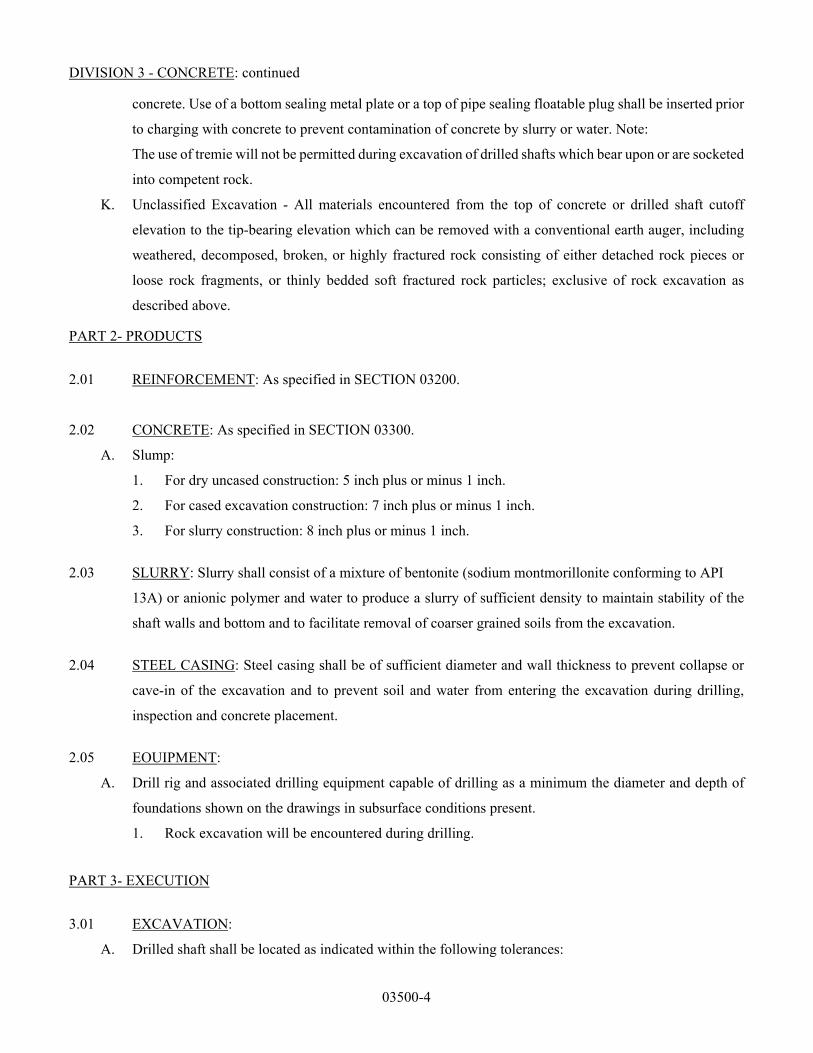
DIVISION 3 - CONCRETE: continued
03500-4
concrete. Use of a bottom sealing metal plate or a top of pipe sealing floatable plug shall be inserted prior
to charging with concrete to prevent contamination of concrete by slurry or water. Note:
The use of tremie will not be permitted during excavation of drilled shafts which bear upon or are socketed
into competent rock.
K. Unclassified Excavation - All materials encountered from the top of concrete or drilled shaft cutoff
elevation to the tip-bearing elevation which can be removed with a conventional earth auger, including
weathered, decomposed, broken, or highly fractured rock consisting of either detached rock pieces or
loose rock fragments, or thinly bedded soft fractured rock particles; exclusive of rock excavation as
described above.
PART 2- PRODUCTS
2.01 REINFORCEMENT: As specified in SECTION 03200.
2.02 CONCRETE: As specified in SECTION 03300.
A. Slump:
1. For dry uncased construction: 5 inch plus or minus 1 inch.
2. For cased excavation construction: 7 inch plus or minus 1 inch.
3. For slurry construction: 8 inch plus or minus 1 inch.
2.03 SLURRY: Slurry shall consist of a mixture of bentonite (sodium montmorillonite conforming to API
13A) or anionic polymer and water to produce a slurry of sufficient density to maintain stability of the
shaft walls and bottom and to facilitate removal of coarser grained soils from the excavation.
2.04 STEEL CASING: Steel casing shall be of sufficient diameter and wall thickness to prevent collapse or
cave-in of the excavation and to prevent soil and water from entering the excavation during drilling,
inspection and concrete placement.
2.05 EOUIPMENT:
A. Drill rig and associated drilling equipment capable of drilling as a minimum the diameter and depth of
foundations shown on the drawings in subsurface conditions present.
1. Rock excavation will be encountered during drilling.
PART 3- EXECUTION
3.01 EXCAVATION:
A. Drilled shaft shall be located as indicated within the following tolerances:

DIVISION 3 - CONCRETE: continued
03500-5
1. Centerline: Within 2 inches or 4 percent of shaft diameter, whichever is less, of location indicated.
2. Diameter: Plus 6 inches, minus 1/2-inch.
3. Plumb: 1.0 percent of the length, 12.5 percent of shaft diameter, or 15 inches total, whichever is
less.
4. Cutoff Elevation: Plus 1 inch or minus 1 inch from cutoff elevation indicated.
B. Deviations in excess of the preceding tolerances will be corrected at Contractor’s expense, including
additional costs for engineering, redesign and inspection.
C. Install drilled shafts in accordance with recommendations in ACI 336.1 and ACI 336.3.
D. Provide temporary casing with a minimum outside diameter equal to the nominal diameter of the drilled
shaft and a sufficient wall thickness to withstand the soil pressure on site prior to start of excavation.
Install:
1. To control seepage.
2. To prevent collapse of the walls.
E. Remove all material regardless of classification within the shaft to the indicated depth, including the
required rock socket as indicated on the drawings. All precautions necessary to prevent blowouts and
disturbance of the bearing soil shall be taken. If required, water shall be maintained in the shaft at all
times at a height sufficient to produce a positive head in the shaft.
F. If loose soil, a high-water table, or other condition which causes the sides or bottom of the excavation to
be unstable is encountered, the excavation shall be advanced through use of slurry, a temporary casing,
or other approved method.
G. When slurry is used, maintain a positive head in the excavation at all times. Circulate the slurry and have
sufficient consistency and velocity to remove the dislodged materials from the hole. Should
materials be encountered which are too heavy to be removed by the slurry, they may be removed by other
approved means.
H. Carry excavation to the indicated elevation at which time the Owner will field observe the excavation and
determine whether the excavation has reached the required bearing layer. The excavation will then be
continued if required by the Owner.
I. Cleanout and remove all loose material and spoil from sides and bottom of shaft prior to placing concrete.
In no case should the volume of such material exceed that which would be required to cover 5 percent of
the area to a depth of 2 inches.
J. For drilled shafts which are over-excavated without Owner’s approval, fill the over-excavation with
unreinforced concrete, at no expense to Owner.
K. Keep the ground surface for a minimum of 5 feet from the edge of the excavation clean and level.
Dispose of materials removed from the excavation as directed by the Owner.

DIVISION 3 - CONCRETE: continued
03500-6
3.02 REINFORCING STEEL: Install as specified in SECTION 03200.
3.03 CONCRETE: As specified in SECTION 03300 and as specified in this Section.
3.04 FORMWORK:
A. As specified in SECTION 03100.
B. In addition, form the drilled shaft above grade and a minimum of 1 foot below final grade with square or
round forms as indicated in the project drawings having an inside diameter equal to the drilled shaft’s
nominal diameter and of sufficient strength to restrain the concrete without deformation or settlement.
3.05 CONCRETE PLACEMENT:
A. Wet forms with clear, potable water prior to placing concrete.
B. Center reinforcing cages in the drilled shaft excavation and suspend them in an approved manner prior to
placement of concrete to the cutoff elevation. Provide spacers as required to maintain minimum concrete
cover at sides and bottom of drilled shafts. The reinforcing cages shall be supported to prevent movement
during and after construction.
C. Place concrete immediately after final inspection by the Owner or Owner’s representative. Place concrete
in the drilled shaft on the same 8-hour working day that the shaft is excavated unless otherwise approved
by the Owner.
D. Fill entire volume of drilled shaft excavation with concrete to the cutoff elevation in one continuous
operation.
E. No construction joints shall be permitted in drilled shafts except as indicated.
F. Place the concrete in a manner that will not cause segregation of the particles or permit infiltration of
water or any other occurrence which would tend to decrease the strength of the concrete or the capacity
of the finished drilled shaft.
G. Excavation, where practicable, shall be dewatered before placing concrete. The water level in the bottom
of the excavation prior to concreting shall be held at a nominal depth not to exceed 2 inches.
H. For dry excavations place concrete with an approved funneling device. Approval of the funneling device
shall depend on the Contractor’s demonstrated ability to direct the concrete flow so as not to fall against
the sides of the temporary casing, the sides of the drilled-shaft excavation, or the reinforcing steel before
reaching the bottom. For shafts with length-to-cage diameter ratio greater than 15, an extension pipe shall
be used to place the concrete. Concrete shall not be allowed to free-fall more than 10-feet.
I. Pump concrete placed through a slurry or underwater as follows:
1. Place concrete using a rigid pipe or flexible hose. Start placing concrete with the lower end of the
pipe sealed with a rubber-gasketed wood plug with a line attached, or similar device, lowered to the
bottom with the pipe dry. Displace plug by concrete and remove from the work. The slurry mud or

DIVISION 3 - CONCRETE: continued
03500-7
water shall be displaced as the concrete is placed and the end of the pipe or hose shall be kept
embedded 5 feet in the concrete as the concrete is placed.
2. Should the end of the pipe or hose be accidentally pulled out of the concrete during the placement,
immediately discontinue the placing and withdraw the pipe or hose from the hole. Reseal the pipe
or hose at the bottom and return to the hole with the sealed end inserted into the concrete. Placement
may then be resumed.
3. The cutoff point indicated on the drawings shall be overpoured. The excess concrete shall then be
dipped out, and visual inspection made of the concrete at the top of the pour. If any contamination
of the concrete is observed, it will be necessary to reinsert the pipe or hose a sufficient distance into
the concrete and to continue placing fresh concrete until the contaminated concrete has been
replaced by uncontaminated concrete.
4. Slurry displaced as a result of concrete placement shall be drawn off by the Contractor during
concrete placement and removed from the site.
5. Use of a tremie pipe, in lieu of pumping, will not be permitted by Owner.
J. Keep the temporary casing plumb and pull with a smooth, vertical motion, without jerks, to ensure, in
Owner’s opinion, that no voids will occur in the shaft due to intrusion of soil or water as the casing is
being removed. Coordinate the withdrawal of temporary casing with concrete placement operations to
maintain a minimum load of concrete approximately 5 feet above the casing bottom.
K. Should soil, rock, or water enter the excavation and contaminate the concrete, remove the contaminated
concrete before completing the pour.
L. At contractor’s option, certain types of casing may be permanently left in place. Casings manufactured
with fiber based products shall not be permanently left in place. Lean grout placed by pressure grouting
shall be required to fill voids between permanent casing and hole wall due to:
1. Use of corrugated thin-wall casing.
2. Use of casing with an outside diameter less than the actual diameter of the excavated shaft.
3. Caving or collapsed wall conditions during construction which result in voids between the
permanent casing and hole wall.
M. Convey concrete as specified in SECTION 03300.
N. Consolidate concrete as specified in SECTION 03300.
3.06 CONCRETE FINISH AND CURING: As specified in SECTION 03300.
3.07 ANCHOR BOLTS:
A. Accurately locate anchor bolts in accordance with the manufacturer’s drawings to maintain the structure’s
indicated grade and alignment. Secure anchor bolts against movement. For dry, non-cased excavations
the reinforcing cage and anchor bolts shall be in place and secured before concrete is placed.

DIVISION 3 - CONCRETE: continued
03500-8
B. Setting dimensions shall not differ from those given by the manufacturer by more than the following:
1. Anchor Bolt Clusters:
a. Center-to-center distance between clusters of multi-legged structures - +1/8-inch.
b. Tangential displacement of cage - +1/8-inch.
C. Center of anchor bolt pattern shall be located within two inches of the indicated location in drilled shaft
foundations.
3.08 BACKFILLING:
A. Backfilling is not anticipated for drilled shaft foundations.
B. Refill any over-excavation in the lateral direction around the drilled shaft resulting from sides of drilled
shaft hole collapsing or sloughing in 6-inch lifts and compact as specified below.
C. Sufficiently compact all material replaced, with the exception of topsoil, as follows:
1. Cohesive Soils: Compaction shall achieve a minimum of 95 percent of maximum density with
moisture content plus or minus 3 percent at optimum moisture per ASTM D698.
2. Cohesionless Soils: Compaction shall achieve a minimum of 70 percent relative density as per:
a. ASTM D4253 - Maximum Index Density of Soils Using a Vibratory Table.
b. ASTM D4254 - Minimum Index Density of Soils and Calculation of Relative Density.
3. Cohesionless materials include gravels, gravel-sand mixtures, sands, and gravelly sands exclusive
of clayey and silty materials -- materials which are free-draining and for which impact compaction
will not produce a well-defined moisture-density relationship curve and for which the maximum
density by impact methods will generally be less than by vibratory methods.
4. Cohesive materials include silts and clays generally exclusive of sands and gravel -- materials for
which impact compaction will produce a well-defined moisture-density relationship curve.
3.09 MEASUREMENT AND PAYMENT: All costs for drilled shaft construction shall be included in the
contract unit price for each type of drilled shaft required for the project.
END OF SECTION 03500

04000-1
DIVISION 4 – STEEL STRUCTURES
1.0 APPLICABLE STANDARDS
The design, material, manufacture, testing, performance, and erection of the Substation Steel Structures shall, at minimum, meet the requirements of the applicable sections of the latest revisions of the following standards:
American Institute of Steel Construction (AISC) o Steel Construction Manual o 303-05 Code of Standard Practice for Steel Buildings and Bridges
American Iron and Steel Institute (AISI) American National Standards Institute (ANSI)
o B18.2.1 – Square and Hex Bolts and Screws Inch Series o B18.2.2 – Square and Hex Nuts
American Society for Testing and Materials (ASTM) o A6 – General Requirements for Rolled Steel Plates, Shapes, Sheet Piling, and Bars for
Structural Use o A36 – Specification for Structural Steel o A53 – Specification for Pipe, Steel, Black and Hot-Dipped, Zinc Coated Welded and
Seamless Steel Structure o A90 – Tests Method for Weight of Coating on Iron and Steel Articles with Zinc or Zinc-
Alloy Coatings o A108 – Steel Bars, Carbon, Cold Finish, Standard Quality o A123 – Specification for Zinc (Hot-Dip Galvanized) Coatings on Products Fabricated
from Rolled, Pressed and Forged Steel Shapes, Plates, Bars and Strip o A143 – Recommended Practice for Safeguarding Against Embrittlement of Hot-Dip
Galvanized Structural Steel Products and Procedure for Detecting Embrittlement o A153 – Specification for Zinc Coating (Hot-Dip) on Iron and Steel Hardware o A239 –Locating the Thinnest Spot in a Zinc (Galvanized) Coating on Iron or Steel
Articles by the Preece Test (Copper Sulfate Dip) o A307 – Specification for Carbon Steel Externally and Internally Threaded Standard
Fasteners o A325 – Specification for High-Strength Bolts for Structural Steel Joints, Including
Suitable Nuts and Plain Hardened Washers o A370 – Test Method and Definitions for Mechanical Testing of Steel Products o A384 – Recommended Practice for Safeguarding Against Warpage and Distortion
During Hot-Dip Galvanizing of Steel Assemblies o A385 – Practice of Providing High-Quality Zinc Coatings (Hot-Dip) o A394 – Specification for Galvanized Steel Transmission Tower Bolts and Nuts o A500-03a – Standard Specification for Cold-Formed Welded and Seamless Carbon
Steel Tubing in Rounds and Shapes o A501 – Specification for Hot-Formed Welded and Seamless Carbon Steel Structural
Tubing o A563 – Specification for Carbon and Alloy Steel Nuts o A572 – High-Strength Low Alloy Columbium - Vanadium Steels of Structural Quality o A615/A615M-09b – Standard Specification for Deformed and Plain Carbon Steel Bars
for Concrete Reinforcement o A675 – Steel Bars o B695 – Coatings of Zinc Mechanically Deposited on Iron and Steel o E376 – Measuring Coating Thickness by Magnetic-Field or Eddy-current
(Electromagnetic) Test Methods

DIVISION 4 – STEEL STRUCTURES: continued
04000-2
o F1554 – Standard Specification for Anchor Bolts American Welding Society (AWS)
o D.1.1 – Structural Welding Code: Steel International Building Code (IBC) Institute of Electrical and Electronics Engineers (IEEE)
o C2 – National Electrical Safety Code o 693 – Recommended Practices for Seismic Design of Substations o 605 – IEEE Guide for Design of Substation Rigid-Bus Structures
National Electrical Manufacturers Association (NEMA) o SG6 – Power Switching Equipment, Part 36, Outdoor Substations o TT1 – Tapered Tubular Steel Structures
American Society of Civil Engineers (ASCE), Manuals and Report on Engineering Practice No. 72, “ Design of Steel Transmission Pole Structure”, 2nd Edition
National Fire Protection Association (NFPA) Occupational Safety and Health Administration (OSHA) Steel Structures Painting Council SSPC-T01 – Surface Tolerance Coating for Steel City of Garland, State of Texas and Federal laws, regulations, ordinances, and codes.
In the event there is a conflict between the requirements of these codes, standards and regulations, the most stringent requirements shall take precedence, as determined by Garland Power & Light (the Owner).
2.0 GENERAL CONDITIONS
2.1 The Substation Steel Structures, as specified and indicated herein, shall be made suitable for its application as the means of distributing power to an electrical distribution system.
2.2 The Substation Steel Structures shall be constructed as specified herein and as indicated on the specification drawings. The Fabricator shall review all specification drawings. The drawings and this specification are complementary; what is shown on or called for on one is binding even if it is not shown on the other.
2.3 Construction of the Substation Steel Structures shall be performed in the highest manner of workmanship using only new and unused, top quality materials. The Substation Steel Structures shall be guaranteed against defects in materials and workmanship for a minimum of five (5) years from the date of shipment.
2.4 The work under this specification shall include furnishing the specified Substation Steel Structures; providing accessories and field services as stipulated herein; and in accordance with the contract documents.
2.5 Delivery will not be considered complete until the Substation Steel Structures are unloaded at the FOB point. Final payment will not be made until structure erection is completed.
2.6 The specification and specification drawings are complementary. What is shown on one is binding even though it may not be shown on the other. Failure to reference the specification or drawings will not be grounds for a change order.
2.7 At the request of the Owner, the Fabricator shall provide a representative to trip to the site and assist the Owner in identifying all pieces required for assembly. This trip shall be included as part of the field services and shall be provided at no additional cost to the Owner.
3.0 QUALIFICATIONS
3.1 The Fabricator of Steel Structures supplied under this specification shall be subject to the approval of the Owner and shall have the following qualifications:

DIVISION 4 – STEEL STRUCTURES: continued
04000-3
3.2 The Fabricator shall be regularly engaged in the fabrication of substation structures of the size and type specified.
3.3 The Fabricator shall have previously fabricated substation structures of the general size and type specified.
3.4 The Fabricator shall have complete facilities for the fabrication and galvanizing of the substation structures.
3.5 The Fabricator shall have been supplying substation structures of similar size and type for a minimum of five (5) years prior to the project bid date.
4.0 STEEL STRUCTURE CONSTRUCTION AND MATERIALS
4.1 GENERAL REQUIREMENTS
4.1.1 The basic design and construction of the Steel Structures shall be as described in the following paragraphs and shown on the specification drawings.
4.1.2 The Steel Structures shall be of first class construction conforming to best modern practices.
4.1.3 The Steel Structures shall conform as nearly as possible to the dimensions indicated in the specification drawings; variations to the layout to make structures fit the manufacturer’s standard design, equipment or material are not acceptable without Owner approval. If conforming to the specification drawings makes the fabrication design of the structures impossible to meet the design criteria, then the Fabricator shall contact the Owner’s Engineer to discuss possible solutions.
4.1.4 Like parts of duplicate units shall be interchangeable.
4.1.5 Steel Structures shall not have been in service at any time prior to delivery, except as required by tests.
4.2 SERVICE CONDITIONS
The Steel Structures are designed to be installed outdoors and suitable for operation under the following conditions:
Temperature Range: 0° to 122°F Humidity Range: 0 to 100% Maximum Wind Velocity: 90 mph Elevation: < 3300 ft NESC Loading District: Heavy NESC Wind: Extreme
4.3 CONSTRUCTION REQUIREMENTS
4.3.1 All field connections shall use galvanized bolts and nuts as fasteners. No field welding shall be required. A lockwasher or Joslyn MF No. 1 locknut shall be provided for each structure bolt whether field or factory installed. Furnish at least five (5) percent spares of each size bolt, nut, washer, lockwasher, locknut, etc., required in assembly. Self-locking type nuts shall not be used.
4.3.2 Provide all drilling, punching, mounting plates, brackets, etc., for all miscellaneous equipment to be mounted on the structures such as nameplates, fuse and terminal cabinets, phase identification tags, etc.
4.3.3 Each member of a structure shall have identifying numbers and letters (piece marks), keyed to the fabrication and erection drawings for each structure. The piece marks shall be a

DIVISION 4 – STEEL STRUCTURES: continued
04000-4
minimum of one-half inch high stamped into the steel prior to galvanizing. Additionally, the piece marks shall be circled with black indelible ink after galvanizing.
4.3.4 Steel templates to properly align the anchor bolts for each individual base plate shall be supplied.
4.4 FINISH AND COATING
4.4.1 All steel members shall be galvanized after all hole punching, drilling, bending, clipping, coping, welding, or other forming or fabricated operations have been completed. Galvanizing shall be done in accordance with ASTM A123 and ASTM A143.
4.4.2 Bolts shall be galvanized in accordance with ASTM A153, except that a 1.65-ounce coating shall be provided.
4.4.3 The Fabricator shall be responsible for all field repair of damage to the galvanized coating occurring during shipping and erection. A minimum of one gallon of a suitable cold galvanizing compound shall be supplied for field repair.
4.4.4 All structural shapes intended for use as base for outdoor mounting shall be coated with an asphalt-base undercoating.
5.0 SHIPMENT AND DELIVERY
5.1 The Substation Steel Structures shall be shipped to the designated location after they have been inspected for compliance to the specification.
5.2 The Substation Steel Structures shall be shipped complete without missing components.
5.3 All accessory items shall be shipped with the structures. Boxes and crates containing accessory items shall be clearly marked and identified with the main structures. The contents of the boxes and crates shall also be indicated.
5.4 All material and equipment shall be boxed, crated, or otherwise suitably protected during shipment, handling and storage. Coated surfaces shall be protected against impact, abrasion, discoloration and other damage. Surfaces that are damaged during shipping shall be repaired by the Fabricator.
5.5 Suitable attachments shall be provided on the bottom of the shipping assemblies for lifting or moving the switchyard structures and materials to their final location. Instructions for lifting the structures and materials shall be provided. Additionally, the weight and center of gravity shall be provided.
5.6 All items shall be tagged or marked as identified in the delivery schedule or submittals. A complete packing list and Bill of Materials shall be included with each shipment.
5.7 The exterior of boxes and crating shall carry identification of contents and shall be clearly marked with contract number and the Bill of Materials item numbers.
5.8 Returnable containers and special shipping devices shall be returned by the Fabricators field representative at the Fabricator’s expense.
5.9 Delivery shall not be considered complete until the Substation Steel Structures are unloaded at the FOB point. The Fabricator shall carry transportation insurance. All risk of loss including damage during shipment shall remain with the Fabricator until delivery and unloading is completed at the designated FOB point.
5.10 The Fabricator shall submit two copies of a shipping notice describing each shipment of material and/or equipment. The shipping notice shall be mailed to arrive approximately seven (7) days ahead of the estimated shipment arrival.

DIVISION 4 – STEEL STRUCTURES: continued
04000-5
6.0 APPROVAL
The Fabricator shall comply with all requirements of this specification. Any exceptions taken by the Fabricator shall be approved in writing by the Owner prior to fabrication. All material, equipment, specifications, and drawings shall be approved by the Owner prior to shipment.
7.0 WARRANTY
All parts and material shall be new and free from defects or imperfections. All workmanship shall meet or exceed accepted construction practices, resulting in a neat and professionally finished appearance. All manufacturing errors or omissions required to be corrected in the field shall be done by the Fabricator or his duly authorized representative.
The Fabricator shall warrant the entire switchyard structures and materials package and all components therein against defects in equipment, materials, and/or workmanship for a period of not less than five (5) years from the date of delivery and acceptance by the Owner.
8.0 LIST OF SPECIFICATION DRAWINGS
Drawing Description AP-3000-1 138kV A-FRAME DEADEND (PERFORMANCE DESIGN) (SHEET 1 OF 3) AP-3000-2 138kV A-FRAME DEADEND (PERFORMANCE DESIGN) (SHEET 2 OF 3) AP-3000-3 138kV A-FRAME DEADEND (PERFORMANCE DESIGN) (SHEET 3 OF 3) AP-3001 138kV 1-PHASE BUS SUPPORT STAND (TALL) AP-3002 138kV 3-PHASE 12' SPACING BUS SUPPORT STAND (SHORT) AP-3003 138kV 3-PHASE 12' SPACING BUS SUPPORT STAND (TALL) AP-3004 138kV 3-PHASE 8' SPACING BUS SUPPORT STAND (TALL) AP-3005 138kV 3-PHASE AIR SWITCH STAND (SHORT) AP-3006 138kV 3-PHASE AIR SWITCH STAND (TALL) AP-3007 138kV 1-PHASE P.T. STAND (SHORT) AP-3007A 138kV 1-PHASE P.T. STAND (SHORT) WITH JUNCTION BOX AP-3008 138kV 1-PHASE P.T. STAND (TALL) AP-3008A 138kV 1-PHASE P.T. STAND (TALL) WITH JUNCTION BOX AP-3009 138kV 1-PHASE STATION SERVICE TRANSFORMER STAND AP-3010 138kV 1-PHASE C.V.T. STAND (XTRA SHORT) WITH JUNCTION BOX AP-3011 138kV 1-PHASE 3000A WAVE TRAP STAND (SHORT) AP-3012 65' SHIELD POLE AP-3020-1 34kV 3-PHASE AIR SWITCH STAND (SHEET 1 OF 2) AP-3020-2 34kV 3-PHASE AIR SWITCH STAND (SHEET 2 OF 2) AP-3021-1 34kV DISTRIBUTION STRUCTURE (SHEET 1 OF 4) AP-3021-2 34kV DISTRIBUTION STRUCTURE (SHEET 2 OF 4) AP-3021-3 34kV DISTRIBUTION STRUCTURE (SHEET 3 OF 4) AP-3021-4 34kV DISTRIBUTION STRUCTURE (SHEET 4 OF 4) AP-3022-1 34kV DISTRIBUTION RISER STRUCTURE (SHEET 1 OF 2) AP-3022-2 34KV DISTRIBUTION RISER STRUCTURE (SHEET 2 OF 2)

DIVISION 5 - WIRE, CABLE AND ACCESSORIES
05000-1
PART 1 - GENERAL
1.01 SUMMARY:
A. This Division includes installation of all electrical wire, cable, fiber optic cable, and accessories. GP&L (Owner) shall provide all electrical wire, cable, fiber optic cable, and control cables, and the Contractor shall install same. Installation shall include all terminations. The Contractor shall be responsible for constructing all grounding systems, duct lines, and conduit systems in accordance with the project responsibility matrix and the project plans and details and shall furnish all miscellaneous materials necessary to complete the installations and terminations.
B. Related Work Specified Elsewhere:
1. Grounding: DIVISION 8.
2. Electrical Raceway Systems – DIVISION 6.
1.02 REFERENCES:
A. Applicable Standards (conform to all standards applicable to each item utilized) shall be latest revisions, supplements, and amendments to the following:
1. American Society for Testing and Materials (ASTM):
a. B3 - Soft or Annealed Copper Wire.
b. B8 - Concentric-Lay-Stranded Copper Conductors, Hard, Medium-Hard, or Soft.
c. B33 - Tinned Soft or Annealed Copper Wire for Electrical Purposes.
d. B172 - Rope-Lay-Stranded Copper Conductors Having Bunch-Stranded Members, for Electrical Conductors.
2. National Electrical Manufacturers Association (NEMA) and Insulated Cable Engineers Association (ICEA):
a. NEMA WC 3/ICEA S-19-81 - Rubber-Insulated Wire and Cable for the Transmission and Distribution of Electrical Energy.
b. NEMA WC 5/ICEA S-61-402 - Thermoplastic-Insulated Wire and Cable for the Transmission and Distribution of Electrical Energy.
c. NEMA WC 7/ICEA S-66-524 - Cross-Linked-Thermosetting-Polyethylene-Insulated Wire and Cable for the Transmission and Distribution of Electrical Energy.
d. NEMA WC 8/ICEA S-68-5 16- Ethylene-Propylene-Rubber-Insulated Wire and Cable for the Transmission and Distribution of Electrical Energy.
e. NEMA WC 55/ICEA S-82-552 - Instrumentation Cables and Thermocouple Wire.
.

DIVISION 5 - WIRE, CABLE AND ACCESSORIES: continued
05000-2
3. National Fire Protection Association (NFPA):
a. 70 - National Electrical Code
4. Underwriters Laboratory (UL):
a. 13 - Power-Limited Circuit Cables.
b. 44 - Rubber-Insulated Wires and Cables.
c. 83 - Thermoplastic-Insulated Wires and Cables.
d. 854 - Service-Entrance Cables.
e. 1072 - Medium-Voltage Power Cables.
f. 1202 - Flame Testing of Cables for Use in Cable Tray in Industrial and Commercial Occupancies.
g. 1277 - Electric Power and Control Tray Cables with Optional Optical-Fiber Members.
h. 1581 - Electrical Wires, Cables, and Flexible Cords.
1.03 COMPLIANCE SUBMITTALS:
A. Submit as specified in DIVISION 1 for all Contractor furnished materials.
B. Include, but are not limited to, the following:
1. Data sheets for each wire and cable type specified.
2. Data sheets for wire and cable accessories.
3. Cable manufacturer’s approved splicing and terminating materials.
4. Cable manufacturer’s approved pulling compounds.
5. Cable manufacturer’s installation requirements such as maximum pulling tensions, sidewall pressures, minimum bending radii, etc.
6. Other equipment and materials to be used.
1.04 OUALITY ASSURANCE:
A. The Contractor shall furnish equipment and materials meeting the specified ratings and performance at the altitude and ambient temperature specified.
PART 2- PRODUCTS
2.01 ACCEPTABLE MANUFACTURERS:
A. Wire and Cable: Acceptable manufacturers for each wire and cable type are listed in the Acceptable Manufacturers Cross Reference Chart at the end of this Division.
B. Wire and Cable Accessories:
1. Control, Instrument and Specialty Cable Connectors:
a. AMP Special Industries.
b. Burndy.

DIVISION 5 - WIRE, CABLE AND ACCESSORIES: continued
05000-3
c. Panduit Corporation.
d. Thomas and Betts Company, Inc.
2. Cable Connectors for Power Cable:
a. AMP Special Industries.
b. Burndy.
c. Homac Companies.
d. Thomas and Betts Company, Inc.
3. Termination and Splice Kits (Shielded Medium-Voltage Power Cable):
a. Minnesota Mining and Manufacturing (3M), Raychem.
4. Tapes and Insulation Putty: Minnesota Mining and Manufacturing (3M).
5. Cable Ties:
a. AMP Special Industries.
b. Avery Dennison Manufacturing Company.
c. Panduit Corporation.
d. Thomas and Betts Company, Inc.
e. Minnesota Mining and Manufacturing (3M).
6. Cable Supports:
a. Hubbell, Kellems Grips.
b. 0. Z. Gedney Company.
7. Terminal Blocks:
a. General Electric.
b. Connectron.
c. States Company.
8. Cable Identification Tags:
a. Allen Marking Products, Kansas City, Missouri.
b. Floy Tag and Manufacturing, Seattle, Washington.
c. Panduit Corporation.
d. Specialty Products Company, Rock Hill, South Carolina.
2.02 WIRE AND CABLE:
A. The Cable Schedule defines the type, size, end points and routing of each wire or cable (excluding lighting, convenience power and grounding cables).
B. Corresponding lighting, convenience power and grounding cable requirements are indicated in associated portions of the Contract Documents.

DIVISION 5 - WIRE, CABLE AND ACCESSORIES: continued
05000-4
C. Wire and cable shall be furnished in accordance with the specification sheets at the end of this Division.
2.03 CONNECTORS:
A. General Requirements:
1. Designed and sized for specific cable being connected.
2. Solder-less, pressure-type connectors constructed of tin-plated copper.
3. Rated current-carrying capacity equal to or greater than the cable being connected.
4. Application tooling for connectors shall contain die or piston stops to prevent over crimping and cycling or pressure relief to prevent under crimping. Dies of all application tooling shall provide dot or wire size coding for quality control verification. All tooling shall be manufactured by the connector manufacturer.
5. Furnish necessary hardware such as bolts, washers, nuts, etc., stainless steel for outdoor connections, and silica bronze for connections in transformer and switchgear cabinets.
B. Power Connectors (Sizes 12-2 AWG):
1. Vinyl or nylon pre-insulated ring-tongue type.
2. Ring tongue sized to match terminal stud size.
3. Have insulation grip sleeve or ring to firmly hold to cable insulation.
4. Application tooling designed to crimp the wire barrel (conductor grip) and the insulation grip sleeve or ring with a one-step crimp.
5. Acceptable manufacturers are listed in the Acceptable Connector Manufacturers’ Cross-Reference Chart at end of this Article.
C. Power Connectors (Sizes 1 AWG -750 MCM):
1. Non-insulated two-hole rectangular tongue.
2. Application tooling shall be hydraulically operated.
3. Acceptable manufacturers are listed in the Acceptable Connector Manufacturers’ Cross-Reference Chart at end of this Article.
D. Current Transformer Lead Connectors:
1. Non-insulated ring type lugs. Spade type lugs not acceptable.
2. Tongue sized to match terminal stud size.
3. Application tooling designed to crimp the wire barrel (conductor grip) and the insulation grip sleeve with a one-step crimp.
E. Control, Instrument, and Specialty Cable Connectors:
4. Vinyl or nylon pre-insulated spade type lug.

DIVISION 5 - WIRE, CABLE AND ACCESSORIES: continued
05000-5
5. Tongue sized to match terminal stud size.
6. Have insulation grip sleeve to firmly hold to cable insulation.
7. Insulation grip sleeve shall be funneled to facilitate wire insertion and prevent turned back strands.
8. Application tooling designed to crimp the wire barrel (conductor grip) and the insulation grip sleeve with a one-step crimp.
9. Acceptable manufacturers are listed in the Acceptable Connector Manufacturers’ Cross-Reference Chart below.
Acceptable Connector Manufacturers’ Cross-Reference Chart
Size Amp Special Thomas Panduit Type (AWG or MCM) Industries & Betts Corp. 3-M
Control 22-18 PIDG RA18 PNI8 MNG-18 16-14 PIDG RB14 PN14 MNG-14 12-10 PIDG RC1O PN1O MNG-I0
Power 10 Solistrand ClO P10 M10 (600Vand 8 Solistrand D8 P8 M8 Below) 6 Solistrand E6 P6 M6
4 Solistrand F4 P4 M4 2-2/0 Ampower 54100 LCA 30000 Series Series 3/0-750 Ampower 54200 LCC 31100 Series
Series
2.04 CABLE TIES:
A. Nylon self-locking type.
B. Have a normal service temperature range of -40 degrees C to 85 degrees C.
C. Be weather resistant for outdoor use.
D. Be AMP Special Industries “AMP-TY,” Dennison Manufacturing Company “BAR-LOK,” Panduit Corporation “PAN-TY” or Thomas & Betts “TY-PAP.”
2.05 TERMINAL BLOCKS:
A. For Mounting in Terminal Boxes:
1. Designed and sized for the cables being terminated.
2. Phenolic block rated 600 volts.
3. Binding-screw-type terminals for power cables and straight-strap stud terminals for control and instrument cables.
4. Rated current carrying capacity equal to or greater than the cable being terminated.

DIVISION 5 - WIRE, CABLE AND ACCESSORIES: continued
05000-6
5. Marking strip on blocks for power cables and control and instrument cables.
6. General Electric Type CR2960SY139 for power cables and States Company Type NT Model M-251 for control and instrument cables.
B. For Mounting in Cabinets, Panels, Control Boards, etc.:
1. Designed and sized for the cables being terminated.
2. Phenolic block rated 600 volts.
3. Binding-screw-type terminals for power cables and current transformer circuits and sliding link stud type terminals for control and instrument cables.
4. Rated current carrying capacity equal to or greater than the cable being terminated.
5. Marking strip on blocks for power cables and control and instrument cables.
6. Short-circuit strips with one shorting screw for each terminal for current transformer circuits.
7. General Electric Type CR296OSY 139 or approved equivalent for power cables. States Company Type NT Model M-250, Connectron Type K4 or Stanwick Type SLS for control and instrument cables. General Electric Type EB-27 for current transformer circuits.
2.06 CABLE IDENTIFICATION TAGS:
A. Designed to provide a permanent wire and cable identification system.
B. The tags shall show complete cable number. Cable numbers are defined in the Cable Schedule and/or Contract Drawings.
C. Cable numbers shall be legible and permanent, hand lettered, stamped or typed.
D. Character size for cable numbers shall be a minimum 1/8, typed. Hand lettering for permanent tags is not acceptable.
E. Material shall be nonmetallic and impervious to moisture.
F. Be securely attached to cables and accessible for inspection.
G. Cable identification tags, marking, and attachment methods shall be subject to approval of the Owner.
PART 3- EXECUTION
3.01 GENERAL REOUIREMENTS:
A. Install wire and cable in raceway system as indicated in Contract Documents. Actual cable lengths needed in the field may be greater than the lengths indicated on the cable schedule drawings for such things as slack loops and end preparations, etc.
B. Carefully inspect all wire and cable for visible defects. Instances of damaged wire or cable shall be promptly brought to the attention of the Owner, who shall

DIVISION 5 - WIRE, CABLE AND ACCESSORIES: continued
05000-7
determine the action to be taken to correct such defects.
C. Do not subject cable to pulling tensions or sidewall pressures in excess of manufacturer’s recommendations.
D. Attach pulling grips over the cable sheath to prevent slipping of the insulation.
E. Do not subject cable to inside bending radius less than those recommended by the cable manufacturer or as noted below (whichever is greater) during or after installation:
1. Twelve times the cable outside diameter for 5-kV or higher rated cables.
2. Eight times the cable outside diameter for 600-volt or lower rated cables.
F. No splices will be allowed for this project.
G. Support cables at connections or termination points such that any strain on cable will not be transmitted to the connection or termination.
H. Install cable supports in vertical runs of tray or conduit, at boxes and at terminations in equipment, and as required to meet intermediate support requirements of NEC.
I. All pulling compounds shall be approved by wire and cable manufacturer as being compatible with cable materials.
J. Provide a load cell tension monitoring device to aid in assuring cable pulling tension limits are not being exceeded. Contractor shall monitor and record individual cable pulls as requested by Owner to ensure compliance with the cable limitations published by the cable manufacturer. Use W.C. Dillon and Company equipment or approved equal.
K. Test each wire for ground or shorts after installation but before any connections are made.
L. Leave at least 12 inches of excess control or low-voltage wire remaining at all terminal blocks for the purpose of making connections or splices.
M. Attach a cable identification tag to each cable at all terminations, splices, and end points.
N. Foam fill cable tray openings to the building walls after cable installation.
3.02 POWER (600V AND BELOW). CONTROL. INSTRUMENT. AND SPECIALTY CABLE:
A. Install metallic barrier in all tray, trench, and boxes to separate power, control and instrumentation from low-level signal (50 volts or less) instrumentation circuits where run in the same tray or box.
B. Secure with cable ties in cable tray risers at intervals not to exceed three feet.
C. Tie together with cable ties all single-conductor cable on each individual circuit in each junction box, equipment, or manhole and in cable tray or trench at intervals not to exceed 6 feet.
D. Control and instrument cable splices shall be as follows:

DIVISION 5 - WIRE, CABLE AND ACCESSORIES: continued
05000-8
1. Made only injunction or terminal boxes.
2. Made on terminal blocks.
3. Conductor color coding shall be maintained.
4. For shielded cables, shield continuity and isolation shall be maintained.
E. Power cable (600V or below) splices shall be as follows:
1. Made only injunction or terminal boxes.
2. Splices shall be made using compression-type connectors bolted together.
3. Splice to be covered with a cold-shrink connector insulator.
E. Terminate and ground control, instrument, and specialty cable shields as indicated in Contract Documents and recommended by the manufacturer of the equipment being connected.
F. Multi-conductor shielded cables shall only be grounded at one end on a terminal block on an instrument rack in the control building or an instrument panel in a control cabinet. The cable shield in the end at the equipment shall not be grounded.
G. Ground Cable: Install as specified in DIVISION 8.
3.03 CABLE CONNECTIONS AND TERMINATIONS:
A. Make up clean and tight to assure a low-resistance joint.
B. Make only in terminal boxes, equipment, or other accepted enclosures and not in conduit or cable tray.
C. Install all connectors with tooling manufactured by the connector manufacturer and as specified.
3.04 POWER/CONTROL/SIGNAL CABLE IDENTIFICATION
Each conductor shall be clearly identified with the terminal number the conductor will be terminated to and the terminal number and equipment that the conductor will be terminated to at the opposite end of the circuit. Install identification in accordance with Sheets 1 and 2 included at the end of this specification.
END OF DIVISION 5

DIVISION 5 - WIRE, CABLE AND ACCESSORIES: continued
05000-9
NOTES: 1. All conductors to each terminal row shall be trained together without interweaving. Bends shall be
made square. 2. Conductor groups shall be bound together at 3" intervals with either three turns of waxed linen cord
and tied in triple knot or .2% carbon filled, locking, black weather-resistant nylon cable ties such as "Pan-ty" or "Ty-Rap" or Ideal "Double Lock" rated 50 lbs. tensile strength for horizontal cables and 120 lbs. tensile strength for vertical cables.
3. The Contractor shall install a pre-printed heat-shrinkable white sleeve label on each conductor, on which shall be machine printed in black the wire number shown on the drawings or, if none, the terminal strip labeling. Labels shall be installed 1/2" out on the wire and heat shrunk in place. Labels shall be W. H. Brady Co. No. B-321, Thomas & Betts Shrink-Kon HVM, Raychem Shrinkmark Series or approved equal. Ink shall be non-smear, as recommended by the label manufacturer. Hand marking or lettering is not acceptable.
4. Terminal lugs shall be the compression indent type and shall completely encircle the terminal screw. Spade lugs of any sort are not acceptable.
5. Where terminal marking strips are not marked, they shall have the conductor number painted, inked, or permanently glued on by the Contractor to correspond with numbers on the interconnection diagrams.
CONDUCTOR TERMINATION IN EQUIPMENT WITH TERMINAL STRIPS
SH. NO.
REV.
DATE
1 OF 2
0
4-17-09
4
6
8
10
2
10
8
6
4
21
3
5
7
9
1
9
7
5
3
1/2"
TERMINALS TERMINALS
TERMINAL MARKING STRIPS
HEAT-SHRINKABLE WHITE SLEEVELABEL WITH MACHINE PRINTEDBLACK NUMBERS
3" MAXIMUM
WAXED LINEN CORDOR TIE-WRAP ASSPECIFIED BELOW

DIVISION 5 - WIRE, CABLE AND ACCESSORIES: continued
05000-10
CONTROL CABLE IDENTIFICATION AND OUTER
JACKET TERMINATION
SH. NO.
REV.
DATE
2 OF 2
0
4-17-09
ON MULTICONDUCTOR CABLES: CUT OFF JACKET SQUARE ANDWRAP CONDUCTORS WITH TIE-WRAP OR 5 TURNS WAXED LINENTWINE. TIE IN TRIPLE KNOT. WRAP OVER WITH 3 LAYERSOF SCOTCH #22 TAPE.
SECURE CABLE TAG AROUND CABLE WITH CABLE TIE-WRAPS.
NOTE: TAG MUST BE EASILY VISIBLE. IF THIS LOCATION DOESNOT AFFORD VISIBILITY, TAG SHALL BE MOVED TOVISIBLE LOCATION. TAG SHALL BE WHITE WITH INDENTEDAND ETCHED BLACK LETTERS. IF NECESSARY, TAG MAYBE TIED TO CABLE WITH WAXED LINEN CORD.
ALTERNATE ATTACHMENT IFREQUIRED FOR VISIBILITY.
CABLE (REQUIRED ON ALL INTERCONNECTION WIRING CABLES)
TAGS SHALL BE WHITE, POLYOLEFIN OR NOMEX, APPROXIMATELY 2" X 3/4". CIRCUITNUMBER SHALL BE TYPED OR MACHINE PRINTED IN BLACK. HAND MARKING OR LETTERINGIS NOT ACCEPTABLE. TAGS SHALL BE BRADYTAG NO. BT-508W-2075, RAYCHEMSHRINKMARK CM-50, OR ENGINEER APPROVED EQUAL.
TAGS ARE REQUIRED AT EACH CABLE END TERMINATION AND IN EACH CONCRETEMANHOLE OR PULL BOX THROUGH WHICH THE CABLE PASSES.

DIVISION 6 – ELECTRICAL RACEWAY SYSTEMS
06100-1
DIVISION 06100 - CONDUIT AND ACCESSORIES
PART 1 - GENERAL
1.01 SUMMARY:
A. This Section includes furnishing and installing of all conduit, fittings, boxes, and accessories as specified or indicated.
B. The Contract Drawings define the size and type of each conduit. This does not apply to lighting and convenience power systems conduit. The specifications define the type of all conduit.
C. Related Work Specified Elsewhere:
1. Site Work: DIVISION 2.
2. Concrete: DIVISION 3.
3. Wire, Cable, and Accessories: DIVISION 5.
4. Cable Trench: Section 06200.
1.02 REFERENCES:
A. Applicable Standards (conform to all standards applicable to each item utilized) shall be latest revisions, supplements, and amendments to the following:
1. American National Standards Institute (ANSI):
a. C80.1 - Rigid Steel Conduit, Zinc Coated.
2. American Society for Testing and Materials (ASTM):
a. A123 - Zinc (Hot-Dip Galvanized) Coatings on Iron and Steel Products.
b. A153 - Zinc Coating (Hot-Dip) on Iron and Steel Hardware.
c. A307 - Carbon Steel Bolts and Studs, 60,000psi Tensile.
d. A61 1 - Steel, Sheet, Carbon, Cold-Rolled, Structural Quality.
e. A668 - Steel Forgings, Carbon and Alloy, for General Industrial Use.
f. F512 - Smooth-Wall Poly(Vinyl Chloride) (PVC) Conduit and Fittings for Underground installation.
3. Federal Specifications:
a. W-C-1094A - Conduit and Conduit Fittings, Plastic, Rigid.
b. WW-C-540A - Conduit, Metal, Rigid, (Electrical, Aluminum).
c. WW-C-566C - Conduit, Metal, Flexible.
d. WW-C-581E - Conduit, Metal, Rigid, and Intermediate; and Coupling, Elbow, and Nipple, Electrical Conduit: Steel, Zinc Coated.

DIVISION 6 ELECTRICAL RACEWAY SYSTEMS: continued
06100-2
4. National Electrical Manufacturers Association (NEMA):
a. FB 1 - Fittings, Cast Metal Boxes, and Conduit Bodies for Conduit and Cable Assemblies.
b. TC 3 - PVC Fittings for Use with Rigid PVC Conduit and Tubing.
5. National Fire Protection Association (NFPA):
a. 70 - National Electrical Code.
6. Underwriters Laboratory (UL):
a. 6 - Rigid Metal Conduit.
b. 360 - Liquid-Tight Flexible Steel Conduit.
c. 467 - Grounding and Bonding Equipment.
d. 514B - Fittings for Conduit and Outlet Boxes.
e. 651 - Schedule 40 and 80 Rigid PVC Conduit.
1.03 COMPLIANCE SUBMITTALS:
A. Submit as specified in DIVISION 1.
B. Include, but are not limited to, catalog cuts.
PART 2- PRODUCTS
2.01 ACCEPTABLE MANUFACTURERS:
A. Rigid Steel Conduit (Type RSC):
1. Allied Tube and Conduit Corporation.
2. Triangle PWC, Inc.
3. Wheatland Tube Company.
B. Rigid Nonmetallic Conduit (Type RNC):
1. Carlon
2. CertainTeed Corp.
3. Condux international, Inc.
C. Liquid Tight Flexible Metal Conduit (Type FSC):
1. Alfiex Corp.
2. Anamet, Inc., Anaconda Metal Hose.
3. Electri-flex Company.
D. Conduit Fittings for Rigid Metallic Conduit:
1. Heavy-Duty Fittings:
a. Appleton Electric Company.

DIVISION 6 ELECTRICAL RACEWAY SYSTEMS: continued
06100-3
b. Crouse-Hinds Company.
c. O-Z/Gedney Company.
2. Conduit Expansion Fittings:
a. O-Z/Gedney Company.
E. Conduit Boxes for Rigid Metallic Conduit:
1. Hoffman Engineering Company.
F. Supports:
1. B-Line Systems, Inc.
2. GS Metals Corporation.
3. Power-Strut Division, Allied Tube and Conduit Corporation.
4. Unistrut Corporation.
G. Conduit Identification Tags: KC Plastic Laminating Company, Kansas City, Missouri.
H. Fireproof Coatings:
1. Carboline Company - Intumastic 285.
2. Flamemaster Corporation - Flamaster 77.
I. Penetration Sealers:
1. 3M Corporation - Fire Stop Foam 2001.
2. Fireproof coatings listed above when applied as specified.
J. Damming Materials:
1. Boards: Thermal Ceramics - Firemasten Board.
2. Fiber: Thermal Ceramics - Firemaster Blanket or Fiber.
K. Paint and Coatings:
1. Supports:
a. Rust-Oleum.
2. Rigid Steel Conduit:
a. Kop-Coat, Carboline Company.
2.02 DESIGN REOUIREMENTS (TYPICAL FOR ALL TYPES):
A. Each length of conduit furnished with coupling on one end and metal thread protector on other end.
B. UL listed and labeled on each conduit length, fitting, and accessory.
C. Sizes of conduit, fittings, and accessories as indicated by construction documents or required by applicable standards.
D. The Contractor shall furnish equipment and materials meeting the specified ratings

DIVISION 6 ELECTRICAL RACEWAY SYSTEMS: continued
06100-4
and performance at the altitude and ambient temperatures specified.
2.03 RIGID STEEL CONDUIT (TYPE RSC):
A. Mild ductile steel, circular in cross section with uniform wall thickness sufficiently accurate to cut clean threads.’
B. Each length threaded on both ends.
C. All scale, grease, dirt, burrs, and other foreign matter removed from inside and outside prior to application of coating materials.
D. Galvanized using the hot-dip process.
2.04 RIGID NONMETALLIC CONDUIT (TYPE RNC):
A. Fabricated from self-extinguishing high-impact polyvinyl chloride designed for aboveground and underground installations.
B. Fittings and accessories fabricated from same material as conduit.
C. Solvent-cement-type joints as recommended by manufacturer.
D. Inside diameter no less than that of rigid steel conduit.
E. Dielectric strength a minimum of 400 volts per mil.
F. Rated and labeled for use with 90-degree C rated conductors.
G. Schedule 40 PVC conduit required for direct burial and concrete encased applications.
H. Type EPC schedule 40 heavy-wall rigid conduit to conform to NEMA W-C-1094A Type II.
2.05 LIQUID TIGHT FLEXIBLE METAL CONDUIT (TYPE FSC):
A. Liquid-tight conduit with flexible galvanized-steel core and a polyvinyl chloride covering.
B. Spiral encased copper bonding conductors for conduit in sizes 1-1/4 inches and smaller.
C. Special grade polyvinyl chloride (PVC) jacket, suitable for use in -50 degrees F through 220 degrees F areas.
D. Special grade polyvinyl chloride (PVC) jacket, suitable for oil-resistant applications.
2.06 CONDUIT FITTINGS FOR RIGID STEEL CONDUIT:
A. Heavy-duty cast malleable iron or aluminum for All types of fittings.
B. Mogul type for conduit sizes 1-1/2 inches and larger.
C. LBD or roller action type LB for right angle fittings for conduit sizes 2 inches and larger.
D. Full-threaded hubs and rubber-gasketed covers.
E. Zinc, cadmium-plated, or bronze hardware, bolts, screws, and bushings for assembly.

DIVISION 6 ELECTRICAL RACEWAY SYSTEMS: continued
06100-5
F. Iron fittings to be cadmium plated or galvanized.
G. Standard and junction fittings.
H. Couplings and elbows fabricated from the same material as conduit and each treated as required for the conduit.
I. Type EPC Schedule 40 heavy-wall rigid conduit to conform to NEMA W-C-1094A Type II.
2.07 CONDUIT BOXES FOR RIGID STEEL CONDUIT:
A. Steel Boxes:
1. Galvanized steel covers.
2. Cadmium-plated or bronze screws and bolts.
B. Minimum gauge requirements:
No Surface Area No Single Dimension
Exceeds Exceeds Steel (MSG) 360sq in 24in 16 1,000sq in 40in 14 1,500sq in 60in 12 over 1,500 sq in over 60 in 10
C. Threaded conduit entrances or waterproof hubs outdoors and in other areas subject to moisture.
D. Include provisions for mounting cable supports where indicated in contract documents or as required by NEC.
2.08 SUPPORT SYSTEM:
A. Use galvanized steel conduit clamps to support all exposed metallic conduit.
B. Use nonmagnetic clamps to support nonmetallic conduits.
C. Fabricated from structural steel or manufactured framing members equal to “Unistrut” P-3000 series as manufactured by Unistrut Corporation unless otherwise indicated.
D. Provide all necessary rods, anchors, inserts, clamps, spacers, shims, bolts and miscellaneous steel.
E. Galvanized or cadmium-plated members.
F. Where exposed to weather or high humidity, use noncorrodible, galvanized or cadmium-plated metal for nuts, bolts, washers, shims, and other small accessories.
2.09 CONDUIT IDENTIFICATION TAGS:
A. Gothic, 3/4-inch, black characters on white background.
B. Made of white flame-retardant PVC, with “Perma-stik” adhesive and peel-off

DIVISION 6 ELECTRICAL RACEWAY SYSTEMS: continued
06100-6
backing.
PART 3- EXECUTION
3.01 GENERAL REOUIREMENTS:
A. Location:
1. Install conduit as near as possible to the routing indicated on contract drawings. Owner shall be notified of any deviations from indicated routing.
2. Shift locations as required to avoid interference with other equipment. Coordinate relocation with other work in area.
3. Where routing of conduit is not indicated, such as for lighting, home run circuits and other systems requiring small conduit runs, route conduit as specified subject to approval by Owner.
C. Furnish conduit in sizes indicated on contract drawings. Where sizes are not indicated, minimum conduit size shall be 1 1/4-inch.
D. Contractor shall provide all excavation, trench safety, trench shoring where necessary, concrete for encasement, conduit spacers, steel casing for bored installations, concrete plugging for bored installations, backfilling, backfill compaction, hauling and disposal of surplus excavated materials, and compaction testing.
E. Conduit installations shall conform to the following:
1. Outdoors, above grade: RSC.
2. Outdoors, below grade: RNC.
Where RNC exits ground, convert to RSC a minimum of 12” below grade.
F. Size conduit in accordance with contract documents.
G. No conduits shall be routed through cable tray or cable trench openings located in walls, floors, etc.
H. Seal around wire and cable and empty conduits in all equipment terminal cabinets and all conduits routed through floors, walls and ceilings of control buildings with duct and conduit sealer.
I. Holes and Sleeves:
1. Unless indicated as being provided by others, provide through floors, walls, ceilings, and roofs as necessary for conduit runs, including weatherproofing at outside walls and on roofs.
2. Furnish sleeves for all holes and forms for all openings in new work.
3. Furnish and install banding for all holes cut through existing or new openings in grating.
4. Core drill all holes in existing work using a dustless method. All core drilling locations shall be approved by Owner before Work commences.
5. Seal all holes and slots in walls, floors and ceilings with penetration sealer:

DIVISION 6 ELECTRICAL RACEWAY SYSTEMS: continued
06100-7
a. Silicone Foam: Dam penetration with specified fiber and/or board and fill to a depth of six inches.
b. Coatings (Holes or Slots):
(1) Fill hole with specified fiber.
(2) Cut a 1/2-inch-thick piece of the specified board large enough to cover the opening and overlap the wall three to six inches.
(3) Attach board in at least two places.
(4) Apply coating 1/4-inch thick (wet) to board and the wall or floor three inches all around the board.
J. Make connections including any required punching to boxes, panels and other equipment as follows:
1. Indoors: Double locknuts, one inside and one outside.
2. Outdoors: Use threaded conduit fittings or waterproof hubs.
K. H. Drill and tap motor main and auxiliary terminal boxes as required, and make connections as follows:
1. Indoors: Double locknuts, one inside and one outside.
2. Outdoors: Use threaded conduit fittings or waterproof hubs.
L. Make connections to cable trays as follows:
1. Attach to tray with cable tray conduit clamps specifically designed for this application.
2. Attach to top of tray where tray covers are not required and to bottom of tray where covers are required.
3. Do not cut or punch tray side rails to install conduit.
M. Terminate all conduit runs with metallic insulated bushings.
N. Running threads will not be permitted.
O. Coat all field cut threads, scars, or wrench abrasions in galvanized conduit with one coat of zinc-rich coating at 3 mils dry:
1. Carboline 658.
2. Keeler & Long 7575.
3. Tnemec 90-94.
P. Place drainage fittings or weep holes (for boxes only) at low points where moisture can collect, except in hazardous areas.
Q. Metallic conduit systems shall be electrically continuous in their entirety, with bonding jumpers provided as required by NEC.
R. Provide suitable protection for conduit risers against damage during construction.
S. Cap all conduits after cleaning where conduits are to be left empty by this contract.

DIVISION 6 ELECTRICAL RACEWAY SYSTEMS: continued
06100-8
T. Carefully ream ends of all conduit lengths after cutting to eliminate sharp burrs.
U. Pull string is required for all conduit installation. Pull string shall be firmly secured to conduit ends.
V. Mandrel testing of all conduits is required to demonstrate that all conduits are unobstructed, undamaged, and free from debris.
3.02 EXPOSED INSTALLATION:
A. Install in building interior spaces where specified or indicated in contract documents.
B. Install above grade outdoors.
C. Install horizontal runs as high above floor as possible, and in no case lower than seven feet above floor, walkway, or platform in passage area.
D. Run conduit parallel or perpendicular to walls, ceilings, beams and columns unless indicated otherwise.
E. Route to clear all doors, windows, access wells and openings.
F. Group parallel runs in neatly aligned banks where possible with minimum of one-inch clearance between conduits.
G. Do not exceed a distance of eight feet between supports on horizontal or vertical runs.
3.03 CAST-IN-CONCRETE INSTALLATION:
A. Install where specified or indicated in contract documents in strict accordance with project details.
B. Use long radius rigid metal elbows as provided by Owner.
C. Make all joints watertight after installation by coating all finished joints with Kop-Coat Bitumastic No. 50 or equivalent waterproof paint.
D. Tie securely in place to prevent movement when concrete is poured.
E. Cap ends of all conduit before concrete is poured.
F. Clean out all conduits immediately after concrete work is finished.
3.04 BURIED INSTALLATION:
A. Install as indicated in contract documents.
B. For duct bank or cast-in-concrete nonmetallic conduit applications refer to project plans and details.
C. Bury conduits a minimum of 24 inches below finish grade unless otherwise indicated.
D. Slope conduits away from conduit risers where possible.
E. Use long radius bends at all risers unless otherwise indicated.
F. Provide wall entrance seals where conduit enters the building or subgrade walls/floors from exterior underground.

DIVISION 6 ELECTRICAL RACEWAY SYSTEMS: continued
06100-9
G. Maintain 2-foot separation from underground piping.
H. Make all joints watertight after installation by coating all finished joints with Kop-Coat Bitumastic No. 50 or equivalent waterproofing paint on galvanized conduit.
I. Cap ends of all conduit before backfilling.
J. After conduits have been installed in trench, carefully backfill trench in layers of four to eight inches of friable sandy or silty clay containing fine material sufficient to provide a dense mass free of voids and capable of satisfactory compaction and tamp each layer with a power tamp.
K. Backfill material shall be free of roots or other organic matter, refuse, ashes, cinder, frozen earth, or other unsuitable material.
3.05 RIGID STEEL CONDUIT (TYPE RSC):
A. Install as specified or indicated in contract documents.
B. Permitted for exposed, concealed, and cast-in-concrete applications.
C. Permitted for buried applications if encased with a minimum of 3 inches of concrete.
D. Use anti-seize compound on conduit threads.
E. Use bender per manufacturer’s instructions.
3.06 RIGID STEEL CONDUIT (ELBOWS) WITH BONDED POLYVINYL CHLORIDE (PVC) JACKET (TYPE PSC):
A. Install as indicated in contract documents.
B. Permitted for buried application.
C. Tighten conduit with strap wrench and repair any damaged coating with a liquid patching compound as recommended by manufacturer.
3.07 RIGID NONMETALLIC CONDUIT (TYPE RNC):
A. Permitted for cast-in-concrete and buried applications. Bury conduits at least 24 inches below finish grade unless indicated otherwise.
B. Make all joints watertight with cement compound furnished by conduit manufacturer.
C. Slope conduits away from conduit risers where possible.
D. Maintain six-inch separation from underground piping.
E. After trench bottom has been finished to grade, lay conduit, then carefully backfill trench in layers of four to eight inches of dry unfrozen material, and tamp each layer with a power tamp.
3.08 LIQUID TIGHT FLEXIBLE METAL CONDUIT (TYPE FSC):
A. Install as specified or indicated.
B. Permitted for exposed and concealed applications.
C. Do not install underground or cast-in-concrete.
D. Install at all points of connection to equipment mounted on supports to allow for

DIVISION 6 ELECTRICAL RACEWAY SYSTEMS: continued
06100-10
expansion and contraction.
E. Install at locations where rigid conduit connections are impractical.
F. Maximum length shall be six feet.
G. Install an external bonding jumper to conform to NEC on conduit sized 1-1/2 inches and larger.
H. Use for conduit expansion joints where practical.
3.09 CONDUIT FITTINGS: Install as specified, indicated, or necessary.
3.10 BOXES:
A. Install boxes as specified, indicated, or as required by NEC.
B. Provide with 1/4-inch drain holes where installed at indoor termination of duct banks or outdoor conduit run.
C. Indoors, conform to NEMA Type 1 enclosure in all nonhazardous locations.
D. Outdoors, conform to NEMA Type 3R except in manholes and handholes NEMA Type 4.
E. Metallic Barriers:
1. Designed not to separate phases of a power circuit.
2. Provide as necessary for the isolation of power circuits from other type circuits.
3.12 SUPPORTS:
A. Construct with sufficient rigidity to hold all mounted equipment and material in permanent and neat alignment.
B. Design to provide 1/4-inch space between equipment housings and walls or columns upon which they are mounted.
C. Do not exceed load requirements in NEC and NEMA standards.
D. Paint all field cuts or welding of supports with one coat of zinc-rich coating at 3 mils dry:
1. Carboline 658.
2. Keeler & Long 7515.
3. Tnemec 90-94.
E. Use electrogalvanized steel conduit clamps and nonmagnetic conduit clamps to support electrogalvanized steel conduit and nonmagnetic conduit respectively.
3.13 CONDUIT IDENTIFICATION TAGS:
A. Install on all scheduled conduit at time of installation.
B. Clean the conduit surface and install a tag at each conduit termination in such a manner that the tag is readable from the floor, platform, or other vantage point.

DIVISION 6 ELECTRICAL RACEWAY SYSTEMS: continued
06100-11
C. Provide temporary conduit identification until the permanent conduit identification can be installed. An acceptable method is the use of a broad-tipped permanent ink marker.
3.14 HOME RUNS: Where routing of conduit is not indicated, such as for lighting, convenience power, and other systems, field route conduit as specified in this Section.
END OF SECTION 06100

DIVISION 6 ELECTRICAL RACEWAY SYSTEMS: continued
06200-1
SECTION 06200 - CABLE TRENCH
PART 1 - GENERAL
1.01 SUMMARY:
A. This Section includes all precast cable trench and accessories.
B. Related Work Specified Elsewhere:
1. Site Work: DIVISION 2.
2. Concrete: DIVISION 3.
3. Wire, Cable, and Accessories: DIVISION 5.
1.02 REFERENCES:
A. Applicable Standards:
1. National Fire Protection Association (NFPA):
a. 70 - National Electrical Code.
PART 2- PRODUCTS
2.01 ACCEPTABLE MANUFACTURERS:
A. Trenwa Products, Inc., Cincinnati, Ohio.
2.02 GENERAL:
A. A precast cable trench system, installed in earth trenches, with covers flush with the surrounding crushed rock surfacing shall be constructed at the locations indicated in contract documents.
B. The trench system shall consist of precast concrete framing members and side sections or precast sections and removable cover sections assembled to form a completely enclosed trench, except with open (earth) bottom having a 4-inch bedding of sand.
C. Construct to elevations as indicated in contract documents including all excavation and backfill.
2.03 MATERIAL:
A. Furnish a precast concrete cable trench system, manufactured by Trenwa Products, Inc. or approved equivalent.
B. The trench shall be approximately 3’-0” wide by 1-6” deep overall (including covers) with an interior clear cross sectional cable area at least 2-6” wide by 1-4” deep.
C. The precast sides of the trench system shall be furnished in standard lengths, however, special lengths and configurations shall be furnished where required by the layout plans on the drawings. Trench design may be such that sides of the trench are held in place by pressure of the external earth backfill.
D. In systems requiring U-shaped transverse framing members, the maximum center-to-center spacing between frames shall be five feet.

DIVISION 6 ELECTRICAL RACEWAY SYSTEMS: continued
06200-2
E. In systems requiring no framing members, the standard section shall not exceed five feet.
F. The precast trench covers shall be furnished in sections sized to permit easy removal by one person and each shall have lifting tool slots or other lifting provisions.
G. Trench systems furnished shall be designed to support at least 200 pounds per square foot live load and shall be sufficient for AASHTO HS-20 wheel load in areas designated as “Heavy Traffic Rated” in plans
H. Precast members shall be cast-in-steel forms using 3,000 pounds or greater, high early strength concrete. Members shall be cured for a period of at least fourteen days.
I. Furnish all necessary special fittings, offsets, terminations and other fittings as indicated in contract documents or required to provide a complete installation.
J. Where transitions to above-ground building entrances are indicated, furnish cable riser manufactured by Trenwa or approved equivalent.
PART 3- EXECUTION
3.01 Excavate trenches to a minimum width consistent with stability of the sides. Remove all material required to provide proper alignment and elevation of work.
3.02 Remove all excess excavated material from the site or place in stockpile.
3.03 Excavate completely to below the bottom elevation of the framing members and fill overexcavation by returning to grade with mechanically compacted fine crushed rock backfill to form a smooth trench bottom.
3.04 Framing members and sections shall be set only on firm, compacted earth at an elevation such that top of cable trench will be at the elevations indicated.
3.05 After setting frames and sides or sections in place, place backfill along sides and place a minimum four-inch bedding of sand in trench to form a level bottom just covering the framing members.
3.06 Mechanically tamp the backfill along outside walls of trench.
3.07 Excavation and backfill shall conform to other requirements of DIVISION 2.
3.08 Install a ground cable in the trench system over its entire length of the same size as the station ground grid. Ground cable clips shall be used to support cable from the support members.
3.09 Install only cables rated 600 volts or less in the trench system and lay cables in trench in accordance with requirements of DIVISION 5.
3.10 Conduits entering the trench system shall be laid out just beneath the sides of the trench as indicated.
3.11 Contractor shall be required to correct settlement of installation before acceptance by Owner.

DIVISION 6 ELECTRICAL RACEWAY SYSTEMS: continued
06200-3
3.12 Place covers on trenches immediately after installation. After cable installation has been completed, once again place covers on trenches.
3.13 Protect trenches against entrance of construction debris, mud, rock, or earth during construction and after placing of sand bedding. Clean out trenches of any such foreign materials immediately prior to each of the following:
A. Placing of sand bedding.
B. Initial placing of trench covers.
C. Placing of cables.
D. Final placing of trench covers.
3.14 Provide the Owner with all cover removal tools used during installation plus two spare.
3.15 Install cable riser for transition from control building entrance to cable trench.
END OF SECTION 06200

DIVISION 8 - GROUNDING
08000-1
PART 1 - GENERAL
1.01 SUMMARY:
A. This Section includes the following:
1. Substation buried ground grid and ground rod system.
2. Ground riser extensions to new fencing.
1.02 REFERENCES:
A. Applicable Standards (conform to all standards applicable to each item utilized) shall be latest revisions, supplements, and amendments to the following:
1. American Society for Testing and Materials (ASTM):
a. B8 - Concentric-Lay-Stranded-Copper Conductors, Hard, Medium-Hard, or Soft.
2. Institute of Electrical and Electronics Engineers (IEEE):
a. C2 - National Electrical Safety Code.
b. 80 - Safety in AC Substation Grounding.
c. 837 - Qualifying Permanent Connections Used in Substation Grounding.
3. National Fire Protection Association (NFPA):
a. 70 - National Electrical Code.
b. 780 - Lightning Protection Code.
1.03 COMPLIANCE SUBMITTALS:
A. Submit as specified in DIVISION 1.
B. Include, but are not limited to, catalog cuts for the following:
1. Ground Rods.
2. Cable.
3. Grounding Lugs.
1.04 QUALITY ASSURANCE:
A. The Contractor shall furnish equipment and materials meeting the specified ratings and performance at the altitude and ambient temperatures specified, in accordance with the specified standards.
PART 2- PRODUCTS
2.01 ACCEPTABLE MANUFACTURERS:
A. Ground Rods:
1. A. B. Chance Company.

DIVISION 8 – GROUNDING: continued
08000-2
2. Copperweld Steel Company.
3. Blackburn.
4. Joslyn Manufacturing Company.
B. Cable-to-Equipment Ground Lugs:
1. DMC Power.
C. Cable-to-Cable Compression Connectors:
1. DMC Power.
2.02 WIRE AND CABLE:
A. Type BC2 as specified in DIVISION 5.
B. Conductor Sizes:
1. As indicated on contract drawings for specific connections.
2. For required connections not indicated, use conductor size not less than No. 4/0 AWG.
2.03 GROUND RODS:
A. Copper-clad steel or copper-alloy sectional-type rods.
B. One end pointed to facilitate driving.
C. 3/4-inch diameter and 10 feet long with diameter and length stamped near top of rod.
D. Interconnectable rods to allow them to be stacked to obtain a greater length.
2.04 CONNECTION MATERIALS:
A. Cable-to-rod, cable-to-cable and cable-to-connector ground connections shall be compression type only.
B. Cable-to-equipment ground connections above grade shall be compression type bolted to equipment using silicon bronze bolts and lock-washers.
C. Cable-to-cable connections made below grade shall be the following:
1. Compression, DMC Power or approved equivalent.
2.05 MISCELLANEOUS GROUNDING EOUIPMENT AND MATERIALS:
A. Flexible braid straps for fence enclosures.
B. Ground Enhancement Material (GEM) shall be as manufactured by Erico (or equal). Ground enhancement material shall be permanent and maintenance-free (no required recharging with salts or chemicals which may be corrosive) and maintain its Earth resistance with time. It shall set up firmly and not dissolve or decompose, or otherwise pollute the soil or the local water table. The ground enhancement material shall be suitable for installation in dry form or in a slurry form. The ground enhancement material shall not depend on the continuous presence of water to maintain its conductivity. The ground enhancement material in its set form shall have a resistivity of not more than 20

DIVISION 8 – GROUNDING: continued
08000-3
ohm-cm.
2.06 TEST EQUIPMENT: Commercial model three-point ground test set, Megger DET 2/2 or
approved equivalent.
PART 3- EXECUTION
3.01 INSPECTION:
A. Do not bury connections prior to inspection by the Owner.
B. All taps, junctions and splices shall be left uncovered until inspected by Owner.
3.02 INSTALLATION:
A. Wire and Cable:
1. Install using as few joints as possible.
2. Protect against abrasion by several wrappings of rubber tape at all points where cable leaves concrete in exposed areas.
3. Suitably protect cable against damage during construction. Grounding conductors shall be straight and free from kinks, breaks, and other damage after installation.
4. Replace or suitably repair cable if damaged by anyone before final acceptance.
5. In Exposed Installations:
a. Route runs as indicated.
b. Route along the webs of columns and beams, and in corners where possible for maximum physical protection.
c. Support at intervals of 3 feet or less with nonmagnetic clamp-type supports.
6. In Buried Installations: Install as indicated on the drawings.
7. In concrete: Where grounding is shown going through concrete, install PVC conduit of suitable size to enclose the ground cable.
B. Connections:
1. Conform to manufacturer’s instructions.
2. Chemically degrease and dry completely before making connection.
3. For underground connections, use exothermic weld process.
4. For compression connectors, use a hydraulic tool by the same manufacturer as connector. Each connector shall be specifically sized for the given conductor.
5. Make connections to equipment as follows:
a. Make up clean and tight to assure a low-resistance connection with resistance drop not exceeding 40 millivolts per 1000A.
b. Install so as not to be susceptible to mechanical damage during operation

DIVISION 8 – GROUNDING: continued
08000-4
or maintenance of equipment.
c. Provide direct copper connection to buried ground grid system.
C. Box Grounds: Ground all boxes by direct copper connection to the buried ground grid system.
D. Ground fence enclosures at posts at intervals indicated.
E. Install flexible braid straps across all hinge points and gates for fence enclosures.
END OF DIVISION 8

DIVISION 9 - INSTALLATION OF MAJOR SUBSTATION EQUIPMENT
09000-1
PART 1 - GENERAL
1.01 DESCRIPTION:
A. This Division includes the hauling (except where indicated otherwise), unloading (except where indicated otherwise), moving, installation (except where noted otherwise), connections to, and necessary field assembly of major substation equipment and materials furnished by the Owner and under other contracts as listed in the project Drawings, Bill of Materials, and elsewhere in this Specification.
B. Related Work Specified Elsewhere:
1. Grounding: DIVISION 8.
2. Field Testing: Performed by Owner and assisted by Contractor.
1.02 REFERENCES:
A. Applicable Standards:
1. American Institute of Steel Construction (AISC):
a. M015L - Manual of Steel Construction Load & Resistance Factor Design.
b. M016 - Manual of Steel Construction Allowable Stress Design.
c. S323 - Quality Criteria and Inspection Standards.
d. Steel Construction Manual
2. American Society for Testing and Materials (ASTM):
a. D877 - Test Method for Dielectric Breakdown Voltage of Insulating Liquids Using Disk Electrodes.
b. D1816 - Test Method for Dielectric Breakdown Voltage of Insulating Oils of Petroleum Origin Using VDE Electrodes.
3. American National Standards Institute/American Welding Society (ANSI/AWS):
a. D1.2 — Structural Welding Code — Aluminum.
4. Institute of Electrical and Electronics Engineers (IEEE):
a. C2 - National Electrical Safety Code.
5. National Fire Protection Association (NFPA):
a. 70 - National Electrical Code.
6. Steel Structures Painting Council (SSPC)
a. SP 3 - Surface Preparation Specification No. 3 Power Tool Cleaning.

DIVISION 9 - INSTALLATION OF MAJOR SUBSTATION EOUIPMENT: continued
09000-2
PART 2 - PRODUCTS
2.01 EQUIPMENT AND MATERIALS: Provide all equipment required for the installation of equipment and materials including, but not limited to, the following:
A. Cranes and fork lifts.
B. Jacking equipment.
C. Miscellaneous hand and power tools.
D. Heavy hauling equipment and materials.
1. Multiwheeled lowboys (size as required).
2. Hauling tractor (size as required).
3. Tractor, capable of pushing, backing, or anchoring on grades, 5 percent or greater.
4. Heavy cribbing, blocks, planks, or rails.
5. Chains, equipment tie down and safety.
6. Winch or cranes.
7. Hydraulic lifting jacks with a common control for simultaneous lifting and lowering.
8. Other miscellaneous materials as required.
2.02 RECEIVING AND STORAGE OF MATERIALS:
A. General:
1. Receipt of Materials:
a. Unload all equipment promptly when delivered and pay all demurrage charges and claims from damage to cars or vehicles resulting from Contractor’s unloading operations. Any additional switching operations required will be the Contractor’s responsibility.
b. Inspect all equipment and material for damage and check against shipping receipts for any missing parts. Inform the Owner of any shortages or damaged materials at the time of delivery. Report obvious shipping damage immediately to the Owner. Note the damage on the shipping company’s forms before accepting shipment.
c. Prepare “Material Receipts” in triplicate for each shipment received. Receipts shall be distributed to the Owner’s as well as the Contractor’s file and shall list in detail all items received noting any items damaged or missing as listed on manufacturer’s shipping list. “Material Receipts” shall have attached to Owner’s copy the

DIVISION 9 - INSTALLATION OF MAJOR SUBSTATION EOUIPMENT: continued
09000-3
shipping list taken from the equipment received. Material receiving reports shall be filled out, signed, dated, and delivered to the Owner within 24 hours of receiving the materials.
d. The Contractor shall be responsible for any damage or missing items of stored equipment and material while in his custody.
e. The Contractor shall pay all deposits for shipping containers such as gas bottles, cable reels, etc.; be responsible for the containers while on site; and arrange for their pickup when the contents of the containers have been expended.
2. Inventory of Crates and Boxes:
a. All accessory parts received in cartons shall be inventoried item-by-item with any damage or shortages noted.
b. All materials received in crates shall be uncrated to the extent that a complete and thorough inventory may be made. Upon the completion of the inventory, the equipment shall be recrated, packaged, and stored to the satisfaction of the Owner.
B. Heavy Equipment Hauling:
1. Provide the services of a heavy hauling contractor experienced in moving and handling equipment of this size, weight, and type (unless evidence can be shown that the contractor possesses the proper equipment and skilled personnel equal to that of such a contractor).
a. The Contractor shall be licensed, if required by the local regulatory agency, for the area in which the work is to be done.
b. The Contractor shall own his equipment or have a bona fide lease for the use of such equipment.
c. The Contractor shall issue a surety bond with the local regulatory agency adequate to cover all possible damage to roads, highways, bridges, etc., as determined by said agency. This bond shall be in addition to the bond required for equipment protection on this contract.
d. The Contractor shall have insurance in minimum amounts as required by these specifications for Personnel Injury Liability and for Property Damage Liability.
(1) Work must be done under the supervision of an experienced rigger approved by the Owner.
(2) Extreme care must be used in moving this equipment to assure personnel safety and prevent damage to the equipment. The proposed methods, materials, and operations must be approved before work is started.
(3) Roadways, bridges, and other areas over which equipment is

DIVISION 9 - INSTALLATION OF MAJOR SUBSTATION EOUIPMENT: continued
09000-4
to be moved shall be planked and braced, if necessary, for their protection.
(4) Contractor shall secure all permits and make all other necessary arrangements with local street and highway authorities and police as required to obtain use of right-of-way, crossing rights, and traffic control for moving equipment from the points of unloading to points of installation. All stipulations for the issuance of permits shall be strictly followed. Copies of these permits shall be provided to the Owner.
(5) The Contractor shall familiarize himself with the design loading of all equipment and structures and shall not overload. Use all lifting lugs provided.
(6) Replace or restore to original condition any equipment or material missing or damaged while under the responsibility of this contract.
(7) Equipment shall be moved to its permanent location as soon as possible. If temporarily stored, the equipment shall be blocked on the ground as low as possible with the approval of the Owner. Cover all spaces and voids in the blocking to limit access under the equipment if stored in an area accessible by the public.
C. Medium-Weight Equipment Receiving:
1. Use cranes or forklifts of sufficient size to prevent overloading of lifting equipment. Do not load rigging in excess of its recommended safe working load. When forklifts are used, line the forks so that equipment finishes will not be marred.
2. Rigging equipment shall be inspected prior to use and during its use to assure safety. If found defective, the rigging equipment shall be replaced.
3. Use lifting hooks, eyes, etc., if provided on the equipment for lifting.
4. Use rope or synthetic webbing for slinging steel structures.
D. Material Storage:
1. Equipment and materials shall be placed in storage areas as designated.
2. Equipment that is not rated for outdoor storage shall be stored indoors.
3. Storage areas shall be divided into lots for the storage of each particular substation’s materials.
4. Substation lots shall be divided into areas for the storage of particular materials, such as follows:
a. Bus, cable, weldments, etc.

DIVISION 9 - INSTALLATION OF MAJOR SUBSTATION EOUIPMENT: continued
09000-5
b. Switches.
c. Insulators.
d. Steel.
e. Grounding.
f. Conduit.
5. Materials shall be stored such that materials being used first will not have to be lifted over materials that will be used later.
6. As much as possible, all parts for a particular piece of equipment shall be stored in one location.
7. The Contractor shall be responsible for any damaged or missing items of stored equipment and material while in his custody.
8. Deliver all spare or extra parts to the Owner’s warehouse and store as directed at the end of the job.
E. Material Inventory Control:
1. Material inventory shall be started in conjunction with “Material Receipts” prepared for receiving materials.
2. Materials shall be listed in accordance with the manner of storage.
3. Materials which are a portion of some other item shall be listed as such.
4. Material inventory control reports shall be made weekly or as directed by the Owner. This report may be compiled by numerical addition or subtraction of items received or used and include, but not be limited to, the following:
a. New materials received.
b. Materials incorporated into the project.
c. Materials missing.
d. General comments concerning the condition of materials.
5. An inventory, item-by-item count, shall be made of all materials on hand monthly or as directed by the Owner.
F. Material Protection: All equipment while under the responsibility of this Contract whether furnished and installed, or furnished by the Owner and installed under this Contract, shall be adequately protected. Provide protection as specified in DIVISION 1 and the following:
1. Equipment shall be stored outdoors unless designed for permanent indoor installation and must be stored indoors.
2. Where stored out of doors, equipment shall be properly blocked up 6 inches off the ground on timbers.
3. Equipment requiring indoor storage must be stored in the control house or

DIVISION 9 - INSTALLATION OF MAJOR SUBSTATION EOUIPMENT: continued
09000-6
warehouse space provided by the Contractor, which shall be heated by this contract when required by weather conditions to prevent condensation and shall be locked or supervised to prevent the entrance of unauthorized persons. Temporary buildings and trailers shall be in locations acceptable to the Owner and will be removed when the work is complete.
4. Provide adequate protection during storage, installation, and up to the time of final acceptance, from the following:
a. Rain and all other weather conditions.
b. Dust, dirt, sand, and concrete splatter.
c. Excessive heat, freezing, and condensation.
d. Welding operations, falling objects, and construction work in general.
e. Theft.
5. Provide protection in a manner meeting the approval of the Owner and manufacturer’s representatives by the application of the following:
a. Tarpaulins.
b. Properly controlled electric heaters, heating lamps and fans.
c. Temporary guards, protective awnings, barricades, etc.
6. Particular care shall be exercised in protecting equipment from moisture and damage to the finish. Equipment with damaged finish shall be touched up or completely repainted to equal the original finish as directed by the Owner.
7. All work, material, and equipment furnished or installed by the Contractor shall be kept in a clean condition during the construction period of the project as required by the Owner.
8. Store equipment and materials in accordance with instructions of the manufacturer’s representatives when storage at the site is required.
9. The Owner shall be informed of any arrangements made for storage of materials or equipment in a place other than the Owner’s site. Evidence of insurance coverage shall be furnished.
10. Contractor shall assume responsibility for and protect all equipment and materials during the storage period in accordance with the manufacturer’s or supplier’s recommendations including the following:
a. Protection of equipment and machinery of all kinds against corrosion, moisture deteriorations, mechanical injury, and accumulation of dirt or other foreign matter.
b. Protection of exposed machined surfaces and unpainted iron and steel as necessary with suitable rust-preventive compounds.

DIVISION 9 - INSTALLATION OF MAJOR SUBSTATION EOUIPMENT: continued
09000-7
c. Blocking equipment and material stored outdoors at least 6 inches above the ground and arranging for natural drainage with equipment drain connections open but protected.
11. Materials and equipment shall not show any pitting, rust, decay or other deleterious effects of storage prior to final acceptance of the work.
PART 3 - EXECUTION
3.01 GENERAL:
A. Install equipment and materials complete as specified and as required for operation and continuous service at the locations shown on the drawings.
B. Include assembly of all shipping sections and miscellaneous items of equipment shipped unassembled as received from the manufacturer.
C. Install at times as required to meet the specified construction schedule and as necessary to move equipment into place without delaying erection of structures. Do not place equipment onto concrete foundations until minimum concrete compressive strength requirements are met as follows:
1. Structure foundations shall be cured at least 14 days and shall have a concrete compressive greater than 70 percent of the specified minimum 28-day strength prior to the installation of structures.
2. Equipment foundations shall be cured at least 14 days and shall have a concrete compressive strength greater than 85 percent of the specified minimum 28-day strength prior to the installation of equipment.
3. Structure foundations shall be cured at least 28 days and shall have a concrete compressive strength greater than or equal to 100 percent of the specified minimum 28-day strength prior to attaching wires or buswork to structures on these foundations.
D. Include any disassembly and reassembly of any parts or sections of equipment made necessary by obstructions or other limitations encountered in moving equipment to the final location indicated.
E. Conform exactly to the manufacturer’s recommendation in all respects. Any conflict between the contract drawings and specifications and the manufacturer’s written or verbal recommendations shall be referred to the Owner for final decision.
F. Provide all openings in floors, walls, roofs, and other structures necessary for complete equipment installation and connection unless such openings are specifically noted on the drawings or reference drawings as being provided by others.
G. Paint all nongalvanized steel supporting material with one coat of red lead chromate primer and two finish coats of fast drying enamel of color selected by the Owner.
H. Include leveling, shimming, anchoring to floor or foundations with bolts or cinch anchors, and any necessary grouting.
I. Include receiving, caring for, and finally delivering to Owner’s storage, all tools,

DIVISION 9 - INSTALLATION OF MAJOR SUBSTATION EOUIPMENT: continued
09000-8
maintenance devices, and other accessories furnished with the equipment.
J. Include removing and replacing any covers, bus and wiring connections, etc., whenever and for whatever number of times it is directed by the Owner for inspection or testing.
K. Restore all equipment to a “factory clean” condition before final acceptance is made.
L. All oil drums furnished by a manufacturer, if any, shall become the property of the Owner. Store oil drums on the site horizontally with bungs down as directed by the Owner.
M. All deposits for cable reels or any other shipping containers shall be paid by this contract.
3.02 138kV POWER TRANSFORMERS:
General:
1. The power transformers will be transported to the site, unloaded, and set by others on foundations constructed by the Contractor. All dress out, testing, and energizing of the transformer will be performed by others. The transformer will be moved from the trucks by others and set directly on its foundation. Contractor shall perform all attachment of high and medium voltage conductors, connection of conduits, grounding connections, and control wiring installation.
2. Contractor shall coordinate with Owner and Transformer Hauler as necessary to accommodate delivery and setting of transformer by others. Areas required for truck turning movements, cranes, and other necessary equipment shall be clear and accessible when required for the transformer delivery.
3. Do not perform any installation work without the presence and consent of the manufacturer’s field representative and Owner.
3.03 138kV POWER CIRCUIT BREAKERS:
A. General:
4. This Contract will perform inspection of 138kV Power Circuit Breakers delivered to the site by the Owner.
5. Power circuit breakers shall be hauled to the site and moved from the trucks by the Contractor and set directly on their foundations. Contractor shall perform attachment of high voltage conductors to breakers, connection of breaker conduit, and breaker grounding connections. All other work including dress out, control wiring, testing, and energizing will be performed by the Owner.
6. Do not perform any installation work without the presence and consent of the manufacturer’s field representative and Owner.

DIVISION 9 - INSTALLATION OF MAJOR SUBSTATION EOUIPMENT: continued
09000-9
B. Assembly:
1. Contractor shall assemble breaker support framing.
2. Contractor shall set breakers and anchor to foundations with galvanized anchor bolts and shim as required for level installation of the breaker.
3. 138kV breakers are shipped with bushings installed.
4. Remove all blocking materials within each breaker pole.
5. Install equipment as directed by the manufacturer’s field representative.
6. Assist manufacturer’s field representative with operating mechanism and contacts adjustments.
7. Make all other adjustments and open and close manholes required by the manufacturer’s field representative.
8. Check all internal and external connections for tightness.
9. Check and lubricate all moving parts.
10. Connect frame grounds as specified in DIVISION 8.
11. Connect conduit risers to mechanism housing.
3.04 138kV CIRCUIT SWITCHERS:
A. General:
1. This Contract will perform inspection of Circuit Switchers delivered to the site by the Owner.
2. Circuit Switchers shall be hauled to the site and moved from the truck by the Contractor and set directly on their foundations. Contractor shall perform attachment of high voltage conductors to the circuit switcher and connection of all conduit, grounding, and control wiring. All other work including testing and energizing will be performed by the Owner.
3. Do not perform any installation work without the presence and consent of the manufacturer’s field representative and Owner.
B. Assembly:
1. Contractor shall assemble support framing.
2. Contractor shall set circuit switchers and anchor to foundations with anchor bolts and shim as required for level installation of the circuit switchers.
3. Install all equipment as directed by the manufacturer’s field representative.
4. Assist manufacturer’s field representative with operating mechanism and contacts adjustments.
5. Check all internal and external connections for tightness.
6. Check and lubricate all moving parts.

DIVISION 9 - INSTALLATION OF MAJOR SUBSTATION EOUIPMENT: continued
09000-10
7. Connect frame grounds as specified in DIVISION 8.
8. Connect conduit risers to mechanism housing.
3.05 MEDIUM VOLTAGE CIRCUIT BREAKERS:
A. General:
1. This Contract will perform inspection of Medium Voltage Vacuum Circuit Breakers delivered to the site by the Owner.
2. Circuit Breakers shall be hauled to the site and moved from the trucks by the Contractor and set directly on their foundations. Contractor shall perform attachment of primary conductors to breakers, connection of breaker conduit, breaker grounding connections, and control wiring. All other work including testing and energizing will be performed by the Owner.
3. Do not perform any installation work without the presence and consent of the manufacturer’s field representative and Owner.
B. Assembly:
1. Contractor shall set breakers and anchor to foundations with galvanized anchor bolts and shim as required for level installation of the breaker.
2. Install equipment as directed by the manufacturer’s field representative.
3. Assist manufacturer’s field representative with operating mechanism and contacts adjustments.
4. Check all internal and external connections for tightness.
5. Check and lubricate all moving parts.
6. Connect frame grounds as specified in DIVISION 8.
7. Connect conduit risers to mechanism housing.
3.06 SUBSTATION STEEL STRUCTURES:
A. General:
1. This Contract will perform all hauling, storing, assembling and installation of all steel structures as indicated by the manufacturer’s drawings and as directed by the Owner in order to place the equipment in complete working order.
2. Steel structures shall not be erected on the foundations until foundation concrete tests indicate acceptability for use and approval for erection is received from the Owner.
B. Description:
1. Substation steel structures with anchor bolts furnished by Owner:

DIVISION 9 - INSTALLATION OF MAJOR SUBSTATION EOUIPMENT: continued
09000-11
a. 138kV Deadend Structures b. 138kV 1-Phase Bus Support Stands (Tall) c. 138kV 3-Phase 12’ Spacing Bus Support Stands (Short) d. 138kV 3-Phase 12’ Spacing Bus Support Stands (Tall) e. 138kV 3-Phase 8’ Spacing Bus Support Stands (Tall) f. 138kV 3-Phase Air Switch Stands (Short) g. 138kV 3-Phase Air Switch Stands (Tall) h. 138kV 1-Phase P.T. Stands (Short) i. 138kV 1-Phase P.T. Stands (Short) with Junction Box j. 138kV 1-Phase P.T. Stands (Tall) k. 138kV 1-Phase P.T. Stands (Tall) with Junction Box l. 138kV 1-Phase Station Service Transformer Stand (Tall) m. 138kV 1-Phase C.V.T. Stand (Short) (re-used existing structure) n. 138kV 1-Phase 3000A Wave Trap Stand (Short) (re-used existing
structure) o. 65’ Shield Poles p. 34kV 3-Phase Air Switch Stands (tall) q. 34kV Distribution Structures (1 North structure, 1 South structure) r. 34kV 3-Phase Distribution Riser Structures
2. Assembly:
a. Erect structures in strict compliance with the manufacturer’s drawings, code markings, and instructions after foundations have cured a minimum of 28 days unless otherwise approved in writing by the Owner.
b. Erect structures in strict compliance with OSHA standards.
c. Assemble sections, square, and approximately align columns.
d. Correction of misfits by the moderate use of drift pins and a moderate amount of reaming, punching, chipping, or cutting are considered a part of erection. Any errors which prevent the proper assembly of parts by these measures or which require correction or adjustment must be immediately reported to the Engineer and Owner before assembly. All correction of errors by this contract, other than those considered a normal part of erection, as directed by the Engineer must be approved by the Owner before such corrections are made. All corrections shall be performed at no increase in the contract price.
e. Assemble the structures, accurately aligning each portion and finally tightening. Installation of fasteners shall be as outlined in the American Institute of Steel Construction, Inc. Manual of Steel Construction.
f. Clean all cuts, welds, and damaged areas in galvanized steel structures according to SSPC 5P3 and 1-3 mils profile depth and apply organic zinc rich primer at 3 mils dry.

DIVISION 9 - INSTALLATION OF MAJOR SUBSTATION EOUIPMENT: continued
09000-12
(1) Carboline - SP676.
(2) Koppers - Organic Zinc.
(3) Tnemec - 90-93.
g. Level all structures, columns, and legs on finished foundations prior to erection of equipment and materials.
h. Ground all steel structures as indicated.
SUBSTATION EQUIPMENT AND MATERIALS:
A. General:
1. This Contract will perform all hauling, storing, assembling, and installation of all bus supports, bus materials, connectors, equipment, etc., as indicated by the manufacturer’s drawings and directed by the Owner in order to place the equipment in complete working order.
B. Assembly:
1. Equipment:
a. Install conduit risers.
b. Disconnect Switches:
(1) Assemble, install, lubricate, and adjust all switches and operating mechanisms in accordance with the manufacturer’s instructions.
(2) Install switch operator’s grounding plates at operator’s normal standing position when operating switch or circuit switcher. Connect switch operator handles to column ground with flexible strap provided, and connect ground plate with a separate copper conductor direct to the point where flexible strap connects to the column ground.
(3) Do not set the set screws of any switch without the approval of the manufacturer’s field representative or the Owner.
c. PTs, CVT’s, SSVT’s, Wave Trap, and Surge Arresters:
(1) Install on stands or on the structures as indicated.
(2) Connect grounds to the equipment above ground with ground grid risers as indicated. Routing of the above grade grounding shall be brought through the structure foundation when indicated.
(3) Mount secondary terminal and fuse cabinets on respective supporting structures or columns as indicated.
2. Buses and Conductors:

DIVISION 9 - INSTALLATION OF MAJOR SUBSTATION EOUIPMENT: continued
09000-13
a. Erect and install all buses, bus supports, switches, conductors and interconnections as required by manufacturer’s drawings.
b. Aluminum bus erection shall include and conform to the following:
(1) Fabricate all buses and interconnections to correct length and shape.
(2) No bends will be permitted in bus
c. Install all connectors and fittings in AAC and ACSR conductors with compression tools recommended by the connector manufacturer. Compression fittings shall be pressed so they are straight when installed. Slight curvatures may be corrected by hydraulic means.
d. Maintain proper phasing of buses and connections as indicated. Install phase identification plates as specified.
e. Install high-voltage and medium-voltafe connections complete to equipment as indicated on the plans including connections to terminals of transformers, circuit breakers, circuit switchers, switches, surge arresters, and voltage transformers.
f. Use electrical joint compound for all aluminum connections. Sufficient quantities have been provided by the manufacturer for use by the Contractor. Additional quantities, if required, shall be furnished by the Contractor.
g. Install bus tubing and interconnections without splices unless otherwise permitted by the Owner. Necessary splices in aluminum tubing shall be made with compression fittings. Only one splice between any two rigid bus supports will be permitted.
h. Drill two weepholes, 1/8-inch diameter, 6 inches apart, in the bottom of each horizontal span of bus tubing at the point of lowest sag and remove all burrs caused by the drilling.
i. Install all bus and cable connectors, compression fittings, clamps, bus expansion joints, bus end caps, bus grounding studs, bus internal vibration damping cable, erection and mounting bolts, nuts, lockwashers, and other hardware. All bus connecting hardware shall be tightened to torques indicated by the manufacturer or specified by the Engineer.
j. Install structure shielding and grounding materials, clamps, etc., including switch operator ground pads, flexible braid, conductor, etc., for all grounding connections. All grounding conductor including lengths to connect to structure grounds shall be furnished by this contract.
k. Install connectors for high-voltage connections to Owner-furnished equipment terminal pads or studs.
l. Megger all buses, switches and equipment, with a 1000-V megger for

DIVISION 9 - INSTALLATION OF MAJOR SUBSTATION EOUIPMENT: continued
09000-14
one minute after the installation of each major section of bus. Meggering shall be phase-to-phase and phase-to-ground.
m. Contractor shall ensure that all structures and vertical buses are installed plumb and that all horizontal buses are installed level.
n. No welds will be permitted in bus
o. Dampening Conductor – Contractor shall install inside of all buses ten (10) feet or greater in length a dampening cable to prevent vibration. conductor may be used for this purpose when available. The following conductor sizes will be provided by the Owner for bus dampening:
2 1/2” tube –266.8 MCM ACSR 26/7 “Partridge”
5” tubes – 1590 MCM ACSR 45/7 “Lapwing”
3.07 RELAY PANELS
A. General:
1. All Relay Panels are included in the prefabricated equipment enclosure including all panel wiring, interpanel wiring, and wiring to terminal cabinets. No handling of relay panels is required for this project.
2. The Contractor shall install all control cabling to the equipment enclosure terminal cabinets including all terminations as shown in the Construction Drawings.
3. Uploading of relay settings, commissioning, and testing activities will be by others.
3.08 MODULAR EQUIPMENT ENCLOSURES (“CONTROL HOUSES”)
A. General:
1. The Modular Equipment Enclosures (MEE’s) for this project are provided by the Owner and consist of two factory built prefabricated prewired modular buildings delivered to the site complete with all relay panels, power systems, devices, internal wiring, lighting, grounding, battery systems, and appurtenances installed. The MEE provider will haul, unload, set, and secure the MEE and associated stairs and landings on foundations constructed by the project Contractor. The two buildings will be shipped separately but joined onsite to form one MEE unit.
2. The MEE includes four (4) termination cabinets, various panels, and
disconnect and transfer switches where all electric condutor and control cabling from the yard will be landed and terminated by the Contractor in accordance with the various Cable Schedules and Details in the project Drawings.

DIVISION 9 - INSTALLATION OF MAJOR SUBSTATION EOUIPMENT: continued
09000-15
All fiber optic and coaxial communication cables from the yard shall be pulled through the appropriate termination cabinet and terminated at the location indicated on the Cable Schedules.
Connection of the enclosure to the substation grounding grid will be by the project Contractor at the points designated in the MEE fabrication drawings (Two Places).
3. Contractor shall restore the MEE to “Factory clean” condition before final
acceptance is made.
END OF DIVISION 9

SECTION V
GEOTECHNICAL REPORT

Geotechnical Engineering Report Apollo 138kV Substation
Garland, Texas
November 17, 2017
Terracon Project No. 94175354
Prepared For:
R-Delta Engineers, Inc.
Garland, Texas
Prepared By:
Terracon Consultants, Inc.
Dallas, Texas

Terracon Consultants, Inc. 8901 Carpenter Freeway, Suite 100 Dallas, Texas 75247 Registration No. F -3272
P [214] 630 1010 F [214] 630 7070 terracon.com
November 17, 2017
R-Delta Engineers, Inc.
618 Main Street
Garland, Texas 75040
Attn: Mr. Frank A. Polma, P.E.
P: 972.494.5031
Re: Geotechnical Engineering Report
Apollo 138kV Substation
North of Apollo Road
Garland, Texas
Terracon Project No. 94175354
Dear Mr. Polma:
Terracon Consultants, Inc. (Terracon) has completed the geotechnical engineering services for the
referenced project. This study was performed in general accordance with our proposal number
P94175354 dated October 13, 2017. This report presents the findings of the subsurface exploration
and provides geotechnical recommendations for the proposed project.
We appreciate the opportunity to be of service to you on this project. If you have any questions
concerning this report, or if we may be of further service, please contact us.
Sincerely,
Terracon Consultants, Inc. Texas Registration #3272
Saheem Ahmed, P.E. Tim G. Abrams, P.E.
Senior Engineer Manager, Geotechnical Services

TABLE OF CONTENTS
Page
EXECUTIVE SUMMARY ........................................................................................................................... i INTRODUCTION ............................................................................................................ 1
PROJECT INFORMATION ............................................................................................ 1
Project Description .............................................................................................. 1
Site Location and Description ............................................................................. 2
SUBSURFACE CONDITIONS ....................................................................................... 2
Geology .............................................................................................................. 2
Typical Profile ..................................................................................................... 2
Groundwater ....................................................................................................... 3
RECOMMENDATIONS FOR DESIGN AND CONSTRUCTION ..................................... 3
Geotechnical Considerations .............................................................................. 3
Earthwork ........................................................................................................... 4
Suitable Fill .............................................................................................. 4
Compaction Requirements ...................................................................... 4
Drainage and Utilities............................................................................... 5
Foundations ........................................................................................................ 5
Straight Drilled Shafts / Direct Embedded Pole – Design Parameters ...... 6
Straight Drilled Shaft / Embedded Pole - Construction Considerations .... 6
Spread Footings – Design Parameters .................................................... 6
Spread Footings – Construction Considerations ...................................... 7
Grade Beams .......................................................................................... 8
Slabs in Conjunction with Drilled Shafts and Shallow Footings ................ 8
Mat Foundations for Support of Heavy Equipment ................................... 9
Field Electrical Resistivity .................................................................................... 9
Seismic Considerations......................................................................................10
GENERAL COMMENTS ...............................................................................................10
APPENDIX A – FIELD EXPLORATION Exhibit A-1 Exploration Plan
Exhibit A-2 Boring Location Plan
Exhibit A-3 to A-4 Field Exploration Description
Exhibit A-5 to A-7 Boring Logs
APPENDIX B – LABORATORY TESTING Exhibit B-1 Laboratory Testing
APPENDIX C – DESIGN PARAMETERS Exhibit C-1 Soil/Rock Parameters for Axial and Lateral Capacity Analysis APPENDIX D – SUPPORTING DOCUMENTS
Exhibit D-1 General Notes Exhibit D-2 Unified Soil Classification Systems

Geotechnical Engineering Report Apollo 138kV Substation Garland, Texas November 17, 2017 Terracon Project No.94175354
Responsive Resourceful Reliable i
EXECUTIVE SUMMARY This geotechnical engineering report is for the substation and transmission structures planned at
north of Apollo Road in Garland, Texas. Three borings were advanced to depths of about 25 feet.
Based on the information obtained from our subsurface exploration, the following geotechnical
considerations were identified.
On-site native soils appear suitable for use as general site fill.
Transmission poles can be supported on straight drilled shafts or directly embedded in the
tan or gray limestone. Transformer and equipment pads can be supported on shallow spread
footings supported in tan limestone, processed limestone, crushed stone flexible base, or
recycled concrete over tan limestone.
In conjunction with shallow spread footings, transformers and equipment pads that are very
sensitive to movement should be structurally suspended.
In accordance with the 2012/2015 International Building Code and ASCE/SEI 7-10, the
Seismic Site Class for this site is B.
This summary should be used in conjunction with the entire report for design purposes. It should
be recognized that details were not included or fully developed in this section, and the report must
be read in its entirety for a comprehensive understanding of the items contained herein. The section
titled GENERAL COMMENTS should be read for an understanding of the report limitations.

Responsive Resourceful Reliable 1
GEOTECHNICAL ENGINEERING REPORT
APOLLO 138KV SUBSTATION
GARLAND, TEXAS Terracon Project No. 94175354
November 17, 2017
INTRODUCTION
The existing switchyard located on the north side of Apollo Road in Garland, Texas is planned to be
reconstructed with a new substation. Our scope of services included drilling and sampling three soil
borings to depths of about 25 feet, laboratory testing, and engineering analysis. Field resistivity
surveys were performed along two lines perpendicular to each other. The purpose of these services
is to provide information and geotechnical engineering recommendations relative to:
subsurface soil conditions
groundwater conditions
earthwork
foundation design and construction
results of field resistivity survey
seismic considerations
PROJECT INFORMATION
Project Description
ITEM DESCRIPTION
Site layout See Appendix A Exhibit A-1 Exploration Plan, and Exhibit A-2 Boring
Location Plan
Project Description
Existing structures are planned to be demolished and a new substation is
planned to be constructed. New substation will include new transmission
structures, control building, switchgear pads, and transformer pads.
Finished floor elevation ±2 feet from the existing grade (assumed)
Maximum column loads 150 kips (assumed)
Grading Minimal grading

Geotechnical Engineering Report Apollo 138kV Substation Garland, Texas November 17, 2017 Terracon Project No.94175354
Responsive Resourceful Reliable 2
Site Location and Description
ITEM DESCRIPTION
Location The project site is located at north of Apollo Road in Garland, Texas
Approximate GPS Coordinate: 32.9539 N, 96.6774 W
Existing Improvements An existing switchyard is present at the site
Current ground cover Concrete and grass
Existing topography Based on the North Central Texas Governments (NCTCOG) topographic
map, the grade across the site varies from about 602 to 608.
SUBSURFACE CONDITIONS
Geology
The site is situated on the outcrop of the Austin Chalk Formation of Cretaceous Age. The Austin
Chalk Formation is a chalky limestone with interbedded marl.
Locally the Austin Chalk Formation consists of surficial soils which are highly expansive underlain
by tan and gray limestone of varying strengths. Considerable faulting has occurred in the
formation. Most of the faults are no longer considered active. Displacements are normally less
than 5 feet, but can exceed 30 feet. The Austin Chalk Formation is not water bearing; however,
groundwater is often found in the fracture zones associated with faults.
Typical Profile
Based on the results of the borings, subsurface conditions on the project site can be generalized as
follows:
Stratum Approximate Depth to
Bottom of Stratum Material Encountered Consistency
11 2 feet Brown fat clay (CH) with limestone fragments Stiff to very stiff
22 3.5 feet Brown lean clay (CL) with limestone fragments Very stiff
33 8 to 25 Tan limestone with clay seams -
44 25 Gray limestone -

Geotechnical Engineering Report Apollo 138kV Substation Garland, Texas November 17, 2017 Terracon Project No.94175354
Responsive Resourceful Reliable 3
Stratum Approximate Depth to
Bottom of Stratum Material Encountered Consistency
1. Stratum 1 was encountered in Borings B-1 and B-3. A plasticity index of 48 was measured in this stratum.
These soils exhibit high swell/shrink potential.
2. Stratum 2 was encountered in Boring B-2. An absorption swell test was performed in this soil. Swell
potential in this soil was computed to be very low.
3. Stratum 3 was encountered in all borings. Boring B-2 was terminated in this stratum at a depth of 25 feet.
4. Stratum 4 was encountered in Borings B-1 and B-3. These borings were terminated in this stratum at a
depth of 25 feet.
Conditions encountered at the boring locations are indicated on the boring logs. Stratification
boundaries on the boring logs represent the approximate location of changes in soil types; in-situ,
the transition between materials may be gradual. Details can be found on the boring logs in
Appendix A of this report.
Groundwater
Borings were advanced using dry auger drilling techniques which allows short-term groundwater
observations to be made while drilling. Groundwater seepage was not observed in any of the
borings during drilling. Borings were observed to be dry at drilling completion.
These groundwater observations provide an indication of the groundwater conditions present at
the time of drilling. Groundwater level fluctuations occur due to seasonal variations in the amount
of rainfall, runoff, landscape irrigation and other factors not evident at the time the borings were
performed. Therefore, groundwater levels during construction or at other times in the life of the
structure may be higher or lower than the levels indicated on the boring logs. The possibility of
groundwater level fluctuation should be considered when developing the design and construction
plans for the project.
RECOMMENDATIONS FOR DESIGN AND CONSTRUCTION
Geotechnical Considerations
Straight drilled shafts or direct embedded poles can be used to support the new transmission pole
structures. Directly embedded poles are placed in pre-drilled hole larger than the transmission
pole and filled with concrete. Straight drilled shafts or direct embedded poles can be placed in
tan or gray limestone. Tan limestone was encountered in the borings at depths ranging from 2 to
3.5 feet. Recommendations for these foundation systems are provided in this report.
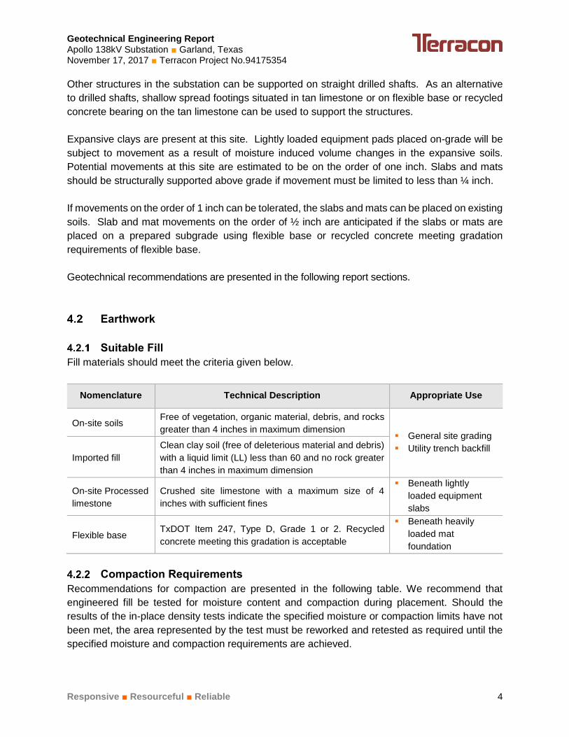
Geotechnical Engineering Report Apollo 138kV Substation Garland, Texas November 17, 2017 Terracon Project No.94175354
Responsive Resourceful Reliable 4
Other structures in the substation can be supported on straight drilled shafts. As an alternative
to drilled shafts, shallow spread footings situated in tan limestone or on flexible base or recycled
concrete bearing on the tan limestone can be used to support the structures.
Expansive clays are present at this site. Lightly loaded equipment pads placed on-grade will be
subject to movement as a result of moisture induced volume changes in the expansive soils.
Potential movements at this site are estimated to be on the order of one inch. Slabs and mats
should be structurally supported above grade if movement must be limited to less than ¼ inch.
If movements on the order of 1 inch can be tolerated, the slabs and mats can be placed on existing
soils. Slab and mat movements on the order of ½ inch are anticipated if the slabs or mats are
placed on a prepared subgrade using flexible base or recycled concrete meeting gradation
requirements of flexible base.
Geotechnical recommendations are presented in the following report sections.
Earthwork
Suitable Fill
Fill materials should meet the criteria given below.
Nomenclature Technical Description Appropriate Use
On-site soils Free of vegetation, organic material, debris, and rocks
greater than 4 inches in maximum dimension General site grading
Utility trench backfill Imported fill
Clean clay soil (free of deleterious material and debris)
with a liquid limit (LL) less than 60 and no rock greater
than 4 inches in maximum dimension
On-site Processed
limestone
Crushed site limestone with a maximum size of 4
inches with sufficient fines
Beneath lightly
loaded equipment
slabs
Flexible base TxDOT Item 247, Type D, Grade 1 or 2. Recycled
concrete meeting this gradation is acceptable
Beneath heavily
loaded mat
foundation
Compaction Requirements
Recommendations for compaction are presented in the following table. We recommend that
engineered fill be tested for moisture content and compaction during placement. Should the
results of the in-place density tests indicate the specified moisture or compaction limits have not
been met, the area represented by the test must be reworked and retested as required until the
specified moisture and compaction requirements are achieved.

Geotechnical Engineering Report Apollo 138kV Substation Garland, Texas November 17, 2017 Terracon Project No.94175354
Responsive Resourceful Reliable 5
Type of Fill Compaction Criteria
Subgrade preparation to
receive fill
Surface scarified to a minimum depth of 6 inches and compacted to criteria
below
Lift thickness of fill Loose lift thickness of 9-inch or less
General site fill / backfill
against grade beams
A minimum of 95% maximum standard Proctor dry density (ASTM D 698)
at minimum of +2 percentage points above optimum moisture content
Flexible base/ processed
limestone
A minimum of 95% maximum standard Proctor dry density (ASTM D 698)
in the range of -2 to +2 percentage points of optimum moisture content
Drainage and Utilities
All grades must be adjusted to provide positive drainage away from the structures. Water
permitted to pond adjacent or near the structures will result in ground movements. Open ground
should preferably be sloped at a minimum of 2 percent grade for at least 5 feet beyond the
perimeter of the structures.
Tan limestone was encountered at shallow depth, and could be encountered during utility
excavations. The limestone is hard and will be difficult to excavate, particularly in narrow utility
trenches.
Care should be taken that utility trenches are not left open for extended periods and they are
properly backfilled. Backfilling should be accomplished with properly compacted on-site soils,
rather than granular materials.
Foundations
Transmission structures can be supported on straight drilled shafts or directly embedded. Straight
drilled shafts and directly embedded poles can be socketed into either tan or gray limestone.
Foundations for switchgear pads, breaker pads and other equipment may be supported on
straight drilled shafts, shallow spread footings or mat foundations. Shallow spread footings should
be situated in tan limestone or on crushed stone flexible base or recycled concrete that extends
to the top of the tan limestone. If limestone is exposed, mat foundations can be placed on tan
limestone. Where clay soils are present, the footing subgrade needs to be prepared as
recommended in this report
Geotechnical recommendations for foundation design and construction are presented in the
following report sections.

Geotechnical Engineering Report Apollo 138kV Substation Garland, Texas November 17, 2017 Terracon Project No.94175354
Responsive Resourceful Reliable 6
Straight Drilled Shafts / Direct Embedded Pole – Design Parameters
We understand that Ensoft’s LPILE computer programs will be used to design the foundations for
straight drilled shafts or directly embedded poles foundations. Axial and lateral capacity design
parameters are presented in Table C-1 in Appendix C for use in L-PILE. Tan limestone is present
at shallow depth. Soil induced uplift forces on drilled shafts are not significant and can be
neglected.
Provided proper construction practices are followed, foundations designed according to the
recommendations provided above are expected to experience a total settlement of about one inch
or less.
Straight Drilled Shaft / Embedded Pole - Construction Considerations
The construction of all drilled shafts and directly embedded poles should be observed by
experienced geotechnical personnel during construction to confirm: 1) the bearing stratum; 2) the
minimum bearing depth; 3) the removal of all cuttings 4) that groundwater seepage is correctly
handled; and 5) that the shafts are within acceptable vertical tolerance.
Recommendations for drilled shaft construction are presented in the following table.
Item Recommendation
Drilled shaft installation
specification
Current version of American Concrete Institute’s “Standard Specification for
the Construction of Drilled Piers” ACI 336.
Top of shaft completion Enlarged (mushroom-shaped) top in contact with the clays should not be
allowed.
Time to complete Straight drilled shafts should be completed within one day.
Groundwater control in
straight drilled shafts
Seepage was not observed in the borings but could be encountered during
installation of the straight drilled shafts, particularly during wet periods of the
year. Rapid placement of steel and concrete may permit shaft installation to
proceed; however, seepage rates could be sufficient to require the use of
temporary casing for installation of the straight drilled shafts. The casing
should be seated below groundwater with all water and most loose material
removed prior to beginning the design penetration. Care must be taken that a
sufficient head of plastic concrete is maintained within the casing during
extraction.
Special Conditions The limestone is relatively hard and can be difficult to penetrate. A contractor
experienced with drilling in rock should be retained for this project.
Spread Footings – Design Parameters
Shallow spread foundations can be used as an alternative to straight drilled shaft foundations to
support the equipment pads. The spread footings should be situated in tan limestone or

Geotechnical Engineering Report Apollo 138kV Substation Garland, Texas November 17, 2017 Terracon Project No.94175354
Responsive Resourceful Reliable 7
processed limestone or recycled concrete over tan limestone. Design parameters for the shallow
foundation are provided below.
Description Recommendations
Footing Type Individual or continuous footing
Bearing stratum Tan limestone or flexible base or recycled concrete over
tan limestone
Net allowable bearing pressure 1 4,000 psf
Minimum dimension 3 feet
Minimum embedment A minimum of 1 foot into bearing stratum
Settlement 2 Less than 1 inch
Ultimate passive pressure 3 350 psf/ft (triangular distribution)
Ultimate Coefficient of sliding friction 4 0.45 for foundation on tan limestone
0.65 for foundation on flexible base or recycled concrete
1. The recommended net allowable bearing pressure is the pressure in excess of the minimum
surrounding overburden pressure at the footing base elevation. No footing should be founded within
a 45 degree plane from the base of the adjacent footing or excavation. Concrete should be placed
directly against the sides of the cut with no backfill below the level of the general excavation.
2. The foundation settlement will depend upon the variations within the subsurface soil profile, the
structural loading conditions, the embedment depth of the footings, and the quality of the earthwork
operations.
3. The sides of the excavation for the footings must be nearly vertical and the concrete should be
placed neat against these vertical faces for the passive earth pressure values to be valid. If the
loaded side is sloped or benched, and then backfilled, the allowable passive pressure will be
significantly reduced. Passive resistance in the upper 1 foot of tan limestone should be neglected.
4. A minimum safety factor of 1.5 should be used for sliding.
Spread Footings – Construction Considerations
Foundation excavations should be protected from standing water. The base of all foundation
excavations should be free of water and loose soil and rock prior to placing concrete. Excavation
of individual footings or sections of continuous footings, placement of steel and concrete, and
backfilling should be completed in a reasonably continuous manner. It is recommended that
complete installation of individual footings or sections of continuous footings be accomplished
within 48 hours of excavation.
Backfilling adjacent and over shallow foundations should proceed as soon as practical to reduce
disturbance. Backfilling should be accomplished using soils similar to those excavated. All backfill
should be properly compacted to the criteria presented in Section 4.2.2 Compaction
Requirements.

Geotechnical Engineering Report Apollo 138kV Substation Garland, Texas November 17, 2017 Terracon Project No.94175354
Responsive Resourceful Reliable 8
All shallow foundation installations should be inspected by qualified geotechnical personnel to
help verify the design depth and perform related duties.
Grade Beams
In conjunction with drilled shafts/shallow spread footings, all grade beams should be supported
by the drilled shafts/shallow spread footings. A minimum void space of 4 inches is recommended
between the bottom of grade beams and the clay subgrade. This void will serve to minimize
distress resulting from swell pressures generated by the clay soils. Structural cardboard forms
are one acceptable means of providing this void beneath cast-in-place elements. Soil retainers
should be used to prevent infilling of the void. A void space is not required for grade beams
supported on tan limestone, crushed stone flexible base, crushed on-site limestone, and recycled
concrete that extends to the top of the limestone.
The grade beams should be formed rather than cast against earth trenches. Forming of the inside
face of grade beams is not required if flexible base or crushed concrete is used below the pads.
Backfill against the exterior face of grade beams should be on site materials placed and
compacted as described in Section 4.2.2 Compaction Requirements.
Slabs in Conjunction with Drilled Shafts and Shallow Footings
Lightly loaded equipments placed on-grade will be subject to movement as a result of moisture
induced volume changes in the active soils. The active soils expand (heave) with increases in
moisture and contract (shrink) with decreases in moisture. The movement typically occurs as post
construction heave.
The potential magnitude of the moisture induced movements is rather variable. It is influenced by
the soil properties, overburden pressures, and to a great extent by soil moisture levels at the time
of construction. The greatest potential for post-construction movement occurs when the soils are
in dry condition at the time of construction. Based on subsurface conditions encountered in the
borings, the magnitude of potential movements at this site is estimated to be about one inch.
In conjunction with drilled shafts/shallow spread footings, structural slabs supported above grade
are recommended if movements greater than ¼ inch cannot be tolerated. A minimum vertical void
of 6 inches is recommended below a structurally suspended floor slab system. Provisions should
be made to provide drainage of this space in the event water becomes trapped or seeps into this
area.
If movements of 1 inch can be tolerated, the slabs can be supported on existing subgrade. Upper
one foot of the on-site soils is recommended to be replaced with flexible base or recycled concrete
meeting the requirements provided in Section 4.2.1 Suitable Fill and compacted as
recommended in Section 4.2.2 Compaction Requirements.

Geotechnical Engineering Report Apollo 138kV Substation Garland, Texas November 17, 2017 Terracon Project No.94175354
Responsive Resourceful Reliable 9
If movements of about ½ inch are acceptable, the slabs can be supported on a modified subgrade.
It is estimated that movements on the order of ½ inch can generally be obtained by replacing
existing soils above tan limestone with processed limestone, flexible base, or recycled concrete.
The slab areas should be excavated to the top of tan limestone. The processed limestone, flexible
base or recycled concrete meeting the requirements provided in Section 4.2.1 Suitable Fill
should then be placed to the bottom of slab following the recommendations in Section 4.2.2
Compaction Requirements.
Mat Foundations for Support of Heavy Equipment
Mat foundations may be used to support equipment and transformers if some movement can be
tolerated. If mats are placed on existing soils, movements are anticipated to be less 1 inch. If
existing soils are replaced with flexible base or crushed concrete as discussed in section in
Section 4.3.6 Slabs in Conjunction with Drilled Shafts / Shallow Footing, movements are
estimated be on the order of ½ inch. Design recommendations for mat foundations are presented
in this section.
Design Parameter Recommendation
Design movement criteria Up to 1 inch About ½ inch
Bearing stratum 1 foot of flexible base
over on-site compacted soil
Tan limestone, flexible base or recycled concrete
Minimum bearing depth 1 foot below finished
grade
1 foot below flexible base
or tan limestone
Minimum length or width 3.0 feet 3.0 feet
Maximum net allowable bearing pressure (1) 2,500 psf 4,000 psf
Modulus of subgrade reaction (1 foot by 1 foot
mat) 50 pci 100 pci
Ultimate coefficient of friction 0.65
0.45 for tan limestone
0.65 for flexible base and
recycled concrete
1. The recommended maximum net allowable bearing pressure is the pressure in excess of the
minimum surrounding overburden pressure at the mat base elevation.
Field Electrical Resistivity
Field electrical resistivity tests were performed at the site using an AEMC Model 4500 ground
resistance meter and 4-point Wenner expanding-spread traverse test method. A pair of

Geotechnical Engineering Report Apollo 138kV Substation Garland, Texas November 17, 2017 Terracon Project No.94175354
Responsive Resourceful Reliable 10
approximately perpendicular soil resistivity test arrays were performed using “A-spacings” of 5,
10, 20, 40 feet for the electrode. The results of the electrical resistivity tests are presented in
Exhibits A-4 and A-5.
Seismic Considerations
Description Value
2012/2015 International Building Code Site Classification (IBC) 1 B2
SDS Design Spectral Acceleration for a Short Period 0.068g
SD1 Design Spectral Acceleration for a 1-Second Period 0.036g
1. In general accordance with the ASCE/SEI 7-10.
2. The ASCE/SEI 7-10 requires a site soil profile determination extending to a depth of 100 feet for seismic site
classification. The current scope does not include the required 100 foot soil profile determination. Borings were
extended to a maximum depth of approximately 25 feet and this seismic site class definition considers that
competent soils and bedrock exist below the maximum depth of the subsurface exploration, which is consistent
with the site geology. Additional exploration to deeper depths would be required to confirm the conditions below
the current depth of exploration. Alternatively, a geophysical exploration could be utilized in order to attempt to
justify a higher seismic site class.
GENERAL COMMENTS
Terracon should be retained to review the final design plans and specifications so comments can
be made regarding interpretation and implementation of our geotechnical recommendations in the
design and specifications. Terracon also should be retained to provide observation and testing
services during grading, excavation, foundation construction and other earth-related construction
phases of the project.
The analysis and recommendations presented in this report are based upon the data obtained
from the borings performed at the indicated locations and from other information discussed in this
report. This report does not reflect variations that may occur between borings, across the site, or
due to the modifying effects of weather. The nature and extent of such variations may not become
evident until during or after construction. If variations appear, we should be immediately notified
so that further evaluation and supplemental recommendations can be provided.
The scope of services for this project does not include either specifically or by implication any
environmental or biological (e.g., mold, fungi, bacteria) assessment of the site or identification or
prevention of pollutants, hazardous materials or conditions. If the owner is concerned about the
potential for such contamination or pollution, other studies should be undertaken.

Geotechnical Engineering Report Apollo 138kV Substation Garland, Texas November 17, 2017 Terracon Project No.94175354
Responsive Resourceful Reliable 11
This report has been prepared for the exclusive use of our client for specific application to the
project discussed and has been prepared in accordance with generally accepted geotechnical
engineering practices. No warranties, express or implied, are intended or made. Site safety,
excavation support, and dewatering requirements are the responsibility of others. In the event that
changes in the nature, design, or location of the project as outlined in this report are planned, the
conclusions and recommendations contained in this report shall not be considered valid unless
Terracon reviews the changes and either verifies or modifies the conclusions of this report in
writing.

APPENDIX A
FIELD EXPLORATION
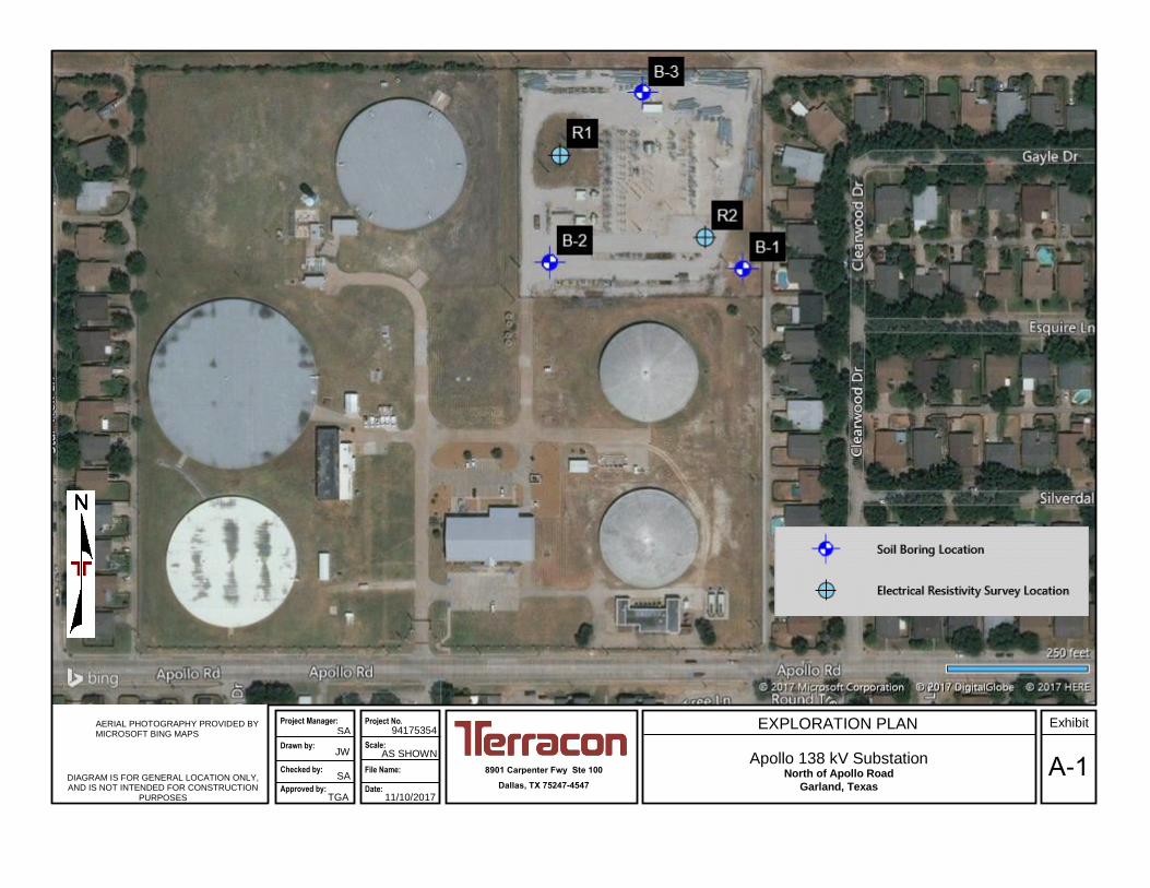
EXPLORATION PLAN
8901 Carpenter Fwy Ste 100
Dallas, TX 75247-4547
94175354 AERIAL PHOTOGRAPHY PROVIDED BY MICROSOFT BING MAPS
Apollo 138 kV Substation North of Apollo Road
Garland, Texas DIAGRAM IS FOR GENERAL LOCATION ONLY, AND IS NOT INTENDED FOR CONSTRUCTION
PURPOSES
Project Manager:
Drawn by:
Checked by: Approved by:
JW
SA
TGA
SA
11/10/2017
Scale:
Project No.
File Name: Date:
AS SHOWN A-1
Exhibit

B-1B-2
B-3
BORING PLANNED
R1
R2
RESISTIVITY SURVEY
Project Mngr:
Approved By:
Checked By:
Drawn By:
Project No.
Scale:
Date: Consulting Engineers and Scientists
8901 CARPENTER FREEWAY DALLAS, TEXAS 75247FAX. (214) 630-7070PH. (214) 630-1010
NOTE: ALL BORING LOCATIONS
ARE APPROXIMATE.
(Registration No.: F-3272)11/10/17
SA
JJD
SA
TGA
94175354
AS SHOWNBORING LOCATION PLAN
APOLLO 138 kV SUBSTATIONNORTH OF APOLLO ROAD
A-2GARLAND, TEXAS
EXHIBIT
SOURCE: GOOGLE EARTH, IMAGERY DATE: 1/27/2017.
SITE VICINITY MAP
SOURCE: GOOGLE MAPS.
N JU
PIT
ER
R
D
HIGH PLATEAU DR
APOLLO RD
ARAPAHO RD

Geotechnical Engineering Report Apollo 138kV Substation Garland, Texas November 17, 2017 Terracon Project No.94175354
Responsive Resourceful Reliable Exhibit A-3
Field Exploration Description
Subsurface conditions were explored by drilling three borings at the approximate locations
indicated on the Boring Location Plan on Exhibit A-2 in Appendix A. The field exploration was
performed on October 27, 2017. The test locations were marked in the field by GP & L. The
coordinate of the boring locations were obtained by a handheld GPS unit with an accuracy of
about 20 feet. The boring elevations were obtained from the North Central Texas Governments
(NCTCOG) topographic map. The boring locations and elevations should be considered accurate
only to the degree implied by the methods employed to determine them.
The borings were performed using truck-mounted drill rigs. Samples of the soils encountered in
the borings were obtained using Shelby tubes and split spoon sampling procedures. The samples
were tagged for identification, sealed to reduce moisture loss, and taken to the laboratory for
further examination, testing, and classification. The load carrying capacity of the limestone
bedrock was evaluated in place by the Texas Department of Transportation (TxDOT) cone
penetration test. Upon the completion of drilling, the boreholes were backfilled with soil cuttings.
Field boring logs were prepared by the drill crew. These logs included visual classifications of the
materials encountered as well as interpretation of the subsurface conditions between samples.
The boring logs included with this report represent the engineer’s interpretation of the field logs
and include modifications based on visual evaluation of the samples and laboratory test results.
The boring logs are presented in Exhibits A-5 through A-7 in Appendix A. General Notes to log
terms and symbols are presented in Exhibit D-1 in Appendix D.
Field Electrical Resistivity Surveys
Two (2) field electrical resistivity surveys were performed using the Wenner Four-Electrode
Method at the locations shown on the Exhibits A-2 and A-3. A pair of approximately perpendicular
soil resistivity test arrays were performed using “A-spacings” of 5, 10, 20, and 40 feet for the
electrodes.
The following table summarizes measured resistance (Ohm) and calculated resistivity (ρ).
Location GPS Coordinate of
Center Direction Parameter
Spacing (feet)
5 10 20 40
R1 Latitude: 32.95395 Longitude: -96.67795
North - South
Measured resistance
(Ω) 0.72 0.49 0.34 0.19
Calculated resistivity (ρ)
689 938 1,302 1,455
East - West
Measured resistance
(Ω) 0.69 0.52 0.32 0.06
Calculated resistivity (ρ)
661 996 1,226 460

Geotechnical Engineering Report Apollo 138kV Substation Garland, Texas November 17, 2017 Terracon Project No.94175354
Responsive Resourceful Reliable Exhibit A-4
Location GPS Coordinate of
Center Direction Parameter
Spacing (feet)
5 10 20 40
R2 Latitude : 32.95356 Longitude: -96.67712
North - South
Measured resistance
(Ω) 1.44 0.79 0.36 0.16
Calculated resistivity (ρ)
1,379 1,513 1,379 1,226
East - West
Measured resistance
(Ω) 1.50 0.66 0.37 0.22
Calculated resistivity (ρ)
1,436 1,264 1,417 1,685

27
17
72-26-46604+/-
598+/-
581+/-
4.5 (HP)
8-9-17N=26
TC=100/2.5"
TC=100/0.75"
TC=100/1.25"
TC=100/1.0"
TC=100/1.0"
Latitude and longitude were obtained from a handheld GPSdevice. Elevation was obtained from the North Central TexasCouncil of Governments (NCTCOG) topographic maps.
2.0
8.0
25.0
FAT CLAY (CH), brown, moist, very stiff
LIMESTONE, with clay seams, tan
LIMESTONE, gray
Boring Terminated at 25 Feet
GR
AP
HIC
LO
G
Hammer Type: AutomaticStratification lines are approximate. In-situ, the transition may be gradual.
TH
IS B
OR
ING
LO
G IS
NO
T V
ALI
D IF
SE
PA
RA
TE
D F
RO
M O
RIG
INA
L R
EP
OR
T.
G
EO
SM
AR
T L
OG
-NO
WE
LL 9
417
535
4 A
PO
LLO
13
8 K
V S
UB
.GP
J T
ER
RA
CO
N_D
AT
AT
EM
PLA
TE
.GD
T 1
1/1
5/17
CO
MP
RE
SS
IVE
ST
RE
NG
TH
(tsf
)
ST
RA
IN (
%)
TE
ST
TY
PE
PE
RC
EN
T F
INE
S
WA
TE
RC
ON
TE
NT
(%
)
DR
Y U
NIT
WE
IGH
T (
pcf)
LL-PL-PI
ATTERBERGLIMITS
ELEVATION (Ft.)
Approximate Surface Elev: 606 (Ft.) +/-
WA
TE
R L
EV
EL
OB
SE
RV
AT
ION
S
DE
PT
H (
Ft.)
5
10
15
20
25
SA
MP
LE T
YP
E STRENGTH TEST
FIE
LD T
ES
TR
ES
ULT
S
North of Apollo Rd Garland, TXSITE:
Page 1 of 1
Advancement Method:Dry Augered
Abandonment Method:Boring backfilled with soil cuttings upon completion.
Notes:
Project No.: 94175354
Drill Rig:
Boring Started: 10-27-2017
BORING LOG NO. B- 1R-Delta Engineers IncCLIENT:Garland, TX
Driller: Total Depth
Boring Completed: 10-27-2017
Exhibit: A-5
See Exhibit A-4 for description of fieldproceduresSee Appendix B for description of laboratoryprocedures and additional data (if any).
See Appendix C for explanation of symbols andabbreviations.
PROJECT: Apollo 138 kV Substation
8901 Carpenter Fwy Ste 100Dallas, TX
No seepage encountered during drilling
Dry at completion
WATER LEVEL OBSERVATIONS
DEPTH
LOCATION See Exhibit A-3
Latitude: 32.9534° Longitude: -96.6769°

18
26 48-20-28604.5+/-
583+/-
4.5 (HP)
4.5 (HP)
50/5.5"TC=100/1.0"
TC=100/1.25"
TC=100/0.75"
TC=100/1.0"
TC=100/1.0"
Latitude and longitude were obtained from a handheld GPSdevice. Elevation was obtained from the North Central TexasCouncil of Governments (NCTCOG) topographic maps.
3.5
25.0
LEAN CLAY (CL), with limestone fragments,brown, moist, very stiff
LIMESTONE, with clay seams, tan
Boring Terminated at 25 Feet
GR
AP
HIC
LO
G
Hammer Type: AutomaticStratification lines are approximate. In-situ, the transition may be gradual.
TH
IS B
OR
ING
LO
G IS
NO
T V
ALI
D IF
SE
PA
RA
TE
D F
RO
M O
RIG
INA
L R
EP
OR
T.
G
EO
SM
AR
T L
OG
-NO
WE
LL 9
417
535
4 A
PO
LLO
13
8 K
V S
UB
.GP
J T
ER
RA
CO
N_D
AT
AT
EM
PLA
TE
.GD
T 1
1/1
5/17
CO
MP
RE
SS
IVE
ST
RE
NG
TH
(tsf
)
ST
RA
IN (
%)
TE
ST
TY
PE
PE
RC
EN
T F
INE
S
WA
TE
RC
ON
TE
NT
(%
)
DR
Y U
NIT
WE
IGH
T (
pcf)
LL-PL-PI
ATTERBERGLIMITS
ELEVATION (Ft.)
Approximate Surface Elev: 608 (Ft.) +/-
WA
TE
R L
EV
EL
OB
SE
RV
AT
ION
S
DE
PT
H (
Ft.)
5
10
15
20
25
SA
MP
LE T
YP
E STRENGTH TEST
FIE
LD T
ES
TR
ES
ULT
S
North of Apollo Rd Garland, TXSITE:
Page 1 of 1
Advancement Method:Dry Augered
Abandonment Method:Boring backfilled with soil cuttings upon completion.
Notes:
Project No.: 94175354
Drill Rig:
Boring Started: 10-27-2017
BORING LOG NO. B- 2R-Delta Engineers IncCLIENT:Garland, TX
Driller: Total Depth
Boring Completed: 10-27-2017
Exhibit: A-6
See Exhibit A-4 for description of fieldproceduresSee Appendix B for description of laboratoryprocedures and additional data (if any).
See Appendix C for explanation of symbols andabbreviations.
PROJECT: Apollo 138 kV Substation
8901 Carpenter Fwy Ste 100Dallas, TX
No seepage encountered during drilling
Dry at completion
WATER LEVEL OBSERVATIONS
DEPTH
LOCATION See Exhibit A-3
Latitude: 32.9534° Longitude: -96.678°

7
11604+/-
597.5+/-
581+/-
11-6-5N=11
50/5"
TC=100/0.75"
TC=1003.0"
TC=100/0.5"
TC=100/0.75"
TC=100/1.0"
Latitude and longitude were obtained from a handheld GPSdevice. Elevation was obtained from the North Central TexasCouncil of Governments (NCTCOG) topographic maps.
2.0
8.5
25.0
FAT CLAY (CH), with limestone fragments, brown,moist, stiff
LIMESTONE, with clay seams, tan
LIMESTONE, with occasional clay seams, gray
Boring Terminated at 25 Feet
GR
AP
HIC
LO
G
Hammer Type: AutomaticStratification lines are approximate. In-situ, the transition may be gradual.
TH
IS B
OR
ING
LO
G IS
NO
T V
ALI
D IF
SE
PA
RA
TE
D F
RO
M O
RIG
INA
L R
EP
OR
T.
G
EO
SM
AR
T L
OG
-NO
WE
LL 9
417
535
4 A
PO
LLO
13
8 K
V S
UB
.GP
J T
ER
RA
CO
N_D
AT
AT
EM
PLA
TE
.GD
T 1
1/1
5/17
CO
MP
RE
SS
IVE
ST
RE
NG
TH
(tsf
)
ST
RA
IN (
%)
TE
ST
TY
PE
PE
RC
EN
T F
INE
S
WA
TE
RC
ON
TE
NT
(%
)
DR
Y U
NIT
WE
IGH
T (
pcf)
LL-PL-PI
ATTERBERGLIMITS
ELEVATION (Ft.)
Approximate Surface Elev: 606 (Ft.) +/-
WA
TE
R L
EV
EL
OB
SE
RV
AT
ION
S
DE
PT
H (
Ft.)
5
10
15
20
25
SA
MP
LE T
YP
E STRENGTH TEST
FIE
LD T
ES
TR
ES
ULT
S
North of Apollo Rd Garland, TXSITE:
Page 1 of 1
Advancement Method:Dry Augered
Abandonment Method:Boring backfilled with soil cuttings upon completion.
Notes:
Project No.: 94175354
Drill Rig:
Boring Started: 10-27-2017
BORING LOG NO. B- 3R-Delta Engineers IncCLIENT:Garland, TX
Driller: Total Depth
Boring Completed: 10-27-2017
Exhibit: A-7
See Exhibit A-4 for description of fieldproceduresSee Appendix B for description of laboratoryprocedures and additional data (if any).
See Appendix C for explanation of symbols andabbreviations.
PROJECT: Apollo 138 kV Substation
8901 Carpenter Fwy Ste 100Dallas, TX
No seepage encountered during drilling
Dry at completion
WATER LEVEL OBSERVATIONS
DEPTH
LOCATION See Exhibit A-3
Latitude: 32.9543° Longitude: -96.6775°

APPENDIX B
LABORATORY TESTING

Geotechnical Engineering Report Apollo 138kV Substation Garland, Texas November 17, 2017 Terracon Project No.94175354
Responsive Resourceful Reliable Exhibit B-1
Laboratory Testing
The boring logs and samples were reviewed by a geotechnical engineer who selected soil
samples for testing. Tests were performed by technicians working under the direction of the
engineer. A brief description of the tests performed follows.
Liquid and plastic limit tests, and moisture content measurements were performed to aid in
classifying the soils in accordance with the Unified Soil Classification System (USCS). The USCS
is summarized on Exhibit D-2 in Appendix D. An absorption swell test was performed on a
selected sample of the cohesive material. This test was used to quantitatively evaluate volume
change potential at in-situ moisture levels. Strength of cohesive soils was measured by hand
penetrometer tests.
The results of the swell tests are presented in the following table. The results of other laboratory
tests are presented on the boring logs in Appendix A.
Boring
No.
Depth
(feet)
Liquid
Limit
(%)
Plasticity
Index
(%)
Initial
Moisture
(%)
Final
Moisture
(%)
Surcharge
(psf)
Swell
(%)
B-2 2-3 48 28 26 30 375 0

APPENDIX C
DESIGN PARAMETERS

Geotechnical Engineering Report Apollo 138kV Substation Garland, Texas November 17, 2017 Terracon Project No.94175354
Responsive Resourceful Reliable Exhibit C-1
Borings B-1 to B-3
Soil/Rock Parameters for Axial and Lateral Capacity Analyses
No.
So
il T
yp
e
LPILE Material
Type
Dep
th t
o t
op
of
lay
er
(fee
t)
Dep
th t
o b
ott
om
of
lay
er
(fe
et)
Eff
ec
tiv
e S
oil
Un
it W
eig
ht
(pc
f)
Un
dra
ine
d
co
he
sio
n,
c (
ps
i)
Str
ain
Fa
cto
r,
є50
Un
iax
ial
Co
mp
res
siv
e
Str
en
gth
, (p
si)
Yo
un
g’s
Mo
du
lus
, E
r (p
si)
Ro
ck
Qu
ali
ty
Des
ign
ati
on
,
RQ
D (
%)
Krm
Ma
xim
um
Ne
t
All
ow
ab
le E
nd
Bea
rin
g C
ap
ac
ity
(ps
f)
All
ow
ab
le S
kin
Fri
cti
on
–
Co
mp
res
sio
n
(ps
f)
All
ow
ab
le S
kin
Fri
cti
on
-
Te
ns
ion
(p
sf)
1 Fat / Lean
Clay Stiff clay w/o
free water 0 3 125 N/A N/A N/A N/A N/A N/A N/A N/A N/A
2 Tan
Limestone Weak rock 3 15 130 N/A N/A 175 35,000 70 0.0005 20,000 3,200 2,400
3 Gray
Limestone Weak rock 15 25 140 N/A N/A 800 180,000 90 0.0004 50,000 6,500 4,700
Notes:
1. Due to the potential for shrinkage of the near surface soils, lateral resistance of clay should be neglected
2. Neglect skin friction in the overburden soils
3. Seepage was not observed in the borings and the boring was observed to be dry at drilling completion
4. Soil induced uplift pressures developed from the overburden are not significant and can be neglected
5. A minimum shaft penetration of 2 feet in gray limestone is required to develop end bearing capacity in gray limestone
6. Minimum straight drilled shaft length of 15 feet is recommended
7. Minimum directly embedded shaft length of 10 feet is recommended
8. The skin friction values in the table should not be used for directly embedded poles
9. Lateral load design parameters should only be used for the directly embedded poles if the compressive strength of the concrete used in the embedded poles are greater
than 1,500 psi

APPENDIX D
SUPPORTING DOCUMENTS
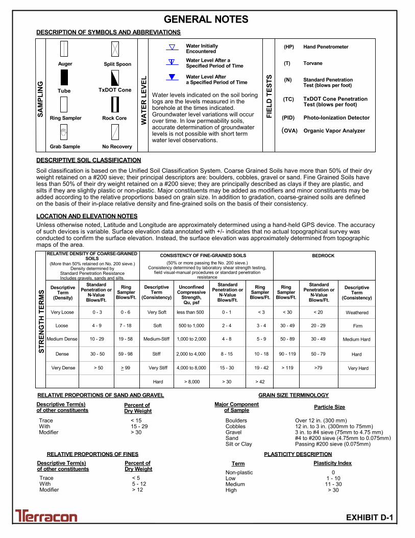
< 20
Soil classification is based on the Unified Soil Classification System. Coarse Grained Soils have more than 50% of their dryweight retained on a #200 sieve; their principal descriptors are: boulders, cobbles, gravel or sand. Fine Grained Soils haveless than 50% of their dry weight retained on a #200 sieve; they are principally described as clays if they are plastic, andsilts if they are slightly plastic or non-plastic. Major constituents may be added as modifiers and minor constituents may beadded according to the relative proportions based on grain size. In addition to gradation, coarse-grained soils are definedon the basis of their in-place relative density and fine-grained soils on the basis of their consistency.
Plasticity Index
01 - 1011 - 30
> 30
RELATIVE PROPORTIONS OF FINES
Descriptive Term(s)of other constituents
Percent ofDry Weight
< 55 - 12> 12
TraceWithModifier
Water Level Aftera Specified Period of Time
GRAIN SIZE TERMINOLOGYRELATIVE PROPORTIONS OF SAND AND GRAVEL
TraceWithModifier
Exhibit C-1
WA
TE
R L
EV
EL
Auger
Shelby Tube
Loose
Medium Dense
Very Dense
10 - 29
4 - 9
19 - 58
500 to 1,000
less than 500
5 - 9
3 - 4
< 3
RingSamplerBlows/Ft.
8 - 15
< 30
30 - 49
> 119
PLASTICITY DESCRIPTION
Term
< 1515 - 29> 30
Descriptive Term(s)of other constituents
Water InitiallyEncountered
Water Level After aSpecified Period of Time
Major Componentof Sample
Percent ofDry Weight
LOCATION AND ELEVATION NOTES
RELATIVE DENSITY OF COARSE-GRAINEDSOILS
DescriptiveTerm
(Density)
RingSamplerBlows/Ft.
Dense
> 50
30 - 50
_ 4,000 to 8,000
> 30
15 - 30
> 42
19 - 42
(50% or more passing the No. 200 sieve.)Consistency determined by laboratory shear strength testing,
field visual-manual procedures or standard penetrationresistance
SA
MP
LIN
G
FIE
LD
TE
ST
S
(HP)
(T)
(b/f)
(PID)
(OVA)
DESCRIPTION OF SYMBOLS AND ABBREVIATIONS
Non-plasticLowMediumHigh
BouldersCobblesGravelSandSilt or Clay
Hand Penetrometer
Torvane
Standard PenetrationTest (blows per foot)
Photo-Ionization Detector
Organic Vapor Analyzer
Water levels indicated on the soil boringlogs are the levels measured in theborehole at the times indicated.Groundwater level variations will occurover time. In low permeability soils,accurate determination of groundwaterlevels is not possible with short termwater level observations.
DESCRIPTIVE SOIL CLASSIFICATION
Unless otherwise noted, Latitude and Longitude are approximately determined using a hand-held GPS device. The accuracyof such devices is variable. Surface elevation data annotated with +/- indicates that no actual topographical survey wasconducted to confirm the surface elevation. Instead, the surface elevation was approximately determined from topographicmaps of the area.
7 - 18
59 - 98
> 99
DescriptiveTerm
(Consistency)
2,000 to 4,000
1,000 to 2,000
10 - 18
CONSISTENCY OF FINE-GRAINED SOILS
Ring Sampler
Grab Sample
Split Spoon
Macro Core
Rock Core
No Recovery
Particle Size
Over 12 in. (300 mm)12 in. to 3 in. (300mm to 75mm)3 in. to #4 sieve (75mm to 4.75 mm)#4 to #200 sieve (4.75mm to 0.075mmPassing #200 sieve (0.075mm)
ST
RE
NG
TH
TE
RM
S
(More than 50% retained on No. 200 sieve.)Density determined by
Standard Penetration ResistanceIncludes gravels, sands and silts.
StandardPenetration or
N-ValueBlows/Ft.
0 - 6Very Loose 0 - 3 Very Soft
Soft
Medium-Stiff
Stiff
Very Stiff
Hard
UnconfinedCompressive
Strength,Qu, psf
2 - 4
0 - 1
StandardPenetration or
N-ValueBlows/Ft.
RingSamplerBlows/Ft.
50 - 89
90 - 119
20 - 29
50 - 79
>79
DescriptiveTerm
(Consistency)
StandardPenetration or
N-ValueBlows/Ft.
BEDROCK
Weathered
Firm
Medium Hard
Hard
Very Hard
30 - 49
> 8,000
4 - 8
GENERAL NOTES
Tube TxDot Cone
(N)
(TC) TxDOT Cone PenetrationTest (blows per foot)
(OVA) Organic Vapor Analyzer
(PID) Photo-Ionization Detector
TxDOT Cone
)
EXHIBIT D-1
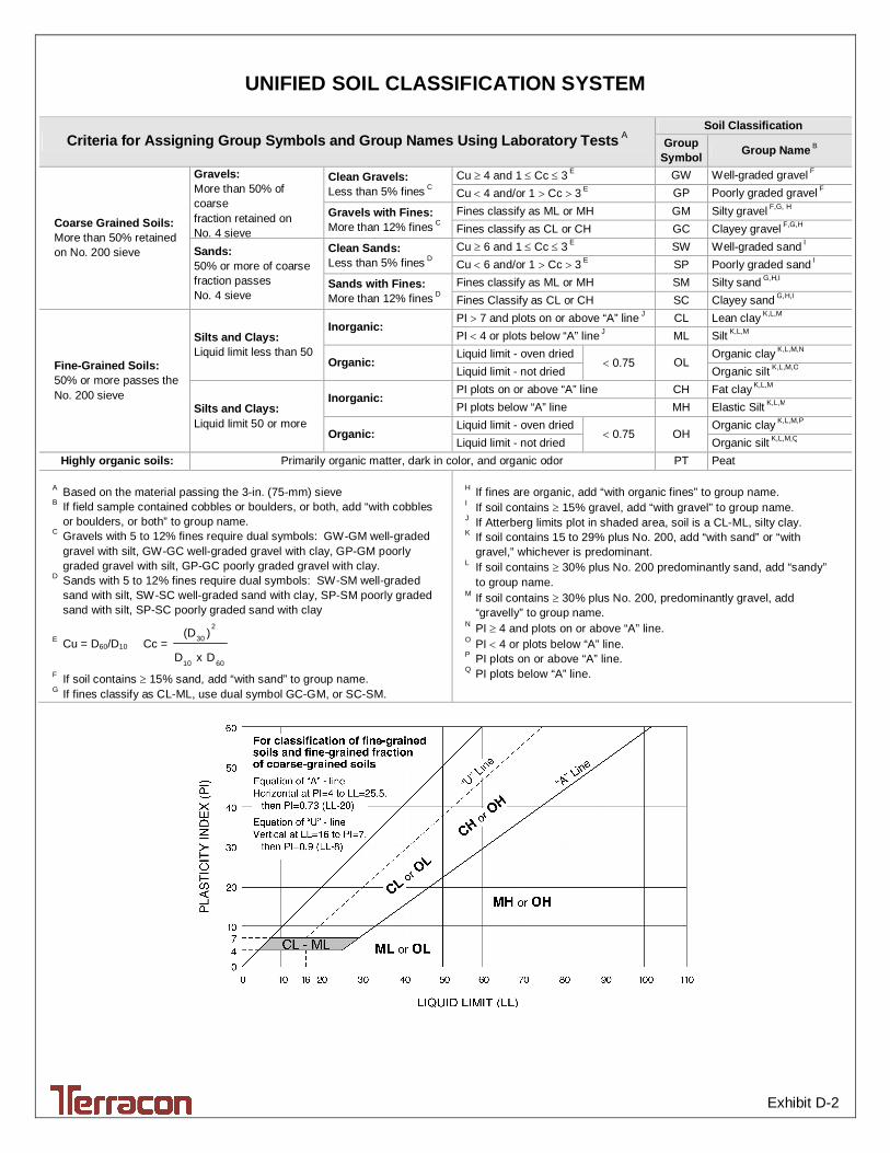
Exhibit D-2
UNIFIED SOIL CLASSIFICATION SYSTEM
Criteria for Assigning Group Symbols and Group Names Using Laboratory Tests A Soil Classification
Group Symbol Group Name B
Coarse Grained Soils: More than 50% retained on No. 200 sieve
Gravels: More than 50% of coarse fraction retained on No. 4 sieve
Clean Gravels: Less than 5% fines C
Cu 4 and 1 Cc 3 E GW Well-graded gravel F Cu 4 and/or 1 Cc 3 E GP Poorly graded gravel F
Gravels with Fines: More than 12% fines C
Fines classify as ML or MH GM Silty gravel F,G, H Fines classify as CL or CH GC Clayey gravel F,G,H
Sands: 50% or more of coarse fraction passes No. 4 sieve
Clean Sands: Less than 5% fines D
Cu 6 and 1 Cc 3 E SW Well-graded sand I Cu 6 and/or 1 Cc 3 E SP Poorly graded sand I
Sands with Fines: More than 12% fines D
Fines classify as ML or MH SM Silty sand G,H,I Fines Classify as CL or CH SC Clayey sand G,H,I
Fine-Grained Soils: 50% or more passes the No. 200 sieve
Silts and Clays: Liquid limit less than 50
Inorganic: PI 7 and plots on or above “A” line J CL Lean clay K,L,M PI 4 or plots below “A” line J ML Silt K,L,M
Organic: Liquid limit - oven dried
0.75 OL Organic clay K,L,M,N
Liquid limit - not dried Organic silt K,L,M,O
Silts and Clays: Liquid limit 50 or more
Inorganic: PI plots on or above “A” line CH Fat clay K,L,M PI plots below “A” line MH Elastic Silt K,L,M
Organic: Liquid limit - oven dried
0.75 OH Organic clay K,L,M,P
Liquid limit - not dried Organic silt K,L,M,Q Highly organic soils: Primarily organic matter, dark in color, and organic odor PT Peat
A Based on the material passing the 3-in. (75-mm) sieve B If field sample contained cobbles or boulders, or both, add “with cobbles
or boulders, or both” to group name. C Gravels with 5 to 12% fines require dual symbols: GW-GM well-graded
gravel with silt, GW-GC well-graded gravel with clay, GP-GM poorly graded gravel with silt, GP-GC poorly graded gravel with clay.
D Sands with 5 to 12% fines require dual symbols: SW-SM well-graded sand with silt, SW-SC well-graded sand with clay, SP-SM poorly graded sand with silt, SP-SC poorly graded sand with clay
E Cu = D60/D10 Cc = 6010
2
30
DxD
)(D
F If soil contains 15% sand, add “with sand” to group name. G If fines classify as CL-ML, use dual symbol GC-GM, or SC-SM.
H If fines are organic, add “with organic fines” to group name. I If soil contains 15% gravel, add “with gravel” to group name. J If Atterberg limits plot in shaded area, soil is a CL-ML, silty clay. K If soil contains 15 to 29% plus No. 200, add “with sand” or “with
gravel,” whichever is predominant. L If soil contains 30% plus No. 200 predominantly sand, add “sandy”
to group name. M If soil contains 30% plus No. 200, predominantly gravel, add
“gravelly” to group name. N PI 4 and plots on or above “A” line. O PI 4 or plots below “A” line. P PI plots on or above “A” line. Q PI plots below “A” line.

Terracon Consultants, Inc. 8901 Carpenter Freeway, Suite 100 Dallas, Texas 75247 Registration No. F -3272
P [214] 630 1010 F [214] 630 7070 terracon.com
December 15, 2017
R-Delta Engineers, Inc.
618 Main Street
Garland, Texas 75040
Attn: Mr. Frank A. Polma, P.E.
P: 972.494.5031
Re: Addendum to Geotechnical Engineering Report
Apollo 138kV Substation
North of Apollo Road
Garland, Texas
Terracon Project No. 94175354
Dear Mr. Polma:
Terracon has performed a geotechnical exploration at the Apollo 138kV Substation site and
presented our geotechnical engineering recommendations in Terracon Report No. 94175354
dated November 17, 2017. In Exhibit C of the report, a minimum drilled shaft length of 15 feet
was recommended.
The drilled shafts are planned to support lightly loaded structures. The axial loads in the drilled
shafts are expected to be about 5 kips and drilled shaft design is governed by lateral design. In
this case, a minimum drilled shaft length of 10 feet can be used.
All other recommendations in the original report (Terracon Report No. 94175354 dated November
17, 2017) remain unchanged. If you have any questions concerning this document, or if we may be
of further service, please contact us.
Sincerely,
Terracon Consultants, Inc.
Saheem Ahmed, P.E. Tim G. Abrams, P.E.
Senior Engineer Senior Principal