Embed Size (px)
Citation preview

PRINCE WILLIAM COUNTY MINNIEVILLE ROAD RTE. 640 – WIDEN TO 4 LANES
PWC: Project No. SPR2015-20094 ; VDOT: Project No. 0640-076-R98 C501 , UPC 103484
INVITATION FOR BID NO. IFB160046
Prince William County post notices of amendment/addenda to a solicitation on the County’s e-procurement website at: www.pwcgov.org/eservices/eprocurement . All Bidders must verify or confirm issuance of addenda prior to submitting an offer/proposal. Notice to all Bidders: In the event of inclement weather and Prince William County implements its liberal leave policy the due date for receipt of bids is postponed until such time as extended by subsequent written addenda.
BID DUE DATE: JUNE 30, 2016 (unless changed by formal written addenda)
NO LATER THAN 3:00 P.M. LOCAL TIME
DELIVER SEALED BID TO: PRINCE WILLIAM COUNTY PURCHASING SUITE 205 McCOART ADMINISTRATION
SHANA N. TERRY, SENIOR CONTRACT SPECIALIST 1 COUNTY COMPLEX COURT PRINCE WILLIAM, VA 22192-9201
Direct written technical questions to Owner Representative: Mark Gunn, P.E., Project Manager, Rinker Design Associates, P.C. (703) 368-7373, email at:[email protected], with a copy to Shana N. Terry at: [email protected] General and Informational Questions Contact: Shana N. Terry, Senior Contract Specialist at 703-792-7233, or email at: [email protected] Advertisement Date: May 31, 2016

PRINCE WILLIAM COUNTY MINNIEVILLE ROAD RTE. 640 – WIDEN TO 4 LANES
INVITATION TO SUBMIT A BID No. IFB160046 PWC: Project No. SPR2015-20094 ; VDOT: Project No. 0640-076-R98 C501 , UPC 103484
TABLE OF CONTENTS
MISCELLANEOUS DOCUMENTS Cover Page Table of Contents
BIDDING DOCUMENTS Invitation I-1 Proposal Form P-1 Summary/Schedule of Unit Prices S-1 Bid Bond BB-1 Insurance Checklist INS CK-1 Conditions of the Contract County Supplemental Specifications to SS-1 VDOT Road and Bridge Specifications County Contract Special Provisions CSP-1 Contract Agreement (Sample) C-1 VDOT Special Provisions, Supplemental Specifications, VSP-1 and Special Provision Copied Notes Contract Requirements Bidder Certification of Prequalification BC-1 Classification and Work Capacity Contractor’s Request for Payment RP-1 Change Order Approval CO-1 Change Order Directive CD-1
Minnieville Road Rte. 640 Widen to 4 Lanes Table of Contents TOC-1

Performance Bond PB-1 Labor and Materials Payment Bond LM-1 Affidavit, Waiver of Lien and Release of Contractor, WL-1 Subcontractor, or Supplier Sublet Form CS-1 Appendices APPENDIX A – Geotechnical Engineering Report
END OF TABLE OF CONTENTS
Minnieville Road Rte. 640 Widen to 4 Lanes Table of Contents TOC-2

PRINCE WILLIAM COUNTY MINNIEVILLE ROAD RTE. 640 – WIDEN TO 4 LANES
INVITATION TO SUBMIT A BID No. IFB160046 PWC: Project No. SPR2015-20094 ; VDOT: Project No. 0640-076-R98 C501 , UPC
103484
INVITATION TO SUBMIT A BID No. IFB160046
Unless changed by formal written addenda, sealed bids for the Minnieville Road Widen to 4 Lanes (Route 234 to Spriggs Road) construction project will be received until 3:00 P.M., June 30, 2016, in the Prince William County McCoart Administration, Purchasing Office, Suite 205, 1 County Complex Court, Prince William, Virginia 22192-9201, (703) 792-6770 (located off of the Prince William Parkway, Woodbridge, Virginia). Only Bids from firms that have been prequalified in accordance with the procedure detailed in RFQ160017 Prequalification for Construction of Minnieville Road Improvements will be accepted. Bids received after that time will not be accepted.
Generally, the project consists of constructing the ultimate Minnieville Road typical section from Route 234 to Spriggs Road in accordance with the Prince William County Comprehensive Plan. Total project length is approximately 10,890 linear feet. The roadway is classified by the Virginia Department of Transportation as an Urban Minor Arterial (Standard GS-6). Minnieville Road will be reconstructed to provide a four-lane divided roadway with raised 16’ median, a 5’ sidewalk on the south side of the road, and a 10’ shared use path on the north side. Construction includes a concrete arch crossing of Powell’s Creek, which is a designated FEMA Floodplain. Work includes, but is not limited to, the installation of erosion control devices, clearing and grubbing, grading, excavation, installing storm sewers pipes and drainage structures, culvert installation, stormwater management facilities, curb and gutter, placing aggregate, asphalt paving, pedestrian facilities (sidewalk/shared use path), installation of traffic signage and pavement markings, waterline and sanitary sewer construction, traffic signals, retaining wall construction, precast concrete arch construction, and all measures required for the maintenance of traffic during construction. All work shall be performed in accordance with the approved project plans and bid documents. The completed project must meet any and all requirements for final acceptance by the Virginia Department of Transportation. Interested Contractors may become a registered Plan Holder by purchasing a CD ROM of printable all inclusive Bidding/Contract Documents, Specs and Plans (drawings and specs) for non-refundable amount of $50.00 from the County’s consulting engineer, Rinker Design Associates, P.C., 9385 Discovery Boulevard, Suite 200, Manassas, VA 20109 Attention: Mark Gunn, P.E., (703) 368-7373, email at: [email protected]. Make checks payable to Rinker Design Associates, P.C. (Credit cards are not accepted). Minnieville Road Rte. 640 Widen to 4 Lanes Invitation to Submit a Bid I-1 of 2
Direct questions in writing to the County’s consulting engineer at least ten (10) calendar days prior to the date established for receipt of Bids. If Specifications, Plans, a word, phrase, clause, or any other portion of the Invitation For Bid including the Bid Pricing Proposal or other documents which makeup the Contract Documents, is alleged to be ambiguous/confusing or in conflict, the Bidder shall submit written notice of such to the Engineer no later than ten (10) calendar days prior to the date for receipt of Bids and shall request an interpretation. The County will not be responsible for any other explanations or interpretations of the Bidding Documents or Contract Documents unless made by formal Addenda. No employee or agent of the County shall have the authority to furnish any other explanation or interpretation, verbal or written. All Bidders shall have a valid certificate of authority or registration to transact business in Virginia with the Virginia State Corporation Commission as required by Title 13.1 or Title 50 of the Code of Virginia at time of bid submission. Prior to submission of bids, all Bidders shall be VDOT prequalified. In accordance with Prince William County Purchasing Regulations, the County reserves the right to reject any and all bids, waive informalities and irregularities in bidding, and to accept bids, which are, in consideration, in the best interest of the County. Bidders interested in bidding shall have registered with Prince William County Purchasing e-Procurement, a 24 hour access for vendor registration, including a variety of solicitation, contract and general information at: www.pwcgov.org/eservices/eprocurement .
END OF SECTION
Minnieville Road Rte. 640 Widen to 4 Lanes Invitation to Submit a Bid I-2 of 2

PRINCE WILLIAM COUNTY MINNIEVILLE ROAD RTE. 640 – WIDEN TO 4 LANES
INVITATION TO SUBMIT A BID No. IFB160046 PWC: Project No. SPR2015-20094 ; VDOT: Project No. 0640-076-R98 C501 , UPC 103484
PROPOSAL PRICING FORM
I. DECLARATION: COMPANY NAME OF BIDDER: ______________________________________________ I/We, the undersigned have examined the location of the proposed work, declare: no other person, firm or corporation has interest in this Proposal; carefully examined any/all documents pertaining to the Contract thoroughly and understand the contents thereof; that Plans, Standard Specifications, Supplemental Specifications, Special Provisions, Addenda, and all other documents form a part of this Proposal as if set forth fully herein. I/We, the undersigned, understand that the attached Summary of Prices are incorporated by reference and made a part hereto and any quantities of work as shown unless designated as plan quantity are estimated by the Engineer and are approximate only and may be greater or less, and offer to do the work, based on this estimate of quantities, at the UNIT prices stated on the Summary of Prices, unless such quantities change as a result of authorized changes by the Engineer or the County; in which case the compensation will increase or decrease at the Unit Price times the quantities of the item of work performed. The Summary or Schedule of Prices shall be good for a period of at least one hundred twenty (120) days after date set for receipt of bids unless this period is extended by the Bidder. I/We, the undersigned, declare as full compensation for the satisfactory prosecution of the project, the Total Cost which is to be determined by multiplying the actual in place quantities (except for noted plan quantities) by the appropriate unit prices as set forth in the agreement. The Contract Total Estimated Bid amount is set forth: ______________________________________________________________________________(In Words) Dollars ($____________________________) which is determined by multiplying the appropriate estimated quantities by the appropriate unit prices as set forth in the Summary/Schedule of Unit Prices contained herein.
Minnieville Road Rte. 640 Widen to 4 Lanes PWC Proposal Form P-1 of 3

II. ACKNOWLEDGEMENTS AND CERTIFICATIONS: The undersigned Bidder acknowledges and certifies: FIRST: To begin Work within fifteen calendar days from date of Contract award by the Board of County Supervisors unless otherwise indicated otherwise in the written “Notice to Proceed” prosecute the Work in such a manner as to achieve to Final Completion within 24 months of the Notice to Proceed for any and all Work, including Punchlist Work, other contractual requirements set by the Contract. SECOND: Bidder acknowledges receipt of Addenda Number ______of ____ and also acknowledges Bid submitted reflects all such Amendment/Addenda and any/all changes/revisions to Contract Documents inclusive of specifications/plan sheets. THIRD: The Bidder (check/circle one) WILL / WILL NOT adopt the Escrow Provision specified in Supplementary Specification. Failure to indicate will be construed Bidder will not adopt the Escrow Provision. FOURTH: The Bidder agrees and understands Liquidated Damages are set in accordance with VDOT Road Bridge Specifications Section 108.6 (b) Liquidated Damages on this project for each day beyond 24 months of the Notice to Proceed, in which the work including punchlist items, all submittals and all other contractual requirements whatsoever under this project remain incomplete. III. BID REPRESENTATION AND EXECUTION:
I/We, represent in preparation and submission of this Bid, I/we did not, either directly or indirectly, enter into any combination or arrangement with any person, firm or corporation or enter into any agreement, participate in any collusion, or otherwise take any action in restraint of free, competitive bidding in violation of the Sherman Act (15 U.S.C. Section 1 et seq) or Sections 59.1-9.1 through 59.1-9.17 or Sections 59.1-68.6 through 59.1-68.8 of the Code of Virginia, 1950 as amended, and is as such a violation of the State and Federal law and can result in fines, prison sentences, and civil damage awards. I/We, hereby declare and certify that the responses to the above representations, certifications-actions, and other statements are accurate and complete and meet the requirements of Title 54.1, Chapter 11, of the Code of Virginia, pertaining to regulations and registrations of construction contractors. I/We declare as a vendor transacting business with Prince William County shall have a valid certificate of authority from or register with the State Corporation Commission (SCC), as required by Title 13.1 or Title 50 of the Code of Virginia and shall maintain such authority or registration to transact business in the Commonwealth during the term of any resulting contract. I/We, agree to abide by all conditions of the Contract for which I/We are bidding and certify that I/We are authorized to sign this bid on behalf of the Bidder and declare below under penalty of perjury of the laws of the United States.
Minnieville Road Rte. 640 Widen to 4 Lanes PWC Proposal Form P-2 of 3

Bidder is (Check one): Individual ( ) Partnership ( ) Corporation ( )
Residence of Bidder:
(if individual)
Name of Partners:
(if partnership)
State of Incorporation: (if corporation)
Organized under the laws of the State of __________________________________ Name and Street Address of Registered Agent or person authorized to accept service of process on behalf of the entity ___________________________________________________________ Street Address of Principal place of business _______________________________________ Attach to this form the names and addresses of all persons having an ownership interest of 3% or more in the Company:
SIGNATURE: By: (Typed/Printed Name of Bidder) Authorized Representative Title:
Date of Bid: Phone Number: _________________________Fax: __________________________ Electronic (E-Mail): ______________________________________ Virginia Contractor Registration No. _________________ Expiration: _____________ State Corporation Commission (SCC), as required by Sections 13.1 or Title 50 of the Code of Virginia Licensing Registration No. ___________________________________________
Minnieville Road Rte. 640 Widen to 4 Lanes PWC Proposal Form P-3 of 3

MINNIEVILLE ROAD RTE. 640 WIDEN TO 4 LANESPWC: Project No. SPR2015-20094 ; VDOT: Project No. 0640-076-R98 C501 , UPC 103484
IFB160046
MINNIEVILLE ROAD RTE. 640 - WIDEN TO 4 LANES Page 1 OF 13 Schedule of Unit Prices
ITEMVDOT ITEM
CODESPEC DESCRIPTION UNIT
ESTIMATED QUANTITY UNIT PRICE EXTENDED PRICE
1
2 00100 513 MOBILIZATION L.S. 1
3 00101 517 CONSTRUCTION SURVEYING L.S. 1
4 00112 301 CLEARING AND GRUBBING L.S. 1
5 25505 514 FIELD OFFICE TYPE 1 MO. 24
6 00140 303 BORROW EXCAVATION C.Y. 149,196
7 00120 303 REGULAR EXCAVATION C.Y. 98,011
8 00270 305 SELECT MATERIAL TYPE I, MIN. CBR-30 (CONTINGENT) C.Y. 19,272
9 25565 ATTD CONSTRUCTION SCHEDULE (24 MONTHS) L.S. 1
10
11
12
13 10636 315 ASPHALT CONCRETE TYPE SM-9.5D TON 8,591
14 10635 315 ASPHALT CONCRETE TYPE SM-9.5A TON 4,162
15 10610 315 ASPHALT CONCRETE TYPE IM-19.0A TON 11,549
16 10642 315 ASPHALT CONCRETE TYPE BM-25.0A TON 38,235
17 10128 305 AGGR. BASE MATERIAL TYPE 1, NO. 21B TON 52,779
18 10013 307 CEMENT STAB. AGG. MATL. NO. 21A TON 295
19 10028 306 MANIPULATION/ CEMENT STABILIZED SUBGRADE (12% CEMENT BY VOLUME) C.Y. 192
20 24260 512 CRUSHER RUN AGGR. NO. 25 OR 26 TON 431
21
22
23
24 60120 401 STRUCTURE EXCAVATION (PRECAST ARCH) C.Y. 3,654
25 64020 401 DRILLED HOLES L.F. 202
26 14502 ATTD REINFORCING STEEL LBS. 148,224
27 26231 414 DRY RIPRAP CL. 2, 30" TON 1,855
28 00100 513 MOBILIZATION (PRECAST ARCH) LS 1
29 00101 517 CONSTRUCTION SURVEYING (PRECAST ARCH) LS 1
30 60403 404 CONCRETE CLASS A3 (PRECAST ARCH) CY 873
31 60125 502 NS PRECAST REINFORCED CONCRETE ARCHES WITH 54' CLEAR SPAN 12' RISE LS 1
32
33
GENERAL ITEMS
PAVEMENT ITEMS
PRECAST ARCH ITEMS

MINNIEVILLE ROAD RTE. 640 WIDEN TO 4 LANESPWC: Project No. SPR2015-20094 ; VDOT: Project No. 0640-076-R98 C501 , UPC 103484
IFB160046
MINNIEVILLE ROAD RTE. 640 - WIDEN TO 4 LANES Page 2 OF 13 Schedule of Unit Prices
ITEMVDOT ITEM
CODESPEC DESCRIPTION UNIT
ESTIMATED QUANTITY UNIT PRICE EXTENDED PRICE
34
35 10011 307 HYDRAULIC CEMENT (FOR SUBGRADE TREATMENT) TON 30
36 51910 501 SAW-CUT (FULL DEPTH) L.F. 2,057
37 12020 502 STD. CURB CG-2 (CG-12) L.F. 449
38 12022 502 RADIAL CURB CG-2 (CG-12) L.F. 449
39 12032 502 RADIAL CURB CG-3 (CG-12) L.F. 20
40 12700 502 STD. COMBO CURB & GUTTER CG-7 (CG-12) L.F. 24
41 12710 502 RADIAL COMBO CURB& GUTTER CG-7 (CG-12) L.F. 695
42 12600 502 STD. COMBO CURB & GUTTER CG-6 L.F. 444
43 12610 502 RADIAL COMBO CURB & GUTTER CG-6 L.F. 142
44 12700 502 STD. COMBO CURB & GUTTER CG-7 L.F. 19,595
45 12710 502 RADIAL COMBO CURB & GUTTER CG-7 L.F. 1,314
46 12940 502 ENTRANCE GUTTER CONC. CG-9D S.Y. 607
47 13510 502 DIRECTIONAL ISLAND CURB SI-3 S.Y. 43
48 21110 502 MEDIAN STRIP MS-1A S.Y. 2,919
49 21215 502 MEDIAN STRIP MS-2 L.F. 3,528
50 13212 503 R/W MONUMENT RM-2 E.A. 140
51 13220 504 HYDR. CEMENT CONC. 4' SIDEWALK S.Y. 5,651
52 13220 504 HYDR. CEMENT CONC. 4' SIDEWALK (CG-12) S.Y. 868
53 25003 504 HANDRAIL HR-1 TYPE II L.F. 1,068
54 25004 504 HANDRAIL HR-1 TYPE III W/ GRIPPING RAIL L.F. 1,308
55 13320 505 STD. GUARDRAIL GR-2 L.F. 3,111
56 13331 505 STD. RAD. GUARDRAIL GR-2 L.F. 126
57 13345 505 STD. GUARDRAIL GR-9 (TERMINAL) E.A. 5
58 13315 505 STD. GUARDRAIL GR-11 (TERMINAL) E.A. 6
59 24602 507 REMOVE EXISTING FENCE N.S. L.F. 2,374
60 22643 507 FENCE FE-CL L.F. 3,065
61 22653 507 LINE BRACE UNIT FE-CL E.A. 2
62 22663 507 CORNER BRACE FE-CL E.A. 43
63 22676 507 GATE FE-CL L=12' (DOUBLE SWING) E.A. 1
64 22677 507 GATE FE-CL L=14" (DOUBLE SWING) E.A. 5
65 24410 508 DEMOLITION OF PAVEMENT S.Y. 54,738
66 24400 508 OBSCURING ROADWAY (DRIVEWAY) UNITS 1
INCIDENTAL ITEMS

MINNIEVILLE ROAD RTE. 640 WIDEN TO 4 LANESPWC: Project No. SPR2015-20094 ; VDOT: Project No. 0640-076-R98 C501 , UPC 103484
IFB160046
MINNIEVILLE ROAD RTE. 640 - WIDEN TO 4 LANES Page 3 OF 13 Schedule of Unit Prices
ITEMVDOT ITEM
CODESPEC DESCRIPTION UNIT
ESTIMATED QUANTITY UNIT PRICE EXTENDED PRICE
67 24600 510 REMOVE EXISTING GUARDRAIL L.F. 6,721
68 24152 512 TYPE III BARRICADE (8') E.A. 30
69 10628 515 FLEXIBLE PAVEMENT PLANING (PER INCH OF DEPTH) S.Y. 16,145
70 27440 608 MOWING HR 200
71 13108 ATTD CG-12 DETECTABLE WARNING SURFACE S.Y. 64
72 69007 ATTD FLOWABLE BACKFILL (CONTINGENT) C.Y. 50.0
73 01110 506 RETAINING WALL 1 L.S. 1
74 01110 506 RETAINING WALL 2 L.S. 1
75 01110 506 RETAINING WALL 3 L.S. 1
76 02091 302 NS EXIST PIPE TO BE CLEANED L.F. 545
77 24700 302 NS EXIST PIPE TO BE REMOVED L.F. 290
78 51966 520 EXISTING WELL TO BE TESTED ( SEE CSP) E.A. 6
79 51962 700 SUBDIVISION SIGN RELOCATION ( SEE CSP) L.S. 1
80 00200 303 SETTLEMENT PLATE EA 10
80 67270 700 TEMPORARY LIGHTING AT PRE-CAST CULVERT ( SEE CSP) L.S. 1
81
81
82
83 14411 ATTD PIPE TIE IN (16" WATERLINE) E.A. 4
84 14412 ATTD PIPE TIE IN (12" WATERLINE) E.A. 2
85 14412 ATTD PIPE TIE IN (8" WATERLINE) E.A. 2
86 40061 520 6" DI WATER MAIN (CL. 52) L.F. 158
87 40081 520 8" DI WATER MAIN (CL. 52) L.F. 699
88 40121 520 12" DI WATER MAIN (CL. 52) L.F. 4,808
89 40161 520 16" DI WATER MAIN (CL. 51) L.F. 344
90 41006 520 6" GATE VALVE AND BOX E.A. 9
91 41008 520 8" GATE VALVE AND BOX E.A. 5
92 41012 520 12" GATE VALVE AND BOX E.A. 9
93 41104 510 ADJUST EXIST. VALVE BOX E.A. 11
94 41820 520 6" FIRE HYDRANT ASSEMBLY (SEE SHEET 26(2)) E.A. 8
95 41820 520 FIRE HYDRANT E.A. 1
96 41815 520 2" BLOW-OFF ASSEMBLY E.A. 5
97 56205 520 TESTHOLE (WATERLINE) E.A. 2
UTLITY RELOCATION ITEMS

MINNIEVILLE ROAD RTE. 640 WIDEN TO 4 LANESPWC: Project No. SPR2015-20094 ; VDOT: Project No. 0640-076-R98 C501 , UPC 103484
IFB160046
MINNIEVILLE ROAD RTE. 640 - WIDEN TO 4 LANES Page 4 OF 13 Schedule of Unit Prices
ITEMVDOT ITEM
CODESPEC DESCRIPTION UNIT
ESTIMATED QUANTITY UNIT PRICE EXTENDED PRICE
98 40406 520 16" BEND (11.25º) E.A. 2
99 40406 520 16" BEND (45º) E.A. 4
100 40406 520 12" BEND (11.25º) E.A. 4
101 40406 520 12" BEND (22.5º) E.A. 14
102 40406 520 12" BEND (45º) E.A. 11
103 40406 520 8" BEND (11.25º) E.A. 4
104 40406 520 8" BEND (22.5º) E.A. 6
105 40406 520 8" BEND (45º) E.A. 4
106 40406 520 6" BEND (22.5º) E.A. 2
107 40406 520 6" BEND (45º) E.A. 4
108 40406 520 6" VERTICAL BEND (90º) E.A. 1
109 40422 520 16" BRANCH (16" X 16" TEE) E.A. 1
110 40422 520 12" BRANCH (12" X 8" TEE) E.A. 3
111 40422 520 12" BRANCH (12" X 6" TEE) E.A. 6
112 40422 520 8" BRANCH (8" X 6" SWIVEL TEE) E.A. 2
113 40440 520 8" PLUG (CAP) E.A. 3
114 40460 520 16" X 12" REDUCER E.A. 2
115 40460 520 16" X 6" REDUCER E.A. 1
116 40460 520 12" X 8" CROSS E.A. 1
117 41018 520 16" BUTTEFLY VALVE AND BOX E.A. 2
118 40460 520 8" X 8" CUT IN BEND (45º) E.A. 2
119 40460 520 12" X 12" CUT IN BEND (45º,90º) E.A. 2
120 40460 520 16" X 16" CUT IN BEND (45º) E.A. 2
121 40440 520 NS WATER UTILITY (12" MOD. BLOW-OFF VALVE AND BOX) E.A. 1
122 42080 520 8" SAN SEWER PIPE (PVC C-900) L.F. 224
123 09056 520 SANITARY SEWER MANHOLE L.F. 32
124 9057 520 FRAME & COVER MH-1 (SANITARY) E.A. 4
125 41817 520 NS SANITARY SEWER (3" PVC SCH.40 FORCE MAIN) L.F. 87
126 42302 520 30" DI SANITARY SEWER PIPE (POLYWRAP. PROTECTO 401 INTERIOR LINING) L.F. 479
127 42362 520 36" DI SANITARY SEWER PIPE (POLYWRAP. PROTECTO 401 INTERIOR LINING) L.F. 136
128 42490 520 3" BEND FORCE MAIN (22.5º) E.A. 2
129 42490 520 3" BEND FORCE MAIN (45º) E.A. 3
130 40422 520 3" BRANCH FORCE MAIN (3" X 3" PVC) E.A. 1

MINNIEVILLE ROAD RTE. 640 WIDEN TO 4 LANESPWC: Project No. SPR2015-20094 ; VDOT: Project No. 0640-076-R98 C501 , UPC 103484
IFB160046
MINNIEVILLE ROAD RTE. 640 - WIDEN TO 4 LANES Page 5 OF 13 Schedule of Unit Prices
ITEMVDOT ITEM
CODESPEC DESCRIPTION UNIT
ESTIMATED QUANTITY UNIT PRICE EXTENDED PRICE
131 42515 520 30" PLUG OR CAP (GRAVITY SEWER) E.A. 1
132 42516 520 36" PLUG OR CAP (GRAVITY SEWER) E.A. 1
133 42755 520 FORCE MAIN ENCLOSURE L.F. 2
134 10123 307 AGGR. BASE MATERIAL TYPE 1, 21A C.Y. 1
135 10098 520 NS MANHOLE (6' DIAMETER) L.F. 46
136 09056 520 RECONSTRUCT EXISTING 5' SANITARY MANHOLE L.F. 6
137 42711 520 RECONSTRUCT EXISTING SANITARY MANHOLE L.F. 8
138 42758 520 MANHOLE FRAME AND COVER WF & C-1 E.A. 6
139 42765 520 ADJUST EXIST. FRAME AND COVER E.A. 3
140 49000 520 PROPERTY LINE FLUSHING STATION E.A. 1
141 49000 520 TERMINAL FLUSHING STATION E.A. 1
142 44301 520 NS SEWER UTILITY (CLAY DAM) E.A. 1
143 24832 520 NS SANITARY SEWER (CONNECT EXIST. SAN. PIPE TO PROP. MH) E.A. 2
144 41104 510 ADJUST EXIST. WATER METER & BOX E.A. 1
145 42082 520 LINE WITH INSITUFORM CIPP L.F. 168
146 00700 520 VIDEO INSPECTION (PRE CONSTRUCTION) L.F. 200
147 00700 520 VIDEO INSPECTION (AFTER CONSTRUCTION) L.F. 200
148 42064 520 CONNECT TO EXIST. SANITARY FORCE MAIN L.F. 4
149
150
151
152 00596 302 ENDWALL EW-12 E.A. 13
153 1156 302 STORM SEWER PIPE 15" L.F. 8,671
154 1186 302 STORM SEWER PIPE 18" L.F. 2,464
155 1246 302 STORM SEWER PIPE 24" L.F. 2,183
156 1306 302 STORM SEWER PIPE 30" L.F. 1,385
157 1366 302 STORM SEWER PIPE 36" L.F. 24
158 1426 302 STORM SEWER PIPE 42" L.F. 106
159 1606 302 STORM SEWER PIPE 60" L.F. 35
160 1150 302 15" PIPE L.F. 97
161 1180 302 18" PIPE L.F. 89
162 1240 302 24" PIPE L.F. 72
163 1300 302 30" PIPE L.F. 78
DRAINAGE ITEMS

MINNIEVILLE ROAD RTE. 640 WIDEN TO 4 LANESPWC: Project No. SPR2015-20094 ; VDOT: Project No. 0640-076-R98 C501 , UPC 103484
IFB160046
MINNIEVILLE ROAD RTE. 640 - WIDEN TO 4 LANES Page 6 OF 13 Schedule of Unit Prices
ITEMVDOT ITEM
CODESPEC DESCRIPTION UNIT
ESTIMATED QUANTITY UNIT PRICE EXTENDED PRICE
164 1360 302 36" PIPE L.F. 147
165 1420 302 42" PIPE L.F. 67
166 1480 302 48" PIPE L.F. 47
167 00700 302 POST INSTALLATION PIPE INSPECTION (STORM SEWER PIPE) L.F. 14,806
168 00700 302 POST INSTALLATION PIPE INSPECTION (PIPE CULVERTS) L.F. 597
169 6816 302 DROP INLET DI-3AA E.A. 2
170 6815 302 DROP INLET DI-3A E.A. 10
171 6817 302 DROP INLET DI-3B,L=4' E.A. 18
172 6818 302 DROP INLET DI-3B,L=6' E.A. 41
173 6819 302 DROP INLET DI-3B,L=8' E.A. 29
174 6820 302 DROP INLET DI-3B,L=10' E.A. 9
175 6821 302 DROP INLET DI-3B,L=12' E.A. 7
176 6822 302 DROP INLET DI-3B,L=18' E.A. 1
177 6826 302 DROP INLET DI-3BB,L=4' E.A. 3
178 6827 302 DROP INLET DI-3BB,L=6' E.A. 5
179 6828 302 DROP INLET DI-3BB,L=8' E.A. 5
180 6829 302 DROP INLET DI-3BB,L=10' E.A. 3
181 6854 302 DROP INLET DI-3E,L=6' E.A. 1
182 6835 302 DROP INLET DI-3C,L=6' E.A. 5
183 6836 302 DROP INLET DI-3C,L=8' E.A. 3
184 6838 302 DROP INLET DI-3C,L=12 E.A. 2
185 7106 302 DROP INLET DI-4A E.A. 1
186 7112 302 DROP INLET DI-4B,L-8' E.A. 1
187 7506 302 DROP INLET DI-5 E.A. 4
188 7508 302 DROP INLET DI-7 E.A. 12
189 8926 302 DROP INLET DI-12B,L=6' E.A. 1
190 8930 302 DROP INLET DI-12B,L=8' E.A. 1
191 9056 302 MANHOLE MH-1 OR 2 L.F. 45
192 09057 302 FRAME & COVER MH-1 E.A. 57
193 06151 302 15" END SECTION ES-1 E.A. 20
194 06181 302 18" END SECTION ES-1 E.A. 11
195 06241 302 24" END SECTION ES-1 E.A. 10
196 06301 302 30" END SECTION ES-1 E.A. 2

MINNIEVILLE ROAD RTE. 640 WIDEN TO 4 LANESPWC: Project No. SPR2015-20094 ; VDOT: Project No. 0640-076-R98 C501 , UPC 103484
IFB160046
MINNIEVILLE ROAD RTE. 640 - WIDEN TO 4 LANES Page 7 OF 13 Schedule of Unit Prices
ITEMVDOT ITEM
CODESPEC DESCRIPTION UNIT
ESTIMATED QUANTITY UNIT PRICE EXTENDED PRICE
197 06361 302 36" END SECTION ES-1 E.A. 5
198 06421 302 42" END SECTION ES-1 E.A. 2
199 00505 302 BEDDING MATL. AGGR NO. 25 OR 26 TON 358
200 00211 303 MINOR STRUCTURE EXCAVATION C.Y. 400
201 27552 303 NS NO. 57 STONE TON 84
202 09148 414 EROSION CONTROL STONE CLASS A1, EC-1 TON 419
203 09150 414 EROSION CONTROL STONE CLASS 1, EC-1 TON 261
204 09152 414 EROSION CONTROL STONE CLASS 2, EC-1 TON 61
205 00580 501 UNDERDRAIN UD-1 L.F. 4,740
206 00585 501 UNDERDRAIN UD-2 L.F. 4,649
207 00587 501 UNDERDRAIN UD-3 L.F. 3,644
208 00588 501 UNDERDRAIN UD-4 L.F. 17,610
209 00590 501 COMBINED UNDERDRAIN CD-1 L.F. 674
210 00591 501 COMBINED UNDERDRAIN CD-2 L.F. 524
211 00595 501 OUTLET PIPE L.F. 870
212 02112 510 NS MODIFY EXIST. E.A. 12
213 02112 510 NS ADJUST EXIST. MANHOLE E.A. 1
214 01186 501 STORM SEWER PIPE (18" GASKETED) L.F. 106
215 01246 501 STORM SEWER PIPE (24" GASKETED) L.F. 64
216 02090 501 48" X 60" ELLIPTICAL CONC. PIPE L.F. 208
217 00525 404 CLASS A3 CONCRETE (ENDWALL) C.Y. 32
218 08990 501 DOGHOUSE BASE UNIT TY. B-2 W/ FOOTING L.F. 6
219 85003 303 UNDERCUT EXCAVATION (DRAINAGE) C.Y. 200
220 06495 501 ENDWALL EW-2 48" E.A. 1
221 06495 501 ENDWALL EW-2 60" E.A. 1
222 06495 501 EW-6 TWIN 30" E.A. 2
223 06495 501 EW-7S TWIN 48" X60" E.A. 2
224 02111 501 CONC. SAFETY SLAB SL-1 E.A. 10
225 08990 501 MONOLITHIC BOX E.A. 10
226 02090 501 66" X 102" METAL PIPE EXTENSION L.F. 228
227 06740 501 DROP INLET DI-1, TYPE 3 GRATE E.A. 2
228 07506 501 DROP INLET DI-5, TYPE 3 GRATE E.A. 3
229 06740 501 DI-1, TYPE 3 GRATE (TOP ONLY) E.A. 1

MINNIEVILLE ROAD RTE. 640 WIDEN TO 4 LANESPWC: Project No. SPR2015-20094 ; VDOT: Project No. 0640-076-R98 C501 , UPC 103484
IFB160046
MINNIEVILLE ROAD RTE. 640 - WIDEN TO 4 LANES Page 8 OF 13 Schedule of Unit Prices
ITEMVDOT ITEM
CODESPEC DESCRIPTION UNIT
ESTIMATED QUANTITY UNIT PRICE EXTENDED PRICE
230 07506 501 DI-5, TYPE 3 GRATE (TOP ONLY) E.A. 2
231
232
233
234 27545 303 STORM WATER MAN. BASIN EXCAVATION C.Y. 10,866
235 27550 501 SWM-1 RISER W/ TRASH RACK L.F. 38
236 60403 404 CONCRETE CLASS A3 (CRADLE) C.Y. 42
237 02110 501 IMPERVIOUS POND LINER S.Y. 3,885
238 02110 501 EC-3 SPILLWAY S.Y. 40
239 02112 501 GABION BASKET BAFFLES 2' X 3' X 1.5' CELLS (OR EQUAL) E.A. 62
240 021129 501 AQUATIC BENCH VEGETATION & MARSH POOL E.A. 229
241 00595 501 8" DIP DEWATERING PIPE L.F. 8
242 00596 501 MODIFIED EW-12 E.A. 3
243 02112 520 8" SLUICE GATE VALVE E.A. 1
244 06118 501 CUTOFF TRENCH (USGS-CL MATERIAL) C.Y. 1,774
245 14260 501 SWM ACCESS 6" CRUSHER RUN AGGR. TON 736
246 13232 504 GEOTEXTILE DRAINAGE FABRIC S.Y. 365
247 02112 501 8" PVC GLOBE VALVE (MICRO POOL DEWATERING) E.A. 2
248 27024 501 12" TOPSOIL LAYER (IMPERVIOUS LINER) C.Y. 1,295
249 02090 501 8" PVC DEWATERING PIPE L.F. 16
250
251
252 27451 303 INLET PROTECTION, TYPE A E.A. 33
253 27461 303 INLET PROTECTION, TYPE B E.A. 178
254 27505 303 TEMPORARY SILT FENCE L.F. 17,047
255 27345 303 TEMPORARY DIVERSION DIKE L.F. 7,787
256 27415 303 CHECK DAM (ROCK TYPE 2) E.A. 64
257 27422 303 DEWATERING BASIN E.A. 5
258 27430 303 SILTATION CONTROL EXCAVATION C.Y. 6,230
259 27580 303 TEMPORARY SEDIMENT BASIN EXCAVATION (SEDIMENT BASIN) C.Y. 995
260 27580 303 TEMPORARY SEDIMENT BASIN EXCAVATION (SEDIMENT TRAP) C.Y. 1,330
261 27288 303 EROSION CONTROL MULCH SY 111,320
262 27510 401 COFFERDAMS E.A. 4
STORMWATER MANAGEMENT POND ITEMS
EROSION & SEDIMENT CONTROL / ROADSIDE DEVELOPMENT

MINNIEVILLE ROAD RTE. 640 WIDEN TO 4 LANESPWC: Project No. SPR2015-20094 ; VDOT: Project No. 0640-076-R98 C501 , UPC 103484
IFB160046
MINNIEVILLE ROAD RTE. 640 - WIDEN TO 4 LANES Page 9 OF 13 Schedule of Unit Prices
ITEMVDOT ITEM
CODESPEC DESCRIPTION UNIT
ESTIMATED QUANTITY UNIT PRICE EXTENDED PRICE
263 69627 414 DRY RIPRAP CL.1 TON 762
264 26117 414 DRY RIPRAP CL. AI TON 85
265 27012 602 TOPSOIL 4" CLASS A ACRES 23
266 27102 603 REGULAR SEED LBS. 4,428
267 27103 603 OVER SEEDING LBS. 2,767
268 10000 603 LIME TONS 30
269 27215 603 FERTILIZER 15-30-15 TONS 7
270 27104 603 LEGUME SEEDS LBS. 486
271 27105 603 LEGUME OVER SEEDING LBS. 2,767
272 27326 606 SOIL STAB. MAT. EC-3 (TYPE B) S.Y. 7,611
273 02112 303 OUTLET PROTECTION E.A. 20
274 02112 303 CULVERT INLET PROTECTION E.A. 35
275 01180 501 PIPE 18", TEMPORARY CULVERT L.F. 62
276 01360 501 PIPE 36", TEMPORARY CULVERT L.F. 142
277 06181 501 18" END SECTION ES-1, TEMPORARY CULVERT E.A. 4
278 06361 501 36" END SECTION ES-1, TEMPORARY CULVERT E.A. 2
279 14280 303 COARSE AGGREGATE NO 3, 357, OR 5 (SEDIMENT TRAP) TON 10
280 27430 303 TEMPORARY STORMWATER CONVEYANCE CHANNEL EXCAVATION (TSCC) C.Y. 360
281 00119 501 TEMPORARY DITCH L.F. 6,524
282
283
284 23560 507 TEMPORARY SAFETY FENCE 4' L.F. 22,171
285 24430 508 DEMO. OF PAVEMENT (FLEXIBLE) S.Y. 19,879
286 24100 511 ALLAYING DUST HR 5,550
287 24160 512 CONSTRUCTION SIGNS S.F. 8,000
288 24272 512 TRUCK MOUNTED ATTENUATOR HR 12,000
289 24278 512 GROUP 2 CHANNELIZING DEVICES DAY 245,868
290 24279 512 PORTABLE CHANGEABLE MESSAGE SIGN HR 30,000
291 24281 512 ELECTRONIC ARROW HR 10,700
292 24282 512 FLAGGER SERVICE L.S. 1
293 24150 512 TYPE III BARRICADE (4') E.A. 13
294 51955 512 TEMPORARY TRAFFIC CONTROL SIGNAL (MINNIEVILLE RD & DUMFRIES RD) L.S. 1
295 51955 512 TEMPORARY TRAFFIC CONTROL SIGNAL (MINNIEVILLE RD & SPRIGGS RD) L.S. 1
TRANSPORTATION MANAGEMENT PLAN & SEQUENCE OF CONSTRUCTION

MINNIEVILLE ROAD RTE. 640 WIDEN TO 4 LANESPWC: Project No. SPR2015-20094 ; VDOT: Project No. 0640-076-R98 C501 , UPC 103484
IFB160046
MINNIEVILLE ROAD RTE. 640 - WIDEN TO 4 LANES Page 10 OF 13 Schedule of Unit Prices
ITEMVDOT ITEM
CODESPEC DESCRIPTION UNIT
ESTIMATED QUANTITY UNIT PRICE EXTENDED PRICE
296 54424 512 CONST. PAVEMENT MARKING TYPE D ELONG. ARROW E.A. 68
297 54425 512 CONST. PAVEMENT MARKING TYPE D ELONG. ARROW DOUBLE E.A. 11
298 54400 512 NS PAVEMENT MARKING CONST. (TYPE D MESSAGE MARK "ONLY") E.A. 2
299 54510 512 CONSTRUCTION PAVEMENT MARKING (TY.D,CL.1 ) 4" L.F. 117,417
300 54522 512 CONSTRUCTION PAVEMENT MARKING (TY.D,CL.1 ) 24" L.F. 2,407
301 24297 512 TRAFFIC BARRIER SERVICE CONC. DOUBLE FACE L.F. 12,196
302 13604 PLAN IMPACT ATTEN.SER. TY. 1 (TL-3, > 45 MPH) E.A. 45
303
304
305 51137 510 INSTALL CONTROLLER E.A. 2
306 51170 700 ELECTRICAL SERVICES SE-5 E.A. 2
307 51184 703 TRAFFIC SIGNAL HEAD SECTION (12" LED 3 SECTION, RETROREFLECTIVE) E.A. 19
308 51184 703 TRAFFIC SIGNAL HEAD SECTION (12" LED 4 SECTION, RETROREFLECTIVE) E.A. 2
309 51198 703 PEDESTRIAN ACTUATION PA-2 E.A. 14
310 51212 700 PEDESTAL POLE PF-2 12' E.A. 12
311 51234 700 CONC. FOUNDATION SIGNAL POLE PF-1 C.Y. 77
312 51240 700 CONCRETE FOUNDATION PF-2 E.A. 12
313 51247 700 CONCRETE FOUNDATION CF-3 E.A. 2
314 51327 700 SIG. POLE MP-1 20' ONE ARM 40' E.A. 1
315 51335 700 SIG. POLE MP-1 20' ONE ARM 48' E.A. 1
316 51347 700 SIG. POLE MP-1 20' ONE ARM 60' E.A. 2
317 51425 700 NS SIG. POLE MP-1 20' TWO ARMS 60'&70' E.A. 1
318 51425 700 NS SIG. POLE MP-1 20' ONE ARM 75' E.A. 1
319 51540 703 LOOP DETECTOR AMPLIFIER E.A. 29
320 51600 700 14/2 CONDUCTOR CABLE L.F. 2,455
321 51607 700 14/7 CONDUCTOR CABLE L.F. 6,840
322 51614 700 NS CONDUCTOR CABLE COAXIAL L.F. 235
323 51615 700 14/1 ENCLOSED COND. CABLE L.F. 6,965
324 51700 700 14/2 CONDUCTOR CABLE SHIELDED L.F. 8,360
325 51830 703 HANGER ASSEMBLY SM-3, ONE WAY E.A. 21
326 51832 703 HANGER ASSEMBLY SMB-1, ONE WAY E.A. 11
327 51838 703 HANGER ASSEMBLY SMB-3, ONEWAY E.A. 1
328 51829 700 NS HANGER ASSEMBLY SMD-2 E.A. 26
SIGNAL MODIFICATIONS

MINNIEVILLE ROAD RTE. 640 WIDEN TO 4 LANESPWC: Project No. SPR2015-20094 ; VDOT: Project No. 0640-076-R98 C501 , UPC 103484
IFB160046
MINNIEVILLE ROAD RTE. 640 - WIDEN TO 4 LANES Page 11 OF 13 Schedule of Unit Prices
ITEMVDOT ITEM
CODESPEC DESCRIPTION UNIT
ESTIMATED QUANTITY UNIT PRICE EXTENDED PRICE
329 51963 700 NS REMOVE EXIST. SIGNAL EQUIP (PER INTERSECTION) E.A. 1
330 52000 700 NS TRAFFIC SIGNALIZATION UNINTERRUPTABLE POWER SPLY. CABINET TYPE B. E.A. 2
331 52000 700 NS TRAFFIC SIGNALIZATION UNINTERRUPTABLE POWER SPLY. E.A. 2
332 52000 700 NS TRAFFIC SIGNALIZATION UNINTERRUPTABLE POWER SPLY. BATTERY E.A. 12
333 52000 700 NS TRAFFIC SIGNALIZATION CAMERA E.A. 1
334 52000 700 NS TRAFFIC SIGNALIZATION INSTALL VIDEO MONITOR E.A. 1
335 52000 700 NS TRAFFIC SIGNALIZATION INSTALL VIDEO PROCESSOR E.A. 1
336 52000 700 NS TRAFFIC SIGNALIZATION VIDEO DETECTION TYPE I E.A. 1
337 52404 700 PEDESTRIAN SIGNAL HEAD SP-9 E.A. 12
338 55060 700 NO. 6 CONDUCTOR CABLE L.F. 165
339 55586 700 JUNCTION BOX JB-S1 E.A. 4
340 55587 700 JUNCTION BOX JB-S2 E.A. 21
341 55588 700 JUNCTION BOX JB-S3 E.A. 2
342 56014 700 ELECT. SER. GRD. ELECTRODE (10') E.A. 8
343 56020 700 1" CONDUIT L.F. 25
344 56022 700 1" METAL CONDUIT L.F. 145
345 56026 700 1 1/4" METAL CONDUIT L.F. 20
346 56030 700 2" CONDUIT L.F. 170
347 56034 700 3" CONDUIT L.F. 1,720
348 56038 700 4" CONDUIT L.F. 120
349 56052 700 BORED 4" CONDUIT L.F. 860
350 56200 700 TRENCH EXCAVATION ECI-1 L.F. 2,055
351 51910 502 SAW CUT L.F. 2,830
352 56205 700 TEST BORE (TRAFFIC) E.A. 8
353
354
355 51951 510 INSTALL SIGN E.A. 80
356 50108 701 SIGN PANEL S.F. 1,095
357 50430 700 SIGN POST STP-1, 2" L.F. 266
358 50434 700 SIGN POST STP-1, 2 1/2" L.F. 1,008
359 50432 700 SIGN POST STP-1, 2 3/16" L.F. 90
360 50490 700 CONCRETE FOUNDATION STP-1 E.A. 90
361 50764 PLAN RELOC. EXIST. SIGN PANEL SP-5 E.A. 3
SIGNAGE AND PAVEMENT MARKING

MINNIEVILLE ROAD RTE. 640 WIDEN TO 4 LANESPWC: Project No. SPR2015-20094 ; VDOT: Project No. 0640-076-R98 C501 , UPC 103484
IFB160046
MINNIEVILLE ROAD RTE. 640 - WIDEN TO 4 LANES Page 12 OF 13 Schedule of Unit Prices
ITEMVDOT ITEM
CODESPEC DESCRIPTION UNIT
ESTIMATED QUANTITY UNIT PRICE EXTENDED PRICE
362 50863 PLAN REM. -DISPOSE SIGN STR.TY.VA E.A. 46
363 50579 700 RESET EXIST. SIGN PANEL E.A. 6
364 54032 704 TYPE B, CLASS I, PAVE. LINE MARKING 4" (WHITE) L.F. 51,433
365 54034 704 TYPE B, CLASS I, PAVE. LINE MARKING 6" (WHITE) L.F. 2,082
366 54037 704 TYPE B, CLASS I, PAVE. LINE MARKING 8" (WHITE) L.F. 572
367 54042 704 TYPE B, CLASS I, PAVE. LINE MARKING 24" (WHITE) L.F. 640
368 54105 512 ERADICATION OF EXIST. PAVE. MARKING L.F. 55,000
369 54217 704 SNOWPLOWABLE RAISED PAVE.MARK. ASPHALT CONC. E.A. 590
370 54300 704 PAVEMENT MESSAGE MARK. ELONGED ARROW SINGLE E.A. 84
371 54310 704 PAVEMENT MESSAGE MARK. ELONGED ARROW DOUBLE E.A. 2
372
373
374 7000 516 D-05 POOL LS 1
375 7000 516 D-07 SHED LS 1
376 7000 516 D-08 SATELITE DISH LS 1
377 7000 516 D-09 CONCRETE PILLAR LS 1
378 7000 516 D-10 CONCRETE PILLAR LS 1
379 7000 516 D-11 CONCRETE PILLAR LS 1
380
381
382 0860 311 LIQUID ASPHALT ADJUSTMENT - ALLOWANCE LS 1
383 27102 603 TEMPORARY SEEDING (CONTINGENT) LBS. 2,214
384 56205 700 TEST PIT (CONTINGENT) EA 20
385
ADDITIONAL ITEMS
DEMOLITION ITEMS

MINNIEVILLE ROAD RTE. 640 WIDEN TO 4 LANESPWC: Project No. SPR2015-20094 ; VDOT: Project No. 0640-076-R98 C501 , UPC 103484
IFB160046
MINNIEVILLE ROAD RTE. 640 - WIDEN TO 4 LANES Page 13 OF 13 Schedule of Unit Prices
ITEMVDOT ITEM
CODESPEC DESCRIPTION UNIT
ESTIMATED QUANTITY UNIT PRICE EXTENDED PRICE
__________________________________________
Company Name
__________________________________________ ______________________
Authorized Signature Date
_________________________________________ ______________________
Printed/Typed Name Title
PROJECT TOTAL

PRINCE WILLIAM COUNTY MINNIEVILLE ROAD RTE. 640 – WIDEN TO 4 LANES
INVITATION TO SUBMIT A BID No. IFB160046 PWC: Project No. SPR2015-20094 ; VDOT: Project No. 0640-076-R98 C501 , UPC 103484
BID BOND
KNOW ALL MEN BY THESE PRESENTS, that we, the undersigned: ______________________________________________________________________ as Principal and
________________________________________________________________as Surety, are hereby held and firmly bound unto Prince William Board of County Supervisors (OWNER) in the penal sum of (5% total amount of Bid) for the payment of which, well and truly to be made, we hereby jointly and severely bind ourselves, successors and assigns. Signed, this _________ day of ____________________ 20 ____. Bond No.________________________ The condition of the above obligation is such that whereas the Principal has submitted to Prince William Board of County Supervisors a certain BID, attached hereto and hereby made a part hereof to enter into a contract in writing for: ______________________________________________________________________________ NOW THEREFORE; (a.) If said BID shall be rejected, or; (b.) If said BID shall be accepted and the Principal shall execute and deliver a contract in the Form of Contract (properly completed in accordance with said BID) and shall furnish a BOND for his faithful performance of said contract, and for the payment of all persons performing labor or furnishing materials in connection therewith, and shall in all other respects perform the agreement created by the acceptance of said BID, Then this obligation shall be void, otherwise the same shall remain in force and effect; it being expressly understood and agreed that the liability of the Surety for any and all claims hereunder shall, in no event, exceed the penal amount of this obligation as herein stated. The Surety, for value received, hereby stipulates and agrees that the obligations of said Surety and its BOND shall be in no way impaired or affected by any extension of the time within which the OWNER may accept such BID; and said Surety does hereby waive notice of any such extension. IN WITNESS WHEREOF, the Principal and the Surety have hereunto set their hands and seals, and such of them as are corporations have caused their corporate seals to be hereto affixed and these presents to be signed by their proper officers, the day and year first set forth above. ____________________________(L.S.) __________________________________ Principal Surety ____________________________ By: _______________________________ IMPORTANT: Surety companies executing bonds must be licensed to do business in the Commonwealth of Virginia. The Surety Corporation providing the bond for this project shall obtain a written release from the Prince William County prior to releasing bond before the expiration date. Surety shall provide the
Minnieville Road Rte. 640 Widen to 4 Lanes Bid Bond BB-1 of 2

Owner with written consent of the Surety to the Final Payment by the Owner. The Surety shall have AM Best Rating of A or better.
(AFFIX SEAL)
Minnieville Road Rte. 640 Widen to 4 Lanes Bid Bond BB-2 of 2

PRINCE WILLIAM COUNTY MINNIEVILLE ROAD RTE. 640 – WIDEN TO 4 LANES
INSURANCE CHECKLIST Items marked “X” are required to be provided if award is made to your firm. Contractor’s Insurance Agent shall mark a “check” yes or no as to availability of insurance. COVERAGES REQUIRED LIMITS (FIGURES DENOTES MINIMUMS) Yes No* ___ ___ X 1. Workers’ Compensation 1. Statutory Limits of ___ ___ and Employers’ Liability: the Commonwealth of VA: ___ ___ X Admitted in Virginia Yes ___ ___ X Employers’ Liability $100,000 ___ ___ X All States Endorsement Statutory ___ ___ X 2. General Liability: 2. $1,000,000 Combined ___ ___ X M&C/CGL Single Limit Bodily ___ ___ X Products Injury and Property ___ ___ X Completed Operations Damage Each Occurrence ___ ___ X Broad Form CG&L $1,000,000 Aggregate ___ ___ X Personal Injury ___ ___ X Independent Contractors ___ ___ X Floater Installation Coverage ___ ___ X 3. Automobile Liability: 3. $1,000,000 Combined ___ ___ X Owned, Hired, & Single Limit Bodily Non-Owned Injury and Property ___ ___ X 4. Fire Legal Liability ___ ___ X 5. Property Insurance on the insurable value of work including materials on the job site.
The portion of the policy dealing with property damage liability shall contain a provision of endorsement providing insurance protection against property damage, including loss of use, caused by explosion and/or collapse, and against damage of existing underground and overhead pipes, cables, ducts and other such facilities, whether or not such facilities appear on available plans and whether or not accurately located on such plans.
___ ___ X 6. County named as additional insured on Auto and General equipment
(and including non-owned and hired vehicles) Liability Policies (This coverage is primary to all other coverages the County may possess).
___ ___ X 7. Contractual Indemnity/Hold Harmless Exactly as Specified. The Contractual Liability Insurance policy requirements of this section may be satisfied by the inclusion of an Umbrella Excess Liability clause in the Contractor's standard insurance policy for an amount equal to One Million Dollars for Bodily Injury and Property Damage.
___ ___ X 8. Umbrella excess liability over $1,000,000 coverage. Bidder and Insurance Agent Acknowledgment and Certification: We, the undersigned hereby acknowledge that insurance coverages in accordance with this checklist and the General Conditions shall be provided in the event the Bidder is awarded a contract for this project. BY: ______________________________ ____________________________ Bidder Signature Insurance Agent/Broker Signature ______________________________ ____________________________ Typed/Printed Name Typed/Printed Name
END OF SECTION
Minnieville Road Rte. 640 Widen to 4 Lanes Insurance Checklist INS CK-1 of 1

TABLE OF CONTENTS PRINCE WILLIAM COUNTY SUPPLEMENTAL SPECIFICATIONS
TO VIRGINIA DEPARTMENT OF TRANSPORTATION
ROAD AND BRIDGE SPECIFICATIONS DATED 2007 Note: This Table of Contents reflects those provisions which the County has made revisions. Section 101 Definition of Terms 101.02 Terms Section 102 Bidding Requirements and Conditions 102.03 Interpretation of Quantities in Proposal 102.04 Examination of Site of Work and Proposal 102.05 Preparation of Bid 102.06 Irregular Bids 102.07 Proposal Guaranty 102.09 Submission of Bid 102.10 Withdrawal of Bids 102.11 Vendor Registration 102.12 Public Opening of Bids Section 103 Award and Execution of Contract 103.02 Award of Contract 103.05 Requirements of Contract Bonds 103.06 Contract Documents Section 104 Scope of Work 104.01 Intent of Contract Section 105 Control of Work 105.01 Notice to Proceed 105.03 Authorities of Project Personnel 105.10 Plans and Working Drawings 105.12 Coordination of Plans, Standard Drawings, Specifications,
Supplemental Specifications, Special Provisions and Special Provision Copied Notes
105.14 Maintenance During Construction 105.19 Submission and Disposition of Claims Section 106 Control of Material 106.04 Disposal Areas Minnieville Road Rte. 640 PWC Supplemental Specifications Widen to 4 Lanes 2007 VDOT Spec SS-1 of 32

Section 107 Legal Relations and Responsibility to the Public 107.08 Protecting and Restoring Property and Landscape 107.12 Responsibility for Damage Claims 107.16 Environmental Stipulations Section 108 Prosecution and Progress of Work 108.01 Prosecution of Work 108.03 Progress Schedule 108.04 Determination and Extension of Contract Time Limit 108.06 Failure to Complete on Time 108.09 Acceptance 108.10 Termination of Contractor’s Responsibilities Section 109 Measurement and Payment 109.05 Extra and Force Account Work (Change Orders) 109.08 Partial Payments 109.09 Measurement and Payment 109.10 Final Payment 109.11 Liens and Lien Release (new Section 109.11)
Minnieville Road Rte. 640 PWC Supplemental Specifications Widen to 4 Lanes 2007 VDOT Spec SS-2 of 32

COUNTY SUPPLEMENTAL SPECIFICATIONS TO
VIRGINIA DEPARTMENT OF TRANSPORTATION ROAD AND BRIDGE SPECIFICATIONS
DATED 2007 The following Supplemental Specifications represent modifications to the corresponding sections of the Virginia Department of Transportation (VDOT) Specifications; hereinabove defined, and relate exclusively to this Contract. In case of conflicting requirements between the Virginia Department of Transportation Specifications and these Supplemental Specifications, the modifications shall govern. Any applicable provision in the Virginia Department of Transportation Specifications not amended by and not in conflict with any Supplemental Specification shall be understood to be in full effect. All modifications given herein are additions to the provisions of the designated sections of the Virginia Department of Transportation Specifications unless the text specifically identifies a requirement to be an amendment to, deletion of or substitution for a provision in the Virginia Department of Transportation Specifications.
DIVISION I
GENERAL PROVISIONS
SECTION 101 - DEFINITION OF TERMS The following terms in the VDOT Specifications are revised as follows: VDOT Term Prince William County (PWC) Term State Prince William County/County Board The Board of Supervisors of Prince William County, VA authorized by the PWC Purchasing Regulations or other law to enter into contracts. Commissioner Chairman of the PWC Board of County Supervisors Department PWC Transportation Department Engineer PWC Transportation Director Contract Engineer PWC Purchasing Manager The following new definitions are added to this Section. ADDENDUM - A written or telegraphic revision or addition to any of the Contract Documents, transmitted prior to or in advance of the opening of bids to all parties who have been recorded by the County/Consulting Engineer as having secured a full and complete sets of the Plans & Bidding Documents/Contract Documents. COUNTY - The County of Prince William in the Commonwealth of Virginia.
Minnieville Road Rte. 640 PWC Supplemental Specifications Widen to 4 Lanes 2007 VDOT Spec SS-3 of 32

CONTRACT ADMINISTRATOR (may also refer to as Engineer”) - Shall mean PWC Transportation Director who may assign an employee as its designee or by separate contract, hire services of an outside consulting engineering firm. CONTRACT OR CONTRACT AGREEMENT The written instrument used for signature and execution which binds the County and Contractor and is evidence of mutual understanding and agreement between the Parties. The Contract Agreement expressly incorporates and enumerates any documents therein which is referred to as the “Contract Documents”. CONTRACT DOCUMENTS - The Contract Documents are complimentary, and what is required by one shall be as binding as if required by all. The intent of the Contract Documents is to include all items necessary for the proper execution and completion of the Work, including without limitation, all labor, materials, equipment and furnishings required in connection therewith. Such incorporated documents customarily include but not limited to; Contract Special Provisions, Special Provision Copied Notes, the Plans, Prince William County Purchasing Regulations, Contractor bid response, General Conditions, Supplemental General Conditions, VDOT Road and Bridge Specifications, Special Conditions, Plans, Insurance coverages/polices, bonds, Specifications, and all Modifications, including Addenda and subsequent Change Orders. ENGINEER, RESIDENT (may also be referred to as Inspector/County’s Representative) - The County reserves the right by separate contract to obtain a construction engineering and inspection consultant to act on behalf of the County to apprise the Engineer as to the progress and quality of the work and who shall monitor compliance with the Contract Documents. In cases where the County has no separate contract for these services such shall be provided by an employee of the Department of Transportation. The County’s Representative shall have no authority to bind the County to additional time or funds unless such authority is agreed upon by the Contract Administrator in writing. PROJECT MANAGER - The PWC Employee designated by the Engineer (Director - Department of Transportation) to administer the construction contracts on behalf of the Engineer RESPONSIBLE BIDDER shall mean a Bidder who has the capability, past experience and qualifications in similar projects, in all respects, to perform fully the Contract requirements and the moral and business integrity and reliability which will assure good faith performance. STANDARD DRAWINGS - Whenever the Plans or specifications refer to “Standards” or “Standard Drawings” such reference shall be construed to mean the set of standard drawings issued by Virginia Department of Transportation, current edition, and entitled “Road and Bridge Standards of the Virginia Department of Transportation”. Only those standard drawings specifically referred to by number in the various Contract Documents are applicable to work on this Contract. SPECIFICATIONS - The general term comprising all the directions, provisions, and requirements contained in the Virginia Department of Transportation, “Road and Bridge Specifications”, current Edition, the County’s Supplemental Specifications and Special Provisions and any Addenda and Change Orders or Supplemental Agreements that may be issued, all of which are necessary for the proper performance of the Contract. Minnieville Road Rte. 640 PWC Supplemental Specifications Widen to 4 Lanes 2007 VDOT Spec SS-4 of 32

Section 101.02 - Terms This section is amended to include the following: It is understood that wherever in the Virginia Department of Transportation Specifications and Standard Drawings handbook the term “Department” appears, it shall be construed to refer to the Prince William County Transportation Department, except in references to said Virginia Department of Transportation as the author of the Specifications and Standard Drawings. Whenever in the Virginia Department of Transportation Specifications and Standard Drawings, the term “District Engineer” appears, it shall be replaced by the term “Engineer” or “County Contract Administrator.” The County reserves the right to enter into a separate contract with a consultant who shall serve as the County’s Resident Engineer. The consultant shall be identified in final Contract Agreement between the County and the Contractor. Whenever in the various Contract Documents the term “State” appears in the context of the governing body of the Commonwealth of Virginia, and whenever the terms “Board”, “Virginia Department of Transportation” and “Department” appear in the context of the authority vested with the operation of the state's roadway network, such term shall remain unchanged. Whenever in the various Contract Documents the term “PWC” appears it shall mean Prince William County.
SECTION 102 - BIDDING REQUIREMENTS AND CONDITIONS Section 102.03 – Interpretation of Quantities in Proposal In the first paragraph, third sentence insert at the beginning of the sentence “Unless, otherwise indicated in the Summary/Schedule of Unit Bid Prices,…”. Delete the last sentence in the first paragraph of this section in its entirety. Delete the last paragraph of this section in its entirety. The County may within 3-5 days after opening of Bids, request a scope review meeting with the apparent successful Bidder to discuss project requirements, major milestones and critical issues. Section 102.04 - Examination of Plans, Specifications, Special Provisions and Site of Work Paragraph (b), second line, of this section delete District Materials Engineer or State Materials Division Administrator and replace with “County Engineer”., Paragraph (c), delete in its entirety and replace with following:
Minnieville Road Rte. 640 PWC Supplemental Specifications Widen to 4 Lanes 2007 VDOT Spec SS-5 of 32

“If a word, phrase, clause, or any other portion of the Invitation For Bid including the Bid Pricing Proposal or other documents which makeup the Contract Documents, is alleged to be ambiguous/confusing or in conflict, the Bidder shall submit written notice of such to the Architect/Engineer/Owner’s Consultant and request an interpretation. No employee or agent of the County shall have the authority to furnish any other explanation or interpretation, verbal or written and is not responsible for any other explanations or interpretations of the Bidding Documents or Contract Documents unless made by formal Addenda.” Section 102.05 - Preparation of Bid Delete in the third paragraph in item (a) in its entirety and replace with the following: The County may provide the Summary of Bid Prices/Schedule of Unit Prices in electronic format to Bidders so requesting in writing. It shall be the sole responsibility of the Bidder to request in writing from the County any/all subsequent amended electronic documents/files. It shall be the sole responsibility of the Bidder to ensure when submitting his bid that his Bid is submitted using the most current version of Summary of Bid Prices/Schedule of Unit Prices reflective of any/all amendments/addenda. Failure of the Bidder to submit his bid using the most current version of any document will result in rejection of Bid. The County reserves the right not to provide any electronic documents. The County shall not be obligated to furnish any document in electronic format to any Bidder. The County shall have the right to reject any or all Bids and to reject a Bid not accompanied by required bid security or other data required by the Bidding Documents, or to reject a Bid which is in any way incomplete or irregular. The County reserves the right to waive informality or irregularity. A minor informality or irregularity is one that is merely a matter of form and not of substance or some immaterial defect in a bid or variation of a bid from the exact requirements of the invitation that can be corrected or waived without being prejudicial to other bidders. Delete in the sixth paragraph from item (a) in its entirety. Delete from item (d) referencing submission of electronic bids after the third sentence in its entirety. Delete from item (e) “as part of electronic bid submission” and replace with “signed Amendment/Addenda”. Add new subparagraph to this Section item (g) as follows: (g) Non-Discrimination Against Faith-Based Organizations: The Prince William County Government does not discriminate against faith-based organizations in procuring goods, services or construction. Minnieville Road Rte. 640 PWC Supplemental Specifications Widen to 4 Lanes 2007 VDOT Spec SS-6 of 32

Section 102.06 - Irregular Bids Delete “M.” of this section and replace with new paragraphs as follows:
M. failure to submit most current version (amended/addenda) of any bid submittal forms including Proposal Form/Summary of Bid Prices/Schedule of Unit Prices.
Section 102.07 - Proposal Guaranty Delete “$250,000” and replace with “$100,000”. Delete “Treasurer of Virginia” and replace with “Prince William County”. Add paragraph as follows: The Bidder shall use the Bonding forms included with the Bidding Documents. If a certified check or a cashiers’ check is submitted as the Proposal Bid Bond, the check is to be made payable to Director of Finance, Prince William County and the project name and Contract Number shall appear on the face of the check, as well as the business name of the Bidder. Section 102.09 – Submission of Bid Delete the first paragraph in its entirety and replace with the following: Bidder shall deliver/submit Bid in a sealed envelope clearly marked to indicate its contents prior to date and time for receipt. Deliver sealed bid to:
Prince William County McCoart Administration Purchasing Office, Suite 205 Attention: Shana N. Terry, Senior Contract Specialist 1 County Complex Court Prince William, Virginia 22192-9201.
The Board of County Supervisors of Prince William County, Virginia reserves the right to reject any and all bids, waive informalities and irregularities in bidding and to accept bids, which are, in consideration, in the best interest of the County. Bidders shall submit the following forms with Bid Submission. Bidders shall use the forms provided and included within the Bidding Documents when submitting bids. The following forms are included with the bidding documents:
• Proposal Form, as may be amended • Summary/Schedule of Unit Bid Prices, as may be amended • Bid Bond (Proposal Surety Guarantee)
Minnieville Road Rte. 640 PWC Supplemental Specifications Widen to 4 Lanes 2007 VDOT Spec SS-7 of 32

The Bidder shall state, on the form in the Proposal, the Unit Price for each pay item listed therein and shall also show the products of the respective unit prices and quantities. The County reserves the right to request from the apparent lowest bidder after submission of bids the following:
• Contractor’s Proposal to Sublet • County’s Contractor Qualification Statement complete details supporting qualification and
experience in satisfactorily completing project similar to scope and size to this project • Insurance Checklist • Proof VDOT Vendor Prequalification Certification
Section 102.10 – Withdrawal of Bids Delete 102.10 in its entirety and replace with the following: Withdrawal of bids is strictly governed by the Prince William County Purchasing Regulations, as amended. If a bid may be lawfully withdrawn, notice of withdrawal must be provided in writing within two (2) business days after the bid opening. Section 102.11 – eVA Business-To-Government Vendor Registration Amend Section heading to read: Section 102.11 – Prince William County Vendor Registration Delete in its entirety and replace with following: Bidders are not required to be a registered vendor with Prince William County e-procurement at time bids are submitted. Prior to award the apparent successful bidder shall register themselves over the internet at www.pwcgov.org/eServices/eProcurement
If internet access is not available or problems are experienced during registration, contact the Purchasing Office shown on the front page of the solicitation. Section 102.12 – Public Opening of Bids Delete Section 102.12 in its entirety and replace with the following: Sealed Bids shall be opened and read publicly at the time and place designated for delivery of bids. Interested parties are invited to attend.
SECTION 103 - AWARD AND EXECUTION OF CONTRACT
Section 103.02 – Award of Contract Add new subparagraphs as follows:
Minnieville Road Rte. 640 PWC Supplemental Specifications Widen to 4 Lanes 2007 VDOT Spec SS-8 of 32

Contractor shall demonstrate qualification and experience in similar scope and size projects as determined acceptable by the County to ensure all the work, services, construction, improvement and maintenance is awarded to the lowest, Responsive, and Responsible Bidder. A Responsible Bidder shall mean a Bidder VDOT Prequalified Contractor who has the capability, past experience and qualifications, in all respects, to perform fully the Contract requirements and moral and business integrity. The following other factors may be considered in determining whether a Bidder is responsible: a) Whether the Bidder can perform the Contract or provide the services promptly, or within the
time specified, without delay or interference; b) The character, integrity, reputation, judgment, experience, and efficiency of the Bidder; c) The quality of performance of previous contracts or services performed by the bidder or its
proposed subcontractors; d) The previous existing compliance by the Bidders with laws and ordinances relating to
contracts or services; e) The quality, availability, and adaptability of the goods or services to the particular use
required; f) The ability of the Bidder to provide service for the warranty period of the Contract; if so
required by the Contract and; g) Whether the Bidder is in arrears to the County on a debt or contract or is in default or is a
defaulter on surety to the County or whether the Bidder’s County taxes or assessments are delinquent.
The County may post Notice of Contract Award as a result of this solicitation on the Prince William County e-procurement website. The successful Bidder, upon award of Contract, shall be required to be licensed in accordance with the Prince William County Code “Business, Professional and Occupational Licensing (BPOL) Tax”. Section 103.05 - Requirements of Contract Bonds Delete in its entirety and replace with the following: The Contractor shall furnish along with the required number of copies of the Contract duly signed by him, two (2) originals of Performance and Payment Bonds, (forms included in the Bid Documents), each in an amount equal to one hundred percent (100%) of the Contract Sum. Bonds shall be properly issued and executed by a Surety licensed in the State of Virginia and acceptable to the County. Cost of Bonds shall be included in the total estimated Bid Price. The Performance Bond shall remain in effect for (1) one year after final acceptance. The cost of obtaining Bonds shall be included in Summary of Unit Bid Prices under the item for Mobilization. The Contractor shall deliver the required Bonds to the County not later than the date of execution of the Contract. However, such Bonds shall not be delivered later than five (5) days after Award of the Contract by the Board of County Supervisors. The Contractor shall require the Attorney-Minnieville Road Rte. 640 PWC Supplemental Specifications Widen to 4 Lanes 2007 VDOT Spec SS-9 of 32

in-Fact who executes the required Bonds on behalf of the Surety to affix thereto a certified and current copy of his power of attorney indicating the monetary limit of such power. The Contractor shall use the Performance Bond and Payment Bond forms included in the Contract Documents and both shall be written in the amount of the Contract Sum. From the surety providing bonding for the successful bidder for this project, the County reserves the right to request and receive documentation of the surety’s financial capabilities, past experience, and other evidence of surety’s reliability. In the event that the Contractor’s surety company becomes insolvent, bankrupt, or in any way incapable of providing the services and/or security of the Performance and Payment bonds, the Contractor shall within ten (10) days of notification to the Contractor that his surety company has become insolvent, furnish County new Performance and Payment bonds from a surety licensed to transact business in Virginia. Any additional cost in securing new bonding shall be the responsibility of the Contractor. Surety companies executing bonds must be licensed to do business in the Commonwealth of Virginia. The Surety Corporation providing the bond for this project shall obtain a written release from the Prince William County prior to releasing bond before the expiration date. Surety shall provide the County with written consent of the Surety to the Final Payment by the County. The Surety shall have an AM Best Rating of A or better. Section 103.06 - Contract Documents Delete in its entirety the first paragraph and subparagraph (a) of this section and replace with following: The intent of the Contract Documents is to include all items necessary for the proper execution and completion of the Work, including without limitation, all labor, materials, equipment and furnishings required in connection therewith. The Contract Documents are complimentary, and what is required by one shall be as binding as if required by all. (a) Contract/Contract Agreement: The written instrument which binds the County and Contractor and is evidence of mutual understanding and agreement between the Parties. The Contract is executed instrument by the County and Contractor and expressly incorporates and enumerates any documents therein which is referred to as the “Contract Documents”. Such incorporated documents customarily include but, not limited to; the Bid response submitted by the Contractor, these Supplemental Conditions, any Special Conditions, the Plans and the Specifications, and all Modifications, including Addenda and subsequent Change Orders. Delete subsection (e) and replace with the following: (e) Progress Schedule/Construction Schedule: The Contractor shall submit a progress schedule/construction schedule in accordance with the Contract Special Provisions, et seq. Where the term “progress schedule” is referred shall also mean “construction schedule”.
Minnieville Road Rte. 640 PWC Supplemental Specifications Widen to 4 Lanes 2007 VDOT Spec SS-10 of 32

(f) Delete the second paragraph of this subsection in its entirety and replace with the following: The Contractor agrees to provide insurance issued by companies admitted within the Commonwealth of Virginia, with the Best’s Key Rating of at least A:VI. The Contractor will attach to each liability insurance policy, with the exception of Workers’ Compensation, an endorsement to save and hold harmless the County from any liability or damages whatsoever arising out of the contract work in accordance with the following endorsement which will form a part of the resulting contract:
“ENDORSEMENT”
The Contractor hereby agrees to indemnify and hold harmless Prince William County, Virginia, its officers, agents and all employees and volunteers, from any and all claims for bodily injuries and personal injuries to the public, including cost of investigation, all expenses of litigation, including reasonable attorney’s fees, and the cost of appeals arising out of any such claims or suits, because of any and all acts of omission or commission of the Contractor, including their agents, subcontractors, employees, volunteers, or in connection with work under this contract.
It is understood and agreed that the Contractor is at all times herein acting as an independent Contractor. The Contractor will provide an original, signed certificate of insurance, evidencing such insurance and such endorsements as prescribed herein, and shall have it filed with the County Purchasing Manager before a contract is executed and any work is started. In connection with the indemnification assumed by the Contractor by virtue of this section, but by no means to be construed as a limitation or release of his responsibility for such indemnification, the Contractor shall provide the following types and minimum amounts of insurance coverage for this project: (a) Contractor's Comprehensive General Bodily Injury and Property Damage Liability Insurance, including Contractor's Protective Liability Insurance and Contractual Liability Insurance: 1. One person in any one occurrence, amount One Million Dollars ($1,000,000.00). 2. Two (2) or more persons in any one (1) occurrence, amount One Million Dollars ($1,000,000.00). 3. Property damage in any one occurrence, amount One Million Dollars ($1,000,000.00). The portion of the policy dealing with property damage liability shall contain a provision of endorsement providing insurance protection against property damage, including loss of use, caused by explosion and/or collapse, and against damage to existing underground and overhead
Minnieville Road Rte. 640 PWC Supplemental Specifications Widen to 4 Lanes 2007 VDOT Spec SS-11 of 32

pipes, cables, ducts and other such facilities, whether or not such facilities appear on available plans and whether or not accurately located on such plans. The Contractual Liability Insurance policy shall contain an endorsement attesting to the Contractor's responsibilities for indemnification set forth in this section. Insurance certificates shall specifically indicate the inclusion of such an endorsement with particular reference to the Contract number and to “Compliance with Section 107.12 of the Specifications”. 4. The Contractual Liability Insurance policy requirements of this section may be satisfied by the inclusion of an Umbrella Excess Liability clause in the contractor's standard insurance policy for an amount equal to One Million Dollars ($1,000,000.00) for Bodily Injury and Property Damage. (b) Comprehensive Automobile and Truck Liability Insurance including coverage for Contractor's automotive equipment (and including non-owned and hired vehicles): 1. One (1) or more persons in any one (1) occurrence, amount One Million Dollars ($1,000,000.00). 2. Property damage in any one (1) occurrence, amount One Million Dollars ($1,000,000.00). 3. XCU Property Damage, if necessary for nature of the work and as applicable to the project (c) Workmen’s Compensation Insurance - Statutory, as required by the Commonwealth of Virginia. If any part of the work is sublet, all of the above insurance coverage shall also be provided by or on behalf of each subcontractor. Furnish satisfactory evidence, in triplicate, of all required insurance coverage, including special endorsements, shall be forwarded to the County for approval within five (5) Calendar Days after the date of written notice of Award of Contract. All insurance coverage must be approved by the County before the Contract will be executed by the County. The County’s approval of insurance furnished by the Contractor, or its failure to disapprove such insurance, shall not relieve the Contractor of full responsibility for liability, damages and accidents as set forth elsewhere herein. The cost of such insurance and bonds shall be included the unit price bid for mobilization which is a part of the Contractor’s Proposal. No change, cancellation, or non-renewal shall be made in any insurance coverage without a forty-five (45) day written notice to the County Purchasing Manager. The Contractor shall furnish a new certificate prior to any change or cancellation date. The failure of the Contractor to deliver a new and valid certificate will result in suspension of all payments until the new certificate is furnished to the County Purchasing Manager. Minnieville Road Rte. 640 PWC Supplemental Specifications Widen to 4 Lanes 2007 VDOT Spec SS-12 of 32

Insurance coverage required in these specifications shall be in force throughout the contract term. Should the Contractor fail to provide acceptable evidence of current insurance within five (5) days of written notice at any time during the contract term, the County shall have the absolute right to terminate the contract without any further obligation to the Contractor, and Contractor shall be liable to the County for the entire additional cost of procuring the incomplete portion of the contract at time of termination. Compliance by the Contractor and all subcontractors with the foregoing requirements as to carrying insurance shall not relieve the Contractor and all subcontractors of their liabilities and obligations under this heading or under any other section or provisions of the contract. Contractual and other liability insurance provided under the contract shall not contain a supervision, inspection, or services exclusion that would preclude the County from supervising and/or inspecting the project as to the end result. The Contractor shall assume all on the job responsibilities as to the control of persons directly employed by it and of the subcontractors and any person employed by the subcontractor.
SECTION 104 - SCOPE OF WORK Section 104.01 -Intent of Contract This section is amended to include the following: Strict adherence to the progress schedule shall be one of the obligations of this Contract. The Contractor understands that the County Risk and Safety personnel shall periodically visit the project site in an effort to protect the County’s interest with regards to safety or risk issues. The Contractor shall have an established risk and safety program and ensure all its employees are adequately trained and detail familiar with such program. The Contractor is required to provide a copy of its safety and risk manual to the County Risk Manager upon request. The County Risk Manager shall have authority to shut-down any project it determined as unsafe. This project shall be subject to the provisions of the current edition of “Rules and Regulations Covering Construction, Demolition and All Excavation”, as adopted by the Safety Codes Commission of the Commonwealth of Virginia. In addition to other safety requirements and restrictions, the project shall be subject to the requirements and provisions of the Occupational Safety and Health Administration (OSHA), and the Contractor shall be responsible for compliance with such requirements and provisions at no added cost to the Owner. The Contractor shall be responsible for initiating, maintaining and supervising all safety precautions and programs in connection with the performance of the Contract. The Contractor shall ensure any/all applicable OSHA/VOSHA requirements are maintained during their performance of the Work by the Contractor, including subcontractors. . The Contractor shall designate a responsible member of the Contractor’s organization at the site whose duty shall be the prevention of accidents. This person shall be the Contractor's
Minnieville Road Rte. 640 PWC Supplemental Specifications Widen to 4 Lanes 2007 VDOT Spec SS-13 of 32

superintendent unless otherwise designated by the Contractor in writing to the Owner and Architect. The Contractor’s superintendent shall be appropriately skilled and trained as deemed necessary according to the nature and extent of the Work. Written records shall be maintained at the project site of any/all incidents involving injury to persons and/or damage to property. The Contractor shall immediately inform the Prince William County Risk Manager of any/all incidents involving injury to persons and/or damage or safety related incidents, mishaps, accidents and etc. Depending upon the nature of the incident, the County Risk Manager may require the Contractor to furnish within a reasonable time a written report detailing the issues and circumstances. The Contractor shall take reasonable precautions for safety of, and shall provide reasonable protection to prevent damage, injury or loss to: 1. Employees on the Work and other persons who may be affected thereby; 2. The work and materials and equipment to be incorporated therein, whether in storage on
or off the site, under care, custody or control of the Contractor or the Contractor's Subcontractors or Sub-subcontractors; and
3. Other property at the site or adjacent thereto, such as trees, shrubs, lawns, walks, pavements, roadways, structures and utilities not designated for removal, relocation or replacement in the course of construction.
The Contractor shall give notices and comply with applicable laws, ordinances, rules, regulations and lawful orders of public authorities bearing on safety of persons or property or their protection from damage, injury or loss. The provisions of all rules and regulations governing health and safety as adopted by the Safety Codes Commission of the Commonwealth of Virginia, issued by the Department of Labor and Industry under Title 40.1 of the Code of Virginia, shall apply to all Work under this Contract. The Contractor shall erect and maintain, as required by existing conditions and performance of the Contract, reasonable safeguards for safety and protection, including posting danger signs and other warnings against hazards, promulgating safety regulations and notifying owners and users of adjacent sites and utilities. When use or storage of explosives or other hazardous materials or equipment or unusual methods are necessary for execution of the Work, the Contractor shall exercise utmost care and carry on such activities under supervision of properly qualified personnel. The Contractor shall promptly remedy damage and loss (other than damage or loss insured under property insurance required by the Contract Documents) to property caused in whole or in part by the Contractor, a Subcontractor, a Sub-subcontractor, or anyone directly or indirectly employed by any of them, or by anyone for whose acts they may be liable and for which the Contractor is responsible.
SECTION 105 - CONTROL OF WORK Section 105.01 – Notice to Proceed Add new paragraph at beginning of section as follows: Minnieville Road Rte. 640 PWC Supplemental Specifications Widen to 4 Lanes 2007 VDOT Spec SS-14 of 32

Prior to issuance of Notice to Proceed by the County to the Contractor, the Contractor shall provide a work history or résumé to the Engineer for the Project Superintendent. The resume shall include supporting information, demonstrating to the County’s satisfaction, acceptable experience and qualifications. At no time shall the Superintendent be replaced, except for cause, unless the Engineer has received prior notification and has approved the replacing Superintendent. A resume of equitable replacement shall be provided to the County for consideration. Section 105.03 – Authorities of Project Personnel Add new paragraphs to this section as follows: No decision made by the Engineer in good faith to exercise or not to exercise its authority shall create any duty or responsibility of the Engineer to the Contractor or any of its subcontractors. Neither the County nor the Resident Engineer (also may be referred to as Inspector/Project Inspector and/or County Representative) is responsible for the Contractor's means and methods; safety precautions or programs; or the Contractor's failure to execute the work in accordance with the Contract Documents or for any acts or omissions of the Contractor. The Engineer or its Resident Engineer has the authority to stop work wholly or in part if the Contractor fails to correct conditions that are unsafe for workers or the general public or carry out the provisions of the Contract. The Contractor is not entitled to additional compensation or an extension of contract time in the event that the Engineer stops work for unsafe conditions or a failure by the Contractor to carry out the provisions of the Contract. The County reserves the right by separate contract to hire an outside consultant to serve as its Resident Engineer during the progress of the work. The Resident Engineer shall have no authority to bind the County to additional funds or time. The Resident Engineer will work under the authority of the County Contract Administrator/Engineer in the administration and inspection of this Contract. The responsibilities and duties of the Resident Engineer are listed below.
General: It shall be the responsibility to provide services, as necessary, to administer the Construction Contract in the manner so that the project is constructed in reasonable conformity with the plans, specifications and Contract provisions.
The Resident Engineer shall advise the Engineer, in writing, of any omissions, substitutions, defects and deficiencies noted in the work of the Contractor and the corrective action taken. The work provided by the Resident Engineer or any of the County employees shall, in no way, shall relieve the Contractor of responsibility for the satisfactory performance of the Construction Contracts.
Resident Inspection/Project Inspector: Prince William County shall provide personnel and services to monitor the Contractor's on site construction operations. One or more persons Minnieville Road Rte. 640 PWC Supplemental Specifications Widen to 4 Lanes 2007 VDOT Spec SS-15 of 32

employed by the County to inspect the Work for the County and/or to document and maintain records of activities at the Site to the extent required by the County. The County shall notify the Contractor in writing of the appointment of such Project Inspector(s). The duties of the Project Inspector are for the benefit of the County only and not for the Contractor. The Contractor may not rely upon any act, statement, or failure to act on the part of the Project Inspector, nor shall the failure of the Project Inspector to properly perform his duties in any way excuse Defective Work or otherwise improper performance of the Contract by the Contractor. (a) All material and workmanship shall be subject to inspection, examination and testing by the County, the Engineer, the Project Inspector, authorized inspectors and authorized independent testing entities at any and all times during manufacture and/or construction. The Engineer and the County shall have authority to reject defective material and workmanship and require its correction. Rejected workmanship shall be satisfactorily corrected and rejected material shall be satisfactorily replaced with proper material without charge therefore, and the Contractor shall promptly segregate and remove the rejected material from the Site. If the Contractor fails to proceed at once with replacement of rejected material and/or the correction of defective workmanship, the County may, by contract or otherwise, replace such material and/or correct such workmanship and charge the cost to the Contractor, or may terminate the right of the Contractor to proceed. As a result, the Contractor and its Surety may be held liable for any damages to the same extent as provided in Contract for termination hereunder. (b) Site inspections, tests conducted on Site or tests of materials gathered on Site, which the Contract requires to be performed by independent testing entities, shall be contracted and paid for by the County. Examples of such tests are the testing of cast-in-place concrete, foundation materials, soil compaction, pile installations, caisson bearings and steel framing connections. The Contractor shall promptly furnish, without additional charge, all reasonable facilities, labor and materials necessary and convenient for making such tests. Except as provided in (d) below, whenever such examination and testing finds defective materials, equipment or workmanship, the Contractor shall reimburse the County for the cost of re-examination and retesting. Although conducted by independent testing entities, the County will not contract and pay for tests or certifications of materials, manufactured products or assemblies which the Contract, codes, standards, etc., require to be tested and/or certified for compliance with industry standards such as Underwriters Laboratories, Factory Mutual or ASTM. If fees are charged for such tests and certifications, they shall be paid by the Contractor. The Contractor shall also pay for all inspections, tests, and certifications which the Contract specifically requires him to perform or to pay, together with any inspections and tests which he chooses to perform for his own purposes, but are not required by the Contract. (c) Where Work is related to or dependent on the Defective Work, the Contractor shall stop such related or dependent Work until the Defective Work or deficiency is corrected or an alternative solution is presented that is satisfactory to the County. Where Work is rejected because of defective material or workmanship, the Contractor shall stop like Work in other areas or locations on the Project until the matter is resolved and the County has approved corrective measures. Minnieville Road Rte. 640 PWC Supplemental Specifications Widen to 4 Lanes 2007 VDOT Spec SS-16 of 32

(d) Should it be considered necessary or advisable by County or the Resident Engineer/Inspector at any time before final acceptance of the entire Work to make an examination of any part of the Work already completed, by removing or tearing out portions of the Work, the Contractor shall on request promptly furnish all necessary facilities, labor and material to expose the Work to be tested to the extent required. If such Work is found to be defective in any respect, due to the fault of the Contractor or his Subcontractors, the Contractor shall defray all the expenses of uncovering the Work, of examination and testing, and of satisfactory reconstruction. If, however, such Work is found to meet the requirements of the Contract, the actual cost of the Contractor’s labor and material necessarily involved in uncovering the Work, the cost of examination and testing, and Contractor’s cost of material and labor necessary for replacement including a markup of fifteen (15%) percent for overhead and profit shall be paid to the Contractor and he shall, in addition, if completion of the Work has been delayed thereby, be granted a suitable extension of time. Notwithstanding the foregoing, the Contractor shall be responsible for all costs and expenses in removing and replacing the Work if the Contractor had covered the Work prior to any inspection or test contrary to the instructions of the Engineer, County or Project Inspector. (e) The County has the authority to recommend to the Engineer that the Work be suspended when in his judgment the Contract Documents are not being followed. Any such suspension shall be continued only until the matter in question is resolved to the satisfaction of the County. The cost of any such Work stoppage shall be borne by the Contractor unless it is later determined that no fault existed in the Contractor’s Work. (f) The County/Project Inspector has the right and the authority to:
(1) Inspect all construction materials, equipment, and supplies for quality and for compliance with the Contract Documents and/or approved shop drawings and Submittals.
(2) Inspect workmanship for compliance with the standards described in the Contract Documents.
(3) Observe and report on all tests and inspections performed by the Contractor. (4) Recommend rejection of Work which does not conform to requirements of the Contract
Documents. (5) Keep a record of construction activities, tests, inspections, and reports. (6) Attend all joint Site construction meetings and inspections held by the County and/or the
Engineer with the Contractor. (7) Check materials and equipment, together with documentation related thereto, delivered
for conformance with approved Submittals and the Contract. (8) Check installations for proper workmanship and conformance with shop drawing and
installation instructions. (9) Assist in the review and verification of the change order, Schedule of Values &
Certificate for Payment, submitted by the Contractor each month. (10) Do all things for or on behalf of the County as the County may subsequently
direct in writing. (g) The Project Inspector shall have no authority to:
(1) Authorize deviations from the Contract Documents; Minnieville Road Rte. 640 PWC Supplemental Specifications Widen to 4 Lanes 2007 VDOT Spec SS-17 of 32

(2) Enter into the area of responsibility of the Contractor’s superintendent; (3) Issue directions relative to any aspect of construction means, methods, techniques,
sequences or procedures, or in regard to safety precautions and programs in connection with the Work;
(4) Authorize or suggest that the County occupy the Project, in whole or in part; or (5) Issue a certificate for payment.
No decision made by the Engineer in good faith to exercise or not to exercise its authority shall create any duty or responsibility of the Engineer to the Contractor or any of its subcontractors. Neither the County nor the Resident Engineer (also may be referred to as Inspector/Project Inspector and/or County Representative) is responsible for the Contractor's means and methods; safety precautions or programs; or the Contractor's failure to execute the work in accordance with the Contract Documents or for any acts or omissions of the Contractor. The Engineer or its Resident Engineer has the authority to stop work wholly or in part if the Contractor fails to correct conditions that are unsafe for workers or the general public or carry out the provisions of the Contract. The Contractor is not entitled to additional compensation or an extension of contract time in the event that the Engineer stops work for unsafe conditions or a failure by the Contractor to carry out the provisions of the Contract. Section 105.10 – Plans and Working Drawings Delete second paragraph in item (C) “Working Drawings” in its entirety and replace with following: Reviewed Working Drawings will be returned to the Contractor within 45 days from the date of receipt by the County. In the event other entities may need review of drawings such time period for return of drawings to the Contractor shall be within 60 days for receipt. If the Working Drawings are not returned by the time specified, no additional compensation will be allowed except that an extension of time in accordance with Section 108.04 may be considered if the Work element detailed by the Working Drawings is on the Project Critical Path or involves a controlling item of Work. Three sets of Working Drawings marked with any suggested modification or comments will be returned to the Contractor. The other sets will be retained by the County. The Contractor shall submit seven (7) prints (on white background) of each shop or working drawing to the Engineer for review sufficiently in advance of the time when the related materials must be ordered and/or related work begun, to allow for the Engineer's review and for possible corrections and resubmissions by the Contractor. Materials ordered and work begun before the governing shop or working drawings are completely approved shall be at the sole risk and expense of the Contractor. Upon completion of review, one print of each shop or working drawing will be returned to the Contractor either marked “No Exceptions Taken” or bearing the reasons for rejection. Rejected drawings shall be corrected and resubmitted (7 prints) as often as necessary until no exceptions are taken by the Engineer. Each resubmission shall be identified by a revision number and date. Shop or working drawings shall be uniform in size and of the same dimensions as the Contract Plans. Each drawing shall state in the title box the name of the Project, Contract number, drawing title and number, revision number and date, scale(s), and Minnieville Road Rte. 640 PWC Supplemental Specifications Widen to 4 Lanes 2007 VDOT Spec SS-18 of 32

names of Contractor and subcontractor (if any). A space approximately 3 inches by 4 inches shall be left clear adjacent to the title box for stamping purposes. The Resident Engineer shall review and return to the Contractor within a reasonable time, all shop and working drawings submitted for review. Section 105.12 - Coordination of Plans, Standard Drawings, Specifications, Supplemental Specifications, Special Provisions and Special Provision Copied Notes Delete last sentence in the first paragraph of Section 105.12 and items (a) – (f) and replace with following: In the event of conflict among documents refer to the “Order of Precedence” in the Sample Contract Agreement which is made a part of the Bidding Documents by reference. Section 105.14—Maintenance During Construction of the Specifications is amended to add the following:
The Contractor shall provide at least one person on the project site during all work operations who is currently verified either by the Department in Intermediate Work Zone Traffic Control, or by the American Traffic Safety Services Association (ATSSA) as a Traffic Control Supervisor (TCS). This person must have the verification card with them while on the project site. This person shall be responsible for the oversight of work zone traffic control within the project limits in compliance with the contract requirements involving the plans, specifications, the VWAPM, and the MUTCD. This person’s duties shall include the supervision of the installation, adjustment (if necessary), inspection, maintenance and removal when no longer required of all traffic control devices on the project.
If none of the Contractor’s on-site personnel responsible for the supervision of such work has the required verification with them or if they have an outdated verification card showing they are not currently verified either by the Department in Intermediate Work Zone Traffic Control, or by the American Traffic Safety Services Association (ATSSA) as a Traffic Control Supervisor (TCS) all work on the project will be suspended by the Engineer.
The Contractor shall provide at least one person on site who is, at a minimum, verified by the Department in Basic Work Zone Traffic Control for each construction and\or maintenance operation that involves installing, maintaining, or removing work zone traffic control devices. This person shall be responsible for the placement, maintenance and removal of work zone traffic control devices. In the event none of the Contractor’s on-site personnel of any construction/maintenance operation has, at a minimum, the required verification by the Department in Basic Work Zone Traffic Control, that construction/maintenance operation will be suspended by the Engineer until that operation is appropriately staffed in accordance with the requirements herein.
Section 105.19 - Submission and Disposition of Claims Minnieville Road Rte. 640 PWC Supplemental Specifications Widen to 4 Lanes 2007 VDOT Spec SS-19 of 32

Add new to beginning of first paragraph of this section as follows: “Prior to submission of an official Certified Claim, the” Add new to beginning of second paragraph of this section as follows: “Prior to submission of an official Certified Claim, in addition, early……” Delete the remaining subparagraphs of this Section in their entirety and replace with the following: Official Certified Claims shall be submitted to the County in accordance with “Claims and Disputes” provision included in the Contract Agreement which shall govern and control disposition of claims and disputes with regards to this project. Any impending/intent or official claim by the Contractor shall set forth the full facts upon which the claim is based. The Contractors shall include all pertinent data and correspondences that significant justification to fully support the Contractor’s facts and figures for the basis of his intent. Only actual cost for materials, labor and equipment will be considered. In an effort to analyze the Claim, the County reserves the right, at its expense to review, inspect, and copy all Contractors project files, data/materials including but not limited to electronic information, and other related items. Claims Submission Certification - The Contractor shall submit by Certified US Mail, a certified claim document using the following format: Pursuant to Prince William County Purchasing Regulations, I hereby submit this Claim to Prince William County Director of Transportation for the project entitled “___________________” Contract Name ____________________ Contract Number __________________ dated _____. I certified this is true and accurate representation of additional cost incurred by (name of contractor) in the performance of the required contract work. I understand any false statements are considered a violation of the law of Commonwealth of Virginia and may be considered for a Class 6 Felony. (Company) By: As Officer or Duly Appointed Agent of (Company name) Title: Date: State Of: City/County of ________________________. To-Wit:
Minnieville Road Rte. 640 PWC Supplemental Specifications Widen to 4 Lanes 2007 VDOT Spec SS-20 of 32

I, the undersigned, a Notary Public in and for the City/County and State aforesaid, do hereby certify that, whose same is signed to the foregoing instrument, bearing date of ___ day of ________, 20___, has this day acknowledged the same before me in my (City/County and State). Given under my hand this day of ___ and month _________, 20___ Notary Public Signature____________________________ Printed Name ______________ My commission expires ______________________ Registration No. ___________________
SECTION 106 - CONTROL OF MATERIAL
paragraph. Add to end of the second sentence “at no change in cost to the County”. Section 106.04 - Disposal Areas Delete second paragraph in section 106.04 in its entirety and replace with the following: All unsuitable and surplus materials of whatever nature, whether shown on the plans or not, shall be disposed of off the right-of-way at the Contractor's expense at a location provided by the Contractor and approved by the Engineer. Disposal areas on-site or flattening of slopes, proposed by the Contractor as a possible disposal area, may be considered by the Engineer whose decisions on such matters shall be final.
SECTION 107 - LEGAL RELATIONS AND RESPONSIBILITY TO THE PUBLIC Section 107.08 - Protecting and Restoring Property and Landscape The section of the Specifications is amended to include the following: The Contractor’s attention in particular is called to the fact that it will be the contractor’s responsibility to protect all trees from damage. No trees shall be allowed within the right-of-way. Trees outside the right-of-way but within the temporary construction easement that do not impact construction operations shall be protected. All trees adjacent to the work but outside the right of way and temporary construction easement shall be protected and not damaged. After flagging limits of clearing and prior to commencing clearing operations, the Contractor will meet with the Engineer to identify selected trees to save within the Temporary Construction Easement. At the time of this meeting, the Contractor must have sufficient stakeout in place to reference the clearing limits to centerline or offset stationing on intervals not exceeding 100 feet. The Contractor shall positively identify “save” trees and review these trees with his clearing crew. The Engineer will be responsible for coordinating with County where saving trees within the Temporary Construction Easements creates a deviation from standards (e.g., elimination of slope rounding or slopes steeper than 2:1). Should the Contractor subsequently damage or Minnieville Road Rte. 640 PWC Supplemental Specifications Widen to 4 Lanes 2007 VDOT Spec SS-21 of 32

destroy “save” trees during construction, the Contractor will be responsible for removing and disposing of these trees at no additional cost. Section 107.12 - Responsibility for Damage Claims Delete in its entirety and replace with the following: The Contractor shall indemnify and save harmless the Prince William County Board of County Supervisors, and its officers, agents, and employees, as well as the city, town, county, or other municipality in which the work is performed and their officers, agents, and employees, from suits, actions, or claims brought for or on account of any injuries or damages received or sustained by any person, persons, or property resulting from or arising out of the work performed by the Contractor, or by or in consequence of any neglect in safeguarding the work, through the use of unacceptable materials in the construction or the improvement, or resulting from any act or omission, neglect, or misconduct of the Contractor; or by or on account of any claims or amounts recovered by infringement of any patent, trademark, or copyright. The Contract Administrator may retain as much of the monies due the Contractor under and by virtue of the Contract as the County of Prince William considers necessary to ensure funds are available to pay a settlement or judgment of such suits, actions, or claims. If no monies are due, the Contractor's Surety will be held accountable until all such claims and actions have been settled and suitable evidence to that effect has been furnished to the County. Any extension of time granted the Contractor, in which to complete the Contract shall not relieve him or his surety of this responsibility. It is not intended by any of the provisions of any part of the Contract to create the public or any member thereof as a third party beneficiary hereunder or to authorize anyone not a party to the Contract to maintain a suit for personal injuries or property damage pursuant to the terms or provisions of the Contract. The Contractor shall comply with all requirements, conditions, and terms of the Contract, including but not limited to, environmental permits, commitments identified within the Contract, and applicable environmental laws. The Contractor shall not cause damage, except as allowed under the terms of the contract, or as allowed under applicable permits or laws, to the Commonwealth’s air, water, or other natural resources, or cause damage to adjacent or off-site property. When any act, omission, or other action of the Contractor occurs, which violates the requirements, conditions or terms of the Contract, and affects the health, safety, or welfare of the public or the Commonwealth’s natural resources, the County Engineer will direct the Contractor to take prompt action to repair, replace, or restore the damage or injury within a reasonable time frame established by the County Engineer. If the Contractor fails to make such repair, replacement, or restoration within the established time frame, the County Engineer will have the damage or injury repaired, replaced, or restored and will deduct the cost of such repair, replacement, or restoration from monies due the Contractor. If the Contract Administrator (Transportation Department Director) determines by its own investigation that injury or damage has occurred as a result of work performed or neglected by Minnieville Road Rte. 640 PWC Supplemental Specifications Widen to 4 Lanes 2007 VDOT Spec SS-22 of 32

the Contractor, the Contract Administrator (Transportation Department Director) may suspend the Contractor from future bidding or initiate debarment in a manner consistent with state law, and Contract Administrator (Transportation Department Director) regulations and policies. Injury is defined as harm or impairment to persons or natural resources. Damage is defined as the loss or harm resulting from injury to person or property. In addition, the Contract Administrator (Transportation Department Director) may recover either (i) the loss or damage that the Contract Administrator (Transportation Department Director) suffers as a result of such act, omission or other action or (ii) any liquidated damages established in such contract plus (iii) reasonable attorney’s fees, expert witness fees, staff salaries, and equipment charges associated with any investigation. Upon a finding against the Contractor by the Contract Administrator (Transportation Department Director), the Contractor is responsible for and shall reimburse the Prince William County for all expenses associated with the injury or damage. Expenses include, but are not limited to: investigating the act, omission or other action, financial penalties incurred by the Contract Administrator (Transportation Department Director) as a result of the injury or damage, salary and expenses incurred by employees or consultants of Prince William County, road user expenses as determined by the Contract Administrator (Transportation Department Director) due to damage or loss of use of the project area, attorney fees, and expert witness fees. The Contract Administrator (Transportation Department Director) may deduct the reimbursement of expenses from any payments owed to the Contractor. Upon determination by the Contract Administrator (Transportation Department Director) of egregious or repetitious acts, omissions or other actions related to injury or damage to person or property, the Contractor shall be responsible for and shall reimburse the Contract Administrator (Transportation Department Director) for all expenses associated with the investigation as described in this provision herein, and the Contract Administrator (Transportation Department Director) will impose other appropriate actions, as permitted by law, policy and Specifications, such as but not limited to, suspension of work, removal from the bidders’ list, or debarment. Once determination is made that injury or damage has resulted in an action against the Contractor, the Contractor shall have the right of appeal through the Director of Finance. Should any cost remain in dispute after appeal to the Director of Finance, resolution shall be handled in accordance with the requirements set out in the Claims and Disputes provision included in the Contract. Furthermore in connection with the indemnification assumed by the Contractor by virtue of this Section, and 107.19 but by no means to be construed as a limitation or release of his responsibility for such indemnification, the Contractor shall provide the following types and minimum amounts of insurance coverage for this project: In compliance with Section 103.06, satisfactory evidence, in triplicate, of all required insurance coverage, including special endorsements, shall be forwarded to the County for approval within five (5) Calendar Days after the date of written notice of Award of Contract. All insurance coverage must be approved by the County before the Contract will be executed by the County. Minnieville Road Rte. 640 PWC Supplemental Specifications Widen to 4 Lanes 2007 VDOT Spec SS-23 of 32

The County’s approval of insurance furnished by the Contractor, or its failure to disapprove such insurance, shall not relieve the Contractor of full responsibility for liability, damages and accidents as set forth elsewhere herein. All policies required above shall include an endorsement requiring thirty (30) days prior written notice to the Owner and the Engineer before any changes or cancellations are made effective. No separate payment will be made for the cost of the insurance herein specified, but the Contractor shall include the cost of such insurance in the unit price under mobilization bid item in its Schedule of Unit Prices. Section 107.16 - Environmental Stipulations Add the following to 107.16 (b) 3. “The Contractor shall conform to the requirements of the Prince William County Noise Ordinance.”
SECTION 108 - PROSECUTION AND PROGRESS OF WORK
Section 108.01– Prosecution of Work Delete “by the provisions of Section 108.02 and insert “as indicated by the date specified in the written notice to proceed (NTP) with the work furnished to the Contractor by the County”. Section 108.03 – Progress Schedule Add new second sentence to 108.03, item b) as follows: The County will deduct an amount equivalent to 5 percent of the monthly progress estimate and will retain such monies until Semi-Final payment of 100% of the Work is completed by the Contractor. Final Payment should be made for Retainage in accordance with Section 109.10 as modified by the County herein Supplementary Specifications. Add new item c) paragraph to end of this Section 108.03 as follows: c) The Contractor must provide monthly Construction Schedule/Progress Report for the duration of the project. The Contractor will only be paid for this service on monthly basis after the County has reviewed and approved the monthly Construction Schedule/Progress Report. Contractor shall refer to the County Contract Special Provisions regarding Construction Schedule. Section 108.04– Determination and Extension of Contract Time Add the following new paragraphs to this section: The Contractor must demonstrate to the Engineer’s satisfaction through an analysis of the Contractor's initial and current accepted Progress Schedule, that due to some cause beyond the Minnieville Road Rte. 640 PWC Supplemental Specifications Widen to 4 Lanes 2007 VDOT Spec SS-24 of 32

control and without the fault or negligence of the Contractor, that the Critical Path of work or some part thereof, will be extended beyond the Contract Time(s) or Contract Milestone(s), prior to the Department authorizing any extension in the Contract Time(s) or Contract Milestone(s). When delays occur due to reasonable causes beyond the control and without the fault or negligence of the Contractor, including but not restricted to “Acts of God”, to war, whether or not declared, civil war, insurrection, rebellion or revolution, or to any act or condition incident to any of the foregoing, acts of the Government, acts of the State or any political subdivision thereof, the Contract Time shall be extended, if the Contractor has adequately demonstrated the impact of the event or cause to the satisfaction of the Engineer as described above in this Subsection. The amount of the extension in Contract Time(s) or Contract Milestone(s) shall be as determined by the Engineer, and if granted, shall be the Contractor's sole and exclusive remedy for any delay resulting from any of the causes listed in this Subsection. Unless otherwise indicated in the Contract Special Provisions, an “Act of God” as used in this Subsection is construed to mean an earthquake, flood, cyclone, or other cataclysmic phenomenon of nature beyond the power of the Contractor to foresee or make preparation in defense of. A rain, windstorm, or other natural phenomenon of normal intensity, based on United States Weather Bureau reports, for the particular locality and for the particular season of the year in which the work is being prosecuted, shall not be construed as an “Act of God” and no extension in Contract Time(s) or Contract Milestone(s) will be granted for the delays resulting therefrom. Within the scope of acts of the Government, consideration will be given to properly documented evidence that the Contractor has been delayed in obtaining any material or class of labor because of any assignment or preference ratings by the Federal Government or its agencies to defense or other Contracts. No extension in Contract Time(s) or Contract Milestone(s) will be granted for any delay or any suspension of the work due to the fault of the Contractor, nor if a request for an extension of time on account of delay due to any of the aforesaid causes is not filed within ten (10) days of the date of the commencement of the delay nor if the request is based on any claim that the Contract Time(s) or Contract Milestone. Section 108.06 – Failure To Complete on Time Add new subparagraphs as follows: The Contractor agrees and understands that Liquidated Damages in the amount as set forth in the contract agreement (included herein) on a per day basis that will be assessed against the Contractor on this project for each day beyond the date set in the Contract for completion of the work, in which the work including punchlist items, all submittals and all other contractual requirements whatsoever under this project remain incomplete. The Contractor shall complete the work within the Contract Time(s) and achieve the Contract Milestone(s) specified in the work schedule.
Minnieville Road Rte. 640 PWC Supplemental Specifications Widen to 4 Lanes 2007 VDOT Spec SS-25 of 32

If the Contractor fails to complete the work required to achieve a Contract milestone or complete the work within the Contract time for completion of the work, as specified in the Contract Documents, or as adjusted by Change Order, the Contractor shall pay to the County not as penalty, but as Liquidated Damages the amounts as set forth in the Contract for each calendar day of delay as set out in the Contract. The assessments against the Contractor for liquidated damages may be cumulative and additive to each other. In the event that the work has been physically completed, but there remains to be submitted to the County by the Contractor any reports or other documents in accordance with the requirements of the Contract, the work shall not be considered satisfactorily completed until the receipt of such reports, instruments of record and/or any other documents by the Engineer. Section 108.09 - Acceptance Add following new subparagraph (d) to Section 108.09 entitled Correction Period and Warranty Period. 1. If within one year after date of Final Completion of the Work, or such longer period of time as may be prescribed by laws or regulations or by the terms of any applicable special guarantee required by the contract documents or by any specific provision of the contract documents, any work found to be defective, or if the repair of any damages to the land or areas made or areas made available for Contractor’s use by County or permitted by laws and regulations is found to be defective, the Contractor shall promptly, without cost to County and in accordance with County’s written instructions:
• repair such defective land or areas, or • correct such defective work or, if the defective work has been rejected by County,
remove it from the project and replace it with work that is not defective, and • Satisfactorily correct or repair or remove and replace any damage to other work, to the
work of others or other land or areas resulting therefrom. If Contractor does not promptly comply with the terms of such instructions, or in an emergency where delay would cause serious risk of loss or damage, County may have the defective work corrected or repaired or may have the rejected work removed and replaced, and all claims, costs, losses, and damages (including but not limited to all fees and charges of engineers, Contractors, attorneys, and other professionals and all court or arbitration or other dispute resolution costs) arising out of or relating to such correction or repair or such removal and replacement (including but not limited to all costs of repair or replacement of work of others) seek restitution from the Contractor Surety under the Performance Bond. 2. Where defective work (and damage to other work resulting therefrom) has been corrected or removed and replaced, the correction period hereunder with respect to such work will be extended for an additional period of one year after such correction or removal and replacement has been satisfactorily completed.
Minnieville Road Rte. 640 PWC Supplemental Specifications Widen to 4 Lanes 2007 VDOT Spec SS-26 of 32

3. Contractor’s obligations hereunder are in addition to any other obligation or warranty. This provision shall not be construed as a substitute for or a waiver of the provisions of any applicable statute of limitation or repose. Section 108.10 - Termination of Contractor’s Responsibilities Add new first paragraph as follows: Termination for Default and Termination for Convenience of County shall be also be governed by provisions included in the Contract (sample contract is included in the Bidding Documents).
SECTION 109 - MEASUREMENT AND PAYMENT Section 109.05 - Extra and Force Account Work (Change Orders and Change Order Directives) Add new sentence at the beginning of the first paragraph as follows: Where the term “Work Order” is referred it shall also mean “Change Order”. Add the following new subparagraph 109.05 (c) as follows: (C) Change Order Directives When the County executes a Change Order, the Contractor explicitly agrees that the total amount of the Change Order includes all amounts necessary to pay for and cover any and all Contractor overhead, administrative fees, profit, labor and equipment charges, and any delay claims or other charges associated with the extension of time for Contract completion granted by the Change Order. A Construction Change Directive is a written order prepared by the Engineer/County and signed by the County and Engineer, directing a change in the Work prior to agreement or adjustment, if any, in the Contract Sum or Contract Time, or both. A Construction Change Directive shall be used in the absence of total agreement on the terms of a Change Order. Without invalidating the Contract and without notice to any Surety, the County may, at any time or from time to time, order additions, deletions, or revisions in the work by a written Change Order, or a Work Change Directive. Upon receipt of any such document, Contractor shall promptly proceed with the work involved which will be performed under the applicable conditions of the contract documents (except as otherwise specifically provided). Upon receipt of a Construction Change Directive, the Contractor shall promptly proceed with the change in the Work involved and advise the Engineer of the Contractor's agreement or Minnieville Road Rte. 640 PWC Supplemental Specifications Widen to 4 Lanes 2007 VDOT Spec SS-27 of 32

disagreement with the method, if any, provided in the Construction Change Directive for determining the proposed adjustment in the Contract Sum or Contract Time. If the Construction Change Directive provides for an adjustment to the Contract Sum, the adjustment shall be based on but, not limited to the following methods:
1 mutual acceptance of a lump sum properly itemized and supported by sufficient substantiating data to permit evaluation;
2 unit prices stated in the Contract Documents or subsequently agreed upon; 3 cost to be determined in a manner agreed upon by the parties and a mutually
acceptable fixed If the Contractor does not respond promptly or disagrees with the method for adjustment in the Contract Sum/Contract Unit Prices, the method and the adjustment shall be determined by the County on the basis of reasonable expenditures and savings of those performing the Work attributable to the change, including, in case of an increase in the Contract Sum, a reasonable allowance for overhead and profit. In such case, the Contractor shall keep and furnish, in such form as the County may prescribe, an itemized accounting together with appropriate supporting data. Unless otherwise provided in the Contract Documents, costs for the purposes of this Section shall be limited to the following:
1 costs of labor, including social security, and unemployment insurance, fringe benefits required by agreement or custom, and workers' compensation insurance;
2 costs of materials, supplies and equipment, including cost of transportation, whether incorporated or consumed;
3 rental costs of machinery and equipment, exclusive of hand tools, whether rented from the Contractor or others;
4 costs of premiums for all bonds and insurance, permit fees, and sales, use or similar taxes related to the Work; and
5 additional costs of supervision and field office personnel directly attributable to the change.
Pending final determination of the total cost of a Construction Change Directive to the County, amounts not in dispute for such changes in the Work shall be included in Applications for Payment accompanied by a Change Order indicating the parties' agreement with part or all of such costs. For any portion of such cost that remains in dispute, the County will make an interim determination for purposes of monthly certification for payment for those costs as acceptable to the County. That determination of cost shall adjust the Contract Sum on the same basis as a Change Order, subject to the right of either party to disagree and assert a claim. The County reserves the right to request the Contractor submit a Cost Proposal to perform the changes in the Work. The Cost Proposal shall include but, not limited to; a complete breakdown in a form showing all units of labor, materials, project overhead and profit. Such information shall include any/all supporting documentation/invoices for work provided by subcontractors and materials from suppliers. If County and Contractor are unable to agree on entitlement to, or on the amount or extent, if any, of an adjustment in the Contract Price or Contract Times, or both, that should be allowed as
Minnieville Road Rte. 640 PWC Supplemental Specifications Widen to 4 Lanes 2007 VDOT Spec SS-28 of 32

a result, a Work Change Directive shall be ordered by the County and a claim may be made therefor as provided herein. When the County and Contractor agree with the determination concerning the adjustments in the Contract Sum and Contract Time, or otherwise reach agreement upon the adjustments, such agreement shall be effective immediately and shall be recorded by preparation and execution of an appropriate Change Order. After issuance of a Change Order, Contractor shall ensure that the amount of the Performance Bond and Labor and Material Payment Bond coverage have been revised to reflect any increase in the Contract Price due to the Change Order and shall provide the County notice of the same. Section 109.08 - Partial Payments Delete the paragraphs (1) (2) and (3), in this Section in their entirety and replace with the following: Payments are Net 30 days after receipt of satisfactory invoice from the Contractor. Partial payments will be based on a monthly progress estimate consisting of approximate quantities and value of work performed prepared by the Contractor and approved by the Engineer. When the method of measurement for a contract item is in units of each or lump sum, the value of work accomplished for partial payment will be determined from the values assigned to the activities on the cost-loaded CPM Schedule. Partial payments will be made once each month for the work performed in accordance with the Contract requirements except when the net receivable amount is less than $500. In this case, no partial payment will be made and the value of such work will be carried over to the next monthly progress estimate. Partial payments will be made for the work shown on the monthly progress estimate subject to the limitations established herein. If the Engineer determines that the Contractor has been overpaid, the Department will deduct such overpayments from any future payments due the Contractor. The County will deduct an amount equivalent to 5 percent of the monthly progress estimate and will retain such monies until Semi-Final payment of 100% of the Work is completed by the Contractor. Final Payment should be made for Retainage. Section 109.09 – Measurement and Payment Delete the paragraphs in this Section in their entirety and replace with the following: When requested in writing by the Contractor, payment allowances may be made for material secured for use on the project. Such material payments will be for only those actual quantities identified in the contract, approved work orders, or otherwise authorized and documented by the Engineer as required to complete the project and shall be in accordance with the following terms and conditions:
Minnieville Road Rte. 640 PWC Supplemental Specifications Widen to 4 Lanes 2007 VDOT Spec SS-29 of 32

(a) Structural Steel or Reinforcing Steel: An allowance of 100 percent of the cost to the Contractor for structural steel or reinforcing steel materials secured for fabrication not to exceed 60 percent of the contract price may be made when such material is delivered to the fabricator and has been adequately identified for exclusive use on the project. The provisions of this section for steel reinforcement will only apply where the quantity of steel reinforcement is identified as a separate and distinct bid item for payment. An allowance of 100 percent of the cost to the Contractor for superstructure units and reinforcing steel, not to exceed 90 percent of the contract price, may be made when fabrication is complete. Prior to the granting of such allowances, the materials and fabricated units shall have been tested or certified and found acceptable to the Department and shall have been stored in accordance with the requirements specified herein. Allowances will be based on invoices, bills, or the estimated value as approved by the Engineer and will be subject to the retainage requirements of Section 109.08. For the purposes of this section fabrication is defined as any manufacturing process such as bending, forming, welding, cutting or coating with paint or anti-corrosive materials which alters, converts, or changes raw material for its use in the permanent finished work.
(b) Other Materials: For aggregate, pipe, guardrail, signs and sign assemblies, and other
nonperishable material, an allowance of 100 percent of the cost to the Contractor for materials, not to exceed 90 percent of the contract price, may be made when such material is delivered to the project and stockpiled or stored in accordance with the requirements specified herein. Prior to the granting of such allowances, the material shall have been tested and found acceptable to the Department. Allowances will be based on invoices, bills, or the estimated value of the material as approved by the Engineer and will be subject to the retainage provisions of Section 109.08.
(c) Excluded Items: No allowance will be made for fuels, form lumber, falsework,
temporary structures, or other work that will not become an integral part of the finished construction. Additionally, no allowance will be made for perishable material such as cement, seed, plants, or fertilizer.
(d) Storage: Material for which payment allowance is requested shall be stored in an
approved manner in areas where damage is not likely to occur. If any of the stored materials are lost or become damaged, the Contractor shall repair or replace them at no additional cost to the Department. Repair or replacement of such material will not be considered the basis for any extension of contract time. If payment allowance has been made prior to such damage or loss, the amount so allowed or a proportionate part thereof will be deducted from the next progress estimate payment and withheld until satisfactory repairs or replacement has been made. When it is determined to be impractical to store materials within the limits of the project, the Engineer may approve storage on private property or, for structural units and reinforcing steel, on the manufacturer’s or fabricator’s yard. Requests for payment allowance for such stored material shall be accompanied by a release from the owner or tenant of such property or yard agreeing to permit the removal of the materials from the property without cost to the Commonwealth.
Minnieville Road Rte. 640 PWC Supplemental Specifications Widen to 4 Lanes 2007 VDOT Spec SS-30 of 32

(e) Materials Inventory: If the Contractor requests a payment allowance for properly
stored material, he shall submit a certified and itemized inventory statement to the Engineer no earlier than five days and no later than two days prior to the progress estimate date. The statement shall be submitted on forms furnished by the Department and shall be accompanied by supplier’s or manufacturer’s invoices or other documents that will verify the material’s cost. Following the initial submission, the Contractor shall submit to the Engineer a monthly-certified update of the itemized inventory statement within the same time frame. The updated inventory statement shall show additional materials received and stored with invoices or other documents and shall list materials removed from storage since the last certified inventory statement, with appropriate cost data reflecting the change in the inventory. If the Contractor fails to submit the monthly-certified update within the specified time frame, the Engineer will deduct the full amount of the previous statement from the progress estimate.
At the conclusion of the project, the cost of material remaining in storage for which payment allowance has been made will be deducted from the progress estimate.
Section 109.10 - Final Payment Add new subparagraph regarding “semi-final estimate”: After final inspection and final acceptance of the project has been made by the Engineer and VDOT, the Contractor will prepare a semifinal estimate of the quantities of the various classes of work performed. The Semifinal Payment estimate shall include billing for all work performed under the Contract, but shall not include billing for retainage. Upon receipt of payment for the semifinal estimate and prior to submitting the final estimate for retainage only, the Contractor is required to make payment in full to all Subcontractors including all retainage withheld by the Contractor. Along with the final estimate and application/invoice for final payment, the Contractor will be required to furnish the following items to the Engineer: a) An executed Final Release of Liability (on the County’s standard form) including final consent form from the Contractor’s surety, attesting to the fact that all bills, charges and salaries for labor, services, materials and rentals of equipment, arising out of the prosecution of work under this Contract have been fully paid and all other just demands and liens relating to this project fully satisfied, and releasing the County, the Engineer and their representatives from all claims, demands and liability of whatsoever nature from anything done or furnished under this Contract; (b) Sworn statements of any property owner or other parties who may have had any claims against the Contractor, evidencing that all their claims and liens are fully satisfied and the Contractor, the County and the Engineer are released therefrom: (c) Two sets of as-built drawings and specifications and any other documents, invoices, guarantees, releases or objects which are required by the Contract. Minnieville Road Rte. 640 PWC Supplemental Specifications Widen to 4 Lanes 2007 VDOT Spec SS-31 of 32

After the above items have been forwarded to the Engineer, and the final estimate and certificate for final payment sent to the County with the Engineer's recommendation for acceptance, the Contractor will be paid the total Contract amount less the amounts of all previous partial payments and less any imposed liquidated damages and less any other damages payable by the Contractor under the Contract. Prior partial estimates and payments shall be subject to correction in the semi-final estimate and payment. Final Payment shall be for release of Retainage. The final payment will become due and payable to the Contractor within 60 calendar days after the date when all the above-listed documents and tracings have been received by the Engineer and acknowledged by him in writing. The Contractor will be entitled to interest on the final payment amount for the length of time beyond said 60-day period that the final payment should remain unpaid. The County will not pay additional interest on funds that are deposited in escrow. The rate of interest will be the greater of the rate set forth in the escrow agreement or the base rate on corporate loans (prime rate) at large U.S. money center commercial banks as reported in The Wall Street Journal. When a split rate is published in The Wall Street Journal, the lower of the two rates shall be used. However, in no event shall the rate of interest paid exceed the rate of interest established pursuant to Section 58.1-1812 of the Code of Virginia 1950, as amended, and the rate effective on the 61st day following final acceptance will be applicable throughout the period of time for which interest is paid. The period subject to payment of interest will begin on the 61st calendar day after the above listed documents and tracings have been received by the Engineer and acknowledged by him in writing, and will extend through the calendar day the final estimate is certified for payment by the County. New Section 109.11 - Liens and Lien Release Add a new section 109.11 entitled “Liens and Lien Release” following 109.10: The Contractor shall execute (and shall cause all subcontractors to execute) such documents as requested monthly by the County to evidence the provisions hereof. Such documents (Affidavit To Partial Payment, Waiver of Lien, and Release and Consent of Surety to Final Payment) is included on pages herein or available by request from the County. These documents shall be provided to the County prior to the release of subsequent partial payments, escrow retainage and/or final payment. The Contractor hereby waives and releases (and agrees to cause each subcontractor to waive and release) any and all laborer’s, mechanic’s, material men's and similar liens that it may have or acquire under the Contract or otherwise as to the Work or the Site or any other property owned by the County.
End of Supplementary Specifications Minnieville Road Rte. 640 PWC Supplemental Specifications Widen to 4 Lanes 2007 VDOT Spec SS-32 of 32

CONTRACT SPECIAL PROVISIONS
for
MINNIEVILLE ROAD WIDENING TO 4 LANES
Item CONTRACT SPECIAL PROVISIONS
CSP-1 CONTINGENT ITEMS IN SCHEDULE OF UNIT PRICES.
CSP-2 UNDERDRAIN.
CSP-3 CROSS SECTIONS.
CSP-4 RIPRAP BEDDING.
CSP-5 INCLEMENT WEATHER.
CSP-6 CONSTRUCTION SAFETY AND HEALTH STANDARDS.
CSP-7 SHOP AND WORK DRAWINGS.
CSP-8 AS-BUILT DRAWINGS AND SPECIFICATIONS.
CSP-9 UNDERCUT—CONTINGENT.
CSP-10 MAJOR/MINOR ITEMS.
CSP-11 ENVIRONMENTAL PERMIT PRECONSTRUCTION MEETING.
CSP-12 FLOWABLE BACKFILL—CONTINGENT.
CSP-13 PROJECT MOWING—CONTINGENT.
CSP-14 MULTIPLE HANDLING OF MATERIAL.
CSP-15 CBR-30 REPLACEMENT MATERIAL—CONTINGENT.
CSP-16 PERSONNEL STAFFING.
CSP-17 AGGREGATE BEDDING MATERIAL #57—CONTINGENT.
CSP-18 PIPE BEDDING MATERIAL.
CSP-19 EROSION AND SEDIMENTATION CONTROL.
CSP-20 SILTATION CONTROL EXCAVATION.
CSP-21 EROSION CONTROL MULCH—CONTINGENT.
CSP-22 SPREAD FOUR-INCH TOPSOIL CLASS A OR B
CSP-23 STORMWATER MANAGEMENT BASIN EXCAVATION.
CSP-24 LIQUID ASPHALT ADJUSTMENT—ALLOWANCE.
Minnieville Road Rte. 640 Widen to 4 Lanes Page CSP-1 of 42 Contract Special Provisions

CSP-25 FUEL ADJUSTMENTS.
CSP-26 STEEL ADJUSTMENTS.
CSP-27 SEQUENCE OF CONSTRUCTION AND TIMING OF UTILITY RELOCATION.
CSP-28 REMOVAL OF EXISTING ENTRANCES.
CSP-29 PARCEL 005 SUBDIVISION SIGN RELOCATION.
CSP-30 STAMPED PATTERN ON CONCRETE MEDIANS.
CSP-31 PRE-EMPTION EQUIPMENT & INSTALLATION.
CSP-32 DETOURS.
CSP-33 SHEETING & SHORING – NOT A PAY ITEM
CSP-34 RETAINING WALLS
CSP-35 ARCHITECTURAL FINISH, CONCRETE FORM LINERS AND COLOR STAIN COATING.
CSP-36 WELL TESTING
CSP-37 CONSTRUCTION NTP FOR PARCELS 005, 010, 014, & 066
CSP-38 ORANGE SAFTEY FENCE
CSP-39 PRECAST REINFORCED CONCRETE ARCH AND WINGWALL SYSTEM
CSP-40 DRILLED SHAFTS
CSP-41 TEMPORARY LIGHTING AT PRE CAST ARCH
CSP-42 ON-SITE REPRESENTATIVE OF PRE-CAST ARCH.
Minnieville Road Rte. 640 Widen to 4 Lanes Page CSP-2 of 42 Contract Special Provisions

CONTRACT SPECIAL PROVISIONS
For
MINNIEVILLE ROAD Rte. 640 WIDEN TO 4 LANES
CSP-1 CONTINGENT ITEMS IN SCHEDULE OF UNIT PRICES.
Items noted in the Schedule of Unit Prices to be contingent items may be necessary for construction of this project and shall be used at the direction of the Engineer.
CSP-2 UNDERDRAIN.
The Unit Price Bid for Underdrain shall include all items incidental to the furnishing, installation and maintenance of the Underdrain during the contract duration and shall include but not be limited to the following: underdrain pipe, aggregate around underdrain, connections to drainage structures including modifications to those drainage structures, geotextile fabric, backfilling, other connections or underdrain fixtures, trenching, compaction, splicing, inspection ports, if any, disposing of surplus and unsuitable materials, and installing outlet markers, and any excavation necessary for the installation of the underdrain, including excavation from finished grade.
Outlet pipe for underdrains will be measured in linear feet, complete-in-place, and will be paid for at the contract unit price per linear foot.
CSP-3 CROSS SECTIONS.
The cross sections are not intended to be used to set roadway elevations or grades. Roadway elevations shall be determined from the profiles and typical sections.
CSP-4 RIPRAP BEDDING.
The cost of furnishing and installing riprap bedding, preparing the surface, geotextile, overlaps, repair work, and excavating and backfilling toe-ins and all material necessary for riprap shall be included in the Contract Unit Price for the respective riprap.
CSP-5 INCLEMENT WEATHER.
The Contract time shall not be adjusted for normal inclement weather. The Contractor must substantiate to the satisfaction of the Engineer that there was greater-than-normal inclement weather considering the full term of the contract time and using a twenty-five (25) year average of accumulated record mean values from climatological data compiled by the US Department of Commerce, National Oceanic and Atmospheric Administration (N.O.A.A.) for the locale of the Project and that such alleged greater-than-normal inclement weather actually delayed the work or portions thereof that had an effect upon the contract time. If the total accumulated number of calendar days lost due to inclement weather from the start of Work until final completion exceeds the norm (as previously defined) for the same period, then the Engineer will consider an extension of time for contract completion.
The supporting data shall include an analysis showing the actual impact of the weather on the Construction Schedule. No adjustments in the Contract time shall be allowed if the weather did not directly impact the critical path.
CSP-6 CONSTRUCTION SAFETY AND HEALTH STANDARDS.
A. The Contractor shall be fully and solely responsible for conducting all field operations under this Contract at all times in such a manner so as to avoid the risk of bodily harm to persons and damage to property. The Contractor shall continually and diligently inspect all work, materials and equipment to discover conditions, which might involve such risks and shall be solely responsible for discovery and correction of such conditions.
Page 1 of 52

B. The Contractor shall furnish safety equipment, test equipment, safety apparel and shall enforce the use of such equipment by its employees and the employees of any of its subcontractors for all Work conducted in the field at any of the work areas.
C. The Contractor shall be totally responsible for its own first-aid and other medical treatment of its employees and its subcontractor’s personnel of any tier for work conducted at any of the field work areas.
D. The Contractor and its subcontractors shall take measures to protect the public’s safety as well as the safety of their employees and all persons at or on the work site. Such measures shall include, but are not limited to, providing protection barriers and barricades, signs, navigation lights and buoys where marine work may be involved, and all other measures required for compliance with all applicable laws and regulations. The Contractor’s responsibility for safety shall apply continuously twenty-four (24) hours per day during the term of this Contract and shall not be limited to normal working hours. The Engineer and the Department, and its agents and consultants shall not be responsible in any way for the methods selected by the Contractor in discharging its exclusive responsibility for safety of its work hereunder.
E. Prior to commencement of the Work, the Contractor shall develop and implement a Health and Safety Plan which is in compliance with applicable Federal, state, local labor and occupational safety procedures, shall be submitted to the Department within five (5) days after the date of Notice-to-Proceed and in no event later than commencement of work, whichever occurs first.
F. The Contractor shall designate a trained, qualified Field Safety Representative who shall be empowered to monitor and enforce the Health and Safety Plan. No Work shall commence prior to acceptance of the Field Safety Representative by the Engineer. The Field Safety Representative shall participate in periodic meetings with the Contractor’s personnel and shall prepare a monthly summary of injuries and manhours lost due to injuries in the field on the appropriate OSHA forms. The Contractor shall be solely responsible for compliance by its employees, and employees of its subcontractors, with the directives of the Field Safety Representative.
G. The Contractor shall at all times provide safe access to the Work for the Engineer and his staff and for all consultants for the purpose of inspecting the work performing and all necessary or required testing. Work that is not tested or inspected due to failure to provide safe access to the work are subject to rejection and will not be paid for until approved by Engineer.
H. It is the Contractor’s sole liability for the safety of the work-site and for the selection of all means, methods, techniques, sequences or procedures of construction and the safety precautions and programs incident thereto. The Engineer, the Department, its officers and employees and consultants operating on behalf of the Department shall not be responsible for safety on site as a result of their inspection, testing or administration work.
CSP-7 SHOP AND WORK DRAWINGS.
All shop drawings, working drawings, detail sheets, materials and sample submittals required by Contract are to be indicated on the Construction Schedule shall include at least 45 day review, approval or correction period including re-submittals time, where required, so that there is no delay to the work. All submittals are to be made, in the form and the number specified in the Specifications, to the Construction Engineer who will be responsible for logging, checking, transmitting to the relevant approving entity, expediting and returning to Contractor for action all reviewed submittals. Although the County will cooperate in making a timely review of the submittals, the County cannot be held responsible for any delay in the review.
CSP-8 AS-BUILT DRAWINGS AND SPECIFICATIONS.
The Contractor shall maintain at the Field Office a complete set of full-size plans and specifications. During the Contract the Contractor shall mark-up these plans and specifications concurrent with changes in the work in order to maintain an as-built record of the work. The Engineer will review these as-built plans and specifications monthly to verify that they are being kept current. On completion of the Project, and as a requirement for final payment, the Contractor shall deliver the original set and one copy of the as-built drawings per Prince William County Standards and Specifications to the Construction Engineer. The
Page 2 of 52

Contractor shall also provide as-built plans in electronic format (as PDF files, compatible with the latest version of Adobe Acrobat DC) to the Construction Engineer. With the as-built drawings and specifications, the Contractor will submit a certification signed by an officer of the company that all work has been completed in accordance with the Plans and Specifications with the exception of the changes noted on the as-built plans and specifications. No payment shall be made for the preparation of As-Built Drawings & Specifications.
CSP-9 UNDERCUT—CONTINGENT.
Undercut excavation as identified by the geotechnical investigation and shown on the plans and cross sections, is included in the Regular Excavation pay item. All unidentified undercut encountered during construction shall be paid as additional regular excavation for the first foot and as “Undercut Excavation—Contingent” item for the remainder. The Unit Price Bid for the contingent Undercut Excavation Pay Item shall not be more than twice the Unit Price Bid for Regular Excavation. The “Undercut Excavation—Contingent” quantity is not reflected in any earthwork volume considerations. Areas to be undercut shall be backfilled as directed by the Engineer, with the backfill material to be paid separately at the contract bid unit price for the backfill material selected by the Engineer. In areas requiring undercut, Contractor shall place a woven geotextile fabric over the entirety of the undercut area prior to backfilling. Furnishing and placing woven geotextile fabric shall be considered incidental to the “Undercut Excavation – Contingent” item, and will not be paid separately.
CSP-10 MAJOR/MINOR ITEMS.
Major items are defined as those items of work that total in excess of $100,000 for that particular contract unit.
CSP-11 ENVIRONMENTAL PERMIT PRECONSTRUCTION MEETING.
The Contractor shall, within 14 calendar days after receipt of notice to proceed by the County, hold a preconstruction meeting on-site to review the environmental permit for the project. The contractor shall coordinate scheduling this meeting with the County, the Engineer and all other interested parties. Any cost incurred for coordination of this meeting shall be included in the price of mobilization.
CSP-12 FLOWABLE BACKFILL—CONTINGENT.
This work shall consist of furnishing and placing flowable backfill for use as backfill material for plugging designated abandoned pipes and culverts. Flowable Backfill shall be installed as directed by the Engineer on a contingent basis and paid for in cubic yards complete-in-place and the price bid shall include furnishing and placing of backfill material, furnishing and installing plugs, and any incidentals required to complete the work.
CSP-13 PROJECT MOWING—CONTINGENT.
The project construction limits, including the right-of-way, throughout the project will be mowed as directed by the Engineer, during the growing season each year or until acceptance of the contract, whichever comes first. The mowing will be to a height of not less than 4 inches. Equipment used for mowing operations shall be in accordance with section 608.02 of the specifications.
A pay item is set up for the mowing. All associated costs for the mowing shall be considered part of this pay item. The measurement is in units of each which will include all activities and costs necessary for each complete mowing.
CSP-14 MULTIPLE HANDLING OF MATERIAL.
In the event where material may require more than one handling by the contractor, no additional payment will be made for additional handling requirements. The contractor is to schedule his work to avoid multi-handling or adjust his bid prices according to cover extra handlings.
Page 3 of 52

CSP-15 CBR-30 REPLACEMENT MATERIAL—CONTINGENT.
A contingent item for CBR-30 Replacement Material is included in the Schedule of Unit Prices. At the direction of the Engineer, Contractor shall place CBR-30 replacement material completely wrapped in woven geotextile stabilization fabric. The cost of furnishing and installing geotextile stabilization fabric shall be included in the Contract Unit Price for CBR-30 material.
CSP-16 PERSONNEL STAFFING. The construction manager can simultaneously serve as the quality control manager. The county assesses that only one person can successfully serve for both positions. CSP-17 AGGREGATE BEDDING MATERIAL #57—CONTINGENT.
This work shall consist of furnishing and placing Aggregate Bedding Material #57 for use as pipe bedding material where standing or running water is present in the pipe foundation excavation. Aggregate Bedding Material #57 shall be installed as directed by the Engineer and paid for in tons, complete-in-place. The price bid shall include furnishing, handling, stockpiling, and placing of aggregate bedding material, and any incidentals required to complete the work.
CSP-18 PIPE BEDDING MATERIAL.
The cost of furnishing and installing pipe bedding material and backfill material as required by VDOT standards and specifications and geotechnical recommendations shall be included in the Contract Unit Price for the respective pipe. Where pipe is installed underneath pavement, regular backfill material in accordance with Section 302 of the Road and Bridge Specifications shall extend to pavement subbase. The cost of this backfill shall be included in the Contract Unit Price for the respective pipe.
CSP-19 EROSION AND SEDIMENTATION CONTROL.
The Virginia Erosion and Sedimentation Control Regulations shall be incorporated into this Contract and will be enforced on this Project. A suggested erosion and sedimentation (E&S) control plan has been developed and applicable E&S control items are shown on the plans. Contractor shall develop a detailed erosion and sedimentation control plan for his work for approval by the Engineer. This E&S plan shall be fully and effectively implemented, maintained and updated as necessary throughout the construction of the Project. Maintenance of the erosion and sediment control items shall be done throughout the duration of the Project. All costs associated with the development of the E&S plan, implementing it, maintaining the items and updating the plan as necessary shall be included in the individual Contract Unit Prices for the applicable E&S control items.
The items shown on the plans are intended to identify areas that will require protective action and to provide estimated quantities for bidding purposes. Applicable erosion and sediment control measures include, but are not limited to, slope drains, protective covering, paved ditches, erosion control treatment, erosion control riprap, sediment basins, sediment traps, temporary silt fences, temporary filter barrier, diversion dikes, rock check dams, inlet protection, erosion control mulch, temporary seeding, tree protection and construction entrances.
A. Stabilized Construction Entrances: Whenever construction traffic will enter or cross a public road, a stabilized construction entrance is required to minimize the transportation of sediment onto the adjoining surface. These entrances shall be constructed of 6 to 10 inches of No. 1 Coarse Aggregate. The aggregate shall extend the full width of the entrance (10’ minimum) with a minimum length of 100’. Filter Cloth Drainage Fabric Type I shall be provided under the aggregate. The number and locations of the stabilized construction entrances shall be shown on the contractor’s E&S control plan according to his proposed operations. The stabilized construction entrances will not be measured or paid for separately, but the cost of them shall be included in Contract Unit Price Bid for individual E&S control items.
When the volume in sediment basins has been reduced by approximately 25% or when a silt fence retains sediment up to ½ of its height, cleanout shall be performed. All silt removal and sediment cleanout from erosion and sediment control items will be paid for at the Contract Unit Price Bid for Siltation Control Excavation.
All E&S items shall be constructed according to the details shown on the plans and/or shown in the Virginia Erosion and Sediment Control Handbook, Chapter 3, State Minimum Criteria, Standards and Specifications.
Page 4 of 52

All costs for mobilization and remobilization associated with the execution of the E&S Plan shall be included in the individual Contract Unit Prices for applicable E&S control items.
CSP-20 SILTATION CONTROL EXCAVATION.
The cost of removal and disposal of all items related to siltation control excavation shall be included in the contract bid price for the respective Siltation Control Excavation.
CSP-21 EROSION CONTROL MULCH—CONTINGENT.
Erosion control mulch shall be installed as directed by the Engineer on a contingent basis and paid for on a square yard basis. Unit price shall include the furnishing, installation and maintenance of all materials necessary for erosion control mulch.
CSP-22 SPREAD FOUR-INCH TOPSOIL CLASS A OR B
Topsoil Class A or B shall be spread to a depth of 4” on any disturbed area requiring establishment of grasses and/or legumes to achieve final grade. Topsoil shall be free from refuse and any other materials toxic to plant growth and subsoil, stumps, viable noxious weeds, roots, brush, rocks, clay lumps, or similar objects larger than 0.5 inches in any dimension. Topsoil will be measured and paid for at the Contract unit price per acre. This price shall include preparing areas to receive topsoil; furnishing, loading, transporting, and applying topsoil; finishing areas; and restoring damaged areas prior to final acceptance.
CSP-23 STORMWATER MANAGEMENT BASIN EXCAVATION.
The following items shall be considered incidental to Stormwater Management Basin Excavation:
1. Cutoff Trench
2. Clay Liner
No separate payment shall be made for these items. All work in associated with the installation of the Clay Liner and Cutoff Trench, including but not limited to excavation, rock excavation, import of material, and placement of material in accordance with plan requirements shall be included in the Contractor’s cost for Stormwater Management Excavation.
These items have not been quantified by the Engineer and are not reflected in the Grading Summary.
CSP-24 LIQUID ASPHALT ADJUSTMENT—ALLOWANCE.
In conjunction with VDOT Special Provision S109G03 “Asphalt Material Price Adjustment”, an estimated amount of $100,000 is included in this contract to be used as an allowance item for payment of asphalt adjustment when necessary. This amount of $100,000 dollars is included in the schedule of unit prices and shall be added in the final bid amount submitted by all bidders to be part of the final bid amount. This amount shall not to be interpreted as either a minimum or maximum allowable amount. The actual amount of asphalt price adjustment shall be calculated based on VDOT S109G03 special provision and billed against this item during monthly progress billing when required.
CSP-25 FUEL ADJUSTMENTS.
There shall be no fuel adjustments on this project.
CSP-26 STEEL ADJUSTMENTS.
There shall be no steel adjustments on this project.
CSP-27 SEQUENCE OF CONSTRUCTION AND TIMING OF UTILITY RELOCATION.
When Notice To Proceed is provided to the Contractor by the County, utility relocations along existing Minnieville Road will be ongoing. Areas which are active with utility relocations will be unavailable to the Contractor at the start of construction and may remain unavailable until the utility relocations are complete. The
Page 5 of 52

Contractor shall sequence, plan and execute his work such that no work will interfere with or be dependent upon the completion of any uncompleted utility relocation activities.
The County shall coordinate utility relocation. Contractor shall coordinate with Prince William County to receive approval of any construction activities within areas where utility relocation is ongoing. Phasing of construction due to utility relocation activities shall not be the basis of any claim.
The Contractor shall not under any circumstances be compensated for inconveniences or delays suffered due to earthwork or other material imbalances resulting from the sequencing of the construction. The Contractor may find it necessary to temporarily stockpile excavated material at sites within project right of way outside of the above listed areas in order to properly conduct the work within the sequencing limitations. The Contractor shall coordinate with the County to identify these sites.
The Contractor is responsible for means, methods and sequencing of the work based upon on-going utility relocation during construction as indicated herein. Depending on the details of his own sequencing, the Contractor may also find it necessary to import offsite embankment material before other on site material can be excavated for use within the project. No additional compensation shall be made for these activities.
The Contractor may find it necessary to stage multiple mobilizations, including clearing and grubbing, in order to prosecute the work in the sequence described herein. No separate payment shall be made by the County for multiple mobilization(s) or multiple clearing and grubbing activities. The Contract Unit price for mobilization, clearing and grubbing and any other activities necessary to perform the Work described herein shall include all costs for performing all activities related to these items, regardless of the time or distance between the individual activities being performed.
In the event that utility relocations are not completed within twelve (12) months from Notice-To-Proceed and it is proven by the Contractor, beyond any reasonable doubt, that the ongoing utility relocation adversely impacts the project’s critical path (CPM), the County may extend the Contract Time of the project’s completion date concurrently with the number of interruption days caused by the utility relocation to the project’s critical path. No monetary compensation will be made due to delays resulting from ongoing utility relocation.
CSP-28 REMOVAL OF EXISTING ENTRANCES.
Description. In areas where entrances are to be relocated or existing entrances removed, Contractor shall obscure the existing entrance at no additional charge.
Procedures. All construction procedures shall be performed in accordance with Section 508 of the 2007 VDOT Road and Bridge Specifications.
Measurement and Payment. No payment shall be made for the removal and obscuring of existing entrances.
CSP-29 PARCEL 005 SUBDIVISION SIGN RELOCATION.
The existing subdivision sign shown on plan sheet 6 at approximately station 32+55, 100’ LT. of the Minnieville Road construction baseline shall be relocated as shown in the plans. The Lump Sum item for Parcel 005 Subdivision Sign Relocation includes any clearing and grading and all items associated with relocating the existing sign. 30 days prior to the planned relocation of the sign, Contractor shall notify the Engineer of his schedule for sign relocation to allow the County 30 days to coordinate the sign relocation with the adjacent property owner.
CSP-30 STAMPED PATTERN ON CONCRETE MEDIANS.
All Proposed Concrete Medians on Minnieville Road shall be stamped and colored concrete. The intent of the stamped concrete treatment is to provide an appearance of conventional red brick. The stamped pattern shall be a brick paver type with a basket weave pattern. The Contractors construction methods for providing the stamped and colored concrete shall be submitted to the Prince William County Department of Transportation and VDOT for review and approval prior to construction, and test panels for the stamped and colored concrete treatment areas shall be provided to PWC Department of Transportation for review and
Page 6 of 52

approval. No additional payment will be added for the coloring or stamping of concrete. The Contractor shall include the coloring and stamping of medians in the price of MS-1 or MS-1A in the Schedule of Unit Prices. CSP-31 PRE-EMPTION EQUIPMENT & INSTALLATION.
I. DESCRIPTION
This work shall consist of furnishing emitters, and furnishing and installing all other emergency preemption equipment in accordance with these specifications and as shown on the plans or as directed by the Engineer.
II. EQUIPMENT
Emergency preemption equipment shall be optically activated providing all features and functions as within Prince William County’s emergency preemption system and shall fully interface with existing equipment in the County. Contact Prince William County Department of Fire and Rescue for specifications. The Fire & Rescue Department current contact is Chief Matt Smolsky 703-792-6363 or e-mail @ [email protected].
Emergency preemption detector cable between the optical detectors and the phase selector(s)/system chassis shall be in accordance with the County or manufacturer's recommendations, as directed by the County.
Mounting assemblies for the detectors shall be fabricated from corrosion resistant materials or shall be galvanized.
III. PROCEDURES
Locations of optical detectors shown on plans are approximate; exact locations shall be as required for proper alignment. Installation of all emergency preemption equipment shall be in accordance with the manufacturer's/County’s recommendations, as directed by the County. Emergency preemption conductor cables shall be permanently identified in accordance with Section 703.03(g) of the Specifications except tags shall indicate preempt detector and the direction of approach. The Contractor shall provide the manufacturer's installation, operational and maintenance manuals to the Engineer for each piece of furnished equipment.
The auxiliary wiring harness shall be supplied to the Department for each Phase selector card furnished and installed. The auxiliary wiring harness shall be placed in the cabinet prior to acceptance of the project.
IV. TESTING
Initial testing of the emergency preemption system shall be accomplished in the presence of the VDOT and Prince William County. The Contractor shall contact the VDOT and Prince William County at least 14 days in advance to arrange system testing. The Department will provide an operator and vehicle equipped with the above emitter for the test to determine if the installed equipment is operating properly and logging vehicles as required. Deficiencies shall be corrected by the Contractor (at no additional cost to the Department) with the approval of the VDOT and Prince William County or their representative; where deficiencies are not corrected in an approved manner, faulty equipment shall be replaced by the Contractor at no additional expense to the Department.
V. MEASUREMENT AND PAYMENT
Emergency preemption equipment will be measured in units of each for the number of ways (directions) the system will receive inputs from emitters and will be paid for at the contract unit price per each. This price shall include furnishing and installing the detector(s), system chassis, phase selector(s), auxiliary wiring harness(s), mounting assemblies, relay(s), detector panel(s), cabinet connecting cables, transient protection and all system documentation and testing.
Page 7 of 52

Emergency Preemption Detector Cable between the optical detectors and the phase selector(s)/system chassis will be measured in units of linear feet and will be paid for at the contract unit price per linear foot. (Contact Prince William County for cable type/size required prior to ordering materials.) This price shall include furnishing and installing conductors, markings and identifications, electrical tape and connections.
Auxiliary Preemption Optical Detector will be measured in units of each and paid for at the contract unit bid price per each. The price bid shall include furnishing and installing the preemption optical detector, mounting assembly, cabinet connecting cables, transient protection and all system documentation and testing.
Payment will be made under:
Pay Item (Pay Unit)
Emergency Preemption(1-Way) (Each)
Emergency Preemption Detector Cable (LF)
Auxiliary Preemption Optical Detector (Each)
CSP-32 DETOURS. Detours are considered part of the Contractor’s means and methods of construction activities and therefore are the COMPLETE, EXCLUSIVE and SOLE responsibility of the contractor. Detours at a minimum require plan preparation, coordination and approval through regulatory agencies, sealing and stamping of the approved plans, and execution. All detours shall be signed and sealed by a professional engineer, holding a valid license to practice engineering in the Commonwealth of Virginia. It is the Contractor’s responsibility to coordinate and staff the proposed Detour through the appropriate County and State Agencies. Any Traffic Pattern that deviates from the approved plans and latest edition of the Manual of Uniform Control Traffic Devices, any VDOT Supplements, and the Virginia Work Area Protection Manual may require a detour. CSP-33 SHEETING & SHORING – NOT A PAY ITEM Various project elements may require temporary sheeting and/or shoring for excavation and construction. Any sheeting or shoring, whether required for construction or used for the convenience of the Contractor, shall not be measured and paid and shall be considered incidental to the work. CSP-34 RETAINING WALLS
Three retaining walls are required for project construction. Retaining walls have been depicted in the plans as VDOT Standard RW-3 Retaining Walls. Contractor shall have the option of constructing Mechanically Stabilized Earth (MSE) Walls (Segmental Block or Concrete Panel Facing) in lieu of the VDOT Standard RW-3 Retaining Walls. Wall systems shall be from the Approved VDOT Retaining Wall Systems List.
In the event that Contractor elects to construct MSE Walls, Contractor shall be wholly responsible for the design of the wall and obtaining approval of the wall design from VDOT and Prince William County. Design plans shall be signed and sealed by a Professional Engineer licensed in the Commonwealth of Virginia. Contractor shall prepare and submit to the Engineer final design plans for the retaining wall system, including all calculations, details, and supporting geotechnical analysis required for plan approval.
Each of the three retaining walls on the project shall be paid as a Lump Sum item. Payment shall include all required design efforts, and construction labor and materials including but not limited to concrete, excavation, backfill, handrail, and other retaining wall appurtenances.
All retaining walls with vertical concrete facing shall be treated with the architectural finish described in the Contract Special Provision “Architectural Finish, Concrete Form Liners, and Color Stain Coating”. The cost of applying the architectural finish will not be paid separately and shall be considered incidental to retaining wall construction.
Page 8 of 52

CSP-35 ARCHITECTURAL FINISH, CONCRETE FORM LINERS AND COLOR STAIN COATING. GENERAL Description This work shall consist of developing, furnishing and placing simulated stone masonry by means of concrete form liners and color stain coating designed to duplicate closely the appearance of natural stone (size, shape, color range and variation, texture, pattern and relief). The Contractor shall furnish all materials, labor, equipment, and incidentals necessary for the construction of simulated stone masonry on all exposed, vertical faces of retaining walls. Design Requirements Patterning of simulated stone masonry shall appear natural and non-repeating. Seam lines or match lines caused from two of more molds coming together will not be apparent when viewing final wall. Final coloration of cast stone concrete surface shall accurately simulate the appearance of real stone including the multiple colors, shades, flecking, and veining that is apparent in real stone. Note that, a sample and mockup are required, as described elsewhere in this Special Provision. Upon approval by Engineer, the mockup shall serve as quality standard for the project. Submittals Sample Panel: The Contractor is required to submit a 24” by 24” sample of the simulated stone masonry finish. Sample is to demonstrate the finish described in 1 A. and 1 B. above. Any sample panel that is not accepted by the Engineer is to be removed and a new sample panel is to be produced at no additional expense to the Department. Approval of sample panel is required by the Engineer and Owner. After the acceptance of the completed structure(s), the Contractor shall dispose of the sample panel(s). Shop Drawings: Plan, elevation, and details to show overall pattern, joint locations, form tie locations, and end, edge, corners, and other special conditions. Shop drawings shall indicate the specific form liner arrangement that exactly correlates to the position that each form liner will be used on the proposed structure(s). The form liners shall be patterned to produce a continuous coursed stone pattern without obvious repetition of the pattern. Shop drawing shall be of sufficient scale to show the detail of all stone and joint patterns, and the layout of the finish pattern. The size of the sheets used for the shop drawings shall be 22” x 34”. If necessary, the shop drawings shall be revised by the Contractor, at no additional expense, until the proposed form liner patterns and arrangement receive the approval of the Engineer. Shop drawings shall be reviewed and accepted prior to fabrication of form liners. Samples: Form ties, sample and description, showing method of separation when forms are removed. Quality Assurance Manufacturer of simulated stone masonry molds and custom coloring system: Five years experience making stone masonry molds and color stains to create formed concrete surfaces to match natural stone shapes, surface textures, and colors. Installer shall be trained in manufacturer's special techniques in order to achieve realistic surfaces. The Engineer shall approve the pattern, color and texture of the sample walls prior to proceeding with the work. The Engineer shall also approve the finished product. Pre-Installation Meeting: Schedule conference with manufacturer(s) representative to assure understanding of simulated stone masonry, molds use, color application, requirements for construction of mockup, and to coordinate the work.
Page 9 of 52

Job Conditions Environmental requirements: Apply color stain when ambient temperatures is between 50 and 100 degrees F. Consult manufacturer if conditions differ from this requirement. Sequencing Schedule color stain application with earthwork and back-filling of any wall areas making sure that all simulated stone texture is colored to the minimum distance below grade. Delay adjacent plantings until color application is completed. Coordinate work to permit coloring applications without interference from other trades. CONCRETE FORM LINERS MATERIALS The materials used in construction of the architectural treatment shall comply with VDOT 2007 Road and Bridge Specifications for concrete materials and form work. Form liners shall be used at locations designated on the Plans or Special Provisions to receive an architectural finish.
Simulated Masonry Form Liners Form liners shall be a high quality re-usable product manufactured of high strength urethane that attaches easily to conventional forming systems and shall not compress more than ¼ inch when poured at a rate of 10 vertical feet per hour. Single use form liners will not be acceptable for this project. The simulated stone form liners shall be capable of withstanding anticipated concrete pour pressures without leakage or without causing physical or visual defects. The liners shall be removable without causing concrete surface deterioration or weakness in the substrate. The pattern consists of a random dry stack stones, with individual stones that are generally rectangular in shape, vary in height and width, and are consistent with size, shape and variation of the natural stone of the Beverley Mill. It would be acceptable to provide the form liner in up to four segments that can be keyed together, and have the capability of being rotated 180 degrees to result in different pattern combinations. Any proposed segments shall be shown on shop drawing submittals. Any variation in the length of the form liner modules shown on the Contract Documents shall be accommodated by field adjusting (splicing in a matching textured liner or removing a segment and blending the joint) of the form liner without impacting the overall appearance of the pattern or individual stones. Any field adjustment shall be done within the body of the stones and not allow joints to line up between modules. Form Release Agent Form release agent shall be a non-staining petroleum distillate free from water, asphaltic and other insoluble residue, or equivalent product. Form release agents, form stripping methods, and patching materials shall be mutually compatible with the simulated stone masonry and with the color stain system to be applied to the surface. Form Ties Form ties shall be made of either metal or fiberglass. Using metal ties, which result in a portion of the tie permanently embedded in the concrete, shall be designed to separate at least one inch back from finished surface, leaving only a neat hole that can be plugged with patching material. When form or wall ties are used which result in a portion of the tie permanently embedded in the concrete, the Contractor shall submit the type of form ties to the Engineer or Owner for approval prior to use in this work.
Page 10 of 52

Color Stain Color Stain coating shall be federal standard color 595B-20400. CONSTRUCTION Mockup The Contractor shall provide, and erect on site, a mockup of the form liner patterns and coloration. The location of the mockup shall be readily visible from the proposed work where possible and placed as approved by the Engineer. The mockup shall be constructed on site a minimum of six weeks prior to the construction of concrete elements to be architecturally treated. The mockup shall measure 50 sq. ft., or larger, if needed to adequately illustrate the pattern or texture selected. The mockup shall be unreinforced, vertically cast, and shall be constructed with all materials including form or wall ties proposed for use for constructing the simulated stone masonry finish. After concrete work on mockup is completed and cured for a minimum of 28 days, and after surface is determined to be acceptable for coloring, apply color stain system. After coloring is determined to be acceptable by the Engineer and Owner, construction of project may proceed, using mockup as quality standard. The Engineer reserves the right to change to another similar color if the color of the finished sample product differs from that required herein. Any mockup deemed unacceptable by the Engineer shall be removed from the project and replaced by additional mockup at no additional cost to the Department. The Contractor shall dispose of the mockup at the completion and acceptance of all work pertaining to the simulated stone finishes as determined by the Engineer. Architectural Finish Simulated stone form liners shall be installed, prepared, stripped, handled or otherwise utilized in conformance with the manufacturer's recommendations, or as directed by the Engineer. Form Liner Preparation Prior to each concrete pour, the form liners shall be clean and free of build-up. Each liner shall be visually inspected for blemishes and tears. Repairs shall be made in accordance with the manufacturer’s recommendations. Form liner panels that do not perform as intended or are no longer repairable shall be replaced. Form Liner Attachment Form liners shall be securely attached to forms in accordance with the manufacturer’s recommendations, with less than a ¼” seam. If the pattern selected has molds connecting through the middle of the stones, carefully remove the seam line created by abutting molds. Match the texture and shape of the surrounding stone, avoiding visible seams or mold marks. Wall ties shall be coordinated with the form liner system. Generally, place form ties at thinnest points of molds (high points of finished wall). Neatly patch the remaining hole after disengaging the protruding portion of the tie so that it will not be visible after coloring the concrete surface. Where an expansion joint must occur at a point other than at mortar or rustication joints, such as at the face of concrete texture that is to have the appearance of stone, the manufacturer for proper treatment of expansion material shall be consulted.
Page 11 of 52

Form Release Form release agent shall be applied in accordance with the manufacturer’s recommendations. Form release agent should be worked into all areas, especially pattern recesses. Finishing Reinforced concrete shall be finished in accordance with the VDOT 2007 Road and Bridge Specifications except that curing of concrete should been done to accommodate the application of coloring and surface finish treatment. Finished texture and pattern shall be continuous without visual disruption to the satisfaction of the Engineer. Form liner butt joints shall be carefully blended into the approved pattern and finished off to the final concrete surface. No visible vertical or horizontal seams or conspicuous form marks created by butt joining form liners will be allowed. All form tie holes and other defects in finished uncolored surface shall be filled or repaired within 48 hours of form removal. Use patching materials and procedures in accordance with the manufacturer’s recommendations. Final surface shall be free of blemishes, discolorations, surface voids, and other irregularities. Liquid curing compound shall not be used on concrete surfaces that are to receive penetrating color stain. COLOR STAIN COATING Locations Except as otherwise specified on the plans, the color stain coating shall be applied to all concrete surfaces which have the simulated dry stack stone pattern. Procedures The concrete stain coating shall be applied in accordance with the manufacturer's recommendations, except as otherwise specified. All concrete surfaces that are to be stained and any patching that had been done in these areas shall be at least 30 days old. Clean surface prior to application of stain materials to assure that surface is free of latency, dirt, dust, grease, efflorescence, paint, or other foreign material, following manufacturer's instructions for surface preparation prior to application of color stain. Do not sandblast. Preferred method to remove latency is pressure washing with water, minimum 3000 psi (a rate of three to four gallons per minute), using fan nozzle perpendicular to and at a distance of one or two feet from surface. Completed surface shall be free of blemishes, discoloration, surface voids, and unnatural form marks. All work shall be performed by experienced workmen familiar with concrete finishing work and with the materials specified. Surfaces not to be treated shall be protected from splatter. Any areas lacking a uniform appearance (consistent with the approved sample) shall be recoated to the satisfaction of the Engineer. Materials shall be delivered to the job site in sealed containers bearing the manufacturer's labels. Materials shall be mixed and applied in accordance with the manufacturer's printed instructions of which two copies shall be furnished the Engineer.
Page 12 of 52

Protection Where exposed soil or pavement is adjacent which may spatter dirt or soil from rainfall, or where surface may be subject to over spray from other processes, provide temporary cover of completed work. Job Conditions Environmental requirements: Apply color stain in accordance with the manufacturer’s specifications. Schedule color stain application with earthwork and back-filling of any wall areas making sure that all simulated stone texture is colored to the minimum distance below grade. Coordinate work to permit coloring applications without interference from other trades. MEASUREMENT AND PAYMENT No separate measurement for payment purposes will be made for this work. All cost for the development and preparation of shop drawings, the furnishing of all form liners, the construction and finishing of the test panel, the services of the manufacturer's representative, the application of the simulated stone form liner finish including application of color stain coating, and all labor, equipment, and incidentals necessary to complete the work as specified above and in the plans should be included in the lump sum price bid for the pertinent walls. CSP-36 WELL TESTING
Water quality testing for a Class III water well, shall be performed on existing water wells in accordance with the State Department of Health Private Well Regulations April 1, 1992, Virginia Water Control Board, and local jurisdiction requirements. Testing shall be performed before and after construction of the Minnieville Road Improvements and in the presence of the Engineer. The Contractor shall provide all equipment, tools, labor, materials, and incidentals necessary to perform the testing. Testing shall be repeated until satisfactory results are obtained according to section 12 VAC 5-630-370 of the State Department of Health Private Well Regulations. If tests indicate that the water is unsatisfactory, refer to section 12 VAC 5-630-370 for proper treatment. Payment shall be made for EACH well test performed.
CSP-37 CONSTRUCTION NTP FOR PARCELS 005, 010, 014, & 066
No construction activities shall be initiated on Parcels 005, 010, 014, and 066 until written authorization is received from the County Construction Manager. Contractor shall request authorization to proceed with construction on these parcels 30 days in advance of its planned construction activities. The County Construction Manager shall notify the landowners of the construction schedule two (2) weeks prior to beginning construction on these parcels.
CSP-38 ORANGE SAFTEY FENCE
The Contractor shall install orange safety fence as directed by the County and shall be paid for by the schedule of unit prices pay item setup for ORANGE SAFTEY FENCE.
Contractor shall install orange safety fence on Parcel 014 along the entire temporary construction easement within the property lines, and shall maintain the safety fence for the duration of construction activities along Parcel 014.
Page 13 of 52

CSP-39 PRECAST REINFORCED CONCRETE ARCH AND WINGWALL SYSTEM I. DESCRIPTION
A. Type This work shall consist of furnishing and constructing a precast reinforced concrete arch bridge system, such as CON/Span O-series or equivalent, in accordance with these provisions and in reasonably close conformity with the lines, grades, design and dimensions shown on the plans or as established by the Engineer. In situations where two or more specifications apply to this work, the most stringent requirements shall govern.
B. Designation Precast reinforced concrete arch units manufactured in accordance with this specification shall be designated by span and rise. Precast reinforced concrete wingwalls and headwalls manufactured in accordance with this specification shall be designated by length, height, and deflection angle.
II. DESIGN
A. Specifications The precast reinforced concrete elements and their appurtenances shall be designed in accordance with the AASHTO LRFD Bridge Design Specifications 7th Edition, 2014 with 2015 Interim Revisions and VDOT Modifications. A minimum of one foot of cover above the crown of the arch units is required in the installed condition; refer to the contract documents, including the plans, for the required fill and grading above and around the proposed bridge.
B. Load Ratings
As a requirement for final acceptance, the contractor shall submit as-built load ratings to Prince William County. The submittal shall include three (3) hard copies of the load ratings report and the associated electronic files (PDF of the report, input and output files for the load rating analysis program, such as CANDE).
The load ratings and report shall be per VDOT instructional and information memorandum IIM-S&B-86.
The load ratings shall be based on LRFR.
The load ratings report shall be sealed and signed by a professional engineer licensed in the Commonwealth of Virginia.
III. MATERIALS
A. Concrete The concrete for the precast elements shall be low permeable concrete per VDOT specifications and air-entrained when installed in areas subject to freeze-thaw conditions, composed of Portland cement, fine and coarse aggregates, admixtures and water. Air-entrained concrete shall contain 6 ± 2 percent air. The air-entraining admixture shall conform to AASHT0 M154. The minimum concrete compressive strength shall be as shown on the approved shop drawings.
i. Portland cement shall conform to the requirements of ASTM Specifications C150-Type I, Type II, or Type III cement.
ii. Coarse aggregate shall consist of stone having a maximum size of 1 inch. Aggregate shall meet requirements for ASTM C33.
iii. Water Reducing Admixture The manufacturer may submit, for approval by the Engineer, a water-reducing admixture for the purpose of increasing workability and reducing the water requirement for the concrete.
iv. Calcium chloride shall not be permitted in the mix nor admixture.
Page 14 of 52

v. Mixture The aggregates, cement and water shall be proportioned and mixed in a batch mixer to produce a homogeneous concrete meeting the strength requirements of this specification and shop drawings. The proportion of Portland cement in the mixture shall not be less than 564 pounds (6 sacks) per cubic yard of concrete.
B. Steel Reinforcement
i. The minimum steel yield strength shall be 60,000 psi unless otherwise noted on the approved shop drawings.
ii. All reinforcing steel for the precast elements shall be fabricated and placed in accordance with the approved detailed shop drawings submitted by the manufacturer.
iii. Reinforcement shall consist of welded wire fabric conforming to ASTM Specification A185 or A497, or deformed billet steel bars conforming to ASTM Specification A615, Grade 60. Longitudinal distribution reinforcement may consist of welded wire fabric or deformed billet-steel bars.
C. Steel Hardware
i. Bolts and threaded rods for wingwall connections shall conform to ASTM A07. Nuts shall conform to AASHTO M292 (ASTM A194) Grade 2H. All bolts, threaded rods and nuts used in wingwall connections shall be mechanically zinc-coated in accordance with ASTM B695 Class 50.
ii. Structural Steel for wingwall connection plates and plate washers shall conform to AASHTO M 270 (ASTM A 709) Grade 36 and shall be hot dip galvanized as per AASHTO M111 (ASTM A123).
iii. Inserts for wingwalls shall be 1" diameter Two-Bolt Preset Wingwall Anchors as manufactured by Dayton Superior Concrete Accessories, Miamisburg or equivalent, and shall be mechanically zinc coated in accordance with ASTM B695 Class 50.
iv. Ferrule Loop Inserts shall be F-64 Ferrule Loop Inserts as manufactured by Dayton Superior Concrete Accessories or equivalent.
v. Hook Bolts used in attached headwall connections shall be ASTM A307.
vi. Inserts for detached headwall connections shall be AISI Type 304 stainless steel, F-58 Expanded Coil inserts as manufactured by Dayton Superior Concrete Accessories or equivalent. Coil rods and nuts used in headwall connections shall be AISI Type 304 stainless steel. Washers used in headwall connections shall be either AISI Type 304 stainless steel plate washers or AASHTO M270 (ASTM A709) Grade 36 plate washers hot dip galvanized as per AASHTO M111 (ASTM A123).
vii. Reinforcing bar splices shall be made using the Dowel Bar Splicer System as manufactured by Dayton Superior Concrete Accessories, Miamisburg, Ohio, (800) 745-3700, and shall consist of the Dowel Bar Splicer (DB-SAE) and Dowel-In (DI).
IV. MANUFACTURE OF PRECAST ELEMENTS
Subject to the provisions of Section V below, the precast element dimension and reinforcement details shall be as prescribed in the contract plans and shop drawings provided by the manufacturer.
A. Forms
The forms used in manufacture shall be sufficiently rigid and accurate to maintain the required precast element dimensions within the permissible variations given in Section V. All casting surfaces shall be of a smooth material.
B. Placement of Reinforcement
Page 15 of 52

i. Placement of Reinforcement in Precast Arch Units The cover of concrete over the outside circumferential reinforcement shall be 2 inches minimum. The cover of concrete over the inside circumferential reinforcement shall be 1 1/2 inches minimum, unless otherwise noted on the approved shop drawings. The clear distance of the end circumferential wires shall not be less than one inch nor more than two inches from the ends of each section. Reinforcement shall be assembled utilizing single or multiple layers of welded wire fabric (not to exceed 3 layers), supplemented with a single layer of deformed billet-steel bars, when necessary. Welded wire fabric shall be composed of circumferential and longitudinal wires meeting the spacing requirements of IV-C below, and shall contain sufficient longitudinal wires extending through the arch unit to maintain the shape and position of the reinforcement. Longitudinal distribution reinforcement may be welded wire fabric or deformed billet-steel bars and shall meet the spacing requirements of IV-C below. The ends of the longitudinal distribution reinforcement shall be not more than 3 inches and not less than 1 1/2 inches from the ends of the arch unit.
ii. Bending of Reinforcement for Precast Arch Units The outside and inside circumferential reinforcing steel for the corners of the bridge shall be bent to such an angle that is approximately equal to the configuration of the precast unit’s outside corner.
iii. Placement of Reinforcement for Precast Wingwalls and Headwalls The cover of concrete over the longitudinal and transverse reinforcement shall be 2 inches minimum. The clear distance from the end of each precast element to the end of reinforcing steel shall not be less than ½ inch nor more than 3 inches. Reinforcement shall be assembled utilizing a single layer of welded wire fabric, or a single layer of deformed billet-steel bars. Welded wire fabric shall be composed of transverse and longitudinal wires meeting the spacing requirements of IV-C below, and shall contain sufficient longitudinal wires extending through the element to maintain the shape and position of the reinforcement. Longitudinal reinforcement may be welded wire fabric or deformed billet-steel bars and shall meet the spacing requirements of IV-C below.
iv. Placement of Reinforcement for Precast Foundation Units The cover of concrete over the bottom reinforcement shall be 3 inches minimum. The cover of concrete for all other reinforcement shall be 2 inches minimum. The clear distance from the end of each precast element to the end of reinforcing steel shall not be less than 2 inches nor more than 3 inches. Reinforcement shall be assembled utilizing a single layer of welded wire fabric or a single layer of deformed billet-steel bars. Welded wire fabric shall be composed of transverse and longitudinal wires meeting the spacing requirements of IV-C below, and shall contain sufficient longitudinal wires extending through the element to maintain the shape and position of the reinforcement. Longitudinal reinforcement may be welded wire fabric or deformed billet-steel bars and shall meet the spacing requirements of IV-C below.
C. Laps, Welds, Spacing
i. Laps, Welds, and Spacing for Precast Arch units Tension splices in the circumferential reinforcement shall be made by lapping. Laps may be tack welded together for assembly purposes. For smooth welded wire fabric, the overlap shall meet the requirements of AASHTO LRFD Bridge Design Specifications, 7th Edition with 2015 Interim Revisions and VDOT Modifications (AASHTO) Sections 5.11.2.5.2 and 5.11.6.2. For deformed welded wire fabric, the overlap shall meet the requirements of AASHTO Sections 5.11.2.5.1 and 5.11.6.1. The overlap of welded wire fabric shall be measured between the outer-most longitudinal wires of each fabric sheet. For deformed billet-steel bars, the overlap shall meet the requirements of AASHTO Section 5.11.2. For splices other than tension splices, the overlap shall be a minimum of 12" for welded wire fabric or deformed billet-steel bars. The spacing center to center of the circumferential wires in a wire fabric sheet shall be not less than 2 inches nor more than 4 inches. The spacing center to center of the longitudinal wires shall not be more than 8 inches. The spacing center to center of the
Page 16 of 52

longitudinal distribution steel for either line of reinforcing in the top slab shall be not more than 1 foot 4 inches.
ii. Laps, Welds, and Spacing for Precast Wingwalls and Their Foundations and Headwalls Splices in the reinforcement shall be made by lapping. Laps may be tack welded together for assembly purposes. For smooth welded wire fabric, the overlap shall meet the requirements of AASHTO Section 5.11.2.5.2 and 5.11.6.2. For deformed welded wire fabric, the overlap shall meet the requirements of AASHTO Section 5.11.2.5.1 and 5.11.6.1. For deformed billet-steel bars, the overlap shall meet the requirements of AASHTO Section 5.11.2. The spacing center-to-center of the wires in a wire fabric sheet shall be not less than 2 inches nor more than 8 inches.
D. Curing
The precast concrete elements shall be cured for a sufficient length of time so that the concrete will develop the specified compressive strength in 28 days or less. Any one of the following methods of curing or combinations thereof shall be used:
i. Steam Curing The precast elements may be low-pressure steam cured by a system that will maintain a moist atmosphere.
ii. Water Curing The precast elements may be water cured by any method that will keep the sections moist.
iii. Membrane Curing A sealing membrane conforming to the requirements of ASTM Specification C309 may be applied and shall be left intact until the required concrete compressive strength is attained. The concrete temperature at the time of application shall be within +/- 10 degrees F of the atmospheric temperature. All surfaces shall be kept moist prior to the application of the compounds and shall be damp when the compound is applied.
E. Storage, Handling & Delivery
i. Storage
1. Precast concrete bridge elements shall be lifted and stored in “as-cast” position.
2. Precast concrete headwall and wingwall units are cast, stored and shipped in a flat position.
3. The precast elements shall be stored in such a manner to prevent cracking or damage. Store elements using timber supports as appropriate. The units shall not be moved until the concrete compressive strength has reached a minimum of 2500 psi, and they shall not be stored in an upright position.
ii. Handling
1. Handling devices shall be permitted in each precast element for the purpose of handling and setting.
2. Spreader beams may be required for the lifting of precast concrete bridge elements to preclude damage from bending or torsion forces.
iii. Delivery
1. Precast concrete elements must not be shipped until the concrete has attained the specified design compressive strength, or as directed by the design engineer.
2. Precast concrete elements may be unloaded and placed on the ground at the site until installed. Store elements using timber supports as appropriate.
F. Quality Assurance
Page 17 of 52

The precaster shall demonstrate adherence to the standards set forth in the National Precast Concrete Association Quality Control Manual. The precaster shall meet either Section IV-F-i or IV-F-ii as outlined.
i. Certification The precaster shall be certified by the Precast/Prestressed Concrete Institute Plant Certification Program or the National Precast Concrete Association's Plant Certification Program prior to and during production of the products covered by this specification.
ii. Qualifications, Testing and Inspection
1. The precaster shall have been in the business of producing precast concrete products similar to those specified for a minimum of three years. He shall maintain a permanent quality control department or retain an independent testing agency on a continuing basis. The agency shall issue a report, certified by a licensed engineer, detailing the ability of the precaster to produce quality products consistent with industry standards.
2. The precaster shall show that the following tests are performed in accordance with the ASTM standards indicated. Tests shall be performed as indicated in Section 6 of these specifications.
a. Air content: C231 or C173
b. Compressive strength: C31, C39, C497
3. Precast concrete arch, headwall, and wingwall members conforming to the requirements herein will only be accepted under a Quality Control/Quality Acceptance Program (QC/QA). The Contractor shall have the manufacturer perform quality control functions in accordance with a VDOT approved QC/QA plan. Each piece, manufactured under the QC/QA program, in addition to the date and other required markings, shall be stamped with the letters (QC), as evidence that the required QC/QA procedures have been performed. Each shipping document shall be affixed with the following statement:
We certify that these materials have been tested and conform to VDOT Precast Concrete Products Quality Assurance Program.
Signature and Title
4. The precaster shall provide documentation demonstrating compliance with this section to the Owner, Contractor and its designer at regular intervals or upon request.
5. The Owner may place an inspector in the plant when the products covered by this specification are being manufactured.
iii. Documentation
The precaster shall submit precast production reports to the Owner, Contractor and its designer as required.
V. PERMISSIBLE VARIATIONS
A. Arch Units
i. The internal dimension shall vary not more than 1% from the design dimensions specified in the approved shop drawings nor more than 1-1/2 inches whichever is less.
ii. The slab and wall thickness shall not be less than that shown in the approved shop drawings by more than 1/4 inch. A thickness more than that specified in the approved shop drawings shall not be cause for rejection.
Page 18 of 52

iii. Length of Opposite Surfaces Variations in laying lengths of two opposite surfaces of the arch unit shall not be more than 1/2 inch in any section, except where beveled ends for laying of curves are specified by the purchaser.
iv. The underrun in length of a section shall not be more than 1/2 inch in any arch unit.
v. Position of Reinforcement The maximum variation in position of the reinforcement shall be ± 1/2 inch. In no case shall the cover over the reinforcement be less than 1 1/2 inches for the outside circumferential steel or be less than 1 inch for the inside circumferential steel as measured to the external or internal surface of the bridge. These tolerances or cover requirements do not apply to mating surfaces of the joints.
vi. The areas of steel reinforcement shall be the design steel areas as shown in the approved manufacturer's shop drawings. Steel areas greater than those required shall not be cause for rejection. The permissible variation in diameter of any reinforcement shall conform to the tolerances prescribed in the ASTM specification for that type of reinforcement.
B. Wingwalls & Headwalls
i. The wall thickness shall not vary from that shown in the approved shop drawings and associated design by more than 1/2 inch.
ii. The length and height of the wall shall not vary from that shown in the design by more than 1/2 inch.
iii. The maximum variation in the position of the reinforcement shall be ± 1/2 inch. In no case shall the cover over the reinforcement be less than 1 1/2 inches.
iv. The permissible variation in diameter of any reinforcing shall conform to the tolerances prescribed in the ASTM Specification for that type of reinforcing. Steel area greater than that required shall not be cause for rejection.
C. Wingwall Foundation Units
i. The wall thickness shall not vary from that shown in the approved shop drawing and associated design by more than 1/2 inch.
ii. The length, height and width of the foundation units shall not vary from that shown in the design by more than 1/2 inch.
iii. The maximum variation in the position of the reinforcement shall be ± 1/2 inch. In no case shall the cover over the reinforcement be less than 1 1/2 inches.
iv. The permissible variation in diameter of any reinforcing shall conform to the tolerances prescribed in the ASTM Specification for that type of reinforcing. Steel area greater than that required shall not be cause for rejection.
VI. TESTING/ INSPECTION
A. Testing
i. Type of Test Specimen
Concrete compressive strength shall be determined from compression tests made on cylinders or cores. For cylinder testing, a minimum of 4 cylinders shall be taken for each bridge element. Each element shall be considered separately for the purpose of testing and acceptance.
ii. Compression Testing
Page 19 of 52

Cylinders shall be made and tested as prescribed by the ASTM C39 specification. Cylinders shall be cured in the same environment as the arch elements. Cores shall be obtained and tested for compressive strength in accordance with the provisions of the ASTM C42 specification.
iii. Acceptability of Cylinder Tests
When the average compressive strength of all cylinders tested is equal to or greater than the design compressive strength, and not more than 10% of the cylinders tested have a compressive strength less than the design concrete strength, and no cylinder tested has a compressive strength less than 80% of the design compressive strength, then the element shall be accepted. When the compressive strength of the cylinders tested does not conform to these acceptance criteria, the acceptability of the element may be determined as described in Section VI-A-iv below.
iv. Acceptability of Core Tests
The compressive strength of the concrete in a arch element is acceptable when the average core test strength is equal to or greater than the design concrete strength. When the compressive strength of a core tested is less than the design concrete strength, the precast element from which that core was taken may be re-cored. When the compressive strength of the re-core is equal to or greater than the design concrete strength, the compressive strength of the concrete in that bridge element is acceptable.
1. When the compressive strength of any re-cored sample is less than the design concrete strength, the precast element from which that core was taken shall be rejected.
2. The core holes shall be plugged and sealed by the manufacturer in a manner such that the elements will meet all of the test requirements of this specification. Precast elements so sealed shall be considered satisfactory for use.
3. Test Equipment
Every manufacturer furnishing precast elements under this specification shall furnish all facilities and personnel necessary to carry out the test required.
B. Inspection The quality of materials, the process of manufacture, and the finished precast elements shall be subject to inspection by the purchaser.
VII. JOINTS
The arch units shall be produced with flat butt ends. The ends of the arch units shall be such that when the sections are laid together they will make a continuous line with a smooth interior free of appreciable irregularities, all compatible with the permissible variations in Section V above. The joint width between adjacent precast units shall not exceed 3/4 inches.
VIII. WORKMANSHIP/ FINISH
The arch units, wingwalls and foundation units, and headwalls shall be substantially free of fractures. The ends of the arch units shall be normal to the walls and centerline of the arch section within the limits of the variations given in Section V above, except where beveled ends are specified. The faces of the wingwalls and headwalls shall be parallel to each other, within the limits of variations given in Section V above. The surface of the precast elements shall be a smooth steel form or troweled surface. Trapped air pockets causing surface defects shall be considered as part of a smooth, steel-form finish.
Page 20 of 52

IX. REPAIRS
Precast elements may be repaired, if necessary, because of imperfections in manufacture or handling damage and will be acceptable if, in the opinion of the purchaser, the repairs are sound, properly finished and cured, and the repaired section conforms to the requirements of this specification.
X. REJECTION
The precast elements shall be subject to rejection on account of any of the specification requirements. Individual precast elements may be rejected because of any of the following:
A. Fractures or cracks passing through the wall, except for a single end crack that does not exceed one half the thickness of the wall.
B. Defects that indicate proportioning, mixing, and molding not in compliance with section 4 of these specifications.
C. Honeycombed or open texture.
D. Damaged ends, where such damage would prevent making a satisfactory joint.
XI. MARKING Each arch unit shall be clearly marked by waterproof paint. The following shall be shown on the inside of the vertical leg of the bridge section:
Bridge Span X Bridge Rise Date of Manufacture Name or trademark of the manufacturer
XII. INSTALLATION PREPARATION
To ensure correct installation of the precast concrete bridge system, care and caution must be exercised in forming the support areas for arch units, headwall, and wingwall elements. Exercising special care will facilitate the rapid installation of the precast components.
A. Wingwall Footings
Do not over-excavate foundations unless directed by the Geotechnical Engineer to remove unsuitable soil.
The Geotechnical Engineer shall certify that the bearing capacity meets or exceeds the footing design requirements, prior to the contractor pouring of the footings.
Wingwalls shall be installed on either precast or cast-in-place concrete footings. The size and elevation of the footings shall be as designed by the Engineer. A keyway shall be formed in the top surface of the bridge footing as specified on the plans. No keyway is required in the wingwall footings, unless otherwise specified on the plans.
The footings shall be given a smooth float finish and shall reach a compressive strength of 2,000 psi before placement of the bridge and wingwall elements. Backfilling shall not begin until the footing has reached the full design compressive strength.
The footing surface shall be constructed in accordance with grades shown on the plans. When tested with a 10-foot straight edge, the surface shall not vary more than 1/4 inch in 10 feet.
If a precast concrete footing is used, the contractor shall prepare a 4-inch thick base layer of compacted granular material the full width of the footing prior to placing the precast footing.
Page 21 of 52

The foundations for precast concrete bridge elements and wingwalls must be connected by reinforcement to form one monolithic body. Expansion joints shall not be used.
The contractor shall be responsible for the construction of the foundations per the plans and specifications.
XIII. INSTALLATION
A. General
The installation of the precast concrete elements shall be per the approved shop drawings.
i. Lifting
It is the responsibility of the Contractor to ensure that a crane of the correct lifting capacity is available to handle the precast concrete units. This can be accomplished by using the weights given for the precast concrete components and by determining the lifting reach for each crane unit. Site conditions must be checked well in advance of shipping to ensure proper crane location and to avoid any lifting restrictions. The lift anchors or holes provided in each unit are the only means to be used to lift the elements. The precast concrete elements must not be supported or raised by other means than those specified in the approved shop drawings without written approval from the designer of the precast elements.
ii. In no case shall equipment operating in excess of the design load (HL-93) be permitted over the arch units unless approved by the designer.
1. In the immediate area of the arch units, the following restrictions for the use of heavy construction machinery during backfilling operations apply:
a. No construction equipment shall cross the bare precast concrete arch unit.
b. After the compacted fill level has reached a minimum of 4 inches over the crown of the bridge, construction equipment with a weight of less than 10 tons may cross the bridge.
c. After the compacted fill level has reached a minimum of 1 foot over the crown of the bridge, construction equipment with a weight of less than 30 tons may cross the bridge.
d. After the compacted fill level has reached the design cover, or 2 feet minimum, over the crown of the precast concrete arches, construction equipment within the design load limits for the road may cross the precast concrete bridge.
B. Leveling Pad/ Shims
The arch units and wingwalls shall be set on hardboard shims conforming to ASTM D1037 or plastic shims (Dayton Superior P-80, P-81 or approved equal) measuring 5" x 5", minimum, unless shown otherwise on the approved shop drawings. A minimum gap of 1/2 inch shall be provided between the footing and the bottom of the arch legs or the bottom of the wingwall. Also, a supply of 1/4 inch, 1/2 inch & 1/8 inch thick hardboard or plastic shims for various shimming purposes shall be on site.
C. Placement of Arch Units
The arch units shall be placed as shown on the Engineer's plan drawings. Special care shall be taken in setting the elements to the true line and grade. The joint width between adjacent precast units shall not exceed 3/4 inches.
D. It is the Contractor’s responsibility to maintain the structure span during all phases of installation. Due to the arch shape, precast arch elements tend to spread under self-weight. It is imperative that any lateral spreading of the arch elements be avoided during and after
Page 22 of 52

their placement. Generally, horizontal tie rods are shipped in the larger bridge elements to assist in preventing this spreading. Tie rods shall not be removed until arch units are grouted and grout has cured. It is recommended that temporary hardwood blocks be used in conjunction with the cable/tie rods to maintain span. If, however, due to site restrictions, these cable ties/tie rods must be removed prior to placement of the precast arch elements, the Contractor must notify the designer (manufacturer) and request a suggested installation procedure.
In addition, if the cable ties/tie rods must be removed prior to setting arch units, the following quality control procedure must be followed:
i. Find “measured span” upon arch unit’s delivery to site, prior to lifting from truck and removing cable ties/tie rods. “Measured span” shall be the average of (3) span measurements along the lay length of the arch unit.
ii. After setting of arch unit on the foundation, verify the span. This “installed span measurement” shall not exceed the maximum of
a. The nominal span + ½” OR
b. The “measured span”.
If the “installed span measurement” exceeds this amount, the arch unit shall be lifted and re-set until the “installed span measurement” meets the limits.
E. Placement of Wingwalls and Foundation Units, Headwalls
The wingwalls and their foundation units, and headwalls shall be placed and installed as shown on the approved shop drawings. Special care shall be taken in setting the elements to the true line and grade.
F. Waterproofing/ Joint protection and Subsurface Drainage
i. External Protection of Joints - The butt joint made by two adjoining arch units shall be covered with a 7/8" x 1 3/8" preformed bituminous joint sealant and a minimum of a 9-inch wide joint wrap. The surface shall be free of soil or any other debris before applying the joint material. A primer compatible with the joint wrap to be used shall be applied for a minimum width of nine inches on each side of the joint. The external wrap shall be either EZ-WRAP RUBBER by PRESS-SEAL GASKET CORPORATION, SEAL WRAP by MAR MAC MANUFACTURING CO. INC. or approved equal. The joint shall be covered continuously from the bottom of one arch section leg, across the top of the arch and to the opposite arch section leg. Any laps that result in the joint wrap shall be a minimum of six inches long with the overlap running downhill.
ii. In addition to the joints between arch units, the joint between the end arch unit and the headwall shall also be sealed as described above. If precast wingwalls are used, the joint between the end arch unit and the wingwall shall be sealed with a 2'-0" strip of filter
Page 23 of 52

fabric. Also, if lift holes are formed in the arch units, they shall be primed and covered with a 9" x 9" square of joint wrap.
iii. During the backfilling operation, care shall be taken to keep the joint wrap in its specified location and position over the joint.
iv. Subsoil drainage shall be as directed by the engineer.
G. Grouting
i. Grouting shall not be performed when temperatures are expected to go below 35°F for a period of 72 hours.
Fill the arch-footing keyway with cement grout (Portland cement and water or cement mortar composed of Portland cement, sand and water) with a minimum 28-day compressive strength of 3000 psi. Vibrate as required to ensure that the entire key around the bridge element is completely filled. If arch elements have been set with temporary ties (cables, bars, etc.) grout must attain a minimum compressive strength of 1500 psi before ties may be removed.
ii. All grout shall have a maximum aggregate size of ¼ inch.
iii. Lifting and erection anchor recesses shall be filled with grout.
H. Backfill
i. Do not perform backfilling during wet or freezing weather.
ii. No backfill shall be placed against any structural elements until they have been approved by the Engineer.
iii. Backfill shall be considered as all replaced excavation and new embankment adjacent to the precast concrete elements. The project construction and material specifications, which include the specifications for excavation for structures and roadway excavation and embankment construction, shall apply except as modified in this section.
iv. Backfill Zones
a. In-situ soil.
b. Zone A: constructed embankment or overfill.
c. Zone B: fill that is directly associated with precast concrete bridge installation.
d. Zone C: road structure.
v. Required Backfill Properties
Page 24 of 52

a. In-situ soil: natural ground is to be sufficiently stable to allow effective support to the precast concrete arch units. As a guide, the existing natural ground should be of similar quality and density to Zone B material for minimum lateral dimension of one bridge span outside of the bridge footing.
b. Zone A requires fill material with specifications and compacting procedures equal to that for normal road embankments.
c. Zone B: generally, soils shall be reasonably free of organic matter, and, near concrete surfaces, free of stones larger than 3 inches in diameter. See charts for detailed descriptions of acceptable soils.
d. Zone C is the road section of gravel, asphalt or concrete built in compliance with local engineering practices.
e. Geotechnical engineer shall review gradations of all interfacing materials and, if necessary, recommend geotextile filter fabric (to be provided by the Contractor).
vi. Placing and Compacting Backfill
a. Dumping for backfilling is not allowed any nearer than 3 ft from the bridge leg.
SPAN FILL HEIGHT ACCEPTABLE MATERIAL INSIDE ZONE B
≤ 24'-0" ≥ 12'-0" A1, A3
≤ 24'-0" < 12'-0" A1, A2, A3, A4> 24'-0" all A1, A3
#10 #40 #200 Liquid Limit
Plasticity Index
GW, GP, SP A-1a 50 max 30 max 15 max 6 max Largely gravel but can include sand and fines
GM, SW, SP, SM A-1b 50 max 25 max 6 max Gravelly sand or graded sand, may
include fines
GM, SM, ML, SP, GP A-2 A-2-4 35 max 40 max 10 max Sands, gravels with low-plasticity silt
fines
SC, GC, GM A-2-5 35 max 41 min 10 max Sands, gravels with plastic silt fines
SP, SM, SW A-3 51 min 10 max non-plastic Fine sands
ML, SM, SC A-4 36 min 40 max 10 max Low-compressibility silts
A-1
Acceptable Soils for use in Zone B Backfill
Soil DescriptionAASHTO Subgroup
Percent passing US Sieve No.Typical USCS
MaterialsAASHTO
Group
Character of Fraction passing No. 40 Sieve
Page 25 of 52

b. The fill must be placed and compacted in layers not exceeding 8 inches. The maximum difference in the surface levels of the fill on opposite sides of the bridge must not exceed 2 feet.
c. The fill behind wingwalls must be placed at the same time as that of the bridge fill. It must be placed in progressively placed horizontal layers not exceeding 8 inches per layer.
d. The backfill of Zone B shall be compacted to a minimum density of 95% of the Standard Proctor, as required by AASHTO T-99.
e. Soil within 1 foot of concrete surfaces shall be hand-compacted. Elsewhere, use of rollers is acceptable. If vibrating roller-compactors are used, they shall not be started or stopped within Zone B and the vibration frequency should be at least 30 revolutions per second.
f. The backfill material and compacting behind wingwalls shall satisfy the criteria for the bridge backfill, Zone B.
g. Backfill against a waterproofed surface shall be placed carefully to avoid damage to the waterproofing material.
vii. Arch units
a. For fill heights over 12 feet (as measured from top crown of bridge to finished grade), no backfilling may begin until a backfill compaction testing plan has been coordinated with and approved by CONTECH® Engineered Solutions.
viii. Wingwalls
a. Backfill in front of wingwalls shall be carried to ground lines as specified in the contract plans.
ix. Monitoring
The Contractor shall check settlements and horizontal displacement of foundation to ensure that they are within the allowable limit provided by the Engineer. These measurements shall include settlement measurements and deformations along the length of the foundations. The first set of measurements should take place after the erection of all precast reinforced concrete arch system elements, a second after completion of backfilling, and a third before opening of the bridge to traffic. Further measurements may be made according to local conditions and per instructions from the Engineer.
XIV. BASIS OF PAYMENT
Precast Reinforced Concrete Arch & Wingwall System
Page 26 of 52

The precast concrete structural arch and precast concrete structural wingwalls that are to be incorporated in the completed bridge will be paid for as a LUMP SUM item. The price shall include design, manufacturing, furnishing and installing the units, including the headwalls, complete-in-place in the bridge; mortar seals on end units; reinforcing steel; structural steel for connecting the units; joint seals and fillers; grouting, water-proofing applied at the plant and field; hauling; handling; the required backfill; and the required treatments. The price shall also include design, manufacturing, furnishing, and installing the wingwalls, including their footings, complete-in-place; reinforcing steel; structural steel for connection; joint seals and fillers; grouting, water-proofing applied at the plan and field; the required backfill; hauling; handling; and the required treatments.
Payments will be made under:
Pay Item Pay Unit
Precast Reinforced Concrete Arch & Wingwall System Lump Sum
Page 27 of 52

CSP-40 DRILLED SHAFTS I. DESCRIPTION:
This work shall consist of providing all labor, materials, equipment and services necessary to perform all operations to complete the drilled shaft installation in accordance with the Virginia Department of Transportation (VDOT) Road and Bridge Specifications, this special provision and with the details and dimensions shown on the plans. Drilled shafts are a reinforced concrete section, cast-in-place against in-situ, undisturbed material. Drilled shafts are a straight shaft type and are vertical.
II. SITE INFORMATION
Engineering Geology sheets are included in the Contract Documents for use by the Contractor. Data on subsurface conditions are not intended as representations or warranties of continuity of such conditions. The data are made available for the convenience of the Contractor, and it is expressly understood that the Prince William County (the County) and VDOT will not be responsible for interpretations or conclusions drawn there from by the Contractor.
The prospective bidders may obtain at their discretion, prior to bidding, right-of-entry and complete whatever investigations, research, tests, or analyses required for bid purposes.
A geotechnical report was prepared for this project. This report was prepared to establish design guidelines only and is not considered part of the Contract Documents or a warranty of subsurface conditions. The opinions and engineering analyses expressed in the report are those of the designers, and they represent their interpretation of subsurface conditions, and field and laboratory test data. Therefore, the information in the Geotechnical Report is not intended as a substitute for the bidder’s personal investigation, interpretation, and good judgment in analyzing and evaluating the data in the report to compose the bid
III. QUALIFICATIONS OF DRILLED SHAFT CONTRACTOR:
The Contractor or subcontractor selected by the Contractor to perform the work described in this specification shall have experience consisting of successful installation of at least 10 drilled shaft projects installed within the past 5 years, 2 of which shall be of similar or greater size and in similar geotechnical conditions.
The Contractor or subcontractor selected by the Contractor shall provide documentation of his superintendent’s qualifications, experience record, and prior project references demonstrating that he can handle unusual site conditions and equipment breakdowns. The drilled shaft work shall be performed under the supervision of the Contractor’s superintendent, who shall have at least 5 years of experience installing drilled shafts within the last 8 years and shall be fully knowledgeable and experienced in construction of drilled shaft foundations of similar size and geotechnical conditions as those shown on the plans.
IV. SUBMITTALS
A. Installation Plan
No later than one month prior to constructing drilled shafts, the Contractor shall submit an installation plan for review by the Engineer. This plan shall provide information of the following:
(a) A list of the 10 projects performed in the last 5 years by the Contractor or subcontractor performing the work specified as required experience in Section III. QUALIFICATIONS OF DRILLED SHAFT CONTRACTOR. The documentation shall reference, for each project the names and current phone numbers of owner’s representatives who can verify the Contractor’s or subcontractor’s participation on those projects, detail the size and number of the shafts installed and accepted, methods used during installation, methods used for wall stabilization, local soil conditions, actual construction time, and contract time. Name and experience record of the drilled shaft superintendent who will be in charge of drilled shaft operations for this project. The Contractor shall provide documentation of his
Page 28 of 52
superintendent’s qualifications, experience record, and prior project references demonstrating that he can handle unusual site conditions and equipment breakdowns. The mentioned documentation shall reference, for each project the names and current phone numbers of owner’s representatives who can verify the Contractors’ or subcontractor’s participation on those projects, detail the size and number of the shafts, methods used during installation, methods used for wall stabilization, local soil conditions, actual construction time, and contract time. These same requirements shall be supplied for the Contractor’s superintendent.
(b) List of proposed equipment to be used, including cranes, drills, augers, bailing buckets, final
cleaning equipment, de-sanding equipment, slurry pumps, core sampling equipment, tremies or concrete pumps, etc.
(c) Details of overall construction operation sequence and the sequence of shaft construction in
bents or groups including the time for driving casing, sealing casing, excavation and/or drilling time, drilled shaft cleaning, rock coring, drilled shaft inspection and concrete placement.
(d) Details of shaft excavation methods. Methods for monitoring verticality of the drilled shaft
walls during excavation and details of proposed corrective measures to be implemented for shafts out of tolerance.
(e) When the use of slurry is anticipated, details of the mix design and its suitability for the
subsurface conditions at the construction site, mixing and storage methods, maintenance methods, and disposal procedures.
(f) Details of methods to clean the excavated shaft.
(g) Details of steel reinforcement placement during construction. Include methods to ensure cage
centering and cover; cage integrity while being lifted during placement (number of cranes, lift points, and spreader bars); number and location of bottom and side spacers; cage support; and tie downs during concrete placement.
(h) Details of concrete placement, including proposed operational procedures for free fall,
tremie or pumping methods.
(i) Details of casing installation and removal methods.
(j) Plan to Protect Existing Structures. The Contractor shall outline the steps they will take during drilled shaft installation to protect adjacent or nearby structures.
(k) Details of Environmental Control Procedures. Indicate plan to prevent loss of soil, slurry or
concrete into waterways, project areas, or protected areas and to comply with all State and Federal environmental regulations.
(l) Method to install and secure the Cross-hole Sonic Logging (CSL) tubes to the reinforcing
cage.
(a) Concrete Mix Design. Include the details of the concrete mix design to be used. Mix design shall include a Slump Loss Graph. The Slump Loss Graph for a proposed drilled shaft mix design shall illustrate the slump reducing slowly and still exceeding 4 inches slump 4 hours after batching.
(b) Concrete Placement Plan. The proposed Concrete Placement Plan shall ensure that
sufficient concrete is at the job site or in transit to the job site so that the entire pour can be done without interruption or delay that will adversely affect the quality and integrity of the finished shaft. Include location of the concrete plant, number of trucks, estimated delivery times, estimated time between trucks, and number of trucks at the site before placement begins. Indicate the use of tremie or concrete pump, de-air lines, details of the seal to be used at the bottom end of the tremie or concrete pump line. Breakdowns of concrete plants, trucks, or traffic problems shall be
Page 29 of 52

considered under this Concrete Placement Plan. Include an estimate of the concrete placement and over-pouring time per drilled shaft.
(c) Methods of Disposal of Spoil Excavation, Waste Slurry, Waste Concrete, and
Drilled Shaft Cutoffs. Sufficient details shall be presented to the Engineer to evaluate the adequacy and compliance of the Contractor’s methods of disposal in accordance with the VDOT specifications (Sections 106.04 and 107.01), including all related environmental permits and local regulations.
The Engineer will evaluate the drilled shaft installation plan for conformance with the plans, specifications and this special provision. Within 14 days after receipt of the installation plan, the Engineer will notify the Contractor of any additional information required and/or changes necessary to meet the contract requirements. All procedural approvals given by the Engineer shall be subject to trial in the field and shall not relieve the Contractor of the responsibility to satisfactorily complete the work as detailed in the plans and specifications.
B. Preconstruction Conference
A drilled shaft preconstruction conference will be held with the Contractor and Sub-Contractor (if applicable) prior to the start of shaft construction to discuss construction and inspection procedures. This conference will be scheduled by the Engineer after the Contractor’s submittals are approved by the Engineer.
V. FIELD DEMONSTRATION OF THE TRIAL SHAFT:
When required on the plans, after the Drilled Shaft Installation Plan has been approved, a trial (non- production) drilled shaft(s) shall be constructed to the dimension(s) and at the location(s) indicated in the plans or as directed by the Engineer. The trial drilled shaft must be constructed in identical manner as that proposed for the production shafts, including the method of installation, CSL tube installation and testing, steel reinforcement, and concreting. The diameter and depth of the trial drilled shaft shall be the maximum diameter and maximum depth of any the production drilled shafts shown on the plans unless otherwise directed by the Engineer. During the construction of the trial drilled shaft, the Contractor must demonstrate the adequacy of his Drilled Shaft Installation Plan.
Construction of the trial drilled shaft(s) will be used to determine if the Contractor’s methods, equipment, and proposed procedures are effective to produce a drilled shaft excavation and concreting that meet the requirements of the plans and specifications.
Failure by the Contractor to demonstrate to the Engineer the adequacy of methods and equipment shall be reason for the Engineer to require alterations in equipment and/or method by the Contractor to eliminate unsatisfactory results. Any additional trial holes required to demonstrate the adequacy of altered methods or construction equipment shall be at the Contractor’s expense. Once approval has been given to construct production shafts, no changes will be permitted in the methods or equipment used to construct the satisfactory trial shaft without written approval of the Engineer. The concreted trial shafts shall be cut off 2 feet below finished grade and left in place. The disturbed areas at the sites of the trial shaft holes shall be restored as nearly as practical to their original condition.
VI. MATERIALS:
A. Hydraulic Cement Concrete for Drilled Shafts
1. Hydraulic cement concrete shall conform to the requirements of Section 217 of the Road and Bridge specifications, except as noted herein.
2. Specifications for Concrete Mixture
(a) Requirements for Hydraulic Cement Concrete
Page 30 of 52

Class of Concrete
Design Min. Laboratory
Compressive Strength at
28 Days (f′c) (psi)
Design Max.
Laboratory Permeability at 28 Days (Coulombs)
Aggregate Size No.
Min. Cementitious
Content (lb./cu yd)
Max. Water /Cementitious
lb. water lb. cement
Consistency (in of slump)
Air Content (percent)
Drilled Shaft Concrete
5,000 or as specified on
the plans
2500 8 635 0.40 See Section
VI.A.2.(c)
4 ½ ± 1 ½
(b) Requirements for Low Permeability
1. Fly ash shall conform to the requirements of Section 241. Class F fly ash shall be between 20 percent and 25 percent by mass of the cementitious material. However, no more than 15 percent of the Portland cement of a standard mixture shall be replaced.
Silica fume shall conform to the requirements of AASHTO M307 or ASTM C1240. Silica fume shall replace between 7 percent and 10 percent by mass of the cementitious material. Only silica fume at the rate of 3 percent to 7 percent may be added to all combinations to reduce the early permeability after the approval of the Engineer.
2. Quality Assurance for Low Permeability Concrete in Drilled
Shafts
When required on the plans testing for permeability shall be conducted and submitted as part of the concrete mix design required in IV.A.(m) Installation Plan. At least two trial batches, using job mix materials, with permissible combination of cementitious materials shall be prepared, and test specimens shall be cast by the Contractor and tested by the County or VDOT for permeability and strength at least a month before the start of field application. The permeability samples shall be cylindrical specimens with a 4-inch diameter and at least 4-inches in length. They shall be moist-cured as the strength cylinders for acceptance except that the last 3 weeks of cure shall be at 100 degrees Fahrenheit ± 10 degrees Fahrenheit. Cylinders shall be tested at 28 days in accordance with VTM 112. The test value shall be the result of the average values of tests on two specimens from each batch. Permeability values obtained from trial batches shall be 500 coulombs below the maximum values specified.
(c) Consistency of Concrete
Ensure that drilled shaft concrete has a slump between 7 inches and 9 inches when placement is to be under a drilling fluid and between 6 inches and 8 inches for all other placement techniques.
Ensure that drilled shaft concrete maintains a slump of 4 inches or more throughout the drilled shaft concrete elapsed time. Ensure that the slump loss is gradual as evidenced by slump loss tests described below. The concrete elapsed time is the sum of the mixing and transit time, the placement time and the time required for removal of any temporary casing that could cause the concrete to flow into the space previously occupied by the temporary casing.
Page 31 of 52

Provide slump loss tests before drilled shaft concrete operations begin, demonstrating that the drilled shaft concrete maintains a slump of at least 4 inches throughout the concrete elapsed time. Perform slump loss testing of the drilled shaft mix using a laboratory acceptable to the Engineer.
(d) Slump Loss Test
Conduct the slump loss test as follows:
1) Batch the actual mix design at 8 inches (9 inches if wet placement) initial
slump and at the highest concrete temperature expected on the job, but no less than 60°F.
2) Batch at least 4 cubic yards in a mixer truck. Begin timing the test when the
mixing water is introduced into the mix.
3) After initial mixing, measure and record the slump, ambient and, concrete temperature and percent air. Ensure all concrete properties are within specification requirements.
4) Mix the concrete intermittently at agitation speed for 30 seconds every 15
minutes.
5) Measure and record the slump, ambient and concrete temperatures, and percent air after every second 15 minute interval until the slump is 3 ½ inches.
Make adjustments as necessary to ensure the concrete maintains a minimum slump of 4 inches at least 4 hours after batching.
(e) At least three concrete test cylinders shall be taken per load.
B. Reinforcing Steel
Deformed reinforcing bars shall comply with the size, spacing, dimension, and details shown on the plans and shall conform to ASTM A 615, Grade 60, and all the pertinent requirements of Section 223 and 406 of the VDOT Road and Bridge Specifications.
C. Casing
Casing shall be steel, rigid, smooth, clean, watertight, and of ample strength to withstand both handling/driving stresses and to withstand pressure from both concrete and the surrounding earth materials. The outside diameter of casing shall not be less than the specified size of the drilled shaft. The thickness of steel casings shall not be less than (a) diameter less than 48 inches, minimum thickness ⅜ inch; (b) diameter 48 to 78 inches, minimum thickness ½ inch; (c) diameter greater than 78 inches minimum thickness ⅝ inch. The dimensions are subjected to American Pipe Institute tolerances applicable to regular steel pipe. When approved by the Engineer, the Contractor may elect to provide a casing larger in diameter than shown in the plans. All casing diameters shown on the plans refer to O.D. (outside dimension).
Casing pipe shall conform to ASTM A252, Grade 2, for temporary and permanent applications. All casing, except permanent casing, shall be removed from drilled shaft excavations. Splices for permanent casing shall be welded in accordance with Section 407.04 of the VDOT Road and Bridge Specifications with no interior splice plates, producing a true and straight casing. All welding shall be in accordance with ANSI/AWS D1.1.
Page 32 of 52
D. Cross-hole Sonic Logging Tubes
Drilled shafts shall be equipped with access tubes for Cross-hole Sonic Logging (CSL) tests at the locations shown in the plans and according to Section XV, of these Specifications. Access tubes for CSL testing shall be 2 inches I.D. schedule 40 steel pipe conforming to ASTM A53, Grade A or B, Type E, F, or S. Pipes shall have a round, regular internal diameter, free of defects or obstructions; including any defect at the pipe joints, so to permit the free unobstructed passage of source and receiver probes. CSL probes should be 1.35 inches diameter or smaller and 6 to 10 inches long. Each tube or steel pipe shall be fitted with a watertight shoe onto the bottom and a removable cap at the top. Both, shoe and cap shall be watertight and free from corrosion, and the internal and external faces of the tubes clean to ensure passage of the probes and good bond with the concrete.
VII. CONSTRUCTION METHODS AND EQUIPMENT:
A. Protection of Existing Structures
All reasonable precautions shall be taken to prevent damage to existing structures and utilities as indicated in Sections 107.12 and 401.03 (g) of the VDOT Road and Bridge Specifications. These measures shall include but are not limited to vibration monitoring, or subsidence control during driving of casings, sheets, or drilling.
B. Construction Sequence
Excavation to bottom of footing elevation shall be completed before shaft construction begins unless otherwise noted in the contract documents or approved by the Engineer. Any disturbance to the footing area caused by shaft installation shall be repaired by the Contractor prior to the footing pour.
When drilled shafts are to be installed in conjunction with embankment placement, the Contractor shall construct drilled shafts after the placement of fill unless shown otherwise in the contract documents or approved by the Engineer.
Drilled shafts, constructed prior to the completion of the fill, shall not be capped until the fill has been placed as near to final grade as possible, leaving only the necessary work room for construction of the caps.
C. General Methods and Equipment
1. General The method used for drilled shaft installation shall be suitable for the intended purpose and materials encountered. The dry method, wet method, temporary casing method, or permanent casing method can be used as necessary to produce a sound and durable foundation free of defects. When a particular installation method is required in the Contract Documents, only that method of construction shall be used. If no particular method is specified for use, the Contractor shall select and use one of the methods of construction cited above as determined by the site conditions and needed to properly accomplish the work. The permanent casing method shall be used only when required in the Contract Documents or authorized by the Engineer. The Contractor shall submit to the Engineer for approval his selected method of construction in the Drilled Shaft Installation Plan described in Section IV of these Specifications.
Where soil and groundwater conditions vary along the site, a single method of construction may be not appropriate for the entire job site, a combination of methods may be used. The Contractor may propose in his Drilled Shaft Installation Plan alternative methods of drilled shaft installation as appropriate, or recommendations in preparation for contingencies, or a contingency plan to change installation method when the new conditions are encountered.
Page 33 of 52

2. Dry Construction Method The dry construction method shall be used only at sites where the ground water level and soil and rock conditions are suitable to permit construction of the shaft in a relatively dry excavation, and where the sides and bottom of the shaft may be visually inspected by the Engineer prior to placing the concrete. The dry method consists of drilling the shaft excavation, removing accumulated water and loose material from the excavation, placing the reinforcing cage, and concreting the shaft in a relatively dry excavation.
The dry construction method shall only be approved by the Engineer when the trial shaft excavation demonstrates that: less 12 inches of water accumulates above the base over a one hour period when no pumping is permitted; the sides and bottom of the hole remain stable without detrimental caving, sloughing or swelling over a four- hour period immediately following completion of excavation; and any loose material and water can be satisfactorily removed prior to inspection and prior to concrete placement. The Contractor shall use the wet construction method or the casing construction method for shafts that do not meet the above requirements for the dry construction method.
3. Wet Construction Method
The wet construction method may be used at sites where a dry excavation cannot be maintained for placement of the shaft concrete. This method consists of using water or slurry (mineral or polymer) to maintain stability of the borehole diameter and perimeter while advancing the excavation to final depth, placing the reinforcing cage, and concreting the shaft. Where drilled shafts are located in open water areas, exterior casings shall be extended from above the water elevation into the ground to protect the shaft concrete from water action during placement and curing of the concrete. The exterior casing shall be installed in a manner that will produce a positive seal at the bottom of the casing so that no piping of water or other materials occurs into or from the shaft excavation.
The wet construction method may be used in combination with the dry method and temporary or permanent casing methods. The wet method may involve de-sanding and cleaning the slurry (for mineral slurries); final cleaning of the excavation by means of a bailing bucket, air lift, submersible pump or other approved devices; and placing the shaft concrete with a tremie or concrete pump beginning at the shaft bottom. Temporary surface casings should be provided to aid shaft alignment and position, and to prevent sloughing of the top of the shaft excavation, unless the Contractor demonstrates to the satisfaction of the Engineer that the surface casing is not required. When using the wet method all drilled shaft operations shall be accomplished while maintaining at least 5 feet of positive head of fluid above the water table.
4. Temporary Casing Construction Method
The temporary casing method shall be used when the dry or wet construction methods are inadequate to prevent hole caving or excessive deformation of the hole. In this method the casing may be either placed in a predrilled hole or advanced through the ground by twisting, driving or vibration before being cleaned out.
When the casing is placed in a predrilled borehole and the temporary stability of the hole is needed, drilling slurry shall be used. The slurry that is trapped in the annular space behind the casing must be forced out of that space by the rising column of fluid concrete as the casing is being extracted. The slurry used to stabilize a borehole temporarily prior to the placement of casing must satisfy all of the criteria of drilling slurry for the wet method of construction.
5. Permanent Casing Construction Method
The permanent casing method shall be used only when required in the plans or approved by the Engineer, to construct drilled shafts through weak caving soils that do not contribute significantly to the drilled shaft shear capacity. In this method, before beginning the excavation, a permanent casing is installed to the projected depth by advancing it through the caving material by twisting, driving, or vibration. Unless
Page 34 of 52

specifically allowed by the plans, placement of permanent casing in an oversized-hole or temporary casing outside the permanent casing beneath the ground surface will not be allowed. If full penetration of the permanent casing cannot be attained to the projected depth, excavate a selected depth inside the permanent casing, resume casing advancing, and repeat the process as necessary until the casing reaches the projected depth. Once the required elevation is reached, clean the excavation as indicated in XII of these specifications, lower the reinforcing cage, and install concrete to completion.
VIII. EXCAVATION AND DRILLING EQUIPMENT
The excavation and drilling equipment shall have adequate capacity, including power, torque and down-thrust to excavate a hole of the maximum diameter and to a depth of 20 percent beyond the depths shown on the plans or 15 feet whichever is greater.
The excavation and over-reaming tools shall be of adequate design, size and strength to perform the work shown in the plans or described herein. When the material encountered cannot be drilled using conventional earth or rock augers and/or under-reaming tools, the Contractor or Subcontractor shall provide special drilling equipment, including but not limited to: rock core barrels, rock tools, air tools, and other equipment as necessary to construct the shaft excavation to the size and depth required. Blasting is not permitted to advance the excavation unless shown on the plans and permitted by project-specific specifications. Blasting for core removal is permitted when approved by the Engineer.
The Contractor shall stabilize all drilled shaft excavations with steel casing and/or fluid except, as approved by the Engineer, above the portions of the excavations in rock. Stabilize excavations at all times from the beginning of drilling through concrete placement. Provide casing or slurry in rock if unstable material is anticipated or encountered during drilling. When slurry is not used, do not leave a partially excavated shaft open overnight unless the excavation is cased to rock.
For the purposes of this special provision, “Rock” is defined as a continuous intact natural material in which the penetration rate with a rock auger is less than 2 inches per 5 minutes of drilling using a drill rig capable of applying at minimum of 35,000 pounds of down pressure (Crowd) while turning the auger for diameters equal to or less than 48 inches in diameter and at least 50,000 pounds of down pressure (Crowd) for augers greater than 48 inches in diameter. Rock augers shall be equipped with carbide teeth in good condition while performing this test. This definition excludes discontinuous loose natural materials such as boulders and man-made materials such as concrete, steel, timber, etc.
When slurry is used the Contractor shall adjust the excavation operations so that the maximum time the slurry is in contact with the sidewalls of the uncased portions of the drilled shaft excavation (from time of drilling to completing concrete placement) does not exceed 24 hours. The slurry shall be agitated in the drilled shaft excavations a minimum of every 4 hours. If the 24 hour time limit is exceeded, over-ream the drilled shaft excavation a minimum of 1 inch and a maximum of 3 inches, or as required by the Engineer, prior to performing other operations in the excavation. Over-ream with a grooving tool, over-reaming bucket or other approved equipment at a minimum spacing of 12 inches. The Contractor bears all costs associated with both over-reaming and additional shaft concrete placement at no additional cost to the County and VDOT. If concrete placement is not completed within three days of beginning drilling, enlarge the design drilled shaft diameter by a minimum of 6 inches, or as required by the Engineer, the entire length and diameter of the shaft shall be at no additional cost to the County and VDOT. Enlarging the drilled shaft includes replacing the steel casing with steel casing the same size to which the drilled shaft is enlarged at no additional cost to the County and VDOT.
Page 35 of 52

IX. EXCAVATIONS:
A. General Shaft excavations shall be made at locations, shaft geometry and dimensions shown in the contract documents. The Contractor shall extend drilled shaft tip (base) elevations when the Engineer determines that the material encountered during excavation is unsuitable and/or differs from that anticipated in the design of the drilled shaft.
The Contractor shall maintain a construction method log during shaft excavation. The information recorded shall be as indicated in the “VDOT Excavation Form” provided by the Engineer. For each drilled shaft installed, record on the VDOT Excavation Form the location, dimensions, verticality, slurry test data, description of the materials encountered at all elevations, drilling time, elevation of the water table during excavation and seepage, description of any change in excavated material, elevation of top and bottom of the finished shaft, depth to the rock bearing stratum, condition of the bottom of the excavation or rock bearing surface, deviation from plan location, concrete data, a description of the tools and drill rigs used and any changes necessitated by changing ground conditions and other pertinent data to the drilled shaft operations. Submit a copy of this form for each completed drilled shaft within 24 hours of shaft completion. Report any unusual observation to the Engineer as soon as possible.
The Contractor shall provide areas for the disposal of unsuitable materials and excess materials removed from drilled shaft excavations and shall dispose them in accordance with applicable requirements of Section 106.04 of the VDOT Road and Bridge Specifications.
The Contractor shall not permit any worker to enter the drilled shaft excavation for any reason unless: a suitable casing has been installed, the water level has been lowered and stabilized below the level to be occupied, and an adequate safety equipment and procedures have been provided to the personnel entering the excavation which includes OSHA certification for confined space entry.
B. Classified Excavation:
When designated in the contract documents, the Contractor shall perform classified excavation under standard and special excavation items. Obstruction removal shall be paid separately.
1. Standard Excavation
For the purposes of this work standard excavation is excavation accomplished with conventional tools such as augers fitted with either soil or rock teeth, drilling buckets, and over-reaming buckets attached to drilling equipment of the size, power, torque, and down thrust (crowd) approved for use by the Engineer after successful construction of a trial drilled shaft.
2. Special Excavation
Special excavation is an excavation that requires special tools and/or procedures to accomplish hole-advancement. Special excavation is paid for excavation, except obstructions, below the depth where conventional tools and the approved drilling equipment, operating at maximum power, torque and down thrust, cannot advance the hole more than 2 inches in 5 minutes and coring, air tools, etc. are required to advance the excavation.
3. Probe Holes
When required on the plans at the completion of Special Excavation, drill a minimum 2 inch probe hole one and one half shaft diameters below the base of the excavation for examination with a feeler probe as directed by the Engineer. Probe Holes shall be incidental to the cost of excavating the shaft.
Page 36 of 52

C. Obstructions Surface and subsurface obstructions at drilled shaft locations shall be removed by the Contractor. Such obstructions may include man-made materials such as old concrete foundations and natural materials such as boulders. Special procedures and/or tools shall be employed by the Contractor after the hole cannot be advanced using conventional augers, drilling buckets and/or under-reaming tools. Such special procedures/tools may include but are not limited to chisels, boulder breakers, core barrels, air tools, hand excavation, temporary casing, and increasing the hole-diameter. Blasting shall not be permitted unless specifically approved by the Engineer.
D. Lost Tools
Drilling tools that are lost in the excavation shall not be considered obstructions and shall be promptly removed by the Contractor without compensation. All costs due to lost tool removal shall be borne by the Contractor including, but not limited to, costs associated with the repair of hole degradation due to removal operations or an excessive time that the hole remains open.
X. CASINGS
Casings shall be steel, smooth, clean, watertight, and of ample strength to withstand both handling and driving stresses and the pressure of both concrete and the surrounding earth materials. The outside diameter of casing shall not be less than the specified diameter of shaft, and the outside diameter of any excavation made below the casing shall not be less than the specified diameter of the shaft. No extra compensation will be allowed for concrete required to fill an oversized casing or oversized excavation. All casings, except permanent casings, shall be removed from shaft excavations. Any length of permanent casing installed below the shaft cutoff elevation, shall remain in place.
When the shaft extends above ground or through a body of water, the portion exposed above ground or through a body of water may be formed with removable casing except when the permanent casing is specified. Removable casing shall be stripped from the shaft in a manner that will not damage the concrete. Casings can be removed when the concrete has attained sufficient strength provided: curing of the concrete is continued for a 72-hour period; the shaft concrete is not exposed to salt water or moving water for 7 days; and after the concrete reaches a compressive strength of at least 2500 psi, as determined from concrete cylinder breaks.
A. Temporary Casing
All subsurface casing shall be considered temporary unless specifically shown as permanent casing in the contract documents. The Contractor shall be required to remove temporary casing before completion of concreting the drilled shaft. Telescoping, predrilling with slurry, and/or over-reaming beyond the outside diameter of the casing may be required to install casing.
If the Contractor elects to remove a casing and substitute a longer or larger-diameter casing through caving soils, the excavation shall be either stabilized with slurry or backfilled before the new casing is installed. Other methods, as approved by the Engineer, may be used to control the stability of the excavation and protect the integrity of the foundation materials.
Before the casing is withdrawn, the level of fresh concrete in the casing shall be a minimum of 10 feet above either the hydrostatic water level in the formation or the level of drilling fluid in the annular space behind the casing, whichever is higher. As the casing is withdrawn, care shall be exercised to maintain an adequate level of concrete within the casing so that fluid trapped behind the casing is displaced upward and discharged at the ground surface without contaminating or displacing the shaft concrete.
Page 37 of 52

Temporary casings which become bound or fouled during shaft construction and cannot be practically removed shall constitute a defect in the drilled shaft. The Contractor shall be responsible to improve defective shafts to the satisfaction of the Engineer. Such improvement may consist of, but is not limited to, removing the shaft concrete and extending the shaft deeper to compensate for loss of frictional capacity in the cased zone, providing straddle shafts to compensate for capacity loss, or providing a replacement shaft. All corrective measures including redesign of footings caused by defective shafts shall be done to the satisfaction of the Engineer by the Contractor without either compensation or an extension of the completion date of the project. In addition, no compensation will be paid for casing remaining in place.
B. Permanent Casing
Permanent casing shall be used when shown in the contract documents. The casing shall be continuous between top and bottom elevations prescribed in the plans. After installation is complete, the permanent casing shall be cut off at the prescribed elevation and the shaft completed by installing necessary reinforcing steel and concrete in the casing. In cases where special temporary casings are shown on the plans or authorized in writing by the Engineer to be used in conjunction with permanent casing, the Contractor shall maintain both alignment of the temporary casing with the permanent casing and a positive, watertight seal between the two casings during excavation and concreting operations.
XI. SLURRY
Mineral or polymer slurries shall be employed when slurry is used in the drilling process unless other drilling fluids are approved by the Engineer. Mineral slurry shall have both a mineral grain size that will remain in suspension and sufficient viscosity and gel characteristics to transport excavated material to a suitable screening system. The percentage and specific gravity of the material used to make the mineral suspension shall be sufficient to maintain the stability of the excavation and to allow proper concrete placement.
In locations with hard water or acidic groundwater, the slurry manufacturer shall measure the hardness, acidity, chloride and organic content of the mix water and groundwater and furnish for review and acceptance recommendations for modifications to the slurry that will ensure successful results in the conditions at the project site.
In locations or areas where saline or chemically contaminated ground water occurs, the use of attapulgite or sepiolite and/or additives instead of bentonite maybe needed. Furnish for review and approved recommendations for the type and modification to the proposed mineral slurry that will ensure successful results in the conditions at the project site.
During construction, the level of the slurry shall be maintained at a height sufficient to prevent caving of the hole. In the event of a sudden significant loss of slurry to the hole, the construction of that foundation shall be stopped until either a method to stop slurry loss or an alternate construction procedure has been approved by the Engineer.
The level of mineral slurry in the shaft excavation shall be maintained at a level not less than 5 feet above the highest expected piezometric pressure head along the depth of the shaft, and the level of polymer slurry shall be maintained at a level not less than 6 feet above the highest expected piezometric pressure head along the shaft. It is anticipated that the highest piezometric pressure head is the static water elevation or the ground water elevation, however, the Contractor is responsible for determining the highest piezometric pressure head. If at any time the slurry construction method fails, in the opinion of the Engineer, to produce the desired final results, then the Contractor shall both discontinue this method and propose an alternate method for approval by the Engineer.
Page 38 of 52
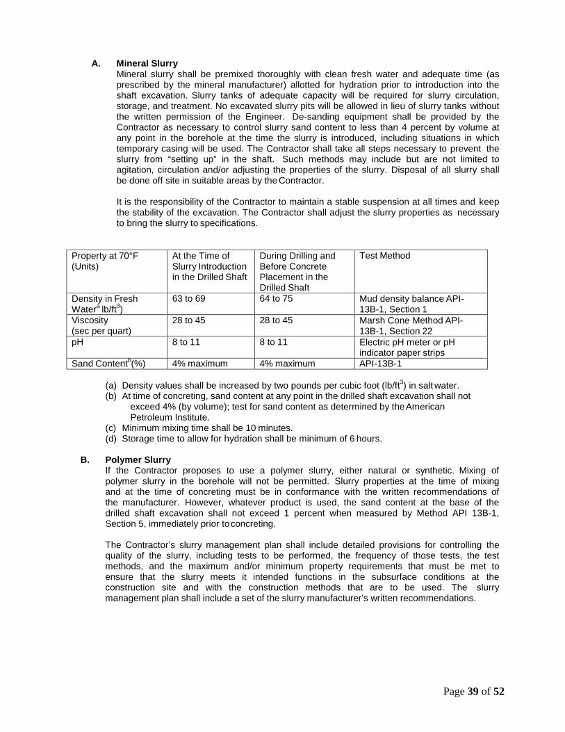
A. Mineral Slurry Mineral slurry shall be premixed thoroughly with clean fresh water and adequate time (as prescribed by the mineral manufacturer) allotted for hydration prior to introduction into the shaft excavation. Slurry tanks of adequate capacity will be required for slurry circulation, storage, and treatment. No excavated slurry pits will be allowed in lieu of slurry tanks without the written permission of the Engineer. De-sanding equipment shall be provided by the Contractor as necessary to control slurry sand content to less than 4 percent by volume at any point in the borehole at the time the slurry is introduced, including situations in which temporary casing will be used. The Contractor shall take all steps necessary to prevent the slurry from “setting up” in the shaft. Such methods may include but are not limited to agitation, circulation and/or adjusting the properties of the slurry. Disposal of all slurry shall be done off site in suitable areas by the Contractor.
It is the responsibility of the Contractor to maintain a stable suspension at all times and keep the stability of the excavation. The Contractor shall adjust the slurry properties as necessary to bring the slurry to specifications.
Property at 70°F (Units)
At the Time of Slurry Introduction in the Drilled Shaft
During Drilling and Before Concrete Placement in the Drilled Shaft
Test Method
Density in Fresh Watera lb/ft3)
63 to 69 64 to 75 Mud density balance API- 13B-1, Section 1
Viscosity (sec per quart)
28 to 45 28 to 45 Marsh Cone Method API- 13B-1, Section 22
pH 8 to 11 8 to 11 Electric pH meter or pH indicator paper strips
Sand Contentb(%) 4% maximum 4% maximum API-13B-1
(a) Density values shall be increased by two pounds per cubic foot (lb/ft3) in salt water. (b) At time of concreting, sand content at any point in the drilled shaft excavation shall not
exceed 4% (by volume); test for sand content as determined by the American Petroleum Institute.
(c) Minimum mixing time shall be 10 minutes. (d) Storage time to allow for hydration shall be minimum of 6 hours.
B. Polymer Slurry
If the Contractor proposes to use a polymer slurry, either natural or synthetic. Mixing of polymer slurry in the borehole will not be permitted. Slurry properties at the time of mixing and at the time of concreting must be in conformance with the written recommendations of the manufacturer. However, whatever product is used, the sand content at the base of the drilled shaft excavation shall not exceed 1 percent when measured by Method API 13B-1, Section 5, immediately prior to concreting.
The Contractor’s slurry management plan shall include detailed provisions for controlling the quality of the slurry, including tests to be performed, the frequency of those tests, the test methods, and the maximum and/or minimum property requirements that must be met to ensure that the slurry meets it intended functions in the subsurface conditions at the construction site and with the construction methods that are to be used. The slurry management plan shall include a set of the slurry manufacturer’s written recommendations.
Page 39 of 52

Polymer slurry shall have the following properties:
Property at 70°F (Units)
At the Time of Slurry Introduction in the Drilled Shaft
During Drilling and Before Concrete Placement in the Drilled Shaft
Test Method
Density in Fresh Watera lb/ft3)
63 to 65 65 to 67 Mud density balance API- 13B-1, Section 1
Viscosity (sec per quart)
50 maximum 50 maximum Marsh Cone Method API- 13B-1, Section 2.2
pH 8 to 10 8 to 10 Electric pH meter or pH indicator paper strips
Sand Contentb(%) 0.3% maximum 1% maximum API-13B-1
(a) Density values shall be increased by two pounds per cubic foot (lb/ft3) in salt water. (b) At time of concreting, sand content at any point in the drilled shaft excavation shall not
exceed 1% (by volume); test for sand content as determined by the American Petroleum Institute.
(c) Minimum mixing time shall be 15 minutes. (d) Storage time to allow for hydration shall be minimum of 4 hours.
C. Water Used As Drill Fluid
If approved by the Engineer, the Contractor may use only water as a drilling fluid. All of the provisions in the table shown in this section for mineral slurries shall be met, except that the maximum density shall not exceed 70 pcf.
D. Slurry Testing
Slurry testing shall include the following tests, as a minimum: Density test (API 13B-1, Section 1), viscosity test (Marsh funnel and cup, API-13B-1, Section 2.2 or approved viscometer), pH test (pH meter, litmus paper), and sand content test (API sand content kit, API 13B-1, Section 5).
Tests should be performed when the slurry temperature is above 40 degrees Fahrenheit.
Tests to determine density, viscosity and pH value shall be performed during the shaft excavation to establish a consistent working pattern. A minimum of four sets of tests shall be made during the first 8 hours of slurry use. When the results show consistent behavior the testing frequency may be decreased to one set every four hours of slurry use.
The Contractor shall ensure that a heavily contaminated slurry suspension, which could impair the free flow of concrete, has not accumulated in the bottom of the shaft. Prior to placing concrete in any shaft excavation, the Contractor shall take slurry samples using a sampling tool approved by the Engineer. Slurry samples shall be extracted from the base of the shaft and at intervals not exceeding 10 feet up the slurry column in the shaft, until two consecutive samples produce acceptable values for density, viscosity, and pH.
When any slurry samples are found to be unacceptable, the Contractor shall take whatever action is necessary to bring the slurry within specifications requirements. Concrete shall not be poured until the slurry in the hole is re-sampled and tests results produce acceptable values.
Reports of all tests required above signed by an authorized representative of the Contractor, shall be furnished to the Engineer on completion of each drilled shaft.
XII. EXCAVATION INSPECTION
The Contractor shall provide equipment for checking the dimensions and alignment of each shaft excavation. The dimensions and alignment shall be determined by the Contractor under the direction of the Engineer. Final shaft depths shall be measured with a suitable weighted tape or
Page 40 of 52

other approved methods after final cleaning. Unless otherwise stated in the plans, a minimum of 50 per cent of the base of each shaft will have less than 1/2 inch of sediment at the time of placement of the concrete. The maximum depth of sediment or any debris at any place on the base of the shaft shall not exceed 1-1/2 inches. Shaft cleanliness will be determined by the Engineer, by visual inspection for dry shafts or other methods deemed appropriate by the Engineer for wet shafts.
For dry excavations, the maximum depth of water shall not exceed 3 inches prior to concrete pour.
For dry shafts, the sidewalls shall be visually free of cuttings that may have been smeared on the walls during the removal and insertion of drilling tools.
XIII. CONSTRUCTION TOLERANCES:
The following construction tolerances apply to drilled shafts unless otherwise stated in the contract documents:
(a) The center of the drilled shaft shall be within 3 inches of plan position in the horizontal plane
at the plan elevation for the top of the shaft.
(b) The vertical alignment of a vertical shaft excavation shall not vary from the plan alignment by more than 1 1/2% of the total length of the shaft.
(c) After all the concrete is placed, the top of the reinforcing steel cage shall be no more than 6
inches above and no more than 3 inches below plan position.
(d) All casing diameters shown on the plans refer to O.D. (outside diameter) dimensions. The dimensions of casings are subject to American Pipe Institute tolerances applicable to regular steel pipe.
(e) The top elevation of the shaft shall have a tolerance of plus 1 inch or minus 3 inches from the
plan top-of-shaft elevation.
(f) Excavation equipment and methods shall be designed so that the completed shaft excavation will have a planar bottom. The cutting edges of excavation equipment shall be normal to the vertical axis of the equipment within a tolerance of ± 3/8 inch per foot of diameter.
Drilled shaft excavations and completed shafts not constructed within the required tolerances are unacceptable. The Contractor shall be responsible for correcting all unacceptable shaft excavations and completed shafts to the satisfaction of the Engineer. Materials and work necessary, including engineering analysis and redesign, to complete corrections for out-of- tolerance drilled shaft excavations shall be furnished without either cost to the County and VDOT or an extension of the completion date of the project.
XIV. REINFORCING STEEL CAGE CONSTRUCTION AND PLACEMENT:
The reinforcing steel cage, consisting of longitudinal bars, ties, cage stiffener bars, spacers, centralizers, and other necessary appurtenances, shall be completely assembled and placed as a unit immediately after the shaft excavation is inspected and accepted, and prior to concrete placement. Internal stiffeners shall be removed as the cage is placed in the shaft so as not to interfere with the placement of concrete.
The reinforcing steel in the shaft shall be tied and supported so that the reinforcing steel will remain within allowable tolerances given in Section XIII of this specification. Plastic spacing devices shall be used at sufficient intervals [near the bottom and at intervals not exceeding 10 feet up the shaft] to ensure concentric spacing for the entire cage length. Use a minimum of one spacer per 30 inches of circumference of the casing with a minimum of three at each layer. The spacers shall be of adequate dimension to ensure a minimum 3 inch annular space between the outside of the reinforcing cage and the side of the excavated hole. Approved cylindrical feet (bottom supports) shall be provided to ensure that the bottom of the cage is maintained the proper distance above the base.
Page 41 of 52

Hooks at the top of the reinforced steel cage shall not be bent outward if a temporary casing is to be used. Interior hooks must be designed to permit adequate clearance for the concrete tremie pipe (i.e. 10 inches minimum space). Hooks may be placed on dowels that may be rotated after concrete placement or casing removal and repositioned after the tremie is removed. The concrete must be fluid during dowel repositioning.
The elevation of the top of the steel cage shall be checked before and after the concrete is placed. If the upward displacement of the rebar cage exceeds 6 inches or if the downward displacement exceeds 3 inches, the drilled shaft will be considered defective. Corrections shall be made by the Contractor to the satisfaction of the Engineer. No additional shafts shall be constructed until the Contractor has modified his rebar cage support in a manner satisfactory to the Engineer.
If the bottom of the constructed shaft elevation is lower than the bottom of the shaft elevation in the plans, a minimum of one half of the longitudinal bars required in the upper portion of the shaft shall be extended the additional length by adding longitudinal reinforcing bars at the bottom of the cage. Tie or spiral bars shall be continued for the extra depth and the stiffener bars shall be extended to the final depth. All longitudinal and transverse bars must be lap spliced or spliced with mechanical splices. Welding to the reinforcing steel will not be permitted unless specifically shown in either the plans or special provisions.
When concrete placement does not follow immediately after cage placement, remove the steel from the excavation unless the Engineer directs otherwise. If the cage is removed, recheck excavation cleanliness in accordance with this special provision prior to reinstallation of the cage.
XV. INSTALLATION REQUIREMENTS FOR CSL INTEGRITY TESTS:
Cross-hole Sonic Logging (CSL), a nondestructive testing (NDT) method, measures the time for an ultrasonic pulse to travel from a signal source in one access tube to a receiver in another access tube. Drilled shafts must be fitted with CSL test tubes to evaluate their integrity as indicated in the plans, Contract Documents, or as designated by the Engineer. Install the access tubes or pipes as nearly parallel and far as possible from the longitudinal bars. The number of tubes to be installed per each drilled shaft diameter is as indicated in the table below:
Drilled Shaft Diameter Number of CSL Tubes Tube Spacinga
3 ft. to 5 ft. 4 minimum 90 degrees
5.5 ft. to 7 ft. 6 minimum 60 degrees
7.5 Ft. to 9 ft. 8minimum 45 degrees
Greater than 10 feet 10 minimum 36 degrees
(a) Spacing based on a central angle in degrees
The tubes shall be securely attached to the interior of the reinforcement cage with a minimum concrete cover of 3 inches, and they shall be wire-tied to the reinforcing cage every five feet to secure the tubes in position during placement of the reinforcing steel cage. In all cases the tubes shall be as near to vertical and parallel as possible. The Contractor shall install the tubes in the drilled shafts in a regular and symmetric pattern such that each tube is spaced a maximum distance possible from its adjacent tube and distributed around the drilled shaft perimeter as indicated by the central angle in the table above.
The tubes shall extend from the bottom of the drilled shaft to at least 3 feet above the top of the drilled shaft, or 2 feet above the ground surface for shafts with cut-offs below the ground surface. The tubes must be capped to prevent concrete or debris from entering during manipulation of the cage and concreting. Care must be taken during lifting and lowering the steel reinforcement so as not to damage the tubes. The CSL tubes shall be filled with clean water no later than 4 hours after concrete placement. Do not break the bond between the tube and the concrete by applying
Page 42 of 52

excessive torque, hammering, or other sort of stress while removing the caps or plugs from the pipes. For production shafts and upon completion of the CSL tests, remove all the water from the access tubes or drilled holes and fill them up with an approved grout. CSL testing procedures are found in Section XVII of this provision.
XVI. CONCRETE PLACEMENT:
A. General
Concrete placement shall be performed in accordance with the applicable portions of the general specifications on concrete materials in Section V.IA of this Special Provision and with the requirements herein. Concrete shall be placed as soon as possible after reinforcing steel placement. Concrete placement shall be continuous from the bottom to the top elevation of the shaft. Concrete placement shall continue after the shaft excavation is filled until good quality concrete is evident at the top of shaft. Concrete shall be placed either by free fall or through a tremie or concrete pump. The free fall placement shall only be permitted in dry holes. Concrete placed by free fall shall fall directly to the base without contacting either the rebar cage or hole-sidewall. Drop chutes may be used to direct concrete to the base during free fall placement.
The elapsed time from the beginning of concrete placement in the shaft to the completion of the placement shall not exceed 2-hours. Admixtures such as water reducers, plasticizers, and retarders shall not be used in the concrete mix unless permitted in the Contract Documents. All admixtures, when approved for use, shall be adjusted for the conditions encountered on the job. The Contractor may request a longer placement time provided he supplies a concrete mix that will maintain a slump of 4 inches or greater over the longer placement time as demonstrated by trial mix and slump loss tests.
Subject to performance satisfactory to the Engineer in the construction of the trial shafts, concrete to be placed in dry shafts less than 5 feet in diameter may be placed by allowing the concrete to free fall up to 60 feet into the excavation; for shafts at least 5 feet in diameter the free fall distance may be increased to 100 feet.
During concrete placement the Contractor is required to plot the theoretical and actual concrete volume curves on the” DRILLED SHAFT CONCRETE VOLUMES FORM.”
Within the first 16 hours after a drilled shaft has achieved its initial concrete set (as determined by the Engineer), do not drill adjacent shafts or allow any equipment wheel loads or excessive vibrations to occur at any point within a 20 foot radius of the drilled shaft unless the concrete has reached a strength of at least 1500 psi.
B. Tremies
Tremies may be used for concrete placement in either wet or dry holes. Tremies used to place concrete shall consist of a tube of sufficient length, weight, and diameter to discharge concrete at the shaft base elevation. The tremie shall not contain aluminum parts that will have contact with the concrete. The tremie inside diameter shall be at least 6 times the maximum size of aggregate used in the concrete mix but shall not be less than 10 inches. The inside and outside surfaces of the tremie shall be clean and smooth to permit both flow of concrete and unimpeded withdrawal during concreting. The wall thickness of the tremie shall be adequate to prevent crimping or sharp bends, which restrict concrete placement.
The tremie used for wet excavation concrete placement shall be watertight. Underwater or under-slurry placement shall not begin until the tremie is placed to the shaft base elevation, and the concrete shall be kept completely separated from the water or slurry prior to the time it is discharged. Valves, bottom plates or plugs may be used for this purpose only if concrete discharge can begin within one tremie diameter of the base of the drilled shaft. Plugs shall either be removed from the excavation or be of a material, approved by the Engineer, which will not cause a defect in the shaft if not removed. The discharge end of the tremie shall be constructed
Page 43 of 52

to permit the free radial flow of concrete during placement operations. The tremie discharge end shall be immersed at least 7 feet in concrete at all times after starting the flow of concrete. The flow of the concrete shall be continuous. The level of the concrete in the tremie shall be maintained above the level of slurry or water in the borehole at all times to prevent water or slurry intrusion into the shaft concrete.
If at any time during the concrete pour, the tremie line orifice is removed from the fluid concrete column and discharges concrete above the rising concrete level, the shaft shall be considered defective. In such case, the Contractor shall remove the reinforcing cage and concrete, complete any necessary sidewall removal directed by the Engineer and re-pour the shaft. All costs of replacement of defective shafts shall be the responsibility of the Contractor.
C. Pumped Concrete
Concrete pumps and lines may be used for concrete placement in either wet or dry excavations. All pump lines shall have a minimum 4 inch diameter and be constructed with watertight joints. Concrete placement shall not begin until the pump line discharge orifice is at the shaft base elevation.
For wet excavations, a plug or similar device shall be used to separate the concrete from the fluid in the hole until pumping begins. The plug shall either be removed from the excavation or be of a material, approved by the Engineer, that will not cause a defect in the shaft if not removed.
The discharge orifice shall remain at least 7 feet below the surface of the fluid concrete. When lifting the pump line during concreting, the Contractor shall temporarily reduce the line pressure until the orifice has been repositioned at a higher level in the excavation.
If at any time during the concrete pour the pump line orifice is removed from the fluid concrete column and discharges concrete above the rising concrete level, the shaft shall be considered defective. In such case, the Contractor shall remove the reinforcing cage and concrete, complete any necessary sidewall removal directed by the Engineer, and re-pour the shaft. All costs of replacement of defective shafts shall be the responsibility of the Contractor.
D. Drop Chutes
Drop chutes may be used to direct placement of free-fall concrete in excavations where the maximum depth of water does not exceed 3 inches. Free fall placement is not permitted in wet excavations. Drop chutes shall consist of a smooth tube of either one piece construction or sections that can be added and removed. A drop chute can also be a hopper with a short tube to direct the flow of concrete. Concrete may be placed through either the hopper at the top of the tube or side openings as the drop chute is retrieved during concrete placement. If concrete placement causes the shaft excavation to cave or slough, or if the concrete strikes the rebar cage or sidewall, the Contractor shall reduce the height of free fall and/or reduce the rate of concrete flow into the excavation. If caving or sloughing of the shaft walls occurs during free-fall placement of concrete, the shaft shall be considered defective. In such case, the Contractor shall remove the reinforcing cage and concrete, complete any necessary sidewall removal directed by the Engineer and re-pour the shaft. All costs of replacement of defective shafts shall be the responsibility of the Contractor. If concrete placement cannot be satisfactorily accomplished by free fall in the opinion of the Engineer, the Contractor shall use either tremie or pumping techniques to accomplish the pour.
XVII. NONDESTRUCTIVE EVALUATION:
A. General When called for in the contract documents, specific completed drilled shafts, the number and/or location of which are specified in the Contract Documents, shall be subjected to nondestructive tests to evaluate their structural integrity. The Contractor shall be responsible for performing and submitting reports of such tests to the Engineer in a timely manner. All testing shall be conducted after the concrete has cured for at least 48 hours. The Contractor
Page 44 of 52

shall employ a registered Professional Engineer registered in the Commonwealth of Virginia who has been qualified by VDOT to perform, evaluate and report the tests. The report on the tests on any given shaft must be submitted to the Engineer within 3 working days of the performance of the tests on that shaft. The Engineer will evaluate and analyze the results and provide to the Contractor a response regarding the acceptability of the shaft that was tested within 3 working days of receipt of the test report.
The Contractor may continue to construct drilled shafts before the receipt of notice of acceptance of the tested shaft or shafts by the Engineer; however, if the Engineer finds the tested shaft(s) to be unacceptable, the Contractor shall be required to repair, at the Contractor’s expense, the unacceptable shaft to the satisfaction of the Engineer and (a) prove to the satisfaction of the Engineer, at no expense to the County and VDOT, the acceptability of all shafts constructed since the unacceptable shaft was constructed and the acceptability of the procedure to be used in constructing future shafts, or (b) cease all drilled shaft construction until a new construction procedure acceptable to the Engineer has been proposed by the Contractor and accepted by the Engineer. In the latter case, those drilled shafts constructed after the unacceptable shaft shall be repaired to the satisfaction of the Engineer at the Contractor’s expense. If any repair procedures or revisions to the Contractor’s installation procedure are proposed by the Contractor, the Contractor shall submit a written plan to the Engineer to repair defects and revise construction procedures. If these plans involve changes to the structural design of the shafts or shaft caps, or to the geometry of the shafts, any redesign proposed in the Contractor’s plan to the Engineer shall be performed at the Contractor’s expense by a Professional Engineer registered in the Commonwealth of Virginia.
The Engineer may require that additional shafts be tested. If the testing of the additional shaft(s) indicates the presence of a defect in any additional shaft, the testing cost for that shaft will be borne by the Contractor and the Contractor shall repair the shaft at the Contractor’s expense, as above. Otherwise, the cost of the testing will be borne by the County.
B. Cross-hole Sonic Logging CSL Test
1. General
Cross-hole Sonic Logging, CSL, is a nondestructive testing (NDT) method that measures the time for an ultrasonic pulse to travel from a signal source inside an access tube to a receiver inside another access tube and evaluates the integrity of drilled shafts. In uniform, good quality concrete, the travel time between these equidistant tubes will be relatively constant from the bottom to the top of the drilled shafts and correspond to a reasonable concrete pulse velocity. In uniform, good quality concrete, the CSL test will also produce records with good signal amplitude and energy. Longer travel times and lower amplitude/energy signals indicate the presence of irregularities such as poor quality concrete, voids, honeycombs, or soil intrusions. The signal will be completely lost by the receiver and system recorder for more severe defects such as voids and soil intrusions.
The Contractor must install access tubes intended for Cross-hole Sonic Logging CSL testing and perform the test(s) as indicated in the plans, and in Sections IV.B.(i),VI-D, and XV of this Special Provision. When the Contractor is required to perform CSL tests in the Contract Documents, he must only employ experienced personnel and engage the services of approved independent testing firm with previous experience in this sort of testing. The Contractor shall submit to the Engineer for his approval the list of personnel and testing firms he intends to use during the CSL testing program along with their competence and field experience to perform evaluate, and report the results of CSL tests. The Contractor shall perform the CSL tests in the number and locations specified in the Contract Documents or as requested by the Engineer, and he shall execute the test after at least 48 hours of concrete curing to allow for hardening of the concrete. The Engineer may specify a longer curing time when retarders are used in the mix design, or
Page 45 of 52

other factors that may result in a slower rate of concrete setting. All CSL testing must be completed within forty five calendar days of concrete placement.
Prior to beginning the CSL test, the Contractor shall assure that the test probes can pass through and down the tubes to the bottom of every installed tube. If a tube is obstructed, the Contractor, at his expense, must core a hole within the drilled shaft and near the obstructed tube to the depth indicated in the plans for that CLS tube, and the core shall be large enough to accommodate the probe through its full length. Coring equipment, procedures, and location of the hole shall be approved by the Engineer prior to beginning coring. Logged results of the core drilling shall be submitted to the Engineer along with the cores. The CSL test can commence after the core hole is inspected and the probes can pass through.
The Contractor is responsible for submission of the CSL test report to the Engineer within 3 work days of its performance for a specific drilled shaft. The Engineer will evaluate and analyze the CSL test results within 3 working days of their receipt and provide the Contractor with a response regarding the acceptability of the drilled shaft tested.
2. Equipment for the Cross-hole Sonic Logging, CSL, Test
The CSL test equipment consists of the following components:
a. A microprocessor-based CSL system or analyzer for display of individual CSL records, analog-digital conversion and recording of CSL data, analysis of receiver responses, and printing of CSL logs.
b. Ultrasonic emitter and receiver probes for 2 inches I.D. pipe.
c. An ultrasonic voltage pulse to excite the source with a synchronized triggering
system to start the recording system.
d. Winch and tripod and connecting cables.
e. A depth measurement device to determine recorded depths.
f. Appropriate filter/amplification and cable systems for CSL testing.
3. Logging Procedures for Cross-hole Sonic Logging, CSL, Test The test should proceed from the bottom to the top of the test tubes and in depth increments of about 3 inches to include the full depth of both tubes. Any slack shall be removed from the cables prior to pulling the probes providing accurate depth measurement records. Test a pair of perimeter and/or diagonal tubes, and include evaluation of the condition of the drilled shaft bottom. The source and receiver should be lifted simultaneously at a speed less than 1 ft. per second, and a set of readings carefully taken at their corresponding depths. The CSL tests shall be carried out with the source and receiver probes in the same horizontal plane unless test results indicate potential anomalies/defects, in which case the questionable zone may be further evaluated with fan shape or angled tests (source and receiver are vertically offset inside the tubes). Equipment, procedures, and evaluation shall be adjusted to detect, locate, and assess the extent of any irregularity or void that appears in the path of the sonic pulse. Any anomalies and\or defects indicated by longer pulse arrival times and significantly lower amplitude/energy signals shall be promptly reported to the Engineer.
Additional testing may be conducted in the event anomalies are detected or suspected during the test. If the Engineer decides further testing (either other non-destructive testing or invasive testing) is necessary to evaluate the possible anomaly or defect, such additional testing shall be carried out as decided and authorized by the Engineer. If an anomaly or defect is found, the cost of the additional testing shall be the responsibility of
Page 46 of 52

the Contractor. If no defects are found, the costs of additional testing shall be borne by the County.
Additional testing may be conducted in the event anomalies should be detected or suspected during the test. Information of the drilled shaft bottom and top elevations, length, along with construction dates shall be provided to the testing organization before or at the time of the CSL tests. Levels will be taken on top of each tube, and actual tube plumbness and length be recorded. CLS tests shall be conducted between pairs of tubes, and the determination of which pairs to be tested made by the independent testing agency.
4. Reporting Results of the Cross-hole Sonic Logging, CSL, Test
Results of CSL test shall be presented in a report including:
a. A brief explanation of how the test was performed, the CSL logs, the analyses, and the test results of each drilled shaft.
b. Record the arrangement of the tubes and their dimensions per drilled shaft
tested.
c. Present a plan view of the CSL test locations in relation to the bridge foundation.
d. Arrival time of acoustic pulse versus depth in each pair of tubes for every drilled shaft tested.
e. Pulse energy/amplitude versus depth in each pair of tubes for every drilled shaft
tested.
f. A CSL log shall be presented for each pair of tube tested, and when applies with any anomaly/defect zones properly discussed. Any zone with long arrival times and low power relative to other zones should be considered anomalous.
XVIII. ACCEPTANCE OF DRILLED SHAFTS:
A. Based on Specifications
Acceptance of drilled shafts shall be based on meeting the requirements as set forth in the Contract Documents. Drilled shafts will not be acceptable if:
1. Drilled shafts constructed disregarding any requirements of the Specifications or this
Special Provision for Drilled Shaft.
2. Drilled shaft excavations constructed out of tolerance. The Contractor shall correct completed drilled shaft to acceptable tolerances before proceeding with new drilled shaft construction and submit correction for the Engineer’s approval.
3. When applicable, slurry out of tolerance, especially late introduction into the drilled shaft and before concreting.
4. Cave-in of the drilled shaft walls due to improper use of casing or slurry; or failure to use weighting agents in the slurry in running groundwater.
5. Temporary casing that cannot be removed.
6. Horizontal separations or severe neck in the drilled shaft walls when pulling temporary casing with concrete adhering to it.
7. Failure to agitate slurry or to place concrete in a timely manner causing excessive build-up of mud cake on the wall of the excavation.
8. Horizontal sand lens in concrete produced by tremie or pump line pulled out of concrete when concreting under slurry or water.
9. Quarter-moon-shaped soil intrusion on the side of the drilled shaft created by
Page 47 of 52

interruption in flow of concrete being pumped or tremied into slurry-filled hole or use of telescoping casing where concrete from inner casing spills into the over break zone behind outer casing.
10. Soft or loose drilled shaft bottom caused by incomplete bottom cleaning, side sloughing, or sedimentation of cuttings from slurry column where base bearing is required.
11. Voids outside of cage when low slump concrete is introduced into the drilled shaft.
12. Honeycombing, washout of fines, or water channels in the concrete if concrete is placed directly into water.
13. Folded-in debris from insufficient cleaning of the drilled shaft excavation or excessive sand in the slurry.
14. Drilled shafts for which the mix design has been altered or extra water has been added without the approval of the Engineer.
15. Drilled shaft constructed in such a manner that the drilled shaft cannot be completed within the required tolerances. The Contractor shall submit correction methods for the Engineer’s approval.
Final acceptance decision on whether repairs can or should be made or if the drilled shaft is rejected and must be replaced will be made by the Engineer as necessary applying criteria set forth herein and sound engineering judgment on a drilled shaft by drilled shaft basis.
B. Based on the Cross Hole Sonic Logging (CSL) Tests Rejection of a drilled shaft based on the drilled shaft cross-hole sonic logging testing shall be conclusive evidence that a defect exists in the drilled shaft that will result in inadequate or unsafe performance of the drilled shaft under service loads. The acceptance of each drilled shaft shall be the decision of the Engineer based on the results of the drilled shaft integrity testing report(s) and other information on the drilled shaft placement. If the CSL records are inconclusive, the Engineer may require coring or excavation of the drilled shaft to verify drilled shaft conditions. If a defect is confirmed, the Contractor shall be responsible for all coring or excavation costs. If no defect is encountered, the County will pay for all coring or excavation costs, including grouting of all core holes. Cores that cannot be advanced to the location of interest will not be paid for.
In the event testing discloses voids or discontinuities in the concrete which indicate that the drilled shaft is not structurally adequate, the drilled shaft shall be rejected, and construction of additional drilled shafts shall be suspended until the Contractor repairs, replaces or supplements the defective work, and the Engineer approves the remedial work. The Contractor shall suspend drilled shaft construction until the Engineer approves proposed changes to the methods of drilled shaft construction submitted in writing by the Contractor.
In the case that any drilled shaft is determined to be unacceptable, the Contractor shall submit a plan for remedial action to the Engineer for approval. Any modifications to the foundation drilled shafts and load transfer mechanisms caused by the remedial action will require calculations and working drawings prepared by and stamped by a Professional Engineer, hired by the Contractor and registered in the Commonwealth of Virginia, for all foundation elements affected. The Contractor shall provide all labor and materials required to design and repair or remediate drilled shafts at no additional cost to the County and VDOT and with no extension of the contract time.
The Contractor may continue to construct drilled shafts at his own risk before the receipt of notice of acceptance by the Engineer of the previously tested drilled shafts or drilled shafts constructed by a modified means and method of construction, however, if the Engineer finds the tested drilled shaft or drilled shafts to be unacceptable, the Contractor shall repair to the satisfaction of the Engineer, at the Contractor’s sole expense, the unacceptable drilled shafts and (a) prove to the satisfaction of the Engineer, at no expense to the County and VDOT, the acceptability of all drilled shafts constructed since the unacceptable drilled shaft
Page 48 of 52

was built and the acceptability of the procedure to be used in construction of future drilled shafts, or (b) cease all drilled shaft construction until a new construction procedure has been proposed by the Contractor and accepted by the Engineer. In the latter case, drilled shafts built after the unacceptable drilled shaft shall be repaired at the Contractor’s expense and to the satisfaction of the Engineer.
XIX. METHOD OF MEASUREMENT & BASIS OF PAYMENT:
A. Drilled Holes Drilled Holes shall be paid for at the contract unit price per linear foot for drilled shafts. Such payment shall be full compensation for excavating the shaft, including excavation through rock as indicated in the plans, for temporary casing or slurry as necessary, installing cross-hole sonic logging tubes and performing Cross-hole Sonic Logging (CSL) Testing, and furnishing all labor, tools, equipment, materials and incidentals necessary to complete the drilled shaft other than concrete and reinforcing steel described herein. Reinforcing steel and concrete will be paid for separately and will not be part of the unit bid price for drilled holes.
B. Concrete Concrete for the drilled shafts will be measured in cubic yards within the neat lines of the drilled shaft as shown on the plans and will be paid for at the contract unit price per cubic yard, complete-in-place. The volume of reinforcing steel or any other material or internal voids within the concrete will be deducted. The unit price for Concrete shall also include all costs related to the mobilization, installation, instrumentation, performance and documentation of the CSL tests.
C. Reinforcing Steel
Reinforcing steel in drilled shafts will be measured in pounds of steel placed in the shaft as shown on the plans. Reinforcing steel in drilled shafts will be paid for at the contract unit price per pound. This price shall include furnishing, fabricating, and placing reinforcement in the shafts.
Payment will be made under:
Pay Item Pay Unit Drilled Holes Linear Foot Concrete Class A3 Cubic Yard Reinforcing Steel Pounds
Page 49 of 52

50
CSP-41 TEMPORARY LIGHTING AT PRE CAST ARCH
The Contractor shall provide temporary lighting along the roadway between the Minnieville Road construction baseline stations 48+00 to 56+00 during Phase 2 and Phase 3 of the TMP/SOC Plan.
The Contractor shall prepare and submit (4) sets of the temporary lighting plans to the engineer for review and approval. This plan shall show locations of poles, length of bracket arms, style of luminaires, mounting height, wiring methods, and other pertinent information. The temporary lighting shall provide an average initial intensity of 1.2 foot-candles with and average to minimum ratio not to exceed 4:1 along Minnieville Road from Sta. 48+00 to 56+00. Mounting height for temporary luminaires shall not be less than 27ft. However, temporary lighting shall meet federal and state safety criteria. If breakaway poles are used to meet these criteria, then underground wiring will be used. Reconditioned or used materials may be furnished for temporary lighting. All materials necessary to complete the temporary lighting shall be furnished and installed by the contractor. A separate power service will be provided by the contractor for the temporary lighting system. When no longer needed the temporary lighting installation shall be removed and properly disposed of by the contractor. The lump sum bid for Temporary Lighting At Precast Arch, shall include payment for all labor, equipment, materials, incidentals, and temporary power services necessary to maintain the existing lighting as specified.
CSP-42 ON-SITE REPRESENTATIVE OF PRE-CAST ARCH.
The manufacturer of the pre-cast arch shall have an on-site representative during the final installation and acceptance of the structure.

COUNTY OF PRINCE WILLIAM 1 County Complex Court, (MC460) Prince William, Virginia 22192-9201 (703) 792-6770 Metro 631-1703 Fax (703) 792-4611
PRINCE WILLIAM COUNTY
ROAD/HIGHWAY CONSTRUCTION CONTRACT
CONTRACT NO.: 16XXXXX
PWC: Project No. SPR2015-20094 VDOT: Project No. 064-076-R98 , UPC 130484
SUBJECT: MINNIEVILLE ROAD RTE. 640 WIDEN TO 4 LANES Between:
PRINCE WILLIAM BOARD OF COUNTY SUPERVISORS 1 COUNTY COMPLEX COURT PRINCE WILLIAM, VIRGINIA 22192-9201 (703) 792- 6770 And the Contractor: TEL.: FAX: E-mail:
REPRESENTATIVE: This Contract made in three (3) original counterparts, is entered into this ____day of __, 2016 by and between the Board of County Supervisors of Prince William County, Virginia, or its authorized agents, or assignee, hereinafter called the party of the first part (Owner) or (County) and -----. , hereinafter called the party of the second part (Contractor) for project entitled: Minnieville Road Widen to 4 Lanes (Rte. 234 to Spriggs Rd.) identified herein, on the following terms and conditions. This Contract is prepared in accordance with the Purchasing Regulations of Prince William County, which are incorporated herein by reference.
Minnieville Road Rte. 640 Widen to 4 Lanes Contract C-1 of 12

Contract No. XXXX
The Contractor agrees for the consideration herein mentioned, and at his, its, or their own proper cost and expense, shall provide and pay for all materials, tools, equipment, labor, and professional and non-professional services, and shall perform all other services and supply all other things necessary, to fully and properly perform and complete the Contract in the manner and to the full extent as set forth in the plans, standard specifications, supplemental specifications, general special provisions, Contract Special Provisions, VDOT Copied Notes to be listed, VDOT special provisions, (for the basis of award stated herein below) and other documents related to said Contract which are on file at the office of the Owner and which are hereby adopted and made part of this Contract Agreement as completely as if incorporated herein, and to the full satisfaction of the Owner or their duly authorized representative who shall have at all times full opportunity to inspect the materials to be furnished and the work to be done under this Contract. A. Definitions As used in this Contract the terms are defined as follows: County: Prince William County, Virginia Owner: Prince William Board of County Supervisors (PWC) Board: Board of County Supervisors of Prince William, Virginia
Prince William County, Virginia Department: PWC Department of Transportation Engineer: PWC Director of Transportation Contract Administrator: PWC Director of Transportation Specifications: The general term comprising all the directions, provisions, and requirements contained in the Virginia Department of Transportation (VDOT), Road and Bridge Specifications, 2007 Edition; the VDOT 2008 Road and Bridge Standards; the County's Supplemental Specifications and Contract Special Provisions; and any addenda and Change Orders or Supplemental Agreements that may be issued, all of which are necessary for the proper performance of the Contract. VDOT: Virginia Department of Transportation
Contractor: Company, Inc., whose authorized representative is __, President, who is responsible for the performance obligation of the Contractor under this Contract.
Contract: The written instrument used for signature and execution which binds the County and Contractor and is evidence of mutual understanding and agreement between the Parties. The Contract expressly incorporates and enumerates any documents therein and referred to as the “Contract Documents”.
Minnieville Road Rte. 640 Widen to 4 Lanes Contract C-2 of 12

Contract No. XXXX
Contract Documents: The Contract Documents are complimentary, and what is required by one shall is binding as if required by all. The intent of the Contract Documents is to include all items necessary for the proper execution and completion of the Work, including without limitation, all labor, materials, equipment and furnishings required in connection therewith. Such incorporated documents customarily include but not limited to; Contract Special Provisions, Special Provision Copied Notes, the Plans, Prince William County Purchasing Regulations, Contractor bid response, General Conditions, Supplemental General Conditions, VDOT Road and Bridge Specifications, Special Conditions, Plans, Insurance coverages/polices, bonds, Specifications, and all Modifications, including Addenda and subsequent Change Orders. B. Precedence and Coordination of Documents The VDOT Road and Bridge Specifications, the Supplemental Specifications, Contract Special Provisions, Special Provision Copied Notes, the Plans, Prince William County Purchasing Regulations, and all supplementary documents are essential parts of the Contract and any requirement occurring in one is as binding as though occurring in all. They are intended as complementary to describe and provide for completion of all the work. In case of a discrepancy, calculated dimensions, unless obviously incorrect, will govern over scaled dimensions. The following documents will take precedence in the order listed; with item No. 1 ranked the highest precedence:
1. This Contract 2. Addenda, issued prior to receipt of bids 3. Contract Special Provisions 4. The Plans 5. Supplemental Specifications 6. Prince William County Purchasing Regulations 7. Special Provision Copied Notes 8. VDOT Road and Bridge Specifications 9. VDOT Road and Bridge Standards 10. Contractor's Bid Response C. Incorporation of Documents The Contract Documents consist of this Contract, any/all applicable laws, ordinances, requirements, and regulations, the Plans, VDOT Road and Bridge Specifications, VDOT Road and Bridge Standards Supplemental Specifications, General Special Provisions, Contract Special Provisions, Geotechnical Report, Technical Special Provisions, VDOT Copied Notes, VDOT Special Provisions, Invitation to Bid as amended by addenda, Contractor Qualification Statement, Contractor’s Proposal and Summary/Schedule of Unit Prices, List of Subcontractors, Performance Bond, Labor and Materials Payment Bond, Progress Schedule, and Contractor’s Certificates of Insurance. Such documents are hereby incorporated by reference into this Contract.
Minnieville Road Rte. 640 Widen to 4 Lanes Contract C-3 of 12

Contract No. XXXX
D. Statement of Work
Generally, the project consists of constructing the ultimate Minnieville Road typical section from Route 234 to Spriggs Road in accordance with the Prince William County Comprehensive Plan. Total project length is approximately 10,890 linear feet. The roadway is classified by the Virginia Department of Transportation as an Urban Minor Arterial (Standard GS-6). Minnieville Road will be reconstructed to provide a four-lane divided roadway with raised 16’ median, a 5’ sidewalk on the south side of the road and a 10’ shared use path on the north side. Construction includes a concrete arch crossing of Powell’s Creek, which is a designated FEMA Floodplain. Work includes, but is not limited to, the installation of erosion control devices, clearing and grubbing, grading, excavation, installing storm sewers pipes and drainage structures, culvert installation, stormwater management facilities, curb and gutter, placing aggregate, asphalt paving, pedestrian facilities (sidewalk/shared use path), installation of traffic signage and pavement markings, waterline and sanitary sewer construction, traffic signals, retaining wall construction, precast concrete arch construction, and all measures required for the maintenance of traffic during construction. All work shall be performed in accordance with the approved project plans and bid documents. The completed project must meet any and all requirements for final acceptance by the Virginia Department of Transportation. E. Time of Commencement and Completion The Contractor hereby acknowledges time is of the essence to the Contract. The Contractor agrees to begin site work not later than thirty (30) calendar days after the written Notice-to-Proceed and to finally complete the entire work including, all punchlist work resulting from the final inspection by VDOT and the County, within 24 months of the Notice to Proceed. The Contractor hereby declares that the Contract Time is sufficient to assure timely final completion of the work.
F. Liquidated Damages The Contractor agrees and understands that Liquidated Damages are set in accordance with VDOT Road Bridge Specifications Section 108.6 (b) Liquidated Damages on this project for each day beyond 24 months of the Notice to Proceed, in which the work including punchlist items, all submittals, and all other contractual requirements whatsoever under this project remain incomplete. G. Contract Amount In return for the services identified above and in the Contract Documents, the County certifies that sufficient funds are budgeted and appropriated and shall compensate the Contractor in accordance with Contractor's Schedule of Unit Prices, proposal dated _____________, 2016 in the estimated total bid amount of: which is determined by multiplying the appropriate estimated quantities by the appropriate unit prices as set forth in the Schedule of Unit Prices. The County will make actual payment for actual quantities, which have been verified by the Engineer. Minnieville Road Rte. 640 Widen to 4 Lanes Contract C-4 of 12

Contract No. XXXX
The County will pay the Contractor for all items of work performed and accepted based upon the estimate of quantities at the Unit Prices as stated on the Schedule of Unit Prices, bid in the Proposal submitted for the Contract by Contractor, and subject to the conditions set forth in the Contract Documents, except that payment for items of works performed may be modified under certain conditions described in the Proposal. H. Examination of Records Contractor agrees the County or any of its duly authorized representatives shall, until the expiration of three (3) years after final payment under this Contract, have access to and the right to examine any directly pertinent books, documents, papers and records of the Contractor involving transactions related to this Contract. Contractor further agrees to include in all its subcontracts hereunder a provision to the effect that the Subcontractor agrees the County or any of its duly authorized representatives shall, until the expiration of three years after final payment under the subcontract, have access to and the right to examine any directly pertinent books, documents, papers and records of such Subcontractor involved in transactions related to the subcontract. The term “subcontract” as used in this clause excludes subcontractors or purchase orders for public utility services at rates established for uniform applicability to the general public. The periods of access and examination described above shall continue until any litigation or claims shall have been finally disposed of. The Contractor shall maintain books; records and accounts of all costs in accordance with generally accepted accounting principles and practices. The County or its authorized representative shall have the right to audit the books, records and accounts of the Contractor.
These provisions for an audit shall give the County unlimited access during normal working hours to the Contractor's books and records. The Contractor shall allow the County the right to interview any of the Contractor's employees.
The County will make all payments required of it under this Contract subject to audit, under circumstances stated above, which audit may be performed at the County's option, either during the Contract time period or during the above record retention time period. Regardless of authorization, approval, or acceptance, signatures or letters which are given by the County and are part of the County's control systems or are requested by the Contractor, the payments made under this Contract shall not constitute a waiver of the County's right to audit, nor shall payments constitute a waiver or agreement by the County that it accepts as correct the billings, invoices or other charges on which the payments are based. If the County's audit produces a claim against the Contractor, the County may pursue all its legal remedies even though it has made all or part of the payments required by this Contract.
If such audit discloses an overpayment, the Contractor shall have the obligation to reimburse the County for the amount of the overpayment. The County's right to reimbursement from the Contractor of the overpayment and the duty of the County and the Contractor to make reimbursements or payments as described in this Article shall not be terminated or waived until the County has completed its audit.
Minnieville Road Rte. 640 Widen to 4 Lanes Contract C-5 of 12

Contract No. XXXX
I. Subcontractor Payment Provisions
In the event the Contractor utilizes a subcontractor for any portion of the work under this Contract, the Contractor hereby agrees to the following: 1. The Contractor shall take one (1) of the two (2) following actions within seven (7) days after
receipt of amounts paid to the Contractor by the County for work performed by a subcontractor under the Contract.
a. Pay a subcontractor for the proportionate share of the total payment received from the
County attributable to the work performed by that subcontractor under the Contract; or b. Notify the County and any subcontractors, in writing, of its intention to withhold all or a
part of a subcontractor's payment with the reason for nonpayment. 2. The Contractor is obligated to pay interest to a subcontractor on all moneys owed by the
Contractor that remain unpaid after seven (7) days following receipt by the Contractor of payment from the County for work performed by a subcontractor under the Contract, except for amounts withheld under subsection 1(b) of this section. The Contractor's obligation to pay an interest charge to a subcontractor pursuant to the provisions of this section may not be construed to be an obligation of the County. A contract modification may not be made for the purpose of providing reimbursement for such interest charge. A cost reimbursement claim may not include any amount for reimbursement for such interest charge.
3. Unless otherwise provided under the terms of this Contract, interest shall accrue at the rate of
one percent (1%) per month. 4. The Contractor is hereby required to include in each of its subcontracts a provision requiring
each subcontractor to include or otherwise be subject to the same payment and interest requirements set forth in subsections 1, 2 and 3 of this section with respect to each lower-tier subcontractor.
J. Employment Discrimination 1. During the performance of this Contract, the Contractor agrees as follows: a. The Contractor will not discriminate against any employee or applicant for employment
because of race, religion, color, sex, national origin, age, disability, or any other basis prohibited by state law relating to discrimination in employment, except where there is a bona fide occupational qualification reasonably necessary to the normal operation of the Contractor. The Contractor agrees to post in conspicuous places, available to employees and applicants for employment, notices setting forth the provision of this nondiscrimination clause.
b. The Contractor, in all solicitations or advertisements for employees placed by or on behalf of the Contractor, will state that such Contractor is an equal opportunity employer.
Minnieville Road Rte. 640 Widen to 4 Lanes Contract C-6 of 12

Contract No. XXXX
c. Notices, advertisements, and solicitations placed in accordance with Federal law, rule, or regulation shall be deemed sufficient for the purpose of meeting the requirements of this section.
2. The Contractor will include the provisions of the foregoing paragraphs a, b, and c in every
Subcontract or purchase orders over $10,000.00, so the provisions is binding upon each Subcontractor or Contractor.
K. Modifications or Changes to This Contract All modifications and changes to this Contract shall be in writing. The Head of the using department for this Contract, with the concurrence of the Purchasing Manager, shall without notice to any sureties, have the authority to order changes in this Contract which affect the cost or time of performance. Such changes shall be ordered in writing specifically designated a “Change Order”. Such orders are limited to reasonable changes in the supplies, services or work performed or the time of performance; provided the Contractor shall is not excused from performance under the changed Contract by failure to agree to such changes, and it is the express purpose of this provision to permit unilateral changes in the Contract subject to the conditions and limitations herein. Contractor need not perform any work described in any Change Order unless it has received a written certification from the County there are funds budgeted and appropriated sufficient to cover the cost of such changes. The Contractor shall make a demand for payment for completed changed work within 30 calendar days of completion of Change Order, unless such time period is extended in writing, or unless the Purchasing Manager requires submission of a cost proposal prior to the initiation of any changed work or services. Later notification shall not bar the honoring of such claim or demand unless the County is prejudiced by such delay. No claim for changes ordered hereunder shall be considered if made after final payment in accordance with the Contract. L. Termination for Convenience of the County The parties agree the County may terminate this Contract or any work or delivery required hereunder, from time-to-time either in whole or in part, whenever the County Executive of Prince William County shall determine that such termination is in the best interest of the County. Termination, in whole or in part, shall be effected by delivery of a Notice of Termination signed by the County Executive or designee, mailed or delivered to the Contractor, and specifically setting forth the effective date of termination. Upon receipt of such Notice, the Contractor shall: 1. Cease any further deliveries or work due under this Contract, on the date, and to the extent,
which may be specified in the Notice; Minnieville Road Rte. 640 Widen to 4 Lanes Contract C-7 of 12

Contract No. XXXX
2. Place no further orders with any subcontractors except as necessary to perform portion of this Contract not subject to the Notice;
3. Terminate all subcontracts except those made with respect to Contract performance not subject to the Notice;
4. Settle all outstanding liabilities and claims which may arise out of such termination, with the ratification of the Purchasing Manager of Prince William County; and
5. Use its best efforts to mitigate any damages sustained by him as a consequence of termination under this clause.
After complying with the foregoing provisions, the Contractor shall submit a termination claim, in no event later than six months after the effective date of their termination, unless an extension is granted by the Purchasing Manager. The Purchasing Manager, with the approval of the County’s signatory to this Contract, shall pay from the using department’s budget, reasonable costs of termination, including a reasonable amount for profit on services delivered or completed. In no event shall this amount be greater than the original contract price, reduced by any payments made prior to Notice of Termination, and further reduced by the price of the services not delivered, or those services not provided. This Contract shall be amended accordingly, and the Contractor shall be paid the agreed upon amount. In the event the parties cannot agree on the whole amount to be paid to the Contractor by reason of termination under this clause, the Purchasing Manager shall pay to the Contractor the amounts determined as follows, without duplicating any amount which may have already been paid under the preceding paragraph of this clause: 1. With respect to all Contract performance prior to the effective date of Notice of Termination,
the total of: a. Cost of the work performed; b. The cost of settling and paying any reasonable claims as provided in subparagraph 4
above; c. A sum as profit on (a) determined by the Purchasing Manager to be fair and reasonable.
2. The total sum to be paid shall not exceed the Contract price, as reduced by the amount of
payments otherwise made, and as further reduced by the Contract price of services not terminated.
In the event that the Contractor is not satisfied with any payments which the Purchasing Manager shall determine to be due under this clause, the Contractor may seek remedy to the Board of County Supervisors in accordance with the “Claims/Disputes” clause of this Contract. The Contractor shall include similar provisions in any subcontract, and shall specifically include a requirement that subcontractors make all reasonable efforts to mitigate damages which may be suffered. Failure to include such provisions shall bar the Contractor from any recovery from the County whatsoever of loss or damage sustained by a subcontractor as a consequence of termination for convenience. Minnieville Road Rte. 640 Widen to 4 Lanes Contract C-8 of 12

Contract No. XXXX
M. Termination for Default Either party may terminate this Contract, without further obligation, for the default of the other party or its agents or employees with respect to any agreement or provision contained herein. N. Drug-free Workplace Maintained by Contractor for Contracts over $10,000.00 During the performance of this Contract, the Contractor agrees to (i) provide a drug-free workplace for the contractor's employees; (ii) post in conspicuous places, available to employees and applicants for employment, a statement notifying employees the unlawful manufacture, sale, distribution, dispensation, possession, or use of a controlled substance or marijuana is prohibited in the Contractor's workplace and specifying the actions taken against employees for violations of such prohibition; (iii) state in all solicitations or advertisements for employees placed by the Contractor it maintains a drug-free workplace; and (iv) include the provisions of the foregoing clauses in every subcontract or purchase orders of over $10,000.00, so the provisions are binding upon each subcontractor or contractor. For the purpose of this section, “drug-free workplace” means a site for the performance of work done in connection with a specific Contract awarded to a Contractor in accordance with this chapter, the employees of whom are prohibited from engaging in the unlawful manufacture, sale, distribution, dispensation, possession or use of any controlled substance or marijuana during the performance of the Contract. O. Indemnification and Hold Harmless The Contractor hereby agrees to indemnify, defend at its own expense, and hold harmless Prince William County, Virginia, its officers, agents, employees, and volunteers, from any and all claims for property damage, bodily injuries, and personal injuries to the public, including cost of investigation, all reasonable attorneys fees, and the cost of appeals arising out of any such claims or suits, because of any and all acts of omission or commission of the Contractor, including its agents, Subcontractors, employees, and volunteers, in connection with Work under this Contract. The Contractor further acknowledges and understands that the construction of this project must be performed in accordance with, and pursuant to a Permit which has been granted to PWC. A copy of this permit is attached to these documents. The Contractor hereby agrees to defend at its own expense, indemnify, and hold PWC; it heirs, successors, and assigns, from and against all costs, liabilities, damages, fines, mitigation, and obligations of any type, resulting from any violation of the terms and conditions of the Permit in the Contractor’s (or any subcontractor’s) construction of the Project. P. Governing Law The Contract Documents shall be governed exclusively by the Constitution and laws of the Commonwealth of Virginia.
The Contractor represents and covenants that the articles, materials, and services furnished hereunder shall be produced and rendered in accordance with all applicable federal, state, and County local laws, ordinances, requirements, regulations, codes, and orders, including, but not Minnieville Road Rte. 640 Widen to 4 Lanes Contract C-9 of 12
Contract No. XXXX
limited to, all applicable environmental laws, rules, regulations, and orders, the applicable provisions of the Fair Labor Standards Act of 1938, as amended, and any applicable unemployment and workers’ compensation laws, rules and regulations. The Contractor also covenants and warrants the products and/or services supplied hereunder shall comply with all current applicable federal and state Occupational Safety and Health Acts and all current applicable rules, regulations, and standards. Q. Claims/Disputes Provision In accordance with Section 2-2-4363, VA Code Ann., this provision shall be followed for consideration and handling of all claims by the Contractor under this Contract. Section 2.2-4365 VA Code Ann., is not applicable to this Contract, and under no circumstances is this paragraph to be construed as an administrative appeals procedure governed by Section 2.2-4365 VA Code Ann. Notice of the intent to submit a claim setting forth the bases for any claim shall be submitted in writing within ten (10) days after the occurrence of the event giving rise to the claim, or within ten (10) days of discovering the condition giving rise to the claim, whichever is later. In no event shall any claim arising out of this Contract be filed after the submission of the request for Final Payment by the Contractor. Claims by the Contractor with respect to this Contract shall be submitted in writing in the first instance for consideration by the Contract Administrator. The decision of the Contract Administrator shall be rendered in writing within forty five (45) days from the receipt of the claim from the Contractor. If the Contractor is not satisfied with the decision or resolution of the Contract Administrator, the Contractor may file a formal dispute with regards to the claim with the Prince William County Director of Finance, which claim shall be received within thirty (30) days of the date of decision of the Contract Administrator. The Director of Finance shall reduce his or her decision on the claim in writing and shall mail or otherwise furnish a copy of this decision to the Contractor within forty five (45) days of the receipt of the claim form the Contractor. The decision of the Director of Finance shall be final on behalf of Prince William County unless the Contractor submits the claim to the County Executive within thirty (30) days of the date of the Director of Finance’s decision. The Contractor may submit the claim to the County Executive by mailing or otherwise furnishing the Purchasing Manager a copy of the claim and a request for the County Executive’s determination. The County Executive’s decision on the claim shall be rendered in writing to the Contractor within forty five (45) days of the Purchasing Manager’s receipt of the request from the Contractor, and shall be final and binding on behalf of Prince William County, unless the Contractor submits the claim for determination by the Board of County Supervisors by furnishing the Purchasing Manager a copy of the claim, along with a request for determination decision on the claim in writing within forty five (45) days of the date on which the Board hears the claim in open meeting. The Board’s procedure in considering claims under this Contractor shall be the same as that for other decisions of the Board on claims made under Section 15.2-1245, et seq., VA Code Ann. The decision of the Board shall be final.
Minnieville Road Rte. 640 Widen to 4 Lanes Contract C-10 of 12

Contract No. XXXX
Should any decision maker designated under this procedure fail to make a decision on a claim within the time period specified, then the claim is deemed to have been denied by the decision maker. Pending a final determination of a claim, the Contractor shall proceed diligently with the performance of the Work under the Contract. In accordance with the provisions of Section 2.2-4363, VA Code Ann., full compliance with this procedure set forth in the provision shall be a precondition to the filing of any lawsuit by the Contractor against the Board of County Supervisors of Prince William County arising out of this Contract. R. Independent Contractor Status The Contractor is at all times herein acting as an independent contractor in the performance of this Contract, and that the Contractor, his subcontractors, their agents, employees, and officers are not employees of the County for any purposes. S. Assignability of Contract Neither this Contract, nor any part hereof, may be assigned by the Contractor to any other party without the express written permission of the County. T. Ethics in Public Contracting The Contractor hereby certifies that it has familiarized itself with Article 6 of Title 2.2 of the Virginia Public Procurement Act, Sections 2.2-4367 through 2.2-3477; VA. Code Ann., and that all amounts received by it are in accordance with therewith. U. Immigration Reform and Control Act The Contractor agrees it will not during the performance of this Contract, violate the provisions of the Federal Immigration Reform and Control Act of 1986, which prohibits employment of illegal aliens. V. Integration Clause Written on this date shown above, this Contract shall constitute the whole agreement between the parties. There are no promises, terms, conditions, or obligations other than those contained herein, and this Contract shall supersede all previous communications, representations, or agreements, written or verbal, between the parties hereto related to the Provision described herein.
Minnieville Road Rte. 640 Widen to 4 Lanes Contract C-11 of 12

Contract No. XXXX
BOARD OF COUNTY SUPERVISORS OF COMPANY NAME, PRINCE WILLIAM COUNTY, VIRGINIA BY: Authorized County Representative BY: Authorized Contractor Representative _____________________________ ______________________________________ Signature Authorized Signature _____________________________ ______________________________________ Printed/Typed Name Printed/Typed Name ______________________________ ______________________________________ Title Title ATTEST: _________________________________ Adam Manne, Purchasing Manager
APPROVED AS TO FORM ____________________ County Attorney
______________________ Date
Minnieville Road Rte. 640 Widen to 4 Lanes Contract C-12 of 12

PRINCE WILLIAM COUNTY MINNIEVILLE ROAD RTE. 640 WIDEN TO 4 LANES
VDOT SPECIAL PROVISIONS
AND SPECIAL PROVISION COPIED NOTES TO
VIRGINIA DEPARTMENT OF TRANSPORTATION ROAD AND BRIDGE SPECIFICATIONS
DATED 2007
The following lists all VDOT Special Provisions (SP) and Supplemental Specifications (SP) (herein under) which govern the work and are incorporated by reference: S100B00 Proj Communication-Decisions S107J31 VPDES Construction Activities S108C00 Progress Schedule Category III S109G07 Price Adjustment –Asphalt S208B00 Crushed Hydraulic Cement Conc S223AG2 Corrosion Resistant Reinf Steel S302B00 Restore Existing Pavement S302G02 Flowable Backfill S303L00 Temporary Silt Fence Type B S314CM3 Asphalt Surface Treatment S315NM5 Place Asphalt Conc Overlay S315Z00 Pavement Shoulder Wedge S504B01 CG-12 Detectable Warn Surface S515B03 Cold Planing Asphalt Operations S704E02 Ty B-Class VI Pave line Marking S704M06 Pavement Markings and Markers S704N00 Ty B-Class VII Pave Line Marking SS1D017 General Provisions (Division I-All Proj) SS20001 General (Materials) SS20702 Select Material SS20802 Subbase and Aggregate Base Materials SS21001 Asphalt Materials SS21202 Joint Materials SS21402 Hydraulic Cement SS21501 Hydraulic Cement Conc Admixtures SS21706 Hydraulic Cement Concrete SS22101 Guardrail SS22201 Masonry Units SS22301 Steel Reinforcement SS23203 Pipe and Pipe Arches SS23401 Glass Beads for Reflectorizing Traffic Markings
Minnieville Road Rte. 640 Widen to 4 Lanes VSP-1 VDOT SP’s & CN’s

SS23802 Electronic and Signal Components SS24504 Geosynthetics SS24701 Reflective Sheeting SS30101 Clearing and Grubbing SS30204 Drainage Structures SS30306 Earthwork SS30401 Constructing Density Control Strips SS30601 Lime Stabilization SS31001 Tack Coat SS40102 Structure Excavation SS40502 Prestressed Concrete SS40604 Reinforcing Steel SS40703 Steel Structures SS40801 Bearing Devices and Anchors SS41401 Riprap SS50102 UDs-CDs-EDs SS51202 Maintaining Traffic SS51401 Field Office SS51505 Planing or Milling Pavement SS60301 Seeding SS70005 General (Traffic Control Devices) SS70103 Traffic Signs SS70301 Traffic Signals SS70402 Pavement Markings and Markers SU105000C SWaM Subcontracting (State Funds) SU503000A RW Monument (Contractor Stkout) SU704000B Preform Thermos Pave Marking The following lists all VDOT Special Provision Copied Notes (herein under) which govern the work and are incorporated by reference: c100ai05 Gen Proj Requirements (Imperial) c100ll3 VDOT SSs SPs SPCNs (Local Assist) c103i01 E-Verify Work Authorization c105is1 Subcontracting (State Funded) c107j12 VPDES Construction Permits c109g07 PG 64V-28 Asphalt Cement Adjustment c302h00 Precast Drainage Struct (QCQA) c512l00 Type III Barricades c704cm1 Sweep Before Pave Mark (SurTreat) cu105000b Work Zone Traffic Control Pers Req cu703000a Saw Cut (Loop Detectors) RTSB RTSB Special Provision RTSB Retrofit RTSB Special Provision
Minnieville Road Rte. 640 Widen to 4 Lanes VSP-2 VDOT SP’s & CN’s

(c100ai05-0815) GENERAL PROJECT REQUIREMENTS, SUPPLEMENTAL SPECIFICATIONS
(SSs), SPECIAL PROVISIONS (SPs) AND SPECIAL PROVISION COPIED NOTES (SPCNs)
This project shall be constructed in accordance with: the plans; the Virginia Department of Transportation Road and Bridge Specifications, dated 2007; the Virginia Department of Transportation Road and Bridge Standards, dated 2008; the 2011 edition of the Virginia Work Area Protection Manual with Revision Number 1 incorporated, dated April 1, 2015; the 2009 edition of the MUTCD with Revision Numbers 1 and 2 incorporated, dated May 2012; and the 2011 edition of the Virginia Supplement to the MUTCD with Revision Number 1 dated September 30, 2013; and the Supplemental Specifications, Special Provisions and Special Provision Copied Notes in this contract. The status in the Contract of each of these documents will be in accordance with Section 105.12 of the Specifications. Special Provision Copied Notes in this contract are designated with “(SPCN)” after the date. The information enclosed in parenthesis “()” at the left of each Special Provision Copied Note in this contract is file reference information for Department use only. The information in the upper left corner above the title of each Supplemental Specification and Special Provision in this contract is file reference information for Department use only. The Department has identified the system of measurement to be used on this particular project as imperial. Any imperial unit of measure in this contract with an accompanying expression in a metric unit will be referred to hereinafter as a “dual unit” measurement. Such a “dual unit” measurement is typically expressed first in the imperial unit followed immediately to the right by the metric unit in parenthesis “()” or brackets “[]” where parenthesis is used in the sentence to convey other information. Where a “dual unit” of measure appears in this project, only the imperial unit will apply. The accompanying metric unit shown is not to be considered interchangeable and mathematically convertible to the imperial unit and shall not be used as an alternate or conflicting measurement.
6-10-15 (SPCN)

(c100c00-0708) OPERATIONS BY STATE FORCES - The Contractor is hereby advised that State
Forces will furnish materials for and perform certain items of work, indicated on the plans to be performed by State Forces, throughout the life of this contract. The Department will perform its operations in such a manner as to minimize interference with the Contractor's operations, and the Contractor shall coordinate his activities with the Department in order to prevent unnecessary interference. In the event the plans provide for seeding operations to be performed by State Forces, such operations will include areas used for stockpiling of topsoil, approved borrow pits and waste areas and will include Department furnished and applied lime, fertilizer, seed and mulch. The Contractor shall prepare the areas to be seeded in accordance with Section 603.03(b) of the Specifications, the cost of which shall be included in the price bid for other items. The Contractor shall coordinate with and notify the Department at such time as each area is ready for seeding operations; thereafter, the Department will assume the responsibility for completing and maintaining such areas. The Contractor will be responsible for all repairing or replacing of any work damage by his use of improper materials or construction methods or because of any damage inflicted by other than normal construction activities. Such corrective work shall be performed at the Contractor's expense. Areas outside the limits of construction, other than those approved by the Department, which are disturbed by the Contractor, shall be restored and seeded at the Contractor's expense. 8-1-91, Reissued 7-2008 (SPCN)

(c100ll3-0116) VDOT SUPPLEMENTAL SPECIFICATIONS (SSs), SPECIAL PROVISIONS
(SPs) AND SPECIAL PROVISION COPIED NOTES (SPCNs)
Where Virginia Department of Transportation (VDOT) Supplemental Specifications, Special Provisions and Special Provision Copied Notes are used in this contract, the references therein to “the Specifications” shall refer to the Virginia Department of Transportation Road and Bridge Specifications, dated 2007 for both imperial and metric unit projects. References to the “Road and Bridge Standard(s)” shall refer to the Virginia Department of Transportation Road and Bridge Standards, dated 2008 for both imperial and metric unit projects. References to the “Virginia Work Area Protection Manual” shall refer to the 2011 edition of the Virginia Work Area Protection Manual with Revision Number 1 incorporated, dated April 1, 2015 for imperial and metric unit projects. References to the “MUTCD” shall refer to the 2009 edition of the MUTCD with Revision Numbers 1 and 2 incorporated, dated May 2012; and the 2011 edition of the Virginia Supplement to the MUTCD with Revision Number 1 dated September 30, 2013 for imperial and metric unit projects. Where the terms “Department”, “Engineer” and “Contract Engineer” appear in VDOT Supplemental Specifications, Special Provisions and Special Provision Copied Notes used in this contract and the VDOT publication(s) that each references, the authority identified shall be in accordance with the definitions in Section 101.02 of the Virginia Department of Transportation Road and Bridge Specifications, dated 2007. Authority identified otherwise for this particular project will be stated elsewhere in this contract. VDOT Supplemental Specifications, Special Provisions and Special Provision Copied Notes used in this contract and the VDOT publication(s) that each reference are intended to be complementary to the each other. In case of a discrepancy, the order of priority stated in Section 105.12 of the Virginia Department of Transportation Road and Bridge Specifications, dated 2007 shall apply. VDOT Special Provision Copied Notes in this contract are designated with “(SPCN)” after the date of each document. VDOT Supplemental Specifications and Special Provision Copied Notes in this contract are designated as such above the title of each document. The information enclosed in parenthesis “( )” at the left of each VDOT Special Provision Copied Note in this contract is file reference information for VDOT use only. The information in the upper left corner above the title of each VDOT Supplemental Specification and VDOT Special Provision in this contract is file reference information for VDOT use only. The system of measurement to be used in this project is stated elsewhere in this contract. VDOT Supplemental Specifications, Special Provisions and Special Provision Copied Notes containing imperial units of measure with accompanying expressions in metric units shall be referred to hereinafter as “dual unit measurement” documents. Such a “dual unit measurement” is typically expressed first in the imperial unit followed immediately to the right by the metric unit in parenthesis “( )” or brackets “[ ]” where parenthesis is used in the sentence to convey other information. Where a “dual unit measurement” appears in VDOT documents, the unit that applies shall be in

accordance with the system of measurement as stated elsewhere in this contract. The unit shown that is not of the declared unit of measurement is not to be considered interchangeable and mathematically convertible to the declared unit and shall not be used as an alternate or conflicting measurement. Where VDOT Specifications are used for metric unit projects and only imperial units of measurement appear the document, the provision(s) in this contract for imperial unit to metric unit conversion shall apply.
6-10-15 (SPCN)

(c103i01-0814) SECTION 103—AWARD AND EXECUTION OF CONTRACTS of the
Specifications is amended as follows: Section 103.09—Execution of Contract is amended to include the following:
According to Section 2.2-4308.2 of the Code of Virginia, any employer with more than an average of 50 employees for the previous 12 months entering into a contract in excess of $50,000 with the Department to provide work or provide services pursuant to such contract shall register and participate in the U.S. Department of Homeland Security’s “E-Verify” system to verify information and work authorization of its newly hired employees performing work pursuant to such contract. Contractors are not required to be enrolled with “E-Verify” at the time bids are submitted, however, prior to award, the lowest responsive and responsible bidder must be enrolled with “E-Verify”. Contractors may use the following website to enroll in “E-Verify”, http://www.uscis.gov/e-verify.
8-8-14 (SPCN)

(c107j12-1215) VPDES CONSTRUCTION PERMITS
The provisions of the Special Provision for “VPDES CONSTRUCTION ACTIVITIES” (S107J31) will govern over Sections 106, 107, 301, 303, and 603 of the Specifications. This includes the Road and Bridge Specifications book and the Supplemental Specifications included in the Contract. The status in the Contract of each of these documents will be in accordance with Section 105.12 of the Specifications. 10-26-15 (SPCN)

(c109g07-0815) POLYMER MODIFIED (PG 64V-28) ASPHALT CEMENT ADJUSTMENT —
When asphalt concrete mixtures require the use of Performance Graded asphalt cement PG 64V-28, the Contractor shall show in the space provided on Form C-16A of the electronic bid proposal submitted by the Contractor, the f.o.b. cost per ton for asphalt cement PG 64V-28 upon which bid items containing PG 64V-28 were developed. During the life of the Contract, the Contractor shall document to the Department, by invoice signed by the supplier, his cost for PG 64V-28 used. The Department will then adjust payments for asphalt concrete containing PG 64V-28 by the difference in the actual f.o.b. price and the f.o.b. quote submitted with the bid. Adjustments will be made at the time for partial payments for asphalt concrete containing PG 64V-28 in accordance with the requirements of Section 109.08 of the Specifications. In the event the Contractor fails to show on Form C-16A of the electronic bid proposal the f.o.b. cost per ton for asphalt cement PG 64V-28 upon which bid items containing PG 64V-28 were developed, or during the life of the contract fails to provide the appropriate invoices with the Current cost for asphalt cement PG 64V-28 for the applicable calendar month during which the work was performed, the Department will base the price adjustment for asphalt concrete containing PG 64V-28 asphalt cement on the indexes for PG 64S-22 in accordance with the Special Provision For Asphalt Material Price Adjustment included in the Contract. 6-15-15 (SPCN)

(c302h00-0708) SECTION 302.03(b) PRECAST DRAINAGE STRUCTURES of the Specifications is
amended to include the following: Precast units, excluding concrete pipe, prestressed concrete items and soundwalls, conforming to the requirements herein will only be accepted under a Quality Control/Quality Acceptance Program (QC/QA). The Contractor shall have the producer perform quality control functions in accordance with a Department approved QC/QA plan. Each piece, manufactured under the QC/QA program, in addition to the date and other required markings, shall be stamped with the letters (QC), as evidence that the required QC/QA procedures have been performed. Each shipping document shall be affixed with the following: We certify that these materials have been tested and conform to VDOT Precast Concrete Products Quality Assurance Program
Signature and Title 1-14-08 (SPCN)

(c512l00-1012) TYPE III BARRICADE — Type III barricades specified in this contract shall refer to the
Type 3 barricades in the 2011 edition of the Virginia Work Area Protection Manual, the 2009 edition of the MUTCD and the current Virginia Supplement to the MUTCD. Materials, procedures, measurement and payment for the Type 3 barricades specified in these publications shall be in accordance with the Type III barricades specified in this contract. 10-3-12 (SPCN)

(c704cm1-1014) SWEEPING PRIOR TO PAVEMENT MARKING - No earlier than 7 days after
completion of surface treatment the Contractor shall sweep the roadway surface prior to installation of permanent pavement markings. Permanent pavement markings shall be installed within 30 calendar days after completion of surface treatment placement. The cost of sweeping the roadway prior to installing pavement marking shall be included in the price bid for pavement marking. 7-28-14 (SPCN)

NOTICE TO REMOVE PARKED VEHICLES - Unless otherwise specified elsewhere in the contract documents, the Department will furnish upon request, street signs for posting or printed notices for distribution, by the Contractor that notifies residents in residential areas to remove parked vehicles from the roadway prior to the Contractor performing work. 9-21-07a (SPCN)

SAW CUT — Section 703.04—Measurement and Payment of the Specifications is amended to replace the ninth paragraph (Saw cuts) with the following:
Saw cut will be measured in linear feet for the width specified and will be paid for at the contract unit price per linear foot. This price shall include cutting, cleaning, drilling, disposing of surplus material, furnishing and installing backer rods, and loop sealant material.
Pay Item
Pay Unit
Saw Cut (Width) Linear foot
10-2-08a (SPCN)

S100B00-0708 VIRGINIA DEPARTMENT OF TRANSPORTATION
SPECIAL PROVISION FOR PROJECT COMMUNICATION AND DECISION MAKING
January 3, 2005c
Reissued July 2008
I. DESCRIPTION The intent of this provision is to establish procedures, processes and guidelines for making decisions and managing communications regarding work under contract on construction and maintenance projects. The information contained herein is not meant to be all inclusive but to serve as a minimal general framework for promoting efficient and effective communication and decision making at both the project and, if needed, executive administrative level. It is also not meant to override the decision-making processes or timeframes of specific contract requirements.
II. DEFINITIONS For the purposes of this provision the following terms will apply and be defined as follows:
Submittals – Documents required by the contract that the Contractor must submit for the Department’s review, acceptance or approval. These may include shop drawings, working drawings, material test reports, material certifications, project progress schedules, and schedule updates. The Contractor shall produce submittals as early as practicable when required by the contract so as not to delay review and determination of action. Confirmation of verbal instructions (COVI) - Contractor requested written confirmation of agreements and instructions developed in negotiations with the Department concerning the Work under contract. Agreements must be able to be quantified using existing contract procedures and will, in the vast majority of cases, not impact contract time and cost. When time and/or cost are impacted, they must be clearly spelled out in the COVI. Requests for information (RFI) – Requests generated by either the Contractor or the Department that the other party supplies information to better understand or clarify a certain aspect of the Work. Requests for owner action (ROA) – Requests when the Contractor asks that the Department take certain action(s) the Contractor feels is required for proper completion of a portion of the Work or project completion. Contract change requests (CCR) - Request where the Contractor asks the Department to make an equitable adjustment to the contract because of excusable and/or compensable events, instructions that have or have not been given or other work requiring time and/or cost beyond that specified or envisioned within the original contract. Requests for contractor action (RCA) – Request generated by the Department where the Department asks the Contractor to take certain action that is in the best interests of the project and/or is required for proper completion of a portion of the Work or for project completion. Contract change directives (CCD) – Directive by the Department which instructs the Contractor to perform work beyond that specified or envisioned in the original contract and which may specify instructions, time, and cost(s) to make an equitable adjustment to the original contract.

Responsible Person – The individual in the normal or escalated resolution process, for either the Contractor or the Department, having the direct authority, responsibility and accountability to formulate and respond to each category of information request.
III. PROCESS FOR DECISION MAKING Project teams composed on responsible individuals directly involved in the administration, prosecution, and inspection of the Work from the Contractor and the Department shall define and agree upon the field decision-making process during the pre-construction conference. This information relative to the process should be written down and distributed to all parties of the process once it is established. Where there are responsibility, authority or personnel changes associated with this process such changes shall be distributed to all affected parties as quickly as practicable after they are effective so as not to delay or impede this process. The process for making field decisions with respect to the Work detailed in the contract basically requires the following steps:
1. The Contractor and the Engineer agree on the decision-making process, the identity, authority and accountability of the individuals involved and on the cycle times for response for each category of decision.
2. The party requiring the information generates the appropriate request documents, and calls for a decision from the individual who is accountable for the particular facet of the Work under consideration within the agreed period.
3. The responding party has an internal decision-making process that supports the individual who is accountable and provides the information required within the agreed period for each category of request.
4. The party receiving the decision has an internal process for accepting the decision or referring it for further action within an agreed period of time.
The process also requires that clear and well-understood mechanisms be in place to log and track requests, document the age and status of outstanding requests and actions to be taken on requests that have not been answered within the agreed period. Both the Department and the Contractor shall agree on the following:
● The documentation and perhaps format to be developed for each category of information requested,
● The name (as opposed to organizational position) of all individuals with the responsibility, authority and accountability to formulate and respond to each category of information requested. The District Administrator (DA) or Chief Executive Officer (CEO) of the Contractor may delegate the responsibility and authority for formulating and responding to requests, however, the accountability for meeting the established response time(s) remains with the District Administrator and CEO.
● The cycle times for each stage in the decision-making process, ● The performance measures to be used to manage the process, ● The action to be taken if cycle times are not achieved and information is not provided in a
timely manner. The following general guideline and timeframe matrix will apply to the various requests for action. Again, please note these guidelines are general in scope and may not apply to specific contract timeframes for response identified within the requirements of the Contract documents. In such cases, specific contract requirements for information shall apply.

P
RO
CE
SS
GU
IDE
LIN
ES
FO
R R
EQ
UE
ST
S G
EN
ER
AT
ED
BY
TH
E C
ON
TR
AC
TO
R
Fin
al
reso
luti
on
Subm
it
RO
A o
r
CC
R
(See
pro
cess f
or
RF
I, R
OA
, or
CC
R)
Subm
it
RO
A o
r C
CR
Subm
it
CC
R
Esta
blis
hed
dis
pute
re
solu
tion
and c
laim
s
pro
cess
1 P
rocess initia
ted o
n the last busin
ess d
ay o
f a w
eek s
hall
be a
cknow
ledged b
efo
re 5
pm
on the n
ext V
DO
T b
usin
ess d
ay.
2 T
he a
bsence o
f a w
ritten c
onfirm
ation fro
m t
he O
wner
to a
Contr
acto
r’s w
ritten r
equest fo
r confirm
ation o
f a v
erb
al in
str
uction s
hall
constitu
te
confirm
ation o
f th
e v
erb
al in
str
uction.
Escala
ted
pro
cess
Wit
hin
7 d
ays
7 d
ays
7 d
ays
7 d
ays
7 d
ays
By
DA
or
their
desig
nee*
Subm
it R
FI,
RO
A o
r C
CR
DA
or
their
desig
nee*
DA
or
their
desig
nee*
DA
or
their
desig
nee*
No
rmal
reso
luti
on
pro
cess
Wit
hin
(cale
nd
ar
days)
●
Acknow
ledge:
3
days
1
●
Accept
or
Retu
rn:
14
days
●
Fin
al
D
ete
rmin
ation\A
ppro
ve:
30 d
ays o
r as o
utlin
ed
in
contr
act
docum
ents
.
●
Confirm
ation:
1 d
ay 2
●
Action:
14 d
ays (
or
appro
priate
Action
P
lan)
●
Acknow
ledge:
3 d
ays 1
●
Action:
14 d
ays (
or
appro
priate
Action
P
lan)
●
Acknow
ledge:
3 d
ays 1
●
A
ction:
30 d
ays (
45
days if
federa
l
overs
ight
pro
ject)
By
Depart
ment’s
Desig
nate
d
Pro
ject
Manager
Depart
ment’s
Appro
priate
field
pers
onnel
Depart
ment’s
Desig
nate
d
Pro
ject
Manager
Depart
ment’s
Desig
nate
d
Pro
ject
Manager
Depart
ment’s
Desig
nate
d
Pro
ject
Manager
Sit
uati
on
Where
the C
ontr
acto
r re
quests
the
Depart
ment’s r
evie
w,
accepta
nce o
r appro
val of
shop d
raw
ings,
mate
rials
data
, te
st
report
s,
pro
ject pro
gre
ss s
chedule
s,
or
oth
er
subm
itta
ls r
equired b
y s
tandard
S
pecific
ations o
r oth
er
contr
act
language.
Resolv
ing r
outine f
ield
issues,
within
the
fram
ew
ork
of th
e C
ontr
act, in n
egotiation
with O
wner
field
pers
onnel.
Requests
the D
epart
ment to
supply
in
form
ation t
o b
etter
unders
tand o
r cla
rify
a c
ert
ain
aspect
of
the w
ork
.
Requests
that th
e D
epart
ment ta
ke c
ert
ain
action t
he C
ontr
acto
r fe
els
is r
equired f
or
pro
per
com
ple
tion o
f a p
ort
ion o
f th
e W
ork
or
pro
ject
com
ple
tion.
Requests
the D
epart
ment to
make a
n
equitable
adju
stm
ent
to t
he c
ontr
act
because o
f excusable
and/o
r com
pensable
events
, in
str
uctions that
have o
r have n
ot
been g
iven o
r oth
er
work
re
quirin
g t
ime a
nd/o
r cost
beyond that
specifie
d o
r envis
ioned w
ithin
the o
rigin
al
contr
act.
Pro
cess
Subm
itta
l
Confirm
ation
of
Verb
al
Instr
uction
(CO
VI)
Request
for
Info
rmation
(RF
I)
Request
for
Ow
ner
Action
(RO
A)
Contr
act
Change
Request
(CC
R)

P
RO
CE
SS
GU
IDE
LIN
ES
FO
R R
EQ
UE
ST
S G
EN
ER
AT
ED
BY
TH
E O
WN
ER
Fin
al
reso
luti
on
Subm
it
RC
A o
r C
CD
Subm
it
CC
D
Esta
blis
hed
dis
pute
re
solu
tion
and
term
ination
pro
cess
1 P
rocess initia
ted o
n the last busin
ess d
ay o
f a w
eek s
hall
be a
cknow
ledged b
efo
re 5
p m
on n
ext
pro
ject
busin
ess d
ay.
Escala
ted
pro
cess
Wit
hin
7 d
ays
7 d
ays
7 d
ays
By
Contr
acto
r’s
Pro
ject
Manager
Contr
acto
r’s
Pro
ject
Manager
CE
O o
r th
eir
desig
nee**
No
rmal
reso
luti
on
pro
cess
Wit
hin
(cale
nd
ar
days)
●
Action:
14 d
ays (
or
appro
priate
writt
en
A
ction P
lan)
●
Response o
r A
ction t
o
safe
ty a
nd
environm
enta
l is
sues:
1 d
ay
●
Oth
erw
ise
acknow
ledge:
3 d
ays 1
●
A
ction:
14 d
ays (
or
appro
priate
Action
P
lan)
●
Acknow
ledge:
3 d
ays 1
●
Action:
30 d
ays
By
Contr
acto
r’s
Pro
ject
Superinte
ndent
Contr
acto
r’s
Pro
ject
Superinte
ndent
Contr
acto
r’s
Pro
ject
Superinte
ndent
Sit
uati
on
Requests
the C
ontr
acto
r to
supply
info
rmation t
o b
etter
unders
tand o
r cla
rify
a
cert
ain
aspect
of th
e w
ork
. (R
FI)
Requesting t
he C
ontr
acto
r ta
ke c
ert
ain
action(s
) th
at is
in t
he b
est
inte
rests
of th
e
pro
ject
and/o
r is
required f
or
pro
per
com
ple
tion o
f a p
ort
ion o
f th
e w
ork
or
for
pro
ject
com
ple
tion.
(R
CA
)
Instr
ucts
the C
ontr
acto
r to
perf
orm
work
beyond t
hat
specifie
d o
r envis
ioned in t
he
origin
al contr
act
and u
ndert
akes a
ction(s
) to
m
ake a
n e
quitable
adju
stm
ent
to the
contr
act.
(CC
D)
Pro
cess
1.
RF
I
2.
RC
A
3.
CC
D

S107J31-1215
VIRGINIA DEPARTMENT OF TRANSPORTATION
SPECIAL PROVISION FOR VPDES CONSTRUCTION ACTIVITIES
October 26, 2015
SECTION 106—CONTROL OF MATERIAL Section 106.08—Storing Materials of the Specifications is amended to replace the third paragraph with the following:
Chemicals, fuels, lubricants, bitumens, paints, raw sewage, and other potential pollutant-generating materials as determined by the Engineer or defined in the VPDES General Permit For Discharge of Stormwater From Construction Activities shall not be stored within any flood-prone area unless no other location is available. A flood-prone area is defined as the area adjacent to the main channel of a river, stream or other waterbody that is susceptible to being inundated by water during storm events and includes, but is not limited to, the floodplain, the flood fringe, wetlands, riparian buffers or other such areas adjacent to the main channel. If stored in a flood-prone area, the material shall be stored in one or more secondary containment structures with an impervious liner and be removed entirely from the flood-prone area at least 24 hours prior to an anticipated storm event that could potentially inundate the storage area. Any storage of these materials outside of a flood-prone area that is in proximity to natural or man-made drainage conveyances where the materials could potentially reach a river, stream, or other waterbody if a release or spill were to occur, must be stored in a bermed or diked area or inside a secondary containment structure capable of preventing a release. Any spills, leaks or releases of such materials shall be addressed in accordance with Section 107.16(b) and (e) of the Specifications. Accumulated rain water shall be pumped out of impoundment or containment areas into approved filtering devices. All proposed pollution prevention measures and practices must be identified by the Contractor in his Pollution Prevention Plan as required by the Specifications, other contract documents and/or the VDPES General Permit for Discharge of Stormwater from Construction Activities.
SECTION 107—LEGAL RESPONSIBILITIES Section 107.02—Permits, Certificates, and Licenses of the Specifications is amended to replace (f) with the following:
(f) Virginia Department of Environmental Quality – VPDES General Permit For Discharge of Stormwater From Construction Activities (VPDES Construction Permit): All construction activities undertaken by or for VDOT involving land disturbances equal to or exceeding one acre must be covered by the VPDES Construction Permit. According to IIM-LD-242 and Section 107.16 of the Specifications, VDOT is responsible for securing VPDES Construction Permit coverage for all applicable land disturbing activities performed on VDOT rights of way or easements, including off-site support facilities that are located on VDOT rights of way or easements that directly relate to the construction site activity. The Contractor shall be responsible for securing VPDES Construction Permit coverage for support facilities that are not located on VDOT rights of way or easements. The Contractor shall be responsible for all costs to obtain VPDES Construction Permit coverage for all support facilities (both on-site and off-site) not included in the construction plans or contract documents for the project. The Department will not be responsible for any inconvenience, delay, or loss experienced by the Contractor as a result of his failure to gain access to any support facility areas at the time contemplated.

Section 107.02—Permits, Certificates, and Licenses of the Specifications is amended to replace last eleven paragraphs with the following: The Contractor shall 1) stockpile excavated material in a manner that prevents reentry into the stream, 2) restore original streambed and streambank contours, 3) revegitate barren areas, and 4) implement strict erosion and sediment control measures throughout the project period. The Contractor shall provide fill material that is clean and free of contaminants in toxic concentrations or amounts in accordance with all applicable laws and regulations. The Contractor shall comply with all applicable FEMA-approved state or local floodplain management requirements. The Contractor shall adhere to any time-of-year restriction conditions as required by state and federal permitting agencies. No in-stream work shall be permitted during in-stream time-of-year restriction. The Contractor shall prohibit wet or uncured concrete from entry into surface waters. The Contractor shall not dispose of excess or waste concrete in surface waters and prevent wash water from discharging into surface waters. The Contractor shall employ measures to prevent spills of fuels or lubricants into state waters. All pollution prevention measures and practices proposed by the Contractor shall be identified in the Contractor’s Pollution Prevention Plan as required by the Specifications, other contract documents and/or the VPDES General Permit For Discharge of Stormwater From Construction Activities. The Contractor shall not violate the water quality standards as a result of the construction activities. The Contractor shall not alter the physical, chemical, or biological properties of surface waters and wetlands or make them detrimental to the public health, to animal or aquatic life, to the uses of such waters for domestic or industrial consumption, for recreation, or for other uses. The Contractor shall not proceed with work covered by a permit until the work is released in writing by the Engineer. If the Department has not released work covered by a U.S. Army Corps of Engineers permit and the Contractor has completed all other work within the limits of the project, the Contractor shall so advise the Engineer in writing. Upon receipt of the notification, the Engineer will evaluate the status of the project and advise the Contractor within 45 days of the portion of the project that is acceptable under Section 108.09 of the Specifications. If the Engineer determines that all of the work except that encumbered by the permit application is acceptable under the requirements of Section 108.09 of the Specifications, the Contractor will be notified accordingly. The Department or the Contractor may then elect to continue or terminate the remaining portion of the Contract. The party electing to terminate the Contract shall so advise the other party in writing after the 45-day period. The terms of contract termination will be in accordance with the requirements of Section 108.08 of the Specifications. No compensation will be made for delays encountered or for work not performed except for an extension of time as determined in accordance with the requirements of Section 108.04 of the Specifications. The Contractor shall submit a request to the Engineer in writing if he wants to deviate from the plans or change his proposed method(s) regarding any proposed work located in waterways or wetlands. Such work may require additional environmental permits. If the Engineer determines that the activities are necessary for completion of the work, the Contractor shall furnish the Engineer all necessary information pertaining to the activity. The Contractor shall be responsible for designing and supplying all plans, sketches and notes necessary to acquire any permit modification required for changes in the proposed construction methods. Such information shall be furnished at least 180 days prior to the date the proposed changed activity is to begin. For other than the VPDES General Permit For Discharge of Stormwater From Construction Activities, the District Environmental Manager will apply for the necessary permits modifications to the permits obtained by the Department. The Contractor shall not begin the activity until directed to do so by the Engineer. Additional compensation will not be made for delay to the

work or change in the Contractor’s proposed methods that result from jurisdiction agency review or disapproval of Contractor’s proposed methods. If additional permits are required to perform dredging for flotation of construction equipment or for other permanent or temporary work as indicated in the Contractor’s accepted plan of operation, but have not been obtained by the Department, the Contractor shall furnish the Engineer, at least 75 days prior to the proposed activity, all necessary information pertaining to the proposed activity in order for the Department to apply for the permits. The Contractor shall not begin the proposed activity until the additional permits have been secured and the Engineer has advised the Contractor that the proposed activity may proceed. The Contractor shall permit representatives of state and federal environmental regulatory agencies to make inspections at any time in order to insure that the activity being performed under authority of the permit(s) is in accordance with the terms and conditions prescribed herein. Section 107.16(a) Erosion and Siltation of the Specifications is replaced with the following:
(a) Erosion and Siltation: The Contractor shall exercise every reasonable precaution, including temporary and permanent soil stabilization measures, throughout the duration of the project to control erosion and prevent siltation of adjacent lands, rivers, streams, wetlands, lakes, and impoundments. Soil stabilization and/or erosion control measures shall be applied to erodible soil or ground materials exposed by any activity associated with construction, including clearing, grubbing, and grading, but not limited to local or on-site sources of materials, stockpiles, disposal areas and haul roads. The Contractor shall comply with the requirements of Sections 301.02 and 303.03 of the Specifications. Should the Contractor as a result of negligence or noncompliance, fail to provide soil stabilization in accordance with these specifications, the cost of temporary soil stabilization in accordance with the provisions of Section 303 of the Specifications shall be at the Contractor’s expense. If the delay in stabilizing an exposed area of land is due to circumstances beyond the Contractor’s control, the Department will be responsible for the expense. Temporary measures shall be coordinated with the work to ensure effective and continuous erosion and sediment control. Permanent erosion control measures and drainage facilities shall be installed as the work progresses. For projects that disturb 10,000 square feet or greater of land or 2,500 square feet or greater in Tidewater, Virginia, the Contractor shall have within the limits of the project during land disturbance activities, an employee certified by the Department in erosion and sediment control who shall inspect erosion and sediment control and pollution prevention practices, devices and measures for proper installation and operation and promptly report their findings to the Inspector. Failure on the part of the Contractor to maintain appropriate erosion and sediment control or pollution prevention devices in a functioning condition may result in the Engineer notifying the Contractor in writing of specific deficiencies. Deficiencies shall be corrected immediately or as otherwise directed by the Engineer. If the Contractor fails to correct or take appropriate actions to correct the specified deficiencies within 24 hours (or as otherwise directed) after receipt of such notification, the Department may do one or more of the following: require the Contractor to suspend work in other areas and concentrate efforts towards correcting the specified deficiencies, withhold payment of monthly progress estimates, or proceed to correct the specified deficiencies and deduct the entire cost of such work from monies due the Contractor. Failure on the part of the Contractor to maintain a Department certified erosion and sediment control employee within the project limits when land disturbance activities are being performed will result in the Engineer suspending work related to any land disturbance activity until such time as the Contractor is in compliance with this requirement.
Section 107.16(b)1 Water of the Specifications is replaced with the following:

1. Water: The Contractor shall exercise every reasonable precaution throughout the duration of the project to prevent pollution of rivers, streams, and impoundments. Pollutants such as, but not limited to, chemicals, fuels, lubricants, bitumens, raw sewage, paints, sedimentation, and other harmful material shall not be discharged into or alongside rivers, streams, or impoundments or into channels leading to them. The Contractor shall provide the Engineer a contingency plan for reporting and immediate actions to be taken in the event of a dump, discharge, or spill within eight hours after he has mobilized to the project site. Construction discharge water shall be filtered to remove deleterious materials prior to discharge into state waters. Filtering shall be accomplished by the use of a standard dewatering basin or a dewatering bag or other measures approved by the Engineer. Dewatering bags shall conform to the requirements of Section 245 of the Specifications. During specified spawning seasons, discharges and construction activities in spawning areas of state waters shall be restricted so as not to disturb or inhibit aquatic species that are indigenous to the waters. Neither water nor other effluence shall be discharged onto wetlands or breeding or nesting areas of migratory waterfowl. When used extensively in wetlands, heavy equipment shall be placed on mats. Temporary construction fills and mats in wetlands and flood plains shall be constructed of approved nonerodible materials and shall be removed by the Contractor to natural ground when the Engineer so directs. If the Contractor dumps, discharges, or spills any oil or chemical that reaches or has the potential to reach a waterway, he shall immediately notify all appropriate jurisdictional state and federal agencies in accordance with the requirements of Section 107.01 and 107.16(e) of the Specifications and the VPDES General Permit For Discharge of Stormwater From Construction Activities and shall take immediate actions to contain, remove, and properly dispose of the oil or chemical. Solids, sludges or other pollutants removed in the course of the treatment or management of pollutants shall be disposed of in a manner that prevents any pollutant from such materials from entering surface waters in compliance with all applicable state and federal laws and regulations. Excavation material shall be disposed of in approved areas above the mean high water mark shown on the plans in a manner that will prevent the return of solid or suspended materials to state waters. If the mark is not shown on the plans, the mean high water mark shall be considered the elevation of the top of stream banks. Constructing new bridge(s) and dismantling and removing existing bridge(s) shall be accomplished in a manner that will prevent the dumping or discharge of construction or disposable materials into rivers, streams, or impoundments. Construction operations in rivers, streams, or impoundments shall be restricted to those areas where identified on the plans and to those that must be entered for the construction of structures. Rivers, streams, and impoundments shall be cleared of falsework, piling, debris, or other obstructions placed therein or caused by construction operations. Stabilization of the streambed and banks shall occur immediately upon completion of work or if work is suspended for more than 14 days. The Contractor shall prevent stream constriction that would reduce stream flows below the minimum, as defined by the State Water Control Board, during construction operations. If it is necessary to relocate an existing stream or drainage facility temporarily to facilitate construction, the Contractor shall design and provide temporary channels or culverts of adequate size to carry the normal flow of the stream or drainage facility. The Contractor

shall submit a temporary relocation design to the Engineer for review and acceptance in sufficient time to allow for discussion and correction prior to beginning the work the design covers. Costs for the temporary relocation of the stream or drainage facility shall be included in the Contract price for the related pipe or box culvert, unless specifically provided for under another Pay Item. Stabilization of the streambed and banks shall occur immediately upon completion of, or during the work or if the work is suspended for more than 14 days. Temporary bridges or other minimally invasive structures shall be used wherever the Contractor finds it necessary to cross a stream more than twice in a 6 month period, unless otherwise authorized by water quality permits issued by the U. S. Army Corps of Engineers, Virginia Marine Resources Commission or the Virginia Department of Environmental Quality for the Contract.
Section 107.16(e) Storm Water Pollution Prevention Plan of the Specifications is replaced with the following:
(e) Storm Water Pollution Prevention Plan and VPDES General Permit for the Discharge of
Stormwater from Construction Activities A Stormwater Pollution Prevention Plan (SWPPP) identifies potential sources of pollutants which may reasonably be expected to affect the stormwater discharges from the construction site and any on-site or off-site support facilities located on VDOT rights of way and easements. The SWPPP also describes and ensures implementation of practices which will be used to minimize or prevent pollutants in such discharges. The SWPPP shall include, but not be limited to, the approved Erosion and Sediment Control (ESC) Plan, the approved Stormwater Management (SWM) Plan (if applicable), the approved Pollution Prevention Plan and all related Specifications and Standards and notes contained within all contract documents and shall be required for all land-disturbing activities that disturb 10,000 square feet or greater, or 2,500 square feet or greater in Tidewater, Virginia. Land-disturbing activities that disturb one acre or greater require coverage under the Department of Environmental Quality’s VPDES General Permit for the Discharge of Stormwater from Construction Activities (hereafter referred to as the VPDES Construction Permit). According to IIM-LD-242, VDOT will apply for and secure VPDES Construction Permit coverage for all applicable land disturbing activities on VDOT rights of way or easements for which it has contractual control, including off-site (outside the project limits) support facilities on VDOT rights of way or easements that directly relate to the construction activity. The Contractor shall be responsible for securing VPDES Construction Permit coverage and complying with all permit conditions for all support facilities that are not located on VDOT rights of way or easements. The required contents of a SWPPP for those land disturbance activities requiring coverage under the VPDES Construction Permit are found in Section II of the permit. While a SWPPP is an important component of the VPDES Construction Permit, it is only one of the many requirements that must be addressed in order to be in full compliance with the conditions of the permit. The Contractor and all other persons that oversee or perform activities covered by the VPDES Construction Permit shall be responsible for reading, understanding, and complying with all of the terms, conditions and requirements of the permit and the project’s SWPPP including, but not limited to, the following:

1. Project Implementation Responsibilities The Contractor shall be responsible for the installation, maintenance, inspection, and, on a daily basis, ensuring the functionality of all erosion and sediment control measures and all other stormwater runoff control and pollution prevention measures identified within or referenced within the SWPPP, the construction plans, the specifications, all applicable permits, and all other contract documents. The Contractor shall be solely responsible for the temporary erosion and sediment control protection and permanent stabilization of all borrow areas and soil disposal areas located outside of VDOT right of way or easement. The Contractor shall prevent or minimize any stormwater or non-stormwater discharge that will have a reasonable likelihood of adversely affecting human health or public and/or private properties.
2. Certification Requirements In addition to satisfying the personnel certification requirements contained in Section 107.16(a) of the Specifications, the Contractor shall certify his activities by completing, signing, and submitting Form C-45 VDOT SWPPP Contractor Certification Statement to the Engineer at least 7 days prior to commencing any project related land-disturbing activities, both within the project limits and any support facilities located on VDOT rights of way or easements outside the project limits.
3. SWPPP Requirements for Support Facilities
VDOT will secure VSMP Construction Permit coverage for support facilities located on VDOT rights of way or easements according to IIM-LD-242. The Contractor shall be responsible for securing separate VSMP Construction Permit coverage for support facilities that are not located on VDOT rights of way or easements. Support facilities shall include, but not be limited to, borrow and disposal areas, construction and waste material storage areas, equipment and vehicle washing, maintenance, storage and fueling areas, storage areas for fertilizers, fuels or chemicals, concrete wash out areas, sanitary waste facilities and any other areas that may generate a stormwater or non-stormwater discharge directly related to the construction site. The Contractor shall develop and enforce a Spill Prevention Control and Countermeasure (SPCC) Plan conforming to 40 CFR 112 if the aggregated volume of Oil stored within the project limits at any one time is greater than 1320 gallons. Oil, in this context, shall be defined according to 40 CFR 112. The aggregated volume includes that of both stationary and portable storage facilities but does not include individual storage containers with less than a 55 gallon capacity. The contractor shall include the SPCC Plan as a part of his Pollution Prevention Plan for the project. Support Facilities located on VDOT rights of way or easements:
a. For those support facilities located within the project limits but not included in the construction plans for the project, the Contractor shall develop a SWPPP according to IIM-LD-246 which shall include, where applicable, an erosion and sediment control plan according to IIM-LD-11, a stormwater management plan according to IIM-LD-195 and a pollution prevention plan, according to these Specifications and the SWPPP General Information Sheet notes in the construction plans or other such contract documents. All plans developed shall

be reviewed and approved by appropriate personnel certified through DEQ’s ESC and SWM Certification program and shall be developed according to Section 105.10 of the Specifications and shall be submitted to the Engineer for review and approval. Once approved, the Engineer will notify the Contractor in writing that the plans are accepted as a component of the Project’s SWPPP and VPDES Construction Permit coverage (where applicable) and shall be subject to all conditions and requirements of the VPDES Construction Permit and all other contract documents. No land disturbing activities can occur in the support area(s) until written notice to proceed is provided by the Engineer.
b. For support facilities located outside the project limits and not included in the construction plans for the project, the Contractor shall develop a SWPPP according to IIM-LD-246 which shall include, where applicable, an erosion and sediment control plan according to IIM-LD-11, a stormwater management plan (where applicable) according to IIM-LD-195, a pollution prevention plan according to these specifications and the SWPPP General Information Sheet notes in the construction plans or other such contract documents and all necessary documents for obtaining VPDES Construction Permit coverage according to IIM-LD-242. All plans developed shall be reviewed and approved by appropriate personnel certified through DEQ’s ESC and SWM Certification program and shall be developed according to Section 105.10 of the Specifications and shall be submitted to the Engineer for review and approval. Once approved by the Engineer, VDOT will secure VPDES Construction Permit coverage according to IIM-LD-242. After VDOT secures VPDES Construction Permit coverage for the support facility, the Engineer will notify the Contractor in writing. The support facility shall be subject to all conditions and requirements of the VPDES Construction Permit and all other contract documents. No land disturbing activities can occur in the support area(s) until written notice to proceed is provided by the Engineer.
4. Inspection Procedures
a. Inspection Requirements
The Contractor shall be responsible for conducting site inspections according to the requirements herein. Site inspections shall include erosion, sediment control, and pollution prevention practices and facilities; all areas of the site disturbed by construction activity; all on-site support facilities; and all off site support facilities within VDOT right of way or easement. The Contractor shall document such inspections by completion of Form C-107, Construction Runoff Control Inspection Form, according to the directions contained within the form. Inspections shall be conducted using one of the following schedules:
Schedule 1 - At least once every 7 calendar days (equivalent to the once every five business days schedule in the VPDES General Permit for Discharge of Stormwater from Construction Activities) and within 48 hours following any measureable storm event. If a measureable storm event occurs when there are more than 48 hours between business days, the Contractor shall perform his inspection no later than the next business day. The Contractor shall install a rain gage at a central location on the project site for the purposes of determining the occurrence of a measureable storm event. Where the project is of such a length that one rain gage may not provide an accurate representation of the occurrence of a measurable storm event over the entire project site, the Contractor shall install as many rain gages as necessary to accurately reflect the amount of rainfall received over all portions of the

project. The Contractor shall observe all rain gages no less than once each business day at the time prescribed in the SWPPP General Information Sheet notes in the construction plans or other contract documents to determine if a measureable storm event has occurred. The procedures for determining the occurrence of a measurable storm event are identified in the SWPPP General Information Sheet notes in the construction plans or other contract documents.
Schedule 2 - At least each Monday and Thursday (equivalent to the once every four business days schedule in the VPDES General Permit for Discharge of Stormwater from Construction Activities). Where Monday or Thursday is a non-business day, the inspection may be performed on the next business day afterward. In no case shall the inspections be performed less than once every four business days.
The inspection schedule (1 or 2) is to be selected prior to the beginning of land disturbance. Once an inspection schedule is selected, it shall be defined in the appropriate note in the SWPPPP General Information Sheets contained in the construction plan set and shall be used for the duration of the project. A business day is defined as Monday through Friday excluding State holidays. A measurable storm event is defined as one producing 0.25 inches of rainfall or greater over a 24 hour time period. For those areas of the site that have been temporarily stabilized or where land disturbing activities have been suspended due to continuous frozen ground conditions and stormwater discharges are unlikely, the inspection schedule may be reduced to once per month. If weather conditions (such as above freezing temperatures or rain or snow events) make stormwater discharges likely, the Contractor shall immediately resume the regular inspection schedule. Those definable areas where final stabilization has been achieved will not require further inspections provided such areas have been identified in the project’s Stormwater Pollution Prevention Plan.
b. Corrective Actions
If a site inspection identifies an existing control measure that is not being maintained properly or operating effectively or an existing control measure that needs to be modified or locations where an additional control measure is necessary or any other deficiencies in the erosion and sediment control and pollution prevention plan, corrective action(s) shall be completed as soon as practical and prior to the next anticipated measurable storm event but no later than seven days after the date of the site inspection that identified the deficiency.
5. Unauthorized Discharges and Reporting Requirements The Contractor shall not discharge into state waters sewage, industrial wastes, other wastes or any noxious or deleterious substances nor shall he otherwise alter the physical, chemical, or biological properties of such waters that render such waters detrimental for or to domestic use, industrial consumption, recreational or other public uses.
(1) Notification of non-compliant discharges The Contractor shall immediately notify the Engineer upon the discovery of or the potential of any unauthorized, unusual, extraordinary, or non-compliant discharge

from the land construction activity or any of support facilities located on VDOT right of way or easement. Where immediate notification is not possible, such notification shall be not later than 24 hours after said discovery.
(2) Detailed report requirements for non-compliant discharges The Contractor shall submit to the Engineer within 5 days of the discovery of any actual or potential non-compliant discharge a written report describing details of the discharge to include a description of the nature and location of the discharge, the cause of the discharge, the date of occurrence, the length of time that the discharge occurred, the volume of the discharge, the expected duration and total volume if the discharge is continuing , a description of any apparent or potential effects on private and/or public properties and state waters or endangerment to public health, and any steps planned or taken to reduce, eliminate and prevent a recurrence of the discharge. A completed Form C-107 shall be included in such reports.
6. Changes and Deficiencies
The Contractor shall report to the Engineer when any planned physical alterations or additions are made to the land disturbing activity or deficiencies in the project plans or contract documents are discovered that could significantly change the nature of or increase the potential for pollutants discharged from the land disturbing activity to surface waters and that have not previously been addressed in the SWPPP.
7. Amendments, Modifications, Revisions and Updates to the SWPPP
a. The Contractor shall amend the SWPPP whenever site conditions, construction sequencing or scheduling necessitates revisions or modifications to the erosion and sediment control plan, the pollution prevention plan or any other component of the SWPPP for the land disturbing activity or onsite support facilities,
b. The Contractor shall amend the SWPPP to identify any additional or modified
erosion and sediment control and pollution prevention measures implemented to correct problems or deficiencies identified through any inspection or investigation process.
c. The Contractor shall amend the SWPPP to identify any new or additional
person(s) or contractor(s) not previously identified that will be responsible for implementing and maintaining erosion and sediment control and pollution prevention devices.
d. The Contractor shall update the SWPPP to include:
(1) A record of dates when, major grading activities occur, construction
activities temporarily or permanently cease on a portion of the site and stabilization measures are initiated.
(2) Documentation of replaced or modified erosion and sediment control and
pollution prevention controls where periodic inspections or other information have indicated that the controls have been used inappropriately or incorrectly.
(3) Identification of areas where final stabilization has occurred and where
no further SWPPP or inspection requirements apply.

(4) The date of any prohibited discharges, the discharge volume released, and what actions were taken to minimize the impact of the release.
(5) A description of any measures taken to prevent the reoccurrence of any
prohibited discharge. (6) A description of any measures taken to address any issues identified by
the required erosion and sediment control and pollution prevention inspections.
e. The Contractor shall update the SWPPP no later than seven days after the
implementation and/or the approval of any amendments, modifications or revisions to the erosion and sediment control plan, the pollution prevention plan or any other component of the SWPPP.
f. Revisions or modifications to the SWPPP shall be approved by the Engineer and
shall be documented by the Contractor on a designated plan set (Record Set) according to IIM-LD-246. All updates to the SWPPP shall be signed by the Contractor and the VDOT Responsible Land Disturber (RLD).
g. The record set of plans shall be maintained with other SWPPP documents on the
project site or at a location convenient to the project site where no on site facilities are available.
SECTION 301—CLEARING AND GRUBBING Section 301.02—Procedures is amended to replace the second paragraph with the following:
The surface area of earth material exposed by grubbing, stripping topsoil, or excavation shall be limited to that necessary to perform the next operation within a given area. Grubbing of root mat and stumps shall be confined to that area of land which excavation or other land disturbance activities shall be performed by the Contractor within 14 days following grubbing.
SECTION 303—EARTHWORK
Section 303.03—Erosion and Siltation Control is amended to replace the title with Erosion and Siltation Control and Stormwater Pollution Prevention. Section 303.03—Erosion and Siltation Control is amended to replace the first three paragraphs with the following:
Erosion, siltation and stormwater pollution shall be controlled through the use of the devices and methods specified herein, identified in other contract documents or as is otherwise necessary. The Engineer reserves the right to require other temporary measures not specifically described herein or in other contract documents to correct an erosion, siltation, or pollution condition. Erosion and sediment control and pollution prevention devices and measures shall be maintained in a functional condition at all times. Temporary and permanent erosion and sediment control and pollution prevention measures shall be inspected and deficiencies corrected in accordance with the requirements of Section 107.16(e) of the Specifications. In addition, the Contractor shall make a daily review of the location of silt fences, filter barriers and other perimeter controls to ensure that they are properly located for maximum effectiveness. Where deficiencies are found, corrections shall be made in accordance with the requirements of Section 107.16(e) of the Specifications or as directed by the Engineer.

When erosion and sediment control devices function by using wet storage, sediments shall be removed when the wet storage volume has been reduced by 50 percent. Sediments shall be removed from dewatering basins when the excavated volume has been reduced by 50 percent. Sediments shall be removed from all other erosion and sediment control devices when capacity, height, or depth has been reduced by 50 percent. Removed sediment shall be disposed of in accordance with the requirements of Section 106.04 of the Specifications. Sediment deposits remaining in place after the device is no longer required shall be removed or dressed to conform to the existing grade. The site shall be prepared and seeded in accordance with the requirements of Section 603 of the Specifications.
Section 303.03(b) Soil Stabilization is replaced with the following:
(b) Soil Stabilization: Soil stabilization shall be initiated on any portion of the project where clearing, grading, excavation or other land disturbing activities have permanently ceased or where land disturbing activities have been temporarily suspended for an anticipated duration of greater than 14 days, or upon completion of grading operation for a specific area. Soil stabilization shall begin as soon as practicable but no later than the next business day (Monday through Friday excluding State holidays) following the day when land disturbing activities temporarily or permanently cease. Initiation of stabilization activities includes, but is not limited to 1) prepping the soil for vegetative or non-vegetative stabilization, 2) applying mulch or other non-vegetative product to exposed soil, 3) seeding or planting the exposed area 4) starting any of the above activities on a portion of the area to be stabilized but not on the entire area or 5) finalizing arrangements to have the stabilization product fully installed within the time frame for completing stabilization. Temporary or permanent soil stabilization shall be completed within 7 days after initiation. Areas excluded from this requirement include areas within 100 feet of the limits of ordinary high water or a delineated wetland which shall be continuously prosecuted until completed and stabilized immediately upon completion of the work in each impacted area. Soil stabilization includes: temporary and permanent seeding, riprap, aggregate, sod, mulching, and soil stabilization blankets and matting in conjunction with seeding. The applicable type of soil stabilization shall depend upon the location of areas requiring stabilization, time of year (season), weather conditions and stage of construction operations. Cut and fill slopes shall be shaped and topsoiled where specified. Seed and mulch shall be applied in accordance with the requirements of Section 603 of the Specifications as the work progresses in the following sequence: 1. Slopes whose vertical height is 20 feet or greater shall be seeded in three equal
increments of height. Slopes whose vertical height is more than 75 feet shall be seeded in 25-foot increments.
2. Slopes whose vertical height is less than 20 but more than 5 feet shall be seeded in two
equal increments. 3. Slopes whose vertical height is 5 feet or less may be seeded in one operation. Areas that cannot be seeded because of seasonal or adverse weather conditions shall be mulched to provide some protection against erosion to the soil surface. Mulch shall be applied in accordance with the requirements of Section 603.03(e) of the Specifications and paid for in accordance with the requirements of Section 603.04 of the Specifications. Organic mulch shall be used, and the area then seeded as soon as weather or seasonal conditions permit in accordance with the requirements of Section 603.03 of the Specifications. Organic mulch includes: straw or hay, fiber mulch, wood cellulose, or wood chips conforming to the requirements of Section 244.02(g) of the Specifications.

Section 303.03(f) Sediment Traps and Sediment Basins is replaced with the following: (f) Sediment Traps and Sediment Basins: Once a sediment trap or basin is constructed, the
earthen embankment and all outfall areas shall be stabilized immediately.
Section 303.03—Erosion and Siltation Control is amended to add the following:
(h) Temporary Diversion Dike: This work shall consist of constructing temporary diversion dikes at the locations designated on the plans and in accordance with the plan details and the Specifications, stabilizing with seed and mulch, maintaining, removing when no longer required, and restoration of the area. Temporary diversion dikes shall be installed as a first step in land-disturbing activities and shall be functional prior to downslope land disturbance. The dike shall be constructed to prevent failure in accordance with Section 303.04 of the Specifications. Seeding and mulch shall be applied to the dike in accordance with Section 603 of the Specifications immediately following its construction. The dikes should be located to minimize damages by construction operations and traffic. The Contractor shall inspect the temporary diversion dikes after every storm and repairs made to the dike, flow channel, outlet, or sediment trapping facility, as necessary. Once every two weeks, whether a storm event has occurred or not, the measure shall be inspected and repairs made if needed. Damages to the dikes caused by construction traffic or other activity must be repaired before the end of the working day.
Section 303.04(a)—Regular Excavation is amended to replace the last paragraph with the following:
Stripping topsoil shall be confined to the area over which grading is to be actively prosecuted within 14 calendar days following the stripping operation. Grading operations shall be confined to the minimum area necessary to accommodate the Contractor’s equipment and work force engaged in the earth moving work.
SECTION 603—SEEDING Section 603.03(d) Applying Seed is amended to replace the third paragraph with the following:
Where temporary seeding is employed as a means of soil stabilization it shall consist of applying seed, fertilizer, and mulch in accordance with the rates specified in the plans or in Section 603.03 of the Specifications to stabilize areas on which grading operations are anticipated to be suspended for durations greater than 14 days. Where temporary seeding is required or directed by the Engineer, the cost for removal of vegetation once grading operations resume shall be included in the price of seeding.

S108C00-0911
VIRGINIA DEPARTMENT OF TRANSPORTATION SPECIAL PROVISION FOR
CPM PROGRESS SCHEDULE FOR CATEGORY III PROJECTS
March 1, 2011 Section 103.06(e) Progress Schedule of the Specifications is deleted and replaced by this provision. Section 108.03 Progress Schedule of the Specifications is deleted and replaced by this provision. For definitions of scheduling terms not defined herein, and guidelines on preparing and maintaining the Progress Schedule, refer to the VDOT Post-Award Scheduling Guide. I. GENERAL REQUIREMENTS
This work shall consist of generating and maintaining a project Progress Schedule to aid the Contractor and the Department in planning and executing the Work. The Progress Schedule shall be used by the Contractor, the Department, and all involved parties to plan and schedule all work required to complete the project. The Progress Schedule shall also be used by the Department to monitor progress of the individual activities required to complete the project; as well as to assess the overall progress of the Work and to evaluate the effects of time-related changes on the project. The Progress Schedule shall consist of a Critical Path Method (CPM) Progress Schedule, Progress Schedule Narrative, and Progress Earnings Schedule submitted in accordance with the requirements of this provision. The Contractor shall prepare and submit, for the Engineer’s review and acceptance, a Progress Schedule to communicate the Contractor’s intentions and proposed plan to accomplish the Work in accordance with the requirements of the Contract. The Progress Schedule shall depict the sequence in which the Contractor proposes to perform the Work and the dates on which the Contractor contemplates starting and completing all schedule activities required to complete the project. The Contractor shall maintain the Progress Schedule, at a minimum, monthly to ensure that it continues to represent the current status of the project and the Contractor’s current work plan to complete the project. The Contractor shall attend a Scheduling Conference with the Engineer no later than seven (7) calendar days prior to beginning the Work, with the exception of project start-up activities such as submittals, mobilization, surveying, construction access and signage, erosion and sedimentation controls, etc., as approved by the Engineer. The Scheduling Conference will be held to discuss the Contractor’s overall plan to complete the Work and the detail work plan for the first ninety (90) calendar days of Work. The Scheduling Conference may be held in conjunction with the Pre-Construction Conference or at a separate meeting as mutually agreed to by the Contractor and the Engineer. The Contractor shall discuss his/her overall plan of operations concerning the Maintenance of Traffic (MOT)/Sequence of Construction or any proposed deviations from the phasing, staging, or sequence of construction as indicated on the Contract plans or as approved by the Engineer. During the Scheduling Conference key issues and project specific requirements necessary for the development of the Baseline Progress Schedule shall also be discussed. Such key issues shall include as applicable, but are not limited to key submittals, permits, construction access, right of way, environmental, utility, traffic or local events indentified in the Contract Documents that may impact traffic; as well as other limitations to the Work or any known constraints or foreseeable issues that may impact the schedule. Such project specific requirements shall include as applicable, but are not limited to scheduling, phasing, sequencing, milestone(s), work to be performed by the Department or other previously identified involved

parties; or any known or likely constructability issues relative to the Contract plans and specifications.
II. OVERVIEW OF THE VARIOUS REQUIRED PROGRESS SCHEDULE SUBMISSIONS
A. Preliminary Progress Schedule – At least two (2) business days prior to the Scheduling
Conference, or as approved by the Engineer, the Contractor shall submit to the Engineer for review and acceptance a Preliminary Progress Schedule. At the Contractor’s discretion, a complete detailed Baseline Progress Schedule for the entire project may be submitted in lieu of the Preliminary Progress Schedule. The Preliminary Progress Schedule submission shall consist of the following:
1. Preliminary Progress Schedule: The Preliminary Progress Schedule shall depict,
at a detailed level, the Contractor’s proposed sequence and start/finish dates for all activities scheduled for the first ninety (90) calendar days of work. It shall also include, as applicable, any milestones or work to be performed by sub-contractors, the Department, or third parties during the first ninety (90) calendar days of work. The Preliminary Progress Schedule shall also depict at a summary level the proposed overall sequence and timing of the remaining Work. The Preliminary Progress Schedule shall be prepared in accordance with Section IV (A), with the exception of cost-loading.
2. Preliminary Progress Schedule Narrative: The Preliminary Progress Schedule
Narrative shall describe the Contractor’s detailed work plan for the first ninety (90) calendar days of work. The Preliminary Progress Schedule Narrative shall be prepared in accordance with Section IV (B).
Until the Baseline Progress Schedule is accepted by the Engineer, the Contractor shall submit an update of the Preliminary Progress Schedule monthly, within five (5) working days after the current data date or as approved by the Engineer. The updated Preliminary Progress Schedule shall show the actual progress of work completed to date and the current detailed schedule for accomplishing the work planned for the following ninety (90) calendar days of Work, as of the data date. It shall also show the summary level activities required to complete the remainder of the Work.
B. Baseline Progress Schedule – Within thirty (30) calendar days after the Notice to
Proceed (NTP) date or as approved by the Engineer, the Contractor shall submit in its entirety, his/her Baseline Progress Schedule, to the Engineer for review and acceptance. The Baseline Progress Schedule submittal shall consist of the following:
1. Baseline Progress Schedule: The Baseline Progress Schedule shall represent
the Contractor’s initial detailed plan to accomplish the entire scope of Work in accordance with the Contract. The Baseline Progress Schedule shall be prepared based on the Critical Path Method (CPM) and shall depict in a time-scaled bar-chart plot, the sequence in which the Contractor proposes to perform the Work, the project critical path, and the dates on which the Contractor contemplates starting and completing the individual schedule activities required to complete the project. The Baseline Progress Schedule shall also depict the current status of the project and the Contractor’s current plan to complete the remaining work, as of the Baseline Progress Schedule submittal date. The Baseline Progress Schedule shall reflect a practicable work plan and logical progress of the Work as indicated in the Contract Documents or as approved by the Engineer. When preparing the schedule, the Contractor shall consider as applicable, all known or specified constraints or restrictions such as: holidays,

seasonal, normal weather, traffic or previously identified local events that may impact traffic, utility, railroad, right-of-way, environmental, permits, or other limitations to the Work that will impact the schedule. The Baseline Progress Schedule shall be prepared in accordance with Section IV (A).
2. Baseline Progress Schedule Narrative: The Baseline Progress Schedule Narrative shall describe the Contractor’s proposed overall work plan to complete the entire project as reflected on the Baseline Progress Schedule. The Baseline Progress Schedule Narrative shall be prepared in accordance with Section IV (B).
3. Baseline Progress Earnings Schedule: The Baseline Progress Earnings
Schedule shall indicate the Contractor’s anticipated cumulative progress each month as of the Contractor’s progress estimate date as defined in Section 109.08(a) of the Specifications. The anticipated cumulative progress shall be expressed as “Percent Complete” based on the anticipated total earnings to date relative to the Total Contract Value. The Baseline Progress Earnings Schedule shall reflect the anticipated progress of the Work as shown on the Baseline Progress Schedule and shall be prepared on the VDOT Form C-13C in accordance with the VDOT Post-Award Scheduling Guide. At the Contractor’s discretion, the Progress Schedule may be cost-loaded, in which case, the Progress Earnings Schedule shall then be prepared and submitted using the VDOT Form C-13CPM.
The Baseline Progress Schedule will be reviewed by the Engineer for acceptance in accordance with Section VII. Upon acceptance by the Engineer, the Baseline Progress Schedule shall replace the Preliminary Progress Schedule. The accepted Baseline Progress Schedule shall henceforth become the project Schedule of Record (SOR). The SOR shall be defined as the currently accepted Baseline Progress Schedule. Until a subsequent Revised Progress Schedule is submitted and accepted, the accepted Baseline Progress Schedule shall remain the SOR against which all subsequent Progress Schedule Updates and progress will be compared. The SOR shall be used by the Engineer to assess the Contractor’s schedule-based performance on the project.
C. Progress Schedule Update – The Contractor shall on a monthly basis submit for the Engineer’s review and acceptance the Contractor’s Progress Schedule Update within five (5) business days after the Contractor’s progress estimate date or as approved by the Engineer. The Progress Schedule Update shall consist of the following: 1. Progress Schedule Update: The Progress Schedule Update shall depict the
current status of the Work and the Contractor’s current plan to complete the remaining work as of the data date. The Progress Schedule Update shall be prepared in accordance with Section IV (A).
2. Progress Schedule Update Narrative: The Progress Schedule Update Narrative shall describe the work performed since the previous update and the Contractor’s current plan for accomplishing the remaining work. It shall also describe any progress deficiencies, schedule slippages, or time-related issues encountered; as well as any actions taken or proposed to avoid or mitigate the effects of the progress deficiencies, schedule slippages, or time-related issues. The Progress Schedule Update Narrative shall be prepared in accordance with Section IV (B).
3. Progress Earnings Schedule Update: The Progress Earnings Schedule Update shall depict the current status of the project by percent complete based on the actual total earnings to date relative to the Total Contract Value. The Progress Earnings Schedule Update shall show the actual monthly and cumulative

earnings to date as reflected on the Contractor’s payment estimate, any variance in percent complete relative to the SOR, and the projected earnings for the remaining payment periods. The Progress Earnings Schedule Update shall be prepared on the VDOT Form C-13C or as specified herein and in accordance with the VDOT Post-Award Scheduling Guide.
The Progress Schedule Update will be reviewed by the Engineer for acceptance in accordance with Section VII. Upon acceptance by the Engineer, the Progress Schedule Update shall replace any previous Progress Schedule Updates as the current update of the SOR; however, it shall not replace the SOR. The currently accepted Progress Schedule Update shall henceforth become the contemporaneous schedule with which to report the current status of the project, plan the remaining Work, and evaluate the effects of any time-related changes or delays on the remaining Work.
D. Revised Progress Schedule – When the current Progress Schedule or work plan deviates significantly from the SOR, the Contractor shall submit to the Engineer for review and acceptance a Revised Progress Schedule to represent the Contractor’s revised plan to complete the remaining work. Deviate significantly will be construed to mean deviations from the SOR resulting from schedule impacts or major changes in the Progress Schedule that alter the project critical path, Contract interim milestone(s), or project completion; or causes a major shift in the Progress Earnings Schedule. A Revised Progress Schedule will be required when: 1. The Engineer approves a Schedule Impact Analysis (SIA) for authorized or
unanticipated changes in the Work or conditions that significantly impacts the Progress Schedule, as determined by the Engineer.
2. The Contractor proposes a different approach to his/her work plan that
significantly impacts the Progress Schedule or the Engineer determines that the current Progress Schedule Update or Contractor’s current work plan deviates significantly from the SOR. Such deviations may include, but are not limited to major changes in the Contractor’s proposed phasing, general sequence, resource plan, means and methods, or durations. The Contractor may revise his/her Progress Schedule at any time, at his/her discretion; however, the Engineer will only consider accepting a Revised Progress Schedule submission for major changes that deviate significantly from the SOR.
3. The Engineer determines that progress of the Work is trending towards
unsatisfactory, in accordance with Section VIII (C), and in the opinion of the Engineer, it is apparent that the progress deficiency will not result in an extension of the completion date of the project beyond the Contract time limit and a Recovery Plan is not required to correct the progress deficiency. In such cases, the Engineer will request a meeting with the Contractor to discuss the progress deficiency to determine the appropriate corrective action required.
The Revised Progress Schedule submission shall be based on the currently accepted Progress Schedule Update and shall be prepared and submitted in the form of a Baseline Progress Schedule as described in Section II (B). However, it shall reflect the current status of the project as of the submittal date, approved changes in the Work, and the proposed plan for completing the remaining work. The Revised Progress Schedule shall be submitted in lieu of a subsequent Progress Schedule Update unless directed otherwise by the Engineer. The Revised Progress Schedule will be reviewed by the Engineer for acceptance in accordance with Section VII. Upon acceptance by the Engineer, the Revised Progress Schedule shall henceforth replace the accepted Baseline Progress Schedule or any previously accepted Revised Progress Schedule as the SOR for the remainder of the project.

E. Final As-Built Progress Schedule – Within thirty (30) calendar days after final
acceptance, the Contractor shall submit to the Engineer his/her Final As-built Progress Schedule. The Final As-built Progress Schedule shall show the actual start and finish dates for each activity in the schedule. The Contractor shall certify in writing that the Final As-built Progress Schedule accurately reflects the actual start and finish dates for all activities contained in the Progress Schedule. The Final As-built Progress Schedule shall be submitted in the form of a monthly Progress Schedule Update and shall represent the last Progress Schedule Update submission.
III. SCHEDULE IMPACT ANALYSIS (SIA) FOR CHANGES AND DELAYS A. Changes, Delays, and Schedule Impacts – When changes in the Work that will impact
the schedule are proposed or authorized by the Engineer, the Contractor shall submit for the Engineer’s review and approval, a Schedule Impact Analysis (SIA) to determine the impact of the change. Also, when the Contractor believes he is entitled to a time extension and/or additional compensation for a time-related impact that is attributable to a cause beyond the control of and without the fault, negligence, or responsibility of the Contractor or those for whom the Contractor is responsible, the Contractor shall submit for the Engineer’s review and approval, a SIA and all available supporting data to substantiate the request for modification of the Contract. The Contractor’s request and SIA shall be submitted in accordance with the following: 1. Impacts Due to Directed or Authorized Changes: When the Engineer issues a
written order or authorizes a change in the Work in writing, the Contractor shall submit in writing within seven (7) calendar days of the Engineer’s written direction or as required by the Engineer, a request for modification of the Contract, if the Contractor believes that additional time and/or compensation is required to perform the Work. Such changes in the Work may include, but are not limited to directed or authorized changes in accordance with the applicable portions of Sections 104.02, 108.05, and 109.05 of the Specifications. The Contractor shall submit along with his/her request a prospective Schedule Impact Analysis (SIA) to substantiate the request for modification of the Contract in accordance with this provision and the applicable portions of Sections 104.02, 108.05, and 109.05 of the Specifications.
2. Impacts Due to Unanticipated Changes or Delays: When the Contractor
discovers or encounters previously unknown or unanticipated changes in the Work or conditions, or a delay event that he believes will impact progress of the Work or completion of the project, the Contractor shall notify the Engineer in writing within two (2) working days of such discovery or encounter. Such changes in the Work or conditions or delay events may include, but are not limited to unusually severe weather, extraordinary or catastrophic weather events, errors or omissions in the Contract Documents; or differing site conditions or utility delays in accordance with the applicable portions of Sections 104.03 and 105.08 of the Specifications. The Contractor shall then gather all available pertinent information and data necessary to determine how such change in the Work or condition will impact progress of the Work or completion of the project. The Contractor and the Department shall promptly meet to evaluate the scope and potential impact of such change or condition to allow the Engineer to make a timely decision on how to proceed, as well as to determine how the impact of such change or condition can be avoided or mitigated.

The Engineer may direct the Contractor to submit a SIA prior to proceeding with the work affected by such change, condition, or delay, in which case the Contractor shall submit in writing within seven (7) calendar days after receipt of the Engineer’s direction, a request for modification of the Contract and a prospective SIA to substantiate the request for modification of the Contract. Otherwise, the Contractor shall submit in writing a request for modification of the Contract and a contemporaneous SIA to substantiate the request for modification of the Contract. The request for modification of the Contract and SIA shall be submitted within fourteen (14) calendar days of completion of the changed work or work directly impacted by such condition, or the cessation date of the delay event, or as approved by the Engineer.
3. Unresolved Impacts: When the Contractor believes he is entitled to a time extension and/or additional compensation for an unresolved impact to the Work that is attributable to a cause beyond the control of and without the fault, negligence, or responsibility of the Contractor or those for whom the Contractor is responsible, the Contractor shall submit for the Engineer’s review and approval, a request for modification of the Contract and a retrospective SIA to substantiate the request for modification of the Contract. Such impacts may involve, but are not limited to changes authorized by either Force Account Work or Unilateral Work Order, or other changes for which the scope of the change or magnitude of the impact could not be determined or mutually agreed to at the time the change was authorized or the delay event or changed condition was encountered.
The Contractor’s notice of a change, a subsequent meeting with the Engineer, or submittal of a request for modification of the Contract as defined herein, shall not constitute a notice of intent to file a claim as required by Section 105.19. No part of this provision is intended to alter, replace, or supersede Section 105.19 of the Specifications. The Contractor must adhere to Section 105.19 as well as this provision to preserve their rights to file a claim.
B. Schedule Impact Analysis (SIA) – The SIA submission shall include a SIA schedule and a written SIA statement as well as supporting data and such information necessary for the Department to make an adequate and timely evaluation of any time-related request received from the Contractor for modification of the Contract. The SIA submission shall consist of the following: 1. A SIA schedule, as specified herein, which shall depict the schedule impact of
the change in the Work or condition or delay event based on the currently accepted Progress Schedule Update, submitted prior to the earlier of the date the change in the Work was authorized or the changed condition or delay event was encountered. If the most recently submitted Progress Schedule Update is unacceptable, then the Engineer will evaluate the request based on the previously accepted Progress Schedule Update. In which case, the Contractor shall update the previously accepted Progress Schedule Update to show the actual progress of the Work to date as of the earlier of the date the change in the Work was authorized or the changed condition or delay event was encountered. The SIA schedule shall:
a) Be based on the “Time Impact Analysis (TIA)” or “Contemporaneous Schedule Analysis” method as determined by the Engineer, to determine the status of the currently accepted Progress Schedule Update before and after the change in the Work or condition or delay event.

b) Show a fragnet (fragmentary network of added or changed activities) representing the added work, changed work or condition, or delay event(s). The fragnet activities shall be logically linked to the affected activities to show the direct impact on the work.
c) Show the current status of the completed and on-going activities as of
the date the change in the Work was authorized or the changed condition was encountered or the delay event started.
d) Depict the schedule impact by showing a comparison between the
impacted Progress Schedule Update and the most recently accepted Progress Schedule Update with a data date closest to and prior to the earlier of the date the change in the Work was authorized or the changed condition or delay event was encountered.
e) Depict the overall impact on the project critical path, Contract interim
milestone(s), other significant dates, and the Contract fixed completion date, as applicable.
2. A written SIA statement to:
a) Describe the type, cause, and scope of the added work, changed work or
condition, or delay event. b) Provide sequence and timing of events and/or actions by all involved
parties relating to the change or delay. c) Describe the particular operations affected as well as identify by Activity
ID and Activity Name the activities that are directly impacted. d) Describe the impact on the critical path, total float, Contract interim
milestone(s), other significant dates, or the Contract fixed completion date, as applicable.
e) Include a comparative analysis report relative to the currently accepted
Progress Schedule Update to identify all changes made to the impacted Progress Schedule.
f) Identify any actions taken and/or needed to avoid or mitigate the delay or
the effects of the delay.
Approval or rejection of the SIA by Engineer shall be made within ten (10) business days after receipt of the SIA, unless subsequent meetings and negotiations are necessary, as determined by the Engineer. Upon approval by the Engineer, the Contractor shall incorporate the SIA into the Progress Schedule and shall submit the impacted Progress Schedule as a Progress Schedule Update or Revised Progress Schedule as directed by the Engineer. If appropriate, the approved SIA shall be used to substantiate any request for a time extension or time-related damages or additional compensations, in accordance with the applicable portions of Sections 104.02, 104.03, 105.08, 108.04, and 109.05 of the Specifications.
IV. DETAILED REQUIREMENTS FOR PROGRESS SCHEDULE SUBMISSIONS A. Progress Schedule – The Progress Schedule shall conform to the following
requirements:

1. Software Compatibility Requirements: The Contractor shall submit his/her
Progress Schedule in the Primavera proprietary exchange format (XER) to ensure compatibility with the Department’s scheduling software system. The Department’s scheduling software system is the latest version of Primavera’s Project Management software (currently P6 version 6.2). Compatible shall mean that the Contractor-provided electronic file versions of the schedule can be imported into the Department’s scheduling software system with no modifications, preparation or adjustments. For projects that are included in a multi-contract mega-project, the Contractor shall prepare and maintain his/her Progress Schedule in the Department’s scheduling software system. At the Contractor’s request, secured access via the internet may be granted to allow the Contractor to develop and maintain his/her Progress Schedule in the Department’s scheduling software system. The Progress Schedule shall be submitted in accordance with Section V.
2. Software Settings: If Primavera (P6) or equivalent scheduling software with
similar features is used to prepare the Progress Schedule, the Contractor shall define the project attributes and schedule calculation options in accordance with the software settings detail requirements defined in the VDOT Post-award Scheduling Guide.
3. Work Breakdown Structure (WBS): The Baseline Progress Schedule shall be
organized using a multi-level hierarchical Work Breakdown Structure (WBS). The Contractor shall define a project WBS to allow for a hierarchical organization and breakdown of the Work based on the Contractor’s approach and in accordance with the phasing/sequence of construction and traffic control plans as specified in the Contract or as approved by the Engineer.
4. Activity Codes: The Contractor shall define and assign as appropriate, activity
codes to allow for filtering, grouping, and sorting of activities by Responsibility, Phase, Stage, Feature of Work, Area, Location, Work Type, Crew, and Contract Modification activity codes to facilitate review and use of the Progress Schedule. If Primavera (P6) or equivalent scheduling software with similar features is used to prepare the Progress Schedule, the Contractor shall define activity codes using the project-specific activity codes option. Use of global activity codes shall not be allowed and shall be grounds for rejecting the Progress Schedule submission. Project-specific activity codes shall be defined and assigned in accordance with the detail requirements defined in the VDOT Post-award Scheduling Guide.
5. Calendars: The Contractor shall define and assign as appropriate, project-
specific calendar to each activity to indicate when the activity can be performed. If Primavera (P6) or equivalent scheduling software with similar features is used to prepare the Progress Schedule, the Contractor shall define the project calendars using the project-specific option. The project calendars shall indicate, as applicable, the standard working hours per day, standard working days per week, and non-work days such as week-ends, holidays, weather days, local events, environmental, time-of-year restrictions, etc. Use of global calendars shall not be allowed and shall be grounds for rejecting the Progress Schedule submission. The project-specific calendars shall be defined in accordance with the detail requirements defined in the VDOT Post-award Scheduling Guide.
6. Level of Detail: The Contractor shall develop the Progress Schedule to an
appropriate level of detail that allows for the formation of a reasonable critical path. The Progress Schedule shall show as applicable, Contract milestones and

other key milestones for significant project events. The Progress Schedule shall also show, as applicable, administrative, procurement, MOT, work to be performed by other involved parties, discrete work activities to indicate the type of operation and location of the work, and other necessary time-based tasks required for completion of the project. The Work shall be sub-divided as practical, to such a level that the activity durations for on-site work excluding, activities whose durations are specified elsewhere in the Contract, are twenty (20) workdays or less. Longer durations may be allowed, as approved by the Engineer, for activities that typically span long periods of time such as fabrication and delivery of materials, administrative, MOT, or other such level of effort activities.
7. Network Logic: The Progress Schedule network logic shall be based on the
Precedence Diagram Method (PDM) and shall show the order and inter-dependence of the activities and the sequence in which the Contractor proposes to accomplish the Work. The Contractor shall apply the Critical Path Method (CPM) of network calculation to generate the Progress Schedule. The project critical path shall be based on the “Longest Path”. The Progress Schedule network logic shall be developed in accordance with the detail requirements defined in the VDOT Post-award Scheduling Guide.
8. Schedule Constraints: All Contract milestone activities shall be constrained, as
applicable, with a “Start On or After” (Early Start) date or “Finish On or Before” (Late Finish) date equal to the “Start No Earlier Than” or “Must Finish By” date specified in the Contract, except as specified below. The Contractor’s use of schedule constraints with the exception of the specific requirements defined below is not allowed, unless approved by the Engineer. The use of schedule constraints such as “Start On” or “Finish On” for the purpose of manipulating float or the use of schedule constraints that violate network logic such “Mandatory Start” or “Mandatory Finish” will not be allowed. When a schedule constraint is used, other than the schedule constraints specified herein, the Contractor shall provide explanation for the use of such constraint in the Progress Schedule or Progress Schedule Narrative.
9. Data Date: The data date is defined as the current status date of the Progress
Schedule, which defines the start date for the scheduled remaining Work. All Progress Schedule submissions shall be calculated using an appropriate data date to indicate the status of the project at the time the Progress Schedule is submitted.
a) For the Preliminary, Baseline, or subsequent Revised Progress Schedule submission, the data date shall be no more than five (5) business days prior to the submittal date.
b) For the monthly Progress Schedule Update submissions the data date
shall be the Contractor’s monthly progress estimate date as defined in Section 109.08(a) of the Specifications.
10. Total Float: This section is intended to apply only to considerations of Contract
time extension requests relative to available total float. Considerations for other time-related impacts, if any, are covered in other Sections of the Specifications. Any request for a Contract time extension will be evaluated, in accordance with Section 108.04, based on the critical path and available total float. Total float is defined as the amount of time, typically expressed in days (number of workdays or calendar days depending on the assigned calendar), that an activity can be delayed without extending the completion date of a related Contract interim

milestone or the project, as applicable. Except as specified herein, total float shall be calculated, as applicable, relative to a constrained Contract interim milestone date or the Contract fixed completion date specified in the Contract or a subsequent Work Order. With the exception of A+B based Contracts, any float available in the Progress Schedule, at any time, shall be considered project float and is not for the exclusive use or benefit of either the Department or the Contractor. It shall be understood by the Contractor and the Department that float is a shared commodity and either party has the right to full use of any available float. Until such time that all available float is depleted, the project float shall be used responsibly in the best interest of the project and in a manner that best serves the timely completion of the Work by either a specified Contract interim milestone or the Contract fixed completion date, as applicable. For A+B based Contracts for which the Contractor bids the Contract time and/or Contract interim milestone(s), any float on a critical activity or activities on the critical path shall belong to the Contractor and any float on non-critical activities or activities not on the critical path shall belong to the project and shall be considered available project float for use by either the Department or the Contractor for the benefit of the project. The Contractor shall not modify the Progress Schedule at any time for the purpose of manipulating float. Negative float conditions will not be allowed in the Preliminary, Baseline, or Revised Progress Schedule.
11. Progress Schedule Update: The Progress Schedule Update shall reflect the actual status of the Work and the current plan to complete the remaining work as of the current data date. It shall show the actual start/finish dates for each completed activity and the actual start date, remaining duration, and progress (percent complete) of each on-going activity. The Progress Schedule Update shall allow for an accurate determination of progress of completed and on-going work based on total actual cost (earnings) to date; as well as an accurate projection of the anticipated monthly earnings for the remaining work based on remaining cost. The Progress Schedule Update shall be based on the most recently accepted Progress Schedule and shall be prepared in accordance with the detail requirements defined in the VDOT Post-award Scheduling Guide.
B. Progress Schedule Narrative – As specified in Section II of this provision, a Baseline
Progress Schedule Narrative shall be submitted with the Baseline Progress Schedule submission and a Progress Schedule Update Narrative shall be submitted with the Progress Schedule Update submission. The Progress Schedule Narrative shall be prepared in accordance with the following:
1. Baseline Progress Schedule Narrative: The Baseline Progress Schedule
Narrative shall include the following written information:
a) The Contractor’s overall plan describing:
i) The proposed overall sequence of construction, including where the work will begin and how the work will progress;
iii) The methodology, scheduling assumptions, and general procedures for completing each major feature of Work;
iii) A list of the major resources (number and type of crews and equipment) required to complete the project as scheduled. For early completion schedules (projects with an early completion

interim milestone provision or projects with scheduled completion dates earlier than the Contract specified date by thirty (30) calendar days or more), the Contractor shall also provide a written resource plan for the major operations to demonstrate the Contractor’s ability and commitment to provide resources at the level required to complete the work within the timeframes shown in the Progress Schedule;
iv) Anticipated daily production rates for each major operation.
b) A description of the project critical path. c) A listing of the major milestone dates, including as applicable, Contract
interim milestone(s), major traffic switches, start/finish milestones for each phase or stage of work, or related work to be performed by the Department or other involved parties.
d) A log identifying the schedule constraints used in the Progress Schedule
and reason for using each constraint. e) A description of the calendar(s) used in the Progress Schedule to
indicate the Calendar ID, number of work days per week, number of shifts per day, and number of hours per day as well as the anticipated number of non-working days per month for each calendar with considerations, as applicable, for holidays, normal weather conditions; as well as for seasonal or other known or specified constraints and restrictions (i.e. traffic, local events, environmental, permits, utility, etc.).
f) A description of any known problems or anticipated issues that may
impact the schedule; and any actions taken, proposed, or needed to correct the problems.
2. Progress Schedule Update Narrative: The Progress Schedule Update Narrative
shall include the following written information:
a) A description of the current status of the project in terms of the current actual percent complete by total earnings relative to the SOR planned percent complete; as well as the scheduled completion dates of the interim milestone(s) and project completion.
b) A description of any deviations from scheduled performance in terms of
the scheduled completion dates of the interim milestone(s) and project completion since the previous schedule submission, including a statement explaining why any of the schedule milestone date(s) is forecast to occur after the specified date(s).
c) A description of the work performed since the previous Progress
Schedule submission and any deviations from the work scheduled. d) A description of major changes in the Contractor’s work plan in terms of
sequence of construction, shifts, manpower, equipment, or materials. e) A description of any deviations in project critical path since the previous
Progress Schedule submission.

f) A listing of adverse weather dates and number of days lost this period due to adverse weather or conditions resulting from adverse weather. List the activities affected and any impacts to the critical path.
g) A description of problems encountered or anticipated since the previous
Progress Schedule submission, including an explanation of any corrective actions taken or required to be taken.
h) A description of work planned for the next update period and actions to
be taken by the Department or other involved parties.
V. REPORTING AND SUBMITTAL REQUIREMENTS FOR PROGRESS SCHEDULE SUBMISSIONS Unless directed otherwise by the Engineer, the Contractor shall submit for each Progress Schedule submission the following submittal items. Each electronic file submittal shall have a unique file name prefixed by the Contract ID to identify the Contract, submission type and order of submission, and date of submittal (e.g. C00012345B01_B-1_12-30-10.xer, C00012345B01_U-1_1-10-11.xer, etc.). The Progress Schedule submittals shall include:
1. A transmittal letter to the Engineer, identifying the date of submittal and which
Progress Schedule is being submitted for review. 2. Two (2) sets of data compact disks (CD) containing the electronic working export
file copy of the Progress Schedule in an “XER” file format in version 6.2 or lower. Each CD shall be labeled to indicate the Contract ID, type of submission, filename, and submittal date.
3. Two (2) sets of paper copies of the following schedule reports:
a) Schedule calculation log. b) A legible time-scaled bar-chart plot of the Progress Schedule organized
by WBS and sorted by early start to show for each activity: the Activity ID, Activity Name, Original Duration, Remaining Duration, Start and Finish dates, Activity Percent Complete, and Total Float. The bar-chart plot shall identify the project critical path (longest path).
4. Electronic file copies by email of the following:
a) A working export file of the Progress Schedule in an “XER” file format in
version 6.2 or lower. b) Electronic “PDF” copy of the tabular Predecessor/Successor report
sorted in ascending order by Activity ID to show the following: i) Activity ID; ii) Activity Name; iii) Original Duration; iv) Remaining Duration; v) Early Start; vi) Early Finish; vii) Late Start; viii) Late Finish; ix) Total Float;

x) Critical (Yes or No); xi) Predecessors: Activity ID, Activity Name, Early Start, Early
Finish, Relationship Type, Lag, Driving (Yes or No), Constraint, and Constraint Date;
xii) Successors: Activity ID, Activity Name, Early Start, Early Finish, Relationship Type, Lag, Driving (Yes or No), Constraint, and Constraint Date.
c) Electronic “PDF” copy of the Progress Schedule Narrative. d) Electronic “PDF” copy of the Progress Earnings Schedule S-Curve. e) A working file of the Progress Earnings Schedule (VDOT Form C-13C).
VI. FAILURE TO SUBMIT PROGRESS SCHEDULES The Engineer will take necessary actions in accordance with the following for failure on the part of the Contractor to submit the required Progress Schedules:
1. If the Contractor fails to submit his/her complete Preliminary Progress Schedule
at least two (2) business days prior to the Scheduling Conference, the Contractor shall not commence Work, with the exception of project start-up activities such as submittals, mobilization, surveying, construction access and signage, erosion and sedimentation controls, etc., until after seven (7) calendar days from the date the Contractor submits his/her complete Preliminary Progress Schedule, unless otherwise approved in writing by the Engineer.
2. If the Contractor fails to submit his/her complete Baseline Progress Schedule
within thirty (30) calendar days after the NTP date or as approved by the Engineer, the Engineer will delay approval of the Contractor’s next monthly progress estimate following the due date of the Baseline Progress Schedule until such time as the Contractor has satisfied the submittal requirements.
3. If the Progress Schedule submission is deemed unacceptable by the Engineer;
and the Contractor fails to submit an acceptable Progress Schedule within fourteen (14) calendar days after the Engineer’s request, the Engineer will delay approval of the Contractor’s next monthly progress estimate following the due date of the Progress Schedule until such time as the Contractor has satisfied the submittal requirements.
4. If the Contractor fails to provide a Progress Schedule Update or if a Revised
Progress Schedule is required as specified herein and the Contractor fails to provide such a Progress Schedule, the Engineer will delay approval of the Contractor’s next monthly progress estimate following the due date of the Progress Schedule until such time as the Contractor has satisfied the submittal requirements.
5. If the Contractor fails to provide an acceptable Final As-built Progress Schedule
as specified, the Engineer will delay approval for payment of the Contractor’s final progress estimate until such time as the Contractor has satisfied the submittal requirements.
Please note: Delays resulting from the Contractor’s failure to provide the Progress Schedule in accordance with the requirements set forth herein will not be considered just cause for extension of the Contract time limit or for additional compensation.

VII. REVIEW AND ACCEPTANCE The Engineer will review all Progress Schedule submissions within fourteen (14) calendar days of receipt of the Contractor’s complete submittal, unless subsequent review meetings are necessary, as determined by the Engineer. The Engineer’s review for acceptance will not commence until all required submittal items and schedule information as defined herein are provided. Acceptance by the Engineer will be based only on completeness and conformance with the requirements of the Contract. If the Contractor’s Progress Schedule submission is deemed to be acceptable, the Engineer will respond with a written notice of acceptance, which may include comments or minor concerns on the submission and/or a request for clarification or justification. When the Engineer’s response include any comments, concerns, or request for clarification or justification, the Contractor shall respond accordingly within seven (7) calendar days of receipt of the Engineer’s response. The Contractor’s response may include a resubmission of the Progress Schedule to address the Engineer’s comments or concerns or provide clarification or justification accordingly. If the Contractor’s Progress Schedule submission is deemed to be unacceptable, the Engineer will issue a written notification of non-conformance, which will include a request for resubmission and comments describing the deficiencies prompting the Engineer’s decision. At the Engineer’s discretion, the Contractor may be required to attend a schedule review meeting to discuss the issues prompting the Engineer’s decision or to facilitate review and acceptance of the Progress Schedule submission. When the Progress Schedule submission is deemed by the Engineer to be unacceptable, the Contractor shall revise and re-submit the Progress Schedule submission accordingly, within seven (7) calendar days of receipt of the Engineer’s response. Review and acceptance by the Engineer will not constitute a waiver of any Contract requirements and will in no way assign responsibilities of the work plan, scheduling assumptions, and validity of the schedule to the Department. Failure of the Contractor to include in the Progress Schedule any element of work required by the Contract for timely completion of the project will not excuse the Contractor from completing the Work within the Contract specified interim milestone(s) or the Contract time limit, as applicable.
VIII. MONITORING THE WORK AND ASSESSING PROGRESS A. Monitoring the Work – The Engineer will monitor the Work regularly to identify
deviations from the Contractor’s scheduled performance relative to the SOR. The Contractor shall notify the Engineer at least two (2) working days in advance of any changes in the Contractor’s planned operations or critical stage work requiring Department oversight or inspection. The Contractor shall attend a monthly progress schedule meeting with the Engineer on a day agreed to by the Contractor and the Engineer. The Contractor shall furnish his/her detailed 30-day look-ahead schedule at the progress meeting and shall be prepared to discuss the current status of the Work and planned operations for the following thirty (30) calendar days. The 30-day look-ahead schedule shall be based on the Contractor’s current monthly Progress Schedule Update.
B. Progress Evaluation – Progress will be evaluated by the Engineer at the time of the
monthly progress estimate relative to the SOR. The Contractor’s actual progress will be considered unsatisfactory if any one of the following conditions occurs:

1. The actual total earnings to date percentage for work completed, based on the Contractor’s progress payment estimate, falls behind the SOR planned cumulative earnings percentage by more than ten (10) percentage points. If the Progress Earnings Schedule is based on a cost-loaded Progress Schedule, then the unsatisfactory progress threshold will be based on falling behind the SOR planned cumulative late dates earnings percentage. Payments for Stored Materials, Materials on Hand, or Adjustments (asphalt, fuel, etc.) shall not be included in the actual progress earnings.
2. The calculated completion date of a Contract interim milestone is later than the
specified completion date by more than fourteen (14) calendar days. 3. The calculated project completion date is later than the Contract fixed completion
date by more than thirty (30) calendar days.
C. Progress Deficiency and Schedule Slippage – When the Contractor’s actual progress is trending toward unsatisfactory status, the Engineer will request a meeting with the Contractor to discuss any actions taken or required by the Contractor to reverse this trend and to correct the progress deficiency or schedule slippage. When the Contractor’s actual progress is deemed unsatisfactory as defined by any one of the conditions listed under Progress Evaluation of this provision, the Engineer will issue a written notice of unsatisfactory performance to advise the Contractor that five (5) percent retainage of the monthly progress estimate is being withheld and will continue to be withheld as described in Section 109.08(c), for each month the Contractor’s actual progress is determined to be unsatisfactory, unless there is a pending decision by the Engineer on a request for modification of the Contract for which the Contractor has previously provided documentation as required. When the Contractor fails to respond with good faith efforts as described herein to restore satisfactory progress, the Engineer will issue a notice to indicate that he may recommend the Contractor be temporarily disqualified from bidding on Contracts with the Department as described in Section 102.08 of the Specifications, if progress remains unsatisfactory at the time of preparation of the next monthly progress estimate following the Engineer’s notice. Prior to recommendation for removal from the list of pre-qualified bidders, the Engineer will allow the Contractor fourteen (14) calendar days from the date of the unsatisfactory performance notice to respond. Such “good faith” efforts shall be provided in sufficient detail to allow the Engineer to fully evaluate the Contractor’s plans for recovery. As an example of good faith efforts, the Contractor may submit to the Engineer, a proposed recovery plan in the form of a Progress Schedule Update and a written statement to describe the Contractor’s proposed actions and timeframe to correct the progress deficiency or schedule slippage. The Contractor may also submit to the Engineer a written explanation and supporting documentation to establish that such delinquency was attributable to conditions beyond his/her control. Any schedule adjustments resulting from a recovery plan will be reviewed in accordance with Section VII, but the modified Progress Schedule Update shall not replace the current SOR. When the Engineer determines the Contractor’s progress is again satisfactory the five (5) percent retainage previously withheld will be released to the Contractor in accordance with the provisions of Section 109.08 (c) of the Specifications. If the Contractor is temporarily disqualified from bidding on Contracts with the Department, the Contractor will not be reinstated until either the Engineer deems that his/her progress has improved to the extent that the Work can be completed within the Contract time limit or the project has received final acceptance in accordance with the provisions of Section 108.09.
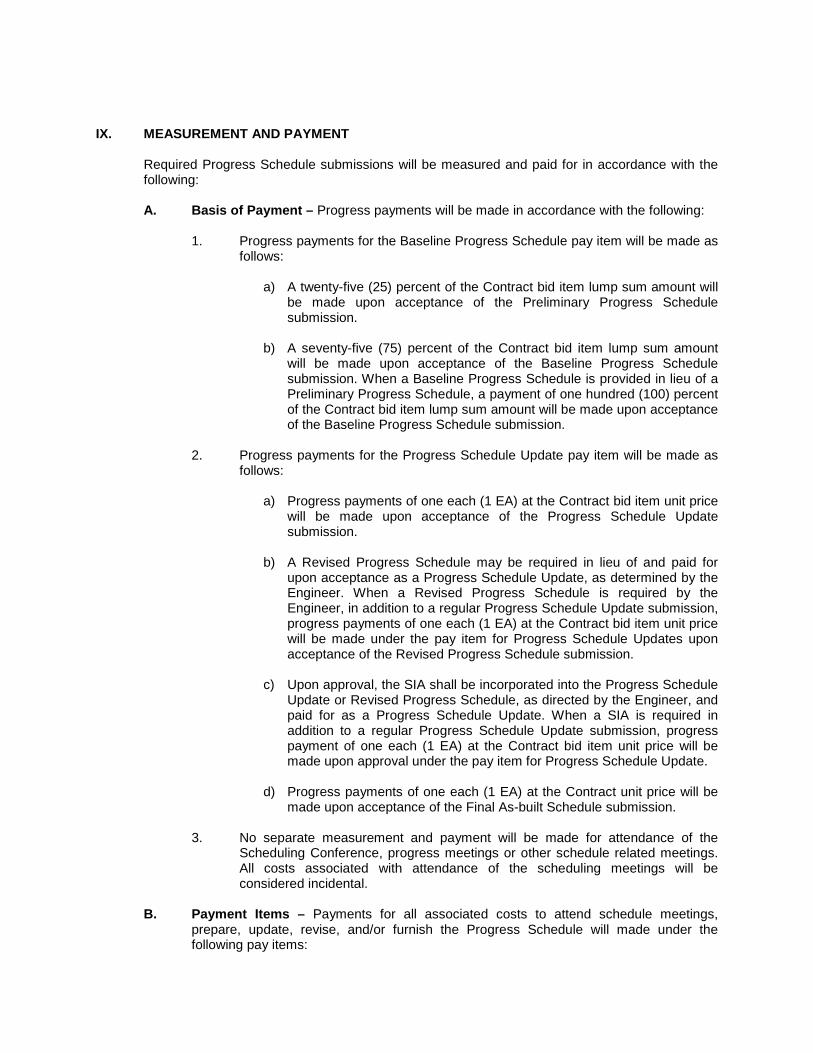
IX. MEASUREMENT AND PAYMENT
Required Progress Schedule submissions will be measured and paid for in accordance with the following: A. Basis of Payment – Progress payments will be made in accordance with the following:
1. Progress payments for the Baseline Progress Schedule pay item will be made as
follows:
a) A twenty-five (25) percent of the Contract bid item lump sum amount will be made upon acceptance of the Preliminary Progress Schedule submission.
b) A seventy-five (75) percent of the Contract bid item lump sum amount
will be made upon acceptance of the Baseline Progress Schedule submission. When a Baseline Progress Schedule is provided in lieu of a Preliminary Progress Schedule, a payment of one hundred (100) percent of the Contract bid item lump sum amount will be made upon acceptance of the Baseline Progress Schedule submission.
2. Progress payments for the Progress Schedule Update pay item will be made as
follows:
a) Progress payments of one each (1 EA) at the Contract bid item unit price will be made upon acceptance of the Progress Schedule Update submission.
b) A Revised Progress Schedule may be required in lieu of and paid for
upon acceptance as a Progress Schedule Update, as determined by the Engineer. When a Revised Progress Schedule is required by the Engineer, in addition to a regular Progress Schedule Update submission, progress payments of one each (1 EA) at the Contract bid item unit price will be made under the pay item for Progress Schedule Updates upon acceptance of the Revised Progress Schedule submission.
c) Upon approval, the SIA shall be incorporated into the Progress Schedule
Update or Revised Progress Schedule, as directed by the Engineer, and paid for as a Progress Schedule Update. When a SIA is required in addition to a regular Progress Schedule Update submission, progress payment of one each (1 EA) at the Contract bid item unit price will be made upon approval under the pay item for Progress Schedule Update.
d) Progress payments of one each (1 EA) at the Contract unit price will be
made upon acceptance of the Final As-built Schedule submission.
3. No separate measurement and payment will be made for attendance of the Scheduling Conference, progress meetings or other schedule related meetings. All costs associated with attendance of the scheduling meetings will be considered incidental.
B. Payment Items – Payments for all associated costs to attend schedule meetings,
prepare, update, revise, and/or furnish the Progress Schedule will made under the following pay items:

Pay Item
Pay Unit
Baseline Progress Schedule Lump Sum Progress Schedule Update Each

S109D02-0815 VIRGINIA DEPARTMENT OF TRANSPORTATION
SPECIAL PROVISION FOR PRICE ADJUSTMENT FOR STEEL
June 15, 2015
The Department will adjust monthly progress payments up or down as appropriate for cost changes in steel used on specific items of work identified in the contract in accordance with this provision. This Special Provision provides a master listing of standard bid items the Department has determined are eligible for steel price adjustment. An automatically generated project-specific listing of standard bid items the Department has identified as eligible for steel price adjustment is included with the bidding proposal. Only items on this listing will be eligible for steel price adjustment. Generally, non-standard pay items will not be eligible for steel price adjustment unless such steel items are project-specific modifications of items normally eligible, are clearly and specifically identified by a separate and distinct steel pay item and the quantities present on the project constitute major items of the work. These items may be addressed by project specific provisions and their related pay items designated as being eligible in the bid proposal. Items eligible for steel price adjustment for a particular project will be shown on Form C-21C “Bid Items Eligible for Steel Price Adjustment” and included with the bidding documents. The Bidder may choose to have steel price adjustment applied to any, all or none of the eligible items shown on Form C-21C. The Bidder’s selection of items for steel price adjustment or non-selection (non-participation) may not be changed once he has submitted Form C-21C to the Department The Contractor shall use Form C-21C to submit to the State Contract Engineer, no later than 15 calendar days after the date of Contract Award letter, those pay items he chooses to have steel price adjustment applied on. Items the Contractor chooses for steel price adjustment must be designated by writing the word “Yes” in the column titled “Option” by each bid item chosen for adjustment. The Contractor’s designations on Form C-21C must be written in ink or typed, and signed by the Contractor to be considered complete. Items not properly designated, or designated with “No” or left blank on the Contractor’s C-21C “Bid Items Eligible for Steel Price Adjustment” form will automatically not be considered for adjustment. No steel items will be eligible for steel price adjustment on this project if the Contractor fails to return his Form C-21C on time. Please note: Inventoried materials from the listing of eligible items are specifically excluded for consideration. Items from the listing of eligible items for which the Contractor has requested payment as Material on Hand in accordance with Section 109.09 are also specifically excluded for consideration past the delivery date to the fabricator. This provision also does not allow for price adjustment for embedded steel where the steel item is a component of the finished bid item and there is no separate or distinct payment for the steel item or for steel used for pre-tensioned or post-tensioned precast components where furnishing steel is included in the unit price of the finished bid item. This provision shall apply only to material cost changes that occur between the date of the receipt of bids by the Department and the date the material is shipped to the fabricator. The Contractor, subcontractor and/or supplier are required to place their purchase order for the steel items designated in this contract for price adjustment within 30 calendar days after the date of execution of this contract with the Department. The timeliness of the Contractor’s response is also to ensure the receipt of such items in a timely manner that shall not adversely affect his progress schedule or contract completion date. The items shall further be specifically stored, labeled, or tagged, recognizable by color marking, and identifiable by project for inspection and audit verification immediately upon arrival at the fabricator. The Contractor shall submit documentation to the appropriate District Construction Engineer for all items listed in the Contract for which it is requesting a steel price adjustment. This documentation shall consist of material price quotes, bid papers, or other similar type of documentation satisfactory to the Department, and support the completion of the form establishing the average price per pound for the

eligible steel bid item. The Contractor must use the format as shown with this provision; no other format for presenting this information will be permitted. The Contractor shall certify that all items of documentation are original and were used in the computation of the amount bid for the represented eligible pay items for the month bids were opened. This documentation shall support the base line material price (“Base Price”) of the steel item only. No adjustment will be made for changes in other components of the contract unit bid price, including, but not limited to, fabrication, shipping, storage, handling, and erection. The Contractor will not be eligible for price adjustment of steel items if he fails to submit specifically required information (i.e., purchase order, price data, bill of lading, material information or other requested information) as noted herein. Price adjustment of each qualifying item will only be considered if there is an increase or decrease in the cost of eligible steel materials in excess of 10 percent up to a maximum of 60 percent from the Base Price when compared with the latest published price index (“Price Index”) in effect at the time material is shipped to the fabricator.
The Price Index the Department is using is based on The U.S. Department of Labor, Bureau of Labor Statistics, Producers Price Index (PPI), which measures the average price change over time of the specific steel eligible item from the perspective of the seller of goods. The specific Producers Price Index (PPI) to be used to adjust the price for the eligible VDOT steel items is shown in the table below. Please note: The Producers Price Index (PPI) is subject to revision 4 months after original publication, therefore, price adjustments and payments will not be made until the index numbers are finalized.
Items under consideration for price adjustment will be compared to the steel category index items and the corresponding I.D. numbers shown in the table attached to the end of this provision. The price adjustment will be determined by comparing the percentage of change in index value beyond 10 percent above or below the index on the bid date to the index value on the date the steel material is shipped to the fabricator (Please see included sample examples). Weights and date of shipment must be documented by a bill of lading provided to the Department. The final price adjustment dollar value will be determined by multiplying this percent increase or decrease in the index (after 10%) by the represented quantity of steel shipped, by the Base Price per pound subject to the limitations herein. Price increase/decrease will be computed as follows:
A = B x P x Q
Where; A = Steel price adjustment in lump sum dollars
B = Average weighted price of steel submitted with bid on project in $ per pound
P = Adjusted percentage change in PPI average from shipping date to bid date minus 10% (0.10) threshold
Q = Total quantity of steel in pounds shipped to fabricator for specific project
Delays to the work caused by steel shortages may be justification for a contract time extension but will not constitute grounds for claims for standby equipment, extended office overhead, or other costs associated with such delays. The Engineer will determine, and specify in the Work Order, the need for application of the adjustments herein to extra work on an individual basis.

This price adjustment is capped at 60 percent. This means the maximum “P” value for increase or decrease that can be used in the above equation is 50% (60%-10% threshold). Calculations for price adjustment shall be shown separate from the monthly progress estimate and will not be included in the total cost of work for determination of progress or for extension of contract time. Any apparent attempt to unbalance bids in favor of items subject to price adjustment may result in rejection of the bid proposal.

20-Jan-05
Sample Form to be turned in for Steel Price Adjustment Provision (All prices to be supported by project-specific quotes)
BID DATE 28-Apr-04
Bid Item 61720 High Strength Structural Steel
Supplier Description of material
Unit price f.o.b supplier
$/lbs Quantity In lbs.
Price Extension
Date of Quote
XYZ mill Structural beams
Various sizes (see quote) $0.28 1,200,000 $336,000.00 21-Apr-04
ABC distributing Various channel & angle
shapes (see quote) $0.32 35,000 $11,200.00 20-Apr-04
Total 1,235,000 $347,200.00
Average weighted price = $0.2816
Note: All prices are to include any surcharges on materials quoted as if they are shipped in the month the bid is submitted. Vendors must include this surcharge along with their base price on their quotes.
v

20-Jan-05
Sample Calculation of a Price Adjustment (increase)
Project bid on April 28, 2004.
Project has 450,000 lb. of structural steel.
Orders placed in timely manner and according to contract.
Contractor's *f.o.b. supplier price for the structural steel in bid is $0.2816 per pound. *free on board
Adjusted** BLS Producers Price Index (PPI) most recently published average at time of bid is 139.6.
** final change after 4 months
All steel shipped to fabricator in same month, October 2004.
Adjusted BLS Producers Price Index (PPI) most recently published average for month of October is 161.1
Adjustment formula is as follows:
A = B X P X Q
Where; A = Steel price adjustment in lump sum dollars
B = Average weighted price of steel submitted with bid on project in $
per pound
P =
Adjusted percentage change in PPI average from shipping date to
bid date minus 10% (0.10) threshold
Q = Total quantity of steel shipped to fabricator in October 2004 for this
project in pounds
B = $0.2816
P = (161.1- 139.6)/139.6 – 0.10 = 0.054
Q = 450,000 lb.
A = 0.2816 x 0.054 x 450,000
A = $6,842.88 pay adjustment to Contractor

20-Jan-05
Sample Calculation of a Price Adjustment (decrease)
Project bid on April 28, 2004.
Project has 450,000 lb. of structural steel.
Orders placed in timely manner and according to contract.
Contractor's *f.o.b. supplier price for structural steel in bid is $0.2816 per pound. *free on board
Adjusted BLS Producers Price Index (PPI) most recently published average at time of bid is 156.6.
All steel shipped to fabricator in same month, October 2004.
Adjusted BLS Producers Price Index (PPI) most recently published average for month of October is 136.3
Adjustment formula is as follows:
A = B X P X Q
Where; A = Steel price adjustment in lump sum dollars
B = Average weighted price of steel submitted with bid on project in $
per pound
P =
Adjusted percentage change in PPI average from shipping date to
bid date minus 10% (0.10) threshold
Q = Total quantity of steel shipped to fabricator in October 2004 for this
project in pounds
B = $0.2816
P = (156.6 – 136.3)/156.6 – 0.10 = 0.030
Q = 450,000 lb.
A = 0.2816 x 0.030 x 450,000
A = $3,801.60 credit to Department

MASTER LISTING
STANDARD BID ITEMS ELIGIBLE FOR STEEL PRICE ADJUSTMENT
Sept. 24, 2008 rev # 1added 4 corrosion resistant re-bar items.
Dec. 4, 2008 rev # 2 deleted item 68138 straighten structural steel
January 14, 2009 rev # 3 identified BLS WPU used in $ adjustment BLS Series I. D.
March 18, 2009 added items 61813,68109 & 68110
ITEM NUMBER ITEM DESCRIPTION UNITS Number WPU used in $ adjust.
00519 SHEET PILE, STEEL SF avg. 1017 & 101
00540 REINF. STEEL LB 101704
00541 CORROSION RESISTANT REINF.STEEL CL. I LB 101704
00542 EPOXY COATED REINF. STEEL LB 101704
00560 STRUCTURAL STEEL JB-1 LB avg. 1017 & 101
11030 REINF. STEEL BRIDGE APPR. SLAB LB 101704
11181 PATCH.HYDR.CEM.CONC. PAVE. SY 101704
13290 GUARDRAIL GR-8 (NCHRP 350 TL-3) LF avg. 1017 & 101
13292 GUARDRAIL GR-8A (NCHRP 350 TL-3) LF avg. 1017 & 101
13294 GUARDRAIL GR-8B (NCHRP 350 TL-3) LF avg. 1017 & 101
13310 GUARDRAIL TERMINAL GR-6 (NCHRP 350) LF avg. 1017 & 101
13312 GUARDRAIL TERMINAL GR-7 (NCHRP 350) EA avg. 1017 & 101
13315 GUARDRAIL TERMINAL GR-11 EA avg. 1017 & 101
13320 GUARDRAIL GR-2 LF avg. 1017 & 101
13323 GUARDRAIL GR-2A LF avg. 1017 & 101
13331 RAD. GUARDRAIL GR-2 LF avg. 1017 & 101
13333 RAD. GUARDRAIL GR-2A LF avg. 1017 & 101
13335 GUARDRAIL GR-3 LF avg. 1017 & 101
13345 ALTERNATE BREAKAWAY CABLE TERMINAL(GR-9) EA avg. 1017 & 101
13351 GUARDRAIL GR-8 LF avg. 1017 & 101
13352 GUARDRAIL GR-8A LF avg. 1017 & 101
13353 GUARDRAIL GR-8B LF avg. 1017 & 101
13355 GUARDRAIL GR-10 LF avg. 1017 & 101
13421 MEDIAN BARRIER MB-3 LF avg. 1017 & 101
13450 MEDIAN BARRIER MB-5 LF avg. 1017 & 101
13451 MEDIAN BARRIER MB-5A LF avg. 1017 & 101
13452 MEDIAN BARRIER MB-5B LF avg. 1017 & 101
13545 REINF. STEEL LB 101704
13594 TRAF. BARR. SER. GUARD RAIL TER. GR-7 EA avg. 1017 & 101
13594 TRAF.BAR.SER.GD.RAIL TER. GR-7 EA avg. 1017 & 101
14502 REINFORCING STEEL LB 101704
15290 PATCH.CEM.CONC.PAVE.TY.CRCP-A SY 101704
15302 PATCH.CEM.CONC.PAVE. TY. II SY 101704
15305 PATCH.CEM.CONC.PAVE.TY. IV-A SY 101704
17323 GUARDRAIL BEAM LF avg. 1017 & 101
17325 RADIAL GUARDRAIL BEAM LF avg. 1017 & 101
17327 RUB RAIL LF avg. 1017 & 101
17342 STEEL TUBE GR-7 EA avg. 1017 & 101
17348 BREAKAWAY POST GR-7 EA 101704
17353 CABLE GR-3 LF avg. 1017 & 101
17381 POST (BENT PLATE OR S 75 X 8.5 STEEL) GR EA avg. 1017 & 101
22501 FENCE FE-W1 LF avg. 1017 & 101
22643 FENCE FE-CL LF avg. 1017 & 101
22645 FENCE FE-CL VINYL COATED LF avg. 1017 & 101
23043 WATER GATE FE-4 TY.III LF avg. 1017 & 101

23501 FENCE FE-W1 (FABRIC ONLY) LF avg. 1017 & 101
45522 4" STEEL ENCASE. PIPE LF 101706
45532 6" STEEL ENCASE. PIPE LF 101706
45562 16" STEEL ENCASE. PIPE LF 101706
45572 18" STEEL ENCASE. PIPE LF 101706
45582 24" STEEL ENCASE. PIPE LF 101706
45584 24" JACKED STEEL ENCASEMENT PIPE LF 101706
45592 30" STEEL ENCASE. PIPE LF 101706
50402 SIGN POST STEEL 3" LF 101706
50404 SIGN POST STEEL 4" LF 101706
50406 SIGN POST STEEL 6" LF 101706
50410 SIGN POST STEEL 10" LF 101706
50412 SIGN POST STEEL 12" LF 101706
50414 SIGN POST STEEL 14" LF 101706
50416 SIGN POST STEEL 16" LF 101706
50418 SIGN POST STEEL 18" LF 101706
51317 SIG. POLE MP-1 20' ONE ARM 30' EA 101706
51319 SIG. POLE MP-1 20' ONE ARM 32' EA 101706
51325 SIG. POLE MP-1 20' ONE ARM 38' EA 101706
51327 SIG. POLE MP-1 20' ONE ARM 40' EA 101706
51329 SIG. POLE MP-1 20' ONE ARM 42' EA 101706
51331 SIG. POLE MP-1 20' ONE ARM 44' EA 101706
51337 SIG. POLE MP-1 20' ONE ARM 50' EA 101706
51339 SIG. POLE MP-1 20' ONE ARM 52' EA 101706
51341 SIG. POLE MP-1 20' ONE ARM 54' EA 101706
51344 SIG. POLE MP-1 20' ONE ARM 56' EA 101706
51346 SIG. POLE MP-1 20' ONE ARM 58' EA 101706
51347 SIG. POLE MP-1 20' ONE ARM 60' EA 101706
51348 SIG. POLE MP-1 20' ONE ARM 62' EA 101706
51368 SIG.POLE MP-1 20'TWO ARMS 36'& 42' EA 101706
51400 SIG.POLE MP-1 CO.LU.ONE ARM 38 EA 101706
51402 SIG.POLE MP-1 CO.LU.ONE ARM 40 EA 101706
51408 SIG.POLE MP-1 CO.LU.ONE ARM 46 EA 101706
51412 SIG.POLE MP-1 CO.LU.ONE ARM 50 EA 101706
51414 SIG.POLE MP-1 CO.LU.ONE ARM 52 EA 101706
51416 SIG.POLE MP-1 CO.LU.ONE ARM 54 EA 101706
51418 SIG.POLE MP-1 CO.LU.ONE ARM 56 EA 101706
51420 SIG.POLE MP-1 CO.LU.ONE ARM 58 EA 101706
51422 SIG.POLE MP-1 CO.LU.ONE ARM 60 EA 101706
55162 LIGHTING POLE LP-1 30'-4' EA 101706
55163 LIGHTING POLE LP-1 30'-6' EA 101706
55166 LIGHTING POLE LP-1 30'-12' EA 101706
55169 LIGHTING POLE LP-1 35'-6' EA 101706
55171 LIGHTING POLE LP-1 35'-10' EA 101706
55176 LIGHTING POLE LP-1 40'-8' EA 101706
55185 LIGHTING POLE LP-2 TYPE A EA 101706
55186 LIGHTING POLE LP-2 TYPE B EA 101706
55187 LIGHTING POLE LP-2 TYPE C EA 101706
55188 LIGHTING POLE LP-2 TYPE D EA 101706
55189 LIGHTING POLE LP-2 TYPE E EA 101706
55190 LIGHTING POLE LP-2 TYPE F EA 101706
55192 LIGHTING POLE LP-2 TYPE H EA 101706
60452 REINF. STEEL BRIDGE APPR. SLAB LB 101704
61700 REINF. STEEL LB 101704
61704 CORROSION RESISTANT REINF. STEEL LB 101704
61705 EPOXY COATED REINF. STEEL LB 101704
61711 CORROSION RESISTANT REINF.STEEL CL. I LB 101704

61712 CORROSION RESISTANT REINF.STEEL CL. II LB 101704
61713 CORROSION RESISTANT REINF.STEEL CL. III LB 101704
61750 STRUCT.STEEL HIGH STRG.PLT.GIRDERS LB avg. 1017 & 101
61811 STR.STEEL PLATE GIRDER ASTM A709 GRADE50 LB avg. 1017 & 101
61812 STR.STEEL PLATE GIRDER ASTM A709 GRADE50 LB avg. 1017 & 101
61813 STR.STEEL PLATE GIRDER ASTM A709 GRADEHPS50W LB avg. 1017 & 101
61814 STR.STEEL PLATE GIRDER ASTM A709 GRADEHPS70W LB avg. 1017 & 101
61820 STR.STEEL ROLLED BEAM ASTM A709 GRADE 36 LB avg. 1017 & 101
61821 STR.STEEL ROLLED BEAM ASTM A709 GRADE50 LB avg. 1017 & 101
61822 STR.STEEL ROLLED BEAM ASTM A709 GRADE50W LB avg. 1017 & 101
61990 STEEL GRID FLOOR SF avg. 1017 & 101
64110 STEEL PILES 10" LF avg. 1017 & 101
64112 STEEL PILES 12" LF avg. 1017 & 101
64114 STEEL PILES 14" LF avg. 1017 & 101
64768 DRIVING TEST FOR 12" STEEL PILE LF avg. 1017 & 101
64778 DRIVING TEST FOR 14" STEEL PILE LF avg. 1017 & 101
65200 REINF. STEEL LB 101704
65204 CORROSION RESISTANT REINF. STEEL LB 101704
65205 EPOXY COATED REINF. STEEL LB 101704
65211 CORROSION RESISTANT REINF.STEEL CL. I LB 101704
65212 CORROSION RESISTANT REINF.STEEL CL. II LB 101704
65213 CORROSION RESISTANT REINF.STEEL CL. III LB 101704
67086 PED. FENCE 6' LF avg. 1017 & 101
67088 PED. FENCE 8' LF avg. 1017 & 101
67089 PED. FENCE 10' LF avg. 1017 & 101
68091 CORROSION RESISTANT REINF.STEEL CL. I LB 101704
68092 CORROSION RESISTANT REINF.STEEL CL. II LB 101704
68093 CORROSION RESISTANT REINF.STEEL CL. III LB 101704
68100 REINF. STEEL LB 101704
68104 CORROSION RESISTANT REINF. STEEL LB 101704
68105 EPOXY COATED REINF. STEEL LB 101704
68107 STR.STEEL PLATE GIRDER ASTM A709 GRADE50 LB avg. 1017 & 101
68108 STR. STEEL PLATE GIRDER ASTM A709 GR50W LB avg. 1017 & 101
68109 STR. STEEL PLATE GIRDER ASTM A709 GR.HPS50W LB avg. 1017 & 101
68110 STR. STEEL PLATE GIRDER ASTM A709 GR.HPS70W LB avg. 1017 & 101
68112 STR.STEEL ROLLED BEAM ASTM A709 GR.36 LB avg. 1017 & 101
68113 STR.STEEL ROLLED BEAM ASTM A709 GR.50 LB avg. 1017 & 101
68114 STR.STEEL ROLLED BEAM ASTM A709 GR. 50W LB avg. 1017 & 101
68115 STRUCT. STEEL LB avg. 1017 & 101
68270 REINF. STEEL BRIDGE APPR. SLAB LB 101704
69060 SHEET PILES, STEEL SF avg. 1017 & 101
69091 CORROSION RESISTANT REINF.STEEL CL. I LB 101704
69092 CORROSION RESISTANT REINF.STEEL CL. II LB 101704
69093 CORROSION RESISTANT REINF.STEEL CL. III LB 101704
69100 REINF. STEEL LB 101704
69104 CORROSION RESISTANT REINF. STEEL LB 101704
69105 EPOXY COATED REINF. STEEL LB 101704
69110 STEEL PILES 10" LF avg. 1017 & 101
69112 STEEL PILE 12" LF avg. 1017 & 101
69113 DRIVING TEST FOR 12" STEEL PILE LF avg. 1017 & 101

S109F01-0815 VIRGINIA DEPARTMENT OF TRANSPORTATION
SPECIAL PROVISION FOR OPTIONAL ADJUSTMENT FOR FUEL
July 1, 2015
The Department will adjust monthly progress payments up or down as appropriate for cost changes in fuel used on specific items of work identified in this provision. The Department will provide a master listing of standard bid items eligible for fuel adjustment on its website. Included with this proposal is a listing of standard bid items the Department has identified as eligible for fuel adjustment on this project(s) as well as the respective fuel factors per pay unit for those items. Only items on this listing will be eligible for adjustment. The fuel usage factor for each item is considered inclusive of all fuel usage. Generally, non-standard pay items are not eligible for fuel adjustment. The listing of eligible items applicable to this particular project is shown on Form C-21B “Bid Items Eligible for Fuel Adjustment” included with the bidding documents. The Bidder may choose to have fuel adjustment applied to any or all eligible items on this project’s listing by designating the items for which the fuel adjustment will apply. The Bidder’s selection of items for fuel adjustment may not be changed once he has submitted Form C-21B to the Department. In order to be eligible for fuel adjustment under this provision, the apparent lowest responsive and responsible Bidder shall clearly identify on Form C-21B those pay items he chooses to have fuel adjustment applied on. Within 21 days after the receipt of bids the apparent successful Bidder shall submit his designated items on Form C-21B to the Contract Engineer. Items the successful Bidder chooses for fuel adjustment must be designated by writing the word “Yes” in the column titled “Option” by each bid item chosen for fuel adjustment. The successful Bidder’s designations on Form C-21B must be written in ink or typed, and signed by this Bidder to be considered complete. Items not properly designated or left blank on the Bidder’s C-21B “Bid Items Eligible for Fuel Adjustment” form may be not considered for adjustment. If the apparent successful Bidder fails to return his Form C-21B within the timeframe specified, items will not be eligible for fuel adjustment on this project. The monthly index price to be used in the administration of this provision will be calculated by the Department from the Diesel fuel prices published by the U. S. Department of Energy, Energy Information Administration on highway diesel prices, for the Lower Atlantic region. The monthly index price will be the price for diesel fuel calculated by averaging each of the weekly posted prices for that particular month. For the purposes of this provision, the base index price will be calculated using the data from the month preceding the receipt of bids. The base index price will be posted by the Department at the beginning of the month for all bids received during that month. The current index price will be posted by the Department and will be calculated using the data from the month preceding the particular estimate being vouchered for payment. The current monthly quantity for eligible items of work selected by the Contractor for fuel adjustment will be multiplied by the appropriate fuel factor to determine the gallons of fuel to be cost adjusted. The amount of adjustment per gallon will be the net difference between the current index price and the base index price. Computation for adjustment will be made as follows:

S = (E - B) QF
Where; S = Monetary amount of the adjustment (plus or minus)
B = Base index price E = Current index price Q = Quantity of individual units of work F = Appropriate fuel factor
Adjustments will not be made for work performed beyond the original contract time limit unless the original time limit has been changed by an executed Work Order. If new pay items are added to this contract by Work Order and they are listed on Department’s master listing of eligible items, the Work Order must indicate which of these individual items will be fuel adjusted; otherwise, those items will not be fuel adjusted. If applicable, designating which new pay items will be added for fuel adjustment must be determined during development of the Work Order and clearly shown on Form C-10 Work Order. The Base Index price on any new eligible pay items added by Work Order will be the Base Index price posted for the month in which bids were received for that particular project. The Current Index price for any new eligible pay items added by Work Order will be the Index price posted for the month preceding the estimate on which the Work Order is paid. When quantities differ between the last monthly estimate prepared upon final acceptance and the final estimate, adjustment will be made using the appropriate current index for the period in which that specific item of work was last performed. In the event any of the base fuel prices in this contract increase more than 100 percent (i.e. fuel prices double), the Engineer will review each affected item of work and give the Contractor written notice if work is to stop on any affected item of work. The Department reserves the right to reduce, eliminate or renegotiate the unit price for remaining portions of affected items of work. Any amounts resulting from fuel adjustment will not be included in the total cost of work for determination of progress or for extension of contract time.

S109G07-0815 VIRGINIA DEPARTMENT OF TRANSPORTATION
SPECIAL PROVISION FOR ASPHALT MATERIAL PRICE ADJUSTMENT
June 15, 2015c
All asphalt material contained in the attached master listing of eligible bid items and designated by pay items in the contract will be price adjusted in accordance with the provisions as set forth herein. Other items will not be adjusted, except as otherwise specified in the contract. If new pay items which contain asphalt material are established by Work Order, they will not be subject to Price Adjustment unless specifically designated in the Work Order to be subject to Price Adjustment. Each month, the Department will publish an average state-wide PG 64S-22 f.o.b. price per ton and an average PG 64E-22 f.o.b. price per ton developed from the average terminal prices provided to the Department from suppliers of asphalt cement to contractors doing work in Virginia. The Department will collect terminal prices from approximately 12 terminals each month. These prices will be received once each month from suppliers on or about the last weekday of the month. The high and low prices will be eliminated and the remaining values averaged to establish the average statewide price for the following month. The monthly state-wide average price will be posted on the Construction Division website on or about the first weekday of the following month. In the event the average prices were to change by 10 percent or more of the Base Index during the middle of the month the Contractor can submit a letter to the Department and supplier that provides evidence of the difference in price. Upon receipt of the letter consideration will be given to extend additional adjustments as deemed necessary. This monthly statewide average price will be the Base Index for all contracts on which bids are received during the calendar month of its posting and will be the Current Index for all asphalt placed during the calendar month of its posting. In the event an index changes radically from the apparent trend, as determined by the Engineer, the Department may establish an index which it determines to best reflect the trend. The amount of adjustment applied will be based on the difference between the contract Base Index and the Current Index for the applicable calendar month during which the work is performed. The quantity of asphalt cement for asphalt concrete pavement to which adjustment will be applied will be the quantity based on the percent of asphalt cement shown on the appropriate approved job mix formula. Adjustment of any asphalt material other than PG 64S-22 and PG 64E-22 will be based on the indexes for PG 64S-22. The quantity of asphalt emulsion for surface treatments to which adjustment will be applied will be the quantity based on 65 percent residual asphalt. Price adjustment will be shown as a separate entry on the monthly progress estimate; however, such adjustment will not be included in the total cost of the work for progress determination or for extension of contract time. Any apparent attempt to unbalance bids in favor of items subject to price adjustment or failure to submit required cost and price data as noted hereinbefore may result in rejection of the bid proposal.

VIRGINIA DEPARTMENT OF TRANSPORTATION MASTER LISTING OF
ASPHALT MATERIAL ITEMS ELIGIBLE FOR PRICE ADJUSTMENT
ITEM DESCRIPTION UNITS SPECIFICATION
10062 Asphalt-Stab. Open-Graded Material Ton 313
10416 Liquid Asphalt Gal 311 312
10420 Blotted Seal Coat Ty. B SY ATTD
10422 Blotted Seal Coat Ty. C SY ATTD
10423 Blotted Seal Coat Ty. C-1 SY ATTD
10424 Blotted Seal Coat Ty. D SY ATTD
10598 Ns Asphalt Concrete Ton 315
10606 Asphalt Concrete Ty. SM-9.5 Ton 315
10607 Asphalt Concrete Ty. SM-12.5A Ton 315
10608 Asphalt Concrete Ty. SM-12.5D Ton 315
10609 Asphalt Concrete Ty. SM-12.5E (64E-22) Ton 315
10610 Asphalt Concrete Ty. IM-19.0A Ton 315
10611 Asphalt Concrete Ty. IM-19.0D Ton 315
10612 Asphalt Conc. Base Cr. Ty. BM-25.0 Ton 315
10613 Asphalt Concrete Ty. BM-37.5 Ton 315
10635 Asphalt Concrete Ty. SM-9.5A Ton 315
10636 Asphalt Concrete Ty. SM-9.5D Ton 315
10637 Asphalt Concrete Ty. SM-9.5E (64E-22) Ton 315
10639 Asphalt Concrete Ty. SM-19.0 Ton 315
10642 Asphalt Concrete Ty. BM-25.0A Ton 315
10643 Asphalt Concrete Ty. BM-25.0D Ton 315
10650 Stone Matrix Asphalt SMA-9.5(64H-22) Ton 317
10651 Stone Matrix Asphalt SMA-9.5(64E-22) Ton 317
10652 Stone Matrix Asphalt SMA-12.5(64H-22) Ton 317
10653 Stone Matrix Asphalt SMA-12.5(64E-22) Ton 317
10654 Stone Matrix Asphalt SMA-19.0(64H-22) Ton 317
10655 Stone Matrix Asphalt SMA-19.0(64E-22) Ton 317
10701 Liquid Asphalt Coating SY ATTD
12505 Asphalt Concrete Curb Backup Material Ton 315
13240 Asphalt Concrete Sidewalk Ton 504
16110 Emul. Asph. Slurry Seal Type A SY ATTD
16120 Emul. Asph. Slurry Seal Type B SY ATTD
16130 Emul. Asph. Slurry Seal Type C SY ATTD
16144 Latex Mod. Emul. Treat. Type B Ton ATTD
16145 Latex Mod. Emul. Treat. Type C Ton ATTD
16146 Latex Mod. Emul. Treat. Rutfilling Ton ATTD
16161 Modified Single Seal SY ATTD
16162 Modified Double Seal SY ATTD
16249 Nontracking Tack Coat Gal. ATTD
16250 Liquid Asphalt Matl. CMS-2 (Mod) Gal ATTD
16251 Liquid Asphalt Matl. CMS-2 Gal ATTD

16252 Liquid Asphalt Matl. CRS-2 Gal ATTD
16253 Liquid Asphalt Matl. CRS-2H Gal. ATTD.
16254 Liquid Asphalt Matl. RC-250 Gal ATTD
16256 Liquid Asphalt Matl. RC-800 Gal ATTD
16257 Ns Liquid Asphalt Matl. Gal ATTD
16260 Liquid Asphalt Matl. CRS-2L Gal ATTD
16325 NS Asphalt Concrete Ton N/A
16330 Asphalt Concrete Ty. SM-9.0A Ton 315
16335 Asphalt Concrete Ty. SM-9.5A Ton 315
16337 Asph. Conc. Ty. SM-9.5ASL (Spot Level) Ton 315
16340 Asphalt Concrete Ty. SM-9.5D Ton 315
16342 Asph. Conc. Ty. SM-9.5DSL (Spot Level) Ton 315
16345 Asphalt Concrete Ty. SM-9.5E (64E-22) Ton 315
16350 Asphalt Concrete Ty. SM-12.5A Ton 315
16352 Asph. Con. Ty. SM-12.5ASL (Spot Level) Ton 315
16355 Asphalt Concrete Ty. SM-12.5D Ton 315
16357 Asph. Con. Ty. SM-12.5DSL (Spot Level) Ton 315
16360 Asphalt Concrete Ty. SM-12.5E (64E-22) Ton 315
16362 Asphalt Concrete Ty. SM-19.0A Ton 315
16365 Asphalt Concrete Ty. IM-19.0A Ton 315
16370 Asphalt Concrete Ty. IM-19.0D Ton 315
16373 Asphalt Concrete Ty. IM-19.0A (T) Ton 315
16374 Asphalt Concrete Ty. IM-19.0D (T) Ton 315
16377 Asphalt Concrete Ty. BM-37.5 Ton 315
16379 Asphalt Concrete Ty. IM-19.0T Ton 315
16390 Asphalt Concrete Ty. BM-25.0A Ton 315
16392 Asphalt Concrete Ty. BM-25.0D Ton 315
16395 Asphalt Concrete Ty. BM-25.0A (T) Ton 315
16397 Asphalt Concrete Ty. BM-25.0D (T) Ton 315
16400 Stone Matrix Asphalt SMA-9.5(64H-22) Ton ATTD
16401 Stone Matrix Asphalt SMA-9.5(64E-22) Ton ATTD
16402 Stone Matrix Asphalt SMA-12.5(64H-22) Ton ATTD
16403 Stone Matrix Asphalt SMA-12.5(64E-22) Ton ATTD
16404 Stone Matrix Asphalt SMA-19.0(64H-22) Ton ATTD
16405 Stone Matrix Asphalt SMA-19.0(64E-22) Ton ATTD
16490 Hot Mix Asphalt Treatment Ton ATTD
16500 Surf.Preparation & Restoration Type I Ton ATTD
16502 Surf.Preparation & Restoration Type II Ton ATTD
16504 Surf.Preparation & Restoration Type III Ton ATTD
67201 NS Asphalt Concrete Overlay Ton 315
67210 NS Asphalt Concrete Ton 315
68240 NS Asphalt Concrete Ton 315

S208B00-0708 VIRGINIA DEPARTMENT OF TRANSPORTATION
SPECIAL PROVISION FOR CRUSHED HYDRAULIC CEMENT CONCRETE (CHCC)
(USED AS SUBBASE AND AGGREGATE BASE MATERIAL)
January 14, 2008c SECTION 208—SUBBASE AND AGGREGATE BASE MATERIAL of the Specifications is amended as follows:
Section 208.02—Materials is replaced with the following:
(a) Subbase material may consist of any mixture of natural or crushed gravel, crushed stone or slag, crushed hydraulic cement concrete (CHCC), natural or crushed sand; with or without soil mortar. Subbase material may be used in a stabilized or unstabilized form.
(b) Aggregate base material may be designated as Type I or Type II as follows: Type I shall
consist of crushed stone, crushed slag, crushed hydraulic cement concrete (CHCC), crushed gravel or any combination of these material: with or without soil mortar or other admixtures. Crushed gravel shall consist of particles of which at least 90 percent by weight of the material retained on the No. 10 sieve shall have at least one face fractured by artificial crushing. Type II shall consist of gravel, stone, or slag screening; fine aggregate and crushed coarse aggregate; sand-clay-gravel mixtures; crushed hydraulic cement concrete; or any combination of these materials; with or without soil mortar or other admixtures. Aggregate base materials Type I or II may be used in a stabilized or unstabilized form.
(c) Crushed Hydraulic Cement Concrete shall not be used as Subbase or aggregate base
material when any subsurface drainage system, such as standard underdrains (UD-4 or UD-5) and /or a stabilized open graded aggregate drainage layer (OGDL) is present, except when the CHCC is cement stabilized.
Section 208.03(b) Atterberg Limits is amended to add the following:
Plasticity: Subbase and aggregate base materials shall be either non-plastic (PI=0) or shall
conform to the requirements of Table II-11 of the Specifications when tested in accordance with VTM-7. If the material is classified as non-plastic (PI=0), in accordance with VTM-7, the Liquid Limit requirement will be waived. Exceptions to this provision are noted as follows: 1. 100% CHCC and 20% or less CHCC Blends will be tested and subject to penalty
as noted in Table II-11 of the Specifications for the plasticity index, excluding Liquid Limit penalties.
2. Greater than 20% CHCC Blends will follow testing guidelines as set forth in
Section 208.06 (b) for Atterburg limits.
Section 208.03 is amended to add the following:
(h) Deleterious Material: The quantity of deleterious materials present in stockpiles of Crushed Hydraulic Cement Concrete, to be used in blending with virgin aggregates or as 100 percent CHCC, shall not exceed the following values:
MATERIAL PERCENT BY WEIGHT (MASS)
Asphalt Concrete 5.0 Glass and Metals 5.0
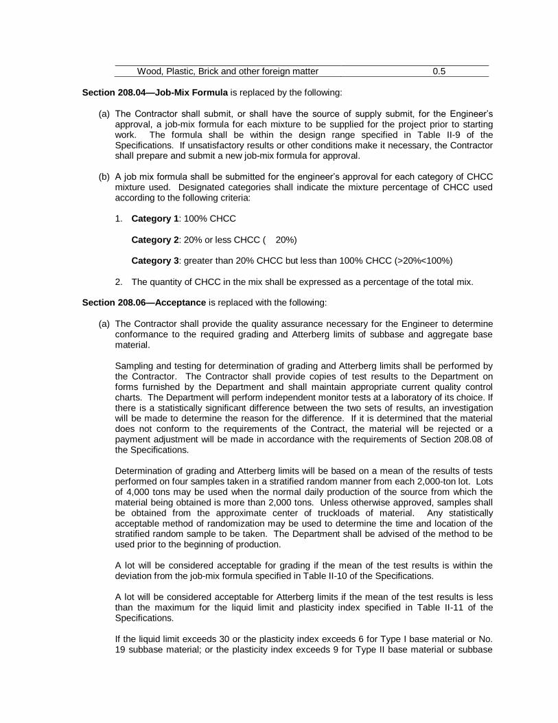
Wood, Plastic, Brick and other foreign matter 0.5
Section 208.04—Job-Mix Formula is replaced by the following:
(a) The Contractor shall submit, or shall have the source of supply submit, for the Engineer’s approval, a job-mix formula for each mixture to be supplied for the project prior to starting work. The formula shall be within the design range specified in Table II-9 of the Specifications. If unsatisfactory results or other conditions make it necessary, the Contractor shall prepare and submit a new job-mix formula for approval.
(b) A job mix formula shall be submitted for the engineer’s approval for each category of CHCC
mixture used. Designated categories shall indicate the mixture percentage of CHCC used according to the following criteria:
1. Category 1: 100% CHCC
Category 2: 20% or less CHCC ( 20%) Category 3: greater than 20% CHCC but less than 100% CHCC (>20%<100%)
2. The quantity of CHCC in the mix shall be expressed as a percentage of the total mix. Section 208.06—Acceptance is replaced with the following:
(a) The Contractor shall provide the quality assurance necessary for the Engineer to determine
conformance to the required grading and Atterberg limits of subbase and aggregate base material. Sampling and testing for determination of grading and Atterberg limits shall be performed by the Contractor. The Contractor shall provide copies of test results to the Department on forms furnished by the Department and shall maintain appropriate current quality control charts. The Department will perform independent monitor tests at a laboratory of its choice. If there is a statistically significant difference between the two sets of results, an investigation will be made to determine the reason for the difference. If it is determined that the material does not conform to the requirements of the Contract, the material will be rejected or a payment adjustment will be made in accordance with the requirements of Section 208.08 of the Specifications. Determination of grading and Atterberg limits will be based on a mean of the results of tests performed on four samples taken in a stratified random manner from each 2,000-ton lot. Lots of 4,000 tons may be used when the normal daily production of the source from which the material being obtained is more than 2,000 tons. Unless otherwise approved, samples shall be obtained from the approximate center of truckloads of material. Any statistically acceptable method of randomization may be used to determine the time and location of the stratified random sample to be taken. The Department shall be advised of the method to be used prior to the beginning of production. A lot will be considered acceptable for grading if the mean of the test results is within the deviation from the job-mix formula specified in Table II-10 of the Specifications. A lot will be considered acceptable for Atterberg limits if the mean of the test results is less than the maximum for the liquid limit and plasticity index specified in Table II-11 of the Specifications. If the liquid limit exceeds 30 or the plasticity index exceeds 6 for Type I base material or No. 19 subbase material; or the plasticity index exceeds 9 for Type II base material or subbase

materials No. 20, 21, 21A, 21B, or 22 on any individual sample; that portion of the lot from which the sample was taken will be considered a separate part of the lot and shall be removed from the road. If either the amount of material in the lot is less than 2,000 tons (4,000 tons if applicable), the job-mix formula is modified within a lot, or a portion of the lot is rejected on the basis of individual test results, the mean test results of the samples taken will be compared to the job-mix formula with the tolerances given in Tables II-10 and II-11 of the Specifications for the number of tests performed. If a visual examination reveals that material in any load is obviously contaminated or segregated, the load will be rejected without additional sampling or testing of the lot. If it is necessary to determine grading or Atterberg limits of material in an individual load, one sample (taken from the load) will be tested and the results compared to the job-mix formula with the tolerances given in Tables II-10 and II-11 of the Specifications for one test. Results obtained in the testing of a specific individual load will apply only to the load in question.
(b) The following applies specifically to the use of Crushed Hydraulic Cement Concrete (CHCC)
mixtures. All provisions for acceptance of these products shall conform to the same criteria as in (a) herein with the following additions: 1. 100% CHCC shall conform to the requirements of this special provision. 2. 20% or Less CHCC Blends shall conform to the requirements of this special provision. 3. Greater than 20% CHCC Blends shall conform to the following:
a. The virgin aggregate portion of the blend will be tested for Atterberg limits, prior to
CHCC blending. b. Price adjustments for Liquid Limit and the Plasticity Index of the virgin aggregates
used in the blend with CHCC shall be in accordance with Table II-11 of the Specifications.
c. No additional testing for Liquid Limit or Plasticity Index will be required on the final
blended product.
4. All shipments of products containing CHCC must be designated on the shipping ticket (scale ticket) by the use of the letter “R”. Examples: [22R, 21AR and 21BR] for: Aggregate Base material, Type I or Subbase materials.

S223AG2-0313
VIRGINIA DEPARTMENT OF TRANSPORTATION
SPECIAL PROVISION FOR CORROSION RESISTANT REINFORCING STEEL
January 24, 2012
SECTION 223—STEEL REINFORCEMENT of the Specifications is revised as follows:
223.02—Detail Requirements is amended to add the following
(e) Corrosion Resistant Reinforcing Steel, Class I: Steel shall conform to the
requirements of ASTM A1035/A1035M – Standard Specification for Deformed and Plain, Low-carbon, Chromium, Steel Bars for Concrete Reinforcement; or shall conform to the requirements of ASTM A955/A955M – Standard Specification for Deformed and Plain, Solid Stainless Steel Bars for Concrete Reinforcement, UNS* Designation(s): S32101.
(f) Corrosion Resistant Reinforcing Steel, Class II: Steel shall conform to the
requirements of AASHTO Designation: MP 13M/MP 13-04, Standard Specification for Stainless Steel Clad Deformed and Plain Round Steel Bars for Concrete Reinforcement; or shall conform to the requirements of ASTM A955/A955M - Standard and Specification for Deformed and Plain Solid Stainless Steel Bars for Concrete Reinforcement. UNS* Designations: S24100. Stainless steel clad bars may only be provided if they are domestically produced except for projects designated as experimental in the plans.
(g) Corrosion Resistant Reinforcing Steel, Class III: Steel shall conform to the requirements of ASTM A955/A955M - Standard Specification for Deformed and Plain Solid Stainless Steel Bars for Concrete Reinforcement. UNS* Designations: S24000, S30400, S31603, S31653, S31803, S32304.
* Unified Numbering System for Metals and Alloys

S302B00-1212
VIRGINIA DEPARTMENT OF TRANSPORTATION SPECIAL PROVISION FOR
RESTORING EXISTING PAVEMENT
January 14, 2008cc I. DESCRIPTION
This work shall consist of restoring existing pavement, removed for installation or repair of utilities such as, but not limited to pipe culverts, conduits, water and sanitary sewer items.
II. MATERIALS Asphalt Concrete shall conform to the requirements of Section 211 of the Specifications. Aggregate Subbase material shall conform to the requirements of Section 208 of the Specifications. Asphalt Material shall conform to the requirements of Section 210 of the Specifications. Fine Aggregate shall conform to the requirements of Section 202 of the Specifications. Coarse Aggregate for surface treatment shall conform to the requirements of Section 203 of the Specifications. Hydraulic Cement Concrete Class A3 shall conform to the requirements of Section 217 of the Specifications. Steel Reinforcement shall conform to the requirements of Section 223 of the Specifications.
III. PROCEDURES Pavement restoration shall be in accordance with this Provision and plan notes. Backfill shall be in accordance with Section 302.03(a)2.g. of the Specifications. Asphalt Concrete shall be placed and compacted in accordance with Section 315 of the Specifications. Surface Treatment shall be placed in accordance with the Asphalt Surface Treatment special provision and the attached drawing. Concrete Pavement shall be placed in accordance with Section 509 of the Specifications and this special provision. Open trench in Hydraulic Cement Concrete Pavement should be located at existing transverse joints if at all possible. If concrete pavement is removed within two feet of an existing transverse joint, pavement removal shall be extended two feet beyond the joint. Reinforcing steel and dowels shall be installed in accordance with Road and Bridge Standard PR-2. Joint replacement shall be in accordance with Road and Bridge Standard PR-2.
IV. MEASUREMENT AND PAYMENT Restoring Existing Pavement unless otherwise specified will not be measured for separate payment, the cost thereof shall be included in the price bid for the utility to which it pertains in accordance with Section 302.04, Section 520.06 or Section 700.05 of the Specifications, as appropriate. However, widths and depths in excess of the attached drawing that are authorized

or directed by the Engineer will be paid for in accordance with Section 109.05 of the Specifications.
NOTES: The following methods for restoring existing pavement shall be adhered to unless otherwise specified on the plans. 1. Pipe culverts, conduits and utility items shall be
installed in accordance with the applicable Road and Bridge Standards and Specifications.
2. Subbase - Aggregate material Type 1, Size 21A
or 21B. 3. Asphalt Concrete Type BM-25.0 4. Surface - Asphalt Concrete Type SM-9.5D @
165 lbs. per sq. yd.
5. Surface - Blotted Seal Coat Type C: The initial
seal and final seal shall be CRS-2, CMA-2 or CMS-2h liquid asphalt material @ 0.17 gal./sq. yd. with 15 lbs. of No. 8P stone/sq. yd. each. The blot seal shall be CRS-2, CMS-2 or CMS-2h liquid asphalt material @ 0.15 gal./sq. yd. with 10 lbs. of fine aggregate grade B sand per sq. yd.
6. Subbase - Aggregate material Type 1 Size 21B 7. Surface - Hydraulic Cement Concrete, high
early strength, matching existing structure for depth and surface texture.
7” Min

S302G02-0610 VIRGINIA DEPARTMENT OF TRANSPORTATION
SPECIAL PROVISION FOR FLOWABLE BACKFILL
March 11, 2010
I. DESCRIPTION
This work shall consist of furnishing and placing flowable backfill for use as backfill material in pipe installations or in other uses at locations as designated on the plans, and as backfill material for plugging designated abandoned pipes and culverts.
II. MATERIALS
Hydraulic Cement shall conform to the requirements of Section 214 of the Specifications. Fly Ash shall conform to the requirements of Section 241.02(a) of the Specifications. Water shall conform to the requirements of Section 216 of the Specifications with the exception that wash water as described in Section 216.02 may comprise the total mix water. Aggregates shall conform to the requirements of Sections 202 and 203 of the Specifications with a combined gradation as determined by the Contractor. Admixtures shall conform to the requirements of Section 215 of the Specifications. Granulated Iron Blast Furnace Slag shall conform to the requirements of Section 215 of the Specifications.
III. MIX DESIGN
Mix design for flowable backfill shall be provided by the Contractor. When used as backfill material in pipe installations or in other uses at locations as designated on the plans flowable backfill shall have a design compressive strength of 30 to 200 pounds per square inch. When used as backfill material for plugging designated abandoned pipes and culverts flowable backfill shall have a design compressive strength of 30 to 1200 pounds per square inch. The design compressive strength requirement shall be at 28 days when tested in accordance with ASTM D 4832. Mix design shall result in a fluid product having no less than an 8-inch slump at time of placement. The Contractor shall submit a mix design for approval supported by laboratory test data verifying compliance with 28 day compressive strength requirements. Mix design shall be approved by the Engineer prior to placement.
IV. PROCEDURES
Mixing and transporting shall be in accordance with Section 217 of the Specifications or by other methods approved by the Engineer. Temperature of flowable backfill shall be at least 50 degrees F at time of placement. Material shall be protected from freezing for 24 hours after placement. When used as backfill for pipe installation and floatation or misalignment occurs, correct alignment of the pipe shall be assured by means of straps, soil anchors or other approved means of restraint.

When used to fill the voids in abandoned pipes and culverts, they shall be plugged and backfilled in accordance with the plan details or as directed by the Engineer. The plugs shall be in accordance with the plan details. The backfill material shall be flowable backfill placed into the abandoned pipe or culvert without voids. When deemed necessary by the Engineer, the Contractor shall submit a plan of operations for acceptance showing how the flowable backfill will be placed without voids. The opening for culvert backfill installation shall be sealed with masonry or Class A-3 concrete at completion of backfilling.
V. MEASUREMENT AND PAYMENT
Flowable Backfill will be measured and paid for in cubic yards complete-in-place. When used as backfill material in pipe installations or in other uses at locations as designated on the plans this price shall be full compensation for furnishing and placing flowable backfill, securing the pipe alignment, and for all materials, labor, tools, equipment and incidentals necessary to complete the work. When used as backfill material for plugging designated abandoned pipes and culverts the price bid shall include furnishing and placing of backfill material and furnishing and installing plugs. Payment will be made under:
Pay Item
Pay Unit
Flowable Backfill Cubic yard
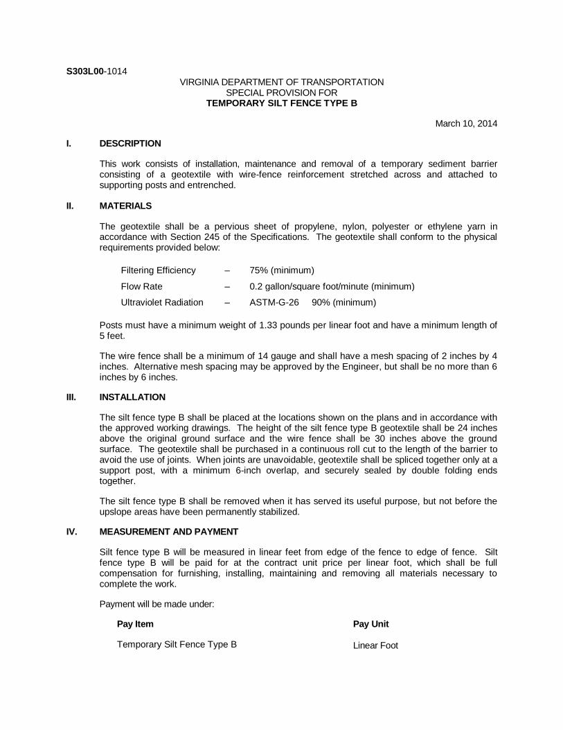
S303L00-1014 VIRGINIA DEPARTMENT OF TRANSPORTATION
SPECIAL PROVISION FOR TEMPORARY SILT FENCE TYPE B
March 10, 2014
I. DESCRIPTION
This work consists of installation, maintenance and removal of a temporary sediment barrier consisting of a geotextile with wire-fence reinforcement stretched across and attached to supporting posts and entrenched.
II. MATERIALS
The geotextile shall be a pervious sheet of propylene, nylon, polyester or ethylene yarn in accordance with Section 245 of the Specifications. The geotextile shall conform to the physical requirements provided below:
Filtering Efficiency – 75% (minimum)
Flow Rate – 0.2 gallon/square foot/minute (minimum)
Ultraviolet Radiation – ASTM-G-26 90% (minimum)
Posts must have a minimum weight of 1.33 pounds per linear foot and have a minimum length of 5 feet.
The wire fence shall be a minimum of 14 gauge and shall have a mesh spacing of 2 inches by 4 inches. Alternative mesh spacing may be approved by the Engineer, but shall be no more than 6 inches by 6 inches.
III. INSTALLATION
The silt fence type B shall be placed at the locations shown on the plans and in accordance with the approved working drawings. The height of the silt fence type B geotextile shall be 24 inches above the original ground surface and the wire fence shall be 30 inches above the ground surface. The geotextile shall be purchased in a continuous roll cut to the length of the barrier to avoid the use of joints. When joints are unavoidable, geotextile shall be spliced together only at a support post, with a minimum 6-inch overlap, and securely sealed by double folding ends together.
The silt fence type B shall be removed when it has served its useful purpose, but not before the upslope areas have been permanently stabilized.
IV. MEASUREMENT AND PAYMENT
Silt fence type B will be measured in linear feet from edge of the fence to edge of fence. Silt fence type B will be paid for at the contract unit price per linear foot, which shall be full compensation for furnishing, installing, maintaining and removing all materials necessary to complete the work.
Payment will be made under:
Pay Item Pay Unit
Temporary Silt Fence Type B Linear Foot

S314CM3-1012
VIRGINIA DEPARTMENT OF TRANSPORTATION SPECIAL PROVISION FOR
ASPHALT SURFACE TREATMENT
September 13, 2012 I. DESCRIPTION
This work shall consist of the application of a single or multiple course of asphalt surface treatment in accordance with the Specifications and as specified herein.
II. DEFINITION OF TERMS Seal Treatment is defined as one application of asphalt material and one application of cover aggregate. Modified Single Seal is defined as two applications of asphalt material, one application of cover aggregate and one application of blot fine aggregate. Modified Double Seal is defined as three applications of asphalt material, two applications of cover aggregate and one application of blot fine aggregate.
III. MATERIALS The Contractor shall demonstrate the compatibility of the asphalt emulsion and cover aggregate (excluding the blot seal) prior to construction of the surface treatment. This testing shall be conducted in accordance with VTM-65 in the presence of the Engineer for each asphalt and aggregate combination. In addition, the Contractor shall conduct the compatibility test at least once a week on stockpiled materials and any additional test, as deemed necessary by the Engineer. Compatibility test results shall be submitted to the Engineer. All material combinations shall pass the compatibility test unless waived in writing by the Engineer. If during the life of this project excessive loss of cover aggregate occurs, the Engineer may suspend the work in accordance with the requirements of Section 108 of the Specifications until the cause of the loss of cover material is corrected. (a) Asphalt Materials shall conform to Section 210 of the Specifications except as specified
herein. CRS-2 shall be a rapid setting cationic emulsified asphalt when tested in accordance with ASHTO T59 Testing Emulsified Asphalt. CRS-2 shall meet the requirements of Type II coating ability. CRS-2h shall conform to CRS-2 except that the penetration shall be 40 to 100. RC-250 when permitted during the period of May 1 to October 1 shall meet the requirements of Type I coating ability. When permitted during the period of October 1 to May 1 the requirements of Type II coating ability shall apply. CRS-2M (Polymer Modified Cationic Emulsified Asphalt) shall meet the physical requirements of asphalt material per AASHTO M316 for CRS-2L or CRS-2P except as

modified herein. The minimum elastic recovery for CRS-2L, as tested in accordance to AASHTO T301, shall be 50 percent.
The Contractor shall provide written certification of the test results.
(b) Cover Material — Coarse and Fine aggregate shall conform to Section 203 and 202 of the Specifications. Coarse aggregate shall be a minimum Grade B. Lightweight aggregate shall conform to the requirements of Section 206 of the Specifications except as noted herein. For light weight aggregate when the material passing the No. 200 sieve by washing is dust of fracture, the percentage of deleterious material shall not exceed 1.7 percent. Crushed stone shall only be used on roads of Traffic Groups VI and above unless the surface treatment consists of modified single seal treatment or modified double seal treatment. Aggregates shall not be used within 24 hours of washing. Aggregate from more than one source shall not be furnished for a specified route or a group of sub-division routes unless permitted by the Engineer. The following modifies the aggregate material as defined in Section 203 of the Specifications:
Designation Modification
N Non-polishing material only L Lightweight G Washed gravel only
Notes: Where 8N is specified, it shall meet the gradation requirements of No. 8P. Where 8L is specified it shall meet the following gradation:
Sieve Size Percent Passing
1/2 100 3/8 75-100
No. 4 10-40 No. 8 max. 5
Where 8G is specified, it shall meet the gradation requirements of No. 8P.
IV. PROCEDURES
Weather limitations for asphalt surface treatment work shall be in accordance with the requirements of Section 314 of the Specifications. The Contractor shall have a certified Surface Treatment Technician present during the surface treatment operation. The Contractor shall use one steel wheel roller and one pneumatic-tire roller on modified single seal, modified double seal and seal treatments using CRS-2L asphalt material in a sequence approved by the Engineer. The Contractor is directed to the exceptions to these requirements found in IV.(c) of this special provision. These treatments shall be subjected to a minimum of one complete pass of each type of roller on either the cover aggregate or the blot seal coat. (a) Seal Treatment shall conform to the requirements of Section 312 of the Specifications.
When seal treatment is specified, the Contractor shall protect the cover aggregate from traffic until the asphalt material has sufficiently cured to carry traffic without damage to the treatment.

The rate of application shall be in accordance with VTM-66. The rate of application for the cover aggregate and asphalt emulsion shown in the contract are approximate and the actual rate shall be determined by the Contractor and approved by the Engineer. After the roadway has been treated and cured, the Contractor shall lightly broom the surface to remove any excessive aggregate in accordance with the requirements of Section 312.04 of the Specifications and as directed by the Engineer. Brooming shall be performed in such a manner as not to damage the embedded aggregate material.
(b) Modified Single Seal and Modified Double Seal Treatments, when specified, shall be lightly broomed on the surface by the Contractor to remove any excessive aggregate in accordance with the requirements of Section 312.04 of the Specifications and as directed by the Engineer. Brooming shall be performed in such manner as not to damage the embedded aggregate material. No traffic, including delivery trucks, shall be allowed on modified seal treatments until after the blot coat material has been placed and rolled. 1. Modified Single Seal Treatment
a. Approximately 0.17 gallons per square yard of asphalt material, of the
type specified, shall be applied to the existing surface immediately followed by an application of approximately 15 pounds per square yard of aggregate size No. 8P. The aggregate shall be spread uniformly (one aggregate deep) over the treated surface. The aggregate shall be rolled immediately at least once with a self-propelled roller of an approved design. When a continuous uninterrupted modified single seal treatment train method is employed, rolling of the initial aggregate course may be omitted.
b. Immediately after the seal coat has been rolled in accordance with IV.(b)1.a., herein a blot seal coat consisting of approximately 0.15 gallons per square yard of asphalt material, of the type specified, shall be applied to the surface treated pavement followed by a uniform application of approximately 10 pounds per square yard of fine aggregate. The fine aggregate shall be Grading A, B or F natural or manufactured in accordance with Section 202 or No. 9 aggregate in accordance with Section 203 of the Specifications, except that the material shall have no more than 5 percent passing the No. 200 sieve by washed analysis. The Contractor is directed to the exceptions to these requirements found in IV.(c) of this special provision. An increase in the application rate for blotter material may be necessary when using natural sand and if the desired results are not achieved with this material, the Engineer may require the use of manufactured sand. Fine aggregate from more then one source shall not be used intermittently. The fine aggregate shall be applied by the use of a self-propelled aggregate spreader of approved design. The blot coat shall be rolled immediately at least once with a self-propelled roller of an approved design. At least 48 hours after the blot coat application, the roadway surface shall be lightly broomed as directed by the Engineer.
2. Modified Double Seal Treatment
a. Two applications of asphalt material and cover aggregate shall be applied in accordance with Section IV.(b)1.a. herein, except that at least

one complete pass shall be made with the roller after each aggregate application.
b. A blot coat shall be applied in accordance with IV.(b)1.b. herein.
The application temperature for liquid asphalt material shall conform to Table III-1 of Section 310 of the Specifications, except that the minimum application temperature for CRS-2 and CRS-2L shall be 160 degrees F.
(c) District-Specific Exceptions for Modified Single Seal and Modified Double Seal
Treatments and Seal Treatment
Bristol District — The blot coat for use in modified single seal and modified double seal shall be No. 9 aggregate conforming to Section 203 of the Specifications and applied at a rate of 12 pounds per square yard in lieu of sand. Two pneumatic-tire rollers shall be used on modified single seal, modified double seal and seal treatments using CRS-2L asphalt material. Lynchburg, Salem, and Staunton Districts — The blot coat for use in modified single seal and modified double seal shall be No. 9 aggregate conforming to Section 203 of the Specifications and applied at a rate of 12 pounds per square yard in lieu of sand. Hampton Roads District — The blot coat for use in modified single seal and modified double seal shall be manufactured sand only conforming to Section 202 of the Specifications. Fredericksburg District (only Caroline, Spotsylvania, and Stafford Counties) — The blot coat for use in modified single seal and modified double seal shall be manufactured stone sand conforming to Section 202 of the Specifications.
(d) Prime Coat, when specified, shall be applied in accordance with Section 311 of the Specifications. When cover material is specified, rolling shall be performed in accordance with the requirements of Section 312 of the Specifications. The prime coat shall be permitted to cure prior to the next application of asphalt. During the period between application of the prime coat and the seal coat, the primed surface shall be kept in repair. Holes, ravels, and areas deficient in primer shall be patched and repaired with asphalt-treated materials by penetration methods or other approved procedures.
(e) Maintenance, Protection and Performance of the Work — The Contractor shall be responsible for the maintenance and protection of the seal treatment on the roadway for a period of 48 hours after application. The Contractor shall exercise control of the delivery and application of the surface treatment materials to prevent damage to the roadway surface. The speed of the delivery equipment and pilot truck shall be limited to a maximum 15 miles per hour. The maintenance and protection shall include, but not be limited to, the placement of signs; the use of flaggers and pilot trucks; and placement of additional asphalt and aggregate material. In the event a failure occurs prior to acceptance, the Contractor shall repair or replace the failed treatment as directed by the Engineer, at no additional cost to the Department.
V. EQUIPMENT

(a) Asphalt Distributors and Aggregate Spreaders 1. Distributors and spreaders shall be calibrated by the Contractor in the presence
of the Engineer prior to placing surface treatment; to ensure an even and accurate spray, and aggregate distribution.
2. Asphalt distributors shall be equipped with proper spray nozzles including end
nozzles for the application rate specified, to provide uniform coverage throughout the width of the application.
(b) Rollers
1. One steel wheel roller and one pneumatic-tire roller shall be used on modified
single seal, modified double seal and seal treatment using CRS-2L asphalt material. The Contractor is directed to the exceptions to these requirements found in IV.(c) of this special provision. The steel wheel roller weight shall be between 6 and 8 tons for the tandem type and between 8 and 10 tons for the three-wheel type.
2. Two pneumatic-tire rollers shall be used on the conventional type seal treatment.
VI. MEASUREMENT AND PAYMENT Liquid asphalt material for seal treatment will be measured and paid for in accordance with Section 312 of the Specifications. Aggregate for seal treatment will be measured and paid for in square yards on a plan quantity basis, which price bid shall include furnishing and applying aggregate, protection of the asphalt surface treatment and all incidentals necessary to complete the work. Authorized increases or decreases to the plan quantity will be adjusted in accordance with Section 109 of the Specifications. Modified single seal and modified double seal treatments will be measured and paid for in square yard on a plan quantity basis, which price bid shall include all cost for furnishing and applying liquid asphalt material and cover aggregate, protection of the asphalt surface treatment and all incidentals necessary to complete the work. Authorized increases and decreases to the plan quantities will be adjusted in accordance with Section 109 of the Specifications. Brooming shall be included in the price bid for other appropriate items. Payment will be made under: Pay Item
Pay Unit
Aggregate (type) Square Yard Modified Single Seal Square Yard Modified Double Seal Square Yard

S315NM5-1215
VIRGINIA DEPARTMENT OF TRANSPORTATION SPECIAL PROVISION FOR
PLACEMENT OF ASPHALT CONCRETE OVERLAYS
December 3, 2015 I. DESCRIPTION
This work shall consist of furnishing and placing asphalt concrete overlay pavement courses on existing roadway surfaces in accordance with the requirements herein and in conformity with the lines, grades, and thickness as established in the Contract or directed by the Engineer. This work shall be performed in accordance with the requirements of Section 211 and Section 315 of the Specifications, and where Stone Matrix Asphalt (SMA) is specified in the Contract, Sections 248 and 317 of the Specifications.
II. EQUIPMENT Equipment for placing asphalt concrete overlay material shall be conform to Section 315.03 of the Specifications, and where Stone Matrix Asphalt (SMA) is specified, Section 317 of the Specifications.
III. PROCEDURES Where pavement planing is required it shall be performed in accordance with the requirements of the Special Provision for COLD PLANING (MILLING) ASPHALT CONCRETE OPERATIONS and Section 515 of the Specifications. No placement of an overlay or deck planing will be permitted on a bridge deck without the prior written approval of the District Bridge Engineer. Limitations of operations for placing asphalt concrete overlays shall be in accordance with the requirements of Section 108.02 of the Specifications, the Contract requirements, and as specified herein. Prior to commencement of paving overlay operations the Contractor shall clean the existing pavement surface to the satisfaction of the Engineer of accumulated dust, mud, or other debris that may adversely affect the bond of the new overlay. In the event the thoroughness of the Contractor’s efforts to clean the existing pavement is questionable, the Engineer may require the Contractor to perform a bond strength test in accordance with the referee system for Nontracking Tack Coat in Section 310 of the Specifications. The cost for cleaning and surface preparation shall be included in the bid price for the asphalt concrete. The following will be corrected by the Engineer ahead of the Contractor’s operations or included in the work performed by the Contractor. When such corrective work is performed by the Contractor, the work will be paid for as designated by the specific pay item(s) in the Contract.
● Pavement irregularities greater than 1 inch in depth shall be filled with a material approved by the Engineer.
● Pavement cracks or joints shall be cleaned and filled in accordance with the Special
Provision for SEALING CRACKS IN ASPHALT CONCRETE SURFACES OR HYDRAULIC CEMENT CONCRETE PAVEMENT.

The Contractor shall remove thermoplastic and tape pavement markings and raised pavement markers prior to performing paving overlay operations. Thermoplastic and tape pavement markings shall be 90 percent removed so as not to interfere with bonding of pavement overlay or the transfer of the existing marking thickness up through the overlay. In lieu of grinding to eradicate thermoplastic, the Contractor will be permitted to mechanically scrape off thermoplastic markings employing adequate controls so as not to damage the affected pavement to a point where such markings are flush with the existing pavement surface. This work shall be performed in accordance with the requirements of Section 512 and Section 704 of the Specifications except as otherwise permitted herein. The Contractor shall protect and reference utility structures prior to paving in order to locate and/or adjust these structures, if necessary, after paving operations are completed. The protection and referencing of utility structures shall be at no cost to the Department. Temporary transverse pavement-wedge tie-ins shall be constructed where pavement overlay operations are temporarily halted as allowed or required herein, in Section 315 of the Specifications, elsewhere in the Contract documents, or by the Engineer. Each temporary tie-in shall be no less than 3 feet in length for every inch of depth of overlaid pavement and shall consist of a mix that is suitable as a surface mix asphalt to provide a smooth transition between the installed overlay and existing pavement or bridge deck. Such temporary tie-ins shall be constructed prior to the overlaid pavement being opened to traffic. Final transverse pavement tie-ins shall be constructed to provide a smooth transition between newly overlaid pavement and existing pavements, bridge decks, and existing pavement underneath bridge overpasses. Such tie-ins shall conform to the requirements of Standard Drawing ACOT-1 or Section 315.05(c) of the Specifications, as applicable, except that all joints at tie-in locations shall be tested using a 10-foot straightedge in accordance with the requirements of Section 315.07(a) of the Specifications. The variation from the testing edge of the straightedge between any two contact points with the pavement surface shall not exceed 1/4 inch. When planing is necessary at tie-ins to existing pavement or bridge decks to obtain the required overlay depth specified in the Contract; the existing pavement shall be planed in accordance with the requirements of the ACOT-1 Standard or the requirements herein. No pavement overlay shall decrease the vertical clearance under a bridge. In situations where the pavement under the overpass cannot be planed in direct proportion to the overlay to be placed, the new pavement is to be tied down to the existing pavement under the overpass a minimum of 75 feet from the outer edges of the bridge overpass in accordance with Standard Drawing ACOT-1. The ACOT-1 Standard for asphalt concrete overlay transitions shall apply when there is at least one (1.00) inch of grade change between the finished asphalt concrete overlay surface and the existing pavement surface and where any of the following conditions exist:
a. Bridge decks or bridge overpasses are located within the project site to receive the
overlay. b. The Contractor has to tie-in the top course of asphalt concrete overlay to an existing
hydraulic cement concrete pavement surface.
c. The Contractor has to tie-in the top course of the asphalt concrete overlay to an existing asphalt concrete pavement surface and planing is included in the Contract as pay item.
When tying in the top course of the asphalt concrete overlay to an existing asphalt concrete pavement surface and there is no pay item in the Contract for planing, the asphalt concrete overlay tie-in shall conform to the requirements of Section 315.07 (a) of the Specifications

When the Special Provision for RIDEABILITY applies as specified in the Contract, a distance of 105 feet (0.02 of a mile), measured from the line of the tie-in will be exempted from pay
adjustment. The following restrictions, based on the type of roadway, will apply:
Roadways with Posted Speed Limit of 55 Mph or Greater The Contractor shall install asphalt concrete overlays to the depths specified for the specific routes identified in the Contract. Where asphalt concrete is being overlaid by 2 inches or less on roadways carrying traffic, the Contractor shall have the option of squaring up the overlay operation at the end of each workday or squaring up all travel lanes, excluding shoulders, before the weekend. Shoulders must be squared up within 48 hours after the weekend and prior to continuing mainline paving. All lanes including shoulders must be squared up before holidays or any temporary shutdowns. Where overlays of more than 2 inches are being placed, the Contractor must square up the overlay operation at the end of each workday. This requirement shall apply to travel lanes and shoulders. Asphalt concrete pavement overlay operations shall be performed in only one travel lane at a time. Under no circumstance will the Contractor be permitted to overlay a portion of the width of a travel lane, ramp or loop and leave it exposed to traffic. Where uneven pavement joints exist either transversely or longitudinally at the edges of travel lanes due to the overlay operations, the Contractor shall provide advance warning signage and traffic control devices for the scope of the overlay operation the Contractor is performing in accordance with the details provided in the Contract. The cost for the advance warning devices and signage shall be included in the cost of other appropriate items. Temporary pavement markings and markers required as a result of staging such operations will be measured and paid for in accordance with the Special Provision for SECTION 704—PAVEMENT MARKINGS AND MARKERS included in the Contract. In the event an emergency or an unforeseen circumstance such as equipment failure or breakdown occurs during the Contractor’s operations that prevents the Contractor from squaring up the overlaid surface on adjacent lanes prior to a weekend, a holiday or a temporary shutdown, any additional signage, traffic control devices, or markings or markers required to protect the traveling public shall be provided at the Contractor’s expense. Ramps, exits, and turn lanes are to be paved in such a manner that a longitudinal joint with a surface elevation of 1 inch or more between the existing pavement and the overlay (where the overlay is the higher of the two elevations) will not be left for vehicles to cross within the posted speed limits in a “run-on” situation. Ramps, exits, and turn lanes are to be paved to the extent that the joint crossed by traffic is traversed at an angle close to 90 degrees (perpendicular), or the ramp, exit and turn lane shall be squared up with the adjacent mainline lane at the time of installation. Only approved mixes that have been verified in accordance with the requirements of Section 211.03(f) of the Specifications and have met the requirement for roller pattern density shall be placed on limited access roadways.
The Contractor shall ensure positive drainage is provided for all overlaid surfaces in accordance with the requirements of Section 315.05(c) of the Specifications.
B. All Other Roadways

Where asphalt concrete is being overlaid to a height of 2 inches or less on roadways carrying traffic, the Contractor shall have the option of squaring up the overlay operation at the end of each workday or squaring up all lanes including shoulders at least once every 4 consecutive workdays, excluding weekends. All lanes including shoulders must be squared up before weekends, holidays, or any temporary shutdowns. Where overlays of more than 2 inches are being placed on roadways carrying traffic the Contractor shall square up the overlay operation at the end of each workday. This requirement shall apply to travel lanes and shoulders. Asphalt concrete pavement overlay operations shall be performed in only one travel lane at a time. Under no circumstance will the Contractor be permitted to overlay a portion of the width of a travel lane, ramp or loop and leave it overnight. Where uneven pavement joints exist either transversely or longitudinally at the edges of travel lanes due to the overlay operations, the Contractor shall provide advance warning signage and traffic control devices at his expense in accordance with the details provided in the Contract for the scope of overlay operation he is performing. In the event an emergency or an unforeseen circumstance such as equipment failure or breakdown occurs during the Contractor’s operations that prevents the Contractor from squaring up the overlaid surface on adjacent lanes prior to a weekend, a holiday or a temporary shutdown, any additional signage, traffic control devices required to protect the traveling public shall be the Contractor’s expense Overlay tie-in requirements to intersecting roads or streets shall be in accordance with the Special Provision for LIMITS OF MAINLINE OVERLAY AT INTERSECTIONS TO PAVED ROADS. The Contractor shall ensure positive drainage is provided for all overlaid surfaces in accordance with the requirements of Section 315.05(c) of the Specifications.
(STANDARD DRAWING ACOT-1 is attached)

(Attachment) STANDARD DRAWING ACOT-1 December 2012

S315Z00-0114
VIRGINIA DEPARTMENT OF TRANSPORTATION SPECIAL PROVISION FOR
PAVEMENT SHOULDER WEDGE
December 4, 2013 I. DESCRIPTION
This work consists of installing a consolidated pavement shoulder wedge shape at locations designated in the plans or as directed by the Engineer. This wedge is designed to assist motorists to safely facilitate operator recovery efforts when an errant vehicle has strayed off the pavement. The pavement shoulder wedge also provides a means of strengthening and stabilizing the pavement edge. A pavement shoulder wedge is formed by an approved pavement shoulder wedge system to produce a consolidated wedge shaped pavement edge.
II. EQUIPMENT
The Contractor shall use a wedge forming and consolidating device to create a sloped edge profile onto the roadway shoulder. All wedge forming devices shall be approved by the Engineer prior to use. The approved device shall accommodate varying paving thicknesses, compact the asphalt concrete, and provide a sloped wedge equal to 30 to 35 degrees measured from the pavement surface cross slope extended. The device shall be adjustable to accommodate transitions to cross roads, driveways and obstructions. The Engineer may require a test section constructed prior to the beginning of work to demonstrate the edge shape and compaction to the satisfaction of the Engineer. The Contractor shall remove and replace defective test sections to the satisfaction of the Engineer and at no additional cost to the Department.
III. PROCEDURES
Prior to placing asphalt pavement, prepare the shoulder material where the pavement wedge will be placed to provide a foundation that will support the placement of the pavement wedge. The Contractor shall attach the approved device to the screed of the paver that confines the material at the end gate and extrudes the asphalt material in such a way that results in a compacted wedge shape pavement edge equal to 30 degrees to 35 degrees measured from the pavement surface cross slope extended. Maintain contact between the device and the road shoulder surface, and allow for transitions to cross roads, driveways and obstructions. Do not use conventional single plate strike off. The Contractor shall obtain approval in advance from the Engineer for short sections of handwork such as transitions at driveways, intersections, interchanges, and bridges.
IV. MEASUREMENT AND PAYMENT
Pavement shoulder wedge will not be measured for payment. Excluding preparation of the shoulder, no separate payment will be made for the construction of the pavement wedge. Excluding preparation of the shoulder, all work associated in the pavement wedge construction shall be integral to the pavement work and shall be included in the contract pricing for those pay items

Pavement shoulder wedge prep will be measured in linear feet along the adjacent edge of pavement and will be paid for at the contract unit price per linear foot. This price shall include preparing the shoulder to accept the pavement wedge material during placement; and the removal and disposal of tracked and spilled material resulting from the Contractor’s operations. Payment will be made under:
Pay Item Pay Unit
Pavement shoulder wedge prep Linear Foot
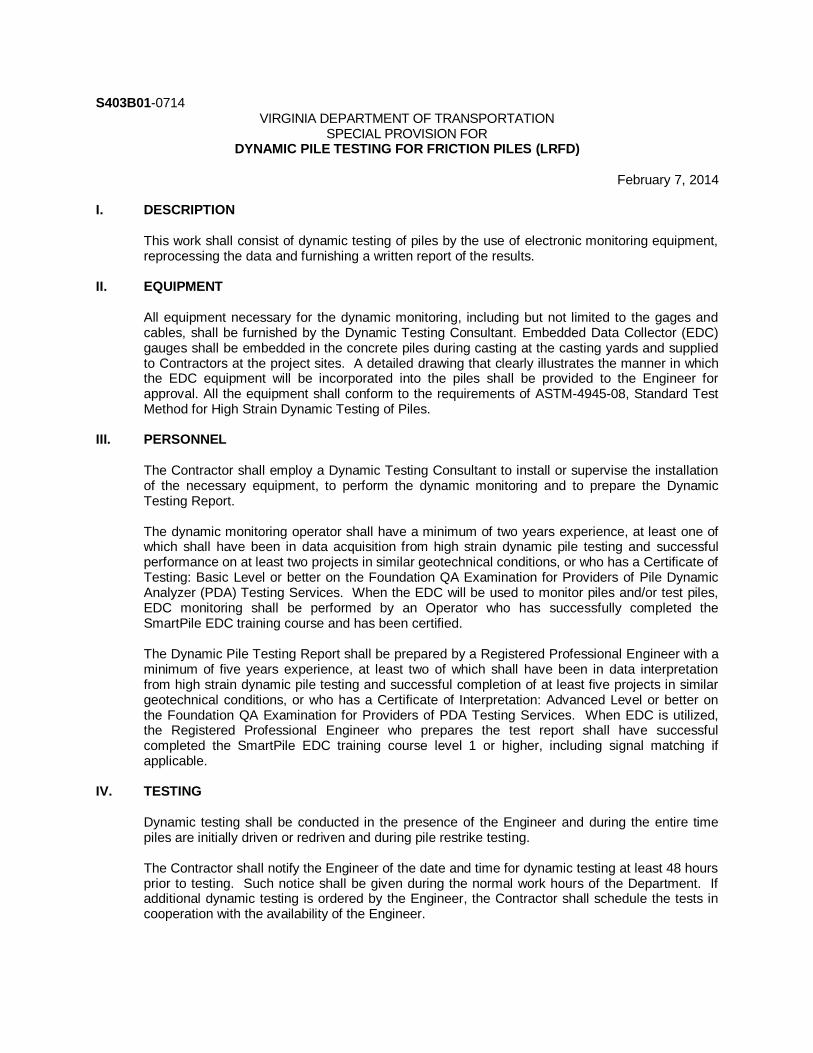
S403B01-0714 VIRGINIA DEPARTMENT OF TRANSPORTATION
SPECIAL PROVISION FOR DYNAMIC PILE TESTING FOR FRICTION PILES (LRFD)
February 7, 2014
I. DESCRIPTION
This work shall consist of dynamic testing of piles by the use of electronic monitoring equipment, reprocessing the data and furnishing a written report of the results.
II. EQUIPMENT
All equipment necessary for the dynamic monitoring, including but not limited to the gages and cables, shall be furnished by the Dynamic Testing Consultant. Embedded Data Collector (EDC) gauges shall be embedded in the concrete piles during casting at the casting yards and supplied to Contractors at the project sites. A detailed drawing that clearly illustrates the manner in which the EDC equipment will be incorporated into the piles shall be provided to the Engineer for approval. All the equipment shall conform to the requirements of ASTM-4945-08, Standard Test Method for High Strain Dynamic Testing of Piles.
III. PERSONNEL
The Contractor shall employ a Dynamic Testing Consultant to install or supervise the installation of the necessary equipment, to perform the dynamic monitoring and to prepare the Dynamic Testing Report. The dynamic monitoring operator shall have a minimum of two years experience, at least one of which shall have been in data acquisition from high strain dynamic pile testing and successful performance on at least two projects in similar geotechnical conditions, or who has a Certificate of Testing: Basic Level or better on the Foundation QA Examination for Providers of Pile Dynamic Analyzer (PDA) Testing Services. When the EDC will be used to monitor piles and/or test piles, EDC monitoring shall be performed by an Operator who has successfully completed the SmartPile EDC training course and has been certified. The Dynamic Pile Testing Report shall be prepared by a Registered Professional Engineer with a minimum of five years experience, at least two of which shall have been in data interpretation from high strain dynamic pile testing and successful completion of at least five projects in similar geotechnical conditions, or who has a Certificate of Interpretation: Advanced Level or better on the Foundation QA Examination for Providers of PDA Testing Services. When EDC is utilized, the Registered Professional Engineer who prepares the test report shall have successful completed the SmartPile EDC training course level 1 or higher, including signal matching if applicable.
IV. TESTING
Dynamic testing shall be conducted in the presence of the Engineer and during the entire time piles are initially driven or redriven and during pile restrike testing. The Contractor shall notify the Engineer of the date and time for dynamic testing at least 48 hours prior to testing. Such notice shall be given during the normal work hours of the Department. If additional dynamic testing is ordered by the Engineer, the Contractor shall schedule the tests in cooperation with the availability of the Engineer.

Where possible, splices to the pile(s) shall be made prior to the start of driving so that dynamic testing can be performed without interruption. The Contractor shall fasten a pair of transducers and a pair of accelerometers in place prior to testing or the Contractor shall have the gauges internally mounted during the casting of the pile, at the top and tip, or at the top only, by properly trained and certified installers at the discretion of the Engineer. Piles shall be driven until the soil resistance measured is 80 percent of the Nominal Pile Resistance shown on the plans and the required minimum tip elevation and penetration have been obtained or as directed by the plans, approved wave equation analysis or as approved by the Engineer. Any pile not developing the specified end of initial drive Mobilized Pile Resistance shall be left at least one foot above cut off grade to allow for restrike testing. Unless EDC is used, the Contractor shall remove the transducers and accelerometers after the dynamic testing is completed. Pile restrike testing shall be conducted no sooner than 120 hours after the pile, or any pile within a 25 foot radius, has been driven. Restrike testing shall include dynamic testing of the pile when it is redriven. The pile shall be redriven with the same pile hammer used for initial driving. The restrike driving sequence shall be performed with a warmed up hammer and shall consist of striking the pile for 20 blows or until the pile penetrates an additional 3 inches, whichever occurs first. If the soil resistance measured on restrike is less than the Nominal Pile Resistance shown on the plans, the Engineer may direct the Contractor to drive all or a portion of the remaining test pile length and repeat the restrike testing. The Contractor will be notified by the Engineer of the necessity to perform a second restrike test within 3 days of the receipt of the results from a signal-matching analysis that estimates static soil resistance and simulates static load test results from the initial restrike. All signals resulting from initial testing and any restrike testing shall be recorded and made available upon the request of the Engineer.
V. REPORTS
If requested by the Engineer, the following information shall be provided within 24 hours after completion of the testing: for each blow from the Dynamic Driving Records provide the Depth, Maximum Transferred Energy, Blows per Minute (including strokes, fuel settings, bounce chamber pressures, etc. as applicable), Maximum Tensile Stress, Maximum Compressive Stress and Pile Resistance. The Contractor shall furnish the Engineer a Dynamic Pile Testing Report with the production pile order list. The Dynamic Pile Testing Report shall include the following information for each pile tested:
Project identification and location
Location of test, Date of test, Description of the subsurface soil condition including log of nearest boring Description of the test pile Description of pile installation equipment, the lead type and any special installation equipment
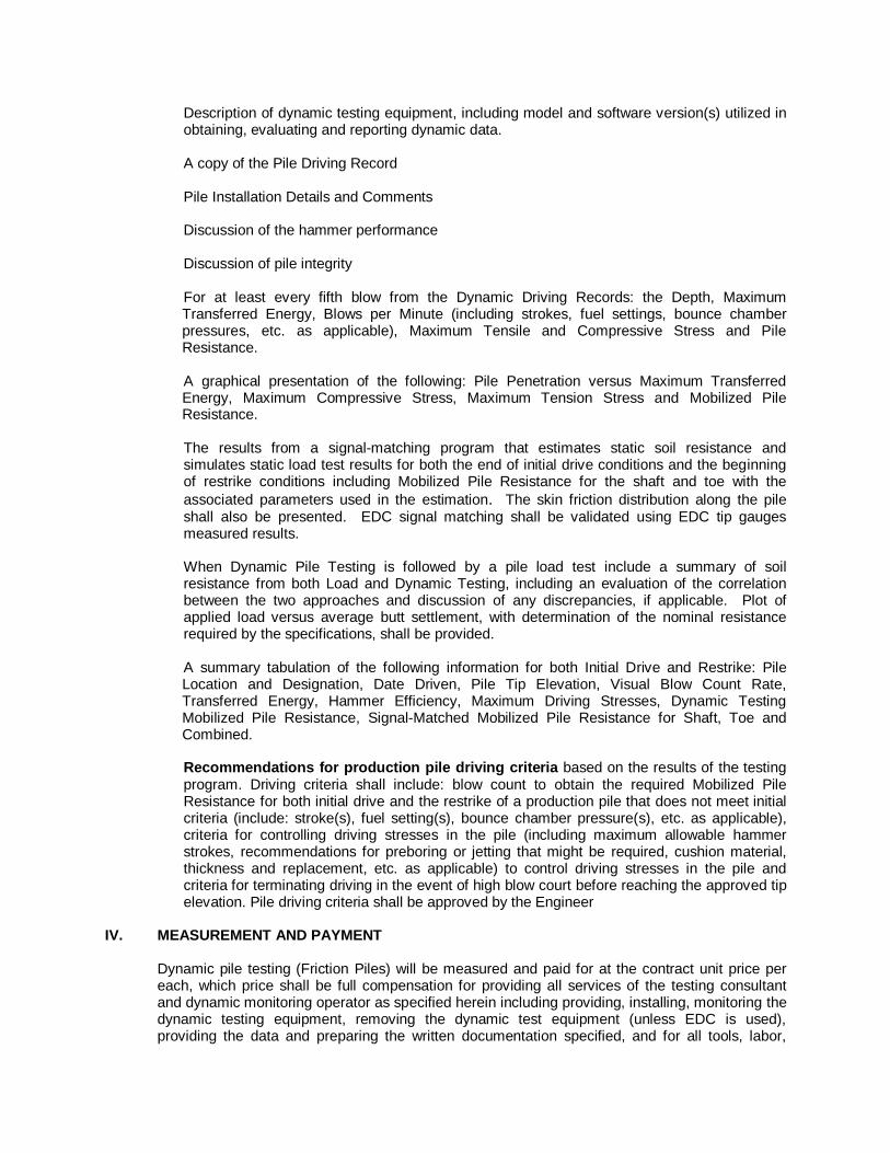
Description of dynamic testing equipment, including model and software version(s) utilized in obtaining, evaluating and reporting dynamic data. A copy of the Pile Driving Record Pile Installation Details and Comments Discussion of the hammer performance Discussion of pile integrity For at least every fifth blow from the Dynamic Driving Records: the Depth, Maximum Transferred Energy, Blows per Minute (including strokes, fuel settings, bounce chamber pressures, etc. as applicable), Maximum Tensile and Compressive Stress and Pile Resistance. A graphical presentation of the following: Pile Penetration versus Maximum Transferred Energy, Maximum Compressive Stress, Maximum Tension Stress and Mobilized Pile Resistance. The results from a signal-matching program that estimates static soil resistance and simulates static load test results for both the end of initial drive conditions and the beginning of restrike conditions including Mobilized Pile Resistance for the shaft and toe with the
associated parameters used in the estimation. The skin friction distribution along the pile shall also be presented. EDC signal matching shall be validated using EDC tip gauges measured results. When Dynamic Pile Testing is followed by a pile load test include a summary of soil resistance from both Load and Dynamic Testing, including an evaluation of the correlation between the two approaches and discussion of any discrepancies, if applicable. Plot of applied load versus average butt settlement, with determination of the nominal resistance required by the specifications, shall be provided. A summary tabulation of the following information for both Initial Drive and Restrike: Pile Location and Designation, Date Driven, Pile Tip Elevation, Visual Blow Count Rate, Transferred Energy, Hammer Efficiency, Maximum Driving Stresses, Dynamic Testing Mobilized Pile Resistance, Signal-Matched Mobilized Pile Resistance for Shaft, Toe and Combined. Recommendations for production pile driving criteria based on the results of the testing program. Driving criteria shall include: blow count to obtain the required Mobilized Pile Resistance for both initial drive and the restrike of a production pile that does not meet initial criteria (include: stroke(s), fuel setting(s), bounce chamber pressure(s), etc. as applicable), criteria for controlling driving stresses in the pile (including maximum allowable hammer strokes, recommendations for preboring or jetting that might be required, cushion material, thickness and replacement, etc. as applicable) to control driving stresses in the pile and criteria for terminating driving in the event of high blow court before reaching the approved tip elevation. Pile driving criteria shall be approved by the Engineer
IV. MEASUREMENT AND PAYMENT
Dynamic pile testing (Friction Piles) will be measured and paid for at the contract unit price per each, which price shall be full compensation for providing all services of the testing consultant and dynamic monitoring operator as specified herein including providing, installing, monitoring the dynamic testing equipment, removing the dynamic test equipment (unless EDC is used), providing the data and preparing the written documentation specified, and for all tools, labor,

materials, and incidentals necessary to complete the work. This price shall also include all work and equipment necessary to drive the pile during restrike testing, and any additional driving required should the required soil resistance not be obtained. A second restrike test, if required, will be paid for at 2/3 of the contract unit price of the Dynamic Pile Test (Friction Piles). Payment will be made under: Pay Item
Pay Unit
Dynamic Pile Test (Friction Piles) Each

S403C01-0714 VIRGINIA DEPARTMENT OF TRANSPORTATION
SPECIAL PROVISION FOR DYNAMIC PILE TESTING FOR END BEARING PILES (LRFD)
February 7, 2014
I. DESCRIPTION
This work shall consist of dynamic testing of piles by the use of electronic monitoring equipment, reprocessing the data and furnishing a written report of the results.
II. EQUIPMENT All equipment necessary for the dynamic monitoring such as gages, cables, etc. shall be furnished by the Dynamic Testing Consultant. The equipment shall conform to the requirements of ASTM-4945-08, Standard Test Method for High Strain Dynamic Testing of Piles.
III. PERSONNEL The Contractor shall employ a Dynamic Testing Consultant to install or supervise the installation of the necessary equipment, to perform the dynamic monitoring and to prepare the Dynamic Testing Report. The dynamic monitoring operator shall have a minimum of two years experience, at least one of which shall have been in data acquisition from high strain dynamic pile testing and successful performance on at least two projects in similar geotechnical conditions, or who has a Certificate of Testing: Basic Level or better on the Foundation QA Examination for Providers of Pile Dynamic Analyzer (PDA) Testing Services. The Dynamic Pile Testing Report shall be prepared by a Registered Professional Engineer with a minimum of five years experience, at least two of which shall have been in data interpretation from high strain dynamic pile testing and successful completion of at least five projects in similar geotechnical conditions, or who has a Certificate of Interpretation: Advanced Level or better on the Foundation QA Examination for Providers of PDA Testing Services.
IV. TESTING Dynamic testing shall be conducted in the presence of the Engineer and during the entire time piles are initially driven or redriven and during pile restrike testing. The Contractor shall notify the Engineer of the date and time for dynamic testing at least 48 hours prior to testing. Such notice shall be given during the normal work hours of the Department. If additional dynamic testing is ordered by the Engineer, the Contractor shall schedule the tests in cooperation with the availability of the Engineer. Where possible, splices to the pile(s) shall be made prior to the start of driving so that dynamic testing can be performed without interruption. The Contractor shall fasten a pair of transducers and a pair of accelerometers in place prior to testing. Piles shall be driven until the soil resistance measured is equal to or greater than the Nominal Pile Resistance as measured during driving shown on the plans and the required minimum tip elevation and penetration have been obtained or as directed by the plans, approved wave equation analysis or as approved by the Engineer. The Contractor shall remove the transducers and accelerometers after the dynamic testing is completed.

All signals resulting from initial testing and any restrike testing shall be recorded and made available upon the request of the Engineer.
V. REPORTS If requested by the Engineer, the following information shall be provided within 24 hours after completion of the testing: for each blow from the Dynamic Driving Records provide the Depth, Maximum Transferred Energy, Blows per Minute (include strokes, fuel settings, bounce chamber pressures, etc. as applicable), Maximum Tensile Stress, Maximum Compressive Stress and Pile Capacity. The Contractor shall furnish the Engineer a Dynamic Pile Testing Report with the production pile order list. The Dynamic Pile Testing Report shall include the following information for each pile tested:
Project identification and location
Location of test, Date of test, Description of the subsurface soil condition including log of nearest boring Description of the test pile Description of pile installation equipment, the lead type and any special installation equipment Description of dynamic testing equipment, including model and software version(s) utilized in obtaining, evaluating and reporting dynamic data. A copy of the Pile Driving Record Pile Installation Details and Comments Discussion of the hammer performance Discussion of pile integrity For at least every fifth blow from the Dynamic Driving Records: the Depth, Maximum Transferred Energy, Blows per Minute (including strokes, fuel settings, bounce chamber pressures, etc. as applicable), Maximum Tensile and Compressive Stress and Pile Capacity A graphical presentation of the following: Pile Penetration versus Maximum Transferred Energy, Maximum Compressive Stress, Maximum Tension Stress and Mobilized Pile Capacity The results from a signal-matching program that estimates static soil resistance and simulates static load test results including Mobilized Pile Capacity for the shaft and toe with the associated parameters used in the estimation A summary tabulation of the following information: Pile Location and Designation, Date Driven, Pile Tip Elevation, Visual Blow Count Rate, Transferred Energy, Hammer Efficiency, Maximum Driving Stresses, Dynamic Testing Mobilized Pile Capacity, Signal-Matched Mobilized Pile Capacity for Shaft, Toe and Combined.

Recommendations for production pile driving criteria based on the results of the testing program. Driving criteria shall include: blow count to obtain the required Mobilized Pile Capacity (include: stroke(s), fuel setting(s), bounce chamber pressure(s), etc. as applicable), criteria for controlling driving stresses in the pile including maximum allowable hammer stroke to control driving stresses in the pile and criteria for terminating driving in the event of high blow court before reaching the approved tip elevation. Pile driving criteria shall be approved by the Engineer.
IV. MEASUREMENT AND PAYMENT Dynamic pile testing (End Bearing) will be measured and paid for at the contract unit price per each, which price shall be full compensation for providing all services of the testing consultant and dynamic monitoring operator as specified herein including providing, installing, monitoring and removing the dynamic testing equipment, for providing the data and preparing the written documentation specified, and for all tools, labor, materials, and incidentals necessary to complete the work. Payment will be made under: Pay Item
Pay Unit
Dynamic Pile Test (End Bearing) Each

S407B00-0708 VIRGINIA DEPARTMENT OF TRANSPORTATION
SPECIAL PROVISION FOR TOOTH EXPANSION JOINT
January 14, 2008c
I. DESCRIPTION
This work shall consist of furnishing and installing tooth expansion joints in accordance with these specifications and in conformity with the lines, grades and locations shown on the plans or established by the Engineer.
II. MATERIALS Materials shall conform to the requirements of Sections 212 and 226 of the Specifications.
III. PROCEDURES Working drawings showing complete details and dimensions of the tooth expansion joint and other pertinent information, shall be submitted to the Engineer for review in accordance with Section 105.10 of the Specifications. Fabrication shall conform to the requirements of Section 407 of the Specifications. Tooth expansion joints shall seal the deck surface, gutters, curbs, and parapets to prevent water and other contaminants from seeping onto the substructure. Final sealing of the finished joint shall be completed as soon as practicable after installation. Surfaces exposed to roadway traffic shall have antiskid provisions.
IV. MEASUREMENT AND PAYMENT Tooth expansion joint will be paid for in linear feet measured along the pavement surface from out to out of the deck slab, complete-in-place for the tooth thickness specified. Payment shall be full compensation for furnishing and installing tooth expansion joint and all necessary components and anchoring devices and for all materials, labor, tools, equipment and incidentals necessary to complete the work. Payment will be made under:
Pay Item
Pay Unit
Tooth Expansion Joint (Tooth thickness) Linear Foot

S504B01-0314 VIRGINIA DEPARTMENT OF TRANSPORTATION
SPECIAL PROVISION FOR CG-12 DETECTABLE WARNING SURFACE
September 18, 2013
I. DESCRIPTION
This work shall consist of providing all labor, tools, equipment, and materials required to furnish and install detectable warning surfaces in the location(s) specified on the plans or in the proposal. The Contractor shall perform the work according to the details shown on the plans or in this special provision, Section 504 of the Specifications, and as directed by the Engineer.
II. MATERIALS Materials shall conform to the requirements of Section 504 of the Specifications except as follows:
Permanent, durable materials suitable for heavy traffic outdoor areas or concrete pavers approved by the Department may be used to construct the detectable warning surfaces where called for in the plans and other contract documents. Concrete paver units shall conform to the current ASTM C936 specifications and the details and requirements shown in the plans. Other durable materials shall be in accordance with Department approved manufacturer’s design and specification requirements.
Products not on the Departments Materials Approved Product list shall be submitted to the Standards & Special Design Section and the appropriate District Materials Engineer for approval prior to use. All detectable warning surfaces shall meet the ADA Standards as set forth by the United States Access Board. The detectable warning shall be “safety yellow” unless otherwise noted in the plans or directed by the Engineer. When visual contrast other than “safety yellow” is specified in the plans or contract documents, the detectable warning surfaces shall contrast visually with adjacent walking surfaces either light-on-dark, or dark-on-light. Verification of visual contrast is required prior to installation.
III. PROCEDURES Construct sidewalk ramp according to Section 504 of the Specifications except for detectable warning/truncated domes that shall be furnished or constructed in accordance with the details in this specification, the manufacturer’s recommendations, the Standard Drawings and the Plans.
All permanent installations of detectable warning surfaces shall be “wet set” in freshly placed concrete. Surface mounted detectable warning surfaces are permitted only for temporary installations where the detectable warning will be in service 6 months or less.
The Contractor shall provide the Department with the manufacturers installation instructions.

IV. MEASUREMENT AND PAYMENT CG-12 Detectable Warning Surface will be measured in square yards and paid for at the contract unit price per square yard, complete-in-place. This price shall be full compensation for furnishing and installing approved truncated dome finished materials including but not limited to concrete pavers, other Department approved materials, integral visual contrast, dowels and all other labor, tools, equipment, materials and incidentals necessary to fully complete the work. Payment will be made under:
Pay Item
Pay Unit
CG-12 Detectable Warning Surface Square yard
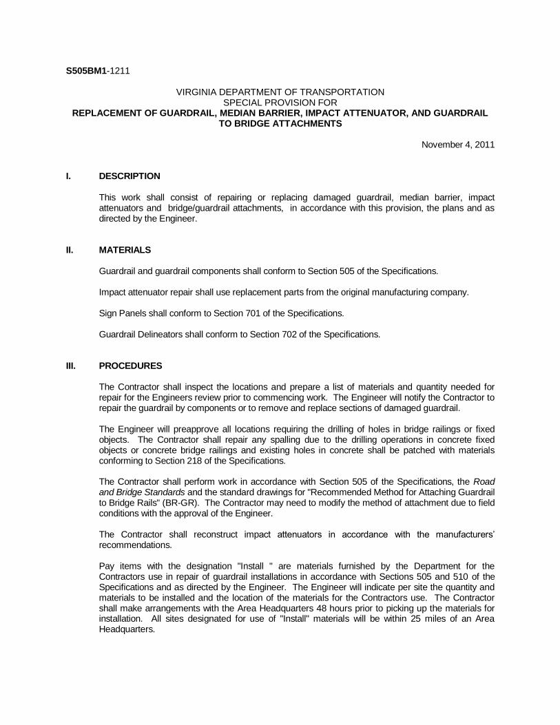
S505BM1-1211
VIRGINIA DEPARTMENT OF TRANSPORTATION SPECIAL PROVISION FOR
REPLACEMENT OF GUARDRAIL, MEDIAN BARRIER, IMPACT ATTENUATOR, AND GUARDRAIL TO BRIDGE ATTACHMENTS
November 4, 2011
I. DESCRIPTION
This work shall consist of repairing or replacing damaged guardrail, median barrier, impact attenuators and bridge/guardrail attachments, in accordance with this provision, the plans and as directed by the Engineer.
II. MATERIALS Guardrail and guardrail components shall conform to Section 505 of the Specifications. Impact attenuator repair shall use replacement parts from the original manufacturing company. Sign Panels shall conform to Section 701 of the Specifications. Guardrail Delineators shall conform to Section 702 of the Specifications.
III. PROCEDURES The Contractor shall inspect the locations and prepare a list of materials and quantity needed for repair for the Engineers review prior to commencing work. The Engineer will notify the Contractor to repair the guardrail by components or to remove and replace sections of damaged guardrail. The Engineer will preapprove all locations requiring the drilling of holes in bridge railings or fixed objects. The Contractor shall repair any spalling due to the drilling operations in concrete fixed objects or concrete bridge railings and existing holes in concrete shall be patched with materials conforming to Section 218 of the Specifications. The Contractor shall perform work in accordance with Section 505 of the Specifications, the Road and Bridge Standards and the standard drawings for "Recommended Method for Attaching Guardrail to Bridge Rails" (BR-GR). The Contractor may need to modify the method of attachment due to field conditions with the approval of the Engineer. The Contractor shall reconstruct impact attenuators in accordance with the manufacturers’ recommendations. Pay items with the designation "Install " are materials furnished by the Department for the Contractors use in repair of guardrail installations in accordance with Sections 505 and 510 of the Specifications and as directed by the Engineer. The Engineer will indicate per site the quantity and materials to be installed and the location of the materials for the Contractors use. The Contractor shall make arrangements with the Area Headquarters 48 hours prior to picking up the materials for installation. All sites designated for use of "Install" materials will be within 25 miles of an Area Headquarters.

Damaged and salvaged guardrail materials shall become the property of the Contractor and shall be disposed of in accordance with Section 106 of the Specifications, unless otherwise specified. All unused or abandoned guardrail post holes shall be backfilled to existing ground level with approved material placed in layers not more than 4 inches in height. Each layer shall be compacted by tamping. All unused or abandoned post holes in paved shoulder shall be backfilled, compacted and sealed with a fine asphalt plant mix no larger than SM-9.5A. No measurement or payment will be made for this work all cost shall be included in other items of work. Cracks in the shoulder as a result of driving or removing guardrail posts shall be repaired at no additional cost to the Department. In soil or aggregate stabilized shoulders, cracks and voids around the posts shall be filled with like material and thoroughly compacted. In asphalt paved or surfaced treated shoulders, cracks and voids around post shall be filled, compacted, and sealed with fine asphalt plant mix no larger than SM-9.5A. No measurement or payment will be made for this work all cost shall be included in other items of work. The Contractor shall ensure all existing guardrail and end treatments left in place are correct and all bolts, are torqued properly and cables are taut. All guardrail to be removed shall start at the run off end and proceed to the run on end terminal, unless otherwise approved by the Engineer. Guardrail installation shall start at the run on end terminal and proceed to the run off end, unless otherwise approved by the Engineer. All guardrail that is removed during the course of the work day shall be replaced the same work day, unless otherwise approved by the Engineer. No fixed objects, which includes but not limited to bridge parapet walls, piers, blunt ends, sign structures, shall not be left unprotected. The Contractor shall use an approved NCHRP 350 approved, temporary guardrail terminal or impact attenuator service before the end of each workday to protect traffic from the fixed object. No measurement or payment will be made for temporary guardrail terminal or impact attenuator service, all cost shall be included in other items of work. The Contractor shall plan and prosecute the work accordingly. No uncompleted sections of guardrail shall be left over weekends or holidays, unless otherwise approved by the Engineer. The Contractor shall plan and prosecute the work accordingly. All aggregate and other material placed at the guardrail terminal end section shall be included in the pay item "guardrail terminal site preparation". Build-up or debris under existing guardrail in areas where guardrail is to be replaced shall be removed to the original shoulder cross slope, in accordance with the contract Special Provisions. Reset existing guardrail shall require the removal and disassembly of the existing w-beam and blockouts to redrill the post for the reassembly of the blockouts and w-beam to the required height specified. In the event the existing post or blockouts are determined non-compliance with the standard drawings or specifications new post or blockouts will be required and will be measured and paid for separately.

IV. MEASUREMENT AND PAYMENT
Guardrail, Reuse Guardrail, Radial Guardrail, Median Barrier, Radial Median Barrier, Cable Barrier, Guardrail Terminal, Median Barrier Terminal and Fixed Object Attachment will be measured and paid for in accordance with Section 505 of the Specifications.
Remove Guardrail, Reset Guardrail and Install Guardrail will be measured and paid for in accordance with Section 510 of the Specifications.
Sign Panel and Guardrail Delineator will be measured and paid for respectively in accordance with Sections 701 and 702 of the Specifications.
Drill Hole will be measured in units of each and will be paid for at the contract unit price per each, which unit price shall include drilling of hole, repairing spalled areas, and patching abandoned holes.
Re-Tension Existing Cable GR. will be measured in units of each per cable system and will be paid for at the contract unit bid price per each for the standard specified, which shall include re-tensioning the existing cable.
The items below will include removal and disposal of existing guardrail components in the unit price bid.
Guardrail Post, Guardrail Blockout and Offset Block will be measured in units of each for the type and standard specified and will be paid for at the contract unit price per each which price shall include furnishing and installing post, blockout and offset block and hardware.
W Beam Terminal Connector, W Beam End Section and Terminal Connector will be measured in units of each for the standard or type specified and will be paid for at the contract unit price per each, which shall include furnishing and placement, and mounting hardware.
Rubrail will be measured in units of linear feet for the type specified and will be paid for at the contract unit price per linear foot, which shall include furnishing and placement of type rubrail specified, and mounting hardware.
Guardrail Beam and Radial Guardrail Beam will be measured in units of linear feet for the type and standard specified and will be paid for in units of linear foot, which unit price shall include furnishing the type and standard beam specified, and mounting hardware.
Plate will be measured in units of each for the type and standard specified and which unit paid shall include furnishing and placing the specified plate and mounting hardware.
Cable will be will be measured in units of linear feet for the type and standard specified and will be paid for in units of linear foot, which unit price bid shall include furnishing the type and standard cable specified, and mounting hardware.
Realign Post will be measured in units of each and will be paid for at the contract bid price per each, which unit price bid shall include disconnecting and reconnecting rail and realigning the post.
BR-GR Attachment will be measured in units of each, for the type specified per attachment location and will be paid for at the contract unit bid price per each attachment, which shall include furnishing and installing guardrail, blockouts, connector, and hardware.
Steel Tube will be measured in units of each for the type and standard specified and will be paid for at the contract bid price per each, which shall include furnishing and placing of the steel tube, and excavation.
Assembly will be measured in units of each for the type and standard specified and will be paid for at the contract unit bid price per each, which shall include furnishing and placing the specified assembly.
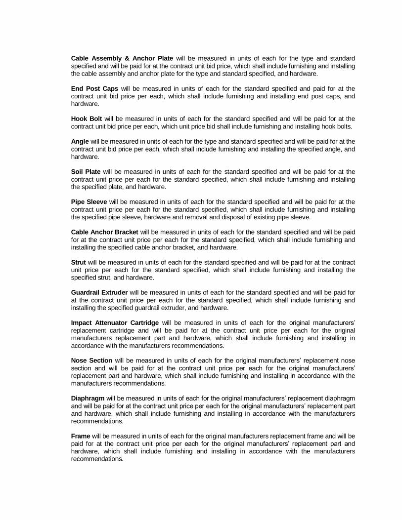
Cable Assembly & Anchor Plate will be measured in units of each for the type and standard specified and will be paid for at the contract unit bid price, which shall include furnishing and installing the cable assembly and anchor plate for the type and standard specified, and hardware. End Post Caps will be measured in units of each for the standard specified and paid for at the contract unit bid price per each, which shall include furnishing and installing end post caps, and hardware. Hook Bolt will be measured in units of each for the standard specified and will be paid for at the contract unit bid price per each, which unit price bid shall include furnishing and installing hook bolts. Angle will be measured in units of each for the type and standard specified and will be paid for at the contract unit bid price per each, which shall include furnishing and installing the specified angle, and hardware. Soil Plate will be measured in units of each for the standard specified and will be paid for at the contract unit price per each for the standard specified, which shall include furnishing and installing the specified plate, and hardware. Pipe Sleeve will be measured in units of each for the standard specified and will be paid for at the contract unit price per each for the standard specified, which shall include furnishing and installing the specified pipe sleeve, hardware and removal and disposal of existing pipe sleeve. Cable Anchor Bracket will be measured in units of each for the standard specified and will be paid for at the contract unit price per each for the standard specified, which shall include furnishing and installing the specified cable anchor bracket, and hardware. Strut will be measured in units of each for the standard specified and will be paid for at the contract unit price per each for the standard specified, which shall include furnishing and installing the specified strut, and hardware. Guardrail Extruder will be measured in units of each for the standard specified and will be paid for at the contract unit price per each for the standard specified, which shall include furnishing and installing the specified guardrail extruder, and hardware. Impact Attenuator Cartridge will be measured in units of each for the original manufacturers’ replacement cartridge and will be paid for at the contract unit price per each for the original manufacturers replacement part and hardware, which shall include furnishing and installing in accordance with the manufacturers recommendations. Nose Section will be measured in units of each for the original manufacturers’ replacement nose section and will be paid for at the contract unit price per each for the original manufacturers’ replacement part and hardware, which shall include furnishing and installing in accordance with the manufacturers recommendations. Diaphragm will be measured in units of each for the original manufacturers’ replacement diaphragm and will be paid for at the contract unit price per each for the original manufacturers’ replacement part and hardware, which shall include furnishing and installing in accordance with the manufacturers recommendations. Frame will be measured in units of each for the original manufacturers replacement frame and will be paid for at the contract unit price per each for the original manufacturers’ replacement part and hardware, which shall include furnishing and installing in accordance with the manufacturers recommendations.
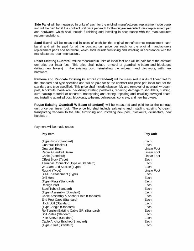
Side Panel will be measured in units of each for the original manufacturers’ replacement side panel and will be paid for at the contract unit price per each for the original manufacturers’ replacement part and hardware, which shall include furnishing and installing in accordance with the manufacturers recommendations. Sand Barrel will be measured in units of each for the original manufacturers replacement sand barrel and will be paid for at the contract unit price per each for the original manufacturers replacement parts and hardware, which shall include furnishing and installing in accordance with the manufacturers recommendations. Reset Existing Guardrail will be measured in units of linear feet and will be paid for at the contract unit price per linear foot. This price shall include removal of guardrail w-beam and blockouts, drilling new hole(s) in the existing post, reinstalling the w-beam and blockouts, with new hardware. Remove and Relocate Existing Guardrail (Standard) will be measured in units of linear feet for the standard and type specified and will be paid for at the contract unit price per linear foot for the standard and type specified. This price shall include disassembly and removal of guardrail w-beam, post, blockouts, hardware, backfilling existing postholes, repairing damage to shoulders, curbing, curb backup material or concrete, transporting and storing; repairing and installing salvaged beam; and installing guardrail post, blockouts, w-beam, delineators, concrete, and new hardware. Reuse Existing Guardrail W-Beam (Standard) will be measured and paid for at the contract unit price per linear foot. The price bid shall include salvaging and installing existing W-beam, transporting w-beam to the site, furnishing and installing new post, blockouts, delineators, new hardware. Payment will be made under:
Pay Item
Pay Unit
(Type) Post (Standard) Each Guardrail Blockout Each Guardrail Beam Linear Foot Radial Guardrail Beam Linear Foot Cable (Standard) Linear Foot Offset Block (Type) Each Terminal Connector (Type or Standard) Each W Beam End Section (Type) Each Rubrail (Type) Linear Foot BR-GR Attachment (Type) Each Drill Hole Each (Type) Plate (Standard) Each Realign Post Each Steel Tube (Standard) Each (Type) Assembly (Standard) Each Cable Assembly & Anchor Plate (Standard) Each End Post Caps (Standard) Each Hook Bolt (Standard) Each (Type) Angle (Standard) Each Re-Tension Existing Cable GR. (Standard) Each Soil Plates (Standard) Each Pipe Sleeve (Standard) Each Cable Anchor Bracket (Standard) Each (Type) Strut (Standard) Each

Guardrail Extruder (Standard) Each Impact Attenuator Cartridge Each Nose Section Each Diaphragm Each Side Panel Each Frame Each Sand Barrel Each Reset Existing Guardrail Linear Foot Remove And Relocated Existing Guardrail (Standard) Linear Foot Reuse Existing Guardrail W-Beam (Standard) Linear Foot
S512N00-1213
VIRGINIA DEPARTMENT OF TRANSPORTATION SPECIAL PROVISION FOR
POLICE ASSISTANCE FOR PAVING OPERATIONS
November 6, 2013 SECTION 512—MAINTAINING TRAFFIC of the Specifications is amended as follows:
SECTION 512.03—PROCEDURES is amended to include the following: (s) Police Assistance for Paving Operations: Police assistance may be required at times for
paving operations in work zones during the life of this contract to ensure the safety of the traveling public and construction personnel. The Contract will specify where police assistance is required in accordance with the following:
1. Interstate Routes: Where the Contract specifies State Police assistance is required,
VDOT will notify the State Police contact person. VDOT will pay for the uniformed police officer(s).
2. Major Primary Routes (Traffic Groups XII and above): Where the Contract
specifies police assistance is required, VDOT will notify the police contact person. VDOT will pay for the uniformed police officer(s).
3. Other Primary Routes: The Contract will list the locations where police assistance is
required and whether it is the Contractor’s responsibility or VDOT’s responsibility to notify the police contact person and pay for the uniformed police officer(s).
4. Secondary Routes: The Contractor will have the option whether to flag intersections
or use uniformed police officers if this is not specified otherwise in the Contract. If the Contractor determines police assistance is necessary, he shall obtain this assistance at no cost to VDOT.
Where VDOT determines police assistance will be required on specific routes, the Contract will list the locations and whether it is the Contractor’s responsibility or VDOT’s responsibility to notify the police contact person and pay for the uniformed police officer(s). If the Contract does not state the responsible party, VDOT will be responsible.
If during the life of this contract the Engineer determines that police assistance is necessary at a specific location not listed in the Contract, VDOT will notify the police contact person. VDOT will pay for the uniformed police officer(s). If during the life of this contract the Contractor determines that police assistance is necessary at a specific location not listed in the Contract, he shall notify the police contact person. The Contractor shall obtain this assistance at no cost to VDOT.

S515B03-1215
VIRGINIA DEPARTMENT OF TRANSPORTATION SPECIAL PROVISION FOR
COLD PLANING (MILLING) ASPHALT CONCRETE OPERATIONS
December 3, 2015 I. DESCRIPTION
This provision shall govern cold planing (milling) asphalt concrete operations in preparation for pavement repair and/or pavement overlay. Cold planing of asphalt concrete pavement shall be performed according to Section 515 of the Specifications and the requirements herein.
II. GENERAL PROCEDURES The Contractor is permitted to perform either regular pavement planing or performance pavement planing to the contract specified depth or as directed by the Engineer in order to provide a uniform sound substrate prior to paving roadways designated in the schedules according to Section 315 of the Specifications, the requirements herein, or elsewhere in the Contract documents. A. Regular and Performance Planing
The following general conditions apply to either type of cold pavement planing:
Limitations of operations for planing shall be performed according to the requirements of Section 108.02 of the Specifications, other Contract specific requirements, and as specified herein. Where the depth of planing designated in the Contract or directed by the Engineer is 2 inches or less, the Contractor shall have the option of planing the abutting lane or shoulder on alternate days or squaring up the planing operation at the end of each work shift. However, abutting lanes or shoulders shall be planed and squared up regardless of planing depth prior to holidays or any temporary shutdowns. Where the depth of planing designated in the Contract or directed by the Engineer is greater than 2 inches in the Contract documents, the Contractor shall square up the planing operation at the end of each workday or plane adjacent lanes including abutting shoulders within the same day for the length of that day’s planing operation. The Contractor will not be permitted to plane a portion of the width of a travel lane, ramp, loop or shoulder and leave it unpaved and open to traffic. Abutting shoulders may also be planed during single and multiple lane planing operations. Planing operations shall be planned and performed to maintain positive drainage according to the requirements of Section 315.05(c) of the Specifications. In the event an emergency or an unforeseen circumstance such as equipment failure or breakdown occurs during the Contractor’s operations and such emergency or unforeseen circumstance within his control prevents the Contractor from squaring up the planed surface on adjacent lanes prior to a holiday or temporary shutdown, any additional signage, traffic control devices or temporary markings or markers required to protect the traveling public shall be the Contractor’s responsibility and at his expense.
Where uneven pavement joints exist either transversely or longitudinally at the edges of travel lanes, the Contractor shall provide advance warning signage and traffic control devices to inform the traveling public according to the details provided in the Contract for the scope of operation he is performing. The cost for such advance warning signage and traffic control devices shall be included in the cost of other appropriate items Where appropriate according to contract requirements and site specific conditions, the existing asphalt concrete layers shall be planed to permit the transition of the top course of the asphalt concrete overlay according to the details of the ACOT-1 Standard. Any sub-courses termination may be notched into the existing pavement or blended with the next course of pavement.
B. Performance Planing Only Limitations: When the Contractor elects to performance plane on roadways specified to be planed to a depth of 2 inches or less, the Contractor shall performance plane only that amount of pavement which can be paved back within the time allowance specified herein for completion of planing the roadway or portion of roadway. The Contractor is required to perform pavement surface testing as specified in Section 515.04 of the Specifications to verify the Contractor has achieved the acceptable surface texture specified in that Section prior to opening the performance planed surface to traffic. Additional traffic control devices and signage required for the extended pave back time allowance specified herein for performance planing operations versus the traffic control devices required for the pave back operations for regular pavement planing operations specified herein shall be at the Contractor’s expense.
III. ROADWAY CLASSIFICATION LIMITATIONS The following restrictions, based on the type of roadway, shall apply:
A. All Interstates and other Limited Access Roadways including Ramps and Loops posted at 55 Mph or Greater
1. Regular planing and performance planing in multiple lanes
The Contractor shall plan, execute and maintain pavement planing operations to avoid trapping water on the roadway. On roadways with a combination of 3 or 4 lanes and shoulders (i.e. 2 travel lanes and 1 or 2 shoulders in one direction) where the travel lanes and shoulders will not be completely planed to drain prior to the start of paving operations, planing shall be performed so that water will not pond on the travel surface. When the contract does not include the removal of the shoulder at the specific roadway planing location, the Contractor shall cut drainage outlets through the shoulder at locations the Engineer designates (excluding curb and gutter sections) for those portions of the planed roadway that are to be opened to traffic. The Contractor shall restore the shoulders to their original grades once paving operations are completed, unless otherwise directed by the Engineer. The cost for cutting and restoring roadway shoulders shall be included in the price bid for other items of work. On roadways with a combination of 5 or more lanes and shoulders (i.e. 3 or more travel lanes and 2 shoulders in one direction, the extent to which the interior lanes shall be planed will be such that the planed portions can be repaved within the work-zone time limits unless provisions are made to mitigate the ponding of

water (i.e., milling adjacent lane(s) and shoulders or cutting drainage outlets through the shoulder). Ramps and exits shall be planed in such a manner that an even longitudinal joint (elevation difference of greater than 1 inch) is not left for vehicles to cross within the posted speed limits in a “run on” situation. To prevent this, the Contractor can plane ramps and exits to the extent that the joint line between new and existing pavement crossed by traffic is traversed at an angle close to ninety (90) degrees per the ACOT-1 Standard for temporary transverse joints or can perform tapered planing along the ramp/exit longitudinal joint to provide a smooth transition for vehicles to cross, or can square up ramp or exit pavement with the adjacent mainline lane at the time of installation. The following additional restrictions will apply to roadways where regular pavement planing is applicable: ● The Contractor will be limited in the case of regular pavement planing,
whether in a single lane or multiple lane operation, to only that amount of pavement that can be paved back within 24 hours of completion of planing that roadway or portion of roadway. If the Contractor does not pave back the planed travel lanes within 24 hours from the end of the regular planing operation, the Department will assess a disincentive in the amount of $5,000 for each calendar day the planed travel lane surface is not paved back, including Sundays and Holidays.
● The Contractor shall pave all roadways, ramps and loops planed during the
week before that weekend. ● On roadways with a combination of 4 or more lanes and shoulders (i.e. 2 or
more travel lanes and 2 shoulders) in one direction, all travel lanes must be paved back before the weekend. Up to two thousand five hundred (2,500) feet of shoulder may be planed and left over the weekend provided the portion of planed shoulder left unpaved over the weekend is paved within 24 hours after the end of the weekend period.
The following additional restrictions will apply to roadways where performance pavement planing is planned by the Contractor: ● Performance planing may be performed in multiple lanes across the entire
widths of the lanes up 4 miles of travel lane unless otherwise stated in the Contract. Performance planed travel lanes surfaces must be paved back within 96 hours from the end of the performance planing operation. If the Contractor does not pave back the planed travel lanes within 96 hours from the end of the performance planing operation, the Department will assess a disincentive in the amount of $5,000 for each calendar day the planed travel lane surface is not paved back, including Sundays and Holidays.
● Where the Contractor decides to performance plane multiple lanes, the
Contractor shall be responsible for furnishing and installing advance warning signage and traffic control devices to inform the traveling public according to the details provided in the Contract. Temporary pavement markings and markers used for lane demarcation on performance planed surfaces will be in accordance with Section 704.04 of the Specifications and the Special Provision for SECTION 704—PAVEMENT MARKINGS AND MARKERS included in the Contract. The cost for such warning devices and advance signage required by multiple lane planing operations shall be included in the

cost of other appropriate items unless otherwise specified in the contract by a specific pay item(s) for separate payment.
B. Non-Limited Access Roadways with an ADT of 10,000 or Greater (Traffic Group XV and above) and a Posted Speed Limit of 45 Mph or Greater
1. Regular planing and performance planing in multiple lanes
The Contractor shall plan and procede with the pavement planing operation to avoid trapping water on the roadway. On roadways with a combination of 3 or 4 lanes and shoulders (i.e. 2 travel lanes and 1 or 2 shoulders) in one direction where the travel lanes and shoulders will not be completely planed prior to the start of paving operations, planing operations shall be performed so water will not pond on the travel surface. When the contract does not include the removal of the shoulder, the Contractor shall cut drainage outlets through the shoulder at locations the Engineer designates, excluding curb and gutter sections, for those portions of the planed roadway that are to be opened to traffic. The Contractor shall restore the shoulders to their original grades once paving operations are completed, unless otherwise directed by the Engineer. The cost for cutting and restoring the roadway shoulder shall be included in the price bid for other items of work. On roadways with a combination of 5 or more lanes and shoulders (i.e. 3 or more travel lanes and 2 shoulders in one direction), the extent of pavement planing on the interior lanes shall be such that the planed surface can be repaved within the timeframe of the work-zone time limits unless provisions are made to mitigate the ponding of water (i.e.planing adjacent lane(s) to mitigate the ponding of water). The following additional restrictions will apply to roadways where performance pavement planing is planned by the Contractor: ● Performance planing may be performed in multiple lanes across the entire
widths of the lanes up a total of 4 miles of travel lane unless otherwise stated in the Contract.
● Performance planed travel lane surfaces must be paved back within 10 days
from the start of the performance planing operation. ● Where the Contractor decides to performance plane multiple lanes, the
Contractor shall be responsible for furnishing and installing advance warning signage and traffic control devices to inform the traveling public according to the details provided in the Contract. The cost for such warning devices and advance signage required by multiple lane planing operations shall be included in the cost of other appropriate items unless otherwise specified in the contract by a specific pay item(s) for separate payment. Temporary pavement markings required by such operations will be handled according to the requirements of Section 704.04 and the Special Provision for SECTION 704—PAVEMENT MARKINGS AND MARKERS included in the Contract.
The following additional restrictions will apply to roadways where regular pavement planing is applicable: ● The Contractor will be limited whether in a single lane or multiple lane
operation, to only that amount of pavement that can be paved back within 24 hours of completion of planing that roadway or portion of roadway.
● The Contractor shall pave all roadways that have been regular planed during the week before that weekend.
● On roadways with a combination of 4 or more lanes and shoulders (i.e. 2 or
more travel lanes and 2 shoulders in one direction, all travel lanes must be paved back before the weekend. Up to two thousand five hundred (2,500) feet of shoulder may be planed and left over the weekend provided the portion of planed shoulder left unpaved over the weekend is paved within 24 hours after the end of the weekend period.
C. All Other Roadways
1. Regular Pavement Planing (single or multiple lanes)
If the Contractor elects to perform regular pavement planing the Contractor will be permitted to leave up to two miles of travel lane open to the traveling public provided such planing (milling) is performed across the entire lane width. This same total length restriction will apply in cases where multiple-lane regular pavement planing is permitted in the Contract or allowed by the Engineer. The Contractor will be limited in the case of regular pavement planing, whether in a single lane or multiple lane operation, to only that amount of pavement that can be paved back within 96 hours of completion of planing that roadway or portion of roadway.
2. Performance Pavement Planing
When the Contractor elects to performance plane roadways specified to be planed to a depth of 2 inches or less, the Contractor shall plane only the amount of pavement that can be paved back within 14 calendar days of completion of planing that roadway or portion of roadway. The Contractor is required to perform pavement surface testing as specified in Section 515.04 of the Specifications to verify the Contractor has achieved the acceptable surface texture prior to opening the performance planed surface to traffic. The additional traffic control devices and signage required for the 14 calendar day pave back operation allowance for performance planing operations shall be at the Contractor’s expense. Temporary pavement markings required by such operations will be handled according to the requirements of Section 704.04 and the Special Provision for SECTION 704—PAVEMENT MARKINGS AND MARKERS included in the Contract. Roadways on which the roadway edges (i.e. edge milling) are to be planed shall be paved back within 10 days from the completion of the planing operation.
IV. MEASUREMENT AND PAYMENT Measurement and payment will be in accordance with Section 515.05 of the SUPPLEMENTAL SPECIFICATION FOR SECTION 515—PLANING OR MILLING PAVEMENT.

S704E02-1211
VIRGINIA DEPARTMENT OF TRANSPORTATION SPECIAL PROVISION FOR
TYPE B, CLASS VI PAVEMENT LINE MARKING TAPE
October 21, 2011 I. DESCRIPTION
This work shall consist of furnishing and installing a profiled (non-flat), permanent, white or yellow preformed pavement line marking tape at locations shown on the plans and as directed by the Engineer.
II. MATERIALS Marking tape shall be a retro-reflective pliant polymer material consisting of a mixture of polymeric materials, pigments and glass beads (reflective optics) distributed throughout its cross-sectional area with a reflective layer of beads (reflective optics) embedded into the surface. The surface of the tape shall exhibit raised areas resulting in a profiled (non-flat) surface. The shelf life of the tape for use on facilities constructed or maintained by the Department shall be one year from the date of manufacture when stored in accordance with the manufacturer’s requirements. The marking tape shall not be formulated with any compounds of the heavy metals listed in 40 CFR 261.24 Table 1, except that barium sulfate is allowed. Total heavy metals, with the exception of barium sulfate, shall not exceed 20 times the specified regulatory limits. Materials that must be heated for application shall not exude fumes that are toxic or injurious to persons or property when heated to the application temperature. The marking tape shall be capable of conforming to pavement contours, breaks and faults through the action of traffic at normal range of pavement temperatures. The marking tape shall be capable of application to new and existing asphalt or hydraulic cement concrete at pavement surface temperatures of 45 to 180 degrees Fahrenheit. Where installed with adhesive, the adhesive shall be per the manufacturer’s instructions. The marking tape shall also be capable of being inlaid during installation of the final riding surface during paving operation on new, dense, or open-graded asphalt concrete and shall be ready for traffic immediately after application. Marking tape shall be weather resistant and after installation shall show no significant tearing, roll back, lifting, shrinkage, or other signs of poor adhesion, nor appreciable bleeding or discoloring (fading), which will impair the intended use of the marking tape throughout its intended service life. The marking tape shall not deteriorate because of contact with sodium chloride, magnesium chloride, calcium chloride, mild alkalies and acids, or other ice control materials, oils in the pavement material, or oil and gasoline drippings from vehicles. When the pay item specifies Type B, Class VI Contrast pavement marking tape, the tape shall be an additional 3 inches minimum wider than the width specified in the pay item. This additional tape width shall be black non-reflective with 1 ½ inches minimum on both sides of the white. A. Initial Approval Requirements:
Marking tape products will be included on the Department’s Materials Division Approved Products List after the Department determines conformance to these specifications.

Determination of conformance will include, but will not be limited to, the evaluation of initial and one year test data from AASHTO’s National Transportation Product Evaluation Program (NTPEP) on a northern deck or other VDOT approved facilities. If tested through AASHTO/NTPEP, the marking tape shall have been installed, tested, and met the following requirements on asphalt and concrete surfaces. If tested on another VDOT approved facility, VDOT reserves the right to test and approve tapes based upon in-service performance data on either asphalt or hydraulic cement concrete or both types of concrete surfaces. AASHTO/NTPEP Testing – Test data values used for approval shall be based upon the data generated per the NTPEP, Pavement Marking Material (PMM) Work Plan. VDOT Test Facility – Test data values used for approval shall be based upon the data generated by following the testing requirements in Virginia Test Method (VTM)-125 to define the evaluation sections and number of measurements needed. VDOT reserves the right to evaluate durability, skid resistance, and no Track Time based upon field (in-service) performance, VDOT lab testing, or third party testing. The manufacturer shall certify each batch or lot of material supplied is the same product (binder and reflective optics) that was tested and approved on the NTPEP or VDOT test facility in accordance with the Materials Division, Manual of Instructions for Certification II materials. 1. Retroreflectivity
Tapes shall have the following retroreflectance values after installation when measured in accordance with the requirements of ASTM E 1710. The reflectance values for NTPEP acceptance will be determined from outside of the wheel path. The photometric quantity to be measured shall be Coefficient of Retroreflected Luminance (RL) and shall be expressed as Millicandelas per square foot per footcandle [(mcd·ft
-2)·fc
-1].
Coefficient of Retroreflected Luminance(RL)
(mcd•ft-2•fc
-1)
Color New 1 Year
White 500 300
Yellow 300 200
2. Day and Nighttime Color:
Daytime and Nighttime Color including Luminance Factor (Cap Y) shall conform to the requirements of ASTM D 6628 when initially installed and then after 1 year. Color and Luminance Factor values for NTPEP acceptance will be determined from outside of the wheel path. Night color may be measured in accordance with VTM-111 or with portable night color instrumentation per ASTM D 6628.
3. Durability Rating: No tape line shall be displaced, torn or missing. The tape shall have a durability rating of at least 4 (40% retained) when evaluated in the wheel path area after 1 year when tested in accordance with NTPEP, PMM Work Plan.
4. Skid Resistance:

The surface of the tape shall provide an initial minimum skid resistance value of 45 BPN when tested in accordance with ASTM E 303.
III. INSTALLATION Marking configurations shall be installed in accordance with the latest edition of the "Manual on Uniform Traffic Control Devices" (MUTCD), the Virginia Supplement to the MUTCD and the Virginia Work Area Protection Manual (latest edition). Markings shall be installed either under the guidance of the manufacturer’s representative or by the manufacturer’s certified installer. Markings to be installed on existing asphalt concrete roadway surfaces or existing and new hydraulic cement concrete surfaces shall be applied in strict accordance with the manufacturer’s recommendations for pavement surface preparation and installation techniques for non-embedded surface applications. Upon delivery of the material to the Contractor, the Contractor shall store all tape in accordance with the manufacturer’s requirements until the day of installation, unless otherwise approved. Tape shall not be installed if the material has exceeded its shelf life, has been improperly stored, has deteriorated or is otherwise damaged. Type B, Class VI markings to be inlaid in new asphalt surfaces shall be installed in accordance with the manufacturer’s recommendations for surface preparation and installation techniques. Temperature requirements of the asphalt concrete and the type and size of roller allowed shall be in accordance with the tape manufacturer’s recommendations. The Contractor shall maintain the road design cross section unless otherwise modified by the contract requirements and ensure that markings are not degraded by the paving operations. Markings shall not be installed directly over longitudinal pavement joints or existing markings.
IV. POST-INSTALLATION EVALUATION Following installation, and prior to final acceptance, a visual evaluation will be made to assess the condition, retroreflectivity, and color of the marking tape. If problem areas are found, an inspection will be made by the Department, the Contractor, and tape manufacturer's representative to identify specific areas of concern. If needed, the suspect areas shall be tested by the Contractor and/or VDOT representative in accordance with VTM-125 to define the evaluation sections and the number of measurements needed. Acceptable test result shall meet the requirements for reflectivity and color specified in Section II, Initial Approval Requirements. Those markings found to be less than the values listed in Initial Approval Requirements for Retroreflectivity and Day and Nighttime Color (1 Year) shall be eradicated and replaced by the Manufacturer at no cost to the Department. Tape that exhibits signs of significant tearing, roll back, lifting, shrinkage, or other signs of poor adhesion will be replaced by the Contractor at no cost to the Department. All costs associated with testing the marking tape for retroreflectivity, color, and adhesion, including the cost of maintenance of traffic, shall be borne by the Contractor.
V. WARRANTY The pavement marking tape shall be warranted against failure resulting from material defects regardless of method of manufacturer’s prescribed application or pavement type. The material shall be warranted to retain its color, retroreflectivity, adherence to the pavement and shall be free of other obvious defects or failures. All pavement marking tape that has failed to meet the warranty conditions shall be replaced with no additional payment.

The warranty shall cover all pavement striping materials (regardless of method of installation), labor, equipment, mobilization\demobilization, tools, incidentals required to remove (eradicate) and replace the pavement striping including maintenance of traffic during the removal and reinstallation operations. Material guarantees that are given by the manufacturer shall be obtained by the Contractor and assigned to the Commonwealth in writing prior to final acceptance. A. Retroreflectivity
White and Yellow longitudinal pavement marking tape shall remain effective for its intended use under normal traffic conditions and meet the minimum Coefficient of Retroreflected Luminance (RL) of 100 millicandelas per square foot per footcandle [(mcd·ft
-2)·fc
-1] when measured in accordance with the requirements of ASTM E 1710 for
the following duration: Longitudinal Marking Tape Retroreflective Warranty Period
New Asphalt Concrete Pavement (Inlay) 6 Years Existing Asphalt Concrete Pavement (Overlay) 6 Years Portland Cement Concrete (PCC) Surfaces 6 Years
B. Color
Longitudinal pavement marking tape shall remain effective for its intended use under normal traffic conditions and meet the minimum Daytime and Nighttime color including Luminance Factor (Cap Y) per ASTM D 6628 for the following duration: Longitudinal Marking Tape Color Warranty Period
New Asphalt Concrete Pavement (Inlay) 4 Years Existing Asphalt Concrete Pavement (Overlay) 4 Years Portland Cement Concrete (PCC) Pavement Surfaces 4 Years
C. Material Loss
Solid Longitudinal Line – more than five percent of the substrate is exposed in any 2000 ft section of pavement marking or 50 ft or more of continuous loss. Broken Line – more than five percent of the substrate is exposed in any 2000 ft section of pavement marking or the loss of two consecutive skips.
VI. MEASUREMENT AND PAYMENT Type B, Class VI pavement line marking tape will be measured in linear feet for the width specified and will be paid for at the contract unit price per linear foot, which price shall be full compensation for furnishing and installing pavement line markings, surface preparation, and testing and warranty. Payment will be made under:
Pay Item
Pay Unit
Type B, Class VI pavement line marking (Width) Linear foot Type B, Class VI contrast pavement line marking (Width) Linear foot

S704M06-1215
VIRGINIA DEPARTMENT OF TRANSPORTATION SPECIAL PROVISION FOR
SECTION 704—PAVEMENT MARKINGS AND MARKERS
December 9, 2015 SECTION 704—PAVEMENT MARKINGS AND MARKERS of the Specifications is replaced with the following: 704.01—Description This work shall consist of establishing the location of and installing temporary pavement markings; and installing permanent pavement markings and pavement markers in accordance with the MUTCD and Virginia Supplement to the MUTCD, these specifications, the Contract Documents, and as directed by the Engineer. 704.02—Materials All pavement marking materials shall be selected from the VDOT Materials Division’s Approved Products List for the specified types of marking materials as noted herein. The Contractor shall use a Department-approved inventory tracking system for all materials received from the manufacturer. Shipment of materials from such inventory shall be accompanied by a signed Form C-85 containing the following certification statement: Material shipped under this certification has been tested and approved by the Department as indicated by the laboratory test numbers (MS#) listed hereon.
(a) Pavement Markings shall conform to Section 246 of the Specifications.
(b) Glass Beads shall conform to Section 234 of the Specifications.
(c) Pavement Markers shall conform to Section 235 of the Specifications.
(d) Flexible Temporary Pavement Markers (FTPMs) shall conform to Section 235. All FTPMs shall be new product. FTPMs are suitable for use up to one year after the date of manufacture when stored in accordance with the manufacturer's recommendations.
The color of FTPM units and their reflective surfaces shall be the same color (white or yellow) as the temporary pavement markings they are being used in substitution for. Flexible Temporary Pavement Markers (FTPMs) shall consist of products from the VDOT Materials Division’s Approved Products List. FTPMs shall include a removable material covering the reflective lens to protect the lens from being obscured or damaged during the paving operation.

TABLE VII-3
Pavement Marking Materials
Type
Class Name Temporary/ Permanent
Surface Temp. at Time of
Application
Film Thick-ness (mils)
App-roved
List No.
Application Limitations
A Traffic Paint Permanent 50°F+ (Note 6)
15 1
when wet
20
May be applied directly after plant mix operations
B I Thermoplastic
Alkyd
Permanent (Note 6) 90 5 43
May be applied directly after plant mix operations
I Thermoplastic
Hydrocarbon
Permanent (Note 6) 90 5 when dry
43
Do not apply for less than 30 days after plant mix operations
II Preformed Thermoplastic
Permanent (Note 6) 120-130 73 (Note 3)
III Epoxy Resin Permanent (Note 6) 20 1
when wet 75
(Note 3)
IV Plastic-backed Preformed Tape
Permanent (Note 6)
60 - 120 17
(Note 3)
VI Patterned Preformed Tape
Permanent (Note 6)
20 min (Note 1)
65 min (Note 2)
17
(Note 4)
VII Polyurea Permanent (Note 6) 20 1 74 (Note 3)
D II Removable Tape
Temporary (Note 6)
(Note 3)
17
III Wet Reflective Removable Tape
Temporary (Note 6) (Note 3)
17
E Removable Black Tape (Non-Reflective)
Temporary (Note 6)
(Note 3)
17
Pavement marking for covering existing markings (Note 7)
F I & II Temporary Pavement Markings Paint
Temporary (Note 6)
15 max when wet (Note 5)
48
FTPM Flexible Temporary Pavement Markers
Temporary (Note 6)
22
(Note 3)
Note 1: Thinnest portion of the tape’s cross section.
Note 2: Thickest portion of the tape’s cross section.
Note 3: In accordance with manufacturer's installation instructions.
Note 4: In accordance with the manufacturer’s installation instructions, except that Type B, Class VI markings on plant mix overlay surfaces shall be inlaid in the freshly installed asphalt surface and not surface applied.
Note 5: When Type F paint is used as a temporary marking on the final surface prior to installation of permanent markings, the film thickness shall be 8-10 mils when wet except lane lines on arterial roads 10,000 or greater with posted/statutory 45 mph or greater may be 10 to 15 mils if expected to be in service for greater than 14 days.

Note 6: Surface temperature at time of application shall be in accordance with manufacturer’s installation instructions. If the installation instructions do not specify minimum surface temperature, then the markings shall not be installed unless surface temperature at time of application is 50 degrees F or higher.
Note 7: Type E pavement markings shall not be used on hydraulic cement concrete.
704.03—Documentation of Existing Markings and Markers The Contractor shall provide construction field staking in the field that documents, at a minimum: any changes in passing zones on undivided roads, exact placement of all aerial speed enforcement markings, and placement of railroad crossing markings. Any changes to these markings that are specified in the contract documents shall be staked, as appropriate, to identify the proposed location of the new permanent markings instead of existing markings placement. All staking shall be completed and the Engineer notified at least 14 days prior to the scheduled start of resurfacing operations. The Contractor shall reference this staking when installing temporary markings (if required as specified herein), and for the premarking to be done in advance of permanent marking installation. The stakes shall be removed at the conclusion of the project. All existing markings shall be replaced with permanent markings of the same width, color, size, and location unless otherwise directed in the Pavement Marking (PM) Series of the VDOT Road and Bridge Standards, the contract documents or by the Engineer. All existing markers shall be replaced with new markers of the same color unless otherwise directed in the contract documents or by the Engineer. 704.04—Temporary and Permanent Pavement Marking Installation Pavement markings shall be white or yellow markings (unless otherwise specified) as required by the MUTCD or the Virginia Supplement to the MUTCD for the specific location or as specified by the Engineer. The sizes and shapes of preformed symbols/characters, or the templates used to create such symbols/characters for non-preformed markings, shall match the size and shape specified in the VDOT Road & Bridge Standards and in the Contract Documents. Hand-drawn or “stick” symbols/characters are not allowed. Once received by the Contractor, all pavement marking materials shall be stored in accordance with the manufacturer’s requirements until the day of installation, unless the Engineer otherwise authorizes. Pavement marking materials shall not be installed if the material has exceeded its shelf life, has been improperly stored, has deteriorated or is otherwise damaged. The markings shall be installed in accordance with Table VII-3 (Pavement Marking Materials) unless otherwise recommended by the manufacturer and approved by the Engineer. The Contractor shall furnish a copy of the manufacturer’s installation instructions to the Engineer prior to installation. Glass beads shall be applied at the rate specified herein, and shall be evenly distributed over the entire surface of the marking. The Contractor shall apply beads to the surface of liquid markings with a bead dispenser attached to the applicator. The applicator shall uniformly dispense beads simultaneously on, and in the just-applied marking. The bead dispenser shall be equipped with a cut-off control synchronized with the cut-off control of the applied marking material so that the beads are applied throughout the completed marking. Beads shall be applied while the liquid marking is still fluid. Approximately 70 percent of beads shall be completely buried in the marking, and the remaining 30 percent shall be 50 to 60 percent embedded in the marking’s surface. Beads installed on crosswalks and stop lines on roadways with curbs only (no gutter) may be hand-applied for two feet at the end of each line next to the curb with 100 percent of the beads embedded 50 to 60 percent into the marking’s surface. The Contractor shall exercise caution and protect the public from damage while performing pavement marking operations. The Contractor shall be responsible for the complete preparation of the pavement

surface, including but not limited to removing dust, dirt, loose particles, oily residues, curing compounds, concrete laitance, residues from eradication, and other foreign matter immediately prior to installing pavement markings. Liquid markings shall be applied so as to prevent splattering and overspray and shall be protected from traffic until track-free by the use of traffic control guarding or warning devices as necessary. If a vehicle crosses a pavement marking and tracks it or if splattering or overspray occurs, the affected marking and resultant tracking, splattering, or overspray shall be removed and new markings shall be applied at the Contractor’s expense. Equipment shall also be thoroughly cleaned between changes in colors or types of materials. Temporary and Permanent Pavement Markings shall have clean and well-defined edges without running, bleeding, overspray or deformation. Temporary markings to be covered by permanent pavement markings shall be completely covered by the permanent markings or shall be eradicated at no additional cost to the Department. Markings shall be uniform in appearance; free of waviness (waviness is defined as the edge of the marking shall not vary from a straight line more than ¼ inch in three feet or more than one inch in fifty feet for a maximum distance of 500 feet); shall be straight on tangent alignment; and shall be on a true arc on curved alignment. Message and symbol markings shall be free of overlaps. The widths of pavement markings shall not deviate more than 1/4 inch on tangent nor more than 1/2 inch on curves from the required width. The length of the gap and the length of the individual stripes that form skip lines shall not deviate more than 2 inches from their required lengths. The length of the gap and individual skip line shall be of such uniformity throughout the entire length of each that a normal striping shall be able to repeat the pattern and superimpose additional striping upon the existing marking.
(a) Maximum Allowable Time Limits for Unmarked Roads: Existing markings that are obscured, covered, or eradicated by resurfacing operations (including existing symbol/message markings where the need for temporary symbol/message markings has been identified in the Contract Documents) shall be replaced with either temporary or permanent markings within the time limits established in the Time Limits for Unmarked Roads in TableVII-4, unless an extension is approved by the Engineer.
If the Contractor begins the next resurfacing operation within the time limits specified in Table VII-4 for a non-final surface, then the time limits shall be recalculated as starting at the end of the work day from the time of that next resurfacing operation. For the straight segments of non-limited access road posted/statutory limit less than 45 mph, if all the lanes are delineated by the milled surface or asphalt overlay and “Unmarked Pavement Ahead” or “No Center Line” warning signs are properly installed, the Engineer may further extend the time limit for temporary markings on straight segments of non-freeway roads. The Engineer may approve an extension of the time limits, and set conditions, for roads posted/statutory limit less than 45 mph as follows:
● By up to 12 hours for 10,000 ADT or greater roads, ● Up to 24 hours for 9,999 to 3000 ADT roads and, ● Up to 48 hours for less than 3000 ADT roads, ● Or allow FTPM’s to be installed for lane delineation in curved segments and in straight
segments where lane delineation on the interim surface is not clear to the drivers. For final surfaces (including but not limited to plant mix operations, surface treatment, slurry seal, and latex emulsion surfaces) the Contractor shall determine if the permanent markings can be installed within these time limits, based on the installation requirements for that permanent marking material on that type of surface, and the weather conditions. If the permanent markings will not be installed within these time limits, then temporary markings shall be installed.
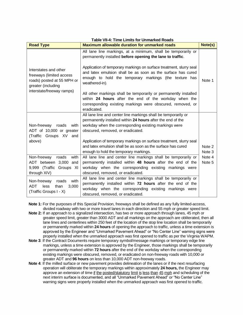
Table VII-4: Time Limits for Unmarked Roads
Road Type Maximum allowable duration for unmarked roads Note(s)
Interstates and other
freeways (limited access
roads) posted at 55 MPH or
greater (including
interstate/freeway ramps)
All lane line markings, at a minimum, shall be temporarily or
permanently installed before opening the lane to traffic.
Application of temporary markings on surface treatment, slurry seal
and latex emulsion shall be as soon as the surface has cured
enough to hold the temporary markings (the texture has
weathered-in).
All other markings shall be temporarily or permanently installed
within 24 hours after the end of the workday when the
corresponding existing markings were obscured, removed, or
eradicated.
Note 1
Non-freeway roads with
ADT of 10,000 or greater
(Traffic Groups XV and
above)
All lane line and center line markings shall be temporarily or
permanently installed within 24 hours after the end of the
workday when the corresponding existing markings were
obscured, removed, or eradicated.
Application of temporary markings on surface treatment, slurry seal
and latex emulsion shall be as soon as the surface has cured
enough to hold the temporary markings.
Note 2
Note 3
Note 4
Note 5
Non-freeway roads with
ADT between 3,000 and
9,999 (Traffic Groups XI
through XIV)
All lane line and center line markings shall be temporarily or
permanently installed within 48 hours after the end of the
workday when the corresponding existing markings were
obscured, removed, or eradicated.
Non-freeway roads with
ADT less than 3,000
(Traffic Groups I - X)
All lane line and center line markings shall be temporarily or
permanently installed within 72 hours after the end of the
workday when the corresponding existing markings were
obscured, removed, or eradicated.
Note 1: For the purposes of this Special Provision, freeways shall be defined as any fully limited-access,
divided roadway with two or more travel lanes in each direction and 55 mph or greater speed limit. Note 2: If an approach to a signalized intersection, has two or more approach through lanes, 45 mph or
greater speed limit, greater than 3000 ADT and all markings on the approach are obliterated, then all lane lines and centerlines within 250 feet of the location of the stop line location shall be temporarily or permanently marked within 24 hours of opening the approach to traffic, unless a time extension is approved by the Engineer and “Unmarked Pavement Ahead” or “No Center Line” warning signs were properly installed when the unmarked approach was first opened to traffic as per the Virginia WAPM.
Note 3: If the Contract Documents require temporary symbol/message markings or temporary edge line markings, unless a time extension is approved by the Engineer, those markings shall be temporarily or permanently marked within 72 hours after the end of the workday when the corresponding existing markings were obscured, removed, or eradicated on non-freeway roads with 10,000 or greater ADT and 96 hours on less than 10,000 ADT non-freeway roads.
Note 4: If the milled surface or new pavement provides delineation of the lanes or if the next resurfacing operation will obliterate the temporary markings within approximately 24 hours, the Engineer may approve an extension of time if the posted/statutory limit is less than 45 mph and scheduling of the next interim surface is documented, and all “Unmarked Pavement Ahead” or “No Center Line” warning signs were properly installed when the unmarked approach was first opened to traffic.

Note 5: When Type F paint is used as a temporary marking on the final surface prior to installation of permanent markings, the film thickness shall be at least 8-10 mils when wet except lane lines on Interstate and Limited Access Roadways with AADT of 10,000 or greater with posted/statutory 45 mph or greater may be 10 to 15 mils if expected to be in service for greater than 14 days
(b) Temporary Pavement Markings:
Premarking, dotting or layout marking shall NOT be used as a substitute for temporary pavement marking. Temporary pavement markings specified in the Contract Documents, including longitudinal lines and message markings, shall be installed at the same locations that the permanent pavement markings are to be installed. Type D-removable tape shall be installed and removed in accordance with manufacturer’s installation instructions. Type F paint shall be installed in accordance with the manufacturer’s installation instructions and as follows:
Milled Surface Intermediate Lifts or Final Surface
Thickness 15 mils 8 to 10 mils** Glass Bead Application Rate
6 lbs. of glass beads per gallon of material
3 lbs. of glass beads per gallon of material for 8 to 10 mils and 6 lbs. per gallon for 11 to 15 mils
Long Line Width Same width as the permanent markings
75% of the permanent marking width
Skip Line Pattern 10-foot line segments / 30-foot gaps (approx.)
8-foot line segments / 32-foot gaps (approx.)
** Type A paint at approximately 15 mils thickness with 6 lbs. of glass beads per gallon will be permitted for the temporary lane line markings provided that the Type A is worn down to no more than 10 mils thickness prior to permanent marking installation. The contractor shall assess how long the temporary lane line, center-line and edge line temporary markings will be in service and may increase the thickness based upon the duration and expected wear.
Temporary Type F pavement markings on final surfaces shall be arranged and spaced so that they will be completely covered by the subsequent installation of permanent pavement markings atop those temporary paint markings. The following Temporary markings location and placement shall comply with the following:
1. Skip- and solid- lane line markings shall be required at all locations unless directed otherwise in the Contract Documents.
2. Centerline markings shall be required at all locations unless directed otherwise in the Contract Documents. Temporary passing zone markings shall be at the same location and pattern as the permanent markings.
3. Edgelines shall be required only when specified in the Contract Documents and only after the surface has reached a condition to support the markings and the equipment, or when directed by the Engineer. Temporary edgelines are not required when the shoulder surface is in a milled condition.
4. Dotted Line Extensions that delineate turning paths or offset lane alignments through intersections shall be required only when specified in the Contract Documents.

5. Stop lines shall be required only when specified in the Contract Documents. Temporary stop lines shall be 12 inches wide unless specified otherwise.
6. Turn Arrows shall be required only when specified in the Contract Documents. 7. Lane Drop Arrows and “MERGE” markings shall be required only when specified in the
Contract Documents, or when directed by the Engineer. 8. Railroad Crossing Symbols shall be required only when specified in the Contract
Documents, or when directed by the Engineer. 9. Crosswalks shall be required only when specified in the Contract Documents. Temporary
crosswalks shall be parallel 6 inch white lines unless otherwise specified. 10. Other markings shall be required only when specified in the Contract Documents.
Temporary lane lines, centerlines, and edge lines may be marked with Type D removable tape, Type F-temporary paint, or FTPMs. All temporary symbol/message markings and other types of temporary markings (including dotted line extensions, stop lines, and crosswalks) may be marked with Type D-removable tape or Type F-temporary paint with at least 3 lbs. of glass beads per gallon. The VTM-94 moisture test is not required for temporary pavement marking. However, if the VTM-94 moisture test is not performed, the Contractor shall make a qualitative surface wetness assessment and note the results on the Form C-85.
If the surface is visibly dry (does not have puddling or free-standing water present), the Contractor is responsible for installing and maintaining the temporary pavement markings. If the Contractor opts not to perform the VTM-94 moisture test and the temporary markings applied to a visibly dry surface do not sufficiently adhere to the surface, no additional payment will be made by the Department for temporary pavement marking reapplication (including Maintenance of Traffic costs associated with temporary pavement marking reapplication). If the surface has puddling or free-standing water present, or if a VTM-94 moisture test result indicates that the condition of the surface is not suitable for temporary pavement marking application, the Engineer may direct the Contractor to install temporary pavement markings on the surface in order to avoid having traffic operate on an unmarked road. In such circumstances the Department may direct the Contractor to install one subsequent reapplication of the temporary markings once the surface has dried, if the previous installation did not satisfactorily adhere to the road. In such circumstances the Contractor will be compensated at the contract bid price for those temporary markings. The Contractor may employ approved methods of drying the pavement surface that will not damage the pavement. Methods that may damage the pavement, such as “torching” of the pavement, will not be allowed. Any drying of pavement will be at no extra cost to the Department. While in place, temporary pavement markings sizes, shapes and retroreflectivity shall be maintained at adequate visibility and retroreflectivity, as defined in Section 512 of the Specifications, until the permanent markings are installed. No additional application (refreshing) is required as long as the temporary markings continue to meet these requirements. If Type D-removable tape fails the visual evaluation or is deficient in any other respect prior to the installation of permanent markings, the tape shall be removed and new Type D-removable tape or Type F-temporary paint shall be reapplied. Under such circumstances, no additional payment will be made by the Department for temporary pavement marking reapplication, including Maintenance of Traffic costs for reapplication. If temporary pavement markings are Type F and do not meet the requirements of Section 512 of the Specifications prior to the installation of permanent markings, such temporary markings shall be refreshed by the application of a lighter application (applied so as to enhance visibility but not as to require eradication before application of permanent markings) of Type F-markings at the Contractor’s expense as directed by the Engineer.

Permanent pavement markings shall not be installed atop Type F-markings if the paint exceeds the maximum specified thickness in Table VII-3, or is not fully dry. If the temporary pavement markings are not located directly underneath the location where the permanent markings are to be installed, they shall be 100% eradicated prior to installation of permanent markings. No additional payment will be made for eradication of excess temporary pavement markings, including Maintenance of Traffic costs, when eradication is required prior to installation of permanent markings.
(c) Premarking: When establishing the location of pavement markings, the Contractor may mark the locations of proposed permanent markings on the roadway by installing premarking materials. Premarkings may be accomplished using Type D removable tape, chalk, or lumber crayons; except symbol/message pavement markings such as stop lines, crosswalks, messages, hatching, etc., shall be premarked using chalk or lumber crayons. Premarkings shall be of the same general color as the pavement markings being premarked. When tape is used as a premarking material, premarking shall consist of 4- inch by 4-inch-maximum squares or 4-inch-maximum diameter circles spaced at 100-foot minimum intervals in tangent sections and 50-foot-minimum intervals in curved sections. At locations where the pavement marking will switch colors (e.g. gore marking) the ends of the markings may be premarked regardless of the spacing. When the Contractor uses chalk or lumber crayon as premarking, the entire length of the proposed pavement marking may be premarked. Premarkings shall be installed so their installation will not affect the adhesion of the permanent markings. When Type D tape is used as the premarking material and the lateral location of such premarkings to the final pavement markings exceeds 6 inches, the Type D premarkings shall be removed at no additional cost to the Department.
(d) Eradication: Eradication of existing pavement markings shall be in accordance with Section 512 of the Specifications, except where new markings will cover the existing markings, at least 90 percent removal of the existing markings is required.
(e) Permanent Pavement Markings: The pavement surface shall be clean and dry at the time of permanent pavement marking installation as tested in accordance with VTM-94. The Contractor shall be responsible for providing the apparatuses that are needed to perform the moisture test prior to application. Permanent markings shall not be installed directly over longitudinal pavement joints except to cross the joint perpendicularly or at an angle. All permanent linear and message/symbol markings on (a) Interstate and Limited Access Roadways posted at 55 MPH or greater, (b) all other roadways with 10,000 ADT or greater and posted or statutory speed limit of 45 mph or greater, shall be placed within the following time limits:
1) For Plant Mix operations: a. All Type B Class VI shall be inlaid the same day as the final surface is placed as
specified herein. b. All other permanent markings shall be completed within 30 days after the end of
the last workday of continuous paving on that section of roadway. 2) For Latex Emulsion and Surface Treatment operations:

a. The contractor shall evaluate the pavement surface between 14 and 18 days after
the end of the last workday of continuous paving on that section of roadway. b. If that evaluation ascertains that the pavement surface meets the markings
manufacturer’s requirements and specifications for application of permanent markings, the texture is weathered-in on the edges, and the temporary marking is worn down to 10 mils or less, then the Engineer shall be notified that the surface meets the markings manufacturer’s specifications. The permanent markings shall be installed between 14 days and 30 days after the end of the last workday of continuous paving on that section of roadway. Otherwise the contractor shall notify the Engineer why the pavement surface does not meet the markers manufacturer’s requirements and all permanent markings shall be completed between 30 days and 45 days after the end of the last workday of continuous paving on that section of roadway.
On all other roadways (non-interstate and non-limited access/non-freeway) roads with less than 10,000 ADT or posted/statutory speed less than 45 MPH), all permanent linear and message/symbol markings shall be installed within 30 days on plant mix surfaces and between 30 and 45 days on surface treatment/slurry seal/latex emulsion surfaces, after the end of the last workday of continuous paving on that section of roadway. Exceptions will be granted by the Engineer only when pavement curing time or weather conditions prohibit installation or the texture is not weathered-in on the edges and the pavement surface does not meet the markings manufacturer’s requirements.
Any necessary refreshing and/or replacement of temporary pavement markings or FTPMs shall not affect the allowable time limit for completion of permanent pavement marking installation. Permanent pavement markings shall be of the material specified in the Contract Documents. Permanent pavement markings shall not be installed atop surface-treatment/slurry seal/latex emulsion surfaces until at least 14 days (and up to 30 days if Type B Class VI is installed) after completion of the paving operation, and only after the contractor determines that the surface has sufficiently cured (weathering-in of the texture) to support the permanent pavement markings in accordance with the manufacturer’s written instructions. The Contractor shall thoroughly sweep surface-treated, slurry seal and latex emulsion roadways prior to installation of permanent pavement markings. Any loose aggregate remaining on the surface shall be blown-out with an air compressor or other approved method. Permanent pavement message and symbol markings shall be installed using Type B, Class I or Class II thermoplastic material as specified in the Contract Documents. Messages and symbol markings shall include, but not be limited to: crosswalks, yield lines, stop lines, school markings, railroad crossing markings, accessible (handicapped) parking symbols, arrows, word messages, etc. 1. Type A Markings: Paint shall be applied as per the manufacturer’s installation instructions.
Paint shall not be applied over existing pavement markings of other materials unless the existing marking is at least 90 percent worn away or eradicated. Paint may be applied over existing Type A paint markings if the existing paint is clean and well adhered. The Contractor shall apply paint with a line painting machine that is capable of hot spraying paint and glass beads directly onto the pavement surface for widths of 4 through 8 inches. The machine shall be capable of simultaneously applying two pavement stripes, either solid or skip, at the same time when double line markings are required. Paint tanks on the equipment shall be equipped with a mechanical agitator and paint shall be thoroughly mixed and heated such that it will not track within 60 seconds after its application.

Non-truck mounted equipment shall be self-propelled and regulated to allow for calibration of the amount of material applied. Glass beads shall be applied by the application equipment to the entire surface of the paint at the minimum rate of 6 pounds per gallon of paint, unless specified otherwise in the VDOT Materials Division’s Approved Products List.
2. Type B Markings (General): Type B markings shall be applied in accordance with the manufacturer’s installation instructions. Type B markings shall not be applied over existing pavement marking materials unless the existing marking is at least 90 percent worn away or eradicated. The Contractor shall furnish a properly calibrated infrared instrument for the purpose of measuring the actual temperature of molten thermoplastic material. Multi-component material shall be applied using internally injected guns for the proper mixing of components. Truck mounted equipment for application of liquid long line Type B markings shall be capable of hot spraying liquid applied markings and glass beads uniformly over the entire surface of the marking for widths of 4 through 8 inches. Equipment tanks shall be equipped with a mechanical agitator and materials shall be thoroughly mixed, heated and applied in accordance with the manufacturer’s installation instructions. Equipment shall be capable of applying two pavement stripes, either solid or skip, at the same time when double line markings are required.
3. Thermoplastic (Type B, Class I) Markings: Material shall be applied by screed extrusion, ribbon gun, or spray equipment. Alkyd thermoplastic may be applied directly to plant mix surfaces after the paving operations if the paved surface can support the equipment; however, hydrocarbon thermoplastic shall be applied between 30 and 45 days after the paving operations. Alkyd and hydrocarbon materials shall not be mixed together. Equipment shall be thoroughly cleaned before color or types of material are changed. Thermoplastic shall only be applied over existing thermoplastic markings if the existing thermoplastic marking is clean, chalk-free (not powdery), and well-adhered; or over previously-applied Type F-paint that is fully dry and is at a thickness of 10 mils or less. Glass beads shall be applied by the application equipment to the surface of the marking at the minimum rate of 7 pounds per 100 square feet, unless specified otherwise in the VDOT Materials Division’s Approved Products List. Non–truck mounted equipment for application of thermoplastic material shall be of the screed extrude type with a screw drive and shall be self-propelled and regulated to allow for calibration of the amount of material applied. Type B, Class I hydrocarbon thermoplastic material shall not be used for the installation of messages or symbols. Alkyd thermoplastic material shall only be applied by screed extrude application equipment for the installation of messages or symbols.
4. Preformed Thermoplastic (Type B, Class II) Markings: When markings are installed on hydraulic cement concrete pavement, a primer/sealer shall be first applied in accordance with manufacturer’s installation instructions.

Additional glass beads shall be applied evenly at the rate of 7 pounds per 100 square feet to flood the entire surface of the preformed thermoplastic material immediately after installation and while the material is still molten.
5. Epoxy Resin (Type B, Class III) Markings: Markings shall be applied per the manufacturer’s recommendations. Epoxy resin shall not be applied over existing pavement markings unless the existing marking is at least 90 percent worn away or eradicated. Non–truck mounted equipment for application of epoxy resin material shall be self-propelled and regulated to allow for calibration of the amount of material applied.
6. Plastic-Backed Preformed Tape (Type B, Class IV) Markings: Markings shall be installed per the manufacturer’s installation instructions and as denoted herein. Unless otherwise specified, Tape applied to freshly paved asphalt surfaces shall be inlaid on the freshly installed asphalt surface before the pavement mat has cooled below 100 degrees F. Surface preparation primer/adhesive shall be used to enhance adhesion in accordance with the manufacturer’s recommendations, except when tape is inlaid immediately following the final rolling of the new asphalt concrete surface. New surface treatment, slurry seal, and latex emulsion surfaces shall be fully cured and temporary markings worn in accordance with manufacturer recommendations prior to installation of the primer/adhesive and surface application of the Tape. Tape for pavement line markings shall be applied by an application cart as recommended by the manufacturer. Tape shall be tamped into place with a tamper cart with a weight as recommended by the manufacturer. Vehicle wheels may be used to tamp line markings if recommended by the manufacturer’s installation instructions. If vehicle wheels are used to tamp the markings, then the Contractor shall ensure that the vehicle tires ride true down the length of the tape marking. Markings that are improperly inlaid during the pavement operations shall be completely eradicated and reapplied via non-embedded surface application at the Contractor’s expense.
7. Patterned Preformed Tape (Type B, Class VI) Markings: Pre-approved material shall be installed either under the guidance of the manufacturer’s representative or by the contractor’s employee that is approved as an installer by the manufacturer. If the material is no longer approved for Surface Treatment applications (Latex Emulsion, Slurry, etc.) at the time of bid advertisement, the material shall not be installed on Surface Treatment applications (Latex Emulsion, Slurry, etc.). The pavement marking tape shall be warrantied by the manufacturer against failure resulting from improper installation and material defects regardless of method of manufacturer’s prescribed application or pavement type. The material shall be warranted to retain its color, retroreflectivity, adherence to the pavement and shall be free of other obvious defects or failures. All pavement marking tape that has failed to meet the warranty conditions shall be replaced at no additional cost to the Department. The warranty shall cover all pavement striping materials (regardless of method of installation), labor, equipment, mobilization\demobilization,

tools, and incidentals required to remove (eradicate) and replace the pavement striping, including maintenance of traffic during the removal and reinstallation operations. The warranty shall include the following:
Retroreflectivity: White and Yellow longitudinal pavement marking tape shall remain effective for its intended use under normal traffic conditions and meet the minimum Coefficient of Retroreflected Luminance (RL) of 100 millicandelas per square foot per foot-candle [(mcd·ft-2)·fc-1] when measured in accordance with the requirements of ASTM E 1710 for six years.
Color: Longitudinal pavement marking tape shall remain effective for its intended use under normal traffic conditions and meet the minimum Daytime and Nighttime color including Luminance Factor (Cap Y) per ASTM D 6628 for six years when inlaid on new asphalt concrete pavement or surface applied on existing asphalt concrete pavement or hydraulic cement concrete.
Material Loss for Solid Longitudinal Lines: more than five percent of the substrate is exposed in any 2000 ft. section of pavement marking or 50 ft. or more of continuous loss.
Material Loss for Skip Line: more than five percent of the substrate is exposed in any 2000 ft. section of pavement marking, or the loss of two consecutive skips.
When Type B, Class VI markings are specified for a paving schedule route that includes a concrete bridge deck greater than 75 feet in length within the paving schedule’s limits, Type B Class VI contrast (black-bordered) tape shall be surface-applied on the concrete bridge deck for the lane lines and edge lines unless otherwise specified in the Contract Documents or directed by the Engineer. Plant Mix Surfaces: Type B, Class VI markings applied to plant mix overlay surfaces shall be installed as per manufacturer’s installation instructions, except that non-embedded (adhesive) surface application will not be permitted; the markings shall be inlaid in the freshly installed asphalt surface before the pavement mat has cooled. The temperature of the asphalt mat shall be between 100 and 180 degrees. The Type B, Class VI markings shall be inlaid with a roller (minimum 2 tons) operating in a non-vibratory mode when the asphalt mat is between 100 and 180 degrees. The Contractor shall ensure that markings are not degraded by subsequent paving and shoulder operations. Markings that are improperly inlaid during the pavement operations shall be completely eradicated and reapplied via non-embedded surface application at the Contractor’s expense. Non-Plant Mix Surfaces: The Contractor shall install Type B, Class VI markings on existing asphalt concrete roadway surfaces, hydraulic cement concrete surfaces, and existing or new surface treatment, slurry seal, and latex emulsion surfaces in accordance with the manufacturer’s installation instructions for pavement surface preparation, sweeping, and installation techniques for non-embedded (adhesive) surface applications and splicing. When Type B, Class VI markings are to be installed on latex emulsion or other approved surface treatment, the selected marking material shall be a material that is warranted by the manufacturer and pre-approved by the Department for application on slurry seal/latex emulsion surfaces. Prior to tape installation on new latex emulsion surfaces, the following shall occur:
The surface shall cure for at least 30 days unless otherwise documented that the pavement surface has sufficiently cured as specified herein.

The surface shall be swept clear of all loose aggregate immediately prior to applying (spraying) surface preparation primer adhesive.
The primer adhesive shall be applied (sprayed) uniformly at the correct thickness (shall not exceed the maximum thickness specified by the manufacturer), and cured in accordance with the manufacturer’s installation instructions.
After proper application of the surface preparation primer adhesive, the tape shall be tamped to the road using a 200 pound minimum tamper cart and vehicle wheels. The Contractor shall ensure that the vehicle tires, if used, ride true down the length of the tape marking and in accordance with manufacturer instructions.
8. Polyurea (Type B, Class VII) Markings: Markings shall be installed in accordance with the manufacturer’s installation instructions, either under the guidance of the manufacturer’s representative or by a Contractor’s technician that has received manufacturer’s certification.
704.05—Pavement Markers The type, installation procedures, time limits, ambient air temperature, ambient moisture condition, and pavement surface condition for pavement markers shall be in accordance with manufacturer’s installation instructions. A copy of those installation instructions shall be provided to the Engineer prior to installation. The front side (the side facing oncoming traffic) of pavement markers retroreflectors shall be the same color as the adjacent pavement marking. The backside of the pavement marker retroreflectors shall be as follows:
One-way markers: The backside (the side facing wrong-way traffic) shall be red for pavement markers with a white retroreflector on the front side.
Two-way markers: The backside shall match the color of the adjacent pavement marking.
The bonding material shall be from the VDOT Materials Division’s Approved Products List for the specific marker listed. The Contractor shall prepare the pavement surface by air blowing or a thorough brushing as necessary to ensure that the pavement surface is free of dirt, dust, debris, moisture, scale, oil, and any contaminant that might reduce bonding. The retroreflector surface shall be kept free of moisture, scale, dirt, oil, grease, and other contaminants that might reduce the retroreflectivity of the retroreflector. Permanent markers shall not be installed until after the installation of the adjacent permanent line marking.
(a) Flexible Temporary Pavement Markers (FTPMs): The Contractor may choose to substitute FTPMs in lieu of Type F-temporary paint or in lieu of Type D temporary pavement markings. Prior to installing FTPMs the Contractor shall submit a plan for substituting FTPMs for temporary pavement markings to the Engineer for approval. The Contractor’s plan for FTPMs shall be in accordance with the requirements and the Typical Plan for FTPM Placement drawings included herein.

When FTPMs are used to simulate temporary edgelines, the FTPMs shall be placed on 20-foot centers and shall match the color of the line markings being simulated. FTPMs shall be installed at the same locations that permanent pavement markings will be installed. For surface treatment, slurry seal or latex emulsion treatment operations, the appropriate FTPMs with protective covering shall be installed prior to placing the new treatment. The lens protective covering shall be kept in place during the final surface placement to protect the lens from being obscured or damaged by the paving operation. Upon completion of surface treatment, slurry seal or latex emulsion treatment placement, the Contractor shall remove the protective covering from the reflective lens of the FTPMs prior to leaving the work site. Failure to remove such covering shall result in the non-payment for that portion type (skip or solid) of temporary pavement marking. For plant mix operations, the appropriate FTPMs shall be installed on the newly-placed pavement after the pavement is thoroughly compacted and has cooled to the FTPM manufacturer’s recommended temperature for installation. The Contractor shall maintain the FTPMs until the permanent pavement markings are installed. Damaged or missing FTPMs shall be immediately replaced at the Contractor’s expense with new FTPMs of the same manufacturing type, color and model. No more than one FTPM may be damaged or missing out of every skip line simulated segment. No two consecutive FTPMs may be damaged or missing on a simulated solid line application, and no more than 30 percent of the FTPMs may be damaged or missing on any measured 100-foot segment of simulated solid line. Once applied, FTPMs will be considered for a single use. If a FTPM requires replacement, it shall be properly disposed of and replaced with a new FTPM at no additional cost to the Department. FTPMs may remain in place, undamaged, after installation for up to 14 consecutive days. When FTPMs are applied prior to final surface placement (such as with surface treatment, slurry seal, or latex emulsion operations) this 14 -consecutive-day time limit shall begin at the time of actual installation of the FTPMs, not at the time of surface placement. The Engineer may approve an extension of the 14 days if all damaged FTPMs are replaced and the remaining FTPMs are maintained. FTPMs shall be removed and properly disposed of when permanent pavement markings are installed. Used FTPMs removed from the pavement, including all containers, packaging, damaged FTPMs and all other miscellaneous items of waste, shall be appropriately disposed of in accordance with Section 106.04 of the Specifications.
(b) Snow-plowable Raised Pavement Markers (SRPMs):
SRPMs shall be installed by cutting two parallel grooves into the pavement at the depth and dimensions recommended by the marker manufacturer. Grooves shall be parallel to the adjacent pavement marking. Grooves shall be cut with saw blades having a diameter to match the curvature of the steel casting bottom and keels. Keel surfaces and the cut grooves shall be free from moisture, scale, dirt, oil, grease, debris, or any other contaminant that might reduce bonding. SRPMs shall be located at least two inches away from any joint, crack, or seam. Casting keels shall be bonded in the saw-cut grooves in accordance with the manufacturer’s installation instructions. Front and rear keel tips of the casting shall be installed flush with or below the pavement surface. The installed height of the raised pavement marker shall be approximately ¼ inch to ½ inch above the pavement surface. The top of retroreflectors shall be mounted flush with or below the top of the casting.

If the SRPM retroreflectors are dirtied or damaged during installation (including dirtying from adhesive residue), they shall be replaced by the Contractor at no additional cost to the Department. All SRPMs on plant mix surfaces shall be installed within 30 calendar days after the end of the last workday (final surface) of continuous paving on that section of roadway. All SRPMs on surface treatment, slurry seal, or latex emulsion surfaces shall be installed within 14 calendar days after the final markings are installed, unless a time extension is approved by the Engineer. Time extensions will be granted when weather conditions prohibit installation or other operations on the project would damage the markers. The time limit for installation of SRPMs shall be determined as follows:
On a two-lane roadway, the time limit commences for the entire roadway at the end of the last workday that the final surface is placed on a continuous section of that roadway.
On a divided highway or a multi-lane undivided highway, the time limit commences for the entire roadway at the end of the last work day that the final surface is placed on a continuous section for that portion [direction] only. The time limit for the entire roadway in the opposite direction does not commence until at the end of the last work day that plant mix or surface treatment is placed on a continuous section for that opposite direction.
(c) Raised Pavement Markers: Raised pavement markers shall be bonded to the pavement surface in accordance with the manufacturer’s installation instructions.
(d) Pavement Marker Retroreflector Replacement: Replacement of existing retroreflector lenses shall be in accordance with the manufacturer’s installation instructions. If the new retroreflectors are dirtied or damaged during installation they shall be replaced at no additional cost to the Department. Properly dispose of the existing retroreflectors in accordance with Section 106.04 of the Specifications.
704.06—Quality Control The Contractor shall have a certified Pavement Marking Technician present during all temporary and permanent pavement marking operations and marker installation operations, except FTPM operations. The Contractor shall maintain a daily log (Form C-85) for both temporary and permanent markings and markers. The C-85 form shall not be modified, all entries in the log shall be in ink, the log shall be legible and complete, and the log shall be signed by the Contractor and delivered to the inspector at the end of each workday. If the Form C-85 is in electronic format, it shall be kept current with VTM-94 testing throughout the day and a printed copy signed by the Contractor shall be delivered to the Inspector at the end of each workday. The Contractor shall also provide a printed or electronic copy of the signed Form C-85 to the Materials Quality Assurance Technician for materials notebook verification. The Contractor shall perform quality control testing for application thickness and glass bead rate in accordance with VTM-94 at the beginning of each workday and every 3 hours thereafter. The Contractor shall be responsible for providing the apparatuses indicated in VTM-94 that are needed to perform the quality control testing. Testing for compliance with VTM-94 shall be performed in the presence of the Engineer and shall be documented on the Form C-85 immediately after testing is completed. If requested by the Engineer, the Contractor shall provide a Quality Control (QC) test plate and the provision of the test plate shall be documented on Form C-85.

The Engineer will make a visual evaluation of the permanent markings and markers to assess the condition, retroreflectivity, and color of the pavement marking material, after installation but prior to final acceptance. If problem areas are found, a further inspection will be made by the Department, the Contractor, and marking manufacturer's representative to identify specific areas of concern. When required by the Engineer, the suspect areas shall be tested by the Contractor in the presence of the Engineer in accordance with VTM-125 to define the evaluation sections and the number of measurements needed. The test results shall meet the requirements for retroreflectivity and color specified in Section 246 of the Specifications. Those markings found to be less than the Initial Approval values in Section 246 of the Specifications shall be eradicated and immediately replaced by the Contractor at no cost to the Department. Pavement markings that exhibits signs of significant tearing, roll back, lifting, shrinkage, or other signs of poor adhesion shall be immediately replaced by the Contractor at no cost to the Department. All costs associated with testing the marking material for retroreflectivity, color, and adhesion shall be borne by the Contractor. The Contractor will be paid for Maintenance Of Traffic during this testing at the contract unit price for the Maintenance Of Traffic items used. Commercially standard material guarantees that are furnished by the manufacturer shall be obtained by the Contractor and assigned to the Commonwealth in writing prior to final acceptance. 704.07—Measurement and Payment Pavement line markings will be measured and paid at the contract unit price per linear foot for the type and/or class and width specified. This price shall include furnishing and installing the pavement marking material, surface preparation, premarking, documentation and staking of existing markings, quality control tests, daily log, guarding devices, primer/adhesive, glass beads, and manufacturer’s warranty. The Schedule of Items may contain permanent pavement marking bid items designated as “Bonus” in addition to the regular permanent pavement marking bid items. This “Bonus” designation indicates an adjustment of 1.25 to be made to the regular Contract unit bid price for the designated item in accordance with Section 102.05 of the Specifications which is to be paid to the Contractor if the conditions specified herein are met. For items with the “Bonus” designation the Contractor will be paid at the adjusted price instead of at the regular bid price for the linear foot of permanent pavement marking installation completed if the following conditions are met:
● Plant Mix: Pavement markings (not including Type B, Class VI) are installed on Plant Mix surfaces within 14 days or less after the last day of paving.
● Non-Plant Mix: Pavement markings (not including Type B, Class VI) are installed on Plant Mix
surfaces within 21 days or less after the last day of paving. Pavement message markings will be measured and paid for at the contract unit price per each per location or linear foot as applicable for the message, size, and type and/or class specified. This price shall include furnishing and installing the pavement marking material, surface preparation, premarking, documentation and staking of existing markings, quality control tests, daily log, guarding devices, primer/adhesive, glass beads, and manufacturer’s warranty. Temporary pavement line markings will be measured and paid for at the contract unit price per linear foot for the type and/or class and width specified. This price shall include furnishing, installing, and maintaining the pavement marking material, surface preparation, quality control tests, daily log, guarding devices, primer/adhesive, glass beads, and disposal. If temporary line markings require refreshing, reapplication, or replacement before the final surface or the permanent markings are installed, all cost for refreshing, reapplication, or replacement shall be at the

Contractor’s expense, unless the Contractor was directed to apply the temporary markings to a visibly wet surface at the direction of the Engineer as specified herein. In the event the Contractor uses FTPMs in lieu of Type F-temporary paint to simulate a longitudinal line marking as allowed herein, the Contractor will be paid at the linear foot pay unit for the length of simulated line marking at the Type F-temporary paint unit price. That measurement shall represent all FTPMs required for that simulated line marking. This cost shall include furnishing, installing and maintaining the FTPMs, removable covers, surface preparation, quality control tests, daily log, guarding devices, FTPMs removal, and disposal. Temporary pavement message markings will be measured and paid for at the contract unit price per each per location or per linear foot as applicable for the message, size and type and/or class specified. This price shall include furnishing, installing, and maintaining the pavement marking material, surface preparation, quality control tests, daily log, guarding devices, primer/adhesive, glass beads and disposal. If temporary pavement message markings require refreshing, reapplication, or replacement before the final surface or the permanent markings are installed, all cost for refreshing, reapplication, or replacement (including Maintenance of Traffic costs) shall be at the Contractor’s expense unless the Contractor was directed to apply the temporary markings to a visibly wet surface at the direction of the Engineer as specified herein. Pavement Markers will be measured and paid for at the contract unit price per each for the type specified. This price shall include surface preparation, furnishing and installing prismatic retroreflectors and castings, pavement cutting, adhesive, guarding devices, quality control tests, daily log, and manufacturer’s warranty. Pavement Marker Retroreflector Replacement will be measured and paid for at the contract unit price per each for the type specified. This price shall include furnishing retroreflectors, removal and disposal of the existing retroreflector, cleaning of the existing casting, adhesive, installation of the new retroreflector, quality control tests, daily log, and manufacturer’s warranty. Payment will be made under:
Pay Item Pay Unit
Pavement line marking (Type and/or class and width) Linear foot
Pavement message marking (Message, size, type and/or class) Each or linear foot
Temporary pavement line marking (Type and width) Linear foot
Temporary pavement message marking (Message, size, type and/or class) Each or linear foot
Pavement marker (Type, [ ]-way, and/or type pavement) Each
Pavement marker retroreflector replacement (Type) Each

TYPICAL PLAN FOR FTPM PLACEMENT

S704N00-1211 VIRGINIA DEPARTMENT OF TRANSPORTATION
SPECIAL PROVISION FOR TYPE B, CLASS VII POLYUREA PAVEMENT MARKINGS
October 17, 2011
I. Description
This work shall consist of furnishing and installing white and/or yellow polyurea pavement line markings at locations shown on the plans and as directed by the Engineer.
II. Materials Polyurea pavement line markings shall be a retro-reflective polymer material consisting of a mixture of polymeric materials, pigments and glass beads and/or reflective optics. The polyurea material shall not be formulated with any compounds of the heavy metals listed in 40 CFR 261.24 Table 1 except that barium sulfate is allowed. Total heavy metals, with the exception of barium sulfate, shall not exceed 20 times the specified regulatory limits. The polyurea coating shall be formed by the reaction of at least two components (Part A and Part B). The components shall be formulated such that the proper cure occurs when they are mixed at the times of the application. The polyurea material shall be capable of application on new and existing asphalt and hydraulic cement concrete surfaces at pavement surface temperatures of 40 degrees Fahrenheit and above. The polyurea material shall maintain its original dimensions and placement without chipping, spalling, shrinking, cracking, bleeding or discoloring (fading) or other signs of poor performance which will impair the intended use of the marking throughout its intended service life. The polyurea material shall not deteriorate due to contact with sodium chloride, magnesium chloride, calcium chloride, mild alkalies and acids, or other ice control materials, oil in the pavement material, or oil and gasoline drippings from vehicles. Materials that must be heated for application shall not exude fumes that are toxic or injurious to persons or property when heated to the application temperature. A. Initial Approval Requirements:
Specific Polyurea pavement markings will be included on the Department's Materials Approved Products List # 74 after the Department determines conformance to these specifications. Determination of conformance will include, but will not be limited to, the evaluation of test data from AASHTO's National Transportation Product Evaluation Program (NTPEP) on a Northern region test deck or other VDOT approved facilities. If tested through AASHTO/NTPEP, the polyurea material shall have been installed, tested, and met the following requirements on both asphalt and concrete surfaces. If tested on another VDOT approved facility, VDOT reserves the right to test and approve based upon in service performance data on either asphalt, hydraulic cement concrete, or both surfaces. AASHTO/NTPEP Testing - Test data values used for approval shall be based upon the data generated per the NTPEP, Pavement Marking Material (PMM) Work Plan.

VDOT Test Facility – Test data values used for approval shall be based upon the data generated by following: Virginia Test Method (VTM)-125 to define the evaluation sections and number of measurements needed, evaluation of Durability, and No Track Time based upon field performance, VDOT lab testing or third party testing for compliance. The manufacturer shall certify each batch or lot of material supplied is the same product (binder and reflective optics) that was tested and approved on the NTPEP or VDOT test facility in accordance with the Materials Division, Manual of Instructions for Certification II materials. 1. Retroreflectivity:
Markings shall have the following retroreflectance values when measured in accordance with the requirements of ASTM E 1710 (outside of the wheel path). The photometric quantity to be measured shall be Coefficient of Retroreflected Luminance (RL) and shall be expressed as millicandelas per square foot per foot-candle [(mcd·ft
-2)·fc
-1].
Coefficient of Retroreflected Luminance (RL)
(mcd•ft-2•fc
-1)
Color New* 1 Year
In-Service
White 400 300
Yellow 300 200
* New Coefficient of Retroreflected Luminance value may be either the 0 or
the 1 month reading, whichever is higher.
2. Day and Nighttime Color: Daytime and Nighttime color including Luminance Factor (Cap Y) shall conform to the requirements of ASTM D 6628 initially and after 1 year. Color and Luminance Factor values for NTPEP acceptance will be from outside of the wheel path. Night color may be measured in accordance with VTM-111 or with portable night color instrumentation per ASTM D 6628.
3. Durability Rating: The marking shall have a durability rating of at least 4 (40% retained) when determined in the wheel path area after 1 year when tested in accordance with NTPEP guidelines.
4. No Track Time: When applied in accordance with manufacturer’s instructions at 20 +/- 1 mils wet film thickness with reflective optics, the polyurea shall exhibit a no-track time of 10 minutes maximum when tested in accordance with ASTM D711.
III. INSTALLATION: Marking configurations shall be in accordance with the latest edition of the "Manual on Uniform Traffic Control Devices". Markings shall be applied in strict accordance with the manufacturer’s recommendations either under the guidance of the manufacturer’s representative or by the manufacturer’s certified installer. Markings shall not be installed directly over longitudinal pavement joints.

IV. POST-INSTALLATION EVALUATION
Following installation and prior to final acceptance, a visual evaluation will be made by the Engineer to assess the condition, retroreflectivity and color of the polyurea marking material. If problems areas are found, an inspection will be made by the Department, the Contractor, and the polyurea manufacturer's representative to identify the specific areas of concern. If needed, the suspect areas shall be tested by the Contractor and/or VDOT representative in accordance with VTM-125 to define the evaluation sections and number of measurements needed. Acceptable test results shall meet the requirements for retroreflectivity and color specified in Section II, A – Initial Approval Requirements. Those markings found to be less than the values listed in Initial Approval Requirements for Retroreflectivity and Day and Nighttime Color (1 Year, In-Service) shall be eradicated and replaced by the Contractor at no cost to the Department. All costs associated with testing the pavement marking for retroreflectivity,color, and adhesion, including the cost of maintenance of traffic, shall be borne by the Contractor.
VI. MEASUREMENT AND PAYMENT Type B, Class VII, Polyurea pavement line marking will be measured in linear feet for the width specified and will be paid for at the contract unit price per linear foot, which price shall be full compensation for furnishing and installing pavement line markings, surface preparation, and testing. Payment will be made under:
Pay Item
Pay Unit
Type B, Class VII Polyurea pavement line marking Linear foot

SS1D017-0215 September 18, 2014
VIRGINIA DEPARTMENT OF TRANSPORTATION 2007 ROAD AND BRIDGE SUPPLEMENTAL SPECIFICATIONS
SUPPLEMENTAL DIVISION I—GENERAL PROVISIONS
SECTION 101—DEFINITIONS OF ABBREVIATIONS, ACRONYMS, AND TERMS Section 101.02—Terms of the Specifications is amended to replace the definition for Notice to Proceed with the following:
Notice to Proceed. A date selected by the Contractor that is no earlier than 15 nor later than 30 calendar days after the date of contract execution on which the Contractor intends to begin the work, or a contract specific date on which the Contractor may begin the work identified as the Notice to Proceed date in the Contract Documents.
Section 101.02—Terms of the Specifications is amended to add the following:
Storm Sewer System - A drainage system consisting of a series of at least two interconnecting pipes and structures (minimum of two drop inlets, manholes, junction boxes, etc.) designed to intercept and convey stormwater runoff from a specific storm event without surcharge.
SECTION 102—BIDDING REQUIREMENTS AND CONDITIONS Section 102.01—Prequalification of Bidders of the Specifications is amended to replace the first paragraph of (a) with the following:
All prospective Bidders, including all members of a joint venture, must prequalify with the Department and shall have received a certification of qualification in accordance with the Rules Governing Prequalification Privileges prior to bidding. These rules and regulations can be found within the Department’s Rules Governing Prequalification Privileges via the Prequalification Application. This requirement may be waived by a project-specific provision in the bid proposal. All subcontractors must be prequalified prior to performing any work on the contract, except that prequalification will not be required for subcontractors only performing a service as defined by the Code of Virginia, or only performing work items noted in the proposal as "Specialty Items". In order to be eligible for DBE credit under Special Provision for Section 107.15, DBE federal-aid contract subcontractors must be VDOT prequalified and DMBE certified at the time of bid submission. The prequalification and certification status of a DBE may affect the award of the contract to the prime contractor and the award of the subcontract to the DBE at any point during the contract.
Section 102.04(c) Notice of Alleged Ambiguities of the Specifications is amended to replace the first paragraph with the following:
If a word, phrase, clause, or any other portion of the proposal is alleged to be ambiguous, the Bidder shall submit to the State Contract Engineer a written notice of the alleged ambiguity not later than 10 days prior to the date of receipt of bids and request an interpretation thereof. This written notice shall be submitted via the CABB (Contractor Advertisement Bulletin Board) system located on the Construction website at www.VDOT.Virginia.gov. Authorized interpretations will be issued by the State Contract Engineer to each person who received a proposal and will be posted on the CABB system.

Section 102.11— eVA Business-To-Government Vendor Registration of the Specifications is replaced with the following:
Bidders are not required to be registered with "eVA Internet e-procurement solution" at the time bids are submitted, however, prior to award, the lowest responsive and responsible bidder must be registered with “eVA Internet e-procurement solution” or the bid will be rejected. Registration shall be performed by accessing the eVA website portal www.eva.state.va.us, following the instructions and complying with the requirements therein. When registering with eVa it is the bidder’s responsibility to enter or have entered their correct PA type address or addresses in eVa in order to receive payments on any contracts that the Department (VDOT) may award to them as the lowest responsive and responsible bidder. The Bidder shall also ensure their prequalification address(es) match those registered with eVa. Failure on the part of the bidder or Contractor to meet either of these requirements may result in late payment of monthly estimates.
SECTION 105—CONTROL OF WORK Section 105.01—Notice to Proceed of the Specifications is replaced with the following:
Unless otherwise indicated in the Contract, the Notice to Proceed date will be the date selected by the Contractor on which the Contractor intends to begin the work. That date shall be no earlier than 15 nor later than 30 calendar days after the date of contract execution. The State Contract Engineer will contact the Contractor on the date of contract execution to inform him that the contract has been executed. The State Contract Engineer will also confirm this date in the Letter of Contract Execution. Copies of the Letter of Contract Execution will be distributed to Department personnel involved in the administration of the Contract and to the Contractor. Within 10 calendar days after the date of contract execution the Contractor shall submit to the Engineer written notice of the date he has selected as his Notice to Proceed date. If the Contractor fails to provide written notice of his selected Notice to Proceed Date within 10 calendar days of contract execution, the selected Notice to Proceed Date will become the date 15 calendar days after the date of contract execution. The Contractor shall begin work no later than 10 calendar days after the date he has selected as his Notice to Proceed date, unless the Notice to Proceed date is otherwise indicated in the Contract, in which case the Contractor shall begin work within 10 calendar days after the specific Notice to Proceed date indicated in the Contract. Contract Time will commence on the date of the Notice to Proceed. The Letter of Contract Execution will identify the Chief Engineer’s authorized representative, hereafter referred to as the Engineer, who is responsible for written directives and changes to the Contract. The Engineer will contact the Contractor after notice of award to arrange a pre-construction conference. In the event the Contractor, for matters of his convenience, wishes to begin work earlier than 15 calendar days or later than 30 calendar days after the date of contract execution, he shall make such a request in writing to the Engineer within 10 calendar days of the date of contract execution or once a Notice to Proceed Date has been established, if he wishes to begin work more than 10 calendar days after his selected Notice to Proceed date or the Notice to Proceed Date indicated in the Contract, he shall make such a request to the Engineer in writing no later than 5 calendar days after the Notice to Proceed date. If this requested start date is acceptable to the Department, the Contractor will be notified in writing; however, the Contract fixed completion date will not be adjusted but will remain binding. The Contractor’s request to adjust the start date for the work on the Contract will not be considered as a basis for claim that the time resulting from the Contractor’s adjusted start date, if accepted by the Engineer, is insufficient to accomplish the work nor shall it relieve the Contractor of his responsibility to perform the work in accordance with the scope of work and requirements of the Contract. In no case shall work begin before the Department executes the Contract or prior to the Notice to Proceed date unless otherwise permitted by the Contract or

authorized by the Engineer. The Contractor shall notify the Engineer at least 24 hours prior to the date on which he will begin the work.
Section 105.02—Pre-Construction Conference of the Specifications is amended to replace the first paragraph with the following:
After notification of award and prior to the Notice to Proceed date the Contractor shall attend a pre-construction conference scheduled by the Engineer to discuss the Contractor's planned operations for prosecuting and completing the work within the time limit of the Contract. At the pre-construction conference the Engineer and the Contractor will identify in writing the authorities and responsibilities of project personnel for each party. The pre-construction conference may be held simultaneously with the scheduling conference when the Engineer so indicates this in advance to the Contractor. When these are simultaneously held, the Contractor shall come prepared to discuss preparation and submittal details of the progress schedule in accordance with the requirements of the Contract.
Section 105.10(c)(1)—Steel Structures of the Specifications is replaced with the following:
Working drawings for steel structures, including metal handrails, shall consist of shop detail, erection, and other working drawings showing details, dimensions, sizes of units, and other information necessary for the fabrication and erection of metal work.
Section 105.14—Maintenance During Construction of the Specifications is amended to add the following:
The Contractor shall provide at least one person on the project site during all work operations who is currently verified either by the Department in Intermediate Work Zone Traffic Control, or by the American Traffic Safety Services Association (ATSSA) as a Traffic Control Supervisor (TCS). This person must have the verification card with them while on the project site. This person shall be responsible for the oversight of work zone traffic control within the project limits in compliance with the contract requirements involving the plans, specifications, the VWAPM, and the MUTCD. This person’s duties shall include the supervision of the installation, adjustment (if necessary), inspection, maintenance and removal when no longer required of all traffic control devices on the project. If none of the Contractor’s on-site personnel responsible for the supervision of such work has the required verification with them or if they have an outdated verification card showing they are not currently verified either by the Department in Intermediate Work Zone Traffic Control, or by the American Traffic Safety Services Association (ATSSA) as a Traffic Control Supervisor (TCS) all work on the project will be suspended by the Engineer. The Contractor shall provide at least one person on site who is, at a minimum, verified by the Department in Basic Work Zone Traffic Control for each construction and\or maintenance operation that involves installing, maintaining, or removing work zone traffic control devices. This person shall be responsible for the placement, maintenance and removal of work zone traffic control devices. In the event none of the Contractor’s on-site personnel of any construction/maintenance operation has, at a minimum, the required verification by the Department in Basic Work Zone Traffic Control, that construction/maintenance operation will be suspended by the Engineer until that operation is appropriately staffed in accordance with the requirements herein.
Section 105.15(b) Mailboxes and Newspaper Boxes of the Specifications is replaced with the following:
(b) Mailboxes and Newspaper Boxes: When removal of existing mailboxes and newspaper boxes is made necessary by construction operations, the Contractor shall place them in temporary locations so that access to them will not be impaired. Prior to final acceptance, boxes shall be placed in their permanent locations as designated by the Engineer and left in as good condition as when found. Boxes or their supports that are damaged through negligence on the part of the

Contractor shall be replaced at his expense. The cost of removing and resetting existing boxes shall be included in other pay items of the Contract. New mailboxes designated in the plans shall be paid for in accordance with the provisions of Section 521 of the Specifications.
Section 105.19—Submission and Disposition of Claims of the Specifications is amended to replace the first sentence of the third paragraph with the following:
Upon completion of the Contract, the Contractor may, within 60 days after the final estimate date established by the Department pursuant to Virginia Code, § 33.2-1101, deliver to the Department a written claim, which must be a signed original claim document along with three legible copies of the claim document, for the amount he deems he is entitled to under the Contract.
SECTION 106—CONTROL OF MATERIAL Section 106.08—Storing Materials of the Specifications is amended to replace the third paragraph with the following:
Chemicals, fuels, lubricants, bitumens, paints, raw sewage, and other harmful materials as determined by the Engineer and the VPDES General Permit For Discharge of Stormwater From Construction Activities shall not be stored within any floodplain unless no other location is available and only then shall the material be stored in a secondary containment structure(s) with an impervious liner. Also, any storage of these materials in proximity to natural or man-made drainage conveyances or otherwise where the materials could potentially reach a waterway if released under adverse weather conditions, must be stored in a bermed or diked area or inside a container capable of preventing a release. Double-walled storage tanks shall meet the berm/dike containment requirement except for storage within flood plains. Any spills, leaks or releases of such materials shall be addressed in accordance with Section 107.16(b) and (e) of the Specifications. Accumulated rain water may also be pumped out of the impoundment area into approved dewatering devices. All proposed pollution prevention measures and practices must be identified by the Contractor in his Pollution Prevention Plan as required by the Specifications, other contract documents and/or the VDPES General Permit for Discharge of Stormwater from Construction Activities.
SECTION 107—LEGAL RESPONSIBILITIES Section 107.02—Permits, Certificates, and Licenses of the Specifications is amended to replace (f) with the following:
(f) Virginia Department of Environmental Quality – VPDES General Permit For Discharge of Stormwater From Construction Activities (VPDES Construction Permit): All construction activities undertaken by or for VDOT involving land disturbances equal to or exceeding one acre must be covered by the VPDES Construction Permit. According to IIM-LD-242 and Section 107.16 of the Specifications, VDOT is responsible for securing VPDES Construction Permit coverage for all applicable land disturbing activities performed on VDOT rights of way or easements, including off-site support facilities that are located on VDOT rights of way or easements that directly relate to the construction site activity. The Contractor shall be responsible for securing VPDES Construction Permit coverage for support facilities that are not located on VDOT rights of way or easements. The Contractor shall be responsible for all costs to obtain VPDES Construction Permit coverage for all support facilities (both on-site and off-site) not included in the construction plans or contract documents for the project. The Department will not be responsible for any inconvenience, delay, or loss experienced by the Contractor as a result of his failure to gain access to any support facility areas at the time contemplated.

Section 107.02—Permits, Certificates, and Licenses of the Specifications is amended to replace last eleven paragraphs with the following: The Contractor shall 1) stockpile excavated material in a manner that prevents reentry into the stream, 2) restore original streambed and streambank contours, 3) revegitate barren areas, and 4) implement strict erosion and sediment control measures throughout the project period. The Contractor shall provide fill material that is clean and free of contaminants in toxic concentrations or amounts in accordance with all applicable laws and regulations. The Contractor shall comply with all applicable FEMA-approved state or local floodplain management requirements. The Contractor shall adhere to any time-of-year restriction conditions as required by state and federal permitting agencies. No in-stream work shall be permitted during in-stream time-of-year restriction. The Contractor shall prohibit wet or uncured concrete from entry into surface waters. The Contractor shall not dispose of excess or waste concrete in surface waters and prevent wash water from discharging into surface waters. The Contractor shall employ measures to prevent spills of fuels or lubricants into state waters. All pollution prevention measures and practices proposed by the Contractor shall be identified in the Contractor’s Pollution Prevention Plan as required by the Specifications, other contract documents and/or the VPDES General Permit For Discharge of Stormwater From Construction Activities. The Contractor shall not violate the water quality standards as a result of the construction activities. The Contractor shall not alter the physical, chemical, or biological properties of surface waters and wetlands or make them detrimental to the public health, to animal or aquatic life, to the uses of such waters for domestic or industrial consumption, for recreation, or for other uses. The Contractor shall not proceed with work covered by a permit until the work is released in writing by the Engineer. If the Department has not released work covered by a U.S. Army Corps of Engineers permit and the Contractor has completed all other work within the limits of the project, the Contractor shall so advise the Engineer in writing. Upon receipt of the notification, the Engineer will evaluate the status of the project and advise the Contractor within 45 days of the portion of the project that is acceptable under Section 108.09 of the Specifications. If the Engineer determines that all of the work except that encumbered by the permit application is acceptable under the requirements of Section 108.09 of the Specifications, the Contractor will be notified accordingly. The Department or the Contractor may then elect to continue or terminate the remaining portion of the Contract. The party electing to terminate the Contract shall so advise the other party in writing after the 45-day period. The terms of contract termination will be in accordance with the requirements of Section 108.08 of the Specifications. No compensation will be made for delays encountered or for work not performed except for an extension of time as determined in accordance with the requirements of Section 108.04 of the Specifications. The Contractor shall submit a request to the Engineer in writing if he wants to deviate from the plans or change his proposed method(s) regarding any proposed work located in waterways or wetlands. Such work may require additional environmental permits. If the Engineer determines that the activities are necessary for completion of the work, the Contractor shall furnish the Engineer all necessary information pertaining to the activity. The Contractor shall be responsible for designing and supplying all plans, sketches and notes necessary to acquire any permit modification required for changes in the proposed construction methods. Such information shall be furnished at least 180 days prior to the date the proposed changed activity is to begin. For other than the VPDES General Permit For Discharge of Stormwater From Construction Activities, the District Environmental Manager will apply for the necessary permits modifications to the permits obtained by the Department. The Contractor shall not begin the activity until directed to do so by the Engineer. Additional compensation will not be made for delay to the

work or change in the Contractor’s proposed methods that result from jurisdiction agency review or disapproval of Contractor’s proposed methods. If additional permits are required to perform dredging for flotation of construction equipment or for other permanent or temporary work as indicated in the Contractor’s accepted plan of operation, but have not been obtained by the Department, the Contractor shall furnish the Engineer, at least 75 days prior to the proposed activity, all necessary information pertaining to the proposed activity in order for the Department to apply for the permits. The Contractor shall not begin the proposed activity until the additional permits have been secured and the Engineer has advised the Contractor that the proposed activity may proceed. The Contractor shall permit representatives of state and federal environmental regulatory agencies to make inspections at any time in order to insure that the activity being performed under authority of the permit(s) is in accordance with the terms and conditions prescribed herein. Section 107.13—Labor and Wages of the Specifications is amended to add the following:
(c) Job Service Offices: In advance of the Contract starting date, the Contactor may contact the Job Service Office of the Virginia Employment Commission at the nearest location to secure referral of available qualified workers in all occupational categories. The closest office may be obtained by accessing the VEC website at http://www.vec.virginia.gov/vec-local-offices.
Section 107.14(f) Training of the Specifications is amended to replace 5 and 6 with the following:
5. If the Contract provides a pay item for trainees, training shall be in accordance with the
requirements of Section 518 of the Specifications. Section 107.16(a) Erosion and Siltation of the Specifications is replaced with the following:
(a) Erosion and Siltation: The Contractor shall exercise every reasonable precaution, including temporary and permanent soil stabilization measures, throughout the duration of the project to control erosion and prevent siltation of adjacent lands, rivers, streams, wetlands, lakes, and impoundments. Soil stabilization and/or erosion control measures shall be applied to erodible soil or ground materials exposed by any activity associated with construction, including clearing, grubbing, and grading, but not limited to local or on-site sources of materials, stockpiles, disposal areas and haul roads. The Contractor shall comply with the requirements of Sections 301.02 and 303.03 of the Specifications. Should the Contractor as a result of negligence or noncompliance, fail to provide soil stabilization in accordance with these specifications, the cost of temporary soil stabilization in accordance with the provisions of Section 303 of the Specifications shall be at the Contractor’s expense. If the delay in stabilizing an exposed area of land is due to circumstances beyond the Contractor’s control, the Department will be responsible for the expense. Temporary measures shall be coordinated with the work to ensure effective and continuous erosion and sediment control. Permanent erosion control measures and drainage facilities shall be installed as the work progresses. For projects that disturb 10,000 square feet or greater of land or 2,500 square feet or greater in Tidewater, Virginia, the Contractor shall have within the limits of the project during land disturbance activities, an employee certified by the Department in erosion and sediment control who shall inspect erosion and sediment control and pollution prevention practices, devices and measures for proper installation and operation and promptly report their findings to the Inspector. Failure on the part of the Contractor to maintain appropriate erosion and sediment control or pollution prevention devices in a functioning condition may result in the Engineer notifying the Contractor in writing of specific deficiencies. Deficiencies shall be corrected immediately or as otherwise directed by the Engineer. If the Contractor fails to correct or take appropriate actions to

correct the specified deficiencies within 24 hours (or as otherwise directed) after receipt of such notification, the Department may do one or more of the following: require the Contractor to suspend work in other areas and concentrate efforts towards correcting the specified deficiencies, withhold payment of monthly progress estimates, or proceed to correct the specified deficiencies and deduct the entire cost of such work from monies due the Contractor. Failure on the part of the Contractor to maintain a Department certified erosion and sediment control employee within the project limits when land disturbance activities are being performed will result in the Engineer suspending work related to any land disturbance activity until such time as the Contractor is in compliance with this requirement.
Section 107.16(b)1 Water of the Specifications is replaced with the following: 1. Water: The Contractor shall exercise every reasonable precaution throughout the
duration of the project to prevent pollution of rivers, streams, and impoundments. Pollutants such as, but not limited to, chemicals, fuels, lubricants, bitumens, raw sewage, paints, sedimentation, and other harmful material shall not be discharged into or alongside rivers, streams, or impoundments or into channels leading to them. The Contractor shall provide the Engineer a contingency plan for reporting and immediate actions to be taken in the event of a dump, discharge, or spill within eight hours after he has mobilized to the project site. Construction discharge water shall be filtered to remove deleterious materials prior to discharge into state waters. Filtering shall be accomplished by the use of a standard dewatering basin or a dewatering bag or other measures approved by the Engineer. Dewatering bags shall conform to the requirements of Section 245 of the Specifications. During specified spawning seasons, discharges and construction activities in spawning areas of state waters shall be restricted so as not to disturb or inhibit aquatic species that are indigenous to the waters. Neither water nor other effluence shall be discharged onto wetlands or breeding or nesting areas of migratory waterfowl. When used extensively in wetlands, heavy equipment shall be placed on mats. Temporary construction fills and mats in wetlands and flood plains shall be constructed of approved nonerodible materials and shall be removed by the Contractor to natural ground when the Engineer so directs. If the Contractor dumps, discharges, or spills any oil or chemical that reaches or has the potential to reach a waterway, he shall immediately notify all appropriate jurisdictional state and federal agencies in accordance with the requirements of Section 107.01 and 107.16(e) of the Specifications and the VPDES General Permit For Discharge of Stormwater From Construction Activities and shall take immediate actions to contain, remove, and properly dispose of the oil or chemical. Solids, sludges or other pollutants removed in the course of the treatment or management of pollutants shall be disposed of in a manner that prevents any pollutant from such materials from entering surface waters in compliance with all applicable state and federal laws and regulations. Excavation material shall be disposed of in approved areas above the mean high water mark shown on the plans in a manner that will prevent the return of solid or suspended materials to state waters. If the mark is not shown on the plans, the mean high water mark shall be considered the elevation of the top of stream banks. Constructing new bridge(s) and dismantling and removing existing bridge(s) shall be accomplished in a manner that will prevent the dumping or discharge of construction or disposable materials into rivers, streams, or impoundments. Construction operations in rivers, streams, or impoundments shall be restricted to those areas where identified on the plans and to those that must be entered for the construction

of structures. Rivers, streams, and impoundments shall be cleared of falsework, piling, debris, or other obstructions placed therein or caused by construction operations. Stabilization of the streambed and banks shall occur immediately upon completion of work or if work is suspended for more than 14 days. The Contractor shall prevent stream constriction that would reduce stream flows below the minimum, as defined by the State Water Control Board, during construction operations. If it is necessary to relocate an existing stream or drainage facility temporarily to facilitate construction, the Contractor shall design and provide temporary channels or culverts of adequate size to carry the normal flow of the stream or drainage facility. The Contractor shall submit a temporary relocation design to the Engineer for review and acceptance in sufficient time to allow for discussion and correction prior to beginning the work the design covers. Costs for the temporary relocation of the stream or drainage facility shall be included in the Contract price for the related pipe or box culvert, unless specifically provided for under another Pay Item. Stabilization of the streambed and banks shall occur immediately upon completion of, or during the work or if the work is suspended for more than 14 days. Temporary bridges or other minimally invasive structures shall be used wherever the Contractor finds it necessary to cross a stream more than twice in a 6 month period, unless otherwise authorized by water quality permits issued by the U. S. Army Corps of Engineers, Virginia Marine Resources Commission or the Virginia Department of Environmental Quality for the Contract.
Section 107.16(b)2 Air of the Specifications is amended to include the following: Reasonable precautions shall be taken at all times to prevent particulate matter from becoming airborne in accordance with the State Air Pollution Control Board regulation 9 VAC 5 Chapter 50, Article 1, Standards of Performance for Visible Emissions and Fugitive Dust/Emissions.
Section 107.16(e) Storm Water Pollution Prevention Plan of the Specifications is replaced with the following:
(e) Storm Water Pollution Prevention Plan and VPDES General Permit for the Discharge of
Stormwater from Construction Activities A Stormwater Pollution Prevention Plan (SWPPP) identifies potential sources of pollutants which may reasonably be expected to affect the stormwater discharges from the construction site and any on-site or off-site support facilities located on VDOT rights of way and easements. The SWPPP also describes and ensures implementation of practices which will be used to minimize or prevent pollutants in such discharges. The SWPPP shall include, but not be limited to, the approved Erosion and Sediment Control (ESC) Plan, the approved Stormwater Management (SWM) Plan (if applicable), the approved Pollution Prevention Plan and all related Specifications and Standards and notes contained within all contract documents and shall be required for all land-disturbing activities that disturb 10,000 square feet or greater, or 2,500 square feet or greater in Tidewater, Virginia. Land-disturbing activities that disturb one acre or greater require coverage under the Department of Environmental Quality’s VPDES General Permit for the Discharge of Stormwater from Construction Activities (hereafter referred to as the VPDES Construction Permit). According to IIM-LD-242, VDOT will apply for and secure VPDES Construction Permit coverage for all applicable land disturbing activities on VDOT rights of way or easements for which it has

contractual control, including off-site (outside the project limits) support facilities on VDOT rights of way or easements that directly relate to the construction activity. The Contractor shall be responsible for securing VPDES Construction Permit coverage and complying with all permit conditions for all support facilities that are not located on VDOT rights of way or easements. The required contents of a SWPPP for those land disturbance activities requiring coverage under the VPDES Construction Permit are found in Section II of the permit. While a SWPPP is an important component of the VPDES Construction Permit, it is only one of the many requirements that must be addressed in order to be in full compliance with the conditions of the permit. The Contractor and all other persons that oversee or perform activities covered by the VPDES Construction Permit shall be responsible for reading, understanding, and complying with all of the terms, conditions and requirements of the permit and the project’s SWPPP including, but not limited to, the following:
1. Project Implementation Responsibilities
The Contractor shall be responsible for the installation, maintenance, inspection, and, on a daily basis, ensuring the functionality of all erosion and sediment control measures and all other stormwater runoff control and pollution prevention measures identified within or referenced within the SWPPP, the construction plans, the specifications, all applicable permits, and all other contract documents. The Contractor shall be solely responsible for the temporary erosion and sediment control protection and permanent stabilization of all borrow areas and soil disposal areas located outside of VDOT right of way or easement. The Contractor shall prevent or minimize any stormwater or non-stormwater discharge that will have a reasonable likelihood of adversely affecting human health or public and/or private properties.
2. Certification Requirements In addition to satisfying the personnel certification requirements contained in Section 107.16(a) of the Specifications, the Contractor shall certify his activities by completing, signing, and submitting Form C-45 VDOT SWPPP Contractor Certification Statement to the Engineer at least 7 days prior to commencing any project related land-disturbing activities, both within the project limits and any support facilities located on VDOT rights of way or easements outside the project limits.
3. SWPPP Requirements for Support Facilities
VDOT will secure VSMP Construction Permit coverage for support facilities located on VDOT rights of way or easements according to IIM-LD-242. The Contractor shall be responsible for securing separate VSMP Construction Permit coverage for support facilities that are not located on VDOT rights of way or easements. Support facilities shall include, but not be limited to, borrow and disposal areas, construction and waste material storage areas, equipment and vehicle washing, maintenance, storage and fueling areas, storage areas for fertilizers, fuels or chemicals, concrete wash out areas, sanitary waste facilities and any other areas that may generate a stormwater or non-stormwater discharge directly related to the construction site.

Support Facilities located on VDOT rights of way or easements:
a. For those support facilities located within the project limits but not included in the construction plans for the project, the Contractor shall develop a SWPPP according to IIM-LD-246 which shall include, where applicable, an erosion and sediment control plan according to IIM-LD-11, a stormwater management plan according to IIM-LD-195 and a pollution prevention plan, according to these Specifications and the SWPPP General Information Sheet notes in the construction plans or other such contract documents. All plans developed shall be reviewed and approved by appropriate personnel certified through DEQ’s ESC and SWM Certification program and shall be developed according to Section 105.10 of the Specifications and shall be submitted to the Engineer for review and approval. Once approved, the Engineer will notify the Contractor in writing that the plans are accepted as a component of the Project’s SWPPP and VPDES Construction Permit coverage (where applicable) and shall be subject to all conditions and requirements of the VPDES Construction Permit and all other contract documents. No land disturbing activities can occur in the support area(s) until written notice to proceed is provided by the Engineer.
b. For support facilities located outside the project limits and not included in the construction plans for the project, the Contractor shall develop a SWPPP according to IIM-LD-246 which shall include, where applicable, an erosion and sediment control plan according to IIM-LD-11, a stormwater management plan (where applicable) according to IIM-LD-195, a pollution prevention plan according to these specifications and the SWPPP General Information Sheet notes in the construction plans or other such contract documents and all necessary documents for obtaining VPDES Construction Permit coverage according to IIM-LD-242. All plans developed shall be reviewed and approved by appropriate personnel certified through DEQ’s ESC and SWM Certification program and shall be developed according to Section 105.10 of the Specifications and shall be submitted to the Engineer for review and approval. Once approved by the Engineer, VDOT will secure VPDES Construction Permit coverage according to IIM-LD-242. After VDOT secures VPDES Construction Permit coverage for the support facility, the Engineer will notify the Contractor in writing. The support facility shall be subject to all conditions and requirements of the VPDES Construction Permit and all other contract documents. No land disturbing activities can occur in the support area(s) until written notice to proceed is provided by the Engineer.
4. Inspection Procedures
a. Inspection Requirements
The Contractor shall be responsible for conducting site inspections in accordance with the requirements herein. Site inspections shall include erosion and sediment control and pollution prevention practices and facilities. The Contractor shall document such inspections by completion of Form C-107, Construction Runoff Control Inspection Form, in strict accordance with the directions contained within the form. Inspections shall include all areas of the site disturbed by construction activity, all on-site support facilities and all off site support facilities within VDOT right of way or easement. Inspections shall be conducted at least once every 7 calendar days (equivalent to once every five business days) and within 48 hours following any measureable storm event. In the event a measureable storm event occurs when there are more than 48 hours between business days, the inspection shall occur no later than the next business day. A

business day is defined as Monday through Friday excluding State holidays. A measurable storm event is defined as one producing 0.25 inches of rainfall or greater over a 24 hour time period. The Contractor shall install a rain gage at a central location on the project site for the purposes of determining the occurrence of a measureable storm event. Where the project is of such a length that one rain gage may not provide an accurate representation of a the occurrence of a measurable storm event over the entire project site, the Contractor shall install as many rain gages as necessary to accurately reflect the amount of rainfall received over all portions of the project. The rain gage shall be observed no less than once each business day at the time prescribed in the SWPPP General Infromation Sheet notes in the construction plans or other contract documents to determine if a measureable storm event has occurred. The procedures for determining the occurrence of a measurable storm event are identified in the SWPPP General Information Sheet notes in the construction plans or other contract documents. For those areas of the site that have been temporarily stabilized or where land disturbing activities have been suspended due to continuous frozen ground conditions and stormwater discharges are unlikely, the inspection schedule may be reduced to once per month. If weather conditions (such as above freezing temperatures or rain or snow events) make stormwater discharges likely, the Contractor shall immediately resume the regular inspection schedule. Those definable areas where final stabilization has been achieved will not require further inspections provided such areas have been identified in the project’s Stormwater Pollution Prevention Plan.
b. Corrective Actions
If a site inspection identifies an existing control measure that is not being maintained properly or operating effectively or an existing control measure that needs to be modified or locations where an additional control measure is necessary or any other deficiencies in the erosion and sediment control and pollution prevention plan, corrective action(s) shall be completed as soon as practical and prior to the next anticipated measurable storm event but no later than seven days after the date of the site inspection that identified the deficiency.
5. Unauthorized Discharges and Reporting Requirements The Contractor shall not discharge into state waters sewage, industrial wastes, other wastes or any noxious or deleterious substances nor shall he otherwise alter the physical, chemical, or biological properties of such waters that render such waters detrimental for or to domestic use, industrial consumption, recreational or other public uses.
(1) Notification of non-compliant discharges The Contractor shall immediately notify the Engineer upon the discovery of or the potential of any unauthorized, unusual, extraordinary, or non-compliant discharge from the land construction activity or any of support facilities located on VDOT right of way or easement. Where immediate notification is not possible, such notification shall be not later than 24 hours after said discovery.
(2) Detailed report requirements for non-compliant discharges The Contractor shall submit to the Engineer within 5 days of the discovery of any actual or potential non-compliant discharge a written report describing details of the discharge to include a description of the nature and location of the discharge, the cause of the discharge, the date of occurrence, the length of time that the

discharge occurred, the volume of the discharge, the expected duration and total volume if the discharge is continuing , a description of any apparent or potential effects on private and/or public properties and state waters or endangerment to public health, and any steps planned or taken to reduce, eliminate and prevent a recurrence of the discharge. A completed Form C-107 shall be included in such reports.
6. Changes and Deficiencies
The Contractor shall report to the Engineer when any planned physical alterations or additions are made to the land disturbing activity or deficiencies in the project plans or contract documents are discovered that could significantly change the nature of or increase the potential for pollutants discharged from the land disturbing activity to surface waters and that have not previously been addressed in the SWPPP.
7. Amendments, Modifications, Revisions and Updates to the SWPPP
a. The Contractor shall amend the SWPPP whenever site conditions, construction sequencing or scheduling necessitates revisions or modifications to the erosion and sediment control plan, the pollution prevention plan or any other component of the SWPPP for the land disturbing activity or onsite support facilities,
b. The Contractor shall amend the SWPPP to identify any additional or modified
erosion and sediment control and pollution prevention measures implemented to correct problems or deficiencies identified through any inspection or investigation process.
c. The Contractor shall amend the SWPPP to identify any new or additional
person(s) or contractor(s) not previously identified that will be responsible for implementing and maintaining erosion and sediment control and pollution prevention devices.
d. The Contractor shall update the SWPPP to include:
(1) A record of dates when, major grading activities occur, construction
activities temporarily or permanently cease on a portion of the site and stabilization measures are initiated.
(2) Documentation of replaced or modified erosion and sediment control and
pollution prevention controls where periodic inspections or other information have indicated that the controls have been used inappropriately or incorrectly.
(3) Identification of areas where final stabilization has occurred and where
no further SWPPP or inspection requirements apply. (4) The date of any prohibited discharges, the discharge volume released,
and what actions were taken to minimize the impact of the release. (5) A description of any measures taken to prevent the reoccurrence of any
prohibited discharge. (6) A description of any measures taken to address any issues identified by
the required erosion and sediment control and pollution prevention inspections.
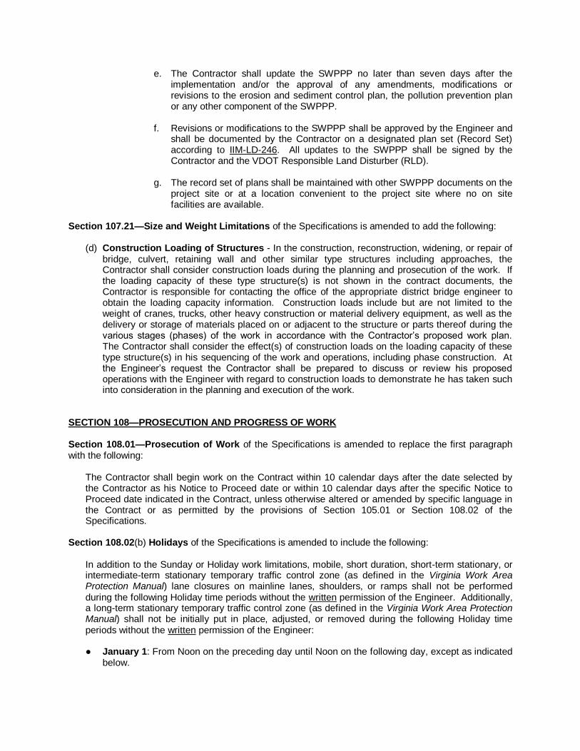
e. The Contractor shall update the SWPPP no later than seven days after the implementation and/or the approval of any amendments, modifications or revisions to the erosion and sediment control plan, the pollution prevention plan or any other component of the SWPPP.
f. Revisions or modifications to the SWPPP shall be approved by the Engineer and
shall be documented by the Contractor on a designated plan set (Record Set) according to IIM-LD-246. All updates to the SWPPP shall be signed by the Contractor and the VDOT Responsible Land Disturber (RLD).
g. The record set of plans shall be maintained with other SWPPP documents on the
project site or at a location convenient to the project site where no on site facilities are available.
Section 107.21—Size and Weight Limitations of the Specifications is amended to add the following:
(d) Construction Loading of Structures - In the construction, reconstruction, widening, or repair of bridge, culvert, retaining wall and other similar type structures including approaches, the Contractor shall consider construction loads during the planning and prosecution of the work. If the loading capacity of these type structure(s) is not shown in the contract documents, the Contractor is responsible for contacting the office of the appropriate district bridge engineer to obtain the loading capacity information. Construction loads include but are not limited to the weight of cranes, trucks, other heavy construction or material delivery equipment, as well as the delivery or storage of materials placed on or adjacent to the structure or parts thereof during the various stages (phases) of the work in accordance with the Contractor’s proposed work plan. The Contractor shall consider the effect(s) of construction loads on the loading capacity of these type structure(s) in his sequencing of the work and operations, including phase construction. At the Engineer’s request the Contractor shall be prepared to discuss or review his proposed operations with the Engineer with regard to construction loads to demonstrate he has taken such into consideration in the planning and execution of the work.
SECTION 108—PROSECUTION AND PROGRESS OF WORK Section 108.01—Prosecution of Work of the Specifications is amended to replace the first paragraph with the following:
The Contractor shall begin work on the Contract within 10 calendar days after the date selected by the Contractor as his Notice to Proceed date or within 10 calendar days after the specific Notice to Proceed date indicated in the Contract, unless otherwise altered or amended by specific language in the Contract or as permitted by the provisions of Section 105.01 or Section 108.02 of the Specifications.
Section 108.02(b) Holidays of the Specifications is amended to include the following:
In addition to the Sunday or Holiday work limitations, mobile, short duration, short-term stationary, or intermediate-term stationary temporary traffic control zone (as defined in the Virginia Work Area Protection Manual) lane closures on mainline lanes, shoulders, or ramps shall not be performed during the following Holiday time periods without the written permission of the Engineer. Additionally, a long-term stationary temporary traffic control zone (as defined in the Virginia Work Area Protection Manual) shall not be initially put in place, adjusted, or removed during the following Holiday time periods without the written permission of the Engineer: ● January 1: From Noon on the preceding day until Noon on the following day, except as indicated
below.

● Easter: As indicated below. ● Memorial Day: As indicated below. ● July 4: From Noon on the preceding day until Noon on the following day, except as indicated
below. ● Labor Day: As indicated below. ● Thanksgiving Day: From Noon on the Wednesday preceding Thanksgiving Day until Noon on
the Monday following Thanksgiving Day. ● Christmas Day: From Noon on the preceding day until Noon on the following day, except as
indicated below. If the Holiday occurs on a Friday or Saturday: From Noon on the preceding Thursday to Noon on the following Monday. If the Holiday occurs on a Sunday or Monday: From Noon on the preceding Friday to Noon on the following Tuesday.
Section 108.04—Determination and Extension of Contract Time Limit of the Specifications is amended to replace the second paragraph with the following:
With a fixed date contract when contract execution is not within 60 calendar days after the opening of bids, or when the Contractor is unable to commence work because of any failure of the Department, or when the Contractor is delayed because of the fault of the Department, the Contractor will be given an extension of time based on the number of days delayed beyond the 60 calendar days. No time extension will be allowed for a delay in the date of contract execution when the delay is the fault of the Contractor.
Section 108.04(a) Fixed Date of the Specifications is amended to add the following after the first paragraph as currently written:
If the Contract identifies a contract-specific Notice to Proceed date and the Contract is not executed by that date, the Contractor will receive an extension of time equal to the number of days between the contract-specific Notice to Proceed date and the eventual date of contract execution. If the Notice to Proceed date is selected by the Contractor and after prior approval the Engineer directs the Contractor not to begin work on that date, the Contractor will receive an extension of time equal to the number of days between the Contractor’s selected Notice to Proceed date and the eventual date the Engineer informs the Contractor that he may commence the work.
Section 108.07—Default of Contract of the Specifications is amended to replace condition (a) with the following:
(a) fails to begin the work under the Contract within 10 calendar days after the Contractor’s selected
Notice to Proceed date, or within 10 calendar days after a contract specific Notice to Proceed date indicated in the Contract, except as otherwise permitted by specific contract language or the provisions of Section 105.01 or Section 108.02 of the Specifications.
SECTION 109—MEASUREMENT AND PAYMENT
Section 109.01(a)—Measurement by Weight is amended to replace the first paragraph and second paragraph including subparagraphs 1-4 with the following:

(a) Measurement by Weight: Materials that are measured or proportioned by weight shall be weighted on accurate scales as specified in this section. When material is paid for on a tonnage basis, personnel performing the weighing shall be certified by the Department and shall be bonded to the Commonwealth of Virginia in the amount of $10,000 for the faithful observance and performance of the duties of the weighperson required herein. The bond shall be executed on a form having the exact wording as the Weighpersons Surety Bond Form furnished by the Department and shall be submitted to the Department prior to the furnishing of the tonnage material. The Contractor shall have the weighperson perform the following:
1. Furnish a signed weigh ticket for each load that shows the date, load number, plant
name, size and type of material, project number, schedule or purchase order number, and the weights specified herein.
2. Maintain sufficient documentation so that the accumulative tonnage and distribution of
each lot of material, by contract, can be readily identified. 3. Submit by the end of the next working day a summary of the number of loads and total
weights for each type of material by contract.
Section 109.01(a)—Measurement by Weight is also amended to delete the third paragraph. Section 109.01(d)4 Asphalt is amended to replace the “formula…used in computing the volume of asphalt at temperatures other than 60 degrees F” with the following:
V1 = V x [1 – K(T – 60)]
Section 109.08(b)—Payment to Sub-Contractors of the Specifications is amended to replace the second paragraph with the following:
Payment to Sub-Contractors shall be in accordance with the provisions of §2.2-4354 of the Highway Laws of Virginia:
The Contractor shall take one of the following two actions within 7 days after receipt of payment from the Department for the subcontractor’s portion of the work as shown on the monthly progress estimate:
1. Pay the subcontractor for the proportionate share of the total payment received from the agency attributable to the work performed by the subcontractor under that contract; or
2. Notify the Department and subcontractor, in writing, of his intention to withhold all or a
part of the subcontractor's payment with the reason for nonpayment. The Contractor shall be obligated to pay interest in the amount 1 (one) percent per month on all amounts owed by the Contractor to the subcontractor that remain unpaid after 7 days following receipt by the Contractor of payment from the Department for work performed by the subcontractor, except amounts withheld as allowed in Section 2. The Contractor shall include in each of its subcontracts a provision requiring each subcontractor to include or otherwise be subject to the same payment and interest requirements with respect to each lower tier subcontractor.
Section 109.09—Payment For Material On Hand of the Specifications is replaced with the following:
When requested in writing by the Contractor, payment allowances may be made for material secured for use on the project. Such material payments will be for only those actual quantities identified in the

contract, approved work orders, or otherwise authorized and documented by the Engineer as required to complete the project and shall be in accordance with the following terms and conditions:
(a) Structural Steel or Reinforcing Steel: An allowance of 100 percent of the cost to the
Contractor for structural steel or reinforcing steel materials secured for fabrication not to exceed 60 percent of the contract price may be made when such material is delivered to the fabricator and has been adequately identified for exclusive use on the project. The provisions of this section for steel reinforcement will only apply where the quantity of steel reinforcement is identified as a separate and distinct bid item for payment. An allowance of 100 percent of the cost to the Contractor for superstructure units and reinforcing steel, not to exceed 90 percent of the contract price, may be made when fabrication is complete. Prior to the granting of such allowances, the materials and fabricated units shall have been tested or certified and found acceptable to the Department and shall have been stored in accordance with the requirements specified herein. Allowances will be based on invoices, bills, or the estimated value as approved by the Engineer and will be subject to the retainage requirements of Section 109.08 of the Specifications. For the purposes of this section fabrication is defined as any manufacturing process such as bending, forming, welding, cutting or coating with paint or anti-corrosive materials which alters, converts, or changes raw material for its use in the permanent finished work.
(b) Other Materials: For aggregate, pipe, guardrail, signs and sign assemblies, and other
nonperishable material, an allowance of 100 percent of the cost to the Contractor for materials, not to exceed 90 percent of the contract price, may be made when such material is delivered to the project and stockpiled or stored in accordance with the requirements specified herein. Prior to the granting of such allowances, the material shall have been tested and found acceptable to the Department. Allowances will be based on invoices, bills, or the estimated value of the material as approved by the Engineer and will be subject to the retainage provisions of Section 109.08 of the Specifications.
(c) Excluded Items: No allowance will be made for fuels, form lumber, falsework, temporary
structures, or other work that will not become an integral part of the finished construction. Additionally, no allowance will be made for perishable material such as cement, seed, plants, or fertilizer.
(d) Storage: Material for which payment allowance is requested shall be stored in an
approved manner in areas where damage is not likely to occur. If any of the stored materials are lost or become damaged, the Contractor shall repair or replace them at no additional cost to the Department. Repair or replacement of such material will not be considered the basis for any extension of contract time. If payment allowance has been made prior to such damage or loss, the amount so allowed or a proportionate part thereof will be deducted from the next progress estimate payment and withheld until satisfactory repairs or replacement has been made. When it is determined to be impractical to store materials within the limits of the project, the Engineer may approve storage on private property or, for structural units and reinforcing steel, on the manufacturer’s or fabricator’s yard. Requests for payment allowance for such stored material shall be accompanied by a release from the owner or tenant of such property or yard agreeing to permit the removal of the materials from the property without cost to the Commonwealth.
(e) Materials Inventory: If the Contractor requests a payment allowance for properly stored
material, he shall submit a certified and itemized inventory statement to the Engineer no earlier than five days and no later than two days prior to the progress estimate date. The statement shall be submitted on forms furnished by the Department and shall be accompanied by supplier’s or manufacturer’s invoices or other documents that will

verify the material’s cost. Following the initial submission, the Contractor shall submit to the Engineer a monthly-certified update of the itemized inventory statement within the same time frame. The updated inventory statement shall show additional materials received and stored with invoices or other documents and shall list materials removed from storage since the last certified inventory statement, with appropriate cost data reflecting the change in the inventory. If the Contractor fails to submit the monthly-certified update within the specified time frame, the Engineer will deduct the full amount of the previous statement from the progress estimate. At the conclusion of the project, the cost of material remaining in storage for which payment allowance has been made will be deducted from the progress estimate.

SS20001-1212 September 28, 2012
VIRGINIA DEPARTMENT OF TRANSPORTATION 2007 ROAD AND BRIDGE SUPPLEMENTAL SPECIFICATIONS
SUPPLEMENTAL SECTION 200—GENERAL
SECTION 200—GENERAL of the Specifications is amended as follows:
200.06-Technician and Batcher Certification is replaced with the following:
Certification for technicians and batchers will be awarded by the Department upon a candidate’s satisfactory completion of an examination.
(a) Central Mix Aggregate Technician: A Central Mix Aggregate Technician designs and
makes necessary adjustments in job mixtures at the plant based on an analysis of the specified material. The technician also samples materials and conducts any tests necessary to put the plant into operation and produce a mixture in accordance with the applicable Specifications.
(b) Asphalt Plant Level I Technician: An Asphalt Plant Level I Technician samples
materials. (c) Asphalt Plant Level II Technician: An Asphalt Plant Level II Technician samples
material and is capable of conducting any tests necessary to put the plant into operation. (d) Concrete Plant Technician: A Concrete Plant Technician performs necessary
adjustments in the proportioning of material used to produce the specified concrete mixtures
(e) Concrete Batcher: A Concrete Batcher performs the batching operation. The batcher
implements adjustments only at the direction of a certified Concrete Plant Technician unless the batcher’s certification authorizes otherwise.
(f) Asphalt Field Level I Technician: An Asphalt Field Level I Technician provides quality
control of the placement operations of Asphalt Concrete. (g) Asphalt Field Level II Technician: An Asphalt Field Level II Technician inspects asphalt
concrete placement in accordance with applicable requirements. (h) Concrete Field Technician: A Concrete Field Technician provides quality control of
placement operations for hydraulic cement concrete in accordance with applicable requirements.
(i) Asphalt Mix Design Technician: An Asphalt Mix Design Technician is responsible for
designing and adjusting mixes as needed, reviewing and approving all test results, having direct communication with the plant for making recommended adjustments and is capable of conducting any tests necessary to put the plant into operation.
(j) Aggregate Properties Technician: An Aggregate Properties Technician conducts all
aggregate tests on aggregate used in asphalt concrete in accordance with applicable requirements
(k) Slurry Surfacing Technician: A Slurry Surfacing Technician inspects the placement of
emulsified asphalt slurry seal and latex modified emulsion treatment (Micro-surfacing) in accordance with applicable requirements.

(l) Surface Treatment Technician: A Surface Treatment Technician inspects the
placement of single seal and modified (blotted) seal coats in accordance with applicable requirements.

SS20702-0714 February 19, 2014
VIRGINIA DEPARTMENT OF TRANSPORTATION 2007 ROAD AND BRIDGE SUPPLEMENTAL SPECIFICATIONS
SUPPLEMENTAL SECTION 207—SELECT MATERIAL
SECTION 207—SELECT MATERIAL of the Specifications is amended as follows:
Section 207.03—Job Mix Formula for Select Material, Type I is amended to replace the first paragraph with the following:
The Contractor shall submit or shall have the source of supply submit a job-mix formula for each mixture for the Engineer’s approval through the “Producer Lab Analysis and Information Details” (PLAID) website https://plaid.vdot.virginia.gov prior to starting work. The formula shall establish a single percentage of aggregate passing each required sieve size denoted in Table II-6 and shall be in effect until a modification is approved by the Engineer. If unsatisfactory results or other changed conditions make it necessary, the Contractor shall prepare and submit a new formula for the Engineer’s approval.
Section 207.05—Acceptance of Select Material, Type I is amended to replace the first and second paragraphs with the following:
Sampling and testing for determination of grading, moisture, and Atterberg limits shall be performed by the Contractor. The Contractor shall provide such test results within 48 hours of sampling to the Department through the “Producer Lab Analysis and Information Details” (PLAID) website https://plaid.vdot.virginia.gov. The Contractor shall maintain appropriate, current quality control charts. The Department will perform independent monitor tests. If there is a statistically significant difference between the two sets of results, an investigation will be made to determine the reason for the difference. If it is determined that the material does not conform to the requirements of the Contract, the material will be rejected or a payment adjustment will be made in accordance with the requirements of Section 207.07. Determination of gradation and Atterberg limits will be based on a mean of the results of tests performed on four samples taken in a stratified random manner from each lot. Lots of 2000 tons or 4000 tons may be used at the discretion of the Engineer when warranted by annual plant shipping quantity and past performance. If visual examination reveals that the material is obviously contaminated or segregated, the material will be rejected without additional sampling or testing. If it is necessary to determine the gradation and Atterberg limits of the material in an individual location, one sample taken from the material in question will be tested and the results will be compared to the job-mix formula with the tolerances specified in Table II-7 and Table II-8 for one test. The results obtained will apply only to the material in question.

SS20802-0714 February 19, 2014
VIRGINIA DEPARTMENT OF TRANSPORTATION 2007 ROAD AND BRIDGE SUPPLEMENTAL SPECIFICATIONS
SUPPLEMENTAL SECTION 208—SUBBASE AND AGGREGATE BASE MATERIAL
SECTION 208—SUBBASE AND AGGREGATE BASE MATERIAL of the Specifications is amended as follows:
Section 208.04—Job Mix Formula is amended to replace the first paragraph with the following: The Contractor shall submit, or shall have the source of supply submit a job-mix formula for each mixture for the Engineer’s approval through the “Producer Lab Analysis and Information Detail” (PLAID) website https://plaid.vdot.virginia.gov prior to starting work. The formula shall be within the design range specified in Table II-9. If unsatisfactory results or other conditions make it necessary, the Contractor shall prepare and submit a new job-mix formula for approval.
Section 208.06—Acceptance is amended to replace the second and third paragraphs with the
following: Sampling and testing for determination of grading, moisture, and Atterberg limits shall be performed by the Contractor. The Contractor shall provide such test results within 48 hours of sampling to the Department through “the Producer Lab Analysis and Information Details” (PLAID) website https://plaid.vdot.virginia.gov. The Contractor shall maintain appropriate current quality control charts. The Department will perform independent monitor tests at a laboratory of its choice. If there is a statistically significant difference between the two sets of results, an investigation will be made to determine the reason for the difference. If it is determined that the material does not conform to the requirements of the Contract, the material will be rejected or a payment adjustment will be made in accordance with the requirements of Section 208.08 of the Specifications. Determination of gradation and Atterberg limits will be based on a mean of the results of tests performed on four samples taken in a stratified random manner from each lot. Lots of 2000 tons or 4000 tons may be used at the discretion of the Engineer when warranted by annual plant shipping quantity and past performance. Samples shall be obtained by methods approved by the Engineer. Any statistically acceptable method of randomization may be used to determine the time and location of the stratified random sample to be taken. The Department shall be advised of the method to be used prior to the beginning of production.

SS21001-1014 September 3, 2014
VIRGINIA DEPARTMENT OF TRANSPORTATION 2007 ROAD AND BRIDGE SUPPLEMENTAL SPECIFICATIONS
SUPPLEMENTAL SECTION 210—ASPHALT MATERIALS
SECTION 210—ASPHALT MATERIALS of the Specifications is replaced with the following:
210.01—Description These specifications cover the manufacturing and material requirements for asphalt material consisting of asphalt, asphalt cement, asphalt cutback, or asphalt emulsion as defined in ASTM D8. 210.02—Materials Asphalt material shall be homogeneous and shall conform to the following:
(a) Rapid curing and medium curing liquid asphalts used as surface treatments shall contain a heat-stable additive conforming to the requirements of Section 211 of the Specifications.
(b) Liquid asphalt material will be tested for coating ability in accordance with the requirements of AASHTO T182, with the following modifications:
1. Material that can coat 95 percent of a shady dolomite will be classified Type I. 2. Material that can coat 95 percent of a siliceous gravel wetted with 2 percent
water by weight will be classified Type II.
(c) Rapid curing cutback asphalts shall conform to the requirements of AASHTO M81.
(d) Medium curing cutback asphalts shall conform to the requirements of AASHTO M82.
(e) Cements shall be viscosity graded and shall conform to the requirements of AASHTO M226, Table 2, except that the loss on heating shall be not greater than 1.0 for AC-5, 0.8 for AC-20, and 0.5 for all other grades.
(f) Emulsions shall conform to the requirements of AASHTO M208 and shall be Type I as specified herein except that CRS-2 shall be Type II as specified herein. CRS-1h shall conform to the requirements of AASHTO M208 for CRS-1 except that the penetration shall be 40 to 110. Emulsions will be sampled and tested in accordance with the requirements of AASHTO T59 except that viscosity will be tested in accordance with the requirements of VTM-64.
(g) Polymer Modified Cationic Emulsified Asphalt shall conform to the requirements of
AASHTO M316.
(h) Non-tracking tack will be tested in accordance with the requirements set forth in Section 210.07 of the Specifications.
210.03—VDOT Asphalt Acceptance Program (VAAP)

Acceptance into the VAAP
(a) Asphalt materials will be accepted under the VDOT Asphalt Acceptance Program
(VAAP). This involves sampling, testing, documentation and certification of the product by the manufacturer in combination with a Department monitoring effort. Performance Graded Binder suppliers shall conform to AASHTO R-26 and Emulsion supplies shall conform to AASHTO PP-71 to be added to the VAAP, with provisions listed below.
(b) To have a new facility added to the VAAP, producers shall:
1. Submit a split sample of each material to be approved to VDOT Central Office Materials Division for testing.
(c) Approved shipping facilities from the VAAP that need to add a material to the approved
list shall:
1. Submit a split sample of the material to be approved to VDOT Central Office Materials Division for testing.
210.04—VDOT Asphalt Acceptance Program Requirements and Compliance The manufacturer shall ensure the following are performed:
(a) Asphaltic materials shall be sampled at a minimum frequency of once a month and when additional materials are added to existing material and tested in accordance with the specified methods in Section 210.07 of the Specifications.
(b) A file or certified test reports representing the asphaltic material shall be maintained by the manufacturer.
(c) A copy of the certified test report shall be provided to the VDOT Central Office Materials Division at Elko within 30 days of sampling. Failure to comply with this requirement can result in removal from the VAAP and the approved materials list.
(d) Manufacturers shall supply to the Central Office Materials Division at Elko a summary sheet of quantities shipped to state work annually in January of the following year. This summary sheet will show the number of gallons of each type/grade of material shipped to Virginia addresses.
(e) The manufacturer shall submit to the Department a detailed plan of action describing the procedures to be taken to ensure tracking of sample test results and the material represented by these results.
210.05—Sampling
(a) Samples shall be taken in the presence of VDOT personnel or a VDOT representative.
(b) Samples taken for testing of asphaltic materials are to be not less than one quart (one liter) of material (0.5 gallons (2 liters) for asphalt emulsions).
(c) Care is to be taken to ensure that the samples are not contaminated and the sample containers are perfectly clean and dry before filling.

(d) Immediately after filling, sample containers are to be tightly closed, and properly marked for identification on the container itself.
210.06—Testing
(a) The Manufacturer shall conduct the standard control tests on asphaltic materials as
detailed in Section 210.07 of the Specifications.
(b) Testing for certified test reports shall be performed by the Manufacturer’s personnel in the Manufacturer’s VDOT approved laboratory or by a VDOT approved commercial testing facility.
(c) The Department shall conduct acceptance testing at a frequency of a minimum of 1 test per month per type/grade of asphaltic material that has been supplied to VDOT projects during the previous month at the VDOT Central Office Materials at Elko. This frequency is to be maintained during the construction season, with a lesser frequency during the remainder of the year.
(d) Laboratories conducting quality control must be certified by VDOT as meeting the requirements of certification:
1. All Binder Laboratories shall hold AASHTO Accreditation and provide VDOT with
a copy of accreditation.
2. All Emulsion Laboratories shall be one of the following two levels: a. Level I: AASHTO Accreditation
(1) Provide VDOT with a copy of accreditation.
b. Level II: AMRL Proficiency Sample Program
(1) Provide VDOT with copies of last “Round Robin” results, with
ratings for each type of asphaltic material tested and copies of the lab’s response for each sample.
(2) Development of a calibration program and personnel record keeping procedure, with results being kept on file at site.
3. All laboratories under the VAAP shall be AASHTO accredited by January 1, 2016.
4. Test Reports a. The Manufacturer shall maintain a file of certified test reports for all
asphaltic materials ultimately shipped to Contractors that perform work for VDOT.
b. Test Reports shall indicate that the material shipped meets the
requirements for that type/grade of asphaltic material and will show the test results that were obtained to determine compliance with the applicable specifications.
c. Records shall be kept by the Manufacturer for at least 12 months and
shall be available for verification by VDOT personnel.

d. Copies of certified test results shall also be sent to the VDOT Central
Office Materials Division at ELKO. e. Certified Test Reports shall be a company’s standard form containing the
following information: (1) Manufacturer’s name and address (2) Type and grade of asphaltic material (3) Testing performed (AASHTO or Virginia Test Method
designation) (4) Test results and date obtained (5) Quantity represented (6) Tank Number (7) Unique Report Identifier (8) Statement indicating that the Manufacturer “certified that these
are the test results obtained on the material tested under the VAAP program”.
210.07—Tests
(a) PG Asphalt Binders:
1. Certified Test Reports for PG Asphalt Binders shall be based upon the results
of tests performed in accordance with AASHTO M332, Table 1. The Manufacturer is not required to perform the Direct Tension Test, AASHTO T314.
2. Certified test results for Superpave PG Asphalt Binders are to be based upon the results of tests performed in accordance with AASHTO R 29, as specified below: a. Original Material
Flash Point °C AASHTO T 48
Viscosity @ 135°C/100°C AASHTO T316
Dynamic Shear, 10 Rad/sec AASHTO T 315
b. RTFO (AASHTO T 240) Material
Mass Loss % AASHTO T 240
Dynamic Shear, 10 Rad/sec AASHTO T 315
Multiple Stress Creep Recovery (MSCR) Test AASHTO T 350
c. Pressure Aging Vessel, Residue at 100°C (AASHTO R 28)
Dynamic Shear, 10 Rad/sec AASHTO T 315
Creep Stiffness, 60 sec AASHTO T 313
M-Slope AASHTO T 313

3. For asphalt binders tested in accordance with AASHTO T 350, indication of
elastic response shall be determined using Figure X1.1 Nonrecoverable Creep Compliance Versus Percent Recovery in AASHTO M 332.
(b) Cutback Asphalts: 1. Certified Test Reports for Cutback Asphalts shall be based upon the results of
tests performed in accordance with AASHTO M81 and M82. The Manufacturer is not required to perform the Flash Point, Ductility, and Solubility tests unless otherwise directed by the Engineer. VDOT shall perform Ductility and Solubility tests on all acceptance samples. Flash Point tests will be performed by VDOT periodically. When performed by VDOT, failure of either sample on Flash Point, Ductility, and Solubility will be considered sufficient reason to require the Manufacturer to perform this testing. If the Manufacturer elects to conduct these tests to better control production, the results shall be included on the certified test report.
2. When used in surface treatments, the Coating Ability test shall be conducted
subject to the specifications listed in Section 210.02 of the Specifications.
(c) Emulsified Asphalts:
1. Certified Test Reports for Emulsified Asphalts shall be based upon the results of tests performed in accordance with AASHTO M208 or AASHTO M316, as specified below:
a. Cationic Emulsions- Table 1, specifically
(1) Tests on Emulsions:
● Saybolt Furol Viscosity ● Sieve Test (if necessary) ● Demulsibility or Classification test ● Particle Charge Test ● Residue by Distillation
(2) Tests on residue from distillation: ● Penetration
b. CSS-1h (Quick Set):
Same tests as Cationic Emulsions, as well as: ● Quick set Emulsified Asphalt Setting Time (VTM-89)
c. Latex Modified Cationic Emulsions (Quick Set)
(1) CQS-1h Latex Modified (CQS-1hLM)
a) Tests on Emulsions
● Saybolt Furol Viscosity ● Sieve Test (if necessary) ● Particle Charge Test ● Residue by Evaporation (VTM-78)
b) Tests on residue ● Penetration

● Ring and Ball Softening Point
(2) CRS-2 Latex a) Tests on Emulsions
● Saybolt Furol Viscosity ● Sieve Test (if necessary) ● Particle Charge Test ● Residue by Distillation
b) Tests on residue by Distillation ● Penetration ● Ring and Ball Softening Point ● Elastic Recovery
2. The Manufacturer is not required to perform the Flash Point, Ductility, and
Solubility tests unless otherwise directed by the Engineer. VDOT shall perform Ductility and Solubility tests on all independent assurance (monitor) and Q.A. samples. Flash Point tests will be performed by VDOT periodically. When performed by VDOT, failure of either sample on Flash Point, Ductility, and Solubility will be considered sufficient reason to require the Manufacturer to perform this testing. If the Manufacturer elects to conduct these tests to better control production, the results shall be included on the certified test report.
(d) Non-Tracking Tack:
1. Certified Test Reports for Non-Tracking Tack shall be based upon the results of
tests performed, as specified below: a. Tests on Non-Tracking Tack:
● Saybolt Furol Viscosity ● Residue by Distillation
b. Tests on residue by distillation: ● Ring and Ball Softening Point
210.08—Storing and Shipping
(a) Shipping:
1. Shipments of asphalt material shall be made in transporting media that are free
from contamination. Tank trucks or trailers shall be equipped with an Engineer approved sampling device. The device shall have an inside diameter of 1/2 to 1 inch and a gate valve or petcock. The device shall be built into the tank or the recirculating or discharge line so that a sample can be drawn during circulation or discharge.
2. All Shipping documents shall contain sufficient information such that at any point, the material may be traceable back to the original test results. If the material is mixed with other approved material for storage, the record system will be such as to assure the traceability of all the material which is being mixed.
3. All shipping documents shall be accompanied by a statement similar to “We certify that all material being shipped on this invoice/bill of lading has been tested and approved under the Virginia Asphalt Acceptance Program and that the

material has been loaded under the supervision of our representative into carriers that are suitable for shipment of this material.”
4. All shipping documents shall be kept by the recipient of the material for at least 12 months and are to be available for verification by VDOT personnel l.
5. Only material tested and certified in accordance with the VAAP shall be mixed and shipped to VDOT projects.
(b) Storing: Asphalt material shall be placed in storage tanks that are free from contamination.
210.09—Payment Adjustment System If the asphalt material represented by any one sample does not conform to the requirements herein and the material is a pay item, the Engineer will reduce the contract unit price for the item by 4 percent for each property that does not conform to the Specifications for the quantity represented by the sample that was used on the project. The Engineer will reject any unused material represented by the failing sample. The Engineer will consider any failed sampled asphalt material that is not a pay item unacceptable and subject to the requirements of Section 105.18 and Section 106.10 of the Specifications.

SS21202-0911 June 28, 2011
VIRGINIA DEPARTMENT OF TRANSPORTATION 2007 ROAD AND BRIDGE SUPPLEMENTAL SPECIFICATIONS
SUPPLEMENTAL SECTION 212—JOINT MATERIALS
SECTION 212—JOINT MATERIALS of the Specifications is amended as follows:
Section 212.02(h)—Gaskets for pipe is replaced with the following:
(h) Gaskets for pipe shall conform to the following: Rubber gaskets for ductile iron pipe and
fittings shall conform to the requirements of AWWA C111; rubber gaskets for all other pipe shall conform to the requirements of ASTM C443 and the ozone cracking resistance described in Section 237.02. Preformed plastic gaskets shall conform to the requirements of ASTM C990.

SS21402-0908 January 28, 2008
VIRGINIA DEPARTMENT OF TRANSPORTATION 2007 ROAD AND BRIDGE SUPPLEMENTAL SPECIFICATIONS
SUPPLEMENTAL SECTION 214—HYDRAULIC CEMENT
SECTION 214—HYDRAULIC CEMENT of the Specifications is amended as follows:
Section 214.02(b) Portland cements is amended by replacing 1. with the following: 1. The SO3 content as specified in AASHTO M85 will be permitted, provided supporting
data specified in AASHTO M85 are submitted to the Department for review and acceptance prior to use of the material.
Section 214.02(b) Portland cements is amended by deleting 3., 4., and 5. Section 214.02—Detail Requirements is amended by adding the following:
(c) Expansive hydraulic cement shall conform to the requirements of ASTM C 845 Type K.

SS21501-0908 January 28, 2008
VIRGINIA DEPARTMENT OF TRANSPORTATION 2007 ROAD AND BRIDGE SUPPLEMENTAL SPECIFICATIONS
SUPPLEMENTAL SECTION 215—HYDRAULIC CEMENT CONCRETE ADMIXTURES
SECTION 215—HYDRAULIC CEMENT CONCRETE ADMIXTURES of the Specifications is amended as follows:
Section 215.02(g) Fly ash is replaced with the following:
(g) Pozzolan shall conform to Section 241 of the Specifications. Section 215.02—Materials is amended by adding the following:
(k) Metakaolin shall conform to the requirements of AASHTO M321

SS21706-0214 July 29, 2013
VIRGINIA DEPARTMENT OF TRANSPORTATION 2007 ROAD AND BRIDGE SUPPLEMENTAL SPECIFICATIONS
SUPPLEMENTAL SECTION 217—HYDRAULIC CEMENT CONCRETE
SECTION 217—HYDRAULIC CEMENT CONCRETE of the Specifications is amended as follows:
Section 217.02(a) Cementitious Materials is replaced with the following:
Cementitious materials shall be a blend of mineral admixtures and Portland cement or a blended cement. In overlay concretes, expansive hydraulic cement is permitted in lieu of Portland cement. Portland cement (Types I, II, III) blended cements (Type IP, Type IS) or expansive cement (Type K) shall comply with Section 214 of the Specifications. Flyash, ground granulated iron blast-furnace slag (GGBFS), silica fume or metakaolin shall conform to Section 215 of the Specifications. As a portion of the cementitious material, Table 1 lists the minimum percents of specific pozzolans required by mass of the cementitious material depending on the alkali content of the cement. Any other mineral admixture or any other amount or combination of mineral admixtures may be used if approved by the Engineer. As a portion of the cementitious material, the fly ash content shall not exceed 30 percent for Class F, the ground granulated blast-furnace slag content shall not exceed 50 percent and the silica fume content shall not exceed 10 percent unless approved by the Engineer. Class C Flyash or other pozzolans may be used provided the contractor demonstrates that the percent usage of Class C Flyash or other pozzolans have a maximum expansion of 0.15% according to ASTM C227 at 56 days using borosilicate glass as aggregate. Blended cements require no further pozzolan additions to meet minimum pozzolan content to compensate for the alkali-silica reaction. Up to 7 percent silica fume may be added to all combinations of cementitious materials to reduce early permeability without approval by the Engineer. Other silica fume additions must be approved by the Engineer. Table 1 – Minimum percent pozzolan required by mass of cementitious material as a portion of the total cementious materials and are based upon the alkali content of the cement.
Total Alkalies of Cement is less than or equal to 0.75%
Total Alkalies of Cement is greater than 0.75% and less than or equal
to 1.0%
Class F Flyash 20% 25%
GGBF Slag 40% 50%
Silica Fume 7% 10%
Metakaolin 7% 10%
TABLE II–17 Requirements for Hydraulic Cement Concrete is replaced with the following:
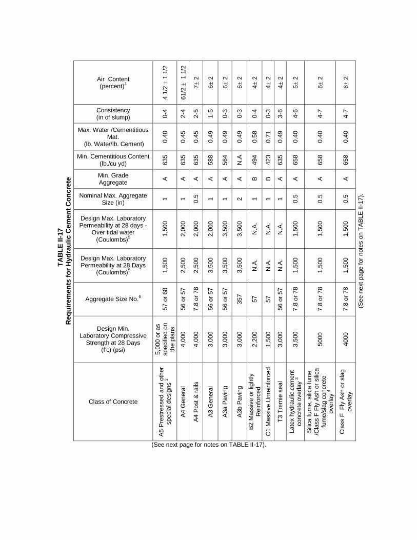
TA
BL
E I
I-17
Req
uir
em
en
ts f
or
Hyd
rau
lic C
em
en
t C
on
cre
te
Air Content (percent)
1
4 1
/2
1 1
/2
61/2
1 1
/2
7 2
6 2
6 2
6 2
4 2
4 2
4 2
5 2
6 2
6 2
(See n
ext
page for
note
s o
n T
AB
LE
II-
17).
Consistency (in of slump) 0
-4
2-4
2-5
1-5
0-3
0-3
0-4
0-3
3-6
4-6
4-7
4-7
Max. Water /Cementitious Mat.
(lb. Water/lb. Cement)
0.4
0
0.4
5
0.4
5
0.4
9
0.4
9
0.4
9
0.5
8
0.7
1
0.4
9
0.4
0
0.4
0
0.4
0
Min. Cementitious Content (lb./cu yd) 6
35
635
635
588
564
N.A
494
423
635
658
658
658
Min. Grade Aggregate
A
A
A
A
A
A
B
B
A
A
A
A
Nominal Max. Aggregate Size (in)
1
1
0.5
1
1
2
1
1
1
0.5
0.5
0.5
Design Max. Laboratory Permeability at 28 days -
Over tidal water (Coulombs)
5
1,5
00
2,0
00
2,0
00
2,0
00
3,5
00
3,5
00
N.A
.
N.A
.
N.A
.
1,5
00
1,5
00
1,5
00
Design Max. Laboratory Permeability at 28 Days
(Coulombs)5 1
,500
2,5
00
2,5
00
3,5
00
3,5
00
3,5
00
N.A
.
N.A
.
N.A
.
1,5
00
1,5
00
1,5
00
Aggregate Size No.6
57 o
r 68
56 o
r 57
7,8
or
78
56 o
r 57
56 o
r 57
357
57
57
56 o
r 57
7,8
or
78
7,8
or
78
7,8
or
78
Design Min. Laboratory Compressive
Strength at 28 Days (f'c) (psi)
5,0
00 o
r as
specifie
d o
n
the p
lans
4,0
00
4,0
00
3,0
00
3,0
00
3,0
00
2,2
00
1,5
00
3,0
00
3,5
00
5000
4000
Class of Concrete
A5 P
restr
essed a
nd o
ther
specia
l desig
ns 2
A4 G
enera
l
A4 P
ost
& r
ails
A3 G
enera
l
A3a P
avin
g
A3b P
avin
g
B2 M
assiv
e o
r lig
htly
Rein
forc
ed
C1 M
assiv
e U
nre
info
rced
T3 T
rem
ie s
eal
Late
x h
ydra
ulic
cem
ent
concre
te o
verlay 3
Sili
ca f
um
e, sili
ca fum
e
/Cla
ss F
Fly
Ash o
r sili
ca
fum
e/s
lag c
oncre
te
overlay 4
Cla
ss F
F
ly A
sh o
r sla
g
overlay
(See next page for notes on TABLE II-17).

--------------------------------------------------------------------------------- (TABLE II-17 Notes) -------------------------------------
1 When a high-range water reducer is used, the upper limit for entrained air may be increased by
1% and the slump shall not exceed 7 inches.
2 When Class A5 concrete is used as the finishing bridge deck riding surface, or when it is to be
covered with asphalt concrete with or without waterproofing, the air content shall be 5 1/2 1 1/2 percent.
3 The latex modifier content shall be 3.5 gallons per bag of cement. Slump shall be measured approximately 4.5 minutes after discharge from the mixer.
4 Silica fume with a minimum of 7% by weight of cementitious material; silica fume with a range of 2.5-5 % shall be combined with Class F Fly Ash in range of 15-20% and minimum cement of 77.5% by weight of cementitious material; silica fume with a range of 2.5-5% shall be combined with Ground Granulated Blast Furnace Slag in the range of 30-35% and a minimum cement of 67.5% by weight of cementitious material.
5 The permeability testing does not apply to small bridges identified on the bridge plans and to
concrete structures and incidental concrete as described in Sections 219, 232, 302, 415, 502, 504, 506 and 519. Curing and testing of test cylinders for permeability will be in accordance with VTM 112.
6 The contractor may use different aggregate sizes or a combination of sizes to increase the coarse
aggregate content of the concrete as approved by the Engineer. The maximum size of the coarse aggregate shall not exceed 2.5 inches.
Note: With the approval of the Engineer, the Contractor may substitute a higher class of concrete for that specified at the Contractor’s expense.
Section 217.02(b) Formulated latex modifier is amended by adding the following: For latex-modified concrete, Type I, Type II, Type III or Type K, cement shall be used without mineral admixtures.
Section 217.04(a)4. Admixtures is replaced with the following:
4. Admixtures shall be dispensed and used according to the manufacturer’s recommendations. They shall be added within a limit of accuracy of 3 percent, by means of an approved, graduated, transparent, measuring device before they are introduced into the mixer. If more than one admixture is to be used, they shall be released in sequence rather than in the same instant. Once established, the sequence of dispensing admixtures shall not be altered. However, when the amount of admixture required to give the specified results deviates appreciably from the manufacturer’s recommended dosage, use of the material shall be discontinued.
Section 217.05—Equipment is amended to replace the first paragraph with the following:
Equipment and tools necessary for handling materials and performing all parts of the work will be approved by the Engineer and must be in accordance with one of the following procedures:
1. having a current National Ready Mix Concrete Association Plant and Truck Certification, or
2. having a Department approved self-certification program in-place prior to the production
of concrete for the Department. Failure to comply with one or the other of these procedures will result in the concrete production being unapproved and work will not be allowed to proceed.

Section 217.05(a) Batching Equipment is amended to replace the second paragraph with the following:
Scales used for weighing aggregates and cement shall be approved and sealed in accordance with the requirements of Section 109 of the Specifications.
Section 217.05—Equipment is amended to add the following:
(d) High Performance Volumetric Mixers (HPVMs): The Contractor may produce the
specified class of hydraulic cement concrete in Table II-17 in accordance with Section 217.02(a) of the Specifications provided that the manufacturer’s equipment meets the tolerance requirements of Section 217.04(a) of the Specifications and has a stamped plate from the Volumetric Mixers Manufacturers Bureau stating that the equipment conforms to the requirements in ASTM C685. The hydraulic cement concrete shall be mixed at the point of delivery by a combination of materials transport and mixer unit conforming to the following:
1. The unit shall be equipped with calibrated proportioning devices for each
ingredient added to the concrete mix. The unit shall be equipped with a working recording meter that is visible at all times and furnishes a ticket printout with the calibrated measurement of the mix being produced. If at anytime the mixer fails to discharge a uniform mix, production of concrete shall halt until any problems are corrected.
2. Each unit shall have a metal plate(s) attached in a prominent place by the
manufacturer on which the following are plainly marked: the gross volume of the transportation unit in terms of mixed concrete, the discharge speed and the mass calibrated constant of the machine in terms of volume.
3. HPVMs shall be calibrated by a Department approved testing agency in
accordance with the manufacturer’s recommendations at an interval of every 6 months or a maximum production of 2500 cubic yards, whichever occurs first prior to use on the project. The yield shall be maintained within a tolerance of ±1 percent and verified using a minimum 2 cubic feet container every 500 cubic yards or a minimum once per week.
4. The three cubic feet initially discharged from the truck shall be discarded and not
used for concrete placement. Acceptance of the specified class of concrete shall comply with Section 217.08 of the Specifications except that the sample secured for acceptance testing will be taken after four cubic feet is discharged from the delivery vehicle. During discharge, the consistency as determined by ASTM C143 on representative samples taken from the mixer discharge at random intervals shall not vary more than 1 inch. Acceptance tests shall be performed on each load. If test data demonstrates that consistency of concrete properties are being achieved, the Engineer may reduce testing requirements.
5. The HPVM shall be operated by a person who is a certified operator by the
HPVM manufacturer. Any equipment adjustments made during the on-site production of concrete shall be done under the direct on-site supervision of the producer’s VDOT Concrete Plant and Field Certified Technician.
Each load of HPVM produced concrete shall be accompanied by a Form TL-28 signed by the producer’s VDOT Certified Concrete Plant Technician or a designated company representative working under the direct on-site supervision of the producer’s VDOT Concrete Plant and Field Certified Technician. The form shall be delivered to the Inspector at the site

of the work. Loads that do not carry such information or do not arrive in satisfactory condition shall not be used.
Section 217.07—Proportioning Concrete Mixtures is amended to replace the first paragraph with the following:
The Contractor is responsible for having a Certified Concrete Plant Technician available during batching operations, and a Certified Concrete Field Technician shall be present during placing operations.
Section 217.07—Proportioning Concrete Mixtures is amended to delete the third paragraph beginning with “A Certified Concrete Batcher”. Section 217.07—Proportioning Concrete Mixtures of the Specifications is amended to replace the eleventh paragraph with the following:
Except for latex hydraulic cement concrete, concrete mixtures shall be developed and/or verified by any one of the following three options listed below. The mix design(s) as determined by the respective option shall be valid provided there is no change in sources of aggregate, chemical admixtures, mineral admixtures or hydraulic cement. All concrete mixtures shall contain the minimum amount of mineral admixtures or combination thereof expressed as a percent of the total cementitious materials in accordance with Section 217.02(a). All quantities of materials shall be weighed in accordance with tolerances specified in Section 217.04. Neither the quantities of coarse or fine aggregates used in concrete production shall deviate by more than ±5% by weight from the batch weights of the approved mix design. When low permeability concrete is specified, two 4 X 8 inch specimens shall be molded from concrete representing the proposed mix design and tested in accordance with VTM 112 to validate conformance. For trial batches, the tested permeability value shall be considered satisfactory provided it is 500 coulombs less than the specified maximum value for the class of concrete specified.
Option 1 - Prescriptive Method: Mix proportions for normal, heavy weight, and lightweight concrete shall be established by the methods described in ACI 211, on an absolute volume basis, for the respective aggregate size and meeting all the requirements of Table II-17 for the class of concrete indicated. Aggregate properties obtained from the aggregate producer shall be used for design purposes. Once the proposed mix design has been established, the contractor or their concrete supplier shall produce one 3-cubic yard production verification batch using the same type of equipment intended for use in supplying concrete to the Department. The proposed mix design will be considered acceptable provided that the plastic properties of the concrete are within the Department’s specification limits for the given class of concrete. Strength tests of the verification batch must equal or exceed f’c for the intended class of concrete.
Option 2 - Trial Batch Mix Design Method: The minimum cementitious content requirement in Table II-17 shall be waived provided that the maximum water-cementitious ratio requirement of Table II-17 is met for the respective class of concrete. The required grading for fine and coarse aggregate shall be waived provided the coarse aggregate meets the nominal maximum size as required in Table II-17 for the respective class of concrete.

The Contractor or their concrete supplier shall prepare a minimum of 3 trial concrete batches with differing cementitious materials contents over a range anticipated to encompass the design strength, f’c, plus overdesign, and water-cementitious ratios encompassing the range permitted for the classes of concrete being evaluated. Trial batches may be produced in either;
Option 2A: Small scale laboratory batches, or Option 2B: Truck batches with a minimum batch volume of 3 cubic yards each.
The plastic properties of the trial concrete batches shall meet the requirements for consistency and air content in Table II-17 and meet the additional requirements listed below:
● The concrete temperature of the trial batches, as batched and sampled, shall be a minimum of 68 degrees F.
● Air content of the trial batches shall within a range of -1.0 to + 1.5 percentage points
of the median design air content for the classes of concrete being evaluated. ● Slump of the trial batches shall be within ± 1 inch of the maximum slump permitted
for the class of concrete.
Three 4 X 8 inch test specimens shall be molded from each batch, cured in accordance with ASTM C 31 for acceptance specimens, and then compression tested at an age of 28 days. The strength results of these tests shall be plotted on a graph to establish the relationship between the water-cementitious ratio and the compressive strength. Alternately, the relationship can be established between the cementitious content and the compressive strength. The design water-cementitious ratio, or design cementitious content, can then be derived from the graph to satisfy the required design strength plus an appropriate overdesign to be designated as f’cr. The required cementitious materials content determined from these tests can be interpolated from the established graph. If desired, the design water-cementitious ratio or cementitious content can be determined from a polynomial regression analysis of the plotted strength data. Test results from prior trial concrete batches are acceptable for use provided that they represent the same material sources proposed for the Department work, meet the requirements for trial concrete batches as stated above and are less than 18 months old. The required cementitious content to satisfy the strength requirement for the respective class of concrete shall be determined in accordance with either of the two following procedures:
1. When the concrete production facility has sufficient data to establish a production
standard deviation (s), as described in Documentation of Previous Field Experience or Production Standard Deviation (s). The cementitious content required to meet the design strength requirement, f’cr, then the f’cr shall be based upon the following equation:
f’cr = f’c + 3s
2. When the concrete production facility does not have a production standard deviation established the cementitious content required to meet the design strength requirement, f’cr, then the f’cr shall be based upon the following equation :
f’cr = f’c + 1700 psi.
Once the proposed mix design has been established, the contractor or their concrete supplier shall produce one 3-cubic yard production verification batch using the same type of

equipment intended for use in supplying concrete to the Department. The proposed mix design will be considered acceptable provided that the plastic properties of the concrete are within the Department’s specification limits for the given class of concrete. Strength tests of the verification batch must equal or exceed f’c for the intended class of concrete. The requirement for a production verification batch shall be waived when the trial batching is performed by Option 2B -Truck batches.
Option 3 - Documented Field Experience Method: The minimum cementitious content requirement in Table II-17 shall be waived provided that the maximum water-cementitious ratio requirement of Table II-17 is met for the respective class of concrete. The required grading for fine and coarse aggregate shall be waived provided the coarse aggregate meets the nominal maximum size as required in Table II-17 for the respective class of concrete. An existing concrete mixture shall be considered acceptable for use provided that the contractor or their concrete supplier has a satisfactory test record of pervious field experience as described in:
Documentation of Previous Field Experience or Production Standard Deviation (s), and that the proposed concrete mixture meets the following requirements:
1. The water cementitious ratio of the proposed concrete mixture is less than or equal to the maximum water cementitious ratio specified for the respective class of concrete.
2. The documented average strength, f’cr, equals or exceeds the design compressive strength f’c for the respective class of concrete in accordance with the following equation: f’cr = f’c + 3s
3. The proposed concrete mixture contains the same aggregate sources, supplementary cementitious materials type, and admixture type as those used to establish the previous field experience test record.
4. The consistency (slump) and air content are within the specification limits for the respective class of concrete.
Documentation of Previous Field Experience or Production Standard Deviation (s)
An acceptable test record to document previous field experience and/or to establish a production facility standard deviation shall represent a minimum of 30 consecutive compressive strength tests results, encompass a production period of at least 45 days and test data not more than 18 months old. A test record of less than 30 tests, but not less than 15 tests, shall be permitted provided a modification factor is applied to the production facility sample standard deviation as shown below:
Multiply Standard Deviation by Modification Factor
Number of Test Modification Factor
15 1.16
20 1.08
25 1.03
30 1.00
The test record does not necessarily have to be based on Department projects provided that documentation of the source(s) of concrete strength test results accompanies the submittal.

Section 217.08—Acceptance is replaced with the following: (a) Air Consistency Tests: Air and consistency tests will be performed by the Department
prior to discharge of concrete into the forms to ensure that specification requirements are consistently being complied with for each class of concrete. The sample secured for the tests shall be taken after at least two cubic feet of concrete has been discharged from the delivery vehicle. The two cubic feet discharged is not to be used as part of the test sample. Any deviation from sampling and testing procedures must be approved by the Engineer. The Contractor shall provide a receptacle conforming to the requirements of ASTM C31, Section 5.9, for the Department’s use in obtaining the sample. If either determination yields a result that is outside of the allowable range for air content or consistence, the following procedure will be used:
1. The Engineer will immediately perform a recheck determination. If the results
confirm the original test results, the load will be rejected. 2. The Contractor’s representative will be immediately informed of the test results. 3. The Contractor’s representative shall notify the producer of the test results through a
pre-established means of communication.
The Engineer may perform any additional tests deemed necessary and reject all remaining material that fails the tests. Entrained air content will be determined in accordance with the requirements of ASTM C231 or ASTM C173. Acceptance or rejection will be based on the results obtained from these tests. In general, a mixture that contains the minimum amount of water consistent with the required workability shall be used. Consistency will be determined in accordance with the requirements of ASTM C143. Adding cement to loads previously rejected for excessive water content or consistency will not be permitted.
(b) Strength Tests: The 28-day compressive strengths (f’c) specified in Table II-17 are the strengths used in the design calculations. The Engineer will verify design strengths by tests made during the progress of the work in accordance with the requirements of ASTM C31 (Standard Practice for Making and Curing Concrete Test Specimens in the Field) and ASTM C39 (Standard Test Method for Compressive Strength of Cylindrical Concrete Specimens) with the exception that the fresh concrete sample used for testing is to be secured after at least two cubic feet has been discharged from the delivery vehicle. The two cubic feet discharged is not to be used as part of the test sample. Any deviation from sampling and testing procedures must be pre-approved by the Engineer. The use of ASTM C42 (Standard Test Method for Obtaining and Testing Drilled Cores and Sawed Beams of Concrete) will be at the Engineer’s discretion. If the 28-day design compressive strength (f’c) test results do not conform to the strength requirements specified in Table II-17, immediate steps shall be taken to adjust the mixture design. In addition, the Engineer may require removal of or corrective measures be applied to any concrete that does not meet the requirements of Table II-17. If the concrete cylinder strength, f’cyl, is less than the specified compressive strength found in Table II-17, the criteria in Table II-17A shall apply: Table II – 17A Price Reduction or Action Taken due to f’cyl not meeting the specification value f’c listed in Table II-17

Condition Concrete is a Pay Item Concrete is Not a Pay Item
f’cyl is greater than or equal to 98% f'c
A A
f'cyl is greater than or equal to 90% f'c and less than 98% f'c
B C
f'cyl is less than 90% f'c D D
f'cyl is not available due to the Contractor’s inappropriate handling and storage of specimens in accordance with ASTM C31
D D
f’c is the 28-day design compressive strength found in Table II-17. f’cyl is the actual average tested strength of the standard-cured concrete cylinder made and tested in accordance with ASTM C31 and ASTM C39. A = full payment B = pay reduction = [((f'c - f'cyl)/f’c) x contract unit price for concrete per yd
3 x
number of yds3 the concrete represents] or $500, whichever is greater.
C = pay reduction = [((f'c - f'cyl)/f’c) x 5 x Contractor's invoice price for concrete per
yd3 x number of yds
3 the concrete represents] or $500, whichever is greater.
D = The Contractor shall submit an investigative plan stamped by a Virginia-
licensed Professional Engineer outlining how the Contractor shall demonstrate that the in-place concrete meets the structural strength requirements of the design. For barriers, parapets, railings, etc., no reduction in concrete strength below 0.9f’c shall be allowed. For all other applications, the investigative plan must be approved by the Department’s Engineer prior to the execution of the investigation. All costs associated with this investigation shall be borne by the Contractor. After the investigation is completed, a report shall be submitted to the Engineer showing the results of the analysis, testing and conclusions of the Virginia-licensed Professional Engineer and recommendations for action proposed by the Contractor to be taken with the concrete that did not meet the strength requirements. The Department retains all rights to determine if the action proposed with regard to the concrete in question is acceptable. If the Department concurs with the proposed action and the concrete meets the structural strength requirements of the design and remains in place, any price reduction will be taken by Method B if the concrete is a pay item or Method C if the concrete is not a pay item. If the concrete does not meet the structural requirements of the design, the concrete shall be removed and replaced at no cost to the Department. The maximum penalty assessed for low strength concrete left in place will be 10% as specified in Table II-17A not including the cost of the investigation and any corrective measures taken by the Contractor.
No calculated penalty less than $500 will be assessed. The Contractor shall have the right to remove and replace concrete failing to meet specifications at the Contractor’s cost.

Before concrete is placed, the Contractor shall provide a storage chamber at his expense for temporary storage of the Department’s concrete cylinders. The contractor shall be responsible for maintaining the chamber such that the concrete test cylinders are kept in a continuously moist condition and within a temperature range of 60 degrees F to 80 degrees F. The chamber shall be equipped with a continuously recording thermometer accurate to ± 2 degrees F for the duration of concrete cylinder curing. The chamber shall be located in an area where the test cylinders will not be subject to vibration and shall be of sufficient size or number to store, without crowding or wedging, the required number of test cylinders as determined by the Contractor based on his plan of operations. Location of the chamber is subject to approval by the Engineer. When use of high-early-strength hydraulic cement concrete is required, it shall conform to the requirements specified in Table II–17 except that the 28-day strength shall be obtained in 7 days. Up to 800 pounds per cubic yard of Type I, Type II or Type III cement may be used to produce high-early-strength concrete.
(c) Concrete Temperature shall be measured in accordance with the requirements of ASTM C1064.
(d) Quality Assurance for Low Permeability Concrete:
General: At least two trial batches, using job materials, with permissible combination of cementitious materials shall be prepared, and test specimens shall be cast by the Contractor and tested by the Department for permeability and strength at least a month before the field application. The permeability samples shall be cylindrical specimens with a 4-inch diameter and at least 4-inches in length. Cylinders will be tested at 28 days in accordance with VTM 112. The test value shall be the result of the average values of tests on two specimens from each batch. Permeability values obtained from trial batches shall be 500 coulombs below the maximum values specified in Table II-17 of the Specifications to be acceptable. Acceptance Tests: For each set of cylinders made for compressive strength tests, two additional cylinders shall be made for the permeability test. The Department will be responsible for making and testing all permeability test specimens. If the average permeability test result is equal to or less than the value for the specified class of concrete in Table II-17, then full payment will be made for the lot the average permeability test result represents. However, if the average permeability test result exceeds the coulomb value in Table II-17, payment for that lot of concrete shall be reduced by 0.005 percent for each coulomb above the coulomb value in Table II-17 multiplied by the bid item cost of the concrete times the number of cubic yards or cubic meters of concrete in the lot. The reduction in price will not exceed 5 percent of the bid price of the concrete. Any concrete with a coulomb value that exceeds the maximum required in Table II-17 by 1000 coulomb will be rejected. However, bridge deck concrete with any coulomb value exceeding the maximum required by over 1000 coulomb may be accepted by the Engineer at 95 percent of the bid price if the concrete in question has the required strength and meets other specification requirements, and the Contractor applies, at his own expense, an approved epoxy concrete overlay to the top of the entire deck. In such case deck grooving will not be required. Epoxy overlays over latex overlays will not be permitted. The adjustment to the roadway grade shall be made as required by the Engineer at the Contractor's expense.

Similarly, concrete in abutments and pier caps with coulomb value exceeding the maximum required in Table II-17, by more than 1000 coulomb may be accepted at 95 percent of the bid price if it has the required strength and meets other specification requirements, and the Contractor applies at his own expense, one coat of Type EP-3B and one coat of EP-3T in conformance with the requirements of Section 243.02 of the Specifications, on top of the pier cap or abutment seat.
Section 217.09(b) Ready Mixed Concrete is amended to replace the second paragraph with the following:
Each load of transit or shrink-mixed concrete shall be accompanied by Form TL-28 signed by the VDOT Certified Concrete Field Technician or a designated company representative working under the direction of the VDOT Certified Concrete Field Technician. The form shall be delivered to the Inspector at the site of the work. Loads that do not carry such information or that do not arrive in satisfactory condition shall not be used.
Section 217.09(b) Ready-Mixed Concrete is amended to replace the fourth paragraph and the table with the following:
Each batch of concrete shall be delivered to the site of work and discharged within 90 minutes of the time the cement is introduced into the mixture unless approved otherwise by the Engineer.
Section 217.09(b)1. Transit mixing is amended to replace the first paragraph with the following:
1. Transit mixing: Concrete shall be mixed in a truck mixer. Mixing shall begin immediately after all ingredients are in the mixer and shall continue for at least 70 revolutions of the drum or blades at the rate of at least 14 but no more than 20 revolutions per minute.
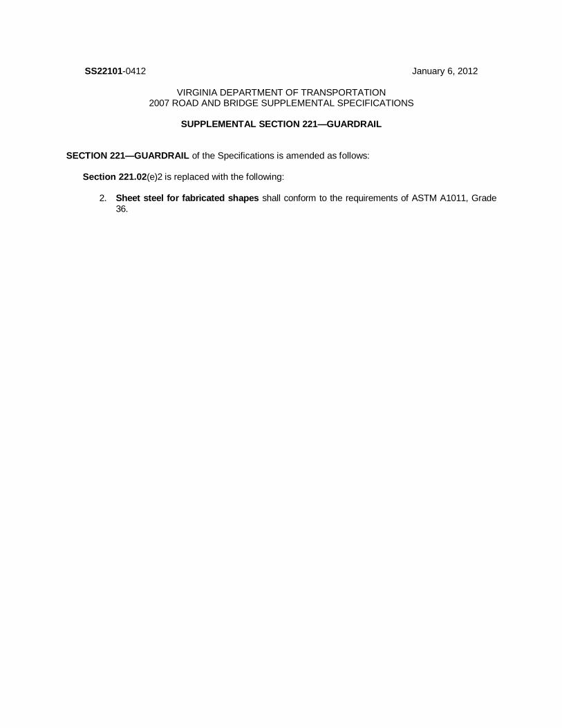
SS22101-0412 January 6, 2012
VIRGINIA DEPARTMENT OF TRANSPORTATION 2007 ROAD AND BRIDGE SUPPLEMENTAL SPECIFICATIONS
SUPPLEMENTAL SECTION 221—GUARDRAIL
SECTION 221—GUARDRAIL of the Specifications is amended as follows:
Section 221.02(e)2 is replaced with the following:
2. Sheet steel for fabricated shapes shall conform to the requirements of ASTM A1011, Grade 36.

SS22201-0911 June 28, 2011
VIRGINIA DEPARTMENT OF TRANSPORTATION 2007 ROAD AND BRIDGE SUPPLEMENTAL SPECIFICATIONS
SUPPLEMENTAL SECTION 222—MASONRY UNITS
SECTION 222—MASONRY UNITS of the Specifications is completely replaced with the following:
222.01—Description These specifications cover masonry units manufactured of regular or lightweight concrete or brick made from clay or shale in a plant specifically designed for such a purpose. 222.02—Detail Requirements
(a) Wall Units:
1. Hollow load-bearing units shall conform to the requirements of ASTM C90, Grade N-I. 2. Hollow non-load bearing units shall conform to the requirements of ASTM C129,
Type I. 3. Solid load-bearing units shall conform to the requirements of ASTM C145, Grade N-I. 4. Building bricks shall conform to the requirements of either
a. ASTM C62 Grade SW, or b. ASTM C55 except that the average compressive strength of 5 bricks shall be a
minimum 3000 psi and no individual brick less than 2500 psi. (b) Catch Basins and Manholes:
1. Masonry blocks shall conform to the requirements of ASTM C139. 2. Bricks shall conform to the requirements of either
a. ASTM C32, Grade MS, or b. ASTM C55 except that the average compressive strength of 5 bricks shall be a
minimum 3000 psi and no individual brick less than 2500 psi. (c) Sewer Brick: Sewer brick shall conform to the requirements of ASTM C32, Grade SM.

SS22301-1214 November 4, 2014
VIRGINIA DEPARTMENT OF TRANSPORTATION 2007 ROAD AND BRIDGE SUPPLEMENTAL SPECIFICATIONS
SUPPLEMENTAL SECTION 223—STEEL REINFORCEMENT
SECTION 223—STEEL REINFORCEMENT of the Specifications is completely replaced with the following:
223.01—Description These specifications cover steel items designed to give added flexural strength to hydraulic cement concrete or to control and reduce cracking. 223.02—Detail Requirements
(a) Reinforcement:
1. Deformed bars shall conform to the requirements of ASTM A615, Grade 40 or 60. 2. Plain bars shall conform to the requirements of ASTM A615, Grade 40 or 60, deformation
waived. When used as a dowel, material may be a plain bar conforming to the requirements of ASTM A615, Grade 40 or 60, or a plain dowel conforming to the requirements of ASTM A709, Grade 36.
3. Welded wire fabric shall conform to the requirements of ASTM A185. When used in
continuously reinforced pavement, wire fabric shall be deformed and furnished in flat sheets and shall conform to the requirements of ASTM A497, high yield of 70,000 pounds per square inch.
4. Longitudinal bars for continuous reinforced concrete pavement shall conform to the
requirements of ASTM A615, Grade 60. 5. Structural steel shall conform to the requirements of Section 226. 6. Bar mats shall conform to the requirements of ASTM A184. 7. Spiral wire shall conform to the requirements of AASHTO M32 or ASTM A82. 8. Wire mesh for use in gabions shall be made of galvanized steel wire at least 0.105 inch, 12
gage, in diameter. The tensile strength of the wire shall be at least 60,000 pounds per square inch. Wire mesh shall be galvanized in accordance with the requirements of ASTM A641, Class 3. When PVC coating is specified, it shall be at least 0.015 inch in thickness and shall be black.
Wire shall be welded to form rectangular openings or twisted to form hexagonal openings of uniform size. The linear dimension of the openings shall be not more than 4 1/2 inches. The area of the opening shall be not more than 9 square inches. The unit shall be nonraveling. Nonraveling is defined as the ability to resist pulling apart at any of the twists or connections forming the mesh when a single wire strand in a section is cut.
(b) Prestressing Tendons: Seven-wire stress-relieved strands, stress-relieved wire, and low-relaxation
strands shall conform to the requirements of ASTM A416, Grade 270; ASTM A421; and ASTM A416, Supplement I, respectively, with the following modifications:

1. Strands or wires used in units of any one-bed layout shall be manufactured by the same plant. 2. A manufacturer’s certification and load-elongation curve in accordance with the requirements of
ASTM A416 or ASTM A421 shall be obtained by the prestressed concrete fabricator for each lot of strand. The data shall be submitted to the Engineer for approval in permanent record form.
(c) Reinforcing Steel to Be Epoxy Coated: Steel shall conform to the requirements herein and shall
be coated in accordance with the requirements of ASTM A775. 1. Plants that epoxy coat reinforcing steel shall be CRSI certified for epoxy coating. CRSI
inspection reports shall be on file at the plant and shall be available to the Engineer. 2. Handling and storage of the coated bars shall conform to the requirements of ASTM A775. 3. Visible damage to the epoxy coating shall be patched or repaired with materials compatible with
the existing coating in accordance with ASTM A775.
(d) Reinforcing Steel to Be Galvanized: Steel shall conform to the requirements herein and shall be galvanized in accordance with the requirements of ASTM A767.
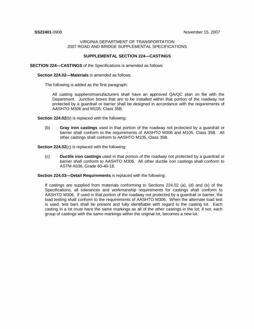
SS22401-0908 November 15, 2007
VIRGINIA DEPARTMENT OF TRANSPORTATION 2007 ROAD AND BRIDGE SUPPLEMENTAL SPECIFICATIONS
SUPPLEMENTAL SECTION 224—CASTINGS
SECTION 224—CASTINGS of the Specifications is amended as follows:
Section 224.02—Materials is amended as follows:
The following is added as the first paragraph:
All casting suppliers/manufacturers shall have an approved QA/QC plan on file with the Department. Junction boxes that are to be installed within that portion of the roadway not protected by a guardrail or barrier shall be designed in accordance with the requirements of AASHTO M306 and M105, Class 35B.
Section 224.02(b) is replaced with the following: (b) Gray iron castings used in that portion of the roadway not protected by a guardrail or
barrier shall conform to the requirements of AASHTO M306 and M105, Class 35B. All other castings shall conform to AASHTO M105, Class 35B.
Section 224.02(c) is replaced with the following:
(c) Ductile iron castings used in that portion of the roadway not protected by a guardrail or
barrier shall conform to AASHTO M306. All other ductile iron castings shall conform to ASTM A536, Grade 60-40-18.
Section 224.03—Detail Requirements is replaced with the following:
If castings are supplied from materials conforming to Sections 224.02 (a), (d) and (e) of the Specifications, all tolerances and workmanship requirements for castings shall conform to AASHTO M306. If used in that portion of the roadway not protected by a guardrail or barrier, the load testing shall conform to the requirements of AASHTO M306. When the alternate load test is used, test bars shall be present and fully identifiable with regard to the casting lot. Each casting in a lot must have the same markings as all of the other castings in the lot; if not, each group of castings with the same markings within the original lot, becomes a new lot.

SS22601-0609 December 16, 2008
VIRGINIA DEPARTMENT OF TRANSPORTATION 2007 ROAD AND BRIDGE SUPPLEMENTAL SPECIFICATIONS
SUPPLEMENTAL SECTION 226—STRUCTURAL STEEL
SECTION 226—STRUCTURAL STEEL of the Specifications is amended as follows:
Section 226.02(b) Other Structural Steel is replaced with the following:
(b) Other Structural Steel: Unless otherwise specified, steel for other structural members
except H-piles shall conform to the requirements of ASTM A36. H-piles shall conform to the requirements of ASTM A572 or ASTM A992. One copy of the mill analysis shall accompany steel piles shipped to the project site. Three copies of the mill analysis for structural steel members shall be submitted to the Engineer.

SS23203-0912 May 17, 2012
VIRGINIA DEPARTMENT OF TRANSPORTATION 2007 ROAD AND BRIDGE SUPPLEMENTAL SPECIFICATIONS
SUPPLEMENTAL SECTION 232—PIPE AND PIPE ARCHES
SECTION 232—PIPE AND PIPE ARCHES of the Specifications is amended as follows:
Section 232.02 Detail Requirements of the specifications is amended to replace the first paragraph with the following:
Concrete, corrugated steel and polyethylene pipe shall only be supplied from manufacturers currently having an approved Quality Control Plan on file with the Department.
Section 232.02(a)1.b.(6) is replaced with the following:
(6) Strength tests shall be performed by the three-edge bearing method in accordance with the requirements of AASHTO T280 or by control cylinders tested in accordance with ASTM C31 and C39 or by the testing of cores in accordance with ASTM C42. Control cylinders for acceptance testing shall be cured under the same conditions as the concrete the cylinders represent. Hand cast pipe and end sections may be tested in accordance with the requirements of ASTM C31 and C39. Concrete pipe may be shipped after reaching 85 percent of design strength as determined by control cylinders or cores.
Section 232.02(a)1.b.(7) is replaced with the following:
(7) Absorption tests shall be performed in accordance with the requirements of AASHTO T280 on specimens of broken pipe or cores.
Section 232.02(c)2. Asphalt-coated corrugated steel culvert pipe and pipe arches is deleted entirely. Section 232.02-Detail Requirements is amended to add the following:
(m) Polypropylene (PP) Pipe:
1. PP corrugated culvert and storm drain pipe shall conform to the requirements of AASHTO MP 21-11, and shall be double wall pipe (Type S) for nominal diameters of 12 inches through 30 inches, inclusive, and shall be triple wall pipe (Type D) for nominal diameters of 36 inches through 48 inches, inclusive. Polypropylene Pipe less than 12 inches and greater than 48 inches in diameter will not be allowed. Fittings and joining systems shall also meet the requirements of the AASHTO MP 21-11.

SS23401-1214 October 16, 2014
VIRGINIA DEPARTMENT OF TRANSPORTATION 2007 ROAD AND BRIDGE SUPPLEMENTAL SPECIFICATIONS
SUPPLEMENTAL SECTION 234—GLASS BEADS FOR REFLECTORIZING TRAFFIC MARKINGS
SECTION 234—GLASS BEADS FOR REFLECTORIZING TRAFFIC MARKINGS of the Specifications is completely replaced with the following:
234.01—Description This specification covers glass beads applied on the surface or incorporated into traffic-marking materials so as to produce a retroreflective surface. 234.02—Detail Requirements Beads shall be manufactured from glass of a composition designed to be highly resistant to traffic wear and weather. Glass beads shall conform to the requirements of AASHTO M247, Type 1-5, except that at least 80 percent of the beads shall be round when tested in accordance with the requirements of ASTM D 1155, Procedure B. The contractor shall provide a written certification that each batch of glass beads used in or on VDOT pavement markings conform to AASHTO M247 including the total concentration limit of lead and arsenic.
SS23802-0609 March 4, 2008
VIRGINIA DEPARTMENT OF TRANSPORTATION 2007 ROAD AND BRIDGE SUPPLEMENTAL SPECIFICATIONS
SUPPLEMENTAL SECTION 238—ELECTRICAL AND SIGNAL COMPONENTS
SECTION 238 ELECTRICAL AND SIGNAL COMPONENTS of the Specifications is amended as follows:
Section 238.02(f) Electrical and Signal Junction Boxes is replaced with following: (f) Electrical and Signal Junction Boxes:
Boxes, frames and covers shall be water resistant. Covers shall be secured with stainless steel bolts and fasteners. Covers shall be flush with surface of the junction box and not protrude above the top of the junction box flange. Junction box bolt attachment holes shall be drilled through to prevent debris from collecting in the threaded bolt holes. Junction boxes shall be tested and certified by an independent testing laboratory as meeting the requirements indicated herein for approval for use. Independent testing laboratory shall be approved by VDOT Materials Division prior to testing. The Contractor shall furnish the Engineer documentation of such test results. Testing reports shall provide complete test results for the type of design testing indicated for the respective type of junction box. Junction Boxes for deliberate traffic in the roadway applications: ● Concrete shall conform to the requirements of Section 217 of the Specifications
and shall be designed to meet the provisions of AASHTO’s Standard Specifications for Highway Bridges for HS20 loading. Concrete shall have a design minimum compressive strength of 4000 psi.
● Gray Iron frame and covers shall conform to the requirements of Section 224 of
the Specifications. Junction Boxes for off roadway applications: ● Shall conform to the requirements of ANSI/SCTE 77 2007 and tier 15 loading.
Boxes shall be open bottom. ● Shall be Polymer concrete with straight sides or Polymer concrete with flared or
straight fiberglass sides. ● Other materials may be submitted for the sidewalls provided they conform to the
requirements of ANSI/SCTE 77 2007 and tier 15 loading. Junction Boxes frames and covers for bridge structures encasements shall be one of the following types: 1. Steel castings conforming to the requirements of Section 224 of the
Specifications, galvanized inside and out.

2. Welded sheet steel having a thickness of at least 3/16 inch or 7 gage, galvanized inside and out.
3. Polymer concrete with fiberglass sides or all polymer concrete.
Section 238.02(h)6.f. Light Emitting Diode (LED) traffic signal head sections is amended to replace the third paragraph with the following:
LED arrow traffic signal modules shall conform to the requirements of the ITE Vehicle Traffic Control Signal Heads – Light Emitting Diode Vehicle Arrow Traffic issued April 3, 2006 (inclusive of any ITE documents that amend, revise and/or supersede it).
And to replace the seventh paragraph with the following: The LED’s shall be mounted and soldered to a printed circuit board. Modules shall be provided with an external in-line fuse or internal fusing of the 120 VAC (+) input. The fuse shall be rated in accordance with the LED module manufacturer. The LED signal module shall utilize the same mounting hardware used to secure the incandescent lens and gasket assembly and shall only require a screwdriver or standard installation tool to complete the mounting.

SS24504-1215 September 25, 2015
VIRGINIA DEPARTMENT OF TRANSPORTATION 2007 ROAD AND BRIDGE SUPPLEMENTAL SPECIFICATIONS
SUPPLEMENTAL SECTION 245—GEOSYNTHETICS AND LOW PERMEABILITY LINERS
SECTION 245—GEOSYNTHETICS of the Specifications is completely replaced with the following:
SECTION 245—GEOSYNTHETICS AND LOW PERMEABILITY LINERS 245.01—Description These specifications cover artificial fiber textile products to be used in transportation construction work, and low permeability liners for stormwater management facilities. 245.02—Shipping, Handling, and Storage Requirements Geosynthetic shall be permanently marked with a clearly legible print showing manufacturing plant or plant Identification Code number, located on the roll edge at least every 16 feet. Rolls shall be labeled at both ends of the outside of the roll outer wrapping and both ends of the inside of the geotextile roll core, and labels shall list the roll number, production date, AASHTO M288 class(es) the product meets, and the product name; if the permanent marking contains this information, the labels may be omitted. Each geosynthetic roll shall be wrapped or otherwise packaged in a manner that will protect the geosynthetic, including the ends of the roll, from damage due to shipment, water, sunlight, and contaminants. The protective wrapping shall be maintained during periods of shipment and storage. During storage, geosynthetics rolls shall be elevated off the ground and adequately covered to protect them from the following: site construction damage; precipitation; extended ultraviolet radiation including sunlight; strong acids or strong bases; flames including welding sparks; temperatures in excess of 160 degrees F; and other environmental conditions that may damage the physical property values of the geosynthetic. Geosynthetics that are not properly protected may be subject to rejection. 245.03—Testing and Documentation Each geosynthetic material provided to the project shall have a manufacture date within its current NTPEP product 3-year evaluation cycle. The manufacturer and any subsequent private labeler facility shall be listed as compliant by NTPEP within the current calendar year, or immediate past calendar year with an application for audit for the current calendar year. VDOT may sample product from a facility or project at any time for verification sampling and testing. Failure may result in the product being rejected or removed from the Approved List. Property values in these specifications represent minimum average roll values (MARV) in the weakest principal direction unless direction is otherwise specified; permittivity values specified are minimum; AOS and panel vertical strain values are maximum; or mass per unit area, UV degradation, and asphalt retention values are typical. Product acceptance is determined by comparing the manufacturer test data against these specifications and using independent assurance testing, verification sampling and testing, and facility audits.

(a) Geotextile Fabric for Use in Silt Fences: Geotextile shall be a woven fabric and function as a
vertical, permeable interceptor designed to remove suspended soil from overland water flow. Fabric shall filter and retain soil particles from sediment-laden water to prevent eroding soil from being transported off the construction site by water runoff.
Physical Property Test Method Requirements
Filtering efficiency ASTM D5141-11 and NTPEP Erosion Control Products Committee Work Plan
Min. 75%
Flow rate ASTM D5141-11 and NTPEP Erosion Control Products Committee Work Plan
Min. 0.2 gal/ft2/min
In addition to these requirements, the geotextile shall comply with the requirements of AASHTO M288 for temporary silt fence property requirements, Table 7, Temporary Silt Fence Property Requirements, for grab strength and ultraviolet stability.
(b) Geotextile for Use as Riprap Bedding Material: Geotextile shall comply with the
requirements of AASHTO M288 for separation geotextile properties, Table 3, for apparent opening size and ultraviolet stability and geotextile strength property requirements, Table 1, Class 2, for grab strength and puncture strength.
(c) Geotextile Fabric for Use in Drainage Systems (Drainage Fabric): Drainage fabric shall be
nonwoven and clog resistant, suitable for subsurface application, and thermally and biologically stable.
Polypropylene material is acceptable in environments with pH values between 3 and 12 inclusive; polyester material between 3 and 9 inclusive.
Physical Property Test Method Requirements
Permittivity ASTM D4491 Min. 0.5 sec-1
Apparent opening size ASTM D4751 Max. No. 50 sieve
In addition to these requirements, the geotextile shall comply with the requirements of AASHTO M288 for strength requirements, Table 1, Class 3, for grab strength.
(d) Geotextile for Use in Stabilization: These are geotextiles used in saturated and/or unstable
conditions to provide the functions of separation and reinforcement.
1. Subgrade Stabilization Fabric:
Physical Property Test Method Requirements
Apparent opening size ASTM D 4751 Max. No. 20 sieve
In addition to this requirement, the geotextile shall comply with the requirements of AASHTO M 288 for strength property requirements, Table 1, Class 3, for grab strength, tear strength, and puncture strength.
2. Embankment Stabilization Fabric Up to 6 Feet High:
Physical Property Test Method Requirements
Apparent opening size ASTM D 4751 Max. No. 20 sieve

Seam strength ASTM D 4632 90% specified grab strength
In addition to this requirement, the geotextile shall comply with the requirements of AASHTO M288 for strength property requirements, Table 1, Class 1 for grab strength, tear strength, and puncture strength.
(e) Prefabricated Geocomposite Pavement Underdrain: Prefabricated geocomposite pavement underdrain shall consist of a polymeric drainage core encased in a nonwoven filter fabric envelope having sufficient flexibility to withstand bending and handling without damage. Prefabricated geocomposite pavement underdrain shall conform to the following:
1. Core: The drainage core shall be made from an inert, polymeric material resistant to
commonly encountered chemicals and substances in the pavement environment and shall have a thickness of not less than 3/4 inch. Outer surfaces shall be smooth to prevent excessive wear of bonded filter fabric.
Physical Properties Test Method Requirements
Compressive strength panel vertical strain and core area change
ASTM D1621/D2412 Min. 40 psi at 20% deflection after 24 hrs at 0 deg F and at 125 deg F
Panel vertical strain and core area change at 22.7 psi
ASTM D6244 Max. 10% for core area and panel height
Water flow rate )after 100 hr at 10 psi normal confining pressure gradient of no more than 1.0)
ASTM D4716 Min. 15 gal/min/ft width for 12-in specimen length
2. Filter Fabric: Geotextile shall be bonded to and tightly stretched over the core. Geotextile
shall not sag or block the flow channels, shall have a life equivalent to that of the core material, and shall conform to the requirements of (c) herein.
(f) Geocomposite Wall Drains: Prefabricated geocomposite wall drain shall consist of a
polymeric drainage core encased in a nonwoven filter fabric envelope having sufficient flexibility to withstand bending and handling without damage. Geocomposite wall drains shall conform to the following:
1. Core: The drainage core shall be made from an inert, polymeric material resistant to
commonly encountered chemicals and substances in the roadway. Outer surfaces shall be smooth to prevent excessive wear of bonded filter fabric.
Physical Property Test Method Requirements
Compressive strength at 20% deflection
ASTM D1621/D2412 Min. 40 psi after 24 hrs at 0 degree F and at 125 degree F
Water flow rate (after 100 hr at 10 psi normal confining pressure and gradient of no more than 0.1)
ASTM D4716 Min. 15 gal/min/ft width (for 12-in specimen length)
2. Filter Fabric: Geotextile shall be bonded to and tightly stretched over both sides of the
core. Geotextile shall not sag or block the flow channels, shall have a life equivalent to that of the core material, and shall conform to the requirements of (c) herein, except that grab strength requirement shall meet AASHTO M288 Table 1, Class 2.

(g) Geomembrane Moisture Barrier: Geomembrane moisture barrier shall be resistant to
biological attack. geomembrane shall be constructed of PVC and shall conform to the requirements of the PVC geomembrane Institute 1104 material specification for PVC geomembrane (Revision #1 effective April 15, 2008) and shall meet the following additional or more stringent requirements:
Physical Property Test Method Requirements
Thickness ASTM D5199 Min. 30 mils
Tensile (1-in strip) ASTM D882 Min. 0.80 kip/ft (ultimate)
Tear Strength (Die C) ASTM D1004 Min. 8 lbf
Seam Seal Strength ASTM D1004 Min. 0.18kip/ft
(h) Dewatering Bag: A nonwoven geotextile sewn together to form a bag that can be used in lieu
of a de-watering basin for the purpose of filtering out suspended soil particles. The bag shall be capable of accommodating the water flow from the pump without leaking at the spout and seams.
Physical Property Test Method Requirements
Grab strength @ ASTM D4632 Min. 250 lb (min)
Elongation >50%(CRE/Dry)
Seam strength ASTM D4632 90% Specified grab strength
Puncture ASTM D4833 Min. 150 lb
Flow rate ASTM D4491 Min. 0.189 ft3/sec/ft
2(min)
Permittivity ASTM D4491 Min. 1.2 sec-1
UV resistance ASTM D4355 Min. 70% at 500 hr
AOS ASTM D4751 Max. 100 sieve
(i) Pavement Interlayer: Paving geosynthetics shall be used as an interlayer between pavement
layers. Specific application of these paving interlayers shall be determined by the Engineer. 1. Paving Fabric: The geotextile shall conform to the requirements of AASHTO M288 Paving
Fabric Property Requirements, Section 10. 2. Paving Mat: The paving mat shall meet the requirements of ASTM D7239 Geosynthetic
Paving Mat, Type 1. (j) Low Permeability Liners for Stormwater Management Facilities: SWM liner soil shall be
classified as CL, CH or MH in accordance with ASTM D2487 and shall have a maximum coefficient of permeability of 1 x 10
-6 cm/sec in accordance with ASTM D5084, after
compaction. The maximum particle size shall be three inches in its largest dimension. Natural soils, which do not meet these specifications, may be blended with bentonite to provide the specified permeability characteristics. Geosynthetic Clay Liner shall have a maximum coefficient of permeability of 1 x 10
-8 cm/sec in
accordance with ASTM D5887. This specification is not intended for dam embankment material or clay core cut-off trench material.

SS24701-0611 February 10, 2011
VIRGINIA DEPARTMENT OF TRANSPORTATION 2007 ROAD AND BRIDGE SUPPLEMENTAL SPECIFICATIONS
SUPPLEMENTAL SECTION 247—REFLECTIVE SHEETING
SECTION 247—REFLECTIVE SHEETING of the Specifications is completely replaced with the following:
247.01—Description This specification covers reflective sheeting used on traffic control devices to provide a retroreflective surface or message. The color of the reflective sheeting shall be as specified in the Contract Documents. Reflective sheeting shall be certified in accordance with the requirements of Section 106.06 of the Specifications. 247.02—Detail Requirements Reflective sheeting shall be selected from the Department’s Approved Products list. Reflective sheeting products are included on the Approved Products List only after the Department determines conformance to the Specifications and the manufacturer has supplied written information indicating conformance to the warranty requirements of Section 247.03 of the Specifications where required. Determination of conformance will include, but not be limited to, the evaluation of test data from AASHTO’s National Transportation Product Evaluation Program (NTPEP) or other Department-approved facilities except as noted. When color test data (Chromaticity and Luminance Factor - Y%) provided by NTPEP or other Department-approved facilities are evaluated, color must have been maintained within the color specification limits for the full duration of the outdoor weathering test. The sheeting and any applied coatings such as inks, overlay films, other coatings, shall be weather resistant in accordance with ASTM D4956 after being tested by AASHTO, NTPEP or other Department approved facilities except as noted.
(a) Reflective sheeting used on permanent signs (except those addressed in Section b), on object markers, nose of guardrails, permanent impact attenuators (except sand barrels), standard road edge delineators, special road edge delineators, barrier delineators, guardrail delineators, interstate road edge delineators, chevron panels, bridge end panel signs (VW-13), and railroad advance warning signs (including any supplemental plaques) vertical panels (Group 2 channelizing devices), traffic gates, Automatic Flagger Assistance Device (AFAD) gate arms, and the "STOP" side of sign paddles (hand signalizing device) shall conform to the requirements of ASTM D4956 for a Type IX material and, except for the “STOP” side of sign paddles, shall be warranted in accordance with Section 247.03 Sheeting Warranty Class I of the Specifications. Color shall conform to the requirements of 23 CFR, Part 655, Subpart F, Appendix Tables 1 and 1A (non-fluorescent colors) and Tables 3 and 3A (fluorescent colors). In Table 1A, the values for daytime luminance factor (Y%) shall be based on the colors for a Type IV, VII, and VIII sheeting. The minimum maintained coefficient of retroreflection of the sheeting after 3 years on the test deck shall conform to the requirements of ASTM D4956. 1. Reflective sheeting used on the following signs shall be Fluorescent Yellow-
Green conforming to the requirements of ASTM D4956 for a Type IX material and shall be warranted in accordance with Section 247.03, Sheeting Warranty Class I of the Specifications.

● Bicycle Crossing sign (W11-1) including supplemental plaques ● Pedestrian Crossing sign (W11-2) including supplemental plaques ● Playground sign (W15-1) including supplemental plaques ● DEAF CHILD AREA sign including supplemental plaques ● WATCH FOR CHILDREN sign including supplemental plaques ● School Signing consisting of the following:
—School Crossing sign (S1-1) —School Bus Stop Ahead sign (S3-1) —SCHOOL plaque (S4-3) —School Portion of the School Speed Limit sign (S5-1) —Supplemental plaques used with these signs
Color shall conform to the requirements of 23 CFR, Part 655, Subpart F, Appendix Tables 3 and 3A. The minimum maintained coefficient of retroreflection of the sheeting after 3 years on the test deck shall conform to the requirements of ASTM D4956.
(b) Reflective sheeting used on permanent recreational and cultural interest area
guidance signs, and for the hand symbol/DON’T WALK and numerals on permanent educational pedestrian signal signs (R10-3b thru R10-3e) shall conform to the requirements of ASTM D4956 for a Type III material and shall be warranted in accordance with Section 247.03, Sheeting Warranty Class I of the Specifications. Color shall conform to the requirements of 23 CFR, Part 655, Subpart F, Appendix Tables 1 and 1A.
The minimum maintained coefficient of retroreflection of the sheeting after 3 years on the test deck shall conform to the requirements of ASTM D4956.
(c) Reflective sheeting used to delineate the trailer’s back frame of Portable Changeable Message Signs (PCMS), Automatic Flagger Assistance Device (AFAD) gate arm, arrow boards and portable lights shall conform to the requirements of 49 CFR 571.108 for a Grade DOT-C2 truck conspicuity marking. References to ASTM specifications therein shall be interpreted to mean the latest version of the specification at the time of advertisement regardless of the date indicated in the reference. Color shall conform to the requirements of 23 CFR, Part 655, Subpart F, Appendix Tables 1 and 1A. This reflective sheeting is not required to be tested by NTPEP.
(d) Reflective sheeting used on Type III barricades shall conform to the following:
Minimum Coefficient of Retroreflection RA (RA =Candelas per foot-candle per square foot)
Observation Angle (o) Entrance Angle (
o) White Orange
0.2 –4 400 200
0.2 +30 200 80
0.5 –4 300 100
0.5 +30 100 40
1.0 –4 50 25
1.0 +30 15 10

Color and Luminance Factor (Y%) shall conform to the requirements of 23 CFR, Part 655, Subpart F, Appendix Tables 1 and 1A, for a Type IV Sheeting. Impact Resistance shall conform to the requirements of ASTM D4956. The minimum maintained coefficient of retroreflection of the sheeting after one year on the test deck shall be at least 50 percent of the minimum coefficient of retroreflection values specified.
(e) Reflective sheeting used on orange construction and maintenance activity signs, barrier vertical panels installed on concrete traffic barrier service, rear panel of truck-mounted attenuators, temporary impact attenuators (except temporary sand barrels), and the "SLOW" side of sign paddles shall conform to the requirements of ASTM D4956 for a Type IX, Fluorescent Orange material (with the following retroreflection exception):
Minimum Coefficient of Retroreflection RA (RA =Candelas per foot-candle per square foot)
Observation Angle (o) Entrance Angle (
o) Fluorescent Orange
0.2 –4 140
0.2 +30 90
0.2 +40 24
0.5 –4 90
0.5 +30 50
0.5 +40 15
1.0 –4 10
1.0 +30 5
1.0 +40 3
Color shall conform to the requirements of 23 CFR, Part 655, Subpart F, Appendix Tables 3 and 3A. The minimum maintained coefficient of retroreflection of the sheeting after one year on the test deck shall be at least 50 percent of the minimum coefficient of retroreflection values specified.
(f) Reflective sheeting used on tubular delineators, drums and temporary sand barrels shall conform to the following: 1. Reflective sheeting used on tubular delineators and drums shall conform
requirements of ASTM D4956 including supplementary requirement S2 for a Type III reboundable material. Color shall conform to the requirements of Tables 1 and 1A of the USDOT specification as contained in the Appendix to 23 CFR, Part 655, Subpart F except the minimum daytime luminance factor (Y%) for white shall be 25 when used on tubular delineators and drums. The following supplementary table shall apply for tubular delineators and drums:
Minimum Coefficient of Retroreflection RA (Candelas per foot-candle per square foot)
(High Intensity)
Observation Angle (
o)
Entrance Angle (o) White Orange

0.2 +50 75 25
0.5 +50 35 10
Reflective sheeting used on tubular delineators is not required to be tested by NTPEP.
2. Reflective sheeting used on temporary sand barrels shall be a fluorescent orange prismatic lens reboundable sheeting conforming to the following: Color shall conform to the requirements of Tables 3 and 3A of the USDOT specification as contained in the Appendix to 23 CFR, Part 655, Subpart F.
Minimum Coefficient of Retroreflection RA (Candelas per foot-candle per square foot)
(High Intensity)
Observation Angle (o)
Entrance Angle (o) Fluorescent Orange
0.2 -4 200
0.2 +30 120
0.2 +50 40
0.5 -4 80
0.5 +30 50
0.5 +50 30
Minimum maintained coefficient of retroreflection of the sheeting after one year on the test deck shall be at least 50 percent of the minimum coefficient of retroreflection values indicated above. Reflective sheeting shall conform to the supplementary requirement S2 of ASTM D4956. Please note: Beginning July 1, 2012 reflective sheeting used on Drums, Temporary Sand Barrels and Tubular delineators for all projects shall conform to the requirements of ASTM D4956 including supplementary requirement S2 for a Type III reboundable material with the following retroreflection exception as shown in the chart below:
Minimum Coefficient of Retroreflection RA (RA =Candelas per foot-candle per square foot)
(Prismatic Lens)
Observation Angle (o) Entrance Angle (
o) White Fluorescent Orange
0.2 -4 400 175
0.2 +30 200 100
0.2 +40 135 60
0.2 +45 120 40
0.5 -4 150 70
0.5 +30 50 30
0.5 +40 45 25
0.5 +45 40 20
Color shall conform to the requirements of 23 CFR, Part 655, Subpart F, Appendix Tables 1 and 1A (non-fluorescent colors) and Table 3 and 3A (fluorescent colors).

The minimum maintained coefficient of retroreflection of the sheeting after one year on the test deck shall be at least 50 percent of the minimum coefficient of retroreflection specified.
(g) Reflective sheeting used on Permanent Sand Barrels and on Cones shall conform to the requirements of ASTM D4956 including supplementary requirement S2 for a Type III reboundable material. The following supplementary table shall also apply for cones:
Minimum Coefficient of Retroreflection RA
(RA =Candelas per foot-candle per square foot) (High Intensity)
Observation Angle (o) Entrance Angle (
o) White
0.2 +50 60
0.5 +50 35
Color shall conform to the requirements of 23 CFR, Part 655, Subpart F, Appendix Tables 1 and 1A. The maintained coefficient of retroreflection of the sheeting after one year on the test deck shall be at least 50 percent of the minimum coefficient of retroreflection specified for permanent sand barrel sheeting. Reflective sheeting for cones is not required to be tested by NTPEP.
(h) Reflective sheeting used on Retroreflective Rollup Signs shall conform to the following:
Minimum Coefficient of Retroreflection RA (RA =Candelas per foot-candle per square foot)
(Prismatic Lens)
Observation Angle (
o)
Entrance Angle (
o )
White Fluorescent
Orange Fluorescent
Pink
0.2 –4 500 200 200
0.2 +30 200 80 100
0.5 -4 225 90 100
0.5 +30 85 35 35
1.0 -4 20 10 10
1.0 +30 15 8 10
1.5 -4 5 3 2
1.5 +30 4 1.5 2
Color shall conform to the requirements of 23 CFR, Part 655, Subpart F, Appendix Tables 1 and 1A for white, and Appendix Tables 3 and 3A for fluorescent colors. Reflective sheeting for retroreflective rollup signs is not required to be tested by NTPEP.
247.03—Warranty Requirements The reflective or retroreflective sheeting manufacturer shall provide the following warranty to the Department for the respective types of sheeting furnished as specified herein:

Class I Warranty: 10-year warranty with 7 years being 100 percent full replacement covering all material and labor costs associated with fabrication and installation of the sign or device and the final 3 years being 100 percent sheeting replacement cost.
The minimum values of retroreflectivity maintained during the warranty period shall be the same as those required for the maintained coefficient of retroreflection values as indicated herein, or where not indicated, shall be in accordance with those specified in ASTM D4956. Loss of colorfastness is considered to have occurred if the color of the sheeting is not within the color specification limits in 23 CFR, Part 655, Subpart F, Appendix during the full duration of the warranty period. Warranty period shall begin on the date of fabrication and shall be documented as follows:
For warranty requirements, each permanent sign shall be labeled on the reverse in a location not to be obscured by sign supports or backing hardware, showing 1.) Month and year the sign was fabricated, marked via punch-out numerals, 2.) Sheeting Manufacturer's name or logo and product designation or number, and 3.) Sign fabricator's name or logo. Labels shall be made of a self adhesive, permanent weather resistant material and shall be a minimum 4" by 4" in size. Label may be made from permanent sign material provided the finished label meets all other aspects required for warranty documentation. Where the information required for the label is not furnished by punched-out numerals, it shall be supplied by permanent means, such as sign ink, capable of resisting weathering so as to be legible for the full duration of the warranty period. Prior to applying the label, the area shall be thoroughly cleaned to ensure proper adhesion.

SS30101-0914 September 3, 2014
VIRGINIA DEPARTMENT OF TRANSPORTATION 2007 ROAD AND BRIDGE SUPPLEMENTAL SPECIFICATIONS
SUPPLEMENTAL SECTION 301—CLEARING AND GRUBBING
SECTION 301—CLEARING AND GRUBBING of the Specifications is amended as follows:
Section 301.02—Procedures is amended to replace the second paragraph with the following:
The surface area of earth material exposed by grubbing, stripping topsoil, or excavation shall be limited to that necessary to perform the next operation within a given area. Grubbing of root mat and stumps shall be confined to that area of land which excavation or other land disturbance activities shall be performed by the Contractor within 14 days following grubbing.

SS30204-0613 March 14, 2013
VIRGINIA DEPARTMENT OF TRANSPORTATION 2007 ROAD AND BRIDGE SUPPLEMENTAL SPECIFICATIONS
SUPPLEMENTAL SECTION 302—DRAINAGE STRUCTURES
SECTION 302—DRAINAGE STRUCTURES of the Specifications is amended as follows:
Section 302.03(b) Precast Drainage Structures is amended to replace the second paragraph with the following:
Requests for approval of a precast design shall include detailed plans and supporting computations that have been reviewed by a registered Professional Engineer having at least 5 years experience in structural design of precast structures or components proposed and licensed in the Commonwealth. Unless otherwise specified, concrete exposed to freeze/thaw environments shall conform to Section 217.02 of the Specifications and shall have a design strength at 28 days of at least 4,000 pounds per square inch and an air content of 6 ± 2 percent. Concrete not exposed to freeze/thaw environments shall be exempt from the requirements of Section 217.02(a) of the Specifications. The design of the concrete mixture and the method of casting, curing handling and erecting of precast units shall be subject to review by the Engineer. Precast units may be shipped after reaching 85 percent of the design strength as determined by control cylinders. Sampling and testing concrete strength shall be performed using control cylinders in accordance with ASTM C31 and C39 at a rate of one set of cylinders per lot. A lot is defined as a maximum 250 cubic yards or a single weeks production (whichever quantity is less) of precast concrete from each batching operation, being of like material, strength and manufactured by the same process. Variations of lot definition will be governed by applicable specifications and approved by the Engineer. Control cylinders used for acceptance testing shall be cured under the same conditions as the concrete the cylinders represent. Units shall retain their structural integrity during shipment and shall be subject to inspection at the job site. Approval to use precast units shall not be construed as waiving the size and weight limitations specified in Section 107.21 of the Specifications.
Section 302.03(b)2. Precast arches is replaced with the following:
2. Precast arches shall conform to the applicable requirements of the current AASHTO’s LRFD
Bridge Design Specifications and VDOT modifications (current VDOT I&IM-S&B-80) and the following modifications: a. Protection against corrosion: The concrete cover of reinforcement shall be at least 1 1/2
inches.
Reinforcing steel for arches in 0 to 2 foot fills, in corrosive or marine environments, or in other severe exposure conditions shall be corrosion resistant reinforcing steel, Class I. When corrosion resistant reinforcing steel is required, the minimum cover specified shall not be reduced.
Exposed reinforcing bars, inserts, and plates intended for bonding with future extensions shall be protected from corrosion as directed by the Engineer. Reinforcement shall be designed and detailed in consideration of fabrication and construction tolerances so that the minimum required cover and proper positioning of reinforcement shall be maintained.

b. Anchorage: Sufficient anchorage shall be provided at the terminus of lines of precast units. Anchorage may consist of a cast-in-place end section at least 3 feet in length with a headwall or collar around the precast unit(s) provided adequate connection can be made between the collar and units.
c. Joints: Joints between units shall be sealed by preformed plastic or mastic gaskets or grout.
When preformed gaskets are used, they shall be of a type listed on the Department’s approved products list.
d. Pipe openings: Pipe openings will not be allowed in the precast arch but may be provided
through the wingwalls. When required, openings shall conform to the requirements of (b)1.b. herein.
Section 302.03(b)3. Precast box culverts is replaced with the following:
3. Precast box culverts shall conform to the applicable requirements of the current AASHTO’s
LRFD Bridge Design Specifications and VDOT modifications (current VDOT I&IM-S&B-80) and the following modifications:
a. Precast Box Culverts shall conform to the applicable material requirements of ASTM C1577.
The design shall be a Special Design which need not conform to the reinforcing steel and geometry shown in the design tables and the appendix in ASTM C1577.
b. For protection against corrosion, the following minimum concrete cover shall be provided for
reinforcement: For boxes with more than 2 feet of fill over the top slab: 1 1/2 inches. For boxes with less than 2 feet of fill over the top slab: top reinforcement of top slab: 2 1/2 inches; bottom reinforcement of top slab: 2 inches; all other reinforcement: 1 1/2 inches.
Reinforcing steel for arches in 0 to 2 foot fills, in corrosive or marine environments, or in other severe exposure conditions shall be corrosion resistant reinforcing steel, Class I. When corrosion resistant reinforcing steel is required, the minimum cover specified shall not be reduced.
c. The type of sealant used in joints between units shall be from the Department’s Approved
List of Preformed Plastic or Mastic Gaskets.
Where double or greater lines of precast units are used, a buffer zone of 3 to 6 inches between lines shall be provided. This buffer zone shall be backfilled with porous backfill conforming to the requirements of Section 204. The porous backfill shall be drained by a 3-inch-diameter weep hole, formed by non-rigid tubing, located at the top of the bottom haunch, centered in the outlet end section and at approximately 50-foot intervals along the length of the box. Weep holes shall be covered with a 3-foot-square section of filter barrier cloth firmly attached to the outside of the box. A 3-foot width of filter barrier cloth shall also be centered over the buffer zone for the entire length of the structure after placement of the porous backfill material. Filter barrier cloth shall conform to the requirements of Section 245.
Forming weep holes and furnishing and placing of the filter barrier cloth shall be included in the price bid per linear foot for the precast box culvert.
d. At the terminus of precast units, sufficient anchorage shall be provided. This anchorage may
consist of a cast-in-place end section at least 3 feet in length with a headwall and curtain wall or a collar cast-in-place around the units provided adequate connection can be made between the collar and units.
When the ends of precast units are skewed, the end section shall be cast monolithically. The skew may be provided by forming, saw cutting, or other methods approved by the Engineer.

Regardless of the method used, the variation in the precast unit from the exact skew shall be not greater than 1 1/2 inches at any point.
e. Pipe openings shall conform to the requirements of 1.b. herein. f. Bedding and backfill shall be in accordance with Standard PB-1 for box culverts.
Section 302.03 Procedures is amended to add the following
(d) Post Installation Inspection In addition to the visual inspection performed by the Department during the initial installation of storm sewer pipes and pipe culverts, a post installation visual/video camera inspection shall be conducted by the Contractor in accordance with the requirements of this specification and VTM 123 on all storm sewer pipe and a selected number of pipe culverts. For the purposes of this Section, a storm sewer pipe is defined as either a component of a storm sewer system as defined in Section 101.02 of the Specifications or any pipe identified on the plans as storm sewer pipe. All other pipe shall be considered pipe culverts. Post installation Inspections shall be performed on straight line and radial installations. For pipe culverts, a minimum of one pipe installation for each size of each material type utilized on the project will be randomly selected by the Engineer for inspection, however, in no case will the amount of pipe subject to inspection be less than ten percent of the total contract amount for the size and material type indicated. Where possible, for all installations in which the pipe or culvert’s size, orientation, or location permit deflection to be easily visually identified, (as verified with the Engineer) the Contractor may perform visual inspections in lieu of video inspections. If defects as described herein are noted during the inspection, the Engineer may require additional pipe installations of that size and/or material be inspected. The Contractor shall coordinate and schedule all post installation inspections so that these are made in the presence of the Engineer. The post installation inspection shall be performed no sooner than 30 days after completion of the pipe installation and placement of final cover (except for pavement structure). The Contractor shall issue a report detailing all issues or deficiencies noted during the inspection (including a remediation plan for each deficiency noted where applicable) no later than 5 days after completion of the inspection. While the intent of this requirement is to perform the post installation inspection prior to paving, project scheduling may dictate that a particular site be paved before the end of the 30 day period. In such cases, a preliminary inspection of the pipe shall be made, prior to paving over it, to insure that the pipe has been properly installed and is performing well. Performing such a preliminary inspection prior to paving will not relieve the Contractor from the requirement to perform the post installation inspection after the 30 day period. The Contractor’s inspection report shall identify and address any of the following items observed during the post installation inspection including identifying any proposed remediation measures the Contractor plans to perform where applicable. Remediation measures may consist of repairing or replacing the defective pipe section(s) or a combination of the two where differing conditions exist within the same run of pipe. Where permitted as an option, remediation methods for the various installation defects shall be proposed by the Contractor, reviewed with the Engineer and must have the Engineer’s approval prior to implementation of the corrective action. Remediation shall be the sole responsibility of the Contractor. Further, if remediation measures are shown to be necessary, any time associated with such measures shall be reflected in the impact to the Contractor’s progress schedule (may take the form of a time impact analysis,

where required by the scheduling requirements) and will not relieve the Contractor of his responsibilities to finish the work required by the contract within the contract time limits or form the basis for any claim of delay where such remediation measures are determined to be a result of the Contractor’s fault, omission or negligence. Upon completion of any corrective remedial measures, the corrected installations are to be re-inspected prior to final acceptance of the project utilizing the test methods identified in VTM 123. The following criteria shall form the basis for inspections for the respective pipe or culvert types listed:
1. Concrete Pipe\Culverts:
a. Misalignment: Vertical and horizontal alignment of the pipe culvert or storm drain pipe barrel shall be checked by sighting along the crown, invert and sides of the pipe, and by checking for sagging, faulting and invert heaving. For the purposes of this provision faulting is defined as differential settlement between joints of the pipe, creating a non-uniform profile of the pipe. The person assigned by the Contractor to perform the inspection should take into account pipe or culvert laid with a designed camber or grade change in accordance with project or site requirements. Horizontal alignment shall be checked for straightness or smooth curvature. Any issues involving incorrect horizontal and/or vertical alignment shall be noted in the inspection report. If any vertical and/or horizontal misalignment problems are visually noted by the Engineer or in the inspection report, a further evaluation shall be conducted by the Engineer to determine the impact of the misalignment on the joints and wall of the pipe to ascertain what corrective actions are needed. All corrective actions determined necessary by the Engineer that are a result of the Contractor’s negligence, omission or fault shall be the sole responsibility of the Contractor to remedy.
b. Joints: Leaking joints may be detected during low flows by visual observation of the joints or checking around the ends of pipes or culverts for evidence of piping or seepage. Differential movement, cracks, spalling, improper gasket placement, movement or settlement of pipe\culvert sections, and leakage shall be noted by the Contractor in the report. Joint separation greater than one inch shall be remediated by the Contractor at his expense to the satisfaction of the Engineer. . Evidence of soil migration through the joint will be further evaluated by the Engineer to determine the level of corrective action necessary. All corrective actions determined necessary by the Engineer that are a result of the Contractor’s negligence, omission or fault shall be the sole responsibility of the Contractor to remedy.
c. Cracks: Longitudinal cracks with a width less than one hundredth of an inch (0.01) are considered hairline and minor. They shall be noted in the inspection report; however, no remedial action is necessary. Longitudinal cracks having a width equal to or greater than one hundredth of an inch (0.01 but equal to or less than one tenth of an inch (0.1) and determined by the Engineer to be detrimental to the structure shall be sealed by a method proposed by the pipe\culvert manufacturer and approved by the Engineer. Pipes or culverts having longitudinal

cracks with widths greater than one tenth of an inch (0.1) and determined to be beyond the limits of a satisfactory structural repair shall be replaced by the Contractor at his expense to the satisfaction of the Engineer. Pipes or culverts having displacement across the crack greater than 0.1 inch but less than 0.3 inch shall be remediated. Remediation methods shall be in accordance with recommendations of the pipe or culvert manufacturer, be acceptable to and authorized by the Engineer before implementation and shall be the sole responsibility of the Contractor. Pipes\culverts having displacement across the crack greater than 0.3 inch shall be replaced by the Contractor at his expense to the satisfaction of the Engineer. Transverse cracks will be evaluated using the same criteria as indicated above for longitudinal cracks.
d. Spalls: Spalling is defined as a localized pop-out of concrete along the wall of the pipe\culvert generally caused by corrosion of the steel reinforcement or at the edges of longitudinal or circumferential cracks. Spalling may be detected by visual examination of the concrete along the edges of the crack. The person conducting the inspection shall check for possible delamination. If delamination is noted or if a hollow sound is produced when the area is tapped with a device such as a hammer, the pipe\culvert shall be remediated. Remediation methods shall be in accordance with recommendations of the pipe\culvert manufacturer, be acceptable to and authorized by the Engineer before proceeding, and shall be the sole responsibility of the Contractor.
e. Slabbing: Any pipe\culvert experiencing slabbing shall be remediated. Slabbing is a structural failure of the pipe\culvert that results from radial or diagonal tension forces in the pipe\culvert. These failures appear as a separation of the concrete from the reinforcing steel near the crown or invert of the pipe\culvert and may span the entire length of a pipe or culvert section (joint to joint). Remediation methods shall be in accordance with recommendations of the pipe or culvert manufacturer, be acceptable to and authorized by the Engineer before proceeding, and shall be the sole responsibility of the Contractor. Where slabbing is of such magnitude that, in the opinion of the Engineer the integrity or service life of the pipe or culvert is severely compromised, the section(s) of pipe or culvert exhibiting such deficiency shall be replaced at the Contractor’s expense to the satisfaction of the Engineer.
2. Thermoplastic Pipe\Culvert: a. Misalignment: Vertical and horizontal alignment of the pipe culvert or
storm drain pipe barrel(s) shall be checked by sighting along the crown, invert and sides of the pipe, and by checking for sagging, faulting and invert heaving. The person assigned by the Contractor to perform the inspection should take into account pipes\culverts laid with a designed camber or grade change. Horizontal alignment shall be checked for straightness or smooth curvature. Any issues with horizontal and/or vertical alignment shall be noted in the inspection report. If any vertical and/or horizontal misalignment problems are noted in the inspection, a further evaluation will be performed by the Engineer to determine the impact of the misalignment on the joints and wall of the pipe\culvert to ascertain what corrective actions are needed. All corrective actions

determined necessary by the Engineer that are a result of the Contractor’s negligence, omission or fault shall be the sole responsibility of the Contractor to remedy.
b. Cracks: Cracks or splits in the interior wall of the pipe shall be
remediated. Remediation methods shall be in accordance with recommendations of the pipe manufacturer, be acceptable to and authorized by the Engineer before proceeding, and shall be the sole responsibility of the Contractor
c. Joints: Pipes\culverts showing evidence of crushing at the joints shall be remediated. Differential movement, improper joint sealing, movement or settlement of pipe\culvert sections, and leakage shall be noted in the inspection report. Joint separation of greater than 1 inch shall be remediated. Evidence of soil migration through the joint will be further investigated by the Engineer to determine the level of remedial action required by the Contractor. Remediation methods shall be in accordance with recommendations of the pipe manufacturer, be acceptable to and authorized by the Engineer before proceeding. All corrective actions determined necessary by the Engineer that are a result of the Contractor’s negligence, omission or fault shall be the sole responsibility of the Contractor to remedy.
d. Buckling, bulging, and racking: Flat spots or dents at the crown, sides
or flow line of the pipe due to racking shall be noted in the inspection report and will be evaluated by the Engineer. Areas of wall buckling and bulging shall also be noted in the inspection report and evaluated by the Engineer for corrective action if deemed necessary by the Engineer. All corrective actions determined necessary by the Engineer shall be the sole responsibility of the Contractor.
e. Deflection: Any one of several methods may be used to measure
deflection of thermoplastic pipe\culvert (laser profiler, mandrel, direct manual measure, etc.) If the initial inspection indicates the pipe\culvert has deflected 7.5 percent or more of its original diameter, and if the original inspection was performed using a video camera, then a mandrel test shall also be performed in accordance with VTM 123. All deflections shall be noted in the inspection report. Deflections of less than 5 percent of the original pipe\culvert’s diameter shall not require remediation. Deflection of 5 percent up to 7.4 percent will be evaluated by the Engineer. If the pipe\culvert experiences additional defects along with deflection of 5 percent up to 7.4 percent of the original pipe\culvert’s diameter, the pipe\culvert shall be remediated. Remediation methods shall be in accordance with recommendations of the pipe\culvert manufacturer, be acceptable to and authorized by the Engineer before proceeding, and shall be the sole responsibility of the Contractor. If the pipe\culvert is deflected 7.5 percent or greater of the original diameter, the pipe\culvert shall be replaced by the Contractor at his expense to the satisfaction of the Engineer In lieu of the options noted above for remediation of deflection in thermoplastic pipe\culvert installations, the Contractor may elect to follow the payment schedule below:

Amount of Deflection Percent of Payment
0.0 % TO 5.0% 100% of Unit Bid Price
5.1% to 7.5% 75% of Unit Bid Price
Greater than 7.5% Remove and Replace at Contractor’s Expense
Remediation efforts and payment shall apply to the entire section(s) of the deflected pipe or culvert, joint to joint.
3. Metal Pipe\Culvert:
a. Misalignment: Vertical and horizontal alignment of the pipe culvert or storm drain pipe barrel shall be checked by sighting along the crown, invert and sides of the pipe\culvert, and by checking for sagging, faulting and invert heaving. The person assigned by the Contractor to perform the inspection should take into account pipe laid with a designed camber or grade change. Horizontal alignment shall be checked for straightness or smooth curvature. Any issues with horizontal and/or vertical alignment shall be noted in the inspection report for evaluation by the Engineer. If any vertical and/or horizontal misalignment problems are noted in the inspection, further evaluation will be conducted by the Engineer to determine the impact of the misalignment on the joints and wall of the pipe\culvert to ascertain what corrective actions by the Contractor are needed. All corrective actions determined necessary by the Engineer that are a result of the Contractor’s negligence, omission or fault shall be the sole responsibility of the Contractor to remedy.
b. Buckling, bulging, and racking: Flat spots or dents at the crown, sides or flow line of the pipe due to racking shall be noted by the Contractor’s inspector in the inspection report and will be evaluated by the Engineer for possible remediation by the Contractor. Areas of wall buckling and bulging shall also be noted in the inspection report and evaluated by the Engineer for possible remediation by the Contractor. If the Engineer determines corrective actions are necessary they shall be in accordance with the pipe\culvert manufacturer’s recommendations, be acceptable to and authorized by the Engineer prior to implementation and be the sole responsibility of the Contractor.
c. Joints: Pipes showing evidence of crushing at the joints shall be remediated. Differential movement, improper joint sealing, movement or settlement of pipe sections, and leakage shall be noted in the report. Joint separation of greater than 1.0 inch shall be remediated. Evidence of soil migration through the joint will be further investigated by the Engineer to determine the level of remedial action required by the Contractor. All corrective actions determined necessary by the Engineer that are a result of the Contractor’s negligence, omission or fault shall be the sole responsibility of the Contractor to remedy.
d. Coating: Areas of the pipe where the original coating has been scratched, scoured or peeled shall be noted in the inspection report and evaluated by the Engineer to determine the need for immediate repair. If repairs are required they shall be performed by and at the expense of the Contractor in accordance with the recommendations of the pipe\culvert coating manufacturer.

e. Deflection: Any one of several methods may be used to measure deflection of metal pipe\culvert (laser profiler, mandrel, direct manual measure, etc.) If the initial inspection indicates the pipe\culvert has deflected 7.5 percent or more of its original diameter, and if the original inspection was performed using a video camera, then a mandrel test shall also be performed in accordance with VTM 123. All deflections shall be noted in the inspection report. Deflections of less than 5 percent of the original pipe\culvert’s diameter shall not require remediation. Deflection of 5 percent up to 7.4 percent will be evaluated by the Engineer. If the pipe\culvert experiences additional defects along with deflection of 5 percent up to 7.4 percent of the original pipe\culvert’s diameter, the pipe\culvert shall be remediated. Remediation methods shall be in accordance with recommendations of the pipe\culvert manufacturer, be acceptable to and authorized by the Engineer before proceeding, and shall be the sole responsibility of the Contractor. If the pipe\culvert is deflected 7.5 percent or greater of the original diameter, the pipe shall be replaced by the Contractor at his expense to the satisfaction of the Engineer In lieu of the options noted above for remediation of metal pipe\CULVERT, the Contractor may elect to follow the payment schedule below:
Amount of Deflection Percent of Payment
0.0 % TO 5.0% 100% of Unit Bid Price
5.1% to 7.5% 75% of Unit Bid Price
Greater than 7.5% Remove and Replace at Contractors Expense
Remediation efforts and percentage of payment shall apply to the entire section(s) of the deflected pipe or culvert, joint to joint.
Section 302.04 Measurement and Payment is amended to add the following:
Post installation inspection shall be measured and paid for at the contract unit price per linear foot. This price shall include performing visual and video camera inspection(s), preparing and furnishing documentation to include narratives and video media in accordance with the requirements herein and VTM 123. The cost of the remedial measures (including removal and replacement of the pipe, if necessary) and the re-inspection of the remediated pipe necessitated as a result of the Contractor’s negligence, omission or fault shall be the contractual and financial responsibility of the Contractor. Payment will be made under:
Pay Item
Pay Unit
Post installation inspection Linear Foot
Section 302.04 Measurement and Payment is amended to add the following:
Epoxy-coated reinforcing steel, when a pay item, will be measured in pounds of uncoated steel and will be paid for at the contract unit price per pound. The weight will be computed from the theoretical weights of the nominal sizes of steel specified and placed in the structure. Measurement will not be made for epoxy-coating material. This price shall include furnishing steel and epoxy-

coating material; applying coating material; fabricating, shipping, and placing epoxy-coated reinforcement in the structure; and necessary repairing of epoxy coatings. Payment will be made under:
Pay Item
Pay Unit
Epoxy-coated reinforcing steel Pound

SS30306-0914 September 3, 2014
VIRGINIA DEPARTMENT OF TRANSPORTATION 2007 ROAD AND BRIDGE SUPPLEMENTAL SPECIFICATIONS
SUPPLEMENTAL SECTION 303—EARTHWORK
SECTION 303—EARTHWORK of the Specifications is amended as follows:
Section 303.02—Materials is amended to add the following:
(e) Seed shall conform to Section 244.02(c) of the Specifications.
Section 303.03—Erosion and Siltation Control is amended to replace the title with Erosion and Siltation Control and Stormwater Pollution Prevention. Section 303.03—Erosion and Siltation Control is amended to replace the first three paragraphs with the following:
Erosion, siltation and stormwater pollution shall be controlled through the use of the devices and methods specified herein, identified in other contract documents or as is otherwise necessary. The Engineer reserves the right to require other temporary measures not specifically described herein or in other contract documents to correct an erosion, siltation or pollution condition. Erosion and sediment control and pollution prevention devices and measures shall be maintained in a functional condition at all times. Temporary and permanent erosion and sediment control and pollution prevention measures shall be inspected and deficiencies corrected in accordance with the requirements of Section 107.16(e) of the Specifications. In addition, the Contractor shall make a daily review of the location of silt fences, filter barriers and other perimeter controls to ensure that they are properly located for maximum effectiveness. Where deficiencies are found, corrections shall be made in accordance with the requirements of Section 107.16(e) of the Specifications or as directed by the Engineer. When erosion and sediment control devices function by using wet storage, sediments shall be removed when the wet storage volume has been reduced by 50 percent. Sediments shall be removed from dewatering basins when the excavated volume has been reduced by 50 percent. Sediments shall be removed from all other erosion and sediment control devices when capacity, height, or depth has been reduced by 50 percent. Removed sediment shall be disposed of in accordance with the requirements of Section 106.04 of the Specifications. Sediment deposits remaining in place after the device is no longer required shall be removed or dressed to conform to the existing grade. The site shall be prepared and seeded in accordance with the requirements of Section 603 of the Specifications.
Section 303.03(b) Soil Stabilization is replaced with the following:
(b) Soil Stabilization: Soil stabilization shall be initiated on any portion of the project where clearing, grading, excavation or other land disturbing activities have permanently ceased or where land disturbing activities have been temporarily suspended for an anticipated duration of greater than 14 days, or upon completion of grading operation for a specific area. Soil stabilization shall begin as soon as practicable but no later than the next business day (Monday through Friday excluding State holidays) following the day when land disturbing activities temporarily or permanently cease. Initiation of stabilization activities includes, but is not limited to 1) prepping the soil for vegetative or non-vegetative stabilization, 2) applying mulch or other non-vegetative product to exposed soil, 3) seeding or planting the exposed area 4) starting any of the above activities on a portion of the area to be stabilized but not on

the entire area or 5) finalizing arrangements to have the stabilization product fully installed within the time frame for completing stabilization. Temporary or permanent soil stabilization shall be completed within 7 days after initiation. Areas excluded from this requirement include areas within 100 feet of the limits of ordinary high water or a delineated wetland which shall be continuously prosecuted until completed and stabilized immediately upon completion of the work in each impacted area. Soil stabilization includes: temporary and permanent seeding, riprap, aggregate, sod, mulching, and soil stabilization blankets and matting in conjunction with seeding. The applicable type of soil stabilization shall depend upon the location of areas requiring stabilization, time of year (season), weather conditions and stage of construction operations. Cut and fill slopes shall be shaped and topsoiled where specified. Seed and mulch shall be applied in accordance with the requirements of Section 603 of the Specifications as the work progresses in the following sequence: 1. Slopes whose vertical height is 20 feet or greater shall be seeded in three equal
increments of height. Slopes whose vertical height is more than 75 feet shall be seeded in 25-foot increments.
2. Slopes whose vertical height is less than 20 but more than 5 feet shall be seeded in two
equal increments. 3. Slopes whose vertical height is 5 feet or less may be seeded in one operation. Areas that cannot be seeded because of seasonal or adverse weather conditions shall be mulched to provide some protection against erosion to the soil surface. Mulch shall be applied in accordance with the requirements of Section 603.03(e) of the Specifications and paid for in accordance with the requirements of Section 603.04 of the Specifications. Organic mulch shall be used, and the area then seeded as soon as weather or seasonal conditions permit in accordance with the requirements of Section 603.03 of the Specifications. Organic mulch includes: straw or hay, fiber mulch, wood cellulose, or wood chips conforming to the requirements of Section 244.02(g) of the Specifications.
Section 303.03(f) Sediment Traps and Sediment Basins is replaced with the following: (f) Sediment Traps and Sediment Basins: Once a sediment trap or basin is constructed, the
earthen embankment and all outfall areas shall be stabilized immediately.
Section 303.03—Erosion and Siltation Control is amended to add the following:
(h) Temporary Diversion Dike: This work shall consist of constructing temporary diversion dikes at the locations designated on the plans and in accordance with the plan details and the Specifications, stabilizing with seed and mulch, maintaining, removing when no longer required, and restoration of the area. Temporary diversion dikes shall be installed as a first step in land-disturbing activities and shall be functional prior to downslope land disturbance. The dike shall be constructed to prevent failure in accordance with Section 303.04 of the Specifications. Seeding and mulch shall be applied to the dike in accordance with Section 603 of the Specifications immediately following its construction. The dikes should be located to minimize damages by construction operations and traffic. The Contractor shall inspect the temporary diversion dikes after every storm and repairs made to the dike, flow channel, outlet, or sediment trapping facility, as necessary. Once every two weeks, whether a storm event has occurred or not, the measure shall be inspected

and repairs made if needed. Damages to the dikes caused by construction traffic or other activity must be repaired before the end of the working day.
Section 303.04(a)—Regular Excavation is amended to replace the last paragraph with the following:
Stripping topsoil shall be confined to the area over which grading is to be actively prosecuted within 14 calendar days following the stripping operation. Grading operations shall be confined to the minimum area necessary to accommodate the Contractor’s equipment and work force engaged in the earth moving work.
Section 303.06(e)—Erosion Control Items is amended to replace “4. Check dams” with the following:
4. Check dams will be paid for at the contract unit price per each. This price shall include
furnishing, excavating, constructing, maintaining, repositioning as may be required during construction and removing the check dams if, or when, no longer required.
Synthetic check dams may be substituted for Type II Rock Check dams (Standard EC-4) at no additional cost to the Department.
Section 303.06(e)—Erosion Control Items is amended to replace “6. Geotextile fabric” with the following:
6. Geotextile fabric attached to brush barriers or existing fence or used for another function
specified on the plans will be measured in square yards, complete-in-place, excluding laps, and will be paid for at the contract unit price per square yard. This price shall include trimming the brush barrier; furnishing, installing, maintaining, and removing the fabric; and dressing and stabilizing the area.
The brush barrier will not be measured for separate payment. The cost thereof shall be included in the price for clearing and grubbing.
Section 303.06(e)—Erosion Control Items is amended to replace “15. Drop Inlet Silt Trap” and its corresponding Pay Item and Pay Unit with the following:
15. Inlet protection:
a. Inlet Protection Type A will be measured in units of each and will be paid for at the
contract unit price per each location shown or specified. The price shall include furnishing and installing temporary filter barrier including posts and top rails, coarse aggregate and, if required, sediment forebay. This price shall also include maintenance and removal until no longer required. Inlet Protection Type A will be paid for only one time during the duration of the project.
b. Inlet Protection Type B will be measured in units of each and will be paid for at the
contract unit price per each location shown or specified. The price shall include furnishing and installing hardware mesh cloth, concrete blocks, wooden studs, coarse aggregate, and maintenance and removal until no longer required. Inlet Protection Type B will be paid for only one time during the duration of the project.
c. Inlet Protection Type C will be measured and paid for in accordance with the individual
pay items and pay units shown in the Standard Drawing for EC-6, Type C. The individual pay items for Inlet Protection Type C will be paid for only one time during the duration of the project for each location shown or specified

Payment will be made under:
Pay Item
Pay Unit
Inlet protection Type A Each Inlet protection Type B Each
Section 303.06(e)—Erosion Control Items is amended to add the following:
18. Temporary diversion dike will be measured in linear feet, complete-in-place, and will be
paid for at the contract unit price per linear foot. This price shall be full compensation for installing the diversion dike, stabilizing with seed and mulch, maintaining, removing when no longer required, and restoration of the area. Payment will be made under: Pay Item
Pay Unit
Temporary diversion dike Linear foot

SS30401-0911 April 27, 2011
VIRGINIA DEPARTMENT OF TRANSPORTATION 2007 ROAD AND BRIDGE SUPPLEMENTAL SPECIFICATIONS
SUPPLEMENTAL SECTION 304—CONSTRUCTING DENSITY CONTROL STRIPS
SECTION 304—CONSTRUCTING DENSITY CONTROL STRIPS of the Specifications is amended as follows:
Section 304.04—Procedures is amended to replace the second paragraph with the following:
One control strip shall be constructed at the beginning of work on each roadway and shoulder course and each lift of each course. An additional control strip shall be constructed when a change is made in the type or source of material or whenever a significant change occurs in the composition of the material from the same source. For subgrade and subbase materials, the maximum theoretical density from either one-point proctor test (VTM-12) or three point proctor tests (VTM-1) may be used in lieu of constructing a control strip, at the discretion of the Engineer.

SS30601-0609 October 2, 2008
VIRGINIA DEPARTMENT OF TRANSPORTATION 2007 ROAD AND BRIDGE SUPPLEMENTAL SPECIFICATIONS
SUPPLEMENTAL SECTION 306—LIME STABILIZATION
SECTION 306—LIME STABILIZATION of the Specifications is amended as follows:
Section 306.01—Description is replaced with the following:
This work shall consist of stabilizing roadbed material by constructing one or more courses of the pavement structure using a mixture of soil or approved aggregates, lime or lime and fly ash, and water.
Section 306.02(b) Fly Ash is replaced with the following:
(b) Fly ash shall conform to the requirements of Section 241 of the Specifications. Bulk fly ash may be transported dry in bulk trucks and stored in tanks or may be transported in the dampened condition, with a maximum of 15 percent moisture, and stockpiled at the job site. Excessively wet or contaminated surface material shall not be used in mixing operations. Stockpiled material shall be covered with a non-absorptive cover material or periodically moistened to prevent moisture loss and becoming airborne.
Section 306.03—Procedures is amended to replace the opening paragraph with the following:
Lime stabilization will not be permitted when aggregate or the surface on which the course is to be placed is frozen. Manipulation shall not be started until the surface is free from mud and frost and the ambient air temperature is at least 40 degrees F.
Section 306.03(b) Preparing the Materials is replaced with the following:
(b) Preparing Materials: The prepared roadbed shall be scarified to the depth and width required for stabilization. The depth of scarification and the blading operation shall be controlled in such a manner that the surface of the roadbed below the scarified material shall remain undisturbed and shall conform to the established cross section. Prior to the beginning of stabilization work, material retained on the 3-inch sieve shall be removed.
Section 306.03(c) Applying Lime is amended to add following:
When applied in dry form, lime shall be spread uniformly over the top of the scarified material by an approved screw-type spreader box or other approved spreading equipment. The spreading operation shall be shrouded to minimize dust. Dry lime shall not be applied pneumatically, dropped from a dump truck, front end loader or bottom dumped. A motor grader shall not be used to spread the dry lime. Dry lime shall not be applied when, in the opinion of the Engineer, wind conditions are such that the blowing material would become objectionable to adjacent property owners or create potential hazards to traffic.
Section 306.03(d) Adding Water is replaced with the following:
(d) Adding Water: Sufficient water shall be added by means of pressure water distributors or
through the mixing chamber of a rotary mixer to provide moisture content at the time of compaction of not less than the optimum for the mixture no more than optimum +20 percent of optimum.

Section 306.03(e) Mixing is replaced with the following:
(e) Mixing: Lime and water shall be mixed throughout the scarified material as thoroughly as practicable using a self-propelled rotary mixer capable of mixing to a compacted depth of at least 12 inches. Disc harrows or motor graders shall not be used for mixing. The mixture shall then be spread over the roadbed. The surface shall be sealed with a steel wheel or pneumatic tire roller to retard the loss of moisture and then allowed to mellow for 4 to 48 hours. After mellowing, the lime-treated material shall be remixed with a rotary mixer until at least 60 percent of the material, exclusive of aggregates, will pass a No. 4 sieve. Additional water may be added, if necessary, during the remixing operations to ensure proper moisture for compaction. When a stationary mixer is used, the material may be placed, compacted, and finished immediately after mixing. When traveling plants are used, additional mixing with blades, tillers, discs, harrows, or repeated passes of the plant may be required. During the interval of time between lime application and initial mixing, lime that has been exposed to the open air for 6 hours or more, or lime that has been lost because of washing or blowing will not be measured for payment.
Section 306.03(f) Compacting and Finishing is replaced with the following:
(f) Compacting and Finishing: The mixture shall be placed and compacted to a density of at least 95 percent of the maximum density determined in accordance with the requirements of VTM-1 or VTM-12. Light sprinkling may be required during placement operations to maintain the specified moisture content. Compaction shall be accompanied by sufficient blading to eliminate irregularities. The surface shall be lightly scarified during finishing operations and bladed to eliminate imprints left by the equipment. Final rolling of the completed surface shall be accomplished with a pneumatic tire roller or steel wheel roller. Final compaction and finishing shall be completed within 12 hours after final mixing.
Section 306.03(g) Tolerances is replaced with the following:
(g) Tolerances: The finished stabilized course shall conform to the specified thickness, subject to the following tolerances: Thickness will be determined in accordance with the requirements of VTM-38A. Areas that are deficient in thickness by more than 1 inch shall be removed or reworked with an additional amount of lime equal to 50 percent of the original amount. In the case of stabilized base courses, the Contractor may correct sections deficient in depth by applying asphalt concrete provided such correction is authorized by the Engineer. Areas that are excessive in thickness by more than 2 inches shall be reworked, and an amount of lime equal to 50 percent of the original amount added to the mixture. Any replacement, corrective work and additional lime required to address deficiencies shall be at the Contractor’s expense.
Section 306.03(h) Protecting and Curing is replaced with the following:
(h) Protecting and Curing: After finishing of the subgrade, no vehicles except sprinkling equipment shall be permitted on the subgrade for a curing period of 7 days or until the next course is placed, whichever is less. During the curing period, the subgrade shall be lightly sprinkled with water at frequent intervals to prevent the surface from drying and cracking. The Contractor shall plan and execute the work in such a manner as to place the next course

during the curing period. If the Contractor has not placed the next course by the end of the curing period, he shall apply liquid asphalt and cover material at the rate specified on the plans. Damage to the stabilized course attributable to other phases of construction by the Contractor shall be repaired at the Contractor’s expense. At least one subsequent course shall be constructed on the stabilized course before hauling operations for the other phases of construction are permitted on the treated course. If the material loses the required stability, density, or finish before the next course is placed or the work accepted, it shall be recompacted and refinished at the Contractor’s expense.
SS31001-1215 December 4, 2015
VIRGINIA DEPARTMENT OF TRANSPORTATION 2007 ROAD AND BRIDGE SUPPLEMENTAL SPECIFICATIONS
SUPPLEMENTAL SECTION 310—TACK COAT
SECTION 310—TACK COAT of the Specifications is completely replaced with the following: 310.01—Description This work shall consist of preparing and treating an existing asphalt or concrete surface with asphalt in accordance with these specifications and in conformity with the lines shown on the plans or as established by the Engineer. 310.02—Materials
(a) Tack Coat asphalt tack coat shall be CQS-1h, CRS-1h, or CSS-1h conforming to Section 210 of the Specifications. Asphalt emulsion CMS-2 conforming to Section 210 of the Specifications may be used during the winter months.
(b) Non-Tracking Tack Coat liquefied asphalt shall be selected from the Materials Division
Approved Products List 50.1A. The Contractor shall not dilute non-tracking tack coat materials with water.
310.03—Procedures The existing surface shall be patched, cleaned, and rendered free from irregularities to the extent necessary to provide a reasonably smooth and uniform surface. The Contractor shall remove unstable corrugated areas, and replace with suitable patching materials when required by the contract specifications. The Contractor shall clean the edges of existing pavements that are to be adjacent to new pavement to permit adhesion of asphalt. The Contractor shall uniformly apply tack coat or non-tracking tack coat material with a pressure distributor conforming to Section 314.04(b) of the Specifications. Hand spray equipment shall not be used except in areas inaccessible by a pressure distributor. The distributor shall be calibrated by the Contractor in the presence of the Engineer prior to initial asphalt plant mix placement to demonstrate an even and accurate spray application. Calibration will be considered acceptable when the spray rate is uniform and within 0.02 gallon per square yard of the design application rate. All tack coat and non-tracking tact coat materials stored longer than 30 days from the shipping date on the Bill of Lading shall be retested in accordance with Section 210.06 of the Specifications to verify the material still meets product specifications. Tack at joints, adjacent to curbs, gutters, or other appurtenances shall be applied with a hand wand or with spray bar at the rate of 0.2 gallon per square yard. At joints, the tack applied by the hand wand or a spray bar shall be 2 feet in width with 4 to 6 inches protruding beyond the joint for the first pass. Tack for the adjacent pass shall completely cover the vertical face of the pavement mat edge so that slight puddling of asphalt occurs at the joint, and extend a minimum of one foot into the lane to be paved.

Care shall be taken to prevent spattering adjacent items during the application of tack coat. The distributor shall not be cleaned or discharged into ditches or borrow pits, onto shoulders, or along the right of way. When not in use, the Contractor shall ensure equipment is parked so that the spray bar or mechanism will not drip asphalt on the surface of the traveled way. The tack coat or non-tracking tack coat shall be applied to the pavement surface in such a manner that it will bond the overlay and the underlying surfaces together. The Contractor shall apply tack coat and non-tracking tack coat in accordance with the weather limitations that apply to the course being placed as well as the manufacturer’s recommendations. The Engineer will verify, and reserves the right to alter, the quantity, rate of application, temperature, and areas to be treated prior to application. The tack coat or non-tracking tack coat shall be applied in a manner to offer the least inconvenience to traffic and to permit one-way traffic without pick up or tracking of the asphalt onto adjacent non-treated areas. All traffic, including construction traffic, shall be excluded from tacked sections until the tack has cured. Tack shall not be required atop asphalt stabilized open-graded material drainage layers. The contractor shall measure and report to the agency on forms provided by the Engineer, the rate of tack material applied on a daily basis using VTM-137 Method B (Tack Yield Method). The Engineer shall verify the desired tack application rate is achieved using VTM-137 Method A (Tack Plate Method). This test shall be performed at a minimum frequency of once per each roadway, within the first 500 tons of asphalt mix placed, unless otherwise approved by the Engineer. The Engineer reserves the right to perform the tack plate method testing at a higher frequency, as determined necessary, to ensure adherence to specifications.
(a) Tack Coat Equipment for heating and applying asphalt shall conform to Section 314.04(b) of the Specifications. The maximum application temperature of liquid asphalt shall conform to Table III-1.
TABLE III-1
Liquid Asphalt Application Temperature
Type Max. Temperature (oF)
RC-70 180 RC-250 220 RC-800 225 RC-3000 290 MC-70 180 MC-250 220 MC-800 255 MC-3000 290 AC-5 300 AC-10 300 AC-20 300 AC-40 300 RS-2 175 SS-1h 180 AE-4 150

CRS-2 175 CSS-1h 180 CMS-2 200 CRS-1h 175 CRS-1 175 CQS-1h 180
The Contractor shall apply asphalt at the rate of 0.05 to 0.10 gallons per square yard. The Contractor shall allow the tack coat to properly cure and break before placement of the hot mix asphalt course.
(b) Non-Tracking Tack Coat
The Contractor shall apply non-tracking tack coat between May 1 and October 1. The Contractor may use tack coat as specified herein at other times. Equipment for heating and applying asphalt shall conform to Section 314.04(b) of the Specifications or the non-tracking tack coat material’s manufacturer’s recommendations. The maximum application temperature of liquefied asphalt shall conform to the manufacturer’s requirements. The Contractor shall apply tack material at the rate recommended by the manufacturer. This rate is typically between 0.05 to 0.10 gallons per square yard. Adjacent concrete or asphalt concrete surfaces shall show minimal visible evidence and white or yellow pavement markings shall show no visible evidence of the asphalt tack material tracking at the end of the production shift. Tracking of the tack material on pavement markings will require the Contractor to restore the marking to their original pre-tack condition. The Contractor shall remove Build-up of the tacking material on existing pavement surfaces.
(c) Referee System
When a new asphalt course is placed on a milled or non-milled surface, the Contractor shall take steps to ensure an adequate bond is made between the new material and the existing surface. If the Engineer suspects the Contractor is failing to apply good bond promoting procedures or adequately tacking the existing surface per the manufacturer’s recommendations, the Engineer may core a minimum of 10 locations to determine the shear and tensile strength at the interface. The Engineer will determine these locations by using a stratified random selection process. The Department will test cores in the Department’s laboratory in accordance with VTM-128. For the surface to be acceptable, the average results for shear and tensile strength specified herein must be met. The Department will test a minimum of 5 cores for shear strength and at least 5 cores for tensile strength. 1. Milled surfaces: The average shear strength must meet or exceed 100 psi with no single
core having a shear strength less than 50 psi. The average tensile strength of the remaining cores must meet or exceed 40 psi with no single core having a tensile strength less than 20 psi.
2. Un-milled surfaces: The average shear strength must meet or exceed 50 psi with no single
core having a shear strength less than 30 psi. The average tensile strength of the remaining cores must meet or exceed 30 psi with no single core having a tensile strength less than 20 psi.

The Engineer will reduce the payment for the asphalt concrete tonnage placed in the area of dispute by 10 percent if the minimum shear or tensile strength requirements in that area are not met.
310.04—Measurement and Payment Tack coat, including Tack Coat and Non-Tracking Tack Coat materials, when a pay item, will be measured in gallons and will be paid for at the contract unit price per gallon. On a daily basis, the Contractor shall provide the Engineer readings taken from the calibrated distributor establishing the quantity of gallons placed for that day. Quantity for payment will be based on volume and temperature corrections in accordance with Section 109 of the Specifications. When not a pay item the Contractor shall include the cost in the contract unit price for other appropriate items.
Payment will be made under:
Pay Item
Pay Unit
Tack coat Gallon

SS40102-0912 April 17, 2012c
VIRGINIA DEPARTMENT OF TRANSPORTATION 2007 ROAD AND BRIDGE SUPPLEMENTAL SPECIFICATIONS
SUPPLEMENTAL SECTION 401—STRUCTURE EXCAVATION
SECTION 401—STRUCTURE EXCAVATION of the Specifications is amended as follows:
Section 401.02(a) Backfill is replaced with the following:
(a) Earthen or other backfill shall be approved by the Engineer and shall be free from large or frozen lumps, wood, or rocks more than 3 inches in their greatest dimension or other extraneous material. Porous backfill shall conform to the requirements of Section 204.02(c) or as specified herein.
Section 401.03(i) Backfilling is replaced with the following:
(i) Backfilling: Excavated spaces that are not occupied by wingwalls, abutments, piers, or other permanent work not specifically addressed herein shall be backfilled with soil to the surface of the surrounding ground. Select backfill material shall be used behind all abutments. A detail indicating the limits (zone) of the select backfill will be included in the plans on the abutment detail sheet(s). Select backfill material shall be No. 21A or 21 B stone conforming to Section 208 or Select Material Type I, Min. CBR 30 conforming to Section 207 and shall be compacted in accordance with Sections 305 and 303 respectively. The top surface of the backfill material shall be neatly graded. The earthen fill around the perimeter of the select material zone in abutments, wingwalls, and retaining walls shall be placed in horizontal layers not more than 6 inches in loose thickness and compacted at ±20 percent of optimum moisture to a density of at least 95 percent as compared to the theoretical maximum density as defined in Division I. Tests for compliance with density requirements will be performed in accordance with the requirements of VTM-12. As the work progresses, backfill in front of units shall be placed and compacted in horizontal layers to the same elevation as the layers behind units until the final elevation in front is reached. Backfill shall be placed in a manner to prevent wedging action against the concrete. Slopes bounding excavation for abutments, wingwalls, or retaining walls shall be modified to lock in adjacent backfill material by stepping or serrating the existing soils. Jetting of the fill behind abutments, wingwalls, or retaining walls will not be permitted. Fills and backfills around piers not included in the roadway prism shall be constructed in uniformly compacted layers and placed alternately to maintain a uniform elevation on both sides of the structure. However, the density requirement will be waived. Provisions shall be made for the draining of backfill material. Geocomposite Wall Drains shall be used to drain the select backfill material in all abutments. Porous backfill shall be used in to drain backfill material in retaining structures unless otherwise stated on the plans. In the event the Contractor requests to substitute geocomposite wall drain in lieu of porous backfill in retaining structure and the Engineer approves such a request, the geocomposite wall drain shall be provided at no additional cost. Geocomposite Wall Drains shall meet the requirements of Section 245.03 (f) and shall be installed in accordance with the manufacturer’s recommendations. A minimum three (3) inch joint overlap of geotextile fabric at the top, bottom, ends, and at adjoining panels

shall be provided. The geocomposite wall drain shall be connected to an outlet drain pipe or weephole of at least 6 inches in diameter. The outlet drain shall be completely wrapped by the bottom fabric flap of the geocomposite wall drain. The Contractor shall provide a detailed sketch of the outlet drain pipe connection as well as connections to any special drainage systems associated with the structure for the Engineer’s approval prior to installation. Porous backfill for draining backfill material behind retaining structures shall consist of crusher run aggregate, conforming to the requirements of Section 205 unless stated otherwise on the plans. Porous backfill shall be placed at the back of weep holes to extend 18 inches behind the entrance to the hole, 18 inches above the elevation of the bottom of the hole, and 18 inches laterally on each side of the centerline of the hole. Where crushed glass is used as porous backfill, No. 78 and/or No. 8 aggregate and an 18-inch by 18- inch swatch of drainage fabric meeting the requirements of Section 245.03(c) shall be used to cover the #4 mesh at each weep hole opening exposed directly to crushed glass, or as otherwise approved by the Engineer. Backfill shall not be placed against abutments or wingwalls until concrete has been in place 14 days, exclusive of days on which the average high-low air temperature is below 40 degrees F in the shade or until test cylinders have attained a compressive strength equal to 93 percent of the required 28-day design compressive strength, except in cases where completion of grading in the area in front of an abutment is desired. In those circumstances, backfill and/or fill may be placed against abutments or wingwalls to a point no higher than the elevation necessary to complete grading in front of the abutment, provided:
1. The concrete has been in place 7 days, exclusive of days on which the average high-low air temperature is below 40 degrees F in the shade, or
2. Test cylinders have attained a compressive strength greater than or equal to 900
psi and the concrete has been in place a minimum of 2 days, exclusive of days on which the average high-low air temperature is below 40 degrees F in the shade. The Contractor shall take additional cylinders at the time of concrete placement and use a calibrated machine or an independent lab to test the cylinders and verify the compressive strength prior to backfilling.
Backfill shall be placed as soon as practicable following attainment of the required compressive strength but not later than 30 days after concrete placement. Excavation openings shall be maintained as dry as practicable at the time of backfilling. Backfill shall be placed in a manner to deter impoundment of water and facilitate existing drainage.
Section 401.04—Measurement and Payment is amended to add the following: Select backfill (Abutment zone) will be measured in tons and paid for at the contract unit price per ton. This price shall include furnishing, placing, compacting and grading backfill material. Geocomposite Wall Drain will be measured in square yards and will be paid for at the contract unit price per square yard. This price shall include furnishing and placing the wall drain, complete-in-place. Overlaps will not be measured for payment. Payment will be made under:
Pay Item
Pay Unit
Geocomposite Wall Drain Square Yard Select Backfill (Abutment Zone) Ton


SS40502-0211 December 20, 2010cc
VIRGINIA DEPARTMENT OF TRANSPORTATION 2007 ROAD AND BRIDGE SUPPLEMENTAL SPECIFICATIONS
SUPPLEMENTAL SECTION 405—PRESTRESSED CONCRETE
SECTION 405—PRESTRESSED CONCRETE of the Specifications is amended as follows:
Section 405.02(a) Concrete is amended to replace 3. with the following:
3. Fully or partially embedded attachments to the prestressed concrete members required for supporting forms shall be galvanized in accordance with Section 233 of the Specifications.
Section 405.03—Plant Review is amended to replace the first paragraph with the following:
Plants that manufacture precast, prestressed concrete elements shall have PCI certification for applicable product groups and categories except that plants supplying only piles will not be required to be certified. PCI inspection reports shall be on file at the plant and available for review by the Department. Plants that have not previously produced products for the Department will be inspected by the Engineer prior to commencement of production. The Contractor shall provide suitable office space for use by the Engineer’s representatives.
Section 405.05(e) Finishing is amended to delete the fifth paragraph.
Section 405.05 (h) Handling, Storing, and Erecting is amended to replace the fourth paragraph with the following:
Lifting and support points for units other than piles shall be as shown on the plans or not less than 6 inches or more than 2/3 of the depth of the unit from the end of the unit. Piles shall be supported and lifted at points shown on the plans. The Contractor shall be responsible for the design and safety of the lifting device used.
Section 405.05(h) Handling, Storing and Erecting is amended to add the following:
Continuity diaphragms for prestressed beams shall not be cast until at least 90 days after the strands in the beams have been detensioned.
Section 405.06(c) Prestressed Deck Panels is deleted. Section 405.07—Measurement and Payment is amended to delete the “Prestressed concrete panels” paragraph, pay item and pay unit.

SS40604-0714 February 19, 2014
VIRGINIA DEPARTMENT OF TRANSPORTATION 2007 ROAD AND BRIDGE SUPPLEMENTAL SPECIFICATIONS
SUPPLEMENTAL SECTION 406—REINFORCING STEEL
SECTION 406—REINFORCING STEEL is completely replaced by the following:
406.01—Description This work shall consist of furnishing; coating, if required, and placing reinforcing steel or wire mesh used in concrete operations, except prestressed strands and wires, in accordance with these specifications and in conformity to the lines and details shown on the plans. 406.02—Materials
(a) Steel used for reinforcement shall conform to the requirements of Section 223 of the
Specifications. Except for spiral bars, bars more than 1/4 inch in diameter shall be deformed bars.
(b) Welded wire fabric shall conform to the requirements of Section 223 of the Specifications. (c) Bar mat reinforcement shall conform to the requirements of Section 223 of the Specifications. (d) Corrosion resistant steel used for reinforcement shall conform to the requirements of
Section 223 of the Specifications.
406.03—Procedures
(a) Order Lists and Bending Diagrams: Copies of order lists and bending diagrams shall be furnished the Engineer when required.
(b) Protecting Material: Reinforcing steel shall be stored on platforms, skids, or other supports that
will keep the steel above ground, well drained, and protected against deformation.
When placed in the work, steel reinforcement shall be free from dirt, paint, oil, or other foreign substances. Steel reinforcement with rust or mill scale will be permitted provided samples wire brushed by hand conform to the requirements for weight and height of deformation.
(c) Fabrication: Bent bar reinforcement shall be cold bent to the shape shown on the plans.
Fabrication shall be in accordance with the requirements of the Manual of Standard Practice for Detailing Reinforced Concrete Structures (ACI 315).
Spiral bars shall be fabricated to have the proper diameter when placed in position at the pitch shown on the plans. Each end of a spiral bar shall have 1 1/2 finishing turns at each end in a plane perpendicular to the axis of the spiral.
(d) Placing and Fastening: Steel reinforcement shall be firmly held during the placing and setting
of concrete. Bars, except those to be placed in vertical mats, shall be tied at every intersection where the spacing is more than 12 inches in any direction. Bars in vertical mats and in other mats where the spacing is 12 inches or less in each direction shall be tied at every intersection or at alternate intersections provided such alternate ties accurately maintain the position of steel reinforcement during the placing and setting of concrete.

Tie wires used with corrosion resistant reinforcing steel shall be solid stainless or plastic coated. The minimum clear distance from the face of the concrete to any reinforcing bar shall be maintained as specified herein. In superstructures, the cover shall be at least 2 1/2 inches except as follows:
1. Bottom of slab: 1 1/4 inches. 2. Stirrups and ties in T-beams: 1 1/2 inches. 3. Rails, rail posts, curbs, and parapets: 1 inch.
In substructures, the cover shall be at least 3 inches except as follows:
1. Abutment neat work and pier caps: 2 1/2 inches. 2. Spirals and ties: 2 inches.
In corrosive or marine environments or under other severe exposure conditions, the minimum cover shall be increased 1 inch. Bars that must be positioned by maintaining clearances from more than one face shall be centered so that clearances indicated by the plan dimension of bars are equalized. Bars shall be placed so that the concrete cover as indicated on the plans will be maintained within a tolerance of 0 to +1/2 inch in the finally cast concrete. Where anchor bolts interfere with reinforcing steel, the steel position shall be adjusted without cutting to permit placing anchors in their proper locations. Reinforcement in bridge deck slabs and slab spans shall be supported by standard CRSI metal or precast concrete bar supports. Bar supports shall be spaced as recommended by CRSI but not more than 4 feet apart transversely or longitudinally. Precast concrete supports shall be less than 1 foot in length and staggered so as not to form a continuous line. The lower mat of steel reinforcement shall be supported by a bolster block or individual chair bar supports and the upper mat can be supported by individual high chair bar supports or continuous bar supports placed
between the upper and lower mats. Bar supports shall be firmly stabilized so as not to displace under construction activities. Reinforcing bar supports (Standees) may be used for the top mat of steel of simple slab spans provided they hold the reinforcing steel to the requirements specified herein and are firmly tied to the lower mat to prevent slippage. The use of standees will not be permitted for the top mat of steel on any continuous slab spans. Precast concrete bar supports shall have a 28-day design compressive strength of at least 4,500 pounds per square inch and shall be from the Department’s list of approved products for the use specified. Supports shall be furnished with plastic ties or shaped to prevent slippage from beneath the reinforcing bar. Metal bar supports shall be fabricated from one of the following: (1) stainless steel wire conforming to the requirements of ASTM A493, or (2) cold-drawn wire protected by plastic coating conforming to CRSI standards, or other protective coating as approved by the Engineer. In reinforced concrete sections other than bridge slabs, the specified clear distance from the face of concrete to any reinforcing bar and the specified spacing between bars shall be maintained by means of approved types of stays, ties, hangers, or other supports. The use of pieces of gravel, stone, brick, concrete, metal pipe, or wooden blocks will not be permitted as supports or spacers for reinforcing steel. The use of precast concrete block supports will be permitted provided blocks are furnished in correct thicknesses and are shaped or tied to prevent slippage from

beneath reinforcing bars. The clear distance between bars shall be at least 1 1/2 times the specified maximum size of coarse aggregate but not less than 1 1/2 inches. Before concrete is placed, reinforcing steel will be inspected and approved for proper position and the adequacy of the method for maintaining position.
(e) Splicing and Lapping: Reinforcement shall be furnished in full lengths as indicated on the plans. Except where shown on the plans, splicing bars will not be permitted without the written approval of the Engineer. Splices shall be as far apart as possible. In lapped splices, bars shall be placed in contact and wired together. Lap lengths shall be as indicated on the plans. When reinforcing bars cannot be fabricated with the lengths shown on the plans, the bars may be lapped at no additional cost to the Department. Lap lengths shall be in accordance with the AASHTO LRFD Bridge Design Specifications. Mechanical butt splicing will be permitted at locations shown on the plans. The mechanical connection shall develop in tension or compression, as required, 125 percent of the specified yield strenghth of the bar. The total slip of the bar within the splice sleeve of the connector after loading in tension to 30.0 ksi and relaxing to 3.0 ksi shall not exceed the following measured displacements between the gage points clear of the splice sleeve:
For bar sizes up to No. 14: 0.01 inch For No. 18 bars: 0.03 inch
For corrosion resistant reinforcing bars, mechanical butt splicers shall be of the same material as the bars being spliced except for stainless clad bars for which the splicers shall be stainless steel. Reinforcing steel shall be welded only if specified on the plans. Welding shall be in accordance with the requirements of Section 407.04(a) of the Specifications. Reinforcing steel conforming to ASTM A615 Grade 60 shall not be welded. Corrosion resistant reinforcing steels shall not be welded. Lap lengths for welded wire fabric or bar mat reinforcement shall be in accordance with the current AASHTO LRFD Bridge Design Specifications.
406.04—Measurement and Payment Reinforcing steel will be measured in pounds of steel placed in the structure as shown on the plans. The weight of welded wire fabric will be computed from the theoretical weight per square yard placed, including allowance for laps not to exceed 8 percent of the net area. Reinforcing steel or welded wire fabric will be paid for at the contract unit price per pound. These prices shall include furnishing, fabricating, and placing reinforcement in the structure. In structures of reinforced concrete where there are no structural steel contract items, expansion joints, plates, rockers, bolts, and similar minor metal parts will be paid for at the contract unit price for reinforcement. Corrosion resistant reinforcing steel, when a pay item, will be measured in pounds and paid for at the contract unit price per pound of the designated type of steel indicated and placed in the structure in the location(s) shown on the plans. This price shall include fabricating, shipping, furnishing and placement. No payment will be made for fastening devices that may be used by the Contractor for keeping reinforcing bars in their correct position. When the substitution of larger bars than those specified is allowed, payment will be made for only the amount of metal that would have been required if the specified size of bar had been used. When full-length bars are shown on the plans and the Contractor obtains approval to use short bars for his convenience, the weight paid for will be based on the full-length dimensions with no allowance made for splices.

Payment will be made under:
Pay Item
Pay Unit
Reinforcing steel Pound Welded wire fabric Pound Corrosion resistant reinforcing steel, Class I Pound Corrosion resistant reinforcing steel, Class II Pound Corrosion resistant reinforcing steel, Class III Pound

SS40703-0912 January 2, 2012
VIRGINIA DEPARTMENT OF TRANSPORTATION 2007 ROAD AND BRIDGE SUPPLEMENTAL SPECIFICATIONS
SUPPLEMENTAL SECTION 407—STEEL STRUCTURES
SECTION 407—STEEL STRUCTURES of the Specifications is amended as follows:
Section 407.04(d) Bolt Holes is amended to replace the second paragraph with the following:
Finished holes shall be 1/16 inch larger than the nominal bolt size. Oversized holes will be permitted only with the permission of the Engineer or in accordance with the requirements of Section 407.06(b). Finished holes shall be within 1/16 inch of the plan gage and match-mating holes, with no offset greater than 1/16 inch. Holes varying more than 1/16 inch from the plan gage will be rejected.
Section 407.06(c)3.b. Direct tension indicators is amended to replace the first paragraph with the following:
b. Direct tension indicators: When direct tension indicators are used, installation shall be in accordance with the requirements of Section 407.06(c)3 of the Specifications. However, the indicator washer shall not be considered a substitute for the required hardened washer under the turned element but may be considered a substitute for the hardened washer required under the unturned element when bolts conforming to the requirements of ASTM A 490 are used with steel conforming to the requirements of ASTM A 709, Grade 36. Direct tension-indicator washers shall not be painted or coated with any epoxy or similar material prior to installation. The normal installation shall consist of the load indicator being placed under the unturned bolt head or unturned nut. However, if conditions required installation under the turned bolt portion, a hardened flat washer or nut face washer shall be fitted against the tension-indicating protrusions. Tension-indicating washers shall not be substituted for the hardened washers required with short-slotted or oversized holes but may be used in conjunction with them.
Section 407.04(j) Stud Shear Connectors is replaced with the following:
(j) Stud Shear Connectors: The diameter of the connectors shall be 7/8 inch, and the length shall be at least 4 inches. Heads shall project at least 2 inches above the plane of the bottom of the deck slab and shall be 3 inches below the plane of the top of the deck slab. In determining the required length, the computed dead-load deflection, vertical curve correction, and actual (measured) camber of the fabricated beam shall be taken into consideration. Studs 3/4 inch in diameter may be substituted for 7/8-inch studs, or vice versa, by making an adjustment in the pitch proportionally to the cross-sectional area of the studs with a spacing of not more than 24 inches. Studs shall be adjusted as necessary to provide clearance for bolts in bolted splices. The fabricator’s shop plans shall show the location (spacing) and heights of the stud shear connectors regardless of whether they will be welded in the shop or in the field. Studs shall be end welded automatically or semi-automatically to the steel beams. The method and equipment used shall be as recommended by the manufacturer of the studs and shall be approved by the Engineer. Studs shall be field welded after structural steel is erected and metal decking or other walking or working surface is in place; however, structural steel with shop-applied studs may be erected provided erection is performed in accordance with the requirements of Section 107.17 of the Specifications.
SS40801-0211 December 20, 2010c
VIRGINIA DEPARTMENT OF TRANSPORTATION 2007 ROAD AND BRIDGE SUPPLEMENTAL SPECIFICATIONS
SUPPLEMENTAL SECTION 408—BEARING DEVICES AND ANCHORS
SECTION 408—BEARING DEVICES AND ANCHORS of the Specifications is amended as follows:
Section 408.04—Measurement and Payment is amended to replace the first paragraph with the following:
Metal bearing and expansion plates and anchors will be measured by shop scales in pounds of actual material placed in accordance with the plans. When not a separate pay item, the Department will include the weights of plates and anchors in the weight of structural steel or reinforcing steel for payment. When a pay item, bearing plates will be paid for at the contract unit price per pound and shall include elastomeric and other flexible bearing pads. The cost of bedding and preparation for metal bearing plates shall be included in the prices for superstructure items. This price shall include furnishing material, galvanizing, painting, and lubricating.

SS41401-0310 January 25, 2010
VIRGINIA DEPARTMENT OF TRANSPORTATION 2007 ROAD AND BRIDGE SUPPLEMENTAL SPECIFICATIONS
SUPPLEMENTAL SECTION 414—RIPRAP
SECTION 414—RIPRAP of the Specifications is amended as follows:
Section 414.04—Measurement and Payment is amended to replace the ninth and tenth paragraphs with the following:
Riprap will be paid for at the contract unit price. This price shall include furnishing and placing riprap, including welded wire fabric, mortar, or grout; excavation; and riprap bedding. These prices shall include geotextile bedding material when required. The price bid shall include preparing the surface, furnishing and installing geotextile bedding material, overlaps, repair work, and excavating and backfilling toe-ins.

SS42300-1112 April 16, 2012c
VIRGINIA DEPARTMENT OF TRANSPORTATION 2007 ROAD AND BRIDGE SUPPLEMENTAL SPECIFICATIONS
SUPPLEMENTAL SECTION 423—NBIS INSPECTION USING UNDER BRIDGE INSPECTION DEVICE SECTION 423.01—Description This work shall consist of furnishing an under bridge inspection device to safely facilitate the full and proper inspection of bridge structure prior to releasing such structures to public traffic. In accordance with the provisions of Section 105.17 and the requirements of the National Bridge Inspection Standards (NBIS) the Contractor shall provide VDOT inspectors full and safe access to bridge structures for the NBIS bridge inspection before public traffic is released on the structure(s). In order to accomplish such inspection of the specified bridge(s) on this contract the Department has determined that such inspection shall require access be provided to Department inspectors by the Contractor furnishing an OSHA compliant under bridge inspection device including operator. The vehicle shall be of sufficient size, capacity and reach to safely access all areas of the specified bridge(s) for inspection purposes. SECTION 423.02—Notification Requirements The Contractor shall notify the Engineer at least 1 month (30 days) in advance of the date he desires the Engineer to arrange the NBIS inspection. This advance notice is necessary so the Department can arrange to have qualified bridge inspection personnel available at the site to conduct the inspection. In the event the Department is able to arrange to supply its under bridge inspection device once the request for the NBIS inspection is received from the Contractor, the Contractor will be notified by the Engineer and this pay item will be deleted from the Contract in accordance with the provisions of Section 109.07. Due to the lead time necessary to reserve some under bridge inspection devices and their rental cost, and the Department’s responsibility to inspect the work with competent personnel, advance notice and coordination of each party to a mutually agreeable date and time is essential. SECTION 423.03—Rescheduling of Inspection In the event the NBIS bridge inspection must be rescheduled, the Contractor’s request for the NBIS inspection will be subject to the next available date of the bridge inspection team, but not later than 10 calendar days from the originally scheduled date of the NBIS inspection. If either party must reschedule the inspection, they must furnish the other party at least seven (7) days advance notice. The under bridge inspection device and operator shall also be available for any subsequent re-inspection (including mobilization) for corrective measures identified in the NBIS bridge inspection, and will be subject to the next available date the bridge inspection team can perform the inspection. If necessary, subsequent re-inspection costs will be in accordance with the pay item listed herein for the first re-inspection only. Re-inspections required after the first re-inspection will be at the Contractor’s expense. A delay in the NBIS bridge inspection attributable to the Contractor will in no way relieve the Contractor from his obligation under the terms of the Contract nor obligate the Department to consider an extension of time in accordance with the provisions of Section 108.04. SECTION 423.04—Traffic Control During Inspection When the Contract has individual pay items to address maintenance of traffic operations, these items may be adjusted to accommodate traffic control necessary for the NBIS bridge inspection. In contracts where maintenance of traffic is specified for Lump Sum payment, the Contractor shall plan the work so

that the cost for maintenance of traffic for the NBIS bridge inspection is covered in the final percentage of the lump sum payment. Therefore, the final percentage of the lump sum amount bid will not be submitted for payment until after the NBIS inspection has been satisfactorily completed. SECTION 423.05—Measurement and Payment NBIS access, under bridge (Str. No.) will be measured and paid for at the contract unit price per day for the bridge structure specified. This price shall be full compensation for furnishing an under bridge inspection device and operator, mobilization/demobilization, development of a traffic control plan for the NBIS inspection and for all labor, tools, other equipment, materials and incidentals required to perform and fully complete the inspection. Time governing payment will commence once the under bridge inspection device and operator are at the inspection location based upon a mutually agreed schedule (date and time) between the Engineer and the Contractor and proper notification in accordance with the requirements here has been made. Payment will be made under:
Pay Item Pay Unit
NBIS access, under bridge (Str. No.) Day

SS50102-1215 June 15, 2015
VIRGINIA DEPARTMENT OF TRANSPORTATION 2007 ROAD AND BRIDGE SUPPLEMENTAL SPECIFICATIONS
SUPPLEMENTAL SECTION 501—UNDERDRAINS, CROSSDRAINS, AND EDGEDRAINS
SECTION 501—UNDERDRAINS of the Specifications is replaced by the following:
501.01—Description This work shall consist of constructing underdrains, crossdrains, edgedrains, and prefabricated geocomposite pavement edgedrains (PGPE), including outlet pipe, (collectively, “underdrains”) using pipe, aggregate, and geosynthetics, in accordance with these specifications, the VDOT Road and Bridge Standards, and in conformity to the lines and grades shown on the plans or as designated by the Engineer. 501.02—Materials
(a) Pipe for underdrains shall conform to Section 232 of the Specifications. (b) Fine Aggregate material used to level and fill depressions in the bottoms of underdrain,
crossdrain, and outlet pipe trenches shall conform to Section 202 of the Specifications. (c) Coarse Aggregate material used to backfill underdrain, crossdrain, and outlet pipe trenches
shall conform to Section 203 of the Specifications and be No. 57 aggregate, No. 8 aggregate, or crushed glass conforming to No. 8 aggregate material gradation requirements.
(d) Geosynthetics, including geotextile drainage fabrics and prefabricated geocomposite
pavement edge drains shall conform to Section 245 of the Specifications.
501.03—Procedures (a) Excavation: The Contractor shall excavate trenches so that the walls and bottom are
uniformly smooth and free of roots and unstable or jagged material. Fine aggregate shall be used to fill large depressions and level sharp contours and rises in the bottoms of underdrain, crossdrain and outlet pipe trenches. Excavated material shall be handled in a way that prevents contaminating clean aggregate material used to backfill the trench for the underdrain. Trench locations and grades shall be in accordance with the plans, the VDOT Road and Bridge Standards, and other contract documents.
(b) Placing Geosynthetics: When geotextile drainage fabric or prefabricated geocomposite
pavement edgedrain (PGPE) is required, these items shall be placed as shown on the plans and the VDOT Road and Bridge Standards. Torn or punctured fabric in either type of application shall be replaced at the Contractor’s expense. The Contractor shall correct or repair misaligned installation of geotextile fabric or inadequate overlaps at pipe joints or other locations prior to placing aggregate.
Splices, when required for PGPE, shall be made using splice kits furnished by the manufacturer and installed in accordance with the manufacturer’s written instructions. Spliced joints in PGPE shall not damage the panel or impede the open flow area of the panel, and shall maintain the vertical and horizontal alignment of the PGPE within 5 percent. The

Contractor shall construct splices in such a manner as to prevent infiltration of the backfill or any fine material into the water flow channel. Inspection ports for PGPE shall be constructed in accordance with details shown in the VDOT Road and Bridge Standards at locations as specified on the contract plans or other contract documents.
(c) Installing Pipe: Perforated pipe shall be installed with the perforations facing downward on
a bed of aggregate material. Pipe sections shall be joined with appropriate corresponding couplings, fittings, and plugs. Semi-round underdrain pipe shall be installed with the rounded section facing down. The Contractor shall use concrete or other types of underdrain pipe having a minimum compressive strength of 100 psi wherever the depth of the trench is modified to a lesser depth than that shown on the VDOT Road and Bridge Standards. Pipe shall be placed with the bell end upgrade. Open joints shall be wrapped with the same geotextile drainage fabric used for lining the excavation. Geotextile drainage fabric shall extend at least 18 inches in each direction past the open joint. Upgrade ends of underdrain pipe, except for crossdrains, shall be closed with suitable plugs. The Contractor shall construct a suitable secure watertight connection through the wall of the manhole or catch basin where an underdrain connects with a manhole or catch basin. After the Engineer has approved the underdrain pipe installation, the Contractor shall place and compact the aggregate backfill material. The Contractor shall exercise caution to ensure pipe and geotextile drainage fabric covering at open joint locations maintain their proper orientation and are not displaced during subsequent construction operations. Outlet pipes shall be installed at the low points of sags in vertical alignment as detailed in the VDOT Road and Bridge Standards. Prior to video camera inspection, the underdrain system shall be filled with water to detect sags. The Contractor shall install outlet pipe in the trench with sections securely joined. The outlet pipe trench shall be backfilled with coarse aggregate material in layers not more than 6 inches in depth and thoroughly compacted by hand tamping, mechanical means or other Engineer-approved methods, but only after the Engineer has approved the outlet pipe installation. Endwalls for outlet pipes shall be placed on a prepared surface that has been compacted to comply with the requirements of Section 303.04 of the Specifications. The Contractor shall make necessary repairs at the Contractor’s expense if settlement of the outlet pipe or endwall occurs.
(d) Post-Construction Inspection: The Contractor shall conduct a post construction video
inspection of the installed system in accordance with Virginia Test Method 108 prior to requesting final acceptance of the underdrain or crossdrain system. The Engineer must approve the video camera, and borescope camera (if used for PGPE), prior to use. Video camera inspection(s) on all underdrains shall be conducted at all outlet locations including mainline longitudinal connections after all potentially damaging construction operations over, near, or adjacent to the underdrain system have been completed. Pipe underdrains, including outlet pipes, shall be inspected in 200 foot segments in both directions from the outlet pipe. PGPE shall be inspected at all inspection ports, if provided. The Contractor shall provide a copy of the inspection report, including any digital recording/photographs, etc., to the Project Inspector, the Area Construction Engineer, and the District Materials Engineer within 2 business days of the completion of the inspection. The report shall be made part of the project records. The Engineer will review the report and communicate the Engineer’s findings to the Contractor within 5 business days of the date of receiving the report. If the report identifies areas requiring remediation efforts on the part of the Contractor, and the Engineer agrees

with the proposed remediation measures submitted by the Contractor in the report, the Contractor shall be notified of such agreement and authorized to begin such work at no cost to the Department. Where the Engineer disagrees with the proposed remediation measures or identifies additional deficiencies that require remedial action by the Contractor, the Contractor will be notified of The Engineer’s findings and advised to submit an amended remediation plan for review. The Contractor shall re-inspect the deficient locations upon completion of the authorized corrective measures and satisfy the same criteria for acceptability as was used in the initial inspection for the new underdrain system. The Contractor shall continue with corrective measures and inspections at the Contractor’s expense until the Engineer accepts the underdrain system at that location. The Contractor shall remediate all deficiencies identified by the Engineer by repairing or removal and replacement of such areas at no cost to the Department. Any pavement settlement above the underdrain installation shall be repaired in kind to the satisfaction of the Engineer at the Contractor’s expense The following deficiencies are examples of unacceptable underdrain installations that require corrective action by the Contractor: 1. Crushed or collapsed pipe (including couplings, connections, or other pipe fittings) in non-
PGPE underdrain, crossdrain, or outlet pipe applications that prevent passage of the 2 ½ inch diameter inspection camera.
2. Pipe that is partially crushed, deformed, splits or cracked for a length of 12 inches or
greater, even if the deficiency allows the passage of the 2 ½ inch diameter inspection camera.
3. Any blockage or sediment buildup caused by rodent nests, open connections, cracks, or splits in the pipe.
4. Sags in the longitudinal profile of the underdrain pipe as evidenced by ponding of water
for continuous lengths of 10 feet or greater. The Contractor shall flush the pipe run with water prior to checking for sags.
5. Blocked, partially blocked, and/or flattened PGPE panels that will not allow the passage
of a 3/8 inch diameter borescope camera. 6. Outlet pipes that are installed with less than a 2 percent uniform positive grade sloped
toward the outlet end. 7. Freeboard of less than 12 inches from the outlet pipe invert to the bottom of the ditch. 8. Pipe that has been penetrated, crushed, misaligned or otherwise damaged by the
installation of guardrail posts, sign posts, delineator posts, etc. or similar construction. 9. Cracked endwalls, reverse sloped installations, separation of outlet pipe from the back of
the endwall, missing rodent screens, and missing or improperly installed outlet markers where required.
10. Cavities or undermining of the backfill at the endwall evidenced by or leading to the
instability of the endwall or erosion at the endwall or on the slope.
11. Cavities, undermining or contamination of the bedding or backfill at joints or couplings as evidenced by instability or erosion in the vicinity of joints or couplings, lack of or displacement of geotextile fabric, etc.
501.04—Measurement and Payment Underdrains and crossdrains will be measured in linear feet, complete-in-place, and will be paid for at the contract unit price per linear foot for the standard specified. The contract unit price for underdrains and crossdrains installed at depths greater than those shown in the VDOT Road and Bridge Standards will be increased 20 percent for each 1-foot increment of increased depth. No adjustment in the contract unit price will be made for an increment of depth of less than 6 inches. The contract unit price shall include removing and replacing pavement in kind when underdrains or crossdrains are to be installed under pavement that is not constructed under the contract. Prefabricated geocomposite edge drains will be measured in linear feet, complete-in-place, and will be paid for at the contract unit price per linear foot. This price shall include furnishing and installing edge drain including connections. Outlet pipe for underdrain, crossdrain, and PGPE systems will be measured in linear feet, complete-in-place, and will be paid for at the contract unit price per linear foot. These prices shall include furnishing and installing underdrain and outlet pipe (including couplings, fittings, and plugs), geotextile drainage fabric, aggregate materials, splice kits, inspection ports (if designated), and outlet markers (if used). These prices shall also include excavating or trenching, leveling or filling depressions, backfilling, compaction, disposing of surplus and unsuitable materials, and video inspection. Payment will be made under:
Pay Item
Pay Unit
Underdrain (Standard) Linear foot Crossdrain (Standard) Linear foot PGPE (Standard) Linear foot Outlet pipe Linear foot

SS51202-0909 June 11, 2009
VIRGINIA DEPARTMENT OF TRANSPORTATION 2007 ROAD AND BRIDGE SUPPLEMENTAL SPECIFICATIONS
SUPPLEMENTAL SECTION 512—MAINTAINING TRAFFIC
SECTION 512—MAINTAINING TRAFFIC of the Specifications is amended as follows:
Section 512.03(a) Signs is amended to replace the last paragraph with the following: When construction signs are covered to prevent the display of the message, the entire sign shall be covered with silt fence or other materials approved by the Engineer such that no portion of the message side of the sign shall be visible. Plywood shall be used on ground-mounted construction signs only. Attachment methods used to attach the covering material to the signs shall be of a durable construction that will prevent the unintentional detachment of the material from the sign. At no times shall a construction sign and/or post be rotated to prevent the display of the message. In addition, the posts where the signs are being covered shall have two ED-3 Type II delineators mounting vertically on the post below the signs at a height of 4 feet to the top of the topmost delineator. The bottom delineator shall be mounted 6 inches below the top delineator.
Section 512.03(b) Flagger Service and Pilot Vehicles is amended to replace the last paragraph with the following:
Portable traffic control signals conforming to the requirements of Section 512.03(h)2 of the Specifications may be used in lieu of flagger service when specified or approved by the Regional Traffic Engineer. When portable traffic control signals are used in lieu of flagger service, the portable traffic control signals will be measured and paid for separately.
Section 512.03(e)b. Group 2 devices is amended to replace the first paragraph with the following:
b. Group 2 devices shall be drums or vertical panels. Drums shall be round, or partially round with no more than one flat side; made from plastic; have a minimum height of 36 inches, have a cross-sectional width no less than 18 inches in any direction; and conform to the requirements of the Virginia Work Area Protection Manual. Drums shall be designed to allow for separation of ballast and drum upon vehicular impact but not from wind and vacuum created by passing vehicles. Drums of two-piece design, i.e., drum and associated base, shall utilize sufficient amounts of enclosed sand at the base in accordance with the manufacturer’s recommendations to provide stable drum support. The base shall be not greater than 5 inches in height. Two-piece drums may also utilize a flared drum foundation and collar of not more than 5 inches in height and of suitable shape and weight to provide stable support. One-piece drums may be used provided they comply with these above requirements.
Section 512.03 Procedures is amended to add (r) Work Zone Traffic Control as the following:
(r) Work Zone Traffic Control: The Contractor shall provide individuals trained in Work Zone Traffic Control in accordance with the requirements of Section 105.14 of the Specifications.
Section 512.04 Measurement and Payment is amended to add the following:
Basic Work Zone Traffic Control – Separate payment will not be made for providing a person to meet the requirements of Section 105.14 of the Specifications. The cost thereof shall be included in the price of other appropriate pay items.

Intermediate Work Zone Traffic Control - Separate payment will not be made for providing a person to meet the requirements of Section 105.14 of the Specifications. The cost thereof shall be included in the price of other appropriate pay items.
Section 512.04 Measurement and Payment is amended to replace the pay item and corresponding pay unit for “Eradication of existing pavement markings” with the following:
Eradication of existing pavement markings will be measured in linear feet of a 6-inch width or portion thereof as specified herein. Widths that exceed a 6-inch increment by more than 1/2 inch will be measured as the next 6-inch increment. Measurement and payment for eradication of existing pavement markings specified herein shall be limited to linear pavement line markings. Eradication of existing pavement markings will be paid for at the contract unit price per linear foot. This price shall include removing linear pavement line markings and disposing of residue. Eradication of existing nonlinear pavement markings will be measured in square feet based on a theoretical box defined by the outermost limits of the nonlinear pavement marking. Nonlinear pavement markings shall include but not be limited to stop bars, arrows, images and messages. Eradication of existing nonlinear pavement markings will be paid for at the contract unit price per square foot. This price shall include removing nonlinear pavement markings and disposing of residue. Payment will be made under:
Pay Item
Pay Unit
Eradication of existing pavement marking Linear foot Eradication of existing nonlinear pavement marking Square foot

1
SS51401-0609 March 6, 2009
VIRGINIA DEPARTMENT OF TRANSPORTATION 2007 ROAD AND BRIDGE SUPPLEMENTAL SPECIFICATIONS
SUPPLEMENTAL SECTION 514—FIELD OFFICE
SECTION 514—FIELD OFFICE of the Specifications is amended as follows:
Section 514.02—Procedures of the Specifications is amended to replace (j) with the following:
(j) Miscellaneous Items: The field office shall also include the following: 1. A certification that the office is free of asbestos and other hazardous material. 2. A broom, dust pan, mop, mop bucket, general cleaning supplies, and trash bags. 3. An all weather parking area for either twelve vehicles (for a Type I office) or six
vehicles (for either a Type II or a Type III office), and all weather graveled access to the public roadway. The Contractor shall maintain the parking area and graveled access such that it is passable with a compact sedan without causing vehicular damage. The parking lot shall be sufficiently lighted to illuminate all areas of the lot.
4. Security measures for the Field Office during other than normal working hours
shall be equivalent to that used by the Contractor for his job site and office facilities.

SS51505-1211 September 27, 2011
VIRGINIA DEPARTMENT OF TRANSPORTATION 2007 ROAD AND BRIDGE SUPPLEMENTAL SPECIFICATIONS
SUPPLEMENTAL SECTION 515—PLANING OR MILLING PAVEMENT
SECTION 515—PLANING PAVEMENT of the Specifications is completely replaced with the following:
SECTION 515—PLANING OR MILLING PAVEMENT
515.01—Description This work shall consist of planing (milling) of rigid or flexible pavement to the designated depth specified in the plans or other Contract documents in preparation for pavement repair or pavement overlay. For the purposes of this section, rigid pavement shall mean hydraulic cement concrete pavement or hydraulic cement concrete surfaced pavements. Flexible pavement shall mean asphalt concrete or asphalt concrete surface pavements. Planing as used herein is also referred to as milling or grinding. Milled cuttings shall be removed and disposed of by the Contractor in accordance with the requirements of Section 106.04 of the Specifications or used in the work if permitted in the Contract or directed by the Engineer. 515.02—Equipment Planing shall be performed with a pavement planing or pavement grinding machine of a type that has operated successfully on work comparable to that specified in the Contract. Milling and cold planing equipment shall be capable of accurately cutting to the length, width, depth and typical section specified in the Contract in flexible pavement or rigid pavement while leaving a uniformly cut or ground roadway surface capable of handling traffic prior to overlay placement. The milling equipment shall not damage the underlying pavement surface. The milling machine shall be equipped with an automatic grade control system that will control the longitudinal profile and cross slope of the existing pavement milled surface as the milling operations proceed. The ground speeds of the machine and the cutting equipment shall be independent. The machine shall have a self-contained water system for the control of dust and fine particles. The width of the machine shall allow for the passage of controlled public traffic while in use. The machine shall have a dust collection system or have a system to minimize dust created by the planing (milling) operation from escaping into the atmosphere. The Contractor shall continuously monitor the cutting or grinding head of the machine so as to ensure and maintain the creation of a uniformly textured milled surface. Equipment and vehicles in use under traffic shall be equipped according to the requirements of the Work Area Protection Manual. 515.03—Procedures Limitations of operations for planing operations shall be in accordance with the requirements of Section 108.02 of the Specifications and as specified in the Contract. The Contractor may perform either regular planing or performance based planing at his option unless otherwise specified in the Contract. Unless otherwise directed by the Engineer, the finished surface for regular pavement planing and performance planing shall have a tolerance of plus or minus 1/4 inch per foot between any two contacts of the resultant surface and the testing edge of a 10-foot straightedge. No application of pavement overlay shall decrease the vertical clearance under a bridge. In situations where the existing pavement under the overpass cannot be planed in direct proportion

to the proposed overlay, the new pavement is to be tied down to the existing pavement under the overpass no less than 75 feet from the outer edges of the overpass in accordance with Standards. The finished surface macrotexture for performance planing shall have a pavement macrotexture MTD (mean texture depth) of less than 2.0 millimeters. Testing for performance pavement planing shall be as described hereinafter. Irregularities and high spots of existing pavement shall be eliminated. The pavement surface shall be milled, ground or planed to the designated grade or gradient as specified on the plans, or where not specified as a grade, shall parallel that of the existing roadway. Transversely, the cross slopes of tangent sections shall be planed to approximately 1/4 inch per foot or as directed by the Engineer. Superelevated curves shall be planed as directed by the Engineer. Where the pavement is to be resurfaced by means of the application of an overlay on curb and gutter roadways, a 1-inch shoulder shall be cut along the gutter line to eliminate the necessity of feathering the edge of the new surface. Payment for providing the 1-inch shoulder shall be based on the total square yards of removed material regardless of the variable depth of the pass. The finished planed surface shall be true to grade, free from gouges, grooves, ridges, soot, oil film, and other imperfections and shall have a uniformly textured appearance suitable as a temporary riding surface. Humps and depressions that exceed the specified tolerances and require additional grinding or planing will be subject to correction or replacement as directed by the Engineer at no additional cost to the Department. The Contractor shall ensure positive drainage is provided for all planed surfaces in accordance with the requirements of Section 315.05(c) of the Specifications. When planing curb and gutter sections the Contractor shall endeavor to work with existing drainage and grades to maintain positive flow. In the event of significant buildup of standing water, the Contractor may be required to erect signage to warn motorists, sweep the roadway to vacate the water, or in extreme cases, close the lane to traffic until proper drainage of the planed surface can be restored. Temporary transverse pavement-wedge tie-ins shall be constructed where planed existing pavement is to remain temporarily without overlay to the extent allowed or required herein, in Section 315 of the Specifications, elsewhere in the Contract documents, or by the Engineer. Each tie-in shall be constructed no less than 3 feet in length for every inch of depth of pavement planing performed and shall consist of a mix that is suitable for a riding surface that provides a smooth transition between planed existing pavement and existing pavement or bridge decks. Such tie-ins shall be constructed prior to the planed surface being opened to traffic. When planing to a depth of 2 inches or less at a bridge, the planed (milled) surface at the bridge may be left unpaved for up to 10 days. Additional or other limitations and conditions to planing operations will be as specified and applicable to the Contract. 515.04—Performance Pavement Planing Testing This section gives testing procedures and criteria for opening a section of performance planed pavement to public traffic on roadways with posted speed limits of 55 mph or greater as specified herein. The test procedure performed by the Contractor shall measure the mean texture depth (MTD) of the resultant macrotexture surface after performance planing operations have been completed. The measurement for performance planed surface texture shall be conducted in accordance with the requirements of ASTM E965 using a volumetric technique. The Contractor shall randomly select 10 locations at each site. Each individual location shall be tested and the

average MTD of the entire 10 locations per site determined. Prior to opening a lane or roadway to traffic the average MTD of the performance planed site shall be less than 2.0 millimeters and the upper limit for any one MTD measurement shall not exceed 3.10 millimeters in order for that site to be exposed to traffic. 515.05—Measurement and Payment Where pavement is to be planed to a uniform depth, planing will be measured in square yards of removed pavement of the surface area to the depth(s) specified in the contract documents. The Engineer may direct the depth to be adjusted during the initial pass ± ½ inch due to field conditions at no additional cost, except where such adjustment constitutes a changed condition as explained herein. The planed area is defined as the actual length and width of the planed pavement surface visually verified and accepted by the Engineer for payment. If scabbing or laminations still exist after planing to the maximum potential depth of the initial pass, the Engineer may direct the Contractor to perform additional passes or to increase the depth beyond the maximum potential depth of the initial pass. Such additional passes or increased depth beyond the maximum potential depth of the initial pass will also be measured and paid for in square yards for the depth authorized by the Engineer. Such additional depth passes (beyond the maximum potential depth of the original pass) will not be adjusted, as in averaging or as a percentage of original depth or maximum potential depth of the initial pass, to achieve final measurement or payment. In the event the authorized adjustment of the ½ inch for field conditions by the Engineer changes the requirements of the “square up” provisions (in excess of 2 inches), this will be considered a changed condition in accordance with the provisions of Section 104.02 of the Specifications. Where planing is variable depth and used to tie into existing structures such as curbs and combination curb and gutters and at bridges, except in cases as mentioned below, such tie-in planing will be measured in square yards of removed pavement for the full surface area (the actual length and width of the planed pavement surface visually verified and accepted by the Engineer for payment) within the range of depth specified in the contract documents. Note: The Engineer may direct the depth to be adjusted during the initial pass ± ½ inch of the specified depth due to field conditions such as scabbing or delamination at no additional cost, except where such adjustment constitutes a changed condition as explained herein. If scabbing or laminations still exist after planing to the maximum potential depth of the initial tie-in planing pass, the Engineer may direct the Contractor to perform additional passes or to increase the depth beyond the maximum potential depth of the initial pass. Additional passes or depths beyond the maximum potential depth of the initial pass, authorized by the Engineer, will also be measured and paid for in square yards of removed pavement of the additional surface area for the depth authorized by the Engineer. Areas of variable depth tie-in planing will not be adjusted, as in averaging or as a percentage of original depth, to achieve final measurement or payment. In the event the authorized adjustment of the ½ inch for field conditions by the Engineer changes the requirements of the “square up” provisions, this will be considered a changed condition in accordance with Section 104.02 of the Specifications. Planing performed to tie-in overlaid pavement to existing pavement or bridge decks that is determined by the Engineer to be a part of the mainline planing operations will not be measured for separate payment, the cost of which, shall be included in the price bid for the appropriate depth range of flexible or rigid pavement planing. This price shall include furnishing vehicles, labor, tools, materials, incidentals, safety equipment, warning devices, and removing and disposing of existing pavement. Payment will be made under:

Pay Item
Pay Unit
Flexible pavement planing (0-2” depth) Square yard
Flexible pavement planing (Above 2”-4” depth) Square yard
Flexible pavement tie-in planing (0-2” depth) Square yard
Flexible pavement tie-in planing (Above 2”-4” depth) Square yard
Flexible pavement planing (over 4” depth) Square yard
Rigid pavement planing (0-2” depth) Square yard
Rigid pavement tie-in planing (0-2” depth)) Square yard
SS60301-0914 September 3, 2014
VIRGINIA DEPARTMENT OF TRANSPORTATION 2007 ROAD AND BRIDGE SUPPLEMENTAL SPECIFICATIONS
SUPPLEMENTAL SECTION 603—SEEDING
SECTION 603—SEEDING of the Specifications is amended as follows:
Section 603.03(d) Applying Seed is amended to replace the third paragraph with the following: Where temporary seeding is employed as a means of soil stabilization it shall consist of applying seed, fertilizer, and mulch in accordance with the rates specified in the plans or in Section 603.03 of the Specifications to stabilize areas on which grading operations are anticipated to be suspended for durations greater than 14 days. Where temporary seeding is required or directed by the Engineer, the cost for removal of vegetation once grading operations resume shall be included in the price of seeding.

SS70005-0815 April 15, 2015
VIRGINIA DEPARTMENT OF TRANSPORTATION 2007 ROAD AND BRIDGE SUPPLEMENTAL SPECIFICATIONS
SUPPLEMENTAL SECTION 700—GENERAL
SECTION 700—GENERAL of the Specifications is amended as follows:
Section 700.02(g) is replaced with the following:
(g) Steel for structural support of light poles and traffic control devices shall conform to Section 226 and shall be fabricated, welded, and inspected in accordance with Section 407.
Section 700.02(i) is amended to replace “Poles, posts, and overhead and bridge-mounted sign structures” in the first sentence with “Poles, posts, and overhead sign structures“. Section 700.02(i) is amended to replace 1, 2, 3, and 4 and the next three paragraphs including the bullets with the following:
1. Conventional and offset lighting poles shall be steel or aluminum. 2. Overhead sign structures, signal poles (mast arm and strain), and high-mast
lighting poles shall be steel. 3. Pedestal poles with a nominal diameter of more than 2 inches shall be steel or
aluminum. Pedestal poles 2 inches and less in nominal diameter shall conform to the requirements of Section 238 for metal conduit.
4. Wood for wooden posts and poles shall conform to Section 236 and shall be
treated in accordance with Section 236. Wood items shall be cut to size or design before treatment.
5. Ground Mounted Sign Structures shall be fabricated from galvanized steel.
Square tube posts shall conform to the requirements of ASTM A1011, Grade 50 except the yield strength after cold-forming shall be 60,000 psi minimum for 12 and 14 gage and 55,000 psi minimum for 10 gage posts. Posts (inside and outside) shall be galvanized in accordance with the requirements of ASTM A653, Coating Designation G-90. Square tube sign posts shall have 7/16-inch (+/- 1/64-inch) openings or knockouts spaced 1-inch on centers on all four sides.
The design of traffic control device structures and foundations shall conform to the requirements of the edition of AASHTO’s Standard Specifications for Structural Supports for Highway Signs, Luminaires, and Traffic Signals specified in the Structure & Bridge Division S&B-IIM-90 Memorandum (VDOT Modifications to AASHTO’s Standard Specifications) in effect at the time of advertisement. Steel poles, posts, and overhead sign structures shall be hot-dip galvanized after fabrication. Except when shop painting is required, steel poles and posts shall be given one shop coat of primer and two field coats of paint and the galvanization finish of overhead sign structures shall be field treated for paint retention and two coats of paint applied.
Section 700.02(k) Breakaway Support Systems is replaced with the following:
Breakaway support systems shall be tested and certified to conform to the requirements of NCHRP Report 350, or be Manual for Assessing Safety Hardware (MASH) certified. The Contractor
shall provide a certification letter stating the brands and models of breakaway systems planned for use have been tested and are in conformance with this requirement. Breakaway couplers shall not be used. The following systems shall be used when breakaway supports are specified on the plans:
1. Frangible bases and skirt covers shall be aluminum.
2. Slip bases shall be galvanized steel or other approved noncorrosive metal. Section 700.04(a)1. Grounding Electrodes is amended to replace the seventh paragraph with the following:
The Contractor shall install a junction box at the primary grounding electrode location for access to the electrode for connection and testing. Grounding electrode conductors shall be installed under the bottom flange of the junction box. The grounding electrode shall be centered in the bottom of the junction box with a minimum of 6 inches exposed. The junction box cover shall have the letters “VDOT ELEC” cast in the depression on the top.
Section 700.04(a)2. Grounding electrode testing is replaced with the following
2. Grounding electrode testing: The Contractor shall test the primary grounding
electrodes after each 10-foot grounding electrode and/or section thereof is installed using the fall of potential (three-point measurement) method. After the primary grounding electrode is installed and tested, the Contractor shall connect to the augmented electrode(s) to conduct a system test. The Contractor shall disconnect the grounding electrode conductor from the service equipment ground bus and bonding bushing before testing the grounding electrodes/system. The Contractor shall test the grounding electrode as required by the manufacturer’s instructions for the type of earth testing equipment. The Contractor shall record the readings on a form provided by the VDOT Regional Traffic Engineering Office. The completed form shall be signed and submitted to the Engineer after installation of the electrical service grounding system.
Section 700.04(c) Concrete Foundations is amended to replace the third paragraph with the following:
The Contractor shall furnish the foundation designs for signal poles, high-mast lighting poles, and overhead sign structures to the Engineer for review and acceptance. Designs shall indicate the cubic yard quantity of concrete required for constructing the foundations. Foundations shall be designed for the structure it is supporting and the proposed loads shown on the plans. The Contractor shall perform at least one test bore, as approved by the Engineer, at each foundation location to determine the subsurface conditions of the proposed site before designing the foundation. Test bores shall be performed in accordance with any of the following three referenced methods:
1. ASTM D 420, ASTM D 1452, and ASTM D 1586. 2. ASTM D 3441. 3. ASTM D 4719.
Section 700.04(g)1. Electrical service and lighting conductor identification is amended to replace the fifth paragraph with the following
2-wire circuits, 120 Volts; 3-wire circuits, 120/240 Volts; 3-phase, 4-wire wye circuits, 208/120 Volts and; 3-phase, 4-wire delta circuits, 240 Volts

Circuit Designation Color Code
Phase A or Line A Black Phase B or Line B Red or orange* Phase C Blue Grounded Conductor (Neutral) White or gray** (see exception above) Equipment Grounding Conductor Bare, green, or green with one/more yellow stripes
3-phase, 4-wire wye circuits, 480/277 Volts; 3-phase, 3-wire delta circuits, 480 volts
Circuit Designation Color Code
Phase A Brown Phase B Orange Phase C Yellow Grounded Conductor (Neutral) White or gray** (see exception above) Equipment Grounding Conductor Bare, green, or green with one/more yellow stripes
* For 3-phase, 4-wire delta circuits, Phase B shall be the high leg and shall be orange. ** For outer covering of conductors of different systems that is contained within the same
enclosure, refer to Article 200 of the NEC.
Section 700.04(h) Conduit Systems is amended to include the following: The Contractor shall install a bushing to protect the conductor cable from abrasion when a conduit enters a junction box, fitting, or other enclosure, unless the design of the junction box, fitting, or enclosure is such as to afford equivalent protection of the conductor cable.
Section 700.04(h)2. Buried conduit systems is amended to replace the second paragraph with the following:
The Contractor shall install conduit by the use of an approved directional boring method when conduit is to be installed under an existing roadway, entrance, or fixed object and open cutting is not allowed. Conduit for the directional boring method shall be Polyvinylchloride (PVC) or High-Density Polyethylene (HDPE) designed specifically for the directional boring operation. When the plans show more than one conduit at a location to be installed by directional boring, with the Engineer’s approval the Contractor may elect to install multiple conduits into a single bore at no additional cost to the Department.
MAXIMUM PILOT OR BACK REAMER BIT DIAMETER WHEN ROTATED 3600
NOMINAL INSIDE PIPE DIAMETER INCHES
BIT (REAMER) DIAMETER INCHES
1 - 2" 4" BORE HOLE
2 - 2" 5" BORE HOLE
3 - 2" 8" BORE HOLE
1 - 3" 5" BORE HOLE
2 - 3" 6 ½ " BORE HOLE
3 - 3" 8" BORE HOLE
1 - 4" 6 ½ " BORE HOLE
The Contractor shall use an Engineer approved stabilizing agent mixed with potable water to create the drilling fluid (mud slurry) for lubrication and soil stabilization. The fluid viscosity may vary to best fit the soil conditions encountered. The Contractor shall not use any chemicals or polymer surfactants in the drilling fluid without written consent from the Engineer. The

Contractor shall certify to the Engineer in writing that any chemical added to the drilling fluid is environmentally safe and not harmful or corrosive to the conduit system. The Contractor may elect to use the jacked method to install a pipe sleeve for installation of the required conduit at no additional cost to the Department. If an obstruction is encountered during the directional boring or jacking operation that requires abandonment of the bore hole, the Contractor shall immediately backfill the hole with flowable fill for its full length at no additional cost to the Department.
Section 700.04(i) Junction Box Covers is replaced with the following: (i) Junction Boxes shall be installed as follows:
The Contractor shall excavate the junction box site to a depth equal to the height of the junction box plus at least 12 inches to allow for the installation of aggregate bedding material. The width of the excavation shall be 6 to 8 inches wider than the junction box to allow proper aggregate backfill. Bedding material shall conform to Section 203 and be No. 68, No. 78, or No. 8 aggregate or crushed glass conforming to No. 78, or No. 8 gradation requirements. Aggregate shall be at least 12 inches in depth and entirely cover the bottom of the excavated area for the junction box. The Contractor shall level and tamp the bedding aggregate to compact it prior to installing the junction box. Junction boxes shall be installed and leveled to grade prior to backfilling. Prior to backfilling the interior of polymer concrete junction boxes (JB-S1, JB-S2 and JB-S3) shall be braced with 2 inch by 4 inch lumber using two braces across the width and one brace across the length of the box or braced as required by the junction box manufacturer. Bracing shall be installed to facilitate removal once backfilling and compaction activities have been completed. The Contractor shall remove internal bracing after backfilling and compacting operations have been completed. The cover of the junction box shall be installed prior to backfilling. The junction box shall be backfilled and compacted around its perimeter utilizing six to eight inch horizontal lifts to the elevation where the concrete collar is to begin. Once the concrete collar has cured the remaining area around the collar shall be backfilled and compacted as stated above. Compaction density shall be to at least ninety percent of the theoretical maximum density as defined in Section 101.02 of the Specifications. The Contractor shall use a mechanical tamping device to compact the backfill material and soil, layer by layer around the perimeter of the junction box. The wheel of a backhoe or other type vehicle shall not be used for compaction of backfill and soil. The internal bracing shall be removed after backfilling and compaction have been completed. The area around the junction box shall be graded and restored according to the plans and as stated in the pertinent Specifications. Junction boxes shall not be installed or backfilled where there is standing water. Backfill material shall be free of large stones, wood or other debris and shall not be saturated with water. If a special tool or wrench is required to remove the junction box cover, the Contractor shall furnish the Engineer with five such tools.

Section 700.04—Procedures is amended to include the following: (k) Anchor Bolts
Foundations for traffic control devices shall have a bolt template positioned for the correct orientation of the structure with respect to the structure’s location and roadway alignment and to maintain the anchor bolts vertically (plumb) and level during construction. Bolt and/or anchor nut covers shall not be installed on any traffic control device structures, unless otherwise specified on the plans. Anchor bolts in double-nut connections shall extend a minimum of 1/4 inch past the second top nut. The threaded portion of the anchor bolts shall be lubricated with beeswax, the bolt manufacturer’s recommended lubricant, or other lubricant as approved by the Engineer to assist in proper tensioning before the structure is installed. Double-nut connections installation procedure: A minimum of three nuts and two hardened washers shall be provided for each anchor bolt.
1. If anchor bolt(s) are not plumb (vertical), determine if beveled washer(s) may be
required prior to erection of the structure. Beveled washers shall be used on top of the leveling nut and/or under the first top nut if any face of the base plate has a slope greater than 1:20 and/or if any nut could not be brought in firm contact with the base plate.
2. Clean and lubricate the exposed thread of all anchor bolts, nuts, and all bearing
surfaces of all leveling nuts. Re-lubricate the exposed threads of the anchor bolts and the threads of the nuts if more than 24 hours has elapsed since earlier lubrication, or if the anchor bolts and nuts have become wet since they were first lubricated.
3. Verify that the nuts can be turned onto the bolts the full length of the threads by
hand. 4. Turn the leveling nuts onto the anchor bolts and align the nuts to the required
elevation shown on the shop drawings. The maximum distance between the bottom of the leveling nut and the top of the foundation shall be one inch (1”).
5. Place structural hardened washers on top of the leveling nuts (one washer
corresponding to each anchor bolt). 6. The post or end frame shall be plumbed or aligned as shown on the shop drawings.
The maximum space between the bottom of the base plate and the top of the foundation shall be the diameter of the anchor bolt plus one (1) inch. Place structural hardened washers on top of the base plate (one washer corresponding to each anchor bolt), and turn the first top nuts onto the anchor bolts.
7. Tighten first top nuts to a snug-tight condition in a star pattern. Snug-tight is defined
as the maximum nut rotation resulting from the full effort of one person using a 12-inch long wrench or equivalent. A star tightening pattern is one in which the nuts on opposite or near-opposite sides of the bolt circle are successively tightened in a pattern resembling a star.
8. Tighten bottom leveling nuts to a snug-tight condition in a star pattern.

9. At this point, verify again if beveled washers are necessary using the criteria from
step 1. If a beveled washer is required, remove the structure if necessary, add the beveled washer(s) and retighten first top nuts and bottom leveling nuts (in a star pattern) to a snug-tight condition.
10. Mark the reference position of each first top nut in a snug-tight condition with a
suitable method on one flat surface of the nut with a corresponding reference mark on the base plate at each bolt before final tightening of the first top nuts. Then rotate the first top nuts incrementally to one half the required nut rotation specified in Table 1 using a star pattern. Rotate the first top nuts again, using a star pattern, to the full required nut rotation specified in Table 1. For example, if total rotation from
snug tight is 1/6 turn (60), rotate 30 in each cycle.
Table 1
Anchor Bolt
Diameter, (in.)
Nut Rotation beyond Snug - Tight
ASTM F 1554 Grade 36 (M314)
ASTM F 1554 Grade 55 (M 314)
≤1½ 1/6 turn (60) 1/3 turn (120)
>1½ 1/12 turn (30) 1/6 turn (60)
Nut rotation is relative to anchor bolt. Anchor bolt nut tensioning shall not exceed
plus 20. Unified Thread Standard (UNC) tensioning is applicable. The Engineer will not permit the use of lock nuts and/or split washers with anchor bolts.
11. The Contractor shall inspect tightened anchor bolt connections by the use of a calibrated torque wrench in the presence of the Engineer. The torque wrench shall be used to verify that a torque at least equal to the verification torque as provided in Table 2 has been achieved. A minimum of every other bolt shall be inspected.
Table 2
Anchor Bolt Diameter, (in.)
Verification Torque
ASTM F 1554 Grade 36 (M314) Tension/Torque
kips/ft-lbs.
ASTM F 1554 Grade 55 (M 314) Tension/Torque
kips/ft-lbs.
1 18 / 180 27 / 270
1 1/4 28 / 350 44 / 550
1 1/2 41 / 615 63 / 945
1 3/4 55 / 962 86 / 1,505
2 73 / 1,460 113 / 2,260
2 1/4 94 / 2,115 146 / 3,285
2 1/2 116 / 2,900 180 / 4,500

2 3/4 143 / 3,932 222 / 6,105
3 173 / 5,190 269 / 8,070
3 1/4 206 / 6,695 320 / 10,400
3 1/2 242 / 8,470 375 / 13,125
3 3/4 280 / 10,500 435 / 16,312
4 321 / 12,840 499 / 19,960
12. Install second top nut on each bolt to snug tight. 13. After all prior steps are completed and all elements of the structure are fully erected,
the Contractor shall perform an ultrasonic test on all anchor bolts in accordance with ASTM E114 - Ultrasonic Pulse Echo Straight Beam Testing by the Contact Method. Ultrasonic testing personnel shall be qualified in accordance with ASNT SNT-TC-1A Level II and certified by the VDOT Materials Division. Equipment shall be qualified in accordance with AWS D1.5 Section 6, Part C. Anchor bolts shall have no indications that are above 10% Full Screen Height at the prescribed scanning level. All indications shall be noted on the test report and submitted to the Engineer and the VDOT Materials Division. A copy of the report for structures with and without indications shall be submitted to the District Bridge Office and the Engineer.
Section 700.05—Measurement and Payment for Overhead and bridge-mounted sign structures is replaced with the following:
Overhead sign structures will be measured in units of each and will be paid for at the contract unit price per each. This price shall include structural units and supports, hand holes and covers, grounding lugs, electrical systems including conduit and fittings, and identification tags.
Section 700.05—Measurement and Payment for, Junction boxes is replaced with the following:
Junction boxes will be measured in units of each and will be paid for at the contract unit price per each. This price shall include concrete collars, frames and covers, tools to remove the cover, ground rods, ground conductors, grounding lugs, knockouts, cable racks, bracing, aggregate, excavating, backfilling, compacting, disposing of surplus and unsuitable material, and restoring disturbed areas.
Section 700.05—Measurement and Payment for Sign Posts is replaced with the following:
VA sign posts will be measured in linear feet for the size specified and will be paid for at the contract unit price per linear foot for the size specified. This price shall include posts, clamps, identification tags, foundation stub post, and breakaway base assemblies.
VIA sign posts will be measured in linear feet for the size specified and will be paid for at the contract unit price per linear foot for the size specified. This price shall include posts, clamps, identification tags, foundation stub post, breakaway base assemblies, hinge plate assemblies and fuse plate assemblies. Square tube sign posts will be measured in linear feet and will be paid at the contract unit price per linear foot for the size and type specified. This price shall include posts, clamps and breakaway base assemblies.
Section 700.05—Measurement and Payment is amended to add the following:

Square tube post foundations will be measured in units of each and will be paid for at the contract unit price per each for the type specified. This price shall include anchor sleeve, post sleeve, slip base assembly, soil stabilizing plate, drive tube foundation, concrete, hardware, excavating, backfilling, compacting, disposing of surplus and unsuitable material, and restoring disturbed areas. VA sign structure foundations will be measured in units of each and will be paid for at the contract unit price per each for the size specified. No payment will be made for concrete in excess of the cubic yards of concrete required by the foundation design unless otherwise approved by the Engineer. When excess concrete is approved by the Engineer, the additional concrete will be paid for in cubic yards for the invoiced material cost only. This price shall include concrete, reinforcing steel, excavating, backfilling, compacting, disposing of surplus and unsuitable material, and restoring disturbed areas. VIA sign structure foundations will be measured in units of each and will be paid for at the contract unit price per each for the size specified. No payment will be made for concrete in excess of the cubic yards of concrete required by the foundation design unless otherwise approved by the Engineer. When excess concrete is approved by the Engineer, the additional concrete will be paid for in cubic yards for the invoiced material cost only. This price shall include concrete, reinforcing steel, excavating, backfilling, compacting, disposing of surplus and unsuitable material, and restoring disturbed areas. Payment will be made under:
Pay Item
Pay Unit
VA sign post (size) Linear foot VIA sign post (size) Linear foot Square tube sign post (size and type) Linear foot Square tube post foundation (type) Each VA sign structure foundation (size) Each VIA sign structure foundation (size) Each

SS70103-0815 April 15, 2015
VIRGINIA DEPARTMENT OF TRANSPORTATION 2007 ROAD AND BRIDGE SUPPLEMENTAL SPECIFICATIONS
SUPPLEMENTAL SECTION 701—TRAFFIC SIGNS
SECTION 701—TRAFFIC SIGNS of the Specifications is amended as follows:
Section 701.03—Procedures is amended as follows:
Section 701.03(a)2. Sign panels is replaced with the following:
Panels for permanent signs shall be fabricated of aluminum 0.100 inch in thickness and shall be smooth, flat, and free of metal burrs and splinters. Sign panels for overlays shall be aluminum alloy conforming to the Section 229.02(a), between 0.080 and 0.100 gage in thickness. Extruded sign panels shall conform to the VDOT Road and Bridge Standards and Section 229.02(c).
Section 701.03(a)5. Joining sign base panels is amended to replace the first sentence with the following:
Horizontal joints shall be constructed according to VDOT Standard Drawing SPD-1. Section 701.03(d) Erection is amended to replace the first sentence of the first paragraph with the following:
The Contractor shall install sign panels on overhead sign structures so that the vertical clearance is not less than 19 feet and not more than 21 feet from the bottom of the lowest mounted sign panel to the crown of the roadway, unless otherwise specified on the plans.
Section 701.03(d). Erection is amended to delete the last sentence of the first paragraph. Section 701.03(d). Erection is amended to delete the last paragraph. Section 701.03(d). Erection is amended to include the following:
Overlay panels shall be installed on a flat portion of the existing sign panel with no protruding bolts or bolt heads. Overlay of overhead sign panels shall be according to details shown on the plans.
Section 701.04 Erection is amended to replace the first paragraph with the following:
Sign panels will be measured in square feet and will be paid for at the contract unit price per square foot. This price shall include background sheeting, sign messages, finishing, framing units, hanger assemblies, bracing, stiffeners, splicing, backing strips, post clips/post clamps, warranty and labeling.

SS70301-0609 January 6, 2009
VIRGINIA DEPARTMENT OF TRANSPORTATION 2007 ROAD AND BRIDGE SUPPLEMENTAL SPECIFICATIONS
SUPPLEMENTAL SECTION 703—TRAFFIC SIGNALS
SECTION 703—TRAFFIC SIGNALS of the Specifications is amended as follows:
Section 703.02—Equipment is amended as follows:
Section 703.02(g)—Detectors is amended to delete 1. Magnetic detectors and 2. Magnetic detector amplifiers.
Section 703.03—Procedures is amended as follows: Section 703.03(e) Installing signal heads is amended to replace the last sentence of the second paragraph with the following:
Joints shall be rendered weatherproof by an approved method. Section 703.03(g)1.—Magnetic Detectors is deleted.
Section 703.04—Measurement and Payment is amended as follows: Section 703.04—Measurement and Payment is amended to delete the sixth paragraph, Magnetic detector sensing elements and the fourteenth paragraph, Cable terminal enclosures. Section 703.04—Measurement and Payment is amended to include the following:
Pedestrian actuation will be measured in units of each and will be paid for at the contract unit price per each. This price shall include pedestrian pushbutton, fittings, sign(s), conduit, condulet when required, supplementary grounding electrode, grounding conductor, and concrete foundation when required. Flashing beacon will be measured in units of each and will be paid for at the contract unit price per each. This price shall include galvanized post, conduit, concrete foundation, grounding electrode, ground conductor, signal heads, breakaway connectors, sign panels and mounting hardware. Payment will be made under: Pay Item
Pay Unit
Pedestrain actuation (Standard) Each Flashing beacon (Standard) Each

SS70402-0815 April 15, 2015
VIRGINIA DEPARTMENT OF TRANSPORTATION 2007 ROAD AND BRIDGE SUPPLEMENTAL SPECIFICATIONS
SUPPLEMENTAL SECTION 704—PAVEMENT MARKINGS AND MARKERS
SECTION 704—PAVEMENT MARKINGS AND MARKERS of the Specifications is amended as follows:
Section 704.02—Materials is amended to include the following:
All pavement markers and pavement marking materials shall be selected from the VDOT Materials Division Approved Products List
Section 704.03—Procedures is amended to replace the second sentence of the second paragraph with the following:
Pavement markings installations, including symbol/message markings, shall be completed within the time limits herein on roadways where the pavement markings have been removed or obscured and the roadway is reopened to traffic, unless otherwise directed by the Engineer.
Section 704.03—Procedures is amended to replace the third through fifth paragraphs with the following:
Pavement marking installation on interstates, and other freeways (fully limited-access divided roadways with two or more lanes per direction) with posted speed limit of 55 mph and greater, , shall be completed within the workday during which the pavement markings were removed, eradicated, or obscured prior to reopening the lanes to traffic. Pavement marking installation on non-freeway roads having traffic volumes of 10,000 ADT or more shall be completed within 24 hours after the end of the workday on which the existing pavement markings were removed, eradicated, or obscured. Pavement marking installation on non-freeway roads having traffic volumes between 3,000 and 10,000 ADT shall be completed within 48 hours after the end of the workday on which the existing pavement markings were removed, eradicated, or obscured. Pavement marking installation on non-freeway roads having traffic volumes of less than 3,000 ADT shall be completed within 72 hours after the end of the workday on which the existing pavement markings were removed, eradicated, or obscured.
Section 704.03(a) Pavement Markings is amended to replace the seventh through eleventh paragraphs with the following:
Pavement message/symbol markings shall be installed using Type B Class I, II, or IV markings unless indicated otherwise in the contract documents and shall include, but not be limited to school zone markings, railroad crossing markings, accessible (disabled) parking symbols, turn lane (elongated) arrows, word messages, etc. The Contractor shall protect the public against potential damages that may result from pavement marking operations. The Contractor shall be responsible for the complete preparation of the pavement surface, including, but not limited to, removing dust, dirt, loose particles, oily residues, curing compounds, concrete laitance, residues from eradication, and other foreign matter immediately prior to installing pavement markings. The pavement surface shall be dry when tested in accordance with VTM-94 at the time of permanent pavement marking installation. The

Contractor shall be responsible for providing the apparatus indicated in VTM-94 that are needed to perform the moisture test.
Liquid markings shall be applied so as to prevent splattering and overspray, and shall be protected from traffic until track free by the use of traffic control guarding or warning devices as necessary. If a vehicle crosses a pavement marking and tracks it, or if splattering or overspray occurs, the affected marking and resultant tracking, overspray or splattering shall be immediately eradicated, the affected pavement and other surfaces cleaned and prepared, and new markings applied at the Contractor’s expense.
Equipment shall be thoroughly cleaned between changes in colors or types of materials.
Pavement markings shall have clean and well-defined edges without running, bleeding or deformation. Markings shall be uniform in appearance, free of waviness; (the edge of the marking not varying more than 1/4 inch in three feet from a straight line or more than one inch in fifty feet for a maximum distance of 500 feet) shall be straight on tangent alignment; and shall be on a true arc on curved alignment.
The widths of pavement markings shall not deviate more than 1/4 inch on tangent sections, nor more than 1/2 inch on curves from the required width. The length of the gap and the length of the individual stripes that form skip lines shall not deviate more than two inches from their required lengths. The length of the gap and individual skip line shall be of such uniformity throughout the entire length of each that a normal striping machine shall be able to repeat the pattern and superimpose additional striping upon the existing marking.
Glass beads shall be applied at the rate specified herein and shall be evenly distributed over the entire surface of the marking. The Contractor shall apply beads to the surface of liquid markings with a bead dispenser attached to the applicator that shall uniformly dispense beads simultaneously on and into the just-applied marking. The bead dispenser shall be equipped with a cut-off control synchronized with the applied marking material cut off control so that the beads are applied totally on the marking. Beads shall be applied while the liquid marking is still fluid. Approximately 70 percent of the beads shall be buried in the marking, and the remaining 30 percent shall be 50 to 60 percent embedded in the marking’s surface, unless otherwise specified by the pavement marking manufacturer. Beads installed on crosswalks and stop lines on roadways with curbs only (no gutter) may be hand applied for two feet at the end of each line next to the curb with 100 percent of the beads embedded 50 to 60 percent into the marking’s surface.
The Contractor shall provide written certification that all preformed symbols/characters, or the templates used to create such symbols/characters for non-preformed markings, match the size and shape specified in the VDOT Road And Bridge Standards and the contract documents.
Section 704.03(a)2 Type B Markings is amended to replace the second paragraph with the following:
Non-truck mounted equipment for application of thermoplastic material shall be of the screed extrude type with a screw-drive or shall be self-propelled and regulated to allow for calibration of the amount of material applied. Non-truck mounted equipment for application of epoxy resin material shall also be self-propelled and regulated to allow for calibration of the amount of material applied.
Section 704.03(a)2a Thermoplastic (Class I) is replaced with the following:
Thermoplastic (Class I) material shall be applied by screed extrusion, ribbon gun, or spray equipment. Alkyd thermoplastic may be applied directly after the paving operations; however, hydrocarbon thermoplastic shall not be applied less than 30 days after the paving operations.

Alkyd and hydrocarbon materials shall not be mixed together. The Contractor shall ensure equipment is thoroughly cleaned when colors or types of material are changed.
Thermoplastic shall not be applied over existing pavement markings of other materials unless the existing marking is 90 percent worn away, obscured, or eradicated. Thermoplastic shall only be applied over existing thermoplastic markings if the existing thermoplastic markings are clean and not chalky, chipped or powdery in appearance or condition.
Section 704.03(a)2b Polyester Resin (Class II) is replaced with the following:
Preformed Thermoplastic (Class II) material shall be installed per the manufacturer’s recommendations. When markings are installed on hydraulic cement concrete pavement, primer shall be applied first in accordance with manufacturer’s requirements. Additional glass beads shall be applied evenly to the surface of the preformed thermoplastic material for messages and symbols immediately after installation at the rate of 7 pounds per 100 square feet to facilitate embedment while the material is in a softened state using manufacturer approved equipment, bead package, and methods.
Section 704.04—Measurement and Payment is amended to replace paragraphs two and three with the following:
Pavement message markings will be measured in units of each or linear feet and will be paid for at the contract unit price per each per location or linear foot as applicable for the size and/or type and class specified. This price shall include the pavement marking material, surface preparation, quality control tests, daily log, guarding devices, primer/adhesive, and glass beads. Pavement markers will be measured in units of each for the type specified and will be paid for at the contract unit price per each. This price shall include pavement cutting, surface preparation, primer if required, prismatic retroreflectors, adhesive, and castings. Payment will be made under:
Pay Item
Pay Unit
Pavement message marking (Symbol or Text, Size, Type and Class) Each or linear foot (Type)Pavement marker (type pavement) Each

Section 704—PAVEMENT MARKINGS AND MARKERS of the Specifications is amended as follows:
Table VII-1 Pavement Markings is replaced with the following:
TABLE VII-1 Pavement Markings
Type Class Name
Surface Temp.
at Time of Application
Film
Thickness (mils)
Pavement Surface
Application Limitations
A Traffic paint 50°F+ 15 1
when wet
AC
HCC
May be applied directly after paving operations
B I Thermoplastic
Alkyd 50°F+
90 5
when set
AC
HCC
May be applied directly after paving
operations
I Thermoplastic
Hydrocarbon 50°F+
90 5
when set
AC
HCC
Do not apply less than 30 days after
paving operations
II Preformed
Thermoplastic 50°F+
120-130
AC HCC
Manufacturer’s recommendations
III Epoxy resin 50°F+ 20 1
when wet
AC
HCC
Pavement surface needs to be at least
1 day old
IV Plastic-backed
preformed Tape (Note 1) 60 - 90
AC
HCC Manufacturer’s recommendations
VI Profiled
preformed Tape (Note 1) (Note 1)
AC
HCC Manufacturer’s recommendations
VII Polyurea (Note 1) 20 1
when wet
AC
HCC Manufacturer’s recommendations
D II Removable tape (Note 1) (Note 1) AC
HCC
Temporary (Construction) pavement marking
E Removable Black tape
(Non-Reflective)
(Note 1) (Note 1) AC Temporary (Construction) pavement marking for covering existing
markings
F I Temporary paint (Note 1) 40 max AC
HCC
Temporary (Construction) pavement marking
Note 1: In accordance with manufacturer's recommendation.

VIRGINIA DEPARTMENT OF TRANSPORTATION SPECIAL PROVISION FOR
SECTION 105.06–SUBCONTRACTING (STATE FUNDED PROJECTS)
August 20, 2015a
SECTION 105.06–SUBCONTRACTING of the Specifications is amended to include the following:
According to Commonwealth of Virginia Executive Order 20, the Contractor is encouraged to seek out and consider Small, Women-owned, and Minority-owned (SWaM) businesses certified by the Department of Small Business and Supplier Diversity (DSBSD) as potential subcontractors and vendors. Further, the Contractor shall furnish and require each subcontractor (first-tier) to furnish information relative to subcontractor and vendor involvement on the project. For purposes of this provision, the term “vendor” is defined as any consultant, manufacturer, supplier or hauler performing work or furnishing material, supplies or services for the contract. The Contractor and, or subcontractor (first-tier) must insert this provision in each subcontract and further require its inclusion in all lower tier subcontracts (excluding purchase orders, rental agreements and other agreements for supplies or services). The applicable requirements of this provision are incorporated by reference for work done by vendors under any purchase order, rental agreement or agreement for other services for the contract. The Contractor shall be responsible for compliance by any subcontractor, lower-tier subcontractor or vendor. The submission of a bid will be considered conclusive evidence that the Contractor agrees to assume these contractual obligations and to bind subcontractors contractually to the same at the Contractor’s expense. When an approved Form C-31 “Subletting Request” is required according to IIM-CD-2013-06.01, the Contractor shall indicate on the Subletting Request if a subcontractor is a certified DBE or SWAM business. The Contractor shall report all subcontractor and vendor payments annually on June 30th (if not a business day, then the next business day), and within 30 days after final acceptance of the work to the District Civil Rights Section. The Contractor shall provide the information in a format consistent with revised Form C-61 Vendor Payment Report, subject to the approval of the Engineer. If the Contractor fails to provide the required information, the Department may delay final payment according to Specification Section 109.10 of the Specifications. It is the policy of the Department that Small, Women-Owned, and Minority-Owned (SWaM) Businesses shall have the maximum opportunity to participate in the performance of VDOT contracts. The Contractor is encouraged to take necessary and reasonable steps to ensure that SWaM firms have the maximum opportunity to compete for and perform work on the Contract, including participation in any subsequent subcontracts. If the Contractor intends to sublet a portion of the work on the project in accordance with the provisions of Section 105.06 of the Specifications, the Contractor is encouraged to seek out and consider SWaM firms as potential subcontractors. SWaM participation shall be in accordance with the special provision for Section 107.15 Use of Small, Women-Owned, And Minority-Owned Businesses.

VIRGINIA DEPARTMENT OF TRANSPORTATION SPECIAL PROVISION FOR
THIN HOT MIX ASPHALT CONCRETE OVERLAY
July 8, 2014b I. DESCRIPTION
This work shall consist of the production and placement of a thin hot mix asphalt concrete overlay in accordance with the contract requirements, this provision, and as directed by the Engineer.
II. MATERIALS A. Asphalt: The asphalt cement shall be a performance graded asphalt (PG) 64H-28
conforming to the requirements of AASHTO Provisional Specification MP-1 and the requirements of Section 210 of the Specifications or as designated by the Engineer
B. RAP: Recycled asphalt pavement material will not be permitted.
C. Coarse aggregate shall conform to the requirements of Section 203 of the Specifications
or as directed by the Engineer. In addition the following requirements shall be met: Flat and Elongated Particles when tested according to ASTM D 4791 the amount retained on and above the No. 4 sieve shall conform to the following: 3 to 1 Not greater than 25 percent. 5 to 1 Not greater than 10 percent. Water Absorption when tested according to AASHTO T85 shall be no greater than 2 percent.
D. Fine aggregate shall conform to the requirements of Section 202 of the Specifications, except for grading, which shall be tested according to AASHTO TP 33 (Method A) with a value of not less than 45 percent and a sand equivalent value of not less than 50 (AASHTO T 176).
E. Mineral Filler shall conform to the requirements of Section 201 of the Specifications. F. Fiber Additive when required shall be cellulose or mineral fiber approved by the
Engineer based on supplier’s certification of properties and documentation of success in similar applications in hot mix asphalt.
G. Antistripping additive shall be used. It may be hydrated lime or a chemical additive from
the VDOT Materials Division Approved Products List No. 7 or a combination of both. The approved chemical additive shall be added at a rate of not less than 0.30 percent by weight of the total asphalt content of the mixture. The mixture shall produce a tensile strength ratio (TSR) of not less than 0.80 for the design and production tests. The TSR shall be determined in accordance with AASHTO T283, including a freeze-thaw cycle (4-inch specimens compacted with a Marshall Hammer or 3.5 by 6-inch specimens when compacted with a gyratory compactor); except that the 16-hour curing time requirement and the 72 to 96-hour storage period will not be enforced.by the Department. Design tests shall use the same materials that are to be used in the production mix and shall be conducted in a laboratory approved by the Department.

When a chemical additive is used, it shall be added to the asphalt cement prior to the introduction of the asphalt cement into the mix. Any chemical additive or particular concentration of chemical additive found to be harmful to the asphalt material or that changes the original asphalt binder performance grade (PG) shall not be used.
(i) Hydrated lime shall conform to the requirements of ASTM C977. Hydrated lime shall be added at a rate of not less than 1 percent by weight of the total dry aggregate. A separate bin or tank and feeder system shall be provided to store and accurately proportion the dry or slurried lime into the aggregate.. The lime and aggregate shall be mixed by pugmill or other Department approved means to achieve a uniform lime coating of the aggregate prior to entering the drier. If lime is added in dry form, the aggregate shall contain at least 3 percent free moisture. The Department will not permit the stockpiling of lime treated aggregate. The feeder system shall be controlled by a proportioning device, which shall be accurate
to within 10 percent of the specified amount. The proportioning device shall have a convenient and accurate means of calibration. A flow indicator or sensor shall be provided with the proportioning device and interlocked with the plant controls, aggregate feed or weigh system, such that production of the mixture shall be consistently maintained and, if there is a stoppage of the lime feed, interrupted. The method of introducing and mixing the lime and aggregate shall be subject to approval by the Engineer prior to beginning production.
III. MIX FORMULA The Contractor shall submit for the Engineer’s approval, a job mix formula within the following design ranges of percent passing each sieve size as noted:
Sieve Size Percent By Weight Passing Square Mesh Sieves (in)
Production Tolerance (Single Test)
1/2” 100 -2 3/8” 85-100 +/- 5 #4 25-40 +/- 4 #8 19-32 +/- 4
#16 15-23 +/- 3 #30 10-18 +/- 3 #50 8-13 +/- 3 #100 6-10 +/- 2 #200 4-7 +/- 1
Asphalt Content, % Production Tolerance (Single Test)
5.0 – 5.5* +/-0.2 *Target asphalt content shall result in a minimum film thickness of 9 microns.
In addition to the job mix submittal, the Contractor shall submit ignition furnace calibration data in accordance with VTM-102 and aggregate property test results prepared by an approved testing laboratory for the aggregate components or aggregate blend. Job mixes outside the above design range will be considered by the Engineer based on mix performance documented by the supplier to eliminate or minimize flushing or visual deficiencies and may include changes to gradation, asphalt content and/or the use of fibers. The Engineer may require limited production of less than 300 tons for verification of an acceptable mix, prior to the Engineer’s approval of the job mix.
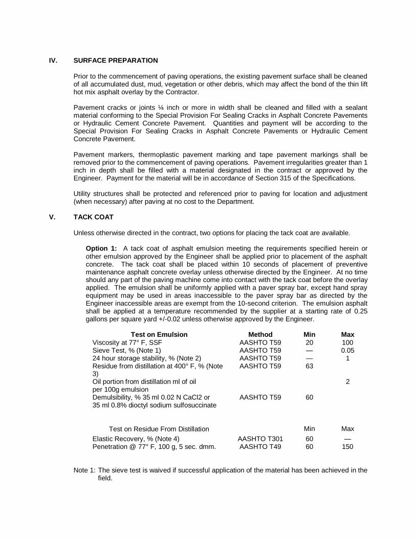
IV. SURFACE PREPARATION
Prior to the commencement of paving operations, the existing pavement surface shall be cleaned of all accumulated dust, mud, vegetation or other debris, which may affect the bond of the thin lift hot mix asphalt overlay by the Contractor. Pavement cracks or joints ¼ inch or more in width shall be cleaned and filled with a sealant material conforming to the Special Provision For Sealing Cracks in Asphalt Concrete Pavements or Hydraulic Cement Concrete Pavement. Quantities and payment will be according to the Special Provision For Sealing Cracks in Asphalt Concrete Pavements or Hydraulic Cement Concrete Pavement. Pavement markers, thermoplastic pavement marking and tape pavement markings shall be removed prior to the commencement of paving operations. Pavement irregularities greater than 1 inch in depth shall be filled with a material designated in the contract or approved by the Engineer. Payment for the material will be in accordance of Section 315 of the Specifications. Utility structures shall be protected and referenced prior to paving for location and adjustment (when necessary) after paving at no cost to the Department.
V. TACK COAT Unless otherwise directed in the contract, two options for placing the tack coat are available.
Option 1: A tack coat of asphalt emulsion meeting the requirements specified herein or other emulsion approved by the Engineer shall be applied prior to placement of the asphalt concrete. The tack coat shall be placed within 10 seconds of placement of preventive maintenance asphalt concrete overlay unless otherwise directed by the Engineer. At no time should any part of the paving machine come into contact with the tack coat before the overlay applied. The emulsion shall be uniformly applied with a paver spray bar, except hand spray equipment may be used in areas inaccessible to the paver spray bar as directed by the Engineer inaccessible areas are exempt from the 10-second criterion. The emulsion asphalt shall be applied at a temperature recommended by the supplier at a starting rate of 0.25 gallons per square yard +/-0.02 unless otherwise approved by the Engineer.
Test on Emulsion Method Min Max Viscosity at 77° F, SSF AASHTO T59 20 100 Sieve Test, % (Note 1) AASHTO T59 — 0.05 24 hour storage stability, % (Note 2) AASHTO T59 — 1 Residue from distillation at 400° F, % (Note 3) Oil portion from distillation ml of oil per 100g emulsion
AASHTO T59 63 2
Demulsibility, % 35 ml 0.02 N CaCl2 or 35 ml 0.8% dioctyl sodium sulfosuccinate
AASHTO T59 60
Test on Residue From Distillation
Min
Max
Elastic Recovery, % (Note 4) AASHTO T301 60 — Penetration @ 77° F, 100 g, 5 sec. dmm. AASHTO T49 60 150
Note 1: The sieve test is waived if successful application of the material has been achieved in the
field.

Note 2: After standing undisturbed for 24 hours, the surface shall show no white, milky colored substance, but shall be a smooth homogeneous color throughout.
Note 3: AASHTO T59 with modifications to include a 400° F +/- 10° F maximum temperature to be held for a period of 15 minutes.
Note 4: With exception that the elongation is 20 cm and the test temperature is 50° F.
Option 2: An asphalt binder tack coat meeting the requirements specified in Special Provision for Non-tracking Tack Coat and listed on Approved List 50.1A shall be applied prior to placement of the preventive maintenance asphalt concrete overlay. The tack coat shall be uniformly applied with a spray bar paver or a mechanical distributor, except hand spray equipment may be used in areas inaccessible. The tack coat shall be applied at a temperature recommended by the supplier at a residual rate of 0.14 gallons per square yard +/-0.02 unless otherwise approved by the Engineer.
VI. PLACEMENT OF HOT MIX ASPHALT The application rates of the overlay shall range from 80 lbs/sy to 85 lbs/sy in order to result in a ¾” compacted lift thickness. The thin lift of hot mix asphalt shall be placed by a paver designed for the placement of thin lifts as designated in the contract. The asphalt mix shall be delivered to the paver hopper at a temperature of 315
oF +/- 15
oF measured in the paver hopper. The paver shall be capable of
placing the asphalt mix at a speed of 30 feet per minute. When the base temperature is 500F or
above, placement of the asphalt concrete wearing course shall be permitted.
VII. COMPACTION Two steel double drum rollers weighing no less than 10 tons shall perform compaction of the asphalt mix. No less than two passes shall be completed before the surface temperature of the asphalt has reached 185
oF.
VIII. ACCEPTANCE
The Contractor shall perform a gradation, and asphalt cement content on one sample taken in a random manner approved by the Engineer from each 500 tons of production. The material will be considered acceptable for gradation and asphalt content, if the results obtained are within the tolerance allowed from the job mix formula in the above table. Material represented by test results outside the tolerance may be removed and replaced with acceptable material by the Contractor at no additional cost to the Department at the discretion of the Engineer. Should visual examination by the Engineer reveal that the material in any load, or portion of the paved roadway is contaminated, segregated, or flushed with asphalt cement, that load, or portion of the paved roadway may be rejected without additional sampling of the material.
IX. WARRANTY The Contractor shall provide a one-year warranty from the date of final acceptance on all thin hot mix asphalt concrete overlay surfaces. The Department will periodically monitor the overlay surface installed throughout the warranty period for compliance and acceptability. The Contractor shall repair any area that fails before the end of the warranty period and shall do so within 14 days after Department notification unless otherwise directed by the Department. Failure of the thin hot mix asphalt concrete overlay surface is defined as the loss of adhesion of the material to the underlying layer resulting in a pothole greater than 1 square foot of area (delamination). The Engineer shall notify the Contractor of the date for the warranty inspection at the end of the warranty period and the Contractor shall be present at the inspection.

X. MEASUREMENT AND PAYMENT Thin hot mix asphalt concrete will be measured in tons and paid for at the contract unit price per ton, which shall include tack coat, surface preparation (except crack and joint sealing), all materials, additives, labor and equipment as described herein to install and complete the work. Crack and joint sealing will be paid in accordance with Special Provision for Sealing Cracks in Asphalt Concrete Pavements or Hydraulic Cement Concrete Pavement (Prior to Overlay). Payment will be made under:
Pay Item Pay Unit Thin Hot Mix Asphalt Concrete Ton

VIRGINIA DEPARTMENT OF TRANSPORTATION SPECIAL PROVISION FOR
PIPE REHABILITATION
July 30, 2015 I. DESCRIPTION
This work shall consist of the rehabilitation of existing storm water, surface water pipe culverts and/or sanitary sewer lines by the method or methods specified at the designated locations described in the Contract using various standard and non-standard methodologies/technologies in accordance with the requirements of this provision and as directed by the Engineer.
II. MATERIALS Cement grout shall conform to Section 218.03(b) or (d) of the Specifications. Corrugated steel pipe liner used for Method C rehabilitation shall conform to Section 232.02 of the Specifications and shall be 10 gage with 3-inch by 1-inch angular corrugations. Corrugated steel pipe used as liners shall be manufactured by QC/QA producers on the VDOT Materials Division Approved Products List. Flexible pipe liner systems used for Method D rehabilitation shall be from the VDOT Materials Division Approved Products List 38 and may be subject to limitations for use as specified herein, by site-specific limitations for those locations listed in the Contract, or as shown on the VDOT Materials Division Approved Products List 38 for the specific liner system. Where such is the case, the Contractor shall use only that type or those types that conform to the requirements for all pipe rehabilitation systems listed in List 38 and what the Department has specified for the specific location listed in the bid proposal documents. The Contractor shall furnish information, services, or other requirements as detailed on List 38 for all materials used for pipe rehabilitation system(s) specified in the Contract. Flexible pipe liners shall be one or more of the following categories as designated in the Contract:
● Category A - Cured-In-Place Pipe (CIPP)
● Category B - Fold and Form flexible liners
● Category C – High Density Polyethylene (HDPE), Polyvinylchloride (PVC), or Polypropylene (PP) slip liners
● Category D - Spray-On liners When Category A - Cured-In-Place Pipe liners are specified, the liner system supplied by the Contractor shall conform to the following requirements as supported by submitted design calculations:
● Must meet Drainage Manual, Chapter 8, Section 8.3.6.7 - Table A, Flexible Liner (Method D) Type Selection Guidelines for Category A systems.
● Must exactly follow ASTM F1216 Appendix X1.2.2 Fully Deteriorated Gravity Pipe Conditions.
● Provide groundwater table elevation at crown of pipe.

● Traffic loading is HL-93, ignore after 8 ft of cover except for multiple barrel rehabs, continue indefinitely.
● Total wet unit weight of soil is 120 pcf, 135 pcf saturated.
● Modulus of soil reaction (based on VDOT pipe installation standards):
● 0-5 ft of cover = 1.8 ksi
● >5-10 ft of cover = 2 ksi
● >10-30 ft of cover = 2.2 ksi
● >30-60 ft of cover = 2.6 ksi
● >60 ft of cover = 2.8 ksi
● Factor of safety N = 2.0.
● Construction:
● Any voids around exterior of host pipe must be filled for design assumptions to be valid.
● Shall specify the following:
● Method for installation and curing.
● Individual components.
● Tube type (whether reinforced or non-reinforced).
● Manufacturer name and type of resin including catalyst.
● Volume of resin required to achieve proper impregnation and curing.
● Shall include lot numbers and expiration dates of all supplied components.
● Shall have an impermeable inner and outer plastic film or plastic pre-liner to promote complete polymerization, prevent resin migration and loss, and prevent contamination of the interior of the finished product.
● Shall conform to the following table:
Property Test Procedures Physical Requirements
Tensile strength at yield ASTM D-638 3,000 PSI
Modulus of elasticity ASTM D-790 200,000 PSI
Flexural strength ASTM D-790 4,000 PSI
When Category B Fold and Form flexible liners are specified, the liner system supplied by the Contractor shall conform to the following requirements as supported by submitted design calculations:
● Must meet Drainage Manual, Chapter 8, Section 8.3.6.7 - Table A, Flexible Liner (Method D) Type Selection Guidelines for Category B systems.

● Must exactly follow ASTM F1947 Appendix X1.2.2 Fully Deteriorated Design Condition or ASTM F1867 Appendix X1.2.3 Fully Deteriorated Design Condition.
● Provide groundwater table elevation at crown of pipe. ● Traffic loading is HL-93, ignore after 8 ft of cover except for multiple barrel
rehabs, continue indefinitely.
● Total wet unit weight of soil is 120 pcf, 135 pcf saturated.
● Modulus of soil reaction (based on VDOT pipe installation standards):
● 0-5 ft of cover = 1.8 ksi
● >5-10 ft of cover = 2 ksi
● >10-30 ft of cover = 2.2 ksi
● >30-60 ft of cover = 2.6 ksi
● >60 ft of cover = 2.8 ksi
● Factor of safety N = 2.0.
● Construction:
● Any voids around exterior of host pipe must be filled for design assumptions to be valid.
When Category C HDPE, PVC, PP slip liners or spirally wound liners are specified, the liner system supplied by the Contractor shall conform to the following requirements as supported by submitted design calculations:
● Must meet Drainage Manual, Chapter 8, Section 8.3.6.7 - Table A, Flexible Liner (Method D) Type Selection Guidelines for Category C systems.
● Must follow AASHTO LRFD Bridge Design Specifications, Section 12, version in use by VDOT Structure & Bridge Division at time of submittal, except that PVC spirally wound liners will follow ASTM F1697 and F1741.
● Must provide SDR and outside diameter of pipe, for solid wall pipe. ● Must provide outside diameter, inside diameter, diameter to centroid of wall,
moment of inertia, gross and effective areas of wall, for corrugated or profile wall pipe.
● Provide groundwater elevation at crown of pipe.
● Traffic loading is HL-93, ignored after 8 ft of cover except for multiple barrel rehabs continue indefinitely.
● Total wet unit weight of soil is 120 pcf, 135 pcf saturated.
● Constrained soil modulus (based on VDOT pipe installation standards):
● 0-5 ft of cover = 1.8 ksi
● >5-10 ft of cover = 2 ksi

● >10-30 ft of cover = 2.2 ksi
● >30-60 ft of cover = 2.6 ksi
● >60 ft of cover = 2.8 ksi
● Shape factor shall be 3.0.
● Long term modulus shall be used for stiffness computation.
● Live Load Distribution Factor = 1.
● Deflection Lag Factor = 1.5.
● Bedding Factor = 0.1.
● Installation Factor = 1.5.
● Maximum deflection, deflection needed in any computations, and service long-term tension strain limit shall be 5 percent for PE, and either 5 percent or 3.5 percent for PVC depending on cell class as per AASHTO LRFD Bridge Design Specs Table 12.12.3.3.1, and 3.5 percent for PP.
● Poisson’s ratio of soil shall be 0.3.
● Earth load modifier shall be 1.05 and live load modifier shall be 1.0.
● Manning’s N number for open channel flow n = 0.011 for smooth interior PVC and 0.012 for smooth interior HDPE and PP. (For hydraulic design.)
● Construction:
● Any voids around exterior of host pipe must be filled for design assumptions to be valid.
● The annular space between host pipe and liner pipe must be fully grouted for design assumptions to be valid.
When Category D Spray-on liners are specified for structural rehabilitation, the liner system supplied by the Contractor shall conform to the following requirements as supported by submitted design calculations:
● Must meet Drainage Manual, Chapter 8, Section 8.3.6.7 - Table A, Flexible Liner (Method D) Type Selection Guidelines for Category D systems.
● Because of the variety of spray-on liners available, several design options may
be used. For cementitous liners, design shall be guided similarly to nonreinforced concrete pipe, or alternately, similar to fiberglass pipe (high modulus material). For other liners, polyurea for example, design shall be guided similarly to fiberglass pipe (high modulus material) or simply as plastic pipe if flexural modulus or ring bending strain results are not satisfactory.
● Cementitious liner treated similarly as fiberglass pipe (this method is based
on the proposed AASHTO LRFD Bridge Design Specifications for fiberglass pipe):
● Articles referenced below are from AASHTO LRFD Bridge Design Specifications, Section 12, version in use by VDOT Structure & Bridge Division at time of submittal.

● The flexibility factor for fiberglass pipe shall be determined in
accordance with Article 12.12.3.6, but with the modulus replaced by flexural modulus, and the flexibility factor shall be limited as specified in Article 12.5.6.3.
● Follow Section 12.12.2.2 for deflection, except replace modulus with flexural modulus (ksi) and drop the “escD” term.
● Factored long term strain due to flexure shall be less than or equal to
0.9*Sb (Sb is ring bending strain). ● Factored buckling strain demand shall be less than or equal to
0.7*nominal strain capacity for buckling demand, computed per Eqn. 12.12.3.10.1e-2, except replace modulus with flexural modulus and soil resistance factor shall be 1.0. Factored buckling strain shall be:
● [[13.65 *Height of soil over crown (in feet) + 1.75*PL] * radius of liner to centroid of wall in in.]/(flexural modulus in ksi * X-S area of liner in in
2/in), where PL is determined from Eqn. 12.12.3.9-1.
● Flexural modulus shall be determined from pipe stiffness tests and
per Appendix 2 of ASTM D2412, and shall be at least 1,200 ksi. ● Long term ring bending strain, Sb, shall be determined in accordance
with ASTM D5365 and results extrapolated to both 50 years and 75 years, and shall be at least 0.006.
● It is recognized that for a spray-on product, obtaining specimens for flexural modulus and ring bending strain tests would require special formwork at a fabrication facility. Similarly as is done for watertight joint testing, these tests may be done and witnessed by a PE and a report submitted, which may then be used as proof of results without having to perform the tests for each future project, as long as materials and processes have not changed. Application thicknesses not tested may be interpolated by a satisfactory method. Extrapolation beyond thicknesses tested will not be permitted on the thin side, and will only be permitted for thicker applications by satisfactory statistical data.
● GW table at crown of pipe. ● Traffic loading is HL-93, ignored after 8 ft of cover except for multiple
barrel rehabs continue indefinitely.
● Unit weight of soil is 120 pcf, 135 pcf saturated.
● Modulus of soil reaction (based on VDOT pipe installation standards):
● 0-5 ft of cover = 1.8 ksi ● >5-10 ft of cover = 2 ksi
● >10-30 ft of cover = 2.2 ksi
● >30-60 ft of cover = 2.6 ksi
● >60 ft of cover = 2.8 ksi

● Shape factor shall be 3.0.
● Live Load Distribution Factor = 1.
● Deflection Lag Factor = 1.5.
● Bedding Factor = 0.1.
● Installation Factor = 1.5.
● Maximum deflection and deflections needed in any computations shall be 5 percent.
● Poisson’s ratio of soil shall be 0.3.
● Earth load modifier shall be 1.05 and live load modifier shall be 1.0.
● Other liner types treated similarly as fiberglass pipe: ● Same as for cementitous liner treated similarly as fiberglass pipe
above.
● Other liner types treated same as plastic pipe: ● Follow AASHTO LRFD Bridge Design Specifications, Section 12, for
thermoplastic pipe, version in use by VDOT Structure & Bridge Division at time of submittal.
● GW table at crown of pipe. ● Traffic loading is HL-93, ignored after 8 ft of cover except for
multiple barrel rehabs continue indefinitely.
● Unit weight of soil is 120 pcf, 135 pcf saturated.
● Modulus of soil reaction (based on VDOT pipe installation standards):
● 0-5 ft of cover = 1.8 ksi ● >5-10 ft of cover = 2 ksi
● >10-30 ft of cover = 2.2 ksi
● >30-60 ft of cover = 2.6 ksi
● >60 ft of cover = 2.8 ksi
● Shape factor shall be 3.0.
● Live Load Distribution Factor = 1.
● Deflection Lag Factor = 1.5.
● Bedding Factor = 0.1.
● Installation Factor = 1.5.
● Maximum deflection and deflections needed in any computations shall be 5 percent.
● Poisson’s ratio of soil shall be 0.3.
● Earth load modifier shall be 1.05 and live load modifier shall be 1.0.
● Construction:
● Any voids around exterior of host pipe must be filled for design assumptions to be valid.
Smooth-wall steel pipe liner used for Method E rehabilitation shall conform to Section 232.02(c)5 of the Specifications.
III. GENERAL PROCEDURES The Contractor shall submit site specific working drawings (and supportive calculations) to the Engineer according to the requirements herein and Section 105.10 of the Specifications for the rehabilitation method selected by the Contractor from the allowable methods per each location listed in the Contract prior to the start of pipe rehabilitation operations. The Contractor shall furnish to the Engineer a certification of the acceptability of the proposed rehabilitation system to provide the necessary hydraulic capacity and structural strength to support the anticipated total load and hydrology at the site of rehabilitation, as determined from a review that has been signed and sealed by a Professional Engineer holding a valid license to practice engineering in the Commonwealth of Virginia. Such certification shall cover all design data, supporting calculations and planned rehabilitation materials. All work and equipment shall be contained within the existing right-of-way. In the event a temporary construction easement is deemed necessary due to the selected method or product chosen by the Contractor, the Contractor shall obtain such additional easement for his convenience at no additional cost to the Department. The Contractor shall maintain all lanes of traffic at all times in accordance with the Special Provision for Section 512—Maintaining Traffic – Non-Schedules (Lump Sum) unless otherwise directed by the Engineer. This maintenance of traffic shall include temporary detours if required by the Contractor’s method of operations to facilitate construction and where permitted by the locality and the Department. When temporary detours are required, the Contractor shall design and construct temporary detours in accordance with Sections 105.14 and 512 of the Specifications and Standard GS-10 of the Road and Bridge Standards respectively. The cost for maintenance of traffic including temporary detours shall be bid as a lump sum amount for the specific location of each pipe rehabilitation as shown in the Contract in accordance with the Special Provision for Section 512—
Maintaining Traffic – Non-Schedules (Lump Sum) unless otherwise specified in the Contract. The Contractor shall contact Miss Utility prior to commencing any work that may conflict with existing utilities, and shall coordinate with the utility company(ies) and the Engineer for any adjustments deemed necessary to complete the work. The Contractor shall notify the VDOT Area Construction Engineer at least 48 hours prior to initiation of rehabilitation operations at the site. In the event the selected method of rehabilitation requires disturbing existing surfaces, these surfaces shall be restored in kind to original pre-construction conditions after rehabilitation operations have been completed and the cost thereof shall be included in the price bid for Pipe Rehabilitation for the specified location.

The Contractor shall obtain all required OSHA confined space entry permits where these are required by the Contractor’s operations and the scope of work in the Contract. The Department has performed an inspection of the existing pipes in each location listed in the Contract to determine the extent and nature of each pipe’s deterioration or damage so as to designate the allowable methods of rehabilitation of the pipe at that specific site. Using the information collected from this inspection, the Department has determined through its engineering analysis the best practical method(s) of rehabilitation for each respective site (location) taking into account site specific conditions such as installation working space for the various types of liners, hydraulic capacity before and after rehabilitation, height of cover, soil density, and loading conditions, among other criteria. The Contractor shall select from the allowable method(s)/category(ies) for each specified location or site indicated in the Contract, how the Contractor chooses to perform the work. Regardless of the final method selected, the Contractor shall provide the Engineer documentation of the proposed procedures, materials, equipment, incidentals and resources the Contractor shall use to ensure successful rehabilitation of the existing pipe(s) to assist the Engineer in monitoring the Contractor’s operations. The Contractor will not be permitted to substitute a different method(s) and category(ies), if designated, than that or those specified for the location described in the Contract. The Contractor shall clear the existing pipe(s) designated for rehabilitation of any debris, protrusions greater than ½ inch in height and any other potential obstructions prior to the start of rehabilitation efforts. The Contractor shall then thoroughly clean and prepare the host pipe prior to the liner installation. Cleaning shall conform to the recommendations of the liner manufacturer/producer or supplier of the methodology to be used. In the absence of such recommendations, the Contractor shall submit his/her proposed method for cleaning and preparing the host pipe for the Engineer’s review and acceptance. A copy of the cleaning methodology and materials shall be provided to the Engineer at least 2 working days prior to beginning the work at that location. Please note: All specified time limits in these specifications refer to working days, not calendar days. Pre-Installation Inspection – In addition to the inspection performed by the Department, and not later than 2 to 3 weeks after cleaning the host pipe at the specified location, the Contractor shall perform a pre-installation visual/video inspection at the designated location of the pipe shown in the Contract or where directed by the Engineer. This visual/video inspection shall be conducted in accordance with the requirements of this specification and VTM 123 to verify pre-construction conditions. The inspection shall be performed in the presence of the Engineer. Video inspections shall be clearly labeled on the media with the time, date, and location of the pipe inspected. A copy of the video inspection shall be furnished to the Engineer prior to the start of rehabilitative construction. The cost of pre-Installation Inspection will be considered incidental to the cost of the installation. In the event the Contractor’s inspection shows the method of rehabilitation the Contractor has selected is no longer viable at that location as verified by the Engineer, the Contractor shall select another allowable method, if specified, from those designated in the Contract. If no other method is designated, or if other methods of rehabilitation also now are deemed impracticable at that location, further work will be determined in accordance with Section 104.03. The following methods of pipe rehabilitation are approved by the Department; however, not all methods may be appropriate for each individual location. The Contractor shall consult the Contract to determine the method (and category if designated) or methods (and categories if designated) that are permitted per the location cited. Individual methods shall conform to the criteria specified. PIPE REHABILITATION BY LINER
Method C - Corrugated steel pipe liner shall be rehabilitation by insertion of a rigid corrugated steel pipe liner through an existing host pipe (36" diameter or larger corrugated or concrete pipe).

Where required, pipe shall be joined by the use of coupling bands of an internal expansion type that shall provide a leak-proof joint after grouting. Expansion devices shall be installed above the mid-point of the pipe. After the Engineer approves installation and alignment of the liner within the host pipe, the Contractor shall pressure grout the annular space between the existing pipe and the liner. Prior to grouting, the annular space shall be adequately sealed at each end. Plug holes required for injection of grout shall be satisfactorily plugged and sealed following the grouting operation. Method D - Flexible pipe liner shall be rehabilitation by the use of a flexible pipe liner. Rehabilitation, as indicated in the Contract, shall be accomplished by the use of the following:
● Category A - Cured-In-Place Pipe (CIPP)
● Category B - Fold and Form flexible liners
● Category C - HDPE, PVC, or PP slip liners
● Category D - Spray-On liners Installation and curing requirements of pipe sections for the various flexible pipe liners shall be according the manufacturer recommendations for the specific product as applicable. Joints shall meet the requirements of Section 30 of the AASHTO Bridge Construction Specifications and leak resistance as defined in AASHTO PP 63-09.
The Contractor shall furnish curing requirements for the various flexible liners to include as applicable individual components of the system, tube type (whether reinforced or non-reinforced), manufacturer name and type of resin including catalyst, volume of resin required to achieve proper impregnation and curing. All components of the systems shall be as recommended by the manufacturer for the specific system used, and all components shall include lot numbers and expiration dates. The Contractor shall submit documentation from the manufacturer to verify compliance with the requirements of this paragraph as well as installation recommendations to the Engineer at least 72 hours prior to the start of installation.
Method D, Category A – Cured-In-Place Pipe liner method. The Cured-In-Place Pipe liner system shall be designed, fabricated and installed in such a manner as to result in a maintained full contact tight fit to the internal circumference of the host pipe for its entire length. The installation shall adhere to the cure times and temperatures stipulated in the manufacturer’s recommended installation and cure specifications and the finished product shall be free of de-lamination, bubbling, rippling or other signs of installation failure. Pulled-in-place liner installation must be accomplished without significant liner twisting or stretching during installation. At no time shall the pulling force for liner installation exceed that established by the liner manufacturer. All Cured-In-Place Pipe installations shall be performed in the dry. The Contractor shall consider the cost to accommodate this requirement as incidental to the cost of the installation. Curing for styrene-based, epoxy-based, and vinyl ester-based CIPP may be accomplished by water, steam or ultraviolet light and shall be in accordance with the liner manufacturer's recommendations.

The Contractor shall submit preconstruction installation and cure specifications (to include site specific cure time and temperature calculations) and design calculations (stamped by a licensed professional engineer) to the VDOT Engineer a minimum of 72 hours prior to initiation of installation. The Contractor shall place an impermeable sheet immediately upstream and downstream of the host pipe prior to liner insertion to capture any possible raw resin spillage during installation and shall remove and properly dispose of any waste materials. Where the pulled-in-place method of installation is used, the Contractor shall install a semi-rigid plastic slip sheet over any interior portions of the host pipe that could tear the outer film or over any significant voids in the host pipe. The Contractor shall ensure there is no loss of impermeability of the inner and outer plastic films or pre-liner during installation. The Contractor shall promptly repair any pinholes or tears in the plastic films or pre-liner before proceeding with the installation. Where such damaged areas cannot be repaired, the Contractor shall promptly replace the impermeable plastic films or pre-liner before proceeding with the installation. The Contractor shall not perform work without oversight of the VDOT Engineer or Inspector for the duration of the installation. The Contractor shall monitor temperature via a minimum of three thermocouples on the outer surface of the liner (one each at the upstream and downstream ends and one approximately mid-length of the host pipe) and automatically log cure time-temperature data with a print-out from the data logger and provide such information to the VDOT Engineer. The Contractor shall obtain and comply with all discharge-related permits, including air, water, and wastewater treatment (i.e. Publicly Owned Treatment Works or “POTW”). For any discharge to a Publicly Owned Treatment Works (POTW), the Contractor shall obtain advanced written approval from the receiving facility for acceptance of effluent waste before repair work can start and shall provide such documentation of the POTW discharge approval to the Engineer prior to the start of the installation. The Contractor shall capture and properly dispose of all cure water and/or steam condensate and be responsible for the proper transportation and off-site disposal of process residuals. The Contractor shall provide disposal documentation from the receiving facility to the VDOT Engineer. For any discharge to a Publicly Owned Treatment Works (POTW), the Contractor shall comply with all the requirements of the POTW receiving the discharge. The Contractor shall thoroughly rinse the cured lined pipe with clean water and capture and properly dispose of rinse water prior to re-introducing flow. For styrene-based CIPP and vinyl ester-based CIPP, the Contractor shall employ the services of a qualified independent environmental services laboratory or environmental consultant to collect the following samples:
● pre-rehabilitation soil and water samples within 3 feet of the pipe ends (or otherwise as close as possible) upstream and downstream of the pipe location; and
● soil and water samples within 3 feet of the pipe ends (or otherwise as close as possible) upstream and downstream of the pipe location within one week after the pipe liner has cured.

These samples shall be collected in accordance with applicable ASTM standard procedures. For styrene-based liners, samples shall be analyzed for styrene using USEPA SW 846 Method 8260. Styrene concentrations in water samples shall not exceed 2.5 mg/L. For vinyl ester-based liners, samples shall be analyzed for diallyl phthalate. Diallyl phthalate concentrations in water samples shall not exceed 0.4 mg/L. The Contractor shall report the results of all sampling to the Engineer within 4 weeks after completion of the rehabilitation. The following information shall also be supplied in the water or soil sampling reports:
Location of pipe:
● County, VDOT Residency ● Route number and distance to nearest intersection
● Name of stream if applicable or known Description of pipe:
● Length, diameter, type i.e. concrete, corrugated steel
● Conveyance conditions i.e. wet weather only, perennial, current conditions
● General flow description i.e. high, medium, low
● Site description i.e. stream bed, earthen ditch, concrete ditch, subsurface stormwater drainage
It shall be the Contractor’s responsibility to report and take appropriate corrective actions to contain and remediate any release of contaminants from cured-in-place process materials, effluent or condensate into the environment in accordance with applicable local, state or federal regulations and the Specifications. The cost for such remediation shall be at the Contractor’s expense. Method D, Category B - Fold and form flexible liners shall be installed in accordance with the requirements of ASTM F1216, ASTM F2019, ASTM F1743, or ASTM D5813 (as applicable) or as recommended by the liner manufacturer. Method D, Category C - HDPE, PVC, or PP slip liner shall be installed in accordance with the requirements of AASHTO M326 or in accordance with ASTM F1698 as applicable or as recommended by the liner manufacturer.
Method D, Category D - Spray-On cementitious and polyurea liners shall be installed in accordance with the liner material manufacturer’s recommendations. For spray-on cementitious or polyurea liner systems, the following requirements shall apply:
● The Contractor shall perform all installations in the dry. ● The Contractor shall thoroughly rinse the lined pipe with clean water.
● The Contractor shall install a temporary curtain at the outlet and inlet to prevent overspray during installation;
● The Contractor shall reinstate water flow no sooner than 24 hours following installation.

● For cementitious spray-on liners, the Contractor shall prevent the escape of any rinse water from the lined pipe or otherwise capture it until he/she can either (1) pump it to a container for proper transportation and off-site disposal; or (2) continuously monitor the pH of the rinse water until the pH is less than 9 whereupon he/she may release it.
● For polyurea spray-on liners, the Contractor shall capture and properly dispose of the rinse water prior to reinstating flow; and employ the services of a qualified independent environmental services laboratory or environmental consultant to collect the following samples:
● pre-rehabilitation water and soil samples within 3 feet of the pipe
ends (or otherwise as close as possible) upstream and downstream of the pipe location; and
● soil and water samples within 3 feet of the pipe ends (or otherwise as close as possible) upstream and downstream of the pipe location within one week after the liner has cured.
Samples shall be collected in accordance with applicable ASTM standard procedures and analyzed for total methylene diphenyl diisocyanate (MDI), methylenedianiline (MDA), and total cyanide. Concentrations of methylene diphenyl diisocyanate (MDI) in water samples must not exceed 1,000 mg/L and concentrations of methylenedianiline (MDA) in water samples must not exceed 39 mg/L. Water characterization for chemical oxygen demand (COD) and total nitrogen (TN) concentrations shall also be conducted. The Contractor shall report the results of all sampling to the Engineer within 4 weeks after completion of the rehabilitation. The following information shall also be supplied in the sampling reports:
Location of pipe:
● County, VDOT Residency ● Route number and distance to nearest intersection ● Name of stream if applicable or known
Description of pipe:
● Length, diameter, type i.e. concrete, corrugated steel ● Conveyance conditions i.e. wet weather only, perennial,
current conditions ● General flow description i.e. high, medium, low ● Site description i.e. stream bed, earthen ditch, concrete
ditch, subsurface stormwater drainage ● It shall be the Contractor’s responsibility to report and take appropriate
corrective actions to remediate any water quality alteration resulting from the lining materials in accordance with applicable local, state or federal regulations. The cost for such remediation shall be at the Contractor’s expense.

Method E – Smooth wall steel pipe liner shall be rehabilitation by the insertion of a smooth wall steel pipe into a host pipe. Where required, pipe shall be joined by butt welds in accordance with AWWA C-206. The Contractor shall pressure inject a non-shrink grout into the annular space between the existing host pipe and the steel liner. The annular space between the existing pipe and the smooth wall steel liner shall not exceed 3 inches at any given point, unless otherwise approved by the Engineer. Prior to grouting, the annular space shall be sealed at each end. Holes required to facilitate injecting grout shall be plugged and sealed following grouting operations. In order to ensure stability during placement, the wall thickness of the liner shall not be less than ½”.
Post Installation Inspection – The Contractor shall perform a post-installation inspection on all flexible liners installations in accordance with Section 302.03(d) of the Specifications and Virginia Test Method (VTM) 123. The finished liner shall be continuous over its entire length and be free from visual defects such as foreign inclusions, dry spots, pinholes, and delamination. In the event a post inspection of the installation reveals a tight fit of the liner was not achieved in localized areas of the host pipe (comprising less than 20 percent of the pipe length) the annular space between the liner and the host pipe shall be filled with a resin mixture or a cementitious grout (at no cost to the Department) that is compatible with the liner system as specified by the manufacturer. Where a tight fit was not achieved on 25 percent or more of the pipe length the annular space shall be filled as designated herein, however, the Contractor will not be allowed to continue with his methodology of installation and/or the liner system used until he/she can demonstrated to the Engineer that he/she has remedied his/her operations so that it results in a snug tight fit between the installed liner and the host pipe. All such remedial efforts shall be at the Contractor’s expense. Further failure(s) to perform a proper installation may result in the disallowance of the use that liner system and an adjustment in the cost or non-payment of the failed installations depending on the severity of the failure. In the event the post installation inspection is not conducted until all or most of the locations in the Contract permitting this methodology have been performed, and the inspection reveals a tight fit between host pipe and liner has not been achieved on 25 percent or more of the host pipe’s length or the finished liner is not free from visual defects such as foreign inclusions, dry spots, pinholes, and delamination, then an adjustment in the cost or non-payment of the failed installations maybe made by the Engineer depending on the severity of the failure. The cost of post Installation Inspection will be considered incidental to the cost of the installation.
IV. MEASUREMENT AND PAYMENT Pipe rehabilitation (Method) will be measured and paid for in units of linear feet of pipe for the Size, Method(s) and Category (if specified) as detailed in the Contract. Note: At locations shown in the Contract where multiple methods are permitted, the Contractor may select any of the methods specified, however, if only one method is specified, this will be the only method permitted at that location. This price shall include inspection, cleaning and preparation of the host pipe, furnishing and installing the liner, coupling and expansion devices, cement grout, design and shop drawing preparation, furnishing and installing liner and all components of the liner system, capturing any discharges or releases during installation or curing operations, obtaining any local, POWT, state or federal permits required to perform the work, furnishing any documentation or fees required for effluent or condensate disposal, all testing and sampling including furnishing reports and post installation video inspections for flexible liners, and waste disposal costs. Prices for pipe rehabilitation shall also include excavating when not designated as a separate pay item attributable to this specific work; sheeting; shoring; dewatering; disposing of surplus and unsuitable

material; backfilling and backfill material; compaction, restoring existing surfaces; and clearing debris and obstructions. Payment will be made under:
Pay Item Pay Unit
(Size) Pipe Rehabilitation (Method, Category-if specified)
Linear Foot

1
VIRGINIA DEPARTMENT OF TRANSPORTATION SPECIAL PROVISION FOR
PIPE REPLACEMENT
February 28, 2013 I. DESCRIPTION
This work shall consist of the replacement of existing storm water, surface water pipe culverts and/or sanitary sewer lines by the method or methods specified at the designated locations described in the Contract using various standard and non-standard methodologies/technologies in accordance with the requirements of this provision and as directed by the Engineer.
II. MATERIALS Cement grout shall conform to Section 218 of the Specifications except the grout shall be a non-shrink mix design. Pipe used in replacement operations shall conform to Section 232 of the Specifications.
III. GENERAL PROCEDURES All work shall be contained within the existing right-of-way. In the event a temporary construction easement is deemed necessary due to the selected method or product chosen by the Contractor, the Contractor shall obtain such additional easement for his convenience at no additional cost to the Department. The Contractor shall maintain all lanes of traffic at all times in accordance with the Special Provision for Section 512—Maintaining Traffic – Non-Schedules (Lump Sum) unless otherwise directed by the Engineer. This maintenance of traffic shall include temporary detours if required by the Contractor’s method of operations to facilitate construction and where permitted by the locality and the Department. When temporary detours are required the Contractor shall design and construct temporary detours in accordance with Sections 105.14 and 512 of the Specifications and Standard GS-10 of the Road and Bridge Standards respectively. The cost for maintenance of traffic including temporary detours shall be bid as a lump sum amount for the specific location of each pipe replacement as shown in the Contract in accordance with the Special Provision for Section 512—
Maintaining Traffic – Non-Schedules (Lump Sum) unless otherwise specified in the Contract. The Contractor shall contact Miss Utility prior to commencing any work that may conflict with existing utilities, and shall coordinate with the utility company(ies) and the Engineer for any adjustments deemed necessary to complete the work. The Contractor shall notify the VDOT Area Construction Engineer at least 48 hours prior to initiation of replacement operations at the site. In the event the selected method of replacement requires disturbing existing surfaces, these surfaces shall be restored in kind to original pre-construction conditions after replacement operations have been completed. The cost shall be included in the price bid for Pipe Replacement for the specified location. The Contractor shall obtain all required OSHA confined space entry permits where these are required by the Contractor’s operations and the scope of work in the Contract. The Department has performed an inspection of the existing pipes in the Contract to determine the extent and nature of each pipe’s deterioration or damage in each location so as to designate the allowable methods of replacement of the pipe at that specific site. Using the information collected from this inspection the Department has determined through its engineering analysis the best practical method(s) of replacement for each respective site (location) taking into account

2
site specific conditions such as installation working space, hydraulic capacity before and after replacement, height of cover, soil density, and loading conditions, among other criteria. The Contractor shall select, according to the method or options of methods designated by the Department for each specified location or site indicated in the Contract, how he/she chooses to perform the work. Regardless of the final method selected, the Contractor shall provide the Engineer documentation of the procedures, materials, equipment, incidentals and resources he/she shall employ to ensure successful replacement of the existing culvert(s) and/or sewers to assist the Engineer in monitoring the Contractor’s operations. The Contractor will not be permitted to substitute a different method(s), if designated, than that or those specified for the location described in the Contract. Replacement procedures shall be performed according to the method specified in accordance with the requirements of Section 302.03 of the Specifications at the location shown or described in the Contract. Pipes shall be installed to the line and grade shown or derived from invert elevations specified in the plans. Unless otherwise specified, pipes abandoned in place shall be grouted to fill the entire inside void with flowable backfill conforming to the requirements of the Special Provision for Flowable Backfill. The following methods of pipe replacement are approved by the Department; however, not all methods may be appropriate for each individual location. The Contractor shall consult the Contract to determine the method or methods that are permitted per the location cited. Individual methods shall conform to the criteria specified.
Method A – Jacked pipe installation shall be the jack and bore method in accordance with Section 302.03(a)1 of the Specifications. Method B - Open trench pipe installation shall be the open trench method in accordance with Section 302.03(a)2 of the Specifications.
Post installation inspection shall be performed in accordance with Section 302.03(d) of the Specifications. The cost of such inspection will be considered incidental to the cost of the installation.
IV. MEASUREMENT AND PAYMENT Pipe Replacement (Method A) will be measured and paid for in units of linear feet of “Jacked Pipe” in accordance with Section 302.04 of the Specifications. Pipe Replacement (Method B) will be measured and paid for in units of linear feet of “Pipe” in accordance with Section 302.04 of the Specifications. These prices shall also include excavating when not designated as a separate pay item attributable to this specific work; sheeting; shoring; dewatering; disposing of surplus and unsuitable material; backfilling and backfill material; compaction; restoring existing surfaces; clearing obstructions, and flowable backfill when not designated as a separate pay item attributable to this specific work. Payment will be made under:
Pay Item Pay Unit
(Size) Pipe Replacement (Method A) (Size) Pipe Replacement (Method B)
Linear Foot Linear Foot
VIRGINIA DEPARTMENT OF TRANSPORTATION SPECIAL PROVISION FOR
RIGHT-OF-WAY MONUMENTATION AND FINAL BOUNDARY STAKEOUT
December 2, 2009a The number of right-of-way monuments to be set for this contract are fill-in. The Contractor shall furnish right-of-way monuments and ensure the setting of such monuments and final boundary stakeout is performed by or under the direct responsibility, control and personal supervision of a Land Surveyor currently licensed and able to practice in the Commonwealth of Virginia.
SECTION 503 is added to the Specifications as a complete section as follows:
SECTION 503—RIGHT-OF-WAY MONUMENTS 503.01—Description This work shall consist of furnishing and setting right-of-way monuments at locations shown on the plans or as designated by the Engineer in accordance with the requirements of the Standard Drawings and the Department’s Survey Manual. 503.02—Materials Right-of-way monuments shall conform to the requirements of Section 219 of the Specifications. 503.03—Procedures Monuments shall be placed at locations designated on the plans, by the Engineer or as required by the Department’s Survey Manual Excavation shall be kept to the minimal for installation so as minimize the disturbance of in-situ material and compaction and backfill efforts. Backfill shall be thoroughly compacted in a manner that will not displace the monument. 503.04—Measurement and Payment Right-of-way monuments will be measured in units of each, complete-in-place, and will be paid for at the contract unit price per each. This price shall include furnishing, installing, excavating, backfilling and compaction. Payment will be made under:
Pay Item Pay Unit
Right-of-way monument (Standard) Each

SECTION 517—CONTRACTOR CONSTRUCTION SURVEYING of the Specifications is amended as follows:
Section 517.02—General Requirements is amended to add the following:
(e) location, final boundary stakeout, and final right of way monumentation Section 517.04(i) Right of way and boundary stakeout affecting property ownership is amended to replace the last sentence with the following:
Final boundary stakeout shall be performed in accordance with the Department’s Survey Manual by or under the direct responsibility, control and personal supervision of a Land Surveyor currently licensed and able to practice in the Commonwealth of Virginia.
Section 517.04(j) Locating and setting right-of-way monuments is replaced with the following:
(j) Locating and setting right-of-way monuments: Final right of way monumentation
shall be performed in accordance with the Department’s Survey Manual and Section 503 herein by or under the direct responsibility, control and personal supervision of a Land Surveyor currently licensed and able to practice in the Commonwealth of Virginia. Hub and tack points for RM-1 right-of-way monuments shall be set in accordance with the Road and Bridge Standards. The Contractor shall furnish RM-2 right-of-way monuments and locator posts. The Department will furnish the required caps for installation by the Contractor. Surveying work and drawings shall be in accordance with the requirements of Sample Figure 4 in Chapter 8—Construction Surveys of the Survey Manual. Where required by the Department’s Survey Manual all drawings, layouts, field notes, documentation, etc shall be signed and sealed by the licensed Land Surveyor. The Certified record drawings, field notes, and computations shall be submitted to the Engineer. Upon completion of the project, the Contractor shall provide the Engineer with all original surveying drawings, field notes, layouts, computations, sketches and drawings in the format approved by the Engineer. All electronic copies submitted shall be in a format fully compatible with the Department’s existing computer hardware and software.
Section 517.05(h) Right of way and boundary stakeout affecting property ownership is amended to replace the last sentence with the following:
Final boundary stakeout shall be performed in accordance with the Department’s Survey Manual by or under the direct responsibility, control and personal supervision of a Land Surveyor currently licensed and able to practice in the Commonwealth of Virginia.
Section 517.05(i) Setting right-of-way monuments is replaced with the following:
(i) Setting right-of-way monuments: Final right of way monumentation shall be performed
in accordance with the Department’s Survey Manual and Section 503 herein by or under the direct responsibility, control and personal supervision of a Land Surveyor currently licensed and able to practice in the Commonwealth of Virginia. Hub and tack points for RM-1 right-of-way monuments shall be set in accordance with the Road and Bridge Standards. The Contractor shall furnish RM-2 right-of-way monuments and locator posts. The Department will furnish the required caps for installation by the Contractor. Surveying work and drawings shall be in accordance with the requirements of Sample Figure 4 in Chapter 8—Construction Surveys of the Survey Manual. Where required by the Department’s Survey Manual all drawings, layouts, field notes,

documentation, etc shall be signed and sealed by the licensed Land Surveyor. Certified record drawings, field notes, and computations shall be submitted to the Engineer. Upon completion of the project, the Contractor shall provide the Engineer with all original surveying drawings, field notes, layouts, computations, sketches and drawings in the format approved by the Engineer. All electronic copies submitted shall be in a format fully compatible with the Department’s existing computer hardware and software.

VIRGINIA DEPARTMENT OF TRANSPORTATION SPECIAL PROVISION
PREFORMED THERMOPLASTIC PAVEMENT MARKINGS
November 29, 2011b I. DESCRIPTION
These specifications provide criteria for furnishing and installing durable, retroreflective preformed thermoplastic material for use in installing pavement markings, message markings and pavement marker applications. Lines, legends and symbol material shall be capable of being affixed (fusing) to asphalt concrete (bituminous) pavements by the use of a heating source.
II. DETAIL REQUIREMENTS Preformed thermoplastic marking materials shall be in accordance with the Department’s approved products list. Material shall be a preformed, beaded reflectorized thermoplastic pavement marking material that is applied to the road surface using a heat source such as a propane torch. Upon cooling to normal pavement temperature, the material shall produce a reflectorized message, legend or symbol of specified thickness, width or design capable of resisting deformation to traffic. Material shall not distort because of temperature variations prior to application. The Contractor shall ensure that the pavement surface is clean, dry and free of debris or other deleterious material which may affect performance by removing all dust, dirt, loose particles heavy oil residues and other deleterious materials that may affect proper installation. Manufacturer\Supplier must enclose application instructions (multilingual) in with each box/package of materials. Material shall be suitable for use on asphalt concrete surfaces and shall be capable of being applied to previously applied pavement marking material of the same composition under normal conditions of use. Marking material must be capable of conforming to pavement contours, breaks and faults through the action of traffic within the range of temperatures as specified herein. The markings shall have resealing characteristics, such that it is capable of fusing with itself and previously applied thermoplastic when heated with the heat source. In addition to being capable of fusing itself over existing markings such new markings shall be furnished to match the size dimensions and shape of existing markings. Material shall not exude fumes that are toxic or injurious to persons, animals or property when heated to the application temperature. Material shall withstand air and roadway temperature variations from 0 degrees F to 140 degrees F without deforming, bleeding, staining, discoloring and shall maintain their original dimensions and placement without chipping, spalling, or cracking. Material shall not deteriorate because of contact with sodium chloride, calcium chloride, mild alkalies and acids, or other ice control material; oil in the pavement material; or oil and gasoline drippings from vehicles. Material, except for reversible arrows, shall have factory applied coated surface and intermixed beads. Intermixed beads shall be uniformly distributed throughout the material at a minimum of 30 percent by weight. Reversible arrows shall have intermixed beads only. Surface beads for reversible arrows shall conform to the requirements of Section 234 and be furnished and applied by the installer. Initial skid resistance value shall be at least 45 BPN when tested in accordance with ASTM E 303.

Retained retroreflectivity, durability and color of markings shall conform to the following requirements after being installed on a northern region test deck for one year. Retroreflectivity: Photometric quantity to be measured is coefficient of retroreflected luminance (RL) in accordance with the requirements of ASTM E 1710. RL shall be expressed in millicandelas per square foot per foot per foot-candle and shall be at least the following values when measured in the wheel path area.
Initial Retained (after 1 Year)
White 300 90
Yellow 200 70
Durability: Material shall have a durability rating of at least 4 when determined in the wheel path area. Retained Daytime Color: Retained daytime color of markings shall conform to the requirements of ASTM D 6628. Initial Nighttime Color: Initial nighttime color of preformed thermoplastic plastic pavement marking material shall conform to the following CIE chromaticity coordinate requirements when tested in accordance with VTM 111.
CIE CHROMATICITY COORDINATE LIMITS (INITIAL WITH DROP-ON BEADS)
Color 1 2 3 4
x y x y x y x y
Yellow 0.486 0.439 0.520 0.480 0.560 0.440 0.498 0.426
Material shall not be formulated with any compounds of the heavy metals listed in 40 CFR 261.24 Table 1 except that barium sulfate is allowed. Total heavy metal levels, with the exception of barium sulfate, shall not exceed 20 times the specified regulatory limits. Amount and type of yellow pigment and inert filler for yellow material shall be at the option of the manufacturer provided the material complies with all other requirements of this specification. Material to be supplied may be of either of the following types: o Type where the manufacturer requires preheating of the roadway surface to a specified
temperature prior to installation of the preformed thermoplastic material. o Type where the manufacturer requires preheating of the roadway surface prior to
installation of the preformed thermoplastic material to only remove moisture when necessary.
Current manufacturer installation instructions will be used to determine which type material a manufacturer produces. A copy of the instructions shall be provided to the Engineer. When installing over existing thermoplastic markings new preformed thermoplastic pavement markings shall conform to the shape and completely adhere (fuse) to the old existing markings. Materials on this list determined not to conform to these requirements based on this verification testing will not be acceptable. Materials failing any of the requirements of this provision will be deemed unacceptable and the Contractor shall then furnish acceptable materials meeting these requirements at no additional cost to the contract.

III. DESIGN APPLICATIONS Crosswalks and stop lines shall be installed using preformed thermoplastic pavement markings conforming to the details and dimensions of the contract. Crosswalk lines shall be one foot wide and stop lines shall be two feet in width. Pavement message markings and symbols shall be installed using preformed thermoplastic pavement markings conforming to the designs and dimensions detailed in the contract.
IV. MEASUREMENT AND PAYMENT Preformed thermoplastic pavement marking will be measured in linear feet or each depending on the configuration of the message marking (linear, message or symbol) as designated in the contract and will be paid for at the contract unit price per linear foot or each as specified by the individual message marking. This price shall include furnishing pavement marking material, message or symbol, surface preparation, primer-sealer, additional surface glass beads, installation, daily log (Form C-85), guarding devices, or other incidentals recommended for installation by the manufacturer. Payment will be made under:
Pay Item Pay Unit
Preformed (width) Thermoplastic Linear foot or Each

1
VIRGINIA DEPARTMENT OF TRANSPORTATION SPECIAL PROVISION FOR
SECTION 238 ELECTRICAL AND SIGNAL COMPONENTS (RETROREFLECTIVE BACKPLATES)
August 19, 2015
SECTION 238 ELECTRICAL AND SIGNAL COMPONENTS of the Specifications is amended as follows:
Section 238.02(h)7. Backplates for signal heads is replaced with the following:
7. Backplates for signal heads shall be aluminum, aluminum composite, or virgin ABS plastic.
a. Aluminum shall be at least 0.06 inch but not more than 0.08 inch thick, and be smooth, flat, and free of metal burrs and splinters. Aluminum alloy shall conform to Section 229 of the Specifications. 1. Retroreflective traffic signal backplate front surface shall be entirely covered with
ASTM D4956-13, Type XI fluorescent yellow retroreflective sheeting conforming to the VDOT Materials Division Approved Product List 46 for permanent signs. Then black color shall be applied to the front and back surfaces except for the outer 3 inches of the front of the backplate which shall remain fluorescent yellow. The black color on the front surface of the backplate shall be obtained by screen printing or applying acrylic film. Black color on the back surface of the backplate shall be obtained by applying acrylic film to the aluminum or by applying retroreflective sheeting to the aluminum and then screen printing or applying acrylic film. Aluminum preparation and application of sheeting and film shall be in accordance with the sheeting manufacturer’s instructions. Sheeting shall be warrantied in accordance with Section 247.03 of the Specifications, or
2. Traffic signal backplates front and back surfaces without retroreflective borders shall be entirely powder coated black in accordance with manufacturer’s instructions.
b. Aluminum Composite shall be at least 0.07 inch but not more than 0.08 inch thick, and shall be an aluminum/plastic composite. The composite shall be manufactured by bonding two skins of aluminum to an extruded polyethylene core using a thermoset adhesive under tension and pressure in a continuous process. The exterior coating shall be a black fluoropolymer paint that provides a surface quality that is suitable for the proper adhesion of retroreflective sheeting. The interior coating of the aluminum skin shall be coated with an epoxy chromate primer for added bonding strength with the polyethylene.
c. Virgin ABS Plastic shall contain 60 percent styrene, 20 percent rubber, and 20 percent
acrylic, with a thickness of at least 0.125 inch. Plastic shall contain ultraviolet inhibitors and stabilizers and shall be compounded for application in cold weather. Plastic shall have a tensile stress at yield of at least 5,300 pounds per square inch at 73 degrees F and a flexural strength at yield of at least 9,300 pounds per square inch at 73 degrees F. Plastic shall conform to or exceed the requirements of UL-94. Test H.B. for fire retardance. The color of backplates shall be impregnated into the plastic. Backplates shall be vacuum formed; the inside and outside edges shall be formed with at least a 1/2-inch flange turned away from the front surface.

1
VIRGINIA DEPARTMENT OF TRANSPORTATION SPECIAL PROVISION FOR
SECTION 703 TRAFFIC SIGNALS (RETROREFLECTIVE BACKPLATES)
August 19, 2015
SECTION 703 TRAFFIC SIGNALS of the Specifications is amended as follows:
Section 703.02(e)2. Traffic Signal Backplates is replaced with the following:
2. Traffic Signal Backplates shall be specifically manufactured for the type and brand of traffic signal heads used or shall be of a universal design expressly manufactured for various types and brands of traffic signal heads. Backplates shall have a border width of 5 inches, shall be without louvers, and be of one-piece construction with the exception of those for five-section cluster signal heads, which may be a maximum of three pieces. All outside corners on backplates shall have a 3 inch radius.
Retroreflective Traffic Signal Backplates (RTSBs) shall be provided if specified in the plans. RTSBs shall be preassembled by the manufacturer with retroreflective sheeting on the outer 3 inches of the front of the backplate. The retroreflective sheeting on the front surface of the backplate shall be ASTM D4956-13, Type XI fluorescent yellow from the VDOT Materials Division Approved Product List 46 for permanent signs. Sheeting shall be warrantied in accordance with Section 247.03 of the Specifications. Retroreflective sheeting shall be applied to the backplate with a zero-degree orientation (downweb direction perpendicular to the road) and adhered to the backplate in accordance with the retroreflective sheeting manufacturer’s instructions. Retroreflective sheeting shall be butt spliced when more than one piece of sheeting is adhered to the backplate. For each surface of the backplate (front and back) a maximum of five butt splices may be used for three-section and four-section signal heads and a maximum of nine butt splices may be used for five-section signal heads. RTSBs shall be made of aluminum or aluminum composite, not virgin ABS plastic.
Section 703.03(b) Equipment Color is replaced with the following:
b. Equipment Color: The color of metal equipment shall be obtained by applying two coats of paint unless otherwise specified. The color of plastic equipment shall be obtained by impregnating the color into the plastic. When painting aluminum and galvanized metal equipment, the equipment surface shall be treated to ensure paint adherence. Signal head color shall be Federal Yellow except that the inside of the visors shall be flat black. Backplates (both sides except for the outer 3 inches of the front of the backplate) and signal leveling attachments shall be flat black.
Section 703.03(e) Installing Signal Heads is amended to replace the first paragraph with the following:
e. Installing signal heads: At new or modified traffic signal installations, each signal head shall be covered with a durable, nontransparent cover upon installation. When a backplate with retroreflective strip is being used, the backplate shall also be covered. The Contractor shall maintain the cover(s) until the signal is put into operation. Signals and backplates not in use shall not obstruct visibility of other signals or other traffic control devices in active use for intersection control.
Section 703.03(e)5. Backplates is replaced with the following:

2
5. Backplates shall be attached with bolts, washers, and lock nuts; or self-tapping screws and washers, unless otherwise directed by the Engineer. The minimum number of fasteners connecting the backplate to the traffic signal head shall be 4 for each 12 inch traffic signal head section. Fasteners and all miscellaneous hardware shall be type 316 stainless steel unless otherwise directed by the Engineer.
Section 703.04 is amended to replace the third paragraph with the following:
Traffic Signal Head Sections (size, lamp type, display type, and backplate type) will be measured in units of each and will be paid for at the contract unit price per each. This price shall include mountings, molded terminal blocks, visors, backplates, retroreflective traffic signal backplates if required, fittings, realignments, lamps, and optical adjustments or LED modules as required.
Pay Item Pay Unit
Traffic Signal Head Section Each (size; lamp, display, and backplate types)

1
VIRGINIA DEPARTMENT OF TRANSPORTATION SPECIAL PROVISION FOR
SECTION 703 TRAFFIC SIGNALS (RETROREFLECTIVE BACKPLATES)
August 19, 2015
SECTION 703 TRAFFIC SIGNALS of the Specifications is amended as follows:
Section 703.02(e)2. Traffic Signal Backplates is replaced with the following:
2. Traffic Signal Backplates shall be specifically manufactured for the type and brand of traffic signal heads used or shall be of a universal design expressly manufactured for various types and brands of traffic signal heads. Backplates shall have a border width of 5 inches, shall be without louvers, and be of one-piece construction with the exception of those for five-section cluster signal heads, which may be a maximum of three pieces. All outside corners on backplates shall have a 3 inch radius.
Retroreflective Traffic Signal Backplates (RTSBs) shall be provided if specified in the plans. RTSBs shall be preassembled by the manufacturer with retroreflective sheeting on the outer 3 inches of the front of the backplate. All retroreflective sheeting on the front surface of the backplate shall be ASTM D4956-13, Type XI fluorescent yellow from the VDOT Materials Division Approved Product List 46 for permanent signs. Sheeting shall be warrantied in accordance with Section 247.03 of the Specifications. Retroreflective sheeting shall be applied to the backplate with a zero-degree orientation (downweb direction perpendicular to the road) and adhered to the backplate in accordance with the retroreflective sheeting manufacturer’s instructions. Retroreflective sheeting shall be butt spliced when more than one piece of sheeting is adhered to the backplate. For each surface of the backplate (front and back) a maximum of five butt splices may be used for three-section and four-section signal heads and a maximum of nine butt splices may be used for five-section signal heads. RTSBs shall be made of aluminum or aluminum composite, not virgin ABS plastic.
Section 703.03(b) Equipment Color is replaced with the following:
b. Equipment Color: The color of metal equipment shall be obtained by applying two coats of paint unless otherwise specified. The color of plastic equipment shall be obtained by impregnating the color into the plastic. When painting aluminum and galvanized metal equipment, the equipment surface shall be treated to ensure paint adherence. Signal head color shall be Federal Yellow except that the inside of the visors shall be flat black. Backplates (both sides except for the outer 3 inches of the front of the backplate) and signal leveling attachments shall be flat black.
Section 703.03(e) Installing Signal Heads is amended to replace the first paragraph with the following:
e. Installing signal heads: At new or modified traffic signal installations, each signal head shall be covered with a durable, nontransparent cover upon installation. When a backplate with retroreflective strip is being used, the backplate shall also be covered. The Contractor shall maintain the cover(s) until the signal is put into operation. Signals and backplates not in use shall not obstruct visibility of other signals or other traffic control devices in active use for intersection control.
Section 703.03(e)5. Backplates is replaced with the following:

2
5. Backplates shall be attached with bolts, washers, and lock nuts; or self-tapping screws and washers, unless otherwise directed by the Engineer. The minimum number of fasteners connecting the backplate to the traffic signal head shall be 4 for each 12 inch traffic signal head section. Fasteners and all miscellaneous hardware shall be type 316 stainless steel unless otherwise directed by the Engineer.
Section 703.04 is amended to replace the third paragraph with the following:
Traffic Signal Head Sections (size, lamp type, display type, and backplate type) will be measured in units of each and will be paid for at the contract unit price per each. This price shall include mountings, molded terminal blocks, visors, backplates, retroreflective traffic signal backplates if required, fittings, realignments, lamps, and optical adjustments or LED modules as required.
Pay Item Pay Unit
Traffic Signal Head Section Each (size; lamp, display, and backplate types)

1
VIRGINIA DEPARTMENT OF TRANSPORTATION SPECIAL PROVISION FOR
RETROREFLECTIVE BACKPLATE INSTALLATION (ON EXISTING TRAFFIC SIGNALS)
August 19, 2015
I. DESCRIPTION
This work shall consist of furnishing and installing retroreflective traffic signal backplates (RTSBs) on new and existing traffic signals.
II. MATERIALS
RTSBs shall be specifically manufactured for the type and brand of traffic signal heads used or shall be of a universal design expressly manufactured for various types and brands of traffic signal heads. RTSBs shall have a border width of 5 inches, shall be without louvers, and be of one-piece construction with the exception of those for five-section cluster signal heads, which may be a maximum of three pieces. All outside corners on backplates shall have a 3 inch radius. RTSBs shall be preassembled by the manufacturer with retroreflective sheeting on the outer 3 inches of the front of the backplate. All retroreflective sheeting on the front surface of the backplate shall be ASTM D4956-13, Type XI fluorescent yellow from the VDOT Materials Division Approved Product List 46 for permanent signs. Sheeting shall be warrantied in accordance with Section 247.03 of the Specifications. Backplate material shall be aluminum or aluminum composite, not virgin ABS plastic. Backplates (both sides except the outer 3 inches of the front of the backplate) shall be flat black.
• Aluminum shall be at least 0.06 inch but not more than 0.08 inch thick, and be smooth, flat, and
free of metal burrs and splinters. Aluminum alloy shall conform to Section 229 of the Specifications. Fluorescent yellow retroreflective sheeting shall be applied to the entire front surface of the backplate. Then black color shall be applied to the front and back surfaces except for the outer 3 inches of the front of the backplate which shall remain fluorescent yellow. The black color on the front surface of the backplate shall be obtained by screen printing or applying acrylic film. Black color on the back surface of the backplate shall be obtained by applying acrylic film to the aluminum or by applying retroreflective sheeting to the aluminum and then screen printing or applying acrylic film. Aluminum preparation and application of sheeting and film shall be in accordance with the sheeting manufacturer’s instructions.
• Aluminum Composite be at least 0.07 inch but not more than 0.08 inch thick, and shall be an aluminum/plastic composite. The composite shall be manufactured by bonding two skins of aluminum to an extruded polyethylene core using a thermoset adhesive under tension and pressure in a continuous process. The exterior coating shall be a black fluoropolymer paint that provides a surface quality that is suitable for the proper adhesion of retroreflective sheeting. The interior coating of the aluminum skin shall be coated with an epoxy chromate primer for added bonding strength with the polyethylene.
Fasteners and all miscellaneous hardware shall be type 316 stainless steel unless otherwise directed by the Engineer.
III.PROCEDURES

2
The Contractor shall perform the work such that each intersection approach shall have consistent backplates on all traffic signal heads (either with the fluorescent yellow border or without) at the end of each work week unless otherwise directed by the Engineer.
A. Equipment Preparation
Retroreflective sheeting shall be applied to the backplate with a zero-degree orientation (downweb direction perpendicular to the road) and adhered to the backplate in accordance with the retroreflective sheeting manufacturer’s instructions. Retroreflective sheeting shall be butt spliced when more than one piece of sheeting is adhered to the backplate. For each surface of the backplate (back and front) a maximum of five butt splices may be used for three-section and four-section signal heads and a maximum of nine butt splices may be used for five-section signal heads. When retrofitting existing traffic signal heads in operation, the new backplate shall be neatly cut vertically near one of the lower corners to allow installation without disassembling the existing traffic signal head from the hanger equipment or disconnecting any existing conductor cables from the traffic signal head. The cut shall be a minimum of 1 inch from either traffic signal head attachment and be nearly inconspicuous and smooth without any gaps in the front surface of the backplate. If the backplate is precut by the manufacturer, the cut shall be reconnected in accordance with the manufacturer’s instructions. If the backplate is not precut, the reconnection shall be performed as shown in the cut reconnection detail or using an alternative reconnection methodology approved by the Engineer. The reconnection panel shall be a minimum 4 inches x 4 inches and shall be of the same material and color as the backplate it is connecting. The fasteners shall be a minimum 3/16 inch diameter and 1/2 inch long. When RTSBs are to be installed on new signal heads, cutting the backplate is not required unless otherwise directed by the Engineer.
B. Backplate Replacement
The Contractor shall make a visual assessment of the traffic signal heads and hanger assemblies surfaces and connections before performing any modification. If during this cursory visual assessment, the Contractor observes a damaged hanger assembly or other signal head equipment that needs to be repaired, replaced, or in the opinion of the Contractor poses risk to the Department and/or travelling public, the Contractor shall notify the Engineer. The Contractor shall not make any modification to the existing signal head, backplate, and/or hanger assembly at that location until authorized by the Engineer. Existing plastic backplates shall be replaced with aluminum composite backplates or as directed by the Engineer. Existing aluminum backplates shall be replaced with aluminum or aluminum composite backplates or as directed by the Engineer. The Contractor shall remove the existing backplates and associated hardware from the traffic signal head and install the new RTSB in a single work day, reconnecting the cut area if a cut has been made. Removing and installing backplates shall be performed without disconnecting the traffic signal head mounting hardware and conductor cables. Any signal head sections, backplates, or components damaged or lost because of the fault of the Contractor shall be repaired or replaced at his expense. When no backplate exists on a traffic signal head, the use and type of backplates shall be in accordance with the contract documents unless otherwise directed by the Engineer.

3
Backplates shall be attached with bolts, washers, and lock nuts; or self-tapping screws and washers, unless otherwise directed by the Engineer. The minimum number of fasteners connecting the backplate to the traffic signal head shall be 4 for each 12 inch traffic signal head section.
C. Equipment Replacement
When directed by the Engineer, the Contractor shall replace existing traffic signal heads, hanger assemblies, and/or conductor cables. The Contractor shall remove existing equipment as well as furnish and install new equipment in accordance with the contract pay items. Hanger assembly and other signal equipment shall be removed and disposed of in accordance with Section 510 of the Specifications. Traffic signal head replacement shall conform to the following: Traffic Signal Head Sections shall be installed with retroreflective backplate and in accordance with Section 703 of the Specifications and will be measured and paid for separately. Hanger Assemblies shall be installed in accordance with SM-3 (for mast arm), SW-1 (for span wire), and SW-2 (for span wire) of the VDOT Road and Bridge Standards and with the Signal Hanger Special Provision and will be measured and paid for separately. Conductor Cable shall be installed in accordance with Section 700 of the Specifications and will be measured and paid for separately.
D. Covering of equipment
When a traffic signal head with a RTSB is installed but not placed in operation, the Contractor shall cover the signal head and the full RTSB with a durable nontransparent cover until the traffic signal head is placed in operation.
IV. MEASUREMENT AND PAYMENT
Retrofit Backplate will be measured in units of each for the material and size specified and will be paid for at the contract unit price per each. This price shall include removing and disposing of the existing backplate and furnishing and installing RTSB and mounting hardware. Install Retroreflective Backplate (RTSB) will be measured in units of each for the size specified and will be paid for at the contract unit price per each. This price shall include picking-up and installing RTSB and, when necessary, removing and disposing of existing backplate. Remove Existing Traffic Signal Head Assembly will be measured in units of each and will be paid for at the contract unit price per each. Signal head assembly is defined as one or more traffic signal head sections (vehicular or pedestrian) assembled as one unit. This price shall include disconnecting the signal head assembly from existing conductor cables, removing the signal head assembly, and backplate, removing and disposing of hanger assembly and/or tether assembly, and removing all associated mounting equipment, hardware, and accessories. When required by the contract, this price shall also include storing, protecting, and delivering to the designated Department facility.
Payment will be made under:
Pay Item Pay Unit Retrofit Backplate (Size and material) Each Install RTSB (Size and material) Each Remove Existing Traffic Signal Head Assembly Each

1
VIRGINIA DEPARTMENT OF TRANSPORTATION SPECIAL PROVISION FOR
RETROREFLECTIVE BACKPLATE INSTALLATION (ON EXISTING TRAFFIC SIGNALS)
August 19, 2015
I. DESCRIPTION
This work shall consist of furnishing and installing retroreflective traffic signal backplates (RTSBs) on new and existing traffic signals.
II. MATERIALS
RTSBs shall be specifically manufactured for the type and brand of traffic signal heads used or shall be of a universal design expressly manufactured for various types and brands of traffic signal heads. RTSBs shall have a border width of 5 inches, shall be without louvers, and be of one-piece construction with the exception of those for five-section cluster signal heads, which may be a maximum of three pieces. All outside corners on backplates shall have a 3 inch radius. RTSBs shall be preassembled by the manufacturer with retroreflective sheeting on the outer 3 inches of the front of the backplate. All retroreflective sheeting on the front surface of the backplate shall be ASTM D4956-13, Type XI fluorescent yellow from the VDOT Materials Division Approved Product List 46 for permanent signs. Sheeting shall be warrantied in accordance with Section 247.03 of the Specifications. Backplate material shall be aluminum or aluminum composite, not virgin ABS plastic. Backplates (both sides except the outer 3 inches of the front of the backplate) shall be flat black.
• Aluminum shall be at least 0.06 inch but not more than 0.08 inch thick, and be smooth, flat, and
free of metal burrs and splinters. Aluminum alloy shall conform to Section 229 of the Specifications. Fluorescent yellow retroreflective sheeting shall be applied to the entire front surface of the backplate. Then black color shall be applied to the front and back surfaces except for the outer 3 inches of the front of the backplate which shall remain fluorescent yellow. The black color on the front surface of the backplate shall be obtained by screen printing or applying acrylic film. Black color on the back surface of the backplate shall be obtained by applying acrylic film to the aluminum or by applying retroreflective sheeting to the aluminum and then screen printing or applying acrylic film. Aluminum preparation and application of sheeting and film shall be in accordance with the sheeting manufacturer’s instructions.
• Aluminum Composite be at least 0.07 inch but not more than 0.08 inch thick, and shall be an aluminum/plastic composite. The composite shall be manufactured by bonding two skins of aluminum to an extruded polyethylene core using a thermoset adhesive under tension and pressure in a continuous process. The exterior coating shall be a black fluoropolymer paint that provides a surface quality that is suitable for the proper adhesion of retroreflective sheeting. The interior coating of the aluminum skin shall be coated with an epoxy chromate primer for added bonding strength with the polyethylene.
Fasteners and all miscellaneous hardware shall be type 316 stainless steel unless otherwise directed by the Engineer.
III.PROCEDURES
2
The Contractor shall perform the work such that each intersection approach shall have consistent backplates on all traffic signal heads (either with the fluorescent yellow border or without) at the end of each work week unless otherwise directed by the Engineer.
A. Equipment Preparation
Retroreflective sheeting shall be applied to the backplate with a zero-degree orientation (downweb direction perpendicular to the road) and adhered to the backplate in accordance with the retroreflective sheeting manufacturer’s instructions. Retroreflective sheeting shall be butt spliced when more than one piece of sheeting is adhered to the backplate. For each surface of the backplate (back and front) a maximum of five butt splices may be used for three-section and four-section signal heads and a maximum of nine butt splices may be used for five-section signal heads. When retrofitting existing traffic signal heads in operation, the new backplate shall be neatly cut vertically near one of the lower corners to allow installation without disassembling the existing traffic signal head from the hanger equipment or disconnecting any existing conductor cables from the traffic signal head. The cut shall be a minimum of 1 inch from either traffic signal head attachment and be nearly inconspicuous and smooth without any gaps in the front surface of the backplate. If the backplate is precut by the manufacturer, the cut shall be reconnected in accordance with the manufacturer’s instructions. If the backplate is not precut, the reconnection shall be performed as shown in the cut reconnection detail or using an alternative reconnection methodology approved by the Engineer. The reconnection panel shall be a minimum 4 inches x 4 inches and shall be of the same material and color as the backplate it is connecting. The fasteners shall be a minimum 3/16 inch diameter and 1/2 inch long. When RTSBs are to be installed on new signal heads, cutting the backplate is not required unless otherwise directed by the Engineer.
B. Backplate Replacement
The Contractor shall make a visual assessment of the traffic signal heads and hanger assemblies surfaces and connections before performing any modification. If during this cursory visual assessment, the Contractor observes a damaged hanger assembly or other signal head equipment that needs to be repaired, replaced, or in the opinion of the Contractor poses risk to the Department and/or travelling public, the Contractor shall notify the Engineer. The Contractor shall not make any modification to the existing signal head, backplate, and/or hanger assembly at that location until authorized by the Engineer. Existing plastic backplates shall be replaced with aluminum composite backplates or as directed by the Engineer. Existing aluminum backplates shall be replaced with aluminum or aluminum composite backplates or as directed by the Engineer. The Contractor shall remove the existing backplates and associated hardware from the traffic signal head and install the new RTSB in a single work day, reconnecting the cut area if a cut has been made. Removing and installing backplates shall be performed without disconnecting the traffic signal head mounting hardware and conductor cables. Any signal head sections, backplates, or components damaged or lost because of the fault of the Contractor shall be repaired or replaced at his expense. Where RTSBs are to be installed on new traffic signal heads or when no backplate exists on a traffic signal head, the use and type of backplates shall be in accordance with the contract documents unless otherwise directed by the Engineer.

3
Backplates shall be attached with bolts, washers, and lock nuts; or self-tapping screws and washers, unless otherwise directed by the Engineer. The minimum number of fasteners connecting the backplate to the traffic signal head shall be 4 for each 12 inch traffic signal head section.
C. Equipment Replacement
When directed by the Engineer, the Contractor shall replace existing traffic signal heads, hanger assemblies, and/or conductor cables. The Contractor shall remove existing equipment as well as furnish and install new equipment in accordance with the contract pay items. Hanger assembly and other signal equipment shall be removed and disposed of in accordance with Section 510 of the Specifications. Traffic signal head replacement shall conform to the following: Traffic Signal Head Sections shall be installed with retroreflective backplate and in accordance with Section 703 of the Specifications and will be measured and paid for separately. Hanger Assemblies shall be installed in accordance with SM-3 (for mast arm), SW-1 (for span wire), and SW-2 (for span wire) of the VDOT Road and Bridge Standards and with the Signal Hanger Special Provision and will be measured and paid for separately. Conductor Cable shall be installed in accordance with Section 700 of the Specifications and will be measured and paid for separately.
D. Covering of equipment
When a traffic signal head with a RTSB is installed but not placed in operation, the Contractor shall cover the signal head and the full RTSB with a durable nontransparent cover until the traffic signal head is placed in operation.
IV. MEASUREMENT AND PAYMENT
Retrofit Backplate will be measured in units of each for the material and size specified and will be paid for at the contract unit price per each. This price shall include removing and disposing of the existing backplate and furnishing and installing RTSB and mounting hardware. Install Retroreflective Backplate (RTSB) will be measured in units of each for the size specified and will be paid for at the contract unit price per each. This price shall include picking-up and installing RTSBs and, when necessary, removing and disposing of existing backplate. Remove Existing Traffic Signal Head Assembly will be measured in units of each and will be paid for at the contract unit price per each. Signal head assembly is defined as one or more traffic signal head sections (vehicular or pedestrian) assembled as one unit. This price shall include disconnecting the signal head assembly from existing conductor cables, removing the signal head assembly, and backplate, removing and disposing of hanger assembly and/or tether assembly, and removing all associated mounting equipment, hardware, and accessories. When required by the contract, this price shall also include storing, protecting, and delivering to the designated Department facility.
Payment will be made under:
Pay Item Pay Unit Retrofit Backplate (Size and material) Each Install RTSB (Size and material) Each Remove Existing Traffic Signal Head Assembly Each

Traffic Signal Safety & Operations Improvements
High-Visibility Signal Backplates
1 Contacts: Michael Clements, P.E. – (804) 796-9609
Ritchie Robbins, P.E., PTOE – (804) 371-2536 Robert Cochrane, P.E. – (804) 796-6176
What are High-Visibility Signal Backplates? High-Visibility Backplates are modified versions of the typical black backplate that surrounds the traffic signal housing to improve visibility of the traffic signal. VDOT’s High-Visibility Backplates have a 3-inch fluorescent yellow retroreflective border on the outside of the backplate.
How Do High-Visibility Backplates Improve Safety and
What are the Safety Benefits? High-visibility backplates enhance the visibility of traffic signals in most
conditions, especially in low-light situations such as at night, and during fog
and rain. They are also effective in urban conditions with distracting visual
clutter (advertising signs, billboards, etc.), at rural locations after long
stretches without signals, and during power outages.
High-Visibility Backplates Safety Numbers:
15% reduction in total crashes
29% reduction in fatal/injury crashes
Where has VDOT Implemented High-Visibility Backplates? A 129-intersection pilot project using Federal Open Container funding was launched in the Bristol, Lynchburg,
and Salem Districts in early 2015. Statewide implementation of the Open Container funded project is set to
begin on Corridors of Statewide Significance in the other VDOT Districts throughout the remainder of 2015
and early 2016.
What Intersections are Appropriate for High-Visibility Backplates? Any signal is a candidate for these safety devices; however VDOT anticipates initial implementation on highly
critical statewide corridors, high-speed roadways, and highly developed urban corridors. They may also be
used to address specific crash-prone locations.
With High-Visibility Backplates Without High-Visibility Backplates

Traffic Signal Safety & Operations Improvements
High-Visibility Signal Backplates
2 Contacts: Michael Clements, P.E. – (804) 796-9609
Ritchie Robbins, P.E., PTOE – (804) 371-2536 Robert Cochrane, P.E. – (804) 796-6176
How Will VDOT Deploy High-Visibility Backplates? Use of high-visibility backplates will become part of VDOT’s normal signal business practices. Outside of the
Open Container project, high-visibility backplates will be included in new signal builds, major signal rebuilds, and
other appropriate signal work. VDOT recognizes that full deployment of these devices may take years and in the
interim there may be some inconsistency in their application across geographic regions and even along
corridors. Research of other agencies methods in inconsistently implementing backplates on corridors has not
shown to cause any safety risk.
How Do High-Visibility Backplates
Help VDOT Achieve Its Goals? These devices are a key component of VDOT’s
safety strategy as outlined in both:
FY2016 Business Plan action item 3.2.3
2014 Strategic Highway Safety Plan
What Other Benefits are there for
High-Visibility Backplates?
VDOT has identified new, lighter, and more durable backplate
materials with warranty improvements, which aid asset
management. VDOT has also streamlined replacement methods
in a way that minimizes time for technicians working “in the air”,
thereby improving technician safety and allowing for much shorter lane closures which saves money and
reduces road user impact.
Complete statewide deployment using Open Container funding.
Add devices to VDOT’s upcoming signal, construction, and materials procurement contracts.
Install devices as part of VDOT’s routine signal work.
Monitor crash and materials performance to validate expected safety and asset management benefits.
Fully Integrate High-Visibility Backplates Into
VDOT’s Everyday Business Practices
NEXT STEPS


PRINCE WILLIAM COUNTY MINNIEVILLE ROAD RTE. 640 – WIDEN TO 4 LANES
INVITATION TO SUBMIT A BID No. IFB160046 PWC: Project No. SPR2015-20094 ; VDOT: Project No. 0640-076-R98 C501 , UPC 103484
BIDDER CERTIFICATION OF PREQUALIFICATION
CLASSIFICATION AND WORK CAPACITY
KNOW ALL MEN BY THESE PRESENTS: we, the undersigned: We, ______________________________________________________________________
(Name of Individual, Partnership or Corporation) Hereby certify that we have the necessary classification and Maximum Capacity Rating (amount approved the Prequalification Committee, less amount of all uncompleted work) to perform the work covered by bids submitted for projects at the letting on _____________(Date) either with our organization or with subcontractors as provided in the Virginia Department of Transportation Rules and Regulations governing the Prequalification of Prospective Bidders. We further certify that to the best of our knowledge, each proposed subcontractor is prequalified in conformance with said Rules and Regulations mentioned above for the Contract items designated. A tabulation of all outstanding Contracts is to date furnished on the attached sheet entitled “Status of Contracts on Hand”. ________________________________ _____________________________ (Joint Venturer #2) (Bidder / Joint Venturer #1) By:_____________________________ By:___________________________ (Signature) (Signature) _____________________________ ___________________________ (Title) (Title) Joint Venture Bids Only I / We propose to perform Contract work amounting to $________ for #1 on this Joint Venture Bid, and $________ for #2.
Minnieville Road Rte. 640 Widen to 4 Lanes Bidder Certification BC-1 of 1

PRINCE WILLIAM COUNTY MINNIEVILLE ROAD RTE. 640 – WIDEN TO 4 LANES
APPLICATION FOR PAYMENT
CONTRACTOR'S REQUEST FOR PAYMENT CONTRACT NO.: _______________________ DATE: _____________________REQUEST FOR PAYMENT NO. _____________________ SUBMISSION OF (Check One as applicable):
_____ Progress Payment ______ Semi-Final Payment ______ Final Payment ORIGINAL CONTRACT AMOUNT ________$________________________ (1) ORIGINAL WORK EARNED ________$________________________ (2) CHANGE ORDER WORK EARNED ________$________________________ (3) TOTAL AMOUNT EARNED (1+2) __ ______$________________________ (4) TOTAL RETAINAGE EARNED ________$________________________ (5) TOTAL RETAINAGE WITHHELD * ________$________________________ (6) RETAINAGE WITHHELD “Thru last Request” ________$________________________ (7) TOTAL AMOUNT OF RETAINAGE THIS REQUEST ________$________________________ (8) AMOUNT PREVIOUSLY INVOICED ________$________________________ (9) SUB TOTAL (3-5)-8 _______$________________________ (10) MATERIALS ON HAND ____ $________________________ (11) PRICE ADJUSTMENT “ASPHALT” _______$________________________ (12) PRICE ADJUSTMENT “STEEL GUARD RAIL”_ ___$________________________ (13) AMOUNT DUE THIS INVOICE _______ $________________________ (9+10+11+12) (*) 5 percent of amount earned Note: Submission of Final Application for Payment shall be for Retainage only. Owner/County Action:
Minnieville Road Rte. 640 Widen to 4 Lanes Request for Payment RP-1 of 2

County Resident Engineer: _______________________________________________ Approved By: County of Prince William Signed:________________________________ Date:_____________________
Minnieville Road Rte. 640 Widen to 4 Lanes Request for Payment RP-2 of 2

PRINCE WILLIAM COUNTY MINNIEVILLE ROAD RTE. 640 – WIDEN TO 4 LANES
CHANGE ORDER APPROVAL Date No. Contract No.
OWNER’S IFB/PROJECT NO. IFB160046 PROJECT Minnieville Road Rte. 640
Widen to 4 Lanes
CONTRACTOR
CONTRACT FOR TO:
CONTRACTOR You are directed to make the changes noted below in the subject Contract: ATTEST Purchasing Manager BY DATE , 20 The total amount of this Change Order includes all amounts necessary to pay for and cover any and all Contract’s overhead, administrative fees, profits, labor and equipment charges and any delay claims or other chargers associated with the extension of time for Contract completion granted by the Change Order. Nature of Changes Enclosures: The changes result in the following adjustment of Contract Price and Contract Time: Contract Price Prior to This Change Order $ Net (Increase) (Decrease) Resulting from this
Minnieville Road Rte. 640 Widen to 4 Lanes Change Order CO-1 of 2

Change Order $ Current Contract Price Including This Change Order
$
Contract Time Prior to This Change Order (Days or Date) Net (Increase) (Decrease) Resulting from this Change Order
(Days) Current Contract Time Including this Change Order
The Above Changes are Approved
ENGINEER
BY
DATE , 20
The Above Changes are Approved
CONTRACTOR
BY
DATE , 20
The Above Changes are Approved OWNER
BY
DATE , 20
Minnieville Road Rte. 640 Widen to 4 Lanes Change Order CO-2 of 2

PRINCE WILLIAM COUNTY MINNIEVILLE ROAD RTE. 640 – WIDEN TO 4 LANES
CONSTRUCTION CHANGE ORDER DIRECTIVE
DATE: C/O DIR. NO. CONTRACT NO. PROJECT NO (If applicable): CONTRACT TIME: (project final completion date) CONTRACTOR: ADDRESS/CITY/STATE/PHONE: CHANGE ORDER REQUESTED BY: TO:__________________. CONTRACTOR
You are directed to make the changes noted below in this Change Order Directive.
A Construction Change Directive is a written order prepared by the Engineer/County and signed by the County and Engineer, directing a change in the Work prior to agreement or adjustment, if any, in the Contract Sum or Contract Time, or both. This Change Order Directive is prepared in accordance with Virginia Department of Transportation Road and Bridge Specifications dated 2007, as modified by Prince William County Supplemental Specifications, Section 109.05. Nature of Changes: This Change Order Directive is to (fill in complete and detailed description of work)…...
Upon receipt of a Construction Change Directive, the Contractor shall promptly proceed with the change in the Work involved and advise the Engineer of the Contractor's agreement or disagreement with the method, if any, provided in the Construction Change Directive for determining the proposed adjustment in the Contract Sum or Contract Time.
Minnieville Road Rte. 640 Widen to 4 Lanes Change Order Directive CD-1 of 3

If the Contractor does not respond promptly or disagrees with the method for adjustment in the Contract Sum/Contract Unit Prices, the method and the adjustment shall be determined by the County on the basis of reasonable expenditures and savings of those performing the Work attributable to the change, including, in case of an increase in the Contract Sum, a reasonable allowance for overhead and profit. In such case, the Contractor shall keep and furnish, in such form as the County may prescribe, an itemized accounting together with appropriate supporting data. Unless otherwise provided in the Contract Documents, costs for the purposes of this Section shall be limited to the following:
1. costs of labor, including social security, and unemployment insurance, fringe benefits required by agreement or custom, and workers' compensation insurance;
2. costs of materials, supplies and equipment, including cost of transportation, whether incorporated or consumed;
3. rental costs of machinery and equipment, exclusive of hand tools, whether rented from the Contractor or others;
4. costs of premiums for all bonds and insurance, permit fees, and sales, use or similar taxes related to the Work; and
5. additional costs of supervision and field office personnel directly attributable to the change.
Pending final determination of the total cost of a Construction Change Directive to the County, amounts not in dispute for such changes in the Work shall be included in Applications for Payment accompanied by a Change Order indicating the parties' agreement with part or all of such costs. For any portion of such cost that remains in dispute, the County will make an interim determination for purposes of monthly certification for payment for those costs as acceptable to the County. That determination of cost shall adjust the Contract Sum on the same basis as a Change Order, subject to the right of either party to disagree and assert a claim. The County reserves the right to request the Contractor submit a Cost Proposal to perform the changes in the Work. The Cost Proposal shall include but, not limited to; a complete breakdown in a form showing all units of labor, materials, equipment for project overhead and profit. Such information shall include any/all supporting documentation/invoices for work provided by subcontractors and materials from suppliers. If County and Contractor are unable to agree on entitlement to, or on the amount or extent, if any, of an adjustment in the Contract Price or Contract Times, or both, that should be allowed as a result, a Work Change Directive shall be ordered by the County and a claim may be made therefor as provided herein.
Minnieville Road Rte. 640 Widen to 4 Lanes Change Order Directive CD-2 of 3

When the County and Contractor agree with the determination concerning the adjustments in the Contract Sum and Contract Time, or otherwise reach agreement upon the adjustments, such agreement shall be effective immediately and shall be recorded by preparation and execution of an appropriate Change Order. ACKNOWLEDGEMENTS The Contractor is directed to proceed with changes: _______________________ ENGINEER BY ____________________ DATE____________, 20 ___ The Above Changes are Authorized: _______________________ COUNTY BY ____________________ DATE____________, 20 ___ The Contractor agrees to commence immediately with changes described in this Change Order Directive. Acknowledgement: _______________________ CONTRACTOR BY __________________ DATE____________, 20 ___
Minnieville Road Rte. 640 Widen to 4 Lanes Change Order Directive CD-3 of 3

PRINCE WILLIAM COUNTY MINNIEVILLE ROAD RTE. 640 – WIDEN TO 4 LANES
PERFORMANCE BOND
KNOW ALL MEN BY THESE PRESENTS: we, the undersigned: Name of Contractor: __________________________________________________________ Address of Contractor: ____________________________________________________________________________, a (Corporation, Partnership or Individual), hereinafter called Principal, and (Name of Surety) _________________________________________________________________________,hereinafter called Surety, are held and firmly bound unto Prince William County Board of Supervisors, 1 County Complex Court, Prince William, Virginia 22192, hereinafter may also be referred to as Owner, in the sum of: ______________________________________________________________________________ (100% of Contract Amount) dollars, ($_________________) in lawful money of the United States, for the payment of which sum well and truly to be made, we bind ourselves, successors, and assigns, jointly and severally, firmly by these presents. Performance Bond No. ___________________________ THE CONDITION OF THIS OBLIGATION is such that whereas, the Principal entered into a certain Contract with the Owner, which is incorporated herein by reference and made hereto, dated the _____ day of ________________, 20___, Contract No. ____________________ for the Project entitled ______________________________________________________________________________ ______________________________________________________________________________ NOW, THEREFORE, if the Principal shall well, truly and faithfully perform its duties, all the undertakings, covenants, terms, conditions, and agreements of said contract during the original term thereof, and any extensions thereof which may be granted by the County of Prince William, with or without notice to the Surety and during one year guaranty period, and if he shall satisfy all claims and demands incurred under such contract, and shall fully indemnify and save harmless the County of Prince William from all costs and damages which it may suffer by reason of failure to do so, and shall reimburse and repay the County of Prince William all outlay and expense which the County of Prince William may incur in making good any default, then this obligation shall be void; otherwise to remain in full force and effect. PROVIDED, FURTHER, that the said Surety, for value received hereby stipulates and agrees that no change, extension of time, alteration or addition to the terms of the Contract or the Work to be performed thereunder or the specifications accompanying the same shall in any way affect its obligation on this bond, and it does hereby waive notice of any such change, extension of time, alteration or addition to the terms of the Contract or to the Work or to the Specifications. IN WITNESS WHEREOF, this instrument is executed in _________ counterparts, each one of which shall be deemed an original, this the _____ day of __________________ 20 ___.
Minnieville Road Rte. 640 Widen to 4 Lanes Performance Bond PB-1 of 2

IMPORTANT: Surety companies executing bonds must be licensed to do business in the Commonwealth of Virginia. The Surety Corporation providing the bond for this project shall obtain a written release from the Prince William County prior to releasing the bond before the expiration date. Surety must have AM Best Rating of A+ or better. Attach AM Best Rating Guide Card to Bond. Date of bond must not be prior to date of Contract. If Contractor is Partnership, all partners should execute Bond.
PRINCIPAL WITNESS TO PRINCIPAL BY:____________________________(L.S.) BY: __________________________________ Principal Signature Witness Signature ____________________________ __________________________________ Typed/Printed Name Typed/Printed Name
SURETY (Power of Attorney) BY: ______________________________ Power of Attorney Signature
(AFFIX SEAL) ___________________________________ Typed/Printed Name SURETY (VIRGINIA RESIDENT AGENT) BY: ____________________________ ______________________________ Signature Agent Company ____________________________ ______________________________ Typed/ Printed Name Address ____________________________ ______________________________ Phone Number City/ State
Minnieville Road Rte. 640 Widen to 4 Lanes Performance Bond PB-2 of 2

PRINCE WILLIAM COUNTY MINNIEVILLE ROAD RTE. 640 – WIDEN TO 4 LANES
LABOR AND MATERIALS PAYMENT BOND
BY KNOW ALL MEN THESE PRESENTS: we, the undersigned: Name of Contractor: __________________________________________________________ Address of Contractor: ____________________________________________________________________________, a (Corporation, Partnership or Individual), hereinafter called Principal, and (Name of Surety) _________________________________________________________________________, hereinafter called Surety, are held and firmly bound unto Prince William County Board of Supervisors, 1 County Complex Court, Prince William, Virginia 22192, hereinafter called Owner, in the sum of: ______________________________________________________________________________ (100% of Contract Amount) dollars, ($_________________) in lawful money of the United States, for the payment of which sum well and truly to be made, we bind ourselves, successors, and assigns, jointly and severally, firmly by these presents. Payment Bond No. ___________________________ THE CONDITION OF THIS OBLIGATION is such that whereas, the Principal entered into a certain Contract with the Owner, which is incorporated herein by reference and made a part hereto, dated the _____ day of ________________, 20___, Contract No. ____________________ for the Project entitled: ______________________________________________________________________________ ______________________________________________________________________________ NOW, THEREFORE, if the Principal shall promptly make payments to all persons, firms, subcontractors, and corporations furnishing materials for contract, and any authorized extension or modification thereof, including all amounts due for materials, lubricants, oil, gasoline, coal, coke, repairs on machinery, equipment and tools, consumed or used in connection with the construction of such work, and all insurance premiums on said Work and for all labor, performed in such Work whether by Subcontractor or otherwise, then this obligation shall be void; otherwise to remain in full force and effect. PROVIDED, FURTHER, that the said Surety, for value received hereby stipulates and agrees that no change, extension of time, alteration or addition to the terms of the Contract or the Work to be performed thereunder or the specifications accompanying the same shall in any way affect its obligation on this Bond, and it does hereby waive notice of any such change, extension of time, alteration or addition to the terms of the Contract or to the Work or to the Specifications. IMPORTANT: Surety companies executing bonds must license to do business in the Commonwealth of Virginia. The Surety Corporation providing the Bond for this project shall obtain a written release from the Prince William County prior to releasing bond before the expiration date. Surety must have AM Best Rating of A+ or better. Attach AM Best Rating Guide Card to Bond. Date of bond must not be prior to date of Contract. If Contractor is Partnership, all partners should execute Bond.
Minnieville Road Rte. 640 Widen to 4 Lanes Labor & Materials Bond LM-1 of 2

IN WITNESS WHEREOF, this instrument is executed in _________ counterparts, each one of which shall be deemed an original, this the _____ day of __________________ 20 ___.
PRINCIPAL WITNESS TO PRINCIPAL BY:____________________________(L.S.) BY: __________________________________ Principal Signature Witness Signature ____________________________ __________________________________ Typed/Printed Name Typed/Printed Name
SURETY (Power of Attorney) BY: ______________________________ Power of Attorney Signature
(AFFIX SEAL) ___________________________________ Typed/Printed Name
Minnieville Road Rte. 640 Widen to 4 Lanes Labor & Materials Bond LM-2 of 2

PRINCE WILLIAM COUNTY
PRINCE WILLIAM COUNTY AFFIDAVIT, WAIVER OF LIEN, AND RELEASE
OF CONTRACTOR
Project: Minnieville Road Rte. 640 Widen to 4 Lanes Contractor: Contract Dated: Type of Work Performed or Materials Supplied: The undersigned, for and in consideration of the payments made by Prince William County or Assignee (The "County") to the undersigned for labor employed in and/or materials furnished for the construction of the above referenced Project, does hereby acknowledge: 1. The undersigned has received payment in the sum of $______________ for all deliveries
of materials and/or for all work performed relating to the construction of the Project, for work completed through, and/or materials delivered through the ______ day of ___________, 20__.
2. The undersigned does hereby forever release and discharge the County, the Project and
the land upon which the Project is being constructed, from any and all causes of action, suites, debts, liens, damages, claims, and demands whatsoever in law or equity which the undersigned and/or its assigns ever had, now have, or ever will have against the County, the Project, and/or such land, by reason of delivery of materials and/or such performance of work through the date specified in paragraph one hereof, exclusive of any retainage withheld or for any pending disputes. Said retention as of the date hereof total $_____________________.
3. The undersigned does hereby certify that all persons, firms or corporations who have
supplied labor and/or materials to the undersigned or at the order of the undersigned in relation to the construction of the Project have been paid.
4. No security interest has been given or executed by the undersigned for or in connection with any materials, appliances, machinery, fixtures, or furnishings placed upon or installed in the Project.
5. The undersigned does hereby certify that neither final acceptance by the County of the
labor, services and/or materials nor the payment for the work by the County, shall release or discharge the Contractor from its obligations or liabilities, whether arising from the negligence of Contractor, faulty materials, services, or workmanship or from any warranties or guarantees under the Contract or applicable law.
Minnieville Road Rte. 640 Widen to 4 Lanes Waiver of Lien WL-1 of 2

IN WITNESS WHEREOF, the undersigned has executed this Release on the ________ day of _______________, 20 ___ ____________________________________ Name of Contractor WITNESS OR ATTEST: By:____________________________ By: _______________________________________ Title: ________________________ Subscribed and sworn to before me this _____ day of _____, 20 __. _______________________________ Notary Public My Commission Expires: _______________
Minnieville Road Rte. 640 Widen to 4 Lanes Waiver of Lien WL-2 of 2

PRINCE WILLIAM COUNTY MINNIEVILLE ROAD RTE. 640 – WIDEN TO 4 LANES
CONTRACTOR'S PROPOSAL TO SUBLET/ SOURCE OF SUPPLIES
Submitted By ________________________________________________________________________
(Firm Name) Date Bid Submitted ________________________________________________________________________ Contractor submits list of major subcontractor(s) designation including Dollar Amounts for the above entitled project. Contractor shall also furnish Source(s) of Materials in space provided below. Name of Subcontractor Description Dollar Amount
Source(s) of Materials:
Minnieville Road Rte. 640 Widen to 4 Lanes Contractor’s Proposal to Sublet CS-1 of 1

APPENDIX A
Geotechnical Engineering Report