Embed Size (px)
Citation preview

PROPOSAL FOR THE
FURNISHING AND DELIVERY OF TWENTY THREE (23) COMPLETE MOTOROLA ACE 3600 REMOTE TERMINAL UNITS
(RTU) AND ACCESSORIES
FOR THE BOARD OF WATER SUPPLY CITY AND COUNTY OF HONOLULU
Honolulu, Hawaii
Date Manager and Chief Engineer Board of Water Supply City and County of Honolulu Honolulu, Hawaii 96843 The undersigned hereby agrees to furnish and deliver Twenty Three (23) Complete
Motorola ACE 3600 (RTU) Remote Terminal Units and Accessories to the Board of Water
Supply, 630 South Beretania Street, Honolulu, Hawaii, all according to the true intent and
meaning of the specifications hereinafter contained. The undersigned further agrees that the
undersigned will, if this proposal is accepted, enter into a contract with the Board of Water
Supply, City and County of Honolulu, Honolulu, Hawaii, in the form of the contract attached
hereto and will furnish and deliver said equipment within the time specified herein at the
prices hereinafter quoted.
ITEM UNIT TOTAL NO. DESCRIPTION QUANTITY PRICE PRICE 1. Complete Motorola ACE
3600 (RTU) as outlined In the Minimum Specifications 23 $__________ $ _________
2. Accessories, software 8 $ __________ $ _________
for ACE 3600 RTU
TOTAL SUM BID $ ____________________
PROPOSAL 1 Motorola ACE 3600 RTU JOB NO. 16-OP20

TOTAL SUM BID (words) DOLLARS
It is understood and agreed that the various equipment as specified herein is being
furnished for the exclusive use of the Board of Water Supply, City and County of Honolulu,
Honolulu, Hawaii.
It is also understood and agreed that the undersigned has read and understands this
Proposal and the Minimum Specifications for this contract and that the Manager and Chief
Engineer reserves the right to accept or reject any or all bids if deemed to be in the best
interest of the Board of Water Supply, City and County of Honolulu
It is also understood and agreed that the bid prices include all taxes which shall be
applicable to the products or services or the furnishing, sale or purchase thereof whether
assessed against, chargeable to or payable by the Board of Water Supply, City and County of
Honolulu or any of its agencies or the undersigned.
It is also understood and agreed that unless otherwise specified in the solicitation, prices
offered shall be based on f.o.b. place of destination and shall include all applicable freight,
delivery, handling and related charges.
It is also understood and agreed that the undersigned agrees to submit the bid using the proposal document contained in the solicitation and also in accordance with the General
Instructions to Bidders (Goods and Services) and the General Terms and Conditions of
Contracts for Goods and Services attached hereto by reference. Since the bid instructions
shall apply to the bid solicitation only, the instructions shall not be included as a part of the
contract.
The undersigned further understands and agrees that by submitting this offer, the
bidder is declaring that its offer is not in violation of Chapter 84, Hawaii Revised Statutes,
concerning prohibited State contracts, and that the bidder is certifying that the price(s)
submitted was (were) independently arrived at without collusion.
PROPOSAL 2 Motorola ACE 3600 RTU JOB NO. 16-OP20
The undersigned represents: (Check one only)
A Hawaii business incorporated or organized under the laws of the State of Hawaii; OR
A Compliant Non-Hawaii business not incorporated or organized under the laws of the State of Hawaii, but registered at the State of Hawaii, Department of Commerce and Consumer Affairs, Business Registration Division, to do business in the State of Hawaii.
State of Incorporation, if other than Hawaii:
Offeror is:
Sole Proprietor; Partnership; Corporation; Joint Venture; Other:
Respectfully submitted, Authorized (Original) Signature Print and Type Name and Title of Above *
Exact Legal Name of Company (Offeror) *If Offeror is a “dba” or a “division” of a corporation, furnish the exact legal name of the corporation under which the awarded contract will be executed:
PROPOSAL 3 Motorola ACE 3600 RTU JOB NO. 16-OP20

Payment address: (If other than street address below.) City, State, Zip Code: Business address: (Street address) City, State, Zip Code: Telephone Number: Cellular Telephone Number: Fax No.: E-Mail Address: Person to Contact if Awarded: State of Hawaii General Excise Tax License Number: Federal Employer Identification Number:
PROPOSAL 4 Motorola ACE 3600 RTU JOB NO. 16-OP20

ACKNOWLEDGMENT OF LIQUIDATED DAMAGES PROVISION
PROJECT NAME AND NUMBER: Furnishing and Delivery of Twenty Three (23) Complete Motorola ACE 3600 Remote Terminal Unit (RTU) and Accessories, Job 16-OP20
This is to certify that the undersigned understands and agrees to the provisions for Liquidated Damage as stated in the Special Provisions, and that submittal of our bid constitutes acceptance of the provisions and amount of liquidated damages that may be assessed per calendar day as specified in the Proposal. ________________________________
Name of Contractor
________________________________ Signature and Title
Dated: _______________________ (Failure to submit this form with the bid may be cause for rejection.)
PROPOSAL 5 Motorola ACE 3600 RTU JOB NO. 16-OP20

ADDENDUM ACKNOWLEDGMENT
The undersigned acknowledges receipt of the following addendum/addenda (if applicable) to Job 16-OP20, Furnishing and Delivery of Twenty Three (23) Complete Motorola ACE 3600 Remote Terminal Units (RTU) and Accessories (Give number and date of each)
Addendum No. ____________________ Dated ____________________________
Addendum No. ____________________ Dated ____________________________
Addendum No. _____________________ Dated ____________________________
Addendum No. _____________________ Dated ____________________________
Addendum No. ____________________ Dated ____________________________
Failure to submit acknowledgment of any addendum issued may be cause for rejection of bid or proposal.
______________________________ ___________________________ Company Name (please print) Authorized Signature
PROPOSAL 6 Motorola ACE 3600 RTU JOB NO. 16-OP20
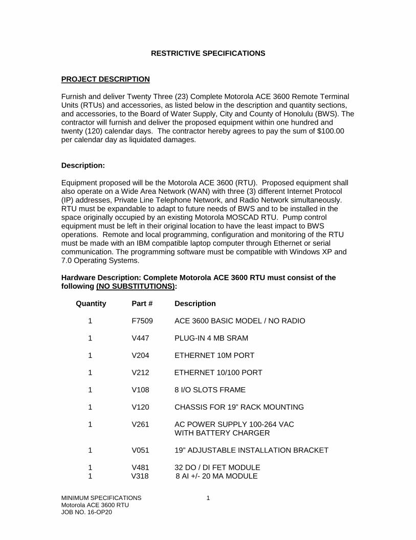
RESTRICTIVE SPECIFICATIONS
PROJECT DESCRIPTION Furnish and deliver Twenty Three (23) Complete Motorola ACE 3600 Remote Terminal Units (RTUs) and accessories, as listed below in the description and quantity sections, and accessories, to the Board of Water Supply, City and County of Honolulu (BWS). The contractor will furnish and deliver the proposed equipment within one hundred and twenty (120) calendar days. The contractor hereby agrees to pay the sum of $100.00 per calendar day as liquidated damages. Description: Equipment proposed will be the Motorola ACE 3600 (RTU). Proposed equipment shall also operate on a Wide Area Network (WAN) with three (3) different Internet Protocol (IP) addresses, Private Line Telephone Network, and Radio Network simultaneously. RTU must be expandable to adapt to future needs of BWS and to be installed in the space originally occupied by an existing Motorola MOSCAD RTU. Pump control equipment must be left in their original location to have the least impact to BWS operations. Remote and local programming, configuration and monitoring of the RTU must be made with an IBM compatible laptop computer through Ethernet or serial communication. The programming software must be compatible with Windows XP and 7.0 Operating Systems. Hardware Description: Complete Motorola ACE 3600 RTU must consist of the following (NO SUBSTITUTIONS): Quantity Part # Description 1 F7509 ACE 3600 BASIC MODEL / NO RADIO 1 V447 PLUG-IN 4 MB SRAM 1 V204 ETHERNET 10M PORT 1 V212 ETHERNET 10/100 PORT 1 V108 8 I/O SLOTS FRAME 1 V120 CHASSIS FOR 19” RACK MOUNTING 1 V261 AC POWER SUPPLY 100-264 VAC WITH BATTERY CHARGER 1 V051 19” ADJUSTABLE INSTALLATION BRACKET 1 V481 32 DO / DI FET MODULE 1 V318 8 AI +/- 20 MA MODULE
MINIMUM SPECIFICATIONS 1 Motorola ACE 3600 RTU JOB NO. 16-OP20
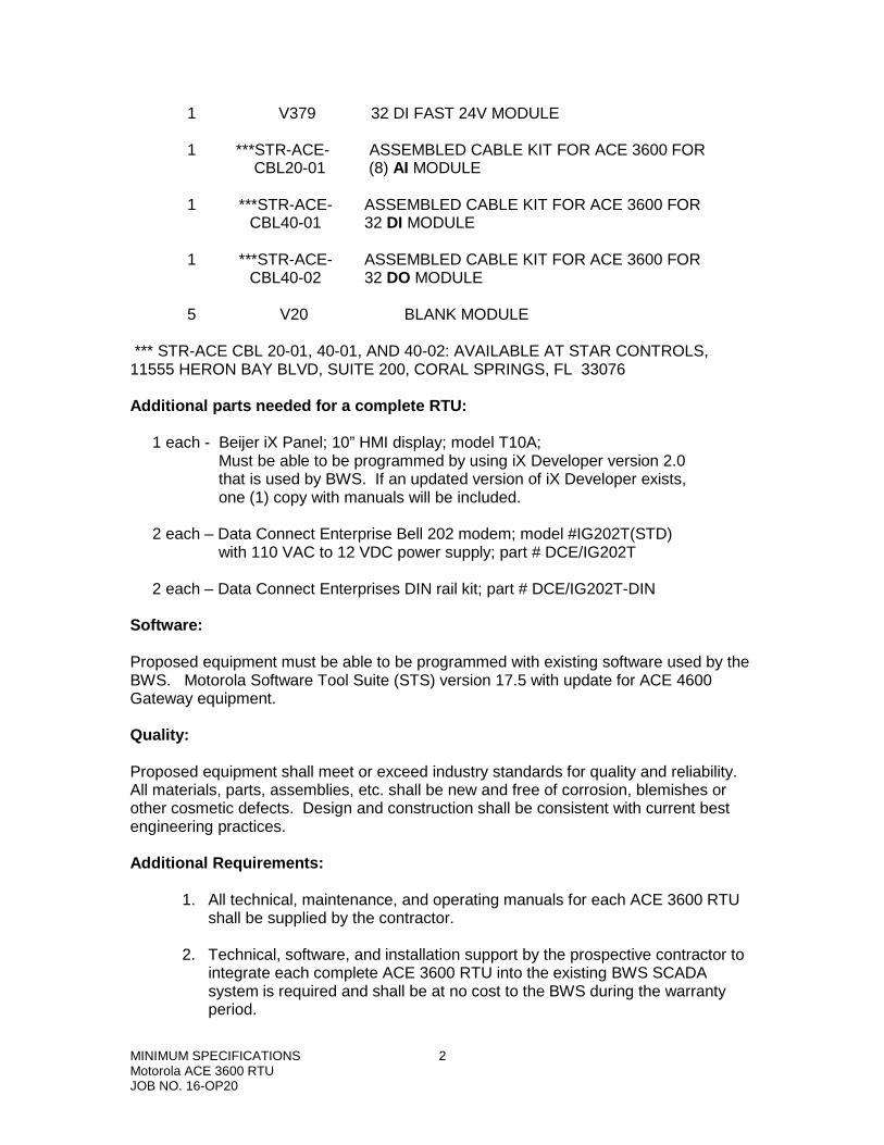
1 V379 32 DI FAST 24V MODULE 1 ***STR-ACE- ASSEMBLED CABLE KIT FOR ACE 3600 FOR CBL20-01 (8) AI MODULE 1 ***STR-ACE- ASSEMBLED CABLE KIT FOR ACE 3600 FOR CBL40-01 32 DI MODULE 1 ***STR-ACE- ASSEMBLED CABLE KIT FOR ACE 3600 FOR CBL40-02 32 DO MODULE 5 V20 BLANK MODULE *** STR-ACE CBL 20-01, 40-01, AND 40-02: AVAILABLE AT STAR CONTROLS, 11555 HERON BAY BLVD, SUITE 200, CORAL SPRINGS, FL 33076 Additional parts needed for a complete RTU: 1 each - Beijer iX Panel; 10” HMI display; model T10A; Must be able to be programmed by using iX Developer version 2.0 that is used by BWS. If an updated version of iX Developer exists, one (1) copy with manuals will be included. 2 each – Data Connect Enterprise Bell 202 modem; model #IG202T(STD) with 110 VAC to 12 VDC power supply; part # DCE/IG202T 2 each – Data Connect Enterprises DIN rail kit; part # DCE/IG202T-DIN Software: Proposed equipment must be able to be programmed with existing software used by the BWS. Motorola Software Tool Suite (STS) version 17.5 with update for ACE 4600 Gateway equipment. Quality: Proposed equipment shall meet or exceed industry standards for quality and reliability. All materials, parts, assemblies, etc. shall be new and free of corrosion, blemishes or other cosmetic defects. Design and construction shall be consistent with current best engineering practices. Additional Requirements:
1. All technical, maintenance, and operating manuals for each ACE 3600 RTU shall be supplied by the contractor.
2. Technical, software, and installation support by the prospective contractor to
integrate each complete ACE 3600 RTU into the existing BWS SCADA system is required and shall be at no cost to the BWS during the warranty period.
MINIMUM SPECIFICATIONS 2 Motorola ACE 3600 RTU JOB NO. 16-OP20
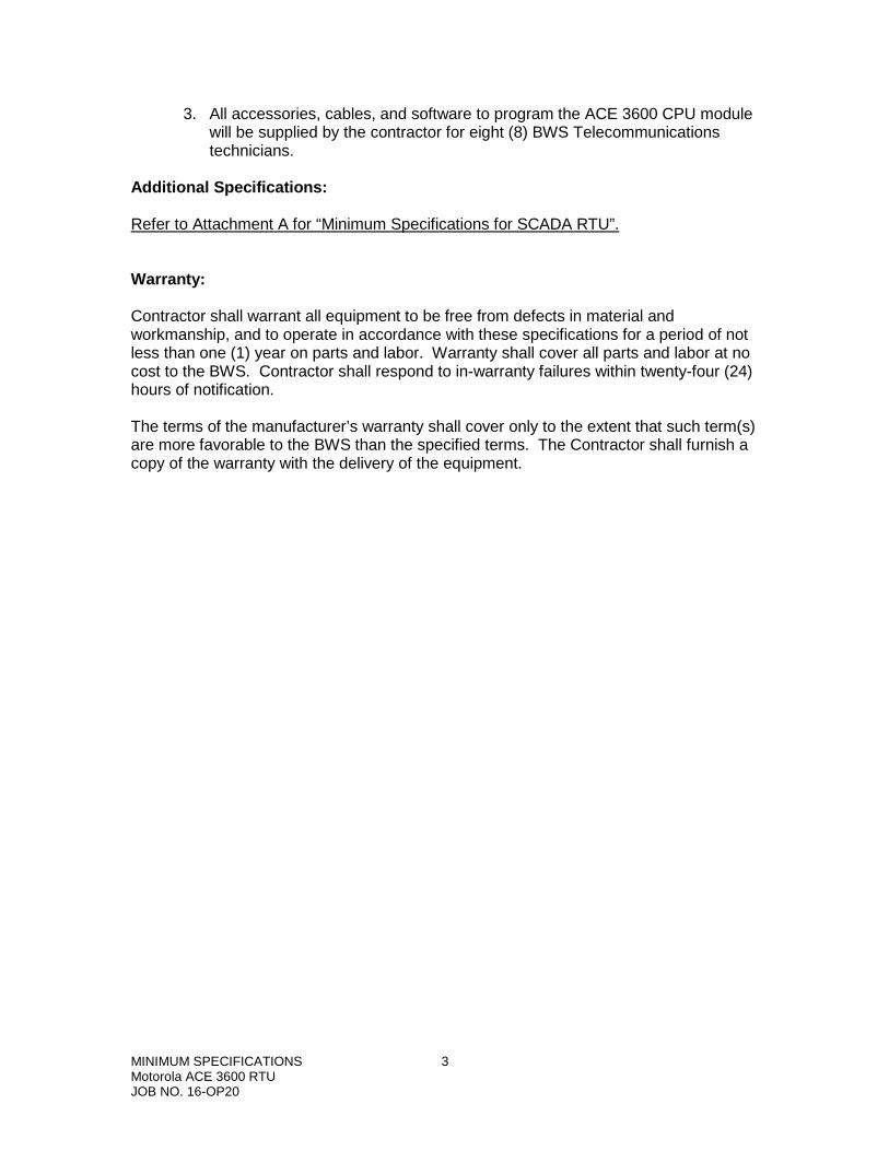
3. All accessories, cables, and software to program the ACE 3600 CPU module will be supplied by the contractor for eight (8) BWS Telecommunications technicians.
Additional Specifications: Refer to Attachment A for “Minimum Specifications for SCADA RTU”. Warranty: Contractor shall warrant all equipment to be free from defects in material and workmanship, and to operate in accordance with these specifications for a period of not less than one (1) year on parts and labor. Warranty shall cover all parts and labor at no cost to the BWS. Contractor shall respond to in-warranty failures within twenty-four (24) hours of notification. The terms of the manufacturer’s warranty shall cover only to the extent that such term(s) are more favorable to the BWS than the specified terms. The Contractor shall furnish a copy of the warranty with the delivery of the equipment.
MINIMUM SPECIFICATIONS 3 Motorola ACE 3600 RTU JOB NO. 16-OP20
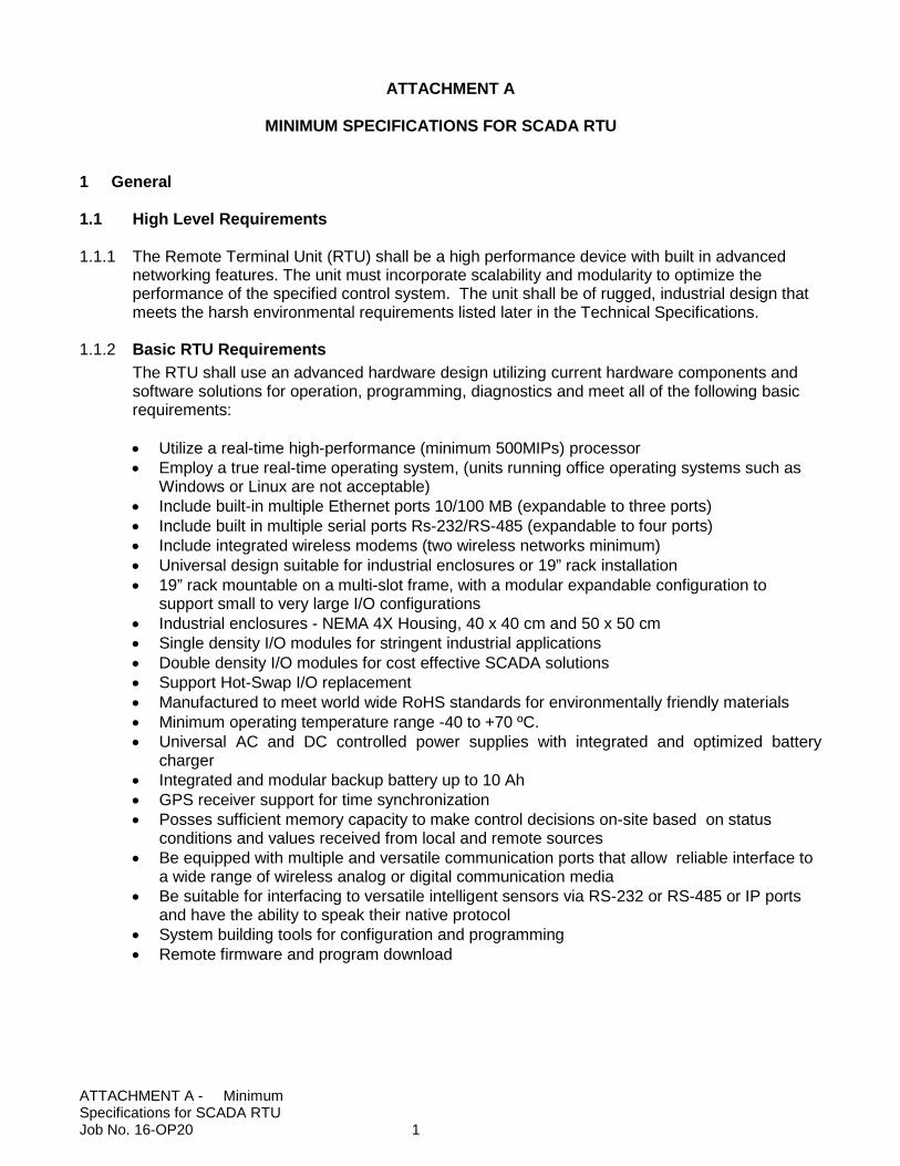
ATTACHMENT A
MINIMUM SPECIFICATIONS FOR SCADA RTU 1 General
1.1 High Level Requirements
1.1.1 The Remote Terminal Unit (RTU) shall be a high performance device with built in advanced
networking features. The unit must incorporate scalability and modularity to optimize the performance of the specified control system. The unit shall be of rugged, industrial design that meets the harsh environmental requirements listed later in the Technical Specifications.
1.1.2 Basic RTU Requirements The RTU shall use an advanced hardware design utilizing current hardware components and software solutions for operation, programming, diagnostics and meet all of the following basic requirements: • Utilize a real-time high-performance (minimum 500MIPs) processor • Employ a true real-time operating system, (units running office operating systems such as
Windows or Linux are not acceptable) • Include built-in multiple Ethernet ports 10/100 MB (expandable to three ports) • Include built in multiple serial ports Rs-232/RS-485 (expandable to four ports) • Include integrated wireless modems (two wireless networks minimum) • Universal design suitable for industrial enclosures or 19” rack installation • 19” rack mountable on a multi-slot frame, with a modular expandable configuration to
support small to very large I/O configurations • Industrial enclosures - NEMA 4X Housing, 40 x 40 cm and 50 x 50 cm • Single density I/O modules for stringent industrial applications • Double density I/O modules for cost effective SCADA solutions • Support Hot-Swap I/O replacement • Manufactured to meet world wide RoHS standards for environmentally friendly materials • Minimum operating temperature range -40 to +70 ºC. • Universal AC and DC controlled power supplies with integrated and optimized battery
charger • Integrated and modular backup battery up to 10 Ah • GPS receiver support for time synchronization • Posses sufficient memory capacity to make control decisions on-site based on status
conditions and values received from local and remote sources • Be equipped with multiple and versatile communication ports that allow reliable interface to
a wide range of wireless analog or digital communication media • Be suitable for interfacing to versatile intelligent sensors via RS-232 or RS-485 or IP ports
and have the ability to speak their native protocol • System building tools for configuration and programming • Remote firmware and program download
ATTACHMENT A - Minimum Specifications for SCADA RTU Job No. 16-OP20 1
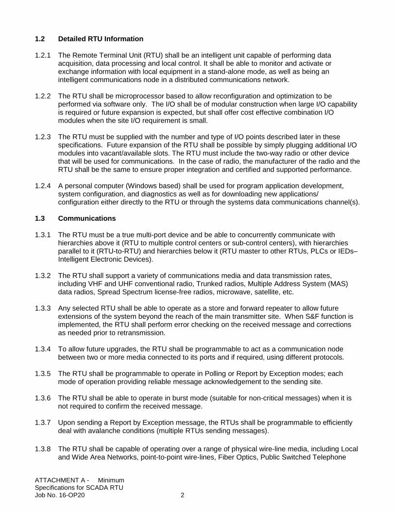
1.2 Detailed RTU Information
1.2.1 The Remote Terminal Unit (RTU) shall be an intelligent unit capable of performing data acquisition, data processing and local control. It shall be able to monitor and activate or exchange information with local equipment in a stand-alone mode, as well as being an intelligent communications node in a distributed communications network.
1.2.2 The RTU shall be microprocessor based to allow reconfiguration and optimization to be performed via software only. The I/O shall be of modular construction when large I/O capability is required or future expansion is expected, but shall offer cost effective combination I/O modules when the site I/O requirement is small.
1.2.3 The RTU must be supplied with the number and type of I/O points described later in these
specifications. Future expansion of the RTU shall be possible by simply plugging additional I/O modules into vacant/available slots. The RTU must include the two-way radio or other device that will be used for communications. In the case of radio, the manufacturer of the radio and the RTU shall be the same to ensure proper integration and certified and supported performance.
1.2.4 A personal computer (Windows based) shall be used for program application development,
system configuration, and diagnostics as well as for downloading new applications/ configuration either directly to the RTU or through the systems data communications channel(s).
1.3 Communications
1.3.1 The RTU must be a true multi-port device and be able to concurrently communicate with
hierarchies above it (RTU to multiple control centers or sub-control centers), with hierarchies parallel to it (RTU-to-RTU) and hierarchies below it (RTU master to other RTUs, PLCs or IEDs–Intelligent Electronic Devices).
1.3.2 The RTU shall support a variety of communications media and data transmission rates, including VHF and UHF conventional radio, Trunked radios, Multiple Address System (MAS) data radios, Spread Spectrum license-free radios, microwave, satellite, etc.
1.3.3 Any selected RTU shall be able to operate as a store and forward repeater to allow future extensions of the system beyond the reach of the main transmitter site. When S&F function is implemented, the RTU shall perform error checking on the received message and corrections as needed prior to retransmission.
1.3.4 To allow future upgrades, the RTU shall be programmable to act as a communication node between two or more media connected to its ports and if required, using different protocols.
1.3.5 The RTU shall be programmable to operate in Polling or Report by Exception modes; each
mode of operation providing reliable message acknowledgement to the sending site. 1.3.6 The RTU shall be able to operate in burst mode (suitable for non-critical messages) when it is
not required to confirm the received message. 1.3.7 Upon sending a Report by Exception message, the RTUs shall be programmable to efficiently
deal with avalanche conditions (multiple RTUs sending messages).
1.3.8 The RTU shall be capable of operating over a range of physical wire-line media, including Local and Wide Area Networks, point-to-point wire-lines, Fiber Optics, Public Switched Telephone
ATTACHMENT A - Minimum Specifications for SCADA RTU Job No. 16-OP20 2
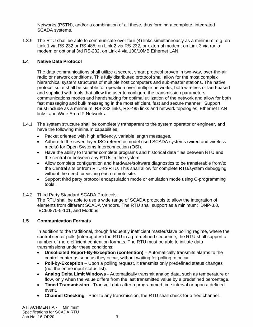
Networks (PSTN), and/or a combination of all these, thus forming a complete, integrated SCADA systems.
1.3.9 The RTU shall be able to communicate over four (4) links simultaneously as a minimum; e.g. on Link 1 via RS-232 or RS-485; on Link 2 via RS-232, or external modem; on Link 3 via radio modem or optional 3rd RS-232, on Link 4 via 100/10MB Ethernet LAN.
1.4 Native Data Protocol
The data communications shall utilize a secure, smart protocol proven in two-way, over-the-air radio or network conditions. This fully distributed protocol shall allow for the most complex hierarchical system structures of multiple host computers and sub-master stations. The native protocol suite shall be suitable for operation over multiple networks, both wireless or land-based and supplied with tools that allow the user to configure the transmission parameters, communications modes and handshaking for optimal utilization of the network and allow for both fast messaging and bulk messaging in the most efficient, fast and secure manner. Support must include as a minimum: RS-232 links, RS-485 links and network topologies, Ethernet LAN links, and Wide Area IP Networks.
1.4.1 The system structure shall be completely transparent to the system operator or engineer, and
have the following minimum capabilities: • Packet oriented with high efficiency, variable length messages. • Adhere to the seven layer ISO reference model used SCADA systems (wired and wireless
media) for Open Systems Interconnection (OSI). • Have the ability to transfer complete programs and historical data files between RTU and
the central or between any RTUs in the system. • Allow complete configuration and hardware/software diagnostics to be transferable from/to
the Central site or from RTU-to-RTU. This shall allow for complete RTU/system debugging without the need for visiting each remote site.
• Support third party protocol encapsulation mode or emulation mode using C-programming tools.
1.4.2 Third Party Standard SCADA Protocols:
The RTU shall be able to use a wide range of SCADA protocols to allow the integration of elements from different SCADA Vendors. The RTU shall support as a minimum: DNP-3.0, IEC60870-5-101, and Modbus.
1.5 Communication Formats
In addition to the traditional, though frequently inefficient master/slave polling regime, where the control center polls (interrogates) the RTU in a pre-defined sequence, the RTU shall support a number of more efficient contention formats. The RTU must be able to initiate data transmissions under these conditions: • Unsolicited Report-By-Exception (contention) – Automatically transmits alarms to the
control center as soon as they occur, without waiting for polling to occur • Poll-by-Exception – Upon a polling request, it transmits only predefined status changes
(not the entire input status list). • Analog Delta Limit Windows - Automatically transmit analog data, such as temperature or
flow, only when the value differs from the last transmitted value by a predefined percentage. • Timed Transmission - Transmit data after a programmed time interval or upon a defined
event. • Channel Checking - Prior to any transmission, the RTU shall check for a free channel.
ATTACHMENT A - Minimum Specifications for SCADA RTU Job No. 16-OP20 3
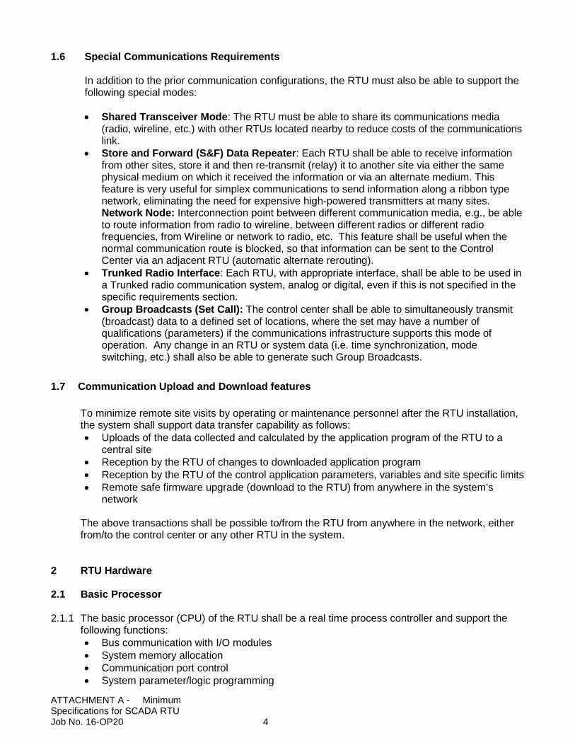
1.6 Special Communications Requirements In addition to the prior communication configurations, the RTU must also be able to support the following special modes: • Shared Transceiver Mode: The RTU must be able to share its communications media
(radio, wireline, etc.) with other RTUs located nearby to reduce costs of the communications link.
• Store and Forward (S&F) Data Repeater: Each RTU shall be able to receive information from other sites, store it and then re-transmit (relay) it to another site via either the same physical medium on which it received the information or via an alternate medium. This feature is very useful for simplex communications to send information along a ribbon type network, eliminating the need for expensive high-powered transmitters at many sites. Network Node: Interconnection point between different communication media, e.g., be able to route information from radio to wireline, between different radios or different radio frequencies, from Wireline or network to radio, etc. This feature shall be useful when the normal communication route is blocked, so that information can be sent to the Control Center via an adjacent RTU (automatic alternate rerouting).
• Trunked Radio Interface: Each RTU, with appropriate interface, shall be able to be used in a Trunked radio communication system, analog or digital, even if this is not specified in the specific requirements section.
• Group Broadcasts (Set Call): The control center shall be able to simultaneously transmit (broadcast) data to a defined set of locations, where the set may have a number of qualifications (parameters) if the communications infrastructure supports this mode of operation. Any change in an RTU or system data (i.e. time synchronization, mode switching, etc.) shall also be able to generate such Group Broadcasts.
1.7 Communication Upload and Download features To minimize remote site visits by operating or maintenance personnel after the RTU installation, the system shall support data transfer capability as follows: • Uploads of the data collected and calculated by the application program of the RTU to a
central site • Reception by the RTU of changes to downloaded application program • Reception by the RTU of the control application parameters, variables and site specific limits • Remote safe firmware upgrade (download to the RTU) from anywhere in the system’s
network
The above transactions shall be possible to/from the RTU from anywhere in the network, either from/to the control center or any other RTU in the system.
2 RTU Hardware
2.1 Basic Processor
2.1.1 The basic processor (CPU) of the RTU shall be a real time process controller and support the
following functions: • Bus communication with I/O modules • System memory allocation • Communication port control • System parameter/logic programming
ATTACHMENT A - Minimum Specifications for SCADA RTU Job No. 16-OP20 4
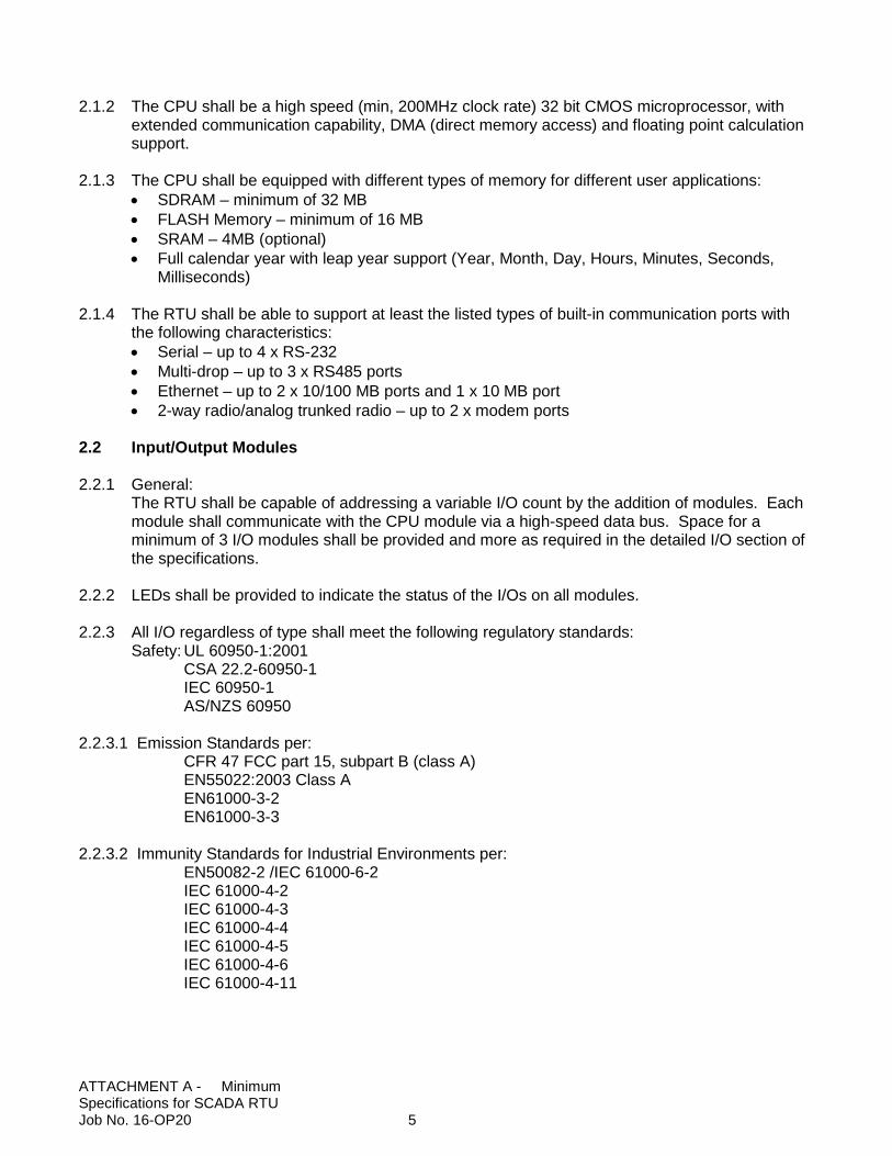
2.1.2 The CPU shall be a high speed (min, 200MHz clock rate) 32 bit CMOS microprocessor, with
extended communication capability, DMA (direct memory access) and floating point calculation support.
2.1.3 The CPU shall be equipped with different types of memory for different user applications: • SDRAM – minimum of 32 MB • FLASH Memory – minimum of 16 MB • SRAM – 4MB (optional) • Full calendar year with leap year support (Year, Month, Day, Hours, Minutes, Seconds,
Milliseconds) 2.1.4 The RTU shall be able to support at least the listed types of built-in communication ports with
the following characteristics: • Serial – up to 4 x RS-232 • Multi-drop – up to 3 x RS485 ports • Ethernet – up to 2 x 10/100 MB ports and 1 x 10 MB port • 2-way radio/analog trunked radio – up to 2 x modem ports
2.2 Input/Output Modules
2.2.1 General:
The RTU shall be capable of addressing a variable I/O count by the addition of modules. Each module shall communicate with the CPU module via a high-speed data bus. Space for a minimum of 3 I/O modules shall be provided and more as required in the detailed I/O section of the specifications.
2.2.2 LEDs shall be provided to indicate the status of the I/Os on all modules.
2.2.3 All I/O regardless of type shall meet the following regulatory standards:
Safety: UL 60950-1:2001 CSA 22.2-60950-1 IEC 60950-1 AS/NZS 60950
2.2.3.1 Emission Standards per: CFR 47 FCC part 15, subpart B (class A) EN55022:2003 Class A EN61000-3-2 EN61000-3-3
2.2.3.2 Immunity Standards for Industrial Environments per:
EN50082-2 /IEC 61000-6-2 IEC 61000-4-2 IEC 61000-4-3 IEC 61000-4-4 IEC 61000-4-5 IEC 61000-4-6 IEC 61000-4-11
ATTACHMENT A - Minimum Specifications for SCADA RTU Job No. 16-OP20 5
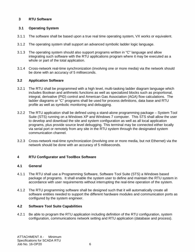
3 RTU Software
3.1 Operating System
3.1.1 The software shall be based upon a true real time operating system, VX works or equivalent.
3.1.2 The operating system shall support an advanced symbolic ladder logic language.
3.1.3 The operating system should also support programs written in “C” language and allow integrating such software with the RTU applications program where it may be executed as a whole or part of the total application.
3.1.4 Cross-network real-time synchronization (involving one or more media) via the network should be done with an accuracy of 5 milliseconds.
3.2 Application Software
3.2.1 The RTU shall be programmed with a high level, multi-tasking ladder diagram language which
includes Boolean and arithmetic functions as well as specialized blocks such as proportional, integral, derivative (PID) control and American Gas Association (AGA) flow calculations. The ladder diagrams or “C” programs shall be used for process definitions, data base and RTU profile as well as symbolic monitoring and debugging.
3.2.2 The RTU application shall be defined using a stand-alone programming package – System Tool Suite (STS) running on a Windows XP and Windows 7 computer. This STS shall allow the user to develop and download the site and system configuration as well as all local application programs, plus provide source level debugging. This terminal may be connected either locally via serial port or remotely from any site in the RTU system through the designated system communication channel.
3.2.3 Cross-network real-time synchronization (involving one or more media, but not Ethernet) via the network should be done with an accuracy of 5 milliseconds.
4 RTU Configurator and ToolBox Software
4.1 General
4.1.1 The RTU shall use a Programming Software, Software Tool Suite (STS) a Windows based package of programs. It shall enable the system user to define and maintain the RTU system in accordance with user requirements without interrupting the real-time operation of the system.
4.1.2 The RTU programming software shall be designed such that it will automatically create all software entities needed to support the different hardware modules and communication ports as configured by the system engineer.
4.2 Software Tool Suite Capabilities
4.2.1 Be able to program the RTU application including definition of the RTU configuration, system
configuration, communications network setting and RTU application (database and process).
ATTACHMENT A - Minimum Specifications for SCADA RTU Job No. 16-OP20 6
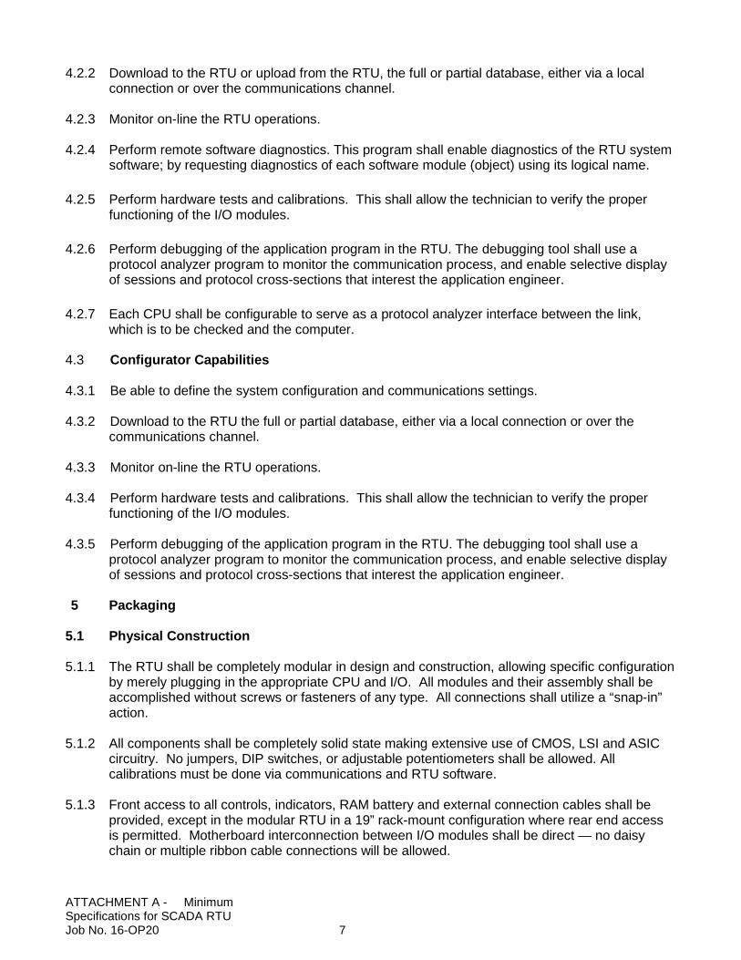
4.2.2 Download to the RTU or upload from the RTU, the full or partial database, either via a local connection or over the communications channel.
4.2.3 Monitor on-line the RTU operations.
4.2.4 Perform remote software diagnostics. This program shall enable diagnostics of the RTU system software; by requesting diagnostics of each software module (object) using its logical name.
4.2.5 Perform hardware tests and calibrations. This shall allow the technician to verify the proper functioning of the I/O modules.
4.2.6 Perform debugging of the application program in the RTU. The debugging tool shall use a protocol analyzer program to monitor the communication process, and enable selective display of sessions and protocol cross-sections that interest the application engineer.
4.2.7 Each CPU shall be configurable to serve as a protocol analyzer interface between the link, which is to be checked and the computer.
4.3 Configurator Capabilities
4.3.1 Be able to define the system configuration and communications settings. 4.3.2 Download to the RTU the full or partial database, either via a local connection or over the
communications channel.
4.3.3 Monitor on-line the RTU operations.
4.3.4 Perform hardware tests and calibrations. This shall allow the technician to verify the proper functioning of the I/O modules.
4.3.5 Perform debugging of the application program in the RTU. The debugging tool shall use a protocol analyzer program to monitor the communication process, and enable selective display of sessions and protocol cross-sections that interest the application engineer.
5 Packaging
5.1 Physical Construction
5.1.1 The RTU shall be completely modular in design and construction, allowing specific configuration
by merely plugging in the appropriate CPU and I/O. All modules and their assembly shall be accomplished without screws or fasteners of any type. All connections shall utilize a “snap-in” action.
5.1.2 All components shall be completely solid state making extensive use of CMOS, LSI and ASIC circuitry. No jumpers, DIP switches, or adjustable potentiometers shall be allowed. All calibrations must be done via communications and RTU software.
5.1.3 Front access to all controls, indicators, RAM battery and external connection cables shall be provided, except in the modular RTU in a 19” rack-mount configuration where rear end access is permitted. Motherboard interconnection between I/O modules shall be direct — no daisy chain or multiple ribbon cable connections will be allowed.
ATTACHMENT A - Minimum Specifications for SCADA RTU Job No. 16-OP20 7
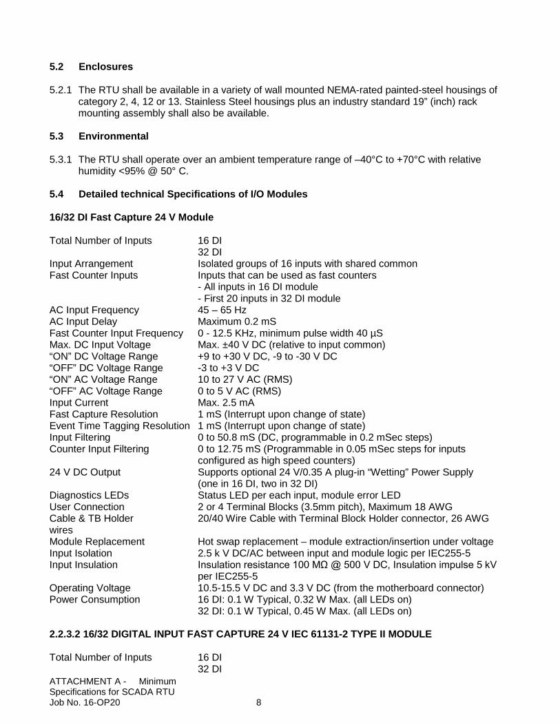
5.2 Enclosures
5.2.1 The RTU shall be available in a variety of wall mounted NEMA-rated painted-steel housings of
category 2, 4, 12 or 13. Stainless Steel housings plus an industry standard 19” (inch) rack mounting assembly shall also be available.
5.3 Environmental
5.3.1 The RTU shall operate over an ambient temperature range of –40°C to +70°C with relative humidity <95% @ 50° C.
5.4 Detailed technical Specifications of I/O Modules
16/32 DI Fast Capture 24 V Module Total Number of Inputs 16 DI 32 DI Input Arrangement Isolated groups of 16 inputs with shared common Fast Counter Inputs Inputs that can be used as fast counters - All inputs in 16 DI module - First 20 inputs in 32 DI module AC Input Frequency 45 – 65 Hz AC Input Delay Maximum 0.2 mS Fast Counter Input Frequency 0 - 12.5 KHz, minimum pulse width 40 µS Max. DC Input Voltage Max. ±40 V DC (relative to input common) “ON” DC Voltage Range +9 to +30 V DC, -9 to -30 V DC “OFF” DC Voltage Range -3 to +3 V DC “ON” AC Voltage Range 10 to 27 V AC (RMS) “OFF” AC Voltage Range 0 to 5 V AC (RMS) Input Current Max. 2.5 mA Fast Capture Resolution 1 mS (Interrupt upon change of state) Event Time Tagging Resolution 1 mS (Interrupt upon change of state) Input Filtering 0 to 50.8 mS (DC, programmable in 0.2 mSec steps) Counter Input Filtering 0 to 12.75 mS (Programmable in 0.05 mSec steps for inputs configured as high speed counters) 24 V DC Output Supports optional 24 V/0.35 A plug-in “Wetting” Power Supply (one in 16 DI, two in 32 DI) Diagnostics LEDs Status LED per each input, module error LED User Connection 2 or 4 Terminal Blocks (3.5mm pitch), Maximum 18 AWG Cable & TB Holder 20/40 Wire Cable with Terminal Block Holder connector, 26 AWG wires Module Replacement Hot swap replacement – module extraction/insertion under voltage Input Isolation 2.5 k V DC/AC between input and module logic per IEC255-5 Input Insulation Insulation resistance 100 MΩ @ 500 V DC, Insulation impulse 5 kV per IEC255-5 Operating Voltage 10.5-15.5 V DC and 3.3 V DC (from the motherboard connector) Power Consumption 16 DI: 0.1 W Typical, 0.32 W Max. (all LEDs on) 32 DI: 0.1 W Typical, 0.45 W Max. (all LEDs on) 2.2.3.2 16/32 DIGITAL INPUT FAST CAPTURE 24 V IEC 61131-2 TYPE II MODULE Total Number of Inputs 16 DI 32 DI ATTACHMENT A - Minimum Specifications for SCADA RTU Job No. 16-OP20 8
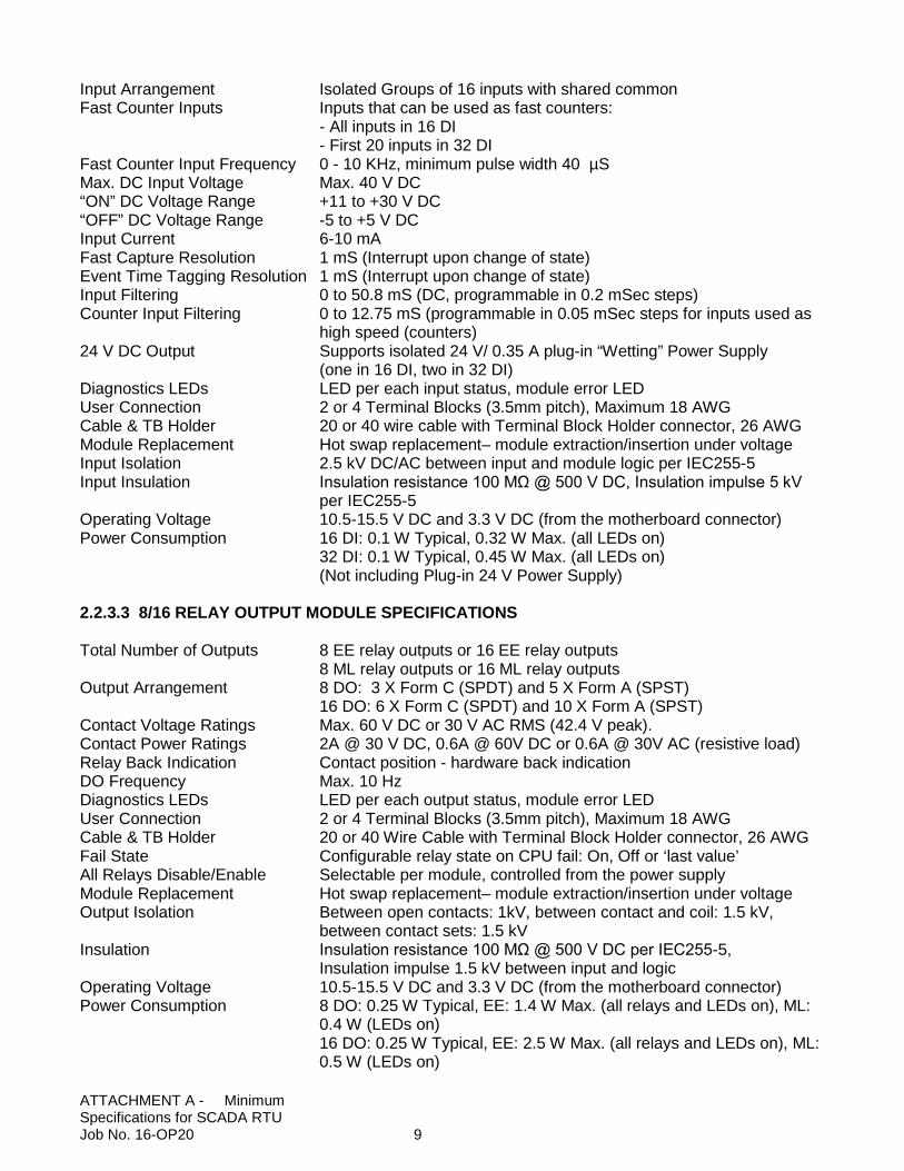
Input Arrangement Isolated Groups of 16 inputs with shared common Fast Counter Inputs Inputs that can be used as fast counters: - All inputs in 16 DI - First 20 inputs in 32 DI Fast Counter Input Frequency 0 - 10 KHz, minimum pulse width 40 µS Max. DC Input Voltage Max. 40 V DC “ON” DC Voltage Range +11 to +30 V DC “OFF” DC Voltage Range -5 to +5 V DC Input Current 6-10 mA Fast Capture Resolution 1 mS (Interrupt upon change of state) Event Time Tagging Resolution 1 mS (Interrupt upon change of state) Input Filtering 0 to 50.8 mS (DC, programmable in 0.2 mSec steps) Counter Input Filtering 0 to 12.75 mS (programmable in 0.05 mSec steps for inputs used as high speed (counters) 24 V DC Output Supports isolated 24 V/ 0.35 A plug-in “Wetting” Power Supply (one in 16 DI, two in 32 DI) Diagnostics LEDs LED per each input status, module error LED User Connection 2 or 4 Terminal Blocks (3.5mm pitch), Maximum 18 AWG Cable & TB Holder 20 or 40 wire cable with Terminal Block Holder connector, 26 AWG Module Replacement Hot swap replacement– module extraction/insertion under voltage Input Isolation 2.5 kV DC/AC between input and module logic per IEC255-5 Input Insulation Insulation resistance 100 MΩ @ 500 V DC, Insulation impulse 5 kV
per IEC255-5 Operating Voltage 10.5-15.5 V DC and 3.3 V DC (from the motherboard connector) Power Consumption 16 DI: 0.1 W Typical, 0.32 W Max. (all LEDs on) 32 DI: 0.1 W Typical, 0.45 W Max. (all LEDs on) (Not including Plug-in 24 V Power Supply) 2.2.3.3 8/16 RELAY OUTPUT MODULE SPECIFICATIONS Total Number of Outputs 8 EE relay outputs or 16 EE relay outputs 8 ML relay outputs or 16 ML relay outputs Output Arrangement 8 DO: 3 X Form C (SPDT) and 5 X Form A (SPST) 16 DO: 6 X Form C (SPDT) and 10 X Form A (SPST) Contact Voltage Ratings Max. 60 V DC or 30 V AC RMS (42.4 V peak). Contact Power Ratings 2A @ 30 V DC, 0.6A @ 60V DC or 0.6A @ 30V AC (resistive load) Relay Back Indication Contact position - hardware back indication DO Frequency Max. 10 Hz Diagnostics LEDs LED per each output status, module error LED User Connection 2 or 4 Terminal Blocks (3.5mm pitch), Maximum 18 AWG Cable & TB Holder 20 or 40 Wire Cable with Terminal Block Holder connector, 26 AWG Fail State Configurable relay state on CPU fail: On, Off or ‘last value’ All Relays Disable/Enable Selectable per module, controlled from the power supply Module Replacement Hot swap replacement– module extraction/insertion under voltage Output Isolation Between open contacts: 1kV, between contact and coil: 1.5 kV, between contact sets: 1.5 kV Insulation Insulation resistance 100 MΩ @ 500 V DC per IEC255-5, Insulation impulse 1.5 kV between input and logic Operating Voltage 10.5-15.5 V DC and 3.3 V DC (from the motherboard connector)Power Consumption 8 DO: 0.25 W Typical, EE: 1.4 W Max. (all relays and LEDs on), ML: 0.4 W (LEDs on) 16 DO: 0.25 W Typical, EE: 2.5 W Max. (all relays and LEDs on), ML: 0.5 W (LEDs on) ATTACHMENT A - Minimum Specifications for SCADA RTU Job No. 16-OP20 9
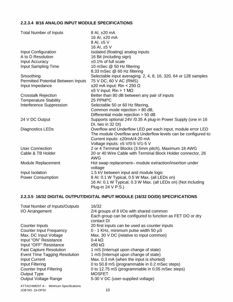
2.2.3.4 8/16 ANALOG INPUT MODULE SPECIFICATIONS Total Number of Inputs 8 AI, ±20 mA 16 AI, ±20 mA 8 AI, ±5 V 16 AI, ±5 V Input Configuration Isolated (floating) analog inputs A to D Resolution 16 Bit (including sign) Input Accuracy ±0.1% of full scale Input Sampling Time 10 mSec @ 50 Hz filtering 8.33 mSec @ 60 Hz filtering Smoothing Selectable input averaging: 2, 4, 8, 16, 320, 64 or 128 samples Permitted Potential Between Inputs 75 V DC, 60 V AC (RMS) Input Impedance ±20 mA input: Rin < 250 Ω ±5 V input: Rin > 1 MΩ Crosstalk Rejection Better than 80 dB between any pair of inputs Temperature Stability 25 PPM/ºC Interference Suppression Selectable 50 or 60 Hz filtering, Common mode rejection > 80 dB, Differential mode rejection > 50 dB 24 V DC Output Supports optional 24V /0.35 A plug-in Power Supply (one in 16 DI, two in 32 DI) Diagnostics LEDs Overflow and Underflow LED per each input, module error LED The module Overflow and Underflow levels can be configured to: Current inputs: ±20mA/4-20 mA Voltage inputs: ±5 V/0-5 V/1-5 V User Connection 2 or 4 Terminal Blocks (3.5mm pitch), Maximum 18 AWG Cable & TB Holder 20 or 40 Wire Cable with Terminal Block Holder connector, 26 AWG Module Replacement Hot swap replacement– module extraction/insertion under voltage Input Isolation 1.5 kV between input and module logic Power Consumption 8 AI: 0.1 W Typical, 0.5 W Max. (all LEDs on)
16 AI: 0.1 W Typical, 0.3 W Max. (all LEDs on) (Not including Plug-in 24 V P.S.)
2.2.3.5 16/32 DIGITAL OUTPUT/DIGITAL INPUT MODULE (16/32 DO/DI) SPECIFICATIONS Total Number of Inputs/Outputs 16/32 I/O Arrangement 2/4 groups of 8 I/Os with shared common Each group can be configured to function as FET DO or dry contact DI Counter Inputs 20 first inputs can be used as counter inputs Counter Input Frequency 0 - 1 KHz, minimum pulse width 50 µS Max. DC Input Voltage Max. 30 V DC (relative to input common) Input “ON” Resistance 0-4 kΩ Input “OFF” Resistance ≥50 kΩ Fast Capture Resolution 1 mS (Interrupt upon change of state) Event Time Tagging Resolution 1 mS (Interrupt upon change of state) Input Current Max. 0.3 mA (when the input is shorted) Input Filtering 0 to 50.8 mS (programmable in 0.2 mSec steps) Counter Input Filtering 0 to 12.75 mS (programmable in 0.05 mSec steps) Output Type MOSFET Output Voltage Range 5-30 V DC (user-supplied voltage) ATTACHMENT A - Minimum Specifications JOB NO. 16-OP20 10
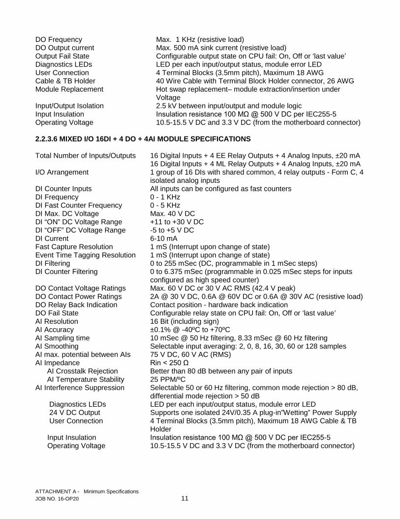
DO Frequency Max. 1 KHz (resistive load) DO Output current Max. 500 mA sink current (resistive load) Output Fail State Configurable output state on CPU fail: On, Off or ‘last value’ Diagnostics LEDs LED per each input/output status, module error LED User Connection 4 Terminal Blocks (3.5mm pitch), Maximum 18 AWG Cable & TB Holder 40 Wire Cable with Terminal Block Holder connector, 26 AWG Module Replacement Hot swap replacement– module extraction/insertion under Voltage Input/Output Isolation 2.5 kV between input/output and module logic Input Insulation Insulation resistance 100 MΩ @ 500 V DC per IEC255-5 Operating Voltage 10.5-15.5 V DC and 3.3 V DC (from the motherboard connector) 2.2.3.6 MIXED I/O 16DI + 4 DO + 4AI MODULE SPECIFICATIONS Total Number of Inputs/Outputs 16 Digital Inputs + 4 EE Relay Outputs + 4 Analog Inputs, ±20 mA 16 Digital Inputs + 4 ML Relay Outputs + 4 Analog Inputs, ±20 mA I/O Arrangement 1 group of 16 DIs with shared common, 4 relay outputs - Form C, 4 isolated analog inputs DI Counter Inputs All inputs can be configured as fast counters DI Frequency 0 - 1 KHz DI Fast Counter Frequency 0 - 5 KHz DI Max. DC Voltage Max. 40 V DC DI “ON” DC Voltage Range +11 to +30 V DC DI “OFF” DC Voltage Range -5 to +5 V DC DI Current 6-10 mA Fast Capture Resolution 1 mS (Interrupt upon change of state) Event Time Tagging Resolution 1 mS (Interrupt upon change of state) DI Filtering 0 to 255 mSec (DC, programmable in 1 mSec steps) DI Counter Filtering 0 to 6.375 mSec (programmable in 0.025 mSec steps for inputs configured as high speed counter) DO Contact Voltage Ratings Max. 60 V DC or 30 V AC RMS (42.4 V peak) DO Contact Power Ratings 2A @ 30 V DC, 0.6A @ 60V DC or 0.6A @ 30V AC (resistive load) DO Relay Back Indication Contact position - hardware back indication DO Fail State Configurable relay state on CPU fail: On, Off or ‘last value’ AI Resolution 16 Bit (including sign) AI Accuracy ±0.1% @ -40ºC to +70ºC AI Sampling time 10 mSec @ 50 Hz filtering, 8.33 mSec @ 60 Hz filtering AI Smoothing Selectable input averaging: 2, 0, 8, 16, 30, 60 or 128 samples AI max. potential between AIs 75 V DC, 60 V AC (RMS) AI Impedance Rin < 250 Ω AI Crosstalk Rejection Better than 80 dB between any pair of inputs AI Temperature Stability 25 PPM/ºC AI Interference Suppression Selectable 50 or 60 Hz filtering, common mode rejection > 80 dB, differential mode rejection > 50 dB Diagnostics LEDs LED per each input/output status, module error LED 24 V DC Output Supports one isolated 24V/0.35 A plug-in”Wetting” Power Supply User Connection 4 Terminal Blocks (3.5mm pitch), Maximum 18 AWG Cable & TB Holder Input Insulation Insulation resistance 100 MΩ @ 500 V DC per IEC255-5 Operating Voltage 10.5-15.5 V DC and 3.3 V DC (from the motherboard connector) ATTACHMENT A - Minimum Specifications JOB NO. 16-OP20 11
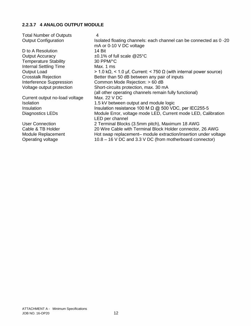
2.2.3.7 4 ANALOG OUTPUT MODULE Total Number of Outputs 4 Output Configuration Isolated floating channels: each channel can be connected as 0 -20 mA or 0-10 V DC voltage D to A Resolution 14 Bit Output Accuracy ±0.1% of full scale @25°C Temperature Stability 30 PPM/°C Internal Settling Time Max. 1 ms Output Load > 1.0 kΩ, < 1.0 µf, Current: < 750 Ω (with internal power source) Crosstalk Rejection Better than 50 dB between any pair of inputs Interference Suppression Common Mode Rejection: > 60 dB Voltage output protection Short-circuits protection, max. 30 mA (all other operating channels remain fully functional) Current output no-load voltage Max. 22 V DC Isolation 1.5 kV between output and module logic Insulation Insulation resistance 100 M Ω @ 500 VDC, per IEC255-5 Diagnostics LEDs Module Error, voltage mode LED, Current mode LED, Calibration
LED per channel User Connection 2 Terminal Blocks (3.5mm pitch), Maximum 18 AWG Cable & TB Holder 20 Wire Cable with Terminal Block Holder connector, 26 AWG Module Replacement Hot swap replacement– module extraction/insertion under voltage Operating voltage 10.8 – 16 V DC and 3.3 V DC (from motherboard connector)
ATTACHMENT A - Minimum Specifications JOB NO. 16-OP20 12

PROPOSAL FOR THE
FURNISHING AND DELIVERY OF TWENTY THREE (23) COMPLETE MOTOROLA ACE 3600 REMOTE TERMINAL UNITS
(RTU) AND ACCESSORIES
FOR THE BOARD OF WATER SUPPLY CITY AND COUNTY OF HONOLULU
Honolulu, Hawaii
Date Manager and Chief Engineer Board of Water Supply City and County of Honolulu Honolulu, Hawaii 96843 The undersigned hereby agrees to furnish and deliver Twenty Three (23) Complete
Motorola ACE 3600 (RTU) Remote Terminal Units and Accessories to the Board of Water
Supply, 630 South Beretania Street, Honolulu, Hawaii, all according to the true intent and
meaning of the specifications hereinafter contained. The undersigned further agrees that the
undersigned will, if this proposal is accepted, enter into a contract with the Board of Water
Supply, City and County of Honolulu, Honolulu, Hawaii, in the form of the contract attached
hereto and will furnish and deliver said equipment within the time specified herein at the
prices hereinafter quoted.
ITEM UNIT TOTAL NO. DESCRIPTION QUANTITY PRICE PRICE 1. Complete Motorola ACE
3600 (RTU) as outlined In the Minimum Specifications 23 $__________ $ _________
2. Accessories, software 8 $ __________ $ _________
for ACE 3600 RTU
TOTAL SUM BID $ ____________________
PROPOSAL 1 Motorola ACE 3600 RTU JOB NO. 16-OP20

TOTAL SUM BID (words) DOLLARS
It is understood and agreed that the various equipment as specified herein is being
furnished for the exclusive use of the Board of Water Supply, City and County of Honolulu,
Honolulu, Hawaii.
It is also understood and agreed that the undersigned has read and understands this
Proposal and the Minimum Specifications for this contract and that the Manager and Chief
Engineer reserves the right to accept or reject any or all bids if deemed to be in the best
interest of the Board of Water Supply, City and County of Honolulu
It is also understood and agreed that the bid prices include all taxes which shall be
applicable to the products or services or the furnishing, sale or purchase thereof whether
assessed against, chargeable to or payable by the Board of Water Supply, City and County of
Honolulu or any of its agencies or the undersigned.
It is also understood and agreed that unless otherwise specified in the solicitation, prices
offered shall be based on f.o.b. place of destination and shall include all applicable freight,
delivery, handling and related charges.
It is also understood and agreed that the undersigned agrees to submit the bid using the proposal document contained in the solicitation and also in accordance with the General
Instructions to Bidders (Goods and Services) and the General Terms and Conditions of
Contracts for Goods and Services attached hereto by reference. Since the bid instructions
shall apply to the bid solicitation only, the instructions shall not be included as a part of the
contract.
The undersigned further understands and agrees that by submitting this offer, the
bidder is declaring that its offer is not in violation of Chapter 84, Hawaii Revised Statutes,
concerning prohibited State contracts, and that the bidder is certifying that the price(s)
submitted was (were) independently arrived at without collusion.
PROPOSAL 2 Motorola ACE 3600 RTU JOB NO. 16-OP20

The undersigned represents: (Check one only)
A Hawaii business incorporated or organized under the laws of the State of Hawaii; OR
A Compliant Non-Hawaii business not incorporated or organized under the laws of the State of Hawaii, but registered at the State of Hawaii, Department of Commerce and Consumer Affairs, Business Registration Division, to do business in the State of Hawaii.
State of Incorporation, if other than Hawaii:
Offeror is:
Sole Proprietor; Partnership; Corporation; Joint Venture; Other:
Respectfully submitted, Authorized (Original) Signature Print and Type Name and Title of Above *
Exact Legal Name of Company (Offeror) *If Offeror is a “dba” or a “division” of a corporation, furnish the exact legal name of the corporation under which the awarded contract will be executed:
PROPOSAL 3 Motorola ACE 3600 RTU JOB NO. 16-OP20

Payment address: (If other than street address below.) City, State, Zip Code: Business address: (Street address) City, State, Zip Code: Telephone Number: Cellular Telephone Number: Fax No.: E-Mail Address: Person to Contact if Awarded: State of Hawaii General Excise Tax License Number: Federal Employer Identification Number:
PROPOSAL 4 Motorola ACE 3600 RTU JOB NO. 16-OP20

ACKNOWLEDGMENT OF LIQUIDATED DAMAGES PROVISION
PROJECT NAME AND NUMBER: Furnishing and Delivery of Twenty Three (23) Complete Motorola ACE 3600 Remote Terminal Unit (RTU) and Accessories, Job 16-OP20
This is to certify that the undersigned understands and agrees to the provisions for Liquidated Damage as stated in the Special Provisions, and that submittal of our bid constitutes acceptance of the provisions and amount of liquidated damages that may be assessed per calendar day as specified in the Proposal. ________________________________
Name of Contractor
________________________________ Signature and Title
Dated: _______________________ (Failure to submit this form with the bid may be cause for rejection.)
PROPOSAL 5 Motorola ACE 3600 RTU JOB NO. 16-OP20

ADDENDUM ACKNOWLEDGMENT
The undersigned acknowledges receipt of the following addendum/addenda (if applicable) to Job 16-OP20, Furnishing and Delivery of Twenty Three (23) Complete Motorola ACE 3600 Remote Terminal Units (RTU) and Accessories (Give number and date of each)
Addendum No. ____________________ Dated ____________________________
Addendum No. ____________________ Dated ____________________________
Addendum No. _____________________ Dated ____________________________
Addendum No. _____________________ Dated ____________________________
Addendum No. ____________________ Dated ____________________________
Failure to submit acknowledgment of any addendum issued may be cause for rejection of bid or proposal.
______________________________ ___________________________ Company Name (please print) Authorized Signature
PROPOSAL 6 Motorola ACE 3600 RTU JOB NO. 16-OP20
CONTRACT NO. C
AGREEMENT FOR GOODS AND SERVICES
This Agreement for Goods and Services is dated ______________, 2016 by and
between the BOARD OF WATER SUPPLY, CITY AND COUNTY OF HONOLULU (hereinafter
the “BWS”), whose address is 630 South Beretania Street, Honolulu, Hawaii 96843, and
(hereinafter “CONTRACTOR”), a existing under the
laws of the State of , whose business address is
.
RECITALS
WHEREAS, on , the BWS issued that certain Invitation for
Bids for Job No. 16-OP20 (hereinafter the “Invitation for Bids”) soliciting competitive sealed bids to furnish and deliver TWENTY THREE (23) COMPLETE MOTOROLA ACE 3600 REMOTE TERMINAL UNITS AND ACCESSORIES for the Board of Water Supply (hereinafter the “Project”); WHEREAS, CONTRACTOR submitted the lowest responsive bid (hereinafter the “Bid”) for the Project; NOW, THEREFORE, in accordance with Chapter 103D of the Hawaii Revised Statutes and in consideration of the promises contained in this fixed priced Agreement for Goods & Services, the BWS and CONTRACTOR hereby agree as follows:
1. Definition of “Contract”. For purposes of this Agreement for Goods & Services, “Contract” means all documents comprising the written agreement between the BWS and CONTRACTOR regarding the Project and the goods and services in connection therewith for which award is made to CONTRACTOR. “Contract” shall include, but not be limited to, this Agreement for Goods & Services, the Invitation for Bids, and the Bid.
2. Scope of Work. CONTRACTOR shall, in a proper and satisfactory manner as determined by the BWS, provide all the goods and services set forth in the Invitation for Bids, the Bid, and Attachment No. 1 hereto (the “Work”), all of which are hereby incorporated into and made a part of this Agreement for Goods & Services.
3. Compensation. The BWS agrees to employ CONTRACTOR to perform the Work according to the terms and conditions herein, and so long as CONTRACTOR faithfully performs the Work, CONTRACTOR shall receive payment in the amount of the unit price or prices set forth therein, inclusive of all fees and taxes. In the event that this section conflicts with other provisions of the Contract, this section shall control.
4. Term of Contract. The term of the contract shall be for a period of
one hundred and twenty (120) calendar days commencing upon the date as specified on the Notice to Proceed. Except as specifically provided for herein, the terms and conditions of this Agreement for Goods and Services shall remain in full force and effect until such time as all the
EXHIBIT A
EXHBIT A – Sample Contract Job No. 16-OP20 – Motorola ACE RTU Modules 1

CONTRACT NO. C Services have been fully and satisfactorily completed or until this Agreement for Goods and Services is terminated as provided in the General Conditions, as this term is defined below. In the event that this section conflicts with other provisions of the Contract, this section shall control.
5. Special Provisions. CONTRACTOR shall comply with the terms and conditions set forth in Attachment No. 2 to this Agreement for Goods & Services, which attachment is entitled “Special Provisions” and is hereby incorporated into and made a part of this Agreement for Goods & Services. 6. General Conditions. CONTRACTOR shall comply with the terms and conditions set forth in Attachment No. 3 to this Agreement for Goods and Services, which attachment is entitled “General Terms and Conditions of Contracts for Goods and Services for the Board of Water Supply” (the “General Conditions”) and is hereby incorporated into and made a part of this Agreement for Goods and Services. 7. Precedence. In the event of a conflict among the documents that comprise the Contract, the order of precedence shall be as follows: (1) this Agreement for Goods and Services, including any Attachments and any Amendments hereto except for the General Conditions; (2) the General Conditions; (3) the Invitation for Bids; (4) the Bid; and (5) other documents that comprise the Contract. 8. Statement of Understanding. CONTRACTOR acknowledges that it has a complete understanding of the Contract and that it is familiar with the Project. Failure on the part of CONTRACTOR to become familiar with the conditions and obstacles, if any, to be encountered and the types and quality of the services to be provided will not relieve CONTRACTOR of any responsibility to meet any of the requirements stated herein. 9. Notices. Any written notice required to be given by a party to the Contract shall be either delivered personally or sent by United States first class mail, postage prepaid. Notice to the BWS shall be sent to:
BOARD OF WATER SUPPLY 630 South Beretania Street, Room 201 Honolulu, Hawaii 96843 Attention: ERNEST Y.W. LAU, P.E. Manager and Chief Engineer
Notice to CONTRACTOR shall be sent to:
EXHBIT A – Sample Contract Job No. 16-OP20 – Motorola ACE RTU Modules 2

CONTRACT NO. C
Attention: A notice shall be deemed to have been received three (3) days after mailing or at
the time of actual receipt, whichever is earlier. CONTRACTOR is responsible for notifying the BWS in writing of any change of address.
[SIGNATURE PAGE FOLLOWS] [THE REMAINDER OF THIS PAGE IS INTENTIONALLY BLANK]
EXHBIT A – Sample Contract Job No. 16-OP20 – Motorola ACE RTU Modules 3
CONTRACT NO. C IN WITNESS WHEREOF, the parties, being duly authorized to do so, execute this Agreement for Goods & Services by their signatures, on the dates below, to be effective as of the date first above written. BOARD OF WATER SUPPLY CITY AND COUNTY OF HONOLULU Dated: ________________________ By: ___________________________ Its: Manager and Chief Engineer Print Name: ERNEST Y.W. LAU, P.E.
[CONTRACTOR] Dated: ________________________ By: ___________________________ Its: ___________________________ Print Name: _________________________ Federal Identification No.: _______________
APPROVED AS TO CONTENTS: By: ___________________________ BOARD OF WATER SUPPLY CITY AND COUNTY OF HONOLULU
APPROVED AS TO FORM: By: ______________________________ DEPUTY CORPORATION COUNSEL CITY AND COUNTY OF HONOLULU REVIEWED AS TO PROCUREMENT FORM: By: _____________________________ Procurement and Specifications Specialist VI BOARD OF WATER SUPPLY CITY AND COUNTY OF HONOLULU
EXHBIT A – Sample Contract Job No. 16-OP20 – Motorola ACE RTU Modules 4

CONTRACTOR’S ACKNOWLEDGMENT
[FOR USE WITH CONTRACT, PERFORMANCE AND PAYMENT BONDS] STATE OF HAWAI`I ) : SS. CITY AND COUNTY OF HONOLULU ) On this day of , before
me appeared and
to me known to be the person(s) described in and who, on the date set forth above did in fact
sign his/her name before me, and being by me duly sworn, did say that he/she/they is/are
and
of the Contractor
named in the foregoing instrument, and that he/she/they is/are authorized to sign said ____
page instrument entitled _________________________________ and dated
______________on behalf of the Contractor, and acknowledges that he/she/they executed
said instrument as the free act and deed of the Contractor.
(Notary Seal) Name Notary Public, State of Hawai`i My commission expires:

ATTACHMENT NO. 1 - - SPECIFICATIONS

ATTACHMENT NO. 2 - - SPECIAL PROVISIONS

ATTACHMENT NO. 3 - - GENERAL CONDITIONS