Embed Size (px)
Citation preview
Equipment Engineering and Quality Assurance Technical Specification
Appendix A EE&QA-886
Subject: Materials and Workmanship Page: i
Date: December 19, 2017 Revised: December 19, 2017 Revision: 1.0
TABLE OF CONTENTS
1 INTRODUCTION .............................................................................................................. 1 1.1 GENERAL ...................................................................................................................... 1 1.2 STANDARDS ................................................................................................................ 1 1.3 MARKING ..................................................................................................................... 1 1.4 CLEANING AGENTS AND LUBRICANTS ............................................................... 1 1.5 PROHIBITED MATERIALS ......................................................................................... 2
2 JOINING AND FASTENING ............................................................................................ 2 2.1 JOINING ......................................................................................................................... 2
GENERAL.................................................................................................................... 2 JOINT FITTING........................................................................................................... 2 METAL-TO-METAL CONNECTIONS ..................................................................... 3 WOOD-TO-METAL CONNECTIONS ....................................................................... 3 WOOD-TO-WOOD CONNECTIONS ........................................................................ 3
2.2 FASTENERS .................................................................................................................. 4 GENERAL.................................................................................................................... 4 THREADED FASTENER STANDARDS .................................................................. 4 FASTENER MATERIALS AND COATINGS ........................................................... 5 NUTS ............................................................................................................................ 6 WASHERS AND RETENTION DEVICES ................................................................ 6 JOINT DESIGN ........................................................................................................... 6 FASTENER PRELOAD............................................................................................... 7 FASTENER CATEGORIES ........................................................................................ 7 RIVET AND BOLT HOLES ..................................................................................... 10
3 STAINLESS STEEL ........................................................................................................ 10 3.1 GENERAL .................................................................................................................... 10 3.2 AUSTENITIC STAINLESS STEEL ............................................................................ 10 3.3 FERRITIC STAINLESS STEELS ............................................................................... 11 3.4 TESTING ...................................................................................................................... 12
4 HIGH STRENGTH LOW ALLOY STEEL ..................................................................... 12 4.1 GENERAL .................................................................................................................... 12 4.2 TESTING ...................................................................................................................... 13
5 STEEL CASTINGS .......................................................................................................... 13 5.1 GENERAL .................................................................................................................... 13 5.2 DESIGN QUALIFICATION OF STRUCTURAL CASTINGS .................................. 14 5.3 QUALITY OF STRUCTURAL CASTINGS ............................................................... 14
GENERAL.................................................................................................................. 14 MAGNETIC PARTICLE INSPECTION ................................................................... 15 RADIOGRAPHIC INSPECTION .............................................................................. 15
5.4 REPAIR WELDING AND CAST-WELD DESIGN ................................................... 15 5.5 DISPOSAL OF NON-CONFORMING CASTINGS ................................................... 16
Equipment Engineering and Quality Assurance Technical Specification
Appendix A EE&QA-886
Subject: Materials and Workmanship Page: ii
Date: December 19, 2017 Revised: December 19, 2017 Revision: 1.0
6 ALUMINUM .................................................................................................................... 16 6.1 GENERAL .................................................................................................................... 16 6.2 DESIGN STRESSES .................................................................................................... 16 6.3 FABRICATION AND FASTENING ........................................................................... 16 6.4 PROTECTION OF CONTACT SURFACES .............................................................. 17 6.5 INTERIOR TRIM ......................................................................................................... 17
7 FORGINGS AND EXTRUSIONS ................................................................................... 18 7.1 GENERAL .................................................................................................................... 18 7.2 CARBON AND HSLA STEEL FORGINGS ............................................................... 18 7.3 AUSTENITIC STAINLESS STEEL FORGINGS ....................................................... 19 7.4 ALUMINUM FORGINGS ........................................................................................... 19 7.5 ALUMINUM EXTRUSIONS ...................................................................................... 19
8 ELASTOMERS ................................................................................................................ 20 8.1 GENERAL .................................................................................................................... 20 8.2 TESTS ........................................................................................................................... 20 8.3 LIFE EXPECTANCY ................................................................................................... 21 8.4 METAL PARTS ........................................................................................................... 21 8.5 BONDING .................................................................................................................... 21 8.6 TRUCK PARTS ........................................................................................................... 22 8.7 SEALS .......................................................................................................................... 22
9 GLAZING MATERIALS ................................................................................................. 22 9.1 SAFETY GLASS .......................................................................................................... 22
GLASS TYPE............................................................................................................. 22 FLATNESS ................................................................................................................ 23 DIMENSION TOLERANCE ..................................................................................... 23 OVERLAP TOLERANCE ......................................................................................... 23 COLOR ....................................................................................................................... 23 HAZE.......................................................................................................................... 23 INTERNAL CONTAMINATION, DIRT, SPECKS AND SCRATCHES ............... 23 BOND SEPARATION ............................................................................................... 24 MARKING ................................................................................................................. 25
LIGHT TRANSMISSION .......................................................................................... 25 GLAZING PROTECTIVE FILM .............................................................................. 25
9.2 PLASTIC GLAZING ................................................................................................... 26 GENERAL.................................................................................................................. 26 MATERIAL PHYSICAL PROPERTIES .................................................................. 26 DIMENSIONAL TOLERANCE ................................................................................ 28 FLATNESS ................................................................................................................ 28 EDGE WORK ............................................................................................................ 28 OPTICAL QUALITY................................................................................................. 28 WEATHERING.......................................................................................................... 28 MATERIAL QUALITY ............................................................................................. 29
Equipment Engineering and Quality Assurance Technical Specification
Appendix A EE&QA-886
Subject: Materials and Workmanship Page: iii
Date: December 19, 2017 Revised: December 19, 2017 Revision: 1.0
SHIPPING .................................................................................................................. 30 IDENTIFICATION .................................................................................................... 30
10 RUBBER FLOOR COVERING ....................................................................................... 31 10.1 GENERAL .................................................................................................................... 31 10.2 PHYSICAL PROPERTIES .......................................................................................... 31 10.3 INSPECTION CRITERIA ............................................................................................ 32
THIN-SKINNED BLISTER....................................................................................... 32 THICK-SKINNED BLISTER .................................................................................... 32 LUMP ......................................................................................................................... 32 HOLE.......................................................................................................................... 33 THIN AREA ............................................................................................................... 33 COLOR DISTRIBUTION .......................................................................................... 33
11 WOOD AND PANELS .................................................................................................... 33 11.1 LUMBER ...................................................................................................................... 33 11.2 PLYMETAL ................................................................................................................. 33 11.3 PLYWOOD .................................................................................................................. 34 11.4 HONEYCOMB PANELS............................................................................................. 34 11.5 PANEL CONTOUR TOLERANCE ............................................................................ 35 11.6 MELAMINE-FACED ALUMINUM ........................................................................... 35 11.7 PHENOLIC COMPOSITE FLOOR PANELS ............................................................. 36
12 SEAT CUSHION MATERIAL ........................................................................................ 36 12.1 GENERAL .................................................................................................................... 36 12.2 PHYSICAL PROPERTIES .......................................................................................... 37
13 SEAT UPHOLSTERY MATERIAL ................................................................................ 37 13.1 CLOTH FABRICS ....................................................................................................... 37
GENERAL.................................................................................................................. 37 PHYSICAL PROPERTIES ........................................................................................ 38
13.2 FABRIC-BACKED VINYL ......................................................................................... 38 GENERAL.................................................................................................................. 38 PHYSICAL PROPERTIES ........................................................................................ 38
14 FIBERGLASS-REINFORCED PLASTIC ....................................................................... 39 14.1 GENERAL .................................................................................................................... 39 14.2 RESIN ........................................................................................................................... 40 14.3 REINFORCEMENT ..................................................................................................... 40 14.4 GEL COAT ................................................................................................................... 40 14.5 ADDITIVES ................................................................................................................. 40 14.6 STRENGTH REQUIREMENTS .................................................................................. 41
15 THERMOPLASTIC SHEET ............................................................................................ 41 15.1 GENERAL .................................................................................................................... 41 15.2 QUALITY ..................................................................................................................... 42 15.3 PHYSICAL REQUIREMENTS ................................................................................... 42
Equipment Engineering and Quality Assurance Technical Specification
Appendix A EE&QA-886
Subject: Materials and Workmanship Page: iv
Date: December 19, 2017 Revised: December 19, 2017 Revision: 1.0
16 PIPING AND TUBING .................................................................................................... 43 16.1 GENERAL .................................................................................................................... 43 16.2 AIR PIPING, TUBING, AND FITTINGS ................................................................... 44 16.3 AIR CONDITIONING SYSTEM PIPING, TUBING, AND FITTINGS .................... 45 16.4 HYDRAULIC TUBING AND HOSES ....................................................................... 46 16.5 BRAZING AND SOLDERING OF PIPING, TUBING, AND FITTINGS ................. 47
17 PRESSURE VESSELS ..................................................................................................... 47
18 WIRE AND CABLE......................................................................................................... 47 18.1 GENERAL .................................................................................................................... 47 18.2 CONDUCTORS ........................................................................................................... 48 18.3 INSULATION .............................................................................................................. 49
COMMON INSULATION REQUIREMENTS ......................................................... 49 INSULATION FOR GENERAL WIRING ................................................................ 50 WIRE INSULATION FOR HIGH TEMPERATURE APPLICATIONS ................. 50 WIRE INSULATION WITHIN EQUIPMENT ......................................................... 51 WIRE INSULATION IN CROWDED LOCATIONS ............................................... 51 INSULATION CONSTRUCTION AND TEST REQUIREMENTS ........................ 52
18.4 MULTI CONDUCTOR CABLES ................................................................................ 56 GENERAL.................................................................................................................. 56 FILLERS .................................................................................................................... 56 TAPE .......................................................................................................................... 57 SHIELD ...................................................................................................................... 57 JACKETS ................................................................................................................... 57
18.5 WIRE WRAP ................................................................................................................ 58 18.6 INSULATION SMOKE TEST ..................................................................................... 59
19 WIRING ............................................................................................................................ 59 19.1 GENERAL .................................................................................................................... 59 19.2 WIRE HANDLING ...................................................................................................... 59 19.3 WIRING LAYOUT AND INSTALLATION .............................................................. 60
WIRE HARNESS ....................................................................................................... 60 CIRCUIT SEPARATION .......................................................................................... 61 WIRE AND CABLE RUNS....................................................................................... 62 CABLE CLEATING AND SUPPORT ...................................................................... 63 WIRE SECUREMENT AND TERMINATION ........................................................ 64 CIRCUIT SHIELDING .............................................................................................. 66
19.4 MARKING AND DESIGNATION.............................................................................. 67 19.5 PULLING COMPOUND ............................................................................................. 69 19.6 SOLDER ....................................................................................................................... 69 19.7 TAPE ............................................................................................................................ 69
20 WIRE AND CABLE CONNECTIONS ........................................................................... 69 20.1 GENERAL .................................................................................................................... 69 20.2 TERMINAL BOARDS AND TERMINAL POINTS .................................................. 69
Equipment Engineering and Quality Assurance Technical Specification
Appendix A EE&QA-886
Subject: Materials and Workmanship Page: v
Date: December 19, 2017 Revised: December 19, 2017 Revision: 1.0
20.3 WIRE TERMINATIONS ............................................................................................. 71 20.4 POWER CABLE TERMINATIONS ........................................................................... 72 20.5 CABLE CONNECTORS .............................................................................................. 72
GENERAL.................................................................................................................. 72 WATERPROOF CABLE CONNECTORS ............................................................... 73 NON WATERPROOF CABLE CONNECTORS ...................................................... 74
20.6 QUICK-DISCONNECT TERMINALS ....................................................................... 74 20.7 GROUNDING .............................................................................................................. 75
CONNECTIONS ........................................................................................................ 75 BONDING .................................................................................................................. 75
20.8 WIRE SPLICING ......................................................................................................... 76
21 CONDUIT......................................................................................................................... 76 21.1 TYPES .......................................................................................................................... 76 21.2 SIZE AND FILL ........................................................................................................... 77 21.3 INSTALLATION ......................................................................................................... 77
22 CONDUIT FITTINGS AND JUNCTION BOXES ......................................................... 78 22.1 GENERAL .................................................................................................................... 78 22.2 BOXES ......................................................................................................................... 78 22.3 CONDUIT INTERFACE ............................................................................................. 79 22.4 COVERS ....................................................................................................................... 79
23 WIREWAYS..................................................................................................................... 79
24 WELDING AND BRAZING ........................................................................................... 80 24.1 GENERAL .................................................................................................................... 80 24.2 STRUCTURAL ............................................................................................................ 81 24.3 INSPECTION ............................................................................................................... 82 24.4 POST-WELD CLEANING REQUIREMENTS .......................................................... 82 24.5 CONTRACTOR DOCUMENTATION ....................................................................... 82 24.6 SPECIAL WELDING ................................................................................................... 82 24.7 RESISTANCE WELDING ........................................................................................... 83 24.8 RESISTANCE SPOT WELD AND INTERMITTENT WELD SPACING ................ 84 24.9 TOUGHNESS OF WELDED ASSEMBLIES ............................................................. 84 24.10 TORCH BRAZING ...................................................................................................... 84 24.11 TORCH SOLDERING ................................................................................................. 84
25 PAINTS AND COATINGS .............................................................................................. 85 25.1 GENERAL .................................................................................................................... 85 25.2 MATERIALS AND PREPARATION ......................................................................... 85 25.3 EXTERIOR PAINTING ............................................................................................... 86
GENERAL.................................................................................................................. 86 HARDNESS ............................................................................................................... 86 ADHESION ................................................................................................................ 87 THICKNESS .............................................................................................................. 87 PAINT CURE ............................................................................................................. 87
Equipment Engineering and Quality Assurance Technical Specification
Appendix A EE&QA-886
Subject: Materials and Workmanship Page: vi
Date: December 19, 2017 Revised: December 19, 2017 Revision: 1.0
25.4 APPARATUS AND UNDERFLOOR EQUIPMENT ................................................. 87 25.5 PAINTING RESTRICTIONS ...................................................................................... 88 25.6 INTERIOR PAINTING ................................................................................................ 88 25.7 CORROSION PROTECTION ..................................................................................... 88 25.8 ACOUSTIC INSULATION ......................................................................................... 89 25.9 PAINT PROCESS DOCUMENTATION .................................................................... 89 25.10 TRUCK PAINTING ..................................................................................................... 89
26 AIR FILTERS ................................................................................................................... 89 26.1 EQUIPMENT VENTILATION FILTERS ................................................................... 89 26.2 COMPRESSED AIR FILTERS.................................................................................... 90
27 ELECTRICAL AND ELECTRONIC DESIGNS ............................................................. 90 27.1 GENERAL .................................................................................................................... 90 27.2 RELIABILITY STANDARDS ..................................................................................... 90 27.3 ABILITY TO REPAIR ................................................................................................. 91 27.4 HARDWARE ............................................................................................................... 91 27.5 ENCLOSURES/RACKS .............................................................................................. 91 27.6 OPTICAL FIBERS ....................................................................................................... 92
28 SEMICONDUCTOR STANDARDS ............................................................................... 92 28.1 GENERAL .................................................................................................................... 92 28.2 RATINGS ..................................................................................................................... 92 28.3 AVAILABILITY AND IDENTIFICATION ............................................................... 93 28.4 BURN-IN ...................................................................................................................... 94 28.5 OTHER PROHIBITIONS ............................................................................................ 94
29 PRINTED CIRCUIT BOARD STANDARDS ................................................................. 94 29.1 GENERAL .................................................................................................................... 94 29.2 MARKING ................................................................................................................... 95 29.3 COMPONENT MOUNTING ....................................................................................... 96 29.4 IC AND DEVICE SOCKETS ...................................................................................... 96 29.5 CONFORMAL COATING .......................................................................................... 96 29.6 KEYING ....................................................................................................................... 97 29.7 CIRCUIT BOARD CONNECTORS ............................................................................ 97 29.8 TESTING ...................................................................................................................... 97 29.9 EXTENDERS ............................................................................................................... 97
30 ELECTRICAL DEVICES AND HARDWARE .............................................................. 98 30.1 GENERAL .................................................................................................................... 98 30.2 CONTACTORS AND RELAYS .................................................................................. 98 30.3 SWITCHES ................................................................................................................ 100 30.4 CIRCUIT BREAKERS ............................................................................................... 100
GENERAL................................................................................................................ 100 HIGH VOLTAGE CIRCUIT BREAKERS ............................................................. 101 LOW VOLTAGE CIRCUIT BREAKERS .............................................................. 102
30.5 FUSES ........................................................................................................................ 102 30.6 BUS BARS ................................................................................................................. 103
Equipment Engineering and Quality Assurance Technical Specification
Appendix A EE&QA-886
Subject: Materials and Workmanship Page: vii
Date: December 19, 2017 Revised: December 19, 2017 Revision: 1.0
30.7 CAPACITORS AND RESISTORS ............................................................................ 103 30.8 TRANSFORMERS AND INDUCTORS ................................................................... 104 30.9 SWITCH, CIRCUIT BREAKER, AND FUSE PANELS .......................................... 104
Equipment Engineering and Quality Assurance Technical Specification
Appendix A EE&QA-886
Subject: Materials and Workmanship Page: 1 of 105
Date: December 19, 2017 Revised: December 19, 2017 Revision: 1.0
1 INTRODUCTION
1.1 GENERAL
Materials and workmanship shall be in accordance with the requirements of the Technical Specification unless otherwise approved by the MBTA.
Inclusion of a material or method in this Section shall not necessarily indicate approval for an application or use in a specific situation. When a material or method is specified in this Technical Specification, it shall be applicable; however, specific requirements detailed in applicable Technical Specification Sections shall take precedence.
Material Safety Data Sheets (MSDS) compliant with ANSI Z400.1 shall be submitted for all materials used in the cars along with a list of the application of each material. This requirement excludes non-hazardous metallic materials.
1.2 STANDARDS
Standards and Specifications published by the following organizations are used to define the materials for this Contract: Military, Aluminum Association of America, AAR, ANSI, APTA, ASME, ASTM, FRA, IEEE, ISO, EN, and others.
Where alternate Standards or Specifications are proposed by the Contractor, the Contractor shall submit documentation for the MBTA review and approval to demonstrate that the proposed Standards and Specifications are the equivalent of the foregoing Standards and Specifications. Proposed substitute Standards and Specifications shall be submitted in both English and the language of the country of origin.
1.3 MARKING
All materials intended for use on these vehicles shall be marked or stored so as to be readily identifiable and shall be adequately protected during handling and storage.
Rejected material shall be clearly marked and stored in an area specifically designated for that purpose.
1.4 CLEANING AGENTS AND LUBRICANTS
A list of recommended cleaning agents and lubricants and their applications on the vehicle with their associated technical or application data sheets and MSDS shall be provided to the MBTA.
The Contractor shall make every reasonable attempt to utilize the cleaning solutions and lubricants currently used by the MBTA.
Equipment Engineering and Quality Assurance Technical Specification
Appendix A EE&QA-886
Subject: Materials and Workmanship Page: 2 of 105
Date: December 19, 2017 Revised: December 19, 2017 Revision: 1.0
This information shall also be included in the maintenance documentation for the vehicle.
1.5 PROHIBITED MATERIALS
PVC; asbestos; cadmium (except for battery); lead, except for solder; PCBs; confirmed or suspected carcinogenic materials as listed by current Publication of the American Conference of Governmental Industrial Hygienists (ACGIH); plywood chemically treated for fire and smoke retardency; materials listed in 29 CFR 1910.19; and urethane foam shall be prohibited from use on the cars or in products used on the cars.
2 JOINING AND FASTENING
2.1 JOINING
GENERAL
2.1.1.1 Certain combinations of materials require particular care in joining to avoid the possibility of corrosion. Isolating and moisture-proofing materials, appropriate to the materials being joined, shall be employed at all times where these combinations exist.
JOINT FITTING
2.1.2.1 Joints shall be properly fitted, whether exposed or concealed.
2.1.2.2 When not otherwise specified in Contractor drawings or specifications, gaps between joints shall be held to a dimension less than 10 percent of the thinner material being joined or 0.002 inch, whichever is greater.
2.1.2.3 Gaps shall be uniform in width. The edges of panels shall have a smooth, finished appearance.
2.1.2.4 Shims may be used as a design element to compensate for component manufacturing or assembly variation within drawing tolerances to achieve a required result or condition. This required result or condition shall be indicated on the drawing.
2.1.2.4.1 The minimum and maximum allowed shim thickness at any location shall be determined based on the relevant component and assembly tolerances being compensated for and clearly identified on the drawing.
2.1.2.4.2 Where the use of shims within the allowed thickness range does not achieve the required result or condition, the underlying non-conforming condition shall be identified and corrected.
Equipment Engineering and Quality Assurance Technical Specification
Appendix A EE&QA-886
Subject: Materials and Workmanship Page: 3 of 105
Date: December 19, 2017 Revised: December 19, 2017 Revision: 1.0
2.1.2.4.3 In structural bolted or riveted connections shims shall have a modulus of elasticity equal to or greater than that of the joint members.
2.1.2.4.4 Shims shall be permanently fastened to one of the base parts being joined.
2.1.2.5 The use of epoxy, caulking compounds, or other plastic filler as a gap filler is prohibited.
2.1.2.6 Caulking compounds shall not be used to achieve a water-tight seal between mating parts or seals of any type except where its use is an approved design element.
METAL-TO-METAL CONNECTIONS
2.1.3.1 Where metals contact each other, the contact surfaces shall be free of dirt, grease, rust, and scale.
2.1.3.2 Unless specified otherwise, the contact surfaces shall be coated with an approved two-part, rust inhibitive, moisture and condensation resistant primer.
2.1.3.2.1 Metal primer may be omitted for austenitic stainless steel to austenitic stainless steel joints.
2.1.3.2.2 Primer shall be omitted in critical joints where embedment may cause a loss of fastener preload.
WOOD-TO-METAL CONNECTIONS
2.1.4.1 Where wood and ferrous metal surfaces are placed together, the wood and metal shall be coated with an approved two-part, rust inhibitive, moisture and condensation resistant paint.
2.1.4.2 All bolts or rods passing through wood shall be coated with an approved two-part, rust inhibitive, moisture and condensation resistant paint.
WOOD-TO-WOOD CONNECTIONS
2.1.5.1 Where wood and wood are placed together, both abutting surfaces shall be coated with an approved aluminum two-part, rust inhibitive, moisture and condensation resistant paint.
Equipment Engineering and Quality Assurance Technical Specification
Appendix A EE&QA-886
Subject: Materials and Workmanship Page: 4 of 105
Date: December 19, 2017 Revised: December 19, 2017 Revision: 1.0
2.2 FASTENERS
GENERAL
2.2.1.1 The Contractor and suppliers are responsible for selecting fastener types, sizes, styles, lengths, materials, grades, and finishes that will meet the requirements of this Specification.
2.2.1.2 The Contractor shall minimize the number of different sizes and styles of fasteners used.
2.2.1.3 Use of self-tapping fasteners is prohibited, unless expressly approved by the MBTA.
2.2.1.4 Fasteners used throughout the car shall be either inch-standard fasteners or ISO metric fasteners; the use of either must be consistent throughout the car to the greatest extent possible. Any exceptions must be approved by the MBTA on a case-by-case basis.
2.2.1.5 All fasteners used on this car can be classified under one of four categories: critical; general purpose; decorative; or electrical and electronic, as defined in this Section.
2.2.1.6 All fasteners must meet the general requirements for design and material in addition to any requirements contained in the section specific to the particular category.
2.2.1.7 All fasteners used to secure access covers, doors, or panels to equipment boxes or interior panels shall be made captive to the panel in which they are used.
2.2.1.7.1 Where access for service is expected more often than every five years, access panels shall be equipped with quarter-turn fasteners.
2.2.1.7.2 Quarter-turn fasteners shall have a minimum shank diameter of ¼-inch, be of adequate strength, and as manufactured by Southco, or approved equal.
2.2.1.8 All fasteners used on the interior of the car shall be flush mounted.
THREADED FASTENER STANDARDS
2.2.2.1 Inch-Standard Fasteners
2.2.2.1.1 Where used, all inch-standard threaded fasteners shall conform dimensionally to ANSI B1.1 Standard, Unified Inch Screw Threads, (UN and UNR Thread Form) or Industrial Fasteners Institute Fastener Standards.
2.2.2.1.2 Strength and materials shall conform to SAE J429.
Equipment Engineering and Quality Assurance Technical Specification
Appendix A EE&QA-886
Subject: Materials and Workmanship Page: 5 of 105
Date: December 19, 2017 Revised: December 19, 2017 Revision: 1.0
2.2.2.2 Metric Fasteners
2.2.2.2.1 Where used, all metric fasteners shall conform dimensionally to ANSI B1.13M (ISO-metric) or Industrial Fasteners Institute Fastener Standards.
2.2.2.2.2 Metric fastener material and strength shall conform to ISO 898-1.
FASTENER MATERIALS AND COATINGS
2.2.3.1 Cadmium plated fasteners are not permitted.
2.2.3.2 Carbon steel, alloy, and martensitic stainless steel fasteners shall be plated with zinc except as specified below, or unless un-plated fasteners are required for a specific application.
2.2.3.2.1 The zinc plating shall conform to ASTM B633 SC2 Type VI, SC3 Type VI, or SC4 Type VI, SC3 Type VI (Hexavalent Chrome Free), or ASTM B695, Class 8, Type II.
2.2.3.2.2 Alternate fastener coatings are permissible if qualified by testing per ASTM B117 with no red rust or visible corrosion products after 96 hour exposure.
2.2.3.2.3 The alternate coating shall be used on all fasteners within a particular LRU. The LRU must contain a label identifying the coating type used within the LRU and the desired torque values for each size fastener used therein.
2.2.3.2.4 In order to use an alternate coating, the vendor must submit the coating manufacturer's product data, including desired thickness, ASTM B117 test results from an accredited third party laboratory, documentation of torque/tension characteristics, and a statement from the coating manufacturer regarding the propensity for the coating process to cause hydrogen embrittlement of the fastener during coating. Regardless of the coating's propensity for hydrogen embrittlement, each lot of critical fasteners must be tested for hydrogen embrittlement as a result of processing and cleaning. Each lot of lower strength fasteners shall be tested for hydrogen embrittlement if the coating has the possibility of causing hydrogen embrittlement.
2.2.3.3 Grade 8 or metric grade 10.9 or stronger externally threaded fasteners and Grade B or metric grade 10.9 or stronger internally threaded fasteners shall not be plated if the OEM finish is other than plating.
2.2.3.4 When making connections to heat producing apparatus, thermal expansion of the components shall be taken into consideration for selection of fastener materials. If the joined components are high expansion alloys such as copper or austenitic stainless steel, austenitic stainless steel fasteners shall be used. If the joined components are low expansion materials such as carbon steel or ferritic stainless steel, zinc plated carbon steel fasteners of minimum Grade 5 shall be used.
Equipment Engineering and Quality Assurance Technical Specification
Appendix A EE&QA-886
Subject: Materials and Workmanship Page: 6 of 105
Date: December 19, 2017 Revised: December 19, 2017 Revision: 1.0
NUTS
2.2.4.1 Unless otherwise required by a specific application, all nuts shall be regular height, nylon insert, self-locking stop nuts (ESNA or approved equal), conforming to IFI-100/107, IFI-524, ASTM B18.6.3M, Military Standard MS-21044 and Military Specification MIL-N-25027 or prevailing torque type all-metal hexagon nuts per ISO 7042-2012 as appropriate.
2.2.4.2 Where nylon-insert self-locking stop nuts cannot be used, self-locking bolts and screws conforming to MIL-DTL-18240 Type L or IFI-524 may be used.
2.2.4.3 Nylon insert lock nuts, bolts, or screws shall not be used near heat sources that will exceed the manufacturer’s recommended operating temperature or 200ºF (93.3ºC), whichever is lower.
2.2.4.4 All metal prevailing-torque type locknuts shall be used where the locknut is exposed to temperatures above 200ºF (93ºC).
WASHERS AND RETENTION DEVICES
2.2.5.1 Washers, of a grade and strength compatible with the fastener, shall be used under the heads of all bolts and under all nuts.
2.2.5.2 Washers shall conform to ANSI B18.22.1 or ANSI B18.22M, latest revision, as is appropriate for the application.
2.2.5.3 Where high strength fasteners are applied, washers shall be hardened and comply with ASTM F436.
2.2.5.4 Split lock washers or star lock washers shall not be used for critical, general purpose or decorative and appearance fasteners.
2.2.5.5 Other types of washers, including Belleville washers, may be used where specified or for special applications with MBTA approval.
JOINT DESIGN
2.2.6.1 Threaded fasteners shall not be threaded directly into non-metallic materials. Metal thread inserts shall be used when a threaded fastener is secured to a non-metallic material.
2.2.6.2 When bolts are used to secure apparatus where the bolt head is not accessible, a reusable mechanical locking device shall be used to prevent the bolt head from turning when the nut is being turned.
2.2.6.3 At least 1½ screw threads shall be visible beyond all nuts.
Equipment Engineering and Quality Assurance Technical Specification
Appendix A EE&QA-886
Subject: Materials and Workmanship Page: 7 of 105
Date: December 19, 2017 Revised: December 19, 2017 Revision: 1.0
2.2.6.4 When used without elastic stop nuts, bolts shall not project more than 1½ threads plus 1/4 inch (6 mm) for bolts 1/4 inch (6 mm) diameter or less and shall not project more than 8 threads for larger diameter bolts, unless otherwise approved.
2.2.6.5 With elastic stop nuts, bolt threads shall not project more than 1/4 inch (6 mm), regardless of bolt size.
2.2.6.6 Undercar equipment shall not be supported by bolts in tension.
FASTENER PRELOAD
2.2.7.1 The Contractor and each sub-contractor shall submit a fastener preload control plan. The fastener preload control plan shall define and include:
2.2.7.1.1 The acceptable standard range of fastener preload for each diameter and grade of fastener used.
2.2.7.1.2 A method to calculate the acceptable range of fastener preload for applications where the standard range is not appropriate for an application.
2.2.7.1.3 A process analysis for torque control demonstrating that the acceptable range of fastener preload can be achieved considering all process variables involved in torque control fastener tightening. Process variables included, but are not limited to: the nut or “k” factor, under head friction, fastener prevailing torque, the use of lubrication (lubricant type and application), torque measurement accuracy.
2.2.7.1.4 Methods of fastener tightening or preload control where torque control is not appropriate for an application.
2.2.7.1.5 Methods for tightening special fasteners such as castellated nuts.
2.2.7.2 Unless otherwise required for an application, critical fasteners and general purpose fasteners used to secure equipment to the carbody, including truck and brake equipment bolts and all fasteners exposed to fatigue loads, shall be tightened to achieve a minimum preload equal to 75 percent of their proof load.
2.2.7.3 All critical and general purpose fasteners shall be "torque striped" after tightening.
FASTENER CATEGORIES
2.2.8.1 Critical Fasteners
2.2.8.1.1 Critical fasteners include, but are not limited to, all fasteners applied to carbody structure, trucks, bolsters, truck-mounted brake equipment, couplers, and power collection devices.
Equipment Engineering and Quality Assurance Technical Specification
Appendix A EE&QA-886
Subject: Materials and Workmanship Page: 8 of 105
Date: December 19, 2017 Revised: December 19, 2017 Revision: 1.0
2.2.8.1.2 Additionally, any fastener is considered critical if failures cannot be tolerated, that is, if even a single fastener fails there is a possibility of brake failure, derailment, or accident.
2.2.8.1.3 In the event of a dispute, the MBTA will be the final arbitrator on which fasteners are classified as critical.
2.2.8.1.4 All critical fasteners shall have documentation identifying manufacturer and purchase specifications available for examination by the MBTA at the Contractor's QA department. This documentation shall include the fastener material or grade, and finish including plating material and specifications, when applicable. Whether the buyer is a sub-contractor, supplier, or the Contractor, the Contractor shall obtain and hold this documentation for a period of not less than termination of the last car's warranty period.
2.2.8.1.5 All critical fasteners shall either:
2.2.8.1.5.1 Be manufactured, tested and distributed in accordance with ASME FAP-1, Quality Assurance Program for Fastener Manufacturers, Distributors, and Testing Laboratories, including the requirements for ASME accreditation.
2.2.8.1.5.2 Have a representative sample of each production lot of fasteners tested for conformance to purchase specifications by an independent laboratory accredited by the American Association of Laboratory Accreditation (AALA), or approved equal. A production lot is defined as one size of fastener, from one manufacturer, and produced during one continuous production run. Fasteners not meeting this definition of production lot shall be treated as separate lots. Testing shall be performed using sample quantities as proposed by the Contractor and approved by the MBTA. Tests conducted shall confirm that fastener material meets specified chemistry and strength requirements. The buyer shall obtain certified test results from the testing laboratory and hold the documents for a period of not less than the termination of the warranty period of the last car.
2.2.8.1.6 All critical fasteners that are plated or chemically cleaned shall have certifications showing freedom from hydrogen embrittlement.
2.2.8.1.7 If non-standard, structural, or safety related fasteners are plated by other than the OEM, a representative sample of these fasteners shall be tested for hydrogen embrittlement by the Contractor or a supplier following ASTM F519 procedures. An ASTM F606 wedge test sample may be used in place of the F519 standard samples. Test loads shall be a minimum of 80 percent of yield strength or proof load and held for a minimum of 168 hours. Any failures shall reject the entire lot.
Equipment Engineering and Quality Assurance Technical Specification
Appendix A EE&QA-886
Subject: Materials and Workmanship Page: 9 of 105
Date: December 19, 2017 Revised: December 19, 2017 Revision: 1.0
2.2.8.2 General Purpose Fasteners
2.2.8.2.1 Fasteners not falling into one of the other three categories are classified as general purpose.
2.2.8.2.2 All bolts used to secure equipment to the carbody shall be a minimum Grade 5 or metric grade 8.8. Stronger fasteners shall be used if the application requires.
2.2.8.2.3 The mounting and attachment bolts for undercar-mounted or roof-mounted equipment and equipment support structures or brackets shall not be less than 3/8 inch (10 mm).
2.2.8.2.4 Fasteners used within equipment shall meet all requirements of this Section other than the requirements specifically listed for critical fasteners or decorative fasteners, and shall be sized as appropriate for the application.
2.2.8.2.5 All general purpose fasteners shall have documentation that identifies the manufacturer, base material, plating or finish if applied, and the fastener type. The Contractor or supplier shall maintain this documentation on file for the MBTA to review for a period of not less than the expiration of the warranty on the last car delivered.
2.2.8.3 Decorative and Appearance Fasteners
2.2.8.3.1 Fasteners used to attach interior lining or trim and exposed to view are classified as Decorative and Appearance Fasteners.
2.2.8.3.2 All interior exposed fasteners shall be either bright or finished to match the surfaces being joined, and installed such that the fastener head is flush with the mating surface.
2.2.8.3.3 Bright finished fasteners used for stanchions shall be austenitic grade stainless steel.
2.2.8.3.4 Bright finished interior fasteners may be either austenitic or plated martensitic stainless steel.
2.2.8.3.5 All exterior exposed fasteners shall be austenitic stainless steel for steel, HSLA steel, and stainless steel car bodies.
2.2.8.3.6 Exterior aluminum shall be joined by austenitic stainless steel or aluminum alloy fasteners, as appropriate to the design and appearance requirements.
2.2.8.3.7 Fasteners used on the side sill to attach equipment brackets are considered either critical or general-purpose fasteners, as appropriate for the application.
Equipment Engineering and Quality Assurance Technical Specification
Appendix A EE&QA-886
Subject: Materials and Workmanship Page: 10 of 105
Date: December 19, 2017 Revised: December 19, 2017 Revision: 1.0
2.2.8.3.8 Fasteners on access panels, plates, or covers shall be of a single style approved by the MBTA.
2.2.8.3.9 All decorative and appearance fasteners shall have documentation that identifies the manufacturer, base material, plating or finish if applied, and the fastener type. The Contractor or supplier shall maintain this documentation on file for the MBTA to review for a period of not less than the expiration of the warranty on the last car delivered.
2.2.8.4 Electrical and Electronic Fasteners
2.2.8.4.1 Fasteners used to secure wire terminations to an electrical or electronic device are considered electrical and electronic, and are specified in appropriate Materials and Workmanship subsections for electrical devices and wiring.
RIVET AND BOLT HOLES
2.2.9.1 Rivet and bolt holes shall be accurately located and aligned, and, when necessary, during assembly, holes shall be reamed round to specified size in position. This allowance does not relieve the Contractor of the interchangeability requirements of the Technical Specification.
2.2.9.2 Bolt hole clearances shall not exceed those listed in ASTM B18.2.8 or IFI-527.
2.2.9.3 All removed and replaced rivets shall have the holes reamed to the size required such that the next larger rivet may be driven securely. Any application of an increased size rivet must be noted in the Car History Book.
3 STAINLESS STEEL
3.1 GENERAL
Permitted uses of structural stainless steels are specified throughout the Technical Specification.
Ferritic stainless steels shall be painted where exposed to weather.
Austenitic stainless steels may be unpainted. Unpainted stainless steels shall be a single grade of austenitic stainless steel in which both the color and surface finish of abutting pieces shall match, except where the design specifically calls for contrasting appearance.
3.2 AUSTENITIC STAINLESS STEEL
Structural austenitic stainless steel components assembled by fusion or resistance welding shall be of AISI type 201L, 301L, 301LN, or SUS301L (with Nitrogen) and shall conform to the requirements of ASTM A666, except that the carbon content
Equipment Engineering and Quality Assurance Technical Specification
Appendix A EE&QA-886
Subject: Materials and Workmanship Page: 11 of 105
Date: December 19, 2017 Revised: December 19, 2017 Revision: 1.0
shall not exceed 0.03 percent and the nitrogen content of type 301LN and SUS301L (with Nitrogen) shall not exceed 0.25 percent.
Other stainless steels conforming to ASTM A666 are acceptable for non-welded applications.
Stainless steel used in structural applications covered by the Technical Specification shall also conform to APTA PR-CS-S-004-98.
General requirements for delivery of stainless steel shall be as required by the Certification Provisions of ASTM A666.
Stainless steel to be used in structural applications shall be tested for susceptibility to intergranular corrosion in accordance with ASTM A262.
3.2.5.1 Practice A of ASTM A262 can be used to accept material only.
3.2.5.2 Practice E of ASTM A262 is required for final determination of acceptance or rejection of material that is not acceptable by Practice A.
3.3 FERRITIC STAINLESS STEELS
Ferritic stainless steel shall be used only where specified or with the specific approval of the MBTA.
When specified or approved, ferritic stainless steel conforming to ASTM A176 may be used for sheeting up to 0.20 inch (5 mm) thickness.
Ferritic stainless steel sheet shall have a ductile-to-brittle transition temperature (DBTT) or nil-ductility temperature (NDT) below 0ºF (-18ºC).
Weld heat-affected zones shall also have a DBTT or NDT below 0ºF (-18ºC).
Ferritic stainless steel sheet shall have a balanced composition (low carbon and/or suitable titanium content) that will, for all conditions of fabrication and assembly into the carbody, inhibit formation of martensite and limit chromium depletion in weld heat-affected zones so that material shall meet ASTM A763 requirements for resistance to intergranular corrosion.
General requirements for delivery of stainless steel shall be per ASTM A480.
Where ferritic stainless steels are welded to other structural steels, the less-noble steel shall be painted with weld-through primer.
Equipment Engineering and Quality Assurance Technical Specification
Appendix A EE&QA-886
Subject: Materials and Workmanship Page: 12 of 105
Date: December 19, 2017 Revised: December 19, 2017 Revision: 1.0
3.4 TESTING
The Contractor shall prepare (or have prepared), submit, and receive approval of a test and inspection plan for acceptance of all stainless steel to be used in welded applications prior to purchasing any such material.
The tests and inspections shall verify that the stainless steel conforms to specified requirements.
For austenitic stainless steels, the test and inspection plan shall include frequency of submittal of certifications in accordance with Certification Provision of ASTM A666 and frequency of submittal of checks for susceptibility to intergranular corrosion in accordance with ASTM A262.
For ferritic stainless steels, the test and inspection plan shall include frequency of submittal of checks for susceptibility to intergranular corrosion in accordance with ASTM A763.
4 HIGH STRENGTH LOW ALLOY STEEL
4.1 GENERAL
High Strength Low Alloy (HSLA) steel structural shapes, plates, and bars shall conform to one of the following:
4.1.1.1 ASTM A588
4.1.1.2 S355NL according to EN10025-3
4.1.1.3 S355J2+N according to EN1025-2
4.1.1.4 E355J2 according to EN10025-2
4.1.1.5 E355J2 according to EN10294-1
4.1.1.6 S700MC according to EN10149-2
ASTM A36 or other materials within the S355 group according to EN10025-5 may be used for limited applications, including equipment supports and jack pads.
General requirements for delivery of HSLA shapes, plates, and bars shall be as required by ASTM A6 for ASTM standard materials or the controlling EN standard for EN materials.
Welded HSLA steel shall develop 15 ft-lbs Charpy V Notch impact strength in the CGHAZ (Coarse grain heat affected zone) 0.039 inches from fusion area at -20ºF (-29ºC).
Equipment Engineering and Quality Assurance Technical Specification
Appendix A EE&QA-886
Subject: Materials and Workmanship Page: 13 of 105
Date: December 19, 2017 Revised: December 19, 2017 Revision: 1.0
Cold and hot rolled HSLA sheet and strip shall, as a minimum, conform to the requirements of ASTM A606, Type 4 or the controlling EN standard. General requirements for delivery of these products shall be as defined by ASTM A568 or the controlling EN standard.
Other high strength, low alloy steels which meet or exceed the above minimum requirements may be used, provided their detailed specifications are submitted and approved as equivalent or better material for the proposed applications.
If the design application of any HSLA steel requires that material properties or alloying elements be controlled more restrictively than allowed by the controlling standard, then the more restrictive requirements shall be explicitly identified on the design drawings, maintenance manuals and part catalogs.
Where corrosion may degrade the performance of a structure using HSLA, the materials used shall have a corrosion index of 6.0 minimum per ASTM G101 or the thickness shall be increased to compensate for corrosion over the life of the structure.
4.2 TESTING
The Contractor shall prepare (or have prepared), submit, and receive approval of a test and inspection plan for acceptance of all structural steels in accordance with the requirements of this Section before purchasing any such material.
The test and inspection plan shall include provisions for submission of reports and certification to the MBTA for each shipment in accordance with the applicable material requirements and specified CGHAZ impact tests.
5 STEEL CASTINGS
5.1 GENERAL
The Contractor shall be responsible for selecting casting grade, composition, strength, and finishing subject to MBTA review and approval.
5.1.1.1 Casting material selection and evaluation shall consider: Weldability as quantified by Carbon Equivalent Value, prevention of hard spots during welding by inherent material properties or process, ultimate tensile strength, yield strength, elongation, reduction of area, toughness as quantified by the Charpy V-Notch test at appropriate temperatures and resilience; all in accordance with the application of the material within the design.
Casting materials meeting AAR Specification M-201 latest revision, Grade “B”, plus two percent minimum nickel, and heat treated to develop a minimum tensile strength of 75,000 psi, a minimum yield strength of 48,000 psi, elongation of not less than 25 percent in 2 inches, and reduction of area of not less than 50 percent have a successful
Equipment Engineering and Quality Assurance Technical Specification
Appendix A EE&QA-886
Subject: Materials and Workmanship Page: 14 of 105
Date: December 19, 2017 Revised: December 19, 2017 Revision: 1.0
history of use and shall be used as a basis of comparison for carbody structure and truck structural castings.
Cast steel meeting AAR Specification M 201, latest revision, Grade “C,” quenched and tempered has a successful history of use for couplers, drawbars and anchors, and shall be used as a basis of comparison for those applications.
5.2 DESIGN QUALIFICATION OF STRUCTURAL CASTINGS
A qualification test report shall be prepared and submitted to the MBTA for approval.
The production of any castings before receipt of the MBTA’s approval of this report shall be at the Contractor’s risk.
All radiographs from the qualification test shall be made available to the MBTA for review.
If the casting selected for qualification fails to qualify, a plan of action including details of how failed material will be handled shall be included in the qualification test report.
After a design is qualified and accepted by the MBTA, no changes shall be made in the casting pattern, technique, heat treatment, or material composition without prequalification in accordance with the requirements of this Section.
One casting, selected by the MBTA from the first lot of production castings, shall be subjected to a qualification test of the casting design by the Contractor. Qualification tests shall include radiographic examination for material soundness using reference radiographs to ASTM E446 and any mechanical testing.
Acceptance levels for the design qualification radiographic examinations shall be selected by the Contractor as appropriate for the service intended, subject to the approval by the MBTA before any castings are produced.
Radiographs shall meet the requirements of ANSI/ASTM E94 and E142, and the quality level in the area of inspection shall be at least two percent (2-2T).
5.3 QUALITY OF STRUCTURAL CASTINGS
GENERAL
5.3.1.1 All structural castings supplied shall be equal to or better than the design qualification castings in all respects.
5.3.1.2 The casting supplier or Contractor shall test, inspect, and accept castings in accordance with procedures described in AAR Specification M-201.
Equipment Engineering and Quality Assurance Technical Specification
Appendix A EE&QA-886
Subject: Materials and Workmanship Page: 15 of 105
Date: December 19, 2017 Revised: December 19, 2017 Revision: 1.0
5.3.1.3 In addition, the inspections below shall be performed and a written report of the results of the tests and inspections shall be furnished for each lot of castings produced.
MAGNETIC PARTICLE INSPECTION
5.3.2.1 Magnetic particle inspections of all surfaces of each casting shall be conducted, according to ASTM E709, by personnel certified to MIL-STD-410.
5.3.2.2 With respect to structural castings, including coupler castings, the maximum permissible magnetic particle indications shall be not more than ¼-inch in the direction transverse to the usual direction of loading, and no more than ¾-inch in the direction parallel to the usual direction of loading.
RADIOGRAPHIC INSPECTION
5.3.3.1 Radiographic inspection shall be conducted according to the requirements of ASTM Standards E94 and E142, using reference radiographs to ASTM E446.
5.3.3.2 A sampling frequency shall be proposed by the Contractor and submitted for approval by the MBTA.
5.3.3.3 Structural castings shall not exceed severity level 3 of ASTM E 446 in all critical areas of such castings and shall not exceed level 5 in all other areas of the castings.
5.3.3.4 During demonstration that the stated severity level requirements of ASTM E446 have been met, successively produced castings shall be re-inspected by radiography in the defective areas shown in the prior radiographic inspection.
5.3.3.5 After such severity levels have been proved, the sampling frequency for structural castings shall be one casting out of each 10 produced. If no castings are rejected by radiographic inspection, this frequency may be extended to one casting in 25.
5.4 REPAIR WELDING AND CAST-WELD DESIGN
Repair welding of castings is permitted, provided the casting supplier performs all repair welds according to the structural welding requirements of this Section.
Castings requiring repair or modification by welding after completion of heat treatment may be stress relieved locally by using electrically-controlled heating to a temperature not greater than 1150ºF (621ºC) and slow cooling. Manual torch stress relief shall not be permitted.
For cast-weld designs, the entire length of all assembly welds on any welded assembly of several separate castings selected for design qualification shall be radiographically inspected to ANSI/ASTM E94 and E142, using reference
Equipment Engineering and Quality Assurance Technical Specification
Appendix A EE&QA-886
Subject: Materials and Workmanship Page: 16 of 105
Date: December 19, 2017 Revised: December 19, 2017 Revision: 1.0
radiographs from the International Institute of Welding’s “Collection of Reference Radiographs of Welds,” quality level Green. Portions of assembly welds stressed in tension by service loads shall meet quality level Blue.
5.5 DISPOSAL OF NON-CONFORMING CASTINGS
If castings are found to be non-conforming to requirements determined by the design qualification castings, the non-conforming castings shall be repaired, retested, and re-inspected or destroyed.
6 ALUMINUM
6.1 GENERAL
Aluminum alloy mill products shall be identified by Unified Numbering System designations and shall conform to The Aluminum Association specifications contained in the Association’s publication “Aluminum Standards and Data.”
Aluminum alloy castings used for door thresholds shall conform to ASTM B26, B85, or B108 for sand, die, or permanent mold castings respectively.
Copies of all test reports for sheet, extrusion, and forgings used in the car structure shall be submitted to the MBTA for approval.
6.2 DESIGN STRESSES
All aluminum structural members shall be designed so that calculated stresses under the specified maximum load do not exceed the allowable stresses listed in the latest revision of the Aluminum Association of America’s “Specification for Aluminum Structures” for bridge and similar type structures and “Engineering Data for Aluminum Structures.” Proper allowance shall be made for the effects of fatigue, for column and plate stability effects, and for strength reduction at welded regions.
6.3 FABRICATION AND FASTENING
The forming of aluminum parts, joining of parts by bolting, riveting, and welding, and the protection of contact surfaces shall as a minimum conform to the requirements of the Aluminum Company of America’s Technical Report No. 524, “Specification Covering Use of Aluminum in Passenger Carrying Railway Vehicles,” except as otherwise specified herein.
Fabrication techniques shall be such that the strength and corrosion resistance of the aluminum shall not be impaired nor the surface finish permanently marred or discolored during construction.
Equipment Engineering and Quality Assurance Technical Specification
Appendix A EE&QA-886
Subject: Materials and Workmanship Page: 17 of 105
Date: December 19, 2017 Revised: December 19, 2017 Revision: 1.0
6.4 PROTECTION OF CONTACT SURFACES
The specific measures to be taken by the Contractor to prevent the risk of direct metal-to-metal contact and resultant possible electrolytic corrosion shall be subject to approval and shall depend upon the determination of the most suitable method which can be adapted to the design involved. The following instructions shall be the minimum protection:
Aluminum alloy surfaces shall not be secured to nor make direct contact with the surfaces of copper, copper-bearing aluminum alloy, brass, bronze, silver, nickel, nickel alloys, nickel plated parts, lead, tin, or wood.
The contact surfaces of aluminum alloy with aluminum alloy shall be painted with zinc chromate primer or approved equal before fastening.
The surfaces of aluminum alloy parts secured to steel parts, where exposed to weathering or harsh environments, shall be protected with a one-part polysulphide sealant, zinc chromate paste, mica insulation joint material, or an approved equivalent material which completely covers the faying surfaces.
6.4.4.1 The insulating material shall be non-hygroscopic, and, if fibrous, shall be impregnated with bitumen or an approved, non-corrosive, water and moisture-repellant substance.
After driving, fasteners shall be primed and painted with red oxide or aluminum paint.
Stainless steel and carbon steel fasteners plated with zinc shall be coated with zinc chromate paste or approved equal before installation. Suitable bushings may be used in place of the zinc-chromate paste.
Where possible, only the head and the shank of the bolt shall be in contact with the aluminum part when secured in place.
6.5 INTERIOR TRIM
Where unpainted aluminum is exposed, it shall have a clear (natural) anodic finish. The finish process shall be according to American Architectural Manufacturer's Association (AAMA) specification 611-98, "Voluntary Specification for Anodized Architectural Aluminum", schedule AA-M12C22A31. The minimum coating thickness shall be 0.0004 inch (10μm) and the minimum amount of coating shall be 21 mg/square inch (32 μg/square mm).
Equipment Engineering and Quality Assurance Technical Specification
Appendix A EE&QA-886
Subject: Materials and Workmanship Page: 18 of 105
Date: December 19, 2017 Revised: December 19, 2017 Revision: 1.0
7 FORGINGS AND EXTRUSIONS
7.1 GENERAL
The Contractor is responsible for selecting the forging or extrusion material grade, composition, strength, and finishing that will meet the intended application.
Steel forgings used for the wheels and axles shall meet the requirements of that respective section.
Acceptance levels for the design qualification radiographic examinations shall be selected by the Contractor as appropriate for the service intended, subject to approval before additional forgings or extrusions are produced.
Carbon and HSLA steel forgings that are to be welded to structure shall meet the toughness requirements (Charpy V-notch impact) specified for the welded structure at the lowest operating temperature.
Forgings not welded shall have adequate toughness for their intended application.
A qualification test report for each forging or extrusion design shall be prepared and submitted for approval.
7.1.6.1 The production of any forgings or extrusions before receipt of the MBTA's approval of this report shall be at the Contractor's risk.
7.1.6.2 All radiographs that resulted from the qualification test shall be made available to the MBTA for review.
In case the forging or extrusion selected for qualification fails to qualify, a plan of action including details of how the failed material will be handled shall be included in the qualification test report. Once a design is qualified and accepted by the MBTA, no changes shall be made in the dies, technique, heat treatment, or material composition without re-qualification in accordance with the requirements of this section.
All forgings or extrusions supplied shall be equal to or better than the design qualification forgings or extrusions in all respects. The forging or extrusion supplier or Contractor shall test, inspect, and accept forgings or extrusions in accordance with a written process that has been reviewed and approved by the MBTA. A written report of the results of the tests and inspections shall be furnished for each lot of forgings or extrusions produced.
7.2 CARBON AND HSLA STEEL FORGINGS
Carbon steel and HSLA steel forgings shall meet the requirements of one of the following: ASTM A668, EN 10083-2, EN 10083-3.
Equipment Engineering and Quality Assurance Technical Specification
Appendix A EE&QA-886
Subject: Materials and Workmanship Page: 19 of 105
Date: December 19, 2017 Revised: December 19, 2017 Revision: 1.0
Carbon steel and HSLA steel forgings shall be qualification tested as follows:
7.2.2.1 Section and etching of flow patterns per ASTM E381
7.2.2.2 Magnetic particle examination per ASTM A275
7.2.2.3 Radiographic or ultrasonic examination per ASTM E94 and ASTM E1742 or ASTM A388
7.2.2.4 Static load testing per ASTM A370
7.3 AUSTENITIC STAINLESS STEEL FORGINGS
Austenitic Stainless Steel Forgings shall meet the requirements of APTA PR-CS-S-004-98 and ASTM A668
Austenitic Stainless Steel Forgings shall be qualification tested as follows:
7.3.2.1 Section and etching of flow patterns per ASTM E381
7.3.2.2 Liquid penetrant examination per ASTM E165
7.3.2.3 Radiographic or ultrasonic examination per ASTM E94 and ASTM E1742 or ASTM A388
7.3.2.4 Static load testing per ASTM A370
7.4 ALUMINUM FORGINGS
Aluminum forgings shall meet the requirements of APTA PR-CS-S-015-99 and ASTM B247.
Aluminum forgings shall be qualification tested as follows:
7.4.2.1 Section and etching of flow patterns per ASTM E340
7.4.2.2 Liquid penetrant examination per ASTM E165
7.4.2.3 Radiographic examination or ultrasonic examination per ASTM E94/E1742 or ASTM B594
7.4.2.4 Static load testing per ASTM B557
7.5 ALUMINUM EXTRUSIONS
Aluminum extrusions shall meet the requirements of APTA PR-CS-S-015-99 and ASTM B221.
Equipment Engineering and Quality Assurance Technical Specification
Appendix A EE&QA-886
Subject: Materials and Workmanship Page: 20 of 105
Date: December 19, 2017 Revised: December 19, 2017 Revision: 1.0
Aluminum extrusions shall be qualification tested as follows:
7.5.2.1 Section and etching of flow pattern per ASTM E340
7.5.2.2 Liquid penetrant examination per ASTM E165
7.5.2.3 Radiographic examination or ultrasonic examination per ASTM E94/E1742 or ASTM B594
7.5.2.4 Static load testing per ASTM B557
8 ELASTOMERS
8.1 GENERAL
All elastomeric parts shall be of neoprene, unless otherwise specified.
The elastomer shall be compounded and cured to perform satisfactorily over the specified temperature range.
The elastomers shall have high resistance to ultraviolet radiation, weather, all the MBTA car washing fluids, and the longest possible life consistent with the other characteristics specified.
All elastomeric parts shall be resistant to ozone, oxidation, heat, oil, grease, and acid.
All resilient mounts shall be of natural rubber.
8.1.5.1 Synthetic rubber compounds may be substituted for natural rubber only when approved for a specific application.
8.1.5.2 Natural rubber compounds shall be Grade 2 per ASTM D2000 or better.
Elastomeric parts within pneumatic or hydraulic equipment shall be as necessary to meet the performance requirements of this Specification for the pneumatic or hydraulic device.
8.2 TESTS
All resilient, natural rubber mounts and elastomeric truck suspension components shall be tested in accordance with the procedures outlined for elastomers in this Section. If the compound or cure, or both, are changed during the production of material for the contract, at least one test of each type shall be made for each different batch.
All tests shall be conducted according to the latest revisions of the specified ASTM test procedures, unless otherwise specified.
Equipment Engineering and Quality Assurance Technical Specification
Appendix A EE&QA-886
Subject: Materials and Workmanship Page: 21 of 105
Date: December 19, 2017 Revised: December 19, 2017 Revision: 1.0
The results of the testing shall be submitted to the MBTA for approval concurrent with drawing submittals.
The test specimens shall be cut out from the extruded material, and at least one tensile strength and elongation test and one accelerated aging test shall be made on the material used for each order.
When testing the 6-inch by ½-inch ASTM “dumb bell” type test specimen (or smaller size if the size of the part necessitates) by the methods specified in ASTM D3182, D3183, D3190, and D412, the tensile strength shall not be less than 1,500 psi and elongation shall be a minimum 275 percent.
The tensile strength of the elastomer shall not be reduced more than 25 percent when subjected to accelerated aging by the methods specified in ASTM D573 for a period of 96 hours in an air oven at 158ºF (70ºC).
The ozone resistance of the elastomer shall be tested in accordance with ASTM D1149 using an ozone concentration of 100 pphm, an exposure time of 100 hours at 100ºF (37.8ºC), and a specimen elongation of 20 percent. The elastomer shall not exhibit any cracks during the test period.
8.3 LIFE EXPECTANCY
The minimum life expectancy for all parts made by vulcanizing an elastomer to metal shall be six years in the service as specified in the Technical Specification.
Any premature failure (less than six years) between metal and the elastomer or in the elastomer shall be considered as having been caused by defect of materials or workmanship.
8.4 METAL PARTS
Except for internal brake valve components, metal parts to which elastomeric material is vulcanized shall be made of SAE 1020 or 1045 hot-rolled steel.
8.5 BONDING
The joining of elastomeric pieces shall be conducted by the hot vulcanization process. Adhesive bonding of elastomers will not be allowed.
For all parts consisting of elastomers bonded to metal, the strength of the elastomer-to-metal bond shall exceed the tensile strength of the elastomer when tested in accordance with method A of ASTM D429.
Equipment Engineering and Quality Assurance Technical Specification
Appendix A EE&QA-886
Subject: Materials and Workmanship Page: 22 of 105
Date: December 19, 2017 Revised: December 19, 2017 Revision: 1.0
8.6 TRUCK PARTS
Truck bumpers, snubbers, and the exterior surfaces of air springs shall be made of natural rubber or synthetic rubber.
They shall be compounded to be resistant to abrasion, oil, grease, and acid.
The compression set for elastomers used in truck assemblies shall be less than 10 percent when measured in accordance with ASTM D395, method B, for 22 hours at 158ºF (70ºC) in air.
The thickness and hardness of elastomers used in truck assemblies and other applications subjected to water shall not vary by more than 5 percent when measured in accordance with ASTM D395, Method B, with test conditions of ASTM D3137, 96 hours at 185ºF (85ºC). The liquid medium shall be water.
8.7 SEALS
Glazing strips, door mating edges, door seals and window seals shall be of neoprene conforming to ASTM C542.
The durometer hardness measured with a Shore Type “A” durometer at a temperature between 70ºF to 90º F (21ºC to 32.2ºC) shall be 70 +/- 5, unless otherwise approved for a specific application.
9 GLAZING MATERIALS
9.1 SAFETY GLASS
GLASS TYPE
9.1.1.1 All safety glass shall meet the requirements under Item 1, Table 1 of ANSI Z26.1, “American National Standard for Safety Glazing Materials for Glazing Motor Vehicles and Motor Vehicle Equipment Operating on Land Highways – Safety Code”.
9.1.1.2 Where specified, safety glass shall also meet the requirements for:
9.1.1.2.1 FRA Type I as specified in 49 CFR 223 and 49 CFR 238.
9.1.1.2.2 FRA Type II as specified in 49 CFR 223 and 49 CFR 238.
9.1.1.3 Where FRA Type I or Type II glass is specified, the glazing, its mounting to the car and the car structure shall meet the requirements for ballistic impact and large object impact as required by 49 CFR 238.
Equipment Engineering and Quality Assurance Technical Specification
Appendix A EE&QA-886
Subject: Materials and Workmanship Page: 23 of 105
Date: December 19, 2017 Revised: December 19, 2017 Revision: 1.0
9.1.1.4 All glazing performance requirements shall be met both with and without the application of the glazing protective film.
9.1.1.5 All safety glass shall be of the laminated type.
FLATNESS
9.1.2.1 When an individual light of glass is laid on a truly flat surface such as a surface plate, the glass shall not indicate a bow of more than 0.030-inch per linear foot in any direction.
DIMENSION TOLERANCE
9.1.3.1 The overall dimensions of individual lights as supplied shall be held within 0.060-inch of the dimensions ordered.
9.1.3.2 The thickness of individual lights shall be held within 5 percent of the specified thickness.
OVERLAP TOLERANCE
9.1.4.1 The overlap of one laminate of the light with respect to the other at an edge shall not exceed 0.030 inches for two-ply laminates or 0.060 inches for 3 or more ply laminates.
9.1.4.2 Corners and burrs shall be ground smooth and all edges shall be treated in accordance with ANSI Z26.1, Section 6.
COLOR
9.1.5.1 When new, there shall be no more than +/- 4 percent variation in the color of individual lights of laminated sheet glass when examined over a white background.
HAZE
9.1.6.1 All the laminates of the safety glass shall be so nearly free from haze that the glass shall have approximately the same clarity as a light of the same nominal thickness of plate glass when viewed against a north light.
INTERNAL CONTAMINATION, DIRT, SPECKS AND SCRATCHES
9.1.7.1 General
9.1.7.1.1 In accordance with ASTM C1172, the defects allowable are segregated into defects allowed in the central area (area formed by an oval or circle whose axes or diameters when centered do not exceed 80% of the overall dimension)
Equipment Engineering and Quality Assurance Technical Specification
Appendix A EE&QA-886
Subject: Materials and Workmanship Page: 24 of 105
Date: December 19, 2017 Revised: December 19, 2017 Revision: 1.0
and outer area (area outside the central area). The limits for these defects are as follows:
9.1.7.2 Central Area:
9.1.7.2.1 Gaseous inclusion: Acceptable if not clustered within 0.500”; Max. 0.060” dia or .030 x .125” elongated; maximum 3 per window
9.1.7.2.2 Hairline: Maximum. 0.500” length; maximum 2 per sq. foot
9.1.7.2.3 Lint: Maximum .125” length, maximum 2 per sq/ foot
9.1.7.2.4 Dirt or other contaminants: Maximum .060” dia., minimum separation of 24”
9.1.7.2.5 Cord: 0.250 to 0.500” maximum 3 per sq. foot; greater than .500” not acceptable
9.1.7.3 Outer Area:
9.1.7.3.1 Gaseous inclusion: Acceptable if not clustered within 0.500”; Max. 0.060” dia or .030 x .125” elongated; maximum 3 per window
9.1.7.3.2 Hairline: Maximum. 0.750” length; maximum 2 per sq. foot
9.1.7.3.3 Scratch: Light - Maximum 2.00” length, Medium - maximum 1.00” length; Heavy not acceptable; cumulative total not to exceed 6.00”.
9.1.7.3.4 Lint: Maximum .125” length, maximum 2 per sq/ foot
9.1.7.3.5 Dirt or other contaminants: Maximum .060” dia., minimum separation of 24”
9.1.7.3.6 Cord: 0.250 to 0.500” maximum 3 per sq. foot; Greater than .500” not acceptable
9.1.7.3.7 Optical Distortion: Optical distortion shall be in accordance with the requirements of Article 5.15 of ANSI Z26.1.
9.1.7.3.8 Occasional specks of foreign material and scratches will be permissible, provided such specks do not exceed 0.020-inch in greatest dimension and scratches do not exceed a total of 3 inches in length, and neither are within the central three-quarters area of the light.
BOND SEPARATION
9.1.8.1 The bond between two sheets of glass and the membrane shall be of such quality that when the glass is broken by twisting or by direct impact, there will be no
Equipment Engineering and Quality Assurance Technical Specification
Appendix A EE&QA-886
Subject: Materials and Workmanship Page: 25 of 105
Date: December 19, 2017 Revised: December 19, 2017 Revision: 1.0
separation between the glass sheets. Lights that contain unbonded areas (“let go’s”) shall not be used.
MARKING
9.1.9.1 All safety glass shall be marked with proper identification in accordance with ANSI Z26.1, Section 7, and appropriate FRA Type designation per 49 CFR 223 and 238.
9.1.9.2 The window light shall be installed so that the identification marking can be read from the inside.
LIGHT TRANSMISSION
9.1.10.1 Average visible light transmission through clear safety glass shall be a minimum of 85%.
GLAZING PROTECTIVE FILM
9.1.11.1 Glazing protective film shall be a four-layer, optically transparent, pressure-sensitive polyester film tape designed to protect the safety glass from intentional vandalism, scratching and etching. The film shall be a high clarity construction providing a glass-like appearance.
9.1.11.2 Each layer shall be able to be quickly and easily removed, exposing a fresh protective sheet. The adhesive system shall be acrylic and shall not leave a residue when a protective layer is removed.
9.1.11.3 The multi-layer film shall meet the following criteria when tested in accordance with the listed ASTM test procedures.
9.1.11.3.1 Film thickness of the total construction shall be a minimum of 19.5 mils when tested to D3652.
9.1.11.3.2 The strength of the base layer to glass adhesion shall be a minimum of 23 oz./in. when tested to D3330.
9.1.11.3.3 The strength of the layer-to-layer adhesion shall be a minimum of 11 oz./in when tested to D3330.
9.1.11.3.4 Visible light transmission shall be a minimum of 82% when tested to D1003.
9.1.11.3.5 Haze shall be a maximum of 6.5% when tested to D1003.
9.1.11.3.6 Clarity shall be a minimum of 93% when tested to D1003.
Equipment Engineering and Quality Assurance Technical Specification
Appendix A EE&QA-886
Subject: Materials and Workmanship Page: 26 of 105
Date: December 19, 2017 Revised: December 19, 2017 Revision: 1.0
9.1.11.3.7 The protective film shall meet the flammability, smoke emissions and toxicity requirements of this Section.
9.2 PLASTIC GLAZING
GENERAL
9.2.1.1 Plastic glazing shall meet the requirements under Item 4, Table 1, of the latest revision of ANSI Z26.1, “American National Standard for Safety Glazing Materials for Glazing Motor Vehicles and Motor Vehicle Equipment Operating on Land Highways – Safety Code.”
9.2.1.2 The material shall be selected from Sabic “Margard,” Atohaas “Tuffak CM 2,” or approved equal, meeting 49 CFR 223.
9.2.1.3 The installation shall meet 49 CFR 238.113 and .221.
MATERIAL PHYSICAL PROPERTIES
9.2.2.1 Strength
9.2.2.1.1 Samples shall be prepared and tested according to 49 CFR 223 and 238 and Test No. 10, Article 5.10, of ANSI Standard Z26.1.
9.2.2.1.2 Samples shall not shatter or break when subjected to the falling dart impact requirements of Test No. 10. The dart tip shall be no more than 0.50-inch radius. Denting or marring of the surface of the tested piece in this test is permissible.
9.2.2.2 Light Transmission
9.2.2.2.1 Visible light transmission through clear plastic glazing shall not be less than 85% in 0.125-inch thickness, 82% in 0.250-inch thickness, 80% in 0.375-inch thickness, and 78% in 0.5-inch thickness.
9.2.2.2.2 Visible light transmission through tinted plastic glazing shall be 28-30%.
9.2.2.3 Color
9.2.2.3.1 The materials shall have UV stabilizer additives to inhibit fading and loss of properties due to extended exposure to direct sunlight.
9.2.2.3.2 When new, there shall be no more than 4% variation in the color between lights of plastic material of a specified color and thickness, when examined over a white background, and measured by the appropriate light transmission or colormeter inspection and test instruments.
Equipment Engineering and Quality Assurance Technical Specification
Appendix A EE&QA-886
Subject: Materials and Workmanship Page: 27 of 105
Date: December 19, 2017 Revised: December 19, 2017 Revision: 1.0
9.2.2.4 Abrasion Resistance
9.2.2.4.1 Plastic glazing materials shall be silicone-coated on both sides to increase resistance to abrasion.
9.2.2.4.2 The coated plastic shall meet ANSI Z26.1 Test 17 for Abrasion Resistance. The change in percent haze after 100 cycles shall be less than six.
9.2.2.4.3 The glazing material supplier is required to perform the following test prior to qualification: The plastic glazing material after 300 hours of weatherometer testing shall pass abrasion resistance ANSI Z26.1 Section 5.17. The foregoing test is to be performed for initial product certification and the results shall be provided concurrent with drawing submittal.
9.2.2.5 Chemical Resistance
9.2.2.5.1 Samples shall be prepared and tested according to Test 19, Article 5.19, of ANSI Z26.1. The exposed fabricated edges of the test samples may be coated with the same material as the face surfaces by the manufacturer. In addition to those chemicals specified in this test, the test shall also include, but not be limited to, such cleaning solutions as dilute oxalic acid solution (3% by weight), ½ strength Neleco Products Subway Soil Solvent – (one gallon Part 1 to 2 pounds Part 2, in 10 gallons water), and Electrosol.
9.2.2.5.2 The exposure time of the test shall be increased to one-hour intimate contact with the test chemicals on the faces of the test sample.
9.2.2.5.3 The contaminants shall be either wiped or sprayed onto the coated faces of the test sample.
9.2.2.5.4 Any tackiness, crazing or apparent loss of transparency shall be cause for rejection.
9.2.2.5.5 After immersion, a change in percent haze greater than five, as measured by Test 17 on ANSI Z26.1, shall be cause for rejection.
9.2.2.6 Adhesion of the Coating Materials
9.2.2.6.1 The abrasion resistant coating materials shall retain adhesion to the substrate materials when subjected to Test No. 10, Article 5.10, of ANSI Standard Z26.1.
9.2.2.6.2 The coating shall also pass a standard cross cut adhesion test. This test consists of scribing a grid of four horizontal and four vertical 1-inch long lines through the coating with a sharp steel blade. Pressure sensitive tape, Scotch brand No. 335-2, is then pressed firmly over the scribed area and is then
Equipment Engineering and Quality Assurance Technical Specification
Appendix A EE&QA-886
Subject: Materials and Workmanship Page: 28 of 105
Date: December 19, 2017 Revised: December 19, 2017 Revision: 1.0
pulled away at 90 degree angle to the sample sheet. The coating shall pass the test if no coating is removed from the substrate material.
DIMENSIONAL TOLERANCE
9.2.3.1 The overall dimensions of individual units as supplied shall be within 0.030-inch of the nominal dimension specified.
9.2.3.2 The thickness of the plastic materials shall be within a tolerance of + 5% of the nominal thickness.
FLATNESS
9.2.4.1 When an individual light is placed on a truly flat surface, such as a surface plate, the material shall not indicate a bow of more than 0.031-inch per linear foot in any direction.
EDGE WORK
9.2.5.1 All edges shall be straight and perpendicular to the surface, and shall be sawed or routed and free of burrs in order to prevent cutting of the rubber glazing strips. Sharp corners shall be removed around the entire periphery.
OPTICAL QUALITY
9.2.6.1 Optical quality of the plastic glazing materials shall be in accordance with Test No. 15, Article 5.15.2.2, of ANSI Z26.1. Under the specified procedure, no light and dark patches, existent over the entire area, shall appear in the shadow of the unmasked area of the specimen before the specimen shall have been moved a distance of at least 14-inches from the screen.
9.2.6.2 Protective covering shall be marked to permit orientation of extrusion grain for most favorable results at installation. This extrusion grain axis shall be horizontal in the installed light.
9.2.6.3 There shall be no detectable cracking of the coating as indicated by fine radial cracks at the point of impact when struck with 2½ ft.-lb. energy from a dart having a ½-inch radius tip. The impacted specimen shall be examined for radial cracks visible by transmitted light.
WEATHERING
9.2.7.1 The plastic glazing material shall pass the long arc Xenon lamp Weathering Test No. 16 of ANSI Standard Z26.1.
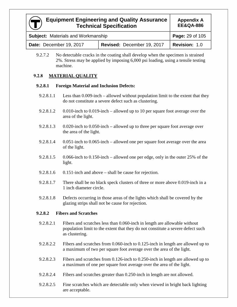
Equipment Engineering and Quality Assurance Technical Specification
Appendix A EE&QA-886
Subject: Materials and Workmanship Page: 29 of 105
Date: December 19, 2017 Revised: December 19, 2017 Revision: 1.0
9.2.7.2 No detectable cracks in the coating shall develop when the specimen is strained 2%. Stress may be applied by imposing 6,000 psi loading, using a tensile testing machine.
MATERIAL QUALITY
9.2.8.1 Foreign Material and Inclusion Defects:
9.2.8.1.1 Less than 0.009-inch – allowed without population limit to the extent that they do not constitute a severe defect such as clustering.
9.2.8.1.2 0.010-inch to 0.019-inch – allowed up to 10 per square foot average over the area of the light.
9.2.8.1.3 0.020-inch to 0.050-inch – allowed up to three per square foot average over the area of the light.
9.2.8.1.4 0.051-inch to 0.065-inch – allowed one per square foot average over the area of the light.
9.2.8.1.5 0.066-inch to 0.150-inch – allowed one per edge, only in the outer 25% of the light.
9.2.8.1.6 0.151-inch and above – shall be cause for rejection.
9.2.8.1.7 There shall be no black speck clusters of three or more above 0.019-inch in a 1 inch diameter circle.
9.2.8.1.8 Defects occurring in those areas of the lights which shall be covered by the glazing strips shall not be cause for rejection.
9.2.8.2 Fibers and Scratches
9.2.8.2.1 Fibers and scratches less than 0.060-inch in length are allowable without population limit to the extent that they do not constitute a severe defect such as clustering.
9.2.8.2.2 Fibers and scratches from 0.060-inch to 0.125-inch in length are allowed up to a maximum of two per square foot average over the area of the light.
9.2.8.2.3 Fibers and scratches from 0.126-inch to 0.250-inch in length are allowed up to a maximum of one per square foot average over the area of the light.
9.2.8.2.4 Fibers and scratches greater than 0.250-inch in length are not allowed.
9.2.8.2.5 Fine scratches which are detectable only when viewed in bright back lighting are acceptable.
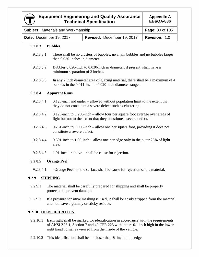
Equipment Engineering and Quality Assurance Technical Specification
Appendix A EE&QA-886
Subject: Materials and Workmanship Page: 30 of 105
Date: December 19, 2017 Revised: December 19, 2017 Revision: 1.0
9.2.8.3 Bubbles
9.2.8.3.1 There shall be no clusters of bubbles, no chain bubbles and no bubbles larger than 0.030-inches in diameter.
9.2.8.3.2 Bubbles 0.020-inch to 0.030-inch in diameter, if present, shall have a minimum separation of 3 inches.
9.2.8.3.3 In any 2 inch diameter area of glazing material, there shall be a maximum of 4 bubbles in the 0.011-inch to 0.020-inch diameter range.
9.2.8.4 Apparent Runs
9.2.8.4.1 0.125-inch and under – allowed without population limit to the extent that they do not constitute a severe defect such as clustering.
9.2.8.4.2 0.126-inch to 0.250-inch – allow four per square foot average over areas of light but not to the extent that they constitute a severe defect.
9.2.8.4.3 0.251-inch to 0.500-inch – allow one per square foot, providing it does not constitute a severe defect.
9.2.8.4.4 0.501-inch to 1.00-inch – allow one per edge only in the outer 25% of light area.
9.2.8.4.5 1.01-inch or above – shall be cause for rejection.
9.2.8.5 Orange Peel
9.2.8.5.1 “Orange Peel” in the surface shall be cause for rejection of the material.
SHIPPING
9.2.9.1 The material shall be carefully prepared for shipping and shall be properly protected to prevent damage.
9.2.9.2 If a pressure sensitive masking is used, it shall be easily stripped from the material and not leave a gummy or sticky residue.
IDENTIFICATION
9.2.10.1 Each light shall be marked for identification in accordance with the requirements of ANSI Z26.1, Section 7 and 49 CFR 223 with letters 0.1-inch high in the lower right hand corner as viewed from the inside of the vehicle.
9.2.10.2 This identification shall be no closer than ¾-inch to the edge.
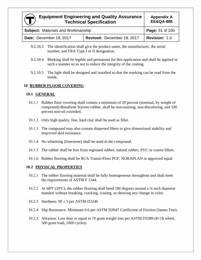
Equipment Engineering and Quality Assurance Technical Specification
Appendix A EE&QA-886
Subject: Materials and Workmanship Page: 31 of 105
Date: December 19, 2017 Revised: December 19, 2017 Revision: 1.0
9.2.10.3 The identification shall give the product name, the manufacturer, the serial number, and FRA Type I or II designation.
9.2.10.4 Marking shall be legible and permanent for this application and shall be applied in such a manner so as not to reduce the integrity of the coating.
9.2.10.5 The light shall be designed and installed so that the marking can be read from the inside.
10 RUBBER FLOOR COVERING
10.1 GENERAL
Rubber floor covering shall contain a minimum of 20 percent (nominal, by weight of compound) Butadiene Styrene rubber, shall be non-staining, non-discoloring, and 100 percent non-oil extended.
Only high quality, fine, hard clay shall be used as filler.
The compound may also contain dispersed fibers to give dimensional stability and improved skid resistance.
No whitening (limestone) shall be used in the compound.
The rubber shall be free from reground rubber, natural rubber, PVC or coarse fillers.
Rubber flooring shall be RCA Transit-Floor PGF, NORAPLAN or approved equal.
10.2 PHYSICAL PROPERTIES
The rubber flooring material shall be fully homogeneous throughout and shall meet the requirements of ASTM F 1344.
At 68ºF (20ºC), the rubber flooring shall bend 180 degrees around a ¾-inch diameter mandrel without breaking, cracking, crazing, or showing any change in color.
Hardness: 90 ± 5 per ASTM D2240
Slip Resistance: Minimum 0.6 per ASTM D2047 Coefficient of Friction (James Test)
Abrasion: Less than or equal to 70 gram weight loss per ASTM D3389 (H-18 wheel, 500 gram load, 1000 cycles)
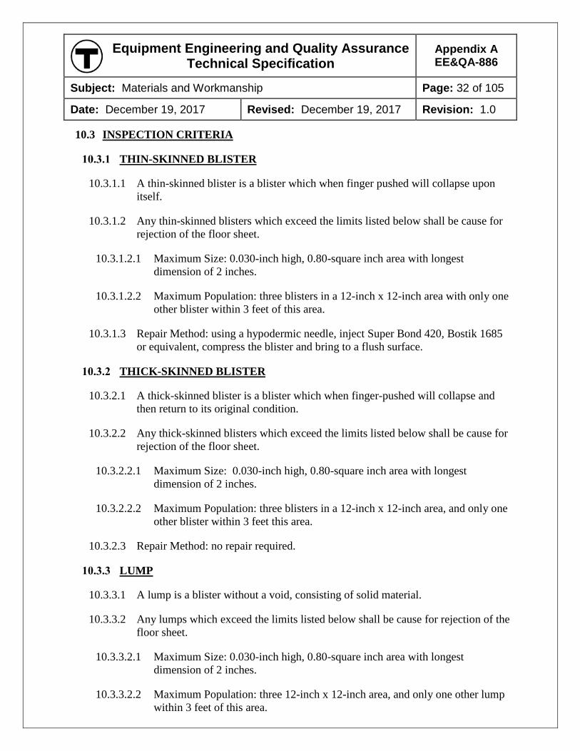
Equipment Engineering and Quality Assurance Technical Specification
Appendix A EE&QA-886
Subject: Materials and Workmanship Page: 32 of 105
Date: December 19, 2017 Revised: December 19, 2017 Revision: 1.0
10.3 INSPECTION CRITERIA
THIN-SKINNED BLISTER
10.3.1.1 A thin-skinned blister is a blister which when finger pushed will collapse upon itself.
10.3.1.2 Any thin-skinned blisters which exceed the limits listed below shall be cause for rejection of the floor sheet.
10.3.1.2.1 Maximum Size: 0.030-inch high, 0.80-square inch area with longest dimension of 2 inches.
10.3.1.2.2 Maximum Population: three blisters in a 12-inch x 12-inch area with only one other blister within 3 feet of this area.
10.3.1.3 Repair Method: using a hypodermic needle, inject Super Bond 420, Bostik 1685 or equivalent, compress the blister and bring to a flush surface.
THICK-SKINNED BLISTER
10.3.2.1 A thick-skinned blister is a blister which when finger-pushed will collapse and then return to its original condition.
10.3.2.2 Any thick-skinned blisters which exceed the limits listed below shall be cause for rejection of the floor sheet.
10.3.2.2.1 Maximum Size: 0.030-inch high, 0.80-square inch area with longest dimension of 2 inches.
10.3.2.2.2 Maximum Population: three blisters in a 12-inch x 12-inch area, and only one other blister within 3 feet this area.
10.3.2.3 Repair Method: no repair required.
LUMP
10.3.3.1 A lump is a blister without a void, consisting of solid material.
10.3.3.2 Any lumps which exceed the limits listed below shall be cause for rejection of the floor sheet.
10.3.3.2.1 Maximum Size: 0.030-inch high, 0.80-square inch area with longest dimension of 2 inches.
10.3.3.2.2 Maximum Population: three 12-inch x 12-inch area, and only one other lump within 3 feet of this area.
Equipment Engineering and Quality Assurance Technical Specification
Appendix A EE&QA-886
Subject: Materials and Workmanship Page: 33 of 105
Date: December 19, 2017 Revised: December 19, 2017 Revision: 1.0
10.3.3.3 Repair Method: no repair required.
HOLE
10.3.4.1 A hole is a defect which is 50 percent or more through the material.
10.3.4.2 Any holes in the floor sheet shall be cause for rejection of the sheet.
THIN AREA
10.3.5.1 A thin area is a defect where the sheet is of reduced thickness locally.
10.3.5.2 Maximum Size: 0.030-inch deep at the lowest point, 3 square inches with the longest dimension of 5 inches.
10.3.5.3 Maximum Population: one thin area in a 40-inch x 40-inch area, and no other thin area within 3 feet of this area.
10.3.5.4 Repair Method: rub with #00 steel wool to blend this area into the normal thickness material and then buff to a normal surface finish.
COLOR DISTRIBUTION
10.3.6.1 Color distribution is an appearance judgment and shall be subject to the approval of the MBTA. If the base coloring is not within 5 percent between production runs or the coloring is not consistent over the entire surface, the roll shall be rejected.
11 WOOD AND PANELS
11.1 LUMBER
Lumber shall be sugar or black maple, sweet or yellow birch only. Lumber shall be thoroughly air seasoned or kiln dried before using, so as not to have a moisture content of greater than 12 percent. Lumber shall be dressed on all surfaces to full dimensions. Lumber shall be straight-grained, free from dry rot, knots, checks, and other defects which may impair its strength and durability or mar its appearance.
11.2 PLYMETAL
The term “plymetal,” as used in the Technical Specification, means metal-faced plywood.
All plymetal panels shall conform to the following mechanical property requirements as defined and tested per ASTM D 2718 and D 3930, reported as minimum metal to wood average shear value or 80 percent wood failure:
Equipment Engineering and Quality Assurance Technical Specification
Appendix A EE&QA-886
Subject: Materials and Workmanship Page: 34 of 105
Date: December 19, 2017 Revised: December 19, 2017 Revision: 1.0
11.2.2.1 Dry shear: 250 lbf/in²
11.2.2.2 Creep or cold flow, under static load for 48 hrs., at room temperature: 250 lbf/in²
11.2.2.3 Where the metal facing is a flat (non-textured) sheet:
11.2.2.3.1 Boil shear, 3 hr. boil, tested wet at room temperature: 150 lbf/in²
11.2.2.3.2 Soak shear, 48 hr. soak wet at room temperature: 150 lbf/in²
11.2.2.4 Where the metal facing is a embossed (textured) stainless steel sheet:
11.2.2.4.1 Boil shear, 3 hr. boil, tested wet at room temperature: 60 lbf/in²
11.2.2.4.2 Soak shear, 48 hr. soak wet at room temperature: 60 lbf/in²
The metal face of the plymetal panel that is faced with melamine shall be constructed prior to the melamine-faced metal panel being laminated to the plywood core.
11.3 PLYWOOD
All plywood shall be manufactured to conform to the requirements of Grade Structural I of the National Bureau of Standards Voluntary Product Standard (American Plywood Association PS-1).
Scarf or finger jointed panels will not be allowed.
All plywood shall be sealed with two coats of epoxy paint on all edges and cutouts as soon as possible after fabrication.
All exposed edges of panels, joints between panels, fastener heads, and openings of panels used in areas accessible to moisture shall be water-proofed and sealed with an approved coating prior to installation in the car.
Plywood shall not be exposed to the weather during manufacturing, shipping or construction.
11.4 HONEYCOMB PANELS
The term “honeycomb panels” as used in the Technical Specification refers to an assembly of honeycomb material bonded to melamine-faced metal panels or to metal panels.
Aluminum honeycomb material shall be commercial grade meeting the requirements of MIL-C-7438G. An alternate standard may be proposed for review and approval by the MBTA. Bonding shall be sufficient to develop the full strength of the honeycomb material.
Equipment Engineering and Quality Assurance Technical Specification
Appendix A EE&QA-886
Subject: Materials and Workmanship Page: 35 of 105
Date: December 19, 2017 Revised: December 19, 2017 Revision: 1.0
Stainless steel-faced, stainless steel honeycomb panels shall be constructed in accordance with the requirements of MSFA-SPEC-445A. The adhesive bond strength of the honeycomb core to the stainless steel face shall not be less than 15-lb/inch climbing drum strength when tested in accordance with MIL STD 401. The adhesive bond strength of the integral stainless frame to stainless steel face shall not be less than 30-lb/inch climbing drum strength when tested in accordance with MIL STD 401.
Stainless steel honeycomb panels shall be tested in accordance with MIL STD 401B to demonstrate the following requirements:
11.4.4.1 Flatwise tension (core) tested per ASTM C 297 to be 330 lbf/in2 or core failure
11.4.4.2 Flatwise tension (frame) tested per ASTM C 297 to be 600 lbf/in2 or 80% cohesive failure
11.4.4.3 Adhesive shear strength (lapshear) tested per ASTM D 1002 to be 3,000 lbf/in2 or 80% cohesive failure
No other honeycomb materials will be permitted.
11.5 PANEL CONTOUR TOLERANCE
Exposed surfaces shall not deviate from the specified contour by more than 3/32-inch in any 36 inch distance. The slope of any such deviation shall not exceed 3/32-inch in 12 inches.
11.6 MELAMINE-FACED ALUMINUM
Melamine-faced aluminum panels shall be constructed by laminating melamine to aluminum sheets. The melamine-impregnated papers shall be directly molded to the aluminum sheets at temperatures of no less than 270ºF (132.2ºC) and pressure no less than 1000 psi. The surface characteristics, after manufacture, shall be no less than that required of type GP (General Purpose) in the NEMA Standards Publication No. LD 3, latest revision. The melamine and the required binder sheets shall be 0.015 +/- 0.005-inch thick. The aluminum sheets shall not be less than 0.025-inch in thickness when used as a facing on plywood. The aluminum sheets shall not be less than 0.081 inch in thickness when not laminated to a substrate such as plywood. Aluminum sheets shall be properly cleaned by etching, sanding, or other approved process to ensure full, permanent adhesion.
The use of contact adhesives to bond the melamine sheets to the aluminum backing is not acceptable.
The bond between the melamine and aluminum sheets shall, as a minimum, meet the following requirements:
Equipment Engineering and Quality Assurance Technical Specification
Appendix A EE&QA-886
Subject: Materials and Workmanship Page: 36 of 105
Date: December 19, 2017 Revised: December 19, 2017 Revision: 1.0
11.6.3.1 Internal bond tested per ASTM D 952 shall be 2,600 lbf/in2 (min).
11.6.3.2 Flexural strength (S) tested per ASTM D 790 shall be 26,500 lbf/in2 (min) with grain and 25,300 lbf/in2 (min) cross grain.
11.6.3.3 Modulus of elasticity (E) tested per ASTM D 790 shall be 2.8 x 10⁶ lbf/in2 (min) with grain and 3.1 x 10⁶ lbf/in2 (min) cross grain.
11.6.3.4 Tensile strength tested per ASTM D 638 shall be 22,300 lbf/in2 (min) with grain and 20,300 lbf/in2 (min) cross grain.
11.7 PHENOLIC COMPOSITE FLOOR PANELS
Phenolic cored panels shall mean panels constructed of top and bottom fiberglass-reinforced phenolic resin matrix skins encapsulating either an isocyanurate closed-rigid cell foam core reinforced with vertical phenolic resin impregnated ribs or an end-grain balsa core. The panel skins shall be comprised, at a minimum, of 24 oz/square yard bi-axial and 8 oz/square yard mat laminated on each side of the coring. The corresponding minimum skin thicknesses shall be 0.050 inches thick.
The panel structure shall contain a dense, syntactic, fiberglass reinforced phenolic resin close-out core to provide support for all edges, cut outs and holes. Fastener holes shall be pre-drilled and countersunk to accommodate the approved fasteners.
The panel shall be manufactured using a sandwich molding process with the application of heat and pressure. Production techniques shall ensure that the glass fiber reinforcement is uniformly distributed throughout the final product in such a manner as to avoid resin-rich or resin-starved sections.
The finished, molded panel shall have a failure load greater than 155 lb./in for a span of 15 inches, when tested to ASTM C-393 for Flexural Properties.
12 SEAT CUSHION MATERIAL
12.1 GENERAL
Seat cushion fill material shall be low-smoke flexible foam constructed of inherently fire-retardant materials. The thickness shall be subject to approval during design review. The material shall have a polymerized homogeneous (free from foreign material) cellular structure with a porous surface and open cells. The cells shall be interconnecting and uniform in size. Cellular material may be molded in one piece or may be assembled by laminating to achieve the required thickness. Laminated cushions shall be bonded together. Cushion material shall be properly cured to prevent any objectionable odor.
Fire retardant low-smoke non-silicone foam shall be Chestnut Ridge Foam Inc., CR Safguard XL or approved equal.
Equipment Engineering and Quality Assurance Technical Specification
Appendix A EE&QA-886
Subject: Materials and Workmanship Page: 37 of 105
Date: December 19, 2017 Revised: December 19, 2017 Revision: 1.0
The low-smoke silicone foam shall be MTI Global Inc., Magnafoam™ or approved equal.
12.2 PHYSICAL PROPERTIES
Non-silicone flexible low smoke foam shall meet the following physical property criteria when tested without upholstery material:
12.2.1.1 Tensile Strength shall be 12.0 lbf/in2 minimum when tested to ASTM D 3574 Test E.
12.2.1.2 Elongation shall be 150% minimum when tested according to ASTM D 3574 Test E.
12.2.1.3 Compression Set at 50 percent shall be a maximum of 10% when tested according to ASTM D 1056.
12.2.1.4 Flex Fatigue – thickness loss shall be 5 percent maximum when tested according to ASTM D 1055.
12.2.1.5 Tear Strength shall be 2 lbf/in2 30% minimum when tested according to ASTM D 3574, Test H.
Silicone foam shall meet the following physical property criteria when tested without upholstery material:
12.2.2.1 Tensile Strength shall be 15 lbf/in2 minimum when tested to ASTM D 3574 Test E.
12.2.2.2 Elongation shall be 100 percent minimum when tested according to ASTM D 3574 Test E.
12.2.2.3 Compression Set at 50 percent shall be a maximum of 5 percent when tested according to ASTM D 1056.
12.2.2.4 Flex Fatigue – thickness loss shall be 5 percent maximum when tested according to ASTM D 1055.
13 SEAT UPHOLSTERY MATERIAL
13.1 CLOTH FABRICS
GENERAL
13.1.1.1 Where specified or permitted, cloth fabrics used for seat upholstery shall be made of woven, transportation grade fabrics of wool/nylon blend (90/10, 85/15).
Equipment Engineering and Quality Assurance Technical Specification
Appendix A EE&QA-886
Subject: Materials and Workmanship Page: 38 of 105
Date: December 19, 2017 Revised: December 19, 2017 Revision: 1.0
13.1.1.2 The maximum fabric shrinkage shall be 2 percent in either the warp or fill direction.
PHYSICAL PROPERTIES
13.1.2.1 Wool/nylon blend seat upholstery material shall be subjected to the physical tests of textile products required by the latest revision of the following ASTM methods, and the results shall not be less than the following values:
13.1.2.1.1 Fabric Weight tested to D3776 shall be 15.5 oz/sq yard without back coating.
13.1.2.1.2 Fabric Count tested to D3775 shall be 88 epi (ends) in Warp; 40 to 72 ppi (picks) in Fill.
13.1.2.1.3 Breaking Strength and Elongation tested to D5034 shall be 200 lbs. in Warp and Fill.
13.1.2.1.4 Tear Strength (Tongue) tested to D2261 shall be 20 lbs. in Warp and Fill.
13.1.2.1.5 Yarn Slippage tested to D4034 shall be 30 lbs. in Warp; 40 lbs. in Fill.
13.1.2.1.6 Color Fastness tested to D3597 shall be rated a minimum Class 4 when tested for Crocking with water, solvent, and light.
13.1.2.1.7 Martindale Abrasion tested to D4966 shall be 20,000 cycles with no breaks.
13.2 FABRIC-BACKED VINYL
GENERAL
13.2.1.1 Where specified or permitted, vinyl used for seat upholstery shall be made of woven transportation grade fabric-backed vinyl with a minimum weight of 32 ounces per linear yard.
13.2.1.2 All exposed surfaces of the existing and new seat upholstery material and plastics shall be coated with the recommended amount of an anti-graffiti material such as Penatone “Barrier Coating”, or approved equal.
PHYSICAL PROPERTIES
13.2.2.1 The seat upholstery material shall be made of woven transportation grade fabric backed vinyl with a weight of 32 ounces per linear yard.
13.2.2.2 The material shall be tested to meet all of the following physical tests for textile products from the Federal Test Method Standard No. 191, latest revision. Values shown are minimum allowable for testing in both warp and filling directions.
Equipment Engineering and Quality Assurance Technical Specification
Appendix A EE&QA-886
Subject: Materials and Workmanship Page: 39 of 105
Date: December 19, 2017 Revised: December 19, 2017 Revision: 1.0
13.2.2.2.1 Tensile Strength tested to ASTM D751 shall be 110 lbs. in Machine Direction; and 100 lbs. in Cross Direction.
13.2.2.2.2 Seam Strength tested to ASTM D751 shall be 85 lbs. in Warp and 70 lbs. in Fill.
13.2.2.2.3 Tear Strength (Trapezoid) tested to CFFA-16C shall be 19 lbs. in Warp; and 16 lbs. in Fill.
13.2.2.2.4 Colorfastness tested to test 5660 for 200 hrs shall exhibit no change.
13.2.2.2.5 Adhesion of Coating tested to ASTM D751 shall be 5 lbs. in Warp; and 4 lbs. in Fill.
13.2.2.2.6 Crocking tested to CFFA-7 shall have a minimum rating of Good.
13.2.2.2.7 Abrasion Resistance tested to CFFA-1A with #8 Cotton Duck, 250,000 double rubs, shall exhibit no wear through of vinyl.
13.2.2.2.8 Abrasion tests on this material shall satisfy the requirements of Federal Specification CCC C 700F, Class 2 Option (b), Treatment a.1.
13.2.2.3 All test procedures and testing data shall be submitted to the MBTA for approval at the time of seat drawing submittal.
14 FIBERGLASS-REINFORCED PLASTIC
14.1 GENERAL
Fiberglass-reinforced plastic (FRP) shall be a laminated, engineered material, consisting of a combination of reinforced fibers in a thermoset polymer resin matrix, where the reinforcement has an aspect ratio that enables the transfer of load between fibers, and the fibers are chemically bonded to the resin.
FRP shall withstand, without any physical deformation or structural damage, the specified environmental conditions or the conditions anticipated local to the application.
FRP shall be resistant to acids, alkalis, and cleaning solutions recommended by the Contractor and approved by the MBTA for this equipment.
FRP shall be manufactured by an open molding or matched die molding process.
14.1.4.1 Production techniques shall ensure that the glass fiber reinforcement is uniformly distributed throughout the final product in such a manner as to avoid resin-rich or resin-starved sections.
Equipment Engineering and Quality Assurance Technical Specification
Appendix A EE&QA-886
Subject: Materials and Workmanship Page: 40 of 105
Date: December 19, 2017 Revised: December 19, 2017 Revision: 1.0
14.1.4.2 An analysis shall be provided to confirm that the proposed construction method and laminate structure is adequate for its intended purpose and meets the strength requirements provided in the Technical Specification.
FRP parts shall have a greater thickness at attachment points and edges. Exposed sharp edges shall not be allowed on any parts.
14.2 RESIN
The resin shall be of good commercial grade, thermosetting matrix selected to meet the physical properties of the Technical Specification and molding process requirements.
14.3 REINFORCEMENT
The fiberglass reinforcement shall be mat, fabric, woven roving, continuous roving, spun roving, or swirl mat as required to meet the physical properties of the Technical Specification and the molding process requirements.
The proposed glass content shall be confirmed through testing to ASTM D 2584.
14.4 GEL COAT
A gel coat shall be provided on all finished surfaces of FRP.
The gel coat shall be resistant to scuffing, fire, weather, and cleaning agents.
The gel coat shall have a minimum thickness of 0.016-inch and a maximum thickness of 0.030-inch.
If the surface of the FRP panel is to be painted, a primer gel coat shall be used and the part shall be painted in accordance with manufacturer’s recommendations.
If the FRP panel does not receive paint, then the gel coat shall be pigmented to match the color scheme selected by the MBTA.
Finished gel coated surfaces shall have a minimum gloss value of 85 when measured with a 60° glossometer.
Finished gel coated surfaces shall exhibit no print-through of the reinforcements.
Finished gel coated surfaces shall not have any appreciable orange peel.
14.5 ADDITIVES
Additives, fillers, monomers, catalysts, activators, pigments, fire retardants, and smoke inhibitors shall be added to the resin mixes to obtain finished products with the
Equipment Engineering and Quality Assurance Technical Specification
Appendix A EE&QA-886
Subject: Materials and Workmanship Page: 41 of 105
Date: December 19, 2017 Revised: December 19, 2017 Revision: 1.0
required physical, flammability, and smoke emissions characteristics of the Technical Specification.
14.6 STRENGTH REQUIREMENTS
Independent laboratory test reports shall be provided confirming that the production laminate structure complies with the requirements of the following standards.
14.6.1.1 The sample tested must be from a final production part and not simply the base laminate material.
14.6.1.2 Test specimens shall be conditioned in accordance with ASTM D 618.
The following are the minimum requirements for interior non load-bearing components:
14.6.2.1 Tensile Strength tested to D 638 shall be a minimum of 10,000 psi.
14.6.2.2 Compressive Strength tested to D 695 shall be a minimum of 18,000 psi.
14.6.2.3 Flexural Strength tested to D 790 shall be a minimum of 15,000 psi.
14.6.2.4 Impact Strength tested to D 256 shall be a minimum of 6 ft-lb per inch of notch.
14.6.2.5 Hardness tested to D 2583 shall be a minimum of 45 Barcol.
The following are the minimum requirements for exterior or load-bearing components:
14.6.3.1 Tensile Strength tested to D 638 shall be a minimum of 18,000 psi.
14.6.3.2 Compressive Strength tested to D 695 shall be a minimum of 24,000 psi.
14.6.3.3 Flexural Strength tested to D 790 shall be a minimum of 30,000 psi.
14.6.3.4 Impact Strength tested to D 256 shall be a minimum of 8 ft-lb per inch of notch.
14.6.3.5 Hardness tested to D 2583 shall be a minimum of 45 Barcol.
15 THERMOPLASTIC SHEET
15.1 GENERAL
Thermoplastic sheet used in the construction of this vehicle shall withstand, without any physical deformation or structural damage, the operating environmental conditions.
Thermoplastic sheet shall be resistant to cleaning solutions.
Equipment Engineering and Quality Assurance Technical Specification
Appendix A EE&QA-886
Subject: Materials and Workmanship Page: 42 of 105
Date: December 19, 2017 Revised: December 19, 2017 Revision: 1.0
Thermoplastic sheet shall be used as extruded or vacuum-formed.
Thermoplastic sheet shall not contain plasticizers in polymer blend.
Thermoplastic sheet shall be homogeneous and extruded from virgin stock which does not include any regrind of vacuum formed parts.
The exposed surface of this material shall conform to the color, texture, and gloss characteristics of the approved color scheme on the existing cars.
15.1.6.1 The applicable ASTM procedure, as approved by the MBTA, shall be used to measure each of the characteristics.
15.1.6.2 The color and surface finish of parts manufactured from this material shall be submitted and approved prior to the production run of any parts.
15.1.6.3 Only UV stabilized pigments shall be used to create the specified color of the thermoplastic sheet.
15.2 QUALITY
The finished parts shall be free of waves and quilting on both sides.
Degraded polymer in the sheet shall not be allowed and, if present, shall be cause for rejection of the piece.
Voids, lumps, and contamination shall also be cause for rejection of parts if the defects are larger than 0.010-inch and the population of these defects is greater than one defect in 4 square feet.
15.3 PHYSICAL REQUIREMENTS
Independent laboratory test certificates shall be provided stating that the thermoplastic sheet complies with the requirements of the following standards. Extruded sheet in the surface finish specified shall be used for testing.
Specific Gravity tested to D 792 shall be a minimum of 1.30 to 1.6.
Tensile Strength tested to D 638 shall be a minimum of 3,300 lbf/in2.
Elongation tested to D 638 shall be a minimum of 50 percent.
Flexural Strength tested to D 790 shall be a minimum of 6,000 lbf/in2.
Flexural Modulus tested to D 790 shall be a minimum of 3.3 x 10⁵ lbf/in2.
Hardness Rockwell “R” Scale tested to D 785 shall be 90 to 110.
Equipment Engineering and Quality Assurance Technical Specification
Appendix A EE&QA-886
Subject: Materials and Workmanship Page: 43 of 105
Date: December 19, 2017 Revised: December 19, 2017 Revision: 1.0
Heat Shrinkage, tested for 15 minutes at 350ºF (176.7ºC), shall be 10 percent maximum in machine direction and 5 percent maximum in transverse direction.
Heat Deflection (annealed) @ 264 lbf/in2 tested to D 648 shall be a minimum of 165ºF (74ºC).
Impact Strength of fabricated parts tested to D 3029 (Gardener Dart Drop 0.5-inch diameter ball) shall be 320 in-lb. minimum at 73ºF (22.8ºC) and 80 in-lb. minimum at -20ºF (-29ºC).
16 PIPING AND TUBING
16.1 GENERAL
Pressure piping valves, fittings, installation methods, and testing shall be in accordance with the Code for Pressure Piping, ANSI B31.1. All joints shall be easily accessible.
Following installation, all piping systems shall be cleaned to remove dirt, metal chips, oily contamination, and moisture. After cleaning, all piping systems shall be pressure tested in accordance with the latest edition of the Code for Pressure Piping, ANSI B31.1. All leaks shall be repaired and the system re-cleaned and retested until leak-free.
Pipes shall be supported throughout their length and at all connections to prevent vibration or noise and to limit stresses in the pipe to less than 50 percent of the pipe’s fatigue endurance limit.
16.1.3.1 Support and clearances provided between adjacent pipes and between pipes and surrounding structure, equipment, or other appurtenances shall be sufficient to prevent chafing or contact due to any combination of car loading and deflection, car dynamics, and thermally-induced movement.
16.1.3.2 The minimum clearance shall be ⅛-inch.
At all locations where pipe or tubing passes through holes in the floor, bulkheads, structure, or any fixed member, it shall be rigidly clamped to protect against possible damage or noise due to bearing, abrasion, or car dynamics-induced rattling and fire-stopped as approved by the MBTA.
Clamps shall not be welded, brazed or otherwise permanently fastened to any pipe or tubing.
Pipe and tubing interfaces with clamps shall be insulated with an elastomeric or woven non-asbestos mineral fabric tape material to protect and sound-insulate the pipe or tubing.
Equipment Engineering and Quality Assurance Technical Specification
Appendix A EE&QA-886
Subject: Materials and Workmanship Page: 44 of 105
Date: December 19, 2017 Revised: December 19, 2017 Revision: 1.0
All pipe clamps shall be attached to car structure.
Pipe clamps shall be fastened on both sides of the clamped pipes.
Pipes and their connections shall not interfere with the removal of other components.
Pipe routing and support design shall keep the total pipe length and number of fittings and bends to a minimum.
All changes in direction accomplished by bending steel pipe to a radius of not less than that specified by AAR Specification No. 2518, Standard S-400.
Direction-change fittings (excluding tee’s) shall not be permitted in the trainline brake pipe or in the brake cylinder pipe, as applicable.
Wherever carbody piping interfaces with vibration-isolated equipment such as the air compressor and air conditioning Compressor/Condensing unit, approved flexible vibration eliminators shall be used. The pipe connection at the downstream end (furthest from the vibrating component) of the flexible elements shall be rigidly clamped no farther than 2 inches from the flexible elements
16.2 AIR PIPING, TUBING, AND FITTINGS
The main reservoir pipe and brake pipe shall conform to ASTM A 53 Schedule 80, seamless pipe. Type “K” copper tube per ASTM B88, latest revision, may also be used, provided it is installed no lower than 2 inches below the floor sheet or structural member and is protected by means of equipment or approved steel guards from any potential impact damage from rail debris, especially in the truck and outboard of the bolster areas. Copper tube shall be of a hardness that will allow bending to 90° or more without cracking. Where suitable protection in damage-prone areas is not possible or practical, approved steel piping sections shall be provided. The diameter of the main reservoir pipe and brake pipes shall meet the brake supplier’s requirements; however, in no case shall these pipes be less than ⅞-inch O.D.
All air pipes shall be sized in accordance with the function intended and may be either ASTM A53 schedule 80 pipe or seamless copper tubing as described previously. All joints for copper tubing shall utilize fittings of wrought copper or non-porous cast brass in accordance with ANSI B 16.22 and B 16.18.
Where ASTM A53 piping is provided its application shall also comply in all respects to AAR Specification No. 2518, Standard S-400. Approved copper tube shall also comply with relevant requirements of AAR Specification No. 2518.
All air piping shall be installed in a manner to provide drainage away from devices or branch pipes leading to devices, when the function of those devices could be impaired by the accumulation of water or ice.
Equipment Engineering and Quality Assurance Technical Specification
Appendix A EE&QA-886
Subject: Materials and Workmanship Page: 45 of 105
Date: December 19, 2017 Revised: December 19, 2017 Revision: 1.0
All air hoses shall conform to the requirements of AAR Specification M-601 and AAR Specification M-618 with AAR-approved reusable fittings conforming to the requirements of AAR Specification M-927.
All cut-out cocks shall be of the vented type, except where function prohibits.
Air piping on the trucks shall be flexible hose as specified above. Low spots (traps) are strictly prohibited. Truck air lines shall not be run on the bottom of truck side frames, transom, or bolster.
Steel piping, if used, all connections and joints where disassembly for service may be required shall utilize swivel type butt-welded or socket-welded flange fittings with an “O” ring type seal. The use of threaded or compression fittings is expressly prohibited.
16.3 AIR CONDITIONING SYSTEM PIPING, TUBING, AND FITTINGS
Air conditioning refrigerant lines shall be ASTM B 280 copper tube.
Air conditioning condensate lines shall be ASTM B88 Type L or Type K copper pipe or stainless steel tube per ASTM A 269.
Joints shall be kept to a minimum and all inaccessible runs of tubing shall be without joints.
Piping supports shall meet the criteria established under ANSI B31.5, and, for horizontal runs shall be spaced no greater than 24 inches and supports for vertical runs shall be spaced no greater than 48 inches.
Finned tubing in evaporators and condensers shall be copper. Instead of elbows, tubing may be bent utilizing a bending tool designed specifically for bending of the tubing to be used.
Suction lines shall be designed and installed without traps. The suction line shall be sized for 3-psi (gauge) maximum system pressure drop and the liquid line shall be sized adequately to prevent flashing due to pressure drop.
Lines subject to collecting condensation shall be insulated with an approved insulation, applied with an approved contact cement. The liquid line shall be insulated in all areas where required to provide additional mechanical or thermal protection. Insulation at all joints and fittings shall be mitered and sealed with an approved material. The insulation, adhesive, and sealant shall meet the requirements of the Technical Specification for thermal, smoke emission, and flammability performance.
All piping and pipe subassemblies shall be de-burred, cleaned, dried, and capped with tight fitting plastic caps or approved equal on all openings after fabrication. Caps shall remain in place until immediately prior to incorporation into the final assembly.
Equipment Engineering and Quality Assurance Technical Specification
Appendix A EE&QA-886
Subject: Materials and Workmanship Page: 46 of 105
Date: December 19, 2017 Revised: December 19, 2017 Revision: 1.0
Vibration eliminators shall be used in piping connections to the compressor. Tubing installations shall be designed to allow any single length of tubing to be replaced without dismantling or removing surrounding equipment, piping, wiring, or other appurtenances.
The Contractor shall develop and submit a Pneumatic Line Design Guide. This design guide shall identify:
16.3.10.1 The types and sizes of tubing to be used.
16.3.10.2 The allowed bend radii for each size of tubing.
16.3.10.3 The methods of tubing support.
16.3.10.4 The types and sizes of fittings to be used.
16.3.10.5 The types and sizes of hoses to be used.
16.4 HYDRAULIC TUBING AND HOSES
Hydraulic tubing shall be seamless stainless steel tube per ASTM A 269 or a metric equivalent.
Fittings shall meet the requirements of ISO 8434-1:1994.
All fittings shall be from a single supplier and a single series or style.
Tapered pipe threads shall not be allowed.
Formed and bent tubing shall be used in preference to fittings for direction changes.
Fittings shall be used where necessary to: ensure that tubing sections may be replaced without the need to disassemble unrelated equipment, transition between tubing sizes, transition between rigid tubing and flexible hose.
Hydraulic hoses shall be wire-reinforced rubber hoses meeting the requirements of SAE J517 100R series or ISO 1436-1.
The Contractor shall develop and submit a Hydraulic Line Design Guide. This design guide shall identify:
16.4.8.1 The types and sizes of tubing to be used.
16.4.8.2 The allowed bend radii for each size of tubing.
16.4.8.3 The methods of tubing support.
16.4.8.4 The types and sizes of fittings to be used.
Equipment Engineering and Quality Assurance Technical Specification
Appendix A EE&QA-886
Subject: Materials and Workmanship Page: 47 of 105
Date: December 19, 2017 Revised: December 19, 2017 Revision: 1.0
16.4.8.5 The types and sizes of hoses to be used.
The contractor shall develop and submit a Hydraulic Tubing Flushing Procedure following the recommendations contained in SAE ARP5891: Achieving Cleanliness Standards for Aircraft Hydraulic Systems during Manufacture.
All hydraulic tubing or each section of the tubing system shall be flushed prior to connecting control devices or actuators to the system. Flushing shall continue until the discharged flushing fluid achieves a cleanliness level recommended by the hydraulic equipment manufacturers connected to the piping, and as defined by SAE AS4059 – Aerospace Fluid Power – Cleanliness Classification for Hydraulic Fluids.
16.5 BRAZING AND SOLDERING OF PIPING, TUBING, AND FITTINGS
All refrigerant piping and air system copper tubing shall be joined using silver solder conforming to AWS B2.2, BAg-5 or BCuP-5.
Refrigeration piping and tubing shall be internally swept with a continuous flow of a non-oxidizing gas such as dry nitrogen during brazing.
Condensate drain tubing shall be joined using 95-5 solder or silver solder as above.
Solder joints shall be wiped and have flux cleaned from tubing and fittings after soldering.
After fabrication, the refrigeration and air systems shall each be cleared of all dirt and foreign matter, flushed with a degreasing agent and dried, all according to a procedure prepared for each by the Contractor and submitted to the MBTA for approval prior to assembly on the cars.
17 PRESSURE VESSELS
17.1 All pressure vessels shall conform to the latest revision of Sections VIII and IX of the ASME Boiler and Pressure Vessel Code.
17.2 Test reports shall be furnished for each pressure vessel.
17.3 Each pressure vessel shall be stamped to record the test.
18 WIRE AND CABLE
18.1 GENERAL
The Contractor’s design and construction shall ensure that the minimum number of wire types and sizes shall be used in the vehicle.
Equipment Engineering and Quality Assurance Technical Specification
Appendix A EE&QA-886
Subject: Materials and Workmanship Page: 48 of 105
Date: December 19, 2017 Revised: December 19, 2017 Revision: 1.0
Selection of wire sizes and insulations shall be based on the current-carrying capacity, voltage drop, mechanical strength, temperature, and flexibility requirements in accordance with applicable AAR, ICEA, ASTM, NEC, and MIL Specifications.
18.1.2.1 In no case shall the properties of the wire and cable be less than those properties delineated in the Technical Specification.
18.1.2.2 Extra-fine wire stranding shall be utilized on applications subject to repetitive motion.
18.1.2.3 All applications of shielded cable shall be subject to approval.
The Contractor and each manufacturer of equipment through the Contractor shall submit to the MBTA for approval samples (at least 12 inches long), specifications, and three copies of certified qualification test documentation of each size and type of wire and cable specified before utilizing said wire and cable.
18.2 CONDUCTORS
Stranding and conductor construction for wire sizes AWG No. 10 and larger shall be in accordance with AAR RP-585 or RP-586, ASTM B-172 Class K, or NEMA WC 70/ICEA S-95-658, Table G-7, Class K, as appropriate for the application.
Stranding and conductor construction for wire sizes AWG No. 12 to AWG No. 16 shall be in accordance with ASTM B-174, Class K, or NEMA WC 70/ICEA S-95-658, Table G-8, Class M, as appropriate for the application.
Stranding and conductor construction for wire sizes AWG No. 18 and smaller shall be in accordance with ASTM B 174 Class L or NEMA WC 70/ICEA S-95-658, Table G-8, Class M, or shall be 19-strand construction as appropriate for the wire size.
Conductors for high-temperature wire AWG No. 12 and smaller shall be soft, annealed nickel-plated copper constructed in accordance with MIL W 22759/6B.
Conductors for all irradiated, cross-linked polyolefin insulated wire shall be soft, annealed tinned copper in accordance with ASTM B33.
The use of solid wire shall not be permitted except for approved wire wrap applications.
Wiring shall be sized for the intended load, voltage drop, installation method, and applicable codes.
18.2.7.1 Maximum wire ampacities for irradiated cross-linked polyolefin wire shall conform to the National Electric Code (NFPA 70), Table 310-16, 90ºC column for wires in raceways or conduit, and 310-17 90ºC column for wires in free air.
Equipment Engineering and Quality Assurance Technical Specification
Appendix A EE&QA-886
Subject: Materials and Workmanship Page: 49 of 105
Date: December 19, 2017 Revised: December 19, 2017 Revision: 1.0
18.2.7.2 Maximum wire ampacities for insulation rating of 110ºC to 250ºC shall conform to NEC (NFPA 70) Table 310-18 or 310-19, as appropriate for the application.
18.2.7.2.1 When the free air rating is used, the Contractor shall furnish data to show that the cables will not exceed their rated temperature at the rated current.
18.2.7.2.2 Where more than three conductors are routed in a raceway or conduit, the ampacities shall be de-rated as detailed by Note 8 to Tables 310-16 through 310-19.
18.2.7.2.3 Wire ampacities shall be de-rated to meet the temperature requirements of all devices to which the wire connects.
18.2.7.2.4 When short-time ratings, short-time overload temperatures, and thermal time constants are used to determine cable size, the parameters used shall be submitted for approval.
In no case shall wire smaller than the following sizes be used:
18.2.8.1 Wire which is pulled through conduits or wireways – AWG No. 14.
18.2.8.2 Wire on electronic units, cards, and card racks – AWG No. 28.
18.2.8.3 Wire within control compartments – AWG No. 18.
18.2.8.4 Multi-conductor cables where current is not a factor in wire size selection – AWG No. 18.
18.2.8.5 All other wire, including that which is not pulled through wireways and conduits – AWG No. 16.
The MBTA may approve smaller wire sizes for selected applications upon submission of appropriate applicable data for justification.
18.3 INSULATION
COMMON INSULATION REQUIREMENTS
18.3.1.1 Insulation shall meet the flammability requirements of NFPA 130.
18.3.1.2 Insulation shall be constructed and tested in accordance with the requirements of this section.
18.3.1.3 All test reports covering Production and Qualification tests shall be submitted to the MBTA for approval with samples prior to any shipment of materials.
Equipment Engineering and Quality Assurance Technical Specification
Appendix A EE&QA-886
Subject: Materials and Workmanship Page: 50 of 105
Date: December 19, 2017 Revised: December 19, 2017 Revision: 1.0
INSULATION FOR GENERAL WIRING
18.3.2.1 Teflon, mineral-filled, abrasion-resistant insulation may be used on wire sizes AWG No. 12 to AWG No. 28.
18.3.2.2 Otherwise, for all general carbody wiring, the insulation shall be a flame retardant, flexible, irradiated cross-linked polyolefin material having a continuous temperature rating of 230ºF (110ºC).
18.3.2.3 The insulation shall be rated at 2000 volts, ac and dc, in the case of wires carrying a nominal voltage greater than 100 volts ac or dc.
18.3.2.3.1 For wiring inside the HVAC unit, the insulation shall be rated at 2000 volts, ac and dc, in the case of wires carrying a nominal voltage greater than 300 volts ac or dc.
18.3.2.4 The insulation shall be rated at 600 volts, ac and dc, in the case of wires carrying a nominal voltage of 100 volts or less, ac or dc.
18.3.2.4.1 For wiring inside the HVAC unit, the insulation shall be rated at 600 volts, ac and dc, in the case of wires carrying a nominal voltage of 300 volts or less, ac or dc.
18.3.2.5 For wire sizes AWG No. 6 and larger, the insulation material shall be formulated for extra flexibility.
18.3.2.6 Flame-retardant, flexible, irradiated, cross-linked polyolefin insulation rated at 257ºF (125ºC) may be used, provided that it meets the requirements of all the tests and standards, modified to reflect the temperature rating-related characteristics.
18.3.2.6.1 The revised values, and the use of such wire, shall be subject to approval by the MBTA.
18.3.2.6.2 Cross-linked polyolefin insulation shall not be permitted for use on wires connected to heater elements or any other high-temperature device.
WIRE INSULATION FOR HIGH TEMPERATURE APPLICATIONS
18.3.3.1 High temperature insulation shall be used where wiring is connected to heat-generating apparatus, where the ambient temperature can exceed 257ºF (125°C), or where Teflon is specified as a requirement.
18.3.3.2 The insulation shall be rated at 1,000 volts, ac and dc, in the case of wires carrying a nominal voltage greater than 100 volts, ac or dc.
18.3.3.3 The insulation shall be rated at 600 volts, ac and dc, in the case of wires carrying a nominal voltage equal to or less than 100 volts, ac or dc.
Equipment Engineering and Quality Assurance Technical Specification
Appendix A EE&QA-886
Subject: Materials and Workmanship Page: 51 of 105
Date: December 19, 2017 Revised: December 19, 2017 Revision: 1.0
18.3.3.4 The insulation shall have a continuous temperature rating of 302ºF (150°C) or greater and shall be in accordance with the following requirements:
18.3.3.4.1 For wire sizes AWG No. 16 and larger: abrasion resistant Teflon (Polytetrafluorethylene – PTFE) meeting MIL-W-22759/6B or 10B, as appropriate for the voltage level used, or silicone rubber meeting AAR Manual of Standards and Recommended Practices, Section M, RP-587.
18.3.3.4.2 For wire sizes AWG No. 18 and smaller: abrasion resistant Teflon (PTFE) meeting MIL-W 22759/6B or 10B, as appropriate.
18.3.3.4.2.1 When used for interconnecting of apparatus, this type wire shall be in bundles with a protective covering of high temperature-rated, low smoke-generating insulation.
18.3.3.5 The Contractor may propose other insulated wire, submitting specifications for approval in a specific high temperature application, including the design ambient temperature, routing, rms ampere value, worst-case ampere value, worst-case temperature rise, stranding, and insulation material.
18.3.3.6 No high temperature insulated wire shall be used in conduit or raceways without specific approval. The Contractor shall submit all applications of high temperature wire insulation for review and approval.
WIRE INSULATION WITHIN EQUIPMENT
18.3.4.1 Insulation on wiring within replaceable modular units, electronic apparatus such as cards and card racks, and other equipment, as approved, shall be Tefzel (Ethylenetetrafluoroethylene – ETFE) per ASTM D 3159, insulation construction per Military Specification MIL-W-22759/16 (AS), irradiated cross-linked polyolefin, or Teflon (Polytetra-fluorethylene – PTFE) type EE, per Military Specification MIL-W-16878/5.
WIRE INSULATION IN CROWDED LOCATIONS
18.3.5.1 Wire for connections to the control console, or in other locations where there are crowded concentrations of low voltage control wiring, may be insulated with Tefzel (ETFE) per ASTM D 3159 and insulation construction per Military Specification MIL-W-22759/16 (AS), except that the wall thickness shall be 0.025-inch.
18.3.5.2 When used for this application, wires shall be bundled with a protective covering of irradiated, cross linked modified polyolefin or similar, approved, high temperature-rated, low smoke-generating insulation.
Equipment Engineering and Quality Assurance Technical Specification
Appendix A EE&QA-886
Subject: Materials and Workmanship Page: 52 of 105
Date: December 19, 2017 Revised: December 19, 2017 Revision: 1.0
INSULATION CONSTRUCTION AND TEST REQUIREMENTS
18.3.6.1 Irradiated Cross-linked Polyolefin Requirements
18.3.6.1.1 Flexibility Tests for Cables
18.3.6.1.1.1 Flexibility tests for cable sizes up to AWG No. 2/0 shall be performed in accordance with AAR Standard S501, paragraph 5.9.7.1, for the appropriate wire size.
18.3.6.1.1.2 Flexibility tests for cable sizes AWG No. 2/0 and larger shall be performed in accordance with AAR Standard S501, paragraph 5.9.7.
18.3.6.1.1.3 Life-cycle flexibility tests shall be conducted on wiring between the doors and the carbody. Test protocol and criteria shall be subject to approval by the MBTA.
18.3.6.1.2 Single Conductor Thermal Overload Test
18.3.6.1.2.1 A continuous current of 115 amperes shall be applied to an 18-foot length of AWG No. 10 test wire in 25ºC still air.
18.3.6.1.2.2 A 3000 volt dc potential shall be maintained between the test wire and an AWG No. 18 bare copper wire wrapped snugly around the outer insulation surface of the test wire.
18.3.6.1.2.3 Failure shall occur when a short circuit is established between the bare copper wire and the test wire.
18.3.6.1.2.4 Minimum time to failure shall be 3 minutes.
18.3.6.1.3 Bundle Overload Test
18.3.6.1.3.1 A bundle overload test using a seven-wire bundle shall be performed in accordance with AAR Standard S501, paragraph 5.9.1.
18.3.6.1.4 Temperature Cycling Tests
18.3.6.1.4.1 This test shall be performed on an 8-foot length of AWG No. 10 wire with 2 kV insulation.
18.3.6.1.4.2 Thermocouples shall be attached to the outer jacket surface, and on the conductor, under a small incision in the insulation approximately 12
Equipment Engineering and Quality Assurance Technical Specification
Appendix A EE&QA-886
Subject: Materials and Workmanship Page: 53 of 105
Date: December 19, 2017 Revised: December 19, 2017 Revision: 1.0
inches from one end of the sample. Both ends of the sample shall be securely clamped using hose clamps.
18.3.6.1.4.3 Prior to temperature cycling, the sample shall be conditioned for 2 hours at a temperature of 302º F (150ºC).
18.3.6.1.4.4 The sample shall then be temperature cycled between ambients of 257ºF (125ºC) and -22º F (-30ºC) by transferring the sample between an air-circulating oven, set at 257ºF (125ºC) and an air-circulating cold box set at -22º F (-30ºC).
18.3.6.1.4.4.1 The time during which the sample stays in each chamber shall be sufficient to allow both thermocouples on the sample to read the same temperature as the environment.
18.3.6.1.4.4.2 One cycle shall be defined as an approved dwell time at both 257ºF (125ºC) and -22º F (-30ºC).
18.3.6.1.4.5 The sample shall be subjected to a total of 250 cycles, with a visual observation at the end of each cycle for cracks and other damage.
18.3.6.1.4.6 After 250 cycles, the sample shall be immersed in water for 6 hours with both ends out of the water, and then subjected to a dielectric test of 5 kVAC for 5 minutes, and also examined by microscope to verify that no cracks exist.
18.3.6.2 Requirements with non-Irradiated-XLPO Insulation
18.3.6.2.1 All insulation other than irradiated, cross-linked polyolefin shall meet the following test requirements, based on MIL-W-22759, and using the following parameters.
18.3.6.2.2 Dielectric – Test per MIL-W-22759/10B (for 1000 V wire with tests at 9.5 kV impulse) or MIL-W 22759/6B (for 600 V wires with tests at 8 kV impulse).
18.3.6.2.3 Insulation Resistance – Test per ASTM D 470. Minimum accepted value shall be 1000 megohms per 1,000 feet, using a 1,000 Vdc megohmmeter.
18.3.6.2.4 Spark test – One hundred percent of all single conductor cables and all single conductor cables being used in a multiconductor cable shall be inspected by Impulse Dielectric Test or by chain electrode Spark Test. Spark Test Apparatus and Procedure shall be in accordance with MIL-W-22759. Spark Test voltages shall be equivalent to impulse test voltages by corresponding rms value at 3 KHz.
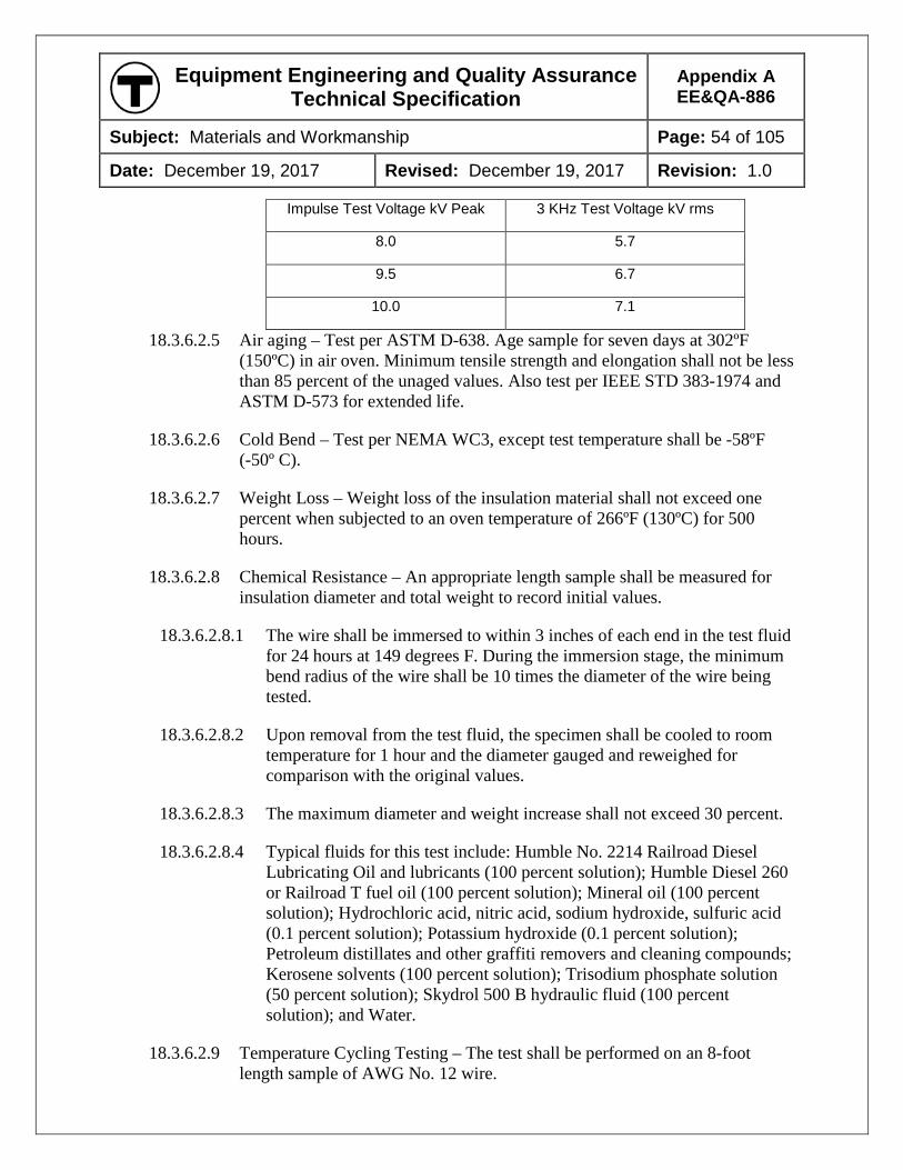
Equipment Engineering and Quality Assurance Technical Specification
Appendix A EE&QA-886
Subject: Materials and Workmanship Page: 54 of 105
Date: December 19, 2017 Revised: December 19, 2017 Revision: 1.0
Impulse Test Voltage kV Peak 3 KHz Test Voltage kV rms
8.0 5.7
9.5 6.7
10.0 7.1
18.3.6.2.5 Air aging – Test per ASTM D-638. Age sample for seven days at 302ºF (150ºC) in air oven. Minimum tensile strength and elongation shall not be less than 85 percent of the unaged values. Also test per IEEE STD 383-1974 and ASTM D-573 for extended life.
18.3.6.2.6 Cold Bend – Test per NEMA WC3, except test temperature shall be -58ºF (-50º C).
18.3.6.2.7 Weight Loss – Weight loss of the insulation material shall not exceed one percent when subjected to an oven temperature of 266ºF (130ºC) for 500 hours.
18.3.6.2.8 Chemical Resistance – An appropriate length sample shall be measured for insulation diameter and total weight to record initial values.
18.3.6.2.8.1 The wire shall be immersed to within 3 inches of each end in the test fluid for 24 hours at 149 degrees F. During the immersion stage, the minimum bend radius of the wire shall be 10 times the diameter of the wire being tested.
18.3.6.2.8.2 Upon removal from the test fluid, the specimen shall be cooled to room temperature for 1 hour and the diameter gauged and reweighed for comparison with the original values.
18.3.6.2.8.3 The maximum diameter and weight increase shall not exceed 30 percent.
18.3.6.2.8.4 Typical fluids for this test include: Humble No. 2214 Railroad Diesel Lubricating Oil and lubricants (100 percent solution); Humble Diesel 260 or Railroad T fuel oil (100 percent solution); Mineral oil (100 percent solution); Hydrochloric acid, nitric acid, sodium hydroxide, sulfuric acid (0.1 percent solution); Potassium hydroxide (0.1 percent solution); Petroleum distillates and other graffiti removers and cleaning compounds; Kerosene solvents (100 percent solution); Trisodium phosphate solution (50 percent solution); Skydrol 500 B hydraulic fluid (100 percent solution); and Water.
18.3.6.2.9 Temperature Cycling Testing – The test shall be performed on an 8-foot length sample of AWG No. 12 wire.
Equipment Engineering and Quality Assurance Technical Specification
Appendix A EE&QA-886
Subject: Materials and Workmanship Page: 55 of 105
Date: December 19, 2017 Revised: December 19, 2017 Revision: 1.0
18.3.6.2.9.1 Thermocouples shall be attached to the outer jacket surface and on the conductor under a small incision in the insulation about 12 inches from one end of the sample. Both ends of the sample shall be securely clamped using hose clamps.
18.3.6.2.9.2 The sample shall be conditioned for 2 hours at a temperature of 150ºC.
18.3.6.2.9.3 The sample shall then be temperature cycled between ambients of 257ºF (125ºC) and -22ºF (-30ºC) by transferring the sample between an air-circulating oven, set at 257ºF (125ºC) and an air-circulating cold box set at -22º F (-30ºC).
18.3.6.2.9.3.1 The time during which the sample stays in each chamber shall be sufficient to allow both thermocouples on the sample to read the same temperature as the environment.
18.3.6.2.9.3.2 One cycle shall be defined as an approved dwell time at both 257ºF (125ºC) and -22ºF (-30ºC).
18.3.6.2.9.4 The sample shall be subjected to a total of 250 cycles, with visual observation at the end of each cycle for cracks and other damage.
18.3.6.2.9.5 After 250 cycles, the sample shall be immersed in water for 6 hours with both ends out of the water, and then subjected to a dielectric test of 5 kVAC for 5 minutes, and also examined by microscope to verify that no cracks exist.
18.3.6.2.10 Single Conductor Thermal Overload Test – A continuous current of 115 amperes shall be applied to an 18-inch length of AWG No. 12 test wire in 77ºF (25ºC) still air.
18.3.6.2.10.1 A 1,000-volt dc potential shall be maintained between the test wire and an AWG No. 18 bare copper wire wrapped snugly around the outer insulating surface of the test wire.
18.3.6.2.10.2 Failure shall occur when a short circuit is established between the copper wire and the test wire. Minimum time to failure shall be 3 minutes.
18.3.6.2.11 Seven-Wire Bundle Thermal Overload Test – A seven-wire cable bundle shall be formed by twisting six insulated AWG No. 12 conductors around a center-insulated AWG No. 12 conductor.
Equipment Engineering and Quality Assurance Technical Specification
Appendix A EE&QA-886
Subject: Materials and Workmanship Page: 56 of 105
Date: December 19, 2017 Revised: December 19, 2017 Revision: 1.0
18.3.6.2.11.1 A 120 ampere current shall be passed through the center conductor for seven minutes.
18.3.6.2.11.2 After a test period, the cable bundle shall be examined for visible damage to the outer six conductors.
18.3.6.2.11.3 Failure shall occur if any of the outer conductors split, rupture, or melt and adhere to the center conductor insulation.
18.3.6.2.12 Qualification and Production Tests – Tests concerning Qualification and Production shall be in accordance with tests in MIL-W-22759 for all lots produced.
18.4 MULTI CONDUCTOR CABLES
GENERAL
18.4.1.1 Multi-conductor cables, where approved, shall be constructed using wiring as described in this Section.
18.4.1.2 For high-temperature applications, the cable shall conform to MIL-C-27072, with Type V connectors, Style 4 sheaths, Class ‘D’ jackets, if needed, and shields, if needed.
18.4.1.3 All conductors in multi-conductor cables shall be color coded or otherwise permanently identified as approved.
18.4.1.4 Materials used in the construction of multi-conductor cables shall meet the requirements below.
18.4.1.5 In applications where current is not a factor in wire size selection, such as LED indicator lights or status displays, AWG No. 16 may be used between repeater devices and displays.
18.4.1.6 For multi-conductor cables carrying low-voltage, high-speed, serial data, exceptions to the wiring requirements may be submitted for approval, based upon availability of wire to meet the application requirements.
FILLERS
18.4.2.1 Where required to obtain a circular cross-section, fillers shall be made of non-hygroscopic materials compatible with the wire insulation and jacket, and shall be of the same or of a higher temperature rating than the wire insulation.
Equipment Engineering and Quality Assurance Technical Specification
Appendix A EE&QA-886
Subject: Materials and Workmanship Page: 57 of 105
Date: December 19, 2017 Revised: December 19, 2017 Revision: 1.0
TAPE
18.4.3.1 A binder tape shall be employed over the assembly of conductors in multi-conductor cables if needed to assist in cable manufacture, or as required to permit the cable to function as intended in its application.
18.4.3.2 The binder tape material shall be non-hygroscopic and shall be of the same (or better) temperature class as the wire insulation, and shall be of a compatible material.
SHIELD
18.4.4.1 The shield, if required, shall consist of either tin-plated copper braid, concentrically-served copper, or aluminum/polyester tape with a drain wire, as appropriate for the application.
18.4.4.2 Tape shields shall be permitted for fixed installations only.
18.4.4.3 The shields shall have the following minimum properties:
18.4.4.3.1 Copper shield shall be made of either tinned, coated copper strands which conform to ASTM B 33, or silver-coated copper strands which conform to ASTM B 298, as is appropriate for the wire insulation.
18.4.4.3.2 Shield coverage shall not be less than 85 percent.
18.4.4.3.3 Shield strand size and application shall be as recommended by the cable manufacturer for the particular application, but shall not be smaller than AWG No. 38.
18.4.4.4 Aluminum/polyester tape shields shall comply with the following requirements:
18.4.4.4.1 The tape shields shall consist of a helical wrap of aluminum/polyester tape with a nominal thickness of 0.0004-inch aluminum on a backing of 0.001-inch polyester.
18.4.4.4.2 The tape shall have a minimum overlap of 10 percent of the tape width to ensure complete coverage.
18.4.4.4.3 In contact with the aluminum side of the shielding tape shall be AWG No. 22 7/30 tinned copper drain wire conforming to ASTM B 33 and B 174.
JACKETS
18.4.5.1 The overall jacket of multi-conductor cables shall be of flame-retardant, irradiated, cross-linked, modified polyolefin, Tefzel (ETFE), or Teflon (PTFE) to be fully compatible with the wire insulation and application as approved.
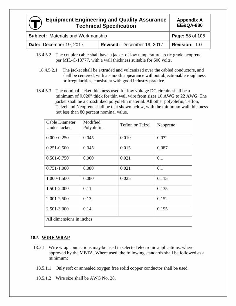
Equipment Engineering and Quality Assurance Technical Specification
Appendix A EE&QA-886
Subject: Materials and Workmanship Page: 58 of 105
Date: December 19, 2017 Revised: December 19, 2017 Revision: 1.0
18.4.5.2 The coupler cable shall have a jacket of low temperature arctic grade neoprene per MIL-C-13777, with a wall thickness suitable for 600 volts.
18.4.5.2.1 The jacket shall be extruded and vulcanized over the cabled conductors, and shall be centered, with a smooth appearance without objectionable roughness or irregularities, consistent with good industry practice.
18.4.5.3 The nominal jacket thickness used for low voltage DC circuits shall be a minimum of 0.020” thick for thin wall wire from sizes 10 AWG to 22 AWG. The jacket shall be a crosslinked polyolefin material. All other polyolefin, Teflon, Tefzel and Neoprene shall be that shown below, with the minimum wall thickness not less than 80 percent nominal value.
Cable Diameter Under Jacket
Modified Polyolefin Teflon or Tefzel Neoprene
0.000-0.250 0.045 0.010 0.072
0.251-0.500 0.045 0.015 0.087
0.501-0.750 0.060 0.021 0.1
0.751-1.000 0.080 0.021 0.1
1.000-1.500 0.080 0.025 0.115
1.501-2.000 0.11 0.135
2.001-2.500 0.13 0.152
2.501-3.000 0.14 0.195
All dimensions in inches
18.5 WIRE WRAP
Wire wrap connections may be used in selected electronic applications, where approved by the MBTA. Where used, the following standards shall be followed as a minimum:
18.5.1.1 Only soft or annealed oxygen free solid copper conductor shall be used.
18.5.1.2 Wire size shall be AWG No. 28.
Equipment Engineering and Quality Assurance Technical Specification
Appendix A EE&QA-886
Subject: Materials and Workmanship Page: 59 of 105
Date: December 19, 2017 Revised: December 19, 2017 Revision: 1.0
18.5.1.3 A silver conductor coating, with a minimum coating thickness of 40 micro-inches, shall be applied to the wire.
18.5.1.4 Wire shall have “MIL-ENE” insulation, or approved equal, manufactured to MIL-W-81822/1A. The insulation shall have a minimum 300 Vac/Vdc voltage rating and shall allow a 275º F (135ºC) maximum conductor temperature.
18.5.1.5 Wrapping shall be “modified” wrap, nominal 7½ turns, including 1½ turns for strain relief.
18.6 INSULATION SMOKE TEST
Wire insulation shall meet the smoke density requirements of NFPA 130. Test equipment calibration, standardization, and operation shall be in accordance with NFPA 262.
19 WIRING
19.1 GENERAL
All car wiring shall be in conformance with Chapter 3 of the NFPA 70, National Electric Code, and Section 4.8 of IEEE Std. 16, except where otherwise specified and except that all wire shall be as required in the Technical Specification.
Circuit protection shall be in conformance with Chapter 2 of NFPA 70, Article 240.
All wiring within an enclosure shall be insulated for the highest voltage in the enclosure, unless approved otherwise.
All wiring connected to apparatus shall be insulated for the highest voltage connected.
19.2 WIRE HANDLING
All wiring shall be performed by qualified, experienced wiring personnel using appropriate tools for stripping insulation, cutting, tinning, soldering, harness making, attaching terminals, and other wire fabrication tasks.
All wiring tools and equipment shall be used as recommended by the tool and equipment manufacturer.
Wire shall be protected from damage during all phases of equipment manufacture.
19.2.3.1 Wire shall not be walked on, dragged across sharp or abrasive objects, kinked or twisted, or otherwise mishandled.
Equipment Engineering and Quality Assurance Technical Specification
Appendix A EE&QA-886
Subject: Materials and Workmanship Page: 60 of 105
Date: December 19, 2017 Revised: December 19, 2017 Revision: 1.0
The ends of wire shall not be permitted to lay on wet floors or other damp areas where moisture may be absorbed into the conductors.
There shall be no nicks in the insulation of any wire or cable.
19.2.5.1 Wire and cable with nicked or otherwise damaged insulation shall be replaced.
19.2.5.2 In isolated cases, a repair procedure may be proposed in lieu of replacement, subject to MBTA approval. Such approval will not be granted for Teflon-based insulation or where the depth of the nick is greater than 50 percent of the insulation thickness.
When removing insulation, wire strands shall not be nicked or broken in excess of the limits of FAA Specification No. AC 43.13-1A, Section 449, “Stripping Insulation.” Additionally, the following criteria shall apply:
19.2.6.1 Wires smaller than AWG No.10 shall have no nicked* or broken strands.
19.2.6.2 AWG No.10 through AWG 1/0 shall be allowed 7.4 percent nicked* strands.
19.2.6.3 Above AWG 1/0 through 1600/24 shall be allowed 4.4 percent nicked* strands.
19.2.6.4 Above AWG 1600/24, nicked* strands shall be allowed on a graduated scale.
19.2.6.5 * Definitions: A broken strand shall count as two nicked strands. A nick is defined as 25 percent or more of the strand area damaged or cut more than 33 percent of its diameter. Longitudinal scratches in a copper strand are not considered cause for rejection.
19.3 WIRING LAYOUT AND INSTALLATION
WIRE HARNESS
19.3.1.1 The layout of wiring, for both car and equipment, shall be designed in advance of its installation and in cooperation with the suppliers of the related equipment.
19.3.1.2 Wiring shall be pre-fabricated into standard harnesses, wrapped or tied with spiral wrap or tie wraps.
19.3.1.3 Harnesses shall be installed with identical arrangement and location in each car having similar equipment.
19.3.1.4 Separate harnesses shall be provided for major circuit groups or types, or as required for specified circuit separation.
19.3.1.5 All circuits and branches shall be separated by means of terminal boards to isolate portions from others for troubleshooting and searching for undesired grounds.
Equipment Engineering and Quality Assurance Technical Specification
Appendix A EE&QA-886
Subject: Materials and Workmanship Page: 61 of 105
Date: December 19, 2017 Revised: December 19, 2017 Revision: 1.0
19.3.1.6 All circuits subject to periodic high potential tests shall be so arranged that they can be conveniently set up for the tests.
19.3.1.7 No exposed wiring within the interior of the car shall be permitted.
19.3.1.8 Alternative methods for fabricating and installing wiring which are standard Contractor practice will be considered for approval by the MBTA.
19.3.1.9 Harnessed wires shall not be installed in conduit.
19.3.1.10 Wires from different conduits or other openings shall not be harnessed together with wires running within the box or entering the box through another entrance point.
19.3.1.11 Each harness or group of wires between equipment enclosures shall contain a minimum of 10 percent spares, but no fewer than two spares for each wire size.
19.3.1.11.1 All spares for all wiring shall be submitted for approval by the MBTA.
19.3.1.11.2 Unless specifically approved by the MBTA, no spare wiring shall be used by the Contractor.
19.3.1.11.3 All spares shall be installed in connectors on terminal boards or other means as approved by the MBTA.
CIRCUIT SEPARATION
19.3.2.1 Circuits shall be physically separated to reduce the possibility of unsafe conditions, interference, or equipment damage.
19.3.2.2 The following major circuit groups shall not be harnessed or bundled together, shall not run in the same conduit, and shall be physically separated and secured in enclosures, wire ducts, junction boxes, or other wire routing devices: High voltage ac; Communication; Battery voltage level; Semiconductor gating voltage level; and Conductors carrying in excess of 100 amps.
19.3.2.3 Wires in circuits with potentials differing by 50 volts or more shall be separated by a physical barrier.
19.3.2.3.1 Whenever possible, the wires shall not be cabled together and shall not be placed in the same conduit, junction box, or enclosure.
19.3.2.3.2 Where a raceway, duct, junction box, or enclosure is divided into two or more distinct areas by metallic partitions, each area may be considered separately in this application.
Equipment Engineering and Quality Assurance Technical Specification
Appendix A EE&QA-886
Subject: Materials and Workmanship Page: 62 of 105
Date: December 19, 2017 Revised: December 19, 2017 Revision: 1.0
19.3.2.4 Where it is impossible to avoid wires at different voltages in the same equipment enclosure, the wires shall be physically separated, bundled, and secured separately such that physical contact between wiring is not possible.
19.3.2.5 Wiring connected to transient-generating apparatus, such as unsuppressed contactor coils, shall not be run adjacent to wiring carrying signals to, from, or between semiconductor circuits, logic circuits, vital no-motion circuits, or communication circuits.
19.3.2.6 In cases in which adequate physical separation is impossible, shielded wire shall be used for all conductors involved.
WIRE AND CABLE RUNS
19.3.3.1 Wire runs shall be continuous and unbroken between connection points.
19.3.3.2 Wire runs shall be supported at no greater than 24 inches spacing.
19.3.3.3 Wire runs shall be protected at each support point against mechanical crushing and abrasion.
19.3.3.4 A watertight bushing and drip loop shall be provided on all exposed cable entries.
19.3.3.5 All cable bundles and wires shall be routed a minimum of 1 inch above the bottom of equipment enclosures.
19.3.3.6 All undercar wiring smaller than AWG No. 6 shall be run in closed wire ducts, conduits, or open wire mesh wireways in an approved manner.
19.3.3.7 Wire and cable shall be secured within ducts or open wireways, including each entrance and exit point, to prevent chafing and movement.
19.3.3.8 Wire ducts and conduits shall be of waterproof construction.
19.3.3.8.1 Permanently retained watertight strain relief bushings, with insulated throat liners of an approved design, shall be used at locations where wires, cables, or harnesses enter or exit conduit, ducts, apparatus, and equipment enclosures.
19.3.3.9 Strain relief bushings on equipment enclosures shall include a permanently retained O-ring type seal.
19.3.3.10 Lead wires to resiliently-mounted electrical apparatus shall be carried in conduit to a point as close to the apparatus as possible.
19.3.3.10.1 The length of the leads between the end of the conduit and each piece of apparatus shall be as approved.
Equipment Engineering and Quality Assurance Technical Specification
Appendix A EE&QA-886
Subject: Materials and Workmanship Page: 63 of 105
Date: December 19, 2017 Revised: December 19, 2017 Revision: 1.0
19.3.3.11 Short runs of cables or harnesses entering or leaving conduit and apparatus shall have an approved guard mounted to the carbody to protect the wires from mechanical damage.
19.3.3.12 Lead wires to solidly-mounted electrical apparatus and equipment enclosures shall run in conduit connected to the apparatus or enclosure.
19.3.3.13 Any wiring run through the floor shall be run in ducts or conduit.
19.3.3.14 Wiring, even if enclosed in loom, must not be run through partitions without suitable bushings at such points of passage.
19.3.3.15 Cables shall be laid in place with sufficient slack at the bends so that cables will clear the inside bend surface of the wireway/wire duct.
19.3.3.16 Wire installation shall not be subject to accumulations of water, oil, or other foreign matter.
19.3.3.17 Wires or cables shall not pass through or over the battery compartment.
19.3.3.18 Wires or cables shall not pass over heat-generating equipment such as acceleration and braking resistors, even if the wires or cables are in conduit.
19.3.3.19 Exposed harnesses, short cable runs, and harnesses entering or leaving exposed raceways shall have approved, fire-resistant, flexible dielectric sleeving installed over the raceway edges and grommet-type insulation at penetration holes. Wiring shall be retained to the sleeving with tie-wraps.
CABLE CLEATING AND SUPPORT
19.3.4.1 All cable and wiring exiting wireways/wire ducts, and that which is not installed in conduit, shall be cleated using split-block cleats of molded neoprene rubber.
19.3.4.2 Cables shall be cleated and bushed when passing through bulkheads and structural members.
19.3.4.3 The cushioning neoprene shall be non-conductive, fire-retardant insulating material with a durometer of 50 to 60.
19.3.4.4 Each cleat shall have a stiffener of at least 10-gauge material on the side away from the mounting bracket which shall act to spread the bolt clamping force over the entire length of the cleat.
19.3.4.5 Bolts shall have lock nuts.
19.3.4.6 AWG No. 6 or larger insulated wire may be cleated in place without conduit, duct, or open wireway.
Equipment Engineering and Quality Assurance Technical Specification
Appendix A EE&QA-886
Subject: Materials and Workmanship Page: 64 of 105
Date: December 19, 2017 Revised: December 19, 2017 Revision: 1.0
19.3.4.6.1 In the areas over the truck in the wheel wash and not protected by underfloor-mounted equipment, the wire shall be mechanically protected by an open mesh, expanded metal, or other type of approved guard. The guard may be attached to the bottom of each cleat with the cleat clamping bolts or by other approved arrangement.
19.3.4.7 Cleats shall be designed to grip each cable individually and firmly, but without causing damage to cable insulation, including cold flow of the insulation.
19.3.4.7.1 Each cable in the cleat shall have its own cutout sized to the correct wire diameter.
19.3.4.7.2 Cleated cables shall be routed and supported such that they cannot, under any combination of forces and car movement, touch each other or any other part of the car, except the cleat cushioning material.
19.3.4.8 Wire and cable runs shall be continuous and unbroken between terminations and shall be supported at not greater than 24 inch intervals in ducts, open wireways, or cleats.
19.3.4.9 Wires that run under the car shall be supported at not greater than 20-inch intervals. The wire shall be protected at each support point from mechanical crushing and abrasion.
19.3.4.10 Wire splices shall not be permitted, except with express written approval of the MBTA.
19.3.4.11 Concealed wires, such as within conduits and wire ducts, shall be such that wires may be replaced or added to without the removal of other than access panels.
19.3.4.11.1 It shall not be necessary to disconnect or disassemble conduit to accomplish this task.
19.3.4.12 Wiring run in looms shall not be carried over potential chafing hazards.
19.3.4.13 Wires entering any removable box shall be harnessed and secured to facilitate removal of the box.
19.3.4.14 All wires and cables shall be fully protected against contact with any surface other than that designed specifically to support or protect them. This applies to all current-carrying wires, cables, or buses on the vehicle.
WIRE SECUREMENT AND TERMINATION
19.3.5.1 Wiring and cabling shall be readily accessible for inspection and maintenance. To control this requirement, the Contractor shall submit a complete wiring plan for approval.
Equipment Engineering and Quality Assurance Technical Specification
Appendix A EE&QA-886
Subject: Materials and Workmanship Page: 65 of 105
Date: December 19, 2017 Revised: December 19, 2017 Revision: 1.0
19.3.5.2 All wiring shall be located and secured such that normal equipment motion, maintenance access, heat sources, and the environment do not damage or reduce the life of the wiring.
19.3.5.3 Junction boxes with terminal boards shall be used, as required, for wire terminations.
19.3.5.4 In cases where it is necessary to anchor wires or cables to metallic parts of the car, cleats or approved stainless steel bottle clamps shall be used.
19.3.5.5 Wires and cables shall not be allowed to chafe or rub against any part of the car or each other.
19.3.5.6 Wire and cable dress shall allow for sufficient slack at equipment terminals to provide for movement induced by shock and vibration, equipment shifting, alignment, cover removal, and component replacement.
19.3.5.7 Sufficient lengths shall be provided at points of termination for additional reterminations without applying tension to the wire and without splicing as follows: AWG No. 10 and smaller – Three reterminations; AWG No. 8 and larger – Two reterminations.
19.3.5.8 A drip loop shall be provided on all exposed wires and cables to prevent fluid runoff into connected equipment.
19.3.5.9 Wire-tying devices shall be of such material and construction that they will adequately retain the wires for the life of the wiring and shall be resistant to ozone and ultraviolet light.
19.3.5.10 Wire and cable ties shall be trimmed and located to eliminate any hazard to personnel from sharp edges.
19.3.5.11 Wire-tying devices shall be snug, but shall not be so tight as to cause indentation and cold flow damage to insulation.
19.3.5.12 Wire-tying devices shall be mechanically fastened to a permanent structure.
19.3.5.12.1 Adhesive-installed mounting bases shall not be used for ties or for cable support.
19.3.5.13 All wire bundles and cables within an enclosure shall:
19.3.5.13.1 Be supported by the use of tape rails.
19.3.5.13.2 Be spaced away from the equipment box structure, metal edges, bolt heads, and other interference points.
Equipment Engineering and Quality Assurance Technical Specification
Appendix A EE&QA-886
Subject: Materials and Workmanship Page: 66 of 105
Date: December 19, 2017 Revised: December 19, 2017 Revision: 1.0
19.3.5.13.3 Have electrical clearance from the covers, regardless of the insulation properties of covers.
19.3.5.13.4 Be located above or alongside the apparatus rather than at the bottom of the box wherever possible.
19.3.5.14 In all cases, wire shall be a minimum of 1-inch above the bottom of the box.
19.3.5.15 Wire entry into control or junction boxes shall not be permitted through the bottom of the box.
19.3.5.16 Truck wiring shall be designed to ensure sufficient slack and shall be provided with clamp supports and abrasion protection. T-splices shall not be permitted.
19.3.5.17 All jumpers, jumper heads, and jumper receptacles shall be sealed in an approved manner to prevent the entry of water at any operational speed of the car.
19.3.5.18 Any wiring needed to calibrate and test car functions shall be a part of the permanent car wiring to enable the MBTA to conveniently maintain the equipment. This wiring shall terminate in approved connectors in the respective control groups and cabinets.
19.3.5.19 Wire and cables that are subject to high currents in fault conditions or normal operation shall be secured against secondary damage from high magnetic forces. Propulsion inverter circuits are an example. This requirement shall include damage to bus bars or devices at which the cables terminate.
CIRCUIT SHIELDING
19.3.6.1 Wire shields used in trainline circuits shall be continuous to the car’s electrical jumper receptacle and coupler contacts.
19.3.6.1.1 The wire shields shall be connected through all applicable connectors and junction boxes.
19.3.6.2 Circuits shall be categorized.
19.3.6.2.1 Shields in one circuit category shall not be interconnected with shields of another category.
19.3.6.3 Shields used to protect against interference shall not carry signal currents.
19.3.6.4 Shields on low-level signal wires shall not be interconnected with shields on high-level signal wires in the same category.
Equipment Engineering and Quality Assurance Technical Specification
Appendix A EE&QA-886
Subject: Materials and Workmanship Page: 67 of 105
Date: December 19, 2017 Revised: December 19, 2017 Revision: 1.0
19.3.6.5 Each group of shields (other than at the electric jumper receptacles and couplers) shall be carried through on a connector pin or pins, or on terminal strips which shall be in the immediate proximity of the categorized group of circuits.
19.3.6.6 Loops at the interconnections of shields shall not be permitted.
19.3.6.7 Coaxial cables used as constant impedance transmission lines shall be terminated as required by the circuit termination design and shall not be considered to be shielded conductors.
19.3.6.8 Triaxial cables may be used as coaxial impedance transmission lines with the outer conductor employed as an RF shield.
19.3.6.9 The following three guidelines shall be applicable in so far as possible, but are not requirements:
19.3.6.9.1 Shields used to suppress electromagnetic interference (EMI) at all frequencies shall be terminated only at the low potential side of the interference circuit, at the termination which exhibits maximum susceptibility.
19.3.6.9.2 Shields used to protect against the effect of, or to exclude, EMI at frequencies below 150 kHz, shall be terminated either to the low potential side or at the balance point of the protected circuit at the termination which exhibits maximum susceptibility.
19.3.6.9.3 Cables requiring both audio frequency (AF) and radio frequency (RF) shields shall be electrically isolated from each other. The resistance between these circuits shall be at least 500 Megohms when 500 volts dc is applied. Double shielding shall be required on circuits that are both AF-susceptible and RF-susceptible.
19.4 MARKING AND DESIGNATION
As part of the wiring plan, the Contractor shall devise and submit for approval a wire and terminal marking and designation system that shall coordinate all electrical circuits in the car into a unified system.
19.4.1.1 The system shall identify all wiring, including circuit return wiring, and terminals according to their respective circuit function(s) and shall accurately correlate these designations with the car schematic diagrams.
19.4.1.2 Each circuit shall be individually designated from point to point.
19.4.1.3 Common designations for return circuits will not be permitted.
Each wire and cable shall have printed on its outer surface the manufacturer’s identification, conductor size, temperature rating, and voltage rating.
Equipment Engineering and Quality Assurance Technical Specification
Appendix A EE&QA-886
Subject: Materials and Workmanship Page: 68 of 105
Date: December 19, 2017 Revised: December 19, 2017 Revision: 1.0
19.4.2.1 For wire size 1/0 and larger, stranding shall be given in addition to the other parameters.
Except for wires entirely within an equipment enclosure, each wire AWG No. 8 and smaller shall be permanently and legibly marked along its entire length.
19.4.3.1 Wires larger than AWG No. 8 may have wire markers applied at each end of the wire.
19.4.3.2 Blank spaces between markings shall measure approximately 6 inches.
19.4.3.3 Wiring entirely within an equipment enclosure may have a single wire marker at each end, in lieu of continuous marking.
19.4.3.4 Wires shall be marked with an alpha-numeric circuit designation.
19.4.3.4.1 A circuit designation shall change only when it passes through an active or passive component such as a relay coil or relay contact, fuse, circuit breaker, lamp, motor, or resistor.
19.4.3.4.2 A circuit designation shall remain unchanged when it passes through a terminal strip or junction box stud regardless of the number of wires of that circuit are common to that point.
19.4.3.4.3 There shall be no duplication of wire codes in unrelated circuits throughout the car.
19.4.3.4.4 Where there is more than one identical assembly per car, each assembly shall be wired identically to the other(s) and wire marking shall be identical at each assembly.
For pre-manufactured multi-conductor cables and for cases where individual circuit identification markers may be approved, the following requirements shall apply:
19.4.4.1 All wires and terminals shall be clearly identified. Wires attached to terminal studs shall have a marker indicating the terminal stud to which it is attached.
19.4.4.2 Identification of wires shall be by continuous wire marking printed on the wire.
19.4.4.2.1 All wires shall be marked 6 inches from the end of the wire and every 12 inches over the length of the wire.
19.4.4.2.2 Wires in multiple-conductor cables shall be color-coded.
19.4.4.3 Identification of terminals shall be by white or yellow permanent markers with black printing.
Equipment Engineering and Quality Assurance Technical Specification
Appendix A EE&QA-886
Subject: Materials and Workmanship Page: 69 of 105
Date: December 19, 2017 Revised: December 19, 2017 Revision: 1.0
19.4.4.4 Wire markers shall meet the adherence and solvent resistance requirements specified by MIL-M-81531, latest revision, and shall withstand all combinations of ambient and equipment temperatures.
19.4.4.4.1 Manual printing is prohibited.
19.4.4.5 For cable identification, the Contractor shall use a basic identification system in conformance with ANSI/IEEE 200 and shall submit the system selected for review and approval by the MBTA.
19.5 PULLING COMPOUND
Pulling compound shall be non-conductive, non-hygroscopic, non-odorous, shall not support bacterial activity, nor attract vermin.
19.6 SOLDER
Solder shall be in accordance with ASTM B 32, Grade Sn60. A non-corrosive flux shall be applied immediately before soldering.
19.7 TAPE
Electrical tape shall not be PVC. Electrical tape shall meet or exceed the voltage rating of wire where the tape is applied.
20 WIRE AND CABLE CONNECTIONS
20.1 GENERAL
All equipment enclosures and junction boxes, except primary power circuits, shall be fitted with terminal boards or connectors.
Primary power circuits shall be fitted with compression terminals and knuckle joint connectors as described herein.
As part of the wiring plan, the Contractor shall submit the proposed design and product line of all connections for approval.
20.1.3.1 Terminal boards with M4 or Number 6 or smaller screws and quick-disconnect terminals, other than those stated herein, shall be permitted only with prior approval by the MBTA.
20.2 TERMINAL BOARDS AND TERMINAL POINTS
Terminals and connections used throughout the car shall be of two types; mechanical solderless type, made by AMP Incorporated or other approved manufacturer for the
Equipment Engineering and Quality Assurance Technical Specification
Appendix A EE&QA-886
Subject: Materials and Workmanship Page: 70 of 105
Date: December 19, 2017 Revised: December 19, 2017 Revision: 1.0
exterior and undercar locations and screwless cage clamp made by Wago Corporation or Entrelec M6/12FF terminal blocks for all interior locations.
The chosen manufacturer must have a comprehensive line of terminal blocks, accessories, and application tools available.
The Contractor shall submit the proposed product lines to the Engineer for approval.
Terminals shall be attached to the wiring with the proper crimping tools and dies recommended by the manufacturer.
Where possible, the terminal used shall be of the pre-insulated type which securely grips and holds the insulation.
Conductors which may be subjected to motion relative to the terminal shall be protected by suitable means to prevent breakage of the conductor at or near the terminal.
All screwless cage clamp terminal blocks shall be arranged so that the wiring is easily attached to the terminals.
20.2.7.1 All terminal blocks shall be of the insulated type which securely grips with a constant restraining of the conductor under all temperature and vibration conditions specified with no loss of conductivity.
20.2.7.2 The terminal blocks shall use copper conducting bars with stainless steel spring connections and shall have test plug adapters to allow troubleshooting without removal of wires from the blocks.
All solderless electrical terminal points and terminal boards shall have brass studs and connections which shall be locked using a single nut with brass flat washers and a plated spring type lock washer. Studs, nuts, and washers may also be made of corrosion resistant plated steel.
Nylon-insert self-locking type nuts and other self-locking fasteners shall not be used for electrical connections.
A minimum of 10% spare terminals shall be provided on each terminal assembly with at least one spare terminal being provided if there are nine or less active terminals.
No. 6 and smaller screw type terminal boards and fast-on type terminations shall not be permitted without the written approval of the Engineer.
All terminal boards shall be in accordance with MIL-T-55164A.
Binding-head, screw-type terminal boards will be permitted only where approved.
Equipment Engineering and Quality Assurance Technical Specification
Appendix A EE&QA-886
Subject: Materials and Workmanship Page: 71 of 105
Date: December 19, 2017 Revised: December 19, 2017 Revision: 1.0
Threaded studs shall have a minimum of 2½ threads exposed beyond the final nuts.
Adequate space shall be provided to permit connecting wire terminals with standard tools.
All terminals shall be properly torqued to assure sound connections.
Spacers shall not be used.
Jumpers between terminal board points shall be brass or plated steel. Wire jumpers between adjacent terminals of terminal boards will not be permitted.
An approved permanent marking strip on each terminal board shall be provided and attached adjacent to the wire junction point to identify the wires attached thereto.
The wires connected to terminal boards shall have the terminal point location printed on the wire or identified by other approved means.
A maximum of two terminals shall be connected to any one binding screw.
A maximum of four terminals shall be connected to any one threaded stud, provided that there is no interference among terminal barrels.
On terminal boards, the wiring shall be arranged so that no more than two terminals are connected to a stud from each side.
20.3 WIRE TERMINATIONS
Terminals and connections used throughout the car by the Contractor shall be mechanical, solderless, crimp type as manufactured by AMP Incorporated or other approved manufacturer with a comprehensive line of terminals, connector pins, and application tools available.
All terminals for the same wire size shall be crimped with the same model tool. The Contractor shall minimize the total number of crimping tool types needed for crimp connections.
20.3.2.1 Terminals for wire sizes AWG No. 10-22 shall require no more than three tool models to provide certified crimp connections.
20.3.2.2 As part of the wiring plan, the Contractor shall submit the proposed product line for approval. For approval, terminals shall have been tested to Military Specification MIL-T-7928G.
20.3.2.3 Test results shall be submitted for approval on a part number basis.
Equipment Engineering and Quality Assurance Technical Specification
Appendix A EE&QA-886
Subject: Materials and Workmanship Page: 72 of 105
Date: December 19, 2017 Revised: December 19, 2017 Revision: 1.0
Terminations used in high temperature applications shall be insulated with a material rated for high temperature; non-insulated terminals in high temperature applications may be proposed for review by the MBTA.
Terminals and connections shall be attached to the wiring with proper crimping tools and dies as recommended by the manufacturer.
20.3.4.1 The terminals used on conductors of size AWG No. 10 or smaller shall securely grip and hold the insulation of the conductor, unless otherwise approved.
Ring lug terminals shall be accordance with Military Standard MS-25036; spade and hook-type terminals shall not be used. Corrosive protection shall be provided for all base materials.
Conductors subject to motion relative to the terminal shall be protected to prevent breakage of the conductor at or near the terminal.
20.3.6.1 Sufficient slack shall be provided in all wires and cables to prevent breaking or pull out of bushings and terminals.
Only one wire shall be crimped in any one terminal.
Wherever several wires are connected to terminals of a terminal strip on a device which is removable from the car for maintenance, the wires shall be terminated, with double-ring terminations which shall be screwed to an insulating fanning strip which shall serve to keep the terminations in the correct relative locations while disconnected from the device, unless otherwise approved by the MBTA.
20.4 POWER CABLE TERMINATIONS
Power cables shall be terminated with an approved compression terminal.
Sufficient cable slack shall be provided to preclude breaking or pull-out from bushings or terminals and to allow two reterminations.
Cable conductors shall be clean prior to installation of terminals.
Compression terminals shall be applied using tools and procedures recommended by the terminal manufacturer for that purpose.
Swaging tools shall be of a type that ensures complete swaging in every case.
20.5 CABLE CONNECTORS
GENERAL
20.5.1.1 All cable connector applications shall be subject to approval.
Equipment Engineering and Quality Assurance Technical Specification
Appendix A EE&QA-886
Subject: Materials and Workmanship Page: 73 of 105
Date: December 19, 2017 Revised: December 19, 2017 Revision: 1.0
20.5.1.2 All cable connectors shall employ removable crimp contacts of the correct size for the wire being terminated. Except as noted below, the connector contact area shall be plated with a minimum of 0.000030-inch of gold over a minimum of 0.000050-inch of low-stress nickel for general purpose and low level dry circuit applications.
20.5.1.2.1 For high current applications, the connector contact area shall be plated with a minimum of 0.00010-inch of silver.
20.5.1.3 Adjacent connectors shall use either different inserts or different insert orientations to prevent erroneous connections.
20.5.1.4 The receptacle portion of all cable connectors shall be rigidly mounted.
20.5.1.5 Connectors of a different size (but similar type) installed in the same area shall be keyed to prevent inadvertent installation into the wrong receptacle.
20.5.1.6 Cables shall be clamped at the back of the connector by clamping over the cable jacket. Clamping on cable wires will be prohibited.
20.5.1.7 Backshell grommets shall be used with circular multiway connectors to prevent adjacent contacts from shorting.
20.5.1.8 Extension bodies shall be used where necessary to insure that there is sufficient room to terminate cable wires while providing the seal and clamp on the cable jacket.
WATERPROOF CABLE CONNECTORS
20.5.2.1 All cable connectors used in exterior locations shall be of the environmental watertight variety.
20.5.2.2 Cable connectors shall be equipped with sealing gaskets on the front mating surface and on the back where the cable enters.
20.5.2.3 The cable jacket shall be held by a clamp within the connector body.
20.5.2.4 Unused connector pin positions shall be sealed with either connector contacts or plastic sealing plugs designed for that purpose.
20.5.2.5 The cable connectors shall be metal-shelled, positive-locking, rectangular connectors as described below or circular one-quarter to one-third turn, with three bayonet couplings, quick disconnect, environmental watertight connectors. Connectors shall give audible, visual and tactile indications of full coupling.
20.5.2.5.1 Quarter-turn, bayonet-lock connectors shall be type CIR connectors as made by Litton-Veam SPA, or approved equal and shall conform to all provisions in
Equipment Engineering and Quality Assurance Technical Specification
Appendix A EE&QA-886
Subject: Materials and Workmanship Page: 74 of 105
Date: December 19, 2017 Revised: December 19, 2017 Revision: 1.0
MIL-C-5015, or other approved standard, except for the screw coupling requirement.
20.5.2.5.2 Heavy-duty multi-pole rectangular connectors shall conform to DIN EN 61984 (VDE 0627) and DIN EN 175301-801 as manufactured by Harting and ILME, or approved equal.
20.5.2.6 Plastic-bodied connectors shall not be used in exterior locations. Quarter-turn, bayonet-lock, quick-disconnect type connectors shall not be used on trainline jumper cables.
20.5.2.7 Connectors in high vibration or high motion areas, such as speed sensors and trainline jumpers, shall have the wire connections soldered and potted and shall have a watertight jacket molded over the cable and connector to form a unitized assembly.
20.5.2.8 Trainline jumper connectors shall be as manufactured by Pyle-National or approved equal. The Contractor shall conduct an approved vibration test on the unitized assemblies.
NON WATERPROOF CABLE CONNECTORS
20.5.3.1 In waterproof interior locations, the use of non-weatherproof connectors will be allowed as approved.
20.5.3.2 Connectors shall be Amp Circular Plastic Connectors, Amp Circular Metal Shell, Souriau SMS or approved equal.
20.5.3.3 All other connector requirements specified in this Section which do not directly apply to weatherproofing shall be met.
20.6 QUICK-DISCONNECT TERMINALS
Approved quick-disconnect terminals shall be utilized to facilitate maintenance and inspection.
Terminals shall provide positive terminal engagement and be shock- and vibration-proof.
All terminals shall be provided with insulation equal to that of the wire.
No “push-to-fit” (FASTON) type terminals shall be permitted unless specifically approved by the MBTA.
20.6.4.1 Only terminals with a positive locking arrangement will be considered for approval.
Equipment Engineering and Quality Assurance Technical Specification
Appendix A EE&QA-886
Subject: Materials and Workmanship Page: 75 of 105
Date: December 19, 2017 Revised: December 19, 2017 Revision: 1.0
20.7 GROUNDING
CONNECTIONS
20.7.1.1 Grounding connections to the carbody and equipment shall be made through silver-soldered or brazed copper pads of an area adequate for the anticipated maximum current that may be carried under any circumstances. Alternative ground pad attachments and locations may be permitted in certain cases as approved by the MBTA.
20.7.1.2 All ground pads shall be visible and accessible for inspection and troubleshooting.
20.7.1.3 The ground connections shall be attached by a bolt, washer, lock washer, and nut designed for the purpose; nylon locking nuts shall not be used.
20.7.1.4 An anti-corrosive grease shall be applied to the contacting surfaces of the connection.
20.7.1.5 If the above copper pads cannot be silver soldered or brazed directly to the base material, transition (base) plates shall be used and shall be made from the same alloy group as the respective carbody and piece of equipment. The base plate shall be welded to the carbody or equipment.
20.7.1.6 All equipment enclosures and resiliently-mounted equipment shall be grounded with flexible, grounding leads bolted between a carbody grounding pad and the equipment’s grounding pad.
20.7.1.6.1 Braided, strap-type leads shall be used where there is relative motion between the two items being connected.
20.7.1.6.2 The ground strap termination method shall apply uniform pressure to the conductive surface and the current density shall not exceed the bonding requirements provided in this Section.
20.7.1.6.3 It will not be permitted to simply remove paint from the component base contact area with the carbody that is to be grounded for making the connection.
20.7.1.7 Low voltage and high voltage circuits shall not be grounded at the same connection.
BONDING
20.7.2.1 All grounding and bonding jumpers and straps shall be sized to carry fault current and lightning discharge current for which the voltage drop shall not exceed 25 volts.
Equipment Engineering and Quality Assurance Technical Specification
Appendix A EE&QA-886
Subject: Materials and Workmanship Page: 76 of 105
Date: December 19, 2017 Revised: December 19, 2017 Revision: 1.0
20.7.2.2 The bonding method employed shall not produce a dc resistance in excess of 0.0025 ohms, or more than 0.025 ohms at 150 kHz for any applied ac voltage.
20.7.2.3 Grounding and bonding jumpers and brazed shunt straps shall be “extra-flexible.”
20.8 WIRE SPLICING
Splicing of conductors shall be avoided and shall be permitted only with approval on a case by case basis.
Splicing of conductors in conduit shall not be permitted.
In the event a splice is approved, it shall be in a junction box, and the spliced joint shall be mechanically as strong and have the same conductivity as any other part of the conductor.
The splice shall be an insulated permanent crimp splice in accordance with Military Specification MIL-T-7928G, Type II, Class I, and shall be installed with the crimping tool and die of the splice manufacturer.
All splices shall be insulated with self-sealing, weather-tight, seamless shrink tubing.
20.8.5.1 The outside diameter of the spliced portion of the cable after the insulation is applied shall not exceed the outside diameter of the unspliced portion by more than 40 percent.
Splices shall be identified in the integrated schematic.
21 CONDUIT
21.1 TYPES
All conduit and conduit couplings shall be of an ANSI-approved type.
All conduit shall be standard weight, galvanized steel with threaded fittings.
All conduit ends shall be deburred inside and out to remove sharp edges, and all pieces shall be blown out with compressed air and cleaned before installation to remove filings and other foreign material.
Steel conduit shall be mild steel in standard lengths with threaded ends and hot-dipped zinc-coated exterior and interior surfaces.
21.1.4.1 Conduit shall be free of burrs and projections, circular in cross-section, of uniform wall thickness, and shall conform to the requirements of ANSI Standard C-80.1.
Equipment Engineering and Quality Assurance Technical Specification
Appendix A EE&QA-886
Subject: Materials and Workmanship Page: 77 of 105
Date: December 19, 2017 Revised: December 19, 2017 Revision: 1.0
21.1.4.2 The threads per inch and length of threading shall conform to ANSI Standard B-2.1 for pipe threads.
Steel fittings shall be used to assemble steel conduit.
21.1.5.1 Elbows, nipples, and couplings shall be made of the same grade of steel as that of the conduit.
21.1.5.2 All fittings shall be treated, coated, and threaded according to the requirements for zinc-coated, rigid steel conduit and shall conform to UL 6.
Flexible conduit, if used, shall be watertight and interlocking steel strip protected, with an approved rust-resistive coating.
21.1.6.1 Flexible covering on conduit shall not contain polyurethane, nylon or PVC vinyl. Cross-linked polyolefin may be used.
Liquid-tight flexible nonmetallic conduit, if required for special applications, may be used with the MBTA’s approval.
21.1.7.1 Liquid-tight flexible nonmetallic conduit shall not be used where subject to physical damage or in lengths longer than 6 feet.
Conduit shall be color coded: red for those carrying circuits above 100 volts and yellow for those carrying conduits under 100 volts.
21.2 SIZE AND FILL
Conduit shall be sized such that the sum of the cross-sectional areas of the conductors and their insulation does not exceed 40 percent of the cross-sectional area of the conduit for three or more conductors.
21.2.1.1 For two conductors, a limit of 31 percent shall be used, while for a single conductor, a limit of 53 percent will be permitted.
Where conduit having a length not exceeding 24 inches without bends of more than 15 degrees is used between enclosures, a maximum fill of 60 percent will be permitted.
21.3 INSTALLATION
A run of conduit between junction boxes and/or pulling outlets shall not contain more than the equivalent of four quarter-bends, 360 degrees total, including the outlet fittings.
Bend radii at the inner surface of the bend shall be no less than eight times the nominal inside diameter of the conduit.
Equipment Engineering and Quality Assurance Technical Specification
Appendix A EE&QA-886
Subject: Materials and Workmanship Page: 78 of 105
Date: December 19, 2017 Revised: December 19, 2017 Revision: 1.0
All conduit bends and offsets used shall be made by the use of special forms or tools and shall have the largest radius possible so that wires can be pulled without the use of tackle or power.
Conduit shall be securely clamped with all runs electrically grounded to make a continuous ground.
21.3.4.1 Conduit installation shall not create problems associated with physical contact between dissimilar metals.
All conduits shall be arranged to prevent moisture traps and shall drain toward control boxes, except that all open-ended conduits shall be installed in such a manner as to ensure gravity drainage out the end.
21.3.5.1 Conduits and wire ducts terminating at floor level shall extend at least 3” above the floor to prevent entrance of liquid that may be on the floor.
21.3.5.2 The conduit arrangement and installation shall be subject to approval by the MBTA.
22 CONDUIT FITTINGS AND JUNCTION BOXES
22.1 GENERAL
The conduit fittings and junction boxes for car wiring shall be as manufactured by the Contractor or by a supplier of a comprehensive line of parts. The Contractor shall submit the proposed product line for approval.
All conduits and their connections to electrical equipment shall be installed to make a continuous ground.
22.2 BOXES
All exterior junction boxes shall be fabricated of minimum 14-gauge steel or other material approved by the MBTA.
All exterior junction boxes shall be weatherproof.
Junction boxes shall be connected in such a way that drainage from equipment will not pass through conduit into the junction boxes.
Interiors of all junction boxes shall be primed and then protected with a white, insulating coating meeting the requirements of this Section.
Equipment Engineering and Quality Assurance Technical Specification
Appendix A EE&QA-886
Subject: Materials and Workmanship Page: 79 of 105
Date: December 19, 2017 Revised: December 19, 2017 Revision: 1.0
22.3 CONDUIT INTERFACE
The open ends of conduit shall be provided with strain relief-type fittings with extended rubber bushings, bell-mouth fittings, or insulated throat box connections as approved by the MBTA.
All conduit entries into removable equipment boxes shall be secured by means of a bolt-on watertight access panel.
22.4 COVERS
All junction box covers shall be retained by compressive spring-type latches or captive screws as approved on a location-by-location basis.
All fasteners used in junction boxes shall be stainless steel.
All covers shall be designed to accept or mate with a bulb-type clamp-on seal.
23 WIREWAYS
23.1 All wireways shall be of rigid, stainless steel construction with the exception of raceways located on the vehicle interior, which may be made out of rigid aluminum, as approved by MBTA.
The trays shall be adequately supported throughout their entire length in an approved manner.
The trays shall be completely de-burred, leaving absolutely no sharp edges, before installation on the vehicles.
Grommet clamps shall be provided at all locations where cables or wires enter or leave the wireways.
Under no circumstances shall leads be draped over the edge of the wireways, with or without wireway edge protection.
Heads of screws or bolts inside the raceways shall be flush with the metal surface.
Metal wireways, elbows, couplings, and similar fittings shall be flush with the metal surface.
Points of screws or fasteners shall not be directed toward the interior of wireways.
23.2 The wireways shall be routed such that they avoid sources of heat such as propulsion and braking resistors; wheel splash; and areas subject to damage by debris or foreign objects.
Equipment Engineering and Quality Assurance Technical Specification
Appendix A EE&QA-886
Subject: Materials and Workmanship Page: 80 of 105
Date: December 19, 2017 Revised: December 19, 2017 Revision: 1.0
23.3 Wireways shall be located to provide access to the harnesses contained within for maintenance.
They shall be provided with approved covers which may be interrupted for entry and exit of wires and cables, with the exception of raceways located on the vehicle interior which may be left uncovered as approved by the MBTA.
Edges of such interruptions shall be completely covered with protective bushings.
23.4 Wireways shall be designed to prevent the collection of dirt and debris, and shall be perforated, without compromising their requisite strength, to permit ventilation and drainage.
23.5 Wireways shall preclude water entrapment.
23.6 Metal raceways and the elbows, couplings, and fittings shall be electrically and mechanically coupled while protecting wires from abrasion, and shall make a continuous ground with the car structure.
23.7 Bends in wireways shall be avoided; however, if required, approved protection shall be provided to avoid insulation chafing at the bends.
23.8 Wireways shall be permitted in approved exterior and ceiling locations only.
They shall not be permitted in the carbody sidewall.
Conduit only shall be permitted in the carbody.
23.9 Wireways shall not contain more than 30 current-carrying (i.e., power source as opposed to signaling) conductors at any cross-section.
The sum of the cross-sectional areas of all conductors contained at any cross-section of a wireway shall not exceed 40 percent of the interior cross-sectional area of the wireway.
23.10 All wire and cable shall be securely fastened within wireways to eliminate movement and chafing.
24 WELDING AND BRAZING
24.1 GENERAL
The Contractor shall be responsible for the quality of its welding and brazing as well as that of its suppliers and subcontractors. Cleaning prior to welding shall be in accordance with applicable parts of Section 2, MIL-HDBK-132, “Protective Finishes”.
Equipment Engineering and Quality Assurance Technical Specification
Appendix A EE&QA-886
Subject: Materials and Workmanship Page: 81 of 105
Date: December 19, 2017 Revised: December 19, 2017 Revision: 1.0
24.2 STRUCTURAL
All structural welding practices shall be according to requirements of the AWS D1.1, “Structural Welding Code – Steel;” AWS D1.2, “Structural Welding Code – Aluminum;” AWS D1.3, “Structural Welding Code – Sheet Steel;”, AWS D1.6, “Structural Welding Code – Stainless Steel;” and the AWS Handbook. Requirements for dynamically loaded structures shall be applied.
Cast steel welding shall be according to ASTM A 488/488M, “Steel Castings, Welding, Qualification of Procedures and Personnel.”
Resistance welding shall be in accordance with AWS D17.2/17.2M, “Specification for Resistance Welding in Aerospace Applications.”
AWS D1.1 shall apply to steel of ⅛-inch and greater thickness.
AWS D1.3 shall apply to steel less than ⅛-inch thickness.
The ferrite number for austenitic stainless steel welds shall be between WRC4 and WRC10, or as proposed by the Contractor and approved by the MBTA.
Weld heat-affected zones (HAZ) and weld metal shall be limited to maximum allowable stress values in ASME Section VIII, Table UHA-23, for UNS S20100 stainless steel and Table UW-12 rating of welds.
Fatigue allowable stresses shall not exceed the lesser of fatigue limits in AWS D1.1 or 50 percent of the joint strength level calculated from ASME maximum allowable stress values. Higher values shall only be used if qualified by Contractor tests.
All WPS shall be fully qualified by the Contractor, accompanied by PQR containing welding test results, and subject to approval by the MBTA and a Certified Welding Inspector.
24.2.9.1 Prequalified WPS, or WPS purchased from AWS, shall be qualified by the Contractor before application to production.
24.2.9.2 The use of Welding Procedure Specifications (WPS) qualified per AWS B2.1 shall not be permitted in their original form. WPS and Procedure Qualification Records (PQR) originally qualified per AWS B2.1 may be rewritten to conform to the requirements of the applicable structural welding code and used within the limitations of that code.
Welders shall make only those welds for which they have been qualified according to the requirements of the AWS, ASME Section IX, ASTM A 488/488M, or other approved qualifying procedures.
Records of welder qualification tests shall be made available for review.
Equipment Engineering and Quality Assurance Technical Specification
Appendix A EE&QA-886
Subject: Materials and Workmanship Page: 82 of 105
Date: December 19, 2017 Revised: December 19, 2017 Revision: 1.0
24.3 INSPECTION
The Contractor shall visually inspect all structural welds in accordance with the applicable AWS requirements.
In addition to the visual inspection specified for all welds, nondestructive surface inspection (dye penetrant or magnetic particle methods, as appropriate) shall also be used to inspect all first-production welds or in welds in areas deemed necessary by the MBTA.
The Contractor shall specify a sample nondestructive inspection rate for all subsequent welds.
A record of all NDT inspections shall be included in the Car History Book.
24.4 POST-WELD CLEANING REQUIREMENTS
All exposed welds or welds on sliding contact surfaces of truck frames and bolsters shall be completely cleaned of spatter.
24.5 CONTRACTOR DOCUMENTATION
All welding procedures and documents, including Welding Procedure Specifications, Procedure Qualification Records, and Resistance Spot Welding Schedules, shall be approved by the MBTA before production begins.
Specifications for purchase of welding electrodes, welding wires, and cover gases shall be submitted for approval before their application.
24.6 SPECIAL WELDING
Procedures for structural welding of stainless steel to HSLA, or other combinations of metals or conditions not covered by AWS specifications or codes, shall be submitted for approval.
Austenitic stainless steel electrodes or wire shall be used to join carbon or HSLA steels to stainless steels.
Galvanized steel shall not be welded to stainless steel.
For the application of welding processes not addressed in other parts of this specification, the Contractor shall submit equipment qualifications, procedure qualification records, and welding procedure specifications either conforming to identified industry standards or consistent with the approach of AWS D17.2/17.2M, “Specification for Resistance Welding in Aerospace Applications.”
Standards that may apply to selected processes include:
Equipment Engineering and Quality Assurance Technical Specification
Appendix A EE&QA-886
Subject: Materials and Workmanship Page: 83 of 105
Date: December 19, 2017 Revised: December 19, 2017 Revision: 1.0
24.6.5.1 AWS D17.3/D17.3M, “Specification for Friction Stir Welding of Aluminum Alloys for Aerospace Applications.”
24.6.5.2 ANSI/AWS C7.2, “Recommended Practices for Laser Beam Welding, Cutting, and Drilling.”
24.6.5.3 ANSI/AWS C7.4/C7.4M, “Process Specification and Operator for Laser Beam Welding.”
24.6.5.4 ISO/DIS 15609-4, “Specification and qualification of welding procedures for metallic materials - Welding procedure specification - Part 4: Laser beam welding.”
24.7 RESISTANCE WELDING
Resistance welding of stainless or carbon steels shall be according to AWS D17.2/D17.2M, Class B for structural applications and Class C for non-structural applications. Contractor-proposed deviations from AWS D17.2/D17.2M, including, but not limited to, weld nugget diameter, tension shear strength, and minimum spacing, shall be submitted, reviewed and approved before application in production.
Design strengths higher than standard certification and production strength requirements shall be qualified according to AWS D17.2/D17.2M, paragraph 4.5.6.1, for the first proposed thickness. This shall require a test lot size of one hundred eighty spot welds. Additional thickness combinations with the same increased strength ratio may be qualified by twenty-five spot weld shear tests plus three macro-sections.
24.7.2.1 Twenty of the twenty-five shear test specimens may be recorded from production witness tests taken from twenty consecutive production days (not calendar days).
24.7.2.2 The Contractor shall submit records of the settings, ultimate shear strength, weld diameter, and weld penetration for approval.
Surface indentation shall not exceed 20 percent of material thickness (t) or 0.01-inch, whichever is greater. However, for exterior resistance-welded areas exposed to view, indentation shall not exceed 10 percent of t or 0.005-inch, whichever is greater. For exposed welds, the Contractor shall vary welding parameters and conditions within their acceptable ranges to minimize indentations.
Surface burn and discoloration shall be removed by chemical cleaning, or an approved equal method, and sanding or polishing to match the surrounding surface.
Production witness welds shall be made and tested once each day and, whenever otherwise necessary, such as by change in the operator; material, material thickness or combination of thicknesses; electrodes; or settings.
Equipment Engineering and Quality Assurance Technical Specification
Appendix A EE&QA-886
Subject: Materials and Workmanship Page: 84 of 105
Date: December 19, 2017 Revised: December 19, 2017 Revision: 1.0
24.8 RESISTANCE SPOT WELD AND INTERMITTENT WELD SPACING
Spacing of resistance and spot welds shall be according to approved structural drawings.
Spacing shall not exceed 2 inches plus twice the weld nugget diameter for any structural application, including carbody side sheets, roof sheets, and corrugation.
Intermittent fusion-weld spacing pitch shall not exceed 5 inches for 2-inch (minimum) weld lengths, such that a minimum weld length of 40 percent of the overall joint length is achieved.
For any corrugation application, if the pitch of the corrugation nodes does not allow the above weld spacing, there shall be two spot welds between each node.
24.9 TOUGHNESS OF WELDED ASSEMBLIES
The Contractor shall prove all welded steel structures are above the ductile-brittle transition temperature for the specified environmental exposure. Specifically, the weld heat-affected zone (HAZ) and base metal shall resist service impact loads at the lowest specified operating temperature without brittle failure. In the absence of prior operating history, and if the Contractor’s approved design does not require greater toughness, the minimum impact value for Charpy V-notch specimens shall be 15 ft.-lbf of absorbed energy at the lowest specified operating temperature. The MBTA shall have the right to require impact tests to verify the specified toughness.
24.10 TORCH BRAZING
All brazing, defined as heating above 840°F, shall follow the recommendations of the latest AWS Welding Handbook, Volume 2 issue.
Procedures and personnel who perform brazing work shall be qualified in accordance with AWS B2.2, Standard for Brazing Procedure and Performance Qualification.
24.11 TORCH SOLDERING
All structural (not electrical) soldering, defined as heating below 840ºF (449ºC), shall follow the recommendations of the latest AWS Welding Handbook, Volume 2.
Procedures and personnel who perform torch soldering shall be qualified in accordance with AWS B2.3/B2.3M, “Specification for Soldering Procedure and Performance Qualification.”
Equipment Engineering and Quality Assurance Technical Specification
Appendix A EE&QA-886
Subject: Materials and Workmanship Page: 85 of 105
Date: December 19, 2017 Revised: December 19, 2017 Revision: 1.0
25 PAINTS AND COATINGS
25.1 GENERAL
The exterior finish shall have a gloss level of 85 +/- 5 as measured with 60 degree Glossometer
Austenitic stainless steel portions of the carbody shall not be painted, unless otherwise approved by the MBTA for cosmetic reasons.
The Contractor and its paint supplier shall assure that a continuing supply of touch-up paints in colors used on the car, suitable for spot application by spray, roller or brush, will continue to be available in the United States.
The supplier shall submit color samples and corresponding gloss and tri-stimulus values for approval concurrent with drawing submittals.
25.2 MATERIALS AND PREPARATION
Preparation of the substrate surface and application of painting materials by roller, brush, or spray shall be in accordance with the paint manufacturer’s recommendations.
All primers, paint and filler materials which are to be superimposed to form a finish system shall be mutually compatible and shall be warranted for use as a system by the manufacturers of the components.
All paint materials shall be used at the consistency recommended by the paint supplier. If thinners are necessary, they shall be approved by the paint manufacturer and shall be used only to the extent recommended.
Painting shall follow documented and approved procedures.
Painting materials for all surfaces shall provide a high-quality finish resistant to corrosion, chipping, fading, and shall retain their gloss level.
The top coating shall be a two-part, high solids, low VOC, polyurethane paint system. All components of the paint system shall be provided by the same manufacturer.
25.2.6.1 Alternate paint systems, such as base coat-clear coat systems, or direct-to-metal paint systems will be considered if the paint performance equals or exceeds that of a two-part polyurethane paint system.
Paint systems used on the exterior shall be graffiti resistant.
Metal portions of the carbody not constructed of austenitic stainless steel shall, after fabricating, be prepared for painting by grit blasting and immediately painted with an
Equipment Engineering and Quality Assurance Technical Specification
Appendix A EE&QA-886
Subject: Materials and Workmanship Page: 86 of 105
Date: December 19, 2017 Revised: December 19, 2017 Revision: 1.0
approved epoxy primer, or washed with an alkaline solution, rinsed, phosphate coated, or painted with a coat of wash (etch) primer, and then coated with an approved epoxy primer.
After erection of the framing structure and body sheets, all undercar metal, except stainless steel, shall receive a polyurethane finish as specified above.
25.2.9.1 The color of the underframe paint shall match DuPont charcoal gray, Color No. 6334.
25.3 EXTERIOR PAINTING
GENERAL
25.3.1.1 All exterior surfaces that are to be painted shall be prepared as specified, and the paint shall be applied according to the paint manufacturer’s recommendations.
25.3.1.2 The paint shall be uniformly applied over all surfaces to be covered and shall be free from runs, sags, or other application defects.
25.3.1.3 Painting shall be performed in a clean, dry atmosphere at an ambient temperature as recommended by the paint manufacturer.
25.3.1.4 The exterior paint application for a given vehicle shall use the same paint batch to assure uniformity of appearance.
25.3.1.5 Before painting any car surface that is exposed to view, all dents, gashes, nicks, roughness, or other surface imperfections or depressions shall be removed, in so far as possible, by straightening and shall then be properly prepared to receive a filler material. These surfaces shall be properly cleaned and wash primed following straightening. Any remaining dents or other surface imperfections shall then be filled with approved filler and sanded smooth.
25.3.1.6 The maximum allowable filler thickness shall be as recommended by the filler manufacturer for the environment and service to which it is to be exposed, but in no case shall it exceed 0.125-inch.
25.3.1.7 The final painted surface shall be tested on the first car to the following criteria:
HARDNESS
25.3.2.1 Pencil Hardness tests shall be performed according to ASTM D 3363. The range of acceptance shall be between H and 2H and shall be the average of 10 readings taken from typical surface locations. This is a destructive test and will require the tested surfaces to be repaired.
Equipment Engineering and Quality Assurance Technical Specification
Appendix A EE&QA-886
Subject: Materials and Workmanship Page: 87 of 105
Date: December 19, 2017 Revised: December 19, 2017 Revision: 1.0
ADHESION
25.3.3.1 Adhesion shall be tested per ASTM D 4541 and achieve a minimum rating as provided by the paint manufacturer. This is a destructive test and will require the tested surfaces to be repaired.
THICKNESS
25.3.4.1 The minimum and maximum dry film thicknesses shall be provided by the paint manufacturer. Dry film thicknesses beyond the manufacturer’s recommendations will not be accepted. Non-destructive testing shall be performed to verify final dry film thickness.
PAINT CURE
25.3.5.1 A solvent rub test shall be performed per ASTM D 5402. The test procedure requires no less than 50 double finger rubs with a cloth wetted in acetone or methyl isobutyl ketone to the painted surface. No paint color shall transfer to the cloth. After 72 hours, the painted surface must retain all original gloss and hardness characteristics.
25.4 APPARATUS AND UNDERFLOOR EQUIPMENT
All underfloor and overhead-mounted apparatus (motors, control boxes, junction boxes, brake valves, and other equipment) shall be primed and painted in accordance with the following requirements unless otherwise indicated.
An exterior finish of two-part polyurethane paint system to match DuPont charcoal gray, Color No. 6334, shall be provided for equipment enclosures and boxes. All other apparatus shall be painted in an approved color.
The exterior surfaces of undercar equipment enclosures and apparatus made from carbon steel or other ferrous materials shall be prepared, primed, and painted, as specified herein.
The interior and exterior surface of all electrical equipment enclosures shall be coated with an approved insulating, thermosetting, resin-based, powder coating or polyurethane paint system.
25.4.4.1 The interior of the boxes, including insides of covers, shall be white and the exteriors shall match the vehicle paint scheme.
Interior surfaces of high voltage electrical equipment enclosures, where not lined with insulating panels, shall be painted with one coat of an approved primer and one top coat of white insulating gloss paint. As an alternative, a thermosetting, resin-based, powder coating may be applied to high voltage areas provided it is appropriate for the application. The insulating rating of the coating in its applied and cured state shall be
Equipment Engineering and Quality Assurance Technical Specification
Appendix A EE&QA-886
Subject: Materials and Workmanship Page: 88 of 105
Date: December 19, 2017 Revised: December 19, 2017 Revision: 1.0
twice the highest voltage in the box or 2,000 V, whichever is greater unless otherwise approved.
Interior surfaces of low voltage electrical equipment enclosures shall be primed and painted with an approved white electrical insulating paint or powder coating. The insulating rating of the coating applied shall be 1,000 V, minimum.
Parts of undercar equipment enclosures made from plastic or fiberglass shall be painted in accordance with the above requirements for metal portions, except that the paint system shall be compatible with the plastic used and an insulating coating need not be applied.
25.5 PAINTING RESTRICTIONS
Any equipment or parts of equipment which can be damaged or suffer impaired operation from painting shall not be painted and shall be corrosion resistant.
The following items shall not be painted: copper tubing, piping, and fittings; wearing surfaces; couplers; wire and cable; power resistors; heat transfer surfaces; electrical insulators; elastomeric parts; grounding pads; and conduit and fittings.
The following truck-related items shall not be painted: wheels; axles; elastomeric parts; grease fittings; linkages; threaded adjustment parts; electrical equipment; and wearing surfaces.
25.6 INTERIOR PAINTING
Interior surfaces requiring painting shall be coated with an approved thermosetting powder coating. Parts which are to be powder-coated shall be cleaned and prepared in accordance with the recommendations of the powder supplier.
The Contractor and its powder supplier shall provide a touch-up procedure and assure that a continued supply of touch-up paint in the proper colors suitable for spot application will continue to be available in the United States.
25.7 CORROSION PROTECTION
Concealed surfaces that can rust or oxidize shall be cleaned, receive a wash primer, shall be primed with an epoxy paint, and shall be painted with an approved finish.
Where arc welding is performed on joints between stainless steel and other materials, the joint shall be de-scaled, cleaned, receive a wash primer coating, and shall be painted.
Equipment Engineering and Quality Assurance Technical Specification
Appendix A EE&QA-886
Subject: Materials and Workmanship Page: 89 of 105
Date: December 19, 2017 Revised: December 19, 2017 Revision: 1.0
25.8 ACOUSTIC INSULATION
Acoustic insulating materials shall be applied to properly cleaned underframe, sides, ends, roof, and floor sheets, in accordance with the supplier’s recommendations. The materials shall be resistant to dilute acids, alcohols, grease, gasolines, aliphatic oils, and vermin. The material shall be unaffected by sunlight and ozone and shall not become brittle with age. It shall be Daubert Chemical Company’s No. 368 sound deadening compound, damping foil 2552 manufactured by 3M, or approved equal.
25.9 PAINT PROCESS DOCUMENTATION
The Contractor shall prepare detailed paint coating and application documentation containing manufacturer’s product data sheets, MSDS, procedures for surface cleaning and preparation, priming, surfacing, and painting for the carbody and all equipment that is to be painted or powder coated, as well as touch-up and repair procedures. A detailed paint schedule showing the equipment painted, paint type and manufacturers’ recommendations for thickness, and other pertinent parameters shall also be included. This document shall be submitted for approval prior to painting of any surfaces or components and shall be made part of the maintenance manuals.
25.10 TRUCK PAINTING
All truck components to be painted shall be given a full coat of primer prior to assembly. Following assembly, all exposed surfaces of each truck, including unused machined mounting surfaces shall be cleaned with compressed air and solvent wiped to remove all dirt and grease. These surfaces shall then be sprayed with one coat of an approved black truck paint of a type which will not conceal cracks that may develop in service, and air-dried.
26 AIR FILTERS
26.1 EQUIPMENT VENTILATION FILTERS
Filters shall be selected in accordance with the manufacturer’s recommendations for the specific equipment involved.
Filters shall be designed to meet the performance requirements of each installation and shall be subject to approval by the MBTA.
All filters shall be freely accessible for replacement and maintenance.
Filters shall meet the requirements of UL 900, Class 2.
All air filters must be from a commercially available standard catalog size available from multiple suppliers.
If possible, filter types and sizes already utilized by the MBTA shall be used.
Equipment Engineering and Quality Assurance Technical Specification
Appendix A EE&QA-886
Subject: Materials and Workmanship Page: 90 of 105
Date: December 19, 2017 Revised: December 19, 2017 Revision: 1.0
Any specialty filters or those only manufactured by a single manufacturer will not be permitted.
Face velocity shall not exceed the manufacturer’s recommendation.
The filters and filter holders shall be sealed at their edges to prevent filter by pass. Support of the filter elements shall be provided to prevent blowout of the filter elements under clogged filter conditions.
26.2 COMPRESSED AIR FILTERS
Air filter assemblies with replaceable filter elements shall be provided in the line that connects each subsystem to the main air supply system.
The filtering capability, flow rate, and overall size shall be appropriate for the application so that the filter replacement interval is greater than one year.
It shall be possible to gain access to filter elements for replacement without disconnecting or loosening pipe fittings.
Filters shall be provided for each air brake control assembly, the horn and bell, and any other item if operated from the air supply system.
27 ELECTRICAL AND ELECTRONIC DESIGNS
27.1 GENERAL
Except as otherwise noted herein, electronic equipment shall conform to IEC 60571, Electronic Equipment Used on Rail Vehicles, Class TX, unless otherwise approved by the MBTA. All standard type tests shall be performed.
27.2 RELIABILITY STANDARDS
A standardized MIL-HDBK-217F reliability part stress prediction shall be performed on all electrical and electronic control systems. This reliability prediction shall be based on the “Ground Mobile” environment. Use of alternative reliability database information may be permitted for parts not contained in MIL HDBK-217F, subject to approval. Submittal of the reliability prediction shall be identified in the Reliability Program Plan. The prediction shall be used during design and development to compare competing designs, perform design tradeoffs, detect overstressed parts, and identify high failure rate items.
A documented closed-looped Failure Reporting and Corrective Action System (FRACAS) (per Reliability Toolkit: Commercial Practices Edition) shall be established and maintained to provide for the identification, tracking, and repair of all product/process failures. Early elimination of failure causes or trends will contribute significantly to reliability growth and continuous process improvement.
Equipment Engineering and Quality Assurance Technical Specification
Appendix A EE&QA-886
Subject: Materials and Workmanship Page: 91 of 105
Date: December 19, 2017 Revised: December 19, 2017 Revision: 1.0
All semiconductor devices shall be de-rated to operate within the acceptable region for electrical and temperature stress as specified in “Reliability Toolkit: Commercial Practices Edition.” If there is a conflict between guidelines given elsewhere in this Specification and the Reliability Toolkit, the more restrictive condition shall govern.
27.3 ABILITY TO REPAIR
Where practical, all electrical assemblies, including such items as PC boards, shall be designed for repair by the MBTA in their electronics laboratory.
27.3.1.1 PC boards shall be designed with test points or test connectors to facilitate connection to test equipment.
Assemblies shall not be sealed, potted, or constructed to prohibit repair by the MBTA. Assemblies that must be potted or sealed by design shall have a minimum 10 year warranty.
27.4 HARDWARE
All hardware associated with electronic and electrical control systems shall be protected against moisture, oxidation, and airborne contaminants.
27.5 ENCLOSURES/RACKS
All circuit boards that are rack-mounted shall plug into racks containing the mating half of the circuit board connector. The rack, circuit board, and circuit board hardware shall be designed as an integrated system.
The rack and enclosure shall provide environmental and EMI shielding as required to meet the requirements of the Technical Specification.
Printed circuit boards shall be positively retained by means of keeper bars or other approved method. The enclosure or rack cover shall not be used to retain the circuit boards, unless specifically designed to do so.
Hinges and latches shall be of stainless steel.
Each circuit board shall be fitted with an ejector or hand grip to assist in board removal. The rack and the edge of each board, or the card ejector, shall be labeled with corresponding numbers to identify board location within the enclosure. A brief functional designation shall also be included on each label.
The enclosure/rack shall not be connected to the power supply return or signal common.
Where it is necessary to use printed circuit boards that are not plug-in and not mounted in an enclosure, the following additional requirements shall apply:
Equipment Engineering and Quality Assurance Technical Specification
Appendix A EE&QA-886
Subject: Materials and Workmanship Page: 92 of 105
Date: December 19, 2017 Revised: December 19, 2017 Revision: 1.0
27.5.7.1 The PC board shall be protected from mechanical damage and hostile environments such as arc discharge and contact with high voltage.
27.5.7.2 If the PC board is part of a high voltage circuit, special care shall be used in its design with regard to strike distance and creepage in the rail vehicle environment. This shall include the distance between PC board components and with respect to any grounded mounting surfaces. APTA PR-E-RP-004-98 shall apply where applicable.
27.5.7.3 Any test points required in routine testing or fault isolation to the user replaceable level shall be easily accessible without disassembly or tools.
If replacement of the PC board is required (as part of secondary maintenance), no special tools or soldering shall be required.
Each PC board use and application of this type shall be subject to the MBTA approval.
27.6 OPTICAL FIBERS
Any application of optical fibers shall be approved prior to implementation. This approval is not intended to discourage the use of optical fibers; rather, it is meant to verify reliability and maintainability of the proposed application.
In no case shall the on-car repair of an optical fiber require sophisticated or complex polishing and alignment.
The connections between optical fibers and car-replaceable units shall be via approved “quick-disconnects.”
28 SEMICONDUCTOR STANDARDS
28.1 GENERAL
Semiconductors shall be selected to withstand all continuous and transient voltage and power demands present in the circuit application without damage or shortened life. All circuit designs shall provide for the presence of high current switching equipment on the vehicle and the resultant induced voltages and currents in electrical equipment.
28.2 RATINGS
Semiconductors, except diodes (see below), operated from the battery supply or those connected to trainlines, shall have minimum breakdown ratings of four times the maximum achievable circuit voltage. Suppression devices shall be provided as necessary to protect the devices and limit the circuit voltage.
Equipment Engineering and Quality Assurance Technical Specification
Appendix A EE&QA-886
Subject: Materials and Workmanship Page: 93 of 105
Date: December 19, 2017 Revised: December 19, 2017 Revision: 1.0
Diodes operated from the battery supply, used as suppression devices, or connected to trainlines shall have a minimum breakdown rating (PIV) of 1,000 volts. Diodes with less than 1,000 V PIV rating may be used if adequate circuit transient protection is also provided.
All discrete semiconductors operated from inverters or other isolating devices shall have a minimum breakdown rating of two times the maximum circuit voltage, except where specifically detailed otherwise. Suppression devices shall be provided as necessary to protect the devices and limit the circuit voltage.
All semiconductors shall be operated at less than 50 percent of the maximum continuous-current rating or 50 percent of the maximum continuous-power rating, whichever is more restrictive. High power/current devices may be exempt from this requirement with prior approval on a case-by-case basis. The Contractor shall submit complete device information, including all manufacturers’ application recommendations, and calculated current and power demands with all waiver requests for approval by the MBTA. If approved, such waivers shall not reduce other requirements, including reliability.
Integrated circuits operated from the battery supply through inverters or other isolating devices shall be operated within the voltage and current ratings specified by the manufacturer, derated to less than 50 percent of the maximum stress level at the maximum operating temperature of the device as specified by the manufacturer.
Where the supplies to integrated circuits are regulated and surge protected, the voltage rating shall be 15 percent below the manufacturer’s recommended maximum. In addition, the maximum power shall be limited to 50 percent of the manufacturer’s specified maximum at the maximum operating temperature.
All semiconductor junction temperatures shall be limited to 302º F (150ºC) (or to the maximum rated temperature for the device, whichever is less) or less at maximum ambient temperature and at maximum rated output power.
Silicon semiconductors shall be rated for operation over the temperature range of -40ºF (-40ºC) to 185ºF (85ºC) and shall be hermetically sealed to the extent required by the application.
Gallium arsenide and similar optical semi-conductors shall be rated for operation over the temperature range of -40ºF (-40ºC) to 185ºF (85ºC).
28.3 AVAILABILITY AND IDENTIFICATION
All semiconductors shall be available from at least two manufacturers and available from U.S. distributors. Single source devices, such as high voltage power devices, microprocessors, ASIC’s and related support chips shall be used only if approved by the MBTA. Such devices shall be essential to the proposed equipment, shall meet the
Equipment Engineering and Quality Assurance Technical Specification
Appendix A EE&QA-886
Subject: Materials and Workmanship Page: 94 of 105
Date: December 19, 2017 Revised: December 19, 2017 Revision: 1.0
proven service requirements, and shall be supplied by veteran manufacturers committed to support the devices.
Each device shall be labeled to identify both the manufacturer and the complete part number. Operational characteristics of the device shall be published and available to the MBTA.
28.4 BURN-IN
Acceptance testing to eliminate infancy failures is required for all sub-assemblies containing electronic components. All such assemblies shall successfully pass a minimum 72-hour, temperature-cycled, burn-in test without failure. Testing shall be performed with the equipment positioned as mounted on the vehicle, powered, and connected to a simulator which shall duplicate the I/O (input/output) conditions seen in normal service. The equipment shall be placed in an environmental chamber and cycled continuously between -13°F (-25ºC) and 158°F (70ºC). Each cycle shall be 8 hours in duration, consisting of 3 hours and 40 minutes at 158°F (70ºC), followed by a 20-minute return to -13ºF (-25ºC), followed by 3 hours and 40 minutes at -13°F (-25ºC) and a 20-minute return to 158°F (70ºC). Alternative burn-in cycles will be considered but must be approved by the MBTA. All outputs of the equipment shall be monitored for anomalous operation. Assemblies consisting exclusively of components rated at 50 amperes or greater will be exempt from this requirement.
28.5 OTHER PROHIBITIONS
Electronic equipment shall utilize stock components and shall function properly with the component manufacturer’s full range of tolerances, such that after-purchase screening or testing of components shall not be required.
Matching of components shall be permitted only if the components are normally available from the manufacturer in matched sets.
Germanium semiconductors shall not be used.
29 PRINTED CIRCUIT BOARD STANDARDS
29.1 GENERAL
Printed circuit boards shall be designed, constructed, and inspected to ANSI/IPC-D-275, latest revision, except where more stringent requirements are noted herein. Within ANSI/IPC-D-275, printed circuit board classes are designated. Printed circuit boards supplied under this Specification shall be Class 2, minimum, with the exception of wayside computers that are not utilized in vehicle operation. Class 3 requirements shall apply to all vital equipment.
Circuit board material shall be per NEMA Standard LI 1, Type FR-4 (MIL-P-13949, Type GF), for boards which have no components whose power dissipation is greater
Equipment Engineering and Quality Assurance Technical Specification
Appendix A EE&QA-886
Subject: Materials and Workmanship Page: 95 of 105
Date: December 19, 2017 Revised: December 19, 2017 Revision: 1.0
than 2 watts, and when said board is not mounted adjacent to components dissipating greater than 2 watts. Service-proven circuit boards not meeting this requirement may be allowed with the MBTA approval. Otherwise, circuit board material shall be per NEMA Standard LI 1, Type FR-5 (MIL-P-13949, Type GH).
Printed circuit boards shall have a minimum thickness of 1/16-inch base material. All conductor material shall be copper and shall be firmly attached to the board and shall be resistant to blistering and peeling when heated with a soldering iron.
All printed circuit boards shall be designed for ease of testing per ANSI/IPC-D-275, “Testability Design Check List.”
Traces shall be made as wide as practical, with the minimum width being based on a 10ºC temperature rise.
Components with pins shall be mounted only on one side. Connections shall be made to the other side or internal layers via plated through holes. SMT devices may be mounted on both sides if part of an approved existing design.
All circuit boards shall be inherently stiff or shall be reinforced to prevent damage due to vibration or handling. Circuit boards larger than 100 square inches shall be centrally stiffened unless otherwise approved.
All printed circuit boards with the same function shall be interchangeable between equipment groups without adjustment.
All printed circuit boards shall be of the “plug-in” type, with positive support against vibration. Single board applications, where approved by the MBTA, may be of a “non-plug-in” type.
Printed circuit boards shall be designed for insertion and removal with power applied, except where power is removed by a switch adjacent to the card rack and except where the mechanical construction would generally prohibit removal and insertion with power applied. Where a switch is used, it shall be labeled with a warning regarding its proper use.
29.2 MARKING
All circuit boards shall be labeled with a part number, serial number, and descriptive nomenclature.
All components shall be labeled on the board with component drawing references and such other information as may be required to repair and troubleshoot the board. The component and wiring sides of the board shall each be marked to indicate capacitor and diode polarity, and at least two leads or one lead and a graphic symbol indicating orientation of all transistors and thyristors.
Equipment Engineering and Quality Assurance Technical Specification
Appendix A EE&QA-886
Subject: Materials and Workmanship Page: 96 of 105
Date: December 19, 2017 Revised: December 19, 2017 Revision: 1.0
Integrated circuits and other multi-terminal devices shall have an index mark on the component side of the board, visible with the component inserted, to indicate proper keying and insertion; additionally, the first pin on all IC packages shall be identified on the wiring side of the board. The labels used to identify components on the printed circuit board shall match those used in the schematic drawings for that particular component.
29.3 COMPONENT MOUNTING
Components shall be fastened to the board in such a manner as to withstand repeated exposure to shock and vibration. Large components shall be mechanically supported in addition to the solder connections. Power resistors shall be mounted on standoffs so that the resistor bodies do not contact the board, spaced far enough away from the board so that resistor-produced heat will not discolor or damage the board.
29.4 IC AND DEVICE SOCKETS
IC and device sockets are prohibited except for components that must be removed for reprogramming or initial calibration procedures or devices that are available only for mounting in sockets. All socket applications shall be subject to approval by the MBTA. All other components shall be soldered in place.
Where approved, IC sockets shall comply with approved standards such as MIL-S-83502 and MIL-S-83734, as applicable for the device, and shall be made of the following materials:
29.4.2.1 The bodies shall be molded from diallyl phthalate, PTFE Teflon, or approved equal.
29.4.2.2 The contacts shall be fabricated from beryllium copper and shall be plated with a minimum of 0.000030-inch of gold over a minimum of 0.000050-inch of low-stress nickel in the area of contact with IC pins.
29.5 CONFORMAL COATING
Both sides of the assembled printed circuit boards shall be coated with a clear insulating and protective coating material conforming to IPC-A-610, latest revision, or approved equal.
The coating shall be easily removed with a brush-applied solvent or penetrated by a hot soldering iron when a component must be unsoldered. The coating solvent shall not adversely affect board-mounted components.
All IC sockets, connectors, and test points shall be masked when the coating is applied.
Equipment Engineering and Quality Assurance Technical Specification
Appendix A EE&QA-886
Subject: Materials and Workmanship Page: 97 of 105
Date: December 19, 2017 Revised: December 19, 2017 Revision: 1.0
29.6 KEYING
All printed-circuit boards shall be mechanically “keyed” to prevent insertion into the wrong slot or in the wrong orientation. Further, circuit boards in safety-related control systems, such as friction brakes, cab signal, ATC, ATS, and systems which can cause damage or unsafe train operation if the vehicle is operated with a card removed, shall be connected through a safety circuit to disable the vehicle if a circuit board is removed.
29.7 CIRCUIT BOARD CONNECTORS
Printed circuit board connectors shall be heavy-duty, high-reliability, two-part type with a history of successful service in rail applications and shall be approved by the MBTA prior to commencing design.
Connectors which comply with MIL-C-55302 or EN 60603-1 or -2 and which have plated contacts as described below are considered to comply with the requirements of this Section.
The connector contact area shall be plated with a minimum of 0.000030-inch of gold over a minimum of 0.000050-inch of low-stress nickel.
Card-edge connectors are prohibited.
29.8 TESTING
Sufficient clearance shall be provided between components to allow testing, removal, and replacement without difficulty.
Test points shall be provided in appropriate locations on modules and printed circuit boards. A negative-return test point shall also be provided. The test points for manual testing shall either accept and hold a standard 0.080-inch diameter tip plug or shall be a turret lug similar to Cambion No. 160-1026-01-05 or approved equal, with sufficient clearance to permit it to accept a standard oscilloscope probe clip and shall be identified by appropriate markings.
29.9 EXTENDERS
For all new control packages, printed circuit board extenders shall be provided by the Contractor for test purposes. At least two extenders of each type shall be available for use and evaluation throughout the design conformance and acceptance test programs. The interfaces between extender and enclosure and PC board shall be positive and secure and shall prevent malfunction and loss of securement during testing. Mechanical locking means shall be considered for large PC boards.
Equipment Engineering and Quality Assurance Technical Specification
Appendix A EE&QA-886
Subject: Materials and Workmanship Page: 98 of 105
Date: December 19, 2017 Revised: December 19, 2017 Revision: 1.0
30 ELECTRICAL DEVICES AND HARDWARE
30.1 GENERAL
All electrical devices shall be rail industry proven.
30.2 CONTACTORS AND RELAYS
All contactors and relays, including hermetically sealed types, with contact ratings in excess of 25A resistive load at 28V dc shall meet or exceed the requirements of MIL-PRF-6106.
All hermetically sealed relays with contact ratings less than or equal to 25A resistive load at 28V dc shall meet or exceed the requirements of MIL-PRF-83536.
Other relays and contactors, including solid state types, shall meet the requirements of this section, including service proven requirements.
In selected applications, contactors and relays need not be qualified to the above specifications if full compliance can be demonstrated and the following requirements are met:
30.2.4.1 The device is service-proven in the same application.
30.2.4.2 The device is service-proven in rail service.
30.2.4.3 All other requirements of the Technical Specification are met.
30.2.4.4 The MBTA approves of the application.
All devices shall be constructed and utilized in a fail-safe manner; that is, all failures shall be such crew and equipment are not placed in jeopardy.
All devices shall be installed so that they are fully accessible for inspection, repair-in-place, or removal and replacement. All contactor terminals shall be fully accessible for troubleshooting. Contactors and non-hermetically sealed relays shall incorporate means of visually determining whether they are picked up or dropped out. Relays on printed circuit boards or within electronic assemblies may be exempted from the requirement for a visual indication, as approved by the MBTA.
There shall be a maximum of two wire terminations on any one contact of any device.
The coils of all devices shall be suppressed to protect the low-voltage network from transients.
Equipment Engineering and Quality Assurance Technical Specification
Appendix A EE&QA-886
Subject: Materials and Workmanship Page: 99 of 105
Date: December 19, 2017 Revised: December 19, 2017 Revision: 1.0
Under no circumstances shall either the main or auxiliary contact tips of the devices be placed in parallel for the purpose of carrying a current load at or above the manufacturer’s contact tip rating.
Contact tip ratings shall be listed in the documentation for the worst condition of reduced surface contact which may result from tip misalignment during normal operation of the device.
Contactor installation shall be such that the arc spray is directed by an arc chute away from ground and any other electrical devices proximate to the contactor.
Devices shall be constructed in a heavy-duty fashion suitable for railroad service. The MBTA reserves the right to review and approve the design and selection of all contactors and relays.
Contactor tip replacement shall not exceed 10 percent of the total number of tips at 90-day intervals.
All contactors shall be constructed so that the main contact tips make and break with a wiping motion that prevents deposits and pitting.
All dc contactors shall have series-fed blowout coils. The Contractor shall demonstrate the ability of each contactor type to reliably interrupt current over the full design operating range.
All devices shall be readily identifiable by means of a permanent, durable marking strip giving the device circuit designation. No identification shall be obscured, or partially obscured, by wire routing. The identification strip shall be mounted adjacent to the mounting of said device.
Contactor and non-hermetically sealed relay contacts to be used for low voltage applications should be of a bifurcated type where necessary due to, for example, dry contacts or low current switching.
All time delay relays shall be of the R-C delay or solid state type. No mechanical or pneumatic time-delay devices will be permitted.
Where plug-in relays are approved, the relay shall be positively retained by means of captive hardware, or a retaining clip or bar. This device shall be captive, of rugged construction, and shall be easily positioned for relay installation and removal without the need for special tools. When the relay is removed, the retainer shall itself be retained so that it cannot come in contact with devices which may have exposed energized electrical circuits, and it shall not interfere with the operation of any other device when in this position.
Adequate gap and creepage distances shall be maintained from high voltage contactor tips and low voltage coil and auxiliary contacts, to prevent entry of high voltage arcs
Equipment Engineering and Quality Assurance Technical Specification
Appendix A EE&QA-886
Subject: Materials and Workmanship Page: 100 of 105
Date: December 19, 2017 Revised: December 19, 2017 Revision: 1.0
or transients into low voltage circuits. The same shall also apply to grounded mounting surfaces. APTA PR-E-RP-004-98 shall apply where applicable.
Relays shall not be affected by the accumulation of airborne dust or humidity.
30.3 SWITCHES
Under no circumstances shall poles of switches be placed in parallel in order to carry currents in excess of the contact pole rating given by the manufacturer.
Switches shall be provided with a “keying” feature so that after installation, the body of the switch is constrained from mechanical rotation.
All control switches subject to water splash (switches mounted near windows or doors, or mounted on the Operator’s console) shall be environmentally sealed. Toggle and push button switches shall be per MIL-S-3950, MIL-S-8805, MIL-S-83731, or equal. All safety-critical switches shall be designed to withstand a high potential test of 1500 volts for 1 second, in a clean, dry condition, without false conduction. The design and selection of all switches shall be subject to review and approval.
There shall be a maximum of two wires connected to each terminal of the device.
Switches shall be individually replaceable by disconnecting only the mounting fasteners and electrical connections of the switch to be replaced.
Switches shall not be utilized in the place of circuit breakers.
In addition to the above requirements, all switches and pushbuttons shall meet the following requirements:
30.3.7.1 Contact resistance shall be less than 0.1 ohm at 3 Vdc and 10 milliamps.
30.3.7.2 Open circuit resistance shall be 50 meg-ohms minimum.
30.3.7.3 Resistance to case shall be 1000 meg-ohms minimum at 500 Vdc.
30.4 CIRCUIT BREAKERS
GENERAL
30.4.1.1 All circuit breakers shall be rugged and fully suitable for the service intended and of the highest quality procurable. Design and selection of all circuit breakers shall be subject to review and approval. All circuit breakers of the same rating shall be of the same manufacture and model throughout the vehicle.
30.4.1.2 The ON, OFF, and TRIPPED positions of all circuit breakers shall be permanently marked on the handle or the case of the circuit breaker. The circuit
Equipment Engineering and Quality Assurance Technical Specification
Appendix A EE&QA-886
Subject: Materials and Workmanship Page: 101 of 105
Date: December 19, 2017 Revised: December 19, 2017 Revision: 1.0
breaker, when tripped, shall assume a distinct position between the ON and OFF positions to permit determination that it has been tripped by either its overcurrent or shunt trip elements. All circuit breakers shall be mounted in the vertical direction with the ON position up.
30.4.1.3 Circuit breakers shall be individually replaceable by disconnecting only the mounting fasteners and electrical connections of the breaker to be replaced.
30.4.1.4 Electrical connections to circuit breakers shall either be threaded to accept machine screws or use a threaded stud. Wires to circuit breakers shall use ring terminals.
30.4.1.5 Circuit breaker terminals shall not be used as junction points.
30.4.1.6 Each input-power circuit shall be protected by an individual circuit breaker. Separate circuit breakers shall be provided for major assemblies or functions. No circuit breaker shall protect more than one circuit, nor shall any one circuit be protected by more than one circuit breaker.
30.4.1.7 All circuit breakers shall be sized by current rating and trip time to protect both the associated equipment and the minimum size wire used for power distribution within the protected circuit without causing nuisance trips.
30.4.1.8 High voltage circuit breaker poles may be connected in series, if necessary, to achieve the stated voltage interruption requirements.
30.4.1.9 Each circuit breaker pole shall be equipped with a means of arc extinguishment to prevent flashover.
30.4.1.10 The continuous current rating of thermal-magnetic trip circuit breakers shall be selected in accordance with ANSI C37.16 for the load and type of service specified.
30.4.1.11 All thermal-magnetic trip circuit breakers shall conform to the requirements of ANSI C37.13 and ANSI C37.14.
30.4.1.12 Circuit breaker current rating shall be clearly and permanently marked and shall be completely visible after installation.
30.4.1.13 Electrically operated circuit breakers shall be arranged for operation from the low voltage dc supply.
HIGH VOLTAGE CIRCUIT BREAKERS
30.4.2.1 All high voltage circuit breakers shall have not less than three poles connected in series.
Equipment Engineering and Quality Assurance Technical Specification
Appendix A EE&QA-886
Subject: Materials and Workmanship Page: 102 of 105
Date: December 19, 2017 Revised: December 19, 2017 Revision: 1.0
30.4.2.2 All distribution-type, high voltage circuit breakers shall be Westinghouse Series C, FDB frame, Heinemann type GH, or approved equal.
30.4.2.3 The trip elements shall be thermal-magnetic, or magnetic, connected in series.
30.4.2.4 The circuit breaker handle shall protrude from the circuit breaker panel cover sufficiently to be manipulated in all positions.
LOW VOLTAGE CIRCUIT BREAKERS
30.4.3.1 Low voltage circuit breakers shall be either one-pole or two-pole devices, depending on the intended function. Trip elements shall be thermal-magnetic, or magnetic, as appropriate for the application.
30.4.3.2 All low voltage circuit breakers shall be:
30.4.3.2.1 General Use – Westinghouse Series C, Quicklag C frame, Heinemann Series AM, or approved equal, with front connection or other approved access arrangement, and approved labeling.
30.4.3.2.2 Fast Operation – Airpax type IMLK, dust sealed, magnetic breaker, or Airpax type UP, hermetically sealed, magnetic breaker, or approved equal.
30.5 FUSES
Fuses shall be used only where specifically called for in the Technical Specification or where the use of circuit breakers is not technically feasible, and only with specific approval by the MBTA. Fuses may be considered:
30.5.1.1 To protect solid state equipment from catastrophic damage.
30.5.1.2 Where current or voltage levels prohibit circuit breakers.
Fuses shall be permanently identified in a location adjacent to the fuse. The rating of each fuse shall be permanently and clearly marked directly on each fuse.
Fuses shall be readily accessible. Fuses mounted in exterior equipment boxes shall be accessible from the side of the car.
Fuse holders shall contain fuse retention devices at both ends.
Air gap and creepage distances shall be subject to approval by the MBTA. APTA PR-E-RP-004-98 shall apply where applicable.
Voltage ratings for fuses in high voltage circuits shall be submitted for review and approval by the MBTA.
Equipment Engineering and Quality Assurance Technical Specification
Appendix A EE&QA-886
Subject: Materials and Workmanship Page: 103 of 105
Date: December 19, 2017 Revised: December 19, 2017 Revision: 1.0
High voltage fuses shall be mounted in totally enclosed, dead front fuse holders, with no exposed high voltage connections. The fuse shall be extracted from the circuit when the fuse holder is opened and the exposed fuse shall be safely isolated.
Where circuits use multiple fuses or fuses and circuit breakers, the coordination between the protective devices shall be subject to approval by the MBTA.
30.6 BUS BARS
Bus bars shall be fabricated from OFE (Oxygen Free Electronic CDA C10100) or ETP (Electrolytic Tough Pitch CDA C11000) copper. Bus bar conductivity shall be 100 percent IACS. All bus bar joints shall be silver or tin plated.
Current densities, other than at joints, shall not exceed 1,000 amperes per square inch, and in any case shall not exceed a value which would cause a bus bar temperature rise greater than 30°C. Current densities in brazed joints shall not exceed 150 amperes per square inch.
Bus bars shall be properly brazed together at joints unless bolted connections are found to be absolutely necessary for maintenance purposes and have been approved. The overlap at bus bar joints shall be no less than 10 times the thickness of the bus material. Bus bar connection bolts shall be torqued to obtain a uniform bus bar connection pressure of 200 psi. Bolting hardware shall be plated steel with Belleville washers to maintain connection pressure. Current densities in bolted joints shall not exceed 300 amperes per square inch for a minimum bolt size of 5/16-inch. The bus temperature rise including joints shall not be greater than 30°C above 40°C ambient.
Except for connection areas, bus bars shall be safety insulated, using a high-dielectric powder coating, heat shrink tubing or other approved means. Tape will not be acceptable. Bus bars that are behind insulating panels are exempt from this requirement.
30.7 CAPACITORS AND RESISTORS
Hermetically-sealed, dry tantalum capacitors, in metal cases, shall be used in place of aluminum electrolytic capacitors, except for very high values which are not commercially practical or available, in which case long-life grade aluminum electrolytic capacitors shall be used.
Commutating capacitors shall be of paper or plastic film type, shall incorporate a non-toxic impregnant, and shall be chosen to give a service life of at least 20 years. Filter capacitors shall have high ripple current rating for long life.
Capacitors shall be derated 20 percent for voltage based on the nominal supply voltage and maximum case temperature. If filter capacitors are exposed to low ripple voltages, lesser values of derating may be accepted if it can be shown that reduced
Equipment Engineering and Quality Assurance Technical Specification
Appendix A EE&QA-886
Subject: Materials and Workmanship Page: 104 of 105
Date: December 19, 2017 Revised: December 19, 2017 Revision: 1.0
operating temperatures can be achieved due to reduced dissipation. However, the sum of the dc and ac ripple voltages shall always be less than the capacitor’s voltage rating at a maximum case temperature of 185ºF (85ºC).
Resistors shall be derated 50 percent for power dissipation. Applications for approval of less derating may be submitted on a case-by-case basis.
30.8 TRANSFORMERS AND INDUCTORS
Transformers and inductors shall be derated 10 percent for current.
Transformers shall:
30.8.2.1 Have vacuum-impregnated windings.
30.8.2.2 Be rated to withstand at least twice the maximum peak-to-peak voltage that they shall be subjected to in operation.
30.8.2.3 Not emit audible noise in excess of 60 dB referenced to 20 micropascals at a distance of 2 feet while operating at rated voltage and load.
30.8.2.4 Be designed to minimize radiated and induced EMI.
30.8.2.5 The location, orientation, mounting, cable connections and cable routing shall be in accordance to the overall EMI/EMC control plan of the vehicle.
30.9 SWITCH, CIRCUIT BREAKER, AND FUSE PANELS
All switch, circuit breaker, and fuse panels shall be of the dead front type, mounted in the specified equipment enclosures.
Each switch and circuit breaker panel shall carry the necessary apparatus, arranged to be easily accessible to connections and designed to prevent operating or maintenance personnel from coming in contact with energized parts when operating the switches or circuit breakers. Furthermore, all energized portions of the protected circuitry shall be completely concealed so that no danger of shock exists from touching the panel or any appurtenances or devices mounted thereto.
Each switch, breaker, fuse, and indicating light shall be provided with a nameplate of raised or recessed lettering on the dead front, clearly identifying the circuit to which each applies and its circuit designation. The dead front panel shall conform to NFPA 70, Article 384. The dead fronts shall be made of moisture-proof, electrically insulating, laminated phenolic or fiberglass of approved quality suitable for switchboards. Asbestos shall not be used.
A wiring gutter shall be provided along the top, sides, and bottom, for the routing of high voltage leads to their designated circuit breakers.
Equipment Engineering and Quality Assurance Technical Specification
Appendix A EE&QA-886
Subject: Materials and Workmanship Page: 105 of 105
Date: December 19, 2017 Revised: December 19, 2017 Revision: 1.0
The panel shall be secured by approved, captive fasteners and shall be configured for easy removal so that maintenance is not impeded.
Power distribution to circuit breakers and switches shall be from a bus bar or bus circuit. Distributing power by successive or “daisy-chained” connections between device terminals shall not be permitted.