Embed Size (px)
Citation preview

This article appeared in a journal published by Elsevier. The attachedcopy is furnished to the author for internal non-commercial researchand education use, including for instruction at the authors institution
and sharing with colleagues.
Other uses, including reproduction and distribution, or selling orlicensing copies, or posting to personal, institutional or third party
websites are prohibited.
In most cases authors are permitted to post their version of thearticle (e.g. in Word or Tex form) to their personal website orinstitutional repository. Authors requiring further information
regarding Elsevier’s archiving and manuscript policies areencouraged to visit:
http://www.elsevier.com/authorsrights

Author's personal copy
EMI shielding effectiveness of carbon based nanostructuredpolymeric materials: A comparative study
Mohammed H. Al-Saleh a,*, Walaa H. Saadeh a, Uttandaraman Sundararaj b
a Department of Chemical Engineering, Jordan University of Science and Technology, P.O. Box 3030, Irbid 22110, Jordanb Department of Chemical and Petroleum Engineering, University of Calgary, 2500 University Drive N.W. Calgary, Alberta, Canada T2N 1N4
A R T I C L E I N F O
Article history:
Received 25 January 2013
Accepted 4 April 2013
Available online 10 April 2013
A B S T R A C T
The microstructure, electromagnetic interference (EMI) shielding effectiveness (SE), DC
electrical conductivity, AC electrical conductivity and complex permittivity of nanostruc-
tured polymeric materials filled with three different carbon nanofillers of different struc-
tures and intrinsic electrical properties were investigated. The nanofillers were multiwall
carbon nanotubes (MWCNT), carbon nanofibers (CNF) and high structure carbon black
(HS-CB) nanoparticles and the polymer was acrylonitrile-butadiene-styrene (ABS). In addi-
tion, the EMI SE mechanisms and the relation between the AC electrical conductivity in the
X-band frequency range and the DC electrical conductivity were studied. The nanocompos-
ites were fabricated by solution mixing and characterized by uniform dispersion of the
nanofillers within the polymer matrix. It was found that, at the same nanofiller loading,
the EMI SE, permittivity and electrical conductivity of the nanocomposites decreased in
the following order: MWCNT > CNF > CB. MWCNT based nanocomposites exhibited the
lowest electrical percolation threshold and the highest EMI SE owning to the higher aspect
ratio and electrical conductivity of MWCNT compared to CNF and HS-CB. The AC conduc-
tivity in the X-band frequency range was found to be independent of frequency.
� 2013 Elsevier Ltd. All rights reserved.
1. Introduction
Because of their low density, design flexibility, ease of pro-
cessing and high conductivity at low filler loading, polymer
nanocomposites based on high aspect ratio conductive
nanofillers are promising advanced materials for protection
from electromagnetic interference (EMI) in laptops, cell
phones, aircraft electronics, military and medical devices [1–
6]. Recently, the EMI shielding capabilities of polymeric mate-
rials filled with high aspect ratio conductive nanofillers, such
as single-walled carbon nanotubes (SWCNTs) [3,6–10], mutli-
walled carbon nanotubes (MWCNTs) [11–18], carbon nanofi-
bers (CNFs) [19–22] and metal nanowires (MNWs) [23,24], have
been investigated. It was evident that polymers filled with
high aspect ratio nanofillers exhibit higher EMI shielding
effectiveness (SE) than polymers filled with the conventional
microfillers such as carbon fiber (CF) [19].
However, it is very difficult to compare and evaluate the EMI
SE performance of the nanocomposite materials based on the
literature data because the EMI SE data varies with many
uncontrolled factors such as the thickness of the shielding
samples, the frequency at which the EMI shielding perfor-
mance was carried out, the polymer matrix type, the fabrica-
tion method and processing conditions. Thus, it is of the
major objectives of thiswork to provide a direct comparison be-
tween polymer nanocomposites based on three different car-
bon nanofillers, namely: high structure carbon black (HS-CB),
CNF, and MWCNT. The nanocomposites were prepared under
identical conditions using acrylonitrile-butadiene-styrene
(ABS) as the polymer matrix, solution processing was used
0008-6223/$ - see front matter � 2013 Elsevier Ltd. All rights reserved.http://dx.doi.org/10.1016/j.carbon.2013.04.008
* Corresponding author: Fax: +962 (2) 720 1074.E-mail address: [email protected] (M.H. Al-Saleh).
C A R B O N 6 0 ( 2 0 1 3 ) 1 4 6 – 1 5 6
Avai lab le at www.sc iencedi rect .com
journal homepage: www.elsev ier .com/ locate /carbon

Author's personal copy
for fabrication and specimens of 1.1 mm in thickness were
used for EMI SE characterization. Detailed information about
the specific characteristics of the nanofillers used in the study
can be found in the experimental section.
Carbon black (CB) nanoparticles are amorphous type of
carbon produced on a large scale by five different processes
[25]. CB nanoparticles used as filler in polymers are mainly
produced by thermal decomposition of oil [25]. During the
manufacturing process, CB prime particles of sizes in the
range of 10–100 nm are fused to form CB aggregates. The size
and shape of CB aggregate in addition to the number of prime
CB particles per aggregate determines the structural classifi-
cation of CB [25]. CB aggregates that are characterized by long
and irregular branches composed of many prime particles are
known as HS-CB. While aggregates that contain less branch-
ing and fewer number of prime particles are termed low
structure carbon black (LS-CB). The irregular and long chains
of the HS-CB allow the aggregates to form conductive net-
works at lower nanofiller loading compared to the low struc-
ture CB. The typical resistivity of HS-CB is �10�2 X-cm.
CNFs are high aspect ratio nanomaterials of hollow core
structure produced by decomposition of a hydrocarbon feed-
stock or carbon monoxide on a metal catalyst [26,27]. The sin-
gle nanofiber is formed of stacked graphene layers that are
nested with each other and have different structures includ-
ing bamboo-like, parallel and cup-stacked. CNF have typical
diameter is in the range of 50–200 nm and a length of up to
100 lm. As-grown CNF are typically formed of disordered
graphene planes. To enhance the electrical conductivity of
the nanofibers, CNF are heat treated. The heat treatment of
CNF enhances the nanofibers crystallinity, and consequently
the electrical conductivity, by re-arranging the carbon planes
and removing the amorphous carbon deposited on the sur-
face of the nanofibers [28]. Electrical conductivity of 10�4 X-
cm was reported for graphitized CNF [19].
The last and most promising nanofiller is CNT. CNT have
higher aspect ratio and smaller diameter compared to CNF.
Thus, the electrical percolation threshold concentration of
CNT based nanocomposites is lower than that of CNF based
nanocomposites. There are many processes to manufacture
CNT including: laser ablation, arc discharge and chemical va-
por deposition (CVD) [29,30]. Among these processes, CVD is
the most promising one because of its simplicity that might
allow continuous production of large amount of CNT at rela-
tivity low cost [29,30]. The purity, size and chirality of CNT
determine its electrical conductivity [31]. Multiwall carbon
nanotubes (MWCNTs), which are the CNT type investigated
in this study, consist of several concentric cylindrical graph-
ene layers that bonded with each other by Van der Waals
forces [32]. The diameter of MWCNT is typically in the range
of 5–50 nm. Electrical resistivity in the range of 10�3–10�5 X-
cm was reported for MWCNT [32].
2. Experimental
2.1. Materials
The ABS copolymer (Cycolac EX39, specific gravity = 1.03,
MFI = 1 g/10 min) used in this study was obtained from SABIC
Innovative Plastic. Multiwall carbon nanotubes (MWCNT)
were purchased from Nanocyl S.A. (NanocylTM NC7000 nano-
tubes, Sambreville, Belgium). According to the manufacturer,
NanocylTM NC7000 has an average diameter of 9.5 nm, a
length of 1.5 lm, carbon purity of 90% and surface area of
250–300 m2/g. Recent study by Castillo and coworkers [33]
showed that NanocylTM NC7000 nanotubes have a mean
diameter and length of 10.0 nm and 1.34 lm, respectively.
The HS-CB was kindly provided by Cabot (BP2000, surface area
1487 m2/g, and prime particle size 12 nm [34]). The CNF were
low heat treated (LHT)-Pyrograf IIITM carbon nanofibers (PR-
24-LHT) produced by Applied Sciences, Inc., Ohio-USA. Re-
cently, we have investigated the diameter and length of PR-
24-LHT CNF [20]. We found that PR-24-LHT has an average
diameter of 110 ± 27 nm and a number average length of
4.2 ± 4.0 lm [20]. HPLC grade chloroform was used for the
nanocomposites preparation and nanofiller dispersion.
2.2. Nanocomposites preparation
All nanocomposites were prepared by solution processing
according the following procedure. Two grams of ABS pellets
were dissolved in 100 mL chloroform. Different amounts of
nanofillers, depending on the required mass fraction of the
nanofiller in the final nanocomposite, were suspended in
40 mL chloroform by sonication for 10 min. The nanotubes
suspension was added to ABS solution all at once and the
mixture was sonicated for another 10 min. The mixture was
cast at room temperature on glass dish and left overnight to
evaporate the solvent. Then the samples were placed in a vac-
uum oven for three hours at 70 �C to remove the remaining
traces of solvent. For the electrical conductivity, dielectric
and EMI SE characterization, 1.1 mm thick rectangular sam-
ples (4 · 2 cm2) were prepared by compression molding using
Carver hot press (Carver Inc., Wabash-IN, USA) at 250 �C un-
der 5 T pressure for 10 min.
2.3. Characterization
The dispersion of the nanofillers was investigated by trans-
mission electron microscopy (TEM). Thin sections �80 nm in
thickness were cut from the molded specimens using Reic-
hert-Jung Ultracut E ultramicrotome. The TEM micrographs
were collected at different magnifications using Zeiss EMIOCR
microscope at an acceleration voltage of 80 kV.
The DC electrical resistivity of the nanocomposites was
conducted using two different setups. For nanocomposites
with electrical conductivity <10�6 X cm, a set-up consisting
of Keithley 6517B electrometer (Keithley, Ohio, USA) and a
Keithley 8009 test fixture was used. For more conductive
nanocomposites, Loresta GP (MCP-T610 model, Mitsubishi
Chemical Co., Japan) electrical resistivity meter connected
to a four-pin probe (MCP-TP08P model, Mitsubishi Chemical
Co., Japan) was used. The probe’s pin diameter is 2 mm and
the inter-pin spacing is 5 mm. For the EMI SE characterization
in the X-band (8.2–12.4 GHz) frequency, ENA series network
analyzer (Model E5071C) connected with a WR-90 rectangular
waveguide was used. The rectangular specimens were placed
between the two sections of the waveguide and the S-param-
eters (S11, S12, S22, S21) of each sample were recorded over the
X-band frequency range. Then the total SE, shielding by
C A R B O N 6 0 ( 2 0 1 3 ) 1 4 6 – 1 5 6 147

Author's personal copy
reflection, shielding by absorption, AC conductivity and com-
plex permittivity were calculated. A MATLAB code based on
Nicolson–Ross–Weir (NRW) method was developed to extract
the complex permittivity from the s-parameters [35,36]. For
each formulation, at least three specimens were fabricated
and tested.
3. Results and discussion
3.1. Microstructure
TEM was used to investigate the dispersion state of the nanof-
illers in the ABS polymer matrix. Fig. 1 depicts TEM micro-
graphs of 5 wt.% nanofiller/ABS nanocomposite. General
speaking, regardless of the nanofiller type, good level of nano-
filler dispersion can be observed. The proper dispersion of the
nanofillers within the polymer can be mainly related to the
processing method used to prepare the nanocomposite (low
viscosity medium with sonication), the selection of a proper
solvent (in this work chloroform) to pre-disperse the nanofil-
lers and the compatibility between the nanofillers and the
ABS polymer matrix. Micrographs (b) and (c) clearly show,
respectively, CNF and CNT particles forming networks within
the polymer matrix. It is very difficult to observe networks of
CB aggregates, in micrograph (a), because of the low aspect ra-
tio of the aggregate.
3.2. Electrical properties
Fig. 2 depicts the DC electrical resistivity (q) of the CB/ABS,
CNF/ABS and CNT/ABS nanocomposites as function of the
nanofiller weight percent. In general, all nanocomposites
exhibited a decrease in the electrical resistivity with the in-
crease in nanofiller concentration. This observation is theo-
retically expected since increasing the nanofiller
concentration creates more networks within the insulating
ABS polymer matrix and consequently reduces the nanocom-
posite overall electrical resistivity. The electrical resistivity of
nanocomposites is also a function of the nanofiller aspect ra-
tio and intrinsic electrical conductivity. CNT/ABS nanocom-
posite has the lowest electrical percolation threshold
concentration, which is the critical concentration required
for a conductive network to be formed within the polymer
matrix. It is apparent that the electrical percolation threshold
is between 4.0 and 5.0 wt.% for the CB/ABS nanocomposites,
between 1.25 and 1.5 wt.% for the CNF/ABS nanocomposite
and below 0.5 wt.% for the CNT/ABS nanocomposite. At
0.5 wt.%, the CNT/ABS nanocomposite is conductive; while
at the same loading the CB and CNF based nanocomposites
are not. CNT has higher aspect ratio (estimated �300 [37])
than CNF (estimated �38 [20]) and the HS-CB nanoparticles
that have irregular-branched structure. The high aspect ratio
facilities the nanofiller/nanofiller conductive network forma-
tion at very low nanofiller loading.
The influence of the nanofiller intrinsic conductivity on
the nanocomposite bulk conductivity is apparent above the
electrical percolation threshold, where at the same nanofiller
loading, the electrical resistivity of the nanocomposites de-
creases with the decrease in nanofiller intrinsic conductivity.
Fig. 1 – TEM micrograph of 5 wt.% nanofiller/ABS
nanocomposites: (a) CB, (b) CNF and (c) CNT. Scale bar is
200 nm in micrographs a and b and 100 nm in
micrograph c.
148 C A R B O N 6 0 ( 2 0 1 3 ) 1 4 6 – 1 5 6

Author's personal copy
Even though it is technically difficult to directly measure the
electrical conductivity of most of the nanofillers because of
their small sizes, the available estimates suggest that the
electrical conductivity of CNT and CNF are higher than that
of CB [19]. In addition, based on the electrical resistivity re-
sults obtained in this work, we may conclude that the electri-
cal conductivity of CNT is higher than that of CNF, since at
very high loadings (15 wt.% in this study) the electrical resis-
tivity of the CNT/ABS nanocomposite (0.81 ± 0.05 Ohm-cm)
was lower than that of CNF/ABS nanocomposite (1.5 ± 0.1 X-
cm).
3.3. Electromagnetic Interference Shielding Effectiveness
The overall EMI SE was calculated based on the S-parameters
as follows:
EMI SE ¼ 10 log1
jS12j2¼ 10 log
1
jS21j2ð1Þ
where |Sij|2 represents the power transmitted from port i to
port j. Fig. 3(a–c) show, respectively, the EMI SE of the CB/ABS,
CNF/ABS and CNT/ABS nanocomposites as a function of
nanofiller content in the X-band frequency range. The results
reported in Fig. 3 are for 1.1 mm thick plates. Most of the
nanocomposites showed marginal dependence or even inde-
pendence of EMI SE on the frequency; similar behavior has
been reported for various types of polymer nanocomposites
[12,13,24,38]. For example, for the 10 wt.% CNT/ABS nanocom-
posite, the maximum and minimum EMI SE values that were
reported in this study over the X-band frequency range were
40.7 dB and 39.9 dB, respectively. For the CB/ABS nanocom-
posite (especially the 10 wt.% and 15 wt.% nanocomposites),
the EMI SE versus frequency curve, as shown in Fig. 3a, exhib-
ited a wave-like behavior. Basuli et al. [13] reported identical
pattern for CNT/ethylene–methyl-acrylate nanocomposites
and ascribed such behavior to the irregular nature of the con-
ductive networks.
Fig. 4 shows the influence of nanofiller type and nanofiller
content on the EMI SE of ABS nanocomposites at 8.2 GHz. First
of all, for the same nanocomposite, it is apparent that the EMI
SE increases with the increase in nanofiller content. For in-
stance, the EMI SE of CB/ABS nanocomposite increased from
8.2 dB to 21.1 dB with increasing CB concentration from
7.5 wt.% to 15 wt.%. Secondly, at the same nanofiller loading,
the EMI SE of CNT based nanocomposites is significantly
higher than that of CNF and CB based nanocomposites. At
10 wt.% nanofiller loading, the EMI SE for the CNT, CNF and
CB nanocomposites were 40.7 dB, 26.1 dB and 15.3 dB, respec-
tively. These numbers demonstrate the superior EMI shield-
ing performance of the CNT based materials compared to
the CNF and HS-CB based nanocomposites. Finally, the
amount of CNT required to formulate a nanocomposite with
EMI SE of 20 dB (a SE level suitable for many applications
[19,38]) is only about 2 wt.%. However, in order to attain the
same level of shielding, a 15 wt.% CB/ABS nanocomposite is
required (corresponding to 7.5 times the amount of CNT).
3.4. Shielding mechanisms
EMI is attenuated by three major mechanisms, namely: reflec-
tion, absorption and multiple reflections. In cases where the
shielding by absorption (i.e. absorption loss) is higher than
10 dB, most of the re-reflected wave will be absorbed within
the shield [39,40]. Thus, multiple reflections can be ignored.
In a previous work [11,41], we found that contribution of
absorption loss to the total shielding is higher than the contri-
bution of reflection loss. Similar finding was reported by
many researchers for different nanocomposite materials
[7,12,38,42]. In this work, it was also found that absorption
loss was higher than the reflection loss. On average, the
absorption loss contributes to 75% of the total EMI SE. As a
representative example, the power balance and the reflection
loss and absorption loss of CNF/ABS nanocomposites are pre-
sented in Fig. 5. Total shielding (SET), absorption loss (SEA),
reflection loss (SER), reflected power (R), transmitted power
(T) and absorbed (A) power were calculated based on the S-
parameters obtained from the vector network analyzer as
follows:
Fig. 2 – Electrical volume resistivity of CB/ABS, CNF/ABS and CNT/ABS nanocomposites as function of nanofiller content. Error
bars represents the standard deviation.
C A R B O N 6 0 ( 2 0 1 3 ) 1 4 6 – 1 5 6 149

Author's personal copy
SET ¼ SER þ SEA ð2Þ
SER ¼ 10log10ð1=ð1� jS11j2ÞÞ ð3Þ
SEA ¼ 10log10
1� jS11j2
jS12j2
!ð4Þ
R ¼ jS11j2 ¼ jS22j2 ð5Þ
T ¼ jS12j2 ¼ jS21j2 ð6Þ
A ¼ 1� R� T ð7Þ
Fig. 3 – EMI SE in the X-band frequency range for 1.1 mm thick plates made from (a) CB/ABS nanocomposite, (b) CNF/ABS
nanocomposite and (c) CNT/ABS nanocomposite.
150 C A R B O N 6 0 ( 2 0 1 3 ) 1 4 6 – 1 5 6
Author's personal copy
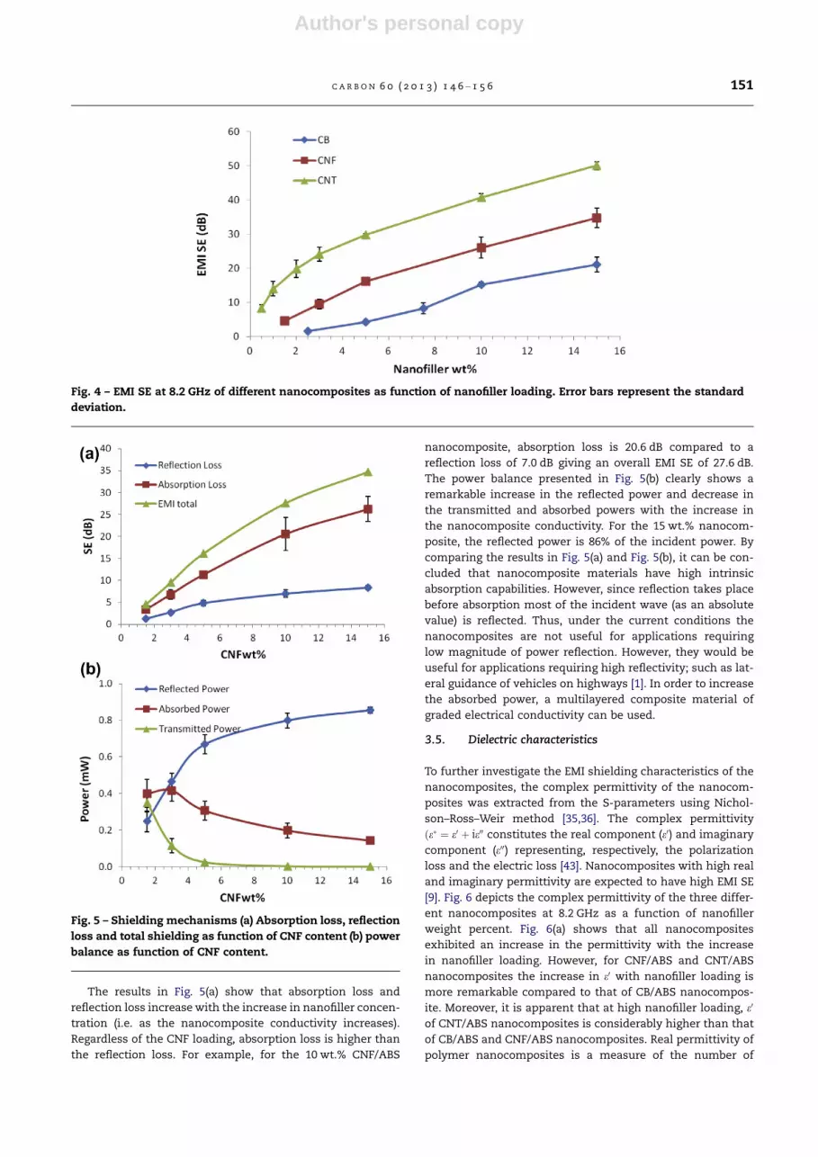
The results in Fig. 5(a) show that absorption loss and
reflection loss increase with the increase in nanofiller concen-
tration (i.e. as the nanocomposite conductivity increases).
Regardless of the CNF loading, absorption loss is higher than
the reflection loss. For example, for the 10 wt.% CNF/ABS
nanocomposite, absorption loss is 20.6 dB compared to a
reflection loss of 7.0 dB giving an overall EMI SE of 27.6 dB.
The power balance presented in Fig. 5(b) clearly shows a
remarkable increase in the reflected power and decrease in
the transmitted and absorbed powers with the increase in
the nanocomposite conductivity. For the 15 wt.% nanocom-
posite, the reflected power is 86% of the incident power. By
comparing the results in Fig. 5(a) and Fig. 5(b), it can be con-
cluded that nanocomposite materials have high intrinsic
absorption capabilities. However, since reflection takes place
before absorption most of the incident wave (as an absolute
value) is reflected. Thus, under the current conditions the
nanocomposites are not useful for applications requiring
low magnitude of power reflection. However, they would be
useful for applications requiring high reflectivity; such as lat-
eral guidance of vehicles on highways [1]. In order to increase
the absorbed power, a multilayered composite material of
graded electrical conductivity can be used.
3.5. Dielectric characteristics
To further investigate the EMI shielding characteristics of the
nanocomposites, the complex permittivity of the nanocom-
posites was extracted from the S-parameters using Nichol-
son–Ross–Weir method [35,36]. The complex permittivity
ðe� ¼ e0 þ ie00 constitutes the real component (e0) and imaginary
component (e00) representing, respectively, the polarization
loss and the electric loss [43]. Nanocomposites with high real
and imaginary permittivity are expected to have high EMI SE
[9]. Fig. 6 depicts the complex permittivity of the three differ-
ent nanocomposites at 8.2 GHz as a function of nanofiller
weight percent. Fig. 6(a) shows that all nanocomposites
exhibited an increase in the permittivity with the increase
in nanofiller loading. However, for CNF/ABS and CNT/ABS
nanocomposites the increase in e0 with nanofiller loading is
more remarkable compared to that of CB/ABS nanocompos-
ite. Moreover, it is apparent that at high nanofiller loading, e0
of CNT/ABS nanocomposites is considerably higher than that
of CB/ABS and CNF/ABS nanocomposites. Real permittivity of
polymer nanocomposites is a measure of the number of
Fig. 4 – EMI SE at 8.2 GHz of different nanocomposites as function of nanofiller loading. Error bars represent the standard
deviation.
Fig. 5 – Shielding mechanisms (a) Absorption loss, reflection
loss and total shielding as function of CNF content (b) power
balance as function of CNF content.
C A R B O N 6 0 ( 2 0 1 3 ) 1 4 6 – 1 5 6 151

Author's personal copy
micro-capacitors and the polarization centers [12,43]. Polari-
zation centers originate from the defects in the nanofiller
structure [43], while the micro-capacitors are simply formed
by nanofiller particles/aggregates acting as electrodes filled
with insulating polymeric material. Thus, the increase in
CNF and CNT loading increases e0 because of the increase in
the number of these micro-capacitors and structural defects.
Moreover, the gap between the nanoparticles decreases as a
result of increasing nanofiller loading, thus increasing the
polarization of the polymeric material filling the gap between
the nanoparticles; and consequently enhancing the absorp-
tion loss. Many studies reported that the real permittivity at
8 GHz of CNT/polymer nanocomposites containing around
15 wt.% CNT is in the range of 60–70 [9,12]. In this work, the
real permittivity of the 15 wt.% CNT/ABS nanocomposite at
8.2 GHz is 590. The high relative permittivity reported in this
work may indicate that the level of nanotubes dispersion in
the ABS matrix is better than that in the aforementioned
studies.
The imaginary permittivity of the nanocomposites is
shown in Fig. 6(b). It is evident that the imaginary permittivity
increases with the increase in nanofiller loading. For 10 wt.%
CNT/ABS nanocomposite, the imaginary permittivity is 323.
This value is higher than that (e00 ¼ 150) reported for CNT/
polystyrene nanocomposite [12]. These difference might be
attributed to the better dispersion of the CNT in the ABS ma-
trix compared to that in the PS matrix and/or to the higher
intrinsic conductivity of the CNT used in this study compared
to CNT used in the other study [12]. In nanocomposites, con-
ductive nanofiller networks act as dissipating mobile charge
carriers. The increase in the number of conductive networks,
as a result of nanofiller addition, leads to higher imaginary
permittivity and consequently higher electromagnetic radia-
tion dissipation by absorption. At any given nanofiller con-
tent, the imaginary permittivity of the nanocomposites has
the following order: CNT/ABS > CNF/ABS > CB/ABS. The ratio
of the imaginary permittivity of CNT based nanocomposite
to that of CNF and CB nanocomposites, at any given nanofiller
loading, decreases with the increase in the nanofiller concen-
tration. For example, at 5 wt.%, the imaginary permittivity
of CNT/ABS nanocomposites was 76 times that of CB/ABS
nanocomposite and 5 times that of CNF/ABS nanocomposite.
Fig. 6 – Real part (a) and imaginary part (b) of complex permittivity of the nanocomposites at 8.2 GHz as a function of
nanofiller content.
152 C A R B O N 6 0 ( 2 0 1 3 ) 1 4 6 – 1 5 6

Author's personal copy
Fig. 7 – AC conductivity of (a) CB/ABS nanocomposite, (b) CNF/ABS nanocomposite and (c) CNT/ABS nanocomposite in the X-
band frequency range.
C A R B O N 6 0 ( 2 0 1 3 ) 1 4 6 – 1 5 6 153

Author's personal copy
However, at 15 wt.%, the imaginary permittivity of CNT/ABS
nanocomposites was 9 and 2 times, respectively, that of CB/
ABS and CNF/ABS nanocomposites.
3.6. AC conductivity vs. DC conductivity
The AC conductivity (rAC)of the nanocomposites can be calcu-
lated based on the imaginary part of permittivity and the fre-
quency as follows:
rAC ðs=mÞ ¼ 2pfeoe00
where, f is the frequency in Hz and eo is the permittivity of free
space (eo = 8.854 · 10�12 F/m). Fig. 7 depicts the AC conductiv-
ity of the nanocomposites as function of frequency and nano-
filler loading. Regardless of the nanofiller type, two major
observations can be drawn from the figure. The first observa-
tion is there is an increase in the AC conductivity with
increasing the nanofiller concentration. The second observa-
tion is AC conductivity almost independence of frequency in
the X-band range. Based on the second observation, we tried,
as shown in Fig. 8, to find a relation between the AC conduc-
tivity at 8.2 GHz range and the DC conductivity measured by
the 4-wire probe method. It is evident that the AC conductiv-
ity is remarkably higher than the DC conductivity for samples
with rDC < 1S=m, i.e. for samples with low nanofiller loading
where hopping of electrons can contribute to the nanocom-
posite conductivity. However, at higher nanofiller concentra-
tion, more conductive networks are built within the
polymer matrix and the AC conductivity approaches the DC
conductivity.
4. Conclusion
The EMI SE, electrical and dielectric properties of CNT/ABS,
CNF/ABS and CB/ABS nanocomposites were studied to reveal
the effect of nanofiller type on the aforementioned properties,
to analyze the EMI shielding mechanisms, and to determine
the relation between DC conductivity at the AC conductivity
in the X-band frequency range. CNT/ABS nanocomposites
exhibited outstanding characteristics compared to those of
CNF/ABS and CB/ABS nanocomposites. For example, at nano-
filler loading of 5 wt.%, the EMI SE of CNT-based nanocompos-
ite was 2 times that of CNF-based nanocomposite and 7 times
that of CB-based nanocomposite. In addition, at CNT content
of only 2 wt.%, the CNT/ABS nanocomposite had an EMI SE of
20 dB. Moreover, the results showed that CNT-based nano-
composite can used in applications requiring high level of
EMI attenuation; for example, a SE of 50 dB was reported for
15 wt.% CNT/ABS nanocomposite. Regardless of the nanofiller
type, absorption loss was higher than reflection loss. How-
ever, because of the remarkable mismatch between the
impedance of wave in free space and the impedance of the
conductive nanocomposites, most of the incident power
was reflected. AC conductivity was found to approach the
DC conductivity at higher nanofiller concentration because
of the increase in number of conduction pathways.
Acknowledgments
The authors thank the Scientific Research Support Fund, Am-
man – Jordan, for the financial support for this research
(Grant Number Bas/2/05/2010). In addition, we would like to
thank the Polymer Processing Group at the University of Cal-
gary for the EMI SE measurements.
R E F E R E N C E S
[1] Chung DDL. Carbon materials for structural self-sensing,electromagnetic shielding and thermal interfacing. Carbon2012;50(9):3342–53.
[2] Dhawan SK, Ohlan A, Singh K. Designing of Nano Compositesof Conducting Polymers for EMI Shielding. In: Reddy B, editor.Advances in Nanocomposites – Synthesis, Characterizationand Industrial Applications [Internet]. InTech; 2011 [cited2012 Jul 24]. Available from: http://www.intechopen.com/books/advances-in-nanocomposites-synthesis-characterization-and-industrial-applications/designing-of-nano-composites-of-conducting-polymers-for-emi-shielding.
Fig. 8 – Relation between DC conductivity and AC conductivity at 8.2 GHz.
154 C A R B O N 6 0 ( 2 0 1 3 ) 1 4 6 – 1 5 6

Author's personal copy
[3] Park SH, Thielemann P, Asbeck P, Bandaru PR. Enhanceddielectric constants and shielding effectiveness of, uniformlydispersed, functionalized carbon nanotube composites. ApplPhys Lett 2009;94(24):243111.
[4] Thomassin J-M, Vuluga D, Alexandre M, Jerome C, MolenbergI, Huynen I, et al. A convenient route for the dispersion ofcarbon nanotubes in polymers: application to the preparationof electromagnetic interference (EMI) absorbers. Polymer2012;53(1):169–74.
[5] Molenberg I, Huynen I, Baudouin A-C, Bailly C, Thomassin J-M, Detrembleur C. Foamed Nanocomposites for EMIShielding Applications. In: Mukherjee M, editor. AdvancedMicrowave and Millimeter Wave TechnologiesSemiconductor Devices Circuits and Systems [Internet].InTech; 2010 [cited 2012 Jul 23]. Available from: http://www.intechopen.com/books/advanced-microwave-and-millimeter-wave-technologies-semiconductor-devices-circuits-and-systems/foamed-nanocomposites-for-emi-shielding-applications.
[6] Micheli D, Pastore R, Apollo C, Marchetti M, Gradoni G, MoglieF, et al. Carbon based nanomaterial composites in RAM andmicrowave shielding applications. 9th IEEE Conference onNanotechnology, 2009. IEEE-NANO; 2009. p. 226–235.
[7] Yuan B, Yu L, Sheng L, An K, Zhao X. Comparison ofelectromagnetic interference shielding properties betweensingle-wall carbon nanotube and graphene sheet/polyanilinecomposites. J Phys D Appl Phys 2012;45(23):235108.
[8] Liu Z, Bai G, Huang Y, Ma Y, Du F, Li F, et al. Reflection andabsorption contributions to the electromagnetic interferenceshielding of single-walled carbon nanotube/polyurethanecomposites. Carbon 2007;45(4):821–7.
[9] Huang Y, Li N, Ma Y, Du F, Li F, He X, et al. The influence ofsingle-walled carbon nanotube structure on theelectromagnetic interference shielding efficiency of its epoxycomposites. Carbon 2007;45(8):1614–21.
[10] Xu H, Anlage SM, Hu L, Gruner G. Microwave shielding oftransparent and conducting single-walled carbon nanotubefilms. Appl Phys Lett 2007;90(18):183119.
[11] Al-Saleh MH, Sundararaj U. Electromagnetic interferenceshielding mechanisms of CNT/polymer composites. Carbon2009;47(7):1738–46.
[12] Arjmand M, Apperley T, Okoniewski M, Sundararaj U.Comparative study of electromagnetic interference shieldingproperties of injection molded versus compression moldedmulti-walled carbon nanotube/polystyrene composites.Carbon 2012;50(14):5126–34.
[13] Basuli U, Chattopadhyay S, Nah C, Chaki TK. Electricalproperties and electromagnetic interference shieldingeffectiveness of multiwalled carbon nanotubes-reinforcedEMA nanocomposites. Polym Compos 2012;33(6):897–903.
[14] Gupta A, Choudhary V. Electrical conductivity and shieldingeffectiveness of poly(trimethylene terephthalate)/multiwalled carbon nanotube composites. J Mater Sci2011;46(19):6416–23.
[15] Jin X, Ni Q-Q, Natsuki T. Composites of multi-walled carbonnanotubes and shape memory polyurethane forelectromagnetic interference shielding. J Compos Mater2011;45(24):2547–54.
[16] Jou W-S, Cheng H-Z, Hsu C-F. The electromagnetic shieldingeffectiveness of carbon nanotubes polymer composites. JAlloys Compd 2007;434–435:641–5.
[17] Kim HM, Kim K, Lee CY, Joo J, Cho SJ, Yoon HS, et al. Electricalconductivity and electromagnetic interference shielding ofmultiwalled carbon nanotube composites containing Fecatalyst. Appl Phys Lett 2004;84(4):589–91.
[18] Kuan C-F, Lin K-C, Chiang C-L, Chen C-H, Peng H-C, Kuan H-C. Effect of modification method and processing condition onthe properties of multiwall carbon nanotube/acrylonitrile-
butadiene-styrene nanocomposite. Adv Sci Lett2013;19(2):559–61.
[19] Al-Saleh MH, Sundararaj U. A review of vapor grown carbonnanofiber/polymer conductive composites. Carbon2009;47(1):2–22.
[20] Al-Saleh MH, Sundararaj U. Processing-microstructure–property relationship in conductive polymernanocomposites. Polymer 2010;51(12):2740–7.
[21] Al-Saleh MH, Sundararaj U. Electrically conductive carbonnanofiber/polyethylene composite: effect of melt mixingconditions. Polym Adv Technol 2011;22(2):246–53.
[22] Al-Saleh MH, Sundararaj U. Morphological, electrical andelectromagnetic interference shielding characterization ofvapor grown carbon nanofiber/polystyrene nanocomposites.Polym Inter 2013;62(4):601–7.
[23] Gelves GA, Al-Saleh MH, Sundararaj U. Highly electricallyconductive and high performance EMI shielding nanowire/polymer nanocomposites by miscible mixing andprecipitation. J Mater Chem 2011;21(3):829–36.
[24] Al-Saleh MH, Gelves GA, Sundararaj U. Copper nanowire/polystyrene nanocomposites: lower percolation thresholdand higher EMI shielding. Compos Part A Appl Sci Manuf2011;42(1):92–7.
[25] Huang J-C. Carbon black filled conducting polymers andpolymer blends. Adv Polym Technol 2002;21(4):299–313.
[26] Tibbetts GG, Lake ML, Strong KL, Rice BP. A review of thefabrication and properties of vapor-grown carbon nanofiber/polymer composites. Compos Sci Technol 2007;67(7–8):1709–18.
[27] Mordkovich VZ. Carbon nanofibers: a new ultrahigh-strengthmaterial for chemical technology. Theor Found Chem Eng2003;37(5):429–38.
[28] Endo M, Kim Y, Hayashi T, Nishimura K, Matusita T,Miyashita K, et al. Vapor-grown carbon fibers (VGCFs): basicproperties and their battery applications. Carbon2001;39(9):1287–97.
[29] Yah CS, Iyuke SE, Simate GS, Unuabonah EI, Bathgate G,Matthews G, et al. Continuous synthesis of multiwalledcarbon nanotubes from xylene using the swirled floatingcatalyst chemical vapor deposition technique. J Mater Res2011;26(05):640–4.
[30] Iqbal J, Rafique MMA. Production of carbon nanotubes bydifferent routes – a review. J Encapsulation Adsorpt Sci2011;1(2):29–34.
[31] Pillai SK, Ray SS. Epoxy-based carbon nanotubes reinforcedcomposites. Advances in Nanocomposites – Synthesis,Characterization and Industrial Applications [Internet].InTech; 2011 [cited 2012 Oct 17]. Available from: http://researchspace.csir.co.za/dspace/handle/10204/5538.
[32] Ma P-C, Siddiqui NA, Marom G, Kim J-K. Dispersion andfunctionalization of carbon nanotubes for polymer-basednanocomposites: a review. Compos Part A Appl Sci Manuf2010;41(10):1345–67.
[33] Castillo FY, Socher R, Krause B, Headrick R, Grady BP, Prada-Silvy R, et al. Electrical, mechanical, and glass transitionbehavior of polycarbonate-based nanocomposites withdifferent multi-walled carbon nanotubes. Polymer2011;52(17):3835–45.
[34] Wang G, Sun G, Zhou Z, Liu J, Wang Q, Wang S, et al.Performance improvement in direct methanol fuel cellcathode using high mesoporous area catalyst support.Electrochem Solid-State Lett 2005;8(1):A12–6.
[35] Weir WB. Automatic measurement of complex dielectricconstant and permeability at microwave frequencies. ProcIEEE 1974;62(1):33–6.
[36] Nicolson AM, Ross GF. Measurement of the intrinsicproperties of materials by time-domain techniques. IEEETrans Instrum Meas 1970;19(4):377–82.
C A R B O N 6 0 ( 2 0 1 3 ) 1 4 6 – 1 5 6 155

Author's personal copy
[37] Krause B, Boldt R, Potschke P. A method for determination oflength distributions of multiwalled carbon nanotubes beforeand after melt processing. Carbon 2011;49(4):1243–7.
[38] Gupta A, Choudhary V. Electromagnetic interferenceshielding behavior of poly(trimethylene terephthalate)/multi-walled carbon nanotube composites. Compos SciTechnol 2011;71(13):1563–8.
[39] Kaiser KL. Electromagnetic shielding. CRC Press; 2005.[40] Ott HW. Noise reduction techniques in electronic systems.
2nd ed. Wiley-Interscience; 1988.[41] Al-Saleh MH, Sundararaj U. X-band EMI shielding
mechanisms and shielding effectiveness of high structure
carbon black/polypropylene composites. J Phys D Appl Phys2013;46(3):035304.
[42] Kim Y-Y, Yun J, Kim H-I, Lee Y-S. Effect of oxyfluorination onelectromagnetic interference shielding of polypyrrole-coatedmulti-walled carbon nanotubes. J Ind Eng Chem2012;18(1):392–8.
[43] Watts PCP, Hsu W-K, Barnes A, Chambers B. High permittivityfrom defective multiwalled carbon nanotubes in the X-band.Adv Mater 2003;15(7–8):600–3.
156 C A R B O N 6 0 ( 2 0 1 3 ) 1 4 6 – 1 5 6


