Embed Size (px)
Citation preview

I I I I I I I I I I I I I I I I I I I
High QualitY Im~ge Compression for Rockets and Satellites
Richard W. Harris, Utah State University, EE/SDL Scott E. Budge, Utah State Univeristy, EE/SDL Paul D. Israelson, Utah State University, EE/SDL William Roark, Nichols Research Corporation, SOL Jan J. Sojka, Utah State University, Physics
Installed communication systems for the more recent imagery rockets and satellites generally do not have sufficient data link bandwidth to allow imagery transmission. High quality image compression can alleviate this problem since 5 to 10 times more image data can be transmitted over existing communication systems.
Researchers at Utah State University haye developed a high quality image compression algorithm which has been denoted as ·Statistically Lossless". This algorithm combines the good features of the well known vector quantization (Va) compression and lossless compression. Results are presented in this paper in which different scientific imagery collection systems have been processed using the algorithm. In order to implement this algorithm, a CMOS VLSI chip has been produced which allows a va compression system to process 512 x 512 pixel images at a rate of 30 frames per second.
1. OVERVIEW
Data generated by present day space bourne instrumentation has long outstripped the associated onboard telemetry bandwidth. Compromises are made to reduce the data flow on all spacecrafts. The outcome of which is arguably of scientifically as great a consequence as the compromises made over the distribution of the limited electrical power on these spacecrafts.
For future missions this situation of inadequate telemetry will not be changed. The scientific, or for that matter any user, community must find alternative means of maximizing the useful data recovery rate. Already techniques to logarithmically compress data, or use periods of "high bit rate" telemetry are common means of improving the data recovery. Another obvious thought is to carry out on board scientific analysis and use the limited telemetry bandwidth to return only reduced scientific data. This presupposes that the scientist knows in advance what the data will look like so that reduction algorithms can be developed. The problem of flying a computer to analyze the data is also none trivial, power consumption becomes prohibitive and space qualified hardware is not readily available.
This report focuses on an alternative procedure for minimizing the above quandary. If an instrument generates x times more data than the instruments telemetry allocation, the problem can be viewed as finding the most efficient information conserving technique to compress this data by a factor of x. Ideally a lossless technique is wanted that will provide sufficient compression with no data loss. For typical 'exploration' type of scientific data it can be shown that the entropy associated with the information is in the range of only 1 to 3 and consequently lossless compression techniques can only give compression factors of x ranging from 1 to 3. Lossy techniques can however be used to achieve factors significantly better. One such technique is vector quantization (Va) compression. This is the specific topic of the remainder of this paper. The va technique is not new, it has been applied in other fields and was extensively discussed at a recent NASA sponsored Scientific Data Compression Workshop [1]. The technique has also been applied to global satellite images of the auroral zone obtained by Dr. L. A. Frank's Dynamics Explorer Imager [2], and to SOl projects with infra-red sensor arrays.

2. POWER CONSIDERATIONS
It is well known that the bit rate transmitted from a satellite or rocket is linearly related to the available power. Thus:
Pr = K R
where P r = power required, K = constant, R = bit rate in bits/sec.
(1 )
If we assume compression is possible and that this compression will provide adequate quality for the user then
Pre = Er = K R C C
where Pre = power required with compression and
C = bits in bits out
Thus the power available for the compression system is
P = P (1-1 ) a r -C
(2)
(3)
A Typical compression system requires 5 to 10 watts, and Pr may be 100 watts. Supose for example that P r = 100 watts and C = 5, then P a = 80 watts. If only 5 watts is needed for the compression system we have gained 75 watts. This extra power can be used for other tasks or we can reduce the required power.
The required power for a certain bit rate will vary widely depending upon the type of satellite or rocket needed for the mission under consideration. However, in the situations studied thusfar, it is hardly ever the case that the power required to perform compression uses up the excess power compression makes available. Thus in many cases, compression provides a net power savings and should be considered by the system designer.
3. va COMPRESSION
3.1 va General Description
I I I I I I I I I I I I I I I
Vector Quantization (Va) is simply an extension of scalar analog to digital conversion. In scalar analog to digital conversion, an analog sample is assigned a predetermined binary code corresponding I to one of a number of levels which is closest to the analog sample level. In va, a finite group of samples called a vector is compared to a number of predetermined groups of samples, vectors, to find the closest matching group of samples. As in scalar quantization, a finite number of vectors is used I in the compression and is called a codebook. Compression comes about because we send the binary code or address corresponding to a vector rather than the individual data values in the vector.
VQ has a very sound theoretical basis. In fact, Shannon has proved that quantizing groups I of samples will always out perform scalar quantization with respect to distortion or sample rate. This is true even though the samples being quantized are samples of random noise. Over 130 technical
I

I I I I I I I I I I I I I I I I I I I
papers, mostly by electrical engineers, have been published on this technique since the early 1980's. va is well established and in use for speech compression systems and is becoming established in video compression systems. Gray [31 at Stanford was one of the first to revive va from the mathematical literature, Baker [4] at Stanford used this technique to develop an algorithm for imagery denoted as Mean Residual Vector Ouantization (MRVO). Budge (5] at BYU, now at Utah State University, was one of the first researchers to use MRVO on color images.
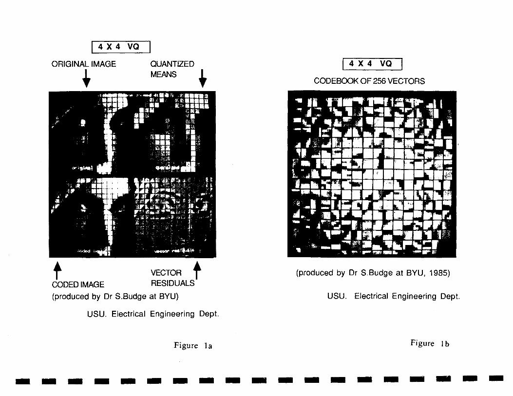
The MRVO algorithm is well illustrated by viewing Figures 1 a and 1 b. Figure 1 a shows four pictures. The upper left hand picture shows a magnified picture of a woman's face which has been divided into 4 by 4 vectors, Le., 16 pixels per vector. The dark grid on the picture shows the vector divisions. If we digitized this picture using standard scalar video AID techniques with 8 bits/pixel, each vector requires 128 bits. This standard digitization provides many more combinations of binary patterns than are needed. For example, the 2128 binary patterns in one vector would take a human viewer at standard TV rates, 1015 times the age of the universe to view the number of patterns possible. It is obvious that in many applications this overdetermined digitization is not required. How can we intelligently reduce this set of patterns?
Following MRVO suggested by Baker [3], we first find the mean of each vector. The image of vector means is shown in the upper right hand corner of Figure 1 a. Next we subtract the vector mean from each pixel which leaves the residual image in the lower right hand corner of Figure 1 a. (The residual image has had a constant value added so we can view it as an image.) Now the process of vector quantization takes place by choosing, according to a distortion criterion, the address of the codebook vector in Figure 1 b which most closely matches each image vector residual. For each residual vector an address will be chosen. In the example shown, the black and white image vectors have 128 bits while the vector mean requires 8 bits and the vector address of the 256 element codebook requires 8 bits. Thus, the compression is 128/16 or 8 to 1.
The encoding procp,ss at the transmitter consists of finding the vector means, creating anrl quantizing the residual vectors. As shown in Figure 2, the transmitter sends the mean value and an address for each vector. At the receiver the decoding process is accomplished by simply looking up the code book entry using the vector address and adding the mean value to reproduce the estimate of the image. The picture in the lower left hand corner of Figure 1 a shows the result for the example. It is not exactly like the original since there is added quantization error. These errors may be reduced by increasing the code book size and reducing the compression.
The codebook is generated off-line by using a training set of images. A popular algorithm is the LBG [6] codebook generation method. This algorithm is related to pattern classification techniques. We are essentially choosing a subset of the 2128 patterns which will represent the individual vectors. it is important to realize the MAVO algorithm sends the vector mean which is a subsample or lower resolution image of the actual data upon which we add the closest match codebook patterns. The subset in our example has 28 mean patterns and 2~ vector patterns or total of 216 = 65,536 patterns. Thus, the overdetermined data patterns have been reduced from 2128 to 216.
An example of the above process applied to color images is shown in Figure 3. The training set used to generate the color codebook had a wide variation in intensity, shapes, and colors, but did not include the image shown in this figure. Figure 3 shows 3 images, the original of PEG (top left), and PEG compressed by a factor of 12 to 1, lower left hand corner, and 48 to 1, lower right hand corner. Typically, the 12 to 1 compressed imager is visually not distinguishable from the original while the 48 to 1 image is useable for some applications but has noticeable degradation. This degradation is seen as a coarseness, at the vector boundaries, appearing in the image. The quantization errors are contained locally in their corresponding vectors.
3.2 Statistically Lossless va Compresslo!"
The MRVO process is a powerful, sound method for compressing visual imagery. Scientific imagery typically requires more accuracy depending upon the application. A method developed and tested on several types of satellite imagery at USU reduces the error from MRVO process by a factor of 3 and does not significantly degrade the image statistics from a scientific point of view. The error

is reduced by computing the residual error from MRVa process and then using a loss less algorithm to encode all errors above a certain threshold. To obtain a constant data rate, a buffer with feedback to the threshold is used. This allows a constant data rate at the output of tile buffer. Using two different scientific imagery data sets USU has been able to achieve a 5 to 1 compression ratio while maintaining very high quality data.
Results from one of these tests using satellite data is as follows. The images were digitized originally with 8 bits per sample. The nns error computed on 5 rows of pixels after compression was only .71 counts. If it is assumed that the input data was uniformly distributed in the AID range, the input nns error is .29 counts. Assuming these errors are independent, the overall rms count error including the AID input count error is only. 77 counts. Error statistics on 5 rows of pixels which are representative of the whole image showed the following results:
Counts in Error Percent of Data out of 256 Counts with this error
0 46 1 42 2 11 3 1
above 3 0
Thus, 46% of the data had zero error, 42% had 1 count error, 11% had 2 counts error, and 1% had 3 counts. There were no errors above 3 counts by design. These error statistics show that the errors introduced by compression are very small, and 46% of the data was error free.
Results reduced from the auroral images (discsssed later) before and after compression were scientifically equivalent. This algorithm has been designed to preserve the statistics of the data as closely as possible. Thus. USU has coined the name 'Statistically Lossless' for this proprietary algorithm.
3.3 Present Day Implementation
USU has developed a va encoding chip which can be used in a variety of key va implementations, denoted as the va full search. va multistage, and va tree search algorithms [7]. Fourteen of these chips are capable of encoding RS-170 color TV at 30 frames per second with an image size of 512 pixels by 512 pixels. The CMOS chip burns about .5 watts at 10 MHz clock rate and can process pixels at a rate of 100 ns per pixel. If the frame rate decreases, fewer chips are required.
. USU has also developed the capability of digitizing RS-170 format black and white or color TV and passing the digitized samples over a 240 Mbps High Speed Bus (HSB) to an image proceSSing subsystem and then to a digital to analog converter [8.9]. The HSB is an uncommon feature not available in industry except from a special purpose video system. For example, frame grabber boards available from many manufacturers do not have this feature that is essential in any real-time digital video communication system.
3.4 Future Potential
I I I I I I I I I I I I I I I I
Although 5 to 1 compression in the Statistically Lossless algorithm has been tested and can be I implemented, experiments show that 10 to 1 is also feasible but will require development of more sophisticated VLSI chips for many real-time applications. For commercial applications USU has demonstrated that high quality RS-170 color TV can be compressed by a factor of 120 to 1 with some I slight degradation in quality. A video tape is available demonstrating this compression at IComp. Inc.
I

I I I I I I I I I I I I I I I I I I I
in Logan, Utah. As more sophisticated VLSI chips are developed, it is entirely feasible that by combining single frame and frame to frame compression commercial color TV can eventually be compressed by 500 to 1 and still be useable for many applications.
4. COMPRESSED AURORAL IMAGES
A particular subset of the above mentioned va techniques were applied in a 'black box' sense to the compression of auroral images. These images, at different wavelengths, were observed by the SAl instrument on the NASA Dynamics Explorer 1 (DE-1) satellite. The images were made available to us courtesy of Professor L.A. Frank from the University of Iowa (Professor Frank is the Principal Investigator for the SAl instrument). The 'black box' va compression scheme was set to give a data compression factor of five. The data from the imager was compressed by the 'black box' after it has been logarithmically manipulated by the imager electronics. This corresponds to the data stream sellt to the satellite telemetry system. No attempt was made to fine tune the 'black box' or improve on the compression ratio in this study [2].
A va process using 4 x 4 vectors was used to compress the DE-1 SAl auroral images. Each image conSisting of 120 x 150 pixels was padded our to a 160 x 160 pixel image for the va processing. Both the raw pixels and the codebook have an 8 bit resolution. The code book for this study was developed from a set of 12 images from day 326, 1981. A codebook of only 256 vectors was used. These were obtained from a statistical analysis of the day 326 images. Other techniques for generating the codebook are being considered, i.e., real clustering analysis and even a synthetic technique. The laHer would enable rapid generation of the codebook. With this codebook, images from day 329, 1981 were compressed. Compression ratioS of 4.8, 5.6, and 4.7 were obtained respectively for the 557 nm, 630 nm, and VUV images. The overall average compression was 5.02, which ws the target figure for this initial study. Each of the day 329 images were subsequently reconstructed using the codebook. On comparing these images with the original images, a mean absolute difference of 0.46 counts per pixel was obtained.
Figure 4a shows two pairs of original images and their reconstructed counterparts as well as the pixel differences (right panels). Each of these images is from the DE-VUV imager and shows the illuminated dayside earth and a well defined auroral oval. After the factor of 5 compreSSion and reconstruction (middle panels) the images look almost identical. In fact, more than 50% of the pixels are identical. This is further demonstrated in the pixel difference plots on the right side where the difference between a pixel before and after compreSSion is color coded with a yellow being no difference. Figure 4b repeats this comparison for images taken at 557 nm. The same conclusion holds, now a slightly greater difference can be seen between the original and compressed images on close inspection. These compressed images were then scientifically analyzed by Sojka et al [2]. They found that within statistical limits already associated with the data the two sets of images (i.e. original and compressed) gave the same results.
5. COMPRESSED INFRA RED IMAGES
The statistically Lossless algorithm has been extensively tested on simulated Infra-Red space images. These images were simulated by using a white Gaussian noise background with a slightly varying DC offset. The DC offset was used to simulate imperfections in adjusting the DC to zero in a DC coupled focal plane array system. The desired results in this system were to have ·pulse like" or "target" signals be processed through the system with virtually no error, and the background noise preserved with as small an error as possible.
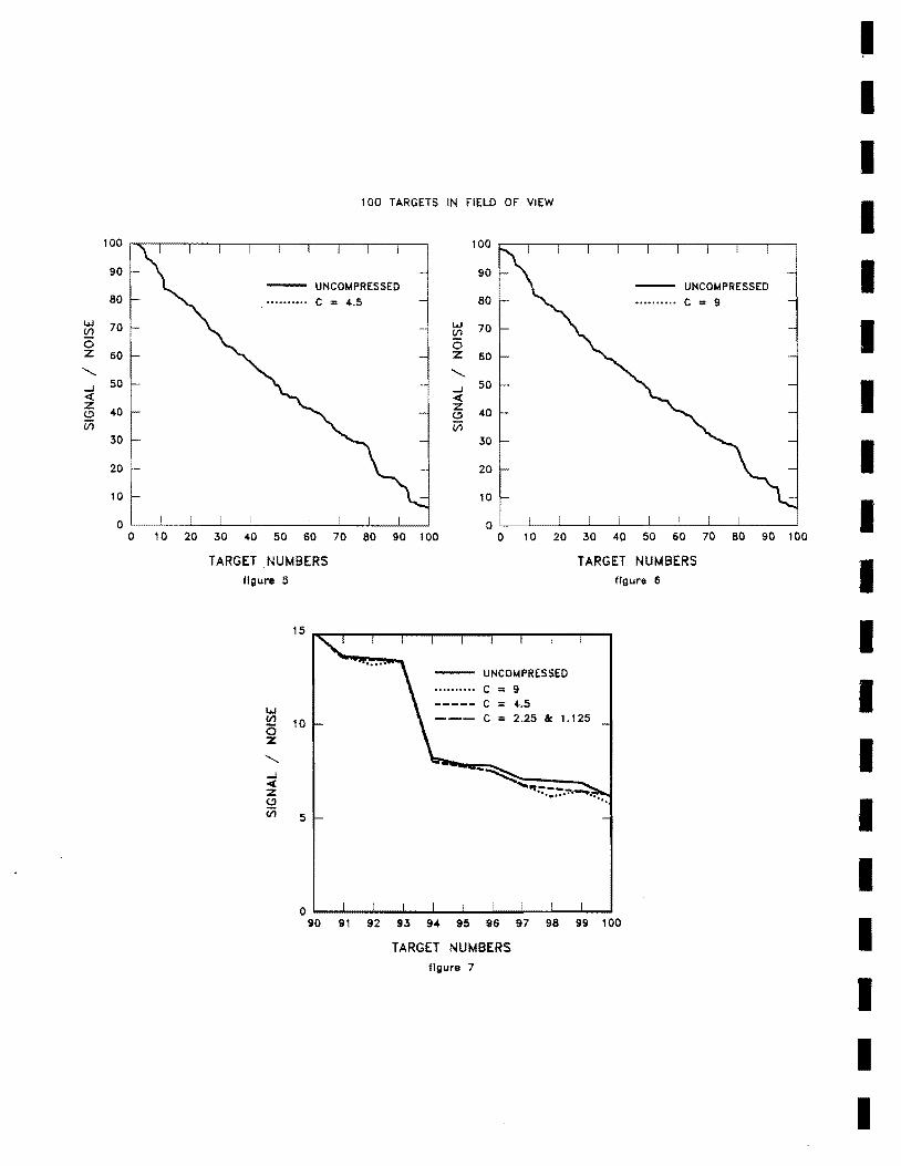
The images were made up of 12 bit samples that were grouped into 4 by 4 vectors of 16 samples. The images were processed by the Statistically Lossless compressioll and decompression system and then compared to the raw data without compression. Four different compression ratios were tested on an image with 100 targets in the field of view (FOV). The peak to rms signal to noise ratio (SIN) of the targets was chosen randomly for the 100 targets and varied over a range of 100 to 1 to 5 to 1.
Figures 5, 6 and 7 show the results. Figure 5 presents results of the SIN versus target number for a 9 to 1 compression ratio. Figure 2 shows this same d<lta for 4.5 to 1 compression ratio. The 9 to 1 and 4.5 to 1 compressed data compare very favorably with the uncompressed data over the entire SIN range. Figure 3 shows the data for low SIN ratios with compression ratios of 9 to 1, 4.5 to 1, 2.25 to 1 and 1.125 to 1. At the lowest SIN's there is some small degradation of the compressed data for 9 to 1 and 4.5 to 1 compression ratios. However for 2.25 to 1 and 1.125 to the compressed data quality is virtually equal to the uncompressed data quality. As a result of these tests and more extensive tests with regard to post processing. the statistically lossless algorithm is scheduled to be used on the Air Force EDX SOl rocket program.
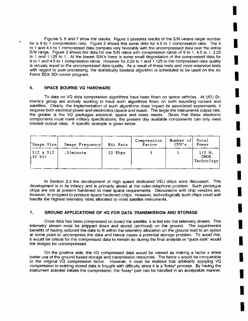
6. SPACE BOURNE va HARDWARE
To date no va data compression algorithms have been flown on space vehicles. At USU Dr. HArris's group are actively working to have such algorithms flown on both sounding rockets and satellites. Clearly, the implementation of such algorithms does impact its associated experiments. it requires both electrical power and electronics (space and mass). The larger the instruments output rate, the greater is the va packages electrical, space and mass needs. Given that these electronic components must meet military specifications, the present day available components can only meet modest output rates. A specific example is given below.
Compression Number of Total Image Size Image Frequency Bit Rate Factor CPU's Power
512 x 512 .5/minute 22 Kbps 3 1 1/2 W. 10 bit CMOS
Technology
In Section 2.3 the development of high speed dedicated VSL! ships were discussed. This development is in its infancy and is primarily aimed at the video-telephone problem. Such prototype chips are not at present hardened to meet space requirements. Discussions with chip vendors are, however, in progress to produce space hardened chips. However, technologically such chips could well handle the highest telemetry rates allocated to most satellite instruments.
7. GROUND APPLICATIONS OF va FOR DATA TRANSMISSION AND STORAGE
Once data has been compressed on board the satellite, it is fed into the telemetry stream. This telemetry stream must be stripped down and stored (archived) on the ground. The experiment<ll benefits of having reduced the data to fit within the telemetry allocation on the ground lead to an option at some pOint to uncompress the data and hence cause a potential storage problem. To avoid this, it would be critical for the compressed data to remain so during the final analysis or "quick-look" would the images be uncompressed.
On the positive side, the va compressed data would be viewed as making a factor x times better use of the ground based storage and transmission resources. The factor x would be comparable to the original va compression factor. However, it must be realized that arbitrarily applying va compression to existing stored data is frought with difficulty since it is a "lossy· process. By having the instrument scientist initiate the compression, the ·Iossy· part can be handled in an acceptable manner.
I I I I I I I I I I I I I I I I I I I

I I I I I I I I I I I I I I I I I I I
8. SUMMARY
With the demand for more sophisticated, higher resolution space instrumentation the satellite telemetry requirements continue to increase. NASA and the DOD (for the most part) are not planning or able to increase their telemetry handling capability at this growth rate. Innovative alternative solutions are needed to maximize the scientific return from such instruments. Alternatives are to use a ·Iossy· or ·statistica"y lossless" compression algorithms described in this report. In using these techniques the scientists attempt to associate the lossy part of the technique with aspects of their data that can be sacrificed. Typically this would be the noise or statistically insignificant component. Based upon VQ testing on images compression factors of 3 to 12 are readily achieved and have good reproduction characteristics.
1.
2.
3.
4.
5.
6.
7.
9.
REFERENCES
Gray, Robert M., ·Vector Quantization," Proceedings of the Scientific Data Compression Workshop, NASA Conference Publication 3025, May 1988.
Sojka, J.J., M. Bowline, P. Israelson, and A. W. Harris, "Dynamics Explorer Auroral Image Pixel Compression,· CASS Report 88-5-2.
Gray, Robert M., "Vector Quantization: IEEE ASSP Magazine, April 1984.
Baker, Richard L., ·Vector Quantization of Digital Images: Ph.D. Dissertation, Stanford University, June 1984.
Budge, Scott E., ·Vector Quantization of Color Digital Images Using Product Codes," MS Thesis, Brigham Young University, August 1985.
Linde, Y., A. Buzo, and R. M. Gray, "An Algorithm for Vector Quantizer Design," IEEE Trans. on Comm., Vol. Com-28, No.1, January 1980.
Makhoul, J .. S. Rouscous, S. and H. Gish, 'Vector Quantization in Speech Coding," Proceedings of the IEEE, Vol. 73, No. 11, November 1985.
Taylor, A.D., P. A. Wheeler and R. W. Harris, ·Color Imager Digitization for Real-Time Video Processing,· IEEE Region 6 Conference Proceedings (CH 2567-6/88/0000-0089), April 1988.
Briscoe, T. D., R. W. Harris and P. A. Wheeler, "A High Speed Para"el Computer Board for Color Image Processing, Compression, and Transmission," IEEE Region 6 Conference Proceedings, (CH 2567-6/88/0000-0099), April 1988.
4 X 4 va ORIGINAL IMAGE
t
t CODED IMAGE
QUANTIZED
MEANS t
VECTOR t RESIDUALS
(produced by Dr S.Budge at BYU)
USU. Electrical Engineering Dept.
Figure la
I 4 X 4 va CODEBOOK OF 256 VECTORS
(produced by Dr S.Budge at BYU, 1985)
USU. Electrical Engineering Dept.
Figure 1 b
-------------------

-------------------Image +0-. Vector Vector Address
Quantize ".
-~
Find 1-+ Vector :---
Means Vector Mean
(a) MRVQ Encoder/Transmitter
Vector Address - Code Book
<} Memory Image
Vector Mean
(b) MRVQ Decoder/Receiver
Figure 2. MRVQ Encoder/Transmitter and Decoder/Receiver

• ORIGINAL IMAGE
VQ COMPRESSED IMAGE,
WITH RATIOS OF:
12:1 48:1 (3 X 3 VECTORS) (6 X 6 VECTORS)
/ I
(from Dr S.Budge MS thesis,BYU, 1985)
USU. Electrical Engineering Dept.
Figure 3
I I I I I I I I I I I I I I I I I I I

I I I I I I I I I I I I I I I I I I I
DE-1 UV Image. 1981 day 329 ORIGINAL COMPRESSED 5:1 PIXEL DIFFERENCE
ORIGINAL COMPRESSED 5:1 PIXEL DIFFERENCE
(DE Images from Prof.l.A.Frank, Univ. of Iowa)
USU. Electrical Engineering Dept.
Figure 4a
DE-1 557nm Image, 1981 day 329
ORIGINAL 'COMPRESSED 5:1 PIXEL DIFFERENCE
ORIGINAL COMPRESSED 5:1 PIXEL DIFFERENCE
(DE Images from Prof.L.A.Frank, Univ. of Iowa)
USU. Electrical Engineering Dept.
Figure 4b
100
90
80
l.\..I 70 !!! 0 Z 60
"-...J 50 4: Z
40 (,!)
Vi 30
20 >-
10
0 0
100 TARGETS IN F"lElD OF VIEW
UNCOMPRESSED C = 4.5
l.\..I (f)
i5 z "-...J 4: Z (,!)
Vi
100
90
80
70
60
50
40
30
20
10
0
UNCOMPRESSED C = 9
10 20 30 40 50 60 70 80 90 100 0 10 20 30 40 50 60 70 80 90 100
TARGET. NUMBERS figure 5
TARGET NUMBERS fIgure 6
15 ~"""'-""T'"-"""-~"""'-""T'"-"""-~"""'-'"
UNCOMPRESSED C = 9 C = 4.5
l.\..I 1.125 (f)
10 C = 2.25 &:. i5 z
"-...J .. ~ 4: '.,.---Z ...•... -:-.-..... (,!)
Vi 5
o ~~-~-~~-~-------~--~~ 90 91 92 93 94 95 96 97 98 99 100
TARGET NUMBERS figure 7
I I I I I I I I I I I I I I I I I I I


