Embed Size (px)
Citation preview
Antennas for Modern Small Satellites
s. Gao1, K. M. U n w i n 2
, J. Z a c k r i s s o n 3, W. A. S h i r o m a 4
, J. M. A k a g f , K. M a y n a r c f ,P. Garner2, L. B o c c i a 5
, G. A m e n d o / a 5, G. Massa5
, C. U n d e r w o o d 1, M. B r e n c h l e y ,
M. Pointer2, a n d M. N. S w e e t i n g 1
1Surrey Space CentreUniversity of Surrey, Guildford, UK
Tel: +44 14683 682226; E-mail: [email protected]
2Surrey Satellite Technology Ltd.Gulldford, UK
3RUAG Aerospace SwedenSweden
"Universlty of Hawaii at ManoaHawaii, USA
5University of CalabriaCalabria, Italy
Abstract
Modem small satellites (MSS) are revolutionizing the space industry. They can drastically reduce the mission cost, and canmake access to space more affordable. The relationship between a modern small satellite and a "conventional" large satelliteis similar to that between a modern compact laptop and a "conventional" work-station computer. This paper gives an overviewof antenna technologies for applications in modem small satellites. First, an introduction to modern small satellites and theirstructures is presented. This is followed by a description of technical challenges in the antenna designs for modern smallsatellites, and the interactions between the antenna and modern small satellites. Specific antennas developed for modernsmall-satellite applications are then explained and discussed. The future development and a conclusion are presented.
Keywords: Antennas; satellite antennas; small satellites; micro satellite; cube-sat; GPS antennas; nano-sat
1. Introduction
T he general trend for conventional satellites is larger, heavier,
higher power, higher data rate, and multi-functional payloads
that are capable of offering better RF performance in terms of
EIRP, G/T, and spatial and polarization isolations. However, this
makes the satellites very expensive and time-consuming to
develop. Modem small satellites are typically one-tenth to one-one
hundredth of the mass and cost of their "big brothers." The devel
opment of modem small satellites is mainly driven by two sets rea
sons: the first consists of the financial and political needs to reduce
the cost; the other set is comprised of the technological advances in
low-power micro-electronics and digital signal processing (DSP)
[1-3]. Very-large-scale integration (VLSI) makes it possible to
build sophisticated circuits into small volumes, with low mass and
low power consumption. Modem technologies make it possible for
a constellation of modem small satellites to realize many sophisti
cated functions. The development of modem small satellites thus
leads to a significant reduction of cost for satellite industries.Another advantage of using modem small satellites is the short
time scale: conventional satellites may take over five years from
the proposal to final launch, while modem small satellites can be
developed within one year. For example, UoSAT-2, developed by
the University of Surrey in 1984, took only six months [1-3].
The term "modem small satellite" denotes several types of
satellites, including mini, micro, nano, pico, and femto-satellites.
Table 1 shows the classification of each satellite, and the corre
sponding mass and cost [2, 3]. As shown, significant savings in
mass, cost, and development time can be achieved by using mod
em small satellites compared to conventional large satellites.
The University of Surrey has been developing modem small
satellite technology since starting its UoSAT program in 1978.
UoSAT-l, developed by Surrey, was launched in 1981 [1-3]. Thiswas followed by UoSAT-2 in 1984. UoSAT-l continued to operate
for eight years, while UoSAT-2 was still operational after 18 years
in orbit. During the past 30 years, the University of Surrey's spin
off company, Surrey Satellite Technology Ltd. (SSTL), together
with Surrey Space Centre (SSC), have successfully designed,
developed and launched 32 modem small satellites for various
40 ISSN 1045-9243120091$25 ©2009IEEE IEEE Antennas and Propagation Magazine, Vol. 51, No.4, August 2009
Authorized licensed use limited to: IEEE Xplore. Downloaded on May 13,2010 at 11:47:37 UTC from IEEE Xplore. Restrictions apply.
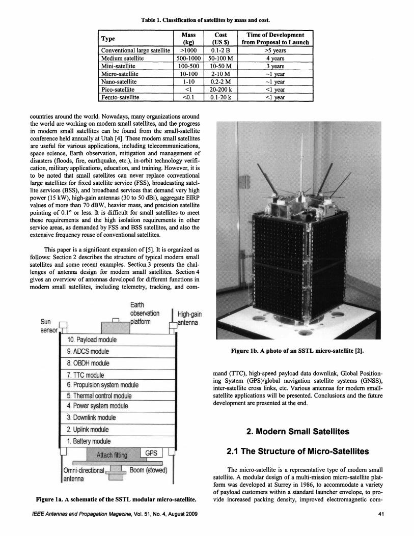
Table 1. Classification of satellites by mass and cost.
TypeMass Cost Time of Development
(kId (US $) from Proposal to Launch
Conventional large satellite >1000 0.1-2 B >5 years
Medium satellite 500-1000 50-100 M 4 years
Mini-satellite 100-500 10-50 M 3 years
Micro-satellite 10-100 2-lOM year
Nano-satellite 1-10 0.2-2M year
Pico-satellite <1 20-200 k <1 year
Femto-satellite <0.1 0.1-20 k <1 year
Figure 1a. A schematic ofthe SSTL modular micro-satellite.
This paper is a significant expansion 0[[5] . It is organized as
follows: Section 2 describes the structure of typical modem small
satellites and some recent examples. Section 3 presents the challenges of antenna design for modem small satellites. Section 4
gives an overview of antennas developed for different functions in
modem small satellites, including telemetry, tracking, and com-
Figure lb. A photo of an SSTL micro-satellite [2).
2. Modern Small Satellites
2.1 The Structure of Micro-Satellites
The micro-satellite is a representative type of modem small
satellite. A modular design of a multi-mission micro-satellite plat
form was developed at Surrey in 1986, to accommodate a varietyof payload customers within a standard launcher envelope, to pro
vide increased packing density, improved electromagnetic com-
mand (TTC), high-speed payload data downlink, Global Positioning System (GPS)/global navigation satellite systems (GNSS),
inter-satellite cross links, etc. Various antennas for modem small
satellite applications will be presented. Conclusions and the futuredevelopment are presented at the end.
High-gainantenna
Earthobservation
n,PlatfOrm
I10. Payload module
9. ADCS module
8. OBDHmodule
7.TICmodule
6. Propulsionsystemmodule
5. Thermal control module
4. Power systemmodule
3.Downlink module
2. Uplinkmodule
1. Battery module
J I Attach fitting I GPS I L
Omni-directional I I Boom (stowed)antenna l-J
Sunsensor
countries around the world. Nowadays, many organizations aroundthe world are working on modem small satellites, and the progress
in modem small satellites can be found from the small-satellite
conference held annually at Utah [4]. These modem small satellitesare useful for various applications, including telecommunications,space science, Earth observation, mitigation and management of
disasters (floods, fire, earthquake, etc.), in-orbit technology verifi
cation, military applications, education, and training. However, it isto be noted that small satellites can never replace conventional
large satellites for fixed satellite service (FSS), broadcasting satel
lite services (BSS), and broadband services that demand very high
power (15 kW), high-gain antennas (30 to 50 dBi), aggregate EIRPvalues of more than 70 dBW, heavier mass, and precision satellite
pointing of 0.10 or less. It is difficult for small satellites to meet
these requirements and the high isolation requirements in otherservice areas, as demanded by FSS and BSS satellites, and also theextensive frequency reuse ofconventional satellites.
IEEE Antennas and Propagation Magazine, Vol. 51, No.4, August 2009 41
Authorized licensed use limited to: IEEE Xplore. Downloaded on May 13,2010 at 11:47:37 UTC from IEEE Xplore. Restrictions apply.
patibility (EMC), low-cost manufacture, and ease of integration.
Here, the electronic modules actually form the primary structure ofthe satellite. Figure Ia shows the schematic of an early SSTL
modular micro-satellite. It has a series of identical-outline
machined-modular boxes, stacked one on top of the other, to formthe satellite's body [3]. The modules are held together by tie-rods
that pass through the whole stack, and allow some dissipation of
vibrational energy. As shown, the micro-satellite consists of various subsystems (or modules), including batteries; uplink;
downlink; power system; thermal control; propulsion system;telemetry, tracking, and command; onboard data handling
(OBDH); the attitude-determination and control system (ADCS);
and the payload module (an Earth-observation compartment, in this
example).
Several stacked module trays form a cubic structure with
body-mounted solar panels on four faces. Some small, low-cost
micro-satellites have limited attitude control, usually confined topassive alignment to the local magnetic field, achieved via perma
nent magnets. The use of low-gain omnidirectional antennas meansthe satellites do not need accurate and costly pointing control.
However, high-speed downlinks for payload data will need high
gain antennas, where accurate pointing control is needed. This isusually achieved by a combination of gravity-gradient boom,
momentum wheel, and closed-loop active damping, using electro
magnets operated by an onboard computer, and even station-keep
ing propulsion systems. Attitude determination is provided by the
sun, geomagnetic-field sensors, and star-field cameras. The orbitalposition is determined to within ±I5m by on-board GPS receivers.
Electrical power is typically generated by four body-mounted GaAssolar array panels, and stored in several lithium-ion rechargeable
batteries. Figure 1b shows a photo of a 65 kg micro-satellite devel
oped by SSTL [2].
2.2 Examples of Recent
Modern Small-Satellite Projects
2.2.1 Disaster-Monitoring Constellation
(DMC)
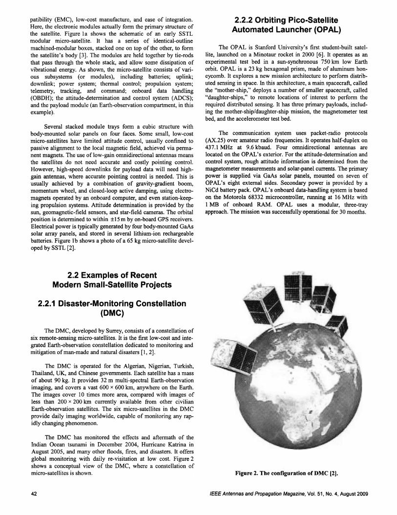
The DMC, developed by Surrey, consists of a constellation ofsix remote-sensing micro-satellites . It is the first low-cost and inte
grated Earth-observation constellation dedicated to monitoring and
mitigation of man-made and natural disasters [1, 2].
The DMC is operated for the Algerian, Nigerian, Turkish,Thailand, UK, and Chinese governments. Each satellite has a mass
of about 90 kg. It provides 32 m multi-spectral Earth-observationimaging, and covers a vast 600 x 600 km, anywhere on the Earth.
The images cover 10 times more area, compared with images of
less than 200 x 200 km currently available from other civilian
Earth-observation satellites. The six micro-satellites in the DMC
provide daily imaging worldwide, capable of monitoring any rap
idly changing phenomenon.
The DMC has monitored the effects and aftermath of the
Indian Ocean tsunami in December 2004, Hurricane Katrina in
August 2005, and many other floods, fires, and disasters. It offers
global monitoring with daily re-visitation at low cost. Figure 2
shows a conceptual view of the DMC, where a constellation of
micro-satellites is shown.
42
2.2.2 Orbiting Pico-Satellite
Automated Launcher (OPAL)
The OPAL is Stanford University's first student-built satel
lite, launched on a Minotaur rocket in 2000 [6]. It operates as an
experimental test bed in a sun-synchronous 750 km low Earthorbit. OPAL is a 23 kg hexagonal prism, made of aluminum hon
eycomb. It explores a new mission architecture to perform distributed sensing in space. In this architecture, a main spacecraft, called
the "mother-ship," deploys a number of smaller spacecraft, called"daughter-ships," to remote locations of interest to perform the
required distributed sensing. It has three primary payloads, includ
ing the mother-ship/daughter-ship mission, the magnetometer test
bed, and the accelerometer test bed.
The communication system uses packet-radio protocols
(AX.25) over amateur radio frequencies. It operates half-duplex on437.1 MHz at 9.6 kbaud. Four omnidirectional antennas arelocated on the OPAL's exterior. For the attitude-determination and
control system, rough attitude information is determined from themagnetometer measurements and solar-panel currents. The primary
power is supplied via GaAs solar panels, mounted on seven of
OPAL's eight external sides. Secondary power is provided by a
NiCd battery pack. OPAL's onboard data-handling system is basedon the Motorola 68332 microcontroller, running at 16 MHz with
I MB of onboard RAM. OPAL uses a modular, three-tray
approach. The mission was successfully operational for 30 months.
Figure 2. The configuration of DMC (2).
IEEE Antennas and Propagation Magaz ine, Vol. 51, No.4, August 2009
Authorized licensed use limited to: IEEE Xplore. Downloaded on May 13,2010 at 11:47:37 UTC from IEEE Xplore. Restrictions apply.
2.2.3 The University Nano-Satellite
Program (UNP) and SNAP-1
The nano-satellite is a type of modem small satellite having a
mass below 10 kg. The UNP is a collaborative program of student
built nano-satellites, started in 1999. The US Air Force Office of
Scientific Research (AFOSR) and the National Aeronautics and
Space Administration (NASA) jo intly funded 10 US universities in
designing and assembling nano-satellites, and conducting creat ive
low-cost space experiments, such as formation flying [7]. As a part
of the UNP, the Three-Comer Sat project is a joint effort among
Arizona State University, University of Colorado at Boulder, and
New Mexico State University. Three identical nano-satellites were
built by each univers ity to form a constellation, and to demonstrate
stereo imaging, formation flying, cellular phone communications,
and an innovative onboard data-handling system . The formation
flying is a cooperative effort between satellites operating as a net
work , where targeting and data acquisition are accomplished and
results transmitted to the ground segment and to the other satellites
via communication links, without the need for strict physical
proximity of the satellites. The three nano-satellites fly in a linear
follow-formation, with relative constant separation from each
other.
The EMERALD project, a collaboration between Stanford
University and Santa Clara Universi ty, is a low-cost, two-satellite
mission for validating formation-flying technologies, including
GPS-based positioning, inter-satellite communication, advanced
colloid micro-thrusters, and simple passive position-control
devices. Other parts of the UNP include ionospheric observation
nano-satellite format ion.
Such research activities have also taken place in Europe and
Asia . One example is the SPUTNIK-40, which weighed 3 kg and
was built in 1997 by l 'Aeroclub of France and the Russ ian Aero
nautical Federation. The first UK-built nano-satellite was SNAP-I.
It has a mass of 6.5 kg, and was designed and built at Surrey in just
nine months [1, 2].
2.2.4 The Cube-Sat
The Cube-Sat is a kind ofpico-satellite, having a cubic shape,
a standardized size of lO x lO x 10 cm, and a mass below 1 kg.
Nowadays, it has become a hot topic of research around the world .
The US Cube-Sat Program is an international collaboration of over
40 universities, high schools, and private firms, developing Cube
Sats containing scientific, private, and government payloads. Many
research projects on Cube-Sat also take place in Europe (Germany,
Surrey), Canada, and Japan.
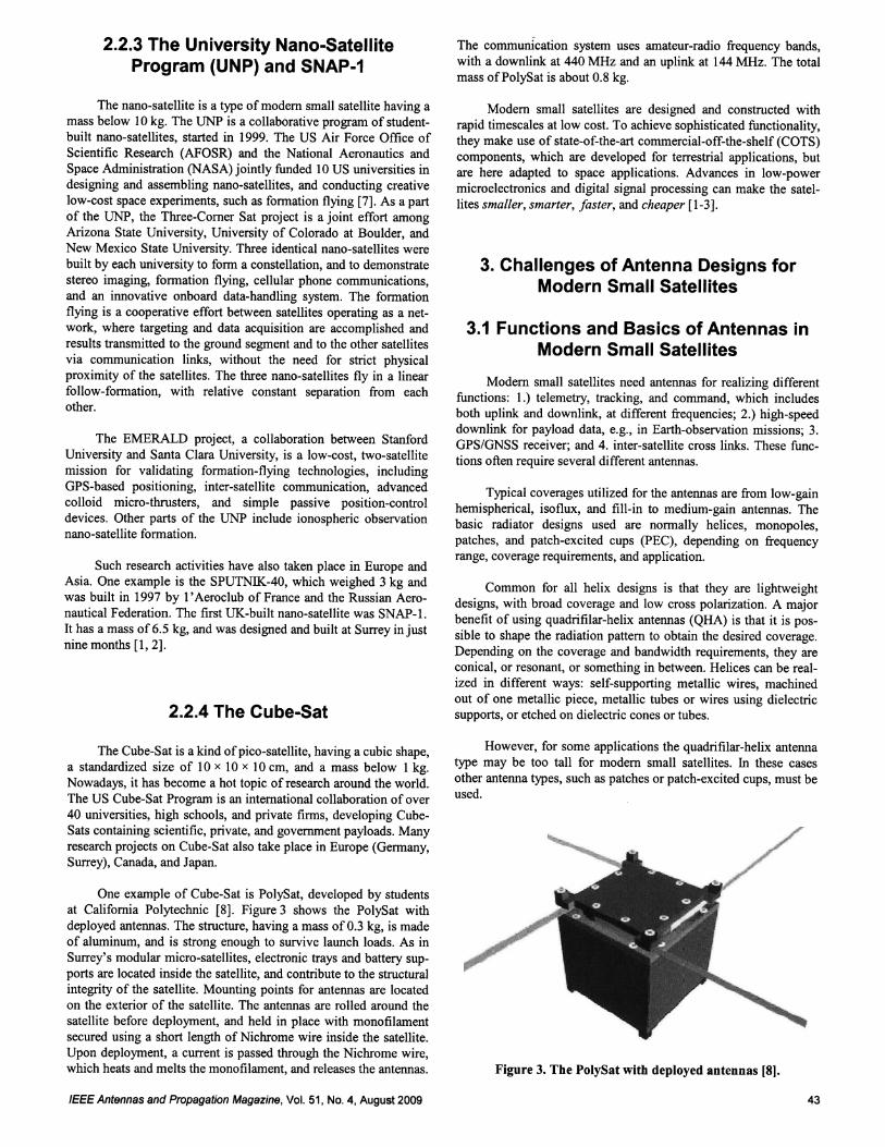
One example of Cube-Sat is PolySat, developed by students
at California Polytechnic [8]. Figure 3 shows the PolySat with
deplo yed antennas. The structure, having a mass of 0.3 kg, is made
of aluminum, and is strong enough to survive launch loads . As in
Surrey's modular micro-satellites, electronic trays and battery sup
ports are located inside the satellite, and contribute to the structural
integrity of the satellite. Mounting points for antennas are located
on the exterior of the satellite. The antennas are rolled around the
satellite before deployment, and held in place with monofilament
secured using a short length of Nichrome wire inside the satelli te.
Upon deployment, a current is passed through the Nichrome wire,
which heats and melts the monofilament, and releases the antennas.
IEEE Antennas and Propagation Magazine , Vol. 51, No.4, August2009
The communication system uses amateur-radio frequency bands,
with a downlink at 440 MHz and an uplink at 144 MHz . The total
mass of PolySat is about 0.8 kg.
Modem small satell ites are designed and constructed with
rapid timescales at low cost. To achieve sophisticated functionality,
they make use of state-of-the-art commercial-off-the-shelf (COTS)
components, which are developed for terrestrial applications, but
are here adapted to space applications. Advances in low-power
microelectronics and digital signal processing can make the satel
lites smaller, smarter, fa ster, and cheaper [1-3].
3. Challenges of Antenna Designs for
Modern Small Satellites
3.1 Functions and Basics of Antennas in
Modern Small Satellites
Modem small satellites need antennas for realizing different
functions: 1.) telemetry, tracking, and command, which includes
both uplink and downlink, at different frequencies ; 2.) high-speed
downlink for payload data, e.g., in Earth-observation missions; 3.
GPS/GNSS receiver; and 4. inter-satellite cross links . These func
tions often requ ire several different antennas.
Typical coverages utilized for the antennas are from low-gain
hemispherical, isoflux, and fill-in to medium-gain antennas. The
basic radiator designs used are normally helices, monopoles,
patches, and patch-excited cups (pEC), depending on frequenc y
range , coverage requirements, and application.
Common for all helix designs is that they are lightweight
designs, with broad coverage and low cross polarization. A major
benefit of using quadrifilar-helix antennas (QHA) is that it is pos
sible to shape the radiation pattern to obtain the desired coverage.
Depending on the coverage and bandwidth requirements, they are
conical, or resonant, or something in between. Helices can be real
ized in different ways : self-supporting metallic wires, machined
out of one metall ic piece, metallic tubes or wires using dielectric
supports, or etched on dielectric cones or tubes .
However, for some applications the quadrifilar-helix antenna
type may be too tall for modem small satellites. In these cases
other antenna types, such as patches or patch-excited cups , must be
used .
- :
Figure 3. The PolyS at with deployed antennas [8].
43
Authorized licensed use limited to: IEEE Xplore. Downloaded on May 13,2010 at 11:47:37 UTC from IEEE Xplore. Restrictions apply.
3.2. Challenges of Antenna Designs for
Modern Small Satellites
Due to the special environment in space and the requirements
of modem small satellites, antenna designs for modem small satel
lites have many challenges. The main challenges include:
Antennas must be highly reliable, as it is difficult to
replace the antenna in space.
Antennas must be very small, have low mass, be highly
efficient, and be low cost, due to the stringent requirements of small size, low mass, and low cost of modem
small satellites.
Antennas must be mechanically robust, and able to sur
vive both random vibration and shock during the
launch.
The thermal design of the antennas must be carefully
evaluated. The antennas are designed to perform over a
wide temperature variation, typically from -150° C to
+150°C. The normal thermal design for wide-coverage
antennas is passive. Some designs must operate even
down to below -200° C. No multi-layer insulation
(MLI) or other thermal hardware is used.
Antennas must be able to survive the harsh radiationenvironment in space, such as ionizing radiation, cos
mic radiation, and solar energetic particles.
Effects of atomic oxygen need to be considered for
LEO (low-Earth-orbit) missions. This can be handled
by using a germanium-coated single-layer-insulation
protective cover on the antenna, or by using a resistant
surface treatment directly on the antenna [9].
Materials for the antennas need to be chosen carefully,considering the effects ofvacuum and micro-gravity.
High data rates require a high antenna gain. However,
the very limited space available on modem small satel
lites makes it difficult to accommodate a high-gain
antenna, which usually consists of bulky and compli
cated reflector antennas or antenna arrays. Costly
pointing will also be needed for high-gain antennas. A
tradeoffhas to be made.
As many antennas are fitted in a small space, EMC and
mutual coupling amongst these antennas, the payloads,
and circuits need to be carefully considered.
A major consideration for antenna design is the interac
tion between antennas and the modem small-satellite
structures. The spacecraft's structure can cause electro
magnetic scattering, as well as have blockage effects on
the antenna's radiation patterns. The scattering can
interfere with the antenna's radiation pattern, and can
cause severe degradation in gain performance and
sidelobes. This degradation will have a major influence
on a communication-link system's performance, and
needs to be assessed.
44
Antennas have to be located (as far as possible) on the
spacecraft in such a way that they can provide accept
able performance and, at the same time, do not disturbor interfere with other antennas, subsystems, or the
allowed outer physical envelope of the satellite (i.e.,
they must fit under the fairing of the launcher used).
As the antenna interaction with modem small satellites is a
major concern, more discussion is given in the next section.
3.3. Discussions on Antenna Designs and
Antenna Interactions with
Modern Small Satellites
The design of a small satellite antenna starts with the mission
requirements and the link budget. During the early phases of theproject, the quantity of data produced is established, and the needs
for separate telemetry, tracking, and command and payload links
are investigated. Simple missions may use a single link for all traf
fic, while more-advanced operations may separate the relatively
low-speed telemetry, tracking, and command functionality from the
high-speed data links. This allows the use of low-gain omnidirec
tional antennas for satellite-bus traffic, and high-gain antennas with
narrower beamwidths for the payload antennas. In the case of non
nominal attitude, the payload link will thus be interrupted, but the
telemetry, tracking, and command traffic can be maintained toensure that commanding of the satellite can continue, such that
nominal attitude can be reestablished.
For telemetry, tracking, and command antennas, the key
requirements are omnidirectional coverage, with associated low
gain, mechanical robustness, and resistance to environmental
effects, such as ultraviolet light, radiation, deep dielectric charging,
and differential surface charging. To achieve near omnidirectional
coverage, more than one antenna is often required. By simply
inspecting the beam pattern of a single antenna, one can be misled
into thinking that multiple antennas will produce a similarly
smooth radiation pattern. This is incorrect, and can be demon
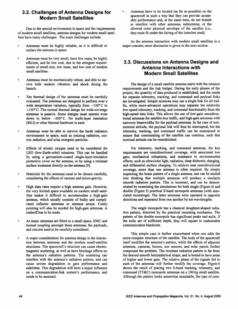
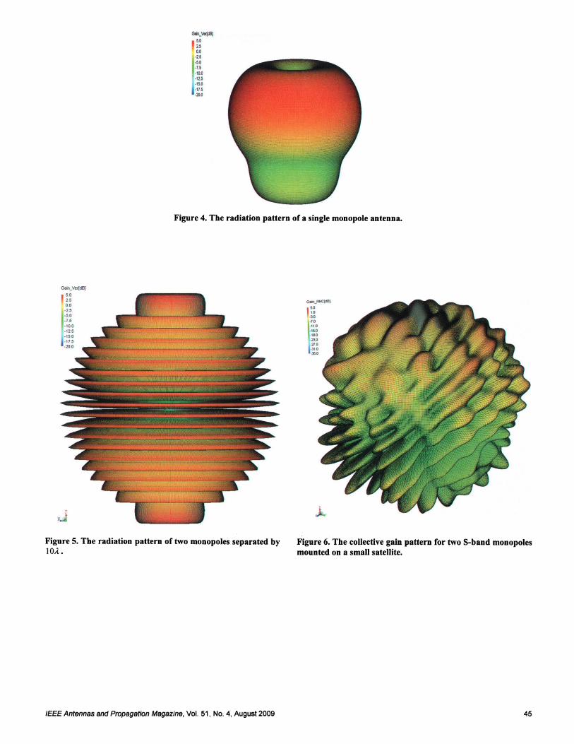
strated by examining the simulations for both single (Figure 4) and
double (Figure 5) practical S-band monopole antennas (with asso
ciated mountings). The latter antennas were operated in opposite
directions and separated from one another by ten wavelengths.
The single monopole has a classical doughnut-shaped radia
tion pattern, distorted by the practical mounting mechanics. The
pattern of the double monopole has significant peaks and nulls. Ifthe nulls are of sufficient depth, they will equate to undesirable
communication blackouts.
This simple case is further exacerbated when one adds the
more-complex structure of the satellite. The body of the spacecraft
itself modifies the antenna's pattern, while the effects of adjacent
antennas, cameras, booms, sun sensors, and solar panels further
compound the problem. The resultant radiation pattern is far from
the desired smooth hemispherical shape, and is bound to have areas
of higher and lower gain. The relative phase of the signals fed toeach of the antennas will further modify the coverage. Figure 6
shows the result of placing two S-band tracking, telemetry, and
command (TT&C) monopole antennas on a 100 kg small satellite.
Although the pattern looks somewhat unsuitable, the type of com-
IEEE Antennas and Propagation Magazine, Vol. 51, No.4, August 2009
Authorized licensed use limited to: IEEE Xplore. Downloaded on May 13,2010 at 11:47:37 UTC from IEEE Xplore. Restrictions apply.
GIIl_v.ldllJ10zs00·20
·00.]3
-10.0·,U.,0.0·'15·20»
Figure 4. The radiation pattern of a single monopole antenna.
Gao\_VerlcllJ002000
."·0 0.,.· 10 0
·1"-1$0
· 11 5
· 20 0
t
x..J
Figure S. The radiation pattern of two monopoles separated bylOA..
IEEE Antennas and Propagation Magazine, Vol. 51, No.4, August 2009
"""-50...:I •
.' 0·110. t So O.'90
·23.-:D .·31 .-J5.
Figure 6. The collective gain pattern for two S-band monopolesmounted on a small satellite.
45
Authorized licensed use limited to: IEEE Xplore. Downloaded on May 13,2010 at 11:47:37 UTC from IEEE Xplore. Restrictions apply.
munication link needs to be considered. The telemetry system on
small satellites often comprises digital packets. If a packet is lost
due to the ground-station's transit through a propagation null, or
due to the satellite's tumbling during the commissioning phase, it
can simply be resent, thus maintaining the overall message integ
rity.
The placement of antennas for optimum coverage and
antenna-performance assessment can be found by using electro
magnetic (EM) simulation, by measurements, or by a combination
of both. The selection of the method or combination of methods is
either driven by the actual size being considered (i.e., if items such
as solar panels or foldable booms or other appendages exist), or by
whether the antenna is integrated or flush-mounted in the space
craft's body. In more recent years, affordable and accurate EM
simulation programs have become widespread. Once the sub-com
ponents of the satellite have been modeled, they can be quickly
configured to try out different positions to minimize radiation-pat
tern perturbations. It is now standard practice to simulate the entire
satellite during the design phase, to evaluate different types of
antennas and to optimize their radiation patterns.
It has been shown that in order to design an antenna
configuration suitable for a small satellite, the entire mission
objectives must be considered. The bulk of payload data required
and the transmission rate, along with the available satellite power,
helps to define the gain of required for the antenna. High-gain
antennas infer the need for an antenna-pointing mechanism, while
specific satellite-pointing requirements, such as for imaging, will
place specifications on the pointing mechanism, itself. Successful
configurations must be simulated in the design phase, and must
take into account the effects of limited ground planes, adjacent
structures, and co-located antenna systems.
Figure 7 shows the results from a typical low-profile antenna
installation on a spacecraft. As can be seen, the current magnitude
is high in the close vicinity to the antenna element, as expected.
4. Overview of Antennas Developed for
Modern Small Satellites
4.1 Antennas for TTC of
Modern Small Satellites
4.1.1 General Requirements
for this Application
During the initial acquisition period, following the satellite's
separation from the launcher, the satellite's stabilization has not
been achieved. Omnidirectional or wide-coverage antennas are
thus required for communication between space and ground.
Sometimes, more than two such antennas are mounted on different
sides of the satellite, to provide better coverage for the telemetry,
tracking, and command link, as well as for redundancy. Several
omnidirectional antennas at different frequencies, e.g., UHF and
VHF bands, are usually used for telemetry, tracking, and command
uplink and downlink, respectively.
46
4.1.2 Antenna Examples
Various monopole antennas, printed inverted-F-shaped anten
nas (PIFAs), microstrip-patch antennas, helices, and patch-excited
cup antennas, have been developed for telemetry, tracking, and
command of modern small satellites in the UHF, VHF, S, C, and Xbands. These antennas are simple, cheap, easy to fabricate, and
have wide radiation-pattern coverage; the satellite thus does not
need accurate control ofattitude.
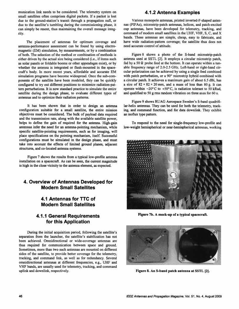
Figure 8 shows a photo of the S-band microstrip-patch
antenna used at SSTL [2]. It employs a circular microstrip patch,
fed by a 50 {} probe feed at the bottom. It can operate within a tun
able frequency range of 2.0-2.5 GHz. Left-hand or right-hand cir
cular polarization can be achieved by using a single feed combined
with patch perturbation, or a 900 microstrip hybrid combined with
a circular patch. It achieves a maximum gain of about 6.5 dBi, has
a size of 82 x 82 x 20 mm, and a mass of less than 80 g. It can
operate within -200 C to +500 C, is radiation tolerant to 50 kRad,
and qualified to 50 g rms random vibration on three axes for 60 s,
Figure 9 shows RUAG Aerospace Sweden's S-band quadrifi
lar-helix antennas. They can be used for both the telemetry, track
ing, and command function, and for data downlink. They exhibit
an isoflux type pattern.
To respond to the need for single-frequency low-profile and
low-weight hemispherical or near-hemispherical antennas, working
Figure 7b. A mock-up of a typical spacecraft.
Figure 8. An S-band patch antenna at SSTL [21.
IEEE Antennas and Propagation Magazine, Vol. 51, No.4, August 2009
Authorized licensed use limited to: IEEE Xplore. Downloaded on May 13,2010 at 11:47:37 UTC from IEEE Xplore. Restrictions apply.
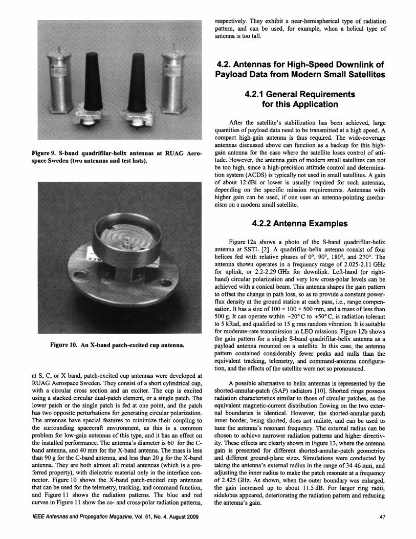
Figure 9. S-band quadrifilar-helix antennas at RUAG Aerospace Sweden (two antennas and test hats).
-- --.......',• .
... "
" . ..,;/-,-,' .. ....- ' "' -
't:.= ,
,..,... - '".
.
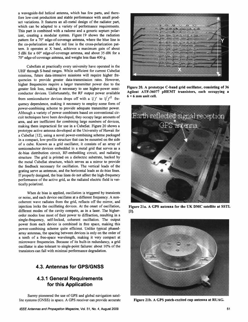
Figure 10. An X-band patch-excited cup antenna.
at S, C, or X band, patch-excited cup antennas were developed at
RUAG Aerospace Sweden . They consist of a short cylindrical cup,
with a circular cross section and an exciter. The cup is excited
using a stacked circular dual-patch element , or a single patch. The
lower patch or the single patch is fed at one point, and the patch
has two oppos ite perturbations for generating circular polarization.
The antennas have special features to minimize their coupling to
the surrounding spacecraft environment, as this is a common
problem for low-gain antennas of this type, and it has an effect on
the installed performance. The antenna's diameter is 60 for the C
band antenna, and 40 mm for the X-band antenna. The mass is less
than 90 g for the C-band antenna, and less than 20 g for the X-band
antenna. They are both almost all metal antennas (which is a pre
ferred property), with dielectric material only in the interface con
nector. Figure 10 shows the X-band patch-excited cup antennas
that can be used for the telemetry, tracking, and command function,
and Figure 11 shows the radiation patterns . The blue and red
curves in Figure II show the co- and cross-polar radiation patterns ,
IEEE Antennas and Propagation Magazine , Vol. 51, No.4, August2009
respectively. They exhibit a near-hemispherical type of radiation
pattern, and can be used, for example, when a helical type of
antenna is too tall.
4.2. Antennas for High-Speed Downlink of
Payload Data from Modern Small Satellites
4.2.1 General Requirements
for this Application
After the satellite's stabilization has been achieved, large
quantities of payload data need to be transmitted at a high speed. A
compact high-gain antenn a is thus required. The wide-coverage
antennas discussed above can function as a backup for this high
gain antenna for the case where the satellite loses control of atti
tude. However, the antenna gain of modern small satellites can not
be too high, since a high-precision attitude control and determina
tion system (ACDS) is typically not used in small satellites. A gain
of about 12 dBi or lower is usually required for such antennas ,
depending on the specific mission requirements. Antennas with
higher gain can be used, if one uses an antenna-pointing mecha
nism on a modern small satellite.
4.2.2 Antenna Examples
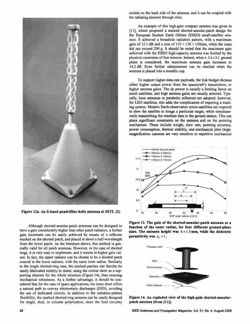
Figure 12a shows a photo of the S-band quadrifilar-helix
antenna at SSTL [2]. A quadrifilar-helix antenna consist of four
helices fed with relative phases of 0°, 90°, 180°, and 270° . The
antenna shown operates in a frequency range of 2.025-2.11 GHz
for uplink , or 2.2-2.29 GHz for downlink. Left-hand (or right
hand) circular polarization and very low cross-polar levels can be
achieved with a conical beam. This antenna shapes the gain pattern
to offset the change in path loss, so as to provide a constant power
flux density at the ground station at each pass, i.e., range compen
sation . It has a size of 100 x 100 x 500 mm, and a mass of less than
500 g. It can operate within -20° C to +50° C, is radiation tolerant
to 5 kRad, and qualified to 15 g rms random vibration. It is suitable
for moderate-rate transmission in LEO missions. Figure 12b shows
the gain pattern for a single S-band quadrifilar-helix antenna as a
payload antenna mounted on a satellite. In this case, the antenna
pattern contained considerably fewer peaks and nulls than the
equivalent tracking, telemetry, and command-antenna configura
tion, and the effects of the satellite were not so pronounced.
A possible alternative to helix antennas is represented by the
shorted-annular-patch (SAP) radiators [10]. Shorted rings possess
radiation characteristics similar to those of circular patches, as the
equivalent magnetic-current distribution flowing on the two exter
nal boundaries is identical. However, the shorted-annular-patch
inner border, being shorted, does not radiate, and can be used to
tune the antenna's resonant frequency. The external radius can be
chosen to achieve narrower radiation patterns and higher directiv
ity. These effects are clearly shown in Figure 13, where the antenna
gain is presented for different shorted-annular-patch geometries
and different ground-plane sizes. Simulations were conducted by
taking the antenna's external radius in the range of 34-46 mm, and
adjusting the inner radius to make the patch resonate at a frequency
of 2.425 GHz. As shown, when the outer boundary was enlarged,
the gain increased up to about 11.5 dB. For larger ring radii,
sidelobes appeared, deteriorating the radiation pattern and reducing
the antenna's gain.
47
Authorized licensed use limited to: IEEE Xplore. Downloaded on May 13,2010 at 11:47:37 UTC from IEEE Xplore. Restrictions apply.
4644
!:10(
lo(
38 40 42SAP outer radius a [mm)
36
-- Infinite Ground plane
200mm X 200mm
-e- 140mm X 140mm
11.5 - 110mm X 110mm
11 r Gain
I [dBi]
',:'(,'//,.... ......>---__ I
y ,,-9.5 i I I j ;
9 !. f34
An example of this high-gain compact antenna was given in
[11], which proposed a stacked shorted-annular-patch design for
the European Student Earth Orbiter (ESEO) small-satellite mis
sion. It achieved a broadside radiation pattern, with a maximum
gain of 12.1 dB and a size of 110 x 130 x 10Omm, while the massdid not exceed 200 g. It should be noted that the maximum gain
achieved with the ESEO high-capacity antenna was limited by the
physical constrains of that mission. Indeed, when a 2AX2A ground
plane is considered, the maximum antenna gain increases to
14.2 dB. Even further enhancement can be reached when theantenna is placed into a metallic cup.
To support higher-data-rate payloads, the link budget dictates
either higher output power from the spacecraft's transmitters, or
higher antenna gains. The de power is usually a limiting factor onsmall satellites, and high antenna gains are usually selected. Typically, horn antennas or parabolic reflectors are adopted; however,
for LEO satellites, this adds the complication of requiring a track
ing system. Modern Earth-observation micro-satellites are requiredto slew the satellite to image a particular target, while simultane
ously transmitting the resultant data to the ground station. This canplace significant constraints on the antenna and on the pointing
mechanism. These include weight, slew rate, pointing accuracy,
power consumption, thermal stability, and mechanical jitter (high
magnification cameras are very sensitive to repetitive mechanical
resides on the back side of the antenna, and it can be coupled with
the radiating element through slots.
Figure 12a. An S-band quadrifilar-helix antenna at SSTL (2).
Although shorted-annular-patch antennas can be designed tohave a gain considerably higher than other patch radiators, a further
gain increment can be easily achieved by means of a reflectorstacked on the shorted patch, and placed at about a half-wavelength
from the lower patch. As the literature shows, this method is gen
erally valid for all patch antennas. However, in the case of shortedrings, it is very easy to implement, and it results in higher gain val
ues. In fact, the upper radiator can be chosen to be a shorted patchcoaxial to the lower radiator, with the same inner radius. Similarly
to the single shorted-ring case, the stacked patches can thereby be
easily fabricated entirely in metal, using the central short as a supporting element for the whole structure (Figure 14), thus ensuring
mechanical robustness. As a further advantage, it should be considered that for the case of space applications, the inner short offers
a natural path to convey electrostatic discharges (ESD), avoiding
the use of dedicated circuits. In addition to the radiation-patternflexibility, the stacked shorted-ring antenna can be easily designed
for single, dual, or circular polarization, since the feed circuitry
Figure 13. The gain of the shorted-annular-patch antenna as a
function of the outer radius, for four different ground-planesizes. The antenna height was h = 1.5mm, while the dielectric
permittivity was cr = 1.
SAP -
Ground plane _ .
Dielectric -
Feed network
Figure 14. An exploded view of the high-gain shorted-annularpatch antenna (from (11)).
48 IEEE Antennasand Propagation Magazine , Vol. 51, No.4, August 2009
Authorized licensed use limited to: IEEE Xplore. Downloaded on May 13,2010 at 11:47:37 UTC from IEEE Xplore. Restrictions apply.
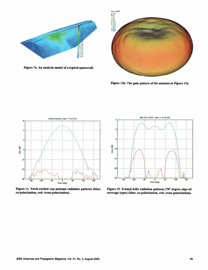
Figure 7a. An analysis model of a typical spacecraft.
Figure 12b. The gain pattern of the antenna in Figure 12a.
"-Band Anlenna , Gain, f = 6.9 GHz
'r-t----r-t- ....--,
150·150
o
; , ; ..
XIlA70 •• RHCP, Gain. f= 8.16 GHz
·15
·20
.50
..... .... . .• • . . ... ... . .
. ; : : .
5 _..
o ; :- ! .
-=lD
......
·10
Figure 11. Patch-excited cup-antenna radiation patterns (blue:co-polarization, red: cross-polarization).
Figure 19. X-band helix radiation patterns (700 degree edge-ofcoverage types) (blue: co-polarization, red: cross-polarization).
IEEE Antennas and Propagation Magazine , Vol. 51, No.4, August 2009 49
Authorized licensed use limited to: IEEE Xplore. Downloaded on May 13,2010 at 11:47:37 UTC from IEEE Xplore. Restrictions apply.
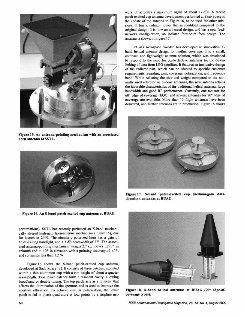
Figure 15. An antenna-pointing mechanism with an associated
horn antenna at SSTL.
Figure 16. An S-band patch-excited cup antenna at RUAG.
perturbations). SSTL has recently perfected an X-band mechani
cally steered high-gain hom-antenna mechanism (Figure 15), due
for launch in 2009. The circularly polarized hom has a gain of
15 dBi along boresight, and a 3 dB beamwidth of 27°. The associ
ated antenna-pointing mechanism weighs 2.7 kg, moves ±270° in
azimuth and ±110° in elevation with a pointing accuracy of < 1° ,
and consumes less than 3.2 W.
Figure 16 shows the S-band patch-excited cup antenna,
developed at Saab Space [9]. It consists of three patches , mounted
within a thin aluminum cup with a rim height of about a quarter
wavelength. Two lower patches form a resonant cavity, allowing
broadband or double tuning. The top patch acts as a reflector that
affects the illumination of the aperture, and is used to improve the
aperture efficiency. To achieve circular polarization, the lower
patch is fed in phase quadrature at four points by a stripline net-
50
work. It achieves a maximum again of about 12 dBi. A recent
patch-excited cup antenna development performed at Saab Space is
the update of the antenna in Figure 16, to be used for other mis
sions . It has a radiator tower that is modified compared to the
original design . It is now an all-metal design, and has a new feed
network configuration, an isolated four-point feed design. The
antenna is shown in Figure 17.
RUAG Aerospace Sweden has developed an innovative X
band helical antenna design for isoflux coverage. It is a small,
compact, and lightweight antenna solution, which was developed
to respond to the need for cost-effective antennas for the down
linking of data from LEO satellites. It features an innovative design
of the radiator part, which can be adapted to specific customer
requirements regarding gain, coverage, polarization, and frequency
band . While reducing the size and weight compared to the nor
mally used reflector or bi-cone antennas, the new antenna retains
the favorable characteristics of the traditional helical antenna : large
bandwidth and good RF performance. Currently, one radiator for
60° edge of coverage (EOC) and several antennas for 70° edge of
coverage are available. More than 15 flight antennas have been
delivered, and further antennas are in production. Figure 18 shows
Figure 17. S-band patch-excited cup medium-gain datadownlink antennas at RUAG.
Figure 18. X-band helical antennas at RUAG (70° edge-ofcoverage types).
IEEE Antennas and Propagation Magazine, Vol. 51, No.4, August2009
Authorized licensed use limited to: IEEE Xplore. Downloaded on May 13,2010 at 11:47:37 UTC from IEEE Xplore. Restrictions apply.
a waveguide-fed helical antenna, which has few parts, and there
fore low-cost production and stable performance with small prod
uct variations. It features an all-metal design of the radiator part,
which can be adapted to a variety of performance requirements .
This part is combined with a radome and a generic septum polar
izer, creating a modular system. Figure 19 shows the radiation
pattern for a 70° edge-of-coverage antenna, where the blue line is
the co-polarization and the red line is the cross-polarization pat
tern. It operates at X band, achieves a maximum gain of about
5 dBi for a 60° edge-of-coverage antenna, and about 35 dBi for a
70° edge-of-coverage antenna, and weighs less than 400 g.
CubeSats at practically every university have operated in the
UHF through S-band ranges. While sufficient for current CubeSat
missions, future data-intensive missions will require higher fre
quencies to provide greater data-transmission rates. However,
higher frequencies require a larger transmitter power due to the
greater link loss, making it necessary to use higher-power semi
conductor devices. Unfortunately, the RF output power available
from semiconductor devices drops off with a 1/f to 1/f2 fre
quency dependence, making it necessary to employ some form of
power-combining scheme to provide adequate transmitter power.
Although a variety of power combiners based on conventional cir
cuit techniques have been developed, they occupy large amounts of
area, and are inefficient for combining large numbers of devices,
making them impractical for use in a CubeSat. Figure 20 shows a
prototype active antenna developed at the University of Hawaii for
a CubeSat [12], using a novel power-combining scheme packaged
in a compact, low-profile structure that can be mounted on the side
of a cube. Known as a grid oscillator, it consists of an array of
semiconductor devices embedded in a metal grid that serves as a
de-bias distribution circuit, RF-embedding circuit, and radiating
structure . The grid is printed on a dielectric substrate, backed bythe metal CubeSat structure, which serves as a mirror to provide
the feedback necessary for oscillation. The vertical leads of the
grating serve as antennas, and the horizontal leads as de-bias lines.
If properly designed, the bias lines do not affect the high-frequency
performance of the active grid, as the radiated electric field is ver
tically polarized .
When de bias is applied, oscillation is triggered by transients
or noise, and each device oscillates at a different frequency. A non
coherent wave radiates from the grid, reflects off the mirror, and
injection locks the oscillating devices. At the onset of oscillation,
different modes of the cavity compete, as in a laser. The higher
order modes lose most of their power to diffraction, resulting in a
single-frequency, self-locked, coherent oscillation. The output
power from each device is combined in free space, making this
power-combining scheme quite efficient. Unlike typical phased
array antennas, the spacing between devices is only on the order of
a tenth of a free-space wavelength, making it very compact at
microwave frequencies. Because of its built-in redundancy, a grid
oscillator is also tolerant to single-point failures: about 10% of the
transistors can fail with minimal performance degradation.
4.3. Antennas for GPS/GNSS
4.3.1 General Requirements
for this Application
Surrey pioneered the use of GPS and global navigation satel
lite systems (GNSS) in space. A GPS receiver can provide accurate
IEEE Antennas and Propagation Magazine, Vol. 51, No.4, August 2009
Figure 20. A prototype C-band grid oscillator, consisting of 36Agilent ATF-36077 pHEMT transistors, each occupying a
6 x 6 mm unit cell.
Figure 21a. A GPS antenna for the UK DMC satellite at SSTL
[2].
Figure 21b. A GPS patch-excited cup antenna at RUAG.
51
Authorized licensed use limited to: IEEE Xplore. Downloaded on May 13,2010 at 11:47:37 UTC from IEEE Xplore. Restrictions apply.
position, velocity, and time for LEO satellites. For this application,the antenna needs to be compact, low profile, able to operate at
GPS frequencies in the Ll (1.575 GHz) and L2 (1.227 GHz) bandswith stable performance, and produce low backward radiationtowards the small satellite body (to minimize the interactions with
the satellite). For more precise measurement, the optimum antenna
location on the satellite must be found, balancing the antenna'scoverage against spacecraft interference and multipath errors.Antenna phase variations must also be reduced.
4.3.2 Antenna Examples
A medium-gain antenna, shown in Figure 21a, was launched
on the UK-DMC satellite of SSTL for the purpose of collecting
reflected GPS signals in orbit [2]. This satellite has begun to col
lect reflected signals under a variety of sea conditions, and overland and ice. The antenna is a three-element, circularly polarizedmicrostrip-patch array with a gain of 12 dBi [2]. Antenna-design
challenges remain in terms of further reducing antenna size,improving the antenna's efficiency, multi-band (LlIL21L5 band)
operation, constant phase center, multipath mitigation, etc.
Figure 21b shows the patch-excited cup antenna developed at
RUAG Aerospace Sweden. It consists of two patches placed in a
circular cup. To obtain a stable antenna covering two GPS fre
quency bands (Ll, L2), the bottom patch was capacitively fed byfour probes and an isolated feed network. The antenna achieved acoverage out to 80° in zenith angle, and low backward radiation.
The antenna's diameter is 160 mm, and the mass is 345 g.
In [13-14] it was demonstrated how shorted-annular-patchantennas can achieve high-accuracy GPS/GNSS performance with
out compromising the physical constrains. These antennas can
indeed be designed to have reduced lateral and back radiation, with
adequate polarization purity and phase uniformity, in both GPS
bands [15]. This can be accomplished without the employment of
ground-plane extensions of choked rings. As a result, they offerperformance compatible with high-accuracy GNSS applications,but with sizes and weights compatible with small-satellite applica
tions.
To reduce the antenna's size, Surrey also worked with
Sarantel to bring out a space version of Sarantel's Geohelixceramic-loaded quadrifilar-helix antennas. The ceramic loading
leads to a smaller-size quadrifilar-helix antenna, compared to stan
dard quadrifilar-helix antennas. The reduced size of this antennaleads to a low antenna gain, but it is a practical solution for nanosatellites.
4.4. Antennas for Inter-Satellite
Cross Links and Others
One of the challenges in designing a distributed small-satellite network - especially a dynamically reconfigurable network,
consisting of satellites too small to contain an attitude-control system - is in establishing and maintaining a reliable crosslink with
other satellites in the network, without a priori knowledge of theirpositions.
Omnidirectional antennas are the obvious choice for crosslinking satellites that are subject to constant repositioning, but this
52
leaves the network susceptible to eavesdropping by unauthorized
ground stations, as well as by satellites outside the network but still
within range of the constellation. Omnidirectional antennas arealso inefficient, as power is radiated in all directions, not just in thedirection of the receiver. In security-sensitive networks, direct
cross links using dynamically beam-steered directional antennas
can prevent signal interception. However, these systems require
phase shifters or digital-signal-processing algorithms, addinganother layer of complexity to the system and negating the advan
tages of the simple, low-cost nature of small satellites.
For pico-satellite applications, an attractive alternative to
dynamic beam steering is a self-steering retrodirective array, whichpermits secure cross-link communications between satellites mov
ing randomly in space [16]. Retrodirective antennas are able to
sense the direction of an incoming radio transmission and send a
reply in that same direction, without the complexities associatedwith phase shifters in conventional phased arrays, or digital signal
processing in smart antennas. As with any directive antenna, thedirectivity not only improves network security, but also improves
the communication-link efficiency by minimizing power consumption.
Most retrodirective antennas have been implemented using a
conventional heterodyne phase-conjugation technique, requiring a
local oscillator (LO) that is twice the frequency of the interrogatingRF signal. This has the disadvantage of requiring a high-frequency
LO, which is sometimes impractical where de power and cost
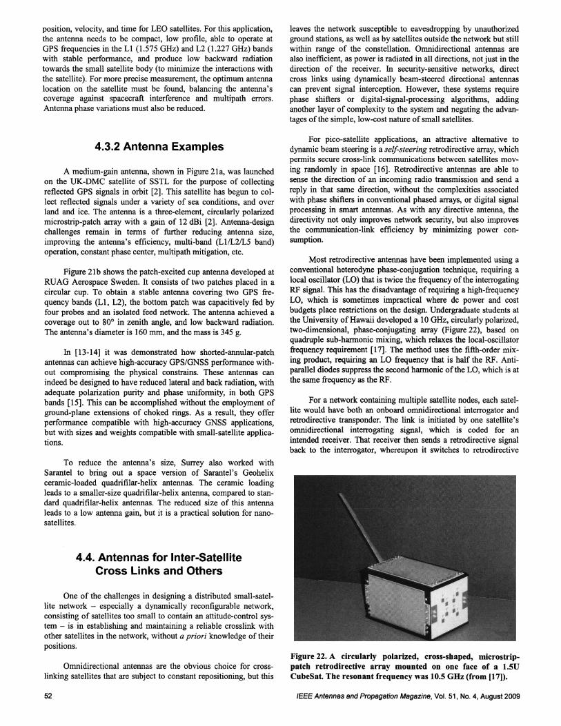
budgets place restrictions on the design. Undergraduate students atthe University of Hawaii developed a 10 GHz, circularly polarized,two-dimensional, phase-conjugating array (Figure 22), based onquadruple sub-harmonic mixing, which relaxes the local-oscillatorfrequency requirement [17]. The method uses the fifth-order mixing product, requiring an LO frequency that is half the RF. Antiparallel diodes suppress the second harmonic of the LO, which is at
the same frequency as the RF.
For a network containing multiple satellite nodes, each satel
lite would have both an onboard omnidirectional interrogator andretrodirective transponder. The link is initiated by one satellite'somnidirectional interrogating signal, which is coded for an
intended receiver. That receiver then sends a retrodirective signalback to the interrogator, whereupon it switches to retrodirective
Figure 22. A circularly polarized, cross-shaped, mlcrostrippatch retrodirective array mounted on one face of a l.5DCubeSat. The resonant frequency was 10.5 GHz (from (17)).
IEEE Antennas and Propagation Magazine, Vol. 51, No.4, August 2009
Authorized licensed use limited to: IEEE Xplore. Downloaded on May 13,2010 at 11:47:37 UTC from IEEE Xplore. Restrictions apply.
Retrodirective Array
with PLLs
Outgoing RF Signal
veoRef
Phase Detector
Incoming Pilot Signal
Down Up
r----------------------------- -- ------------, 0
,
,,,
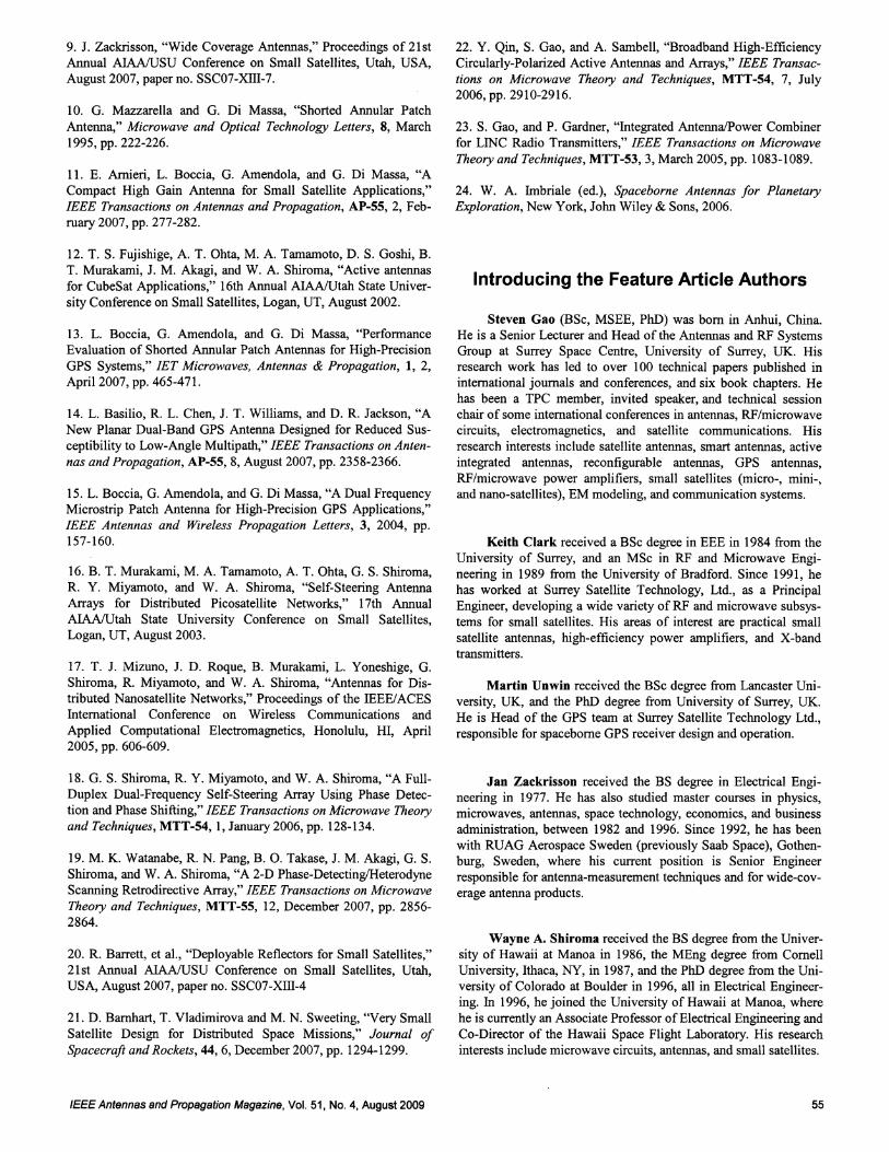
University of Hawaii students further extended the phase
detect ion concept from [18] to two-d imensional retrodirectivity
[19]. In addition to the power-loss reduction from 1/ R4 to 1/ R
2,
the heterodyne-scanning architecture eliminates the need for indi
vidual phase shifters at each radiating element , and reduces steer
ing control to a single voltage-controlled oscillator (VeO) per
steering dimension. Similar to [18], when the system in [19] is
interrogated, the E-plane phase detector outputs an error voltage
proportional to the E-plane-detected phase difference at its input.
Simultaneously, the H-plane phase detector outputs an error volt
age proportional to the H-plane-phase detected at its input. Each
error voltage is then passed as an input to the control-circuit mod
ule, which contains two independent steering-control circuits: an
LO phase-shifting network, and an IF phase-shifting network,
shown in Figure 25. The control circuit creates phase gradients in
each phase-shifting network by varying the veo tuning voltage,
based on the input phase-detector error voltage. A phase-addition
circuit, shown in Figure 26, is then used to add the E- and H-plane
phase gradients from the LO and IF networks to steer the two-
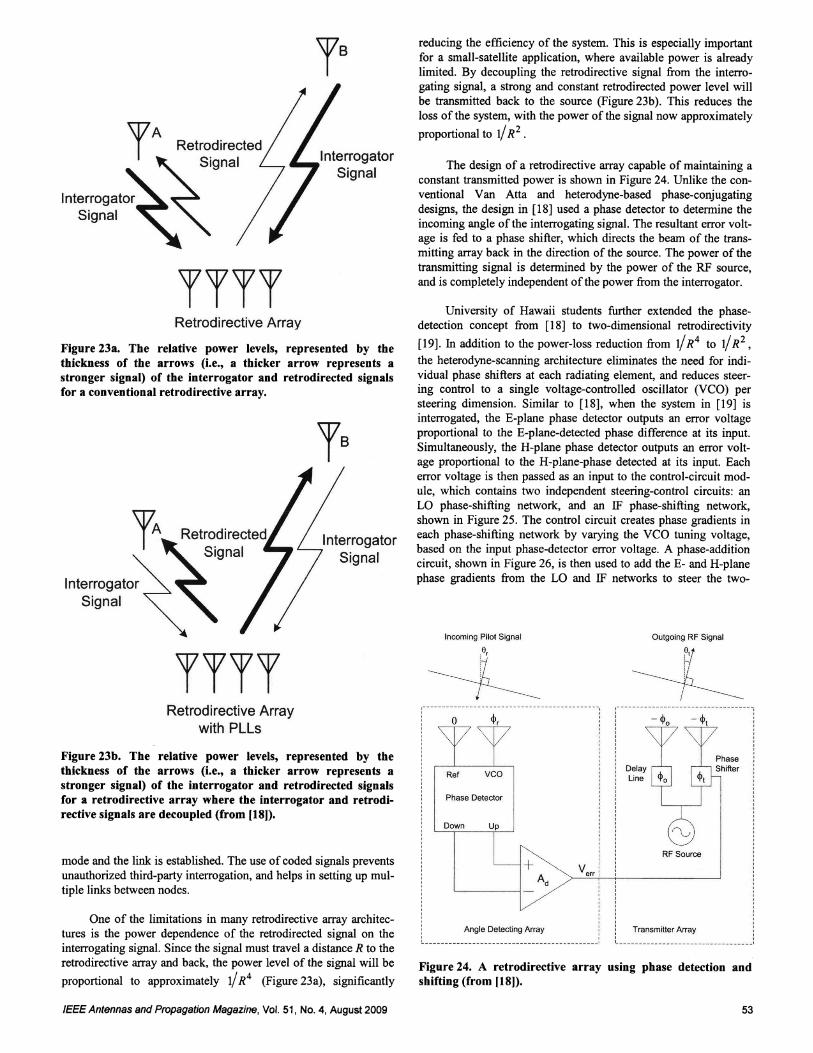
reducing the efficiency of the system. This is especially important
for a small-satellite application, where available power is already
limited. By decoupling the retrodirective signal from the interro
gating signal, a strong and constant retrodirected power level will
be transmitted back to the source (Figure 23b). This reduces the
loss of the system , with the power of the signal now approx imately
proportional to 1/ R2
•
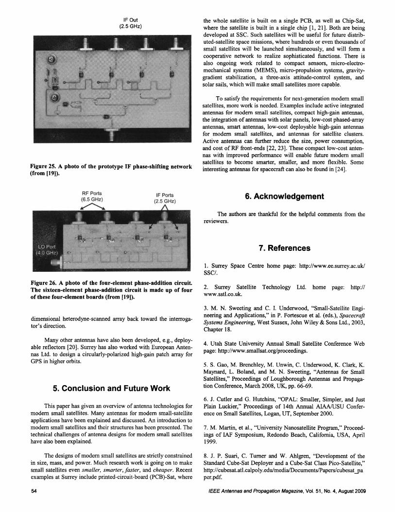
The design of a retrodirective array capable of maintaining a
constant transmitted power is shown in Figure 24. Unlike the con
ventional Van Atta and heterodyne-based phase-conjugating
designs, the design in [18] used a phase detector to determine the
incoming angle of the interrogating signal. The resultant error volt
age is fed to a phase shifter, which directs the beam of the trans
mitting array back in the direction of the source . The power of the
transmitting signal is determined by the power of the RF source,
and is completely independent of the power from the interrogator.
Interrogator
Signal
InterrogatorSignal
Retrodirective Array
TTTT
TTTT
Interrogato r
Signal
TA Retrodirected
Signal
Figure 23b. The relative power levels, represented by thethickness of the arrows (l.e., a thicker arrow represents astronger signal) of the interrogator and retrodirected signalsfor a retrodirective array where the interrogator and retrodirective signals are decoupled (from (18)).
Figure 23a. The relative power levels, represented by thethickness of the arrows (l.e., a thicker arrow represents astronger signal) of the interrogator and retrodirected signalsfor a conventional retrodirective array.
Figure 24. A retrodirective array using phase detection andshifting (from (18)).
mode and the link is established. The use of coded signals prevents
unauthorized third-party interrogation, and helps in setting up mul
tiple links between nodes .
One of the limitations in many retrodirective array architec
tures is the power dependence of the retrodirected signal on the
interrogating signal. Since the signal must travel a distance R to the
retrodirective array and back, the power level of the signal will be
proportional to approx imately 1/R4 (Figure 23a), significantly
,
Angl e Detecting Arr ay, ,L • I
RF Source
TransmiUer Arr a y
IEEE Antennas and Propagation Magazine , Vol. 51, No.4, August2009 53
Authorized licensed use limited to: IEEE Xplore. Downloaded on May 13,2010 at 11:47:37 UTC from IEEE Xplore. Restrictions apply.
IF Out
(2.5 GHz)
Figure 25. A photo of the prototype IF phase-shifting network(from (19)).
IF Ports(2.5 GHz)
Figure 26. A photo of the four-element phase-addition circuit.
The sixteen-element phase-addition circuit is made up of four
of these four-element boards (from [19)).
dimensional heterodyne-scanned array back toward the interroga
tor's direction.
Many other antennas have also been developed, e.g., deploy
able reflectors [20]. Surrey has also worked with European Anten
nas Ltd. to design a circularly-polarized high-gain patch array for
GPS in higher orbits.
5. Conclusion and Future Work
This paper has given an overview of antenna technologies for
modern small satellites . Many antennas for modern small-satellite
applications have been explained and discussed. An introduction to
modern small satellites and their structures has been presented. The
technical challenges of antenna designs for modern small satellites
have also been explained .
The designs of modern small satellites are strictly constrained
in size, mass, and power. Much research work is going on to make
small satellites even smaller, smarter, faster, and cheaper. Recent
examples at Surrey include printed-circuit-board (PCB)-Sat, where
54
the whole satellite is built on a single PCB, as well as Chip-Sat,
where the satellite is built in a single chip [1,21]. Both are being
developed at SSC. Such satellites will be useful for future distrib
uted-satellite space missions, where hundreds or even thousands of
small satellites will be launched simultaneously, and will form a
cooperative network to realize sophisticated functions. There is
also ongoing work related to compact sensors, micro-electro
mechanical systems (MEMS), micro-propulsion systems, gravity
gradient stabilization, a three-axis attitude-control system, and
solar sails, which will make small satellites more capable.
To satisfy the requirements for next-generation modern small
satellites, more work is needed. Examples include active integratedantennas for modern small satellites, compact high-gain antennas,
the integration of antennas with solar panels, low-cost phased-array
antennas, smart antennas, low-cost deployable high-gain antennas
for modern small satellites, and antennas for satellite clusters.
Active antennas can further reduce the size, power consumption,
and cost of RF front-ends [22, 23]. These compact low-cost anten
nas with improved performance will enable future modern small
satellites to become smarter, smaller, and more flexible. Some
interesting antennas for spacecraft can also be found in [24].
6. Acknowledgement
The authors are thankful for the helpful comments from the
reviewers.
7. References
1. Surrey Space Centre home page: http://www.ee.surrey.ac.uk/
sSC/.
2. Surrey Satellite Technology Ltd. home page: http://www.sstl.co.uk.
3. M. N. Sweeting and C. 1. Underwood, "Small-Satellite Engi
neering and Applications," in P. Fortescue et al. (eds.), Spacecraft
Systems Engineering, West Sussex, John Wiley & Sons Ltd., 2003,
Chapter 18.
4. Utah State University Annual Small Satellite Conference Web
page: http://www.smallsat.org/proceedings.
5. S. Gao, M. Brenchley, M. Unwin, C. Underwood, K. Clark, K.
Maynard, L. Boland, and M. N. Sweeting, "Antennas for Small
Satellites," Proceedings of Loughborough Antennas and Propaga
tion Conference, March 2008, UK, pp. 66-69.
6. J. Cutler and G. Hutchins, "OPAL: Smaller, Simpler, and Just
Plain Luckier," Proceedings of 14th Annual AIAAlUSU Confer
ence on Small Satellites, Logan, UT, September 2000.
7. M. Martin, et al., "University Nanosatellite Program," Proceed
ings of IAF Symposium, Redondo Beach, California, USA, April
1999.
8. J. P. Suari, C. Turner and W. Ahlgren, "Development of the
Standard Cube-Sat Deployer and a Cube-Sat Class Pico-Satellite,"
http://cubesat.atl.calpoly.edulmediaIDocuments/Papers/cubesat-pa
per.pdf.
IEEE Antennas and Propagation Magazine, Vol. 51, No.4, August 2009
Authorized licensed use limited to: IEEE Xplore. Downloaded on May 13,2010 at 11:47:37 UTC from IEEE Xplore. Restrictions apply.
9. J. Zackrisson, "Wide Coverage Antennas," Proceedings of 21st
Annual AIANUSU Conference on Small Satellites, Utah, USA,
August 2007, paper no. SSC07-XIII-7.
10. G. Mazzarella and G. Di Massa, "Shorted Annular Patch
Antenna," Microwave and Optical Technology Letters, 8, March
1995, pp. 222-226.
11. E. Amieri, L. Boccia, G. Amendola, and G. Di Massa, "A
Compact High Gain Antenna for Small Satellite Applications,"
IEEE Transactions on Antennas and Propagation, AP-55, 2, Feb
ruary 2007, pp. 277-282.
12. T. S. Fujishige, A. T. Ohta, M. A. Tamamoto, D. S. Goshi, B.
T. Murakami, 1. M. Akagi, and W. A. Shiroma, "Active antennas
for CubeSat Applications," 16th Annual AIANUtah State Univer
sity Conference on Small Satellites, Logan, UT, August 2002.
13. L. Boccia, G. Amendola, and G. Di Massa, "Performance
Evaluation of Shorted Annular Patch Antennas for High-Precision
GPS Systems," lET Microwaves, Antennas & Propagation, 1, 2,
April 2007, pp. 465-471.
14. L. Basilio, R. L. Chen, J. T. Williams, and D. R. Jackson, "A
New Planar Dual-Band GPS Antenna Designed for Reduced Sus
ceptibility to Low-Angle Multipath," IEEE Transactions on Anten
nas and Propagation, AP-55, 8, August 2007, pp. 2358-2366.
15. L. Boccia, G. Amendola, and G. Di Massa, "A Dual Frequency
Microstrip Patch Antenna for High-Precision GPS Applications,"
IEEE Antennas and Wireless Propagation Letters, 3, 2004, pp.
157-160.
16. B. T. Murakami, M. A. Tamamoto, A. T. Ohta, G. S. Shiroma,
R. Y. Miyamoto, and W. A. Shiroma, "Self-Steering Antenna
Arrays for Distributed Picosatellite Networks," 17th Annual
AIAA/Utah State University Conference on Small Satellites,Logan, UT, August 2003.
17. T. J. Mizuno, J. D. Roque, B. Murakami, L. Yoneshige, G.
Shiroma, R. Miyamoto, and W. A. Shiroma, "Antennas for Dis
tributed Nanosatellite Networks," Proceedings of the IEEE/ACES
International Conference on Wireless Communications and
Applied Computational Electromagnetics, Honolulu, HI, April
2005, pp. 606-609.
18. G. S. Shiroma, R. Y. Miyamoto, and W. A. Shiroma, "A Full
Duplex Dual-Frequency Self-Steering Array Using Phase Detec
tion and Phase Shifting," IEEE Transactions on Microwave Theory
and Techniques, MTT-54, 1, January 2006, pp. 128-134.
19. M. K. Watanabe, R. N. Pang, B. O. Takase, J. M. Akagi, G. S.
Shiroma, and W. A. Shiroma, "A 2-D Phase-Detecting/Heterodyne
Scanning Retrodirective Array," IEEE Transactions on Microwave
Theory and Techniques, MTT-55, 12, December 2007, pp. 2856
2864.
20. R. Barrett, et aI., "Deployable Reflectors for Small Satellites,"
21st Annual AIANUSU Conference on Small Satellites, Utah,USA, August 2007, paper no. SSC07-Xill-4
21. D. Barnhart, T. Vladimirova and M. N. Sweeting, "Very Small
Satellite Design for Distributed Space Missions," Journal of
Spacecraft and Rockets, 44, 6, December 2007, pp. 1294-1299.
IEEE Antennas and Propagation Magazine, Vol. 51, No.4, August 2009
22. Y. Qin, S. Gao, and A. Sambell, "Broadband High-Efficiency
Circularly-Polarized Active Antennas and Arrays," IEEE Transac
tions on Microwave Theory and Techniques, MTT-54, 7, July
2006,pp.2910-2916.
23. S. Gao, and P. Gardner, "Integrated AntennaIPower Combiner
for LINC Radio Transmitters," IEEE Transactions on Microwave
Theory and Techniques, MTT-53, 3, March 2005, pp. 1083-1089.
24. W. A. Imbriale (ed.), Spaceborne Antennas for Planetary
Exploration, New York, John Wiley & Sons, 2006.
Introducing the Feature Article Authors
Steven Gao (BSc, MSEE, PhD) was born in Anhui, China.
He is a Senior Lecturer and Head of the Antennas and RF Systems
Group at Surrey Space Centre, University of Surrey, UK. His
research work has led to over 100 technical papers published in
international journals and conferences, and six book chapters. He
has been a TPC member, invited speaker, and technical session
chair of some international conferences in antennas, RF/microwave
circuits, electromagnetics, and satellite communications. His
research interests include satellite antennas, smart antennas, active
integrated antennas, reconfigurable antennas, GPS antennas,
RF/microwave power amplifiers, small satellites (micro-, mini-,
and nano-satellites), EM modeling, and communication systems.
Keith Clark received a BSc degree in EEE in 1984 from the
University of Surrey, and an MSc in RF and Microwave Engi
neering in 1989 from the University of Bradford. Since 1991, he
has worked at Surrey Satellite Technology, Ltd., as a Principal
Engineer, developing a wide variety of RF and microwave subsys
tems for small satellites. His areas of interest are practical small
satellite antennas, high-efficiency power amplifiers, and X-band
transmitters.
Martin Unwin received the BSc degree from Lancaster Uni
versity, UK, and the PhD degree from University of Surrey, UK.
He is Head of the GPS team at Surrey Satellite Technology Ltd.,
responsible for spaceborne GPS receiver design and operation.
Jan Zackrisson received the BS degree in Electrical Engi
neering in 1977. He has also studied master courses in physics,
microwaves, antennas, space technology, economics, and business
administration, between 1982 and 1996. Since 1992, he has been
with RUAG Aerospace Sweden (previously Saab Space), Gothen
burg, Sweden, where his current position is Senior Engineer
responsible for antenna-measurement techniques and for wide-cov
erage antenna products.
Wayne A. Shiroma received the BS degree from the Univer
sity of Hawaii at Manoa in 1986, the MEng degree from Cornell
University, Ithaca, NY, in 1987, and the PhD degree from the Uni
versity of Colorado at Boulder in 1996, all in Electrical Engineer
ing. In 1996, he joined the University of Hawaii at Manoa, where
he is currently an Associate Professor of Electrical Engineering and
Co-Director of the Hawaii Space Flight Laboratory. His research
interests include microwave circuits, antennas, and small satellites.
55
Authorized licensed use limited to: IEEE Xplore. Downloaded on May 13,2010 at 11:47:37 UTC from IEEE Xplore. Restrictions apply.
Justin M. Akagi received the as degree in Electrical Engi
neering from the University ofHawaii at Manoa in 2005. He is cur
rently working towards the MSEE at the same university. His
research includes microwave circuits, phased arrays, and small sat
ellites.
Kevin Maynard received an HNC in Electronic Engineering
from Guildford College of Technology in 1990, and an HND inElectronics and Electrical Engineering from Famborough College,
in 1993. Since joining SSTL in 1990, he has worked on RF sys
tems as a Principal Engineer, working on a wide variety of RF sub
systems and antennas for small satellites. He has been involved in
over 30 small satellites and numerous technology-transfer pro
grams. His areas of interest are implementation and simulations of
communication systems, components, and antennas.
Luigi Boccia received the Information Technology Engineering degree from the University of Calabria, Rende, Italy, and the
PhD degree from the University "Mediterranea" of Reggio
Calabria, Italy, in 2000 and 2003, respectively. He is Assistant Pro
fessor in the Dipartimento di Elettronica, Informatica e Sistemis
tica of the University of Calabria. His research interests include
microstrip antennas and microwave circuits.
Giandomenico Amendola received the Electrical Engineering degree from the University of Calabria, Rende, Italy. He is currently with the University of Calabria as an Associate Professor.
His main research interests are in the areas of microstrip antennas,
conformal antennas, microwave and millimeter-wave circuits.
Giuseppe Di Massa received the Laurea degree as Doctor in
Electronic Engineering from the University of Naples. He is a full
Professor at the University of Calabria. His main research interests
56
are focused on applied computational electromagnetic, microstrip
antennas, microwave integrated circuits, Gaussian-beam solutions,
millimeter-wave antennas, and near-field measurements.
Craig Ian Underwood (BSc, PGCE, PhD, MIEEE, FBIS) is
a Reader in Spacecraft Engineering and also Deputy Director of
Surrey Space Centre, University of Surrey, UK. He heads the
Planetary Environments Group within the Surrey Space Centre. His
current research activities include the development of miniaturized
instrumentation for ionizing-radiation detection, UV-VIS-NIR and
thermal-IR satellite remote sensing, micro-satellite-based bistatic
synthetic-aperture radar (SAR) imaging, and nano-/pico-satellite
technologies.
Prof. Sir Martin Sweeting (OBE, FRS) is the Executive
Chairman of Surrey Satellite Technology Ltd. (SSTL) and Direc
tor of Surrey Space Centre, University of Surrey, UK. Sir Martinpioneered the concept of rapid-response, low-cost, and highly
capable small satellites utilizing modem terrestrial commercial-off
the-shelf devices to "change the economics of space." In 1985, he
formed a spin-off university company (SSTL), which has designed,
built, launched, and operates in orbit a total of 32 nano-, micro-,
and mini-satellites, including the international Disaster Monitoring
Constellation, and the GIOVE-A Galileo satellite for ESA. He is
also Director of the Surrey Space Centre, leading a team of 60 fac
ulty and doctoral researchers investigating advanced small-satelliteconcepts and techniques. He is a Fellow of the Royal Society and a
Fellow of the Royal Academy of Engineering. In 1995, he was
awarded an OBE in HM Queen's Birthday Honours, and was
knighted by HM Queen in the 2002 New Year Honours, for ser
vices to the small-satellite industry. He was awarded the Royal
Institute of Navigation Gold Medal in recognition of the successful
GIOVE-A mission for the European Galileo system, and featured
in the UK's "Top Ten Great Britons." @)
IEEE Antennas and Propagation MagaZine, Vol. 51, No.4, August 2009
Authorized licensed use limited to: IEEE Xplore. Downloaded on May 13,2010 at 11:47:37 UTC from IEEE Xplore. Restrictions apply.


