Embed Size (px)
Citation preview
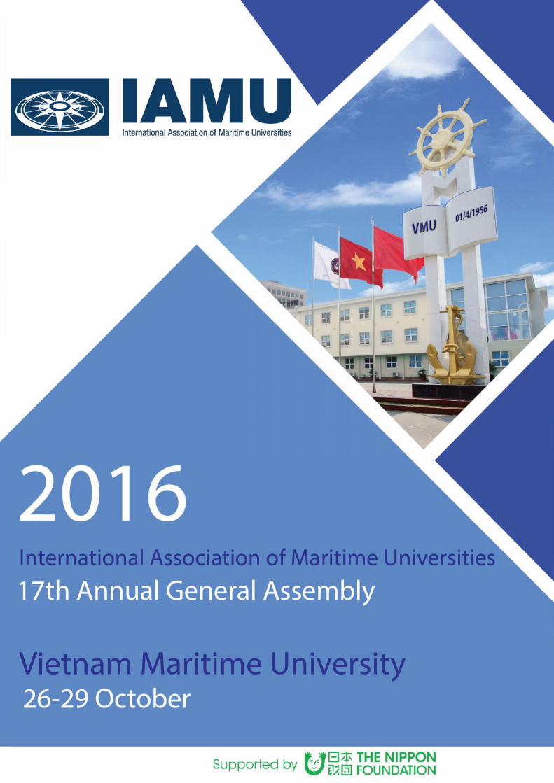
17th Annual General Assembly
International Association of Maritime Universities
IAMU AGA 17
Working together:
the key way to enhance the quality of
maritime education, training and research
Vietnam Maritime University
26 – 29 October 2016
i
WelcomeThe Vietnam Maritime University (VMU) is honored to host the 17th Annual General Assembly
(AGA17) of the International Association of Maritime Universities (IAMU) in Haiphong City, Vietnamin the period from October 26-29, 2016.
After taking the role of the representative of Region 2 (Asia, Pacific and Oceania) of the IAMU intwo continuous terms from 2012 to 2015, we are very proud to be elected for the host university ofAGA17 where the Presidents, experts and scientists of more than 60 member universities from all overthe world to discuss recent progress and future trends in maritime education, training, research and othermatters within the scope of IAMU. The year of 2016 is really a milestone for VMU marking the 60th
anniversary of its foundation and receiving honor awards from the government.
The theme of AGA17 is “Working together: the key way to enhance the quality of maritimeeducation, training and research”, including following sub-themes:
1. Standardization of maritime education, training and technical research;
2. Strengthening cooperation for maritime safety and security;
3. Strengthening cooperation for protection of ocean environment.
Many IAMU members are involved in researches on such sub-themes and the best will be exploredat the AGA17. We have finally over 50 scientific papers, 8 research/ development projects as well as anexcited program for IAMU students (IAMUS) including technical seminars with 31 studentpresentations. We sincerely hope that AGA17 will provide the opportunity to share and discuss issuesof mutual concern as well as a catalyst to enhance networking between member institutions.
Once again, on behalf of VMU’s staff, lecturers and students, I would like to welcome alldelegations to AGA17. Please enjoy its activities and take the opportunity to stay longer at ourflamboyance flower city as well as to spend your time on visiting the neighbor landscapes.
Finally, I would like to acknowledge and express my sincere thanks to all involved in ensuring thesuccess of AGA17, including representatives, speakers, students, participants, the Local ExecutiveCommittee and particularly the IAMU Secretariat and the Nippon Foundation for their continuing andvaluable supports.
People’s Teacher, Prof., Dr., C/E
Luong Cong Nho
President
Vietnam Maritime University
ii
Organization of the IAMU
Honorary ChairMr. Yohei Sasakawa
(Chairman of The Nippon Foundation)
International Executive Board
Professor Neil BOSE, IAMU Chair
(Australian Maritime College, University of Tasmania)
Prof. Dr. Luong Cong NHO, Head of LEC
(Vietnam Maritime University)
Dr. Cleopatra DOUMBIA-HENRY
(World Maritime University)
Prof. Dr. Janusz ZAREBSKI
(Gdynia Maritime University)
RADM Thomas A CROPPER
(California State University Maritime Academy)
Commodore Prof. DSc. PhD. BoyanMEDNIKAROV
(Nikola Vaptsarov Naval Academy)
Prof. Dr. Ismail Abdel Ghafar Ismail Farag
(Arab Academy for Science, Technology andMaritime Transport)
Prof. Dr. Abdi KÜKNER
(Istanbul Technical University, MaritimeFaculty)
Mr. Mitsuyuki UNNO
(The Nippon Foundation)
Dr. Mary Lou Lacson ARCELO
(John B. Lacson Foundation MaritimeUniversity)
Dr. Takeshi NAKAZAWA, Executive Director
(IAMU Secretariat)
SecretariatDr. Takeshi NAKAZAWA, Executive Director
Mr. Yutaka EMI, Deputy Executive Director
Ms. Shigemi MATSUZAKI, Coordinator
Ms. Akiko YAMADA, Coordinator
iii
Working together:
the key way to enhance the quality of
maritime education, training and research
Vietnam Maritime University
Hai Phong, Viet Nam, 26 – 29 October 2016
iv
AGA 17
Working together: the key way to enhance the quality of maritime education,training and research
Published by:
Vietnam Maritime University
Local Executive Committee of IAMU AGA 17
The texts of the papers in this volume were set individually be the authors or under their supervision.Only corrections pertaining to the style and/or formatting of the text may have been carried out by theeditors.
No responsibility is assumed by the Publisher, the Editors and Authors for any injury and/or damage topersons or property as a matter of products liability, negligence or otherwise, or from any use ofoperation of any methods, products, instructions or ideas contained in this book.
All rights reserved. No part of this book may be reproduced or transmitted in any form or by any means,electronic or mechanical, including photocopying, recording, or by an information storage and retrievalsystem – except by a reviewer who may quote brief passages in a review to be printed in a magazine ornewspaper – without permission in writing from the publisher.
© 2016 The Vietnam Maritime University
ISBN: 978-604-937-120-2
1
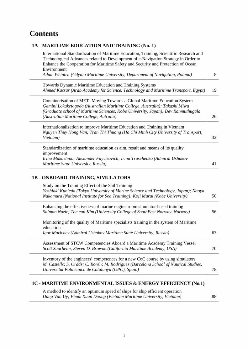
Contents
1A - MARITIME EDUCATION AND TRAINING (No. 1)
International Standardization of Maritime Education, Training, Scientific Research andTechnological Advances related to Development of e-Navigation Strategy in Order toEnhance the Cooperation for Maritime Safety and Security and Protection of OceanEnvironmentAdam Weintrit (Gdynia Maritime University, Department of Navigation, Poland) 8
Towards Dynamic Maritime Education and Training SystemsAhmed Kassar (Arab Academy for Science, Technology and Maritime Transport, Egypt) 19
Containerisation of MET- Moving Towards a Global Maritime Education SystemGamini Lokuketagoda (Australian Maritime College, Australia); Takashi Miwa(Graduate school of Maritime Sciences, Kobe University, Japan); Dev Ranmuthugala(Australian Maritime College, Autralia) 26
Internationalization to improve Maritime Education and Training in VietnamNguyen Thuy Hong Van; Tran Thi Thuong (Ho Chi Minh City University of Transport,Vietnam) 32
Standardization of maritime education as aim, result and means of its qualityimprovementIrina Makashina; Alexander Fayvisovich; Irina Truschenko (Admiral UshakovMaritime State University, Russia) 41
1B - ONBOARD TRAINING, SIMULATORS
Study on the Training Effect of the Sail TrainingYoshiaki Kunieda (Tokyo University of Marine Science and Technology, Japan); NaoyaNakamura (National Institute for Sea Training); Koji Murai (Kobe University) 50
Enhancing the effectiveness of marine engine room simulator-based trainingSalman Nazir; Tae eun Kim (University College of SouthEast Norway, Norway) 56
Monitoring of the quality of Maritime specialists training in the system of MaritimeeducationIgor Marichev (Admiral Ushakov Maritime State University, Russia) 63
Assessment of STCW Competencies Aboard a Maritime Academy Training VesselScott Saarheim; Steven D. Browne (California Maritime Academy, USA) 70
Inventory of the engineers’ competences for a new CoC course by using simulatorsM. Castells; S. Ordás; C. Borén; M. Rodríguez (Barcelona School of Nautical Studies,Universitat Politècnica de Catalunya (UPC), Spain) 78
1C - MARITIME ENVIRONMENTAL ISSUES & ENERGY EFFICIENCY (No.1)
A method to identify an optimum speed of ships for ship efficient operationDang Van Uy; Pham Xuan Duong (Vietnam Maritime University, Vietnam) 88
2
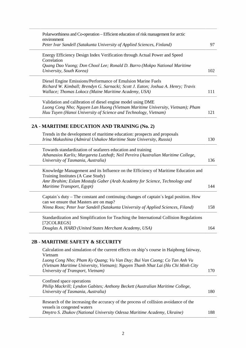
Polarworthiness and Co-operation – Efficient education of risk management for arcticenvironmentPeter Ivar Sandell (Satakunta University of Applied Sciences, Finland) 97
Energy Efficiency Design Index Verification through Actual Power and SpeedCorrelationQuang Dao Vuong; Don Chool Lee; Ronald D. Barro (Mokpo National MaritimeUniversity, South Korea) 102
Diesel Engine Emissions/Performance of Emulsion Marine FuelsRichard W. Kimball; Brendyn G. Sarnacki; Scott J. Eaton; Joshua A. Henry; TravisWallace; Thomas Lokocz (Maine Maritime Academy, USA) 111
Validation and calibration of diesel engine model using DMELuong Cong Nho; Nguyen Lan Huong (Vietnam Maritime University, Vietnam); PhamHuu Tuyen (Hanoi University of Science and Technology, Vietnam) 121
2A - MARITIME EDUCATION AND TRAINING (No. 2)
Trends in the development of maritime education: prospects and proposalsIrina Makashina (Admiral Ushakov Maritime State University, Russia) 130
Towards standardization of seafarers education and trainingAthanasios Karlis; Margareta Lutzhoft; Neil Pereira (Australian Maritime College,University of Tasmania, Australia) 136
Knowledge Management and its Influence on the Efficiency of Maritime Education andTraining Institutes (A Case Study)Amr Ibrahim; Eslam Mostafa Gaber (Arab Academy for Science, Technology andMaritime Transport, Egypt) 144
Captain´s duty – The constant and continuing changes of captain´s legal position. Howcan we ensure that Masters are on map?Ninna Roos; Peter Ivar Sandell (Satakunta University of Applied Sciences, Filand) 158
Standardization and Simplification for Teaching the International Collision Regulations[72COLREGS]Douglas A. HARD (United States Merchant Academy, USA) 164
2B - MARITIME SAFETY & SECURITY
Calculation and simulation of the current effects on ship’s course in Haiphong fairway,VietnamLuong Cong Nho; Pham Ky Quang; Vu Van Duy; Bui Van Cuong; Co Tan Anh Vu(Vietnam Maritime University, Vietnam); Nguyen Thanh Nhat Lai (Ho Chi Minh CityUniversity of Transport, Vietnam) 170
Confined space operationsPhilip Mackrill; Lyndon Gabites; Anthony Beckett (Australian Maritime College,University of Tasmania, Australia) 180
Research of the increasing the accuracy of the process of collision avoidance of thevessels in congested watersDmytro S. Zhukov (National University Odessa Maritime Academy, Ukraine) 188
3
Evaluating the Safety Of Floating Struture Under Designed Sea ConditionNguyen Tien Cong; Le Thanh Binh (Vietnam Maritime University, Vietnam) 194
Integration of Maritime Spatial Planning into the Waterways Safety ManagementstudiesMadli Kopti; Roomet Leiger; Inga Zaitseva-Pärnaste; Jarmo Kõster (EstonianMaritime Academy of Tallinn University of Technology, Estonia) 205
2C - MARITIME ENVIRONMENTAL ISSUES & ENERGY EFFICIENCY (No.2)
Effect of Injection Timing and Mixing Rate of Water in Jatropha Emulsion onCombustion and Performance of DI Diesel EngineNguyen Kim Bao (Vietnam Maritime University, Vietnam) 214
Sediment management practices for ports and shipyards –applicable approachesVlado Frančić; Lovro Maglić; Marija Šimić Hlača (University of Rijeka, Faculty ofMaritime Studies Rijeka, Croatia) 225
Particle Emissions from ships at berth using Heavy Fuel OilThuy Van Chu; Thomas Rainey; Zoran Ristovski; Ali Mohammad Pourkhesalian;Liping Yang; Richard J. Brown (Biofuel Engine Research Facility, QueenslandUniversity of Technology, Australia); Vikram Garaniya; Rouzbeh Abbassi (AustralianMaritime College, Australia) 235
Guessing to Prediction – A Conceptual Framework to Predict LNG Bunker DemandProfile in AustraliaRumesh H Merien-Paul; Hossein Enshaei; Shantha Gamini Jayasinghe (AustralianMaritime College, University of Tasmania, Australia) 244
EEDI reduction by investigatingthe capability of RANSE CFD for propeller, propeller–hull form performance calculation during ship optimization processTran Ngoc Tu; Nguyen Manh Chien (VietNam Maritime University, Vietnam) 253
3A - MARITIME EDUCATION AND TRAINING (No. 3)
Characteristic of post-degree courses organized in GMU on example “MODERN SHIPMANAGEMENT” courseLaczynski Bogumil; Laczynski Tomasz (Gdynia Maritime University, Poland) 264
Study On The Ideal Ways Of Enhancing The Quality Of Maritime Education, TrainingAnd ResearchCol.Dr.G. Thiruvasagam (AMET University, India) 272
IMO E-navigation Concept and MET trends analysisVladimir A. Loginovsky (Admiral Makarov State University of Maritime and InlandShipping, Russia) 276
Integrity of Electronic Testing of MarinersJohn Tucker; John Cross (Memorial University of Newfoundland, Canada) 282
Increasing the sustainability of the maritime research and trainingBoyan Mednikarov; Kalin Kalinov; Nedko Dimitrov; Zhelyazko Nikolov (NikolaVaptsarov Naval Academy, Bulgaria) 290
4
Distance learning for egyptian seafarers: a critiqueHesham M. Helal (Maritime Postgraduate Studies Institute, AASTMT, Egypt) 300
3B - HUMAN RESOURCHES & CULTURAL AWARESS
Opportunities and advantages for oversea seafarers human resources development inVietnamDinh Xuan Manh; Dao Quang Dan (Vietnam Maritime University, Vietnam) 308
Language Barriers, Cultural Differences and International Cooperation betweenMaritime InstitutionsQi Chen (Massachusetts Maritime Academy, USA) 318
Women seafarers as minority organizational membersMomoko Kitada (World Maritime University, Sweden); Lise Langåker(Stord/Haugesund University College, Bjørnsonsg. 45, 5531 Haugesund, Norway) 326
Study over the increasing of situational awareness and the culture of safety amongyounger officersRadu Hanzu-Pazara; Gabriel Raicu; Anastasia Duse; (Constanta Maritime University,Romania); Loredana Hanzu-Pazara (“Ovidius” University of Constanta, Romania) 334
Cultural Intelligence and Awareness in Maritime Education: A Case StudyBani Ghosh (Massachusetts Maritime Academy, USA) 345
A career capital approach in the training and development of merchant marine seafarers:The case of South AfricaSamrat Ghosh (Australian Maritime College (UTAS), Australia); Shaun Ruggunan(University of Kwazulu-Natal, South Africa) 352
3C - MARITIME ENVIRONMENTAL ISSUES & ENERGY EFFICIENCY (No.3)
Modelling reasonable operating regimes of the main propulsion plant: main dieselengine - propeller - hull on the general cargo shipDo Duc Luu; Luong Cong Nho; Tran Ngoc Tu (Vietnam Maritime University, Vietnam) 360
Ballast Water Management: Challenges for the Flag State and Port State ControlSamrat Ghosh; Christopher Rubly (Australian Maritime College, University ofTasmania, Australia) 372
Whirling vibration characteristics due to lubricating oil pressure in the Diesel –Generator shafting systemPham Huu Tan; Nguyen Tri Minh; Vuong Quang Dao (Vietnam Maritime University,Vietnam) 381
A Collaborative Approach to Protecting the Ocean EnvironmentPaul S. Szwed (Massachusetts Maritime Academy, USA); Carleen Lyden-Kluss (NorthAmerican Marine Environmental Protection Association, USA); Matthew Rooks(Graduate School of Maritime Science, Kobe University, Japan) 392
Floating Power Platforms for Off-shore Cold-ironingShantha Jayasinghe; Gamini Lokuketagoda; Hossein Enshaei; Dev Ranmuthugala(Australian Maritime College, University of Tasmania, Australia); Daniel Liang (DNVGL - Energy, Singapore) 402

5
The determing torsional vibration damping coefficients algorithm for computing marineshafting’ s vibrationsNguyen Manh Thuong (Vietnam Maritime University, Vietnam) 411
4 - RESEARCH IN MET
Ship Automatic Track keeping At Low SpeedThanh-Dat Le; Van-Luong Tran (Vietnam Maritime University, Vietnam); Nam-kyun Im(Mokpo National Maritime University, South Korea) 420
Advanced Navigation System in the Mediterranean Sea “Regional Project forManagement Control System”Mohamed Abdel Fattah Omar; Zouheir Abdel Fattah Badawy (Arab Academy forScience & Technology & Maritime Transport, Egypt) 431
Construction of Global Shipping Big Data PlatformShulong Dai; Shuping Liu; Jian Sun; Linhai Du; Yuguang Gong (Dalian MaritimeUniversity, China) 440
Logistics and Supply Chain Finance: Managing Financial Risks and OptimizingFinancial Flows in Logistics and Supply ChainsThuy Duong Dang (Vietnam Maritime University, Vietnam) 448

6
7
Session 1A
MARITIME EDUCATION AND TRAINING
(No. 1)
8
International Standardization of Maritime Education, Training, ScientificResearch and Technological Advances related to Development of e-
Navigation Strategy in Order to Enhance the Cooperation for MaritimeSafety and Security and Protection of Ocean Environment
Prof. Dr. Capt. Adam Weintrit, FRIN, FNI
Gdynia Maritime University, Department of Navigation, Gdynia, Poland; [email protected]
Abstract: The advantage of the latest technical development in the field of nautical sciences,automation, electronics, telecommunications, informatics, telematics, geomatics and global positionfixing techniques, achievement in data storing, processing, analysing, transferring and visualisationshould be taken into account and applied to the maritime technology. In the paper the author tries todiscuss a strategic vision of development e-Navigation concept using those new technologies and themain tasks of the maritime community for the near future in international standardization of maritimeeducation, training, scientific research and technological advances related to development of e-Navigation strategy in order to enhance the cooperation for maritime safety and security and protectionof ocean environment. The author believes it is now appropriate time to develop a broad strategic visionfor incorporating the use of new technologies in a structured way and ensuring that their use is compliantwith the various electronic navigational and communication technologies and services that are alreadyavailable. The author tries to present the background to „Why e-Navigation‟ and its definition, the keyelements which in the vision for e-Navigation were covered and the IMO's strength as the co-ordinatorof e-Navigation development, including strategy implementation plan. The underlying importantprinciples were stated, together with the need to take user needs into account. Later presentations andcomments showed just how ambiguous the term „users‟ can be in the context of e-Navigation. This ledto a more in depth review of the components of the IMO strategy implementation plan. The author triesto answer the question of whether these assumptions, decisions and actions taken were appropriate andsufficient. Implementing technology is like a three-legged stool: if any one leg is inadequate, the wholesystem fails. Here, one leg is the technology itself; another is the procedure for how to use the technology(gained through testing and experience) and the final one is maritime education and training, both in theoperation of the technology itself but most importantly in using the technology with agreed, standardizedprocedures to make good decisions. The development of well-balanced and highly qualified seafarers ispossible. It should be one of most important objectives for IAMU members.
Keywords: Navigation, Communications, Marine Transportation, Safety at Sea, Maritime Education andTraining (MET), e-Navigation
1. Introduction. Development of e-Navigation Concept
The last decades have seen huge developments in technology within navigation and communicationsystems. Sophisticated and advanced technology is developing rapidly. Seafarers have never had moretechnological support systems than today and therefore there is a need to coordinate systems and moreuse of harmonized standards. Although ships now carry Global Satellite Navigation Systems (GNSS)and will soon all have reliable Electronic Chart Displays and Information Systems (ECDIS) [9], theiruse on board is not fully integrated and harmonized with other existing systems and those of other shipsand ashore. At the same time it has been identified that the human element, including training,competency, language skills, workload and motivation are essential in today's world. Administrativeburden, information overload and ergonomics are prominent concerns. A clear need has been identifiedfor the application of good ergonomic principles in a well-structured human machine interface as partof the e-Navigation strategy [7],[10]. The combination of navigational errors and human failure indicatea potential failure of the larger system in which ships are navigated and controlled. Maritime accidentsrelated to navigation continue to occur despite the development and availability of a number of ship-and shore-based technologies that promise to improve situational awareness and decision-making. These
9
include radio navigation systems, including Global Navigation Satellite Systems (GNSS), AutomaticIdentification Systems (AIS), Electronic Chart Display and Information Systems (ECDIS), IntegratedBridge Systems (IBS), Integrated Navigation Systems (INS), Long Range Identification and Tracking(LRIT) systems, sophisticated maritime radars, Automatic Radar Plotting Aids (ARPA), Vessel TrafficServices (VTS) and Global Maritime Distress Safety Systems (GMDSS) [8].
The e-Navigation is a major IMO (International Maritime Organization) initiative to harmonise andenhance navigation systems and is expected to have a significant impact on the future of marinenavigation. The IMO has mandated that this initiative be led by ‘user needs’. It is believed that thesetechnologies can reduce navigational errors and failures, and deliver benefits in areas like search andrescue, pollution incident response, security and the protection of critical marine resources, such asfishing grounds. They may also contribute to efficiencies in the planning and operation of cargologistics, by providing information about sea, port and forwarder conditions [8].
1.1 Definition of e-Navigation
e-Navigation is a current international initiative that is intended to facilitate the transition of maritimenavigation into the digital era, is a vision for the integration of existing and new navigational tools, in aholistic and systematic manner that will enable the transmission, manipulation and display ofnavigational information in electronic format [12]. The IMO has defined e-Navigation as "theharmonized collection, integration, exchange, presentation and analysis of marine information on boardand ashore by electronic means to enhance berth to berth navigation and related services for safety andsecurity at sea and protection of the marine environment". e-Navigation would help reduce navigationalaccidents, errors and failures by developing standards for an accurate and cost effective shipping. e-Navigation is intended to meet present and future user needs through harmonisation of marine navigationsystems and supporting shore services.
The IMO further describes the compelling need for e-Navigation as a clear and compelling need to equipthe master of a vessel and those ashore responsible for the safety of shipping with modern, proven toolsto make maritime navigation and communications more reliable and user friendly and thereby reducingerrors. However, if current technological advances continue without proper coordination there is a riskthat the future development of marine navigation systems will be hampered through a lack ofstandardisation onboard and ashore, incompatibility between vessels and an increased and unnecessarylevel of complexity.
1.2 Electronic Navigation versus e-Navigation
The strength of the IMO’s e-Navigation initiative is that it should lead to greater harmonization ofnavigation information and communication on an international basis. This will be essential for safetyand international trade. The weakness, however, is the time it will take to obtain agreement by all nationsand stakeholders, particularly in a time of such rapid technology advancement. Electronic navigation iswith us now and is epitomized by ECDIS with GNSS. We recognize that this is widely relied upon, oreven over-relied upon. The training requirements for ECDIS came into force in January 2012 as per theManila amendment to STCW [4], and the first phase of ECDIS carriage requirements commenced inJuly 2012. The phased carriage requirement of Electronic Chart Display and Information System(ECDIS) is underway and is scheduled to be completed by 2018. ECDIS is a complex system and willbe one of the most essential tools for supporting mariners in their efforts to ensure the safety ofnavigation and protection of the marine environment’. The ability to harness the power of ECDIS andto avoid catastrophe due to incompetence is largely down to training and familiarisation.
1.3 ECDIS Guidance for Good Practice
All Comprehensive guidance is available in the IMO Circular MSC.1/Circ.1503 ECDIS Guidance forGood Practice [6]. All ships masters, navigating officers and operators of ships fitted with ECDIS areencouraged to use this guidance to facilitate the safe and effective use of ECDIS.
10
Ship owners and operators need to ensure careful management and regular maintenance of both ECDIShardware and software. MSC.1/Circ.1503 contains guidance on maintenance of ECDIS software andidentifies the need to keep ECDIS updated to meet the current International Hydrographic Organization(IHO) standards.
A list of known ECDIS anomalies is included in MSC.1/Circ.1503. Due to the complex nature ofECDIS, and because it involves a mix of hardware, software and data, it is possible (but considered notlikely) that further undetected anomalies may exist. The existence of anomalies highlights theimportance of maintaining ECDIS software to ensure the correct display of up-to-date electronicnavigational charts. To help understand the extent of these anomalies, navigating officers are encouragedto report any such anomalies, including specific details regarding fitted equipment, to their flag Stateauthority.
The IHO has produced an ECDIS Data Presentation and Performance Check dataset that allows marinersto check some important aspects of the operation of their ECDIS. This dataset contains two fictitiousENC cells which can be loaded into an ECDIS to assess operating performance. The test will checkwhether there are any display anomalies that need to be remedied or otherwise managed. If the checkhighlights a problem, guidance notes in the check dataset offer suggested courses of action.
2. The IMO e-Navigation Strategy
It should be noted that the term e-Navigation is often used in a generic sense by equipment and serviceproviders. This claim should be seen as an aspiration, rather than an indication of compliance.The e- Navigation is a concept to support and improve decision-making through maritime informationmanagement and it aims to [7]:- facilitate the safe and secure navigation of vessels by improved traffic management, and through the
promotion of better standards for safe navigation;- improve the protection of the marine and coastal environment from pollution;- enable higher efficiency and reduced costs in transport and logistics;- improve contingency response, and search and rescue services;- enhance management and usability of information onboard and ashore to support effective decision
making, and to optimize the level of administrative workload for the mariner.
The e-Navigation aims to provide digital information for the benefit of maritime safety, security andprotection of the environment, reducing the administrative burden and increasing the efficiency ofmaritime trade and transport. The work conducted by the IMO during the last years lead to theidentification of specific user needs and potential e-Navigation solutions. The e-Navigation StrategyImplementation Plan (SIP), which was approved in 2014, contains a list of tasks required to be conductedin order to address 5 prioritized e-Navigation solutions, namely [10]:- improved, harmonized and user-friendly bridge design;- means for standardized and automated reporting;- improved reliability, resilience and integrity of bridge equipment and navigation information;- integration and presentation of available information in graphical displays received via
communication equipment; and- improved Communication of VTS Service Portfolio (not limited to VTS stations).
It is expected that these tasks, when completed during the period 2015–2020, should provide the industrywith harmonized information in order to start designing products and services to meet the e-Navigationsolutions. The ultimate goal of e‐Navigation is to integrate ship borne and land based technology on aso far unseen level. e-Navigation is meant to integrate existing and new electronic navigational tools(ship and shore based) into one comprehensive system that will contribute to enhanced navigationalsafety and security while reducing the workload of the mariner (navigator) [3]. The bridge between thosetwo domains will be broadband communication technology which is about to arrive in regular
11
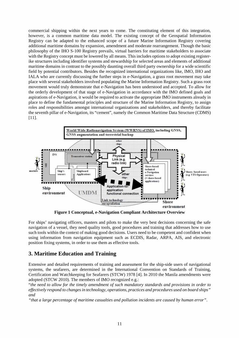
commercial shipping within the next years to come. The constituting element of this integration,however, is a common maritime data model. The existing concept of the Geospatial InformationRegistry can be adapted to the enhanced scope of a future Marine Information Registry coveringadditional maritime domains by expansion, amendment and moderate rearrangement. Though the basicphilosophy of the IHO S‐100 Registry prevails, virtual barriers for maritime stakeholders to associatewith the Registry concept must be lowered by all means. This includes options to adopt existing register‐ike structures including identifier systems and stewardship for selected areas and elements of additionalmaritime domains in contrast to the possibly daunting overall third party ownership for a wide scientificfield by potential contributors. Besides the recognized international organizations like, IMO, IHO andIALA who are currently discussing the further steps in e‐Navigation, a grass root movement may takeplace with several stakeholders involved populating the Marine Information Registry. Such a grass rootmovement would truly demonstrate that e‐Navigation has been understood and accepted. To allow forthe orderly development of that stage of e‐Navigation in accordance with the IMO defined goals andaspirations of e‐Navigation, it would be required to activate the appropriate IMO instruments already inplace to define the fundamental principles and structure of the Marine Information Registry, to assignroles and responsibilities amongst international organizations and stakeholders, and thereby facilitatethe seventh pillar of e‐Navigation, its “cement”, namely the Common Maritime Data Structure (CDMS)[11].
Figure 1 Conceptual, e-Navigation Compliant Architecture Overview
For ships’ navigating officers, masters and pilots to make the very best decisions concerning the safenavigation of a vessel, they need quality tools, good procedures and training that addresses how to usesuch tools within the context of making good decisions. Users need to be competent and confident whenusing information from navigation equipment such as ECDIS, Radar, ARPA, AIS, and electronicposition fixing systems, in order to use them as effective tools.
3. Maritime Education and Training
Extensive and detailed requirements of training and assessment for the ship-side users of navigationalsystems, the seafarers, are determined in the International Convention on Standards of Training,Certification and Watchkeeping for Seafarers (STCW) 1978 [4]. In 2010 the Manila amendments wereadopted (STCW 2010). The members of IMO recognized e.g.:“the need to allow for the timely amendment of such mandatory standards and provisions in order toeffectively respond to changes in technology, operations, practices and procedures used on board ships”and“that a large percentage of maritime casualties and pollution incidents are caused by human error”.
12
Such changes generate new demands on training institutions and on instructors working within them.The implementation of the e-Navigation concept on board and ashore requires a further adaption relatedto new training concepts and new instructional media to changed standards. Complementary it must beensured that instructors and assessors are appropriately trained and experienced. Trainers must bequalified in the task for which training is being conducted.
3.1. Training and Assessment On-line Introducing New Technology
During the last decades a lot of new navigational systems were installed on ships’ bridges. Respondingto that development the Maritime Safety Committee (MSC) published already in June 2003 theMSC/Circ. 1091 “Issues to be considered when introducing new technology on board ship” [5]. Theintroduction describes the way of looking at the problem in summary:
“The effectiveness of crews to use the technology safely and to best effect requires familiarity with theequipment and training as recognized in the STCW Convention. There are a number of aspects to beconsidered with respect to how seafarers interact with the technology and also some issues to beconsidered when assessing the training needs for the seafarers who use such technology” [5].
Furthermore document [5] stipulates issues to consider for the training of seafarers when introducingnew technology:
a) Standardization: Although performance standards exist, the controls and displays are notstandardized. The result is an increase in the amount of training needed to make a seafarer familiarwith and effective in the use of the equipment. There are some causes which make increased trainingimpossible e.g. a seafarer joins the vessel just prior to departure or the system aboard the vessel isvery different from those on which the seafarer has received training ashore.
“One solution is to familiarise seafarers with equipment by training them using simulators (eitherdesktop or full mission) prior to them joining their ships. This is made far more efficient whenmanufacturer provide assistance in developing the training tools” [5].
This solution can be improved by developing a common interface with standard symbology forcommon operations. Seafarers should be trained to use the standard dis-play whenever possible,preconditioned the “standard operation” includes all functionalities for safe navigation.
b) Training for technology based systems: There are a lot of challenges to be managed when trainingseafarers for using technology-based systems on board. E.g. different cultural and practical behaviourpatterns. It was ascertained that many young watchkeepers have a culture of using in-formationtechnology (home computers, Internet, video games etc.) and that during times of stress revert toelectronic displays for their primary decision support systems. “Inexperienced seafarer may seekmore data and information in stressful situations, often confusing themselves further. Problems canalso develop when novice navigators are trained on desktop simulators which do not have theadvantage of a simulated ’window‘ for visual observation. This may reinforce the habit of constantreliance on a digital display for situational awareness during actual operations” [5]. Onequintessence concluding this section is that only well-trained officers understand to manage andprioritise ECDIS and AIS information. The same information provided to an officer without ECDISand AIS training can lead to information overload and poor decision making.
c) Introducing new technology regarding the human element: The results of research referenced toautomation are:- automation has qualitative consequences for human work and safety,- automation does not simply replace human work with machine work,- automation changes the task it was meant to support,- automation creates new error pathways,
13
- automation shifts the consequences of error further into the future and may delay opportunities forerror detection and recovery,
- when automation is installed operators will monitor less effectively,- automation creates new kinds of knowledge demands.
“Watchkeepers must have a working knowledge of the functions of the automation in differentsituations, and know how to co-ordinate their activities with the automated system’s activities. Thismanifests itself in situations whereby officers do not understand weakness or limitations of systemsthey rely on. Training in this respect will become more important, as systems become more integratedand sophisticated” [5].
d) Summary: New technology installed on board can improve the efficiency and effectiveness ofwatchkeeping and consequential improve the safety of operations. However, this technology bringswith it the inherent training requirement needed to operate the new systems physically, and also thetraining need to use the system to make better decisions. The positive effects of new technology willincrease with degree of standardization of designs.
3.2 E-Navigation Specific Training
The IMO’s Strategy Implementation Plan (SIP) describes the further development of e-Navigation andcontains a plan for enhancing public awareness of e-Navigation. The SIP focuses on five prioritizedsolutions, as follows [10]:
S1: improved, harmonized and user-friendly design;S2: means for standardized and automated reporting;S3: improved reliability, resilience and integrity of bridge equipment and navigation information;
S4: integration and presentation of available information in graphical displays received viacommunications equipment; and
S9: improved communication of VTS Service Portfolio.
The implementation of all prioritized solutions require specific training referred to the used technicalmethods and new operational procedures to comply with the key messages for all stakeholders listed inthe table “Examples of key messages to promote the benefits of e-Navigation”. A detailed descriptionand a table presenting the structure of the SIP are included in [10]. Scrutinizing the solutions in detail itbecomes clear that the solutions S1and S4 address the equipment and its use on a ship only, while S2and S9 address improved communications between ships, ship to shore and shore to ship. Solution S3addresses both bridge equipment and e.g. shore-ship information as part of the PNT system.Consequently training courses which must developed for the solutions S2 and S9 must include newtechnical and operational competencies for both users groups, the seafarers and the shore side users.With regard to S9 the STCW requirements and the “IALA Model Course V-103/1 – Vessel TrafficServices Operator Training” must be revised. A possible solution could be an IMO Model Course:“Operational use of VTS Services” [1].
3.3 The Evolution of Using Simulators in Maritime Education and Training
By 1967 first ship simulators came into use for the maritime education of seafarers at merchant marineacademies. In the 1990ies, along with the increasing capabilities of computers the simulators developedfrom pure radar simulators to full mission simulators with more and more sophisticated visualisation.The modern ship handling simulator provides the new students of the naval academies and universitieswith the opportunity to sample ship handling, without hazard. Simulators also allow working bridgepersonnel to learn the techniques of Bridge Team Management (BTM), working through a variety ofpotential problems that might never be encountered, but would be life-threatening should they occur.
The simulator allows mariners access to a real time simulation of the conditions aboard ship-on thebridge, in engineering spaces or in specialized spaces such as cargo handling at a lower cost thanteaching classes aboard a training ship. Ship handling simulators are used to train mariners to handle
14
ships in a variety of situations, from docking and undocking, to navigating various approaches in avariety of conditions using actual ship performance data in real time. The key features to a ship simulatorare real operational controls and a system that allows the instructors operating the simulator to put thesimulator students into realistic situations. All simulators are designed to provide an experience as closeas possible to the real world. Bridge simulators provide accurate visual representations through the"bridge windows" and some are even mounting on hydraulic platforms to mimic movement. The speedcontrols, steering, radar and charting systems are the same found on the bridge of modern ships.
Today marine simulators take over an increasing part in maritime training to raise safety standards.STCW 2010 [4], section A-I/12, contains the standards governing the use of simulators for maritimetraining of seafarer:- Part 1 deals with the general performance standards for simulators used for mandatory simulator-
based training, assessment of competence and in accordance with their specific type (Radarsimulation, ARPA simulation);
- Part 2 deals with the training and assessment procedures. STCW 2010 [4] section B explains the“Recommended performance standards for non-mandatory types of simulation” “Such forms ofsimulation include, but are not limited to, the following types:.1 navigation and watchkeeping;.2 ship handling and manoeuvring;.3 cargo handling and stowage;.4 reporting and radiocommunications; and.5 main and auxiliary machinery operation.
“Navigation and watchkeeping simulation equipment should, in addition to meeting all applicableperformance standards set out in section A-I/12, be capable to .4 realistic simulate VTS communicationprocedures between ship and shore”.
For the shore side part of VTS communication the IALA Model course V, Part D – Guidelines forinstructors, section 5, describes subjects and assessment criteria included in 100 hours simulatedexercises.
3.4. E-Navigation Training Proposals
In this section the author presents the candidate solutions relating to education, training and usingsimulators. In the Interreg North Sea Region Programme ACCSEAS were identified in total 14 trainingproposals, described in the “Baseline Report” [1]. Some were portrayed in detail including technicalspecifications and user manuals. At the end of ACCSEAS project the solutions reached a different stageof development. For further work on training and use of simulators in e-Navigation training anddemonstration it is reasonable to group them as follows:
1. Maritime Service Portfolios (MSPs),2. Route Topology Model (RTM),3. “Maritime Cloud” as an underlying technical framework solution,4. Innovative Architecture for Ship Positioning:
a) Multi Source Positioning Service,b) R-Mode at existing MF DGNSS and AIS Services,
5. Maritime Safety Information / Notices to Mariners (MSI/NM) Service,6. No-Go-Area Service,7. Tactical Route Suggestion Service (shore-ship),8. Tactical Exchange of Intended Route (ship-ship and ship-shore),9. Vessel Operations Coordination Tool (VOCT),10.Dynamic Predictor (for tug boat operations),11.Augmented Reality / Head-Up-Displays (HUDs),12.Automated FAL Reporting,13.Harmonized Data Exchange – Employing the Inter-VTS Exchange Format (IVEF),14.Real Time Vessel Traffic Pattern Analysis and Warning Functionality for VTS.
15
The majority of mentioned solutions are thoroughly investigated and ready for developing trainingarrangements except the last three solutions. They are in principle recognized, but unfortunately yet notready for developing training arrangements.In addition, in the author opinion, we should take into account the following extra proposals:
1. Virtual Aids to Navigation (Virtual ATON) and AIS ATON (Real, Synthetic and Virtual),2. Back-up Arrangements for ECDIS,3. A robust electronic position-fixing system with redundancy,4. IHO S-100 Universal Hydrographic Data Model (explanation and use).
First of all we should teach our students how to:- avoid common-mode failures (e.g. GNSS, e-Loran, inertial systems, integrity checks),- improve situational awareness (target matching, coherent presentation), and- prevent information overload (alarm management, essential information only).
3.5. Training Requirements for Operating an e-Navigation ship
We must ask ourselves why we need this new concept and why we expect it to improve. From a simplelook on the ships bridges we can see that the deck officer has a multitude of information presented tohim at the same time on different displays (ECDIS, Radar, and GPS receiver) and the most importantissue of all is that each equipment has functions/features that will distinguish itself from others that areto be found on different ships. Unfortunately, the user interface (the main menu) is not internationallystandardized. Even if the information is readily available at almost any console (for example, positioninformation provided by GPS, can be found at the radar and ECDIS displays) and operation at firstglance seems simple and easy, in emergency situation, where will be required our fast response andquick decision to be made, even knowing where on the screen is presented the required information, thesituation as a whole becomes very problematic [2],[7]. That means that each officer will need some timeto find out how to operate the systems efficiently at the same time: there is the risk of accidents ormisinterpretation of data due to fatigue or tiredness that is not all that uncommon in this line of activity.With e-Navigation we see an important step being made towards standardization while leaving withregard that sufficient room is left to equipment producers while leaving sufficient room forimprovement. It is also under debate whether an S-Mode (Standard Mode) should be introduced for eachequipment to be found on board a standard mode to which every officer and pilot should be familiarized,so to prevent any misinterpretation of data [7].
We must remember that e-Navigating means that the OOW has a completely autonomous and fullyworking system on board for a safe voyage, but also has the possibility to be fed with a wide variety ofinformation from shore-based facilities [3]. That means e-Navigation requires a highly efficient datacommunication network that allows a constant flux of information between the ship and shore systemslike VTS, ship to ship communication. This higher efficiency is needed because services like the VTSfind themselves having to cope with a greater and greater number of ships and, as a result an increasingamount of time has to be spent on organizing the traffic flow and on security operations. Also the shipsowners and charters will benefit because of improved communication with the ship allowing them to beup to date with her general operation. But the e-Navigation concept is not limited to the equipment onboard a ship it also includes the officer as an integral part of the system, because based on all theinformation available to him, he is expected to make decisions that could make the difference betweensafe navigation and maritime disasters. But we must realize that every equipment has its limitations andits inherent flaws, and could fail to perform. Thus, it is a very dangerous trend that in modern days anOOW should rely only on the information provided by the GPS or RADAR or the ECDIS. Indeed, manymasters consider for a good reason that on board their ships the most important equipment are the eyes,ears, and the mind of the OOW, and that the most important consoles are the windows of the ships [2].
Colreg states under Rule 5 that "a good every vessel shall at all time maintain a proper look out by sightand hearing as well as by all available means appropriate in prevailing circumstances and conditionsso as to make a full appraisal of the situation and of the risk of collision", and under Rule number 7 it
16
is stated: "every vessel shall use all available means appropriate to prevailing circumstances todetermine if risk of collision exists" also it warns that "assumptions shall not be made on the basis ofscanty information, especially scanty radar information". With this in mind we must realize that withthe technological advancement in navigation equipment we expect the naval officers to exercise theirprofession in a safer manner. And indeed it should be so, but nowadays most of the naval accidents andnaval disasters are due to human error [2]. However, along with the STCW convention, e-Navigationshould make a great impact on safety levels and prevention of pollution. We think that it will becompulsory that upon arrival on a new ship (which has an integrated bridge system), the OOW musthave special time allocated to reading the user manuals for the IBS equipment [2]. After that, adiscussion and practical explanation session must be arranged under the supervision of senior officers,before the ship will leave the port.
3.6. Preparing Students for e-Navigation
At the Faculty of Navigation in Gdynia Maritime University, as in many other maritime universities [2],we are educating our students with due regard to e-Navigation concept since a few years. We believethat the maritime officer is a crucial part of this concept and the way they are educated is crucial to theirfuture performances. In their two first years they learn how to navigate a ship without the use of modernsystems. Disciplines like celestial navigation and coastal navigation emphasize the fact that a ship canbe safely navigated with only a sextant, a compass, navigational charts, and a very well prepared bridgeteam of officers. They gain basic knowledge on theoretical and practical aspects of navigation as awhole. The program curricula includes Radar Navigation, Radar Plotting, as well as the use of ARPA.At these practical trainings our students are introduced to at least five/six different radar/ARPA displaytypes, five/six various ECDIS simulators, five/six diverse GPS receivers, off course of differentmanufacturers. They learn how to make proper use of the ENCs, the GPS, AIS, ARPA, ECDIS, and thecommunication services on board a ship. The most important aspect of education regarding e-Navigation is represented by the skills they gain by working on simulator and how to use all theknowledge they have accumulated over the years and to experience situations that they may encounterat sea [2]. Apart from putting to practice the Colreg rules, they are accustomed to being in constantcommunication with VTS stations, as well as with ships in their vicinity.
4. Conclusions
The IMO as a specialized agency of the United Nations, which primary purpose is to develop andmaintain a comprehensive regulatory framework for shipping and its remit includes safety,environmental concerns, legal matters, technical co-operation, maritime security and the efficiency ofshipping and as the leading international body for maritime professionals will continue to use theresources of its members states to promote the effective application of the e-Navigation concept, ofcourse including innovative methods of education and training. The maritime universities associated inthe IAMU should assist in that process and therefore it is my pleasure to invite all maritime professionalsto join in this critical effort.
Thanks to advances in information technology, free communication between ocean and land is nowavailable and all maritime society carry forward the e-Navigation for maritime accident prevention,transport efficiency, energy conservation and marine environment protection purpose. A large-scaleimplementation of the e-Navigation features is inevitable in the near future. The impact of electronicsand computers on the ships' bridges is well known for at least 20 years. Despite this, there are still a lotof debates regarding the real improvement of safety based on electronics. Because the future means e-Navigation, we have to start to prepare our students and cadets to face the challenges raised by anincreasing amount of navigation information that must be selected, absorbed, processed and analysed ina proper way, in order to determine the correct actions.
In order to achieve this goal, to traditional methods to teach navigation must be added a new kind ofmodule able to integrate the main information from all kind of navigational sources and sensors. We
17
have to develop the students habitudes to generate their own overall image of the surrounding situation,based on as much information available as possible. We also have to develop new kind of maritimesafety culture of our students for a self-learning process when confronted with new types of navigationalequipment and a new layout/configuration of the integrated bridge system. They have to obtain a properonboard training, starting with enough time to familiarize and understand the user manuals of thenavigation equipment installed in the INS/IBS.
The e-Navigation is a broad concept that is aimed at enhancing navigation safety, security and theprotection of the marine environment through the harmonised collection, integration, exchange,presentation and analysis of maritime information onboard and ashore by electronic means. It isenvisioned that e-Navigation will be a ‘living’ concept that will evolve and adapt over a long time scaleto support this objective. During this time information will change, technologies will change, politicaland commercial objectives will change, and tasks will change, and even our expectations will change.However it is unlikely that the need for safe and efficient seaborne transport will change significantly.It is also certain that the safe and efficient transport will continue to rely on good decisions being madeon an increasingly constant and reliable basis. Some decisions may be made with increased dependenceon technology, but at some level we will always rely on good human decisions being made and thereforeevery effort needs to be made to apply an understanding of the Human Element at all stages, of design,development, implementation and operation of e-Navigation. Therefore we need new, modifiededucation and training system dedicated and targeted to e-Navigation and well standardisedinternational procedures for marine navigation.
5. References
[1] ACCSEAS: The Interreg IVB North Sea Region Programme: ACCessibility for Shipping,Efficiency, Advantages and Sustainability ACCSEAS Baseline and Priorities Report, Latestversion: 3.4a, London, 14 January 2015.
[2] Barsan E., Muntean C.: e-Navigation Requires New Methods of Training for Deck Officers.Proceedings of the 9th Annual General Assembly of the International Association of MaritimeUniversities (IAMU): Common Seas, Common Shores: The New Maritime Community. Editors:Donna Nincic and Graham Benton. California Maritime Academy, San Francisco, 2008.
[3] Bibik Ł., Królikowski A., Czaplewski K., Duda D.: Vision of the Decision Support Model on Boardof the Vessel with Use of the Shore Based IT Tools. TransNav, the International Journal on MarineNavigation and Safety of Sea Transportation, Vol. 2, No. 3, September 2008
[4] IMO: International Convention on Standards of Training, Certification and Watch-keeping forSeafarers (STCW 2010), International Maritime Organization, London, 2010.
[5] IMO: Issues to be considered when introducing new technology on board ship, MSC/Circ.1091,International Maritime Organization, London, 2003.
[6] IMO: ECDIS - Guidance for Good Practice. MSC.1/Circ.1503. International MaritimeOrganization, London, 2015.
[7] Patraiko D., Introducing the e-Navigation Revolution. Seaways, The International Journal of theNautical Institute, March 2007.
[8] Patraiko D., Wake P., Weintrit A.: e-Navigation and the Human Element. TransNav, theInternational Journal on Marine Navigation and Safety of Sea Transportation, Vol. 4, No. 1, March2010.
[9] Weintrit A.: The Electronic Chart Display and Information System (ECDIS). An OperationalHandbook. A Balkema Book. CRC Press, Taylor & Francis Group, Boca Raton – London - NewYork - Leiden, 2009 (ISBN: 9780415482462), pp. 1101.
[10] Weintrit A., Prioritized Main Potential Solutions for the e-Navigation Concept. TransNav, theInternational Journal on Marine Navigation and Safety of Sea Transportation, Vol. 7, No. 1, March2013.
[11] Weintrit A.: Development of the IMO e-Navigation Concept – Common Maritime Data Structure.In: Mikulski J. (ed.) TST 2011, Communications in Computer and Information Science, vol. 239.Modern Transport Telematics. Springer, Heidelberg 2011, pp. 151-163.

18
[12] Weintrit A.: Software Quality Assurance in e-Navigation. In: Mikulski J. (ed.) TST 2015,Communications in Computer and Information Science, vol. 531. Tools of Transport Telematics.Springer, Heidelberg 2015, pp. 141-150.
19
Towards Dynamic Maritime Education and Training Systems
Capt. Ahmed Kassar, PhD.
Arab Academy for Science, Technology and Maritime Transport, Email: [email protected]
Abstract
Despite the rushing development in shipping industry paralleled to technology acceleration, accidentsand disasters still frequently happened. MET systems still relying on the minimum standards laid downby STCW convention to achieve the required standards for competency and qualification of seafarers.Furthermore, STCW convention does not designate the suitable teaching methodology for differentsubjects to achieve the required competencies and skills.
Maritime education and training depends mainly on providing candidates with knowledge andcompetencies to be able to perform certain duties and assignments, without any consideration ofcandidates` self-experiences, industry feedback and lesson learnt from previous accidents, incidents andnear-miss reports.
Same safety training and proficiencies are provided to Master and First officers on one side,and Chiefengineer and Second engineer on the other side at management level, this meana repetition of the sameproficiencies whether during upgrading studies or refreshment of competences. Officers at managementlevel can have instead more advanced management studies depending on the intellectual development,sharing of experiences and industry feedback.
It is important to have more reliable and effective MET system capable to overcome the problem ofhuman errors and be able to keep pace with shipping industry updates. A proposed methodology for amore dynamic MET system is introduced as a new approach on how the maritime education and trainingcan be provided to seafarers.
Key Words: Maritime Education and Training systems (MET), Dynamic Education System, STCWConvention, Experiences Exchange, shipping Industry
1. Introduction
Shipping today is a highly technical professional discipline. It requires special workforce withconsiderable skills, knowledge and expertise. Effective and reliable standards of training are the basesof a safe, secure and clean shipping industry. The main goal of MET standards is to providelearners withthe required competences and proficiencies, yet experiences only achieved during practicing of workonboard ships along unlimited time duration, where seafarer practicing trial and error until reachingsatisfied performance. However, seafarer experiences and their response to different situations alwaysdiffer from one to another, despite the fact that maritime training institutions are generally implementingthestandards of STCW convention as a minimum requirements guided by IMO related model courses.
STCW convention standards still provided to student as indoctrination of subject material without anyconsideration paid to the role of human errors in shipping accidents and the surrounding contributingfactors that affect efficiency of preforming assigned tasks.
In fact, what has been achieved in technology during the past two decades can`t be evencompared withthe whole progress that has been achieved during the last century as a whole. Despite the technologicaldevelopment in all sorts of life,it hasn’tbeen imitated the same way with same speed in shipping industry,not only in the field of shipbuilding, management, but extends to differentother management style,whether onboard ships or in shipping companies.
20
Effective education deals with emotions, attitudes, and values of students through instructional designto modify thinking and behavior of the learner. Khan,(6).In order to provide ships with crewshavingqualifications and experiencesalways aligned with the frequent development in shippingindustry,and being able to prevent accidents in active and professional manner, MET has to be moreallied to industry and representsreality of work at sea.
Moreover, to add value to MET systems, it has to rely much more onsharing experiences rather thanlistening to repeated knowledge and skills, especially for those at management level as Masters andChief Engineers.In addition, shipboard staff needsto be fully conversant with supporting professionaltechniques such as management and intellectual sciences.
2. Shipping Accident and Human Errors
According to the annual report issued by Allianz (1), shipping losses continued their long-termdownward trend with 85 total losses reported worldwide in 2015. Although the number of ships lossesremained stable yearly, declining by just 3% compared with the previous year (88), which fortunatelymakes year 2015 the safest year in shipping for decades. Losses have declined by 45% since 2006,driven by safety environment and self-regulation.
Cargo and fishing ships accounted for over 60% of ships lost globally, with cargo ships losses up forthe first time in three years. The most common cause of total losses was foundering (sinking), accountingfor almost 75% of losses, also up 25% happened due to bad weather. In general, the reportdeclared 2,687reported shipping incidents globally in 2015.
All references and statistics of shipping accidents during the last five decades have pointed to humanerrors as the main reason behind 85% ~ 90% of accidents at sea. EMSA, (2) declares that the mainfactors which have an effect on the potential for human error are education, training and workingconditions. Therefore, the better the education and training received by seafarers is, the safer shippingwill become.
According to TrasNav, (8) There are two factors that Human errors depend upon, the internal factorswhich related to the operatorsʹ characteristics and differences such as skill, experience, task familiarity,and the external factors that related to equipment design and installation, task complexity, workenvironment, organizational factors and operating procedures. A proper balance between the capabilityand experiences of the human operator and the difficulty of the task would decrease the likelihood ofhuman error.
As Jenni (5) explained the underlying theory of incidents reporting or what is known as iceberg modelor accident pyramid, that, for every serious accident, there are 29 less serious accidents and 300 nearmiss cases. However, near misses and less serious accidents have the same underlying reasons as seriousaccidents. Incidents and near misses are usually unnoticed and unreported, and quite often seen asnormal operational failure issues. As no accidents have occurred, as result of these unreported incidentsand near misses, or avoided due to unintentional acts, they have remained hidden. However, the worldhas become more aware of major accidents that involve ships, than the initial events or faults that if thechain or the tree of faults or events is accomplished, risk might accelerate and lead to unavoidable seriousaccidents.
Procedia, (7) declared that learning lessons from incidents and near misses improves safety performance.The mandatory International Safety Management Code requires shipping companies to establish areporting system in order to promote continuous learning in safety management. However, incidentsand near misses still reported poorly in the shipping industry, and always limited to the level of shippingcompanies or certain group of fleets, but not yet broadcasted worldwide and not effectively utilized inMET.
21
Therefore, if incidents and near misses are frequently reported, communicated globally, and thenintegrated in the MET systems, serious accidents would be avoided and diminished worldwide.
Unfortunately, reasons behind several accidents onboard are relatively the same and repeated along thelast nearby decades with the same way,consequences and errors. Seafarers onboard are systematicallyfocused on performing tasks depending on theiracquired experiences and skills without anyconsideration or review of steps that shall be taken to start or carry out the required task. Onboard ships,seafarers at all levels, gaining experiences through their own practices or individual situationalcircumstances; there is no chance for them to study or upgradetheir knowledge and skills.
3. Shortcomings of the current Maritime Education and Training system
The latest major amendments to the STCW convention entered into force in 2012, the same year thathas witnessed the disaster of passenger ship "Costa Concordia", just few meters from the Italian coastwith the same reasons and causations of the "Herald of Free Enterprise" disaster that happened thirty-five years ago. This obviously indicates that current MET systems are still not capable enough to reachthe right approach to cut the potentials of accident at sea.
STCW review reflects the same trends in the need for more specialization to address the higher-levelmaritime operations onboard through a wider coverage of knowledge, skills and competencies. STCWconvention depends mainly on the competency-based training always targets skill gaps and focuses onperformance of skills and acquisition of knowledge. STCW convention of course doesn`t contain anyreferences to the suitable methodologies to be used to provide such competencies and skills. Using thetraditional training methodology, that often generic, rather than targeted toward specific experiencedevelopment.
Maritime education and training Standards are frequently amended and updated in response to proposalssubmitted by IMO`s parties, these always prepared according to research findings or outcomes of newtechnology and accident investigation reports. Proposals for change always proceed for prolongedprocedures that might take four to five years duration until being completely effective. This prolongedprocedures causethe graduated students become always behind industry updates and always attainobsolete knowledge.
Despite the comprehensive amendments of STCW convention, there is still a gap between the actualindustry practices and the standards of training and competencies required to be addressed. There is aneed to add much more proficiencies such as Port State Control procedures and Coastal State Control.In addition, special safety control and reviews carried out on tankers like; the International TankerOwners Association review, Chemical Distribution Institute (CDI) M, (Marine), Tanker Managementand Self Assessment (TMSA) inspection, and Ship Inspection Report (SIRE) Program on gas, oil, andchemical tankers have not yet covered as proficienciesin STCW convention. Seafarers only gainedexperiences on how to deal with such safety control systems through self-obtained experiences or bydoing non-compulsory special courses.
Furthermore, practices and experiences have shown that there is a need for more proficiencies andskillsto be included in STCW such as Proficiency in ship/ Helicopter Operations, Hydrogen Sulphide -(H2S)-Safety Training, Smoke Diving training, Proficiency of Safety Officers, Helicopter UnderwaterEscape Training (HUET).
Despite the evolution in management techniques, especially in the field of decision-making undermental strain, emotional intelligence, creative thinking, risk assessment and root causes; there is nointention of IMO parties to introduce such new/old techniques for ships personnel at management levelsinstead of repetition of the same proficiency short courses.
22
Despite, the application of quality management systems in all sorts of operation at sea through theimplementation of the International Safety Management code (ISM) and the management systemrequired by the International Ship and Port facilities Security code (ISPS), still there isn`t any requiredproficiency that address the application of quality management systems in the STCW convention.
Technology in MET has not yet well utilized, the STCW is still behind the usage of remote study,distance learning and electronic learning. The usage of social web pages, if modified and adapted, it willprovide seafarers with effectual knowledge and experiences with enormous outcomes. Completelectures and the outcomes of incident and near miss reports could be instantly downloaded or remotelybroadcasted for seafarers.
As STCW convention statement, 'revalidation of certificate means establishing continued professionalcompetence', that is obviously indicate the attainment of the same acquired proficiency andcompetencies IMO, (4). The proficiency short courses for officers at operation level and managementlevel are the same. Advanced Fire Fighting, Proficiency in Survival Techniques and Personal Safety andSocial Responsibilities courses are renewed or revalidated every five years, with the same competencyand proficiency requirements.
4. Maritime Education and Training Styles
There are different teaching styles, lecturer can use in the classroom, such as the authority model whereteacher-centered and frequently entails lengthy lecture sessions or one-way presentations where studentsare expected to take notes or absorb information. Some other style where lecturers demonstrate theirexpertise by showing students what they need to know. They combine a variety of teaching methodsincluding lectures, multimedia presentations and demonstrations. Sometimes, lecturer promote self-learning and help students develop critical thinking skills and retain knowledge that leads to self-actualization.
Teaching style is considered effective when engages students in the learning process and helps themdeveloping critical thinking skills and gaining experiences in the field of study. Despite, MET traditionalteaching styles have evolved with the application of simulators and different multimedia applications,there still a need for new style which can make use of all available sources of information, sharingexperiences and industry updates, specially accidents, incidents, near miss reports and different controlregime reports. The new style of education will be adjusted toward students’ learning needs, industryupdates and always find solutions for the frequent developed problems and potential risks.
As MET student are unique and completely different from any sort of students in all studying fields,especially those at management level, as they have already practical experiences in the field of study,they may attend this course before and they need to hear something new much relating to the currentactual working environment. The MET needs integrated approaches to new teaching methods thatmerges the teachers’ experiences and interests with students’ experiences and needs together whileadhering to the subject curriculum.
Due to the unique working environment of seafarers at sea, and the successive thousands of accidentsthat reported every year, a dynamic style of education and training is required. Dynamic style ofeducation and training depends mainly on the direct interaction and exchange of experiences betweenlecturers and learners especially for those at the higher level of responsibility (management level). Inaddition, frequent industry development and updates are integrated in the education processes regularly.Moreover, feedback of industry is collected, analysed and then communicated between students,lecturers and researchers.
Martinson, (3) defined Dynamic knowledgeas “steps beyond just "know about" and steps intoperformance. It isactually doing something with the information, working with it, building skillsandunderstanding on a deeper level. Dynamic knowledge is to gain a feel for
23
something, to internalize information and have it become real and active in thelearner's world’. Information provided by a lecturer will challenge participants to take action based upontheir decisions, whether the decision is the result of personal or group problem solving.
The experience-based training and development is a learner-centered approach to develop studentsexperiencesas well as updating lecturer` practices and experiences. Rather than presenting informationas a lecture-expert, a lecturer using this methodology will create situations which invite participants todiscover their own answers to challenging industry issues and presenting student own intelligence insolving problems.
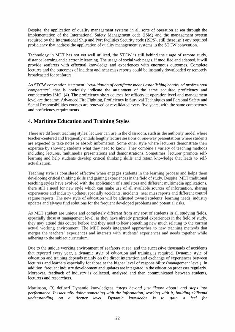
Sources of information required to be integrated in the teaching curriculums
To deliver the dynamic style of MET, there shall be a complete information database regarding eachindividual subject concerning the following:
a) The latest industry updates and the future targets and intentions of the industry developments.b) The latest Port State Control and other special control regime reports including the most
common deficiencies detected.c) Updated database of collected incident, near-misses and unsafe acts reports worldwide.d) The impact of the concerned subject on the safety of the user and the surrounding environment.e) The impact of the related subject on the marine environment and how to avoid and control
potential risks of pollution.f) The impact of the related subject on the security of the ship as general and the security of
information and protection of the shipping company interests.g) The latest research updates and results.h) Database of the accumulated especial experiences collected from students during previous
classes.i) Database of lecture`s tacit experiences and cases to study.j) Student feedback on industry updates, human element and the effectiveness of newly
implemented standards and requirements.
The following figure showing the main Parameters of the dynamic style of MET
Figure 1 The main Parameters of the dynamic style of MET
Maritime Educationand Training
Student ExperiencesExchange
Seafarers` continuousupdates
Incidents, Near Missand Unsafe Acts reports
Safety Controlreports and feedback
Students` feedback onshipping Industry
Shipping industryupdates
Scientific Researches
IAMU Industryupdates
24
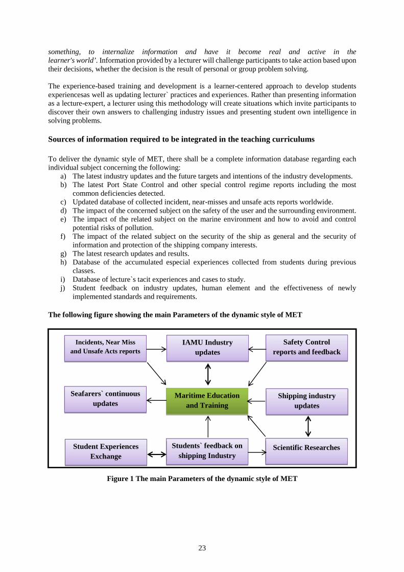
Comparison between the Conventional and Dynamic Styles of MET
Table 1 Comparison between static and dynamic styles of MET
MET Dynamic StyleMET Conventional Style
Concerning with the development of acquiredcapabilities and experiences.
Concerning with the know how
Answering questions like how to manage, howto utilize and how to avoid.
Answering questions like; what, How and when
Concerning with gaining experiences fromprevious accident and learn how to take properpro-active actions.
Concerning with how to respond to emergencies
Providing information on recently appliedtechnologies and the trend of industry updatesand development.
Providing information on technologies alreadyexist in accordance with the requirements oftreaties entered into force.
Focusing on all levels of accidents, incidentsand near misses.
Focusing mainly on major accidents
Knowledge and experiences are shared betweenlectures and students.
Knowledge and proficiencies are provided fromlecturers to students.
Considering students experiences and theirfeedback on industry.
Not considering students experiences and theirfeedback on industry.
Expand the concept of training to a widerintegrated conceptual training system toinclude all contributing parameters like
environment impact, security and safety.
The concept of training is to provide knowledgeand skills.
Conclusion
Despite the obvious decrease in accident rates at sea and successive amendments to STCW convention,yet accidents still happened with the same reasons and errors. Human element remains in the forefrontof errors that have led to accidents at sea.
The current maritime education and training systemsstill depend on theconventional model of education,that to provide students with knowledge and skills straightforwardjust to ensure that requiredproficiencies and skillsare achieved. Feedback on the present maritime education system declared thatpresent style of education is not effective enough to provide students with sufficient experiences on howto avoid errors and in turn accidents and incidents.
Dynamic system of education relies on the exchange of experiences between students on one side andstudents and lecturers on the other side. The presence of experienced student is also being utilized in thepurposes of scientific researches and development of the industry.
There is a gap between industry evolution and maritime education, that the later always been restrictedto the requirements of STCW convention and its amendments in force. STCW convention is still in needof more improvements and updates to be much more effective and tangible. Dynamic system ofeducation is a unique system much suitable for maritime education especially for students atmanagement level.
Recommendations
1- It is important to expand the concept of training from just providing knowledge and skills to a widerintegrated conceptual training system.
25
2- Dynamic system of education is a unique style much suitable for maritime education, theapplication of it, could help in reducing the rate of accidents at sea and eliminatingthe potentials ofhuman errors.
3- Reports of different levels of accidents should be globally collected, analyzed, and investigated,then, rebroadcasted to maritime institutions as lessons to learn.
4- There should be clear identified link between MET and shipping industry. Maritime institutionsshouldbe a step forward of thedate of implementation of the STCW convention updates andamendments.
5- Officers at management level should have more advanced management studies such as; decision-making under mental strain, emotional intelligence, creative thinking, risk assessment and rootcauses.
6- There is a need to establish channels of communication between maritime institutions and graduatesto update their knowledge and awareness of the industry updates.
7- STCW convention is still in need of more proficiencies to cover such as; ship/ helicopter operations,Proficiency of Safety Officers and handling of Port State Control.
8- It is important to expand the concept of training from just providing knowledge and skills to a widerintegrated conceptual training system. The core of teaching material can be considered frommultifunctional approach, for example, if the teaching syllabus was regarding safety practices, thereshould be thoroughly considerations of the environment impact, security, personal safety and theapplication of good management practicing.
9- It is important to consider the standards for revalidation and updates of competency certificatesand, instructors, supervisors and assessors` proficiency.
References:
[1] Allianz, (2016). "Safety & Shipping Review 2016". Allianz Global Corporate & Specialty last sitedon the following website: http://www.agcs.allianz.com/insights/white-papers-and-case-studies/safety-and-shipping-review-2016/
[2] EMSA, (2016). “Visits and Inspections related to standards for seafarers (inspections in thirdcountries”, European Maritime Safety Agency. sited on the following web:http://www.emsa.europa.eu/visits-a-inspections/training-of-seafarers.html
[3] Heather Martinson, (2010). ‘Dynamic versus Static Learning’. Celebration Education. Sited on thefollowing web: http://celebrationeducation.ning.com/profiles/blogs/dynamic-versus-static-learning.
[4] IMO, (1978), “The International Convention on Standards of Training, Certification and Watchkeeping for Seafarers (STCW) convention”. International Maritime Organization. IMO.
[5] Jenni Storgard et al. (2012). “Developing incident and near miss reporting in the maritime industry-a case study on the Baltic sea”. ESEVIER, Transport Research Arena-Europe 2012. Sited at:https://www.researchgate.net/profile/Jouni_Lappalainen/publication/257716529_Developing_Incident_and_Near_Miss_Reporting_in_the_Maritime_Industry-A_Case_Study_on_the_Baltic_Sea/links/00b7d52f4792685502000000.pdf/download?version=vs
[6] Khan, Rani, (2014). “The Influence of educational technology on affective education in MaritimeEducation and Training (MET). A dissertation submitted to the World Maritime University, WMU.Last viewed on the following web address:http://commons.wmu.se/cgi/viewcontent.cgi?article=1455&context=all_dissertations
[7] Procedia, (2012), "Developing Incident and Near Miss Reporting in the Maritime Industry–A CaseStudy on the Baltic". Procedia - Social and Behavioral Sciences. Vol. 48. Last viewed on thefollowing web address: Seahttp://www.sciencedirect.com/science/article/pii/S1877042812028145
[8] TransNav, (2013), “An Empirical Survey on the Role of Human Error in Marine Incidents”, theInternational Journal on Marine Navigation and Safety of Sea Transportation. Volume 7, Number3.
26
Containerisation of MET- Moving Towards a Global MaritimeEducation System
Mr Gamini Lokuketagoda1, DrTakashi Miwa2, and Prof Dev Ranmuthugala3
1. National Centre for Ports and Shipping, Australian Maritime College,[email protected], Locked Bag 1397, Launceston Tasmania 7250, Australia.
2. Graduate school of Maritime Sciences, Kobe University, 5-5-1 Fukaeminami, Higashinada, KobeJapan. [email protected]
3. Australian Maritime College, Locked Bag 1397, Launceston Tasmania 7250, [email protected]
Abstract: In order to be relevant and efficient, Maritime Education and Training (MET) has toconstantly evolve to meet changing industry and social demands that are influenced by many factorsincluding development of technology, cost to industry and MET institutions, changes in legislation forsafety, security requirements, and environmental concerns, etc.
Although International Maritime Organisation (IMO) continues to play an active role in prescribing thecompetencies and standards for training and certification of seafarers through various conventions andassociated national legislation, the shipping world is yet to implement a comprehensive and uniformglobal standard for MET. There are many factors that contribute to this discrepancy in standards acrossthe maritime world, including:
varying education backgrounds of seafarers from different countries and regions; cultural, ethnic and demographical diversities of seafarers; affordability of MET facilities; and reluctance to break away from the deep rooted traditions and practices.
This paper explores the above issues across the regions and looks into strategies to standardise METacross the maritime world, with parallels drawn with the aviation industry standards and practices.Interestingly, it is noted that the maritime industry is able to standardise practices across boundaries inoperations, such as the containerisation of break bulk cargo that revolutionised cargo operations,significantly improving speed, efficiency and safety.
A similar approach is discussed, referred to as the ‘Containerisation of MET’in an attempt to unify thestandards and processesinherent to maritime education, training and assessment to achieve one globalstandard. Although the proposed containerisation of MET would take a few years to achieve its goalworldwide, if properly designed and implemented will result in globalising MET, providing seafarerswith the:
ability to study modules in locations anywhere around the world; complete modules while sailing, without adverse downtime; and appear for assessments anywhere in the world.
The benefits for the respective certification authoritiesare that the results of assessments will beaccessible and accepted by all participating institutions through secure web based portals and thecertificates issued will be verified by each administration through Port State Control MOU’s.
Keywords: Maritime Education and Training, Seafarer Training, Global Standards.
1. Introduction
To be successful and to meet the demands of a changing world, all facets of education has to evolve. Itcould be argued that this has never been more important than in the current environment, where rapidlychanging economic and social demands and significant developments in technology heavily influence
27
the educational outcomes and the delivery methodology. This is true irrespective of whether theeducation programmesare technical, non-technical, or specialised such as within themaritime discipline.A salient feature ofMaritime Education and Training (MET) is that it comprises of a broad andsignificantly large curriculum that has to be delivered to seafarers over a short period of time,sandwiched between periods of time at sea. The delivery of the large spectrum of knowledge and skillsrequired is hampered by a mix ofold and traditional delivery and assessment strategies with modernconcepts, exacerbated by varying standards and methods across the different nations and regions [1][2].
Today’s industry finds seafarers working on vessels with diverse technology that can span from fivedays to five decades in age, and adhering to systems and practices that vary between operators andnations. In this back drop it is difficult to prescribe a ‘one size fits all’ curriculum. Over the years theInternational Maritime Organisation (IMO) has been very careful when prescribing the competenciesinthe Standards of Training, Certification and Watchkeepingconvention (STCW 1995 and 2010) Codetables and model courses 7.01 to 7.04. The syllabi were more generic than specific and IMO wascautiousin suggesting it as a guideline rather than a prescription [3]. This position was meant to assistthe administrations to adopt their own syllabi, training programmes, and assessment criteria in METconforming to the guidelines provided. However, it also can result in the different authorities andinstitutions interpreting the standards and qualifications differently.
The 1995 amendments to the STCW convention (STCW, ’95), brought the requirement for countries tobe in the IMO ‘white list’[2].At first glance it was assumed that the step taken by IMO was towards aglobal standard in MET. However, the countries within the white list were not required to recogniseeach other’s Certificates of Competency (CoC’s) due to the methodologies adopted by member statesto conduct MET and assessment of seafarers. This further widened the gap in MET across the world,and many nations continued to conduct their education and assessment programmes with a domesticfocus and in many cases with very little changes to traditional practices.
There were further factors for member states to continue their traditional MET practices with very littlechanges, such as:
varying education backgrounds of seafarers from different countries and regions; cultural, ethnic, and demographical diversities of seafarers; affordability of MET facilities; and reluctance to break away from deep rooted traditions and practices.
2. The requirement for global standard
The requirement for unified global standard for MET stems from the requirement of shipping companiesfor seafarers to obtain their qualificationsthrough a flexible system that provides for shorter and cheapertraining options that will produce competent seafarers at a lower cost and be more conducive tointernational shipping schedules. This is especially so for company sponsored seafarers, as their trainingcosts and time is a direct expense to the company. From the view point of the self-funded seafarer, therequirements are similar although the reasons can differ as they need to spend less money and time awayfrom their families while obtaining their qualifications and be available on the relatively competitivejob market for their next opportunity.In this context a major hindrance to seafarers and shippingcompanies alike in achieving these objectivesis the non-recognition oftheir prior learning completed indifferent MET institute across different flag state administrations.
Although shipping is global in every sense, it is yet to have a global system to provide flexible andglobally recognisedseafarer qualifications. The flag state administrations and MET institutions togetherwith other stakeholders determine the standards of qualifications for seafarers, which may notnecessarily be global. The differences becomes apparent whenseafarers seek to obtain theirqualifications from a number countries, for example obtaining their CoCs from different countries asthey progressed through their careers. This occurs when seafarers migrate between countries or arerequired to seek qualifications from other countries due to limitations in their own flag state qualification
28
structure, (i.e. non-offering of management levelCoCs), location of their employers company and therout of their vessels, or attainment of higher qualifications and pathways.
In extreme cases, some state administrations are not willing to accept any of the prior qualifications theseafarers had obtained from other jurisdictions, although they would be recognised on the IMO whitelist.Unfortunately, the IMO itself provides the justification for countries to adopt such a position bydeclaring in the regulations, that the training provided by a MET institution should be, “…approved,administered,supervised and monitored by the same administration to be accepted as valid” [4].Thisinference enables an administration toconsider any qualification or associated education and trainingdone outside their jurisdiction as unacceptable, requiring the applicants to redo the qualification or therelevant components, although the training and assessment regimes in the two jurisdictions could bevery similar.From the viewpoint of the administration, they are adhering to the regulation. However,this leads to many difficulties to the seafarersand their employers, who will need to spend more timeand money to qualify to the level required, irrespective of the qualifications theypossess.
Coupled with the above administrative implication, the dissimilarity of the relevant MET curriculumandthe delivery and assessment strategies across different countries contribute to the non-acceptance of eachother’s qualifications or associated learning. In most cases it is difficult to map the curriculum andsyllabi of two different nations and the training programmes and qualifications themselves may havetotally different structures.
Although the STCW 95 amendments clearly spelt out the levels of responsibility and associatedfunctions for each level of responsibility, there is little information on entry requirements. Thus, METinstitutions in different jurisdictions adopteddiverse entry points for school leavers embarking onseafaring careers to suit their own needs, requirements, and internal influences. In essence, the METstructures, curriculum and assessment methodologies have evolved within each jurisdiction, that manynow have significantly differences between them.
Although the different jurisdictions are reluctant to recognise each other’s qualifications, the shippingcompanies that hire multi-national crew do so very successfully with seafarers holding CoC’s fromdifferent jurisdictions. This impliesthat the IMO white list is working at the exit level with regard to thecompetencies attained by seafarers, although the administrations may be reluctant to accept each other’straining and education programmes.
A quick look at the crew list of a ship with a multi-national crew would clearly showthe diversity of thecrew’s background and their training, education, and qualifications. It is typical for a ship to have a mixof officers from Western and Eastern Europe, the Subcontinent, Asia, South America, and Africa, witheach officer trained under their own MET system and qualified under their own state administration.Although the qualificationsmay come from different continents with different MET structures andcurriculum, the final outcome is that they run the ship to the satisfaction of all stakeholders.
It can be debated that although the different administrations have adopted their own structure andcurriculum, the individual processes guided by the standards outlined in the STCW code to meet thestipulated white list requirements, results in a similar end product, i.e. competent seafarers that meet theneeds of the industry. This begs the question, why the global maritime industry does not adopt a unifiedcurriculum to produce competent seafarers that are recognised across nations.
This is similar to that practised within aviation industry. It is true that the bulk of the commercial aircraftsbelong to fewmakes and categories making it easier for the aviation industry to have a uniform globalstandard. However, even in the aviation industry, despite attempts to harmonise the requirementsbetween nations, the differences in certification practices and standards from place to place serve tolimit full international validity of the national qualifications [5]. On the other hand, ships are quitediverse in comparison with aircrafts and can be argued, that the existence of different standards asinevitable.
29
However, as per IMO STCW Code, all merchant ships require personnel to be qualified in the sameseven functions to operate a vessel safely and efficiently. These functions are:
Navigation Cargo handling and stowage Controlling the operation and care of the ship Marine Engineering Electrical, electronics and control engineering Maintenance and repair Radio communications [6].
When considering different types of ships, the only difference comes in the cargo handling function.The other six functions remainthe same for all ships immaterial of what they carry or where they tradeexcept under special conditions such as operations in polar waters.This further strengthens the case toadopt a uniform global standard and a structure for MET.
3. Proposed Approach
The proposed approach is based on three main factors, which needs to be embraced worldwide: MET structure and curriculum is similar for all administrations The education and training is carried out in specific unit modules, which will be similar for all
countries. Assessment methodology is similar for all administrations.
4. The Containerisation analogy
The strategy of this new approach can be compared with or analogues with the containerisation of cargoin the seventies. Before containers were introduced to carry cargo, break bulk cargo was loaded into anddischarged out of cargo holds of ships using cargo nets, pallets, cranes and/or derricks. This necessarilyrequired manual labour for storing and moving cargo, which took considerable amounts of time. Onaverage a 20,000 GRTcargo ship of yesteryear would take anywhere between three to four weeks tocompletely discharge and then load a full load of cargo while in port, which could further extend inadverse weather conditions. Today a similar capacity container ship with around 1500 containers willtake only two and half days or less to do the same cargo operation, with very little interruption due tothe weather, unless encountering severe conditions [7].
Containerisation enabled the pre-stuffing of break bulk cargo into containers, speeding up the transferof the cargo to the ship’s location, easy pre-storage in close proximity to the ship, and quick loading ofthem into the ship, and stacking them in specified bays and tiers to enable easy and structured subsequentmovement of the cargo. These ships normally berth in terminals with large gantry cranes, which canmove cargo at a much faster rate than the previous cargo cranes and derricks. The movement ofcontainers on land is also made easy with a combinations of gantries, shifters, stackers, trucks, andtrains. The cargo was unpacked only when they reached their final destination.
The proposed MET unit module will be like containers, with a specific amount of material for thestudents to learn and be assessed on. The MET institutions can deliver these modules through face-to-face, distance, or blended delivery strategies. There are many ways in which seafarers can obtain theireducation, one being through e-learning using modern information and communicationstechnology (ICT)assisted learning practised in many MET institutions [8] [9].
The assessment process will require approved centres or locations in strategic points across the world(similar to container ports with gantries) to carry out assessment when a seafarer wishes to appear forhis assessment. These centres can utilise modern communication technology such as the internet,common web portals, and share points to enable consistency, validity and reliability [10] [11][12].
30
A seafarer should be able to get a module to study and appear for the assessment at any approved centre.The assessment does not have to be overseen by the same administration from where the study modulewas obtained from. The results can be handled by a worldwide data base similar to the port state controlweb portals for various Memorandum of Understanding’s(MoU’s).
Seafarers can collect the modules necessary for certification from various administrations and graduallycomplete the required assessments at the various portals. This will prepare them for the final assessmentwhich canbe completed anywhere in the world. The certificate can be issued by theadministrationconducting the orals, making sure that the candidate has collected all the necessarymodules and completed the final assessment.
5. The challenges ahead
As this proposed maritime education, training, assessment, and certification system will operate undera single umbrella framework, it will evoke various reactions from parties to the STCW convention.Thus, these will need to be addressed through active dialogue and negotiations. The final outcome needsto satisfy all parties of its authenticity, transparency, and the fairness of the process, which will guaranteeacceptance by the stakeholders and the competence of the end product.
The challenges for the proposed containerisation of MET requires: Universally accepted curriculum Development of modules with learning material for all threemajor forms of delivery Development of relevant, reliable, and authentic assessment tools Establishment of a protected web portal and share points for each administration
In such a context, anorganisation, such as the IAMU, needsto take the lead role in developing andchampioning this proposal. Further, the IMO or a nominee needs to play the role of the overseer andestablish a process to audit the MET institutions/administrations who take part in education, training,and assessment of seafarers worldwide.
6. Conclusion
The containerisation of cargo was made possible by adopting specific sizes of containers; i.e. 20 footand 40 foot containers, thus enabling the ease of stacking and transportation. Further they are handledby respective spreaders, gantries, and other transportation equipment, standards and practices, which areuniversal. The logistics involved in container movement and trans-shipment also follow the same globalstandards and procedures. Over the past 40 years containerisation of break bulk cargo completelytransformed the world shipping into a very efficientphase with mega ships and hub ports.
A similar approach is proposed for MET, with key institutions functioning as learning providers and‘education / assessment hubs’ in various parts of the world. Seafarers can then obtain their qualificationsat their own pace, with a choice of different learning styles.
Assessments would be standardised and controlled through the protected web portals, ensuringconsistent, reliable, and validated assessments that have been tried and tested to the satisfaction of themaritime community. This will ensure quality, accountability, and easy transferability acrossjurisdictions, with information stored on and accessed from a secure global database.
However, this will require a collective approach to be implemented and succeed. It will need anorganisation such as the IAMU to lobby for such change and lead the development. It will need theadministrations across the regions the willingness to share with and accommodate others. Onceachieved, it will provide seafarers and their employers with a flexible and robust education, training,and certification framework.
31
References
[1] Butman, B,Maritime Security and MET,6th Annual General Assembly and Conference of theInternational-Association-of-Maritime-Universities, Study in standardizing marine engineeringcurriculum, 12-28 pp 2005
[2] Bloor, M, Sampson, H,&Gekara V, Regulation& Governance, Global governance of trainingstandards in an outsourced labour force: The training double bind in seafarer license andcertification assessments, Vol.8, 455-471pp, 2014
[3] IMO STCW Convention and STCW Code including 2010 Manila Amendments. Third consolidatededition 2011, Approval of training courses 81 pp
[4] IMO STCW Convention and STCW Code including 2010 Manila Amendments. Third consolidatededition 2011. Regulation I/6, 28 pp
[5] Wikipedia the free encyclopedia, Pilot licensing andcertification.https://en.wikipedia.org/wiki/Pilot_licensing_and_certification
[6] IMO STCW Convention and STCW Code including 2010 Manila Amendments. Third consolidatededition 2011. Annex Part A: Mandatory standards regarding provisions of the annex to the STCWConvention 73 pp
[7] GubbinsE. J, “The Shipping Industry, The Technology and Economics of Specialisation”Gordon andBreach Publishers 1996, pp 37-38
[8] Raicu, A. &Raicu, G., “Innovation in engineering education through computer assisted learningand virtual university model”,3rd International Conference on Modern Technologies in IndustrialEngineering (ModTech2015), IOP Conference Series-Materials Science and Engineering, ,vol.95,2015
[9] Astratinei, C,“Let’s build the future through learning innovation”,vol, eLearning and Software forEducation,e-learning Maritime English course piloting, 33-36pp, 2014
[10] Linn, R. L., Baker, E. L. & Dunbar, S. B., 1991,“Complex, Performance-Based Assessment:Expectations and Validation Criteria”, Educational Researcher, 20, 15-21.
[11] Moskl, B. M. & Leydens, J. A., 2000,“Scoring Rubric Development: Validity and Reliability”,Practical Assessment, Research & Evaluation, 7.
[12] Stevens, P., 2013. “An Examination of a Teacher's Use of Authentic Assessment in an UrbanMiddle School Setting”, Doctor of Education PhD, Ohio University.
32
Internationalization to Improve Maritime Education and Trainingin Vietnam
Dr. Nguyen Thuy Hong Van1, MSc. Tran Thi Thuong2
1. Ho Chi Minh City University of Transport, Vietnam, Email: [email protected]. Ho Chi Minh City University of Transport, [email protected]
Abstract Quality of maritime manpower has become increasingly important especially when thisindustry moves towards higher standards of safety, environmental impact and sustainability. Educatingand training qualified manpower with appropriate level of competence for international standards is thekey task for all maritime institutions. In Vietnam, the Resolution 09-NQ/TW by the National Assemblyon the Ocean strategy for Vietnam towards 2020 and the Prime Minister decision on Vietnam’s seaeconomy development plan towards 2020 highlighted that Vietnam would make all its efforts to rise thesea economic contribution to Vietnam’s gross domestic product (GDP) up to 55%-60%. In addressingthis development, improving the quality of maritime education and training is very important. However,Vietnam is currently in the shortage of seafarers (especially ship officers), both in quantity and quality.Although maritime industry is very internationalised and all MET institutions have internationalizedprograms with global learning outcomes regulated in the STCW Convention, not many Vietnameseseafarers were ranked qualified due to their weaknesses in English competency, skills and safetyawareness. Only a small number is accepted by the international market. Why does the bespokenproblem happen though Vietnam has already got a clear national strategy on sea economic developmentand Vietnamese maritime institutions have been delivering standard MET programs developed by IMO?Studies showed that internationalisation can improve quality of education. Internationalisation helpshigher education institutions to provide graduates with inter-cultural and international skills, Englishcompetency, and confidence to compete in the global labour market. The aim of this paper is to discussthe current maritime manpower in Vietnam and explores how internationalization can help Vietnamesemaritime institutions improve quality of MET.
Key words: internationalization, maritime, education, seafarers, manpower.
1. Introduction
Manpower is always the most important factor of all industries. This factor has become even moreimportant in maritime when this industry aims at higher standards of safety, environment impact andsustainability. It is the maritime education and training institutions (METIs) responsibility to educatequalified human resource for maritime industry.
In dealing with the globalisation, internationalization becomes an inevitable trend of higher educationinstitutions (HEIs) including METIs. Studies showed that internationalisation can improve quality ofeducation [4, 7, 11, 17]. Internationalisation helps HEIs to provide graduates with inter-cultural andinternational skills, English competency, and confidence to compete in the global labour market.
In Vietnam, in addressing the Government’s Ocean strategy and Vietnam’s sea economy developmentplan towards 2020, the issue of how to improve the quality of maritime education and training is raisedin any debate on maritime improvement [24]. The membership of Vietnam in the Trans-Pacific StrategicEconomic Partnership Agreement (TPP) and in the Association of South East Asian Nations EconomicCommunity (AEC) creates both benefits and challenges for Vietnamese HEIs [18]. Although maritimeindustry is internationalised in addition to the required global learning outcomes for every maritimegraduate, Vietnamese METIs are still struggling on how to improve the MET quality and how to enhancestudents’ capacity to work on board international ships.
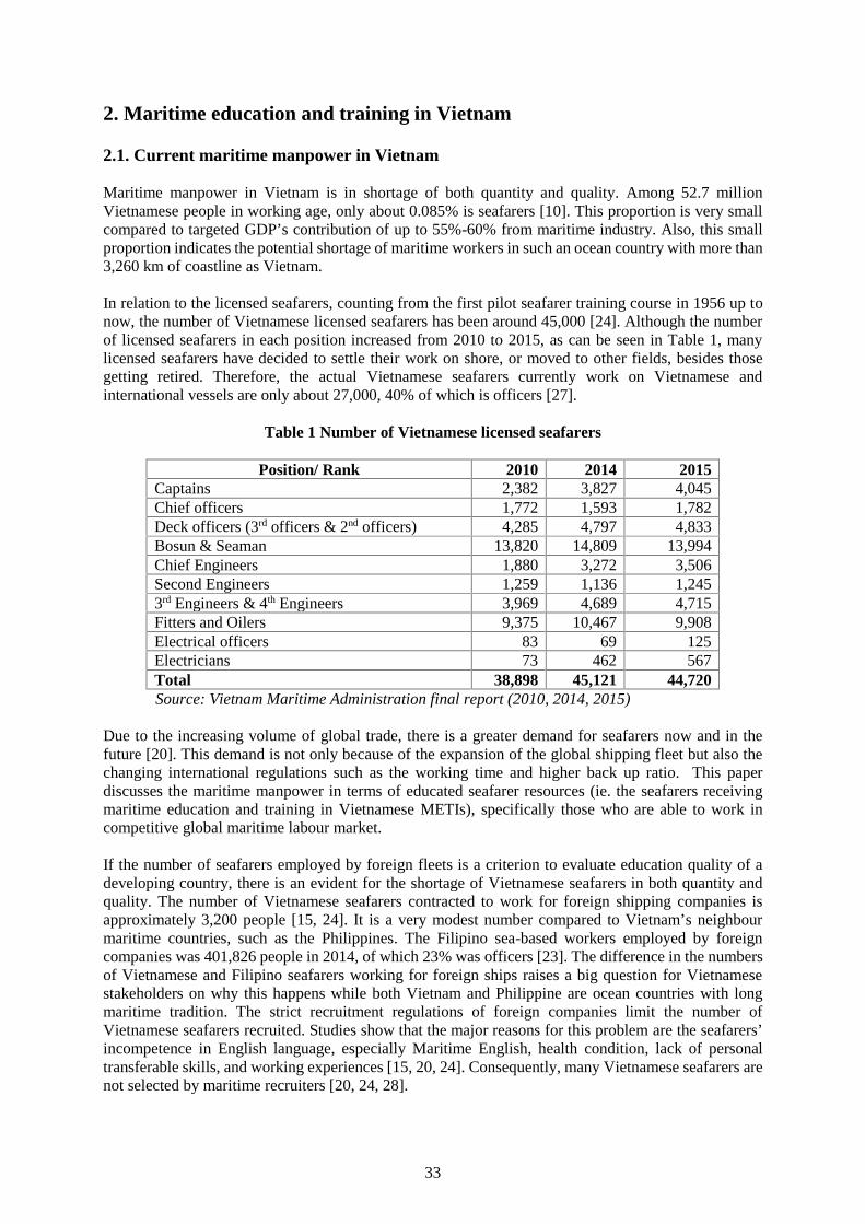
33
2. Maritime education and training in Vietnam
2.1. Current maritime manpower in Vietnam
Maritime manpower in Vietnam is in shortage of both quantity and quality. Among 52.7 millionVietnamese people in working age, only about 0.085% is seafarers [10]. This proportion is very smallcompared to targeted GDP’s contribution of up to 55%-60% from maritime industry. Also, this smallproportion indicates the potential shortage of maritime workers in such an ocean country with more than3,260 km of coastline as Vietnam.
In relation to the licensed seafarers, counting from the first pilot seafarer training course in 1956 up tonow, the number of Vietnamese licensed seafarers has been around 45,000 [24]. Although the numberof licensed seafarers in each position increased from 2010 to 2015, as can be seen in Table 1, manylicensed seafarers have decided to settle their work on shore, or moved to other fields, besides thosegetting retired. Therefore, the actual Vietnamese seafarers currently work on Vietnamese andinternational vessels are only about 27,000, 40% of which is officers [27].
Table 1 Number of Vietnamese licensed seafarers
Position/ Rank 2010 2014 2015Captains 2,382 3,827 4,045Chief officers 1,772 1,593 1,782Deck officers (3rd officers & 2nd officers) 4,285 4,797 4,833Bosun & Seaman 13,820 14,809 13,994Chief Engineers 1,880 3,272 3,506Second Engineers 1,259 1,136 1,2453rd Engineers & 4th Engineers 3,969 4,689 4,715Fitters and Oilers 9,375 10,467 9,908Electrical officers 83 69 125Electricians 73 462 567Total 38,898 45,121 44,720Source: Vietnam Maritime Administration final report (2010, 2014, 2015)
Due to the increasing volume of global trade, there is a greater demand for seafarers now and in thefuture [20]. This demand is not only because of the expansion of the global shipping fleet but also thechanging international regulations such as the working time and higher back up ratio. This paperdiscusses the maritime manpower in terms of educated seafarer resources (ie. the seafarers receivingmaritime education and training in Vietnamese METIs), specifically those who are able to work incompetitive global maritime labour market.
If the number of seafarers employed by foreign fleets is a criterion to evaluate education quality of adeveloping country, there is an evident for the shortage of Vietnamese seafarers in both quantity andquality. The number of Vietnamese seafarers contracted to work for foreign shipping companies isapproximately 3,200 people [15, 24]. It is a very modest number compared to Vietnam’s neighbourmaritime countries, such as the Philippines. The Filipino sea-based workers employed by foreigncompanies was 401,826 people in 2014, of which 23% was officers [23]. The difference in the numbersof Vietnamese and Filipino seafarers working for foreign ships raises a big question for Vietnamesestakeholders on why this happens while both Vietnam and Philippine are ocean countries with longmaritime tradition. The strict recruitment regulations of foreign companies limit the number ofVietnamese seafarers recruited. Studies show that the major reasons for this problem are the seafarers’incompetence in English language, especially Maritime English, health condition, lack of personaltransferable skills, and working experiences [15, 20, 24]. Consequently, many Vietnamese seafarers arenot selected by maritime recruiters [20, 24, 28].
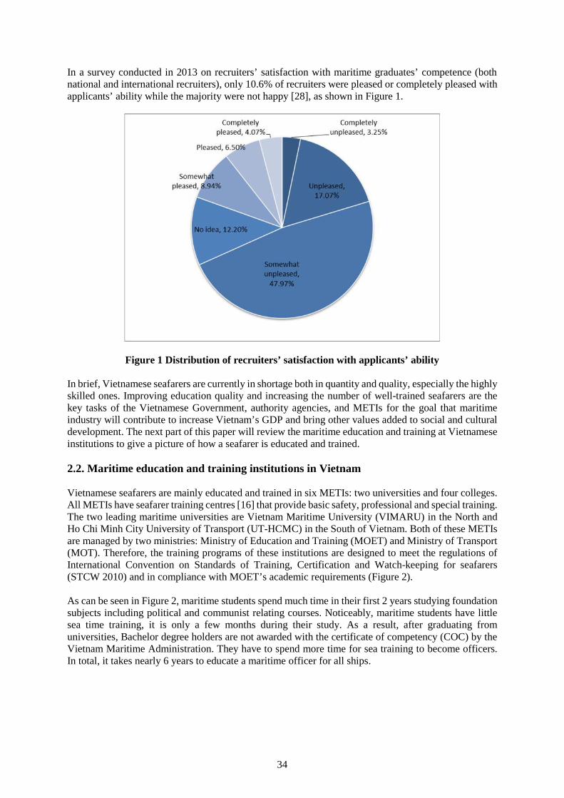
34
In a survey conducted in 2013 on recruiters’ satisfaction with maritime graduates’ competence (bothnational and international recruiters), only 10.6% of recruiters were pleased or completely pleased withapplicants’ ability while the majority were not happy [28], as shown in Figure 1.
Figure 1 Distribution of recruiters’ satisfaction with applicants’ ability
In brief, Vietnamese seafarers are currently in shortage both in quantity and quality, especially the highlyskilled ones. Improving education quality and increasing the number of well-trained seafarers are thekey tasks of the Vietnamese Government, authority agencies, and METIs for the goal that maritimeindustry will contribute to increase Vietnam’s GDP and bring other values added to social and culturaldevelopment. The next part of this paper will review the maritime education and training at Vietnameseinstitutions to give a picture of how a seafarer is educated and trained.
2.2. Maritime education and training institutions in Vietnam
Vietnamese seafarers are mainly educated and trained in six METIs: two universities and four colleges.All METIs have seafarer training centres [16] that provide basic safety, professional and special training.The two leading maritime universities are Vietnam Maritime University (VIMARU) in the North andHo Chi Minh City University of Transport (UT-HCMC) in the South of Vietnam. Both of these METIsare managed by two ministries: Ministry of Education and Training (MOET) and Ministry of Transport(MOT). Therefore, the training programs of these institutions are designed to meet the regulations ofInternational Convention on Standards of Training, Certification and Watch-keeping for seafarers(STCW 2010) and in compliance with MOET’s academic requirements (Figure 2).
As can be seen in Figure 2, maritime students spend much time in their first 2 years studying foundationsubjects including political and communist relating courses. Noticeably, maritime students have littlesea time training, it is only a few months during their study. As a result, after graduating fromuniversities, Bachelor degree holders are not awarded with the certificate of competency (COC) by theVietnam Maritime Administration. They have to spend more time for sea training to become officers.In total, it takes nearly 6 years to educate a maritime officer for all ships.
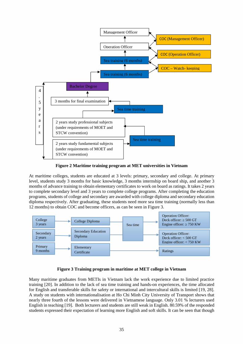
35
Figure 2 Maritime training program at MET universities in Vietnam
At maritime colleges, students are educated at 3 levels: primary, secondary and college. At primarylevel, students study 3 months for basic knowledge, 3 months internship on board ship, and another 3months of advance training to obtain elementary certificates to work on board as ratings. It takes 2 yearsto complete secondary level and 3 years to complete college programs. After completing the educationprograms, students of college and secondary are awarded with college diploma and secondary educationdiploma respectively. After graduating, these students need more sea time training (normally less than12 months) to obtain COC and become officers, as can be seen in Figure 3.
Figure 3 Training program in maritime at MET college in Vietnam
Many maritime graduates from METIs in Vietnam lack the work experience due to limited practicetraining [20]. In addition to the lack of sea time training and hands-on experiences, the time allocatedfor English and transferable skills for safety or international and intercultural skills is limited [19, 28].A study on students with internationalisation at Ho Chi Minh City University of Transport shows thatnearly three fourth of the lessons were delivered in Vietnamese language. Only 3.01 % lecturers usedEnglish in teaching [19]. Both lecturers and students are still weak in English. 80.59% of the respondedstudents expressed their expectation of learning more English and soft skills. It can be seen that though
COC – Watch- keeping
Operation Officer
Management Officer
COC (Operation Officer)
COC (Management Officer)
4.5years
2 years study fundamental subjects(under requirements of MOET andSTCW convention)
Sea time training
2 years study professional subjects(under requirements of MOET andSTCW convention)
Sea time training
3 months for final examination
Bachelor Degree
Sea training (6 months)
Sea training (6 months)
College3 years
College Diploma
Operation Officer:Deck officer: ≥ 500 GTEngine officer: ≥ 750 KW
Secondary2 years
Primary9 months
Operation Officer:Deck officer: < 500 GTEngine officer: < 750 KW
Ratings
Secondary EducationDiploma
ElementaryCertificate
Sea time
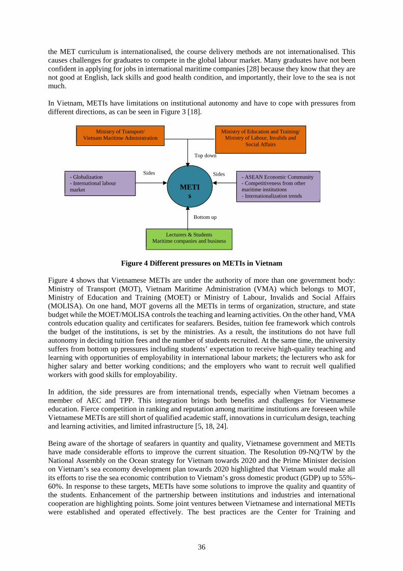
36
the MET curriculum is internationalised, the course delivery methods are not internationalised. Thiscauses challenges for graduates to compete in the global labour market. Many graduates have not beenconfident in applying for jobs in international maritime companies [28] because they know that they arenot good at English, lack skills and good health condition, and importantly, their love to the sea is notmuch.
In Vietnam, METIs have limitations on institutional autonomy and have to cope with pressures fromdifferent directions, as can be seen in Figure 3 [18].
Figure 4 Different pressures on METIs in Vietnam
Figure 4 shows that Vietnamese METIs are under the authority of more than one government body:Ministry of Transport (MOT), Vietnam Maritime Administration (VMA) which belongs to MOT,Ministry of Education and Training (MOET) or Ministry of Labour, Invalids and Social Affairs(MOLISA). On one hand, MOT governs all the METIs in terms of organization, structure, and statebudget while the MOET/MOLISA controls the teaching and learning activities. On the other hand, VMAcontrols education quality and certificates for seafarers. Besides, tuition fee framework which controlsthe budget of the institutions, is set by the ministries. As a result, the institutions do not have fullautonomy in deciding tuition fees and the number of students recruited. At the same time, the universitysuffers from bottom up pressures including students’ expectation to receive high-quality teaching andlearning with opportunities of employability in international labour markets; the lecturers who ask forhigher salary and better working conditions; and the employers who want to recruit well qualifiedworkers with good skills for employability.
In addition, the side pressures are from international trends, especially when Vietnam becomes amember of AEC and TPP. This integration brings both benefits and challenges for Vietnameseeducation. Fierce competition in ranking and reputation among maritime institutions are foreseen whileVietnamese METIs are still short of qualified academic staff, innovations in curriculum design, teachingand learning activities, and limited infrastructure [5, 18, 24].
Being aware of the shortage of seafarers in quantity and quality, Vietnamese government and METIshave made considerable efforts to improve the current situation. The Resolution 09-NQ/TW by theNational Assembly on the Ocean strategy for Vietnam towards 2020 and the Prime Minister decisionon Vietnam’s sea economy development plan towards 2020 highlighted that Vietnam would make allits efforts to rise the sea economic contribution to Vietnam’s gross domestic product (GDP) up to 55%-60%. In response to these targets, METIs have some solutions to improve the quality and quantity ofthe students. Enhancement of the partnership between institutions and industries and internationalcooperation are highlighting points. Some joint ventures between Vietnamese and international METIswere established and operated effectively. The best practices are the Center for Training and
- Globalization- International labourmarket
Sides Sides
METIs
Lecturers & StudentsMaritime companies and business
Top down
Bottom up
- ASEAN Economic Community- Competitiveness from othermaritime institutions- Internationalization trends
Ministry of Education and Training/Ministry of Labour, Invalids and
Social Affairs
Ministry of Transport/Vietnam Maritime Administration
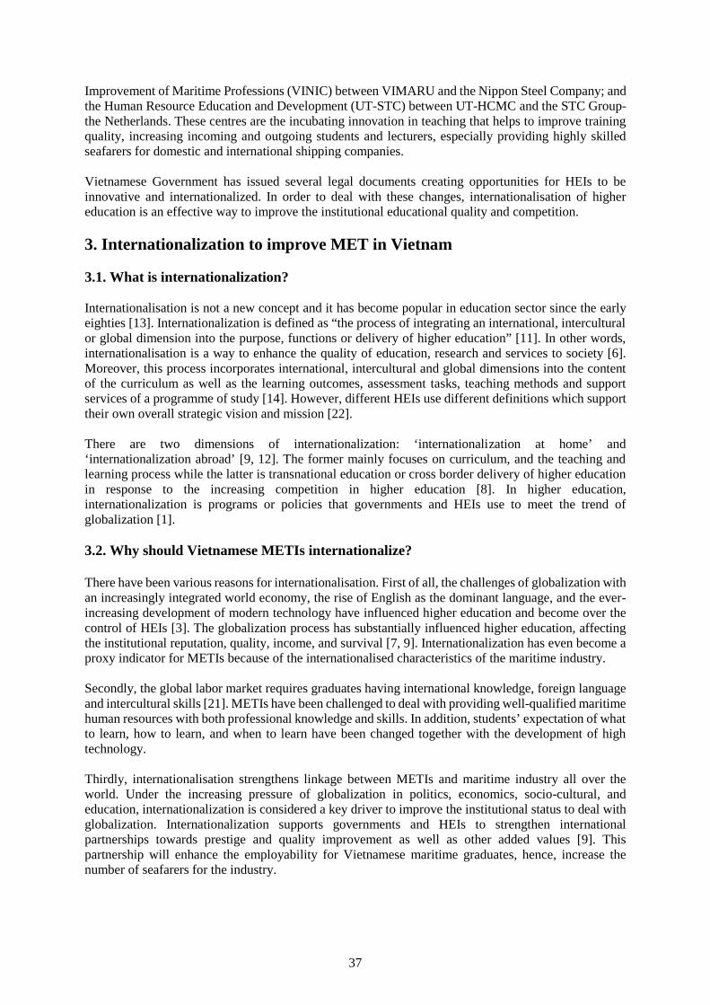
37
Improvement of Maritime Professions (VINIC) between VIMARU and the Nippon Steel Company; andthe Human Resource Education and Development (UT-STC) between UT-HCMC and the STC Group-the Netherlands. These centres are the incubating innovation in teaching that helps to improve trainingquality, increasing incoming and outgoing students and lecturers, especially providing highly skilledseafarers for domestic and international shipping companies.
Vietnamese Government has issued several legal documents creating opportunities for HEIs to beinnovative and internationalized. In order to deal with these changes, internationalisation of highereducation is an effective way to improve the institutional educational quality and competition.
3. Internationalization to improve MET in Vietnam
3.1. What is internationalization?
Internationalisation is not a new concept and it has become popular in education sector since the earlyeighties [13]. Internationalization is defined as “the process of integrating an international, interculturalor global dimension into the purpose, functions or delivery of higher education” [11]. In other words,internationalisation is a way to enhance the quality of education, research and services to society [6].Moreover, this process incorporates international, intercultural and global dimensions into the contentof the curriculum as well as the learning outcomes, assessment tasks, teaching methods and supportservices of a programme of study [14]. However, different HEIs use different definitions which supporttheir own overall strategic vision and mission [22].
There are two dimensions of internationalization: ‘internationalization at home’ and‘internationalization abroad’ [9, 12]. The former mainly focuses on curriculum, and the teaching andlearning process while the latter is transnational education or cross border delivery of higher educationin response to the increasing competition in higher education [8]. In higher education,internationalization is programs or policies that governments and HEIs use to meet the trend ofglobalization [1].
3.2. Why should Vietnamese METIs internationalize?
There have been various reasons for internationalisation. First of all, the challenges of globalization withan increasingly integrated world economy, the rise of English as the dominant language, and the ever-increasing development of modern technology have influenced higher education and become over thecontrol of HEIs [3]. The globalization process has substantially influenced higher education, affectingthe institutional reputation, quality, income, and survival [7, 9]. Internationalization has even become aproxy indicator for METIs because of the internationalised characteristics of the maritime industry.
Secondly, the global labor market requires graduates having international knowledge, foreign languageand intercultural skills [21]. METIs have been challenged to deal with providing well-qualified maritimehuman resources with both professional knowledge and skills. In addition, students’ expectation of whatto learn, how to learn, and when to learn have been changed together with the development of hightechnology.
Thirdly, internationalisation strengthens linkage between METIs and maritime industry all over theworld. Under the increasing pressure of globalization in politics, economics, socio-cultural, andeducation, internationalization is considered a key driver to improve the institutional status to deal withglobalization. Internationalization supports governments and HEIs to strengthen internationalpartnerships towards prestige and quality improvement as well as other added values [9]. Thispartnership will enhance the employability for Vietnamese maritime graduates, hence, increase thenumber of seafarers for the industry.
38
Finally, more engagement with the world is also an essential way to adding value to the institution,including to its quality, revenue, prestige, and competitiveness [21]. Via international cooperation suchas student exchanges, international projects, and transnational education delivery, the universities havegained added values that can support them in two international dimensions: competition and cooperation[2,8].
4. Recommendations
Internationalisation can support Vietnamese METIs to improve quality and quantity and so is theemployability ratio, institutional competitiveness, income generation, and other value added.
Recommendations to METIs
First of all, in the prevailing environment of fierce competition for outstanding staff, students andresources, strategic planning is important as Vietnamese METIs need to develop internationalisationstrategies which identify their position, needs, expectation, future focus, decisions, and actions.However, internationalisation is not an ‘one size fits all’[13] so each institution should make a carefulinternational assessment on its internationalisation.
Secondly, improving administrative and management system is necessary. Effective educationmanagement is the core issue. A transparent system which includes more autonomy, accountability,better quality assurance and policy to attract qualified staff and more students. Maritime is veryinternationalised because of the standard model courses issued by the International MaritimeOrganization (IMO) and regulated in the STCW Convention that all METIs must follow. In other words,METIs have already got global learning outcomes. This is a great advantage that never happens in othersectors. If this advantage is fully taken, it will facilitate METIs with lecturer and student mobility,classroom diversity, intercultural development, language acquisition, and global citizenshipdevelopment.
Thirdly, the curriculum should be redesigned to meet the international standards of IMO. METIs shouldreform the existing educational system which proves to be unable to meet the demand for highly skilledseafarers. A work-based learning model can be applied in Vietnamese METIs so that students canexperience the real working environment. They also have chance to improve their awareness of safetyissues on board ship. Students should be provided with more soft skills especially international andintercultural skills. Lack of these skills may lead to the large number of seafarers leaving companiesevery year.
The ocean is of all people in the world and issues of ocean like safety, security and environmentalprotection are the concern of the world. Students should be educated with not only professionalknowledge but also skills and ethical behaviour. A working culture of Vietnamese seafarers, such asgood disciplines or loyalty, should be created. This culture will position Vietnamese maritime manpowerin the international labour market.
Next, Vietnamese METIs should increase lecturer and student mobility to create a more internationalteaching and learning environment. In this environment, English is used more often and there are moreEnglish teaching materials and textbooks. This helps to improve English competence of both lecturersand students. In addition, international teaching and learning environment help students to learnintercultural skills. They will be prepared for an internationally social life in their future career.
More practice and sea time training for students are needed. The traditional teaching methodologyshould be changed into more active. This improvement can be made when METIs improve theinstitution-institution partnerships to improve teaching pedagogy of maritime lecturers. Active teachingmethods can be shared among METIs in the world. Thus, soft skills can be incorporated with activeteaching to produce more effective lessons.
39
In order to increase the number of seafarers, METIs should be more active in promotion campaigns topublicize the advantages of maritime works and lives. Seafarers should be the jobs that deserve morerespects from society. University-industry partnerships should be strengthened and developed in orderto get more internship places for students. Moreover, the partnership helps to create jobs which attractmore graduates and seafarers to apply for, hence maritime manpower retention can be improved.
Last but not least, METIs needs more investment in technology and modern facilities for teaching andlearning activities. It is understood that good maritime education is costly. Besides the state budget,dynamic international activities can increase revenue for institutions via grants or international projects.In response to the government’s direction, METIs should be more active in privatisation or‘socialisation’ of MET and research activities in order to create more revenue for effective operation.Such models as joint ventures or self-funding training centres can become incubators for VietnameseMETIs in internationalisation.
Recommendations to the Government authorities
In relation to the policies, the government should develop a better welfare policy for maritime jobswhich are particularly characteristic. Also, there should be policies to encourage ship owners to beresponsible for crew training, skills development for seafarers and potential graduates. A real Vietnammaritime labour union should be set up, not just in name but in effective action, to protect seafarers’rights and support them in any flag ship countries.
The government should create favourable conditions for crew export. Specifically, joint venturecompanies and international maritime training centres should be allowed to export seafarers. As the jointventure and international maritime companies have good relationship with international shippingcompanies and international maritime associations, they are able to find more recruiters and do bettermanning. Hence, the seafarers have more chance to work on board foreign shipping.
5. Conclusions
Maritime industry with the increasing growth of the world fleet is in high demand for highly skilledseafarers. Vietnamese sea economy is aimed to contribute more for the development of the country. Thisgoal requires Vietnamese METIs to improve education and training quality and increase the number ofmaritime students and seafarers. Internationalisation and appropriate internationalisation strategies willimprove quality of maritime teaching and learning, and produce qualified and competent seafarers.
References
[1] Altbach, Reisberg, and Rumbley, Trends in Global Higher Education: Tracking an AcademicRevolution, A report prepared for the UNESCO 2009 World Conference on Higher Education,France, (2009).
[2] The Bologna Declaration, (1999) retrieved fromhttp://www.msgsu.edu.tr/Assets/UserFiles/unverst_xyonetim_xulik/ulik_genel/bologna.pdf on 2June 2016.
[3] Brandenburg, U. & De Wit, H., The End of Internationalization, International Higher Education,No 62 winter, Center for International Higher Education, Boston College, (2010).
[4] Christa L.O., Madeleine F. G. and Barbara A.H., A Handbook for Advancing ComprehensiveInternationalization: What institutions can do and what students should learn, American Councilon Education, Washington, (2006).
[5] Dang V.U, Pham X.D, “The Improvement of Higher MET at Vietnam Maritime University byEnhancement of the Linkage with Industries and International Relations”, International Journal onMarine Navigation and Safety of Sea Transportation, Vol. 2, No. 3, (2008), pp. 319-325.
[6] De Wit, H., Internationalization of Higher Education in Europe and its Assessment, Trends andIssues, Accreditation Organization of the Netherlands and Flanders (2010), retrieved from
40
http://www.nvao.net/page/downloads/internationalisation_of_Higher_Education_in_Europe_DEF_december_2010.pdf on 17 February 2015.
[7] De Wit, H., Trends, Issues and Challenges in Internationalization of Higher Education, Centre forApplied Research on Economics and Management, Hogeschool van Amsterdam, (2011a).
[8] De Wit, H. (2011b), “Globalization and Internationalization of Higher Education”, Vol. 8, No 2(2011b) pp. 241- 248.
[9] Egron-Polak, E. & Hudson, R.), Internationalization of Higher Education: Growing Expectations,Fundamental Values, IAU 4th Global Survey, International Association of Universities (2014).
[10] General statistics office of Vietnam, retrieved fromhttps://www.gso.gov.vn/default.aspx?tabid=714 on 16 May 2016.
[11] Knight, J., “Internationalization Remodeled: Definition, Approaches, and Rationales”, Journal ofStudies in International Education, Vol. 8, (2004), pp.15-31.
[12] Knight, J., Higher Education in Turmoil, The Changing World of Internationalization, Rotterdam:Sense Publishers, (2008).
[13] Knight, J., Internationalisation: Key Concepts and Elements (2009).[14] Leask, B., Internationalizing the curriculum, Routledge: Abingdon, (2015).[15] Le V. T, Sung-june Kim, Jung-sik Jeong, Current Situation and Policies of Shipping Industry in
Vietnam, J.Navig. Port Res, Vol.39, No. 2: (April 2015), pp 131-140.[16] Nguyen X.P., Research on Development of Human Resource Meeting Requirement of Vietnam
Ocean Strategy towards 2020, Master dissertation, Ho Chi Minh City university of Transport, HoChi Minh (2010).
[17] Nguyen T. H.V, “The Role of Internationalisation for the Development of Ho Chi Minh CityUniversity of Transport”, Journal of Transportation Science and Technology, Vol. 15 (2015a), pp3-7.
[18] Nguyen T.H.V, “Internationalization of Higher Education in Ho Chi Minh City University ofTransport, Vietnam: before and after ISAS”, IAU Horizons, International Association ofUniversities, SEP Nimes France, Vol. 21 No.2 (October 2015b), pp.12-13.
[19] Nguyen T.H.V, Tran T.T, Internationalization Strategy Development for Ho Chi Minh CityUniversity of Transport, Research project at the university level, Ho Chi Minh City University ofTransport, (2015).
[20] Nguyen T. T., Ghaderi H., Ceasar L.D., and Cahoon S., “Current Challenges in the Recruitmentand Retention of Seafarers: An Industry Perspective from Vietnam”, The Asian Journal of Shippingand Logistics, Vol. 30, No. 2 (2014), pp.217-242.
[21] OECD, Education at a Glance, OECD, (2012), retrieved from http://www.oecd-ilibrary.org/sites/eag-highlights-2012-en/01/07/index.html?contentType=/ns/StatisticalPublication/ns/Chapter&itemld=/content/chapter/eag_highlights-2012-9-en&containerItemld=/content/serial/2076264 on 24 June 2015.
[22] Paulsdottir, G. & Van Liempd, H.G. (2012), Do We Need to Define Internationalization? InInternational Association of Universities (IAU) Horizons, Vol. 17, In Focus: Re-thinkingInternationalization, February/ March 2012, Paris.
[23] Philippine Overseas Employment Administration, 2010-2014 Overseas employment statistics,Philippine Overseas Employment Administration, Philippine, (2015).
[24] Tieu V. K., Road to develop human resouces for Vietnam maritime industry, Vietnam Captain Club,(2012), retrieved from http://www.sotayhanghai.com/AuthorTVK on 25 March 2016.
[25] Vietnam Maritime Administration, Annual report of Vietnam Maritime Administration, VietnamMaritime Administration, Vietnam, (2010).
[26] Vietnam Maritime Administration, Annual report of Vietnam Maritime Administration, VietnamMaritime Administration, Vietnam, (2014).
[27] Vietnam Maritime Administration, Annual report of Vietnam Maritime Administration, VietnamMaritime Administration, Vietnam, (2015).
[28] Vu T.L.A, “A study of Vietnamese Maritime students’ perceptions and employers’ perspectivestowards employability” Journal of Transportation Science and Technology, Vol. 12 (2014),pp.123-127.
41
Standardization of maritime education as aim, resultand means of its quality improvement
Pro. DSc., Irina Makashina (1) and Pro. DSc., Alexander Fayvisovich (2) andAss. Pro. Irina Truschenko (3)
(1) Admiral Ushakov Maritime State University, Novorossiysk, Russia, e-mail: [email protected];(2) Admiral Ushakov Maritime State University, Novorossiysk, Russia, e-mail: [email protected]
(3) Admiral Ushakov Maritime State University, Novorossiysk, Russia, e-mail: [email protected]
Abstract. Standardization of maritime education is considered by all the parties concerned as a way ofsearch for a workable mechanism of educational activities aimed at training of highly skilled maritimeprofessionals who meet the national and the Conventional requirements and comply with therequirements of the maritime industry.
The paper shows the contradiction between the need for standardization of maritime education and thetendency of transition to the formal procedure for evaluation of education results. The paper describesthe development of mechanisms for comparing the expected results with the real ones, which in turn,allow to assess the quality and effectiveness of the learning process, and everything that is used in aprocess of sea specialist training.
The issues related to the technological process of the maritime education standardization are considered,and methods for determining the necessary and sufficient actions for their decision are offered. It isproved that a change in standards of the maritime education is determined by both external and internalfactors and their role is shown.
On the basis on the philosophical and educational concepts four components of marine education areconsidered: the value, the system, the process and the result. It is proved that it is impossible to considerthe issue of standardization of maritime education only as the achieved level of knowledge and skills. Itis substantiated that the outlook of a person defines the further vector of its development and thereforeto its formation and development adequate attention should be given.
It is concluded that standardization of maritime education must be tough on the one hand, to ensurecompliance with the requirements of the International Convention STCW 1978/95 and amendmentsadopted at the Manila Conference, 2010 [2], and flexible enough, on the other, to enable the creationand contribute to the search for new forms, methods and means of training and education of futuremarine specialists.
Keywords: standardization, maritime education, Conventional requirements, learning process, quality.
1. Introduction
Different researchers considering the issues of vocational education quality, determine in diverse waysthecriteria, fit to evaluate this objectively. At the same time almost all the participants of Maritimeeducation consider standardization as a meansof finding workable mechanism of educational activities.The main goal of this mechanism is to prepare highly qualified marine specialist meeting the national[3] and conventional requirements [2] and corresponding to up-to-date level of the Maritime industrydevelopment.
The analysis of current practice of standardization of Maritime education allowedto highlight thecontradiction between the need of standardization of Maritime education and the tendency tomechanical, formal assessment of its results. The resolution of this contradiction will contribute toimproving the quality of marine specialist’s training.
42
When speaking about the standard, quality is always meant. From a philosophical point of view qualityis the category, showing a substantial certainty of things and phenomena of the real world. Quality isusually understood as the objective characteristics of the objects that appear in the aggregate of theirproperties. Under the “2010 Manila Amendments” to the Standards of Training, Certification andWatchkeeping for Seafarers (STCW) Convention and Code,Quality Standard System (QSS)requirements require “in accordance with the provisions of section A-I/8 of the STCW Code, all training,assessment of competence, certification, including medical certification, endorsement and revalidationactivities carried out by non-governmental agencies or entities under its authority are continuouslymonitored through a quality standards system to ensure achievement of defined objectives, includingthose concerning the qualifications and experience of instructors and assessors [2].
It is common understanding, that the quality of education of specialists is determined by the quality ofeducational programs and content; quality of potential of teaching personnel; quality of potential of theapplicants; quality of educational technologies; quality of resource provision (information, educationaland logistical, etc.).
The logic of the proposed paper is constructedon the basis of a philosophical and educational conceptaccording to which four aspects of the standardization of maritime education are considered: aim,system, process and result.
2. Standardization of maritime education as anaim
We believe it is necessary to note that we are talking primarily about the educational space. This spaceis the aggregate of the conditions ensuring the existence of education. The educational environmentproduces nothing, because it is not a mechanism, it provides the conditions for the functioning of themechanism of education [7]. One of these conditions is to standardize the quality of education.
Standardization means the process of implementing and developing standards. Standardization ofeducation, including themarine one, involves the implementation of procedures for the generalstandardization and dictates the definition of objectives, competencies, learning outcomes, programs,materials, assessments at the input, while process and on results of learning. Also requirements for thelevel of training of the teaching staff and the conditions of the educational process should be defined.
The standardization of Maritime education first of all is determined by the STCW Code “Each Partyshall ensure that the education and training objectives and related standards of competence to beachieved are clearly defined and that the levels of knowledge, understanding and skills appropriate tothe examinations and assessments required under the Convention are identified. The objectives andrelated quality standards may be specified separately for different courses and training programs andshall cover the administration of the certification system”. Further it stipulates that this evaluation shallinclude all changes to national regulations and procedures in compliance with the amendments to theConvention and STCW Code…” [2]. We fully agree with this statement but we believe it is alsoimportant to emphasize that any standard, even the highest one, shouldn’t be considered as final one.Society in general and maritime industryin particular, is in constant development. And the emergenceof new technologies dictates the need for standards review. The way out from this situation we see in anadvanced training. The most important, in our opinion, is the training of specialist, havingcompetencesaccording to the requirements, and at the same timeready to continuingself-development. It is thetrait ofa personality of a specialist which will help him to remain in demand on labour market under anycircumstances.The aim of standardization of Maritime education is primarily the creation of a unifiededucational space and the continuity of basic educational programs at all levels of education: elementary,secondary, higher and postgraduate professional education.
3. Standardization of maritime education as a system
43
Certainly, the standardization is systemic phenomenon, and like any system its content presumespresence of many components and links, both direct and reverse, ensuring the functioning of this system.This system is influenced by both external and internal factors.
External factors cannot be controlled and the institution is unable to change them, but considering oftrends and risk assessment, as a rule, brings positive results. These factors include: socio-demographic;geopolitical, scientific and technical; economic; infrastructure development of the industry and of labourmarket, requirements of STCW, IMO, ITF and etc.
As to internal factors, usually they are controlled by management of institutions. These include:personality of the heads of an institution; the institution’s affiliates network; financial managementsystem; the level of training of professor and lecturers staff; specialty and education; pricing policies;availability and completeness of usage of information resources; participation of employers ineducational process (e.g. Board of Trustees), the material-technical base; stimulators, base of practices,etc.
External factors contribute to the emergence and development of the system, the internal reflectingnature of a particular educational institution and Merchant industry are generated by separate elementsconstituting the system, inherent only tocertain industry, in our case, the industry of merchant shipping.Their influence on the standardization as the system causes its operation and effectiveness.
The development of the standardization as a system is determined by the purpose and informationresources. While attaining the aim the system accepts any useful input information, which effects theinternal structure of the system of Maritime education, its quality and provides the opportunity to initiateand support the best path of its development. Properties of openness, flexibility and mobility ofstandardization as the system is ensured with:
– structure and content of professional training, allowing the possibility of changes in thecomposition and content of education;
– continuous modernization of means and technologies of training;– openness of professionally oriented educational environment, ensuringformation of positive
motivation and development of cognitive activity of trainees.
On the one hand, this system is conservative and inert, as it is built on traditions, and on the other itneeds to be optimized, i.e., tuned on the development and changes taking place in the constantly evolvingMaritime industry. The design and control leads the system to a stable, ordered state, and innovation,educational experiments suggest the presence of instability, i.e., the state preceding the transition to aqualitatively new level. The innovation factor (creativity etc.) is significant fluctuation in the process ofdevelopment of the system [5].
The system of education, as well as the culture, is significantly influenced by the context in which itarises and develops. Russian education came from the Soviet Union, when the social circle was limitedto the socialist countries, and in fact by borders of the USSR. Apparently, this condition should first betaken into account while considering the Russian education.
A distinctive feature of the Soviet, and subsequently the Russian higher education is the presence in alleducational programs of an essential component of fundamental knowledge, which do not exist inEuropean education, and in education in majority of other countries of the world. This fact shouldn’t beconsidered as an advantage or a disadvantage.
Just this should be stated and borne in mind when analyzing the structure of the curriculum. However,it should be noted that despite the above essential difference, the Soviet experts, were highly valued onthe world labor market, both in technical and in humanitarian areas, and most probablyfor this certainreason. It is clear that including additional subjects in educational process, for strengthening thefundamental component, could not fail to influence the duration of training. If one compares the same
44
educational program, in Russia the duration of training is 1-2 years longer. The same thing takes placein the training of sea transport specialists: navigators, engineers and electricians.The curricula of educational programs of marine specialists training must meet both the requirements ofnational standards and international (STCW 78/95 with amendments 2010). Often there is a discrepancyin the titles of disciplines and in hours. As a rule, the national standard covers the international on hours.Duration of training of marine specialists with higher education is at least 5 years.
In Russian Maritime universities there is secondary vocational education, the duration of which is 2years and 10 months, on completing which a young specialist can also take a position of the 3d assistantor mechanics, but for a career and the appointment for a position of a Chief Engineer, Mate or Master,he will have to go back to maritime institution and complete the educational process to the level of aspecialist (2,5 years more).Therefore, requirements to the structure of basic educational programs,conditions of realization of basic educational programs and the results of their development are theimportant issues of the standardization as the system.
We consider standardization of the quality of Maritime education on three levels. The first is the levelof the educational institution.The ongoing transformations in the maritime education involve the entirerange of activities of any educational institution: organizational, managerial, economic, legal,technological and content aspects.In this context, the need for improving the quality of Maritimeeducation, in particular, by creating optimal conditions providing a set of purposefully created learningopportunities to meet the educational needs of students is actualized.
The task of improving the quality of education is becoming a priority. Assessment of the quality ofMaritime education in connection with standards is an integral part of the work of educationalinstitutions in the field of quality management. And that is why, the criteria chosen by a specificeducational institution, will depend on the system of work of the institution based on its mission, goalsand objectives. As standards Conventional and national (Federal state educational standards)requirements to the quality of education are considered [2; 3].
The importance of the following fact is evident. The quality assurance activities of an educationalinstitution largely depend on the level of quality management, which refers not only to a system oftargeted management actions to create optimal conditions for the functioning of the organization, butalso the image of the organization, which is based not only on the quality of services rendered, but aswell asthe reputation of the University in the scientific world.
While understanding the importance of the issues mentioned above, as an example we areconsideringissues, connected with sailing practice. They are:
– logistical issues with sending and arrival of the cadets;– the reluctance of many companies to take 1-2 people (because of a mismatch in the industrial
task with the schedule of educational process);– lack of places for the cadets sailing practice;– the reluctance of companies to take students of first/second-year (2-3), etc.
These and other issues in organizing sailing practices significantly affect the organization of trainingcadets on the shore, which, in turn, affects changes to the schedule of the educational process.
The best solution to all these problems is the presence at the University its ownbase for sailingpracticein the form of training vessel. However, solving problems of practice the University takes on newchallenges with the maintenance and operation of the vessel.
The second level of standardization of the quality of Maritime education is the level of participants ofthe educational space, i.e. teachers, students, employers, parents, etc. The educational space of thesecond level of educational institution is formed on such characteristics as maintenance of knowledge,skills development processes, ability to act and ensure the presentation of content, methods of action,means of action, ensuring the formation and development of the whole composition of features of an
45
object of education and application of this composition of conditions for accomplishing educationalactivities. As criteria of quality assessment of participants the following can be distinguished: themotivation of people both in the choice of educational institution, and in the process of study, and their(students) social activity.
Development of the educational space involves improvement of conditions for teaching, training offuture specialists to perform professional activities, i.e. improvement of the content of education, itsforms, methods, technologies, relations with industrial enterprises, financing, welfare, health, conditionsfor the selection of applicants, etc. By changing these conditions, society changes educational space [7].The role of standardization is difficult to overestimate. Namely, standardization helps to coordinateactions for the development of educational space, to define the vector of its development, which meetsthe requirements of education and industry, and society as a whole.
Ensuring the presentation of content, methods of action and means of actions, ensuring the formationand development of the qualities of a student, requires attention to all components of content of theeducation. As an example, we consider foreign language training of future marine specialists.
This issue is a constant object of attention of all Russian universities, preparing marine specialists. In agreat measure – it is an internal problem of the University, which can be solved by "immersing" a studentin the language environment. And the opportunities provided by the national educational standard aresufficient for the successful solution of this matter, in which, the potential employers are interested in.It should be noted that there are companies that take specific actions, including additional funding forthe successful solution of this question. But it often turns out that the level of English language skills aslearning outcome is less than desirable.
For many years there have been numerous efforts undertaken to standardize the language used forcommunication at sea between ships in different situations, between ships and VTS shore stations orbetween ships and helicopters in case of rescue operations. In this connection, under the IMO MaritimeSafety Committee’s decision, the Standard Marine Navigational Vocabulary was developed. It wasadopted in 1977 and after being used in nautical colleges and maritime universities it was revised andamended for several times. Some years later the Standard Marine Navigational Vocabulary was updatedand in result, the Standard Marine Communication Phrases (SMCP) appeared, which were adopted in2001, and published in 2002, and its inclusion in STCW makes it a mandatory part of the METcurriculum in all of the current 156 ratifying States. The renewed version is widely used both in maritimeeducation and training institutions ashore and on board ships. Moreover, in recent years several ModelCourses were developed and approved by IMO and already implemented in curricula of differentMaritime institutions.The Model Course 3.17 for Maritime English assists the Maritime English teachersand lecturers in organizing and introducing new training courses or enhancing, updating orsupplementing the existing training materials and fulfills the competence regarding Maritime Englishcontained in STCW 1995 [10]. But teachers of English Department (not English speaking countries),who teach Maritime English continue to encounter some difficulties in the process of teaching andlearning Maritime English. And it isn’t connected with teachers’ skill, which is usually quite high, butother different factors impact on the learning outcome. It isn’t a problem of one maritime institute. Thegreat contribution in solving this problem belongs to international projects, which are developed andimplemented. Majority of them aims at promoting the Maritime English competence of the peopleworking in various maritime professions in different parts of the world so the intended users includethose actually working at sea as well as those studying and working in a wide range of sea-related areas.
Another important suggestion, often neglected, is that the experience of Maritime English teachersshould be updated. It is essential for the Maritime English teachers to have on board training to providethe students good knowledge of maritime education. It is also essential to have enough teaching periodsfor Maritime English to obtain more competence in Maritime English in the long term [4; 6; 11].
The next important point to be recommended is that it is necessary to exchange Maritime Englishteachers between countries to share their ideas and experiences of teaching Maritime English to each
46
other. In this connection AUMSU offered Innovative Project on lecturers exchange in frame of BSAMI(Black Sea Association of Maritime Institutions). This Project has already been implemented and hasgood results, but its extension could considerably enrich opportunities we have now [8; 9; 11].
Prospective seafarers entering the Merchant Marine or the Navy are highly motivated to communicateacross language and cultural borders and several of the partner institutions have already found thatinterest in language training is spontaneous. Seafarers are, of course, required to conduct theirprofessional tasks in English, the lingua franca of the sea. The acquisition of Maritime English is thusof key importance in MET and naval academies and those cadets who hope to succeed at high level(officers, captains, commanders) must master English in the context of their duties. For many seafarerslearning English to the high level demanded by the Merchant Marine and Navy can be a daunting task.In addition, today’s multi-ethnic, multilingual crews provoke cultural and linguistic barriers,complicating and hindering communication. In both a professional and social context on board theseafarer needs to be able to display strong linguistic skills [6; 9; 11].
The third level of standardization of quality is the level of external assessment (IMO, State, society,employers).The Russian standards specify the requirements to graduate as a result of education, but alsoto the quality of education and to the educational process itself.At this level, the criteria can be:
– the demand for young specialists in internal and external labour market;– conformity of material-technical base with licensing requirements of Ministry of education,
Ministry of Transport, the International Maritime organization;– the degree of access of all participants to use information resources of the University.
4. Standardization of maritime education as a process
When considering the standardization of the quality of Maritime education as a process, we relyprimarily on the understanding the essence of the concept of "process", i.e. natural, consecutive changeof phenomena. And in this case the result of the standardization process depends largely on the targetand conditions in which it occurs. The need forelaborating mechanism of comparing expected resultswith real ones, is obvious. The creation of such mechanism will allow judge the quality and effectivenessof the educational process, and all that is used in the process of training marine specialists.
Standardization presumes performance of necessary comparisons of a specific model with a standard bymeans of various measurements, assessments, and adjustments. The standard in this case acts as themodel. The standard establishes a set of rules, regulations, requirements to object of standardization,and should be approved by the competent authorities.
The standardization process also presumes the monitoring and measuring of actions, based oninternational and national standards, including a number of standards: objectives, competencies,outcomes, level of teacher skills and learning environment etc.
Also there many issues associated with the technology of the process of standardization of Maritimeeducation. These include problems relating to:
– manageability of the educational process;– ability to change due to the constantly increasing demands from industry and educational
standards;– inclusion of employers in the process and standards development, and in educational
process;– readiness and ability to innovate;– the need to continuous update of the material and technical base;– the opportunity of free access to information to all participants concerned in a result of the
process of education, etc.
47
5. Standardization of maritime education as result and means
Relevant and not solved yet is the problem of the use of quality assessment techniques, includingMaritime education. Mastering of different competences becomes the aim, and the result of the learningprocess, managing achievement of which in the educational process determines its effectiveness, i.e. itsquality. At the same time, we would like to note that it is impossible to reduce the problem ofstandardization of the Maritime education only to the level of knowledge, abilities and skills, formedatgraduates.
It is the worldview of an individual that determines the further vector of his development and soquestions of its formation and development should be given enough attention. In this regard, we shouldagree with standards of learning outcome. They include:
a) personal (attitude to knowledge) – determines the social and cultural identification of the youngspecialist personality, his vital meanings, worldview and abilities to further self-development;
b) interdisciplinary (knowledge obtaining) –relates to self-regulation and self-control in academicand professional activities, social, communicative skills and cognitive abilities;
c) subject (possession of knowledge) – belongs to the social (social and cultural, cross-cultural)professional skills, and also communicative competences.Criteria of the result quality evaluation can be the following:– the stability of results over time;– the degree of conformity of educational services to consumers’ inquiry;– educational achievement of students;– high demand for graduates by employers etc.
All of the proposed criteria of evaluation, goals, process and result, from our point of view are very easyto handle, that allow significantly reduce the time spent on quality assessment. Such information isalways generated in any educational institution in the framework of the reporting in the process ofinterim and final assessment, i.e. it is the typical and makes the process of data collection not difficultand at the same time the most accurate.
6. Conclusion
It is well-known that standardization allows to create a unified educational space and to provide auniform level of education to students in different countries and universities.
The International Convention STCW 1978/95 and amendments adopted at the Manila Conference, 2010provided guidelines on what the seafarer student should know and demonstrate before being awardedwith the Certificate of Competence which is considered as the basis for their recruitments andpromotions. At the same time Maritime Universities must meet National Standards of Education, whichdiffer in some positions from the Conventional ones (e.g. period of training, assessment process, etc.).In spite of the fact that National Maritime Regulators interpret the STCW Code requirements anddevelop the seafarer training curriculum to assure that students can demonstrate the attainment of theminimum standards of competence, there is often a risk of individual interpretation which can result inlack of coincidence with the Conventional requirements.
The problems of standardization of professional Maritime education and evaluation of its quality do nothave a unique solution. Usually, different approaches to the choice of criteria for assessing the qualityof any educational system, marine, in particular, rely on different understanding of the quality ofeducation – from traditional interpretations of it as educational or as a result of the quality of theeducational process conditions to the quality of control processes. In order to achieve aimed results alldevelopers of standards should correlate their criteria both with the STCW Code requirements andNational Standards (which are certainly tough) and the dynamics of industry development.
48
At the same time current focus should be also made on issue of teaching, learning and assessmentprocess which is widely vary on a global level. Criteria chosen for assessment these activities should beflexible enough that will allow creativity and will contribute to the search for new forms, methods andmeans of training and education of future seafarers.
References
[1] IMO, STW 39/7/3, Comprehensive review of the STCW Convention and the STCW Code. –Communication and leadership skills.
[2] IMO, STW 39/7/3, International Convention on Standards of Training, Certification andWatchkeeping for Seafarers (STCW), IMO, www.imo.org.2014.
[3] Federal State Educational Standards on maritime education. Moscow. 2015.[4] Makashina I.I., Malinochka E.G. Situational and functional approach in training of marine
managers. – Krasnodar: Kuban State University, 2007. – 44 p.[5] Makashina, I.I. Poly-profile training of managers for merchant shipping. – Palmarium Academic
Publishing.AV Akademikerverlag GmbH and CoKG. Saarbrucken. Deutchland / Germany. – 2012.– 239 p.
[6] Makashina, I.I. Studying of foreign language is means of training to professional activity. –Novorossiysk: NSMA, 2004. – 160 p.
[7] Marichev, I. Systemic arrangement of the educational space. Novorossiysk: Admiral Ushakov StateUniversity, 2013. – 216 p.
[8] Marichev, I.V. Cooperation projects in maritime education / Conference paper. “Looking ahead.Innovation in maritime education”15th IAMU Annual General Assembly.Published by: AustralianMaritime College. Launceston, Tasmania, Australia. 27-29 October. 2014. – pp. 402-406.
[9] Makashina, I.I. Cooperation projects as a way of further BSAMI development /Conferenceproceedings. International scientific conference «Science and technology for sustainable maritimedevelopment». Nikola Vaptsarov Naval Academy. Varna 13-14 May. 2015. – pp. 47-54.
[10] Model Course 3.17. IMO Model course. – Maritime English. IMO 2014 – 351 p.[11] Fayvisovich, A., Makashina, I., Truschenko I. Joint educational programs within the frame of
BSAMI: condition, problems, prospects / Conference proceedings. International scientificconference «Science and technology for sustainable maritime development». Nikola VaptsarovNaval Academy. Varna 13-14 May. 2015. – pp. 37-40.
49
Session 1B
ONBOARD TRAINING, SIMULATORS
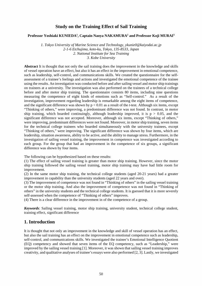
50
Study on the Training Effect of Sail Training
Professor Yoshiaki KUNIEDA1, Captain Naoya NAKAMURA2 and Professor Koji MURAI3
1. Tokyo University of Marine Science and Technology, [email protected] Etchujima, koto-ku, Tokyo, 135-8533, Japan
2. National Institute for Sea Training3. Kobe University
Abstract It is thought that not only the sail training does the improvement in the knowledge and skillsof vessel operation have an effect, but also it has an effect in the improvement in emotional competence,such as leadership, self-control, and communications skills. We created the questionnaire for the self-assessment of a trainee’s feelings and actions and investigated the emotional competence of the traineeusing the results. An investigation was conducted before and after sailing vessel and motor ship trainingson trainees at a university. The investigation was also performed on the trainees of a technical collegebefore and after motor ship training. The questionnaire consists 80 items, including nine questionsmeasuring the competence of eight kinds of emotions such as “Self-control.” As a result of theinvestigation, improvement regarding leadership is remarkable among the eight items of competence,and the significant difference was shown by p < 0.01 as a result of the t-test. Although six items, except“Thinking of others,” were improving, a predominant difference was not found. In contrast, in motorship training, which boarded continuingly, although leadership improved, it is p > 0.05, and thesignificant difference was not accepted. Moreover, although six items, except “Thinking of others,”were improving, predominant differences were not found. Moreover, in motor ship training, seven itemsfor the technical college trainees who boarded simultaneously with the university trainees, except“Thinking of others,” were improving. The significant difference was shown by four items, which areleadership, situation awareness, ability to be active, and the ability to manage stress. Furthermore, in theinvestigation of sailing vessel training, the improvement in competence was investigated according toeach group. For the group that had an improvement in the competence of six groups, a significantdifference was shown by four items.
The following can be hypothesized based on these results:(1) The effect of sailing vessel training is greater than motor ship training. However, since the motorship training followed the sailing vessel training, motor ship training may have had little room forimprovement.(2) In the same motor ship training, the technical college students (aged 20-21 years) had a greaterimprovement in capability than the university students (aged 22 years and over).(3) The improvement of competence was not found in “Thinking of others” in the sailing vessel trainingor the motor ship training. And also the improvement of competence was not found in “Thinking ofothers” in the university students and the technical college students. It is guessed that it is more severelyself-assessed when the competence of “Thinking of others” improves.(4) There is a clear difference in the improvement in of the competence of a group.
Keywords: Sailing vessel training, motor ship training, university student, technical college student,training effect, significant difference
1. Introduction
It is thought that not only an improvement in the knowledge and skill of vessel operation has an effect,but also the sail training has an effect on the improvement in emotional competence such as leadership,self-control, and communications skills. We investigated the trainee’s Emotional Intelligence Quotient(EQ) competency and showed that seven items of the EQ competency, such as “Leadership,” wereimproved by the sailing vessel training [1]. Moreover, it was shown that sailing vessel training improvescreativity, and qualitative analyses of trainee’s essays were also performed [2, 3]. Lastly, we investigated
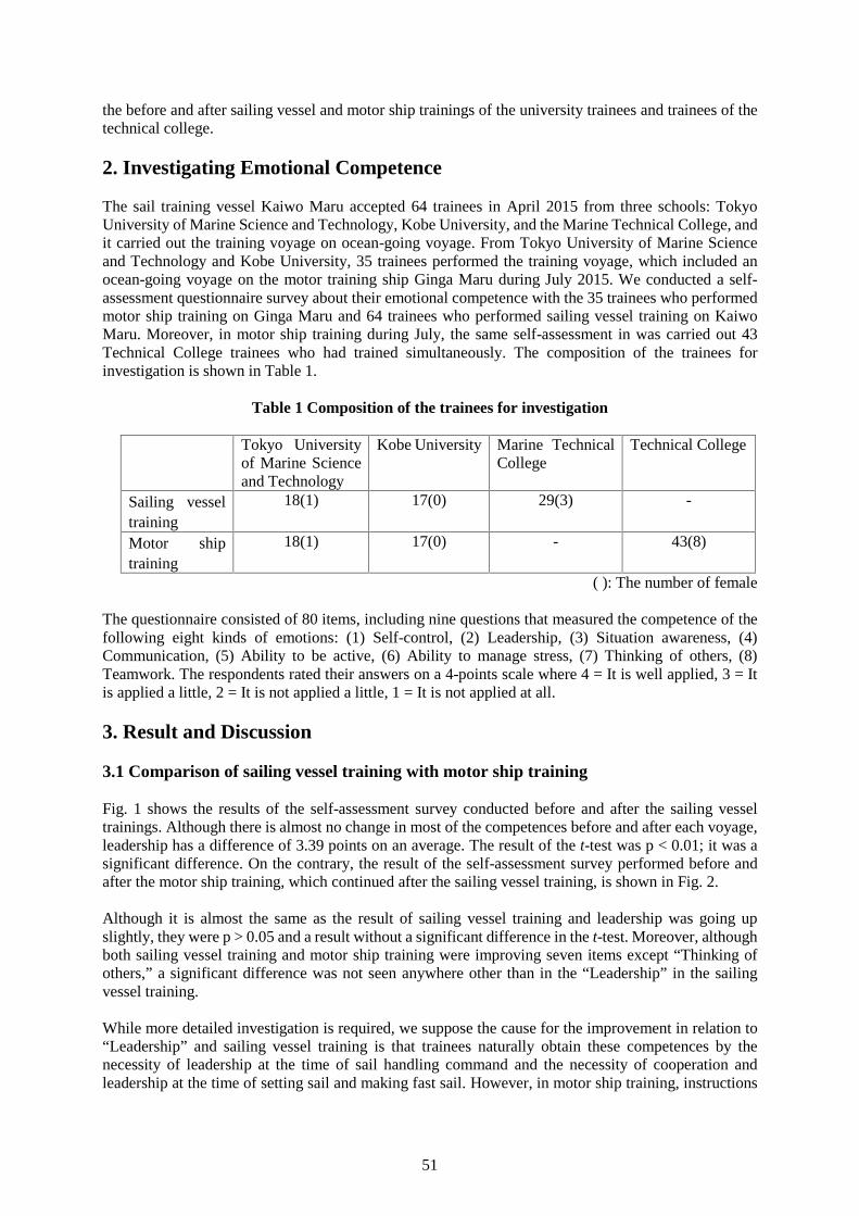
51
the before and after sailing vessel and motor ship trainings of the university trainees and trainees of thetechnical college.
2. Investigating Emotional Competence
The sail training vessel Kaiwo Maru accepted 64 trainees in April 2015 from three schools: TokyoUniversity of Marine Science and Technology, Kobe University, and the Marine Technical College, andit carried out the training voyage on ocean-going voyage. From Tokyo University of Marine Scienceand Technology and Kobe University, 35 trainees performed the training voyage, which included anocean-going voyage on the motor training ship Ginga Maru during July 2015. We conducted a self-assessment questionnaire survey about their emotional competence with the 35 trainees who performedmotor ship training on Ginga Maru and 64 trainees who performed sailing vessel training on KaiwoMaru. Moreover, in motor ship training during July, the same self-assessment in was carried out 43Technical College trainees who had trained simultaneously. The composition of the trainees forinvestigation is shown in Table 1.
Table 1 Composition of the trainees for investigation
Tokyo Universityof Marine Scienceand Technology
Kobe University Marine TechnicalCollege
Technical College
Sailing vesseltraining
18(1) 17(0) 29(3) -
Motor shiptraining
18(1) 17(0) - 43(8)
( ): The number of female
The questionnaire consisted of 80 items, including nine questions that measured the competence of thefollowing eight kinds of emotions: (1) Self-control, (2) Leadership, (3) Situation awareness, (4)Communication, (5) Ability to be active, (6) Ability to manage stress, (7) Thinking of others, (8)Teamwork. The respondents rated their answers on a 4-points scale where 4 = It is well applied, 3 = Itis applied a little, 2 = It is not applied a little, 1 = It is not applied at all.
3. Result and Discussion
3.1 Comparison of sailing vessel training with motor ship training
Fig. 1 shows the results of the self-assessment survey conducted before and after the sailing vesseltrainings. Although there is almost no change in most of the competences before and after each voyage,leadership has a difference of 3.39 points on an average. The result of the t-test was p < 0.01; it was asignificant difference. On the contrary, the result of the self-assessment survey performed before andafter the motor ship training, which continued after the sailing vessel training, is shown in Fig. 2.
Although it is almost the same as the result of sailing vessel training and leadership was going upslightly, they were p > 0.05 and a result without a significant difference in the t-test. Moreover, althoughboth sailing vessel training and motor ship training were improving seven items except “Thinking ofothers,” a significant difference was not seen anywhere other than in the “Leadership” in the sailingvessel training.
While more detailed investigation is required, we suppose the cause for the improvement in relation to“Leadership” and sailing vessel training is that trainees naturally obtain these competences by thenecessity of leadership at the time of sail handling command and the necessity of cooperation andleadership at the time of setting sail and making fast sail. However, in motor ship training, instructions
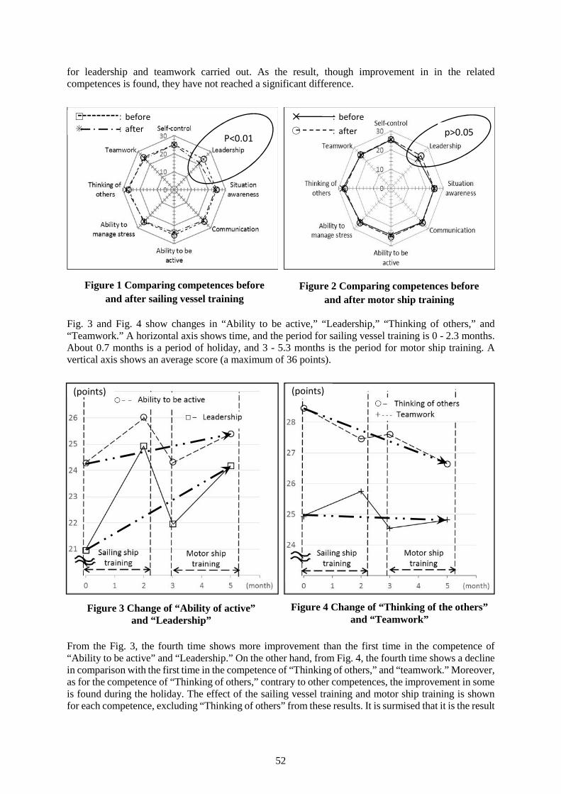
52
for leadership and teamwork carried out. As the result, though improvement in in the relatedcompetences is found, they have not reached a significant difference.
Fig. 3 and Fig. 4 show changes in “Ability to be active,” “Leadership,” “Thinking of others,” and“Teamwork.” A horizontal axis shows time, and the period for sailing vessel training is 0 - 2.3 months.About 0.7 months is a period of holiday, and 3 - 5.3 months is the period for motor ship training. Avertical axis shows an average score (a maximum of 36 points).
From the Fig. 3, the fourth time shows more improvement than the first time in the competence of“Ability to be active” and “Leadership.” On the other hand, from Fig. 4, the fourth time shows a declinein comparison with the first time in the competence of “Thinking of others,” and “teamwork.” Moreover,as for the competence of “Thinking of others,” contrary to other competences, the improvement in someis found during the holiday. The effect of the sailing vessel training and motor ship training is shownfor each competence, excluding “Thinking of others” from these results. It is surmised that it is the result
Figure 1 Comparing competences beforeand after sailing vessel training
Figure 2 Comparing competences beforeand after motor ship training
Figure 3 Change of “Ability of active”and “Leadership”
Figure 4 Change of “Thinking of the others”and “Teamwork”
(points) (points)
□ :before✳ :after
P<0.01 p>0.05✕ :before○ :after
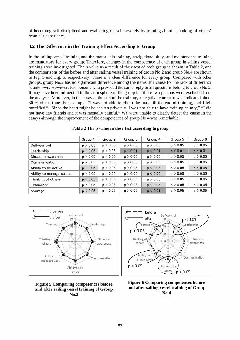
53
of becoming self-disciplined and evaluating oneself severely by training about “Thinking of others”from our experience.
3.2 The Difference in the Training Effect According to Group
In the sailing vessel training and the motor ship training, navigational duty, and maintenance trainingare mandatory for every group. Therefore, changes in the competence of each group in sailing vesseltraining were investigated. The p value as a result of the t-test of each group is shown in Table 2, andthe comparisons of the before and after sailing vessel training of group No.2 and group No.4 are shownin Fig. 5 and Fig. 6, respectively. There is a clear difference for every group. Compared with othergroups, group No.2 has no significant difference among the items; the cause for the lack of differenceis unknown. However, two persons who provided the same reply to all questions belong to group No.2.It may have been influential to the atmosphere of the group but these two persons were excluded fromthe analysis. Moreover, in the essay at the end of the training, a negative comment was indicated about30 % of the time. For example, “I was not able to climb the mast till the end of training, and I feltmortified,” “Since the heart might be shaken privately, I was not able to have training calmly,” “I didnot have any friends and it was mentally painful.” We were unable to clearly detect the cause in theessays although the improvement of the competences of group No.4 was remarkable.
Table 2 The p value in the t-test according to group
Group 1 Group 2 Group 3 Group 4 Group 5 Group 6
Self-control p > 0.05 p > 0.05 p > 0.05 p > 0.05 p > 0.05 p > 0.05
Leadership p < 0.05 p > 0.05 p < 0.01 p < 0.01 p < 0.01 p < 0.01
Situation awareness p > 0.05 p > 0.05 p > 0.05 p > 0.05 p > 0.05 p > 0.05
Communication p > 0.05 p > 0.05 p > 0.05 p > 0.05 p > 0.05 p > 0.05
Ability to be active p < 0.05 p > 0.05 p > 0.05 p < 0.05 p > 0.05 p < 0.05
Ability to manage stress p > 0.05 p > 0.05 p > 0.05 p < 0.05 p > 0.05 p > 0.05
Thinking of others p < 0.05 p > 0.05 p > 0.05 p > 0.05 p > 0.05 p > 0.05
Teamwork p > 0.05 p > 0.05 p > 0.05 p < 0.05 p > 0.05 p > 0.05
Average p < 0.05 p > 0.05 p > 0.05 p < 0.01 p > 0.05 p > 0.05
Figure 5 Comparing competences beforeand after sailing vessel training of Group
No.2
Figure 6 Comparing competences beforeand after sailing vessel training of Group
No.4
✕ :before○ :after p < 0.01
✕ :before○ :after
p < 0.05
p < 0.05p < 0.05
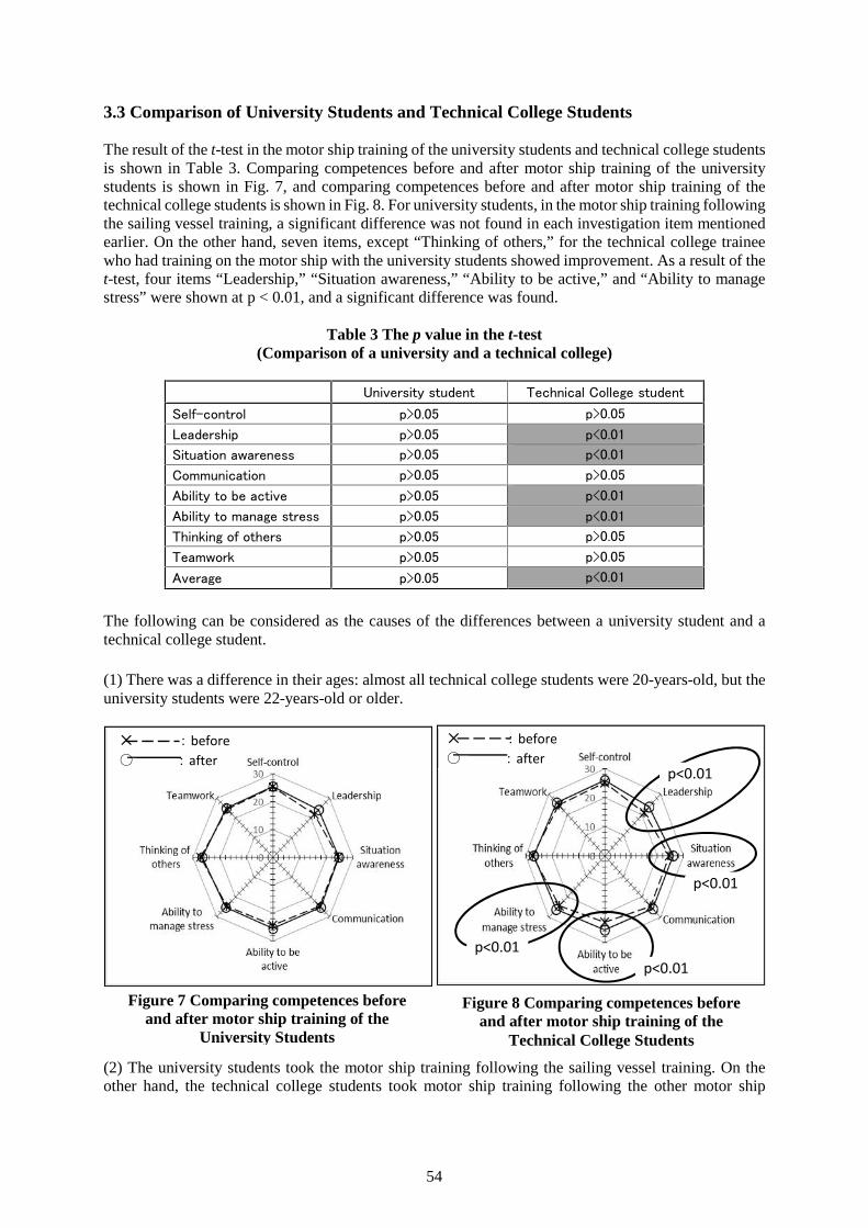
54
3.3 Comparison of University Students and Technical College Students
The result of the t-test in the motor ship training of the university students and technical college studentsis shown in Table 3. Comparing competences before and after motor ship training of the universitystudents is shown in Fig. 7, and comparing competences before and after motor ship training of thetechnical college students is shown in Fig. 8. For university students, in the motor ship training followingthe sailing vessel training, a significant difference was not found in each investigation item mentionedearlier. On the other hand, seven items, except “Thinking of others,” for the technical college traineewho had training on the motor ship with the university students showed improvement. As a result of thet-test, four items “Leadership,” “Situation awareness,” “Ability to be active,” and “Ability to managestress” were shown at p < 0.01, and a significant difference was found.
Table 3 The p value in the t-test(Comparison of a university and a technical college)
University student Technical College student
Self-control p>0.05 p>0.05
Leadership p>0.05 p<0.01
Situation awareness p>0.05 p<0.01
Communication p>0.05 p>0.05
Ability to be active p>0.05 p<0.01
Ability to manage stress p>0.05 p<0.01
Thinking of others p>0.05 p>0.05
Teamwork p>0.05 p>0.05
Average p>0.05 p<0.01
The following can be considered as the causes of the differences between a university student and atechnical college student.
(1) There was a difference in their ages: almost all technical college students were 20-years-old, but theuniversity students were 22-years-old or older.
(2) The university students took the motor ship training following the sailing vessel training. On theother hand, the technical college students took motor ship training following the other motor ship
Figure 7 Comparing competences beforeand after motor ship training of the
University Students
Figure 8 Comparing competences beforeand after motor ship training of the
Technical College Students
✕ :before○ :after
✕ :before○ :after
p<0.01
p<0.01
p<0.01p<0.01
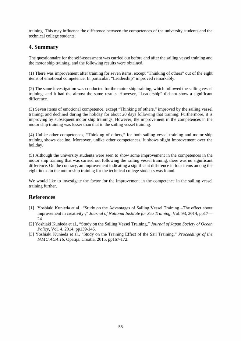
55
training. This may influence the difference between the competences of the university students and thetechnical college students.
4. Summary
The questionnaire for the self-assessment was carried out before and after the sailing vessel training andthe motor ship training, and the following results were obtained.
(1) There was improvement after training for seven items, except “Thinking of others” out of the eightitems of emotional competence. In particular, “Leadership” improved remarkably.
(2) The same investigation was conducted for the motor ship training, which followed the sailing vesseltraining, and it had the almost the same results. However, “Leadership” did not show a significantdifference.
(3) Seven items of emotional competence, except “Thinking of others,” improved by the sailing vesseltraining, and declined during the holiday for about 20 days following that training. Furthermore, it isimproving by subsequent motor ship trainings. However, the improvement in the competences in themotor ship training was lesser than that in the sailing vessel training.
(4) Unlike other competences, “Thinking of others,” for both sailing vessel training and motor shiptraining shows decline. Moreover, unlike other competences, it shows slight improvement over theholiday.
(5) Although the university students were seen to show some improvement in the competences in themotor ship training that was carried out following the sailing vessel training, there was no significantdifference. On the contrary, an improvement indicating a significant difference in four items among theeight items in the motor ship training for the technical college students was found.
We would like to investigate the factor for the improvement in the competence in the sailing vesseltraining further.
References
[1] Yoshiaki Kunieda et al., “Study on the Advantages of Sailing Vessel Training –The effect aboutimprovement in creativity-,” Journal of National Institute for Sea Training, Vol. 93, 2014, pp17―24.
[2] Yoshiaki Kunieda et al., “Study on the Sailing Vessel Training,” Journal of Japan Society of OceanPolicy, Vol. 4, 2014, pp139-145.
[3] Yoshiaki Kunieda et al., “Study on the Training Effect of the Sail Training,” Proceedings of theIAMU AGA 16, Opatija, Croatia, 2015, pp167-172.
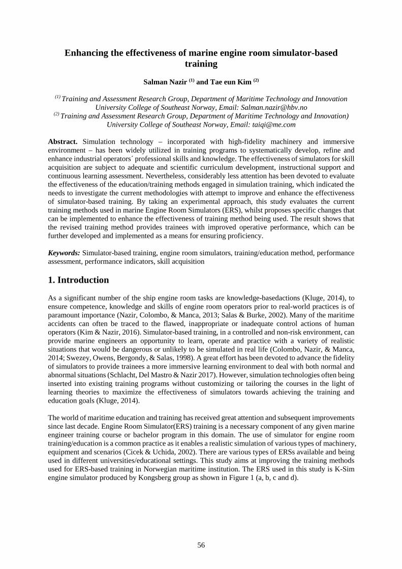
56
Enhancing the effectiveness of marine engine room simulator-basedtraining
Salman Nazir (1) and Tae eun Kim (2)
(1) Training and Assessment Research Group, Department of Maritime Technology and InnovationUniversity College of Southeast Norway, Email: [email protected]
(2) Training and Assessment Research Group, Department of Maritime Technology and Innovation)University College of Southeast Norway, Email: [email protected]
Abstract. Simulation technology – incorporated with high-fidelity machinery and immersiveenvironment – has been widely utilized in training programs to systematically develop, refine andenhance industrial operators´ professional skills and knowledge. The effectiveness of simulators for skillacquisition are subject to adequate and scientific curriculum development, instructional support andcontinuous learning assessment. Nevertheless, considerably less attention has been devoted to evaluatethe effectiveness of the education/training methods engaged in simulation training, which indicated theneeds to investigate the current methodologies with attempt to improve and enhance the effectivenessof simulator-based training. By taking an experimental approach, this study evaluates the currenttraining methods used in marine Engine Room Simulators (ERS), whilst proposes specific changes thatcan be implemented to enhance the effectiveness of training method being used. The result shows thatthe revised training method provides trainees with improved operative performance, which can befurther developed and implemented as a means for ensuring proficiency.
Keywords: Simulator-based training, engine room simulators, training/education method, performanceassessment, performance indicators, skill acquisition
1. Introduction
As a significant number of the ship engine room tasks are knowledge-basedactions (Kluge, 2014), toensure competence, knowledge and skills of engine room operators prior to real-world practices is ofparamount importance (Nazir, Colombo, & Manca, 2013; Salas & Burke, 2002). Many of the maritimeaccidents can often be traced to the flawed, inappropriate or inadequate control actions of humanoperators (Kim & Nazir, 2016). Simulator-based training, in a controlled and non-risk environment, canprovide marine engineers an opportunity to learn, operate and practice with a variety of realisticsituations that would be dangerous or unlikely to be simulated in real life (Colombo, Nazir, & Manca,2014; Swezey, Owens, Bergondy, & Salas, 1998). A great effort has been devoted to advance the fidelityof simulators to provide trainees a more immersive learning environment to deal with both normal andabnormal situations (Schlacht, Del Mastro & Nazir 2017). However, simulation technologies often beinginserted into existing training programs without customizing or tailoring the courses in the light oflearning theories to maximize the effectiveness of simulators towards achieving the training andeducation goals (Kluge, 2014).
The world of maritime education and training has received great attention and subsequent improvementssince last decade. Engine Room Simulator(ERS) training is a necessary component of any given marineengineer training course or bachelor program in this domain. The use of simulator for engine roomtraining/education is a common practice as it enables a realistic simulation of various types of machinery,equipment and scenarios (Cicek & Uchida, 2002). There are various types of ERSs available and beingused in different universities/educational settings. This study aims at improving the training methodsused for ERS-based training in Norwegian maritime institution. The ERS used in this study is K-Simengine simulator produced by Kongsberg group as shown in Figure 1 (a, b, c and d).
57
Figure 1 Engine Room Simulator (ERS)
One possible way to improve the training method for ERS training is to uncover the limitation of currenttraining methods exercised, and use it as a basis to develop measures in order to enhance theeffectiveness of this simulator-based training. To ensure the effective utilization of ERS and resources,while maximizing the learning outcome of engine room trainees, this study is designed with anexperimental approach to systematically identify loop holes of current training curriculum andinstructional support exercised and propose effective changes that can be implemented in order toimprove the effectiveness of marine ERS-based training.
2. Methodology
2.1. Experiment design and measurements
Proficiently and correctly starting the main engine from cold conditions is often considered as thefundamental knowledge and key learning target for engine room trainees and students. To identify thepotentials for improvement of current training method used for addressing this fundamental activity, aquasi-experimental design is performed which can be further divided into two phases.
Phase 1 aims to investigate the potential limitations of the current training method used in ERS, and toevaluate students´ learning outcome generated through current ERS-based training method. Allparticipants are invited to follow training program to start the main engine from cold conditions withthe instructions provided by the trainer/instructor. Participants received the first questionnaire regardingtheir backgrounds, motivations, and feedbacks of current training. The aim is to understand thesatisfaction level and learning outcomes of participants in current ERS-based training. Two researchers– one has over 10 years’ working experience in engine room and the other one is an expert in training
a. The engine control room and the instructor room b. The dark engine room
c. View from the instructor room d. View from the instructor room
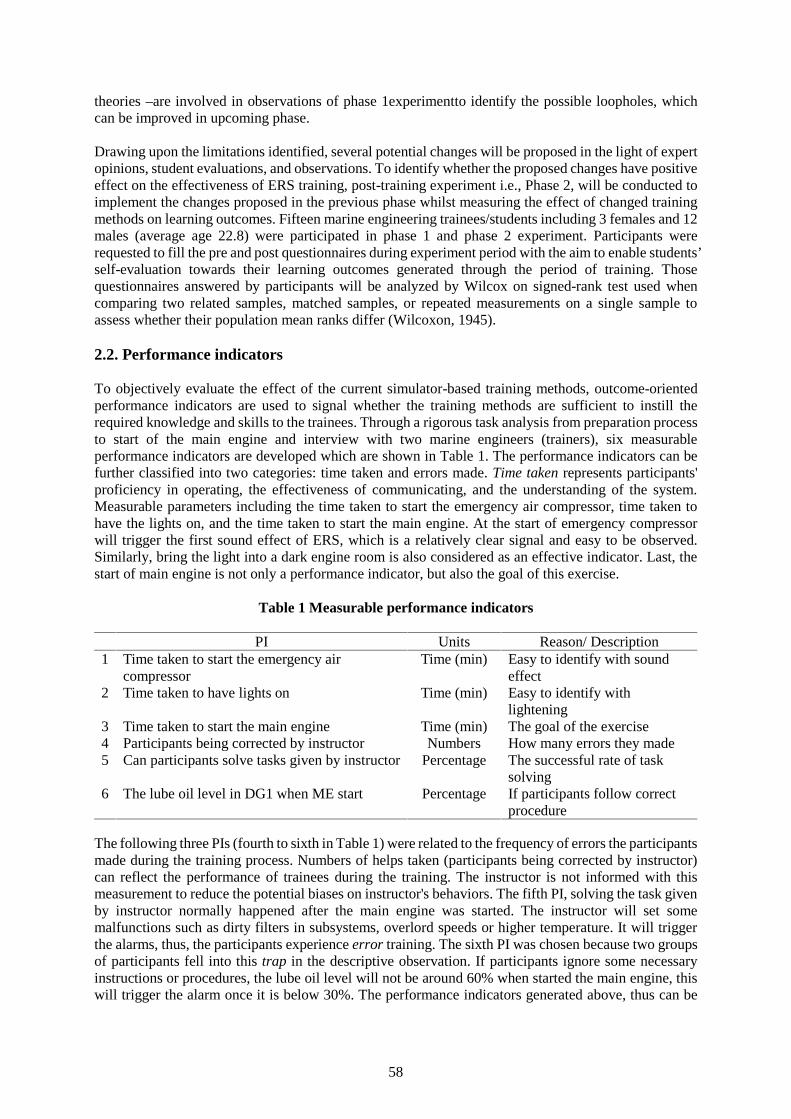
58
theories –are involved in observations of phase 1experimentto identify the possible loopholes, whichcan be improved in upcoming phase.
Drawing upon the limitations identified, several potential changes will be proposed in the light of expertopinions, student evaluations, and observations. To identify whether the proposed changes have positiveeffect on the effectiveness of ERS training, post-training experiment i.e., Phase 2, will be conducted toimplement the changes proposed in the previous phase whilst measuring the effect of changed trainingmethods on learning outcomes. Fifteen marine engineering trainees/students including 3 females and 12males (average age 22.8) were participated in phase 1 and phase 2 experiment. Participants wererequested to fill the pre and post questionnaires during experiment period with the aim to enable students’self-evaluation towards their learning outcomes generated through the period of training. Thosequestionnaires answered by participants will be analyzed by Wilcox on signed-rank test used whencomparing two related samples, matched samples, or repeated measurements on a single sample toassess whether their population mean ranks differ (Wilcoxon, 1945).
2.2. Performance indicators
To objectively evaluate the effect of the current simulator-based training methods, outcome-orientedperformance indicators are used to signal whether the training methods are sufficient to instill therequired knowledge and skills to the trainees. Through a rigorous task analysis from preparation processto start of the main engine and interview with two marine engineers (trainers), six measurableperformance indicators are developed which are shown in Table 1. The performance indicators can befurther classified into two categories: time taken and errors made. Time taken represents participants'proficiency in operating, the effectiveness of communicating, and the understanding of the system.Measurable parameters including the time taken to start the emergency air compressor, time taken tohave the lights on, and the time taken to start the main engine. At the start of emergency compressorwill trigger the first sound effect of ERS, which is a relatively clear signal and easy to be observed.Similarly, bring the light into a dark engine room is also considered as an effective indicator. Last, thestart of main engine is not only a performance indicator, but also the goal of this exercise.
Table 1 Measurable performance indicators
PI Units Reason/ Description1 Time taken to start the emergency air
compressorTime (min) Easy to identify with sound
effect2 Time taken to have lights on Time (min) Easy to identify with
lightening3 Time taken to start the main engine Time (min) The goal of the exercise4 Participants being corrected by instructor Numbers How many errors they made5 Can participants solve tasks given by instructor Percentage The successful rate of task
solving6 The lube oil level in DG1 when ME start Percentage If participants follow correct
procedure
The following three PIs (fourth to sixth in Table 1) were related to the frequency of errors the participantsmade during the training process. Numbers of helps taken (participants being corrected by instructor)can reflect the performance of trainees during the training. The instructor is not informed with thismeasurement to reduce the potential biases on instructor's behaviors. The fifth PI, solving the task givenby instructor normally happened after the main engine was started. The instructor will set somemalfunctions such as dirty filters in subsystems, overlord speeds or higher temperature. It will triggerthe alarms, thus, the participants experience error training. The sixth PI was chosen because two groupsof participants fell into this trap in the descriptive observation. If participants ignore some necessaryinstructions or procedures, the lube oil level will not be around 60% when started the main engine, thiswill trigger the alarm once it is below 30%. The performance indicators generated above, thus can be
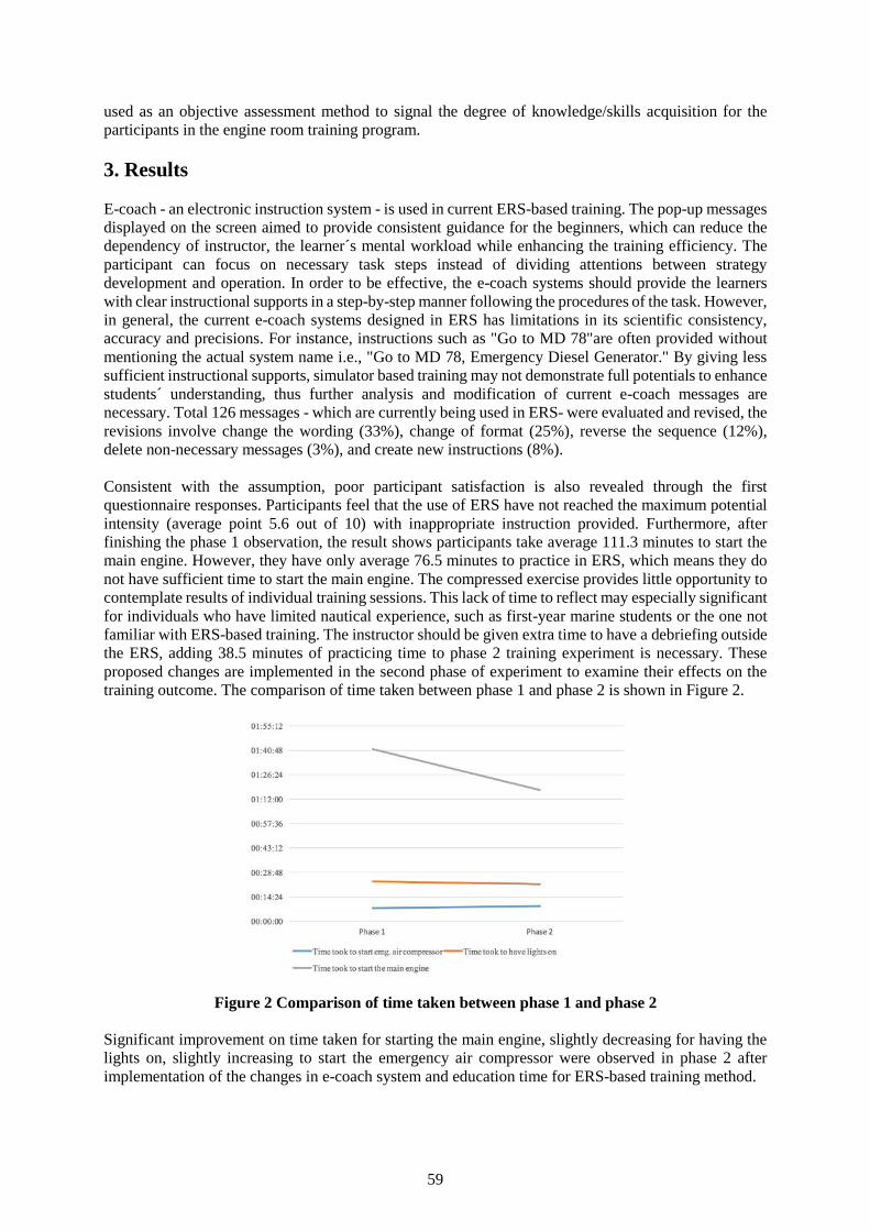
59
used as an objective assessment method to signal the degree of knowledge/skills acquisition for theparticipants in the engine room training program.
3. Results
E-coach - an electronic instruction system - is used in current ERS-based training. The pop-up messagesdisplayed on the screen aimed to provide consistent guidance for the beginners, which can reduce thedependency of instructor, the learner´s mental workload while enhancing the training efficiency. Theparticipant can focus on necessary task steps instead of dividing attentions between strategydevelopment and operation. In order to be effective, the e-coach systems should provide the learnerswith clear instructional supports in a step-by-step manner following the procedures of the task. However,in general, the current e-coach systems designed in ERS has limitations in its scientific consistency,accuracy and precisions. For instance, instructions such as "Go to MD 78"are often provided withoutmentioning the actual system name i.e., "Go to MD 78, Emergency Diesel Generator." By giving lesssufficient instructional supports, simulator based training may not demonstrate full potentials to enhancestudents´ understanding, thus further analysis and modification of current e-coach messages arenecessary. Total 126 messages - which are currently being used in ERS- were evaluated and revised, therevisions involve change the wording (33%), change of format (25%), reverse the sequence (12%),delete non-necessary messages (3%), and create new instructions (8%).
Consistent with the assumption, poor participant satisfaction is also revealed through the firstquestionnaire responses. Participants feel that the use of ERS have not reached the maximum potentialintensity (average point 5.6 out of 10) with inappropriate instruction provided. Furthermore, afterfinishing the phase 1 observation, the result shows participants take average 111.3 minutes to start themain engine. However, they have only average 76.5 minutes to practice in ERS, which means they donot have sufficient time to start the main engine. The compressed exercise provides little opportunity tocontemplate results of individual training sessions. This lack of time to reflect may especially significantfor individuals who have limited nautical experience, such as first-year marine students or the one notfamiliar with ERS-based training. The instructor should be given extra time to have a debriefing outsidethe ERS, adding 38.5 minutes of practicing time to phase 2 training experiment is necessary. Theseproposed changes are implemented in the second phase of experiment to examine their effects on thetraining outcome. The comparison of time taken between phase 1 and phase 2 is shown in Figure 2.
Figure 2 Comparison of time taken between phase 1 and phase 2
Significant improvement on time taken for starting the main engine, slightly decreasing for having thelights on, slightly increasing to start the emergency air compressor were observed in phase 2 afterimplementation of the changes in e-coach system and education time for ERS-based training method.
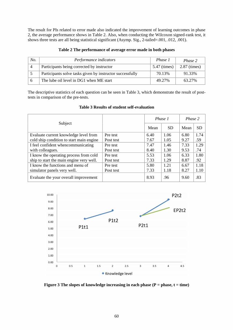
60
The result for PIs related to error made also indicated the improvement of learning outcomes in phase2, the average performance shows in Table 2. Also, when conducting the Wilcoxon signed-rank test, itshows three tests are all being statistical significant (Asymp. Sig., 2-tailed=.001, .012, .001).
Table 2 The performance of average error made in both phases
No. Performance indicators Phase 1 Phase 24 Participants being corrected by instructor 5.47 (times) 2.87 (times)5 Participants solve tasks given by instructor successfully 70.13% 91.33%6 The lube oil level in DG1 when ME start 49.27% 63.27%
The descriptive statistics of each question can be seen in Table 3, which demonstrate the result of post-tests in comparison of the pre-tests.
Table 3 Results of student self-evaluation
SubjectPhase 1 Phase 2
Mean SD Mean SDEvaluate current knowledge level fromcold ship condition to start main engine
Pre testPost test
6.407.67
1.061.05
6.809.27
1.74.59
I feel confident whencommunicatingwith colleagues.
Pre testPost test
7.478.40
1.461.30
7.339.53
1.29.74
I know the operating process from coldship to start the main engine very well.
Pre testPost test
5.537.33
1.061.29
6.338.87
1.80.92
I know the functions and menu ofsimulator panels very well.
Pre testPost test
5.807.33
1.211.18
6.678.27
1.181.10
Evaluate the your overall improvement 8.93 .96 9.60 .83
Figure 3 The slopes of knowledge increasing in each phase (P = phase, t = time)
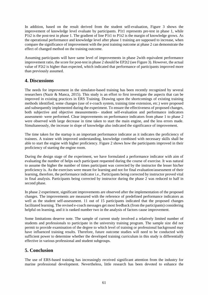
61
In addition, based on the result derived from the student self-evaluation, Figure 3 shows theimprovement of knowledge level evaluate by participants. P1t1 represents pre-test in phase 1, whileP1t2 is the post-test in phase 1. The gradient of line P1t1 to P1t2 is the margin of knowledge grows. Asthe operational performance and knowledge level after phase 1 training are supposed to increase, whencompare the significance of improvement with the post training outcome at phase 2 can demonstrate theeffect of changed method on the training outcome.
Assuming participants will have same level of improvements in phase 2with equivalent performanceimprovement ratio, the score for post-test in phase 2 should be EP2t2 (see Figure 3). However, the actualvalue of P2t2 is higher than expected, which indicated that performance of participants improved morethan previously assumed.
4. Discussions
The needs for improvement in the simulator-based training has been recently recognized by severalresearchers (Nazir & Manca, 2015). This study is an effort to first investigate the aspects that can beimproved in existing practices in ERS Training. Drawing upon the shortcomings of existing trainingmethods identified, some changes (use of e-coach system, training time extension, etc.) were proposedand subsequently implemented during the experiment. To ensure the effectiveness of proposed changes,both subjective and objective measurements– student self-evaluation and performance indicatorsassessment- were performed. Clear improvements on performance indicators from phase 1 to phase 2were observed with large decrease in time taken to start the main engine, and the less errors made.Simultaneously, the increase in slope of knowledge also indicated the significance of improvement.
The time taken for the startup is an important performance indicator as it indicates the proficiency oftrainees. A trainee with improved understanding, knowledge combined with necessary skills shall beable to start the engine with higher proficiency. Figure 2 shows how the participants improved in theirproficiency of starting the engine room.
During the design stage of the experiment, we have formulated a performance indicator with aim ofevaluating the number of helps each participant requested during the course of exercise. It was naturalto assume the higher the number of times participant was corrected by the instructor the lesser his/herproficiency is. As the exercises were meant for learning and not for final evaluation/assessment of theirlearning, therefore, the performance indicator i.e., Participants being corrected by instructor proved vitalin final analysis. Participants being corrected by instructor during the phase 2 was reduced to half insecond phase.
In phase 2 experiment, significant improvements are observed after the implementation of the proposedchanges. The improvements are measured with the reference of predefined performance indicators aswell as the student self-assessment. 11 out of 15 participants indicated that the proposed changesfacilitated learning. The revised e-coach messages get most feedback (from the participants) consideringhelpful on learning, and it is ranked number two in the analysis of factors cause improvement.
Some limitations deserve note. The sample of current study involved a relatively limited number ofstudents and professionals to participate in the university training program. The sample size did notpermit to provide examination of the degree to which level of training or professional background mayhave influenced training results. Therefore, future outcome studies will need to be conducted withsufficient power to determine whether the developed training curriculum in this study is differentiallyeffective in various professional and student subgroups.
5. Conclusion
The use of ERS-based training has increasingly received significant attention from the industry formarine professional development. Nevertheless, little research has been devoted to enhance the
62
effectiveness of the education/training methods engaged in simulation training. This paper thus hastaken an experimental approach to propose several changes in the light of identified limitations of thecurrent marine engine room simulator-based training with attempt to improve and enhance theeffectiveness of simulator-based training. This study reveals that the ERS-based training method at oneinstitution in Norway possess several possibilities of improvement. Implementation of proposed changesresulted in evident improvements in the learning outcomes of the participants/students.
By enhancing the marine simulator-based training with the surplus of the thought which we can generate,hopefully can pave the way for future work aiming at improvement of education/training in maritimedomain.
6. Acknowledgement
Special acknowledgement should be given to Chingshin Lin, Terje Width Berg for their assistances indata acquisition and analyses during the course of this research. We would also like to show our gratitudeto Bent Moskvil– theengine room training instructor at University College of Southeast Norway – forhis continuous support in the experiment process.
7. Reference
[1] Cicek, I., & Uchida, M. (2002). Improvement of Marine Engineering Curriculum Using The EngineRoom Simulator.
[2] Colombo, S., Nazir, S., & Manca, D. (2014). Immersive virtual reality for training and decisionmaking: Preliminary results of experiments performed with a plant simulator. SPE Economics andManagement, 6(4), 165-172.
[3] Kim, T.-e., & Nazir, S. (2016). Exploring marine accident causation: A case study. In A. e. al. (Ed.),Occupational Safety and Hygiene IV. London: Taylor & Francis Group.
[4] Kluge, A. (2014). The acquisition of knowledge and skills for taskwork and teamwork to controlcomplex technical systems: A cognitive and macroergonomics perspective (Vol. 9789400750494).
[6] Nazir, S., Colombo, S., & Manca, D. (2013) Testing and analyzing different training methods forindustrial operators: An experimental approach. Vol. 32. Computer Aided Chemical Engineering(pp. 667-672).
[7] Nazir, S., & Manca, D. (2015). How a plant simulator can improve industrial safety. Process SafetyProgress, 34(3), 237-243. doi:10.1002/prs.11714
[8] Salas, E., & Burke, C. S. (2002). Simulation for training is effective when. Quality and Safety inHealth Care, 11(2), 119-120.
[9] Schlacht, I. L., Del Mastro, A., & Nazir, S. (2017). Virtual Reality for Safety, Entertainment orEducation: The Mars Mission Test. In Advances in Applied Digital Human Modeling andSimulation (pp. 75-83). Springer International Publishing.
[10] Swezey, R. W., Owens, J. M., Bergondy, M. L., & Salas, E. (1998). Task and training requirementsanalysis methodology (TTRAM): An analytic methodology for identifying potential training usesof simulator networks in teamwork-intensive task environments. Ergonomics, 41(11), 1678-1697.doi:10.1080/001401398186135
[11] Wilcoxon, F. (1945). Individual comparisons by ranking methods. Biometrics bulletin, 1(6), 80-83.
63
Monitoring of the quality of Maritime specialists trainingin the system of Maritime education
PhD. Igor Marichev
Admiral Ushakov Maritime State University, Novorossiysk, Russia, e-mail: [email protected]
Abstract. Maritime universities are focused on the principal issues of the maritime education, includingcreation of new competitive image of the merchant shipping industry, its support through scientific andtechnological development. The result of set tasks first of all depends on quality of training which shouldguarantee professionalism of specialists working in the branch.
Currently, the need to improve the quality of Maritime education is connected with the rapiddevelopment of shipping industry and a number of documents both national and conventional, regulatingactivities in this field.
The article shows that there are many methods of quality control of the educational process at theMaritime universities, from collecting information on the performance and other indicators set byregulatory documents to complex psychological and pedagogical tests.
It is proved that there is no optimal model of monitoring, which could validly describe different aspectsof the quality of the educational process at the Maritime Universities. The issue of criteria of quality inMaritime education is considered; its links with the elaboration of educational standards are shown andgrounded.
The method of monitoring the quality of marine specialists training in the system of Maritime educationis submitted. Criteria of the quality of training are highlighted and the mechanism for monitoring thequality of training of future marine specialists is described.
This paper provides theoretical justification to application of the Matrix approach to the construction ofthe educational space which can contribute much to development of the issue of monitoring andestimation of qualityof Maritime specialists training. The theoretical arguments are supported withempirical evidence from the previous research.
Key words: seafarer, quality of training, standardization, maritime transport, maritime university, skilldevelopment, educational space, coefficient of comfort.
1. Introduction
Issues of regular monitoring of Maritime education quality are explained by need of scientific andtechnical progress in professional training of specialists for the Maritime industry. The need to improvethe quality of Maritime education currently is associated with the rapid development of merchantshipping and a number of documents regulating activities in this branch. The urgency of considering theissues of improving the quality of professional training of future sea specialists at Maritime universitiesis obvious. The main contradiction here is the discrepancy between criteria for its (quality) assessment:on the one hand:in any educational institution the main evaluation criterion is volume and quality ofknowledge, abilities and skills of the graduate on certain disciplines, on the other hand: the customersof the «product» of the Maritime Universities consider a real readiness of the graduates to the solutionof multidimensional tasks while performing the professional activity.
There are some inconsistencies which should be solved. Often professionals with high learningoutcomesafter graduating from the Maritime institutions, with sufficient engineering knowledge, skillsand abilities, are not always able fully to apply knowledge in the professional activity. This isparticularly evident in the lack of readiness of young seafarers (and other specialists working in the
64
Maritime industry) to solve complex professional tasks especially in stressful and unusualcircumstances, which often leads to various kinds of accidents. Hence, the cause of much quantity ofaccidents is the human factor. To some extent, the system of quality of professional training in Maritimeuniversities is urged to resolve this situation.
The essence of the system of quality of professional training at Maritime universities as a pedagogicalsystem is the ratio of activity of participants of education with the pedagogical result. The eternal task(at least, due to the fact that educational standards are constantly changedowing to development ofindustry) and require constant attention. Therefore, a system-forming factor of the system of quality ofmarine specialists’professional training is the goal, determined by demands of consumers of services ofMaritime education – by Maritime companies (crewing, shipping, forwarding etc.). The result of wideimplementation of this system must reflect the readiness of graduates of Maritime universities to performcomplex professional activities and correspond to the requirements of the International ConventionSTCW 1978/95 and amendments adopted at the Manila Conference, 2010 [5].
2. Monitoring of quality of educational process in Maritime universities
The quality of professional training in the Maritime universities is not only a complex system, butcomplex systemic objectfor management or control. Namely, the quality of management of professionaltraining determines the achievement of the objectives of the quality system of professional training andit is subject to appropriate control and regulation of the functioning of all its (the system’s) elements.Orientation of the purpose of quality management of training for the creation of conditions for formationof graduates’readiness for professional activity determines the appropriate change in its objectives,content, forms and methods of realization of this training. We do not speak about competenceassessment or learning outcome of a student to demonstrate his/her capacity to perform tasks listed inthe STCW Code. We will focus on one aspect of this issue, on method of control of the educationalprocess quality in Maritime universities, i.e. monitoring.
Monitoring of quality of the educational process means thesupervision for its development to ensureoptimal choice of tasks, their solutions and used methods while organizing this process. Monitoringinvolves a systematic diagnosis of qualitative and quantitative characteristics of efficiency of theeducational system functioning, and therefore, interaction of all components of the pedagogical system,including direct and feedback amongits (system) components.
Currently, there aredifferent methods for monitoring of the quality of the educational process inMaritime universities, from collecting information about students’ performance and other indicators setby regulatory documents to complex psychological and pedagogical tests.
It goes without saying that criteria or indicators under which the quality is assessed should be clearenough, easy to handle, but at the same time it must be grounded on the scientific approach. Whileestimating quality of education all aspects should be accounted: learning outcomes of students, work ofeducational institutions and all participants of the educational process. Obviously, there is no optimalmodel of monitoring, which could reliably classify most aspects of the quality of the educational processin all and in each certain University, including a Maritime University. And this state of affairs onlycomplicates the task of the monitoring.
Maritime education is a special category due to the fact that its realization occursboth on the basis ofFederal StateStandards and Conventional ones. Maritime education institutions work with increasingindependency although it is supposed to work according to STCW Convention.And the Conventionalstandards and requirements play often a leading role«…each Party shall ensure that an independentevaluation of the knowledge, understanding, skills and competence acquisition and assessmentactivities…»and «…each Party shall also ensure that an evaluation is periodically undertaken, inaccordance with the provisions of section A-I/8 of the STCW Code, by qualified persons who are notthemselves involved in the activities concerned. This evaluation shall include all changes to national
65
regulations and procedures in compliance with the amendments to the Convention and STCW Code…»[5].As a rule, the monitoring of quality of Maritime education provides the following:
– evaluating the overall goals and objectives of training marine specialists and determination ofparameters of this assessment;
– analysis of curricula content of various disciplines, consistent both with national andinternational standards and the requirements of employers;
– quality assessment of learning resources (textbooks, software products, simulators, etc.);– the verification of the effectiveness of the used teaching methods and their adjustment and
optimization if necessary;– creation of special agencies, departments, groups, etc. for rapid assessment and analysis of the
quality and trends of the educational system both on state level and on level of educationalinstitution;
– development of operational methods for assessing the current quality and its relationship to amodel (although, the model is always conditional);
– assessmentboth of a process of development of professional competences and personalqualities (for example, all-intellectual development, the formation of value orientations, ethnicand cultural competence, etc.) and learning outcomes.
Regardless of what aspects of the educational process will be subject to monitoring, for itsimplementation it is necessary to ground on certain principles of monitoring arrangement. Whileimplementing the Quality System in Admiral Ushakov Maritime State University (Novorossiysk,Russia) the following principles were developed and introduced:
– the principle of the system arrangement, ensuring the integrity of the construction and therelationship of components included in the monitoring system;
– the binarity principle, reflecting the basic pattern of the effectiveness of the educationalsystems that is binary (inseparable) combination of teaching and self-learning, education andself-education, external control and self-discipline;
– the principle of management including organization of processes, procedures of measurement,analysis and improvement, as well as the choice of ways to manage the entire monitoringprocess adequate to the set task;
– the principle of informational activity, which includes collecting information about thelearning outcomes of the graduates as the main objective of the management of the qualitysystem, preparation and implementation of decisions on the adjustment of processes (teachingmethods, applied aids, pedagogical technologies, etc.);
– the principle of continuity that defines the sequence of changing requirements to knowledge,abilities and skills of learners, the interrelation among the content, methods and forms ofeducational process;
– the principle of predictability, which is determined primarily by demands of the MaritimeIndustry, as well as scientific and methodological and financial support of the educationalinstitution.
Reliance on these principles contributes to systematic and profound analysis of the monitoring system.
Typically, monitoring in the Maritime University is carried out in several stages:– general control of the educational process (education and training);– evaluation of the shipboard training process and its parameters reflecting, primarily specifics
of Maritime activities;– control of the educational process outcome (bothlearning outcomeand the monitoring of
employment of graduates);– certification of the educational process in general (both by the national bodies, and IMO,
different Quality Systems, etc.).
According to results of such monitoring, typically the specific proposals for improving the educationalprocess are submitted and someoffers on improving the quality are given.
66
3. Criteria of quality of Maritime education
The concept «quality» is one of the most difficult one. The interpretation of this concept involves thedetermination of the list of properties and characteristics, as well as methods of their measurement.These difficulties arise because the category «quality» reflects the great diversity of properties of objectsand phenomena.
The concept of «quality» of professional training of seafarers is a large-scale in nature. In conditions oflabor market and competition the quality of marine specialisttraining often influencesbothon the levelof production, andon human life. Improvement of quality of training is associated with the developmentof human potential at educational institutions. Moreover, it includes the ability of a graduate to meetcurrent and anticipated requirements of consumers.
However, there is no a unified attitude to the definition of quality in today's educational environment.It is to be noted that the concepts «quality of education» and «training quality» used in the work arenot identical.
The concept of «quality of education» often has more formalized content (presence of scientific schoolsat universities; potential demand for vocational/professional education; financial stability ofaneducational institution; employability of graduates; qualification of scientific and pedagogicalpersonnel, staffing of libraries, results of scientific and publishing activities, focus of educationalprograms, international activities, etc.). These and other features are taken into account while assessingthe effectiveness of the certain University. However, this information in the framework of modernapproach to assessing quality is more likely to be considered for the characterization of capabilities ofany University, but is not always able to give an adequate assessment of a result – a level of training ofa particular specialist, his/her learning outcome.
The meaning of the term «quality of professional training», involves a greater emphasis on adequacy ofresults to objectives of educational activities, i.e. readiness of graduates for professional activities in aparticular industry, in this case, in the sector of the Merchant Shipping.
The issue of measuring the quality of training causes a lot of disputes. Almost all researchers andpractitioners agree on the necessity of search of quality indicators, acceptable for any University. Weare sure it is impossible, due to the fact of different directions of educational institutions, differenttraditions and different culture.
A significant role in this aspect belongs to educational standards, which define the set of competencies,and hence, determine the choice of methods, ways and means of developing these competences. Thecase with the monitoring of the process of developing these competences is different one. Here again, anumber of issues related to the choice of evaluation criteria arises. In this case, the STCW Conventionindicates very clearly the required level of competencies of graduates of Maritime educationalinstitutions, but how to assess the formed competence objectively, and what criteria to use? This issueis not fully resolved and it requires further attention. Different authors describe criteria as the essentialqualities expected from a graduating student’s performance, i.e. ability to demonstrate and provideevidence of the achievement of learning outcomes. Despite the existing different approaches to theconcept “criteria”, its description should contain measurable terms across a range of cultural andperformance context. Moreover, the criteria should be explained by a wide number of performancelevels that ensure a gradation of the quality of performance.
4. The ratio of the monitoring methodology and coefficient of comfort ofeducational space of Maritime University
The creation of a normative and methodological base for assessing the quality of professional trainingis the most important task forany University. Methods of evaluationof graduates training quality should
67
be grounded onthe system and structural analysis, taking into account all the internal opportunities ofthe University and external factors influencing on its activities.
Any method of monitoring of training quality is subject to the conditions of educational space of theUniversity. In this regard, we propose to consider the coefficient of comfort of educational space of aMaritime University, which measure of conformity is characterized by general condition of all itsfunctional objects.
We would like to point out, that understanding of comfort of educational space of any educationalinstitution in much contributes to quality of education in general and quality of learning outcome of astudent in particular. That is why we pay so much attention to it.
Grounding on the statement of M. Heidegger [1], according to which the place is some point of spacefor existence, arrangements of object in it, we understand«educational space» as conditions forimplementation of educational interactivity, which main objective is the changing of objects located inthis space.
We’ve distinguished the basic attributes of educational space. They are the following:– filling of emptiness by material and (or) virtual educational objects;– prevalence (concerning objects and their quantity) and coherence of educational objects;– determination of educational objects of space [3; 4].
Educational objects include: the contingent of learners (pupils, students, trainees, etc.), the staff ofteachers, state standards of education, educational literature, educational-material resources, hostels, etc.Prevalence of objects is characterized by their «volume» and quantity. Determination of educationalobjects consists in the following. Each of them has the sphere of existence, the borders, differs fromothers. Objects of one level of the maintenance consist of objects of another (more concrete, detailed).
We relied on the fact that an applied structure of the educational space of any institution has thecharacteristics of multi-dimensional matrices. Hence, the orderliness and predictability of the structurecomponent of the educational space is evident. Based on this structure when creating the next level ofconditions of educational space, it is possible to predict in advance what conditions, and with whatpurpose it can or should be created.
Each component while distinguishing and detailed consideration can be decomposed by selection of thecharacteristic inherent to the components of the next level. This process of constructing of new levelscan be continued depending on available information and opportunities to specify the conditions forimplementation of educational actions.
We assumed that any quality of a personality is a property of the brain and consists of the actions that itperforms. Actions performed by a man on the basis of his «human formation» can be subdivided intotwo groups. First group includes those which primary purpose is the formation and/or the developmentof any human feature (knowledge, personality traits...). Theseare educational actions. Their productivitydepends on their adequacy to the set objective. The second group includes all other actions. They areperformed to meet the different needs of life, achieve different purposes (cultural, labor, etc.). They alsoto some extent affect the formation of human features. This effect can be called as natural.
Effective formation of professional competences requires adequate targeted actions. To see it happen, itis necessary to create conditions for them based on specific level of education and capacity to performnecessary actions. These conditions are subdivided into established spontaneously and purposefullycreated. Actions to develop features of aperson are also subdivided into natural and purposeful. The firstis considered as socialization, and the last is understood as education. Actions of the educational processare executed in a certain social environment,hence the formation of personality traits is also influencedby the social circumstances.
68
The foregoing allows conclude, that in the society there are conditions that can be called socialized, andtheir combination – the «socialized space». It exists together with educational space and intersects withit, as pedagogues use the conditions of social medium for solution of educational tasks. The combinationof educational and socialized conditions of formation and development of professional competences canbe considered as a space of formation of personal and professional features of a person.
In this development the dominant role is played by an educational institution. It acts under programsbased on the national and the international training standards that establish mandatory requirements tothe formation and development of competences of future specialists. The space of formation ofprofessional competences must contain the terms (objects), the existence of which allows to each personperform his relevant actions.
In this connection in an educational institution both the educational and social space are created.
The space of formation of professional competences of students in educational institutions may be in adifferent state of readiness. It is advisable to have a tool for its evaluation allowing reliably track itscompleteness and state its level. We’ve attempted to create its original image on the basis of ourproposed anthropological matrix structure of educational space [2] and index of its comfort [4],characterizing its quantitative readiness.
Developing of the matrix approach to the construction of the educational space-based on solutions ofeducational targets reveals the prospects of constructing of the objects in this space, the formed level ofdetailed elaboration, as well as consequent transition to next levels.
Application structure of the educational space of the institution has a symptom of a multidimensionalmatrix. Hence, the orderliness and predictability of the structure of the educational space is evident.Grounding on this structure when creating the next level of conditions of the educational space inadvance, we can predict what conditions for what can or should be created.
Each component when concrete defining and detailed elaborating can be decomposed by highlightingthe inherent characteristics to the components of the next level. This process of new levels building canbe continued depending on the available information and opportunities to specify the conditions forperforming educational actions.
Criteria of readiness of the educational space are: securing of the functional conditions for thedevelopment of a person; ensuring an adequate range of conditions for implementation of theeducational actions. The degree of correspondence of the educational space to the service of theeducational activity is characterized by the ratio of his comfort, which summarizes the status of all ofits functional components.
The actual material for evaluation of objects of meaningful matrix can be assembled through a survey,evaluation by experts, questionnaires, inspections of conditions of the considered space (readiness ofthe institution to solution of the set tasks) or otherwise. It is necessary that the analysis of conditionswas continuous (collecting of information about each object) and uniform as possible.We should not expect that the result will be absolutely correct. Its objectivity depends on the experienceand expertise of the involved in the research experts, respondents; onunderstanding the core ofeducational institution; on provided time to collect information and on many other circumstances.
5. Conclusion
The growth of the ships capacities is obvious and this process is resulted in increasing quality ofoperability, bringing onboard the ship the newest technology and people able to work in these newconditions. The constant development of technology and its implementation onboard ships, requireshighly skilled sea specialists to perform complex professional functions. The first step in achievement
69
of high results is training of future seafarers in maritime institutions where monitoring of the educationalprocess takes one of the most important place.
There is no single model of monitoring which meet the requirements of different universities fromdifferent countries. Monitoring establishes not only the uptake of generated knowledge and skills, butalso the quality of this assimilation, which is specified by aims of educating process and createspossibilities for the correction of learning process. A record of all proposed parameters significantlycomplicates the procedure of evaluating the quality of the educational process.This paper suggests that use of the matrix approach to the construction of the educational space cancontribute much to development of the issue of monitoring and estimation of quality.
Despite the relativity of the expected results of applying the proposed methodology, its use undoubtedlywill help develop the analysis of readiness of the educational institutions to the solution of their tasks.Now in this analysis mapping of individual opinions and impressions prevails, and the suggested methodof finding the index of comfort of created space of professional competence formation represents theattempt of the orderly collection and processing of objective information.
References:
[1] Heidegger M. Art and space / Time and life. – 1993.[2] Marichev I., Malinochka E.G. Comfort of educational space // Space of contemporary education:
Maritime academy in educational space. – Krasnodar. Kuban State University, 2009. – pp. 34–39.[3] Marichev I. Maritime academy in educational space. – Novorossiysk. Admiral Ushakov State
Maritime Academy. – 2006.[4] Marichev I. Systemic arrangement of the educational space. – Palmarium Academic Publishing.AV
Akademikerverlag GmbH and CoKG. Saarbrucken. Deutchland / Germany. – 2014.[5] Revised International Convention on Standards of Training, Certification and Watchkeeping for
Seafarers (STCW) Convention and Code adopted at the Manila Conference. IMO,www.imo.org.2014
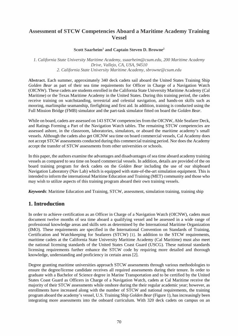
70
Assessment of STCW Competencies Aboard a Maritime Academy TrainingVessel
Scott Saarheim1 and Captain Steven D. Browne2
1. California State University Maritime Academy, [email protected], 200 Maritime AcademyDrive, Vallejo, CA, USA, 94510
2. California State University Maritime Academy, [email protected]
Abstract. Each summer, approximately 340 deck cadets sail aboard the United States Training ShipGolden Bear as part of their sea time requirements for Officer in Charge of a Navigation Watch(OICNW). These cadets are students enrolled in the California State University Maritime Academy (CalMaritime) or the Texas Maritime Academy in the United States. During this training period, the cadetsreceive training on watchstanding, terrestrial and celestial navigation, and hands-on skills such asmooring, marlinspike seamanship, firefighting and first aid. In addition, training is conducted using theFull Mission Bridge (FMB) simulator and the part-task simulator fitted on board the Golden Bear.
While on board, cadets are assessed on 143 STCW competencies from the OICNW, Able Seafarer Deck,and Ratings Forming a Part of the Navigation Watch tables. The remaining STCW competencies areassessed ashore, in the classroom, laboratories, simulators, or aboard the maritime academy’s smallvessels. Although the cadets also get OICNW sea time on board commercial vessels, Cal Academy doesnot accept STCW assessments conducted during this commercial training period. Nor does the Academyaccept the transfer of STCW assessments from other universities or schools.
In this paper, the authors examine the advantages and disadvantages of sea time aboard academy trainingvessels as compared to sea time on board commercial vessels. In addition, details are provided of the onboard training program for deck cadets on the Golden Bear including the use of our shipboardNavigation Laboratory (Nav Lab) which is equipped with state-of-the-art simulation equipment. This isintended to inform the international Maritime Education and Training (MET) community and those whomay wish to utilize aspects of this training program aboard their own training vessels.
Keywords: Maritime Education and Training, STCW, assessment, simulation training, training ship
1. Introduction
In order to achieve certification as an Officer in Charge of a Navigation Watch (OICNW), cadets mustdocument twelve months of sea time aboard a qualifying vessel and be assessed in a wide range ofprofessional knowledge areas and skills sets as determined by the International Maritime Organization(IMO). These requirements are specified in the International Convention on Standards of Training,Certification and Watchkeeping for Seafarers (STCW) [1]. In addition to the STCW requirements,maritime cadets at the California State University Maritime Academy (Cal Maritime) must also meetthe national licensing standards of the United States Coast Guard (USCG). These national standardslicensing requirements further enhance the STCW code by requiring more detailed and thoroughknowledge, understanding and proficiency in certain areas [2].
Degree granting maritime universities approach STCW assessments through various methodologies toensure the degree/license candidate receives all required assessments during their tenure. In order tograduate with a Bachelor of Science degree in Marine Transportation and to be certified by the UnitedStates Coast Guard as Officers in Charge of a Navigation Watch, cadets at Cal Maritime receive themajority of their STCW assessments while onshore during the their regular academic year; however, asenrollments have increased along with the number of STCW and national requirements, the trainingprogram aboard the academy’s vessel, U.S. Training Ship Golden Bear (Figure 1), has increasingly beenintegrating more assessments into the onboard curriculum. With 320 deck cadets on campus on an
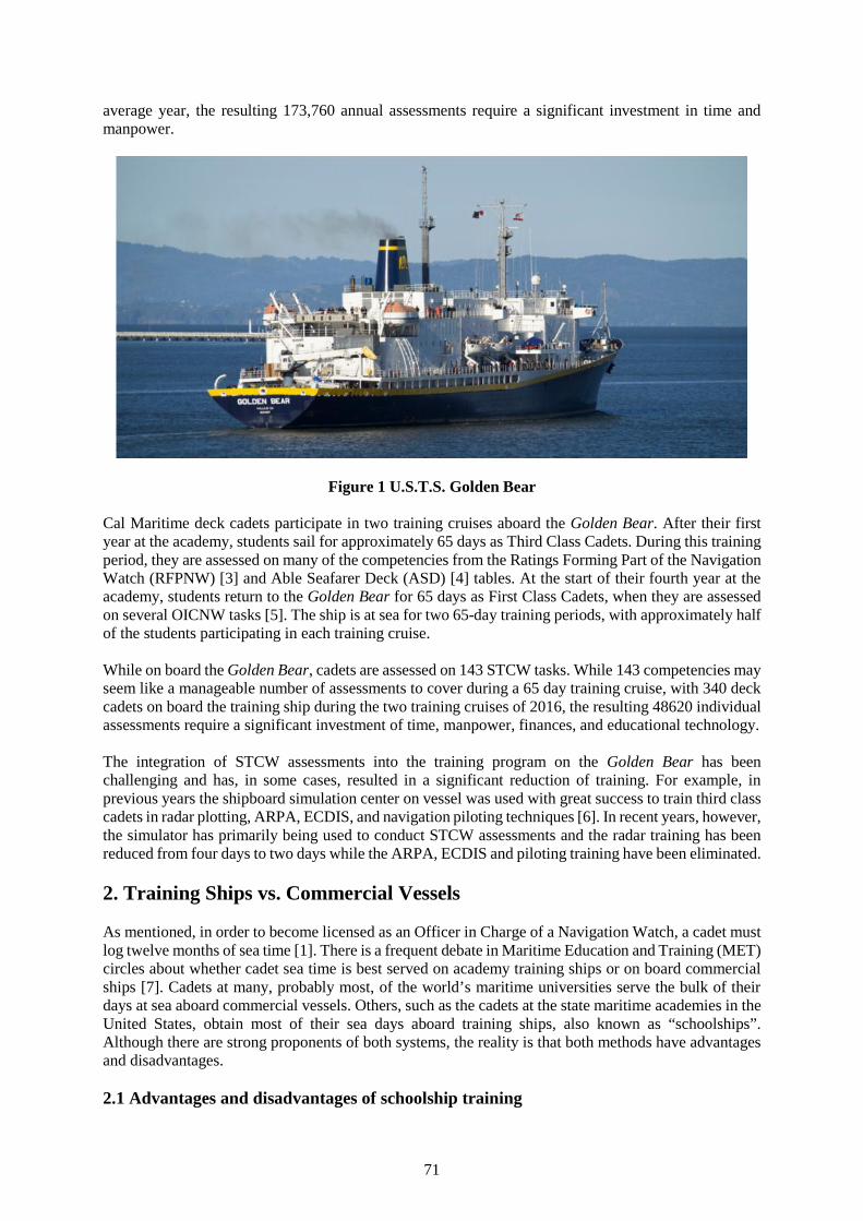
71
average year, the resulting 173,760 annual assessments require a significant investment in time andmanpower.
Figure 1 U.S.T.S. Golden Bear
Cal Maritime deck cadets participate in two training cruises aboard the Golden Bear. After their firstyear at the academy, students sail for approximately 65 days as Third Class Cadets. During this trainingperiod, they are assessed on many of the competencies from the Ratings Forming Part of the NavigationWatch (RFPNW) [3] and Able Seafarer Deck (ASD) [4] tables. At the start of their fourth year at theacademy, students return to the Golden Bear for 65 days as First Class Cadets, when they are assessedon several OICNW tasks [5]. The ship is at sea for two 65-day training periods, with approximately halfof the students participating in each training cruise.
While on board the Golden Bear, cadets are assessed on 143 STCW tasks. While 143 competencies mayseem like a manageable number of assessments to cover during a 65 day training cruise, with 340 deckcadets on board the training ship during the two training cruises of 2016, the resulting 48620 individualassessments require a significant investment of time, manpower, finances, and educational technology.
The integration of STCW assessments into the training program on the Golden Bear has beenchallenging and has, in some cases, resulted in a significant reduction of training. For example, inprevious years the shipboard simulation center on vessel was used with great success to train third classcadets in radar plotting, ARPA, ECDIS, and navigation piloting techniques [6]. In recent years, however,the simulator has primarily being used to conduct STCW assessments and the radar training has beenreduced from four days to two days while the ARPA, ECDIS and piloting training have been eliminated.
2. Training Ships vs. Commercial Vessels
As mentioned, in order to become licensed as an Officer in Charge of a Navigation Watch, a cadet mustlog twelve months of sea time [1]. There is a frequent debate in Maritime Education and Training (MET)circles about whether cadet sea time is best served on academy training ships or on board commercialships [7]. Cadets at many, probably most, of the world’s maritime universities serve the bulk of theirdays at sea aboard commercial vessels. Others, such as the cadets at the state maritime academies in theUnited States, obtain most of their sea days aboard training ships, also known as “schoolships”.Although there are strong proponents of both systems, the reality is that both methods have advantagesand disadvantages.
2.1 Advantages and disadvantages of schoolship training
72
There are several advantages of schoolship training. 1. The university can control the trainingenvironment, including the vessel’s itinerary and the daily routine, in order to achieve the educationalgoals. 2. The vessel is manned by a crew of professional maritime educators that have extensiveexperience in training and assessing cadets in their knowledge and skills. 3. The ships typically haveabundant education resources such as classrooms, library, computer labs, and simulation facilities, and4. The maritime university has direct control over the assessment of the required STCW knowledge,understanding and proficiency (KUP).
There are, however, disadvantages to schoolship training as well. 1. There are a lot of cadets on thetraining ships, as many as 700 in some cases [7]. As a result, there are limited opportunities to standwatch on the bridge. At Cal Maritime, we typically sail with 60 to 70 4th year deck cadets (seniors).During a 65 day training cruise, each cadet will stand only 4 or 5 watches as the Cadet Watch Officeron the bridge. 2. The cadets get a limited understanding of the realities of working on commercialvessels, and 3. Training ships are very expensive to operate and maintain.
2.2 Advantages and disadvantages of commercial ship training
Cadet sea service on commercial ships also has its advantages. 1. Cadets gain a realistic understandingof life and work aboard a commercial ship, and 2. The shipping company pays most of the costs of thetraining, greatly reducing the expense to the academy and to the cadet.
There are some disadvantages, as well, to cadet sea time obtained on commercial vessels. 1. On someships, cadets spend more time painting and doing maintenance than they do on watchkeeping. 2. Thetraining opportunities available to the cadets will vary greatly from vessel to vessel, depending on thetype of ship and the operational schedule. 3. Vessel officers often do not have time or teachingexperience necessary to effectively train cadets in essential skills. 4. Placing cadets on commercialvessels can be challenging with the availability of cadet berths being determined by economic factorsand pressure from other maritime institutions, and 5. The assessment of STCW KUPs conducted on thevessel is out of the control of the academy. As a result, some KUPs might not be assessed at all due tothe vessel’s operational schedule or type. In such cases, the academy must make an individualassessment plan for each cadet, to ensure that all KUPs are assessed prior to graduation.
2.3 The hybrid approach
There is a third option in the debate between commercial sea time and training ships. That option is ahybrid approach in which cadets obtain sea time in two or more ways. This approach seeks to maximizethe advantages of both of the options, above, while minimizing the disadvantages. For example, CalMaritime cadets sail for two summers (approximately 130 days) aboard the Training Ship Golden Bearand one summer (approximately 100 days) on commercial ships. The remaining sea time is obtainedthrough simulation training and operation of the academy’s smaller vessels during the academic year.All assessments of STCW KUPs are conducted at the academy, during the academic year, or on boardthe training ship during the summer training cruises. At Cal Maritime we have chosen to administer allof the assessments ourselves so that we don’t have to create an individual assessment plan for each cadetthat would otherwise be necessitated by their varying experiences while on their commercial vessel.
3. Assessment of STCW KUPs at Cal Maritime
Conducting assessments of competence in STCW KUPs is a modern reality for Maritime Education andTraining establishments. In order to graduate with a Bachelor of Science degree in MarineTransportation and to be certified by the United States Coast Guard (USCG) as Officers in Charge of aNavigation Watch, cadets at Cal Maritime must complete all of the requirements in several of the STCWtables. These tables are as follows: Officer In Charge of a Navigation Watch (Table A-II/1), RatingForming Part of a Navigation Watch (Table A-II/4), Able Seafarer Deck (Table A-II/5), GMDSS Radio
73
Operator (Table A-IV/2), Basic Training – Personal Survival Techniques (Table A-VI/1-1), BasicTraining – Fire Fighting (Table A-VI/1-2), Basic Training – Elementary First Aid (Table A-VI/1-3),Basic Training – Personal Safety and Social Responsibilities (Table A-VI/1-4), Proficiency in SurvivalCraft (Table A-VI/2-1), Fast Rescue Boat (Table A-VI/2-2), Advanced Fire Fighting (Table A-VI/3),Medical First Aid (Table A-VI/4-1), Medical Care (Table A-VI/4-2), Ship Security Officer (Table A-VI/5), Security Awareness (Table A-VI/6-1), and Seafarers with Designated Security Duties (Table A-VI/6-2).
The United States Coast Guard has issued further guidance to US mariners and maritime educatorsconcerning STCW assessments through a series of Navigation and Vessel Inspection Circulars (NVICs).The NVICs elaborate and expand upon the STCW code and provide multiple assessment tasks for eachcompetence and associated KUPs. For example, the first competence in STCW Table A-II/1, OICNW,is “Plan and conduct a passage and determine position” and the first KUP is “Ability to use celestialbodies to determine the ship’s position” [5]. The national assessment guidelines for that KUP, aspublished in NVIC 12-14 [2], require the assessment of six independent tasks: 1.1.A - Adjust a sextant,1.1.B - Measure the altitude of the sun, 1.1.C - Measure the altitude of at least 3 stars, 1.1.D - Measurethe altitude of the sun at meridian passage (LAN), 1.1.E – Celestial running fix, and 1.1.F - Plot star fix.In all, a Cal Maritime cadet needs to be assessed on 543 tasks. With 320 deck cadets on campus on anaverage year, the resulting 173,760 annual assessments require a significant investment in time andmanpower.
3.1 Assessing STCW tasks on the training ship
As stated previously, Cal Maritime has chosen to conduct all assessments of STCW competenciesdirectly. The majority of the assessments are done on campus during the academic year, in theclassroom, labs, on small craft, and in the full mission bridge simulator. The remaining 143 tasks areassessed aboard the Golden Bear. In all, 90 tasks are assessed for the third class cadets and 53 areconducted for the first class cadets (seniors). More will be discussed regarding these shipboardassessments later in the paper.
4. Training Program Overview
The annual training cruises on the United States Training Ship Golden Bear serve as a practical trainingplatform and classroom for 340 deck students from Cal Maritime and the Texas Maritime Academy.The deck training program covers almost all aspects of a student’s learning experience aboard, and wasdesigned by the Cal Maritime Department of Marine Transportation to require students to participateactively in all aspects of training necessary to obtain a level of competency and to successfully advancetoward their degree and OICNW certification. With enrollments increasing and more stringent standardsof training, certification and watch keeping for licensing of graduates, the department has beenincreasing the number of STCW assessments conducted onboard the Training Ship Golden Bear.
At the conclusion of a deck cadet’s third class cruise the student will possess the knowledge and skillsconsistent with an able bodied seaman (able seafarer deck). The student should be competent to standwatch as a helmsman and lookout, proficient in the training objectives of the practical, and navigationtraining programs, and adequately participate in shipboard maintenance projects.
Upon completion of the first class cruise period, students should be competent to stand watch as anofficer in charge on a navigation watch, proficient in the training objectives of the entire trainingprogram, competent in celestial navigation, flashing light, and able to adequately supervise workprojects and programs.
To account for the operations of the ship and to ensure efficient progression through their respectivecruise training programs, the students are grouped by major (deck or engine) and class (third class orfirst class) and divided into divisions (e.g. 1 Deck – 1D, 2 Engine 2E, etc.). Each third and first class
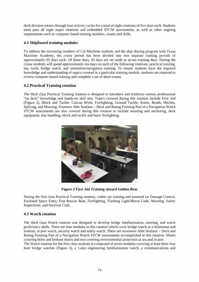
74
deck division rotates through four activity cycles for a total of eight rotations of five days each. Studentsmust pass all eight major rotations and embedded STCW assessments, as well as other ongoingrequirements such as computer based training modules, exams and drills.
4.1 Shipboard training modules
To address the increasing numbers of Cal Maritime students and the ship sharing program with TexasMaritime Academy, the cruise period has been divided into two separate training periods ofapproximately 65 days each. Of those days, 43 days are set aside as at-sea training days. During thecruise students will spend approximately ten days on each of the following rotations: practical training,day work, bridge watch, and simulation/navigation training. To ensure students have the requiredknowledge and understanding of topics covered in a particular training module, students are required toreview computer based training and complete a set of short exams.
4.2 Practical Training rotation
The third class Practical Training rotation is designed to introduce and reinforce various professional“on deck” knowledge and hands-on skill sets. Topics covered during this rotation include First Aid(Figure 2), Block and Tackle, Canvas Work, Firefighting, Ground Tackle, Knots, Bends, Hitches,Splicing, and Mooring. Fourteen Able Seafarer – Deck and Rating Forming Part of a Navigation WatchSTCW assessments are also covered during this rotation to include mooring and anchoring, deckequipment, line handling, block and tackle and basic firefighting.
Figure 2 First Aid Training aboard Golden Bear
During the first class Practical Training rotation, cadets are training and assessed on Damage Control,Enclosed Space Entry, Fast Rescue Boat, Firefighting, Flashing Light/Morse Code, Mooring, SafetyInspections, and Survival Craft.
4.3 Watch rotation
The third class Watch rotation was designed to develop bridge familiarization, steering, and watchproficiency skills. There are four modules in this rotation which cover bridge watch as a helmsman andlookout, in port watch, security watch and safety watch. There are seventeen Able Seafarer – Deck andRating Forming Part of a Navigation Watch STCW assessments accomplished in this rotation, fifteencovering helm and lookout duties and two covering environmental protection at sea and in port.The Watch rotation for the first class students is composed of seven modules covering at least three fourhour bridge watches (Figure 3), a 1-day engineering familiarization watch, a communications and
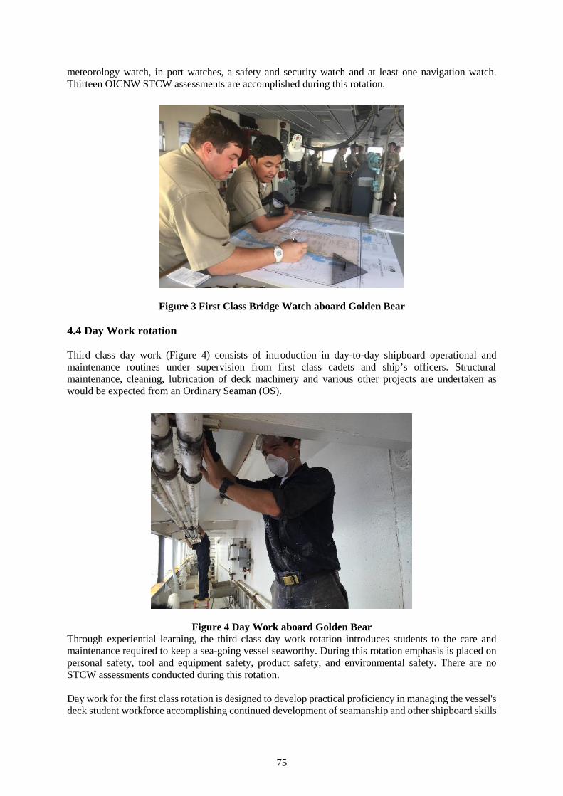
75
meteorology watch, in port watches, a safety and security watch and at least one navigation watch.Thirteen OICNW STCW assessments are accomplished during this rotation.
Figure 3 First Class Bridge Watch aboard Golden Bear
4.4 Day Work rotation
Third class day work (Figure 4) consists of introduction in day-to-day shipboard operational andmaintenance routines under supervision from first class cadets and ship’s officers. Structuralmaintenance, cleaning, lubrication of deck machinery and various other projects are undertaken aswould be expected from an Ordinary Seaman (OS).
Figure 4 Day Work aboard Golden BearThrough experiential learning, the third class day work rotation introduces students to the care andmaintenance required to keep a sea-going vessel seaworthy. During this rotation emphasis is placed onpersonal safety, tool and equipment safety, product safety, and environmental safety. There are noSTCW assessments conducted during this rotation.
Day work for the first class rotation is designed to develop practical proficiency in managing the vessel'sdeck student workforce accomplishing continued development of seamanship and other shipboard skills
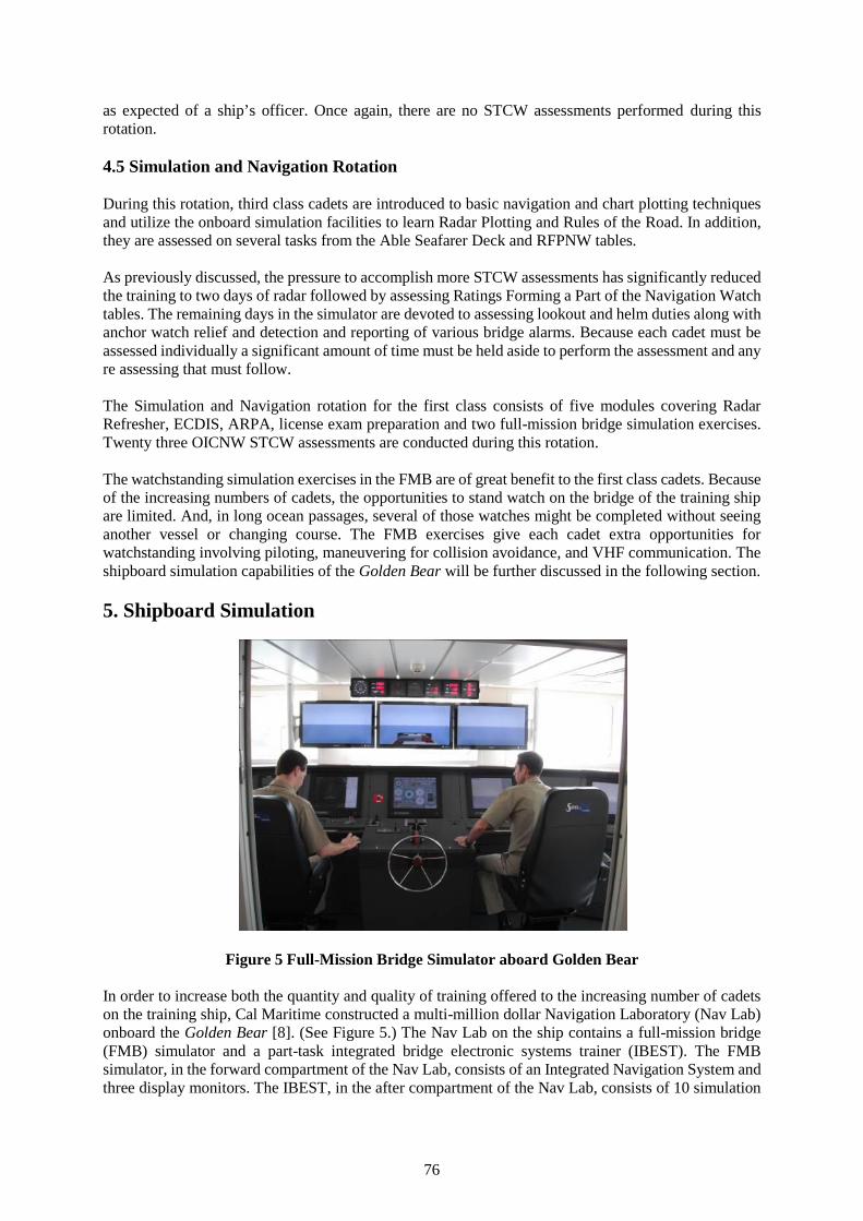
76
as expected of a ship’s officer. Once again, there are no STCW assessments performed during thisrotation.
4.5 Simulation and Navigation Rotation
During this rotation, third class cadets are introduced to basic navigation and chart plotting techniquesand utilize the onboard simulation facilities to learn Radar Plotting and Rules of the Road. In addition,they are assessed on several tasks from the Able Seafarer Deck and RFPNW tables.
As previously discussed, the pressure to accomplish more STCW assessments has significantly reducedthe training to two days of radar followed by assessing Ratings Forming a Part of the Navigation Watchtables. The remaining days in the simulator are devoted to assessing lookout and helm duties along withanchor watch relief and detection and reporting of various bridge alarms. Because each cadet must beassessed individually a significant amount of time must be held aside to perform the assessment and anyre assessing that must follow.
The Simulation and Navigation rotation for the first class consists of five modules covering RadarRefresher, ECDIS, ARPA, license exam preparation and two full-mission bridge simulation exercises.Twenty three OICNW STCW assessments are conducted during this rotation.
The watchstanding simulation exercises in the FMB are of great benefit to the first class cadets. Becauseof the increasing numbers of cadets, the opportunities to stand watch on the bridge of the training shipare limited. And, in long ocean passages, several of those watches might be completed without seeinganother vessel or changing course. The FMB exercises give each cadet extra opportunities forwatchstanding involving piloting, maneuvering for collision avoidance, and VHF communication. Theshipboard simulation capabilities of the Golden Bear will be further discussed in the following section.
5. Shipboard Simulation
Figure 5 Full-Mission Bridge Simulator aboard Golden Bear
In order to increase both the quantity and quality of training offered to the increasing number of cadetson the training ship, Cal Maritime constructed a multi-million dollar Navigation Laboratory (Nav Lab)onboard the Golden Bear [8]. (See Figure 5.) The Nav Lab on the ship contains a full-mission bridge(FMB) simulator and a part-task integrated bridge electronic systems trainer (IBEST). The FMBsimulator, in the forward compartment of the Nav Lab, consists of an Integrated Navigation System andthree display monitors. The IBEST, in the after compartment of the Nav Lab, consists of 10 simulation
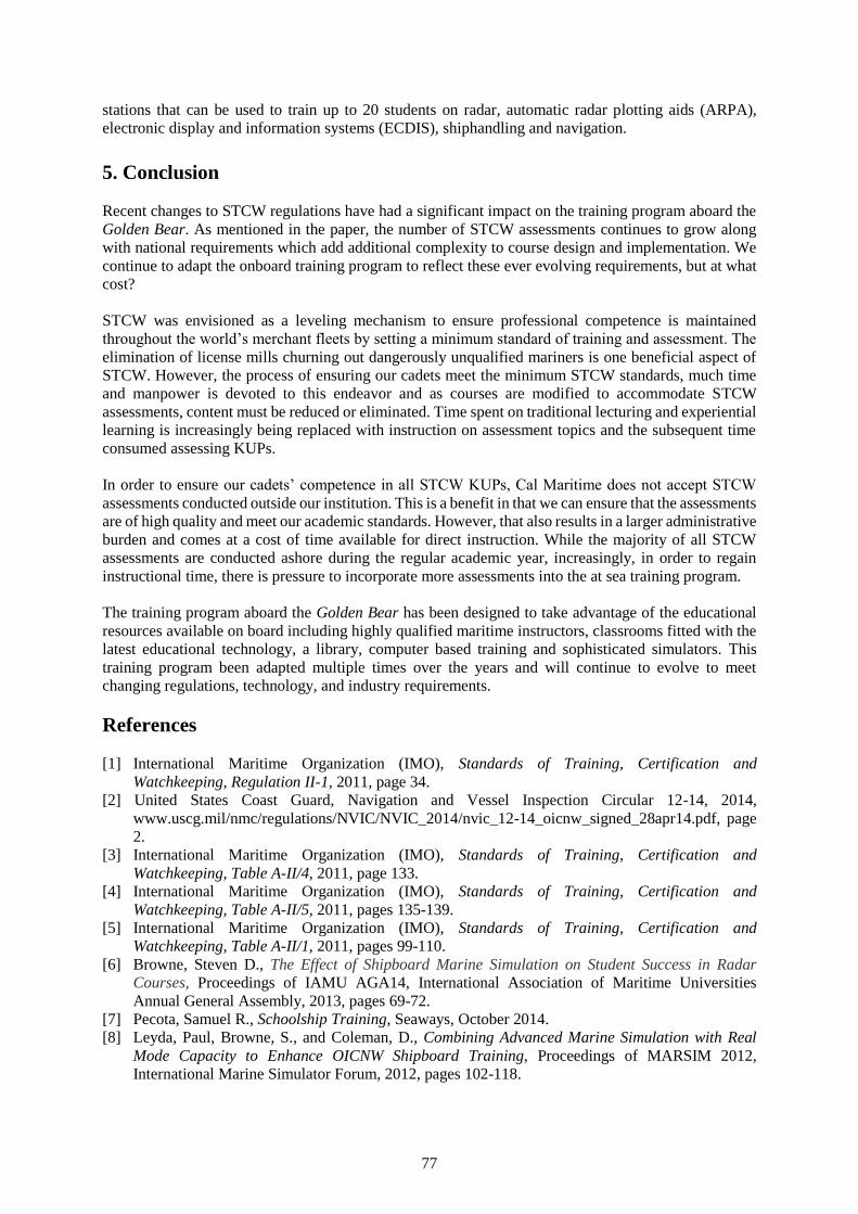
77
stations that can be used to train up to 20 students on radar, automatic radar plotting aids (ARPA),
electronic display and information systems (ECDIS), shiphandling and navigation.
5. Conclusion
Recent changes to STCW regulations have had a significant impact on the training program aboard the
Golden Bear. As mentioned in the paper, the number of STCW assessments continues to grow along
with national requirements which add additional complexity to course design and implementation. We
continue to adapt the onboard training program to reflect these ever evolving requirements, but at what
cost?
STCW was envisioned as a leveling mechanism to ensure professional competence is maintained
throughout the world’s merchant fleets by setting a minimum standard of training and assessment. The
elimination of license mills churning out dangerously unqualified mariners is one beneficial aspect of
STCW. However, the process of ensuring our cadets meet the minimum STCW standards, much time
and manpower is devoted to this endeavor and as courses are modified to accommodate STCW
assessments, content must be reduced or eliminated. Time spent on traditional lecturing and experiential
learning is increasingly being replaced with instruction on assessment topics and the subsequent time
consumed assessing KUPs.
In order to ensure our cadets’ competence in all STCW KUPs, Cal Maritime does not accept STCW
assessments conducted outside our institution. This is a benefit in that we can ensure that the assessments
are of high quality and meet our academic standards. However, that also results in a larger administrative
burden and comes at a cost of time available for direct instruction. While the majority of all STCW
assessments are conducted ashore during the regular academic year, increasingly, in order to regain
instructional time, there is pressure to incorporate more assessments into the at sea training program.
The training program aboard the Golden Bear has been designed to take advantage of the educational
resources available on board including highly qualified maritime instructors, classrooms fitted with the
latest educational technology, a library, computer based training and sophisticated simulators. This
training program been adapted multiple times over the years and will continue to evolve to meet
changing regulations, technology, and industry requirements.
References
[1] International Maritime Organization (IMO), Standards of Training, Certification and
Watchkeeping, Regulation II-1, 2011, page 34.
[2] United States Coast Guard, Navigation and Vessel Inspection Circular 12-14, 2014,
www.uscg.mil/nmc/regulations/NVIC/NVIC_2014/nvic_12-14_oicnw_signed_28apr14.pdf, page
2.
[3] International Maritime Organization (IMO), Standards of Training, Certification and
Watchkeeping, Table A-II/4, 2011, page 133.
[4] International Maritime Organization (IMO), Standards of Training, Certification and
Watchkeeping, Table A-II/5, 2011, pages 135-139.
[5] International Maritime Organization (IMO), Standards of Training, Certification and
Watchkeeping, Table A-II/1, 2011, pages 99-110.
[6] Browne, Steven D., The Effect of Shipboard Marine Simulation on Student Success in Radar
Courses, Proceedings of IAMU AGA14, International Association of Maritime Universities
Annual General Assembly, 2013, pages 69-72.
[7] Pecota, Samuel R., Schoolship Training, Seaways, October 2014.
[8] Leyda, Paul, Browne, S., and Coleman, D., Combining Advanced Marine Simulation with Real
Mode Capacity to Enhance OICNW Shipboard Training, Proceedings of MARSIM 2012,
International Marine Simulator Forum, 2012, pages 102-118.
78
Inventory of the engineers’ competences for a new CoC course by usingsimulators
Lecturer PhD. M. Castells1, Dean S.Ordás2, Lecturer C. Borén3 & Lecturer M. Rodríguez4
1Barcelona School of Nautical Studies, Universitat Politècnica de Catalunya (UPC), BarcelonaTech,Email: [email protected], Pla de Palau, 18 08003 Barcelona, Spain.
2Barcelona School of Nautical Studies, Universitat Politècnica de Catalunya (UPC), BarcelonaTech,email:[email protected]
3Barcelona School of Nautical Studies, Universitat Politècnica de Catalunya (UPC), BarcelonaTech,email: [email protected]
2Barcelona School of Nautical Studies, Universitat Politècnica de Catalunya (UPC), BarcelonaTech,email: [email protected]
Abstract This paper presents achieved results of the first stage of the IAMU Development Project titled“CoC course to revalidate marine engineers’ competences by using simulators”, relevant for Maritimeand Education Training and Simulation. This development project is for the completion of the projectawarded in the Call for Proposals FY2013 titled: "Simulation-based course to demonstrate seafarers'competences (for deck department)". The main objective of this development project is obtain fourcomplete revalidation courses (deck and marine engineer disciplines) using simulation technology toobtain a well-defined project to reach a common academic programme to demonstrate all competencesto license the revalidation certification by using simulation.
In accordance with Part A, Chapter I, Section I/11 Revalidation of certificates, continued professionalcompetence shall be established, among others, successfully completing an approved training course orcourses. Every master, officer and radio operator holding a certificate issued or recognized under anychapter of the Convention other than chapter VI, who is serving at sea or intends to return to sea after aperiod ashore, shall, in order to continue to qualify for seagoing service, be required, at intervals notexceeding five years, to establish continued professional competence.
This paper will describe the first stage of the project, WP1: inventory of marine engineers’ competencesby using simulators. The main objective of this paper is to identify which competences can bedemonstrated by approved simulator training, according to the STCW 95/2010 in order to design thefollowing step of the development project: a revalidation model course structure using simulationtechnology to assessment, examination and certification of seafarers’ competence in accordance withthe provisions of STCW Code for existing marines who need upgrade their professional maritimecertificates in accordance also with the Standards governing the use of simulators, Reg I/12 of 2010STCW Code.
Keywords: Maritime Education and Training, Simulation, STCW Code, Revalidation of certificates,Marine Engineer
1. Background of the project
International Maritime Organization’s (IMO) international convention on Standards of Training,Certification and Watch-keeping for seafarers (STCW) [1] was ratified by all maritime nations. Today,IMO has advised/encouraged all contracting governments/interested parties to review and, as necessary,to revise their crew academic/vocational competency described in STCW. Furthermore, the EuropeanMaritime Safety Agency (EMSA) started a regular assessment process providing quality improvementin the MET institutions throughout EU members, candidate countries and others.
This development project is for the completion of the project awarded in the Call for Proposals FY2013titled: "Simulation-based course to demonstrate seafarers' competences (for deck department)" [2]. The
79
main objective of this IAMU Development Project titled “CoC course to revalidate marine engineers’competences by using simulators” is to obtain four complete revalidation courses (deck and marineengineer disciplines) using simulation technology to obtain a well-defined project and reach a commonacademic programme to demonstrate all competences to license the revalidation certification by usingsimulation.
The specific goals are: Prepare a publication and integrate all courses as a result of a whole project that can be used by
any member that needs to revalidate CoC’s, based on STCW Code. Develop teaching materials (simulator scenario’s) that can be used by IAMU and member
universities. Provide schools and maritime authorities with a modern way to examine the revalidation of the
expired CoCs, incorporating into the IAMU’s e-learning platform and it represents aconsiderable value of practically applicable work which often lacks in most academies.
Provide maritime industry revalidated and newly educated seafarers. Promote the implementation, development, harmonisation and unification of the maritime
programme contents.
The development project is divided into following different stages (work-packages, WP):WP1. Inventory of the competencesWP2. Design courses structureWP3. Developing and testing simulator exercises for competence assessmentWP4. Incorporating into the IAMU’s e-learning platformWP5. Integration of projects, review and final discussion
2. Maritime simulation
Within IMO an Inter-sessional Simulator Working Group (ISWG) was established in order to organizeand structure simulator related matters for inclusion in the STCW revision. One definition adopted byISGW [2] reads: Simulation is a realistic imitation, in real time, of any ship handling, radar andnavigation, propulsion, cargo/ballast or other ship-system incorporating an interface suitable forinteractive use by the trainee or candidate either within or outside of the operating environment, andcomplying with the performance standards prescribed in the relevant parts of this section of the STCWcode.
The fact that a simulation system represents a powerful teaching tool, which can lead to more effectivetraining outcomes as well as a more efficient use of available teaching time, adds to the increasedpopularity of simulation equipment. Additionally, the assessment of competence of seafaring skills canbe performed in a lifelike simulation centre, which resembles as closely as possible the real systemcalled “ship”. As IMO is seeing the necessity to assess competence rather than knowledge in order toimprove shipping safety and simulators are offering possibilities for such, it seems without doubt thatmuch more emphasis will placed on marine simulation in the years to come.
It is quite surprising to see which other types of activities and equipment have become models for amaritime training simulator system and up to date have been developed and installed:
- navigation equipment trainer- communication procedures/GMDSS equipment trainer- radar simulator- radar and navigation simulator- ship handling simulator with/without motion platform/image generation- fisheries simulator- inland waterways simulator- dynamic positioning simulator- crane handling simulator
80
- vessel traffic management simulator- engine room simulator (ERS)- search and rescue management trainer- oil spill management trainer- propulsion plant trainer- team generation plant trainer- electrical power plant trainer- refrigeration plant trainer- cargo handling trainer- ballast control trainer- dredging ship trainer- offshore process simulator- drilling technology simulator
Note: name in brackets and bold is assigned to refer the type of simulator later on.
This list is not intended to be all-inclusive. As technology advances, new systems, both from theshipping industry as well as within the simulation techniques, are being created with certain regularity.From the list it will be clear that all elements of a ship are becoming available for simulation application.
3. Inventory of the engineers’ competences
This section will make the inventory of which competences can be demonstrated by approved simulatortraining, according to the STCW 95/2010 code Part A Competence tables.
In the CoC Revalidation Model Course structure [3], these are the competences that will no longerrequire theoretical, written or oral examinations, but can be practically demonstrated by means ofsimulation, identification of which is one of the objectives of this development project.
The competences that will be taken into consideration will be the ones related to the Engine Departmentas described in STCW Code Part A Chapter III.
The STCW function Groups in Chapter III are as follows:- Marine engineering.- Electrical, electronic and control engineering.- Maintenance and repair.- Controlling the operation of the ship and care for persons on board.
3.1 Listed competences considering Chapter III assessable by simulator
In this section a list of competences of chapter III assessable through Engine Room Simulator aredescribed for the model course scenario development and testing.
The legal basis for evaluating only with simulator is found in column 3 of the tables provided, where itsays for all these cases (see figure 1):
Column 3. Methods for demonstrating competence; Assessment of evidence obtained from one or moreof the following:(…)
In all cases, one of the modalities is: approved simulator training, where appropriate
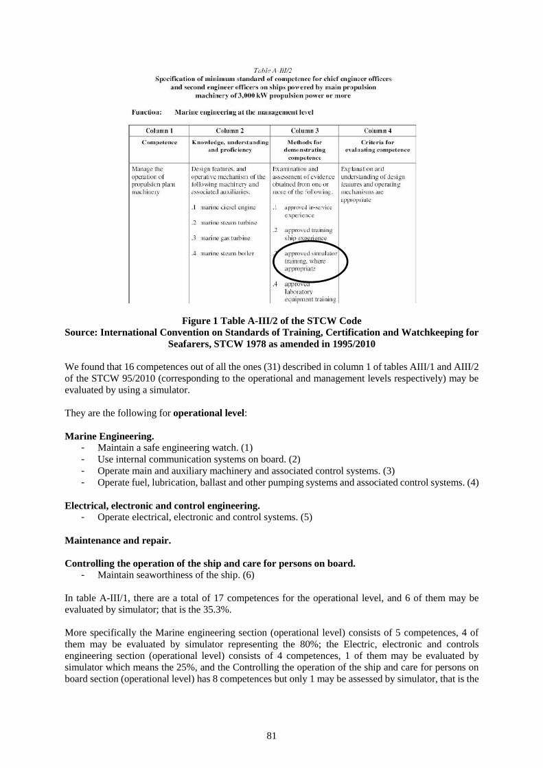
81
Figure 1 Table A-III/2 of the STCW CodeSource: International Convention on Standards of Training, Certification and Watchkeeping for
Seafarers, STCW 1978 as amended in 1995/2010
We found that 16 competences out of all the ones (31) described in column 1 of tables AIII/1 and AIII/2of the STCW 95/2010 (corresponding to the operational and management levels respectively) may beevaluated by using a simulator.
They are the following for operational level:
Marine Engineering.- Maintain a safe engineering watch. (1)- Use internal communication systems on board. (2)- Operate main and auxiliary machinery and associated control systems. (3)- Operate fuel, lubrication, ballast and other pumping systems and associated control systems. (4)
Electrical, electronic and control engineering.- Operate electrical, electronic and control systems. (5)
Maintenance and repair.
Controlling the operation of the ship and care for persons on board.- Maintain seaworthiness of the ship. (6)
In table A-III/1, there are a total of 17 competences for the operational level, and 6 of them may beevaluated by simulator; that is the 35.3%.
More specifically the Marine engineering section (operational level) consists of 5 competences, 4 ofthem may be evaluated by simulator representing the 80%; the Electric, electronic and controlsengineering section (operational level) consists of 4 competences, 1 of them may be evaluated bysimulator which means the 25%, and the Controlling the operation of the ship and care for persons onboard section (operational level) has 8 competences but only 1 may be assessed by simulator, that is the
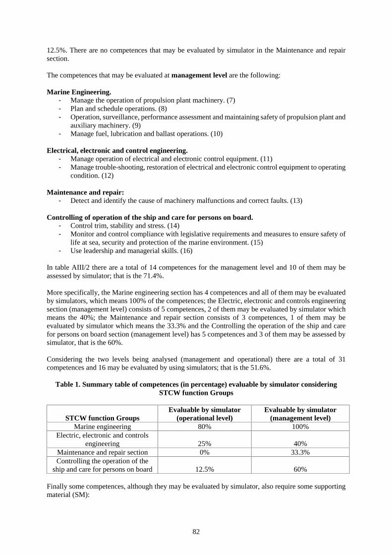
82
12.5%. There are no competences that may be evaluated by simulator in the Maintenance and repairsection.
The competences that may be evaluated at management level are the following:
Marine Engineering.- Manage the operation of propulsion plant machinery. (7)- Plan and schedule operations. (8)- Operation, surveillance, performance assessment and maintaining safety of propulsion plant and
auxiliary machinery. (9)- Manage fuel, lubrication and ballast operations. (10)
Electrical, electronic and control engineering.- Manage operation of electrical and electronic control equipment. (11)- Manage trouble-shooting, restoration of electrical and electronic control equipment to operating
condition. (12)
Maintenance and repair:- Detect and identify the cause of machinery malfunctions and correct faults. (13)
Controlling of operation of the ship and care for persons on board.- Control trim, stability and stress. (14)- Monitor and control compliance with legislative requirements and measures to ensure safety of
life at sea, security and protection of the marine environment. (15)- Use leadership and managerial skills. (16)
In table AIII/2 there are a total of 14 competences for the management level and 10 of them may beassessed by simulator; that is the 71.4%.
More specifically, the Marine engineering section has 4 competences and all of them may be evaluatedby simulators, which means 100% of the competences; the Electric, electronic and controls engineeringsection (management level) consists of 5 competences, 2 of them may be evaluated by simulator whichmeans the 40%; the Maintenance and repair section consists of 3 competences, 1 of them may beevaluated by simulator which means the 33.3% and the Controlling the operation of the ship and carefor persons on board section (management level) has 5 competences and 3 of them may be assessed bysimulator, that is the 60%.
Considering the two levels being analysed (management and operational) there are a total of 31competences and 16 may be evaluated by using simulators; that is the 51.6%.
Table 1. Summary table of competences (in percentage) evaluable by simulator consideringSTCW function Groups
STCW function GroupsEvaluable by simulator
(operational level)Evaluable by simulator
(management level)Marine engineering 80% 100%
Electric, electronic and controlsengineering 25% 40%
Maintenance and repair section 0% 33.3%Controlling the operation of the
ship and care for persons on board 12.5% 60%
Finally some competences, although they may be evaluated by simulator, also require some supportingmaterial (SM):
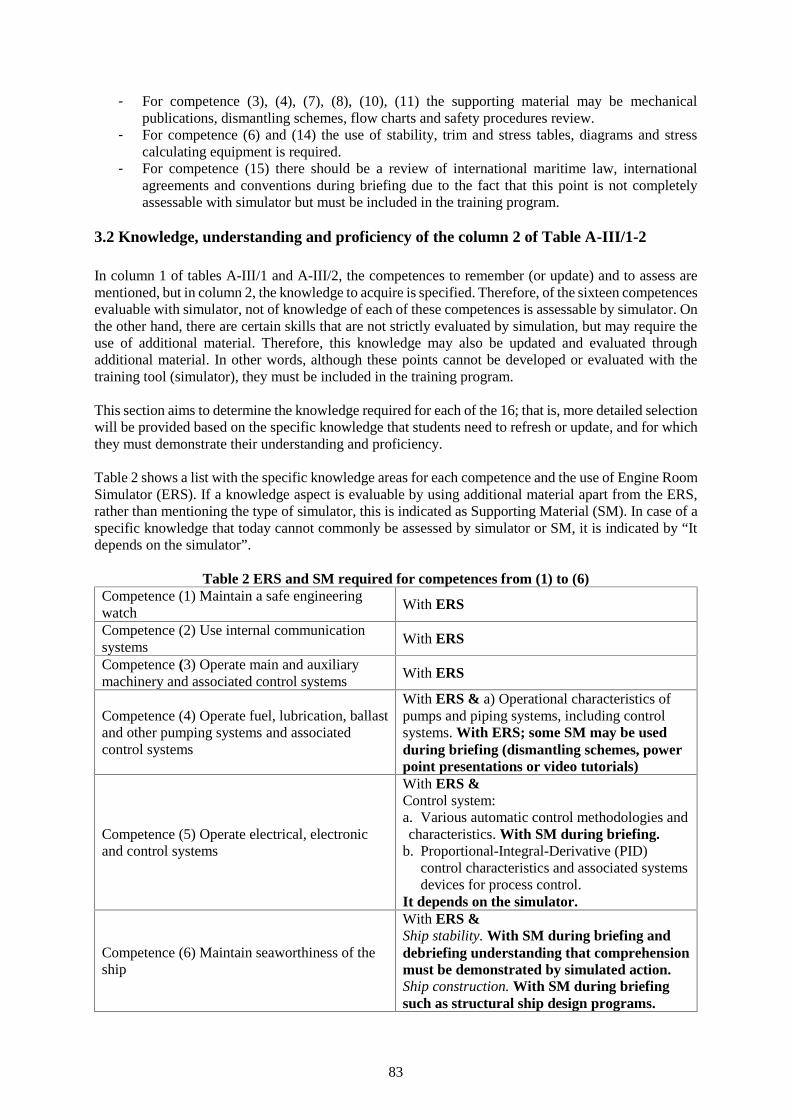
83
- For competence (3), (4), (7), (8), (10), (11) the supporting material may be mechanicalpublications, dismantling schemes, flow charts and safety procedures review.
- For competence (6) and (14) the use of stability, trim and stress tables, diagrams and stresscalculating equipment is required.
- For competence (15) there should be a review of international maritime law, internationalagreements and conventions during briefing due to the fact that this point is not completelyassessable with simulator but must be included in the training program.
3.2 Knowledge, understanding and proficiency of the column 2 of Table A-III/1-2
In column 1 of tables A-III/1 and A-III/2, the competences to remember (or update) and to assess arementioned, but in column 2, the knowledge to acquire is specified. Therefore, of the sixteen competencesevaluable with simulator, not of knowledge of each of these competences is assessable by simulator. Onthe other hand, there are certain skills that are not strictly evaluated by simulation, but may require theuse of additional material. Therefore, this knowledge may also be updated and evaluated throughadditional material. In other words, although these points cannot be developed or evaluated with thetraining tool (simulator), they must be included in the training program.
This section aims to determine the knowledge required for each of the 16; that is, more detailed selectionwill be provided based on the specific knowledge that students need to refresh or update, and for whichthey must demonstrate their understanding and proficiency.
Table 2 shows a list with the specific knowledge areas for each competence and the use of Engine RoomSimulator (ERS). If a knowledge aspect is evaluable by using additional material apart from the ERS,rather than mentioning the type of simulator, this is indicated as Supporting Material (SM). In case of aspecific knowledge that today cannot commonly be assessed by simulator or SM, it is indicated by “Itdepends on the simulator”.
Table 2 ERS and SM required for competences from (1) to (6)Competence (1) Maintain a safe engineeringwatch
With ERS
Competence (2) Use internal communicationsystems
With ERS
Competence (3) Operate main and auxiliarymachinery and associated control systems
With ERS
Competence (4) Operate fuel, lubrication, ballastand other pumping systems and associatedcontrol systems
With ERS & a) Operational characteristics ofpumps and piping systems, including controlsystems. With ERS; some SM may be usedduring briefing (dismantling schemes, powerpoint presentations or video tutorials)
Competence (5) Operate electrical, electronicand control systems
With ERS &Control system:a. Various automatic control methodologies andcharacteristics. With SM during briefing.
b. Proportional-Integral-Derivative (PID)control characteristics and associated systemsdevices for process control.
It depends on the simulator.
Competence (6) Maintain seaworthiness of theship
With ERS &Ship stability. With SM during briefing anddebriefing understanding that comprehensionmust be demonstrated by simulated action.Ship construction. With SM during briefingsuch as structural ship design programs.
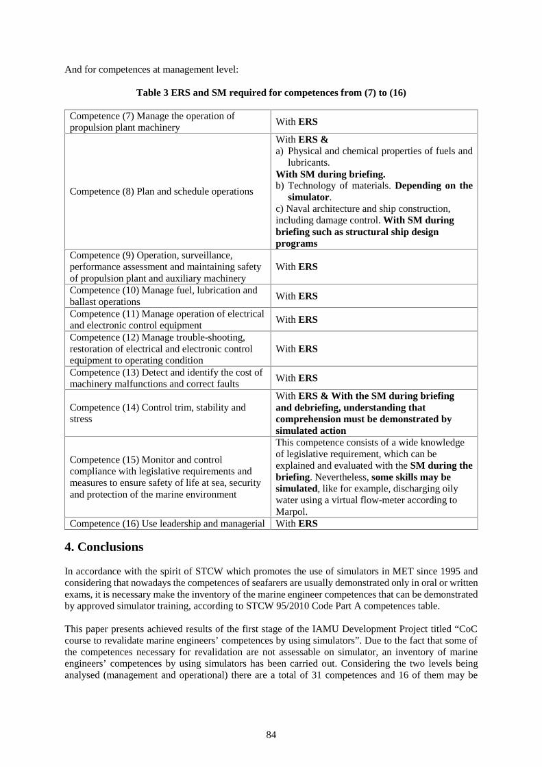
84
And for competences at management level:
Table 3 ERS and SM required for competences from (7) to (16)
Competence (7) Manage the operation ofpropulsion plant machinery
With ERS
Competence (8) Plan and schedule operations
With ERS &a) Physical and chemical properties of fuels and
lubricants.With SM during briefing.b) Technology of materials. Depending on the
simulator.c) Naval architecture and ship construction,including damage control. With SM duringbriefing such as structural ship designprograms
Competence (9) Operation, surveillance,performance assessment and maintaining safetyof propulsion plant and auxiliary machinery
With ERS
Competence (10) Manage fuel, lubrication andballast operations
With ERS
Competence (11) Manage operation of electricaland electronic control equipment
With ERS
Competence (12) Manage trouble-shooting,restoration of electrical and electronic controlequipment to operating condition
With ERS
Competence (13) Detect and identify the cost ofmachinery malfunctions and correct faults
With ERS
Competence (14) Control trim, stability andstress
With ERS & With the SM during briefingand debriefing, understanding thatcomprehension must be demonstrated bysimulated action
Competence (15) Monitor and controlcompliance with legislative requirements andmeasures to ensure safety of life at sea, securityand protection of the marine environment
This competence consists of a wide knowledgeof legislative requirement, which can beexplained and evaluated with the SM during thebriefing. Nevertheless, some skills may besimulated, like for example, discharging oilywater using a virtual flow-meter according toMarpol.
Competence (16) Use leadership and managerial With ERS
4. Conclusions
In accordance with the spirit of STCW which promotes the use of simulators in MET since 1995 andconsidering that nowadays the competences of seafarers are usually demonstrated only in oral or writtenexams, it is necessary make the inventory of the marine engineer competences that can be demonstratedby approved simulator training, according to STCW 95/2010 Code Part A competences table.
This paper presents achieved results of the first stage of the IAMU Development Project titled “CoCcourse to revalidate marine engineers’ competences by using simulators”. Due to the fact that some ofthe competences necessary for revalidation are not assessable on simulator, an inventory of marineengineers’ competences by using simulators has been carried out. Considering the two levels beinganalysed (management and operational) there are a total of 31 competences and 16 of them may be
85
evaluated by using simulators; that is the 51.6%. Moreover, more detailed analysis is carried out basedon the specific knowledge in Column 2 of tables A-III/1 and A-III/2.This selection process of competences will be the point of departure for the following stages of thisdevelopment project: the design of two CoC model courses to provide training and use of simulationmaterial for marine engineers.
Acknowledgements
The materials and data in this publication have been obtained through the support of the InternationalAssociation of Maritime Universities (IAMU) and The Nippon Foundation in Japan.
References
[1] IMO STCW (2011) International Convention on Standards of Training, Certification andWatchkeeping for Seafarers, (STCW) 1978, as amended in 1995/2010, International MaritimeOrganisation, London, United Kingdom
[2] IMO ISWG (1994). STW 26/Inf. 7, Sub-Committee STCW, submitted by Consultants/ISWG, IMO.[3] Castells, M. et al. “Model course to demonstrate and revalidate deck officer’s competences by suing
simulators” World Maritime Journal Maritime Affairs. IAMU section articles. DOI:10.1007/s13437-015-0092-2. October 2015
[4] IMO (2005). IMO Model Courses. IMO, London, UK.

86
87
Session 1C
MARITIME ENVIRONMENTAL ISSUES &ENERGY EFFICIENCY
(No. 1)
88
A method to identify an optimum speed of ships for ship efficient operation
Prof. DSc. Dang Van Uy1; Dr. Pham Xuan Duong2
1.Vietnam Maritime University, [email protected], 484 Lach Tray Str., Haiphong City2. Vietnam Maritime University, [email protected], 484 Lach Tray Str., Haiphong City
Abstract: An efficient operation of ships is essential task required to all shipping companies in over theworld. The concept of ship efficient operation is very different; however the minimum consumption offuel for a voyage is a good explanation of the ship efficient operation. To use a minimum fuel for avoyage can be achieved by optimum speed of a ship, but the ship optimum speed is depending on somefactors such as sea condition, ship condition, mode of ship charter and so on. In this paper, there presentsa method to calculate an optimum speed of a ship within actual operation conditions in order to helpoperators following well Ship Energy Efficiency Management Plan-SEEMP).
Keywords: ship operation, optimum ship speed, SEEMP.
1. Introduction
The expenditure of fuel in shipping is normally taken about 35% to 40% of the total operation cost of aship. Although, shipping companies are aware about this problem, but almost companies do nothings tominimize the fuel consumption even at the period in which the fuel price was as highest. Recently, inVietnam, we carried out some surveys about what method a shipping company usually uses to minimizethe fuel consumptions during ship operation. The answers from almost shipping companies are to set apackage of fuel for a voyage or to set an operation speed for a ship and on a base of the ship speed, anamount of fuel per hour is supplied for a ship. So, it is clear that shipping companies do not haveappropriate methods to control usage of fuel on board ships. Therefore, there results in increasingoperation cost of a ship and also there may create a good condition for crews to do cheating in usingfuel oil.
At present time, the shipping is highly competitive worldwide. Although, the fuel price sometimes isdecreased from last year. But, the pressure of the environment protection is higher due to therequirements on control of NOx emission from marine diesel engines in Annex VI, MARPOL 73/78.According to those requirements, marine diesel engines must be equipped with special exhaust gasemission treated apertures and shipping companies also must be required to minimize the fuelconsumption in order to meet the EEOI.
For complying with the dual purposes such as minimizing fuel consumption and environment protection,International Maritime Organization has already proposed so called the Ship Energy EfficiencyManagement Plan (SEEMP). In this Plan, there are many recommended items which should beimplemented in order to help shipping companies and ships to meet safe and efficient operation of ships.However, among those recommended items, how to reach optimum operation speed of a ship rather ismost important.
2. Proposed concept of optimum operation speed of ships
In practical, a concept of optimum operation speed of ships is very different in connection with boundaryconditions. In some cases, the optimum speed is depending on a minimum fuel oil consumption of amain engine. It means that the optimum speed will be calculated on base of function between ship speedand minimum fuel usage per hour. But in other case, the optimum operation speed of ships will bedetermined by using an objective function between ship speed and operation expenditure for one voyage.However, the above explanation about optimum operation speed of ships can achieve only limitedoperation conditions and does not concern anything with a contribution into the environment protectionwhich is mentioned by the Index of Energy Efficient Operation (EEOI).
89
2.1 Procedure to determine an optimum operation speed of ships
The requirements of IMO covering multi-purposes which include both effective operation of a ship andengine exhaust gas emission control make shipping companies in difficult situation of implementation.An appropriate solution for this objective is to raise a suitable function which can estimate an optimumoperation speed of ships on a base of boundary conditions such as actual loading conditions, sea state,and mode of ship chattering, fuel price and some others. Therefore, an appropriate concept of anoptimum operation speed of ships is presented by a function (1) as follow:
),,,,( concharterfsopt SMPDRfV (1)
In which: Rs- basic ship resistance; D- ship draft; Pf - actual fuel price; Mcharter- mode of ship charter(voyage charter or time charter); Scon- sea state.
A new ship was designed and built with specific technical features such as total length, width, draftspeed, propulsive power and displacement. With that, the resistance of ship can be determined anddefined as a basic resistance (total resistance). The basic resistance of a ship will be changeddramatically during operation depending on load conditions, sea state and technical state of hull,propulsion system.
The basic resistance of a ship consists of many source resistances that can be classified into three maingroups: frictional resistance, residual resistance and air resistance. In fact, during ship sailing on opensea, the basic resistance of a ship is influenced by sea wave, air, hull fouling and wind direction to ship.Therefore, the basic resistance of a ship is normally increased. The phenomenon of ship resistanceincrease makes a reduction of ship speed and increase of main engine fuel consumption. So, if shippingcompanies want to operate ships with high efficiency, the companies must find out an optimum speedof ships. To solve this problem, a calculation procedure of an operation optimum speed of a ship isproposed to be carried out into five stages.
- Ship basic resistance will be determined on a base of specific technical features of an actualship;
- A change of ship basic resistance will be estimated on a base of actual operation conditionssuch as loading condition (ship draft), sea state, wind direction and some other more if it isnecessary;
- Based on a mode of ship charter and calculated results from first two stages mentioned above,a ship optimum operation speed will be determined;
- To verify the determined optimum operation speed of a ship (stage 3), let check a time of shiparrival to a port based on criteria “Just on time”;
- To determine the index of energy efficient operation of ship (EEOI) in certain period of shipoperation in orders to verify a ship operation in compliance with requirements of theenvironment protection.
2.2 Formulas needed in determination of ship optimum speed
In practice, to determine an optimum operation speed of ships is complicated. There is no concertmathematical model for this purpose due to many boundary conditions influencing on the optimumspeed of ships. Therefore, helping to come to final result of optimum speed calculation, there needs touse several formulas concerning with ship resistance, gross profit of shipping and some others. Our idea
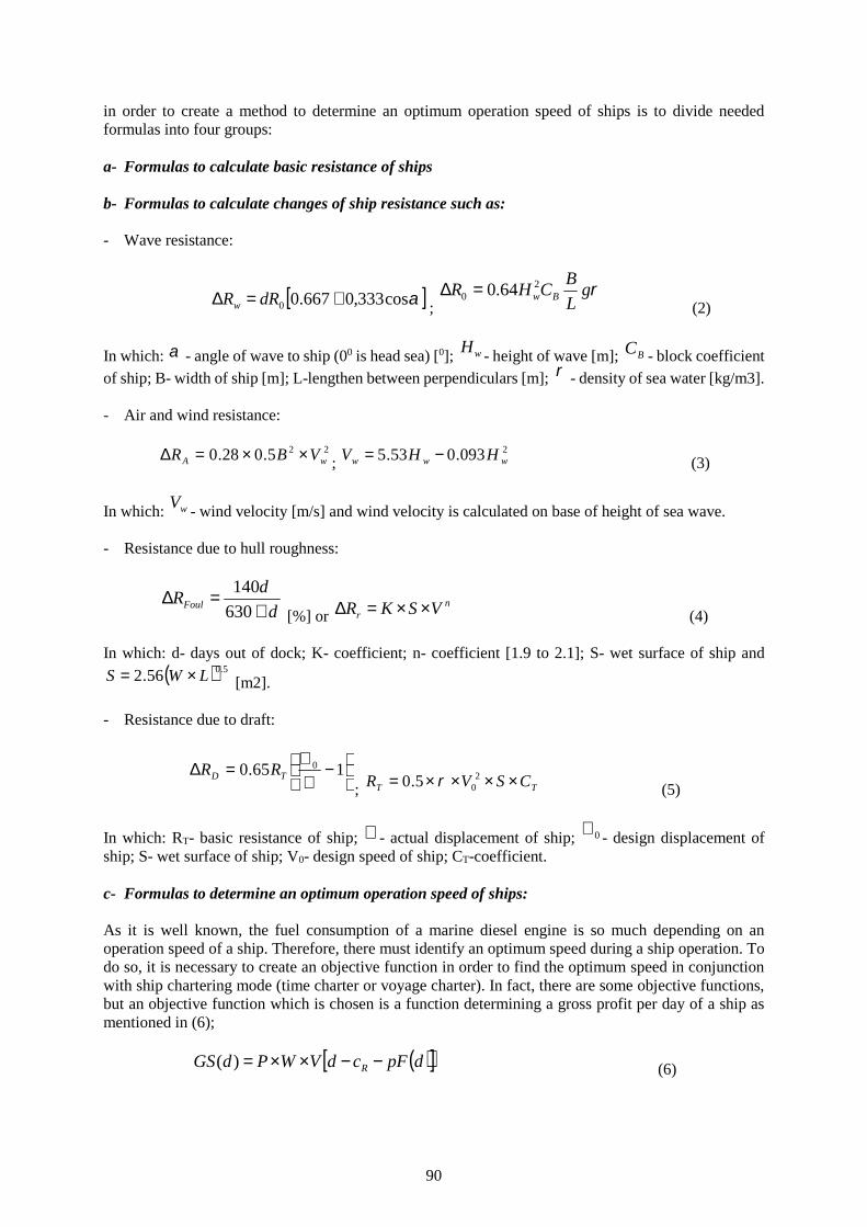
90
in order to create a method to determine an optimum operation speed of ships is to divide neededformulas into four groups:
a- Formulas to calculate basic resistance of ships
b- Formulas to calculate changes of ship resistance such as:
- Wave resistance:
cos333,0667.00 dRRw ;g
L
BCHR Bw
20 64.0
(2)
In which: - angle of wave to ship (00 is head sea) [0]; wH - height of wave [m]; BC - block coefficientof ship; B- width of ship [m]; L-lengthen between perpendiculars [m]; - density of sea water [kg/m3].
- Air and wind resistance:
225.028.0 wA VBR ;2093.053.5 www HHV (3)
In which: wV - wind velocity [m/s] and wind velocity is calculated on base of height of sea wave.
- Resistance due to hull roughness:
d
dRFoul
630
140
[%] orn
r VSKR (4)
In which: d- days out of dock; K- coefficient; n- coefficient [1.9 to 2.1]; S- wet surface of ship and
5.056.2 LWS [m2].
- Resistance due to draft:
165.0 0TD RR
; TT CSVR 205.0 (5)
In which: RT- basic resistance of ship; - actual displacement of ship; 0 - design displacement ofship; S- wet surface of ship; V0- design speed of ship; CT-coefficient.
c- Formulas to determine an optimum operation speed of ships:
As it is well known, the fuel consumption of a marine diesel engine is so much depending on anoperation speed of a ship. Therefore, there must identify an optimum speed during a ship operation. Todo so, it is necessary to create an objective function in order to find the optimum speed in conjunctionwith ship chartering mode (time charter or voyage charter). In fact, there are some objective functions,but an objective function which is chosen is a function determining a gross profit per day of a ship asmentioned in (6);
dpFcdVWPdGS R )( (6)
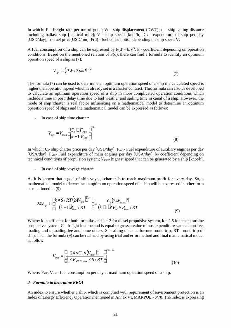
91
In which: P - freight rate per ton of good; W - ship displacement (DWT); d - ship sailing distanceincluding ballast ship [nautical mile]; V - ship speed [knot/h]; CR - expenditure of ship per day[USD/day]; p - fuel price[USD/ton]; F(d) - fuel consumption depending on ship speed V.
A fuel consumption of a ship can be expressed by F(d)= k.V3; k - coefficient depending on operationconditions. Based on the mentioned relation of F(d), there can find a formula to identify an optimumoperation speed of a ship as (7):
2/13/ pkdPWVopt (7)
The formula (7) can be used to determine an optimum operation speed of a ship if a calculated speed ishigher than operation speed which is already set in a charter contract. This formula can also be developedto calculate an optimum operation speed of a ship in more complicated operation conditions whichinclude a time in port, delay time due to bad weather and sailing time in canal of a ship. However, themode of ship charter is real factor influencing on a mathematical model to determine an optimumoperation speed of ships and the mathematical model can be expressed as follows:
- In case of ship time charter:
k
ME
Auxsopt Fk
FCVV
/1
max 1
(8)
In which: Cs- ship charter price per day [USD/day]; FAux- Fuel expenditure of auxiliary engines per day[USA/day]; FME- Fuel expenditure of main engines per day [USA/day]; k- coefficient depending ontechnical conditions of propulsion system; Vmax- highest speed that can be generated by a ship [knot/h].
- In case of ship voyage charter:
As it is known that a goal of ship voyage charter is to reach maximum profit for every day. So, amathematical model to determine an optimum operation speed of a ship will be expressed in other formas mentioned in (9)
RTPFk
VC
RTPk
VRTSkV
timenl
ki
time
kopt
opt /1
24
/1
24/24 max
1
(9)
Where: k- coefficient for both formulas and k = 3 for diesel propulsive system, k = 2.5 for steam turbinepropulsive system; Ci - freight income and is equal to gross a value minus expenditure such as port fee,loading and unloading fee and some others; S - sailing distance for one round trip; RT- round trip ofship. Then the formula (9) can be realized by using trial and error method and final mathematical modelas follow:
1_/1
max,
max
/
24
k
VME
ki
opt RTSFk
VCV
(10)
Where: FME, Vmax- fuel consumption per day at maximum operation speed of a ship.
d- Formula to determine EEOI
An index to ensure whether a ship, which is complied with requirement of environment protection is anIndex of Energy Efficiency Operation mentioned in Annex VI, MARPOL 73/78. The index is expressing
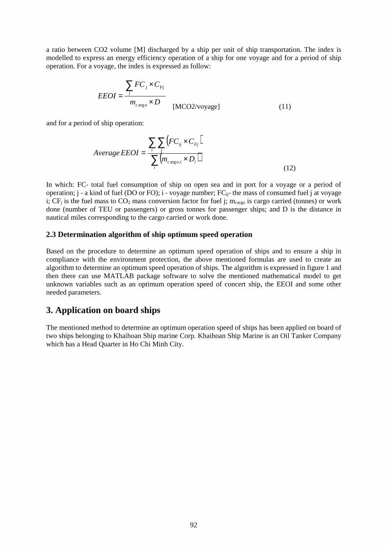
92
a ratio between CO2 volume [M] discharged by a ship per unit of ship transportation. The index ismodelled to express an energy efficiency operation of a ship for one voyage and for a period of shipoperation. For a voyage, the index is expressed as follow:
Dm
CFC
EEOIoc
jFjj
arg [MCO2/voyage] (11)
and for a period of ship operation:
iiioc
i jFjij
Dm
CFC
EEOIAverage,arg
(12)
In which: FC- total fuel consumption of ship on open sea and in port for a voyage or a period ofoperation; j - a kind of fuel (DO or FO); i - voyage number; FCij- the mass of consumed fuel j at voyagei; CFj is the fuel mass to CO2 mass conversion factor for fuel j; mcargo is cargo carried (tonnes) or workdone (number of TEU or passengers) or gross tonnes for passenger ships; and D is the distance innautical miles corresponding to the cargo carried or work done.
2.3 Determination algorithm of ship optimum speed operation
Based on the procedure to determine an optimum speed operation of ships and to ensure a ship incompliance with the environment protection, the above mentioned formulas are used to create analgorithm to determine an optimum speed operation of ships. The algorithm is expressed in figure 1 andthen there can use MATLAB package software to solve the mentioned mathematical model to getunknown variables such as an optimum operation speed of concert ship, the EEOI and some otherneeded parameters.
3. Application on board ships
The mentioned method to determine an optimum operation speed of ships has been applied on board oftwo ships belonging to Khaihoan Ship marine Corp. Khaihoan Ship Marine is an Oil Tanker Companywhich has a Head Quarter in Ho Chi Minh City.
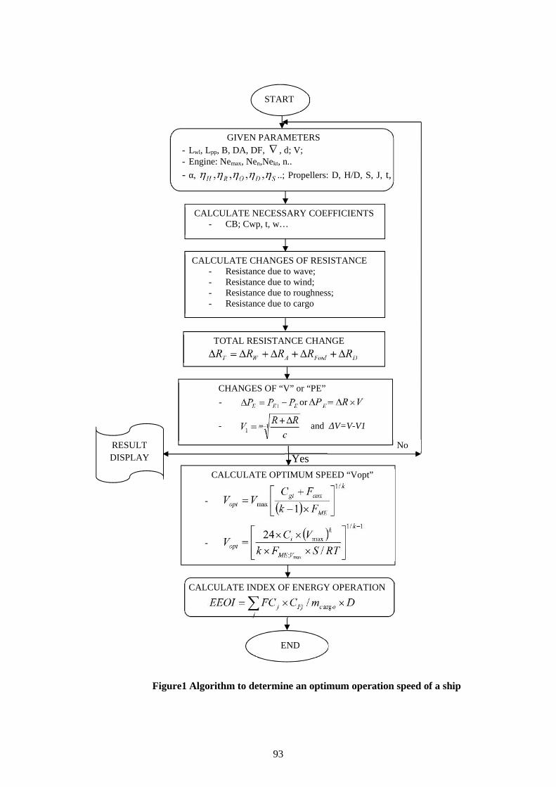
93
START
CALCULATE NECESSARY COEFFICIENTS- CB; Cwp, t, w…
CALCULATE CHANGES OF RESISTANCE- Resistance due to wave;- Resistance due to wind;- Resistance due to roughness;- Resistance due to cargo
GIVEN PARAMETERS- Lwl, Lpp, B, DA, DF, , d; V;- Engine: Nemax, Nen,Nekt, n..
- α, ..; Propellers: D, H/D, S, J, t,
w;
TOTAL RESISTANCE CHANGE
CHANGES OF “V” or “PE”- or
- and ΔV=V-V1
CALCULATE OPTIMUM SPEED “Vopt”
-
-
END
RESULTDISPLAY
No
Yes
CALCULATE INDEX OF ENERGY OPERATION
Figure1 Algorithm to determine an optimum operation speed of a ship
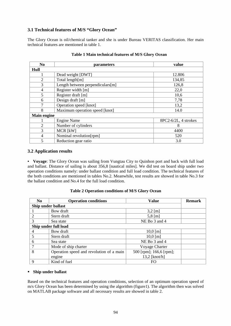
94
3.1 Technical features of M/S “Glory Ocean”
The Glory Ocean is oil/chemical tanker and she is under Bureau VERITAS classification. Her maintechnical features are mentioned in table 1.
Table 1 Main technical features of M/S Glory Ocean
No parameters valueHull
1 Dead weight [DWT] 12.8062 Total length[m] 134,853 Length between perpendiculars[m] 126,84 Register width [m] 22,05 Register draft [m] 10,66 Design draft [m] 7,787 Operation speed [knot] 13,28 Maximum operation speed [knot] 14.0
Main engine1 Engine Name 8PC2-6/2L, 4 strokes2 Number of cylinders 83 MCR [kW] 44004 Nominal revolution[rpm] 5205 Reduction gear ratio 3.0
3.2 Application results
Voyage: The Glory Ocean was sailing from Vungtau City to Quinhon port and back with full loadand ballast. Distance of sailing is about 356,8 [nautical miles]. We did test on board ship under twooperation conditions namely: under ballast condition and full load condition. The technical features ofthe both conditions are mentioned in tables No.2. Meanwhile, test results are showed in table No.3 forthe ballast condition and No.4 for the full load condition.
Table 2 Operation conditions of M/S Glory Ocean
No Operation conditions Value RemarkShip under ballast1 Bow draft 3,2 [m]2 Stern draft 5,8 [m]3 Sea state NE Bo 3 and 4Ship under full load4 Bow draft 10,0 [m]5 Stern draft 10,0 [m]6 Sea state NE Bo 3 and 47 Mode of ship charter Voyage Charter8 Operation speed and revolution of a main
engine500 [rpm]; 166,6 [rpm];
13,2 [knot/h]9 Kind of fuel FO
Ship under ballast
Based on the technical features and operation conditions, selection of an optimum operation speed ofm/s Glory Ocean has been determined by using the algorithm (figure1). The algorithm then was solvedon MATLAB package software and all necessary results are showed in table 2.
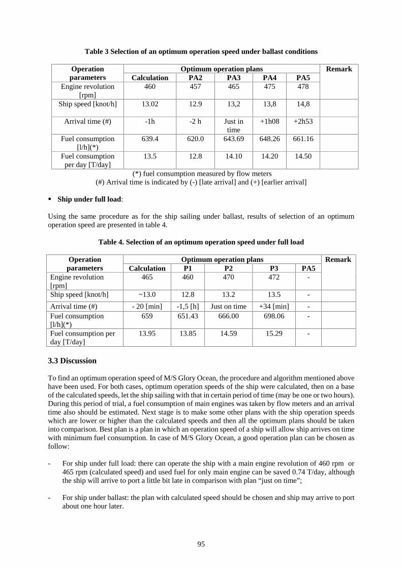
95
Table 3 Selection of an optimum operation speed under ballast conditions
Operationparameters
Optimum operation plans RemarkCalculation PA2 PA3 PA4 PA5
Engine revolution[rpm]
460 457 465 475 478
Ship speed [knot/h] 13.02 12.9 13,2 13,8 14,8
Arrival time (#) -1h -2 h Just intime
+1h08 +2h53
Fuel consumption[l/h](*)
639.4 620.0 643.69 648.26 661.16
Fuel consumptionper day [T/day]
13.5 12.8 14.10 14.20 14.50
(*) fuel consumption measured by flow meters(#) Arrival time is indicated by (-) [late arrival] and (+) [earlier arrival]
Ship under full load:
Using the same procedure as for the ship sailing under ballast, results of selection of an optimumoperation speed are presented in table 4.
Table 4. Selection of an optimum operation speed under full load
Operationparameters
Optimum operation plans RemarkCalculation P1 P2 P3 PA5
Engine revolution[rpm]
465 460 470 472 -
Ship speed [knot/h] ~13.0 12.8 13.2 13.5 -
Arrival time (#) - 20 [min] -1,5 [h] Just on time +34 [min] -Fuel consumption[l/h](*)
659 651.43 666.00 698.06 -
Fuel consumption perday [T/day]
13.95 13.85 14.59 15.29 -
3.3 Discussion
To find an optimum operation speed of M/S Glory Ocean, the procedure and algorithm mentioned abovehave been used. For both cases, optimum operation speeds of the ship were calculated, then on a baseof the calculated speeds, let the ship sailing with that in certain period of time (may be one or two hours).During this period of trial, a fuel consumption of main engines was taken by flow meters and an arrivaltime also should be estimated. Next stage is to make some other plans with the ship operation speedswhich are lower or higher than the calculated speeds and then all the optimum plans should be takeninto comparison. Best plan is a plan in which an operation speed of a ship will allow ship arrives on timewith minimum fuel consumption. In case of M/S Glory Ocean, a good operation plan can be chosen asfollow:
- For ship under full load: there can operate the ship with a main engine revolution of 460 rpm or465 rpm (calculated speed) and used fuel for only main engine can be saved 0.74 T/day, althoughthe ship will arrive to port a little bit late in comparison with plan “just on time”;
- For ship under ballast: the plan with calculated speed should be chosen and ship may arrive to portabout one hour later.
96
4. Conclusion
At present period, the shipping is very competitive worldwide. One hand, the shipping companies mustensure their ability in carrying goods safely with reasonable freight rate and in the other hand, shippingcompanies also must comply with the requirements of environment protection. It means that ships haveto be in good technical conditions; therefore they may or have to be equipped with further necessaryequipment in order to support ships in compliance with strict standards set by IMO in Annex VI,MARPOL 73/78. However, according to our survey results, even some newly built ships cannot matchthe criteria of EEOI during operation. There can conclude some reasons, but mainly ship crews have aproblem with understanding about ship optimum operation speed and EEOI.
The procedure and algorithm of determination of ship optimum operation speed as mentioned above isnecessarily to be developed and applied on board ships. The test results in m/s Glory Ocean are verypositive and are highly appreciated by the owner (Khaihoan Ship Marine Corp. ). The method is beingin further development under support of Vietnam Ministry of Transportation and it will be widely usedto help shipping companies and ship crews in Vietnam.
References
[1] Dang Van Uy and Research Group, To propose technical and managerial solutions to reduce fuelconsumption on board ship; be applied for one merchant fleet. National Energy Saving Program,Project of Fuel Consumption Reduction; Hanoi, 2015;
[2] Technical data, Noon report, Voyage report) from Vietnamese shipping companies: VOSCO,EDSCO, FALCON, PTSC, PVTRANS, VITACO, KHAI HOAN, VITRANSCHART,COASTSHIP,...
[3] Governmental Development Plan of Vietnamese Fleet to Year 2020 and Directed to year 2030",2014;
[4] The national Law about efficiency of fuel using and energy saving; Vietnam 2010;[5] Hans Otto Kristensen, Marie Lutzen; Prediction of Resistance and Propulsion Power of Ships;
Denmark, 2012;[6] IMO Rsolution MEPC.213(63); Guidelines for the development of a ship energy efficiency
management plan (SEEMP), 2012;[7] Kongsberg Maritime AS; Ship Performace System, Norway, 2013;[8] Mads Aas-Hasan. Monitoring of Hull Condition of Ships, M.Sc. Thesis; Norwegian University of
Science and Technology, 2010;[9] MAN Diesel & Turbo; Basic Principles of Ship Propulsion; Denmark 2013;[10] Robert Moody, Preliminary Power Prediction During Early Design Stages of a Ship; Cape Town,
South Africa, 1996;[11] Tadeusz Borkowski, Przemyslaw Kowalak, Jaroslaw Myskow, Vessel Main Propulsion Engine
Performance Evaluation, Szczecin, Poland, 2012;[12] www.Marorka.com; Fuel Manager; 2013.
97
Polarworthiness and Co-operation – Efficient education of riskmanagement for arctic environment
Peter Ivar Sandell, Senior lecturer of Maritime and Commercial law
Satakunta University of Applied Sciences, [email protected], Suojantie 2, 26100 Rauma, Finland.
Abstract The Polar Code enters into force and the Maritime Academies and Maritime Universities havea task to train the seafarers and company management facing the implementation into the vesselspractice and company practice. The subject of the article is to examine the changes brought by the PolarCode that influence the environmental risk management. The International Maritime Organization IMOis to update the SOLAS, MARPOL and STCW Conventions, to take account of the specific features ofthe Polar Regions. These updates will take effect at the beginning of 2017. At the beginning of the articlethere is a short description of Polar Code key issues, as well as a brief explanation of the existingregulation in the Arctic regions from environmental protection point of view.
The effects of the Polar Code were investigated by the term polarworthiness. When the vessels move inregion where polar code is effected, new rules will require ships of different things, and their importanceto ship's seaworthiness is described in this article in relation to environmental risk management.
Teaching these new issues has potential for co-operation between Maritime Universities. Polar Codeimplementation is an important issue not just northern shipping companies, but also all companies whichconsider the use of northern route from Asian markets to Europe in the future.
Maritime Universities can do research and co-operate with the companies already present in the Arcticenvironment. The co-operation between Universities and companies can and will be used to provide indepth study courses, which can be delivered also to other Maritime Universities through studentexchange and seminars. Building a course module for environmental risk management for ice operationswill be presented - Company representatives have taken their Master of Maritime Management degreeand produced parts of in-depth study course in Arctic Shipping Management based on their researchtogether with Satakunta University of Applied Sciences. The topics presented as examples are STS-operations in the arctic environment, oil pollution response planning in the arctic and DP icemanagement. The model of using the Master of Maritime Management student´s expertise in creationof new knowledge and use of the alumni organisation in teaching the specialised courses will bepresented.
Keywords: Maritime education and training (MET), Polarworthiness, Polar Code, risk management,environmental risk assessment, environmental liability, methods of learning, safety and security, studentexchange and co-operation.
1. Introduction
The IMO Polar Code enters into force creating new standard of seaworthiness for Arctic Shipping.
The new code sets the standards of seaworthiness in the Polar context. Implications for maritimecontracting (risk management and risk sharing) in the polar environment needs to be addressed by theshipowner´s and their masters. The International Maritime Organization IMO is to update the SOLAS,MARPOL and STCW Conventions, to take account of the specific features of the Polar Regions. Theseupdates will take effect at the beginning of 2017. Polar Code is not an own Convention, but it updatesSOLAS, MARPOL and STCW conventions [1].
98
2. Polar Code raises standards of seaworthiness in the Polar Context
The effects of the Polar Code were investigated by the term polarworthiness. When the vessels move inregion where polar code is effected, new rules will require ships of different things. Fitness is a relativeterm, and implies fitness to the vessel’s working environment: Equipment (propulsion, navigation,safety, cargo, etc.), supplies, number and training of crew, etc.IMO’s Polar Code addresses bothtechnical issues and training issues. Polar Code recognizes the unique nature and risks of the Arcticenvironment [1].
Polar Codes part on operations and manning relates to navigation (ice conditions, weather). Shipentering polar waters need a specific Polar Ship Certificate and Polar Water Operational Manual.Appropriate basic training for open-water operations and Advanced training for other waters, includingice needs to be created and arranged [2]. The Code provides standards for both polar ready vessels andcrews in order for the vessel to be considered Polarworthy.
Specific problems arise when meeting the demands of Polarworthiness. The harsh and fragileenvironmental conditions create challenges for operation in Polar waters. Lack of infrastructure is aspecial problem. Especially this consists of lack of navigational aids, lack of bunker facilities and lackof repair facilities. The vessels entering Polar waters need to need to be able to operate moreindependently than usually. Technical assistance, salvage and ice breaking are services which are notavailable like elsewhere in more southern levels.
Achieving polarworthiness demands is crucial for ship owners who need to assess their potential risksand liabilities. If the vessel is not seaworthy in arctic conditions the environmental liabilities cannot belimited. The insurance aspects are also related to seaworthiness: If the vessel is not seaworthy in arcticenvironment, the insurance cover will not be in force or if the safety regulations are breached, accordingto Nordic Marine Insurance Plan, the insurance will not cover the casualty. The Polar Code isautomatically considered as a safety regulation under the Nordic Marine Insurance Plan [3].
Many Nordic ship owners insure their vessels on Nordic standard conditions and for those using theseconditions it is enough for their risk management and insurance cover to follow the SOLAS, MARPOLand STCW conventions in version updated by Polar Code rules (as well as other conventions by IMOrelated to safety of vessels) to be certain that their risks are covered also by their insurance conditions.However, few non Nordic owners use Nordic insurance conditions and in the future many ship ownerswho will be interested in entering Polar waters will be covered by English law of marine insurance andEnglish Marine Insurance Clauses and conditions.
Seaworthiness in English law may be defined like Tetley: “Seaworthiness may be defined as the state ofa vessel in such a condition, with such equipment, and manned by such a master and crew, that normallythe cargo will be loaded, carried, cared for and discharged properly and safely on the contemplatedvoyage.” [4]. In other words, the essential issue is fitness for purpose and carriage relating to the polarand arctic environment. Therefore, the term polarworthiness is the term which we need to address andexamine when we concentrate on the specific requirements in risk management for the Polar regions.
What is required of a vessel in order to be polarworthy throughout the voyage? Fitness is a relative term,and implies fitness to the vessel’s working environment and harshness of the conditions to be expectedduring and throughout the voyage contemplated. When examining the expected fitness in Polar watersthe Polar Code concentrates on equipment (propulsion, navigation, safety, cargo, etc.), supplies, numberand training of crew, etc.IMO’s Polar Code addresses technical issues and training issues. Polar Coderecognizes the unique nature and risks of the Arctic environment and for the first time as a mandatoryregulation it creates a standard of seaworthiness specifically for Polar environment which needs to beaddressed by the ship owners as a part of their risk management in order to comply the internationalstandards of safety in this region and to held their insurance cover in force throughout the journey.Seafaring is especially risky business. Therefore, the modern insurance system was first established formaritime trade. Risk management in the Polar shipping defines the issue: Who is to bear the risk (of
99
casualty, cargo loss, damage to the environment or delay) in the Polar context and how can these risksbe shared or carved out? Polar Code as well as the other safety conventions is also a tool of riskmanagement: Following the international standards is of utmost importance and procedures incomplying with the standards by company procedures is the starting point.
Developing the company procedures in critical issues (relating to Polar environment) in uniform manneris the key element which can be achieved by in co-operations with the education and ship owners riskmanagement professionals as we will examine below in the chapter four in this article. The investmenton developing company procedures relating to safety in the arctic regions is a necessity – It has to bealso a clear indication of company strategy if the company wants to avoid the negative publicity in usingthe arctic regions. In Nordic countries we have examples of companies facing severe difficulties withpublic image and organisations like Greenpeace if the company management has not made a decent riskassessment on the operations in the Polar region. Even though the organisations like Greenpeace do nothave that purpose, their actions create environmental concerns when they forcefully enter the offshoreplatforms or supply vessels or try to prevent them from working in the region.
3. Educating seafarers for the Arctic
IMO gives guidance for implementation of the new Rules [2]. Model courses do not however meet allthe demands the shipowner´s and masters are facing in the area. Teaching these new issues has potentialfor co-operation between Maritime Universities.
Polar Code implementation is an important issue not just northern shipping companies, but also allcompanies which consider the use of northern route from Asian markets to Europe in the future. Theeconomic advantages are lucrative when using the northern route. This creates possibilities especiallyfor Nordic Maritime Universities in exporting the education and attracts students to choose NordicUniversities as a destination for student exchange. The Nordic Universities should use this challengeand develop their activities to meet this challenge.
As approximately 80 % of maritime accidents have human elements involved when casualty occurs inrelation to a vessel, the training of the seafarers for the Polar conditions is an important part ofPolarworthiness of vessels when the Code enters into force. After 1 January 2017, ships operating inpolar waters shall be appropriately manned with adequately trained, qualified and experienced seafarers,taking into account the relevant provisions in the STCW Convention and Code [2].Amendments to theSTCW Convention and Code regarding the training and certification associated to the Polar Code areexpected to become effective in 2018. New training guidance for personnel serving on board shipsoperating in polar waters need to implemented before that. Measures to ensure the competency ofmasters and officers of ships operating in polar waters has to be created by the Maritime Universities.Training for Masters, Chief Mates and Officers in charge of a navigational watch on ships operating inpolar waters is mandatory requirement but the problem is that not all Maritime Universities have enoughexpertise in teaching the navigation in the Polar waters. The starting point for the training are theinternational requirements, but several countries have local legislation which need to be implementedin the training requirements when the vessels are about to enter their waters, e.g: Russia, Canada,Norway and the US [2].
When considering the basics of the education needed for Masters and officers in charge of a navigationalwatch, they should receive basic training or instructions as determined by the Administration on Icecharacteristics and ice areas, relevant education on Ship’s performance in ice and cold climate as wellas Operating and handling a ship in ice. For masters and chief mates on board ships sailing in Polarwaters the following skills are needed in addition: Knowledge of voyage planning and reporting,knowledge of equipment limitations, knowledge of safety, knowledge of commercial and regulatoryconsiderations [2].The importance of expertise in teaching these topics is essential for the safe operation of those who takethe courses. The issue of Polarworthiness in relation to the quality of training will probably be raised ina court - If there will be a casualty. Therefore, we need to think how to achieve the best possible modes
100
for educating crew for polarworthy vessels? – At least it is the maritime Universities who should takecare that if there will be vessels found not to be polarworthy.
It is up to the training institutions to assure the vessels are not breaking the rules on seaworthiness dueto indecent training for the Polar environment. The co-operation here is more important than ever before.As most Maritime Universities have no experience at all on training crews for the vessels operating inthe arctic, we must share our experiences in a situation when entering Polar waters in the future islucrative for most ship owners. In this respect I see the IAMU organisation and family of Universitiesas an important tool for Unification of the training in the years to come.
4. Modes of co-operation for achieving arctic excellence
Maritime Universities in Nordic countries have a huge benefit when they develop education for arcticenvironment. Many Universities do research and co-operate with the companies already present in theArctic environment. The co-operation between Satakunta University of Applied Sciences andcompanies is already used to develop in depth study courses, which can be delivered also to otherMaritime Universities through student exchange and seminars. Building a course module forenvironmental risk management for ice operations is already on its way. Company representatives havetaken their Master of Maritime Management degree and produced parts of in-depth study course inArctic Shipping Management based on their research together with Satakunta University of AppliedSciences.
Some examples of the research conducted in co-operation with the student working in the companieswith arctic experience and the University can already be listed. This co-operation is part of the researchwork of the University as well as risk management procedure of the companies working in the Polarregions:
Tanker operations in the arctic environment are especially risky due to the environmental vulnerabilityof the region and the specific risk element for tankers relating to the ice pressure. The ship to shipoperations of tankers (STS-operations) in the arctic are however a necessity in specific circumstances.In a research study the safety procedures of STS operations in this environment are analysed, data fromprevious operations is collected as well as silent information from the captains with tens of years ofexperience from the arctic altogether is analysed in order for the risk assessment tool for the tankersoperating in the arctic to be developed [5]. Tanker fleet personnel operating in the arctic environment ishighly skilled group of seafarers. The experience and practices adjusted to the new Polar coderequirements is a model example of the co-operations between Maritime Universities and specialisedshipping companies. Tanker operations in ice is one of the expertise courses to be developed based onthe co-operation in research work.
Another important research project to be analysed is oil pollution response planning of the companyoperating in the arctic [6]. The problems of collecting oil from sea with ice cover or ice blocks has beenan issue for researchers for decades. Taking the technology to Polar areas is especially important butalso extremely costly. Effective as well as cost effective produces and equipment together with acompany environmental response strategy are part of a research combined into Master’s thesis andcompany development project which will also benefit the Arctic environmental risk courses of theUniversity in the future. The oil catastrophe in the arctic is something which no one dares to imagine –But the companies planning their activities has to prepare for the worst scenario. The Maritime traininginstitutions cannot turn a blind eye either.
Third example of an ongoing research project is DP ice management, which is also a topic very littleexamined by researchers [7]. The topic is and research is highly based on persons with long experiencein offshore activities in the arctic environment. This project is well targeted to serve the persons whoneed further education on DP in the arctic environment in the future years when the offshore industryrecovers and the arctic drilling projects now waiting for implementation will be carried out. Safe
101
offshore drilling in the harsh environment is highly dependent on the skilled experts navigating andoperating in ice.
Satakunta University of Applied Sciences uses the Master of Maritime Management student´s expertiseas well as the own staff’sexpertise in creation of new knowledge and use of the experienced Masters arealso used in teaching the specialised arctic courses. The strength of the education is close co-operationwith the companies workingin the Polar region. The companies which can be specially referred to areNeste Shipping Ltd. and Arctia Shipping Ltd. and Arctia offshore Ltd. We feel privileged to have theirbest people working together with our University´s staff and further educating together crews for thevessel operating in the Polar waters and ensuring that all our students and exchange students visiting ourinstitution get the best possible education and the latest experience from the Polar water navigationexperts.
The ship design and shipbuilding industry in Finland is concentrating also to designing and buildingspecialised vessels for arctic regions. Combining this knowledge to the course development and usingthe expertise of the companies in teaching the courses gives also great advantages for those attendingthe courses in Nordic Universities.
5. Conclusions
Polar Code is an important tool for the industry. Its implementation needs to be done with cautiousnessby the companies that intend to operate in arctic regions. Therefore, the educations of those who willoperate in the region also needs to be done properly. It is also important for the image of seafaring andshipping community in general.
The environmental organisations are strongly opposing the use of arctic regions for transportation andespecially for offshore activities. We all remember the consequences of the Exxon Valdez accident inAlaska 1989 and its impact in the oil transport industry as well as the legal implications that followedthe incident. If the industry wants to operate in arctic regions, we cannot afford to allow any more fatalcatastrophes even near the arctic. The education is of the essence and we need to use every opportunityto show that the education system together with the shipowners is ready to invest in education andpreventing the spills to the sensitive areas. Therefore, we need to seek co-operation together with theUniversities and the industry to make the arctic shipping as safe as possible. I hope our practice in thisfield described in this presentation is an example for other institutions. We are happy to share ourexperiences to fellow colleagues and visiting professors as well as exchange students.
References
[1] Haaslahti, Simo, Polaarikelpoisuus, 2015, Rauma, Satakunnan Ammattikorkeakoulu.[2] IMO, International code for ships operating in polar waters (polar code) and Model course
advanced training ice navigation in arctic water, 2016, London, IMO[3] Nordic Marine Insurance Plan 2016, issued by Cefor at http://www.nordicplan.org/The-Plan/[4] Tetley, William, Marine Cargo Claims, Thomson Carswell, 4ed.[5] Hornborg, Lauri, STS- operations in Ice, research plan for Satakunta University of Applied
Sciences, 2015[6] Tammiala, Sampo, Oil response in ice, research plan for Satakunta University of Applied Sciences,
2015[7] Westerlund, Matti, Dynamic Positioning in ice, research plan for Satakunta University of Applied
Sciences, 2015
102
Energy Efficiency Design Index Verificationthrough Actual Power and Speed Correlation
Quang Dao Vuong1, Professor Don Chool Lee2, Professor Ronald D. Barro*
1. Mokpo National Maritime University, [email protected]. Mokpo National Maritime University, [email protected]
*. Corresponding Author: Mokpo National Maritime University, [email protected],91Haeyangdaehak-ro, Mokpo-si, Jeonnam, South Korea
Abstract. The International Maritime Organization (IMO) mandatory requirement for EnergyEfficiency Design Index (EEDI) has been in place since 01 January 2015 to address emission and globalwarming concerns. This regulation must be satisfied by newly-built ships with 400 gross tonnages andabove. In addition, the MEPC-approved 2013 guidance, ISO 15016 and ISO 19019 on EEDI serves thepurpose for calculation and verification of attained EEDI value. As such, verification should be carried-out through an acceptable method during sea trial and this demands extensive planning duringpropulsion power system design stage. Power and speed assessment plays the important factor in EEDIverification. The shaft power can be determined by telemeter system using strain gage while the shipspeed can be verified and calibrated by differential ground positioning system (DGPS).
An actual measurement was carried-out on a newly-built ship during sea trial to assess the correlationbetween speed and power. In this paper, the Energy-efficiency Design Index or Operational IndicatorMonitoring System (EDiMS) software developed by the Dynamics Laboratory-Mokpo NationalMaritime University (DL-MMU) and Green Marine Equipment RIS Center (GMERC) of MokpoNational Maritime University was utilized. Mainly, EDiMS software employs four channels – enginespeed, ship speed, shaft power and fuel consumption - for the verification process. In addition, thesoftware can continuously monitor air pollution and is a suitable tool for inventory and ship energymanagement plan. Ships greenhouse gas inventory can likewise be obtained from the base of emissionresult during the engine shop test trial and the actual monitoring of shaft power and ship speed. It issuggested that an integrated equipment and compact software be used in EEDI verification. It is alsoperceived that analog signals improve the measurement accuracy compared to digital signal. Otherresults are presented herein.
Keywords: shaft power, ship speed, exhaust gas emissions, energy efficiency design index (oroperational indicator) (EEDI, EEOI), ship energy efficiency management plan (SEEMP).
1. Introduction
Shipping is the most efficient form of cargo transportation and with its increasing globalization havelead to the continued growth of the maritime transport. Along with this development, ships’exhaustemissions into the environment have become a big concerning issue. In addition, potential harmfulinfluence on human health, cause acid rain and contribute to global warming are seen to be some of thenegative effects of these emissions. In 2009, the shipping sector was estimated to have emitted around3.3% of global CO₂ emissions of which the international shipping contributed roughly 2.7% or 870million tonnes. If unabated, shipping’s contribution to greenhouse gases (GHG) emissions could reach18% by 2050 [1].
To address this concern, the IMO’s pollution prevention treaty (MARPOL) under Annex VI has adoptedthe mandatory energy-efficiency measures to reduce emissions of GHG from international shipping. InJuly 2011, the ‘Energy Efficiency Design Index’ (EEDI) was adopted setting the minimum energyefficiency requirements and must not be exceeded the given threshold by new ships built after 2013. Itis based on a complex formula, taking the ship’s emissions, capacity and speed into account. The targetrequires most new ships with 400 gross tonnages and above to be 10%-, 20%-, and 30% more efficient
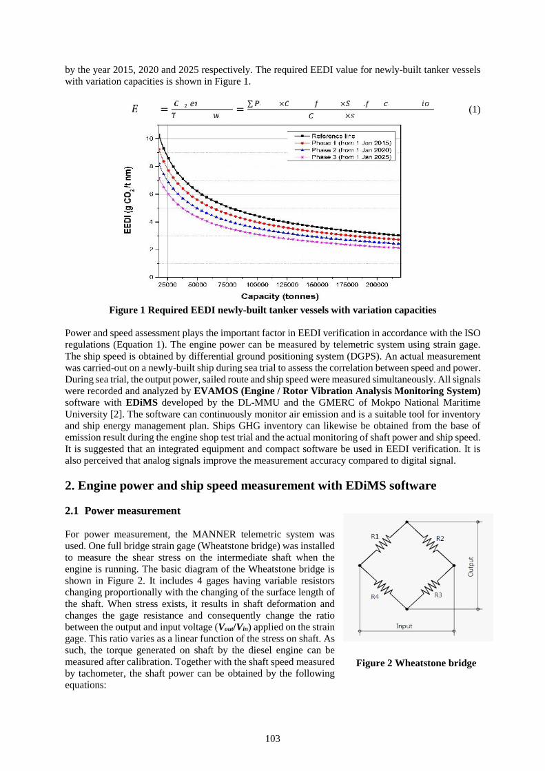
103
by the year 2015, 2020 and 2025 respectively. The required EEDI value for newly-built tanker vesselswith variation capacities is shown in Figure 1.= = ∑ × × .× (1)
Figure 1 Required EEDI newly-built tanker vessels with variation capacities
Power and speed assessment plays the important factor in EEDI verification in accordance with the ISOregulations (Equation 1). The engine power can be measured by telemetric system using strain gage.The ship speed is obtained by differential ground positioning system (DGPS). An actual measurementwas carried-out on a newly-built ship during sea trial to assess the correlation between speed and power.During sea trial, the output power, sailed route and ship speed were measured simultaneously. All signalswere recorded and analyzed by EVAMOS (Engine / Rotor Vibration Analysis Monitoring System)software with EDiMS developed by the DL-MMU and the GMERC of Mokpo National MaritimeUniversity [2]. The software can continuously monitor air emission and is a suitable tool for inventoryand ship energy management plan. Ships GHG inventory can likewise be obtained from the base ofemission result during the engine shop test trial and the actual monitoring of shaft power and ship speed.It is suggested that an integrated equipment and compact software be used in EEDI verification. It isalso perceived that analog signals improve the measurement accuracy compared to digital signal.
2. Engine power and ship speed measurement with EDiMS software
2.1 Power measurement
For power measurement, the MANNER telemetric system wasused. One full bridge strain gage (Wheatstone bridge) was installedto measure the shear stress on the intermediate shaft when theengine is running. The basic diagram of the Wheatstone bridge isshown in Figure 2. It includes 4 gages having variable resistorschanging proportionally with the changing of the surface length ofthe shaft. When stress exists, it results in shaft deformation andchanges the gage resistance and consequently change the ratiobetween the output and input voltage (Vout/Vin) applied on the straingage. This ratio varies as a linear function of the stress on shaft. Assuch, the torque generated on shaft by the diesel engine can bemeasured after calibration. Together with the shaft speed measuredby tachometer, the shaft power can be obtained by the followingequations:
Figure 2 Wheatstone bridge
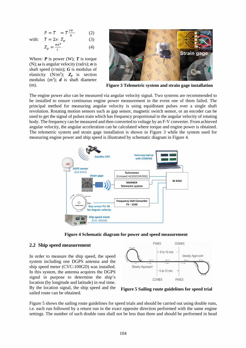
104
= = (2)
with: = 2 (3)= (4)
Where: P is power (W); T is torque(N); ω is angular velocity (rad/s); n isshaft speed (r/min); G is modulus ofelasticity (N/m2); Zp is sectionmodulus (m3); d is shaft diameter(m).
The engine power also can be measured via angular velocity signal. Two systems are recommended tobe installed to ensure continuous engine power measurement in the event one of them failed. Theprincipal method for measuring angular velocity is using equidistant pulses over a single shaftrevolution. Rotating motion sensors such as gap sensor, magnetic switch sensor, or an encoder can beused to get the signal of pulses train which has frequency proportional to the angular velocity of rotatingbody. The frequency can be measured and then converted to voltage by an F-V converter. From achievedangular velocity, the angular acceleration can be calculated where torque and engine power is obtained.The telemetric system and strain gage installation is shown in Figure 3 while the system used formeasuring engine power and ship speed is illustrated by schematic diagram in Figure 4.
Figure 4 Schematic diagram for power and speed measurement
2.2 Ship speed measurement
In order to measure the ship speed, the speedsystem including one DGPS antenna and theship speed meter (CVC-100GD) was installed.In this system, the antenna acquires the DGPSsignal in purpose to determine the ship’slocation (by longitude and latitude) in real time.By the location signal, the ship speed and thesailed route can be obtained.
Figure 5 shows the sailing route guidelines for speed trials and should be carried out using double runs,i.e. each run followed by a return run in the exact opposite direction performed with the same enginesettings. The number of such double runs shall not be less than three and should be performed in head
Figure 3 Telemetric system and strain gage installation
Figure 5 Sailing route guidelines for speed trial
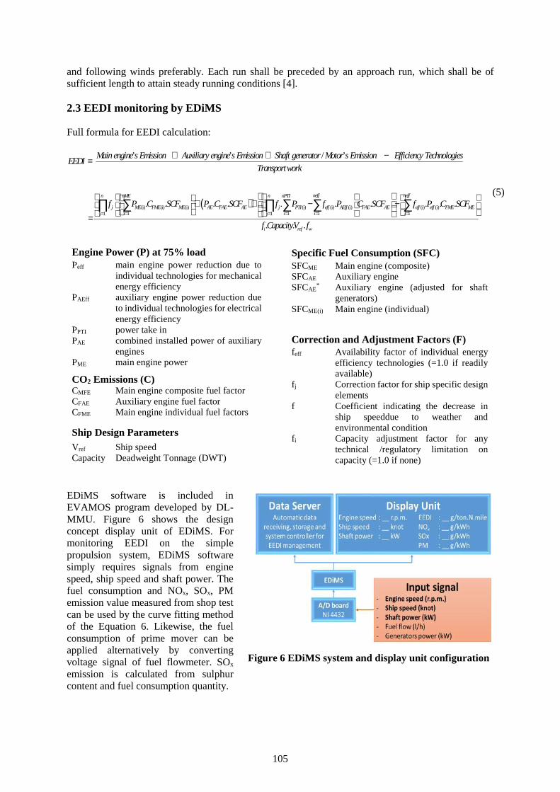
105
and following winds preferably. Each run shall be preceded by an approach run, which shall be ofsufficient length to attain steady running conditions [4].
2.3 EEDI monitoring by EDiMS
Full formula for EEDI calculation:
(i ) (i) (1
’ ’ / ’
. .n
j ME FME MEj
Main engines Emission Auxiliary engines Emission Shaft generator Motor s Emission Efficiency TechnologiesEEDI
Transport
f P C SCF
work
i) (i) (i) (i) (i) (i)
1 1 1 11
. . . . . . . .
. . .
neff neffnnME nPTI
AE FAE AE j PTI eff AEff FAE AE eff eff FME MEi i i ij
i ref w
P C SCF f P f P C SCF f P C SCF
f CapacityV f
EDiMS software is included inEVAMOS program developed by DL-MMU. Figure 6 shows the designconcept display unit of EDiMS. Formonitoring EEDI on the simplepropulsion system, EDiMS softwaresimply requires signals from enginespeed, ship speed and shaft power. Thefuel consumption and NOx, SOx, PMemission value measured from shop testcan be used by the curve fitting methodof the Equation 6. Likewise, the fuelconsumption of prime mover can beapplied alternatively by convertingvoltage signal of fuel flowmeter. SOx
emission is calculated from sulphurcontent and fuel consumption quantity.
Specific Fuel Consumption (SFC)SFCME Main engine (composite)SFCAE Auxiliary engineSFCAE
* Auxiliary engine (adjusted for shaftgenerators)
SFCME(i) Main engine (individual)
Correction and Adjustment Factors (F)feff Availability factor of individual energy
efficiency technologies (=1.0 if readilyavailable)
fj Correction factor for ship specific designelements
f Coefficient indicating the decrease inship speeddue to weather andenvironmental condition
fi Capacity adjustment factor for anytechnical /regulatory limitation oncapacity (=1.0 if none)
Engine Power (P) at 75% loadPeff main engine power reduction due to
individual technologies for mechanicalenergy efficiency
PAEff auxiliary engine power reduction dueto individual technologies for electricalenergy efficiency
PPTI power take inPAE combined installed power of auxiliary
enginesPME main engine power
CO2 Emissions (C)CMFE Main engine composite fuel factorCFAE Auxiliary engine fuel factorCFME Main engine individual fuel factors
Ship Design ParametersVref Ship speedCapacity Deadweight Tonnage (DWT)
Figure 6 EDiMS system and display unit configuration
(5)
106
= + + + (6)
Where c0, c1, c2, c3 are coefficients for each of fuel consumption, NOx, SOx, PM emission - y; x is thepart load ratio for maximum continuous rating.
Figure 7 EDiMS monitor display configuration
Figure 8 EDiMS raw signal and emission values display
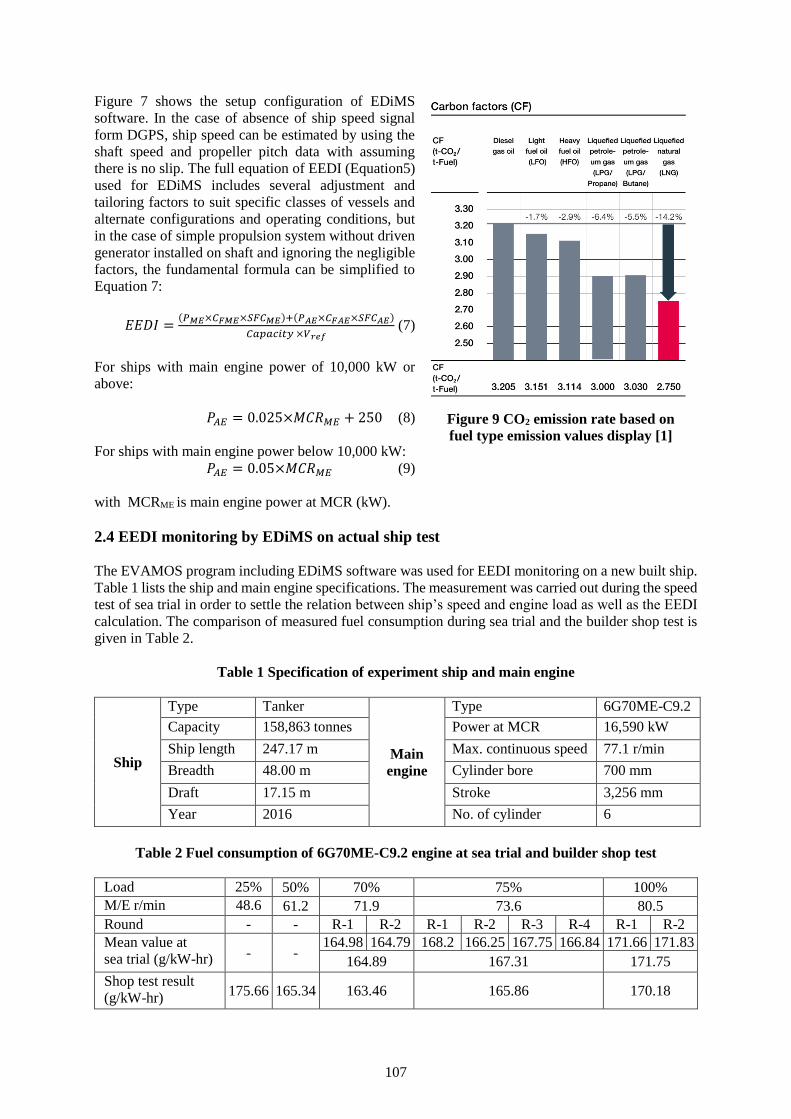
107
Figure 7 shows the setup configuration of EDiMS
software. In the case of absence of ship speed signal
form DGPS, ship speed can be estimated by using the
shaft speed and propeller pitch data with assuming
there is no slip. The full equation of EEDI (Equation5)
used for EDiMS includes several adjustment and
tailoring factors to suit specific classes of vessels and
alternate configurations and operating conditions, but
in the case of simple propulsion system without driven
generator installed on shaft and ignoring the negligible
factors, the fundamental formula can be simplified to
Equation 7:
𝐸𝐸𝐷𝐼 =(𝑃𝑀𝐸×𝐶𝐹𝑀𝐸×𝑆𝐹𝐶𝑀𝐸)+(𝑃𝐴𝐸×𝐶𝐹𝐴𝐸×𝑆𝐹𝐶𝐴𝐸)
𝐶𝑎𝑝𝑎𝑐𝑖𝑡𝑦 ×𝑉𝑟𝑒𝑓 (7)
For ships with main engine power of 10,000 kW or
above:
𝑃𝐴𝐸 = 0.025×𝑀𝐶𝑅𝑀𝐸 + 250 (8)
For ships with main engine power below 10,000 kW:
𝑃𝐴𝐸 = 0.05×𝑀𝐶𝑅𝑀𝐸 (9)
with MCRME is main engine power at MCR (kW).
2.4 EEDI monitoring by EDiMS on actual ship test
The EVAMOS program including EDiMS software was used for EEDI monitoring on a new built ship.
Table 1 lists the ship and main engine specifications. The measurement was carried out during the speed
test of sea trial in order to settle the relation between ship’s speed and engine load as well as the EEDI
calculation. The comparison of measured fuel consumption during sea trial and the builder shop test is
given in Table 2.
Table 1 Specification of experiment ship and main engine
Ship
Type Tanker
Main
engine
Type 6G70ME-C9.2
Capacity 158,863 tonnes Power at MCR 16,590 kW
Ship length 247.17 m Max. continuous speed 77.1 r/min
Breadth 48.00 m Cylinder bore 700 mm
Draft 17.15 m Stroke 3,256 mm
Year 2016 No. of cylinder 6
Table 2 Fuel consumption of 6G70ME-C9.2 engine at sea trial and builder shop test
Load 25% 50% 70% 75% 100%
M/E r/min 48.6 61.2 71.9 73.6 80.5
Round - - R-1 R-2 R-1 R-2 R-3 R-4 R-1 R-2
Mean value at
sea trial (g/kW-hr) - - 164.98 164.79 168.2 166.25 167.75 166.84 171.66 171.83
164.89 167.31 171.75
Shop test result
(g/kW-hr) 175.66 165.34 163.46 165.86 170.18
Figure 9 CO2 emission rate based on
fuel type emission values display [1]
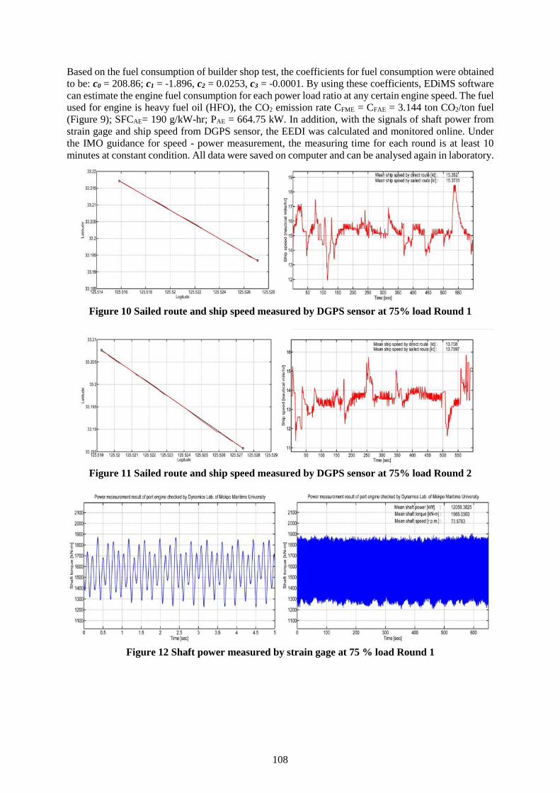
108
Based on the fuel consumption of builder shop test, the coefficients for fuel consumption were obtainedto be: c0 = 208.86; c1 = -1.896, c2 = 0.0253, c3 = -0.0001. By using these coefficients, EDiMS softwarecan estimate the engine fuel consumption for each power load ratio at any certain engine speed. The fuelused for engine is heavy fuel oil (HFO), the CO2 emission rate CFME = CFAE = 3.144 ton CO2/ton fuel(Figure 9); SFCAE= 190 g/kW-hr; PAE = 664.75 kW. In addition, with the signals of shaft power fromstrain gage and ship speed from DGPS sensor, the EEDI was calculated and monitored online. Underthe IMO guidance for speed - power measurement, the measuring time for each round is at least 10minutes at constant condition. All data were saved on computer and can be analysed again in laboratory.
Figure 10 Sailed route and ship speed measured by DGPS sensor at 75% load Round 1
Figure 11 Sailed route and ship speed measured by DGPS sensor at 75% load Round 2
Figure 12 Shaft power measured by strain gage at 75 % load Round 1
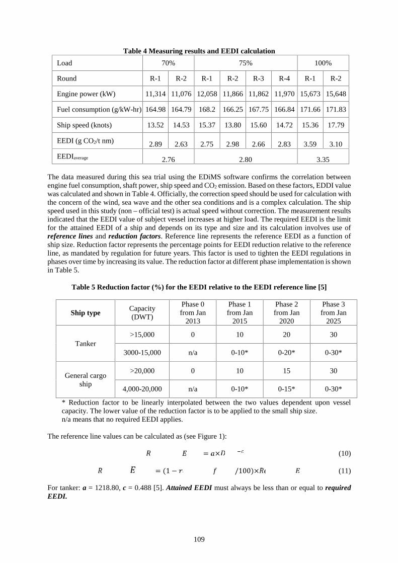
109
Table 4 Measuring results and EEDI calculation
Load 70% 75% 100%
Round R-1 R-2 R-1 R-2 R-3 R-4 R-1 R-2
Engine power (kW) 11,314 11,076 12,058 11,866 11,862 11,970 15,673 15,648
Fuel consumption (g/kW-hr) 164.98 164.79 168.2 166.25 167.75 166.84 171.66 171.83
Ship speed (knots) 13.52 14.53 15.37 13.80 15.60 14.72 15.36 17.79
EEDI (g CO2/t nm) 2.89 2.63 2.75 2.98 2.66 2.83 3.59 3.10
EEDIaverage 2.76 2.80 3.35
The data measured during this sea trial using the EDiMS software confirms the correlation betweenengine fuel consumption, shaft power, ship speed and CO2 emission. Based on these factors, EDDI valuewas calculated and shown in Table 4. Officially, the correction speed should be used for calculation withthe concern of the wind, sea wave and the other sea conditions and is a complex calculation. The shipspeed used in this study (non – official test) is actual speed without correction. The measurement resultsindicated that the EEDI value of subject vessel increases at higher load. The required EEDI is the limitfor the attained EEDI of a ship and depends on its type and size and its calculation involves use ofreference lines and reduction factors. Reference line represents the reference EEDI as a function ofship size. Reduction factor represents the percentage points for EEDI reduction relative to the referenceline, as mandated by regulation for future years. This factor is used to tighten the EEDI regulations inphases over time by increasing its value. The reduction factor at different phase implementation is shownin Table 5.
Table 5 Reduction factor (%) for the EEDI relative to the EEDI reference line [5]
Ship typeCapacity(DWT)
Phase 0from Jan
2013
Phase 1from Jan
2015
Phase 2from Jan
2020
Phase 3from Jan
2025
Tanker>15,000 0 10 20 30
3000-15,000 n/a 0-10* 0-20* 0-30*
General cargoship
>20,000 0 10 15 30
4,000-20,000 n/a 0-10* 0-15* 0-30*
* Reduction factor to be linearly interpolated between the two values dependent upon vesselcapacity. The lower value of the reduction factor is to be applied to the small ship size.n/a means that no required EEDI applies.
The reference line values can be calculated as (see Figure 1):= × (10)= (1 − /100)× (11)
For tanker: a = 1218.80, c = 0.488 [5]. Attained EEDI must always be less than or equal to requiredEEDI.
110
The subject vessel was built in 2016 and thereby must adhere to Phase 1 of the EEDI reduction factorequivalent to 10%. The shaft power ratio required by the IMO regulation is at 75% load only, howeverat all the other load conditions, the EEDI value (Table 4) is lower than the required limit (about 3.53 gCO2/t nm). As such, the subject vessel satisfies the IMO regulation for Energy Efficiency Design Index.In addition, monitoring the SOx, NOx, PM emission are available in EDiMS software. All of these signalscan be measured, analysed and displayed online. File management of all data can be saved on hard driveof PC storage or either be transmitted to onshore shipping company office through internet connection.
3. Conclusion
Owing to rapid development in the shipping industry and maritime transportation, air pollutionemissions from ocean-going ships are continuously increasing. Exhaust gases from ships contain CO2
and many other harmful pollutants. The increased volume of air pollutant results in serious negativeeffects to environment, to human health and contributes to global warming. In order to control CO2
emission from shipping, the Energy Efficiency Design Index requirement was adopted by IMO fornewly-built ships. The EEDI expresses the amount of CO2 emission on transport ability, assesses theenergy consumption of a ship under normal seagoing conditions. The passage of EEDI regulation camewith one important compromise that could affect the magnitude of benefits in developing more efficientships to serve the demand.
The Energy-efficiency Design Index or Operational Indicator Monitoring System (EDiMS) wasdeveloped by DL-MMU in order to analyse and monitor EEDI on the base of results during the engineshop test trial and the actual monitoring of shaft power and ship speed. It is recommended for EEDIverification to use a compact software capable of measuring the shaft power and ship speedsimultaneously. This software is a suitable tool for inventory and ship energy management plan. Notonly EEDI, EDiMS can estimate and help to control air pollution source in exhaust gases such as SOx,NOx and PM. All of the energy-efficiency indexes can be displayed online continuously and transmittedto other server via internet connection. The software capability should be continually improvedaccording to the expectations and participations from the ship owners and shipping companies withaccurate advices from specialists.
References
[1] IMO, Second IMO GHG Study 2009, International Maritime Organization, London, UK, 2009[2] Donchool Lee, Kisee Joo, Takkun Nam, Eunseok Kim, Sanghwan Kim, Development of Integrated
Vibration Analysis and Monitoring System for Marine Diesel Engines and Ship Machineries,©CIMAC Congress, Bergen, Norway, 2010.
[3] MAN Diesel & Turbo, EEDI - Energy Efficiency Design Index, Copyright ©MAN Diesel & Turbo,D2366498EN-N2, printed in Germany GGKM-04152.
[4] IMO, Ships and Marine Technology – Guidelines for the Assessment of Speed and PowerPerformance by Analysis of Speed Trial Data, International Maritime Organization, 2002.
[5] IMO, M2 Ship Energy Efficiency Regulations and Related Guidelines, International MaritimeOrganization, 2016.
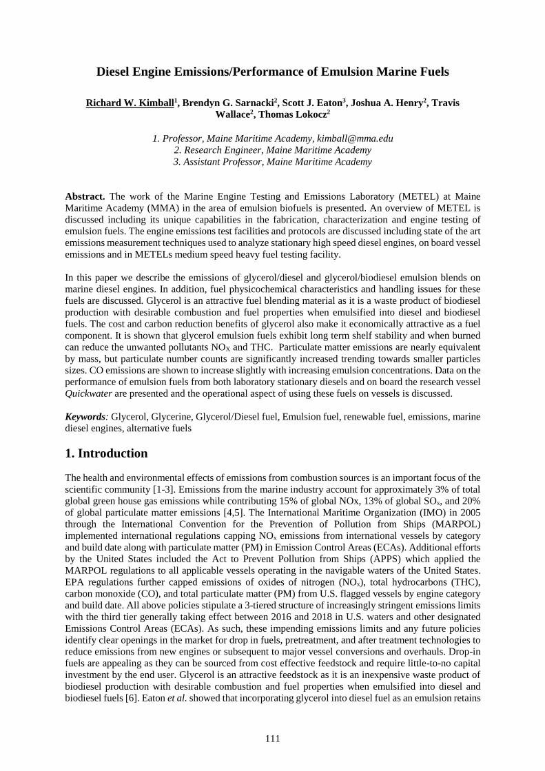
111
Diesel Engine Emissions/Performance of Emulsion Marine Fuels
Richard W. Kimball1, Brendyn G. Sarnacki2, Scott J. Eaton3, Joshua A. Henry2, TravisWallace2, Thomas Lokocz2
1. Professor, Maine Maritime Academy, [email protected]. Research Engineer, Maine Maritime Academy3. Assistant Professor, Maine Maritime Academy
Abstract. The work of the Marine Engine Testing and Emissions Laboratory (METEL) at MaineMaritime Academy (MMA) in the area of emulsion biofuels is presented. An overview of METEL isdiscussed including its unique capabilities in the fabrication, characterization and engine testing ofemulsion fuels. The engine emissions test facilities and protocols are discussed including state of the artemissions measurement techniques used to analyze stationary high speed diesel engines, on board vesselemissions and in METELs medium speed heavy fuel testing facility.
In this paper we describe the emissions of glycerol/diesel and glycerol/biodiesel emulsion blends onmarine diesel engines. In addition, fuel physicochemical characteristics and handling issues for thesefuels are discussed. Glycerol is an attractive fuel blending material as it is a waste product of biodieselproduction with desirable combustion and fuel properties when emulsified into diesel and biodieselfuels. The cost and carbon reduction benefits of glycerol also make it economically attractive as a fuelcomponent. It is shown that glycerol emulsion fuels exhibit long term shelf stability and when burnedcan reduce the unwanted pollutants NOX and THC. Particulate matter emissions are nearly equivalentby mass, but particulate number counts are significantly increased trending towards smaller particlessizes. CO emissions are shown to increase slightly with increasing emulsion concentrations. Data on theperformance of emulsion fuels from both laboratory stationary diesels and on board the research vesselQuickwater are presented and the operational aspect of using these fuels on vessels is discussed.
Keywords: Glycerol, Glycerine, Glycerol/Diesel fuel, Emulsion fuel, renewable fuel, emissions, marinediesel engines, alternative fuels
1. Introduction
The health and environmental effects of emissions from combustion sources is an important focus of thescientific community [1-3]. Emissions from the marine industry account for approximately 3% of totalglobal green house gas emissions while contributing 15% of global NOx, 13% of global SOx, and 20%of global particulate matter emissions [4,5]. The International Maritime Organization (IMO) in 2005through the International Convention for the Prevention of Pollution from Ships (MARPOL)implemented international regulations capping NOx emissions from international vessels by categoryand build date along with particulate matter (PM) in Emission Control Areas (ECAs). Additional effortsby the United States included the Act to Prevent Pollution from Ships (APPS) which applied theMARPOL regulations to all applicable vessels operating in the navigable waters of the United States.EPA regulations further capped emissions of oxides of nitrogen (NOx), total hydrocarbons (THC),carbon monoxide (CO), and total particulate matter (PM) from U.S. flagged vessels by engine categoryand build date. All above policies stipulate a 3-tiered structure of increasingly stringent emissions limitswith the third tier generally taking effect between 2016 and 2018 in U.S. waters and other designatedEmissions Control Areas (ECAs). As such, these impending emissions limits and any future policiesidentify clear openings in the market for drop in fuels, pretreatment, and after treatment technologies toreduce emissions from new engines or subsequent to major vessel conversions and overhauls. Drop-infuels are appealing as they can be sourced from cost effective feedstock and require little-to-no capitalinvestment by the end user. Glycerol is an attractive feedstock as it is an inexpensive waste product ofbiodiesel production with desirable combustion and fuel properties when emulsified into diesel andbiodiesel fuels [6]. Eaton et al. showed that incorporating glycerol into diesel fuel as an emulsion retains
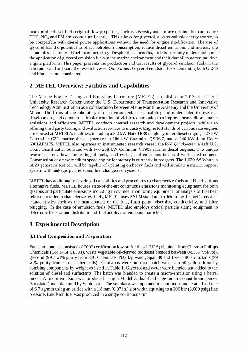
112
many of the diesel fuels original flow properties, such as viscosity and surface tension, but can reduceTHC, NOx and PM emissions significantly. This allows for glycerol, a water-soluble energy source, tobe compatible with diesel power applications without the need for engine modification. The use ofglycerol has the potential to offset petroleum consumption, reduce diesel emissions and increase theeconomics of biodiesel fuel manufacturing. Despite these benefits, little is currently understood aboutthe application of glycerol emulsion fuels in the marine environment and their durability across multipleengine platforms. This paper presents the production and test results of glycerol emulsion fuels in thelaboratory and on board the research vessel Quickwater. Glycerol emulsion fuels containing both ULSDand biodiesel are considered.
2. METEL Overview: Facilities and Capabilities
The Marine Engine Testing and Emissions Laboratory (METEL), established in 2013, is a Tier IUniversity Research Center under the U.S. Department of Transportation Research and InnovativeTechnology Administration as a collaboration between Maine Maritime Academy and the University ofMaine. The focus of the laboratory is on environmental sustainability and is dedicated to research,development, and commercial implementation of viable technologies that improve heavy diesel engineemissions and efficiency. METEL conducts internal research and development projects, while alsooffering third party testing and evaluation services to industry. Engine test stands of various size enginesare housed at METEL’s facilities, including a 5.2 kW Hatz 1B30 single cylinder diesel engine, a 27 kWCaterpillar C2.2 marine diesel generator, a 186 kW Cummins QSB6.7, and a 246 kW John Deere6081AFM75. METEL also operates an instrumented research vessel, the R/V Quickwater, a 41ft U.S.Coast Guard cutter outfitted with two 268 kW Cummins VT903 marine diesel engines. The uniqueresearch asset allows for testing of fuels, load cycles, and emissions in a real world environment.Construction of a new medium speed engine laboratory is currently in progress. The 1,020kW Wartsila6L20 generator test cell will be capable of operating on heavy fuels and will simulate a marine supportsystem with tankage, purifiers, and fuel changeover systems.
METEL has additionally developed capabilities and procedures to characterize fuels and blend variousalternative fuels. METEL houses state-of-the-art continuous emissions monitoring equipment for bothgaseous and particulate emissions including in cylinder monitoring equipment for analysis of fuel heatrelease. In order to characterize test fuels, METEL uses ASTM standards to determine the fuel’s physicalcharacteristics such as the heat content of the fuel, flash point, viscosity, conductivity, and filterplugging. In the case of emulsion fuels, METEL also employs optical particle sizing equipment todetermine the size and distribution of fuel additive or emulsion particles.
3. Experimental Description
3.1 Fuel Composition and Preparation
Fuel components consisted of 2007 certification low-sulfur diesel (ULS) obtained from Chevron PhillipsChemicals (Lot 14GPUL701), waste vegetable oil-derived biodiesel blended between 0-50% (vol/vol),glycerol (99.7 wt% purity from KIC Chemicals, NJ), tap water, Span 80 and Tween 80 surfactants (99wt% purity from Croda Chemicals). Emulsions were prepared batch-wise in a 50 gallon drum bycombing components by weight as listed in Table 1. Glycerol and water were blended and added to thesolution of diesel and surfactants. The batch was blended to create a macro-emulsion using a barrelmixer. A micro-emulsion was produced using a Model A dual-feed edge-tone resonant homogenizer(sonolator) manufactured by Sonic corp. The sonolator was operated in continuous mode at a feed rateof 6.7 kg/min using an orifice with a 1.8 mm (0.07 in.) slot width equating to a 206 bar (3,000 psig) linepressure. Emulsion fuel was produced in a single continuous run.
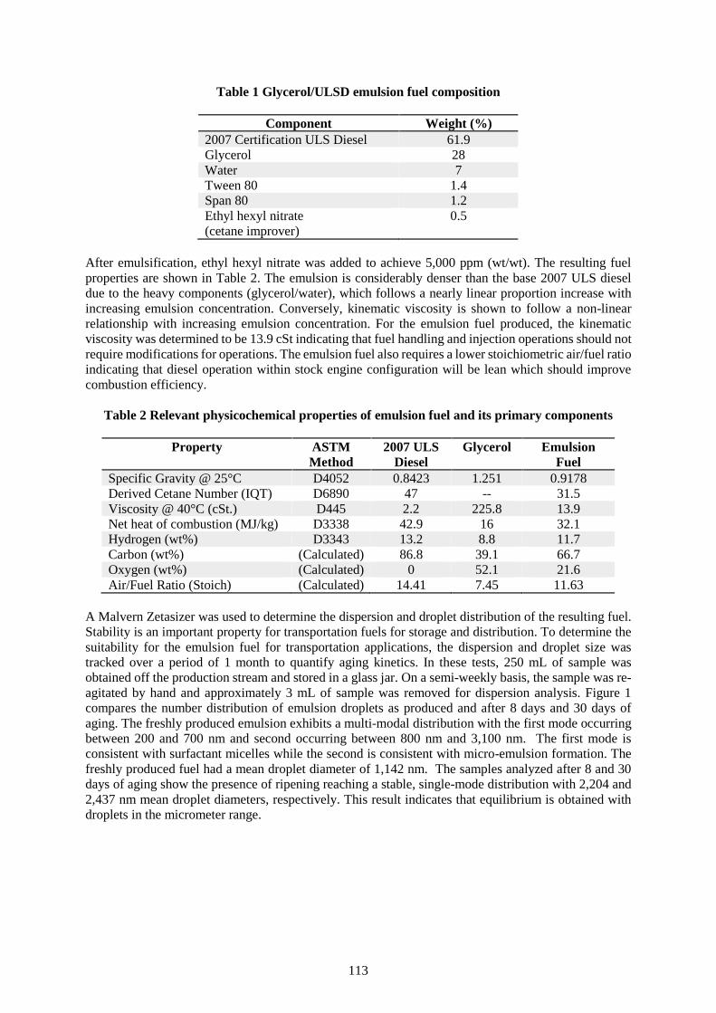
113
Table 1 Glycerol/ULSD emulsion fuel composition
Component Weight (%)2007 Certification ULS Diesel 61.9Glycerol 28Water 7Tween 80 1.4Span 80 1.2Ethyl hexyl nitrate(cetane improver)
0.5
After emulsification, ethyl hexyl nitrate was added to achieve 5,000 ppm (wt/wt). The resulting fuelproperties are shown in Table 2. The emulsion is considerably denser than the base 2007 ULS dieseldue to the heavy components (glycerol/water), which follows a nearly linear proportion increase withincreasing emulsion concentration. Conversely, kinematic viscosity is shown to follow a non-linearrelationship with increasing emulsion concentration. For the emulsion fuel produced, the kinematicviscosity was determined to be 13.9 cSt indicating that fuel handling and injection operations should notrequire modifications for operations. The emulsion fuel also requires a lower stoichiometric air/fuel ratioindicating that diesel operation within stock engine configuration will be lean which should improvecombustion efficiency.
Table 2 Relevant physicochemical properties of emulsion fuel and its primary components
Property ASTMMethod
2007 ULSDiesel
Glycerol EmulsionFuel
Specific Gravity @ 25°C D4052 0.8423 1.251 0.9178Derived Cetane Number (IQT) D6890 47 -- 31.5Viscosity @ 40°C (cSt.) D445 2.2 225.8 13.9Net heat of combustion (MJ/kg) D3338 42.9 16 32.1Hydrogen (wt%) D3343 13.2 8.8 11.7Carbon (wt%) (Calculated) 86.8 39.1 66.7Oxygen (wt%) (Calculated) 0 52.1 21.6Air/Fuel Ratio (Stoich) (Calculated) 14.41 7.45 11.63
A Malvern Zetasizer was used to determine the dispersion and droplet distribution of the resulting fuel.Stability is an important property for transportation fuels for storage and distribution. To determine thesuitability for the emulsion fuel for transportation applications, the dispersion and droplet size wastracked over a period of 1 month to quantify aging kinetics. In these tests, 250 mL of sample wasobtained off the production stream and stored in a glass jar. On a semi-weekly basis, the sample was re-agitated by hand and approximately 3 mL of sample was removed for dispersion analysis. Figure 1compares the number distribution of emulsion droplets as produced and after 8 days and 30 days ofaging. The freshly produced emulsion exhibits a multi-modal distribution with the first mode occurringbetween 200 and 700 nm and second occurring between 800 nm and 3,100 nm. The first mode isconsistent with surfactant micelles while the second is consistent with micro-emulsion formation. Thefreshly produced fuel had a mean droplet diameter of 1,142 nm. The samples analyzed after 8 and 30days of aging show the presence of ripening reaching a stable, single-mode distribution with 2,204 and2,437 nm mean droplet diameters, respectively. This result indicates that equilibrium is obtained withdroplets in the micrometer range.
114
Figure 1 Number distribution of emulsion droplets measured with a Malvern Zetasizer asproduced and after 8 days and 30 days of aging.
Figure 2 presents the growth of mean droplet diameter as a function of time. Average particles diametersare shown to increase over the first week of aging reaching a meta-stable droplet size exceeding 2,000nm. The observations are well captured by a logarithmic rate. To quantify the rate of droplet ripening,the data was fit to a simple step-response model as shown in Equation 1.( ) = 1 − Eq. 1
where S(t) is the mean droplet diameter, is equilibrium droplet diameter (taken at 30 days) and isthe time constant. The rate constant was determined by linear regression and found to be 12.4 days,which provided an adjusted coefficient of determination of 0.56. The fuel stability analysis providesstrong support for the use of emulsion fuels in transportation applications.
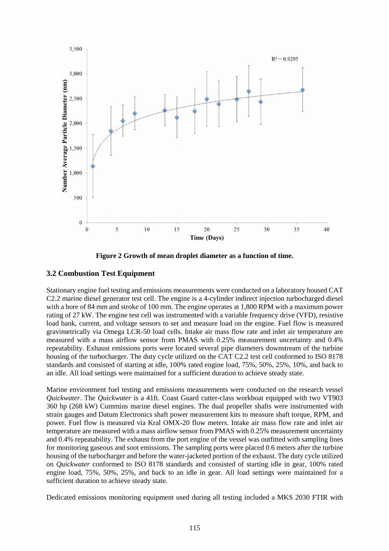
115
Figure 2 Growth of mean droplet diameter as a function of time.
3.2 Combustion Test Equipment
Stationary engine fuel testing and emissions measurements were conducted on a laboratory housed CATC2.2 marine diesel generator test cell. The engine is a 4-cylinder indirect injection turbocharged dieselwith a bore of 84 mm and stroke of 100 mm. The engine operates at 1,800 RPM with a maximum powerrating of 27 kW. The engine test cell was instrumented with a variable frequency drive (VFD), resistiveload bank, current, and voltage sensors to set and measure load on the engine. Fuel flow is measuredgravimetrically via Omega LCR-50 load cells. Intake air mass flow rate and inlet air temperature aremeasured with a mass airflow sensor from PMAS with 0.25% measurement uncertainty and 0.4%repeatability. Exhaust emissions ports were located several pipe diameters downstream of the turbinehousing of the turbocharger. The duty cycle utilized on the CAT C2.2 test cell conformed to ISO 8178standards and consisted of starting at idle, 100% rated engine load, 75%, 50%, 25%, 10%, and back toan idle. All load settings were maintained for a sufficient duration to achieve steady state.
Marine environment fuel testing and emissions measurements were conducted on the research vesselQuickwater. The Quickwater is a 41ft. Coast Guard cutter-class workboat equipped with two VT903360 hp (268 kW) Cummins marine diesel engines. The dual propeller shafts were instrumented withstrain gauges and Datum Electronics shaft power measurement kits to measure shaft torque, RPM, andpower. Fuel flow is measured via Kral OMX-20 flow meters. Intake air mass flow rate and inlet airtemperature are measured with a mass airflow sensor from PMAS with 0.25% measurement uncertaintyand 0.4% repeatability. The exhaust from the port engine of the vessel was outfitted with sampling linesfor monitoring gaseous and soot emissions. The sampling ports were placed 0.6 meters after the turbinehousing of the turbocharger and before the water-jacketed portion of the exhaust. The duty cycle utilizedon Quickwater conformed to ISO 8178 standards and consisted of starting idle in gear, 100% ratedengine load, 75%, 50%, 25%, and back to an idle in gear. All load settings were maintained for asufficient duration to achieve steady state.
Dedicated emissions monitoring equipment used during all testing included a MKS 2030 FTIR with
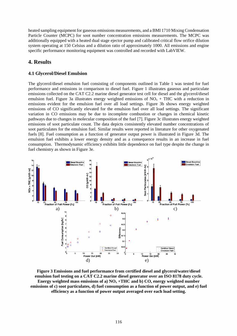
116
heated sampling equipment for gaseous emissions measurements, and a BMI 1710 Mixing CondensationParticle Counter (MCPC) for soot number concentration emissions measurements. The MCPC wasadditionally equipped with a heated dual stage ejector pump and calibrated critical flow orifice dilutionsystem operating at 150 Celsius and a dilution ratio of approximately 1000. All emissions and enginespecific performance monitoring equipment was controlled and recorded with LabVIEW.
4. Results
4.1 Glycerol/Diesel Emulsion
The glycerol/diesel emulsion fuel consisting of components outlined in Table 1 was tested for fuelperformance and emissions in comparison to diesel fuel. Figure 1 illustrates gaseous and particulateemissions collected on the CAT C2.2 marine diesel generator test cell for diesel and the glycerol/dieselemulsion fuel. Figure 3a illustrates energy weighted emissions of NOx + THC with a reduction inemissions evident for the emulsion fuel over all load settings. Figure 3b shows energy weightedemissions of CO significantly elevated for the emulsion fuel over all load settings. The significantvariation in CO emissions may be due to incomplete combustion or changes in chemical kineticpathways due to changes in molecular composition of the fuel [7]. Figure 3c illustrates energy weightedemissions of soot particulate count. The data depicts consistently elevated number concentrations ofsoot particulates for the emulsion fuel. Similar results were reported in literature for other oxygenatedfuels [8]. Fuel consumption as a function of generator output power is illustrated in Figure 3d. Theemulsion fuel exhibits a lower energy density and as a consequence results in an increase in fuelconsumption. Thermodynamic efficiency exhibits little dependence on fuel type despite the change infuel chemistry as shown in Figure 3e.
a) b) c)
d) e)
Figure 3 Emissions and fuel performance from certified diesel and glycerol/water/dieselemulsion fuel testing on a CAT C2.2 marine diesel generator over an ISO 8178 duty cycle.
Energy weighted mass emissions of a) NOx +THC and b) CO, energy weighted numberemissions of c) soot particulates, d) fuel consumption as a function of power output, and e) fuel
efficiency as a function of power output averaged over each load setting.
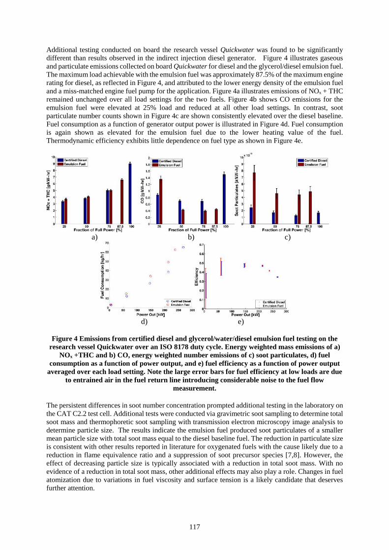
117
Additional testing conducted on board the research vessel Quickwater was found to be significantlydifferent than results observed in the indirect injection diesel generator. Figure 4 illustrates gaseousand particulate emissions collected on board Quickwater for diesel and the glycerol/diesel emulsion fuel.The maximum load achievable with the emulsion fuel was approximately 87.5% of the maximum enginerating for diesel, as reflected in Figure 4, and attributed to the lower energy density of the emulsion fueland a miss-matched engine fuel pump for the application. Figure 4a illustrates emissions of NOx + THCremained unchanged over all load settings for the two fuels. Figure 4b shows CO emissions for theemulsion fuel were elevated at 25% load and reduced at all other load settings. In contrast, sootparticulate number counts shown in Figure 4c are shown consistently elevated over the diesel baseline.Fuel consumption as a function of generator output power is illustrated in Figure 4d. Fuel consumptionis again shown as elevated for the emulsion fuel due to the lower heating value of the fuel.Thermodynamic efficiency exhibits little dependence on fuel type as shown in Figure 4e.
a) b) c)
d) e)
Figure 4 Emissions from certified diesel and glycerol/water/diesel emulsion fuel testing on theresearch vessel Quickwater over an ISO 8178 duty cycle. Energy weighted mass emissions of a)
NOx +THC and b) CO, energy weighted number emissions of c) soot particulates, d) fuelconsumption as a function of power output, and e) fuel efficiency as a function of power output
averaged over each load setting. Note the large error bars for fuel efficiency at low loads are dueto entrained air in the fuel return line introducing considerable noise to the fuel flow
measurement.
The persistent differences in soot number concentration prompted additional testing in the laboratory onthe CAT C2.2 test cell. Additional tests were conducted via gravimetric soot sampling to determine totalsoot mass and thermophoretic soot sampling with transmission electron microscopy image analysis todetermine particle size. The results indicate the emulsion fuel produced soot particulates of a smallermean particle size with total soot mass equal to the diesel baseline fuel. The reduction in particulate sizeis consistent with other results reported in literature for oxygenated fuels with the cause likely due to areduction in flame equivalence ratio and a suppression of soot precursor species [7,8]. However, theeffect of decreasing particle size is typically associated with a reduction in total soot mass. With noevidence of a reduction in total soot mass, other additional effects may also play a role. Changes in fuelatomization due to variations in fuel viscosity and surface tension is a likely candidate that deservesfurther attention.
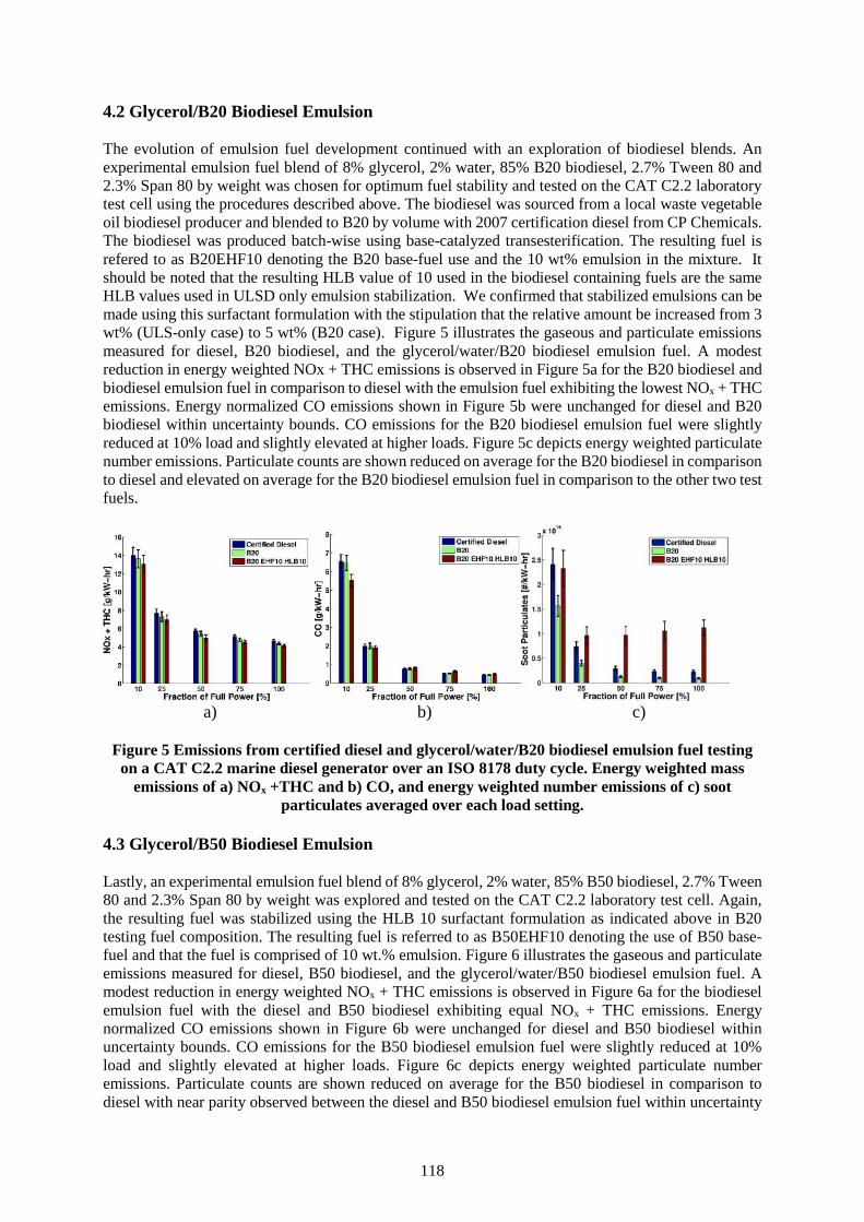
118
4.2 Glycerol/B20 Biodiesel Emulsion
The evolution of emulsion fuel development continued with an exploration of biodiesel blends. Anexperimental emulsion fuel blend of 8% glycerol, 2% water, 85% B20 biodiesel, 2.7% Tween 80 and2.3% Span 80 by weight was chosen for optimum fuel stability and tested on the CAT C2.2 laboratorytest cell using the procedures described above. The biodiesel was sourced from a local waste vegetableoil biodiesel producer and blended to B20 by volume with 2007 certification diesel from CP Chemicals.The biodiesel was produced batch-wise using base-catalyzed transesterification. The resulting fuel isrefered to as B20EHF10 denoting the B20 base-fuel use and the 10 wt% emulsion in the mixture. Itshould be noted that the resulting HLB value of 10 used in the biodiesel containing fuels are the sameHLB values used in ULSD only emulsion stabilization. We confirmed that stabilized emulsions can bemade using this surfactant formulation with the stipulation that the relative amount be increased from 3wt% (ULS-only case) to 5 wt% (B20 case). Figure 5 illustrates the gaseous and particulate emissionsmeasured for diesel, B20 biodiesel, and the glycerol/water/B20 biodiesel emulsion fuel. A modestreduction in energy weighted NOx + THC emissions is observed in Figure 5a for the B20 biodiesel andbiodiesel emulsion fuel in comparison to diesel with the emulsion fuel exhibiting the lowest NOx + THCemissions. Energy normalized CO emissions shown in Figure 5b were unchanged for diesel and B20biodiesel within uncertainty bounds. CO emissions for the B20 biodiesel emulsion fuel were slightlyreduced at 10% load and slightly elevated at higher loads. Figure 5c depicts energy weighted particulatenumber emissions. Particulate counts are shown reduced on average for the B20 biodiesel in comparisonto diesel and elevated on average for the B20 biodiesel emulsion fuel in comparison to the other two testfuels.
a) b) c)
Figure 5 Emissions from certified diesel and glycerol/water/B20 biodiesel emulsion fuel testingon a CAT C2.2 marine diesel generator over an ISO 8178 duty cycle. Energy weighted mass
emissions of a) NOx +THC and b) CO, and energy weighted number emissions of c) sootparticulates averaged over each load setting.
4.3 Glycerol/B50 Biodiesel Emulsion
Lastly, an experimental emulsion fuel blend of 8% glycerol, 2% water, 85% B50 biodiesel, 2.7% Tween80 and 2.3% Span 80 by weight was explored and tested on the CAT C2.2 laboratory test cell. Again,the resulting fuel was stabilized using the HLB 10 surfactant formulation as indicated above in B20testing fuel composition. The resulting fuel is referred to as B50EHF10 denoting the use of B50 base-fuel and that the fuel is comprised of 10 wt.% emulsion. Figure 6 illustrates the gaseous and particulateemissions measured for diesel, B50 biodiesel, and the glycerol/water/B50 biodiesel emulsion fuel. Amodest reduction in energy weighted NOx + THC emissions is observed in Figure 6a for the biodieselemulsion fuel with the diesel and B50 biodiesel exhibiting equal NOx + THC emissions. Energynormalized CO emissions shown in Figure 6b were unchanged for diesel and B50 biodiesel withinuncertainty bounds. CO emissions for the B50 biodiesel emulsion fuel were slightly reduced at 10%load and slightly elevated at higher loads. Figure 6c depicts energy weighted particulate numberemissions. Particulate counts are shown reduced on average for the B50 biodiesel in comparison todiesel with near parity observed between the diesel and B50 biodiesel emulsion fuel within uncertainty
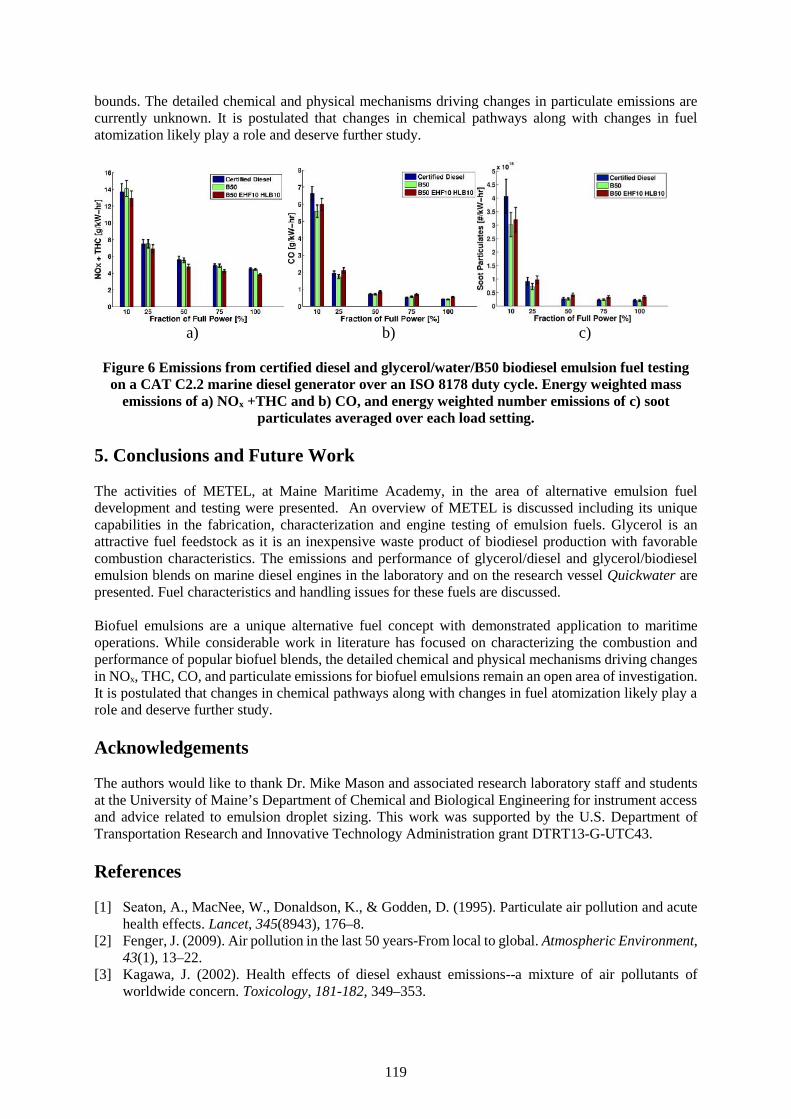
119
bounds. The detailed chemical and physical mechanisms driving changes in particulate emissions arecurrently unknown. It is postulated that changes in chemical pathways along with changes in fuelatomization likely play a role and deserve further study.
a) b) c)
Figure 6 Emissions from certified diesel and glycerol/water/B50 biodiesel emulsion fuel testingon a CAT C2.2 marine diesel generator over an ISO 8178 duty cycle. Energy weighted mass
emissions of a) NOx +THC and b) CO, and energy weighted number emissions of c) sootparticulates averaged over each load setting.
5. Conclusions and Future Work
The activities of METEL, at Maine Maritime Academy, in the area of alternative emulsion fueldevelopment and testing were presented. An overview of METEL is discussed including its uniquecapabilities in the fabrication, characterization and engine testing of emulsion fuels. Glycerol is anattractive fuel feedstock as it is an inexpensive waste product of biodiesel production with favorablecombustion characteristics. The emissions and performance of glycerol/diesel and glycerol/biodieselemulsion blends on marine diesel engines in the laboratory and on the research vessel Quickwater arepresented. Fuel characteristics and handling issues for these fuels are discussed.
Biofuel emulsions are a unique alternative fuel concept with demonstrated application to maritimeoperations. While considerable work in literature has focused on characterizing the combustion andperformance of popular biofuel blends, the detailed chemical and physical mechanisms driving changesin NOx, THC, CO, and particulate emissions for biofuel emulsions remain an open area of investigation.It is postulated that changes in chemical pathways along with changes in fuel atomization likely play arole and deserve further study.
Acknowledgements
The authors would like to thank Dr. Mike Mason and associated research laboratory staff and studentsat the University of Maine’s Department of Chemical and Biological Engineering for instrument accessand advice related to emulsion droplet sizing. This work was supported by the U.S. Department ofTransportation Research and Innovative Technology Administration grant DTRT13-G-UTC43.
References
[1] Seaton, A., MacNee, W., Donaldson, K., & Godden, D. (1995). Particulate air pollution and acutehealth effects. Lancet, 345(8943), 176–8.
[2] Fenger, J. (2009). Air pollution in the last 50 years-From local to global. Atmospheric Environment,43(1), 13–22.
[3] Kagawa, J. (2002). Health effects of diesel exhaust emissions--a mixture of air pollutants ofworldwide concern. Toxicology, 181-182, 349–353.

120
[4] Smith, T. W. P., Jalkanen, J. P., Anderson, B. A., Corbett, J. J., Faber, J., Hanayama, S., … Pandey,A. (n.d.). Third IMO GHG Study 2014. London, UK.
[5] Environmental Protection Agency. (2012). Report to Congress on Black Carbon. Washington DC.[6] Eaton, S.J., Harakas, G.N., Kimball, R.W., Smith, J.A., Pilot, K.A., Kuflik, M.T. & Bullard, J.M.
(2014). Formulation and Combustion of Glycerol-Diesel Fuel Emulsions. Energy & Fuels, 28,3940-3947
[7] Westbrook, C. K., Pitz, W. J., & Curran, H. J. (2006). Chemical Kinetic Modeling Study of theEffects of Oxygenated Hydrocarbons on Soot Emissions from Diesel Engines †. The Journal ofPhysical Chemistry A, 110(21), 6912–6922.
[8] Song, J., Cheenkachorn, K., Wang, J., Perez, J., Boehman, L., Young, P. J., & Waller, F. J. (2002).Effect of Oxygenated Fuel on Combustion and Emissions in a Light-Duty Turbo Diesel Engine.Energy & Fuels, 16(2), 294–301.
121
Validation and calibration of diesel engine model using DME
(Assoc. Prof. Luong Cong Nho, Dr. Nguyen Lan Huong)1, (Assoc. Prof. Pham Huu Tuyen)2
1. Vietnam Maritime University, Email: [email protected], 484 Lach Tray street, Ngo Quyendistrict, Hai Phong, Vietnam
2. Hanoi University of Science and Technology
Abstract Diesel engines are utilized in most of heavy duty vehicles due to their high efficiency andperformance. However, fossil fuel is being depleted currently, and emissions from diesel engine containsmany toxic substances such as CO, HC, NOx, PM…which effect adversely on environment and humanhealth. Therefore, research and application of renewable alternative fuels are under consideration inmany countries and Vietnam as well. Recently, Dimethyl ether (DME) has been considered as a potentialalternative fuel for diesel engine. DME can be produced from a variety of raw materials such as biomass,coal and natural gas. It is also easy to liquefy and suitable to use in diesel engines. DME is not a natureproduct but a synthetic product is produced either through the dehydration of methanol or a directsynthesis from syngas. Using DME for diesel engine may reduce not only dependence on fossil fuel butalso environmental pollution. Certain amounts of DME have been commercially produced as apropellant for spray cans because of its non-toxicity and suitable solubility and vapor pressure at roomtemperature. Some experimental investigations were conducted on diesel engine to clarify how DMEinjection characteristics affect the engine performance and exhaust emissions. Most of the resultsshowed that emissions when fueled DME reduced significantly, especially CO and soot.
This paper presents a validation and calibration of diesel engine model fueled by DME. The engine wasmodeled by AVL Boost software and validated by experience. The parameters related to combustionprocess, for example ignition delay, combustion parameters, were calibrated and the effects of theseparameterson performance of diesel engine fueled by DME were studied. Results show that in case ofthe same engine power the ignition delay calibration factor with DME can be chosen value of 1.37 whileit is 1 with diesel.
Keywords: Dimethyl ether, engine simulation, combustion parameter, ignition delay calibration factor.
1. Introduction
Nowadays, research and utilization of renewable fuels in order to ensure energy security and reducepollution emissions are of interest in many countries. Among these fuels, Dimethyl Ether (DME) is afriendly - environment fuel, easy to liquefy and suitable for use in diesel engines.
DME, chemical formula is CH3-O-CH3, is a colorless organic compound. DME is in gaseous form atambient pressure and temperature. To increase the energy density, DME is usually stored in liquid formunder compressed pressure of 7 to 10bar. DME can be produced from a variety of raw materials such asbiomass, coal and natural gas and it is considered as a clean alternative fuel in near future. Using DMEfor diesel engine may reduce not only dependence on fossil fuel but also environmental pollution. DMEis not a nature product but a synthetic product is produced either through the dehydration of methanolor a direct synthesis from syngas. Most of the results showed that emissions when fueled DME reducedsignificantly, especially CO and soot.
This paper presents a validation and calibration of diesel engine model fueled by DME. Diesel engineKubota RT140 is modeled by using AVL Boost software and validated by experience.
2. Modeling theory
2.1 Combustion model
122
1 2. ( , ). ( , )MCCComb F MCC
dQC f m Q f k V
d
2 3( , ) .Rate
kf k V C
V
,
.
1Diff
turb kin
F I stoich
C Ek
m m
The combustion in diesel engine can be considered by two processes: premixed combustion and mixing
controled combustion processes
total MCC PMCdQ dQ dQ
d d d
Qtotal: total heat release over the combustion process [kJ].
QPMC : total fuel heat input for the premixed combustion [kJ]
QMCC: cumulative heat release for the mixture controlled combustion [kJ]
Premixed combustion model:
A Vibe function is used to describe the actual heat release due to the premixed combustion:
( 1).. 1 . .m
PMC
PMC m a y
c
dQ
Q am y e
d
, id
c
y
QPMC : total fuel heat input for the premixed combustion = mfuel,id . CPMC
mfuel,id : total amount of fuel injected during the ignition delay phase
CPMC: premixed combustion parameter
∆αc : premixed combustion duration= id.CPMC-Dur
CPMC-Dur : premixed combustion duration factor
m : shape parameter m=2.0
a : Vibe parameter a= 6.9
- Mixing Controlled Combustion process:
In this regime the heat release is a function of the fuel quantity available (f1) and the
turbulent kinetic energy density (f2):
with
𝑓1(𝑚𝐹 , 𝑄) = (𝑚𝐹 −𝑄𝑀𝐶𝐶
𝐿𝐶𝑉) . (𝑤𝑂𝑥𝑦𝑔𝑒𝑛,𝑎𝑣𝑎𝑖𝑙𝑎𝑏𝑙𝑒)
𝐶𝐸𝐺𝑅
CComb : combustion constant [kJ/kg/deg CA]
CRate: mixing rate constant [s]
k : local density of turbulent kinetic energy [m2/s2]
mF:vaporized fuel mass (actual) [kg]
LVC: lower heating value[kJ/kg]
V: cylinder volume [m3]
α : crank angle [deg CA]
wOxygen,available: mass fraction of available Oxygen (aspirated and in EGR) at SOI [-]
CEGR EGR influent constant [-]
123
Ekin : kinetic jet energy [J]Cturb : turbulent energy production constant [-]
F,I : injection fuel mass (actual) [kg]Diff : Air Excess Ratio for diffusion burning [-]
mstoich :stoichiometric mass of fresh charge [kg/kg]
2.2 Heat transfer model
The heat transfer to the walls of the combustion chamber, i.e. the cylinder head, the piston, and thecylinder liner, is calculated from equation [3]
( )Q A T Tcwi i i wi
Where Qwi - wall heat flow, Ai - surface area, αi - heat transfer coefficient, Tc - gas temperature in thecylinder, Twi - wall temperature.
Heat transfer coefficient (αi) is usually calculated by WOSCHNI Model, The Woschni model publishedin 1978 for the high pressure cycle is summarized as follows [6]:
0,2 0,8 0,53130. . . .
. 0,81 .[ . . .( )]1 2 ,0.,1 ,1
D p Tw c cv TD cC c C p pm c cp Vc c
Where C1 = 2.28 + 0.308.cu/cm, C2 = 0,00324 for DI engines, D - cylinder bore, cm - mean piston speed,cu - circumferential velocity, cu = π.D.nd/60, VD - displacement per cylinder, pc,o - cylinder pressure ofthe motored engine (bar), Tc,1 - temperature in the cylinder at intake valve closing (IVC) , pc,1 - pressurein the cylinder at IVC (bar).
2.3 Modeling diesel engine Kubota RT140
Kubota RT140 Engine is a single horizontal cylinder, four-stroke, naturally aspirated, water cooled, DI.The engine specification is shown in Table 3, and the model is built by AVL Boost software(Figure 1)
Table 3 Specifications of the engine
Table. 3 Specifications of the engineRating outputMaximum torqueBore / StrokeSwept volumeCompression ratioInjection pressureNozzle number x orificediameter/ mmStatic injection timing
11kW at 2400 rpm42 Nm at 1500 rpm97/96 mm709 cm3
18:1240 bar4 x 0.30
25 CA BTDC
m
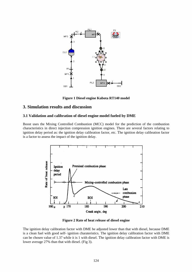
124
Figure 1 Diesel engine Kubota RT140 model
3. Simulation results and discussion
3.1 Validation and calibration of diesel engine model fueled by DME
Boost uses the Mixing Controlled Combustion (MCC) model for the prediction of the combustioncharacteristics in direct injection compression ignition engines. There are several factors relating toignition delay period as: the ignition delay calibration factor, etc. The ignition delay calibration factoris a factor to assess the impact of the ignition delay.
Figure 2 Rate of heat release of diesel engine
The ignition delay calibration factor with DME be adjusted lower than that with diesel, because DMEis a clean fuel with good self- ignition charateristics. The ignition delay calibration factor with DMEcan be chosen value of 1.37 while it is 1 with diesel. The ignition delay calibration factor with DME islower average 27% than that with diesel. (Fig 3).
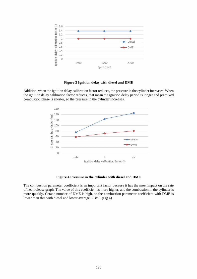
125
Figure 3 Ignition delay with diesel and DME
Addition, when the ignition delay calibration factor reduces, the pressure in the cylinder increases. Whenthe ignition delay calibration factor reduces, that mean the ignition delay period is longer and premixedcombustion phase is shorter, so the pressure in the cylinder increases.
Figure 4 Pressure in the cylinder with diesel and DME
The combustion parameter coefficient is an important factor because it has the most impact on the rateof heat release graph. The value of this coefficient is more higher, and the combustion in the cylinder ismore quickly. Cetane number of DME is high, so the combustion parameter coefficient with DME islower than that with diesel and lower average 68.8%. (Fig 4)
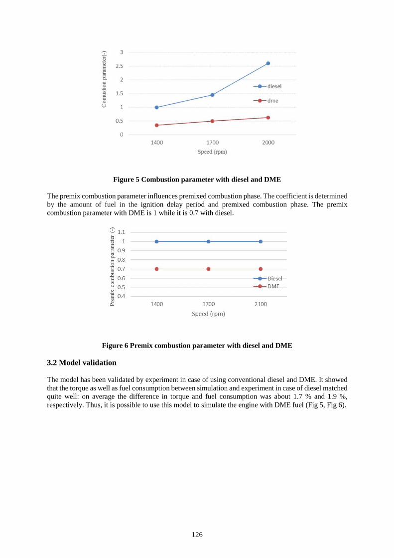
126
Figure 5 Combustion parameter with diesel and DME
The premix combustion parameter influences premixed combustion phase. The coefficient is determinedby the amount of fuel in the ignition delay period and premixed combustion phase. The premixcombustion parameter with DME is 1 while it is 0.7 with diesel.
Figure 6 Premix combustion parameter with diesel and DME
3.2 Model validation
The model has been validated by experiment in case of using conventional diesel and DME. It showedthat the torque as well as fuel consumption between simulation and experiment in case of diesel matchedquite well: on average the difference in torque and fuel consumption was about 1.7 % and 1.9 %,respectively. Thus, it is possible to use this model to simulate the engine with DME fuel (Fig 5, Fig 6).
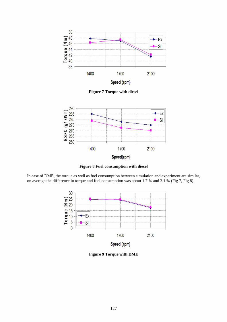
127
Figure 7 Torque with diesel
Figure 8 Fuel consumption with diesel
In case of DME, the torque as well as fuel consumption between simulation and experiment are similar,on average the difference in torque and fuel consumption was about 1.7 % and 3.1 % (Fig 7, Fig 8).
Figure 9 Torque with DME
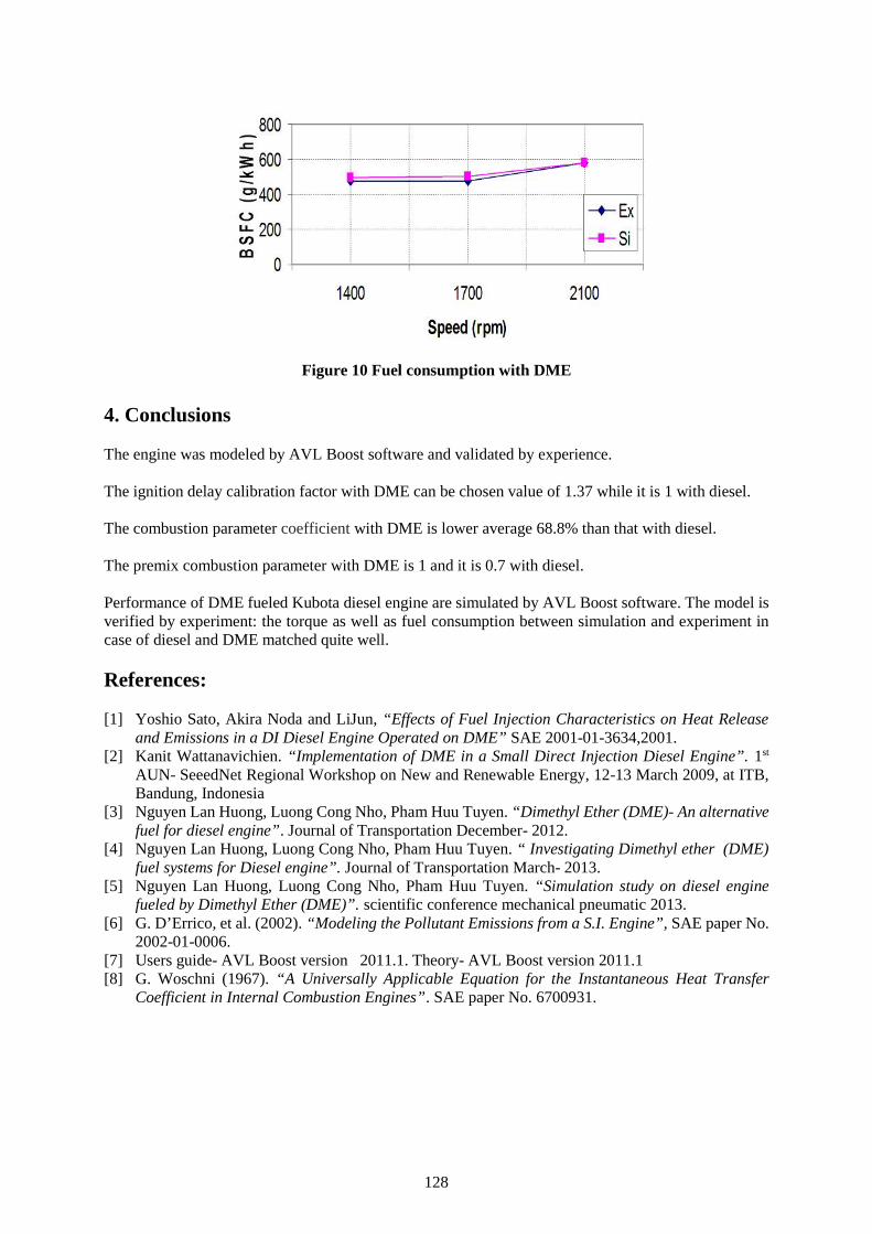
128
Figure 10 Fuel consumption with DME
4. Conclusions
The engine was modeled by AVL Boost software and validated by experience.
The ignition delay calibration factor with DME can be chosen value of 1.37 while it is 1 with diesel.
The combustion parameter coefficient with DME is lower average 68.8% than that with diesel.
The premix combustion parameter with DME is 1 and it is 0.7 with diesel.
Performance of DME fueled Kubota diesel engine are simulated by AVL Boost software. The model isverified by experiment: the torque as well as fuel consumption between simulation and experiment incase of diesel and DME matched quite well.
References:
[1] Yoshio Sato, Akira Noda and LiJun, “Effects of Fuel Injection Characteristics on Heat Releaseand Emissions in a DI Diesel Engine Operated on DME” SAE 2001-01-3634,2001.
[2] Kanit Wattanavichien. “Implementation of DME in a Small Direct Injection Diesel Engine”. 1st
AUN- SeeedNet Regional Workshop on New and Renewable Energy, 12-13 March 2009, at ITB,Bandung, Indonesia
[3] Nguyen Lan Huong, Luong Cong Nho, Pham Huu Tuyen. “Dimethyl Ether (DME)- An alternativefuel for diesel engine”. Journal of Transportation December- 2012.
[4] Nguyen Lan Huong, Luong Cong Nho, Pham Huu Tuyen. “ Investigating Dimethyl ether (DME)fuel systems for Diesel engine”. Journal of Transportation March- 2013.
[5] Nguyen Lan Huong, Luong Cong Nho, Pham Huu Tuyen. “Simulation study on diesel enginefueled by Dimethyl Ether (DME)”. scientific conference mechanical pneumatic 2013.
[6] G. D’Errico, et al. (2002). “Modeling the Pollutant Emissions from a S.I. Engine”, SAE paper No.2002-01-0006.
[7] Users guide- AVL Boost version 2011.1. Theory- AVL Boost version 2011.1[8] G. Woschni (1967). “A Universally Applicable Equation for the Instantaneous Heat Transfer
Coefficient in Internal Combustion Engines”. SAE paper No. 6700931.
129
Session 2A
MARITIME EDUCATION AND TRAINING
(No. 2)
130
Trends in the development of maritime education:prospects and proposals
Irina Makashina
DSc., Professor of the English Department, Director of International Education Center ofAdmiral Ushakov Maritime State University, Novorossiysk, Russia
e-mail: [email protected]
Abstract. Maritime Education and Training is an essential factor for the contribution to the sustainablemaritime development. The article reveals the basic trends in the development of maritime education. Itis shown that the need to study and scientific understanding of the processes taking place in the spaceof maritime education, is determined by increasing the Convention's requirements, the new educationalstandards of professional maritime education, needs of society, the state and the merchant shippingindustry. Maritime branch can be adequately updated and maintained only through effective maritimeeducation and training.
This paper shows that a change in educational purposes causes a change in the content of the training,as well as methods of teaching and carrying out control and assessment procedures. In this regard, thesystem of technological criteria of professional training in maritime education is proposed andsubstantiated.
As an example of the expansion of educational opportunities the new educational project is offered. ThisProject implementation can be considered as an opportunity and platform for developing the mechanismfor regular exchange and valuable discussion by maritime educators from different regions, who areready to share and cooperate during workshops in favour of Maritime Education and Training, andMaritime industry.
The originality of the idea of the proposed Project corresponds with IAMU goal to invite new potentialmembers, including different representatives of maritime industry and provide the opportunity not onlyto strengthen connections among IAMU Members, by enhancing the sharing of experience andknowledge, but also to promote the next step of maritime education evolution.
Key words: maritime education, educational space, poly-profiled and communicative competence,maritime transport.
1. Introduction
Maritime education is a complex, multilevel process, presuming the interaction of closely linkedquantitative and qualitative transformations and at the same time the result of a long historical,economic, and spiritual coexistence and interaction of participants of the Global Maritime educationalcommunity.
The issues of Maritime education development do not cease to be urgent, as it covers the complexrelationship of education, social and economic environment and society. Its unity has become essential,because there is a process of integration of all components of the Maritime transport sector at differentlevels. This process leads to the enrichment of each component in the existing system, to an appearancein it of new, integrative features. One of such components is marine education, with its new quality –poly-functionality.
131
2. Poly-functionality of Maritime Education
Poly-functionality of Maritime Education is both the process and the result acting as a resource ofoptimization of Maritime transportation industry. Level and quality of Maritime education in muchdetermine the state of the sea industry. Maritime education at the present stage includes severalfunctional tendencies: organizational, social, informational, communicative, preventive, analytical andpredictive, etc.
The quality of implementation of these tendencies depends heavily on the diversification of maritimeeducation, involving the organization of the learning process and the result of poly-functional, poly-profile training of future specialists for professional activity using of hierarchical training system [3, pp.107-108]. This approach to the training process allows providing future specialist with extra opportunityof choosing personal and professional vector of their development.
Peculiarities of the multi-level system of marine specialist training in modern maritime universityinclude: a high degree of unification of curricula in profiles and specialties of higher and secondarymaritime professional education and a combination of broad basic training with subsequentspecialization. At the same time, the global Maritime community imposes new requirements to thetraining of seafarers, and provides for new types of practical training that, in turn, necessitatesoptimization of the existing multi-level system of professional Maritime education.
When designing maritime educational space it is necessary to account the multisided nature of anactivity of a maritime specialist. Analysis of the Manila amendments to the STCW Convention-78/95,adopted in 2010 showed that the standards of competence of all crew members introduced newcompetencies, knowledge and skills, providing different types of training caused by the introduction ofmodern new technologies and sophisticated equipment on ships. Also a step was made in the directionof development at sailors of non-technical skills, namely leadership features and ability to work in ateam [1]. Such ability often becomes decisive in professional situations.
Such changes have already been reflected in the content of Maritime education, but not always at aproper level. In this aspect application of the poly-profile and communicative approach to the selectionof content of maritime education can be useful and urgent. This approach presumes analysis of cognitivetasks, industrial and cultural characteristics of partners, including foreign ones, and organization of thecommunicative actions of all participants of solution and realization of set tasks [3, pp. 43-45].
Application of poly-profile and communicative approach to the selection and optimization of the contentof education of future maritime specialists provides: systematic construction of the entire educationalprocess; generalization and systematization of the training content, its components, reflecting poly-profile character of specialists’ relations; continuity at all stages of lifelong learning; use of inter-subjectlinks in the constructing of integrated training programs [3, p. 13].
At present the best maritime specialists are considered as complicated managers possessing poly-profileknowledge. The content of their education must be aimed at permanent accumulation at them essentialprofessional features that adequately reflect the specificity of the nature of professionalism andformation of poly-profile and communicative competence, i.e. the integral abilities, consisting ofnumber of competences of specialists of different professions, but included in the same professionalfield [3, p. 202]. Poly-functionality as a specialist’s characteristic must be included in the content ofeducation that further will provide him the different directions of development, depending on hisabilities, desires and possibilities.
The development of poly-functional Maritime training assumes performing actions representing certainstages of its functioning and development. Each stage differs qualitatively by new state of theeducational process and people included in it. Such actions include:
132
– career-guidance work, which allow attract to universities only concerned entrants, not thosewho are not interested in a specific specialty, but only the possibility of training on a budgetarybasis (maritime education in Russia in much is on budget ground);
– investigating of factors influencing the Maritime education content and consideration ofeconomic and legal conditions for the functioning of educational institutions and possiblechanges in the prospective period;
– implementation of innovative models of functioning of Maritime Universities andimprovement of their departments management systems;
– introduction updated educational technologies in educational process; creation of digital,interactive textbooks and manuals in accordance with international and national requirements,as well as programs and integrated courses having poly-profile character, with subsequentorganization of poly-profile practices at different companies in the industry or in differentdepartments in accordance with the program;
– study and use of best experience, including international one with the aim of improving boththe quality of education, and external academic mobility of students and members of teachingstaff of Maritime Universities;
– creation of legal support of simulator training, and improving the organization of industrialpractice and training on ships and at the shore companies, both national and foreign, providingregular financial support of this practice;
– providing conditions for increasing scientific potential of Maritime Universities and supportthe development of young scientific and pedagogical staff, and also attraction of students toperformance of research work and the preparation of scientific projects;
– further development of the system of continuous education, reflecting the continuity of basic,secondary and higher professional education with the use of reduced terms of training,especially for graduates of the branch colleges in universities in their field, where they mustundergo the full training period;
– formation and support of different forms of cooperation with employers (target training,seminars, conferences, involvement of customers in the structure of the University, forexample, in a methodical Committees or boards of Trustees, development of proposals onimproving the procedures of licensing of educational activity and state accreditation ofMaritime universities engaged in Maritime specialists’ training process;
– regular monitoring of the demand for Maritime specialists of any rank on domestic andinternational labour market and improving the planning of volume of their training for theMaritime industry;
– development and implementation of programs of support of cadets at the stage of theirprofessional adaptation, the revival of mentoring and internship programs;
– raising the prestige of teaching activities and involvement employees working in the Merchantshipping branch in the educational process, etc.;
– wide extending of distance learning as alternative method of learning and teaching in MET.Implementation of these tools enables education institutions to provide a range of programsfor seafarers. Successful delivery of distance learning provides more and more educationalopportunities.
In this connection while developing content for distance learning the following factors should be takeninto consideration: targeted competencies and outcomes; profiles of the different learning cohorts andtheir requirements and limitations; understanding the impediments to the learning; time and cost ofdeveloping the learning resources and the availability and access to the associated systems to deliverthem, etc. [2, p. 210].
Networked learning, which allows connecting learning spaces, flexible learning programs and tools andhybrid learning, combining different methods of teaching have already enlarged existing learningopportunities and have further prospects.
133
3. Factors influencing quality of Maritime education
Consideration of the development trends in Maritime education involves the significant expansion of itsdiversification opportunities: different training period, forms, technologies, methods and means ofteaching. But it is necessary to take into account external and internal factors that influence the qualityof Maritime education, among which the following are:
1) changing of geopolitical and economic conditions of international integration with theirdetermining influence on the competitiveness of specialists on the international labour market;
2) constantly increasing requirements of Federal Educational Standards of Higher Education tothe level of marine expert training and Conventional requirements including the Manilaamendments as well as current requirements, regularly published by the International MaritimeOrganization [1];
3) continued growth of accidents in the Maritime transport sector;4) significant damage to the environment due to the increase of major disasters;5) continuous development of technologies and their implementation on ships and in shore
structures industry;6) the best experience of Maritime universities, including foreign ones etc. [5; 7; 8; 9].
Accounting the external factors and specific conditions of implementation of marine education allowsbuild a productive educating process, and plan and implement interaction with shipping industry.Internal factors, reflecting the nature of the industry are generated by combining the individual systemelements. Their influence determines the operation and effectiveness of the poly-profiled training offuture Maritime experts.
Change, or rather an adjustment of the educational purposes causes a change in the substantial part ofthe training and teaching methods, and conducting monitoring and evaluation procedures. Training ofspecialists working in a branch Universities is of particular importance. In this regard, we propose asystem of technological criteria of quality of industry training of teachers (lecturers, instructors) workingin the system of Maritime education. These criteria include:
– expediency, presuming the training corresponding to updated requirements of merchantshipping industry to the level of knowledge of Maritime specialists;
– poly-profileness, including not only knowledge of a certain specialty, but also profilesinvolved in the production of merchant shipping;
– diversification, supposing a variety of ways, methods and means of presentation of educationalmaterial;
– succession, namely, a) rationality of the choice of methods, forms and means of training; b)identification of the most effective teaching techniques; c) timely replacement of obsoleteitems of operational component of the learning process; d) maintaining of the above elements,which have stood the test of time and proven to be effective.
– coherence, involving continuous coordination of educational programs with accounting newmodel courses approved by the IMO and compliance with requirements of national andConventional educational standards.
Accounting of technological criteria of industry training of lecturers, instructors, which train marineprofessionals, contribute to the definition of technology of acquiring of special subjects.
4. International cooperation as resource of development of maritime space
While considering tendencies of Maritime education development as a resource of industry optimizationit is necessary to point out the international partnership as one of the important aspects. In Maritimeeducation this component plays a special role that is stipulated by the international character of Maritimeactivities. It is well aware that international links in educational space of Maritime University arenecessary to ensure the training of future marine specialists to contacts with foreign partners,
134
coordination of related industrial activity and acquiring value orientations prevailing in the world, topreparation for inclusion in international programs, projects and etc.
In this regard, activities of such international associations as IAMU, IMLA, BSAMI, etc. are of greatimportance.Admiral Ushakov Maritime State University (Russia, Novorossiysk) proposed some educationalprojects, the implementation of which contributes and will contribute in the further to the developmentof international Maritime educational space [4; 6; 7; 8; 9]. One of the latest projects is a Database of aninnovative educational product. The idea of the Project is creating a free database of innovativeeducational products with a purpose to offer extra opportunities for educators from different countriesto use them to improve the quality of Maritime education in Universities.
The urgency of the offered project is evidenced by challenges facing maritime education and trainingproviders, and the Maritime industry and constantly growing requirements to quality and a level offuture sea experts training. It also contributes to the implementation of new methods of teaching,development of technologies directed to the training of highly skilled sea professionals and developmentof cooperation among universities in promoting intercultural exchange and cooperation amongprofessors, lecturers and instructors of the maritime educational space.
5. Conclusion
Maritime universities are focused on the principal issues of the maritime education, including theobjectives to create a new competitive image of the merchant shipping industry, to support the industrythrough scientific and technological development. The result of set tasks first of all depends onspecialists working in the branch, on their educational and cultural level. In this connection knowledgeof trends in the development of maritime education and their accounting in the choice of new methods,forms and technologies of education would determine future success of educational process in maritimeuniversities and success of maritime industry as a whole.
References
[1] International convention on standards of training certification and watchkeeping for seafarers,1978, as amended (2011 Edition). IMO. London, United Kingdom.
[2] Lokuketagoda Gamini, Ranmuthagala, Dev, Jayasinghe Shanta. Distance delivery of IMO STCWcompetency courses making the concept a realty through modern technologies and learning tools.Annual General Assembly. International Association of Maritime Universities proceedings.University of Rijeka, Faculty of Maritime Studies, Croatia,2015. – pp.209-215.
[3] Makashina I.I. System of pedagogical support of training of managers for merchant shipping. –Novorossiysk: Admiral Ushakov State University, 2011. – 228 p.
[4] Makashina, I.I. Cooperation projects as a way of further BSAMI development /Conferenceproceedings. International scientific conference «Science and technology for sustainable maritimedevelopment». Nikola Vaptsarov Naval Academy. Varna 13-14 May. 2015. – pp. 47-54.
[5] Marichev, I.V. Systemic arrangement of the educational space. Novorossiysk: Admiral UshakovState University, 2013. – 216 p.
[6] Marichev, I.V. Cooperation projects in maritime education / Conference paper. “Looking ahead.Innovation in maritime education”15th IAMU Annual General Assembly. Published by: AustralianMaritime College. Launceston, Tasmania, Australia. 27-29 October. 2014. – pp. 402-406.
[7] Marichev, I.V. Partnerships as a significant contribution to enhancing productivity in maritimetransport. Annual General Assembly. International Association of Maritime Universitiesproceedings. University of Rijeka, faculty of Maritime Studies , Croatia,2015. – pp. 239-244.
[8] Fayvisovich, A., Makashina, I., Truschenko I. Joint educational programs within the frame ofBSAMI: condition, problems, prospects / Conference proceedings. International scientificconference «Science and technology for sustainable maritime development». Nikola VaptsarovNaval Academy. Varna 13-14 May. 2015. – pp. 37-40.

135
[9] Fayvisovich, A., Makashina, I., Truschenko I. Cultural diversity as a strategic asset and a sourcefor achieving competitive advantage in maritime transport companies. Annual general Assembly.International Association of Maritime Universities proceedings. University of Rijeka, Faculty ofMaritime Studies, Croatia, 2015. – pp. 231-238.
136
Towards standardization of seafarers education and training
Professor Athanasios Karlis1, Professor Margareta Lutzhoft2, Neil Pereira3
1. Australian Maritime College/University of Tasmania, Swanson Building, Launceston, TAS 7250,Tel +61 3 6324 9593, Locked Bag 1398, [email protected]
2. Australian Maritime College/University of Tasmania, [email protected]. Australian Maritime College/University of Tasmania, [email protected]
Abstract: The shipping industry is the first and largest globalised industry. International seaborne tradeis conducted by ships which in most part are manned by international crew. In addition ships offerservices around the globe and thus many seafarers operate in waters other than the countries wereeducated, trained and certified. In addition, the crew is required to be trained following the STCWstipulations but application of the curriculum, training period and structure differs among the countries.Thus an interesting situation arises where the crew being certified and trained in one county serves andperforms operation and application of his training in another.
The above situation is not in itself problematic. However, the need to assess compliance with therequirements of the STCW Convention (Standards of Training, Certification and Watchkeeping) isincreasing. Thus, there is a need for greater standardization in the training processes and education ofseafarers. And within this line a methodology should be created for comparing educational and trainingcurricula and duration in order to move to greater standardization that will ultimately allow the qualityimprovement of the training and education of seafarers.
This paper examines the seafaring training systems in some of the leading maritime countries and inparticular Greece, UK, China and Australia. The primary aim of the examination is to set up the basisfor a methodology that will allow comparison of delivery of curriculum and training duration thusproviding a basis for greater standardisation.
Keywords: Maritime education, Seafaring, STCW convention, training evaluation, standardization
1. Introduction
The shipping industry is the first and largest globalised industry [1]. It has been a globalised industryfrom the very early years when sea transportation was used for trade among civilisations. In these earlyyears the training of seafarers started from a very early age through on-the job training schemes andultimately competence of seafarers was evaluated on the spot by the captain-shipowner.
With the advent of steam propulsion and internal combustion engines, responsibility of seafarers'training slowly moved from the captain – shipowner to onshore management companies. The newadministrative structure no longer had the possibility for on the job training and direct assessment ofseafaring skills and competence. The training of seafarers is now being done before boarding the shipto ensure a minimum of skill, competence and certification.
In addition, in the last quarter of the twentieth century international trade grew with unprecedented paceand with it the possible damage and cost of an accident grew substantially. With these two parametersin mind the international community aiming to “promote safety of life and property at sea and theprotection of the marine environment” [2] established STCW which came into force in 1984. TheConvention was amended in 2010 with the Manila amendments that brought about changes to eachchapter of the convention.
The STCW, together with MLC, SOLAS and MARPOL are the 4 pillars of global maritime regulation[3]. However an interesting difference exists. In the case of MLC, SOLAS and MARPOL applicationconformity of the agreed standards is examined on an ex-ante and ex-post approach. The application
137
conformity is, or at least should be, monitored ex ante by the flag state and ex post by the Port StateControl (PSC). International Registers also apply an ex post and ex ante monitor and examination. Thecase is different with STCW training courses where curricula offered by Maritime Education & Training(MET) institutions are approved and assessed by the Maritime Administrations of the countries thatsolely retain the privilege. It remains the ex-ante responsibility of the Maritime Regulator of the countryof issue of certificates and of the flag state. This applies even in cases where refreshment of certificatesis necessary.
As it is noted by the IMO [4] “The initial approval of a maritime training programme by a MaritimeAdministration might include assessment of items … in order to ensure that the training institute ortraining programme meet the appropriate STCW Convention standards:…”
It should be obvious with the above wording that there is considerable scope for diversification amongMETs and maritime training courses. This diversity is identified by the EU and a relevant policyapplication is adopted for a thorough enforcement of STCW requirements by all granting nations andthus METs [5]. This led to a list of recognised countries as regards the systems for training andcertification of seafarers [6]. The recognition applies as criteria “…the inspection of facilities andprocedures to evaluate whether the requirements concerning the standard of competence, the issue andendorsement of certificates and record keeping are fully complied with, and that a quality standardssystem has been established...” [7]. Therefore the primary focus of evaluation and recognition is onfacilities, processes and systems and there is also a provision for assessment of MET. There is notrelevant quality evaluation of training courses or providers or of training outcomes.
Indeed, despite the fact that STCW was entered into force almost 40 years now, there is agreement inthe industry that considerable differentiation among training providers from different countries exists[8]. This potentially leads to a significant spectrum of differentiation of the training standards andtherefore a methodology for assessing the quality of training in various METs is of significantimportance.
2. Evaluation Methodology
According to Moss [9] “Programme evaluation is the process of attributing differences between actualand comparative outcomes to program characteristics under different conditions of studentcharacteristics and other intervening influences, and making judgement about the value of the programcharacteristics”.
This above definition points to two important elements. The first is that evaluation must becomparative. The evaluation process aims at reaching a judgement of the training programme. Thisrequires comparing outcomes with some other set of expected or actual outcomes. In the case of STCWrelated courses the expected outcome is “competence”. On a country level this training outcome isevaluated and affirmed through the provision of Certificate of Competency by the respective regulatoryauthority. With this in mind one might adopt a view that evaluation is already in place and from a certainperspective it would be true. Such an approach however would overlook the globalized nature ofshipping. And as the shipping industry operates in a global competitive environment the trainingprograms should be evaluated at transnational level aiming to standardization and homogeneouscompetence of seafarers. It is therefore suggested in our case that a comparative evaluation of STCWcourses should be undertaken by evaluating the comparative outcomes of programmes of differentcountries. However, we also believe that a definition of the concept of “competency” needs to beoperationalised. This may prove to be the largest challenge in this undertaking.
The second element of the definition is that any differences in programme outcomes must beattributable to programme characteristics. This task is quite tedious. The final programme outcomesare affected by student characteristics as well as other socio-economic influences rather than only theprogramme characteristics. Still however tedious the evaluation exercise needs to include thespecification of evaluation parameters.
138
With the above in mind there are two tasks in hand. Identify the program outcomes that will serve as theevaluation criteria. Adopt a measure process for comparative assessment based on the identified criteria.
2.1 Evaluation parameters
The criteria by which instructional programs are to be evaluated must be the outcomes and the productsof instruction. Program characteristics cannot be used as evaluative criteria, for, by so doing, we assume,rather than prove, that those characteristics are good. In the case of STCW related training courses theprogramme content and to some extend characteristics are directly or indirectly determined by theConvention itself and thus some degree of standardisation in curriculum exists. If only for this reason,programme characteristics and content cannot be the basis of comparison but rather programmeoutcomes must be the focus. By focusing on outcomes rather than processes or delivery methods, METsare able to apply innovative methods [10].
With the above in mind some of the most common criteria for evaluating educational and training resultsfocus on learning outcomes, certification level and employment of graduates.
As far back as 1980 [11] a connection between time spent learning and increased outcome has beenshown. Empirical studies indicate correlation between time spent and student’s learning outcome [12].Most of these studies [13] focus on the increase of learning outcome per increased time per class hour.The principle though is clear. There is a correlation between learning time and cognitive outcomes.Returning to the need for a definition of competence, from this follows that we also need to establish aconnection between cognitive outcomes and competence. With that in mind, courses and of courseSTCW courses that provide ample time to students to absorb the educative content will provide for bestlearning outcome and will improve seafaring competence. Following this approach it is suggested thatthe length of academic studies is utilised as an evaluative parameter as increasing the MET learningoutcomes is subject to the ample learning time provided by the MET institution.
Furthermore, research [14] shows that returns of individuals increase with higher degree qualification.In fact the higher the educational level the higher the returns and for the UK at least, returns on averageof 27% for those completing some sort of Higher Education (HE) than anything else. The findings areconsistent. The higher the degree compared to 16 year old school leavers the higher the returns.Educational attainment is rewarded with better employment conditions, higher employability and lowunemployment [15], than individuals with lower levels of education. With this point in mind it issuggested that the degree level offered at the end of the training period to seafaring students should bethe second evaluative parameter.
The quality and prestige of the degree is a key factor explaining the success to work transition. It hasbeen suggested [16] that quality in higher education is based on three dimensions and specificallyacademic quality, administrative quality and relationship quality with “customers”. These dimensionsare important to measure academic quality but also very difficult to approach. However as suggestedabove quality of degree will be reflected in the employability and working conditions of graduates. Infact employability will increase or decrease based on perceived degree quality from companies that willevaluate the degree against expected productivity in order to make the hiring decision [17]. Althoughthe literature suggests increased employability with higher degree, the crew market in shipping isglobalised [18] and thus country specific employment records could be deceptive. On the other handexpected productivity which as was noted is linked with the degree quality is usually connected withsalary rate. Therefore salary differences of equally ranked seafarers based on degree origin should bethe third evaluative parameter.
2.2 Measuring Outcomes
The identification of evaluation criteria is one step of the assessment exercise. The adoption of a relevantmeasurement mechanism is also required and this task is not simple and can sometimes be as
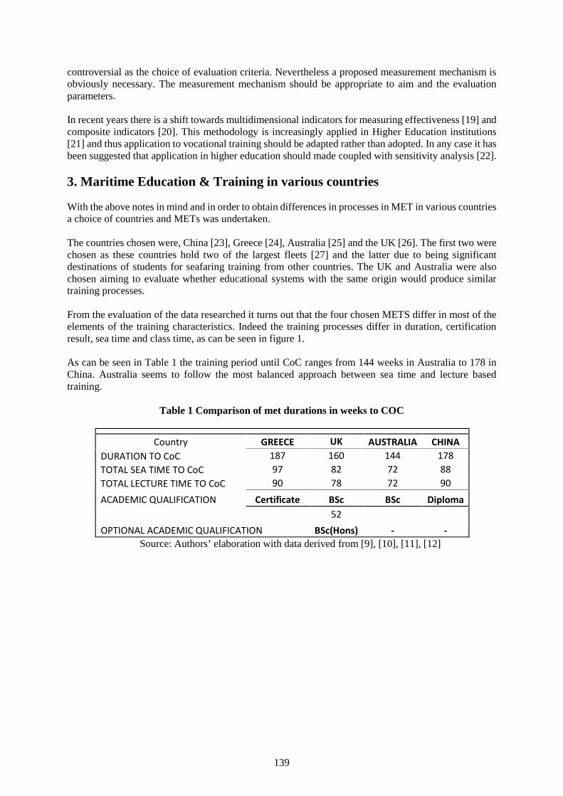
139
controversial as the choice of evaluation criteria. Nevertheless a proposed measurement mechanism isobviously necessary. The measurement mechanism should be appropriate to aim and the evaluationparameters.
In recent years there is a shift towards multidimensional indicators for measuring effectiveness [19] andcomposite indicators [20]. This methodology is increasingly applied in Higher Education institutions[21] and thus application to vocational training should be adapted rather than adopted. In any case it hasbeen suggested that application in higher education should made coupled with sensitivity analysis [22].
3. Maritime Education & Training in various countries
With the above notes in mind and in order to obtain differences in processes in MET in various countriesa choice of countries and METs was undertaken.
The countries chosen were, China [23], Greece [24], Australia [25] and the UK [26]. The first two werechosen as these countries hold two of the largest fleets [27] and the latter due to being significantdestinations of students for seafaring training from other countries. The UK and Australia were alsochosen aiming to evaluate whether educational systems with the same origin would produce similartraining processes.
From the evaluation of the data researched it turns out that the four chosen METS differ in most of theelements of the training characteristics. Indeed the training processes differ in duration, certificationresult, sea time and class time, as can be seen in figure 1.
As can be seen in Table 1 the training period until CoC ranges from 144 weeks in Australia to 178 inChina. Australia seems to follow the most balanced approach between sea time and lecture basedtraining.
Table 1 Comparison of met durations in weeks to COC
Country GREECE UK AUSTRALIA CHINADURATION TO CoC 187 160 144 178TOTAL SEA TIME TO CoC 97 82 72 88TOTAL LECTURE TIME TO CoC 90 78 72 90ACADEMIC QUALIFICATION Certificate BSc BSc Diploma
52OPTIONAL ACADEMIC QUALIFICATION BSc(Hons) - -
Source: Authors’ elaboration with data derived from [9], [10], [11], [12]
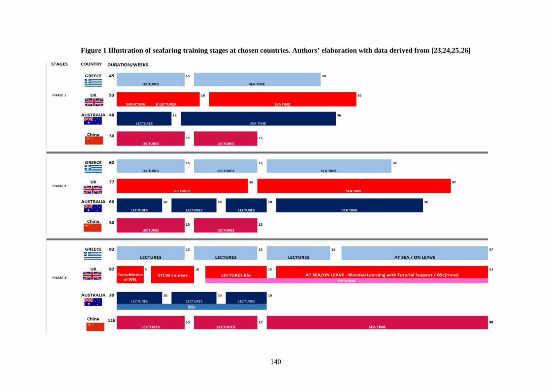
140
Figure 1 Illustration of seafaring training stages at chosen countries. Authors’ elaboration with data derived from [23,24,25,26]
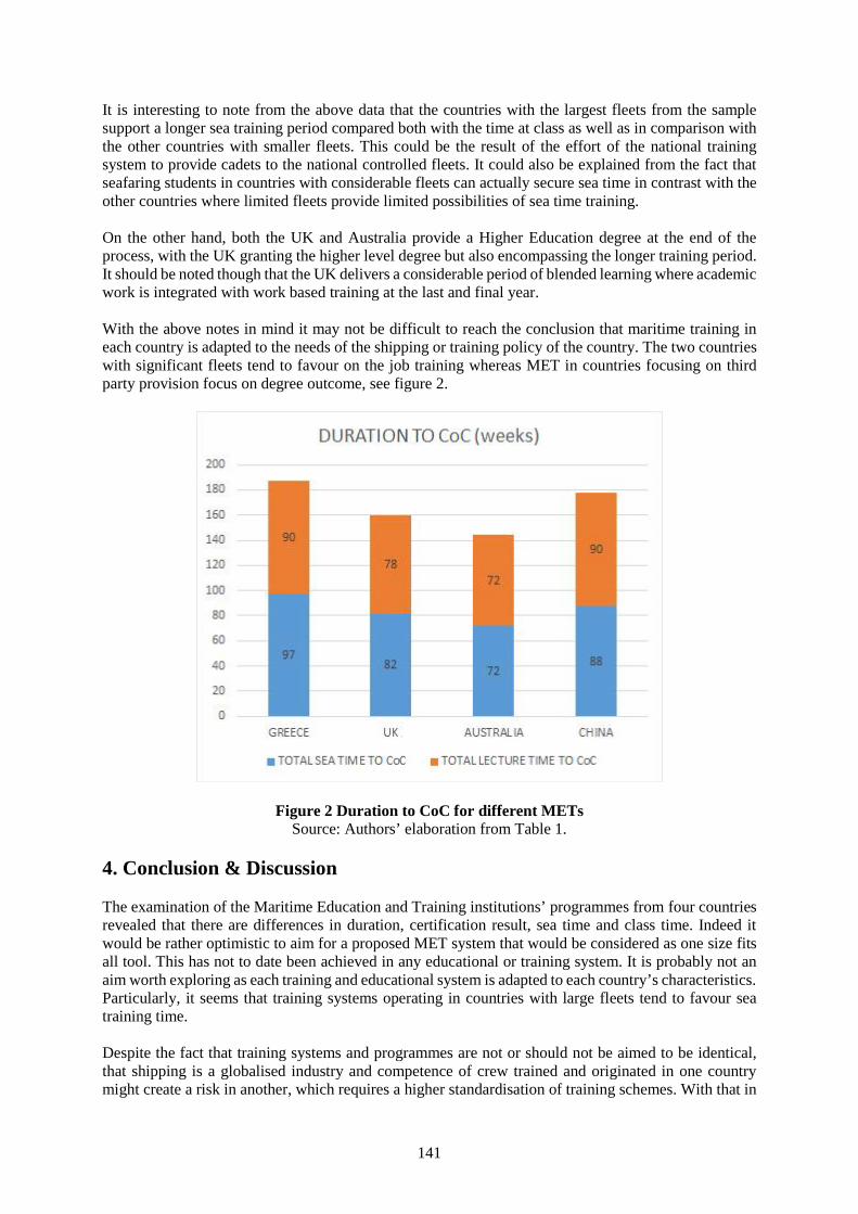
141
It is interesting to note from the above data that the countries with the largest fleets from the samplesupport a longer sea training period compared both with the time at class as well as in comparison withthe other countries with smaller fleets. This could be the result of the effort of the national trainingsystem to provide cadets to the national controlled fleets. It could also be explained from the fact thatseafaring students in countries with considerable fleets can actually secure sea time in contrast with theother countries where limited fleets provide limited possibilities of sea time training.
On the other hand, both the UK and Australia provide a Higher Education degree at the end of theprocess, with the UK granting the higher level degree but also encompassing the longer training period.It should be noted though that the UK delivers a considerable period of blended learning where academicwork is integrated with work based training at the last and final year.
With the above notes in mind it may not be difficult to reach the conclusion that maritime training ineach country is adapted to the needs of the shipping or training policy of the country. The two countrieswith significant fleets tend to favour on the job training whereas MET in countries focusing on thirdparty provision focus on degree outcome, see figure 2.
Figure 2 Duration to CoC for different METsSource: Authors’ elaboration from Table 1.
4. Conclusion & Discussion
The examination of the Maritime Education and Training institutions’ programmes from four countriesrevealed that there are differences in duration, certification result, sea time and class time. Indeed itwould be rather optimistic to aim for a proposed MET system that would be considered as one size fitsall tool. This has not to date been achieved in any educational or training system. It is probably not anaim worth exploring as each training and educational system is adapted to each country’s characteristics.Particularly, it seems that training systems operating in countries with large fleets tend to favour seatraining time.
Despite the fact that training systems and programmes are not or should not be aimed to be identical,that shipping is a globalised industry and competence of crew trained and originated in one countrymight create a risk in another, which requires a higher standardisation of training schemes. With that in
142
mind it is strongly contented that the evaluation of a maritime training scheme should be comparativeand that outcome evaluation should focus on results such as employment of graduates, salaries or degreeprestige that tend to be connected with market oriented results. Nevertheless, the evaluation should alsobe based on a multi-dimensional approach as well and to that end the use of composite indicators isproposed as a methodology for evaluation.
Reference list
[1] V. Fetisov, N. Maiorov, S. Krile and I. Đurđević Tomaš, "Some Experiences of Specialists inMaritime Transport Education at SUAI (Russia) and the University of Dubrovnik (Croatia)", Našemore, vol. 62, no. 1, pp. 25-29, 2015.
[2] “STCW Convention", Imo.org, 2016. [Online]. Available:http://www.imo.org/en/OurWork/HumanElement/TrainingCertification/Pages/STCW-Convention.aspx. [Accessed: 14- May- 2016].
[3] P. Zhang and M. Zhao, "Maritime Labour Convention, 2006 and the Chinese seafarers: How far isChina to ratification?", Marine Policy, vol. 61, pp. 54-65, 2015.
[4] “STCW Convention", Imo.org, 2016. [Online]. Available:http://www.imo.org/en/OurWork/HumanElement/TrainingCertification/Pages/STCW-Convention.aspx. [Accessed: 14- May- 2016].
[5] COM (2009) 8 final, Commission of the European Communities, “Communication from theCommission to the European Parliament, the Council, the European Economic and SocialCommittee and the Committee of the Regions: Strategic goals and recommendations for the EU’smaritime transport policy until 2018", European Commission, Brussels, 2009.
[6] OJ C 261/25, List of third countries recognised as regards the systems for training and certificationof seafarers for the purposes of Directive 2008/106/EC
[7] OJ C 261/25, List of third countries recognised as regards the systems for training and certificationof seafarers for the purposes of Directive 2008/106/EC
[8] P. Chawla, "Standardizing Maritime Education Across Nationalities", The Maritime Executive,2016. [Online]. Available: http://www.maritime-executive.com/editorials/standardizing-maritime-education-across-nationalities. [Accessed: 14- May- 2016].
[9] J.A.M., "Evaluating occupational education and training programs", Evaluation and ProgramPlanning, vol. 1, no. 4, p. 325, 1978.
[10] J. Ng and T. Yip, "Maritime Education in a Transdisciplinary World: The Case of Hong Kong",The Asian Journal of Shipping and Logistics, vol. 25, no. 1, pp. 69-82, 2009.
[11] C. Denham and A. Lieberman, Time to learn, 1st ed. Washington, DC: National Institute ofEducation., 1980
[12] J. Scheerens and R. Bosker, The foundations of educational effectiveness. Oxford, OX: Pergamon,1997.
[13] S. Jez and R. Wassmer, "The Impact of Learning Time on Academic Achievement", Education andUrban Society, vol. 47, no. 3, pp. 284-306, 2013.
[14] R. Blundell, L. Dearden and B. Sianesi, "Evaluating the effect of education on earnings: models,methods and results from the National Child Development Survey", J Royal Statistical Soc A, vol.168, no. 3, pp. 473-512, 2005.
[15] From initial education to working life. Paris: Organisation for Economic Co-operation andDevelopment, 2000.
[16] B. Ruben, Quality in higher education. New Brunswick, U.S.A.: Transaction Publishers, 1995.[17] I. Livanos and I. Nunez, "Better safe than sorry? The role of stratification and quality of higher
education in the labour market outcomes of graduates across Europe", Economic and IndustrialDemocracy, vol. 37, no. 2, pp. 345-372, 2014.
[18] B. Wu and N. Winchester, "Crew study of seafarers: a methodological approach to the global labourmarket for seafarers", Marine Policy, vol. 29, no. 4, pp. 323-330, 2005.
[19] M. Martini and L. Fabbris, "Beyond Employment Rate: A Multidimensional Indicator of HigherEducation Effectiveness", Soc Indic Res, 2015.
[20] P. Murias, J. de Miguel and D. Rodríguez, "A Composite Indicator for University QualityAssesment: The Case of Spanish Higher Education System", Soc Indic Res, vol. 89, no. 1, pp. 129-
143
146, 2007.[21] M. Asif and C. Searcy, "A composite index for measuring performance in higher education
institutions", Int J Qual & Reliability Mgmt, vol. 31, no. 9, pp. 983-1001, 2014.[22] M. Bas, S. Tarantola, J. Carot and A. Conchado, "Sensitivity Analysis: A Necessary Ingredient for
Measuring the Quality of a Teaching Activity Index", Soc Indic Res, 2016.[23] "Regulations on Examination and Certification of Competence for Seafarers of the People's
Republic of China - Seafarer Management - China Maritime Safety Administration",En.msa.gov.cn, 2016. [Online]. Available:http://en.msa.gov.cn/index.php?m=content&c=index&a=show&catid=25&id=161. [Accessed: 03-Jun- 2016].
[24] "ΥΝΑ - Διάγραμμα φοίτησης στις Α.Ε.Ν", Yen.gr, 2016. [Online]. Available:http://www.yen.gr/wide/yen.chtm?prnbr=25213. [Accessed: 03- Jun- 2016].
[25] 2016. [Online]. Available: https://www.amc.edu.au/seafaring/courses. [Accessed: 03- Jun- 2016].[26] "Maritime Studies | Engineering, Offshore, Ship Simulation | Warsash Maritime Academy |
Warsash Maritime Academy | Southampton Solent University", Warsashacademy.co.uk, 2016.[Online]. Available: http://www.warsashacademy.co.uk/courses/courses.aspx. [Accessed: 03- Jun-2016].
[27] K. Menzel, "Greek Merchant Fleet Tops World Tonnage Ranking | GreekReporter.com",Greece.greekreporter.com, 2016. [Online]. Available:http://greece.greekreporter.com/2014/05/06/greek-merchant-fleet-tops-world-tonnage-ranking/.[Accessed: 03- Jun- 2016].
144
Knowledge Management and itsInfluence on the Efficiency of MaritimeEducation and Training Institutes (A Case Study)
Capt. Amr Moneer Ibrahim (1)Capt. Eslam Mostafa Gaber (2)
Arab Academy of Science, Technology & Maritime Transport (AASTMT), [email protected] Academy of Science, Technology & Maritime Transport (AASTMT), [email protected]
Abstract Knowledge Management (KM) had been one of the hottest topics in the last decade, especiallyin knowledge-intensive and highly competitive organizations. Admitting that knowledge is a key assetin any organization, any management should start planning how to manage the knowledge available inthe organization represented in employees, and how to establish a method to utilize and maintain suchknowledge in order to become skilled at creating, acquiring and transferring knowledge to supportsustainable development of the organization.
The Maritime Education and Training (MET) is a vocational education in general; requires highlyqualified and field-experienced individuals to serve as maritime teachers. This arises the researchproblem; that mostly used KM tools may be good enough to efficiently manage explicit knowledge butdo not manage implicit knowledge to the same extent, especially when dealing with implicit-richeducational facility like marine simulators. Therefore, a system capable of concurrently managing bothexplicit and implicit knowledge is critically in need, in order to resolve the current problem.
From that perspective, this paper illustrates the introduction of KM concept into Maritime Educationand Training, specifically in short courses delivered by the Marine Simulator Department in the ArabAcademy for Science, Technology and Maritime Transport. An appropriate KM tool was introducedand implemented, managing both implicit and explicit knowledge simultaneously over a period of 14months, over which continuous feedback were collected quantitatively and statistically analyzed.
The findings of the study were interestingly positive. The efficiency of education for the test subjecthave improved significantly after comparing Key Performance Indicators (KPIs) before and afteradopting the KM system into the department. The paper finally recommends that due to the specialnature of MET; a specified (MET related) Knowledge Management tool should be developed andgeneralized to all aspects of MET.
Key words: Knowledge Management, Maritime education and Training, Communities of practice,Implicit and explicit knowledge, Short Maritime Courses.
1. Introduction
Knowledge Management (KM) had been a hot topic in the last few years, it was found essentialespecially in knowledge intensive and highly competitive organizations. Admitting that the knowledgeis the main asset in any organization, any management should start planning how to manage all theknowledge available in the organization represented in their employees, and how to establish a methodto utilize and maintain such knowledge.
KM concept is important to enhance the understanding of how an organization becomes skilled atcreating, acquiring and transferring knowledge to support sustainable development.
Therefore, this paper will discuss KM concept and its sub-theories, of Communities of Practice (COP)and different types of knowledge, and how a successful KM system could be established. Furthermore,to illustrate the functionality of these theories, an issue in a Maritime Education and Training Institute(METI) concerning a knowledge gap problem between teachers will be taken as a case study, proposing
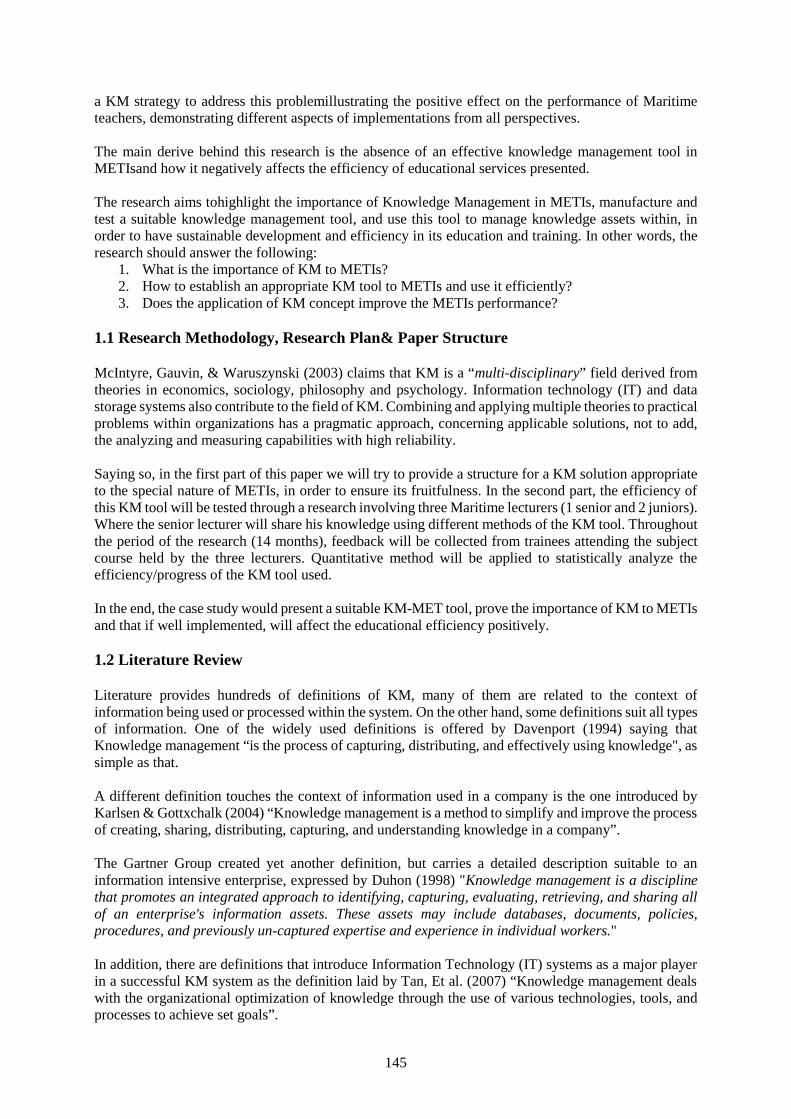
145
a KM strategy to address this problemillustrating the positive effect on the performance of Maritimeteachers, demonstrating different aspects of implementations from all perspectives.
The main derive behind this research is the absence of an effective knowledge management tool inMETIsand how it negatively affects the efficiency of educational services presented.
The research aims tohighlight the importance of Knowledge Management in METIs, manufacture andtest a suitable knowledge management tool, and use this tool to manage knowledge assets within, inorder to have sustainable development and efficiency in its education and training. In other words, theresearch should answer the following:
1. What is the importance of KM to METIs?2. How to establish an appropriate KM tool to METIs and use it efficiently?3. Does the application of KM concept improve the METIs performance?
1.1 Research Methodology, Research Plan& Paper Structure
McIntyre, Gauvin, & Waruszynski (2003) claims that KM is a “multi-disciplinary” field derived fromtheories in economics, sociology, philosophy and psychology. Information technology (IT) and datastorage systems also contribute to the field of KM. Combining and applying multiple theories to practicalproblems within organizations has a pragmatic approach, concerning applicable solutions, not to add,the analyzing and measuring capabilities with high reliability.
Saying so, in the first part of this paper we will try to provide a structure for a KM solution appropriateto the special nature of METIs, in order to ensure its fruitfulness. In the second part, the efficiency ofthis KM tool will be tested through a research involving three Maritime lecturers (1 senior and 2 juniors).Where the senior lecturer will share his knowledge using different methods of the KM tool. Throughoutthe period of the research (14 months), feedback will be collected from trainees attending the subjectcourse held by the three lecturers. Quantitative method will be applied to statistically analyze theefficiency/progress of the KM tool used.
In the end, the case study would present a suitable KM-MET tool, prove the importance of KM to METIsand that if well implemented, will affect the educational efficiency positively.
1.2 Literature Review
Literature provides hundreds of definitions of KM, many of them are related to the context ofinformation being used or processed within the system. On the other hand, some definitions suit all typesof information. One of the widely used definitions is offered by Davenport (1994) saying thatKnowledge management “is the process of capturing, distributing, and effectively using knowledge", assimple as that.
A different definition touches the context of information used in a company is the one introduced byKarlsen & Gottxchalk (2004) “Knowledge management is a method to simplify and improve the processof creating, sharing, distributing, capturing, and understanding knowledge in a company”.
The Gartner Group created yet another definition, but carries a detailed description suitable to aninformation intensive enterprise, expressed by Duhon (1998) "Knowledge management is a disciplinethat promotes an integrated approach to identifying, capturing, evaluating, retrieving, and sharing allof an enterprise's information assets. These assets may include databases, documents, policies,procedures, and previously un-captured expertise and experience in individual workers."
In addition, there are definitions that introduce Information Technology (IT) systems as a major playerin a successful KM system as the definition laid by Tan, Et al. (2007) “Knowledge management dealswith the organizational optimization of knowledge through the use of various technologies, tools, andprocesses to achieve set goals”.
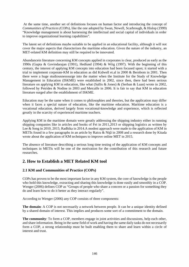
146
At the same time, another set of definitions focuses on human factor and introducing the concept ofCommunities of Practices (COPs), like the one adopted by Swan, Newell, Scarbrough, & Hislop (1999)“Knowledge management is about harnessing the intellectual and social capital of individuals in orderto improve organizational learning capabilities”.
The latent set of definitions maybe suitable to be applied in an educational facility, although it will notcover the major aspects that characterizes the maritime education. Given the nature of the industry, anMET-related KM definition may still be required to be innovated.
Abundancein literature concerning KM concepts applied in corporates is clear, produced as early as the1990s (Gupta & Govindarajan (1991), Hedlund (1994) & Wiig (1997). With the beginning of thiscentury, the interest of applying KM concepts into education had been focused upon; it started with atrial to implement corporate-KM in education as did Kidwell et.al in 2000 & Bernbom in 2001. Thenthere were a huge studiousnesssurge into the matter when the Institute for the Study of KnowledgeManagement in Education (ISKME) were established in 2002, since then, there had been seriousliterature on applying KM in education, like what (Sallis & Jones) & (Serban & Luan) wrote in 2002,followed by Petrides & Nodine in 2003 and Metcalfe in 2006. It is fair to say that KM in educationliterature surged after the establishment of ISKME.
Education may be the same when it comes to philosophies and theories, but the application may differwhen it faces a special nature of education, like the maritime education. Maritime education is avocational education, derived largely from vocational-knowledge and experience, which is reflectedgreatly in the scarcity of experienced maritime teachers.
Applying KM in the maritime domain were greatly addressing the shipping industry either in runningshipping companies like in articles and books of Fei in 2011,2013 or shipping logistics as written byLee & Song in 2010, 2015; Radhika in 2014.A modest approach were made to the application of KM inMETIs found in a few paragraphs in an article by Raicu & Niţǎ in 2008 and a research done by Kitadawrote about the application of KM techniques to improve online MET in 2015.
The absence of literature describing a serious long time testing of the application of KM concepts andtechniques in METIs will be one of the motivation for the contribution of this research and futureresearches.
2. How to Establish a MET Related KM tool
2.1 KM and Communities of Practice (COPs)
COPs has proven to be the most important factor in any KM system, the core of knowledge is the peoplewho hold this knowledge, extracting and sharing this knowledge is done easily and smoothly in a COP.Wenger (2006) defines COP as “Groups of people who share a concern or a passion for something theydo and learn how to do it better as they interact regularly”.
According to Wenger (2006) any COP consists of three components:
The domain: A COP is not necessarily a network between people. It can be a unique identity definedby a shared domain of interest. This implies and produces some sort of a commitment to the domain.
The community: To form a COP, members engage in joint activities and discussions, help each other,and share information. Being in the same field of work and having the same daily tasks do not necessarilyform a COP, a strong relationship must be built enabling them to share and learn within a circle ofinterest and trust.
147
The practice: A community of practice is not a community of interest. Members of a community ofpractice must be practitioners. They develop a shared reservoir of experiences, tools, and ways of dealingwith problems.
“Nurses who meet regularly for lunch in a hospital cafeteria may not realize that their lunchdiscussions are one of their main sources of knowledge about how to care for patients. Still,in the course of all these conversations, they have developed a set of stories and cases thathave become a shared repertoire for their practice.” Wenger (2006)
The concept of COP is applicable in all sort of human-interactive entities, like organizations, institutions,governmental/non-governmental associations, and most importantly, educational institutes, which is thecore subject of this paper.
2.2 Implicit and Explicit Knowledge
As discussed, KM is all about sharing knowledge with others sharing the same interest, based oninteractive and transmission processes between producers and consumers of knowledge. Thisknowledge is either implicit or explicit.
Schacter (1987) defines implicit memory by the limited control of conscious or intentional recollectionof data. Reber (1993) on the other hand, defines implicit learning as “the acquisition of knowledge thattakes place largely independently of conscious attempts to learn and largely in the absence of explicitknowledge about what was acquired”.
The difference between implicit and explicit was expressed by Dienes & Perner (1999) in an illustrativeexample “They didn’t say so explicitly; it was left implicit”. Furthermore, a formal differentiationbetween implicit and explicit knowledge is introduced by Polanyi (1966):
“Explicit knowledge is that which is stated in detail and leaves nothing merely implied. Itis termed “codified” or “formal” knowledge because it can be recorded. Implicitknowledge is that which is understood, implied and exists without being stated. It isinformal, experiential, and difficult to capture or share. It is knowledge that cannot beexpressed”
Because of that contradiction, different KM methods should be used to deal with different types ofknowledge says Fei (2011), IT for example has limited outcome when implicit knowledge is transferred,when face-to-face approach should be facilitated for better results.
2.3 How to Transfer Knowledge
Based on Nonaka & Takeuchi (1995) theory on organizational knowledge creation, where it says thatthe best results of flowing of information through an organizational KM system happens when theknowledge is converted from implicit to explicit continuously and dynamically, as illustrated in figure2.1.
Figure 2.1 Unknown, knowledge conversion process according to Nonaka & Takeuchi, Hcklaboratory
148
Educational knowledge is pretty much complicated; it is a strong mixture of implicit and explicitknowledge, to the extent that a decent education process cannot be built on one type without the other(Pazaver, 2013).
Therefore, it is important to manage the cycle of knowledge very carefully to ensure the completebeneficence of the information within. Nonaka & Takeuchi theory has four pillars; socialization,externalization, combination, and internalization.
Implementing Nonaka & Takeuchi cycle in METs as follows:
1. Socialization (implicit to implicit)Experienced teachers share implicit knowledge with the new incomers based on the “share and learn”concept.“The results of a recent study conducted by the IBM Institute for Knowledge Management found thateven in a company with a well-developed infrastructure of knowledge management technology, peoplestill turn first to other people as they seek solutions to problems and knowledge”. Bartlett (2000)This step is mostly done through formal/in-formal COPs, technology may also be used to supportknowledge sharing and learning process.
2. Externalization (implicit to explicit)McIntyre, Gauvin, & Waruszynski (2003) divided this step into two parts:Capture and Acquire: where new teachers gain implicit information from the close socialization withseniors in a COP, then tries to converse it into explicit knowledge by recording it into the CMS, e.g.,attending a lecture with an experienced teacher and trying to record notes of tactics used during thelecture, body movement, voice tone, analogies, metaphors etc…, the main challenge here is the abilityof the new teacher to capture this implicit knowledge from his tutor.Organize: After establishing a KM system that enables organizing and editing the context, a suitableCMS would be a useful platform for new teachers to upload their findings and recording the knowledgegained from their socialization. This platform can even be used by the management as an assessmenttool to assess all teachers and quantify their performance as discussed earlier.
3. Combination (explicit to explicit)This is where the new explicit knowledge added by the new teacher is joined in the CMS with otherexplicit knowledge recorded from other teachers, resulting in a resourceful and enriched database. Nowthe information can be circulated, shared, evaluated, and (more importantly) accessed through a searchengine using technological and statistical methods capable of retrieving the required content.
4. Internalization (explicit to implicit)This is the process where teachers practice repeatedly what they have learned as explicit knowledge,either from the database, in training sessions, or in real classroom environment supervised by a seniorstaff member. This internalization period lasts until the new teacher accommodates a satisfying level ofimplicit knowledge, and only then, the management can end his training period and confirm hisemployment.To that point, the cycle will have had completed its first round and starts a new round for additionalknowledge building up in the data base, conditioned by the participation of senior/junior staff membersunder managerial supervision.
2.4 The Design and Structure of theMET Related KM System
Inspired by a research done by Haas, Aulbur & Thakar (2003), a MET Related KM system can (andwas) established by doing the following:1. Construct COPs from expert teachers in different subjects and specialties (representatives) to
extract different expertise and different ideologies and backgrounds. COP of navigation teachers,COP of stability teachers, etc….
149
2. Encouraging the formation of formal &non-formal COPs of teachers and try to institutionalize thesegroups.
3. Establish a Content Management System (CMS)1 suitable to deal with different types of knowledge(implicit–explicit).
4. Force/encourage teachers to participate in the formal/in-formal COPs and provide feedback.5. Management may use CMS to monitor the progress of junior teachers and evaluate accordingly.6. Teachers who will not participate in the system will be sanctioned or may even get their contract
terminated, depending on their progress verses time allowed.7. May be used in calibrating the performance of senior teachers, through evaluating the data recorded
by the juniors explicating the knowledge they gained from them.
3. Case study & Research Framework
After constructing the KM system, a COP of three Maritime Lecturers were constructed. They all sharedthe same interest in simulator based training. The COP consisted of one senior lecturer with longexperience in teaching the subject simulator course; where the 2 junior lectures were new to the subjectcourse teaching.
The current research includes 1053 trainees attending a Short (5 days) Simulator Course, tested over aperiod of 16 months, from 4th of January 2015 to 24th of April 2016, subdivided into three groups:
Group No.1 (G1)Feedback from 346 trainees were collected, representing 32.9% of the population, over a period of 6months. During this time, the KM system and the CMS were established and in progress but thereceiving instructors were not contributing to teaching in the classroom, the senior instructor was stillin full command of the complete course being the sole instructor. This group is considered a controlgroup validating the hypothesis of the research.
Group No.2 (G2)Feedback from 175 trainees, representing 16.5%, collected for the period of one month. At this time ofresearch, the senior instructor allowed the receiving instructors to contribute in actual teaching underhis direct supervision and intervening when appropriate; as a part of the Knowledge transfer plan.
Group No. 3 (G3)532 trainees, representing 50.5%, of which feedback were collected for the period of 7 months. In thisperiod of time, the senior lecture had stepped down handing over the full responsibility of the course tothe junior lecturers. As a final step in the research.
As the main idea of the research is to find out if the implementation of the Knowledge Management(KM) model introduced was effective or not, the research will compare the periods under study bycomparing different responses to the research statements in different periods of implementation. Also,the overall performance in the three groups will be constructed and compared. Accordingly, the researchhypothesis could be stated as follows:
H1: There is a positive change in the overall performance as we proceed in the steps of KMimplementation.
All trainees were subject to a survey of 9 questions and the answers were collected and entered on SPSS– version 22 to be analyzed. The analysis includes a descriptive analysis for the statements under study.Also, data testing using validity and reliability tests will be applied to check the validity of data for the
1CMS are systems that enable adding, editing, formatting, publishing and maintaining data. These systems can also be integrated into moresophisticated programs that have the ability to extract more information statistically and knowing which individual has what information,e.g. METADATA (Bolmsten, 2013).
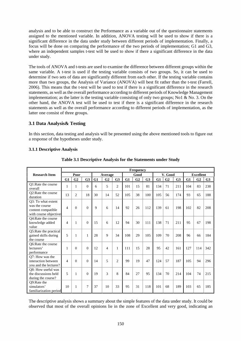
150
analysis and to be able to construct the Performance as a variable out of the questionnaire statementsassigned to the mentioned variable. In addition, ANOVA testing will be used to show if there is asignificant difference in the data under study between different periods of implementation. Finally, afocus will be done on comparing the performance of the two periods of implementation; G1 and G3,where an independent samples t-test will be used to show if there a significant difference in the dataunder study.
The tools of ANOVA and t-tests are used to examine the difference between different groups within thesame variable. A t-test is used if the testing variable consists of two groups. So, it can be used todetermine if two sets of data are significantly different from each other. If the testing variable containsmore than two groups, the Analysis of Variance (ANOVA) will best fit rather than the t-test (Farrell,2006). This means that the t-test will be used to test if there is a significant difference in the researchstatements, as well as the overall performance according to different periods of Knowledge Managementimplementation; as the latter is the testing variable consisting of only two groups; No1 & No. 3. On theother hand, the ANOVA test will be used to test if there is a significant difference in the researchstatements as well as the overall performance according to different periods of implementation, as thelatter one consist of three groups.
3.1 Data Analysis& Testing
In this section, data testing and analysis will be presented using the above mentioned tools to figure outa response of the hypotheses under study.
3.1.1 Descriptive Analysis
Table 3.1 Descriptive Analysis for the Statements under Study
The descriptive analysis shows a summary about the simple features of the data under study. It could beobserved that most of the overall opinions lie in the zone of Excellent and very good, indicating an
Research ItemFrequency
Poor Average Good V. Good ExcellentG1 G2 G3 G1 G2 G3 G1 G2 G3 G1 G2 G3 G1 G2 G3
Q1:Rate the courseoverall
1 1 0 6 5 2 101 15 81 134 71 211 104 83 238
Q2:Rate the courseduration
13 2 18 30 14 52 105 38 100 105 56 174 93 65 188
Q3: To what extentwas the coursecontent compatiblewith course objectives
4 0 0 9 6 14 92 26 112 139 61 198 102 82 208
Q4:Rate the courseknowledge addedvalue
4 1 0 15 6 12 94 30 111 138 71 211 95 67 198
Q5:Rate the practicalgained skills duringthe course
5 1 1 28 9 34 108 29 105 109 70 208 96 66 184
Q6:Rate the courselecturers’performance
1 0 0 12 4 1 111 15 28 95 42 161 127 114 342
Q7: How was theinteraction betweenyou and the lecturer?
4 0 0 14 5 2 99 19 47 124 57 187 105 94 296
Q8: How useful wasthe discussions heldduring the course?
5 1 0 19 3 8 84 27 95 134 70 214 104 74 215
Q9:Rate thesimulators’familiarization period
10 1 7 37 10 33 95 31 118 101 68 189 103 65 185

151
overall satisfaction regarding the simulation training course performance. Moreover, some of theresponses lie in the neutral zone. On the other hand, there is a relatively very low number of responseslying in the zones of Average and Poor, indicating very few number of trainees who are not actuallyhappy regarding the course provided.
Also, it could be observed that the periods of G2 and G3 enjoy better opinions of Very Good andExcellent zones from trainees than the period of G1, as the percentages of trainees in the zone ofdisagreement decrease while the trainee’s percentages in the zone of agreement increase.
3.1.2 Data Testing
Validity and Reliability of the data under study are two important conditions that have to be satisfied tostart using the data available in responding to the research hypotheses. In the current research, thevariable; Performance is the variable that is supposed to be improved among different periods ofKnowledge Management implementation.
3.1.3 Validity Testing
Validity means the extent to which an instrument measures what it supposes to measure correctly(Sekaran & Bougie, 2005). Convergent validity tests the data using factor analysis (multivariatetechnique) that confirms whether or not the theorized dimensions are applicable (Sekaran & Bougie,2005). Convergent validity was essential to ensure that the items measuring the same construct arehighly correlated (Hair et al., 2003).
In order to test the convergent validity, the average value extracted for each of the scales should becalculated, which represents the average community for each latent factor. In an adequate model, AVEshould be greater than 0.5, which means that the factors should explain at least half the variance of theirrespective indicators (Garson, 2011; Hair et al., 2003).
Table 3.2 represents the items having adequate factor loading, which means that all dimensions understudy have convergent validity, as AVE is greater than 50% and Factor Loadings are greater than 40%.
Table 3.2 Average Variance Extracted and factor Loadings of Research Items
Variables Under Study Number ofItems Entered AVE Items Factor Loading of
Items
Performance 9 60.666%
Q1 .694Q2 .504Q3 .629Q4 .688Q5 .684Q6 .469Q7 .607Q8 .622Q9 .562
3.1.4 Reliability Analysis
For the purpose of evaluation of measures of concepts, any multidimensional scale should be reliableand valid. In order to test reliability of the study, Cronbach's Alpha, as the most commonly used test ofreliability, was applied. Alpha coefficient ranges in value from 0 to 1 and may be used to describe thereliability of factors extracted from dichotomous (that is, questions with two possible answers) and/ormulti-point formatted questionnaires or scales (i.e., rating scale: 1 = poor, 5 = excellent). The higher the
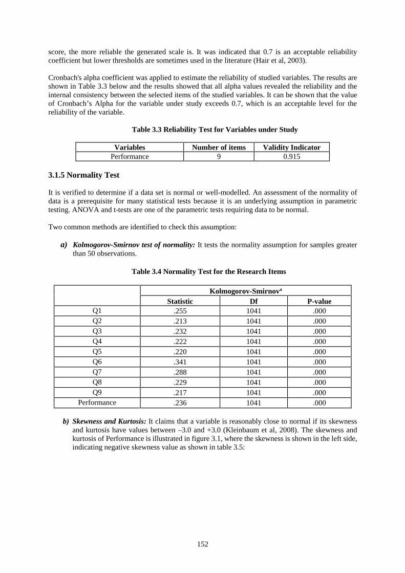
152
score, the more reliable the generated scale is. It was indicated that 0.7 is an acceptable reliabilitycoefficient but lower thresholds are sometimes used in the literature (Hair et al, 2003).
Cronbach's alpha coefficient was applied to estimate the reliability of studied variables. The results areshown in Table 3.3 below and the results showed that all alpha values revealed the reliability and theinternal consistency between the selected items of the studied variables. It can be shown that the valueof Cronbach’s Alpha for the variable under study exceeds 0.7, which is an acceptable level for thereliability of the variable.
Table 3.3 Reliability Test for Variables under Study
Variables Number of items Validity IndicatorPerformance 9 0.915
3.1.5 Normality Test
It is verified to determine if a data set is normal or well-modelled. An assessment of the normality ofdata is a prerequisite for many statistical tests because it is an underlying assumption in parametrictesting. ANOVA and t-tests are one of the parametric tests requiring data to be normal.
Two common methods are identified to check this assumption:
a) Kolmogorov-Smirnov test of normality: It tests the normality assumption for samples greaterthan 50 observations.
Table 3.4 Normality Test for the Research Items
Kolmogorov-Smirnova
Statistic Df P-valueQ1 .255 1041 .000Q2 .213 1041 .000Q3 .232 1041 .000Q4 .222 1041 .000Q5 .220 1041 .000Q6 .341 1041 .000Q7 .288 1041 .000Q8 .229 1041 .000Q9 .217 1041 .000
Performance .236 1041 .000
b) Skewness and Kurtosis: It claims that a variable is reasonably close to normal if its skewnessand kurtosis have values between –3.0 and +3.0 (Kleinbaum et al, 2008). The skewness andkurtosis of Performance is illustrated in figure 3.1, where the skewness is shown in the left side,indicating negative skewness value as shown in table 3.5:
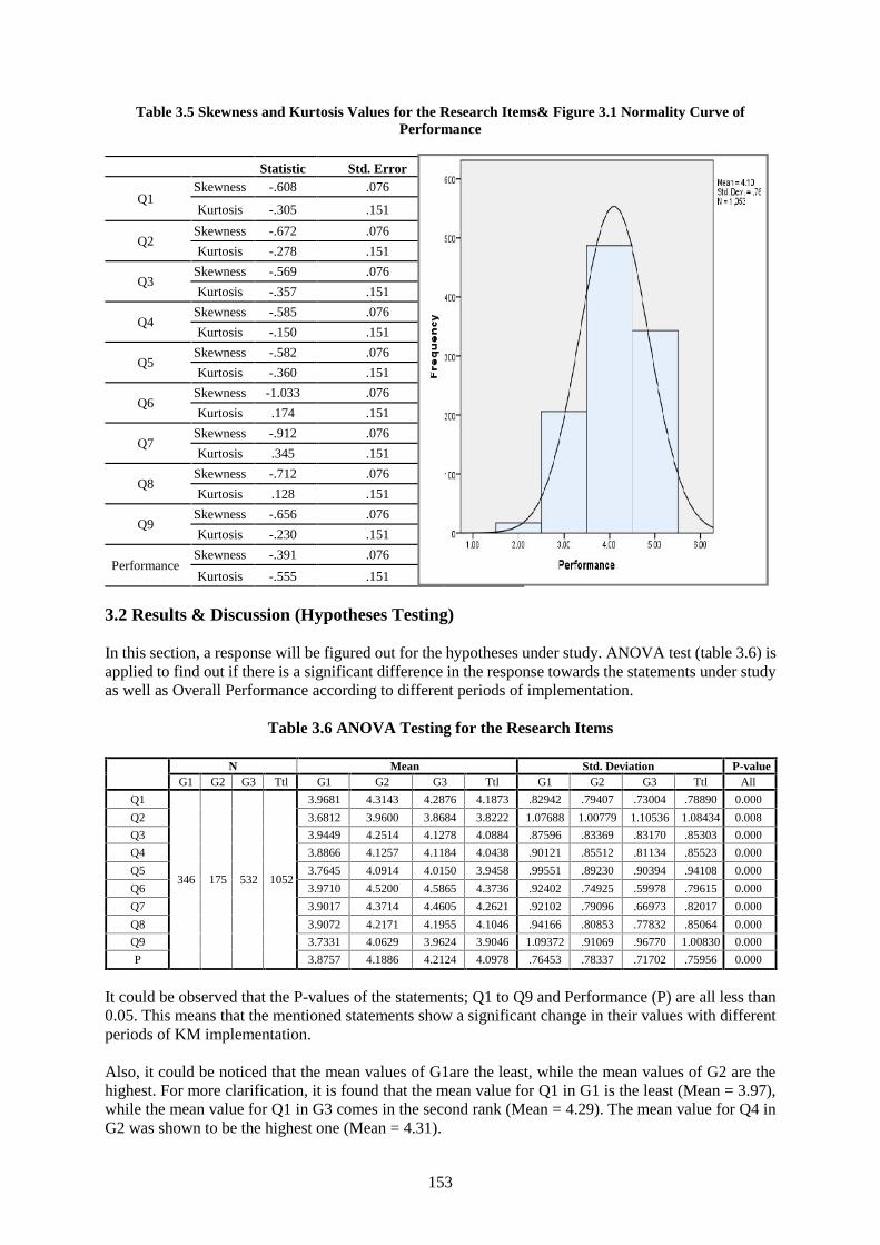
153
Table 3.5 Skewness and Kurtosis Values for the Research Items& Figure 3.1 Normality Curve ofPerformance
Statistic Std. Error
Q1Skewness -.608 .076
Kurtosis -.305 .151
Q2Skewness -.672 .076
Kurtosis -.278 .151
Q3Skewness -.569 .076
Kurtosis -.357 .151
Q4Skewness -.585 .076
Kurtosis -.150 .151
Q5Skewness -.582 .076
Kurtosis -.360 .151
Q6Skewness -1.033 .076
Kurtosis .174 .151
Q7Skewness -.912 .076
Kurtosis .345 .151
Q8Skewness -.712 .076
Kurtosis .128 .151
Q9Skewness -.656 .076
Kurtosis -.230 .151
PerformanceSkewness -.391 .076
Kurtosis -.555 .151
3.2 Results & Discussion (Hypotheses Testing)
In this section, a response will be figured out for the hypotheses under study. ANOVA test (table 3.6) isapplied to find out if there is a significant difference in the response towards the statements under studyas well as Overall Performance according to different periods of implementation.
Table 3.6 ANOVA Testing for the Research Items
It could be observed that the P-values of the statements; Q1 to Q9 and Performance (P) are all less than0.05. This means that the mentioned statements show a significant change in their values with differentperiods of KM implementation.
Also, it could be noticed that the mean values of G1are the least, while the mean values of G2 are thehighest. For more clarification, it is found that the mean value for Q1 in G1 is the least (Mean = 3.97),while the mean value for Q1 in G3 comes in the second rank (Mean = 4.29). The mean value for Q4 inG2 was shown to be the highest one (Mean = 4.31).
N Mean Std. Deviation P-valueG1 G2 G3 Ttl G1 G2 G3 Ttl G1 G2 G3 Ttl All
Q1
346 175 532 1052
3.9681 4.3143 4.2876 4.1873 .82942 .79407 .73004 .78890 0.000
Q2 3.6812 3.9600 3.8684 3.8222 1.07688 1.00779 1.10536 1.08434 0.008
Q3 3.9449 4.2514 4.1278 4.0884 .87596 .83369 .83170 .85303 0.000
Q4 3.8866 4.1257 4.1184 4.0438 .90121 .85512 .81134 .85523 0.000
Q5 3.7645 4.0914 4.0150 3.9458 .99551 .89230 .90394 .94108 0.000
Q6 3.9710 4.5200 4.5865 4.3736 .92402 .74925 .59978 .79615 0.000
Q7 3.9017 4.3714 4.4605 4.2621 .92102 .79096 .66973 .82017 0.000
Q8 3.9072 4.2171 4.1955 4.1046 .94166 .80853 .77832 .85064 0.000
Q9 3.7331 4.0629 3.9624 3.9046 1.09372 .91069 .96770 1.00830 0.000
P 3.8757 4.1886 4.2124 4.0978 .76453 .78337 .71702 .75956 0.000
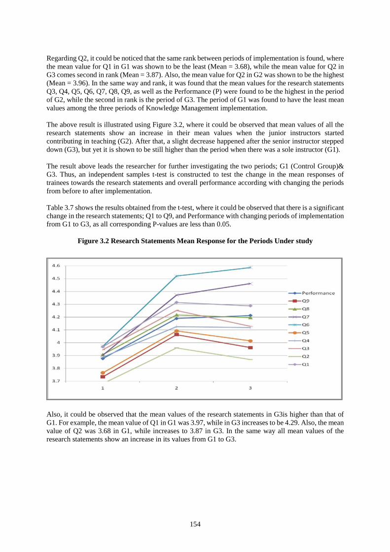
154
Regarding Q2, it could be noticed that the same rank between periods of implementation is found, wherethe mean value for Q1 in G1 was shown to be the least (Mean = 3.68), while the mean value for Q2 inG3 comes second in rank (Mean = 3.87). Also, the mean value for Q2 in G2 was shown to be the highest(Mean = 3.96). In the same way and rank, it was found that the mean values for the research statementsQ3, Q4, Q5, Q6, Q7, Q8, Q9, as well as the Performance (P) were found to be the highest in the periodof G2, while the second in rank is the period of G3. The period of G1 was found to have the least meanvalues among the three periods of Knowledge Management implementation.
The above result is illustrated using Figure 3.2, where it could be observed that mean values of all theresearch statements show an increase in their mean values when the junior instructors startedcontributing in teaching (G2). After that, a slight decrease happened after the senior instructor steppeddown (G3), but yet it is shown to be still higher than the period when there was a sole instructor (G1).
The result above leads the researcher for further investigating the two periods; G1 (Control Group)&G3. Thus, an independent samples t-test is constructed to test the change in the mean responses oftrainees towards the research statements and overall performance according with changing the periodsfrom before to after implementation.
Table 3.7 shows the results obtained from the t-test, where it could be observed that there is a significantchange in the research statements; Q1 to Q9, and Performance with changing periods of implementationfrom G1 to G3, as all corresponding P-values are less than 0.05.
Figure 3.2 Research Statements Mean Response for the Periods Under study
Also, it could be observed that the mean values of the research statements in G3is higher than that ofG1. For example, the mean value of Q1 in G1 was 3.97, while in G3 increases to be 4.29. Also, the meanvalue of Q2 was 3.68 in G1, while increases to 3.87 in G3. In the same way all mean values of theresearch statements show an increase in its values from G1 to G3.
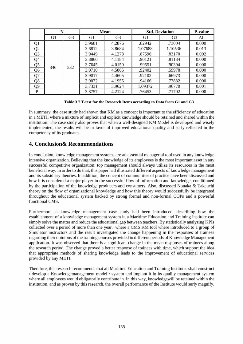
155
N Mean Std. Deviation P-valueG1 G3 G1 G3 G1 G3 All
Q1
346 532
3.9681 4.2876 .82942 .73004 0.000Q2 3.6812 3.8684 1.07688 1.10536 0.013Q3 3.9449 4.1278 .87596 .83170 0.002Q4 3.8866 4.1184 .90121 .81134 0.000Q5 3.7645 4.0150 .99551 .90394 0.000Q6 3.9710 4.5865 .92402 .59978 0.000Q7 3.9017 4.4605 .92102 .66973 0.000Q8 3.9072 4.1955 .94166 .77832 0.000Q9 3.7331 3.9624 1.09372 .96770 0.001P 3.8757 4.2124 .76453 .71702 0.000
Table 3.7 T-test for the Research Items according to Data from G1 and G3
In summary, the case study had shown that KM as a concept is important to the efficiency of educationin a METI; where a mixture of implicit and explicit knowledge should be retained and shared within theinstitution. The case study also proves that when a well-designed KM Model is developed and wiselyimplemented, the results will be in favor of improved educational quality and surly reflected in thecompetency of its graduates.
4. Conclusion& Recommendations
In conclusion, knowledge management systems are an essential managerial tool used in any knowledgeintensive organization. Believing that the knowledge of its employees is the most important asset in anysuccessful competitive organization; top management should always utilize its resources in the mostbeneficial way. In order to do that, this paper had illustrated different aspects of knowledge managementand its subsidiary theories. In addition, the concept of communities of practice have been discussed andhow it is considered a major player in the successful flow of information and knowledge, conditionedby the participation of the knowledge producers and consumers. Also, discussed Nonaka & Takeuchitheory on the flow of organizational knowledge and how this theory would successfully be integratedthroughout the educational system backed by strong formal and non-formal COPs and a powerfulfunctional CMS.
Furthermore, a knowledge management case study had been introduced, describing how theestablishment of a knowledge management system in a Maritime Education and Training Institute cansimply solve the matter and reduce the educational gap between teachers. By statistically analyzing KPIscollected over a period of more than one year. where a CMS KM tool where introduced to a group ofSimulator instructors and the result investigated the change happening in the responses of traineesregarding their opinions of the training courses provided in different periods of Knowledge Managementapplication. It was observed that there is a significant change in the mean responses of trainees alongthe research period. The change proved a better response of trainees with time, which support the ideathat appropriate methods of sharing knowledge leads to the improvement of educational servicesprovided by any METI.
Therefore, this research recommends that all Maritime Education and Training Institutes shall construct/ develop a Knowledgemanagement model / system and implant it in its quality management systemwhere all employees would obligatorily contribute in. In this way, knowledgewill be retained within theinstitution, and as proven by this research, the overall performance of the Institute would surly magnify.
156
Acknowledgments
Firstly, we would like to Thank ALLAH, the most genoures, for granting us the wisdom and knowledgeto present this research. Secondly, the Authors of this research acknowledge the endless support of theMarine Simulators Department in the Integrated Simulators Complex of the Arab Academy of Science,Technology and Maritime Transport, for that all the equipment and resources used for this research weretheir own property. Also would like to appreciate the help of Mrs. Nermeen Gohar for her scientificsupport. Finally, all the sincerity and appreciation for IAMU and their Liaison officer in the AcademyCapt. Mahmoud El Bawab, for their trust and encouragement to publish this paper under the Auspicesof their AGA.
References
[1] Bartlett, J. (2000, December). Knowing people. Knowledge management.[2] Bernbom, G. V. (2001). Information alchemy: The art and science of knowledge management. San
Francisco: Jossey-Bass.[3] Bolmsten, J. (Director) (2013, June 19). Organizational knowledge management. Maritime
education and training. Lecture conducted from World Maritime University, Malmo.[4] Davenport, T. (1994). Saving IT's soul: human centered information management. Harvard
business review, 72(2), 119-131.[5] David G. Kleinbaum, Keith E. Muller, Lawrence L. Kupper (2008). Applied Regression Analysis
and Other Multivariable Methods. Thomson Brooks/Cole- Multivariate Analysis.[6] Dienes, Z., & Perner, J. (1999). A theory of implicit and explicit knowledge. Behavioral and brain
sciences, 22(05), 735-808.[7] Duhon, B. (1998). It's All in Our Heads. Inform, 12(8), 9-13.[8] Farrell, P.J., Rogers-Stewart, K. (2006) "Comprehensive study of tests for normality and symmetry:
extending the Spiegelhalter test". Journal of Statistical Computation and Simulation[9] Fei, J. (2011). "An Empirical Study of the Role of Information Technology in Effective Knowledge
Transfer in the Shipping Industry." Maritime Policy & Management 38.4: 347-67. Web. 29 Feb.2016.
[10] Fei, J. (2013). Knowledge management in the shipping industry: The effects of human mobility onthe organisational knowledge base and effective knowledge transfer practices. Saarbrücken,Germany: LAP Lambert Academic Publishing
[11] Garson, G.D. (2011). Structural Equation Modelling. [Online] Available:http://faculty.chass.nscu.edu/garson/PA765/structur.htm (May 10, 2016).
[12] Gupta, A. K., & Govindarajan, V. (1991). Knowledge Flows and the Structure of Control withinMultinational Corporations [Abstract]. Academy of Management Review, 16(4), 768-792.Retrieved February 28, 2016, from http://amr.aom.org/content/16/4/768.short
[13] Haas, R., Aulbur, W., & Thakar, S. (2003). Enabling communities of practice at EADSairbus. Sharing expertise: beyond knowledge management (pp. 179-198). Cambridge, Mass. [u.a.:MIT Press.
[14] Hair, J.F. Jr., Anderson, R.E., Tatham, R.L., & Black, W.C. (1998). Multivariate Data Analysis,(5th Edition). Upper Saddle River, NJ: Prentice Hall.
[15] Hedlund, G. (1994). A model of knowledge management and the N-form Corporation[Abstract]. Strategic Management Journal, 15(S2), 73-90. Retrieved February 28, 2016, fromhttp://onlinelibrary.wiley.com/doi/10.1002/smj.4250151006/abstract
[16] Karlsen, J. T., & Gottschalk, P. (2004). Factors affecting knowledge transfer in ITprojects. Engineering management journal, 16(1), 3.
[17] Kidwell, J. J., Vander Linde, K. M., & Johnson, S. L. (2000). Applying Corporate KnowledgeManagement Practices in Higher Education. EDUCAUSE QUARTERLY, 4, 28-33. RetrievedFebruary 28, 2016, from https://net.educause.edu/ir/library/pdf/EQM0044.pdf
[18] Kitada, M., Bolmsten, J., & Trong, P. (2015). Utilizing E-learning tools to foster knowledgemanagement practices in Maritime Education & Training. In 16th IAMU Annual GeneralAssembly, Opatija, Croatia, 2015. Retrieved March 1, 2016, from
157
https://www.researchgate.net/publication/283485182_Utilizing_E-learning_tools_to_foster_knowledge_management_practices_in_Maritime_Education_Training
[19] Lee, E., & Song, D. (2010). Knowledge management for maritime logistics value: Discussingconceptual issues. Maritime Policy & Management, 37(6), 563-583.
[20] Lee, E., & Song, D. (2015). Maritime logistics value in knowledge management. New York:Abingdon, Oxon.
[21] McIntyre, S. G., Gauvin, M., & Waruszynski, B. (2003). Knowledge management in the militarycontext. Canadian military journal, 30-40. Retrieved June 24, 2013, fromhttp://www.journal.dnd.ca/vo4/no1/doc/v4n1-p35-40-eng.pdf
[22] Metcalfe, A. S. (2006). Knowledge management and higher education: A critical analysis.Hershey: Information Science Pub.
[23] Nonaka, I., & Takeuchi, H. (1995). The knowledge-creating company: how Japanese companiescreate the dynamics of innovation. New York: Oxford University Press.
[24] Pazaver, A. (Director) (2013, February 20). Pedagogy. Train the trainer, GHG emissions fromships. Lecture conducted from World Maritime University, Malmo.
[25] Petrides, L. A., & Nodine, T. R. (2003). Knowledge management in education: Defining thelandscape. Half Moon Bay, CA: Institute for the Study of Knowledge Management in Education.
[26] Polanyi, M. (1966). The tacit dimension (1st Ed.). Garden City, N.Y.: Doubleday.[27] Radhika, D. (2014). The Role of Knowledge Management as an Innovative Strategy in Maritime
Logistics Management. International Journal of Humanities Social Sciences and Education(IJHSSE),1(9), 52-57. Retrieved March 1, 2016, from https://www.arcjournals.org/pdfs/ijhsse/v1-i9/7.pdf.
[28] Raicu, G., & Niţǎ, A. (2008, October). Improve economical performance using knowledgemanagement. In International Maritime Lecturers? Association 16th Conference on MET," Safety,Security and Quality Objectives of MET Institutions", 14-17 October 2008 (pp. 567-574).
[29] Reber, A. S. (1993). Implicit learning and tacit knowledge: an essay on the cognitive unconscious.New York: Oxford University Press
[30] Sallis, E., & Jones, G. (2002). Knowledge management in education: Enhancing learning &education. London: Kogan Page.
[31] Schacter, D. L. (1987). Implicit memory: history and current status... Journal of experimentalpsychology: learning, memory, and cognition, 13(3), 501-518.
[32] Sekaran, U., & Bougie, R. (2005). Research methods for business: A skill building approach (5thed.). Chichester, West Sussex: John Wiley & Sons.
[33] Serban, A. M., & Luan, J. (2002). Knowledge management: Building a competitive advantage inhigher education. San Francisco, CA: Jossey-Bass.
[34] Swan, J., Newell, S., Scarbrough, H., & Hislop, D. (1999). Knowledge management andinnovation: Networks and networking. Journal of knowledge management, 3(4), 262-275.
[35] Tan, H. C., Carrillo, P. M., Anumba, C. J., Bouchlaghem, N., Kamara, J. M., & Udeaja, C. E.(2007). Development of a Methodology for Live Capture and Reuse of Project Knowledge inConstruction. Journal of Management in Engineering,23(1), 18-26. Retrieved February 24, 2016,from http://ascelibrary.org/doi/abs/10.1061/(ASCE)0742-597X(2007)23:1(18)
[36] Unknown. n.d. The knowledge conversion processes in a knowledge creating organization. [Table]Retrieved from http://libguides.scf.edu/content.php?pid=107184&sid=1354168
[37] Wenger, E. (2006). Communities of practice. Etienne Wenger home page. Retrieved June 5, 2016,from http://www.ewenger.com/theory/
[38] Wiig, K. M. (1997). Integrating intellectual capital and knowledge management [Abstract]. LongRange Planning,30(3), 399-405. Retrieved February 28, 2016, fromhttp://www.sciencedirect.com/science/article/pii/S0024630197902569.
158
Captain´s duty – The constant and continuing changes of captain´s legalposition. How can we ensure that Masters are on map?
Senior Lecturer, Captain Ninna Roos1
Senior lecturer of Maritime and Commercial lawPeter Ivar Sandell 2
1Satakunta University of Applied Sciences, [email protected], Suojantie 2, 26100 Rauma, Finland.2Satakunta University of Applied Sciences, [email protected], Suojantie 2, 26100 Rauma,
Finland.
Abstract The aim of this article is to examine the ship master’s legal position and his rights,responsibilities and obligations. The idea is to find out what the ship master’s role is with respect to theship owner and ship’s charterer and to what extent the master is allowed and expected to make hisindependent decisions. In addition, the purpose of this thesis was to clarify the general view of themaster’s roles and tasks in legal and contractual context and to examine how different changes in thetransport industry over time have affected the development.
The ship master’s role has changed over the time especially through development of technical means ofcommunication and increase of internalisation of legislation and contract practice. The focus of thearticle is to describe the present situation predict some of the coming changes in horizon. Shipping iscontrolled by various international and national laws which impact the master and ship’s crew. Thechanges in laws and regulations create new challenges for the master to maintain his/her knowhow andlegal knowledge. This creates a constant challenge for the maritime Universities, but it also offerspossibilities and need for further education. Some models for further educating the Masters will beoffered.
The master works in close cooperation with different authorities who look after the safety of vessels. Inthis article, different methods of educating the authorities together with the Master Mariners have beenfound useful. Further education of the authorities and Master Mariners in co-operation with the MaritimeUniversities influences the ship safety and the protection of marine environment.
The article also focuses on the seaworthiness of ships, which is a significant issue when it comes to thecharter party. It is in the best interest for both the master’ and ship owner’ to be concerned withseaworthiness. This is considered a serious issue, the breach of which may lead to the cancellation ofthe charter party. Marine insurance and charter parties are essential topics which are based oninternational development and which can be taught for Master Mariners on a global basis.
The final section of the article focuses on accidents at sea and general average decision making from themaster’s point of view.
Keywords: Captains legal position, safety and security, maritime environment, seaworthiness, education,further education, maritime accidents, general average.
1. Introduction
The ship master’s role and status are exceptional compared to many other managerial duties ashore. Onboard the vessel he /she controls global operation of many matters and advantages of the differentinterest groups. His / her duty is to act behalf of the ship owner and the charterer.
When operating a vessel in the international traffic, the master has to act under several differentlegislations and be aware of and to take into account laws and rules which are valid in different sea areasand harbours.
159
The ship master's essential role is to manage risks which are related to safety of the ship, crew,passengers, cargo and environment. The master should always be authorised to make independentdecisions and perform whatever acts are necessary for the safe prosecution of the voyage.
2. The ship master’s role today and in the future
2.1 Master’s role today
The ship master’s role has changed over the time especially through development of technical means ofcommunication and increase of internalisation of legislation and contract practice. Various internationaland national laws control shipping and impact the ship operation. [1]
The master is the agent of the ship owner and the bailee of the cargo and he/ she has to act like the shipand cargo were his/her own uninsured property so as to complete the voyage with the minimum of delayand the minimum of expense. [2] According to most time-charter parties, the master and the vessel'screw have to give " customary assistance" to charterers, which means that, they have to give the sameassistance to the time charterers as they would give to ship owners if they were trading for their account.[3]
The ship master is responsible for implementing ISM code on board the vessel and motivating the crewin the observation of shipping company's safety and environmental-protection policy. According to ISMCode, the master has " the overriding authority and responsibility to make decisions with respect tosafety and pollution prevention and to request the Company's assistance as may be necessary." On theother hand, the Shipping company's obligation is to make sure that master and other personnel arequalified and trained for their tasks. [4]
Sometimes position of the master as an employer of the shipping company and as trustee of the charterercan be challenging, for example under the circumstances which are related to both safety/seaworthinessand time/economic issues. The threshold to settle against the employer can be high if priorities differs.
2.2 Challenges of the master in the future
The ship master's role has changed within time with development of a technology and society. Increasinginternational and national legislation and rules challenge both seafarers and shore operators to updatetheir knowledge and competence. The essential feature for masters and supporting organisations ashoreis that most decisions at sea need to be taken fast if not immediately. Courts of law can weigh the factsof the case even years while the master has to act often in minutes based on the existing knowledge andoften without possibility for consultation. The ever growing amount of legislation and technologycreates challenges also for education and further education during the careers at sea and in supportingroles of those ashore in shipping companies and in maritime administrations.
Before we turn into the problem of preparing the masters for these challenges through education we takeup some issues which describe more closely the challenges the masters meet and what kind of decisionsthey have to make in modern seafaring. We take a closer look at the issues of seaworthiness and generalaverage situations.
3. Seaworthiness
The seaworthiness of the vessel and cargo is one of the highest priorities of the ship master's duties.
Many parties have their own interests involved in vessel's seaworthiness – insurance companies,classification societies, charterers and investors.
160
There are many aspects how to define a vessels seaworthiness. In one circumstance a ship can beseaworthy and in an another not. Because of new technological advantages, what was earlier consideredto be a seaworthy ship may not be that anymore. The simple definition for the seaworthiness, - a vesselis seaworthy when it's reasonably fit for its intended purpose.[5] Other requirement is that a vessel hasto be able to meet the ordinary perils contemplated for the voyage.
The demand of seaworthiness can be roughly categorised to three different layers. First of all, the vesselhas to meet the demands of relevant authorities like flag state, classification societies, authorities ofcountries where the ship is intended to visit while its journey.
The second layer is the insurance companies and the demand of seaworthiness described in the insurancecontract and insurance legislation. Most marine insurance is still based on the warranty of seaworthinessof vessels, but some insurance contracts have taken another view: Nordic Marine Insurance Plan hassince 2007 (at that time still carrying the previous name “Norwegian Marine insurance Plan”, whichwas changed to Nordic Marine Insurance Plan 2013) been based on the idea that insurers are not able todeny cover based on seaworthiness of the ship but only on a basis of breach of safety regulations. [6]Many ships are however nowadays insured with several different insurance conditions and have tofollow both of these demands. Typical combination is to insure a vessel with German or Englishconditions for hull insurance and with Nordic conditions for loss of hire.
The third layer of seaworthiness is the guarantee offered by the ship owner´s in charter parties wherethey give a guarantee that the vessel is offered for chartering in seaworthy condition and is to remainseaworthy at all times during the charter party period [7]. This requires that the vessel remains seaworthyin relation to all loaded cargoes and combinations of cargo. For masters this demand is the most difficultas the cargoes need to be well planned and their positioning in especially container vessel´s causesheadache as the loading should also meet the tight time constraints. Far too often the cargo inside thecontainers is not what was announced in the documents or the properties of the carried substances arenot in order. Especially this is endangering the vessels seaworthiness when dangerous goods are carriedin containers.
Seaworthiness is also a matter of human error which causes most accidents at sea. Lack of education orinduction to the vessels safety measures or technical specifications still causes accidents even thoughthe education levels have been harmonised through STCW convention.
Obligation to make the ship seaworthy lies foremost with the master of the vessel. He must ensure thatthe vessel is seaworthy before the vessels leaves port and this must be done by stages every time whenleaving a new port during the voyage. The owner´s role is also crucial. The owners need to makeeverything at their disposal to guarantee the master a seaworthy vessel. The owner´s must take intoaccount the masters opinion and demand of maintaining the seaworthiness of the vessel. The last thingthe master can do is to decline leaving port if the vessel is not maintained in a seaworthy state in everyrespect or if it not possible to meet the demands of every safety regulations.
4. General average
When at sea, the master is the master of the ship. Despite modern communication equipment the masterstill has authority to make independent decisions and he/she is expected to act accordingly in matters ofurgent danger. The most important issue in this regard are the acts which are formulated in order for themaster to be able to protect the ship and cargo in imminent danger and to make continuation of thevoyage possible despite urgent measures which need to be taken fast.
The general average act is an issue which has existed in seafaring since the times of Rhodian maritimelaw. At that time according to the Rules the master was able to decide that cargo will be thrownoverboard and sacrificed for interest of common safety for all to safe the “common adventure” fromtotal destruction. Another rule from those ancient times was that if a broken mast has to be cast into seain order to save the rest of the vessel and its cargo, the value of the mast will be compensated for the
161
owner by the cargo owners whose cargo was saved by that action. The Rule of General Average wasformulated to divide the risk in GA situations between all contributing interests whose property wassaved by sacrificing the others property in danger.[8]
In the modern world the same basic rules are in heart of seafaring – Only in much more complicatedform covering many different kinds of perils of the sea. The rules of General Average have existed inall seafaring nations in all times since the Rhodians. The law on General Average was diversified sincethe fall of Roman empire but the Rule were again unified in York 1864 and again in Antwerp 1877.Since then they have been called York-Antwerp Rules. The newest version of the Rules was accepted2016 in New York and is called York-Antwerp Rules 2016. BIMCO gave its acceptance to the newrules on following Tuesday after the acceptance of the new rules by CMI on previous Friday.[9][10]TheRules are expected to be incorporated in Bills of Ladings and Charter parties as soon as new versions ofthem are implemented.
According to York-Antwerp Rules the master is able to decide on matters like stranding the ship whennecessary in order to prevent it from sinking, he/she can make the decision on extinguishing fire onboard even though this would mean destroying the containers above the containers on fire, he/she candrop the cargo like in ancient times, he/she can enter into a salvage contract on terms which arecommonly accepted in maritime community or he/she can deviate to port of refuge and the costs ofgetting and staying there in order to be able to continue the voyage will be divided according to theYork-Antwerp Rules.
5. Models for education
Learning rules and legal issues can be boring. Reading rules by heart seldom makes sense if they are notvisualised from practical point of view. This applies to all students but especially seafarers as they areoften practically orientated persons. The lecturers in law in law schools are too often lecturing just byreferring to legislation or cases just briefly explained. Quite often when a new convention in maritimeworld enters into force, this method is used also when masters are taught to understand the new rules.This is sometimes caused by cautiousness of the lecturers who do not want to guess how the law will beimplemented in practical life. This is the specific problem in a situation when something totally new isimplemented in maritime community. We have good and recent examples of this: Many of us have beensitting and hearing about the implementation of the ISM code and later the ISPS code.
Also when conventions like ISM and ISPS are taught for the first time before they are implemented andtaken into practise, they should be put to life for the masters. Problems which lead to the very existenceof the new rules should at least be opened up. But as soon as the implementation is started and thepractical examples are available, they should be used. In Finland the Maritime Universities workedtogether to educate the masters in both these conventions. Combining the forces and experiences wasmade not only together with the Universities teaching in Finnish language but also together with theFinnish maritime administration. The whole maritime industry in the country was taught systematically.This is the first example of national co-operation which combined all the best resources in a situationwhere all masters needed to be updated at the highest possible speed to meet the deadline by theimplementation.
In the beginning of 21st century the maritime administration and shipping companies as well as theMaritime Trade Unions started to discuss the problem of ageing of the workers in the maritimemanagement professions ashore. Finland like many other countries had seen the growth of maritimesector after the second world war and persons who had been born before or immediately after the warand had been recruited to maritime professions were ageing fast. The need for persons working ashorewho had maritime experience from sea were vanishing and retiring rapidly. Master Mariners educationwas based on a lower University degree. With strong support from the maritime industry a new Masterdegree was established and developed starting 2006 in Satakunta University of Applied Sciences.
162
The Master of Maritime Management- degree programme in Satakunta University of Applied Scienceswas based on the idea that Master Mariners –bachelor degree programme was the basis for furthereducation supplemented first by reasonable amount of working experience at sea (minimum three years)and then supplemented by theoretical and practically oriented studies on maritime economics, maritimelaw, marine insurance, charterparties, shipbroking, safety of ships etc. The Master of MaritimeManagement program has since then produced tens of Master Mariners now also holding a higher degreein Maritime Management. The program was developed and built up in close co-operation and withsupport from the industry. The degree programme has been beneficial for those still working at sea butespecially for those who wanted to develop their careers ashore. There we have been able to fulfil a holein education and respond to the need of professionals with seafaring experience in shipping companiesand maritime administration. The careers after the education in general have been quite successful.
These successes however need to be followed by the next steps to be taken. The Master of MaritimeManagement programme is now starting 2017 in English language and has been enlarged also to coverMarine Engineers Master-level education. Not all Master Mariners want to take a higher Universitydegree with a demanding thesis to be written during and in the end of the studies. The problem basedmethods developed for the Master program can however be applied to also further education for MasterMariners in general. Keeping the Masters on map on legal issues should be explored on the basis of theneeds explored during the development of the Master programme. This cannot be done by MaritimeUniversities only. There we need again co-operation. Some models for co-operation are already underobservation and development.
Seminar activities together with maritime administration and the alumni organisation has already beenestablished. The growing number of alumni’s are also further educating in their respective organisations.They have been allowed to use the materials for in-house education for free of charge. They need to befurther educated and updated. The idea of meeting the alumni´s once a year and using this meeting forupdating has already been tested and found useful.
Maritime law, Law of charter parties, law of marine insurance and General Average are topics whichare heavily based on development on case law. Master Mariners are dealing mostly with English lawbeside their national legislation. Case studies are used in Satakunta University of Applied Sciences inboth levels of mariner’s education on bachelor and Master degree programmes.
Using the case studies also for further education is an idea that could be even tested as an internationalco-operation together with Maritime Universities. One possibility for financing these activities andmobility of teachers could be using the existing teacher exchange programmes. The other possibilitycould be financing it with fees from the students whose employers would participate in travel costs andfees.
6. Conclusions
Master Mariners role is constantly changing and they are required increasing amount of information. Atsea google doesn’t help much. And often there is no time to search information as the decisions aremade fast. As Maritime University we should take care that the Masters have enough knowledge whenthey graduate and help them to maintain the essential skills and knowledge. All Maritime Universitiesneed to do or cover everything. From legal point of view our Maritime industry is unique – there is noother field of education where harmonisation through international conventions and case law of onesingle country makes it possible for us to unite education and work together. It’s time for co-operationand specialisation. At least it´s time for developing and dividing teaching and learning methods and bestpractices – Time for ensuring together that the Master Mariners are on map globally.
References

163
[1] Roos N, Aluksen päällikön oikeudellinen asema, Satakunta University of Applied Sciences,(2012).
[2] Hopkins F N, BUSINESS & LAW for the ship master, Brown, Son & Ferguson, LTD, (1989).[3] Gorton L, Ihre R and Sandevärn A, Shipbroking and chartering practice, fifth ed., London: LLP
Limited, (1999).[4] IMO, ISM Code International Safety Management Code, 2014 Edition.[5] Raia M, “Seaworthiness defined”, Advisories and insights, 11/2009, Bullivant House Bailey PC,
30.05.2016, < http://www.bullivant.com/Seaworthiness-Defined-Article>.[6] Bull – Wilhelmssen, Introduction to Hull Insurance, 2007, Oslo, Gyldendal.[7] Wilford – Coghlin – Kimball, Time Charters, 2003, London, LLP.[8] Cornah – Reeder, Lowndes and Rudolf The Law of General Average and the York-Antwerp Rules,
2013, London, Sweet & Maxwell.[9] www.bimco.org, published 10.5.2016
164
Standardization and Simplification forTeaching the International Collision Regulations [72COLREGS]
Douglas A. Hard, Master Mariner, Captain, USMS (Ret.) & USNR (Ret.)Professor (Ret.) of Navigation Law
U.S. Merchant Marine Academy, [email protected] Newmarket Road
Garden City, NY 11530, USA
Abstract - The International Regulations for Preventing Collisions at Sea, 1972 [72COLREGS]provide the standard by which every description of water craft is to be operated on COLREGS waters.In many instances the COLREGS, or The Rules as they are more commonly known, are the standard towhich various appropriate authorities around the world have created their own special rules for thewaters under their jurisdiction, an example being the Inland Rules of the United States. According toRule 2 of both the COLREGS and U.S. Inland Rules, “Nothing in these Rules shall exonerate any vessel,or the owner, master or crew thereof, from the consequences of any neglect to comply with these Rules. . . “ That fiat is a worthy and uncompromising objective designed to ensure that all vessels, commercial,public or private, are operated in accordance with the mandates of The Rules. The underlying corollary,however, is that The Rules are unambiguously clear and understood by all who operate vessels;unfortunately, that is not always the case. The Rules as presently written are not perfectly clear and invarious places are confusing, ambiguous and even contradictory. Such uncertainty is frustrating enoughfor the professional mariner, to say nothing of the consternation experienced by the student orrecreational mariner. But what is of overwhelming and paramount concern is the danger posed by thevarious uncertainties contained in The Rules which could lead to collisions, loss of life, pollutions andother undesirous results. This paper highlights some of the uncertainties and inconsistencies containedin The Rules as presently written and suggests changes that are intended to make The Rules clearer andeasier to understand by the mariner (professional, recreational or student) as well as by members of thelegal profession.
1. Introduction
- It is in the best interests of every inhabitant of our planet that vessels be operated as safely as is possibleon the waters upon which we all depend. One critical aspect of such concern is the prevention ofcollisions and allisions, loss of life, pollutions, etc. and to this end the international maritime communityhas agreed upon a code of conduct embraced in the International Regulations for Preventing Collisionsat Sea, 1972 [72COLREGS]. For almost two centuries the signatory nations have endorsed and enforcedthese and prior similar regulations, one of the earliest examples of international cooperation of whichthe maritime community can take great pride!
To ensure that the safe operation of vessels is achieved, mariners must be taught (and comply with) TheRules and, as stated in Rule 2 of those regulations, “Nothing . . . shall exonerate any vessel . . . from theconsequences of any neglect to comply with these rules . . .“ However, in order for the mariner to complycorrectly, the meaning and intent of The Rules must be perfectly clear and unambiguous which,unfortunately, is not always the case.
In many instances The Rules are confusing, inconsistent or contradictory. This is troublesome enoughfor those conversant in English, but it is especially vexing and difficult for the majority of the world’smariners whose native language is not English. Therefore, if the maritime community is going to holdthe mariner to the high and unalterable standard of Rule 2 . . . that is, that nothing exonerates the marinerfrom non-compliance with The Rules . . . then it is incumbent upon the maritime community to ensurethat what is meant and intended by those very same Rules be absolutely and incontrovertibly clear to allconcerned!
165
The vast majority of vessels encountered out on the water today are not operated by professionalmariners, yet the courts of law are going to hold these same individuals to the high standards of Rule 2;therefore, it is imperative that The Rules be presented in clear, unambiguous language in such a way asto be absolutely clear to every reader, whether they be judge, attorney, student, recreational boater orprofessional mariner.
To that end, this paper will highlight some of the confusing, ambiguous and contradictory aspects of theCOLREGS as presently written and offer suggestions for resolving the shortcomings noted in order tofacilitate both the teaching and the learning of this most important aspect of overall maritime training.
2. Examples of Confusion and Suggested Remedies
Rule 1. The very first paragraph of The Rules [i.e., Rule 1(a)], commences with an unintentionallymisleading statement: “These Rules shall apply to all vessels upon the high seas and in all watersconnected therewith navigable by seagoing vessels.” Since every sovereign nation (and any otherappropriate authority) has the right to make its own Rules for its own waters, as a stand-alone statementRule 1’s paragraph (a) is just not true and is very confusing to the average reader, especially students.This confusion can easily be eliminated (as was made clear in The Rules previous to the 72COLREGSby the use of the word “except”) by adding at the end of the present wording of Rule 1(a) the phrase“except as provided in Rule 1(b).” By doing so the intent of Rule 1(a) is made perfectly clear.
One of the questions most frequently asked by students relates to lights and shapes, and is generallystated in a manner such as this: May vessels exhibit signals in addition to those specifically required?Such uncertainty could easily be resolved, for each and every rule, by inserting a paragraph in Rule 20similar to that which presently appears in Rule 26, Fishing Vessels. Rule 26(a) states, “A vessel engagedin fishing . . . shall exhibit only the lights and shapes prescribed in this Rule”. A similar assertion inRule 20, “Application” [of Part C - Lights and Shapes] . . . for example, an additional paragraph reading,“The vessels of the categories addressed in Part C shall exhibit only the lights and shapes prescribein Rules 23 through 31” . . . would eliminate any uncertainty.
Another source of confusion is the use of the phrase “in a vertical line” (especially when pertaining to apower-driven vessel when towing [PDVWT]). To the professional mariner it is clear that the rule (24)intends for the masthead lights, which specifically indicate a towing operation, be mounted directlyabove or below each other; that is on the same supporting structure or the same vertical axis. However,for the student or non-professional, this vague wording is problematic because that which constitutes a“vertical line” depends on one’s aspect of view and can be very misleading. For instance, when viewedfrom dead ahead a power-driven vessel [PDV] exhibiting both a forward and an after masthead lightappears to be exhibiting, “in a vertical line”, the same arrangement of masthead lights as a PDVWT thatis less than 50 meters in length exhibiting both masthead lights on the same supporting structure which,of course, is not the case at all. It is suggested that wherever the phrase “in a vertical line” occurs it bereplaced by the words “in the same vertical axis”.
3. Examples of Ambiguities and Suggested Remedies
Throughout The Rules, there is no greater source of ambiguity or consternation than the use of the word“restricted” (or its variants) because its specific meaning and/or interpretation is dependent on the topicof the particular rule or the context of the conversation in question. Since the use of the word is soprevalent, the number of suggestions that would be required for clarifying each appearance goes farbeyond the scope of this paper. Suffice to say, however, that an expansion of the Interpretive Ruleschapter of the COLREGS may offer the most efficient method for providing the precise interpretationto be made of the word “restricted” each time it appears.
Rule 3 - Definitions, contains several ambiguities. For example, both 3(f) and 3(g), which define vesselsnot under command [VNUC] and restricted in ability to maneuver [VRIATM] respectively, state that
166
the vessels in question are “unable to maneuver” which, of course, is not necessarily the case at all; suchan inaccurate blanket statement is the cause of much confusion, consternation and frustration, especiallyamong students.
For example, the VNUC: To begin with, the vessel must have encountered some unplanned for orunexpected event (i.e., encountered an exceptional circumstance). In addition, unless it has actually lostits rudder or the use of its propelling machinery (and therefore cannot physically maneuver), addressingthe actual exceptional circumstance incurred may very well require extremely accurate maneuvering onthe vessel’s part. For instance, a vessel attempting to recover someone who has fallen overboard mustbe maneuvered very precisely in order to return to the exact spot in the water where the individual waslast seen. Clearly, and contrary to what one is lead to believe as per the definition contained in Rule 3(f),this VNUC is not unable to maneuver; in fact, it must maneuver to handle the exceptional circumstanceencountered.
The definition of a VRIATM presents a similar ambiguity. In carrying out the very work which justifiesits claim to VRIATM status, a VRIATM may have to maneuver very precisely to perform its work. Forinstance, a buoy tender’s placing of a buoy requires extremely accurate shiphandling; an aircraft carrierengaged in launching or recovery of aircraft; vessels involved in underway replenishment, all classifiedas VRIATM, of necessity must be maneuvered with great precision and are, by no interpretation,“unable to maneuver” as stated in the Rule 3(g) definition.
To eliminate the ambiguities associated with the definitions of both VNUC and VRIATM, it is suggestedthat the respective definitions be reworded (as in the following bold print) to state:
3(f) – “The term vessel not under command means a vessel which through some exceptionalcircumstance is relieved of the maneuvering obligations of the Steering and Sailing Rules for theduration of the exceptional circumstance and, therefore, will not keep out of the way of othervessels in a traffic encounter.”
3(g) – “The term vessel restricted in her ability to maneuver means a vessel which from the nature ofher work is relieved of the maneuvering obligations of the Steering and Sailing Rules for theduration of its work and, therefore, will not keep out of the way of other vessels in a trafficencounter. The term . . . shall include but not be limited to:”
“Restricted Visibility” - The lack of a clarity in Rule 3(l)’s critical definition of restricted visibility isextremely problematic. What actually constitutes the concept of restricted visibility is not clear untilarriving at Rule 19 (Conduct of Vessels in Restricted Visibility) and even then clarity is due the rule’sname rather than the actual wording of the rule itself.
To ensure the correct understanding of the restricted visibility concept, its meaning should beunquestionably clear from the very outset (i.e., in its Rule 3(l) definition). Therefore, the followingrewording of Rule 3(l) is suggested: “The term restricted visibility means any condition in whichmeteorological conditions (such as fog, mist, falling snow, heavy rainstorms, sandstorms or anyother similar cause) prevent the observer from actually seeing the risk of collision.“ It is extremelyimportant that it be made crystal clear, in the simplest of terms, that the mere presence of rain or snow,etc. is not, in and of itself, sufficient to constitute restricted visibility! Rather it is the inability (due tothe meteorological conditions present) to actually see the potential risk of collision that determineswhich of the Steering and Sailing Rules apply at any particular time and place.
167
4. Examples of Contradictions and Suggested Remedies
A contradiction of a subtle nature appears in Rule 9, specifically in paragraphs (d), (e) and (f). Each ofthese paragraphs calls for the use of various whistle signals from Rule 34. The contradiction arises fromthe fact the Rule 9 is contained in Section One [Rules 4-10] of the Steering and Sailing Rules and, asper Rule 4, is to be followed in any condition of visibility. However, the Rule 34 whistle signals calledfor in Rule 9 are to be employed only when vessels are in sight of one another; thus the signals calledfor by Rule 9 are not to be employed in restricted visibility and, therefore, aspects of Rule 9 do not, asper Rule 4, ”apply to any condition of visibility”!
In order to counter the existing contradictions in Rule 9 and prevent any further misinterpretation of theuse of the whistle signals referenced therein, it is suggested the following be added as an additionalparagraph (h) to Rule 9: “The Rule 34 whistle signals referenced by this rule are to be sounded onlywhen in sight of the other vessel and not in restricted visibility.”
There are other similar contradictions throughout the rules, but the most glaring – and potentially mostdangerous – arises with Rule 8(f) which addresses the concept not to impede.
The invented concept of not impeding was introduced with the 72COLREGS without definition orexplanation. It had no maritime tradition or precedence, thus mariners were at a loss as to its meaningor implications. Therefore, in order to clarify its intentions, the IMO Subcommittee on Safety ofNavigation issued “guidance” as to the meaning of the concept that, in effect, stated that a vessel soburdened (i.e., ordered not to impede) should take action so early in a potential traffic encounter thatrisk of collision would never develop and, therefore, the responsibilities of a stand-on vessel and a give-way vessel would never evolve. Although not nearly as specific as some of the other maneuveringmandates (e.g., Rule 14, the Head-on Situation), the guidance did explain what was intended andexpected of the vessel which was ordered not to impede.
However, in 1989 the IMO decided that the “not to impede” guidance should become a formal part ofThe Rules themselves and, therefore, as an amendment to the COLREGS, a new Rule 8(f) was added.The new rule, 8(f), was (and still is) composed of three subparagraphs (i), (ii) and (iii). Subparagraph (i)clearly explains the intention of the previously issued guidance although it does not explain what isintended by “early action”; however, the general concept is explained clearly enough for the mariner tounderstand the IMO’s intent. Had that been the entirety of the new Rule 8(f), few questions would havearisen; however, the additional paragraphs (ii) and (ii) are completely contradictory!
Rule 8(f)(ii) mandates that a “vessel required not to impede . . . is not relieved of this obligation . . .[when in] risk of collision and shall, when taking action, have full regard to the action . . . required bythe rules of this part.” This part is Part B (The Steering and Sailing Rules), and the mandate of Rule 17is absolutely clear stating that a Stand-on Vessel “. . . shall keep her course and speed.” Therefore thecritical question arises, what if a Stand-on Vessel is also required not to impede? How, at the same time,is a vessel to comply with Rule 17 - and “keep her course and speed” - while simultaneously mandatedto take action (i.e., maneuver) so as not to impede? This is a blatant contradiction; a vessel cannot Stand-on and maneuver at the same time!
The confusion generated by 8(f)(ii) is further compounded by the following subparagraph (iii) whichspecifically states that a “vessel . . . not to be impeded remains fully obligated to comply with the rulesof this part [Part B] . . . [when in] risk of collision.” What if, as required by one of the other rules of PartB (e.g., Rule 12- Sailing Vessels, 13-Overtking, 15-Crossing Situation or Rule 18-Responsibilitiesbetween Vessels), a vessel not to be impeded is mandated to give-way? How is it expected/required tomaneuver? Or is it expected/required to maneuver at all?
At the very least the intent and/or expectation of Rule 8(f) is not clear, and it is the opinion of the authorthat Rule 8(f)’s second and third subparagraphs are unquestionably contradictory and, as a result, very

168
dangerous! Therefore, it is recommended strongly that subparagraphs (ii) and (iii) of Rule 8(f) beeliminated.
5. Conclusion
If the international community is going to hold the mariner to the worthy high standards of Rule 2 (i.e.,that nothing exonerates the mariner from failure to comply with The Rules), then those same rules mustbe absolutely and incontrovertibly clear to the student trying to learn the rules as well as to theprofessional or recreational mariner! There should be no doubt whatsoever on anyone’s part as to whatis required of a vessel when in risk of collision with another vessel.
169
Session 2B
MARITIME SAFETY & SECURITY
170
Calculation and simulation of the current effects on maritime safetyin Haiphong fairway, Vietnam
Prof. Dr. Luong Cong Nho1, Prof. Dr. Pham Ky Quang2, Dr. Vu Van Duy3,PhD. Student Bui Van Cuong4, PhD. Student Co Tan Anh Vu5,
PhD. Student Nguyen Thanh Nhat Lai6.
1. Vietnam Maritime University, [email protected]. Vietnam Maritime University, [email protected]
3. Vietnam Maritime University, [email protected]. Faculty of Navigation, Vietnam Maritime University, [email protected]. Faculty of Navigation, Vietnam Maritime University, [email protected]
6. Ho Chi Minh City University of Transport, [email protected]
Abstract: Haiphong is the biggest port in the Northern region, with 80 million tons of cleared goodspassing through it in 2015. Haiphong fairway with 85 km length with high density of the maritimetransports, plays the vital role in the Vietnam Northern waterway system. Moreover, in this one-directionfairway still remain complicated natural features such as many bends, branches, shallow spots and strongcurrent and these factors are the potential causes for maritime accidents.
One of the reasons leading to these accidents in this channel (mainly grounding and collision) is thedirect effect of the current on the process of ship course control which is pre-programmed.
With the features mentioned above, this paper focuses on analyzing the areas which potentially havemaritime risks, as well as reasons for maritime accidents involving current effects such as: Interactionbetween rudder and propeller; impact on vessel’s shell when altering course; rudder cavitation problems.
According to these facts, the authors built a research model and a mathematical one by basing on theBEM method and simulating them by the Fluent-Ansys software. Then, results of simulated calculationof the current effect on controlling ship course in the Haiphong fairway are presented in order to improvethe safety of navigation in this channel.
To prove research outcomes, authors conducted an experiment and visually monitored the process ofship course control on M/V TAN CANG FOUNDATION in the Haiphong fairway.
Keywords: current effect, ship course, Haiphong fairway, rudder and propeller, rudder cavitation.
1. Analyzing some potential risk areas of maritime accidents in Haiphongfairway
Currently, the task of guiding the vessel through navigational access channels to Hai Phong port is takenon by pilot or the ship’s captain. The average number of vessels passing through the channels daily is60, and at times, as many as 80 vessels do. Hai Phong fairway is one-direction with several avoidingspots, along the channels, there are areas where river branches meet, and the crooked channels consistof several areas with restricted depths and narrow parts. In addition, the hydrometeorological particularsof these channels can cause difficulties to navigation, for example, the current at some places can be asstrong as 4.5 knots [4].
On average 45 maritime accidents occur annually (mainly collision and grounding). Some of them areextremely serious and cause both severe damage to property and loss of human life [4]. The main causesto maritime accidents are the ability of the captain and pilots when handling vessels. In addition, theeffect of strong currents on vessels’ maneuverability, deviating the ships from their planted tracks is alsoanother cause to these.
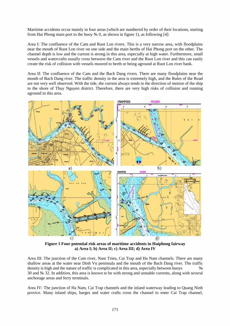
171
Maritime accidents occur mainly in four areas (which are numbered by order of their locations, startingfrom Hai Phong main port to the buoy № 0, as shown in figure 1), as following [4]:
Area I: The confluence of the Cam and Ruot Lon rivers. This is a very narrow area, with floodplainsnear the mouth of Ruot Lon river on one side and the main berths of Hai Phong port on the other. Thechannel depth is low and the current is strong in this area, especially at high water. Furthermore, smallvessels and watercrafts usually cross between the Cam river and the Ruot Lon river and this can easilycreate the risk of collision with vessels moored to berth or being aground at Ruot Lon river bank.
Area II: The confluence of the Cam and the Bach Dang rivers. There are many floodplains near themouth of Bach Dang river. The traffic density in the area is extremely high, and the Rules of the Roadare not very well observed. With the tide, the current always tends to the direction of motion of the shipto the shore of Thuy Nguyen district. Therefore, there are very high risks of collision and runningaground in this area.
Figure 1 Four potential risk areas of maritime accidents in Haiphong fairwaya) Area I; b) Area II; c) Area III; d) Area IV
Area III: The junction of the Cam river, Nam Trieu, Cai Trap and Ha Nam channels. There are manyshallow areas at the water near Dinh Vu peninsula and the mouth of the Bach Dang river. The trafficdensity is high and the nature of traffic is complicated in this area, especially between buoys №30 and № 32. In addition, this area is known to be with strong and unstable currents, along with severalanchorage areas and ferry terminals.
Area IV: The junction of Ha Nam, Cai Trap channels and the inland waterway leading to Quang Ninhprovice. Many inland ships, barges and water crafts cross the channel to enter Cai Trap channel,
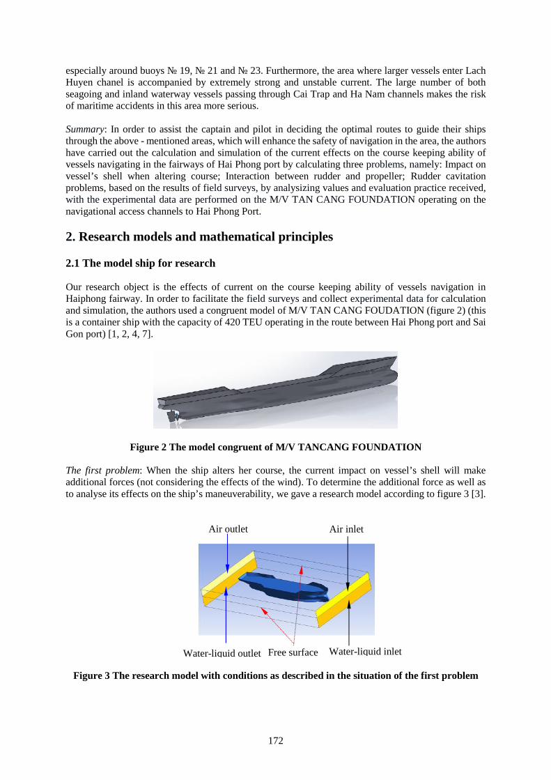
172
especially around buoys № 19, № 21 and № 23. Furthermore, the area where larger vessels enter LachHuyen chanel is accompanied by extremely strong and unstable current. The large number of bothseagoing and inland waterway vessels passing through Cai Trap and Ha Nam channels makes the riskof maritime accidents in this area more serious.
Summary: In order to assist the captain and pilot in deciding the optimal routes to guide their shipsthrough the above - mentioned areas, which will enhance the safety of navigation in the area, the authorshave carried out the calculation and simulation of the current effects on the course keeping ability ofvessels navigating in the fairways of Hai Phong port by calculating three problems, namely: Impact onvessel’s shell when altering course; Interaction between rudder and propeller; Rudder cavitationproblems, based on the results of field surveys, by analysizing values and evaluation practice received,with the experimental data are performed on the M/V TAN CANG FOUNDATION operating on thenavigational access channels to Hai Phong Port.
2. Research models and mathematical principles
2.1 The model ship for research
Our research object is the effects of current on the course keeping ability of vessels navigation inHaiphong fairway. In order to facilitate the field surveys and collect experimental data for calculationand simulation, the authors used a congruent model of M/V TAN CANG FOUDATION (figure 2) (thisis a container ship with the capacity of 420 TEU operating in the route between Hai Phong port and SaiGon port) [1, 2, 4, 7].
Figure 2 The model congruent of M/V TANCANG FOUNDATION
The first problem: When the ship alters her course, the current impact on vessel’s shell will makeadditional forces (not considering the effects of the wind). To determine the additional force as well asto analyse its effects on the ship’s maneuverability, we gave a research model according to figure 3 [3].
Figure 3 The research model with conditions as described in the situation of the first problem
Air outlet Air inlet
Water-liquid outlet Water-liquid inletFree surface
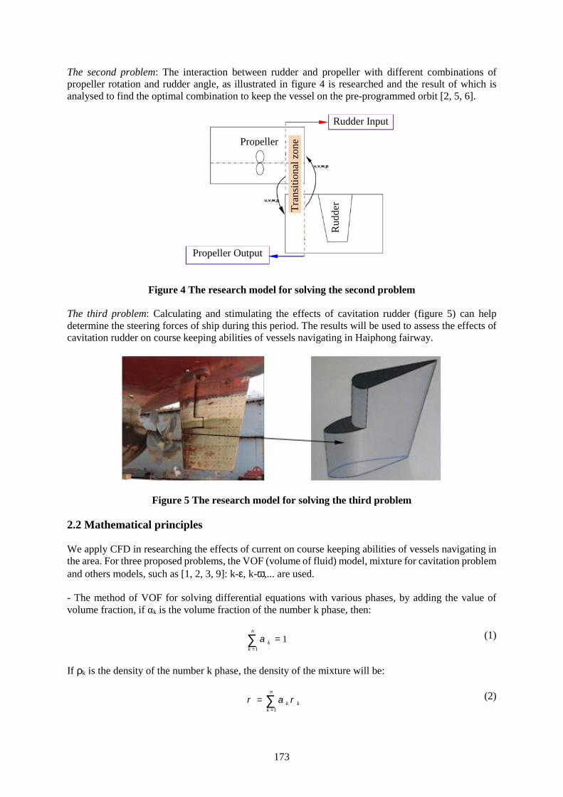
173
The second problem: The interaction between rudder and propeller with different combinations ofpropeller rotation and rudder angle, as illustrated in figure 4 is researched and the result of which isanalysed to find the optimal combination to keep the vessel on the pre-programmed orbit [2, 5, 6].
Figure 4 The research model for solving the second problem
The third problem: Calculating and stimulating the effects of cavitation rudder (figure 5) can helpdetermine the steering forces of ship during this period. The results will be used to assess the effects ofcavitation rudder on course keeping abilities of vessels navigating in Haiphong fairway.
Figure 5 The research model for solving the third problem
2.2 Mathematical principles
We apply CFD in researching the effects of current on course keeping abilities of vessels navigating inthe area. For three proposed problems, the VOF (volume of fluid) model, mixture for cavitation problemand others models, such as [1, 2, 3, 9]: k-, k-,... are used.
- The method of VOF for solving differential equations with various phases, by adding the value ofvolume fraction, if αk is the volume fraction of the number k phase, then:
1
1n
kk
(1)
If k is the density of the number k phase, the density of the mixture will be:
1
n
k kk
(2)
Propeller
Rud
der
Rudder Input
Propeller Output
Tra
nsiti
onal
zon
e

174
Then, we solve major differential equations to determine specific values:
1
1k
nk
k k pk kpkk
v s m mt
(3)
The value of volume fraction is determined by time step:
1 1
1 1 1
1k
n n n n nn n nk k k kk k kf pk kp
f k
U s m m Vt
(4)
In the equation: n - the previous time step; (n+1) - the current time step; αkf - the representative value ofvolume fraction of the number k phase; V - the volume of the calculating element; Uf - the volume ofwater flowing through the surface according to linear methods;
kpm - the mass transferred from phase
number p to phase number k; sαk = 0.
The velocity distribution and energy can be determined by momentum equation and energy equation:
tv v v p v v g Ft
(5)
eff hE v E p k T st
(6)
T - temperature; E - energy and the value of E can be determined according to (7):
1 1
/n n
k k k k kk k
E E
(7)
The standard equation describes the flow and turbulence effect in the mixture model. The vapor transportequation determines the vapor mass fraction fvap by the following equation.
. . . .j
vapvap vap vap e c
j j j
ff f u R R
t x x x
(8)
In which: Re, Rc dependent on the values of static pressure p and saturation vapor pressure pvap:
If p < pvap: 2
13vapch
e e l vap vapl
p pvR C f
(9)
If p > pvap: 2
3vapch
c c l l vapl
p pvR C f
(10)
In which: vch - characteristic velocity (m/s); Ce, Cc - empirically constants (Ce = 0.02; Cc = 0.01) [8,10].
3. Analysing results
3.1 The result of the first problem
Due to the limitation of the article, we calculate two situations with input parameters as following:- Situation 1: The ship’s true course is 0000, the speed Vs is 5 m/s, wind speed Vw is 0 m/s.- Situation 2: The ship’s true course is 0150, the speed Vs is 5 m/s, wind speed Vw is 0.
175
Figure 6 The simulation results of the distribution of static pressure on both sides of the vessel(the submerged area only) (a) and contour of volume fraction (air) (b)
In situation 1, the distribution of static pressure on both sides of the ship is nearly symmetrical. In orderto have a more detailed look, we can analyse one waterline as following:
Figure 7 The simulation results of the distribution of static pressure (a)and pressure coefficient along the surveyed waterline (b)
Based on the result shown in figure 7, we come to the verdict: The distribution of static pressure on bothside of the waterline is symmetrical and the pressure distributing coefficient along the waterline on bothside of the vessels are near equal. There is no additional force impact on the ship’s hull in this situation.
When the ship alters her course to 0150 (situation 2), this situation can be considered as if the currentflew around the ship’s hull with an angle of 150 to the ship’s center line. The simulation result ismeasured on the same waterline as in situation 1.
Figure 8 The simulation results of the distribution of static pressureon both sides of the vessel (submerged area only)
a) b)
176
Figure 9 The simulation results of the distribution of static pressure (a)and pressure coefficient along the surveyed waterline (b)
Based on the result shown in figure 9, we come to the verdict: The distribution of static pressure on twosides of the vessel is not symmetrical. Specifically, the pressure coefficient Cp is divided into two lineswith noticeable difference, which indicates the presence of additional force impact on the ship’s hull. Inthis article, we do not carry out qualitative calculations for different specific situations but ratherintroduce the procedures and expanded possibility for the research problem.
3.2 The result of the second problem
The simulation results are the contours of axial velocity and contours of turbulent viscosity on thetransitional zone when experiencing two situations with different propeller rotation, the first time withn1 = 90 r.p.m and the second with n2 = 150 r.p.m (which correspond with the lowest and highest r.p.mof M/V TAN CANG FOUNDATION when operating in the fairway).
Situation 1: n1 = 90 r.p.m (figure 10).
Figure 10 The simulation results of contours of axial velocity and contours of turbulent viscosity
Situation 1: n2 = 150 r.p.m (figure 11).
Figure 11 The simulation results of contours of axial velocity and contours of turbulent viscosity
Based on the received results as illustrated on figure 10 and figure 11, it is clear that the steering forcescorrespond with various combinations of r.p.m and the rudder angle can be determined in order to findthe optimal combination to keep the ship on the pre-programmed orbit. The outcome of this researchwill be published on sequence reports.
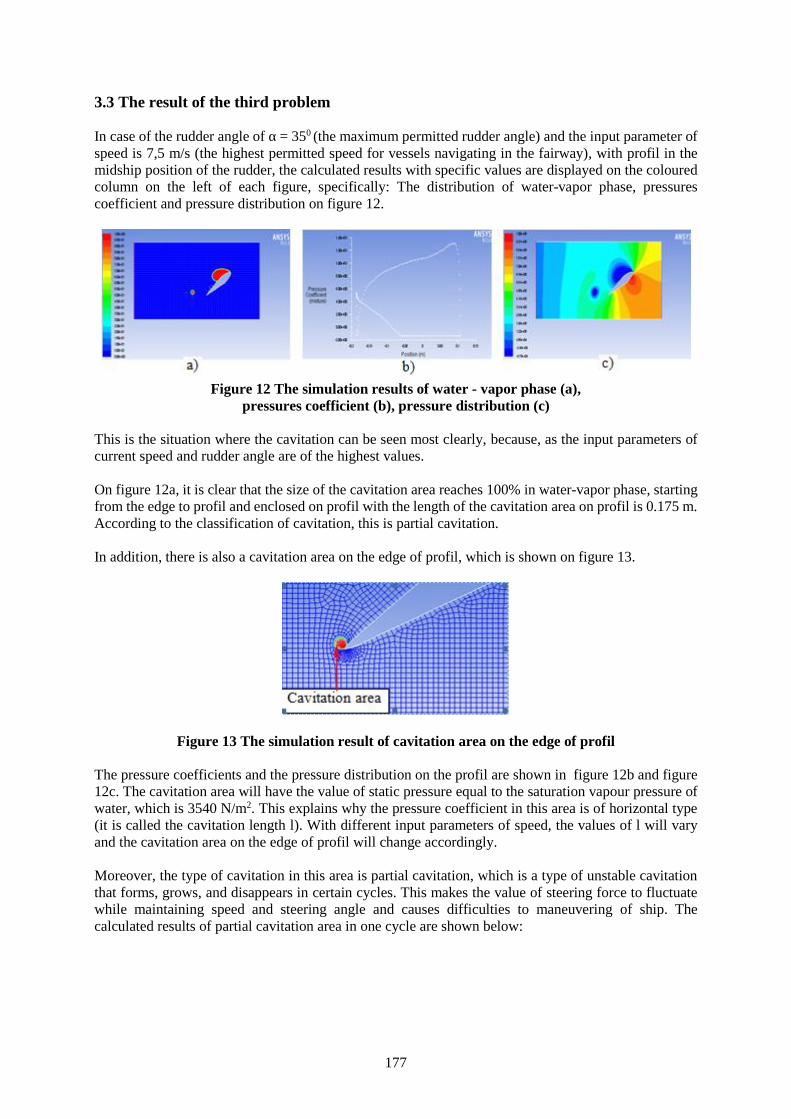
177
3.3 The result of the third problem
In case of the rudder angle of α = 350 (the maximum permitted rudder angle) and the input parameter ofspeed is 7,5 m/s (the highest permitted speed for vessels navigating in the fairway), with profil in themidship position of the rudder, the calculated results with specific values are displayed on the colouredcolumn on the left of each figure, specifically: The distribution of water-vapor phase, pressurescoefficient and pressure distribution on figure 12.
Figure 12 The simulation results of water - vapor phase (a),pressures coefficient (b), pressure distribution (c)
This is the situation where the cavitation can be seen most clearly, because, as the input parameters ofcurrent speed and rudder angle are of the highest values.
On figure 12a, it is clear that the size of the cavitation area reaches 100% in water-vapor phase, startingfrom the edge to profil and enclosed on profil with the length of the cavitation area on profil is 0.175 m.According to the classification of cavitation, this is partial cavitation.
In addition, there is also a cavitation area on the edge of profil, which is shown on figure 13.
Figure 13 The simulation result of cavitation area on the edge of profil
The pressure coefficients and the pressure distribution on the profil are shown in figure 12b and figure12c. The cavitation area will have the value of static pressure equal to the saturation vapour pressure ofwater, which is 3540 N/m2. This explains why the pressure coefficient in this area is of horizontal type(it is called the cavitation length l). With different input parameters of speed, the values of l will varyand the cavitation area on the edge of profil will change accordingly.
Moreover, the type of cavitation in this area is partial cavitation, which is a type of unstable cavitationthat forms, grows, and disappears in certain cycles. This makes the value of steering force to fluctuatewhile maintaining speed and steering angle and causes difficulties to maneuvering of ship. Thecalculated results of partial cavitation area in one cycle are shown below:
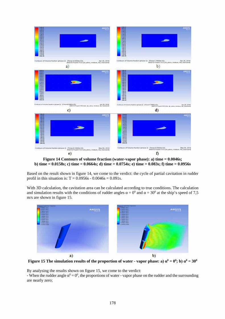
178
Figure 14 Contours of volume fraction (water-vapor phase): a) time = 0.0046s;b) time = 0.0158s; c) time = 0.0664s; d) time = 0.0754s; e) time = 0.083s; f) time = 0.0956s
Based on the result shown in figure 14, we come to the verdict: the cycle of partial cavitation in rudderprofil in this situation is: T = 0.0956s - 0.0046s = 0.091s.
With 3D calculation, the cavitation area can be calculated according to true conditions. The calculationand simulation results with the conditions of rudder angles α = 00 and α = 300 at the ship’s speed of 7,5m/s are shown in figure 15.
Figure 15 The simulation results of the proportion of water - vapor phase: a) α0 = 00; b) α0 = 300
By analysing the results shown on figure 15, we come to the verdict:- When the rudder angle α0 = 00, the proportions of water - vapor phase on the rudder and the surroundingare nearly zero;
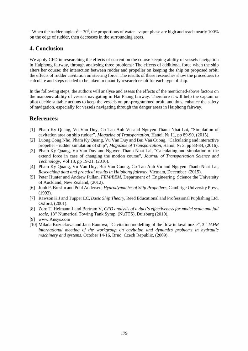
179
- When the rudder angle α0 = 300, the proportions of water - vapor phase are high and reach nearly 100%on the edge of rudder, then decreases in the surrounding areas.
4. Conclusion
We apply CFD in researching the effects of current on the course keeping ability of vessels navigationin Haiphong fairway, through analysing three problems: The effects of additional force when the shipalters her course; the interaction between rudder and propeller on keeping the ship on proposed orbit;the effects of rudder cavitation on steering force. The results of these researches show the procedures tocalculate and steps needed to be taken to quantify research result for each type of ship.
In the following steps, the authors will analyse and assess the effects of the mentioned-above factors onthe manoeuvrability of vessels navigating in Hai Phong fairway. Therefore it will help the captain orpilot decide suitable actions to keep the vessels on pre-programmed orbit, and thus, enhance the safetyof navigation, especially for vessels navigating through the danger areas in Haiphong fairway.
References:
[1] Pham Ky Quang, Vu Van Duy, Co Tan Anh Vu and Nguyen Thanh Nhat Lai, “Simulation ofcavitation area on ship rudder”, Magazine of Transportation, Hanoi, № 11, pp 89-90, (2015).
[2] Luong Cong Nho, Pham Ky Quang, Vu Van Duy and Bui Van Cuong, “Calculating and interactivepropeller - rudder simulation of ship”, Magazine of Transportation, Hanoi, № 3, pp 83-84, (2016).
[3] Pham Ky Quang, Vu Van Duy and Nguyen Thanh Nhat Lai, “Calculating and simulation of theextend force in case of changing the motion course”, Journal of Transportation Science andTechnology, Vol 18, pp 19-21, (2016).
[4] Pham Ky Quang, Vu Van Duy, Bui Van Cuong, Co Tan Anh Vu and Nguyen Thanh Nhat Lai,Reseaching data and practical results in Haiphong fairway, Vietnam, December (2015).
[5] Peter Hunter and Andrew Pullan, FEM/BEM, Department of Engineering Science the Universityof Auckland, New Zealand, (2012).
[6] Jonh P. Breslin and Poul Andersen, Hydrodynamics of Ship Propellers, Cambrige University Press,(1993).
[7] Rawson K J and Tupper EC, Basic Ship Theory, Reed Educational and Professional Puplishing Ltd.Oxford, (2001).
[8] Zorn T, Heimann J and Bertram V, CFD analysis of a duct’s effectiveness for model scale and fullscale, 13th Numerical Towing Tank Symp. (NuTTS), Duisburg (2010).
[9] www.Ansys.com[10] Milada Kozuckova and Jana Rautova, “Cavitation modelling of the flow in laval nozle”, 3rd IAHR
international meeting of the workgroup on cavitaion and dynamics problems in hydraulicmachinery and systems. October 14-16, Brno, Czech Republic, (2009).
180
Confined space operations
Lecturer, Philip Mackrill1, Associate lecturer, Lyndon Gabites 2, Lecturer, Anthony Beckett 3
1. Australian Maritime College, [email protected] , University of Tasmania, Launceston 7250,Australia.
2. Australian Maritime College, [email protected]. Australian Maritime College, [email protected]
Abstract The intent of this paper is to further stimulate a global approach to managing the risk exposurefor seafarers working in, on or around confined spaces. Whilst this requires a holistic approach, thispaper focuses on the standards of training and competence, in an effort to enhance the human andconfined space operations interface within maritime specific training, drills, equipment and regulatoryaspects. The ultimate aim being to mitigate the rate of injury and fatal incidences.
It is widely accepted in the maritime industry workingin, on or around confined spaces has its risks.Whilst these risks are controllable, incidents resulting in serious injury and fatalities are nothing new,thecontinued loss of seafarer lives must be addressed.
In an effort to improve safety, the International Maritime Organisation (IMO) released its revisedrecommendations for entering enclosed spaces aboard ships in 2011. However incidents listed bymaritime investigation bodies since the adoption of the IMO’s revised recommendations, suggest moreneeds to be done. The introduction of mandatory entry & rescue drills are certainly a move in the rightdirection; question is, are they enough to positively influence safety and reduce incidents? Or do theysimply provide a mechanism to tick the compliance box.
Why is it, in this day and age, seafarers are still succumbing to the hazards and risks of these spaces?Investigative reports often cite the cause of fatalities, as atmospheric, this being the most common hazard.What is contributing to these lethal situations? Is it a combination of error inducing factors at individual,job or organisational levels?
More needs to be done in developing and embracing standards, including operational, equipment andtraining to enhance human reliability and reduce error inducing factors and those fatal consequencesthat follow. Could part of the answer be the introduction of confined space training under the mandatoryStandards of Training, Certification and Watchkeeping (STCW) structure?
Keywords: Competence, standards of training certification and watchkeeping, confined space operations,fatalities, error inducing factors, relevant.
1. Introduction
‘Seafaring has always been one of the world's most dangerous occupations’ [25]. The maritimeindustries guidelines and regulations have been developed and enhanced in response to many incidentsover the years. In 1912 when the RMS Titanic collided with an iceberg tearing a hole in her, many liveswere lost. This event prompted the creation of the International Convention for the Safety of Life at Sea(SOLAS) with the first convention enacted in 1914 [26]. Standards for training, certification andwatchkeeping were introduced in 1978, through the implementation of the International Convention onStandards STCW.
Prior to this, standards were set by the governments of each country, subsequently the standards acrossthe global maritime industry proved inconsistent. [27].
Across the globe, countries/flag states have various regulatory frameworks and guidance documents,along with recommendations from the IMO and yet, fatalities continue to occur.
181
Standards for training associated with enclosed/confined space currently remains under the control ofgoverning countries with a wide range of standards. The vast differences in approaches to confinedspace is supported by a global survey conducted in 2011 by Enhesa, anenvironmental, health and safetyconsultancy firm, specialising in supporting business to meet regulatory requirements. Enhesa found, ofthe sixty countries surveyed, “no two countries used the same regulatory approach”. [16] As themaritime industry has a diverse multicultural workforce, would it not make sense to standardise thistraining under the STCW.
2. Background
Incidents resulting in fatalities in, on or around confined spaces aboard ships are nothing new; sadly this‘unnecessary and avoidable loss of seafarer’s lives’ [3] is a theme that has been continuing for manyyears. For the ill-informed or ignorant seafarer, confined spaces may be likened to aniceberg. Whilstthe top of the space can be clearly seen, they may not appreciate orbe aware of what may lay beneaththe surface. In this day of age it is reasonable to expect seafarers to have a heightened level of knowledgeand awarenessof the risks whichmay be associated with confined spaces.
Whilst the loss of lives attributed to confined space work on vesselsshould not occur,it does!Accordingto Patraiko D[1] this remains‘a deadly serious issue, and one which the marine industry has to come togrips with,’this is further echoed by Lloyd and Allan’s view that the maritime industry ‘have reached acritical situation with more people injured and dying in enclosed spaces than through any other relatedon-board work activity.’[2] Surely the time has come for change of mindset, withmore needing to doneto address the continued loss of seafarer’s lives.The international maritime community must becomemore proactive and move to develop, embrace and enforce standards, whichaddress the harsh realitiesof confined space operations within the industry. It is time to getserious about this deadly issue.
It is the opinion of the author’s that forward progress to reduce the rate of incidences can only beachieved throughaholistic approach addressing aspects such as; ship design, safety culture, procedures,appropriate equipment &most importantly seafarer competence.
3. Confined space fatalities
In 2007 the Maritime Accident Investigators International Forum (MAIIF), identified the rate ofincidence, resulting in fatalities and serious injuries across the maritime industry on global scale wasincreasing [4]. In 2008 the Marine Accident Investigation Branch (MAIB) of the United Kingdom,releaseda global safety bulletin, highlighting the issue of fatalities as a result of spate of confined spacesincidents. Contained within, the MAIB released details that the MAIIF had received responses fromeighteen flag states at this time identifying “120 fatalities and 123serious injurieshad occurred since1991”. [4]
The industry as a whole should be horrified by these figures derived from such a small percentage offlag states, particularly when one considers what the magnitude of the true figures could be, if all flagsstates data had been included. It is fair to say that we may never know or appreciate the true magnitudeof seafarers who have sustained fatal injuries, serious injuries, minor injuries and/or near misses. Thisis a significant challenge for the maritime industry, but it is one that must be undertaken. The time forchange has come.
Confined space fatalities and serious injuries are not restricted to international shipping alone. It affectsall of the maritime industry regardless of; the ship’s country of origin, seafarer’s nationality, or theposition one holds in the crew compliment. People are dying in these spaces unnecessarily, fromcadetsstarting their careersto thechief officer and all that come between. No singular vessel type is exempt; itoccurs on them all, tankers, bulk cargo, containerships, passenger liners, roll on roll off, trawlers, barges,cruise vessels, research vessels and the list goes on.
182
4. Continuing incidents
The incidence of seafarers sustaining injury when interacting with confined spaces are continuing, thefollowing incidents represent a brief overview: March 2014 a first mate, died from asphyxiation afterentering a hold containing zinc concentrate. During the rescue the space was found to have an oxygenconcentration of 2.8%. [5] May 2014 two crewmen and a chief officer lost their lives during preparationto unload a vessel with a cargo of sawn timber and the rescue party narrowly escapeddeathduring therescue. [6] August 2013 during an attempted recovery of a broken oil sampler, a master lost his life anda cadet sustained injuries. Prior to their entry atmospheric testing established the following readings20.6% oxygen, with HC at 26% of LEL. [7] June 2011a chief officer and a crew member, peeredthrougha hatch and saw thebosun lying motionless. Theyraised the alarm, prior to the emergency team arriving,the chief officer entered the space to assist he collapsed, the other seaman entered to help he collapsed.All three were recovered from the space, the chief and seaman recovered in hospital however the bosundied. [8] November 2009, a chief mate on a chemical tanker lost his life after entering a cargo tankcontaining hydrocarbon vapours and deficient in oxygen. [9] May 2009 a chief officer and an ableseaman went to the aid of other crew member who was overcome bya toxic cocktail ofhydrogensulphide, volatile organic compounds (VOCs) and mercaptans vapours. The chief officer was overcomeas they had no respiratory protection; luckily they made a full recovery [10]
The following incidents highlight that one does not need to be in the space, to be impacted by it:November 2001, eight seafarers lost their lives as a result of a ballast tank explosion that occurred duringthe painting, of the eight only one crew member was in the space. [11] July 1996, three seafarers losttheir lives and six sustained irreversible medical conditions, when anengineer opened a refrigeratedseawater tank’s side door. The engineer was quickly overcome, two seafarers who came to his aid wereovercome and six others in the vicinity were injured. [12] These examples are a small sample of deathand injury associated with confined spaces and without serious interventionincidenceswill continue togrowand seafarers will continue to die.
5. Contributing factors
After a serious incident investigationsare conducted to ascertain the root cause and determine howsimilar incidents can be prevented. The contributing factors can often be referred to as ‘human factorswhich fall into three basic categories, individual, job & organisational’ [22]. Investigative reports willidentify a range of factors that may have contributed to a fatalityor serious injury. Common themes re-emerge time after time. They are: lack of competence, acting on impulse or emotional decisions(rescuer), inability to identify confined spaces, complacency and failure to follow confined space entryprocedures including: poor preparation and planning, inability to identify hazards, risks and suitablecontrol measures. The list continues withineffectivesafety management system procedures, lackofequipment which is fit for purpose, or inappropriate use of equipment and training in the use ofequipment. If these ‘factors are not managed they are known as error inducing factors’. [22]
‘Often the concept of human error leads to the conclusion that the intervention should be directedtowards the human operator e.g. more training, better education’etc. [21] and while this conclusion isnot always the cause, there can be no better argument for better skills and knowledge development forthose likely to be affected by confined spaces.
6. Who needs to address this?
The International Maritime Organisation (IMO) principal function is to facilitate the development,implementation and maintenance of international regulatory frameworks that support internationalshipping. One of these areas is safety, which is addressed through the Safety of Life at Sea (SOLAS)convention. [13] The SOLAS convention is considered to be one of most important conventions, thefirst convention coming about after the sinking of the Titanic. Since then there hasbeenmodifications,updates, amendments and subsequent release of consolidated versions.
183
There is no disputing that the IMO has achieved much in the area of safety, for example the regulatoryframework surrounding the prevention of fire through the Fire Safety Systems (FFS) code and the levelsof training to prevent and respond to fireaddressed by the Standards of Training & Certification forWatchkeepers (STCW) issound. However! Compared to the likes of fire little has been done to stem thewake of fatalities and injuries, which continuesaboard ships when working in, on or around confinedspaces.
In 1997 the IMO provided guidancefor the entering of enclosed / confined spaces through theintroduction ofthe Resolution A.864 (20) Recommendations for entering enclosed spaces aboardships.[28] Sadlysince the adoption of the resolution andup until 2009there ‘have been at least 101 incidents,resulting in 93 deaths and 96 injuries’. [14] November 2011 saw the adoption ofrevisedrecommendations through Resolution A.1050(27). These recommendations provide sound guidance,however they are not mandatory. They ‘are intended to compliment national laws or regulations’. [15]Whilst it seems feasible to use such recommendations to compliment national laws and regulations,national laws and regulations are typically orientated to the land and not necessarily designed forconfined space work in remote and isolated situations such as shipping. It has previously been statedthat, the regulatory approaches found across the countries of the world are very different. This in turnimpacts on how a confined space is defined and as a result how confined space work is approached.
In January 2015 a new resolution came into force, bringing change to SOLAS chapter three regulationnineteen (Emergency Training & Drills). This requires seafarers with roles and responsibilities relatingto confined space entry & rescue, to participate in drills at least once every two months [17]. Thisresolution refers to ‘revised recommendations for entering enclosed spaces aboard ships’, [18] Thesemandated entry & rescue drills are certainly a move in the right directionthe question is, are they enoughto positively influence safety and reduce incidents? Or do they simply provide a mechanism to tick thecompliance box? Anecdotal evidence suggests that there is room for improvement at all human factorlevels, with particular emphasis on individual factors.
In general terms the maritime industry tends not to use the term ‘confined space’, instead continuing touse the term ‘enclosed space’, which the IMO “defines asa space which has limited openings for entryand exit; inadequate ventilation; and is not designed for continuous worker occupancy”.[18]Thisdefinition fails to bring to the attention of seafarers working in on or around confined spaces thepotential, and foreseeable risks; furthermore many hazardous areas are only partially enclosed.Couldthe IMO’s definition contribute to seafarer’s not recognising areas that are potentially life threatening.
Whilst the requirement to conduct drills for confined space entry and rescue isacknowledged, a questionremains, what standards underpin the training, procedures and equipment requirements of those drills?Could substandard knowledge, skillsand acceptance of inappropriate equipment be inadvertentlyperpetuated?
7. Time to change the mindset
All too often when discussions occur, procedures are written or legislation is drafted the term confinedspace “entry” is used. Entry being: “the act or instance of entering, a point or place for entering” [19]Use of the term entry might also lead people into a false sense of security, i.e. if we are not actuallyentering the space, there is minimal or no risk! Rather than thinking about the entire operation at handor indeed acknowledging the high casualty count of people affected by confined spaces without enteringthem. E.g. Eight seafarers died when a ballast tank exploded, only one had entered the space. [11] Threeseafarers died and the six sustained irreversible respiratory damage, no one had entered the space. [12]It is the opinion of the author’s that the term confined spaceshould be used rather than enclosed space.This allows for a broader and more risk based definition, such as the one used by the Australianregulatory framework as listed below:
184
‘A confined space means an enclosed or partially enclosed space that: is not designed or intended primarily to be occupied by a person; and is, or is designed or intended to be, at normal atmospheric pressure while any person is in the
space; and is or is likely to be a risk to health and safety from:
o an atmosphere that does not have a safe oxygen level, oro contaminants, including airborne gases, vapours and dusts, that may cause injury from
fire or explosion, oro harmful concentrations of any airborne contaminants, oro engulfment’. [29]
If the maritime industry enforced the adoption of a more holistic approach and used terms like confinedspace operations: operations being ‘a process, method or series of acts especially of a practical ormechanical nature’ [19] instead of enclosed space entry, could this lead to greater awareness, increasedsafety, supporting a reduction in the rate incidents and unnecessary loss of life.
As the broader maritime industry is a truly global industry, it makes perfect sense that an internationalmaritime standard for confined space operations aboard ships be developed. In doing so all regulators,shipping companies, operators and seafarers across the maritime industry could consistently address theissues associated with these high risk operations.
The industry as a whole needs to change itsmindsettowards how work in, on or around confined spacesis conducted. The starting point for this change must rest with the International Maritime Organisationby laying down mandates followed by a collaborative approach amongstindustry stakeholders to reducethe risk. This holistic change should include, but not be limited to, ship designers, safety culture,procedures, equipment, and competence.
7.1 Designers
Wherever possible during the design process and subsequent manufacturing of ships, attention shouldbe given to remove thenecessity to enterconfined spaces. Where elimination is not a realistic option,spaces should be designed in a manner to reduce the risks associated when entering and working in thespace. Consideration needs to be given to ease of access, exiting, retrieval and emergency extricationfrom such spaces.
7.2 Safety Culture
Most would be aware of situations were errors of judgement or complacency and the outright ignoringof procedures have led to serious injury and/or the loss of life. Some might assume this is the juniorseafarers unfortunately this is not the case, even chief officers that should know better, but probablydon’t, are making these fatal errors. If senior personnel are exhibiting a lack of knowledge, know how,or promote cutting corners, what message does this send to other crew members.
It is the opinion of the authorsthat in order to support an industry wide improvement in safety culture,there needs to be more specific regulatory frameworks in place underpinned by standards of trainingand competence levels. A good foundation to support such change is the development andimplementation of sound confined space management plans, an outline of which was published in 2013in the maritime journal Seaways. [20]
7.3 Procedures
Each vessel should have confined space management plans complete with checklists embedded withinthe Safety Management System that outlines a clearly defined processthat seafarers can work throughto safely undertake work in on or around confined spaces. Theplan should highlight what is required to
185
done; before work commences, during occupancy, upon exiting and what to do in the event of a confinedspace emergency. These procedures should be supported by realistic and relevant training drills andauditing system to validate and monitor compliance on board.
7.4 Equipment Use
Anecdotal evidence identifies in some cases crew members are entering spaces without personalatmospheric detection, leaving them vulnerable and unaware of atmospheric changes. Whilst manyvessels have atmospheric detectors of sort, it is as of 1st July this year ‘a new SOLAS regulation XI-1/7on Atmosphere testing instrument for enclosed spaces, to require ships to carry an appropriate portableatmosphere testing instrument or instruments, capable of measuring concentrations of oxygen,flammable gases or vapours, hydrogen sulphide and carbon monoxide, prior to entry into enclosedspaces’ [30].
Thereshould be a minimum standard of equipment defined by the industry and specific training in theuse of the equipment should be mandated. Having the right equipment is one thing knowing how to useit is another, which brings us back to competence of the seafarer.
8. Competence
The definition of competence has been argued for many years and is not the subject of debate in thisarticle, for the purpose of this paper competence will be referred to as the ability to complete a job taskefficiently and safely (trained) which is different to knowing how to do it (educated).
‘Education and training are not the only two factors affecting individual competences. Other factorsshould also be considered. For example, personal characteristics such as ability, experience, cognitivecapacities, receptiveness, behaviour, knowledge background etc. Also the environment to whichindividuals are exposed to; whether in their personal environment or in the organisation environmentthat they work in are important factors.’ [31]
The citation above supports the concept that competence is an ability based measure which is achievedthrough the practical application of knowledge and skills over time in a range of circumstances toenhance, maintain and fine tune initial training or education. To this end, someone who has completeda formal training course, is able to apply the principles of that learning back to their work place and ableto adapt those principles to the unique nature of the jobunder initial guidance should be able to workmore safely, efficiently and effectively into the future.
It can be argued that personal characteristics, like abilities, change over time based on the opportunityto apply learned knowledge and skills. This trait is often accelerated when similar past experiences areused to support the evolution of those particular work abilities. However, it needs to be acknowledgedthat workplace guidance from colleagues and supervisors can act as both positive and negativeinfluences on the development and maintenance of initial training based on the attitude, practical skillsand level of knowledge that they hold. This raises the question, are the supervisors competent tosupervise confined space entry procedures?
9. Recommendation
Current evidence overwhelmingly suggests that something needs to be done and soon. A valuablesupport mechanism would be the adoption and implementation of an IMO model course with mandatorytraining outcomes to be agreed at an STCW convention with mandatory refresher training as is the casewith other safety based courses.A three days course that covers at least the following, should form the basis of the mandatory STCWcourse for confined space operations.
186
Day1: the basic knowledge and skills required by an individual to participate as part of a confined spacework team including but not limited to: Defining a confined space, roles and responsibilities, hazardidentification, risk assessment, control measures, isolation practices, entry and retrieval equipment,permit requirements, stand by attendants, planning for emergencies.
Day 2: gas detection and the use of atmospheric detection equipment and respiratory protection,including self-contained breathing apparatus (SCBA) and airline systems; &
Day 3: theoretical and practical aspect of confined space rescue, specific to shipboard environments.
10. Conclusion
At present there are substandard procedures and practices being undertaking in the maritime industrywith devastating effect, which are leading to the loss of seafarers lives. The maritime industry as awhole including: maritime institutions, shipping companies, associations, unions all need to step up andbecome more proactive in addressing this issue.
There is a clear need to mandate standards of training for confined space operations on boardships/vessels. Training needs to be rigorous enough to ensure that course outcomes achieve what theysay they will, and that subsequent assessment of competence is clearly aligned. It is important thatseafarers truly understand, what is needed to work safely in, on or around confined spaces and it isespecially important that those embarking on their careers have a plan to develop their knowledge andskills beyond routine day to day tasks and to have their knowledge and skills challenged from time totime with appropriate refresher training.
Seafarers invariably leave maritime education facilities with a foundation of knowledge and skills thatwill almost always need to be developed and adapted to fit a vessels operations and design, let us allmake that foundation as strong and resilient as we can.
References
[1] Patraiko D, “Enclosed space entry: a deadly serious issue”, Nautical Institute, Sept 2013, Oct 2015,http://www.nautinst.org/en/Media/press/index.cfm/enclosed-space-entry.
[2] Captain Lloyd M, Allan A, The enclosed space management system, Seaways, (2013).[3] Maritime Safety Committee, Resolution MSC.350 (92) Amendments to the International
Convention for Safety of Life at Sea, International Maritime Organisation, (2013)[4] Meyer, S. Fatalities in enclosed space, Marine Accident Investigation Branch, (2008).[5] Dutch Safety Board,Asphyxiated after entering cargo hold, Dutch safety Board, Netherlands,
(2014)http://www.onderzoeksraad.nl/uploads/phase-docs/929/ba0607f279b3b-rapport-hudsonborg-en.pdf
[6] Clinch, S.MAIB Safety Bulletin 3/2014, Marine Accident Investigation Branch, United Kingdom(2014)https://assets.digital.cabinetoffice.gov.uk/media/547c6f0ced915d4c0d000005/Safety_Bulletin3_2014.pdf
[7] Isle of Man Ship Registry, Casulaty Investigation, CA118, Isle of Man ship Registry,(2013)https://www.gov.im/lib/docs/ded/shipregistry/formsdocs/reports/casualty/iompg12.pdf
[8] The Nauatical Institute, Report 201309 Fatality in slop tank, Mariners’ Alerting and ReportingScheme (2013)
[9] Australian Transport Safety Bureau, Fatality on board the chemical tanker Bow De Jin at sea offNew South Wales, ATSB Transport Safety Reports, Barton ACT (2010)
[10] Marine Accident Investigation Branch, Report on the investigation of the release of cargo vapoursresulting in two casualties on board the chemical tanker, Report No. 24/2009. (2009)http://www.maib.gov.uk/cms_resources.cfm?file=/Jo_Eik_Report.pdf
[11] Australian Transport Safety Bureau, Ballast tank explosion and fatalities abord the Nego Kim,Marine Safety Investigation Report 174, ACT Australia (2002)

187
[12] Withington, S. Report of the Inspector’s inquiry into three fatalities and injures to six crewmembers on board FV Atlantic Princess, Marine Accident Investigation Branch, Southhampton(1997) http://www.maib.gov.uk/cms_resources.cfm?file=/atlantic_princess_%20pub_1997.pdf
[13] International Maritime Organisation, Introduction to IMO, International Maritime Organisation,(2013). Retrieved fromhttp://www.imo.org/en/About/pages/default.aspx March 2016
[14] International Maritime Organisation, Sub-Committee on Dangerous Goods, Solid Cargoes andContainers (DSC), 14th session: 21-25 September 2009, (2009).. Retrieved fromhttp://www.imo.org/en/MediaCentre/MeetingSummaries/CCC/Pages/DSC-14th-Session.aspxMay 2016
[15] International Maritime Organisation, Revised - Recommendations for entering enclosed spacesResolution-A 1050 (27), International Maritime Organisation, (2011).
[16] Dumortier T. Hendel-Blackford T. Confined Spaces. Health & Safety International. 40. (2012).Retrieved from http://www.hsimagazine.com/article.php?article_id=59
[17] Maritime Safety Committee. Resolution MSC.350(92) Amendments to the International Conventionfor the Safety of Life at Sea, 1974 As Amended. London, International Maritime Organisation(2013).
[18] International Maritime Organisation, Resolution 1050(27) Revised-recommendations for enteringenclosed spaces aboard ships, International Maritiem Organisation (2011).
[19] Collins Dictionary, English Dictionary, Retrieved from,http://www.collinsdictionary.com/dictionary/english. (2015)
[20] Captain M Lloyd & A Allan, The enclosed space managment system, Seaways, (August 2013), pp5 - 7.
[21] Grech M R, Horberry T J and Koester, Human factors in the martime domain, CRC Press, (2008).[22] National Offshore Petroleum Safety and Environmental Management Authority “Human factors”,
NOPSEMA, 20th May 2016, https://www.nopsema.gov.au/resources/human-factors/[23] National Offshore Petroleum Safety and Environmental Management Authority “Human error”,
NOPSEMA, 20th May 2016, https://www.nopsema.gov.au/resources/human-factors/[24] Harvey C, Stanton N and Zheng P, “Safety at sea human factors aboard ship”, Chartered institute
of ergonomics and human factors, 2013 issue 517, retrieved May 2016,http://www.ergonomics.org.uk/safety-at-sea-human-factors-aboard-ship/
[25] Unknown, “History of safety at sea” International maritime organisation, retrieved May2016,http://www.imo.org/en/KnowledgeCentre/ReferencesAndArchives/HistoryofSafetyatSea/Pages/default.aspx
[26] Unknown, “International convention for the safety of life at sea (SOLAS) 1974” Internationalmaritime organisation, retrieved May 2016,http://www.imo.org/en/About/Conventions/ListOfConventions/Pages/International-Convention-for-the-Safety-of-Life-at-Sea-(SOLAS),-1974.aspx
[27] Unknown, “International convention on the standards of training, certification and watchkeepingfor seafarers (STCW)” International maritime organisation, retrieved May2016,http://www.imo.org/en/About/Conventions/ListOfConventions/Pages/International-Convention-on-Standards-of-Training,-Certification-and-Watchkeeping-for-Seafarers-(STCW).aspx
[28] International Maritime Organisation, Resolution A,864(20) Recommendations for enteringenclosed spaces aboard ships, International Maritime Organisation (1997).
[29] Safe Work Australia, “Confined spaces code of practice”, Safe work australia, Feb 2016, accessedMay 2016, pp5,http://www.safeworkaustralia.gov.au/sites/swa/about/publications/pages/confined-spaces-cop
[30] Unknown, “List of amendments expected to enter into force this year and in the coming years”International maritime organisation, retrieved May2016,http://www.imo.org/en/About/Conventions/Pages/Action-Dates.aspx
[31] Alainati S, AlShawi S, Al-Karaghouli W, “The Effect of Education and Training on Competency”,European and Mediterranean Conference on Information Systems, Abu Dhabi UAE, (2009), pp1-11.
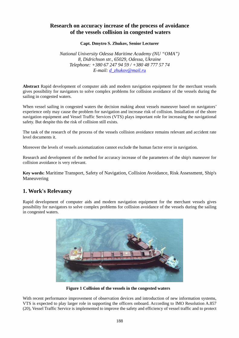
188
Research on accuracy increase of the process of avoidanceof the vessels collision in congested waters
Capt. Dmytro S. Zhukov, Senior Lecturer
National University Odessa Maritime Academy (NU “OMA”)8, Didrichson str., 65029, Odessa, Ukraine
Telephone: +380 67 247 94 59 / +380 48 777 57 74E-mail: [email protected]
Abstract Rapid development of computer aids and modern navigation equipment for the merchant vesselsgives possibility for navigators to solve complex problems for collision avoidance of the vessels during thesailing in congested waters.
When vessel sailing in congested waters the decision making about vessels maneuver based on navigators’experience only may cause the problem for navigation and increase risk of collision. Installation of the shorenavigation equipment and Vessel Traffic Services (VTS) plays important role for increasing the navigationalsafety. But despite this the risk of collision still exists.
The task of the research of the process of the vessels collision avoidance remains relevant and accident ratelevel documents it.
Moreover the levels of vessels axiomatization cannot exclude the human factor error in navigation.
Research and development of the method for accuracy increase of the parameters of the ship's maneuver forcollision avoidance is very relevant.
Key words: Maritime Transport, Safety of Navigation, Collision Avoidance, Risk Assessment, Ship'sManeuvering
1. Work's Relevancy
Rapid development of computer aids and modern navigation equipment for the merchant vessels givespossibility for navigators to solve complex problems for collision avoidance of the vessels during the sailingin congested waters.
Figure 1 Collision of the vessels in the congested waters
With recent performance improvement of observation devices and introduction of new information systems,VTS is expected to play larger role in supporting the officers onboard. According to IMO Resolution A.857(20), Vessel Traffic Service is implemented to improve the safety and efficiency of vessel traffic and to protect
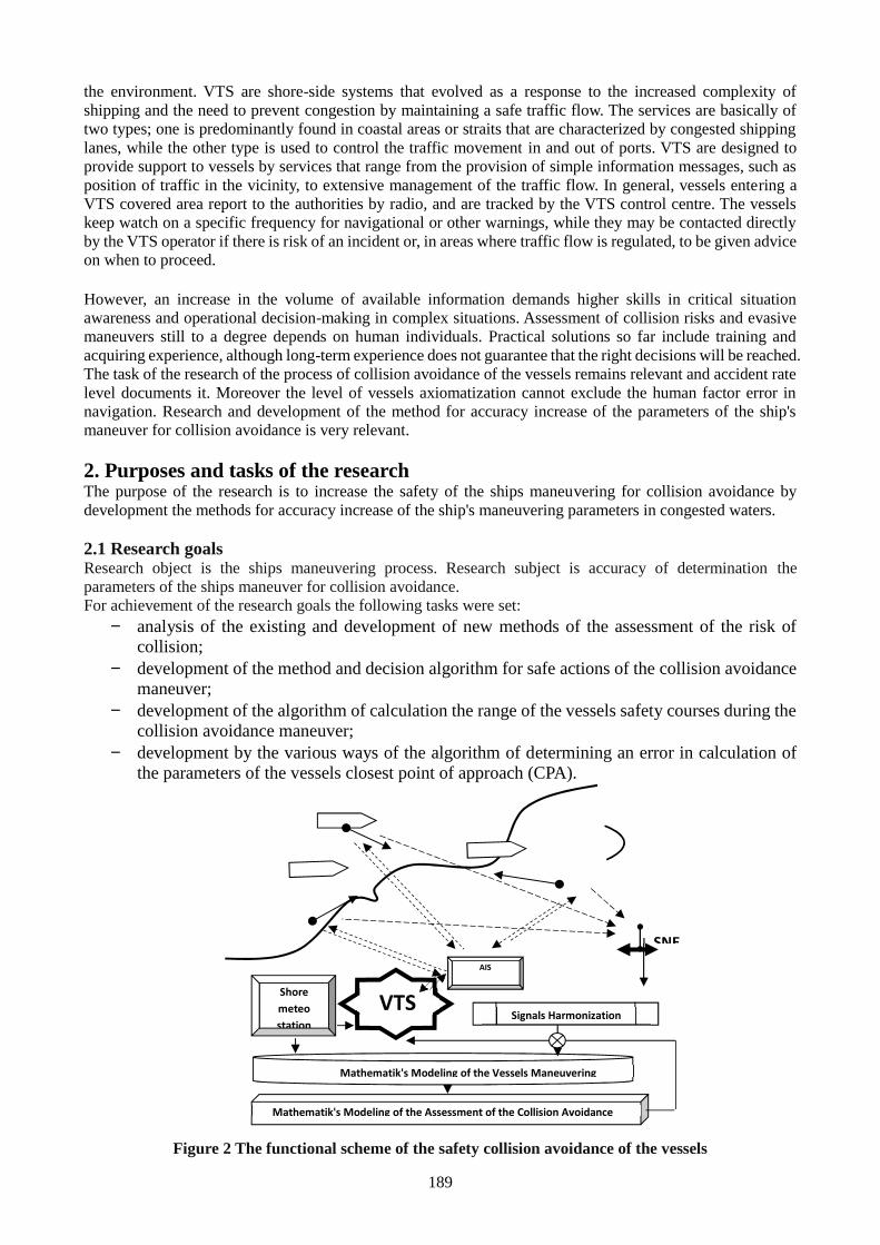
189
the environment. VTS are shore-side systems that evolved as a response to the increased complexity ofshipping and the need to prevent congestion by maintaining a safe traffic flow. The services are basically oftwo types; one is predominantly found in coastal areas or straits that are characterized by congested shippinglanes, while the other type is used to control the traffic movement in and out of ports. VTS are designed toprovide support to vessels by services that range from the provision of simple information messages, such asposition of traffic in the vicinity, to extensive management of the traffic flow. In general, vessels entering aVTS covered area report to the authorities by radio, and are tracked by the VTS control centre. The vesselskeep watch on a specific frequency for navigational or other warnings, while they may be contacted directlyby the VTS operator if there is risk of an incident or, in areas where traffic flow is regulated, to be given adviceon when to proceed.
However, an increase in the volume of available information demands higher skills in critical situationawareness and operational decision-making in complex situations. Assessment of collision risks and evasivemaneuvers still to a degree depends on human individuals. Practical solutions so far include training andacquiring experience, although long-term experience does not guarantee that the right decisions will be reached.The task of the research of the process of collision avoidance of the vessels remains relevant and accident ratelevel documents it. Moreover the level of vessels axiomatization cannot exclude the human factor error innavigation. Research and development of the method for accuracy increase of the parameters of the ship'smaneuver for collision avoidance is very relevant.
2. Purposes and tasks of the researchThe purpose of the research is to increase the safety of the ships maneuvering for collision avoidance bydevelopment the methods for accuracy increase of the ship's maneuvering parameters in congested waters.
2.1 Research goalsResearch object is the ships maneuvering process. Research subject is accuracy of determination theparameters of the ships maneuver for collision avoidance.For achievement of the research goals the following tasks were set:
analysis of the existing and development of new methods of the assessment of the risk ofcollision;
development of the method and decision algorithm for safe actions of the collision avoidancemaneuver;
development of the algorithm of calculation the range of the vessels safety courses during thecollision avoidance maneuver;
development by the various ways of the algorithm of determining an error in calculation ofthe parameters of the vessels closest point of approach (CPA).
Figure 2 The functional scheme of the safety collision avoidance of the vessels
AIS
Receiver
SNE
Signals Harmonization
Shoremeteostation
Mathematik's Modeling of the Vessels Maneuvering
Mathematik's Modeling of the Assessment of the Collision Avoidance
VTS
190
Figure 3 Vessels approaching situation – VTS view
Figure 4 VTS services (source: IALA VTS manual)
2.2 Scientific novelty of the obtained results
191
1 - 90 ≤ α(t); 2 - αмин ≤α(t) ≤ 90; 3 - 0< α(t) < αмин;
4 - -αмин < α(t) ≤ 0; 5 - α(t) ≤ -αмин; 6 - α(t) ≤ 90.
Figure 5 The collision situation dependences by α(t)
α(t)
αмин
Dmin
RMLVA
VB
VAB
α(t)
RML
D min
VA
VA
VAB
VB
RMLαмин
α(t)Dmin
VAB
VB
VA
VA
α(t)
RML
αмин
Dmin
VA
VB
VAB
VA
VA
α(t)
RML
αмин
Dmin
VA
VB
VAB
RML
α(t)
Dmin
1 2
3 4
5 6
192
Minimum value of the α(t):
)()( arcsin
iAB
задiзад D
D (1)
where)( i
ABD - distance between the vessels in time “i”:
2)()(2)()()( iB
iA
iB
iA
iAB YYXXD (2)
The algorithm of vessel's action for collision avoidance is developed. This algorithm considers three types ofmaneuvering for each vessel and its dynamic.The following results with scientific novelty were obtained:
the method of the collision risk assessment by heading angle to relative movement line (RML) wasdeveloped;
the method of vessels collision avoidance during the movement on curvilinear trajectory wasdeveloped;
the conceptual model for the ensuring safety collision avoidance of the vessels was developed; the selection method of the vessel safety action in time of collision avoidance with unlimited number
of the vessels was developed; algorithms of the assessment the calculation error in the CPA parameters were improved.
Figure 6 Block diagram of the collision risk assessment by heading angle to relative movementline(RML)
Determination the angle to RML(α(t))
193
3. Research methods and practical value
For the theoretical part of the research the following methods were used: the method of the operational research,the method of information theory in navigational tasks, mathematical modeling, the theory of randomprocesses with elements of probability theory and mathematics statistics, methods of assessment of thenavigational safety level, differential and integral calculus.
Experimental part of the research included the full scale investigation on the merchant vessels and computersimulation. Experiment data was processed by mathematics statistics methods.
Research results can be used in navigation to increase the navigational safety and reduce the accidents numberby fuller information support for the vessels collision avoidance. Obtained results form base for improvementof the functionality shore based navigational aids and for fuller information support of the navigation incongested waters. Research results concerning automatic calculation of the range of safety courses andselection safety action of the vessels can find application in automatic radar plotting aid (ARPA). Obtainedresults also may be useful for researches and investigation connected with design of ports, canals and vesselstraffic schemes.
References
[1] Aleksandr D. Pipchenko, Dmytro S. Zhukov, “On risk assessment and decision making while controllingthe ship in adverse weather conditions”, IAMU, 2008, AGA 9 Proceeding, pp. 208-214
[2] Benedict, K. et al: “Combining Fast-Time Simulation and Automatic Assessment for Tuning of SimulatorShip Models”, MARSIM - International Conference on Marine Simulation and Ship Manoeuvrability,Terschelling, Netherlands, 2006 Proceedings, M-Paper 19 p. 1-9
[3] Benedict, K., Baldauf, M., Fischer, S., Gluch, M., Kirchhoff, M., « Manoeuvring Prediction Display forEffective Ship Operation On-Board Ships and for Training in Ship Handling Simulators», IAMU 2009,AGA 5 Proceeding, pp. 267-281
[4] Gucma L., Przywarty M. «The Model of Oil Spills Due to Ships Collisions in Southern Baltic Area».TransNav - International Journal on Marine Navigation and Safety of Sea Transportation, 2000, Vol. 2,No. 4, pp. 415-419
[5] Loginovsky V., Fuzzy Interference as approach to Safety Management System (SMS) analysis, IAMU2004, AGA 5 Proceeding, pp. 194-197
[6] Miyusov M., Zhukov D. “The methodological principles of the deck officers training and management ofthe training process”, IAMU 2009, AGA 10 Proceeding, pp. 270-281.
[7] Montewka J., Goerlandt F., Kujala P., Determination of collision criteria and causation factors appropriateto a model for estimating the probability of maritime accidents, Ocean engineering 40, pp. 50-61,2012
[8] Weintrit A., The Electronic Chart Display and Information System (ECDIS), An Operational HandbookA Balkema Book, CRC Press, Taylor & Francis Group, 2009, 1101p.
[9] Демин C.И., Жуков Е.И., Кубачев Н.А. и др. Управление судном М.: Транспорт, 1991. 359 с.[10] Логиновский В.А. “Концепция зон навигационной безопасности и её применение в судовождении»
Эксплуатация морского транспорта -2012. No 3. - С. 13[11] Логиновский В.А. «Моделирование оценки вероятности посадки судна на грунт с помощью
нечеткихчисел», Вестник Государственного университета морского и речного флота им. адм.С.О.Макарова–2013.-No 1. -С. 89-96
[12] Мальцев А.М. Маневрирование судов при расхождении Одесса.: ОМТЦ. 2002. 208 с.[13] Мальцев Анатолій Сидорович. Теорія і практика безпечного управління судном при маневруванні
Дис. д-ра наук: 05.22.16 - 2007.
194
Evaluating the safety of floating structure under the design sea condition
Msc. Nguyen Tien Cong [1], Dr. Le Thanh Binh[2]
1. Shipbuilding Faculty, Vietnam Maritime University, [email protected]. Shipbuilding Faculty, Vietnam Maritime University, [email protected]
Abstract This paper shows results from the calculations and analyses of the longitudinal strength of amulti-purpose floating structure built by Quang Trung Mechanical Enterprise in Vietnam. The structureis concerned under its design sea conditions, using environmental statistical data and spectral theory ofship hydrodynamic in irregular waves. The long-term distribution of wave bending moment isapproximated to the Weibull distribution based on the results of short-term analyses. For analyzing thelongitudinal strength, the calculation is taken for different wave propagation directions and in differentsea states corresponding to the wave statistical data. As a result, the study will give a conclusion aboutthe safety of the structure in terms of longitudinal strength. This paper also introduces a reliability basedapproach for accessing structure’s strength to predict the working safety of floating structures under thereal sea conditions.
Keywords: shear forces, bending moments, floating structure, longitudinal strength, spectral theory,reliability based approach.
1. Introduction
During the lifetime of ships and floating structures, besides loads from structure’s weight, cargo, etcthe structures have to work under loads induced by surrounding environment, for example sea waves,wind and current. Wave induced motions and loads on structures are the common topics that are beinghighly concerned in recent years. In the assessment process of longitudinal strength, the most importantload is vertical wave bending moment amidships that depends on many factors, for example the loadingconditions, the weight distribution, the angle of incoming waves, etc. These factors are mostly randomand must be taken into account in calculations. Because of the randomness, many studies often basedon probabilistic theory and spectral theory using wave statistic data of the navigating area. So, theresearched structures are then evaluated the safety factor by calculating probability of exceedingextreme values. A.P. Teixeira & C. Guedes Soares [5] presented the reliability based approach todetermine the design loads for the remaining lifetime of ships. In their study, the probability distributionof the wave induced loads was obtained by weighting the conditional Rayleigh distribution accordingto the probability of occurrence of the various sea states in the ship route, such as significant wave highHs, zero up-crossing frequency T0, the ship heading θ, ship speed v and loading condition c, etc. Theexceedance probability of the vertical bending moment (VBM) was approximated to the Weibulldistribution. Using these methods, authors evaluated the longitudinal strength of the studied ship in theperiod of 20 years, predicted the remaining time of the ship. This calculation method was also appliedby C. Guedes Soares in the report for “Probabilistic Models for Load Effects in Ship Structures” [6].
In addition, to ensure the safety during working time, the strength of ships are often evaluated througheither ships ultimate strength performance or fatigue and fracture analyses. For example, J.K. Paik et al[9], in 2009, used ALPS/ULSAP code for ultimate strength calculations of stiffened plate structures andALPS/HULL code for progressive hull collapse analysis. The structure in their study is a Suezmaxtanker. Z. Shu & T. Moan [10] also presented a study for the “assessment of the hull girder ultimatestrength of a bulk carrier using nonlinear finite element analysis”.
Regarding the fatigue and fracture analyses, ship structures are often studied in more details, at specificpositions which are predicted to occur the fatigue or fracture damages, such as window and door cornersof ship structure studied by Mika Bäckström & Seppo Kivimaa [11], fillet welds at doubler plates andlap joints studied by O. Feltz & W. Fricke [12], hatch corners studied by Hubertus von Selle et al [13]and hatch cover bearing pad by Kukkanen T. and Mikkola T. P. J. [15].
195
This paper presents an analysis of the longitudinal strength of the multi-purpose floating structure builtby Quang Trung Mechanical Enterprise. The structure has the main task as a transhipment terminal ofcontainers for container ships in Vietnam, and as a floating dock for building new ship and shiprepairing. Because the structure is newly designed with the dimensions exceeding the current upperlimit values of Vietnam Register (VR), all the analyses of the structure safety are strictly considered,especially long-term analysis of longitudinal strength. The structure is designed to work along the Northcoast of Vietnam, between Hon Dau and Hon Ngu islands with the sea data are shown in the section 3later. The Response Amplitude Operator (RAO) of shear forces and bending moments (SF/BM) of thestructure will be calculated, combined with wave spectra data to get the output spectra of SF/BM. Fromthese calculations, the life time of the researched structure will be predicted.
2. Theory background
2.1 Wave load on ships and offshore structures
During the working time, there are a number of forces impacting on the structures. Generally, theseforces include static loads, low-frequency dynamic loads and high-frequency dynamic loads.
Static loads are influenced by weights of ship and her contents, static buoyancy of the ship at rest ormoving, thermal loads resulting from nonlinear temperature gradients within the hull, etc.
Low – frequency dynamic loads include following components: wave-induced hull pressurevariations, hull pressure variations caused by oscillatory ship motions, inertial reactions resulting fromthe acceleration of the mass of the ship and its contents.
High-Frequency dynamic loads are generally generated by propulsive devices on the hull orappendages, reciprocating or unbalanced rotating machinery, interaction of appendages with the flowpast the ship, short waves induced loads and termed springing.
In fact, gathering all aforementioned loads in one study requires much effort and time. Kukkanen T etal [16] gave a summary report of “Nonlinear wave loads of ships”, in which the these wave loads weredetailed by using their own numerical calculations and model test results.
Generally, depending on the purpose of particular research, one or several loads are often neglected andthe calculations will be easier and faster. Similarly, this paper will focus on the first type of theaforementioned loads: static loads and low – frequency dynamic loads. The low-frequency dynamicloads, loads on ship when neglect dynamic stress amplification are called wave-induced loads.
The calculation of these loads requires a previous determination of ship motions induced by waves.This is based on the assumptions of linear theory which both waves and ship motion amplitudes aresmall. In addition, the viscous forces are considered as a relatively unimportant forces in vertical loadscalculations. Thus, the external hydrodynamic force and moment with respect to the neutral axis of aship are [1]: ( , ) = (− )
( , ) = − (− ) (1)
where w is the wave frequency, Sx is the wetted surface partition from stern to the cross-section, p is thesummation of the hydrostatic and total hydrodynamic pressures, vector n is the normal vector of thewetted surface pointing towards the fluid field and x0 is the location of considered intersection point X0
on the neutral axis.
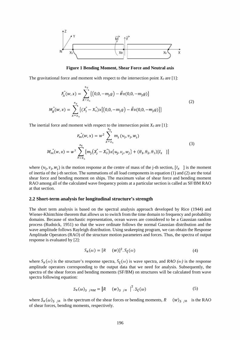
196
Figure 1 Bending Moment, Shear Force and Neutral axis
The gravitational force and moment with respect to the intersection point X0 are [1]:
( , ) = 0,0,− − (0,0, − )( , ) = ( − ) 0,0,− − (0,0,− ) (2)
The inertial force and moment with respect to the intersection point X0 are [1]:( , ) = ( , , )( , ) = − , , + ( , , )[ ] (3)
where ( , , ) is the motion response at the centre of mass of the j-th section, [ ] is the momentof inertia of the j-th section. The summations of all load components in equation (1) and (2) are the totalshear force and bending moment on ships. The maximum value of shear force and bending momentRAO among all of the calculated wave frequency points at a particular section is called as SF/BM RAOat that section.
2.2 Short-term analysis for longitudinal structure’s strength
The short term analysis is based on the spectral analysis approach developed by Rice (1944) andWiener-Khintchine theorem that allows us to switch from the time domain to frequency and probabilitydomains. Because of stochastic representation, ocean waves are considered to be a Gaussian randomprocess (Rudnick, 1951) so that the wave ordinate follows the normal Gaussian distribution and thewave amplitude follows Rayleigh distribution. Using seakeeping program, we can obtain the ResponseAmplitude Operators (RAO) of the structure motion parameters and forces. Thus, the spectra of outputresponse is evaluated by [2]: ( ) = [ ( )] . ( ) (4)
where ( ) is the structure’s response spectra, ( ) is wave spectra, and RAO ( ) is the responseamplitude operators corresponding to the output data that we need for analysis. Subsequently, thespectra of the shear forces and bending moments (SF/BM) on structures will be calculated from wavespectra following equation:( ) / = ( ) / . ( ) (5)
where ( ) / is the spectrum of the shear forces or bending moments, ( ) / is the RAOof shear forces, bending moments, respectively.

197
Generally, to study the motions and loads on floating structures or ships, the wave frequency is oftenconsidered in the range from 0.2 rad/s to 2.5 rad/s.
Regarding the sea spectra, we can describe the sea state as a stationary random process. This means thatwe can observe the sea at a particular position within a limited time period, from 0.5 to 3 hours. This isthe short-term description of the sea. Two commonly recommended wave spectra are JONSWAP andPierson-Moskowitz. The JONSWAP spectrum is recommended by 17th ITTC for limited fetch [3]:
( ) = 155 exp (3.3) ( )where = exp − . . .√ .and = 0.07 ≤ .= 0.09 > .
(6)
T1 is the mean wave period defined as: = 2 /where = ∫ ( ) (7)
H1/3 is defined as:
/ = 4 (8)
The Pierson-Moskowitz spectrum is a special case for fully developed long crested sea. The spectralordinate at a frequency (in rad/s) is [3]:( ) = 0.112 2 −0.44 2 (9)
where = 2 ( ) /T1 = 1.086.T2
T0 = 1.408.T2
(10)
Equation (6) satisfied equation (8) is only true for a narrow-banded spectrum and when theinstantaneous value of the wave elevation is Gaussian distributed.
Following IACS Recommendation No.34, [4] with the assumption that the process is narrow banded,amplitudes of the vertical wave bending moment (MW) in short-term sea state follows Rayleighdistribution. Thus, the probability function for the maxima (peak values) MW can be obtained followingequation:
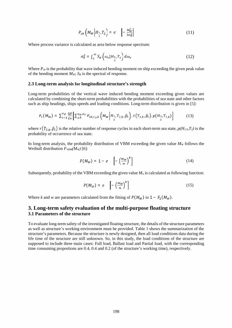
198
, = − (11)
Where process variance is calculated as area below response spectrum:
= ∫ | , (12)
Where Psh is the probability that wave induced bending moment on ship exceeding the given peak valueof the bending moment MW; SR is the spectral of response.
2.3 Long-term analysis for longitudinal structure’s strength
Long-term probabilities of the vertical wave induced bending moment exceeding given values arecalculated by combining the short-term probabilities with the probabilities of sea state and other factorssuch as ship headings, ships speeds and loading conditions. Long-term distribution is given in [5]:( ) = ∑ ∆ ∑ , , , , , , . , , . ( , , ),, (13)
where , , is the relative number of response cycles in each short-term sea state, p(H1/3,T2) is theprobability of occurrence of sea state.
In long-term analysis, the probability distribution of VBM exceeding the given value MW follows theWeibull distribution FVBM(MW) [6]:
( ) = 1 − − (14)
Subsequently, probability of the VBM exceeding the given value Mw is calculated as following function:
( ) = − (15)
Where k and w are parameters calculated from the fitting of ( ) to 1 − ( ).
3. Long-term safety evaluation of the multi-purpose floating structure3.1 Parameters of the structure
To evaluate long-term safety of the investigated floating structure, the details of the structure parametersas well as structure’s working environment must be provided. Table 1 shows the summarization of thestructure’s parameters. Because the structure is newly designed, then all load conditions data during thelife time of the structure are still unknown. So, in this study, the load conditions of the structure aresupposed to include three main cases: Full load, Ballast load and Partial load, with the correspondingtime consuming proportions are 0.4, 0.4 and 0.2 (of the structure’s working time), respectively.
199
Table 1 Main parameters of the structure
Main parametersLpp [m] 171.000 D [m] 12.000
B [m] 25.000 CB [m] 0.951
T [m] 4.500 Elastic section modulusamidships [m3]
4.476Neutral axis [m] 4.600
Parameters in particular load conditions
Full load Partial load Ballast load
Draft amidships [m] 4.500 3.830 2.830
xG [m] -0.804 -0.404 1.261
yG [m] 0.000 0.000 0.000
zG [m] 5.621 4.565 3.949
Displacement [kg] 19173605 16102481 11711206
3.2 Working area data
The structure is designed to work along the North coast of Vietnam, between Hon Dau and Hon Nguislands shown on Figure 2.
Figure 2 The design working area of the structure
In 2014, Supott Thammasittirong (AIT), Sutat Weesakul (AIT), Ali Dastgheib (UNESCO-IHE) andRoshanka Ranasinghe (UNESCO-IHE) [14] presented a report of their study on “Climate ChangeDriven Variations in the Wave Climate along the Coast of Vietnam”. This report included statisticalwave data of sea area along the North coast of Vietnam, between Hon Dau and Hon Ngu islands. Thereport also shown that during the period of time from 1981 to 2000, the mean wave height at the abovesea area ranged from 0.4 m to 1.0 m; the mean wave period ranged from 4.0 s to 6.5 s and the mainwave direction was South-East. These data are well fitted with the data from the National Centre forHydro - Meteorological Forecasting [7] which are given on the Table 2 below.
Table 2 gives basic data for the short-term calculations for the structure strength. With the results gainedfrom the short-term calculations, strength of structure will be evaluated in given periods of time, suchas 1 years, 5 years, 10 years, and 20 years.
200
Table 2 Annual statistical data of the design sea area
SUM 559 315 101 20 4 1 0 0 1000
Sign
ific
ant W
ave
Hei
ght [
m]:
Hi >9.5 -- -- -- -- -- -- -- -- 0
8.5 -- -- -- -- -- -- -- -- 0
7.5 -- -- -- -- -- -- -- -- 0
6.5 -- -- -- -- -- -- -- -- 0
5.5 -- -- -- -- -- -- -- -- 0
4.5 -- -- -- -- -- -- -- -- 0
3.5 -- 1 1 -- -- -- -- -- 2
2.5 6 11 5 2 1 -- -- -- 25
1.5 73 85 38 9 2 -- -- -- 207
0.5 480 218 57 9 1 1 -- -- 766
T0 [s] 3.5 4.5 5.5 6.5 7.5 8.5 9.5 >10.5 SUM
T0- mean [s] 4.10
3.3 Results and discussion
The structure is supposed to work in its design sea wave environment with different wave frequenciesand propagation directions. These frequencies range from 0.2 rad/s to 2.5 rad/s. The wave propagationangles range from -180o to +180o ( = 30o) with the corresponding probability of each is 1/12, [3]. Wealso suppose that the weight distribution in each load condition is fixed, the liquid’s sloshing in tanksare neglected, and the structure will generally have 1 month docking for small renovation each year, 3÷6 months docking for big renovation every 5 years of working. Figure 3 shows examples of thecalculated bending moment RAO at mid-section of the structure in different wave propagationdirections.
201
Figure 3 RAO of BM in the full load condition at different wave propagation directions
The results of bending moment RAO calculations can be combined with wave spectra data to obtainthe spectra of bending moment following equation (5). The values of are calculated followingequation (12), and the short-term probability (Psh) of bending moment on the structure exceeding thegiven values are calculated following equation (11), depending on sea state probability, wavepropagation directions, wave frequencies. For example, Table 3 shows a result of the full load conditioncalculation. It shows the probabilities of which the VBM exceed the permissible bending moment ofthe structure amidships (M0) in the full load condition. Here, the value of the moment M0 is determinedby the formula following IACS Recommendation 1989/Rev.6 [8]≤ [ ] [MN/m2] (16)
where [ ] is the permissible stress of the structure steel, and [ ] = 175 [MN/m2] for ordinary hullstructure steel. is the structure’s elastic section modulus, and = 4.476 [m3] as shown in the Table1.From the condition shown in the formula (16), we can obtained the limited value of bending momentof the structure as follows = . [ ] = 787.494 [MN.m] (17)Table 3 Corresponding Probability of BM exceeding the limited value M0 in full load condition
SUM 8.5E-175 8.45E-21 3.63E-14 5.16E-22 1.2E-23 0 3.63E-14
Sign
ific
ant W
ave
Hei
ght [
m]:
Hi >9.5 -- -- -- -- -- -- -- -- 0
8.5 -- -- -- -- -- -- -- -- 0
7.5 -- -- -- -- -- -- -- -- 0
6.5 -- -- -- -- -- -- -- -- 0
5.5 -- -- -- -- -- -- -- -- 0
4.5 -- -- -- -- -- -- -- -- 0
3.5 -- 8.45E-21 3.63E-14 -- -- -- -- -- 3.63E-142.5 8.5E-175 2.45E-35 1.12E-22 5.16E-22 1.2E-23 -- -- -- 6.4E-221.5 0 5.4E-91 3.15E-55 6.64E-53 1.41E-57 -- -- -- 6.68E-530.5 0 0 0 0 0 0 -- -- 0
T0 [s] 3.5 4.5 5.5 6.5 7.5 8.5 9.5 >10.5
202
It is clearly seen that, in the full load case, the total probability of which the VBM amidships exceedthe permissible bending moment of the structure M0 is 3.63E-14.
By assuming a range of exceeded VBM MW, we can calculate the corresponding probabilities shown inthe Table 4 for all load conditions.
Table 4 Short-term Probabilities of the bending moments exceeding the given values MW
MWProbability of exceeding Mw
MWProbability of exceeding Mw
Full Load Partial Ballast Full Load Partial Ballast
(kN.m) Psh Psh Psh (kN.m) Psh Psh Psh
10 4.07E-01 3.44E-01 3.39E-01 145 1.43E-03 1.15E-03 1.11E-03
25 1.38E-01 1.16E-01 1.12E-01 160 8.81E-04 7.15E-04 6.86E-04
40 6.77E-02 5.46E-02 5.25E-02 175 5.48E-04 4.48E-04 4.26E-04
55 3.79E-02 2.96E-02 2.90E-02 190 3.43E-04 2.83E-04 2.66E-04
70 2.14E-02 1.66E-02 1.64E-02 300 1.07E-05 9.90E-06 8.63E-06
85 1.20E-02 9.36E-03 9.27E-03 400 5.13E-07 4.79E-07 4.28E-07
100 6.79E-03 5.37E-03 5.29E-03 500 1.95E-08 1.59E-08 1.46E-08
115 3.94E-03 3.15E-03 3.08E-03 600 3.85E-10 2.80E-10 2.54E-10
130 2.34E-03 1.89E-03 1.83E-03 787.494 3.63E-14 2.08E-14 1.78E-14
where Psh = , is the short-term probability of VBM exceeding the given value MW in
each load condition. For example, when MW = 115 [kN.m], the total probability of VBM exceeding thisMW in the Full load, Partial load and Ballast load conditions are 3.94E-03, 3.15E-03 and 3.08E-03,respectively. By fitting the values of Psh in each load condition with the values of P(MW) given inequation (15), we can find the Weibull parameters k and w shown on Table 5.
Table 5 Long-term safety assessment results of the structure
Load condition Full load Partial load Ballast load
Weibullparameters
k 0.7924 0.7244 0.724
w 11.24 9.05 8.876
Goodness of fit
SSE: 0.0003943R-sq: 0.9975Adjusted R-sq: 0.9973RMSE: 0.005507
SSE: 0.000131R-square: 0.9988Adjusted R-sq: 0.9988RMSE: 0.003175
SSE: 0.0001535R-square: 0.9986Adjusted R-sq: 0.9985RMSE: 0.003436
T (years) PT PF PP PB
1 year 1.417E-06 3.543E-07 3.543E-07 7.087E-07
5 years 2.998E-07 7.496E-08 7.496E-08 1.499E-07
10 years 1.499E-07 3.748E-08 3.748E-08 7.496E-08
20 years 7.496E-08 1.874E-08 1.874E-08 3.748E-08
P(Mw>M0) 2.55027E-13 9.1948E-12 6.71896E-12
PT(Mw>M0) 1.617E-11
Here, PT is the total probability in all load conditions (full load, partial load and ballast load conditions)at which the structure has one time within T years the BM exceeds its limit value. Similarly, PF, PP, PB
are the probabilities at which the structure has one time the wave bending moment exceeds its limitvalue in the time period of survey in the full load, partial load and ballast load conditions, respectively.
203
PT(Mw>M0) is the totally long-term probability occurring one time BM on the structure exceeding thelimited value M0. This probability is 1.617E-11, much lower than 20 years probability shown in theTable 5, which is 7.496E-08. It means that in terms of wave bending moment, the structure have a morethan 20 years life time working well under this load. This result should be combined with othercalculations such as longitudinal strength analysis of the structure working in hogging and saggingconditions, ultimate strength analysis and other analyses to give a final conclusion of the structure’slongitudinal strength.
4. Conclusion
The paper presents a method for long-term analysis of the structure strength under wave induced BM,based on spectra analysis and probability theory. The study also analysed partly the longitudinalstrength of the structure in both short-term and long-term periods and predicted the age of the structureunder the working sea environment. This is the key study that helps to solve the problems and currentarguments of the very large structure built by Quang Trung Mechanical Enterprise. However, there areseveral issues in the study that need to take into account more carefully, such as the assumptions.
Regarding the input data, the sea environment data should be updated to the latest figures. Thedistribution of weight components along the structure is supposed to be fixed at each load condition,but in practice, this weight distribution will vary significantly, depending on different working states.Moreover, the load conditions in the study are only three main types (full load, partial load and ballastload conditions), which the corresponding time consuming proportions are supposed to follow thetraditional rate of ship as 0.4, 0.4 and 0.2. The reason is the structure is newly built, leading to a lack ofstatistical data of structure working information.
Besides, the effect of mooring system should be considered, because it has significant influence on theRAO of wave bending moment. Similarly, the probabilities of wave propagation directions need to beobtained from real sea statistics, which may not be equal between different directions as the assumptionin this study.
Acknowledgements
This study is a part of the safety assessment process for the floating structure built by Quang TrungMechanical Enterprise which have been received essential data from the company.
References
[1] Newman, J.N. (1978), 'The theory of ship motions', Advances in Applied Mechanics, Vol.18.[2] Alaa Mansour & Donald Liu, Strength of Ships and Ocean Structures, Society of Naval Architects
and Marine Engineers, 2nd Edition, New Jersey, USA, (2008).[3] O. M. Faltinsen, Sea Loads on Ships and Offshore Structures, 1st Edition, Cambridge University
Press, (1990).[4] IACS 2000, Recommendation No. 34, “Standard Wave Data”, Rev. 1.[5] A.P. Teixeira & C. Guedes Soares, “Reliability based approach to determine the design loads for
the remaining lifetime of ships”, Proceedings of the 11th International Congress of theInternational Maritime Association of the Mediterranean (IMAM 2005), Lisbon, Portugal, 26-30September 2005, pp. 1611-1619
[6] Guedes Soares, C., “Probabilistic Models for Load Effects in Ship Structures”, Division of MarineStructures, the Norwegian Institute of Technology, Report UR-84-38, (1984).
[7] Nguyen Ngoc Thuy, Nguyen Tai Hoi, Duong Quang Loc, Nguyen Manh, Nguyen Doan Toan,Nguyen Manh Hung, Duong Van Que, “Statistical wave data of sea areas in Vietnam”, NationalCentre for Hydro - Meteorological Forecasting, (2014).
[8] IACS Recommendation 1989/Rev.6. “Longitudinal Strength Standard” (2010), pp. 1-12
204
[9] J.K. Paik, D.K. Kim and M.S. Kim, “Ultimate strength performance of Suezmax tanker structures:Pre-CSR versus CSR designs”, Proceedings of Marstruct 2009, the 2nd International Conferenceon Marine Structures, Lisbon, Portugal, 16–18 March 2009, pp. 181- 189.
[10] Z. Shu & T. Moan, “Assessment of the hull girder ultimate strength of a bulk carrier usingnonlinear finite element analysis”, Proceedings of Marstruct 2009, the 2nd InternationalConference on Marine Structures, Lisbon, Portugal, 16–18 March 2009, pp. 173- 188.
[11] Mika Bäckström & Seppo Kivimaa, “Fracture mechanics procedures for assessing fatigue life ofwindow and door corners in ship structures”, Proceedings of Marstruct 2009, the 2nd InternationalConference on Marine Structures, Lisbon, Portugal, 16–18 March 2009, pp. 239- 245.
[12] O. Feltz & W. Fricke , “Experimental and numerical fatigue analysis of partial-load and full-loadcarrying fillet welds at doubler plates and lap joints”, Proceedings of Marstruct 2009, the 2ndInternational Conference on Marine Structures, Lisbon, Portugal, 16–18 March 2009, pp. 247-253.[13] Hubertus von Selle, Olaf Doerk & Manfred Scharrer, “Global strength analysis of ships withspecial focus on fatigue of hatch corners”, Proceedings of Marstruct 2009, the 2nd InternationalConference on Marine Structures, Lisbon, Portugal, 16–18 March 2009, pp. 255- 260.
[14] Supott Thammasittirong (AIT), Sutat Weesakul (AIT),Ali Dastgheib (UNESCO-IHE), RoshankaRanasinghe (UNESCO-IHE), “Climate Change Driven Variations in the Wave Climate along theCoast of Vietnam”, UNESCO-IHE, March 2014, pp. 39-73.
[15] Kukkanen T. and Mikkola T. P. J., Fatigue assessment of spectral approach for the ISSCcomparative study of the hatch cover bearing pad, Marine Structures 17,2004, pp 75-90[16] Kukkanen T., Summary report of the project: Nonlinear wave loads of ships, VTT ResearchReport, VTT-R_02391-09, 2009
205
Integration of Maritime Spatial Planning into the Waterways SafetyManagement studies
Madli Kopti1;2, PhD Student; Roomet Leiger1, MSc; Dr. Inga Zaitseva-Pärnaste1, PhD; CaptainJarmo Kõster1
1. Estonian Maritime Academy of Tallinn University of Technology, [email protected], 101 Kopli Str,11712 Tallinn, Estonia
2. University of Tartu, Estonian Marine Institute, 14 Maealuse Str, 12618 Tallinn, Estonia
Abstract Maritime spatial planning (MSP) arose in the beginning of the millennium as a response to ahistoric failure to protect the marine environment, because of an increased competition for marine spaceand the opportunities for economic growth [1]. The EU Directive established a framework for maritimespatial planning [2] and defined objectives of maritime spatial planning (MSP) as follows “Whenestablishing and implementing maritime spatial planning, Member States shall consider economic,social and environmental aspects to support sustainable development and growth in the maritime sector,applying an ecosystem-based approach, and to promote the coexistence of relevant activities and uses.Through their maritime spatial plans, Member States shall aim to contribute to the sustainabledevelopment of energy sectors at sea, of maritime transport, and of the fisheries and aquaculture sectors,and to the preservation, protection and improvement of the environment, including resilience to climatechange impacts. In addition, Member States may pursue other objectives such as the promotion ofsustainable tourism and the sustainable extraction of raw materials.” Since historic times, the Baltic Seahas been an important route for maritime trade. During the last decades, the number of ships sailing inthe Baltic Sea and their sizes have continued to increase and, therefore, there is growing need forefficient integration of maritime safety into process of MSP.
Estonian Maritime Academy of Tallinn University of Technology (EMARA TUT) is the onlyeducational institution in Estonia that offers higher education in the maritime field. One of the mainaims of EMARA TUT is to provide the maritime labour market with highly qualified specialists indifferent maritime fields. Waterway Safety Management (WSM) is one of the study programmes inEMARA TUT focusing on the development of comprehensive and broad-based knowledge in allaspects of the theory and practice of waterway engineering and maritime safety. WSM studies areregulated by International Association of Marine Aids to Navigation and Lighthouse Authorities(IALA) and International Hydrographic Organization (IHO). Studies of WSM are associated withplanning and optimization of fairways, charting and surveying navigable waters etc. Graduates work inorganizations responsible for ensuring safe navigation of maritime transport in Estonian andinternational waters. Though, these organizations are not responsible for carrying out the official MSP,they are the key stakeholders, data providers and decision makers in line with safe shipping during theMSP process. Because of the above-described situation and due to the rapid development of MSP inthe Baltic Sea region and worldwide there is a need for integrating the MSP efficiently into to the WMSstudies.
The contribution attempts to demonstrate the efficient methods on the integration of MSP into the WSMstudies. Efficient integration of MSP into the studies of WSM study process will provide students withbroad knowledge on the interconnection of WSM and MSP and provide an effective interdisciplinaryapproach to MSP process.
Keywords: maritime spatial planning, the Baltic Sea, waterways safety management, maritime safety,maritime education.
206
1. Introduction
Maritime spatial planning (MSP) is having considerable importance all around the world, especially inEuropean Union (EU). According to the United Nations Educational, Scientific and CulturalOrganization (UNESCO) initiative [3] “MSP is a public process of analyzing and allocating the spatialand temporal distribution of human activities in marine areas to achieve ecological, economic, andsocial objectives that usually have been specified through a political process. Characteristics of MSPinclude ecosystem-based, area-based, integrated, adaptive, strategic and participatory approach. MSPis not an end in itself, but a practical way to create and establish a more rational use of marine spaceand the interactions among its uses, to balance demands for development with the need to protect theenvironment, and to deliver social and economic outcomes in an open and planned way.”
Numerous countries have started to establish MSP to achieve sustainable use, to ensure biodiversityconservation in ocean and coastal areas, to encourage investments, to increase cross-border cooperation,to enhance “blue growth”, to support synergies and coherent use of marine space among differentsectors such as shipping, energy, environment, fisheries, defense etc.
Originally, the concept of MSP was stimulated by international and national interests in developingmarine protected areas (MPAs). More recent attention has been placed on planning and managingmultiple uses of marine space, particularly in areas where use conflicts and potential synergies and co-use are already well known and specified. In various countries marine regional planning concepts arebeing used as a first step to make ecosystem-based marine spatial planning a reality. Ecosystem basedapproach is supported by the EU and the Baltic Marine Environment Protection Commission(HELCOM). For example, Directive 2014/89/EU establishing a framework for maritime spatialplanning states [1]: “in order to promote the sustainable growth of maritime economy, the sustainabledevelopment of marine areas and the sustainable use of marine resources, maritime spatial planningshould apply an ecosystem-based approach.” Additionally, the Fifth Ordinary Meeting of theConference of the Parties to the Convention on Biological Diversity, Nairobi 2000 [4] defined the“ecosystem approach” as “... a strategy for the integrated management of land, water and livingresources that promotes conservation and sustainable use in an equitable way.” HELCOM and theCommission for the Protection of the Marine Environment of the North East Atlantic (OSPAR) jointlyadopted their common vision [5] of an “ecosystem approach” as “the comprehensive integratedmanagement of human activities based on the best available scientific knowledge about the ecosystemand its dynamics, in order to identify and take action on influences which are critical to the health ofmarine ecosystems, thereby achieving sustainable use of ecosystem goods and services andmaintenance of ecosystem integrity.“
The need for maritime spatial planning in the region guided the European Union (EU) to develop legalframework for MSP. In July 2014 was adopted Directive of the European Parliament and of the Councilestablishing a framework for maritime spatial planning (MSP Directive) where Article 15 states thatthe maritime spatial plans shall be established as soon as possible and at the latest by 31 March 2021.Because of the set requirements in MSP Directive, the development of MSP is especially rapid in theEU. The Directive establishes a framework for MSP [2] and defines objectives of MSP as follows:“When establishing and implementing maritime spatial planning, Member States shall considereconomic, social and environmental aspects to support sustainable development and growth in themaritime sector, applying an ecosystem-based approach, and to promote the coexistence of relevantactivities and uses. Through their maritime spatial plans, Member States shall aim to contribute to thesustainable development of energy sectors at sea, of maritime transport, and of the fisheries andaquaculture sectors, and to the preservation, protection and improvement of the environment, includingresilience to climate change impacts. In addition, Member States may pursue other objectives such asthe promotion of sustainable tourism and the sustainable extraction of raw materials.”
One of the main purposes of higher professional education is to prepare highly qualified specialists,who are productively able to contribute in different sectors by offering relevant qualifications, high-
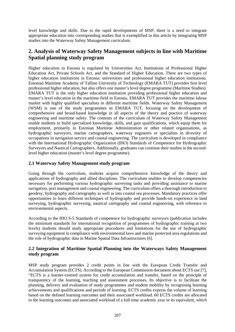
207
level knowledge and skills. Due to the rapid developments of MSP, there is a need to integrateappropriate education into corresponding studies that is exemplified in this article by integrating MSPstudies into the Waterway Safety Management curriculum.
2. Analysis of Waterway Safety Management subjects in line with MaritimeSpatial planning study program
Higher education in Estonia is regulated by Universities Act, Institutions of Professional HigherEducation Act, Private Schools Act, and the Standard of Higher Education. There are two types ofhigher education institutions in Estonia: universities and professional higher education institutions.Estonian Maritime Academy of Tallinn University of Technology (EMARA TUT) provides first levelprofessional higher education, but also offers one master’s level degree programme (Maritime Studies).EMARA TUT is the only higher education institution providing professional higher education andmaster’s level education in the maritime field in Estonia. EMARA TUT provides the maritime labourmarket with highly qualified specialists in different maritime fields. Waterway Safety Management(WSM) is one of the study programmes in EMARA TUT, focusing on the development ofcomprehensive and broad-based knowledge in all aspects of the theory and practice of waterwayengineering and maritime safety. The contents of the curriculum of Waterway Safety Managementenable students to build specialized knowledge, skills, and gain qualifications, which equip them foremployment, primarily in Estonian Maritime Administration or other related organisations, ashydrographic surveyors, marine cartographers, waterway engineers or specialists in diversity ofoccupations in navigation service and coastal engineering. The curriculum is developed in compliancewith the International Hydrographic Organization (IHO) Standards of Competence for HydrographicSurveyors and Nautical Cartographers. Additionally, graduates can continue their studies in the second-level higher education (master’s level degree programme).
2.1 Waterway Safety Management study program
Going through the curriculum, students acquire comprehensive knowledge of the theory andapplications of hydrography and allied disciplines. The curriculum enables to develop competenciesnecessary for performing various hydrographic surveying tasks and providing assistance to marinenavigation, port management and coastal engineering. The curriculum offers a thorough introduction togeodesy, hydrography and cartography as well as into coastal sea processes. Mandatory practices offeropportunities to learn different techniques of hydrography and provide hands-on experience in landsurveying, hydrographic surveying, nautical cartography and coastal engineering, with reference toenvironmental aspects.
According to the IHO S-5 Standards of competence for hydrographic surveyors (publication includesthe minimum standards for international recognition of programmes of hydrographic training at twolevels) students should study appropriate procedures and limitations for the use of hydrographicsurveying equipment in compliance with environmental laws and marine protected area regulations andthe role of hydrographic data in Marine Spatial Data Infrastructures [6].
2.2 Integration of Maritime Spatial Planning into the Waterways Safety Managementstudy program
MSP study program provides 2 credit points in line with the European Credit Transfer andAccumulation System (ECTS). According to the European Commission document about ECTS use [7],“ECTS is a learner-centred system for credit accumulation and transfer, based on the principle oftransparency of the learning, teaching and assessment processes. Its objective is to facilitate theplanning, delivery and evaluation of study programmes and student mobility by recognising learningachievements and qualifications and periods of learning. ECTS credits express the volume of learningbased on the defined learning outcomes and their associated workload. 60 ECTS credits are allocatedto the learning outcomes and associated workload of a full-time academic year or its equivalent, which
208
normally comprises a number of educational components to which credits (on the basis of the learningoutcomes and workload) are allocated. In most cases, workload ranges from 1,500 to 1,800 hours foran academic year, which means that one credit corresponds to 25 to 30 hours of work. It should berecognised that this represents the typical workload and that for individual students the actual time toachieve the learning outcomes will vary.”
Aim of MSP subject is to give an overview about the MSP and skills how to compile Maritime SpatialPlan. On the completion of MSP course student should achieve following learning outcomes: 1) knowsthe meaning and importance of the Maritime Spatial Planning; 2) gives an overview about the politicalissues considering the Maritime Spatial Planning; 3) knows and exemplifies different phases of theMaritime Spatial Planning process; 4) gives an overview about the different IT programs/software thatare used for spatial data presentation and management; 5) knows the situation of the newest MaritimeSpatial Plans in Europe, including Estonia. Learning outcomes mean the minimum level of knowledge,skills and attitudes that have to be acquired as a result of passing the subject or the completion of thecurriculum [8].
The subject topics have been divided into 8-week sessions and during the studies following topics arecovered: introduction, overview of the MSP, phases of the MSP process, political issues of the MSP,IT programs and software used for the MSP, MSP in Europe and in Estonia. First three weeks of studiesfocus on giving an overview about the MSP and special focus is on the detailed introduction of fullcycle of MSP process (Figure 1), by having detailed approach on every phase starting with assessingthe MSP context and finalizing with the evaluation of results.
Figure 1 Process of MSP [9]
After receiving a clear overview about MSP process details will be focused on the overall developmentdirections of MSP by giving examples on MSP experiences of different countries and MSP related
209
scientific results. For this, students have to work through different countries corresponding MSPs(group work) and one scientific MSP related paper and present the first results in e-learning environmentand second one is presented as oral presentation in the classroom. Additionally, special attention is onthe political developments in line with MSP. Last section of the studies focuses on using differentgeographical information systems (GIS) for gathering MSP related spatial information. The last partexercise is mainly based on using existing public MSP maps and data providers such as HELCOMBaltic Sea data and map service [10] or European Atlas of the Seas [11]. The main focus of the exerciseis to acquire knowledge about the possibilities of mapping the MSP relevant information and how touse different GIS tools and features such as metadata, identification of data, downloading the data etc.Additionally, a test is carried out to gain knowledge about EUs spatial information infrastructuredevelopments, different data formats, national MSP data providers and GIS software.
Until year 2015, the course on MSP was mandatory in WSM curriculum. After 2015 the course isoptional and included in the Waterway Safety Management and Port and Shipping Management studyprogrammes. Hydrographic specialists need to engage with other users of marine and coastal areas, toensure that the principles of MSP are taken into consideration while planning waterways and thereforeminimising potential conflict between users. Since graduates of the programme work in organizationsresponsible for ensuring safe navigation for maritime transport in Estonia and international waters,integration of the maritime spatial planning studies into the WSM programme is an importantengagement for providing co-ordinated decisions on various use of marine areas and resources in thefuture. Additionally, as graduates of the WSM study programme are often involved duringgovernmental MSP processes and in waterway design process, planning of the sustainable use of inlandwaters and coastal areas, the knowledge about MSP allows students to establish a link between differentsectors, such as industry, government, environmental- and science communities, within the process ofplanning shipping traffic lanes, management of the coastal areas and harbours. The result of anintegration of MSP studies to the WSM programme provides students with a better understanding ofthe use of water areas by different users, thus allows to develop appropriate management strategies andplans.
As stated previously, MSP is much wider approach than only providing maritime safety and thereforeit is important to provide WSM programme students with knowledge about maritime spatial planning.Sufficiently planned waterways minimize potential risks of shipping accidents and spills by providingsolid ground of achieving aims of EU Strategy for the Baltic Sea Region (EUSBSR), Water FrameworkDirective (WFD) and Marine Strategy Framework Directive (MSFD). The EUSBSR [12] intends toincrease levels on environmental sustainability, prosperity, accessibility and attractiveness, safety andsecurity meanwhile the WFD [13] intends to achieve and preserve good quality of marine water (up toone nautical mile from shore) and MSFD [14] aims to achieve Good Environmental Status (GES) ofthe EU's marine waters by 2020.
2.3 Necessary improvement of MSP study course in line with integration to other subjectsin the WSM curriculum
The present course of MSP is focused on general description of the maritime spatial planning and doesnot give enough specific issue, typical for waterway management tasks, such as design of fairways,waterways risk assessment, hydrographic operations etc. In addition, the course is optional and somestudents do not choose it. As was mentioned above, the curriculum is developed in compliance withIHO S-5 Standard. According to the learning outcomes listed in the standard, student should know theprinciples of hydrographic data exchange and limitations in use of hydrographic equipment inaccordance with environmental regulations. Some of the mandatory topics are included in compulsorycourses’ content, but still there is no pronounced relation with MSP. For example, there are some ofmandatory courses in WSM study program, e.g. Environmental Impact Assessment and Audit,Environmental Engineering, International Law of the Sea content topics which should be conducted bytaking into account the means of MSP principles and vice versa.
210
In addition, students’ feedback suggests integrating hydrography and waterway managementcomponent to the MSP course to establish the link between compulsory courses of the studyprogramme, e.g. course Design of waterways and Hydrographic surveying. First of which is mostlyfocusing on IALA regulations and guidelines, such as IALA Guideline No. 1058 on the use ofsimulation as a tool for waterway design and aids to navigation planning and IALA Guideline No. 1078on the use of aids to navigation in the design of fairways. The aim of the course Hydrographic surveyingis to give basic knowledge about the main concepts involved in hydrography, planning and executionof hydrographic surveys and includes a study about methods of hydrographic survey, positioning, seafloor classification and object detection, depth determination, specification of hydrographic surveyingand IHO standards regulating hydrographic works. This issue suggests changing the overall approachof teaching MSP as a general subject and incite to develop more specific approach to provideinterdisciplinarity.
3. Conclusions
During the past 10 years, MSP has gained considerable importance all around the world, especially inEuropean Union, where the MSP Directive has been adopted aiming to create a common frameworkfor maritime spatial planning in Europe. According to the established MSP Directive, the whole EUs’sea area should be planned by 2021. Due to the rapid developments of MSP, there is a need for highlyqualified specialists who are sufficiently able to contribute during the MSP process. As the graduatesof WSM are working for different organizations that are important stakeholders and decision makersduring MSP process this research revealed key factors for integration MSP studies to WSM curriculum.
Efficient integration of specific courses’ topics of WSM programme into the MSP studies providestudents with broad knowledge on the interconnection of different activities associated withhydrography and waterway management with MSP process. Therefore, the course of MSP should beestablished as mandatory course for WSM students. Additionally, the hydrography and waterwaymanagement component should be integrated into the MSP course to establish the link betweencompulsory courses of the study programme, e.g. course Design of waterways and Hydrographicsurveying. Finally, reciprocal integration between MSP and other mandatory courses, e.g.Environmental Impact Assessment and Audit, Environmental Engineering, International Law of the Seashould be implemented.
References
[1] Kerr S, Johnson K and Side J C, Planning at the edge: Integrating across the land sea divide,Marine Policy, No 47 (2014), pp 118-125.
[2] EC, Establishing a Framework for Maritime Spatial Planning: Directive 2014/89/EU, EuropeanCouncil, Brussels, (2014).
[3] UNESCO, Marine Spatial Planning Iniative, 29 June 2016, UNESCO IntergovernmentalOceanographic Commission, Paris/France, <http://www.unesco-ioc-marinesp.be/marine_spatial_planning_msp>
[4] COP, Fifth Ordinary Meeting of the Conference of the Parties to the Convention on BiologicalDiversity, Nairobi, Kenya, 15 - 26 May 2000. COP Decision V/6 Ecosystem approach.
[5] HELCOM/OSPAR, Statement on the Ecosystem Approach to the Management of HumanActivities: “Towards an ecosystem approach to the management of human activities”. First jointministerial meeting of the Helsinki and OSPAR Commissions (JMM), Bremen: 25 – 26 June 2003,Annex 5, 7 p.
[6] IHO, Standards of competence for category “A” hydrographic surveyors. Publication S-5A, Vol1,No 1.0.0. The International Hydrographic Organization, (2016).
[7] European Commission, ECTS Users’ Guide, (2015).[8] Rutiku S, Valk A, Pilli E and Vanari K. Guidelines for curriculum development (in Estonian),
Archimedes, Primus, (2009).[9] Schultz-Zehden A, Gee K and Scibior K, HANDBOOK on Integrated Maritime Spatial Planning,

211
From the INTERREG III B CADSES PlanCoast Project, Sustainable Projects, (2008).[10] HELCOM, “Martime Spatial Planning”, Baltic Sea data and map service, HELCOM, 20 June
2016, <http://maps.helcom.fi/website/mapservice/index.html>[11] EC, “Maritime Europe”, European Atlas of the Seas, European Commission Maritime Affairs, 20
June 2016.<http://ec.europa.eu/maritimeaffairs/atlas/maritime_atlas/#lang=EN;p=w;pos=11.754:54.605:4;bkgd=5:0.52;gra=0;mode=0;theme=46:0.5:1:0,2:0.75:1:1;>
[12] EC, the European Union Strategy for the Baltic Sea Region, Council of the European Union,Brussels, 1 December 2009.
[13] EC, Establishing a framework for Community action in the field of water policy: Directive2000/60/EC, the European Parliament and the Council of the European Union, (2000).
[14] EC, Establishing a framework for community action in the field of marine environmental policy(Marine Strategy Framework Directive): Directive 2008/56/EC, the European Parliament and theCouncil of the European Union, (2008).

212
213
Session 2C
MARITIME ENVIRONMENTAL ISSUES &ENERGY EFFICIENCY
(No. 2)
214
Effect of Injection Timing and Mixing Rate of Water in Jatropha Emulsionon Combustion and Performance of DI Diesel Engine
Nguyen Kim Bao1
1. Vietnam Maritime University; E-mail: [email protected]: 484 Lach tray street, Hai phong City, Vietnam
Abstract The current paper studies the effect of the injection timing and Jatropha water emulsion (JWE)with different mixing ratios on the combustion and performance characteristics of a direct injectiondiesel engine. The experimental study was carried out using a four-stroke, high speed, small capacity,direct-injection diesel engine. The engine ran on the Light oil (LO) and neat Jatropha oil (JO) forbaseline data. In this study, Jatropha emulsion was made by mixing mass ratios of 10% and 20% ofwater so called JWE10%, and JWE20%, respectively. While changing fuels from LO to JO, JWE10%,and JWE20%, we tested the engine with various injection timings of 17, 20, and 23 degree crank anglebefore top dead center (o BTDC). The acquired data was analyzed for various combustion parameterssuch as in-cylinder pressure, heat release rate (HRR), ignition delay (ID); for performance parameterssuch as exhaust gas temperature and brake thermal efficiency (BTE). At the original injection timing,the peak of in-cylinder pressure, and the HRR reduced, and they marginally increased when advancingthe injection timing in comparison with those of the Jatropha oil at original injection timing. Ignitiondelay increased with an increase of the injection timing for both emulsion fuels. When advancing theinjection timing to 23o BTDC, the emulsion fuels reduced exhaust gas temperature. BTE increased whenusing emulsion fuels, particularly the JWE10%. Overall, the optimum water mixing rate was 10%, whilethe optimum injection timing was 20o BTDC.
Keywords: Jatropha water emulsion, mixing rate, injection timing, combustion, performance.
1. Introduction
Diesel engines have been faced with problems like the fossil fuel crisis, and the more stringent criteriaregulated by governments the world over attempting to protect the air quality. The main harmfulpollutants, namely NOx and particulates, which are trade-offs in using diesel engines, have been closelywatched. Additionally, the production of global warming gas (CO2) is unavoidable whatever the fuelwhen using diesel engines. To allay these concerns, vegetable oils have recently gained attention as apromising alternative fuel for a greener future. Short-term tests have revealed that most vegetable oilsare capable of being used directly in existing diesel engines with little or no modification. However,long-term test has reported some operational problem such as piston ring sticking, injector and enginedeposits, gum formation and oil thickening [1]. Physical properties of the vegetable oils such as highviscosity, poor volatility, and bulky molecules result in an increase in CO, HC and PM, but lower NOxemissions compared to those of diesel oil alone [2-4]. Among vegetable oils, Jatropha has been ofinterest because it is not a food source [3]. Jatropha oil was identified as a leading candidate for analternative fuel among various non-edible vegetable oils [5] since the plant does not suffer excessivelyfrom droughts, or need concentrated irrigation. Higher smoke, HC, CO have been observed [3, 7, 8],while NOx emissions have also been reported lower when engines run on Jatropha oil [3, 8]. In theperformance aspect, the brake thermal efficiencies of engines fueled with Jatropha have been generallylower in comparison with those using diesel oil [3, 6-9]. This is attributed to the physical-chemical-properties of Jatropha oil such as high viscosity, poor volatility, bulky molecular structure, and lowcetane number. The drawbacks of Jatropha oil may be overcome by preheating [7, 8], and/or blendingwith diesel [10, 11].
The usage of water emulsion fuel is a well-known way to significantly reduce NOx emissions due tothe cooling effect of the vaporization of water in the emulsion fuel [12-16]; while the reduction of soot
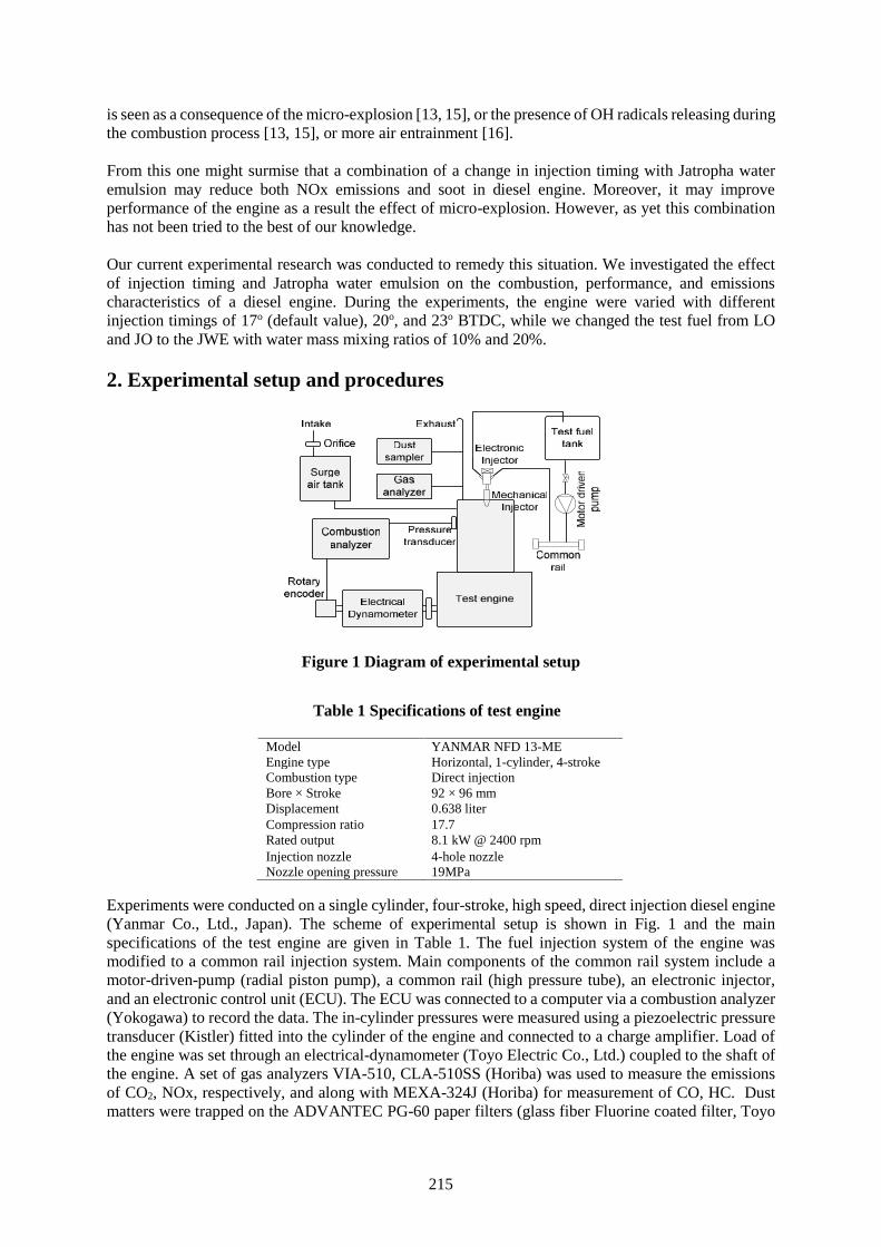
215
is seen as a consequence of the micro-explosion [13, 15], or the presence of OH radicals releasing duringthe combustion process [13, 15], or more air entrainment [16].
From this one might surmise that a combination of a change in injection timing with Jatropha wateremulsion may reduce both NOx emissions and soot in diesel engine. Moreover, it may improveperformance of the engine as a result the effect of micro-explosion. However, as yet this combinationhas not been tried to the best of our knowledge.
Our current experimental research was conducted to remedy this situation. We investigated the effectof injection timing and Jatropha water emulsion on the combustion, performance, and emissionscharacteristics of a diesel engine. During the experiments, the engine were varied with differentinjection timings of 17o (default value), 20o, and 23o BTDC, while we changed the test fuel from LOand JO to the JWE with water mass mixing ratios of 10% and 20%.
2. Experimental setup and procedures
Figure 1 Diagram of experimental setup
Experiments were conducted on a single cylinder, four-stroke, high speed, direct injection diesel engine(Yanmar Co., Ltd., Japan). The scheme of experimental setup is shown in Fig. 1 and the mainspecifications of the test engine are given in Table 1. The fuel injection system of the engine wasmodified to a common rail injection system. Main components of the common rail system include amotor-driven-pump (radial piston pump), a common rail (high pressure tube), an electronic injector,and an electronic control unit (ECU). The ECU was connected to a computer via a combustion analyzer(Yokogawa) to record the data. The in-cylinder pressures were measured using a piezoelectric pressuretransducer (Kistler) fitted into the cylinder of the engine and connected to a charge amplifier. Load ofthe engine was set through an electrical-dynamometer (Toyo Electric Co., Ltd.) coupled to the shaft ofthe engine. A set of gas analyzers VIA-510, CLA-510SS (Horiba) was used to measure the emissionsof CO2, NOx, respectively, and along with MEXA-324J (Horiba) for measurement of CO, HC. Dustmatters were trapped on the ADVANTEC PG-60 paper filters (glass fiber Fluorine coated filter, Toyo
Table 1 Specifications of test engine
Model YANMAR NFD 13-MEEngine type Horizontal, 1-cylinder, 4-strokeCombustion type Direct injectionBore × Stroke 92 × 96 mmDisplacement 0.638 literCompression ratio 17.7Rated output 8.1 kW @ 2400 rpmInjection nozzle 4-hole nozzleNozzle opening pressure 19MPa
216
Roshi Kaisha, Ltd.) in 10 liters of exhaust gas at each step of the experiments with the help of a D-25UPgas sampler (OCT science, Ltd.). In each experiment step, we collected the dust on 4 paper filter sheets.Afterward, soluble organic fraction in the dust trapped filters was dissolved by dichloromethane andwas calculated by balancing the mass of the filters before and after extraction (average value). In-solubleorganic fraction was calculated by subtraction of the paper filter mass after SOF dissolving and theoriginal filter. Measurements were carried out using LO, JO, JWE10%, and JWE 20%. To make theemulsion fuel, a mixing system with a tank for JO; a tank for water; a circulating pump; and a staticmixer was used. The engine was fed with LO, and JO at the injection timings of 17, 20, and 23o BTDCfor baseline data. These timings were also set to investigate the effect of the Jatropha emulsion withdifferent water mass mixing rates. Water with 10% and 20% in mass was added to the Jatropha creatingemulsion fuels prior to the experiments. The experimental conditions (injection timing and test fuels)of the experiments are provided in Table 2. All experimental steps were conducted at room temperatureand the results were recorded at steady operational conditions of the engine. During the experiments,the engine load was set at different values of 3.0 kW, 4.5 kW, and 6.0 kW with a speed of 2000 rpm,while the rail pressure was kept at 100 MPa. The gas emissions including CO, CO2, HC, smoke, andNOx were read during each step of the experiments. While, the concentration of dust, in-soluble organicfraction (ISF), and SOF were determined in experiments, as well.
3. Results and discussions
3.1 Combustion characteristics
In this section, the combustion characteristics are demonstrated by a number of factors, namelycombustion pressure, heat release rate, and ignition delay. In-cylinder pressure of the engine is indicatedin Fig. 2. It is clear that the peak pressures of the engine depend on the injection pattern as well as thefuel. Perhaps, for emulsion fuels, the development of the pressure in the cylinder depends on somefactor, such as the cooling effect; the combustion of cumulated fuel; and the help of second-atomization.When compared with JO-17, the JWE10% reduced the peak pressures of 5%, 5.8%, and 4.5%, whilethe JWE20% had a minor reduction of 0.1%, 0.9% and 0.2% at 3.0, 4.5 and 6.0 kW, respectively. Atthis timing, it can be seen that for the emulsion fuels the developments of pressure were retarded whencompared with JO or LO. The reduction and retardation of peak pressures can be resulted from thecooling effect and higher viscosity of the emulsion fuels. When advancing injection timing, mostemulsion fuel increased peak pressures in the cylinder, particularly for the 23o BTDC. At lower powers,the JWE10% had a relative increment of peak pressure of 7.0% and 8.8%, while the JWE20% had peakpressure of 7.0% and 5.5% higher in comparison with those of the JO-17. At 6.0 kW, the JWE20% hadan increment of 5.9%, while the JWE10% had 7.1% higher in comparison with peak pressure of the JO-17. The increment of the peak pressure may result from either the combustion of the fuel cumulated inthe combustion chamber or the help of micro-explosion contributing to the better mixing of fuel and airin the combustion chamber. At the 20o BTDC, for the JWE10%, the minor reductions are seen at lowerpowers, while it had a marginal increase of 6.2% when compared with JO-17. These may result fromthe cooling effect could over the other factors at lower loads, while at higher power the cumulated fueland second-atomization could enhanced the development of the in-cylinder pressure. At this timing,and at lower power, the JWE20% had slight increment of 4.3% and 5.8%, while the pressure wascomparable with those of the JO-17 at 6.0 kW. This can be explained as the high enough water content
Table 2 Experimental conditions
EngineSpeed[rpm]
Injectiontiming
[o BTDC]
Test fuels
Lightoil
Jatrohaoil
Jatropha emulsion
10% 20%2000 17 LO-17 JO-17 JWE10%-17 JWE20%-172000 20 - - JWE10%-20 JWE20%-202000 23 - - JWE10%-23 JWE20%-23
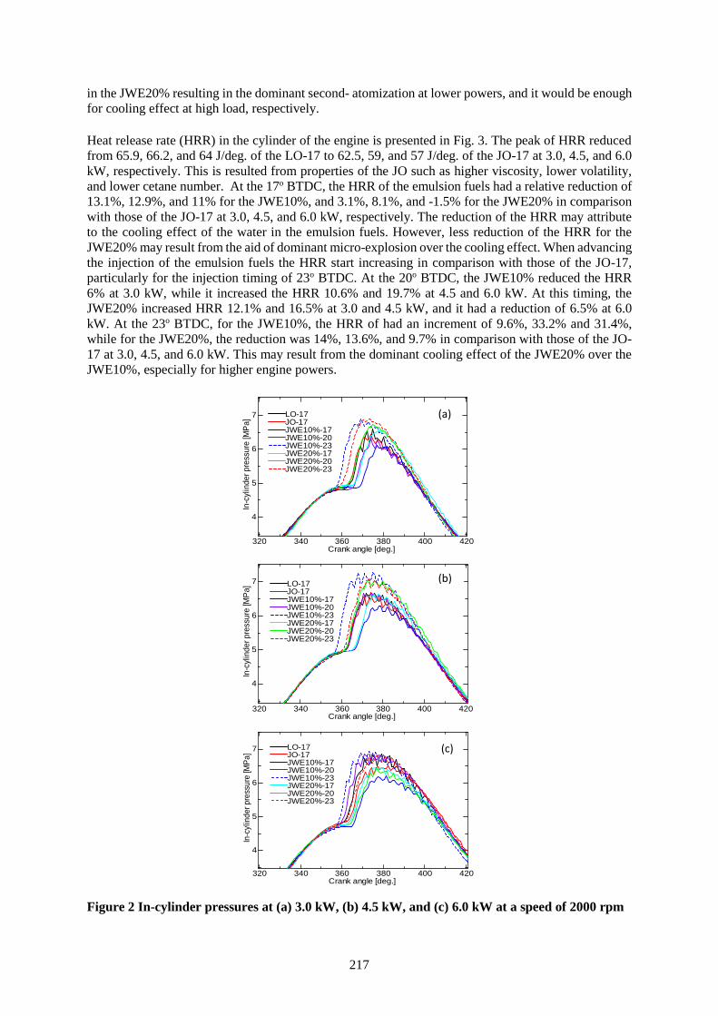
217
in the JWE20% resulting in the dominant second- atomization at lower powers, and it would be enoughfor cooling effect at high load, respectively.
Heat release rate (HRR) in the cylinder of the engine is presented in Fig. 3. The peak of HRR reducedfrom 65.9, 66.2, and 64 J/deg. of the LO-17 to 62.5, 59, and 57 J/deg. of the JO-17 at 3.0, 4.5, and 6.0kW, respectively. This is resulted from properties of the JO such as higher viscosity, lower volatility,and lower cetane number. At the 17o BTDC, the HRR of the emulsion fuels had a relative reduction of13.1%, 12.9%, and 11% for the JWE10%, and 3.1%, 8.1%, and -1.5% for the JWE20% in comparisonwith those of the JO-17 at 3.0, 4.5, and 6.0 kW, respectively. The reduction of the HRR may attributeto the cooling effect of the water in the emulsion fuels. However, less reduction of the HRR for theJWE20% may result from the aid of dominant micro-explosion over the cooling effect. When advancingthe injection of the emulsion fuels the HRR start increasing in comparison with those of the JO-17,particularly for the injection timing of 23o BTDC. At the 20o BTDC, the JWE10% reduced the HRR6% at 3.0 kW, while it increased the HRR 10.6% and 19.7% at 4.5 and 6.0 kW. At this timing, theJWE20% increased HRR 12.1% and 16.5% at 3.0 and 4.5 kW, and it had a reduction of 6.5% at 6.0kW. At the 23o BTDC, for the JWE10%, the HRR of had an increment of 9.6%, 33.2% and 31.4%,while for the JWE20%, the reduction was 14%, 13.6%, and 9.7% in comparison with those of the JO-17 at 3.0, 4.5, and 6.0 kW. This may result from the dominant cooling effect of the JWE20% over theJWE10%, especially for higher engine powers.
Figure 2 In-cylinder pressures at (a) 3.0 kW, (b) 4.5 kW, and (c) 6.0 kW at a speed of 2000 rpm
320 340 360 380 400 420
4
5
6
7
Crank angle [deg.]
In-c
ylin
der p
ress
ure
[MPa
] LO-17JO-17JWE10%-17JWE10%-20JWE10%-23JWE20%-17JWE20%-20JWE20%-23
(b)
(a)
320 340 360 380 400 420
4
5
6
7 LO-17JO-17JWE10%-17JWE10%-20JWE10%-23JWE20%-17JWE20%-20JWE20%-23
Crank angle [deg.]
In-c
ylin
der p
ress
ure
[MPa
]
(c)
320 340 360 380 400 420
4
5
6
7
Crank angle [deg.]
In-c
ylin
der p
ress
ure
[MPa
]
LO-17JO-17JWE10%-17JWE10%-20JWE10%-23JWE20%-17JWE20%-20JWE20%-23
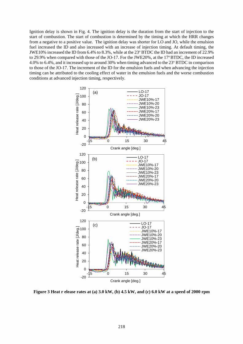
218
Ignition delay is shown in Fig. 4. The ignition delay is the duration from the start of injection to thestart of combustion. The start of combustion is determined by the timing at which the HRR changesfrom a negative to a positive value. The ignition delay was shorter for LO and JO, while the emulsionfuel increased the ID and also increased with an increase of injection timing. At default timing, theJWE10% increased the ID from 6.4% to 8.3%, while at the 23o BTDC the ID had an increment of 22.9%to 29.9% when compared with those of the JO-17. For the JWE20%, at the 17o BTDC, the ID increased4.0% to 6.4%, and it increased up to around 30% when timing advanced to the 23o BTDC in comparisonto those of the JO-17. The increment of the ID for the emulsion fuels and when advancing the injectiontiming can be attributed to the cooling effect of water in the emulsion fuels and the worse combustionconditions at advanced injection timing, respectively.
Figure 3 Heat r elease rates at (a) 3.0 kW, (b) 4.5 kW, and (c) 6.0 kW at a speed of 2000 rpm
-20
0
20
40
60
80
100
120
-15 0 15 30 45
Hea
t rel
ease
rate
[J/d
eg.]
Crank angle [deg.]
LO-17JO-17JWE10%-17JWE10%-20JWE10%-23JWE20%-17JWE20%-20JWE20%-23
(a)
-20
0
20
40
60
80
100
120
-15 0 15 30 45
Hea
t rel
ease
rate
[J/d
eg.]
Crank angle [deg.]
LO-17JO-17JWE10%-17JWE10%-20JWE10%-23JWE20%-17JWE20%-20JWE20%-23
(b)
-20
0
20
40
60
80
100
120
-15 0 15 30 45
Hea
t rel
ease
rate
[J/d
eg.]
Crank angle [deg.]
LO-17JO-17JWE10%-17JWE10%-20JWE10%-23JWE20%-17JWE20%-20JWE20%-23
(c)
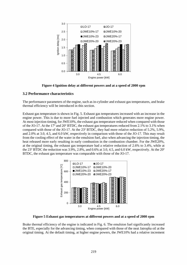
219
Figure 4 Ignition delay at different powers and at a speed of 2000 rpm
3.2 Performance characteristics
The performance parameters of the engine, such as in-cylinder and exhaust gas temperatures, and brakethermal efficiency will be introduced in this section.
Exhaust gas temperature is shown in Fig. 5. Exhaust gas temperatures increased with an increase in theengine power. This is due to more fuel injected and combustion which generates more engine power.At most injection timing, for JWE10%, the exhaust gas temperature reduced when compared with thoseof the JO-17. At the 17o and 20o BTDC, the exhaust gas temperatures reduced from 2.1% to 3.1% whencompared with those of the JO-17. At the 23o BTDC, they had more relative reduction of 5.2%, 5.9%,and 2.0% at 3.0, 4.5, and 6.0 kW, respectively in comparison with those of the JO-17. This may resultfrom the cooling effect of the water in the emulsion fuel, also when advancing the injection timing, theheat released more early resulting in early combustion in the combustion chamber. For the JWE20%,at the original timing, the exhaust gas temperature had a relative reduction of 2.6% to 3.4%, while atthe 23o BTDC the reduction was 3.9%, 2.8%, and 0.6% at 3.0, 4.5, and 6.0 kW, respectively. At the 20o
BTDC, the exhaust gas temperature was comparable with those of the JO-17.
Figure 5 Exhaust gas temperatures at different powers and at a speed of 2000 rpm
Brake thermal efficiency of the engine is indicated in Fig. 6. The emulsion fuel significantly increasedthe BTE, especially for the advancing timing, when compared with those of the neat Jatropha oil at theoriginal timing. At the default timing, at higher engine powers, the JWE10% had a relative increment
0.0
0.5
1.0
1.5
2.0
2.5
3.0
3.0 4.5 6.0
Igni
tion
dela
y [m
s]
Engine power [kW]
LO-17 JO-17
JWE10%-17 JWE10%-20
JWE10%-23 JWE20%-17
JWE20%-20 JWE20%-23
0
200
400
600
800
3.0 4.5 6.0
Exha
ust g
as te
mpe
ratu
re [o C
]
Engine power [kW]
LO-17 JO-17JWE10%-17 JWE10%-20JWE10%-23 JWE20%-17JWE20%-20 JWE20%-23
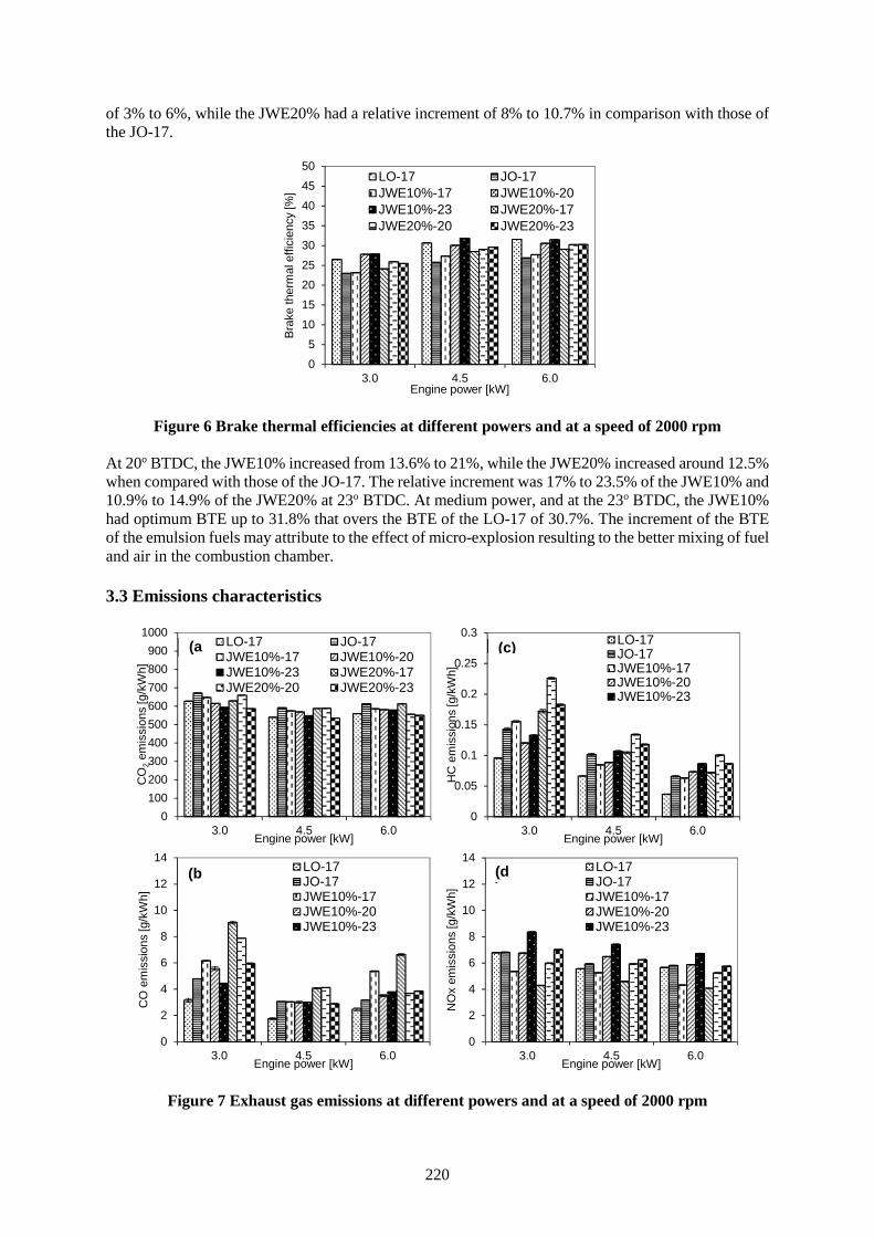
220
of 3% to 6%, while the JWE20% had a relative increment of 8% to 10.7% in comparison with those ofthe JO-17.
Figure 6 Brake thermal efficiencies at different powers and at a speed of 2000 rpm
At 20o BTDC, the JWE10% increased from 13.6% to 21%, while the JWE20% increased around 12.5%when compared with those of the JO-17. The relative increment was 17% to 23.5% of the JWE10% and10.9% to 14.9% of the JWE20% at 23o BTDC. At medium power, and at the 23o BTDC, the JWE10%had optimum BTE up to 31.8% that overs the BTE of the LO-17 of 30.7%. The increment of the BTEof the emulsion fuels may attribute to the effect of micro-explosion resulting to the better mixing of fueland air in the combustion chamber.
3.3 Emissions characteristics
Figure 7 Exhaust gas emissions at different powers and at a speed of 2000 rpm
05
101520253035404550
3.0 4.5 6.0
Brak
e th
erm
al e
ffici
ency
[%]
Engine power [kW]
LO-17 JO-17JWE10%-17 JWE10%-20JWE10%-23 JWE20%-17JWE20%-20 JWE20%-23
0100200300400500600700800900
1000
3.0 4.5 6.0
CO
2em
issi
ons
[g/k
Wh]
Engine power [kW]
LO-17 JO-17JWE10%-17 JWE10%-20JWE10%-23 JWE20%-17JWE20%-20 JWE20%-23
(a)
0
2
4
6
8
10
12
14
3.0 4.5 6.0
CO
em
issi
ons
[g/k
Wh]
Engine power [kW]
LO-17JO-17JWE10%-17JWE10%-20JWE10%-23
(b)
0
0.05
0.1
0.15
0.2
0.25
0.3
3.0 4.5 6.0
HC
em
issi
ons
[g/k
Wh]
Engine power [kW]
LO-17JO-17JWE10%-17JWE10%-20JWE10%-23
(c)
0
2
4
6
8
10
12
14
3.0 4.5 6.0
NO
x em
issi
ons
[g/k
Wh]
Engine power [kW]
LO-17JO-17JWE10%-17JWE10%-20JWE10%-23
(d)
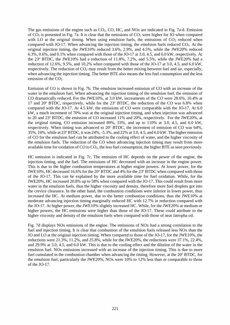
221
The gas emissions of the engine such as CO2, CO, HC, and NOx are indicated in Fig. 7a-d. Emissionof CO2 is presented in Fig. 7a. It is clear that the emissions of CO2 were higher for JO when comparedwith LO at the original timing. When using emulsion fuels, the emissions of CO2 reduced whencompared with JO-17. When advancing the injection timing, the emulsion fuels reduced CO2. At theoriginal injection timing, the JWE10% reduced 3.6%, 2.9%, and 4.5%, while the JWE20% reduced6.3%, 0.6%, and 0.1% when compared with those of the JO-17 at 3.0, 4.5, and 6.0 kW, respectively. Atthe 23o BTDC, the JWE10% had a reduction of 11.8%, 7.2%, and 5.5%, while the JWE20% had areduction of 12.6%, 9.5%, and 10.2% when compared with those of the JO-17 at 3.0, 4.5, and 6.0 kW,respectively. The reduction of CO2 may result from the better mixing between fuel and air, especially,when advancing the injection timing. The better BTE also means the less fuel consumption and the lessemission of the CO2.
Emission of CO is shown in Fig. 7b. The emulsion increased emission of CO with an increase of thewater in the emulsion fuel. When advancing the injection timing of the emulsion fuel, the emission ofCO dramatically reduced. For the JWE10%, at 3.0 kW, increaments of the CO were 28.6%, 16.4% at17 and 20o BTDC, respectively, while for the 23o BTDC, the reduction of the CO was 6.8% whencompared with the JO-17. At 4.5 kW, the emissions of CO were comparable with the JO-17. At 6.0kW, a much increment of 70% was at the original injection timing, and when injection was advancedto 20 and 23o BTDC, the emission of CO increased 11% and 20%, respectively. For the JWE20%, atthe original timing, CO emission increased 89%, 33%, and up to 110% at 3.0, 4.5, and 6.0 kW,respectively. When timing was advanced to 20o BTDC, the increment of emission of CO was 64%,35%, 16%, while at 23o BTDC, it was 24%, -5.3%, and 22% at 3.0, 4.5, and 6.0 kW. The higher emissionof CO for the emulsion fuel can be attributed to the cooling effect of water, and the higher viscosity ofthe emulsion fuels. The reduction of the CO when advancing injection timing may result from moreavailable time for oxidation of CO to CO2, the less fuel consumption, the higher BTE as seen previously.
HC emission is indicated in Fig. 7c. The emission of HC depends on the power of the engine, theinjection timing, and the fuel. The emissions of HC decreased with an increase in the engine power.This is due to the higher combustion temperatures at higher engine powers. At lower power, for theJWE10%, HC decreased 16.6% for the 20o BTDC and 4% for the 23o BTDC when compared with thoseof the JO-17. This can be explained by the more available time for fuel oxidation. While, for theJWE20%, HC increased 20.8% up to 58% when compared with the JO-17. This could result from morewater in the emulsion fuels, thus the higher viscosity and density, therefore more fuel droplets got intothe crevice clearance. In the other hand, the combustion conditions were inferior in lower power, thusincreased the HC. At medium power, due to the better combustion conditions, thus the JWE10% atmoderate advancing injection timing marginally reduced HC with 12.7% in reduction compared withthe JO-17. At higher power, the JWE10% slightly increased HC. While, for the JWE20% at medium orhigher powers, the HC emissions were higher than those of the JO-17. These could attribute to thehigher viscosity and density of the emulsion fuels when compared with those of neat Jatropha oil.
Fig. 7d displays NOx emissions of the engine. The emissions of NOx had a strong correlation to thefuel and injection timing. It is clear that combustion of the emulsion fuels released less NOx than theJO and LO at the original injection timing. When compared to those of the JO-17, for the JWE10%, thereductions were 21.3%, 11.2%, and 25.8%, while for the JWE20%, the reductions were 37.1%, 22.4%,and 29.9% at 3.0, 4.5, and 6.0 kW. This is due to the cooling effect and the dilution of the water in theemulsion fuel. NOx emissions increased with an increase of the injection timing. This is due to morefuel cumulated in the combustion chamber when advancing the timing. However, at the 20o BTDC, forthe emulsion fuel, particularly the JWE20%, NOx were 10% to 12% less than or comparable to thoseof the JO-17.
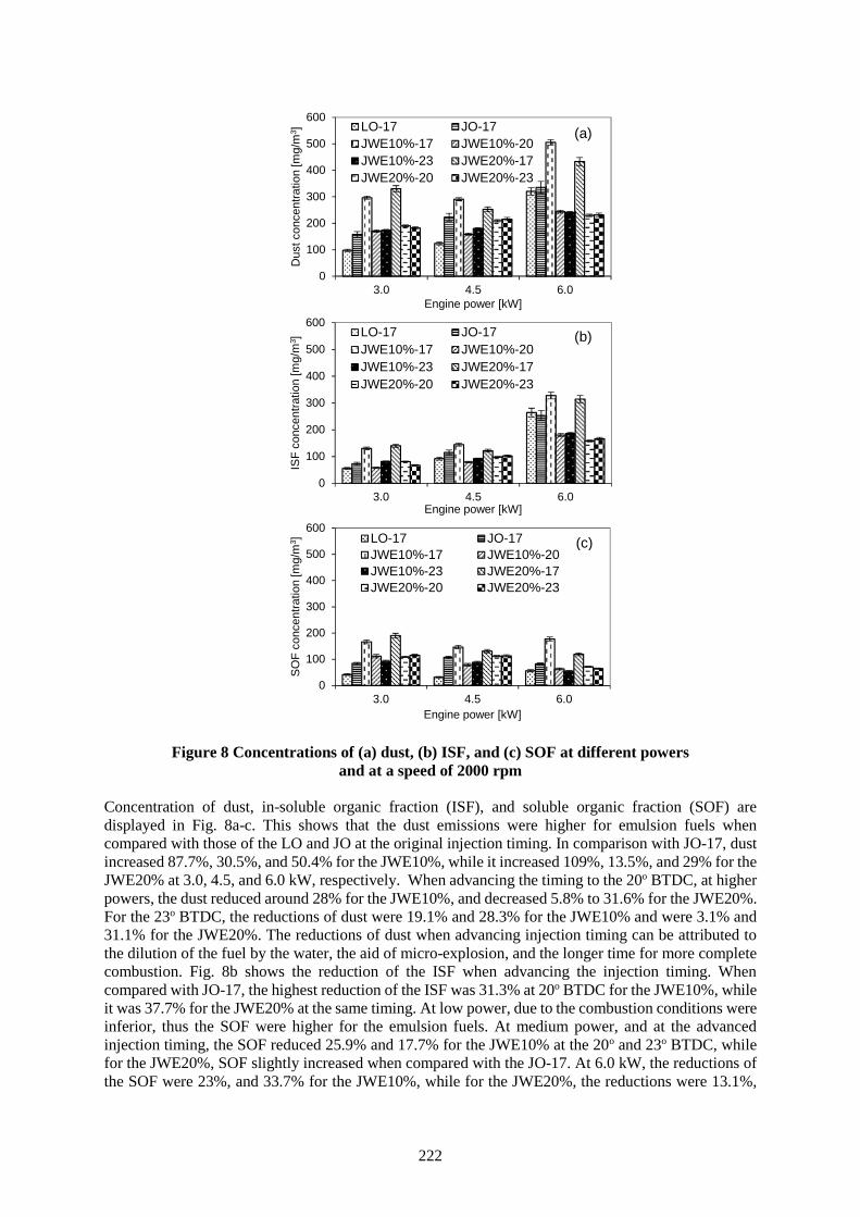
222
Figure 8 Concentrations of (a) dust, (b) ISF, and (c) SOF at different powersand at a speed of 2000 rpm
Concentration of dust, in-soluble organic fraction (ISF), and soluble organic fraction (SOF) aredisplayed in Fig. 8a-c. This shows that the dust emissions were higher for emulsion fuels whencompared with those of the LO and JO at the original injection timing. In comparison with JO-17, dustincreased 87.7%, 30.5%, and 50.4% for the JWE10%, while it increased 109%, 13.5%, and 29% for theJWE20% at 3.0, 4.5, and 6.0 kW, respectively. When advancing the timing to the 20o BTDC, at higherpowers, the dust reduced around 28% for the JWE10%, and decreased 5.8% to 31.6% for the JWE20%.For the 23o BTDC, the reductions of dust were 19.1% and 28.3% for the JWE10% and were 3.1% and31.1% for the JWE20%. The reductions of dust when advancing injection timing can be attributed tothe dilution of the fuel by the water, the aid of micro-explosion, and the longer time for more completecombustion. Fig. 8b shows the reduction of the ISF when advancing the injection timing. Whencompared with JO-17, the highest reduction of the ISF was 31.3% at 20o BTDC for the JWE10%, whileit was 37.7% for the JWE20% at the same timing. At low power, due to the combustion conditions wereinferior, thus the SOF were higher for the emulsion fuels. At medium power, and at the advancedinjection timing, the SOF reduced 25.9% and 17.7% for the JWE10% at the 20o and 23o BTDC, whilefor the JWE20%, SOF slightly increased when compared with the JO-17. At 6.0 kW, the reductions ofthe SOF were 23%, and 33.7% for the JWE10%, while for the JWE20%, the reductions were 13.1%,
0
100
200
300
400
500
600
3.0 4.5 6.0D
ust c
once
ntra
tion
[mg/
m3 ]
Engine power [kW]
LO-17 JO-17JWE10%-17 JWE10%-20JWE10%-23 JWE20%-17JWE20%-20 JWE20%-23
(a)
0
100
200
300
400
500
600
3.0 4.5 6.0
ISF
conc
entra
tion
[mg/
m3 ]
Engine power [kW]
LO-17 JO-17JWE10%-17 JWE10%-20JWE10%-23 JWE20%-17JWE20%-20 JWE20%-23
(b)
0
100
200
300
400
500
600
3.0 4.5 6.0
SOF
conc
entra
tion
[mg/
m3 ]
Engine power [kW]
LO-17 JO-17JWE10%-17 JWE10%-20JWE10%-23 JWE20%-17JWE20%-20 JWE20%-23
(c)
223
and 21.2%. At higher power, the combustion temperature is higher resulting in better micro-explosion;and the longer available time for combustion thus reducing the SOF.
4. Conclusions
A direct injection diesel engine was used to investigate the effects of injection timing and Jatropha wateremulsion fuels with a mixing rate of 10% and 20% on the combustion, performance, and emissions ofthe engine. In summary, the main features are as follows.
1- The peak of in-cylinder pressure reduced when the emulsion fuels were used at the originalinjection timing. When advancing the injection timing, it marginally increased when comparedwith those of neat Jatropha oil at the original timing. The increment was from 7% to 8.8% for theJWE10%, and from 5.5% to 13.1% for the JWE20% at 23o BTDC in comparison with those of theJO-17. The HRR slightly reduced at the original injection timing when using the JWE10%, whilefor the JWE20%, the marginal increment has seen at lower power, and the reduction has observedat high power. When advancing injection timing, heat released more early and higher than thoseof the JO-17. The ignition delay increased with an increase of injection timing, and up to 30%when compared with those of the JO-17 for both emulsion fuels.
2- Emulsion fuel reduced the exhaust gas temperature at lower engine powers. When advancinginjection timing to 23o BTDC, both emulsion fuels reduced exhaust gas temperature. BTE of theengine using emulsion fuels was higher than that of the neat Jatropha oil fueled engine. Whenadvancing injection timing, emulsion fuels increased the BTE, particularly for the JWE10% witha maximum relative increment of 23.5% when compared with that of the JO-17 fueled engine.
3- When advancing the injection timing to a reasonable timing, the emulsion fuel reduced or kept thecomparable emission of CO2, CO, HC, and NOx. For emulsion fuels, the dust, ISF, and SOFconcentration dramatically reduced when injection timing advanced to 20o or 23o BTDC, especiallyfor the JWE10%.
4- Overall, the optimum mixing rate of water for Jatropha emulsion fuel was 10%, while the optimuminjection timing was at 20o BTDC for combustion, performance, and emissions of the engine.
References
[1] R. Altın, S. Çetinkaya, and H. S. Yücesu. “The potential of using vegetable oil fuels as fuel fordiesel engines”, Energy Conversion and Management (2001), Volume 42, pp. 529-538
[2] N. Hemmerlein, V. Korte, H. Richter, and G. Schröder, “Performance, exhaust emissions anddurability of modern diesel engines running on rapeseed oil”, SAE Technical Paper 910848 (1991)
[3] M. S. Kumar, A. Ramesh, B. Nagalingam. “An experimental comparison of methods to usemethanol and Jatropha oil in a compression ignition engine”, Biomass and Bioenergy (2003),Volume 25, pp. 309-318
[4] A.S. Huzayyin, A.H. Bawady, M.A. Rady, A. Dawood, “Experimental evaluation of diesel engineperformance and emission using blends of jojoba oil and diesel fuel”, Energy Conversion andManagement (2004), Volume 45, pp. 2093-2112
[5] S.-Y. No, “Inedible vegetable oils and their derivatives for alternative diesel fuels in CI engines:A review”, Renewable and Sustainable Energy Reviews (2011), Volume 15, pp. 131-149
[6] K. Pramanik, “Properties and use of jatropha curcas oil and diesel fuel blends in compressionignition engine”, Renewable Energy (2003), Volume 28, pp. 239-248
[7] Deepak Agarwal, Avinash Kumar Agarwal, “Performance and emissions characteristics ofJatropha oil (preheated and blends) in a direct injection compression ignition engine”, AppliedThermal Engineering (2007), Volume 27, pp. 2314-2323
[8 B. S. Chauhan, N. Kumar, Y. D. Jun, K. B. Lee, “Performance and emission study of preheatedJatropha oil on medium capacity diesel engine”, Energy (2010), Volume 35, pp. 2484-2492
[9] A. K. Agarwal and A. Dhar, “Performance, emission and combustion characteristics of preheatedand blended Jatropha oil”. Chapter 26 in "Jatropha, Challenges for a New Energy Crop", Volume1: Farming, Economics and Biofuel by Carels, Nicolas, Sujatha, Mulpuri, Bahadur, Bir (Eds.)
224
[10] B. S. Chauhan, N. Kumar, H. M. Cho, “A study on the performance and emission of a diesel enginefueled with Jatropha biodiesel oil and its blends”, Energy (2012), Volume 37, pp. 616-622
[11] M. Mofijur, H. H. Masjuki, M. A. Kalam, A. E. Atabani, “Evaluation of biodiesel blending, engineperformance and emissions characteristics of Jatropha curcas methyl ester: Malaysianperspective”, Energy (2013), Volume 55, pp. 879-887
[12] R. J. Crookes, F. Kiannejad, and M. A. A. Nazha, “Systematic assessment of combustioncharacteristics of biofuel and emulsions with water for use and diesel engine fuels”, EnergyConversion and Management (1997), Volume 38, pp. 1785-1795
[13] O. Armas, R. Ballesteros, F. J. Martos, J. R. Agudelo, “Characterization of light duty diesel enginepollutant emissions using water-emulsified fuel”, Fuel (2005), Volume 84, pp. 1011-1018
[14] J. Ghojel, D. Honnery, K. Al-Khaleefi, “Performance, emissions and heat release characteristicsof direct injection diesel engine operating on diesel oil emulsion”, Applied Thermal Engineering(2006), Volume 26, pp. 2132-2141
[15] R. Ochoterena, A. Lif, M. Nyden, S. Andersson, I. Denbratt, “Optical studies of spray developmentand combustion of water-in-diesel emulsion and microemulsion fuels”, Fuel (2010), Volume 89,pp. 122-132
[16] A. Maiboom, X. Tauzia, “NOx and PM emissions reduction on an automotive HSDI diesel enginewith water-in-diesel emulsion and EGR: An experimental study”, Fuel (2011), Volume 90, pp.3179-3192.
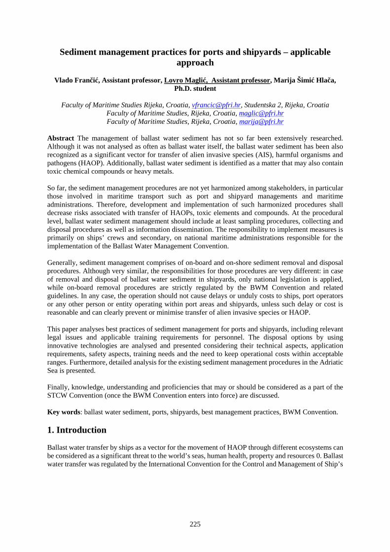
225
Sediment management practices for ports and shipyards – applicableapproach
Vlado Frančić, Assistant professor, Lovro Maglić, Assistant professor, Marija Šimić Hlača,Ph.D. student
Faculty of Maritime Studies Rijeka, Croatia, [email protected], Studentska 2, Rijeka, CroatiaFaculty of Maritime Studies, Rijeka, Croatia, [email protected] of Maritime Studies, Rijeka, Croatia, [email protected]
Abstract The management of ballast water sediment has not so far been extensively researched.Although it was not analysed as often as ballast water itself, the ballast water sediment has been alsorecognized as a significant vector for transfer of alien invasive species (AIS), harmful organisms andpathogens (HAOP). Additionally, ballast water sediment is identified as a matter that may also containtoxic chemical compounds or heavy metals.
So far, the sediment management procedures are not yet harmonized among stakeholders, in particularthose involved in maritime transport such as port and shipyard managements and maritimeadministrations. Therefore, development and implementation of such harmonized procedures shalldecrease risks associated with transfer of HAOPs, toxic elements and compounds. At the procedurallevel, ballast water sediment management should include at least sampling procedures, collecting anddisposal procedures as well as information dissemination. The responsibility to implement measures isprimarily on ships’ crews and secondary, on national maritime administrations responsible for theimplementation of the Ballast Water Management Convention.
Generally, sediment management comprises of on-board and on-shore sediment removal and disposalprocedures. Although very similar, the responsibilities for those procedures are very different: in caseof removal and disposal of ballast water sediment in shipyards, only national legislation is applied,while on-board removal procedures are strictly regulated by the BWM Convention and relatedguidelines. In any case, the operation should not cause delays or unduly costs to ships, port operatorsor any other person or entity operating within port areas and shipyards, unless such delay or cost isreasonable and can clearly prevent or minimise transfer of alien invasive species or HAOP.
This paper analyses best practices of sediment management for ports and shipyards, including relevantlegal issues and applicable training requirements for personnel. The disposal options by usinginnovative technologies are analysed and presented considering their technical aspects, applicationrequirements, safety aspects, training needs and the need to keep operational costs within acceptableranges. Furthermore, detailed analysis for the existing sediment management procedures in the AdriaticSea is presented.
Finally, knowledge, understanding and proficiencies that may or should be considered as a part of theSTCW Convention (once the BWM Convention enters into force) are discussed.
Key words: ballast water sediment, ports, shipyards, best management practices, BWM Convention.
1. Introduction
Ballast water transfer by ships as a vector for the movement of HAOP through different ecosystems canbe considered as a significant threat to the world’s seas, human health, property and resources 0. Ballastwater transfer was regulated by the International Convention for the Control and Management of Ship’s
226
Ballast Water and Sediments, 2004 (BWM Convention) which defines the global standards on ballastwater and sediment management requirements.2
Sediments in ballast water tanks and their management, although mentioned in numerous differentdocuments, have not been extensively researched [2].3 Before adopting BWM Convention, the accentwas on evaluating possibilities and the extent of transfer of HAOPs via ballast water. Internationallyavailable sources do not deal much with sediment management. The majority of the documents andscientific papers on ballast water sediments deal with presence of organisms and their identificationproving that sediment is a significant vector for the transfer of organisms [2].
Another group of papers deals with ship design, management and new treatment techniques for reducingthe build-up of sediments and sediment sampling methods from the ballast water tanks [10-12].
The research on the physical and chemical properties including the presence of heavy metals in ballasttank sediments is presented in the study created by Macdonald and Davidson in 1997 [13] and Maglicin 2016 [14]. The first study was based on an extensive number of samples taken from ships visitingScottish ports. The results showed that the levels of heavy metal in ballast tank sediment build-up arefrequently higher than those detected in the natural environment. In the second paper, the analysis ofsamples from three ships visiting the port of Rijeka (Croatia) revealed no significant abundance ofheavy or toxic metals. However, high concentrations of detected metals may endanger humans orenvironment.
The Contracting States are responsible for deciding on best sediment management and disposalpractices for ports and shipyards taking into account technical aspects, application requirements, safetyaspects, and the related costs. Sediment management should take into account three main issues:whether a sediment accumulation which is about to be unloaded from a ship may endanger humanhealth and/or the environment, how to treat the unloaded sediments, and where it may be disposed.
Policies and regulations that will be proposed should be in accordance with principles and requirementsoutlined in guidelines adopted by the International Maritime Organization, notably in line withResolution MEPC.152(55) Guidelines for Sediment Reception Facilities (G1) [15] and ResolutionMEPC.150(55) Guidelines on Design and Construction to Facilitate Sediment Control on Ships (G12)[16]. New regulations should cause no delays or unduly costs to the ships or port operators or any otherperson or entity operating within port areas and shipyards, unless such delay or cost is reasonable andclearly prevents or minimises the transfer of alien invasive species or influence of the toxic or heavymetals to humans and environment.
2. Ballast water tanks sediments
Ballast water sediment builds up in ballast tanks from water containing different solid particles eithersucked or being produced by different processes in tanks and associated pipelines. Soil sediment drawnconsists mostly of clay, silt and sand and sometimes includes even larger granular particles.
Clay is a natural earthy material consisting mainly of fine particles of hydrated silicates of aluminiumand other minerals. In most cases, clay soil shows plastic behaviour due to water content. However,
2 BWM Convention is still not in force. Presently 50 countries have ratified the Convention. However these 50countries represent 34,8% of the GT of the world’s merchant fleet, less than the 35% that is required.
3 A “search by title” in Web of Science revealed 1.850 publications with the term ‘ballast water’ as opposed toonly 338 with ‘ballast sediment’ (May 2016). However, a significant increase of interest in the topic is notedbecause the number of results increased approximately 3 times for ‘ballast water’ and 10 times for ‘ballastsediment’ term within one year.

227
after being dried, clay usually becomes hard and brittle. Depending on additional substances, it mayappear in various colours, including white, grey, brown or red. The size of clay particles is usuallyconsidered to be 2 m or less. As such, it is easily sucked and deposited in ballast tanks. If homogenousstructure is formed in tank, clay removal may be quite a demanding task.
Silt may occur as soil (low water content) or as sediment mixed with water. On board ships it is almostalways found as a suspended load in a body of water. It may be found also as soil deposited at thebottom. Silt, when dry, usually has a floury feel, and may give a slippery feel when wet. Silt particlesare much larger then clay but smaller than sand particles, usually in range between 2 m and 63 m. Itcan be found across the world.
Sand is a naturally occurring granular material composed of finely divided rock and mineral particles.It is finer than gravel and coarser than silt. Sand particles range in diameter from 63 m to 2 mm. Thecomposition of sand varies, depending on the local sources and conditions, but the most commonconstituent is silicon dioxide, usually in the form of quartz, or calcium carbonate. Colour can bedifferent, depending on other constituents, and vary from white to yellow, orange and even red.
Larger particles may occasionally be found in ballast tanks. They may be found in tanks if suction pointis quite close to the sea bottom and/or external forces upheld larger particles in the water column (forexample, in river estuaries where tidal currents meet fresh water flow).
Beside sediment in the ballast tanks, there also may be found particles produced by different processesin tanks or in associated pipelines. These particles include the corrosion products, parts of protectivecoatings, and organic material.
Finally, there is sea water. Pumping out the complete volume of ballast water is rarely possible. Thequantity that persistently remains in a tank mostly depends on design of the suction line(s) andefficiency of the ballast pumps. Usually, in the area around suction bell it remains up to 5 centimetresof water, assuming that sediment build-up does not block the free water flow. The quantity of waterdepends on sediment content; sediment actually prevents free water flaw, thus decreasing the capabilityof the ballast pumps to suck out maximum quantity of water. The water may contain up to 70% ofcontent of the tank that cannot be pumped out.
Deposited sediments are not removed by themselves from the ballast tanks, even though the tanks arerepeatedly filled and emptied. In fact, the quantity of deposited sediments may increase gradually asballast water is loaded and discharged because pumps cannot extract sediments that have already settleddown.
Sometimes, particularly when mud-based sediments prevail, deposits on the bottoms of the ballast tanksgradually harden and become denser under pressure. This hardening is caused by repelling of water.Such hardened, mud-based dense sediments from the ballast tanks are usually difficult to remove,requiring lot of manual work.
A layer of sediment in a ballast tank may reach up to 10-15 centimetres. It may occur in tanks that arenot easily accessible (low water dynamics and/or restricted movement of water between differentcompartments made of athwart ship floors and bottom longitudinals).
For example, a Panamax-type bulk carrier, with a length over all of 220 m and a breadth of 32.20 m,typically contains ballast tanks that encompass a joint area of about 150 m length and about 30 m width,rendering an area of approximately 4,500 m². A layer of 0.10 m of sediment over such bottom wouldresult in a mean volume of 450 m³. With an estimated average sediment density of 1.5 kg/ dm³, thesediment may reach 675 tons. However, such build-up is relatively rare. Usually, the height of thedeposited sediment reaches up to few centimetres, rarely more. Density of sediment may vary between
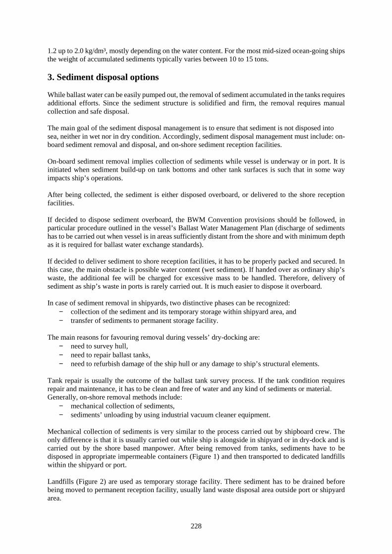
228
1.2 up to 2.0 kg/dm³, mostly depending on the water content. For the most mid-sized ocean-going shipsthe weight of accumulated sediments typically varies between 10 to 15 tons.
3. Sediment disposal options
While ballast water can be easily pumped out, the removal of sediment accumulated in the tanks requiresadditional efforts. Since the sediment structure is solidified and firm, the removal requires manualcollection and safe disposal.
The main goal of the sediment disposal management is to ensure that sediment is not disposed intosea, neither in wet nor in dry condition. Accordingly, sediment disposal management must include: on-board sediment removal and disposal, and on-shore sediment reception facilities.
On-board sediment removal implies collection of sediments while vessel is underway or in port. It isinitiated when sediment build-up on tank bottoms and other tank surfaces is such that in some wayimpacts ship’s operations.
After being collected, the sediment is either disposed overboard, or delivered to the shore receptionfacilities.
If decided to dispose sediment overboard, the BWM Convention provisions should be followed, inparticular procedure outlined in the vessel’s Ballast Water Management Plan (discharge of sedimentshas to be carried out when vessel is in areas sufficiently distant from the shore and with minimum depthas it is required for ballast water exchange standards).
If decided to deliver sediment to shore reception facilities, it has to be properly packed and secured. Inthis case, the main obstacle is possible water content (wet sediment). If handed over as ordinary ship’swaste, the additional fee will be charged for excessive mass to be handled. Therefore, delivery ofsediment as ship’s waste in ports is rarely carried out. It is much easier to dispose it overboard.
In case of sediment removal in shipyards, two distinctive phases can be recognized: collection of the sediment and its temporary storage within shipyard area, and transfer of sediments to permanent storage facility.
The main reasons for favouring removal during vessels’ dry-docking are: need to survey hull, need to repair ballast tanks, need to refurbish damage of the ship hull or any damage to ship’s structural elements.
Tank repair is usually the outcome of the ballast tank survey process. If the tank condition requiresrepair and maintenance, it has to be clean and free of water and any kind of sediments or material.Generally, on-shore removal methods include:
mechanical collection of sediments, sediments’ unloading by using industrial vacuum cleaner equipment.
Mechanical collection of sediments is very similar to the process carried out by shipboard crew. Theonly difference is that it is usually carried out while ship is alongside in shipyard or in dry-dock and iscarried out by the shore based manpower. After being removed from tanks, sediments have to bedisposed in appropriate impermeable containers (Figure 1) and then transported to dedicated landfillswithin the shipyard or port.
Landfills (Figure 2) are used as temporary storage facility. There sediment has to be drained beforebeing moved to permanent reception facility, usually land waste disposal area outside port or shipyardarea.
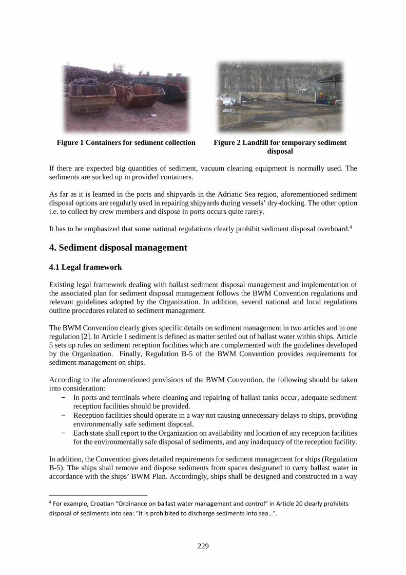
229
Figure 1 Containers for sediment collection Figure 2 Landfill for temporary sedimentdisposal
If there are expected big quantities of sediment, vacuum cleaning equipment is normally used. Thesediments are sucked up in provided containers.
As far as it is learned in the ports and shipyards in the Adriatic Sea region, aforementioned sedimentdisposal options are regularly used in repairing shipyards during vessels’ dry-docking. The other optioni.e. to collect by crew members and dispose in ports occurs quite rarely.
It has to be emphasized that some national regulations clearly prohibit sediment disposal overboard.4
4. Sediment disposal management
4.1 Legal framework
Existing legal framework dealing with ballast sediment disposal management and implementation ofthe associated plan for sediment disposal management follows the BWM Convention regulations andrelevant guidelines adopted by the Organization. In addition, several national and local regulationsoutline procedures related to sediment management.
The BWM Convention clearly gives specific details on sediment management in two articles and in oneregulation [2]. In Article 1 sediment is defined as matter settled out of ballast water within ships. Article5 sets up rules on sediment reception facilities which are complemented with the guidelines developedby the Organization. Finally, Regulation B-5 of the BWM Convention provides requirements forsediment management on ships.
According to the aforementioned provisions of the BWM Convention, the following should be takeninto consideration:
In ports and terminals where cleaning and repairing of ballast tanks occur, adequate sedimentreception facilities should be provided.
Reception facilities should operate in a way not causing unnecessary delays to ships, providingenvironmentally safe sediment disposal.
Each state shall report to the Organization on availability and location of any reception facilitiesfor the environmentally safe disposal of sediments, and any inadequacy of the reception facility.
In addition, the Convention gives detailed requirements for sediment management for ships (RegulationB-5). The ships shall remove and dispose sediments from spaces designated to carry ballast water inaccordance with the ships’ BWM Plan. Accordingly, ships shall be designed and constructed in a way
4 For example, Croatian “Ordinance on ballast water management and control” in Article 20 clearly prohibitsdisposal of sediments into sea: “It is prohibited to discharge sediments into sea…”.
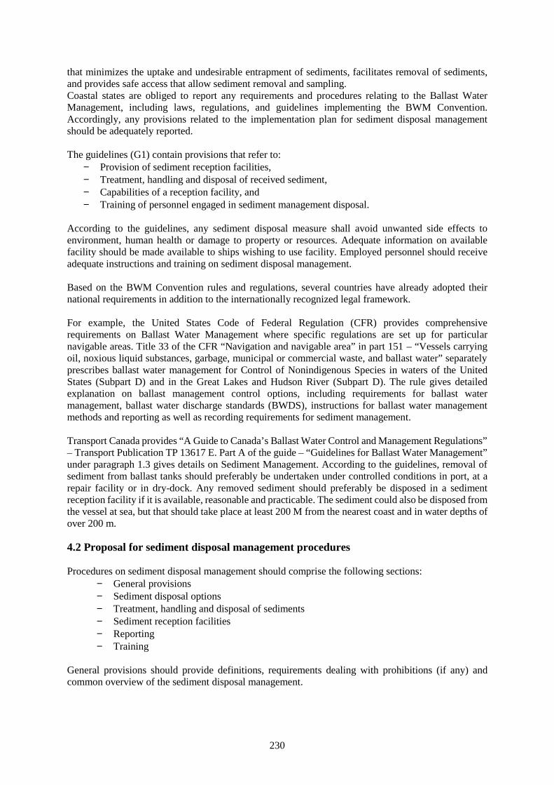
230
that minimizes the uptake and undesirable entrapment of sediments, facilitates removal of sediments,and provides safe access that allow sediment removal and sampling.Coastal states are obliged to report any requirements and procedures relating to the Ballast WaterManagement, including laws, regulations, and guidelines implementing the BWM Convention.Accordingly, any provisions related to the implementation plan for sediment disposal managementshould be adequately reported.
The guidelines (G1) contain provisions that refer to: Provision of sediment reception facilities, Treatment, handling and disposal of received sediment, Capabilities of a reception facility, and Training of personnel engaged in sediment management disposal.
According to the guidelines, any sediment disposal measure shall avoid unwanted side effects toenvironment, human health or damage to property or resources. Adequate information on availablefacility should be made available to ships wishing to use facility. Employed personnel should receiveadequate instructions and training on sediment disposal management.
Based on the BWM Convention rules and regulations, several countries have already adopted theirnational requirements in addition to the internationally recognized legal framework.
For example, the United States Code of Federal Regulation (CFR) provides comprehensiverequirements on Ballast Water Management where specific regulations are set up for particularnavigable areas. Title 33 of the CFR “Navigation and navigable area” in part 151 – “Vessels carryingoil, noxious liquid substances, garbage, municipal or commercial waste, and ballast water” separatelyprescribes ballast water management for Control of Nonindigenous Species in waters of the UnitedStates (Subpart D) and in the Great Lakes and Hudson River (Subpart D). The rule gives detailedexplanation on ballast management control options, including requirements for ballast watermanagement, ballast water discharge standards (BWDS), instructions for ballast water managementmethods and reporting as well as recording requirements for sediment management.
Transport Canada provides “A Guide to Canada’s Ballast Water Control and Management Regulations”– Transport Publication TP 13617 E. Part A of the guide – “Guidelines for Ballast Water Management”under paragraph 1.3 gives details on Sediment Management. According to the guidelines, removal ofsediment from ballast tanks should preferably be undertaken under controlled conditions in port, at arepair facility or in dry-dock. Any removed sediment should preferably be disposed in a sedimentreception facility if it is available, reasonable and practicable. The sediment could also be disposed fromthe vessel at sea, but that should take place at least 200 M from the nearest coast and in water depths ofover 200 m.
4.2 Proposal for sediment disposal management procedures
Procedures on sediment disposal management should comprise the following sections: General provisions Sediment disposal options Treatment, handling and disposal of sediments Sediment reception facilities Reporting Training
General provisions should provide definitions, requirements dealing with prohibitions (if any) andcommon overview of the sediment disposal management.
231
Sediment disposal options should define locations and methods that are to be used in collection process.Additionally, handling and treatment measures and options used shall be provided to effectively reducethe risk of nonindigenous species to be discharged into sea or in any other way impair or damage theenvironment, human health, property or resources of the disposal area.
Treatment, handling and disposal of sediments should include provisions for health and safety measuresto be applied by workers.
Sediment reception facilities should describe facility-related procedures and actions such as quantities,restrictions, minimal requirements, etc. Information about facilities shall be available to ships and couldinclude:
methods of ship-to-shore sediment transfer, information required, in particular on:
o approximate quantity of sediment,o moisture content if possible,o plan of the ballast tanks,o other information that may be required from the ship.
Reporting shall include mandatory information exchange procedures and records on all activities onsediments disposal including quantities removed from ships and quantities disposed.
5. Training
As it is already noticed, the provisions of BWM Convention as well as the provisions of STCWConvention do not explicitly require training for non-crew personnel. However, the IMO MEPC inseveral Guidelines (G1 - G14) requires training for the following personnel:
ships’ masters and crews (G4 and G6), personnel in charge of and those employed in the provision of a ballast water and sediment
reception facility including the treatment and disposal of ballast water and sediment (G1and G5),
Training for ships’ masters and crews should cover the requirements of BWM Convention, the ballastwater and sediment management procedures and the Ballast Water Record Book as well as topics onthe safety issues associated with the BWE procedures. Training should follow information from therelevant guideline.
Training for personnel of the reception facility should be organized internally and delivered bycompetent and skilled professionals.
In order to satisfy aforementioned, the following training requirements can be proposed: personnel in charge for sediment reception facility shall receive training including
information on international and national provisions on BWM including principles of theBWM Convention, risk to the environment and human health associated to sedimentdisposal process, equipment and process used for sediment collection and disposal, theship/port communication interface and understanding of local disposal requirements.
personnel employed on sediment disposal shall receive adequate familiarization on safetyprocedures, tank entry procedures, human health risks and use of personal protective clothesand equipment.
managing authority of the shipyard should ensure adequate training and familiarization forpersonnel involved in sediment disposal.
Training may be divided in separate modules, thus offering combination of different modules to bedelivered depending on target audience.
232
In the following tables applicable competences and topics in the “BWM options for ports” module areproposed.
Table 1 Standard of competence and knowledge related to training on sediment managementoptions
Competence Knowledge, understanding and proficiency
Shore-based Ballast WaterManagement options
Principal knowledge of the available Ballast Water treatmenttechnologies
Use of shore based receptionfacilities
Knowledge and ability to use shore-based reception facilitiesKnowledge and ability to explain use of barge-basedreception facilitiesUnderstanding of ballast water sediment and use of shoresediment reception facility
Table 2 Main topics on sediment management options
Subject Area and topics
1. IntroductionPossible BWM and sediment optionsRegulatory perspective of BW sediment options in ports and shipyards2. Ballast Water port optionsUse of different ballast water technologiesPreconditions for use of the shore based BWM optionsLand based reception facility systemBarge-based reception facility systemMobile land-based reception facility systemSustainability and environmental acceptance of different options (advantages and disadvantages)Guidelines for ballast water reception facilities (G5)3. Implementation standardsEnvironmental constraintsFeasibility of shore based sediment management options4. Ballast sediment managementSediment removal methodsBest practices of sediment management in portsSediment disposal management optionsGuidelines for sediment reception facilities (G1)5. Impact to environmentBallast Water quantities – influence to the environmentSediment compositionPossible negative impact to environmentEnvironmental friendly treatment methods and disposal options
Proposed training topics could be considered as a recommendation. It is assumed that more preciseprogramme with detailed requirements for training on sediment management has to be developed.
6. Conclusion
Sediments from ballast tanks are clearly recognized as a potential vector helping to globally spread non-indigenous species. Generally, sediments are removed from ballast tanks in cases when build-up is suchmanner that impacts commercial effectiveness or when thorough inspection of ballast tanks is required.The sediment removal is mostly carried out in repairing shipyards and only occasionally by ships’ crews
233
underway or in ports. One of the main issues that should be addressed when sediment is removed fromthe tanks is to ensure that neither water content nor dry sediment finds its way into sea. Generally,removed sediment has to be dried at temporary storage facilities which is sufficiently distant fromnearest shoreline, and properly protected to prevent leakages into sea. Afterwards, dry sediment shouldbe permanently stored at waste disposal facilities or area where similar materials are stored.Alternatively, wet sediment may be transported directly to permanent storage facility by using onlyvacuum storage containers.
All contracting States should introduce regulations on removal, transport, temporary and permanentdisposal of sediment. In that respect, particular attention should be paid to sediment management inrepairing shipyards.
Workforce involved in any sediment handling process should be properly equipped, trained and shallreceive adequate familiarization on potential hazards, importance of sediment management and alloperational procedures.
For efficient implementation of the BWM Convention, the training should be developed for shipboardpersonnel (for essential on-board competences) and for shore-based personnel (advanced competences).Training for shipboard personnel should also include the shore-based ballast water management optionsand the use of reception facilities.
Currently, trainings on BWM are usually developed and offered by the classification societies andvarious MET institutions solely for shore-based personnel involved in the implementation of the BWMConvention. As a consequence of entering BWM Convention into force, appropriate training onsediment management options should be introduced, primarily for shore-based personnel but also forshipboard personnel.
Effectiveness of the BWM Convention implementation, once it enters into force, inevitably will dependon the development of appropriate training and education. MET institutions, particularly higher METinstitutions, should be prepared for development of appropriate and harmonized training programme onBWM.
Acknowledgment
Main findings and outcomes in this paper are based on the research and results of the Ballast watermanagement system for Adriatic Sea protection project (BALMAS), financed by the EU AdriaticIPACross Border Cooperation 2007-2013 program, which integrates activities aiming to ensure soundimplementation of the BWM Convention measures in the Adriatic Sea including development ofstandards, training, procedures and legal framework for ballast water sediment management.
References
[1] David, M., Gollasch, S., Pavliha, M., 2013. Global ballast water management and the “samelocation” concept: a clear term or a clear issue? Ecological Applications, 23(2), 331-338.
[2] Villac, M.C., Kaczmarska, I., Ehrman, J.M., 2013. The diversity of diatom assemblages in ships’ballast sediments: colonization and propagule pressure on Canadian ports. Journal of PlanktonResearch, 35(6), 1267–1282.
[3] Casas-Monroy, O., Roy, S., Rochon, A., 2011. Ballast sediment-mediated transport of non-indigenous species of dinoflagellates on the East Coast of Canada. Aquatic Invasions 6(3), 231–248.
[4] Bailey, S.A., Duggan, I.C., Jenkins, P.T., MacIsaac, H.J., 2005. Invertebrate resting stages inresidual ballast sediment of transoceanic ships. Canadian Journal of Fisheries and AquaticSciences, 62, 1090–1103.
234
[5] Bailey, S.A., Duggan, I.C., van Overdijk, C.D.A., Jenkins, P.T., MacIsaac, H.J., 2003. Viability ofinvertebrate diapausing eggs collected from residual ballast sediment. Limnology andOceanography, 48(4), 1701–1710.
[6] Duggan, I.C., van Overdijk, C.D.A., Bailey, S.A., Jenkins, P.T., Limén, H., MacIsaac H.J., 2005.Invertebrates associated with residual ballast water and sediments of cargo-carrying ships enteringthe Great Lakes. Canadian Journal of Fisheries and Aquatic Sciences, 62, 2463–2474.
[7] Johengen, T., Reid, D., Fahnenstiel, G, MacIsaac, H., Dobbs, F., Doblin, M., Ruiz, G., Jenkins, P.,2005. Assessment of Transoceanic NOBOB Vessels and Low-Salinity Ballast Water as Vectorsfor Non-indigenous Species Introductions to the Great Lakes. A Final Report for the Project.National Oceanic and Atmospheric Administration and University of Michigan, Ann Arbor.
[8] Wonham, J.M., Bailey, S.A., MacIsaac, H.J., Lewis, M.A., 2005. Modelling the invasion risk ofdiapausing organisms transported in ballast sediments. Canadian Journal of Fisheries and AquaticSciences, 62, 2386–2398.
[9] Gollasch, S., 2002. The Importance of Ship Hull Fouling as a Vector of Species Introductions intothe North Sea. Biofouling, 18(2), 105-121.
[10] Taylor, A.H, Rigby, G., 2001. Suggested Designs to Facilitate Improved Management andTreatment of Ballast Water on New and Existing Ships. Discussion Paper prepared for Agriculture,Fisheries and Forestry Australia as part of the Research Advisory Group Ballast Water Researchand Development Program.
[11] Prange, G.J., Pereira, N.N., 2013. Ship Ballast Tank Sediment Reduction Methods. NavalEngineers Journal, 125(2), 127-134.
[12] Gollasch, S., David, M., 2015. Ballast Water Sampling and Sample Analysis for ComplianceControl, Global Maritime Transport and Ballast Water Management. Invading Nature - SpringerSeries in Invasion Ecology 8, 171-223, Springer Science & Business Media Dordrecht.
[13] Macdonald, E., Davidson, R., 1997. Ballast Water Project - final report. FRS Marine Laboratory,Aberdeen.
[14] Maglic, L., Zec, D., Francic, V., 2016. Ballast water sediment elemental analysis, Marine PollutionBulletin, 103, 93-100.
[15] International Maritime Organization (IMO), Guidelines for Sediment Reception Facilities (G1),Annex 4. Resolution MEPC.152(55). London: International Maritime Organization, 2006.
[16] International Maritime Organization (IMO), Guidelines on Design and Construction to FacilitateSediment Control on Ships (G12), Annex 2. Resolution MEPC.150(55). London: InternationalMaritime Organization, 2006.
[17] International Maritime Organization (IMO), International Convention for the Control andManagement of Ship’s Ballast Water and Sediments, London: International MaritimeOrganization, 2004.
235
Particle emissions from ships at berth using heavy fuel oil
Thuy Van Chu1, 2, 3, a, Thomas Rainey1, 2, b, Zoran Ristovski1, 2, c, Ali Mohammad Pourkhesalian1,
2, d, Vikram Garaniya4, e, Rouzbeh Abbassi4, f, Liping Yang1, 2, 5, g, Richard J. Brown1, 2, h
1Biofuel Engine Research Facility, Queensland University of Technology (QUT), QLD, Australia2ILAQH, Queensland University of Technology (QUT), QLD, Australia
3Vietnam Maritime University (VMU), Haiphong, Vietnam4Australian Maritime College (AMC), TAS, Australia
5Institute of Power and Energy Engineering, Harbin Engineering University, Harbin, China
[email protected]@qut.edu.au
[email protected]@qut.edu.au
[email protected]@[email protected]
Abstract In this study, the composition of exhaust from a marine diesel auxiliary engine running onHeavy Fuel Oil (HFO) on-board a large cargo vessel was investigated. Measurements of particlenumber and size distributions in the range 5-1000 nm and gaseous emissions of O2, CO, CO2, SO2 andNOx were undertaken. The measurements were performed on two large cargo ships at berth and duringtravel. Measurements were also carried out on auxiliary engines of two ships when they were at berth.Data on engine power, engine revolution, fuel oil consumption, intercooled air temperature, scavengingair pressure, cooling fresh water and exhaust gas temperature were measured using instrumentation ofthe ship. Results showed that emission factors (g/kWh) are higher than that of previous studies for SO2.This may be due to the high sulphur content of fuel. Particle number size distribution was observed tobe the highest around 35 – 45 nm in diameter, and the particle number remarkably decreased duringhigher engine load conditions.
Key words: On-board ship emission measurement, heavy fuel oil, fuel sulphur content, particle numberemission factor, particulate matter emission factor, HFO composition.
1. Introduction
Exhaust emissions from ships have negative effects on both the environment and public health [1-6].Based on sufficient evidence in 2012, the International Agency for Research on Cancer (IARC), whichis part of the World Health Organization (WHO), classified diesel engine exhaust as carcinogenic tohuman health (Group 1, same as asbestos). According to Viana et al. [7], shipping-related emissions areone of the major contributors to global air pollution, especially in coastal areas. This is obvious becauseover 70% of ship emissions may spread up to 400 km inland and significantly contribute to air pollutionin the vicinity of harbors [8]. They may cause an increase in the levels and composition of bothparticulate and gaseous pollutants and the formation of new particles in densely-populated regions [7,9]. Corbett et al. [6] estimated that shipping-related PM2.5 emissions are the causes of approximately60,000 deaths globally associated with cardiopulmonary and lung problems yearly. Continuedimplementation of the amendments to the Maritime Pollution Convention (MARPOL) Annex VIregulations is a good way to reduce ship emissions, however, further regulation should be implementedbecause a fuel shift to low sulphur alone seems to be not enough to reduce fine and nano-particleemissions [10]. Quantitative and qualitative estimation of pollutant emissions from ships and theirdispersion thus are becoming more important [4]. However, a very limited number of on-boardmeasurement studies are found in the literature [4, 11].
Heavy Fuel Oil (HFO), which contains many impurities including sulphur, ash, vanadium, and nickel,is the main fuel for up to 95% of 2-stroke low-speed main engines and around 70% of 4-stroke medium-speed auxiliary engines [12] owing to its economic benefit [2]. Different compounds like sulphate,organic carbon (OC), black carbon (BC), ash and heavy metals in emitted particles are associated with
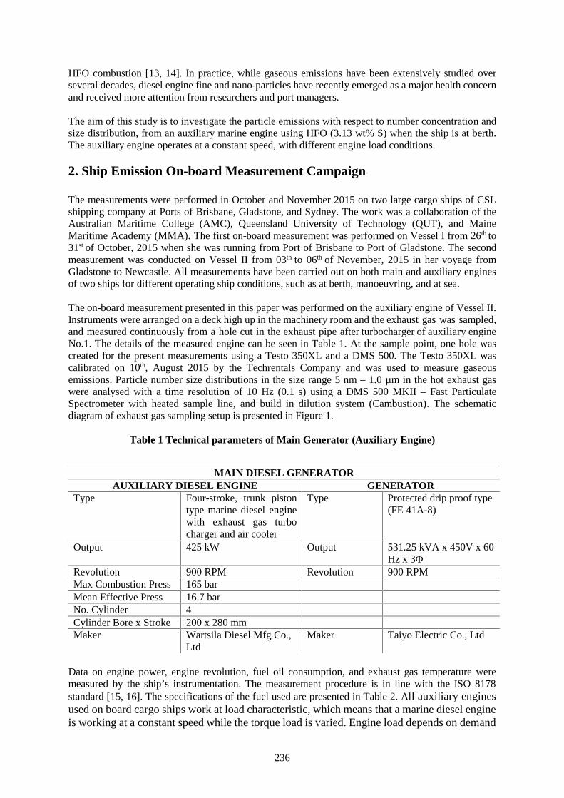
236
HFO combustion [13, 14]. In practice, while gaseous emissions have been extensively studied overseveral decades, diesel engine fine and nano-particles have recently emerged as a major health concernand received more attention from researchers and port managers.
The aim of this study is to investigate the particle emissions with respect to number concentration andsize distribution, from an auxiliary marine engine using HFO (3.13 wt% S) when the ship is at berth.The auxiliary engine operates at a constant speed, with different engine load conditions.
2. Ship Emission On-board Measurement Campaign
The measurements were performed in October and November 2015 on two large cargo ships of CSLshipping company at Ports of Brisbane, Gladstone, and Sydney. The work was a collaboration of theAustralian Maritime College (AMC), Queensland University of Technology (QUT), and MaineMaritime Academy (MMA). The first on-board measurement was performed on Vessel I from 26th to31st of October, 2015 when she was running from Port of Brisbane to Port of Gladstone. The secondmeasurement was conducted on Vessel II from 03th to 06th of November, 2015 in her voyage fromGladstone to Newcastle. All measurements have been carried out on both main and auxiliary enginesof two ships for different operating ship conditions, such as at berth, manoeuvring, and at sea.
The on-board measurement presented in this paper was performed on the auxiliary engine of Vessel II.Instruments were arranged on a deck high up in the machinery room and the exhaust gas was sampled,and measured continuously from a hole cut in the exhaust pipe after turbocharger of auxiliary engineNo.1. The details of the measured engine can be seen in Table 1. At the sample point, one hole wascreated for the present measurements using a Testo 350XL and a DMS 500. The Testo 350XL wascalibrated on 10th, August 2015 by the Techrentals Company and was used to measure gaseousemissions. Particle number size distributions in the size range 5 nm – 1.0 µm in the hot exhaust gaswere analysed with a time resolution of 10 Hz (0.1 s) using a DMS 500 MKII – Fast ParticulateSpectrometer with heated sample line, and build in dilution system (Cambustion). The schematicdiagram of exhaust gas sampling setup is presented in Figure 1.
Table 1 Technical parameters of Main Generator (Auxiliary Engine)
Data on engine power, engine revolution, fuel oil consumption, and exhaust gas temperature weremeasured by the ship’s instrumentation. The measurement procedure is in line with the ISO 8178standard [15, 16]. The specifications of the fuel used are presented in Table 2. All auxiliary enginesused on board cargo ships work at load characteristic, which means that a marine diesel engineis working at a constant speed while the torque load is varied. Engine load depends on demand
MAIN DIESEL GENERATORAUXILIARY DIESEL ENGINE GENERATOR
Type Four-stroke, trunk pistontype marine diesel enginewith exhaust gas turbocharger and air cooler
Type Protected drip proof type(FE 41A-8)
Output 425 kW Output 531.25 kVA x 450V x 60Hz x 3Φ
Revolution 900 RPM Revolution 900 RPMMax Combustion Press 165 barMean Effective Press 16.7 barNo. Cylinder 4Cylinder Bore x Stroke 200 x 280 mmMaker Wartsila Diesel Mfg Co.,
LtdMaker Taiyo Electric Co., Ltd
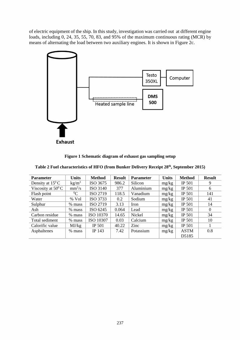
237
of electric equipment of the ship. In this study, investigation was carried out at different engineloads, including 0, 24, 35, 55, 70, 83, and 95% of the maximum continuous rating (MCR) bymeans of alternating the load between two auxiliary engines. It is shown in Figure 2c.
Figure 1 Schematic diagram of exhaust gas sampling setup
Table 2 Fuel characteristics of HFO (from Bunker Delivery Receipt 28th, September 2015)
Parameter Units Method Result Parameter Units Method ResultDensity at 150 C kg/m3 ISO 3675 986.2 Silicon mg/kg IP 501 9Viscosity at 500 C mm2/s ISO 3140 377 Aluminium mg/kg IP 501 6Flash point 0C ISO 2719 118.5 Vanadium mg/kg IP 501 141Water % Vol ISO 3733 0.2 Sodium mg/kg IP 501 41Sulphur % mass ISO 2719 3.13 Iron mg/kg IP 501 14Ash % mass ISO 6245 0.064 Lead mg/kg IP 501 0Carbon residue % mass ISO 10370 14.65 Nickel mg/kg IP 501 34Total sediment % mass ISO 10307 0.03 Calcium mg/kg IP 501 10Calorific value MJ/kg IP 501 40.22 Zinc mg/kg IP 501 1Asphaltenes % mass IP 143 7.42 Potassium mg/kg ASTM
D51850.8
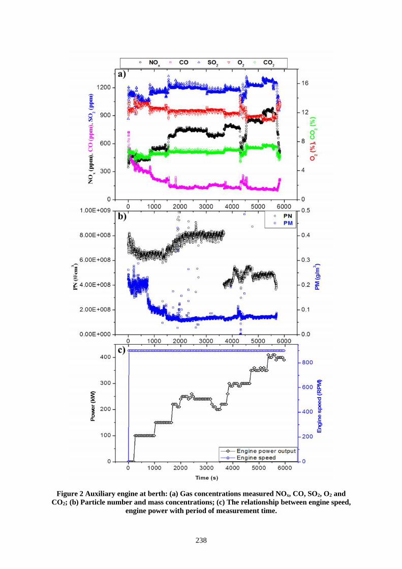
238
Figure 2 Auxiliary engine at berth: (a) Gas concentrations measured NOx, CO, SO2, O2 andCO2; (b) Particle number and mass concentrations; (c) The relationship between engine speed,
engine power with period of measurement time.
239
Emission factors for emitted gas-phase species and number/mass of particles were calculated followingISO 8178 [15, 16], using specific fuel consumption and formed CO2 to obtain the exhasut gas flow rate(equation (1)). These calculations assume that all carbon in the fuel is converted completely into CO2.
ℎ = × (%) × ( )× ( , , ) [ ] (1)
= × [ ] (2)
= × [ # ] (3)
where CCO2, exh and CCO2, air are the CO2 concentration in v/v % in the exhaust gas and in the air,respectively. Data on fuel consumption and engine power were obtained from the ship’s instrument.The emission factors of both gases and particulate matter are presented as mass or number per kWh ofengine work (g/kWh, #/kWh), and normalised to standard conditions regarding temperature of 273.15K and pressure of 101.325 kPa.
20 40 60 80 1000
5
10
15
20
Em
issi
on F
acto
rs (g
/kW
h)
Power (%)
O2/100 CO CO
2/100 SO
2 NO
x PM
1.0
Figure 3 Specific emissions against engine load. (A 95% CI for each mean value is shown as themean ± X)
3. Results and Discussion
The major gaseous emissions of interest in the engine exhaust were NOx, CO, SO2, O2, and CO2. Thereal-time on-board measurement of these gases can be seen in Figure 2a. Figure 2 demonstates therelationship between the changes of emisions with time and engine power output while engine speed iskept at a constant value. The results of gas-phase emision factors for O2, CO, CO2, SO2, and NOx interms of g/kWh are presented in Figure 3. There was an initial peak in CO concentration at start-up incold start period - this can be seen in Figure 2a and 3. This is due to the cold start of the engine and thelow engine load condition, which leads to incomplete combustion and aids carbon monoxide to gain
240
the highest level. The CO concentration then significantly decreased and remained at a stable value athigh engine load condition.
Table 3 Comparison of gaseous emissions between this study and previous studies.
Study Engine Type Fuel(% S)
EngineLoad(%)
O2
(g/kWh)CO
(g/kWh)CO2
(g/kWh)SO2
(g/kWh)NOx
(g/kWh)
Moldanováet al. [17]
4-stroke,medium speed,main engine,4440 kW
HFO(1.0)
30
80
1127
1054
1.82
1.17
617
678
3.24
3.65
9.6
9.6
Khan et al.[18]
2-stroke, lowspeed, mainengine, 36740kW
HFO(3.14)
29527381
----
0.570.410.360.35
577555561576
11.410.911.011.3
19.518.519.519.1
Winnesand Fridell[10]
4-stroke,medium speed,main engine,4500 kW
HFO(1.6)
507090
---
1.050.740.3
620603607
4.624.624.57
7.498.49
10.71
Agrawal etal. [19]
2-stroke, lowspeed, mainengine, 15750kW
HFO(2.85)
1325507585
-----
2.51.51.00.80.5
~1200640620670680
1312
10.51010
22171821
20.5Cooper[20]
4-stroke,medium speed,auxiliaryengine, 1270kW
HFO(0.53)
47-58 - 1.06 -1.71
763-803 2.5-2.7 13.3 -17.5
4-stroke,medium speed,auxiliaryengine, 2675kW
HFO(2.2)
41 - 0.90 691 9.5 15.2
4-stroke,medium speed,auxiliaryengine, 2005kW
HFO(2.2)
39 - 0.77 697 9.6 12.9
This study 4-stroke,medium speed,auxiliaryengine, 425 kW
HFO(3.13)
243555708395
1338120811501104969992
2.811.661.141.160.880.87
850850849849849849
22.2022.4922.3021.2421.1721.11
4.405.176.406.306.917.14
A significantly decreasing trend of O2 emissions with power was observed as shown in Figure 2a and3. This may be due to the engine revolution being constant, which makes the amount of air stable whilethe engine load is increased. Thus, more fuel is required and a rich fuel-air mixture combustioncondition is reached. The fuel-dependent specific emissions of SO2 and CO2 is given in Figure 2a aregenerally proportional to the fuel carbon and sulphur content, and therefore these emission factors ofSO2 and CO2 seem to be constant as was expected. Of most interest in this study is that the emissionfactor of SO2 was much higher than that of compared studies (Table 3), which is the result of highersulphur content fuel used in this research. The theoretical value of SO2 emission factor calculated inthis study was around 16.6 g/kWh, which was significantly less than measured cases. The emission ofNOx depends on the engine temperature, and thus the emission of NOx presented in Figure 2a and 3shows a dependence on engine load in which high engine load produces the highest emission. Shown
241
in Table 3, the value of NOx emission in the present research was much lower than that of previousstudies, this may be due to difference engine types and working conditions.
For particle emissions presented in Figure 2b, a general pattern in the emitted nanoparticles is that therewas an initial peak both in mass and number concentration at engine start-up in cold start period beforereaching the constant value or significantly decreasing to low level at higher engine load workingcondition. This can be seen clearly in PN case, a significant difference in particle number concentrationsobserved between low and medium engine load of 0, 24, 35 and 55% with 70, 83 and 95% of engineload working conditions, which illustrated in Figure 2b and 4. This may be due to low temperatureinside engine combustion chamber at low loads, which caused more particles can be created [3]. Figure4 indicated that the number size distributions were dominant by nano-particles and only one modal withthe peak at around 35 – 45 nm for all engine load working conditions. Particle mass emission factor(PM) was calculated from the number concentrations measured with the DMS 500 (5.0 – 1000 nm)assuming spherical particles with unit densities for nucleation and accommodation mode. A 95%confidence interval (CI) to each mean value in Table 4 was calculated.
1 10 100 10000.00E+000
3.00E+008
6.00E+008
9.00E+008
1.20E+009
1.50E+009
1.80E+009
dN/d
logD
p(#
/cm
3 )
Particle Diameter (nm)
0%24%35%55%70%83%95%
Figure 4 Number size distributions of measured particles (5-1000 nm) for idle, 24%, 35%, 55%,70%, 83%, and 95% load.
In comparison with the literature that can be seen in Table 4, there is a large variation of particle numberemission factor, which may be due to limited available data on PN and a difference in fuel used, enginemodels, working conditions, and instruments used for PN measurement [21]. A decreasing trend of bothPN and PM emission factors was observed clearly as engine output power increased in this study. Thistrend was also observed in the study of Anderson et al. [3], but particle number emissions at 10 and25% load in this study (HFO, 0.12 wt% S) were much higher than that of present study (HFO, 3.13 wt%S). This shows that a fuel shift to low sulphur content fuel may only have limited effect on small sizeparticle number concentrations. It can be supported by studies of Winnes and Kasper [10, 22].Magnitude of PM emission factor in this study was rather similar to that of previous studies.
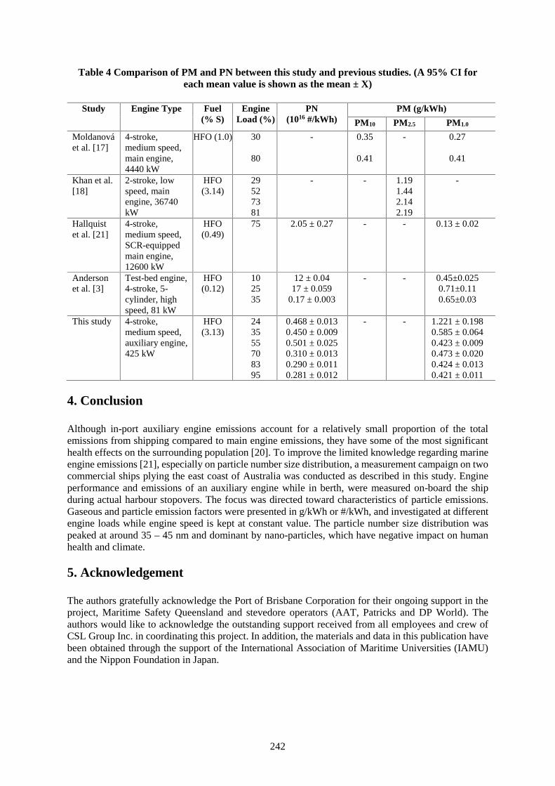
242
Table 4 Comparison of PM and PN between this study and previous studies. (A 95% CI foreach mean value is shown as the mean ± X)
Study Engine Type Fuel(% S)
EngineLoad (%)
PN(1016 #/kWh)
PM (g/kWh)
PM10 PM2.5 PM1.0
Moldanováet al. [17]
4-stroke,medium speed,main engine,4440 kW
HFO (1.0) 30
80
- 0.35
0.41
- 0.27
0.41
Khan et al.[18]
2-stroke, lowspeed, mainengine, 36740kW
HFO(3.14)
29527381
- - 1.191.442.142.19
-
Hallquistet al. [21]
4-stroke,medium speed,SCR-equippedmain engine,12600 kW
HFO(0.49)
75 2.05 ± 0.27 - - 0.13 ± 0.02
Andersonet al. [3]
Test-bed engine,4-stroke, 5-cylinder, highspeed, 81 kW
HFO(0.12)
102535
12 ± 0.0417 ± 0.059
0.17 ± 0.003
- - 0.45±0.0250.71±0.110.65±0.03
This study 4-stroke,medium speed,auxiliary engine,425 kW
HFO(3.13)
243555708395
0.468 ± 0.0130.450 ± 0.0090.501 ± 0.0250.310 ± 0.0130.290 ± 0.0110.281 ± 0.012
- - 1.221 ± 0.1980.585 ± 0.0640.423 ± 0.0090.473 ± 0.0200.424 ± 0.0130.421 ± 0.011
4. Conclusion
Although in-port auxiliary engine emissions account for a relatively small proportion of the totalemissions from shipping compared to main engine emissions, they have some of the most significanthealth effects on the surrounding population [20]. To improve the limited knowledge regarding marineengine emissions [21], especially on particle number size distribution, a measurement campaign on twocommercial ships plying the east coast of Australia was conducted as described in this study. Engineperformance and emissions of an auxiliary engine while in berth, were measured on-board the shipduring actual harbour stopovers. The focus was directed toward characteristics of particle emissions.Gaseous and particle emission factors were presented in g/kWh or #/kWh, and investigated at differentengine loads while engine speed is kept at constant value. The particle number size distribution waspeaked at around 35 – 45 nm and dominant by nano-particles, which have negative impact on humanhealth and climate.
5. Acknowledgement
The authors gratefully acknowledge the Port of Brisbane Corporation for their ongoing support in theproject, Maritime Safety Queensland and stevedore operators (AAT, Patricks and DP World). Theauthors would like to acknowledge the outstanding support received from all employees and crew ofCSL Group Inc. in coordinating this project. In addition, the materials and data in this publication havebeen obtained through the support of the International Association of Maritime Universities (IAMU)and the Nippon Foundation in Japan.
243
References
[1] Reda, A.A., et al., "Gas phase carbonyl compounds in ship emissions: Differences between dieselfuel and heavy fuel oil operation", Atmospheric Environment, 112, (2015), p. 370-380.
[2] Mueller, L., et al., "Characteristics and temporal evolution of particulate emissions from a shipdiesel engine", Applied Energy, 155, (2015), p. 204-217.
[3] Anderson, M., et al., "Characterization of particles from a marine engine operating at low loads",Atmospheric Environment, 101, (2015), p. 65-71.
[4] Blasco, J., et al., "Towards an integrated environmental risk assessment of emissions from ships'propulsion systems", Environment International, 66, (2014),p. 44-7.
[5] Ristovski, Z.D., et al., "Respiratory health effects of diesel particulate matter", Respirology, 17, 2,(2012), p. 201-212.
[6] Corbett, J.J., et al., "Mortality from Ship Emissions: A Global Assessment", EnvironmentalScinece & Technology, 41, 24, (2007), p. 8512–8518.
[7] Viana, M., et al., "Impact of maritime transport emissions on coastal air quality in Europe",Atmospheric Environment, 90, (2014), p. 96-105.
[8] Eyring, V., et al., "Transport impacts on atmosphere and climate: Shipping", AtmosphericEnvironment, 44, 37, (2010), p. 4735-4771.
[9] González, Y., et al., "Ultrafine particles pollution in urban coastal air due to ship emissions",Atmospheric Environment, 45, 28, (2011), p. 4907-4914.
[10] Winnes, H. and E. Fridell, "Particle Emissions from Ships: Dependence on Fuel Type", Journal ofthe Air & Waste Management Association, 59, 12, (2012), p. 1391-1398.
[11] Agrawal, H., et al., "In-use gaseous and particulate matter emissions from a modern ocean goingcontainer vessel", Atmospheric Environment, 42, 21, (2008), p. 5504-5510.
[12] Corbett, J.J., "Updated emissions from ocean shipping", Journal of Geophysical Research, 108,D20, (2003).
[13] Anderson, M., et al., "Characterization of particles from a marine engine operating at low loads",Atmospheric Environment, 101, (2015), p. 65-71.
[14] Moldanová, J., et al., "Characterisation of particulate matter and gaseous emissions from a largeship diesel engine", Atmospheric Environment, 43, 16, (2009), p. 2632-2641.
[15] ISO 8178-2:2008, "Reciprocating internal combustion engines - Exhaust emission measurement -Part 2: Measurement of gaseous and particulate exhaust emissions under field conditions", theInternational Organization for standard,<http://www.iso.org/iso/iso_catalogue/catalogue_tc/catalogue_detail.htm?csnumber=41171>.
[16] ISO 8178-1:2006, "Reciprocating internal combustion engines - Exhaust emission measurement -Part 1: Test-bed measurement of gaseous and particulate exhaust emissions", the InternationalOrganization for standard,<http://www.iso.org/iso/iso_catalogue/catalogue_tc/catalogue_detail.htm?csnumber=42714>.
[17] Moldanová, J., et al., "Physical and chemical characterisation of PM emissions from two shipsoperating in European emission control areas", Atmospheric Measurement Techniques, 6, 12,(2013), p. 3577-3596.
[18] Khan, M.Y., et al., "Measuring in-use ship emissions with international and U.S. federal methods",Journal of the Air and Waste Management Association, 63, 3, (2013), p. 284-291.
[19] Agrawal, H., et al., "Emission measurements from a crude oil tanker at sea", EnvironmentalScience and Technology, 42, 19, (2008), p. 7098-7103.
[20] Cooper, D.A., "Exhaust emissions from ships at berth", Atmospheric Environment, 37, 27, (2003),p. 3817-3830.
[21] Hallquist, Å.M., et al., "Onboard Measurements of Nanoparticles from a SCR-Equipped MarineDiesel Engine", Enironmental Science & Technology, 47, 2, (2013), p. 773-780.
[22] Kasper, A., et al., "Particulate Emissions from a Low-Speed Marine Diesel Engine", AerosolScience and Technology, 41, 1, (2007), p. 24-32.
244
Guessing to Prediction – A Conceptual Framework to Predict LNG BunkerDemand Profile in Australia
Rumesh H Merien-Paul1, Hossein Enshaei², Shantha Gamini Jayasinghe³
1. Australian Maritime College, University of Tasmania, [email protected]. Australian Maritime College, University of Tasmania, [email protected]
3. Australian Maritime College, University of Tasmania, [email protected]
Abstract Liquefied Natural Gas (LNG) is considered as one of the most appropriate alternative fuel toreplace conventional marine fuels in near future. Major motivations for adopting LNG as a marine fuelare the recent international and regional regulations on ship emissions, increased awareness onimproving air quality in strategic sea routes, demarcation of Emission Controlled Areas (ECAs) and theneed for preserving marine environment including Particularly Sensitive Sea Areas (PSSAs) such asGreat Barrier Reef, Coral Sea and Torres Strait in Australia. In recent years, European Union and fewother individual countries such as Norway have been in the forefront in adopting LNG as a marine fueland have invested heavily on research and development as well as in infrastructure development forLNG bunkering. The U.S. and Asian countries such as Singapore, South Korea and Japan have alsofollowed the suit with similar interests in LNG adoption. Nevertheless, the lack of adequate LNGbunkering infrastructure along major sea routes and the early stages of the current developments foundto be the main deterrent among several barriers for the adoption of LNG as a marine fuel.
Australia is well placed to become the leading LNG producer in the world by 2018 [1]. It is expectedthat Australia, as the world’s leading LNG supplier, could gain enormous economic benefits andpreserve its invaluable ecosystems by actively adopting LNG as a marine fuel. Nevertheless, comparedto the aforementioned leading countries, Australia has not taken strong initiatives so far to promoteLNG as a marine fuel, build up necessary bunkering infrastructure and conduct relevant research anddevelopment work. Besides, a comprehensive scientific research to predict the future LNG demand inAustralia has not been conducted so far. This leads to guessing rather than accurate prediction in takingimportant decisions related to the LNG future in Australia. In order to fill this knowledge gap, authorsare developing an LNG bunker demand prediction method for Australia. This paper presents theconceptual framework of the prediction method. The projection could be used as a strategic decisionsupport tool for Australian Government/authorities for development of LNG bunkering infrastructurein Australia, especially to identify the most important regions for bunkering.
Keywords: Emission Control Areas, Emission Regulations, LNG Bunkering, Liquefied Natural Gas,Marine Environment and Prediction tool.
1. Ship Emissions and Control Measures
Human civilisation has been intricately bound to its dependency on carbonaceous fuels for manymillennia. The carefree and widespread use of such fuels has taken its toll causing far-reaching damagesto the interdependent ecosystems we share. For the marine sector, Heavy Fuel Oil (HFO) and MarineDiesel/Marine Gas Oil (MDO/MGO) have been fuels of the choice for many ship operators due toobvious economic reasons. Key emission components from these fuels are Carbon Dioxide (CO2),Nitrogen Oxides (NOX), Sulphur Oxides (SOX), Volatile Organic Compounds (VOC), Black Carbon orsoot (BC) and/or particulate organic matter POM/PM. It has been reported that even the emissionsoccur at sea, they affect coastal areas and reach further inland polluting atmosphere, land and water [2;3; 4; 5]. Out of these emissions NOX and SOX cause acidification of ecosystems. In additions, excessiveNitrogen input causes eutrophication in freshwater habitats, which threatens biodiversity [6] andcontributes to increase of ground level ozone and thereby many respiratory issues. Having assessed theeffects of emission factors on human health, the World Health Organisation (WHO) classified dieselexhaust as a human carcinogen [7]. Therefore, not only the economic and environmental factors butalso human health related issues force to look for alternative fuels.
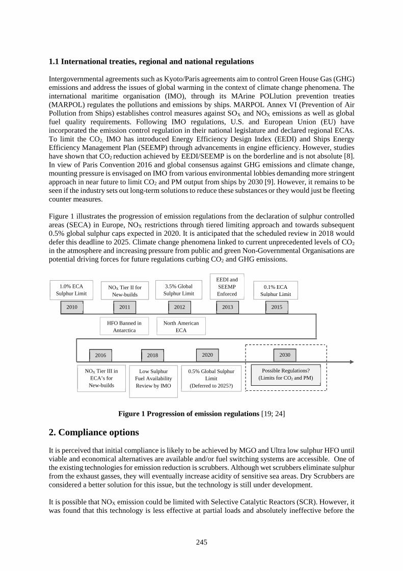
245
1.1 International treaties, regional and national regulations
Intergovernmental agreements such as Kyoto/Paris agreements aim to control Green House Gas (GHG)emissions and address the issues of global warming in the context of climate change phenomena. Theinternational maritime organisation (IMO), through its MArine POLlution prevention treaties(MARPOL) regulates the pollutions and emissions by ships. MARPOL Annex VI (Prevention of AirPollution from Ships) establishes control measures against SOX and NOX emissions as well as globalfuel quality requirements. Following IMO regulations, U.S. and European Union (EU) haveincorporated the emission control regulation in their national legislature and declared regional ECAs.To limit the CO2, IMO has introduced Energy Efficiency Design Index (EEDI) and Ships EnergyEfficiency Management Plan (SEEMP) through advancements in engine efficiency. However, studieshave shown that CO2 reduction achieved by EEDI/SEEMP is on the borderline and is not absolute [8].In view of Paris Convention 2016 and global consensus against GHG emissions and climate change,mounting pressure is envisaged on IMO from various environmental lobbies demanding more stringentapproach in near future to limit CO2 and PM output from ships by 2030 [9]. However, it remains to beseen if the industry sets out long-term solutions to reduce these substances or they would just be fleetingcounter measures.
Figure 1 illustrates the progression of emission regulations from the declaration of sulphur controlledareas (SECA) in Europe, NOX restrictions through tiered limiting approach and towards subsequent0.5% global sulphur caps expected in 2020. It is anticipated that the scheduled review in 2018 woulddefer this deadline to 2025. Climate change phenomena linked to current unprecedented levels of CO2
in the atmosphere and increasing pressure from public and green Non-Governmental Organisations arepotential driving forces for future regulations curbing CO2 and GHG emissions.
Figure 1 Progression of emission regulations [19; 24]
2. Compliance options
It is perceived that initial compliance is likely to be achieved by MGO and Ultra low sulphur HFO untilviable and economical alternatives are available and/or fuel switching systems are accessible. One ofthe existing technologies for emission reduction is scrubbers. Although wet scrubbers eliminate sulphurfrom the exhaust gasses, they will eventually increase acidity of sensitive sea areas. Dry Scrubbers areconsidered a better solution for this issue, but the technology is still under development.
It is possible that NOX emission could be limited with Selective Catalytic Reactors (SCR). However, itwas found that this technology is less effective at partial loads and absolutely ineffective before the
2010 2013\
20122011 2015
3.5% GlobalSulphur Limit
1.0% ECASulphur Limit
NOX Tier II forNew-builds
North AmericanECA
EEDI andSEEMPEnforced
0.1% ECASulphur Limit
2016\
2018\
2020\
2030\
NOX Tier III inECA’s for
New-builds
Low SulphurFuel AvailabilityReview by IMO
0.5% Global SulphurLimit
(Deferred to 2025?)
Possible Regulations?(Limits for CO2 and PM)
HFO Banned inAntarctica
246
system reaches operational temperature hence limits the application [10; 11; 12]. Even for the fullcompliance, this necessitates the use of low sulphur fuel during start-ups. In addition, a network forsupply of Urea-catalyst and disposal of residue from SCR and scrubbers are needed at a global scale.
Methanol is an alternative to be considered in fuel switching, which is easily transportable. However,due to its higher GHG potential, additional safety precautions in the fuel system and higher Free OnBoard (FOB) price thwart its adoption. Nevertheless, there are cleaner options [13] such as: biofuels,hydrogen, wind power and nuclear energy, which could be strong contenders as future ship fuels. In avery conservative and capital intensive industry such as shipping, new technologies are adoptedcautiously, often after assessing their merits in other industries. Therefore, new alternatives are unlikelyto be adopted in the immediate future due to various technical, economical, and safety challenges. Inthis context, LNG is considered as the most promising alternative marine fuel capable of meetingpresent emission regulations along with its availability/abundance and low cost compared toHFO/MGO.
3. LNG and its advantages
LNG produces 100% less SOX, about 25-30% less CO2 and 95-100% less PM while reduction of NOX
is 40-90% depending on the combustion cycle [14; 15; 16; 17; 18; 19; 8]. According to Ashworth 2016[9], proven vast resources of gas are estimated to be sufficient for next 200 years’ worth of demand.The net calorific value of LNG is 18-20% higher than HFO/MGO [20] and is cost competitive, [21]with HFO/MGO through 2035. With vast known reserves and higher energy output, LNG commandsrespect as an economical and viable alternative compared to conventional fuel oils for many years tocome.
3.1 Challenges for LNG adoption
Deal 2013[22] claimed that cost of LNG conversions for new-builds is going to be high by additional15-20% of capital requirement. In addition, experiences from Norwegian LNG ferries and relatedstudies [11; 23; 16] confirm that, the volume required to store LNG can be up to three times higher thanHFO/MGO. Reduction in cargo volume and/or passenger carrying capacity and increased capitalexpenditure are main deterrents of LNG adoption.
IMO 2016 [24] calls for a reliable network of LNG bunker distribution essential for LNG adoption.Many relate this issue to chicken-egg paradox. While ship owners complain the lack of bunkeringinfrastructure for LNG adoption, bunker suppliers blame the lack of demand for LNG bunkers as adeterrent against investing on infrastructure. Many ship-owners and bunker suppliers are thereforelikely to follow wait-and-see approach in LNG adoption.
Lack of unified regulation and standards [18; 25] are identified as an obvious issue for the widespreaduse of LNG as a ship fuel and therefore, IMO adopted International Code of Safety for Ships usingGases or other Low-flashpoint Fuels (IGF Code) in June 2015 to address this concern. Reviewing thesafety records of gas carriers, it is expected that a similar safety culture could be developed upon carefultraining and enforcement of safety regimes. However, critics [26] argue that IGF Code applies only toreceiving vessel and not the LNG supplier. This regulatory gap is expected to be fulfilled throughInternational Standard Organisations’ (ISO) LNG bunkering guidelines including standardisation ofbunkering equipment.
LNG as a bunker fuel is still a novel concept for the world and there are many LNG-specific hazards[14] which may result in casualties and damage to property during delivery and storage. Emphasise aregiven on safety and security [27; 28] of transporting LNG through populated areas and development offilling stations in strategic areas. That highlights the importance of risk analysis in development of LNGbunkering infrastructure, which requires thorough risk assessments, control measures and mitigationprocedures. Any catastrophe involving LNG can create a public outcry against its adoption and
247
discourage potential initiatives from governments and private sector. Even minor seepages could makeLNG a worse alternative [11] considering its GHG potential, which is 25 times that of CO2 if releasedaccidentally.
4. Future of LNG in Australia
Australia is a signatory to both MARPOL and Paris Convention [29] and the commonwealth haspledged to reduce country-wide emissions of 2005 baseline by 26-28 per cent by 2030. The recordwarming of atmosphere and recent unprecedented bleaching phenomena of the Great Barrier Reef haveprompted public support for stricter environmental regulations at state and federal level. According toEPA NSW 2015 [30], government of New South Wales has urged the commonwealth to addressshipping emissions when developing The National Clean Air Agreement, which is due for completionin 2016. In addition to strict limits for SOX and NOX as in ECAs, CO2 and PM/BC emissions shallprobably be given precedence in these regulations. Enforcement of relative regulations wouldencourage adoption of cleaner fuels; this is more evident in North European ECA where LNG’sprominence as a marine fuel is on the rise. A similar effect is anticipated assuming Australia woulddeclare emission controlled areas in its waters in near future.
Australia is en-route to become the leading LNG producer in the world by 2018 [1] owing to its variousLNG projects nearing completion. Meanwhile in the milieu of widespread regulatory push for stricteremission controls, Australia is in a unique position as a nation which attracts significantinternational/domestic maritime traffic. These opportunities present the strong possibility of using LNGas a transient fuel for a future energy by breaking away from dependency from fuel-oil. Australia shouldseize this opportunity and learn from leading countries in LNG adoption and thereby, secure enormousenvironmental and economic benefits for the society and the generations to come.
4.1 Challenges to be met
Ongoing LNG projects in Australia have run into cost overruns and delays due to their remote locations,high labour costs and interference of powerful trade unions [1]. The repercussions of these eventualitieswould cause higher LNG prices and reluctance of investors to launch new projects, limiting futuresupplies as well as damage to Australia’s reputation as a LNG supplier.
Natural gas in Australia was first utilised for domestic power generation. As a result, some stategovernments declared gas reservation policies to secure supplies for domestic use in view of LNGprojects targeting export market. However, as noted by EnergyQuest 2009[31], reservation policieshave not prevented domestic price sensitivity in relation to global gas demands. Therefore, domesticconsumers demand subsidies and/or nationwide reservation policies to be in place. If Australia is tosupply LNG as bunker fuel, it would add another dimension to the current issues surroundingreservation policies. If security of LNG supply as a bunker fuel to be ensured, it would probably warrantintervention of the commonwealth to declare an across board gas distribution policy addressing allstakeholders.
It is now apparent that existing regulatory framework for LNG fuelled shipping in Australia isinadequate [17]. However, adoption of IMO’s gas and low-flash point fuels code (IGF Code) and ISOstandards for LNG bunkering could well supplement these gaps. Once the regulations and standards arein place, it is expected that public support can be earned if all stakeholders collaborate [27].
The initial capital requirements for establishing LNG bunkering facilities could be overwhelming formany investors considering the current economic outlook and price dynamics in worldwide energymarkets. Therefore, government intervention in the form of subsidies/tax rebate schemes and co-sharingthe initial risk by various stakeholders would encourage first movers and expedite early adoption ofLNG as a ship fuel.
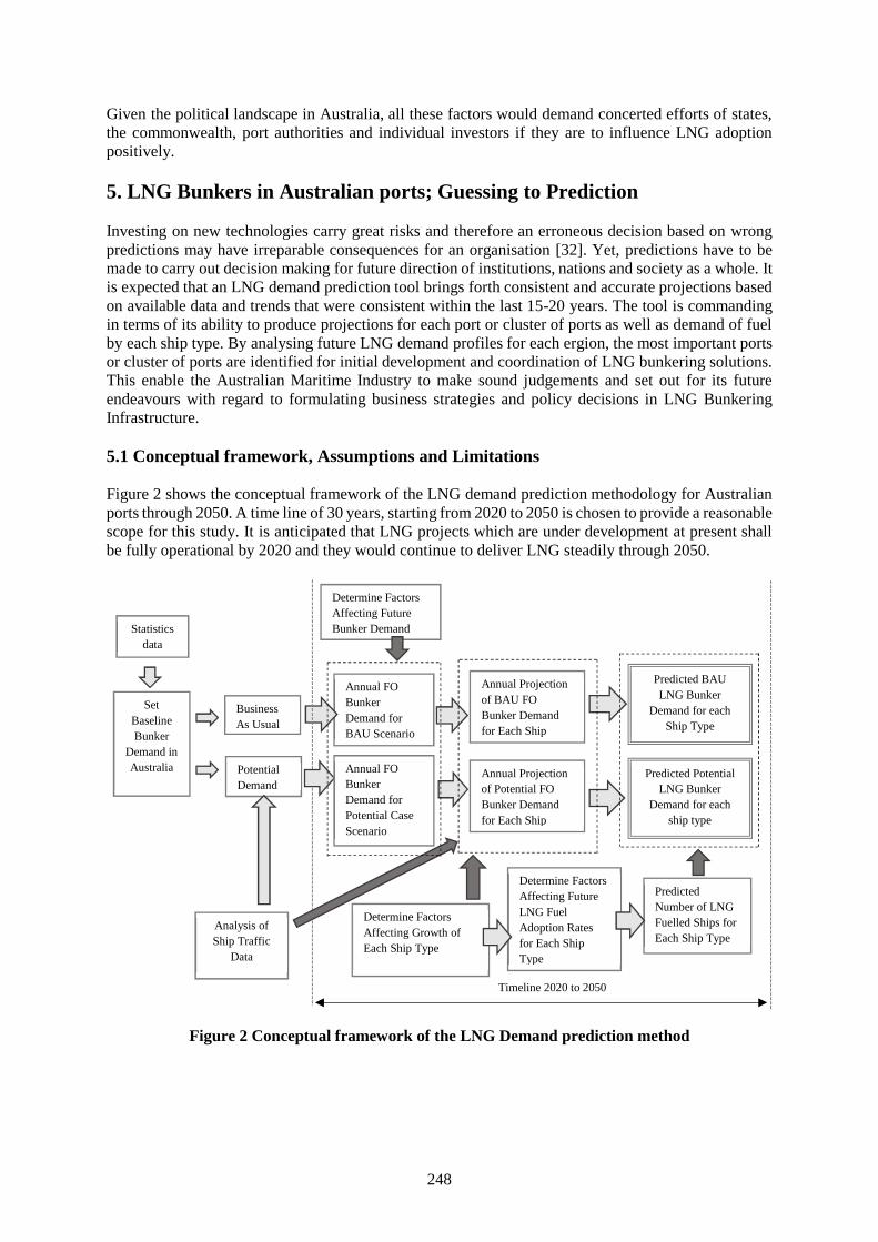
248
Given the political landscape in Australia, all these factors would demand concerted efforts of states,the commonwealth, port authorities and individual investors if they are to influence LNG adoptionpositively.
5. LNG Bunkers in Australian ports; Guessing to Prediction
Investing on new technologies carry great risks and therefore an erroneous decision based on wrongpredictions may have irreparable consequences for an organisation [32]. Yet, predictions have to bemade to carry out decision making for future direction of institutions, nations and society as a whole. Itis expected that an LNG demand prediction tool brings forth consistent and accurate projections basedon available data and trends that were consistent within the last 15-20 years. The tool is commandingin terms of its ability to produce projections for each port or cluster of ports as well as demand of fuelby each ship type. By analysing future LNG demand profiles for each ergion, the most important portsor cluster of ports are identified for initial development and coordination of LNG bunkering solutions.This enable the Australian Maritime Industry to make sound judgements and set out for its futureendeavours with regard to formulating business strategies and policy decisions in LNG BunkeringInfrastructure.
5.1 Conceptual framework, Assumptions and Limitations
Figure 2 shows the conceptual framework of the LNG demand prediction methodology for Australianports through 2050. A time line of 30 years, starting from 2020 to 2050 is chosen to provide a reasonablescope for this study. It is anticipated that LNG projects which are under development at present shallbe fully operational by 2020 and they would continue to deliver LNG steadily through 2050.
Figure 2 Conceptual framework of the LNG Demand prediction method
Determine FactorsAffecting FutureBunker Demand
BusinessAs Usual
Annual FOBunkerDemand forBAU Scenario
Predicted BAULNG Bunker
Demand for eachShip Type
Statisticsdata
Annual Projectionof BAU FOBunker Demandfor Each ShipType
SetBaselineBunker
Demand inAustralia Potential
Demand
Determine FactorsAffecting FutureLNG FuelAdoption Ratesfor Each ShipType
PredictedNumber of LNGFuelled Ships forEach Ship Type
Timeline 2020 to 2050
Analysis ofShip Traffic
Data
Annual FOBunkerDemand forPotential CaseScenario
Annual Projectionof Potential FOBunker Demandfor Each Ship
Predicted PotentialLNG Bunker
Demand for eachship type
Determine FactorsAffecting Growth ofEach Ship Type
249
5.2.1 Baseline of fuel oil bunker demand
In this conceptual framework, the present Fuel Oil (HFO/MDO/MGO) bunker demand in Australia isconsidered to be business as usual (BAU). This represents the annual aggregate bunker quantitiesreceived by domestic ships and deep-sea-going vessels in Australia.
By anticipating stringent air emission regulations in near future, there is a strong possibility that allvessels shall be obliged to consume ECA compliant fuels in Australian territorial waters. In addition,there is a great potential that fuel burnt in Australian waters will be bunkered in Australia provided thatfuel pricing is attractive compared to international markets.
These two baselines of demand profiles set a foundation for future prediction paths of BAU bunkerdemands as well as potential bunker demands.
Analysis of annual ship traffic data determines the time spent by ships in Australian waters and thereby,the fuel consumption in Australian waters is calculated.
5.2.2 Factors affecting FO bunker demands
Trade volumes and/or GDP have strong correlation to shipping traffic trends [33; 34]. Considering thepresent global economic downturn and grim state of offshore/mining sectors, there is a high probabilityof a decline in shipping activity in Australia along with its GDP and trade-volumes. However, athorough analysis of historical data related to fuel consumptions and trade-volume/GDP can be carriedout to establish whether similar correlation exists in Australia. Another fact that affects future of fuelconsumption is the trend in engine and hull form efficiency improvements. O’Malley et al. 2015 [16]suggested that the operating efficiency of ships is expected to increase at an average of 1% annually.The regulatory push from EEDI and SEEMP as well as competitive research and development effortsby engine makers are expected to improve this trend further. Therefore, efficiency improvement ratesshall be factored in bunker demand projections. Thus, annual fuel oil (FO) bunker demands for bothBAU and potential case scenarios are projected through 2050 in relation to mentioned two governingfactors.
5.2.3 Annual bunker demands for ship type
It was identified [20] that offshore support vessels, tug segments, new-build cruise and new-buildcontainer feeder segments are the potential early adopters of LNG in Wider Caribbean, whilst anotherstudy [17] found that tug and offshore segments could trigger early LNG adoption in Australia. Asexperienced in Norway and EU, it is widely expected that initial bunkering of LNG will cater the smallvessels followed by larger ferries and cargo ships. Considering diverse operations in Australian waters,the offshore sector and commodity export market, tugs, offshore support vessels, container feeders, bulkcarriers, ferries, and tankers should all be included as ship types for future prediction.
Analysis of ship traffic data is a reliable source to identify present distribution of each ship type inAustralia. It is assumed that growth rate of each ship type is generally dependent on future trends intrade-volume/GDP growth projections in Australia. In addition, key trends in demand for differentshipping services in Australia shall be identified so that ship-type-specific trends could also be factoredfor projections in growth trend of ship types through 2050. Annual FO Bunker demand is then projectedfor dual scenarios by combining annual projected FO demands with growth trend for each ship typethrough 2050.
5.2.4 Factors affecting future LNG adoption
As per report DNV-GL 2014 [19], 100 LNG fuelled new-builds are on order as of end 2015 and wouldincrease to 1000 by 2020. The global drivers affecting adoption of LNG fuelled ships are regulatorypush, attractive pricing, public consensus and push for cleaner fuels and possible economic incentive
250
schemes. Australian-specific elements for LNG adoption are security of gas supply for bunkering,outlook of ongoing and future LNG projects, and future trends in potential regulatory changes at federallevel. Whilst these are common factors which affect all ship types, present order books for new-buildsreveal that different ship types have different rates of LNG adoption, which is referred to as LNGadoption rate in figure 2. Therefore, in addition to common factors, ship-type-specific factors should beconsidered and factored in determining future LNG adoption forecasts. The combination of commonfactors and ship-type-specific sub-factors shall be used to forecast LNG fuelled portion of each shiptype through 2050. Consequently, by comparing the projected growth trend (through 2050) of a certainship type and its projected portion of LNG adoption through 2050, the number of LNG fuelled shipsfor a particular ship type could be determined.
5.2.5 Predicting LNG bunker demands
The annual bunker demand forecast for ship types in both scenarios are compared against annualpredicted number of LNG fuelled vessels to determine the annual LNG demand through 2050. To deriveat predicted LNG bunker figures, simply an energy equivalent conversion factor in relation toHFO/MGO is introduced.
5.3 Data Collection and Analysis
Data of past Bunker quantities can be sourced from publications of Australian Petroleum Statistics toproject future growth rates for BAU scenarios. As Bunker delivery quantities are categorised for eachstate, Analysis of ship traffic data is necessary to recognise concentration of ship traffic and variousship types in different ports so that approximate individual bunker delivery could be assigned to eachport/port-cluster. Nevertheless, ship traffic data could be obtained from Automatic ship IdentificationSystems’ (AIS) or AMSA’s vessel traffic data.
GDP and trade-volume growth rate forecasts required for LNG prediction could be retrieved frompublicly available reports of Reserve Bank of Australia and World Monetary Fund. Annual growth rateof Ship efficiency is assumed to be 1%; however, relevant literature shall be continuously scrutinisedfor further developments in engine and ship design enhancements, which effect fuel consumptionprofiles.
According to Verbeek 2012 [35], prediction techniques and Econometric conceptualising could becategorised as follows, depending on their objectives and utilization of data:a) Models that appraise interactions between descriptive and dependent variables over periods of
time, which normally lack inclusion of causal economic dynamics;b) Techniques that represent interactions between the historical and contemporary parameters, and
estimate forthcoming events based on historical outcomes with addition of causal economicdynamics;
c) Models that describe relationships between several variables at a point in time for diverse entities;and
d) Methods that study interactions between different variables for different entities over a long periodof time involving panel data.
Nature of this framework suggests utilising time-series data such as fuel consumptions, GDP growth,cross sectional data such as ship traffic data and multistep projections over time with many variables orfactors, which could potentially evolve over the timeframe. This complexity demands a model thatcould carry out individual projections for various entities separately over a period of time and showhow their final projections interact with each other to present final dual scenario predictions.Considering multiple variables involved and the type of data to be utilised, the third prediction modelmentioned above is appropriate for developing the projection tool. Review of literature suggests thatcombining regression methods and stochastic forecasting is adequate to tackle the complexity of thedemand prediction methodology. For projecting LNG adoption rates, different weights are allocated inaddition to the common factors affecting LNG adoption for all ship types. Ship-specific weightages
251
would be allotted for each ship type concerning their suitability for early LNG adoption. However, theworkable model is to be verified and validated accordingly.
6. Conclusion
There are clear and obvious benefits of adopting LNG as a ship fuel, especially in Australia as stated insection 4. However, there remains a number of challenges which should be overcome by cooperationof various stakeholders in the private and public sectors. The conceptual framework set forth in thispaper aims to develop a decision support tool which would assist the decision makers to formulatesound strategies with regard to developing bunkering infrastructure in Australian ports. The demandprediction methodology is based on dual scenario approach; addressing BAU and Potential futurebunker demand in Australia. Such methodology widens potential gains as it increases scope of exploringprospective growth paths of LNG bunkering in view of future trends in energy markets andenvironmental regulations. As various ship types show different growth trends as well as differing LNGadoption rates, both variables are projected separately in order to derive the number of LNG fuelledships for each ship type and finally, LNG bunker demands through the timeline. Whilst the datacollection is deemed simple, the data analysis part, especially that of ship traffic data and FO bunkerconsumptions, would be a complex task entailing cautious approach to determine distribution of vesseltypes and their individual bunker intakes. The ultimate product can be customisable so that it could beapplied to a specific port or port-cluster based on baseline bunker demand and ship traffic data specificto that region.
References:
[1] Ledesma, D, Henderson, J & Palmer, N 2014, The Future of Australian LNG Exports, The OxfordInstitute for Energy Studies.
[2] Dalsøren, SB, Eide, MS, Endresen, Ø, Mjelde, A, Gravir, G & Isaksen, ISA 2009, 'Update onemissions and environmental impacts from the international fleet of ships', Atmos. Chem. Phys.,vol. 9, 2171–2194, 2009.
[3] Eyring, V, Isaksen, ISA, Berntsen, T, Collins, WJ, Corbett, JJ, Endresen, O, Grainger, RG,Moldanova, J, Schlager, H & Stevenson, DS 2010, 'Transport impacts on atmosphere and climate:Shipping', Atmospheric Environment, vol. 44, no. 37, pp. 4735-4771
[4] MAGALOG 2008, Magalog - Maritime Gas Fuel Logistics LNG as a clean fuel 2008, TheIntelligent Energy Executive Agency EU.
[5] Tzannatos, E 2010, 'Ship emissions and their externalities for the port of Piraeus–Greece',Atmospheric Environment, vol. 44, no. 3, pp. 400-407.
[6] Boyer, EW, Howarth, RW, Galloway, JN, Dentener, FJ, Cleveland, C, Asner, GP, Green, P &Vörösmarty, C 2004, 'Current nitrogen inputs to world regions', Agriculture and the nitrogencycle: assessing the impacts of fertilizer use on food production and the environment, pp. 221-230.
[7] Lack, DA, Thuesen, J & Elliot, R 2012, Investigation of appropriate control measures (abatementtechnologies) to reduce Black Carbon emissions from international shipping, IMO
[8] DNV-GL 2015b, shipping 2020 - final report.[9] Ashworth, J 2016, LNG-Bunkers-Perspective-Feb-2016-Foggy-Passage, IMO, Singapore,
http://www.onthemosway.eu/wp-content/uploads/2016/02/LNG-Bunkers-Perspective-Feb-2016-Foggy-Passage.pdf?00cab0.
[10] Brynolf, S, Magnusson, M, Fridell, E & Andersson, K 2014, 'Compliance possibilities for thefuture ECA regulations through the use of abatement technologies or change of fuels',Transportation Research Part D: Transport and Environment, vol. 28, pp. 6-18
[11] Bengtsson, S, Andersson, K & Fridell, E 2011, 'Life cycle assessment of marine fuels-Acomparative study of four fossil fuels for marine propulsion', Chalmers University of Technology,Gothenburg.
[12] Bosch, P., Coenen, P., Fridell, E., Åström, S., Palmer, T., and Holland, M. (2009). Cost BenefitAnalysis to Support the Impact Assessment accompanying the revision of Benefit Analysis to
252
Support the Impact Assessment accompanying the revision of Directive 1999/32/EC on the SulphurContent of certain Liquid Fuels. Final AEA Report, 2009.
[13] Wang, S & Notteboom, T 2014, 'The Adoption of Liquefied Natural Gas as a Ship Fuel: ASystematic Review of Perspectives and Challenges', Transport Reviews, vol. 34, no. 6, pp. 749-774.
[14] Meyers, TE & Woessner, LNA 2011, 'Recent Acceptance of Natural Gas As Fuel on USFlag_Vessels', Gas Fuelled Ships Conference in Rotterdam, The Netherlands.
[15] Kolwzan, K & Narewski, M 2012, 'Alternative fuels for marine applications', Latvian Journal ofChemistry, vol. 51, no. 4, p. 398.
[16] O’Malley, S, Walsh, K, Hasen, A, Bratvold, D & Ratafia-Brown, J 2015, Marine Fuel Choice forOcean- Going Vessels within Emissions Control Areas, US Energy Information Administration.
[17] DNV-GL 2013, JIP on LNG bunkering in Australia DNV & Partners 2013.[18] Shroder, M, Gullberg, M & Gahnstrom, J 2011, LNG Infrastructure - Base line report: A feasibility
study for an LNG filling station infrastructure and test recommendations, Danish MaritimeAuthority.
[19] DNV-GL 2014, LNG as ship fuel DNV GL DNV-GL.[20] Algell, J, Bakosch, A & Forsman, B 2012, IMO Feasibility Study on LNG fuelled short sea &
coastal ships in Wider Caribbean Region, IMO.[21] McGill, R, Remley, WB & Winther, K 2013, Alternative Fuels for Marine Applications, IEA[22] Deal, A 2013, Liquefied natural gas as marine fuel a closer look at Tote’s containership projects,[23] Harperscheidt, J 2011, 'Bunkering, infrastructure, storage, and processing of LNG', Ship &
Offshore, vol. 1.[24] IMO 2016, IMO study on the feasibility and use of LNG as a fuel for shipping 2016, IMO.[25] Danish Maritime Authority 2012, Nort EU Ports LNG filling Station Infrastructure Feasibility
Report.[26] Langfeldt, L & Pewe, H 2013, GL Study on Standards and Rules for Bunkering of Gas-Fuelled
Ships,[27] Verbeek, R, Ligterink, N, Meulenbrugge, J, Koornneef, G, Kroon, P, Wilde, Hd, Kampman, B,
Croezen, H & Aarnink, S 2013, Natural gas in transport, An assessment of different routes, DutchMinistry of Infrastructure and Environment.
[28] DNV-GL 2015a, DNVGL-Recommended Bunker practices 2015, DNV-GL.[29] DPMC 2015, Factsheet Australia's 2030 Climate Change Target. (Department of Prime Minister
and Cabinet – Australia)[30] EPA NSW 2015, Diesel and Marine Emissions Management Strategy, Government of NSW,
Sydney.[31] EnergyQuest 2009, Australia's natural gas markets; connecting with the world.[32] Acciaro, M 2013, 'Investment in Greener Shipping; A Real Options Approach', in World
Conference on Transport Research, Rio de Janeiro, Brazil.[33] Azzara, AJ, Wang, H & Rutherford, D 2015, A 10-Year Projection of Maritime Activity in The US
Arctic Region, The International Council on Clean Transportation,<http://www.cmts.gov/downloads/CMTS_10Year_Arctic_Vessel_Projection_Report_1.1.15.pdf>.
[34] Li, J, Dong, X, Shangguan, J & Hook, M 2011, 'Forecasting the growth of China’s natural gasconsumption', Energy, vol. 36, no. 3, pp. 1380-1385.
[35] Verbeek, 2012. ‘A Guide to Modern Econometrics’, fourth ed. John Wiley & Sons, NJ.
253
EEDI reduction by investigating the capability of RANSE CFD forpropeller, propeller– hull form performance calculation
during ship optimization process
Dr. Tran Ngoc Tu (1), Msc. Nguyen Manh Chien (2)
1. Vietnam Maritime university, [email protected]. Vietnam Maritime university, [email protected]
Abstract. In recent years, the concerning about environment protection has grown significantly,especially about global warming and reduction of CO2 emission. Besides, there are considerabledevelopment in marine transportation and activities: from offshore installation supply to the exploitationof marine resources. It leads to the high increasing of fuel consumption for ship operation on the ocean.Moreover, in 2010, International Maritime Organization (IMO) introduced Energy Efficiency DesignIndex (EEDI) as a technical measure to limit pollution of the environment resulted by marine engines[1]. EEDI is expressed by CO2 gram per ship’s capacity. So smaller EEDI means smaller CO2exhausting to the environment.
With that reason, many efforts have been made to optimize ship’s fuel consumption, to save theoperation cost, on the one hand and to reduce the CO2 emission, or reduce EEDI on the other hand.From the EEDI equations [2], according to Bazari & Longva, 2011 and IMO MEPC 63 (2011) [2], thereare 15 methods of EEDI reduction. Within these 15 methods, hull form and propulsion optimization arecommon approaches for many designers and researchers.
To optimize the hull form and propeller, the designers need to carry many designs then select the bestone based on their performance. Estimation of hull form and propeller performance usingmodel testswidely accepted as most reliable means, and could be considered as the closest method to reality.However, due to time and cost for making testing models, it is not suitable for optimization process; itis just only used to validate the result of optimization. Besides, with the rapid improvement ofcomputational resources, Computational Fluid Dynamic (CFD) is getting to become a useful tool in shipdesign and power prediction. CFD method is able to look into local flow properties and providing aroom for designers to improve the design.
In this paper, the authors will investigate the capability of CFD method for propeller and propeller –hull form performance calculation, during ship optimization process. The approach of CFD here isReynolds-averaged Navier–Stokes equations (RANSE). During the optimization process, many designshave to be analyzed, so the level of accuracy and computational time of the calculation have to be takeninto account.
The paper has two major parts. For the propeller calculation in open water, the authors will perform 3methods to model the rotation of propeller and select the best one in terms of accuracy and timeconsumption. Later, the self-propulsion simulation is carried out. That is a setup with full rotatingpropeller behind a ship. The ISIS - CFD code, integrated in the commercial software Numeca FineMarine is used. The simulation results will be compared with model test results.
Keywords: propeller, hull, CFD, optimization, RANSE, EEDI reduction, ISIS code.
1. Introduction
Propeller calculation using CFD method is not a new topic for researchers. Many authors have predictedthe performance of the propeller, both in open water and behind condition. Giulio Dubbioso et al [3] hasperformed the open water simulation with INSEAN E779A propeller with fine mesh (1.31 million cells)and in-house solver χ navis - a finite volume uRaNSe (unsteady Reynolds-averaged Navier–Stokes
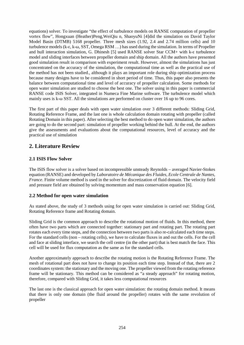
254
equations) solver. To investigate “the effect of turbulence models on RANSE computation of propellervortex flow”, Hongxuan (Heather)Peng,WeiQiu n, ShaoyuNi [4]did the simulation on David TaylorModel Basin (DTMB) 5168 propeller. Three mesh sizes (1.92, 2.4 and 2.74 million cells) and 10turbulence models (k-ε, k-ω, SST, Omega RSM …) has used during the simulation. In terms of Propellerand hull interaction simulation, G. Dhinesh [5] used RANSE solver Star CCM+ with k-ε turbulencemodel and sliding interfaces between propeller domain and ship domain. All the authors have presentedgood simulation result in comparison with experiment result. However, almost the simulations has justconcentrated on the accuracy of the simulation, the computational time as well as the practical use ofthe method has not been studied., although it plays an important role during ship optimization processbecause many designs have to be considered in short period of time. Thus, this paper also presents thebalance between computational time and level of accuracy of propeller calculation. Some methods foropen water simulation are studied to choose the best one. The solver using in this paper is commercialRANSE code ISIS Solver, integrated in Numeca Fine Marine software. The turbulence model whichmainly uses is k-ω SST. All the simulations are performed on cluster over 16 up to 96 cores.
The first part of this paper deals with open water simulation over 3 different methods: Sliding Grid,Rotating Reference Frame, and the last one is whole calculation domain rotating with propeller (calledRotating Domain in this paper). After selecting the best method to do open water simulation, the authorsare going to do the second part: simulation of propeller working behind the hull. At the end, the authorsgive the assessments and evaluations about the computational resources, level of accuracy and thepractical use of simulation
2. Literature Review
2.1 ISIS Flow Solver
The ISIS flow solver is a solver based on incompressible unsteady Reynolds – averaged Navier-Stokesequation (RANSE) and developed by Laboratoire de Mécanique des Fluides, Ecole Centrale de Nantes,France. Finite volume method is used in the solver for discretization of fluid domain. The velocity fieldand pressure field are obtained by solving momentum and mass conservation equation [6].
2.2 Method for open water simulation
As stated above, the study of 3 methods using for open water simulation is carried out: Sliding Grid,Rotating Reference frame and Rotating domain.
Sliding Grid is the common approach to describe the rotational motion of fluids. In this method, thereoften have two parts which are connected together: stationary part and rotating part. The rotating partrotates each every time steps, and the connection between two parts is also re-calculated each time steps.For the standard cells (non – rotating cells), we have to calculate fluxes in and out the cells. For the celland face at sliding interface, we search the cell centre (in the other part) that is best match the face. Thiscell will be used for flux computation as the same as for the standard cells.
Another approximately approach to describe the rotating motion is the Rotating Reference Frame. Themesh of rotational part does not have to change its position each time step. Instead of that, there are 2coordinates system: the stationary and the moving one. The propeller viewed from the rotating referenceframe will be stationary. This method can be considered as “a steady approach” for rotating motion,therefore, compared with Sliding Grid, it takes less computational resources
The last one is the classical approach for open water simulation: the rotating domain method. It meansthat there is only one domain (the fluid around the propeller) rotates with the same revolution ofpropeller

255
The open water simulation is carried out with all 3 methods. The authors are going to compare in termsof level of accuracy and computational time, then select the best one.
3. Open water simulation
3.1 Propeller Test Case
To evaluate the result of open water test, the well – known propeller test case is used. It is Potsdampropeller test case [7]. The Potsdam propeller is 5 blades, right handed propeller (look from the pressureside) with some basic dimension as follows: diameter 0.25m, area ratio: 0.77896; skew angle: 18.837degree.
3.2 Mesh generation
As stated above, the open water simulation is carried out by 3 different methods: Rotating ReferenceFrame, Sliding Grid and the classical approach: whole domain rotating with propeller (in this paper, wecall Rotating Domain). The same mesh can be used for Rotating reference frame and rotating domainmethod. The difference between two methods is the simulation setup. For Sliding Grid method, we needto generate different mesh, because there are 2 domains: propeller domain and fluid domain.
3.2.1 Mesh generation for Rotating Domain (RD) and Rotating Reference Frame (RRF) method
The mesh is hexahedral and mesh is generated by using Hexpress. Detail characteristic of calculationDomain is described in Figure 1. The Domain is a cylinder with the Diameter equaling 10 times thePropeller Diameter
Figure 1: Calculation Domain for RRF and RD method
The Leading Edge, Trailing Edge and Tips of propeller are much more refined compared to other areasdue to complex geometry at these areas. The mesh size for RRF and RD method is around 3.9 millioncells
Outlet
D = 2.5m
Calculation Domain: a Cylinder
Diameter = 2.5m
Va
Inlet
L =4.3m
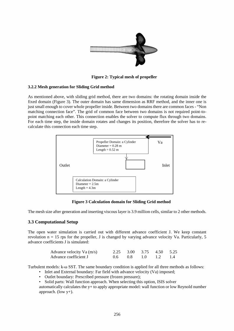
256
Figure 2: Typical mesh of propeller
3.2.2 Mesh generation for Sliding Grid method
As mentioned above, with sliding grid method, there are two domains: the rotating domain inside thefixed domain (Figure 3). The outer domain has same dimension as RRF method, and the inner one isjust small enough to cover whole propeller inside. Between two domains there are common faces - “Nonmatching connection face”. The grid of common face between two domains is not required point-to-point matching each other. This connection enables the solver to compute flux through two domains.For each time step, the inside domain rotates and changes its position, therefore the solver has to re-calculate this connection each time step.
Figure 3 Calculation domain for Sliding Grid method
The mesh size after generation and inserting viscous layer is 3.9 million cells, similar to 2 other methods.
3.3 Computational Setup
The open water simulation is carried out with different advance coefficient J. We keep constantrevolution n = 15 rps for the propeller, J is changed by varying advance velocity Va. Particularly, 5advance coefficients J is simulated:
Advance velocity Va (m/s) 2.25 3.00 3.75 4.50 5.25Advance coefficient J 0.6 0.8 1.0 1.2 1.4
Turbulent models: k-ω SST. The same boundary condition is applied for all three methods as follows:• Inlet and External boundary: Far field with advance velocity (Va) imposed;• Outlet boundary: Prescribed pressure (frozen pressure);• Solid parts: Wall function approach. When selecting this option, ISIS solverautomatically calculates the y+ to apply appropriate model: wall function or low Reynold numberapproach. (low y+).
Calculation Domain: a CylinderDiameter = 2.5mLength = 4.3m
Outlet
Propeller Domain: a CylinderDiameter = 0.28 mLength = 0.52 m
Va
Inlet
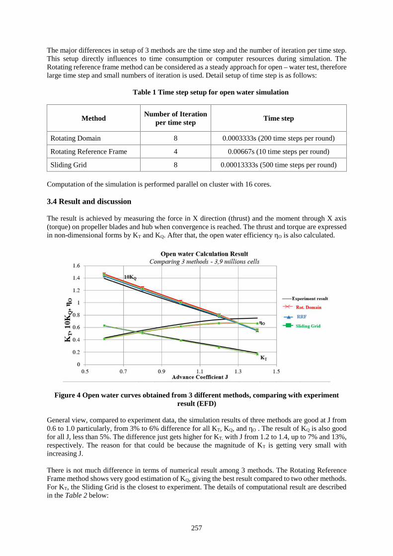
257
The major differences in setup of 3 methods are the time step and the number of iteration per time step.This setup directly influences to time consumption or computer resources during simulation. TheRotating reference frame method can be considered as a steady approach for open – water test, thereforelarge time step and small numbers of iteration is used. Detail setup of time step is as follows:
Table 1 Time step setup for open water simulation
Method Number of Iterationper time step Time step
Rotating Domain 8 0.0003333s (200 time steps per round)
Rotating Reference Frame 4 0.00667s (10 time steps per round)
Sliding Grid 8 0.00013333s (500 time steps per round)
Computation of the simulation is performed parallel on cluster with 16 cores.
3.4 Result and discussion
The result is achieved by measuring the force in X direction (thrust) and the moment through X axis(torque) on propeller blades and hub when convergence is reached. The thrust and torque are expressedin non-dimensional forms by KT and KQ. After that, the open water efficiency ηO is also calculated.
Figure 4 Open water curves obtained from 3 different methods, comparing with experimentresult (EFD)
General view, compared to experiment data, the simulation results of three methods are good at J from0.6 to 1.0 particularly, from 3% to 6% difference for all KT, KQ, and ηO . The result of KQ is also goodfor all J, less than 5%. The difference just gets higher for KT, with J from 1.2 to 1.4, up to 7% and 13%,respectively. The reason for that could be because the magnitude of KT is getting very small withincreasing J.
There is not much difference in terms of numerical result among 3 methods. The Rotating ReferenceFrame method shows very good estimation of KQ, giving the best result compared to two other methods.For KT, the Sliding Grid is the closest to experiment. The details of computational result are describedin the Table 2 below:
258
Table 2 Open water simulation result of different methods
Experiment Sliding Grid Rotating Domain Rotating Reference Frame
J 10KQ 10KQ ΔKQ 10KQ ΔKQ 10KQ ΔKQ
0.6 1.396 1.451 3.94% 1.466 4.98% 1.432 2.53%
0.8 1.178 1.224 3.88% 1.242 5.41% 1.208 2.52%
1.0 0.975 1.002 2.78% 1.019 4.57% 0.988 1.35%
1.2 0.776 0.791 1.92% 0.803 3.50% 0.779 0.33%
1.4 0.559 0.559 0.10% 0.546 -2.36% 0.546 -2.38%
Experiment Sliding Grid Rotating Domain Rotating Reference FrameJ KT KT ΔKT KT ΔKT KT ΔKT
0.6 0.629 0.630 0.13% 0.630 0.12% 0.623 -0.99%0.8 0.510 0.506 -0.74% 0.508 -0.33% 0.501 -1.74%1.0 0.399 0.388 -2.97% 0.390 -2.35% 0.383 -4.08%1.2 0.295 0.277 -6.06% 0.278 -5.72% 0.273 -7.39%1.4 0.188 0.166 -11.37% 0.162 -13.69% 0.162 -13.71%
Experiment Sliding Grid Rotating Domain Rotating Reference FrameJ ηO ηO ΔηO ηO ΔηO ηO ΔηO
0.6 0.430 0.414 -3.66% 0.410 -4.63% 0.415 -3.43%0.8 0.551 0.527 -4.44% 0.521 -5.44% 0.528 -4.15%1.0 0.652 0.616 -5.59% 0.609 -6.62% 0.617 -5.34%1.2 0.726 0.669 -7.82% 0.661 -8.91% 0.670 -7.69%1.4 0.749 0.663 -11.44% 0.662 -11.59% 0.662 -11.59%
In terms of computational time, the simulation for all 3 methods is performed in parallel with 16 cores.The mesh sizes are 3.9 million cells.
The average computational time is follows:
Table 3 Computational time of 3 different methods
Method Sliding GridRotating Reference
FrameRotatingDomain
Computational time (average) 58.3 h 15 h 40h
Percentage (compared to SlidingGrid method)
100% 25.% 68.6%
It is clear that Rotating Reference Frame takes least computational time, by less than one-third comparedto two other methods. Therefore, Rotating Reference Frame method has big advantage in practical anddaily use.
3.5 Assessment and conclusion of result for open water simulation
Rotating reference frame method proves that it is suitable method for open water simulation, concerningcomputational time and level of accuracy, as well as convergence of result. However, this method isonly suitable for simulation with 1 domain, it cannot be used for simulation of propeller behind the ship.In this case, Sliding Grid approach should be used. The investigation of setup for sliding grid approach
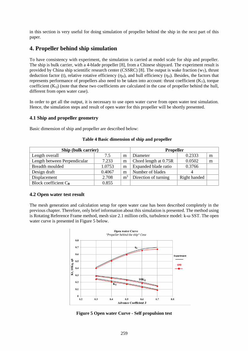
259
in this section is very useful for doing simulation of propeller behind the ship in the next part of thispaper.
4. Propeller behind ship simulation
To have consistency with experiment, the simulation is carried at model scale for ship and propeller.The ship is bulk carrier, with a 4-blade propeller [8], from a Chinese shipyard. The experiment result isprovided by China ship scientific research center (CSSRC) [8]. The output is wake fraction (wT), thrustdeduction factor (t), relative rotative efficiency (ηR), and hull efficiency (ηH). Besides, the factors thatrepresents performance of propellers also need to be taken into account: thrust coefficient (KT), torquecoefficient (KQ) (note that these two coefficients are calculated in the case of propeller behind the hull,different from open water case).
In order to get all the output, it is necessary to use open water curve from open water test simulation.Hence, the simulation steps and result of open water for this propeller will be shortly presented.
4.1 Ship and propeller geometry
Basic dimension of ship and propeller are described below:
Table 4 Basic dimension of ship and propeller
Ship (bulk carrier) PropellerLength overall 7.5 m Diameter 0.2333 mLength between Perpendicular 7.233 m Chord length at 0.75R 0.0502 mBreadth moulded 1.0753 m Expanded blade ratio 0.3766Design draft 0.4067 m Number of blades 4Displacement 2.708 m3 Direction of turning Right handedBlock coefficient CB 0.855
4.2 Open water test result
The mesh generation and calculation setup for open water case has been described completely in theprevious chapter. Therefore, only brief information about this simulation is presented. The method usingis Rotating Reference Frame method, mesh size 2.1 million cells, turbulence model: k-ω SST. The openwater curve is presented in Figure 5 below.
Figure 5 Open water Curve - Self propulsion test
260
4.3 Mesh setup for simulation of propeller behind the ship
The number of cells for Propeller domain and Ship domain are 2.9 and 2.1 million cells, respectively.The total cells are 5 million cells. It can be considered as reason number for mesh size, because timeconsumption for Sliding Grid is very high.
The simulation is performed at services speed 14.5 knots, corresponding with Froude number equals to0.159.
Figure 6 Propeller domain and sliding interface
Figure 7 Mesh generation for propeller and ship
4.4 Setup of simulation
The basic setup of simulation is as follows: multi fluid approach (air and fresh water) and free surface.Turbulence model is k-ω SST. For the boundary conditions, wall-function approach is used for solidparts (hull, propeller, shaft, hub and cap), while the external boundary is set to Far field condition exceptPrescribed pressure for Top boundary. The propeller is connected to the ship by “Pin” connection. Atfirst, large time step is applied to simulation: ∆t = 0.026 second (equal to 5 times step per propellerrevolution). The number of iteration per time step is 4. After the force acting on the ship becomes quitesteady (around 1000 time-step), we switch to second simulation using previous result, but much smallertime step, ∆t = 0.000525 (250 time steps per propeller revolution), and 8 iterations per time step, tostabilize propeller thrust. Time steps setup for propulsion test is described in the table 5 below:
Table 5 Time steps setup for propulsion test
Computationalcase
Propellerrevolution (rps)
Time step (s)1st computation 2nd computation
Vs = 14.5knots7.623 0.026 0.000525
8.2 0.024 0.000488
261
4.5 Result and discussion
The propulsion factors acquired from CFD simulation is shown below, in comparison with experimentresult:
Table 6 Simulation result of propeller behind the ship
Self - propulsion parametersCFD result Experiment
result [8]Compare to experimentThrust coefficient KT 0.154 -7.49% 0.166Torque coefficient KQ 0.213 -3.14% 0.22Revolution n 7.812 2.48% 7.623Thrust deduction coefficient (1 - t) 0.808 3.06% 0.784Advance coefficient J 0.5408 -0.04% 0.541Open water coefficient 0.633 -0.92% 0.639Relative rotative efficient ηR 0.980 -3.48% 1.015Effective wake coefficient (1 - w ) 0.724 2.37% 0.707Hull efficient ηH 1.116 -1.02% 1.128
Regarding level of accuracy, the result of simulation is quite promising. The difference is around, andless than 5% for the propulsion parameters in behind-condition (thrust deduction, wake fraction, relativerotative efficiency).
In terms of time consumption, the average computational time by using 16 cores on 1 node, the meshsize is 5 million cells is belowFirst computation (large time step) Time: 1200 min = 20 hoursSecond computation (small time step) Time: 10000 min = 167 hours = 7 days
There is extremely time consumption for second computation; it takes 160s to calculate 1 time step.
However, there is a solution for that. The computational time will reduce much if we run parallel on 96cores over 3 nodes. It only takes around 70 second to calculate one time step. It means the speedincreases by 2.5 times. And if the calculation is performed in 128 CPU over 4 nodes, the speed canincrease by roughly 4 times, around 50 seconds per time step. Therefore, one simulation (including twosteps of computation) can be done within 1.5 days (36 hours).
5. Conclusion and further development
The paper presents the CFD approach using RANSE solver for propeller calculation, in both case: openwater and behind condition case, with concentration on the practical use of the method duringoptimization process. Few methods have been tested for open water simulation. The investigation alsopoints out that Rotating Reference Frame method is the most suitable one for doing open watersimulation, considering level of accuracy and computational resources. Rotating Reference Framemethod could be applied in practical or daily use, to simulate propeller in open water condition.
The self-propulsion simulation (or simulation of propeller working behind ship) shows quite promisingresult. The results of the parameters, characterizing “propeller behind ship performance”, such as thrustdeduction (t), effective wake coefficient (1 - w) or relative rotative efficiency (ηR) are good incomparison with experiment: less than 5% difference.
However, the most difficulty of this simulation is computational time. Using Sliding Grid with largenumber of cells (including full ship, propeller and rudder) is very time and resources consumption.
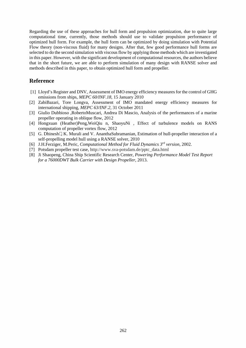
262
Regarding the use of these approaches for hull form and propulsion optimization, due to quite largecomputational time, currently, those methods should use to validate propulsion performance ofoptimized hull form. For example, the hull form can be optimized by doing simulation with PotentialFlow theory (non-viscous fluid) for many designs. After that, few good performance hull forms areselected to do the second simulation with viscous flow by applying those methods which are investigatedin this paper. However, with the significant development of computational resources, the authors believethat in the short future, we are able to perform simulation of many design with RANSE solver andmethods described in this paper, to obtain optimized hull form and propeller.
Reference
[1] Lloyd’s Register and DNV, Assessment of IMO energy efficiency measures for the control of GHGemissions from ships, MEPC 60/INF.18, 15 January 2010
[2] ZabiBazari, Tore Longva, Assessment of IMO mandated energy efficiency measures forinternational shipping, MEPC 63/INF.2, 31 October 2011
[3] Giulio Dubbioso ,RobertoMuscari, Andrea Di Mascio, Analysis of the performances of a marinepropeller operating in oblique flow, 2012
[4] Hongxuan (Heather)Peng,WeiQiu n, ShaoyuNi , Effect of turbulence models on RANScomputation of propeller vortex flow, 2012
[5] G. Dhinesh∗, K. Murali and V. AnanthaSubramanian, Estimation of hull-propeller interaction of aself-propelling model hull using a RANSE solver, 2010
[6] J.H.Ferziger, M.Peric, Computational Method for Fluid Dynamics 3rd version, 2002.[7] Potsdam propeller test case, http://www.sva-potsdam.de/pptc_data.html[8] Ji Shaopeng, China Ship Scientific Research Center, Powering Performance Model Test Report
for a 76000DWT Bulk Carrier with Design Propeller, 2013.
263
Session 3A
MARITIME EDUCATION AND TRAINING
(No. 3)
264
Characteristic of post-degree courses organized in GMU on example“MODERN SHIP MANAGEMENT” course
Laczynski Bogumil,Prof. Captain (1)
Laczynski Tomasz, M. Sc. , PhD student (2)
Gdynia Maritime University, POLAND, Email: [email protected]
Abstract Apart of undergraduate and postgraduate studies offered in GMU new concept of post degreestudies was developed on Faculty of Navigation from 30th September 2015. Post degree course followrequirements of Ministry of Higher Education of Poland. According to this requirements post degreecourse should be continuous minimum 2 semester in total amount of lessons 200 hours and total creditsshould be minimum 60 ECTS. Curricula’s and programs of post degree studies accepted by Dean’sBoard. The group of 15 person in age 30-55 years old was established and they decide that lessons tookplace on Wednesday afternoon 14:00 – 18:00. Participants of post – degree course “Modern ShipManagement” have few years of experience as officers on board or few years as an office workers indifferent offices. In Feb 2015 was established The Polish Ship Managers’ Association, what is a is avoluntary organization of Polish business entities performing technical and crew management of shipsbelonging to foreign shipowners and ship operators and marine risk management concerning those ships.Above association fully accepts post degree course.
Intention of organizers is presenting no theoretical knowledge but practical experience, “keys studies”.Apart of GMU teachers about 80% of presenters were the top managers of ship management companiesfrom Poland and Europe. 30% of lessons were conduct in English language, 70% in Polish.Apart of the lessons in GMU facilities a special exercise were prepared on board vessel mooring in Portof Gdynia (active participation of students in inspection of PSC). Special lessons were done DNV-GLInspections Simulator in their office in Gdynia. Part of course are the individual students projects forexample: organizing of crew exchange, ship supply, medical care on board vessel etc. The final commonproject it is legal establishing of brand new private ship management company. Realistic plans contain:budgeting for 1 year, organizing office and staff , preparing ISM code, etc.
Keywords: ship management, crewing, technical management, GMU, post-degree, course syllabus,commercial management
Contain of paper:
1. Introduction & system of maritime education in Poland2. The specific post degree studies3. Polish Ship Managers Association4. Prognosis for 2nd edition5. Proposition of new post degree studies in GMU6. Conclusions7. References
Introduction & System of Maritime Education in Poland
Gdynia Maritime University founded in 1920 is the biggest Maritime school with over 6000 studentsin 4 faculties:
1. Faculty of Navigation (1200 students)2. Faculty of Marine Engineering3. Faculty of Electrical Engineering4. Faculty of Entrepreneurship and Quality Science
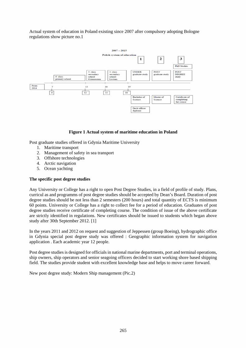
265
Actual system of education in Poland existing since 2007 after compulsory adopting Bologneregulations show picture no.1
Figure 1 Actual system of maritime education in Poland
Post graduate studies offered in Gdynia Maritime University1. Maritime transport2. Management of safety in sea transport3. Offshore technologies4. Arctic navigation5. Ocean yachting
The specific post degree studies
Any University or College has a right to open Post Degree Studies, in a field of profile of study. Plans,curricul as and programms of post degree studies should be accepted by Dean’s Board. Duration of postdegree studies should be not less than 2 semesters (200 hours) and total quantity of ECTS is minimum60 points. University or College has a right to collect fee for a period of education. Graduates of postdegree studies receive certificate of completing course. The condition of issue of the above certificateare strictly identified in regulations. New certificates should be issued to students which began abovestudy after 30th September 2012. [1]
In the years 2011 and 2012 on request and suggestion of Jeppessen (group Boeing), hydrographic officein Gdynia special post degree study was offered : Geographic information system for navigationapplication . Each academic year 12 people.
Post degree studies is designed for officials in national marine departments, port and terminal operations,ship owners, ship operators and senior seagoing officers decided to start working shore based shippingfield. The studies provide student with excellent knowledge base and helps to move career forward.
New post degree study: Modern Ship management (Pic.2)
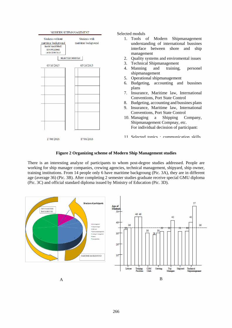
266
Figure 2 Organizing scheme of Modern Ship Management studies
There is an interesting analyze of participants to whom post-degree studies addressed. People areworking for ship manager companies, crewing agencies, technical management, shipyard, ship owner,training institutions. From 14 people only 6 have maritime backgroung (Pic. 3A), they are in differentage (average 36) (Pic. 3B). After completing 2 semester studies graduate receive special GMU diploma(Pic. 3C) and official standard diploma issued by Ministry of Education (Pic. 3D).
Selected moduls1. Tools of Modern Shipmanagement
understanding of international bussinesinterface between shore and shipmanagement
2. Quality systems and enviromental issues3. Technical Shipmanagement4. Manning and training, personel
shipmanagement5. Operational shipmanagement6. Budgeting, accounting and bussines
plans7. Insurance, Maritime law, International
Conventions, Port State Control8. Budgeting, accounting and bussines plans9. Insurance, Maritime law, International
Conventions, Port State Control10. Managing a Shipping Company,
Shipmanagement Compnay, etc.For individual decission of participant:
11. Selected topics : communication skills,
A B
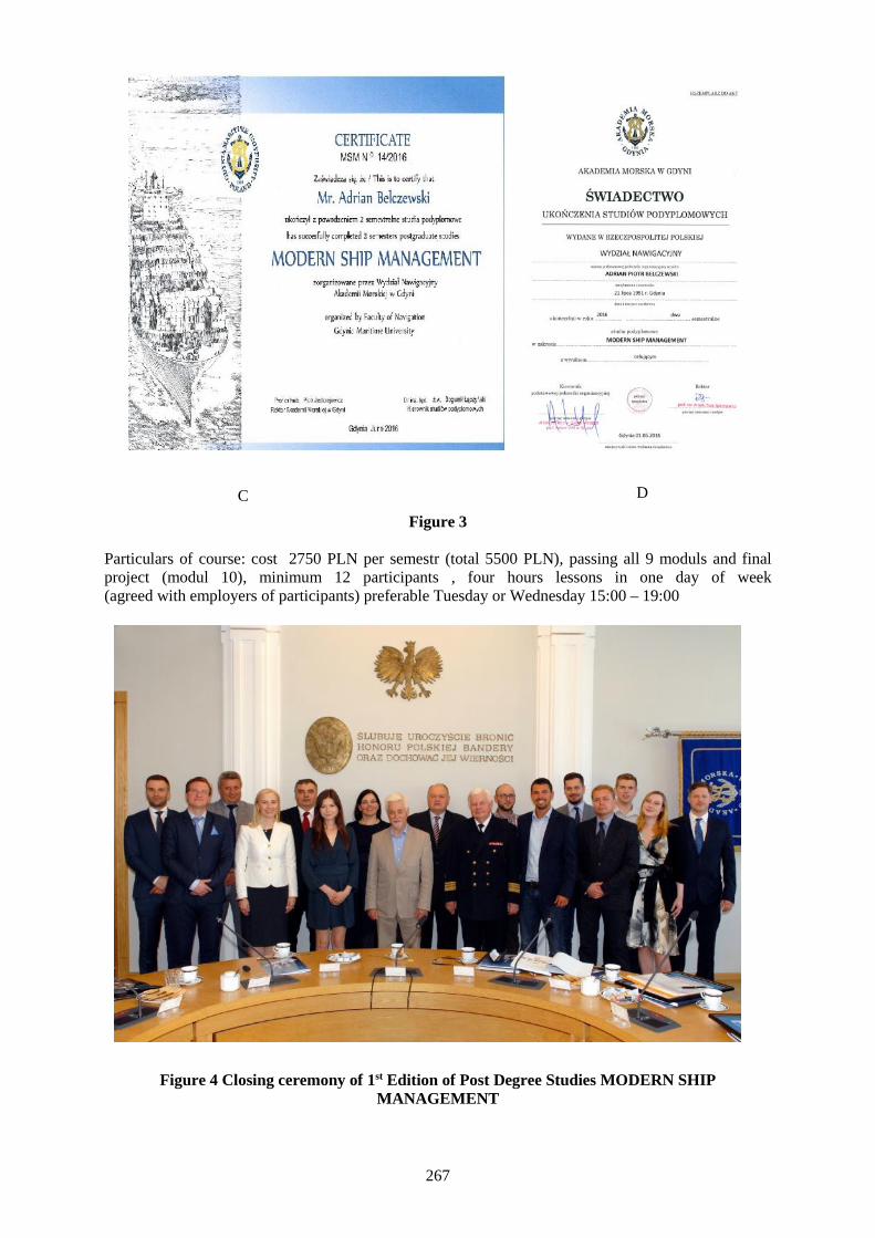
267
Figure 3
Particulars of course: cost 2750 PLN per semestr (total 5500 PLN), passing all 9 moduls and finalproject (modul 10), minimum 12 participants , four hours lessons in one day of week(agreed with employers of participants) preferable Tuesday or Wednesday 15:00 – 19:00
Figure 4 Closing ceremony of 1st Edition of Post Degree Studies MODERN SHIPMANAGEMENT
C D
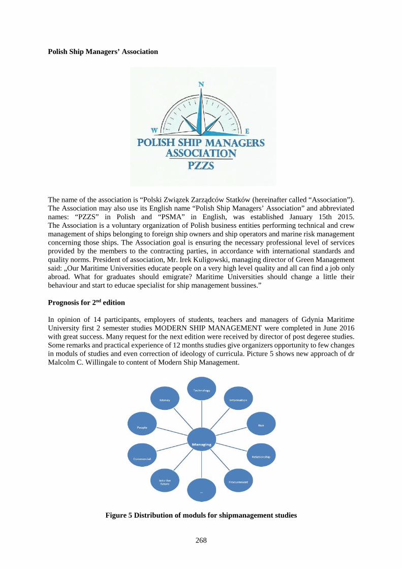
268
Polish Ship Managers’ Association
The name of the association is “Polski Związek Zarządców Statków (hereinafter called “Association”).The Association may also use its English name “Polish Ship Managers’ Association” and abbreviatednames: “PZZS” in Polish and “PSMA” in English, was established January 15th 2015.The Association is a voluntary organization of Polish business entities performing technical and crewmanagement of ships belonging to foreign ship owners and ship operators and marine risk managementconcerning those ships. The Association goal is ensuring the necessary professional level of servicesprovided by the members to the contracting parties, in accordance with international standards andquality norms. President of association, Mr. Irek Kuligowski, managing director of Green Managementsaid: „Our Maritime Universities educate people on a very high level quality and all can find a job onlyabroad. What for graduates should emigrate? Maritime Universities should change a little theirbehaviour and start to educae specialist for ship management bussines.”
Prognosis for 2nd edition
In opinion of 14 participants, employers of students, teachers and managers of Gdynia MaritimeUniversity first 2 semester studies MODERN SHIP MANAGEMENT were completed in June 2016with great success. Many request for the next edition were received by director of post degeree studies.Some remarks and practical experience of 12 months studies give organizers opportunity to few changesin moduls of studies and even correction of ideology of curricula. Picture 5 shows new approach of drMalcolm C. Willingale to content of Modern Ship Management.
Figure 5 Distribution of moduls for shipmanagement studies
269
Proposition of new post degree studies in GMU
Fields of interest for futurepost degree studies
1. Ship inspection together with DNV+GL and PRSand surveying
2. Wide spectrum Maritime Administrationof Hydrography Polish Science Academy
3. Aero/Air Airports administration,Navigation Sanitary/agro aviation
4. LNG Industry LNG Terminals, inland LNG
5. Port State Maritime administration,Control Shipmanagers & shipowners
6. Ship operation for shore based companiesand modern portoperations
7. Ship Agency ship management companies, port authorityShip Superindendents
8. SAR Search and Rescue
9. Safety management andrisk assessment
10. To be advised ….
Conclusions
In opinion of authors of this paper we should define a term in Modern Ship Management which arisedfrom following dates and circumstances.
CLASSIC SHIP MANAGEMENT TILL APR. 1995
MODERN SHIP MANAGEMENT FROM APR. 1995
The best knowledge about ship handling contain contained in classic book of dr Malcolm C.Willingale (Pic. 6) [3]
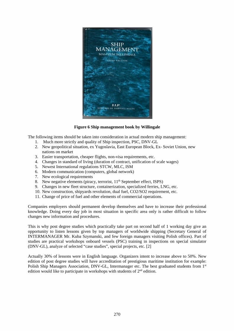
270
Figure 6 Ship management book by Willingale
The following items should be taken into consideration in actual modern ship management:1. Much more strictly and quality of Ship inspection, PSC, DNV-GL2. New geopolitical situation, ex Yugoslavia, East European Block, Ex- Soviet Union, new
nations on market3. Easier transportation, cheaper flights, non-visa requirements, etc.4. Changes in standard of living (duration of contract, unification of scale wages)5. Newest International regulations STCW, MLC, ISM6. Modern communication (computers, global network)7. New ecological requirements8. New negative elements (piracy, terrorist, 11th September effect, ISPS)9. Changes in new fleet structure, containerization, specialized ferries, LNG, etc.10. New construction, shipyards revolution, dual fuel, CO2/SO2 requirement, etc.11. Change of price of fuel and other elements of commercial operations.
Companies employers should permanent develop themselves and have to increase their professionalknowledge. Doing every day job in most situation in specific area only is rather difficult to followchanges new information and procedures.
This is why post degree studies which practically take part on second half of 1 working day give anopportunity to listen lessons given by top managers of worldwide shipping (Secretary General ofINTERMANAGER Mr. Kuba Szymanski, and few foreign managers visiting Polish offices). Part ofstudies are practical workshops onboard vessels (PSC) training in inspections on special simulator(DNV-GL), analyze of selected “case studies”, special projects, etc. [2]
Actually 30% of lessons were in English language. Organizers intent to increase above to 50%. Newedition of post degree studies will have accreditation of prestigious maritime institution for example:Polish Ship Managers Association, DNV-GL, Intermanager etc. The best graduated students from 1st
edition would like to participate in workshops with students of 2nd edition.

271
References:
[1] Laczynski Bogumil, Laczynski Tomasz, “Recent Developments in International MaritimeEducation and Training - Enhancing the Productivity, Safety and Energy Efficiency in MaritimeTransport “, IAMU AGA 15, IAMU Proceedings
[2] Laczynski Bogumil, “The Impact of Shipping Company Environment Industry to Extend Studies atthe Faculty of Navigation in Gdynia Maritime University”, 11th INTERNATIONALCONFERENCETRANSNAV 2015 ON MARINE NAVIGATION AND SAFETY OF SEA TRANSPORTATION,Gdynia, Poland 2015
[3] Willingale Malcolm, “Ship Management”, LLP London Hong Kong, Business of Shipping Series,Third Edition, 1998, 321 pages.
272
Study on the Ideal Ways of Enhancing the Quality of Maritime Education,Training and Research
Col. Dr. G. Thiruvasagam1
1. Vice Chancellor, [email protected], AMET University, 135, East Coast Road, Kanathur, Chennai
Abstract It is a well-known fact that more that 90% of global trade is accomplished through shippingand shipping is the back bone of international trade. Without shipping the transport of essentialcommodities across the globe on a scale necessary to sustain the world is yet to be discovered. Shippingis unarguably the safest, cheapest, cleanest and efficient means of transportation despite the disastersand its consequences through which it had evolved over centuries. Although ship is a single entity, it isa component of the marine environment the rest of them being the person s involved as seafarers takingcare of the routine shipboard operations, the architects involved in the design, development andconstruction of ships, the managers taking care of the commercial, technical and human resources aspectof the ship under the domain of shipping company, the persons involved in the logistics sector, theadministrators, policy makers and the most important component at the grass root level but with whomthe growth, development and sustenance of present and future shipping industry is entrusted with isnone other than the Maritime education and training (MET) institutes.
Keywords: MET, STCW, ISF, Sea Time, Watch keeping.
1. Introduction
Education is the process of facilitating learning or the acquisition of knowledge, skills, values, beliefs,habits whereas training is the one of the methods in pedagogy, the rest being teaching, discussion anddirected research. Training per se is teaching, or developing in oneself or others, any skills andknowledge that relate to specific useful competencies. Training has specific goals of improving one'scapability, capacity, productivity and performance. “Integrating maritime education and training alongwith directed research in order to provide a seamlesssupply of skilled manpower to all the componentsthat make up the marine environment so as to sustain global trade by sea is the fundamental principleof every maritime education and training institute”.
2. STCW code – Brief review
The procedure to the accomplish the essence of the fundamental principle is framed as minimumstandards in the international convention on standards of training, certification and watch keeping forseafarers (STCW) code 1978, as amended, wherein it contains, in:
- Part A, the mandatory provisions to which specific reference is made in the annex to the STCWConvention and which give, in detail, the minimum standards required to be maintained byparties in order to give full and complete effect to the provisions of the STCW convention;
- Part B, recommended guidance to assist parties to the STCW convention and those involved inimplementing, applying or enforcing its measures to give the STCW convention full andcomplete effect in a uniform manner.
Under Article I – General obligations under the convention, parties to the STCW code have agreed totake all necessary steps which may be necessary to give the convention full and complete effect, so asto ensure that, from the point of view of safety of life and property at sea and the protections of themarine environment seafarers on board ships are qualified and fit for their duties.
273
To facilitate homogenous interpretation of the recommended guidance given in Part B, of the STCWcode a table explaining the type of competence, expected level of knowledge, understanding andproficiency for the said competency and criteria for evaluating competence is given as below:
Table A-II/1 (of STCW Code)Function: Navigation at the operational level
Column 1 Column 2 Column 3 Column 4
Competence Knowledge, Understanding andproficiency
Methods fordemonstratingcompetence
Criteria forevaluatingcompetence
Transmit andreceive informationby visual signaling
Visual signalingAbility to use the internationalcode of signals.
Ability to transmit and receive byMorse light, distress signal SOSas specified in Annex IV of theinternational regulations forpreventing collisions at sea,1972,as amended and appendix 1 of theinternational code of signals andvisual signaling of single lettersignals as also specified in theinternational code of Signals
Assessment ofevidenceobtained frompracticalinstruction andsimulation
Communicationwithin theoperators area ofresponsibilityare consistentlysuccessful
Despite such revealing mandatory provisions and recommended guidance in the STCW code there stillexists laps, gaps and inconsistency in the quality of MET as per BIMCO/ISF manpower report 2015.Theparties who have agreed to give full and complete effect to the convention implement it as an expectationof the outcome of training given by MET.
3. Concerns about MET - BIMCO/ISF manpower report 2015
The MET institution survey, 2015 revealed some concerns about a number of issues including the: Proportion of trainees who fail to successfully complete their training courses and obtain an
STCW certificate; Proportion of trainees who obtain STCW operational level certificates, but then only finding sea
going employment as a rating; Difficulties for trainees in securing pre-qualification sea time; Problem faced by MET institutions in providing adequate facilities, instruction and experience
to trainees; and Lack of quality and competency of some seafarers graduating from MET institutions.
4. Concerns about training standards –BIMCO/ISF manpower report 2015
The following comments from the MET institution and seafarer surveys provide an indication of someconcerns that exist about training standards.
“There are no international standards of maritime education and training. The STCW convention isonly the outline, and does not define the professional or academic level that graduates achieve” – METinstitution.
274
“There are many institutions with different levels of standards. The job of regulating institutes shouldnot only be of the Administration, but employers too should take this as their responsibility.” – METinstitution.
“A global maritime control center regarding the quality and standards of teachers and of traininginstitutes is needed” – MET institution.
“Junior bridge officers demonstrate an over reliance on modern electronic aids to navigation. Basicskills are not covered in college, which is of concern – Master, British
“My biggest complaint is the decreasing quality of new officers.”- Master Bulgarian
Although the comments are personal opinion, as a whole it calls out for a control on the perceivedwaning quality in the training standards as well as for the intervention of administration to get a betterhandle on the training imparted by the institutes in their states respectively.
5. Key ways to enhance quality of Maritime Education and Training
Recalling resolution 7 of the final act of the 2010 STCW conference which invokes the promotion oftechnical knowledge, skills and professionalism of seafarers, the stake holders primarily the MET, theshipping company and the administration have to realize that enhancing maritime education and trainingis not an independent responsibility but it is an interdependent responsibility.
5.1 Induction
It is imperative for the MET and shipping companies to be cognizant of the fact that the overalleffectiveness of selection, training and certification processes can only be evaluated through the skills,abilities and competence exhibited by seafarers during the course of their service onboard ship, hencethere should not be any compromise in the established criteria and in the process for the selection ofseafarers exhibiting the highest practicable standards of technical knowledge, skills and professionalism.
At the beginning of the program itself the prospective officer (trainee) should be given full informationand guidance as to what is expected of them and how the training programme is to be organized.Induction presents the opportunity to brief prospective officers about important aspects of the tasks theywill be undertaking with particular regard to safe working practices and protection of the marineenvironment.
5.2 Training
The shipping company must have arrangements to encourage all officers serving on their ships toparticipate actively in the training of junior personal.The seafarers who are newly assigned to a shipshould take of full advantage of every opportunity provided to become familiar with the shipboardequipment, operating procedures and other arrangements needed for proper performance of theirduties.Immediately upon arriving on board for the first time, each seafarer has the responsibility tobecome acquainted with the ship’s working environment, particularly with respect to new or unfamiliarequipment, procedure or arrangements.
There should be a seamless transition between training imparted ashore and onboard, in a broaderperspective the shore based training institutes should precisely map the onboard procedures which areeventually changing from the beaten procedures because of technological advancement.It is extremelyimportant that the prospective officer (trainee) is given adequate opportunity for supervised bridge andengine room watch keeping experience, particularly in the later stages of the onboard trainingprogramme.
275
5.3 Monitoring
Guidance and reviewing are essential to ensure that prospective officers are fully aware of the progressthey are making and to enable them to join in decisions about their future programme. Reviews shouldbe linked to information gained through the training record book and other sources asappropriate.Training record book should be scrutinized and endorsed formally the Master and shipboardtraining officer beginning, during and at the end of each voyage. The training record book should alsobe examined and endorsed by the company training officer between voyages.
5.4 Evaluation
The MET must ensure that the curriculum is designed to take account of different methods of assessmentwhich can provide different types of evidence about candidates competence, e.g:
Direct observation of their seamanship activity; Skills/proficiency/ competency test; Project and assignments; Written, oral and computer-based questioning techniques
Assessment of competence should encompass more that the immediate technical requirements of thejob, the skills and tasks to be performed and should reflect broader aspects needed to meet the fullexpectations of competent performance as a ship’s officer, like; Anticipate prepare for and deal withcontingencies&Adapt to new and changing requirements.
The entire training imparted to the prospective training officer should be comprehensively documented,periodically reviewed and appropriately corrected to ensure complete transformation from a prospectiveofficer (trainee) to a competent officer.
6. Conclusion
The International Maritime Organization (IMO) in its unflagging efforts to defend its twin motto “safeships and clean seas” have taken constant measures and method to keep the quality of maritimeeducation and training by passing several amendments to STCW code in order stay abreast and at timesto outpace the advancement of technology. The spirit with which the code is compiled is vested withthose people who are in the capacity of implementing the code and monitoring the changes it is bringinginto effect. The ways to enhance the quality of the maritime education and training is existing as aconstitution in the STCW code but the key to implement it lies with individual seafarer.
References
[1] International Convention on Standards of Training Certification and watch keeping for seafarers[2] STCW code including 2010 manila amendments.

276
IMO E-navigation Concept and MET trends
Vladimir A. Loginovsky, DSc, Professor
Admiral Makarov State University of Maritime and Inland [email protected], [email protected]
198035, Dvinskaya str., 5/7, Saint-Petersburg, Russian Federation
Abstract The e-navigation Strategy Implementation Plan (SIP), which was approved by IMO MaritimeSafety Committee (MSC 94) in November 2014 [1], contains a list of tasks required to be conducted inorder to address 5 prioritized e-navigation solutions, namely:
improved, harmonized and user-friendly bridge design; means for standardized and automated reporting; improved reliability, resilience and integrity of bridge equipment and navigation information; integration and presentation of available information in graphical displays received via
communication equipment; and improved Communication of VTS Service Portfolio (not limited to VTS stations).
The paper reviews the IMO e-navigation papers and current trends related dynamics of MET stipulatedby development of SIP, which can affect in the near future the STCW Convention and Code.
Keywords: e-navigation, Strategy Implementation Plan, MET, gap analysis, STCW 78.
1. Introduction
The shipping industry is constantly moving to digital world. As per paper [3], e-navigation is expectedto provide digital information and infrastructure for the benefit of maritime safety, security andprotection of the marine environment, reducing the administrative burden and increasing the efficiencyof maritime trade and transport.
In this context the following questions can be raised: Is adequate MET system needed for seafarers inthe era of e-navigation? Do maritime universities ready to meet the upcoming new ICT (Informationand Communications Technology) challenges in shipping? Do they ready to equip their students withnew thorough knowledge or may be the STCW Convention has enough well developed competencies,which are completely adequate to changing environment and nothing to be done?
The e-navigation SIP introduces a vision of e-navigation which is embedded in general expectations forthe on board, on shore and communications elements. The main objective of the present SIP is toimplement the five prioritized e-navigation solutions, taking into account the IMO Formal SafetyAssessment (FSA), from which a number of required tasks have been identified. These tasks should,when completed in the period 2015–2019, provide the industry with the harmonized information, inorder to start designing products and services to meet the e-navigation solutions.
2. Background
IMO has begun to develop Manila amendments and e-navigation concept practically in parallel ways in2006. Let us recall some facts, which have occurred the last years and which might be linked in thenear future as consistent events:
1. E-navigation SIP, which was approved by the Sub-committee NCSR 2 [3] and then alsoapproved by Maritime Safety Committee (MSC) on its 94th session [1] actually represents theinitial stage of the development of e-navigation and it is designed for the period 2015- 2019.
277
2. Resolution 15 [4] “Future amendments and review of the STCW Convention and Code” adoptedby Manila Diplomatic Conference in June 2010 recommends, that a comprehensive review ofthe STCW Convention and Code should, as far as possible, be carried out every ten years toaddress any inconsistencies identified in the interim; and to ensure that they are up to date withemerging technologies. So, in principle comprehensive changes might be initiated and stipulatedin 2020 by the progress of fulfillment of e-navigation SIP, but
3. In 2011 STW 43 noted, that: some training elements, especially those that were, in general,covered by the STCW Convention and Code, might need to be reviewed in the future in light ofthe forthcoming developments on e-navigation and the revision, updating or development oftraining elements should only be considered in the future, after having a clear understanding ofthe potential technical, operational and regulatory e-navigation solutions that would bedeveloped by the Organization [5].
4. IMO HTW 1 meeting of Sub-Committee in 2014 has agreed that it is premature to consider anytraining requirements on e-navigation, pending the finalization of the e-navigation SIP. HTW 2meeting confirmed this solution.
5. However, at the same period IMO has developed the Gap Analysis and practical e-navigationsolutions with Human Element, which include some important proposals for identifying gaps intraining of seafarers and appropriate staff ashore. Some identified gaps might relate to STCWCode and they in turn also can be the basis for future consideration.
Contradictory views were sounded in 2012 during the International conference on e-navigation [6], forexample:
6. ICS considers that training, but not necessarily a training course, may be required to introducethe concept of e-Navigation to users;
7. The automation, harmonization and integration driven by the definition of e-Navigation shouldensure that training additional to that already required under the STCW is generallyunnecessary.
8. E-Navigation improves situational awareness and decision making at sea and ashore. When usedin conjunction with other communications and display systems it enables shore organizationsto deliver more timely and relevant information to the mariner. And through its many levels ofsophistication and scalability it can embrace all levels of system users from recreational craft tothe largest and most modern commercial vessels. A drawback is that its use requires that therebe a new level of sophistication and equipage on the part of the system users. And this in turnrequires new levels of user training and certification.
So, a lot of things in MET are needed to think over and consider before the e-navigation SIP begins tostart its implementation.
3. E-navigation and Situation Awareness
The IMO definition of e-navigation concept is as follows [7]: "E-navigation is the harmonizedcollection, integration, exchange, presentation and analysis of marine information on board and ashoreby electronic means to enhance berth to berth navigation and related services for safety and security atsea and protection of the marine environment."
The following clarification of IMO definition is given in US e-navigation Strategic Action Plan [8]: e-Navigation is not about equipment, but is about the integration of information. There is and will be nosuch thing as an “e-navigation system,” nor will there be a carriage requirement for an “e-navigation
278
box.” Eventually, equipment and systems may be required to be “e-navigation compliant” but suchrequirements are yet to be developed.
Let us try to combine the sense of definition and clarification above with definition of SituationAwareness (SA). SA is the safety driven perception of the elements in the environment within a volumeof time and space (navigational area) , the comprehension of their meanings (dangers, marks, ships,lighthouses…) and the projection of their status in the near future (developing of navigational situation),[9]. In other words SA involves the real-time processing of event-based information coming from anevolving situation in an attempt to understand what is happening, [10].
So, one of the goals of e-navigation, as globally integrated maritime network, is electronically to knowwhat is going on around the ship. In principle, it has the task to support the proper level of SituationAwareness of personnel on board and ashore for safety and security at sea and protection of the marineenvironment.
One can say that e-navigation concept is also in line with the appropriate provision of STCW 78 andnamely “obtaining and maintaining the situation awareness “, which is included into Column 2«Knowledge, understanding and Proficiency» of STCW Code by Manila amendments (Tables A-II/1,2;A-III/1,2,6 ). In what way the e-navigation concept with its integrated approach can influence the STCWcompetences? Do only Section A-II, or possibly Sections A-III, A-IV and A-VIII also might besubjected to some changes?
From the viewpoint of training, the integrated information, in spite of human-centered design ofequipment, might be less clear for operator than information obtained by traditional non- integratedapproach that is why more deep understanding of principles of integration might be needed. It may bethe additional subject for MET programs.
4. Gap analysis results: training
HTW2 Subcommittee adjourned the discussion of issues related to the training of seafarers, explainingthat by number of uncertainties, but however carried out a gap analysis, allows pre-select the field thatcan change the training or affect the training of seafarers.
What one can say about the shore-based personnel training in field of e-navigation? If to followprinciples of e-navigation, some training programs need to be also integrated with training programs forseafarers? Officers and shore staff should have an opportunity to be trained together. Perhaps, it wouldbe reasonable to develop and include in STCW Convention or ISM Code the requirements for all typesof joined training for crews and shore staff.
Some ideas and proposals extracted from gap analysis [3] in the area of e-navigation and related to stafftraining, both for onboard and ashore are as follows:
Training courses are proposed to be developed5:1) on automated procedure of ship reporting;2) on procedure of data entry, using harmonized data format and related equipment;3) on information management system;4) on familiarization with new symbolic presentation environment (due to lack of standardized
symbology of all information required to display on the navigational system);5) on new communication equipment;6) for shore based users to be familiarized with the CMDS (Common Maritime Data Structure)
and its contents of their own work;
5 The original wordings of referred document were kept.

279
7) for shore based users to be familiarized with new presentation and its contents (due to lack ofharmonized presentation of domain awareness to improve situational awareness for allied andother support services.)
8) familiarization with the management system for report handling;9) for shore based users to be familiarized with the information management system and its
decision-making support function (traffic monitoring).
In principle, it can be seen that majority the proposals in the list above relate to communication,exchanging and sharing of information. There is no doubt that they are Situation Awareness items, whichare included into the STCW Code and worded as “obtaining and maintaining situational awareness”.
Training courses are proposed to be revised:10) on operation of identification procedure of the communication system;11) current GMDSS for integrated GMDSS system;12) on GMDSS should be revised based on the standard operational procedure;13) on understand the system's automatic action and report to user (due to lack of self-checking
functionality of the electronic equipment for improved reliability);14) on familiarization with the new feature of maneuvering data presentation (due to lack in
presentation of maneuvering information/data (engine-room telegraphs) on navigationaldisplay;
15) on ECDIS to be familiarized electronic procedure related passage plan (due to lack ofstandardization for operation of functions to observe the passage plan. Users requirestandardization on the level of function provided and the operating way of it);
16) on ECDIS as appropriate (due to lack of presentation of calling message of pilot on navigationaldisplay. Communication with pilot could be improved;
17) on operation on communication and navigation equipment involved within transfer ofinformation;
18) on general skill on user computer to use the software for digital publication;19) on Integrated Navigation Systems (due to ineffective access to information);20) on simple and standardized procedure for priority message;
It can be seen also that majority the proposals of the second list above relate to communication,exchanging and sharing of information.
Mariners and shore personnel are proposed to be trained in the following fields:21) For proper filtering of information. Some information should not be “filtered away”;22) Familiarization to status information of each type of equipment. Training to respond the
equipment status if necessary;23) Consideration should be given to the revision of training/education for affected equipment and
impact on Bridge Resource Management Training reflecting operational changes and how it isincorporated into practice of navigation;
24) Operator must be trained for operation of data systems;25) Training should include standards and where to find them;26) A basic level of relevant language competency should be required ahead of being able to use
SMCP (Insufficient use of IMO Standard Marine Communication Phrases (SMCP));27) Users need to be made aware of the vulnerability of GNSS and the lack of integrity. - users also
need to be trained in procedures to be followed if GNSS is disrupted, or in the use of alternativesystems;
28) On-line help function should be included in the systems, if available. Familiarization for usingof automatic generated assessment results;
29) On-line help function should include self-descriptive information of system's characteristic inview of operational, technical, regulatory and training;
30) Control of software and hardware update should not require additional training of mariners.Human intervention of this procedure should be minimum but there are certain recognition ofthe certification status;
280
31) Familiarization for using digital publication on User's computer. Revise the training course forgeneral skill on user computer to use the software for digital publication;
32) Training for a system should be focused to standardized operational procedure of e-navigationFunctions dependent on manufacturer or type should be trained and covered by familiarizationmaterial and/or on-site training and on-line help function;
33) Stakeholders will need to be trained to comply with data security requirements;34) Training should be provided for the procedures and use of the equipment both on board and
ashore;35) Identify training required for applying guidance (VTS)- Current VTS hardware may not have
the capacity for increased collection, integration, exchange, presentation, storage and analysisof data;
36) Identify training required for the provision of NAS (Navigational Advice and Assistance) andTOS (Traffic Organization) - Current VTS hardware/software may not have the capacity forreal time display of vessels’ track to provide a NAS or TOS service;
37) Provide adequate training for all communication needs;38) Ensure training identifies AIS errors and their likely causes;39) Training for NAS and TOS to be provided to ship and shore personnel. The use of simulation
should be considered;40) All VTS training courses to adopt V 103 model training courses;41) V 103 model training courses and STCW need to include training in this regard;42) SAR person should be familiarized with the shared information and its presentation to recognize
whole status of SAR operation;43) On scene operator and coordinator should be advised by the decision support system with
enough information for situation awareness;44) Explicit distress and safety training.
5. Conclusion
So, taking into consideration the proposals above and that e-navigation is about the integration ofinformation, it is getting clear that MET process is waiting challenging changes.
Serious attributions involving SA occur when “Bridge (or Engine room) or Shore based Personnel” errordue to loss of SA is listed as a cause of accidents. The results from maritime operations literature surveyrevealed that 71% of human errors were Situation Awareness related problems, [11]. Failure to mitigateaccident due to poor SA also is pointed in frames of e-navigation concept [12,13].
IMO concept of e-navigation might provide ICT revolution initiating and launching the new paradigmof MET system for better SA at all three levels (perception, comprehension, projection) which shouldbe resulted in better decision making on board and ashore for safety and security at sea and protectionof the marine environment.
In spite of the viewpoint, that now it is premature to consider any training requirements on e-navigation,pending the finalization of the e-navigation Strategy Implementation Plan, for MET universities it is hottime to start the research in e-navigation field relating MET to march in step with Industry and be inadvance ready for further phase of comprehensive review of STCW 78 Convention and Code.
References
[1] MSC 94/21, Report of the Maritime Safety Committee on its 94 session, 26 November 2014, 81 p.[2] HTW 2/19, Report of the Maritime Safety Committee, 6 February 2015, 121 p.[3] Report to the MSC, NCSR 1/28 16, July 2014, ANNEX 7, Draft E-Navigation Strategy
Implementation Plan, 341 p.
281
[4] Final Act of the Conference of Parties to the International Convention on Standards of Training,Certification and Watchkeeping for Seafarers (STCW), 1978. STCW/CONF.2/32, 1 July 2010, 26p.
[5] Report to the MSC, STW 43/14 11 June 2012, 185 p.[6] E-Navigation underway international conference on e- navigation, M/S Crown Seaways,
Copenhagen–Oslo–Copenhagen 18 January - 20 January 2012 Jointly organized by the EfficientSea project and the International Association of Marine Aids to Navigation and LighthouseAuthorities (IALA) Supported by the Nautical Institute and the International Association for MarineElectronics Companies), 21 p.
[7] Strategy for the development and implementation of e-navigation, MSC 85/26/Add.1, annex 20,277 p.
[8] http://www.cmts.gov/downloads/CMTS_e-Navigation_Strategic_Action_Plan_Feb_2012.pdf, 20 p.[9] Endsley M., “Theoretical Underpinning of Situation Awareness: Critical Review” in Mica R.
Endsley and Daniel J. Garland (Eds.) Situation Awareness Analysis and Measurement. LawrenceErlbaum Associates, Mahwah, New Jersey, 2000. pp. 3-32.
[10] Matheus C.J. et al., A. “Core ontology for situation awareness”, Versatile Information Systems,Inc., Framingham, MA, USA, 2003, http://www.mendeley.com/research/core-ontology-situation-awareness/, 11 May 2012, 8 p.
[11] Grech M.R., et al., “Human error in maritime operations: analyses of accident reports using theLeximancer tool”, Key Centre of Human Factors and Applied Cognitive Psychology, University ofQueensland, Brisbane, Qld;https://www.leximancer.com/wiki/images/4/44/HFES2002_MGRECH.pdf, 11 May 2012, 5 p.
[12] NAV 58/inf.6, Development of an e-navigation strategy implementation plan. Report from thecorrespondence group on e-navigation to NAV 58,http://www.nmri.go.jp/navigation/staff/yasuyuki_niwa/e-NAV-CG-2012/NAV 58-6.pdf, 11 May2012, 3 p.
[13] STW 43/6, 27 January 2012, Development of an e-navigation strategy implementation plan. Reportfrom the correspondence group on e-navigation to STW 43, 51 p.
282
Integrity of Electronic Testing of Mariners
John Tucker [Professor, M.Eng., P.Eng.]1, John Cross [Professor, ONII, M.Eng., P.Eng.]2
1 Marine Institute, Memorial University of Newfoundland, [email protected]. Marine Institute, Memorial University of Newfoundland, [email protected]
Abstract. With the Manila Amendments to SCTW that introduce distance learning and web-basedlearning as valid course delivery systems there have been several initiatives aimed at developing distancecourses for mariners. There are ways that content can now be effectively delivered to mariners thatallow learning to take place outside the academic setting, most importantly on ship.However, electronic testing brings with it two potential problems:• First, the test must be structured so that it provides a fair opportunity for assessment.• Second, the test must maintain the academic integrity of the evaluation and course.
While electronic testing has been around as long as computers have been in common use, the technologyand educational pedagogy is only now beginning to capture the sophistication of a typical test. Thedelivery of the test is fairly easy, but grading it so that it provides a fair and accurate assessment of astudent’s capability is much more challenging.
The second problem is that the provider of the test must be certain that the student is displaying theircapability. It is naive to think that students are not taking advantage of electronics or other methods togive them an unfair advantage in examination performance. If the examination is taking place at adistance the problem is even greater with the potential for everything from a student “googling” theanswer to it not even being the student sitting and writing the test.
For electronic testing to reach its full potential these problems must be addressed. This paper beginswith lessons learned from the author’s experience in developing electronic questions over the last 5years and provides some insight and guidance for anyone interested in creating questions. It then goeson to look at how the Marine Institute is currently handling distance testing and the potential for newbiometric processes to make distance invigilation stronger and more secure.
Keywords: Electronic Testing, Online Proctoring, Examination of Mariners
1. Introduction
The 2012 Manilla Amendments to STCW opened the door for national certifying authorities to permitMaritime Education and Training institutions (MET’s) to deliver certification level training using onlineor web based. The critical nature of maritime training training and the assessment that must accompanyit for certification advancement resulted in this evolution taking a longer time to occur than in most otherpost secondary education institutions, but the authors feel that this evolution is inevitable.
With the MET transition to online or web delivery lagging most other higher education fields, we areafforded the opportunity to study and learn from online delivery of programs in other areas of highereducation and apply those lessons learned to the evolution of our programs and the ways in which weevaluate our learners.
2. The Categorization of MET
Trenholme categorizes online deliveries as being of two distinct types; “Writing-Based” (WB) courseswhere learners are required to author papers and answer essay type questions, or “Math or Fact-Based”(MFB) style courses in which in which the learners are required to recall facts or perform calculations[1].
283
WB courses tend to be assessed in a more subjective way where presentation as well as creativity mayhave an impact on the performance of the learner in an evaluation. A test for academic dishonesty inthis type of evaluation would typically be an assessment to determine plagiarism. There are a host oftools and devices to assist in ensuring the academic integrity of WB type evaluations ranging from onlineplagiarism checkers to student portfolio creation and maintenance tools incorporated into the majorityof Learning Management Systems. Sadly, the development of a set of similar tools to prevent academicdishonesty in MFB type courses has not evolved at the same pace. MFB style course evaluations aremore objective. The correct answer is, simply, the correct answer. As a consequence of this, anassessment of plagiarism in an MFB type evaluation is not valid.
MET would tend to fall into the category of a MFB type of delivery. Mariners are required to learnmission critical facts and perform objective evaluations in a consistent and timely fashion. This isreflected in the model course content presented in STCW, course deliveries provided by METInstitutions, and evaluations performed to permit certification level advancement as provided by eitherthe MET Institutions or the national certifying authorities.
2.1 Cheating in MET Certification Level Evaluations
It is important to note that, at this time, all certification advancement level examinations of marinersconducted in Canada are conducted using a face-to-face method. In this system, examinees presentthemselves at an authorized examination centre with appropriate documentation, identification andcredentials, and sit to write their examination in an invigilated setting.
In high stakes evaluations such as these, academic honesty is a well-guarded feature of the entirecertification process. It is conceivable, however, that even with such a strict and time-tested system, thepressures to perform well on these evaluations can lead individuals to use any means at their disposal toassist them in succeeding in their evaluations.
In the 1980’s, the authors observed a method that was employed to better the chances of success in METevaluations that was a consequence of poorly designed evaluation databases. It was the case at this timethat a limited database of static (unchanging) examinations was employed for certification purposes inCanada. Mariners would write a certification level examination offered by the national certifyingauthority that was drawn from this limited database, and upon completion they would leave the examand immediately note the exam questions on that version of the examination. These questions weresolved, shared and compiled over time as a set of exam questions that you could expect to see in thecertification level examination. Some learners would memorize a set of questions and then take theexamination multiple times until they received the exam with the questions they had committed tomemory…and pass.
The examination database in Canada has experienced a serious restructuring and updating over the lastfew years and now draws on a more flexible bank of new questions in the hopes of alleviating the abovementioned issue.
In considering the possibility of offering MET certification level advancement examinations online, aspart of a course or not, we must re-evaluate the methods we use to administer and secure theexaminations and the writing of the examinations. Providing a less strictly controlled environment forthe writing of examinations must be avoided, as it would provide a more tempting opportunity forcheating.
Three factors should be considered as influencing mariners when faced with the perceived opportunityto cheat in an online evaluation:
1. Increasing pressure to advance in certification level. This can come from the opportunity formonetary gains, employment opportunities or status shift.
284
2. Shifting socio-economic views on the acceptability of cheating on an evaluation. From theexaminee’s perspective, the mission is to obtain the advancement in certification level. What ittakes to obtain this advancement is somewhat irrelevant. From the perspective of the certifyingauthority, it is imperative that the examinee demonstrate knowledge and expertise in theexamination topic area.
3. Anonymity is a factor unique to the administration of online examinations. In the case of onlineevaluations it is more the perception of anonymity that the examinee may feel when writing anexamination with no one else in attendance than the actual fact of anonymity.
Trenholme goes on to add that academic dishonesty observed in an online or web based delivery of aMFB type course is observed as either:
1. Use of an alternate individual, typically an expert, to complete evaluations or assessments.2. Unauthorized collaboration on evaluations; and3. Unauthorized coaching on evaluations.
In the context of MET, these evaluations typically consist of requiring the mariner to provide anevaluation or factual data in which the correct answer must be provided in a clear and concise fashion.
Plagiarism is not a factor in MFB assessments as the correct answer is the correct answer. However,the three above-mentioned concerns for academic dishonesty are. For online course deliveries as wellas online evaluations to take place, a paradigm must be established whereby there is complete confidencein the academic integrity of all evaluations in the online MET delivery.
3. Structuring Electronic Tests
The purpose of any test is to provide a fair assessment of a student’s knowledge and ability. At the mostbasic level, this is just a recall of facts, however at the higher cognitive levels it requires both a recall offacts as well as assessment of pertinent information and application of a solution algorithm.
In fact testing by electronic machines has been around for over 80 years. The IBM 805 was developedin 1934 and would correct a score sheet placed in it [2]. It would apply a small voltage across the correctmultiple choice answer and if a pencil mark was present in that place a small current would flow. Themachine would measure the total current flowing and thus the total score for that sheet.
However the digital age has allowed much greater flexibility and sophistication to be employed. Theauthors were trying various means of incorporating electronic assignments into their classes as a meansof reducing plagiarism prior to 2010 [3]. However with the adoption of MapleTA in 2011 forassignments the potential to use it for tests and examinations was first realized. It should be noted thatwhile we use MapleTA, there are a number of similar software packages available that have similarfunctionality.
The first use of MapleTA for testing was its use to administer a multiple choice type examination in amaterial science class. It was an obvious candidate since previous examinations in this course weredeveloped from an existing bank of multiple choice questions. However MapleTA allowed a couple ofbeneficial options. The first was that we could create multiple copies of similar questions (for examplea diagram showing a particular plastic manufacturing process and asking what the process was). Wecould also group related questions together. For example we might have 10 questions related tocorrosion. When it came time to make up the exam we would choose the topics we wanted and then thenumber of questions from each topic (for example we might want 4 questions on corrosion) andMapleTA would create each student an individual test based on how we specified (for example in thecase outlined the computer would choose a random 4 out of the 10 corrosion questions). This way testscould be created to target certain areas but also prevent any potential for copying since each student hadan individual exam.
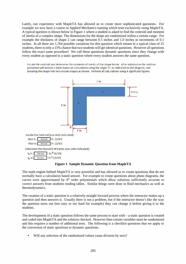
285
Lately, our experience with MapleTA has allowed us to create more sophisticated questions. Forexample we now have a course in Applied Mechanics running which tests exclusively using MapleTA.A typical question is shown below in Figure 1 where a student is asked to find the centroid and momentof inertia of a complex shape. The dimensions for the shape are randomized within a certain range. Forexample the thickness of shape 2 can range between 0.5 inches and 1.0 inches in increments of 0.1inches. In all there are 1,764 possible variations for this question which means in a typical class of 25students, there is only a 15% chance that two students will get identical questions. However all questionsfollow the exact same procedure! We call these questions dynamic questions since they change withevery student as opposed to a static question where every student answers the same question.
Figure 1 Sample Dynamic Question from MapleTA
The math engine behind MapleTA is very powerful and has allowed us to create questions that do notnormally have a calculation based answer. For example to create questions about phase diagrams, thecurves were approximated by 4th order polynomials which allow solutions sufficiently accurate tocorrect answers from students reading tables. Similar things were done in fluid mechanics as well asthermodynamics.
The creation of a static question is a relatively straight forward process where the instructor makes up aquestion and then answers it. Usually there is not a problem, but if the instructor doesn’t like the waythe question turns out (too easy or too hard for example) they can change it before giving it to thestudents.
The development of a static question follows the same process to start with – a static question is createdand coded into MapleTA and the solution checked. However then certain variables must be randomizedand this requires a number of additional tests. The following is a checklist questions that we apply tothe conversion of static questions to dynamic questions.
Will any selection of the randomized values cause division by zero?
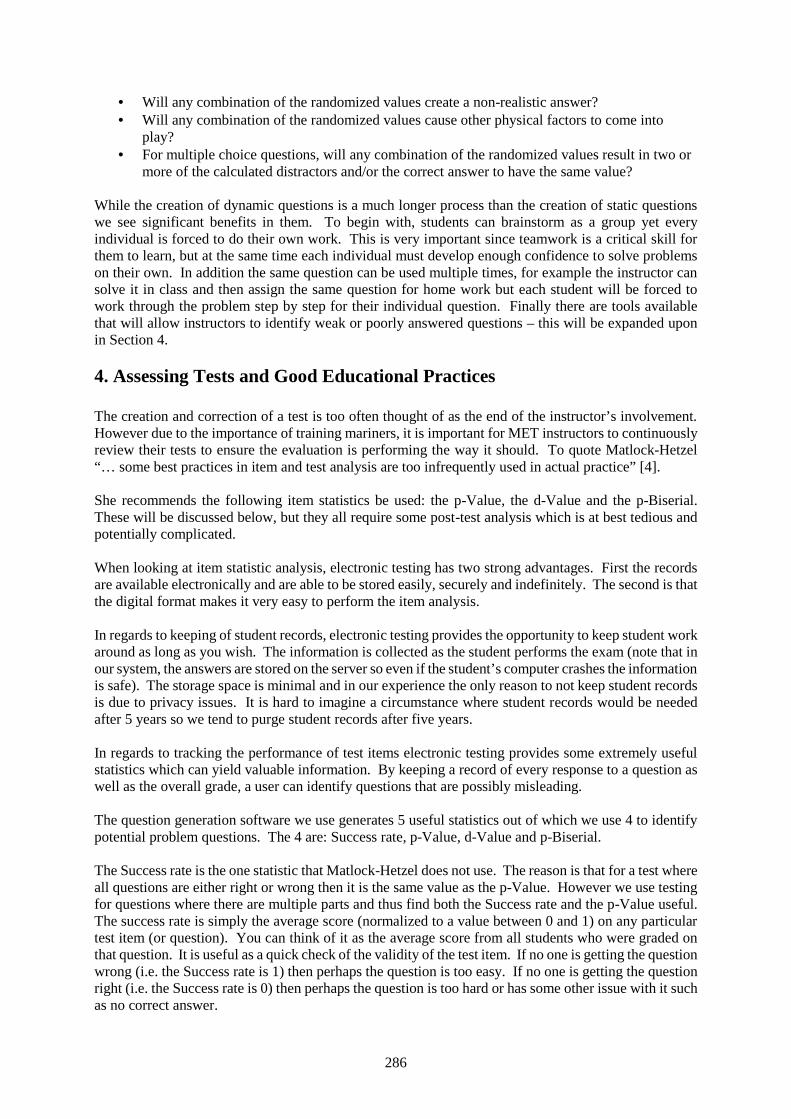
286
Will any combination of the randomized values create a non-realistic answer? Will any combination of the randomized values cause other physical factors to come into
play? For multiple choice questions, will any combination of the randomized values result in two or
more of the calculated distractors and/or the correct answer to have the same value?
While the creation of dynamic questions is a much longer process than the creation of static questionswe see significant benefits in them. To begin with, students can brainstorm as a group yet everyindividual is forced to do their own work. This is very important since teamwork is a critical skill forthem to learn, but at the same time each individual must develop enough confidence to solve problemson their own. In addition the same question can be used multiple times, for example the instructor cansolve it in class and then assign the same question for home work but each student will be forced towork through the problem step by step for their individual question. Finally there are tools availablethat will allow instructors to identify weak or poorly answered questions – this will be expanded uponin Section 4.
4. Assessing Tests and Good Educational Practices
The creation and correction of a test is too often thought of as the end of the instructor’s involvement.However due to the importance of training mariners, it is important for MET instructors to continuouslyreview their tests to ensure the evaluation is performing the way it should. To quote Matlock-Hetzel“… some best practices in item and test analysis are too infrequently used in actual practice” [4].
She recommends the following item statistics be used: the p-Value, the d-Value and the p-Biserial.These will be discussed below, but they all require some post-test analysis which is at best tedious andpotentially complicated.
When looking at item statistic analysis, electronic testing has two strong advantages. First the recordsare available electronically and are able to be stored easily, securely and indefinitely. The second is thatthe digital format makes it very easy to perform the item analysis.
In regards to keeping of student records, electronic testing provides the opportunity to keep student workaround as long as you wish. The information is collected as the student performs the exam (note that inour system, the answers are stored on the server so even if the student’s computer crashes the informationis safe). The storage space is minimal and in our experience the only reason to not keep student recordsis due to privacy issues. It is hard to imagine a circumstance where student records would be neededafter 5 years so we tend to purge student records after five years.
In regards to tracking the performance of test items electronic testing provides some extremely usefulstatistics which can yield valuable information. By keeping a record of every response to a question aswell as the overall grade, a user can identify questions that are possibly misleading.
The question generation software we use generates 5 useful statistics out of which we use 4 to identifypotential problem questions. The 4 are: Success rate, p-Value, d-Value and p-Biserial.
The Success rate is the one statistic that Matlock-Hetzel does not use. The reason is that for a test whereall questions are either right or wrong then it is the same value as the p-Value. However we use testingfor questions where there are multiple parts and thus find both the Success rate and the p-Value useful.The success rate is simply the average score (normalized to a value between 0 and 1) on any particulartest item (or question). You can think of it as the average score from all students who were graded onthat question. It is useful as a quick check of the validity of the test item. If no one is getting the questionwrong (i.e. the Success rate is 1) then perhaps the question is too easy. If no one is getting the questionright (i.e. the Success rate is 0) then perhaps the question is too hard or has some other issue with it suchas no correct answer.
287
The p-Value is a measure of the ratio of fully correct responses to the test item to all the responses.Taken with the Success rate it can provide information about the internal structure of the test item. Ifthe p-Value is the same as the Success rate then there are no partial marks being awarded because allstudents get the question completely correct or completely wrong.
The d-Value is the discrimination of the test item. It is calculated by finding the difference of the p-Value of the top half of students (based on overall exam scores) and the p-Value of the bottom half ofthe students. It can be a value between -1 and +1. This is useful as rough measurement of how wellgood students do on a question as opposed to no-so-good students. We would expect students who scorehighly on the test to be knowledgeable about the subject material and thus would score well on anygiven item. The converse is true for students who are in the lower half of exam scores. A high positivevalue is desirable for a typical test item.
The last statistic is the p-Biserial or point biserial correlation coefficient. It is a more sophisticatedmeasure of how well good students do as opposed to the no-so-good students, so it is a better indicatorof how good students (and how no-so-good students) do on a particular question. It ranges in valuepotentially between -1 and +1. A higher positive value generally indicates a test item that is accurate atmeasuring student performance.
It is important to note that any of the above statistics for the results from an individual class are, bythemselves, only an indication of whether a problem exists. An instructor needs to examine potentialproblematic questions to see if there really is an issue with the question. Figure 2 shown the statisticsfrom a typical class of 21 students.
Figure 2 Question Statistics obtained from MapleT.A.
As can be seen, no question had either a 100% success rate or a 100% failure rate which is an indicatorthat it is testing student knowledge. The p-Value is showing that there are a suitable range of partialmarks being awarded for each question. The d-Values are all positive, but question 1 and 5 show verylow values indicating that students in the top half of the class do about the same as students in the bottomhalf of the class. While not a problem by itself, it does indicate potential problems so we look at the p-Biserial value. The p-Biserial values are 0.54 and 0.43 which both indicate a question which isfunctioning as it should.
288
5. Online Proctoring
The issue of proctoring exams is one of the most critical and culturally complex issues in the deliveryof online certification level courses. Historically, students taking distance courses were required totravel to an authorized examination centre to write tests and examinations in a proctored or supervisedsetting. The challenge being that many learners participate in these courses because they lack the abilityto conveniently travel to such a centre to participate in course evaluations. This contradicts with therationale for online delivery and, until recently, resulted in post secondary institution struggling with thequestion of trusting students to write examinations on their own computers in an unproctored setting orrequiring the students to travel to an examination centre.
Advancements in technology have provided some interesting solutions to this challenge. There aremany companies who, today, provide online proctoring services. All of these services have standard,common features [5]. The process of taking an online test would typically begin with some form ofauthentication. This could be in the form having the student input a username and password but mayalso involve verification of the persons identity using a photo ID and a webcam or facial recognitionsoftward. The test itself typically involves an actual proctor, which could be human or some form oftechnology which would observe the test taker during the evaluation event. This observation could beof the form where the testees computer (screen) is being observed or recorded as well as the individualbeing observed using a webcam and a computer microphone. This permits the proctor to observe thetest paper, to watch the individual to ensure that they stay at their desk during the evaluation, and it alsopermits the proctor to listen to the person being tested to ensure they are not in communication withanyone who is unauthorized during the test event.
MUN recently conducted a study and has implemented a policy to manage online proctoring ofexaminations. Online exam proctoring is now the default method of invigilation for examining studentsthat reside outside the province of Newfoundland and Labrador. Professional proctors use webcamsand microphones to remotely supervise students writing exams during their examination period.
The students may write their examinations at home or any quiet location with an active internetconnection. The exam is written using a secure lock down browser and the scheduling of examinationsis flexible but has to be set up beforehand.
Similar to writing exams in a classroom, students are required to show both their MUN Campus ID Cardas well as a government-issued photo ID to the proctor prior to taking the exam. To ensure the privacyof student information, all data is stored in a secure data center in Canada and may be temporarily storedin secure locations outside Canada to facilitate transfer.
There are specific technical requirements that must be met, but they are not onerous or requirementsthat a student participating in an online course would not already be expected to have.
We can expect uncertainty about electronic examinations outside of a campus to remain a concern, butnew technologies are constantly alleviating problems.
More sophisticated and secure means of authenticating and proctoring critical evaluations is that of usingbiometric techniques to monitor students. The three main biometric systems are: finger prints, facialrecognition and retina scans. All provide some degree of certainty that the correct person is sitting atthe computer, however there are still potential problems with having unmonitored students takingexaminations. In addition, Canada has some of the strongest privacy laws in the country and some ofthese methods are considered intrusive.
289
6. Conclusion
With online distance courses becoming almost the norm these days, the use of electronic testing fordistance courses must be seriously considered. It provides the convenience of allowing mariners toprogress without the challenges of geography that mariners often face. However it comes with a numberof potential problems that must be weighed against the benefits.
The problems are that confidence in the test administration and delivery process must be gained at alllevels on the certifying side. Everyone from those who administer the evaluations to the certifyingauthority and IMO must have full confidence in the delivery of online evaluations before this type oftesting will be permissible. An additional challenge to be considered is from the perspective of themariner being evaluated in that they must understand the safeguards that have been put in place to ensurethe academic integrity of the test and not feel that, although they are alone in the room while taking theevaluation, they are not being proctored.
The benefits are that it allows great flexibility in administering tests and has the potential to make testsmore secure by allowing individual tests to be created, administered and corrected automatically. Inaddition it allows the instructor to continuously monitor the test’s performance to ensure that it isevaluating the way it is supposed to.
While the proctoring issue is significant, we feel that this will soon be solved in an acceptable mannerand then electronic testing will allow the convenience and flexibility that mariners will find useful asthey progress through their careers.
References
[1] Trenholm, S. (2007)., “A Review of Cheating in Fully Asynchronous Online Courses: A math orFact-Based Course Perspective”. J. Educational Technology Systems, 35(3), 281-300.
[2] IBM (2016) "IBM 805 Test Scoring Machine.", (http://www-03.ibm.com/ibm/history/exhibits/specialprod1/specialprod1_9.html) IBM Archives:. Web. 10 June2016.
[3] Tucker, J. & Cross, J. (2013). “Testing in the electronic age”. 21st International Maritime LecturersAssociation Conference: Into the Future – Challenges for MET in the 21st Century (pp 229-236).St. John’s, Newfoundland, Canada.
[4] Matlock-Hetzel S.(1997), “Basic Concepts in Item and Test Analysis”, Paper presented at Annualmeeting of SouthWest Educational Research Association, Austin, Texas, 1997.
[5] Foster, D., "Online Proctoring Systems Compared”, (https://www.researchgate.net):. Web. 13March 2013.
290
Increasing the sustainability of the maritime research and training
Commodore Boyan Mednikarov, Prof.Dr.M.Sc.1
Captain (Navy) Kalin Kalinov, Professor Ph.D.2
Captain (Navy) Nedko Dimitrov, Associated Professor Ph.D. 3
CDR Zhelyazko Nikolov, Assistant Professor Ph.D. 4
1. Nikola Vaptsarov Naval Academy, Varna, Bulgaria, [email protected]
2. Nikola Vaptsarov Naval Academy, [email protected]
3. Nikola Vaptsarov Naval Academy, [email protected]
4. Nikola Vaptsarov Naval Academy, [email protected]
Abstract. The research actions in the maritime domain today are very High-Tech oriented and require
specialised research infrastructure. That is the reason for the necessity to invest in such a research
infrastructure in order to keep the cutting edge level of maritime research and innovation.
Because we cannot afford a big amount of money in our budget for acquiring an expensive maritime
research infrastructure, the only way to succeed is to conduct project oriented research activities.
Proceeding this way, we have to convincingly prove that the research infrastructure will be used on an
effective manner to benefit best.
One of the possible ways to reach maximum use of such an expensive maritime research infrastructure
is to use it not only for the research activities but for education and training as well. We are gathering
experience in this area applying for financing the project “Centre of Competence for the Black Sea
offshore support”. It is dedicated to establishment of Centre of Competence in the area of ICT that has
the capability to support scientific research in the maritime area and the offshore business developments.
At the same time the sustainability of the infrastructure is increased by using it as a simulator in the
E&T of personnel for the offshore and nautical industry.
This optimisation is possible because of the use of competence, knowledge and information by means
of software and hardware products. The modelling of the processes allows us tosimulate the functions
of the real infrastructure and to provide complex standardized realistic and real-time simulation
environments for the maritime and offshore industry, used in nautical studies and training facilities.
ICT in the area of simulation is a basis for personnel training and scientific research following the
integration of the scientific/educational organization and separate scientists/instructors. We think about
three possible areas of application of this infrastructure: simulators; technology transfer; training.
We hope the problem with the sustainability of the research infrastructure we are facing is addressed
and resolved best.
Keywords: modelling, simulation, research and training, sustainability, integration
1. Introduction
The Bulgarian high education is close connected to the research, development and innovations (R&D&I)
activities due to many reasons.
The most important among them is that R&D&Ihelp the academic staff to keep the level of knowledge
and competences up-to date. The development of research and innovations activities in the EU member
states and the regions is one of the key tools for achieving the targets under Europe 2020. This is the
solid base for reaching a sustainable economic development and social prosperity. As a national priority,
as well, our country tries to stimulate R&D&I activities creating appropriate environment in the
universities and scientific institutions. This is valid in the maritime area, too.
291
On the other hand maritime education and training has to follow the global tendencies in the maritime
domain6:
increasing role of the automation of the processes and subsequent tendency for professionalization
of the activities
multiagency environment for maritime activities
enlargement of the maritime activities geographically
establishment of a common maritime safety and security system
Following the trends in maritime education and R&D&I the developments in the area are logically
connected with the complexity approach that allows double use of the capacity - scientific and
educational.
2. Modern simulation systems for marine personnel training
The maritime education system in Bulgaria prepares personnel for two major areas – the marine industry
and the navy. The users of such personnel demand higher and higher standards for their level of training.
A way the maritime education system to respond to the latest requirements and to reflect better the global
tendencies in the maritime domain is to facilitate conditions of training as close as possible to the real
world. Thus, the acquisition of simulators adequate to the requirements is becoming an important issue
for the modern maritime training. Notwithstanding its financial aspect, the solution to this issue is
indirectly preconditioned by the development tendencies for the maritime platforms, and directly - by
the closely related to that progress prospects for the simulation systems.
2.1 Maritime simulation systems at Nikola Vaptsarov Naval Academy, Varna
One of the most important elements of the training equipment are simulators that allow to conduct
training in conditions close to reality. To provide the necessary practical skills of students and cadets
from different specialties 11 simulator are used, the majority of which were delivered in the last 2-3
years.The Naval Academy, Varna has a number of trainers involved in teaching and training of maritime
personnel. All laboratories are built to the highest standards of learning and using modern facilities and
advanced technical realization of leading companies in their respective fields. All teachers are trained
and certified by manufacturers.
Simulators take a serious place in the courses under STCW, by meeting all requirements of the
International Maritime Organization.
The following simulators are available:
- "Ship bridge" - TRANSAS-NTPRO- 5000
- Complex navigation simulator "Ship bridge" - TRANSAS-NTPRO-3000
- Navigation simulator "Ship bridge" - TRANSAS - NTPRO -5000 + ECDIS
- Navigation simulator "TRANSAS-NTPRO-3000 for maneuvering and radarguidance
- Electronic navigation charts simulator - ECDIS
- Simulator "NORCONTOL"
- Simulator "ERS - 5000"
- Simulator 'GMDSS"
- Simulator “VTMIS”
- Simulator "Watch Naval Officer"
- Simulator "Watch Naval Engine Officer"
- Simulator of information systems for vessel traffic monitoring and managing
6Mednikarov B, Transforming Maritime Education:Local Decisions in Global Perspective, International
Association of Maritime Universities AGA11, pp. 367-376 8
292
- Simulation complex Information system for monitoring and integrated control of the coastal
zone.
A number of laboratories are involved in teaching and training of maritime personnel. Could be outlined:
- Laboratory for preventing and oil spills response
- Laboratory for analysis and efficiency improvement of ship propulsion complex "NAVYSIM
BRIDGE"
- Academic Training Workshop
- High Voltage Ship Laboratory (over 1000 Volts)
- Laboratory for marine power systems and electric drives for ships
All laboratories are built to the highest standards of learning and using modern facilities and advanced
technical realization of leading companies in their respective fields. All teachers are trained and certified
by manufacturers.
Nevertheless, we have a long list of simulators we need on one hand to keep them up-to date and on the
second hand – to increase the training capacity of the Academy in order to be adequate to the market
situation. This requires allocation of investments, even bigger one that could not be available any time.
So we have found an alternative decision for such cases.
2.2 Trends of the modern simulation systems for the maritime E&T
2.2.1. Accounting for the diminished significance of the human factor.
The expected ever-increasing automation of ship control and maritime related processes will diminish
the impact of the human factor on the navigation bridge, in the central command post, on the offshore
installations etc., and this will lead to the creation of simulation systems facilitating the practice of issues
related to:
- work with multifunctional software-supported consoles
- monitoring and control of software and hardware for processing information obtained from various
sources
- analysis of data from the on-board computers and the environment and decision-making.
2.2.2. High level of integration – integrating the navigation, communications, firefighting, power
plant and other simulators.
This prospect will direct the development of simulation systems toward the creation of virtual
ship/installation models to enable simultaneous and joint practice of trainees from different specialties.
2.2.3. Making the working conditions as realistic as possible.
Enabling the realistic recreation of a wide array of factors from the environment – visual picture, weather
conditions, noise, ship motions, vibrations, as well as working under time pressure and at involuntary
rate.
2.2.4. Modern simulation systems for the naval personnel E&T and research.
Naval simulators play an important part in the preparation of personnel for the Navy. Simultaneously,
some of them permit all-level operational and tactical modelling, facilitating conditions for academic
research and for studying different scenarios for different operations. Beside the prospects mentioned in
the previous paragraph, the expected development of the existing simulators by enhancing their
capabilities for modelling and simulation of planning and conducting combat action, as well as
enhancing the modelling of different platforms, weapons systems control, using communications and
information support systems, electronic warfare, etc.
293
2.2.5. Technology transfer as a result of the increased importance of the simulation systems in the
maritime E&T.
An important way and mean to facilitate technology transfer through simulations is finding, acquisition
and utilisation of modern simulation systems. The steady trends in this direction give reasons to conclude
that technology transfer is becoming a significant prospect in the context of the subject of this paper. In
today’s world, the need of sharing knowledge, skills and technology, especially in the marine industry,
is ever increasing. Expanding the sphere of possibilities in this aspect can be supported by the use of
simulation systems.
3. Capacity building for research, development and innovations
The specific needs that Bulgaria experiences in this area fall into several groups:
3.1. At a national level: increasing investment in R&D&I with a focus on excellent science
3.1.1. Increasing investment in R&D&I and enhancing research excellence.
The statistical data shows7,8 that in the past seven years, the R&D intensity in Bulgaria increased from
0.45% of the GDP in 2007 to 0.67% in 2013. However, the latter value is still significantly lower than
the national target of 1.5% by 20209, as well as the current EU average value of 2.06%. The increase in
the total intensity is exclusively due to increased R&D investment in the business sector (to 0.43%),
while in the public sector there was a decrease - from 0.31 in 2007 to 0.24% in 2012 (the lowest value
in the EU)10. The main factor for the increase in the total R&D investment was the increased share of
foreign funding (both private and EU funding), which grew from 7% in 2007 to 44% in 2011.
These persistently low levels of R&D funding in the country generated an array of negative
consequences:3,11
- obsolete research infrastructure
- low payment for researchers
- emigration of talented and highly-skilled young researchers (brain-drain)
- significantly reduced interest in a research career among young people, and
- continuously decreasing interest in the study of engineering and natural science subjects. The overall
scientific performance in Bulgaria is relatively low, as reflected in various indicators.3 For example, of
particular concern are the declining share of scientific publications featured in the top 10 % most-cited
scientific publications worldwide, which are only 3.2 % from all scientific publications for 2009 (the
third lowest value in the EU) and the low and falling level of public expenditure on R&D financed by
business enterprise (-4.4 % as % of GDP over period 2007-2012) 3.
The level of Bulgarian participation in EU Framework Programmes is also limited. Both the applicant
success rate of 16.5% and the EC financial contribution success rate of 10.5% are much lower than the
EU averages (21.9% and 19.7% respectively). On the composite indicator of research excellence,
Bulgaria ranks 21st in the EU.3
To overcome these negative trends Bulgaria needs to increase significantly the funding in R&D
activities, mobilizing both public and private investments, with a special focus on research excellence.
7Research and Innovation Performance in Bulgaria, Country Profile 2014 10 8 Data from the National Institute of Statistics for 2013 9National Development Program: Bulgaria 2020, adopted with decision 1057/Council of Ministers, 20.12.2012,
p. 250 9. 10 Innovation Union Competitiveness Report 2013 SWD, January 20145 11Innovation Strategy for Smart Specialization, The Republic of Bulgaria, 2014-2020 (draft 17.11.2014)4
294
3.1.2. Market-oriented research to boost innovation capacity and competitiveness
Bulgaria is a modest innovator and remains the poorest performer in the EU-28,12 due to structural
underfunding, difficult procedures to access project funding, fragmented funding in different areas, poor
connections between science, education and business, and lack of strategic focus of the interventions in
this area.3,6 It is important to note that the poor performance is grossly affected by the excessively low
R&D expenditure in the public sector as % of GDP, by the weak innovation activities of SMEs and by
the strong orientation of the Bulgarian research system towards the basic research13.
There are certain strengths that could be used as the basis for a market-oriented reform:6,14
- good traditions in natural sciences
- preserved science schools and high publication rate in specific areas which are relevant to the
emerging technologies (physics, chemistry, materials science, biochemistry and molecular biology,
medicine, pharmaceutical and engineering sciences)
- cultural diversity coupled with a specific national identity
- pronounced orientation towards international collaboration of researchers
- positive public attitude towards education and science.
Modern and well-equipped research infrastructures are important elements of R&D&I eco-systems.9
The analysis of the National Research Development Strategy 2020 identifies the following negative
trends in the state of play of research infrastructure in Bulgaria:
- outdated facilities and inefficient use of the existing facilities
- lack of advanced approach to the administrative and financial management of the existing
infrastructure in base organisations
- lack of professionally trained and qualified staff to operate the facilities and their users
- lack of coordination and complementarity of available modern facilities within a single organisation
or in between different organisations
- lack of concentration of equipment and, in some cases, a highly personalised approach and
duplication of equipment.
3.2. At a regional level: Improvement of the territorial and thematic distribution of
research infrastructure, with a view to regional smart specialization
Bulgaria’s research system remains highly concentrated in institutional and geographic terms.9The top
five institutions, all of them being located in Sofia city region, produce about 75 % of the total
publications.9 The analysis of the current map of research organizations in Bulgaria reveals the following
features:
The most active scientific organisations in attracting funding (86 % of the total R&D funding in
Bulgaria) and in the implementation of national and international projects are those in Sofia-city
region15. These organizations have diverse research profiles and are involved in active cooperation with
local and international companies.
Relatively high research activity and a clear regional specialisation can be observed in the Plovdiv
region. The economic profile of the country’s second largest city – Plovdiv, is strongly food- and
agriculture-oriented16.
12Innovation Union Scoreboard 2014 6 13cf. Figures 1, 7 and 11 in the Innovation Union Scoreboard 20146 14Input to Bulgaria’s Research and Innovation Strategy for Smart Specialization, World Bank Report, 2013 7. 15Including the institutes of the Bulgarian Academy of Sciences, Sofia University “St. Kliment Ohridski”, Medical
University of Sofia, Technical University of Sofia and some other universities. 16The most active players in the area are: Plovdiv University “Paisii Hilendarski”, Medical University of Plovdiv
and University for Food Technologies.
295
The third most developed region in terms of knowledge and entrepreneurial dynamics is Varna17. The
region is further important for the development of alternative energy sources and the conservation of the
natural resources of the Black Sea region.
In the remaining Bulgarian regions there is no clear specialisation of the scientific organisations and
their cooperation with the business.
Regionally sited research infrastructure and universities are of particular importance given the potential
socio-economic that they can produce18. Universities in particular are critical 'assets', mainly in less
developed regions where private sector may be weak or relatively small, with low level of research and
development activity19.
3.3 Necessity at institutional level
As noted in the World Bank Report, countries like Bulgaria need a viable, internationally connected
scientific system, in order to absorb and economically benefit from the knowledge generated
worldwide.9 Therefore, systemic interventions are needed to support the Bulgarian research
organizations and schools of higher education in their international research cooperation. These
interventions will find a good basis – almost 50 % of all published articles are produced in collaboration
with researchers from other countries.9 Bulgaria’s main partners are from high-performance countries.
The efforts in favour of the internationalisation of Bulgarian research should be driven by the objective
of achieving results in the areas where impact could be potentially the greatest for Bulgarian economy20.
Several types of current needs could be identified in this context:
- It is necessary to create and modernize unique research infrastructures which could be included as
integral parts of the distributed European research infrastructures
- Bulgarian researchers and research organizations need better and more systematic support in their
efforts to be fully integrated in the European Research Area, including the development of future and
emerging technologies at European level, as well as the participation in EU research programs, European
technology platforms, partnership projects and networks.
- Bulgarian researchers need free and convenient access to the international databases of scientific data
and publications, as they could not be fully efficient in their research without such access.
3.4 Possible financing for research infrastructure improvement
However, the strengths must be streamlined to materialize the innovation potential of the Bulgarian
research institutionsand to work on their adaptability and sustainability through greater focus on market
signals and ways to attract private investors21,22. The Operational Program Science and Education for
the Smart Growth (OP SESG) should play a crucial role in improving the level of R&D&I and in
activating the innovation potential that Bulgaria could move up from 'modest' to the level of 'moderate'
innovators. For this purpose, OP SESG will focus the R&D&I financial resources and innovations on
the following priority areas:9
- Mechatronics and clean technologies
17The best performing actors in Varna are: Technical University of Varna, Medical University of Varna and
Oceanology Institute of BAS, working in areas such as quality of life, health and environment.
18Commission publication 'Connecting Universities to regional growth – practical guide' Sept 2011. 1
19Guide to strategies for S3 – May 2012.3
20Science and Education for Smart Growth, Operational programme 2014-2020, pp. 12-18 11
21Study of DG RTDExpert Group, October 2013, sections 4.3-4,412.
22ERAWATCH report 2012, p. 17.2
296
- Informatics and ICT
- Industry for healthy living and biotechnology, and
- New technologies in creative and recreational industries.
The expected financial intervention by OP SESG to support research infrastructure improvement is app.
13M Euro – 15M Euro per Centre of Competence (CoC). Thus supporting the market-oriented R&D
activities and mainstreaming the financial interventions from OP SESG in the priority sectors aims to
improve the competitiveness of Bulgarian research system and overall economy.
The modernisation of research infrastructures can have important positive effects in several aspects:
- improving the opportunities for cooperation between leading scientific organisations and the
business
- much higher quality of staff training in modern technologies
- improving the opportunities for involvement of Bulgarian scientific teams in European networks for
development of new technologies in key enabling areas, which have been identified as priorities for
Bulgaria and for the entire European Union.
In this context, it is crucial that universities are not seen only as islands for academic and fundamental
research but as potentially strong contributors to the local economy including employment and
industry10. They should become key players of regional specialisation and build the capacity to cooperate
with businesses in the priority areas identified.
The negative trends, mentioned above, underpin a number of important issues whose solution requires
a systemic approach. First, it is necessary to prioritise infrastructure investments which contribute to
specialisation in the priority areas. Second, it is necessary to set up a national system for the use of large
research infrastructures, created with public funds – with publicly available map of the research
equipment, clear rules of its use, broad access for public organisations and businesses, maximum
efficiency, and a unified system for the distribution of public results. Third, it is necessary to support
the leading regional universities and scientific centres to adapt to the new priorities - this will require a
modernisation of their laboratories and research equipment to improve their capacity for research and
to allow them to provide relevant, business oriented services.
4. Integration of the maritime research and training trough theCentre of
competence concept
Nikola Vaptsarov Naval Academy (NVNA) decided to benefit from the OP SESG establishing Centre
of Competence (CoC) for the offshore support at the Black Sea region. The subject was chosen after
analysis of the level of the offshore explorations and further actions and existing centres on the topic
worldwide.
According to the developed CoC concept paper the mission of the CoC will provide practice-oriented
scientific and educational/training support to the development of the strategic area of the maritime
offshore industry, subsea actions and related support and supply activities, the national policy for
training of highly qualified personnel for the European maritime economics.
The functional areas for the scientific activities will be:
Offshore and related support and supply activities
Subsea actions and engineering support
Support and supply fleet
Oil spill management.
As the analysis reveals the need for creation and development of a leading research centre it has to be
equipped with modern research infrastructure and equipment, able to conduct top-level research and
innovations at European level, with focus on offshore actions support.
297
The research activities will be focused on the optimisation of the functional parameters and control of
the offshore installations, support fleet and oil spill response. As general, the acquired machinery
samples will be used to prepare software (simulations) models of different type of equipment,
installations and sensor systems. These models will be tested in a virtual environment in order to find a
way to provide:
- Optimisation of the functional parameters of the authentic complexes
- Creation of the optimised models of education/training
- Determine the opportunities for new technologies and sample installations implementation.
Important role of the CoC is the development and the test of virtual models and sensor systems used in
the area of ocean engineering and in education/training the personnel for the offshore industry.
A unique nature of the approach is that the CoC is proposed to be as a network of collaborations and
partnerships between the academic and non-academic, public and private sectors. This will keep the
existing unique research and training specialization and expertise of the institutions as well as of
individual researchers, and will create a synergy of efforts that will allow further improvement of the
existing capacities and avoidance of resource duplication in reaching the goals. Inclusion of a business
cluster in this network will bring a benefit in correct needs identification and issues addressing, as well
as to achieve knowledge and technology transfer, market oriented research program in order to improve
the competitiveness of Bulgarian research system and overall economy.
Table 1 Expected specific outcomes of the CoC
2 years 5 years 10 years
R&D infrastructure
improvement;
5 doctoral researches in the area
of offshore support launched
Completed 4 doctoral programs
Cooperation and participation in
international joint R&D teams
Completed 2 research
project and generated 4+
Publications with impact
factor
Generate 2 R&D activities on
offshore industry request
Completed 2 R&D activities on
industry request;
stabile training environment
Conducted R&D on yearly
industry request;
Continuous training.
Accredited:
- Master program
- Doctoral program
Graduated masters and doctoral
degree;
Min 30% women involved;
Young specialists educated
and trained in offshore area
The expected benefit of the CoC operation will be complex. Both sides – researchers and users
(business) will directly benefit from the CoC initiatives, and indirect ones will be for the society and
regional/national economy. The benefits will include:
- coordinated policy for scientific and innovation activities
- modern research and innovation infrastructure
- integrated institutional research environment
- excellent training opportunities
- favorable age profile
- interaction between research/training institutions and companies.
The general outcomes include:
- networking collaboration and partnership between the academic and non-academic public and
private sectors in the area of offshore support
- successful knowledge and technology transfer
- strengthening the synergy of the scientific organizations’ efforts and key economic entities leading
to overall economic development of the region
- Preparation of next generation researchers and training needed for the offshore industry.
The specific outcomes refer to the objectives and future expectations are defined in table №1.
298
5. Conclusion
The upgrade/modernization of the scientific infrastructure of the academies and research institutions is
needed and planned based on the conducted analysis of the current status and the level of ambition at
national level. The financing will be used for the establishment of modern research center (CoC).
The developed concept paper for CoCfor the Black Sea offshore supportstresses on the need to acquire
the necessary scientific infrastructure in the area of maritime and offshore actions and organizational
establishment. At the same time this infrastructure has to be maintained and upgrade during the life
cycle. Not to forget that the modern technologies are rapidly evolving and therefore grow old very
quickly. Using the software simulations (as part of the scientific infrastructure) for the training purpose
out of the research time (that expect to be significantly lower) will increase the sustainability of the
research infrastructure and will guarantee incomes that may be used for maintenance and upgrade during
the life cycle. Thus integration of research and training on common infrastructure will increase its
sustainability and effectiveness compared with the separate conduction.
The opportunity to acquire research infrastructure could be motivated and supported better by involving
it in the training and qualification activities. This way the integrity of the scientific infrastructure will
be the main guaranty for itssustainability, i.e. the integration of the research with the training and
qualification activities.
References
1 Commission publication 'Connecting Universities to regional growth – practical guide' Sept 2011,
Available at
http://ec.europa.eu/regional_policy/sources/docgener/presenta/universities2011/universities2011_
en.pdf. (last accessed 01.06.2016).
2 ERAWATCH report 2012, Available at http://www.kooperation-
international.de/uploads/media/ERAWATCH.Country.Report.2012.Bulgarien.pdf. (last accessed
01.06.2016).
3 Guide to strategies for S3, Available at http://s3platform.jrc.ec.europa.eu/ris3-guide. (last accessed
01.06.2016).
4 Innovation Strategy for Smart Specializationthe Republic of Bulgaria, Available at
https://www.eufunds.bg/en/programming-period-2014-2020/operational-programmes-2014-
2020/innovation-strategy-for-smart-specialisation-the-republic-of-bulgaria/item/13795-
innovation-strategy-for-smart-specialisation-the-republic-of-bulgaria. (last accessed 01.06.2016).
5 Innovation Union Competitiveness Report 2013 SWD, Available at
http://ec.europa.eu/research/innovation-union/pdf/state-of-the-
union/2013/state_of_the_innovation_union_report_2013.pdf. (last accessed 01.06.2016).
6 Innovation Union Scoreboard 2014, Available at
http://ec.europa.eu/growth/industry/innovation/facts-figures/scoreboards/index_en.htm. (last
accessed 01.06.2016).
7 Input to Bulgaria’s Research and Innovation Strategy for Smart Specialization, World Bank Report,
Available at
https://www.mi.government.bg/files/useruploads/files/innovations/full_report_3s.pdf.(last
accessed 01.06.2016).
8 Mednikarov B, Transforming Maritime Education: Local Decisions in Global Perspective,
International Association of Maritime Universities AGA11
9 National Development Program: Bulgaria 2020, Available at
https://www.eufunds.bg/en/normativna-baza/national-strategic-documents/national-development-
programme-bulgaria-2020.(last accessed 01.06.2016).

299
10 Research and Innovation Performance in Bulgaria, Country Profile 2014. Available at
http://ec.europa.eu/research/innovation-union/pdf/state-of-the-
union/2014/iuc_progress_report_2014.pdf, (last accessed 01.06.2016).
11 Science and Education for Smart Growth, Operational programme 2014-2020, Available at
http://sf.mon.bg/?go=page&pageId=55. (last accessed 01.06.2016).
12 Study of DG RTD Expert Group, Available at
http://ec.europa.eu/research/evaluations/pdf/archive/other_reports_studies_and_documents/rtd_an
nual_report_evaluation_activities_2013.pdf. (last accessed 01.06.2016).
300
Distance Learning for Egyptian seafarers: a critique
Prof. Capt. Hesham M. Helal
Maritime Postgraduate Studies Institute, [email protected] - Miami, P.O.Box 1029, Alexandria, EGYPT
Abstract: Maritime industry is one of the most important international industries as the majority of theglobal cargo is transferred onboard ships. It is organized through a group of international instrumentssuch as; Conventions, Resolutions, Decrees, and Codes that give great cares for the three elements. Eventhough, the International Maritime Organization (IMO) prove statistically that more than 80% of themarine casualties occur because of human errors, which gives more emphasis to the importance ofhuman element engaged on jobs either at ports or onboard ships [2].
This paper will focus on seafarers, the most important element of the maritime industry, from theeducation and training point of view. As, seafarers need to update their certificates (Mandatory Courses)every 5 years, in addition to the upgrading studies for the officers, and of course all of these coursesshould be done, otherwise the seafarer will not be able to renew their seaman book or Certificate ofCompetency (COC) to get a job onboard. Moreover, the fees for these courses are often slightly high,not only the course fees, but for seafarers who do not live in the same city they have to spend extraexpenses to pay transportation and accommodation.
Thus, time and expenses represent tow major problems facing seafarers, as they should attend thesecourses in person at a maritime institute or Academy. Some countries like NORWAY considers theComputer Based Training (CBT) where seafarers can take the courses in their place without attendingthe courses physically in any institute, but this system is not applied in many countries like EGYPT.This might suggest a real need to solve this problem which may require using Distance Learning (DL)as a tool for all seafarers registered or graduated from EGYPT or from other ARAB States. Studentsmay be asked then to attend the training sessions and exams to fulfill the administration requirementsand also comply with all international regimes, saving most of the expenses for their transportation andaccommodation.
Keywords: Maritime Industry - international instruments – Distance learning- Seafarers
1. Introduction:
In order to look for a job onboard, a seafarer should hold a valid Certificate of Competency (COC) inmaritime field. Sometimes, the time for upgrading and getting mandatory courses required for a seafarermay conflict with his/her job schedule, leading in most cases to job loss. This represents one of the mainproblems in this regard. Moreover, relatively high course fees and the indirect expenses, such astransportation and accommodation, represent another major problem to seafarers.
To get around these difficulties, some countries provided Computer Based Training (CBT), whereseafarers can take his courses at any location without attending physically in any institute. But thissystem is not commonly applied in many countries including EGYPT, which addresses the real need forother mechanisms to solve this problem [8]. Distance Learning (DL) represents one of these solutions.In this case, applicants will take part of the course through DL, whereas the training sessions andexaminations will be completed at the maritime institution, in compliance with the nationaladministration requirements and international conventions, resolutions, decrees and codes. Thisparticular alternative, that is DL, seems to be promising and will, therefore, be the main theme of thecurrent endeavor.
Moreover, the international bodies encourage member states to use Distance Learning, as IMO in thelast amendments to the Standard of Training, Certification, and Watch keeping (STCW 1978)
301
convention in its amendments in 2010 in Manila encourages member states to use modern trainingmethodology including distance learning and web-based learning [3].
Also, the World Bank is now actively promoting the quality and relevance of tertiary education, whilein the past the World Bank was emphasizing basic education and provided only ad-hoc support fortertiary educational development [11].
Furthermore, the opportunities offered by DL, facilitating both mandatory and upgrading maritime study,and reducing geographical constraints regarding travel and access. Thus, it could be the most efficientexpansion route for tertiary education, as United Nations educational, Scientific, and CulturalOrganization [9] clarified that one of the major benefit of DL lies in its potential for making knowledgeand skills accessible to: Indigenous peoples and others located in remote, rural areas who do not haveconventional access to higher education institutions and where there is often a shortage of well-preparedteachers and other educational professionals.
The purpose of this paper has two primary objectives. The first objective is to examine the relationshipsbetween on-campus studies in the maritime field including academic approach to deep learning tocomply with the national and international requirements and to cope with the modern technology usedrecently at sea, and Distance Learning. Second is to explore the individual effects and benefits from thedeep approaches to learning in distance education environments when delivering short courses(mandatory courses) and upgrading studies in the maritime field.
2. Seafarers' Problem:
Although many theorists develop theories about Distance Learning, but those theories are not suitableto be implemented as it is in the maritime field, which means they need some modifications to be capableto be used in this field. For example, Moore suggested that instructors must change their behaviors bychanging their course structure and course dialogue, while in the maritime field the instructors disabledto change the course structure as they have to follow the course structure issued from the domesticadministration and IMO [6].
Despite, the huge number of seafarers, they are suffering from lack of job opportunities, which has beenreflected on their disability to pay for the courses needed to upgrade their certificates or to get themandatory courses. In addition, they must comply with all conventions issued from the IMO and ILOand to be familiar with all required codes, resolutions and decrees as well, that means to get jobopportunities they must be qualified and updated for these opportunities and able to compete with othernationalities. Usually, they attend these courses in maritime institutes but the majority of those seafarersare not living nearby those institutes or even out of the country, which cost them a lot of money not onlyfor fees but also for transportation and accommodation.
Thus, they need an alternative method to fulfill these requirements rather than attending these coursesin institutes which may be done through Distance Learning. Distance Learning up to now is not used inthe maritime field in EGYPT and all studies depended on the traditional learning on-campus, butdeveloped DL theory or new one may be a solution to overcome the seafarers’ problems of education.
3. Importance of DL for Seafarers:
The spread of technology, using of computer and computer-based communications are the major reasonsnowadays for depending on distance learning as an alternative method of traditional teaching inclassrooms [1]. Distance Learning gives opportunity to people who are disadvantaged from attendingclass while these courses are essential to seafarers. Several significant models were developed based ondifferent theories that explain important aspect of DL. In explanation of the concept of DL,Wedemeyerclarified that DL is quite a different concept than traditional teaching in school as it's
302
physically separated from a teacher by means of communications through print, mechanical or electronicdevices [10].
Thus, Wedemeyer put a concept or legislation for administrator, program planner, teacher and officialsin governments and industry for a modern approach of education. Also, Moore (1990) built his theory(transactional theory) on Wedemeger theory as he believes there is a distance in the relationship oflearner and teacher in the educational enterprise, which is not geographic, but educational andpsychological as well [10].
From the statement of Moore it is clear that his concept in education was based on a social considerationrather than physical consideration which fits with the nature and circumstances of seafarers’ life [5].Thus, Moore’s theory contributes to DL by recognizing the industrialization of education, whichdepends on the number of the audience, so in the case of the maritime field especially in Arab Academyfor Science, Technology and Maritime Transport (AASTMT) the mass of audience is expected to besuitable for establishing the use of DL programs for seafarers as most of them are not only located awayfrom the campus in Alexandria, but also sometimes they are located overseas from Arab and/or Africancountries. Furthermore, Perraton defined distance education as;
“distance study is a rationalized method involving the division of labor of providingknowledge, which as a result of applying the principals of industrial organizations aswell as extensive use of technology, therefore facilitating the reproduction of objectiveteaching activity in any numbers, allows large numbers of students to participate inuniversity study simultaneously, regardless of their place and occupation”. [7]Moreover, DL should be defined as a whole education, not only just a separation between
teacher and student in space and time, which could be bridged by communications technology. The mostcommon problem in teaching is the absence of the dialogue between the teacher and the students, whichmay occur even in the traditional teaching in the classroom, so the solution not in the face-to-facerelationship but it is the way of creating a relationship between both of them, so DL may be consideredas a product of postindustrial information culture. In other words, rather than traditional teaching forexample in the maritime field tried to standardize marine sciences and instructions to make seafarerscapable of performing routine job, DL role is to respond to individual differences and fulfill the nationaland international requirements as diversified as possible.
This brief review looks to the maritime field and the problem facing seafarers in Arab countries.Maritime institutions have thought of expanding the intake of new students despite the rising costs andquality of teaching. This needs from administrators and officials in government to find out alternativesin education methods, such as to consider the reliance on distance education to meet these challenges[6]. However, teachers and administrators are familiar and experts in on-campus maritime studies andare capable to deliver these courses (short courses & upgrading studies) and evaluate them, but therehas been little research about the influence of distant learning and the institutions’ ability of providingquality learning experiences in the institutional environment.
4. Case study:
Two studies has been chosen, the first for the examining the effects of instructional format for both DLand traditional education, which this paper discuss. While the second has been chosen because of thesociety circumstances and the age range of the population of the study, which is similar to seafarers'circumstances.
BUCCI, conducted a study to examine the individual and interaction effects of instructional format(distance education and on-campus environments) and academic disciplinary affiliations on deeplearning [1]. Data has been utilized from the Faculty Survey of Student Engagement (FSSE) IndianaUniversity. The FSSE has collected data from 630 institutions and 160,000 faculties since its firstoffering in 2003 and provides valuable information about faculty behaviors, perceptions, andexpectations, particularly regarding their influence on student engagement. The sample for this studyconsisted of 6,396 faculty students in four-year institutions across the United States. This population
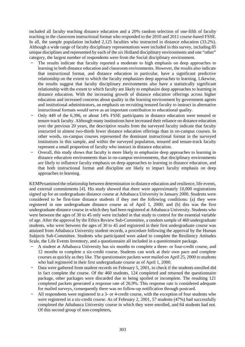
303
included all faculty teaching distance education and a 20% random selection of one-fifth of facultyteaching in the classroom instructional format who responded to the 2010 and 2011 course-based FSSE.In all, the sample population included 2,125 faculties who instructed in distance education (33.2%).Although a wide range of faculty disciplinary representations were included in this survey, including 85unique disciplines and represented by each of the six Holland disciplinary environments and one “other”category, the largest number of respondents were from the Social disciplinary environment. The results indicate that faculty reported a moderate to high emphasis on deep approaches to
learning in both distance education and classroom environments. However, the results also indicatethat instructional format, and distance education in particular, have a significant predictiverelationship on the extent to which the faculty emphasizes deep approaches to learning. Likewise,the results suggest that faculty disciplinary environments also have a statistically significantrelationship with the extent to which faculty are likely to emphasize deep approaches to learning indistance education. With the increasing growth of distance education offerings across highereducation and increased concerns about quality in the learning environment by government agentsand institutional administrators, an emphasis on recruiting tenured faculty to instruct in alternativeinstructional formats would serve as an important contribution to educational quality.
Only 449 of the 6,396, or about 14% FSSE participants in distance education were tenured ortenure-track faculty. Although many institutions have increased their reliance on distance educationover the previous 20 years, the descriptive results from the surveyed faculty indicate that facultyinstructed in almost two-thirds fewer distance education offerings than in on-campus courses. Inother words, on-campus courses represented the dominant instructional format in the surveyedinstitutions in this sample, and within the surveyed population, tenured and tenure-track facultyrepresent a small proportion of faculty who instruct in distance education.
Overall, this study shows that faculty is more likely to emphasize deep approaches to learning indistance education environments than in on-campus environments, that disciplinary environmentsare likely to influence faculty emphasis on deep approaches to learning in distance education, andthat both instructional format and discipline are likely to impact faculty emphasis on deepapproaches to learning.
KEMPexamined the relationship between determination in distance education and resilience, life events,and external commitments [4]. His study showed that there were approximately 10,000 registrationssigned up for an undergraduate distance course at Athabasca University in January 2000. Students wereconsidered to be first-time distance students if they met the following conditions: (a) they wereregistered in one undergraduate distance course as of April 1, 2000; and (b) this was the firstundergraduate distance course in which they had been registered at Athabasca University. Students whowere between the ages of 30 to 45 only were included in that study to control for the essential variableof age. After the approval by the Ethics Review Sub-Committee, a random sample of 460 undergraduatestudents, who were between the ages of 30 to 45 and registered in their first undergraduate course wasattained from Athabasca University student records, a procedure following the approval by the HumanSubjects Sub-Committee. Students who participated were asked to complete the Resiliency AttitudesScale, the Life Events Inventory, and a questionnaire all included in a questionnaire package. A student at Athabasca University has six months to complete a three- or four-credit course, and
12 months to complete a six-credit course. Students can work at their own pace and completecourses as quickly as they like. The questionnaire packets were mailed on April 25, 2000 to studentswho had registered in their first undergraduate course as of April 1, 2000.
Data were gathered from student records on February 5, 2001, to check if the students enrolled didin fact complete the course. Of the 460 students, 124 completed and returned the questionnairepackage, other packages were discarded due to being spoiled or incomplete. The resulting 121completed packets generated a response rate of 26.9%. This response rate is considered adequatefor mailed surveys, consequently there was no follow-up notification through postcard.
All respondents were registered in a 3- or 4-credit course, with the exception of four students whowere registered in a six-credit course. As of February 2, 2001, 57 students (47%) had successfullycompleted the Athabasca University course in which they were enrolled, and 64 students had not.Of this second group of non-completers,
304
(a) 38 did not begin work on their course,(b) 19 withdrew from their course, and(c) 7 received an academic failing grade.
Figure 1 Sample population distribution
None of the students registered in a six-credit course completed their course; three did not initiatework on their course and one withdrew from the course. More than half of the students in the non-completer group (53%) had previously taken a distance course. For the most part, externalcommitments—in the form of personal, family, home, financial, and community commitments—were not found to be significant interpreters of persistence (or lack of persistence) in distanceeducation.
In other words, students with high levels of commitments in these areas were no more or less likelyto complete their Athabasca University course successfully, in comparison to students with lowerlevels of commitments in these areas.
This study contributes to the field of inquiry relating to persistence in adult distance learning byproviding insight into the resilience skills employed by adult students who successfully completedtheir first course at Athabasca University. The field is widened to include better predictors of adultstudent persistence. Additionally, this study adds to the understanding of the application andlimitations that prominent theories of persistence have in relationship to distant learner populations.Finally, the results provide practical efficacy by offering an evaluation guide for distance educationinstitutions to respond more effectively to the needs of adults. The study may help adult students,faculty, and administrators better understand persistence and dropout in undergraduate distanceeducation.
Undergraduate studentsbetween ages of 30 - 45
Completed and returned thequestionnaire package(26.9%)
Completedpackets(97.5%)/ (26.3% of total)
Didn’t completed the coursesuccessfully(52.8%)/ (13.9% of total)
Completed the course successfully(47.2%)/ (12.4% of total)
Didn’t beginwork on theircourse (59.4%)/(8.2% of total)
Withdrew fromtheircourse(29.7%)/(4.1% of total)
Received anacademic failinggrade (10.9%)/(1.5% of total)
305
5. Conclusion:
This paper illustrates seafarers’ problem regarding certificate renewal and upgrading necessary for theircareer development. This requires them to attend courses on-campus, resulting in loss of time andexpenses for course fees, transportation and accommodation for those who leave away from the campus,which is sometimes in a different city or even country. Thus, the suggested solution to this problem liesin DL, since the other solution of CBT is impossible, as it is not recognized by the authority. DL can beused, as it is also recommended by the IMO.
To make sure of the results of using DL as a solution for seafarers in Egypt two case studies have beendiscussed and results of both are recognized, which proves that using DL in both cases was a bettersolution. However, a limitation of the present research is that it does not include a case study forseafarers, as no relevant studies were found in the maritime field. Similarly, it does not include statisticsin Egypt or in the maritime field, which will be undertaken by the researcher in future studies.
References:
[1] Bucci, David Andrew (2014). Distance Education, Disciplinary Environments and Deep Learning:A Quantitative Exploration of Faculty Instruction. (Doctoral dissertation). North Carolina StateUniversity. Raleigh, North Carolina.
[2] IMO, (2000). The role of IMO in harmonizing the shipping industry. Accessed on Nov. 2014 from:http://www.imo.org/blast/mainframe.asp?topic_id=83&doc_id=369
[3] IMO, (2014). International Convention on Standards of Training, Certification and Watchkeepingfor seafarers (STCW). Accessed on Jan. 2015 from:http://www.imo.org/about/conventions/listofconventions/pages/international-convention-on-standards-of-training,-certification-and-watchkeeping-for-seafarers-(stcw).aspx
[4] Kemp, Wendy (2001). Persistence of Adult Learners in Distance Education. (Master dissertation).Athabasca University. Athabasca, Alberta.
[5] Moore, M. G., (1990). Contemporary issues in American distance education. New York: Pergamonpress.
[6] Moore, M. G., &Kearsley, G. (2011). Distance education: A systems view of online learning.Wadsworth Publishing Company.
[7] Perraton, H. (2000). Open and distance learning in the developing world. London: Routledge.[8] Quality, Interoperability and Standards in e-learning (QUIS), (2004). Cost Effectiveness and Cost
efficiency in e-learning. Borje Hansson, Mid Sweden University.[9] UNESCO, (2002). Open and Distance Learning: Trends, policy and strategy considerations: Paris.
UNESCO[10] Wedemeyer, C.A., (1981). Learning at the back door: Reflections of nontraditional learning in the
life spam. Madison, W.I. University of Wisconsin press.[11] World Bank, (2002). Constructing Knowledge Societies: New challenges for tertiary education.
Washington, D.C.: World Bank.

306

307
Session 3B
HUMAN RESOURCHES&
CULTURAL AWARESS
308
Opportunities and advantagesfor oversea seafarers human resources development in Vietnam
Dinh Xuan Manh1, Dao Quang Dan2
1Vietnam Maritime University, Professor, Captain, Vice-Rector, [email protected] Faculty, Vietnam Maritime University, [email protected]
Abstract: Despite of the increasing demand of seafarer markets in the world particular in Northern EastAsia, Singapore, European countries…, the annual number of Vietnamese exported seafarers has justfluctuated around 2,500 per year over last 20 years. It is the modest amount compared to Vietnamesepopulation and potential. There are a lot of limitations, difficulties and challenges in exportingVietnamese seafarers.
This paper presents fundamental problems and challenges. However, apart from these difficulties andchallenges, Vietnam has many advantages in developing labour resource for exporting Vietnameseseafarers to the world labour market. Vietnam should take these advantages to overcome challenges anddilemmas, otherwise these problems would turn into long–term problems which are really hard torecover. This paper will focus on analyzing opportunities and advantages of Vietnam in developinghuman resource for exporting seafarers.
Keywords: human resource, seafarers, seafarers export, opportunities, advantages, limitations,challenges, STCW78/2010.
1. Introduction
Many researches, analysis which have been carried out by individuals, prestigious organizations in theworld maritime industry showed a serious concern related to the severe shortage of seafarers in theinternational seafarers market, especially officers at present and in the future. [1],[2],[3],[4],[5].
In Asia, ASEAN is the large labour resource providing a considerable amount of seafarers to theinternational seafarers market at present and in the future. There are many similar features between thetwo ASEAN members, Vietnam and Philippines, such as population, GDP, economic-socialdevelopment rate…. However, while Philippines occupies the biggest amount of exported seafarers overthe world, Vietnam, with many remarkable advantages in comparison to other countries in the region,consisting such as the crucially strategic location; the golden population structure is predicted to last innext 20 years (the population in Vietnam is 91 millions) and Vietnamese young seafarers desire to workfor the international prestigious shipping companies, particularly working onboard ships of large fleetsin developed maritime countries…, has exported 2500 to 3000 seafarers annually over last 20 years, aquite modest quantity compared with its potential.
Meanwhile, the quality of management and operation in Vietnamese shipping companies are limitedwith many weakness and shortcoming. Additionally, these shipping companies suffered from incomelosses, decreasing scope of business, even bankrupt due to economic crisis in recent years. Theseproblems which led to low salary, long-term delayed payment as well as poor compensation to seafarers.The above-mentioned reasons result in increasing significantly the number of seamen who want toabandon their career and the quality of seafarers is decreasing.
However, by ratifying and implementing MLC 2006 showed the determination of Vietnamesegovernment in developing seafarers resource and Maritime Transportation Industry.
Promoting seafarers export is really a right policy because, firstly, it will create more job opportunities,improving economic-society condition and building up Vietnamese seafarer trade mark in the
309
international seafarer labour market; secondly, it plays very important role in improving not only thequality of Vietnamese seamen but also maritime transportation in Vietnam.
Vietnamese seafarers basically can meet all international ship-owners’ requirements because they aretrained, well educated and certificated in accordance with STCW 78/2010 standards. However, themajor reasons that the number of Vietnamese exported seamen is quite small and much lower than itspotential are the cutthroat competition from opponents when Vietnam merges deeply and widely intothe international economy, and on the other hand the Vietnamese seafarers is not so qualified.
Therefore, it is completely necessary and practical to study the potential of Vietnam in order to turn thepotential into opportunities and advantages in intensifying seafarers export issue.
2. SWOT Analysis
2.1. Strengths
- Vietnam in general and costal cities in particular are with abundant labour resources which meet notonly the demand of socio-economic development but also the demand of supplying overseas labourincluding seafarers.
- With young age structure and with tradition of hard-working and inquisitiveness, Vietnamese labourwill have abilities to meet the special requirements of exported seafarers at a large quantity if they areeducated and trained properly.
- The economy tendency of shifting to service operation in many regions in Vietnam releases a largeamount of agriculture labour that would be reserve labour force for seafarers resource as well as overseassafarers. Higher salary for seamen working for international shipowners in comparision to those workingfor domestic shipping fleet or those working in other careers is an advantage and a strong point inattracting and developing overseas seafarers.
- Management system, policies system which support in developing seafarers resource and MaritimeEducation Institutes, Maritime Training Centers has been completed and will promote its ability in thestage of developing.
- Vietnamese seamen has mastered smoothly huge vessels owned by international shipowners includingHandy size, Panamax, Capsize size vessels. The number of seafarers working onboard these ships isincreasing, even there are crews who works onboard these vessels are all full Vietnamses. This is a clearaffirmation that Vietnamese seafarers have sufficient ability and qualification to master almost vesselswith different types and sizes at the international level.
- Generally, Vietnamese seafarers are good at accquiring specialized knowledge and foreign languagequickly, and they are easy to merge with a multinations crews.
- Vietnamese students in general and maritime students in specific are men of intellect, intelligent, eagerto learn, especially always desire to master new cutting edge technologies.
2.2. Weaknesses
- The weakest point as well as the biggest challenge in exporting seafarers in Vietnam is the low-qualityseamen, the unprofessional behaviour leading to low competition ability. The reason for this problemobviously is that the relation between quantity and quality of Vietnamese seafarer is not inadequate.
310
- Almost offices at different management levels in maritime industry in Vietnam, Maritime TrainingCenter as well as crew manning companies/agencies have not built up a strategy for expanding exportedseafarers.
- Awareness of the role of exported seamen resource in the national economy falls short of expectations,even in the maritime filed, this role is not properly considered. In addition, crew manningcompanies/agencies have not paid much attention to training and providing further training for seamenworking overseas. It can be clearly seen that the issue of increasing seafarers resource for exportinghasn’t been mentioned in developing plans or strategies.
- Vietnam hasn’t made specified policies for developing export seafarers resource including a policy ofoverseas seafarers education, recuirtment and an other of encouraging to expand export seamenresources.
- Governmental officies, minitries, policies system haven’t proven their roles in developing exportseafarer resources.
- The domestic business environment is facing with a lot of difficulties. The Vietnam legal system ingeneral and shipping sectors in particular have not been fully sufficient to cover all operation in maritimeand shipping industry..
- Several Maritime Education Institutes, Maritime Traning Centers (MTCs) are small-scale ones, poorlyequiped training facilities and the quality of education and training is not really good. These things leadsto different education and training qualities among Maritime Education Institutes, MTCs in Vietnam.
- Most of Maritime Education Institutes, Maritime Training Centers haven’t any plan to train and educateseafarer according to international shipowners’ requirements.
- An other considerable concern is that the financial capital for expanding export seafarers resource isquite limited.
- The shipowners’ roles is underestimated, a larger proportion of shipowners haven’t participated intraning and educating human resource for overseas seafarers and they also haven’t made any plans forimproving their overseas seamen.
- Problems such as poor financial capacity, poor management, unprofessional working manner, pooradvertisement and negotiation with foreign shipowners… are challenges that many crew manningcompanies/agencies deal with. In particular, they don’t have any strategies to enchance the competitionability. These weakenesses results in the crew manning companies/agencies’ ability of integrating intothe international seafarers supply chain is restricted. Furthermore, the mentioned weaknesses could leadthese companies/agencies to the limitations in the international integration mind.
- Vietnamese seamen’s discipline, working skills and English ability are not really good, especially theworking manner and attitude are not as professional as seamen from Philippines, India… To solve thisproblem, it will need to renovate training and education works
- Vietnam haven’t had its own Seafarers Association
- Crew manning companies/agencies have limitation in consolidating and expanding the seafarers exportmarket. They are in experienced and don’t pay much attention to advertising and creating theirtrademarks in the dosmestic and international markets. Since these Vietnamese companies/agencieshaven’t got any supports to promote their trademarks in overseas markets, it is quite difficult for themto approach the reputable foreign shiponwers.
- Finally, the information system of seafarers market has remained many weakenesses and restrictions.
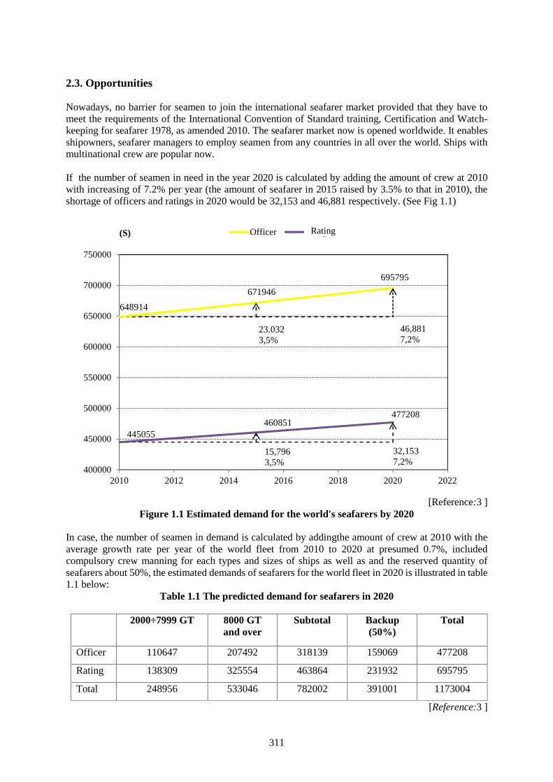
311
2.3. Opportunities
Nowadays, no barrier for seamen to join the international seafarer market provided that they have tomeet the requirements of the International Convention of Standard training, Certification and Watch-keeping for seafarer 1978, as amended 2010. The seafarer market now is opened worldwide. It enablesshipowners, seafarer managers to employ seamen from any countries in all over the world. Ships withmultinational crew are popular now.
If the number of seamen in need in the year 2020 is calculated by adding the amount of crew at 2010with increasing of 7.2% per year (the amount of seafarer in 2015 raised by 3.5% to that in 2010), theshortage of officers and ratings in 2020 would be 32,153 and 46,881 respectively. (See Fig 1.1)
[Reference:3 ]Figure 1.1 Estimated demand for the world's seafarers by 2020
In case, the number of seamen in demand is calculated by addingthe amount of crew at 2010 with theaverage growth rate per year of the world fleet from 2010 to 2020 at presumed 0.7%, includedcompulsory crew manning for each types and sizes of ships as well as and the reserved quantity ofseafarers about 50%, the estimated demands of seafarers for the world fleet in 2020 is illustrated in table1.1 below:
Table 1.1 The predicted demand for seafarers in 2020
2000÷7999 GT 8000 GTand over
Subtotal Backup(50%)
Total
Officer 110647 207492 318139 159069 477208
Rating 138309 325554 463864 231932 695795
Total 248956 533046 782002 391001 1173004
[Reference:3 ]
648914
671946
695795
445055460851
477208
400000
450000
500000
550000
600000
650000
700000
750000
2010 2012 2014 2016 2018 2020 2022
(S) Officer rating
23.0323,5%
46,8817,2%
15,7963,5%
32,1537,2%
Rating
312
With above figures, it can be clearly seen that Vietnamese seafarers export has great opportunities todevelop.
According to many researches as well as the facts, the source of seafarers supplying to internationalseafarers market in the future would come predominantly from Asian countries, especially ASEANcountries. Besides cheap labour cost, those seamen who comes from East and South East Asia havegood relations with countries that having long developed-history of maritime industry.
Several foreign markets and shipowners always give priorities to Vietnamese seafarers in comparisonto other countries in region. For example, Japanese shipowners have been attracting a large amount ofVietnamese seamen.
Maritime Labour Convention (MLC) 2006 took effective as from 20th August 2013. This conventionguarantees that every seaman who works onboard ship would have a satisfied living and workingenvironment regardless of their nationality and ship’s flag nationality. With a better working and livingcondition, especially more adequate salary, it is believed that education and training seafarers forexporting would have been developed significantly.
Furthermore, seaman unions in all developed maritime countries are members of the InternationalTransport Workers’ Federation (ITF). Thus, Vietnamese seafarers working onboard vessels which areregistered in these countries will receive not only high salary but safer working and better livingenvironment as well.
Vietnam has good opportunities to approach to many internationally potential markets for deploymentseafarers without discrimination.
As a contracting party to many IMO conventions and integrating into many agreements, Vietnam has tocomplete it’s legal system with market mechanism orientation and perform them effectively.
Vietnam is equal with other countries on drawing up their global trade policies and for a more equitableand rational economy order. Vietnam has to protect benefit of country, companies and seafarers.
By merging into world economy which improves the domestic economy reform and process of economicreform in Vietnam is more comprehensive and effective.
By contracting and approving many international trade agreements which has lifted Vietnam to a newlevel in the world and it enables Vietnam to execute it’s foreign policy effectively.
Besides, this could create more jobs with appropriate salary to Vietnamese seafarers who are sufferingfrom the economic crisis as the domestic sea transportation is dealing with a lot of difficulties.Meanwhile, the international seafarers resource is seriously insufficient, particularly officer positions.We should take full advantage of this opportunity in order to strongly step up seafarers export issue.
2.4. Threats
Threats in developing seafarer export that Vietnam has faced with are really major issues. The threatscan be mentioned as below:
First of all, at present and in the future, all countries in all over the world, especially developed ones aregiving priorities to professions that require high qualified labour resources. This will result in differencesbetween demands for labour recruitment. This trend also occurs in marine transportation, seafarersshould be high qualified and skilled in order to master the up-to-date technologies [6] that areincreasingly applied in the shipping industry. Competition in the seafarer export market will be keener,with various competitors in wider and deeper scale.
313
Second, Vietnamese crew manning companies/agencies are in small scale, therefore, it is quite difficultfor them to deploy Vietnamese seafarers abroad deeply and widely. This makes Vietnamese crewmanning companies/agencies unstably and unable to control the seafarers market. Furthermore, theirmanagement ability is really not so good which results in low competition of Vietnamese seamen,especially it could be more difficult when merging into the international economy.
Third, almost Vietnamese crew manning companies/agencies haven’t had a sufficient preparation beforesigning a contract. They haven’t anticipated all problems that might occur in performing the contracts.They have been lack of knowledge in terms of international shipping laws and practice. Therefore theyhaven’t been prepared well in advanced for any internationally commercial claims or disputes. On theother hand, legal consultant service has not been used often. This leads to many difficulties anddisadvantages, even loss for Vietnamese crew manning companies/agencies if any international claimsor disputes occur.
Fourth, dispite Vietnamese economy has deeply and widely integrated into the global economy andsigned many international commercial agreements such as FTA, TPP, AEC…, many crew manningcompanies/agencies have low financial ability, small scale business, unprofressional and poormanagement and haven’t made a strategy to improve their competition when they take part in the globalseafarers supply chain. Because of limitations in ability and strategy, Vietnamese crew manningcompanies/agencies will deal with many challenges in competiton in the global market, even lose inVietnamese market.
Fifth, the thought of sea carrier as only a short-term carrier is quite popular among Vietnamese seafarers.Many seafarers consider this sea career is just a temporary job so they just complete their worksindifferently without progressive attitude. Some of them don’t have any plans to elevate theirprofessional knowledge and foreign language to enhance their seafarer skills while the requirements formaritime safety and security, and marine environmental protection applied to seafarers are increasingseverely.
Sixth, increasing modernization and globalization in the maritime industry requires seafarers to owngood specialized knowledge, working at sea experience, foreign language (English), good physicalcondition and professional manner. However, seafarers from Vietnam are just good at theory only, theirworking skills, English ability and physical strength are not as good as seamen’s from India,Phillipinnes…
Seventh, the growth of Vietnam econimic has improve living standard. Seafarers job is not much a high-paid jobs in comparing to other jobs ashore. A quite large quantity of experienced seafarers includingofficer at management level resign from this career and looks for suitable jobs ashore.
Eight, the overwhelmed factors of Vietnamese seamen in competition with other countries such as cheaplabour cost… no longer exist. Vietnam now have to encounter serve competitions from Philipines, Indiaand some raising countries which have numerous seamen resource, are well-qualified, highly-disciplined and are willing to receive a competitive salary.
Ninth, due to the growth rate of the domestic shipping fleet, the demand of seafarers is rasing. This leadsto the shortage of high quality seafarers, especially officers at management level for exporting.
Finally, the demand of transportation including maritime one begins to surge due to the global economicrecovery. After a time of reducing the fleet, shipowners have started to recruit more highly qualifiedseafarers for further development.
2.5. Building combined strategies S-W-O-T
314
Combination between Strengths and Opportunities: With inherent strengths particularly young working-age population, inquisitiveness, harmony, and a part of Vietnam seafarers has good experiences, hasproved their ability in operating many different types of extremely large vessels including ones ownedby international shipowners. Besides, the numbers of seamen who had been trained and educated is quitelarge so it could provide for the global seafarers market a large amount of seafarers after a short time ofretraining. Furthermore, the desire of working for famous and prestigious shipowners that have strongattraction to Vietnamese seafarers would last for a long time, at least over decades.
If Vietnamese seafarers force are properly oriented and invested, they will take this opportunitieseffectively for developing the export seafarer resource quickly in order to meet the quality and quantityof the international seafarers market demand. To achieve this goal under the condition of strength andadvantage mentioned above, both Vietnamese crew manning companies/agencies and seafarers need tostrengthen their position in the traditional markets as East-Northern Asia, Singapore, then expand to thepotential markets including Europe, North America.
Combination between Weaknesses and Opportunities: All Maritime Education Institutes, MaritimeTraining Centers, crew manning companies/agencies and Vietnamese seafarers always eager tocooperate with international reputable shipowners. These advantages will create a new direction forVietnamese seafarers and this tendency also help crew manning companies/agencies’ and maritimeofficies’ operation to be more professional as well seafarers will gain better reputation. Although allcrew manning companies/agencies and seamen are willing to cooperate with foreign shipowners, theyhaven’t well prepared in every aspects for a good cooperation results. If Vietnamese government and itsdepartments take full advantages of these opportunities to issue policies and to models supporting fortraining and exporting seafarers, eliminate unprofessional factors in the seafarers supplying chainoperation, invest more money to enhance the human resource quality, it would be believe thatweaknesses could be minimized and no longer exist.
Combination between Strengths and Threats: Any labours including overseas seafarers always considertwo sides of the same coin when they made their decision to be a seafarer. They have to think aboutwhether the amount of money that they earn could be enough to afford their family’s life after resigningfrom this career and whether this amount of money is better than that they could earn by doing otherjobs. With strengths, Vietnam will build up a model of export seafarers with good salary andcompensation which makes seafarers satisfied and attract more young and high qualification seafarersto join export seafarer market. Apart from salary, compensation and allowance…that are provided bythe international shipowners, Vietnamese government also need to issue preferential policies toencourage overseas seafarers. If these things could be done, it is ensure that seafarer export work wouldbe able to overcome all risks. Since, according to income and currently average development rate,attraction of working for international famous shipowners to Vietnamese seamen would last in at leastseveral decades.
Combination between Weaknesses and Threats: In progress of developing and integrating into worldshipping, it can’t avoid elimination. Maritime Education Institutes Maritime Training Centers, crewmanning companies/agencies, and seafarers that are at low quality and poor competition will beeliminated. Vietnamese organizations, crew manning companies/agencies and seafarers need to awareclearly of this because joining the international market means that competitions with many rivals frommany regions in the world not only from Vietnam.
In spite of abundant number of seafarers and good qualification, Vietnamese seafarers are not so atunprofessional manner which is represented by skills and working-attitude. Vietnamese seafarers’working attitude and attitude towards shiponwers is not really good. Because of skills, especiallyattitudes, the quality of Vietnamese seamen is not high, just stopping at a passing-level. To meet therequirements of foreign shipowners, it is essential to set up inadequate mind and attitudes towardsshipowners and operators among seafarers. Seamen must recognizes that their benefits and rights areattached closely to that of shipowners, operators. They should consider vessels as their own house.
315
Vietnamese seafarers’ low awareness and attitude are at restriction in their perception. To createoverseas seafarer force which could satisfy foreign shipowners’ requirements and prove Vietnameseseafarers’ trademark in the global market, it is necessary for Maritime Education Institutes especiallyMaritime Training Centers and Crew manning companies/agencies to reform training and educationsyllabus in order to enhance seafarers’ professional manner and improve their onboard working skillsand attidutes. Establishing an internationally professional mind in seafarers’ thought will overcomeweakness, control threats and finally improve strengths.
3. Advantages in developing seafarer resource for exporting in Vietnam
Apart from mentioned strengths and opportunities, Vietnam is holding unique overwhelmed factors indeveloping overseas seafarers recource that can’t be found in other countries.
3.1. Geographical location of Vietnam
At location of the west of Eastern Sea, with more than 3,260 km coastline, Vietnam is contiguous toseas in the East, South and South West, from Mong Cai in the North to Ha Tien in the South West. Theexpanded area to the East and South East in the East Sea which belongs to Vietnam’s sovereign. It hascontinental shelf, islands and archipelagos. Vietnam also has sea area of more than 1,000,000 squaremeter with it’s sovereign, sovereign right and jurisdiction. The sea area is 3 times bigger than land area.Additionally, the Eastern Sea is an important sea area with a strategic location of region and in the world.where main shipping routes passing through with the goods value of 5,000 billion USD transportedannually. Eastern Sea have played an important role in developing strategy of the East Sea countries aswell as other powerful maritime countries in the world.
Every year, about 70% of imported oil and 45% of exported commodities in Japan; about 60% ofimported-exported goods in China have been carrying through this route. Especially, Singaporeeconomy mostly depends on the Eastern Sea.
3.2. Golden population
According to Vietnamese Statistic Directorate, as of 01/01/2016, Vietnamese population is in “goldenperiod”. The workforce aged 15 years old and above is 54,61 million which was 185,000 people higherthan that in the same period of 2014, consisted of 51.7% male, 48.3% female. Vietnam is one of countrieshaving the youngest population in the world, the workforce aged 15-39 years old is 51.0% including26,7% in group aged 15-29 and nearly 15% in group aged 15-24 [4]. This group is believed to be highlypotential to learn new knowledge and skills in order to be high quality workforce.
3.3. Political issue
Vietnam is a country which is always has a good stability in politics- society. It is the essential factor tohelp Vietnam being consistent with economic developing policy and having a long lasting peace.Meanwhile, most countries in ASEAN, except Singapore, have dealt with many political problems thatcaused serious loses in economy of these countries. It is, therefore, obviously that Vietnam’s stablepolitics is a great guarantee for remarkable success in process of reforming in Vietnam.
3.4. The Vietnam young workforce
With hard-working, studiousness, enthusiasm and ambition, Vietnamese young generation is now quitewilling to take risks to learn and start new things.
Vietnamese workforce and seafarers are highly competent to meet strict requirements given byinternational employers as well as shipowners when Vietnam is merging widely and deeply into globaleconomic community. This is clearly proven by impressive performances of Vietnamese seafarers on
316
huge vessels and number of Handymax, Panamax and Capsize vessels with full Vietnamese crew isincreasingly significant.
Vietnamese seafarers have ability to learn new professional knowledge, foreign languages, and to adaptthemselves to be harmony with other seafarers who come from different countries and have differentcultures. All things they need to do now is being confident to learn and use the existing potential whichmaritime education and training centers provide and to gain necessary knowledge to prove thatVietnamese seafarers would be able to compete against with other countries in seafarer market.
It is used to say that the cheap labour cost of Vietnamese seafarers was one of competitive factors.However, it is no longer suitable nowaday. Vietnam is now competing against with countries whichhave good reputation in maritime field such as Philippines, India. Furthermore, seafarers coming fromChina and Myanmar who could provide the international labour market with skilled, disciplined andlow cost seafarers are raising as remarkable rivals. For these reasons, Vietnam should uphold its inherentadvantages so called inner ability which is existing in each Vietnamese seafarer. Inner ability factor,creativity and adaptability, optimist that are typical characteristic of Vietnamese.
Nowadays, in Vietnam, not only students who just graduate from Maritime Universities or Colleges butalso experienced and skillful seafarers desire to work for foreign shipping companies and shipowners.According to the survey carried out by group of researchers in Vietnam Maritime University, MaritimeCollege No.1 and other Maritime Training and Education units, all students and learners really want towork onboard vessel owned by prestigious foreign shipowners after graduating because of deservedsalary, professional working environment, and equitable in evaluating their performance and inpromoting. Maritime students, who are well trained and educated, eager to study new cutting-edgetechnologies. They would be optimize their ability when working in professional environment.Therefore, all students who just graduated from Maritime Universities or Colleges, desire to work inprofessional and disciplined working environment in the beginning of their career. This will give themgood opportunities to practice what they have studied and to gain valuable experiences, knowledge andreceiving good salary deserved to their effort.
There is a trend now in Vietnam economy that service sectors are increasing. This release a large amountof labours from agriculture which is a good reserved workforce source for exporting seafarers. Seafarerworking overseas or for foreign shipowners would get higher payment to those one working on boarddomestic vessels. This is really a great advantage to attract more and more labour for exporting seafarers.
4. Conclusion
By making use of opportunities and advantages to overcome difficulties, challenges toward to furthersuccesses, Vietnam is completely able to be a major seafarers supplier to the international seafarersmarket. Otherwise these advantages will be passed and these obstacles would grow up and become long-term problems that it would be very difficult to recover. Vietnam used to miss these opportunities andmight miss once again a good chance to create jobs for young and intelligent labour who is willing tobe trained and educated to become high quality labour. The period of golden population will last 25years, and then Vietnam will be entering the period of the old population. Therefore, if Vietnam makesuse of these opportunities effectively, it will have sufficient accumulation for social security to meet theincreasing demand when the population gets old. Conversely, Vietnam will deal with many difficultiesand challenges when the golden population opportunity ends and the old population period begins.
Developing the Vietnamese seafarers resource for exporting will play crucial part not only in enhancingthe quality of Vietnam seamen but also in developing a sustainable sea transportation industry inVietnam in accordance with deeply and widely merging into the international economy.
Opportunities and advantages in exporting Vietnamese seafarers are scientifically analysed which willenable Vietnam to build up a strategy for improving seafarer export resource. Furthermore, theseanalysis help seafarer employers, particularly international shipowners have reliable information to
317
evaluate situation and to make decisions on investing in the potential Vietnamese seafarers market inorder to solve the problem of seafarer shortage effectively, economically and sustainably.
References
[1] Branislav Ćorović, Sanela Pejaković-Kovačević, Senka,Šekularac - Ivošević: “Analysis of RecentSupply and Demand of Educated Seafarers in Montenegro and Worldwide”. Transactions OnMaritime Science. 2012
[2] Study on EU Seafarers Employment, Final Report, European Commission, May 20th 2011.[3] Japan International Transport Institute and The Nippon Foundation, “Future Global Supply and
Demand for Seafarers and Possible Measures to Facilitate Stakeholders to Secure a Quantity ofQuality Seafarers”. May 2010.
[4] General Statistics Office of Viet Nam[5] https://www.bimco.org/[6] Lloyd’s Register, QinetiQ and University of Southampton. Global Marine Technology Trends
2030. First Printed: August 2015
318
Language Barriers, Cultural Differences and International Cooperationbetween Maritime Institutions
Professor Qi Chen, Ph.D
Massachusetts Maritime Academy, 101 Academy Drive, Buzzards Bay, MA, [email protected]
Abstract. For eight years, the Massachusetts Maritime Academy (MMA) of the USA has beenengaging in a student exchange program with the Shanghai Maritime University (SMU) of China, andlater, in 2013, extending it to the Dalian Maritime University (DMU) of China. The MMA-SMU/DMUexchange program, conducted in two countries which differ greatly in culture, history, economicsystems, social values and government structures, has become a huge success, and is greatly applaudedby the faculties, administrators, students, and other maritime institutions. Almost 300 students from bothsides have participated in the program and nearly all have demonstrated a strong capability to overcomethe language barriers, adapt to the new environments, achieve hugely in the job market and theirsubsequent career development.
This paper presents an empirical analysis of what accounts for the success of the exchange program,how the participating students outperform in the international programs and their subsequentachievements in the job market. Applying a case-study methodology, drawing on the school-widesurveys and the data collected over the course of eight years, this paper examines how the setup of theMMA-SUM/DMU exchange program helps students overcome cultural shock, promotes languageproficiency and fosters leadership qualities. The findings indicate that the culturally sensitivearrangements of the program, such as the rooming of a visiting cadet with one from the home school,and the free selection of classes at the host institution, play a crucial role in its continuing success.Further, the findings suggest that the program has been very effective in helping the participating cadetsenhance their self-confidence, broaden their global visions and adapt to new environments with easeand grace. And the school–wide cultural awareness and job market success motivates more cadets toparticipate in the MMA-SMU/DMU exchange programs.
The successful experiences of the MMA-SMU/DMU program are applicable not only to the maritimeuniversities of the USA and China, but also to similar institutions located in other culturally diversecountries, like the UK and Vietnam. When the participating cadets prove that they can survive andperform well in two completely different cultures, they demonstrate that they have acquired thenecessary and sufficient skills to be successful within any type of job they are offered. And this is exactlywhat potential employers are seeking of all graduating maritime cadets nowadays.
With the on-going development of the exchange program and the availability of additional data, morerigorous statistical analysis could be applied to the research, generating more significant conclusions.To do so would unquestionably help further enhance the MMA-SMU/DMU exchange program.
Keywords: International programs between maritime institutions, Cross-cultural education, Culturaladaptability, Language proficiency.
1. Introduction
Since the spring term of 2009, the Massachusetts Maritime Academy (MMA) of the USA has beenengaging in a student exchange program with the Shanghai Maritime University (SMU), and later, in2013, extending it to the Dalian Maritime University (DMU) of China. The MMA-SMU/DMU exchangeprogram has been conducted in two countries which differ greatly in culture, history, economic systems,social values and government structures, it imposes a huge challenge for the participating students tosurvive and be successful. Nevertheless, it has been well proved that MMA-SMU program providedstudents with strategies to move from shock to cross-cultural adaptability, which in turn, will make the
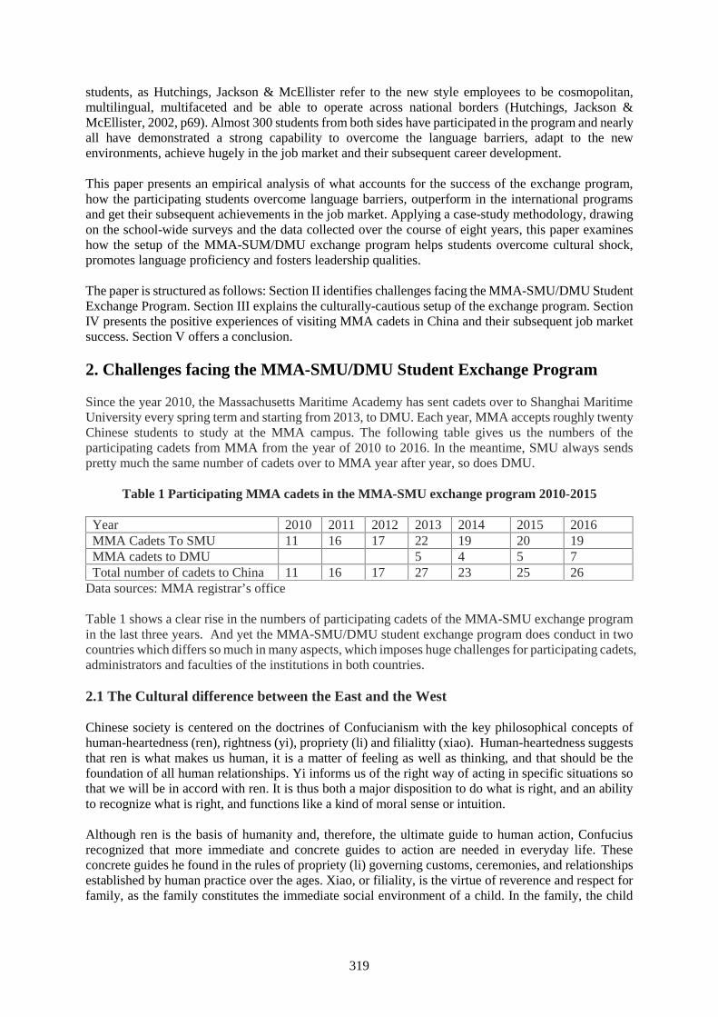
319
students, as Hutchings, Jackson & McEllister refer to the new style employees to be cosmopolitan,multilingual, multifaceted and be able to operate across national borders (Hutchings, Jackson &McEllister, 2002, p69). Almost 300 students from both sides have participated in the program and nearlyall have demonstrated a strong capability to overcome the language barriers, adapt to the newenvironments, achieve hugely in the job market and their subsequent career development.
This paper presents an empirical analysis of what accounts for the success of the exchange program,how the participating students overcome language barriers, outperform in the international programsand get their subsequent achievements in the job market. Applying a case-study methodology, drawingon the school-wide surveys and the data collected over the course of eight years, this paper examineshow the setup of the MMA-SUM/DMU exchange program helps students overcome cultural shock,promotes language proficiency and fosters leadership qualities.
The paper is structured as follows: Section II identifies challenges facing the MMA-SMU/DMU StudentExchange Program. Section III explains the culturally-cautious setup of the exchange program. SectionIV presents the positive experiences of visiting MMA cadets in China and their subsequent job marketsuccess. Section V offers a conclusion.
2. Challenges facing the MMA-SMU/DMU Student Exchange Program
Since the year 2010, the Massachusetts Maritime Academy has sent cadets over to Shanghai MaritimeUniversity every spring term and starting from 2013, to DMU. Each year, MMA accepts roughly twentyChinese students to study at the MMA campus. The following table gives us the numbers of theparticipating cadets from MMA from the year of 2010 to 2016. In the meantime, SMU always sendspretty much the same number of cadets over to MMA year after year, so does DMU.
Table 1 Participating MMA cadets in the MMA-SMU exchange program 2010-2015
Year 2010 2011 2012 2013 2014 2015 2016MMA Cadets To SMU 11 16 17 22 19 20 19MMA cadets to DMU 5 4 5 7Total number of cadets to China 11 16 17 27 23 25 26
Data sources: MMA registrar’s office
Table 1 shows a clear rise in the numbers of participating cadets of the MMA-SMU exchange programin the last three years. And yet the MMA-SMU/DMU student exchange program does conduct in twocountries which differs so much in many aspects, which imposes huge challenges for participating cadets,administrators and faculties of the institutions in both countries.
2.1 The Cultural difference between the East and the West
Chinese society is centered on the doctrines of Confucianism with the key philosophical concepts ofhuman-heartedness (ren), rightness (yi), propriety (li) and filialitty (xiao). Human-heartedness suggeststhat ren is what makes us human, it is a matter of feeling as well as thinking, and that should be thefoundation of all human relationships. Yi informs us of the right way of acting in specific situations sothat we will be in accord with ren. It is thus both a major disposition to do what is right, and an abilityto recognize what is right, and functions like a kind of moral sense or intuition.
Although ren is the basis of humanity and, therefore, the ultimate guide to human action, Confuciusrecognized that more immediate and concrete guides to action are needed in everyday life. Theseconcrete guides he found in the rules of propriety (li) governing customs, ceremonies, and relationshipsestablished by human practice over the ages. Xiao, or filiality, is the virtue of reverence and respect forfamily, as the family constitutes the immediate social environment of a child. In the family, the child
320
learns to respect and love others, first parents, brothers and sisters, and relatives, then, by gradualextension, all humankind.
Those philosophical concepts evolve into the four basic principles of traditional Chinese cultures: unitybetween nature and human, people oriented, vigorous and promising, harmony and neutralism. And thefour basic principles decree people to follow the doctrine of Golden Mean, requiring people to live bythe felicitous middle between the extremes of excess (too much) and deficiency (too little). What liesthe proper distance between these extremes is believed leading to a personal embodiment of virtue andresulting in a well-ordered society.
Hugely influenced by the Chinese value system, the participating Chinese students demonstrate, like allthe other Chinese, characteristics of collective-oriented, hierarchical and high-uncertainty- avoidantsociety, such as pursuing the success and well-being of the larger group rather than individual benefit,interdependence rather than independence, valuing long-term social relationship rather than short-termaccomplishments, modesty rather than insolence, diligence rather than indolence, respect for authority,elderly and superior, discouragement of conflicts, greater fear of failure and risk taking.
On the other hand, the western culture is centered upon the principles of freedom, liberty and equality.It emphasizes the worth and dignity of individual activities and personal success, encourages risk-takingbehavior and change, value autonomy and independence, fewer social obligations, confrontation beingacceptable, delegation of authority and minimum deference for superiors. Therefore, it is well expectedthat the Chinese exchange students, coming from such a different cultural background and being blendedinto the new environment in a swift period of time, would unavoidably experience a “culture shock”when collectivism, familism and hierarchy of the East meet with individualism, rationality andsecularism of the West.
The term culture shock was first introduced by anthropologist/economist Kalervo Oberg (1960) as a"disease" suffered by individuals living in a new cultural environment. According to Oberg, cultureshock resulted from the loss of well-known cultural signs and symbols, causing individuals to experienceanxiety, frustration, and helplessness. To be aware of the stress and difficulties cultural differences mightimpose on the participating Chinese students, the MMA-SMU program is to be designed in such a wayas to make the cultural shock to the minimum.
2.2. The Unique Features of the Two Engaging Maritime Institutions
The two institutions, MMA and SMU, are quite different in their scales and their comparativeadvantages, though both are playing a leading role in fostering maritime professionals. The exchangeProgram gives a challenge to both schools, and yet provides an opportunity to bring out the potentialsof each school and benefit the other.
Shanghai Maritime University is the key maritime institution in China, enjoying a high reputationinternationally as an excellent center of maritime education and training. SMU consists of 14 colleges,45 undergraduate programs, 62 master, 11 doctoral and 2 post-doctoral programs, currently retainingapproximately 21,000 students pursuing these programs and over 1,000 faculty members. The cadetsat SMU are well-known for their diligence, persistence and virtues.
The SMU exchange students, selected from a large pool of candidates to participate in the MMA-SMUexchange program, are a group of the elite cadets with all the fine qualities to be expected in maritimestudents. These young Chinese students, though adhering to traditional Chinese value system, have beenimpacted more or less by the western cultures, ideology, arts and trends. One student puts it in herpersonal statement: “I grow up seeing American movies, TV series and shows. My most favorite onesare So You Think You Can Dance, Transformers and Heroes. And I really look forward to seeingAmerica with my own eyes.” The exposures to western cultures, such as involving in other internationalprograms, world travels, attending international schools in China, reading western books, watching
321
western movies, and listening to western music, help the Chinese students understand the westernsociety and recognize its value systems.
There are two more common characteristics about the Chinese students which facilitate them blendingin the new environment: being fluent in oral and written English, and coming to MMA as a group. TheChinese students are required to take English from elementary schools (some even from kindergartens).The English proficiency greatly enables the Chinese students communicating smoothly with MMAcadets and performing to their potentials in the classroom. Furthermore, different from other individualforeign cadets studying at the academy, SMU students come as a group of 20, which gives them muchcushion to minimize the cultural discomfort if they do experience any.
Massachusetts Maritime Academy is a principal maritime educational institute in US with the focus onseagoing programs like Marine Transportation and Marine Engineering. For over 100 years, it has beenpreparing women and men for exciting and rewarding careers on land and sea. As the nation's oldestand finest maritime college, MMA challenges students to succeed by balancing a unique regimentedlifestyle with a typical four-year college environment. In the past two decades, the academy expandedthe majors to include Facilities Engineering, Marine Engineering, Energy System Engineering, Marinesafety and Environmental Protection, International Maritime Business and Emergency Management,consisting of 7 undergraduate and 2 master’s programs. MMA has long gained the reputation of highquality faculty and facilities for education and training purposes, especially in the sea going majors.However, as a state college, the great majority of cadets enrolled are from Massachusetts and other localareas in New England, a region in the North-Eastern corner of the United States. The academy hasshown, more or less, the features of homogeneity and conservativeness.
Therefore, when proposed for the exchange program, both MMA and SMU believe that it is in themutual interests to launch the program which would fully utilize the potential of both schools, theexcellent SMU students and high quality faculties, and educational and training facilities at MMA.
2.3. The Challenges for visiting Chinese cadets to MMA
When MMA cadets visit SMU/DMU, the classes offered in China are taught in English, though MMAcadets are required to take two semesters of Chinese. The Chinese visiting cadets come to MMA,academically they are treated as MMA students, taking classes offered by MMA professors here andin English. So language barrier become a big issue for Chinese students. A survey was conducted inJune 2013 of 21 Chinese visiting cadets at MMA, the following table sums up the answers to thequestion, “What is the biggest academic challenge you face this semester at MMA?”
Table 2 Answers to the questionaries’ (June 2013)
Category AnswersLanguage barrier Understanding classes fully, writing papers in English, reading lots after
classes, answering questions in classesCultural shock Getting use to American way of learning and American way of life
3. The Culturally-Cautious setup of the exchange program
In this section, we will present the establishment of the exchange program between MassachusettsMaritime Academy and Shanghai Maritime University, and explain how the cultural differences havebeen addressed and the comparative advantages of both institutions have been fully utilized.
3.1 Roommate assignment
To better understand each other, SMU exchange students are teamed up with American cadets for thedormitories, that is, one American cadet is assigned to be the roommate of one Chinese visiting cadet.
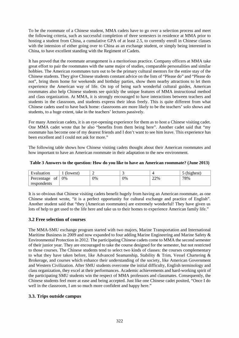
322
To be the roommate of a Chinese student, MMA cadets have to go over a selection process and meetthe following criteria, such as successful completion of three semesters in residence at MMA prior tohosting a student from China, a cumulative GPA of at least 2.5, to currently enroll in Chinese classeswith the intension of either going over to China as an exchange student, or simply being interested inChina, to have excellent standing with the Regiment of Cadets.
It has proved that the roommate arrangement is a meritorious practice. Company officers at MMA takegreat effort to pair the roommates with the same major of studies, comparable personalities and similarhobbies. The American roommates turn out to be the primary cultural mentors for the entire stay of theChinese students. They give Chinese students constant advice on the lists of “Please do” and “Please donot”, bring them home for weekends and birthday parties, show them nearby attractions to let themexperience the American way of life. On top of being such wonderful cultural guides, Americanroommates also help Chinese students see quickly the unique features of MMA instructional methodand class organization. At MMA, it is strongly encouraged to have interactions between teachers andstudents in the classroom, and students express their ideas freely. This is quite different from whatChinese cadets used to have back home: classrooms are more likely to be the teachers’ solo shows andstudents, to a huge extent, take in the teachers’ lectures passively.
For many American cadets, it is an eye-opening experience for them as to host a Chinese visiting cadet.One MMA cadet wrote that he also “benefits from them being here”. Another cadet said that “myroommate has become one of my dearest friends and I don’t want to see him leave. This experience hasbeen excellent and I could not ask for more.”
The following table shows how Chinese visiting cadets thought about their American roommates andhow important to have an American roommate in their adaptation to the new environment.
Table 3 Answers to the question: How do you like to have an American roommate? (June 2013)
Evaluation 1 (lowest) 2 3 4 5 (highest)Percentage ofrespondents
0% 0% 0% 22% 78%
It is so obvious that Chinese visiting cadets benefit hugely from having an American roommate, as oneChinese student wrote, “it is a perfect opportunity for cultural exchange and practice of English”.Another student said that “they (American roommates) are extremely wonderful! They have given uslots of help to get used to the life here and take us to their homes to experience American family life.”
3.2 Free selection of courses
The MMA-SMU exchange program started with two majors, Marine Transportation and InternationalMaritime Business in 2009 and now expanded to four adding Marine Engineering and Marine Safety &Environmental Protection in 2012. The participating Chinese cadets come to MMA the second semesterof their junior year. They are encouraged to take the course designed for the semester, but not restrictedto those courses. The Chinese students tend to select two kinds of classes: the courses complementaryto what they have taken before, like Advanced Seamanship, Stability & Trim, Vessel Chartering &Brokerage, and courses which enhance their understanding of the society, like American Governmentand Western Civilization. After SMU students overcome the initial difficulty, English terminology andclass organization, they excel at their performances. Academic achievements and hard-working spirit ofthe participating SMU students win the respect of MMA professors and classmates. Consequently, theChinese students feel more at ease and being accepted. Just like one Chinese cadet posited, “Once I dowell in the classroom, I am so much more confident and happy here.”
3.3. Trips outside campus
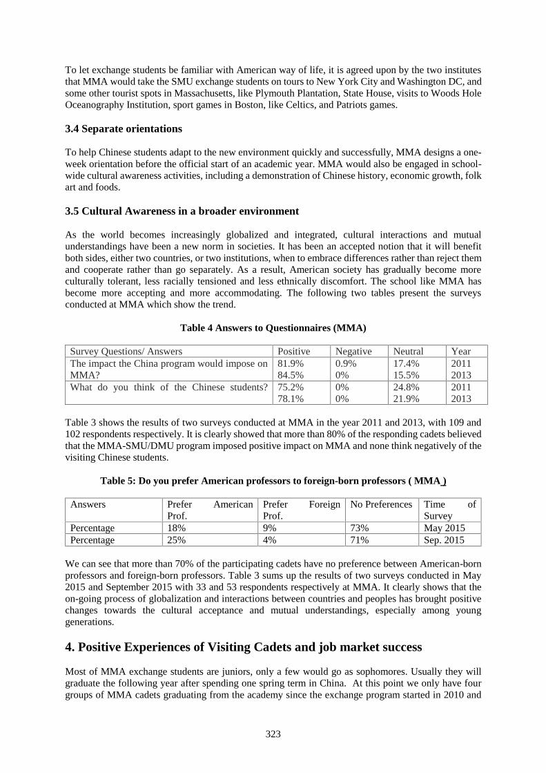
323
To let exchange students be familiar with American way of life, it is agreed upon by the two institutesthat MMA would take the SMU exchange students on tours to New York City and Washington DC, andsome other tourist spots in Massachusetts, like Plymouth Plantation, State House, visits to Woods HoleOceanography Institution, sport games in Boston, like Celtics, and Patriots games.
3.4 Separate orientations
To help Chinese students adapt to the new environment quickly and successfully, MMA designs a one-week orientation before the official start of an academic year. MMA would also be engaged in school-wide cultural awareness activities, including a demonstration of Chinese history, economic growth, folkart and foods.
3.5 Cultural Awareness in a broader environment
As the world becomes increasingly globalized and integrated, cultural interactions and mutualunderstandings have been a new norm in societies. It has been an accepted notion that it will benefitboth sides, either two countries, or two institutions, when to embrace differences rather than reject themand cooperate rather than go separately. As a result, American society has gradually become moreculturally tolerant, less racially tensioned and less ethnically discomfort. The school like MMA hasbecome more accepting and more accommodating. The following two tables present the surveysconducted at MMA which show the trend.
Table 4 Answers to Questionnaires (MMA)
Survey Questions/ Answers Positive Negative Neutral YearThe impact the China program would impose onMMA?
81.9%84.5%
0.9%0%
17.4%15.5%
20112013
What do you think of the Chinese students? 75.2%78.1%
0%0%
24.8%21.9%
20112013
Table 3 shows the results of two surveys conducted at MMA in the year 2011 and 2013, with 109 and102 respondents respectively. It is clearly showed that more than 80% of the responding cadets believedthat the MMA-SMU/DMU program imposed positive impact on MMA and none think negatively of thevisiting Chinese students.
Table 5: Do you prefer American professors to foreign-born professors ( MMA )
Answers Prefer AmericanProf.
Prefer ForeignProf.
No Preferences Time ofSurvey
Percentage 18% 9% 73% May 2015Percentage 25% 4% 71% Sep. 2015
We can see that more than 70% of the participating cadets have no preference between American-bornprofessors and foreign-born professors. Table 3 sums up the results of two surveys conducted in May2015 and September 2015 with 33 and 53 respondents respectively at MMA. It clearly shows that theon-going process of globalization and interactions between countries and peoples has brought positivechanges towards the cultural acceptance and mutual understandings, especially among younggenerations.
4. Positive Experiences of Visiting Cadets and job market success
Most of MMA exchange students are juniors, only a few would go as sophomores. Usually they willgraduate the following year after spending one spring term in China. At this point we only have fourgroups of MMA cadets graduating from the academy since the exchange program started in 2010 and
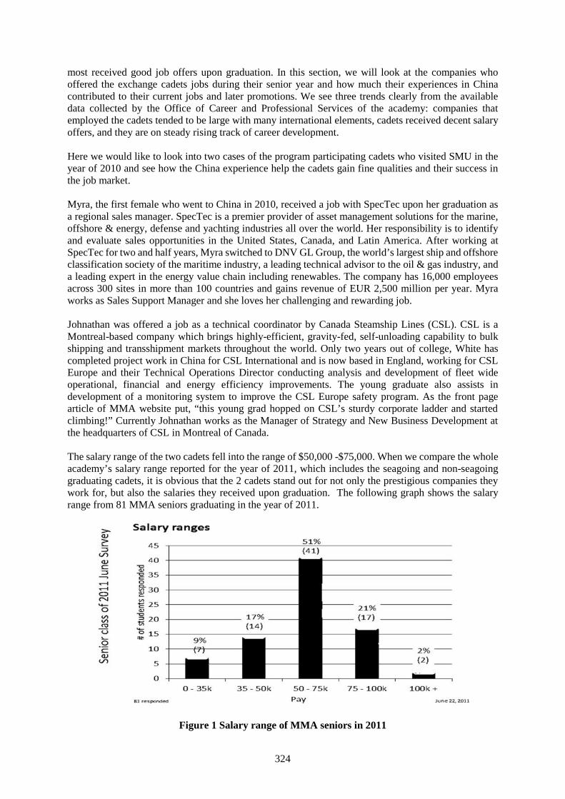
324
most received good job offers upon graduation. In this section, we will look at the companies whooffered the exchange cadets jobs during their senior year and how much their experiences in Chinacontributed to their current jobs and later promotions. We see three trends clearly from the availabledata collected by the Office of Career and Professional Services of the academy: companies thatemployed the cadets tended to be large with many international elements, cadets received decent salaryoffers, and they are on steady rising track of career development.
Here we would like to look into two cases of the program participating cadets who visited SMU in theyear of 2010 and see how the China experience help the cadets gain fine qualities and their success inthe job market.
Myra, the first female who went to China in 2010, received a job with SpecTec upon her graduation asa regional sales manager. SpecTec is a premier provider of asset management solutions for the marine,offshore & energy, defense and yachting industries all over the world. Her responsibility is to identifyand evaluate sales opportunities in the United States, Canada, and Latin America. After working atSpecTec for two and half years, Myra switched to DNV GL Group, the world’s largest ship and offshoreclassification society of the maritime industry, a leading technical advisor to the oil & gas industry, anda leading expert in the energy value chain including renewables. The company has 16,000 employeesacross 300 sites in more than 100 countries and gains revenue of EUR 2,500 million per year. Myraworks as Sales Support Manager and she loves her challenging and rewarding job.
Johnathan was offered a job as a technical coordinator by Canada Steamship Lines (CSL). CSL is aMontreal-based company which brings highly-efficient, gravity-fed, self-unloading capability to bulkshipping and transshipment markets throughout the world. Only two years out of college, White hascompleted project work in China for CSL International and is now based in England, working for CSLEurope and their Technical Operations Director conducting analysis and development of fleet wideoperational, financial and energy efficiency improvements. The young graduate also assists indevelopment of a monitoring system to improve the CSL Europe safety program. As the front pagearticle of MMA website put, “this young grad hopped on CSL’s sturdy corporate ladder and startedclimbing!” Currently Johnathan works as the Manager of Strategy and New Business Development atthe headquarters of CSL in Montreal of Canada.
The salary range of the two cadets fell into the range of $50,000 -$75,000. When we compare the wholeacademy’s salary range reported for the year of 2011, which includes the seagoing and non-seagoinggraduating cadets, it is obvious that the 2 cadets stand out for not only the prestigious companies theywork for, but also the salaries they received upon graduation. The following graph shows the salaryrange from 81 MMA seniors graduating in the year of 2011.
Figure 1 Salary range of MMA seniors in 2011
325
5. Conclusion
The data and analysis show that the international cooperation between two maritime institutes, such asthe MMA-SMU/DMU student Exchange program, would be very effective to help the participatingcadets enhance their self-confidence, broaden their global visions and adapt to a new environment withease and grace. The successful experiences of the MMA-SMU program are applicable not only to themaritime universities of USA and China, but also to the institutions located in two other culturallydiverse countries, like the UK and Vietnam. When the participating cadets prove that they can surviveand perform well in two completely different cultures, they demonstrate that they have all the necessaryand sufficient skills to be successful within any type of job they are offered. And this is exactly what thepotential employers are seeking of all graduating maritime cadets nowadays, as what Schneider &Brasseux refer to, the capability to operate “across national borders somewhat like James Bond”(Schneider & Barsoux, 1997, p. 157).
With the on-going development of the exchange program and availability of additional data on thefemale cadets at MMA, more rigorous statistical analysis could be applied to the research, generatingmore significant conclusions. To do so will unquestionably help us to see how the exchange programenhances cultural awareness, educates maritime cadets to embrace the differences, and fosters leadershipqualifications of cadets of maritime institutions.
References
[1] Beiser, M., & Hou, F. (2000). Gender differences in language acquisition and employmentconsequences among Southeast Asian refugees in Canada. Canadian Public Policy–Analyze depolitiques, XXVI(3), 311–330.
[2] Ehrman, M., & Oxford, R. (1989). Effects of sex difference, career choice and psychological typeon adult language learning strategies. The Modern Language Journal, 73(1), 1–13.
[3] Ferraro, G. (2010). The cultural dimension of international business. Boston: Prentice Hall, p134.[4] Gardiner, H. & Kosmitzki, C., “Lives across Cultures: Cross-cultural Human Development”, 5th
edition, Boston: Allyn & Bacon, 2010.[5] Heidi, D., “On (Mis-)Conceptions of Culture as a Vehicle of Business Success: Singapore
Chinese Investment Strategies after Failing in China”, East Asia: An International Quarterly, June1, 2007.
[6] Hutchings, K., Jackson, P., & McEllister, R. (2002). Exploiting the links between theory andpractice: Developing students’ cross-cultural understanding through an international study tour toChina. Higher Education Research & Development, 21(1), 55–71.
[7] Koller, J., Asian Philosophies”, 5th Edition, Prentice Hall, New Jersey, 2007.[8] Lockwood, V. (2009). The impact of development on women: The interplay of material conditions
and gender ideology. In C.B. Brettell & C.F. Sargent (Eds.), Gender in cross-cultural perspective(pp. 510-524). New York: Prentice Hall.
[9] Moore, H. (1988). Feminism and Anthropology. Minneapolis, MN: University of MinneapolisPress, pp 79.
[10] Nash, J. (1977). Women and development. Development and Change, 8, pp161-182[11] Oberg, K. (1960). Culture shock: adjustment to new cultural environments. Practical
Anthropologist, 7, 177–182.[12] Rowntree, L., Lewis, M., Price, M., & Wyckoff, W., Diversity amid Globalization: World
Religions, Environment, Development, 4th Edition, New Jersey: Pearson, 2009.[13] Salary reports of senior graduates, (July 2011), Office of Career and Professional Placement at
Massachusetts Maritime Academy, USA[14] Schneider, S. & Barsoux, J, ( 1997). Managing across cultures. Hertfordshire: Prentice Hall.[15] SpecTech (2014). Overview. http://www.spectec.net/en. Accessed 1 Apr 2014.
326
Women seafarers as minority organizational members
Assistant Professor Dr. Momoko Kitada1, Associate Professor Dr. Lise Langåker2
1. World Maritime University, Fiskehamnsgatan 1, 21118 Malmö, Sweden;[email protected]
2. Stord/Haugesund University College, Bjørnsonsg. 45, 5531 Haugesund, Norway;[email protected]
Abstract Women constitute a minority among employees on merchant cargo ships [1]. There is anexisting body of research concerning women as minorities in several industries, for example, inengineering [2] and police [3]. Less is written, though, concerning women at sea in the perspective ofthe organizational context they enter into when becoming ship operational personnel. This paperexplores questions from organizational perspectives, based on the interviews with 15 men and womenworking in the maritime industry in Norway. A significant part of a ship’s organizational context lies inits status as a total institution [4] in which people work as well as reside, and where organizationalmembers are cut off from the outside world for periods of time. Within this organizational context, howdo women as “others” [5] find their place and what challenges do they seem to encounter? The paperalso argues whether the presence of women potentially may create a type of disorder which might disruptthe existing male-dominated organizational culture [6]. Gender becomes sensitive within a shipboardworkplace where a total institution is particularly vulnerable when it comes to possible disorderingeffects created by “otherness”. In order to illuminate these research questions the paper looks at howwomen create their gender identities [7] on board as well as expectations from fellow employeesconcerning their identity enactment. It appears that organizational humour, language and culturalartefacts are important aspects in analyzing the situation of women as minority members in a totalinstitution. Finally, the paper reflects upon the seeming organizational silence within the maritimeindustry concerning women as minority organizational members. The research suggests the necessityof leader/captain acknowledgement of organizational cultural issues emphasizing gender. Such anacknowledgement could be looked upon as positive means of recruiting and retaining women as shipoperational personnel.
Keywords: women seafarers, minority issues, total institution, cultural disorder, identity, behaviouralrules, leadership awareness
1. Introduction
Women constitute a marked minority among the world’s maritime work force. Figures estimate womenconstituting 1 or 2 % of the total seafaring work force [8]. According to the ILO study in 2003, thenumber of women differs between different countries, from Sweden (23.3 %) to Italy (1.2%). InNorway, where this study is situated, it was reported that a female participation of seafaring wasapproximately 10 % [9]. It is not unreasonable to assume that these numbers have grown in favour ofmore women entering to the industry since 2003. The more recent study published in 2011 explains thatwomen represent 1.07% at deck officer level and 0.28% at engine officer level among the six countriesof Bulgaria, Germany, Lithuania, Norway, Sweden, and UK [10]. Hence, it is appropriate to argue thatthe maritime sea-based industry lags behind most business areas when it comes to female participation.
This general lack of gender balance in the industry is a worldwide issue. Nonetheless, the scope of thispaper is limited to a glimpse into the Norwegian sea-based maritime business. Norway’s maritimesector might be a particularly interesting study object since Norway is known as – and like to portrayitself as – a country where gender balance is a goal in multiple parts of society including work life.Another research interest in this paper is to shed light upon women seafarers on cargo vessels as minoritymembers of an organizational culture. This approach is to bring forward knowledge of circumstancesthat might be essential to an understanding of issues concerning being “different” within a workenvironment. Such questions become emphasized by the fact that a sea-based work environment is
327
more than a mere work environment – it is also an environment where organizational members spendtheir leisure time in what Goffman calls a total institution [11].
The focus of our study is to explore into being “different” and being “the others” when it comes togender and gender identity in a male-dominated environment. The paper will look into some of thecritical questions: (1) What challenges in such a situation might pose for individual women seafarers aswell as an organizational culture on board a ship?; (2) What expectations do women seafarers encounterfrom both themselves and their fellow employees?; and (3) Is there any way in which the presence ofwomen might create some form of organizational and cultural “disorder” that can be challenging foreveryone involved? Finally, the paper will reflect upon the seeming organizational and industry silenceconcerning these issues.
2. Being a minority in the workplace
The term, 'minority' is used in different contexts with reference to, for example, gender, race, ethnicity,religion, sexual orientation, disability, disease, social class, locality, and nationality. These attributes areoften intersectional and present a complex community space that they belong. For example, AfricanAmerican women fire-fighters have at least two factors to be categorised as a minority, that are beingAfrican American; and being women. The research show that African American women fire-fightersexperienced discriminations because of their two elements [12] [13].
There are a number of studies on minority women in the workplace, such as police [14], Navy [15],carpenters and engineers [16]. The common claim as a minority group of women in such traditionallymale-dominated workplaces is gender-related challenges and cultural biases. A stereo-typing againstwomen in physically demanding jobs or high-risk occupations is likely to imply that women cannotperform as well as men do. It results in the situation where women have to prove their competencieseven better than their male counterparts. The study into the occupational culture of engineering showsthat women had to work hard and suppress emotions to ‘become one of the guys’ [17].
The case of women seafarers is similar to the above-mentioned stream of research, however only alimited number of literature is available. Some of the completed studies focus on female cadets ratherthan women who actually repeat a cycle of signing on and off aboard ships. Though maritime educationand training (MET) plays an important role in introducing women into seafaring professions, voicesfrom women seafarers who know the reality of work life should be heard much more intensively. Theknowledge that women seafarers have created would be a useful source of feedback to improve astrategy of encouraging female cadets to go to sea.
3. Ship as a total institution
With a number of reasons, seafaring is a unique occupation which accommodates a specific work cultureand environment for both men and women. Shipboard life is still contained in modern shipping wherethe number of crew is smaller, typically 17 seafarers on a vessel, and very little free time is allocatedboth at sea and in port. Seafarers work and live in the same limited space to share. Their onboard life isextremely routinized and scheduled. It is a total institution, as Goffman theorizes [18], which exercizesabsolute control over seafarers’ onboard lives, including their behaviour and language.
One aspect of ship as a total institution will be the presence of hegemonic masculinity. A hierarchicalstructure on board a ship, a Captain behaves like a father of his crew which resembles a classic norm ofpatriarchy [19]. Shipboard organizations are gendered in terms of the way seafarers' identities areconstructed. Hegemonic masculinity is symbolically positioned on board ships within discourses thatproduce and reproduce gendered operation of work within the organizational culture. Such positioningis problematic when women enter seafaring professions as their 'difference' may create a disorderedorgasm within the ship organization. Geldalof [20] implies this phenomenon as 'tensions betweenlocatedness and dislocation are played out through both discursive representations of ‘Woman’ and the
328
activities of women', hence the narratives of women's identity repeatedly position ‘Woman’ as ‘place'.This notion matches the understanding of onboard organizational culture where the majority is men; andthe minority women if there is a woman on board - and even so, she will be considered to be in a 'wrong'place which is not common for women at all. In this setting where the absence of femininity is evident,it may be a challenge for women to be a part of the crew unless they choose to be 'one of the boys'.
Culture determines what the appropriate behaviours are for men and women in the context oforganizations [21]. The impact of ship's culture has been observed in women seafarers’ lives in variousways. Kitada's [22] research exhibits how women seafarers tend to develop their identity managementstrategies over time. 'Sameness' strategies are typically employed when women enter a man's world ofseafaring work, for example, they attempt to hide their feminine qualities by wearing buggy clothes andwithout much make-up. In a more intensified format, some women decide to adopt masculine behaviour,such as swearing to present themselves as one of the boys. 'Difference' strategies are, on the other hand,not to compromise their behaviour to a masculine way of decision-making and practices, but rather tostick to their own best way. The study reveals that this process of women's identity management is beingaffected by the seafaring culture.
4. Methods
This study is based in 15 in-depth interviews with men and women working in the maritime industry inNorway. The interviews were conducted in 2013 – 2014 and took place as explorative semi-structuredinterviews with the main intention of looking for possible barriers for female participation in the sea-based maritime industry. The interviewed persons all have experience from the sea for longer or shorterperiods. Some of them are at present ship operational personnel, some are working in land-basedmaritime positions.
From this limited data material it is not possible to generalize any results. When we nevertheless willargue that our data constitutes a valid basis for an analysis of women seafarers’ organizational life, webuild upon a long tradition of the value of qualitative case studies within the organizational sciences[23]. We hence look upon our informants’ stories as valuable information in order to illuminate womenseafarers’ position as minority members in a sea environment.
The goal of this research is to try to understand the contextual dynamics that take place within thisorganizational setting. Analyses of the data material allow us to gain knowledge concerningorganizational traits that seem vital for an understanding of gender minority issues aboard a ship.Although the study is set within a Norwegian context, it is our hope that our findings and discussionswill be of interest not only for a Norwegian audience but also for the international maritime industry aswomen seafarers in a minority organizational position are found all over the world.
5. Women seafarers – one of the boys?
Several researchers have studied work life from the perspective of women as minority organizationalmembers. It seems that regardless of occupation and culture, certain general organizational traits canbe found when women enter into work domains dominated by men. The study conducted by Kvandediscusses the construction of femininities in engineering organizations [24]. In line with other writers,Kvande finds it significant for women when entering the engineering business to become “one of theboys”, to become a “social man”.
One of our female informants says:
“On my first ship, I was met with skepticism and given a rough time … I felt I was tested outmore than the men were. I don’t think there should be different expectations for women.”
329
Kvande discusses the dilemmas facing women when negotiating their status and identity in male-dominated organizational contexts. She utilizes the concepts of “sameness” and “difference” toilluminate possible strategic choices women hold when entering into such work domains. Our researchinterest is whether women seafarers are obliged to become “one of the boys” or whether it is an optionto choose “difference” as a strategy:
“I have seen one woman who came on board and the first thing she did was to enter the crewquarters and remove the pictures of lightly dressed women from the walls. She didn’t wantsuch pictures at her place of work. But was this necessary? By the way, she didn’t last longon the ship,” a female first officer told.
This female officer apparently chose the strategy of being “different” without much success andunderstanding in the work environment. Is it easier to accept “sameness” and become “one of the boys”in order to become accepted and achieve a good working life on board? Our data suggest that this mightbe the case.
Also, the minority position may lead to a struggle for seafaring women to prove themselves competentin order to gain respect from their colleagues [25] [26]. Due to this position and the following highorganizational visibility, women tend to look upon themselves as symbols of their gender, and this“proving” of capabilities is not an uncommon feature of “the others”. Both authors point to how womenon board have to prove their worth to become accepted and respected as co-workers. These statementsare shared by our informants:
“It is wrong – and probably not uncommon – to have special demands and expectationsconcerning job performance towards women seafarers”, argued one informant, a female firstofficer.
“A woman would have to be extremely competent … to do all tasks in an almost perfectmanner. I guess a strong woman could survive in such a work environment”, a male shippingcompany administrator stated.
Conclusively so far, it seems the female minority position induces special work demands couples witha need for mental and social strength in order to be fully accepted by their male colleagues.
6. Women’s “otherness” seen from an organizational perspective
Gherardi and Poggio [27] discuss the “otherness” situation experienced by female employees in apredominantly male work, and their research is much in line with what Kvande [28] and also our studyhas shown: It seems to be expected that women take on a “sameness” identity in order to becomeintegrated into the work environment. What also is explored in Gherardi and Poggio’s [29] work is apossible explanation for why this generally seems to be the case: Is it viable to argue that women’sentry into male-dominated workplaces in itself may undermine traditions? Research by Alvesson andBilling [30] echoes this question in their discussion of how beliefs and values concerning what is“natural” and legitimate ways of behaviour and language are set within the organizational culture. Inline with other researchers, they argue that a stable organizational situation may become somewhatshattered when “others” enter.
Is it then viable to argue that the entering of “others” into maritime work environments – consciously orunconsciously – may provoke skepticism or even resistance towards female participation? And will themale organizational culture be “defended” by for example the use of coarse language and sexualcomments in which women as a group are targeted? The mentioned authors argue that female employeesinstinctively may try to “solve” this complex situation by seeking more or less to conceal their genderidentity in order to prevent conflicts and leave the male gender culture alone.

330
Thomas’ [31] research from a maritime environment underlines these arguments by showing thatwomen seafarers have to accept sexual jokes and language while they simultaneously are expected todownplay their femininity for example in the way they dress when being off duty. We find it legitimateto argue that when fulfilling such incongruent expectations, women’s gender enactment contributes topreserving the existing male-dominated organizational culture. From this perspective, Gherardi andPoggio’s [32] affirmative answers to the cited questions along with Thomas’ [33] and Alvesson andBilling’s [34] observations constitute valuable organizational perspectives to shed light on women’sposition on board a ship. As an analytical tool, it helps us to comprehend that possible male skepticismand expectations towards female colleagues at times has less to do with a dislike and discrimination ofwomen but more to do with a dislike of something – here: women seafarers – threatening the stabilityof their organizational culture.
Our informants support this reflection by their shared perception of change in the maritime workenvironment if women become part of the crew:
“It makes a difference when women are employed on board. It has to do with how you behave… sometimes life on a ship can be almost childish when it comes to language use and nonsensewith only men present … you have to speak in a different manner when there are women”, amale captain argued.
“The conversations become different, both in style and content when women come into thework environment”, a female first officer maintained.
Conclusively so far, it seems fair to argue that the organizational culture enters a change phase whenwomen become employees on board. For some organizational members, this will be positively received,while others will regret the cracks in their up-to-then stable on board culture.
7. Female sexuality as the ultimate disordering element?
It was unexpected for us to find that quite a few of our informants talked about sexuality on board whendescribing women’s positions as minority organizational members. This theme was not part of ourinitial research topic, but it proved to become important due to informants’ reflections. Based on theinformation of sexuality’s “presence” on board, it is rather interesting to find that few – to our knowledge– academic writers have been occupied with this subject. One exception is the Swedish ethnographer,Ingrid Kaijser [35] who discusses sexuality on board by utilizing the categories “visible”, “secret” and“invisible”. Even though the categorizing of sexual behaviour is not a theme of our analysis, Kaijser’swork is important to us in the way it acknowledges that sexuality can be found on board a ship.
Our findings point to specific behavioural expectations regarding female sexuality in order to protectthe organizational order on board from unwanted disruptions. Such behavioural expectations are arguedby both women and men among our informants and are widely shared among these. The activation offemale sexuality seems to be the utmost example of how women’s gender enactment may threaten thestability and culture of a ship’s work environment.
“There have been situations where sexual relations have developed between men and women onboard. Then maybe jealousy has developed…. That is maybe why they say that women shouldnot work at sea”, a male captain maintained.
A female first officer told about the advice she had given to a young female seafarer:
“What do you consider wise behaviour if you want to be respected as a colleague and nothingelse? Do you think you ought to sun-bathe at the swimming pool wearing a bikini?”
A former male captain, now a shipping administrator, put it this way:
331
“It is mainly the women who are in charge of this sexual play. It is their responsibility to decidetheir behaviour. Then they must understand the consequences if they …”
The same informant talked about a fellow captain, now retired:
“He didn’t want to have women on board. He wanted peace. He knew what it could mean tohave …”
Other informants claimed that women’s age is important when it comes to sexuality and life on board.One of the interviewed male captains remarked that captains might prefer women seafarers to be moreor less middle-aged, because:
“ … young girls can’t handle all the attention they get … at sea for weeks and months”.
When analyzing our data material, it is quite obvious that the responsibility for sexual behaviour onboard is placed upon the female minority, and indeed accepted by the women as well. In general, itseems that women are expected to conceal parts of their female identity while on board in order not toraise emotional and sexual tensions among their male colleagues. Such tensions within the life of a totalinstitution may be very harmful for the necessary organizational stability, it is claimed by many of ourinformants.
8. Women seafarers as minority organizational members: A silent topic?
Based on well-known leadership literature in which organizational culture is discussed (for exampleSchein) [36], it would not be unreasonable to imagine that the challenges of integrating minorityorganizational members into the work environment would be a topic of systematic leadership attentionwithin the maritime industry. Our informants were asked about the state of the art concerning this, butnone of them could remember any occasions in which issues concerning women seafarers had beenformally discussed, neither on their ships nor generally in the industry.
“I don’t know whether we will put this on our agenda … I have to acknowledge that this is notsomething we have been concerned with,” said a male shipping administrator when asked ifwomen seafarers was an organizational topic of interest.
“The maritime industry is not occupied with the existing gender imbalance and what thispossibly might mean for the few women on board,” another male administrator maintained.
After having told several stories involving women and sexuality on board, a former captain, nowadministrator, said:
“What I talk about now is something we do not openly talk about … but I do hear some storieswhich are quite sad. But these stories mostly stay on board, they do not often come to ourknowledge at shore”.
It is important to emphasize that the informant did not talk about sexual abuse, but rather of situationsin which women seafarers in his opinion had not taken proper responsibility for avoiding that sexualrelations had developed. His phrasing leads us to suggest that in his company, taboos existed concerningopenness about what sexuality might mean both for individuals and for life in general within the totalinstitution of the ship.
Our informants confirm that organizational discussions about the minority position of women seafarersare not to be found on the formal agenda. When they at the same time are occupied with organizationalculture issues and the work environment on board, it seems viable to point to an interesting paradox intheir approach: Through the silence concerning women as minority members, it becomes difficult toaddress the organizational challenges of having employed someone (i.e. women) who are different from
332
the mainstream male employee. The challenges are similar to those found in other gender-imbalancedindustries and they do not disappear if they are looked upon as non-existing, not of interest or even astaboos.
9. Conclusion
The Norwegian maritime industry – and the maritime industry in general – have to decide whether itwill be a future business strategy to employ and retain more women seafarers. If the answer to thisquestion is positive, then our paper has come forward with knowledge that we believe is vital for thesuccessful implementation of such a strategy.
In this paper, we have shown that to be part of a minority group at a workplace can be challenging bothfor the individual and for the organization. Women seafarers' experience of being a minority is notpersonal but common in such work organizations. Hence, this paper has extensively provided theevidence of advantages of approaching this situation as an organizational rather than an individual issue.By doing so, the individual responsibility of behaving like “one of the boys” will be lifted from thewomen seafarers, and their male colleagues will be relieved from the individual responsibility of tryingto act well-intentioned within organizational processes of which they – quite naturally – have limitedknowledge. From this, we find it vital that maritime organizations acknowledge the challenge andresponsibility following from having minority members as part of their work stock at sea. On thecontrary, such an acknowledgment will be misleading if it merely focuses on existing poor practice.What it needs to give attention is rather a lack of knowledge concerning what it means to be part of aminority in any workplace.
This research highlights silence rather than words that distinguishes the way in which the maritimeindustry copes with the topic of women seafarers and their minority position. In fact, key participantswho referred to the existing organizational minority challenges in this work are the local leaders – i.e.the sailing captains. If the industry wants to hire and retain more women on their ships, it is vital in ouropinion to end the silence and openly talk about and discuss issues like the ones we have commentedupon in this paper. Such a discussion does not suggest that the industry or individuals are to blame forthe present situation. To the contrary, it suggests that improvements for the benefit of the industry haveto include open discussions without some topics being looked upon as taboos.
Lastly, it is our concern that little research has been done concerning women seafarers as minorityorganizational members. It is our conviction that more research within this field will contribute tobroader knowledge about a topic that is strategically important in the future of the maritime industry.
10. Acknowledgement
We want to thank the Norwegian Research Council for financing the “Mirror Mirror” research projectwhich made it possible to collect data about women seafarers.
References
[1] Belcher, P. et al., Women Seafarers: Global Employment policies and practices, Geneva:International Labour Office, (2003).
[2] Kvande, E., Constructing Femininities in Engineering Organizations. The European Journal ofWomen’s Studies, 6, pp. 305-328, (1999).
[3] Bellingham, T., Police culture and the need for change. Police Journal 73(1), pp. 31-41, (2000).[4] Goffman, E., Asylums – Essays on the Social Situation of Mental Patients and Other Inmates. New
York: Anchor Books, (1961).[5] Gherardi, S., Poggio, B., Gendertelling in Organizations: Narratives from male-dominated
environments. Copenhagen: Liber, (2007).[6] Alvesson, M., Billing, Y.D., Understanding Gender and Organizations. London: SAGE, (2009).
333
[7] Kitada, M., Code of behaviour at sea: women seafarers’ shipboard identity management. WMUJournal of Maritime Affairs, 12, pp. 213-227, (2013).
[8] Belcher, P. et al., Women Seafarers: Global Employment policies and practices, Geneva:International Labour Office, (2003).
[9] ibid.[10] Salpice, G., Study on EU Seafarers Employment: Final Report, MOVE/C1/2010/148/SI2.588190
European Commission, (2011).[11] Goffman, E., Asylums – Essays on the Social Situation of Mental Patients and Other Inmates. New
York: Anchor Books, (1961).[12] Yoder, J. D. and Aniakudo, P., The responses of African American women firefighters to gender
harassment at work. Sex Roles, 32(3-4), (1995), pp125-137.[13] Yoder, J. D. and Aniakudo, P., When pranks become harassment: the case of African American
women firefighters. Sex Roles, 35(5-6), (1996), pp253-270.[14] Bellingham, T., Police culture and the need for change. Police Journal, 73(1), (2000), pp31-41.[15] Newell, C. E. et al., Sexual Harassment Experiences and Equal Opportunity Perceptions of Navy
Women. Sex Roles, 32(3/4), (1995), pp159-168.[16] Goodwin, J. and O’Connor, H., Exploring Complex Transitions: Looking Back at the ‘Golden Age’
of From School to Work. Sociology, 39(2), (2005), pp201-220.[17] Hacker, S. A., Pleasure, Power and Technology. London: Unwin Hyman, (1989).[18]Goffman, E., Asylums – Essays on the Social Situation of Mental Patients and Other Inmates. New
York: Anchor Books, (1961).[19] Kitada, M., Women Seafarers and their Identities. Doctorial thesis, Cardiff: Cardiff University
(2010).[20] Gedalof, I., Identity in Transit: Nomads, Cyborgs and Women. European Journal of Women's
Studies, 7(3), pp337-354.[21]Cassell, C. and Walsh, S., Being seen but not heard: Barriers to women’s equality in the workplace.
The Psychologist, 6, (1993), pp110-114.[22] Kitada, M., Code of behaviour at sea: women seafarers’ shipboard identity management. WMU
Journal of Maritime Affairs, 12, pp. 213-227, (2013).[23] Flyvbjerg, B., Five Misunderstandings about Case-Study Research. Qualitative Inquiry, 12 (2), pp.
219 – 245, (2006).[24] Kvande, E., Constructing Femininities in Engineering Organizations. The European Journal of
Women’s Studies, 6, pp. 305-328, (1999).[25] Thomas, M., ‘Get yourself a proper job girlie!’: recruitment, retention and women seafarers.
Maritime Policy & Management, 31, 4, pp. 309 – 318, (2004).[26] Zhao, M., Women Seafarers in the EC: A preliminary Report Based on German and UK Case
Studies. Cardiff: Seafarers International Research Center, (1998).[27] Gherardi, S., Poggio, B., Gendertelling in Organizations: Narratives from male-dominated
environments. Copenhagen: Liber, (2007).[28] Kvande, E., Constructing Femininities in Engineering Organizations. The European Journal of
Women’s Studies, 6, pp. 305-328, (1999).[29] Gherardi, S., Poggio, B., Gendertelling in Organizations: Narratives from male-dominated
environments. Copenhagen: Liber, (2007).[30] Alvesson, M., Billing, Y.D., Understanding Gender and Organizations. London: SAGE, (2009).[31] Thomas, M., ‘Get yourself a proper job girlie!’: recruitment, retention and women seafarers.
Maritime Policy & Management, 31, 4, pp. 309 – 318, (2004).[32] Gherardi, S., Poggio, B., Gendertelling in Organizations: Narratives from male-dominated
environments. Copenhagen: Liber, (2007).[33] Thomas, M., ‘Get yourself a proper job girlie!’: recruitment, retention and women seafarers.
Maritime Policy & Management, 31, 4, pp. 309 – 318, (2004).[34] Alvesson, M., Billing, Y.D., Understanding Gender and Organizations. London: SAGE, (2009).[35] Kaijser, I., Kvinnliga sjömän – finns dom? Stockholm: Statens Maritima Museer, (2005).[36] Schein, E., Organizational Culture and Leadership. San Francisco: Jossey-Bass, (2010).
334
Study over the increasing of situational awareness and the culture of safetyamong younger officers
Professor Radu Hanzu-Pazara1, Professor Gabriel Raicu2, Lecturer Anastasia Duse3, LecturerLoredana Hanzu-Pazara4
1. Constanta Maritime University, [email protected], Mircea cel Batran Street 104, 900663, Constanta,Romania
2. Constanta Maritime University, [email protected]. Constanta Maritime University, [email protected]
4. “Ovidius” University of Constanta, [email protected]
Abstract Two aspects count most on board of all ship today: safety and security. There are many rulesand regulations stated on this issues containing requirements on managing different situations, on theway of approach a safety or security situation, and most important of all, on how to prevent these events.But, all these are coldly established for understanding and application when is necessary, without takinginto consideration variant human behavior. Based on these observations, we can emphasize theimportance of rules, regulations and procedures, but only after testing the situational feed-back.Basically, all situations involving ship’s safety and security are treated as potential risks, before beingrecognized as a real threat. It’s important to increase the crew situational awareness into identifying andassessing the risks and to establish a culture of safety in order to prevent future dangerous situations.The question that arises is how are we capable to obtain the same average of understanding and responsefor a considered risk?
In the study we evaluated the understanding and addressing situations of risk for ship’s safety, by usingsimulations of different events to be faced at sea like stranding or collision situations, piracy attacks andterrorist threats. We included seafarers with different levels of training and experience on sea, fromcadets and young officers – considered less experienced or in the beginning of their seafarer carrier, upto seafarers with considerable number of years on sea.
Present paper presents the methods used in the study and the results obtained on human response overdifferent risky situations, on the way that situational awareness and culture of safety influence theassessment process for these conditions, the influence of experience and what are the optimal solutionsto be considered in accordance with present evolution of maritime industry and procedural requirementsfor ship safety.
Keywords: Safety, awareness, culture, younger officers, study.
1. Introduction
Today, the maritime industry is focused on increasing the safety and security in all sectors and at alllevels. This increase is based both on technical development and also on changing the human behaviour.The time when only the technical measures were taken into consideration is no longer available. Studiesabout the impact of technology on safety in different industries have shown that the improvement ofequipment alone, without a proper increasing of human awareness, is not efficient. The technology canbring a lot of advantages on safety matters, but only if it is controlled by aware operators, able tounderstand the meaning of “safety”.
To define safety is important for every seafarer, because the understanding of this concept generates asecured working environment for all on board persons. A person able to perform activities in safemanners for him, will be able to offer safe environment for others. But, if you will not be able to definewhat is safe for yourself, there will be really difficult to offer a protected environment for the others.To be safety aware is not a characteristic of the “older” seafarers only, it must be seen as a basic conceptfor all seafarers. For a seafarer is important to be aware of possible dangers in most of the situations.
335
Any activity that has to be performed must begin with a risk evaluation, that aware the person involvedabout what can happen, which is the best way to approach the job and what is necessary to be done inorder to avoid possible dangerous conditions. If these considerations will be taken into account for allactivities performed on board, the number of dangerous situations, near misses and accidents will bevery much reduced, and the maritime industry will no longer be considered as dangerous as it is today.
The relationship between situational awareness and the culture of safety is well known: is difficult to beaware about the risks without knowledge. A good safety knowledge will make the seafarers more awareabout the risky situations for life, ship and environment.
For these reasons, the meaning of any maritime education and training institution is to guide the studentsto complete their training in ship safety and security, and to be able to bring their contribution to theultimate concept of “safer ships, safer seas”.
2. Situational awareness and maritime safety
Like in many other industries, for the maritime, a good situational awareness means to have always aright and clear perception of your surroundings, to be able to understand what’s happening around youand how all of these will affect the ship [1]. Situational awareness refers to the capability to maintain aconstant vigil over important information, to understand the relationships among the various pieces ofinformation monitored, and to project this understanding into the near future for making criticaldecisions.
On board, regardless department affiliation, the seafarers must constantly maintain situational awarenessin order to ensure safe operations. A healthy dose of situational awareness is essential to make informeddecisions, act in a timely manner, and ultimately ensure operational safety, even on sea or in harbour.Studies over the maritime incidents have high lightened that the loss of situational awareness plays asignificant role in incidents attributed to human factor. Different studies made by United States CoastGuard revealed that human factors accounted for 54% of the medium and high severity incidents andabout 40% of the low severity incidents. Also, failures in situational awareness or task performanceaccounted for 69% of the medium and high severity human incidents. The same studies have shown thatonly 5% of the cases were attributed to mechanical problems [2].
To avoid inclusion in these statistics is important to know how to establish a good situational awareness,including the following considerations [3]:
to be aware of your situational environment (ships in the transiting area, necessarycommunication with coastal stations or other ships, water depth, tide, current, weather, seastate),
to be aware of the status of your ship’s systems, to have mode awareness (know the own ship configuration, including equipment and systems), to keep a time horizon (always allow time for unplanned events or emergencies), to maintain spatial orientation.
According to Endsley [4], the situational awareness can be organized in three levels of informationprocessing. The first level, perception, is fundamental. Without basic perception of importantinformation, the odds of forming an incorrect image of the situation will increase a lot. At this level, theseafarer perceives the status and the dynamics of the relevant elements in his environment and a typicalerror would be the missing of critical information [5].At second level, the comprehension, situational awareness as unitary construct, goes beyond mereperception. It is ssurprising how people combine, interpret, store and retain information. At this level,there is an integration of multiple pieces of information and a determination of their relevance to theperson’s goals. In this stage, the seafarer will evaluate and integrate the existing information. It isrequired for him to understand the information in relation to the relevant objectives and goals [5].

336
At the last level of situational awareness, projection, person is developing the ability to forecast futuresituational events and dynamics; this marks persons who have the highest level of understanding of thesituation. In the final stage, the seafarer uses his perception and comprehension of the present situationto approximate what will be produced in the near future [5].
Regarding to the situational awareness levels, an analyse of the incidents occurred in offshore industrythat included 135 cases, revealed that 67% of these were resulted from lack of perception of criticalinformation (Level 1), 20% due to failure to comprehend the real situation (Level 2), and 13% wereattributed to inability to project what will happen in the near future (Level 3) [6].
Regarding maritime safety, the situational awareness involves both a temporal and also a spatialcomponent. Time is an important concept in situational awareness, being a dynamic construct, changingat a tempo dictated by the actions of seafarers, task characteristics, and the surrounding environment.As new inputs enter the system, the seafarer incorporates them into this mental representation, changingthe plan and actions as necessary to reach the desired objectives. The situational awareness concept alsoincludes the spatial knowledge about all the events and activities developed in locations of interest forseafarer. As example, the officer on the watch on the bridge has to be aware about the location andextent of the maintenance activities that take place on deck, in order to protect the seamen from anydangerous situation.
Presently, building of a firm situational awareness on maritime safety has faced an entire set ofchallenges, which must be considered in process designing [7]. The first challenge is to gatherinformation on the situation around you and second one, to have the capability to identify the criticalsituations.
Thus, the concept of situational awareness includes perception, comprehension, and projection ofsituational information, as well as temporal and spatial components.
Important is not to forget that activities on board ship are made in most of the cases as a team work andsituational awareness have to be treated as a whole for the entire team members. The team situationalawareness is based and depends on the level of safety awareness for each member of the team and thelevel of safety awareness shared between team members. These aspects provide an accurate operatingpicture of those aspects of the situation common to the needs of each member of the team [8].
Regarding the team situational awareness, Endsley and Jones [1] describe a model intending toconceptualize how teams develop high levels of shared safety awareness across members, a modelsuitable to be used for those on board activities based on team activities. The factors considered to helpinto building a strong team and to share situational awareness are requirements, devices, mechanismsand processes.
The team situational awareness requirements represent the highest level of comprehension ofinformation, of selecting the most important aspects that should be shared, including personalassessments and projections. There is also information on team member’s activities and capabilities.For situational awareness devices are considered the devices available in different workingcompartments for sharing information, including direct communication, visual or audio displays or ashared environment.
Team situational awareness mechanism represents the way of processing information by team members,like shared mental models, which support their ability to interpret information in the same way and makeaccurate projections regarding each other’s actions. To have capacity to use a shared mental model canhelp a lot to increase communication and coordination in team settings.
The situational awareness processes are the degrees of involvement of each team members into effectiveprocesses for sharing necessary information, like a group norm of questioning assumptions, checking
337
each other for conflicting information or perceptions, setting up coordination and prioritization ofactions, and establishing contingency planning among others.
Related to this, in our study, we tried to recreate the situations possible to be met on the bridge duringnavigation and to find how different trained level seafarers manifest their situational awareness. Wechecked if practical experience and good knowledge about the events around offered the opportunity totake better decisions on ships control.
In the study, the team intended to identify the key factors characteristic for the evaluation of situationalawareness level. We have been observing the way of using the perception, comprehension, andprojection of relevant events.
3. Study on risk perception and reaction among younger officers
A good analysis of the maritime activities will reveal that many are characterized by a medium to highlevel of risk. It is well known that any risk can be assessed and managed in good conditions, if it isrecognized. The real problem, when introducing humans in the work equation, is how they evaluate andrecognize the risk value.
In risk evaluation and safety measures an important consideration is given to situational awareness andsafety culture. Both have the meaning to create and improve the sense of good and safe work.
3.1. Aims of the study
The study was initiated to get explanation on how the situational awareness and the existence of a safetyculture among the ship crew can contribute to increasing of ship safety and security. As research methodwas used simulation techniques combined with questioning technique and discussions, for a morecomplete explanation of decisions and results.
The study was realized using Constanta Maritime University’s simulation complex together with thesupport of our students and collaborators from maritime industry. Also, we received support frommedicine faculty colleagues, to understand different psychological aspects of decision making process.
The main goal of the study was to understand the human response over different risky situations, andthe influence of situational awareness and culture of safety on the assessment processes, considering thepeople involved experience in these situations. In the same time, was intended to found the optimalsolutions to be considered according to the present evolution of maritime industry and proceduralrequirements for ship safety.
3.2. Methods
For analysis of situational awareness in different sailing conditions were included 30 students withvariable periods of practice on sea or no practice, 10 students with more than 2 years of experience onsea as helmsmen or able seafarers and 4 Master licensed with more than 5 years of experience in thisposition. For the students were created simulation scenarios for some possible dangerous or difficult tobe managed situations, and interviews, for the Masters were used professional discussions and opinionsbased on own experience in these kind of situations.The situations considered for simulations were navigation in restricted visibility with risk of collisions,possible piracy attack in isolate ship condition, engine failure in bad weather conditions, loss of thesteering system during a channel transit and fail of the electronic charts system during transiting of aheavy traffic area.
338
For a better analyse of the participant’s situational awareness, part of the simulations were performedby students alone, others in a bridge team format. When the simulations required a team format,members of the team were chosen with different level of experience.
Procedure: Students were given no instructions other than as per normal procedures. Immediately afterstarting simulation, there were included heading changes in short succession. On re-commencing thesimulation after the first freeze, students were instructed to continue with their simulation as planned.During this segment various radio calls were made, some of which were relevant, others incidental tothe task. The relevant calls advised of traffic information, and of changing weather conditions. Afterdifferent situations of system failure (engine failure, loss of steering system, failure of electronic charts,etc.), the second questionnaire was administered. On continuing the simulation, additional calls weremade to advise of deteriorating weather conditions, restricted visibility, risk of collisions, piracy attack,etc.
The final questionnaire was instigated about 5 minutes prior to simulation termination.
This arrangement was agreed to allow to: analyse how are used perception, comprehension andprojection according to the classification levels of situational awareness, which is the role of goals andgoal directed processing attention and interpreting the significance of perceived information, the role ofinformation in increasing of the situational awareness, the role of expectations in directing attention andinterpreting information, the heavy demands on limited working memory restricting situationalawareness for students without onboard experience or a short one, the use of mental models forproviding a means for integrating different part of information and comprehending its meaning andpattern matching to schema, that provides rapid retrieval of comprehension and projection relevant tothe recognized situation.
3.3. Results
The resulting error scores ranged from 1 (best answer score) to 10 (worst answer score). Categoricalresponses were scored as 1 (accurate) or 10 (inaccurate). The scores were then averagedacross items for each of the three questionnaires to form three general scores (G1, G2, and G3), andacross all items to form one overall G-score (G). Best inclusion for situational awareness scored theminimum average points (best attitude of situational awareness and minimal errors).
Questionnaires were including six pattern questions for the 3 factors – 3 for timing and 3 for spacing –for each of the freeze moments. (6 minimal score = best answers over all; 60 maximal score = worstanswers over all).
Median age was 25,73 (differentiated on experience into subgroups according to experience/practiceonboard). All participants were deck students/personnel.
After completion of the simulated situations, during interviews and discussions with the participants,there were requested explanations for reactions and decisions in different situations of navigation, therewere given solutions and it was created the framework for understanding how situational awareness,good information and the sense of safety can influence it.
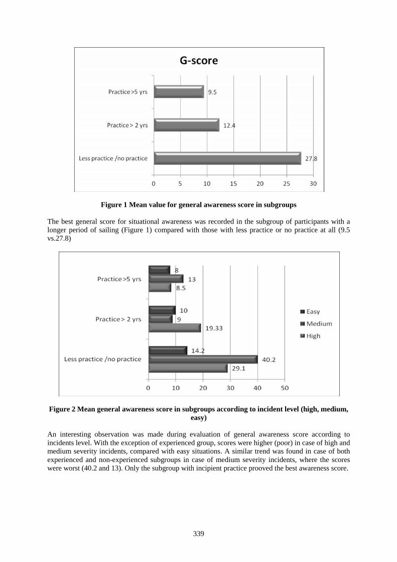
339
Figure 1 Mean value for general awareness score in subgroups
The best general score for situational awareness was recorded in the subgroup of participants with alonger period of sailing (Figure 1) compared with those with less practice or no practice at all (9.5vs.27.8)
Figure 2 Mean general awareness score in subgroups according to incident level (high, medium,easy)
An interesting observation was made during evaluation of general awareness score according toincidents level. With the exception of experienced group, scores were higher (poor) in case of high andmedium severity incidents, compared with easy situations. A similar trend was found in case of bothexperienced and non-experienced subgroups in case of medium severity incidents, where the scoreswere worst (40.2 and 13). Only the subgroup with incipient practice prooved the best awareness score.
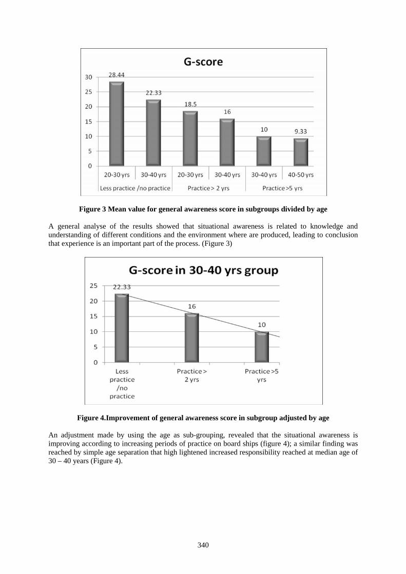
340
Figure 3 Mean value for general awareness score in subgroups divided by age
A general analyse of the results showed that situational awareness is related to knowledge andunderstanding of different conditions and the environment where are produced, leading to conclusionthat experience is an important part of the process. (Figure 3)
Figure 4.Improvement of general awareness score in subgroup adjusted by age
An adjustment made by using the age as sub-grouping, revealed that the situational awareness isimproving according to increasing periods of practice on board ships (figure 4); a similar finding wasreached by simple age separation that high lightened increased responsibility reached at median age of30 – 40 years (Figure 4).
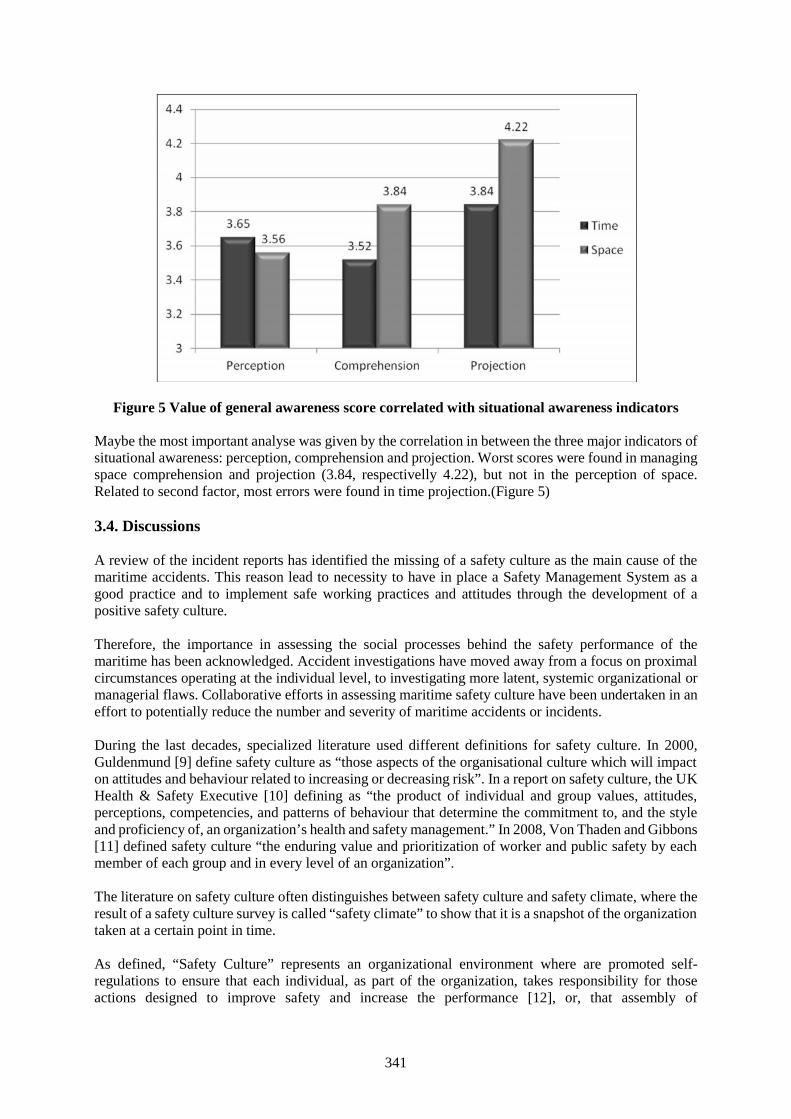
341
Figure 5 Value of general awareness score correlated with situational awareness indicators
Maybe the most important analyse was given by the correlation in between the three major indicators ofsituational awareness: perception, comprehension and projection. Worst scores were found in managingspace comprehension and projection (3.84, respectivelly 4.22), but not in the perception of space.Related to second factor, most errors were found in time projection.(Figure 5)
3.4. Discussions
A review of the incident reports has identified the missing of a safety culture as the main cause of themaritime accidents. This reason lead to necessity to have in place a Safety Management System as agood practice and to implement safe working practices and attitudes through the development of apositive safety culture.
Therefore, the importance in assessing the social processes behind the safety performance of themaritime has been acknowledged. Accident investigations have moved away from a focus on proximalcircumstances operating at the individual level, to investigating more latent, systemic organizational ormanagerial flaws. Collaborative efforts in assessing maritime safety culture have been undertaken in aneffort to potentially reduce the number and severity of maritime accidents or incidents.
During the last decades, specialized literature used different definitions for safety culture. In 2000,Guldenmund [9] define safety culture as “those aspects of the organisational culture which will impacton attitudes and behaviour related to increasing or decreasing risk”. In a report on safety culture, the UKHealth & Safety Executive [10] defining as “the product of individual and group values, attitudes,perceptions, competencies, and patterns of behaviour that determine the commitment to, and the styleand proficiency of, an organization’s health and safety management.” In 2008, Von Thaden and Gibbons[11] defined safety culture “the enduring value and prioritization of worker and public safety by eachmember of each group and in every level of an organization”.
The literature on safety culture often distinguishes between safety culture and safety climate, where theresult of a safety culture survey is called “safety climate” to show that it is a snapshot of the organizationtaken at a certain point in time.
As defined, “Safety Culture” represents an organizational environment where are promoted self-regulations to ensure that each individual, as part of the organization, takes responsibility for thoseactions designed to improve safety and increase the performance [12], or, that assembly of
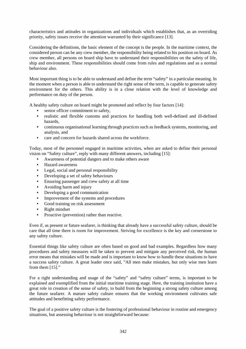
342
characteristics and attitudes in organizations and individuals which establishes that, as an overridingpriority, safety issues receive the attention warranted by their significance [13].
Considering the definitions, the basic element of the concept is the people. In the maritime context, theconsidered person can be any crew member, the responsibility being related to his position on board. Ascrew member, all persons on board ship have to understand their responsibilities on the safety of life,ship and environment. These responsibilities should come from rules and regulations and as a normalbehaviour also.
Most important thing is to be able to understand and define the term “safety” in a particular meaning. Inthe moment when a person is able to understand the right sense of the term, is capable to generate safetyenvironment for the others. This ability is in a close relation with the level of knowledge andperformance on duty of the person.
A healthy safety culture on board might be promoted and reflect by four factors [14]: senior officer commitment to safety, realistic and flexible customs and practices for handling both well-defined and ill-defined
hazards, continuous organisational learning through practices such as feedback systems, monitoring, and
analysis, and care and concern for hazards shared across the workforce.
Today, most of the personnel engaged in maritime activities, when are asked to define their personalvision on “Safety culture”, reply with many different answers, including [15]:
Awareness of potential dangers and to make others aware Hazard awareness Legal, social and personal responsibility Developing a set of safety behaviours Ensuring passenger and crew safety at all time Avoiding harm and injury Developing a good communication Improvement of the systems and procedures Good training on risk assessment Right mindset Proactive (prevention) rather than reactive.
Even if, as present or future seafarer, is thinking that already have a successful safety culture, should becare that all time there is room for improvement. Striving for excellence is the key and cornerstone toany safety culture.
Essential things like safety culture are often based on good and bad examples. Regardless how manyprocedures and safety measures will be taken to prevent and mitigate any perceived risk, the humanerror means that mistakes will be made and is important to know how to handle these situations to havea success safety culture. A great leader once said, ”All men make mistakes, but only wise men learnfrom them [15].”
For a right understanding and usage of the “safety” and “safety culture” terms, is important to beexplained and exemplified from the initial maritime training stage. Here, the training institution have agreat role in creation of the sense of safety, to build from the beginning a strong safety culture amongthe future seafarer. A mature safety culture ensures that the working environment cultivates safeattitudes and benefitting safety performance.
The goal of a positive safety culture is the fostering of professional behaviour in routine and emergencysituations, but assessing behaviour is not straightforward because:
343
People have a tendency to change their behaviour when they know they are being watch, Apparent routine behaviour may not be sustained in an emergency, or stressful situations, Behaviour assessment can be very time-consuming Behavioural assessment requires corroboration by assessments of attitudes and values.
Attitudes, values and opinions should be drawn out as they are central to most definitions of safetyculture.
4. Conclusions
Safety and security will remain the main concerning of the maritime industry. It’s important to increasethe crew situational awareness into identifying and assessing the risks and to establish a culture of safetyin order to prevent future dangerous situations. Proposed model is emphasizing the necessity ofquantifying the level of situational awareness in the continuous education and training of maritimepersonnel. The best general score for situational awareness was recorded in the subgroup of participantswith a longer period of sailing compared with those with less practice or no practice at all, emphasizingthe importance of experience in a definite practical occupation, even if the subgroup with incipientpractice prooved the best awareness score in case of risk situations (signal of decreased awareness forroutined seafarers). Maybe the most important analyse was given by the correlation in between the threemajor indicators of situational awareness: perception, comprehension and projection. Worst scores werefound in managing space comprehension and projection (especially in time projection), but not in theperception of space, showing a promising possibillity of improving the ability in a close relation withthe level of knowledge and performance on duty of the person, implicitly generating safety environmentfor the others.
References
[1] Endsley M.R. and Jones W.M., “A model of inter- and intrateam situation awareness: Implicationsfor design, training and measurement”, In M. McNeese, E. Salas and M. Endsley (Eds.) New trendsin cooperative activities: Understanding system dynamics in complex environments, Santa Monica,CA, (2001), pp.46-67.
[2] United States Coast Guard, “Situational awareness – What is it?”, Crew endurance management,Summer 2008, Accessed 15.04.2014, <http://www.uscg.mil/hq/cg5/cg5211>
[3] Maritime Safety Queensland, “Situational awareness”, Marine information bulletin, Issued May2012, Accessed 25.05.2016, <www.msq.qld.gov.au//Marineinformationbulletins/mib_situational_awareness.pdf>
[4] Endsley M.R., Garland D.J., “Theoretical underpinnings of situation awareness: A critical review”,Situation awareness analysis and measurements, New Jersey, (2000)
[5] Sandhaland H., Oltedal H. and Eid J., “Situation awareness in bridge operations – A study ofcollision between attendant vessels and offshore facilities in the North Sea”, Safety Science, Vol.79(2015), pp. 277-285.
[6] Sneddon A., Mearns K. and Flin R., “Situation awareness and safety in offshore drill crew”,Cognition, Technology and work. Vol.8, Issue 4 (2006), pp.255-267.
[7] Van de Laar P. et al., Situation awareness with systems of systems, DOI 10.1007/978-1-4614-6230-9-2, Springer Science and Bussiness Media New York, (2013).
[8] Situation awareness, Accessed 15.05.2016, https://en.wikipedia.org/wiki/Situation_awareness[9] Guldenmund F.W., “The nature of safety culture: a review of theory and research”, Safety Science,
Vol.34 (2000), pp. 215-257.[10] UK Health and Safety Executive, Safety culture: A review of the literature, Health and Safety
Project HSL/2002/25, (2002).[11] Von Thaden T.L., “Distributed information behaviour: a study of dynamic practice in a safety
critical environment”, The Journal of the American Society for Information Science andTechnology, Vol. 59, No.10, (2008), pp.1555-1569.

344
[12] Moore W.H., Roberts K.H., “Safety management for the maritime industry: The InternationalSafety Management Code”, Proceedings of the 1995 International Oil Spill Conference,Washington D.C., Vol. 1995, No.1 (1995), pp305-310.
[13] American Bureau of Shipping, Guidance notes on safety culture and leading indicators of safety,American Bureau of Shipping, (2014)
[14] Pidgeon N. and O’Leary M., “Man-made disasters: why technology and organizations (sometimes)fail”, Safety Science, Vol. 34, (2000), pp.15-30.
[15] Stephen F., “Safety culture”, Health and Safety, Published on 29.05.2013, Accessed 30.05.2016,www.shippingandmarine.co.uk/article-page.php?contentid=17628&issueid=491
345
Cultural Intelligence and Awareness in Maritime Education: A Case Study
Dr. Bani Ghosh, PhD in Economics, Professor
Department of International Maritime Business, Massachusetts Maritime Academy101 Academy Drive, MA 02532, USA
Phone: 508 830 5000 x 2112; Email: [email protected]
Abstract Cultural intelligence is the ability to accurately decipher seemingly ambiguous situations incross cultural environments. In a world, where crossing geographical boundaries is routine, and moreso in the context of maritime transportation, this happens to be a very relevant topic for discussion. Asglobalization has rendered the maritime business environment more complex, diverse and competitive,the ability to function effectively in different cultural contexts is now critically important. It is commonknowledge that cross cultural skills are best developed through experiential learning e.g. by studying orworking in a foreign culture where one learns by trial and error. This paper is based on a case studytracing US maritime college student learning experiences that take them to two locations in Asia, namelySingapore and Malaysia. This initiative was part of an experiential learning program. The InternationalMaritime Business (IMB) program at Massachusetts Maritime Academy (MMA) undertook thisinitiative to enhance the knowledge base of its student body who typically work on the shore side of theshipping industry. This is also critical because, although the seafaring side of the shipping industryexperiences a cultural immersion due to their job description, as they visit various ports around theworld, the shore side maritime professionals are generally recruited from the corporate headquarterswith little cultural cross pollination. In this initiative, students spent three weeks in these locationsduring the month of February, 2016 under faculty supervision. They learned about the port infrastructureand maritime activities in those locations and were required to write a paper on their observations.During their stay in the two locations, they also experienced complete cultural immersion. Many of thesestudents had never stepped out of the US prior to this. Upon their return to the US, the students weresurveyed on their experiences revealing some interesting findings about cultural intelligence andawareness. The paper discusses the design of the program leveraging existing partnerships, thepreparatory phase, the actual experience and post experience cognition as expressed in the survey.
Keywords: Cultural intelligence, cross cultural communication, experiential learning
1. Introduction:
It is commonly understood that success in a globalized economy depends significantly on culturalawareness and adaptability. Cultural competence is commonly defined as the combination ofknowledge, attitudes and skills necessary to effectively interact with culturally and ethnically diversepopulations. One should have knowledge of culture, history, traditions of these populations. As forattitudes, one should be aware of diverse values, beliefs, and behaviors, be accepting of culturaldifferences and should be able to reflect on one’s own socio-cultural background and personal biases ortendency to stereotype. The skills element focuses on communication skills to interact with diversepopulations and overcome language barriers and also the adaptability to adequately respond to culturallydiverse situations. Research indicates that those kinds of awareness and abilities can be measured andevaluated. They are quantified as cultural intelligence quotient, or CQ. First introduced by two businessresearchers, Christopher Earley and Soon Ang[1] , in their 2003 book, ‘Cultural intelligence: Individualinteractions across cultures’, it measures the capability to function effectively in a variety of national,ethnic and organizational settings. This form of intelligence has been tested by academic researchers inmore than 30 countries over a decade. In a world, where crossing geographical boundaries is routine,and in a profession like maritime business where the sun never sets, cultural intelligence is a vitalaptitude and skill. In this paper, an attempt has been made to underscore the importance of culturalintelligence in maritime business education.
346
Section 2 provides a brief description of cultural intelligence and its relevance in maritime education.Section 3 presents the motivation behind the development of cultural intelligence through experientiallearning in the International Maritime Business (IMB) curriculum at Massachusetts Maritime Academy(MMA). As a case study, Section 4 describes a student learning experience in two locations in Asia,namely Singapore and Malaysia. It outlines the survey findings used to test the impact of the study touron the cultural intelligence of participating students. Section 5 provides conclusions.
2. The Relevance of Cultural Intelligence in Maritime Education:
Organization management textbooks have several anecdotes of expatriate managers facing severeprofessional problems due to lack of cultural intelligence. Ethnocentrism or the belief that one’s nativeculture and ethnicity is superior to all others is considered to be a major roadblock in managerial andorganizational contexts. This is linked to several personnel problems like recruitment difficulties, highturnover rates, low employee motivation and even expensive lawsuits. Current and future managers needto overcome this ethnocentric bias through greater cross cultural awareness, education and internationalexperiences of cultural immersion. Given the number of cross-functional assignments, job transfers,virtual teams and distant postings, most managers are likely to experience in the course of a career, alow cultural intelligence quotient (CQ) can turn out to be a significant disadvantage.[2] In fact, Universityof Michigan professor Jeffrey Sanchez-Burks’[3] research on cultural barriers in business found that jobcandidates who adopted some of the mannerisms of recruiters with cultural backgrounds different fromtheir own were more likely to be made an offer.
While general businesses continue to grapple with CQ issues, the matter is even more critical in themaritime context which is perhaps the most global sector in the world. Given the international andgeographically dispersed nature of the maritime industry, the skills required are more complex than inregular domestic businesses. Not only are ships being operated by multinational crew members, thebusiness of shipping on the shore-side is also truly global. Addressing issues of cultural competency isof utmost importance in this field and must be treated as a core component of the maritime curriculum.
Michael Ircha[4] in his 2006 paper, ‘Maritime education in cross cultural settings,’ explores severalproblems of misunderstandings and misinterpretations among people having different worldviews in amaritime context. His paper discusses cross-cultural dimensions including conflicting information,time/space issues and resulting emotional responses. This is followed by a review of the adjustmentproblems faced by international students and instructors studying or teaching in other countries. Thepaper concludes with a discussion of the facilitating factors that help instructors ensure effective learningin cross-cultural settings.
The importance of CQ in the maritime context was also recognized by Graham Benton and TimothyLynch[5] in their 2014 paper ‘Globalization, cultural intelligence and maritime education.’ The authorsdiscuss the initiatives taken by California Maritime Academy in assessing and improving student CQ ina maritime educational institution.
In 2015[6], Momoko Kitada discusses the same issue in her paper ‘Promoting cultural awareness throughwelfare in maritime education and training.’ Kitada emphasizes cultural awareness as becomingincreasingly important, because it facilitates smoother communication and mutual understanding amongthe multinational crew, and thus, contributes to the safe operation of ships. It is commonly understoodthat better communication and mutual understanding among the crew members should help reducinghuman errors in marine accidents, which are known as the major causes of catastrophes at sea. Kitada’sstudy also found that an early exposure to different cultures while cadets study in a MET institutionhelps to foster soft skills to negotiate and harmonize with other nationalities of the crew.
This paper underscores the importance of cultural intelligence not only for the seafaring students in amaritime institution but also those students who end up working on the shore-side of the maritimeindustry. It identifies three broad cultural competence domains:
347
1. General knowledge: This includes knowledge of culture, history, traditions, values, and familysystems of culturally diverse populations.
2. Reflection ability: For culturally competent individuals, reflection is required for insight intoone’s own understanding of prejudice and cultural frames of reference
3. Culturally competent behavior: Communicate and work effectively with individuals fromvarious cultural backgrounds and ethnicities.
Section 3 discusses the various international experiences that students at MMA are exposed to in orderto enhance their CQ in the aforementioned domains. It focuses on a specific initiative undertaken in2016 in Singapore and Malaysia and discusses its impact on participating students.
3. MMA Initiatives to Enhance CQ:
MMA engages in a number of international experiential learning initiatives for its students that are listedbelow:
The sea going license track students of MMA complete their sea going experiential training aboardthe training vessel T.S. Kennedy and other commercial shipping voyages. The cruises areaccomplished in the following order on the following vessels: Academy training ship, training orcommercial ship followed by Academy training ship. This experiential element is an integral partof the academic curriculum for the license track programs. This gives an opportunity to travel tointernational ports and work alongside multinational crew in commercial vessels.
However, a non license track, shore based major like IMB also has a significant experientiallearning component. The emphasis on curricular design is aligned to the educational philosophy ofthe Academy: Learn–Do–Learn. The original framework of the curriculum was based on thefollowing model. Through academic coursework, students learn the concepts and principles ofinternational maritime business. They then apply this learning in a professional context. In order tograduate, students need to complete a minimum of two internships and an international experientiallearning program. Based upon that experience, students then improve and adapt their understandingof the concepts and theories of maritime business.[7] Apart from these, there are semester long studyabroad programs that allow for a deeper cultural immersion.
The following experiences help students in the IMB program at MMA develop their cross cultural andglobal awareness by visiting other countries, learning and observing international maritime business inpractice at various ports and related maritime interests.
i. Semester long study abroad programs at Shanghai Maritime University (SMU) and Dalian MaritimeUniversity (DMU).
ii. An internship in Panama City, Panama, to learn about the operations of the Panama Canal.
iii. International short term experiential learning programs:
In an increasingly global environment, it is critical that business professionals learn aboutglobalization and international business practices. Similarly, it is important that maritime businessprofessionals learn about shipping and maritime industries in a global context and develop their CQ.These experiential learning programs, designed specifically for upper division IMB students, providea first-hand international experience. In the learn-do-learn tradition, the centerpiece of this course isa 3 week faculty-led field study in a selected country absorbing the practical and cultural implicationsof international business or maritime business. The course is designed to provide a series ofpreliminary sessions leading up to the experiential portion and will conclude with an integrative andreflective segment. Thus the three phases of the IMB experiential learning include preliminary predeparture instruction, travel logistics to an international location, and post-travel reflection. The IMB
348
international experiential learning course is geared towards enhancing cultural awareness and globalbusiness competencies. The various opportunities and destinations are listed below:
a) Liverpool (UK)
This program is being conducted in a partnership with Liverpool John Moore’s University (LJMU)and the University College of Southeast Norway (HSN). Students from the three institutions will bepart of this experiential learning project. The experience will provide the students with an industryinsight into contemporary issues and trends and develop understanding of the different marketsegments in the maritime sector with special emphasis on port infrastructure. The maritime industrycomprises of a high cultural disparity. This challenges the efficiency and safety performance aboarda vessel as well as port operations ashore. Enhancing both the future onshore and offshore crew’scultural competence will allow maritime operations to be carried out in a more efficient and safemanner. Making students from three different countries work on joint projects will enhance theability to work on cross-cultural communication skills, teamwork skills and business culture skills.
b) Ol Pejeta Conservancy (Kenya)
The corporate partner in this initiative is the world famous Ol Pejeta conservancy. The students workhand in hand with the conservationists to provide new alternative office practices and refine andtweak daily operations. As they go about their daily work schedule, they quickly adapt to their newenvironment and gain cultural insight. This also provides a fantastic opportunity for severalcommunity outreach programs and enhance cross cultural awareness.
c) Guácimo (Costa Rica)
Our academic partner is Earth University. The program has an emphasis on maritime business, agri-business and sustainability. There are several hands on activities planned during the three week stayincluding visits to the ports of Puntarenas and Limon and local plantations that provide the ports withagricultural cargo. The program provides significant multicultural exposure to our students.
d) Singapore and Johor Bahru (Malaysia)
The Corporate partner in Singapore was NOL (Neptune Orient Lines), the parent organization ofAPL (American Presidents Lines) and the academic partner in Malaysia was NMIT (NetherlandsMaritime Institute of Technology).
Education is a key pillar in developing talent for the long term sustainability of the maritime industry.Recognizing this, APL became our corporate partner and hosted IMB students at the NOL Corporateoffice in Singapore. For a week, APL staff from various fields share their insights, expertise andinvaluable experiences on land and at sea with these aspiring maritime professionals. They covertopics ranging from liner operations, chartering, technical services, special cargo, to branding andLEAN application. APL also facilitates visits to Lloyd’s Register Quality Assurance, PSA Singaporeand Maritime Port Authority to deepen the learning experiences. Through these visits, students getto better understand the diverse roles each stakeholder plays in ensuring high levels of productivity,efficiency, sustainability and progress in the culturally diverse global maritime industry.
In Johor Bahru, Malaysia, the students learn about port infrastructure and the fierce competitionbetween the regional ports. They visit several maritime businesses in this region as well. They learnabout the cost advantage of Malaysian ports versus the tremendous efficiency of Singapore. Studentswrite a paper and prepare a presentation on regional port infrastructure for the faculty and selectedstudents of NMIT. As in the other initiatives, the scope for enhancing cultural quotient is significant.

349
These experiences are not just fantastic educational opportunities for students; they also pave theway for better trained and culturally sensitive prospective employees for maritime companies thathave a global presence.
4. Experiential learning and cultural immersion in Singapore-Malaysia
As a case study, this paper focuses on the last one mentioned above; the trip to Singapore and JohorBahru, Malaysia. In this initiative, students spent three weeks in these locations during the month ofFebruary, 2016 under faculty supervision. Students were given preparatory assignments to familiarizethemselves with the port infrastructure in that region. [8]They learned about the port infrastructure andmaritime activities in those locations and were required to write a paper on regional port competitivenessin Singapore and Malaysia. During their stay in the two locations, they also experienced completecultural immersion. Some of these students had never stepped out of the US prior to this trip. Upon theirreturn to the US, the students were surveyed on their experiences revealing some interesting findingsabout cultural intelligence and awareness.
There are several reasons why an international maritime business program may wish to conduct a surveyof student cultural competence, particularly in cross cultural global initiatives. First, it may want tovalidate its understanding of the ethnic and cultural awareness of the student body. Further, it may seekto identify the unique attributes of a given cultural group to ensure effective communication.Additionally, the survey may reveal opportunities for improving cultural capabilities. Most important,the very act of conducting the self-assessment is a statement to the stakeholders that the IMB departmentvalues diversity and desires to increase its cultural competence. This survey will help us evaluate wherewe are in the spectrum of cultural competence and whether, these international initiatives enhancediversity awareness and cultural awareness of our students. The findings will suggest actions we maytake to improve our cross-cultural competence.
The Cultural Competence Survey comprised of 10 questions that attempted to assess culturalintelligence in the aforementioned categories: general knowledge, reflection ability and culturallycompetent behavior. The objective was to see if the experiential learning opportunities had a positiveimpact on cultural intelligence.
a) Although there was a preparatory phase prior to departure, all students agreed that their knowledgeand understanding of the diverse cultural profiles of Singapore and Malaysia improved significantlyas a result of the trip.
b) Students were able to reflect on their prior understanding of the cultures of Singapore and Malaysiaand how that perception altered (if any). Most students wrote about how their perception aboutSingapore altered after their visit. In spite of the very traditional Asian roots, students were quitesurprised by the significant western influence in Singapore. They had renewed respect for theimpact of regulations on the development of the nation. Students also wrote about how warm andwelcoming the Malaysian hosts were although several of them had prior concerns about Americansbeing negatively viewed as rather arrogant. They wrote about how friendly their hosts were in bothlocations. Much of their prior trepidation and concern disappeared as a result of the visit.
Students wrote at length about their experience and two excerpts are given below:
‘I do believe I have a better understanding of cultural and ethnic diversity. This is because I havevisited an area of the world that is very different from mine. Growing up and staying in one countryof the world may make a person complacent with their beliefs and living standards. Traveling toSingapore and Malaysia allowed me to see similarities and differences for myself, and not just in abook or on TV.’
‘Yes, I found that many Muslims and Chinese were the most kind and generous people that I haveever met. I believe that this is a common problem back in the US, and people should be more
350
knowledgeable and respectful of other cultures and religions. Additionally, I now understand thesubtle social and culture differences in Asian countries that differ greatly from those in the US. Ilearned many things that I would not have learned in a classroom or in a textbook. I am now a muchmore humble and appreciative person because of my experiences. I also found that the hospitalityin Singapore and Malaysia was unmatched by anywhere in the world. The local people wereextremely respectful and polite to everyone in the group at every place that we visited during ourtrip.’
c) In their response to survey questions, students provided examples of how such an exposureenhances their communication skills and prepared them better for the global workplace. One ofthem mentioned ‘I think this trip will be beneficial for me in future career prospects. This is becauseI have experienced the culture in this area of the world. If I were to apply for a job that requiredspending time in Singapore or Malaysia, I think I would look like a better candidate than someonewho hasn’t. There are many ports in Malaysia, and Singapore’s main business is the maritimeindustry. These areas are great spots for potential job opportunities.’
In all these categories, a higher level of cultural intelligence was acknowledged by students afterparticipating in the international experience. In a scale of 1 to 10, 10 being best, all students gave ascore of 7 or higher when asked to rate the importance of the Singapore Malaysia trip as a tool to improvetheir cultural competence. The students commented that the program could be further improved withgreater interaction with local students.
The outcome of the survey provides some guidance for curriculum development, as it allows us tounderstand what curriculum elements need to be improved and what are didactically the most naturalplaces to address the missing issues. For example, this could provide insight if there is training whichexplicitly addresses reflection around one’s own prejudices or cultural values. If such training is non-existent, it should be added to the existing reflection piece. The assessment outcomes could serve as abaseline score that can be used as a benchmark in a subsequent assessment later on, after curriculumimprovements have been realized. However, this was only a rudimentary first step in outcomeassessment. Greater resources should be directed toward a more sophisticated collection andinterpretation of data. Several tools are available in the market today such as the InterculturalDevelopment Inventory (IDI) which provides an individual profile report for each student anda customized development plan for improving cultural competence.[9] This will need to have a qualifiedadministrator who will need to be certified. This cultural competence assessment will be a valuableaddition to existing curriculum assessments and measures of cultural competence.
5. Conclusion
Today’s maritime students are exposed to a world that require considerable cross cultural understandingand recognition that education is far more than learning facts about specific disciplines while sitting ina classroom. Based on the generally accepted premise that learning occurs through experience,international experiential learning can be a critical component of education in maritime institutions.However, we need to integrate this carefully into our curriculum. As Montrose (2008) wrote, ‘Theimportance of an international experience for the purpose of language development, cultural immersion,service projects, discipline-specific studies, or enhancement of a student’s world view cannot beunderestimated. Although there is little doubt about the benefits and importance of encouraging studentsto participate in study abroad, in many cases there is a lack of integration between the experience andthe learning or educational value that can be derived from it.’[10]
In the present era, the importance of an international experience for the purpose of cultural immersion,discipline-specific studies and enhancement of a maritime student’s world view cannot beunderestimated. The purpose of this paper was to demonstrate that with the help of strategic partners, itis possible to identify opportunities that will strengthen the cultural competence of maritime students.
351
References:
[1] Earley, C. and Ang,S. (2003), Cultural intelligence: Individual interactions across cultures.Stanford University Press, Stanford, California.
[2] Early, C. and Mosakowski, E. (2004), Cultural intelligenc. Harvard Business Review, October.[3] Sanchez-Burks. J., Flannery, S. and Plaut, V. Unlocking the benefits of diversity all- inclusive
multiculturalism and positive organizational change. The Journal of Applied BehavioralScience: vol 44.
[4] Irchha, M. (2006), Maritime education in cross cultural settings. WMU Journal of MaritimeAffairs, Vol5, No.1.
[5] Benton, G. and Lynch, T.(2014), Globalization, cultural intelligence and maritime education.IAMU AGA 2014.
[6] Kitada, M. (2015), Promoting cultural awareness through welfare in maritime education andtraining. Conference paper, ECONSHIP 2015, Chios, Greece.
[7] Dewey, J. (1938), Experience and Education. Toronto: Collier-MacMillan Canada Ltd.[8] The Maritime and Port Authority of Singapore (2014), Towards a future ready maritime Singapore.
Retrieved from:http://www.mpa.gov.sg/sites/images/pdf_capture/mpa-intergrated-report-2014.pdf
[9] Hammer, M. (2013), The Intercultural Development Inventory: A New Frontier in Assessmentand Development of Intercultural Competence.Retrieved from:https://idiinventory.com/wp-content/uploads/2013/08/HAMMER-STUDY-ABROAD ARTICLE-2012.pdf
[10] Montrose, L. (2008) International study and experiential learning: The academic context. Frontiers:The Interdisciplinary Journal of Study Abroad. Retrieved from:http://www.frontiersjournal.com/issues/vol8/vol8-08_montrose.htm
352
A career capital approach in the training and development of merchantmarine seafarers: The case of South Africa
Samrat Ghosh1 , Dr. Shaun Ruggunan2
1. Australian Maritime College (University of Tasmania), [email protected], Australia2. University of Kwazulu-Natal, [email protected], South Africa
Abstract: The South African state in 2014 launched a maritime focused economic revival programmeknown as operation ‘Phakisa’. Inspired by Malaysia’s ‘Big Fast Results’ method of economic revival,the South African state, hopes to treble the maritime sector’s current R60 Billion-Rand contribution tothe economy by 2033. Part of the strategy is for the maritime sector to create between 800,000 and 1million direct jobs. This is part of a wider African renaissance of the continent’s maritime economy.The purpose of this paper is to assess the extent to which job creation of merchant marine seafarers ispossible within this broader economic strategy. This paper argues that the ambition to grow SouthAfrica’s seafaring labour market to 19,000 by 2019 may represent political rhetoric rather than reality.It does not fully take into account a dysfunctional secondary and tertiary education system, and aracialised and iniquitous labour market. This paper argues that a more sophisticated understanding ofcareer choices of potential seafaring cadets is needed. Drawing on a sample of 120 South African cadetsat various levels of their academic training the paper demonstrates that the biggest predictor of whetheryoung people chose a career at sea is dependent on them having a family member in the present or pastthat has also worked at sea. Given that black South Africans were not allowed to train as officers until1994, and that black officers only entered the labour market in significant numbers recently, there islimited generational history of seafaring amongst the current cohort of black cadets. Further studentsare making career decision based on instrumental decision making processes rather than viewing theoccupation as a ‘calling’. The qualitative data allows us to apply the theory of career capital as a moresophisticated way of understanding career choice amongst cadets. The paper concludes that policiestargeting greater racial equality in the labour market, quality teaching in mathematics and science, andgreater experiential education and exposure to occupations at sea ought to be pursued. A focus on thesewill increase the chances of operation ‘Phakisa’ succeeding.
Keywords: Training, Seafarers, Policy, South Africa, Career Theory
1. Introduction
The South African state in 2014 launched a maritime focused economic revival programme known asoperation ‘Phakisa’. Inspired by Malaysia’s ‘Big Fast Results’ method of economic revival, the SouthAfrican state, hopes to treble the maritime sector’s current R60 Billion-Rand contribution to theeconomy by 2033 (Operation Phakisa, 2014). Part of the strategy is for the maritime sector to createbetween 800 000 and 1 million direct jobs. This is part of a wider African renaissance of the continent’smaritime economy. The purpose of this paper is to assess the extent to which job creation of merchantmarine seafarers is possible within this broader economic strategy. Operation ‘Phakisa’ is a policyintervention aimed at aiding South Africa to achieve goals set in the National Development Plan firstpromulgated in 2011. The intervention is based on two specific sectors of the economy: the ‘oceans’economy and the health sector. For the purpose of this paper, we will focus on a component (growth ofseafaring labour) of the oceans economy component of the policy strategy. The Oceans Economy pillarof operation ‘Phakisa’ is composed of (1) Marine Transport and Manufacturing, (2) Offshore Oil andGas Exploration, (3) Aquaculture Work and (4) Marine Protection Services and Ocean Governance(Department of Planning, Monitoring and Evaluation, 2014). A common thread running through thesefour ocean economy priorities is the need for a reservoir of maritime labour and specialised seafaringlabour to support the deliverables across these streams. Seafarer training and development is notexplicitly stated as part of Operation Phakisa’s goal but is rather seen as an aligned goal to support thedevelopment of these four maritime sectors. The South African International Maritime Institute (SAIMI)contends that seafarer training and development is key to ‘for the successful implementation of the
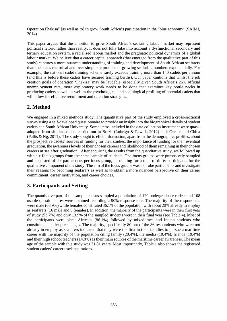
353
Operation Phakisa” [as well as to] to grow South Africa’s participation in the “blue economy’ (SAIMI,2014).
This paper argues that the ambition to grow South Africa’s seafaring labour market may representpolitical rhetoric rather than reality. It does not fully take into account a dysfunctional secondary andtertiary education system, a racialised labour market and the pragmatic political dynamics of a globallabour market. We believe that a career capital approach (that emerged from the qualitative part of thisstudy) captures a more nuanced understanding of training and development of South African seafarersthan the states rhetorical and over simplistic promise of growing seafaring numbers exponentially. Forexample, the national cadet training scheme rarely exceeds training more than 140 cadets per annum(and this is before these cadets have secured training berths). Our paper cautions that whilst the jobcreation goals of operation ‘Phakisa’ may be laudable, especially given South Africa’s 26% officialunemployment rate, more exploratory work needs to be done that examines key bottle necks inproducing cadets as well as well as the psychological and sociological profiling of potential cadets thatwill allow for effective recruitment and retention strategies.
2. Method
We engaged in a mixed methods study. The quantitative part of the study employed a cross-sectionalsurvey using a self-developed questionnaire to provide an insight into the biographical details of studentcadets at a South African University. Some items included in the data collection instrument were quasi-adopted from similar studies carried out in Brazil (Lobrigo & Pawlik, 2012) and; Greece and China(Pallis & Ng, 2011). The study sought to elicit information; apart from the demographics profiles, aboutthe prospective cadets’ sources of funding for their studies, the importance of funding for their eventualgraduation, the awareness levels of their chosen careers and likelihood of them remaining in their chosencareers at sea after graduation. After acquiring the results from the quantitative study, we followed upwith six focus groups from the same sample of students. The focus groups were purposively sampledand consisted of six participants per focus group, accounting for a total of thirty participants for thequalitative component of the study. The aim of the focus groups was to probe participants and investigatetheir reasons for becoming seafarers as well as to obtain a more nuanced perspective on their careercommitment, career motivation, and career choices.
3. Participants and Setting
The quantitative part of the sample census sampled a population of 120 undergraduate cadets and 108usable questionnaires were obtained recording a 90% response rate. The majority of the respondentswere male (63.9%) while females constituted 36.1% of the population with about 20% already in employas seafarers (16 male and 6 females). In addition, the majority of the participants were in their first yearof study (53.7%) and only 13.9% of the sampled students were in their final year (see Table 4). Most ofthe participants were black Africans (86.1%) followed by mixed race and Indian students whoconstituted smaller percentages. The majority, specifically 80 out of the 86 respondents who were notalready in employ as seafarers indicated that they were the first in their families to pursue a maritimecareer with the majority of the population citing family (20.4%), the media (19.4%), friends (19.4%)and their high school teachers (14.8%) as their main sources of the maritime career awareness. The meanage of the sample with this study was 21.81 years. Most importantly, Table 1 also shows the registeredstudent cadets’ career track aspirations.
354
GenderTotal
FrequencyMale
(Frequency)Female
(Frequency)Race B. African 56 37 93
White 2 0 2Mixed Race 4 0 4Indian 6 2 8Other 1 0 1
T/Berth Secured Yes 16 6 22No 53 33 86n/a 53 33 86
Career Aspiration Deck Officer 23 14 37Seafaring Cadet 8 7 15Navigator 15 7 22Marine Pilot 12 7 19officer of the watch 3 1 4Master 3 2 5Marine Surveyor 1 1 2Missing 4 0 4
Total 69 39 108Mean Age Median Age Stan. Deviation Range Minimum Maximum
21.81 20 4.73 32 17 49
Table 1 Demographic Characteristics of the participants (N=120; n=108)
4. Data Collection Instruments
Career Motivation Scale [CMS: Noe et al., 1990; London, 1993] is a quasi-adopted and modified 19-item measure which emphasise feelings and attitudes related to work and career. A sample item is: ‘Ican adequately handle work problems that come my way.’ Noe et al.’s (1990) items focus on behaviours.A sample item is: ‘To what extent do you spend your free time on activities that will help your job?’Reasonably high convergent validity has been found between London’s (1993) and Noe et al.’s (1990)scales suggesting that the two measure the same construct (London & Noe, 1997). We combine the twomeasures in order to investigate both attitudes and behaviours of CM. Previous studies reported aChronbach’s coefficient α of 0.84 for this scale (Day & Allen, 2004). The Chronbach’s alpha coefficientfor the overall CMS and subscales with this study sample was ranged from 0.61 to0.74.
Career Commitment Scale [CCS: Meyer, Allen & Smith, 1993) is an 18-item measure of affective,continuance and normative occupational commitment (six items in each scale). Five items werenegatively phrased, and were reversed scored. The items were modified to apply to the seafaringprofession. Responses to these items were on 5-point scales ranging from 1(strongly disagree) to 5(strongly agree). Meyer et al.’s (1993) reported coefficient alphas ranging from .73 to .87 for thesescales. In this study, only the overall CCS was adopted because it had an acceptable level of reliability(α<0.70).
5. Data Analysis
Statistical analysis was carried out using the Statistical Package for the Social Sciences programme(SPSS version 22) described in Pallant (2013). Both descriptive and inferential statistics were used toanalyse the data. Thematic analysis was used to reduce and report the focus group data. Only selectedresults are reported since the institution at which the study was conducted has embargoed results untilthe full report is presented to them.
355
6. Ethics
Full ethical clearance was granted by the University of KwaZulu - Natal’s ethics committee and eachparticipants signed an informed consent form.
7. Relationships between variables
Results from the Spearman’s rank-order correlation tests showed that students’ motivation, as measuredby the career identity and career planning scales is practically (medium effect) and significantly relatedto career commitment. The relationship between these measures could indicate that students who havea more positive attitude towards their future as seafarers and identify with the profession are more likelyto be more committed than those who don’t. In other words, students who scored high in planning forachieving realistic career goals, who reflect an idea of where their seafaring career is going or take extracourses related to the programme, stay abreast with developments in area of specialisation or volunteerin career related assignments are more likely to be committed to their career when they start working asseafarers. Interesting to note is that, all the personal characteristics included in this study except race didnot show any significant relationship to either motivation or commitment in the Spearman’scorrelational analysis. Therefore, influential as it was, race was controlled for in further analyses. Ourstudy outcome confirms the findings from a related South African study by Bagraim (2003) who founddemographics characteristics not related to professional commitment amongst actuaries. However, thiscontradicts other previous studies to found the opposite (e.g. Colarelli & Bishop, 1990; Kaldenberg,Becker, & Zvonkovic, 1995).
8. Focus Group Themes8.1 Math and Science AnxietiesThe qualitative part of the study captured a high level of math and science competency anxiety amongstparticipants. Participants indicated that even when they have high levels of career interest in seafaringcareers, this interest was not matched by concomitant math and science skills. This proved to bedemotivating for students and also accounted for up to 50% attrition rates. In order to ensure less attritionand increase the quality of graduates, policy interventions need to be made in the domains of math andscience training. For example, maritime education and training (MET) institutes like the AustralianMaritime College (AMC) provide seafarer training graduates mandatory maths training and optionalmaths tutoring classes throughout their study period.
8.2 Professional Calling versus Instrumentalist Career decisionsThe results from the focus group discussions reinforced the findings that the more informed cadets areof what to expect from a seafaring career, the more likely they are to succeed at their studies. This isimportant since over half the participants in the focus group had never even seen an ocean or a ship in‘real life’. The cadet training programme was therefore viewed in a more instrumental way by theseparticipants rather than a professional or vocational calling. The challenge therefore for the SouthAfrican state is to make information about seafaring careers accessible to students as early as possible.An important theme to emerge from all focus group participants was the theme of instrumentalist careerdecision making (ICDM). By this, we mean that participants chose to enter the cadet programme purelybecause they were motivated by the promise of ‘work’ or a ‘job’ after graduating. ‘work’ and ‘job’ inthis sense substitutes as a shorthand for income. Given the over 40% level of unemployment amongstSouth African youth, it does not seem anomalous that this is the chief motivator for cadets entering thiscareer. We suspect that this has implications for career commitment and career longevity of seafarersfrom this institute.
Fei and Lu (2015) who proposed that in traditional maritime nations, seafaring was and still is a “calling”due to the long history and tradition of sailing, the pride and promise associated with it, and the lifestyleit represents. We argue that in South Africa, most determinants of career choice behaviour andmotivation and commitment are mostly rooted on socio economic needs which can be in form of tangiblemonetary and non-monetary rewards. These rewards can be employed from the undergraduate in the
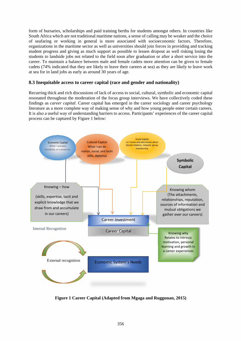
356
form of bursaries, scholarships and paid training berths for students amongst others. In countries likeSouth Africa which are not traditional maritime nations, a sense of calling may be weaker and the choiceof seafaring or working in general is more associated with socioeconomic factors. Therefore,organizations in the maritime sector as well as universities should join forces in providing and trackingstudent progress and giving as much support as possible to lessen dropout as well risking losing thestudents to landside jobs not related to the field soon after graduation or after a short service into thecareer. To maintain a balance between male and female cadets more attention can be given to femalecadets (74% indicated that they are likely to leave their careers at sea) as they are likely to leave workat sea for in land jobs as early as around 30 years of age.
8.3 Inequitable access to career capital (race and gender and nationality)
Recurring thick and rich discussions of lack of access to social, cultural, symbolic and economic capitalresonated throughout the moderation of the focus group interviews. We have collectively coded thesefindings as career capital. Career capital has emerged in the career sociology and career psychologyliterature as a more complete way of making sense of why and how young people enter certain careers.It is also a useful way of understanding barriers to access. Participants’ experiences of the career capitalprocess can be captured by Figure 1 below:
Internal Recognition
External recognition
Figure 1 Career Capital (Adapted from Mgaga and Ruggunan, 2015)
Cultural CapitalWhat I can do
(Education, social, and technicalskills, diploma)
Career Investment
Career Capital
Economic System’s Needs
Knowing whyRelates to intrinsic
motivation, personallearning and growth ina career experiences
Economic CapitalWhat I possess
(Possibility of conversion)
Social CapitalWhom I know and who knows about me
(Social relations, network, groupmembership
s)
Knowing – how
(skills, expertise, tacit andexplicit knowledge that wedraw from and accumulate
in our careers)
Knowing whom(The attachments,
relationships, reputation,sources of information and
mutual obligations wegather over our careers)
SymbolicCapital
357
9. Conclusion and future research directions
The findings in this study contribute to a growing body of research that illustrates the appropriatenessof a multidimensional approach to the study of careers, including those of merchant mariners. It attemptsto show that policy makers and politicians often devise policies with quantitative targets that may bemore rhetoric than reality. Our exploratory study has shown that in order to achieve the envisioned19000 seafarers, South Africa has to seriously examine how career capital is accessed and experiencedby its youth in the path to becoming a seafarer.
Of course our study is limited in that it used a cross-sectional design and relied on self-reports from asmall, highly select group of professionals. This study seeks to help both industry and academiaunderstand factors contributing to prospective seafarers’ experience of their training and development.We hope that this will address the challenges facing the seafaring industry as well as preparing studentsand organisations for a future of rapid changes in the industry.
The current findings should be adopted with caution because they are based on a small sample drawnfrom one institution. Therefore, further studies are required which may also include employers andpeople already in employ, before any recommendations can be made regarding the importance ofpersonal characteristics in understanding professional commitment. The researchers also aim to replicatethis study with seafarers in Australia and compare findings.
References
[1] Allen N J and Meyer J P, “The measurement and antecedents of affective, continuance andnormative commitment to the organization”, Journal of occupational psychology, Vol. 63, No.1,(1990), pp.1-18.
[2] Bagraim J J, “The nature and measurement of multiple commitment foci amongst South Africanknowledge workers”, Management Dynamics: Journal of the Southern African Institute forManagement Scientists, Vol.12, No.2, (2003), pp.1-13.
[3] Colarelli S M and Bishop R C, “Career commitment functions, correlates, andmanagement”, Group & Organisation Management, Vol.15, No.2, (1990), pp.158-176.
[4] Day R and Allen T D, “The relationship between career motivation and self-efficacy with protégécareer success”, Journal of Vocational Behaviour, Vol.64, No.1, (2004), pp.72-91.
[5] Department of Planning, Monitoring and Evaluation, “Operation Phakisa”, Department ofPlanning, Monitoring and Evaluation, 2014, Republic of South Africa, 7 May 2016,http://www.operationphakisa.gov.za/Pages/Home.aspx.
[6] Fei J and Lu J, “Analysis of students’ perceptions of seafaring career in China based on artificialneural network and genetic programming”, Maritime Policy & Management: The flagship journalof international shipping and port research, Vol.42, No.2, (2015), pp.111-126
[7] Kaldenberg D O, Becker B W, and Zvonkovic A, “Work and commitment among youngprofessionals: a study of male and female dentists”, Human Relations, Vol.48, No.11, (1995),pp.1355-1377.
[8] Lobrigo E and Pawlik T, “The seafaring labour market in Brazil”, Maritime Policy & Management:The flagship journal of international shipping and port research, Vol.39, No.6, (2012), pp.621-639.
[9] London M and Noe R A, “London's career motivation theory: An update on measurement andresearch”, Journal of Career Assessment, Vol.5, No.1, (1997), pp.61-80.
[10] London M, “Relationship between motivation, empowerment and support for career development”,Journal of Occupational and Organisational Psychology, Vol.66, (1993), pp.55-69.
[11] Mgaga S and Ruggunan S, Assessing the role of career capital in influencing women’s decisionsto choose a career at sea in Durban: A Proposal, Unpublished paper, University of KwaZulu-Natal, Durban, (2015).

358
[12] Meyer J P, Allen N J and Smith C A, “Commitment to organizations and occupations: Extensionand test of a three-component conceptualization”, Journal of applied psychology, Vol.78, No.4,(1993), p.538.
[13] Noe R A, Noe A W, and Bachhuber J A, “An investigation of the correlates of careermotivation”, Journal of Vocational Behaviour, 37(3), (1990), pp.340-356.
[14] Pallant J, SPSS survival manual: a step by step guide to data analysis using IBM SPSS, 5th Edition,Maidenhead, CA: McGraw-Hill Publishers, (2013).
[15] Pallis A A and Ng A K, “Pursuing maritime education: an empirical study of students’ profiles,motivations and expectations”, Maritime Policy & Management, Vol.38, No.4, (2011), pp.369-393.
[16] South African International Maritime Institute (SAIMI), “Blue Economy”, SAIMI, 2014, SouthAfrican International Maritime Institute, 7th May 2016, http://saimi.co.za/blue-economy.html
359
Session 3C
MARITIME ENVIRONMENTAL ISSUES &ENERGY EFFICIENCY
(No. 3)
360
Modelling reasonable operation regimes of the main propulsion plant maindiesel engine - propeller - hull on the general cargo ship
Prof. DSc. Do Duc Luu, Prof. Dr. Luong Cong Nho, Dr. Tran Ngoc Tu
Vietnam Maritime [email protected]; [email protected];[email protected]
Abstract: The article presents the modeling results of the characteristics of main propulsion plant DieselEngine – Propeller – Hull, based on the combination of the analytical method and regressive analysis ofthe empirical data. The authors create the algorithms on the base of the created models to select thereasonable operating regime of the main propulsion plant (MPP) according to the different operatingconditions (in still water, in sea wave, in the canal, etc.). This paper provides the numerical simulationresults of the drawn combination characteristics of MPP on the 34000 DWT general cargo ship built inVietnam with the main engine MAN 6S 46 MCC, and of the selected regime respectively the desiredoperated conditions. The research results would be used for the simulation of monitoring and controllingthe MPP on the general cargo ship, in order to improve the education quality of the electrical and marineengineering field at Vietnam Maritime University.
Keywords: Main Engine, Propeller, Hull resistance, Main Propulsion Plant.
1. Basis of selecting reasonable exploitation regime
Choosing reasonable working regime of the combination of hull – propeller - main engine underdifferent exploitation regimes ensures the safety of diesel main engine (DME), so that mechanical andthermal overload may not be occurred. In addition, the proposing voyage efficiency of (time, economy)for a cargo ship and sea-going cargo fleet can be achieved by choosing reasonable exploitation regimeof engine’s revolutions and ship’s speeds in different environmental conditions, in which MPP works.Further more, the efficiency of reasonably exploiting working regime of MPP is not only suitable forship’s working purpose from the concepts of safety, high reliability and economy, but also ensuresenvironmental norms set by International Association of Classification Societies (IACS).
The frequent regimes in MPP’s exploitation of a marine vessel: working in still water, carrying cargo(Cargo Load Index, CLI) from ballast (CLI = 0) to full load (CLI = 100%); working in sea wave andwind with given CLI; working in canal; vessel in shallow water. In working process, the resistance statesof ship hull and propeller are deteriorated. In this case, the reasonable exploitation regime of MPP mayvaries from normal exploitation regime (normal regime).
During operating the marine vessel’s MPP, the captain chooses the revolution regime of the DME (fromthe Control Bridge) or gives a command to the engine control room (ECR), which is recommended bythe Chief Engineer in order to have the desired velocity in practice. The engineer- officer staff, whochooses the exploitation revolution regime of main propulsion shaft (MPS), firstly follows the captainbidding, but need to ensure the working safety of MPP: DME is not overloaded, MPS does not fall intothe area of dangerous revolutions; secondly ensures the Specific Fuel Oil Consumption (S.F.O.C) withpossible minimum, attached to supervision of environmental norms in chosen DME regime.
To have necessary knowledge and skills to manage and operate the MPP in different operating regimes,the education and training electro-mechanical crew, as well as deck officer with the management levelis only deployed by independent simulation software for self-studying, self-improving ability or byintergraded software’s module built in the simulation system of ECR. The essence of building imitationsoftware is to establish mathematical model and algorithm to select reasonable exploitation regime forMPP in all situations that may happen in reality. In the process of researching this complicated issue,we can choose one of mathematical models with different accuracy and coherence, which is illustrated
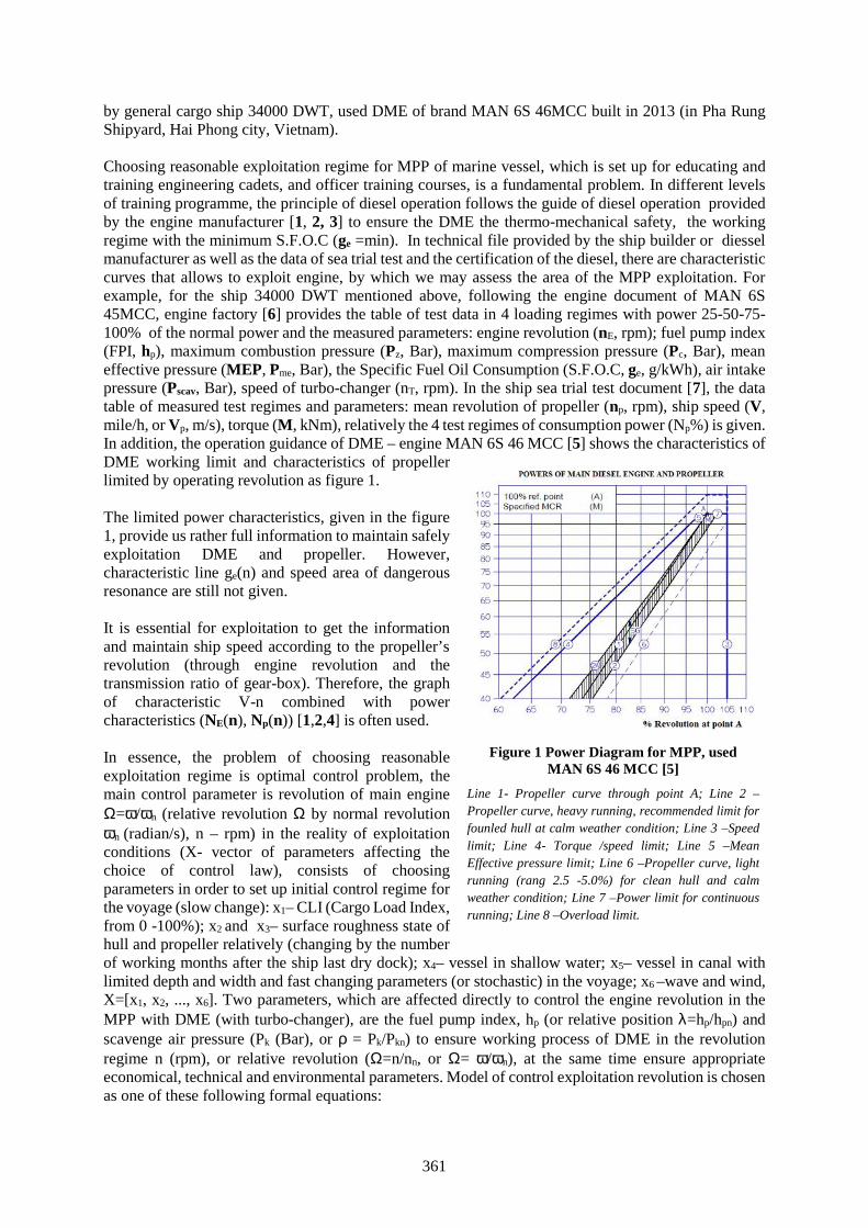
361
by general cargo ship 34000 DWT, used DME of brand MAN 6S 46MCC built in 2013 (in Pha RungShipyard, Hai Phong city, Vietnam).
Choosing reasonable exploitation regime for MPP of marine vessel, which is set up for educating andtraining engineering cadets, and officer training courses, is a fundamental problem. In different levelsof training programme, the principle of diesel operation follows the guide of diesel operation providedby the engine manufacturer [1, 2, 3] to ensure the DME the thermo-mechanical safety, the workingregime with the minimum S.F.O.C (ge =min). In technical file provided by the ship builder or diesselmanufacturer as well as the data of sea trial test and the certification of the diesel, there are characteristiccurves that allows to exploit engine, by which we may assess the area of the MPP exploitation. Forexample, for the ship 34000 DWT mentioned above, following the engine document of MAN 6S45MCC, engine factory [6] provides the table of test data in 4 loading regimes with power 25-50-75-100% of the normal power and the measured parameters: engine revolution (nE, rpm); fuel pump index(FPI, hp), maximum combustion pressure (Pz, Bar), maximum compression pressure (Pc, Bar), meaneffective pressure (MEP, Pme, Bar), the Specific Fuel Oil Consumption (S.F.O.C, ge, g/kWh), air intakepressure (Pscav, Bar), speed of turbo-changer (nT, rpm). In the ship sea trial test document [7], the datatable of measured test regimes and parameters: mean revolution of propeller (np, rpm), ship speed (V,mile/h, or Vp, m/s), torque (M, kNm), relatively the 4 test regimes of consumption power (Np%) is given.In addition, the operation guidance of DME – engine MAN 6S 46 MCC [5] shows the characteristics ofDME working limit and characteristics of propellerlimited by operating revolution as figure 1.
The limited power characteristics, given in the figure1, provide us rather full information to maintain safelyexploitation DME and propeller. However,characteristic line ge(n) and speed area of dangerousresonance are still not given.
It is essential for exploitation to get the informationand maintain ship speed according to the propeller’srevolution (through engine revolution and thetransmission ratio of gear-box). Therefore, the graphof characteristic V-n combined with powercharacteristics (NE(n), Np(n)) [1,2,4] is often used.
In essence, the problem of choosing reasonableexploitation regime is optimal control problem, themain control parameter is revolution of main engine=/n (relative revolution by normal revolutionn (radian/s), n – rpm) in the reality of exploitationconditions (X- vector of parameters affecting thechoice of control law), consists of choosingparameters in order to set up initial control regime forthe voyage (slow change): x1– CLI (Cargo Load Index,from 0 -100%); x2 and x3– surface roughness state ofhull and propeller relatively (changing by the numberof working months after the ship last dry dock); x4– vessel in shallow water; x5– vessel in canal withlimited depth and width and fast changing parameters (or stochastic) in the voyage; x6 –wave and wind,X=[x1, x2, ..., x6]. Two parameters, which are affected directly to control the engine revolution in theMPP with DME (with turbo-changer), are the fuel pump index, hp (or relative position =hp/hpn) andscavenge air pressure (Pk (Bar), or = Pk/Pkn) to ensure working process of DME in the revolutionregime n (rpm), or relative revolution (=n/nn, or = /n), at the same time ensure appropriateeconomical, technical and environmental parameters. Model of control exploitation revolution is chosenas one of these following formal equations:
Figure 1 Power Diagram for MPP, usedMAN 6S 46 MCC [5]
Line 1- Propeller curve through point A; Line 2 –Propeller curve, heavy running, recommended limit forfounled hull at calm weather condition; Line 3 –Speedlimit; Line 4- Torque /speed limit; Line 5 –MeanEffective pressure limit; Line 6 –Propeller curve, lightrunning (rang 2.5 -5.0%) for clean hull and calmweather condition; Line 7 –Power limit for continuousrunning; Line 8 –Overload limit.
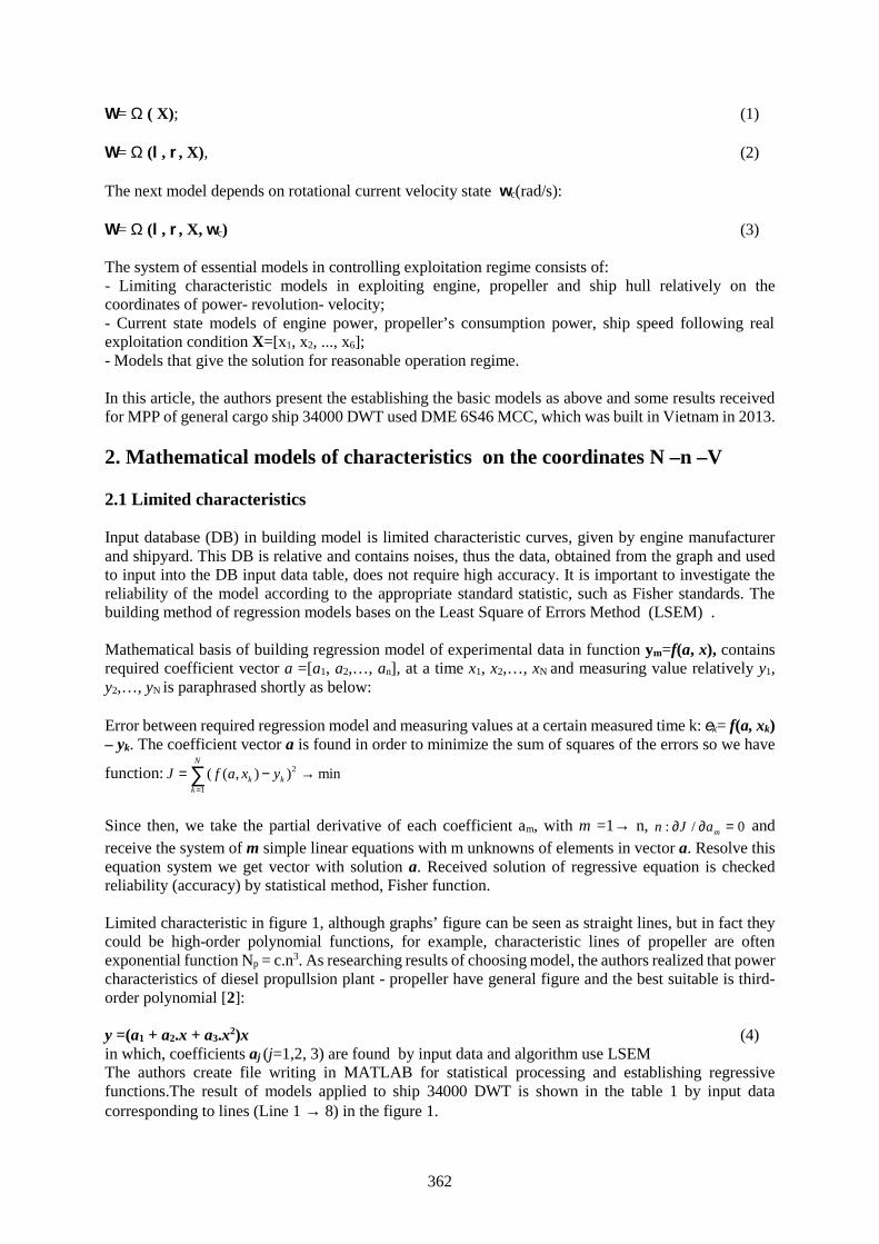
362
= ( X); (1)
= (, , X), (2)
The next model depends on rotational current velocity state c(rad/s):
= (, , X, c) (3)
The system of essential models in controlling exploitation regime consists of:- Limiting characteristic models in exploiting engine, propeller and ship hull relatively on thecoordinates of power- revolution- velocity;- Current state models of engine power, propeller’s consumption power, ship speed following realexploitation condition X=[x1, x2, ..., x6];- Models that give the solution for reasonable operation regime.
In this article, the authors present the establishing the basic models as above and some results receivedfor MPP of general cargo ship 34000 DWT used DME 6S46 MCC, which was built in Vietnam in 2013.
2. Mathematical models of characteristics on the coordinates N –n –V
2.1 Limited characteristics
Input database (DB) in building model is limited characteristic curves, given by engine manufacturerand shipyard. This DB is relative and contains noises, thus the data, obtained from the graph and usedto input into the DB input data table, does not require high accuracy. It is important to investigate thereliability of the model according to the appropriate standard statistic, such as Fisher standards. Thebuilding method of regression models bases on the Least Square of Errors Method (LSEM) .
Mathematical basis of building regression model of experimental data in function ym=f(a, x), containsrequired coefficient vector a =[a1, a2,…, an], at a time x1, x2,…, xN and measuring value relatively y1,y2,…, yN is paraphrased shortly as below:
Error between required regression model and measuring values at a certain measured time k: k= f(a, xk)– yk. The coefficient vector a is found in order to minimize the sum of squares of the errors so we have
function: 2
1
( ( , ) ) minN
k kk
J f a x y
Since then, we take the partial derivative of each coefficient am, with m =1 n, : / 0mn J a andreceive the system of m simple linear equations with m unknowns of elements in vector a. Resolve thisequation system we get vector with solution a. Received solution of regressive equation is checkedreliability (accuracy) by statistical method, Fisher function.
Limited characteristic in figure 1, although graphs’ figure can be seen as straight lines, but in fact theycould be high-order polynomial functions, for example, characteristic lines of propeller are oftenexponential function Np = c.n3. As researching results of choosing model, the authors realized that powercharacteristics of diesel propullsion plant - propeller have general figure and the best suitable is third-order polynomial [2]:
y =(a1 + a2.x + a3.x2)x (4)in which, coefficients aj (j=1,2, 3) are found by input data and algorithm use LSEMThe authors create file writing in MATLAB for statistical processing and establishing regressivefunctions.The result of models applied to ship 34000 DWT is shown in the table 1 by input datacorresponding to lines (Line 1 8) in the figure 1.
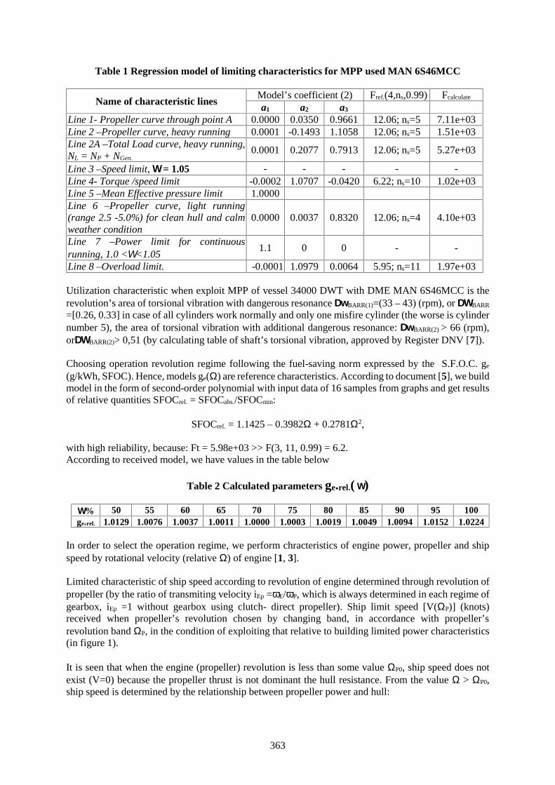
363
Table 1 Regression model of limiting characteristics for MPP used MAN 6S46MCC
Name of characteristic linesModel’s coefficient (2) Fref.(4,ns,0.99) Fcalculate
a1 a2 a3
Line 1- Propeller curve through point A 0.0000 0.0350 0.9661 12.06; ns=5 7.11e+03Line 2 –Propeller curve, heavy running 0.0001 -0.1493 1.1058 12.06; ns=5 1.51e+03Line 2A –Total Load curve, heavy running,NL = NP + NGen.
0.0001 0.2077 0.7913 12.06; ns=5 5.27e+03
Line 3 –Speed limit, = 1.05 - - - - -Line 4- Torque /speed limit -0.0002 1.0707 -0.0420 6.22; ns=10 1.02e+03Line 5 –Mean Effective pressure limit 1.0000Line 6 –Propeller curve, light running(range 2.5 -5.0%) for clean hull and calmweather condition
0.0000 0.0037 0.8320 12.06; ns=4 4.10e+03
Line 7 –Power limit for continuousrunning, 1.0 <<1.05
1.1 0 0 - -
Line 8 –Overload limit. -0.0001 1.0979 0.0064 5.95; ns=11 1.97e+03
Utilization characteristic when exploit MPP of vessel 34000 DWT with DME MAN 6S46MCC is therevolution’s area of torsional vibration with dangerous resonance BARR(1)=(33 – 43) (rpm), or BARR
=[0.26, 0.33] in case of all cylinders work normally and only one misfire cylinder (the worse is cylindernumber 5), the area of torsional vibration with additional dangerous resonance: BARR(2) > 66 (rpm),orBARR(2)> 0,51 (by calculating table of shaft’s torsional vibration, approved by Register DNV [7]).
Choosing operation revolution regime following the fuel-saving norm expressed by the S.F.O.C. ge
(g/kWh, SFOC). Hence, models ge() are reference characteristics. According to document [5], we buildmodel in the form of second-order polynomial with input data of 16 samples from graphs and get resultsof relative quantities SFOCrel. = SFOCabs./SFOCmin:
SFOCrel. = 1.1425 – 0.3982 + 0.27812,
with high reliability, because: Ft = 5.98e+03 >> F(3, 11, 0.99) = 6.2.According to received model, we have values in the table below
Table 2 Calculated parameters ge.rel.( )
% 50 55 60 65 70 75 80 85 90 95 100ge.rel. 1.0129 1.0076 1.0037 1.0011 1.0000 1.0003 1.0019 1.0049 1.0094 1.0152 1.0224
In order to select the operation regime, we perform chracteristics of engine power, propeller and shipspeed by rotational velocity (relative ) of engine [1, 3].
Limited characteristic of ship speed according to revolution of engine determined through revolution ofpropeller (by the ratio of transmiting velocity iEp =E/P, which is always determined in each regime ofgearbox, iEp =1 without gearbox using clutch- direct propeller). Ship limit speed [V(P)] (knots)received when propeller’s revolution chosen by changing band, in accordance with propeller’srevolution band P, in the condition of exploiting that relative to building limited power characteristics(in figure 1).
It is seen that when the engine (propeller) revolution is less than some value P0, ship speed does notexist (V=0) because the propeller thrust is not dominant the hull resistance. From the value > P0,ship speed is determined by the relationship between propeller power and hull:
364
1; ,
(1 )H R p p Ht
tRV M
w
where: V – ship speed (m/s);Mp– moment of propeller (Nm); R – ship hull resistance (N); H – Hullhydrodynamic efficiency; R – Relative rotative efficiency; t – Thrust deduction; wt – wake fraction.
Studying propeller’s power characteristic Np(p) for general cargo ship, we can choose the model Np(p)= C(p)3, where: C- coefficient, which represents ship resistance-propeller, depends on: their roughnessstate, cargo loading and marine condition. We build the model: C =C(X).
The total ship resistance is summation of component resistances and each component is proportional tosquare of ship speed. We have relationship between ship speed and propeller revolution:
1/3 1/3( )H H p pk V C , in which, hull resistance’s coefficient kH depends on density of water (kg/m3),
wetted surface S (m2) and received from experiment or analytical model of hull total resistance inexploitation conditions. This coefficient also depends on X, so we have: kH=kH(X).
Then, we have first-order relation between ship speed and propeller revolution:
V= p; v = p, (5)Concerning the hysteresis of system, we build the model in the following equations:
V = (p - p0) = p - 0 (6)
v = p- 0; or v = X p - X0 (7)
where: perfomance operating characteristics curve = X = (X) may be derived by experimental oranalytical methods; V(m/s) and v =V/Vn are absolute and relative ship speed, Vn - speed of ship atnominal operating condition Vn = V(X=Xn).
We use the limited resistance coefficient [n] to describe the ship limited speed when the propeller workson the maximum propeller characteristics with nominal operating condition Xn (curve 2, fig. 1). Likelyto equation (7), we change to equation for the limited speed:
[vn] = [n] p - [n0] (8)
The significant factor is that, in the most severe, the main engine can sustain upper DME limited powercharacteristics. The method to establish this perfomance operating characteristics curve is as follows:Propeller torque M = D5n2KQ, KQ - Propeller torque coefficient. This coeficient can be describedapproximately with a line form. KQ = a2 – b2(v/n) therefore, we obtain the computational models of thepower of main engine, which Prof. Emil Stanchev defined [2, page 13]:
M = A20n2 – B20nV, (Nm) (9)
where: A20, B20 - coefficients depending on propeller parameters.
A20 = D5a2, (kg.m2); B20 = D4b2, (kg.m) (10)
Where - density of seawater, kg/m3 ( =1025 kg/m3); D – diameter of propeller (m); a2 and b2 can becalculated from propeller torque coefficient.
From (9), we have the limited speed equals the power of main engine with limited torque characteristicsM0() = N0/; = n/30:
365
[V] = (A20/B20) - M0()/B20, (m/s) (11)
Hence:1 220 0
20 20
[ ]A M
v k kB B
The coefficients1k and
1k can be changed to dimensionless.The curve of limited speed based on torque characteristics of engine is a hyperbol curve.Then, we define A20 and B20 from equation (9) base on sea trial data with LSEM.
With 34000DWT ship using DME, MAN 6S46 MCC, base on the sea trial data [7], we obtain A20 =6.1374 and B20 = 6.0041 with the following model:
M = 6.1374 2 – 6.0041V, (kN.m); (12)
Fisher standard: Fr = 878.67 >> F(2,4,0.99) = 18, prove that the reliability of model is 99%.
The limited speed equation (11) with limited torque of engine:
[V] = 1.0222 - 0,1666 M0()/, (m/s) (13)
If "Fuel Pump Index" unchanges at the maximum value, the limited speed curve is hyperbol form.
2.2. The current operation characteristics
To establish the mathematical model of MPP in real operation condition by assuming X vector and theoperation conditions are determined (or set up the concrete operation), we will establish the operatingcharacteristics of engine power, propeller and ship speed.
NE(, XE), NP(, XP), and V(, XH), (14)
Where: XE,XP and XH - the concrete operation condition vectors for engine, propeller and ship hull,corresponding to the factor condition of X vector which was mentioned above.
Models are established (14) by analytical methods or experimental method, and by combination ofanalytical and experimental methods.
2.2.1. Establishing the charateristics of MPP using analytical method
The advantage of analytical method is that, it is more flexible and has the sense of initiative to describethe different conditions from X operation condition to obtain the relationships (4). The only difficultyof analytical method is that, we need experimental data with a large of range fluctuation, or the reliabilityis low. To overcome that disadvantage, we need to take test in some favourable conditions, therefore,the analytical data can be confirmed.
Ship resistance at various operation conditionsThe total resistance in the still water. The total resistance in the still water includes the followingcomponents:
, kNF V W APP A AAR R R R R R R (15)
Where: RF – frictional resistance; RV – form resistance; RAPP – appendage resistance; RA – roughnessresistance; RAA – Air resistance.
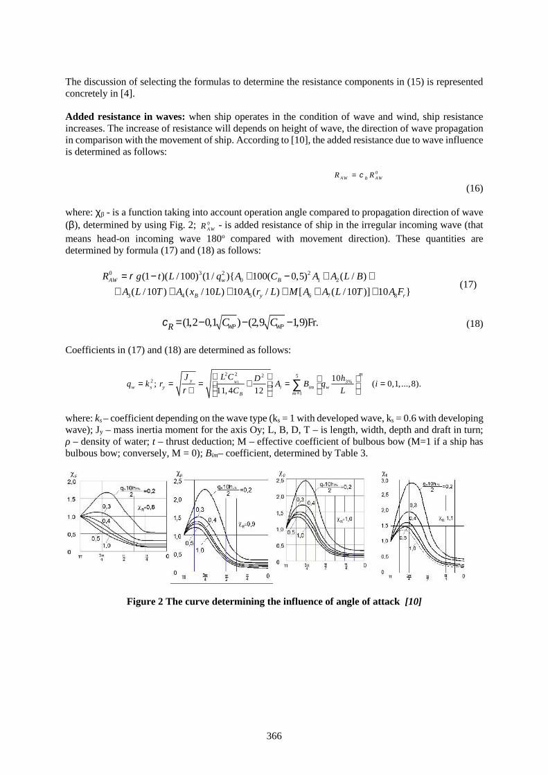
366
The discussion of selecting the formulas to determine the resistance components in (15) is representedconcretely in [4].
Added resistance in waves: when ship operates in the condition of wave and wind, ship resistanceincreases. The increase of resistance will depends on height of wave, the direction of wave propagationin comparison with the movement of ship. According to [10], the added resistance due to wave influenceis determined as follows:
0AW AWR R
(16)
where: β - is a function taking into account operation angle compared to propagation direction of wave(), determined by using Fig. 2; 0
AWR - is added resistance of ship in the irregular incoming wave (thatmeans head-on incoming wave 180o compared with movement direction). These quantities aredetermined by formula (17) and (18) as follows:
0 3 2 20 1 2
3 4 5 6 7 8
(1 )( /100) (1/ ){ 100( 0,5) ( / )
( /10 ) ( /10 ) 10 ( / ) [ ( /10 )] 10 }AW w B
B y r
R g t L q A C A A L B
A L T A x L A r L M A A L T A F
(17)
(1,2 0,1 ) (2,9 1,9)Fr.WP WPR C C (18)
Coefficients in (17) and (18) are determined as follows:
2 2 2 52 3%
1
10; ; ( 0,1,...,8).
11, 4 12WL
my
w s y i im wmB
L CJ hDq k r A B q i
C L
where: ks – coefficient depending on the wave type (ks = 1 with developed wave, ks = 0.6 with developingwave); Jy – mass inertia moment for the axis Oy; L, B, D, T – is length, width, depth and draft in turn;ρ – density of water; t – thrust deduction; M – effective coefficient of bulbous bow (M=1 if a ship hasbulbous bow; conversely, M = 0); Bim– coefficient, determined by Table 3.
Figure 2 The curve determining the influence of angle of attack [10]
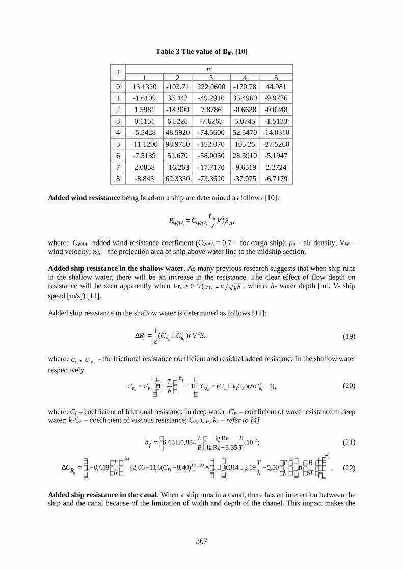
367
Table 3 The value of Bim [10]
i m1 2 3 4 5
0 13.1320 -103.71 222.0600 -170.78 44.981
1 -1.6109 33.442 -49.2910 35.4960 -9.9726
2 1.5981 -14.900 7.8786 -0.6628 -0.0248
3 0.1151 6.5228 -7.6263 5.0745 -1.5133
4 -5.5428 48.5920 -74.5600 52.5470 -14.0310
5 -11.1200 98.9780 -152.070 105.25 -27.5260
6 -7.5139 51.670 -58.0050 28.5910 -5.1947
7 2.0858 -16.263 -17.7170 -9.6519 2.2724
8 -8.843 62.3330 -73.3620 -37.075 -6.7179
Added wind resistance being head-on a ship are determined as follows [10]:
2 ,2
aWAA WAA A AR C V S
where: CWAA –added wind resistance coefficient (CWAA = 0,7 – for cargo ship); ρa – air density; VW –wind velocity; SA – the projection area of ship above water line to the midship section.
Added ship resistance in the shallow water. As many previous research suggests that when ship runsin the shallow water, there will be an increase in the resistance. The clear effect of flow depth onresistance will be seen apparently when Fr 0, 3h ( Frh V gh ; where: h- water depth [m], V- shipspeed [m/s]) [11].
Added ship resistance in the shallow water is determined as follows [11]:
21( ) .
2 h hh F RR C C V S (19)
where:hFC ,
hRC - the frictional resistance coefficient and residual added resistance in the shallow water
respectively.
211 1 ; ( )( 1),
h h hF F R w F R
fbT
C C C C k C Ch
(20)
where: CF – coefficient of frictional resistance in deep water; CW – coefficient of wave resistance in deepwater; k1CF – coefficient of viscous resistance; CF, CW, k1 – refer to [4]
2lg Re6,63 0,884 .10 ;
lg Re 3,35fL B
bB T
(21)
1,644 23 0,333
1
1 0,618 [2,06 11,6( 0,40) ] 1 0,314 3,59 5,50 ln ,6h
BRT T T B
C Ch h h T
(22)
Added ship resistance in the canal. When a ship runs in a canal, there has an interaction between theship and the canal because of the limitation of width and depth of the chanel. This impact makes the

368
change in water resistance of a ship. As a result, additional resistance causing by the influence of widthand depth is calculated [11]:
2
;2KK
V SR C
(23)
Where: CK – the coefficient of water resistance of a ship in the canal, determined as follows:
K KK F RC C C (24)
Where:KFC ,
KRC - the frictional resistance coefficient and residual added resistance in the canal. They
are determined as follows:
1
5 3 0,335 0,3220,285 24,4 1 1 0,54
1,26 ( ) lg Re 3,16 FKF B KK KP
TC C m C
h v v
(25)
2
1( )KR W FC C k C V (26)
These quantities in formula (25) and (26) are determined as follows:
2
1
1 1,195 (1 0,345 ),
1 0,88K K
KP Ki
m mV gh
b
Fr ;
Kh
V
gh 2 [ ( )].K M K W Bm C BT h B B
3
1
1 (2,44 4,48 ) 1 1 ;1
KK
K KP
m VV m
m V
( ) ( )W B W Bib B B B B
where: bi = (BW – BB)/(BW + BB) - Trapezoidal coefficient; BW – width of canal’s water surface; BB –width of canal’s bottom; hK – canal depth; VKP1 – first limmited speed of ship in the canal; CM – midshipsection coefficient.
Formula (25) and (26) are correct in the range as follows: 106 Re 2.109; V 0,95VKP1; 0,04 mK 0,30; bi 0,60; 0,450 CB 0,920; 0,2 T/hK 0,90.
Ship resistance when there is a change in ship deadweight. Throughout the voyage, deadweight ofship varies incessantly because of the change of fuel, cargo weight and so on,… It leads to the variationin the draft and eventually in ship resistance. In order to assess the change in resistance of a ship due tothe change draft we use the following formula [9]:
i iR k R (27)
where: Ri – ship resistance in the random loading case; R– Ship resistance full loaded condition;coefficient ki is determined according to [9, page 201].
Characteristic model of propellerThe work of combination “propeller – ship hull – main engine” causes the mechanical andhydrodynamic impact between each component.
Performance of the propulsion combination η is calculated by [12]:
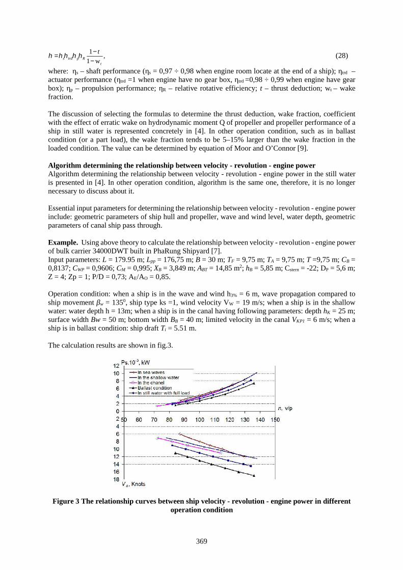
369
1,
1 ws trd p Rt
t
(28)
where: ηs – shaft performance (ηs = 0,97 ÷ 0,98 when engine room locate at the end of a ship); ηtrd –actuator performance (ηtrd =1 when engine have no gear box, ηtrd =0,98 ÷ 0,99 when engine have gearbox); ηp – propulsion performance; ηR – relative rotative efficiency; t – thrust deduction; wt – wakefraction.
The discussion of selecting the formulas to determine the thrust deduction, wake fraction, coefficientwith the effect of erratic wake on hydrodynamic moment Q of propeller and propeller performance of aship in still water is represented concretely in [4]. In other operation condition, such as in ballastcondition (or a part load), the wake fraction tends to be 5–15% larger than the wake fraction in theloaded condition. The value can be determined by equation of Moor and O’Connor [9].
Algorithm determining the relationship between velocity - revolution - engine powerAlgorithm determining the relationship between velocity - revolution - engine power in the still wateris presented in [4]. In other operation condition, algorithm is the same one, therefore, it is no longernecessary to discuss about it.
Essential input parameters for determining the relationship between velocity - revolution - engine powerinclude: geometric parameters of ship hull and propeller, wave and wind level, water depth, geometricparameters of canal ship pass through.
Example. Using above theory to calculate the relationship between velocity - revolution - engine powerof bulk carrier 34000DWT built in PhaRung Shipyard [7].Input parameters: L = 179.95 m; Lpp = 176,75 m; B = 30 m; TF = 9,75 m; TA = 9,75 m; T =9,75 m; CB =0,8137; CWP = 0,9606; CM = 0,995; XB = 3,849 m; ABT = 14,85 m2; hB = 5,85 m; Cstern = -22; DP = 5,6 m;Z = 4; Zp = 1; P/D = 0,73; AE/AO = 0,85.
Operation condition: when a ship is in the wave and wind h3% = 6 m, wave propagation compared toship movement βw = 1350, ship type ks =1, wind velocity VW = 19 m/s; when a ship is in the shallowwater: water depth h = 13m; when a ship is in the canal having following parameters: depth hK = 25 m;surface width Bw = 50 m; bottom width BB = 40 m; limited velocity in the canal VKP1 = 6 m/s; when aship is in ballast condition: ship draft Ti = 5.51 m.
The calculation results are shown in fig.3.
Figure 3 The relationship curves between ship velocity - revolution - engine power in differentoperation condition
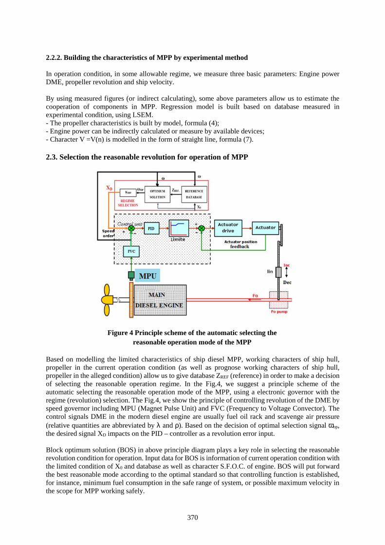
370
2.2.2. Building the characteristics of MPP by experimental method
In operation condition, in some allowable regime, we measure three basic parameters: Engine powerDME, propeller revolution and ship velocity.
By using measured figures (or indirect calculating), some above parameters allow us to estimate thecooperation of components in MPP. Regression model is built based on database measured inexperimental condition, using LSEM.- The propeller characteristics is built by model, formula (4);- Engine power can be indirectly calculated or measure by available devices;- Character V =V(n) is modelled in the form of straight line, formula (7).
2.3. Selection the reasonable revolution for operation of MPP
Based on modelling the limited characteristics of ship diesel MPP, working characters of ship hull,propeller in the current operation condition (as well as prognose working characters of ship hull,propeller in the alleged condition) allow us to give database ZREF (reference) in order to make a decisionof selecting the reasonable operation regime. In the Fig.4, we suggest a principle scheme of theautomatic selecting the reasonable operation mode of the MPP, using a electronic governor with theregime (revolution) selection. The Fig.4, we show the principle of controlling revolution of the DME byspeed governor including MPU (Magnet Pulse Unit) and FVC (Frequency to Voltage Convector). Thecontrol signals DME in the modern diesel engine are usually fuel oil rack and scavenge air pressure(relative quantities are abbreviated by and ). Based on the decision of optimal selection signal op,the desired signal XD impacts on the PID – controller as a revolution error input.
Block optimum solution (BOS) in above principle diagram plays a key role in selecting the reasonablerevolution condition for operation. Input data for BOS is information of current operation condition withthe limited condition of X0 and database as well as character S.F.O.C. of engine. BOS will put forwardthe best reasonable mode according to the optimal standard so that controlling function is established,for instance, minimum fuel consumption in the safe range of system, or possible maximum velocity inthe scope for MPP working safely.
Figure 4 Principle scheme of the automatic selecting thereasonable operation mode of the MPP
371
Standard database includes: The limited characters {[Ne], [Np], [V]} and character SFOC ge, that areregressive models, some of them are shown in the table No1 in the paper; The basic operation charactersare built by the analytical method {Ne(, X0), Np(,X0) and V(,X0)}, according to the above mentionalbases in the point 2.2.
3. Conclusion
This paper builds the system of regression models for limited characteristic curve of DME, limitedcharacter of the ship speed when engine works above maximum constant moment characteristic curve;characteristic curve of the S.F.O.C. of DME and propeller characteristic curve in the full loadedcondition. Those models have an essential reference data for maintaining the operation mode in a safeand economical way.
Based on analytical models determining ship resistance, moment and thrust of propeller in everyoperation mode MPP will be the prediction of propeller characteristic curve and ship hull so that we areable to select a suitable operation mode.
This article puts forward principle diagram of the automatic selecting the reasonable operation regimes;specifically it puts forth round mode of main engine and propeller according to reference data (standardcharacteristic model system) as well as actual operation mode of ship hull, propeller (these cases dependon working condition vector X of MPP).
References
[1] Bogdanov H.Marine Energy Equipment (Operation). Military Edition. Sofia, 1983. (InBulgarian).Богданов Х.Г.Корабни енергични уредби. София, «Военно издателство», 1983. 244с.
[2] Emil Stanchev and others. Dynamic researching on the marine propullsion plants in the exploitationconditions. Military Edition. Sofia, 1982. (In Bulgarian). Емил Станчев и др. Динамичниизледвания на корабния пропилсивен комплекс в эксплуатационни условия. София, «Военноиздателство», 1982. – 284 с.
[3] Ovsianicov M. and Petukhov V. Marine propulsion plants. Leningrad, 1987. (In Russian).Овсянников М.К, Петухов В.А. Дизели в пропульсивном комплексе морских судов:Справочник. Л.: Судостроение, 1987. 256 с.
[4] LuuD.D., Nho L.C, Tu Tr.Ng.Modelling characteristics of the hull and propeller of sea-goinggeneral cargo ship in normal operating conditions. Maritime Science-Technology Journal, N46,March 2016 (VietNam). ISBN.
[5] MAN DIESEL 6S46 MC-C. VOLUME I. Operation.[6] Hồ sơ tàu 34000 DWT. Technical File 6S46 MC MK II. HHM–Shanghai Hujiang Diesel Emission
Test Scie-Tech Co.Ltd. Approved DNV 20 -08-2007.[7] Hồ sơ tàu 34000 DWT. Hồ sơ thử tàu 34000 DWT. NMĐT Phà Rừng.2007.[8] Hồ sơ tàu 34000 DWT. Torsional Vibration Calculation Report DE 6S46MC –C7860 kW @ 129
r/min 34,000 DWT. HUDONG HEAVY MACHINERY Co. Ltd. PhaRung Shipyard. DNV(Classification Society) Approved 2007 - 06 -06.
[9] Molland, Anthony F. Ship resistance and propulsion: practical estimation of ship propulsive power. ISBN 978-0-521-76052-2 (hardback).
[10] Под ред. Я.И. Войткунского. Справочник по теории корабля: В трех томах. Том 1.Гидромеханика. Сопротивление движению судов. Судовые движители. (1985). Л.:Судостроение - 768 с.
[11] В.Ф. Бавин, В.И. Зайков и др.; Под ред. В.Г. Павленко.Ходкость и управляемость судов(1991). Учебник для вузов/ – М.: Транспорт. 1991. 397 с.
[12] Гайкович А.И. Теория проектирования водоизмещающих коряблей и судов. TOM 2: Изд.НИЦ МОРИНТЕХ, 2014.
372
Ballast Water Management: Challenges for the Flag State and Port StateControl
Samrat Ghosh1 and Christopher Rubly2
1. Australian Maritime College (University of Tasmania), [email protected], Australia2. Australian Maritime College (University of Tasmania), [email protected]
Abstract Merchant shipping facilitates 90 percent of global trade by volume, and in performing thisvital function around 45000 vessels move more than 10 billion tons of ballast water around the globeannually. When ballast water is loaded and discharged at different ports, immense quantities of aquaticlife in the form of larvae, eggs, cysts, bacteria, microbes and small invertebrates are relocated.Introduced aquatic species often become invasive in their new environment, proliferating at dramaticrates displacing native populations, causing damage to local eco-systems, human health and property,and has been recognised as a huge ecological and economic threat to the planet’s environment.Overwhelming global environmental concern prompted the International Maritime Organization (IMO)to adopt the International Convention for the Control and Management of Ships’ Ballast Water andSediments (BWM Convention) during the International Conference on Ballast Water Management forShips’ in 2004, defining strict regulations for ship’s ballast water and sediment controls. The BWMConvention seeks to protect the marine environment and prevent the global spread of IAS byestablishing benchmark strategies and standards for managing ships’ ballast water and sediments.Although the Convention remains to be ratified, it is nearing its tonnage requirement of 35% of theworld’s merchant shipping that will allow it to come into force in the near future. To manage themagnitude of ships that will be obliged to fulfil the requirements of the Convention, IMO has authorizedFlag State Control (FSC) and Port State Control (PSC) to enforce compliance. However, regulatorybodies face a number of challenges in ensuring compliance. Based on a review of literature, this paperhighlights the various facets of the BWM Convention that are inadvertently creating challenges for thePSCs and FSCs to ensure effective compliance of the Convention.
Keywords: Ballast water management, Port State Control (PSC), Flag State Control (FSC),Compliance, Invasive aquatic species (IAS), marine environmental protection
1. Introduction
Merchant shipping facilitates 90 percent of global trade by volume, and with ever expandingglobalization and demand for fast turnaround times, it represents a cost effective method in theinternational transport of cargo (Maritime Gateway 2016). In performing this vital function around45,000 vessels move more than 10 billion tons of ballast water around the globe annually (NationalGeographic 2016). The impact of this is causing significant ecological and economic damage throughthe transportation of marine aquatic species such as bacteria, eggs, cysts, small invertebrates, microbesand larvae in ships ballast water, which often multiply into pest proportions in the new environment,becoming invasive and displacing native species (International Maritime Organization (IMO) 2016a).Highlighting the seriousness of the problem, Briski et al. (2013) indicates invasive aquatic species (IAS)have caused 20% of global animal extinctions and contribute significantly to an additional 34% ofanimal extinctions.
Overwhelming global environmental concern prompted the International Maritime Organization (IMO)to adopt the International Convention for the Control and Management of Ships’ Ballast Water andSediments (BWM Convention) during the International Conference on Ballast Water Management forShips’ in 2004. The BWM Convention seeks to protect the marine environment and prevent the globalspread of IAS by establishing benchmark strategies and standards for managing ships’ ballast water andsediments (IMO 2016b). The BWM Convention, detailing the prerequisites and technical guidelines formanaging ships’ ballast water and sediments, is set to enter force 12 months after it has been ratified by30 maritime states representing 35% of global commercial shipping tonnage. As at February 2016, the
373
treaty had been ratified by 47 States, with less than 35% of world tonnage (IMO 2016d). Although theConvention is not in force yet, on ratification, all ships will be required to implement a ballast water andsediments management plan, carry a ballast water record book and perform ballast water managementroutines to a defined standard (IMO 2016b). Ballast water management standards are to be eased inover time, with ships exchanging ballast water mid-ocean as an interim measure. Eventually, with theratification of the BWM convention, all ships would be required to be fitted with ballast water treatmentsystems (IMO 2016b).
To ensure compliance with the requirements of the Convention, the IMO has authorized the regulatorybodies of Port State Controls (PSC) and Flag State Controls (FSC). However, the regulatory bodies facea number of challenges in ensuring compliance. Based on a review of literature, this paper highlightsthe various facets of the BWM Convention that are inadvertently creating challenges for PSC and FSCto ensure effective compliance of the Convention.
2. Obligations of the Flag State and Port State Controls
The IMO is the over-arching regulatory body which together with national maritime regulators enforcethe requirements of the BWM Convention on maritime nations (or States) that have ratified theconvention. The national regulator is usually known as the ‘Flag State’ (also known as Flag State Controlor FSC) which can be an administration or the government of the State under which ships can beregistered, e.g. Australian Maritime Safety Authority (AMSA) in Australia. The FSC becomes ‘PortState Control’ (PSC) when ships of other registry call at their ports (Ghosh, Bowles, Ranmuthugala, andBrooks 2014).
Article 4 of the BWM Convention requires Flag States to adopt appropriate measures and oblige shipsregistered and operating under its authority to comply with the relevant standards of the Convention. Todo so, the article stipulates that each Flag State shall, “with due regard to its particular conditions andcapabilities, develop national policies, strategies or programmes for Ballast Water Management in itsports and waters under its jurisdiction that accord with, and promote the attainment of the objectives ofthis Convention”. In addition, Article 7 of the Convention stipulates that each Flag State shall requireships registered under its authority to undergo surveys to obtain certification of compliance (IMO 2004).Hence, the Flag States shall develop national legislations that contain procedures for survey of ships byqualified surveyors and include approval of Ballast Water Management Plan (BWMP), Type approvalof Ballast Water Management System (BWMS), and outsourcing of tasks that fall out of the area ofexpertise of the Flag States to recognized organizations (Kim 2013). Flag States are also required toimpose sanctions on ships under its domestic law, for any violations of the convention. Concurrently, ifthe Flag States are notified of a violation of the Convention by any one of its ships, they are obliged toinvestigate the matter, collect and analyse evidence, and implement procedures according to itslegislation (Ahmed and Youssef 2014).
PSCs are required to develop and implement guidelines, plans, and facilities to enforce compliance withthe BWM Convention when ships (other than those registered under its authority) visit theirjurisdictional waters. Similar to Flag States, PSC must establish sanctions for any violation of theConvention that takes place within its jurisdiction. A violation in such cases may result in the ship beingwarned, detained, or rejected from entering the port. When a violation happens inside its jurisdiction, aPSC has the choice to take procedures according to its legislation or give information and evidenceidentified to the violation to the Flag State under whose authority the ship is registered. PSC may alsohave to carry out additional inspections of ships at the request of other PSCs or FSCs when providedwith evidence of the ship’s violation of the Convention in the recent past.
However, in their efforts to ensure global compliance of the BWM Convention, PSC and FSC face anumber of challenges.
374
3. Challenges to the Flag State and Port State Controls
3.1 Identification of exchange locations
The BWM convention specifies criteria based on geographic locations for an exchange of ballast water.This criteria requires vessels to carry out the exchange at a distance of normally 200 nautical miles fromthe nearest land and in water depths exceeding 200 meters. Ships’ officers have to record details of suchexchanges in the ballast water log book where the geographic location in terms of latitude and longitudeas well as nearest distance form land need to be logged. However, PSC and FSC officers have no meansto verify whether the ballast water was indeed exchanged on the logged position. The accuracy of theinformation is completely based on the ethics of the ships’ officers who are trusted to carry out theexchange operations as per the Convention’s requirements.
In addition, port states are required to determine alternate and appropriate locations for the ballast waterexchange to take place. In identification of locations, the BWM convention requires port states toidentify areas within its waters where there are risks of harmful uptakes, outbreaks or infestation of AIS,sewage outfalls, and poor tidal flushing (Anstey 2008). This will require PSC and FSC to carry outcontinued scientific and technical research towards the identification and maintenance of suitableexchange locations, which may result in the imposition of financial restraints.
3.2 Financial costs
Kim (2013) classifies the financial costs to PSC and FSC under ‘preparatory’ and ‘compliance’. The‘preparatory’ costs relate to the fulfilment of institutional needs (for example, staff required, equipment,technology, etc.) and developing national strategies (for example, stakeholder involvement, developingcooperative relationships with other States, inspection regimes, etc.). On the other hand, the‘compliance’ costs may include expenses related to issuance and renewal of certificates, surveyprocedures, approval of ballast water management systems, training of crew, and reforms of the nationalregulatory framework. For example, Australia is a signatory Party to the BWM Convention subject toratification and The Department of Agriculture is developing the Biosecurity Bill 2014 to provide aframework for Australia to manage risks associated with ballast water (AMSA 2016). Theimplementation costs of the bill is estimated around $0.6 million dollars (Queensland Legislation 2013).
To comply with the numerous provisions of the BWM Convention, States should reform theırlegislations and policies, strategies and institutional arrangements through a consistent review processto achieve the ultimate purpose of establishing a national BWM framework (Ahmed and Youssef 2014).However, such reforms are not achieved overnight and may require a number of years that requires costconsiderations. For example, the Biosecurity Bill in Australia took six years to be developed and passedby the Senate (Invasive species council 2016). Hence, for many States, the concerns are not only focuseson financial investments towards ‘preparatory’ and ‘compliance’ costs but also towards buildingnational systems towards the compliance requirements of the BWM Convention. For example, Rittel &Webber (1973) describe governmental policy and planning problems as inherently imprecise ‘wicked’problems, which rely on intangible political evaluation for resolution, and that solutions are usuallyfound through engaging with stakeholders to build consensus. For many States, it may be challengingto engage all concerned stakeholders, towards compliance with the BWM Convention. Therefore,continuous support for those States through capacity building in international or regional levels isrequired to the effective implementation of the BWM Convention (Kim 2013).
In building a global consensus to ratify the BWM Convention and reduce the environmental impacts ofIAS through ships’ ballast water, the IMO has taken the ‘wicked’ approach to solve the problem throughextensive stakeholder engagement. Despite the extraordinary amount of time that has elapsed, thisstrategy has been instrumental in the move towards ratifying the BWM Convention. This may be seenthrough the GloBallast Partnerships joint initiative between IMO, United Nations DevelopmentProgramme (UNDP) and the Global Environment Facility (GEF), which has been key to progressing
375
global ballast water technology solutions; strengthening global understanding and information transferin support of marine biosecurity strategies; and the formation of innovative public-private partnershipswith leading marine companies through the establishment of the Global Industry Alliance (GIA) andassisting developing countries reducing the transfer of IAS (IMO 2016c). Outcomes from integrated andcollaborative initiatives such as these are significant, demonstrating to the global community that despitethe many complexities involved, challenges can be overcome to protect the marine environment (IMO2016c).
However, once the reforms are in place, the challenge for Flag States would be to train their staff tounderstand their national regulatory framework and the aspects concerning ballast water management.Such training would involve monetary investments which may be large in cases where there is anabsence of suitable training providers.
3.3 Lack of recognized training providers
The training of Port State and Flag State Control officials in the understanding and implementation ofthe BWM convention is of a significant interest in the effective compliance of the convention (Kim2013). Training must cover all aspects of the Convention including requirements for and of a ballastwater management plan (BWMP) approval; testing of equipment; sampling requirements; recordkeeping; and safety considerations for ballast water exchange. Although this list is not exhaustive, ithighlights the various aspects of training required and the need for suitable and qualified trainingproviders. However, due to the Convention not being in force and a resulting absence of a formal globalrecognition leading to varying national standards, there appears to be a dearth of specialised training(Anstey 2008). This is a major challenge for PSCs and FSCs who are required to keep themselvesupdated with changing nature of the Convention.
A web search revealed that one of the most recognized training providers, Lloyd’s Register Marine(2016), provides some degree of training to shore staff who will be involved in planning how to complywith the upcoming ballast water management legislation as well as those who will be responsible forimplementing the plan. The training delivered by experts in the field of BWM Convention includes thefollowing:
Requirements of the BWM Convention and the United States Coast Guard (USCG) legislation,including their implementation schedules.
Options for complying with ballast water management legislation. Operational limitations of the various ballast water treatment technologies. Recognise the ship types and trades which may be suited to other alternative compliance options
(such as using reception facilities). One approach for comparing the suitability of ballast water treatment systems for use on board
a specific ship with a defined operational profile. Issues associated with retrofitting ballast water treatment systems. Approach that port state control inspectors are likely to take when reviewing compliance with
the BWM Convention.
However, the training is a one-day course that does not allow it to be extensive, or provide acomprehensive understanding of all the different aspects of the Convention. For example, in April 2008,the IMO sponsored a four-day training in an introductory course on the topic of ballast watermanagement for the Mediterranean region. While the four-day training was of value, some of theparticipants’ stated that the requirements of the Convention was one of the most difficult to comprehendand implement (Anstey 2008).
A further search on the web for specific training provided to PSCs and FSCs in the area of BWMConvention did not reveal its prevalence. This paper acknowledges that the web search may haveoverlooked certain training providers, the fact cannot be ignored that there is very little in the way ofBWM training being offered. The IMO Resolution A.868 (20) specifies the need for training for ships’masters and crews and goes further by directing governments to ensure that their marine training
376
organizations include this in the contents of their syllabus. It also encourages them to include knowledgeof duties regarding the control of pollution of the sea by harmful aquatic organisms and pathogens intheir training requirements for certificates. It appears that, so far, this guidance has had very little impacton the provision of national BWM training requirements (Anstey 2008).
3.4 Safety Considerations
Training for PSC and FSC officials is most essential for the recognition of safety hazards that challengethem during routine inspections. For example, officials may be exposed and affected by the IAS presentin the sample of ballast water collected for testing and monitoring compliance to discharge standards(Balaji and Yaakob 2014). Sampling of ballast water is primarily a matter for the authorized inspectionofficers during PSC inspections (Enshaei, Carney, and Mesbahi 2015). One may view the duty ofcollecting samples as the responsibility of the ship’s staff under the supervision of PSC officials,however, the risk of exposure cannot be ruled out. PSC and FSC officials should be trained in the useof biological protocols such as the use of protective equipment which may provide the necessaryprotection against exposure to infectious elements when handling the samples of ballast water or whenentering ballast water tanks for inspections.
3.5 Determination of sampling size
Article 9 of the BWM Convention stipulates that a ship may, in any port or offshore terminal of anotherParty, be inspected by officers duly authorized by that Party (i.e. PSC Inspection) in order to determinethe ship’s compliance with the applicable requirements. Such an inspection involves checkingcertificates, crew familiarization and BW sampling. Sampling of ballast water is required to monitorship’s compliance with the BWM convention. Testing the samples will provide PSC officials with keyinformation regarding the measurement of IAS in the ballast water, effectiveness of water treatmentsystems in reducing/eliminating the IAS, and ship’s discharge as per BWM Convention standards. Forexample, a ship will be banned from discharging ballast water where the ship ballast waters’ samplingresults show that it present harm to the environment, property, natural resources or human health. TheIMO has developed publications that provide “Guidance on ballast water sampling and analysis (G2)”adopted by Res.MEPC.173 (58) in 2008. However, PSC and FSC officials face a number of challengesdue to the vagueness that still exist in the standards described for sampling (Kim 2013).
The problem is that the G2 guidelines are not sufficient for practical use by PSC officers in many aspects.For example, the Guidelines stipulate that “the sampling and analysis methodologies to test forcompliance with the Convention are still in development and at the present time, there are no specificsampling or analysis protocols that can be recommended for Administrations to use”. Accordingly, afterlong discussion at the MEPC 65th session held in May 2013, “Guidance on ballast water sampling andanalysis for trial use in accordance with the BWM Convention and Guidelines (G2)” was approved toprovide sampling and analysis methodologies and disseminated by BWM.2/Circ.42. However, theaforementioned Guidance will be used for trial purposes only because there is still technical uncertaintywith regard to BW sampling and negative opinion about BW sampling. For example, there are no clearguidelines on the volume and frequency of sample required, areas where the sampling should becollected from, etc. (Ahmed and Youssef 2014). Enshaei et al. (2015) highlight that IAS present in theballast water tanks are known to be heterogeneously distributed throughout the tank. Hence, it is achallenge to determine the amount and location of sampling that will reveal accurate estimation of thepopulation of IAS.
3.6 Lack of technical expertise and guidelines
Flag States require access to the appropriate technology prior to approval of the ballast watermanagement systems (BWMS) or ballast water treatment systems (BWTS). Currently, there are reviewsthat have used vendor supplied information or data to evaluate the potential efficiency of these systems(Enshaei et al. 2015). Therefore, Flag States may need to improve their capacity for establishing
377
procedures for Type Approval of BWMS and its proper application. Flag States may face difficulties toassess the required technologies (Kim 2013). Before Type Approval Certificates are issued there mayalso be costs incurred in order to be able to provide a detailed review of the test results and technicaldocuments. Flag States that lack the required technical expertise or facilities may have to rely onoutsourcing. In such cases, they may struggle to verify and assure the quality of the tests (Kim 2013).
Flag States also face challenges in the sampling process due to the absence of comprehensive technicalguidelines (Kim 2013). To verify compliance with the BWM Convention, two kinds of sampling arerequired. One is Regulation D-1 (BW Exchange Standard) that requires vessels to exchange their ballastwater while in the open ocean during transit; and the other is Regulation D-2 (BW PerformanceStandard) that defines concentration of live organisms that can be present in ballast water at the point ofdischarge (Enshaei et al. 2015). In absence of comprehensive technical guidelines, some States arepromoting that inspection of ship’s documents (such as BWMP, Ballast water record books, etc.) shouldbe sufficient to confirm compliance, shading the need of sampling (Kim 2013). Although ship’sdocuments may confirm compliance with D-1 (subject to accuracy of information provided), they cannotverify D-2 compliance. To determine accurate levels of IAS, complex scientific procedures are required.
3.7 Managing inspections
As mentioned in Section 2 (obligations of the Port State and Flag State Control) of this paper, PSC andFSC have to carry out inspections to ensure compliance. They may also have to carry out additionalinspections of ships at the request of other PSC or FSC when provided with evidence of the ship’sviolation of the Convention in the recent past. However, PSCs and FSCs are required to ensure that suchinspections do not result in the undue delay or detainment of the ship. In cases of undue delay, shipowners may have to be compensated (financially) by the relevant PSC or FSC (Ahmed and Youssef2014). Considering the time restrictions and the fact that PSC not only inspect ships for complying withthe Convention of BWM but numerous others, it is a possibility that PSC may struggle to conduct acomprehensive inspection within a stipulated time frame.
3.8 Varying Standards
The BWM Convention allows States to take additional or more stringent measures than the requirementsstipulated in the Convention. In this regard, Article 2.3 of the BWM Convention stipulates as follows:‘Nothing in this Convention shall be interpreted as preventing a Party from taking, individually or jointlywith other Parties, more stringent measures with respect to the prevention, reduction or elimination ofthe transfer of Harmful Aquatic Organisms and Pathogens through the control and management of shipsBallast Water and Sediments, consistent with international law’.
Therefore, it can be construed that any Administration has a right to take more stringent measures thanthe requirements of the BWM Convention to protect their jurisdictional water by adopting and enforcingtheir national legislation. Some individual maritime states view their national interests require higherstandards than the IMO’s Type approval standards (Bartlett 2014b). In the absence of uniform standards,the Flag States face the risks of ships registered under their authority to violate requirements of otherPSC. For example, in the absence of a uniform standard, newly installed ballast water treatment systemsmay not pass some member port state inspection standards, leading to heavy port state fines, vesseldetentions or even the prospect of a complete ballast water treatment system replacement, despite havingan IMO Type approved treatment system fitted (Bartlett 2014b; IHS Maritime 2014, p. 10). Althoughship owners will face the brunt of the fines and additional costs, Flag States may face flak from the shipowners that may result in ships being deregistered from the respective Flag States.
Nationalistic approaches to BWM by some States are raising concerns that vessels with IMO typeapproved treatment systems installed, may still be penalized due to differing type approval, port stateand testing standards (Water and Wastewater International 2015; Bartlett 2014a). For example, despitethe USCG treated ballast water standard being the same as the IMO D-2 standard, US regulations requireballast water treatment systems to be USCG type approved, the process of which is considerably more
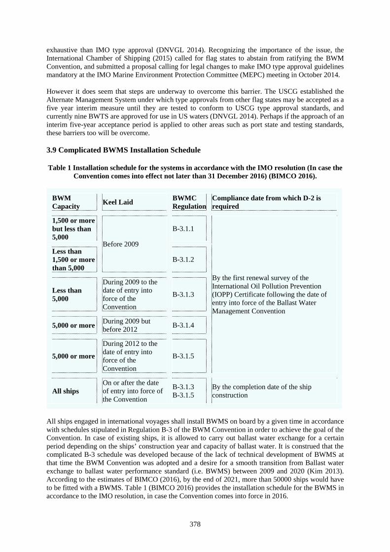
378
exhaustive than IMO type approval (DNVGL 2014). Recognizing the importance of the issue, theInternational Chamber of Shipping (2015) called for flag states to abstain from ratifying the BWMConvention, and submitted a proposal calling for legal changes to make IMO type approval guidelinesmandatory at the IMO Marine Environment Protection Committee (MEPC) meeting in October 2014.
However it does seem that steps are underway to overcome this barrier. The USCG established theAlternate Management System under which type approvals from other flag states may be accepted as afive year interim measure until they are tested to conform to USCG type approval standards, andcurrently nine BWTS are approved for use in US waters (DNVGL 2014). Perhaps if the approach of aninterim five-year acceptance period is applied to other areas such as port state and testing standards,these barriers too will be overcome.
3.9 Complicated BWMS Installation Schedule
Table 1 Installation schedule for the systems in accordance with the IMO resolution (In case theConvention comes into effect not later than 31 December 2016) (BIMCO 2016).
BWMCapacity Keel Laid BWMC
RegulationCompliance date from which D-2 isrequired
1,500 or morebut less than5,000
Before 2009
B-3.1.1
By the first renewal survey of theInternational Oil Pollution Prevention(IOPP) Certificate following the date ofentry into force of the Ballast WaterManagement Convention
Less than1,500 or morethan 5,000
B-3.1.2
Less than5,000
During 2009 to thedate of entry intoforce of theConvention
B-3.1.3
5,000 or moreDuring 2009 butbefore 2012
B-3.1.4
5,000 or more
During 2012 to thedate of entry intoforce of theConvention
B-3.1.5
All shipsOn or after the dateof entry into force ofthe Convention
B-3.1.3B-3.1.5
By the completion date of the shipconstruction
All ships engaged in international voyages shall install BWMS on board by a given time in accordancewith schedules stipulated in Regulation B-3 of the BWM Convention in order to achieve the goal of theConvention. In case of existing ships, it is allowed to carry out ballast water exchange for a certainperiod depending on the ships’ construction year and capacity of ballast water. It is construed that thecomplicated B-3 schedule was developed because of the lack of technical development of BWMS atthat time the BWM Convention was adopted and a desire for a smooth transition from Ballast waterexchange to ballast water performance standard (i.e. BWMS) between 2009 and 2020 (Kim 2013).According to the estimates of BIMCO (2016), by the end of 2021, more than 50000 ships would haveto be fitted with a BWMS. Table 1 (BIMCO 2016) provides the installation schedule for the BWMS inaccordance to the IMO resolution, in case the Convention comes into force in 2016.
379
Considering the estimated number of ships and the complicated B-3 schedule, it will be a challenge forthe Flag and Port State Controls to understand the schedule correctly and ensure its effectiveimplementation (Kim 2013).
4. Conclusion
This paper does not claim to provide an exhaustive list but does highlight a number of challenges facedby FSC and PSC towards ensuring compliance. In seeking to protect the marine environment from thethreat of IAS through the compliance of the BWM Convention, a global consensus is required to resolveissues such as nationalistic approaches to port state control and treatment system type approval. Theissues may be overcome through extensive stakeholder engagement, while maintaining benchmarks thatprotect the marine environment. The need for qualified and national training providers is essentiallyrequired for all States to comprehend various facets of the Convention. To ensure its effectivecompliance, FSC and PSC have a mammoth task towards managing their resources such as increasedworkload, technical expertise, and monetary investments. Although, the Convention is nearing itstonnage requirement (35% of the gross tonnage of the world’s merchant shipping) for coming into force,lack of specific guidelines towards its requirements are still creating gaps towards enforcement and mustbe addressed by IMO. Future research should address the challenges faced by other stakeholders suchas seafarers on ships, BWMS manufacturers, ship owners, and ports.
References
[1] Ahmed M W A E and Youssef S I A M, “Proposed Ballast Water Management Under MaritimeAdministrations Implementation of the Convention”, International Academy of Science,Engineering and Technology, Vol.3, No.5, (2014), pp. 13-22.
[2] Anstey F, “Ballast Water Management: A Time for Action”, IMLA Conference, Turkey, (2008),pp. 325 – 334.
[3] Australian Maritime Safety Authority (AMSA), “AMSA’s role in maritime environment issues”,AMSA, 2016, Australian Government, 22 May 2016, http://amsa.gov.au/environment/legislation-and-prevention/amsas-role-in-maritime-environment-issues/.
[4] Balaji R and Yaakob O, “Ballast Water Management Triad: Administration, Ship Owner and theSeafarer”, International Journal of Environmental, Chemical, Ecological, Geological andGeophysical Engineering, Vol.8, No.8, (2014), pp. 562 -566
[5] Bartlett C, “Concerns as IMO Pushes Ballast Water Convention Ratification”, Seatrade MaritimeNews, 3 April 2014a, Accessed on 17 March 2016, http://www.seatrade-global.com/news/americas/concerns-as-imo-pushes-for-ballast-water-convention-ratification.html.
[6] Bartlett C, “Serious Problems Remain for Ballast Water Says Industry”, Seatrade Maritime News,8 April 2014b, Accessed on 20 March 2016, http://www.seatrade-global.com/news/americas/mepc-66-ends-still-serious-problems-for-ballast-water-say-industry-representatives.html.
[7] BIMCO, “Ballast Water Management”, BIMCO, 13 May 2016, 20 May 2016,https://www.bimco.org/About/Viewpoint/02_Ballast_Water_Management.aspx
[8] Briski E, Allinger L, Balcer M, Cangelosi A, Fanberg L, Markee T, Mays N, Polkinghorne C,Prihoda K, Reavie E, Regan D, Reid D, Saillard H, Schwerdt T, Schaefer H, TenEyck M, Wiley Cand Bailey S, “Multidimensional Approach to Invasive Species Prevention”, EnvironmentalScience & Technology, Vol.47, (2013), pp. 1216-1221.
[9] DNVGL, “Ballast Water Management (BWM) and Biofouling”, DNV. GL, 2014, Accessed on 10March 2016,http://www.dnv.com/industry/maritime/servicessolutions/classification/addrelser/BWM/.
[10] Enshaei H, Carney J and Mesbahi E, “A decade of delay in ratification of the ballast watermanagement convention and further underlying problems”, 16th IAMU Annual General Assembly,Opatija, Croatia, (2015), pp. 63 -70.
380
[11] Ghosh S, Bowles M, Ranmuthugala D and Brooks B, “Reviewing seafarer assessment methods todetermine the need for authentic assessment”, Australian Journal of Maritime Ocean and Affairs,Vol.6, No.1, (2014), pp. 49-63.
[12] International Chamber of Shipping, “Ballast Convention - Making it Fit for Purpose”, InternationalChamber of Shipping, 2015, Accessed on 17 March 2016, http://www.ics-shipping.org/key-issues/all-key-issues-(full-list)/ballast-convention---making-it-fit-for-purpose.
[13] IHS Maritime, Guide to Ballast Water Treatment Systems 2014, London: IHS Fairplay, (2014).[14] International Maritime Organization (IMO), “Ballast Water Management”, IMO, 2016a, Accessed
on 19 March 2016,http://www.imo.org/OurWork/Environment/BallastWaterManagement/Pages/Default.aspx.
[15] International Maritime Organization (IMO), “International Convention for the Control andManagement of Ships’ Ballast Water and Sediments (BWM)”, IMO, 2016b, Accessed on 19 March2016, http://www.imo.org/en/About/Conventions/ListOfConventions/Pages/International-Convention-for-the-Control-and-Management-of-Ships%27-Ballast-Water-and-Sediments-(BWM).aspx.
[16] International Maritime Organization (IMO), “GloBallast Programme”, IMO, 2016c, Accessed on18 March 2016,http://www.imo.org/OurWork/Environment/SpecialProgrammesAndInitiatives/Pages/GloBallast.aspx
[17] International Maritime Organization (IMO), “Ballast water management - the control of harmfulinvasive species”, IMO, 2016d, Accessed on 18 March 2016,http://www.imo.org/en/MediaCentre/HotTopics/BWM/Pages/default.aspx
[18] International Maritime Organization (IMO), “Adoption of the final act and any instruments,recommendations and resolutions resulting from the work of the conference: InternationalConvention for the control and management of ships’ ballast water and sediments, 2004”,International Conference on Ballast Water Management For Ships, BWM/CONF/36, (2004).
[19] Invasive species council, “Biosecurity Bill – six years in the making”, Invasive Species Council,2016, 20 May 2016, http://invasives.org.au/project/biosecurity-bill-2014/
[20] Kim K M, A study of the implications of the ballast water management for flag states, Paper 398,World Maritime University Dissertation, (2013).
[21] Lloyd’s Register Marine, “Ballast Water management Awareness”, Lloyd’s Register Marine, 2016,Lloyd’s register Group Services Limited, 21 May 2016,http://www.lr.org/en/marine/training/ballast-water-management.aspx
[22] Maritime Gateway, “Safeguarding the Seas”, Maritime Gateway, 2016, Accessed on 12 March2016,http://maritimegateway.com/mgw/index.php?option=com_content&view=category&layout=blog&id=57&Itemid=163&limitstart=1.
[23] Rittel H and Webber M, “Dilemmas in a General Theory of Planning”, Policy Sciences, Vol.4,(1973), pp.155-169
[24] Queensland Legislation, Biosecurity Bill 2013: Explanatory Notes, Queensland Government,(2013).
[25] Water and Wastewater International, “Ballast Backlash: Is IMO Ratification Helping or HinderingTechnology”, WWi, 2015, Accessed on 15 March 2016,http://www.waterworld.com/articles/wwi/print/volume-27/issue-5/regional-spotlight-america-caribbean/ballast-backlash-is-imo-ratification-helping-or-hindering-technology.html.
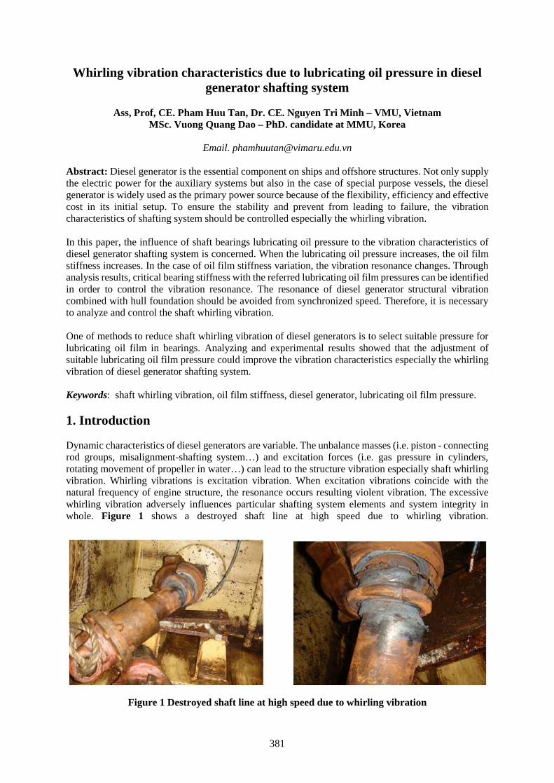
381
Whirling vibration characteristics due to lubricating oil pressure in dieselgenerator shafting system
Ass, Prof, CE. Pham Huu Tan, Dr. CE. Nguyen Tri Minh – VMU, VietnamMSc. Vuong Quang Dao – PhD. candidate at MMU, Korea
Email. [email protected]
Abstract: Diesel generator is the essential component on ships and offshore structures. Not only supplythe electric power for the auxiliary systems but also in the case of special purpose vessels, the dieselgenerator is widely used as the primary power source because of the flexibility, efficiency and effectivecost in its initial setup. To ensure the stability and prevent from leading to failure, the vibrationcharacteristics of shafting system should be controlled especially the whirling vibration.
In this paper, the influence of shaft bearings lubricating oil pressure to the vibration characteristics ofdiesel generator shafting system is concerned. When the lubricating oil pressure increases, the oil filmstiffness increases. In the case of oil film stiffness variation, the vibration resonance changes. Throughanalysis results, critical bearing stiffness with the referred lubricating oil film pressures can be identifiedin order to control the vibration resonance. The resonance of diesel generator structural vibrationcombined with hull foundation should be avoided from synchronized speed. Therefore, it is necessaryto analyze and control the shaft whirling vibration.
One of methods to reduce shaft whirling vibration of diesel generators is to select suitable pressure forlubricating oil film in bearings. Analyzing and experimental results showed that the adjustment ofsuitable lubricating oil film pressure could improve the vibration characteristics especially the whirlingvibration of diesel generator shafting system.
Keywords: shaft whirling vibration, oil film stiffness, diesel generator, lubricating oil film pressure.
1. Introduction
Dynamic characteristics of diesel generators are variable. The unbalance masses (i.e. piston - connectingrod groups, misalignment-shafting system…) and excitation forces (i.e. gas pressure in cylinders,rotating movement of propeller in water…) can lead to the structure vibration especially shaft whirlingvibration. Whirling vibrations is excitation vibration. When excitation vibrations coincide with thenatural frequency of engine structure, the resonance occurs resulting violent vibration. The excessivewhirling vibration adversely influences particular shafting system elements and system integrity inwhole. Figure 1 shows a destroyed shaft line at high speed due to whirling vibration.
Figure 1 Destroyed shaft line at high speed due to whirling vibration
382
The problems caused by whirling vibration are as the following:o Complete shafting system destruction;o Shorten shaft and other elements fatigue life;o Fatigue cracks at crankshaft and journal bearing;o Excessive noise, hull and superstructure vibrations.
In order to reduce the structure vibration, most diesel generators are mounted on a flexible bed, whilethe engine and generator are coupled by employing a flexible coupling. Shaft whirling vibration isclosely related to the oil film pressure in shaft bearings. When the lubricating oil pressure increases, theoil film stiffness increases. In the case of oil film stiffness variation, the vibration resonance changes.
This paper presents whirling vibration characteristics due to lubricating oil pressure variation in thediesel generator shafting system. The influence of shaft bearings lubricating oil pressure to the vibrationcharacteristics of diesel generator shafting system is concerned.
2. Theory for whirling calculation
2.1 Vibration of diesel generators by the moving parts and the expanding gas forces
Structural vibration is generally caused by the dynamic properties of the structure and excitation forces.Mathematically the relationship between the exciting forces, structure properties and the vibrationresponse is normally presented by the general equation of motion [1]: ( ) + ( ) + ( ) (1)
Where x(t) = solution of the equation (deflection at the system nodes); M = mass matrix; C = dampingmatrix; K= stiffness matrix; F(t) = excitation force vector.
Mass of moving parts of diesel generator can be calculated by equation as [2]:= ( . ) + 0.7 (2)
Where: m = total mass of a piston-connecting rod mechanism, mp = mass of the piston, mc = mass of theconnecting rod, r = rotating radius of crankpin.
The matrices M and K represent the dynamic characteristics of the structure. Modifying thesecharacteristics or excitation forces can result reducing the vibration response.
The matrix M is not only the total masses, but represents also the masses distribution over the wholestructure. The same applies to the stiffness matrix K. From the vibration point of view, it may be veryimportant where the mass or stiffness is located.
C denotes the damping, which in practice is not only a uniform number. In real structures the dampingnormally varies depending on the frequency and mode shape, as well as on the location. In complexstructures like engines, several different damping types can be found.
Figure 2 shows a schematic diagram for researching the dynamic properties of the structure and theexcitation forces [2]. The crank shaft is driven by the expanding gas in the cylinder. The expanding gascreates on the piston top a pressure force F, which is transmitted to the crankshaft through the connectingrod. The transmitted gas pressure acting on crankshaft can be divided into two components: centripetalforce resulting shaft axial vibration and tangent force resulting torque, which tents to rotate thecrankshaft.Acceleration of the piston. The pressure force F exists on the top of piston and makes piston movingdownward. If we consider the origin of the x - axis as the uppermost position of the piston, the
383
displacement of the piston corresponding to an angular displacement of crank of = . Thedisplacement of the piston from its topmost position can be expressed as [2]:= + − cos − 1 − (3a)Also: sin = sin = sin (3b)
cos = 1 − (3c)
Figure 2 Schematic diagram of a cylinderof diesel generator
So that:
= + − cos − 1 − (4)
In general, r/l < ¼, Eq. (4) can be approximated as:= (1 − cos ) + (5)
Or, equivalently:= 1 + − (cos + cos 2 ) (6)
Eq. (6) can be differentiated with respect to time toobtain expression for the velocity and acceleration ofthe piston: = (sin + sin 2 ) (7) = (cos + cos 2 ) (8)
Where: xp = vertical displacement of the piston in the xdirection from its topmost position, ω = angularvelocity of the crankshaft, l = length of connecting rod.
Acceleration of the Crankpin. With respect to the xz – coordinate shown in Fig. 2, the vertical andhorizontal displacements of the crankpin are given by [2]:= + = + (1 − cos ) (9)= = sin (10)
Where: xc = vertical displacement of crankpin in the x direction, zc = horizontal displacement of crankpinin the z direction.Differentiations of Eqs. (8) and (9) with respect to time give the velocity and acceleration of the crankpin: = sin (11)
384
= cos (12) = cos (13) = − sin (14)
Inertia Force. Although the mass of the connecting rod is distributed throughout its length. It isgenerally idealized as a massless link with two masses concentrated at its ends, the piston end and thecrankpin end. The vertical component of the inertia force (Fx) for one cylinder is given by [2]:= + (15a)or: = ( + ) cos + cos 2 (15b)
Similarly, the horizontal component of inertia force for a cylinder can be obtained:= + (16a)
Where = 0 and is given by Eq. (14). Thus:= − sin (16b)
The unbalanced and inertia force on a single cylinder are given by Eqs. (15b) and (16b). The mass mp
is always positive, but mc can be made zero by counterbalancing on the crank. Therefore, it is possibleto reduce the horizontal inertia force Fy to zero, but the vertical unbalanced force always exists. Thus, asingle cylinder engine is inherently unbalanced.
In a multi-cylinder engine, it is positive to balance some or all of the inertia forces and torque by properarrangement of the cranks. The lengths of all the cranks and connecting rods are taken to be r and l. Forforce balance, the total inertia force in the x and y directions must be zero, so that:( ) = ∑ ( ) = 0 (17)( ) = ∑ ( ) = 0 (18)
Where (Fx)i and (Fz) are the vertical and horizontal component of inertia forces
Thus, if the moving parts of the cylinders are equivalence and the power of cylinders are balance, thevibration due to the expanding gas forces and inertial forces of cylinders are suppressed, so the engineswill not vibrate.
2.2 Stiffness and damping calculation for journal bearing
Lubricating oil is supplied into bearings of shafting system to lubricate its working surfaces and thenreduce the friction. It plays a key role in determining the dynamic characteristics of diesel generatorsshafting system.
The schematics of a journal are shown in Fig. 3. Letter O is the center of journal whereas O’ is the centerof bearing. The radial clearance, c, between the bearing bore of radius r1 and of the journal radius, r,equals r1 - r.
385
Figure 3 Schematics of plain journal bearing geometry
When the shaft speed is fast enough to create hydrodynamic pressure larger than the applied load, thejournal can separate and move around the bearing until it reaches an equilibrium. The eccentricity isthe distance between the centers of shaft and bearing. When the journal touches the bearing and whenthe load equals zero. The ratio of eccentricity to clearance is presented by eccentricity ratio ε:= (0 ≤ ε ≤ 1) (19)
The oil film thickness at any position can be calculated approximately by [3]:ℎ ~ (1 + ) (20)
The minimum thickness is given as: ℎ = – = (1 − ) (21)
Journal bearings are short bearing in this case. Following Reynolds equation [4], the pressure of oil filmcan be calculated by the equation: = − ( ) (22)
Maximum pressure of oil film at angular position m and y = 0 can calculate by [5]:= ( ) (23)
with: = 1 − √(24)
386
The load capacity is solved by integration of the pressure wave around the bearing:= 2 ∫ ∫ sin/(25)= 2 ∫ ∫ cos/(26)
By using the Sommerfeld substitution we can obtain:= ( ) / (27)
= (28)
= + = 4 2 16 2+ 2(1− 2)1− 2 2 (29)
The Sommerfeld number S is given by equation:= = ( ) (30)
And average pressure is calculated by equation [6]:= (31)
The bearing stiffness can be obtained by equation:= (32)
Where: r = journal radius (m); r1 = bearing bore radius (m); L = bearing length (m); c = radius clearance(m); e = eccentricity (m); ε = eccentricity ratio; h = oil film thickness (m); hmin= minimum oil filmthickness (m); θ = angular position (rad); hv = oil film thickness at angular position θv (m); θm =maximum pressure position (rad); P = oil film pressure (Pa); Pm = maximum oil film pressure (Pa); Wx,Wy, Wr = load capacity (N); Paverage = average oil film pressure (Pa); Kf = bearing stiffness (N/m); =lubricant absolute viscosity (Pa-s).
2.3 Whirling vibration in diesel generator shaft system
Whirling vibration due to shaft static and dynamic unbalance is a forced vibration caused by internalcentrifugal force. It is well known that a diesel generator shafting system will never be perfectlybalanced. Due to material inhomogeneity the center of gravity does not coincide with the rotation axis.Due to the center of journal and bearing does not coincide to make eccentricity. Eccentricity dependson oil film pressure of journal bearing. When the shaft rotates, the eccentric masses produce excitingcentrifugal force. Unbalance excites forward synchronous whirling.
Alignment-related vibration of shaft system of diesel generator is possible if the shafts are not properlycoupled due to assembly or manufacture errors. It is the case when shaft system loses the rotation axiscontinuity and smoothness. Alignment-related errors excite first order synchronous whirling vibration.
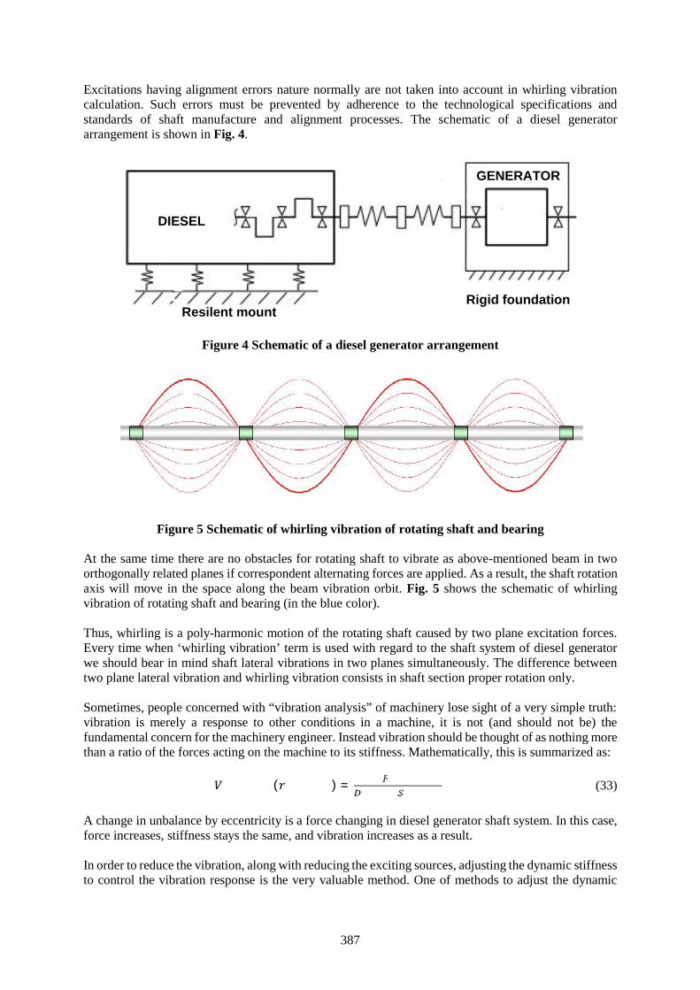
387
Excitations having alignment errors nature normally are not taken into account in whirling vibrationcalculation. Such errors must be prevented by adherence to the technological specifications andstandards of shaft manufacture and alignment processes. The schematic of a diesel generatorarrangement is shown in Fig. 4.
Figure 4 Schematic of a diesel generator arrangement
Figure 5 Schematic of whirling vibration of rotating shaft and bearing
At the same time there are no obstacles for rotating shaft to vibrate as above-mentioned beam in twoorthogonally related planes if correspondent alternating forces are applied. As a result, the shaft rotationaxis will move in the space along the beam vibration orbit. Fig. 5 shows the schematic of whirlingvibration of rotating shaft and bearing (in the blue color).
Thus, whirling is a poly-harmonic motion of the rotating shaft caused by two plane excitation forces.Every time when ‘whirling vibration’ term is used with regard to the shaft system of diesel generatorwe should bear in mind shaft lateral vibrations in two planes simultaneously. The difference betweentwo plane lateral vibration and whirling vibration consists in shaft section proper rotation only.
Sometimes, people concerned with “vibration analysis” of machinery lose sight of a very simple truth:vibration is merely a response to other conditions in a machine, it is not (and should not be) thefundamental concern for the machinery engineer. Instead vibration should be thought of as nothing morethan a ratio of the forces acting on the machine to its stiffness. Mathematically, this is summarized as:( ) = (33)
A change in unbalance by eccentricity is a force changing in diesel generator shaft system. In this case,force increases, stiffness stays the same, and vibration increases as a result.
In order to reduce the vibration, along with reducing the exciting sources, adjusting the dynamic stiffnessto control the vibration response is the very valuable method. One of methods to adjust the dynamic
DIESEL
GENERATOR
Rigid foundationResilent mount
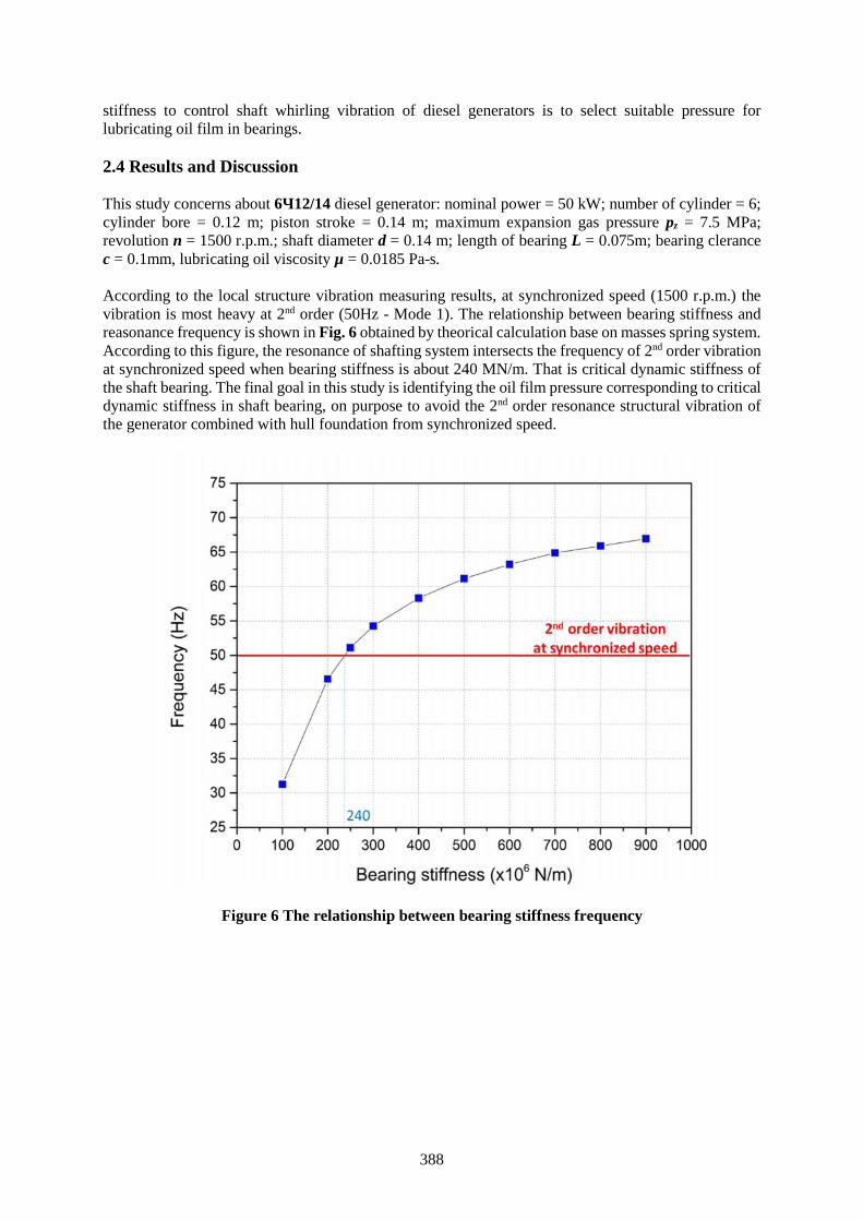
388
stiffness to control shaft whirling vibration of diesel generators is to select suitable pressure forlubricating oil film in bearings.
2.4 Results and Discussion
This study concerns about 6Ч12/14 diesel generator: nominal power = 50 kW; number of cylinder = 6;cylinder bore = 0.12 m; piston stroke = 0.14 m; maximum expansion gas pressure pz = 7.5 MPa;revolution n = 1500 r.p.m.; shaft diameter d = 0.14 m; length of bearing L = 0.075m; bearing clerancec = 0.1mm, lubricating oil viscosity µ = 0.0185 Pa-s.
According to the local structure vibration measuring results, at synchronized speed (1500 r.p.m.) thevibration is most heavy at 2nd order (50Hz - Mode 1). The relationship between bearing stiffness andreasonance frequency is shown in Fig. 6 obtained by theorical calculation base on masses spring system.According to this figure, the resonance of shafting system intersects the frequency of 2nd order vibrationat synchronized speed when bearing stiffness is about 240 MN/m. That is critical dynamic stiffness ofthe shaft bearing. The final goal in this study is identifying the oil film pressure corresponding to criticaldynamic stiffness in shaft bearing, on purpose to avoid the 2nd order resonance structural vibration ofthe generator combined with hull foundation from synchronized speed.
Figure 6 The relationship between bearing stiffness frequency

389
The attitude angle :
∅ = √(34)
The oil film thickness : ℎ~ (1 + cos ) (35)
At the lowest bottom position ( = 180 − ) :ℎ = (1 − ) (36)
The load can be obtained: = ( )( ) (37)
The bearing stiffness: = = ( ) ( . )( ) ( . ) (38)
And average pressure is calculated by: = = (39)
All of the other parameters can be calculated and are shown on Table 1.
Figure 6 Schematics of shaft bearing geometry
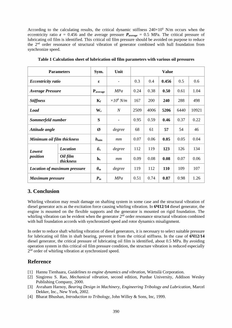
390
According to the calculating results, the critical dynamic stiffness 240×106 N/m occurs when theeccentricity ratio ε = 0.456 and the average pressure Paverage = 0.5 MPa. The critical pressure oflubricating oil film is identified. This critical oil film pressure should be avoided on purpose to reducethe 2nd order resonance of structural vibration of generator combined with hull foundation fromsynchronize speed.
Table 1 Calculation sheet of lubrication oil film parameters with various oil pressures
Parameters Sym. Unit Value
Eccentricity ratio ε - 0.3 0.4 0.456 0.5 0.6
Average Pressure Paverage MPa 0.24 0.38 0.50 0.61 1.04
Stiffness Kf ×106 N/m 167 200 240 288 498
Load Wr N 2509 4006 5206 6440 10921
Sommerfeld number S - 0.95 0.59 0.46 0.37 0.22
Attitude angle Ø degree 68 61 57 54 46
Minimum oil film thickness hmin mm 0.07 0.06 0.05 0.05 0.04
Lowestposition
Location v degree 112 119 123 126 134
Oil filmthickness
hv mm 0.09 0.08 0.08 0.07 0.06
Location of maximum pressure θm degree 119 112 110 109 107
Maximum pressure Pm MPa 0.51 0.74 0.87 0.98 1.26
3. Conclusion
Whirling vibration may result damage on shafting system in some case and the structural vibration ofdiesel generator acts as the excitation force causing whirling vibration. In 6Ч12/14 diesel generator, theengine is mounted on the flexible supports and the generator is mounted on rigid foundation. Thewhirling vibration can be evident when the generator 2nd order resonance structural vibration combinedwith hull foundation accords with synchronized speed and rotor dynamics misalignment.
In order to reduce shaft whirling vibration of diesel generators, it is necessary to select suitable pressurefor lubricating oil film in shaft bearing, prevent it from the critical stiffness. In the case of 6Ч12/14diesel generator, the critical pressure of lubricating oil film is identified, about 0.5 MPa. By avoidingoperation system in this critical oil film pressure condition, the structure vibration is reduced especially2nd order of whirling vibration at synchronized speed.
Reference
[1] Hannu Tienhaara, Guidelines to engine dynamics and vibration, Wärtsilä Corporation.[2] Singiresu S. Rao, Mechanical vibration, second edition, Purdue University, Addison Wesley
Publishing Company, 2000.[3] Avraham Harnoy, Bearing Design in Machinery, Engineering Tribology and Lubrication, Marcel
Dekker, Inc., New York, 2002.[4] Bharat Bhushan, Introduction to Tribology, John Willey & Sons, Inc, 1999.

391
[5] Fouad Y. Zeidan and Bernard S. Herbage, Fluid film bearing fundamentals and failure analysis,TAMU Turbo Show, 1991
[6] Bernard J. Hamrock, Steven R. Schmid, and Bo O. Jacobson, Fundamentals of Fluid FilmLubrication, second edition, Marcel Dekker, Inc., New York, 2004.
[7] ORBIT Second Quarter 2000, Understanding and Using Dynamic, ORBIT Magazine, 2000.
392
A Collaborative Approach to Protecting the Ocean Environment
Professor Paul Szwed1, Director Carleen Lyden-Kluss2, Associate Professor Matthew Rooks3
1. Massachusetts Maritime Academy, [email protected],100 Academy Drive, Buzzards Bay, Massachusetts, 02532 USA
2. North American Marine Environmental Protection Association ([email protected])3. Graduate School of Maritime Science, Kobe University ([email protected])
Abstract Oceans, often thought of as our last global commons, serve many important roles fromproviding us food and resources to connecting nations for trade. Despite this role of importance, ourseas are becoming increasingly stressed. Addressing such issues of the common requires a collaborativeinternational approach, as evidenced by the United Nations sustainable development goal 14 to“conserve and sustainably use the oceans, seas and marine resources” [1]. Further, the IAMU recognizesthe importance of this aspect of their mission as evidenced by the Tasmanian Statement [2] and also bythe theme of their 2016 annual general assembly calling for submissions about “strengtheningcooperation for protection of the ocean environment” [3]. Using the collaborative value creation (CVC)framework [4, 5], this paper describes how IAMU might form a partnership with various INTERMEPA(the International Marine Environmental Protection Association) member associations to jointlyadvance their mutual shared mission to “save our seas” [6]. Using the CVC framework, this paper willdescribe a pathway for partner selection, partnership implementation, design and operations, andinstitutionalization. Building upon the foundation of success experienced by NAMEPA (the NorthAmerican MEPA), this paper will also explore the opportunity to utilize IAMU member networkconnections to fulfil a critical objective listed under the Tasmanian Statement and create a new MEPAchapter in Japan (NIPPONMEPA) as a case study using the CVC framework. Proposed activities willlikely include identified effective practices and may include new innovations such as joint eventsconducted virtually using the MIX methodology [7].
Keywords: Cooperation, Partnership, Protection of Maritime Environment, Oceans, Sustainability.
1. Introduction
Oceans, often thought of as our last global commons, serve many important roles from providing usfood and resources to connecting nations for trade. Despite this role of importance, our seas arebecoming increasingly stressed. Addressing such issues of the common requires a collaborativeinternational approach, as evidenced by the United Nations sustainable development goal 14 to“conserve and sustainably use the oceans, seas and marine resources” [1]. Further, the IAMU recognizesthe importance of this aspect of their mission as evidenced by the Tasmanian Statement [2] and also bythe theme of their 2016 annual general assembly calling for submissions about “strengtheningcooperation for protection of the ocean environment” [3]. This article will examine how two non-profitorganizations can form a partnership using a “top-down” collaborative value creation framework and“bottom-up” chapter-first approach to address the continuing challenge of protecting or marineenvironment – to “save our seas”.
1.1 International Marine Environmental Protection Association
[8] The International Marine Environmental Protection Association (MEPA) movement began in 1983with the formation of Hellenic MEPA (HELMEPA) in Greece by shipowner George P. Livanos. Sincethat initial chapter began more than three decades ago, six more MEPA’s have been created (in Cyprus,Turkey, Australia, Uruguay, North America and the Ukraine). Each share the voluntary commitment to“Save our Seas”. In 2006, INTERMEPA (International MEPA) was created as an umbrellaorganizations and to demonstrate that the marine environment is independent of “politics of any nationor nations” and to foster the voluntary cooperation of its members in order to:
393
Encourage the effective compliance of the members of every MEPA with the national andinternational laws and regulations adopted for the protection of the marine environment frompollution;
Conduct a uniform public awareness campaign with top priority to offer young schoolchildrenin every MEPA’s country a specially designed education on the marine environmental and theways to prevent its pollution;
Create and promote safety mindedness and security spirit within the industrial sectors in eachcountry that are voluntarily enlisting as members in every MEPA;
Enhance quality standards and professional competence throughout each MEPA'smembership and especially the members from within the maritime community, with the meansof a concerted training effort to educate and inform all, from the owner to the youngest employeeof every participating company;
Cooperate with international organizations, such as the United Nations Environment Program(UNEP), the International Maritime Organization (IMO), and the European Union, as well asnational agencies, i.e. coast guards, port authorities, tourist boards and any other entity whoseaims coincide with those of INTERMEPA;
Promote relationships and/or partnerships with educational institutions (schools, colleges,universities, maritime academies, and other MET institutions) to further spread the MEPAvoluntary commitment within today’s youth who are the world’s future scientists, engineers,managers, and politicians;
Publicly recognize individuals, associations, organizations, companies and any other thatdemonstrate outstanding achievements in the field of the protection of the marine environmentfrom pollution; and
Promote and spread the MEPA philosophy in other countries.
Typically, to establishing a MEPA, whoever has the initiative to establish a MEPA should first submitto the Secretariat and through it to the Steering Committee:
Written proposal by one existing MEPA member of INTERMEPA; Draft declaration similar to INTERMEPA’s with a list of the particulars of the founders; Statement providing that it is a non-profit, private initiative; and Written support of at least two of IMO, UNEP, WWF, ICS, and prospective volunteer
membership mainly from within the ranks of shipping and the wider business community of thehome country.
By joining, the new member has access to information material, technical assistance and other supportfrom the existing members. As can be seen by this foundation process is “top-down” in that it is drivenby an often high-level organizing organization within the maritime industry (as opposed to a “bottom-up” or more organic “grassroots” formation from an individual or employees). This will become animportant distinction later in the article as a “bottom-up” approach will later be explored.
1.2 International Association of Maritime Universities
[9] The International Association of Maritime Universities (IAMU) was founded by seven universitiesrepresenting the five continents of the world (representative universities) in November of 1999, with ashared recognition of significance of maritime education and training (MET) in the rapid globalizationof the international shipping arena. Since then, IAMU has significantly expanded its membership, andnow boasts 58 universities/academies/faculties of the world’s maritime education and traininginstitutions, and the Nippon Foundation as its members, totaling 59 altogether.
The original representative universities at the time of foundation in 1999 are: Arab Academy for Science and Technology and Maritime Transport (representing Africa); Australian Maritime College (representing Oceania); Cardiff University (representing western Europe) [now replaced by Polytechnical University
of Catalonia, Faculty of Nautical studies, Barcelona];
394
Istanbul Technical University, Maritime Faculty (representing Mediterranean, Black Sea, aswell as central and eastern Europe);
Kobe University of Mercantile Marine (representing Asia) [now transformed to KobeUniversity, Faculty of Maritime Sciences];
Maine Maritime Academy (representing the Americas including the Caribbean Sea); and World Maritime University (of general representation).
The IAMU is the global network of leading maritime universities providing maritime education andtraining (MET) of seafarers for the global shipping industry. All members of IAMU share theunderstanding that:
Globalization has been progressing rapidly in the international shipping arena; Safety, security and environmental protection [emphasis added] are crucial issues for the
maritime sector; and Passing on maritime skills and knowledge to the following generations needs to be achieved on
a global scale.
All members of IAMU also recognize the significance of MET and note that: The shipping industry is a service industry, in which human resources are the critical element; It is only feasible to secure and to preserve highly qualified human resources in the maritime
industries through effective education and training; and Effective education and training in the maritime sector derives from scientific and academic
rigor and development of a clear link between practical skills, management techniques and afocus on quality.
Based on this shared understanding, it has been mutually agreed that members shall: Cooperate with each other in a range of scientific and academic studies, developments, and
practical applications associated with MET; Endeavor to achieve measurable and worthwhile outcomes for MET through IAMU activities; Publicize the results of their activities as extensively as possible both within and outside IAMU,
and shall endeavor to accumulate scientific results for the benefit of the international maritimecommunity; and
Thereby contribute to the enhancement of maritime safety, security and environmentalprotection [emphasis added].
The Association was created in 1999 by a group of maritime universities from across the world as a non-profit organization. It is interesting to note that, like INTERMEPA, IAMU is a non-profit collection ofaffiliated organizations who share similar interests and missions.
The balance of this article will examine the collaborative value creation (CVC) framework as it appliesto partnerships among non-profit organizations. It will then examine the international MEPA’s and theIAMU as two such non-profit organizations with aligned missions who might benefit from enhancedpartnership.
2. Collaborative Value Creation
The socio-economic and environmental problems facing the world are too difficult for individualorganizations to address adequately [4]. Since we are “all in this together,” we can no longer “go italone;” collaboration between and among organizations is an imperative [10]. Businesses have longcollaborated or co-created value with other businesses and their customers [11, 12, 13] and have workedclosely with governments or non-profits [14, 15, 16] in cross-sector partnering. We are now seeing non-profit organizations collaborate and co-create value with each other [17, 18]. Using a collaborative valuecreation framework (CVC) [4, 5], this article explores opportunities among non-profit organizations tocollaborate and co-create value.
395
The CVC framework is comprised of four components: 1) the value creation spectrum, 2) collaborationstages, 3) partnership processes, and 4) collaboration outcomes. While this CVC framework wasoriginally established to explore the nature of collaborations between business and non-profit partners,it will be used in this study examine the collaboration between two non-profit organizations.
2.1 Value Creation Spectrum
According to Austin and Seitanidi, the creators of the CVC framework, greater value is realized ascollaboration moves across the value creation spectrum (from sole creation toward co-creation) [4]. Inessence, as organizations deepen their partnering efforts, more value may and often will be created atall levels. In an effort to deepen the understanding of this value creation spectrum, the variousdimensions indicated by sources of value will be examined.
There are four proposed sources of value in organizational collaboration: Resource complementarity – While much of the resource dependency literature focuses on
partnering to access resources other than those already possessed, there is support for the notionthat greater value co-creation can exist when partners exhibit fit and complementarity also [19,20].
Nature of resource – Similarly, partners can share generic resources that all organizationspossess (e.g., money/time, reputation/brand). However, when partners share unique,organization-specific resources (e.g., knowledge, membership, networks), there will be a greaterpotential for value co-creation.
Resource directionality and use – Resources can flow unilaterally or reciprocally. However, itis suggested that as complementary and distinctive resources are co-mingled, new services oractivities can be created that neither of the organizations could have created on their own.
Linked interests – While cross-sector alliances may have difficulty in that they do not shareobjectives or even value functions, in a single-sector, value co-creation may be enhanced whenboth partners perceive self-interests to be linked (by the value created for each other or the socialgood).
With the above sources of value in mind, four types of value can be derived in varying degrees: 1)associational value (based on the benefit achieved from the relationship itself), 2) transferred resourcevalue (based upon the exchange of resources), 3) interaction value (resulting from derived intangibleslike trust, reputation, joint capabilities), and 4) synergistic value (such that what is producedcollaboratively is “more than the sum of its parts”).
2.2 Collaboration Stages
Partnerships are dynamic and as they evolve, so too does the nature of value creation. To describe thevarious stages of collaboration, Austin [21, 22] created a collaboration continuum consisting of three-stages: 1) philanthropic (typically where a corporate donor unilaterally transferred resources to a non-profit recipient), 2) transactional (where partners reciprocally exchanged resources), and 3) integrative(where organizations integrate missions, strategies, etc. for the purpose of co-creating value). A fourthstage is also envisioned that goes beyond integrative collaboration – transformational collaboration(where organizations co-create transformative change at the societal level) [5]. This last highest levelstage of convergence, marked by increased interdependency and intensity of relationship, is emergentwith some signs of practice, but not fully realized.
It is important to consider collaboration as dynamic within the stages of development. The continuumdoes not represent sequential progression of discrete points. A partnership may be partially in one stageand partially in another. A partnership need not pass through every stage. Likewise, partnerships maymove in either direction along the continuum at different points in time.
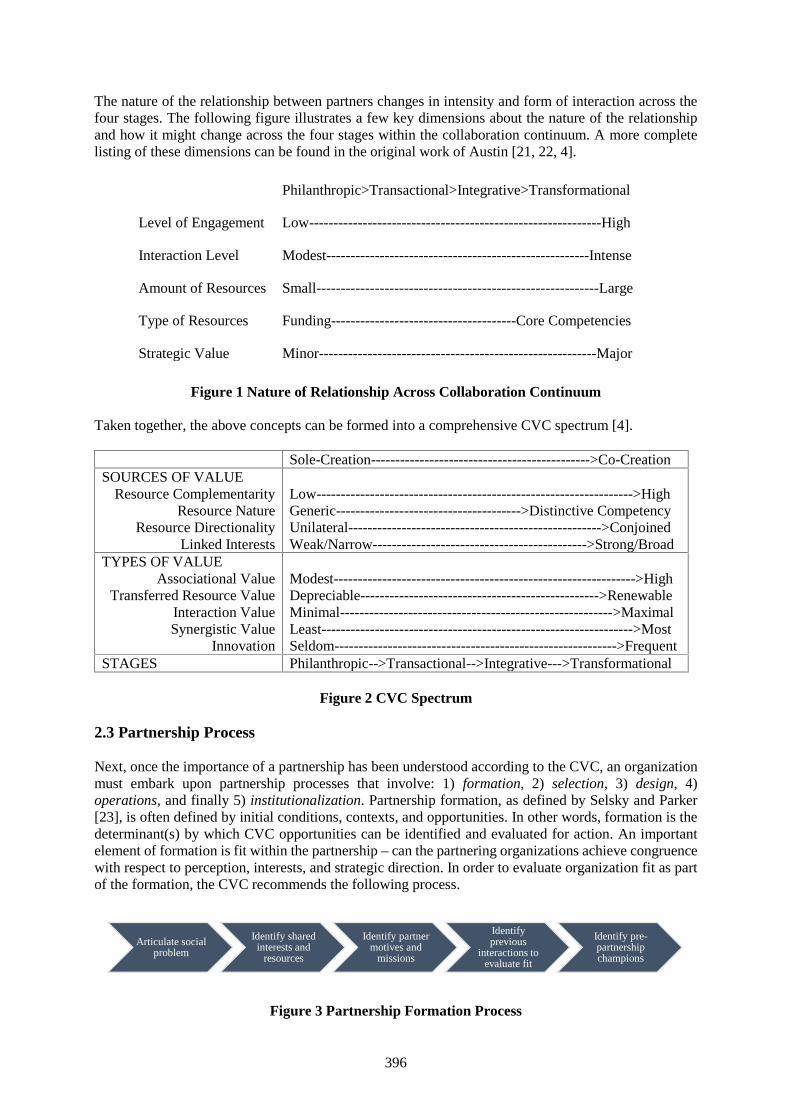
396
The nature of the relationship between partners changes in intensity and form of interaction across thefour stages. The following figure illustrates a few key dimensions about the nature of the relationshipand how it might change across the four stages within the collaboration continuum. A more completelisting of these dimensions can be found in the original work of Austin [21, 22, 4].
Figure 1 Nature of Relationship Across Collaboration Continuum
Taken together, the above concepts can be formed into a comprehensive CVC spectrum [4].
Sole-Creation--------------------------------------------->Co-CreationSOURCES OF VALUE
Resource ComplementarityResource Nature
Resource DirectionalityLinked Interests
Low----------------------------------------------------------------->HighGeneric-------------------------------------->Distinctive CompetencyUnilateral---------------------------------------------------->ConjoinedWeak/Narrow-------------------------------------------->Strong/Broad
TYPES OF VALUEAssociational Value
Transferred Resource ValueInteraction ValueSynergistic Value
Innovation
Modest-------------------------------------------------------------->HighDepreciable------------------------------------------------->RenewableMinimal-------------------------------------------------------->MaximalLeast---------------------------------------------------------------->MostSeldom---------------------------------------------------------->Frequent
STAGES Philanthropic-->Transactional-->Integrative--->Transformational
Figure 2 CVC Spectrum
2.3 Partnership Process
Next, once the importance of a partnership has been understood according to the CVC, an organizationmust embark upon partnership processes that involve: 1) formation, 2) selection, 3) design, 4)operations, and finally 5) institutionalization. Partnership formation, as defined by Selsky and Parker[23], is often defined by initial conditions, contexts, and opportunities. In other words, formation is thedeterminant(s) by which CVC opportunities can be identified and evaluated for action. An importantelement of formation is fit within the partnership – can the partnering organizations achieve congruencewith respect to perception, interests, and strategic direction. In order to evaluate organization fit as partof the formation, the CVC recommends the following process.
Figure 3 Partnership Formation Process
Articulate socialproblem
Identify sharedinterests and
resources
Identify partnermotives and
missions
Identifyprevious
interactions toevaluate fit
Identify pre-partnershipchampions
Philanthropic>Transactional>Integrative>Transformational
Level of Engagement Low------------------------------------------------------------High
Interaction Level Modest------------------------------------------------------Intense
Amount of Resources Small----------------------------------------------------------Large
Type of Resources Funding--------------------------------------Core Competencies
Strategic Value Minor---------------------------------------------------------Major
397
Partner selection is part of and an extension to the formation process. As might be expected, poorpartnership selection is a common reason for partnership failure [24]. The process of assessing potentialpartners is further facilitated by developing partnership-specific criteria (e.g., target industry, scope ofoperations, time scales of operation). Seitanidi and Crane [25] created a partnership selection processfor co-creation of value that included: 1) assessing potential, 2) developing partnership criteria, and 3)risk assessment.
Once formation and selection takes place, the partnership must be implemented, which serves as theCVC engine. There are many parameters that influence design and operations (e.g., setting objectives,specifying structure, forming rules, drafting MOUs, establishing leadership positions). These forms offormal control are typically identified early on and have significant influence on the partnership thatultimately develops. The CVC framework suggests a set of partnership design and operations processesthat involve iterative experimentation and adaptation (at the organizational and collective levels) leadingto operationalization (which includes the stabilization of shared processes and structures [25]). Anotheruseful framework for considering partnership processes involves educational institutions efforts tocollaborate [26], including pilot studies to get to know partners, a limited cooperation phase, andfollowed by an extended cooperation phase. Partnering processes are deemed complete whenconvergence, fusion, or abandonment occur.
2.4 Collaboration Outcomes
Collaboration outcomes are the metric by which the partnership is judged. Understanding ofcollaboration outcomes is an evolving area of practice and research, particularly when the focus is onbenefits to society [27, 28]. Traditionally, partnerships between businesses focused on internal valuecreation, but more recently there has been a strong shift to focus on external value creation, particularlywhen it comes to partnerships among non-profit organizations. Example include collective impact [29],social value measurement [30], and social impact beyond financial returns [31]. For non-profitpartnerships, collaboration outcomes “should encompass the social value generated by the collaboration[5]. This form of external value creation can be evaluated across different levels [32, 33], but the focushere will be at the macro- (vice meso- or micro-) level. At the macro-level, the loci of focus is on thegeneration of social, environmental, or economic value for the broader community or society beyondthe partnering organizations.
3. Case Study
Most of CVC framework comes from the perspective of a “top-down” approach. For the purposes oflater argument, lets now consider the potential for partnership between INTERMEPA and IAMU (twonon-profit organizations) using the CVC framework:1. Is there potential value in such a partnership? Yes. Through resource complementarity and shared
interests (namely protection of the marine environment), associational and interaction value arehighly likely. Additionally, assuming a depth and breadth of the partnership, synergistic value mayalso be realized.
2. How might the partnership develop? Any partnership is only as strong as the commitment ofmember organizations and individual efforts. Given the strong overlapping missions in the area ofenvironmental protection and education, it can be foreseen that a high level of development couldbe realized at the integrative, or even eventually transformational, level.
3. What might the processes of such a partnership look like? The first three conditions illustrated infigure 3 of partnership formation exist. There is no known history of efforts (unsuccessful orotherwise) to previously form a partnership. The next formation step would be the identification ofchampions within each organization to shepherd the formation. Taken together, this selection ofpotential partners would set up the foundation necessary design and implementation of thepartnership (through MOU of other means).
398
4. Which outcomes might this partnership adopt? Any partnership should have realistic measurementobjectives to inform strategy and operations. Any objectives would be a significant topic for thedesign of the partnership, but could include aspects of education, outreach, and advocacy, as wellas direct impact on the ideal to “save our seas”.
While a “top-down” approach to developing a partnership among non-profit organizations would likelybe effective (and should be pursued), we will present a case study to illustrate how a “bottom-up”approach may be equally effective. In fact, the “bottom-up” approach has the added advantage that it“provides an opportunity for community empowerment that conventional approaches have failed toprovide” [34]. This type of approach at the local and regional (as opposed to national and international)level allows for stakeholder involvement at the community level. Given the interests of the authors, thiscase study leverages the depth of experience in founding and running a Marine Environmental ProtectionAssociation (MEPA) in North America (second author) and the creativity of launching and growing alocal NAMEPA chapter at a North American maritime education and training (MET) university (firstauthor) against the interest to form a similar MEPA-styled chapter at MET university in Japan (thirdauthor), considering “the rise of Japanese NGOs… resulting from ‘bottom-up’ motivation to addresssocio-economic, technological, and environmental concerns in an increasingly borderless world” [35].The history of the Japanese environmental movement has illustrated that while “weakly consolidated atthe national level” two-decades ago, recent events have brought heightened attention to environmentalissues that would allow for a strong “bottom-up” approach [36].
This final section will draw upon the experience in successfully forming and growing the NAMEPAand translating lessons learned there toward establishment of a new chapter in Japan that might form thefoundation for a NIPPONMEPA.
When the now Executive Director of NAMEPA was in Greece in 2006, Ms. Carleen Lyden-Klus wasasked why no MEPA existed in North America. Upon return, after interviewing key stakeholders (e.g.,ship owners, class societies, Coast Guard officials), a consensus for support was built. A sponsor in theform of the other co-founder (and until recently Chairman of NAMEPA), Mr. Clay Maitland, wasidentified and invited to underwrite the effort and work set forth to develop a concept statement andapply to INTERMEPA using the process previously described. In 2007, a “road trip” of seminars wasconducted to engage stakeholders (e.g., maritime concerns, regulatory agencies, and environmentalconservancy groups) and develop common vision built upon mutual interests to preserve the marineenvironment.
A portfolio of educational materials and programs were developed to education the public, with a focuson K-12 students, as future stewards of the environment. That outreach extended into the maritimeacademies where local chapters have been formed to further extend the reach of the mission. Thisstructure of leveraging alliances is crucial given the small size of the non-profit NAMEPA organization(currently two full-time and 11 part-time employees in addition to the Executive Director). Memorandaof Understanding (MOUs) were developed with the US Coast Guard, Transport Canada, US NationalOceanic and Atmospheric Administration, INTERTANKO, Chamber of Shipping of America, the USPower Squadron, and more.
To establish a local MEPA chapter (where a national or regional MEPA does not exist), the following“bottom-up” steps are suggested:
Review NAMEPA chapter guide (available in hardcopy and digital forms). Review the by-law structure of NAMEPA, and consistent with national non-profit (or NGO)
laws and regulations. When operating a student chapter under the auspices of a MET college oruniversity, such as Kobe University, separate by-laws may not be necessary and local rules maydictate.
Recruit a cadre of environmentally-minded students (preferably those who will be around for atleast a couple of years to accomplish formation work and activities).
Review the mission of MEPAs and identify which aspect will best serve the interests of thechapter and the community. Each MEPA and chapter are unique and based upon the strengths
399
of membership. NAMEPA has a strong communications theme reflective of the Director’sexpertise. HELMEPA is active in seafarer training to address a need in Greece.
Develop your platform and mission. Identify officers and a Board of Directors (making sure to invite key stakeholders from the
maritime industry and environmental advocacy groups). Seek support from the maritime industry and its members (e.g., Japanese ship owners and
shipping companies, Class NK, Japanese Ministry of Transport, and former Secretary-Generalof the IMO, Hon. Koji Sekimizu).
Identify an anchor sponsor (e.g., like NIPPON Foundation support for IAMU). File for MEPA status through INTERMEPA process. Host a kick-off education event and invite campus community, maritime industry leaders, and
local community (e.g., TEDx Talks, themed Pecha Kucha night, etc.). Consider a blend ofstudent/faculty and industry speakers. Invite selected speaker from an environmental advocacygroup.
Continue to recruit new members. One great way to increase membership (as well as informingthe broader public is to host a beach clean-up activity [37].
Train members on how to deliver educational programs into local schools and public communitygroups.
Continue to build using techniques appropriate for the institution and national culture. Becreative in how best to advance your mission and vision using a platform designed by yourmember.
Additionally, having recently established and re-energized a local NAMEPA chapter at MassachusettsMaritime Academy, it will be possible for Kobe University to use the MIX methodology [7] to conductshared virtual events and chapter-to-chapter communication, learning, and growth. It is anticipated thatby leveraging existing networks, building upon a history of success, and engaging students, aninnovative and thriving NIPPONMEPA will result.
References
[1] United Nations, “Goal 14: Conserve and sustainably use our oceans, seas, and marine resources”,Sustainable development goals, Accessed: December 29, 2015, Retrieved from: http://www.un.org/sustainabledevelopment/sustainable-development-goals/
[2] International Association of Maritime Universities, “Tasmanian Statements 2014”, IAMUactivities, Accessed: March 12, 2016, Retrieved from: iamu-edu.org/?page_id=2995
[3] International Association of Maritime Universities, “AGA 2016 theme”, IAMU 17th AnnualGeneral Assembly 2016, Accessed: February 27, 2016, Retrieved from: http://iamuaga2016.com/
[4] Austin, J and Seitanidi, M, “Collaborative value creation, A review of partnering between nonprofitsand businesses. Part 1: Value creation spectrum and collaboration stages”, Nonprofit and voluntarysector quarterly, 41(5), (2012), pp. 726-758.
[5] Austin, J E; & Seitanidi, M M, Collaborative value creation, A review of partnering betweennonprofits and businesses. Part 2: Partnership processes and outcomes. Nonprofit and voluntarysector quarterly, 41(6), (2012), pp. 929-968.
[6] North American Marine Environmental Protection Association, “NAMEPA Strategic Plan 2015-2018”, Our mission, Accessed: NAMEPA (2015). Retrieved from: http://www.namepa.net/ourmission/
[7] Rooks M, Progouaki M and Szwed P, "Delivering and assessing a cross-cultural learning modulefor seafarers and maritime university students," Proceedings of the IAMU annual general assembly,Reijka, Croatia, (2015), pp 136-148.
[8] INTERMEPA, “About us”, INTERMEPA organization, Retrieved June 15, 2016, Accessed at:http://www.intermepa.org/about_us.html.
[9] IAMU, “About us,” International Association of Maritime Universities, Retrieved June 15, 2016,Accessed at: http://iamu-edu.org/?page_id=22.
400
[10] Visser W, The age of responsibility: CSR 2.0 and the new DNA of business. John Wiley and Sons,(2011).
[11] O’Cass A and Ngo L, “Examing the firms value creation process: A managerial perspective of thefirm’s value offering strategy and performance”, British journal of management, 22(4), (2010), pp.646-671.
[12] Lepak D, Smith K and Taylor M, “Value creation and value capture: a multilevel perspective”,Academy of management review, 32(1), (2007), pp. 180-194.
[13] Brouthers K, Brouthers L and Wilkinson T, “Strategic alliances: Choose your partners”, Long rangeplanning, 28(3), (2005), pp. 2-5.
[14] Cooper T, Bryer T and Meek J, “Citizen‐centered collaborative public management”, Publicadministration review, 66(1), (2006), pp. 76-88.
[15] Bryson J, Crosby B and Stone M. “The design and implementation of cross‐sector collaborations:Propositions from the literature”, Public administration review, 66(1), (2006), pp. 44-55.
[16] Warner M and Sullivan R (eds.) Putting partnerships to work: Strategic alliances for developmentbetween government, the private sector and civil society. Greenleaf, (2004).
[17] Cairns B, Harris M, Hutchison R and Tricker M. “Improving performance? The adoption andimplementation of quality systems”, Nonprofit management and leadership, 16(2), (2006), pp. 35-51.
[18] McLaughlin T, Nonprofit mergers and alliances, 2/e, John Wiley & Sons, (2010).[19] Andrioff J and Waddock S, Unfolding stakeholder management, Greeleaf, (2002), pp. 19-42.[20] Finn C, “Utilizing stakeholder strategies for positive collaborative outcomes”, in Huxam C (ed.)
Creating collaborative advantage, Sage, (1996).[21] Austin J, “Strategic alliances between nonprofits and businesses”, Nonprofit and voluntary sector
quarterly, 29(1), (2000), pp. 69-97.[22] Austin J, Collaboration challenge: How nonprofits and businesses succeed through strategic
alliances, John Wiley & Sons, (2010).[23] Selsky J and Parker B, “Cross-sector partnerships to address social issues: Challenges to theory and
practice”, Journal of management, 31(6), (2005), pp. 849-73.[24] Holmberg S and Cummings J, “Building successful strategic alliances: strategic process and
analytical tool for selecting partner industries and firms”, Long range planning, 42(2), (2009), pp.164-93.
[25] Seitanidi M and Crane A, “Implementing CSR through partnerships: Understanding the selection,design and institutionalisation of nonprofit-business partnerships”, Journal of business ethics,85(2), (2009), pp. 413-29.
[26] Schwald R, “Toward a new practice of internationalization: A case study on a short-term studyabroad program at European institutions of higher education”, Review of European studies, 4(2),(2012), pp. 44-55.
[27] Austin J, “From organization to organization: On creating value”, Journal of business ethics, 94(1),(2010), pp. 13-15.
[28] Margolis J and Walsh J, “Misery loves companies: Rethinking social initiatives by business”,Administrative science quarterly, 48(2), (2003), pp. 268-305.
[29] Kania J and Kramer M, “Collective impact”, Stanford social innovation review, (2011), pp. 36-50.[30] Mulgan G, “Measuring social value”, Stanford social innovation revue, 8(3), (2010), pp. 38-43.[31] O’Donohue N, Leijonhufvud C, Saltuk Y, Bugg-Levine A and Brandenburg M, “Impact
investments: An emerging asset class”, JP Morgan, Accessed on June 12, 2016, Retrieved at:http://ventureatlanta.org/wp-content/uploads/2011/11/JP-Morgan-impact_investments_nov2010.pdf
[32] Seitanidi M. “Adaptive responsibilities: Nonlinear interactions in cross sector social partnerships”,Emergence: Complexity & organization, 10(3), (2008), pp. 51-64.
[33] Seitanidi M and Lindgreen A, “Cross-sector social interactions”, Journal of business ethics, 94,(2010), pp. 1-7.
[34] Fraser E, Dougill A, Mabee W, Reed M and McAlpine P, “Bottom up and top down: Analysis ofparticipatory processes for sustainability as a pathway for community empowerment andsustainable environmental management”, Journal of environmental management, 78, (2006), pp.114-127.

401
[35] Reinmann, K (ed.), The rise of Japanese MGOs: Activism from below, Routledge, (2010).[36] Mason, R, “Whither Japan’s environmental movement? An assessment of problems and prospects
at the national level”, Public affairs, 72(2), pp. 187-207.[37] Liddie, K, “What motivates people to volunteer: A case study using coastal cleanup day in San Luis
Obispo, California”, Senior Thesis, California Polytechnic State University, (2010).
402
Floating Power Platforms for Offshore Cold-ironing
Dr. Shantha Jayasinghe1, Mr. Gamini Lokuketagoda1, Dr. Hossein Enshaei1, Professor DevRanmuthugala1, Dr. Daniel Liang2
1. Australian Maritime College, University of Tasmania, Launceston, Tasmania, 7250 Australia2. DNV GL - Energy, SingaporeEmail: [email protected]
Abstract The colloquial term ‘cold-ironing’ refers to connecting a ship to shore power when it is atberth, as its main and auxiliary engines, made of steel/iron, are shut down, literally becoming cold. Inthe current environment where strict emission regulations govern virtually every ship operation, shorepower has become an essential service sought by ships at berth in emission controlled ports. At present,these ships in port can receive shore power only when they are at berth, usually during the transfer ofcargo or passengers. However, there are many more ships anchored in and around the ports awaitingaccess to berths. Efficient supply of shore power to these anchored ships is a challenge and thus theyrely on their on-board power generation systems to supply essential loads. As the waiting time can varyfrom a few hours to weeks, emissions from these ships are significant, especially as they are clusteredtogether in close proximity to land. Therefore, if an efficient and effective way of powering anchoredships with clean or low emission power is available, it can significantly contribute towards reducingemission around busy ports as well as the operating cost of anchored ships.
In an attempt to address this problem, authors propose a floating power platform for ‘offshore cold-ironing’. The proposed system consists of a fuel cell, a battery bank, and a small LNG engine drivengenerator set installed on a floating platform such as a barge and moored in close proximity to theanchored ships to supply them with their required electrical power. Nowadays, with the advancementsof the fuel cell technology, installation of a suitable fuel cell stack on a floating platform such as a bargehas become feasible. Nevertheless, fuel cells response slowly and thus fast dynamic loads such asdynamic positioning load in adverse sea conditions can easily push the fuel cell beyond its safe operatingrange, possibly creating power system instabilities that can result in blackouts. In addition, the floatingplatform itself needs dynamic positioning or some form of control to maintain its position relative tosupplied ships, further influencing the dynamic load.
The battery bank can support the fuel cell to cope with such loads. However, in extreme situations, eventhe battery bank will discharge rapidly and the fuel cell may struggle to charge it. Therefore, when thestate of charge of the battery bank drops below a defined lower threshold, the LNG engine-drivengenerator set starts and provides boost power to charge the batteries. As the generator is used only whenthe battery charge is low, and the emission from the LNG is relatively low in comparison to other fossilfuels used on-board, the proposed system can be considered as a low emission technology solution. Thefeasibility of the proposed concept of floating power platform, from the power system controlperspective, is investigated in this paper through modelling and simulation, with the results clearlyshowing the efficacy of the proposed hybrid power system to supply the dynamic loads encountered onanchored ships.
Keywords: Battery, cold ironing, fuel cell, LNG engine, power management, shore power.
1. Introduction
Shipping is considered essential for the growth of the global economy as it accounts for more than 90%of the goods transported locally and internationally [1]. Therefore, current economic and populationgrowth across the world requires a complementary growth in the shipping industry, with greater demandfor the number and size of ships plying the major economic routes. Unfortunately, this results in a greateruse of fossil fuels, in turn increasing the global share of greenhouse gas (GHG) emissions from shipsand thus contributing significantly to climate change and other environmental issues [2, 3]. In an attempt
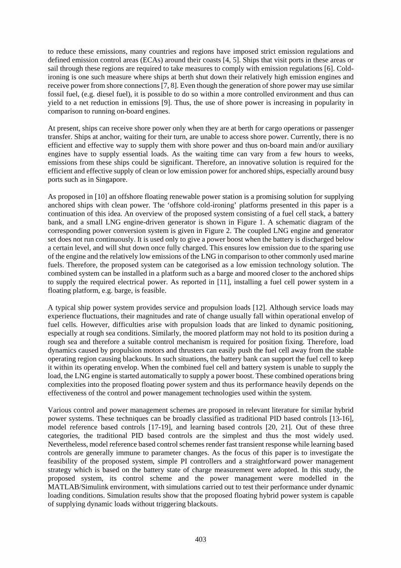
403
to reduce these emissions, many countries and regions have imposed strict emission regulations anddefined emission control areas (ECAs) around their coasts [4, 5]. Ships that visit ports in these areas orsail through these regions are required to take measures to comply with emission regulations [6]. Cold-ironing is one such measure where ships at berth shut down their relatively high emission engines andreceive power from shore connections [7, 8]. Even though the generation of shore power may use similarfossil fuel, (e.g. diesel fuel), it is possible to do so within a more controlled environment and thus canyield to a net reduction in emissions [9]. Thus, the use of shore power is increasing in popularity incomparison to running on-board engines.
At present, ships can receive shore power only when they are at berth for cargo operations or passengertransfer. Ships at anchor, waiting for their turn, are unable to access shore power. Currently, there is noefficient and effective way to supply them with shore power and thus on-board main and/or auxiliaryengines have to supply essential loads. As the waiting time can vary from a few hours to weeks,emissions from these ships could be significant. Therefore, an innovative solution is required for theefficient and effective supply of clean or low emission power for anchored ships, especially around busyports such as in Singapore.
As proposed in [10] an offshore floating renewable power station is a promising solution for supplyinganchored ships with clean power. The ‘offshore cold-ironing’ platforms presented in this paper is acontinuation of this idea. An overview of the proposed system consisting of a fuel cell stack, a batterybank, and a small LNG engine-driven generator is shown in Figure 1. A schematic diagram of thecorresponding power conversion system is given in Figure 2. The coupled LNG engine and generatorset does not run continuously. It is used only to give a power boost when the battery is discharged belowa certain level, and will shut down once fully charged. This ensures low emission due to the sparing useof the engine and the relatively low emissions of the LNG in comparison to other commonly used marinefuels. Therefore, the proposed system can be categorised as a low emission technology solution. Thecombined system can be installed in a platform such as a barge and moored closer to the anchored shipsto supply the required electrical power. As reported in [11], installing a fuel cell power system in afloating platform, e.g. barge, is feasible.
A typical ship power system provides service and propulsion loads [12]. Although service loads mayexperience fluctuations, their magnitudes and rate of change usually fall within operational envelop offuel cells. However, difficulties arise with propulsion loads that are linked to dynamic positioning,especially at rough sea conditions. Similarly, the moored platform may not hold to its position during arough sea and therefore a suitable control mechanism is required for position fixing. Therefore, loaddynamics caused by propulsion motors and thrusters can easily push the fuel cell away from the stableoperating region causing blackouts. In such situations, the battery bank can support the fuel cell to keepit within its operating envelop. When the combined fuel cell and battery system is unable to supply theload, the LNG engine is started automatically to supply a power boost. These combined operations bringcomplexities into the proposed floating power system and thus its performance heavily depends on theeffectiveness of the control and power management technologies used within the system.
Various control and power management schemes are proposed in relevant literature for similar hybridpower systems. These techniques can be broadly classified as traditional PID based controls [13-16],model reference based controls [17-19], and learning based controls [20, 21]. Out of these threecategories, the traditional PID based controls are the simplest and thus the most widely used.Nevertheless, model reference based control schemes render fast transient response while learning basedcontrols are generally immune to parameter changes. As the focus of this paper is to investigate thefeasibility of the proposed system, simple PI controllers and a straightforward power managementstrategy which is based on the battery state of charge measurement were adopted. In this study, theproposed system, its control scheme and the power management were modelled in theMATLAB/Simulink environment, with simulations carried out to test their performance under dynamicloading conditions. Simulation results show that the proposed floating hybrid power system is capableof supplying dynamic loads without triggering blackouts.
404
Figure 1 An overview of the proposed system
Figure 2 Schematic diagram of the proposed ‘offshore cold-ironing’ system
405
2. System Modeling
2.1 Fuel Cell Model
A schematic diagram of the fuel cell model used in this study is shown in Figure 3. In this model, theopen circuit voltage (Eoc), exchange current (i0) and the Tafel slope (A) are calculated using equations(1), (2) and (3) respectively [22, 23].
0
lni
iNA fc
13/1
dST
Figure 3 Fuel cell model
ncoc EKE (1)
RT
GOH
o eRh
PPzFki
22
(2)
Fz
RTA
(3)
where N is the number of cells in the fuel cell stack, R is the universal gas constant (8.3145 J/mol K), Fis Faraday's constant (96485 C/mol), z is the number of moving electrons, En is the nernst voltage whichis the thermodynamics voltage of the cells that depends on the temperatures and partial pressures ofreactants and products inside the stack (V), α is the charge transfer coefficient which depends on thetype of electrodes and catalysts used, PH2 is the partial pressure of hydrogen inside the stack (atm), PO2
is the partial pressure of oxygen inside the stack (atm), k is the Boltzmann's constant (1.38 × 10⁻²³ J/K),h is the Planck's constant (6.626 × 10⁻³⁴ Js), ΔG is the size of the activation barrier which depends onthe type of electrode and catalyst used, T is the temperature of operation (K), Kc is the voltage constantat nominal condition of operation, Rfc is the internal resistance of the fuel cell stack, S is the Laplacevariable and Td is the response time (s).
2.2 Engine and Generator Models
The engine is represented as a first order delay with the time constant en as shown in Figure 4. Thegovernor of the engine controls the fuel supply to the engine and thus controls the engine torque, TENG,to regulate the engine speed under varying load conditions. The corresponding closed loop speedcontroller of the small LNG engine and the generator set is represented as in Figure 4, where Te is theelectrical load and Jgen is the equivalent inertia of the rotating parts.
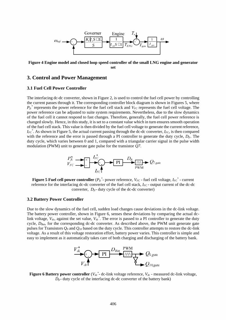
406
S
SK ii 11
1
Sen genJ
1
Figure 4 Engine model and closed loop speed controller of the small LNG engine and generatorset
3. Control and Power Management
3.1 Fuel Cell Power Controller
The interfacing dc-dc converter, shown in Figure 2, is used to control the fuel cell power by controllingthe current passes through it. The corresponding controller block diagram is shown in Figures 5, wherePfc
* represents the power reference for the fuel cell stack and VFC represents the fuel cell voltage. Thepower reference can be adjusted to suite system requirements. Nevertheless, due to the slow dynamicsof the fuel cell it cannot respond to fast changes. Therefore, generally, the fuel cell power reference ischanged slowly. Hence, in this study, it is set to a constant value which in turn ensures smooth operationof the fuel cell stack. This value is then divided by the fuel cell voltage to generate the current reference,IFC
*. As shown in Figure 5, the actual current passing through the dc-dc converter, IFC, is then comparedwith the reference and the error is passed through a PI controller to generate the duty cycle, Dfc. Theduty cycle, which varies between 0 and 1, compared with a triangular carrier signal in the pulse widthmodulation (PWM) unit to generate gate pulse for the transistor Q7.
Figure 5 Fuel cell power controller (Pfc*- power reference, VFC - fuel cell voltage, IFC
* - currentreference for the interfacing dc-dc converter of the fuel cell stack, IFC - output current of the dc-dc
converter, Dfc- duty cycle of the dc-dc converter)
3.2 Battery Power Controller
Due to the slow dynamics of the fuel cell, sudden load changes cause deviations in the dc-link voltage.The battery power controller, shown in Figure 6, senses these deviations by comparing the actual dc-link voltage, Vdc, against the set value, Vdc
*. The error is passed to a PI controller to generate the dutycycle, DBat, for the corresponding dc-dc converter. As described above, the PWM unit generate gatepulses for Transistors Q9 and Q10 based on the duty cycle. This controller attempts to restore the dc-linkvoltage. As a result of this voltage restoration effort, battery power varies. This controller is simple andeasy to implement as it automatically takes care of both charging and discharging of the battery bank.
Figure 6 Battery power controller (Vdc*- dc-link voltage reference, Vdc - measured dc-link voltage,
Dfc- duty cycle of the interfacing dc-dc converter of the battery bank)
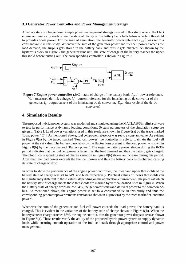
407
3.3 Generator Power Controller and Power Management Strategy
A battery state of charge based simple power management strategy is used in this study where the LNGengine automatically starts when the state of charge of the battery bank falls below a certain thresholdto provides boost power. For the sake of simulation, the generator power reference Pgen
*, was set to aconstant value in this study. Whenever the sum of the generator power and fuel cell power exceeds theload demand, the surplus gets stored in the battery bank and thus it gets charged. As shown by thehysteresis block in Figure 7 the generator runs until the state of charge of the battery reaches the upperthreshold before cutting out. The corresponding controller is shown in Figure 7.
Figure 7 Engine power controller (SoC - state of charge of the battery bank, Pgen*- power reference,
Vdc - measured dc-link voltage, Ig* - current reference for the interfacing dc-dc converter of the
generator, Ig - output current of the interfacing dc-dc converter, Dgen- duty cycle of the dc-dcconverter)
4. Simulation Results
The proposed hybrid power system was modelled and simulated using the MATLAB/Simulink softwareto test its performance at dynamic loading conditions. System parameters of the simulation setup aregiven in Table I. Load power variations used in this study are shown in Figure 8(a) by the trace marked‘Load power’[24]. As mentioned above, fuel cell power reference was set to a constant value. As evidentin Figure 8(a) by the traced marked ‘Fuel cell power’ the controller is able to maintain the fuel cellpower at the set value. The battery bank absorbs the fluctuations present in the load power as shown inFigure 8(b) by the trace marked ‘Battery power’. The negative battery power shown during the 0-30speriod indicates that the fuel cell power is larger than the load demand and thus the battery gets charged.The plot of corresponding state of charge variation in Figure 8(b) shows an increase during this period.After that, the load power exceeds the fuel cell power and thus the battery bank is discharged causingits state of charge to drop.
In order to show the performance of the engine power controller, the lower and upper thresholds of thebattery state of charge was set to 64% and 65% respectively. Practical values of theses thresholds canbe significantly different to these values, depending on the application environment. The points at whichthe battery state of charge meets these thresholds are marked by vertical dashed lines in Figure 8. Whenthe Battery state of charge drops below 64%, the generator starts and delivers power to the common dc-bus. As mentioned above, the engine power is set to a constant value in this study and thus thecorresponding generator power remains constant as shown in Figure 8(a) by the trace marked ‘Generatorpower’.
Whenever the sum of the generator and fuel cell power exceeds the load power, the battery bank ischarged. This is evident in the variations of the battery state of charge shown in Figure 8(b). When thebattery state of charge reaches 65%, the engine cuts out, thus the generator power drops to zero as shownin Figure 8(a). These results verify the ability of the proposed hybrid power system to supply dynamicloads while ensuring smooth operation of the fuel cell stack through appropriate control and powermanagement.
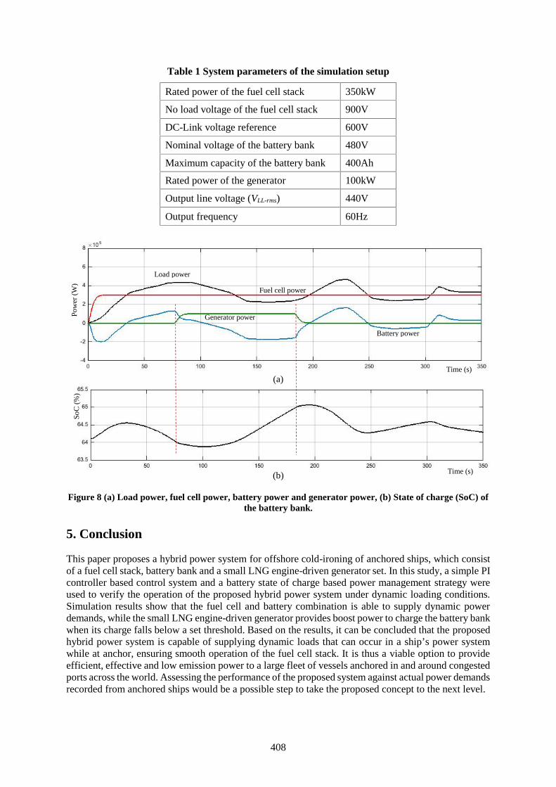
408
Table 1 System parameters of the simulation setup
Rated power of the fuel cell stack 350kW
No load voltage of the fuel cell stack 900V
DC-Link voltage reference 600V
Nominal voltage of the battery bank 480V
Maximum capacity of the battery bank 400Ah
Rated power of the generator 100kW
Output line voltage (VLL-rms) 440V
Output frequency 60Hz
(a)
(b)
Figure 8 (a) Load power, fuel cell power, battery power and generator power, (b) State of charge (SoC) ofthe battery bank.
5. Conclusion
This paper proposes a hybrid power system for offshore cold-ironing of anchored ships, which consistof a fuel cell stack, battery bank and a small LNG engine-driven generator set. In this study, a simple PIcontroller based control system and a battery state of charge based power management strategy wereused to verify the operation of the proposed hybrid power system under dynamic loading conditions.Simulation results show that the fuel cell and battery combination is able to supply dynamic powerdemands, while the small LNG engine-driven generator provides boost power to charge the battery bankwhen its charge falls below a set threshold. Based on the results, it can be concluded that the proposedhybrid power system is capable of supplying dynamic loads that can occur in a ship’s power systemwhile at anchor, ensuring smooth operation of the fuel cell stack. It is thus a viable option to provideefficient, effective and low emission power to a large fleet of vessels anchored in and around congestedports across the world. Assessing the performance of the proposed system against actual power demandsrecorded from anchored ships would be a possible step to take the proposed concept to the next level.
Load power
Fuel cell power
Generator power
Battery power
Time (s)
Time (s)
Pow
er (
W)
SoC
(%
)
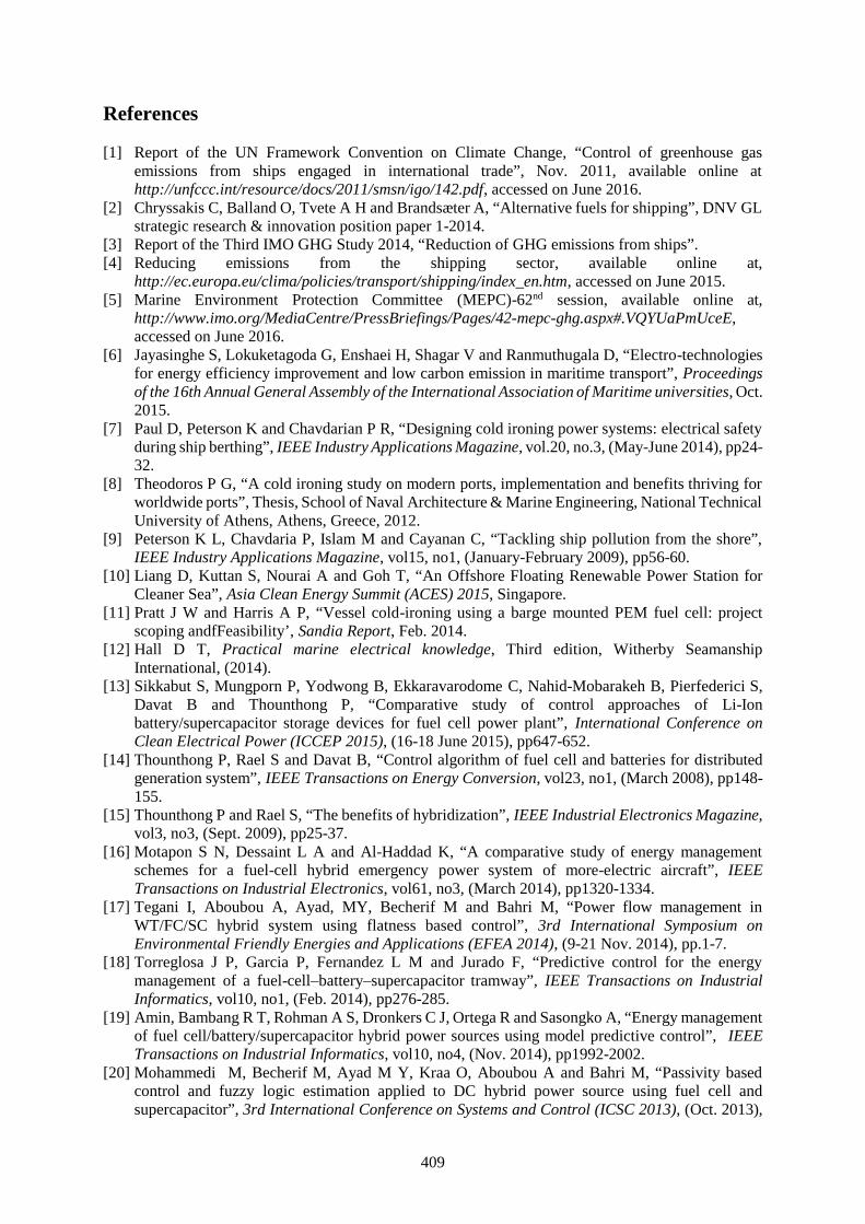
409
References
[1] Report of the UN Framework Convention on Climate Change, “Control of greenhouse gasemissions from ships engaged in international trade”, Nov. 2011, available online athttp://unfccc.int/resource/docs/2011/smsn/igo/142.pdf, accessed on June 2016.
[2] Chryssakis C, Balland O, Tvete A H and Brandsæter A, “Alternative fuels for shipping”, DNV GLstrategic research & innovation position paper 1-2014.
[3] Report of the Third IMO GHG Study 2014, “Reduction of GHG emissions from ships”.[4] Reducing emissions from the shipping sector, available online at,
http://ec.europa.eu/clima/policies/transport/shipping/index_en.htm, accessed on June 2015.[5] Marine Environment Protection Committee (MEPC)-62nd session, available online at,
http://www.imo.org/MediaCentre/PressBriefings/Pages/42-mepc-ghg.aspx#.VQYUaPmUceE,accessed on June 2016.
[6] Jayasinghe S, Lokuketagoda G, Enshaei H, Shagar V and Ranmuthugala D, “Electro-technologiesfor energy efficiency improvement and low carbon emission in maritime transport”, Proceedingsof the 16th Annual General Assembly of the International Association of Maritime universities, Oct.2015.
[7] Paul D, Peterson K and Chavdarian P R, “Designing cold ironing power systems: electrical safetyduring ship berthing”, IEEE Industry Applications Magazine, vol.20, no.3, (May-June 2014), pp24-32.
[8] Theodoros P G, “A cold ironing study on modern ports, implementation and benefits thriving forworldwide ports”, Thesis, School of Naval Architecture & Marine Engineering, National TechnicalUniversity of Athens, Athens, Greece, 2012.
[9] Peterson K L, Chavdaria P, Islam M and Cayanan C, “Tackling ship pollution from the shore”,IEEE Industry Applications Magazine, vol15, no1, (January-February 2009), pp56-60.
[10] Liang D, Kuttan S, Nourai A and Goh T, “An Offshore Floating Renewable Power Station forCleaner Sea”, Asia Clean Energy Summit (ACES) 2015, Singapore.
[11] Pratt J W and Harris A P, “Vessel cold-ironing using a barge mounted PEM fuel cell: projectscoping andfFeasibility’, Sandia Report, Feb. 2014.
[12] Hall D T, Practical marine electrical knowledge, Third edition, Witherby SeamanshipInternational, (2014).
[13] Sikkabut S, Mungporn P, Yodwong B, Ekkaravarodome C, Nahid-Mobarakeh B, Pierfederici S,Davat B and Thounthong P, “Comparative study of control approaches of Li-Ionbattery/supercapacitor storage devices for fuel cell power plant”, International Conference onClean Electrical Power (ICCEP 2015), (16-18 June 2015), pp647-652.
[14] Thounthong P, Rael S and Davat B, “Control algorithm of fuel cell and batteries for distributedgeneration system”, IEEE Transactions on Energy Conversion, vol23, no1, (March 2008), pp148-155.
[15] Thounthong P and Rael S, “The benefits of hybridization”, IEEE Industrial Electronics Magazine,vol3, no3, (Sept. 2009), pp25-37.
[16] Motapon S N, Dessaint L A and Al-Haddad K, “A comparative study of energy managementschemes for a fuel-cell hybrid emergency power system of more-electric aircraft”, IEEETransactions on Industrial Electronics, vol61, no3, (March 2014), pp1320-1334.
[17] Tegani I, Aboubou A, Ayad, MY, Becherif M and Bahri M, “Power flow management inWT/FC/SC hybrid system using flatness based control”, 3rd International Symposium onEnvironmental Friendly Energies and Applications (EFEA 2014), (9-21 Nov. 2014), pp.1-7.
[18] Torreglosa J P, Garcia P, Fernandez L M and Jurado F, “Predictive control for the energymanagement of a fuel-cell–battery–supercapacitor tramway”, IEEE Transactions on IndustrialInformatics, vol10, no1, (Feb. 2014), pp276-285.
[19] Amin, Bambang R T, Rohman A S, Dronkers C J, Ortega R and Sasongko A, “Energy managementof fuel cell/battery/supercapacitor hybrid power sources using model predictive control”, IEEETransactions on Industrial Informatics, vol10, no4, (Nov. 2014), pp1992-2002.
[20] Mohammedi M, Becherif M, Ayad M Y, Kraa O, Aboubou A and Bahri M, “Passivity basedcontrol and fuzzy logic estimation applied to DC hybrid power source using fuel cell andsupercapacitor”, 3rd International Conference on Systems and Control (ICSC 2013), (Oct. 2013),

410
pp77-82.[21] Odeim F, Roes Jand Heinze A, “Power management optimization of a fuel
cell/battery/supercapacitor hybrid system for transit bus applications”, IEEE Transactions onVehicular Technology, Early access, (July 2015).
[22] Njoya S M, Tremblay O and Dessaint L A, “A generic fuel cell model for the simulation of fuelcell vehicles”, IEEE Vehicle Power and Propulsion Conference, (Sept. 2009), pp1722–29.
[23] Motapon S N, Tremblay O and Dessaint L A, “Development of a generic fuel cell model:application to a fuel cell vehicle simulation”, International Journal of Power Electronics, Vol4,No6, (2012), pp.505–522.
[24] Radan D, Sørensen A J, Ådnanes A K and Johansen T A, “Reducing Power Load Fluctuations onShips Using Power Redistribution Control” Marine Technology, Vol45, No3, (July 2008), pp162–174.
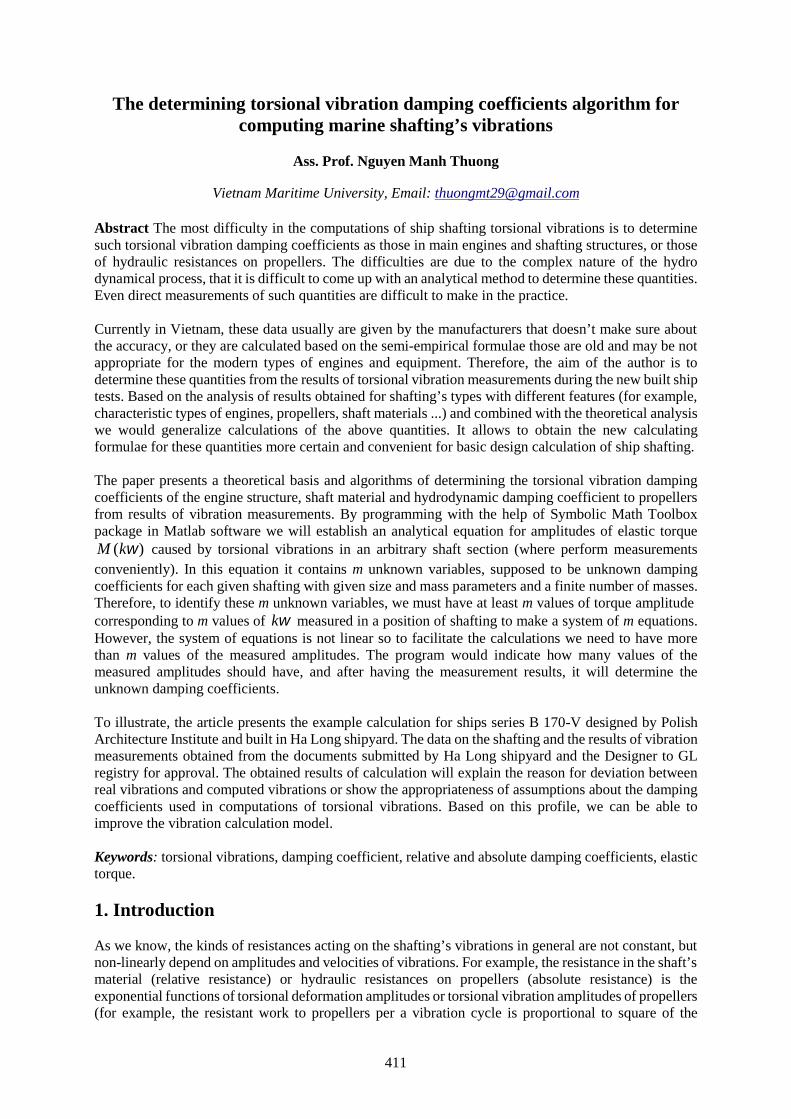
411
The determining torsional vibration damping coefficients algorithm forcomputing marine shafting’s vibrations
Ass. Prof. Nguyen Manh Thuong
Vietnam Maritime University, Email: [email protected]
Abstract The most difficulty in the computations of ship shafting torsional vibrations is to determinesuch torsional vibration damping coefficients as those in main engines and shafting structures, or thoseof hydraulic resistances on propellers. The difficulties are due to the complex nature of the hydrodynamical process, that it is difficult to come up with an analytical method to determine these quantities.Even direct measurements of such quantities are difficult to make in the practice.
Currently in Vietnam, these data usually are given by the manufacturers that doesn’t make sure aboutthe accuracy, or they are calculated based on the semi-empirical formulae those are old and may be notappropriate for the modern types of engines and equipment. Therefore, the aim of the author is todetermine these quantities from the results of torsional vibration measurements during the new built shiptests. Based on the analysis of results obtained for shafting’s types with different features (for example,characteristic types of engines, propellers, shaft materials ...) and combined with the theoretical analysiswe would generalize calculations of the above quantities. It allows to obtain the new calculatingformulae for these quantities more certain and convenient for basic design calculation of ship shafting.
The paper presents a theoretical basis and algorithms of determining the torsional vibration dampingcoefficients of the engine structure, shaft material and hydrodynamic damping coefficient to propellersfrom results of vibration measurements. By programming with the help of Symbolic Math Toolboxpackage in Matlab software we will establish an analytical equation for amplitudes of elastic torque
( )M k caused by torsional vibrations in an arbitrary shaft section (where perform measurementsconveniently). In this equation it contains m unknown variables, supposed to be unknown dampingcoefficients for each given shafting with given size and mass parameters and a finite number of masses.Therefore, to identify these m unknown variables, we must have at least m values of torque amplitudecorresponding to m values of k measured in a position of shafting to make a system of m equations.However, the system of equations is not linear so to facilitate the calculations we need to have morethan m values of the measured amplitudes. The program would indicate how many values of themeasured amplitudes should have, and after having the measurement results, it will determine theunknown damping coefficients.
To illustrate, the article presents the example calculation for ships series B 170-V designed by PolishArchitecture Institute and built in Ha Long shipyard. The data on the shafting and the results of vibrationmeasurements obtained from the documents submitted by Ha Long shipyard and the Designer to GLregistry for approval. The obtained results of calculation will explain the reason for deviation betweenreal vibrations and computed vibrations or show the appropriateness of assumptions about the dampingcoefficients used in computations of torsional vibrations. Based on this profile, we can be able toimprove the vibration calculation model.
Keywords: torsional vibrations, damping coefficient, relative and absolute damping coefficients, elastictorque.
1. Introduction
As we know, the kinds of resistances acting on the shafting’s vibrations in general are not constant, butnon-linearly depend on amplitudes and velocities of vibrations. For example, the resistance in the shaft’smaterial (relative resistance) or hydraulic resistances on propellers (absolute resistance) is theexponential functions of torsional deformation amplitudes or torsional vibration amplitudes of propellers(for example, the resistant work to propellers per a vibration cycle is proportional to square of the
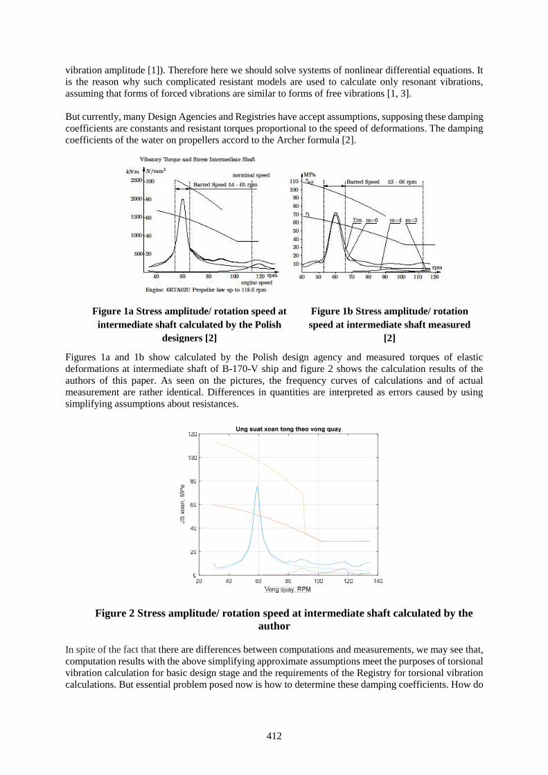
412
vibration amplitude [1]). Therefore here we should solve systems of nonlinear differential equations. Itis the reason why such complicated resistant models are used to calculate only resonant vibrations,assuming that forms of forced vibrations are similar to forms of free vibrations [1, 3].
But currently, many Design Agencies and Registries have accept assumptions, supposing these dampingcoefficients are constants and resistant torques proportional to the speed of deformations. The dampingcoefficients of the water on propellers accord to the Archer formula [2].
Figures 1a and 1b show calculated by the Polish design agency and measured torques of elasticdeformations at intermediate shaft of B-170-V ship and figure 2 shows the calculation results of theauthors of this paper. As seen on the pictures, the frequency curves of calculations and of actualmeasurement are rather identical. Differences in quantities are interpreted as errors caused by usingsimplifying assumptions about resistances.
Figure 2 Stress amplitude/ rotation speed at intermediate shaft calculated by theauthor
In spite of the fact that there are differences between computations and measurements, we may see that,computation results with the above simplifying approximate assumptions meet the purposes of torsionalvibration calculation for basic design stage and the requirements of the Registry for torsional vibrationcalculations. But essential problem posed now is how to determine these damping coefficients. How do
Figure 1a Stress amplitude/ rotation speed atintermediate shaft calculated by the Polish
designers [2]
Figure 1b Stress amplitude/ rotationspeed at intermediate shaft measured
[2]
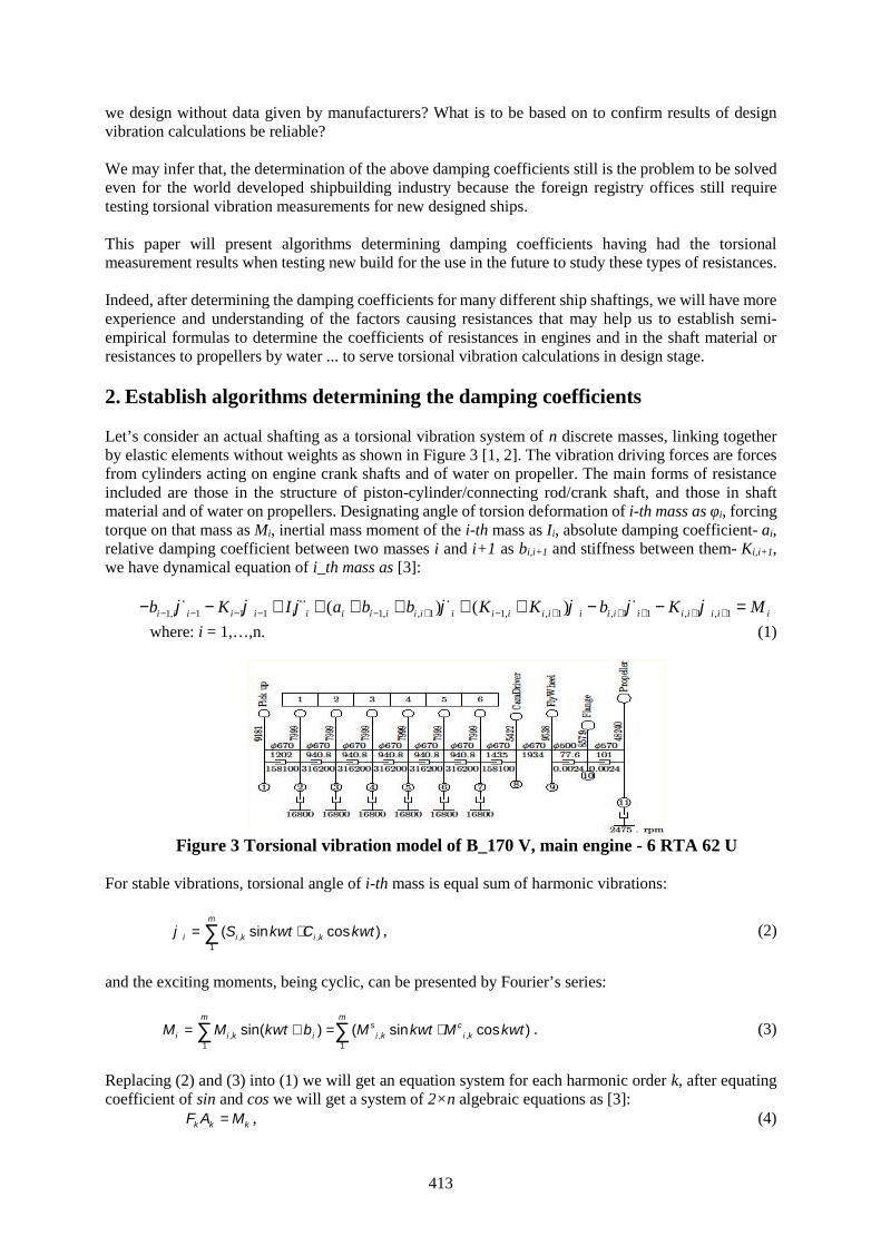
413
we design without data given by manufacturers? What is to be based on to confirm results of designvibration calculations be reliable?
We may infer that, the determination of the above damping coefficients still is the problem to be solvedeven for the world developed shipbuilding industry because the foreign registry offices still requiretesting torsional vibration measurements for new designed ships.
This paper will present algorithms determining damping coefficients having had the torsionalmeasurement results when testing new build for the use in the future to study these types of resistances.
Indeed, after determining the damping coefficients for many different ship shaftings, we will have moreexperience and understanding of the factors causing resistances that may help us to establish semi-empirical formulas to determine the coefficients of resistances in engines and in the shaft material orresistances to propellers by water ... to serve torsional vibration calculations in design stage.
2. Establish algorithms determining the damping coefficients
Let’s consider an actual shafting as a torsional vibration system of n discrete masses, linking togetherby elastic elements without weights as shown in Figure 3 [1, 2]. The vibration driving forces are forcesfrom cylinders acting on engine crank shafts and of water on propeller. The main forms of resistanceincluded are those in the structure of piston-cylinder/connecting rod/crank shaft, and those in shaftmaterial and of water on propellers. Designating angle of torsion deformation of i-th mass as φi, forcingtorque on that mass as Mi, inertial mass moment of the i-th mass as Ii, absolute damping coefficient- ai,relative damping coefficient between two masses i and i+1 as bi,i+1 and stiffness between them- Ki,i+1,we have dynamical equation of i_th mass as [3]:
1, 1 1 1 1, , 1 1, , 1 , 1 1 , 1 , 1( ) ( )i i i i i i i i i i i i i i i i i i i i i i i i i ib K I a b b K K b K M
where: i = 1,…,n. (1)
Figure 3 Torsional vibration model of B_170 V, main engine - 6 RTA 62 U
For stable vibrations, torsional angle of i-th mass is equal sum of harmonic vibrations:
, (2)
and the exciting moments, being cyclic, can be presented by Fourier’s series:
. (3)
Replacing (2) and (3) into (1) we will get an equation system for each harmonic order k, after equatingcoefficient of sin and cos we will get a system of 2×n algebraic equations as [3]:
, (4)
, ,1
( sin cos )m
i i k i kS k t C k t
, , ,1 1
sin( ) ( sin cos )m m
s ci i k i i k i kM M k t M k t M k t
k k kF A M

414
where:- column vector of exciting torque amplitudes at
harmonic order k;- column vector of torsion angle amplitudes according to
harmonic order k;Fk = [fi,j ] – square matrix 2×n, its elements fi,j are functions of kω, stiffness of shafts Ki,i+1, inertial
moment Ii and of damping coefficients ai, bi,i+1 [4].
In calculations forced vibrations, the elements fi,j of Fk are determined if damping coefficients are givenand torsional vibration amplitudes of masses due to harmonic k are computed by:
. (5)
Then elastic torsion torque amplitude at order k in shaft between masses i-th and (i+1)_th is calculatedby:
. (6)
If supposing we measure the elastic torsional torque in a shaft Ei,i+1 (see Figure 4), then according to (6)we can determine the amplitude of the relative torsion deformation , 1i i between two masses i and
i+1:
. (7)
Figure 4 Stress/time at the intermediate shaft at different rotation speeds [2]
On the other side , 1i i can be calculated by equation (5) as following. Having:
1,1...2 ,1...2 1, , .det( )i n i n k i k i k kM S S F
1,1...2 ,1...2 1, , .det( )n i n n i n k i k i k kM C C F
Therefore:
2 22 2 2, 1 1,1...2 ,1...2 1,1...2 ,1...2det ( ) .i i k i n i n i n i n kF M ,
(8)
1, 2, , 1, 2, ,=[ ,. ..., , , ...., ]s s s c c c Tk k k n k k k n kM M M M M M M
1, 2, , 1, 2, ,[ , ,..., , , ,..., ]Tk k k n k k k n kA S S S C C C
1k k kA F M
2 2, 1 , 1 , 1, , 1, , 1 , 1( ) ( )k
i i i i i k i k i k i k i i i iE K S S C C K
, 1 , 1 , 1/ki i i i i iE K

415
where: ; ; 1,1...2n i n ; ,1...2n i n are lines i, i+1 and n+i+1, n+i of matrix
with elements determined as: - where - algebraic complement of the element (j,i) of Fk.
, 1i i can be calculated according to (7) if the elastic deformation torque is measured.
Thus, suppose there are m values of damping coefficients aj and bj, j+1 are unknown and should bedefined. Then equation (8) will contain m unknown variables (they are damping coefficients in Fk). Inprinciple, in order to determine the m these variables, we should get m values of elastic torsional torquein shaft between masses i, i+1 (see F. 4) in order to make m algebraic equations to determine m unknownvalues of aj and bj,j+1. However, the system of equations obtained is the type of multi-hidden variableand high order, so that to be able to solve it, we should make more than m equations to obtain a systemof linear equations with the new hidden variables, those are combination of productions of unknown as::
To illustrate, here we consider the ships of series B 170 V. Its torsional vibration model is as shown inF.3 having the following characteristic parameters.
- The number of concentrated masses: n=11;- The inertial moments of concentrated masses (kgm2):Ii = [9181.0 7999.0 7999.0 7999.0 7999.0 7999.0 7999.0 5422.0 9538.3 857.9 48240.1];- The stiffness of shafts (MNm/rad)Ki=[1201.92 940.82 940.82 940.82 940.82 940.82 1434.93 934.24 77.16 101.04];- Diameters of shafts (mm):Di =[670 670 670 670 670 670 670 670 500 570];
Designating unknown damping coefficients ai and bi,i+1, with symbles s, z, f, y, r and place them intoequation (1), we get matrix FK(22,22) for each value of kw (k- harmonic order, w- rotation speed ofpropeller), having form:
Fk =
[1201920-9.18*kw2, -1201920, 0,… -kw*r, kw*r,… 0][ -1201920,2142740-7.99*kw2, -940820, 0,0,0,0,0,0,0,0, kw*r, -kw*z, kw*s,… 0][ 0, -940820,1881640-7.99*kw2,-940820, … kw*s,-f*kw, kw*s, …0]……[ -kw*r, kw*z, -kw*s,.. ,-1201920, 2142740-7.99*kw2,-940820,… 0]……………………[ 0, 0, ... ,-77160, 178200-0.85*kw2, -101040][ 0, … 0,.. ,kw*y, ... 0, -101040, 101040-4.82*kw2]
To determine the determinant det(Fk) and the algebraic complements Di,j can be done with using theSymbolic Math Toolbox package of Matlab software by the command “det(Fk)” if the matrix size issmall enough (depending on the number of non-zero elements), the result is a formula in symbolic formon the screen, for example:
ans=2871048086689088639517089901.315*kw14*r3*s4*z+2218063572479354423019604109325.3*kw16*r2*s3*z + … +12883815368824962090418376
Finally, with each value of kw, after having computed all the algebraic complements Di,j of elements inthe interesting lines, replacing them into equation (8), supposing we get an equation as:
15 2 7 41 2 1 0... ....i p p pC f r z C z s C s C y C r C . (9)
1,1...2i n ,1...2i n
, ,i j j iD ,j iD
1 2 1 21 2 1 2. ... . ...m m n n
ix a a b b

416
There are p constants Ci in the left side of the equation (9), according to k and rotation speed w of thepropeller shaft. Here, to determine r, f, z…, we should obtain p values of torsion torque amplitudesaccording to p value of kw in order to make p equations (9) and a system of p linear equations with phidden: x1=r, x2=f, x3=z, …, xi=fm rn…z,… Resolving this system we would identify the hidden r, f, s…
If the computing is performed correctly and with inputs being the elastic torque values obtained bycalculations as described above (assuming the damping coefficients are constant), then the result mustmatch, it means, for example:
if: x1=r, x2=f, x3=z, xi=fm rnz,then: xi=x2
mx1nx3.
Being sure it correct, take values of elastic torsional torques measured practically to put into (9) tocalculate. If xi≠x2
m x1nx3, for example, depending on differences we may assess the suitability of the used
assumptions about resistances.
However, in the example case, unfortunately we can not directly use the command det(Fk). It wouldcause errors “Out of Memory” or the text is too long, we would get a report on screens, for example:
ans=2871048086689088639517089901.315*kw^14*r^3*s^4*z+………………………………………
…… … +.2218063572479354423019604109325.3*kw^16*r^2*s^3*z +12883815368824962090418376... Output truncated. Text exceeds maximum line length of 25.000characters for Command Window display.
To overcome this problem, we should divide the calculation procedure into some steps:
- Step 1: replace the original terms of the first matrix by new symbols (to get more compact form),for example:
I1=-I1*kw^2+K1; r=kw*r; I2=-Ic*kw^2+K1+Kx; z=kw*z; s=kw*s; I3=-Ic*kw^2+2*Kx;I4=-Ic*kw^2+2*Kx; I5=-Ic*kw^2+K3+Kx; I6=-I3*kw^2+K3+K4=I6; I7=-I4*kw^2+K4+K5; I8=-I5*kw^2+K5+K6; I9= -Ic*kw^2+K6,
to obtain matrix Fk looking as:Fk=[ I1, -K1, 0, 0,0,0,0,0,0,0,0,-r, r,0,0,0,0,0,0,0,0,0];[-K1, I2,-Kx, 0,0,0,0,0,0,0,0, r,-z, s,0,0,0,0,0,0,0,0];…………..[r,-r,0,0,0,0,0,0,0,0,0,I1,-K1,0,0,0,0,0,0,0,0,0];……………[0,0,0,0,0,0,0,0,0,0,0,0,0,0,0,0,0,0,0,-K5, I8,-K6];[0,0,0,0,0,0,0,0,0,0,y,0,0,0,0,0,0,0,0, 0,-K6, I9];
- Step 2: use the comand “det” for a smaller size, for example: D10=det(Fk(1:10,1:10)). Theobtained results looks like that:
D10 =- I3*I4^3*K1^2 - I1*I4^3*Kx^2 + I1*I2*I3*I4^3 + I4^2*K1^2*Kx^2 -I1*I2*I4^2*Kx^2 + 2*I3*I4*K1^2*Kx^2 + 2*I1*I4*Kx^4 - 2*I1*I2*I3*I4*Kx^2 -K1^2*Kx^4 + I1*I2*Kx^4
- Step 3: transform Fk to Fk1 by Gause method so that Fk
1(1:10,1:10) be a triangle matrix;
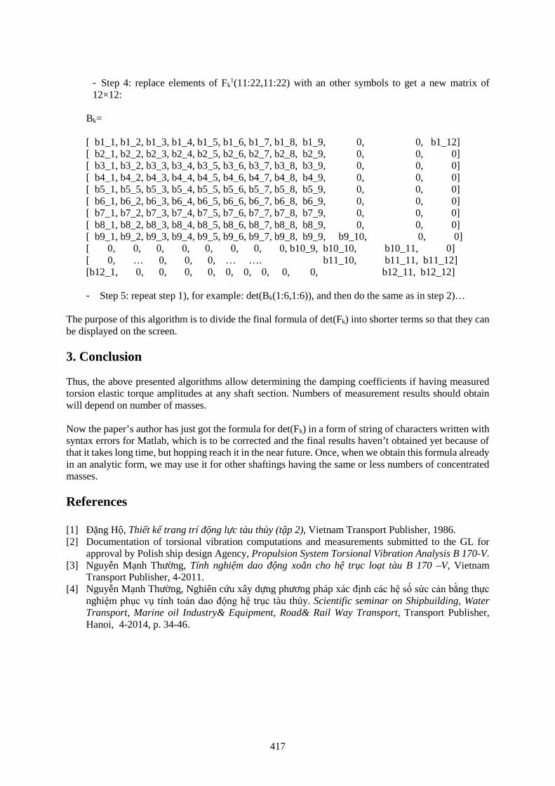
417
- Step 4: replace elements of Fk1(11:22,11:22) with an other symbols to get a new matrix of
12×12:
Bk=
[ b1_1, b1_2, b1_3, b1_4, b1_5, b1_6, b1_7, b1_8, b1_9, 0, 0, b1_12][ b2_1, b2_2, b2_3, b2_4, b2_5, b2_6, b2_7, b2_8, b2_9, 0, 0, 0][ b3_1, b3_2, b3_3, b3_4, b3_5, b3_6, b3_7, b3_8, b3_9, 0, 0, 0][ b4_1, b4_2, b4_3, b4_4, b4_5, b4_6, b4_7, b4_8, b4_9, 0, 0, 0][ b5_1, b5_5, b5_3, b5_4, b5_5, b5_6, b5_7, b5_8, b5_9, 0, 0, 0][ b6_1, b6_2, b6_3, b6_4, b6_5, b6_6, b6_7, b6_8, b6_9, 0, 0, 0][ b7_1, b7_2, b7_3, b7_4, b7_5, b7_6, b7_7, b7_8, b7_9, 0, 0, 0][ b8_1, b8_2, b8_3, b8_4, b8_5, b8_6, b8_7, b8_8, b8_9, 0, 0, 0][ b9_1, b9_2, b9_3, b9_4, b9_5, b9_6, b9_7, b9_8, b9_9, b9_10, 0, 0][ 0, 0, 0, 0, 0, 0, 0, 0, b10_9, b10_10, b10_11, 0][ 0, … 0, 0, 0, … …. b11_10, b11_11, b11_12][b12_1, 0, 0, 0, 0, 0, 0, 0, 0, 0, b12_11, b12_12]
- Step 5: repeat step 1), for example: det(Bk(1:6,1:6)), and then do the same as in step 2)…
The purpose of this algorithm is to divide the final formula of det(Fk) into shorter terms so that they canbe displayed on the screen.
3. Conclusion
Thus, the above presented algorithms allow determining the damping coefficients if having measuredtorsion elastic torque amplitudes at any shaft section. Numbers of measurement results should obtainwill depend on number of masses.
Now the paper’s author has just got the formula for det(Fk) in a form of string of characters written withsyntax errors for Matlab, which is to be corrected and the final results haven’t obtained yet because ofthat it takes long time, but hopping reach it in the near future. Once, when we obtain this formula alreadyin an analytic form, we may use it for other shaftings having the same or less numbers of concentratedmasses.
References
[1] Đặng Hộ, Thiết kế trang trí động lực tàu thủy (tập 2), Vietnam Transport Publisher, 1986.[2] Documentation of torsional vibration computations and measurements submitted to the GL for
approval by Polish ship design Agency, Propulsion System Torsional Vibration Analysis B 170-V.[3] Nguyễn Mạnh Thường, Tính nghiệm dao động xoắn cho hệ trục loạt tàu B 170 –V, Vietnam
Transport Publisher, 4-2011.[4] Nguyễn Mạnh Thường, Nghiên cứu xây dựng phương pháp xác định các hệ số sức cản bằng thực
nghiệm phục vụ tính toán dao động hệ trục tàu thủy. Scientific seminar on Shipbuilding, WaterTransport, Marine oil Industry& Equipment, Road& Rail Way Transport, Transport Publisher,Hanoi, 4-2014, p. 34-46.

418
419
Session 4
RESEARCH IN MET
420
Ship Automatic Track keeping At Low Speed
MSc. Thanh-Dat Le1, Prof. Nam-kyun Im2, PhD. Van-Luong Tran3
1. Vietnam Maritime University, [email protected]. Mokpo National Maritime University, [email protected]
3. Vietnam Maritime University, [email protected]
Abstract: There are lots of ship’s situations when operating from port to port such as with full speedsailing, reducing speed inside traffic scheme, stopping at a certain area and berthing operation withdesigned heading angle. However, the previous studies on ship automatic track -keeping controllershave not been designed properly as they considered that the ship speed is stable and in constant value.It seems improperly situation in practical maneuverings, especially when the ship entering to ports.
In this paper, the authors focus on studying on the activities of the ship inside traffic scheme until shipis stopped at certain area before berthing. We considered ship operation at low speed and reducing speedsituation under disturbance effect. However, in low speed and disturbance’s influence, ship’s Track-keeping is not easy. Extra auxiliary devices such as tug-boats, ship’s bow and side thrusters, etc. are alsoneeded. Without these assistances, other methods should be needed in order to help the ship that called“Boosting effect”. “Boosting effect” study will be introduced in this paper and numerical simulationsfor this effect were carried out to perform the ship auto track-keeping inside traffic scheme at low speedunder disturbance influence. The results of simulations showed good performance and this designedcontrol can be adapted in near future.
Keywords: Simulation; Track-keeping; Nonlinear expression; Wind effect; Boosting Effect.
1. Introduction
In the field of maritime safety system, various reports have been given on the research of ship automaticTrack-keeping control and ship automatic berthing control over a long time but they are distinct fromeach other. Until the late 1970s, marine control studies were focused on the design of differentautopilots. While the classical proportional-integral-derivative (PID) autopilots perform reasonably wellin a specified performance envelope, their overall operational effectiveness is limited; this is due to thefact that classical PID autopilots require manual adjustments to compensate for changes in environment(wind and sea state) and in the dynamics of the ship. With the advent of accurate marine positioningsystem installed on board, Track-keeping control for ships has been studied extensively during the1980s.
Hasegawa, K. (1987) introduced an adaptive track keeping subsystem for automatic collision avoidancesystem using fuzzy control which is described quite similar to human behaviors and easily linkable toan expert system. Kallstrom (1999) suggested PID automatic track keeping algorithm for high speedcraft. Hwang, C. (2002) suggested a H∞-autopilots using PID-type controllers for collision avoidance.His autopilots subsystem considered the worst case disturbances. Velagic, J. (2005) developed astandard fuzzy ship autopilot to an adaptive fuzzy autopilot for track keeping. Furthermore, Xue,Y.(2011) also introduced simulation result of PID heading control for automatic collision avoidance forships navigating in waterway. However, they have considered in common just nearly constant speed,which could not be assured of in berthing circumstance. To be confirmed berthing in advance, a ship isrequired to reduce its own speed and to stop at a certain area with designed heading angle.
The automatic berthing control of ships has been a relatively new development beginning in earnest inthe 1990s. In a marine context, the berthing maneuver is a complicated procedure in which both humanexperience and intensive control operations are involved. Ship berthing needs for handling multipleinput and output parameters with the inclusion of data from environmental disturbances. Due to the slowspeed of the berthing ship the controllability of the ship is significantly reduced, whereas the
421
disturbances from wind and current can become relatively large; intensive rudder/propeller adjustmentsand large lateral movement of the ship can intensify the non-linear aspects of the ship dynamics, makingthe behavior of the ship rather unpredictable; ship motion at low advance speed is difficult to representusing differential equations, there by negating most control methods which are dependent upon themathematical model of the dynamics of the ship; the shallow water and bank effects will add furtheradverse influence upon the ship handling.
Hasegawa, K. and Im, N (2002) introduced comparison method in which wind forces and moment werecompared with rudder and thrusters forces and moment respectively when ship maneuvers in port. Morerecently, Tran, V (2012) used nonlinear mathematical expression and equilibrium equation to calculatedcritical wind velocity in automatic berthing. These researches was successful as the effects of the windto ship maneuvering were clearly verified. Although considering low speed situation and disturbances,those previous researches on automatic berthing control have been carried out in very shortcircumstances with few steps to finish the operation. And even they suggested auxiliary devices, it stilldid not make a perfectly benefit for whole auto-berthing system for ship from port to port.
Usually, the ship that manned carries out three stages to be berthed at a quay; Stage 1, the ship departs from previous port, takes manoeuvring through open sea, then
approaches the entrance of port of arrival. She often operates at normal speed or full speed.Previous researches on auto-Track-keeping are in this stage;
Stage 2, she navigates inside traffic scheme route leading to a certain area with reducing speed.She stops at that area with desired heading angle;
Stage 3, with the assistant of other devices, the ship takes berthing to the wharf with nodifficulties. Previous researches on auto-berthing are only in this stage.
In order to connect the automatic track keeping in with berthing procedure, this research recommendedautomatic Track-keeping for ship at low speed. That means only 2nd stage which stated above is theenvironment to carried out this research. It can be understood that Track-keeping operation of ship startsfrom the first approach of ship in port domain until the ship stops at anchorage area, just before berthingprocedure is operated.
Ship’s Track-keeping at low speed and reducing speed under disturbance’s affection faces difficultiesto keep heading angle. This difficulty comes when rudder is not enough effective. We suggest the engineoperation “Boosting effect” to be a solution for ship under this situation, without extra auxiliary devices.The clarified definition of “Boosting effect” is showed further in this paper.
2. Ship mathematical model
Ship Motion Equation
There are lots of mathematical models such as MMG, HSVA four quadrant, DEN-Mark 1 and othersfor ship’s maneuvering motion. In case of MMG mathematical model among the above methods it wasoriginally proposed by MMG (Mathematical Models of Maneuvering Motion Group) which wasestablished by the second section of the Japan Towing Tank Committee in March 1976. MMG modelsdivided the hydrodynamic forces and moments acting on a ship in maneuvering motion into the modulessuch as hull, propeller, rudder and other considerable external hydrodynamic forces and moments.
( m+ mx )u - m+ my vr = XH + XP + XR + XWm+ my v + ( m+ mx)ur = YH + YP + YR + YW
(1) ( Izz+Jzz)r = NH + NR + NW
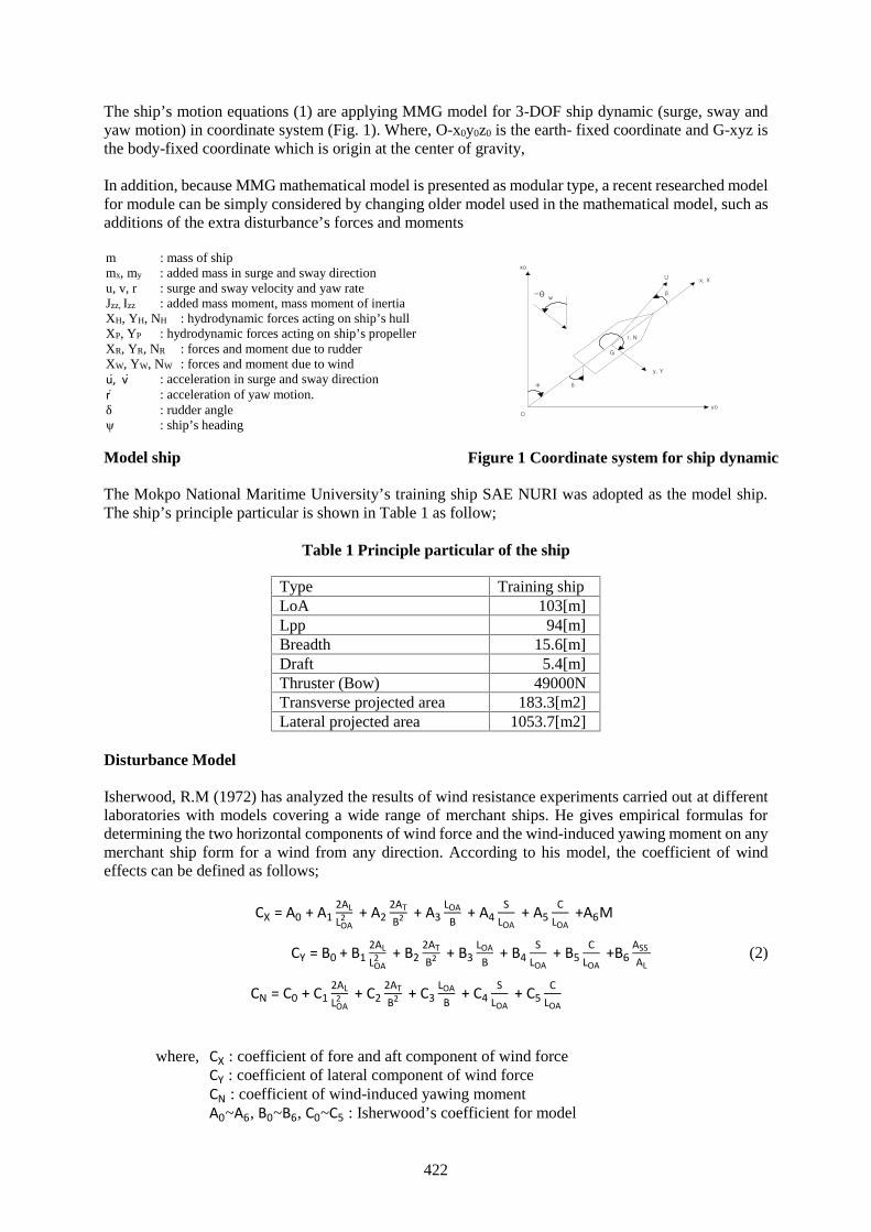
422
The ship’s motion equations (1) are applying MMG model for 3-DOF ship dynamic (surge, sway andyaw motion) in coordinate system (Fig. 1). Where, O-x0y0z0 is the earth- fixed coordinate and G-xyz isthe body-fixed coordinate which is origin at the center of gravity,
In addition, because MMG mathematical model is presented as modular type, a recent researched modelfor module can be simply considered by changing older model used in the mathematical model, such asadditions of the extra disturbance’s forces and moments
m : mass of shipmx, my : added mass in surge and sway directionu, v, r : surge and sway velocity and yaw rateJzz, Izz : added mass moment, mass moment of inertiaXH, YH, NH : hydrodynamic forces acting on ship’s hullXP, YP : hydrodynamic forces acting on ship’s propellerXR, YR, NR : forces and moment due to rudderXW, YW, NW : forces and moment due to windu, v : acceleration in surge and sway directionr : acceleration of yaw motion.δ : rudder angleψ : ship’s heading
Model ship
The Mokpo National Maritime University’s training ship SAE NURI was adopted as the model ship.The ship’s principle particular is shown in Table 1 as follow;
Table 1 Principle particular of the ship
Type Training shipLoA 103[m]Lpp 94[m]Breadth 15.6[m]Draft 5.4[m]Thruster (Bow) 49000NTransverse projected area 183.3[m2]Lateral projected area 1053.7[m2]
Disturbance Model
Isherwood, R.M (1972) has analyzed the results of wind resistance experiments carried out at differentlaboratories with models covering a wide range of merchant ships. He gives empirical formulas fordetermining the two horizontal components of wind force and the wind-induced yawing moment on anymerchant ship form for a wind from any direction. According to his model, the coefficient of windeffects can be defined as follows;
CX = A0 + A12ALLOA
2 + A22ATB2 + A3
LOAB
+ A4S
LOA+ A5
CLOA
+A6M
CY = B0 + B12ALLOA
2 + B22ATB2 + B3
LOAB
+ B4S
LOA+ B5
CLOA
+B6ASSAL
(2)
CN = C0 + C12ALLOA
2 + C22ATB2 + C3
LOAB
+ C4S
LOA+ C5
CLOA
where, CX : coefficient of fore and aft component of wind forceCY : coefficient of lateral component of wind forceCN : coefficient of wind-induced yawing momentA0~A6, B0~B6, C0~C5 : Isherwood’s coefficient for model
xo
yoO
y, Y
δ
β
x, XU
r, N
G
-θ w
ψ
Figure 1 Coordinate system for ship dynamic
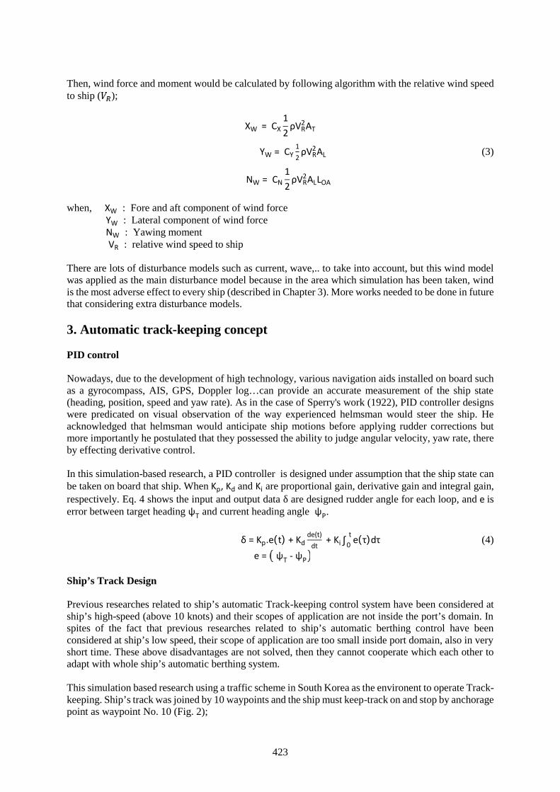
423
Then, wind force and moment would be calculated by following algorithm with the relative wind speedto ship ( );
XW = CX12
ρVR2AT
YW = CY12
ρVR2AL (3)
NW = CN12
ρVR2ALLOA
when, XW : Fore and aft component of wind forceYW : Lateral component of wind forceNW : Yawing momentVR : relative wind speed to ship
There are lots of disturbance models such as current, wave,.. to take into account, but this wind modelwas applied as the main disturbance model because in the area which simulation has been taken, windis the most adverse effect to every ship (described in Chapter 3). More works needed to be done in futurethat considering extra disturbance models.
3. Automatic track-keeping concept
PID control
Nowadays, due to the development of high technology, various navigation aids installed on board suchas a gyrocompass, AIS, GPS, Doppler log…can provide an accurate measurement of the ship state(heading, position, speed and yaw rate). As in the case of Sperry's work (1922), PID controller designswere predicated on visual observation of the way experienced helmsman would steer the ship. Heacknowledged that helmsman would anticipate ship motions before applying rudder corrections butmore importantly he postulated that they possessed the ability to judge angular velocity, yaw rate, thereby effecting derivative control.
In this simulation-based research, a PID controller is designed under assumption that the ship state canbe taken on board that ship. When Kp, Kd and Ki are proportional gain, derivative gain and integral gain,respectively. Eq. 4 shows the input and output data δ are designed rudder angle for each loop, and e iserror between target heading ψT and current heading angle ψP.
δ = Kp.e(t) + Kdde(t)
dt+ Ki ∫ e(τ)dτt
0 (4)
e = ψT - ψP
Ship’s Track Design
Previous researches related to ship’s automatic Track-keeping control system have been considered atship’s high-speed (above 10 knots) and their scopes of application are not inside the port’s domain. Inspites of the fact that previous researches related to ship’s automatic berthing control have beenconsidered at ship’s low speed, their scope of application are too small inside port domain, also in veryshort time. These above disadvantages are not solved, then they cannot cooperate which each other toadapt with whole ship’s automatic berthing system.
This simulation based research using a traffic scheme in South Korea as the environent to operate Track-keeping. Ship’s track was joined by 10 waypoints and the ship must keep-track on and stop by anchoragepoint as waypoint No. 10 (Fig. 2);
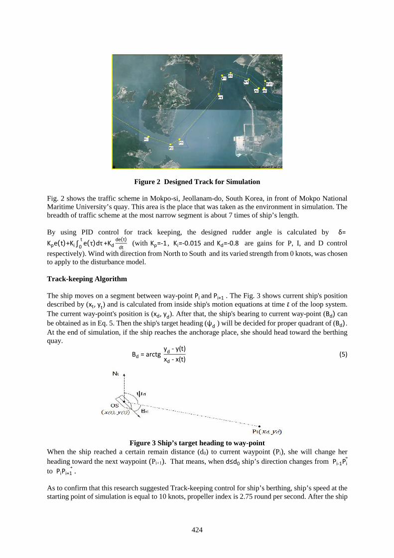
424
Figure 2 Designed Track for Simulation
Fig. 2 shows the traffic scheme in Mokpo-si, Jeollanam-do, South Korea, in front of Mokpo NationalMaritime University’s quay. This area is the place that was taken as the environment in simulation. Thebreadth of traffic scheme at the most narrow segment is about 7 times of ship’s length.
By using PID control for track keeping, the designed rudder angle is calculated by δ=Kpe(t)+Ki ∫ e(τ)dτt
0 +Kdde(t)
dt(with Kp=-1 , Ki=-0.015 and Kd=-0.8 are gains for P, I, and D control
respectively). Wind with direction from North to South and its varied strength from 0 knots, was chosento apply to the disturbance model.
Track-keeping Algorithm
The ship moves on a segment between way-point Pi and Pi+1 . The Fig. 3 shows current ship's positiondescribed by (xt, yt) and is calculated from inside ship's motion equations at time of the loop system.The current way-point's position is (xd, yd). After that, the ship's bearing to current way-point (Bd) canbe obtained as in Eq. 5. Then the ship's target heading (ψd ) will be decided for proper quadrant of (Bd).At the end of simulation, if the ship reaches the anchorage place, she should head toward the berthingquay.
Bd = arctgyd - y(t)xd - x(t)
(5)
Figure 3 Ship’s target heading to way-pointWhen the ship reached a certain remain distance (d0) to current waypoint (Pi), she will change herheading toward the next waypoint (Pi+1). That means, when d≤d0 ship’s direction changes from Pi-1Pito PiPi+1 .
As to confirm that this research suggested Track-keeping control for ship’s berthing, ship’s speed at thestarting point of simulation is equal to 10 knots, propeller index is 2.75 round per second. After the ship
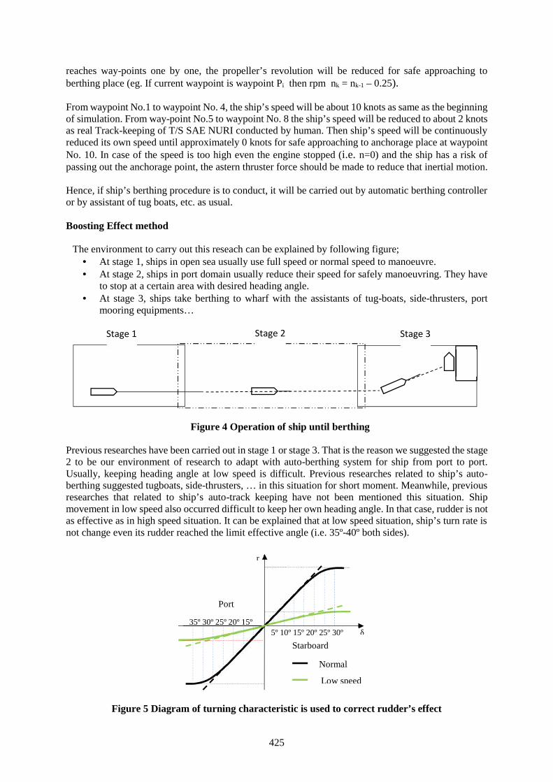
425
reaches way-points one by one, the propeller’s revolution will be reduced for safe approaching toberthing place (eg. If current waypoint is waypoint Pi then rpm nk = nk-1 – 0.25).
From waypoint No.1 to waypoint No. 4, the ship’s speed will be about 10 knots as same as the beginningof simulation. From way-point No.5 to waypoint No. 8 the ship’s speed will be reduced to about 2 knotsas real Track-keeping of T/S SAE NURI conducted by human. Then ship’s speed will be continuouslyreduced its own speed until approximately 0 knots for safe approaching to anchorage place at waypointNo. 10. In case of the speed is too high even the engine stopped (i.e. n=0) and the ship has a risk ofpassing out the anchorage point, the astern thruster force should be made to reduce that inertial motion.
Hence, if ship’s berthing procedure is to conduct, it will be carried out by automatic berthing controlleror by assistant of tug boats, etc. as usual.
Boosting Effect method
The environment to carry out this reseach can be explained by following figure; At stage 1, ships in open sea usually use full speed or normal speed to manoeuvre. At stage 2, ships in port domain usually reduce their speed for safely manoeuvring. They have
to stop at a certain area with desired heading angle. At stage 3, ships take berthing to wharf with the assistants of tug-boats, side-thrusters, port
mooring equipments…
Figure 4 Operation of ship until berthing
Previous researches have been carried out in stage 1 or stage 3. That is the reason we suggested the stage2 to be our environment of research to adapt with auto-berthing system for ship from port to port.Usually, keeping heading angle at low speed is difficult. Previous researches related to ship’s auto-berthing suggested tugboats, side-thrusters, … in this situation for short moment. Meanwhile, previousresearches that related to ship’s auto-track keeping have not been mentioned this situation. Shipmovement in low speed also occurred difficult to keep her own heading angle. In that case, rudder is notas effective as in high speed situation. It can be explained that at low speed situation, ship’s turn rate isnot change even its rudder reached the limit effective angle (i.e. 35º-40º both sides).
Figure 5 Diagram of turning characteristic is used to correct rudder’s effect
Stage 1 Stage 3Stage 2
5º 10º 15º 20º 25º 30º35º
35º 30º 25º 20º 15º10º 5º
Port
Starboard
r
δ
NormalspeedLow speed
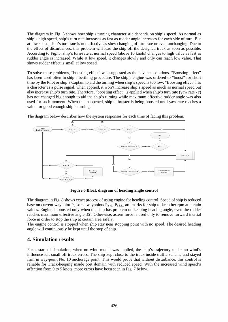
426
The diagram in Fig. 5 shows how ship’s turning characteristic depends on ship’s speed. As normal asship’s high speed, ship’s turn rate increases as fast as rudder angle increases for each side of turn. Butat low speed, ship’s turn rate is not effective as slow changing of turn rate or even unchanging. Due tothe effect of disturbances, this problem will lead the ship off the designed track as soon as possible.According to Fig. 5, ship’s turn-rate at normal speed (above 10 knots) changes to high value as fast asrudder angle is increased. While at low speed, it changes slowly and only can reach low value. Thatshows rudder effect is small at low speed.
To solve these problems, “boosting effect” was suggested as the advance solutions. “Boosting effect”has been used often in ship’s berthing procedure. The ship’s engine was ordered to “boost” for shorttime by the Pilot or ship’s Captain to aid the turning when ship’s speed is too low. “Boosting effect” hasa character as a pulse signal, when applied, it won’t increase ship’s speed as much as normal speed butalso increase ship’s turn rate. Therefore, “boosting effect” is applied when ship’s turn rate (yaw rate - r)has not changed big enough to aid the ship’s turning while maximum effective rudder angle was alsoused for such moment. When this happened, ship’s thruster is being boosted until yaw rate reaches avalue for good enough ship’s turning.
The diagram below describes how the system responses for each time of facing this problem;
Figure 6 Block diagram of heading angle control
The diagram in Fig. 8 shows exact process of using engine for heading control. Speed of ship is reducedbase on current waypoint Pi, some waypoints Pn-k1, Pn-k2,.. are marks for ship to keep her rpm at certainvalues. Engine is boosted only when the ship has problem on keeping heading angle, even the rudderreaches maximum effective angle 35º. Otherwise, astern force is used only to remove forward inertialforce in order to stop the ship at certain area safely.The engine control is stopped when ship stay near stopping point with no speed. The desired headingangle will continuously be kept until the stop of ship.
4. Simulation results
For a start of simulation, when no wind model was applied, the ship’s trajectory under no wind’sinfluence left small off-track errors. The ship kept close to the track inside traffic scheme and stayedfirm in way-point No. 10 anchorage point. This would prove that without disturbance, this control isreliable for Track-keeping inside port domain with reduced speed. With the increased wind speed’saffection from 0 to 5 knots, more errors have been seen in Fig. 7 below.

427
Figure 7 Ship’s trajectory with the assistant of “Boosting effect”under the affection of wind (from N to S, 5 kts)
More errors have been found when the ship at the very end of keeping track from way-point No. 9 toNo. 10 when ship’s speed was very low under 1.2 knots. However, the ship could keep stable as formersituation. The ship reached the final point, kept staying at last waypoint. For outcome history data, thecontrol seems to be reliable when keeping ship’s track under small disturbance’s influence.
When wind’s speed was 10 knots high, it seems that the control finally completed the Track-keepingprocedure with great effort. Fig. 8 shows the ship’s Track-keeping trajectory with the assistant of“Boosting effect”. In this circumstance, the last schedule of Track-keeping this trajectory is the mosterror trajectory among the last shown 3 results, under the wind’s conditions of 0 kts upped to 10 kts.The ship drifted out of track from way-point No.6 to No.10.
In fact that this problem lead us to reconsider to improve the effort of the control. However, we shouldpay attention to the disturbance’s affection to review this controller’s effort. Wind speed in thiscircumstance was about 10 knots high meanwhile the ship’s speed was very low at the end of theoperation as about 1.0 knots when she had just passed waypoint No.9 and even equal to 0 knots whenshe reached way-point No. 10.
Figure 8 Ship’s trajectory with the assistant of “Boosting effect”under the affection of wind (from N to S, 10 knots)
Fig. 9 shows how the ship’s Track-keeping without the assistant of “Boosting effect” under the samecharacteristic with the last condition shown above;
-50 -40 -30 -20 -10 0 10 20 30
-40
-30
-20
-10
0
10
L
L
Wind: N to S, 5 ktsTime interval 150(s)
-50 -40 -30 -20 -10 0 10 20 30
-40
-30
-20
-10
0
10
L
L
Wind: N to S, ~ 10 ktsTime interval 150(s)
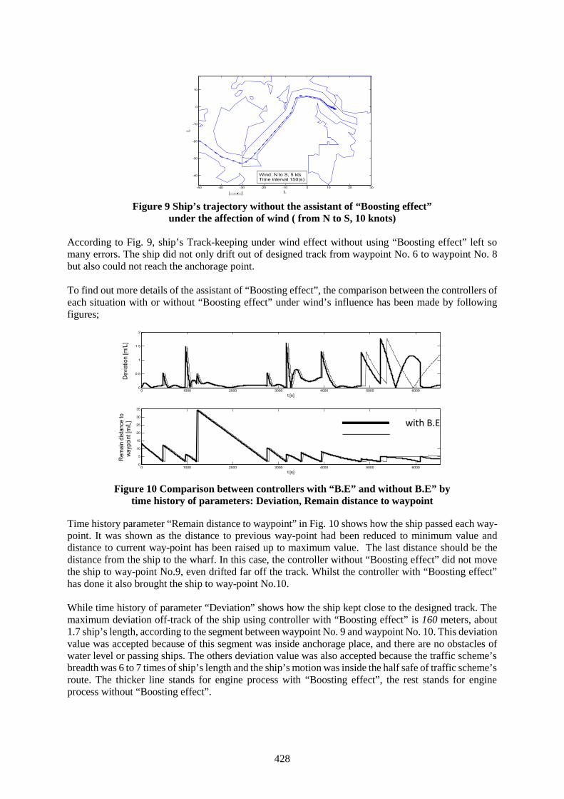
428
Figure 9 Ship’s trajectory without the assistant of “Boosting effect”under the affection of wind ( from N to S, 10 knots)
According to Fig. 9, ship’s Track-keeping under wind effect without using “Boosting effect” left somany errors. The ship did not only drift out of designed track from waypoint No. 6 to waypoint No. 8but also could not reach the anchorage point.
To find out more details of the assistant of “Boosting effect”, the comparison between the controllers ofeach situation with or without “Boosting effect” under wind’s influence has been made by followingfigures;
Figure 10 Comparison between controllers with “B.E” and without B.E” bytime history of parameters: Deviation, Remain distance to waypoint
Time history parameter “Remain distance to waypoint” in Fig. 10 shows how the ship passed each way-point. It was shown as the distance to previous way-point had been reduced to minimum value anddistance to current way-point has been raised up to maximum value. The last distance should be thedistance from the ship to the wharf. In this case, the controller without “Boosting effect” did not movethe ship to way-point No.9, even drifted far off the track. Whilst the controller with “Boosting effect”has done it also brought the ship to way-point No.10.
While time history of parameter “Deviation” shows how the ship kept close to the designed track. Themaximum deviation off-track of the ship using controller with “Boosting effect” is 160 meters, about1.7 ship’s length, according to the segment between waypoint No. 9 and waypoint No. 10. This deviationvalue was accepted because of this segment was inside anchorage place, and there are no obstacles ofwater level or passing ships. The others deviation value was also accepted because the traffic scheme’sbreadth was 6 to 7 times of ship’s length and the ship’s motion was inside the half safe of traffic scheme’sroute. The thicker line stands for engine process with “Boosting effect”, the rest stands for engineprocess without “Boosting effect”.
-50 -40 -30 -20 -10 0 10 20 30
-40
-30
-20
-10
0
10
LL
Wind: N to S, 5 ktsTime interval 150(s)
0 1000 2000 3000 4000 5000 60000
0.5
1
1.5
2
t [s]
Devia
tion
[m/L
]
0 1000 2000 3000 4000 5000 60000
5
10
15
20
25
30
35
t [s]
Rem
ain
dist
ance
to w
aypo
int [
m/L
] with B.E
without B.E
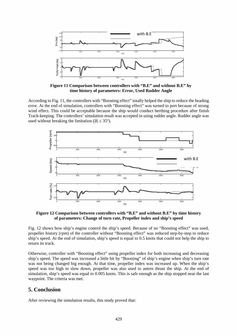
429
Figure 11 Comparison between controllers with “B.E” and without B.E” bytime history of parameters: Error, Used Rudder Angle
According to Fig. 11, the controllers with “Boosting effect” totally helped the ship to reduce the headingerror. At the end of simulation, controllers with “Boosting effect” was turned to port because of strongwind effect. This could be acceptable because the ship would conduct berthing procedure after finishTrack-keeping. The controllers’ simulation result was accepted in using rudder angle. Rudder angle wasused without breaking the limitation (|δ| ≤ 35º).
Figure 12 Comparison between controllers with “B.E” and without B.E” by time historyof parameters: Change of turn rate, Propeller index and ship’s speed
Fig. 12 shows how ship’s engine control the ship’s speed. Because of no “Boosting effect” was used,propeller history (rpm) of the controller without “Boosting effect” was reduced step-by-step to reduceship’s speed. At the end of simulation, ship’s speed is equal to 0.5 knots that could not help the ship toreturn its track.
Otherwise, controller with “Boosting effect” using propeller index for both increasing and decreasingship’s speed. The speed was increased a little bit by “Boosting” of ship’s engine when ship’s turn ratewas not being changed big enough. At that time, propeller index was increased up. When the ship’sspeed was too high to slow down, propeller was also used to astern thrust the ship. At the end ofsimulation, ship’s speed was equal to 0.005 knots. This is safe enough as the ship stopped near the lastwaypoint. The criteria was met.
5. Conclusion
After reviewing the simulation results, this study proved that:
0 1000 2000 3000 4000 5000 6000-100
-50
0
50
100
150
t [s]
Error
[deg
]
0 1000 2000 3000 4000 5000 6000-40
-20
0
20
40
t [s]
Rudd
er An
gle [d
eg]
0 1000 2000 3000 4000 5000 6000
-100
0
100
t [s]
Pro
pelle
r [rp
m]
0 1000 2000 3000 4000 5000 60000
5
10
t [s]
Spe
ed [k
ts]
0 1000 2000 3000 4000 5000 6000
-0.5
0
0.5
t [s]
Turn
rate
[%]
with B.E
without B.E
with B.E
without B.E
430
The ship can use this controller for specific purpose of automatic Track-keeping at the specifiedmoment as when finished ocean navigating and before berthing to a quay; in the specified placeas Track-keeping insides traffic scheme that is leading to the wharf; and with difficulties arelow speed, reducing speed and disturbance effect.
Heading angle at low speed was controlled with the assistant of “Boosting effect” which isunfamiliar with other previous researches. “Boosting effect” was proved as a vital characteristicof this controller to aid the ship at low speed, under the strong wind and without any help ofextra auxiliary devices.
Acknowledgement
This research was a part of the project titled “Development of Ship-handling and Passenger EvacuationSupport System” funded by the Ministry of Oceans and Fisheries (South Korea - MOF).
References
[1] Fossen, T.I., Guidance and control of ocean vehicles, John Wiley & and Sons Ltd., ISBN 0-471-94113-1, (1994)
[2] Hamamoto, M., MMG report II, Bulletin of the society of Naval Architects of Japan, No. 577, pp.322-329, (1997)
[3] Hasegawa K., Automatic Collision avoidance system for ships using fuzzy control, Ship controlsystem Symposium the 8th, vol.2, p. 34-58, (1987)
[4] Hasegawa, K. and Im, N. K., A Study on Critical of Wind Velocity of a Ro-Ro Passenger ShipEquipped with Side Thrusters in a Port, Journal of the Kansai Society of Naval Architects, Japan,No. 238, p. 71-76, (2002)
[5] Hwang, C., The Integrated Design of Fuzzy Collision-Avoidance and H∞-Auto pilots on Ships,Journal of Navigation, vol.55, p.117-136, (2002)
[6] Isherwood, R.M., Wind Resistance of Merchant Ship, Trans. RINA, vol.115, p.327-338, (1972)[7] Kallstrom, C. G., Autopilot and Track-keeping Algorithm for High-speed Craft, Control
Engineering Practice 8, p. 185-190, (1999)[8] Kinoshita, M. and Nakajima, Y., On the Effect of Wind on the Maneuverability of Vessels,
Experiment Tank Committee of Japan, p. 11-24, (1951)[9] Martin, L.L., Ship Maneuvering and Control in Wind, Trans. SNAME, vol.88, p.257-281, (1980)[10] Sperry, E. A., Automatic steering, Trans. Society of Naval Architects and Marine Engineers, p. 61-
63, (1922)[11] Tran, V.L. and Im, N.K, A study on ship automatic berthing with assisstance of auxiliary devies,
Journal of Korean Naval Architects of Ocean Engineering, p. 199-210, (2012)[12] Velagic, J., , Adaptive fuzzy ship autopilot for Track-keeping, Control Engineering Practice 11, pp.
433-443, (2003)[13] Xue, Y., Automatic Simulation of Ship Navigation, Ocean Engineering 38, pp. 2290-2299. (2011)
431
Advanced Navigation System (ANS) in the Mediterranean Sea“Regional Project for Management Control System”
Captain: Mohamed Abdel Fattah Omar ¹Captain: Zouheir Abdel Fattah Badawy ²
1. Marine lecturers in maritime college, Arab Academy for Science, Technology and MaritimeTransport (AASTMT), Email: [email protected]
2. Marine lecturers in maritime college, Arab Academy for Science, Technology and MaritimeTransport (AASTMT), Email: [email protected]
Abstract- Mediterranean Sea is a major oil and gas transportation route accommodating a large numberof ships crossing the sea annually; it is an area in which the oil and gas industry is highly active withseveral important producers located in the region. Despite increased environmental awareness andinternational conventions on pollution, marine pollution continues to be an environmental issue; the oilwell explosion was a tragic accident that preventable with different systems and procedures in place.Going forward, the safety of workers and the environment must be of paramount importance, and aguiding principal for all in the regulation, exploration, and production of oil and gas. New systems andprocedures must now be described, implemented and regulated, however, in a way that is reliable andtransparent. This will allow the nation's offshore oil and natural gas industry to return to work in a waythat will preserve thousands of critical jobs, in a region just beginning to recover from unprecedentedhardship.
Advancements in information technology have significant impacts on the shipping industry. Many ofthe modern navigational technologies and data are amenable to computerization. A key hydrographicsurvey within the Traffic Separation Scheme (TSS) of the Straits of Malacca and Singapore, as part ofthe Marine Electronic Highway (MEH) Demonstration Project, a regional project of the GlobalEnvironment Facility (GEF)/World Bank, which International Maritime Organization (IMO) isexecuting. The demonstration project aims to link shore-based marine information and communicationinfrastructure with the corresponding navigational and communication facilities aboard transiting ships,while being also capable of incorporating marine environmental management systems. The deploymentof information systems in more mature applications such as in a Marine Electronic Highway could leadto the integration of maritime safety technologies with marine environment management and protectionsystems resulting in improved performance, new capabilities and innovative applications. MEHprovides a host of potential opportunities and benefits not only for the shipping industry, but also to avariety of users. Its application may be extended to environmental management programs, search-and-rescue operations, anti-piracy program, environmental impact assessment, and fisheries/aquaculturemanagement, among others. The use of such experience to execute a similar project as Malacca StraitMEH in the Mediterranean Sea can be considered an important need for such strategic place.
Key words: Marine Electronic Highway -The Traffic Separation Scheme – The oil industry – TheGeographic Information System – The Space borne Synthetic Aperture Radar.
1. Introduction
The Mediterranean region has so far been a relatively small producer of offshore oil and gas as comparedto the world production. In 2011, total offshore oil and gas production in the Mediterranean region wasestimated at 87 million toe (Tone of Oil Equivalent) with 19 million toe crude oil, 68 million toe naturalgas. However, Mediterranean oil reserves represent 9,400 million toe, equivalent to 4.6% of world oilreserves. Offshore structures and waste streams can affect marine species and the entire food webthrough intrusive noise and the possible introduction of non-indigenous species. Explosions and drillingcan also cause seafloor and geological disturbances. This impact increases as offshore explorationactivities go deeper, a trend that is observed worldwide and in the Mediterranean Sea. (WWF, 2015)
432
Overall vessel activity within the Mediterranean has been rising steadily over the past 10 years and isprojected to increase by a further 18 per cent over the next 10 years. Transits through the Mediterraneanare expected to rise by 23 per cent. Increases in vessel activity will be coupled with the deployment ofever larger vessels. The development of new pipelines by passing the Bosporus and the expansion ofcurrent pipeline capacity is likely to result in a significant increase in the density of tanker deploymentin the eastern Mediterranean The Mediterranean is both a major load and discharge centre for crude oil.Approximately 18 per cent of global seaborne crude oil shipments take place within or through theMediterranean. North African ports in Libya, Algeria, Tunisia and Persian Gulf oil shipped via Egyptaccount for over 90 per cent of all crude oil loaded in the Mediterranean. Italy accounts for nearly halfof all crude oil discharged in the Mediterranean. Exports of crude oil from Black Sea ports averaging atover 100 million tons a year are expected to continue to rise, resulting in continued seaborne transits viathe Bosporus and increased use of eastern Mediterranean ports linked to new pipelines intended tobypass the Bosporus. (SAFEMED, 2008)
The Mediterranean Sea is a high risk of marine pollution, and came up with possible ways of which themarine pollution can be prevented with measures in place to check and minimize the occurrence of thespill in this special area. The most important challenge of IMO nowadays is to develop a frameworkwhich accommodates and builds on existing systems already furthering the concept of Navigationsystem by integration and display of maritime information onboard and ashore by electronic means toenhance berth-to-berth navigation and related services, safety and security at sea and protection of themarine environment. The most important projects in focused and related with the Navigation system areWorld Bank-funded Marine Electronic Highway (MEH) project in the Malacca Straits. During the lastyears the possibilities and value of satellite based detection of oil spills could be impressivelydemonstrated, as well as in operational near real time processing and transmission of the satellite basedresults to the users on board vessels. (Bak, 2013) Pollution can be caused by a collision or by accidentalor deliberate dumping. Pollution from vessels is often not discovered until it is found on the coastlinemany hours after the vessel has departed the area. This provides a problem for Law Enforcement and soit is clear that if pollution incidents are to be handled effectively the important criteria are early detectionand the ability to contain the pollutant before it spreads uncontrollably. In addition, if early detectioncan be implemented then it may be possible to identify and arrest the polluter before he leaves the area.Safety of Navigation and efficiency of Vessel traffic services (VTS) are essential to minimize the riskof collisions that could pollute the marine environment. (VTMIS, 2016)
2. The development of Vessel Traffic Services
Traditionally, the master of a ship has been responsible for a ship's course and speed, assisted by a pilotwhere necessary. Ships approaching a port would announce their arrival using flag signals. With thedevelopment of radio in the late 19th century, radio contact became more important. But thedevelopment of radar during World War Two made it possible to accurately monitor and track shippingtraffic. The world's first harbor surveillance radar was inaugurated in Liverpool, England, in July 1948and in March 1950; a radar surveillance system was established at Long Beach, California - the firstsuch system in the United States. The ability of the coastal authority to keep track of shipping traffic byradar, combined with the facility to transmit messages concerning navigation to those ships by radio,therefore constituted the first formal VTS systems. The value of VTS in navigation safety was firstrecognized by IMO in resolution A.158 (ES.IV) Recommendation on Port Advisory Systems adoptedin 1968, but as technology advanced and the equipment to track and monitor shipping traffic becamemore sophisticated, it was clear guidelines were needed on standardizing procedures in setting up VTS.In particular, it became apparent that there was a need to clarify when a VTS might be established andto allay fears in some quarters that a VTS might impinge on the ship's master's responsibility fornavigating the vessel. As a result, in 1985, IMO adopted resolution A.578 (14) Guidelines for VesselTraffic Services, which said that VTS was particularly appropriate in the approaches and access channelsof a port and in areas having high traffic density, movements of noxious or dangerous cargoes,navigational difficulties, narrow channels, or environmental sensitivity. The Guidelines also made clearthat decisions concerning effective navigation and maneuvering of the vessel remained with the ship's
433
master. The Guidelines also highlighted the importance of pilotage in a VTS and reporting proceduresfor ships passing through an area where a VTS operates. (IMO, 2016a)Vessels Traffic Management Systems (VTMS) are making valuable contribution to safer navigation,more efficient traffic flow, and protection of the environment. Incidents and emergency situations canbe dealt with quickly. The VTMS traffic image is compiled and collected by means of advanced sensorssuch as radar, Direction Finding (DF), Closed-Circuit Television (CCTV), Automatic IdentificationSystem (AIS) and Very High Frequency radio (VHF) or other co-operative systems and services. Amodern VTMS integrates all of the information into a single operator working environment for ease ofuse and in order to allow for effective traffic organization and communication. The Mini-VTS-Systemsas shown in figure 1 or complex VTMS with several radars, integration with VHF, AIS, GNSS, CCTV,DF, Operator Positions, and Power Supplies etc. For the smaller harbors the Mini-VTS should be morethan sufficient, with options for add-ons if any rise in demand occurs. For large ports covering largerareas with several operators and integration with other ports or Authorities, a more complex system isrecommended. The VTS also has many impacts especially in the Mediterranean Sea due to manychallenges in this area. (ARLO, 2016)
Figure 1 The Mini-VTS-SystemsSource: (ARLO, 2016)
3. Environmental Challenges in the Mediterranean Sea
The Mediterranean Sea is one of the most important areas in the world in terms of maritime transport;it is the world's largest inland sea covering an area of 2,499,350 sq km. The Mediterranean Sea also is abody of water that is almost completely surrounded by land. It lies between three continents: Europe tothe north, Asia to the east and Africa to the south. It stretches over 2,500 miles (4000 km) from Gibraltarto Israel. It is connected to the Atlantic through a 14 km wide strait, where Europe and Africa meet. TheSuez Canal links it to the Red Sea and the Bosporus to the Black Sea. The environmental challenges inthis area depend on the shipping and trades there. (Worldatlas, 2016)
3.1 Shipping in Mediterranean Sea
The Mediterranean Sea is one of the crowded area in terms of shipping activities as shows in figure 2,with about 30% of international marine trade taking place among the ports of Mediterranean and nearbyseas. Every year nearly 20.000 tons of petroleum leaks to Mediterranean from the surrounded 60 oilrefining plants as a result of consciously or unconsciously accidents.
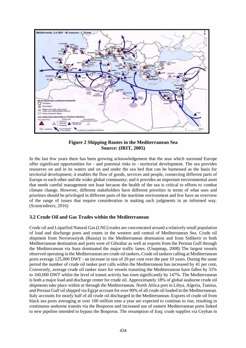
434
Figure 2 Shipping Routes in the Mediterranean SeaSource: (IRIT, 2005)
In the last few years there has been growing acknowledgement that the seas which surround Europeoffer significant opportunities for - and potential risks to - territorial development. The sea providesresources on and in its waters and on and under the sea bed that can be harnessed as the basis forterritorial development; it enables the flow of goods, services and people, connecting different parts ofEurope to each other and the wider global community; and it provides an important environmental assetthat needs careful management not least because the health of the sea is critical to efforts to combatclimate change. However, different stakeholders have different priorities in terms of what uses andpriorities should be privileged in different parts of the maritime environment and few have an overviewof the range of issues that require consideration in making such judgments in an informed way.(Sciencedirect, 2016)
3.2 Crude Oil and Gas Trades within the Mediterranean
Crude oil and Liquefied Natural Gas (LNG) trades are concentrated around a relatively small populationof load and discharge ports and routes in the western and central of Mediterranean Sea. Crude oilshipment from Novorossiysk (Russia) to the Mediterranean destination and from Sidikerir to bothMediterranean destination and ports west of Gibraltar as well as exports from the Persian Gulf throughthe Mediterranean via Suez dominated the major traffic lanes. (Unepmap, 2008) The largest vesselsobserved operating in the Mediterranean are crude oil tankers. Crude oil tankers calling at Mediterraneanports average 125,000 DWT - an increase in size of 26 per cent over the past 10 years. During the sameperiod the number of crude oil tanker port calls within the Mediterranean has increased by 41 per cent.Conversely, average crude oil tanker sizes for vessels transiting the Mediterranean have fallen by 31%to 160,000 DWT whilst the level of transit activity has risen significantly by 147%. The Mediterraneanis both a major load and discharge center for crude oil. Approximately 18% of global seaborne crude oilshipments take place within or through the Mediterranean. North Africa port in Libya, Algeria, Tunisia,and Persian Gulf oil shipped via Egypt account for over 90% of all crude oil loaded in the Mediterranean.Italy accounts for nearly half of all crude oil discharged in the Mediterranean. Exports of crude oil fromblack sea ports averaging at over 100 million tons a year are expected to continue to rise, resulting incontinuous seaborne transits via the Bosporus and increased use of eastern Mediterranean ports linkedto new pipeline intended to bypass the Bosporus. The resumption of Iraq; crude supplies via Ceyhan in
435
turkey and via Pipeline development will increase oil exports from eastern Mediterranean sea loadterminals, but if black sea exports continues to increase, this may not result in a significant fall in oilexported through the Bosporus. (Statoil, 2013) Around 80 per cent of Mediterranean ports are locatedin the west and central Mediterranean region. The majority of Crude Oil consumed by Mediterraneancountries transported by pipeline. Spain is currently an exception in transporting a large portion of itsCrude Oil supplies by ship to its six terminals (3 of which are in the Mediterranean). SeveralMediterranean countries have plans underway to develop Crude Oil terminals in order to lessendependence on a small set of supplier counties. (Ports, 2014) Due to all this information should establisha demonstration project same the MEH system in the Straits of Malacca and Singapore.
4. Marine Electronic Highway (MEH) Demonstration Project
The International Maritime Organization (IMO) implemented the Marine Electronic Highway (MEH)Demonstration Project in the Straits of Malacca and Singapore (SOMS) following the signing, on 19th
of June 2005, agreement between the Global Environment Facility (GEF)/World Bank and IMO. Thisproject was developed by a separate grant from GEF/World Bank to IMO with the participation of thethree littoral States and shipping associations. The MEH Demonstration Project was a collaborativeagreement between IMO and the littoral States of Indonesia, Malaysia and Singapore and in partnershipwith the Republic of Korea, International Hydrographic Commission, the International Chamber ofShipping and the International Association of Independent Tanker Owners. The regional demonstrationproject aimed to link shore-based marine information and communication infrastructure with thecorresponding navigational and communication facilities aboard transiting ships, while being alsocapable of incorporating marine environmental management systems. The overall objectives were toenhance maritime services, improve navigational safety and security and promote marine environmentprotection and the sustainable development and use of the coastal and marine resources of the Straits'littoral States, Indonesia, Malaysia and Singapore (Sekimizu, 2006).
The MEH system with its environmental modules can be used in marine pollution response and controlsuch as to predict the direction and speed of oil spill and aid in response and clean-up. It is also possibleto use it to identify and track ships that illegally discharge their bilges or dump other oily wastes. TheMarine Electronic Highway (MEH) is envisioned to be a regional network of marine informationtechnologies linked through the ENCs-ECDIS. The availability of differential global positioning system(DGPS) with accuracy of 1 to 5 meters enhances the navigational accuracy of ENCs-ECDIS especiallyin congested and confined waters. Recent enhancements in maritime safety infrastructure and regulatorymechanisms have improved navigational safety and traffic flow. Singapore has an efficient radar-basedship position monitoring system covering the Singapore Strait. In 1998, the three littoral states ofRepublic of Indonesia, Malaysia, and Republic of Singapore jointly commissioned a mandatory shipreporting system (STRAITREP) for the most congested 300 kilometer section of the Straits from OneFathom Bank to the Singapore Strait, which combines radar and automatic ship identification andtracking. However, the threat of collisions and groundings and of consequent environmental damage isstill significant and, with rapid traffic growth, is increasing. (IMO, 2016b)
5. Development of technologies to detect oil spill
In dealing with oil spill, a number of technologies have been developed to detect and deal with oil spill.Some of the technologies developed include; Geographic Information System (GIS), Satellite-MountedSynthetic-Aperture Radar (SAR), Ground Penetrating Radar (GPR) and Remote Sensing Technology(RST). The Geographic Information System (GIS) is proven to be an excellent management tool forresource assessment, oil spill response, and planning damage assessment. GIS approach to a problem ofoil spill mapping includes integration of the geographical, remote sensing, oil &gasproduction/infrastructure data and slick signatures, detected by SAR, in GIS as shows in figure 3.Compiled from data of several sources including nautical maps, geo-databases, ground truth and remotesensing data, GIS allows retrieval of key information, i.e. predict spill locations, reveal offshore/onshoresources, and estimate intensity of oil pollution. SAR and GIS technologies can significantly improve
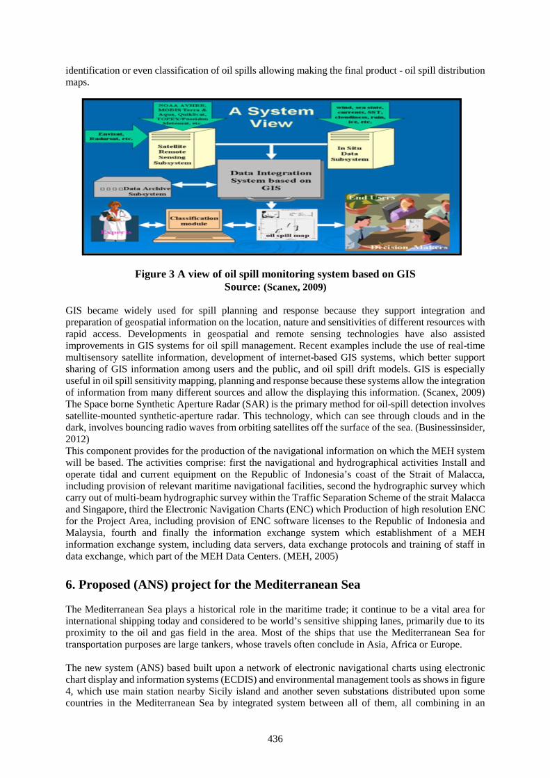
436
identification or even classification of oil spills allowing making the final product - oil spill distributionmaps.
Figure 3 A view of oil spill monitoring system based on GISSource: (Scanex, 2009)
GIS became widely used for spill planning and response because they support integration andpreparation of geospatial information on the location, nature and sensitivities of different resources withrapid access. Developments in geospatial and remote sensing technologies have also assistedimprovements in GIS systems for oil spill management. Recent examples include the use of real-timemultisensory satellite information, development of internet-based GIS systems, which better supportsharing of GIS information among users and the public, and oil spill drift models. GIS is especiallyuseful in oil spill sensitivity mapping, planning and response because these systems allow the integrationof information from many different sources and allow the displaying this information. (Scanex, 2009)The Space borne Synthetic Aperture Radar (SAR) is the primary method for oil-spill detection involvessatellite-mounted synthetic-aperture radar. This technology, which can see through clouds and in thedark, involves bouncing radio waves from orbiting satellites off the surface of the sea. (Businessinsider,2012)This component provides for the production of the navigational information on which the MEH systemwill be based. The activities comprise: first the navigational and hydrographical activities Install andoperate tidal and current equipment on the Republic of Indonesia’s coast of the Strait of Malacca,including provision of relevant maritime navigational facilities, second the hydrographic survey whichcarry out of multi-beam hydrographic survey within the Traffic Separation Scheme of the strait Malaccaand Singapore, third the Electronic Navigation Charts (ENC) which Production of high resolution ENCfor the Project Area, including provision of ENC software licenses to the Republic of Indonesia andMalaysia, fourth and finally the information exchange system which establishment of a MEHinformation exchange system, including data servers, data exchange protocols and training of staff indata exchange, which part of the MEH Data Centers. (MEH, 2005)
6. Proposed (ANS) project for the Mediterranean Sea
The Mediterranean Sea plays a historical role in the maritime trade; it continue to be a vital area forinternational shipping today and considered to be world’s sensitive shipping lanes, primarily due to itsproximity to the oil and gas field in the area. Most of the ships that use the Mediterranean Sea fortransportation purposes are large tankers, whose travels often conclude in Asia, Africa or Europe.
The new system (ANS) based built upon a network of electronic navigational charts using electronicchart display and information systems (ECDIS) and environmental management tools as shows in figure4, which use main station nearby Sicily island and another seven substations distributed upon somecountries in the Mediterranean Sea by integrated system between all of them, all combining in an
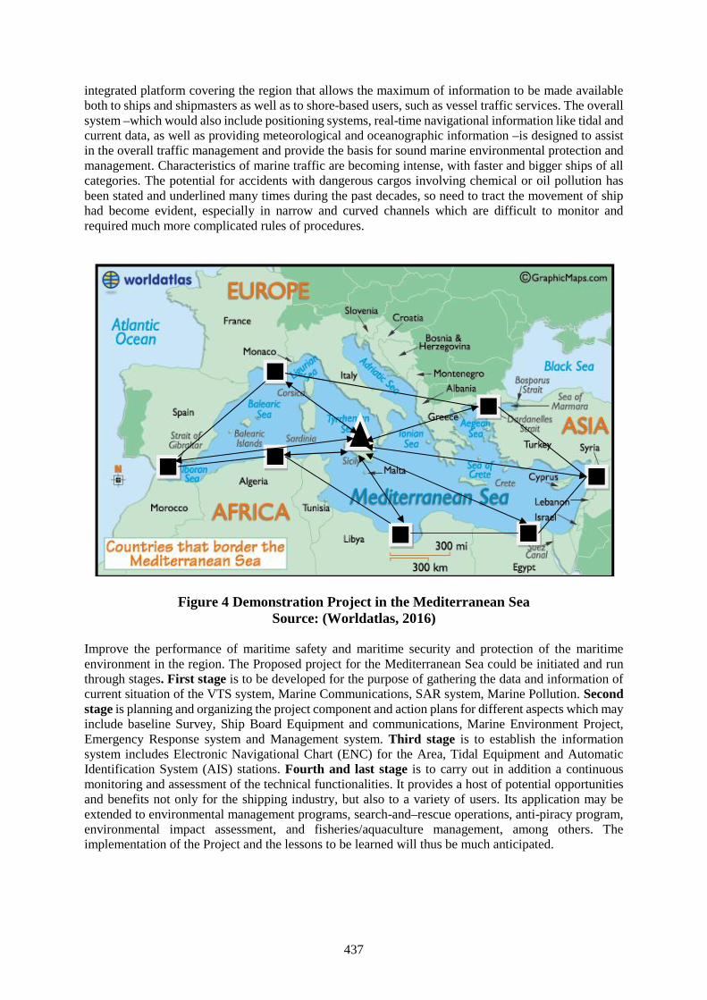
437
integrated platform covering the region that allows the maximum of information to be made availableboth to ships and shipmasters as well as to shore-based users, such as vessel traffic services. The overallsystem –which would also include positioning systems, real-time navigational information like tidal andcurrent data, as well as providing meteorological and oceanographic information –is designed to assistin the overall traffic management and provide the basis for sound marine environmental protection andmanagement. Characteristics of marine traffic are becoming intense, with faster and bigger ships of allcategories. The potential for accidents with dangerous cargos involving chemical or oil pollution hasbeen stated and underlined many times during the past decades, so need to tract the movement of shiphad become evident, especially in narrow and curved channels which are difficult to monitor andrequired much more complicated rules of procedures.
Figure 4 Demonstration Project in the Mediterranean SeaSource: (Worldatlas, 2016)
Improve the performance of maritime safety and maritime security and protection of the maritimeenvironment in the region. The Proposed project for the Mediterranean Sea could be initiated and runthrough stages. First stage is to be developed for the purpose of gathering the data and information ofcurrent situation of the VTS system, Marine Communications, SAR system, Marine Pollution. Secondstage is planning and organizing the project component and action plans for different aspects which mayinclude baseline Survey, Ship Board Equipment and communications, Marine Environment Project,Emergency Response system and Management system. Third stage is to establish the informationsystem includes Electronic Navigational Chart (ENC) for the Area, Tidal Equipment and AutomaticIdentification System (AIS) stations. Fourth and last stage is to carry out in addition a continuousmonitoring and assessment of the technical functionalities. It provides a host of potential opportunitiesand benefits not only for the shipping industry, but also to a variety of users. Its application may beextended to environmental management programs, search-and–rescue operations, anti-piracy program,environmental impact assessment, and fisheries/aquaculture management, among others. Theimplementation of the Project and the lessons to be learned will thus be much anticipated.
438
7. Conclusion and recommendations
7.1 Conclusion
Amongst the numerous environmental concerns we are facing, the marine environment is one of the toppriorities that must be addressed. The Mediterranean Sea is one of the most important and busiest seasin the world in terms of maritime transport, and shipping activities, with about 30% of internationalmarine trade taking place among the ports of Mediterranean and nearby seas. The Mediterranean is botha major load and discharge center for crude oil. Approximately 18% of global seaborne crude oilshipments take place within or through the Mediterranean. There are more than 40 refineries with acombined capacity of around 458 million tons per annum. The largest exporters of oil are in Libya,Algeria, Egypt, and Syria, with major imports taking place into France, Italy, Spain and turkey. Oil spillsonly make up about 12% of the oil that enters the ocean, but it is still the worst form of ocean pollution,with its effects being immediate, long-term and extremely damaging. The oil spreads rapidly, and formsa thin, film-like layer on the surface, as it cannot be dissolved. The oil slick suffocates fish, gets caughtin marine birds’ feathers, and blocks light. With a long-term outcome, oil spills can cause reproductiveand growth problems in marine creatures.Furthermore, the Mediterranean Sea is considered as an area with a high risk of accidental pollution dueto the density of traffic, the large number of ports and the existence of a large number of scattered islandsand other insular features situated at short distances from international shipping routes. The use ofinformation systems in more mature and expansive applications such as in a marine electronic highwaythat integrates maritime safety technologies and environmental management systems will improve theperformance, situational awareness and innovative applications to enhanced monitoring system.Offshore exploitation activities increase the risk and potential for a major oil spill incident. As such, itcreates new demands and challenges to Mediterranean countries which must not be underestimated.
7.2 Recommendations
1) Initiate the application of a pilot project which integrates maritime safety technologies andenvironmental management systems to improve the performance, situational awareness andinnovative applications to enhance monitoring systems in the Mediterranean Sea.
2) The potential efficiency of cooperative and joined ventures of oil response should be recognized,facilitated and any mutual support of regional agreement must be included in exercise programsto ensure their effective integration into response efforts.
3) The National Maritime Administrations, in the Mediterranean Sea Region after identify andestablish personnel with high degree of preparedness and equipment to support oil spillcontingency plans.
4) Familiarizing personnel with oil spill management and mitigation techniques.5) Establish a link between all the ECDIS and the AIS systems on all the platforms operating in
the Mediterranean Sea to share and exchange information (data) which will be helpful in theevent of an oil spill.
6) Take full advantage of the Geographic Information System (GIS) and Satellite-MountedSynthetic-Aperture Radar (SAR) for full coverage of the Mediterranean Sea, and the necessaryinformation should be relayed to the platforms and ships operating within the MediterraneanSea.
References
[1] ARLO (2016), http://www.arlomaritime.com/vessel-traffic-services/, Norway.[2] Bak (2013), “Improvement of oil spill fighting by using SAR satellite detection and e-navigation
systems”, Scientific Journals Maritime University of Szczecin, Andrzej Bąk, Poland.[3] Businessinsider (2012), www.businessinsider.com.

439
[4] IMO International Maritime Organization (2016a),http://www.imo.org/en/OurWork/Safety/Navigation/Pages/VesselTrafficServices.aspx, UnitedKingdom.
[5] IMO International Maritime Organization (2016b)http://www.imo.org/en/OurWork/Environment/SpecialProgrammesAndInitiatives/Pages/MarineElectronicHighway.aspx, United Kingdom.
[6] IRIT (2005), www.irit.fr/scanmaris, France.[7] MEH (2005), Marine Electronic Highway Demonstration project, www.meh-project.com.[8] Ports (2014), http://ports.com/sea/mediterranean-sea/.[9] SAFEMED (2008), “Regional marine pollution emergency response centre for the Mediterranean
Sea (REMPEC)”, Euro-Mediterranean partnership, Euromed cooperation on maritime safety andprevention of pollution from ships, EU-Funded MEDA Regional Project, Study of Maritime TrafficFlows in the Mediterranean Sea, Final Report - Unrestricted Version, United Kingdom.
[10] Scanex (2009), www.scanex.ru.[11] Sciencedirect (2016), http://www.sciencedirect.com/science/article/pii/S0308597X16301853,
Netherlands.[12] Koji Sekimizu, Jean-Claude Sainlos , James N. Paw (2006) ,The Marine Electronic
Highway in the Straits of Malacca and Singapore ,IMO.[13] Statoil (2013),
http://www.statoil.com/en/OurOperations/TradingProducts/CrudeOil/Pages/CrudeOilTrading.aspx, Norway.
[14] Unepmap (2008), www.unepmap.org, Greece.[15] VTMIS (2016), http://www.vtmis.info/vts/functions/cleanseas/, European Union.[16] Worldatlas (2016), http://www.worldatlas.com/aatlas/infopage/medsea.htm, Canada.[17] WWF (2015), “Blue growth in the Mediterranean Sea: The challenge of good environmental
status”, Catherine Piante and Denis Ody with the contribution of Adriana Raveau, FlorenceKrowicki, Pierre Stroesser, WWF-France.
440
Construction of Global Shipping Big Data Platform Based on Information Sharing
Shulong Dai1, Shuping Liu2, Jian Sun3, Linhai Du4, Yuguang Gong5
1. Dalian Maritime University, [email protected], Nautical Training and Research Centre, DalianMaritime University, Liaoning, China. Tel: +86 18098836630/13478529326.
2. Dalian Maritime University, [email protected]. Dalian Maritime University, [email protected].
4. Dalian Maritime University, [email protected]. Dalian Maritime University, [email protected].
Abstract With the development of the maritime technology and technique, Maritime Education andTraining (MET) and safety of navigation confronts with great challenges. First, there is a regionalimbalance for different countries, especially in MET and safety of navigation. Second, for the seafarers,they have rarely chance to get further career development education and professional advice. In addition,the rate of maritime accidents keeps increasing in recent years. It has become a challenge for globalshipping that how to give the maritime students from different countries the equal chances to receivehigh level MET, and create chances for seafarers to receive career development education, includingtechniques, career planning, occupational psychology and so on. Therefore, it is necessary to develop acomprehensive studying platform for all maritime students and seafarers with different levels,backgrounds and countries.
This research proposes to construct the Global Shipping Big Data Platform (GSBDP) using theoptimized MET and navigational resources collected, which can predict navigation dangers and provideuseful information for maritime users. Based on the idea of Big Data, the GSBDP builds severaldatabases by analyzing and processing these data from all kinds of maritime resources, and provides todifferent users in different ways after a recombination. Generally, GSBDP includes two main parts, METand safety of navigation. For MET, it consists of two modules, which are college education and careerdevelopment education. With a method of modular learning, it offers the maritime students and crew allthe learning resources they need, such as professional courses, international convention and regulation,crew business, working procedure, etc. For safety of navigation, GSBDP can predict navigationaldangers and offer important information for seafarers to ensure the safety of navigation and ship’ssecurity by collecting and analyzing a large amount of navigational data and accidents. Above all,GSBDP can play an important role in improving and balancing the level of MET and safety of navigationworldwide, strengthen the cooperation of different countries, and advance the development level ofglobal shipping.
Keywords: Big data platform, Maritime education and training, Safety of navigation, Informationsharing, Career development education, International cooperation
1. Introduction
This research aims to bridge the gap among different countries in MET (Maritime Education andTraining) and ensure the safety of navigation. With the rapid development of marine science andtechnology, the global shipping has raised to an unprecedented level. However, due to the differences infoundation, emphasis, and investment of different countries, there is a regional imbalance in thedevelopment of global shipping, especially in MET and safety of navigation. The developed countries,like Britain and the United States, have rich and high-level educational resources, and take a leadingpart in MET. However, developing countries are lack of information and educational resources. To acertain extent, this situation restricts the healthy development of global shipping, lowers the quality ofinternational MET, and is prejudicial to the safety of navigation worldwide.
At present, the research of big data is still in a stage of exploratory, and has been successfully applied insome fields like politics, public transportation, biomedicine, network information, etc. In politics, the
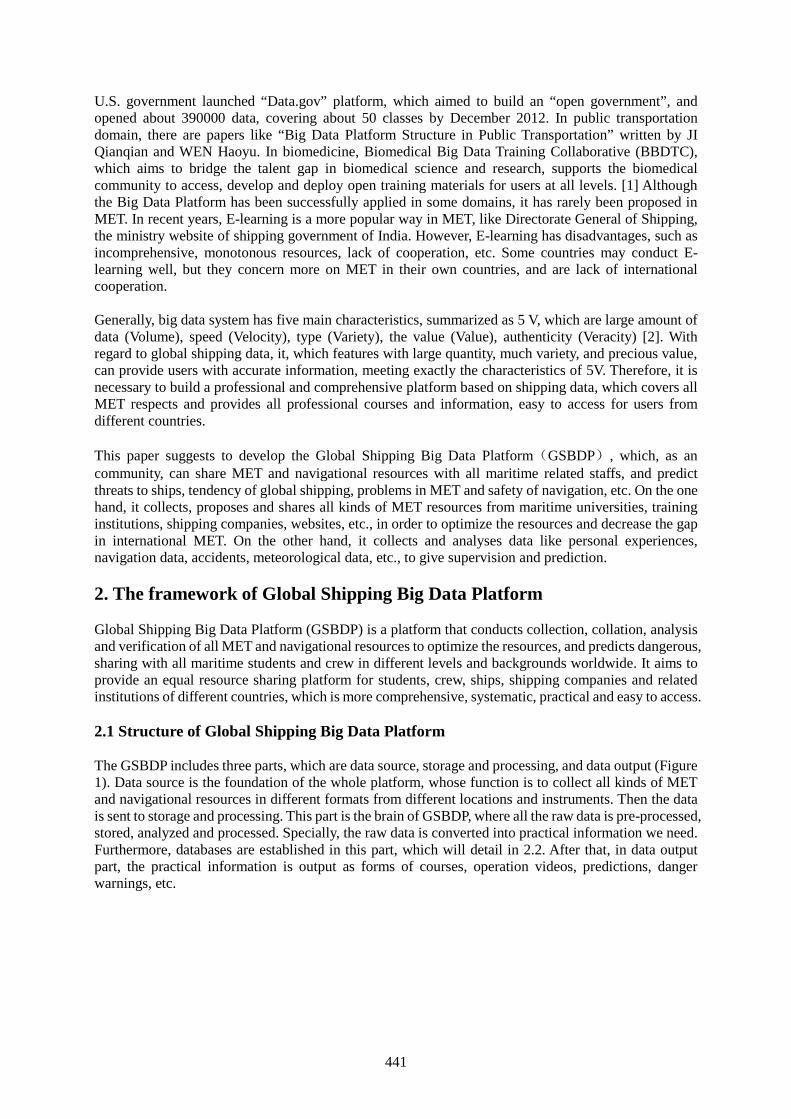
441
U.S. government launched “Data.gov” platform, which aimed to build an “open government”, andopened about 390000 data, covering about 50 classes by December 2012. In public transportationdomain, there are papers like “Big Data Platform Structure in Public Transportation” written by JIQianqian and WEN Haoyu. In biomedicine, Biomedical Big Data Training Collaborative (BBDTC),which aims to bridge the talent gap in biomedical science and research, supports the biomedicalcommunity to access, develop and deploy open training materials for users at all levels. [1] Althoughthe Big Data Platform has been successfully applied in some domains, it has rarely been proposed inMET. In recent years, E-learning is a more popular way in MET, like Directorate General of Shipping,the ministry website of shipping government of India. However, E-learning has disadvantages, such asincomprehensive, monotonous resources, lack of cooperation, etc. Some countries may conduct E-learning well, but they concern more on MET in their own countries, and are lack of internationalcooperation.
Generally, big data system has five main characteristics, summarized as 5 V, which are large amount ofdata (Volume), speed (Velocity), type (Variety), the value (Value), authenticity (Veracity) [2]. Withregard to global shipping data, it, which features with large quantity, much variety, and precious value,can provide users with accurate information, meeting exactly the characteristics of 5V. Therefore, it isnecessary to build a professional and comprehensive platform based on shipping data, which covers allMET respects and provides all professional courses and information, easy to access for users fromdifferent countries.
This paper suggests to develop the Global Shipping Big Data Platform(GSBDP), which, as ancommunity, can share MET and navigational resources with all maritime related staffs, and predictthreats to ships, tendency of global shipping, problems in MET and safety of navigation, etc. On the onehand, it collects, proposes and shares all kinds of MET resources from maritime universities, traininginstitutions, shipping companies, websites, etc., in order to optimize the resources and decrease the gapin international MET. On the other hand, it collects and analyses data like personal experiences,navigation data, accidents, meteorological data, etc., to give supervision and prediction.
2. The framework of Global Shipping Big Data Platform
Global Shipping Big Data Platform (GSBDP) is a platform that conducts collection, collation, analysisand verification of all MET and navigational resources to optimize the resources, and predicts dangerous,sharing with all maritime students and crew in different levels and backgrounds worldwide. It aims toprovide an equal resource sharing platform for students, crew, ships, shipping companies and relatedinstitutions of different countries, which is more comprehensive, systematic, practical and easy to access.
2.1 Structure of Global Shipping Big Data Platform
The GSBDP includes three parts, which are data source, storage and processing, and data output (Figure1). Data source is the foundation of the whole platform, whose function is to collect all kinds of METand navigational resources in different formats from different locations and instruments. Then the datais sent to storage and processing. This part is the brain of GSBDP, where all the raw data is pre-processed,stored, analyzed and processed. Specially, the raw data is converted into practical information we need.Furthermore, databases are established in this part, which will detail in 2.2. After that, in data outputpart, the practical information is output as forms of courses, operation videos, predictions, dangerwarnings, etc.
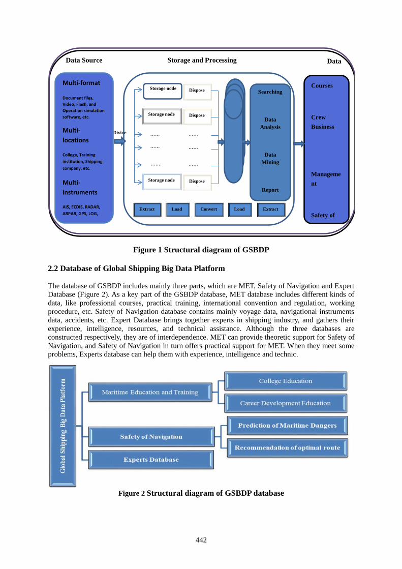
442
Figure 1 Structural diagram of GSBDP
2.2 Database of Global Shipping Big Data Platform
The database of GSBDP includes mainly three parts, which are MET, Safety of Navigation and ExpertDatabase (Figure 2). As a key part of the GSBDP database, MET database includes different kinds ofdata, like professional courses, practical training, international convention and regulation, workingprocedure, etc. Safety of Navigation database contains mainly voyage data, navigational instrumentsdata, accidents, etc. Expert Database brings together experts in shipping industry, and gathers theirexperience, intelligence, resources, and technical assistance. Although the three databases areconstructed respectively, they are of interdependence. MET can provide theoretic support for Safety ofNavigation, and Safety of Navigation in turn offers practical support for MET. When they meet someproblems, Experts database can help them with experience, intelligence and technic.
Figure 2 Structural diagram of GSBDP database
Extract Load Convert Load Extract
Divide
Multi-format
Document files,Video, Flash, andOperation simulationsoftware, etc.
Multi-locations
College, Traininginstitution, Shippingcompany, etc.
Multi-instruments
AIS, ECDIS, RADAR,ARPAR, GPS, LOG,etc.
Data Source Storage and Processing DataOutput
Courses
Crew
Business
Manageme
nt
Safety of
navigation
Storage node
Storage node
Storage node
……
……
……
Dispose
Dispose
……
……
……
Dispose
Database
Searching
DataAnalysis
DataMining
Report
……
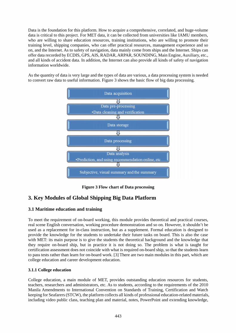
443
Data is the foundation for this platform. How to acquire a comprehensive, correlated, and huge-volumedata is critical to this project. For MET data, it can be collected from universities like IAMU members,who are willing to share education resources, training institutions, who are willing to promote theirtraining level, shipping companies, who can offer practical resources, management experience and soon, and the Internet. As to safety of navigation, data mainly come from ships and the Internet. Ships canoffer data recorded by ECDIS, GPS, AIS, RADAR, ARPAR, SOUNDING, Main Engine, Auxiliary, etc.,and all kinds of accident data. In addition, the Internet can also provide all kinds of safety of navigationinformation worldwide.
As the quantity of data is very large and the types of data are various, a data processing system is neededto convert raw data to useful information. Figure 3 shows the basic flow of big data processing.
Figure 3 Flow chart of Data processing
3. Key Modules of Global Shipping Big Data Platform
3.1 Maritime education and training
To meet the requirement of on-board working, this module provides theoretical and practical courses,real scene English conversation, working procedure demonstration and so on. However, it shouldn’t beused as a replacement for in-class instruction, but as a supplement. Formal education is designed toprovide the knowledge for the students to undertake their future tasks on board. This is also the casewith MET: its main purpose is to give the students the theoretical background and the knowledge thatthey require on-board ship, but in practice it is not doing so. The problem is what is taught forcertification assessment does not coincide with what is required on-board ship, so that the students learnto pass tests rather than learn for on-board work. [3] There are two main modules in this part, which arecollege education and career development education.
3.1.1 College education
College education, a main module of MET, provides outstanding education resources for students,teachers, researchers and administrators, etc. As to students, according to the requirements of the 2010Manila Amendments to International Convention on Standards of Training, Certification and Watchkeeping for Seafarers (STCW), the platform collects all kinds of professional education-related materials,including video public class, teaching plan and material, notes, PowerPoint and extending knowledge,
444
etc. Materials collected are provided by each cooperating college and institution. Related experts areresponsible for resources integration and reorganization. By doing this, all the professional knowledgeis covered, which satisfies the needs of different learners of different levels and backgrounds. Thecourses are mainly theoretical and practical parts. Specific forms include open courses, textinterpretations, video demonstrations, flash demonstrations, operations of simulation software, etc.There are mainly four items in this module, which are professional courses, practical training,professional English and international convention and regulation.
(1) Professional courses
Facing to anyone who wants to receive professional and comprehensive MET, this module offers opencourses involving all the related fields, like navigation, marine engineering,electrical and electronic engineering, marine law, etc. With a selection and combination of professionalcourses in global maritime universities and colleges, it will provide appropriate courses for the users allover the world. The courses are classified according to the fields, which are carefully organized to helpusers study systematically. In addition, users can link to extensive knowledge in their learning process.This module plays an important guiding role in the international MET integration and resource sharing.Open courses of navigation, marine engineering, marine law and so on, are recorded by professors andinstructors in different maritime universities and colleges. After carefully chosen and classified, moreprofessional, systematical, and authoritative courses are available for the users. As for students inbackward areas, it will be a fully supplement and support to the education they received.
(2) Practical training
Different from traditional practical training, this module carries out training in the way of video, flash,and operation of simulation software, etc. Video demonstration and flash demonstration are mainly forpractical parts. Videos record real working scenes on board and exemplify typical operations in detail,including demonstrations of entering enclosed space, releasing lifeboat, working aloft, repairing failureof the main engine, dealing with man overboard, etc. Flash, which makes the content more vivid, mainlypresents some regular operations, including operation procedure of fire extinguishing system, garbageclassification, usage of oil preventing equipment, etc. Operation of simulation software mainly helps tobe familiar with operation instruction. It can improve crew’s practical operation ability, includingsteering simulation software, radar operation simulation software, positioning simulation software,collision avoidance simulation software, stowage simulation software, etc.
(3) Professional English
Maritime English, as a common language on board, is more and more important to both routine workon the ship and external communication. There're a total of 26 modifications and supplements directlyto the maritime English in the 2010 Manila amendments to STCW convention. The basic principle doesnot change, but general requirements are higher. In addition, the convention has a special emphasis onthe seafarers' language accepting ability, especially reading and listening ability. This module presentsthe users how to communicate in all kinds of scenes on the ship in English. This method, more vividthan text interpretation, can put the crew in the specific scene and help them to memorize theprofessional English. Taking the business of the third office as an example, English communicationscenes consist of the organization of fire-fighting practice, organizing drill, steering and steering orders,loading and unloading, gangway watch, etc.
(4) International Convention and Regulation
This module includes all the international conventions, regulations, rules and relevant documents. Asmandatory rules or suggestion, international convention and regulation plays important roles ininternational shipping to regulate the behavior of shipping companies, crew, relative institutions, etc.They include but not limit to the International Convention for the Safety of Life at Sea (SOLAS), theInternational Convention on Load Lines, the International Convention for the Prevention of Pollution
445
from ships, the International Maritime Dangerous Goods (IMDG) Code, the International MaritimeSolid Bulk Cargoes (IMSBC) Code, the International Regulations for Preventing Collisions at Sea(COLREG), the International Code of Signals, etc. For example, in the 2010 Manila Amendments toSTCW, it stipulates explicitly that captain, officers and engineers should have knowledge of relatedinternational maritime conventions and recommendations, and national legislation.
3.1.2 Career development education
Based on the crew’s responsibility, this module helps the crew to enrich their business related knowledgesystematically, and aims to become an encyclopedia for seaman career development education in theway of modular learning. The ways of training can be video material recorded, a demonstration of joboperation process, the summary of crew’s own experience, or experiences and lessons drawing fromaccidents. Based on modern methods,the platform will build a large database of maritime careerdevelopment education. In addition, it will make every effort to help the crew to solve the problems theymeet, such as lacking of career related information, without professional support andunsystematic process of study. By establishing information database and expert database, it will makethe maritime vocational education more open, professional and diversified, and achieve the goal foroptimization of nautical education system. There are mainly two items in this module, which are crewbusiness and ship quality management.
(1) Crew business
On the basis of the 2010 Manila amendments to STCW convention, this module is divided into differentunits according to different positions, and focus on the practical operations. This module mainly combsand spreads the business knowledge of corresponding positions on board, aiming to contain all relevantbusiness. For those who want to make development and improve their business ability, it provides thema self-learning opportunity, making it easier for them to understand and research in their business.
(2) Ship quality management
This module provides a platform to share resources for those who want to know something about thesafety management system of other companies or departments. In addition, this module also offers somemature management experience and successful cases as part of effort to provide references for newrecruits or the crew having such demand. On this basis, the platform adds teacher link module, whichgives solution and guidance online to solve the problems encountered in the process of autonomouslearning.
3.2 The safety of navigation
In this part, we establish a database of maritime accidents. With a statistical analysis of them, it canprovide suggestions for accidents prevention and control. At the same time, as a communicationplatform, when some accidents or dangers happen at sea, the first ship finding it can post the messageon the platform, thus ships passing through can take measures to keep away from distress. There areseveral modules that play different roles in this platform.
(1) Prediction of maritime dangers
The most valuable advantage of big data is prediction. The advantages of this module includes accidentstatistics and prevention advice, early warning of maritime dangerous, prevention and against of thepirates, etc. Firstly, by collecting different kinds of navigational data, the platform can predict thedangerous about to happen, which is very important for safety of navigation. Secondly, by collecting,classifying and statistical analysis of maritime accidents, it can obtain the reason, percentage and resultof different kinds of accidents, so that suggestions or procedures preventing accidents from happeningcan be acquired. Thirdly, when some accidents, bad weather or other dangers, happen at sea, the firstship who finds it can post the message on the platform, warning ships passing through this area. Finally,
446
it makes a statistical analysis of global pirate attacks, for example types of attack, the way pirates boardship, weapons and outfits equipped and the successful case out of danger and so on, and marks differentcolors on the chart according to the probability of pirate attacks happened in different areas. This willhelp the ships passing through these areas be well prepared for piracy earlier and give some suggestionsto prevent the pirate attach.
(2) The recommendation of optimal route
By collecting and analyzing different kinds of navigational information from different ships, this moduleoffers a choice of optimal route to meet ship’s requirement. First, navigation information is collectedfrom navigation equipment, such as electronic chart, Radar, AIS and so on. Then, after series of dataprocessing, it will provide recommended routes for ships navigating around the world, such as economicpriority route, distance priority route, and time preference route, etc. Meanwhile, the users can optimizethe recommended route combining with their own needs. After choosing the recommended route, somerelated information can also be labelled on the route, which ensures the safety of navigation. Theinformation includes all hazards at close range, shallow water, narrow channel, traffic dense areas andany dangerous on the way. Besides, it can also provide some other information, like reporting point,reporting frequency, regulations of ports, etc. Users can obtain the above content only by inputting theGPS-coordinates of the departure point and destination point.
3.3 Expert Database
This module links to maritime experts so as to give online or email instructions to students and seafarers.They can help them solve practical problems, build up correct career development plan, and improveprofessional abilities. Experts will be selected from eminent professors in maritime colleges anduniversities, and remarkable captains or chief engineers in shipping companies. They must be well-versed in their own business, have an acute insight, be good at discovering and solving problems, andbe willing to share their precious experience. Upon meeting thorny problems, designated relevant expertis requested to give an online guidance. Every few months, experts are called up to discuss problemsrecently happening together in a way of video conference to find out solutions. It can not only save timeand energy, but also make good use of the integrated resources. Furthermore, it is also a great chancefor maritime elites to cooperate together.
4. Conclusion and expectation
To balance the international maritime education resources and provide help for the safety of navigation,this paper proposes a creative idea of constructing the GSBDP. Through establishing MET database, itwill provide the same opportunities for students from different countries to receive high level maritimeeducation, help the crew to improve their business, and solve the problems they meet in work. Inaddition, it will also contribute to safeguarding and providing favorable conditions for navigation.GSBDP will strengthen the cooperation of different countries in MET and safety of navigation, and playan important role in pushing forward the development of shipping industry worldwide. On this basis,we can establish a feedback system of crew tracking and assessment, which helps to evaluate theworking process of the crew, collect the difficulties and confusions they meet in work process. Furtherly,if we can improve the database, form a closed loop, and make continuous improvement, it will play animmeasurable role in pushing forward the shipping development.
Acknowledgements
This work is greatly supported by Professor Ma Long. The authors also gratefully acknowledge thehelpful comments and suggestions of the reviewers, which have improved the presentation.

447
References
[1] Shweta Purawat, Charles Cowart, Rommie E. Amaro and Ilkay Altintas, “Biomedical Big DataTraining Collaborative (BBDTC): An effort to bridge the talent gap in biomedical science andresearch”, Procedia Computer Science, Volume 80, (2016), pp 1791–1800.
[2] Chenainichen, “Big Data”,http://wenku.baidu.com/link?url=GUEpf14BTel2iuxNgzuBkgCYEuqe5FCNZuLqeskJ6ZBTkpmOOqy_7QqdaJlLgFNSwkltag_cx8o1p02sc69g9TqLRcKG_EajOwra6tEqKQq, Baidu Wenku,(Dec.15, 2015).
[3] Gholamreza Emad and Wolff Michael Roth, "Contradictions in the practices of training for andassessment of competency", Education + Training, Vol 50, (2008),pp 260 – 272.
[4] The 2010 Manila Amendments to International Convention on Standards of Training, Certificationand Watch keeping for Seafarers (STCW), (2010).
448
Logistics and supply chain finance: managing financial risks and
optimizing financial flows in logistics and supply chains
M. Com. Thuy Duong Dang 1
1. Faculty of Management and Finance - Vietnam Maritime University, [email protected]
Abstract. Logistics and supply chain management (SCM) play more and more important roles in
modern world and have great potential for improving bottom line results. In the literature, there are a lot
of contributions towards managing physical risks, information and goods flows while issues related to
managing financial risks such as market risk, credit risk, currency risk and optimizing financial flows
have not been discussed adequately. This article will focus on this research gap to enhance efficiency of
logistics and supply chains by applying finance to develop the framework to optimize cost flows of those
companies taking capital structure, cost of capital and various cost drivers into consideration and also
recommending the use of derivatives such as forward or future contracts, swaps, option to hedge
different financial risks that logistics and supply chain companies may face in global context.
Keywords: Logistics and Supply chain Finance, risks, derivatives, hedging, financial flows, cost
optimization.
1. Introduction
The modern business world has put logistics and SCM into practice because they are considered to be
essential drivers of differential competencies for the companies and value maximization for the
shareholders by optimizing goods, information and financial flows within a company as well as the
whole supply chain. While there are many academic contributions toward issues related to the flows of
goods and information, the financial flows were less paid attention. The integration of finance and
logistics and SCM is research gap with huge potential to explore and develop both theory and practice.
Logistics and SCM are applied widely in order to lower cost (65%) and increase revenue (25%) however
not many companies know how to direct their investment in this field to maximize the business
performance (D’Avanzo et al. 2003). Logistics and SCM decisions can have a great influence on the
capital structure, risk profile, profitability and market value of a firm. Therefore, logisticians and supply
chain executives are required to understand and communicate in the “language of finance”.
Since the global financial crisis in 2008, it has been more difficult for logistics and supply chain
companies to assess to commercial bank loans while those firms will require more and more capital in
both short – term and long – term. The key to the success of a logistics and SCM decision is that the
firm profitability is higher than its capital cost rate. Supply chain finance (SCF) solutions can help not
only improve the efficiency of order cycle and working capital management but also reduce the cost of
capital (CoC).
According to a report by the Supply Chain Management Faculty at the University of Tennessee, in a
survey among over 150 different supply chain managers, none of them hired external experts outside to
assess their supply chains risks; 90% of companies do not quantify risk when outsourcing production;
and 100% of supply chain executives considered insurance as a highly effective risk mitigation tool, but
it was not in their purview. The study also analyzed over 800 supply chain disruptions that occurred
from 1989 to 2000. Firms that experienced major supply chain disruptions saw the following
consequences: Sales were reduced 93%, and share returns were 33-40 % lower over a three-year period;
Stock price volatility was 13.5% higher; Operating income reduced by 107%; and Return on Assets
(ROA) declined by 114%. By nature, risks cannot be completely eliminated but they can be identified
and mitigated. Many research findings (e.g. Meulbroek JACF 2002 and Stulz JACF 1996) noted that
risk management can and does add value to the firms.
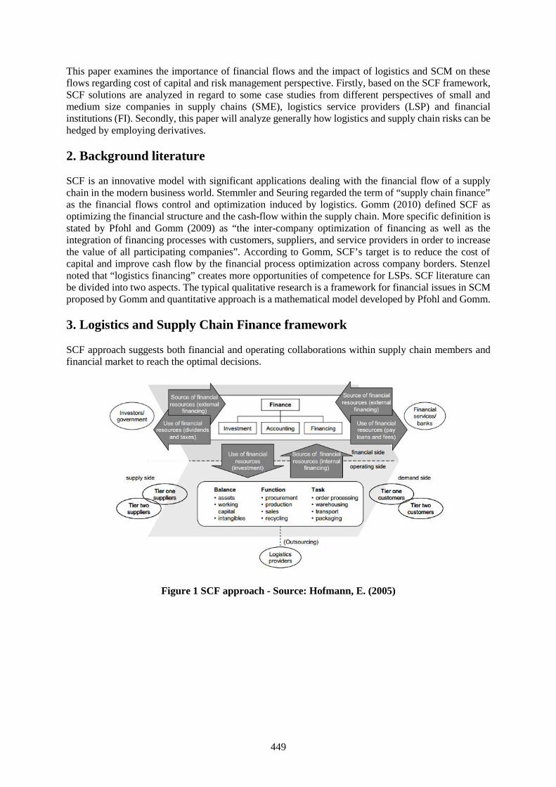
449
This paper examines the importance of financial flows and the impact of logistics and SCM on theseflows regarding cost of capital and risk management perspective. Firstly, based on the SCF framework,SCF solutions are analyzed in regard to some case studies from different perspectives of small andmedium size companies in supply chains (SME), logistics service providers (LSP) and financialinstitutions (FI). Secondly, this paper will analyze generally how logistics and supply chain risks can behedged by employing derivatives.
2. Background literature
SCF is an innovative model with significant applications dealing with the financial flow of a supplychain in the modern business world. Stemmler and Seuring regarded the term of “supply chain finance”as the financial flows control and optimization induced by logistics. Gomm (2010) defined SCF asoptimizing the financial structure and the cash-flow within the supply chain. More specific definition isstated by Pfohl and Gomm (2009) as “the inter-company optimization of financing as well as theintegration of financing processes with customers, suppliers, and service providers in order to increasethe value of all participating companies”. According to Gomm, SCF’s target is to reduce the cost ofcapital and improve cash flow by the financial process optimization across company borders. Stenzelnoted that “logistics financing” creates more opportunities of competence for LSPs. SCF literature canbe divided into two aspects. The typical qualitative research is a framework for financial issues in SCMproposed by Gomm and quantitative approach is a mathematical model developed by Pfohl and Gomm.
3. Logistics and Supply Chain Finance framework
SCF approach suggests both financial and operating collaborations within supply chain members andfinancial market to reach the optimal decisions.
Figure 1 SCF approach - Source: Hofmann, E. (2005)
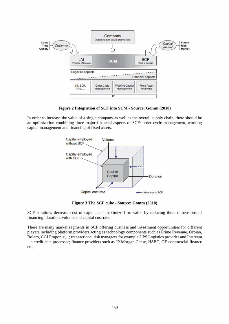
450
Figure 2 Integration of SCF into SCM - Source: Gomm (2010)
In order to increase the value of a single company as well as the overall supply chain, there should bean optimization combining three major financial aspects of SCF: order cycle management, workingcapital management and financing of fixed assets.
Figure 3 The SCF cube - Source: Gomm (2010)
SCF solutions decrease cost of capital and maximize firm value by reducing three dimensions offinancing: duration, volume and capital cost rate.
There are many market segments in SCF offering business and investment opportunities for differentplayers including platform providers acting as technology components such as Prime Revenue, Orbian,Bolero, CGI Proponix,...; transactional risk managers for example UPS Logistics provider and Instream– a credit data processor; finance providers such as JP Morgan Chase, HSBC, GE commercial financeetc.
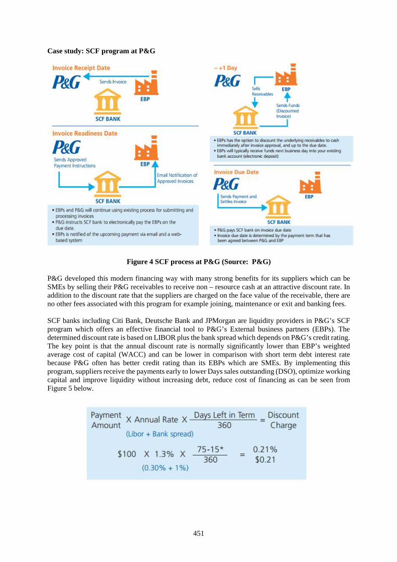
451
Case study: SCF program at P&G
Figure 4 SCF process at P&G (Source: P&G)
P&G developed this modern financing way with many strong benefits for its suppliers which can beSMEs by selling their P&G receivables to receive non – resource cash at an attractive discount rate. Inaddition to the discount rate that the suppliers are charged on the face value of the receivable, there areno other fees associated with this program for example joining, maintenance or exit and banking fees.
SCF banks including Citi Bank, Deutsche Bank and JPMorgan are liquidity providers in P&G’s SCFprogram which offers an effective financial tool to P&G’s External business partners (EBPs). Thedetermined discount rate is based on LIBOR plus the bank spread which depends on P&G’s credit rating.The key point is that the annual discount rate is normally significantly lower than EBP’s weightedaverage cost of capital (WACC) and can be lower in comparison with short term debt interest ratebecause P&G often has better credit rating than its EBPs which are SMEs. By implementing thisprogram, suppliers receive the payments early to lower Days sales outstanding (DSO), optimize workingcapital and improve liquidity without increasing debt, reduce cost of financing as can be seen fromFigure 5 below.
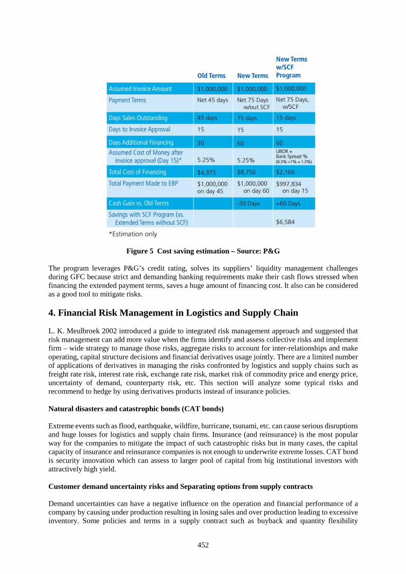
452
Figure 5 Cost saving estimation – Source: P&G
The program leverages P&G’s credit rating, solves its suppliers’ liquidity management challengesduring GFC because strict and demanding banking requirements make their cash flows stressed whenfinancing the extended payment terms, saves a huge amount of financing cost. It also can be consideredas a good tool to mitigate risks.
4. Financial Risk Management in Logistics and Supply Chain
L. K. Meulbroek 2002 introduced a guide to integrated risk management approach and suggested thatrisk management can add more value when the firms identify and assess collective risks and implementfirm – wide strategy to manage those risks, aggregate risks to account for inter-relationships and makeoperating, capital structure decisions and financial derivatives usage jointly. There are a limited numberof applications of derivatives in managing the risks confronted by logistics and supply chains such asfreight rate risk, interest rate risk, exchange rate risk, market risk of commodity price and energy price,uncertainty of demand, counterparty risk, etc. This section will analyze some typical risks andrecommend to hedge by using derivatives products instead of insurance policies.
Natural disasters and catastrophic bonds (CAT bonds)
Extreme events such as flood, earthquake, wildfire, hurricane, tsunami, etc. can cause serious disruptionsand huge losses for logistics and supply chain firms. Insurance (and reinsurance) is the most popularway for the companies to mitigate the impact of such catastrophic risks but in many cases, the capitalcapacity of insurance and reinsurance companies is not enough to underwrite extreme losses. CAT bondis security innovation which can assess to larger pool of capital from big institutional investors withattractively high yield.
Customer demand uncertainty risks and Separating options from supply contracts
Demand uncertainties can have a negative influence on the operation and financial performance of acompany by causing under production resulting in losing sales and over production leading to excessiveinventory. Some policies and terms in a supply contract such as buyback and quantity flexibility
453
conditions act as “embedded options” which have a number of limitations in risk management. A firmnot only can operationally manage the risk but also reduce it financially with derivative instruments.Shi, D. et al. 2004 introduced a simple call option whose underlying asset is the customer demand level.They proved that with greater flexibility in comparison with embedded options, this derivative canfacilitates risk sharing and risk taking among different supply chain partners, financial intermediariessuch as banks, hedge funds, insurance companies etc. which have various risk appetites and risk bearingability, therefore, enhance the whole supply chain coordination and performance.
Freight rate risk and Freight rate derivatives
The major part of a transportation logistics companies’ income is freight rate. The operating cash flowsand profitability of a shipping company for example will highly exposure to the freight rate uncertainty.The research by Stefan, A. et al. 2011 indicates that the volatility of freight prices is much higher thanthat of equity or bond and also cyclical, seasonal. Besides, its distribution shows “fat tails” and negativeskewness. Especially, during GFC (global financial crisis), the standard deviation of freight rate leaptsignificantly.
There are many compound factors affecting the change in the derived demand for freight services, forinstance, global economy, and international trade, the seasonality of commodity consumption andmarkets, vehicle or vessel size and contract maturity.
Common freight rate derivatives such as forward freight agreements (FFA), freight rate future contractsand freight rate options can be more flexible and cost – effective solution to hedge risk and integratewith the classic methods of operation management and capital structure adjustment.
The Baltic Exchange provides information and indexes of maritime transportation markets which areused for the trade and settlement of derivatives contracts. BIFFEX (the Baltic International FreightFutures Exchange) is an organized exchange located in London trading ocean freight futures contractswhich are settled based on the Baltic Freight Index.
CME Group is one of the largest options and futures exchanges. FFAs offered by CME group are dividedinto two main groups: wet freight for different routes (Baltic and Platts) and dry freight based ondifferent time charter index made public by Baltic exchange.
Wet freight options designed for different routes are European type and settled at average price.Additional tailor - made products are being developed to meet various requirement of all ranges ofmarket participants.
In the past, most freight derivatives were traded by the network of dealers in OTC (over – the – counter)market. Nowadays, more and more futures and options are traded on or traded off and then clearedthrough standardized exchanges such as NYMEX.
Asset Value Risk and Scrap Derivatives
One typical example is that ship owners can manage vessel value by employing forward products suchas FOSVA (Forward Ship Value Agreement) which are cash settled contracts, similar to the structure ofplain vanilla FFAs and whose underlying assets ‘prices are based on BSPA index (the Baltic Sale andPurchase Assessments). The drawback of this market is that it is less liquid than the traditional forwardsmarket.
Another index of demolition values is BDA (the Baltic Exchange Demolition Assessments) which canbe treated as the underlying assets of derivative instruments created to trade on vessel scrap.
5. Conclusion and Recommendation
454
One common issue of SMEs in supply chains is capital constraint. SCF opens the access to cheapersources of fund by taking the advantage of the gap in the refinancing interest rates of different companiesin the same supply chain due to credit rating and solving agency problem caused by informationasymmetries between supply chain insiders and external parties from financial market. SCF solutionscreate a win – win situation for all involved participants by converting supply chain information andknowledge into accelerated value by improving financing methods and reducing risks.
In the volatile business environment, depending on risk appetites and comparative advantages, logisticsand supply chain companies have to determine which risks and how much risk should be borne andmanaged internally, which risks should be transferred to financial market who can bear the risks at lowercost and in more efficient way. More and more sophisticated and innovative financial instruments havebeen designed to satisfy the various demand of risk management and diversifying alternative investment.However, both risk managers and investors must understand and be cautious when using those toolsbecause of their complex structures with attractive and flexible characteristics.
In Vietnam, logistics and supply chain industry seeks lending capital from commercial banks whichoffer very simple and basic products with strict financial requirements. There is a lack of SCFapplication to leverage and exploit the potential of logistics and supply chains to achieve the sustainableeconomic development. The recommendation would be further research and cooperation at both microand macro level between logistics, SCM with financial services providers such as investment banks,hedge funds, and insurance companies etc. to develop variety of comprehensive SCF solutions to replacethe classical one – size – fits - all method.
References[1] Andreas Otto, Robert Obermaier, How can supply networks increase firm value? A causal
framework to structure the answer, Springer (2009)[2] Avanzo R, Von Lewinski H, Van Wassenhove LN (2003), The link between supply chain and
financial performance, Supply Chain Manag Rev 7(6):40–47[3] Brealey RA, Myers SC (2000), Principles of corporate finance. 6.Aufl. Boston u.a[4] Campbell TS (1979), Optimal investment financing decisions and the value of confidentiality. J
Finance Quant Anal 14(5):913–924[5] Ceccarello C, Neser G, Pestre C, Roman N, Poisson V (2002) Financial indicators and supply chain
integration: a European study. Supply Chain Forum 3(1):44–52[6] Christopher M (2005) Logistics and supply chain management— strategies for reducing cost and
improving service. 3. Aufl. London u. a[7] Christopher M, Ryals L (1999) Supply chain strategy: its impact on shareholder value. Int J Logist
Manag 10(1):1–10[8] Dailun, R. Daniels and W. Grey (2004), Managing Supply Chain Risks with Derivatives, IBM
research report.[9] Erik Hofmann (2005), Supply chain finance – some conceptual insights.[10] Hans-Christian Pfohl, Moritz Gomm, Supply chain finance: optimizing financial flows in supply
chains, Springer (2009)[11] Hans-Christian Pfohl, Holger Ko¨hler, David Thomas, State of the art in supply chain risk
management research: empirical and conceptual findings and a roadmap for the implementation inpractice, Springer (2010)
[12] Kerstin Lampe, Erik Hofmann, Understanding the cost of capital of logistics service providers: anempirical investigation of multiple contingency variables, Springer (2014)
[13] Moritz Leon Gomm, Supply chain finance: applying finance theory to supply chain managementto enhance finance in supply chains, International Journal of Logistics: Research and Applications,Vol. 13, No. 2, April 2010, 133–142
[14] Xiaohong Liu et al. (2015), Supply chain in Finance: Business innovation and theory development,Sustainability.
[15] Weygandt, Kimmel, Kieso, Managerial Accounting tools for business decision making 6th ed,Wiley.