Embed Size (px)
Citation preview

Macula precise localization using digital retinal angiographies
C.MARINO, S. PENA, M.G.PENEDO, J. ROUCO, J.M. BARJAGrupo de Vision Artificial y Reconocimiento de Patrones
University of A CorunaCampus de Elvina s/n, A Coruna, 15071
SPAIN{castormp,mgpenedo,jrouco, jmbarja}@udc.es, [email protected]
Abstract: The fovea is a spot located in the center of the macula, and responsible for sharp central vision. In thispaper a method to detect the macula location and size is presented, as a first step towards the fovea location. Priorto the macula detection, the optic disk size and position is computed. This is performed through the combinationof two stages: firstly, a clustering algorithm is used to select the regions which contain the pixels with the highestgray levels. A correlation filter is applied to these regionsto compute the approximate center of the optic disk.Then, in order to extract the optic disk, a deformable model which is used. Then, following the morphologicalproperties of the eye, the macula location and size is determined by means of a new correlation filter. Search withthis filter is performed in a reduced area of interest, whose size and position is determined by means, again, of themorphological properties of the eye. The algorithm has proven to be fast and accurate in the set of test images,composed by 135 digital retinal images.
Key–Words:Optic disk, macula, fovea, correlation filter, deformable model.
1 Introduction
The retinal fundus photographs are widely used in thediagnosis of eye diseases. Processing automaticallya large number of retinal images can help ophthal-mologists to increase the efficiency in medical envi-ronment. The optic disk is the brightest area in im-ages that have not large areas of exudates and it is aslightly oval disk. It is the entrance region of vesselsand its detection is very important since it works asa landmark for the other features in the retinal image.The macula is a commonly visible as a hazy dark area.This is the area with the highest number of cones androds per unit area.
There are many previous works on optic disk lo-calization. Lalonde et al. [1] extract the optic disk us-ing Hausdorff based template matching and pyrami-dal decomposition. It is neither sufficiently sensitivenor specific enough for clinical application. On theother hand, strategies based on active contours [2–4]are used to detect the optic disk boundary in reti-nal images. These techniques are very robust againstnoise but their main disadvantage is their high compu-tational cost.
A method for the detection of the macular centerwas presented by Sinthanayothin [5]. In this approacha template based algorithm was used, combined withthe morphological properties of the eye. The systemshowd an accuracy 80.4% on 100 images. Li et al. [6]
presented a model based approac in which an snakewas used to extract the vascular tree based on the loca-tion of the optic disk. Then, the information from thesnake was used to find the macula center. The authorsreported an accuracy 100% for optic disk localizationand 100% for macula localization in 89 digital retinalimages.
This paper presents an algorithm for the auto-matic localization and segmentation of the optic nervehead, macula and fovea working on digital retinal im-ages. Without user intervention, the optice nerve headis located and its shape is extracted. Localization ofthe optic disk is achieved by means of a two stagesalgorithm: the former locates several regions of inter-est candidates , where the optic disk could be located.In the latter the regions where the optic disk is notpresent are rejected by means of a simple correlationfilter. Once the optic disk position has been achieved,macula and fovea are located using the morphologi-cal properties of the eye, combined with a correlationfilter for a more accurate result.
The setup of the paper is as follows. In section 2the algorithm for the optic disk localization, while sec-tion 3 provides details on the segmentation process.Section 4 describes the macula segmentation process.Experiments and results are given in section 5 for themacula localization and segmentation, and finally sec-tion 6 provides discussion and conclusions.
Proceedings of the 11th WSEAS International Conference on COMPUTERS, Agios Nikolaos, Crete Island, Greece, July 26-28, 2007 601

2 Optic disk localization
The first stage of the process consists of locating theregion where the optic disk is located. A clusteringalgorithm is used to compute the regions with highestgray level pixels, among which will be the one con-taining the optic disk. Later, a correlation filter is ap-plied to these regions in order to discard the regionswhere the optic disk is not located, and to computethe approximate center of the optic disk in the rightregion. With the addition of the clustering algorithmto the whole process proposed by Lowell et all. a bet-ter performance has been obtained, improving resultsby reducing the wrong localization cases, as will beshown in results chapter.
2.1 A clustering algorithm
Since the intensity of the optic disk is much higherthan the retinal background, a possible method in or-der to localize the optic disk is to find the largest clus-ters of pixels with the highest gray levels. For thisreason, the pixels with the highest 1% gray levels areselected. After this, a clustering algorithm groups thenearby pixels into clusters. Iniatilly, each point is acluster and its own centroid.If the Euclidean distancebetween two centroids is less than a specified thresh-old ε, these clusters are combined to form a new one.The new centroid(cx,cy) is computed by means ofEquations 1 and 2.
cx =n
∑i=0
xi
n(1)
cy =n
∑i=0
yi
n(2)
where(xi ,yi) are the cluster points andn is thenumber of points in the cluster.
If there are bright areas as well as the optic diskin the retinal image, the algorithm might compute sev-eral clusters. The regions of interest are defined asn×m rectangles whose centers are the centroids ofthese clusters. The rectangle size depends on the im-age resolution.
Figure 1 shows the points which the clustering al-gorithm is applied to. It is also depicted the regions ofinterest computed by means of this process.
2.2 Correlation filter
As depicted in Figure 1(f), several regions of interestmight be computed by means of the clustering algo-rithm because of bright areas in the retinal images. A
(a) (b)
(c) (d)
(e) (f)
Fig 1: Top: original digital retinal images. Middle: selectedpoints (highest 1% gray levels) which the clustering algorithm isapplied to. Bottom: the regions of interest computed by means ofthe clustering algorithm when applied to images 1(a) and 1(b).
correlation filter is applied to each region in order tolocate the true region where the optic disk is situated.
The optic disk consists of a high intensity near-circular disk, with a roughly centrally band of low in-tensity vessels. Due to this fact, the template consistsof a Laplacian of Gaussian with a vertical channel inthe middle to correspond to the major vessel band.This correlation filter is shown in Figure 2, where allcommented features of the filter are depicted.
The template is correlated with the intensity com-ponent of the retinal image. We use the full Pearson-R correlation to take variations in mean, intensity andcontrast into account, as defined in Equation 3.
Ci, j =∑x,y( f (x,y)− f (x,y))(w(x− i,y− j)− w)
∑x,y( f (x,y)− f (x,y))2 ∑x,y(w(x− i,y− j)− w)2
(3)wherew is the mean value of the template andf
is the mean value of the area covered byw.The region of interest containing the optic disk is
defined asn×m rectangle whose center is the pointwith the higher response computed by means of the
Proceedings of the 11th WSEAS International Conference on COMPUTERS, Agios Nikolaos, Crete Island, Greece, July 26-28, 2007 602
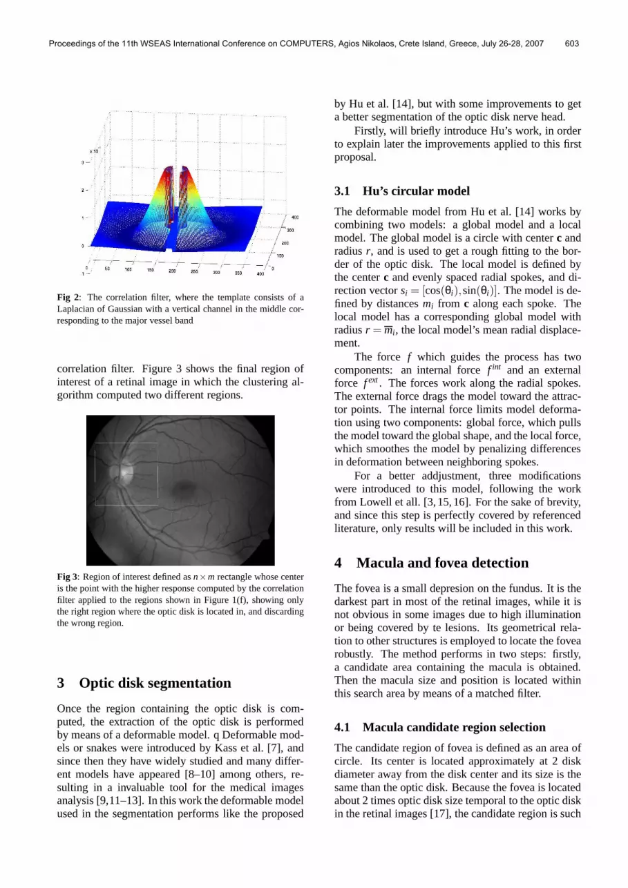
Fig 2: The correlation filter, where the template consists of aLaplacian of Gaussian with a vertical channel in the middle cor-responding to the major vessel band
correlation filter. Figure 3 shows the final region ofinterest of a retinal image in which the clustering al-gorithm computed two different regions.
Fig 3: Region of interest defined asn×m rectangle whose centeris the point with the higher response computed by the correlationfilter applied to the regions shown in Figure 1(f), showing onlythe right region where the optic disk is located in, and discardingthe wrong region.
3 Optic disk segmentation
Once the region containing the optic disk is com-puted, the extraction of the optic disk is performedby means of a deformable model. q Deformable mod-els or snakes were introduced by Kass et al. [7], andsince then they have widely studied and many differ-ent models have appeared [8–10] among others, re-sulting in a invaluable tool for the medical imagesanalysis [9,11–13]. In this work the deformable modelused in the segmentation performs like the proposed
by Hu et al. [14], but with some improvements to geta better segmentation of the optic disk nerve head.
Firstly, will briefly introduce Hu’s work, in orderto explain later the improvements applied to this firstproposal.
3.1 Hu’s circular model
The deformable model from Hu et al. [14] works bycombining two models: a global model and a localmodel. The global model is a circle with centerc andradiusr, and is used to get a rough fitting to the bor-der of the optic disk. The local model is defined bythe centerc and evenly spaced radial spokes, and di-rection vectorsi = [cos(θi),sin(θi)]. The model is de-fined by distancesmi from c along each spoke. Thelocal model has a corresponding global model withradiusr = mi , the local model’s mean radial displace-ment.
The force f which guides the process has twocomponents: an internal forcef int and an externalforce f ext. The forces work along the radial spokes.The external force drags the model toward the attrac-tor points. The internal force limits model deforma-tion using two components: global force, which pullsthe model toward the global shape, and the local force,which smoothes the model by penalizing differencesin deformation between neighboring spokes.
For a better addjustment, three modificationswere introduced to this model, following the workfrom Lowell et all. [3,15,16]. For the sake of brevity,and since this step is perfectly covered by referencedliterature, only results will be included in this work.
4 Macula and fovea detection
The fovea is a small depresion on the fundus. It is thedarkest part in most of the retinal images, while it isnot obvious in some images due to high illuminationor being covered by te lesions. Its geometrical rela-tion to other structures is employed to locate the fovearobustly. The method performs in two steps: firstly,a candidate area containing the macula is obtained.Then the macula size and position is located withinthis search area by means of a matched filter.
4.1 Macula candidate region selection
The candidate region of fovea is defined as an area ofcircle. Its center is located approximately at 2 diskdiameter away from the disk center and its size is thesame than the optic disk. Because the fovea is locatedabout 2 times optic disk size temporal to the optic diskin the retinal images [17], the candidate region is such
Proceedings of the 11th WSEAS International Conference on COMPUTERS, Agios Nikolaos, Crete Island, Greece, July 26-28, 2007 603

defined in order to ensure that the fovea is within theregion.
The definition of the foveal candidate area is asfollows, where all commented points are depicted inFigure 4: firstly, main creases from the image are ob-tained [18] (marked asc1 andc2), because fovea willallways be within the area determined by this creases.Then an arc is drawn with a radius of two times opticdisk diameter, and pointsA andB are taken, from theintersection of this arc and the creases. The straightline r1 which passes through both this points is con-sidered, and then the new straight liner2 wich goesfrom the optic disk center passing by the middpoint ofr1 is drawn. Finally, the pointC wherer2 intersects︷ ︷
AB is defined as the center of the candidate area. Al-though the size of the macula is about the optic disk,the size of the candidate area is again two times theoptic disk, ensuring that way that the macula will al-ways be within the search region.
Fig 4: Computation of the candidate foveal region. Left: digi-tal retinal angiography with creases of the arch vessel in white(oversized for better visualization). Right: scheme of thefovealcandidate region composition from the optic disk (center and ra-dius) and creases of the vessel arc (candidate region is marked asa shaded circular area).
4.2 Macula segmentation
Once the candidate area containing the macula havebeen obtained, a correlation filter is applied to the re-gion in order to locate the macula and so the fovea.
As stated before, the fovea is a spot located in thecenter of the macula, and responsible for sharp centralvision. The macula macula is a commonly visible as ahazy dark area. To locate this dark area, a mathed filterwhich consists of a Laplacian of Gaussian is used. Thecorrelation filter is shown in Figure 5. The fovea willbe located at the position where the response of thefilter is maximum.
Fig 5: The correlation filter to locate the macula, where the tem-plate consists of a Laplacian of Gaussian
The template is correlated with the intensity com-ponent of the retinal image. We use the full Pearson-R correlation to take variations in mean, intensity andcontrast into account, as defined in Equation 3. Thesize of the filter is taken the same as the optic disk size,since the diameter of the macula is about the same asthe diameter of the optic disk [17].
The region of interest containing the macula is de-fined asn×m rectangle whose center is the point withthe higher response computed by means of the corre-lation filter. Figure 6 shows the result obtained in themacula segmentation process. Macula is marked asa circle about the center of the image, while fovea ismarked as a cross in its center (optic disk segmenta-tion result is also included, with its center marked asa red cross).
5 Results
To test the accuracy of the localization and segmenta-tion algorithms described below, a set of 135 imageswhere used as the benchmark. Images were acquiredin different centers of the Complejo Hospitalario Uni-versitario de Santiago de Compostela (CHUS), all of
Proceedings of the 11th WSEAS International Conference on COMPUTERS, Agios Nikolaos, Crete Island, Greece, July 26-28, 2007 604

Fig 6: Result obtained from the macula segmentation process us-ing the correlation matched filter in image from Figure 4.
them with a Cannon CR6-45NM Non-Mydriatic Reti-nal Camera, with a 768× 576 pixel resolution. Al-though the camera originally captures color images,a conversion to gray-level images (with 256 gray lev-els) was performed prior to the application of the al-gorithms, since color does not provide any useful in-formation.
Validation of the algorithms was performed byexpert clinicians of the CHUS, who analyzed the out-put of the techniques to set its accuracy.
To validate our experiments, two expert clinicianssegmented manually the optic nerve head (marking itscenter) and macula (marking the fovea) from the testimages, and these results were compared with the re-sults obtained by the application of the process de-scribed in the preceding sections. Results for the firststage of the algorithm are included in [15,16], so theywill not be presented here. Results from that compar-isons for the macula localization is shown in Table 1,where three categories were defined (good, fair, poor),function of the difference between the results obtainedby clinicians and automatic results. This discrepancyfor image j was computed using equation 4.
δi =9
∑i=1
∣
∣
∣C j −C′j
∣
∣
∣
9(4)
with C j representing the automatic segmentationof the macula,C′
j representing the manually seg-mented macula rim and the summation over 8 pointsevenly spaced (one eachπ/4 rad) plus the fovea point,taken from each of the obtained macula rim estima-tions.
Analyzing results shown in Table 1, macula local-ization give an mean effectiveness of 99.25%, whichis a very good percentage. The image giving a poorresult is depicted in Figure 7. In that image the dif-ference between the result obtained manually by theclinician was not so similar to the one obtained with
LocalizationGood Fair Poor
Number images 128 6 1% 94.81 4.44 0.75
99.25% 0.75%Table 1: Results obtained in each stage (localization and segmen-tation) of the process. Three quantitative categories weredefined(good, fair, poor), with disparities one, two or more, respectively,computed using equation 4
our method because of the blurriness of the macula,giving raise to the poor result presented.
Fig 7: Image showing poor result for the macula localization.Macula manually obtained by the clinician is represented bythered circle, and macula obtained by our method is representedbythe green circle.
To illustrate these results, Figure 8 depicts severalresult images from the localization and segmentationof the optic disk (rim and center), macula and fovea.
6 Conclusions
In this work an algorithm for the precise localizationand segmentation of the optic disc nerve head and lo-calization of the macula has been presented. The opticdisk localization algorithm performs in two stages: inthe first, the region of interest where the optic disc islocated is obtained by combining a clustering processwith a posterior correlation procedure.The size of thecentral channel (corresponding to the main optic discvessel) has been estimated, with a mean size in thetest set of 20 pixels, which is also the size of this areain the correlation kernel. By other side, the size ofthis filter has been calculated for the set of images inthe test set, getting sizes from 130px to 220px. Sincethe filter must have at least the size of the bigger op-tic disc, commented results have been obtained witha kernel of 221×221px, which have performed wellfor the whole set of images. In the second stage, thelocated optic disc is segmented through a deformable
Proceedings of the 11th WSEAS International Conference on COMPUTERS, Agios Nikolaos, Crete Island, Greece, July 26-28, 2007 605

Fig 8: Result images showing the optic disk with its center (redcircle and red cross, respectively) and macula with the fovea(green circle and green cross, respectively) in several images.
model, proposed by Lowell et al. and which we re-implemented with very good results (successful per-centage 93.3% [15,16]).
For the macula and fovea localization, the mor-phological properties of the eye has been used. Acandidate region for the localization of the macula iscomputed two optic disk diameters away from the op-tic disk center obtained in the previous stages. Oncelocated this area, a search is performed through a cor-relation procedure, with a Gaussian kernel with thesize determined by the optic disk size, since the mac-ula is about the size of the optic disk. Obtained resultsshow a successfull percentage 99.25% in a test set of135 digital retinal images.
The whole process has taken an average time of2.2 seconds in the experiment performed, with a setof 135 different digital retinal images. The averagetime for the localization stage is 1.1 seconds, while thesegmentation stages is in average 0.3 seconds, and themacula localization is in average 0.8 seconds runningon a PIV 2.0GHz.
In the future work we will test the algorithm witha wider set of images, trying to evaluate the effect ofimages with diseases like diabetic retinopathy in theresults. By other side, we are working on several im-provements to both the proposed algorithms. By oneside, a better fitting to the optic disk which will alsoimprove the detection of the macula, since both di-ameters are related. By other side, obtaining a bettersegmentation of the macula by a multiscale approxi-mation.
Acknowledgements: This paper has been partlyfunded by the Xunta de Galicia through thegrant contracts PGIDT04PXIC10501PN andPGIDIT06TIC10502PR.
References
[1] Lalonde M., Beaulieu M., and Gagnon L. Fastand robust optic disk detection using pyrami-dal decomposition and Hausdorff–based tem-plate matching. IEEE Transaction on MedicalImaging, vol. 20, 2001, pp. 1193–1200.
[2] Mendels F., C. H., and J.P. T. Identification ofthe optic disk boundary in retinal images usingactive contours. Proceedings of the Irish Ma-chine Vision and Image Processing Conference,1999, pp. 103–115.
[3] Lowell J., Hunter A., Steel D., Basu A., RyderR., Fletcher E., and Kennedy L. Optic nervehead segmentation.IEEE Transactions on med-ical Imaging, vol. 23, 2004, pp. 256–264.
Proceedings of the 11th WSEAS International Conference on COMPUTERS, Agios Nikolaos, Crete Island, Greece, July 26-28, 2007 606

[4] Chanwimluang T. and Fan G. An efficient algo-rithm for extraction of anatomical structures inretinal images.IEEE International Conferenceon Image Processing, vol. 23, 2004, pp. 1093–1096.
[5] Sinthanayothin C., Boyce J., Cook H., andWilliamson T. Automated localisation of theoptic disc, fovea and retinal blood vessels fromdigital colour fundus images.British Journal ofOphthalmology, vol. 83, 1999, pp. 902–910.
[6] Li H. and Chutatape O. Automated Feature Ex-traction in Color Retinal Images by a ModelBased Approach.IEEE Transactions on Medi-cal Imaging, vol. 51(2), 2004, pp. 246–254.
[7] Kass M., Witkin A., and Terzopoulos D. ActiveContour Models.International Journal of Com-puter Vision, vol. 1(2), 1988, pp. 321–331.
[8] Bro-Nielsen M. Active Nets and Cubes, 1994.
[9] Cootes T.F., A. Hill C.J.T., and Haslam J. Useof active shape models for locating structures inmedical images.Image and Vision Computing,vol. 12(6), 1994, pp. 355–365.
[10] Giraldi G., Strauss E., and Oliveira A. Dual-T-Snakes model for medical imaging segmenta-tion. vol. 24(7), 2003, pp. 993–1003.
[11] Pardo X.M., Carreira M.J., Mosquera A., andCabello D. A snake for CT image segmen-tation integrating region and edge information.Image and Vision Computing, vol. 19(7), 2001,pp. 461–475.
[12] Hang X., Greenberg N.L., and Thomas J.D.A geometric deformable model for echocardio-graphic image segmentation.Computers in Car-diology, (4), 2002, pp. 77–80.
[13] Yan P. and Kassim A.A. Medical image segmen-tation with minimal path deformable models. InInternational Conference on Image Processing,2004. ICIP ’04, vol. 4, 2004.
[14] Hu Y.L., Rogers W.L., Coast D.A., KramerC.M., and Reicheck N. Vessel boundary ex-traction based on a global and local deformablephysical model with variable stiffness.MagneticResonance Imaging, vol. 16, 1998, pp. 943–951.
[15] Marino C., Barreira N., Penedo M., Ortas M.,Perez-Urria A., Doncel J., and Gonzalez F. Opticdisc segmentation using a matching filter and adeformable model. InInternational Conferences
WSEAS on Applied Computer Science, vol. 1,2006.
[16] Marino C., Barreira N., Penedo M., Ortas M.,Doncel J., and Gomez-Ulla F. Two stages op-tic disc segmentation in digital retinal images.WSEAS Transactions on Information Scienceand Applications, vol. 4(4), 2007, pp. 771–778.
[17] Larsen H. The Ocular Fundus: A Color Atlas.Munksgaard, 1976.
[18] Marino C., Penedo M., Penas M., Carreora M.J.,and Gonzalez F. Personal authentication usingdigital retinal images.Pattern Analysis and Ap-plications, (9), 2006, pp. 21–33.
Proceedings of the 11th WSEAS International Conference on COMPUTERS, Agios Nikolaos, Crete Island, Greece, July 26-28, 2007 607


