Embed Size (px)
Citation preview
Mutation-based Test Case Generation forSimulink Models
Angelo Brillout1, Nannan He2, Michele Mazzucchi1, Daniel Kroening2,Mitra Purandare1, Philipp Rummer2, and Georg Weissenbacher1,2
1 Computer Systems Institute, ETH Zurich2 Computing Laboratory, Oxford University
Abstract. The Matlab/Simulink language has become the standard for-malism for modeling and implementing control software in areas likeavionics, automotive, railway, and process automation. Such software isoften safety critical, and bugs have potentially disastrous consequencesfor people and material involved. We define a verification methodologyto assess the correctness of Simulink programs by means of automatedtest-case generation. In the style of fault- and mutation-based testing,the coverage of a Simulink program by a test suite is defined in termsof the detection of injected faults. Using bounded model checking tech-niques, we are able to effectively and automatically compute test suitesfor given fault models. Several optimisations are discussed to make theapproach practical for realistic Simulink programs and fault models, andto obtain accurate coverage measures.
1 Introduction
Model-based design is a development methodology for modern software artifacts.It promotes the use of powerful and specialized modeling languages, allowing theengineer to focus on the domain-specific aspects of the system under develop-ment. The implementation of the system is either generated or derived manuallyfrom high-level models. The goal is to identify design flaws as early as possiblein the development cycle, thereby avoiding costly late-stage design fixes.
The Matlab/Simulink language, developed by The MathWorks,3 has emergedas the predominant modeling formalism in the automotive industry and is alsowidely deployed for avionic applications. A software glitch in these applicationdomains may result in high cost and considerable damage of reputation. Due tothe safety-critical nature of these domains, defects in the software may put hu-man lives at stake. Accordingly, international safety standards such as DO-178Bor IEC 61508 demand the application of rigorous verification techniques. In par-ticular, they require the test engineers to provide a set of test cases that exercisethe implementation of the system according to certain coverage metrics. The
Supported by the EU FP7 STREP MOGENTES (project ID ICT-216679) and theARTEMIS CESAR project.
3 http://www.mathworks.com/products/simulink/
effort to create appropriate test suites is substantial, and the execution of thetest suites is time consuming. There is therefore a strong incentive to automatethe generation of test cases and to keep the resulting test suite small.
Model-based testing is an application of model-based design for deriving testcases from a model of the design, which promises better scalability and is appli-cable before the implementation phase. In the context of model-based testing,the question of suitable coverage metrics has to be reconsidered: traditional met-rics such as location or branch coverage are no longer meaningful, since the testcases are not derived from implementation source code. In this paper, we focuson mutation testing : the quality of the test suite is assessed by injecting muta-tions into the model and by measuring which percentage of these modificationscan be detected when exercising the test cases. We say that a modification isdetected if we can observe that the modified and the original model generatedifferent output signals. The resulting test vectors can be used to check thatthe model satisfies requirements or can be applied to an implementation of thedesign.
The generation of test suites that achieve high mutation coverage is difficult.We use model checking [1] for this task, as it is also able to address the issue ofequivalent mutants. The application of model checking to generate high-coveragetest suites has become commonplace (see, for instance, [2] for an application inthe automotive domain). Test case generation for Simulink models is complicatedby the fact that the Simulink language lacks a formal semantics and makes heavyuse of floating-point arithmetic.
Contribution. We describe an application of the bounded model checkingengine Cbmc [3] to generate test suites for Simulink models with high mutationcoverage. The implementation features precise reasoning with respect to thefloating-point semantics of the models. The computational complexity of theunderlying model checking algorithm requires us to deploy a number of heuristicsto achieve the desired coverage if the number of mutations is large. Moreover,these heuristics also serve the orthogonal purpose of keeping the number ofredundant test cases small in order to reduce the time required to execute thetest suite.
Related Work. We briefly relate our work to other tools that generate test-vectors by means of software model checkers. A number of papers report applica-tions of Cbmc or similar techniques for generating high-coverage test suites [4–6].These implementations are very similar to ours. There are also reports of theuse of predicate abstraction in test-vector generation, e.g., using Slam [7] andBlast [8].
We refer the reader to [9] for a broad survey on mutation testing. We only con-sider mutant models with single mutations, whereas other authors also considercombinations of faults [10]. Do and Rothermel [11] proposes to use mutations toprioritise test cases to increase a test suite’s rate of fault detection.
Schuler et al. [12] discusses the impact of equivalent mutations (mutationsthat keep the semantics of the model unchanged) and presents an approach todetect such mutations by means of checking dynamic invariants. We propose a
similar approach in Section 5, but we rely on invariants statically generated bymeans of verification techniques such as k-induction.
We also relate our work to other methods for analyzing Simulink models.Most tools that aim at formal analyses of Simulink models focus on a partic-ular and usually relatively small fragment. In particular, models that containANSI-C are often not considered [13–15]. Strichman and Ryabtsev [16] uses anautomated decision procedure to validate code generated by Simulink against aset of verification conditions extracted from the model.
Another issue is the floating-point semantics of Simulink. Tools such as theSimulink Design Verifier rely on approximations of floating point arithmetic bymeans of infinite-precision rational numbers [17]. In contrast to that, we use abit-accurate representation of floating-point arithmetic, as presented in [18]. Weare therefore able to analyse the exact behaviour of the model rather than anapproximation. Furthermore, our bit-level technique enables the use of mutationssuch as bit-flips in data values.
Outline. Section 2 describes the transformation of Simulink diagrams into anintermediate representation amenable to static analysis. This translation processconclusively determines the semantics of the model. Section 3 discusses how faultinjection and mutations of the model and (bounded) model checking can be usedto generate test cases. For this purpose, we rely on a model checking techniqueable to deal with floating-point arithmetic. We present a novel algorithm whichaims at identifying efficient test cases that cover more than one mutation, thusreducing the size of the test suite and improving the performance of the test-case generation process in Section 4. In Section 5, we discuss strategies to detectmutations that do not have an observable impact on the model.
2 Simulink Models
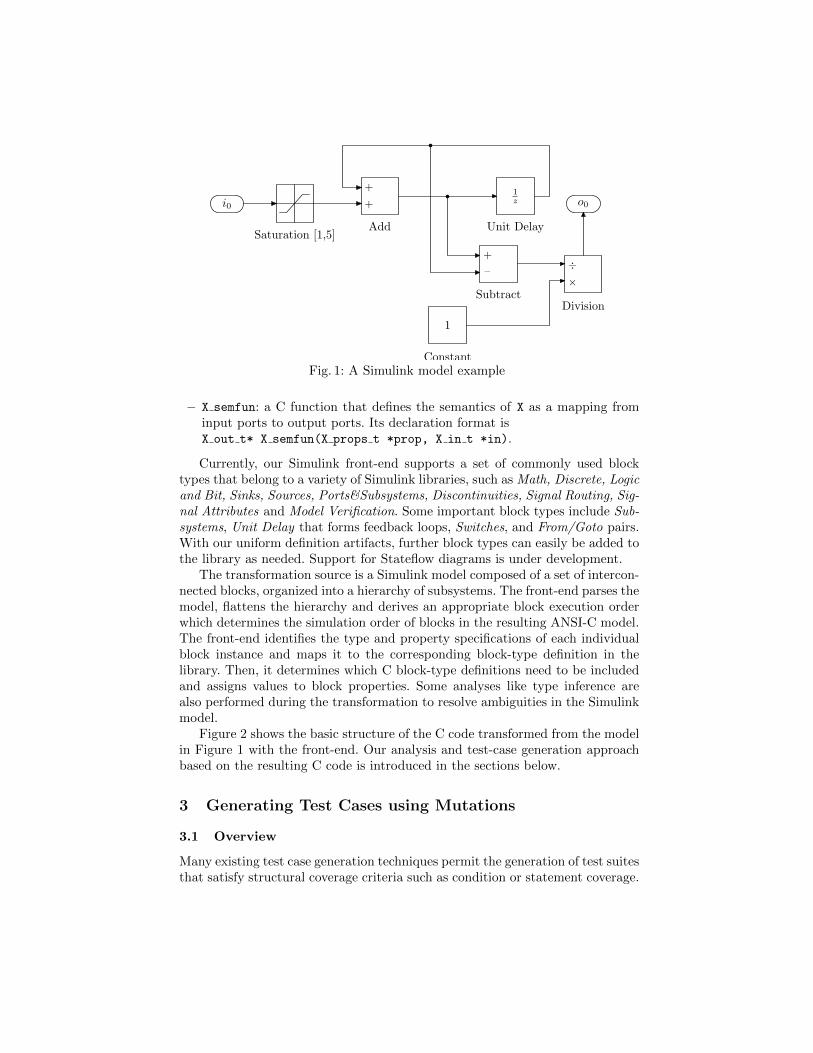
The Simulink language is a graphical modeling language comprising block dia-grams and an extensive set of block libraries. An example of a Simulink modelis presented in Figure 1. Due to the complexity of the language and the lack offormal semantics, Simulink models are not directly amenable to automated anal-ysis. We present a front-end to transform these models into intermediate ANSI-C programs with well-defined semantics. This transformation is performed fullyautomatically and allows us to separate the ambiguity issues in the Simulinksemantics from our test case generation process.
Each Simulink block is associated with a type. We define the meaning ofblocks of a particular type by means of C code, which is organized in a library.This library can be independently refined or modified (e.g., to add a new block-type definition) without the need to change the transformation process.
A block-type X is defined with the following artifacts:
– X in t: a C struct that defines the input ports of X.
– X out t: a C struct that defines the output ports of X.
– X props t: a C struct that specifies the verification-relevant properties of X.
i01z
1
o0+
+
Add
×÷
Division
Constant
Unit Delay
–
+
Subtract
Saturation [1,5]
Fig. 1: A Simulink model example
– X semfun: a C function that defines the semantics of X as a mapping frominput ports to output ports. Its declaration format isX out t* X semfun(X props t *prop, X in t *in).
Currently, our Simulink front-end supports a set of commonly used blocktypes that belong to a variety of Simulink libraries, such as Math, Discrete, Logicand Bit, Sinks, Sources, Ports&Subsystems, Discontinuities, Signal Routing, Sig-nal Attributes and Model Verification. Some important block types include Sub-systems, Unit Delay that forms feedback loops, Switches, and From/Goto pairs.With our uniform definition artifacts, further block types can easily be added tothe library as needed. Support for Stateflow diagrams is under development.
The transformation source is a Simulink model composed of a set of intercon-nected blocks, organized into a hierarchy of subsystems. The front-end parses themodel, flattens the hierarchy and derives an appropriate block execution orderwhich determines the simulation order of blocks in the resulting ANSI-C model.The front-end identifies the type and property specifications of each individualblock instance and maps it to the corresponding block-type definition in thelibrary. Then, it determines which C block-type definitions need to be includedand assigns values to block properties. Some analyses like type inference arealso performed during the transformation to resolve ambiguities in the Simulinkmodel.
Figure 2 shows the basic structure of the C code transformed from the modelin Figure 1 with the front-end. Our analysis and test-case generation approachbased on the resulting C code is introduced in the sections below.
3 Generating Test Cases using Mutations
3.1 Overview
Many existing test case generation techniques permit the generation of test suitesthat satisfy structural coverage criteria such as condition or statement coverage.
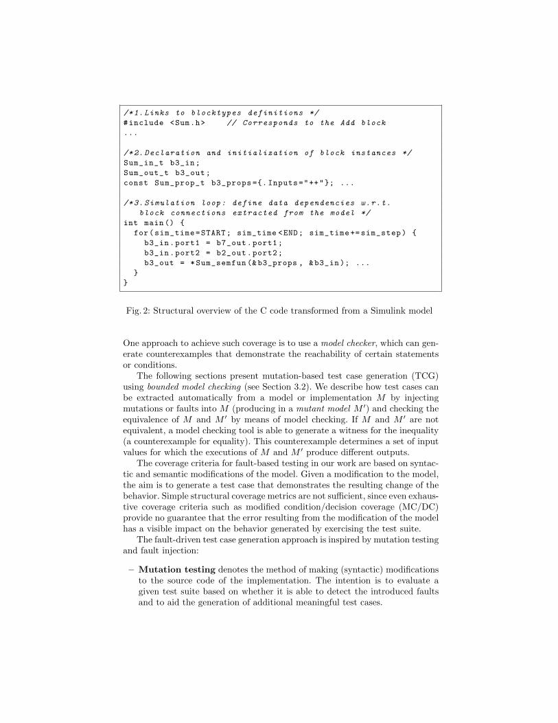
/*1. Links to blocktypes definitions */
#include <Sum.h> // Corresponds to the Add block
...
/*2. Declaration and initialization of block instances */
Sum_in_t b3_in;
Sum_out_t b3_out;
const Sum_prop_t b3_props ={. Inputs="++"}; ...
/*3. Simulation loop: define data dependencies w.r.t.
block connections extracted from the model */
int main() {
for(sim_time=START; sim_time <END; sim_time += sim_step) {
b3_in.port1 = b7_out.port1;
b3_in.port2 = b2_out.port2;
b3_out = *Sum_semfun (&b3_props , &b3_in ); ...
}
}
Fig. 2: Structural overview of the C code transformed from a Simulink model
One approach to achieve such coverage is to use a model checker, which can gen-erate counterexamples that demonstrate the reachability of certain statementsor conditions.
The following sections present mutation-based test case generation (TCG)using bounded model checking (see Section 3.2). We describe how test cases canbe extracted automatically from a model or implementation M by injectingmutations or faults into M (producing in a mutant model M ′) and checking theequivalence of M and M ′ by means of model checking. If M and M ′ are notequivalent, a model checking tool is able to generate a witness for the inequality(a counterexample for equality). This counterexample determines a set of inputvalues for which the executions of M and M ′ produce different outputs.
The coverage criteria for fault-based testing in our work are based on syntac-tic and semantic modifications of the model. Given a modification to the model,the aim is to generate a test case that demonstrates the resulting change of thebehavior. Simple structural coverage metrics are not sufficient, since even exhaus-tive coverage criteria such as modified condition/decision coverage (MC/DC)provide no guarantee that the error resulting from the modification of the modelhas a visible impact on the behavior generated by exercising the test suite.
The fault-driven test case generation approach is inspired by mutation testingand fault injection:
– Mutation testing denotes the method of making (syntactic) modificationsto the source code of the implementation. The intention is to evaluate agiven test suite based on whether it is able to detect the introduced faultsand to aid the generation of additional meaningful test cases.
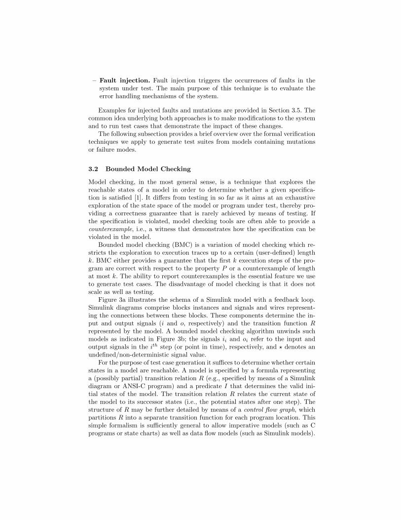
– Fault injection. Fault injection triggers the occurrences of faults in thesystem under test. The main purpose of this technique is to evaluate theerror handling mechanisms of the system.
Examples for injected faults and mutations are provided in Section 3.5. Thecommon idea underlying both approaches is to make modifications to the systemand to run test cases that demonstrate the impact of these changes.
The following subsection provides a brief overview over the formal verificationtechniques we apply to generate test suites from models containing mutationsor failure modes.
3.2 Bounded Model Checking
Model checking, in the most general sense, is a technique that explores thereachable states of a model in order to determine whether a given specifica-tion is satisfied [1]. It differs from testing in so far as it aims at an exhaustiveexploration of the state space of the model or program under test, thereby pro-viding a correctness guarantee that is rarely achieved by means of testing. Ifthe specification is violated, model checking tools are often able to provide acounterexample, i.e., a witness that demonstrates how the specification can beviolated in the model.
Bounded model checking (BMC) is a variation of model checking which re-stricts the exploration to execution traces up to a certain (user-defined) lengthk. BMC either provides a guarantee that the first k execution steps of the pro-gram are correct with respect to the property P or a counterexample of lengthat most k. The ability to report counterexamples is the essential feature we useto generate test cases. The disadvantage of model checking is that it does notscale as well as testing.
Figure 3a illustrates the schema of a Simulink model with a feedback loop.Simulink diagrams comprise blocks instances and signals and wires represent-ing the connections between these blocks. These components determine the in-put and output signals (i and o, respectively) and the transition function Rrepresented by the model. A bounded model checking algorithm unwinds suchmodels as indicated in Figure 3b; the signals ii and oi refer to the input andoutput signals in the ith step (or point in time), respectively, and ? denotes anundefined/non-deterministic signal value.
For the purpose of test case generation it suffices to determine whether certainstates in a model are reachable. A model is specified by a formula representinga (possibly partial) transition relation R (e.g., specified by means of a Simulinkdiagram or ANSI-C program) and a predicate I that determines the valid ini-tial states of the model. The transition relation R relates the current state ofthe model to its successor states (i.e., the potential states after one step). Thestructure of R may be further detailed by means of a control flow graph, whichpartitions R into a separate transition function for each program location. Thissimple formalism is sufficiently general to allow imperative models (such as Cprograms or state charts) as well as data flow models (such as Simulink models).
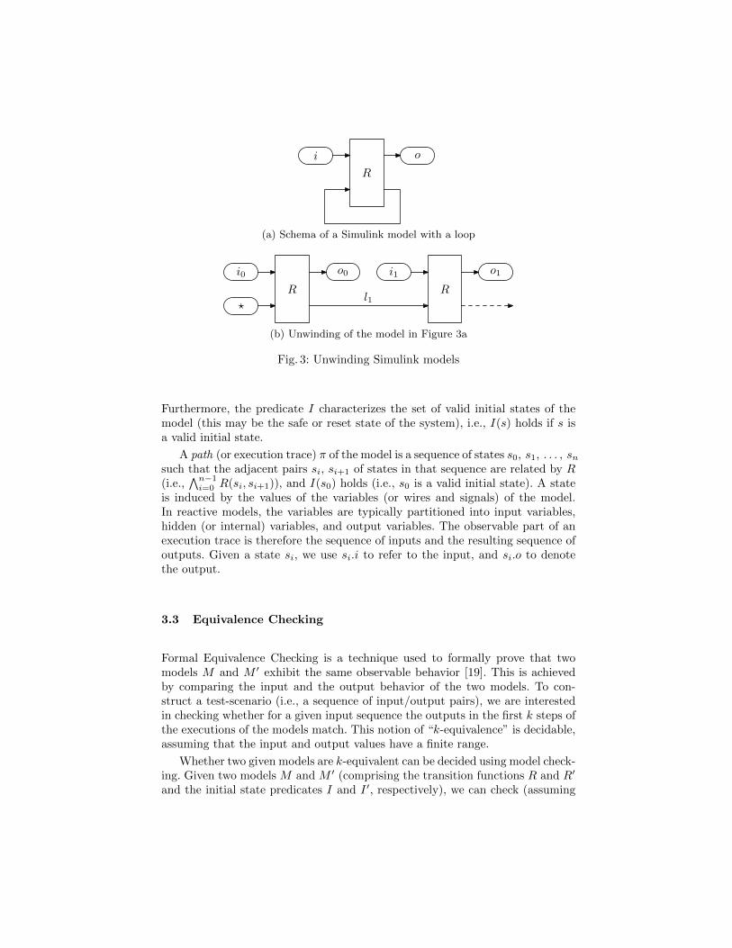
i
R
o
(a) Schema of a Simulink model with a loop
i0
R
o0 i1
R
o1
?l1
(b) Unwinding of the model in Figure 3a
Fig. 3: Unwinding Simulink models
Furthermore, the predicate I characterizes the set of valid initial states of themodel (this may be the safe or reset state of the system), i.e., I(s) holds if s isa valid initial state.
A path (or execution trace) π of the model is a sequence of states s0, s1, . . . , snsuch that the adjacent pairs si, si+1 of states in that sequence are related by R(i.e.,
∧n−1i=0 R(si, si+1)), and I(s0) holds (i.e., s0 is a valid initial state). A state
is induced by the values of the variables (or wires and signals) of the model.In reactive models, the variables are typically partitioned into input variables,hidden (or internal) variables, and output variables. The observable part of anexecution trace is therefore the sequence of inputs and the resulting sequence ofoutputs. Given a state si, we use si.i to refer to the input, and si.o to denotethe output.
3.3 Equivalence Checking
Formal Equivalence Checking is a technique used to formally prove that twomodels M and M ′ exhibit the same observable behavior [19]. This is achievedby comparing the input and the output behavior of the two models. To con-struct a test-scenario (i.e., a sequence of input/output pairs), we are interestedin checking whether for a given input sequence the outputs in the first k steps ofthe executions of the models match. This notion of “k-equivalence” is decidable,assuming that the input and output values have a finite range.
Whether two given models are k-equivalent can be decided using model check-ing. Given two models M and M ′ (comprising the transition functions R and R′
and the initial state predicates I and I ′, respectively), we can check (assuming
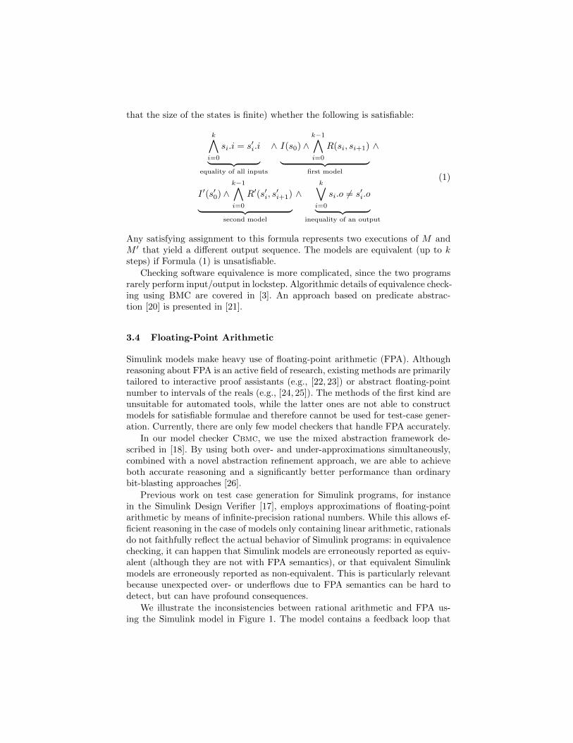
that the size of the states is finite) whether the following is satisfiable:
k∧i=0
si.i = s′i.i︸ ︷︷ ︸equality of all inputs
∧ I(s0) ∧k−1∧i=0
R(si, si+1)︸ ︷︷ ︸first model
∧
I ′(s′0) ∧k−1∧i=0
R′(s′i, s′i+1)︸ ︷︷ ︸
second model
∧k∨i=0
si.o 6= s′i.o︸ ︷︷ ︸inequality of an output
(1)
Any satisfying assignment to this formula represents two executions of M andM ′ that yield a different output sequence. The models are equivalent (up to ksteps) if Formula (1) is unsatisfiable.
Checking software equivalence is more complicated, since the two programsrarely perform input/output in lockstep. Algorithmic details of equivalence check-ing using BMC are covered in [3]. An approach based on predicate abstrac-tion [20] is presented in [21].
3.4 Floating-Point Arithmetic
Simulink models make heavy use of floating-point arithmetic (FPA). Althoughreasoning about FPA is an active field of research, existing methods are primarilytailored to interactive proof assistants (e.g., [22, 23]) or abstract floating-pointnumber to intervals of the reals (e.g., [24, 25]). The methods of the first kind areunsuitable for automated tools, while the latter ones are not able to constructmodels for satisfiable formulae and therefore cannot be used for test-case gener-ation. Currently, there are only few model checkers that handle FPA accurately.
In our model checker Cbmc, we use the mixed abstraction framework de-scribed in [18]. By using both over- and under-approximations simultaneously,combined with a novel abstraction refinement approach, we are able to achieveboth accurate reasoning and a significantly better performance than ordinarybit-blasting approaches [26].
Previous work on test case generation for Simulink programs, for instancein the Simulink Design Verifier [17], employs approximations of floating-pointarithmetic by means of infinite-precision rational numbers. While this allows ef-ficient reasoning in the case of models only containing linear arithmetic, rationalsdo not faithfully reflect the actual behavior of Simulink programs: in equivalencechecking, it can happen that Simulink models are erroneously reported as equiv-alent (although they are not with FPA semantics), or that equivalent Simulinkmodels are erroneously reported as non-equivalent. This is particularly relevantbecause unexpected over- or underflows due to FPA semantics can be hard todetect, but can have profound consequences.
We illustrate the inconsistencies between rational arithmetic and FPA us-ing the Simulink model in Figure 1. The model contains a feedback loop that
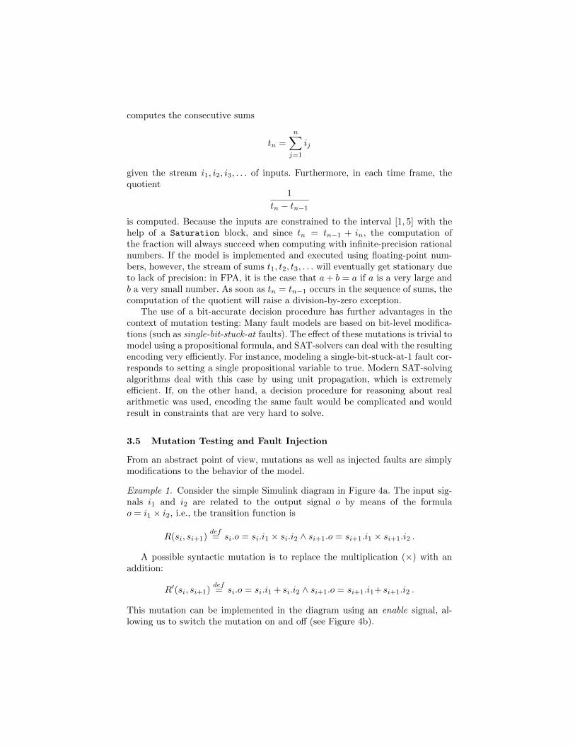
computes the consecutive sums
tn =
n∑j=1
ij
given the stream i1, i2, i3, . . . of inputs. Furthermore, in each time frame, thequotient
1
tn − tn−1
is computed. Because the inputs are constrained to the interval [1, 5] with thehelp of a Saturation block, and since tn = tn−1 + in, the computation ofthe fraction will always succeed when computing with infinite-precision rationalnumbers. If the model is implemented and executed using floating-point num-bers, however, the stream of sums t1, t2, t3, . . . will eventually get stationary dueto lack of precision: in FPA, it is the case that a+ b = a if a is a very large andb a very small number. As soon as tn = tn−1 occurs in the sequence of sums, thecomputation of the quotient will raise a division-by-zero exception.
The use of a bit-accurate decision procedure has further advantages in thecontext of mutation testing: Many fault models are based on bit-level modifica-tions (such as single-bit-stuck-at faults). The effect of these mutations is trivial tomodel using a propositional formula, and SAT-solvers can deal with the resultingencoding very efficiently. For instance, modeling a single-bit-stuck-at-1 fault cor-responds to setting a single propositional variable to true. Modern SAT-solvingalgorithms deal with this case by using unit propagation, which is extremelyefficient. If, on the other hand, a decision procedure for reasoning about realarithmetic was used, encoding the same fault would be complicated and wouldresult in constraints that are very hard to solve.
3.5 Mutation Testing and Fault Injection
From an abstract point of view, mutations as well as injected faults are simplymodifications to the behavior of the model.
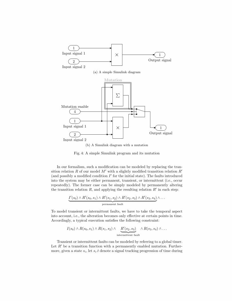
Example 1. Consider the simple Simulink diagram in Figure 4a. The input sig-nals i1 and i2 are related to the output signal o by means of the formulao = i1 × i2, i.e., the transition function is
R(si, si+1)def= si.o = si.i1 × si.i2 ∧ si+1.o = si+1.i1 × si+1.i2 .
A possible syntactic mutation is to replace the multiplication (×) with anaddition:
R′(si, si+1)def= si.o = si.i1 + si.i2 ∧ si+1.o = si+1.i1+ si+1.i2 .
This mutation can be implemented in the diagram using an enable signal, al-lowing us to switch the mutation on and off (see Figure 4b).
1
2
× 1Input signal 1
Input signal 2
Output signal
(a) A simple Simulink diagram
Mutation
1
2
× 1
∑
4
Input signal 1
Input signal 2
Output signal
Mutation enable
(b) A Simulink diagram with a mutation
Fig. 4: A simple Simulink program and its mutation
In our formalism, such a modification can be modeled by replacing the tran-sition relation R of our model M ′ with a slightly modified transition relation R′
(and possibly a modified condition I ′ for the initial state). The faults introducedinto the system may be either permanent, transient, or intermittent (i.e., occurrepeatedly). The former case can be simply modeled by permanently alteringthe transition relation R, and applying the resulting relation R′ in each step:
I ′(s0) ∧R′(s0, s1) ∧R′(s1, s2) ∧R′(s2, s3) ∧R′(s3, s4)︸ ︷︷ ︸permanent fault
∧ . . .
To model transient or intermittent faults, we have to take the temporal aspectinto account, i.e., the alteration becomes only effective at certain points in time.Accordingly, a typical execution satisfies the following constraint:
I(s0) ∧R(s0, s1) ∧R(s1, s2) ∧ R′(s2, s3)︸ ︷︷ ︸intermittent fault
∧R(s3, s4) ∧ . . .
Transient or intermittent faults can be modeled by referring to a global timer.Let R′ be a transition function with a permanently enabled mutation. Further-more, given a state si, let si.t denote a signal tracking progression of time during
the execution. A transition function R′′ with an intermittent fault occurring ev-ery c execution steps can be modeled as
R′′(si, si+1)def=
{R′(si, si+1) if (si.t = 0 mod c)R(si, si+1) if (si.t 6= 0 mod c)
.
Mutations are small syntactic changes of the model, whereas simulated hard-ware faults require semantic changes to the model that reflect physical faults ofthe system as accurately as possible. Conceptually, however, there is no differencewhen it comes to their integration into the transition relation: The implementa-tion of faults in the model M requires syntactic changes to M .
Depending on the extent of these modifications, the resulting error may notbe immediately observable, i.e., it is not necessarily the case that
s0.i = s′0.i ∧R(s0, s1) ∧R′(s′0, s′1) =⇒ s1.o 6= s′1.o
holds. Even though s1 differs from s′1, the outputs s1.o and s′1.o may be indis-tinguishable: the modification of R may not necessarily have an (immediate)impact on the observable behavior. Intuitively, a test case is “good” if it yieldsa different outcome for M and M ′. In mutation testing, the term weak mutationtesting refers to the condition that the test cases should cause different programstates for the mutant and the original model. In the case that the affected partof the state is not observable, this condition is not sufficient for our purpose.Strong mutation testing refers to the case where the error propagates to theoutput of the model and is caught by an appropriate test case. In dependablesystems, this notion may be too strong, since redundant systems may tolerate acertain number of faults. Note that this case can be detected using a completemodel checking technique or k-induction. A brief outline of these techniques isprovided in Section 5.1.
3.6 Generating Test Cases
One way of generating test cases that detect a mutation is to find a satisfyingassignment to Formula (1). Such a satisfying assignment provides the inputsthat yield a different output sequence during the first k steps and, provided theobservable behaviors of the two models M and M ′ are not fully equivalent, sucha solution must exist for some k.
Encoding Combinations of Faults Assume that the objective is to gener-ate a test suite that detects single faults (or mutations). The naıve approachto create such a test suite is to generate a new model M ′ for each conceivablefault or mutation and to generate an instance of Formula (1) for each pair ofmodels M and M ′. In practice, this approach is very wasteful, since modernsatisfiability checkers such as MiniSAT [27] are able to solve problem instancesincrementally. Encoding M ′ in a way such that faults or mutations can be acti-vated or deactivated by adding constraints to the formula allows the SAT solverto (partially) reuse the information it has already derived.
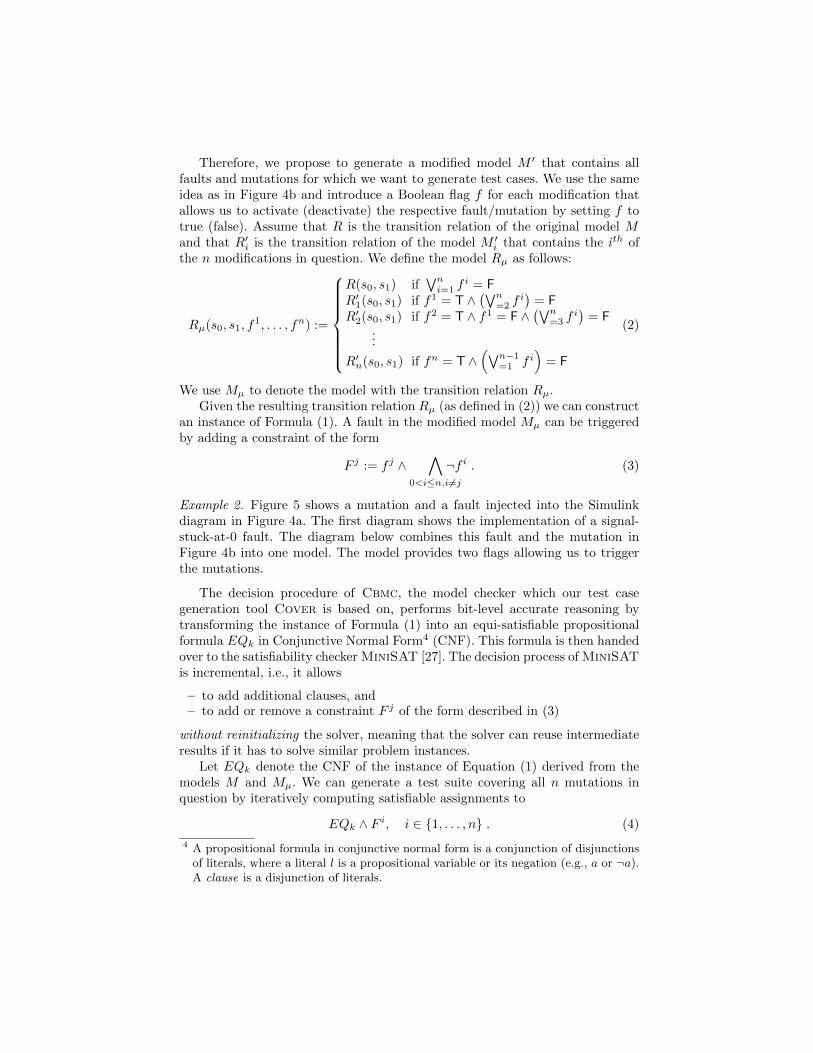
Therefore, we propose to generate a modified model M ′ that contains allfaults and mutations for which we want to generate test cases. We use the sameidea as in Figure 4b and introduce a Boolean flag f for each modification thatallows us to activate (deactivate) the respective fault/mutation by setting f totrue (false). Assume that R is the transition relation of the original model Mand that R′i is the transition relation of the model M ′i that contains the ith ofthe n modifications in question. We define the model Rµ as follows:
Rµ(s0, s1, f1, . . . , fn) :=
R(s0, s1) if∨ni=1 f
i = FR′1(s0, s1) if f1 = T ∧
(∨n=2 f
i)
= FR′2(s0, s1) if f2 = T ∧ f1 = F ∧
(∨n=3 f
i)
= F...
R′n(s0, s1) if fn = T ∧(∨n−1
=1 f i)
= F
(2)
We use Mµ to denote the model with the transition relation Rµ.Given the resulting transition relation Rµ (as defined in (2)) we can construct
an instance of Formula (1). A fault in the modified model Mµ can be triggeredby adding a constraint of the form
F j := f j ∧∧
0<i≤n,i6=j
¬f i . (3)
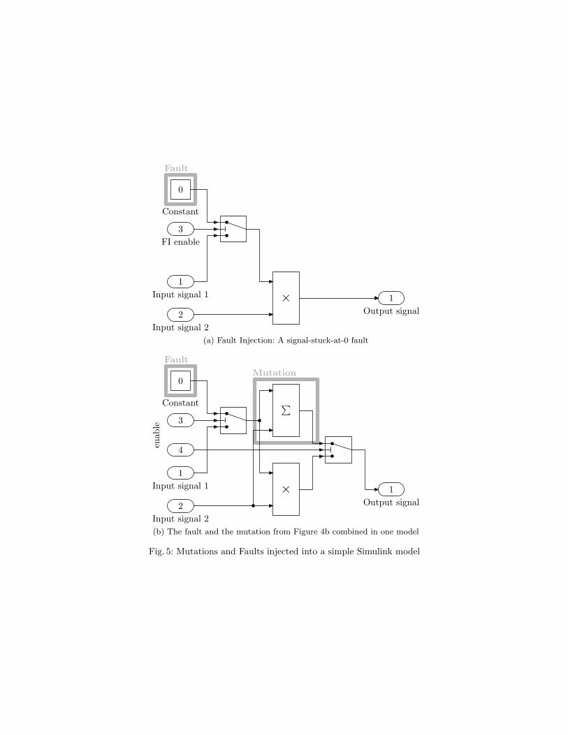
Example 2. Figure 5 shows a mutation and a fault injected into the Simulinkdiagram in Figure 4a. The first diagram shows the implementation of a signal-stuck-at-0 fault. The diagram below combines this fault and the mutation inFigure 4b into one model. The model provides two flags allowing us to triggerthe mutations.
The decision procedure of Cbmc, the model checker which our test casegeneration tool Cover is based on, performs bit-level accurate reasoning bytransforming the instance of Formula (1) into an equi-satisfiable propositionalformula EQk in Conjunctive Normal Form4 (CNF). This formula is then handedover to the satisfiability checker MiniSAT [27]. The decision process of MiniSATis incremental, i.e., it allows
– to add additional clauses, and– to add or remove a constraint F j of the form described in (3)
without reinitializing the solver, meaning that the solver can reuse intermediateresults if it has to solve similar problem instances.
Let EQk denote the CNF of the instance of Equation (1) derived from themodels M and Mµ. We can generate a test suite covering all n mutations inquestion by iteratively computing satisfiable assignments to
EQk ∧ F i, i ∈ {1, . . . , n} . (4)
4 A propositional formula in conjunctive normal form is a conjunction of disjunctionsof literals, where a literal l is a propositional variable or its negation (e.g., a or ¬a).A clause is a disjunction of literals.
1
2
× 1
3
0
Fault
Input signal 1
Input signal 2
Output signal
FI enable
Constant
(a) Fault Injection: A signal-stuck-at-0 fault
Mutation
1
2
× 1
∑3
4
0
Fault
Input signal 1
Input signal 2
Output signal
enab
le
Constant
(b) The fault and the mutation from Figure 4b combined in one model
Fig. 5: Mutations and Faults injected into a simple Simulink model
We say that a test case t independently covers a mutation if it correspondsto a satisfying assignment of (4) for that mutation i. If each of the instancesof Formula (4) has a solution, we obtain n (not necessarily different) test casesthat cover all mutations injected into the model Mµ.
4 Generating Test-Cases for Many Mutations
In this section, we propose an optimisation of the mutation-based test-case gen-eration approach discussed in Section 3.
4.1 Finding an Efficient and Sufficient Test-Suite
The technique described in Section 3.6 uses a SAT-solver to extract n test casesfrom Formula (4), each of which corresponds to one mutation. If the number ofmutations (n) is large, this may lead to an equally large number of test cases.These test-cases are computationally expensive to generate and time-consumingto execute. Therefore, it is desirable to minimize the size of the test-suite.
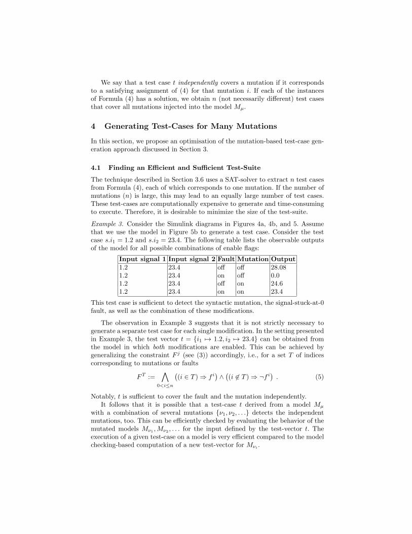
Example 3. Consider the Simulink diagrams in Figures 4a, 4b, and 5. Assumethat we use the model in Figure 5b to generate a test case. Consider the testcase s.i1 = 1.2 and s.i2 = 23.4. The following table lists the observable outputsof the model for all possible combinations of enable flags:
Input signal 1 Input signal 2 Fault Mutation Output1.2 23.4 off off 28.081.2 23.4 on off 0.01.2 23.4 off on 24.61.2 23.4 on on 23.4
This test case is sufficient to detect the syntactic mutation, the signal-stuck-at-0fault, as well as the combination of these modifications.
The observation in Example 3 suggests that it is not strictly necessary togenerate a separate test case for each single modification. In the setting presentedin Example 3, the test vector t = {i1 7→ 1.2, i2 7→ 23.4} can be obtained fromthe model in which both modifications are enabled. This can be achieved bygeneralizing the constraint F j (see (3)) accordingly, i.e., for a set T of indicescorresponding to mutations or faults
FT :=∧
0<i≤n
((i ∈ T )⇒ f i
)∧((i 6∈ T )⇒ ¬f i
). (5)
Notably, t is sufficient to cover the fault and the mutation independently.It follows that it is possible that a test-case t derived from a model Mµ
with a combination of several mutations {ν1, ν2, . . .} detects the independentmutations, too. This can be efficiently checked by evaluating the behavior of themutated models Mν1 ,Mν2 , . . . for the input defined by the test-vector t. Theexecution of a given test-case on a model is very efficient compared to the modelchecking-based computation of a new test-vector for Mνi .
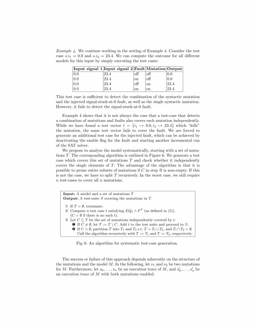
Example 4. We continue working in the setting of Example 4. Consider the testcase s.i1 = 0.0 and s.i2 = 23.4. We can compute the outcome for all differentmodels for this input by simply executing the test cases:
Input signal 1 Input signal 2 Fault Mutation Output0.0 23.4 off off 0.00.0 23.4 on off 0.00.0 23.4 off on 23.40.0 23.4 on on 23.4
This test case is sufficient to detect the combination of the syntactic mutationand the injected signal-stuck-at-0 fault, as well as the single syntactic mutation.However, it fails to detect the signal-stuck-at-0 fault.
Example 4 shows that it is not always the case that a test-case that detectsa combination of mutations and faults also covers each mutation independently.While we have found a test vector t = {i1 7→ 0.0, i2 7→ 23.4} which “kills”the mutation, the same test vector fails to cover the fault. We are forced togenerate an additional test case for the injected fault, which can be achieved bydeactivating the enable flag for the fault and starting another incremental runof the SAT solver.
We propose to analyze the model systematically, starting with a set of muta-tions T . The corresponding algorithm is outlined in Figure 6. We generate a testcase which covers this set of mutations T and check whether it independentlycovers the single elements of T . The advantage of the algorithm is that it ispossible to prune entire subsets of mutations if C in step  is non-empty. If thisis not the case, we have to split T recursively. In the worst case, we still requiren test-cases to cover all n mutations.
Input: A model and a set of mutations TOutput: A test-suite S covering the mutations in T .
À If T = ∅, terminate.Á Compute a test case t satisfying EQk ∧ FT (as defined in (5)).
(C = ∅ if there is no such t). Let C ⊆ T be the set of mutations independently covered by t:
Ê If C 6= ∅, let T := T \ C. Add t to the test suite and proceed to À.Ë If C = ∅, partition T into T1 and T2 s.t. T = T1∪T2, and T1∩T2 = ∅.
Call the algorithm recursively with T := T1 and T := T2, respectively.
Fig. 6: An algorithm for systematic test-case generation.
The success or failure of this approach depends inherently on the structure ofthe mutations and the model M . In the following, let ν1 and ν2 be two mutationsfor M . Furthermore, let s0, . . . , sn be an execution trace of M , and s′0, . . . , s
′n be
an execution trace of M with both mutations enabled.
Assume that ν1 and ν2 affect different output signals, i.e., given a fixed inputsequence s0.i, . . . sn.i, the set of signals changed by activating the mutation ν1
is disjoint from the set of signals changed by enabling the mutation ν2. Then,we can increase the chance of finding a test case that covers both mutationsindependently by trying to maximize the difference between s0.o, . . . sn.o ands′0.o, . . . s
′n.o.
Unfortunately, such an independence cannot be assumed in general, sincethere may be a mutual influence between mutations. In particular, two mutationsmay cancel each other out. Checking whether two mutations are independent inthe sense explained above is computationally as expensive as model checkingand therefore not a feasible strategy.
5 Detecting Non-Observability of Mutations
In traditional mutation-based testing, the difficulty to identify mutations withoutobservable effect on the system outputs is known to be one of the main obstacles.Assume that one instance EQk ∧ F c of (4) (with i = c) is unsatisfiable. Thisindicates that the injected fault corresponding to f c (see Formula (2)) does notresult in an error that propagates to an observable output within k steps. Thereare two possible reasons for this phenomenon:
1. The bound k is not sufficiently large to reveal the error.2. The model contains redundancy and the injected fault does not result in an
observable change of its behavior. We say that the model tolerates the fault.The mutant is an equivalent mutant.
A complete model checking algorithm can distinguish both cases. The firstcase can be addressed by simply increasing the bound k. In the second case, themutation is not strong enough to have any impact on the observable behaviorof the model and the model checking tool provides a proof for the equivalenceof the mutated and original model. This concept is explained in the followingsubsection.
5.1 Model Checking, Induction, and Invariants
BMC is only capable of providing a guarantee that a property P is not violatedwithin at most k execution steps. In this section, we briefly discuss two techniquesto lift this restriction: k-induction [28] and finding invariants by means of fixed-point detection [1].
k-Induction. This technique generalizes the standard induction principle, andhas been used before for test-vector generation for Simulink models [2]. The basecase is established by means of BMC. The following equation holds if and onlyif the property P is not violated in the first k execution steps:
I(s0) ∧k−1∧i=0
R(si, si+1) ∧k∧i=0
P (si) (6)
If the base case (6) holds, the technique proceeds to show by induction that Pholds for any arbitrary k ∈ N: k∧
i=0
R(si, si+1) ∧k∧j=0
P (sj)
⇒ P (sk+1) (7)
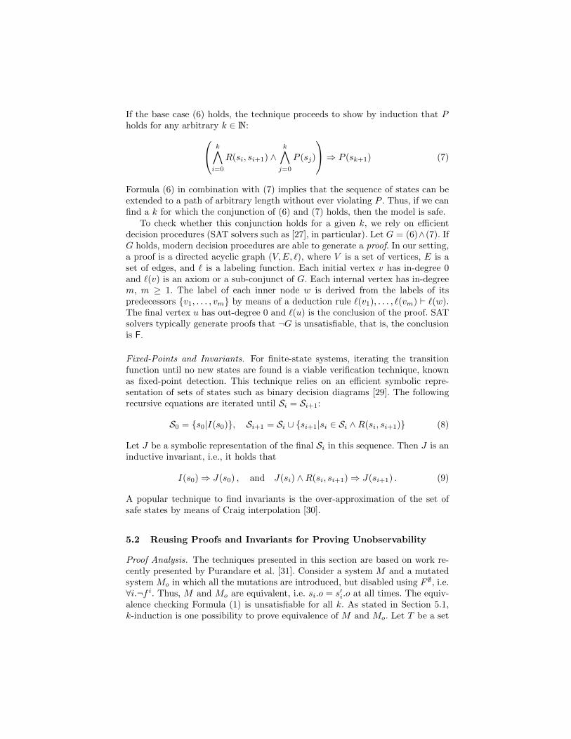
Formula (6) in combination with (7) implies that the sequence of states can beextended to a path of arbitrary length without ever violating P . Thus, if we canfind a k for which the conjunction of (6) and (7) holds, then the model is safe.
To check whether this conjunction holds for a given k, we rely on efficientdecision procedures (SAT solvers such as [27], in particular). Let G = (6)∧(7). IfG holds, modern decision procedures are able to generate a proof. In our setting,a proof is a directed acyclic graph (V,E, `), where V is a set of vertices, E is aset of edges, and ` is a labeling function. Each initial vertex v has in-degree 0and `(v) is an axiom or a sub-conjunct of G. Each internal vertex has in-degreem, m ≥ 1. The label of each inner node w is derived from the labels of itspredecessors {v1, . . . , vm} by means of a deduction rule `(v1), . . . , `(vm) ` `(w).The final vertex u has out-degree 0 and `(u) is the conclusion of the proof. SATsolvers typically generate proofs that ¬G is unsatisfiable, that is, the conclusionis F.
Fixed-Points and Invariants. For finite-state systems, iterating the transitionfunction until no new states are found is a viable verification technique, knownas fixed-point detection. This technique relies on an efficient symbolic repre-sentation of sets of states such as binary decision diagrams [29]. The followingrecursive equations are iterated until Si = Si+1:
S0 = {s0|I(s0)}, Si+1 = Si ∪ {si+1|si ∈ Si ∧R(si, si+1)} (8)
Let J be a symbolic representation of the final Si in this sequence. Then J is aninductive invariant, i.e., it holds that
I(s0)⇒ J(s0) , and J(si) ∧R(si, si+1)⇒ J(si+1) . (9)
A popular technique to find invariants is the over-approximation of the set ofsafe states by means of Craig interpolation [30].
5.2 Reusing Proofs and Invariants for Proving Unobservability
Proof Analysis. The techniques presented in this section are based on work re-cently presented by Purandare et al. [31]. Consider a system M and a mutatedsystem Mo in which all the mutations are introduced, but disabled using F ∅, i.e.∀i.¬f i. Thus, M and Mo are equivalent, i.e. si.o = s′i.o at all times. The equiv-alence checking Formula (1) is unsatisfiable for all k. As stated in Section 5.1,k-induction is one possibility to prove equivalence of M and Mo. Let T be a set
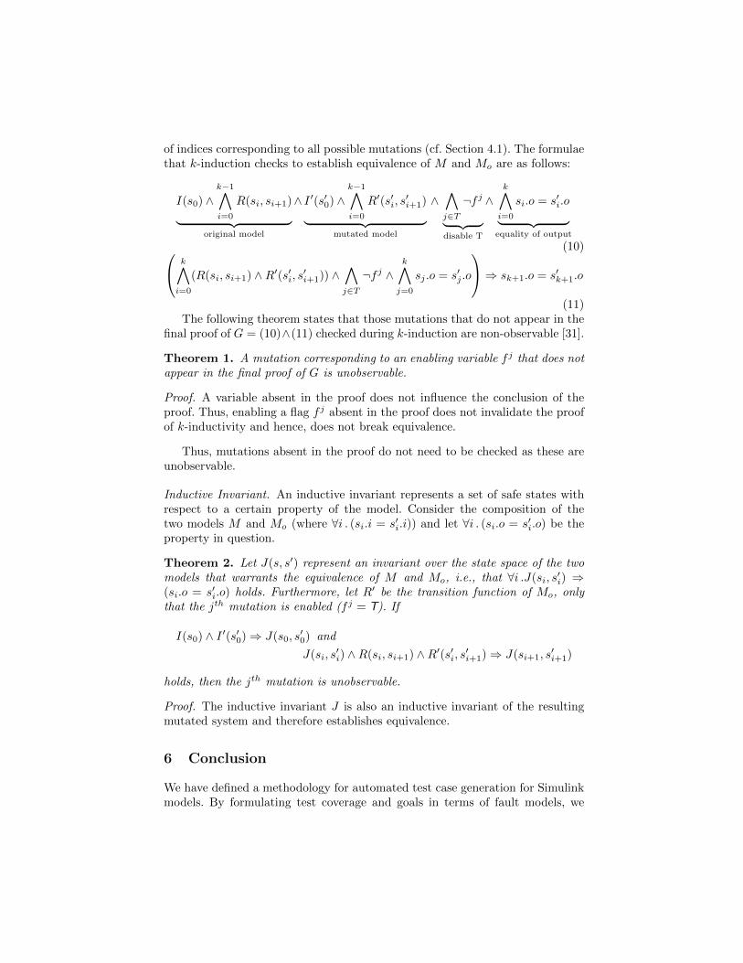
of indices corresponding to all possible mutations (cf. Section 4.1). The formulaethat k-induction checks to establish equivalence of M and Mo are as follows:
I(s0) ∧k−1∧i=0
R(si, si+1)︸ ︷︷ ︸original model
∧ I ′(s′0) ∧k−1∧i=0
R′(s′i, s′i+1)︸ ︷︷ ︸
mutated model
∧∧j∈T¬f j︸ ︷︷ ︸
disable T
∧k∧i=0
si.o = s′i.o︸ ︷︷ ︸equality of output
(10) k∧i=0
(R(si, si+1) ∧R′(s′i, s′i+1)) ∧∧j∈T¬f j ∧
k∧j=0
sj .o = s′j .o
⇒ sk+1.o = s′k+1.o
(11)The following theorem states that those mutations that do not appear in the
final proof of G = (10)∧(11) checked during k-induction are non-observable [31].
Theorem 1. A mutation corresponding to an enabling variable f j that does notappear in the final proof of G is unobservable.
Proof. A variable absent in the proof does not influence the conclusion of theproof. Thus, enabling a flag f j absent in the proof does not invalidate the proofof k-inductivity and hence, does not break equivalence.
Thus, mutations absent in the proof do not need to be checked as these areunobservable.
Inductive Invariant. An inductive invariant represents a set of safe states withrespect to a certain property of the model. Consider the composition of thetwo models M and Mo (where ∀i . (si.i = s′i.i)) and let ∀i . (si.o = s′i.o) be theproperty in question.
Theorem 2. Let J(s, s′) represent an invariant over the state space of the twomodels that warrants the equivalence of M and Mo, i.e., that ∀i .J(si, s
′i) ⇒
(si.o = s′i.o) holds. Furthermore, let R′ be the transition function of Mo, onlythat the jth mutation is enabled (f j = T). If
I(s0) ∧ I ′(s′0)⇒ J(s0, s′0) and
J(si, s′i) ∧R(si, si+1) ∧R′(s′i, s′i+1)⇒ J(si+1, s
′i+1)
holds, then the jth mutation is unobservable.
Proof. The inductive invariant J is also an inductive invariant of the resultingmutated system and therefore establishes equivalence.
6 Conclusion
We have defined a methodology for automated test case generation for Simulinkmodels. By formulating test coverage and goals in terms of fault models, we
achieve a flexible and general framework that subsumes standard coverage crite-ria and is directly related to functional and non-functional requirements specifi-cations. The use of equivalence checking and bounded model checking makes itpossible to explore the behavior of models with high precision, taking intricatedetails such as the actual floating-point semantics of execution platforms intoaccount. We implemented this approach in our test-case generation tool Cover,which is based on the model checker Cbmc. The evaluation of Cover on indus-trial case studies developed in the European projects MOGENTES and CESARis currently in progress.
In order to handle the size of real-world Simulink models, we have introducedtwo main concepts to keep the complexity of test case generation manageable:a strategy to compute small test suites by maximizing the number of mutationsthat are covered by each test case, and techniques to efficiently detect unobserv-ability of mutations. An experimental evaluation of both techniques is plannedas future work.
References
1. Clarke, E., Grumberg, O., Peled, D.: Model Checking. MIT Press (1999)2. Gadkari, A., Yeolekar, A., Suresh, J., Ramesh, S., Mohalik, S., Shashidar, K.C.:
AutoMOTGen: Automatic model oriented test generator for embedded controlsystems. In Gupta, A., Malik, S., eds.: Computer Aided Verification (CAV). Volume5123/2008 of LNCS., Springer (2008) 204–208
3. Kroening, D., Clarke, E.M., Yorav, K.: Behavioral consistency of C and Verilog pro-grams using bounded model checking. In: Design Automation Conference (DAC),ACM (2003) 368–371
4. Holzer, A., Schallhart, C., Tautschnig, M., Veith, H.: FShell: Systematic test casegeneration for dynamic analysis and measurement. In: Computer Aided Verifica-tion (CAV). Volume 5123 of LNCS., Springer (2008) 209–213
5. Angeletti, D., Giunchiglia, E., Narizzano, M., Puddu, A., Sabina, S.: Automatictest generation for coverage analysis using CBMC. In: Computer Aided SystemsTheory (EUROCAST). Volume 5717 of LNCS., Springer (2009) 287–294
6. Holzer, A., Schallhart, C., Tautschnig, M., Veith, H.: Query-driven program test-ing. In: Verification, Model Checking and Abstract Interpretation (VMCAI). Vol-ume 5403 of LNCS., Springer (2009) 151–166
7. Ball, T.: A theory of predicate-complete test coverage and generation. In: FormalMethods for Components and Objects (FMCO). Volume 3657 of LNCS., Springer(2005) 1–22
8. Beyer, D., Chlipala, A.J., Henzinger, T.A., Jhala, R., Majumdar, R.: Generatingtests from counterexamples. In: International Conference on Software Engineering(ICSE). (2004) 326–335
9. Jia, Y., Harman, M.: An analysis and survey of the development of mutationtesting. IEEE Transactions on Software Engineering (TSE) (2010)
10. Kupferman, O., Li, W., Seshia, S.A.: A theory of mutations with applications tovacuity, coverage, and fault tolerance. In: Formal Methods in Computer-AidedDesign (FMCAD), IEEE (2008) 1–9
11. Ruthruff, J.R., Burnett, M.M., Rothermel, G.: Interactive fault localization tech-niques in a spreadsheet environment. IEEE Transactions on Software Engineering(TSE) 32 (2006) 213–239
12. Schuler, D., Dallmeier, V., Zeller, A.: Efficient mutation testing by checking in-variant violations. In: International Symposium on Software Testing and Analysis(ISSTA), ACM (2009) 69–80
13. Meenakshi, B., Bhatnagar, A., Roy, S.: Tool for translating simulink models intoinput language of a model checker. In: Formal Engineering (ICFEM). Volume 4260of LNCS., Springer (2006) 606–620
14. Fehnker, A., Krogh, B.H.: Hybrid system verification is not a sinecure: The elec-tronic throttle control case study. In: Automated Technology for Verification andAnalysis (ATVA). Volume 3299 of LNCS., Springer (2004) 263–277
15. Joshi, A., Heimdahl, M.P.E.: Model-based safety analysis of Simulink models us-ing SCADE design verifier. In: Computer Safety, Reliability, and Security (SAFE-COMP). Volume 3688 of LNCS., Springer (2005) 122–135
16. Ryabtsev, M., Strichman, O.: Translation validation: From simulink to c. In:Computer Aided Verification (CAV). Volume 5643 of LNCS., Springer (2009) 696–701
17. The Mathworks: Simulink design verifier user’s guide. http://www.mathworks.
com/access/helpdesk/help/toolbox/sldv/ (2009) version 1.5.18. Brillout, A., Kroening, D., Wahl, T.: Mixed abstractions for floating-point arith-
metic. In: Formal Methods in Computer-Aided Design (FMCAD), IEEE (2009)69–76
19. Kuehlmann, A., van Eijk, C.A.J.: Combinational and sequential equivalence check-ing. In: Logic Synthesis and Verification. Kluwer International Series in Engineeringand Computer Science Series. Kluwer, Norwell, MA, USA (2002) 343–372
20. Graf, S., Saıdi, H.: Construction of abstract state graphs with PVS. In: ComputerAided Verification (CAV). Volume 1254 of LNCS. Springer (1997) 72–83
21. Kroening, D., Clarke, E.: Checking consistency of C and Verilog using predicateabstraction and induction. In: IEEE/ACM International conference on Computer-aided design, IEEE (2004) 66–72
22. Victor A., C.: Interpretation of IEEE-854 floating-point standard and definitionin the HOL system. Technical report, NASA Langley (1995)
23. Harrison, J.: Formal verification of square root algorithms. Formal Methods inSystem Design (FMSD) 22 (2003) 143–153
24. Blanchet, B., Cousot, P., Cousot, R., Feret, J., Mauborgne, L., Mine, A., Monniaux,D., Rival, X.: A static analyzer for large safety-critical software. In: ProgrammingLanguage Design and Implementation (PLDI), ACM (2003) 196–207
25. Min, A.: Relational abstract domains for the detection of floating-point run-timeerrors. In: European Symposium on Programming (ESOP). Volume 2986 of LNCS.,Springer (2004) 3–17
26. Kroening, D., Strichman, O.: Decision Procedures. Springer (2008)27. Een, N., Sorensson, N.: An extensible SAT-solver. In: Theory and Applications of
Satisfiability Testing (SAT). Volume 2919 of LNCS., Springer (2004) 502–51828. Sheeran, M., Singh, S., Stalmarck, G.: Checking safety properties using induction
and a SAT-solver. In: Formal Methods in Computer-Aided Design (FMCAD).Volume 1954 of LNCS., Springer (2000) 108–125
29. Bryant, R.E.: Graph-based algorithms for Boolean function manipulation. IEEETransactions on Computers 35 (1986) 677–691
30. McMillan, K.L.: Interpolation and SAT-based model checking. In: Computer AidedVerification (CAV). Volume 2725 of LNCS., Springer (2003) 1–13
31. Chockler, H., Kroening, D., Purandare, M.: Coverage in interpolation-based modelchecking. In: Design Automation Conference (DAC), ACM (2010)


