Embed Size (px)
Citation preview

TH2883 Series Operation Manual Version:1.0.1
1
O p e r a t i o n M a n u a l
MMMOOODDDEEELLL TTTHHH222888888333---555///---111000
IIImmmpppuuulllssseee WWWiiinnndddiiinnnggg TTTeeesssttteeerrr
TTTooonnnggghhhuuuiii EEEllleeeccctttrrrooonnniiicccsss CCCooo... ,,, LLLtttddd...
AAAddddddrrreeessssss ::: NNNOOO... 333,,, TTTiiiaaannnSSShhhaaannn RRRoooaaaddd,,, XXXiiinnnBBBeeeiii
DDDiiissstttrrriiicccttt,,, CCChhhaaannngggzzzhhhooouuu,,, JJJiiiaaannngggsssuuu,,, CCChhhiiinnnaaa
TTTEEELLL:::(((000555111999)))888555111333222222222222,,,888555111111333333444222
FFFAAAXXX:::(((000555111999)))888555111000999999777222
EEEMMMAAAIIILLL:::sssaaallleeesss@@@tttooonnnggghhhuuuiii...cccooommm...cccnnn
HHHttttttppp::://////wwwwwwwww...tttooonnnggghhhuuuiii...cccooommm...cccnnn

TH2883 Series Operation Manual Version:1.0.1
2
Contents Chapter 1 Overview ........................................................................................................................ 1-1
1.1 Production introduction .................................................................................................... 1-2
1.2 Operation environment ..................................................................................................... 1-3
1.2.1 Power supply .......................................................................................................... 1-3
1.2.2 Environment temperature and humidity ................................................................ 1-3
1.2.3 Warm-up ................................................................................................................ 1-3
1.3 Dimensions and weight .................................................................................................... 1-3
Chapter 2 General specifications .................................................................................................... 2-1
2.1 Specifications ................................................................................................................... 2-1
2.2 Comparison methods ........................................................................................................ 2-2
2.2.1 Area size comparison ............................................................................................. 2-2
2.2.2 Differential area comparison .................................................................................. 2-2
2.2.3 Corona discharge comparison ................................................................................ 2-3
2.2.4 Differential phase comparison ............................................................................... 2-4
Chapter 3 Panels and display .......................................................................................................... 3-1
3.1 Front panel ....................................................................................................................... 3-1
3.2 Rear panel ......................................................................................................................... 3-3
3.3 Introduction to display area .............................................................................................. 3-4
Chapter 4 Introduction to [DISP] .................................................................................................... 4-1
4.1 Measurement display page ............................................................................................... 4-1
4.2 Introduction to symbols in measurement display page .................................................... 4-1
4.3 Introduction to soft keys in measurement display page ................................................... 4-2
4.3.1 Standard sampling .................................................................................................. 4-2
4.3.2 Compare ................................................................................................................. 4-3
4.3.3 Measure .................................................................................................................. 4-4
4.3.4 Utility ..................................................................................................................... 4-5
4.3.5 Statistics ................................................................................................................. 4-6
4.3.6 Modify ................................................................................................................... 4-6
Chapter 5 Introduction to [SETUP] ................................................................................................ 5-1
5.1 Introduction to icons of soft keys ..................................................................................... 5-1
5.2 Measurement setup page .................................................................................................. 5-1
5.2.1 Imp Volt ................................................................................................................. 5-2
5.2.2 Samp ...................................................................................................................... 5-2
5.2.3 Test Imp ................................................................................................................. 5-3
5.2.4 Erase Imp ............................................................................................................... 5-3

TH2883 Series Operation Manual Version:1.0.1
3
5.2.5 Volt ADJ ................................................................................................................. 5-3
5.2.6 Wave Disp .............................................................................................................. 5-3
5.2.7 Trig Mode .............................................................................................................. 5-4
5.2.8 Delay Time ............................................................................................................. 5-4
5.2.9 BDV Test ............................................................................................................... 5-5
5.2.10 Start Volt .............................................................................................................. 5-5
5.2.11 End Volt ................................................................................................................ 5-5
5.2.12 Volt Step ............................................................................................................... 5-6
5.2.13 Comparator .......................................................................................................... 5-6
5.2.14 Position (AREA SIZE, DIFF ZONE, PHASE DIFF) .......................................... 5-6
5.2.15 Position(PHASE DIFF) .................................................................................. 5-6
5.2.16 DIFF(Limit)(AREA SIZE, DIFF ZONE, PHASE DIFF) ............................ 5-7
5.2.17 DIFF(Limit)(CORONA) ............................................................................. 5-7
5.3 Int. File ............................................................................................................................. 5-7
5.4 Ext. File ............................................................................................................................ 5-9
Chapter 6 Introduction to [SYSTEM]............................................................................................. 6-1
6.1 System .............................................................................................................................. 6-1
6.1.1 Brightness .............................................................................................................. 6-2
6.1.2 Pass/Fail ................................................................................................................. 6-2
6.1.3 Pass Alarm ............................................................................................................. 6-2
6.1.4 Fail Alarm .............................................................................................................. 6-2
6.1.5 Key Sound .............................................................................................................. 6-2
6.1.6 Hard Copy .............................................................................................................. 6-3
6.1.7 Password ................................................................................................................ 6-3
6.1.8 Language ................................................................................................................ 6-3
6.1.9 Theme .................................................................................................................... 6-3
6.1.10 Date ...................................................................................................................... 6-4
6.1.11 Time ..................................................................................................................... 6-4
6.2 Interface ............................................................................................................................ 6-4
6.2.1 I/O .......................................................................................................................... 6-5
6.2.2 TH2883 RS232C interface ..................................................................................... 6-5
6.2.3 USB interface ......................................................................................................... 6-7
6.2.4 LAN interface ........................................................................................................ 6-9
6.3 About .............................................................................................................................. 6-11
Chapter 7 User guide ...................................................................................................................... 7-1
7.1 Use of keys ....................................................................................................................... 7-1
7.1.1 Use of the roller ..................................................................................................... 7-1
7.1.2 Switch the display page ......................................................................................... 7-1
7.1.3 Numeric arrow key ................................................................................................ 7-1

TH2883 Series Operation Manual Version:1.0.1
4
7.2 Basic measurement ........................................................................................................... 7-2
7.2.1 Non-standard test ................................................................................................... 7-2
7.2.2 Sample test for standard wave ............................................................................... 7-2
7.3 BDV test ........................................................................................................................... 7-2
7.4 Technology application .................................................................................................... 7-3
7.4.1 Test objects ............................................................................................................. 7-3
7.4.2 Select comparison method ..................................................................................... 7-3
7.4.3 Settings of comparison method .............................................................................. 7-4
7.4.4 Select standards ...................................................................................................... 7-4
7.4.5 Chart for differential area ....................................................................................... 7-4
Chapter 8 Command reference ....................................................................................................... 8-1
8.1 Command structure .......................................................................................................... 8-1
8.2 Notation conventions and definitions ............................................................................... 8-3
8.3 Command reference ......................................................................................................... 8-3
8.3.1 DISPlay subsystem commands .............................................................................. 8-4
8.3.2 IVOLTage subsystem commands ........................................................................... 8-6
8.3.3 SRATE subsystem commands ............................................................................... 8-9
8.3.4 COMParator subsystem commands ..................................................................... 8-10
8.3.5 TRIGger subsystem commands ........................................................................... 8-15
8.3.6 STATistic subsystem commands .......................................................................... 8-16
8.3.7 WADJust subsystem commands .......................................................................... 8-17
8.3.8 SWAVE subsystem commands ............................................................................ 8-18
8.3.9 FETCh? subsystem commands ............................................................................ 8-20
8.3.10 MEASure subsystem commands ....................................................................... 8-22
8.3.11 ABORt subsystem command ............................................................................. 8-23
8.3.12 Mass MEMory subsystem commands ............................................................... 8-23
8.3.13 Common commands .......................................................................................... 8-24
8.4 Error and warning message ............................................................................................ 8-25
8.5 Waveform data format .................................................................................................... 8-26
Chapter 9 Handler interface ............................................................................................................ 9-3
9.1 Basic information ............................................................................................................. 9-3
9.2 Electrical characteristics ................................................................................................... 9-4
9.2.1 DC isolated output ................................................................................................. 9-4
9.2.2 Isolated input .......................................................................................................... 9-5
9.3 Jumper setup on HANDLER interface ............................................................................. 9-6
Chapter 10 Package contents and warranty .................................................................................. 10-1
10.1 Package contents .......................................................................................................... 10-1

TH2883 Series Operation Manual Version:1.0.1
5
10.2 Warranty ....................................................................................................................... 10-1
TH2883 Series Operation Manual Version:1.0.1
1-1
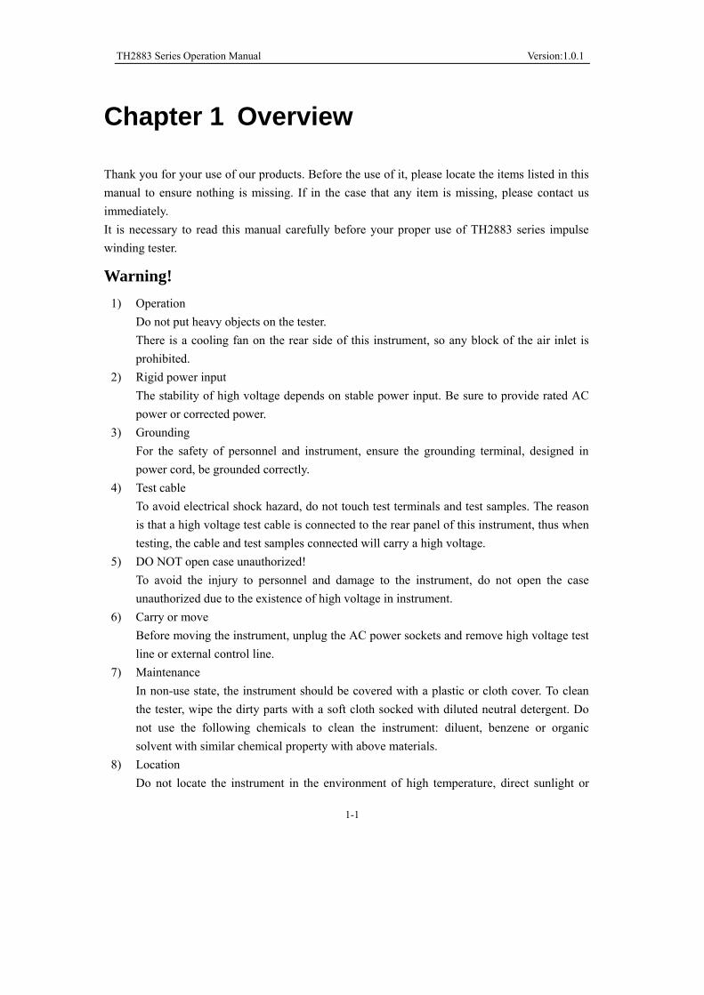
Chapter 1 Overview
Thank you for your use of our products. Before the use of it, please locate the items listed in this
manual to ensure nothing is missing. If in the case that any item is missing, please contact us
immediately.
It is necessary to read this manual carefully before your proper use of TH2883 series impulse
winding tester.
Warning!
1) Operation
Do not put heavy objects on the tester.
There is a cooling fan on the rear side of this instrument, so any block of the air inlet is
prohibited.
2) Rigid power input
The stability of high voltage depends on stable power input. Be sure to provide rated AC
power or corrected power.
3) Grounding
For the safety of personnel and instrument, ensure the grounding terminal, designed in
power cord, be grounded correctly.
4) Test cable
To avoid electrical shock hazard, do not touch test terminals and test samples. The reason
is that a high voltage test cable is connected to the rear panel of this instrument, thus when
testing, the cable and test samples connected will carry a high voltage.
5) DO NOT open case unauthorized!
To avoid the injury to personnel and damage to the instrument, do not open the case
unauthorized due to the existence of high voltage in instrument.
6) Carry or move
Before moving the instrument, unplug the AC power sockets and remove high voltage test
line or external control line.
7) Maintenance
In non-use state, the instrument should be covered with a plastic or cloth cover. To clean
the tester, wipe the dirty parts with a soft cloth socked with diluted neutral detergent. Do
not use the following chemicals to clean the instrument: diluent, benzene or organic
solvent with similar chemical property with above materials.
8) Location
Do not locate the instrument in the environment of high temperature, direct sunlight or

TH2883 Series Operation Manual Version:1.0.1
1-2
LxVdc C1C2 Rx
SW DUT
Vo(t)
poor ventilation. In addition, the instrument will generate high voltage, so it must be used
at room temperature and in the absence of much dust.
1.1 Production introduction
Due to the influence of wire material, magnetic material, framework and manufacture technics,
winding products such as transformers, motor windings may have defects of low insulation
between winding layers, circles and leads. TH2883 series impulse winding tester, adopting
high-speed sampling techniques, is a new test instrument for insulation performance of winding
products.
TH2883 series compares the standard waveform stored in the non-volatile memory with the
current tested waveform. TH883 series provides the PASS or FAIL comparison result according
to AREA SIZE, DIFFERENTIAL AREA, CORONA DISCHARGE or DIFFERENTIAL PHASE.
With its strong functions, accurate comparison methods, easy operation and various interfaces,
TH2883 can provide a perfect test solution for most winding products.
Principles of impulse winding test
The impulse winding tester tests the electrical characteristics of coil winding without damaging the
DUT. The prerequisite condition is to test the quality of a coil at just a glance. The detection is
carried out when the same electric impulse, as used in the standard coil and here discharged by a
capacitor, is applied to the DUT. The voltage attenuation wave is generated in response to the
impulse, related to the Q-factor and inductance of the coil. In this sense, the tester can detect turn
and layer short, the differences in the number of turns and the material of the core. If high impulse
voltage is applied, the poor insulation will appear as a corona or layer discharge.
Figure 1-1 Simplified diagram for principles of impulse winding test
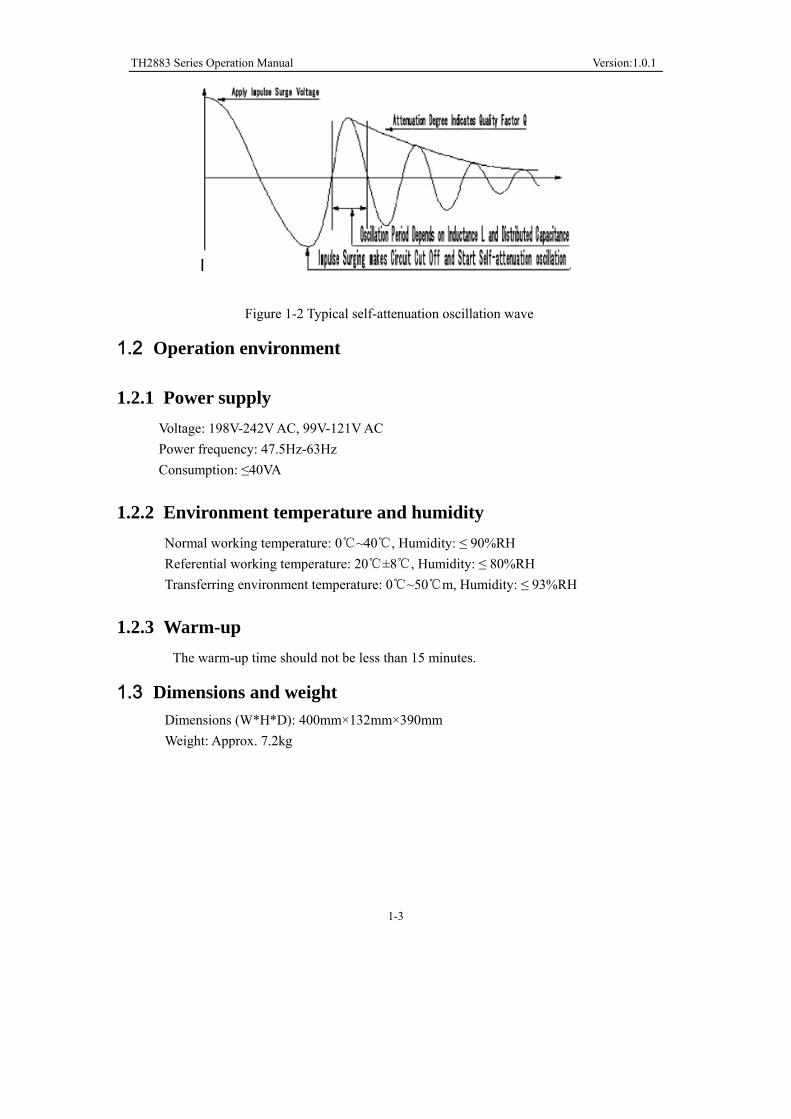
In figure 1-2, the self-oscillation attenuation wave has a close relation with the inductance L and
quality factor Q, while L and Q depend on the number of turn, manufacture technology,
properties of iron core material and whether it has air-coils. What’s more, the applied voltage is a
high impulse voltage, thus, it is easy to observe the short circuit, partial short turns and lays or
turns discharge phenomenon caused by insulation damage.
TH2883 Series Operation Manual Version:1.0.1
1-3
Figure 1-2 Typical self-attenuation oscillation wave
1.2 Operation environment
1.2.1 Power supply
Voltage: 198V-242V AC, 99V-121V AC
Power frequency: 47.5Hz-63Hz
Consumption: ≤40VA
1.2.2 Environment temperature and humidity
Normal working temperature: 0 ~40 , Humidity: ≤ 90%RH
Referential working temperature: 20 ±8 , Humidity: ≤ 80%RH
Transferring environment temperature: 0 ~50 m, Humidity: ≤ 93%RH
1.2.3 Warm-up
The warm-up time should not be less than 15 minutes.
1.3 Dimensions and weight
Dimensions (W*H*D): 400mm×132mm×390mm
Weight: Approx. 7.2kg

TH2883 Series Operation Manual Chapter 2 General specifications
2-1
Chapter 2 General specifications
2.1 Specifications
Specifications TH2883-5 TH2883-10
Output for impulse voltage 100V~5000V
10V steps
5%±15V
500V~10000V
200V steps
5%±25V
Inductance test range >10μH >20μH
Impulse energy Max 250milli-Joules Max 500 milli-Joules
Contents in waveform
display area on LCD
800×480 dot-matrix LCD
250×600 dot-matrix
Setup parameters, standard wave and test wave, comparison result, file
information, etc.
Sample wave Sampling rate: 200MSPS/5ns, 100MSPS/10ns, 50MSPS/20ns,
25MSPS/40ns, 12.5MSPS/80ns, 6.25MSPS/160ns, 3.12MSPS/320ns,
1.56MSPS/640ns
Resolution: 8bits
Sampling point: 6000bytes
Standard wave sample Sequential cycle, single cycle, one sample (up to 32 times of sample
averaging)
Input impedance 5MΩ
Test speed 6 times/sec
Averaging rate
Number of test impulse 1 to 32 averaging rate
programmable
Number of demagnetizing impulse 0 to 16 averaging rate
programmable
Measurement function Voltage, time and frequency
Trigger mode Internal, Manual (Foot), External and Bus
Comparison method AreaSize Comparison
DiffZone Comparison
Corona Comparison
PhaseDiff Comparison
Area size measurement
accuracy
±1%
Area difference
measurement accuracy
±1%

TH2883 Series Operation Manual Chapter 2 General specifications
2-2
Comparison output PASS/FAIL display
Beeper alarm
Beep mode ON (adjust for high and low tone), OFF
Memory Built-in memory: 100 files
USB disk memory
Interface HANDLER (START, STOP, PASS, NG, BUSY, EOC, etc.)
RS232C USB Device USB Host LAN
2.2 Comparison methods
2.2.1 Area size comparison
As shown in figure 2-1, when comparison method is set to AREA SIZE, the area sizes of both
standard waveform and the tested waveform are calculated (integration method) between A and
B. The percent deviation is the ratio of the area size difference to the area size of the standard
waveform between A and B, expressed as a percentage.
Figure 2-1 Area Size Comparison
The area size of the waveform is nearly proportional to the energy loss in the winding. When a
sample winding has a short circuit between layers, the short circuit area is reflected as an
increase of energy loss.
2.2.2 Differential area comparison
When comparison method is set to Differential Area, TH2883 calculates the area size of
differential portion between the standard waveform and the tested waveform from A to B. (The
differential portion area size is indicated as the shaded part in Figure 2-2.) The percent deviation
is the ratio of the differential portion area size to the area size of the standard waveform between
A and B, expressed as a percentage.

TH2883 Series Operation Manual Chapter 2 General specifications
2-3
Figure 2-2 Differential Area Comparison
The differential area size reflects the value of inductance and total energy loss. This method is
especially effective to detect the differences of inductance L between the standard winding and
the tested winding.
2.2.3 Corona discharge comparison
When comparison method is set to Corona Discharge, TH2883 detects the high frequency energy
of corona discharge from A to B as shown in Figure 2-3. When the corona evaluation value is
less than the corona difference limit, then the comparison result will be PASS. When the corona
evaluation value is more than the corona difference limit, then the comparison result will be
FAIL. The corona evaluation value and difference limit are both expressed as an integer.
Figure 2-3 Corona Discharge Comparison
User can sample some coil samples (e.g. 10 samples) to set an effective corona discharge value.
First, applying an impulse voltage to each coil will gain the corona discharge value of each coil.
Then, a new effective value can be set by adding 20% to the maximum corona discharge value.
In order to ensure the correctness of the new value, user can test these coils once more and
observe the corona PASS or FAIL.

TH2883 Series Operation Manual Chapter 2 General specifications
2-4
2.2.4 Differential phase comparison
User can specify a zero-crossing point to compare. The instrument will judge the zero-crossing
offset between the tested waveform and standard waveform and then compare the oscillation
period between the two waveforms. The percentage of the two values will be taken as the
judging criterion and the reference is set by percentage. As is shown in figure 2-4, A~B is the
offset and C~D is the oscillation period of standard waveform. The third zero-crossing point of
the compared waveform is to set.
Figure 2-4 Phase Differential Comparison
NOTE: The tester can only set zero-crossing points from 2 to 10. The first zero-crossing point
cannot reflect the actual performance of coils, so it is not necessary to set the first point. In real
phase differential comparison, there are four results generated: PASS, FAIL, FAIL1 and FAIL2.
PASS is up to standard; FAIL, below standard. While FAIL1 means the zero-crossing point has
not been found, that is to say, it is unable to find the set zero-crossing point on the waveform of
the tested coil; FAIL2 indicates that a complete period cannot be found on the standard
waveform. As shown in figure2-4, the third zero-crossing point must be present in the waveform
so as to ensure the normal operation of phase differential comparison.

TH2883 Series Operation Manual Chapter 3 Panels and display
3-1
Chapter 3 Panels and display
3.1 Front panel
USB
TH2883-5 Impulse Winding Tester
POWER
MENU
COPY
ENTRY
ESC
ENTER
DISP SETUP SYSTEMPQRS TUV WXYZ7 8 9
+/-
PASS
FAIL
START
GHI JKL MNO
ABC DEF
654
1 2 3
0
Serial Number Name Instruction 1 Brand and model
2 LCD 320×240 Large-Scale dot-matrix LCD displays
measurement waveform, set parameters, system
configurations, etc.
3 SOFTKEY The five keys’ functions are not fixed and have
different functions in different menus. Five soft
keys are used to select control and parameter
functions. Current function of each soft key is
displayed along its left side.
4 [DISP] Press DISP menu key to enter the <MEAS DISP>
page.
5 [SETUP] Press SETUP menu key to enter the <MEAS
SETUP> page.
6 Roller Control the movement of the cursor, confirm and
modify data
7 [SYSTEM] Press SYSTEM menu key to enter the <SYSTEM
SETUP> page.
8 NUMBER keys Input numbers or characters

TH2883 Series Operation Manual Chapter 3 Panels and display
3-2
9 ESC ESC key is used to cancel the enter of numbers or
characters.
10 BACKSPACE The function of BACKSPACE key is to delete
numbers or characters wrongly entered.
11 ENTER ENTER key terminates numeric input data and
enters the displayed value on the data input line
(bottom line of the LCD screen).
12 HV High Voltage Indicator indicates that the
instrument is outputting dangerous impulse test
voltage to the HV terminal on the rear panel. Do
not touch test terminals or DUT.
13 PASS/FAIL indicator When PASS indicator flashes, the comparison
result is up to standard; while FAIL, below
indicator. Valid only in comparison function.
14 START Press the START key to start a measurement. In
the process of test, pressing the key will terminate
the measurement.
15 High voltage terminal Output high voltage.
16 Ground terminal Low terminal for high voltage test, connecting to a
test fixture and DUT with 15.
17 COPY Capture the screen information
18 POWER Switch on or off the main power
19 USB Host interface An USB disk can be connected for standard
waveforms and measurement conditions storage.
Table 3-1 Front panel instruction

TH2883 Series Operation Manual Chapter 3 Panels and display
3-3
3.2 Rear panel
GND
FOOT.CHANDLER DEVICE RS-232C LAN
RATING FUSE
T1AL~ T2AL110V / 60Hz~220V / 50Hz
HV
WARNINGTHIS INSTRUMENT CONTAINS NO OPERATOR SERVICEABLE PARTS INSIDE;REFER SERVICING TO SERVICE TRAINED PERSONNEL ONLY.
!
PLEASE READ MANUAL FOR SAFETY
DISCONNECT INPUT POWER BEFORE REPLACING FUSE FOR CONTINUED FIREPROTECTION,USE MANUAL SPECIFIED TYPE RATING FUSE ONLY.
!
Serial number Name Instruction 1 HANDLER interface Comparison results are output via the handler
interface. You can also start or stop a test through
the interface.
2 USB DEVICE interface A PC can remotely control TH2883 through the
USB DEVICE interface.
3 RS232C serial interface RS232C serial interface can be connected to an
external device for remote control and operation
4 LAN interface Be used to connect network cable.
5 FOOT CONTROL A footswitch can be used to start a measurement
instead of pressing the START key from the front
panel.
6 Name plate Show manufacture date, model, batch number,
manufacturer, etc.
7 Fan window Discharge heat.
8 Ground terminal Ground the instrument shell.
9 Fuse Fuse is used to protect the instrument .220V/1A
10 3-wire power socket Connect the power.
11 Test terminal High voltage output terminal, the function is the
same as that of the high voltage terminal on the
front panel.
12 Test terminal It is the GND terminal connected to the DUT with
11 and 16 on the front panel.
Table 3-2 Rear Panel Instruction

TH2883 Series Operation Manual Chapter 3 Panels and display
3-4
3.3 Introduction to display area
1 2 3 4 5 6 7 8 9 10 11
12 13 14 15 16 17 18
Specific definition for each area:
1 Voltage
Show the voltage of waveform
2 Test status
RUN means in the test process, STOP means the test has been terminated.
3 Waveform display area
In this area, test and standard waveforms, peaks of impulse voltage and comparison results
are displayed.
4 Indicate the waveform location in the memory.
5 Indicate whether a standard waveform exists. N means a standard waveform exists while H
does not.
6 Show the memory depth and indicate the current display color of the test waveform. User
can use the roller to change the color.
7 Impulse voltage
Show the current set impulse voltage. This voltage can be changed by the [Modify] soft key
and the roller.

TH2883 Series Operation Manual Chapter 3 Panels and display
3-5
8 Measurement result
Show the final measurement result.
9 Comparison result
Four comparison results and their final display results
10 Main menu for soft key
11 Function zones of soft keys
Show the corresponding function and parameter of each soft key.
12 Information
Show the state of interface selecting, availability of U disk, key lock, etc.
13 Time base
This area shows the time between the two dash lines of this waveform display area in X
direction. The time shown in this area cannot be modified by user but varies with the
sampling rate and time base zoom.
14 Peak value
Show the peak value of the current test voltage.
15 Secondary display zone
Display comparison methods and their basic parameters, extraction quantity of corona
16 File name
Show the name of the current file, *means no file.
17 Sampling rate
Show the sampling rate of the current waveform, which can be altered by the [Modify] soft
key and the roller.
18 Time
Display the real time.

TH2883 Series Operation Manual Chapter 4 Introduction to [DISP]
4-1
Chapter 4 Introduction to [DISP]
Press the DISP menu key to enter the < MEAS DISP> page (the default page). In this page,
measurements are taken and the test waveform is displayed. Some function settings such as
standard sampling (Standard), comparison setting (Compare), measurement function (Measure),
auxiliary function (Utility), statistic function (Statistics), display color of the waveform,
sampling rate, etc. Figure 4-1 shows the measurement display page.
4.1 Measurement display page
Figure 4-1 Measurement display page
4.2 Introduction to symbols in measurement display page
Enter the next menu.
Return to the upper menu.
Lighten this symbol to enable the roller, while darken this symbol to disable the roller.
The roller can be rotated and has the function of key.

TH2883 Series Operation Manual Chapter 4 Introduction to [DISP]
4-2
4.3 Introduction to soft keys in measurement display page
Standard Enter the Standard sampling sub-menu. Under this menu, standard sampling
method, standard sampling, etc. can be selected.
Compare Enter the Compare setup submenu. Under this menu, states of the four compare
methods, compare parameters can be set.
Measure Enter the Compare function submenu. Under this menu, wave voltage, wave time,
wave frequency can be set.
Utility Enter the Utility function submenu. Under this menu, internal file, wave amplitude,
grid in the waveform display zone, corona display zone, and the state of the key lock can be
set.
Statistics Enter the Statistics function submenu. Under this menu, statistics for the current
test result can be set. User can select to open, clear or save data.
Modify Press the corresponding soft key and revolve the roller to modify the impulse
voltage, sampling rate, etc.
4.3.1 Standard sampling
The instrument provides three sampling modes: manual, auto and loop.
4.3.1.1 Manual Start to sample a standard waveform. When finished, standard
waveform will be displayed in the waveform display zone.
Complete Press this key to complete the acquisition of standard waveforms.
Average 1 Indicate the sampling times for standard waveform.
Undo Cancel the current acquisition data for standard waveform. Each
press of this soft key will reduce the sampling average times by 1.
This key is available when Average is larger than 1.
Undo All Cancel all acquisition data for standard waveform. This key is
available when Average is larger than 1.
Start Start to collect data for standard sample wave. Averaging can be
taken after multiple sample data is collected for several times.
Return to previous page.
4.3.1.2 AUTO At each frequency, the instrument automatically samples a standard
wave on the sample. Finally, a wave at an appropriate frequency
will be selected. Display sample waveforms at lower frequencies.
Display sample waveforms at higher frequencies.
Select Select the sample waveform at the current frequency as the
standard waveform.
Select & Check Compare the sample wave with the standard wave at the
current frequency, if the compare result is within the error

TH2883 Series Operation Manual Chapter 4 Introduction to [DISP]
4-3
range, choose the sample wave at the current frequency as the
standard wave and return to the main menu; if the compare
result is beyond the error range, an error information will
prompt and the instrument will keep in the wait state to Start a
new sample.
Start Start automatic test.
Return to previous page.
4.3.1.3 LOOP The instrument starts to sample standard waveforms, change frequency,
and cycle sampling. Select Select the sample waveform at the current frequency as the standard
waveform.
Select & Check Compare the sample wave with the standard wave at the
current frequency, if the compare result is within the error
range, choose the sample wave at the current frequency as
the standard wave and return to the main menu; if the
compare result is beyond the error range, an error
information will prompt and the instrument will keep in the
wait state to Start a new sample.
Start Start loop test.
Return to previous page.
4.3.1.4 Modify Lighten the icon to enable the roller. Revolve the roller to choose or
modify the wave color, voltage and sample rate. Revolve the roller to move the cursor to this zone and press the
roller for one time. Then rotate the roller to choose the wave color.
Revolve the roller to move the cursor to this zone. Then rotate the
roller to change the voltage by 10V. The voltage ranges from 100V
to 5000V.
Revolve the roller to move the cursor to this zone. Then rotate the
roller to select the desired sample rate.
4.3.1.5 Return to the main menu.
4.3.2 Compare
TH2883 series provides four kinds of compare methods as follows: Area Size Comparison,
Differential Area Comparison, Corona Discharge Comparison and Phase Differential
Comparison. The instrument collects the waveform data of 6000 points, thus user can select
the comparison area between the start position and 6000.
Press the Compare soft key to enter the main menu of it. Four compare methods can be set
under this menu.
【 N 】
Volt 1000V
Samp: 200MSa/s

TH2883 Series Operation Manual Chapter 4 Introduction to [DISP]
4-4
Note: Press the soft key to enable the roller. When the roller is revolved,
two parallel yellow lines (except Differential Phase comparison) will be displayed in
the waveform display zone. The full line is the selected one, while the dash line is not
the selected one.
4.3.2.1 AREA SIZE
Select the area comparison method.
State means this method is turned on, while means off.
Lighten this icon to enable the roller. The start point, the end point
or both the start and the end points will be selected by the press of
the roller. Revolve the roller will change the position of the start
point, the end point or both the start and the end points by 10
points. The position ranges from 0 to 6000.
Lighten the icon to enable the roller and change the differential
value.
Return to previous page.
4.3.2.2 DIFF ZONE Select the differential area size comparison method. All setup
operations are the same as those of AREA SIZE.
4.3.2.3 CORONA Select the corona comparison method. All setup operations are the
same as those of AREA SIZE. The corona comparison value has no
unit ranging from 1 to 255.
4.3.2.4 PHASE DIFF Select the phase differential comparison method. All setup
operations are the same as those of AREA SIZE. But the position
parameter is different, it means to choose the zero-crossing
position and the value ranges from 2 to 99.
4.3.2.5 Return to the main menu.
4.3.3 Measure
Measurement function is used to measure impulse voltage, time and frequency.
Note: When a function is selected and the roller is enabled, two lines will be displayed
Position 0000-6000
Method AREA
Position 0000-6000
Diff 2.0%
Method DIFF ZONE
Method Corona Method Corona
Method PHASE DIFF

TH2883 Series Operation Manual Chapter 4 Introduction to [DISP]
4-5
in the waveform display zone. The differential value of the two lines corresponds to the
value showing on the second soft key.
Press the roller to switch between the high limit, the low limit and the
high and low limits. Then revolve the roller to change the position of
the high and the low limits. The voltage differential value between the
high and the low limits (ΔV) is as shown on the second soft key.
Note: The default low limit locates on the center line.
The high limit, the low limit or the high and the low limits can be
selected by the press of the roller. Then revolve the roller to change
the position of the high and the low limits. The differential value
between the high and the low limits (Δs) is as shown on the second
soft key.
The high limit, the low limit or the high and the low limits can be
selected by the press of the roller. Then revolve the roller to change
the position of the high and the low limits. The differential value
between the high and the low limits (ΔHz) is as shown on the second
soft key.
Return to the main menu.
4.3.4 Utility
Utility function is used to set waveform files and parameters displayed in the waveform
display zone.
File Press this soft key, the internal file system page will pop up and the soft key
zone will display soft keys under File Menu. See 5.3 Operation for internal
file system for details.
Scale Lighten the icon and enable the roller. Then revolve the roller to enlarge the
waveform display scale ranging from 1 to 3 times. When the display scale is
larger than 1 times, the ratio will be displayed in the top right corner of the
waveform display zone.
Grid means the grid is turned on, while is off.
2nd means the corona is turned on. The secondary display zone will display
the quantity of the extracted corona.
means the corona is turned off. The secondary display zone will display
basic test parameters of the standard waveform and the comparison
methods.
Key This soft key is used to lock the keyboard. When the function is enabled, the
icon will be displayed in the information zone. This soft key is also the
Unlock key.
Voltage 1000V
Time 10.00μs
Freq 100.00KHz

TH2883 Series Operation Manual Chapter 4 Introduction to [DISP]
4-6
Unlock This soft key is used to unlock the keyboard. Its icon is .
Return to the main menu.
4.3.5 Statistics
Check, save or clear statistic results.
Press Statistics, the statistics page will pop up. This page shows each method’s measure
times, pass times and ratio of pass.
State means this function is turned on, while is off.
Clear Clear the current statistic results.
Save Save the current statistic data to external U disk. The default format is csv.
Return to the main menu.
4.3.6 Modify
See 4.3.1.4.

TH2883 Series Operation Manual Chapter 5 Introduction to [SETUP]
5-1
Chapter 5 Introduction to [SETUP]
Press SETUP to enter the <Setup> page. This is a toggle key, by pressing it, the displayed page
can be toggled among <Setup>, <Int. File>, <Ext. File>.
5.1 Introduction to icons of soft keys
Numerical arrow key. Lighten this icon to enable this key. Respectively press the
four keys, 8, 2, 4, 6, the cursor will move up, down, left and right. When the icon
becomes dark, the numerical arrow key is disabled. Likewise the cursor can be moved
by pressing START (except in the measure display page).
NOTE: When the icon is lightened, the original numerical input function for the four
numerical keys will be invalid.
Coarse adjustment key used to increase the selected value.
Coarse adjustment key used to decrease the selected value.
Fine adjustment key used to increase the selected value.
Fine adjustment key used to decrease the selected value.
5.2 Measurement setup page
Figure 5-1 shows the measure setup page.
Figure 5-1 Measure setup page

TH2883 Series Operation Manual Chapter 5 Introduction to [SETUP]
5-2
Follow parameters can be set in <Setup>.
Impulse voltage (Imp Volt)
Sampling rate (Samp)
Test impulse (Test Imp)
Erase impulse (Erase Imp)
Voltage adjustment (Volt ADJ)
Wave display (Wave Disp)
Trigger mode (Trig Mode)
Delay time (Delay Time)
Breakdown voltage test (BDV)
Start voltage(Start Volt)
End voltage (End Volt)
Voltage step(Volt Step)
Comparator (Comparator)
Position (Position)
Limit (Limit)
State (State)
5.2.1 Imp Volt
The impulse voltage can be adjusted from 100V to 5000V by a resolution of 10V. Move the
cursor to the impulse voltage zone, following soft keys will be displayed.
They are coarse adjustment keys used to increase and decrease the voltage by a
resolution of 100V.
They are fine adjustment keys used to increase and decrease the voltage by a
resolution of 10V.
Lighten this key to enable the numerical arrow key. Respectively press 8, 2, 4, 6, the
cursor will move up, down, left and right.
Note: User can directly input the desired voltage by numerical keys. In the state of
inputting numbers, soft keys are unavailable. When the number is input, ENTER can be
used to end inputting and the default unit is volt (V).
5.2.2 Samp
200MSa/s, 100MSa/s, 50MSa/s, 25MSa/s, 12.5MSa/s, 6.25MSa/s, 3.12MSa/s, 1.56MSa/s are
optional for sample rate. Move the cursor to the sample rate zone, following soft keys are
available.
Be used to select the desired sample rate.
Lighten this key to enable the numerical arrow key. Respectively press 8, 2, 4, 6, the
cursor will move up, down, left and right.

TH2883 Series Operation Manual Chapter 5 Introduction to [SETUP]
5-3
5.2.3 Test Imp
The number of tested impulses can be set from 1 to 32. Move the cursor to this zone, the
following soft keys will be displayed.
They are fine adjustment soft keys used to change the number of impulses by 1.
Lighten this key to enable the numerical arrow key. Respectively press 8, 2, 4, 6, the
cursor will move up, down, left and right.
Note: User can directly input the desired number by numerical keys. In the state of
inputting numbers, soft keys are unavailable. ENTER can be used to terminate
inputting.
5.2.4 Erase Imp
The number of erase impulses can be set from 0 to 16. Move the cursor to this zone, following
soft keys will be displayed.
They are fine adjustment soft keys used to change the number of impulses by 1.
Lighten this key to enable the numerical arrow key. Respectively press 8, 2, 4, 6, the
cursor will move up, down, left and right.
Note: User can directly input the desired number by numerical keys. In the state of
inputting numbers, soft keys are unavailable. ENTER can be used to terminate inputting.
5.2.5 Volt ADJ
For different load on each DUT, when a given impulse voltage is applied across them, the actual
voltage applied on each DUT may also be different. User can turn on the voltage adjust function
to automatically change the output voltage, thus making all voltages applied across all DUT
identical.
Move the cursor to this zone, following soft keys will be available.
ON Turn on the voltage adjust function.
OFF Turn off the voltage adjust function.
Lighten this key to enable the numerical arrow key. Respectively press 8, 2, 4, 6, the
cursor will move up, down, left and right.
5.2.6 Wave Disp
If user only wants the comparison result, the wave display can be switched off so as to obtain a
test speed much faster.
Move the cursor to this zone, following soft keys will be displayed.
ALL ON Both the standard waveform and the test waveform will be displayed on the
screen at the same time. For the consumption of display time, the test speed
will be decreased. This display will bring convenience for user to observe

TH2883 Series Operation Manual Chapter 5 Introduction to [SETUP]
5-4
waveforms.
ONLY STD WAVE In the phase of measurement, only the standard waveform will be
displayed on the screen, so the measurement will be taken at the
fastest speed. This way is suitable for users only needing the
comparison result.
ONLY TEST WAVE In this mode, only the test waveform is displayed thus it will take some
time to refresh the tested waveforms after each test and the test
speed will be decreased.
ALL OFF With the exception of comparison result, none waveforms will be displayed,
therefore the test speed is the fastest in this mode.
Lighten this key to enable the numerical arrow key. Respectively press 8, 2, 4, 6, the
cursor will move up, down, left and right.
Note: In the latter two modes, when SEQ CYCLE or SINGLE CYCLE is selected, the
standard waveform will disappear; when SINGLE SAMPLE is selected, none waveforms
will be displayed. Thus it is highly recommended for user to turn on standard waveform.
5.2.7 Trig Mode
The instrument will perform a measurement only at the receipt of a trigger signal. TH2883
provides four kinds of trigger mode: MAN (manual including foot control), EXT (external), INT
(internal) and BUS. Trigger signals only in the current trigger mode can be received and will be
valid only on the MEAS DISP page. Move the cursor to this zone, following soft keys will be
displayed.
MAN This is the default trigger mode. Pressing START or using the foot
switch to start a measurement.
EXT Via HANDLER interface,input a negative TTL pulse (more than 1µs)
from external to the instrument, the rising edge of which will form a
trigger impulse.
INT When the trigger mode is set to this mode, TH2883 starts a
measurement once START is pressed on the MEAS DISP page, and
then the instrument will continuously repeat measurements until
MEAS EXIT soft key is pressed.
BUS TRIGGER commands are sent to TH2883 via RS232SC, USBTMC,
USBCDC or LAN interface.
Lighten this key to enable the numerical arrow key. Respectively press 8, 2, 4, 6, the
cursor will move up, down, left and right.
5.2.8 Delay Time
Delay time refers to the time between the end of a measurement and the start of the next
measurement. The delay function is only available when trigger mode is set to INT trigger mode.

TH2883 Series Operation Manual Chapter 5 Introduction to [SETUP]
5-5
The trigger delay time can be set from 0.1s to 99s by 0.1 steps.
Move the cursor to this zone. User can input the delay time by pressing numerical keys and
ENTER for confirmation. The input unit is s. Following soft keys can also be used to set the
delay time.
They are coarse adjustment keys used to change the delay time by 1.0s.
They are fine adjustment keys used to change the delay time by 0.1s.
Lighten this key to enable the numerical arrow key. Respectively press 8, 2, 4, 6, the
cursor will move up, down, left and right.
5.2.9 BDV Test
BDV test is a test method for turn-to-turn insulation test. Starting from Start Volt and ending at
End Volt by a resolution of Volt Step, the test is finally done by comparing with four comparison
methods. Move the cursor to this zone, following soft keys will be displayed.
ON Turn BDV test on.
OFF Turn BDV test off.
Lighten this key to enable the numerical arrow key. Respectively press 8, 2, 4, 6, the
cursor will move up, down, left and right.
Note: Only in ON mode, Start Volt, End Volt and Volt Step can be set.
5.2.10 Start Volt
Start Volt ranges from 100V to 5000V but cannot be larger than End Volt. Move the cursor to this
zone, following soft keys will be displayed.
They are coarse adjustment keys used to change Start Volt by 100V.
They are fine adjustment keys used change Start Volt by 10V.
Lighten this key to enable the numerical arrow key. Respectively press 8, 2, 4, 6, the
cursor will move up, down, left and right.
5.2.11 End Volt
End Volt ranges from 100V to 5000V but must be larger than Start Volt. Move the cursor to this
zone, following soft keys will be displayed.
They are coarse adjustment keys used to change End Volt by 100V.
They are fine adjustment keys used change End Volt by 10V.
Lighten this key to enable the numerical arrow key. Respectively press 8, 2, 4, 6, the
cursor will move up, down, left and right.
TH2883 Series Operation Manual Chapter 5 Introduction to [SETUP]
5-6
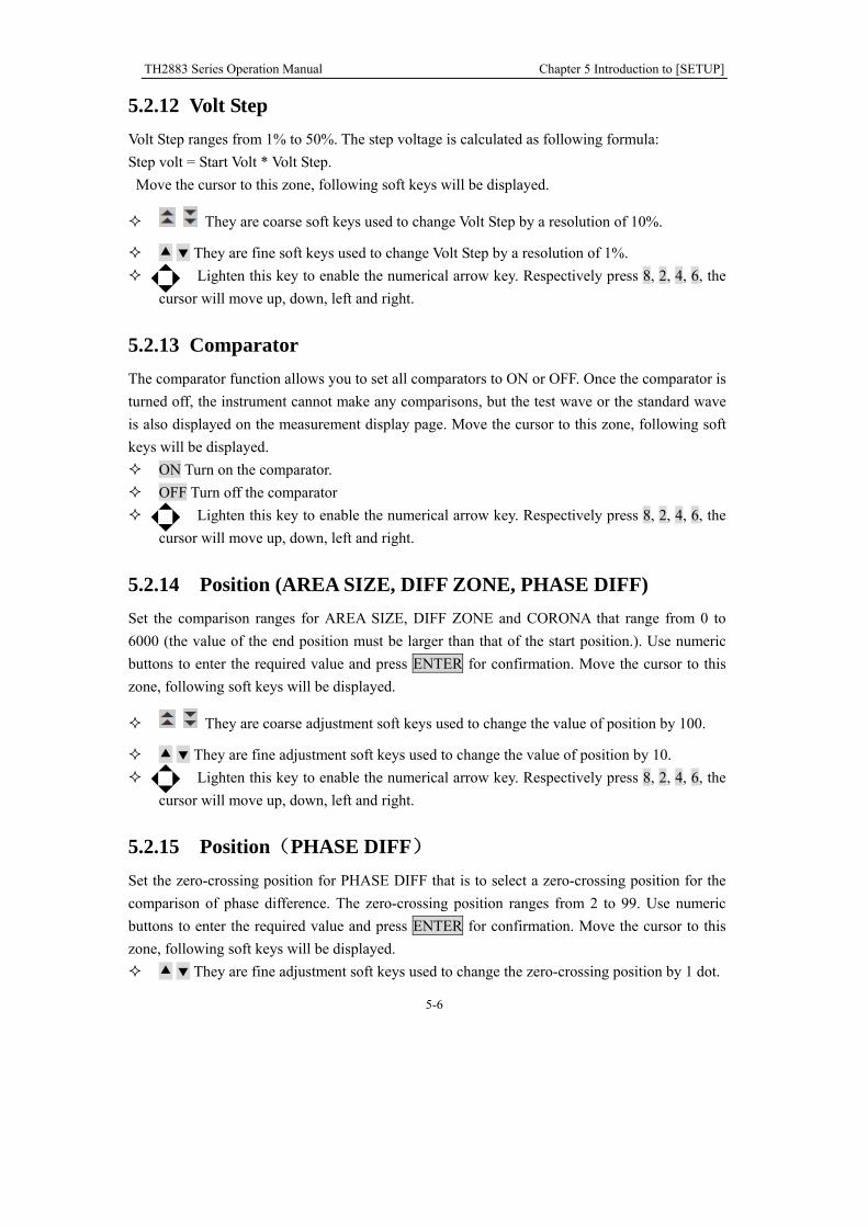
5.2.12 Volt Step
Volt Step ranges from 1% to 50%. The step voltage is calculated as following formula:
Step volt = Start Volt * Volt Step.
Move the cursor to this zone, following soft keys will be displayed.
They are coarse soft keys used to change Volt Step by a resolution of 10%.
They are fine soft keys used to change Volt Step by a resolution of 1%.
Lighten this key to enable the numerical arrow key. Respectively press 8, 2, 4, 6, the
cursor will move up, down, left and right.
5.2.13 Comparator
The comparator function allows you to set all comparators to ON or OFF. Once the comparator is
turned off, the instrument cannot make any comparisons, but the test wave or the standard wave
is also displayed on the measurement display page. Move the cursor to this zone, following soft
keys will be displayed.
ON Turn on the comparator.
OFF Turn off the comparator
Lighten this key to enable the numerical arrow key. Respectively press 8, 2, 4, 6, the
cursor will move up, down, left and right.
5.2.14 Position (AREA SIZE, DIFF ZONE, PHASE DIFF)
Set the comparison ranges for AREA SIZE, DIFF ZONE and CORONA that range from 0 to
6000 (the value of the end position must be larger than that of the start position.). Use numeric
buttons to enter the required value and press ENTER for confirmation. Move the cursor to this
zone, following soft keys will be displayed.
They are coarse adjustment soft keys used to change the value of position by 100.
They are fine adjustment soft keys used to change the value of position by 10.
Lighten this key to enable the numerical arrow key. Respectively press 8, 2, 4, 6, the
cursor will move up, down, left and right.
5.2.15 Position(PHASE DIFF)
Set the zero-crossing position for PHASE DIFF that is to select a zero-crossing position for the
comparison of phase difference. The zero-crossing position ranges from 2 to 99. Use numeric
buttons to enter the required value and press ENTER for confirmation. Move the cursor to this
zone, following soft keys will be displayed.
They are fine adjustment soft keys used to change the zero-crossing position by 1 dot.

TH2883 Series Operation Manual Chapter 5 Introduction to [SETUP]
5-7
Lighten this key to enable the numerical arrow key. Respectively press 8, 2, 4, 6, the
cursor will move up, down, left and right.
5.2.16 DIFF(Limit)(AREA SIZE, DIFF ZONE, PHASE DIFF)
Set the limit values for comparison methods of AREA SIZE, DIFF ZONE, PHASE DIFF which
range from 0.1% to 99.9% by a resolution of 0.1%. Use numeric buttons to enter the required
value and press ENTER for confirmation. Move the cursor to this zone, following soft keys will
be displayed.
They are coarse adjustment soft keys used to change the limit value by a resolution
of 1.0.
They are fine adjustment soft keys used to change the limit value by a resolution of
0.1.
Lighten this key to enable the numerical arrow key. Respectively press 8, 2, 4, 6, the
cursor will move up, down, left and right.
5.2.17 DIFF(Limit)(CORONA)
Set the limit values for comparison methods of CORONA which range from 0 to 256 by a
resolution of 1 dot. Use numeric buttons to enter the required value and press ENTER for
confirmation. Move the cursor to this zone, following soft keys will be displayed.
They are coarse adjustment soft keys used to change the limit value by a
resolution of 10 dots.
They are fine adjustment soft keys used to change the limit value by a resolution
of 1 dot.
Lighten this key to enable the numerical arrow key. Respectively press 8, 2, 4, 6, the
cursor will move up, down, left and right.
5.3 Int. File
TH2883 series can save parameters that are set by user to the internal non-volatile memory in file
format. User can load the file to use these parameters instead of resetting. The internal memory
can store 100 groups of files including files of measure parameters, compare parameters, etc.
Figure 5-2 shows the page of internal file.

TH2883 Series Operation Manual Chapter 5 Introduction to [SETUP]
5-8
Figure 5-2 Internal File
Int. File consists of file number (NO), file name (File), Date/ Time, Load. Following soft keys
can be used in this page.
Load Press this key to load a file stored in the internal non-volatile memory. As
figure 5-2 indicates, using the arrow key or the roller can select the needed
file. Press LOAD to load the file. If the selected file is needed to load, press
YES; otherwise, press NO.
Undo Undo the loaded file. Using the arrow key or the roller can select the needed
file. If the selected file has been loaded, press Undo. If the selected file is
needed to undo, press YES; otherwise NO.
Copy to E: Copy internal files to external files (in U disk). Using the arrow key or the
roller can select the desired file. If the selected file is needed to copy to an
external U disk, press Copy to E: and then choose YES, otherwise choosing
NO to give up this operation.
Delete Delete stored files. Press the Delete soft key and then choose YES to confirm
this operation or NO to give up.
Note: If the selected file has been loaded, the starting-up load function
will be invalid.
Save Press this key to save a file. Move the arrow key to choose the catalog to
store the file. Press the SAVE soft key to store the file and then YES for
confirmation (Choose NO to give up the save operation.) The file can be
save after entering a file name and pressing the ENTER button. If user press
the ENTER button without entering the file name, the file will be saved as

TH2883 Series Operation Manual Chapter 5 Introduction to [SETUP]
5-9
the default name-<Unnamed>. Pressing ESC can exit the operation of saving
file. Letters from A to Z, numbers from 0 to 9, and underline, etc. can be
used for a file name. Enter rules: Pressing a numeric key, the corresponding letters or
characters will be displayed on the screen. If user wants to input a
number, the numeric key should be pressed again. While a letter or
character is needed, then the soft key corresponding to the letter or the
character should be pressed.
Lighten this key to enable the numerical arrow key. Respectively press 8, 2, 4, 6, the
cursor will move up, down, left and right.
5.4 Ext. File
Figure 5-3 shows the page of external file.
Figure 5-3 External file
The set parameters can be saved to a U disk (external file) in file format. External file storage
supports three extension names: .STA, .TXT, .CSV. Only .STA file has file load function. Soft
keys in the external file page are as follows:
Sub Dir Enter the sub-directory. Using the arrow key or the roller to choose a file,
press Sub Dir to enter the sub-directory.
Note: When the cursor is locating in the folder zone, pressing the
roller down will also enter the sub-directory.
Parent Dir Return to the parent directory.
Create Create a new folder. Press Create and then input the name of the file folder.

TH2883 Series Operation Manual Chapter 5 Introduction to [SETUP]
5-10
End the creation of new folder by press ENTER. If user presses ENTER
without inputting the folder name, the folder will be named as the default
name-<FOLDERxx> (xx is a number ranging from 01 to 99.). Pressing ESC
can exit the operation of creating. Letters from A to Z, numbers from 0 to 9,
and underline, etc. can be used for a file name. Note: Users are recommended to use self-defined folder name. The
default name ranges from FOLDER01 to FOLDER 99.
Save Press this key to save a file. Move the arrow key to choose the catalog
storing the file. Press the Save soft key and then enter the file name.
Press ENTER to end this operation. If the ENTER button is pressed without
inputting the file name, the default name is FILExxx.STA (xxx ranges from
001 to 999.).
Press . , soft keys .STA, .TXT and .CSV will be displayed in the soft key
zone.
Press .STA, the file will be save as .STA file. If the file name is not
input, the file will be named as the default name FILExxx. STA (xxx
ranges from 001 to 999.).
Press .TXT, the file will be save as .TXT file. If the file name is not
input, the file will be named as the default name FILExxx. TXT (xxx
ranges from 001 to 999.).
Press .CSV, the file will be save as .CSV file. If the file name is not
input, the file will be named as the default name FILExxx. CSV (xxx
ranges from 001 to 999.).
Note: Users are recommended to use self-defined folder name. The
default name ranges from FOLDER001 to FOLDER 099.
Load Load a file saved in an external U disk. Using the arrow key or the roller can
choose the desired file. Press Load. If the selected external file is needed to
load to the internal RAM, press YES, otherwise NO.
Note: Although the instrument supports three file
formats, .STA, .TXT and CSV, only .STA file can be loaded to internal
RAM.
Delete Delete saved files. Press Delete. Then choose YES to delete the file,
otherwise NO to cancel the delete operation.
Copy to I: Copy external files (in U disk) to internal file list. Using the arrow key or the
roller can select the desired file. If the selected file is needed to copy to the
internal file list, press Copy to I: and then choose YES, otherwise choosing
NO to give up this operation. Press ENTER to end coping. In numeric input
state, press ESC to exit from this page.
Lighten this key to enable the numerical arrow key. Respectively press 8, 2, 4, 6, the
cursor will move up, down, left and right.

TH2883 Series Operation Manual Chapter 6 Introduction to [SYSTEM]
6-1
Chapter 6 Introduction to [SYSTEM]
Press SYSTEM to enter System. This is a toggle key, the press of which will make the displayed
page toggled among System, Interface, About.
6.1 System
Figure 6-1 shows the System page.
Figure 6-1 System
Parameters irrelevant to test performance can be set in this page.
Brightness
Pass/Fail
Pass Alarm
Fail Alarm
Key Sound
Hard Copy
Password
Language
Theme
Date

TH2883 Series Operation Manual Chapter 6 Introduction to [SYSTEM]
6-2
Time
6.1.1 Brightness
Move the cursor to this zone, following soft keys will be displayed.
They are soft keys used to increase and decrease the LCD display.
Lighten this key to enable the numerical arrow key. Respectively press 8, 2, 4, 6, the
cursor will move up, down, left and right.
6.1.2 Pass/Fail
Move the cursor to this zone, following soft keys will be displayed.
On Turn on Pass/Fail display function.
Off Turn off Pass/Fail display function.
Lighten this key to enable the numerical arrow key. Respectively press 8, 2, 4, 6, the
cursor will move up, down, left and right.
6.1.3 Pass Alarm
Move the cursor to this zone, following soft keys will be displayed.
They are soft keys used to adjust the volume of the pass alarm. The lowest volume is
mute.
Lighten this key to enable the numerical arrow key. Respectively press 8, 2, 4, 6, the
cursor will move up, down, left and right.
6.1.4 Fail Alarm
Move the cursor to this zone, following soft keys will be displayed.
They are soft keys used to adjust the volume of the fail alarm. The lowest volume is
mute.
Lighten this key to enable the numerical arrow key. Respectively press 8, 2, 4, 6, the
cursor will move up, down, left and right.
6.1.5 Key Sound
Move the cursor to this zone, following soft keys will be displayed.
On Turn on the key sound.
Off Turn off the key sound.
Lighten this key to enable the numerical arrow key. Respectively press 8, 2, 4, 6, the
cursor will move up, down, left and right.

TH2883 Series Operation Manual Chapter 6 Introduction to [SYSTEM]
6-3
6.1.6 Hard Copy
Move the cursor to this zone, following soft keys will be displayed.
Full Full screen will be copied.
Wave Only wave zone will be copied.
Lighten this key to enable the numerical arrow key. Respectively press 8, 2, 4, 6, the
cursor will move up, down, left and right.
Note: Wave is valid only in the measurement display page. In the other pages, the default copy zone is Full.
6.1.7 Password
Move the cursor to this zone, following soft keys will be displayed.
On Turn on the password function. When user turns on or unlocks the instrument, it is
required to input password.
Off Turn off the password function. When user turns on or unlocks the instrument, it is
not required to input password.
Note: When turning off the password function, it is required to input the password.
Modify This key is used to modify the password. The instrument will prompt user to input
old password, new password and new password again in turn. (Press ESC to exit
from modifying password.)
Note: Only numbers can be used as password.
Lighten this key to enable the numerical arrow key. Respectively press 8, 2, 4, 6, the
cursor will move up, down, left and right.
6.1.8 Language
Move the cursor to this zone, following soft keys will be displayed.
中文 Choose Chinese as the display and operation language.
English Choose English as the display and operation language.
Lighten this key to enable the numerical arrow key. Respectively press 8, 2, 4, 6, the
cursor will move up, down, left and right.
6.1.9 Theme
RoyalBlue
Seagreen
Steelblue
Indianred

TH2883 Series Operation Manual Chapter 6 Introduction to [SYSTEM]
6-4
6.1.10 Date
Date can be set in this zone. The display format is like 2011/05/04. Move the cursor to this zone,
following soft keys can be used.
They are soft keys used to adjust date by 1 day.
Lighten this key to enable the numerical arrow key. Respectively press 8, 2, 4, 6, the
cursor will move up, down, left and right.
Note: The date can be directly input by numeric keys. In the process of inputting
numbers, soft keys are not available. User can press ENTER to terminate inputting (In the
state of inputting, if it is required to exit from modifying, press ESC.).
6.1.11 Time
Time can be set in this zone. The display format is like 06:22:28. Move the cursor to this zone,
following soft keys can be used.
They are soft keys used to adjust time by 1.
Lighten this key to enable the numerical arrow key. Respectively press 8, 2, 4, 6, the
cursor will move up, down, left and right.
Note: The time can be directly input by numeric keys. In the process of inputting
numbers, soft keys are not available. User can press ENTER to terminate inputting (In the
state of inputting, if it is required to exit from modifying, press ESC.).
6.2 Interface
In this page, information about RS232 interface, USB interface (USBTMC or USBCDC),
LAN interface and interface setups can be set, as shown in figure 6-2.
Figure 6-2 Interface

TH2883 Series Operation Manual Chapter 6 Introduction to [SYSTEM]
6-5
6.2.1 I/O
Move the cursor to the I/O: zone, following soft keys will be displayed.
RS232C Set RS232 interface as the I/O interface.
USB Set USB interface as the I/O interface.
LAN Set LAN interface as the I/O interface.
Lighten this key to enable the numerical arrow key. Respectively press 8, 2, 4, 6, the
cursor will move up, down, left and right.
Note: Once an interface is selected, the cursor can only move in the corresponding zone.
For example, when RS232C interface is selected, the cursor can move only in the RS232C
setup zone.
6.2.2 TH2883 RS232C interface
RS-232 standard, also called as asynchronous serial communication standard, has already been
widely used for data communication between computers, computer and external equipment. RS
is the English abbreviation of Recommended Standard; 232, the standard number. This standard
is issued by IEA in 1969, which rules to send one bit in a data line every time.
As most serial interfaces, the serial interface of TH2883 is also not strictly based on RS-232
standard but only uses the smallest subset of this standard. The signals are listed in the following
table.
Signal Code Connector pin number
Transmitted data TXD 2
Received data RXD 3
Signal ground common GND 5
Table 6-1 RS-232 signal and pin number
The reason is that the use of three lines is much more inexpensive and much simpler than that of
five lines or six lines, which is the biggest advantage of using serial interface for communication.
The connection of the instrument with PC is shown in figure 6-3:
TXD(2) (3) RXD
PC
(Controller) RXD(3) (2) TXD TH2883
GND(5) (5) GND
Figure 6-3 Connection of the instrument with PC
Figure 6-3 shows that the serial interface pin definition of this instrument is different from that of

TH2883 Series Operation Manual Chapter 6 Introduction to [SYSTEM]
6-6
9 pin connector used in IMB AT compatible computer. User can purchase the serial interface
cable from our company.
TH2883’s baud rate, data bit, stop bit, parity bit and Tx term can be set. See the following 5
sections for details.
Commands of TH2883 comply with SCPI standard. When a command string is sent to the
instrument, Tx term must be attached to the end of the string. The length of a SCPI command
string thatTH2883 can receive every time is up to 2k Byte.
See command reference for data format that the instrument sends to PC.
6.2.2.1 Baud Rate TH2883 provides five baud rates: 4800bit、9600bit、19200bit、38400bit、115200bit. Move the
cursor to this zone, following soft keys can be used.
They are soft keys used to choose the required baud rate.
Lighten this key to enable the numerical arrow key. Respectively press 8, 2, 4, 6, the
cursor will move up, down, left and right.
6.2.2.2 Data Bit
Move the cursor to this zone, following soft keys can be used.
6 Set the data bit to 6 Bit.
7 Set the data bit to 7 Bit.
8 Set the data bit to 8 Bit.
Lighten this key to enable the numerical arrow key. Respectively press 8, 2, 4, 6, the
cursor will move up, down, left and right. 6.2.2.3 Stop Bit
Move the cursor to this zone, following soft keys can be used.
1 Bit Set the stop bit to1 bit.
1.5 Bit Set the stop bit to 1.5 bit.
2 Bit Set the stop bit to 2 bit.
Lighten this key to enable the numerical arrow key. Respectively press 8, 2, 4, 6, the
cursor will move up, down, left and right.
6.2.2.4 Parity Move the cursor to this zone, following soft keys can be used.
None Set the parity as None.
Odd Set the parity as Odd.
Even Set the parity as Even.
Lighten this key to enable the numerical arrow key. Respectively press 8, 2, 4, 6, the
cursor will move up, down, left and right.
6.2.2.5 Tx Term Move the cursor to this zone, following soft keys can be used.
LF Set the Tx term as \n (ASCII is 0x0A).
CR Set the Tx term as \r (ASCII is 0x0D).
LFCR Set the Tx term as \r\n (ASCII is 0x0D and 0x0A).
TH2883 Series Operation Manual Chapter 6 Introduction to [SYSTEM]
6-7
Lighten this key to enable the numerical arrow key. Respectively press 8, 2, 4, 6, the
cursor will move up, down, left and right.
6.2.3 USB interface
Move the cursor to this zone, following soft keys can be used.
USBCDC Set USBCDC interface as the USB interface.
USBTMC Set USBTMC interface as the USB interface.
Lighten this key to enable the numerical arrow key. Respectively press 8, 2, 4, 6, the
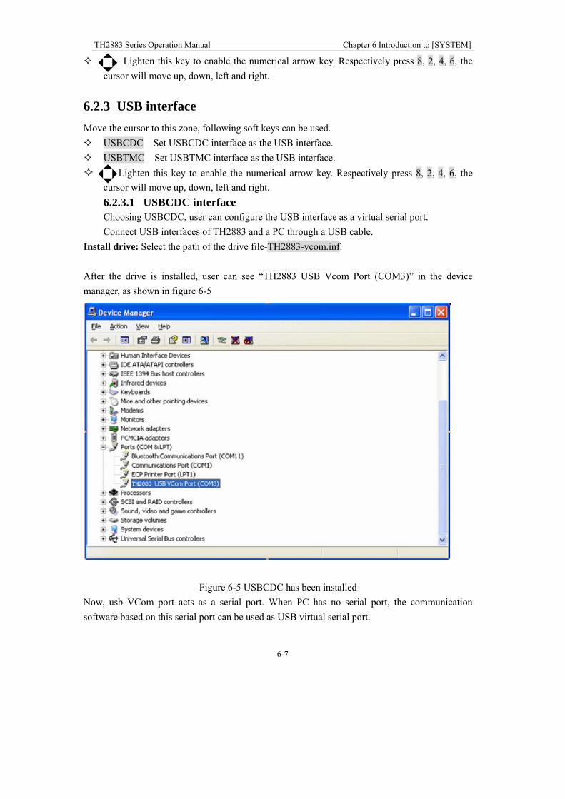
cursor will move up, down, left and right. 6.2.3.1 USBCDC interface Choosing USBCDC, user can configure the USB interface as a virtual serial port.
Connect USB interfaces of TH2883 and a PC through a USB cable.
Install drive: Select the path of the drive file-TH2883-vcom.inf.
After the drive is installed, user can see “TH2883 USB Vcom Port (COM3)” in the device
manager, as shown in figure 6-5
Figure 6-5 USBCDC has been installed
Now, usb VCom port acts as a serial port. When PC has no serial port, the communication
software based on this serial port can be used as USB virtual serial port.

TH2883 Series Operation Manual Chapter 6 Introduction to [SYSTEM]
6-8
Figure 6-6 USBCDC has not been installed.
6.2.3.2 USBTMC interface USB (Universal Serial Bus) remote control system controls the instrument through the USB
interface. This connection conforms to USBTMC-USB488 and USB2.0 protocols.
Connect USB interfaces on PC and TH2883 through a USB cable.
Install drive: The installing steps of USBTMC are the same as that of USBCDC, see 6.2.3.1 for
reference. When the installation of drive is finished, user can see “USB Test and Measurement
Devices” in the device manager of PC, as shown in figure 6-7.

TH2883 Series Operation Manual Chapter 6 Introduction to [SYSTEM]
6-9
Figure 6-7 PC has installed USBTIMC drive
When user is using USBTMC interface, labview software can be used to access the instrument.
Tonghui provides Labview software for controlling TH2883. See Labview instruction manual for
more details.
6.2.4 LAN interface
LAN (Local Area Network) can access TH2883 by two ways.
(1) Access TH2883 by a browser.
(2) Access TH2883 by Labview software.
System configuration TH2883 is connected to a PC by a crossover network cable. If TH2883 is connected to a router,
peer to peer network cable should be used.
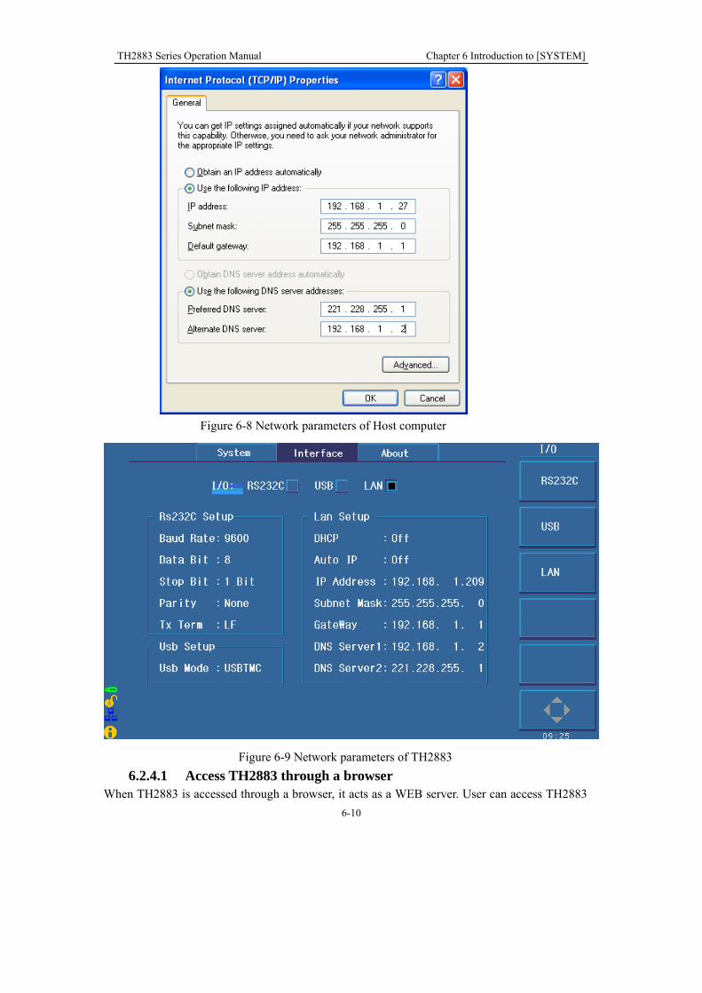
Parameter settings Select LAN interface in the interface page to enter the LAN setup page. Now you can set the
following parameters: IP address, SUB MASK, gateway and DNS. Refer to the PC (connecting
with TH2883) network parameter setups for TH2883 LAN parameter setups. For example: PC
(connecting with TH2521) network parameter setups are shown in figure 6-8, TH2883 network
parameter setups are shown in figure 6-9.
TH2883 Series Operation Manual Chapter 6 Introduction to [SYSTEM]
6-10
Figure 6-8 Network parameters of Host computer
Figure 6-9 Network parameters of TH2883
6.2.4.1 Access TH2883 through a browser When TH2883 is accessed through a browser, it acts as a WEB server. User can access TH2883
TH2883 Series Operation Manual Chapter 6 Introduction to [SYSTEM]
6-11
by Internet Explorer (IE6.0 or upgraded version).
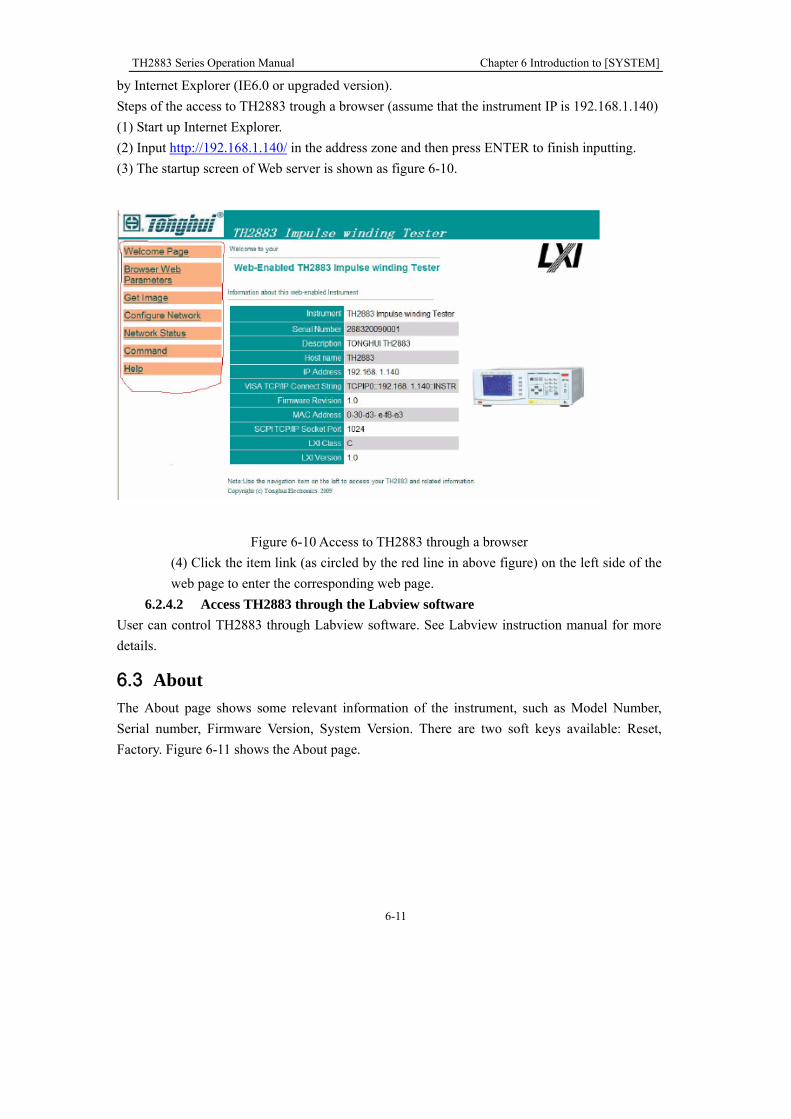
Steps of the access to TH2883 trough a browser (assume that the instrument IP is 192.168.1.140)
(1) Start up Internet Explorer.
(2) Input http://192.168.1.140/ in the address zone and then press ENTER to finish inputting.
(3) The startup screen of Web server is shown as figure 6-10.
Figure 6-10 Access to TH2883 through a browser
(4) Click the item link (as circled by the red line in above figure) on the left side of the
web page to enter the corresponding web page.
6.2.4.2 Access TH2883 through the Labview software
User can control TH2883 through Labview software. See Labview instruction manual for more
details.
6.3 About
The About page shows some relevant information of the instrument, such as Model Number,
Serial number, Firmware Version, System Version. There are two soft keys available: Reset,
Factory. Figure 6-11 shows the About page.

TH2883 Series Operation Manual Chapter 6 Introduction to [SYSTEM]
6-12
Figure 6-11 About
Following soft keys can be used in the About page.
Reset Press this key to reset the instrument.
Factory Press this key to reset the instrument to factory settings.

TH2883 Series Operation Manual Chapter 7 User guide
7-1
Chapter 7 User guide
7.1 Use of keys
7.1.1 Use of the roller
The roller can be used as a roller and a key. The roller can be rotated in clockwise and
anti-clockwise directions, thus achieving parameter setups.
1. Indicate operations to the displayed waveform. Press the roller, if the icon is displayed, user can amplify or zoom the tested waveform. Press this roller again, if the
icon is displayed, in the state that the waveform is amplified user can shift the
waveform right or left. Another press of the roller will disable the amplification and the
shift functions.
2. Enable the roller. In the measurement display page, if the icon is displayed on the
soft key, press the soft key to enable the roller. When this icon is lightened, the roller
can be used; otherwise it is darkened, all functions of the roller will be invalid.
3. Choose and modify parameters. Revolve the roller in the purpose of moving the cursor
to the parameter to be modified. Press the roller to choose the parameter and then
revolve the roller to modify its value. When the value is modified, press the roller
again to confirm and exit from the modification.
7.1.2 Switch the display page
There are three function pages displayed on the instrument: DISP, STEUP and SYSTEM.
1. DISP Press this key to enter the measurement display page.
2. SETUP Press this key to enter the parameter setup page. Continuously press this key,
the display page will toggle among Setup, Int. File, and Ext. File.
3. SYSTEM Press this key to enter the system setup page. Continuously press this key,
the display page will toggle among System, Interface and About.
7.1.3 Numeric arrow key
Lighten this icon to enable this key. Respectively press the four keys, 8, 2, 4, 6,
the cursor will move up, down, left and right. When the icon becomes dark, the
numerical arrow key is disabled.

TH2883 Series Operation Manual Chapter 7 User guide
7-2
7.2 Basic measurement
Start up the instrument to enter the default measurement display page. The primary display
zone shows the tested waveform while the secondary one shows parameters of corona or
test.
7.2.1 Non-standard test
This test is applicable to trial sample test.
Switch on the instrument at the test impulse voltage of 1000V and the sample rate of
50MSa/s. Connect the test cable to DUT and press START, thus a test for DUT is done.
Waveforms of the damping oscillation will be displayed in the primary display zone,
observe the density of the waveforms and then modify the sample rate and repeat above
processes. The secondary display zone shows the corona value, which is tested at high
voltage test impulse and directly representing the insulation performance of DUT.
7.2.2 Sample test for standard wave
This test is applicable to batch test.
Modify the test voltage. Press the Standard soft key under the main menu. Choose Auto to
enter the page of auto sample function. Press the Start soft key to automatically change the
test frequencies. After a loop test for DUT is done, a waveform, most suitable for observing
test, will be selected. Press Select to finish the acquisition of standard waveform. Replace a
DUT and then press the START button to start the test. Set some criteria to judge the DUT
to be good or bad.
7.3 BDV test
Determine an impulse voltage appropriate to test.
The applied voltage has little effect on the turn-to-turn short test and the layer-to-layer short
test of coil, but the amplitude of the applied impulse voltage has a great impact on the
insulation test of coil. TH2883 solves the problem of how to set an appropriate voltage.
When it is required to determine an appropriate voltage for a kind of new product or for trial
test, except the industrial specified voltage, TH2883 can find out the appropriate test voltage
by switching on the BDV test function.
Enter the setup page and turn on BDV test. After setting start voltage, end voltage and step
voltage, turn on the corona comparison and return to the measurement display page. Press
START to start the test on DUT from the start voltage and then raise the voltage by step
voltage. By observing the corona discharge (corona transition value), the voltage can be
determined. 70~80% of the voltage is appropriate for test voltage.

TH2883 Series Operation Manual Chapter 7 User guide
7-3
7.4 Technology application
7.4.1 Test objects
1. Turn-to-turn and layer-to-layer short
Turn-to-turn short refers to the short caused by the insulation damage between turns.
Layer-to-layer short occurs in the coil consisting of multiple layers. There are two
kinds of short: direct short and pull arc short, both of which are shown as more
dissipation.
2. Bad coil
The different number of coils will cause the variation of inductance, which is reflected
as the change of oscillation period.
3. Corona discharge
Due to the use of impulse high voltage, if the insulations between the coil and layer
and terminal are not strong enough, operator can observe the discharge and the corona
discharge phenomenons. The corona discharge that can be captured by the impulse
winding tester has weak energy. Instead of influencing the attenuation oscillation wave,
it is only displayed as discrete jumping points around the waveform of high potential.
4. Material of magnetic core
Whether a magnet is used in the coil as the magnetic core or the magnet is poor, above
conditions of the magnet will influence the inductance and the dissipation. Likewise, if
air gas is designed in the magnetic core, the size of which will also have an impact on
the inductance and the dissipation. Effects mentioned above will show as changes of
the attenuating vibration period and the attenuation degree.
7.4.2 Select comparison method
Area size comparison is mainly used to compare the energy consumption.
Differential area comparison is sensitive to energy consumption and inductance change.
Corona comparison method is the best one for testing internal insulation of the coil.
Differential phase comparison is the most suitable one to show the inductance difference.
To test turn-to-turn short or layer-to-layer short, it is recommended to use Area Size
comparison.
Poor coil can be recognized by Differential Phase comparison.
The insulation performance has some impacts on the life span of the coil products. For this
reason, when the test occasion requires high standard of insulation performance, corona
comparison must be switched on.
The material difference of magnetic core can be tested by Area Size comparison,
Differential Area comparison or Corona comparison.
Both Area size comparison and corona comparison can be used to test coils of motor,

TH2883 Series Operation Manual Chapter 7 User guide
7-4
solenoid and relay. Area size comparison, according to energy dissipation, can effectively
detect layer-to-layer short and circle-to-circle short, while corona comparison is mainly
applied to detect coil’s internal insulation failure. If it is required to test inductance,
differential area comparison should be selected.
7.4.3 Settings of comparison method
Sample the standard wave by ways mentioned in 7.2.2 and turn on the required comparisons
dealt with in 7.4.2. For area size comparison and corona comparison, the setting values are
determined by the two methods discussed below:
A. ① If the condition is permitted, test10 to 20 samples.
② Find out the entity that has the largest deviation value and then use it to make
electrical test. If this one is good, enlarge the value by 20% and take it as the criteria
(except corona).
③ When testing a product, if a boundary value is detected, repeat step ②.
④ The corona value is the transition one. The default value is 10.
B. ① I t is the same as A①.
② Take a coil to make failure test. Short two adjacent turns of coil and then make
another test.
③ Take the differential area size of the sample as the high limit, the maximum unit
differential area size of the sample as the low limit. Select an appropriate value as the
criteria.
④ If the low limit is larger than the high limit, take the product that has the largest
unit difference to make electrical test thus judging whether it is a poor product.
Another way is to average samples (see 7.4.4) to take their differential area size or
switch off the test method and directly take the corona comparison method.
⑤ It is the same as A④.
7.4.4 Select standards
1. Set test voltage. Then observe the corona value under non-standard test mode (7.2.1).
2. Sample the standard wave by methods mentioned in 7.2.2. Test 10 to 20 samples and
select products that have the most similar differences.
3. Take the selected products to make sample average (4.3.1.1 Manual) and choose the
final result as the standard wave.
4. Results obtaining after procedures 1-3 can be taken as the standards.
7.4.5 Chart for differential area
In the process of BDV test, the secondary display zone displays not only the extraction
value of the corona but also the chart record of differential area after each test. The chart can

TH2883 Series Operation Manual Chapter 7 User guide
7-5
help user observe the changing regularity of the area differences during the test from the
start voltage to the end voltage.

TH2883 Series Operation Manual Chapter 8 SCPI Command reference
8-1
Chapter 8 Command reference
8.1 Command structure
TH2883 series has two types of commands: GPIB common commands and SCPI commands. The
GPIB common commands are defined in IEEE std.488.2-1987, and these commands are common
for all devices. Not all GPIB commands are supported by the TH2883 series. The SCPI commands
are used to control all of the TH2883’s functions. The SCPI commands are tree-structured and
three-level deep. (The highest level commands are called the subsystem commands in this manual.)
So the lower level commands are legal only when the subsystem commands have been selected. A
colon (:) is used to separate the higher level commands and the lower level commands. See Figure
8-1 for a sample.
Figure 8-1 Command Tree
Basic rules of commands structure:
Letter case (upper and lower) is ignored.
For example: COMP:AREA ON = comp:area on = Comp:aRea On
Space (_ indicates a space) must not be placed before and/ or after a colon (:).
For example: COMP _:_ AREA ON COMP:AREA ON
Space is used to partition off command and parameter. Commands locate before space and
their corresponding parameters put after space.
For example: COMP:AREA ON, AREA is command, ON is parameter.
Some command has no parameter.
For example: Trigger command-TRIG, Standard waveform choosing command:

TH2883 Series Operation Manual Chapter 8 SCPI Command reference
8-2
SWAVE:CHOOSE
The command can be completely spelled out or in abbreviated type. (The rules of command
abbreviation are described later in this section, and abbreviation is spelling out in upper letter
case.)
For example: COMPARATOR:AREASIZE ON = COMP:AREA ON
The command header should be followed by a question mark (?) to generate a query for that
command.
For example: COMP:AREA?
Multiple command rules:
The semicolon (;) can be used as a separator to execute multiple commands on a single line. The
multiple command rules are as follows.
Commands at the same level and in the same subsystem command group can be separated by
a semicolon (;) on a multiple command line.
For example: COMP:AREA:STAT ON;RANG 0,960
STA ON and RANG 0,960 are commands in the same level and subcommands under AREA.
To restart commands from the highest level, a semicolon (;) must be used as the separator, and
then a colon (:), which shows that the restarted command is a command at the top of the
command tree, must follow.
For example: COMP:AREA:STAT ON;:COMP:AREA:RANG 0,960
The GPIB common commands can be placed in previous, middle or last on a multiple
command line, partitioned off with semicolons.
For example: COMP:AREA ON;*trg;DIFF ON
Short-form rules:
If complete commands and parameters (called long form afterwards) have four characters or
less, the long form and short form are the same.
When the long form has more than 4 characters:
1. And if the 4th character is a vowel, the short form is the first 3 characters of the long form.
2. If the 4th character is not a vowel, the short form is the first 4 characters.
For example:
TIME abbreviates to TIME.
TRIGger abbreviates to TRIG.
DELete abbreviates to DEL.
FREQuency abbreviates to FREQ.
If the long form mnemonic is defined as a phrase rather than a single word, then the long form
mnemonic is the first character of the first word(s) followed by the entire last word. The above
rules, when the long form mnemonic is a single word, are then applied to the resulting long
form mnemonic to obtain the short form.

TH2883 Series Operation Manual Chapter 8 SCPI Command reference
8-3
For example: Mass MEMory abbreviates to MMEM (long form is MMEMory)
Impulse VOLTage abbreviates to IVOLT (long form is IVOLTage)
NOTE: At the process of commands, the instrument does not distinguish letter case
including units.
For example: disp:page meas = DISP:PAGE MEAS = DiSp:PAGe MEas
8.2 Notation conventions and definitions
1. The following characters are used in the command syntax.
: A colon is used to separate the higher level commands and the lower level commands.
; The semicolon can be used as a separator to execute multiple commands on a single line.
* Asterisk is used to indicate that the command followed is a common command.
?A question mark is used to generate a query for the command in front of it.
, Comma is used to separate the multi-parameters in the command.
_ White space is used to separate the command and the parameters.
“” Double quotation marks indicate that the enclosed test is string data.
2. The following characters will be used in this chapter to describe GPIB commands.
NR1 Integer numeric data For example: 123
NR2 Fixed point numeric data For example: 12.3
NR3 Floating point numeric data For example: 12.3E+5
NL New Line character (decimal 10) is the end of the input/output string.
^END: EOI terminator signal of IEEE-488 bus.
< > Angular brackets enclose words or characters that are used to symbolize a program
code parameter or a GPIB command.
[ ] Square brackets indicate that the enclosed items are optional.
NOTE:The following commands are divided into two types: command syntax and query
syntax. All the command syntaxes have the returned value of “1” and “0”.
(“1” and “0” are in character type. “1” means the command of modifying the parameters has
been successfully finished and the next command is allowed. “0” means the command of
modifying the parameters has been failed and the next command is allowed.)
8.3 Command reference
TH2883 subsystem commands:
DISPlay Impulse VOLTage Sample RATE
COMParator TRIGger STATistic
WADJust Standard WAVE FETCh?
MEASure ABORt MMEMory
GPIB common commands:

TH2883 Series Operation Manual Chapter 8 SCPI Command reference
8-4
*RST *TRG *IDN
8.3.1 DISPlay subsystem commands
The DISPlay subsystem commands set the display page. Figure 8-2 shows the command tree of
the DISPlay subsystem commands.
Figure 8-2 DISPlay subsystem command tree
The :PAGE command sets the display page. The :PAGE? query returns the abbreviated page name
displayed on the LCD screen.
Command syntax: DISPlay:PAGE <page name>
<page name> are as follows:
MEASurement sets the display page to the measurement display page (MEASurement).
MSETup sets the display page to the measurement setup page (Meas SETup).
IFILE sets the display page to the internal file setup page (IFILE).
EFILE sets the display page to the external file setup page (EFILE).
SSETup sets the display page to the system setup page (System SETup).
ISETup sets the display page to the interface setup page (IO SETup)
ABOut sets the display page to the about page (ABOut).
For example: WrtCmd( “DISP:PAGE MEAS” ); set the display page to the measurement display
page.

TH2883 Series Operation Manual Chapter 8 SCPI Command reference
8-5
NOTE: This command will be ignored in the phase of measurement.
Query syntax: DISPlay:PAGE?
Return format: <page name><NL^END>
<page name> are as follows:
< MEAS DISP > indicates that the current displayed page is the measurement display page.
< MEAS SETUP > indicates that the current displayed page is the measurement setup page.
<SYSTEM SETUP> indicates that the current displayed page is the system setup page.
< INT FILE > indicates that the current displayed page is the internal file page.
< EXT FILE > indicates the current displayed page is the external file page.
< IO SETUP > indicates that the current displayed page is the IO setup page.
< ABOUT> indicates that the current displayed page is the About display page.
The :WAVE command sets the waveform display mode. The :WAVE? query returns the current
waveform display mode.
Command syntax:
AON
DISPlay:WAVE STD
TEST
AOFF
Where,
AON Both the standard waveform and the tested waveform are displayed on the screen.
STD Only the standard waveform is displayed on the screen.
TEST Only the tested waveform is displayed on the screen.
AOFF No waveform is displayed.
For example: WrtCmd( “DISP:WAVE STD” ); set to display the standard waveform only.
Query syntax: DISPlay:WAVE?
Return format: <WAVE STAT><NL^END>
Where,
ALL ON Both the standard waveform and the tested waveform are currently displayed
on the screen.
ALL OFF No waveform is displayed on the screen.
ONLY STDWAVE Only the standard waveform is currently displayed on the screen.
ONLY TESTWAVE Only the tested waveform is currently displayed on the screen.
The :GRID command sets the grid of waveform display area in measurement display page.
Command syntax:
DISPlay:GRID ON

TH2883 Series Operation Manual Chapter 8 SCPI Command reference
8-6
OFF
Where,
ON the grid function is ON.
OFF the grid function is OFF.
For example: WrtCmd( “DISP:GRID ON” ); the grid display function is ON.
Query syntax: DISPlay:GRID?
Return format: <GRID STAT><NL^END>
Where, GRID STAT is as follows:
ON the grid function is ON.
OFF the grid function is OFF.
The :SECDisplay command sets the function of secondary display.
Command syntax:
DISPlay:SECDisplay ON
OFF
Where,
ON the secondary display function is ON.
OFF the secondary display function is OFF.
For example: WrtCmd( “DISP: SECD ON” ); the current secondary display function is ON.
Query syntax: DISPlay: SECD?
Return format: <GRID STAT><NL^END>
Where,
ON the secondary display function is ON.
OFF the secondary display function is OFF.
8.3.2 IVOLTage subsystem commands
The Impulse VOLTage subsystem commands set the parameters related to the impulse voltage,
including impulse voltage, impulse times, erasing impulse times, impulse voltage adjust, break
impulse voltage range and delay time. Figure 8-3 shows the Impulse VOLTage subsystem
command tree.

TH2883 Series Operation Manual Chapter 8 SCPI Command reference
8-7
Figure 8-3 Impulse VOLTage subsystem command tree
The [:VOLTage] command sets the impulse voltage. The :VOLTage? query returns the current
impulse voltage value.
Command syntax:
IVOLTage:VOLTage <value>
Where,
<value> can be NR1, NR2 or NR3 format followed by KV or V and the value must be between
100V to 5000V.
For example: WrtCmd( “IVOLT:VOLT 1000V” ); set the impulse voltage to 1000V.
Query syntax: IVOLTtage:VOLTage?
Return format: <NR1><NL^END>
The :BVOLTage command sets the start voltage, end voltage and voltage step percentage for Break
Test. The :BVOLTage? query returns the value.
Command syntax:
IVOLTage:BVOLTage <value1,value2,value3>
Where
<value1,value2> can be NR1, NR2 or NR3 format followed by KV or V and the value must be
between 100V to 5000V. <value 2> must be larger than <value1>; <value3> ranges from 1-50, it
means the set voltage step percentage from value1 to value2.
For example: WrtCmd(“IVOLT:BVOLT 1000V,3000V,4”); set the start voltage to 1000V, end
voltage to 3000V and the voltage step is 4%.
Query syntax: IVOLT:BVOLT?

TH2883 Series Operation Manual Chapter 8 SCPI Command reference
8-8
Return format: <NR1>,<NR1>,<NR1><NL^END>
The :TIMPulse command sets the impulse times for testing. The :TIMPulse? query returns the
current impulse times.
Command syntax: IVOLTage:TIMPulse <number>
Where,
<number> is NR1 format ranging from 1 to 32.
For example: WrtCmd( “IVOLT: TIMPulse 3” ); set the impulse times to 3.
Query syntax: IVOLTage:TIMPulse?
Return format: <NR1><NL^END>
The :EIMPulse command sets the times of erasing impulses. The :EIMPulse? query returns the
current times of erasing impulses.
Command syntax: IVOLTage: EIMPulse <number>
Where,
<number> is NR1 format ranging from 0 to 16.
For example: WrtCmd( “IVOLT: EIMPulse 3”); set the times to 3.
Query syntax: IVOLTage:EIMPulse?
Return format: <NR1><NL^END>
The :VADJust command sets the impulse voltage adjust function to ON or OFF.
The :VADJust? query returns the current state of the impulse voltage adjust function.
Command syntax:
IVOLTage:VADJust ON
OFF
Where,
ON the impulse voltage adjust function is ON
OFF the impulse voltage adjust function is OFF
For example: WrtCmd( “IVOLT:VADJ ON” ); set the voltage adjust function to ON.
Query syntax: IVOLTage:VADJust?
Return format: <VADJ STAT><NL^END>
Where, <VADJ STAT> is as follows:
ON the impulse voltage adjust function is ON
OFF the impulse voltage adjust function is OFF

TH2883 Series Operation Manual Chapter 8 SCPI Command reference
8-9
The :DTIME command sets the delay time between two tests in the INT test mode. The :DTIME?
query returns the current delay time.
Command syntax: IVOLTage:DTIME <value>
Where,
<value> can be NR1, NR2 or NR3 data format. The set delay time ranges from 0.1s to 99.9s.
For example: WrtCmd( “IVOLT:DTIME 50.1s” ); set the delay time to 50.1s.
Command syntax: IVOLTage:DTIME?
Return format: <NR3><NL^END>
8.3.3 SRATE subsystem commands
The Sample RATE subsystem commands set the sample rate. Figure 8-4 shows the Sample RATE
subsystem command tree.
Figure 8-4 Sample RATE subsystem command tree
[:RATE]command sets the sample rate. [:RATE]?query returns the current sample rate.
Command syntax: SRATE[:RATE] <value>
Where,
<value> is the sampling rate parameter, available values are listed as follows:
200msa/s(200m),100msa/s, 50msa/s,25msa/s,12.5msa/s,6.25msa/s,
3.12msa/s,1.56msa/s
For example: WrtCmd( “SRATE:RATE 100msa/s” ); set the sample rate as 100msa/s.
WrtCmd( “SRATE:RATE 50msa/s” ); set the sample rate as 50msa/s.
Command syntax: SRATE[:RATE]?
Return format: <NR2 Msa/s><NL^END>

TH2883 Series Operation Manual Chapter 8 SCPI Command reference
8-10
8.3.4 COMParator subsystem commands
The COMParator subsystem commands set the compare conditions, including Areasize, Diffzone,
Corona and Phasediff. Figure 8-5 shows the command tree of the COMParator subsystem
commands.
Figure 8-5 COMParator subsystem command tree
Here, BDV means breakdown voltage testing. The compare setting method is the same as the
non-break testing. The command syntax and query syntax in break testing and non-break
testing will be merged together.
The [:STATe] command sets the comparator function to ON or OFF. The [:STATe]? query returns
the current comparator state.

TH2883 Series Operation Manual Chapter 8 SCPI Command reference
8-11
Command syntax:
ON
COMParator[:STATe] OFF
1
0
Where,
1 (decimal49) is equal to ON;
0 (decimal48) is equal to OFF;
(The meaning of 0 and 1 in the following text will not be described.)
For example: WrtCmd( “COMP ON” ); set the comparator function to ON.
Query syntax: COMParator[:STATe]?
Return format: <COMP STAT><NL^END>
Where, <COMP STAT> is as follows:
ON the comparator function is ON
OFF the comparator function is OFF
The :AREAsize[:STATe] or :BDV:AREAsize[:STATe] command sets the Areasize comparator
function to ON or OFF. The :AREAsize[:STATe]?or :BDV:AREAsize[:STATe] ? query returns
the current Areasize comparator state.
Command syntax:
COMParator:AREAsize[:STATe] ON
OFF
1
0
COMParator:BDV:AREAsize[:STATe] ON
OFF
1
0
For example: WrtCmd( “COMP:AREA ON” ); set the Areasize comparator function as ON.
WrtCmd( “COMP:BDV:AREA ON” ); set the Areasize comparator function in break testing
as ON.
Query syntax: COMParator:AREAsize[:STATe]?
COMParator:BDV:AREAsize[:STATe]?
Return format: <AREA STAT><NL^END>
Where, <AREA STAT>is as follows:
ON the Areasize comparator function is ON
OFF the Areasize comparator function is OFF

TH2883 Series Operation Manual Chapter 8 SCPI Command reference
8-12
NOTE: The Query Syntax of BDV will not be introduced in the following text.
The :AREAsize:RANGe command sets the comparison range of Areasize comparator.
The :AREAsize:RANGe? query returns the current comparison range of Areasize comparator.
Command syntax: COMParator:AREAsize:RANGe <start pot, end pot>
<start pot> start point of comparison range. NR1 format, range from 0 to 6000, without unit.
<end pot> end point of comparison range. NR1 format, range from 0 to 6000, without unit.
For example: WrtCmd( “COMP:AREA:RANG 0,960 ); set the comparison range from 0 to 960.
NOTE: The end point value should be larger than that of the start point; otherwise an
error message will be displayed on the system message line.
Query syntax: COMP:AREA:RANG?
Return format: <start pot, end pot><NL^END>
start pot, end pot are NR1 format.
The :AREAsize:DIFFerence command sets the difference limit value of Areasize comparator.
The :AREAsize:DIFFerence? query returns the current difference limit value of Areasize
comparator.
Command syntax: COMParator:AREAsize:DIFFerence <value>
Where
<value> can be NR1, NR2 or NR3 format without unit.
For example: WrtCmd( “COMP:AREA:DIFF 2.5” ); set the difference limit value to 2.5%.
NOTE: The <value> here is a percent value, For example, input 2.5 for2.5%.
Query syntax: COMParator:AREAsize:DIFFerence?
Return format: <NR3><NL^END>
The :DIFFzone[:STATe] command sets the Diffzone comparator to ON or OFF.
The :DIFFzone[:STATe]? query returns the current Diffzone comparator state.
Command syntax:
ON
COMParator:DIFFzone[:STATe] OFF
1
0
For example: WrtCmd( “COMP:DIFF ON”); turn on the Diffzone comparator.
Query syntax: COMParator:DIFFzone[:STATe]?
Return format: <DIFFz STAT><NL^END>
Where, < DIFFz STAT >is as follows:
ON the Diffzone comparator function is ON
OFF the Diffzone comparator function is OFF

TH2883 Series Operation Manual Chapter 8 SCPI Command reference
8-13
The :DIFFzone:RANGe command sets the comparison range of the Diffzone comparator.
The :DIFFzone:RANGe? query returns the current comparison range of the Diffzone comparator.
Command syntax: COMParator:DIFFzone:RANGe <start pot, end pot>
Where,
<start pot> start point of comparison range. NR1 format, range from 0 to 6000, without unit.
<end pot> end point of comparison range. NR1 format, range from 0 to 6000, without unit.
For example: WrtCmd(“COMP:DIFF:RANG 0,960 ); set the comparison range from 0 to 960.
NOTE: The end point value should be larger than that of the start point; otherwise an
error message will be displayed on the system message line.
Query syntax: COMP:DIFF:RANG?
Return format: <start pot>, <end pot><NL^END>
start pot, end pot are NR1 format.
The :DIFFzone:DIFFerence command sets the difference limit value of Diffzone comparator.
The :DIFFzone:DIFFerence? query returns the current difference limit value of the Diffzone
comparator.
Command syntax: COMParator:DIFFzone:DIFFerence <value>
Where,
<value> can be NR1, NR2 or NR3 format without unit.
For example: WrtCmd( “COMP:AREA:DIFF 2.5” ); set the difference limit value to 2.5%.
NOTE: Here <value> is a percent value, for example, input 2.5 for 2.5%.
Query syntax: COMParator:DIFFzone:DIFFerence?
Return format: <NR3><NL^END>
The :COROna[:STATe] command sets the Corona comparator to ON or OFF.
The :COROna[:STATe]? query returns the current Corona comparator state.
Command syntax:
ON
COMParator:COROna[:STATe] OFF
1
0
For example: WrtCmd( “COMP:CORONA ON” ); turn on the Corona comparator.
Query syntax: COMParator:COROna[:STATe]?
Return format: <CORONA STAT><NL^END>
Where, < CORONA STAT >is as follows:
ON the Corona comparator function is ON
OFF the Corona omparator function is OFF

TH2883 Series Operation Manual Chapter 8 SCPI Command reference
8-14
The :COROna:RANGe command sets the comparison range of the Corona comparator.
The :COROna:RANGe? query returns the current comparison range of the Corona comparator.
Command syntax: COMParator:COROna:RANGe <start pot, end pot>
Where,
<start pot> start point of comparison range. NR1 format, range from 0 to 6000, without unit.
<end pot> end point of comparison range. NR1 format, range from 0 to 6000, without unit.
For example: WrtCmd( “COMP:CORO:RANG 100,200 ); set the comparison range from 100 to
200.
NOTE: The end point value should be larger than that of the start point; otherwise an
error message will be displayed on the LCD screen.
Query syntax: COMP:CORO:RANG?
Return format: <start pot, end pot> <NL^END>
start pot, end pot are NR1 format.
The :COROna:DIFFerence command sets the difference limit value of the Corona comparator.
The :COROna:DIFFerence? query returns the current difference limit value of the Corona
comparator.
Command syntax: COMParator:COROna:DIFFerence <value>
Where,
<value> is NR1 format, range from 0 to 999 without unit.
For example: WrtCmd( “COMP:CORO:DIFF 20” ); set the difference value to 20.
Query syntax: COMParator:COROna:DIFFerence?
Return format: <NR1><NL^END>
The :PHASediff[:STATe] command sets the Phasediff comparator to ON or OFF.
The :PHASediff[:STATe]? query returns the current Phasediff comparator state.
Command syntax:
ON
COMParator:PHASediff[:STATe] OFF
1
0
For example: WrtCmd( “COMP:PHAS ON” ); turn on the Phasediff comparator.
Query syntax: COMParator:PHASediff[:STATe]?
Return format: <PHAS STAT><NL^END>
Where, < PHAS STAT >is as follows:
ON the Phasediff comparator function is ON
OFF the Phasediff comparator function is OFF

TH2883 Series Operation Manual Chapter 8 SCPI Command reference
8-15
The :PHASediff:POSItion command sets which zero-crossing point is used in the Phasediff
comparator. The :PHASediff:POSItion? query returns the zero-crossing position value of the
Phasediff comparator.
Command syntax: COMParator:PHASediff:POSition <value>
Where,
<value> Zero-crossing position value, NR1 format, range from 2 to 10 without unit. For example: WrtCmd( “COMP:PHAS:POS 3” ); the third zero-crossing point is used.
Query syntax: COMP:PHAS:POS?
Return format: <NR1><NL^END>
The :PHASediff:DIFFerence command sets the difference limit value of the Phasediff comparator.
The :PHASediff:DIFFerence? query returns the current difference limit value of the Phasediff
comparator.
Command syntax: COMParator:PHASediff:DIFFerence <value>
Where,
<value> can be NR1, NR2 or NR3 format without unit.
For example: WrtCmd( “COMP:PHAS:DIFF 2.5” ); set the difference limit value to 2.5%.
NOTE: Here <value> is a percent value, for example, input 2.5 for 2.5%.
Query syntax: COMParator:PHASediff:DIFFerence?
Return format: <NR3><NL^END>
8.3.5 TRIGger subsystem commands
The TRIGger subsystem command group is used to trigger a measurement or to set the trigger
mode. Figure 8-6 shows the TRIGger subsystem command tree.
Figure 8-6 TRIGger subsystem command tree
The [:IMMediate] command triggers a measurement.
Command syntax: TRIGger[:IMMediate]
For example: WrtCmd( “TRIG” );

TH2883 Series Operation Manual Chapter 8 SCPI Command reference
8-16
REMARK: before sending this command, the PC will get a return value of “1” and “END”.
“END” means the measurement has been finished. The instrument will receive the next
command.
NOTE: The TRIGger[:IMMediate] command, available only in the <MEAS DISP> page,
will be ignored when TH2883 is in the testing state. The trigger mode must be set to BUS
mode, or this command will be ignored. This command is only used to trigger the test of DUT.
Refer to Standard WAVE subsystem commands for the details of triggering standard
waveform test.
The :SOURce command sets the trigger mode. The :SOURce? query returns the current trigger
mode.
Command syntax:
MAN
TRIGger:SOURce EXTernal
INTernal
BUS
Where,
MAN Triggered by pressing the START button or using foot control switch
EXTernal Triggered by the HANDLER interface.
INTernal Automatically triggered after pressing the START button.
BUS Triggered by RS232 interface or GPIB interface.
For example: WrtCmd(“TRIG:SOUR BUS”); set to bus mode.
Query syntax: TRIGger:SOURce?
Return format: <SOUR STAT><NL^END>
Where, <SOUR STAT> is MAN, EXTERNAL, INTERNAL or BUS.
8.3.6 STATistic subsystem commands
The STATistic subsystem commands set the statistic function to ON or OFF, clear or save statistic
data. Figure 8-9 shows the STATistic subsystem command tree.
Figure 8-7 STATistic subsystem command tree

TH2883 Series Operation Manual Chapter 8 SCPI Command reference
8-17
The [:STATe] command sets the statistic function to ON or OFF. The [:STATe]? query returns the
current state of the statistic function.
Command syntax:
ON
STATistic[:STATe] OFF
1
0
Where,
For example: WrtCmd( “STAT ON” ); turn on the statistic function.
Query syntax: STATistic[:STATe]?
Return format:<STAT><NL^END>
Where, < STAT >is as follows:
ON the statistic function is ON
OFF the statistic function is OFF
The :CLEAr command is used to clear the statistic data.
Command syntax: STATistic:CLEAr
The :SAVE command is used to save the statistic data to a file.
Command syntax: STATistic:SAVE
8.3.7 WADJust subsystem commands
The WADJust subsystem commands set the time base change and move of the waveform. Figure
8-8 shows the WADJust subsystem command tree.
Figure 8-8 Wave Adjust subsystem commands
The :MOVE command sets the move of the waveform.

TH2883 Series Operation Manual Chapter 8 SCPI Command reference
8-18
Command format:
WADJust:MOVE RIGHt
LEFt
Where, RIGHt Move the waveform to the right.
LEFt Move the waveform to the left.
For example: WrtCmd(“WADJust:MOVE +1”); move the waveform to the right.
WrtCmd(“WADJust:MOVE RIGHt” ); move the waveform to the right.
The :EXTend command is used to extend or zoom the waveform.
Command format: WADJust:EXTend 1
For example: WrtCmd(“WADJust:EXTend 1” ); the waveform display to the most
Or WrtCmd( “WADJust:EXTend min” ); the waveform display to the most
Query syntax: WADJust:EXTend?
Return format: <NR1><NL^END>
8.3.8 SWAVE subsystem commands
The Standard WAVE subsystem commands set the parameters for sampling the standard waveform,
including setting the standard waveform sample mode, triggering the measurement of a standard
waveform and choosing a sampled standard waveform. Figure 8-9 shows the Standard WAVE
subsystem command tree.
Figure 8-9 Standard WAVE subsystem command tree
The :SMODE command sets the sample mode of the standard waveform. The :SMODE? query
returns the current sample mode.

TH2883 Series Operation Manual Chapter 8 SCPI Command reference
8-19
Command syntax:
SCYCLe
SWAVE:SMODE OCYCLe
OSAMPle
Where,
SCYCLe Set the standard waveform sample mode to sequential-cycle.
OCYCLe Set the standard waveform sample mode to one-cycle.
OSAMPle Set the standard waveform sample mode to one-sample.
For example: WrtCmd( “SWAVE:SMODE OSAMPle” ); set the standard waveform sample mode
to one-sample.
Query syntax: SWAVE:SMODE?
Return format:
SEQ CYCLE
ONE CYCLE <NL^END>
ONE SAMPLE
Where: SEQ CYCLE is sequence-cycle mode, ONE CYCLE is one-cycle mode, ONE SAMPLE is
one-sample mode.
The :TRIGger[:IMMediate] command is used to trigger a standard waveform measurement.
Command syntax: SWAVE:TRIGger[:IMMediate]
For example: WrtCmd( “SWAVE:TRIG” );
NOTE: 1.This command is available only on the <MEAS DISP> page.
2. This command will be ignored if the trigger mode is not set to BUS mode.
3. This command will be ignored when TH2883 is in testing state.
The :CHOose command is used to select the required standard waveform.
Command syntax: SWAVE:CHOose
For example: WrtCmd( “SWAVE:CHO” );
The :LOAD command is used to load the standard waveform.
Command syntax: SWAVE:LOAD <data>
For example: WrtCmd( “SWAVE:LOAD 78F6……98” );
The :LOADADJVOLT command is used to load the adjust voltage.
Command syntax: SWAVE:LOADADJVOLT <value>
For example: WrtCmd( “SWAVE: LOADADJVOLT 1350V”);
The :ADJVOLT command is used to query the adjust voltage.
Command syntax: WAVE:ADJVOLT?

TH2883 Series Operation Manual Chapter 8 SCPI Command reference
8-20
For example: <NR1><NL^END>
NOTE:
1. This command is available only on <MEAS DISP> page.
2.This command is valid only when standard waveform sampling test is finished in SEQ
CYCLE mode or ONE CYCLE mode. When in ONE CYCLE mode, the test must be finished
and enter into the choose state, or this command will be ignored.
8.3.9 FETCh? subsystem commands
The FETCh? subsystem commands are used to output waveform data, comparison results, output
voltage, frequency and time measurement result. Figure 8-10 shows the FETCh? subsystem
command tree.
Figure 8-10 FETCh? subsystem command tree
The :SWAVE? query outputs the current standard waveform data.
Query syntax: FETCh:SWAVE?
For example: WrtCmd( “FETC:SWAVE?” );
The :TWAVE? Query outputs the latest tested waveform data.
Query syntax: FETCh:TWAVE?
For example: WrtCmd( “FETC:TWAVE?” );
NOTE:
If the waveform data is not ready, the FETCh SWAVE? and FETCh TWAVE? query will be
executed after the current measurement or next measurement is finished.

TH2883 Series Operation Manual Chapter 8 SCPI Command reference
8-21
The CRESult? query returns the latest comparison result.
Query syntax: FETCh:CRESult?
Return format: There are three cases as follows:
1. If the comparator function or four comparison methods is set to OFF, the query
response will be <NR1><NL^END>, here NR1 is 2.
2. If there is no waveform data available, the return format will be <NR1><
NL^END>, here NR1 is 3.
3. If the comparator function is set to on and at least one of the four comparison
methods is set to ON, the return format will be <NR1, NR3, NR3, NR1,
NR3><NL^END>, the first NR1 is the general comparison result: 1 (PASS) or 0
(FAIL). The following four data are the comparison results corresponding to each
comparator: AREA SIZE, DIFF ZONE, CORONA and PHASE DIFF.
NOTE: TH2883 returns the comparison result when the comparator is turned
on. TH2883 returns 9.9E37 when the AREA SIZE, DIFF ZONE or PHASE DIFF
comparator is turned off. TH2883 returns 9999 when the CORONA comparator
is turned off.
The :VOLTage? query returns the current voltage value in the set voltage range. Refer to MEASure
subsystem commands for the voltage range settings.
Query syntax: FETCh:VOLTage?
Return format: <NR1><NL^END>
NOTE: The unit of the returned voltage is V.
The :FREQuency? query returns the current frequency result in the set frequency range. Refer to
MEASure subsystem commands for the frequency range settings.
Query syntax: FETCh:FREQuency?
Return format: <NR3><NL^END>
NOTE: The unit of the returned frequency is Hz. If the start point is overlapped with the
end cursor completely, then 9.9E37 will be returned.
The TIME? query returns the current time result in the set time range. Refer to MEASure
subsystem commands for the time range settings.
Query syntax: FETCh:TIME?
Return format: <NR3><NL^END>
NOTE: The unit of the returned time is s.
The :STATistic? query returns the current statistic result.
Query syntax: FETCh:STATistic?

TH2883 Series Operation Manual Chapter 8 SCPI Command reference
8-22
Return format: <NR1>, <NR1>, <NR1>, <NR1>, <NR1>, <NR1>, <NR1>, <NR1>, <NR1>,
<NR1>, <NL^END>
The returned data are in turn as follows: total test times and times of PASS, total test times for Area
Size comparison and times of PASS, total test times for Diff Zone comparison and times of PASS,
total test times for Corona comparison and times of PASS, total times for Phase Diff comparison
and times of PASS. PASS rate can be automatically calculated according to the returned data.
8.3.10 MEASure subsystem commands
The MEASure subsystem commands sets the measurement range of voltage, frequency and time.
Figure 8-11 shows the MEASure subsystem command tree.
Figure 8-11 MEASure subsystem command tree
The :VOLTage command sets the measurement range of voltage. The :VOLTage? query returns the
current voltage range.
Command syntax: MEASure:VOLTage <upper>,<lower>
Where,
<upper> is the upper limit of voltage, NR1 format, ranging from 1 to 248 without unit.
<lower> is the lower limit of the voltage, NR1 format, ranging from 1 to 248 without unit.
For example: WrtCmd( “MEAS:VOLT 1,199” ); set the voltage to range from 1 to 199.
NOTE: The lower limit must be less than the upper one; otherwise an error message will be
displayed on the system message line.
Query sntax: MEASure:VOLTage?
Return format: <upper>,<lower><NL^END>
Both upper limit and lower limit are NR1 format.
The :FREQuency command sets the frequency range. The :FREQuency? query returns the
currently set frequency range.
Command syntax: MEASure:FREQuency <start>,<end>
Where,
<start> is the start point of frequency, NR1 format and ranging from 1 to 598 without unit.
<end> is the end point of frequency, NR1 format and ranging from 1 to 598 without unit.
For example: WrtCmd( “MAES:FREQ 100,200” ); set the frequency to range from 100 to 200.

TH2883 Series Operation Manual Chapter 8 SCPI Command reference
8-23
NOTE: The value of the end point must be larger than that of the start point; otherwise an
error message will be displayed on the system message line.
NOTE: The measurement ranges of frequency and time are the same, thus the time range
will vary with the frequency range.
Query syntax: MEASure:FREQuency?
Return format: <start>,<end><NL^END>
Both <start> and <end > are NR1 format.
The :TIME command sets the time range. The :TIME? query returns the current time range.
Command syntax: MEASure:TIME <star>,<end>
Where,
<start> is the start point of time, NR1 format and ranging from 1 to 598 without unit.
<end> is the end point of time, NR1 format and ranging from 1 to 598 without unit.
For example: WrtCmd( “MAES:TIME 100,200” ); set the time to range from 100 to 200.
NOTE: The value of the end point must be larger than that of the start point; otherwise an
error message will be displayed on the system message line.
NOTE: The measurement ranges of frequency and time are the same, thus the time range
will vary with the frequency range.
Query syntax: MEASure:TIME?
Return format: <start>,<end><NL^END>
Both <start> and <end> are NR1 format.
8.3.11 ABORt subsystem command
TH2883 will abort the current measurement as soon as the ABORt command is received.
Command syntax: ABORt
For example: WrtCmd( “ABOR” );
8.3.12 Mass MEMory subsystem commands
The Mass MEMory subsystem commands load and store files. Figure 8-12 shows the Mass
MEMory subsystem command tree.
Figure 8-12 Mass MEMory subsystem command tree.

TH2883 Series Operation Manual Chapter 8 SCPI Command reference
8-24
The :LOAD:STATe command is used to load the stored file.
Command syntax: MMEMory:LOAD:STATe <record number>
Where,
<record number> is the file serial number ranging from 1 to 100 without unit.
For example: WrtCmd(“MMEM:LOAD:STAT 1”); load file 1.
NOTE: 1. If the file you want to load is not available, “File not exist” message will be
displayed on the system message line.
2. If the input file number is out of 1 to 100, message “Out of file range” will be
displayed on the system message line.
NOTE: The file contains the page information. When a file is loaded, TH2883 will display
the saved page.
The :SAVE:STATe or STORe:STATe command is used to save the current setting data to a file.
Command syntax: MMEMory:STORe:STATe <record number , “filename”>
Where,
<record number> is the file serial number ranging from 1 to 100 , NR1 format without unit.
<“filename”> The file name consists of less than 10 ASCII characters. <Unnamed> will be the
default name, if you don’t input a file name.
For example: WrtCmd(“MMEM:STOR:STAT 1,“#TH2883*””);
NOTE:The file name assigned by bus will be quoted without any change, thus user can
enter some special characters such as special symbols and letters in lower case that cannot be
input on the panel of the instrument.
The :DELete:STATe command deletes a file.
Command syntax: MMEMory:DELete:STATe <record number>
Where,
<record number> is the file serial number ranging form 1 to 100, NR1 format without unit.
For example: WrtCmd( “MMEM:DEL:STAT 1” ); delete file 1.
NOTE: TH2883 will not give a warning message when a file is to be deleted.
8.3.13 Common commands
TH2883 provides following common commands:
*RST
The *RST command is used to reset the instrument.
Command syntax: *RST
For example: WrtCmd( “*RST” );
*TRG
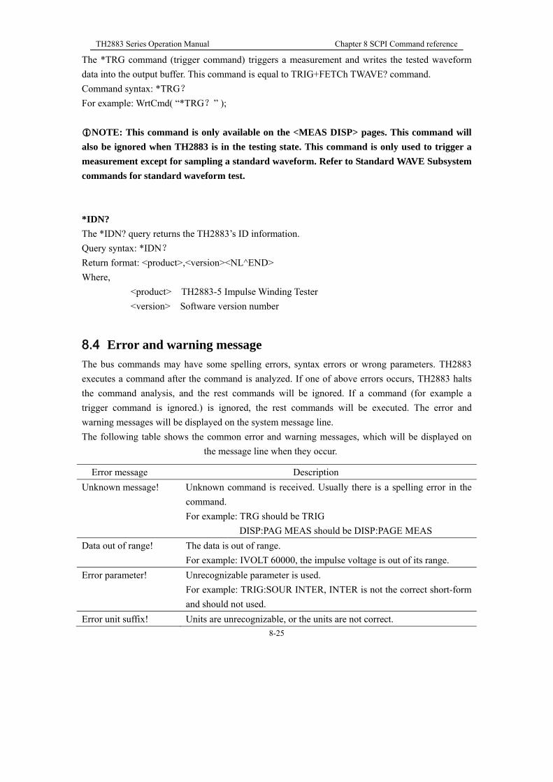
TH2883 Series Operation Manual Chapter 8 SCPI Command reference
8-25
The *TRG command (trigger command) triggers a measurement and writes the tested waveform
data into the output buffer. This command is equal to TRIG+FETCh TWAVE? command.
Command syntax: *TRG?
For example: WrtCmd( “*TRG?” );
NOTE: This command is only available on the <MEAS DISP> pages. This command will
also be ignored when TH2883 is in the testing state. This command is only used to trigger a
measurement except for sampling a standard waveform. Refer to Standard WAVE Subsystem
commands for standard waveform test.
*IDN?
The *IDN? query returns the TH2883’s ID information.
Query syntax: *IDN?
Return format: <product>,<version><NL^END>
Where,
<product> TH2883-5 Impulse Winding Tester
<version> Software version number
8.4 Error and warning message
The bus commands may have some spelling errors, syntax errors or wrong parameters. TH2883
executes a command after the command is analyzed. If one of above errors occurs, TH2883 halts
the command analysis, and the rest commands will be ignored. If a command (for example a
trigger command is ignored.) is ignored, the rest commands will be executed. The error and
warning messages will be displayed on the system message line.
The following table shows the common error and warning messages, which will be displayed on
the message line when they occur.
Error message Description
Unknown message! Unknown command is received. Usually there is a spelling error in the
command.
For example: TRG should be TRIG
DISP:PAG MEAS should be DISP:PAGE MEAS
Data out of range! The data is out of range.
For example: IVOLT 60000, the impulse voltage is out of its range.
Error parameter! Unrecognizable parameter is used.
For example: TRIG:SOUR INTER, INTER is not the correct short-form
and should not used.
Error unit suffix! Units are unrecognizable, or the units are not correct.

TH2883 Series Operation Manual Chapter 8 SCPI Command reference
8-26
8.5 Waveform data format
The waveform data is transferred in ASCII character string format. The specific format is as
follows:
Standard waveform data transfer format:
<DATA[1][0]><DATA[1][1]><DATA[2][0]><DATA[2][1]><DATA[3][0]><DATA[3][1] ……
<DATA[5999][0]> <DATA[5999][1]> <NL^END>
Figure 8-5-1 data format
Measured waveform data transfer format:
<DATA[1][0]><DATA[1][1]><DATA[2][0]><DATA[2][1]><DATA[3][0]><DATA[3][1] ……
<DATA[1199][0]> <DATA[1199][1]> <NL^END>
Figure 8-5-2 data format
As shown in Figure 8-5-1, NL is the line break, which means the end of the string and its ASCII
code is 10; ^END is the EOI (end) signal of bus IEEE-488. If the queried waveform data exists, the
instrument return the ASCII character string and the end character <NL ^ END> of waveform data;
if the waveform data does not exist, the instrument directly return back to the end character <NL ^
END>. Figure 8-5-1 shows that each waveform data point is returned in two character data, the two
For example: IVOLT:DEL 200us,us can not be the unit of the impulse
voltage.
Data too long! Data is too long.
For example: The number of characters for a file name can not exceed
12 characters and numeric parameter, 10 characters.
File not exist! Load a file that is not available.
Out of file range! For example:WrtCmd(“MMEM:STOR:STAT 105,“#TH2883*”)
where, 105 is out of file range, the maximum is 100.
Trigger ignores! When TH2883 is in the testing state, all trigger signals will be ignored.
Command ignores! Some command may be ignored.
For example: DISP:PAGE MSET
When TH2883 is in the testing state, this command will be ignored.
Error syntax! For example:WrtCmd(“MMEM:STOR:STAT 105,“#TH2883*”)
If there is no “ ” added in the file name #TH2883*, this error message
will pop up.
File already exist! The input file already exists. For example: MMEM:STOR:STAT2,
TH2883, if file 2 already exists, this error message will pop up.

TH2883 Series Operation Manual Chapter 9 Handler interface
8-2
characters represents upper and lower bit of hexadecimal data for waveform data points (range of
the waveform data points: 0-255), the upper bit is followed by the lower bit. Users can make data
conversion after receiving the data. For example, the data can be converted to decimal data.
NOTE: once the waveform data query command is made, the host machine must be in the
receiving state at once in case of data losing.
REMARK: the tested waveform and standard waveform sampled are composed of 6000 data
points.
In figure 8-5-2, its data points are 1200. When compiling the upper machine software, these
1200 points can be acquired. The measured waveform (not standard waveform) can be
displayed on the upper machine.

TH2883 Series Operation Manual Chapter 9 Handler interface
9-3
Chapter 9 Handler interface
9.1 Basic information
The handler interface employs a 9-pin DB connector. Pin sequence is as follow.
(side view)
The signal definitions for each pin are described as follows:
Note: The / (back slash) in the signal name means that the signal is asserted when low
level
PIN EXGND: Common for external voltage source EXV.
When TH2883 series uses the internal voltage as the power supply for handler
interface, TH2883 series’ circuit common will be connected to EXTEND.
PIN /EOC: End of conversion.
/EOC signal is asserted when the A/D conversion is completed and TH2883 series
is ready for the next DUT to be connected to the test terminals. The measurement
data, however, is not valid until BUSY is asserted to low.
PIN BUSY: TH2883 series is in the test state. When calculation, comparison and display are
all completed, this signal is asserted to low.
PIN /PASS: Pass signal output.
PIN /FAIL: Fail signal output.
PIN EXV: External DC voltage
DC voltage supply pins for DC isolated collector outputs, /EOC, /START, /STOP,
/PASS, /FAIL, /EOM. The setting of internal jumpers must be changed when
using the internal voltage supply.
PIN /START: External trigger signal.
TH2883 series is triggered bon the rising edge of a pulse applied to this pin
when the trigger mode is set to EXT mode.
PIN /STOP: External stop signal
Test is interrupted on the rising edge of a pulse applied to this pin.
PIN VCC: Internal voltage source supply (+5V)
Internal source is not recommended for user to use. Make sure the current is
lower than 0.1 A and keep the signal line be away form interference source
12345
6789

TH2883 Series Operation Manual Chapter 9 Handler interface
9-4
when use.
The timing diagram for handler interface is displayed in above figure, T1 is the trigger pulse width
and the minimum pulse width is 1 us. T2 is the delay time, after the foregoing measurement
completed to next trigger signal; its minimum pulse width is 0 us. /PASS and /FAIL signals are
asserted after the measurement completed, till next trigger. The request of the /STOP pulse signal is
the same as /START pulse signal.
9.2 Electrical characteristics
9.2.1 DC isolated output
Each DC output (pins 2 through 5) is the collector output of the built-in pull-up resistor and
isolated by an opto-coupler. The output voltage of each line is set by a pull-up resistor on the
handler interface board. The pull-up resistors can be connected to the internally supplied voltage
(+5V), or to an externally applied voltage (EXV: +5V to +24V) by setting jumpers. Table 9-1
shows the electrical characteristics of the DC isolated outputs.
Table 9-1 DC isolated output electrical characteristics
Output signal Voltage output rating Maximum
current Circuit common
Low High
/EOC
BUSY
/PASS
/FAIL
≤0.5V +5V~
+24V 6mA
Internal pull-up voltage:
TH2883 series circuit
common GND
External voltage (EXV):
EXGND

TH2883 Series Operation Manual Chapter 9 Handler interface
9-5
Figure 9-1 Simplified diagram of the output signals
A simplified diagram of the output signals is shown in Figure 9-1. * is the default jumper setting
when shipped from factory. That is to say, the default jumper setting is to use external voltage
source.
Refer to the next section Jumper Setup.
9.2.2 Isolated input
The /START signal (pin 7) and the /STOP signal (pin 8) are connected to the cathode of the LED in
an opto-coupler. TH2883 series is triggered on the rising edge of the /START pulse and stopped on
the rising edge of the /STOP pulse. The anode of the LED can be connected to the internal +5V, or
an external voltage source EXV (the same external voltage source used for output signal).

TH2883 Series Operation Manual Chapter 9 Handler interface
9-6
Figure 9-2 Simplified diagram of the input signal
In figure 9-2, the default jumper setting is to use external voltage source. Actually, the input signals
and the output signals use the external voltage source together. The Current-limit resistor is used to
limit the current and the default resistor is only suitable for external voltage source range from 5V
to 8V. If the external voltage source is higher than 8V, you should replace the Current–limit resistor
to avoid damaging circuit components. Current-limit resistor R705 and R706 should be both
replaced. The detailed replacement information about Current-limit resistor is listed in table 9-2.
Current-limit resistor Range of external voltage source
680Ω 5V to 8V
1.2KΩ 8V to 15V
2.2KΩ 15V to 24V
Table 9-2 Current-limit resistor for different voltage
9.3 Jumper setup on HANDLER interface
There are two jumpers on the Handler interface board. The two jumpers are used to select the
internal voltage source for external voltage source for the output signal and input signal. Their
locations are shown in figure 9-3.
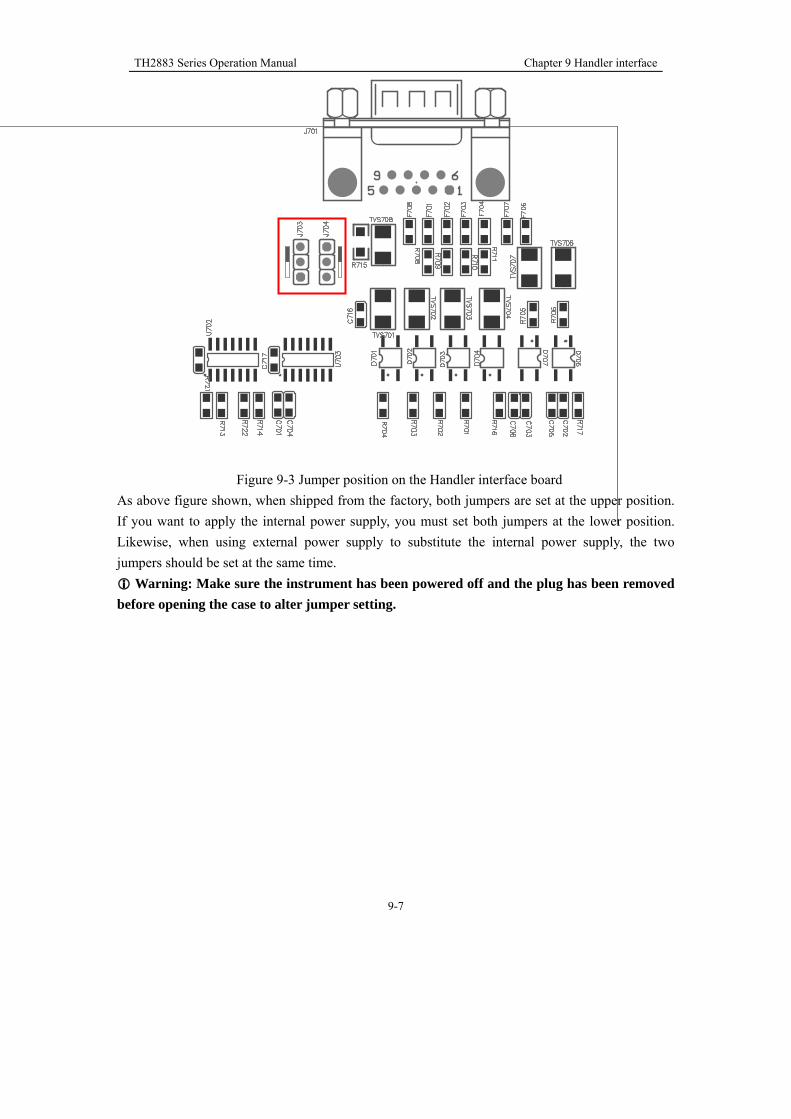
TH2883 Series Operation Manual Chapter 9 Handler interface
9-7
Figure 9-3 Jumper position on the Handler interface board
As above figure shown, when shipped from the factory, both jumpers are set at the upper position.
If you want to apply the internal power supply, you must set both jumpers at the lower position.
Likewise, when using external power supply to substitute the internal power supply, the two
jumpers should be set at the same time.
Warning: Make sure the instrument has been powered off and the plug has been removed
before opening the case to alter jumper setting.

TH2883 Series Operation Manual Chapter 10 Package contents and warranty
10-1
Chapter 10 Package contents and warranty
10.1 Package contents
Following items should be contained in the package.
Verify that you have received all above items and any optional accessories you may have ordered.
If any one is missing, please contact us without delay.
10.2 Warranty
This Tonghui instrument product is warranted against defects in material and workmanship for a
period of two years from the date of shipment. You should supply us with the warranty card before
you enjoy the free maintenance service. This warranty does not apply in the event of misuse or
abuse of the product or as a result of unauthorized alterations or repairs. Tonghui will, without
charge, repair or replace, at its option, defective product or component parts.
The maintenance for this instrument should be performed by professional maintenance personnel.
Do not substitute the internal components unauthorized when maintaining. In order to ensure the
measurement accuracy, the instrument must be measured and corrected after maintenance. You
should bear the maintenance expense for damages caused by unauthorized repairing or substituting
components.
The instrument should not be placed in the environment present direct sunlight and moisture.
Place the instrument in the original package box if you do not use it for a long time.
SSSeeerrr iiiaaalll
nnnuuummmbbbeeerrr
NNNaaammmeee QQQuuuaaannnttt iii tttyyy
1 TH2883-5/-10 Impulse Winding Tester 1
2 TH2883-01 High-voltage Test clip leads 1
3 TH2881-001 Foot Switch 1
4 Three-wire power line 1
5 Fuse of 1A 2
6 Operational Manual 1
7 Manufacturer Certificate 1
8 Test Report 1
9 Warranty Card 1