Embed Size (px)
Citation preview
Operation Manual
Emergency Combination System
ECS-6216P/S
* Rack mount products in the Western Hemisphere(North America, South America, and the Caribbean)do not have handles installed due to customer preference.
EMERGENCY COMBINATION SYSTEM
WelcomeWelcomeA personal welcome to you from the management and employees of Inter-M
All of the co-workers here at Inter-M are dedicated to providing excellent products with inherently good value,and we are delighted you have purchased one of our products.
We sincerely trust this product will provide years of satisfactory service, but if anything is not to your completesatisfaction, we will endeavor to make things right.
Welcome to Inter-M, and thank you for becoming part of our worldwide extended family!
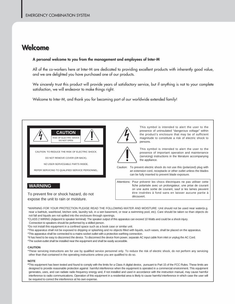
RISK OF ELECTRIC SHOCKDO NOT OPEN
CAUTION
CAUTION: TO REDUCE THE RISK OF ELECTRIC SHOCK.
DO NOT REMOVE COVER (OR BACK).
NO USER-SERVICEABLE PARTS INSIDE.
REFER SERVICING TO QUALIFIED SERVICE PERSONNEL.
WARNING
To prevent fire or shock hazard, do notexpose the unit to rain or moisture.
*WARNING FOR YOUR PROTECTION PLEASE READ THE FOLLOWING-WATER AND MOISTURE: Unit should not be used near water(e.g.near a bathtub, washbowl, kitchen sink, laundry tub, in a wet basement, or near a swimming pool, etc). Care should be taken so than objects donot fall and liquids are not spilled into the enclosure through openings.
*CLASS 2 WIRING (Adjacent to speaker terminal): The speaker output of this apparatus can exceed 10 Watts and could be a shock injury.Connection to speakers should be performed by a skilled person.
*Do not install this equipment in a confined space such as a book case or similar unit.*This apparatus shall not be exposed to dripping or splashing and no objects filled with liquids, such vases, shall be placed on the apparatus.*This apparatus shall be connected to a mains socket outlet with a protective earthing connection.*It has heed to be easy to disconnect the device. To disconnect the device from power, separate AC input cable from inlet or unplug the AC Cord.*The socket-outlet shall be installed near the equipment and shall be easily accessible.
CAUTION*These servicing instructions are for use by qualified service personnel only. To reduce the risk of electric shock, do not perform any servicingother than that contained in the operating instructions unless you are qualified to do so.
NOTE*This equipment has been tested and found to comply with the limits for a Class A digital device, pursuant to Part 15 of the FCC Rules. These limits aredesigned to provide reasonable protection against harmful interference when the equipment is operated in a commercial environment. This equipmentgenerates, uses, and can radiate radio frequency energy and, if not installed and used in accordance with the instruction manual, may cause harmfulinterference to radio communications. Operation of this equipment in a residential area is likely to cause harmful interference in which case the user willbe required to correct the interference at his own expense.
This symbol is intended to alert the user to thepresence of uninsulated “dangerous voltage” withinthe product’s enclosure that may be of sufficientmagnitude to constitute a risk of electric shock topersons.
This symbol is intended to alert the user to thepresence of important operation and maintenance(servicing) instructions in the literature accompanyingthe appliance.
Caution: To prevent electric shock do not use this (polarized) plug withan extension cord, receptacle or other outlet unless the bladescan be fully inserted to prevent blade exposure.
Attentions: Pour prévenir les chocs électriques ne pas utiliser cettefiche polarisée avec un prolongateur, une prise de couranton une autre sortie de courant, sauf si les lames peuventétre insérées à fond sans en laisser aucune partie àdécouvert.
EMERGENCY COMBINATION SYSTEM
1ECS-6216P/S
ContentsContentsUnpacking .......................................................................................................................................2
InstallationEnvironment....................................................................................................................................2Important Safety Instructions.............................................................................................................2
Features............................................................................................................................................3
Equipment Setting and Checking.................................................................................................4
Front Panel ......................................................................................................................................5
Rear Panel .......................................................................................................................................6
Applications ..................................................................................................................................10
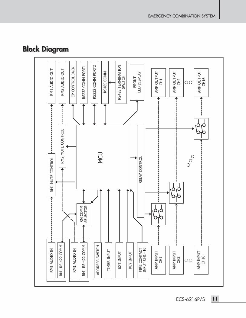
Block Diagram ..............................................................................................................................11
Specifications ................................................................................................................................12
Service............................................................................................................................................13Procedures....................................................................................................................................13Schematic .....................................................................................................................................13Parts List .......................................................................................................................................13
Warranty .......................................................................................................................................13
"We, Inter-M to apply the appropriate set of E4 & Class A for Electromagnetic Environment Condition."
EMERGENCY COMBINATION SYSTEM
2 ECS-6216P/S
Installation
UnpackingUnpackingAlthough your ECS-6216P/S is neither complicated nor difficult to operate, we recommend you take a fewminutes to read this brief manual and familiarize yourself with the important information regarding productfeatures, setup and operation.
As with most electronic devices, we strongly recommend you to retain the original packaging. In the unlikelyevent the product must be returned for servicing, the original packaging (or reasonable equivalent) is required.
InstallationEnvironmentNever place this product in an environment which could alter its performance or reduce its service life. Suchenvironments usually include high levels of heat, dust, moisture, and vibration.
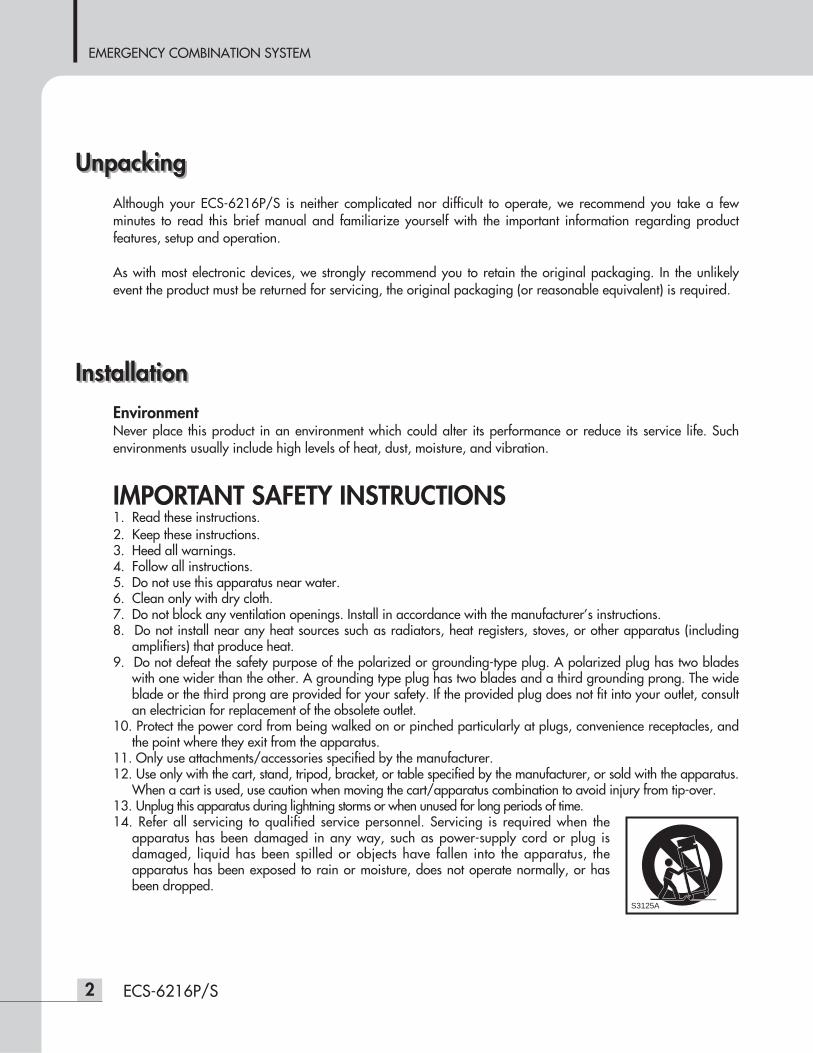
IMPORTANT SAFETY INSTRUCTIONS1. Read these instructions.2. Keep these instructions.3. Heed all warnings.4. Follow all instructions.5. Do not use this apparatus near water.6. Clean only with dry cloth.7. Do not block any ventilation openings. Install in accordance with the manufacturer’s instructions.8. Do not install near any heat sources such as radiators, heat registers, stoves, or other apparatus (including
amplifiers) that produce heat.9. Do not defeat the safety purpose of the polarized or grounding-type plug. A polarized plug has two blades
with one wider than the other. A grounding type plug has two blades and a third grounding prong. The wideblade or the third prong are provided for your safety. If the provided plug does not fit into your outlet, consultan electrician for replacement of the obsolete outlet.
10. Protect the power cord from being walked on or pinched particularly at plugs, convenience receptacles, andthe point where they exit from the apparatus.
11. Only use attachments/accessories specified by the manufacturer.12. Use only with the cart, stand, tripod, bracket, or table specified by the manufacturer, or sold with the apparatus.
When a cart is used, use caution when moving the cart/apparatus combination to avoid injury from tip-over.13. Unplug this apparatus during lightning storms or when unused for long periods of time.14. Refer all servicing to qualified service personnel. Servicing is required when the
apparatus has been damaged in any way, such as power-supply cord or plug isdamaged, liquid has been spilled or objects have fallen into the apparatus, theapparatus has been exposed to rain or moisture, does not operate normally, or hasbeen dropped.
S3125A
S3125A
EMERGENCY COMBINATION SYSTEM
3ECS-6216P/S
FeaturesFeaturesFeatures- INTEGRATED SYSTEM
System consists of EMERGENCY SWITCHER, MATRIX, RELAY GROUP, SPEAKER SELECTOR, and TERMINALBOARD functions.
- BROADCAST CONTROL DEPENDING ON PRIORITIESIt controls the priority broadcasting by connecting to emergency panel (EP-6216) and remote MIC (RM-6024).It switches to remote or emergency broadcasting due to priorities of emergency signals or outside remote signals(remote MIC broadcasting signals) even if during general broadcasting.
- AUTOMATIC FIRE DETECTING FUNCTIONWith 16-channels corresponding to fire contact point signals, fire alarm broadcasting will be transmittedautomatically.
- MANUAL CONTROL OF EMERGENCY AND GENERAL BROADCASTSIt can broadcast to desired channels by manually selecting emergency or general broadcasting.
- DISPLAY BROADCASTING STATUSIt displays the priority and broadcasting status on LED, so user can verify the broadcasting status without anyeffort.
- MEMORY/SAVE FUNCTIONFire/RM Macro information will be saved in internal PC memory allowing for normal operation in event of PCerror.
- CHANNEL EXPANSION AND RS-485 COMMUNICATION INTERFACELong distance transmission is available and system can be expanded to 160 Zones by utilizing ECS-6216S.
- INSTALLATION TIME AND SPACESince it is an integrated system, it is easy to install and can save installation labor, time and space.
EMERGENCY COMBINATION SYSTEM
4 ECS-6216P/S
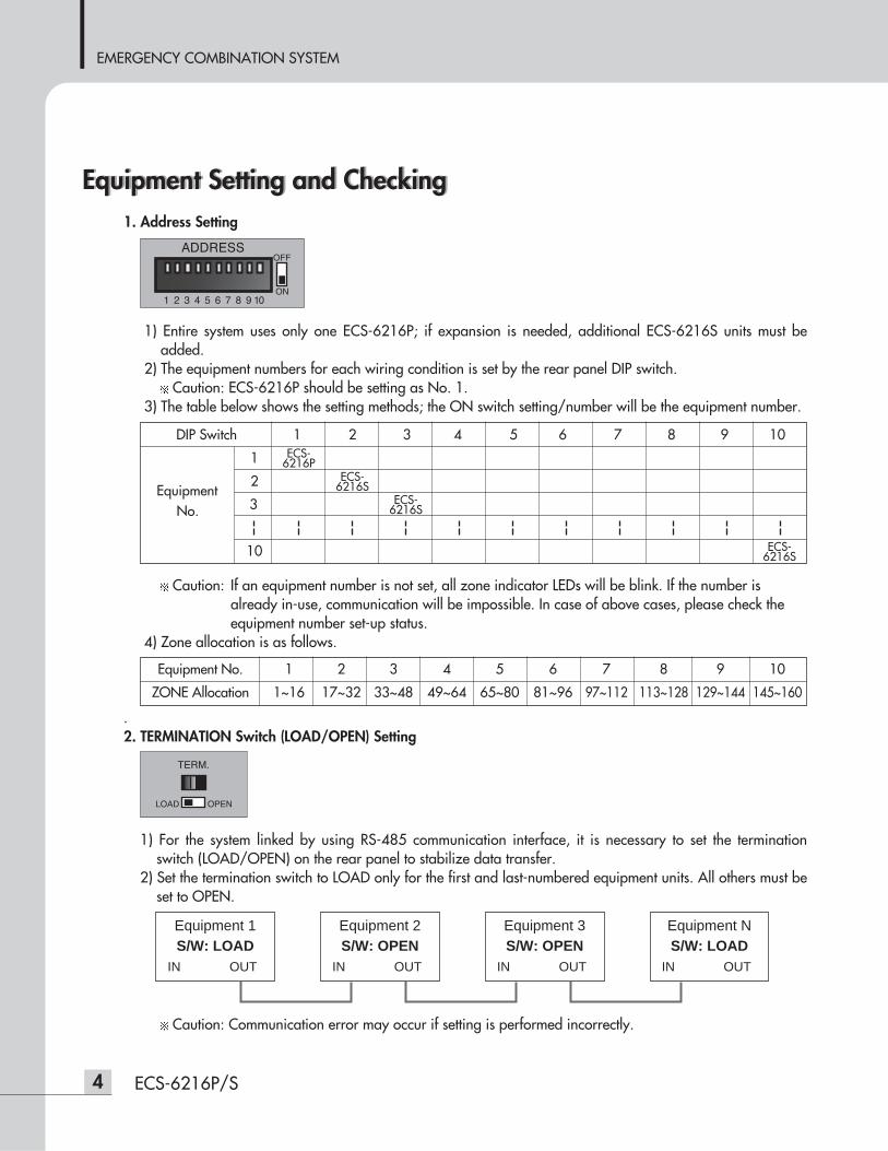
Equipment Setting and CheckingEquipment Setting and Checking1. Address Setting
1) Entire system uses only one ECS-6216P; if expansion is needed, additional ECS-6216S units must beadded.
2) The equipment numbers for each wiring condition is set by the rear panel DIP switch.Caution: ECS-6216P should be setting as No. 1.
3) The table below shows the setting methods; the ON switch setting/number will be the equipment number.
Caution: If an equipment number is not set, all zone indicator LEDs will be blink. If the number isalready in-use, communication will be impossible. In case of above cases, please check theequipment number set-up status.
4) Zone allocation is as follows.
.2. TERMINATION Switch (LOAD/OPEN) Setting
1) For the system linked by using RS-485 communication interface, it is necessary to set the terminationswitch (LOAD/OPEN) on the rear panel to stabilize data transfer.
2) Set the termination switch to LOAD only for the first and last-numbered equipment units. All others must beset to OPEN.
Caution: Communication error may occur if setting is performed incorrectly.
DIP Switch 1 2 3 4 5 6 7 8 9 10
1
2Equipment
3No.
10
ECS-6216P
ECS-6216S
ECS-6216S
ECS-6216S
Equipment No. 1 2 3 4 5 6 7 8 9 10
ZONE Allocation 1~16 17~32 33~48 49~64 65~80 81~96 97~112 113~128 129~144 145~160
Equipment 1S/W: LOAD
IN OUT
Equipment 2S/W: OPEN
IN OUT
Equipment 3S/W: OPEN
IN OUT
Equipment NS/W: LOAD
IN OUT
EMERGENCY COMBINATION SYSTEM
5ECS-6216P/S
Front PanelFront Panel
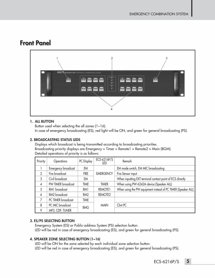
1. ALL BUTTONButton used when selecting the all zones (1~16).In case of emergency broadcasting (ES), red light will be ON, and green for general broadcasting (PS).
2. BROADCASTING STATUS LEDSDisplays which broadcast is being transmitted according to broadcasting priorities.Broadcasting priority displays are Emergency > Timer > Remote1 > Remote2 > Main (BGM).Detailed operations of priority is as follows:
3. ES/PS SELECTING BUTTONEmergency System (ES) or Public-address System (PS) selection button.LED will be red in case of emergency broadcasting (ES), and green for general broadcasting (PS).
4. SPEAKER ZONE SELECTING BUTTON (1~16)LED will be ON for the zone selected by each individual zone selection button.LED will be red in case of emergency broadcasting (ES), and green for general broadcasting (PS).
1 2 3
4
Priority Operations PC Display ECS-6216P/S RemarkLED1 Emergency broadcast EM EM mode switch, EM MIC broadcasting2 Fire broadcast FIRE EMERGENCY Fire Sensor input3 Civil broadcast EM When inputting EXT terminal contact point of ECS directly4 PW TIMER broadcast TIME TIMER When using PW-6242A device (Speaker ALL)5 RM1 broadcast RM1 REMOTE1 When using the PW equipment instead of PC TIMER (Speaker ALL)6 RM2 broadcast RM2 REMOTE27 PC TIMER broadcast TIME8 PC MIC broadcast
BMGMAIN Clint PC
9 MP3, CDP, TUNER
EMERGENCY COMBINATION SYSTEM
6 ECS-6216P/S
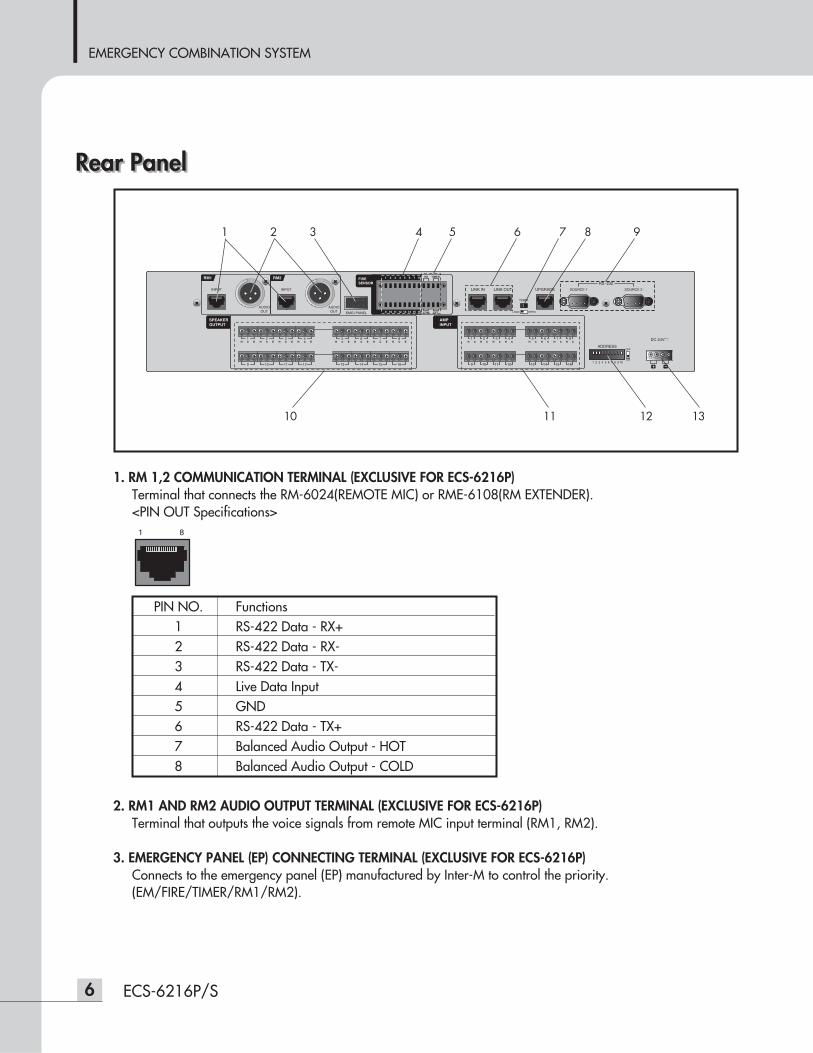
Rear PanelRear Panel
1. RM 1,2 COMMUNICATION TERMINAL (EXCLUSIVE FOR ECS-6216P)Terminal that connects the RM-6024(REMOTE MIC) or RME-6108(RM EXTENDER).<PIN OUT Specifications>
2. RM1 AND RM2 AUDIO OUTPUT TERMINAL (EXCLUSIVE FOR ECS-6216P)Terminal that outputs the voice signals from remote MIC input terminal (RM1, RM2).
3. EMERGENCY PANEL (EP) CONNECTING TERMINAL (EXCLUSIVE FOR ECS-6216P)Connects to the emergency panel (EP) manufactured by Inter-M to control the priority.(EM/FIRE/TIMER/RM1/RM2).
RM1
INPUT
AUDIOOUT
AUDIOOUT
RM2
INPUT LINK IN LINK OUT UPGRADE SOURCE 1
RS 232
SOURCE 2
EMG PANEL/
ADDRESS
1 2 3 4 5 6 7 8 9 10
1 2 3 4 5 6 7 8
9 10 11 12 13 14 15 16
1 2 3 4 5 6 7 8
9 10 11 12 13 14 15 16
TERM.
LOAD OPEN
1 2 3 4 5 6 7 8
9 10 11 12 13 14 15 16
FIRESENSOR
SPEAKEROUTPUT
AMPINPUT
H E H C EC E H C E H C E EH C E H C E H C H C H C H C H C H C H C H C H C H C
PD TIMER
EXTCOM
DC 24V
1 2 3
10 11 12 13
4 5 6 7 8 9
PIN NO. Functions1 RS-422 Data - RX+2 RS-422 Data - RX-3 RS-422 Data - TX-4 Live Data Input5 GND6 RS-422 Data - TX+7 Balanced Audio Output - HOT8 Balanced Audio Output - COLD
EMERGENCY COMBINATION SYSTEM
7ECS-6216P/S
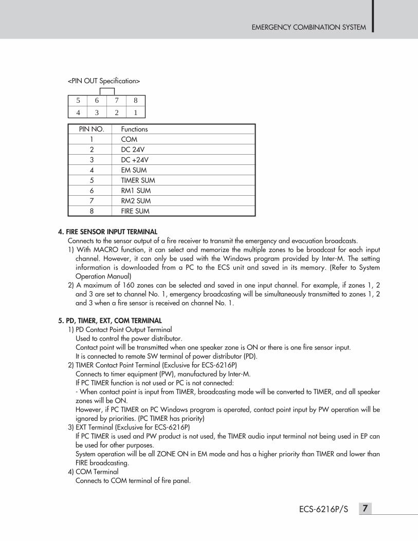
<PIN OUT Specification>
4. FIRE SENSOR INPUT TERMINALConnects to the sensor output of a fire receiver to transmit the emergency and evacuation broadcasts.1) With MACRO function, it can select and memorize the multiple zones to be broadcast for each input
channel. However, it can only be used with the Windows program provided by Inter-M. The settinginformation is downloaded from a PC to the ECS unit and saved in its memory. (Refer to SystemOperation Manual)
2) A maximum of 160 zones can be selected and saved in one input channel. For example, if zones 1, 2and 3 are set to channel No. 1, emergency broadcasting will be simultaneously transmitted to zones 1, 2and 3 when a fire sensor is received on channel No. 1.
5. PD, TIMER, EXT, COM TERMINAL1) PD Contact Point Output Terminal
Used to control the power distributor.Contact point will be transmitted when one speaker zone is ON or there is one fire sensor input.It is connected to remote SW terminal of power distributor (PD).
2) TIMER Contact Point Terminal (Exclusive for ECS-6216P)Connects to timer equipment (PW), manufactured by Inter-M.If PC TIMER function is not used or PC is not connected:- When contact point is input from TIMER, broadcasting mode will be converted to TIMER, and all speakerzones will be ON.However, if PC TIMER on PC Windows program is operated, contact point input by PW operation will beignored by priorities. (PC TIMER has priority)
3) EXT Terminal (Exclusive for ECS-6216P)If PC TIMER is used and PW product is not used, the TIMER audio input terminal not being used in EP canbe used for other purposes.System operation will be all ZONE ON in EM mode and has a higher priority than TIMER and lower thanFIRE broadcasting.
4) COM TerminalConnects to COM terminal of fire panel.
5 6 7 8
4 3 2 1
PIN NO. Functions1 COM2 DC 24V3 DC +24V4 EM SUM5 TIMER SUM6 RM1 SUM7 RM2 SUM8 FIRE SUM
EMERGENCY COMBINATION SYSTEM
8 ECS-6216P/S
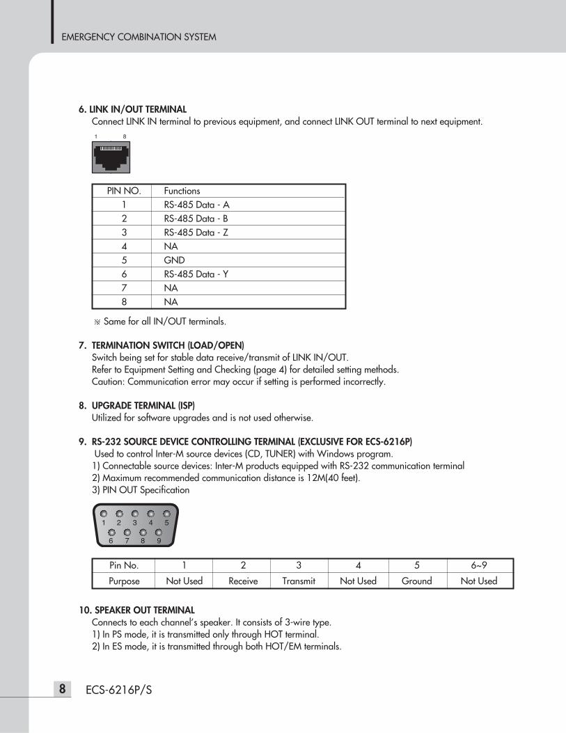
6. LINK IN/OUT TERMINALConnect LINK IN terminal to previous equipment, and connect LINK OUT terminal to next equipment.
Same for all IN/OUT terminals.
7. TERMINATION SWITCH (LOAD/OPEN)Switch being set for stable data receive/transmit of LINK IN/OUT.Refer to Equipment Setting and Checking (page 4) for detailed setting methods. Caution: Communication error may occur if setting is performed incorrectly.
8. UPGRADE TERMINAL (ISP)Utilized for software upgrades and is not used otherwise.
9. RS-232 SOURCE DEVICE CONTROLLING TERMINAL (EXCLUSIVE FOR ECS-6216P)Used to control Inter-M source devices (CD, TUNER) with Windows program.1) Connectable source devices: Inter-M products equipped with RS-232 communication terminal2) Maximum recommended communication distance is 12M(40 feet).3) PIN OUT Specification
10. SPEAKER OUT TERMINALConnects to each channel’s speaker. It consists of 3-wire type.1) In PS mode, it is transmitted only through HOT terminal.2) In ES mode, it is transmitted through both HOT/EM terminals.
PIN NO. Functions1 RS-485 Data - A2 RS-485 Data - B3 RS-485 Data - Z4 NA5 GND6 RS-485 Data - Y7 NA8 NA
Pin No. 1 2 3 4 5 6~9
Purpose Not Used Receive Transmit Not Used Ground Not Used
11. AMP IN TERMINALConnects with output of AMP.
12. ADDRESS SWITCHSets the role for each system when equipment is expanded and linked.Refer to Basic Setting and Checking (Page 4) for setting methods.
13. POWER INPUT TERMINAL- Power input terminal. Check polarity before connecting DC 24V. - When connecting to PD (Power Distributor), connect to unswitched terminal.
EMERGENCY COMBINATION SYSTEM
9ECS-6216P/S
EMERGENCY COMBINATION SYSTEM
10 ECS-6216P/S
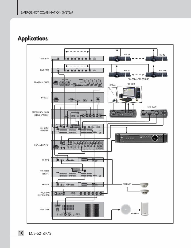
ApplicationsApplications
DUCK P.PWR
CH1CH2
DUCK P.PWR
CH3CH4CH5CH6CH7CH8CH9
LINE IN
MIC IN
L
RR
L
R
L
2
1
AUX
1
2
PRIORITY
+-DC INPUT
24VINSERTREC OUT
MASTER
2
1
SUB OUTOUTPUT INPUTINPUT
LINE IN
MIC IN
LINE IN
MIC IN
LINE IN
MIC IN
LINE IN
MIC IN
LINE IN
MIC IN
LINE IN
MIC IN
LINE IN
MIC IN
LINE IN
MIC IN
RM1
INPUT
AUDIOOUT
AUDIOOUT
RM2
INPUT LINK IN LINK OUT UPGRADE SOURCE 1
RS 232
SOURCE 2
EMG PANEL/
ADDRESS
1 2 3 4 5 6 7 8 9 10
1 2 3 4 5 6 7 8
9 10 11 12 13 14 15 16
1 2 3 4 5 6 7 8
9 10 11 12 13 14 15 16
TERM.
LOAD OPEN
1 2 3 4 5 6 7 8
9 10 11 12 13 14 15 16
FIRESENSOR
SPEAKEROUTPUT
AMPINPUT
H E H C EC E H C E H C E EH C E H C E H C H C H C H C H C H C H C H C H C H C
PD TIMER
EXTCOM
DC 24V
LINK IN LINK OUT
ADDRESS
1 2 3 4 5 6 7 8 9 10
1 2 3 4 5 6 7 8
9 10 11 12 13 14 15 16
1 2 3 4 5 6 7 8
9 10 11 12 13 14 15 16
1 2 3 4 5 6 7 8
9 10 11 12 13 14 15 16
FIRESENSOR
SPEAKEROUTPUT
AMPINPUT
H E H C EC E H C E H C E EH C E H C E H C H C H C H C H C H C H C H C H C H C
PD TIMER
EXTCOM
DC 24V
DC OUT24V
MATRIX
12 0
SIREN/VOLUME
PRE IN REMOTE IN 2 REMOTE IN 1 TIMER IN AUTO ANN IN PRE OUT
CONTROL OUT (TO AUTO ANN)
EXT INTAUTO. ANN
REMOTE MICMIC SW
EXT INT
HPFON OFF
~AC INPUT220V 60Hz
FUSEDC INPUT
24V
BALANCEDINPUT
1V/10K LINK
INPUT(ADJ)
12dB 0dB
100V(20.8 )43.8V(4 )
OUTPUT
COMAB
70V(10.2 )
FRAMEFLOAT
GROUNDLIFT
CH 1OUTPUT CH 2CH 3CH 4CH 5CH 6INPUT
FUSE
~AC INPUT
INPUT OUTPUT
INPUT OUTPUT
LINELINK
TERM.OPEN
LOAD
GND.FLOAT
FRAMEDIRECT BOXDIB 6000
+
VOL INPUT OUTPUTPOWER
TO PC
MUTELEVEL
INPUT
VOL
+
MIC
PRI.
OFF
ONMAXMIN
LINE
IN OUT VOICEFILETERM.
LINK
LOAD OPEN
ADDRESS
1 2 3 4 5 6 7 8 9 10
FIRE SENSOR 1 2 3 4 5 6 7 8 COM
COM9 10 11 12 13 14 15 16
DC 24V
COMNO NC
RELAYOUTPUT
IN OUT VOICEFILETERM.
LINK
LOAD OPEN
ADDRESS
1 2 3 4 5 6 7 8 9 10
FIRE SENSOR 1 2 3 4 5 6 7 8 COM
COM9 10 11 12 13 14 15 16
DC 24V
COMNO NC
RELAYOUTPUT
RM 1 RM 2 RM 3 RM 4 RM 5 RM 6 RM 7 RM 8
INPUTOUTPUTDC 24V
RM 1 RM 2 RM 3 RM 4 RM 5 RM 6 RM 7 RM 8
INPUTOUTPUTDC 24V
SPEAKER
RECEIVER
RME-6108
RME-6108
PV-6232
PROGRAM TIMER
PRE AMPLIFIER
EMERGENCY PANEL(SLIDE S/W: EXT)
ECS-6216P(MASTER)
ER-6116
ECS-6216S(SLAVE)
ER-6116
PROGRAMDISTRIBUTOR
AMPLIFIER
DIB-6000
RM-01
RM-6024+RM-6012KP
RM #1 RM #8
RM #9 RM #16
PC(GUI)
EMERGENCY COMBINATION SYSTEM
11ECS-6216P/S
Block DiagramBlock DiagramRM
1 AU
DIO
IN
RM
1 RS-
422
COM
M
RM
1 AU
DIO
IN
ADD
RES
S SW
ITCH
TIM
ER I
NPU
T
EXT
INPU
T
KEY
INPU
T
AMP
INPU
TCH
1
AMP
INPU
TCH
2
AMP
INPU
TCH
16
FIRE
CON
TACT
INPU
T CH
1~16
RM
1 RS-
422
COM
M
REL
AY C
ON
TRO
L
MCU
RM
CO
MM
SELE
CTO
R
RM
1 M
UTE
CO
NTR
OL
RM
2 M
UTE
CO
NTR
OL
RM
1 AU
DIO
OU
T
RM
2 AU
DIO
OU
T
EP C
ON
TRO
L JA
CK
RS2
32 C
OM
M P
ORT
1
RS2
32 C
OM
M P
ORT
2
RS4
85 C
OM
M
RS4
85 T
ERM
INAT
ION
SWIT
CH
FRO
NT
LED
DIS
PLAY
AMP
OU
TPU
TCH
1
AMP
OU
TPU
TCH
2
AMP
OU
TPU
TCH
16
EMERGENCY COMBINATION SYSTEM
12 ECS-6216P/S
ECS-6216P/S
Priority Emergency>Timer>Remote 1>Remote 2>Main
Channel 16CH
Communications Protocol LINK IN/OUT RS-485 (Maximum: 1km/3,280 feet)
RM INPUT (RM1, 2) RS-422 (Maximum: 1km/3,280 feet)
SOURCE RS-232 (Maximum: 12m/40 feet)
Fire Sensor Dry Contact
Operating Temperature -10°C ~ +40°C/14°F~104°F
Power Source DC 24V, 900mA
Weight (Set) 4.3kg/9.5lbs
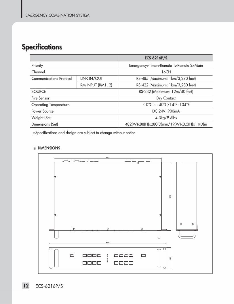
Dimensions (Set) 482(W)x88(H)x280(D)mm/19(W)x3.5(H)x11(D)in
Specifications and design are subject to change without notice.
SpecificationsSpecifications
DIMENSIONS
280
482
8828
088
482
440
EMERGENCY COMBINATION SYSTEM
13ECS-6216P/S
ServiceService
ProceduresTake steps to insure the problem is not related to operator error or other products within the system. Informationprovided in the troubleshooting portion of this manual may help with this process. Once it is certain that theproblem is related to the product contact your warranty provider as described in the warranty section of thismanual.
SchematicA Schematic is available by contacting your warranty provider.
Parts ListA Parts List is available by contacting your warranty provider.
WarrantyWarranty
Warranty terms and conditions vary by country and may not be the same for all products. Terms and conditionsof warranty for a given product may be determined first by locating the appropriate country which the productwas purchased in, then by locating the product type.
To obtain specific warranty information and available service locations contact Inter-M directly or theauthorized Inter-M Distributor for your specific country or region.

MADE IN KOREAJanuary 2012 127746
Inter-M, Ltd. (Korea) began operations in 1983.
Since then, Inter-M has grown to become one of the largest manufacturers of professional audio and commercial sound electronics equipment in the world.
Inter-M has gained worldwide recognition for its own branded products, as well as private label manufacturing of electronics sold under other names (OEM).
The company is no longer just a Korean company, but rather a global company that is truly international in scope, with factories and offices in Korea and China, and sales and marketing operations located in Japan, Europe, and the U.S.A.
With more than 850 employees around the globe,Inter-M is well-poised for further growth and expansion.
Inter-M Americas, Inc. 13875 Artesia Blvd. Cerritos, CA 90703 USATEL : +1-562-921-0313, FAX : +1-562-921-0370Home Page : http://www.inter-m.net, E-mail : [email protected]
Inter-M CorporationSeoul OFFICE:653-5 BANGHAK-DONG, DOBONG-KU, SEOUL, KOREA TEL : +82-2-2289-8140~8, FAX : +82-2-2289-8149Home Page : http://www.inter-m.com, E-mail : [email protected]