Embed Size (px)
Citation preview
Operation Manual
X62DFIssue 002 2021-09
Winterthur Gas & Diesel Ltd. Schützenstrasse 3 Tel. +41 (0)52 264 8844Winterthur Gas & Diesel AG P.O. Box 414, 8401 Fax +41 (0)52 264 8866Winterthur Gas & Diesel S.A. Winterthur, Switzerland www.wingd.com

© 2021 Winterthur Gas & Diesel Ltd. – All rights reserved
No part of this publication may be reproduced or copied in any form or by any means (electronic,mechanical, graphic, photocopying, recording, taping or other information retrieval systems) without theprior written permission of the copyright holder. Winterthur Gas & Diesel Ltd. makes no representation,warranty (express or implied) in this publication and assumes no responsibility for the correctness, errorsor omissions of information contained herein. Information in this publication is subject to change withoutnotice.
NO LIABILITY, WHETHER DIRECT, INDIRECT, SPECIAL, INCIDENTAL ORCONSEQUENTIAL, IS ASSUMED WITH RESPECT TO THE INFORMATION CONTAINEDHEREIN. THIS PUBLICATION IS INTENDED FOR INFORMATION PURPOSES ONLY.
www.wingd.com

Table of contents
1 Introduction1.1 Operation Manual - change record............................................................................201.2 Preface......................................................................................................................221.3 Technical documentation set.....................................................................................241.4 Data module codes (descriptive data).......................................................................261.5 Data module codes (procedural data).......................................................................281.6 About this book..........................................................................................................301.7 About the engine.......................................................................................................321.8 List of abbreviations...................................................................................................36
2 Safety2.1 Safety precautions and safety guidelines..................................................................422.2 Safety precautions and safety rules for natural gas..................................................462.3 Contamination and fire in the scavenge air spaces...................................................482.4 Fire-fighting in the scavenge air space......................................................................502.5 Explosions in the crankcase......................................................................................522.6 Prevent explosions in the crankcase.........................................................................542.7 Prevention of explosions in the exhaust gas system (gas mode)..............................562.8 Access to engine spaces...........................................................................................58
3 Design and function of the engine3.1 Short description of the DF engine............................................................................623.2 Use of the engine......................................................................................................663.3 The relation between engine and propeller...............................................................70
4 Design and function of systems4.1 General for systems..................................................................................................744.2 Cooling water system................................................................................................764.3 Wash-water system...................................................................................................784.4 System oil system......................................................................................................804.5 Servo oil system........................................................................................................824.6 Cylinder oil system....................................................................................................844.7 Starting air system.....................................................................................................864.8 Scavenge air system.................................................................................................884.9 Control air system......................................................................................................904.10 Exhaust gas system..................................................................................................924.11 Fuel system...............................................................................................................944.12 Gas system................................................................................................................984.13 Pilot fuel system......................................................................................................100
X62DF
Operation Manual
Winterthur Gas & Diesel Ltd. - 3 - Issue 002 2021-09

4.14 LP Selective catalytic reduction system..................................................................1024.15 Steam production control system............................................................................116
5 Design and function of components5.1 Group 1 - Engine frame and bearings
5.1.1 Bedplate..........................................................................................................1245.1.2 Main bearing....................................................................................................1265.1.3 Thrust bearing.................................................................................................1285.1.4 Monoblock column...........................................................................................1305.1.5 Tie rod.............................................................................................................132
5.2 Group 2 - Cylinder5.2.1 Cylinder liner....................................................................................................1345.2.2 Lubricating quill................................................................................................1365.2.3 Gas admission valve.......................................................................................1385.2.4 Piston rod gland...............................................................................................1405.2.5 Direct controlled injection valve.......................................................................1425.2.6 Starting valve...................................................................................................1445.2.7 Relief valve......................................................................................................1465.2.8 Exhaust valve..................................................................................................1485.2.9 Pilot injection valve..........................................................................................150
5.3 Group 3 - Crankshaft, connecting rod and piston5.3.1 Crankshaft.......................................................................................................1525.3.2 Torsional vibration damper..............................................................................1545.3.3 Axial vibration damper.....................................................................................1585.3.4 Turning gear....................................................................................................1605.3.5 Connecting rod and connecting rod bearing....................................................1625.3.6 Crosshead and guide shoe..............................................................................1645.3.7 Piston...............................................................................................................166
5.4 Group 4 - Supply unit drive and control components5.4.1 Supply unit drive..............................................................................................1685.4.2 Starting air shut-off valve.................................................................................1705.4.3 Control air supply.............................................................................................1725.4.4 Local maneuvering stand for UNIC.................................................................1745.4.5 Pick-up for speed measurement......................................................................176
5.5 Group 5 - Supply unit, pumps and control valves5.5.1 Servo oil pump.................................................................................................1785.5.2 Supply unit.......................................................................................................1805.5.3 Supply unit pilot fuel........................................................................................1825.5.4 Fuel pump........................................................................................................1845.5.5 Pressure control valve.....................................................................................1865.5.6 Flow limiting valve...........................................................................................1885.5.7 Exhaust valve control unit................................................................................190
5.6 Group 6 - Scavenge air components
X62DF
Operation Manual
Winterthur Gas & Diesel Ltd. - 4 - Issue 002 2021-09

5.6.1 Scavenge air receiver......................................................................................1925.6.2 Turbocharger...................................................................................................1945.6.3 Auxiliary blower...............................................................................................1965.6.4 Auxiliary blower switch box..............................................................................1985.6.5 Scavenge air cooler.........................................................................................2005.6.6 Water separator...............................................................................................202
5.7 Group 7 - Cylinder lubrication and balancer5.7.1 Cylinder lubrication..........................................................................................2045.7.2 Integrated electrical balancer (iELBA).............................................................206
5.8 Group 8 - Pipes5.8.1 Exhaust waste gate.........................................................................................212
5.9 Group 9 - Monitoring instruments5.9.1 Crank angle sensor unit...................................................................................2145.9.2 Water in oil monitor..........................................................................................2165.9.3 Oil mist detector...............................................................................................218
6 Control system6.1 Engine control system UNIC...................................................................................2246.2 Intelligent combustion control..................................................................................2306.3 Gas valve unit and external gas supply system......................................................2346.4 Local display unit (LDU-20) - general......................................................................2406.5 Local display unit (LDU-20)- Option for UNIC - pages
6.5.1 Operate the local display unit (LDU-20)..........................................................2426.5.2 LDU-20 pages - general for DF engine...........................................................2486.5.3 LDU-20 page - MAIN.......................................................................................2506.5.4 LDU-20 page - CONTROL LOCATIONS.........................................................2546.5.5 LDU-20 page - FUEL MODE CONTROL........................................................2566.5.6 LDU-20 page - CA SENSOR STATUS............................................................2586.5.7 LDU-20 page - CYLINDER BALANCING DIESEL..........................................2606.5.8 LDU-20 page - CYLINDER BALANCING GAS...............................................2626.5.9 LDU-20 page - CYLINDER LUBRICATION.....................................................2646.5.10 LDU-20 page - iCAT........................................................................................2666.5.11 LDU-20 page - DYNAMIC COMBUSTION CONTROL (DCC)........................2706.5.12 LDU-20 page - EXHAUST VENTILATION......................................................2726.5.13 LDU-20 page - EXHAUST VALVES................................................................2746.5.14 LDU-20 page - FAILURE LIST........................................................................2766.5.15 LDU-20 page - FAILURE SIMULATION..........................................................2786.5.16 LDU-20 page - FUEL SHARING (if applicable)...............................................2806.5.17 LDU-20 page - FUEL SYSTEM.......................................................................2826.5.18 LDU-20 page - GAS PRESSURE....................................................................2846.5.19 LDU-20 page - GAS LEAK TEST....................................................................2866.5.20 LDU-20 page - GAS ADMISSION VALVES....................................................2886.5.21 LDU-20 page - GAV MANUAL VALVE TEST..................................................290
X62DF
Operation Manual
Winterthur Gas & Diesel Ltd. - 5 - Issue 002 2021-09

6.5.22 LDU-20 page - GVU & VALVE TEST..............................................................2926.5.23 LDU-20 page - KNOCK CONTROL.................................................................2946.5.24 LDU-20 page - LOG MESSAGES...................................................................2966.5.25 LDU-20 page - MAIN FUEL INJECTION.........................................................2986.5.26 LDU-20 page - PAGE INDEX..........................................................................3006.5.27 LDU-20 page - PERFORMANCE DATA DIESEL............................................3026.5.28 LDU-20 page - PERFORMANCE DATA GAS.................................................3046.5.29 LDU-20 page - PILOT FUEL INJECTION.......................................................3066.5.30 LDU-20 page - PILOT FUEL PRESSURE.......................................................3086.5.31 LDU-20 page - SCAVENGE AIR - EWG (optional).........................................3106.5.32 LDU-20 page - SCREENSHOT.......................................................................3126.5.33 LDU-20 page - SOFTWARE INFO..................................................................3146.5.34 LDU-20 page - IMO CRC INFO.......................................................................3166.5.35 LDU-20 page - SOFTWARE TOOLS..............................................................3186.5.36 LDU-20 page - SYSTEM STATUS..................................................................3206.5.37 LDU-20 page - SYSTEM SETTINGS..............................................................3226.5.38 LDU-20 page - TEMPERATURES..................................................................3246.5.39 LDU-20 page - USER PARAMETERS............................................................3266.5.40 LDU-20 page - LOG ENTRY DATA.................................................................3286.5.41 MCP page - FUEL / LUBRICATION SYSTEM................................................3306.5.42 LDU-20 page - DATE......................................................................................3326.5.43 LDU-20 page - ETHERNET.............................................................................3346.5.44 LDU-20 page - iELBA Control (optional).........................................................336
7 Installation7.1 Installation...............................................................................................................340
8 Operation8.1 Prepare the engine before start - general................................................................3428.2 Prepare the engine before start...............................................................................3448.3 Start the engine - general........................................................................................3528.4 Start the engine.......................................................................................................3548.5 Do checks during operation - general......................................................................3568.6 Do checks during operation.....................................................................................3588.7 Do regular safety checks.........................................................................................3628.8 Maneuver the ship - general....................................................................................3668.9 Maneuver the ship...................................................................................................3688.10 Change-over the diesel fuel - general.....................................................................3708.11 Change-over to and from gas - general...................................................................3748.12 Change-over the diesel fuel automatically...............................................................3768.13 Change-over from HFO to MDO manually..............................................................3788.14 Change-over from MDO to HFO manually..............................................................3808.15 Change-over to and from gas..................................................................................382
X62DF
Operation Manual
Winterthur Gas & Diesel Ltd. - 6 - Issue 002 2021-09

8.16 Stop the engine - general........................................................................................3848.17 Stop the engine.......................................................................................................3868.18 Emergency stop the engine - general......................................................................3888.19 Emergency stop the engine.....................................................................................3908.20 Prepare the engine after stop - general...................................................................3928.21 Prepare the engine for a short service break..........................................................3948.22 Prepare the engine for standstill or for maintenance...............................................396
9 Service during operation9.1 Do an analysis of the system oil..............................................................................4029.2 Do an analysis of the cylinder oil.............................................................................4049.3 Replace the filter element of the duplex filter..........................................................4089.4 Clean the scavenge air cooler during operation......................................................4109.5 Do a test of the exhaust waste valve.......................................................................4149.6 Running-in of new components - general................................................................4169.7 Running-in of new components...............................................................................4189.8 Clean the turbocharger during operation.................................................................420
10 Troubleshooting10.1 Troubleshooting - general data................................................................................42410.2 Malfunctions of systems and components...............................................................42610.3 Failures and defects of UNIC-flex components.......................................................44610.4 LP SCR - Alarm failure troubleshooting...................................................................44810.5 Bleed the cooling water system of the liner wall......................................................45410.6 Examine the supply unit for servo oil leakage.........................................................45610.7 Examine the supply unit for fuel leakage.................................................................46010.8 Examine the rail unit for leakage.............................................................................46410.9 Examine the FLV or fuel pipes for fuel leakage.......................................................46610.10 Temporary cut out a defective injection valve.........................................................47010.11 Temporary cut out a defective exhaust valve drive.................................................47210.12 Temporary isolate a cylinder with cooling water leakage........................................47410.13 Servo oil pump - troubleshooting.............................................................................47810.14 Servo oil pump - Calibration for Bosch pump..........................................................48010.15 Servo oil pump - Calibration for Hawe pump...........................................................48210.16 Fuel pump - cutting out............................................................................................48410.17 Fuel pump - cutting in..............................................................................................49010.18 Temporary isolate a defective turbocharger............................................................49410.19 Temporary isolate the exhaust waste gate..............................................................49810.20 Isolate a defective engine at twin engine installation...............................................50210.21 Gas detector - calibrate...........................................................................................50410.22 LDU-20 - remove.....................................................................................................51010.23 LDU-20 - install........................................................................................................51410.24 CCM-20 - remove....................................................................................................518
X62DF
Operation Manual
Winterthur Gas & Diesel Ltd. - 7 - Issue 002 2021-09
10.25 CCM-20 - install.......................................................................................................52010.26 CCM-20 - Emergency back-up lubrication...............................................................52210.27 CCM-20 - replace....................................................................................................52610.28 MCM-11 - remove....................................................................................................52810.29 MCM-11 - install......................................................................................................53010.30 IOM-10 - remove.....................................................................................................53210.31 IOM-10 - install........................................................................................................53410.32 Special running condition: Cylinder cut out.............................................................53610.33 Special running condition: Turbocharger cut out.....................................................542
11 Technical data11.1 Engine data.............................................................................................................55211.2 List of usual values and safeguard settings - general.............................................55411.3 List of usual values and safeguard settings.............................................................55811.4 Section views...........................................................................................................570
12 Operating media12.1 General for operating media....................................................................................57212.2 Compressed air.......................................................................................................57412.3 Scavenge air............................................................................................................57612.4 Gas fuels.................................................................................................................578
13 Schematic diagrams13.1 Schematic diagrams - general.................................................................................58413.2 List of diagrams.......................................................................................................590
X62DF
Operation Manual
Winterthur Gas & Diesel Ltd. - 8 - Issue 002 2021-09

List of tables
1 Introduction1-1 Change record ............................................................................................. 201-2 Data module codes (descriptive data) ......................................................... 261-3 Data module codes (procedural data) ......................................................... 281-4 List of abbreviations and acronyms ............................................................. 36
4 Design and function of systems4-1 LP SCR SYSTEM STATUS (MAIN PAGE) ................................................. 1114-2 LP SCR SYSTEM OVERVIEW ................................................................... 1124-3 LP SCR INTERFACES ................................................................................ 1134-4 LP SCR SOFTWARE INFO ........................................................................ 1144-5 LP SCR PAGE INDEX ................................................................................ 1154-6 STEAM PRODUCTION CONTROL (SPC) ................................................. 117
5 Design and function of components5-1 iELBA - control cabinet ................................................................................ 2105-2 iELBA - error indication ............................................................................... 211
6 Control system6-1 MAIN ........................................................................................................... 2516-2 CONTROL LOCATIONS ............................................................................. 2556-3 FUEL MODE CONTROL ............................................................................. 2576-4 CA SENSOR STATUS ................................................................................ 2596-5 CYLINDER BALANCING DIESEL ............................................................... 2616-6 CYLINDER BALANCING GAS .................................................................... 2636-7 CYLINDER LUBRICATION ......................................................................... 2656-8 iCAT (integrated Cylinder lubricant Auto Transfer) ..................................... 2676-9 DYNAMIC COMBUSTION CONTROL (DCC) ............................................. 2716-10 EXHAUST VENTILATION ........................................................................... 2736-11 EXHAUST VALVES .................................................................................... 2756-12 FAILURE LIST ............................................................................................. 2776-13 FAILURE SIMULATION .............................................................................. 2796-14 FUEL SHARING (if applicable) ................................................................... 2816-15 FUEL SYSTEM ........................................................................................... 2836-16 GAS PRESSURE ........................................................................................ 2856-17 GAS LEAK TEST ........................................................................................ 2876-18 GAS ADMISSION VALVES ......................................................................... 2896-19 GAV MANUAL VALVE TEST ...................................................................... 2916-20 GVU & VALVE TEST .................................................................................. 2936-21 KNOCK CONTROL ..................................................................................... 2956-22 LOG MESSAGES ........................................................................................ 2976-23 MAIN FUEL INJECTION ............................................................................. 2996-24 PAGE INDEX .............................................................................................. 301
X62DF
Operation Manual
Winterthur Gas & Diesel Ltd. - 9 - Issue 002 2021-09

6-25 PERFORMANCE DATA DIESEL ................................................................ 3036-26 PERFORMANCE DATA GAS ..................................................................... 3056-27 PILOT FUEL INJECTION ............................................................................ 3076-28 PILOT FUEL PRESSURE ........................................................................... 3096-29 SCAVENGE AIR - EWG (optional) .............................................................. 3116-30 SOFTWARE INFO ...................................................................................... 3156-31 IMO CRC INFO ........................................................................................... 3176-32 SOFTWARE TOOLS ................................................................................... 3196-33 SYSTEM STATUS ...................................................................................... 3216-34 SYSTEM SETTINGS ................................................................................... 3236-35 TEMPERATURES ....................................................................................... 3256-36 USER PARAMETERS ................................................................................. 3276-37 LOG ENTRY DATA ..................................................................................... 3296-38 FUEL / LUBRICATION SYSTEM ................................................................ 3316-39 DATE ........................................................................................................... 3336-40 ETHERNET ................................................................................................. 3356-41 iELBA Control .............................................................................................. 337
10 Troubleshooting10-1 Supply pressure of the cylinder cooling water is too low ............................. 42910-2 Supply temperature of the cylinder cooling water is too low ....................... 42910-3 Cylinder cooling water temperature downstream of a cylinder is too high . . 42910-4 Supply pressure of the cooling water to the SAC is too low ........................ 42910-5 Supply temperature of the cooling water to the SAC is too low .................. 43010-6 Temperature of the cooling water downstream of the SAC is too high ....... 43010-7 Lubricating oil supply pressure at the engine inlet is too low ...................... 43110-8 Lubricating oil supply pressure upstream of the injectors is too low ........... 43110-9 Lubricating oil supply temperature at the engine inlet is too high ................ 43110-10 Lubricating oil supply pressure upstream of the crossheads is too low ...... 43110-11 Servo oil pressure in the distributor pipe (mini rail) is not in the permitted
range .......................................................................................................... 43110-12 Servo oil leakage flow from the servo oil supply unit is too high ................. 43210-13 Servo oil flow at a servo oil pump inlet is too low ........................................ 43210-14 Bearing oil temperature at a bearing outlet is too high ................................ 43210-15 Oil mist concentration is too high ................................................................ 43210-16 Piston cooling oil temperature downstream of a piston is too high ............. 43310-17 Piston cooling oil flow to a piston is not in the permitted range ................... 43310-18 TC bearing oil temperature at a turbocharger outlet is too high .................. 43310-19 TC bearing oil supply pressure upstream of a turbocharger is too low ....... 43310-20 TC bearing oil temperature at a turbocharger inlet is too high (external oil
supply) ........................................................................................................ 43310-21 Damper oil supply pressure upstream of the torsional vibration damper is
too low ......................................................................................................... 43410-22 Damper oil supply pressure upstream of the axial vibration damper is too
low ............................................................................................................... 43410-23 Cylinder oil supply pressure is too low ........................................................ 43410-24 Cylinder oil flow is too low ........................................................................... 43410-25 Fuel supply temperature is not in the permitted range ................................ 435
X62DF
Operation Manual
Winterthur Gas & Diesel Ltd. - 10 - Issue 002 2021-09

10-26 Fuel supply pressure at the engine inlet is too low ...................................... 43510-27 Fuel leakage flow from the fuel supply unit is too high ................................ 43510-28 Temperature difference of the fuel outlet of the two fuel pumps is too high
(for X35/-B or X40/-B engine) ...................................................................... 43510-29 Leakage flow from the rail unit is too high ................................................... 43510-30 Fuel leakage flow from fuel rail items is too high (engine with FLV) ........... 43510-31 Fuel leakage flow from fuel rail items is too high (engine with ICU) ............ 43610-32 Fuel pressure in the fuel rail is too high (for X35/-B or X40/-B engine) ....... 43610-33 Fuel pressure in the fuel rail is too low (for X35/-B or X40/-B engine) ........ 43610-34 Gas concentration in piston underside is too high ....................................... 43710-35 Difference pressure of pilot fuel filter is too high ......................................... 43710-36 Gas supply pressure is too low ................................................................... 43710-37 Exhaust gas temperature downstream of a cylinder is too high .................. 43810-38 Exhaust gas temperature difference downstream of all cylinders is too
high .............................................................................................................. 43810-39 Exhaust gas temperature upstream of a turbocharger is too high .............. 43810-40 Exhaust gas temperature downstream of a turbocharger is too high .......... 43910-41 Exhaust valve does not operate, unwanted noise ....................................... 43910-42 Smoke is too dark ........................................................................................ 43910-43 Scavenge air temperature in the receiver is too high ................................. 44010-44 Scavenge air temperature in the receiver is too low .................................. 44010-45 Scavenge air pressure is too high .............................................................. 44010-46 Scavenge air pressure is too low ............................................................... 44010-47 Condensation flow at a water separator is too high ................................... 44110-48 Condensation flow upstream of a water separator is too high ................... 44110-49 Scavenge air temperature in the piston underside is too high ................... 44110-50 Starting air supply pressure is too low ........................................................ 44110-51 Pressure of the air spring air supply is too high ......................................... 44110-52 Pressure of the air spring air supply is too low ........................................... 44210-53 Oil leakage flow in the collector for leakage oil from the air spring is too
high ............................................................................................................. 44210-54 Control air supply pressure is too low (usual supply) ................................. 44210-55 Control air supply pressure is too low (stand-by supply) ............................ 44210-56 Control air supply pressure is too low (safety supply) ................................ 44210-57 Temperature of a thrust bearing pad is too high ........................................ 44310-58 Cylinder liner wall temperature is too high ................................................. 44310-59 A fuel pump actuator has a failure .............................................................. 44310-60 Power supply to the power supply box E85 has a failure ........................... 44410-61 Unwanted engine speed decrease ............................................................. 44410-62 Unwanted engine stop ................................................................................ 44410-63 Examples of failure messages ................................................................... 44610-64 Special failures ........................................................................................... 44710-65 Hardwired ID failure to MCM #n ................................................................. 44810-66 CAN interface failure .................................................................................. 44810-67 Urea dosing failure ..................................................................................... 44910-68 Temperature sensor failure ........................................................................ 44910-69 SCR system failure ..................................................................................... 45010-70 SCR sequence failure ................................................................................ 450
X62DF
Operation Manual
Winterthur Gas & Diesel Ltd. - 11 - Issue 002 2021-09
10-71 SCR alarm failure ....................................................................................... 45010-72 Sensor failure ............................................................................................. 45010-73 External system failure ............................................................................... 45110-74 Emergency bypass failure .......................................................................... 45110-75 Bypass switch activation failure .................................................................. 45110-76 Outputs to SCR system failure ................................................................... 452
11 Technical data11-1 Function code ............................................................................................. 55611-2 Function group ........................................................................................... 55711-3 Applied system ........................................................................................... 55711-4 Cooling water systems (XX10NN to XX19NN) ........................................... 55911-5 Oil systems (XX2NNN, part 1) .................................................................... 56011-6 Oil systems (XX2NNN, part 2) .................................................................... 56111-7 Oil systems (XX2NNN, part 3 (turbocharger bearing oil)) .......................... 56211-8 Oil systems (XX2NNN, part 4) .................................................................... 56311-9 Gas system (XX33NN and XX39NN) ......................................................... 56411-10 Fuel system (XX34NN) ............................................................................... 56511-11 Exhaust gas system (XX37NN) .................................................................. 56611-12 Air systems (XX40NN to XX44NN) ............................................................ 56711-13 Miscellaneous items (XX45NN to XX52NN) ............................................... 56811-14 Failure messages ....................................................................................... 569
12 Operating media12-1 Specifications for gas fuel .......................................................................... 578
13 Schematic diagrams13-1 Function code ............................................................................................. 58613-2 Function group ........................................................................................... 58713-3 Applied system ........................................................................................... 58713-4 List of diagrams .......................................................................................... 590
X62DF
Operation Manual
Winterthur Gas & Diesel Ltd. - 12 - Issue 002 2021-09

List of illustrations
1 Introduction1-1 Side view (generic) ...................................................................................... 331-2 Engine numbering (generic) ........................................................................ 34
3 Design and function of the engine3-1 Pressure - volume diagram and schematic of the two-stroke diesel cycle .. 633-2 Pressure - volume diagram and schematic of the two-stroke otto cycle ..... 643-3 Operating range .......................................................................................... 663-4 Tuning options ............................................................................................. 683-5 Schematic diagram - Relation Speed/Power (FPP) .................................... 71
4 Design and function of systems4-1 Line codes for systems ................................................................................ 744-2 Cooling water system (generic and simplified) ............................................ 774-3 Wash-water system (generic and simplified) ............................................... 794-4 System oil system (generic and simplified) ................................................. 814-5 Servo oil system (generic and simplified) .................................................... 834-6 Cylinder oil system (generic and simplified, with and without iCAT) ........... 854-7 Starting air system (generic and simplified) ................................................ 874-8 Scavenge air system ................................................................................... 894-9 Control air system (generic and simplified) ................................................. 914-10 Exhaust gas system (generic and simplified) .............................................. 934-11 Fuel system with FLV (generic and simplified) ............................................ 964-12 Fuel system with ICU (generic and simplified) ............................................ 974-13 Gas system (generic and simplified) ........................................................... 994-14 LP SCR temperature controlled (example) ................................................. 1034-15 LP SCR bypass rate controlled (example) .................................................. 1044-16 LP SCR control system layout ..................................................................... 1064-17 LP SCR system - principal control configuration ......................................... 1074-18 Control box E70 with option SPC ................................................................ 1084-19 Control box E71 with option SPC ................................................................ 1094-20 Control boxes E72 and E73 ........................................................................ 1104-21 LDU-20 page - LP SCR SYSTEM STATUS (MAIN PAGE) ........................ 1114-22 LDU-20 page - LP SCR SYSTEM OVERVIEW ........................................... 1124-23 LDU-20 page - LP SCR INTERFACES ....................................................... 1134-24 LDU-20 page - LP SCR SOFTWARE INFO ................................................ 1144-25 LDU-20 page - LP SCR PAGE INDEX ........................................................ 1154-26 Example of SPC .......................................................................................... 1164-27 LDU-20 page - STEAM PRODUCTION CONTROL .................................... 1174-28 LDU for the steam boost mode ................................................................... 119
5 Design and function of components5-1 Bedplate (generic) ....................................................................................... 124
X62DF
Operation Manual
Winterthur Gas & Diesel Ltd. - 13 - Issue 002 2021-09

5-2 Main bearing (generic) ................................................................................ 1265-3 Thrust bearing (generic) .............................................................................. 1295-4 Monoblock column (generic) ....................................................................... 1305-5 Tie rod (generic) .......................................................................................... 1325-6 Cylinder - cooling water outlet (generic) ...................................................... 1345-7 Lubricating quill (generic) ............................................................................ 1365-8 Gas admission valve (generic) .................................................................... 1385-9 Piston rod gland (generic) ........................................................................... 1405-10 Starting valve (example) .............................................................................. 1445-11 Integrated sensor and pressure relief valve ................................................ 1465-12 Exhaust valve (generic) ............................................................................... 1485-13 Crankshaft (generic) .................................................................................... 1525-14 Steel spring damper (generic) ..................................................................... 1555-15 Viscous damper (generic) ........................................................................... 1565-16 Axial vibration damper (generic) .................................................................. 1585-17 Axial vibration damper monitor (generic) ..................................................... 1595-18 Turning gear (generic) ................................................................................. 1605-19 Connecting rod and connecting rod bearing (generic) ................................ 1625-20 Crosshead and guide shoe (example) ........................................................ 1645-21 Piston (example) ......................................................................................... 1665-22 Supply unit drive (generic) ........................................................................... 1695-23 Starting air shut-off valve (example) ............................................................ 1705-24 Control air supply (generic) ......................................................................... 1725-25 Local maneuvering stand (generic) ............................................................. 1745-26 Pick-up for speed measurement (generic) .................................................. 1765-27 Servo oil pump (example) ........................................................................... 1785-28 Supply unit (example) .................................................................................. 1805-29 Supply unit pilot fuel (generic) ..................................................................... 1825-30 Fuel pump (generic) .................................................................................... 1845-31 Fuel pump - cross section (example) .......................................................... 1855-32 Pressure control valve - location (example) ................................................ 1875-33 Flow limiting valve (generic) ........................................................................ 1885-34 Exhaust valve control unit (VCU) (example) ............................................... 1905-35 Scavenge air receiver (example) ................................................................. 1925-36 Scavenge air receiver - cross section (example) ........................................ 1935-37 Turbocharger (example) .............................................................................. 1945-38 Auxiliary blower ........................................................................................... 1965-39 Switch box ................................................................................................... 1985-40 Scavenge air cooler (generic) ..................................................................... 2005-41 Water separator (generic) ........................................................................... 2025-42 Effect of second order moments (M2v) of the engine ................................. 2065-43 iELBA - function ........................................................................................... 2075-44 iELBA - control cabinet ................................................................................ 2095-45 Exhaust waste gate (generic) ...................................................................... 2125-46 Crank angle sensor unit on intermediate wheel (example) ......................... 2145-47 Crank angle sensor unit on flywheel (example) .......................................... 2155-48 Water in oil monitor (generic) ...................................................................... 2165-49 Oil mist detector (example) ......................................................................... 218
X62DF
Operation Manual
Winterthur Gas & Diesel Ltd. - 14 - Issue 002 2021-09

5-50 Oil mist detector - schematic diagram (example) ........................................ 219
6 Control system6-1 ECS modules .............................................................................................. 2256-2 Signal flow diagram ..................................................................................... 2286-3 ICC - pressure diagram ............................................................................... 2316-4 ICC - control schematic ............................................................................... 2326-5 GVU-ED ...................................................................................................... 2356-6 GVU-OD ...................................................................................................... 2366-7 GVU-OD: Schematic Diagram for Installation ............................................. 2376-8 GVU Control Panel ...................................................................................... 2386-9 Fuel gas removal from the fuel gas pipes: Schematic Diagram .................. 2396-10 LDU-20 - overview ....................................................................................... 2406-11 LDU-20 color display - general items ......................................................... 2416-12 LDU-20 - navigation menu ......................................................................... 2436-13 LDU-20 - USB insert ................................................................................... 2466-14 LDU-20 - EDL export .................................................................................. 2476-15 MAIN .......................................................................................................... 2506-16 CONTROL LOCATIONS ............................................................................ 2546-17 FUEL MODE CONTROL ............................................................................ 2566-18 CA SENSOR STATUS ............................................................................... 2586-19 CYLINDER BALANCING DIESEL .............................................................. 2606-20 CYLINDER BALANCING GAS ................................................................... 2626-21 CYLINDER LUBRICATION ........................................................................ 2646-22 iCAT (integrated Cylinder lubricant Auto Transfer) .................................... 2666-23 DYNAMIC COMBUSTION CONTROL (DCC) ............................................ 2706-24 EXHAUST VENTILATION .......................................................................... 2726-25 EXHAUST VALVES ................................................................................... 2746-26 FAILURE LIST ............................................................................................ 2766-27 FAILURE SIMULATION ............................................................................. 2786-28 FUEL SHARING (if applicable) .................................................................. 2806-29 FUEL SYSTEM .......................................................................................... 2826-30 GAS PRESSURE ....................................................................................... 2846-31 GAS LEAK TEST ....................................................................................... 2866-32 GAS ADMISSION VALVES ........................................................................ 2886-33 GAV MANUAL VALVE TEST ..................................................................... 2906-34 GVU & VALVE TEST ................................................................................. 2926-35 KNOCK CONTROL .................................................................................... 2946-36 LOG MESSAGES ....................................................................................... 2966-37 MAIN FUEL INJECTION ............................................................................ 2986-38 PAGE INDEX ............................................................................................. 3006-39 PERFORMANCE DATA DIESEL ............................................................... 3026-40 PERFORMANCE DATA GAS .................................................................... 3046-41 PILOT FUEL INJECTION ........................................................................... 3066-42 PILOT FUEL PRESSURE .......................................................................... 3086-43 SCAVENGE AIR - EWG (optional) ............................................................. 3106-44 SOFTWARE INFO ..................................................................................... 3146-45 IMO CRC INFO .......................................................................................... 316
X62DF
Operation Manual
Winterthur Gas & Diesel Ltd. - 15 - Issue 002 2021-09

6-46 SOFTWARE TOOLS .................................................................................. 3186-47 SYSTEM STATUS ..................................................................................... 3206-48 SYSTEM SETTINGS .................................................................................. 3226-49 TEMPERATURES ...................................................................................... 3246-50 USER PARAMETERS ................................................................................ 3266-51 LOG ENTRY DATA .................................................................................... 3286-52 MCP page - FUEL / LUBRICATION SYSTEM ........................................... 3306-53 DATE .......................................................................................................... 3326-54 ETHERNET ................................................................................................ 3346-55 iELBA Control ............................................................................................. 336
8 Operation8-1 Cooling water system with bypass cooling ................................................. 3468-2 Cooling water system without bypass cooling ............................................ 3478-3 Cooling water system with circulation ........................................................ 3488-4 Cylinder lubricant quantity .......................................................................... 372
9 Service during operation9-1 Location of ball valves - dirty oil samples ................................................... 4059-2 SAC - clean during operation (example) .................................................... 4119-3 Feed rate adjustments - running-in ............................................................ 416
10 Troubleshooting10-1 Cooling water system with bypass cooling ................................................. 45510-2 Example of inspection point ....................................................................... 45710-3 Supply unit (example) and example of inspection point ............................. 46110-4 Leakage on FLV and pipes (example) ....................................................... 46710-5 Exhaust valve with pressure element ......................................................... 47510-6 Location of flanges ..................................................................................... 48610-7 Roller lifting tool assembly .......................................................................... 48710-8 Pre-tensioner install .................................................................................... 48810-9 Location of flanges ..................................................................................... 49210-10 Assembly of roller lifter tool ........................................................................ 49310-11 Not all turbochargers are defective (example) ........................................... 49510-12 All turbochargers are defective (example) .................................................. 49610-13 Exhaust waste gate (example) ................................................................... 49910-14 Location of gas detectors ........................................................................... 50510-15 Gas detector - prepare ............................................................................... 50610-16 Gas detector - calibrate .............................................................................. 50710-17 Gas detector - completion .......................................................................... 50810-18 LDU-20 rear view ....................................................................................... 51110-19 LDU-20 rear view ....................................................................................... 51510-20 CCM-20 - Connecting cable with plug ........................................................ 52310-21 Schematic diagram - emergency back-up lubrication ................................ 52410-22 Allowed load during cylinder cut out ........................................................... 54010-23 Turbocharger cut out procedure: Illustration 1 ........................................... 54510-24 Turbocharger cut out procedure: Illustration 2 ........................................... 546
X62DF
Operation Manual
Winterthur Gas & Diesel Ltd. - 16 - Issue 002 2021-09

10-25 Turbocharger cut out procedure: Illustration 3 ........................................... 54610-26 Turbocharger cut out procedure: Illustration 4 ........................................... 54710-27 Turbocharger cut out procedure: Illustration 5 ........................................... 548
11 Technical data11-1 Signal codes ............................................................................................... 556
12 Operating media12-1 Maximum achievable power ....................................................................... 57912-2 Design gas feed pressure requirements .................................................... 581
13 Schematic diagrams13-1 Line codes .................................................................................................. 58413-2 Process codes ............................................................................................ 58513-3 Signal codes ............................................................................................... 58613-4 Color codes and symbols - electric connection diagram ............................ 588
X62DF
Operation Manual
Winterthur Gas & Diesel Ltd. - 17 - Issue 002 2021-09

X62DF
Operation Manual
Page left intentionally blank
Winterthur Gas & Diesel Ltd. - 18 - Issue 002 2021-09

1 Introduction1.1 Operation Manual - change record............................................................................201.2 Preface......................................................................................................................221.3 Technical documentation set.....................................................................................241.4 Data module codes (descriptive data).......................................................................261.5 Data module codes (procedural data).......................................................................281.6 About this book..........................................................................................................301.7 About the engine.......................................................................................................321.8 List of abbreviations...................................................................................................36
X62DF
Operation Manual
Winterthur Gas & Diesel Ltd. - 19 - Issue 002 2021-09

1.1 Operation Manual - change record
Tab 1-1 Change record
Data module code, issueChapter number - technical nameReason for change
Status
Revised Issue 002, 2021-09
All data modulesn/aCompletely revised and updated Operation Manual. The new issue 001 of the Operation Manualpublished on 2020-05 is replaced with the revised issue 002 published on 2021-09.
revised
New issue 001, 2020-05
Initial issue of the Operation Manual.
X62DF AA00-0000-00AAA-003A-A
Operation Manual Operation Manual - change record
Winterthur Gas & Diesel Ltd. - 20 - Issue 002 2021-09

X62DF AA00-0000-00AAA-003A-A
Operation Manual Operation Manual - change record
Page left intentionally blank
Winterthur Gas & Diesel Ltd. - 21 - Issue 002 2021-09

1.2 Preface
This manual is for use only for the related type of engine (the engine described in this manual).
Make sure that you know the inspection and overhaul intervals before you operate the engine.
Also obey the items that follow:
• Safety
Make sure that you read carefully this manual before you start work on the engine.
Make sure that you read carefully and obey the data given in chapter safety.
• Data
The specifications and recommendations of the classification societies are included in thedesign of the engine.
The data, instructions, graphics and illustrations etc in this manual are related to drawingsfrom WinGD. These data relate to the date of issue of the manual (the year of the issue isshown on the title page and on the footer). All instructions, graphics and illustrations etc canchange because of continuous new development and modifications.
• Equipment and tools
Keep all equipment and tools for maintenance and operation serviceable and in goodcondition.
• Spare parts
Use only original spare parts and components to make sure that the engine will continue tooperate satisfactorily.
• Personnel
Only qualified personnel that have the applicable knowledge and training may do work onthe engine, its systems and related auxiliary equipment.
X62DF AA00-0000-00AAA-018A-A
Operation Manual Preface
Winterthur Gas & Diesel Ltd. - 22 - Issue 002 2021-09

X62DF AA00-0000-00AAA-018A-A
Operation Manual Preface
Page left intentionally blank
Winterthur Gas & Diesel Ltd. - 23 - Issue 002 2021-09

1.3 Technical documentation set
Because of the continuous development of the engine, the technical documentation for the enginechanges and is regularly updated. The change record shows all changes.
Important data and changes are given directly to the customer in the service bulletins.
To order technical documents, the data that follows is necessary:
• Engine type, year of manufacture and engine manufacturer
• Name of ship or site of installation
• Cylinder or engine number
• Special equipment
• Document type (printed manuals, CD or Shipdex dataset).
The technical documentation set for this engine includes the publications that follow.
1.3.1 Operation Manual
The Operation Manual (OM) contains data about engine operation, the necessary operating media(oil, water, fuel etc) and descriptions of the components and systems. The manual also givestroubleshooting procedures.
The manual gives data about the standard engine with all cylinder numbers, alternative designsand special equipment.
In this manual the engine connections (refer to the pipe connection plan) are the interface of thedescription. For a description of the plant supply systems refer to the Marine Installation Manual.
1.3.2 Maintenance Manual
The Maintenance Manual (MM) contains data about disassembly / assembly procedures that arenecessary for the engine maintenance. The manual includes the maintenance schedule, aclearance table, tightening values for important screw connections and a tool list.
1.3.3 Spare Parts Catalogue
In the Spare Parts Catalogue (SPC, or code book) all spare parts of the engine are marked witha unique code number. You can order spare parts only with the code number from the Spare PartsCatalogue. Order spare parts from one of the suppliers that follow:
• CSSC Marine Service Co., Ltd.
• Wärtsilä Services Switzerland Ltd.
• Engine supplier.
X62DF AA00-0000-00AAA-018B-A
Operation Manual Technical documentation set
Winterthur Gas & Diesel Ltd. - 24 - Issue 002 2021-09

1.3.4 External supplier documentation
The documentation from external suppliers gives data about the parts of the engine that are notsupplied by WinGD, such as turbocharger, automatic filter or damper. Most of this documentationalso contains data about spare parts.
1.3.5 Records and drawings
The setting tables, shop trial documents, schematic diagrams and survey certificates of the relatedengine are given with the first supply of the documentation.
1.3.6 Marine Installation Manual
The Marine Installation Manual (MIM) contains data for design engineers and naval architects,enabling them to optimize plant items and machinery space, and to do installation design work.
X62DF AA00-0000-00AAA-018B-A
Operation Manual Technical documentation set
Winterthur Gas & Diesel Ltd. - 25 - Issue 002 2021-09

1.4 Data module codes (descriptive data)
This manual is divided into several data modules. Each data module is identified with a uniquedata module code, refer to Table 1-2 - Data module codes (descriptive data). The structure of thedata module codes is as follows:
• ??##-####-##???-###?-? (structure)
• AA00-5551-00AAA-043A-A (example).
Tab 1-2 Data module codes (descriptive data)
Code Description Length/type Property Example
?? 1 Alternative versions/designs of items.Used when two or more items could beinstalled in the engine as alternatives forthe same function (for example tur-bochargers from different suppliers)
2 alphabeticcharacters [A-Z]
sequential,starts with AA
AA
## 2 Applicability related to cylinder number.00 = applicable to all engines indepen-dent of the number of cylinders; ## = ap-plicable only to engines with that specificnumber of cylinders.
2 numeric char-acters [0-9]
arbitrary 00
#### 2 WinGD design group number 4 numeric char-acters [0-9]
arbitrary 5551
## 2 Used for sequential numbering of datamodules.
2 numeric char-acters [0-9]
sequential,starts with 00
00
??? 1 Used for alternative items differing in de-sign but not enough to change the vari-ant code.
3 alphabeticcharacters [A-Z]
sequential,starts with AAA
AAA
### 2 Shipdex information code, for example043 = description of function attributed tothe crew (functional breakdown)
3 numeric char-acters [0-9]
Shipdex specif-ic
043
? 1 Shipdex information code variant. Usedfor sequential numbering
1 alphabeticcharacter [A-Z]
sequential,starts with A
A
? 1 Shipdex item location code, for exampleA = information related to items installedon the product
1 alphabeticcharacter [A-D]
Shipdex specif-ic, default is A
A
1 Placeholder symbol for alphabetic characters.
2 Placeholder symbol for numeric characters.
NOTE: For the full list of available Shipdex information codes and more data about the Shipdexspecification, refer to www.shipdex.org.
X62DF AA00-0000-00AAA-018D-A
Operation Manual Data module codes (descriptive data)
Winterthur Gas & Diesel Ltd. - 26 - Issue 002 2021-09

X62DF AA00-0000-00AAA-018D-A
Operation Manual Data module codes (descriptive data)
Page left intentionally blank
Winterthur Gas & Diesel Ltd. - 27 - Issue 002 2021-09

1.5 Data module codes (procedural data)
This manual is divided into several data modules. Each data module is identified with a uniquedata module code, refer to Table 1-3 - Data module codes (procedural data). The structure of thedata module codes is as follows:
• ??##-####-##???-###?-? (structure)
• AA00-5556-00AAA-520A-A (example).
Tab 1-3 Data module codes (procedural data)
Code Description Length/type Property Example
?? 1 Alternative versions/designs of items.Used when two or more items could beinstalled in the engine as alternatives forthe same function (for example tur-bochargers from different suppliers)
2 alphabeticcharacters [A-Z]
sequential,starts with AA
AA
## 2 Applicability related to cylinder number.00 = applicable to all engines indepen-dent of the number of cylinders; ## = ap-plicable only to engines with that specificnumber of cylinders.
2 numeric char-acters [0-9]
arbitrary 00
#### 2 WinGD design group number 4 numeric char-acters [0-9]
arbitrary 5556
## 2 Used for sequential numbering for thephysical breakdown of components; 00= complete component, 01 = first break-down; for illustrated parts (tools) it isused for sequential numbering of datamodules.
2 numeric char-acters [0-9]
sequential,starts with 00
00
??? 1 Used for alternative items differing in de-sign but not enough to change the vari-ant code (for example AAA = Bearingshell No.1; AAB = Bearing shell No. 2 to#)
3 alphabeticcharacters [A-Z]
sequential,starts with AAA
AAA
### 2 Shipdex information code, for example520 = Remove procedure
3 numeric char-acters [0-9]
Shipdex specif-ic
520
? 1 Shipdex information code variant. Usedto differentiate different procedures de-fined by the same information code forthe same DMC/Hardware section.
1 alphabeticcharacter [A-Z]
variable A
X62DF AA00-0000-00AAA-018E-A
Operation Manual Data module codes (procedural data)
Winterthur Gas & Diesel Ltd. - 28 - Issue 002 2021-09

Code Description Length/type Property Example
? 1 Shipdex item location code. A = informa-tion related to items installed on theproduct; B = information related to itemsinstalled on a major assembly removedfrom the product; C - information relatedto items on the bench. In this context, itdoes not matter, for example, whether anitem has been removed from the prod-uct; D - information related to all threelocations A, B, and C. No other combi-nations are allowed.
1 alphabeticcharacter [A-D]
Shipdex specif-ic
A
1 Placeholder symbol for alphabetic characters.
2 Placeholder symbol for numeric characters.
NOTE: For the full list of available Shipdex information codes and more data about the Shipdexspecification, refer to www.shipdex.org.
X62DF AA00-0000-00AAA-018E-A
Operation Manual Data module codes (procedural data)
Winterthur Gas & Diesel Ltd. - 29 - Issue 002 2021-09

1.6 About this book
In the sections that follow you find the definitions of WinGD for this book.
1.6.1 Definitions for general text
For general text in this book the definitions that follow are applicable:
• ASD Simplified Technical English
The text in this book obeys the rules for ASD Simplified Technical English.
• Illustrations
The items in an illustration are shown, if possible, in clockwise direction, for example 001,002, 003.NOTE: Illustrations are usually generic or are shown as example. Thus some items can
be different on the current engine.
• Cross references
A cross reference to a different section of this book has the number and the title of thesection, for example “refer to section 1.2 Preface”. In the electronic version, a mouse clickon the blue text shows the related section.NOTE: The text “[section not applicable for this engine]” shows, that this cross reference
and the related section are not applicable for this book.
• Instructions
Instructions in the procedures are given as steps, for example 1, 2, 3. These steps can bedivided into sub-steps, for example 1.1, 1.2, 1.3 or also sub-sub-steps, for example 1.1.1,1.1.2, 1.1.3.
• Notes
Notes give more data to help you do a task, or they give data about the related item. Notescome immediately before or after the related paragraph.
• Decimal separator
In this book a full stop (.) is used as decimal separator, for example 3.21 bar.
X62DF AA00-0000-00AAA-018C-A
Operation Manual About this book
Winterthur Gas & Diesel Ltd. - 30 - Issue 002 2021-09

1.6.2 Warnings
Warnings in procedures give data about a hazard.
Warnings have the basic structure that follows:
• Signal word
The signal words that follow are applicable:○ WARNING
○ CAUTION
• Hazard
The hazard data gives the dangerous situation.
• Procedure
The procedure gives data of how to prevent the dangerous situation.
The signal words have the different hazard levels that follow:
• WARNING
The signal word WARNING gives a dangerous situation at which death or large injury arepossible. Do the related procedure to prevent this.
• CAUTION
The signal word CAUTION gives a dangerous situation at which moderate or small injuryto personnel or damage to equipment are possible. Do the related procedure to preventthis.
X62DF AA00-0000-00AAA-018C-A
Operation Manual About this book
Winterthur Gas & Diesel Ltd. - 31 - Issue 002 2021-09

1.7 About the engine
In the sections that follow you find the definitions of WinGD for the engine.
1.7.1 Groups of components
Each component of the engine has a four-digit material number. WinGD has divided thesecomponents related to the first digit of the number into 9 groups:
• Group 1 - Engine frame and bearings
• Group 2 - Cylinder
• Group 3 - Crankshaft, connecting rod and piston
• Group 4 - Supply unit drive and control components
• Group 5 - Supply unit, pumps and control valves
• Group 6 - Scavenge air components
• Group 7 - Cylinder lubrication and balancer
• Group 8 - Pipes
• Group 9 - Monitoring instruments.
X62DF AA00-0000-00AAA-018L-A
Operation Manual About the engine
Winterthur Gas & Diesel Ltd. - 32 - Issue 002 2021-09

1.7.2 Engine sides and ends - names
The sides and ends of the engine have the names and abbreviations that follow (refer to Figure1-1:
• DE - Driving End (end that has a flange to attach the propeller shaft)
• FS - Fuel Side (side that has the equipment for the supply of fuel and other operating media)
• FE - Free End (end that is closed with a cover)
• ES - Exhaust Side (side that has the equipment for the discard of the exhaust gas and forthe supply of scavenge air).
Fig 1-1 Side view (generic)
DE FE
nn-121
005
004
001
002
003
Legend
FE Free end DE Driving end001 Turbocharger 004 Flywheel002 Auxiliary blower 005 Supply unit003 Main bearing number
1.7.3 Standard and LEFT engine
An engine is one of two types:
• A standard engine has the exhaust side (ES) on the right side of the engine (seen from thedriving end).
X62DF AA00-0000-00AAA-018L-A
Operation Manual About the engine
Winterthur Gas & Diesel Ltd. - 33 - Issue 002 2021-09
• A LEFT engine has the exhaust side (ES) on the left side of the engine (seen from the drivingend).
NOTE: In the Spare Parts Catalogue parts that have the mark (LEFT) are only applicable for aLEFT engine. Parts that are applicable for the two engines types (Standard and LEFT)have no mark.
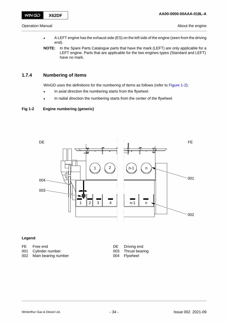
1.7.4 Numbering of items
WinGD uses the definitions for the numbering of items as follows (refer to Figure 1-2):
• In axial direction the numbering starts from the flywheel.
• In radial direction the numbering starts from the center of the flywheel.
Fig 1-2 Engine numbering (generic)
FEDE
n
n
004
003
001
002
n-1
n-1
4321
21
Legend
FE Free end DE Driving end001 Cylinder number 003 Thrust bearing002 Main bearing number 004 Flywheel
X62DF AA00-0000-00AAA-018L-A
Operation Manual About the engine
Winterthur Gas & Diesel Ltd. - 34 - Issue 002 2021-09

X62DF AA00-0000-00AAA-018L-A
Operation Manual About the engine
Page left intentionally blank
Winterthur Gas & Diesel Ltd. - 35 - Issue 002 2021-09

1.8 List of abbreviations
Tab 1-4 List of abbreviations and acronyms
Short form Full form, meaning
ACM Angle Calculation Module
ADA crank Angle Determination Algorithm
AHD ahead
ALM alarm
AMS Alarm and Monitoring System
A/R as required
AST astern
ASTM American Society for Testing and Materials
BDC Bottom Dead Center
BN Base Number
BSEC Brake Specific Energy Consumption
BSFC Brake Specific Fuel Consumption
BSGC Brake Specific Gas Consumption
BSPC Brake Specific Pilot fuel Consumption
CAN Controller Area Network
CCAI Calculated Carbon Aromaticity Index
CCM Cylinder Control Module
CCU Cylinder Control Unit
CCW counterclockwise
CMCR Contract Maximum Continuous Rating
COC Cleveland Open Cup
CPP Controllable Pitch Propeller
CS crankshaft
CW clockwise
Cyl. cylinder
DBT Delta Bypass Tuning
DCC Dynamic Combustion Control
DE Driving End
DENIS Diesel Engine coNtrol and optImizing Specification
DF Dual Fuel
X62DF AA00-0000-00AAA-005A-A
Operation Manual List of abbreviations
Winterthur Gas & Diesel Ltd. - 36 - Issue 002 2021-09

Short form Full form, meaning
ECA Emission Control Area
ECR Engine Control Room
ECS Engine Control System
eg or e.g. for example (exempli gratia)
EGR Exhaust Gas Recirculation
ELBA ELectrical BAlancer
ES Exhaust Side
ESS Engine Safety System
FAME Fatty Acid Methyl Esters
FAST Fuel Actuated Sacless Technology
FCM Flex Control Module
FCV Forged Crankshaft Version
FE Free End
FGSS Fuel Gas Supply System
FLV Flow Limiting Valve
FPP Fixed Pitch Propeller
FQS Fuel Quality Setting
FS Fuel Side
FZG Forschungsstelle für Zahnräder und Getriebebau (gear research center)
GAV Gas Admission Valve
GSS Gas Safety System
GTD General Technical Data
GTU GaTeway Unit
GVU Gas Valve Unit
HFO Heavy Fuel Oil
HFR High Feed Rate
HP High Pressure
HT High Temperature
IACS International Association of Classification Societies
iCAT integrated Cylinder lubricant Auto Transfer
ICC Intelligent Combustion Control
ICM Intelligent Combustion Monitoring
X62DF AA00-0000-00AAA-005A-A
Operation Manual List of abbreviations
Winterthur Gas & Diesel Ltd. - 37 - Issue 002 2021-09

Short form Full form, meaning
ICU Injection Control Unit
ie or i.e. that is (id est)
iELBA integrated ELectrical BAlancer
iGPR integrated Gas Pressure Regulation
IMO International Maritime Organization
Ind. Indenture
IOM Input Output Module
ISO International Standard Organization
JIS Japanese Industrial Standard
KOH Potassium hydroxide
LDU Local Display Unit
LED Light Emitting Diode
LEL Lower Explosive Level
LFR Low Feed Rate
LHV Lower Heating Value
LLT Low-Load Tuning
LNG Liquefied Natural Gas
LP Low Pressure
LT Low Temperature
MARPOL International Convention for the Prevention of Pollution from Ships (MARine POLlution)
MCM Main Control Module
MCP Manual Control Panel
MCR Maximum Continuous Rating
MCU Main Control Unit
MDO Marine Diesel Oil
MEG MonoEthylene Glycol
MEP Mean Effective Pressure
MGO Marine Gas Oil
MIM Marine Installation Manual
MM Maintenance Manual
Modbus serial communications protocol published by Modicon
MPG MonoPropylene Glycol
X62DF AA00-0000-00AAA-005A-A
Operation Manual List of abbreviations
Winterthur Gas & Diesel Ltd. - 38 - Issue 002 2021-09
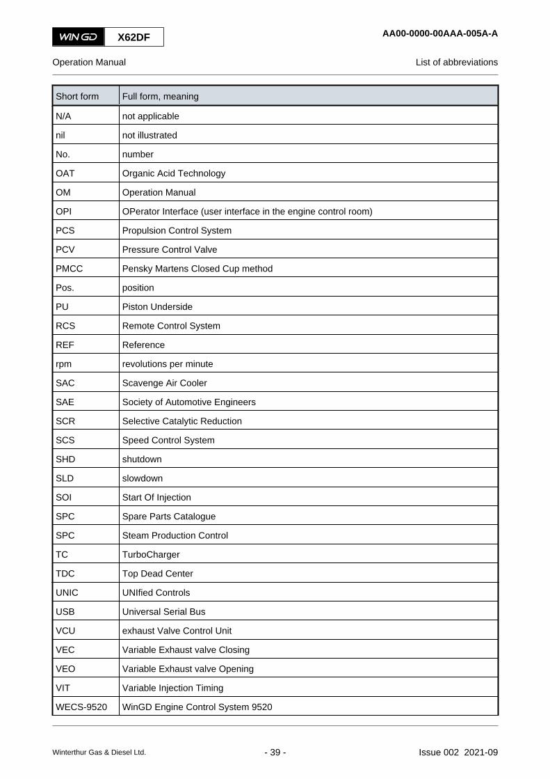
Short form Full form, meaning
N/A not applicable
nil not illustrated
No. number
OAT Organic Acid Technology
OM Operation Manual
OPI OPerator Interface (user interface in the engine control room)
PCS Propulsion Control System
PCV Pressure Control Valve
PMCC Pensky Martens Closed Cup method
Pos. position
PU Piston Underside
RCS Remote Control System
REF Reference
rpm revolutions per minute
SAC Scavenge Air Cooler
SAE Society of Automotive Engineers
SCR Selective Catalytic Reduction
SCS Speed Control System
SHD shutdown
SLD slowdown
SOI Start Of Injection
SPC Spare Parts Catalogue
SPC Steam Production Control
TC TurboCharger
TDC Top Dead Center
UNIC UNIfied Controls
USB Universal Serial Bus
VCU exhaust Valve Control Unit
VEC Variable Exhaust valve Closing
VEO Variable Exhaust valve Opening
VIT Variable Injection Timing
WECS-9520 WinGD Engine Control System 9520
X62DF AA00-0000-00AAA-005A-A
Operation Manual List of abbreviations
Winterthur Gas & Diesel Ltd. - 39 - Issue 002 2021-09

Short form Full form, meaning
WHR Waste Heat Recovery
WiCE WinGD Integrated Control Electronics
WinGD Winterthur Gas & Diesel Ltd.
WLL Work Load Limit
X62DF AA00-0000-00AAA-005A-A
Operation Manual List of abbreviations
Winterthur Gas & Diesel Ltd. - 40 - Issue 002 2021-09

2 Safety2.1 Safety precautions and safety guidelines..................................................................422.2 Safety precautions and safety rules for natural gas..................................................462.3 Contamination and fire in the scavenge air spaces...................................................482.4 Fire-fighting in the scavenge air space......................................................................502.5 Explosions in the crankcase......................................................................................522.6 Prevent explosions in the crankcase.........................................................................542.7 Prevention of explosions in the exhaust gas system (gas mode)..............................562.8 Access to engine spaces...........................................................................................58
X62DF
Operation Manual
Winterthur Gas & Diesel Ltd. - 41 - Issue 002 2021-09

2.1 Safety precautions and safety guidelines
2.1.1 General safety precautions
Use the data given below as a guide to the personnel.
• Lighting
Make sure that there is good permanent lighting in the engine room. Have a sufficientnumber of hand lamps available at different locations in the engine room.
• Clean areas
Keep the engine as clean as possible. Keep the electronic control boxes on the rail unitclean and dry. Make sure that no dust, sand or chemical vapor can go into the engine room.
This will help to prevent a fire in the engine room.
• Fire
Make sure that fire-fighting equipment is available in the engine room. Keep covers andcasings of the engine closed until the engine is sufficiently cool.
Make sure that no fire extinguisher gases can be automatically released when personnelare in the engine room.
Make sure that the emergency exits are clearly marked.
Make sure that personnel do not smoke in the engine room.
• Tools
Put hand-tools in locations where you can easily get access to them. Put special tools anddevices in positions in the engine room near the area where you use them.
Make sure that all tools have protection from corrosion.
Make sure that all tools are fixed to prevent from unwanted movement and from damage.
• Spare parts
Keep large spare parts as near as possible to the position where they will be installed andnear the engine room crane.
Make sure that the spare parts have protection from corrosion.
Make sure that the spare parts are fixed to prevent from unwanted movement and fromdamage.
Replace used spare parts as soon as possible.
• Temperature
Parts of the engine become hot during operation. Be careful and use gloves when you haveto touch hot parts with your hands.
• Frost hazard
If the ambient air temperature decreases below 0°C and the engine is not in operation, thewater in the pipe systems can freeze. To prevent this, drain the pipe systems or increasethe temperature in the engine room.
2.1.2 General safety guidelines
If you do work at or near the engine, obey the guidelines that follow to prevent risks of harm ordamage to personal, to equipment, or to environment.
X62DF AA00-0000-00AAA-012A-A
Operation Manual Safety precautions and safety guidelines
Winterthur Gas & Diesel Ltd. - 42 - Issue 002 2021-09

• Guidelines for personnel
Put on the correct safety and protective equipment.
Use fall protection equipment when you work in a height of more than one meter.
Make sure that you know the fire-fighting procedures.
Make sure that you know the health and general safety data and the environment protectiondata.
Prevent direct contact with operating media or with hot parts.
Only stay on areas that are intended for this.
Do not stay on pipes, valves or fittings.
Do not stay under hanging loads.
Do not put hands or feet under hanging loads.
Keep away from the running engine.
Keep ignition sources away from the engine.
Carry out all work carefully.
• Guidelines for operation
Start the engine only if the engine is in good condition.
Keep the safety signs on the engine clean.
Keep unauthorized persons away from the engine.
Clean walk ways and stays regularly.
Open valves and shut-off devices carefully to prevent injury from released media.
Do not use water or cleaning fluid to clean the electronic components and control boxes.
Do not open the relief valve to release pressure during engine operation.
• Guidelines for service and maintenance
Keep the tools serviceable, for example calibrate gauges regularly.
Use the correct tools in a correct way, for example lifting devices and ropes.
Protect lifted parts with applicable materials.
Do work inside the engine with a safety person on the outside.
Put covers or protection on opened openings or on removed sealing faces.
Attach removed parts in the engine room to prevent movement of the parts.
Replace O-rings during an overhaul of components.
Make sure that after installation all pipes and items are fixed correctly.
Use lock wires, tab washers, and lock plates one time only.
Before you assemble screws and studs in very hot areas, apply on the threads a lubricantthat is resistant to high temperatures.
X62DF AA00-0000-00AAA-012A-A
Operation Manual Safety precautions and safety guidelines
Winterthur Gas & Diesel Ltd. - 43 - Issue 002 2021-09

• Guidelines for hot work: General
Hot work means any work requiring the use of electric arc or gas welding equipment, cuttingburner equipment or other forms of naked flame, as well as heating or spark generatingtools, regardless of where it is carried out on board.
The Safety Management System (SMS) on board must include guidance on control of hotwork and which must ensure compliance.
Always use safe workspaces to perform any hot work.
Hot work performed outside of safe workspaces must respect the guidelines below:
• Guidelines for hot work: Outside of safe workspaces
The safety officer ensures that the hot work is carried out safely.
The safety officer provides a permit to everybody related to hot work.
Hot work procedures must follow national laws, regulations and any other national safetyand health regulations.
Another safety officer must ensure that safety procedures are followed.
All officers follow a written instruction plan.
The work area must be completely isolated before the hot work starts.
Review the fire safety precautions. This includes: firefighting equipment preparations,designation of a fire watch in all nearby areas and fire-extinguishing measures.
Continue the isolation of the workspaces and the fire safety precautions until the risk of fireno longer exists.
Protect components like the turbocharger silencer, ECS electronic control boxes andcables, with a cover.
• Guidelines for hot work: inside the engine room
Stop the engine before doing an electric welding.
Set the engine room fire extinguisher to Manual mode.
Isolate the work area.
Make sure that emergency exists are open and cleared.
Make sure that telecommunication or radio communication operates correctly.
Set to OFF the electronic module system and wait for one minute.
Disconnect the electronic modules and sensors near the work area.
Make sure that there are no explosive fluids or gases in the work area.
Put the earthing connection as near as possible to the work area.
Make sure that welding cables have no loops.
Make sure that welding cables lie parallel to the cables of electronic units.
Only use DC power supply and OCV below 70 volts.
Make sure that the connection clamp is near to the work area.
Make sure that electronic parts have protection to prevent damage from sparks and heat.
X62DF AA00-0000-00AAA-012A-A
Operation Manual Safety precautions and safety guidelines
Winterthur Gas & Diesel Ltd. - 44 - Issue 002 2021-09

• Guidelines for work with hydraulic tools
Always use personal protection safety goggles and safety gloves while operating hydraulictools.
Check high pressure double walled hydraulic hoses for any damages before operation.
Check all connection points from the pump to the hydraulic tool for leaks during pressurebuild-up.
Make sure the pressure gauges are properly calibrated before operation. Applied oilpressure must be within a range of +/-5 bar of the specified pressure for each stud type andsize.
X62DF AA00-0000-00AAA-012A-A
Operation Manual Safety precautions and safety guidelines
Winterthur Gas & Diesel Ltd. - 45 - Issue 002 2021-09

2.2 Safety precautions and safety rules for natural gas
2.2.1 General
High concentrations of natural gas can cause dizziness and there is a risk of suffocation. Makesure that all related spaces have good airflow.
Natural gas in low concentration is not dangerous to personnel.
Natural gas can be dangerous in a gas engine installation. Gas leakage into the engine room cancause fires and explosions.
An explosion also can occur, if unburned gas flows into the exhaust gas system.
2.2.2 Definition of gas hazardous zones
The definitions of hazardous zones refer to IEC 600092-502:1999 and are as follows:
• Zone Z0
This is an area in which an explosive gas atmosphere is continuously present or is presentfor long periods.
Examples - Combustion chamber, gas pipes
• Zone Z1
This is an area in which an explosive gas atmosphere can be present during usual operationor during unusual operating conditions.
Examples - Piston under side, space of double wall pipe
• Zone Z2
This is an area in which an explosive gas atmosphere usually is not present or is presentonly for short periods, for example if a leakage occurs.
Examples - Exhaust gas system
The engine room and the engine crankcase are given as gas safe non-hazardous areas. Thusthey do not refer to the definitions of hazardous zones.
X62DF AA00-0000-00AAA-012H-A
Operation Manual Safety precautions and safety rules for natural gas
Winterthur Gas & Diesel Ltd. - 46 - Issue 002 2021-09

2.2.3 Precautions for work in gas hazardous zones
If you do work in a gas hazardous zone, obey the rules that follow to prevent risks of harm ordamage to personal, to equipment, or to environment:
• Make sure that you have completed the safety training.
• Make sure that you have the necessary qualification.
• Make sure that you have the permission of the safety officer.
• Ask for the aid of one more person.
• Make sure that the fuel gas system has no pressure.
• Make sure that the remaining gas in the fuel gas system is replaced with inert gas (forexample nitrogen).
• Make sure that the airflow is sufficient for the work area.
• Make sure that related systems are prevented from an unwanted start. Use the lock-out andtag-out practice.
• Use a handheld gas detector.
• Do not use systems and devices that can cause a spark, for example a cigar lighter,matches, etc.
• Do not smoke or start a fire.
• Put on antistatic clothes.
• Make sure that your safety shoes are in good condition. Steel toe caps can cause sparks.
• Use only approved tools that do not cause sparks and test equipment that will not cause anexplosion.
• Do not use digital cameras, mobile phones or other electronic devices (for example radios,CD-players).
• Use only intrinsically safe and approved MHSA two-way radios and transceivers.
• Use only approved light sources (safety flashlights).
• If you do welding, obey the instructions of the responsible safety officer and the primarycontractor. Make sure that the responsible safety officer does checks during the weldingwork.
• Read and obey the safety procedures for the ship or for the engine room (for examplesecurity plan, warnings, life-saving devices, escape routing, meeting point, gas hazardouszones, special instructions on the safety notice board).
• Keep your work area clean. Remove flammable material immediately.
X62DF AA00-0000-00AAA-012H-A
Operation Manual Safety precautions and safety rules for natural gas
Winterthur Gas & Diesel Ltd. - 47 - Issue 002 2021-09

2.3 Contamination and fire in the scavenge air spaces
2.3.1 Causes of contamination
The primary cause of contamination is when combustion materials are blown between the pistonand cylinder into the scavenge air spaces (blow-by). The contamination will be more if the fuel isnot fully burned, which causes exhaust smoke.
2.3.1.1 Unsatisfactory combustion
The causes of unsatisfactory combustion are as follows:
• The injection valves do not operate correctly (the nozzle tip has trumpets or is worn).
• The fuel is too cold, specially at low load.
• Operation with a temporarily low air supply during large differences in engine load and thescavenge air pressure fuel-limiter set too high.
• Too much load.
• Low air supply because the ventilation in the engine room is not sufficient.
• The silencer and diffuser on the air side of the turbocharger has contamination.
• The wire mesh and nozzle ring upstream of the turbocharger has contamination.
• The exhaust gas boiler, the air cooler and water separator, the air flaps in the scavenge airreceiver and the scavenge ports have contamination.
2.3.1.2 Blow-by
The causes of blow-by are as follows:
• Worn piston rings, broken piston rings or piston rings that cannot move.
• Worn cylinder liner.
• Incorrect operation of a lubricating quill.
• The running surface of the cylinder liners have damage.
If there are one or more of these conditions, the remaining particles will collect at the areas thatfollow:
• Between the piston ring and piston ring groove.
• On the piston skirt.
• In the scavenge ports.
• On the bottom of the cylinder block (piston underside).
• In the scavenge air receiver.
X62DF AA00-0000-00AAA-012B-A
Operation Manual Contamination and fire in the scavenge air spaces
Winterthur Gas & Diesel Ltd. - 48 - Issue 002 2021-09

2.3.2 Causes of fire
The causes of fires are as follows:
• If sealing rings of the piston rod gland are defective, system oil and cylinder oil will collectin the piston underside. If the drain pipes from the piston underside are blocked, this oil cannot drain. A high temperature in the piston underside then can cause a fire.
• If piston rings are defective, combustion gases and sparks can go into the piston underside.Contamination in the piston underside then can cause a fire.
You must do regular checks of the bottom of the cylinder block and scavenge air receiver to keepclean the cylinder block and scavenge air receiver, refer to section 8.5 Do checks during operation- general.
2.3.3 Indication of a fire
The indications of a fire are as follows:
• You can hear the related temperature alarms.
• A large increase in the exhaust gas temperature of the related cylinder and an increase inpiston underside temperature.
For the fire-fighting procedures, refer to section 2.4 Fire-fighting in the scavenge air space.
X62DF AA00-0000-00AAA-012B-A
Operation Manual Contamination and fire in the scavenge air spaces
Winterthur Gas & Diesel Ltd. - 49 - Issue 002 2021-09

2.4 Fire-fighting in the scavenge air spacePeriodicityDescriptionUnscheduledDuration for performing preliminary requirements 0.0 man-hoursDuration for performing the procedure 1.0 man-hoursDuration for performing the requirements after job completion 0.0 man-hours
PersonnelDescription Specialization QTYEngine crew Intermediate 1
Support equipmentDescription Part No. CSN QTYNone
SuppliesDescription QTYNone
Spare PartsDescription Part No. CSN QTYNone
SAFETY PRECAUTIONS
• None
PRELIMINARY OPERATIONS
• Refer to section 2.3 Contamination and fire in the scavenge air spaces
X62DF AA00-0000-00AAA-140B-A
Operation Manual Fire-fighting in the scavenge air space
Winterthur Gas & Diesel Ltd. - 50 - Issue 002 2021-09

PROCEDURE
1 If you think there is no fire, do the steps as follows:1.1 Decrease the engine power.1.2 Cut out the injection of the related cylinder.1.3 Increase the feed rate of the lubricating oil in the related cylinder to the maximum,
although there is high temperature in the related cylinder.
WARNINGInjury Hazard. Where CO2 is used to extinguish a fire in the engine, there is a risk ofsuffocation. Make sure that all related spaces have good airflow to remove all CO2 gasbefore you go into the engine.
CAUTIONDamage Hazard. Steam can cause corrosion. If steam is used to extinguish a fire you mustdo procedures to prevent corrosion.
2 If you think there is a fire, do the steps as follows:2.1 Shut down the engine.2.2 Fight the fire with the installed fire extinguishing system.
3 After approximately 5 minutes to 15 minutes, do the checks as follows:3.1 Do a check of the exhaust gas temperature.3.2 Do a careful check of the temperatures of the doors to the piston underside space.
4 Find the causes of the problems as follows:4.1 Do a check of the cylinder liner running surface, piston and piston rings.4.2 Do a check of the flaps in the scavenge air receiver (replace if necessary).4.3 Do a check for possible leaks.4.4 Do a check of the piston rod gland as much as possible.4.5 Do a check of the injection nozzles.4.6 If necessary, clean or repair the defective items.
5 Start the engine as follows:5.1 If applicable, cut in the injection.5.2 Start the engine.5.3 Start the injection and slowly increase the load.5.4 Set the cylinder oil feed rate to the applicable value.
NOTE: Do not operate the engine for long periods with a high cylinder oil setting.
CLOSE UP
• None
X62DF AA00-0000-00AAA-140B-A
Operation Manual Fire-fighting in the scavenge air space
Winterthur Gas & Diesel Ltd. - 51 - Issue 002 2021-09

2.5 Explosions in the crankcase
Examples of explosions in the crankcase of diesel engines have shown that they can only occurin special conditions, and thus do not occur frequently.
The cause of crankcase explosions is oil mist. Oil mist comes from components that have becomeunusually hot.
The engine has oil mist detectors, refer to section 5.9.3 Oil mist detector.
Correct engine maintenance will help prevent explosions in the crankcase.
X62DF AA00-0000-00AAA-012C-A
Operation Manual Explosions in the crankcase
Winterthur Gas & Diesel Ltd. - 52 - Issue 002 2021-09

X62DF AA00-0000-00AAA-012C-A
Operation Manual Explosions in the crankcase
Page left intentionally blank
Winterthur Gas & Diesel Ltd. - 53 - Issue 002 2021-09

2.6 Prevent explosions in the crankcasePeriodicityDescriptionUnscheduledDuration for performing preliminary requirements 0.0 man-hoursDuration for performing the procedure 1.0 man-hoursDuration for performing the requirements after job completion 0.0 man-hours
PersonnelDescription Specialization QTYEngine crew Basic 1
Support equipmentDescription Part No. CSN QTYNone
SuppliesDescription QTYNone
Spare PartsDescription Part No. CSN QTYNone
SAFETY PRECAUTIONS
WARNINGDanger: If an oil mist alarm is activated, keep away from the engine. There is a risk ofexplosion.
WARNINGDanger: Do not open the crankcase doors or the covers for a minimum of 20 minutes afterengine stop. If air goes into the crankcase, an explosion can occur.
WARNINGInjury hazard: The crankcase doors have relief valves. To prevent accidents no person mustbe in the areas of gases that can come out of these relief valves. Injury to personnel canoccur.
PRELIMINARY OPERATIONS
• None
X62DF AA00-0000-00AAA-012D-A
Operation Manual Prevent explosions in the crankcase
Winterthur Gas & Diesel Ltd. - 54 - Issue 002 2021-09

PROCEDURE
1 If an oil mist detector activates an alarm, do as follows:1.1 Decrease immediately the engine speed (power).1.2 Stop the engine if possible.1.3 Let the engine temperature decrease for a minimum of 20 minutes.1.4 Find the cause and repair the fault.
NOTE: If no fire-extinguishing system is installed or not in use, a portable fireextinguisher must be kept ready when the crankcase doors are opened.
CLOSE UP
• None
X62DF AA00-0000-00AAA-012D-A
Operation Manual Prevent explosions in the crankcase
Winterthur Gas & Diesel Ltd. - 55 - Issue 002 2021-09

2.7 Prevention of explosions in the exhaust gas system (gas mode)
Unburned gas in the exhaust gas system can cause an explosion.
2.7.1 General
When the engine operates in gas mode or in fuel sharing mode, unburned gas can stay in theexhaust gas system after the conditions that follow:
• There are misfires in a combustion chamber.
• There is an emergency engine stop.
• There is an engine shutdown signal that you cannot cancel.
• There is an electrical power failure to the engine control system (ECS).
Related to the safety concept of WinGD the engine has the items and functions that follow:
• The components of the exhaust gas system upstream of the turbochargers are resistant toexplosions.
• The gas pipes of the engine and of the related gas system have connection points for inertgas. Thus you can remove fuel gas from the related pipes before you do work on them.
• The ECS continuously monitors the combustion. If necessary the ECS adjusts thecombustion parameters.
• If there are too many misfires, the ECS automatically changes to diesel mode.
• If the ECS finds a dangerous condition at an engine stop, the ECS sends a signal for anautomatic ventilation sequence, refer to Para 2.7.2.
X62DF AA00-0000-00AAA-012G-A
Operation Manual Prevention of explosions in the exhaust gas system (gas mode)
Winterthur Gas & Diesel Ltd. - 56 - Issue 002 2021-09
2.7.2 Ventilation sequence
The ventilation sequence removes unburned gas from the exhaust gas system to the air.
After an engine stop, if necessary the engine safety system (ESS) or the ECS sends a signal fora ventilation request.
The steps of the ventilation sequence are as follows:
• The engine safety system (ESS) or the ECS sends a signal to the control panel (VentilationRequest “Automatic”).NOTE: A start interlock is active until the ventilation is automatically or manually stopped.
NOTE: If necessary the operator can manually send a signal (Ventilation Request“Manual”).
• The operator must always start the ventilation sequence manually:○ The operator starts the auxiliary blowers.
○ The operator starts the servo oil service pump.
• The exhaust valves open and the ventilation starts (Ventilation Passed “In progress”).
• If necessary the operator can always stop the ventilation before the automatic stop (forexample if there is an urgent need to start the engine immediately).
• After a specified period the ECS stops the ventilation (Ventilation Passed “Yes”).
• At the next engine start the ECS does a longer air run than usual.
X62DF AA00-0000-00AAA-012G-A
Operation Manual Prevention of explosions in the exhaust gas system (gas mode)
Winterthur Gas & Diesel Ltd. - 57 - Issue 002 2021-09

2.8 Access to engine spacesPeriodicityDescriptionUnscheduledDuration for performing preliminary requirements 0.0 man-hoursDuration for performing the procedure 0.5 man-hoursDuration for performing the requirements after job completion 0.0 man-hours
PersonnelDescription Specialization QTYEngine crew Basic 1
Support equipmentDescription Part No. CSN QTYNone
SuppliesDescription QTYNone
Spare PartsDescription Part No. CSN QTYNone
SAFETY PRECAUTIONS
WARNINGInjury Hazard: Be careful of the slippery and sharp edges inside the engine spaces.
PRELIMINARY OPERATIONS
• The engine must be stopped and prepared for maintenance, refer to section 8.20 Preparethe engine after stop - general
X62DF AA00-0000-00AAA-012E-A
Operation Manual Access to engine spaces
Winterthur Gas & Diesel Ltd. - 58 - Issue 002 2021-09

PROCEDURE
1 Make sure that there is always a safety person on the outer side of the engine.2 Use the correct personal protection equipments.3 For a DF engine, obey the safety rules for natural gas, refer to section 2.2 Safety
precautions and safety rules for natural gas.4 De-pressurize the air spring to open the exhaust valve housing.5 Make sure that the starting air supply pipe has no pressure (ie starting air shut-off valve
30-4325_E0_1 is closed, ball valves 30-8605_E0_6 and 30-8605_E0_7 are open).6 Engage the turning gear and lock the lever in this position.
NOTE: Other ships in the water cause currents, which cause the movement of thepropeller and the engine. The engine and propeller cannot move when theturning gear is engaged.
7 Make sure the indicator valves are open.8 Make sure that there is sufficient air in the engine spaces, e.g use a ventilator.9 When you go out of the engine spaces, move all the equipment out of the engine.
CLOSE UP
• None
X62DF AA00-0000-00AAA-012E-A
Operation Manual Access to engine spaces
Winterthur Gas & Diesel Ltd. - 59 - Issue 002 2021-09

X62DF AA00-0000-00AAA-012E-A
Operation Manual Access to engine spaces
Page left intentionally blank
Winterthur Gas & Diesel Ltd. - 60 - Issue 002 2021-09

3 Design and function of the engine3.1 Short description of the DF engine............................................................................623.2 Use of the engine......................................................................................................663.3 The relation between engine and propeller...............................................................70
X62DF
Operation Manual
Winterthur Gas & Diesel Ltd. - 61 - Issue 002 2021-09

3.1 Short description of the DF engine
The engine is a single acting two-stroke dual fuel (DF) engine of crosshead design. The enginehas turbochargers and exhaust valves.
General data about the engine are given as follows:
• In diesel mode, the engine can use marine diesel oil (MDO) and heavy fuel oil (HFO) withdifferent qualities. In diesel mode also a small quantity of pilot fuel is injected to preventcontamination of the pilot fuel valves.
• In gas mode, the engine uses liquefied natural gas (LNG) at low-pressure. Thus the lean-burn principle (Otto cycle) is used. The pilot fuel is marine diesel oil that is injected into thecylinder to ignite the gas-air mixture. In gas mode the engine obeys the IMO Tier IIIregulations.
• In the optional fuel sharing mode (refer to Para 3.1.3), the engine can use a mixture of MDO/HFO and LNG in the given range.
• The engine obeys the IGC (International Code for the Construction and Equipment of ShipsCarrying Liquefied Gases in Bulk) and the IGF (International Code for Ships using Gas orother Low Flashpoint Fuels) codes.
• The engine uses the common-rail system with full electronic control of the fuel injectionsystem, exhaust valve operation, starting valve operation, and cylinder operation.
• Related to the design, the engine turns clockwise or counterclockwise for the aheaddirection. For the astern direction the engine can turn in the other direction.
• The engine control system (ECS) electronically controls all important engine functions (egspeed control, overspeed protection, and fuel injection). The engine control can havedifferent remote controls, which are related to the WinGD specifications from recommendedmanufacturers.
X62DF AA00-0000-00AAA-020B-A
Operation Manual Short description of the DF engine
Winterthur Gas & Diesel Ltd. - 62 - Issue 002 2021-09

3.1.1 Cycle of a two-stroke DF engine in diesel mode
The sequences of a two-stroke DF engine in diesel mode are as follows (refer to Figure 3-1):
• Sequence 1 - 2
The piston moves up and thus compresses the scavenge air. This increases thetemperature of the air above the self-ignition temperature of the fuel.
• Sequence 2 - 3
At almost TDC fuel at very high pressure is injected into the hot air in the combustionchamber. The fuel ignites and combustion starts.
• Sequence 3 - 4
The gases expand and push the piston down. The pressure in the combustion chamberdecreases.
• Sequence 4 - 1
The scavenge air replaces the exhaust gas as follows:○ At (4) the exhaust valve opens.
○ At (a) the scavenge ports get uncovered. Scavenge air enters the cylinder and pushesthe exhaust gas into the exhaust gas manifold.
○ At (b) the scavenge ports get covered.
○ At (1) the exhaust valve closes.
The cycle is completed and starts again.
Fig 3-1 Pressure - volume diagram and schematic of the two-stroke diesel cycle
1 1
22
3 3
44ab
V
p
00120
X62DF AA00-0000-00AAA-020B-A
Operation Manual Short description of the DF engine
Winterthur Gas & Diesel Ltd. - 63 - Issue 002 2021-09

3.1.2 Cycle of a two-stroke DF engine in gas mode
The sequences of a two-stroke DF engine in gas mode are as follows (refer to Figure 3-2):
• Sequence 1 - 2
The piston moves up and thus compresses the scavenge air. Gas is injected into thecombustion chamber. The temperature and the pressure of the gas-air mixture increase.
• Sequence 2 - 3
At almost TDC a small quantity of pilot fuel is injected into the combustion chamber. Thegas-air mixture ignites and combustion starts.
• Sequence 3 - 4
The gases expand and push the piston down. The pressure in the combustion chamberdecreases.
• Sequence 4 - 1
The scavenge air replaces the exhaust gas as follows:○ At (4) the exhaust valve opens.
○ At (a) the scavenge ports get uncovered. Scavenge air enters the cylinder and pushesthe exhaust gas into the exhaust gas manifold.
○ At (b) the scavenge ports get covered.
○ At (1) the exhaust valve closes.
The cycle is completed and starts again.
Fig 3-2 Pressure - volume diagram and schematic of the two-stroke otto cycle
1 1
2
23 3
44ab
V
p
X62DF AA00-0000-00AAA-020B-A
Operation Manual Short description of the DF engine
Winterthur Gas & Diesel Ltd. - 64 - Issue 002 2021-09

3.1.3 Fuel sharing mode
The optional fuel sharing mode enables an increased fuel flexibility. You can use liquid fuel (HFO,MDO, or MGO) and at the same time gas fuel. The fuel sharing mode has the limits that follow:
• The engine must operate in ahead direction.
• The engine power must be more than 50% of CMCR.
• The maximum ratio of liquid fuel to gas is 50%.
• The minimum quantity of liquid fuel is 5% related to the total energy input.
You have to select the fuel sharing mode and the ratio of liquid fuel to gas (fuel sharing ratio)manually.
The gas admission valves (GAV) supply the gas into the combustion chamber. The injection valvessupply the specified quantity of liquid fuel. The gas and the liquid fuel combust at the same time.The speed governor controls the quantity of the two fuels to the selected ratio.
3.1.4 Dynamic Combustion Control
Dynamic Combustion Control (DCC) enables full power output for gas mixtures with a methanenumber of 65 and higher, independent of ambient condition and engine rating.
While DCC is active in combustion stabilising mode, a small amount of liquid fuel is injected bythe main injectors. This increases the speed of the turbochargers. Thus the engine gets sufficientcombustion air to keep the intended gas-air mixture (lambda).NOTE: While DCC is active in gas mode the engine remains IMO Tier III compliant related to
NOx limits.
X62DF AA00-0000-00AAA-020B-A
Operation Manual Short description of the DF engine
Winterthur Gas & Diesel Ltd. - 65 - Issue 002 2021-09

3.2 Use of the engine
3.2.1 Intended use
The engine is intended to drive a propeller of a vessel. The engine changes the chemical energyof the fuel to mechanical energy.
The engine must only be used in the operating range as given in the data sheets, refer tochapter 11.
Related to the contract the Contract Maximum Continuous Rating (CMCR) is specified in the rangeof Figure 3-3. The points R1+ and R2+ are only applicable, if the engine has an extended range.
Fig 3-3 Operating range
R1 R1+
R2 R2+R4
R4
R3
S
P
Legend
R1 Highest power at highest speed R3 Highest power at lowest speedR1+ Highest power at highest speed (extended) R4 Lowest power at lowest speedR2 Lowest power at highest speed P PowerR2+ Lowest power at highest speed (extended) S Speed
The intended use of the engine includes the items that follow:
• Obey this Operation Manual.
• Obey the related safety regulations.
• Obey the instructions of the operating company.
• Operate the engine in the specified limits.
• Use the correct operating media.
X62DF AA00-0000-00AAA-020C-A
Operation Manual Use of the engine
Winterthur Gas & Diesel Ltd. - 66 - Issue 002 2021-09

3.2.2 Incorrect use
Incorrect use of the engine can result in personal injury and in damage to physical properties.
Personal injury or damage to physical properties caused by incorrect use will be the responsibilityof the operating company.
The actions that follow must be looked as examples to be an incorrect use:
• Operation of the engine with disabled, changed or defective safety devices
• Operation of the engine with personnel who are not approved.
X62DF AA00-0000-00AAA-020C-A
Operation Manual Use of the engine
Winterthur Gas & Diesel Ltd. - 67 - Issue 002 2021-09

3.2.3 Tuning
Related to the contract the engine has one of the tuning options that follow (refer to Figure 3-4):
• Standard tuning
The standard tuning gives a good fuel consumption over the full engine power range.
• Delta tuning
The delta tuning decreases the fuel consumption below 90% engine power compared tostandard tuning. But it increases the fuel consumption between 90% and 100% of enginepower.
• Delta bypass tuning
The delta bypass tuning decreases the fuel consumption below 50% engine powercompared to delta tuning. For more than 50% of engine power the fuel consumption is thesame as delta tuning, but the steam production is increased.
• Low-load tuning
The low-load tuning decreases the fuel consumption below 75% engine power comparedto delta tuning or delta bypass tuning. But it increases the fuel consumption between 90%and 100% of engine power compared to delta tuning.
Fig 3-4 Tuning options
X62DF AA00-0000-00AAA-020C-A
Operation Manual Use of the engine
Winterthur Gas & Diesel Ltd. - 68 - Issue 002 2021-09

X62DF AA00-0000-00AAA-020C-A
Operation Manual Use of the engine
Page left intentionally blank
Winterthur Gas & Diesel Ltd. - 69 - Issue 002 2021-09

3.3 The relation between engine and propeller
3.3.1 General
There is a specified relation between the propeller speed and the absorbed power in ships thathave fixed pitch propellers. The relation is between the propeller and the speed at which it turns.
The formula that follows (where P = power and n = speed) gives an approximate result, which issufficient for conventional vessels:
The graph from this formula is known as the propeller property.
If the engine is in good condition, correctly supplied with air (ie turbochargers in good conditionand the resistance of the air and exhaust pipes is in the specifications) and the fuel injectionquantity is correctly adjusted (see the shop test protocol), then the mean effective pressure (MEP)developed during service conditions (in accordance with the specified load indication), is relatedto the approximate MEP for this position on the test bed.
In the diagram (see Figure 3-5), the propeller property line through the CMCR point (100% powerat 100% engine speed) is known as the nominal propeller property. Engines that are used for thepropulsion of vessels with fixed propellers have a load applied on the test bed in accordance withthis propeller property. But, during sea trial of a new ship with a smooth and clean hull, theapplicable power is lower and the operation point is below the nominal propeller property.
During operation, a higher torque is necessary for the propeller to keep its speed than at the timeof the sea trial (sea margin) because:
• There are changes in wake flow conditions because of marine growth on the hull
• The cargo load has an effect on the depth of the vessel in the water
• The propeller has a rough surface or has mechanical damage
• The vessel operates in bad sea and weather conditions
• The vessel operates in shallow water. The MEP of the engine (and thus the fuel injectionquantity) will increase. In such a condition, the operation point will then be at the left of theinitial propeller curve which was calculated during sea trials.
A hull that was cleaned and painted will help to decrease the resistance as the vessel movesthrough the water. It is not possible to get the hull back to its initial condition.
Because the thermal load of the engine is related to the MEP, the position of the operation pointis also important. The air supply to the engine and the operation conditions will becomeunsatisfactory if the operation point is far above the propeller curve.
To get the best conditions, the operation point of the engine for service range must be on or belowthe nominal propeller property.
X62DF AA00-0000-00AAA-042B-A
Operation Manual The relation between engine and propeller
Winterthur Gas & Diesel Ltd. - 70 - Issue 002 2021-09
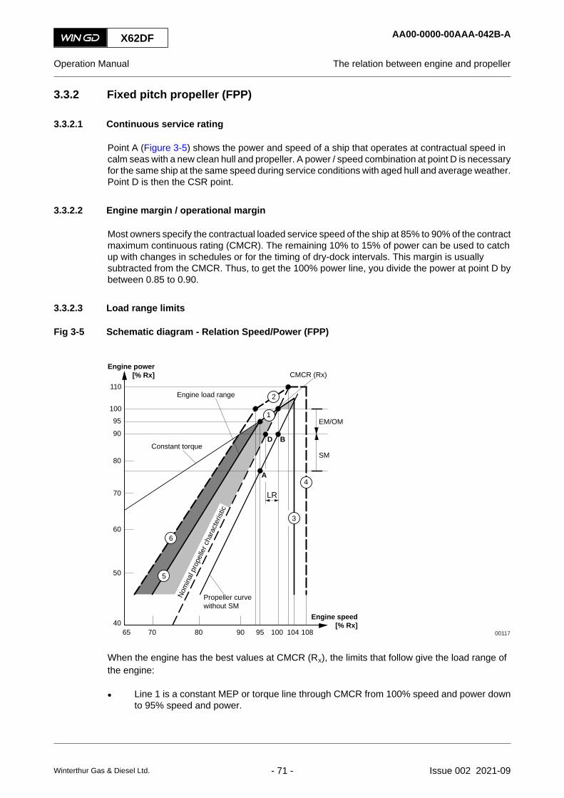
3.3.2 Fixed pitch propeller (FPP)
3.3.2.1 Continuous service rating
Point A (Figure 3-5) shows the power and speed of a ship that operates at contractual speed incalm seas with a new clean hull and propeller. A power / speed combination at point D is necessaryfor the same ship at the same speed during service conditions with aged hull and average weather.Point D is then the CSR point.
3.3.2.2 Engine margin / operational margin
Most owners specify the contractual loaded service speed of the ship at 85% to 90% of the contractmaximum continuous rating (CMCR). The remaining 10% to 15% of power can be used to catchup with changes in schedules or for the timing of dry-dock intervals. This margin is usuallysubtracted from the CMCR. Thus, to get the 100% power line, you divide the power at point D bybetween 0.85 to 0.90.
3.3.2.3 Load range limits
Fig 3-5 Schematic diagram - Relation Speed/Power (FPP)
110
10095
90
80
70
60
50
4065 70 80 90 95 104100 108
Engine power[% Rx]
Engine speed[% Rx]
Propeller curvewithout SM
EM/OM
SM
4
3
1
2
5
6
CMCR (Rx)
B
A
D
Engine load range
Constant torque
Nom
inal
pro
pelle
r cha
ract
erist
ic
LR
00117
When the engine has the best values at CMCR (RX), the limits that follow give the load range ofthe engine:
• Line 1 is a constant MEP or torque line through CMCR from 100% speed and power downto 95% speed and power.
X62DF AA00-0000-00AAA-042B-A
Operation Manual The relation between engine and propeller
Winterthur Gas & Diesel Ltd. - 71 - Issue 002 2021-09

• Line 2 is the overload limit. This is a constant MEP line from 100% power and 93.8% speedto 110% power and 103.2% speed. 103.2% speed is the intersection point between thenominal propeller property and 110% power.
• Line 3 is the 104% speed limit where an engine can operate continuously. For RX withdecreased speed (NCMCR ≤0.98 NMCR) this limit can be extended to 106%, but, the torsionalvibration must not be more than the specified limits.
• Line 4 is the overspeed limit. The overspeed range between 104% (106%) and 108% speedis only permitted during sea trials if necessary. This is to demonstrate the speed of the shipat CMCR power with a light running propeller in the presence of authorized representativesof the engine builder. The torsional vibration must not be more than the specified limits.
• Line 5 is the permitted torque limit from 95% power and speed to 45% power and 70%speed. This shows a curve defined by the equation: P2 ÷ P1 = (N2 ÷ N1)2.45. When the enginespeed and power is near the data in Line 5 there will be a decrease in scavenge air, whichhas an effect on the engine. The area between Lines 1, 3 and 5 show the range in whichthe engine must be operated. The area in the nominal propeller property, 100% power andLine 3 is recommended for continuous operation. The area between the nominal propellerproperty and Line 5 must be reserved for acceleration, shallow water and usual flexibility ofoperation.
• Line 6 gives the equation: P2 ÷ P1 = (N2 ÷ N1)2.45 through 100% power and 93.8% speed andthe maximum torque limit in transient conditions. The area above Line 1 is the overloadrange. You must only operate the engine in this range for a maximum of one hour duringsea trails in the presence of authorized representatives of the engine builder. The areabetween Lines 5 and 6 and the constant torque line (shown as a dark area) must only beused for transient conditions, ie during fast acceleration. This range is known as the servicerange with operational time limit.
X62DF AA00-0000-00AAA-042B-A
Operation Manual The relation between engine and propeller
Winterthur Gas & Diesel Ltd. - 72 - Issue 002 2021-09
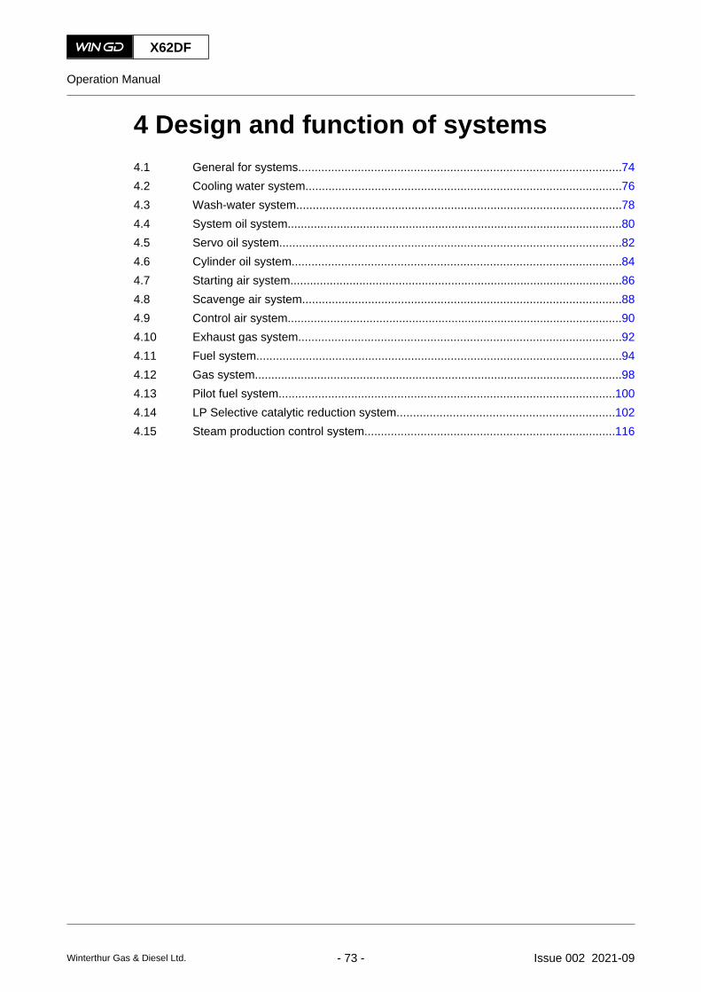
4 Design and function of systems4.1 General for systems..................................................................................................744.2 Cooling water system................................................................................................764.3 Wash-water system...................................................................................................784.4 System oil system......................................................................................................804.5 Servo oil system........................................................................................................824.6 Cylinder oil system....................................................................................................844.7 Starting air system.....................................................................................................864.8 Scavenge air system.................................................................................................884.9 Control air system......................................................................................................904.10 Exhaust gas system..................................................................................................924.11 Fuel system...............................................................................................................944.12 Gas system................................................................................................................984.13 Pilot fuel system......................................................................................................1004.14 LP Selective catalytic reduction system..................................................................1024.15 Steam production control system............................................................................116
X62DF
Operation Manual
Winterthur Gas & Diesel Ltd. - 73 - Issue 002 2021-09

4.1 General for systems
In the chapters that follow you can find a short description of the systems of the engine. Thedescriptions and figures are generic and simplified.
You can find an overview of the used line codes in Figure 4-1.
Fig 4-1 Line codes for systems
001002
003
004
007006
008
009
005
Legend
001 Main supply pipe 006 Double wall pipe002 Drain / leakage pipe 007 Heating pipe003 Vent pipe 008 Insulated pipe004 Waste pipe (dirty drain pipe) 009 Trace heated and insulated pipe005 Optional pipe
X62DF AA00-0000-00AAA-043U-A
Operation Manual General for systems
Winterthur Gas & Diesel Ltd. - 74 - Issue 002 2021-09

X62DF AA00-0000-00AAA-043U-A
Operation Manual General for systems
Page left intentionally blank
Winterthur Gas & Diesel Ltd. - 75 - Issue 002 2021-09

4.2 Cooling water system
The cooling water system supplies the items that follow with cooling water:
• Cylinder liner
• Cylinder cover
• Exhaust valve cages
• Scavenge air cooler (SAC).
For the schematic diagrams, refer to section 13.1 Schematic diagrams - general.
The cooling water system has the engine connections as interface to the plant as follows (in Figure4-2 marked with a circle):
• Connection 01 (cylinder cooling water inlet)
• Connection 02 (cylinder liner cooling water inlet (bypass cooling water system)) (optional)
• Connection 03 (cylinder cooling water outlet)
• Connection 05 (cylinder cooling water drain outlet)
• Connection 07 (SAC LT-cooling water inlet) (not shown)
• Connection 08 (SAC LT-cooling water outlet) (not shown).
If the supply at the engine connection 02 is installed, the cylinder liner is supplied with coolingwater at a higher temperature than the cylinder cover.
The cooling water system has the parts that follow:
• Automatic venting unit
The automatic venting unit (001) constantly releases unwanted air from the cooling water.
• Optional vent valve
The optional vent valves (008) can be used manually to release unwanted air from thecooling water, if the automatic venting unit (001) does not operate correctly.
• Vent valve
The vent valves (009) constantly release cooling water to the automatic venting unit (001)to release unwanted air from the cooling water.
• Vent valve
The vent valve (010) can be used manually to release unwanted air from the cooling water,if the automatic venting unit (001) does not operate correctly.
X62DF AA00-0000-00AAA-043A-A
Operation Manual Cooling water system
Winterthur Gas & Diesel Ltd. - 76 - Issue 002 2021-09

Fig 4-2 Cooling water system (generic and simplified)
Cyl. 1 Cyl. n
02
03
05
01
ENG
INE
PLAN
T
006
007
005
004
003
002009
010
001
008
Legend
001 Automatic venting unit 006 Drain valve002 Shut-off valve cooling water outlet 007 Orifice003 Shut-off valve, if supply 02 is installed 008 Optional vent valve (usually closed)004 Shut-off valve, if supply 02 is not installed 009 Vent valve (usually open)005 Shut-off valve 010 Vent valve (usually closed)
X62DF AA00-0000-00AAA-043A-A
Operation Manual Cooling water system
Winterthur Gas & Diesel Ltd. - 77 - Issue 002 2021-09

4.3 Wash-water system
The wash-water system supplies the scavenge air cooler (SAC) with wash-water. This lets youwash the SAC, refer to 9.4 Clean the scavenge air cooler during operation. To regularly wash theSAC increases the service life of the cooler and keeps the performance in the specified range.
For the schematic diagrams, refer to section 13.1 Schematic diagrams - general.
The wash-water system has the engine connections as interface to the plant as follows (in Figure4-3 marked with a circle):
• Connection 06 (SAC drain outlet) (for X35 and X40)
• Connection 11 (water for cleaning plant for TC and SAC inlet)
• Connection 12 (air for cleaning plant for TC and SAC inlet)
• Connection 13 (oily water from receiver outlet)
• Connection 16 (SAC condensate water outlet)
• Connection 17 (SAC wash-water outlet) (optional)
• Connection 18 (SAC venting).
Condensation and wash-water flow through the cyclone separator and back to the plant at theconnection 16.
The wash-water system has the parts that follow:
• Wash-water tank
The wash-water tank (001) keeps the wash-water for the wash procedure of the SAC.Compressed air is used to pressurize the wash-water tank before the wash procedure.
• Cyclone separator
The cyclone separator (004) separates the air and the wash-water.
X62DF AA00-0000-00AAA-043P-A
Operation Manual Wash-water system
Winterthur Gas & Diesel Ltd. - 78 - Issue 002 2021-09

Fig 4-3 Wash-water system (generic and simplified)
11 12
PLAN
TEN
GIN
E
PLAN
TEN
GIN
E1318
16
06
17
06
005
002
002003 003
001
004
Legend
001 Wash-water tank 004 Cyclone separator002 Scavenge air cooler (SAC) 005 Turbocharger003 Auxiliary blower
X62DF AA00-0000-00AAA-043P-A
Operation Manual Wash-water system
Winterthur Gas & Diesel Ltd. - 79 - Issue 002 2021-09

4.4 System oil system
The system oil system supplies the items that follow with system oil:
• Bearings
• Gear wheels
• Vibration dampers
• Pistons
• Crosshead assemblies
• iELBA (optional)
• Other running parts
• Servo oil system.
For the schematic diagrams, refer to section 13.1 Schematic diagrams - general.
The system oil system has the engine connections as interface to the plant as follows (in Figure4-4 marked with a circle):
• Connection 22 (oil drain bedplate horizontal) (if applicable)
• Connection 23 (oil drain bedplate vertical)
• Connection 25 (main oil inlet)
• Connection 26 (lubricating oil turbocharger inlet) (optional)
• Connection 27 (lubricating oil turbocharger outlet)
• Connection 30 (lubricating oil crosshead inlet) (optional)
• Connection 37 (leakage oil gland box outlet).
System oil from the bearings and gear wheels drops into the crankcase.
The system oil system has the parts that follow:
• Oil pipes
The oil pipes connect the items that use oil.
• Lever
The levers (010) in the crankcase supply the oil to the crosshead.
• Oil sample valve
Use the oil sample valve (009) to get a sample of the supplied oil.
X62DF AA00-0000-00AAA-043B-A
Operation Manual System oil system
Winterthur Gas & Diesel Ltd. - 80 - Issue 002 2021-09

Fig 4-4 System oil system (generic and simplified)
001001
003004005006
008
007
012
010009
27
23 2222 23
25
30
011
37
002
002
26
ENGINEPLANT ENGINE PLANT
Legend
001 Turbocharger 007 Crosshead002 iELBA (optional) 008 Thrust bearing003 Torsional vibration damper (optional) 009 Oil sample valve004 Axial vibration damper 010 Lever005 Main bearing 011 Supply pipe to servo oil system006 Crank bearing 012 Piston
X62DF AA00-0000-00AAA-043B-A
Operation Manual System oil system
Winterthur Gas & Diesel Ltd. - 81 - Issue 002 2021-09
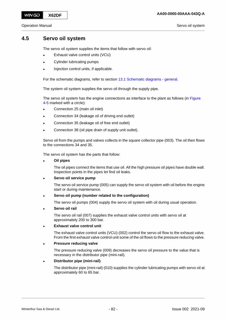
4.5 Servo oil system
The servo oil system supplies the items that follow with servo oil:
• Exhaust valve control units (VCU)
• Cylinder lubricating pumps
• Injection control units, if applicable.
For the schematic diagrams, refer to section 13.1 Schematic diagrams - general.
The system oil system supplies the servo oil through the supply pipe.
The servo oil system has the engine connections as interface to the plant as follows (in Figure4-5 marked with a circle):
• Connection 25 (main oil inlet)
• Connection 34 (leakage oil of driving end outlet)
• Connection 35 (leakage oil of free end outlet)
• Connection 38 (oil pipe drain of supply unit outlet).
Servo oil from the pumps and valves collects in the square collector pipe (003). The oil then flowsto the connections 34 and 35.
The servo oil system has the parts that follow:
• Oil pipes
The oil pipes connect the items that use oil. All the high pressure oil pipes have double wall.Inspection points in the pipes let find oil leaks.
• Servo oil service pump
The servo oil service pump (005) can supply the servo oil system with oil before the enginestart or during maintenance.
• Servo oil pump (number related to the configuration)
The servo oil pumps (004) supply the servo oil system with oil during usual operation.
• Servo oil rail
The servo oil rail (007) supplies the exhaust valve control units with servo oil atapproximately 200 to 300 bar.
• Exhaust valve control unit
The exhaust valve control units (VCU) (002) control the servo oil flow to the exhaust valve.From the first exhaust valve control unit some of the oil flows to the pressure reducing valve.
• Pressure reducing valve
The pressure reducing valve (009) decreases the servo oil pressure to the value that isnecessary in the distributor pipe (mini-rail).
• Distributor pipe (mini-rail)
The distributor pipe (mini-rail) (010) supplies the cylinder lubricating pumps with servo oil atapproximately 60 to 65 bar.
X62DF AA00-0000-00AAA-043Q-A
Operation Manual Servo oil system
Winterthur Gas & Diesel Ltd. - 82 - Issue 002 2021-09

Fig 4-5 Servo oil system (generic and simplified)
Cyl. 1 Cyl. 2
38
25
34
Cyl. n
35
ENG
INE
ENG
INE
PLAN
T
PLAN
T
003
001
002
004
005
006
007
008 009 010
Legend
001 Injection control unit (ICU) for X82 and X92 006 Oil pipe to exhaust valve002 Exhaust valve control unit (VCU) 007 Servo oil rail003 Square collector pipe 008 Rail unit004 Servo oil pump 009 Pressure reducing valve005 Servo oil service pump 010 Distributor pipe (mini-rail)
X62DF AA00-0000-00AAA-043Q-A
Operation Manual Servo oil system
Winterthur Gas & Diesel Ltd. - 83 - Issue 002 2021-09

4.6 Cylinder oil system
The cylinder oil system supplies cylinder oil onto the cylinder liners. The engine control system(ECS) controls the adjustable load-related supply rate of cylinder oil to each lubrication point.
The engine has an automatic pre-lubrication sequence. At each engine start the ECS automaticallystarts this sequence. This makes sure that the cylinders are sufficiently lubricated. The sequenceincludes a specified number of lubrication pulses. For the specified number refer to chapter 11Technical data.NOTE: You can also start the pre-lubrication sequence manually.
For the schematic diagrams, refer to section 13.1 Schematic diagrams - general.
The cylinder oil system has the engine connections as interface to the plant as follows (in Figure4-6 marked with a circle):
• Connection 32 (cylinder oil inlet (high BN)), only applicable on an engine with iCAT
• Connection 33 (cylinder oil inlet (low BN, on an engine with iCAT))
• Connection 36 (dirty oil of piston underside outlet).
The cylinder oil is used only one time.
The cylinder oil system has the parts that follow:
• Oil pipes
The oil pipes connect the items that use oil.
• Duplex oil filter
The duplex oil filter (004) filters the oil before it flows to the cylinder lubricating pumps. Thechange-over valve makes it possible to shut off one filter chamber.
• Cylinder lubricating pump
Each cylinder has a cylinder lubricating pump (003). Servo oil operates the cylinderlubricating pumps. The ECS controls the cylinder lubricating pumps.
• Lubricating quill
The lubricating quills (002) spray cylinder oil onto the running surface of the cylinder liners.The lubricating quills are installed on the circumference of the cylinder liner.
• Oil sample valve
To drain a sample of dirty oil, use the oil sample valve (001) at the cylinder liner underside.
• iCAT (if installed)
The iCAT system (integrated Cylinder lubricant Auto Transfer system) automatically selectsthe cylinder oil with the correct base number (BN) related to the fuel in use. If necessary,the iCAT system automatically changes over the cylinder oil. The change-over valve (007)is near the cylinder lubricating pump (003). Thus the correct cylinder oil is immediatelysupplied to the cylinder liner. The engine control system (ECS) controls the iCAT system.NOTE: You have to enter the correct basic values (eg the sulfur content of the fuels) for
the iCAT system in the RCS, refer to the related documentation.
X62DF AA00-0000-00AAA-043R-A
Operation Manual Cylinder oil system
Winterthur Gas & Diesel Ltd. - 84 - Issue 002 2021-09

Fig 4-6 Cylinder oil system (generic and simplified, with and without iCAT)
ENG
INE
PLAN
T33
32
36
Cyl. 1 Cyl. n
005006
008
iCAT
007
004
003
002
001
Legend
001 Oil sample valve 005 Square collector pipe002 Lubricating quill 006 Rail unit003 Cylinder lubricating pump 007 Change-over valve004 Duplex oil filter 008 Servo oil supply
X62DF AA00-0000-00AAA-043R-A
Operation Manual Cylinder oil system
Winterthur Gas & Diesel Ltd. - 85 - Issue 002 2021-09

4.7 Starting air system
The starting air system turns the crankshaft before the usual combustion cycle of the engine isstarted.
For the schematic diagrams, refer to section 13.1 Schematic diagrams - general.
The starting air system has the engine connections as interface to the plant as follows (in Figure4-7 marked with a circle):
• Connection point 40 (starting air pipe inlet)
• Connection point 41 (venting crankcase outlet)
• Connection point 45 (control air supply inlet).
The starting air system has the parts that follow:
• Starting air shut-off valve
The starting air shut-off valve (009) supplies the starting air supply pipe with starting air.The starting air shut-off valve has three positions:○ CLOSED
○ AUTO
○ OPEN.
• Starting air supply pipe
The starting air supply pipe (007) supplies the starting valves of each cylinder with startingair. The starting air supply pipe has a safety valve (003) and two drain valves (004).
• Starting valve
Each cylinder has a starting valve with a solenoid valve (001). Each starting valve suppliesthe related cylinder with the specified quantity of starting air at the correct time.
• Valve unit for start E
The valve unit for start E (008) supplies the starting air shut-off valve with control air.
• Disengaging device turning gear
When the turning gear is engaged, the disengaging device turning gear (006) closes theshut-off valve in the supply pipe. This prevents the supply of control air to the valve unit forstart E, and thus prevents engine start.
• Flame arrestor
The flame arrestor (002) prevents combustion gas to flow back into the air pipe.
X62DF AA00-0000-00AAA-043C-A
Operation Manual Starting air system
Winterthur Gas & Diesel Ltd. - 86 - Issue 002 2021-09
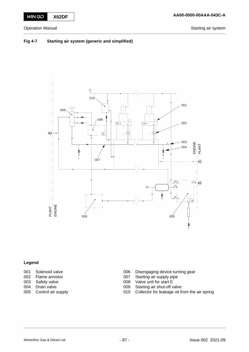
Fig 4-7 Starting air system (generic and simplified)
40
PLAN
TEN
GIN
E
E
45
41
A3
A1A2
A6
APL
ANT
ENG
INE
010
008
009
007
001
002
004
005006
Cyl. 1 Cyl. n
003
Legend
001 Solenoid valve 006 Disengaging device turning gear002 Flame arrestor 007 Starting air supply pipe003 Safety valve 008 Valve unit for start E004 Drain valve 009 Starting air shut-off valve005 Control air supply 010 Collector for leakage oil from the air spring
X62DF AA00-0000-00AAA-043C-A
Operation Manual Starting air system
Winterthur Gas & Diesel Ltd. - 87 - Issue 002 2021-09

4.8 Scavenge air system
The scavenge air system replaces the exhaust gas in the cylinder with fresh air.
For the schematic diagrams, refer to section 13.1 Schematic diagrams - general.
The scavenge air comes in from the outside through a duct or from the engine room. The scavengeair enters at the silencer of the turbocharger.
The scavenge air system has the parts that follow:
• Scavenge air receiver
The scavenge air receiver (013, Figure 4-8) supplies the cylinders with the applicablequantity of air.
• Turbocharger
The compressor (005) of the turbocharger compresses the air to the applicable pressure.The compressor is attached to the shaft of the turbine (004). The remaining energy of theexhaust gas operates the turbine and thus the compressor.
• Auxiliary blower
The two auxiliary blowers (010) supply the scavenge air at the engine start and during lowload operation.
• Auxiliary blower switch box
The auxiliary blower switch box controls the auxiliary blowers.
• Scavenge air cooler
The scavenge air cooler (SAC) (006) decreases the temperature of the hot compressed airfrom the turbocharger. This increases the mass of air and thus increases the quantity of airthat is supplied to the cylinders.
• Water separator
The water separator (007) removes water from the scavenge air. This prevents damageand gives better combustion in the cylinders. Water occurs when the scavenge air coolerdecreases the temperature of wet air. Water also occurs during the wash procedure of theSAC.
• Drains
The scavenge air system has the drains (009) that follow:○ Condensation drain from the scavenge air cooler
○ Water drain from the water separator
○ Oily water drain.
X62DF AA00-0000-00AAA-043S-A
Operation Manual Scavenge air system
Winterthur Gas & Diesel Ltd. - 88 - Issue 002 2021-09

Fig 4-8 Scavenge air system
00148
001
002
003004
005
006
007008
009
015
014
013
012011
010
Legend
001 Exhaust gas manifold 009 Drains002 Exhaust gas outlet 010 Auxiliary blower003 Scavenge air inlet 011 Piston underside004 Turbine 012 Piston005 Compressor 013 Scavenge air receiver006 Scavenge air cooler 014 Cylinder liner007 Water separator 015 Exhaust valve008 Charging unit
X62DF AA00-0000-00AAA-043S-A
Operation Manual Scavenge air system
Winterthur Gas & Diesel Ltd. - 89 - Issue 002 2021-09

4.9 Control air system
The control air system supplies the air spring of the exhaust valves and the starting air systemwith control air.
For the schematic diagrams, refer to section 13.1 Schematic diagrams - general.
The plant supply systems supply compressed air with the specified properties at the two engineconnections (in Figure 4-9 marked with a circle) that follow:
• Connection 45 (control air supply inlet) for usual supply
• Connection 40 (starting air pipe inlet) for stand-by supply.
The control air system has the parts that follow:
• Control air supply
The control air supply (002) decreases the supply air pressure to the specified pressures.
• Air tank
The air tank (003) is a container for control air. If the two plant air supply systems becomedefective, the air tank supplies control air to the engine for a short period.
• Air bottle
The air bottle (001) collects condensation from the starting air.
• Collector for leakage oil from the air spring
The collector for leakage oil from the air spring (007) controls the oil leakage from the airspring of the exhaust valves with a float control. When the collector pipe is full, the shut-offvalve opens and the oil flows into the crankcase.
X62DF AA00-0000-00AAA-043T-A
Operation Manual Control air system
Winterthur Gas & Diesel Ltd. - 90 - Issue 002 2021-09
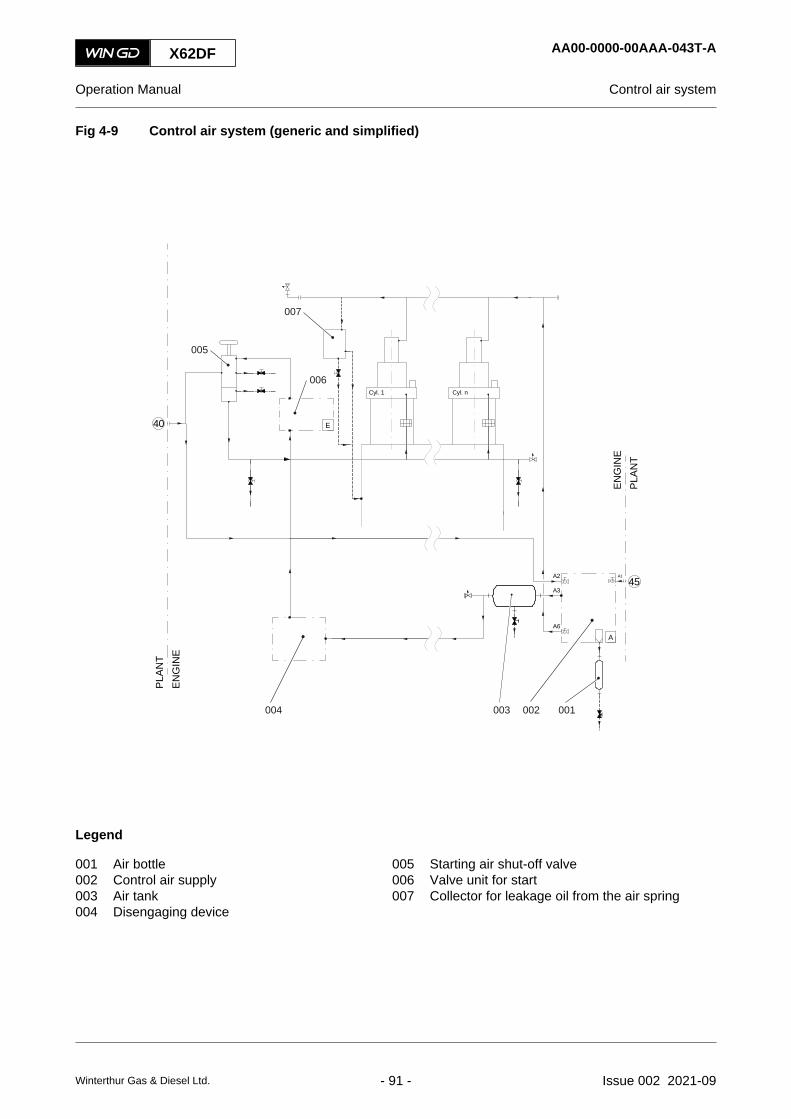
Fig 4-9 Control air system (generic and simplified)
40
PLAN
TEN
GIN
E
E
45A3
A1A2
A6
APL
ANT
ENG
INE
007
006
005
001002003004
Cyl. 1 Cyl. n
Legend
001 Air bottle 005 Starting air shut-off valve002 Control air supply 006 Valve unit for start003 Air tank 007 Collector for leakage oil from the air spring004 Disengaging device
X62DF AA00-0000-00AAA-043T-A
Operation Manual Control air system
Winterthur Gas & Diesel Ltd. - 91 - Issue 002 2021-09

4.10 Exhaust gas system
The exhaust gas system collects the exhaust gas of the cylinders in a manifold. The remainingenergy of the exhaust gas is used to operate the turbine of the turbocharger (002, Figure 4-10)(refer to section 4.8 Scavenge air system).
For the schematic diagrams, refer to section 13.1 Schematic diagrams - general.
The exhaust gas system has as interface to the plant the engine connection 71 (exhaust gasturbocharger outlet, in Figure 4-10 marked with a circle).
The exhaust gas system has the parts that follow:
• Exhaust valve
The exhaust valve (004) of each cylinder releases the exhaust gas of the combustion intothe exhaust gas manifold.
• Exhaust gas manifold
The exhaust gas manifold (003) collects the exhaust gas from the cylinders.
• Turbocharger bypass pipe
Usually the engine has a turbocharger bypass pipe (001) for different operating conditions.
X62DF AA00-0000-00AAA-043D-A
Operation Manual Exhaust gas system
Winterthur Gas & Diesel Ltd. - 92 - Issue 002 2021-09

Fig 4-10 Exhaust gas system (generic and simplified)
71
PLANT
ENGINE
003
001 002
Cyl. 1 Cyl. 2 Cyl. 3 Cyl. 4 Cyl. n
004
Legend
001 Turbocharger bypass pipe 003 Exhaust gas manifold002 Turbocharger 004 Exhaust valve
X62DF AA00-0000-00AAA-043D-A
Operation Manual Exhaust gas system
Winterthur Gas & Diesel Ltd. - 93 - Issue 002 2021-09

4.11 Fuel system
The fuel system supplies the injection valves of the cylinders with the applicable quantity of fuel.
For the schematic diagrams, refer to section 13.1 Schematic diagrams - general.
The fuel system has the engine connections as interface to the plant as follows (in Figure 4-11and Figure 4-12 marked with a circle):
• Connection 49 (fuel inlet)
• Connection 50 (fuel return outlet)
• Connection 51 (fuel leakage rail unit outlet)
• Connection 52 (fuel leakage outlet)
• Connection 57 (leakage outlet)
• Connection 59 (trace heating fuel inlet)
• Connection 60 (trace heating fuel outlet)
• Connection 67 (fire extinguishing plant cylinder block inlet).
The constant flow of fuel through the fuel system keeps the fuel warm.
At low load the ECS automatically cuts out injection valves in each cylinder as follows:
• For an engine with two injection valves - one of the two injection valves
• For an engine with three injection valves - one or two of the three injection valves.
This makes sure that the engine has the best fuel and combustion properties, which decreasessmoke and fuel consumption. The ECS cuts out a different injection valve at regular intervals toget an equal thermal load in the combustion chamber. There is no time limit to operate the engineat low load.
The fuel system has the parts that follow:
• Fuel pipes
The fuel pipes connect the items of the fuel system. All the fuel pipes have a trace heatingto keep the fuel warm during operation and for short engine stops. The high pressure fuelpipes that are not in the rail unit have a double wall design and leakage inspection points.
• Pressure retaining valve
The adjustable pressure retaining valve (009) in the return pipe keeps the fuel pressure inthe supply pipe to the fuel pumps at the correct value.
• Supply unit
The supply unit (007) holds the fuel pumps and the related items.
• Fuel pump (number related to the configuration)
The fuel pumps (008) supply the fuel rail with fuel at up to 1000 bar.
• Fuel rail
The fuel rail (004) supplies the flow limiting valves or the injection control units with fuel.
• Non-return valve
The non-return valves prevent fuel flow back from the fuel rail to the fuel pumps (eg if a fuelpump has no delivery, or a fuel pipe is defective).
X62DF AA00-0000-00AAA-043E-A
Operation Manual Fuel system
Winterthur Gas & Diesel Ltd. - 94 - Issue 002 2021-09

• Pressure control valve
The pressure control valve (001) has different functions to control the flow and the pressurein the fuel rail.
• Relief valve
The relief valve (002) is a safety device. If the fuel pressure increases to more than the setvalue, the relief valve opens.
• Flow limiting valve
The flow limiting valves (003) (FLV, not for X82, X92, RT-flex, and related DF engines)installed on the fuel rail supply fuel to the related injection valves with the adjusted quantityof fuel.
• Injection control unit
The injection control units (003) (ICU, for X82, X92, RT-flex, and related DF engines)installed on the fuel rail supply fuel to the related injection valves with the adjusted quantityof fuel.
• Injection valve
The injection valves (006) supply the fuel into the combustion chamber as a spray.
X62DF AA00-0000-00AAA-043E-A
Operation Manual Fuel system
Winterthur Gas & Diesel Ltd. - 95 - Issue 002 2021-09

Fig 4-11 Fuel system with FLV (generic and simplified)
Cyl. n 59
51
67
ENG
INE
PLAN
T
49
50
526057
PLAN
TEN
GIN
E
001 002 003 004 005
006
007
008009
Cyl. 1
Legend
001 Pressure control valve 006 Injection valve002 Relief valve 007 Supply unit003 Flow limiting valve (FLV) 008 Fuel pump004 Fuel rail 009 Pressure retaining valve005 Rail unit
X62DF AA00-0000-00AAA-043E-A
Operation Manual Fuel system
Winterthur Gas & Diesel Ltd. - 96 - Issue 002 2021-09

Fig 4-12 Fuel system with ICU (generic and simplified)
57
Cyl. 1 Cyl. 2 Cyl. 3 Cyl. 4 Cyl. n
60 50 49
52
51
PLAN
TEN
GIN
E
59
67
ENG
INE
PLAN
T
001 002 004 005003
007008009
006
Legend
001 Pressure control valve 006 Injection valve002 Relief valve 007 Supply unit003 Injection control unit (ICU) 008 Fuel pump004 Fuel rail 009 Pressure retaining valve005 Rail unit
X62DF AA00-0000-00AAA-043E-A
Operation Manual Fuel system
Winterthur Gas & Diesel Ltd. - 97 - Issue 002 2021-09

4.12 Gas system
The gas system supplies the gas admission valves (GAV) of the cylinders with the applicablequantity of gas.
For the schematic diagrams, refer to section 13.1 Schematic diagrams - general.
The gas system has the engine connections as interface to the plant as follows (in Figure 4-13marked with a circle):
• Connection 25 (main oil inlet)
• Connection 34 (leakage oil of driving end outlet)
• Connection 35 (leakage oil of free end outlet)
• Connection 38 (oil pipe drain of supply unit outlet)
• Connection 52 (fuel leakage outlet)
• Connection 76 (supply unit fuel pilot valve inlet)
• Connection 77 (supply unit fuel pilot valve outlet)
• Connection 78 (gas supply pipe inlet)
• Connection 79 (gas release pipe, engine side outlet)
• Connection 80 (gas release pipe, system side outlet)
• Connection 81 (ventilation air annular space inlet)
• Connection 82 (gas monitoring pipe piston under side).
The gas system is continuously monitored with gas detectors installed in the gas pipes. If there isa gas leak, the gas detectors will activate an alarm.
When there is a fire alarm in the engine room and the engine operates in gas mode, the enginecontrol system automatically changes to diesel mode (gas trip) and closes the master gas fuelvalve.
The gas system has the parts that follow:
• Gas pipes
The gas pipes connect the items of the gas system. All the gas pipes have a double walldesign. The annular spaces of the double wall pipes have open pipes to the atmosphere.Fans cause a negative air pressure in the annular spaces. The air flows through the annularspaces to the fans. The fans release the air and possible gas leakages to the atmosphere.
• Shut-off valve
The shut-off valves (005) on the fuel side and on the exhaust side isolate the gas supply tothe engine, if there is a gas leakage on the engine. The shut-off valves also isolate the gassupply, if the engine runs in diesel mode.
• Vent valve
The vent valves (007) on the fuel side and on the exhaust side release the remaining gasto the atmosphere, when the shut-off valves are closed.
• Gas admission valve (GAV)
The gas admission valves (GAV) (006) supply the gas to the related cylinders.
X62DF AA00-0000-00AAA-043F-A
Operation Manual Gas system
Winterthur Gas & Diesel Ltd. - 98 - Issue 002 2021-09

Fig 4-13 Gas system (generic and simplified)
Legend
001 Gas detection 005 Shut-off valve002 Exhaust valve control unit (VCU) 006 Gas admission valve (GAV)003 Pilot fuel pump unit 007 Vent valve004 Control air supply 008 Pilot fuel valve
X62DF AA00-0000-00AAA-043F-A
Operation Manual Gas system
Winterthur Gas & Diesel Ltd. - 99 - Issue 002 2021-09

4.13 Pilot fuel system
The pilot fuel system supplies the pilot injection valves of the cylinders with the applicable quantityof pilot fuel.
For the schematic diagrams, refer to section 13.1 Schematic diagrams - general.
The pilot fuel system has the engine connections as interface to the plant as follows:
• Connection 76 (pilot fuel inlet)
• Connection 77 (pilot fuel outlet).
Pilot fuel is diesel fuel and is used in gas mode to start the ignition of the gas-air mixture.
The pilot fuel system also operates with a decreased quantity of fuel injection during engineoperation in diesel mode. This prevents contamination on the ends of the pilot injection valves andthe prechambers.
The pilot fuel system has the parts that follow:
• Pilot fuel pipes
The pilot fuel pipes connect the items of the pilot fuel system. The HP pilot fuel pipes havea double wall design.
• Supply unit pilot fuel
The supply unit pilot fuel increases the pressure of the pilot fuel to the necessary value.
• Pilot injection valve
The pilot injection valves supply the pilot fuel to the related cylinders.
X62DF AA00-0000-00AAA-043M-A
Operation Manual Pilot fuel system
Winterthur Gas & Diesel Ltd. - 100 - Issue 002 2021-09

X62DF AA00-0000-00AAA-043M-A
Operation Manual Pilot fuel system
Page left intentionally blank
Winterthur Gas & Diesel Ltd. - 101 - Issue 002 2021-09

4.14 LP Selective catalytic reduction system
The Low Pressure Selective Catalytic Reduction (LP SCR) system is an optional system todecrease the level of nitrogen oxides in the exhaust gas. This makes sure that the emissions ofnitrogen oxides obey the Tier III regulations of the International Maritime Organization (IMO).
Nitrogen oxides are dangerous and are made in secondary reactions in the engine during fuelcombustion.
The LP SCR system is installed after the turbocharger. The system design and the supply ofcomponents is divided between the LP SCR system supplier, the shipyard and WinGD/enginebuilder.
The LP SCR system adds a urea water solution to the exhaust gas flow. Chemical reactionschange nitrogen oxides to molecular nitrogen and water, which are not dangerous.
Because of the low exhaust gas temperature after the turbocharger ammonia bisulfates are formedin the LP SCR reactor. You must regularly change to bypass operation and do a regenerationprocedure to remove these deposits, refer to the related documentation of the manufacturer.During this procedure the LP SCR system cannot operate.NOTE: For a DF engine: The LP SCR system can only be used in diesel mode.
NOTE: For further details about the operation, maintenance and troubleshooting aspects of theLP SCR system, please refer to the manuals of the manufacturer.
4.14.1 Description of the LP SCR system
4.14.1.1 LP SCR system parts
The LP SCR system has the parts shown in the paragraphs that follow (see Figure 4-14 and Figure4-15):
• Urea pump unit
This unit supplies the urea solution from the tank to the urea solution dosing unit. This keepsthe applicable pressure in the related pipes.
• Urea dosing unit
The urea dosing unit controls the supply of urea solution to the decomposition unit.
• Burner
The burner heats up the exhaust gas flow that is used to inject the urea.
• Decomposition unit
In the decomposition unit the exhaust gas and the urea is mixed to form ammonia.
• LP SCR reactor
The LP SCR reactor has a steel wall and has an inlet and an outlet cone. A steel structureholds the catalyst layers. At the catalytic surface of the catalyst layers the nitrogen oxides(NO and NO2) react with the ammonia into molecular nitrogen (N2) and water (H2O). Thesegases are part of the ambient air and are not dangerous.
Manholes in the reactor walls are used to examine and, if necessary, to clean or replacethe catalyst elements.
X62DF AA00-9270-00AAA-043B-A
Operation Manual LP Selective catalytic reduction system
Winterthur Gas & Diesel Ltd. - 102 - Issue 002 2021-09

• Valves
The valves in the LP SCR system are used for the different operation modes. The LP SCRsystem has the valves that follow:○ V1 - reactor inlet valve
○ V2 - reactor outlet valve
○ V3 - reactor bypass valve
○ V4 - turbine bypass valve
The turbine bypass valve (V4) is also used for other functions of the ECS, for example forlow-load tuning (LLT) or for steam production control (SPC).
4.14.1.2 Layout
The LP SCR system can be designed in different layouts related to the project. Two examples areshown in Figure 4-14 and Figure 4-15.
Fig 4-14 LP SCR temperature controlled (example)
V3
V1
V4
V2
003 004 005001
006
002
Legend
001 Engine 004 Burner002 Urea dosing unit 005 LP SCR reactor003 Decomposition unit 006 Turbocharger
X62DF AA00-9270-00AAA-043B-A
Operation Manual LP Selective catalytic reduction system
Winterthur Gas & Diesel Ltd. - 103 - Issue 002 2021-09

Fig 4-15 LP SCR bypass rate controlled (example)
V3
V1
V4
V2
002 003 005001
006
004
Legend
001 Engine 004 Burner002 Urea dosing unit 005 LP SCR reactor003 Decomposition unit 006 Turbocharger
4.14.2 Operation modes
The LP SCR system can be operated if the exhaust gas temperature is in the permitted limits.These limits are adjusted during commissioning. A temperature that is less than the permitted limitcan cause the catalyst elements to clog. A temperature that is more than the permitted limit cancause the catalyst elements to become worn quickly.
4.14.2.1 LP SCR system - (emergency) bypass
In this operation mode, the LP SCR system is bypassed. The engine operates in Tier II mode.Urea solution is not injected.
The valves have the conditions that follow:
• V1 - closed
• V2 - closed
• V3 - open
• V4 - the control systems control this valve.
X62DF AA00-9270-00AAA-043B-A
Operation Manual LP Selective catalytic reduction system
Winterthur Gas & Diesel Ltd. - 104 - Issue 002 2021-09

4.14.2.2 LP SCR system - preparation
In this operation mode, exhaust gas causes the temperature of the LP SCR reactor to slowlyincrease. Urea solution is not injected.
The valves have the conditions that follow:
• V1 - slowly changes from closed to open
• V2 - slowly changes from closed to open
• V3 - slowly changes from open to closed
• V4 - the control systems control this valve.
When the temperature of the LP SCR reactor has the value for operation in Tier III mode, a timerstarts. As long as the timer runs, the operator must change to Tier III mode. If the operator doesnot change to Tier III and the timer stops, the ECS changes back to bypass mode (Tier II).
4.14.2.3 LP SCR system - Tier III
In this operation mode, the LP SCR system is set to ON. The engine operates in Tier III mode.Urea solution is injected.
The valves have the conditions that follow:
• V1 - open
• V2 - open
• V3 - closed
• V4 - the control systems control this valve to keep the temperature of the exhaust gas inthe correct range.
4.14.2.4 LP SCR system - at engine stop
If you stop the engine in Tier III mode, the LP SCR system changes to bypass mode immediatelyand urea solution injection stops.
X62DF AA00-9270-00AAA-043B-A
Operation Manual LP Selective catalytic reduction system
Winterthur Gas & Diesel Ltd. - 105 - Issue 002 2021-09

4.14.3 LP SCR control system
The main tasks of the WinGD control system for the LP SCR system are as follows:
• Calculate the setpoint position for the turbine bypass valve (V4) to control the exhaust gastemperature.
• Control the operation of the auxiliary blowers.
• Calculate the setpoint for the urea dosing unit.
Related to the input signals the LP SCR control system gives the related signals to the LP SCRsystem, refer to Figure 4-16.
Fig 4-16 LP SCR control system layout
001 002 003
Legend
001 Input signals 003 Output signals002 LP SCR control system
The main input signals are as follows:
• Engine parameters
• Prepare Tier III command from RCS
• Tier III command from RCS
• Position of turbine bypass valve (V4)
• Different temperatures and pressures
The main output signals are as follows:
• Different temperatures and pressures
• Signals to enable or disable the LP SCR system
The principal control configuration of the LP SCR system is shown in Figure 4-17.
X62DF AA00-9270-00AAA-043B-A
Operation Manual LP Selective catalytic reduction system
Winterthur Gas & Diesel Ltd. - 106 - Issue 002 2021-09

Fig 4-17 LP SCR system - principal control configuration
E72
PCS
ECR Engine room
(E73) E71 E70
AMSECS Signals
External maincontrol panel
4.14.3.1 Messages of the LP SCR control system
The LP SCR control system gives three messages to the alarm and monitoring system (AMS).The messages are as follows:
• LP SCR ON - This message shows that the LP SCR system is set to ON and thus urea isinjected.
• LP SCR minor failure - This message shows a failure that does not have an effect on LPSCR system operation.
• LP SCR major failure - This message shows a failure that has an effect on LP SCR systemoperation. The LP SCR control system stops the LP SCR system operation and changesto Tier II mode.
X62DF AA00-9270-00AAA-043B-A
Operation Manual LP Selective catalytic reduction system
Winterthur Gas & Diesel Ltd. - 107 - Issue 002 2021-09

4.14.3.2 Control box E70
The control box E70 is installed on the engine and has switches and visual indicators.
Fig 4-18 Control box E70 with option SPC
001
002
003
004
005
006
007
008
009
010
Legend
001 SCR bypass switch 006 Indication (orange) - SPC bypass002 Indication (red) - SCR failure 007 Indication (green) - SPC running003 Indication (orange) - SCR bypass 008 Indication (green) - SCR running004 Indication (red) - SPC failure 009 Indication (green) - Power on005 SPC bypass switch 010 Power switch
X62DF AA00-9270-00AAA-043B-A
Operation Manual LP Selective catalytic reduction system
Winterthur Gas & Diesel Ltd. - 108 - Issue 002 2021-09

4.14.3.3 Control box E71
The control box E71 is installed on the engine or in the engine room and has switches below theLDU-20.
Fig 4-19 Control box E71 with option SPC
001
002003
Legend
001 LDU-20 003 SCR bypass switch002 SPC bypass switch
X62DF AA00-9270-00AAA-043B-A
Operation Manual LP Selective catalytic reduction system
Winterthur Gas & Diesel Ltd. - 109 - Issue 002 2021-09

4.14.3.4 Control box E72 or E73
The control box E72 (without SPC) or E73 (with SPC) is installed in the engine control room andhas switches below the LDU-20.
Fig 4-20 Control boxes E72 and E73
001
002
003
004
Legend
001 LDU-20 003 SPC bypass switch002 SCR bypass switch 004 Conductor terminal block
X62DF AA00-9270-00AAA-043B-A
Operation Manual LP Selective catalytic reduction system
Winterthur Gas & Diesel Ltd. - 110 - Issue 002 2021-09

4.14.4 LDU-20 pages
The LDU-20 panel has the pages that follow (examples).
Fig 4-21 LDU-20 page - LP SCR SYSTEM STATUS (MAIN PAGE)
010
008
009
001 002 003
007
006
005004
Tab 4-1 LP SCR SYSTEM STATUS (MAIN PAGE)
Item Function Effect
001 OVERVIEW button Opens the SCR system overview page
002 INTERFACES button Opens the interfaces page
003 INDEX button Opens the index page
004 SCREENSHOT button Makes a screenshot of the current screen
005 RCS CTRL OFF button Gets control from the remote control system (if button is active)
006 Status indication Shows the SCR status
007 Status indication Shows the control location
008 Status indication Shows the related status
009 Button and indication Starts and indicates the related SCR operation mode
010 Status indication Shows the status of the SCR system
X62DF AA00-9270-00AAA-043B-A
Operation Manual LP Selective catalytic reduction system
Winterthur Gas & Diesel Ltd. - 111 - Issue 002 2021-09

Fig 4-22 LDU-20 page - LP SCR SYSTEM OVERVIEW
006
009
008007
001 002 003
005
004
Tab 4-2 LP SCR SYSTEM OVERVIEW
Item Function Effect
001 INTERFACES button Opens the interfaces page
002 INDEX button Opens the index page
003 SCREENSHOT button Makes a screenshot of the current screen
004 RCS CTRL OFF button Gets control from the remote control system (if button is active)
005 Status indication Shows the SCR status
006 Status indication Shows the control location
007 Status indication Shows the values
008 Status indication Shows the engine status
009 Status indication Shows the current value and the valve setpoint value in percent(0% to 100%)
X62DF AA00-9270-00AAA-043B-A
Operation Manual LP Selective catalytic reduction system
Winterthur Gas & Diesel Ltd. - 112 - Issue 002 2021-09

Fig 4-23 LDU-20 page - LP SCR INTERFACES
008
007
001 002 003
006
005
004
Tab 4-3 LP SCR INTERFACES
Item Function Effect
001 OVERVIEW button Opens the SCR system overview page
002 INDEX button Opens the index page
003 SCREENSHOT button Makes a screenshot of the current screen
004 RCS CTRL OFF button Gets control from the remote control system (if button is active)
005 Status indication Shows the SCR status
006 Status indication Shows the control location
007 Status indication Shows the auxiliary blower status
008 Status indication Shows the status of the SCR system
X62DF AA00-9270-00AAA-043B-A
Operation Manual LP Selective catalytic reduction system
Winterthur Gas & Diesel Ltd. - 113 - Issue 002 2021-09
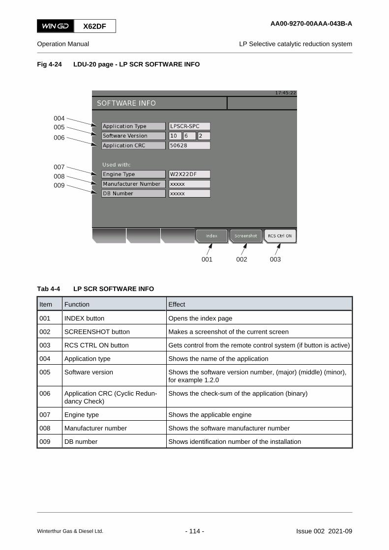
Fig 4-24 LDU-20 page - LP SCR SOFTWARE INFO
004
001 002 003
005006
007008009
Tab 4-4 LP SCR SOFTWARE INFO
Item Function Effect
001 INDEX button Opens the index page
002 SCREENSHOT button Makes a screenshot of the current screen
003 RCS CTRL ON button Gets control from the remote control system (if button is active)
004 Application type Shows the name of the application
005 Software version Shows the software version number, (major) (middle) (minor),for example 1.2.0
006 Application CRC (Cyclic Redun-dancy Check)
Shows the check-sum of the application (binary)
007 Engine type Shows the applicable engine
008 Manufacturer number Shows the software manufacturer number
009 DB number Shows identification number of the installation
X62DF AA00-9270-00AAA-043B-A
Operation Manual LP Selective catalytic reduction system
Winterthur Gas & Diesel Ltd. - 114 - Issue 002 2021-09

Fig 4-25 LDU-20 page - LP SCR PAGE INDEX
004
001 002 003
Tab 4-5 LP SCR PAGE INDEX
Item Function Effect
001 INDEX button Opens the index page
002 SCREENSHOT button Makes a screenshot of the current screen
003 RCS CTRL ON button Gets control from the remote control system (if button is active)
004 Page button Opens the selected page
X62DF AA00-9270-00AAA-043B-A
Operation Manual LP Selective catalytic reduction system
Winterthur Gas & Diesel Ltd. - 115 - Issue 002 2021-09

4.15 Steam production control system
The steam production control system (SPC) supplies the steam production of the ship with exhaustgas, which has a higher temperature.
SPC is an optional system.NOTE: The engine obeys the IMO NOx limits, with and without steam production.
Fig 4-26 Example of SPC
007
001 004002 003 006005
Legend
001 Engine 005 Steam production002 Exhaust waste gate valve 006 Steam consumer003 Steam production control system 007 Turbocharger004 Stack
4.15.1 Function
The SPC controls the exhaust waste gate valve (002, Figure 4-26). If the exhaust waste gate valve(EWG) opens, a part of the exhaust gas bypasses the turbocharger (007). As a result thetemperature of the exhaust gas increases, which is supplied to the steam production (005).
The supply of the turbocharger comes first, before the supply of the steam production.
The supply of the steam production is only permitted in the range between the minimum engineload and the maximum bypass rate. These limits are related on the ambient conditions and areproject specific.
4.15.2 User interface on the LDU-20
If an SCR system is installed, the control for SPC is part of the SCR system.
If no SCR system is installed, the control for SPC has separate control boxes.
X62DF AA00-9270-00AAA-043C-A
Operation Manual Steam production control system
Winterthur Gas & Diesel Ltd. - 116 - Issue 002 2021-09

Fig 4-27 LDU-20 page - STEAM PRODUCTION CONTROL
007008
009010011
012
015
013
006
001 002 003
005
014
004
Tab 4-6 STEAM PRODUCTION CONTROL (SPC)
Item Function Effect
001 ON/OFF button Starts or stops the SPC system
002 INDEX button Opens the index page
003 SCREENSHOT button Makes a screen shot of the current screen
004 RCS CTRL ON button Gets control from the remote control system (if button is active)
005 Value indication Shows the values
006 SPC/EXT. CONTROL button Changes to the external control of the SPC
007 MinEWGPos mode button Sets the minimum permitted EWG positionOther SPC modes than the initial mode MinEWGPos are onlypossible, if the signal Engine ready for SPC from ECS is active(green).
008 MaxEWGPos mode button Sets the maximum permitted EWG position
009 ManEWGSetp mode button Sets the EWG setpoint, if the specific LDU-20 is in controlYou can set a value of 0 to 100%, but the SPC uses only a valuein the permitted range.
X62DF AA00-9270-00AAA-043C-A
Operation Manual Steam production control system
Winterthur Gas & Diesel Ltd. - 117 - Issue 002 2021-09

Item Function Effect
010 PressCtrl mode 1 button Starts the PressCtrl mode 1This mode is applicable only, if the steam pressure signal fromthe steam plant is correct.SPC compares the setpoint and the actual steam pressure. Ifthere is a difference, it opens or closes the EWG to change thesteam pressure.If the status of the steam pressure signal changes to FAIL, SPCwill change to MinEWGPos mode.
011 PressCtrl mode 2 button Starts the PressCtrl mode 2Same effect as PressCtrl mode 1: But, if the burner is ON, theSPC uses the minimum permitted EWG position only.
012 Steam Pressure Setpoint Shows the actual setpoint of the steam pressureYou can manually set the setpoint, if the PressCtrl mode 1 or 2is active.It is only possible to set the setpoint if the specific LDU-20 is incontrol.
013 Manual EWG Setpoint Shows the actual EWG setpointIf the ManEWGSetp mode is active, you can enter the EWGsetpoint.
014 EWG Limitation Shows the current EWG setpoint together with the actual mini-mum and maximum limitationsToo wide EWG opening decreases the scavenge air pressure.This will start the auxiliary blowers.The limit of the EWG opening prevents the scavenge air pres-sure to decrease below the switching-On point of the auxiliaryblowers.
015 dIT Shows the delta injection timing (dIT)SPC calculates the dIT. The dIT controls the timing of the fuelinjection. This timing is related to the difference between EWGsetpoint and the minimum permitted EWG position.The ECS controls, if the dIT from SPC will be used or not.Rule: If ICC is on, then dIT is not used.
4.15.3 Steam boost mode (SBM)
Steam boost mode is an optional application that can be activated or deactivated manually. It isonly available in gas mode operation. Activating the steam boost mode allows for a higher steamproduction on board. The steam boost mode is available for two different power ranges:
• 51% to 91% of the contracted maximum continuous rating
• 76% to 91% of the engine power
The steam boost mode offset can be chosen freely on the LDU from 0% to 100%. Use the LDU-Screen to control the steam boost mode functions.
X62DF AA00-9270-00AAA-043C-A
Operation Manual Steam production control system
Winterthur Gas & Diesel Ltd. - 118 - Issue 002 2021-09

4.15.4 LDU screen for steam boost mode
Fig 4-28 LDU for the steam boost mode
X62DF AA00-9270-00AAA-043C-A
Operation Manual Steam production control system
Winterthur Gas & Diesel Ltd. - 119 - Issue 002 2021-09

4.15.5 Activate the steam boost mode
Before activating the steam boost mode, make sure the LDU-Screen (Figure 4-28) shows thefollowing:
• Firing Pressure Gas Mode indicates (5) “OK”.
• Servo Oil (6) indicates “OK”.
• DCC (7) indicates “Not Active”.
• Load Range (8) indicates “OK”.
1 Press the button “Enable SBM” (1) to activate the steam boost mode.NOTE: The indication “SBM Enabled” (4) becomes green.
4.15.6 Deactivate the steam boost mode
Before deactivating the steam boost mode, make sure the LDU-Screen (Figure 4-28) shows thefollowing:
1 Press the button “Disable SBM” (2) to deactivate the steam boost mode.
4.15.7 Adjust the steam boost mode offset
Before adjusting the steam boost mode offset, make sure the following conditions are met:
• The engine is running with correct power ranges for the steam boost mode.
• The load range (8) indicates “OK”.
• The steam boost mode is activated.
1 a.) On the right side of LDU-Screen, turn the control key to the left to decrease the SBM-Offset-%.
or
1 b.) On the right side of LDU-Screen, turn the control key to the right to increase the SBM-Offset-%.
2 Press the control key to acknowledge the selected value of the Exhaust-Valve-Operation-Offset.NOTE: Adjusting the SBM-Offset advances the exhaust valve opening timing. This leads
to an increase of the exhaust gas temperatures of the cylinder. Depending on theengine load, the exhaust gas waste gate will also be opening and closing for steamboost production. This is a desired effect to further increase the exhaust gastemperature before entering the economizer.
X62DF AA00-9270-00AAA-043C-A
Operation Manual Steam production control system
Winterthur Gas & Diesel Ltd. - 120 - Issue 002 2021-09

5 Design and function of components5.1 Group 1 - Engine frame and bearings
5.1.1 Bedplate..........................................................................................................1245.1.2 Main bearing....................................................................................................1265.1.3 Thrust bearing.................................................................................................1285.1.4 Monoblock column...........................................................................................1305.1.5 Tie rod.............................................................................................................132
5.2 Group 2 - Cylinder5.2.1 Cylinder liner....................................................................................................1345.2.2 Lubricating quill................................................................................................1365.2.3 Gas admission valve.......................................................................................1385.2.4 Piston rod gland...............................................................................................1405.2.5 Direct controlled injection valve.......................................................................1425.2.6 Starting valve...................................................................................................1445.2.7 Relief valve......................................................................................................1465.2.8 Exhaust valve..................................................................................................1485.2.9 Pilot injection valve..........................................................................................150
5.3 Group 3 - Crankshaft, connecting rod and piston5.3.1 Crankshaft.......................................................................................................1525.3.2 Torsional vibration damper..............................................................................1545.3.3 Axial vibration damper.....................................................................................1585.3.4 Turning gear....................................................................................................1605.3.5 Connecting rod and connecting rod bearing....................................................1625.3.6 Crosshead and guide shoe..............................................................................1645.3.7 Piston...............................................................................................................166
5.4 Group 4 - Supply unit drive and control components5.4.1 Supply unit drive..............................................................................................1685.4.2 Starting air shut-off valve.................................................................................1705.4.3 Control air supply.............................................................................................1725.4.4 Local maneuvering stand for UNIC.................................................................1745.4.5 Pick-up for speed measurement......................................................................176
5.5 Group 5 - Supply unit, pumps and control valves5.5.1 Servo oil pump.................................................................................................1785.5.2 Supply unit.......................................................................................................1805.5.3 Supply unit pilot fuel........................................................................................1825.5.4 Fuel pump........................................................................................................1845.5.5 Pressure control valve.....................................................................................1865.5.6 Flow limiting valve...........................................................................................1885.5.7 Exhaust valve control unit................................................................................190
5.6 Group 6 - Scavenge air components5.6.1 Scavenge air receiver......................................................................................192
X62DF
Operation Manual
Winterthur Gas & Diesel Ltd. - 121 - Issue 002 2021-09

5.6.2 Turbocharger...................................................................................................1945.6.3 Auxiliary blower...............................................................................................1965.6.4 Auxiliary blower switch box..............................................................................1985.6.5 Scavenge air cooler.........................................................................................2005.6.6 Water separator...............................................................................................202
5.7 Group 7 - Cylinder lubrication and balancer5.7.1 Cylinder lubrication..........................................................................................2045.7.2 Integrated electrical balancer (iELBA).............................................................206
5.8 Group 8 - Pipes5.8.1 Exhaust waste gate.........................................................................................212
5.9 Group 9 - Monitoring instruments5.9.1 Crank angle sensor unit...................................................................................2145.9.2 Water in oil monitor..........................................................................................2165.9.3 Oil mist detector...............................................................................................218
X62DF
Operation Manual
Winterthur Gas & Diesel Ltd. - 122 - Issue 002 2021-09

X62DF
Operation Manual
Page left intentionally blank
Winterthur Gas & Diesel Ltd. - 123 - Issue 002 2021-09

5.1 Group 1 - Engine frame and bearings5.1.1 Bedplate
The bedplate is the basic structure of the engine. The bearing girders (001, Figure 5-1) areattached in the bedplate and hold the crankshaft.
The bottom part of the bedplate is the crankcase and collects lubricating oil. This oil flows back tothe oil supply system through oil drains (002).
The length of the bedplate is related to the number of cylinders.
Fig 5-1 Bedplate (generic)
001
002
Legend
001 Bearing girder 002 Oil drain
X62DF AA00-1115-00AAA-043A-A
Operation Manual Bedplate
Winterthur Gas & Diesel Ltd. - 124 - Issue 002 2021-09

X62DF AA00-1115-00AAA-043A-A
Operation Manual Bedplate
Page left intentionally blank
Winterthur Gas & Diesel Ltd. - 125 - Issue 002 2021-09

5.1.2 Main bearing
The main bearings hold the crankshaft (007, Figure 5-2) and transmit the forces through thebearing girders (008) into the bedplate.
The bottom bearing shell (006) is installed in the bearing girder (008) of the bedplate and the topbearing shell (004) in the bearing cover (003). The screws (005) engage and hold the top bearingshell and bottom bearing shell in position. The spring dowel pin (009) helps to get the bearingcover (003) in position.
The elastic studs (001) have a non-hardening locking compound applied to the threads. Hydraulictension is applied to the elastic studs during the install procedure. The round nuts (002) keep thebearing cover (003) against the bearing girder.
For the main bearings adjacent to the thrust bearing the oil flows through the oil bore (013) to therunning surface of the bearing. For the other main bearings the oil flows from the oil supply pipethrough the oil inlet (011) to the running surface of the bearings.
Fig 5-2 Main bearing (generic)
001
002
003
004
005
005
011006007008
005
005
009
009
012
013
014
010
Legend
001 Elastic stud 008 Bearing girder002 Round nut 009 Spring dowel pin003 Bearing cover 010 Flange004 Top bearing shell 011 Oil inlet005 Screw 012 Oil groove006 Bottom bearing shell 013 Oil bore007 Crankshaft 014 Coating
X62DF AA00-1132-00AAA-043A-A
Operation Manual Main bearing
Winterthur Gas & Diesel Ltd. - 126 - Issue 002 2021-09

X62DF AA00-1132-00AAA-043A-A
Operation Manual Main bearing
Page left intentionally blank
Winterthur Gas & Diesel Ltd. - 127 - Issue 002 2021-09

5.1.3 Thrust bearing
The thrust bearing is installed on the crankshaft at the driving end of the engine. The thrust bearingflange (014, Figure 5-3) transmits the axial thrust from the propeller through the thrust pads intothe bedplate:
• The thrust pads on the engine side adapt the propeller thrust of the ahead direction.
• The thrust pads on the driving end adapt the propeller thrust of the astern direction.
The thrust pads adapt to the clockwise or counterclockwise rotation of the engine.
The arbor supports (004) prevent circular movement of the thrust pads.
Bearing oil flows through the oil pipe (002) to the two nozzles (003). The oil flows out of the twonozzles as a spray, which becomes an oil layer between the thrust bearing flange (014) and thethrust pads (006, 013).
X62DF AA00-1203-00AAA-043A-A
Operation Manual Thrust bearing
Winterthur Gas & Diesel Ltd. - 128 - Issue 002 2021-09

Fig 5-3 Thrust bearing (generic)
001
002
003
004
005
006
007
008
007
009
006
010
011
012
013
014
015
Legend
001 Column 009 Crankshaft002 Oil pipe 010 2-part oil baffle003 Nozzle 011 Flywheel004 Arbor support 012 Bedplate005 Bedplate 013 Thrust pad (engine side)006 Thrust pad (driving end) 014 Thrust bearing flange007 Bearing cover 015 Column008 Crankshaft gear wheel
X62DF AA00-1203-00AAA-043A-A
Operation Manual Thrust bearing
Winterthur Gas & Diesel Ltd. - 129 - Issue 002 2021-09

5.1.4 Monoblock column
The monoblock column is the middle part of the engine. The monoblock column is installed on thebedplate and holds the cylinders.
On the exhaust side (ES) the monoblock column has one relief valve (001, Figure 5-4) per cylinder.The relief valves open, if the pressure in the monoblock increases too much.
On the fuel side (FS) the monoblock column has one door (002) per cylinder. During normaloperation the doors are closed and locked. For maintenance or inspection work the doors can beopened. Obey the safety rules before you open the doors.
The length of the monoblock column is related to the number of cylinders.
Fig 5-4 Monoblock column (generic)
FS ES
001
002
Legend
001 Relief valve FS Fuel side002 Door ES Exhaust side
X62DF AA00-1406-00AAA-043A-A
Operation Manual Monoblock column
Winterthur Gas & Diesel Ltd. - 130 - Issue 002 2021-09

X62DF AA00-1406-00AAA-043A-A
Operation Manual Monoblock column
Page left intentionally blank
Winterthur Gas & Diesel Ltd. - 131 - Issue 002 2021-09

5.1.5 Tie rod
The tie rods (004, Figure 5-5) keep the cylinder block (002), column (003) and bedplate (005)together at four locations around each cylinder.
Fig 5-5 Tie rod (generic)
001
002
003
004
005
001
Legend
001 Protection cover 004 Tie rod002 Cylinder block 005 Bedplate003 Column
If a tie rod breaks in the bottom area, a special device makes sure that the nut of the tie rod doesnot fall into the crankcase.
X62DF AA00-1903-00AAA-043A-A
Operation Manual Tie rod
Winterthur Gas & Diesel Ltd. - 132 - Issue 002 2021-09

X62DF AA00-1903-00AAA-043A-A
Operation Manual Tie rod
Page left intentionally blank
Winterthur Gas & Diesel Ltd. - 133 - Issue 002 2021-09
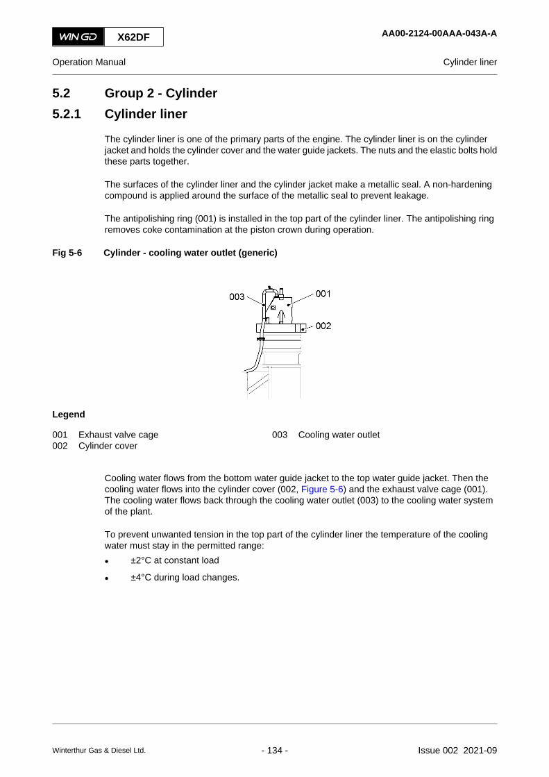
5.2 Group 2 - Cylinder5.2.1 Cylinder liner
The cylinder liner is one of the primary parts of the engine. The cylinder liner is on the cylinderjacket and holds the cylinder cover and the water guide jackets. The nuts and the elastic bolts holdthese parts together.
The surfaces of the cylinder liner and the cylinder jacket make a metallic seal. A non-hardeningcompound is applied around the surface of the metallic seal to prevent leakage.
The antipolishing ring (001) is installed in the top part of the cylinder liner. The antipolishing ringremoves coke contamination at the piston crown during operation.
Fig 5-6 Cylinder - cooling water outlet (generic)
Legend
001 Exhaust valve cage 003 Cooling water outlet002 Cylinder cover
Cooling water flows from the bottom water guide jacket to the top water guide jacket. Then thecooling water flows into the cylinder cover (002, Figure 5-6) and the exhaust valve cage (001).The cooling water flows back through the cooling water outlet (003) to the cooling water systemof the plant.
To prevent unwanted tension in the top part of the cylinder liner the temperature of the coolingwater must stay in the permitted range:
• ±2°C at constant load
• ±4°C during load changes.
X62DF AA00-2124-00AAA-043A-A
Operation Manual Cylinder liner
Winterthur Gas & Diesel Ltd. - 134 - Issue 002 2021-09

X62DF AA00-2124-00AAA-043A-A
Operation Manual Cylinder liner
Page left intentionally blank
Winterthur Gas & Diesel Ltd. - 135 - Issue 002 2021-09

5.2.2 Lubricating quill
The lubricating quills spray oil onto the cylinder liner wall. The lubricating quills are installed on thecircumference of the cylinder liner.
The cylinder lubricating pump supplies a specified quantity of cylinder oil at high pressure throughthe cylinder oil inlet (006, Figure 5-7) into the lubricating quills. The non-return valve (009) opensand the cylinder oil flows out of the nozzle tip (003) and the lubricating point (004) as a spray.Some of the cylinder oil flows into the grooves of the cylinder liner wall. The non-return valve (009)prevents the exhaust gas to flow back into the oil pipe.
Fig 5-7 Lubricating quill (generic)
001
002003
004
008
007
006
009
005
Legend
001 Piston 006 Cylinder oil inlet002 Piston ring 007 Holder003 Nozzle tip 008 Cylinder liner004 Lubricating point in cylinder liner 009 Non-return valve005 Compression spring
X62DF AA00-2138-00AAA-043A-A
Operation Manual Lubricating quill
Winterthur Gas & Diesel Ltd. - 136 - Issue 002 2021-09

X62DF AA00-2138-00AAA-043A-A
Operation Manual Lubricating quill
Page left intentionally blank
Winterthur Gas & Diesel Ltd. - 137 - Issue 002 2021-09

5.2.3 Gas admission valve
The two gas admission valves (GAV) per cylinder supply the gas to each combustion chamber.When the GAV opens, there is an injection of gas into the combustion chamber.
The ECS monitors and controls the GAV. The ECS controls the gas quantity independently foreach cylinder to adjust the engine load. Servo oil is used to operate the GAV, when the ECS hasenergized the solenoid valve (003, Figure 5-8).
Servo oil at decreased pressure is used to lubricate and to seal the valve spindle of the GAV.
The valve stroke sensor installed in the cover (006) transmits signals to the ECS. The ECS usesthese signals to adjust the timing of the gas supply, which is related to the engine load.
If the GAV has a leak, gas will flow through a bore in the valve body (001) to the space betweenthe walls of the gas supply pipe (double wall). The gas will activate the gas detection sensor andthe ECS will show an alarm.
Fig 5-8 Gas admission valve (generic)
007
001 002
003
004
005006
001
Legend
001 Valve body 005 Piston cover002 Hydraulic pipe (servo oil inlet) 006 Cover003 Solenoid valve 007 Gas inlet pipe004 Oil return pipe
X62DF AA00-2140-00AAA-043A-A
Operation Manual Gas admission valve
Winterthur Gas & Diesel Ltd. - 138 - Issue 002 2021-09

X62DF AA00-2140-00AAA-043A-A
Operation Manual Gas admission valve
Page left intentionally blank
Winterthur Gas & Diesel Ltd. - 139 - Issue 002 2021-09

5.2.4 Piston rod gland
The piston rod gland keeps the dirty cylinder oil in the scavenge space and thus preventscontamination of the bearing oil in the crankcase. Also, the piston rod gland seals the scavengeair from the crankcase.
Use the sample valve to get system oil samples regularly. The analysis of this oil gives data aboutthe quality of the cylinder lubrication.
Do regular checks of the leakage oil drain to make sure that oil flows freely. This prevents the riskof fire.
Fig 5-9 Piston rod gland (generic)
001002003
004
006
005
007
011010009
008
Legend
001 Scraper ring (4-part) 007 Oil drain002 Housing (2-part) 008 Ring support (3-part)003 Relief opening 009 Scraper ring (3-part)004 Neutral space 010 Gasket (4-part)005 Cylinder jacket 011 Tension spring006 Support
During operation, the two scraper rings (001, Figure 5-9) remove dirty oil from the piston rod. Thedirty oil flows through oil bores and collects in the bottom of the scavenge space. The dirty oil flowsout through the leakage oil drain on the fuel side.
The two gaskets (010) prevent the release of scavenge air into the crankcase.
The oil that flows through the relief openings (003) into the neutral space (004) flows into the oildrain.
The ring supports (008) hold the scraper rings (009) in position. The scraper rings (009) removebearing oil from the piston rod. This bearing oil flows through the oil drain (007) to the crankcase.
The tension springs (011) push the scraper rings (009) and (012) against the piston rod.
X62DF AA00-2303-00AAA-043A-A
Operation Manual Piston rod gland
Winterthur Gas & Diesel Ltd. - 140 - Issue 002 2021-09

X62DF AA00-2303-00AAA-043A-A
Operation Manual Piston rod gland
Page left intentionally blank
Winterthur Gas & Diesel Ltd. - 141 - Issue 002 2021-09

5.2.5 Direct controlled injection valve
The injection valves are installed in the cylinder cover of each cylinder. The injection valves spraythe fuel into the combustion chamber. The ECS controls the pilot valve of the injection valvesindirectly through the solenoid valve. ECS also controls the timing and the quantity of the injectedfuel.
X62DF AA00-2722-00AAA-043A-A
Operation Manual Direct controlled injection valve
Winterthur Gas & Diesel Ltd. - 142 - Issue 002 2021-09

X62DF AA00-2722-00AAA-043A-A
Operation Manual Direct controlled injection valve
Page left intentionally blank
Winterthur Gas & Diesel Ltd. - 143 - Issue 002 2021-09

5.2.6 Starting valve
The starting valve in each cylinder cover supplies pressurized air into the combustion chamber inthe two situations that follow:
• To start the engine before combustion starts
• To decrease the engine speed when combustion has stopped.
The ECS and the cylinder control modules (CCM-20) control and monitor the starting valves. Eachstarting valve opens and closes at the correct crank angle of the related cylinder. This makes thepiston move down (for engine start) or makes the piston speed decrease (for engine speeddecrease).
As soon as combustion starts the starting air supply stops.
Fig 5-10 Starting valve (example)
001
002
003004005006
007
008
009
Legend
001 Solenoid valve 006 Valve spindle002 Cover 007 Cylinder cover003 Piston 008 Starting air outlet004 Housing 009 Starting air inlet005 Compression spring
X62DF AA00-2728-00AAA-043A-A
Operation Manual Starting valve
Winterthur Gas & Diesel Ltd. - 144 - Issue 002 2021-09

X62DF AA00-2728-00AAA-043A-A
Operation Manual Starting valve
Page left intentionally blank
Winterthur Gas & Diesel Ltd. - 145 - Issue 002 2021-09

5.2.7 Relief valve
An integrated sensor and pressure relief valve are installed on each cylinder cover.
The integrated sensor measures the pressure inside the cylinder. (online sensor)
The pressure relief valve with integrated online sensor is used to avoid the gas pockets in thecylinders.
Open the pressure relief valve before slow-turning with the turning gear.
WARNINGThe pressure relief valve must be closed before the engine starts.
WARNINGDo not open the pressure relief valve when engine is running to avoid any damage to theonline sensor.
Fig 5-11 Integrated sensor and pressure relief valve
X62DF AA00-2740-00AAA-043A-A
Operation Manual Relief valve
Winterthur Gas & Diesel Ltd. - 146 - Issue 002 2021-09

X62DF AA00-2740-00AAA-043A-A
Operation Manual Relief valve
Page left intentionally blank
Winterthur Gas & Diesel Ltd. - 147 - Issue 002 2021-09
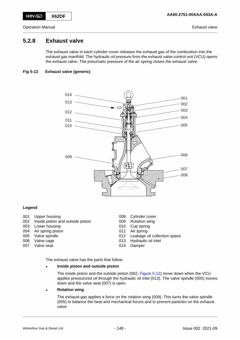
5.2.8 Exhaust valve
The exhaust valve in each cylinder cover releases the exhaust gas of the combustion into theexhaust gas manifold. The hydraulic oil pressure from the exhaust valve control unit (VCU) opensthe exhaust valve. The pneumatic pressure of the air spring closes the exhaust valve.
Fig 5-12 Exhaust valve (generic)
001002003
004
005
006
007008
009
010011
012
014
013
Legend
001 Upper housing 008 Cylinder cover002 Inside piston and outside piston 009 Rotation wing003 Lower housing 010 Cup spring004 Air spring piston 011 Air spring005 Valve spindle 012 Leakage oil collection space006 Valve cage 013 Hydraulic oil inlet007 Valve seat 014 Damper
The exhaust valve has the parts that follow:
• Inside piston and outside piston
The inside piston and the outside piston (002, Figure 5-12) move down when the VCUapplies pressurized oil through the hydraulic oil inlet (013). The valve spindle (005) movesdown and the valve seat (007) is open.
• Rotation wing
The exhaust gas applies a force on the rotation wing (009). This turns the valve spindle(005) to balance the heat and mechanical forces and to prevent particles on the exhaustvalve.
X62DF AA00-2751-00AAA-043A-A
Operation Manual Exhaust valve
Winterthur Gas & Diesel Ltd. - 148 - Issue 002 2021-09

• Air spring
When the exhaust valve is closed, compressed air flows through an air inlet connection intothe air spring (011). When the exhaust valve opens, this air is compressed to a higher value.When the hydraulic oil pressure releases, the compressed air expands and thus closes theexhaust valve.
• Thrust piece
The thrust piece on the valve spindle (005) prevents damage to the inside piston (002) andto the top of the valve spindle (005) when the exhaust valve operates.
• Valve stroke sensor
The valve stroke sensor monitors and transmits the open and closed positions of the valvespindle (005) to the ECS.
• Cup spring
The cup spring (010) absorbs vibration and shock to prevent damage to the exhaust valve.
Different parts of the exhaust valve are lubricated as follows:
• Leakage oil from the outer piston and inner piston (002) lubricates the air spring piston (004).Oil in the leakage oil collection space (012) drains to the leakage oil drain.
• While the exhaust valve closes, oil flows through the air spring piston (004) and into the airspring (011). The air in the air spring (011) changes oil that collects at the bottom of the airspring into a mist. The mist lubricates the upper part of the valve spindle (005).
• Oil that collects at the bottom of the air spring (011) flows through a groove on the lowerside of the distance ring and through holes in the guide bush. Thus the oil lubricates thebottom part of the valve spindle (005).
• When the exhaust valve opens, oil flows out of the air spring (011) through the throttle valvein the air spring pipe to the collector for leakage oil. The oil in the collector automaticallydrains through the leakage oil pipe into the crankcase.
X62DF AA00-2751-00AAA-043A-A
Operation Manual Exhaust valve
Winterthur Gas & Diesel Ltd. - 149 - Issue 002 2021-09

5.2.9 Pilot injection valve
The two pilot injection valves per cylinder supply pilot fuel to each combustion chamber during gasmode to ignite the gas-air mixture.
The ECS controls the pilot injection valves. The ECS calculates the injection timing and the pilotfuel quantity related to the engine load.
The pilot injection valves have a combustion prechamber to get the best ignition timing and a stablecombustion. Cooling water in the cylinder cover keeps cool the prechamber.
System oil is used to lubricate and to seal the pilot injection valve. The fuel and system oil leakagedrains to the overflow tank.
X62DF AA00-2790-00AAA-043A-A
Operation Manual Pilot injection valve
Winterthur Gas & Diesel Ltd. - 150 - Issue 002 2021-09

X62DF AA00-2790-00AAA-043A-A
Operation Manual Pilot injection valve
Page left intentionally blank
Winterthur Gas & Diesel Ltd. - 151 - Issue 002 2021-09

5.3 Group 3 - Crankshaft, connecting rod and piston5.3.1 Crankshaft
The crankshaft turns as it gets the power from the pistons. The crankshaft transmits the power tothe attached propeller shaft of the ship.
Main bearings on the two sides of each crank (002, Figure 5-13) hold the crankshaft in position.
The crankshaft gear wheel (005) is part of the thrust bearing.
On the driving end of the crankshaft there is a flywheel (004). This flywheel decreases the pulsationfrom the cylinders.
The length of the crankshaft is related to the number of cylinders.
Fig 5-13 Crankshaft (generic)
001002
003
004
005
Legend
001 Torsional vibration damper (optional) 004 Flywheel002 Crank 005 Crankshaft gear wheel003 Crankshaft
X62DF AA00-3103-00AAA-043A-A
Operation Manual Crankshaft
Winterthur Gas & Diesel Ltd. - 152 - Issue 002 2021-09

X62DF AA00-3103-00AAA-043A-A
Operation Manual Crankshaft
Page left intentionally blank
Winterthur Gas & Diesel Ltd. - 153 - Issue 002 2021-09

5.3.2 Torsional vibration damper
The torsional vibration damper decreases the torsional vibrations in the shafting system and inother components of the engine.
If a torsional vibration damper is necessary for the engine, one of the two damper types that followcan be used.
X62DF AA00-3130-00AAA-043A-A
Operation Manual Torsional vibration damper
Winterthur Gas & Diesel Ltd. - 154 - Issue 002 2021-09

5.3.2.1 Steel spring damper
A steel spring damper (Figure 5-14) is a tuned torsional vibration damper. It consists of two mainparts:
• The inner part (inner star (005) and spring pack (004)) is attached to the crankshaft flangeat the free end.
• The outer part (side plates (001), clamping ring (002) and intermediate pieces (003)) isconnected with spring packs (004) to the inner part.
The damper is supplied with pressurized system oil that fills the chambers between the inner andouter part. The usual setting value for the oil supply pressure is 2.8 bar. But the setting value canbe different, refer to the specification of the damper manufacturer.
If torsional vibrations move the steel springs, oil is pressurized on one side of the oil chambersand pushed through small clearances to the other side of the chambers. This small oil flow createsthe damping effect of the damper. The combined effect of spring stiffness and damping decreasesthe torsional vibrations in the shafting system. The damping work causes heat which is dissipatedby the oil flow. The oil drains into the crankcase.
The optional damper monitoring system monitors the dynamic twist in the damper and the oilsupply pressure.
Fig 5-14 Steel spring damper (generic)
001002003004
005
001
001002
005006
001
Legend
001 Side plate 004 Spring pack002 Clamping ring 005 Inner star003 Intermediate piece 006 Sealing
X62DF AA00-3130-00AAA-043A-A
Operation Manual Torsional vibration damper
Winterthur Gas & Diesel Ltd. - 155 - Issue 002 2021-09

5.3.2.2 Viscous damper
A viscous damper (Figure 5-15) is a tuned torsional vibration damper. It consists of two main parts:
• The housing (002) is fully sealed and is attached to the crankshaft flange at the free end.
• The inertia ring (004) is in the housing. The bearing (005) holds the inertia ring in the housing.
Between the housing and the inertia ring there is a layer of silicone oil (006) of a specified viscosity.If no torsional vibrations occur during engine operation, the housing and the inertia ring turn withthe same speed, as the silicone oil transfers the torque. If torsional vibrations occur during engineoperation, the housing and the inertia ring dynamically turn at different speeds. This differenceshears the silicone oil and thus decreases the vibration.
The damping work causes heat. This heat increases the temperature of the outer side of thedamper. The heat dissipates to the ambient air in the crankcase. If installed, system oil is sprayedon the damper to dissipate more heat. The oil drains into the crankcase.
If the viscous damper gets too much dynamic torque and thus causes too much heat, the viscosityof the silicone oil can change. Then the damping effect can change. Thus do regularly a check ofthe viscosity of the silicone oil, refer to the Maintenance Manual.
Fig 5-15 Viscous damper (generic)
001
001002 002 003003 004
004
005
006
Legend
001 Cover 004 Inertia ring002 Housing 005 Bearing003 Sealing 006 Silicone oil
X62DF AA00-3130-00AAA-043A-A
Operation Manual Torsional vibration damper
Winterthur Gas & Diesel Ltd. - 156 - Issue 002 2021-09

X62DF AA00-3130-00AAA-043A-A
Operation Manual Torsional vibration damper
Page left intentionally blank
Winterthur Gas & Diesel Ltd. - 157 - Issue 002 2021-09
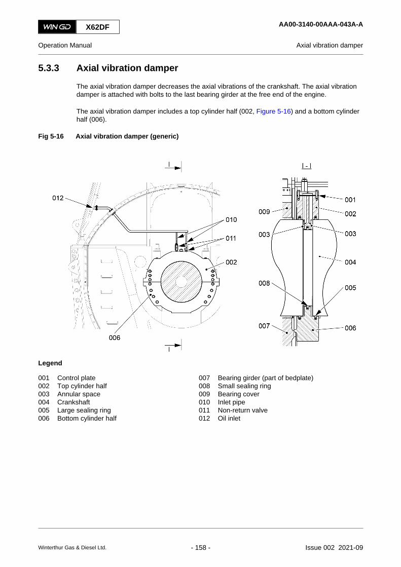
5.3.3 Axial vibration damper
The axial vibration damper decreases the axial vibrations of the crankshaft. The axial vibrationdamper is attached with bolts to the last bearing girder at the free end of the engine.
The axial vibration damper includes a top cylinder half (002, Figure 5-16) and a bottom cylinderhalf (006).
Fig 5-16 Axial vibration damper (generic)
Legend
001 Control plate 007 Bearing girder (part of bedplate)002 Top cylinder half 008 Small sealing ring003 Annular space 009 Bearing cover004 Crankshaft 010 Inlet pipe005 Large sealing ring 011 Non-return valve006 Bottom cylinder half 012 Oil inlet
X62DF AA00-3140-00AAA-043A-A
Operation Manual Axial vibration damper
Winterthur Gas & Diesel Ltd. - 158 - Issue 002 2021-09

5.3.3.1 Function
Oil flows from the oil inlet (012) through the top cylinder half (002) into the two annular spaces(003). When the crankshaft (004) moves in an axial direction, the pressure of the oil in thecompressed annular space (003) increases. This makes the oil slowly flow through the small holesin the control plate (001) into the other annular space (003). This slow oil flow decreases the axialvibrations. When the pressure is equal again in the two annular spaces (003), the oil flow stops.
The constant oil flow through the vent bore in the top cylinder half (002) keeps air away from theannular spaces (003).
The small oil leakage through the gap of the large sealing rings (005) drains into the crankcase.
5.3.3.2 Axial vibration damper monitor
The axial vibration damper monitor monitors the oil pressure in the two annular spaces (003, Figure5-16) of the axial vibration damper. The needle valve (004, Figure 5-17) and the throttle (003)prevent fast movement of the pointer in the pressure gauges (001).
Fig 5-17 Axial vibration damper monitor (generic)
001
002
003
004
Legend
001 Pressure gauge 003 Throttle002 Pressure transmitter 004 Needle valve
X62DF AA00-3140-00AAA-043A-A
Operation Manual Axial vibration damper
Winterthur Gas & Diesel Ltd. - 159 - Issue 002 2021-09

5.3.4 Turning gear
The turning gear slowly turns the crankshaft and thus moves the pistons, if the pinion (002, Figure5-18) is engaged on the flywheel (003). The electric motor (001) turns the pinion (002) and isattached on the driving end of the engine. Related to the ratio of the gear wheels there isapproximately one full turn of the crankshaft in ten minutes.
Fig 5-18 Turning gear (generic)
001
002
003
Legend
001 Electric motor 003 Flywheel002 Pinion
X62DF AA00-3206-00AAA-043A-A
Operation Manual Turning gear
Winterthur Gas & Diesel Ltd. - 160 - Issue 002 2021-09

X62DF AA00-3206-00AAA-043A-A
Operation Manual Turning gear
Page left intentionally blank
Winterthur Gas & Diesel Ltd. - 161 - Issue 002 2021-09

5.3.5 Connecting rod and connecting rod bearing
The connecting rod connects the crosshead with the crankshaft and converts the linear movementof the piston into a circular movement of the crankshaft.
The bearing shells are installed on the connecting rod for the bottom end bearing and the top endbearing. The top bearing cover is lined with white metal.
Crosshead lubricating oil flows through the guide shoe into the crosshead pin. A hole in thecrosshead pin lets lubricating oil flow into the bearing shells.
Fig 5-19 Connecting rod and connecting rod bearing (generic)
Legend
001 Top bearing cover 006 Round nut002 Bearing shell (top end bearing) 007 Elastic bolt003 Top bearing shell (bottom end bearing) 008 Dowel pin004 Bottom bearing cover 009 Allen screw005 Bottom bearing shell (bottom end bearing) 010 Oil bore
X62DF AA00-3303-00AAA-043A-A
Operation Manual Connecting rod and connecting rod bearing
Winterthur Gas & Diesel Ltd. - 162 - Issue 002 2021-09

X62DF AA00-3303-00AAA-043A-A
Operation Manual Connecting rod and connecting rod bearing
Page left intentionally blank
Winterthur Gas & Diesel Ltd. - 163 - Issue 002 2021-09

5.3.6 Crosshead and guide shoe
The crosshead guides the piston rod (009, Figure 5-20) and absorbs the lateral forces that comefrom the connecting rod (005).
The piston rod (009) is attached to the compression shim (007) and the crosshead pin (006) withscrews. The bearing oil necessary to keep the piston cool, flows through the space (002) to thepiston. The oil from the piston flows back through the oil pipe (001) to the crosshead pin (006).Then the oil flows into the crankcase.
The guide shoes (004) are attached to the crosshead pin (006) and move up and down on theguide ways of the column. The guide rails (008) hold the guide shoes (004) and thus the crossheadin the horizontal position.
Fig 5-20 Crosshead and guide shoe (example)
003
004007
009
010
006
005
002001
008
Legend
001 Oil pipe (from piston) 006 Crosshead pin002 Space 007 Compression shim003 Top bearing half (top end bearing) 008 Guide rail004 Guide shoe 009 Piston rod005 Connecting rod 010 Oil flow (to piston and from piston)
X62DF AA00-3326-00AAA-043A-A
Operation Manual Crosshead and guide shoe
Winterthur Gas & Diesel Ltd. - 164 - Issue 002 2021-09

X62DF AA00-3326-00AAA-043A-A
Operation Manual Crosshead and guide shoe
Page left intentionally blank
Winterthur Gas & Diesel Ltd. - 165 - Issue 002 2021-09

5.3.7 Piston
The piston moves in each cylinder. The piston rings seal the combustion chamber. The pistontransmits the force from the gas that expands in the cylinder to the crankshaft through theconnecting rod.
Elastic bolts (008, Figure 5-21) and round nuts (009) attach the piston crown (001) to the pistonrod (004). The piston skirt (003) is attached to the piston rod with screws. The piston rod (004) isattached to the crosshead pin in a specified position. The compression shims are installed betweenthe piston rod and the crosshead pin. The thickness of the compression shims is related to thespecified compression ratio.
System oil is used to keep cool the piston crown (001). This oil flows from the crosshead pin intothe space (005) between the oil pipe (007) and the piston rod (004). The oil then flows to the sprayplate (010). The oil comes out as a spray from the nozzles (011) into the cooling bores of the pistoncrown (001). The oil then flows through the oil pipe (007) into the crosshead pin and out throughthe oil bores to the crankcase.
Fig 5-21 Piston (example)
003
002
001
004
011
008
007
006
009
010
005
Legend
001 Piston crown 007 Oil pipe (from piston crown)002 Piston ring groove 008 Elastic bolt003 Piston skirt 009 Round nut004 Piston rod 010 Spray plate005 Space 011 Nozzle006 Oil flow
X62DF AA00-3403-00AAA-043A-A
Operation Manual Piston
Winterthur Gas & Diesel Ltd. - 166 - Issue 002 2021-09

X62DF AA00-3403-00AAA-043A-A
Operation Manual Piston
Page left intentionally blank
Winterthur Gas & Diesel Ltd. - 167 - Issue 002 2021-09

5.4 Group 4 - Supply unit drive and control components5.4.1 Supply unit drive
The supply unit drive is installed at the driving end of the engine on the fuel side.
The crankshaft gear wheel (003, Figure 5-22) moves the intermediate wheel (001). Theintermediate wheel (001) moves the intermediate wheel (006).
The gear wheel (005) operates the gear wheels (004) for the servo oil pumps. The camshaft ofthe gear wheel (005) also operates the fuel pumps.
Oil flows through an oil inlet to lubricate the bearings of the gear wheels (004). Oil also flowsthrough the nozzles in the bearing housing to lubricate the teeth of the gear wheels (004) and thegear wheel (005).
If you hear unusual noises from the area of the supply unit drive, you must find the cause andrepair the fault immediately.
X62DF AA00-4104-00AAA-043A-A
Operation Manual Supply unit drive
Winterthur Gas & Diesel Ltd. - 168 - Issue 002 2021-09

Fig 5-22 Supply unit drive (generic)
I
I001
002003
001
003
006
005
004
002
006
001
003
007
Legend
001 Intermediate wheel 005 Gear wheel (servo oil pumps)002 Flywheel 006 Intermediate wheel003 Crankshaft gear wheel 007 Crankshaft004 Gear wheel (servo oil pump)
X62DF AA00-4104-00AAA-043A-A
Operation Manual Supply unit drive
Winterthur Gas & Diesel Ltd. - 169 - Issue 002 2021-09

5.4.2 Starting air shut-off valve
The starting air shut-off valve supplies the starting air pipe with starting air. The starting air shut-off valve has a hand-wheel with three positions:
• CLOSED
• AUTO
• OPEN.
Fig 5-23 Starting air shut-off valve (example)
I
I
001
002003
004
005
006007008009010011
017
016015014013
012
018
Legend
001 Control valve 010 Non-return valve002 Valve space 011 Starting air outlet003 Spindle 012 Inlet chamber004 Hand-wheel 013 Pressure switch PS5017C005 To test valve 014 Solenoid valve CV7014C006 Spring 015 Double check valve007 Valve 016 Solenoid valve CV7013C008 Starting air inlet 017 Control air inlet009 Balance bore 018 Lever
With the lever (018, Figure 5-23) you can lock the valve in the selected position. During usualoperation the starting air shut-off valve is in position AUTO.
Starting air flows through the starting air inlet (008) into the inlet chamber (012), then through thebalance bore (009) into the valve space (002). The spring (006) and the pressure in the valvespace (002) keep the valve (007) closed.
X62DF AA00-4325-00AAA-043A-A
Operation Manual Starting air shut-off valve
Winterthur Gas & Diesel Ltd. - 170 - Issue 002 2021-09

During the start sequence the MCM-20 / IOM-20 module operates the solenoid valves (014) and(016). The control air from the control air inlet (017) opens the control valve (001) through thesolenoid valve CV7014C (014) and releases the pressure in the valve space (002). The valve (007)opens and starting air from the inlet chamber (012) flows through the non-return valve (010) to thestarting air outlet (011).
When the control valve (001) closes, starting air flows through the balance bores (009) and fillsthe inlet chamber (012) again. The valve (007) closes.
The starting air shut-off valve has a test valve. You can use this test valve for a function check ofthe starting air shut-off valve.
X62DF AA00-4325-00AAA-043A-A
Operation Manual Starting air shut-off valve
Winterthur Gas & Diesel Ltd. - 171 - Issue 002 2021-09

5.4.3 Control air supply
The control air supply supplies control air to the engine. The plant supply systems supplycompressed air with the specified properties at the two engine connections that follow:
• Connection 45 (control air supply inlet) for usual supply
• Connection 40 (Starting air pipe inlet) for stand-by supply.
The pressure reducing valves (008, Figure 5-24) and (009) decrease the pressure of thecompressed air to the set values. If the plant supply system for control air becomes defective, thesupply changes over to stand-by supply. The non-return valves (007) and (010) control theautomatic change over of the compressed air supply.
Fig 5-24 Control air supply (generic)
003
004
005
006007008
009010011
012
001
002
Legend
001 Pressure transmitter PT4411A 007 Non-return valve 35-342HA002 Pressure transmitter PT4401A 008 Pressure reducing valve 35-23HA003 Pressure gauge PI4401L 009 Pressure reducing valve 35-19HA004 3/2-way valve 35-36HB (connection point A1) 010 Non-return valve 35-342HB005 3/2-way valve 35-36HC (connection point A2) 011 Air filter 35-351HA006 3/2-way valve 35-36HA (connection point A6) 012 Pressure gauge PI4411L
X62DF AA00-4605-00AAA-043A-A
Operation Manual Control air supply
Winterthur Gas & Diesel Ltd. - 172 - Issue 002 2021-09

X62DF AA00-4605-00AAA-043A-A
Operation Manual Control air supply
Page left intentionally blank
Winterthur Gas & Diesel Ltd. - 173 - Issue 002 2021-09

5.4.4 Local maneuvering stand for UNIC
The local maneuvering stand has the local control panel (001, Figure 5-25) and is attached to theengine at the free end. The local control panel has the components necessary for engine operation.Some components can look different because the remote control manufacturer supplies the localcontrol panel (001).
For data about maneuvering instructions, refer to section 8.8 Maneuver the ship - general.
Fig 5-25 Local maneuvering stand (generic)
Legend
001 Local control panel 003 Main engine tachometer002 LDU-20 004 Telegraph receiver
X62DF AA00-4618-00AAA-043A-A
Operation Manual Local maneuvering stand for UNIC
Winterthur Gas & Diesel Ltd. - 174 - Issue 002 2021-09

5.4.4.1 Local control panelNOTE: If a fault occurs in the remote control, which prevents engine control from the control
room, you can operate the engine from the local control panel.
The local control panel (001) has the electronic components that follow:
• Local display unit (LDU-20)
There are two LDU-20 (002, Figure 5-25). One LDU-20 is installed in the local controlpanel (001). The other LDU-20 is installed in the engine control room. The two LDU-20operate independently from the remote control system. For more data about the LDU-20,refer to section 6.4 Local display unit (LDU-20) - general.
• ME tachometer
The ME tachometer (003) shows the engine speed in the ahead or astern directions.
• Emergency stop buttonNOTE: Not all local control panels have an emergency stop button installed.
When you operate the emergency stop button (not shown), the engine stops immediately.
The fuel pressure control valve (PCV) releases the pressure in the fuel rail. At the sametime, the fuel pump supply decreases to 0 (zero).○ For data about the PCV, refer to section 5.5.5 Pressure control valve.
○ For data about engine stop, refer to section 8.17 Stop the engine.
• Telegraph receiver
The telegraph system is part of the propulsion control system, refer to section 6.1 Enginecontrol system UNIC.
X62DF AA00-4618-00AAA-043A-A
Operation Manual Local maneuvering stand for UNIC
Winterthur Gas & Diesel Ltd. - 175 - Issue 002 2021-09

5.4.5 Pick-up for speed measurement
To measure the engine speed (rpm), proximity sensors are installed in a speed pick-up unit,attached to the support near the flywheel.
For safety, there are three electrically isolated proximity sensor groups as follows:
• Speed identification in the remote control system (RCS)
• Overspeed safety system
• Speed control system.
The proximity sensors measure the speed of the flywheel (003, Figure 5-26). When the flywheelturns, the proximity sensors (002) sense the movement of the teeth. The engine control systemsends signals to the RCS to monitor the load and speed related functions. Data are also sent tothe speed indication instruments.
Fig 5-26 Pick-up for speed measurement (generic)
002
001
003
004
Legend
001 Cover 003 Flywheel002 Proximity sensor 004 Crank angle mark
X62DF AA00-4628-00AAA-043A-A
Operation Manual Pick-up for speed measurement
Winterthur Gas & Diesel Ltd. - 176 - Issue 002 2021-09

X62DF AA00-4628-00AAA-043A-A
Operation Manual Pick-up for speed measurement
Page left intentionally blank
Winterthur Gas & Diesel Ltd. - 177 - Issue 002 2021-09

5.5 Group 5 - Supply unit, pumps and control valves5.5.1 Servo oil pump
The servo oil pumps (004, Figure 5-27) supply the servo oil system with oil during usual operation.The number of servo oil pumps is related to the engine.
The pressure value is related to the engine load. The electrically controlled system adjusts thesystem pressure for the full load range, ie high pressure (approximately 300 bar) at high engineload, and decreased pressure at low engine load.
Flow sensors monitor the oil supply in each inlet pipe of the servo oil pumps. A malfunction of aservo oil pump will show in the alarm and monitoring system.
If a servo oil pump cannot turn, for safety the waisted shaft (003) will break. This will prevent toomuch damage to the supply unit drive.
Also if one servo oil pump becomes defective, the engine can continue to operate at full load.NOTE: Do not operate the engine with a defective servo oil pump for too long. You must replace
a defective servo oil pump as soon as possible.
Fig 5-27 Servo oil pump (example)
001002
004
003
Legend
001 Supply unit 003 Shaft002 Intermediate wheel (supply unit) 004 Servo oil pump
X62DF AA00-5551-00AAA-043A-A
Operation Manual Servo oil pump
Winterthur Gas & Diesel Ltd. - 178 - Issue 002 2021-09

X62DF AA00-5551-00AAA-043A-A
Operation Manual Servo oil pump
Page left intentionally blank
Winterthur Gas & Diesel Ltd. - 179 - Issue 002 2021-09

5.5.2 Supply unit
The supply unit includes the servo oil pumps and the fuel pumps. The supply unit is installed onthe column at the driving end of the engine. The gear wheels and intermediate wheels in the supplyunit operate the fuel pumps and servo oil pumps, refer to section 5.4.1 Supply unit drive.
Fig 5-28 Supply unit (example)
Legend
001 Fuel pump 004 Bedplate002 Supply unit with covers 005 Column003 Flywheel
X62DF AA00-5552-00AAA-043A-A
Operation Manual Supply unit
Winterthur Gas & Diesel Ltd. - 180 - Issue 002 2021-09

X62DF AA00-5552-00AAA-043A-A
Operation Manual Supply unit
Page left intentionally blank
Winterthur Gas & Diesel Ltd. - 181 - Issue 002 2021-09

5.5.3 Supply unit pilot fuel
The supply unit pilot fuel increases the pressure of the pilot fuel to the necessary value.
The supply unit pilot fuel (Figure 5-29) has the items that follow:
• Pilot fuel pump (003) with electric motor (004) and built-in relief valve
• Relief valve (007)
• Duplex filter (002)
• Needle valve (006)
• Main leakage collector
• Leakage pipes.
Fig 5-29 Supply unit pilot fuel (generic)
Legend
001 HP fuel pipe 005 Measuring unit002 Duplex filter 006 Needle valve003 Pilot fuel pump 007 Relief valve004 Electric motor 008 Fuel leakage pipe
X62DF AA00-5555-00AAA-043A-A
Operation Manual Supply unit pilot fuel
Winterthur Gas & Diesel Ltd. - 182 - Issue 002 2021-09

X62DF AA00-5555-00AAA-043A-A
Operation Manual Supply unit pilot fuel
Page left intentionally blank
Winterthur Gas & Diesel Ltd. - 183 - Issue 002 2021-09

5.5.4 Fuel pump
The fuel pumps (001, Figure 5-30) supply the fuel rail with fuel at high pressure. The number offuel pumps is related to the engine.
Fig 5-30 Fuel pump (generic)
001
002
Legend
001 Fuel pump 002 Supply unit
5.5.4.1 Function
When the cam (007, Figure 5-31) moves the roller (006) up, the guide piston (008) moves up.Then the bottom spring carrier (005) compresses the compression spring (004). The pumpplunger (003) then moves up. The control grooves in the pump plunger (003) control the fuelquantity.
When the toothed rack (011) moves, the teeth engage with the teeth on the regulating sleeve (010)and the regulating sleeve turns. The regulating sleeve (010) turns the driver (009) and thus thepump plunger (003). The quantity of fuel that goes into the plunger chamber is related to the controlposition (between 0 for zero supply and 10 for maximum supply).
X62DF AA00-5556-00AAA-043A-A
Operation Manual Fuel pump
Winterthur Gas & Diesel Ltd. - 184 - Issue 002 2021-09

Fig 5-31 Fuel pump - cross section (example)
001
002
003
004
005
006007
014
013
012011010009
008
Legend
001 HP fuel to fuel rail 008 Guide piston002 Fuel inlet 009 Driver (of pump plunger)003 Pump plunger 010 Regulating sleeve004 Compression spring 011 Toothed rack005 Bottom spring carrier 012 Fuel outlet006 Roller 013 Non-return valve007 Cam 014 Pump cover
5.5.4.2 Lubrication
Engine lubricating oil, which flows through the lubricating oil inlet into the bottom housing,lubricates the fuel pump.
Leakage fuel lubricates the pump plunger (003). The leakage fuel and the engine lubricating oilfrom the regulating sleeve (010) flows through the drain bore. This mixture then flows into aninternal bore in the housing of the fuel pump unit.
5.5.4.3 Operation with an unserviceable fuel pump
If a fuel pump is unserviceable (eg the pump plunger cannot move) or the HP fuel pipe is broken(between the fuel pump and the fuel rail) the fault must be repaired immediately. If the fault cannotbe repaired, it is possible to cut out the unserviceable fuel pump. Related to the number of installedfuel pumps, there are limits of operation.
X62DF AA00-5556-00AAA-043A-A
Operation Manual Fuel pump
Winterthur Gas & Diesel Ltd. - 185 - Issue 002 2021-09

5.5.5 Pressure control valve
The pressure control valve (PCV) (002, Figure 5-32) is attached to the fuel rail (007) and has thefunctions that follow:
• Usual operation
During usual operation the engine software controls the fuel flow and thus the fuel pressure.The PCV is closed because the pressure in the fuel rail is lower than necessary to open thePCV.
• Operation with a defective item
If an item becomes defective or unserviceable (for example missing or incorrect controlsignals, a flow control valve of a fuel pump is unserviceable), the operator must do therelated procedures. Then the engine control sets the fuel pumps to the maximum flow andthe PCV controls the pressure in the fuel rail. The PCV opens to gradually drain sufficientfuel to keep the adjusted pressure. Prevent a longer engine operation time in this operationmode to prevent a possible damage to the PCV.
After this operation mode, do a check of the PCV for a tight seal. The seal can be damaged.You can hear a loud sound like a whistle. Replace the PCV seal if necessary.
• Engine stand-by
During engine stand-by, the engine software opens the PCV. This gives a constant flow offuel through the fuel system.
• Emergency stop
If an emergency stop is activated, the safety system operates the solenoid valve (001) andthe fuel pressure in the fuel rail decreases immediately to less than 200 bar (usually to 0 bar).Thus, fuel injection is not possible.
Attached to the PCV are the solenoid valve (001), the relief valve (003) and the fuel returnpipes (004, 005). As a safety device the relief valve opens, if the fuel pressure is more than thespecified pressure.
X62DF AA00-5562-00AAA-043A-A
Operation Manual Pressure control valve
Winterthur Gas & Diesel Ltd. - 186 - Issue 002 2021-09

Fig 5-32 Pressure control valve - location (example)
003
005
006
007
008
004
001
002
Legend
001 Solenoid valve (ZV7061S) 005 Fuel return pipe002 Pressure control valve (10-5562_E0_5) 006 Rail unit003 Relief valve 007 Fuel rail004 Fuel return pipe 008 Drain pipe
X62DF AA00-5562-00AAA-043A-A
Operation Manual Pressure control valve
Winterthur Gas & Diesel Ltd. - 187 - Issue 002 2021-09
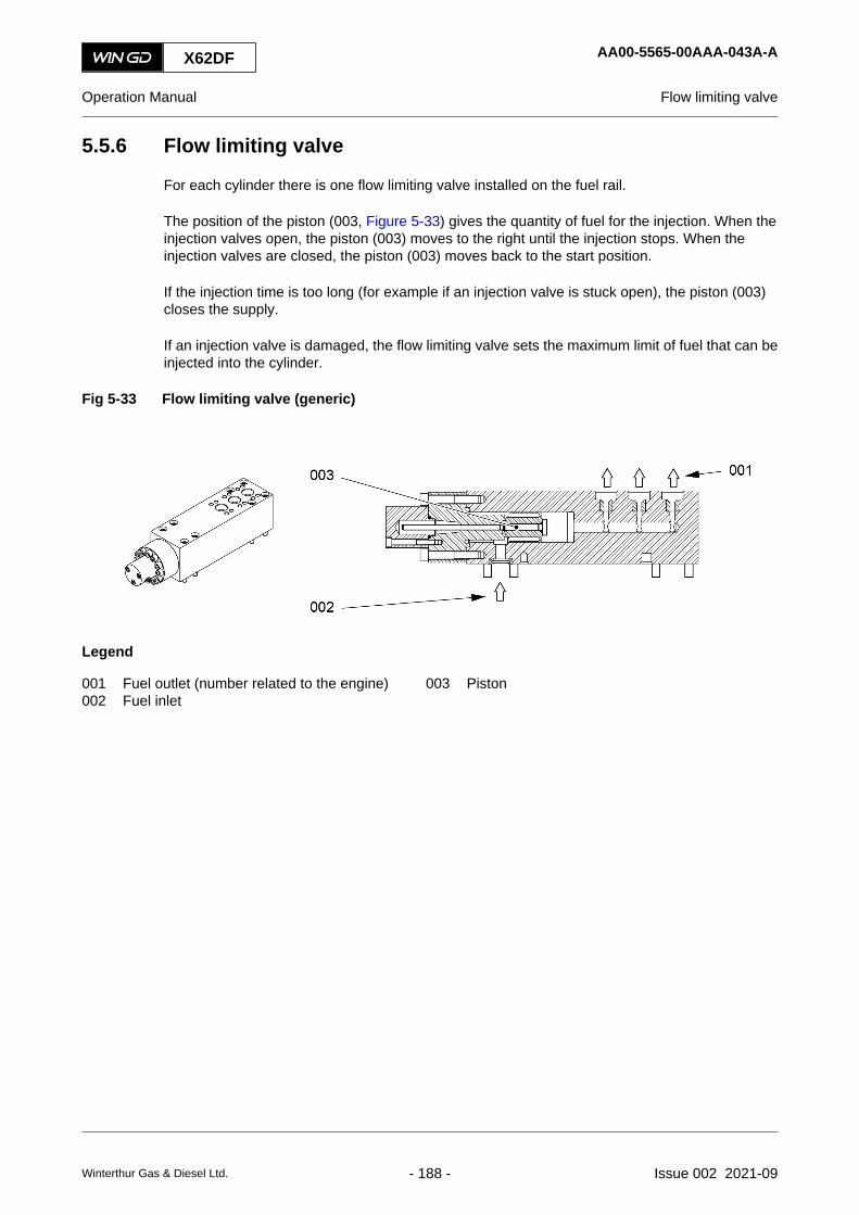
5.5.6 Flow limiting valve
For each cylinder there is one flow limiting valve installed on the fuel rail.
The position of the piston (003, Figure 5-33) gives the quantity of fuel for the injection. When theinjection valves open, the piston (003) moves to the right until the injection stops. When theinjection valves are closed, the piston (003) moves back to the start position.
If the injection time is too long (for example if an injection valve is stuck open), the piston (003)closes the supply.
If an injection valve is damaged, the flow limiting valve sets the maximum limit of fuel that can beinjected into the cylinder.
Fig 5-33 Flow limiting valve (generic)
Legend
001 Fuel outlet (number related to the engine) 003 Piston002 Fuel inlet
X62DF AA00-5565-00AAA-043A-A
Operation Manual Flow limiting valve
Winterthur Gas & Diesel Ltd. - 188 - Issue 002 2021-09

X62DF AA00-5565-00AAA-043A-A
Operation Manual Flow limiting valve
Page left intentionally blank
Winterthur Gas & Diesel Ltd. - 189 - Issue 002 2021-09

5.5.7 Exhaust valve control unit
The exhaust valve control units (VCU) control the servo oil to the exhaust valve of the relatedcylinders. The exhaust valve control units are attached to the servo oil rail.
When the solenoid valve operates, servo oil is released to the slide rod (001, Figure 5-34). Thisreleases servo oil to the piston (003). Thus servo oil from the servo oil outlet (004) opens theexhaust valve.
Fig 5-34 Exhaust valve control unit (VCU) (example)
001
002003
004
Legend
001 Slide rod 003 Piston002 Servo oil inlet 004 Servo oil outlet
X62DF AA00-5612-00AAA-043A-A
Operation Manual Exhaust valve control unit
Winterthur Gas & Diesel Ltd. - 190 - Issue 002 2021-09

X62DF AA00-5612-00AAA-043A-A
Operation Manual Exhaust valve control unit
Page left intentionally blank
Winterthur Gas & Diesel Ltd. - 191 - Issue 002 2021-09

5.6 Group 6 - Scavenge air components5.6.1 Scavenge air receiver
The scavenge air receiver (005, Figure 5-35) supplies the cylinders with the applicable quantity ofair.
The scavenge air receiver is a welded assembly attached to the cylinder block on the exhaustside.
The relief valve, installed on the scavenge air receiver, opens when the air pressure increases tomore than the permitted value in the air space (001, Figure 5-36).
For more data about the scavenge air system, refer to section 4.8 Scavenge air system.
Fig 5-35 Scavenge air receiver (example)
001
002
003
004
005
Legend
001 Scavenge air from turbocharger 004 Auxiliary blower002 Diffuser 005 Scavenge air receiver003 Scavenge air cooler
The longitudinal wall (002, Figure 5-36) divides the scavenge air receiver into the receiverspace (003) and the air space (001). The flaps (005) are attached to the longitudinal wall (002).The flaps (005) prevent the scavenge air to flow back into the air space (001).
X62DF AA00-6420-00AAA-043A-A
Operation Manual Scavenge air receiver
Winterthur Gas & Diesel Ltd. - 192 - Issue 002 2021-09

Fig 5-36 Scavenge air receiver - cross section (example)
001
002
005
004
003
Legend
001 Air space 004 Outlet to piston underside002 Longitudinal wall 005 Flap003 Receiver space
X62DF AA00-6420-00AAA-043A-A
Operation Manual Scavenge air receiver
Winterthur Gas & Diesel Ltd. - 193 - Issue 002 2021-09

5.6.2 Turbocharger
The compressor (001, Figure 5-37) of the turbocharger compresses the scavenge air to theapplicable pressure. The compressor is directly attached to the shaft of the turbine (005). Theremaining energy of the exhaust gas drives the turbine and thus the compressor.
The number and the size of the turbochargers is accurately tuned to the engine and the numberof cylinders.
Fig 5-37 Turbocharger (example)
Legend
001 Compressor 005 Turbine002 Air inlet 006 Exhaust gas outlet003 Silencer 007 Exhaust gas inlet004 Air outlet
If a turbocharger becomes defective, you must stop the engine as quickly as possible to preventdamage.
If repair or replacement of a turbocharger is not immediately possible, you can cut out the defectiveturbocharger, refer to section 10.18 Temporary isolate a defective turbocharger. Then the enginecan operate at decreased load, refer to the limits in section 8.3 Start the engine - general.
WinGD recommends to regularly clean the turbochargers and the silencers, refer to section 9.8Clean the turbocharger during operation. This prevents or decreases contamination of theturbochargers and thus increases the time between overhauls.
X62DF AA00-6500-00AAA-043A-A
Operation Manual Turbocharger
Winterthur Gas & Diesel Ltd. - 194 - Issue 002 2021-09

X62DF AA00-6500-00AAA-043A-A
Operation Manual Turbocharger
Page left intentionally blank
Winterthur Gas & Diesel Ltd. - 195 - Issue 002 2021-09

5.6.3 Auxiliary blower
The auxiliary blowers supply air from the engine room through the duct into the scavenge airreceiver during the engine start and operation at low load. The flaps prevent the back flow of airto the scavenge air receiver during usual operation of the turbochargers and during engine stop.
The electric motor (004, Figure 5-38) operates the auxiliary blower (003).
The pressure relief valve is installed to protect the scavenge air receiver, when pressure is morethan set limit.
The auxiliary blowers are installed on the scavenge air receiver, refer to section 5.6.1 Scavengeair receiver.
Fig 5-38 Auxiliary blower
001
002004
003
Legend
001 Air outlet 003 Auxiliary Blower002 Air inlet 004 Electric motor
During the engine start operation, the auxiliary blowers start one by one at two or three secondsinterval, to avoid electric overload.
Minimum one auxiliary blower is necessary to start the engine.NOTE: During emergency operation, the auxiliary blowers can be manually controlled when all
the scavenge air pressure transmitters are faulty.
During the engine operation, when the turbochargers supply sufficient air pressure in the scavengeair receiver, the auxiliary blowers stop automatically by tunings depended setup and starts againif required, (Delta bar).
The auxiliary blower switch box (refer to section 5.6.4 Auxiliary blower switch box) is the interfacebetween the operator and auxiliary blower and gives data about the condition of the auxiliaryblowers.
X62DF AA00-6545-00AAA-043A-A
Operation Manual Auxiliary blower
Winterthur Gas & Diesel Ltd. - 196 - Issue 002 2021-09

X62DF AA00-6545-00AAA-043A-A
Operation Manual Auxiliary blower
Page left intentionally blank
Winterthur Gas & Diesel Ltd. - 197 - Issue 002 2021-09

5.6.4 Auxiliary blower switch box
The auxiliary blower switch box is used to operate the auxiliary blowers in Auto mode or Manualmode.
When the auxiliary switch box is in Auto mode, the first auxiliary blower will start and second willstart after few seconds.
Auxiliary blower will automatically stop when the turbochargers give sufficient air pressure. Theauxiliary blowers will automatically start when the scavenge air pressure drops.
When the engine stops, the auxiliary blowers will continue to operate for some time period forcooling and ventilation of the engine.
In Manual mode, the operator can start or stop the auxiliary blowers manually.
In Off mode, the auxiliary blowers are switch off.
Fig 5-39 Switch box
001002
003
004
005
006007
008
009
010
011012013
014
Legend
001 Indicator (auxiliary blower No. 2 running) 008 Restart push button002 Indicator (auxiliary blower No. 2 overload) 009 Ampere meter (auxiliary blower No. 1)003 Hour counter (auxiliary blower No. 2) 010 Hour counter (auxiliary blower No. 1)004 Ampere meter (auxiliary blower No. 2) 011 Supply fault indicator005 Main switch (auxiliary blower No. 2) 012 Indicator (auxiliary blower No. 1 running)006 Emergency push button 013 Indicator (auxiliary blower No. 1 overload)007 Main switch (auxiliary blower No. 1) 014 Control voltage indicator
X62DF AA00-6547-00AAA-043A-A
Operation Manual Auxiliary blower switch box
Winterthur Gas & Diesel Ltd. - 198 - Issue 002 2021-09

X62DF AA00-6547-00AAA-043A-A
Operation Manual Auxiliary blower switch box
Page left intentionally blank
Winterthur Gas & Diesel Ltd. - 199 - Issue 002 2021-09

5.6.5 Scavenge air cooler
The scavenge air cooler (SAC) decreases the temperature of the hot compressed air from theturbochargers. This increases the density of the air and thus increases the quantity of air that issupplied to the cylinders.
The cooling water flows constantly through the tubes of the SAC and flows back to the coolingwater system of the plant.
The SAC has a cover (004, Figure 5-40). For maintenance you can remove the cover.
Fig 5-40 Scavenge air cooler (generic)
001
002
003
004
Legend
001 Air flow 003 Cooling water inlet002 Cooling water outlet 004 Cover
WinGD recommends to regularly clean the scavenge air coolers, refer to section 9.4 Clean thescavenge air cooler during operation. This prevents or decreases contamination of the scavengeair coolers and thus increases the time between overhauls.
X62DF AA00-6606-00AAA-043A-A
Operation Manual Scavenge air cooler
Winterthur Gas & Diesel Ltd. - 200 - Issue 002 2021-09

X62DF AA00-6606-00AAA-043A-A
Operation Manual Scavenge air cooler
Page left intentionally blank
Winterthur Gas & Diesel Ltd. - 201 - Issue 002 2021-09

5.6.6 Water separator
The water separator removes water from the scavenge air. This prevents damage and gives bettercombustion in the cylinders. Water occurs when the scavenge air cooler (SAC) decreases thetemperature of wet air. Water also occurs during the wash procedure of the SAC.
The profiles (002, Figure 5-41) hold back the water in the air flow. This water collects at the bottomof the frame (003) and then flows back to the drain system.
Fig 5-41 Water separator (generic)
003002
001
Legend
001 Air flow 003 Frame002 Profile
X62DF AA00-6708-00AAA-043A-A
Operation Manual Water separator
Winterthur Gas & Diesel Ltd. - 202 - Issue 002 2021-09

X62DF AA00-6708-00AAA-043A-A
Operation Manual Water separator
Page left intentionally blank
Winterthur Gas & Diesel Ltd. - 203 - Issue 002 2021-09

5.7 Group 7 - Cylinder lubrication and balancer5.7.1 Cylinder lubrication
For information about the cylinder lubrication oil, refer to section: 12.1 General for operating media
For information about the cylinder oil system in general, refer to section: 4.6 Cylinder oil system
X62DF AA00-7218-00AAA-043A-A
Operation Manual Cylinder lubrication
Winterthur Gas & Diesel Ltd. - 204 - Issue 002 2021-09

X62DF AA00-7218-00AAA-043A-A
Operation Manual Cylinder lubrication
Page left intentionally blank
Winterthur Gas & Diesel Ltd. - 205 - Issue 002 2021-09

5.7.2 Integrated electrical balancer (iELBA)
The optional integrated ELectrical BAlancer (iELBA) decreases second order vertical massmoments (M2v) of the engine, refer to Figure 5-42.NOTE: For the engine itself it is not necessary to install a balancer. But a balancer decreases
the exitation forces of the engine. A calculation of the mass moment M2v shows if abalancer is necessary for a specified hull design.
Usually there are two iELBAs installed, one at the free end (FE) and one at the driving end (DE)of the engine. For special designs it is possible to install only one balancer at the free end (FE) orat the driving end (DE).
Fig 5-42 Effect of second order moments (M2v) of the engine
5.7.2.1 Function
An electric motor operates the two gear wheels (001, Figure 5-43) and thus the counterweights(002) in opposite directions. The horizontal elements (Fhoriz) of the forces (F) are always canceled.The vertical elements (Fvert) are always added to a resulting vertical force. This resulting forceoperates up and down with the same frequency as the counterweights (002) turn. The resultingforce is transmitted through the bearings (003) to the column (005) and thus to the engine.
The rotating speed (ω) of the counterweights (002) is always two times the engine rotating speedand is in phase to the engine. Thus the second order vibrations in the hull are decreased.
Engine system oil lubricates the iELBA. The oil flows back to the crankcase.NOTE: Operate the iELBA only if system oil is available at correct pressure and flow rate.
A brake resistor for each balancer changes the rotating energy of the iELBA to heat in theconditions that follow:
• If the engine speed changes quickly.
• If there is an emergency stop of the iELBA.
• If there is an energy sink during the phase synchronisation of the iELBA.
X62DF AA00-7752-00AAA-043A-A
Operation Manual Integrated electrical balancer (iELBA)
Winterthur Gas & Diesel Ltd. - 206 - Issue 002 2021-09

Fig 5-43 iELBA - function
Legend
001 Gear wheel 004 Housing002 Counterweight 005 Column003 Bearing
X62DF AA00-7752-00AAA-043A-A
Operation Manual Integrated electrical balancer (iELBA)
Winterthur Gas & Diesel Ltd. - 207 - Issue 002 2021-09

5.7.2.2 Control system
Each iELBA has two control cabinets (E38 and E39). The control system monitors the speed ofthe electric motor and the rotating speeds and phases of the counterweights (002) and of theflywheel of the engine. The control system also uses TDC and BDC data of piston #1 of the engine.A frequency converter controls the electric motor.
When the iELBA is started, there are two states that are indicated on the control cabinet:
• Swing state
The electric motor swings the counterweights back and forward some times until thecounterweights turn fully.
• Run state
The iELBA has started to turn fully. The control system increases the speed of the iELBAand synchronises it to the engine.
5.7.2.3 Operation
Usually the iELBA operates in the speed range of the engine of 65% to 105% of CMCR in theAHEAD direction.NOTE: In heavy sea mode the iELBA does not operate.
The engine can also operate if one or the two balancers do not operate (eg in manual mode or ifa balancer is defective). Then it is possible that there are more vibrations on the hull.
When the power for the iELBA is set to ON, it takes some seconds to complete the initialisationof the system.
The iELBA operates independently of the engine control system (ECS). The iELBA can beoperated in automatic mode or manual mode:
• Automatic mode
In automatic mode the balancers operate as follows:○ The iELBA starts if the engine speed is higher than the specified threshold value.
○ The iELBA stops if the engine speed is lower than the specified threshold value.
• Manual mode
In manual mode the balancers operate at a specified speed. Use the manual mode fortroubleshooting only.NOTE: Use the manual mode only if system oil is available at correct pressure and flow
rate.
X62DF AA00-7752-00AAA-043A-A
Operation Manual Integrated electrical balancer (iELBA)
Winterthur Gas & Diesel Ltd. - 208 - Issue 002 2021-09

5.7.2.4 Control cabinet
Figure 5-44 shows the buttons and indications on the control cabinet of the iELBA.
Fig 5-44 iELBA - control cabinet
X62DF AA00-7752-00AAA-043A-A
Operation Manual Integrated electrical balancer (iELBA)
Winterthur Gas & Diesel Ltd. - 209 - Issue 002 2021-09

Tab 5-1 iELBA - control cabinet
Item Function Effect
A9 Drive Power Consumption indica-tion
Shows the electric motor current (in Ampere)
S7 Manual Start button Starts the iELBA (in manual mode)
S8 Manual Stop button Stops the iELBA (in manual mode)
H11 Power 24V indicator light Shows if electric power is on
S5/H5 Error reset button Shows and resets iELBA errors, refer to Table 5-2 - iELBA - errorindicationNOTE: If an error occurs, the indicator light shows the related
number of flashes.
NOTE: Only reset an error after you have done the relatedprocedures.
S6 Mode Auto / Manual switch Changes between automatic and manual mode
H3 Swing / Run indicator light Shows the state of the running iELBA:• Lamp blinks - iELBA is in swing state
• Lamp is steady - iELBA is in run state
H4 Synch OK indicator light Shows the synchronisation state of the iELBA:• Lamp is steady - iELBA is synchronised to the engine
• Lamp blinks slowly - iELBA is +/-15° from engine syn-chronisation
• Lamp blinks quickly - iELBA is +/-30° from engine syn-chronisation
S1 Emergency stop button Stops the iELBA immediately
S2/H2 Emerg. Stop Reset button Resets an emergency stop to enable iELBA restartThe integrated indicator light shows as follows:• Lamp is on - an emergency stop is active
• Lamp is off - usual operation
A10 Hour indication Shows the running hours of the electric motorNOTE: A10 is installed in the control cabinet.
X62DF AA00-7752-00AAA-043A-A
Operation Manual Integrated electrical balancer (iELBA)
Winterthur Gas & Diesel Ltd. - 210 - Issue 002 2021-09

Table 5-2 - iELBA - error indication shows the possible iELBA error indications related to thenumber of flashes of the indicator light.NOTE: The error indications are active in automatic mode and in manual mode.
Tab 5-2 iELBA - error indication
Number offlashes
Status iELBA state
1 Start OK, “Boost to Control Speed Threshold” not OK OFF
2 Start OK, “Setpoint Speed” not OK in 60 s OFF
3 Start OK, speed OK, “Phase Synchronisation” not OK in 60 s OFF
4 Overspeed error OFF
5 Electric motor error OFF
6 The lubricating oil pressure is too low OFF
7 iELBA pickup sensor error OFF
8 TDC pickup sensor error Usual operation
9 BDC pickup sensor error Usual operation
X62DF AA00-7752-00AAA-043A-A
Operation Manual Integrated electrical balancer (iELBA)
Winterthur Gas & Diesel Ltd. - 211 - Issue 002 2021-09

5.8 Group 8 - Pipes5.8.1 Exhaust waste gate
The optional exhaust waste gate is a by-pass pipe to the turbine (006, Figure 5-45) of theturbochargers. The valve (007) in this pipe controls the flow of exhaust gas through theturbines (006). This controls the compressor (002) of the turbochargers and thus the supply ofscavenge air to the scavenge air receiver (003).
During usual operation the valve (007) is closed and thus all the exhaust gas flows through theturbines (006).
Fig 5-45 Exhaust waste gate (generic)
001
002
003
004
005
006007
008
Legend
001 Air inlet 005 Exhaust gas manifold002 Compressor 006 Turbine003 Scavenge air receiver 007 Valve004 Engine 008 Exhaust gas outlet
If the turbochargers deliver too much scavenge air pressure, the ECS opens the valve (007). Ifthe valve (007) is controllable, the ECS opens it as much as necessary. This decreases theperformance of the turbochargers and thus the pressure of the scavenge air.
If the valve (007) is blocked in the open position, you have to close the exhaust waste gate, referto section 10.19 Temporary isolate the exhaust waste gate.
X62DF AA00-8135-00AAA-043A-A
Operation Manual Exhaust waste gate
Winterthur Gas & Diesel Ltd. - 212 - Issue 002 2021-09

X62DF AA00-8135-00AAA-043A-A
Operation Manual Exhaust waste gate
Page left intentionally blank
Winterthur Gas & Diesel Ltd. - 213 - Issue 002 2021-09

5.9 Group 9 - Monitoring instruments5.9.1 Crank angle sensor unit
The crank angle sensor unit is installed on the supply unit drive at the driving end.
There are two crank angle systems that monitor the teeth on the intermediate wheel. The two setsof proximity sensors (003, Figure 5-46) operate independently to sense the teeth on theintermediate wheel (002).
Fig 5-46 Crank angle sensor unit on intermediate wheel (example)
Legend
001 Supply unit 003 Proximity sensor002 Intermediate wheel
X62DF AA00-9223-00AAA-043A-A
Operation Manual Crank angle sensor unit
Winterthur Gas & Diesel Ltd. - 214 - Issue 002 2021-09
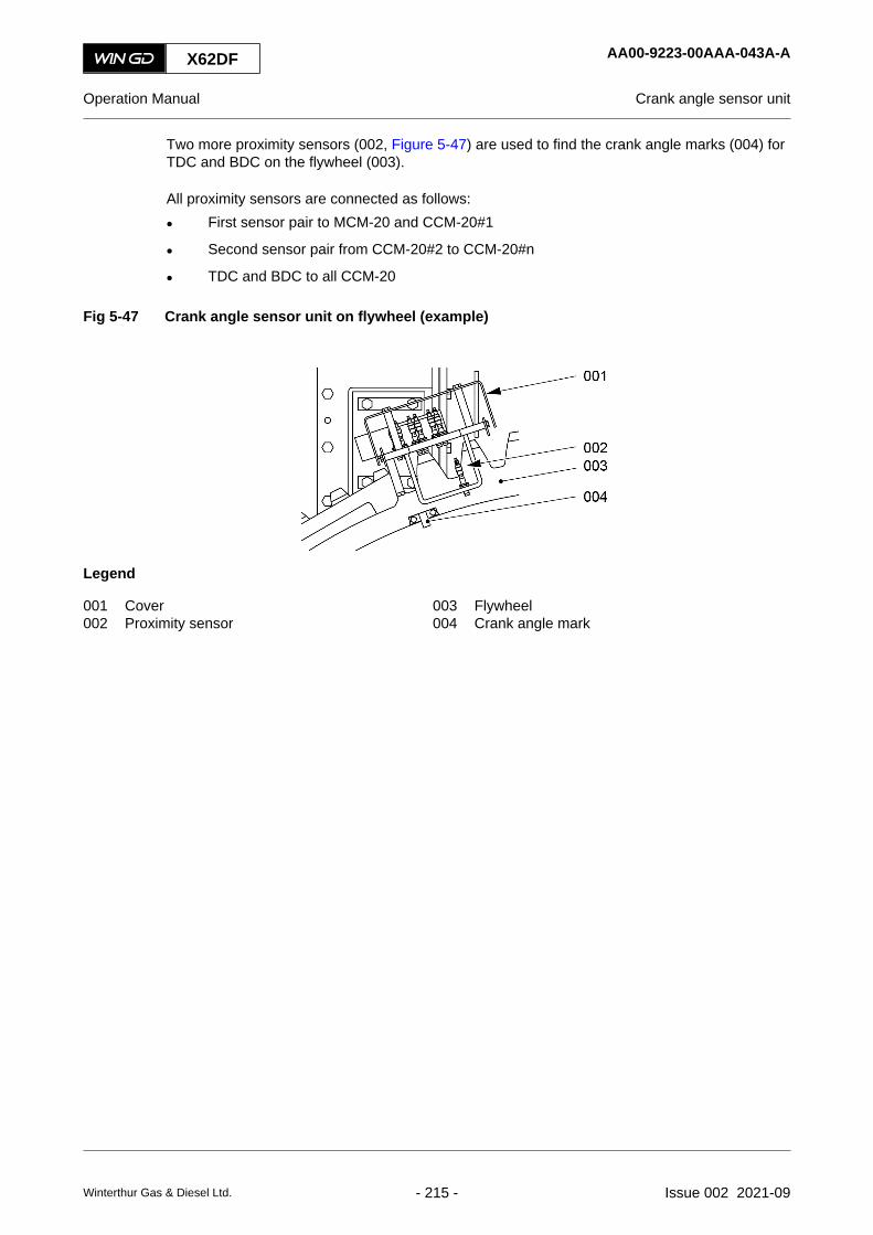
Two more proximity sensors (002, Figure 5-47) are used to find the crank angle marks (004) forTDC and BDC on the flywheel (003).
All proximity sensors are connected as follows:
• First sensor pair to MCM-20 and CCM-20#1
• Second sensor pair from CCM-20#2 to CCM-20#n
• TDC and BDC to all CCM-20
Fig 5-47 Crank angle sensor unit on flywheel (example)
Legend
001 Cover 003 Flywheel002 Proximity sensor 004 Crank angle mark
X62DF AA00-9223-00AAA-043A-A
Operation Manual Crank angle sensor unit
Winterthur Gas & Diesel Ltd. - 215 - Issue 002 2021-09

5.9.2 Water in oil monitor
The optional water in oil monitor continuously monitors the concentration of water in the oil supplypipe. The water in oil monitor continuously sends a signal to the alarm and monitoring system(AMS).
On the display (001, Figure 5-48) you can see the data that follow:
• aw - water activity
• T - temperature in °C
• H2O - water content in ppm
Fig 5-48 Water in oil monitor (generic)
002
001
003
Legend
001 Display 003 Connection points002 Keypad
X62DF AA00-9313-00AAA-043A-A
Operation Manual Water in oil monitor
Winterthur Gas & Diesel Ltd. - 216 - Issue 002 2021-09

X62DF AA00-9313-00AAA-043A-A
Operation Manual Water in oil monitor
Page left intentionally blank
Winterthur Gas & Diesel Ltd. - 217 - Issue 002 2021-09

5.9.3 Oil mist detector
The oil mist detection system continuously monitors the concentration of oil mist in the crankcase,in the supply unit drive and in the supply unit. If there is a high oil mist concentration, the oil mistdetector activates an alarm. Thus damage to the bearings can be quickly found and explosions inthe crankcase can be prevented.
The system includes the sensors (002, Figure 5-49) and the control unit (003) on the engine.
Fig 5-49 Oil mist detector (example)
004003
001
002
Legend
001 Data cable 003 Control unit E15.1002 Sensor 004 Column
Each sensor monitors the concentration of oil mist. Each sensor has a self-test function to makesure that there are no internal faults.
X62DF AA00-9314-00AAA-043A-A
Operation Manual Oil mist detector
Winterthur Gas & Diesel Ltd. - 218 - Issue 002 2021-09

Fig 5-50 Oil mist detector - schematic diagram (example)
002
001
003002004005006007
008009
Legend
001 Control panel 006 Control unit E15.1002 Power supply 007 Supply unit003 Data cable 008 Crankcase and gear box004 To alarm system 009 Sensor005 To safety system
Data communication is between the control unit (006, Figure 5-50) and the control panel (001).
The adjustments can be programmed in the display unit (001). The menu-driven software hasthree user levels:
• User - Read-only of data
• Operator - Password-protected level for access to most adjustments and functions
• Service - Password-protected level for authorized staff of the manufacturer and servicepersonnel.
NOTE: Instructions that relate to adjustments, commissioning, troubleshooting, andmaintenance are given in the related documentation of the manufacturer.
X62DF AA00-9314-00AAA-043A-A
Operation Manual Oil mist detector
Winterthur Gas & Diesel Ltd. - 219 - Issue 002 2021-09

X62DF AA00-9314-00AAA-043A-A
Operation Manual Oil mist detector
Page left intentionally blank
Winterthur Gas & Diesel Ltd. - 220 - Issue 002 2021-09

6 Control system6.1 Engine control system UNIC...................................................................................2246.2 Intelligent combustion control..................................................................................2306.3 Gas valve unit and external gas supply system......................................................2346.4 Local display unit (LDU-20) - general......................................................................2406.5 Local display unit (LDU-20)- Option for UNIC - pages
6.5.1 Operate the local display unit (LDU-20)..........................................................2426.5.2 LDU-20 pages - general for DF engine...........................................................2486.5.3 LDU-20 page - MAIN.......................................................................................2506.5.4 LDU-20 page - CONTROL LOCATIONS.........................................................2546.5.5 LDU-20 page - FUEL MODE CONTROL........................................................2566.5.6 LDU-20 page - CA SENSOR STATUS............................................................2586.5.7 LDU-20 page - CYLINDER BALANCING DIESEL..........................................2606.5.8 LDU-20 page - CYLINDER BALANCING GAS...............................................2626.5.9 LDU-20 page - CYLINDER LUBRICATION.....................................................2646.5.10 LDU-20 page - iCAT........................................................................................2666.5.11 LDU-20 page - DYNAMIC COMBUSTION CONTROL (DCC)........................2706.5.12 LDU-20 page - EXHAUST VENTILATION......................................................2726.5.13 LDU-20 page - EXHAUST VALVES................................................................2746.5.14 LDU-20 page - FAILURE LIST........................................................................2766.5.15 LDU-20 page - FAILURE SIMULATION..........................................................2786.5.16 LDU-20 page - FUEL SHARING (if applicable)...............................................2806.5.17 LDU-20 page - FUEL SYSTEM.......................................................................2826.5.18 LDU-20 page - GAS PRESSURE....................................................................2846.5.19 LDU-20 page - GAS LEAK TEST....................................................................2866.5.20 LDU-20 page - GAS ADMISSION VALVES....................................................2886.5.21 LDU-20 page - GAV MANUAL VALVE TEST..................................................2906.5.22 LDU-20 page - GVU & VALVE TEST..............................................................2926.5.23 LDU-20 page - KNOCK CONTROL.................................................................2946.5.24 LDU-20 page - LOG MESSAGES...................................................................2966.5.25 LDU-20 page - MAIN FUEL INJECTION.........................................................2986.5.26 LDU-20 page - PAGE INDEX..........................................................................3006.5.27 LDU-20 page - PERFORMANCE DATA DIESEL............................................3026.5.28 LDU-20 page - PERFORMANCE DATA GAS.................................................3046.5.29 LDU-20 page - PILOT FUEL INJECTION.......................................................3066.5.30 LDU-20 page - PILOT FUEL PRESSURE.......................................................3086.5.31 LDU-20 page - SCAVENGE AIR - EWG (optional).........................................3106.5.32 LDU-20 page - SCREENSHOT.......................................................................3126.5.33 LDU-20 page - SOFTWARE INFO..................................................................3146.5.34 LDU-20 page - IMO CRC INFO.......................................................................3166.5.35 LDU-20 page - SOFTWARE TOOLS..............................................................318
X62DF
Operation Manual
Winterthur Gas & Diesel Ltd. - 221 - Issue 002 2021-09

6.5.36 LDU-20 page - SYSTEM STATUS..................................................................3206.5.37 LDU-20 page - SYSTEM SETTINGS..............................................................3226.5.38 LDU-20 page - TEMPERATURES..................................................................3246.5.39 LDU-20 page - USER PARAMETERS............................................................3266.5.40 LDU-20 page - LOG ENTRY DATA.................................................................3286.5.41 MCP page - FUEL / LUBRICATION SYSTEM................................................3306.5.42 LDU-20 page - DATE......................................................................................3326.5.43 LDU-20 page - ETHERNET.............................................................................3346.5.44 LDU-20 page - iELBA Control (optional).........................................................336
X62DF
Operation Manual
Winterthur Gas & Diesel Ltd. - 222 - Issue 002 2021-09

X62DF
Operation Manual
Page left intentionally blank
Winterthur Gas & Diesel Ltd. - 223 - Issue 002 2021-09

6.1 Engine control system UNIC
6.1.1 Engine control system
The engine control system (ECS) is an embedded system that has a modular design. Some partsand functions in the ECS system configuration are optional and are related to the application.
The name of the WinGD engine control system is UNIfied Controls Flex (UNIC-flex). It has theitems that follow:
• Main control module (MCM-11)
The main control module (MCM-11) is installed at the local maneuvering stand in theterminal box E25. The MCM-11 has functions for speed control, engine control and commonengine functions (eg starting air shut-off valve). External control systems transmit data tothe MCM-11.
• Local display unit (LDU-20)
One local display unit (LDU-20) is installed at the local maneuvering stand at the free end.The other LDU-20 is installed in the engine control room (ECR). External control systemstransmit data to the LDU-20. The LDU-20 gives the operator a graphical user interface foraccess to data and system adjustments.
• Input/output module (IOM-10)
The input/output module (IOM-10) is installed at the rail unit in the terminal box E90. TheIOM-10 has the engine control functions (eg exhaust waste gate control) and redundantsensor and actuator signals of the MCM-11.
• Cylinder control module (CCM-20)
The cylinder control modules (CCM-20) for each cylinder are installed on the rail unit in theterminal box E95. The CCM-20 have different cylinder-related and engine-related controlfunctions. The CCM-20 also have redundant global functions for the engine control.
Redundant CAN system buses connect all these modules.
Two 230 VAC supplies from the ship installation, supply electrical power to E85.1 to E85.n. Thetwo 230 VAC supplies are isolated from each other.
The power supplies have redundancy. If it is necessary to isolate the ECS, make sure that eachof the two 230 VAC power supplies are set to off. This will prevent injury to personnel.
Each control function that is important for engine operation has redundancy in the ECS.
X62DF AA00-0000-00AAA-043K-A
Operation Manual Engine control system UNIC
Winterthur Gas & Diesel Ltd. - 224 - Issue 002 2021-09

Fig 6-1 ECS modules
00214
002
004
003
001
Legend
001 Input output module (IOM-10) 003 Cylinder control module (CCM-20)002 Main control module (MCM-11) 004 Local display unit (LDU-20)
6.1.2 Functions of the engine control system
The main functions of the engine control system are as follows:
• Starting valve control
• Servo oil pressure control
• Exhaust valve control
• Cylinder lubricating control
• Engine speed and crank angle sensor monitoring
• Diesel fuel pressure control
• Diesel fuel injection control
• For a DF engine, also gas injection control
X62DF AA00-0000-00AAA-043K-A
Operation Manual Engine control system UNIC
Winterthur Gas & Diesel Ltd. - 225 - Issue 002 2021-09

6.1.3 External control systems
The Diesel Engine CoNtrol and OptImizing Specification (DENIS) and the engine control system(ECS) are designed so that different remote controls can be used. All nodes are fully specified.The terminal boxes are installed on the engine, to which the cable ends from the control room orfrom the bridge can be connected.
The engine control has all the parts necessary to operate and monitor the engine, and for thesafety of the engine.
The ECS supplies the data communications to:
• The propulsion control system (PCS)
• The alarm and monitoring system (AMS).
The standard version of ECS includes the external communications that follow:
• Two redundant CANBus lines to the PCS (one CANBus connection to MCM-11 and oneconnection to the LDU-20 in the terminal box E25)
• Two redundant Modbus lines to the AMS (one Modbus connection to MCM−11 and oneconnection to the LDU−20 in the terminal box E25).
For the signal flow, refer to Figure 6-2.
For the schematic diagrams, refer to section 13.1 Schematic diagrams - general.NOTE: The communications between the systems can be different. See the related
documentation from the approved propulsion control system manufacturer.
6.1.3.1 Propulsion control system
The propulsion control system (PCS) has the subsystems that follow:
• Remote control system
The remote control system (RCS) has the primary functions that follow:○ Start, stop and reverse
○ Automatic slow turning
Data about the ECS status is available in the RCS. This includes measured values ofsensors, defects and other indications (refer to the documentation of the remote controlmanufacturer).
All commands to operate the engine (eg AHEAD or ASTERN) come from the RCS.
• Engine safety system
The engine safety system (ESS) has the primary functions that follow:○ Emergency stop
○ Overspeed protection
○ Automatic shutdown
○ Automatic slowdown
• Telegraph system
The telegraph system transmits maneuvering signals from the bridge to the ECR and localcontrol panel.
NOTE: The ESS and telegraph system operate independently and are also fully serviceable ifthe RCS is defective.
X62DF AA00-0000-00AAA-043K-A
Operation Manual Engine control system UNIC
Winterthur Gas & Diesel Ltd. - 226 - Issue 002 2021-09

6.1.3.2 Alarm and monitoring system
The alarm and monitoring system (AMS) is an external system and monitors the engine. The AMSgives the operator alarms and status data of the engine to make sure of safe and satisfactoryengine operation.
The functions of the AMS are specified in the diesel engine control and optimizing specification(DENIS). The AMS sends signals to the engine safety system to slow down or shut down theengine.
For more data, see the documentation of the AMS manufacturer.
X62DF AA00-0000-00AAA-043K-A
Operation Manual Engine control system UNIC
Winterthur Gas & Diesel Ltd. - 227 - Issue 002 2021-09

Fig 6-2 Signal flow diagram
UN
IC S
hipy
ard
Inte
rface
Box
UN
IC S
enso
rs a
nd A
ctua
tors
UN
IC
Sens
ors
and
Act
uato
rs
Alar
man
dM
onito
ring
Syst
em
Rem
ote
Con
trol
Syst
emSa
fety
Sys
tem
Tele
grap
hSy
stem
DEN
IS-U
NIC
Rem
ote
Con
trolS
peci
ficat
ion
Alar
ms
Slow
dow
ns
Prop
ulsi
onCo
ntro
lSys
tem
Loca
lCon
trol
Pane
l
ECR
Man
ual
Con
trolP
anel
Loca
lIn
dica
tions
CAN
toLC
P
Elec
tric
Mot
orSt
arte
rUni
tsG
VU /
iGPR
*
Alar
m a
ndSl
owdo
wn
Sign
als
Gas
Dete
ctio
nSy
stem
*
Alar
msig
nals
DE
NI
S-
UN
IC
En
gi
ne
Sp
ec
if
ic
at
io
n
Fuel
Gas
Supp
lySy
stem
*
*Onl
yfo
rDua
lFue
lEng
ines
2 x
AMS
CAN
Bus
Signals for Alarm / Indication
Indications
Command Orders from RCS
Ethernet to ECR Manual Control
Signals for Alarm and Slowdown
UNIC Alarm Signals
Feedback Signals from UNIC
Signals for Alarm
Signals for Safety
Signals for Control
Signals for Control*
Gas SHD and Venting GVU / iGPR*
2 x
PCS
CAN
Bus
E10,
E15
, E20
, E28
E110
, E12
0, E
130
Con
trol T
erm
inal
Box
esAl
arm
Ter
min
al B
oxes
Alar
m S
enso
rs
Sens
or*
Pow
er
E25
E90
X62DF AA00-0000-00AAA-043K-A
Operation Manual Engine control system UNIC
Winterthur Gas & Diesel Ltd. - 228 - Issue 002 2021-09

X62DF AA00-0000-00AAA-043K-A
Operation Manual Engine control system UNIC
Page left intentionally blank
Winterthur Gas & Diesel Ltd. - 229 - Issue 002 2021-09

6.2 Intelligent combustion control
The intelligent combustion control (ICC) permanently monitors and automatically controls thecombustion process.
The ICC is part of the engine control system (ECS). All ICC modifications of the engine controlparameters obey the IMO regulations and are related to the IMO certificate of the vessel.
The ICC calculates the best engine control parameters for operation, which balances thecompression and firing pressures in the engine (for example injection time offsets and exhaustvalve closing time for each cylinder).
• This decreases the excessive wear of engine components.
• This decreases the risk of an engine overload.
• This prevents manual adjustment failures.
In the ECS you can set to OFF or ON each individual function of the ICC system. When all ICCfunctions are set to OFF, the engine operates in a conventional open-loop control mode.NOTE: Large differences in the values (for example injection time or exhaust valve operation)
for a cylinder is an indication of possible wear or damage of the cylinder. If necessary,replace the defective parts.
X62DF AA00-9308-00AAA-043A-A
Operation Manual Intelligent combustion control
Winterthur Gas & Diesel Ltd. - 230 - Issue 002 2021-09

6.2.1 Pressure calculation
In the ICC system, the compression pressure of each cycle is calculated with the polynomialformula and the data of the piston position. The ICC uses the values that follow for calculation,refer to Figure 6-3:
• Compression pressure at TDC (pC)
• Pressure at start of ignition (pI) (001)
• Maximum firing pressure (pF) (002).
NOTE: If ignition is not exactly at TDC, the pressure at start of ignition pI is smaller than thecompression pressure at TDC pC.
The pressure increase is the difference between the maximum firing pressure pF and the pressureat start of ignition pI. The ICC system sets the limit of this pressure increase related to the shoptest results. This prevents mechanical overload to the engine.
Fig 6-3 ICC - pressure diagram
001
002
Cyl
inde
r pre
ssur
e (b
ar)
Crank angle (°)
Legend
001 Pressure at start of ignition (pI) 002 Maximum firing pressure (pF)
X62DF AA00-9308-00AAA-043A-A
Operation Manual Intelligent combustion control
Winterthur Gas & Diesel Ltd. - 231 - Issue 002 2021-09

6.2.2 ICC control
A pressure transmitter is installed on each cylinder cover. The cylinder pressure data of eachcylinder is taken as an analogue input signal from the pressure transmitter into the ECS.
The ECS filters the signals from the sensors and then transmits these signals to a controller. Themeasured value is adjusted to the correct setpoint value and is related to the engine load. Thisreal-time site correction and comparison is done for each engine cycle (refer to Figure 6-4).
Fig 6-4 ICC - control schematic
Measured values
Target values
X62DF AA00-9308-00AAA-043A-A
Operation Manual Intelligent combustion control
Winterthur Gas & Diesel Ltd. - 232 - Issue 002 2021-09

X62DF AA00-9308-00AAA-043A-A
Operation Manual Intelligent combustion control
Page left intentionally blank
Winterthur Gas & Diesel Ltd. - 233 - Issue 002 2021-09
6.3 Gas valve unit and external gas supply system
6.3.1 External gas supply
The external gas supply system upstream of the gas valve unit (GVU) contains the gas supplypipes and the pressurized gas supply.NOTE: Your gas valve units can look different.
NOTE: Your engine could have iGPR instead of GVU. In that case, refer to the chapter:Integrated gas pressure regulation.
6.3.2 Gas supply pipes
The gas supply pipes between the gas storage area and the engine room are in a closed area.The supply pipes have double walls or are installed in a closed, ventilated duct. This duct has agas detector to detect the gas and monitor the gas flow.
6.3.3 Shut-off valve
The propulsion control system (PCS) controls the shut-off valve. During usual operation, the shut-off valve for the GVU shuts-off the gas supply to the engine room. The shut-off valve can be closedfrom the engine room, the engine control room or the bridge. In some conditions, the shut-off valveis automatically closed.
6.3.4 Gas valve unit (GVU)
It is necessary for dual fuel engines to have accurate control of the gas pressure and the changesof the load conditions.
The GVU has three primary functions:
1 Gas pressure controla The gas pressure depends on the engine load.b The signal for the applicable gas pressure comes from the Engine Control System.
2 Leak test sequencea The leak test sequence is done before the engine changes from diesel to gas mode.b The leak test sequence makes sure that the valves of the GVU operate correctly and
that there is no internal leakage.
3 Inert gas functiona The GVU uses inert gas and runs pressure release sequences automatically.b The pressure release sequence is safe during usual operation.
Your GVU is on of these two variants:
1 GVU-ED (Enclosed Design see )
2 GVU-OD (Open Design see )
X62DF AA00-8014-00AAA-042A-A
Operation Manual Gas valve unit and external gas supply system
Winterthur Gas & Diesel Ltd. - 234 - Issue 002 2021-09

6.3.4.1 GVU-ED
This closed design Figure 6-5 has pipes with double walls installed in a gas-tight area. This gas-tight area has continuous and sufficient airflow. This design can be safely installed in engine rooms.There is no danger of gas release. The design is in proportion to the bore dimensions of yourengine and your cylinder configuration.
Fig 6-5 GVU-ED
The air vent connects to an extractor fan to move air from the gas-tight area. The dimensions ofthe extractor fan are sufficient to replace the necessary volume of air in the gas-tight area and thedouble wall pipes. The extractor fan keeps a constant negative pressure in the gas-tight area. Thisnegative pressure is monitored.
To make sure that the airflow is sufficient, the ventilation system of the GVU-ED must operateindependently from all other ventilation systems.
Gas detectors constantly monitor the double wall pipes and the GVU for concentrations of gas. Ifgas is found, the safety system activates a mode change to diesel operation. The gas pressure isreleased and inert gas flows inside the pipes.
The GVU-ED has an integrated control panel.
6.3.4.2 GVU-OD
This open design Figure 6-6 does not have a closed area or pipes with double walls. This designis installed externally in an isolated room with sufficient airflow like for example a gas valve room.The design is in proportion to the bore dimensions of your engine and your cylinder configuration.
X62DF AA00-8014-00AAA-042A-A
Operation Manual Gas valve unit and external gas supply system
Winterthur Gas & Diesel Ltd. - 235 - Issue 002 2021-09

Fig 6-6 GVU-OD
The isolated room Figure 6-7 is gas-tight and follows these standards:
1 All electrical equipment follows the standards in the ATEX Directives (Equipment forpotentially explosive atmospheres)
2 An ATEX approved airlock of sufficient dimensions for one person is installed at the entranceof the GVU room.
3 Large ATEX approved fans with redundancy are installed. These fans keep sufficientnegative pressure in the GVU room. The air in the GVU room and the air in the pipes arereplaced 30 times per hour.
4 The gas pipes between the GVU room and the engine have double walls.
5 The maximum GVU room capacity for pressurized gas must be calculated.
6 The maximum GVU room pressure resistance must be calculated.
7 The ventilation system of the GVU-OD operates independently from all other ventilationsystems.
For the GVU-OD, the control panel is installed outside of it.
X62DF AA00-8014-00AAA-042A-A
Operation Manual Gas valve unit and external gas supply system
Winterthur Gas & Diesel Ltd. - 236 - Issue 002 2021-09
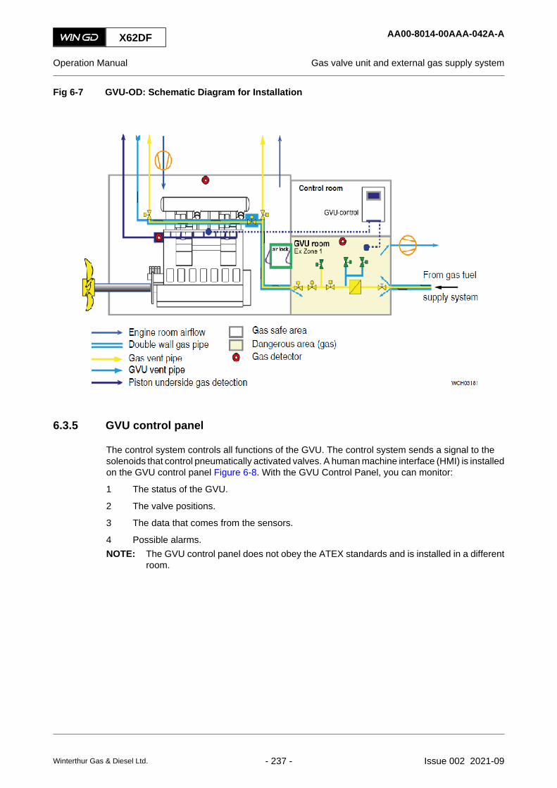
Fig 6-7 GVU-OD: Schematic Diagram for Installation
6.3.5 GVU control panel
The control system controls all functions of the GVU. The control system sends a signal to thesolenoids that control pneumatically activated valves. A human machine interface (HMI) is installedon the GVU control panel Figure 6-8. With the GVU Control Panel, you can monitor:
1 The status of the GVU.
2 The valve positions.
3 The data that comes from the sensors.
4 Possible alarms.NOTE: The GVU control panel does not obey the ATEX standards and is installed in a different
room.
X62DF AA00-8014-00AAA-042A-A
Operation Manual Gas valve unit and external gas supply system
Winterthur Gas & Diesel Ltd. - 237 - Issue 002 2021-09
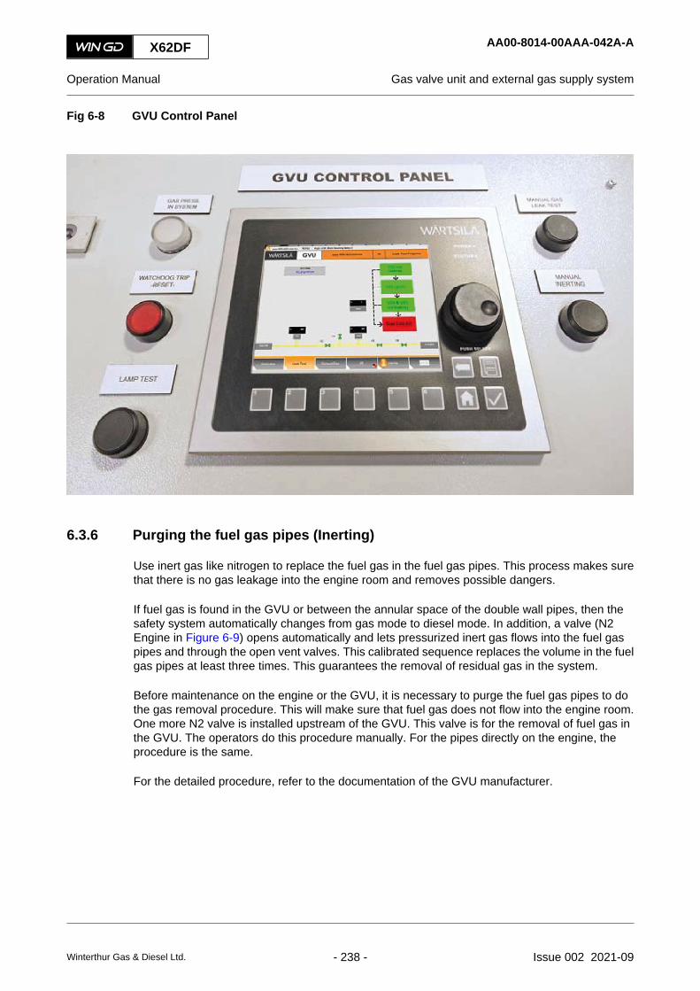
Fig 6-8 GVU Control Panel
6.3.6 Purging the fuel gas pipes (Inerting)
Use inert gas like nitrogen to replace the fuel gas in the fuel gas pipes. This process makes surethat there is no gas leakage into the engine room and removes possible dangers.
If fuel gas is found in the GVU or between the annular space of the double wall pipes, then thesafety system automatically changes from gas mode to diesel mode. In addition, a valve (N2Engine in Figure 6-9) opens automatically and lets pressurized inert gas flows into the fuel gaspipes and through the open vent valves. This calibrated sequence replaces the volume in the fuelgas pipes at least three times. This guarantees the removal of residual gas in the system.
Before maintenance on the engine or the GVU, it is necessary to purge the fuel gas pipes to dothe gas removal procedure. This will make sure that fuel gas does not flow into the engine room.One more N2 valve is installed upstream of the GVU. This valve is for the removal of fuel gas inthe GVU. The operators do this procedure manually. For the pipes directly on the engine, theprocedure is the same.
For the detailed procedure, refer to the documentation of the GVU manufacturer.
X62DF AA00-8014-00AAA-042A-A
Operation Manual Gas valve unit and external gas supply system
Winterthur Gas & Diesel Ltd. - 238 - Issue 002 2021-09

Fig 6-9 Fuel gas removal from the fuel gas pipes: Schematic Diagram
X62DF AA00-8014-00AAA-042A-A
Operation Manual Gas valve unit and external gas supply system
Winterthur Gas & Diesel Ltd. - 239 - Issue 002 2021-09

6.4 Local display unit (LDU-20) - general
6.4.1 Local display unit (LDU-20)
The LDU-20 (Figure 6-10) is a multi-purpose module that has an LCD color display (009), ten multi-function buttons (004 to 008) and a rotary button (003).
The number of LDU-20 installed on the engine is related to the engine control system (ECS) andto other optional systems.
Fig 6-10 LDU-20 - overview
POWER
STATUS
PUSH SELECT
00209
001
009
008 008 008 008 008 008 007 006
002
003
005
004
Legend
001 Power LED 006 CHECK button (used to accept the action orenter data)
002 Status LED 007 HOME button (push to show the main page)003 Rotary button (16 steps in one turn, push to
select)008 Multi-function buttons (function is shown on the
display)004 BACK button (used to cancel the action or delete
data)009 Color display
005 Failure LIST button (push to show the failure list)
X62DF AA00-0000-00AAA-043H-A
Operation Manual Local display unit (LDU-20) - general
Winterthur Gas & Diesel Ltd. - 240 - Issue 002 2021-09

6.4.2 Color display
The color display (009) of the LDU-20 shows different pages for each application. After boot-up,or when you push the HOME button, the MAIN page is shown.
Some elements are shown on all pages as follows:
• In the top right-hand corner, the system time is shown above the title bar.
• Below the system time, Local or ECR is shown. If the LDU-20 is the active control location,the indication In Control is shown.
• The bottom of the color display has some space to show the function of the multi-functionbuttons.
The color display has the general items that follow, refer to Figure 6-11:
• An orange arrow (001) shows the active item.
• A 3D-rectangle (002) indicates a command button.
• An orange frame (003) indicates the edit mode.
• A black dotted frame (004) around an item shows the position of the cursor.
• A white background (005) shows a parameter, which the operator can adjust.
• A grey background (006) shows a parameter, which the operator cannot adjust.
Fig 6-11 LDU-20 color display - general items
004003 005 006
002
001
Legend
001 Orange arrow 004 Black dotted frame002 3D-rectangle 005 White background003 Orange frame 006 Grey background
For the procedures how to use the LDU-20, eg change a LDU-20 page, refer to section 6.5.1Operate the local display unit (LDU-20).
X62DF AA00-0000-00AAA-043H-A
Operation Manual Local display unit (LDU-20) - general
Winterthur Gas & Diesel Ltd. - 241 - Issue 002 2021-09

6.5 Local display unit (LDU-20)- Option for UNIC - pages6.5.1 Operate the local display unit (LDU-20)
PeriodicityDescriptionUnscheduledDuration for performing preliminary requirements 0.0 man-hoursDuration for performing the procedure 0.5 man-hoursDuration for performing the requirements after job completion 0.0 man-hours
PersonnelDescription Specialization QTYEngine crew Intermediate 1
Support equipmentDescription Part No. CSN QTYNone
SuppliesDescription QTYNone
Spare PartsDescription Part No. CSN QTYNone
SAFETY PRECAUTIONS
• None
PRELIMINARY OPERATIONS
• The engine control system must be set to on.
X62DF AA00-0000-00AAA-131I-A
Operation Manual Operate the local display unit (LDU-20)
Winterthur Gas & Diesel Ltd. - 242 - Issue 002 2021-09

PROCEDURE
Fig 6-12 LDU-20 - navigation menu
00210
001
1 To change between LDU-20 pages, do the steps that follow:1.1 Push and hold the rotary button for three seconds to show the page navigation
menu (001, Figure 6-12).1.2 Turn the rotary button to select a page:
• To select an item below, turn the rotary button clockwise.• To select an item before, turn the rotary button counterclockwise.NOTE: As an alternative you can use the Index button to change between
LDU-20 pages.1.3 Push the rotary button to change to the selected page and to close the navigation
menu.
2 To edit a selected item on a LDU-20 page, do the steps that follow:NOTE: Values and settings that the operator can change are shown with a white
background.
2.1 Use the rotary button to select the item.NOTE: While in edit mode, the text field has an orange frame.
2.2 Push and turn the rotary button.• To increase the value, turn the rotary button clockwise.• To decrease the value, turn the rotary button counterclockwise.
2.3 Push the rotary button to apply the change.
3 To operate the engine from the MAIN page, do the steps that follow:NOTE: The changes have an immediate effect on the engine.
X62DF AA00-0000-00AAA-131I-A
Operation Manual Operate the local display unit (LDU-20)
Winterthur Gas & Diesel Ltd. - 243 - Issue 002 2021-09

3.1 Make sure that the LDU-20 is the active control location. If necessary, select theCTRL.TR button to transfer control.
3.2 To change modes, move the cursor on the related button then push the rotarybutton.NOTE: The indicator (orange triangle) shows the control mode of the LDU-20
(speed mode or fuel command mode).NOTE: If the MCM-11 becomes defective, a fuel command mode is selected
automatically.NOTE: While in edit mode, the text field has an orange frame. Turn the rotary
button to adjust the set point (turn clockwise to increase,counterclockwise to decrease).
3.3 To adjust the speed or fuel command setpoint, move the cursor to the related fieldthen push the rotary button to enter the edit mode.
3.4 To go out of the editing mode, push the rotary button again.
4 To change the LDU-20 control location from the CONTROL LOC. page, do the steps thatfollow:4.1 Push the CTRL. TR. button to accept control to the LDU-20 at your location.4.2 To get / accept control to / from a different location, select the related on-screen
button, then push the CHECK button.
5 To adjust the fuel injection parameters from the FUEL INJECTION page, do the steps thatfollow:5.1 Turn the rotary button to move the cursor to the related text field.5.2 Push the rotary button to enter the edit mode.5.3 Turn the rotary button to adjust the value (turn clockwise to increase, or
counterclockwise to decrease).5.4 Push the rotary button again to go out of the edit mode.
WARNINGAfter an air run, the crankshaft can turn suddenly when the pressurized air in the cylinderreleases. There is a risk of death, serious injury or damage to components. Before you domaintenance on the engine, engage the turning gear, or start the Crank Angle DeterminationAlgorithm (ADA) a second time:• Make sure that there is no pressurized air in the cylinder and the starting air pipes• Make sure that you open the relief valves on all cylinder covers to release the pressure
6 To do an ADA Start from the CRANK ANGLE page, do the steps that follow:NOTE: It is possible to do the ADA procedure with open or closed indicator valves.
6.1 In the LDU-20, get the USER PARAMETERS page.6.2 Push the AIR RUN button until the engine status changes from ADA to AIR RUN.
NOTE: It is also satisfactory if each cylinder was activated and has movedautomatically at the ADA procedure (independently from the direction inwhich the engine turns).
NOTE: If the ADA procedure has activated each cylinder but the engine stays inits initial position, release the AIR RUN button. Do Step 6.4 to Step 6.7.
6.3 If the ADA procedure is not successful (ie the absolute crank angle position couldnot be found), do the steps that follow:
6.4 Open the indicator valves on all cylinders to release the compressed air.6.5 Make sure that the starting air pressure is sufficient.
X62DF AA00-0000-00AAA-131I-A
Operation Manual Operate the local display unit (LDU-20)
Winterthur Gas & Diesel Ltd. - 244 - Issue 002 2021-09

6.6 If necessary, use the turning gear to turn the engine to another initial position.6.7 Do Step 6.1 to Step 6.2 again.
7 To open the exhaust valve for inspections from the EXHAUST VALVE page, do the stepsthat follow:7.1 Set to ON the servo oil service pump to get some pressure in the servo oil rail.7.2 Make sure that the air spring air pressure is sufficient.7.3 Move the cursor to the related text field.7.4 Push the rotary button to enter the edit mode.7.5 Turn the rotary button to adjust the value to ON to open the exhaust valve. Adjust
the value to OFF to go back to automatic mode. Push the rotary button again togo out of the edit mode.
7.6 Use the manual exhaust valve operation to manually open and close an exhaustvalve after the engine has stopped (This can be used for tests and bleedprocedures, eg after maintenance).
7.7 Set to OFF the servo oil service pump.
8 To change the filter settings on the LOG MESSAGES page, do the steps that follow:8.1 Push the BACK button to put the cursor on the Filters field, then push the rotary
button to display the list of available filters, eg All/Safety/Event/Info/Error.8.2 Use the rotary button to move the cursor up or down in the list of available filters.8.3 Push the rotary button to select or deselect the filters.8.4 Push the BACK button two times to move the cursor back to the list of log
messages.8.5 Use the rotary button to scroll the list up or down.8.6 When the cursor (a blue highlight in the list) is on a selected log message, push
the rotary button. This shows a different screen, which has more data about thislog entry.
9 To export a screenshot from the LOG ENTRY page, do the steps that follow:9.1 Connect a USB drive to the USB port on the rear of the LDU-20. Make sure that
the USB drive has a compatible data format (FAT32).9.2 Wait until the USB menu window is displayed on the screen.9.3 Use the rotary button to move the cursor to the SCREENSHOT button.9.4 Push the rotary button to take a screenshot of the page.
NOTE: The screenshot will be automatically saved to the USB drive.9.5 If necessary, send the saved xx.png file to WinGD.
10 To download backup files from the SYSTEM STATUS page, do the steps that follow:NOTE: The dialog box that is shown gives an option to download, or not to download
the backup files to the selected modules.
10.1 Use the rotary button (turn and then push) to select the DOWNLOAD button.10.2 Select Yes to start the download backup files procedure.
NOTE: Select NO if you want to cancel the procedure.
11 To export EDL messages from the SOFTWARE TOOLS page, do the steps that follow:11.1 Connect a USB drive to the USB port on the rear of the LDU-20 back panel.
NOTE: USB drive must have FAT32 file system (format command cannot beused for this purpose). If the USB drive memory storage is too large, LDU-20 may not recognize the USB drive. It is recommended to use the USBdrive of 4GB memory or less.
X62DF AA00-0000-00AAA-131I-A
Operation Manual Operate the local display unit (LDU-20)
Winterthur Gas & Diesel Ltd. - 245 - Issue 002 2021-09
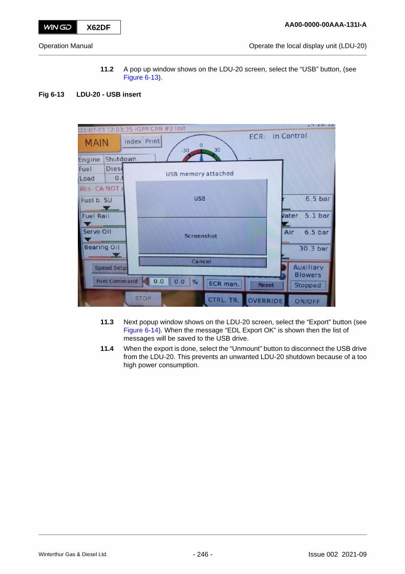
11.2 A pop up window shows on the LDU-20 screen, select the “USB” button, (seeFigure 6-13).
Fig 6-13 LDU-20 - USB insert
11.3 Next popup window shows on the LDU-20 screen, select the “Export” button (seeFigure 6-14). When the message “EDL Export OK” is shown then the list ofmessages will be saved to the USB drive.
11.4 When the export is done, select the “Unmount” button to disconnect the USB drivefrom the LDU-20. This prevents an unwanted LDU-20 shutdown because of a toohigh power consumption.
X62DF AA00-0000-00AAA-131I-A
Operation Manual Operate the local display unit (LDU-20)
Winterthur Gas & Diesel Ltd. - 246 - Issue 002 2021-09

Fig 6-14 LDU-20 - EDL export
12 To use the partial upgrade wizard from the SOFTWARE TOOLS page, do the steps thatfollow:NOTE: You use the partial upgrade wizard to adjust software parameters, which the user
does not usually have access. A file from WinGD stored on a USB drive isnecessary.
NOTE: Connect the USB drive to the USB port on the back of the LDU-20.
12.1 Use the rotary button to put the cursor on the Start Wizard button.12.2 Push the rotary button to select Start Wizard.
CLOSE UP
• None
X62DF AA00-0000-00AAA-131I-A
Operation Manual Operate the local display unit (LDU-20)
Winterthur Gas & Diesel Ltd. - 247 - Issue 002 2021-09

6.5.2 LDU-20 pages - general for DF engine
In the chapters that follow you can find a description of the LDU-20 pages that follow:
• 6.5.3 LDU-20 page - MAIN
• 6.5.4 LDU-20 page - CONTROL LOCATIONS
• 6.5.5 LDU-20 page - FUEL MODE CONTROL
• 6.5.6 LDU-20 page - CA SENSOR STATUS
• 6.5.7 LDU-20 page - CYLINDER BALANCING DIESEL
• 6.5.8 LDU-20 page - CYLINDER BALANCING GAS
• 6.5.9 LDU-20 page - CYLINDER LUBRICATION
• 6.5.10 LDU-20 page - iCAT
• 6.5.11 LDU-20 page - DYNAMIC COMBUSTION CONTROL (DCC)
• 6.5.12 LDU-20 page - EXHAUST VENTILATION
• 6.5.13 LDU-20 page - EXHAUST VALVES
• 6.5.14 LDU-20 page - FAILURE LIST
• 6.5.15 LDU-20 page - FAILURE SIMULATION
• 6.5.16 LDU-20 page - FUEL SHARING (if applicable)
• 6.5.17 LDU-20 page - FUEL SYSTEM
• 6.5.18 LDU-20 page - GAS PRESSURE
• 6.5.19 LDU-20 page - GAS LEAK TEST
• 6.5.20 LDU-20 page - GAS ADMISSION VALVES
• 6.5.21 LDU-20 page - GAV MANUAL VALVE TEST
• 6.5.22 LDU-20 page - GVU & VALVE TEST
• 6.5.23 LDU-20 page - KNOCK CONTROL
• 6.5.24 LDU-20 page - LOG MESSAGES
• 6.5.25 LDU-20 page - MAIN FUEL INJECTION
• 6.5.26 LDU-20 page - PAGE INDEX
• 6.5.27 LDU-20 page - PERFORMANCE DATA DIESEL
• 6.5.28 LDU-20 page - PERFORMANCE DATA GAS
• 6.5.29 LDU-20 page - PILOT FUEL INJECTION
• 6.5.30 LDU-20 page - PILOT FUEL PRESSURE
• 6.5.31 LDU-20 page - SCAVENGE AIR - EWG (optional)
• 6.5.32 LDU-20 page - SCREENSHOT
• 6.5.33 LDU-20 page - SOFTWARE INFO
• 6.5.34 LDU-20 page - IMO CRC INFO
• 6.5.35 LDU-20 page - SOFTWARE TOOLS
• 6.5.36 LDU-20 page - SYSTEM STATUS
• 6.5.37 LDU-20 page - SYSTEM SETTINGS
X62DF AA00-9606-01AAA-043B-A
Operation Manual LDU-20 pages - general for DF engine
Winterthur Gas & Diesel Ltd. - 248 - Issue 002 2021-09

• 6.5.38 LDU-20 page - TEMPERATURES
• 6.5.39 LDU-20 page - USER PARAMETERS
• 6.5.40 LDU-20 page - LOG ENTRY DATA
• 6.5.42 LDU-20 page - DATE
• 6.5.43 LDU-20 page - ETHERNET
• 6.5.44 LDU-20 page - iELBA Control (optional)
X62DF AA00-9606-01AAA-043B-A
Operation Manual LDU-20 pages - general for DF engine
Winterthur Gas & Diesel Ltd. - 249 - Issue 002 2021-09

6.5.3 LDU-20 page - MAIN
Fig 6-15 MAIN
002001 004003 006005
008
007
010
016
007
015
009
013 014011 012
018017 019
024025 022023 020021
X62DF AA00-9606-02AAA-043B-A
Operation Manual LDU-20 page - MAIN
Winterthur Gas & Diesel Ltd. - 250 - Issue 002 2021-09

Tab 6-1 MAIN
Item Function Effect
001 START AST button Starts the engine in astern direction (for reversible engine)
002 STOP button Stops the engine
003 START AHD button Starts the engine in ahead direction
004 CTRL. TR. button Sends a signal for a control transfer to this LDU-20
005 OVERRIDE button Cancels a shutdown from the safety system
006 ON/OFF button Sets to On and OFF the auxiliary blowers
007 Different sensor indications Indications that are necessary to operate the engine locally
008 Load Shows the value of the estimated engine power or the engineload in percent (%)
009 Fuel Shows the used fuelShows: Diesel or Gas
010 Engine status Shows the engine statusShows: Start interlock, Stopped, Slow turning, Air Run, Starting,Heavy Start, Running or Shutdown, Angle Detection Slowdown
011 Index button Opens the INDEX page
012 Print button Makes a screenshot of the current screen, refer to 6.5.32LDU-20 page - SCREENSHOT
013 Engine speed gauge Shows engine rpm in ahead (AHD) or astern (AST) direction
014 Indication of this LDU-20 Shows if Local has control, or does not have control
015 Control transfer request indication Text flashes to show a transfer request if one control locationrequests a control transfer
016 Indication of status Shows the status of different items, if applicable
017 Speed Setpoint button Changes to manual speed control mode
018 Manual speed setpoint Manually adjust the rpm between zero and maximum. The max-imum value is related to the installation specifications (rating etc)
019 External speed setpoint Shows the setpoint sent to the ECS from the remote controlsystem
020 Auxiliary Blowers status Shows if one or the two auxiliary blowers are runningShows: Running or Stopped
021 Indication of shutdown Shows the shutdown status.• When a shutdown is active, the red indicator (SHD) is on
and Engine status (010) shows stopped.• When you gave the OVERRIDE command (005), the red
indicator (Ovrd SHD) is on.Press the Reset button to enable a restart of the engine.
X62DF AA00-9606-02AAA-043B-A
Operation Manual LDU-20 page - MAIN
Winterthur Gas & Diesel Ltd. - 251 - Issue 002 2021-09

Item Function Effect
022 Control location Shows the active control locationShows: Local, ECR manual, ECR remote or Bridge
023 External fuel command setpoint Shows the fuel command setpoint that the ECS calculates re-lated to the speed setpoint from the remote control system
024 Manual fuel command setpoint Manually adjust the fuel command setpoint between 0% and150%
025 Fuel Command button Changes to manual fuel command modeNOTE: The fuel command mode is only applicable, if the con-
trol location is “Local” or “ECR manual”.
NOTE: If the control location is “Local” or “ECR manual”, obey the items that follow:
• The operator must set the setpoint for speed setpoint or for load commandmanually, because the speed / load program is not in automatic mode.
• If a slowdown message is active, the operator must set the related setpoint forslowdown manually.
X62DF AA00-9606-02AAA-043B-A
Operation Manual LDU-20 page - MAIN
Winterthur Gas & Diesel Ltd. - 252 - Issue 002 2021-09

X62DF AA00-9606-02AAA-043B-A
Operation Manual LDU-20 page - MAIN
Page left intentionally blank
Winterthur Gas & Diesel Ltd. - 253 - Issue 002 2021-09

6.5.4 LDU-20 page - CONTROL LOCATIONS
Fig 6-16 CONTROL LOCATIONS
00153
002001 004003
012
009
007
010
011008
006005
X62DF AA00-9606-03AAA-043B-A
Operation Manual LDU-20 page - CONTROL LOCATIONS
Winterthur Gas & Diesel Ltd. - 254 - Issue 002 2021-09
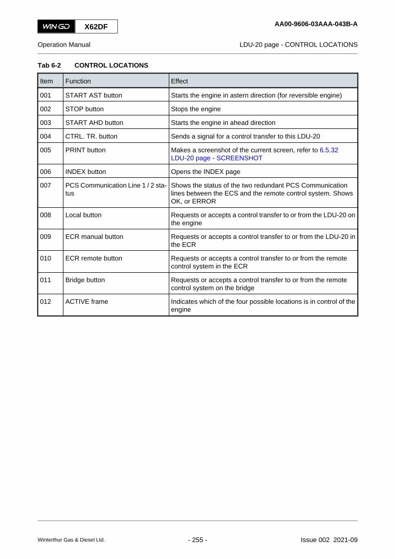
Tab 6-2 CONTROL LOCATIONS
Item Function Effect
001 START AST button Starts the engine in astern direction (for reversible engine)
002 STOP button Stops the engine
003 START AHD button Starts the engine in ahead direction
004 CTRL. TR. button Sends a signal for a control transfer to this LDU-20
005 PRINT button Makes a screenshot of the current screen, refer to 6.5.32LDU-20 page - SCREENSHOT
006 INDEX button Opens the INDEX page
007 PCS Communication Line 1 / 2 sta-tus
Shows the status of the two redundant PCS Communicationlines between the ECS and the remote control system. ShowsOK, or ERROR
008 Local button Requests or accepts a control transfer to or from the LDU-20 onthe engine
009 ECR manual button Requests or accepts a control transfer to or from the LDU-20 inthe ECR
010 ECR remote button Requests or accepts a control transfer to or from the remotecontrol system in the ECR
011 Bridge button Requests or accepts a control transfer to or from the remotecontrol system on the bridge
012 ACTIVE frame Indicates which of the four possible locations is in control of theengine
X62DF AA00-9606-03AAA-043B-A
Operation Manual LDU-20 page - CONTROL LOCATIONS
Winterthur Gas & Diesel Ltd. - 255 - Issue 002 2021-09

6.5.5 LDU-20 page - FUEL MODE CONTROL
Fig 6-17 FUEL MODE CONTROL
002001 004003
007
011
008
012
006005
009 010
X62DF AA00-9606-04AAA-043B-A
Operation Manual LDU-20 page - FUEL MODE CONTROL
Winterthur Gas & Diesel Ltd. - 256 - Issue 002 2021-09

Tab 6-3 FUEL MODE CONTROL
Item Function Effect
001 START AST button Starts the engine in astern direction (for reversible engine)
002 STOP button Stops the engine
003 START AHD button Starts the engine in ahead direction
004 CTRL. TR. button Sends a signal for a control transfer to this LDU-20
005 DIESEL button Switches to diesel mode
006 GAS button Starts transfer to gas mode operation
007 Fail Reset button Resets a failure that occurred during gas preparationNOTE: Use this button only when you have done the related
measures to repair the failure.
008 Active mode Shows the active operation mode (orange frame)NOTE: GFS - Gas Fuel Supply
009 Index button Opens the INDEX page
010 Print button Makes a screenshot of the current screen, refer to 6.5.32LDU-20 page - SCREENSHOT
011 Diesel Mode Shows the status of diesel mode
012 Gas Mode Shows the status of gas mode
X62DF AA00-9606-04AAA-043B-A
Operation Manual LDU-20 page - FUEL MODE CONTROL
Winterthur Gas & Diesel Ltd. - 257 - Issue 002 2021-09

6.5.6 LDU-20 page - CA SENSOR STATUS
Fig 6-18 CA SENSOR STATUS
002001 004003
008
006005
007
X62DF AA00-9606-05AAA-043B-A
Operation Manual LDU-20 page - CA SENSOR STATUS
Winterthur Gas & Diesel Ltd. - 258 - Issue 002 2021-09

Tab 6-4 CA SENSOR STATUS
Item Function Effect
001 START AST button Starts the engine in astern direction (for reversible engine)
002 STOP button Stops the engine
003 START AHD button Starts the engine in ahead direction
004 CTRL. TR. button Sends a signal for a control transfer to this LDU-20
005 PRINT button Makes a screenshot of the current screen, refer to 6.5.32LDU-20 page - SCREENSHOT
006 INDEX button Opens the INDEX page
007 Status indication Shows the status of the crank angle sensors:• Green - status OK
• Red - status not OK
008 Reset Status button Resets the status of the crank angle sensors
X62DF AA00-9606-05AAA-043B-A
Operation Manual LDU-20 page - CA SENSOR STATUS
Winterthur Gas & Diesel Ltd. - 259 - Issue 002 2021-09

6.5.7 LDU-20 page - CYLINDER BALANCING DIESEL
Fig 6-19 CYLINDER BALANCING DIESEL
002001 004003
009
008
006005
007
X62DF AA00-9606-06AAA-043B-A
Operation Manual LDU-20 page - CYLINDER BALANCING DIESEL
Winterthur Gas & Diesel Ltd. - 260 - Issue 002 2021-09

Tab 6-5 CYLINDER BALANCING DIESEL
Item Function Effect
001 START AST button Starts the engine in astern direction (for reversible engine)
002 STOP button Stops the engine
003 START AHD button Starts the engine in ahead direction
004 CTRL. TR. button Sends a signal for a control transfer to this LDU-20
005 PRINT button Makes a screenshot of the current screen, refer to 6.5.32LDU-20 page - SCREENSHOT
006 INDEX button Opens the INDEX page
007 Compr. Balancing button Changes the compression balancing function• Green - ON
• Red - OFF
008 Firing Balancing button Changes the firing balancing function• Green - ON
• Red - OFF
009 Firing Control button Changes the firing control function• Green - ON
• Red - OFF
X62DF AA00-9606-06AAA-043B-A
Operation Manual LDU-20 page - CYLINDER BALANCING DIESEL
Winterthur Gas & Diesel Ltd. - 261 - Issue 002 2021-09

6.5.8 LDU-20 page - CYLINDER BALANCING GAS
Fig 6-20 CYLINDER BALANCING GAS
002001 004003
008
006005
007
X62DF AA00-9606-07AAA-043B-A
Operation Manual LDU-20 page - CYLINDER BALANCING GAS
Winterthur Gas & Diesel Ltd. - 262 - Issue 002 2021-09
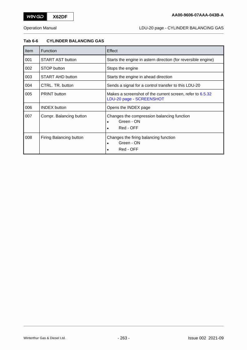
Tab 6-6 CYLINDER BALANCING GAS
Item Function Effect
001 START AST button Starts the engine in astern direction (for reversible engine)
002 STOP button Stops the engine
003 START AHD button Starts the engine in ahead direction
004 CTRL. TR. button Sends a signal for a control transfer to this LDU-20
005 PRINT button Makes a screenshot of the current screen, refer to 6.5.32LDU-20 page - SCREENSHOT
006 INDEX button Opens the INDEX page
007 Compr. Balancing button Changes the compression balancing function• Green - ON
• Red - OFF
008 Firing Balancing button Changes the firing balancing function• Green - ON
• Red - OFF
X62DF AA00-9606-07AAA-043B-A
Operation Manual LDU-20 page - CYLINDER BALANCING GAS
Winterthur Gas & Diesel Ltd. - 263 - Issue 002 2021-09

6.5.9 LDU-20 page - CYLINDER LUBRICATION
Fig 6-21 CYLINDER LUBRICATION
002001 004003
016
008
006005
009
010
011
012
007
014013 015
NOTE: Some indications on this LDU-20 page are only applicable for a DF engine.
X62DF AA00-9606-08AAA-043B-A
Operation Manual LDU-20 page - CYLINDER LUBRICATION
Winterthur Gas & Diesel Ltd. - 264 - Issue 002 2021-09

Tab 6-7 CYLINDER LUBRICATION
Item Function Effect
001 START AST button Starts the engine in astern direction (for reversible engine)
002 STOP button Stops the engine
003 START AHD button Starts the engine in ahead direction
004 CTRL. TR. button Sends a signal for a control transfer to this LDU-20
005 Low BN button Changes between low BN and high BN cylinder oil, if button isenabled
006 LFO button Changes between LFO (Light Fuel Oil) and HFO (Heavy FuelOil), if button is enabled
007 Feed rate of cylinder oil Shows the nominal cylinder oil feed rate at CMCR
008 Feed rate of cylinder oil Shows the actual cylinder oil feed rate. The value is calculatedrelated to the engine load.
009 Oper. Mode Shows the active operation mode of the cylinder lubrication withthe green indicator
010 On/Off button Sets to ON and OFF the auxiliary electric servo oil pump (servooil service pump)NOTE: If necessary, start this pump only in engine stop mode.
011 Num. of Inj. Manually set the number of injections for lubrication at enginestop mode (range 0 to 255)
012 Man. Lub. Cyl.# Manually select the cylinder for manual lubrication:• Set 100 for all cylinders
• Set 1 to n for the related cylinder
013 Man. Lub. button Starts the manual cylinder lubrication procedure related to theset values
014 Index button Opens the INDEX page
015 Print button Makes a screenshot of the current screen, refer to 6.5.32LDU-20 page - SCREENSHOT
016 Feed rate increase Manually adjust the increase of the cylinder oil feed rate for dy-namic load operation
X62DF AA00-9606-08AAA-043B-A
Operation Manual LDU-20 page - CYLINDER LUBRICATION
Winterthur Gas & Diesel Ltd. - 265 - Issue 002 2021-09

6.5.10 LDU-20 page - iCAT
Fig 6-22 iCAT (integrated Cylinder lubricant Auto Transfer)
002001 004003 006005
007
009
008
011
012013
010
014 015
017
018
016
X62DF AA00-9606-09AAA-043B-A
Operation Manual LDU-20 page - iCAT
Winterthur Gas & Diesel Ltd. - 266 - Issue 002 2021-09

Tab 6-8 iCAT (integrated Cylinder lubricant Auto Transfer)
Item Function Effect
001 START AST button Starts the engine in astern direction (for reversible engine)
002 STOP button Stops the engine
003 START AHD button Starts the engine in ahead direction
004 CTRL. TR. button Sends a signal for a control transfer to this LDU-20
005 Low BN button Changes between low BN and high BN cylinder oil, if buttonshows Enabled
006 LFO button Changes between LFO (Light Fuel Oil) and HFO (Heavy FuelOil), if button shows Enabled
007 FS Ratio For an engine with fuel sharing mode: Shows the current dieselratio and the hysteresis of the fuel sharing ratio for the change-over of the cylinder oilNOTE: These values are internal parameters. You cannot
change these values.
008 FS Ratio values For an engine with fuel sharing mode: Shows the fuel sharingratio value (diesel ratio in %) for the change-over of the cylinderoilNOTE: These values are only applicable, if the diesel fuel is
HFO.
009 Fuel Mode Shows the active fuel mode and the used cylinder oil (illuminat-ed):• Green - correct cylinder oil in use
• Red - incorrect cylinder oil in use
010 Valve position status Shows the position of the change-over valves related to thesensor of each valve (illuminated):• Green and grey - correct valve positions
• Red and grey - incorrect valve positions
011 Actuate Valve button Starts the valve actuating mode (only in commissioning mode),thus you manually can set the valve position of the change-overvalves
012 Commissioning button Starts the commissioning mode, if the conditions that follow areOK:• Control transfer from RCS to ECS
• Engine at standstill
• Usual range of control air pressure
013 Active Mode status Shows the active mode status:• No iCAT Functionality
• Auto Mode
• Auto Mode - RCS Offline
• Commissioning Mode
X62DF AA00-9606-09AAA-043B-A
Operation Manual LDU-20 page - iCAT
Winterthur Gas & Diesel Ltd. - 267 - Issue 002 2021-09

Item Function Effect
014 Index button Opens the INDEX page
015 Print button Makes a screenshot of the current screen, refer to section 6.5.32LDU-20 page - SCREENSHOT
016 Transfer Mode status Shows the transfer mode status:• High BN
• Low BN
• Transferring
• Transfer interlock
017 Sulfur Content Shows the sulfur content of the fuels related to the settings inthe RCSNOTE: Here you only can change these values, if the RCS
has failed.
018 Force Transfer button Starts a transfer (only applicable if a transfer is interlocked)NOTE: An interlock is active, if the related cylinder oil pressure
is too low. Use this button only, if you are sure to over-ride the interlock.
X62DF AA00-9606-09AAA-043B-A
Operation Manual LDU-20 page - iCAT
Winterthur Gas & Diesel Ltd. - 268 - Issue 002 2021-09

X62DF AA00-9606-09AAA-043B-A
Operation Manual LDU-20 page - iCAT
Page left intentionally blank
Winterthur Gas & Diesel Ltd. - 269 - Issue 002 2021-09

6.5.11 LDU-20 page - DYNAMIC COMBUSTION CONTROL (DCC)
Fig 6-23 DYNAMIC COMBUSTION CONTROL (DCC)
002001 004003 006005
007
X62DF AA00-9606-10AAA-043B-A
Operation Manual LDU-20 page - DYNAMIC COMBUSTION CONTROL (DCC)
Winterthur Gas & Diesel Ltd. - 270 - Issue 002 2021-09
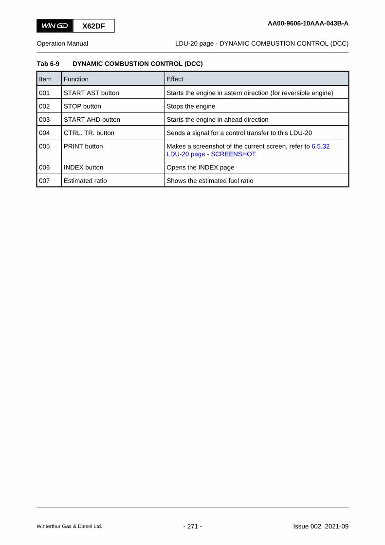
Tab 6-9 DYNAMIC COMBUSTION CONTROL (DCC)
Item Function Effect
001 START AST button Starts the engine in astern direction (for reversible engine)
002 STOP button Stops the engine
003 START AHD button Starts the engine in ahead direction
004 CTRL. TR. button Sends a signal for a control transfer to this LDU-20
005 PRINT button Makes a screenshot of the current screen, refer to 6.5.32LDU-20 page - SCREENSHOT
006 INDEX button Opens the INDEX page
007 Estimated ratio Shows the estimated fuel ratio
X62DF AA00-9606-10AAA-043B-A
Operation Manual LDU-20 page - DYNAMIC COMBUSTION CONTROL (DCC)
Winterthur Gas & Diesel Ltd. - 271 - Issue 002 2021-09

6.5.12 LDU-20 page - EXHAUST VENTILATION
Fig 6-24 EXHAUST VENTILATION
002001 004003
010
006005
007
008009
X62DF AA00-9606-11AAA-043B-A
Operation Manual LDU-20 page - EXHAUST VENTILATION
Winterthur Gas & Diesel Ltd. - 272 - Issue 002 2021-09

NOTE: For a description of the exhaust ventilation refer to section 2.7 Prevention of explosionsin the exhaust gas system (gas mode).
Tab 6-10 EXHAUST VENTILATION
Item Function Effect
001 START AST button Starts the engine in astern direction (for reversible engine)
002 STOP button Stops the engine
003 START AHD button Starts the engine in ahead direction
004 CTRL. TR. button Sends a signal for a control transfer to this LDU-20
005 PRINT button Makes a screenshot of the current screen, refer to section 6.5.32LDU-20 page - SCREENSHOT
006 INDEX button Opens the INDEX page
007 Manual Ventilation Request button Sends a signal for ventilation request (Ventilation Request“Manual”)
008 Aux. Elect. SO Pump start button Starts and stops the auxiliary electrical servo oil pumpNOTE: The green indicator light shows that you should start
the auxiliary electrical servo oil pump for sufficient ser-vo oil pressure.
NOTE: You only can start the auxiliary electrical servo oilpump, if the conditions that follow are OK:• Green indicator light is on
009 Start Aux. Blowers button Starts and stops the auxiliary blowersNOTE: The green indicator light shows that you should start
the auxiliary blowers for ventilation.
NOTE: You only can start the auxiliary blowers, if the condi-tions that follow are OK:• Green indicator light is on
• Shutdown signal is reset
010 Cancel Exhaust Ventilation buttonWARNING
Explosion hazard. Cancel the exhaust ventilation only inan urgent situation. Gas could stay on the engine side, ifthe exhaust ventilation is not sufficient.
Stops the exhaust ventilationNOTE: The control system stops the auxiliary blowers and
auxiliary electrical servo oil pump.
X62DF AA00-9606-11AAA-043B-A
Operation Manual LDU-20 page - EXHAUST VENTILATION
Winterthur Gas & Diesel Ltd. - 273 - Issue 002 2021-09

6.5.13 LDU-20 page - EXHAUST VALVES
Fig 6-25 EXHAUST VALVES
002001 004003
008
009
010
006005
007
X62DF AA00-9606-12AAA-043B-A
Operation Manual LDU-20 page - EXHAUST VALVES
Winterthur Gas & Diesel Ltd. - 274 - Issue 002 2021-09

Tab 6-11 EXHAUST VALVES
Item Function Effect
001 START AST button Starts the engine in astern direction (for reversible engine)
002 STOP button Stops the engine
003 START AHD button Starts the engine in ahead direction
004 CTRL. TR. button Sends a signal for a control transfer to this LDU-20
005 PRINT button Makes a screenshot of the current screen, refer to 6.5.32LDU-20 page - SCREENSHOT
006 INDEX button Opens the INDEX page
007 Operation mode selection button Selects the operation mode of the related exhaust valve• On - manual operation mode (valve opens, if conditions
are OK)• Off - automatic operation mode (valve closes)
008 Closing Offset Manually adjust the closing offset of the exhaust valve
009 Open Dead Times Shows the time between the open command to the solenoidvalve of the VCU and the exhaust valve stroke start
010 Close Dead Times Shows the time between the close command to the solenoidvalve of the VCU and the exhaust valve stroke start
X62DF AA00-9606-12AAA-043B-A
Operation Manual LDU-20 page - EXHAUST VALVES
Winterthur Gas & Diesel Ltd. - 275 - Issue 002 2021-09

6.5.14 LDU-20 page - FAILURE LIST
Fig 6-26 FAILURE LIST
002001 004003
008
006005
007
009
X62DF AA00-9606-13AAA-043B-A
Operation Manual LDU-20 page - FAILURE LIST
Winterthur Gas & Diesel Ltd. - 276 - Issue 002 2021-09

Tab 6-12 FAILURE LIST
Item Function Effect
001 START AST button Starts the engine in astern direction (for reversible engine)
002 STOP button Stops the engine
003 START AHD button Starts the engine in ahead direction
004 CTRL. TR. button Sends a signal for a control transfer to this LDU-20
005 LOG MSG button Opens the LOG MESSAGE page
006 INDEX button Opens the INDEX page
007 Filter button Manually select the applicable type filter for the related failure
008 Filter button Manually select the applicable category filter for the related fail-ure
009 Scroll bar Manually scroll through the failure list
X62DF AA00-9606-13AAA-043B-A
Operation Manual LDU-20 page - FAILURE LIST
Winterthur Gas & Diesel Ltd. - 277 - Issue 002 2021-09

6.5.15 LDU-20 page - FAILURE SIMULATION
Fig 6-27 FAILURE SIMULATION
002001 004003
007
008
006005
X62DF AA00-9606-14AAA-043B-A
Operation Manual LDU-20 page - FAILURE SIMULATION
Winterthur Gas & Diesel Ltd. - 278 - Issue 002 2021-09

Tab 6-13 FAILURE SIMULATION
Item Function Effect
001 START AST button Starts the engine in astern direction (for reversible engine)
002 STOP button Stops the engine
003 START AHD button Starts the engine in ahead direction
004 CTRL. TR. button Sends a signal for a control transfer to this LDU-20
005 PRINT button Makes a screenshot of the current screen, refer to section 6.5.32LDU-20 page - SCREENSHOT
006 INDEX button Opens the INDEX page
007 Failure Test Mode button Sets to ON and OFF the failure test modeNOTE: You only can start the test mode, if the conditions that
follow are OK:• Engine at standstill (green indicator light is on)
• No shutdown signal active
• Turning gear is engaged, thus there is a startinterlock (green indicator light is on)
008 Failure ID To Simulate Manually set the failure number related to the Modbus to AMSsignal listNOTE: This specified failure will be sent to the RCS for a spe-
cific test.
X62DF AA00-9606-14AAA-043B-A
Operation Manual LDU-20 page - FAILURE SIMULATION
Winterthur Gas & Diesel Ltd. - 279 - Issue 002 2021-09

6.5.16 LDU-20 page - FUEL SHARING (if applicable)
Fig 6-28 FUEL SHARING (if applicable)
002001 004003
011
006005
007
008
009 010
X62DF AA00-9606-15AAA-043B-A
Operation Manual LDU-20 page - FUEL SHARING (if applicable)
Winterthur Gas & Diesel Ltd. - 280 - Issue 002 2021-09

Tab 6-14 FUEL SHARING (if applicable)
Item Function Effect
001 START AST button Starts the engine in astern direction (for reversible engine)
002 STOP button Stops the engine
003 START AHD button Starts the engine in ahead direction
004 CTRL. TR. button Sends a signal for a control transfer to this LDU-20
005 DIESEL button Switches to diesel mode
006 GAS button Starts transfer to gas mode operation
007 Fail Reset button Resets a failure that occurred during gas preparationNOTE: Use this button only when you have done the related
measures to repair the failure.
008 Active mode Shows the active operation mode (orange frame)NOTE: GFS - Gas Fuel Supply
009 Index button Opens the INDEX page
010 Print button Makes a screenshot of the current screen, refer to 6.5.32LDU-20 page - SCREENSHOT
011 Fuel Share request button Requests fuel sharing modeNOTE: You have to set the value for the ratio of liquid fuel to
gas in the RCS.
X62DF AA00-9606-15AAA-043B-A
Operation Manual LDU-20 page - FUEL SHARING (if applicable)
Winterthur Gas & Diesel Ltd. - 281 - Issue 002 2021-09

6.5.17 LDU-20 page - FUEL SYSTEM
Fig 6-29 FUEL SYSTEM
002001 004003 006005
NOTE: Some indications on this LDU-20 page are only applicable for a DF engine.
X62DF AA00-9606-16AAA-043B-A
Operation Manual LDU-20 page - FUEL SYSTEM
Winterthur Gas & Diesel Ltd. - 282 - Issue 002 2021-09

Tab 6-15 FUEL SYSTEM
Item Function Effect
001 START AST button Starts the engine in astern direction (for reversible engine)
002 STOP button Stops the engine
003 START AHD button Starts the engine in ahead direction
004 CTRL. TR. button Sends a signal for a control transfer to this LDU-20
005 PRINT button Makes a screenshot of the current screen, refer to 6.5.32LDU-20 page - SCREENSHOT
006 INDEX button Opens the INDEX page
X62DF AA00-9606-16AAA-043B-A
Operation Manual LDU-20 page - FUEL SYSTEM
Winterthur Gas & Diesel Ltd. - 283 - Issue 002 2021-09

6.5.18 LDU-20 page - GAS PRESSURE
Fig 6-30 GAS PRESSURE
002001 004003
008
006005
007
X62DF AA00-9606-17AAA-043B-A
Operation Manual LDU-20 page - GAS PRESSURE
Winterthur Gas & Diesel Ltd. - 284 - Issue 002 2021-09

Tab 6-16 GAS PRESSURE
Item Function Effect
001 START AST button Starts the engine in astern direction (for reversible engine)
002 STOP button Stops the engine
003 START AHD button Starts the engine in ahead direction
004 CTRL. TR. button Sends a signal for a control transfer to this LDU-20
005 PRINT button Makes a screenshot of the current screen, refer to 6.5.32LDU-20 page - SCREENSHOT
006 Leak Test button Opens the GAS LEAK TEST page
007 Index button Opens the INDEX page
008 Fail Reset button Resets the failure, that is indicated in red
X62DF AA00-9606-17AAA-043B-A
Operation Manual LDU-20 page - GAS PRESSURE
Winterthur Gas & Diesel Ltd. - 285 - Issue 002 2021-09

6.5.19 LDU-20 page - GAS LEAK TEST
Fig 6-31 GAS LEAK TEST
002001 004003 006005
008
007
009
010
011
012
013
014
X62DF AA00-9606-38AAA-043B-A
Operation Manual LDU-20 page - GAS LEAK TEST
Winterthur Gas & Diesel Ltd. - 286 - Issue 002 2021-09

Tab 6-17 GAS LEAK TEST
Item Function Effect
001 START AST button Starts the engine in astern direction (for reversible engine)
002 STOP button Stops the engine
003 START AHD button Starts the engine in ahead direction
004 CTRL. TR. button Sends a signal for a control transfer to this LDU-20
005 Gas Pr. button Opens the GAS PRESSURE page
006 INDEX button Opens the INDEX page
007 Open/Close Sealing Oil Valve but-ton
Opens or closes the sealing oil valves
008 Aux. Elect. SO Pump start button Starts and stops the auxiliary electrical servo oil pump manually
NOTE: You only can start the tests (item 009 to 011), if the conditions that follow are OK:• Engine at standstill
• Turning gear is engaged
NOTE: Each test is OK, if during the test period of 1000 seconds the pressure drop is less than700 mbar.
009 Fuel Side Test Req. button Starts the automatic gas leak test of the pipes on the fuel side,if the conditions show OK
010 Exh. Side Test Req. button Starts the automatic gas leak test of the pipes on the exhaustside, if the conditions show OK
011 GVU - ENG Test Req. button Starts the automatic gas leak test of the pipes between the gasvalve unit (GVU) and the engine, if the conditions show OK
012 Cancel Test button Stops the running gas leak test
013 Test status Shows data about the three gas leak tests
014 Pipes schematic Shows the status of the related valves:• black fill - valve closed
• no fill - valve open
X62DF AA00-9606-38AAA-043B-A
Operation Manual LDU-20 page - GAS LEAK TEST
Winterthur Gas & Diesel Ltd. - 287 - Issue 002 2021-09

6.5.20 LDU-20 page - GAS ADMISSION VALVES
Fig 6-32 GAS ADMISSION VALVES
002001 004003
007
008
006005
X62DF AA00-9606-18AAA-043B-A
Operation Manual LDU-20 page - GAS ADMISSION VALVES
Winterthur Gas & Diesel Ltd. - 288 - Issue 002 2021-09

Tab 6-18 GAS ADMISSION VALVES
Item Function Effect
001 START AST button Starts the engine in astern direction (for reversible engine)
002 STOP button Stops the engine
003 START AHD button Starts the engine in ahead direction
004 CTRL. TR. button Sends a signal for a control transfer to this LDU-20
005 PRINT button Makes a screenshot of the current screen, refer to 6.5.32LDU-20 page - SCREENSHOT
006 INDEX button Opens the INDEX page
007 GAV Feedback status Shows the status of the stroke sensor of the gas admission valve(GAV)
008 GAV Actuator status Shows the status of the actuator of the gas admission valve(GAV)
X62DF AA00-9606-18AAA-043B-A
Operation Manual LDU-20 page - GAS ADMISSION VALVES
Winterthur Gas & Diesel Ltd. - 289 - Issue 002 2021-09

6.5.21 LDU-20 page - GAV MANUAL VALVE TEST
Fig 6-33 GAV MANUAL VALVE TEST
002001 004003
009
006005
007
008
X62DF AA00-9606-19AAA-043B-A
Operation Manual LDU-20 page - GAV MANUAL VALVE TEST
Winterthur Gas & Diesel Ltd. - 290 - Issue 002 2021-09

Tab 6-19 GAV MANUAL VALVE TEST
Item Function Effect
001 START AST button Starts the engine in astern direction (for reversible engine)
002 STOP button Stops the engine
003 START AHD button Starts the engine in ahead direction
004 CTRL. TR. button Sends a signal for a control transfer to this LDU-20
005 PRINT button Makes a screenshot of the current screen, refer to section 6.5.32LDU-20 page - SCREENSHOT
006 INDEX button Opens the INDEX page
007 GAVn button Opens and closes the related gas admission valve (GAV), ifmanual test request is active and conditions are OK• black fill - valve closed
• no fill - valve open
NOTE: Do a check of the sound of the movement of the gasadmission valve.
008 Manual Test Request button Sends a signal for a manual test of the gas admission valvesNOTE: You only can start the test mode, if the conditions that
follow are OK:• Engine at standstill
• Turning gear is engaged
• Usual range of servo oil pressure
• Usual range of sealing oil pressure
009 Shutoff valve button Opens and closes the shut-off valve for sealing oil (CV7296C)
X62DF AA00-9606-19AAA-043B-A
Operation Manual LDU-20 page - GAV MANUAL VALVE TEST
Winterthur Gas & Diesel Ltd. - 291 - Issue 002 2021-09

6.5.22 LDU-20 page - GVU & VALVE TEST
Fig 6-34 GVU & VALVE TEST
002001 004003
011
006005
007
008
009
010
X62DF AA00-9606-20AAA-043B-A
Operation Manual LDU-20 page - GVU & VALVE TEST
Winterthur Gas & Diesel Ltd. - 292 - Issue 002 2021-09

Tab 6-20 GVU & VALVE TEST
Item Function Effect
001 START AST button Starts the engine in astern direction (for reversible engine)
002 STOP button Stops the engine
003 START AHD button Starts the engine in ahead direction
004 CTRL. TR. button Sends a signal for a control transfer to this LDU-20
005 PRINT button Makes a screenshot of the current screen, refer to section 6.5.32LDU-20 page - SCREENSHOT
006 INDEX button Opens the INDEX page
007 Valve button In test mode - opens and closes the related valve• black fill - valve closed
• no fill - valve open
008 GVU Vent button In test mode - opens and closes the vent valves in the GVUNOTE: These valves are not shown on the display.
009 GVU Shut-off button In test mode - opens and closes the shut-off valves in the GVUNOTE: These valves are not shown on the display.
010 On / Off Test Mode button Sets to On and OFF the test modeNOTE: You only can start the test mode, if the conditions that
follow are OK:• Engine at standstill
• Turning gear is engaged
• No gas trip or gas interlock avtive
• No pressure in gas supply
• Usual range of control air pressure
011 GVU Inert button Starts and stops the inert procedure of the GVUNOTE: This button is only applicable, if the two indications
Eng. Maint. Switch and GVU Maint. Switch are active.
X62DF AA00-9606-20AAA-043B-A
Operation Manual LDU-20 page - GVU & VALVE TEST
Winterthur Gas & Diesel Ltd. - 293 - Issue 002 2021-09

6.5.23 LDU-20 page - KNOCK CONTROL
Fig 6-35 KNOCK CONTROL
002001 004003 006005
007
X62DF AA00-9606-21AAA-043B-A
Operation Manual LDU-20 page - KNOCK CONTROL
Winterthur Gas & Diesel Ltd. - 294 - Issue 002 2021-09

Tab 6-21 KNOCK CONTROL
Item Function Effect
001 START AST button Starts the engine in astern direction (for reversible engine)
002 STOP button Stops the engine
003 START AHD button Starts the engine in ahead direction
004 CTRL. TR. button Sends a signal for a control transfer to this LDU-20
005 PRINT button Makes a screenshot of the current screen, refer to 6.5.32LDU-20 page - SCREENSHOT
006 INDEX button Opens the INDEX page
007 Knock status Shows the knock status:• No Knocking
• Light Knocking
• Heavy Knocking
X62DF AA00-9606-21AAA-043B-A
Operation Manual LDU-20 page - KNOCK CONTROL
Winterthur Gas & Diesel Ltd. - 295 - Issue 002 2021-09

6.5.24 LDU-20 page - LOG MESSAGES
Fig 6-36 LOG MESSAGES
00164
002001 004003
008
007
009
010
006005
X62DF AA00-9606-22AAA-043B-A
Operation Manual LDU-20 page - LOG MESSAGES
Winterthur Gas & Diesel Ltd. - 296 - Issue 002 2021-09

Tab 6-22 LOG MESSAGES
Item Function Effect
001 START AST button Starts the engine in astern direction (for reversible engine)
002 STOP button Stops the engine
003 START AHD button Starts the engine in ahead direction
004 CTRL. TR. button Sends a signal for a control transfer to this LDU-20
005 PRINT button Makes a screenshot of the current screen, refer to 6.5.32LDU-20 page - SCREENSHOT
006 INDEX button Opens the INDEX page
007 Selected log message Shows the selected log message with a blue background
008 List of log messages Shows the messages with the latest message at the bottom
009 Filter button Manually select the applicable filter for the log messages
010 Scroll bar Manually scroll through the log messages
X62DF AA00-9606-22AAA-043B-A
Operation Manual LDU-20 page - LOG MESSAGES
Winterthur Gas & Diesel Ltd. - 297 - Issue 002 2021-09

6.5.25 LDU-20 page - MAIN FUEL INJECTION
Fig 6-37 MAIN FUEL INJECTION
002001 004003
009
008
006005
007
X62DF AA00-9606-23AAA-043B-A
Operation Manual LDU-20 page - MAIN FUEL INJECTION
Winterthur Gas & Diesel Ltd. - 298 - Issue 002 2021-09

Tab 6-23 MAIN FUEL INJECTION
Item Function Effect
001 START AST button Starts the engine in astern direction (for reversible engine)
002 STOP button Stops the engine
003 START AHD button Starts the engine in ahead direction
004 CTRL. TR. button Sends a signal for a control transfer to this LDU-20
005 PRINT button Makes a screenshot of the current screen, refer to 6.5.32LDU-20 page - SCREENSHOT
006 INDEX button Opens the INDEX page
007 Inj. Begin Offset Manually adjust the injection begin offset (-1.5 to +1.5 degrees)
008 Inj. Quant. Corr. Manually adjust the injection quantity (80% to 110%) if there areoperation problems in the related cylinder
009 Inj. Cutoff select button Manually select the operation mode:• Auto - automatic operation
• Cutoff - no injection
X62DF AA00-9606-23AAA-043B-A
Operation Manual LDU-20 page - MAIN FUEL INJECTION
Winterthur Gas & Diesel Ltd. - 299 - Issue 002 2021-09

6.5.26 LDU-20 page - PAGE INDEX
Fig 6-38 PAGE INDEX
002001 004003 005
006
X62DF AA00-9606-24AAA-043B-A
Operation Manual LDU-20 page - PAGE INDEX
Winterthur Gas & Diesel Ltd. - 300 - Issue 002 2021-09

Tab 6-24 PAGE INDEX
Item Function Effect
001 START AST button Starts the engine in astern direction (for reversible engine)
002 STOP button Stops the engine
003 START AHD button Starts the engine in ahead direction
004 CTRL. TR. button Sends a signal for a control transfer to this LDU-20
005 PRINT button Makes a screenshot of the current screen, refer to 6.5.32LDU-20 page - SCREENSHOT
006 Page button Opens the selected page
X62DF AA00-9606-24AAA-043B-A
Operation Manual LDU-20 page - PAGE INDEX
Winterthur Gas & Diesel Ltd. - 301 - Issue 002 2021-09

6.5.27 LDU-20 page - PERFORMANCE DATA DIESEL
Fig 6-39 PERFORMANCE DATA DIESEL
002001 004003 006005
X62DF AA00-9606-25AAA-043B-A
Operation Manual LDU-20 page - PERFORMANCE DATA DIESEL
Winterthur Gas & Diesel Ltd. - 302 - Issue 002 2021-09

Tab 6-25 PERFORMANCE DATA DIESEL
Item Function Effect
001 START AST button Starts the engine in astern direction (for reversible engine)
002 STOP button Stops the engine
003 START AHD button Starts the engine in ahead direction
004 CTRL. TR. button Sends a signal for a control transfer to this LDU-20
005 PRINT button Makes a screenshot of the current screen, refer to 6.5.32LDU-20 page - SCREENSHOT
006 INDEX button Opens the INDEX page
X62DF AA00-9606-25AAA-043B-A
Operation Manual LDU-20 page - PERFORMANCE DATA DIESEL
Winterthur Gas & Diesel Ltd. - 303 - Issue 002 2021-09

6.5.28 LDU-20 page - PERFORMANCE DATA GAS
Fig 6-40 PERFORMANCE DATA GAS
002001 004003 006005
X62DF AA00-9606-26AAA-043B-A
Operation Manual LDU-20 page - PERFORMANCE DATA GAS
Winterthur Gas & Diesel Ltd. - 304 - Issue 002 2021-09

Tab 6-26 PERFORMANCE DATA GAS
Item Function Effect
001 START AST button Starts the engine in astern direction (for reversible engine)
002 STOP button Stops the engine
003 START AHD button Starts the engine in ahead direction
004 CTRL. TR. button Sends a signal for a control transfer to this LDU-20
005 PRINT button Makes a screenshot of the current screen, refer to 6.5.32LDU-20 page - SCREENSHOT
006 INDEX button Opens the INDEX page
X62DF AA00-9606-26AAA-043B-A
Operation Manual LDU-20 page - PERFORMANCE DATA GAS
Winterthur Gas & Diesel Ltd. - 305 - Issue 002 2021-09

6.5.29 LDU-20 page - PILOT FUEL INJECTION
Fig 6-41 PILOT FUEL INJECTION
002001 004003 006005
X62DF AA00-9606-27AAA-043B-A
Operation Manual LDU-20 page - PILOT FUEL INJECTION
Winterthur Gas & Diesel Ltd. - 306 - Issue 002 2021-09

Tab 6-27 PILOT FUEL INJECTION
Item Function Effect
001 START AST button Starts the engine in astern direction (for reversible engine)
002 STOP button Stops the engine
003 START AHD button Starts the engine in ahead direction
004 CTRL. TR. button Sends a signal for a control transfer to this LDU-20
005 PRINT button Makes a screenshot of the current screen, refer to 6.5.32LDU-20 page - SCREENSHOT
006 INDEX button Opens the INDEX page
X62DF AA00-9606-27AAA-043B-A
Operation Manual LDU-20 page - PILOT FUEL INJECTION
Winterthur Gas & Diesel Ltd. - 307 - Issue 002 2021-09
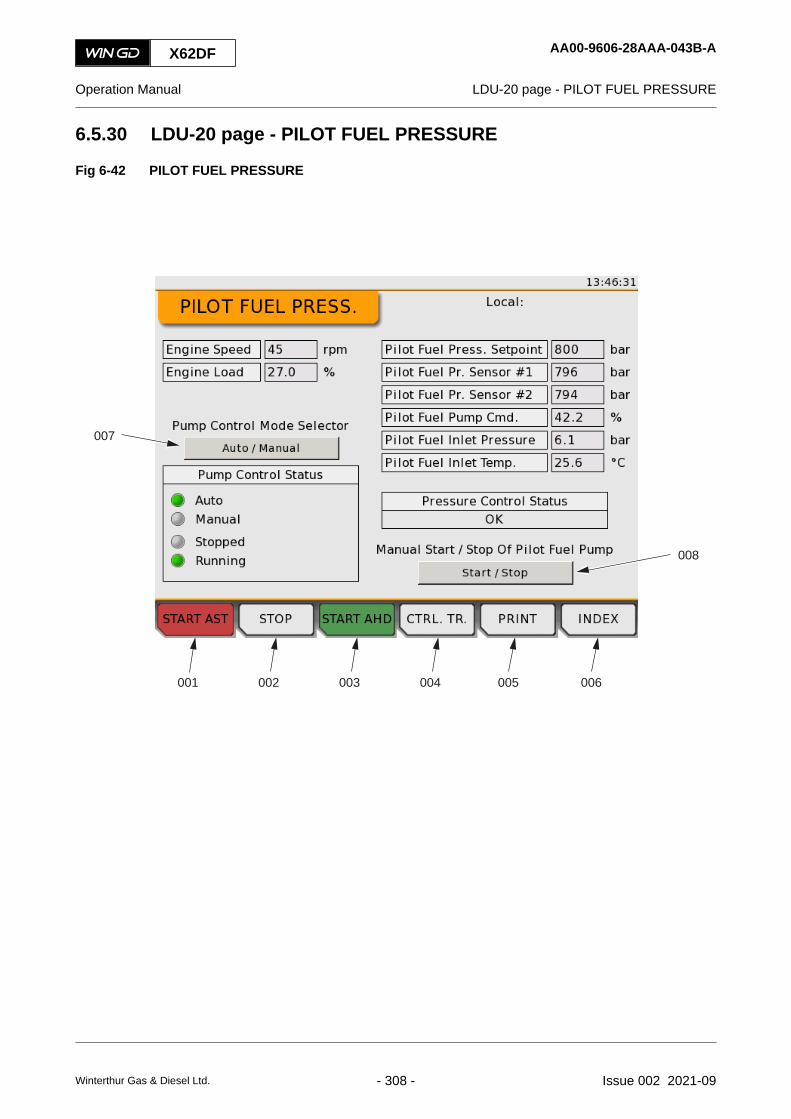
6.5.30 LDU-20 page - PILOT FUEL PRESSURE
Fig 6-42 PILOT FUEL PRESSURE
002001 004003
008
006005
007
X62DF AA00-9606-28AAA-043B-A
Operation Manual LDU-20 page - PILOT FUEL PRESSURE
Winterthur Gas & Diesel Ltd. - 308 - Issue 002 2021-09

Tab 6-28 PILOT FUEL PRESSURE
Item Function Effect
001 START AST button Starts the engine in astern direction (for reversible engine)
002 STOP button Stops the engine
003 START AHD button Starts the engine in ahead direction
004 CTRL. TR. button Sends a signal for a control transfer to this LDU-20
005 PRINT button Makes a screenshot of the current screen, refer to section 6.5.32LDU-20 page - SCREENSHOT
006 INDEX button Opens the INDEX page
007 Auto / Manual button Changes between automatic and manual control mode of thepilot fuel pump
008 Start / Stop button In manual mode: Starts and stops the pilot fuel pumpNOTE: You only can start the pilot fuel pump, if the conditions
that follow are OK:• Engine is running (usual operation or slowdown
condition)• No failure of flow control valve
• Usual range of pilot fuel inlet pressure
• Usual range of servo oil pressure
X62DF AA00-9606-28AAA-043B-A
Operation Manual LDU-20 page - PILOT FUEL PRESSURE
Winterthur Gas & Diesel Ltd. - 309 - Issue 002 2021-09

6.5.31 LDU-20 page - SCAVENGE AIR - EWG (optional)
Fig 6-43 SCAVENGE AIR - EWG (optional)
002001 004003 006005
007
008
009010
This LDU-20 page is only applicable, if the engine has a controllable exhaust waste gate.
X62DF AA00-9606-29AAA-043B-A
Operation Manual LDU-20 page - SCAVENGE AIR - EWG (optional)
Winterthur Gas & Diesel Ltd. - 310 - Issue 002 2021-09

Tab 6-29 SCAVENGE AIR - EWG (optional)
Item Function Effect
001 START AST button Starts the engine in astern direction (for reversible engine)
002 STOP button Stops the engine
003 START AHD button Starts the engine in ahead direction
004 CTRL. TR. button Sends a signal for a control transfer to this LDU-20
005 PRINT button Makes a screenshot of the current screen, refer to section 6.5.32LDU-20 page - SCREENSHOT
006 INDEX button Opens the INDEX page
007 Activate Manual Command button Activates the manual exhaust waste gate command. For a con-trollable exhaust waste gate valve manually adjust the openingof the valve from 0% (closed) to 100% (open).
008 Manual Open/Close Cmd. button Sends a signal for a manual command to open / close the ex-haust waste gate
009 Manual Control Mode button Sends a signal for a mode changeNOTE: You only can start the mode change, if the conditions
that follow are OK:• Engine at standstill
• No shutdown signal active
010 Deposit Cleaning Command but-ton
Starts the deposit cleaning procedure for the EWG, if buttonshows AvailableNOTE: For the cleaning procedure the exhaust waste gate
valve opens 5% during 60 seconds.
NOTE: You only can start the deposit cleaning, if the condi-tions that follow are OK:• Engine operates in diesel mode
• Engine load is less than 70%
X62DF AA00-9606-29AAA-043B-A
Operation Manual LDU-20 page - SCAVENGE AIR - EWG (optional)
Winterthur Gas & Diesel Ltd. - 311 - Issue 002 2021-09

6.5.32 LDU-20 page - SCREENSHOT
This function saves a screenshot of the page to a USB drive (if connected). The saved screenshotis a 640 x 480 pixel image in the xx.png format.
When you save a screenshot, the pop-up text Screenshot saved shows on the bottom right-handcorner of the display. If no USB drive is connected, or if there was an error during the saveprocedure to the USB drive, the pop-up message shows USB Mounting failed.NOTE: When the export is done, disconnect the USB drive from the LDU-20. This prevents an
unwanted LDU-20 shutdown because of a too high power consumption.
X62DF AA00-9606-30AAA-043B-A
Operation Manual LDU-20 page - SCREENSHOT
Winterthur Gas & Diesel Ltd. - 312 - Issue 002 2021-09

X62DF AA00-9606-30AAA-043B-A
Operation Manual LDU-20 page - SCREENSHOT
Page left intentionally blank
Winterthur Gas & Diesel Ltd. - 313 - Issue 002 2021-09

6.5.33 LDU-20 page - SOFTWARE INFO
Fig 6-44 SOFTWARE INFO
002001 004003 006005
007
X62DF AA00-9606-31AAA-043B-A
Operation Manual LDU-20 page - SOFTWARE INFO
Winterthur Gas & Diesel Ltd. - 314 - Issue 002 2021-09

Tab 6-30 SOFTWARE INFO
Item Function Effect
001 START AST button Starts the engine in astern direction (for reversible engine)
002 STOP button Stops the engine
003 START AHD button Starts the engine in ahead direction
004 CTRL. TR. button Sends a signal for a control transfer to this LDU-20
005 PRINT button Makes a screenshot of the current screen, refer to 6.5.32LDU-20 page - SCREENSHOT
006 INDEX button Opens the INDEX page
007 IMO CRC INFO PAGE button Opens the IMO CRC INFO page
X62DF AA00-9606-31AAA-043B-A
Operation Manual LDU-20 page - SOFTWARE INFO
Winterthur Gas & Diesel Ltd. - 315 - Issue 002 2021-09

6.5.34 LDU-20 page - IMO CRC INFO
Fig 6-45 IMO CRC INFO
002001 004003 006005
007
X62DF AA00-9606-32AAA-043B-A
Operation Manual LDU-20 page - IMO CRC INFO
Winterthur Gas & Diesel Ltd. - 316 - Issue 002 2021-09

Tab 6-31 IMO CRC INFO
Item Function Effect
001 START AST button Starts the engine in astern direction (for reversible engine)
002 STOP button Stops the engine
003 START AHD button Starts the engine in ahead direction
004 CTRL. TR. button Sends a signal for a control transfer to this LDU-20
005 PRINT button Makes a screenshot of the current screen, refer to 6.5.32LDU-20 page - SCREENSHOT
006 INDEX button Opens the INDEX page
007 SW INFO PAGE button Opens the software info page
NOTE: CRC - Cyclic Redundancy Check
X62DF AA00-9606-32AAA-043B-A
Operation Manual LDU-20 page - IMO CRC INFO
Winterthur Gas & Diesel Ltd. - 317 - Issue 002 2021-09

6.5.35 LDU-20 page - SOFTWARE TOOLS
Fig 6-46 SOFTWARE TOOLS
00167
007
008
006
009
002001 005003 004
X62DF AA00-9606-33AAA-043B-A
Operation Manual LDU-20 page - SOFTWARE TOOLS
Winterthur Gas & Diesel Ltd. - 318 - Issue 002 2021-09
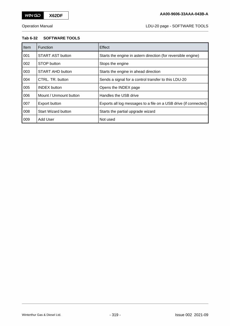
Tab 6-32 SOFTWARE TOOLS
Item Function Effect
001 START AST button Starts the engine in astern direction (for reversible engine)
002 STOP button Stops the engine
003 START AHD button Starts the engine in ahead direction
004 CTRL. TR. button Sends a signal for a control transfer to this LDU-20
005 INDEX button Opens the INDEX page
006 Mount / Unmount button Handles the USB drive
007 Export button Exports all log messages to a file on a USB drive (if connected)
008 Start Wizard button Starts the partial upgrade wizard
009 Add User Not used
X62DF AA00-9606-33AAA-043B-A
Operation Manual LDU-20 page - SOFTWARE TOOLS
Winterthur Gas & Diesel Ltd. - 319 - Issue 002 2021-09

6.5.36 LDU-20 page - SYSTEM STATUS
Fig 6-47 SYSTEM STATUS
00166
002001 004003
006
007
008
005
X62DF AA00-9606-34AAA-043B-A
Operation Manual LDU-20 page - SYSTEM STATUS
Winterthur Gas & Diesel Ltd. - 320 - Issue 002 2021-09

Tab 6-33 SYSTEM STATUS
Item Function Effect
001 START AST button Starts the engine in astern direction (for reversible engine)
002 STOP button Stops the engine
003 START AHD button Starts the engine in ahead direction
004 CTRL. TR. button Sends a signal for a control transfer to this LDU-20
005 INDEX button Opens the INDEX page
006 Refresh button Updates the module status list
007 Status indications for each module Shows either:• Initialization: Hardware module has been reset and
bootloader has started the application• Bootloader, staying in bootloader: Different version of
application/configuration/DSP is found, SW download isnecessary to synchronize the module with the rest of thesystem
• Pre-operational, synchronization: Module is booting upand waits for synchronization
• Pre-operational, ready: Module is booting up, every-thing set-up successfully and is ready to enter Opera-tional state
• Operational: Module operates correctly, System soft-ware and application initialized successfully
• None: Module is set to OFF or disconnected from theCAN bus
• Stopped: Module is not configured correctly, system ini-tialization has failed, state is transitioned from pre-oper-ational state
The usual working cycle is as follows:• Reset
• Initialization
• Pre-operational --> Stopped --> Reset
• Operational --> Stopped --> Reset
008 Download button Does a software download on the selected modules
X62DF AA00-9606-34AAA-043B-A
Operation Manual LDU-20 page - SYSTEM STATUS
Winterthur Gas & Diesel Ltd. - 321 - Issue 002 2021-09
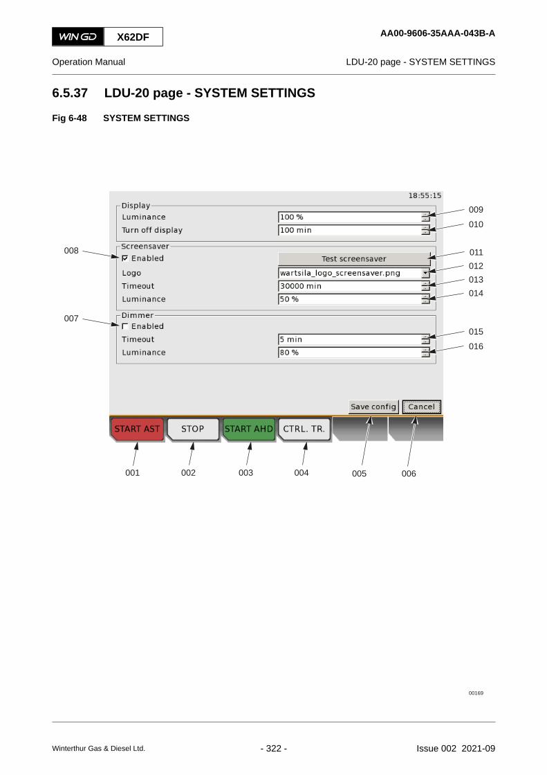
6.5.37 LDU-20 page - SYSTEM SETTINGS
Fig 6-48 SYSTEM SETTINGS
00169
007
008
010009
016015
012011
014013
002001 003 004 006005
X62DF AA00-9606-35AAA-043B-A
Operation Manual LDU-20 page - SYSTEM SETTINGS
Winterthur Gas & Diesel Ltd. - 322 - Issue 002 2021-09

Tab 6-34 SYSTEM SETTINGS
Item Function Effect
001 START AST button Starts the engine in astern direction (for reversible engine)
002 STOP button Stops the engine
003 START AHD button Starts the engine in ahead direction
004 CTRL. TR. button Sends a signal for a control transfer to this LDU-20
005 Save config button Saves the configuration settings
006 Cancel button Cancels the changes and goes back to the last saved settings
007 Enable/Disable dimmer Enables or disables the dimmer to decrease the display bright-ness after a specified period of inactivity
008 Enable/Disable screensaver Enables or disables the screensaver functions
009 Display luminance setting Adjusts the brightness of the display from 1% to 100%
010 Turn off display Adjusts the time period to turn off the display after inactivitySet to between 1 min and 100 minSet to 0 to never turn off the display
011 Test screensaver button Starts and stops the screensaver mode
012 Logo Selects the picture to use in the screensaver mode
013 Timeout Adjusts the time period to turn off the display after inactivity. Setto between 1 min and 100 min
014 Screensaver luminance Adjusts the display brightness for the screensaver mode from1% to 100%
015 Timeout Adjusts the time period to dim the display after inactivity. Set tobetween 1min and 100 min
016 Dimmer luminance Adjusts the display brightness for the dimmer mode from 1% to100%
017 Save config button Saves the configuration settings
018 Cancel button Cancels the changes and goes back to the last saved settings
X62DF AA00-9606-35AAA-043B-A
Operation Manual LDU-20 page - SYSTEM SETTINGS
Winterthur Gas & Diesel Ltd. - 323 - Issue 002 2021-09

6.5.38 LDU-20 page - TEMPERATURES
Fig 6-49 TEMPERATURES
002001 004003 006005
X62DF AA00-9606-36AAA-043B-A
Operation Manual LDU-20 page - TEMPERATURES
Winterthur Gas & Diesel Ltd. - 324 - Issue 002 2021-09

Tab 6-35 TEMPERATURES
Item Function Effect
001 START AST button Starts the engine in astern direction (for reversible engine)
002 STOP button Stops the engine
003 START AHD button Starts the engine in ahead direction
004 CTRL. TR. button Sends a signal for a control transfer to this LDU-20
005 PRINT button Makes a screenshot of the current screen, refer to 6.5.32LDU-20 page - SCREENSHOT
006 INDEX button Opens the INDEX page
X62DF AA00-9606-36AAA-043B-A
Operation Manual LDU-20 page - TEMPERATURES
Winterthur Gas & Diesel Ltd. - 325 - Issue 002 2021-09

6.5.39 LDU-20 page - USER PARAMETERS
Fig 6-50 USER PARAMETERS
00159
002001 004003 006005
010
009
008
007
011
013
012
015
014
X62DF AA00-9606-37AAA-043B-A
Operation Manual LDU-20 page - USER PARAMETERS
Winterthur Gas & Diesel Ltd. - 326 - Issue 002 2021-09

Tab 6-36 USER PARAMETERS
Item Function Effect
001 START AST button Starts the engine in astern direction (for reversible engine)
002 STOP button Stops the engine
003 START AHD button Starts the engine in ahead direction
004 CTRL. TR. button Sends a signal for a control transfer to this LDU-20
005 SLOWTURN button Puts the engine in slow turning modeNOTE: The engine goes back to stopped mode after it has
operated for some turns.
006 AIR RUN button Starts the air run mode of the engineNOTE: The engine is in air run mode as long as you press the
AIR RUN button.
007 Slow turning / Slow turning failureindications
Shows the slow turning status. When the slow turning mode isactive, the related indicator is on. When there is a slow turningfailure, the related indicator is on.
008 Angle determination / Angle deter-mination failure indication
Shows the angle determination status. When the crank angledetermination algorithm (ADA) mode is active, the related indi-cator is on. When there is a crank angle determination failure,the related indicator is on.
009 FQS Manually adjust the parameter for the fuel quality setting (FQS)from -5° to +5°• A negative correction angle makes an earlier injection
start and thus increases the maximum firing pressure.• A positive correction angle makes a later injection start
and thus decreases the maximum firing pressure.
010 VIT button Sets to ON and OFF the variable injection timing (VIT)
011 Index button Opens the INDEX page
012 Heavy Sea Mode button Sets to ON and OFF the heavy sea modeNOTE: This function sets the fuel rail pressure to a constant
value to make the pressure control more stable. Allinjection valves are in operation.
013 EWG Open button Opens and closes the exhaust waste gateNOTE: This button is only applicable for a binary exhaust
waste gate.
014 Manual fuel pump cut off button Sets the related fuel pump operation mode:• Auto - automatic mode (usual operation)
• On - fuel pump is manually set to ON
• Off - fuel pump is manually set to OFF
015 Reset button Resets a failure for angle determination or slow turning
X62DF AA00-9606-37AAA-043B-A
Operation Manual LDU-20 page - USER PARAMETERS
Winterthur Gas & Diesel Ltd. - 327 - Issue 002 2021-09

6.5.40 LDU-20 page - LOG ENTRY DATA
Fig 6-51 LOG ENTRY DATA
00165
002001 005
007
009
010
008
006
004003
X62DF AA00-9606-39AAA-043B-A
Operation Manual LDU-20 page - LOG ENTRY DATA
Winterthur Gas & Diesel Ltd. - 328 - Issue 002 2021-09

NOTE: Some data on this screen are only applicable to WinGD SW developers, eg the ID andstatus flag numbers.
Tab 6-37 LOG ENTRY DATA
Item Function Effect
001 START AST button Starts the engine in astern direction (for reversible engine)
002 STOP button Stops the engine
003 START AHD button Starts the engine in ahead direction
004 CTRL. TR. button Sends a signal for a control transfer to this LDU-20
005 INDEX button Opens the INDEX page
006 Acknowledge button Has no function
007 Module identifier Shows the source module that sent this log entry
008 Message type Shows the message type. Shows Info, Error, Event, Safety
009 Description Shows general data about the log entry
010 Recommended action Shows recommended action that the operator can do to solvethe problem
X62DF AA00-9606-39AAA-043B-A
Operation Manual LDU-20 page - LOG ENTRY DATA
Winterthur Gas & Diesel Ltd. - 329 - Issue 002 2021-09

6.5.41 MCP page - FUEL / LUBRICATION SYSTEM
Fig 6-52 MCP page - FUEL / LUBRICATION SYSTEM
001
008
011
010
009
007
002
003
004
005
006
X62DF AA00-4618-08AAA-043B-A
Operation Manual MCP page - FUEL / LUBRICATION SYSTEM
Winterthur Gas & Diesel Ltd. - 330 - Issue 002 2021-09

Tab 6-38 FUEL / LUBRICATION SYSTEM
Item Function Effect
001 LFO button Changes to LFO (Light Fuel Oil)
002 HFO button Changes to HFO (Heavy Fuel Oil)
003 LOW BN button Changes to low BN cylinder oil
004 HIGH BN button Changes to high BN cylinder oil
005 MANUAL LUBRICATION button Starts the manual cylinder lubrication procedure related to theset values
006 AUX SO PUMP START/STOP Starts and stops the auxiliary electric servo oil pump (servo oilservice pump)NOTE: If necessary, start this pump only in engine stop mode.
007 Manual Lub. Cylinder buttons Manually select the cylinder for manual lubrication:• Set 1 to n for the related cylinder
• Set 0 (zero) for all cylinders
008 Manual Lub. Pulses buttons Manually set the number of injections for lubrication at enginestop mode (range 0 to 255)
009 Cyl. Lub. Oil Type indication Shows the type of cylinder lubrication oil in useShows: Low BN, High BN
010 Cyl. Lubrication Mode indication Shows the status of the cylinder lubricationShows: Dry Running, Pre-Lubrication, Speed Dependent, LoadDependent, Manual Lubrication, Stopped
011 Used Fuel Type indication Shows the fuel in useShows: HFO, LFO, GAS, LFO & GAS, HFO & GAS
X62DF AA00-4618-08AAA-043B-A
Operation Manual MCP page - FUEL / LUBRICATION SYSTEM
Winterthur Gas & Diesel Ltd. - 331 - Issue 002 2021-09

6.5.42 LDU-20 page - DATE
Fig 6-53 DATE
002001 004003
008009
010
012
011
006005
007
X62DF AA00-9606-40AAA-043B-A
Operation Manual LDU-20 page - DATE
Winterthur Gas & Diesel Ltd. - 332 - Issue 002 2021-09

Tab 6-39 DATE
Item Function Effect
001 START AST button Starts the engine in astern direction (for reversible engine)
002 STOP button Stops the engine
003 START AHD button Starts the engine in ahead direction
004 CTRL. TR. button Sends a signal for a control transfer to this LDU-20
005 Save config button Saves the configuration settings
006 Cancel button Cancels the changes and goes back to the last saved settings
007 Time Synchronization Mode button Selects a Network Time Protocol (NTP). Not used
008 Local time Shows the time offset from UTC
009 UTC time Shows the coordinated universal time
010 Timezone button Opens a list with all available time zones
011 Set Date field Manually adjust the date setting
012 Set Time field Manually adjust the time setting
X62DF AA00-9606-40AAA-043B-A
Operation Manual LDU-20 page - DATE
Winterthur Gas & Diesel Ltd. - 333 - Issue 002 2021-09

6.5.43 LDU-20 page - ETHERNET
Fig 6-54 ETHERNET
002001 004003
008
009
010
012
013
011
006005
007
X62DF AA00-9606-41AAA-043B-A
Operation Manual LDU-20 page - ETHERNET
Winterthur Gas & Diesel Ltd. - 334 - Issue 002 2021-09
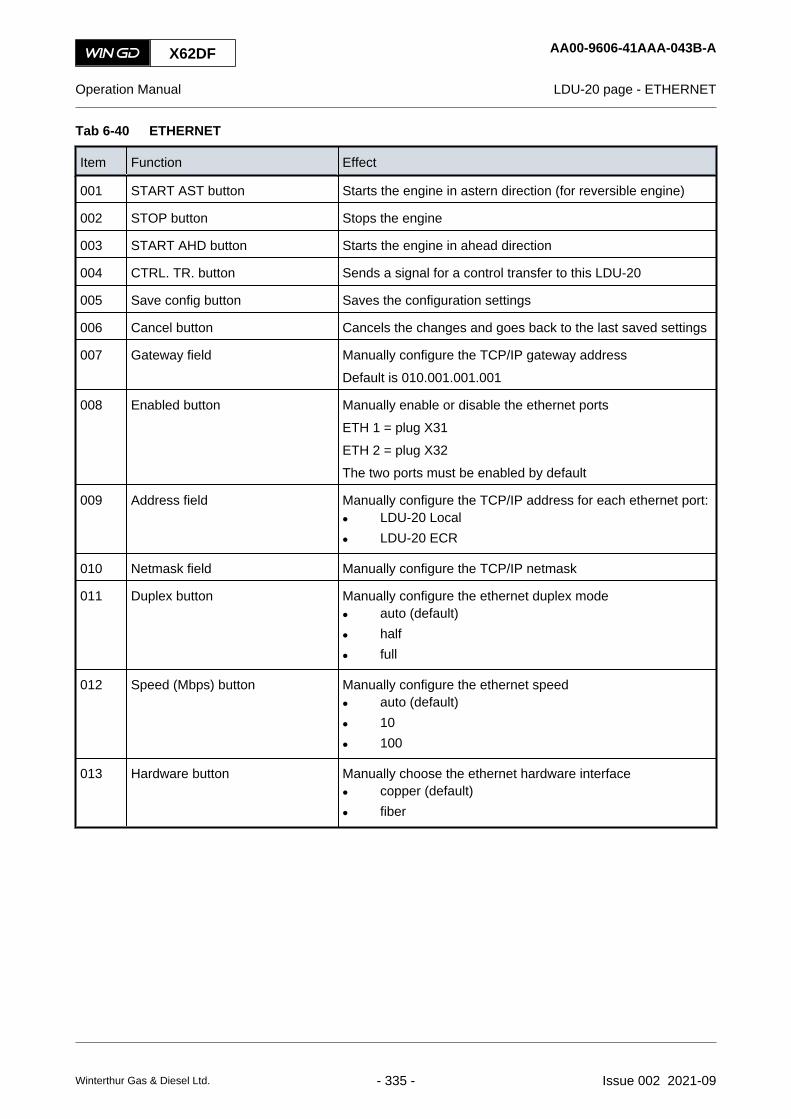
Tab 6-40 ETHERNET
Item Function Effect
001 START AST button Starts the engine in astern direction (for reversible engine)
002 STOP button Stops the engine
003 START AHD button Starts the engine in ahead direction
004 CTRL. TR. button Sends a signal for a control transfer to this LDU-20
005 Save config button Saves the configuration settings
006 Cancel button Cancels the changes and goes back to the last saved settings
007 Gateway field Manually configure the TCP/IP gateway addressDefault is 010.001.001.001
008 Enabled button Manually enable or disable the ethernet portsETH 1 = plug X31ETH 2 = plug X32The two ports must be enabled by default
009 Address field Manually configure the TCP/IP address for each ethernet port:• LDU-20 Local
• LDU-20 ECR
010 Netmask field Manually configure the TCP/IP netmask
011 Duplex button Manually configure the ethernet duplex mode• auto (default)
• half
• full
012 Speed (Mbps) button Manually configure the ethernet speed• auto (default)
• 10
• 100
013 Hardware button Manually choose the ethernet hardware interface• copper (default)
• fiber
X62DF AA00-9606-41AAA-043B-A
Operation Manual LDU-20 page - ETHERNET
Winterthur Gas & Diesel Ltd. - 335 - Issue 002 2021-09

6.5.44 LDU-20 page - iELBA Control (optional)
Fig 6-55 iELBA Control
002001 004003 005
006 007
008
009
X62DF AA00-9606-42AAA-043B-A
Operation Manual LDU-20 page - iELBA Control (optional)
Winterthur Gas & Diesel Ltd. - 336 - Issue 002 2021-09

Tab 6-41 iELBA Control
Item Function Effect
001 START AST button Starts the engine in astern direction (for reversible engine)
002 STOP button Stops the engine
003 START AHD button Starts the engine in ahead direction
004 CTRL. TR. button Sends a signal for a control transfer to this LDU-20
005 INDEX button Opens the INDEX page
006 Manual / Auto Mode Changes between automatic and manual control mode of theiELBA
007 Free End ON/OFF In manual mode - starts and stops the iELBA on the related en-gine end
008 Operator Phase Setpoint In manual mode - manually adjust the crank angle setpoint forthe related engine end in manual mode
009 Auto Phase Setpoint In manual mode - manually adjust the crank angle setpoint forthe related engine end in auto mode
X62DF AA00-9606-42AAA-043B-A
Operation Manual LDU-20 page - iELBA Control (optional)
Winterthur Gas & Diesel Ltd. - 337 - Issue 002 2021-09

X62DF AA00-9606-42AAA-043B-A
Operation Manual LDU-20 page - iELBA Control (optional)
Page left intentionally blank
Winterthur Gas & Diesel Ltd. - 338 - Issue 002 2021-09

7 Installation7.1 Installation...............................................................................................................340
X62DF
Operation Manual
Winterthur Gas & Diesel Ltd. - 339 - Issue 002 2021-09

7.1 Installation
The Marine Installation Manual (MIM) gives data about the installation of the engine on the ship.The general installation topics in the MIM are as follows:
• Engine dimensions and masses
• Outline views
• Platform arrangement
• Engine seating
• Engine coupling
• Propulsion shaft earthing
• Engine stays
• Extinguishing system
• Auxiliary systems.
NOTE: The latest version of the Marine Installation Manual and the installation drawings areavailable on the WinGD website.https://www.wingd.com/
X62DF AA00-0000-00AAA-910A-A
Operation Manual Installation
Winterthur Gas & Diesel Ltd. - 340 - Issue 002 2021-09

8 Operation8.1 Prepare the engine before start - general................................................................3428.2 Prepare the engine before start...............................................................................3448.3 Start the engine - general........................................................................................3528.4 Start the engine.......................................................................................................3548.5 Do checks during operation - general......................................................................3568.6 Do checks during operation.....................................................................................3588.7 Do regular safety checks.........................................................................................3628.8 Maneuver the ship - general....................................................................................3668.9 Maneuver the ship...................................................................................................3688.10 Change-over the diesel fuel - general.....................................................................3708.11 Change-over to and from gas - general...................................................................3748.12 Change-over the diesel fuel automatically...............................................................3768.13 Change-over from HFO to MDO manually..............................................................3788.14 Change-over from MDO to HFO manually..............................................................3808.15 Change-over to and from gas..................................................................................3828.16 Stop the engine - general........................................................................................3848.17 Stop the engine.......................................................................................................3868.18 Emergency stop the engine - general......................................................................3888.19 Emergency stop the engine.....................................................................................3908.20 Prepare the engine after stop - general...................................................................3928.21 Prepare the engine for a short service break..........................................................3948.22 Prepare the engine for standstill or for maintenance...............................................396
X62DF
Operation Manual
Winterthur Gas & Diesel Ltd. - 341 - Issue 002 2021-09

8.1 Prepare the engine before start - general
If you have done maintenance work on the engine, make sure that you have done the relatedfunction tests and the engine is ready for operation.
Do checks on the systems that follow to make sure that the engine is ready for engine start.NOTE: For the specifications of the operating media refer to section 12.1 General for operating
media.
8.1.1 Standard preparation
The systems that follow must be prepared for operation:
• Cooling water system
Make sure that the quality of the cooling water obeys the related specifications.
Make sure that cooling water is available at the engine connections 01 and/or 02 (cylindercooling water inlet).
Make sure that the cooling water system is full.
• Wash-water system
Make sure that the quality of the wash-water obeys the related specifications.
Make sure that wash-water is available at the engine connection 11 (water for cleaning plantturbocharger and SAC inlet).
• System oil system
Make sure that the quality of the system oil obeys the related specifications.
Make sure that main lubricating oil is available at the engine connection 25 (main lubricatingoil inlet).
Make sure that crosshead lubricating oil is available at the engine connection 30 (lubricatingoil crosshead inlet).
Make sure that the lubricating oil system is full.
• Cylinder oil system
Make sure that the quality of the cylinder oil obeys the related specifications.
Make sure that cylinder oil is available at the engine connection 33 (cylinder oil inlet).
Make sure that the cylinder oil system is full.
• Starting air system
Make sure that the quality of the starting air obeys the related specifications in section 12.2Compressed air.
Make sure that starting air is available at the engine connection 40 (starting air pipe inlet).
• Scavenge air system
Make sure that the quality of the scavenge air obeys the related specifications in section12.3 Scavenge air.
Make sure that scavenge air is available at the turbocharger inlet.
X62DF AA00-0000-00AAA-120A-A
Operation Manual Prepare the engine before start - general
Winterthur Gas & Diesel Ltd. - 342 - Issue 002 2021-09

• Control air system
Make sure that the quality of the control air obeys the related specifications in section 12.2Compressed air.
Make sure that control air is available at the engine connection 49 (control air supply inlet).
Make sure that the control air system is full.
• Fuel system
Make sure that the quality of the fuel obeys the related specifications.
Make sure that fuel is available at the engine connection 45 (fuel inlet).
Make sure that the fuel system is full and the fuel can flow.
• Exhaust gas system
Make sure that the exhaust gas system is ready for operation.
• Power supply system
Make sure that the power supply system is ready for operation.
• Leakage drain system
Make sure that the leakage drain tanks of the plant have sufficient capacity.
For a DF engine, also the systems that follow must be prepared for operation:
• Gas system
Make sure that the quality of the gas obeys the related specifications in section 12.4 Gasfuels.
Make sure that gas is available at the engine connection 78 (gas supply inlet).
• Pilot fuel system
Make sure that the quality of the pilot fuel obeys the related specifications.
Make sure that pilot fuel is available at the engine connection 76 (supply unit fuel pilot valveinlet).
Make sure that the pilot fuel system is full and the pilot fuel can flow.NOTE: You can start a DF engine only in diesel mode.
8.1.2 Preparation if components are defective
You also can operate the engine, if components of the engine are defective and you cannot repairthe fault immediately. You have to do more preparations related to the defective component, referto chapter 10 Troubleshooting.
Obey the limits of operation, if components of the engine are not in operation, refer to section 8.3Start the engine - general.
X62DF AA00-0000-00AAA-120A-A
Operation Manual Prepare the engine before start - general
Winterthur Gas & Diesel Ltd. - 343 - Issue 002 2021-09

8.2 Prepare the engine before startPeriodicityDescriptionEngine startDuration for performing preliminary requirements 0.0 man-hoursDuration for performing the procedure 1.0 man-hoursDuration for performing the requirements after job completion 0.0 man-hours
PersonnelDescription Specialization QTYEngine crew Intermediate 1
Support equipmentDescription Part No. CSN QTYNone
SuppliesDescription QTYNone
Spare PartsDescription Part No. CSN QTYNone
SAFETY PRECAUTIONS
• None
PRELIMINARY OPERATIONS
• Refer to section 8.1 Prepare the engine before start - general
X62DF AA00-0000-00AAA-121A-A
Operation Manual Prepare the engine before start
Winterthur Gas & Diesel Ltd. - 344 - Issue 002 2021-09

PROCEDURE
1 Make sure that there is no alarm indication.2 Prepare the control system for operation.
2.1 Set to ON the engine control system (ECS) and the remote control system (RCS).2.2 Set to ON all circuit breakers in the power supply box E85.2.3 Set to ON the control box for the cylinder oil filter (refer to the documentation of
the manufacturer).
X62DF AA00-0000-00AAA-121A-A
Operation Manual Prepare the engine before start
Winterthur Gas & Diesel Ltd. - 345 - Issue 002 2021-09

3 Prepare the cooling water system for operation.3.1 For an engine with a bypass cooling water system (refer to Figure 8-1), and when
the liner wall temperature is between 60°C and 90°C (for example when the engineis pre-heated or after engine full stop for a sufficient period), release the unwantedair with a high flow rate as follows:
Fig 8-1 Cooling water system with bypass cooling
002
0205
01
003
001
Legend
001 Optional vent valve 01 Connection 01 (cylinder cooling water inlet)002 Shut-off valve 02 Connection 02 (cylinder liner CW inlet)003 Shut-off valve 05 Connection 05 (cylinder CW drain outlet)
3.1.1 Close all shut-off valves (002) in the cylinder cover supply pipes (engineconnection 01).NOTE: This increases the pressure and thus the flow rate at the engine
connection 02.3.1.2 Let the cooling water flow through the cylinder liners for approximately ten
minutes.3.1.3 Close the shut-off valves (003) in the cylinder liner supply pipes of the first
half of cylinders (for example cylinder 1 to 3 for a 5 or 6 cylinder engine).NOTE: This increases again the pressure and thus the flow rate to the
other cylinders.3.1.4 Let the cooling water flow through the other cylinder liners for
approximately ten minutes.3.1.5 Open the shut-off valves (003) in the cylinder liner supply pipes of the first
half of cylinders.3.1.6 Do Step 3.1.3 to Step 3.1.5 again for the second half of cylinders (for
example for cylinder 4 and 5 or for cylinder 4 to 6).3.1.7 Open all shut-off valves (002) in the cylinder cover supply pipes.3.1.8 If there is unwanted air in the cooling water and the optional vent valve
(001) is installed, do as follows:3.1.8.1 Put an applicable container under the vent valve (001).3.1.8.2 Carefully open the vent valve (001) until only cooling water flows
out of the vent valve (001).3.1.8.3 Close the vent valve (001).3.1.8.4 Discard the hot cooling water correctly.
X62DF AA00-0000-00AAA-121A-A
Operation Manual Prepare the engine before start
Winterthur Gas & Diesel Ltd. - 346 - Issue 002 2021-09

3.2 For an engine without a bypass cooling water system (refer to Figure 8-2), andwhen the liner wall temperature is between 60°C and 90°C (for example when theengine is pre-heated or after engine full stop for a sufficient period), release theunwanted air with a high flow rate as follows:
Fig 8-2 Cooling water system without bypass cooling
001
05
02
Legend
001 Shut-off valve 05 Connection 05 (cylinder cooling water drainoutlet)
02 Connection 02 (cylinder liner cooling water inlet)
3.2.1 Close the shut-off valves (001) in the cylinder liner supply pipes of the firsthalf of cylinders (for example cylinder 1 to 3 for a 5 or 6 cylinder engine).NOTE: This increases the pressure and thus the flow rate to the other
cylinders.3.2.2 Let the cooling water flow through the other cylinder liners for
approximately ten minutes.3.2.3 Open the shut-off valves (001) in the cylinder liner supply pipes of the first
half of cylinders.3.2.4 Do Step 3.2.1 to Step 3.2.3 again for the second half of cylinders (for
example for cylinder 4 and 5 or for cylinder 4 to 6).
X62DF AA00-0000-00AAA-121A-A
Operation Manual Prepare the engine before start
Winterthur Gas & Diesel Ltd. - 347 - Issue 002 2021-09

3.3 For an engine with an internal circulation cooling water system (with circulationpump and temperature control valve, refer to Figure 8-3), and when the liner walltemperature is between 60°C and 90°C (for example when the engine is pre-heated or after engine full stop for a sufficient period), release the unwanted airwith a high flow rate as follows:
Fig 8-3 Cooling water system with circulation
02
05
001
002003
Legend
001 Temperature control valve 02 Connection 02 (cylinder liner cooling water inlet)002 Circulation pump 05 Connection 05 (cylinder cooling water drain
outlet)003 Shut-off valve
3.3.1 Close the shut-off valves (003) in the cylinder liner supply pipes of the firsthalf of cylinders (for example cylinder 1 to 6 for a 12 cylinder engine).NOTE: This increases the pressure and thus the flow rate to the other
cylinders.3.3.2 Let the cooling water flow through the other cylinder liners for
approximately ten minutes.3.3.3 Open the shut-off valves (003) in the cylinder liner supply pipes of the first
half of cylinders.3.3.4 Do Step 3.3.1 to Step 3.3.3 again for the second half of cylinders (for
example cylinder 7 to 12 for a 12 cylinder engine).
3.4 Set all valves to their correct positions for operation.3.5 Release the unwanted air in the cooling water pipes and the scavenge air coolers
at the related vent valves.3.5.1 Carefully open the first vent valve.3.5.2 After water that has no air flows out, close the vent valve.3.5.3 Do Step 3.5.1 and Step 3.5.2 again with the other vent valves.
3.6 Make sure that the values that follow are in the permitted range:• Pressure in the supply pipe of the cylinder cooling water• Temperature in the supply pipe of the cylinder cooling water• Pressure in the cooling water supply pipe of the scavenge air cooler (SAC)• Temperature in the cooling water supply pipe of the SAC.
X62DF AA00-0000-00AAA-121A-A
Operation Manual Prepare the engine before start
Winterthur Gas & Diesel Ltd. - 348 - Issue 002 2021-09

4 Prepare the air systems for operation.4.1 Set all valves to their correct positions for operation.4.2 Drain the air system at the related drain valves.
4.2.1 Open the first drain valve.4.2.2 After no more water flows out from the valve, close the drain valve.4.2.3 Do Step 4.2.1 and Step 4.2.2 again with the other drain valves.
4.3 Make sure that the values that follow are in the permitted range:• Pressure in the supply pipe to the air springs• Pressure in the supply pipe to the starting air system.
4.4 Set the auxiliary blowers to AUTO.
5 Prepare the lubricating oil systems for operation.5.1 Set all valves to their correct positions for operation.5.2 If it is necessary to have servo oil pressure, set to ON the servo oil service pump.5.3 Make sure that the values that follow are in the permitted range:
• Temperature in the oil supply pipes• Pressure in the oil supply pipes• Pressure before the torsional vibration damper (if applicable)• Pressure in the servo oil rail (only pressure of servo oil service pump)• Pressure in the distributor pipe (mini-rail)• Pressure at the turbocharger (if applicable)
5.4 Set to ON the cylinder oil system.
6 Prepare the exhaust gas system for operation.6.1 If necessary (for example after maintenance), do a check of the exhaust valves for
correct function.6.1.1 Manually open and close the exhaust valve of cylinder No. 1.6.1.2 Do Step 6.1.1 for a minimum of four times.6.1.3 Do Step 6.1.1 and Step 6.1.2 again with the other cylinders.6.1.4 If an exhaust valve does not function correctly, find the cause and repair
the fault.
6.2 Make sure that all exhaust valves are closed.
7 Prepare the fuel system for operation.7.1 Set all valves to their correct positions for operation.7.2 Make sure that the selected fuel supply is in the permitted range.
X62DF AA00-0000-00AAA-121A-A
Operation Manual Prepare the engine before start
Winterthur Gas & Diesel Ltd. - 349 - Issue 002 2021-09

8 For a DF engine, prepare the gas system for operation.8.1 Do a visual check of the gas pipes for damage. If damage is found, replace the
defective gas pipes immediately.8.2 Do the gas related checks. If alarms or failure messages occur, repair the related
item.8.3 Set all valves to their correct positions for operation.8.4 Make sure that the selected gas supply is in the permitted range.
9 For a DF engine, prepare the pilot fuel system for operation.9.1 Set all valves to their correct positions for operation.9.2 Make sure that the selected pilot fuel supply is in the permitted range.
10 Carefully open all indicator valves on the cylinder covers.NOTE: This makes it possible, that fluids can come out of the cylinder, if the pistons
move. Fluids can be in a cylinder, if there are leaks in the water, oil, or fuelsystem.
WARNINGInjury hazard: Before you operate the turning gear, make sure that no personnel are nearthe flywheel, or in the engine.
11 Engage and start the turning gear.12 If the engine has been stopped for more than approximately five days, start a manual pre-
lubrication procedure.NOTE: This makes sure, that the cylinders get sufficient lubrication before start-up.
13 Turn the engine a minimum of three full turns.14 If water, oil, or fuel comes out of the indicator valves, do a check of the related components
that follow and repair if necessary:• Cylinder liner• Cylinder cover• Piston• Injection valve.
15 Do a check of all the running gears for correct operation.16 Stop and disengage the turning gear and lock the lever.17 If you have started the servo oil service pump, set to OFF the servo oil service pump.18 On the starting air shut-off valve turn the hand-wheel to the position AUTO.19 Close the indicator valves on the cylinder covers.20 Make sure that all doors on the monoblock column are closed and locked.21 Start the slowturning of the engine on the local control panel.
NOTE: The engine will slowly turn at approximately 5 rpm to 10 rpm.22 Tell personnel on the bridge that the engine is prepared for operation.
CLOSE UP
• None
X62DF AA00-0000-00AAA-121A-A
Operation Manual Prepare the engine before start
Winterthur Gas & Diesel Ltd. - 350 - Issue 002 2021-09

X62DF AA00-0000-00AAA-121A-A
Operation Manual Prepare the engine before start
Page left intentionally blank
Winterthur Gas & Diesel Ltd. - 351 - Issue 002 2021-09

8.3 Start the engine - general
8.3.1 Usual start conditions
The engine must be prepared for operation.
All the auxiliary systems must be in correct operation related to section 8.2 Prepare the enginebefore start.
You can start the engine from the locations that follow:
• At the bridge or engine control room (ECR) with remote control
• At the backup control panel in the ECR
• At the local control panel of the engine.
Obey the rules for operation related to barred speed ranges:
• Do not continuously operate the engine in a barred speed range.
• If you change the speed, go through the barred speed range as quickly as possible.
NOTE: It is possible that the engine has more than one barred speed range (for example if theaxial vibration damper becomes defective, or one or more cylinders are not in operation).You can find data about the barred speed ranges near the telegraph on the bridge, nearthe local control panel, and in the related documentation of vibration calculations.
8.3.2 Start conditions - limits
With some limits you also can start the engine, if parts of the engine are not prepared for operation,for example:
• One or more turbochargers are defective.
• One or more cylinders are unserviceable.
• The cooling water flow is decreased.
8.3.2.1 One or more turbochargers are defective
To prevent damage to the engine, make sure that you know the limits that follow:
• For an engine with two turbochargers and one turbocharger is defective:- Make sure that the exhaust gas temperature at the serviceable turbocharger inlet is
less than the maximum permitted temperature.- The maximum power output of the engine is approximately 50% related to the power
of the serviceable turbocharger.
X62DF AA00-0000-00AAA-130A-A
Operation Manual Start the engine - general
Winterthur Gas & Diesel Ltd. - 352 - Issue 002 2021-09

• For an engine with three turbochargers and one or two turbochargers are defective:- Make sure that the exhaust gas temperature at the serviceable turbochargers inlet is
less than the maximum permitted temperature.- If one turbocharger is defective, the maximum power output of the engine is
approximately 66% related to the power of the serviceable turbochargers.- If two turbochargers are defective, the maximum power output of the engine is
approximately 33% related to the power of the serviceable turbocharger.- For a DF engine, the engine can operate in diesel mode, gas mode, or fuel sharing
mode.
• If all turbochargers of the engine are defective:- The maximum power output of the engine is between 10% (as a minimum) to
approximately 15% related to the power of the auxiliary blowers.
8.3.2.2 One or more cylinders are unservicable
Obey the rules for operation, if one or more cylinders are unserviceable:
• Operate the engine only at decreased load.
• It is possible that the turbochargers surge. This makes a loud sound and causes largedifferences in the scavenge air pressure. In this condition decrease the load of the enginesufficiently.
• It is possible that the engine had stopped in a position from which it cannot start. In thiscondition start the engine momentarily in the opposite direction to get the crankshaft to adifferent position.
8.3.2.3 Cooling water flow is decreased
If the cooling water flow is decreased, operate the engine only at decreased load.
X62DF AA00-0000-00AAA-130A-A
Operation Manual Start the engine - general
Winterthur Gas & Diesel Ltd. - 353 - Issue 002 2021-09

8.4 Start the enginePeriodicityDescriptionEngine startDuration for performing preliminary requirements 0.0 man-hoursDuration for performing the procedure 0.5 man-hoursDuration for performing the requirements after job completion 0.0 man-hours
PersonnelDescription Specialization QTYEngine crew Intermediate 1
Support equipmentDescription Part No. CSN QTYNone
SuppliesDescription QTYNone
Spare PartsDescription Part No. CSN QTYNone
SAFETY PRECAUTIONS
• None
PRELIMINARY OPERATIONS
• Refer to section 8.3 Start the engine - general
X62DF AA00-0000-00AAA-131A-A
Operation Manual Start the engine
Winterthur Gas & Diesel Ltd. - 354 - Issue 002 2021-09

PROCEDURE
1 If there is a clutch coupling between engine and propeller, do the steps that follow:1.1 Engage the clutch coupling.1.2 Keep the clutch coupling engaged during operation to prevent damage to the
engine.
2 Select the applicable control panel.3 Start the auxiliary blowers.4 Set the minimum fuel injection quantity on the related control panel to 30%.5 Push the button START AHD or START AST to start the engine.
NOTE: The ECS starts an automatic pre-lubrication sequence with a specified numberof pulses.
NOTE: The ECS increases the engine speed.6 If new cylinder liners or piston rings were installed, do a running-in, refer to section 9.7
Running-in of new components.7 If necessary, slowly adjust the fuel injection quantity.
NOTE: The ECS changes the engine speed.
CLOSE UP
• None
X62DF AA00-0000-00AAA-131A-A
Operation Manual Start the engine
Winterthur Gas & Diesel Ltd. - 355 - Issue 002 2021-09

8.5 Do checks during operation - general
During operation, do regular checks of the operating values, refer to section 8.6 Do checks duringoperation. This prevents damage to the engine if malfunctions occur.
Compare the values with those given in the acceptance records. This gives a good indication ofthe engine performance. If there are unusual differences in the values, find the causes and repairthe faults.
Do not open the covers of the rail unit during engine operation.NOTE: For data about regular maintenance work refer to the Maintenance Manual.
When the engine is at standstill, do also regular checks of the alarm and safety system, refer tosection 8.7 Do regular safety checks. This prevents damage to the engine if settings have changedor malfunctions occur.
X62DF AA00-0000-00AAA-130B-A
Operation Manual Do checks during operation - general
Winterthur Gas & Diesel Ltd. - 356 - Issue 002 2021-09

X62DF AA00-0000-00AAA-130B-A
Operation Manual Do checks during operation - general
Page left intentionally blank
Winterthur Gas & Diesel Ltd. - 357 - Issue 002 2021-09

8.6 Do checks during operationPeriodicityDescriptionUnscheduledDuration for performing preliminary requirements 0.0 man-hoursDuration for performing the procedure 1.0 man-hoursDuration for performing the requirements after job completion 0.0 man-hours
PersonnelDescription Specialization QTYEngine crew Intermediate 1
Support equipmentDescription Part No. CSN QTYNone
SuppliesDescription QTYNone
Spare PartsDescription Part No. CSN QTYNone
SAFETY PRECAUTIONS
• None
PRELIMINARY OPERATIONS
• The engine is running.
X62DF AA00-0000-00AAA-131B-A
Operation Manual Do checks during operation
Winterthur Gas & Diesel Ltd. - 358 - Issue 002 2021-09

PROCEDURE
1 Make sure that the engine control system indicates no alarm signals.2 If there are alarm signals, find the cause and repair the fault.3 Listen to the engine for unusual noise. If you hear unusual noise, find the cause and repair
the fault.4 If you cannot find the cause of the unusual noise, stop the engine as soon as possible.
Find the cause and repair the fault.5 Do daily the checks and the servicing that follow:
5.1 Do a check of the condensation collectors through the sight glasses of the SACand the water separator for free flow. If there is a blockage, clean the condensationcollector.
5.2 Release the unwanted air from the cooling water system.
6 Do a check of the exhaust gas for dark smoke. If there is dark smoke, find the cause andrepair the fault.
7 Do regular checks of the items that follow:• Levels of fuel, oil and water tanks• Temperatures of oil, cooling water, bearings and exhaust gas• Pressures of oil, cooling water and control air• Pressure difference of the oil filter• For a DF engine, also pressure of gas.
8 If there are unusual operating values, find the cause and repair the fault.9 Do regular checks of pipes for leaks. If there are leaks, find the cause and repair them.10 Do a careful check of the dirty oil drain pipes for differences in temperature.
NOTE: Different temperatures show a blockage in the pipes.11 If there is an unusual temperature difference, remove the blockage of the pipe as soon as
possible.12 Do weekly the checks and the servicing that follow:
12.1 Do a check of the quality of the cooling water, refer to the instructions of the inhibitormanufacturer.
12.2 Do a careful check of the temperature of the pipe upstream of the starting airvalves. If a pipe is too hot, repair the related starting air valve.
12.3 Do a check of the fuel pump cover for oil leaks. If necessary, replace the O-ring.12.4 Drain the bottle of the filter in the control air supply.12.5 Do a check of the electrical installations, connectors and modules.
X62DF AA00-0000-00AAA-131B-A
Operation Manual Do checks during operation
Winterthur Gas & Diesel Ltd. - 359 - Issue 002 2021-09

13 For a DF engine, do also the checks that follow:13.1 Do regular checks (leak checks) of the gas piping system, refer to the related data
or documentation.13.2 Do daily a check of the cylinder compression pressures on the related control
panel.13.3 If there is a drift that is too high or if there is a related alarm message, clean or
replace the related pressure transmitter, refer to the Maintenance Manual.13.4 Do daily a check of the cylinder liner wall temperatures on the related control panel.13.5 If there is a drift that is too high or if there is a related alarm message, release the
unwanted air from the cooling water, for an engine with bypass cooling watersystem refer to section 10.5 Bleed the cooling water system of the liner wall.
CLOSE UP
• None
X62DF AA00-0000-00AAA-131B-A
Operation Manual Do checks during operation
Winterthur Gas & Diesel Ltd. - 360 - Issue 002 2021-09

X62DF AA00-0000-00AAA-131B-A
Operation Manual Do checks during operation
Page left intentionally blank
Winterthur Gas & Diesel Ltd. - 361 - Issue 002 2021-09

8.7 Do regular safety checksPeriodicityDescriptionMonths 3Unscheduled After maintenance workDuration for performing preliminary requirements 0.0 man-hoursDuration for performing the procedure 4.0 man-hoursDuration for performing the requirements after job completion 0.0 man-hours
PersonnelDescription Specialization QTYEngine crew Intermediate 1
Support equipmentDescription Part No. CSN QTYPressure calibration hand-pump
94050 1
Smoke test instrument N/A 1Ampere meter N/A 1
SuppliesDescription QTYNone
Spare PartsDescription Part No. CSN QTYNone
SAFETY PRECAUTIONS
CAUTIONEquipment Hazard: Leaks can cause faults in the engine control systems and damage toengine components. Leaks that are found during the engine control system checks mustbe repaired to prevent damage to equipment.
PRELIMINARY OPERATIONS
• The engine must be prepared for operation, refer to section 8.1 Prepare the engine beforestart - general
• The engine must be stopped.
X62DF AA00-0000-00AAA-340A-A
Operation Manual Do regular safety checks
Winterthur Gas & Diesel Ltd. - 362 - Issue 002 2021-09

PROCEDURE
1 Make sure that the remote control system (RCS), the engine safety system (ESS), and thealarm and monitoring system (AMS) are set to ON.
2 Do a check of the EMERGENCY STOP buttons:2.1 On the control panel in the engine control room (ECR), push the EMERGENCY
STOP button.2.2 Make sure that the pressure control and safety valve 10-5562_E0_5 is electrically
operated (ie the coil is energized).NOTE: This causes an alarm (M/E Emergency Stop) in the AMS.
2.3 Make sure that the EMERGENCY STOP button is deactivated again.2.4 Do Step 2.1 to Step 2.3 again with the EMERGENCY STOP buttons on the local
control panel and on the bridge.
3 Do a check of the all the pressure switches.3.1 Carefully remove the first pressure switch.
NOTE: The stop valve in the connection closes automatically.3.2 Connect the pressure calibration hand-pump to the pressure switch.3.3 Operate the pressure calibration hand-pump to increase the pressure to more than
the SHD pressure of the pressure switch. Repeat this step for each pressureswitch.NOTE: For the related SHD pressure refer to section [section not applicable for
this engine]3.4 Make sure that the pressure switch opens.3.5 Decrease the pressure to less than the SHD pressure.3.6 Make sure that the pressure switch closes at the related pressure.3.7 If the pressure switch does not close, find the cause and repair the fault.3.8 Disconnect the pressure calibration hand-pump from the pressure switch.3.9 Install the pressure switch.3.10 Do Step 3.1 to Step 3.9 again for the other pressure switches.3.11 To do a test of the passive failures, temporary disconnect the sockets of the
switches that follow:• PS1101S• PS2002S• PS4341S• FS2521-nnS
4 Do a function check of the oil mist detector:4.1 Remove a plug from the junction box, or start the Test Menu in the control unit.4.2 Connect the smoke test instrument to the test connection of a sensor.4.3 Simulate oil mist to activate an alarm in the safety system.4.4 If removed, install the plug on the junction box.
5 For a DF engine, do a calibration and a function check of the gas detectors, refer to therelated documentation of the manufacturer.
6 Do a check of the auxiliary blowers:6.1 Make sure that main bearing oil is available.6.2 If applicable, set to ON the turbocharger oil supply.6.3 Do a check of the applicable lubricating oil pressure, refer to section [section not
applicable for this engine].
X62DF AA00-0000-00AAA-340A-A
Operation Manual Do regular safety checks
Winterthur Gas & Diesel Ltd. - 363 - Issue 002 2021-09

6.4 Set to ON the electrical power supply for each auxiliary blower.6.5 Get control at the local control panel.6.6 Start the auxiliary blowers.
6.6.1 Make sure that the auxiliary blower 1 starts immediately.6.6.2 Make sure that the auxiliary blower 2 starts after an interval of between
3 to 6 seconds.
6.7 Make sure that the two auxiliary blowers turn in the correct direction.6.8 Stop the auxiliary blowers.6.9 Get control at the control panel in the engine control room (ECR).6.10 Do Step 6.6 to Step 6.8 again from the control panel in the ECR.
7 Do a check of the auxiliary blowers from the control panel in the engine control room (ECR):7.1 On the MCM-11, disconnect terminal X33.7.2 Start the auxiliary blowers.7.3 Make sure that the command and feedback of auxiliary blowers continue to
operate.NOTE: If the auxiliary blowers do not operate, do a check of the wiring to the
starter box.7.4 Stop the auxiliary blowers.7.5 On the MCM-11, connect terminal X33.7.6 On the IOM-10, disconnect terminal X11.7.7 Start the auxiliary blowers. Command and feedback of auxiliary blowers must
continue to operate.7.8 If the auxiliary blowers do not operate, do a check of the wiring to the starter box.7.9 Stop the auxiliary blowers.7.10 On the IOM-10, connect terminal X11.7.11 Get control at the local control panel.7.12 Do Step 7.1 to Step 7.10 again from the local control panel.
8 Do a check of the turning gear interlocks:8.1 Make sure that the turning gear is engaged.8.2 Make sure that the pressure transmitter PT5017C and the switch ZS5016C do not
operate.NOTE: The pressure transmitter PT5017C operates at 2.0 bar.
8.3 Make sure that the indication Turning Gear Engaged shows on each control panel(in the engine control room and at the local maneuvering stand).
8.4 Make sure that no starting air is in the starting air supply pipe:8.4.1 Make sure that the starting air shut-off valve 30-4325_E0_1 is in the
position AUTO.8.4.2 Disconnect the plugs on the two solenoid valves CV7013C and CV7014C.8.4.3 Open the two drain valves in the starting air supply pipe.
8.5 Get control at the local control panel.8.6 Select the button START AHD.8.7 Make sure that the indication Turning Gear Engaged is shown on each control
panel.8.8 Make sure that no start command is released.8.9 Do Step 8.1 to Step 8.8 again from the locations that follow:
• Control panel in the engine control room (ECR)
X62DF AA00-0000-00AAA-340A-A
Operation Manual Do regular safety checks
Winterthur Gas & Diesel Ltd. - 364 - Issue 002 2021-09

• Remote control.
8.10 Make sure that the supply of starting air to the starting air supply pipe is possible:8.10.1 Close the two drain valves in the starting air supply pipe.8.10.2 Connect the plugs on the two solenoid valves CV7013C and CV7014C.
8.11 Disengage the turning gear.NOTE: On each control panel, the indication changes to Turning Gear
Disengaged. The start command is canceled in the remote control.
9 If there is a malfunction, find the cause and repair the fault, before you start the engine.
CLOSE UP
• None
X62DF AA00-0000-00AAA-340A-A
Operation Manual Do regular safety checks
Winterthur Gas & Diesel Ltd. - 365 - Issue 002 2021-09

8.8 Maneuver the ship - general
Maneuvering is the operation between leaving a port and approaching to port. Maneuvering alsoincludes all changes during usual operation, for example changing of direction.
The conditions as follows affect the speed of the ship:
• Sailing into strong head winds
• Sailing in heavy seas
• Sailing in shallow water
• Unwanted heavy growth on the hull.
The governor increases the fuel quantity to keep the speed of the ship constant. The increase inthe fuel injection quantity shows on the control panel.
8.8.1 Usual maneuvering
The maneuvering range is the speed range between FULL AHEAD and FULL ASTERN. This rangeis usually divided into four maneuvering steps with related given speeds in each direction.
Load changes must be done slowly to let the piston rings adapt the new conditions. This alsoprevents increased wear and contamination of the piston rings and the cylinder liners.
The total time to increase the engine load from leaving port to sea speed must not be less than30 minutes.
The total time to decrease the engine load from sea speed to port approach must not be less then15 minutes.
Usual time for these two maneuvering operations is between 40 and 45 minutes.
You can do maneuvering operations from the locations that follow:
• At the bridge or engine control room (ECR) with remote control
• At the backup control panel in the ECR
• At the local control panel of the engine.NOTE: Maneuvering from the local control panel does not decrease the quality or the
safety of the engine operation.
X62DF AA00-0000-00AAA-130C-A
Operation Manual Maneuver the ship - general
Winterthur Gas & Diesel Ltd. - 366 - Issue 002 2021-09

8.8.2 Maneuvering at overload
The engine should only be operated at overload (110% of CMCR power) during sea trials andwhen there is an authorized representative of the engine builder on board the ship. The limit foroperation of the engine at overload is a maximum of one hour each day (refer also to section 3.3The relation between engine and propeller).
During operation at overload, you must carefully monitor the engine. If there are unusualindications, you must decrease the load (power).
The load indication (fuel injection quantity) and the exhaust gas temperature upstream of theturbocharger show the engine load.
The cooling water temperatures must stay in their usual ranges.
The maximum permitted position of the load indication (fuel injection quantity) is given in theacceptance records. The adjustments are only permitted to show the CMCR power during seatrials with an overspeed of 104% to 108% of CMCR power.
X62DF AA00-0000-00AAA-130C-A
Operation Manual Maneuver the ship - general
Winterthur Gas & Diesel Ltd. - 367 - Issue 002 2021-09

8.9 Maneuver the shipPeriodicityDescriptionUnscheduledDuration for performing preliminary requirements 0.0 man-hoursDuration for performing the procedure 0.5 man-hoursDuration for performing the requirements after job completion 0.0 man-hours
PersonnelDescription Specialization QTYEngine crew Intermediate 1
Support equipmentDescription Part No. CSN QTYNone
SuppliesDescription QTYNone
Spare PartsDescription Part No. CSN QTYNone
SAFETY PRECAUTIONS
• None
PRELIMINARY OPERATIONS
• None
X62DF AA00-0000-00AAA-131C-A
Operation Manual Maneuver the ship
Winterthur Gas & Diesel Ltd. - 368 - Issue 002 2021-09

PROCEDURE
1 Select the applicable control console.2 To change the speed, do the steps that follow:
2.1 Use the rotary button to select the fuel command button.2.2 Turn the rotary button to set the related fuel injection quantity.
NOTE: Refer to the time limits given in section 8.8 Maneuver the ship -general.
3 To operate the engine in the opposite direction, do the steps that follow:3.1 Use the rotary button to select the fuel command button.3.2 Turn the rotary button to set the fuel injection quantity to approximately 30%.3.3 Push the related button START AHD or START AST.
NOTE: After some minutes the engine operates in the opposite direction.
CLOSE UP
• None
X62DF AA00-0000-00AAA-131C-A
Operation Manual Maneuver the ship
Winterthur Gas & Diesel Ltd. - 369 - Issue 002 2021-09

8.10 Change-over the diesel fuel - general
When you change from heavy fuel oil (HFO) to marine diesel oil (MDO) or back, you must keepthe thermal stresses of the related fuel components as low as possible. Thermal stress occursbecause of the large temperature changes. Too fast change of the temperature can cause damageto the fuel pump plungers and can cause leakages in the fuel pipes.
During the change-over procedure the temperature of the fuel must not change more than 2°Ceach minute. This prevents damage to the system, specially when you do the procedure frequently.The small change rate is also because of the large difference of viscosity between HFO and MDO/MGO.
You can do a change-over of the fuel only when the engine is running. While the engine hasstopped, there is no fuel flow through the fuel rail. In this situation a change-over is not possible.
8.10.1 Automatic fuel change-over
WinGD recommends the installation and use of an automatic fuel change-over system to preventproblems during the change-over procedure.
• This system decreases the thermal load of the related fuel components (for example fuelpump plungers).
• The safety functions decrease the risk of damage because of thermal loads.
• You can do the change-over procedure at a load of up to 100% CMCR.
• The time period for automatic change-over is less than that of a manual change-over.
8.10.2 Manual fuel change-over
When you do a manual change-over of the fuel, you must make sure that the change-over is safe.Refer to the related procedures.
Make sure that during the procedures HFO never can flow into the MDO tank and pipe system.NOTE: WinGD recommends to do a manual change-over only, if an automatic change-over
system is not installed or if the automatic change-over system is unserviceable.
8.10.3 Recommended viscosity at the inlet of the fuel pumps
For the temperature necessary to make sure that the fuel upstream of the inlet to the fuel pumpsis at the correct viscosity, refer to the Viscosity / Temperature Diagram in the related specification,refer to section 12.1 General for operating media. The viscosity for MDO must not be less than 2cSt.
A viscosimeter measures the viscosity and thus controls the temperature of the fuel.
Make sure that you monitor the viscosity and the temperature of the fuel.
X62DF AA00-0000-00AAA-130D-A
Operation Manual Change-over the diesel fuel - general
Winterthur Gas & Diesel Ltd. - 370 - Issue 002 2021-09

8.10.4 Cylinder oil
When you do a change-over of the fuel, you must make sure that you change to the correct cylinderoil at the same time. This prevents damage of the piston running system because of an incorrectBN. For more data refer to the related procedures.
8.10.4.1 Engine with iCAT
If the engine has an iCAT system (integrated Cylinder lubricant Auto Transfer system), WinGDrecommends as follows, when you change-over the fuel:
• If the iCAT system is in auto mode, the iCAT system automatically changes-over the cylinderoil at the correct time.
• If the iCAT system is in manual control (no iCAT functionality mode), you have to manuallychange-over the cylinder oil at the same time as the diesel fuel change-over.
8.10.4.2 Engine without iCAT
If the engine has no iCAT system (integrated Cylinder lubricant Auto Transfer system), WinGDrecommends to monitor the change-over of the cylinder oil. Do a calculation of the cylinderlubricant quantity and make sure that you know the cylinder lubricating feed rate, refer to Figure8-4.
1 Make sure that you know the cylinder lubricant quantity that is between the change-overvalve and the lubricating quills including the measurement tube.
2 Calculate the related lead time that the cylinder oil has to get to the lubricating quills.
3 Use this lead time to have the correct timing for the change-over of the cylinder oil.NOTE: When you change from MDO to HFO, WinGD recommends to start the change-over of
the cylinder oil from low BN to high BN already inside the ECA zone. This preventsoperation with high sulphur fuel and low BN cylinder oil.
X62DF AA00-0000-00AAA-130D-A
Operation Manual Change-over the diesel fuel - general
Winterthur Gas & Diesel Ltd. - 371 - Issue 002 2021-09
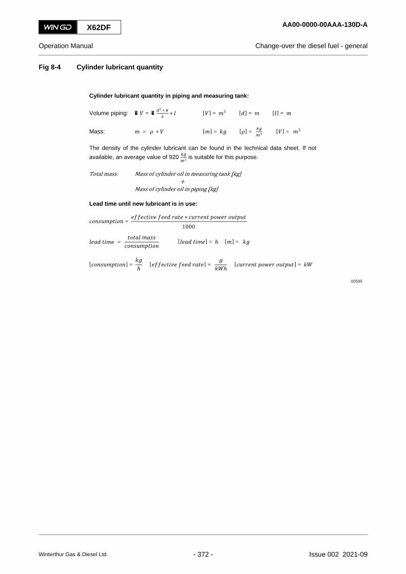
Fig 8-4 Cylinder lubricant quantity
Cylinder lubricant quantity in piping and measuring tank:
Volume piping: ∑ = ∑2 ∗4
∗ [ ] = 3 [ ] = [ ] =
Mass: = ∗ [ ] = [ ] = 3 [ ] = 3
The density of the cylinder lubricant can be found in the technical data sheet. If notavailable, an average value of 920 3 is suitable for this purpose.
Lead time until new lubricant is in use:
=∗1000
=
[ ] = ℎ [ ] = [ ] =
[ ] = ℎ [ ] =
ℎ00595
X62DF AA00-0000-00AAA-130D-A
Operation Manual Change-over the diesel fuel - general
Winterthur Gas & Diesel Ltd. - 372 - Issue 002 2021-09

X62DF AA00-0000-00AAA-130D-A
Operation Manual Change-over the diesel fuel - general
Page left intentionally blank
Winterthur Gas & Diesel Ltd. - 373 - Issue 002 2021-09

8.11 Change-over to and from gas - general
If you change-over the fuel to and from gas operation, you have to obey the related limits.
If the engine has the optional fuel sharing mode, there are some more limits.
8.11.1 Change-over from liquid fuel to gas
If you change-over from liquid fuel to gas, the engine must operate at MDO. If you operate theengine at HFO, there is an interlock for change-over to gas. Thus you first must change-over fromHFO to MDO, refer to section 8.10 Change-over the diesel fuel - general.
The change-over from MDO to gas has the limits that follow:
• The engine load must be in the range of 10% to 80% of CMCR.
• You only can start the procedure manually.
• Related to the conditions the procedure takes approximately one to two minutes. The ECSdoes some tests. If the tests are satisfactory the ECS slowly changes from diesel mode togas mode.
NOTE: When you operate the engine continuously in gas mode for more than one week, WinGDrecommends to change back to diesel mode one time each week. In diesel mode operatethe engine for approximately 5 to 10 minutes at a high load of a minimum of 60%. Theinjection of diesel fuel makes free the holes in the nozzle tip of the injection valves(“cleaning shots”) and thus decreases or prevents clogging of the holes. For more datarefer to the service letter SL-0005.
NOTE: The operation in diesel mode obeys the IMO Tier II regulations. Thus do this change-over to diesel mode out of ECA zones.
8.11.2 Change-over from gas to liquid fuel
If there is a change-over from gas to liquid fuel, the ECS quickly changes to liquid fuel. First theliquid fuel is always MDO. Then you manually can change-over to HFO, if necessary.
The change-over from gas to MDO has the limits that follow:
• The engine load can be in the range of 10% to 100% of CMCR.
• If a safety limit is given, the ESS or the ECS start the procedure automatically (gas trip).
• You also can start the procedure manually.
• The procedure is done during one turn of the crankshaft.
X62DF AA00-0000-00AAA-130H-A
Operation Manual Change-over to and from gas - general
Winterthur Gas & Diesel Ltd. - 374 - Issue 002 2021-09

8.11.3 Change-over related to fuel sharing mode
If the engine has the optional fuel sharing mode, the liquid fuel in use can be HFO or MDO.NOTE: You have to set the value for the ratio of liquid fuel to gas in the RCS.
Related to fuel sharing mode the conditions that follow are possible:
• Liquid fuel to fuel sharing
The change-over from liquid fuel to fuel sharing has the limits that follow:○ The engine load must be in the range of 50% to 80% of CMCR.
○ You only can start the procedure manually.
○ Related to the conditions the procedure takes approximately one to two minutes. TheECS does some tests. If the tests are satisfactory the ECS slowly changes from dieselmode to fuel sharing mode.
• Gas to fuel sharing
The change-over from gas to fuel sharing has the limits that follow:○ The engine load must be in the range of 50% to 100% of CMCR.
○ You only can start the procedure manually.
○ The ECS slowly changes from gas mode to fuel sharing mode. First the liquid fuel isalways MDO. Then you manually can change-over to HFO, if necessary.
• Fuel sharing to liquid fuel
The change-over from fuel sharing to liquid fuel has the limits that follow:○ The engine load is in the range of 50% to 100% of CMCR.
○ If the engine load decreases to less than 50%, the ECS sends an alarm. If you donot increase the load to more than 50% in a specified period, the ECS automaticallychanges to diesel mode.
○ You also can start the procedure manually.
○ The ECS slowly changes from fuel sharing mode to liquid fuel.
• Fuel sharing to gas
The change-over from fuel sharing to gas has the limits that follow:○ The engine load is in the range of 50% to 100% of CMCR.
○ The liquid fuel that is in operation must be MDO.
○ If the engine load decreases to less than 50%, the ECS sends an alarm. If you donot increase the load to more than 50% in a specified period, the ECS automaticallychanges to diesel mode.
○ You only can start the procedure manually.
○ The ECS slowly changes from fuel sharing mode to gas.
NOTE: The period for the change-over of these procedures is related to the selected ratio ofliquid fuel to gas.
X62DF AA00-0000-00AAA-130H-A
Operation Manual Change-over to and from gas - general
Winterthur Gas & Diesel Ltd. - 375 - Issue 002 2021-09

8.12 Change-over the diesel fuel automaticallyPeriodicityDescriptionUnscheduledDuration for performing preliminary requirements 0.0 man-hoursDuration for performing the procedure 0.5 man-hoursDuration for performing the requirements after job completion 0.0 man-hours
PersonnelDescription Specialization QTYEngine crew Intermediate 1
Support equipmentDescription Part No. CSN QTYNone
SuppliesDescription QTYNone
Spare PartsDescription Part No. CSN QTYNone
SAFETY PRECAUTIONS
• None
PRELIMINARY OPERATIONS
• WinGD recommends to always do this automatic change-over procedure when possible.There is no load limit of the engine to do an automatic fuel change-over.
X62DF AA00-0000-00AAA-131E-A
Operation Manual Change-over the diesel fuel automatically
Winterthur Gas & Diesel Ltd. - 376 - Issue 002 2021-09

PROCEDURE
1 Start the automatic change-over procedure, refer to the instructions of the manufacturer.
CLOSE UP
• None
X62DF AA00-0000-00AAA-131E-A
Operation Manual Change-over the diesel fuel automatically
Winterthur Gas & Diesel Ltd. - 377 - Issue 002 2021-09

8.13 Change-over from HFO to MDO manuallyPeriodicityDescriptionUnscheduledDuration for performing preliminary requirements 0.0 man-hoursDuration for performing the procedure 2.0 man-hoursDuration for performing the requirements after job completion 0.0 man-hours
PersonnelDescription Specialization QTYEngine crew Intermediate 1
Support equipmentDescription Part No. CSN QTYNone
SuppliesDescription QTYNone
Spare PartsDescription Part No. CSN QTYNone
SAFETY PRECAUTIONS
• None
PRELIMINARY OPERATIONS
• WinGD recommends to do a manual change-over only, if an automatic change-over systemis not installed or if the automatic change-over system is unserviceable.
X62DF AA00-0000-00AAA-131D-A
Operation Manual Change-over from HFO to MDO manually
Winterthur Gas & Diesel Ltd. - 378 - Issue 002 2021-09

PROCEDURE
1 Make a full time schedule for the change-over to obey the ECA rules.2 If you operate the engine with MDO for a long period, you must change the cylinder oil to
the applicable BN at the related time, refer to section 8.10 Change-over the diesel fuel -general.
3 Set to OFF the trace heating of the fuel pipes and fuel rail approximately one hour beforethe change-over. The correct time is related to the pipe diameter and the waste heat in thesystem.
4 Set the viscosimeter to 17 cSt to decrease the temperature of the fuel.5 Set to OFF all heating sources in the system (for example fuel heaters) some minutes
before the change-over.6 Decrease the load of the engine to max. 50% CMCR. The decrease of the engine power
is related to the total quantity of fuel that flows in the system (for example the larger themixing tank, the less decrease in load is necessary).
7 Follow the instructions of the plant to slowly change-over the fuel supply from HFO to MDO.Make sure that you decrease the fuel temperature a maximum of 2°C each minute.
8 If the temperature changes too much, wait until the fuel temperature is stable. Then youcan continue the procedure. Try to decrease the temperature as linearly as possible.
9 When the temperature of the fuel is near the applicable value, you can start the coolerslowly to give a linear and smooth temperature change at minimum viscosity.NOTE: The viscosity of the fuel must not be less than 2 cSt.
10 Do a check of the temperature, viscosity and pressure of the supplied fuel.11 If the temperature, viscosity, or pressure is not correct, find the cause and repair the fault.12 If you have to collect the MDO from the leakage and return pipes, do as follows:
12.1 Wait until the system is completely flushed with MDO.NOTE: This prevents contamination of the MDO with HFO.
12.2 If also a MDO leakage tank is installed, move the 3-way valve in the pipe from theoutlet of the fuel leakage fuel pump and injection control to the MDO leakage tank.
12.3 If the fuel return of the pressure control valve goes into the HFO service tank, setthe valve positions to have the fuel return go into the MDO service tank.
13 If you have to stop the engine, wait until the change-over procedure is fully completed.NOTE: This prevents problems during the subsequent engine start because of a mixture
of HFO and MDO in the system.
CLOSE UP
• None
X62DF AA00-0000-00AAA-131D-A
Operation Manual Change-over from HFO to MDO manually
Winterthur Gas & Diesel Ltd. - 379 - Issue 002 2021-09

8.14 Change-over from MDO to HFO manuallyPeriodicityDescriptionUnscheduledDuration for performing preliminary requirements 0.0 man-hoursDuration for performing the procedure 2.0 man-hoursDuration for performing the requirements after job completion 0.0 man-hours
PersonnelDescription Specialization QTYEngine crew Intermediate 1
Support equipmentDescription Part No. CSN QTYNone
SuppliesDescription QTYNone
Spare PartsDescription Part No. CSN QTYNone
SAFETY PRECAUTIONS
• None
PRELIMINARY OPERATIONS
• WinGD recommends to do a manual change-over only, if an automatic change-over systemis not installed or if the automatic change-over system is unserviceable.
X62DF AA00-0000-00AAA-131H-A
Operation Manual Change-over from MDO to HFO manually
Winterthur Gas & Diesel Ltd. - 380 - Issue 002 2021-09

PROCEDURE
1 Make a full time schedule for the change-over to obey the ECA rules.2 Make sure that you have changed the cylinder oil to the applicable BN, refer to section
8.10 Change-over the diesel fuel - general.3 Set to ON the trace heating of the fuel pipes and fuel rail.4 If the engine room is cold, after a minimum of one hour make sure to get correct heating.5 Make sure that HFO cannot flow into the MDO system.
5.1 If also a MDO leakage tank is installed, move the 3-way valve in the pipe from theoutlet of the fuel leakage fuel pump and injection control to the HFO leakage tank.
5.2 If the fuel return of the pressure control valve goes into the MDO service tank, setthe valve positions to have the fuel return go into the HFO service tank.
6 Close all covers on the rail unit.7 Decrease the load of the engine to max. 75% CMCR. The decrease of the engine power
is related to the total quantity of fuel that flows in the system (for example the larger themixing tank, the less decrease in load is necessary).
8 Set the viscosimeter to 13 cSt to increase the temperature of the fuel.NOTE: The viscosimeter controls the end-heater, which keeps the fuel temperature at
the necessary viscosity.9 Follow the instructions of the plant to slowly change-over the fuel supply from MDO to
HFO. Make sure that you increase the fuel temperature a maximum of 2°C each minute.NOTE: Sudden temperature changes can stop the movement of the fuel pump plungers.
10 If the temperature changes too much, wait until the fuel temperature is stable. Then youcan continue the procedure.
11 Do a check of the temperature, viscosity and pressure of the supplied fuel.12 If the temperature, viscosity, or pressure is not correct, find the cause and repair the fault.13 If you have to stop the engine, wait until the change-over procedure is fully completed.
NOTE: This prevents problems during the subsequent engine start because of a mixtureof HFO and MDO in the system.
CLOSE UP
• None
X62DF AA00-0000-00AAA-131H-A
Operation Manual Change-over from MDO to HFO manually
Winterthur Gas & Diesel Ltd. - 381 - Issue 002 2021-09

8.15 Change-over to and from gasPeriodicityDescriptionUnscheduledDuration for performing preliminary requirements 0.0 man-hoursDuration for performing the procedure 0.1 man-hoursDuration for performing the requirements after job completion 0.0 man-hours
PersonnelDescription Specialization QTYEngine crew Intermediate 1
Support equipmentDescription Part No. CSN QTYNone
SuppliesDescription QTYNone
Spare PartsDescription Part No. CSN QTYNone
SAFETY PRECAUTIONS
• None
PRELIMINARY OPERATIONS
• The engine is in usual operation.
X62DF AA00-0000-00AAA-131J-A
Operation Manual Change-over to and from gas
Winterthur Gas & Diesel Ltd. - 382 - Issue 002 2021-09
PROCEDURE
1 To change-over from liquid fuel to gas, do as follows:1.1 Make sure that the engine operates with MDO.1.2 On the related control panel start the gas mode request.
NOTE: The ECS makes a test, if gas mode is available. Then the ECS sends asignal to the gas pressure control system. This system automaticallystarts the transfer preparation. When this transfer procedure is finished,the ECS slowly changes to gas mode.
2 To change-over from gas to liquid fuel, do as follows:2.1 On the related control panel start the diesel mode request.
NOTE: The ECS quickly changes from gas to MDO operation.
CLOSE UP
• None
X62DF AA00-0000-00AAA-131J-A
Operation Manual Change-over to and from gas
Winterthur Gas & Diesel Ltd. - 383 - Issue 002 2021-09

8.16 Stop the engine - general
You can stop the engine from the locations that follow:
• At the bridge or engine control room (ECR) with remote control
• At the backup control panel in the ECR
• At the local control panel of the engine.
Related to the situation and to the planned tasks after engine shutdown, WinGD recommends tooperate the engine with marine diesel oil (MDO) for some time before you stop the engine, referto section 8.13 Change-over from HFO to MDO manually.
For a DF engine that operates in gas mode are the procedures related to the conditions as follows:
• The operator pushes the STOP button
When the operator pushes the STOP button, the ECS starts the procedures that follow:○ The ECS changes to stop mode, thus the related control system stops the gas supply
and releases the pressure in the gas inlet pipes.○ The ECS de-energizes the solenoid valve on the gas admission valves (GAV), thus
the gas flow to the cylinders stops.○ The ECS stops the operation of the pilot fuel valves after the crankshaft has turned
360°, thus makes sure that all gas in the combustion chambers burns.NOTE: If the crankshaft cannot turn 360°, the ECS sends a signal for an exhaust
ventilation request.
• The ESS or ECS sends a cancelable shutdown signal
The engine safety system (ESS) or the ECS sends a cancelable shutdown signal, when arelated failure or defect occurs. The procedures are as follows:○ The ECS changes to diesel mode, thus the related control system stops the gas
supply and releases the pressure in the gas inlet pipes.○ The engine continues to operate in diesel mode until the shutdown signal becomes
active.○ If the operator cancels the shutdown signal within the specified period, the engine
continues to operate in diesel mode.
• The ESS or ECS sends a non-cancelable shutdown signal
The ESS or the ECS sends a non-cancelable shutdown signal, when a related failure ordefect occurs. The procedures are as follows:○ The ECS changes to diesel mode, thus the related control system stops the gas
supply and releases the pressure in the gas inlet pipes.○ The ECS de-energizes the solenoid valve on the gas admission valves (GAV), thus
the gas flow to the cylinders stops.○ The ECS stops the engine.
○ The ECS sends a signal for an exhaust ventilation request.
X62DF AA00-0000-00AAA-130G-A
Operation Manual Stop the engine - general
Winterthur Gas & Diesel Ltd. - 384 - Issue 002 2021-09

X62DF AA00-0000-00AAA-130G-A
Operation Manual Stop the engine - general
Page left intentionally blank
Winterthur Gas & Diesel Ltd. - 385 - Issue 002 2021-09

8.17 Stop the enginePeriodicityDescriptionUnscheduledDuration for performing preliminary requirements 0.0 man-hoursDuration for performing the procedure 0.5 man-hoursDuration for performing the requirements after job completion 0.0 man-hours
PersonnelDescription Specialization QTYEngine crew Intermediate 1
Support equipmentDescription Part No. CSN QTYNone
SuppliesDescription QTYNone
Spare PartsDescription Part No. CSN QTYNone
SAFETY PRECAUTIONS
• None
PRELIMINARY OPERATIONS
• Refer to section 8.16 Stop the engine - general
X62DF AA00-0000-00AAA-131G-A
Operation Manual Stop the engine
Winterthur Gas & Diesel Ltd. - 386 - Issue 002 2021-09
PROCEDURE
1 Select the applicable control panel.2 Decrease the engine load to the minimum.3 On the control panel push the STOP button.
NOTE: The ECS shuts down the engine in a controlled manner.4 For a DF engine, start the exhaust ventilation sequence, if there is a ventilation request.
CLOSE UP
• None
X62DF AA00-0000-00AAA-131G-A
Operation Manual Stop the engine
Winterthur Gas & Diesel Ltd. - 387 - Issue 002 2021-09

8.18 Emergency stop the engine - general
To stop the engine in an emergency, do the procedure given in section 8.19 Emergency stop theengine.
X62DF AA00-0000-00AAA-140A-A
Operation Manual Emergency stop the engine - general
Winterthur Gas & Diesel Ltd. - 388 - Issue 002 2021-09

X62DF AA00-0000-00AAA-140A-A
Operation Manual Emergency stop the engine - general
Page left intentionally blank
Winterthur Gas & Diesel Ltd. - 389 - Issue 002 2021-09

8.19 Emergency stop the enginePeriodicityDescriptionUnscheduledDuration for performing preliminary requirements 0.0 man-hoursDuration for performing the procedure 0.1 man-hoursDuration for performing the requirements after job completion 0.0 man-hours
PersonnelDescription Specialization QTYEngine crew Intermediate 1
Support equipmentDescription Part No. CSN QTYNone
SuppliesDescription QTYNone
Spare PartsDescription Part No. CSN QTYNone
SAFETY PRECAUTIONS
• None
PRELIMINARY OPERATIONS
• In some conditions the ECS starts an automatic shutdown.
X62DF AA00-0000-00AAA-141A-A
Operation Manual Emergency stop the engine
Winterthur Gas & Diesel Ltd. - 390 - Issue 002 2021-09

PROCEDURE
1 In the control room (control console), or on the local control panel, push the EMERGENCYSTOP button.NOTE: The ECS stops the engine immediately.
2 For a DF engine, start the exhaust ventilation sequence, if there is a ventilation request.3 To make the engine ready for restart after an emergency stop, you must reset the
EMERGENCY STOP button.
CAUTIONDamage Hazard. Do this step only as a last alternative selection, if the EMERGENCY STOPbutton is not working. Damage to the engine can occur.
4 In the power supply boxes E85.1 to E85.#, set to OFF the electrical power to the ECS.5 Find the cause of the emergency stop and repair the fault.
CLOSE UP
• None
X62DF AA00-0000-00AAA-141A-A
Operation Manual Emergency stop the engine
Winterthur Gas & Diesel Ltd. - 391 - Issue 002 2021-09

8.20 Prepare the engine after stop - general
After a decrease of the engine speed to less than 8% the ECS automatically starts the post-lubrication of the cylinders.NOTE: The water and oil pumps must operate for a minimum of 20 minutes after the engine has
stopped. This is to make sure that when the engine temperature has decreased, thetemperature of engine parts become as stable as possible.
For a short period after an engine stop of one week or less, usually you keep the auxiliary systemsin operation, refer to section 8.21 Prepare the engine for a short service break.
For a long period after an engine stop of more than one week or for maintenance of the engine,you do the steps in section 8.22 Prepare the engine for standstill or for maintenance. If you haveto do maintenance, you have to make a decision about which steps of the procedure are necessaryfor the specified maintenance tasks.
X62DF AA00-0000-00AAA-150A-A
Operation Manual Prepare the engine after stop - general
Winterthur Gas & Diesel Ltd. - 392 - Issue 002 2021-09

X62DF AA00-0000-00AAA-150A-A
Operation Manual Prepare the engine after stop - general
Page left intentionally blank
Winterthur Gas & Diesel Ltd. - 393 - Issue 002 2021-09

8.21 Prepare the engine for a short service breakPeriodicityDescriptionUnscheduledDuration for performing preliminary requirements 0.0 man-hoursDuration for performing the procedure 0.5 man-hoursDuration for performing the requirements after job completion 0.0 man-hours
PersonnelDescription Specialization QTYEngine crew Intermediate 1
Support equipmentDescription Part No. CSN QTYNone
SuppliesDescription QTYNone
Spare PartsDescription Part No. CSN QTYNone
SAFETY PRECAUTIONS
• None
PRELIMINARY OPERATIONS
• The engine must be stopped. Refer to section 8.20 Prepare the engine after stop - general
X62DF AA00-0000-00AAA-151A-A
Operation Manual Prepare the engine for a short service break
Winterthur Gas & Diesel Ltd. - 394 - Issue 002 2021-09

PROCEDURE
1 Make sure that the auxiliary systems continue to operate.2 If possible, keep the cooling water warm to prevent too much temperature decrease of the
engine.3 Open the indicator valves in the cylinder covers.4 Engage the turning gear.
WARNINGInjury hazard. Before you operate the turning gear, make sure that no personnel are nearthe flywheel, or in the engine.
5 Operate the turning gear for a short period at the intervals that follow:• Daily in damp climate• Weekly in usual climate.
6 Stop the turning gear so, that the pistons stop in different positions each time.
CLOSE UP
• None
X62DF AA00-0000-00AAA-151A-A
Operation Manual Prepare the engine for a short service break
Winterthur Gas & Diesel Ltd. - 395 - Issue 002 2021-09

8.22 Prepare the engine for standstill or for maintenancePeriodicityDescriptionUnscheduledDuration for performing preliminary requirements 0.0 man-hoursDuration for performing the procedure 1.0 man-hoursDuration for performing the requirements after job completion 0.0 man-hours
PersonnelDescription Specialization QTYEngine crew Intermediate 1
Support equipmentDescription Part No. CSN QTYNone
SuppliesDescription QTYNone
Spare PartsDescription Part No. CSN QTYNone
SAFETY PRECAUTIONS
• None
PRELIMINARY OPERATIONS
• The engine must be stopped. Refer to section 8.20 Prepare the engine after stop - general
X62DF AA00-0000-00AAA-151B-A
Operation Manual Prepare the engine for standstill or for maintenance
Winterthur Gas & Diesel Ltd. - 396 - Issue 002 2021-09

PROCEDURE
1 Open the indicator valves in the cylinder covers.2 Engage the turning gear.3 Stop the fuel supply to the engine as follows:
3.1 Stop the fuel supply system from the plant.3.2 Close the shut-off valve at engine connection 49 (fuel inlet).3.3 Release the pressure in the fuel system.3.4 Drain the fuel system.3.5 Close the shut-off valve at engine connection 50 (fuel return outlet).
4 Drain the exhaust gas manifold and the exhaust gas pipe.5 Stop the air supply to the engine as follows:
5.1 Stop the air supply systems from the plant.5.2 Close the shut-off valves at engine connection 40 (starting air pipe inlet).5.3 Turn the hand-wheel of the starting air shut-off valve to the position CLOSED.5.4 Drain the air systems of the engine.5.5 Release the pressure in the air pipes.
6 Stop the lubricating oil supply to the engine as follows:6.1 Stop the oil supply systems from the plant.6.2 Close the shut-off valves to the engine at engine connection 33 (cylinder oil inlet).6.3 Set to OFF the control box for the automatic filter.6.4 If installed, close the shut-off valves to the engine upstream of engine connection
25 (main lubricating oil inlet) and of engine connection 30 (lubricating oil crossheadinlet).
6.5 Release the pressure in the oil pipes and the oil rail.6.6 Drain the oil systems of the engine.
7 Stop the cooling water supply to the engine as follows:7.1 Stop the cooling water supply system from the plant.7.2 If installed, close the shut-off valves upstream of engine connections 01 and/or 02
(cylinder cooling water inlet).7.3 Release the pressure in the cooling and wash-water pipes.7.4 Drain the water systems of the engine.
X62DF AA00-0000-00AAA-151B-A
Operation Manual Prepare the engine for standstill or for maintenance
Winterthur Gas & Diesel Ltd. - 397 - Issue 002 2021-09

8 For a DF engine, stop the gas system.8.1 If you have to do maintenance downstream of the block valve (CV7285), do as
follows:8.1.1 Make sure that the valve positions are in degassing state.8.1.2 On the iGPR cabinet switch the button S8 to maintenance to activate the
maintenance mode.8.1.3 On the LDU-20 iGPR page, make sure that all conditions are satisfactory.8.1.4 On the LDU-20 iGPR page, push the Engine Inerting button to start the
engine inerting sequence.8.1.5 Make sure that the indication in progress shows on the LDU-20.
NOTE: The iGPR control system does the engine inerting sequence.8.1.6 Wait until the indication passed shows on the LDU-20.8.1.7 On the iGPR cabinet push the button S7 to degas the system.
8.2 If you have to do maintenance on a component downstream of the master shut-off valve, do as follows:8.2.1 Make sure that the valve positions are in degassing state.8.2.2 On the iGPR cabinet switch the button S8 to maintenance to activate the
maintenance mode.8.2.3 On the LDU-20 iGPR page, make sure that all conditions are satisfactory.8.2.4 On the LDU-20 iGPR page, push the Supply Line Inerting button to start
the supply line inerting sequence.8.2.5 Make sure that the indication in progress shows on the LDU-20.
NOTE: The iGPR control system does the supply line inerting sequence.8.2.6 Wait until the indication passed shows on the LDU-20.8.2.7 On the iGPR cabinet push the button S7 to degas the system.
9 For a DF engine, stop the pilot fuel supply to the engine as follows:9.1 Stop the pilot fuel supply from the plant.9.2 Close the shut-off valve at engine connection 76 (pilot fuel inlet).9.3 Release the pressure in the pilot fuel system.9.4 Drain the pilot fuel system.9.5 Close the shut-off valve at engine connection 77 (pilot fuel return outlet).
X62DF AA00-0000-00AAA-151B-A
Operation Manual Prepare the engine for standstill or for maintenance
Winterthur Gas & Diesel Ltd. - 398 - Issue 002 2021-09

10 Stop the control system from the engine as follows:10.1 Set to OFF all circuit breakers in the power supply box E85.10.2 Set to OFF the engine control system (ECS) and the remote control system (RCS).
11 Do a check of the rail unit as follows:11.1 Open the covers.11.2 Make sure that there is no condensation or corrosion.11.3 If you find condensation or corrosion, do the steps that follow:
11.3.1 Clean the related part.11.3.2 Find the cause and repair the fault.
11.4 If necessary, apply anti-corrosion oil to give protection.11.5 Close the covers.
12 Do a check of the supply unit as follows:12.1 Make sure that there is no condensation or corrosion.12.2 If you find condensation or corrosion, do the steps that follow:
12.2.1 Clean the related part.12.2.2 Find the cause and repair the fault.
12.3 If necessary, apply anti-corrosion oil to give protection.
13 If the engine must have preservation for a long period, speak to or send a message toWinGD for the applicable preservation procedures.
CLOSE UP
• None
X62DF AA00-0000-00AAA-151B-A
Operation Manual Prepare the engine for standstill or for maintenance
Winterthur Gas & Diesel Ltd. - 399 - Issue 002 2021-09

X62DF AA00-0000-00AAA-151B-A
Operation Manual Prepare the engine for standstill or for maintenance
Page left intentionally blank
Winterthur Gas & Diesel Ltd. - 400 - Issue 002 2021-09

9 Service during operation9.1 Do an analysis of the system oil..............................................................................4029.2 Do an analysis of the cylinder oil.............................................................................4049.3 Replace the filter element of the duplex filter..........................................................4089.4 Clean the scavenge air cooler during operation......................................................4109.5 Do a test of the exhaust waste valve.......................................................................4149.6 Running-in of new components - general................................................................4169.7 Running-in of new components...............................................................................4189.8 Clean the turbocharger during operation.................................................................420
X62DF
Operation Manual
Winterthur Gas & Diesel Ltd. - 401 - Issue 002 2021-09
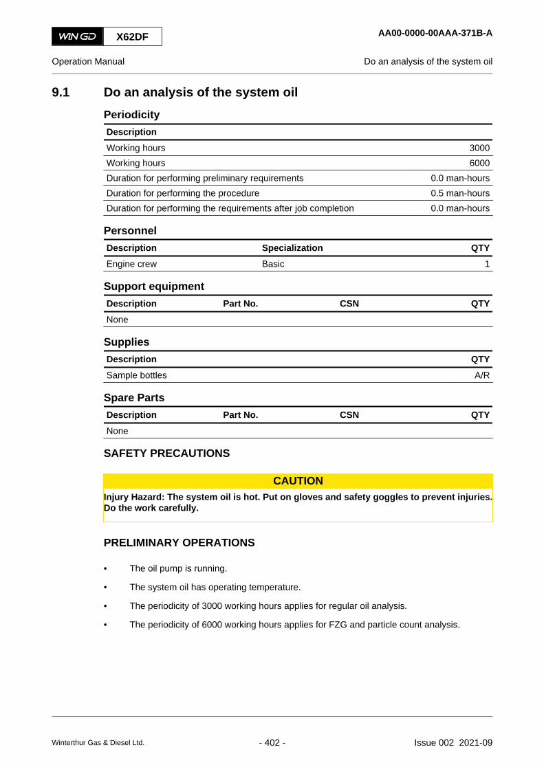
9.1 Do an analysis of the system oilPeriodicityDescriptionWorking hours 3000Working hours 6000Duration for performing preliminary requirements 0.0 man-hoursDuration for performing the procedure 0.5 man-hoursDuration for performing the requirements after job completion 0.0 man-hours
PersonnelDescription Specialization QTYEngine crew Basic 1
Support equipmentDescription Part No. CSN QTYNone
SuppliesDescription QTYSample bottles A/R
Spare PartsDescription Part No. CSN QTYNone
SAFETY PRECAUTIONS
CAUTIONInjury Hazard: The system oil is hot. Put on gloves and safety goggles to prevent injuries.Do the work carefully.
PRELIMINARY OPERATIONS
• The oil pump is running.
• The system oil has operating temperature.
• The periodicity of 3000 working hours applies for regular oil analysis.
• The periodicity of 6000 working hours applies for FZG and particle count analysis.
X62DF AA00-0000-00AAA-371B-A
Operation Manual Do an analysis of the system oil
Winterthur Gas & Diesel Ltd. - 402 - Issue 002 2021-09

PROCEDURE
1 Flush the sample pipe.NOTE: Use the sample point related to the engine as follows:
• For an engine with servo oil filter, do as follows:○ Get a sample from the sample point at the engine inlet.
○ If the analysis shows unusual values, get a sample from the samplepoint after the servo oil filter.
• For an engine without servo oil filter, get the sample from the sample pointat the engine inlet.
1.1 Put an applicable container under the sample valve.1.2 Slowly open the sample valve to flush out oil and possible dirt.1.3 Close the sample valve.1.4 Discard the oil correctly.
2 Get an oil sample.2.1 Put the sample bottle under the sample valve.2.2 Slowly open the sample valve to fully fill the sample bottle.
NOTE: The necessary quantity of oil is as follows:• 100 ml for regular oil analysis• 5 l for FZG and particle count analysis.
2.3 Close the sample valve.2.4 Close the sample bottle tight.
3 Write the data that follows on the sample bottle:• Name of the ship• Type and serial number of the engine• Date of the sampling• Location of the sample point• Operating hours of the oil and of the engine• Brand and type of the oil.
4 If applicable, do Step 1 to Step 3 again for the other sample point.5 Send the sample bottles in an applicable package to a laboratory for analysis.6 Do the procedures related to the results, refer to section [section not applicable for this
engine] or to the document “Lubricants” on the WinGD website (https://www.wingd.com/).
CLOSE UP
• None
X62DF AA00-0000-00AAA-371B-A
Operation Manual Do an analysis of the system oil
Winterthur Gas & Diesel Ltd. - 403 - Issue 002 2021-09

9.2 Do an analysis of the cylinder oilPeriodicityDescriptionWeeks 1Unscheduled After a fuel changeUnscheduled After a cylinder oil changeUnscheduled After a feed rate changeDuration for performing preliminary requirements 2.0 man-hoursDuration for performing the procedure 6.0 man-hoursDuration for performing the requirements after job completion 0.0 man-hours
PersonnelDescription Specialization QTYEngine crew Basic 1
Support equipmentDescription Part No. CSN QTYNone
SuppliesDescription QTYSample bottles A/R
Spare PartsDescription Part No. CSN QTYNone
SAFETY PRECAUTIONS
CAUTIONInjury Hazard: The cylinder oil is hot. Put on gloves and safety goggles to prevent injury.Do the work carefully.
PRELIMINARY OPERATIONS
• The engine must be in stable operation for a minimum of 12 hours.
• The duration of the procedure is related to the number of cylinders.
X62DF AA00-0000-00AAA-371A-A
Operation Manual Do an analysis of the cylinder oil
Winterthur Gas & Diesel Ltd. - 404 - Issue 002 2021-09
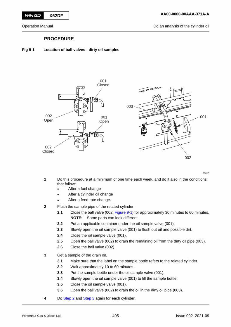
PROCEDURE
Fig 9-1 Location of ball valves - dirty oil samples
Closed
00010
002
001
Closed002
Open002
001
003
001Open
1 Do this procedure at a minimum of one time each week, and do it also in the conditionsthat follow:• After a fuel change• After a cylinder oil change• After a feed rate change.
2 Flush the sample pipe of the related cylinder.2.1 Close the ball valve (002, Figure 9-1) for approximately 30 minutes to 60 minutes.
NOTE: Some parts can look different.2.2 Put an applicable container under the oil sample valve (001).2.3 Slowly open the oil sample valve (001) to flush out oil and possible dirt.2.4 Close the oil sample valve (001).2.5 Open the ball valve (002) to drain the remaining oil from the dirty oil pipe (003).2.6 Close the ball valve (002).
3 Get a sample of the drain oil.3.1 Make sure that the label on the sample bottle refers to the related cylinder.3.2 Wait approximately 10 to 60 minutes.3.3 Put the sample bottle under the oil sample valve (001).3.4 Slowly open the oil sample valve (001) to fill the sample bottle.3.5 Close the oil sample valve (001).3.6 Open the ball valve (002) to drain the oil in the dirty oil pipe (003).
4 Do Step 2 and Step 3 again for each cylinder.
X62DF AA00-0000-00AAA-371A-A
Operation Manual Do an analysis of the cylinder oil
Winterthur Gas & Diesel Ltd. - 405 - Issue 002 2021-09

5 Write the applicable data on the oil analysis form (for example operation conditions, fuelparameters, cylinder lubricating feed rate).
6 Do an oil analysis of the samples on-board. The oil analysis must include the data thatfollows:• Residual BN• Iron (Fe) content (if possible).
7 If necessary, do the applicable recommended procedures, refer to section [section notapplicable for this engine] or to the document “Lubricants” on the WinGD website (https://www.wingd.com/).
8 Send the oil samples to a laboratory for an oil analysis.8.1 Make sure that the sample bottles are tightly closed.8.2 Put the sample bottles in an applicable package.
9 Compare the oil analysis from the laboratory with the oil analysis from on-board.10 If the oil analyses are different, do the applicable recommended procedures related to the
oil analysis from the laboratory, refer to section [section not applicable for this engine] orto the document “Lubricants” on the WinGD website (https://www.wingd.com/).
CLOSE UP
• None
X62DF AA00-0000-00AAA-371A-A
Operation Manual Do an analysis of the cylinder oil
Winterthur Gas & Diesel Ltd. - 406 - Issue 002 2021-09

X62DF AA00-0000-00AAA-371A-A
Operation Manual Do an analysis of the cylinder oil
Page left intentionally blank
Winterthur Gas & Diesel Ltd. - 407 - Issue 002 2021-09

9.3 Replace the filter element of the duplex filterPeriodicityDescriptionUnscheduledDuration for performing preliminary requirements 0.0 man-hoursDuration for performing the procedure 1.0 man-hoursDuration for performing the requirements after job completion 0.0 man-hours
PersonnelDescription Specialization QTYEngine crew Basic 1
Support equipmentDescription Part No. CSN QTYNone
SuppliesDescription QTYNone
Spare PartsDescription Part No. CSN QTYFilter element HA1-59-9613-01 -002 pc 1
SAFETY PRECAUTIONS
• None
PRELIMINARY OPERATIONS
• None
X62DF AA00-7200-00AAA-200A-A
Operation Manual Replace the filter element of the duplex filter
Winterthur Gas & Diesel Ltd. - 408 - Issue 002 2021-09
PROCEDURE
1 Change over to the clean filter chamber.2 Drain the clogged filter chamber.3 Remove the cover of the clogged filter chamber.4 Remove the filter element from the filter chamber.5 Clean the filter chamber.6 Clean the filter element or take a new filter element.7 Install the new filter element into the filter chamber.8 Install the cover on the filter chamber.9 Make sure that the cleaned filter chamber has no leaks.
CLOSE UP
• None
X62DF AA00-7200-00AAA-200A-A
Operation Manual Replace the filter element of the duplex filter
Winterthur Gas & Diesel Ltd. - 409 - Issue 002 2021-09
9.4 Clean the scavenge air cooler during operationPeriodicityDescriptionWeeks 1Duration for performing preliminary requirements 0.0 man-hoursDuration for performing the procedure 1.0 man-hoursDuration for performing the requirements after job completion 0.0 man-hours
PersonnelDescription Specialization QTYEngine crew Intermediate 1
Support equipmentDescription Part No. CSN QTYNone
SuppliesDescription QTYCleaning fluid A/R
Spare PartsDescription Part No. CSN QTYNone
SAFETY PRECAUTIONS
• None
PRELIMINARY OPERATIONS
• None
X62DF AA00-6600-00AAA-200A-A
Operation Manual Clean the scavenge air cooler during operation
Winterthur Gas & Diesel Ltd. - 410 - Issue 002 2021-09

PROCEDURE
Fig 9-2 SAC - clean during operation (example)
ScavengeAir Cooler
AuxBlower
Turbocharger
1211
18
16
07
08
AuxBlower
13
LS4075A
LS4071A
PI1361L
TI1371L
TI1381L
PT1361A
TE1371A
TE1381A
WashingPlant SAC
PLAN
TEN
GIN
E
PLANTENGINE
003
00520
004 005
006
007
008
009 001 002
X62DF AA00-6600-00AAA-200A-A
Operation Manual Clean the scavenge air cooler during operation
Winterthur Gas & Diesel Ltd. - 411 - Issue 002 2021-09

1 Decrease the engine power to approximately 45%.2 Make sure that compressed air is available at the shut-off valve (001, Figure 9-2) and fresh
water is available at the shut-off valve (009).NOTE: The schematic diagram in Figure 9-2 is an example and is used for reference.
Some parts can look different.3 Fill the tank (006, Figure 9-2) through the funnel (008) with fresh water and the specified
quantity of cleaning fluid (max. 30 liters).3.1 Open the vent valve (002) and the valve (007) of the tank (006).3.2 Carefully open the shut-off valve (009) in the water supply pipe and fill the
tank (006).NOTE: You can also use a hand-held container filled with cleaning fluid mixed
with fresh water to put into the funnel. When you use this method, makesure that the shut-off valve in the supply pipe stays closed.
3.3 Close the shut-off valve (009) in the water supply pipe.3.4 Close the vent valve (002) and the valve (007) of the tank (006).
4 Open the shut-off valve (001) in the compressed air supply pipe to pressurize thetank (006).
5 Clean the scavenge air cooler (005) as follows:5.1 Open the shut-off valve (003).5.2 After no more cleaning water comes out, close the shut-off valve (003).
6 Close the shut-off valve (001) in the compressed air supply pipe.7 Open the vent valve (002) to release the pressure in the tank (006).8 After 10 minutes, do Step 2 to Step 7 again with fresh water (no cleaning fluid).9 Do a check of the water separator for dirt.10 If the water separator is dirty, clean the water separator (refer to the Maintenance Manual).
CLOSE UP
• None
X62DF AA00-6600-00AAA-200A-A
Operation Manual Clean the scavenge air cooler during operation
Winterthur Gas & Diesel Ltd. - 412 - Issue 002 2021-09

X62DF AA00-6600-00AAA-200A-A
Operation Manual Clean the scavenge air cooler during operation
Page left intentionally blank
Winterthur Gas & Diesel Ltd. - 413 - Issue 002 2021-09

9.5 Do a test of the exhaust waste valvePeriodicityDescriptionWeeks 1Duration for performing preliminary requirements 0.0 man-hoursDuration for performing the procedure 0.2 man-hoursDuration for performing the requirements after job completion 0.0 man-hours
PersonnelDescription Specialization QTYEngine crew Basic 1
Support equipmentDescription Part No. CSN QTYNone
SuppliesDescription QTYNone
Spare PartsDescription Part No. CSN QTYNone
SAFETY PRECAUTIONS
• None
PRELIMINARY OPERATIONS
• This procedure is only applicable, if the engine has operated for a long period at low loadwith the exhaust waste valve closed.
• The engine load must be less than 70%, or the engine can be stopped.
X62DF AA00-8135-00AAA-320A-A
Operation Manual Do a test of the exhaust waste valve
Winterthur Gas & Diesel Ltd. - 414 - Issue 002 2021-09

PROCEDURE
1 On the related control panel manually open the exhaust waste valve.2 Make sure that the exhaust waste gate is open.3 Close the exhaust waste valve.4 If the check is incorrect, find the cause and repair the fault.
CLOSE UP
• None
X62DF AA00-8135-00AAA-320A-A
Operation Manual Do a test of the exhaust waste valve
Winterthur Gas & Diesel Ltd. - 415 - Issue 002 2021-09

9.6 Running-in of new components - general
After an overhaul or an installation of new components of the piston running system, WinGDrecommends a running-in procedure. This makes sure a correct film of cylinder oil on the pistonrunning system is built. The procedure includes a temporary higher feed rate, refer to Figure 9-3.
WinGD recommends an inspection of the cylinder liners and of the piston rings after 24 operationhours and after 72 operation hours (001, Figure 9-3). For this running-in procedure it is notnecessary to have a special loading up apart from vessel specific loading up protocols.
Fig 9-3 Feed rate adjustments - running-in
001
001
X62DF AA00-0000-00AAA-950B-A
Operation Manual Running-in of new components - general
Winterthur Gas & Diesel Ltd. - 416 - Issue 002 2021-09

X62DF AA00-0000-00AAA-950B-A
Operation Manual Running-in of new components - general
Page left intentionally blank
Winterthur Gas & Diesel Ltd. - 417 - Issue 002 2021-09

9.7 Running-in of new componentsPeriodicityDescriptionUnscheduledDuration for performing preliminary requirements 0.0 man-hoursDuration for performing the procedure 72.0 man-hoursDuration for performing the requirements after job completion 0.0 man-hours
PersonnelDescription Specialization QTYEngine crew Intermediate 1
Support equipmentDescription Part No. CSN QTYNone
SuppliesDescription QTYNone
Spare PartsDescription Part No. CSN QTYNone
SAFETY PRECAUTIONS
• None
PRELIMINARY OPERATIONS
• This procedure is only applicable after an overhaul or an installation of new components ofthe piston running system.
X62DF AA00-0000-00AAA-950A-A
Operation Manual Running-in of new components
Winterthur Gas & Diesel Ltd. - 418 - Issue 002 2021-09

PROCEDURE
1 Set the cylinder lubricating feed rate for the applicable cylinders in the control system to1.2 g/kWh.
2 Operate the engine for 24 hours.3 Inspect the components for damage.4 If damage occurs, find the cause and repair the fault.5 If it is necessary to replace parts of the piston running system, do Step 2 and Step 3 again.6 Set the feed rate to 1.1 g/kWh.7 Operate the engine for 24 hours.8 Set the feed rate to 1.0 g/kWh.9 Operate the engine for 24 hours.10 Inspect the components for damage.11 If damage occurs, find the cause and repair the fault.12 If it is necessary to replace parts of the piston running system, start with Step 1 again.13 Set the feed rate to 0.9 g/kWh.
CLOSE UP
• After 72 hours set the feed rate to the usual settings. Refer to the document “Lubricants” onthe WinGD website (https://www.wingd.com/) or to section [section not applicable for thisengine]
X62DF AA00-0000-00AAA-950A-A
Operation Manual Running-in of new components
Winterthur Gas & Diesel Ltd. - 419 - Issue 002 2021-09

9.8 Clean the turbocharger during operationPeriodicityDescriptionWeeks 1Duration for performing preliminary requirements 0.0 man-hoursDuration for performing the procedure 1.0 man-hoursDuration for performing the requirements after job completion 0.0 man-hours
PersonnelDescription Specialization QTYEngine crew Intermediate 1
Support equipmentDescription Part No. CSN QTYNone
SuppliesDescription QTYCleaning fluid A/R
Spare PartsDescription Part No. CSN QTYNone
SAFETY PRECAUTIONS
CAUTIONDamage Hazard: For an engine with LP SCR system, do not do this procedure, if there isgas flow through the LP SCR reactor. This could cause damage to the components of theSCR system.
PRELIMINARY OPERATIONS
• None
X62DF AA00-6500-00AAA-200A-A
Operation Manual Clean the turbocharger during operation
Winterthur Gas & Diesel Ltd. - 420 - Issue 002 2021-09

PROCEDURE
1 Decrease the engine power to approximately 25 to 85%.2 Clean the compressor of the turbocharger, refer to the documentation of the manufacturer.3 Clean the turbine of the turbocharger, refer to the documentation of the manufacturer.
CLOSE UP
• None
X62DF AA00-6500-00AAA-200A-A
Operation Manual Clean the turbocharger during operation
Winterthur Gas & Diesel Ltd. - 421 - Issue 002 2021-09

X62DF AA00-6500-00AAA-200A-A
Operation Manual Clean the turbocharger during operation
Page left intentionally blank
Winterthur Gas & Diesel Ltd. - 422 - Issue 002 2021-09

10 Troubleshooting10.1 Troubleshooting - general data................................................................................42410.2 Malfunctions of systems and components...............................................................42610.3 Failures and defects of UNIC-flex components.......................................................44610.4 LP SCR - Alarm failure troubleshooting...................................................................44810.5 Bleed the cooling water system of the liner wall......................................................45410.6 Examine the supply unit for servo oil leakage.........................................................45610.7 Examine the supply unit for fuel leakage.................................................................46010.8 Examine the rail unit for leakage.............................................................................46410.9 Examine the FLV or fuel pipes for fuel leakage.......................................................46610.10 Temporary cut out a defective injection valve.........................................................47010.11 Temporary cut out a defective exhaust valve drive.................................................47210.12 Temporary isolate a cylinder with cooling water leakage........................................47410.13 Servo oil pump - troubleshooting.............................................................................47810.14 Servo oil pump - Calibration for Bosch pump..........................................................48010.15 Servo oil pump - Calibration for Hawe pump...........................................................48210.16 Fuel pump - cutting out............................................................................................48410.17 Fuel pump - cutting in..............................................................................................49010.18 Temporary isolate a defective turbocharger............................................................49410.19 Temporary isolate the exhaust waste gate..............................................................49810.20 Isolate a defective engine at twin engine installation...............................................50210.21 Gas detector - calibrate...........................................................................................50410.22 LDU-20 - remove.....................................................................................................51010.23 LDU-20 - install........................................................................................................51410.24 CCM-20 - remove....................................................................................................51810.25 CCM-20 - install.......................................................................................................52010.26 CCM-20 - Emergency back-up lubrication...............................................................52210.27 CCM-20 - replace....................................................................................................52610.28 MCM-11 - remove....................................................................................................52810.29 MCM-11 - install......................................................................................................53010.30 IOM-10 - remove.....................................................................................................53210.31 IOM-10 - install........................................................................................................53410.32 Special running condition: Cylinder cut out.............................................................53610.33 Special running condition: Turbocharger cut out.....................................................542
X62DF
Operation Manual
Winterthur Gas & Diesel Ltd. - 423 - Issue 002 2021-09

10.1 Troubleshooting - general data
If the AMS shows trigger value signals, do a check of the data that follow:
• Make sure that all shut-off valves to the instruments are open.
• Make sure that all shut-off valves are in the correct operation position.
• Make sure that the instruments are serviceable.
• Make sure that the cables are connected correctly to the instruments.
• Make sure that there are no leaks.
Before you look for other causes repair defects immediately. For the procedures to replacedefective components, refer to the Maintenance Manual.
The tables in section 10.2 Malfunctions of systems and components show how to repairmalfunctions on the engine. The tables give the data that follow:
• Title of the table
The title of the table gives the description of the malfunction.
• Indication
This list specifies the number of the signal related to the value. The list can also contain textor be empty.
• Possible cause
This list gives possible causes that have activated the alarm, or have started the malfunction.Refer to the specified sequence to find faults.
• Procedure
This list gives data about the related malfunction. Refer to the specified sequence duringtroubleshooting. For repair work refer to the related section of the Maintenance Manual. Ifyou cannot repair the malfunction, speak to or send a message to WinGD.
X62DF AA00-0000-00AAA-410B-A
Operation Manual Troubleshooting - general data
Winterthur Gas & Diesel Ltd. - 424 - Issue 002 2021-09

X62DF AA00-0000-00AAA-410B-A
Operation Manual Troubleshooting - general data
Page left intentionally blank
Winterthur Gas & Diesel Ltd. - 425 - Issue 002 2021-09

10.2 Malfunctions of systems and components
10.2.1 Table of malfunctions
Malfunctions of the water systems (XX10NN to XX19NN)
• Table 10-1 - Supply pressure of the cylinder cooling water is too low
• Table 10-2 - Supply temperature of the cylinder cooling water is too low
• Table 10-3 - Cylinder cooling water temperature downstream of a cylinder is too high
• Table 10-4 - Supply pressure of the cooling water to the SAC is too low
• Table 10-5 - Supply temperature of the cooling water to the SAC is too low
• Table 10-6 - Temperature of the cooling water downstream of the SAC is too high
Malfunctions of the oil systems (XX20NN to XX31NN)
• Table 10-7 - Lubricating oil supply pressure at the engine inlet is too low
• Table 10-8 - Lubricating oil supply pressure upstream of the injectors is too low
• Table 10-9 - Lubricating oil supply temperature at the engine inlet is too high
• Table 10-10 - Lubricating oil supply pressure upstream of the crossheads is too low
• Table 10-11 - Servo oil pressure in the distributor pipe (mini rail) is not in the permitted range
• Table 10-12 - Servo oil leakage flow from the servo oil supply unit is too high
• Table 10-13 - Servo oil flow at a servo oil pump inlet is too low
• Table 10-14 - Bearing oil temperature at a bearing outlet is too high
• Table 10-15 - Oil mist concentration is too high
• Table 10-16 - Piston cooling oil temperature downstream of a piston is too high
• Table 10-17 - Piston cooling oil flow to a piston is not in the permitted range
• Table 10-18 - TC bearing oil temperature at a turbocharger outlet is too high
• Table 10-19 - TC bearing oil supply pressure upstream of a turbocharger is too low
• Table 10-20 - TC bearing oil temperature at a turbocharger inlet is too high (external oilsupply)
• Table 10-21 - Damper oil supply pressure upstream of the torsional vibration damper is toolow
• Table 10-22 - Damper oil supply pressure upstream of the axial vibration damper is too low
• Table 10-23 - Cylinder oil supply pressure is too low
• Table 10-24 - Cylinder oil flow is too low
Malfunctions of the fuel system (XX34NN)
• Table 10-25 - Fuel supply temperature is not in the permitted range
• Table 10-26 - Fuel supply pressure at the engine inlet is too low
• Table 10-27 - Fuel leakage flow from the fuel supply unit is too high
• Table 10-28 - Temperature difference of the fuel outlet of the two fuel pumps is too high (forX35/-B or X40/-B engine)
X62DF AA00-0000-00AAA-410C-A
Operation Manual Malfunctions of systems and components
Winterthur Gas & Diesel Ltd. - 426 - Issue 002 2021-09

• Table 10-29 - Leakage flow from the rail unit is too high
• Table 10-30 - Fuel leakage flow from fuel rail items is too high (engine with FLV)
• Table 10-31 - Fuel leakage flow from fuel rail items is too high (engine with ICU)
• Table 10-32 - Fuel pressure in the fuel rail is too high (for X35/-B or X40/-B engine)
• Table 10-33 - Fuel pressure in the fuel rail is too low (for X35/-B or X40/-B engine)
Malfunctions of systems for DF engine (XX33NN to XX39NN)
• Table 10-34 - Gas concentration in piston underside is too high
• Table 10-35 - Difference pressure of pilot fuel filter is too high
• Table 10-36 - Gas supply pressure is too low
Malfunctions of the exhaust gas system (XX37NN)
• Table 10-37 - Exhaust gas temperature downstream of a cylinder is too high
• Table 10-38 - Exhaust gas temperature difference downstream of all cylinders is too high
• Table 10-39 - Exhaust gas temperature upstream of a turbocharger is too high
• Table 10-40 - Exhaust gas temperature downstream of a turbocharger is too high
• Table 10-41 - Exhaust valve does not operate, unwanted noise
• Table 10-42 - Smoke is too dark
Malfunctions of the air systems (XX40NN to XX44NN)
• Table 10-43 - Scavenge air temperature in the receiver is too high
• Table 10-44 - Scavenge air temperature in the receiver is too low
• Table 10-45 - Scavenge air pressure is too high
• Table 10-46 - Scavenge air pressure is too low
• Table 10-47 - Condensation flow at a water separator is too high
• Table 10-48 - Condensation flow upstream of a water separator is too high
• Table 10-49 - Scavenge air temperature in the piston underside is too high
• Table 10-50 - Starting air supply pressure is too low
• Table 10-51 - Pressure of the air spring air supply is too high
• Table 10-52 - Pressure of the air spring air supply is too low
• Table 10-53 - Oil leakage flow in the collector for leakage oil from the air spring is too high
• Table 10-54 - Control air supply pressure is too low (usual supply)
• Table 10-55 - Control air supply pressure is too low (stand-by supply)
• Table 10-56 - Control air supply pressure is too low (safety supply)
Miscellaneous malfunctions (XX45NN to XX52NN)
• Table 10-57 - Temperature of a thrust bearing pad is too high
• Table 10-58 - Cylinder liner wall temperature is too high
• Table 10-59 - A fuel pump actuator has a failure
• Table 10-60 - Power supply to the power supply box E85 has a failure
X62DF AA00-0000-00AAA-410C-A
Operation Manual Malfunctions of systems and components
Winterthur Gas & Diesel Ltd. - 427 - Issue 002 2021-09
• Table 10-61 - Unwanted engine speed decrease
• Table 10-62 - Unwanted engine stop
X62DF AA00-0000-00AAA-410C-A
Operation Manual Malfunctions of systems and components
Winterthur Gas & Diesel Ltd. - 428 - Issue 002 2021-09
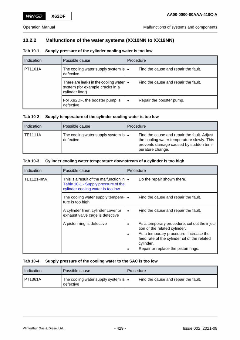
10.2.2 Malfunctions of the water systems (XX10NN to XX19NN)
Tab 10-1 Supply pressure of the cylinder cooling water is too low
Indication Possible cause Procedure
PT1101A The cooling water supply system isdefective
• Find the cause and repair the fault.
There are leaks in the cooling watersystem (for example cracks in acylinder liner)
• Find the cause and repair the fault.
For X92DF, the booster pump isdefective
• Repair the booster pump.
Tab 10-2 Supply temperature of the cylinder cooling water is too low
Indication Possible cause Procedure
TE1111A The cooling water supply system isdefective
• Find the cause and repair the fault. Adjustthe cooling water temperature slowly. Thisprevents damage caused by sudden tem-perature change.
Tab 10-3 Cylinder cooling water temperature downstream of a cylinder is too high
Indication Possible cause Procedure
TE1121-nnA This is a result of the malfunction inTable 10-1 - Supply pressure of thecylinder cooling water is too low
• Do the repair shown there.
The cooling water supply tempera-ture is too high
• Find the cause and repair the fault.
A cylinder liner, cylinder cover orexhaust valve cage is defective
• Find the cause and repair the fault.
A piston ring is defective • As a temporary procedure, cut out the injec-tion of the related cylinder.
• As a temporary procedure, increase thefeed rate of the cylinder oil of the relatedcylinder.
• Repair or replace the piston rings.
Tab 10-4 Supply pressure of the cooling water to the SAC is too low
Indication Possible cause Procedure
PT1361A The cooling water supply system isdefective
• Find the cause and repair the fault.
X62DF AA00-0000-00AAA-410C-A
Operation Manual Malfunctions of systems and components
Winterthur Gas & Diesel Ltd. - 429 - Issue 002 2021-09

Tab 10-5 Supply temperature of the cooling water to the SAC is too low
Indication Possible cause Procedure
TE1371A The cooling water supply system isdefective
• Find the cause and repair the fault.
Tab 10-6 Temperature of the cooling water downstream of the SAC is too high
Indication Possible cause Procedure
TE1381-nnA This is a result of the malfunction inTable 10-4 - Supply pressure of thecooling water to the SAC is too low
• Do the repair shown there.
This is a result of the malfunction inTable 10-5 - Supply temperature ofthe cooling water to the SAC is toolow
• Do the repair shown there.
X62DF AA00-0000-00AAA-410C-A
Operation Manual Malfunctions of systems and components
Winterthur Gas & Diesel Ltd. - 430 - Issue 002 2021-09

10.2.3 Malfunction of the oil systems (XX20NN to XX31NN)
Tab 10-7 Lubricating oil supply pressure at the engine inlet is too low
Indication Possible cause Procedure
PT2001APT2012A (if applica-ble)
The oil supply system is defective • Find the cause and repair the fault.
Tab 10-8 Lubricating oil supply pressure upstream of the injectors is too low
Indication Possible cause Procedure
PT2003A If applicable: the injector oil valve8423_E0_1 is defective
• Open the shut-off valve 8423_E0_2.
• Repair the injector oil valve.
If injector oil valve 8423_E0_1 isnot applicable: shut-off valve8423_E0_2 is closed
• Open the shut-off valve 8423_E0_2.
An injection valve is defective or apipe is clogged
• Find the cause and repair the fault.
The alarm has no effect at engine standstill.
Tab 10-9 Lubricating oil supply temperature at the engine inlet is too high
Indication Possible cause Procedure
TE2011ATE2012A (if applica-ble)
The oil supply system is defective • Find the cause and repair the fault.
Tab 10-10 Lubricating oil supply pressure upstream of the crossheads is too low
Indication Possible cause Procedure
PT2021A The crosshead oil supply system isdefective
• Decrease the engine load.
• Find the cause and repair the fault.
Tab 10-11 Servo oil pressure in the distributor pipe (mini rail) is not in the permitted range
Indication Possible cause Procedure
PT2041A There is an incorrect setting of thepressure reducing valve
• Set the pressure reducing valve to the cor-rect value.
There is an incorrect setting of thesafety valve
• Set the safety valve to the correct value.
The filter or the opening in the ex-haust valve control unit is clogged
• Clean the filter or the exhaust valve controlunit.
A servo oil pump or the servo oilservice pump is defective
• Repair the defective pumps.
X62DF AA00-0000-00AAA-410C-A
Operation Manual Malfunctions of systems and components
Winterthur Gas & Diesel Ltd. - 431 - Issue 002 2021-09

Tab 10-12 Servo oil leakage flow from the servo oil supply unit is too high
Indication Possible cause Procedure
LS2055A The servo oil unit or a servo oil pipeis defective
• Find the cause and repair the fault, refer tosection 10.6 Examine the supply unit for ser-vo oil leakage.
Tab 10-13 Servo oil flow at a servo oil pump inlet is too low
Indication Possible cause Procedure
FS2061-nnA The related servo oil pump is de-fective
• Replace the defective servo oil pump assoon as possible.
The alarm has an effect only above 30% of engine load.
Tab 10-14 Bearing oil temperature at a bearing outlet is too high
Indication Possible cause Procedure
TE2101-nnATE2201-nnATE2301-nnA
This is a result of the malfunction inTable 10-7 - Lubricating oil supplypressure at the engine inlet is toolow
• Do the repair shown there.
A bearing is defective • Find the cause and repair the fault.
The oil does not have the specifiedproperties
• Use correct oil.
Tab 10-15 Oil mist concentration is too high
Indication Possible cause Procedure
AE2401-nnA(crankcase)AE2415A(gearcase)AE2421-nnA (fuelsupply unit)
The oil supply system is defective • Find the cause and repair the fault.
Parts that move have become toohot
• As a temporary procedure, decrease the en-gine load.
• Stop the engine.
• Wait a minimum of 20 minutes to let the en-gine temperature decrease.
• Find the cause and repair the fault.
X62DF AA00-0000-00AAA-410C-A
Operation Manual Malfunctions of systems and components
Winterthur Gas & Diesel Ltd. - 432 - Issue 002 2021-09

Tab 10-16 Piston cooling oil temperature downstream of a piston is too high
Indication Possible cause Procedure
TE2501-nnA This is a result of the malfunction inTable 10-9 - Lubricating oil supplytemperature at the engine inlet istoo high
• Do the repair shown there.
A piston ring is defective • As a temporary procedure, cut out the injec-tion of the related cylinder.
• As a temporary procedure, increase thefeed rate of the cylinder oil of the relatedcylinder.
• Repair or replace the piston rings.
Tab 10-17 Piston cooling oil flow to a piston is not in the permitted range
Indication Possible cause Procedure
FS2521-nnA This is a result of the malfunction inTable 10-7 - Lubricating oil supplypressure at the engine inlet is toolow
• Do the repair shown there.
A lever is defective • Repair the defective lever.
Tab 10-18 TC bearing oil temperature at a turbocharger outlet is too high
Indication Possible cause Procedure
TE2601-nnA This is a result of the malfunction inTable 10-9 - Lubricating oil supplytemperature at the engine inlet istoo high
• Do the repair shown there.
A turbocharger is defective • Refer to the turbocharger manual.
Tab 10-19 TC bearing oil supply pressure upstream of a turbocharger is too low
Indication Possible cause Procedure
PT2611-nnA This is a result of the malfunction inTable 10-7 - Lubricating oil supplypressure at the engine inlet is toolow
• Do the repair shown there.
There is an incorrect setting of theadjustable orifice
• Set the adjustable orifice to the correct val-ue.
Tab 10-20 TC bearing oil temperature at a turbocharger inlet is too high (external oil supply)
Indication Possible cause Procedure
TE2621A The external oil supply system isdefective
• Find the cause and repair the fault.
X62DF AA00-0000-00AAA-410C-A
Operation Manual Malfunctions of systems and components
Winterthur Gas & Diesel Ltd. - 433 - Issue 002 2021-09

Tab 10-21 Damper oil supply pressure upstream of the torsional vibration damper is too low
Indication Possible cause Procedure
PT2711A There is an incorrect setting of thethrottle valve
• Set the throttle valve to the correct value.
An oil supply pipe is defective • Replace the oil supply pipe.
Tab 10-22 Damper oil supply pressure upstream of the axial vibration damper is too low
Indication Possible cause Procedure
PT2721APT2722A
A sealing ring is defective • Replace the defective sealing ring.
Tab 10-23 Cylinder oil supply pressure is too low
Indication Possible cause Procedure
PT3124A A filter element is clogged • Change over to the other filter chamber.
• Replace or clean the clogged filter element.
The cylinder oil tank is empty • Fill the cylinder oil tank.
Tab 10-24 Cylinder oil flow is too low
Indication Possible cause Procedure
This is a result of the malfunction inTable 10-23 - Cylinder oil supplypressure is too low
• Do the repair shown there.
This is a result of the malfunction inTable 10-11 - Servo oil pressure inthe distributor pipe (mini rail) is notin the permitted range
• Do the repair shown there.
There is air in the cylinder oil sys-tem
• Release the unwanted air from the cylinderoil system.
Lubricating quills are blocked • Clean or replace defective parts.
X62DF AA00-0000-00AAA-410C-A
Operation Manual Malfunctions of systems and components
Winterthur Gas & Diesel Ltd. - 434 - Issue 002 2021-09

10.2.4 Malfunction of the fuel system (XX34NN)
Tab 10-25 Fuel supply temperature is not in the permitted range
Indication Possible cause Procedure
TE3411A The fuel supply system is defective • Find the cause and repair the fault.
Tab 10-26 Fuel supply pressure at the engine inlet is too low
Indication Possible cause Procedure
PT3421A The fuel supply system is defective • Find the cause and repair the fault.
The fuel does not have the speci-fied properties
• Use correct fuel.
Tab 10-27 Fuel leakage flow from the fuel supply unit is too high
Indication Possible cause Procedure
LS3426-27A An HP fuel pipe or a fuel pump isdefective
• Find the cause and repair the defective item,refer to section 10.7 Examine the supply unitfor fuel leakage.
Tab 10-28 Temperature difference of the fuel outlet of the two fuel pumps is too high (for X35/-B orX40/-B engine)
Indication Possible cause Procedure
TE3431-nnA Flow control valve of a fuel pump isdefective
• Clean or replace the defective flow controlvalve.
One of the two fuel pumps is de-fective
• Replace the defective fuel pump.
• As a temporary procedure, close the 3/2-way valve 10-8752_E0_3-4 in the HP fuelpipe of the defective fuel pump.
Tab 10-29 Leakage flow from the rail unit is too high
Indication Possible cause Procedure
LS3444-nnA An item of the rail unit is defective • Find the cause and repair the defective item,refer to section 10.8 Examine the rail unit forleakage.
Tab 10-30 Fuel leakage flow from fuel rail items is too high (engine with FLV)
Indication Possible cause Procedure
LS3446A A flow limiting valve (FLV), a injec-tor or a pipe is defective
• Find the cause and repair the defective item,refer to section 10.9 Examine the FLV or fuelpipes for fuel leakage.
NOTE: The leakage flow from the FLV is related to the viscosity of the used fuel.
X62DF AA00-0000-00AAA-410C-A
Operation Manual Malfunctions of systems and components
Winterthur Gas & Diesel Ltd. - 435 - Issue 002 2021-09
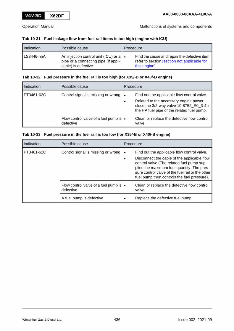
Tab 10-31 Fuel leakage flow from fuel rail items is too high (engine with ICU)
Indication Possible cause Procedure
LS3446-nnA An injection control unit (ICU) or apipe or a connecting pipe (if appli-cable) is defective
• Find the cause and repair the defective item,refer to section [section not applicable forthis engine].
Tab 10-32 Fuel pressure in the fuel rail is too high (for X35/-B or X40/-B engine)
Indication Possible cause Procedure
PT3461-62C Control signal is missing or wrong • Find out the applicable flow control valve.
• Related to the necessary engine powerclose the 3/2-way valve 10-8752_E0_3-4 inthe HP fuel pipe of the related fuel pump.
Flow control valve of a fuel pump isdefective
• Clean or replace the defective flow controlvalve.
Tab 10-33 Fuel pressure in the fuel rail is too low (for X35/-B or X40/-B engine)
Indication Possible cause Procedure
PT3461-62C Control signal is missing or wrong • Find out the applicable flow control valve.
• Disconnect the cable of the applicable flowcontrol valve (The related fuel pump sup-plies the maximum fuel quantity. The pres-sure control valve of the fuel rail or the otherfuel pump then controls the fuel pressure).
Flow control valve of a fuel pump isdefective
• Clean or replace the defective flow controlvalve.
A fuel pump is defective • Replace the defective fuel pump.
X62DF AA00-0000-00AAA-410C-A
Operation Manual Malfunctions of systems and components
Winterthur Gas & Diesel Ltd. - 436 - Issue 002 2021-09

10.2.5 Malfunctions of systems for DF engine (XX33NN to XX39NN)
Tab 10-34 Gas concentration in piston underside is too high
Indication Possible cause Procedure
AE3315C There is a leakage in the gas sys-tem
• Find the cause and repair the defective item.
Tab 10-35 Difference pressure of pilot fuel filter is too high
Indication Possible cause Procedure
PS3464A The pilot fuel filter is clogged • Replace the filter element.
Tab 10-36 Gas supply pressure is too low
Indication Possible cause Procedure
PT3901C The gas supply is defective • Find the cause and repair the fault.
The gas filter is clogged • Clean or replace the gas filter. For the filterof the iGPR refer to [section not applicablefor this engine].
X62DF AA00-0000-00AAA-410C-A
Operation Manual Malfunctions of systems and components
Winterthur Gas & Diesel Ltd. - 437 - Issue 002 2021-09

10.2.6 Malfunctions of the exhaust gas system (XX37NN)
Tab 10-37 Exhaust gas temperature downstream of a cylinder is too high
Indication Possible cause Procedure
TE3701-nnA The scavenge air flow is too low • Clean the turbocharger.
• Clean the air flaps in the scavenge air re-ceiver.
• Clean the scavenge ports.
This is a result of the malfunction inTable 10-3 - Cylinder cooling watertemperature downstream of acylinder is too high
• Do the repair shown there.
There is air in the cooling watersystem
• Open the vent valves of the cooling watersystem.
An injection nozzle is defective • Repair or replace the defective injectionnozzle.
The injection time is too long • Find the cause and repair the fault.
There are leaks in the cooling watersystem (for example cracks in acylinder liner)
• Find the cause and repair the fault.
There is a fire in the piston under-side
• Do the procedure in section 2.4 Fire-fightingin the scavenge air space.
Tab 10-38 Exhaust gas temperature difference downstream of all cylinders is too high
Indication Possible cause Procedure
TE3701-nnA An injection nozzle is defective • Repair or replace the defective injectionnozzle.
The fuel supply system is defective • Find the cause and repair the fault.
An exhaust valve is defective • Repair or replace the defective exhaustvalve.
Tab 10-39 Exhaust gas temperature upstream of a turbocharger is too high
Indication Possible cause Procedure
TE3721-nnA This is a result of the malfunction inTable 10-37 - Exhaust gas temper-ature downstream of a cylinder istoo high
• Do the repair shown there.
X62DF AA00-0000-00AAA-410C-A
Operation Manual Malfunctions of systems and components
Winterthur Gas & Diesel Ltd. - 438 - Issue 002 2021-09
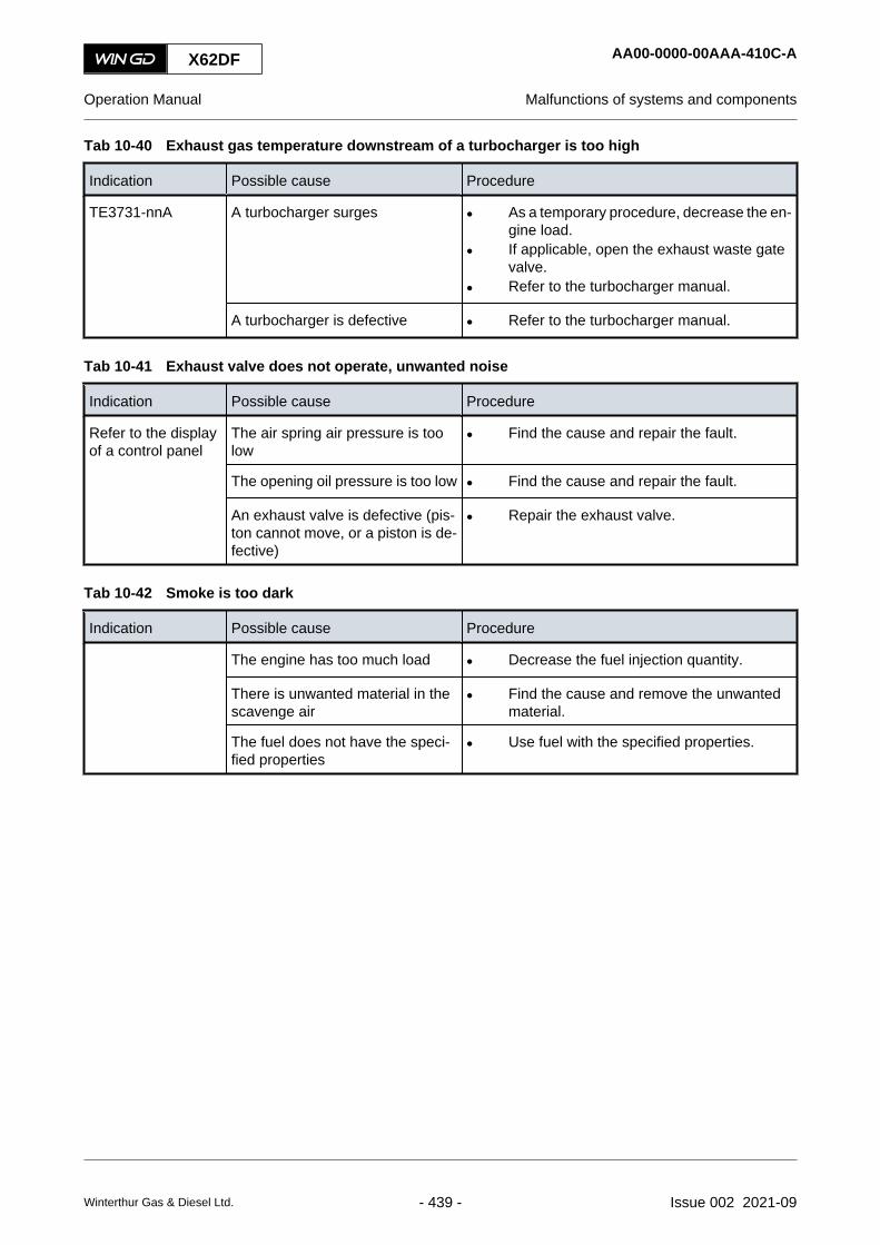
Tab 10-40 Exhaust gas temperature downstream of a turbocharger is too high
Indication Possible cause Procedure
TE3731-nnA A turbocharger surges • As a temporary procedure, decrease the en-gine load.
• If applicable, open the exhaust waste gatevalve.
• Refer to the turbocharger manual.
A turbocharger is defective • Refer to the turbocharger manual.
Tab 10-41 Exhaust valve does not operate, unwanted noise
Indication Possible cause Procedure
Refer to the displayof a control panel
The air spring air pressure is toolow
• Find the cause and repair the fault.
The opening oil pressure is too low • Find the cause and repair the fault.
An exhaust valve is defective (pis-ton cannot move, or a piston is de-fective)
• Repair the exhaust valve.
Tab 10-42 Smoke is too dark
Indication Possible cause Procedure
The engine has too much load • Decrease the fuel injection quantity.
There is unwanted material in thescavenge air
• Find the cause and remove the unwantedmaterial.
The fuel does not have the speci-fied properties
• Use fuel with the specified properties.
X62DF AA00-0000-00AAA-410C-A
Operation Manual Malfunctions of systems and components
Winterthur Gas & Diesel Ltd. - 439 - Issue 002 2021-09
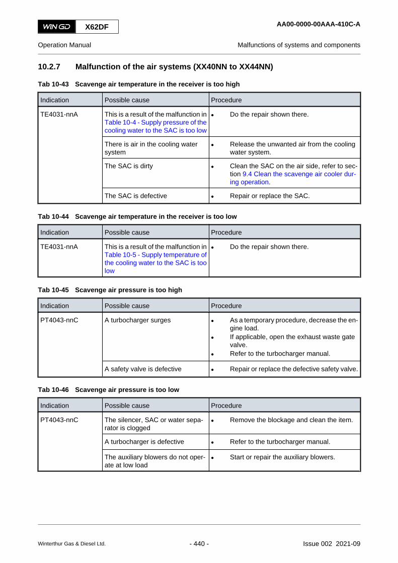
10.2.7 Malfunction of the air systems (XX40NN to XX44NN)
Tab 10-43 Scavenge air temperature in the receiver is too high
Indication Possible cause Procedure
TE4031-nnA This is a result of the malfunction inTable 10-4 - Supply pressure of thecooling water to the SAC is too low
• Do the repair shown there.
There is air in the cooling watersystem
• Release the unwanted air from the coolingwater system.
The SAC is dirty • Clean the SAC on the air side, refer to sec-tion 9.4 Clean the scavenge air cooler dur-ing operation.
The SAC is defective • Repair or replace the SAC.
Tab 10-44 Scavenge air temperature in the receiver is too low
Indication Possible cause Procedure
TE4031-nnA This is a result of the malfunction inTable 10-5 - Supply temperature ofthe cooling water to the SAC is toolow
• Do the repair shown there.
Tab 10-45 Scavenge air pressure is too high
Indication Possible cause Procedure
PT4043-nnC A turbocharger surges • As a temporary procedure, decrease the en-gine load.
• If applicable, open the exhaust waste gatevalve.
• Refer to the turbocharger manual.
A safety valve is defective • Repair or replace the defective safety valve.
Tab 10-46 Scavenge air pressure is too low
Indication Possible cause Procedure
PT4043-nnC The silencer, SAC or water sepa-rator is clogged
• Remove the blockage and clean the item.
A turbocharger is defective • Refer to the turbocharger manual.
The auxiliary blowers do not oper-ate at low load
• Start or repair the auxiliary blowers.
X62DF AA00-0000-00AAA-410C-A
Operation Manual Malfunctions of systems and components
Winterthur Gas & Diesel Ltd. - 440 - Issue 002 2021-09

Tab 10-47 Condensation flow at a water separator is too high
Indication Possible cause Procedure
LS4071-nnA The filter in the return pipe isclogged
• Clean the filter.
The opening in the return pipe isclogged
• Clean the return pipe.
There are leaks in the SAC • Find the cause and repair the fault.
Tab 10-48 Condensation flow upstream of a water separator is too high
Indication Possible cause Procedure
LS4075-nnA The filter in the return pipe isclogged
• Clean the filter.
The opening in the return pipe isclogged
• Clean the return pipe.
There are leaks in the SAC • Find the cause and repair the fault.
Tab 10-49 Scavenge air temperature in the piston underside is too high
Indication Possible cause Procedure
TE4081-nnA There is fire in the piston underside • Refer to section 2.4 Fire-fighting in the scav-enge air space.
A piston ring is defective • As a temporary procedure, decrease theload and cut out the injection of the relatedcylinder.
• As a temporary procedure, increase thefeed rate of the cylinder oil of the relatedcylinder.
• Repair or replace the piston rings.
The engine has too much load • Decrease the fuel injection quantity.
Tab 10-50 Starting air supply pressure is too low
Indication Possible cause Procedure
PT4301-nnC The starting air supply system isdefective
• Find the cause and repair the fault.
Tab 10-51 Pressure of the air spring air supply is too high
Indication Possible cause Procedure
PT4341A There is an incorrect setting of thecontrol air supply
• Set the control air supply to the correct val-ue.
X62DF AA00-0000-00AAA-410C-A
Operation Manual Malfunctions of systems and components
Winterthur Gas & Diesel Ltd. - 441 - Issue 002 2021-09

Tab 10-52 Pressure of the air spring air supply is too low
Indication Possible cause Procedure
PT4341A There is an incorrect setting of thecontrol air supply
• Set the control air supply to the correct val-ue.
There is an incorrect setting of thesafety valve
• Set the safety valve to the correct value.
The control air supply is defective • Repair or replace the defective item of thecontrol air supply.
Tab 10-53 Oil leakage flow in the collector for leakage oil from the air spring is too high
Indication Possible cause Procedure
LS4351-52A The collector for leakage oil fromthe air spring is clogged
• Clean the collector for leakage oil from theair spring.
The float control is defective • Repair the float control.
Tab 10-54 Control air supply pressure is too low (usual supply)
Indication Possible cause Procedure
PT4401A The control air supply system is de-fective
• Find the cause and repair the fault.
There is an incorrect setting of thecontrol air supply
• Set the control air supply to the correct val-ue.
Tab 10-55 Control air supply pressure is too low (stand-by supply)
Indication Possible cause Procedure
PT4411A The starting air supply system isdefective
• Find the cause and repair the fault.
There is an incorrect setting of thecontrol air supply
• Set the control air supply to the correct val-ue.
Tab 10-56 Control air supply pressure is too low (safety supply)
Indication Possible cause Procedure
PT4421A This is a result of the malfunction inTable 10-54 - Control air supplypressure is too low (usual supply)and in Table 10-55 - Control airsupply pressure is too low (stand-by supply)
• As a temporary procedure, stop the engine.
• Do the repair shown there.
The drain valve of the air tank isopen
• Close the drain valve of the air tank.
X62DF AA00-0000-00AAA-410C-A
Operation Manual Malfunctions of systems and components
Winterthur Gas & Diesel Ltd. - 442 - Issue 002 2021-09

10.2.8 Miscellaneous malfunctions (XX45NN to XX52NN)
Tab 10-57 Temperature of a thrust bearing pad is too high
Indication Possible cause Procedure
TE4521A This is a result of the malfunction inTable 10-7 - Lubricating oil supplypressure at the engine inlet is toolow
• Do the repair shown there.
The thrust bearing is defective • Find the cause and repair the fault.
The oil does not have the specifiedproperties
• Use correct oil.
Tab 10-58 Cylinder liner wall temperature is too high
Indication Possible cause Procedure
TE4801-nnCTE4841-nnC
The cylinder oil system is defective • Find the cause and repair the fault.
An injection nozzle is defective (forexample wrong spray angle, toolong spray period)
• Repair or replace the defective injectionnozzle.
This is a result of the malfunction inTable 10-1 - Supply pressure of thecylinder cooling water is too low orin Table 10-3 - Cylinder cooling wa-ter temperature downstream of acylinder is too high
• Do the repair shown there.
There is air in the cooling watersystem
• Release the unwanted air from the coolingwater system, for an engine with bypasscooling water system refer to section 10.5Bleed the cooling water system of the linerwall.
There are exhaust gas leaks intothe cooling water system (for ex-ample valve seat area)
• Find the cause and repair the fault.
Tab 10-59 A fuel pump actuator has a failure
Indication Possible cause Procedure
XS5046A The fuel does not have the speci-fied properties
• Use correct fuel.
A fuel pump actuator is defective • Repair the fuel pump actuator.
X62DF AA00-0000-00AAA-410C-A
Operation Manual Malfunctions of systems and components
Winterthur Gas & Diesel Ltd. - 443 - Issue 002 2021-09

Tab 10-60 Power supply to the power supply box E85 has a failure
Indication Possible cause Procedure
XS5056A The power supply is set to OFF • Set to ON the power supply.
The power supply system is defec-tive
• Repair the power supply system.
Tab 10-61 Unwanted engine speed decrease
Indication Possible cause Procedure
The speed setting from the speedcontrol system is decreased or isnot in the specified limits
• Do a check of the speed control system.
The fuel injection quantity from thespeed control system is decreased
• A procedure is not necessary because thecontrol system prevents too much load inheavy sea.
The fuel injection system is defec-tive
• Find the cause and repair the fault.
Tab 10-62 Unwanted engine stop
Indication Possible cause Procedure
The fuel injection system is defec-tive
• Find the cause and repair the fault.
This is a result of the malfunction inTable 10-61 - Unwanted enginespeed decrease
• Do the repair shown there.
There is heavy sea • Set to ON the heavy sea mode.
X62DF AA00-0000-00AAA-410C-A
Operation Manual Malfunctions of systems and components
Winterthur Gas & Diesel Ltd. - 444 - Issue 002 2021-09

X62DF AA00-0000-00AAA-410C-A
Operation Manual Malfunctions of systems and components
Page left intentionally blank
Winterthur Gas & Diesel Ltd. - 445 - Issue 002 2021-09

10.3 Failures and defects of UNIC-flex components
Failures and defects of UNIC-flex components cause failure messages, which are transmitted tothe alarm and monitoring system (AMS).
10.3.1 Failure messages
The UNIC-flex engine control system (ECS) constantly does internal integrity checks and monitorsthe connected sensors. UNIC-flex records each unusual condition and makes an event.
• The system software level does the checks for basic sensor failures.
• The software application level gives the level of the created event.
Related to the severity of the event there are three levels of messages:
• Minor failures
This category contains failures that will not cause to decrease the engine load (slowdown)or to stop the engine (shutdown). But you have to do a check of the message. If necessarycorrect the fault as soon as possible.
• Major failures
This category contains failures that will cause to decrease the engine load (slowdown) and/or to stop the engine (shutdown). Major failures are divided in the two sub-groups SLD(slowdown) and SHD (shutdown):○ The SLD sub-group contains failures that cause one cylinder to cut off. The AMS
sends a slowdown signal to the ECS.○ The SHD sub-group contains failures that prevent an engine operation. The engine
safety system (ESS) sends a shutdown signal to the ECS. UNIC-flex stops the fuelinjection.
These two sub-groups are not shown in internal or external interfaces. Thus they are onlyused on the application level.
If a major failure occurs, the AMS sends a signal to the ECS for a slowdown or shutdowncommand. Usually the ECS automatically sets the related setpoint for a slowdown orshutdown of the engine, refer also to Para 10.3.2.
• Info logs
This category contains messages which describe engine operation conditions or give moredata to other failures. Related to the functional description only the most importantmessages are sent to the AMS.
The table that follows shows some examples of failure messages.
Tab 10-63 Examples of failure messages
ID Failure text Failure type
3 Gear Wheel Sensor A Signal Fail Minor
46 Crank Angle Measurement Fail CCM #2 to #n Major / SHD
48 Crank Angle Measurement Fail CCM #1 Major / SLD
250 Remote Start Interlock - Main Start Air Valve Manually Closed Info
X62DF AA00-0000-00AAC-410C-A
Operation Manual Failures and defects of UNIC-flex components
Winterthur Gas & Diesel Ltd. - 446 - Issue 002 2021-09

For the complete list of failure messages refer to the document - Modbus to AMS signal list - ofthe engine.
10.3.2 Special failures
WinGD has specified a few special failures (refer to Table 10-64 - Special failures) that makes itnecessary to start other steps.
Tab 10-64 Special failures
ID Failure text Failure type
45 Crank Angle Measurement Fail CCM #1 & MCM Major / SLD
47 Crank Angle Measurement Fail MCM Minor
96 Module Fail MCM Minor
If one of these special failures occur, the ECS automatically does the steps that follow:
• The ECS changes the active control location to “ECR manual”.
• The ECS changes to the “Fuel command mode”.
In this condition the ECS cannot set a setpoint for a command. Thus obey the rules that follow:
• If failure 45 occurs the operator must set the fuel command setpoint for slowdown manually.
• If failure 47 or 96 occurs the operator can set the fuel command setpoint if necessary.
10.3.3 Troubleshooting of UNIC-flex failures
If there is an indication of a UNIC-flex failure, use the data that follows to find the failure and torepair it:
• Use the failure ID to find the related system or item.
• If applicable, compare the indicated values with the values on the local instruments.
• Make sure that the related items are mounted correctly and can operate correctly.
• Make sure that the related shut-off valves are in the correct operation positions.
• Do a check of the related cable connections.
• Do a check of the related cable or plugs for damage.
• Do a check of the related item for damage.
• Use a multimeter to do a check of the power supply.
• Use a multimeter to do a check of the sensor signal.
• Use a multimeter to do a check for a short circuit or a ground fault.
• If applicable, do a check of the terminating resistors for correct connection.
• Repair the faults, or temporarily repair defective cables with insulation tape.
• If necessary, replace damaged items.
If you cannot repair a fault, speak to or send a message to WinGD.
X62DF AA00-0000-00AAC-410C-A
Operation Manual Failures and defects of UNIC-flex components
Winterthur Gas & Diesel Ltd. - 447 - Issue 002 2021-09
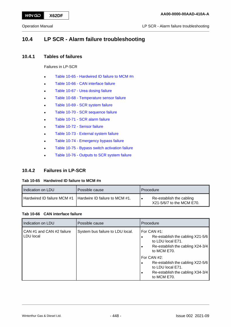
10.4 LP SCR - Alarm failure troubleshooting
10.4.1 Tables of failures
Failures in LP-SCR
• Table 10-65 - Hardwired ID failure to MCM #n
• Table 10-66 - CAN interface failure
• Table 10-67 - Urea dosing failure
• Table 10-68 - Temperature sensor failure
• Table 10-69 - SCR system failure
• Table 10-70 - SCR sequence failure
• Table 10-71 - SCR alarm failure
• Table 10-72 - Sensor failure
• Table 10-73 - External system failure
• Table 10-74 - Emergency bypass failure
• Table 10-75 - Bypass switch activation failure
• Table 10-76 - Outputs to SCR system failure
10.4.2 Failures in LP-SCR
Tab 10-65 Hardwired ID failure to MCM #n
Indication on LDU Possible cause Procedure
Hardwired ID failure MCM #1 Hardwire ID failure to MCM #1. • Re-establish the cablingX21-5/6/7 to the MCM E70.
Tab 10-66 CAN interface failure
Indication on LDU Possible cause Procedure
CAN #1 and CAN #2 failureLDU local
System bus failure to LDU local. For CAN #1:• Re-establish the cabling X21-5/6
to LDU local E71.• Re-establish the cabling X24-3/4
to MCM E70.For CAN #2:• Re-establish the cabling X22-5/6
to LDU local E71.• Re-establish the cabling X34-3/4
to MCM E70.
X62DF AA00-0000-00AAD-410A-A
Operation Manual LP SCR - Alarm failure troubleshooting
Winterthur Gas & Diesel Ltd. - 448 - Issue 002 2021-09

Indication on LDU Possible cause Procedure
SCR CAN failure SCR system does not receives CANsignal.
• Re-establish the cabling ofX24-5/6 to the MCM E70.NOTE: This is only applicable
to SCR systems withCAN interface.
Communication to ECS fail ECS does not receive CAN interfacesignals.
• Re-establish the cabling X34-5/6to MCM E70.
For WECS:• Re-establish the cabling CAN-M
X22-55/56 to FCM 20.3.For UNIC:• Re-establish the cabling CAN 3
X21-2/3 to LDU-20.
CAN interface failure LDUECR
CAN interface failure to LDU ECR. • Reboot the LDU local and LDUECR.
• Re-establish the cabling CAN#2X22-5/6 to the LDU local E71.
• Re-establish the cabling CAN#3X21-2/3 to the LDU ECR E72.
Tab 10-67 Urea dosing failure
Indication on LDU Possible cause Procedure
Urea dosing system Setpointfailed
Status bit for hardware signal failure:Urea dosing setpoint.NOTE: This failure can occur due
to short circuit or wirebreak.
• Re-establish the wiring betweenE70 and external dosing system.
Urea feedback input failed Status bit for hardware signal failure:Urea feedback.NOTE: This failure can occur due
to short circuit or wirebreak.
• Re-establish the wiring betweenE70 and external dosing system.
Dosing system not ready SCR system sent a signal that ureadosing system is not ready.
• Do a check of the external SCRcontrol system.
Tab 10-68 Temperature sensor failure
Indication on LDU Possible cause Procedure
TE3746C Temperature sensor fails to mea-sure the exhaust gas temperature atSCR reactor outlet.Status bit for hardware signal failure:Temperature sensor TE3746C.
• Re-establish the cabling X41-1/2to MCM E70.
• Replace the faulty sensor if re-quired.
X62DF AA00-0000-00AAD-410A-A
Operation Manual LP SCR - Alarm failure troubleshooting
Winterthur Gas & Diesel Ltd. - 449 - Issue 002 2021-09

Indication on LDU Possible cause Procedure
TE3745C Temperature sensor fails to mea-sure the exhaust gas temperature atSCR reactor inlet.Status bit for hardware signal failure:Temperature sensor TE3746C.
• Re-establish the cabling X41-5/6to MCM E70.
• Replace the faulty sensor if re-quired.
Tab 10-69 SCR system failure
Indication on LDU Possible cause Procedure
External valve system notready
SCR system sent a signal that ex-ternal valve is not ready.
• Do a check of the external valvecontrol system.
SCR shutdown SCR system sent a signal for SCRshutdown.
• Do a check of the external SCRcontrol system.
Tab 10-70 SCR sequence failure
Indication on LDU Possible cause Procedure
SCR sequence failure Failure during Tier 3 sequence. • Do an investigation of EDL mes-sages from the LDU local E71 orLDU ECR E72.
Urea failure The minimal level or setpoint is notreached, when the urea dosing inrequested.
• Do a detail check of the externaldosing system.
Tab 10-71 SCR alarm failure
Indication on LDU Possible cause Procedure
SCR Alarm Stop CAN sent a signal for SCR alarmstop.
• Do a detail check of the externalSCR control system.
SCR Alarm CAN sent a signal for SCR alarm. • Do a detail check of the externalSCR control system.
Tab 10-72 Sensor failure
Indication on LDU Possible cause Procedure
TE3755C Temperature sensor fails to mea-sure the exhaust gas temperature atturbine outlet.Status bit for hardware signal failure:Temperature sensor TE3755C.
• Re-establish the cabling X41-7/8to MCM E70.
• Replace the faulty sensor if re-quired.
AE3803C Humidity sensor fails to measure therelative humidity at turbocharger in-let.Status bit for hardware signal failure:Humidity sensor.
• Re-establish the cabling X41-5/6to MCM E70.
• Replace the faulty sensor if re-quired.
X62DF AA00-0000-00AAD-410A-A
Operation Manual LP SCR - Alarm failure troubleshooting
Winterthur Gas & Diesel Ltd. - 450 - Issue 002 2021-09

Indication on LDU Possible cause Procedure
AE3802C NOx sensor fails to measure NOx atturbocharger outlet.NOx-Sensor alarm signal is not inmeasuring mode (1 Hz) or in cali-bration mode (2 Hz).Status bit for hardware signal failure:NOx sensor.
For Hardware signal failure:• Re-establish the cabling
X31-3/4/5 to MCM E70.For Alarm signal failure:• Re-establish the cabling X12-1/2
to MCM E70.
• Replace the faulty sensor if re-quired.
Tab 10-73 External system failure
Indication on LDU Possible cause Procedure
Auxiliary blower #1 failure The SCR control system is unable toreceive the auxiliary blower #1 op-erating signal in specified time inter-val.Parameter: PAR_AuxBI_FailDelay
• Do a check of the auxiliary blow-er control box.
Auxiliary blower #2 failure The SCR control system is unable toreceive the auxiliary blower #2 op-erating signal in specified time inter-val.Parameter: PAR_AuxBI_FailDelay
• Do a check of the auxiliary blow-er control box.
External SCR common alarm SCR system sends common alarm. • Do a check of the external SCRcontrol system.
Tab 10-74 Emergency bypass failure
Indication on LDU Possible cause Procedure
Emergency bypass Emergency bypass command onone of the E70, E71, E73 or PCS.
• If it is not possible to activateemergency bypass manually, re-establish the cabling.
Tab 10-75 Bypass switch activation failure
Indication on LDU Possible cause Procedure
SCR - S2 - Emergency bypassswitch E71
Bypass switch signal from the relat-ed control unit is active.
• If it is not possible to activate by-pass switch manually, re-estab-lish the cabling.
SCR - S3 - Emergency bypassswitch E72
SCR - Emergency bypassswitch PCS
SCR - S1 - Emergency bypassswitch E70
X62DF AA00-0000-00AAD-410A-A
Operation Manual LP SCR - Alarm failure troubleshooting
Winterthur Gas & Diesel Ltd. - 451 - Issue 002 2021-09

Tab 10-76 Outputs to SCR system failure
Indication on LDU Possible cause Procedure
SCR common alarm failure Any of the minor or major failure isactive.
• Do a check of the local LDU onE71 or LDU ECR on E72 foralarm details.
SCR shutdown request sent toSCR system
If it is a major failure, a shutdown re-quest from the SCR control is sentto the SCR system.
• Do a check of the local LDU onE71 or LDU ECR on E72 foralarm details.
Power failure Power failure on the MCM-11 • Re-establish the power supplycables for power input 1 and 2.
For power input 1:• Re-establish the cabling
X24-1/2.For power input 2:• Re-establish the cabling
X34-1/2.
10.4.3 Sequence failure
A sequence failure occurs, when a specified condition is not obeyed. The current active state isnot allowed and the state-machine activates the sequence fail state.
Another cause of a sequence failure can be that the timers for dosing start-up or maximum allowedpreparation time expire.
A sequence failure ignores a minor failure and Tier 2 SCR will disengage.NOTE: In this case SCR shut-down is not requested.
X62DF AA00-0000-00AAD-410A-A
Operation Manual LP SCR - Alarm failure troubleshooting
Winterthur Gas & Diesel Ltd. - 452 - Issue 002 2021-09

X62DF AA00-0000-00AAD-410A-A
Operation Manual LP SCR - Alarm failure troubleshooting
Page left intentionally blank
Winterthur Gas & Diesel Ltd. - 453 - Issue 002 2021-09

10.5 Bleed the cooling water system of the liner wallPeriodicityDescriptionUnscheduledDuration for performing preliminary requirements 0.0 man-hoursDuration for performing the procedure 0.2 man-hoursDuration for performing the requirements after job completion 0.0 man-hours
PersonnelDescription Specialization QTYEngine crew Basic 1
Support equipmentDescription Part No. CSN QTYNone
SuppliesDescription QTYNone
Spare PartsDescription Part No. CSN QTYNone
SAFETY PRECAUTIONS
• None
PRELIMINARY OPERATIONS
• The engine has a bypass cooling water system.
• The engine must be in operation.
X62DF AA00-0000-00AAA-231A-A
Operation Manual Bleed the cooling water system of the liner wall
Winterthur Gas & Diesel Ltd. - 454 - Issue 002 2021-09

PROCEDURE
1 Close the shut-off valve (002, Figure 10-1) in the cylinder cover supply pipe of the relatedcylinder.
2 Let the cooling water flow through the shut-off valve (003) and the cylinder liner withincreased flow rate for approximately 15 seconds.
3 Open the shut-off valve (002) and wait approximately 30 seconds.4 Close the shut-off valve (002) again.5 Let the cooling water again flow through the shut-off valve (003) and the cylinder liner with
increased flow rate for approximately 15 seconds.6 Open the shut-off valve (002) to usual operation.7 Do a check of the temperature of the liner wall.8 If the temperature of the liner wall is too high, do Step 1 to Step 7 again.
Fig 10-1 Cooling water system with bypass cooling
002
0205
01
003
001
Legend
001 Optional vent valve 01 Connection 01 (cylinder cooling water inlet)002 Shut-off valve 02 Connection 02 (cylinder liner cooling water inlet)003 Shut-off valve 05 Connection 05 (cylinder cooling water drain
outlet)
CLOSE UP
• None
X62DF AA00-0000-00AAA-231A-A
Operation Manual Bleed the cooling water system of the liner wall
Winterthur Gas & Diesel Ltd. - 455 - Issue 002 2021-09

10.6 Examine the supply unit for servo oil leakagePeriodicityDescriptionUnscheduledDuration for performing preliminary requirements 0.0 man-hoursDuration for performing the procedure 1.0 man-hoursDuration for performing the requirements after job completion 0.0 man-hours
PersonnelDescription Specialization QTYEngine crew Basic 1
Support equipmentDescription Part No. CSN QTYNone
SuppliesDescription QTYNone
Spare PartsDescription Part No. CSN QTYNone
SAFETY PRECAUTIONS
PRELIMINARY OPERATIONS
• None
X62DF AA00-0000-00AAA-311A-A
Operation Manual Examine the supply unit for servo oil leakage
Winterthur Gas & Diesel Ltd. - 456 - Issue 002 2021-09

PROCEDURE
1 Do a check of the level switch LS2055A for free flow. If necessary, clean the bore of thepipe of the level switch.
2 Carefully do a check of the temperature of the oil leakage pipe of each servo oil pipe tofind the leakage pipe that has an oil flow.NOTE: There is an oil flow in the leakage pipe that has a higher temperature than the
other leakage pipes.3 Do a check of the related servo oil pipe at the highest inspection point for oil flow.
3.1 Carefully loosen the screw plug (003, Figure 10-2) a maximum of two turns andlook for oil flow.
3.2 If there is an oil flow, repair the cause of the leaks as soon as possible. Refer tothe Maintenance Manual.
3.3 Tighten the screw plug (003).
Fig 10-2 Example of inspection point
002
001
003
Legend
001 Servo oil pipe 003 Screw plug002 Flange
4 Do Step 3 again for the other inspection points.NOTE: Step 5 to Step 8 are only applicable for an X82 engine.
5 Do a check of the level switch LS2076A (if applicable also LS2077A) for free flow. Ifnecessary, clean the bore of the pipe of the level switch.
6 Carefully do a check of the temperature of the oil leakage pipe of each valve control unit(VCU) to find the leakage pipe that has an oil flow.NOTE: There is an oil flow in the leakage pipe that has a higher temperature than the
other leakage pipes.NOTE: As an alternative you can carefully loosen and tighten the screw plug of the
inspection point of each flange a maximum of two turns to find the leakage pipethat has an oil flow.
7 Cut out the injection of the related cylinder and replace the defective oil pipe, refer to theMaintenance Manual.
X62DF AA00-0000-00AAA-311A-A
Operation Manual Examine the supply unit for servo oil leakage
Winterthur Gas & Diesel Ltd. - 457 - Issue 002 2021-09

8 If there is no oil flow from none of the leakage pipes, find (if applicable) the connecting pipethat has a leakage as follows:8.1 Carefully loosen the screw plug of the inspection point of the first connecting pipe
a maximum of two turns.8.2 Do a check for oil flow.8.3 If there is an oil flow, shut-off the related connecting pipe an repair it at the next
occasion, refer to the Maintenance Manual.8.4 Tighten the screw plug.8.5 Do Step 8.1 to Step 8.4 again for the other connecting pipe.
CLOSE UP
• None
X62DF AA00-0000-00AAA-311A-A
Operation Manual Examine the supply unit for servo oil leakage
Winterthur Gas & Diesel Ltd. - 458 - Issue 002 2021-09

X62DF AA00-0000-00AAA-311A-A
Operation Manual Examine the supply unit for servo oil leakage
Page left intentionally blank
Winterthur Gas & Diesel Ltd. - 459 - Issue 002 2021-09

10.7 Examine the supply unit for fuel leakagePeriodicityDescriptionUnscheduledDuration for performing preliminary requirements 0.0 man-hoursDuration for performing the procedure 1.0 man-hoursDuration for performing the requirements after job completion 0.0 man-hours
PersonnelDescription Specialization QTYEngine crew Basic 1
Support equipmentDescription Part No. CSN QTYNone
SuppliesDescription QTYNone
Spare PartsDescription Part No. CSN QTYNone
SAFETY PRECAUTIONS
CAUTIONInjury Hazard: Always put on gloves and safety goggles when you do work on hot orpressurized components. When you open the screw plugs, fuel can come out as a sprayand cause injury.
PRELIMINARY OPERATIONS
• None
X62DF AA00-0000-00AAA-311B-A
Operation Manual Examine the supply unit for fuel leakage
Winterthur Gas & Diesel Ltd. - 460 - Issue 002 2021-09
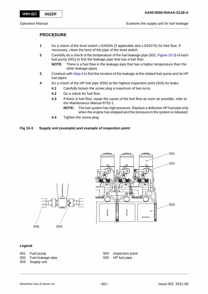
PROCEDURE
1 Do a check of the level switch LS3426A (if applicable also LS3427A) for free flow. Ifnecessary, clean the bore of the pipe of the level switch.
2 Carefully do a check of the temperature of the fuel leakage pipe (002, Figure 10-3) of eachfuel pump (001) to find the leakage pipe that has a fuel flow.NOTE: There is a fuel flow in the leakage pipe that has a higher temperature than the
other leakage pipes.3 Continue with Step 4 to find the location of the leakage at the related fuel pump and its HP
fuel pipes.4 Do a check of the HP fuel pipe (005) at the highest inspection point (004) for leaks.
4.1 Carefully loosen the screw plug a maximum of two turns.4.2 Do a check for fuel flow.4.3 If there is fuel flow, repair the cause of the fuel flow as soon as possible, refer to
the Maintenance Manual 8752-1.NOTE: The fuel system has high pressure. Replace a defective HP fuel pipe only
when the engine has stopped and the pressure in the system is released.4.4 Tighten the screw plug.
Fig 10-3 Supply unit (example) and example of inspection point
001
002
003
004005
Legend
001 Fuel pump 004 Inspection point002 Fuel leakage pipe 005 HP fuel pipe003 Supply unit
X62DF AA00-0000-00AAA-311B-A
Operation Manual Examine the supply unit for fuel leakage
Winterthur Gas & Diesel Ltd. - 461 - Issue 002 2021-09

5 Do Step 4 again for the other inspection points.6 If the related HP fuel pipes are tight, a fuel pump is defective. Thus do an overhaul of the
fuel pump, refer to the Maintenance Manual 5556-1.NOTE: If the defective HP fuel pipe cannot be replaced immediately (or the engine must
continue to operate), the related fuel pump must be cut out.
CLOSE UP
• None
X62DF AA00-0000-00AAA-311B-A
Operation Manual Examine the supply unit for fuel leakage
Winterthur Gas & Diesel Ltd. - 462 - Issue 002 2021-09

X62DF AA00-0000-00AAA-311B-A
Operation Manual Examine the supply unit for fuel leakage
Page left intentionally blank
Winterthur Gas & Diesel Ltd. - 463 - Issue 002 2021-09

10.8 Examine the rail unit for leakagePeriodicityDescriptionUnscheduledDuration for performing preliminary requirements 0.0 man-hoursDuration for performing the procedure 1.0 man-hoursDuration for performing the requirements after job completion 0.0 man-hours
PersonnelDescription Specialization QTYEngine crew Basic 1
Support equipmentDescription Part No. CSN QTYNone
SuppliesDescription QTYNone
Spare PartsDescription Part No. CSN QTYNone
SAFETY PRECAUTIONS
CAUTIONInjury Hazard: Always put on gloves and safety goggles when you do work on hot orpressurized components. Fuel can come out as a spray and cause injury.
PRELIMINARY OPERATIONS
• None
X62DF AA00-0000-00AAA-311E-A
Operation Manual Examine the rail unit for leakage
Winterthur Gas & Diesel Ltd. - 464 - Issue 002 2021-09

PROCEDURE
1 Do a check of the level switch LS3444A (if applicable also LS3445A) for free flow. Ifnecessary, clean the bore of the pipe of the level switch.
2 Carefully look into the rail unit to find the cause of the leakage.NOTE: Possible causes can be a defective pipe to the exhaust valve, a defective flange
or an other defective item.3 Repair the defective item.
CLOSE UP
• None
X62DF AA00-0000-00AAA-311E-A
Operation Manual Examine the rail unit for leakage
Winterthur Gas & Diesel Ltd. - 465 - Issue 002 2021-09

10.9 Examine the FLV or fuel pipes for fuel leakagePeriodicityDescriptionUnscheduledDuration for performing preliminary requirements 0.0 man-hoursDuration for performing the procedure 1.0 man-hoursDuration for performing the requirements after job completion 0.0 man-hours
PersonnelDescription Specialization QTYEngine crew Basic 1
Support equipmentDescription Part No. CSN QTYNone
SuppliesDescription QTYNone
Spare PartsDescription Part No. CSN QTYNone
SAFETY PRECAUTIONS
CAUTIONInjury Hazard: Always put on gloves and safety goggles when you do work on hot orpressurized components. When you open the screw plugs, fuel can come out as a sprayand cause injury.
PRELIMINARY OPERATIONS
• None
X62DF AA00-0000-00AAA-311C-A
Operation Manual Examine the FLV or fuel pipes for fuel leakage
Winterthur Gas & Diesel Ltd. - 466 - Issue 002 2021-09

PROCEDURE
Fig 10-4 Leakage on FLV and pipes (example)
001
002003
004
006 005007
008
Legend
001 HP fuel pipe to injection valve 005 Fuel rail002 Screw 006 Fuel leakage pipe003 Screw-in union 007 Screw-in union004 Fuel leakage pipe 008 Flow limiting valve (FLV)
1 Do a check of the level switch LS3446A for free flow. If necessary, clean the bore of thepipe of the level switch.
2 Carefully do a check of the temperature of the fuel leakage pipe (004, Figure 10-4) of eachflow limiting valve (FLV) (008) to find the leakage pipe that has a fuel flow.NOTE: There is a fuel flow in the leakage pipe that has a higher temperature than the
other leakage pipes.NOTE: As an alternative you can carefully open and close the screw-in union (003) of
each FLV a maximum of two turns to find the leakage pipe that has a fuel flow.3 If there is a leakage pipe (004) that has a fuel flow, do as follows:
3.1 Make sure that the screws (002) are tightened correctly, refer to the MaintenanceManual 8733-1.
3.2 On the fuel leakage pipe (004), carefully loosen the screw-in union (003) amaximum of two turns.
3.3 Do a check for fuel flow.3.4 If fuel continues to flow from the screw-in union (003), do as follows (an HP fuel
pipe (001) is defective):3.4.1 Stop the engine.3.4.2 Remove each of the HP fuel pipes (001) until you find the defective HP fuel
pipe (refer to the Maintenance Manual 8733-1).3.4.3 Do a check for damage on the sealing face of the defective HP fuel pipe
(001). If you find damage, grind the sealing face (refer to the MaintenanceManual 8733-1).
3.4.4 If the HP fuel pipe is defective, cut out the injection of the related cylinderand replace the defective HP fuel pipe, refer to the Maintenance Manual.
3.4.5 Tighten the screw-in union (003).3.4.6 Start the engine.
3.5 If no fuel flows from the screw-in union (003), tighten the screw-in union (003).
X62DF AA00-0000-00AAA-311C-A
Operation Manual Examine the FLV or fuel pipes for fuel leakage
Winterthur Gas & Diesel Ltd. - 467 - Issue 002 2021-09

4 If none of the leakage pipes (004) have a leakage, find the FLV that has a fuel flow morethan usual (compared to the amount of leakage from the other FLV) as follows:4.1 Put an oil tray under the screw-in union (007, Figure 10-4) of the fuel leakage pipe
(006) to collect the usual fuel flow.4.2 Carefully loosen the screw-in union (007) a maximum of two turns.4.3 Do a check of the fuel flow.4.4 If fuel flows from the screw-in union (007) more than usual (compared to the
amount of leakage from the other FLV), the piston rod is defective. Replace thedefective piston rod (refer to the Maintenance Manual 5564-1).
4.5 Tighten the screw-in union (007).4.6 Do Step 4.1 to Step 4.5 again for the other FLV.
CLOSE UP
• None
X62DF AA00-0000-00AAA-311C-A
Operation Manual Examine the FLV or fuel pipes for fuel leakage
Winterthur Gas & Diesel Ltd. - 468 - Issue 002 2021-09

X62DF AA00-0000-00AAA-311C-A
Operation Manual Examine the FLV or fuel pipes for fuel leakage
Page left intentionally blank
Winterthur Gas & Diesel Ltd. - 469 - Issue 002 2021-09

10.10 Temporary cut out a defective injection valvePeriodicityDescriptionUnscheduledDuration for performing preliminary requirements 0.0 man-hoursDuration for performing the procedure 0.5 man-hoursDuration for performing the requirements after job completion 0.0 man-hours
PersonnelDescription Specialization QTYEngine crew Basic 1
Support equipmentDescription Part No. CSN QTYNone
SuppliesDescription QTYNone
Spare PartsDescription Part No. CSN QTYNone
SAFETY PRECAUTIONS
• None
PRELIMINARY OPERATIONS
• None
X62DF AA00-0000-00AAA-662A-A
Operation Manual Temporary cut out a defective injection valve
Winterthur Gas & Diesel Ltd. - 470 - Issue 002 2021-09

PROCEDURE
1 Cut out the injection of the related cylinder.NOTE: If possible, the exhaust valve must always operate.
2 For an engine with direct controlled injection valves, disconnect the electrical connectionfrom the injection valve.
3 For an engine with conventional injection valves, disconnect the electrical connection fromthe injection control unit (ICU).
4 If it is necessary to operate the engine with the injection cut out for an extended period, doas follows:4.1 Record the settings of the cylinder oil feed rate.4.2 Decrease the cylinder oil feed rate for the related cylinder to the minimum setting.
5 Repair the fault as soon as possible, refer to the Maintenance Manual.
CLOSE UP
• None
X62DF AA00-0000-00AAA-662A-A
Operation Manual Temporary cut out a defective injection valve
Winterthur Gas & Diesel Ltd. - 471 - Issue 002 2021-09

10.11 Temporary cut out a defective exhaust valve drivePeriodicityDescriptionUnscheduledDuration for performing preliminary requirements 0.0 man-hoursDuration for performing the procedure 0.5 man-hoursDuration for performing the requirements after job completion 0.0 man-hours
PersonnelDescription Specialization QTYEngine crew Basic 1
Support equipmentDescription Part No. CSN QTYNone
SuppliesDescription QTYNone
Spare PartsDescription Part No. CSN QTYNone
SAFETY PRECAUTIONS
• None
PRELIMINARY OPERATIONS
• The engine must be stopped and prepared for maintenance, refer to section 8.20 Preparethe engine after stop - general
X62DF AA00-0000-00AAA-662D-A
Operation Manual Temporary cut out a defective exhaust valve drive
Winterthur Gas & Diesel Ltd. - 472 - Issue 002 2021-09

PROCEDURE
1 Cut out the defective cylinder from the injection, refer to section 10.10 Temporary cut outa defective injection valve.
2 Disconnect the electrical connection to the related exhaust valve control unit (VCU).3 Repair the fault as soon as possible, refer to the Maintenance Manual.
CLOSE UP
• The engine can be started and operated at decreased load, refer to section 8.3 Start theengine - general
X62DF AA00-0000-00AAA-662D-A
Operation Manual Temporary cut out a defective exhaust valve drive
Winterthur Gas & Diesel Ltd. - 473 - Issue 002 2021-09

10.12 Temporary isolate a cylinder with cooling water leakagePeriodicityDescriptionUnscheduledDuration for performing preliminary requirements 0.0 man-hoursDuration for performing the procedure 1.0 man-hoursDuration for performing the requirements after job completion 0.0 man-hours
PersonnelDescription Specialization QTYEngine crew Basic 1
Support equipmentDescription Part No. CSN QTYPressure element 94259 A/R
SuppliesDescription QTYNone
Spare PartsDescription Part No. CSN QTYNone
SAFETY PRECAUTIONS
• None
PRELIMINARY OPERATIONS
• The engine must be stopped and prepared for maintenance, refer to section 8.20 Preparethe engine after stop - general
X62DF AA00-0000-00AAA-662B-A
Operation Manual Temporary isolate a cylinder with cooling water leakage
Winterthur Gas & Diesel Ltd. - 474 - Issue 002 2021-09

PROCEDURE
1 Isolate the defective cylinder from the cooling water system.2 Make sure that there is no air spring air pressure.3 Lock the exhaust valve in the open position as follows:
3.1 Remove the damper (002, Figure 10-5) from the top housing (001).3.2 Make sure that you do not lose the shim(s) (004).
NOTE: The shim(s) must stay in position when the pressure element is installed.3.3 Apply a thin layer of oil to the thread of the pressure element (003).3.4 Install the pressure element (003).
Fig 10-5 Exhaust valve with pressure element
001002 003
004
Legend
001 Top housing 003 Pressure element002 Damper 004 Shim
4 Cut out the defective cylinder from the injection, refer to section 10.10 Temporary cut outa defective injection valve.
5 Disconnect the electrical connection to the related exhaust valve control unit (VCU).6 Disconnect the control signal connection from the related starting air valve.7 Repair the fault as soon as possible, refer to the Maintenance Manual.
X62DF AA00-0000-00AAA-662B-A
Operation Manual Temporary isolate a cylinder with cooling water leakage
Winterthur Gas & Diesel Ltd. - 475 - Issue 002 2021-09

CLOSE UP
• The engine can be started and operated at decreased load, refer to section 8.3 Start theengine - general
X62DF AA00-0000-00AAA-662B-A
Operation Manual Temporary isolate a cylinder with cooling water leakage
Winterthur Gas & Diesel Ltd. - 476 - Issue 002 2021-09

X62DF AA00-0000-00AAA-662B-A
Operation Manual Temporary isolate a cylinder with cooling water leakage
Page left intentionally blank
Winterthur Gas & Diesel Ltd. - 477 - Issue 002 2021-09

10.13 Servo oil pump - troubleshooting
To troubleshoot the flow sensor, refer to the following instructions:
10.13.1 Flow sensor check
To resolve a flow sensor alarm, refer to the following instructions:
1 Disconnect the sensor from the connector.
2 Wait for 10 seconds to connect the sensor to the connector.
3 Monitor the following conditions:
Condition 1: If 2 LEDs glow orange and 1 LED glows green at the same time, then the sensoris OK.
Condition 2: If only 1 LED glows green, then the sensor is faulty.
Condition 3: If no LEDs glow, then there is no power supply to the sensor.NOTE: If the sensor is OK, then check the servo oil pump operation.
10.13.2 Servo oil pump operation check
To check for the servo oil pump operation, refer to the following instructions:
1 Engine must be at low load.
2 Remove the solenoid connector from the servo oil pump.NOTE: Do no remove the solenoid connector from the servo oil pump which gives a flow
alarm.
3 The servo oil pump which gives a flow alarm must now supply the servo oil in full capacity.
4 The flow alarm stops.
5 Wait for a minute to monitor the following conditions:
Condition 1: If the flow alarm stops, then the servo oil pump is operational and only needscalibration.
Condition 2: If the flow alarm does not stop, the servo oil pump must be removed from theengine.
X62DF AA00-5551-00AAA-410A-A
Operation Manual Servo oil pump - troubleshooting
Winterthur Gas & Diesel Ltd. - 478 - Issue 002 2021-09

X62DF AA00-5551-00AAA-410A-A
Operation Manual Servo oil pump - troubleshooting
Page left intentionally blank
Winterthur Gas & Diesel Ltd. - 479 - Issue 002 2021-09

10.14 Servo oil pump - Calibration for Bosch pump
To calibrate the Bosch servo oil pumps, refer to the following instructions.
10.14.1 Calibration procedure of the Bosch servo oil pump
To calibrate the Bosch servo oil pumps, refer to the following instructions.
1 Locate the pressure adjustment screw on the servo oil pump.
2 Remove the plastic cover from the adjustment screw.
3 Put marks on the initial position of the setting screw.
4 Loosen the locknut.
5 Turn the setting screw in clockwise direction for 22.5 degrees.
6 Tighten the locknut.
7 Monitor the condition for 5 minutes on the pump angle indicators.NOTE: If the pump angle indicators show different angles, an adjustment of the pump
angles is required.
8 Put the plastic cover on the adjustment screw.
9 Monitor if there is a change in flow alarm indication for 10 minutes.NOTE: If the flow alarm indication remains, repeat steps 4 to 7.
NOTE: Do no turn the setting screw more than 90 degrees in total.
NOTE: The calibration of the servo oil pump can show another kind of alarm: the controllerlimit alarm.If this happens, turn the setting screw 22.5 degrees back to its initial position.
X62DF AA00-5551-00AAB-273A-A
Operation Manual Servo oil pump - Calibration for Bosch pump
Winterthur Gas & Diesel Ltd. - 480 - Issue 002 2021-09

X62DF AA00-5551-00AAB-273A-A
Operation Manual Servo oil pump - Calibration for Bosch pump
Page left intentionally blank
Winterthur Gas & Diesel Ltd. - 481 - Issue 002 2021-09
10.15 Servo oil pump - Calibration for Hawe pump
To calibrate the Hawe servo oil pumps, refer to the following instructions.
10.15.1 Calibration procedure of the Hawe servo oil pump
To calibrate the Hawe servo oil pumps, refer to the following instructions.
1 Locate the pressure adjustment screw on the servo oil pump.
2 Put marks on the initial position of the setting screw.
3 Loosen the locknut.NOTE: A small leakage can occur, it will stop when it is tightened.
4 Turn the setting screw in clockwise direction for 22.5 degrees.
5 Tighten the locknut.
6 Monitor the condition for 5 minutes on the pump angle indicators.NOTE: If the pump angle indicators show different angles, an adjustment of the pump
angles is required.
7 Monitor if there is a change in flow alarm indication for 10 minutes.NOTE: If the flow alarm indication remains, repeat steps 4 to 7.
NOTE: Do no turn the setting screw more than 90 degrees in total.
NOTE: The calibration of the servo oil pump can show another kind of alarm: the controllerlimit alarm.If this happens, turn the setting screw 22.5 degrees back to its initial position.
X62DF AA00-5551-00AAC-273A-A
Operation Manual Servo oil pump - Calibration for Hawe pump
Winterthur Gas & Diesel Ltd. - 482 - Issue 002 2021-09

X62DF AA00-5551-00AAC-273A-A
Operation Manual Servo oil pump - Calibration for Hawe pump
Page left intentionally blank
Winterthur Gas & Diesel Ltd. - 483 - Issue 002 2021-09

10.16 Fuel pump - cutting outPeriodicityDescriptionUnscheduledDuration for performing preliminary requirements 0.0 man-hoursDuration for performing the procedure 1.0 man-hoursDuration for performing the requirements after job completion 0.0 man-hours
PersonnelDescription Specialization QTYEngine crew Basic 1
Support equipmentDescription Part No. CSN QTYFlange 94569 1Flange 94569A 1Roller lifting tool 94430 1Pre-tensioner 94430A 1
SuppliesDescription QTYNone
Spare PartsDescription Part No. CSN QTYNone
SAFETY PRECAUTIONS
WARNINGInjury hazard: The cutting out procedure can only be done when the engine is stop.
WARNINGInjury hazard: Before you operate the turning gear, make sure that no personnel are nearthe flywheel or the engine.
CAUTIONDamage hazard: When the fuel pump is unserviceable, repair the fault immediately. If thefault cannot be repaired, because the engine must operate, it becomes necessary to cutout the unserviceable fuel pump. This will prevent damage hazard.
X62DF AA00-5556-00AAB-510B-A
Operation Manual Fuel pump - cutting out
Winterthur Gas & Diesel Ltd. - 484 - Issue 002 2021-09

CAUTIONDamage hazard: Do not operate the engine with the fuel pump removed. This will decreasethe oil supply, i.e. there could be a decrease of lubrication to the other fuel pumps.
NOTE: There can be a limitation in available engine power, based on engine configuration andrating. Power can be increased to that, when the fuel rail pressure starts to drop.
PRELIMINARY OPERATIONS
• The engine must be stopped and prepared for maintenance, refer to section 8.20 Preparethe engine after stop - general
X62DF AA00-5556-00AAB-510B-A
Operation Manual Fuel pump - cutting out
Winterthur Gas & Diesel Ltd. - 485 - Issue 002 2021-09

PROCEDURE
Fig 10-6 Location of flanges
1 Release the pressure of the fuel supply unit to 0 bar.
X62DF AA00-5556-00AAB-510B-A
Operation Manual Fuel pump - cutting out
Winterthur Gas & Diesel Ltd. - 486 - Issue 002 2021-09
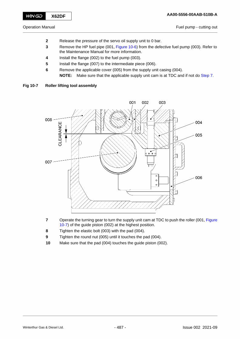
2 Release the pressure of the servo oil supply unit to 0 bar.3 Remove the HP fuel pipe (001, Figure 10-6) from the defective fuel pump (003). Refer to
the Maintenance Manual for more information.4 Install the flange (002) to the fuel pump (003).5 Install the flange (007) to the intermediate piece (006).6 Remove the applicable cover (005) from the supply unit casing (004).
NOTE: Make sure that the applicable supply unit cam is at TDC and if not do Step 7.
Fig 10-7 Roller lifting tool assembly
7 Operate the turning gear to turn the supply unit cam at TDC to push the roller (001, Figure10-7) of the guide piston (002) at the highest position.
8 Tighten the elastic bolt (003) with the pad (004).9 Tighten the round nut (005) until it touches the pad (004).10 Make sure that the pad (004) touches the guide piston (002).
X62DF AA00-5556-00AAB-510B-A
Operation Manual Fuel pump - cutting out
Winterthur Gas & Diesel Ltd. - 487 - Issue 002 2021-09

Fig 10-8 Pre-tensioner install
11 Install the pre-tensioner (005, Figure 10-8) on to the elastic bolt (002).12 Make sure that the pre-tensioner (005) touches the pad (003).13 Use the pre-tensioner (005) to adjust the tension of the elastic bolt (002).14 Remove the pre-tensioner (005). Refer to the Maintenance Manual for more information.15 Make sure that the roller (007) is approximately 3.0 mm above the cam (006).16 Install the cover (006, Figure 10-7).
NOTE: For the torque values and lubrication of the screws, refer to the MaintenanceManual tightenings instruction.
CLOSE UP
• None
X62DF AA00-5556-00AAB-510B-A
Operation Manual Fuel pump - cutting out
Winterthur Gas & Diesel Ltd. - 488 - Issue 002 2021-09

X62DF AA00-5556-00AAB-510B-A
Operation Manual Fuel pump - cutting out
Page left intentionally blank
Winterthur Gas & Diesel Ltd. - 489 - Issue 002 2021-09

10.17 Fuel pump - cutting inPeriodicityDescriptionUnscheduledDuration for performing preliminary requirements 0.0 man-hoursDuration for performing the procedure 1.0 man-hoursDuration for performing the requirements after job completion 0.0 man-hours
PersonnelDescription Specialization QTYEngine crew Basic 1
Support equipmentDescription Part No. CSN QTYFlange 94569 1Flange 94569A 1Roller lifting tool 94430 1Pre-tensioner 94430A 1
SuppliesDescription QTYNone
Spare PartsDescription Part No. CSN QTYNone
SAFETY PRECAUTIONS
WARNINGInjury hazard: The cutting in procedure can only be done when the engine is stop.
WARNINGInjury hazard: Before you operate the turning gear, make sure that no personnel are nearthe flywheel or the engine.
CAUTIONDamage hazard: Do not operate the engine with the fuel pump removed. This will decreasethe oil supply, i.e. there could be a decrease of lubrication to the other fuel pumps.
X62DF AA00-5556-00AAB-730B-A
Operation Manual Fuel pump - cutting in
Winterthur Gas & Diesel Ltd. - 490 - Issue 002 2021-09

PRELIMINARY OPERATIONS
• The engine must be stopped and prepared for maintenance, refer to section 8.20 Preparethe engine after stop - general
X62DF AA00-5556-00AAB-730B-A
Operation Manual Fuel pump - cutting in
Winterthur Gas & Diesel Ltd. - 491 - Issue 002 2021-09

PROCEDURE
Fig 10-9 Location of flanges
1 Release the pressure of the fuel supply unit to 0 bar.
X62DF AA00-5556-00AAB-730B-A
Operation Manual Fuel pump - cutting in
Winterthur Gas & Diesel Ltd. - 492 - Issue 002 2021-09

2 Release the pressure of the servo oil supply unit to 0 bar.3 Remove the flange (002. Figure 10-9) from the fuel pump (003).4 Remove the flange (007) from the intermediate piece (006).5 Install the HP fuel pipe (001) on to the fuel pump (003). Refer to the Maintenance Manual
for more information.6 Remove the applicable cover (005) from the supply unit (004).
NOTE: Make sure that the applicable supply unit cam is at TDC and if not do Step 7.
Fig 10-10 Assembly of roller lifter tool
7 Operate the turning gear to turn the supply unit cam at TDC to push the roller (007, Figure10-10) of the guide piston (001) is at the highest position.
8 Install the pre-tensioner (005) on to the elastic bolt (004).9 Make sure that pre-tensioner (005) touches the pad (003).10 Use the pre-tensioner (005) to loosen the elastic bolt (003). Refer to the Maintenance
Manual for more information.11 Remove the pre-tensioner(005).12 Remove the round nut (004), the elastic bolt (002) and the pad (003).13 Attach the round nut (004) to the elastic bolt (002) on the pad (003) manually.14 Install the cover (005, Figure 10-9).15 Make sure that the fuel pump (003) operates correctly.16 Make sure that the HP fuel pipe (001) has no leaks.
CLOSE UP
• None
X62DF AA00-5556-00AAB-730B-A
Operation Manual Fuel pump - cutting in
Winterthur Gas & Diesel Ltd. - 493 - Issue 002 2021-09

10.18 Temporary isolate a defective turbochargerPeriodicityDescriptionUnscheduledDuration for performing preliminary requirements 0.0 man-hoursDuration for performing the procedure 4.0 man-hoursDuration for performing the requirements after job completion 0.0 man-hours
PersonnelDescription Specialization QTYEngine crew Intermediate 1
Support equipmentDescription Part No. CSN QTYCover 94653A A/RCover 94653B A/RCover 94653C A/RCover 94653D A/R
SuppliesDescription QTYNone
Spare PartsDescription Part No. CSN QTYNone
SAFETY PRECAUTIONS
• None
PRELIMINARY OPERATIONS
• None
X62DF AA00-6500-00AAA-662A-A
Operation Manual Temporary isolate a defective turbocharger
Winterthur Gas & Diesel Ltd. - 494 - Issue 002 2021-09

PROCEDURE
1 Stop the engine.2 If not all turbochargers are defective, isolate the defective turbocharger from the exhaust
gas system and from the scavenge air system.NOTE: This step is only applicable for an engine with more than one turbocharger, and
if one ore two turbochargers are serviceable.
2.1 Lock the rotor of the defective turbocharger (refer to the turbocharger manual).2.2 Remove the expansion joint (007, Figure 10-11) between the defective
turbocharger and the exhaust gas manifold.2.3 Install the covers 94653A and 94653B (001 and 002).2.4 Remove the expansion joint (005) between the defective turbocharger air outlet
and the diffusor.2.5 Install the covers 94653C and 94653D (003 and 004).
NOTE: You only have to install the covers (003), if the turbochargers areconnected to a suction duct.
Fig 10-11 Not all turbochargers are defective (example)
Legend
001 Cover 94653A 005 Expansion joint002 Cover 94653B 006 Turbocharger003 Cover 94653C 007 Expansion joint004 Cover 94653D
X62DF AA00-6500-00AAA-662A-A
Operation Manual Temporary isolate a defective turbocharger
Winterthur Gas & Diesel Ltd. - 495 - Issue 002 2021-09

3 If all turbochargers are defective, isolate the defective turbochargers from the scavengeair system.NOTE: This step is applicable for an engine with one, two, or three turbochargers, and
none of the turbochargers are serviceable.
3.1 Lock the rotor of the defective turbochargers (refer to the turbocharger manual).3.2 Remove the expansion joint (005, Figure 10-12) between the defective
turbochargers air outlet and the diffusor.3.3 Install the covers 94653C (001).
NOTE: You only have to install the covers (001), if the turbochargers areconnected to a suction duct.
3.4 Open the covers (003 and 004) on the scavenge air receiver.3.5 Set to ON the auxiliary blowers.
Fig 10-12 All turbochargers are defective (example)
Legend
001 Cover 94653C 004 Cover002 Cover 94653D 005 Expansion joint003 Cover 006 Turbocharger
4 Make sure that the air supply to the engine room is satisfactory.5 Make sure that the oil supply pressure to the serviceable turbochargers is satisfactory.6 Start the engine with the given limits, refer to section 8.3 Start the engine - general.
CLOSE UP
• None
X62DF AA00-6500-00AAA-662A-A
Operation Manual Temporary isolate a defective turbocharger
Winterthur Gas & Diesel Ltd. - 496 - Issue 002 2021-09

X62DF AA00-6500-00AAA-662A-A
Operation Manual Temporary isolate a defective turbocharger
Page left intentionally blank
Winterthur Gas & Diesel Ltd. - 497 - Issue 002 2021-09

10.19 Temporary isolate the exhaust waste gatePeriodicityDescriptionUnscheduledDuration for performing preliminary requirements 0.0 man-hoursDuration for performing the procedure 0.5 man-hoursDuration for performing the requirements after job completion 0.0 man-hours
PersonnelDescription Specialization QTYEngine crew Basic 1
Support equipmentDescription Part No. CSN QTYNone
SuppliesDescription QTYNone
Spare PartsDescription Part No. CSN QTYNone
SAFETY PRECAUTIONS
• None
PRELIMINARY OPERATIONS
• None
X62DF AA00-8135-00AAA-662A-A
Operation Manual Temporary isolate the exhaust waste gate
Winterthur Gas & Diesel Ltd. - 498 - Issue 002 2021-09

PROCEDURE
Fig 10-13 Exhaust waste gate (example)
Legend
001 Exhaust gas manifold 006 Indicator002 Cardan rod 007 Ball valve 50-8135_E0_3 (air spring air)003 Positioner and feedback with EMC module 008 Flange004 Actuator 009 Valve005 Plate
X62DF AA00-8135-00AAA-662A-A
Operation Manual Temporary isolate the exhaust waste gate
Winterthur Gas & Diesel Ltd. - 499 - Issue 002 2021-09

1 Stop the engine.2 Loosen the screws of the flange (008, Figure 10-13), but do not loosen one of the two
middle screws.3 Turn the flange (008) to close the exhaust waste gate.4 Tighten the screws to attach the flange (008).5 Start the engine.
CLOSE UP
• None
X62DF AA00-8135-00AAA-662A-A
Operation Manual Temporary isolate the exhaust waste gate
Winterthur Gas & Diesel Ltd. - 500 - Issue 002 2021-09

X62DF AA00-8135-00AAA-662A-A
Operation Manual Temporary isolate the exhaust waste gate
Page left intentionally blank
Winterthur Gas & Diesel Ltd. - 501 - Issue 002 2021-09
10.20 Isolate a defective engine at twin engine installationPeriodicityDescriptionUnscheduledDuration for performing preliminary requirements 0.0 man-hoursDuration for performing the procedure 1.0 man-hoursDuration for performing the requirements after job completion 0.0 man-hours
PersonnelDescription Specialization QTYEngine crew Basic 1
Support equipmentDescription Part No. CSN QTYNone
SuppliesDescription QTYNone
Spare PartsDescription Part No. CSN QTYNone
SAFETY PRECAUTIONS
• None
PRELIMINARY OPERATIONS
• None
X62DF AA00-0000-00AAA-662C-A
Operation Manual Isolate a defective engine at twin engine installation
Winterthur Gas & Diesel Ltd. - 502 - Issue 002 2021-09
PROCEDURE
1 Engage the shaft locking device of the defective engine. Refer to the related documentationof the manufacturer.NOTE: This prevents the windmilling effect on the propeller of the defective engine (shaft
movement), when you operate the other engine.2 If installed, disengage the shaft clutch of the defective engine. Refer to the related
documentation of the manufacturer.3 If the shaft locking device and the shaft clutch are unserviceable, make sure that you
operate the auxiliary systems.4 If installed, change the pitch of the controllable propeller (CPP) to the lowest resistance.
WARNINGInjury Hazard: Do not go near movable parts of the engine unless you are sure, that in eachcondition, no part can move.
5 Obey the procedure to get access to the engine spaces, refer to section 2.8 Access toengine spaces.
6 If possible, find the cause and repair the fault.
CLOSE UP
• None
X62DF AA00-0000-00AAA-662C-A
Operation Manual Isolate a defective engine at twin engine installation
Winterthur Gas & Diesel Ltd. - 503 - Issue 002 2021-09

10.21 Gas detector - calibratePeriodicityDescriptionUnscheduledDuration for performing preliminary requirements 0.0 man-hoursDuration for performing the procedure 1.0 man-hoursDuration for performing the requirements after job completion 0.0 man-hours
PersonnelDescription Specialization QTYEngine crew Intermediate AR
Support equipmentDescription Part No. CSN QTYIndicator 1Adapter 1Valve 1Terminal block 5Extension cable 1Splash guard 1FKM hose 1Gas cylinder 1Magnet 1
SuppliesDescription QTYCalibration gas for zero point adjustment, 99.9% N2 (UHP) A/RSensitivity calibration gas 2.5% CH4 / air A/R
Spare PartsDescription Part No. CSN QTYNone
SAFETY PRECAUTIONS
• None
PRELIMINARY OPERATIONS
• The engine must be stopped and made safe for maintenance, refer to section [section notapplicable for this engine]
X62DF AA00-9223-00AAA-273A-A
Operation Manual Gas detector - calibrate
Winterthur Gas & Diesel Ltd. - 504 - Issue 002 2021-09
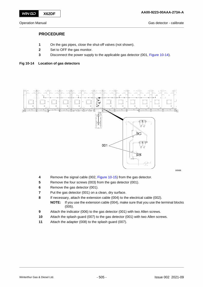
PROCEDURE
1 On the gas pipes, close the shut-off valves (not shown).2 Set to OFF the gas monitor.3 Disconnect the power supply to the applicable gas detector (001, Figure 10-14).
Fig 10-14 Location of gas detectors
4 Remove the signal cable (002, Figure 10-15) from the gas detector.5 Remove the four screws (003) from the gas detector (001).6 Remove the gas detector (001).7 Put the gas detector (001) on a clean, dry surface.8 If necessary, attach the extension cable (004) to the electrical cable (002).
NOTE: If you use the extension cable (004), make sure that you use the terminal blocks(005).
9 Attach the indicator (006) to the gas detector (001) with two Allen screws.10 Attach the splash guard (007) to the gas detector (001) with two Allen screws.11 Attach the adapter (008) to the splash guard (007).
X62DF AA00-9223-00AAA-273A-A
Operation Manual Gas detector - calibrate
Winterthur Gas & Diesel Ltd. - 505 - Issue 002 2021-09

Fig 10-15 Gas detector - prepare
12 Attach the valve (002, Figure 10-16) to the gas bottle (001).13 Attach the FKM hose (003) to the connection on the adapter (004) and the valve (002).
X62DF AA00-9223-00AAA-273A-A
Operation Manual Gas detector - calibrate
Winterthur Gas & Diesel Ltd. - 506 - Issue 002 2021-09
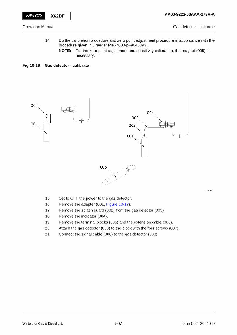
14 Do the calibration procedure and zero point adjustment procedure in accordance with theprocedure given in Draeger PIR-7000-pi-9046393.NOTE: For the zero point adjustment and sensitivity calibration, the magnet (005) is
necessary.
Fig 10-16 Gas detector - calibrate
15 Set to OFF the power to the gas detector.16 Remove the adapter (001, Figure 10-17).17 Remove the splash guard (002) from the gas detector (003).18 Remove the indicator (004).19 Remove the terminal blocks (005) and the extension cable (006).20 Attach the gas detector (003) to the block with the four screws (007).21 Connect the signal cable (008) to the gas detector (003).
X62DF AA00-9223-00AAA-273A-A
Operation Manual Gas detector - calibrate
Winterthur Gas & Diesel Ltd. - 507 - Issue 002 2021-09

Fig 10-17 Gas detector - completion
X62DF AA00-9223-00AAA-273A-A
Operation Manual Gas detector - calibrate
Winterthur Gas & Diesel Ltd. - 508 - Issue 002 2021-09

CLOSE UP
• None
X62DF AA00-9223-00AAA-273A-A
Operation Manual Gas detector - calibrate
Winterthur Gas & Diesel Ltd. - 509 - Issue 002 2021-09

10.22 LDU-20 - removePeriodicityDescriptionWorking hours 66 000Duration for performing preliminary requirements 0.0 man-hoursDuration for performing the procedure 1.0 man-hoursDuration for performing the requirements after job completion 0.0 man-hours
PersonnelDescription Specialization QTYElectronic Basic 1
Support equipmentDescription Part No. CSN QTYNone
SuppliesDescription QTYNone
Spare PartsDescription Part No. CSN QTYNone
SAFETY PRECAUTIONS
PRELIMINARY OPERATIONS
• The engine must be stopped.
• The engine control system must be set to off.
X62DF AA00-9606-00AAA-520A-A
Operation Manual LDU-20 - remove
Winterthur Gas & Diesel Ltd. - 510 - Issue 002 2021-09

PROCEDURE
1 To remove a defective LDU-20 in the local control panel do the steps that follow:NOTE: The LDU-20 in the local control panel is the master.
Fig 10-18 LDU-20 rear view
008
00137
003
009
007 006 005 004
002
001
1.1 Open the cover of control box E25 to get access to the rear of the LDU-20 (009,Figure 10-18), refer to the Operation Manual.
1.2 Record the positions of the plugs and cables that follow:• The plug X21 (007) and plug X22 (005)• The cables of the service connection (002)• The cables to the Ethernet connection (003).
1.3 Remove and discard the four cable ties (004).1.4 Disconnect the plugs X21 (007) and X22 (005).1.5 Disconnect the cables from the Ethernet connection (003).1.6 Disconnect the cables from the service connection (002).1.7 If installed, disconnect the USB cable (006).1.8 Disconnect the earth cable (008).1.9 Remove the four nuts and spring washers (001) from the studs.1.10 Remove the LDU-20.1.11 Attach an UNSERVICEABLE label to the LDU-20.
2 To remove a defective LDU-20 in the engine control room do the steps that follow:2.1 Get access to the rear of the LDU-20. Refer to the documentation of the control
panel manufacturer.2.2 Do Step 1.2 to Step 1.11.
X62DF AA00-9606-00AAA-520A-A
Operation Manual LDU-20 - remove
Winterthur Gas & Diesel Ltd. - 511 - Issue 002 2021-09

CLOSE UP
• None
X62DF AA00-9606-00AAA-520A-A
Operation Manual LDU-20 - remove
Winterthur Gas & Diesel Ltd. - 512 - Issue 002 2021-09

X62DF AA00-9606-00AAA-520A-A
Operation Manual LDU-20 - remove
Page left intentionally blank
Winterthur Gas & Diesel Ltd. - 513 - Issue 002 2021-09

10.23 LDU-20 - installPeriodicityDescriptionWorking hours 66 000Duration for performing preliminary requirements 0.0 man-hoursDuration for performing the procedure 1.0 man-hoursDuration for performing the requirements after job completion 0.0 man-hours
PersonnelDescription Specialization QTYElectronic Basic 1
Support equipmentDescription Part No. CSN QTYNone
SuppliesDescription QTYNone
Spare PartsDescription Part No. CSN QTYLDU-20 HA1-59-9606-01 -004 pc 1
SAFETY PRECAUTIONS
PRELIMINARY OPERATIONS
• The engine must be stopped.
• The engine control system must be set to off.
X62DF AA00-9606-00AAA-720A-A
Operation Manual LDU-20 - install
Winterthur Gas & Diesel Ltd. - 514 - Issue 002 2021-09

PROCEDURE
1 To install an LDU-20 in the local control panel do the steps that follow:NOTE: The LDU-20 in the local control panel is the master. You must replace this
LDU-20 only with the item from the engine control room (ECR).
Fig 10-19 LDU-20 rear view
008
00137
003
009
007 006 005 004
002
001
1.1 Attach the LDU-20 (009, Figure 10-19) to the control box E25 with the four springwashers and nuts (001), refer to the Operation Manual.
1.2 Connect the earth cable (008) to the connection on the LDU-20.1.3 If installed, connect the USB cable (006).1.4 Connect the cables to the service connection (002).1.5 Connect the cables to the Ethernet connection (003).1.6 Connect the plugs X21 (007) and X22 (005) to the connections on the LDU-20.1.7 Attach four new cable ties (004) to the positions shown.1.8 Attach a new label to identify the LDU-20.1.9 Close the cover of control box E25.1.10 Set to ON the LDU-20.
NOTE: You must first start the replaced LDU-20 before you start the enginecontrol system. Approximately five minutes are necessary to do the fullstart procedure of the LDU-20.
1.11 Do a check to make sure that the LDU-20 operates correctly. If you get an errormessage, speak to or send a message to WinGD.
1.12 Do Step 1.1 to Step 1.8 to install the spare LDU-20 to the position in the ECR.1.13 Set to ON the engine control system.
X62DF AA00-9606-00AAA-720A-A
Operation Manual LDU-20 - install
Winterthur Gas & Diesel Ltd. - 515 - Issue 002 2021-09

NOTE: You must first start the engine control system before you start the spareLDU-20 in the ECR. The spare LDU-20 in the ECR will be synchronizedwith the master LDU-20 in the local control panel through the Ethernetcable.
1.14 Set to ON the LDU-20.1.15 Do a check to make sure that the LDU-20 operates correctly. If you get an error
message, speak to or send a message to WinGD.1.16 If applicable, start the engine at the remote control system (RCS), refer to the
Operation Manual.NOTE: The engine will do a standard start.
2 To install an LDU-20 in the engine control room do the steps that follow:NOTE: To replace a defective LDU-20 in the ECR, you must use only the spare item.
Do not use the LDU-20 from the local control panel.
2.1 Get access to the rear of the LDU-20. Refer to the documentation of the controlpanel manufacturer.
2.2 Do Step 1.12 to Step 1.16.
CLOSE UP
• None
X62DF AA00-9606-00AAA-720A-A
Operation Manual LDU-20 - install
Winterthur Gas & Diesel Ltd. - 516 - Issue 002 2021-09
X62DF AA00-9606-00AAA-720A-A
Operation Manual LDU-20 - install
Page left intentionally blank
Winterthur Gas & Diesel Ltd. - 517 - Issue 002 2021-09
10.24 CCM-20 - removePeriodicityDescriptionWorking hours 66 000Duration for performing preliminary requirements 0.0 man-hoursDuration for performing the procedure 1.0 man-hoursDuration for performing the requirements after job completion 0.0 man-hours
PersonnelDescription Specialization QTYElectronic Basic 1
Support equipmentDescription Part No. CSN QTYNone
SuppliesDescription QTYNone
Spare PartsDescription Part No. CSN QTYNone
SAFETY PRECAUTIONS
PRELIMINARY OPERATIONS
• The engine must be stopped.
• The engine control system must be set to off.
X62DF AA00-9606-00ABA-520A-A
Operation Manual CCM-20 - remove
Winterthur Gas & Diesel Ltd. - 518 - Issue 002 2021-09
PROCEDURE
1 Disconnect the power supply to the defective CCM-20 on the related cylinder.NOTE: WinGD recommends to make a software back-up from the LDU-20. This will
make sure that the correct configuration is loaded. For more data, speak to orsend a message to WinGD.
2 Remove the defective CCM-20.3 Attach an UNSERVICEABLE label to the CCM-20.
CLOSE UP
• None
X62DF AA00-9606-00ABA-520A-A
Operation Manual CCM-20 - remove
Winterthur Gas & Diesel Ltd. - 519 - Issue 002 2021-09

10.25 CCM-20 - installPeriodicityDescriptionWorking hours 66 000Duration for performing preliminary requirements 0.0 man-hoursDuration for performing the procedure 1.0 man-hoursDuration for performing the requirements after job completion 0.0 man-hours
PersonnelDescription Specialization QTYElectronic Basic 1
Support equipmentDescription Part No. CSN QTYNone
SuppliesDescription QTYNone
Spare PartsDescription Part No. CSN QTYCCM-20 HA1-59-9606-01 -002 pc 1
SAFETY PRECAUTIONS
PRELIMINARY OPERATIONS
• The engine must be stopped.
• The engine control system must be set to off.
X62DF AA00-9606-00ABA-720A-A
Operation Manual CCM-20 - install
Winterthur Gas & Diesel Ltd. - 520 - Issue 002 2021-09
PROCEDURE
1 Install the CCM-20.2 Connect the power supply to the CCM-20.3 After a reboot of the CCM-20, the ECS activates a software download.
NOTE: You can monitor the software download on the LDU-20 at the local control panel.4 If applicable, start the engine, refer to the Operation Manual.
NOTE: The engine does an air run to find the crank angle for the installed CCM-20. Afterthe air run, the engine will do a standard start.
CLOSE UP
• None
X62DF AA00-9606-00ABA-720A-A
Operation Manual CCM-20 - install
Winterthur Gas & Diesel Ltd. - 521 - Issue 002 2021-09

10.26 CCM-20 - Emergency back-up lubricationPeriodicityDescriptionUnscheduledDuration for performing preliminary requirements 0.0 man-hoursDuration for performing the procedure 1.0 man-hoursDuration for performing the requirements after job completion 0.0 man-hours
PersonnelDescription Specialization QTYElectronic Basic 1
Support equipmentDescription Part No. CSN QTYConnection cable with plug 94929 1
SuppliesDescription QTYNone
Spare PartsDescription Part No. CSN QTYNone
SAFETY PRECAUTIONS
• None
PRELIMINARY OPERATIONS
• The engine must be stopped and prepared for maintenance, refer to section [section notapplicable for this engine]
X62DF AA00-9606-01AAA-140A-A
Operation Manual CCM-20 - Emergency back-up lubrication
Winterthur Gas & Diesel Ltd. - 522 - Issue 002 2021-09

PROCEDURE
1 General information:1.1 If the CCM-20 failure occurs, the related cylinder is cut-out automatically and will
have no cylinder lubrication, SLD requested and also all the common function fails.NOTE: Other cylinders and common functions will continue to operate.
1.2 Do an emergency cylinder lubrication on this cut-out unit, a special back-up cableconnection (001, Figure 10-20) from one of the other CCM-20 to that flexLubepump can be installed temporarily.NOTE: One CCM-20 can activate two flexLube pumps.
1.3 Any CCM-20 module can be replaced easily. The related software and parametersare stored in the LDU panels and new software can be loaded to the new CCM-20at the engine standstill.
Fig 10-20 CCM-20 - Connecting cable with plug
001
2 The CCM-20 of cylinder X (see Figure 10-21) is failed. Do Step 2.1 to Step 2.7 foremergency back-up lubrication.2.1 Use the terminal boxes (005) to bypass the defective CCM-20 and give emergency
lubrication to the related cylinder.2.2 Attach the terminal box (005) to the related cylinder lubrication pump. The terminal
box has magnets (004) installed in the base.2.3 Disconnect the connection A from the valve CV731YC of cylinder lubrication pump
from the cylinder Y.2.4 Connect plug A (003) of the terminal box (005) to the connection A of the cylinder
Y CCM-20.2.5 Connect plug B (001) with valve CV713YC of cylinder lubrication pump of cylinder
Y.2.6 Disconnect the connection C from the valve CV713XC from the cylinder X.2.7 Connect plug C (002) with valve CV713XC of cylinder lubrication pump of cylinder
X.NOTE: In case the failed CCM-20 of the cylinder X is restored, disconnect the
terminal box and connect all the valves with the related CCM-20.
X62DF AA00-9606-01AAA-140A-A
Operation Manual CCM-20 - Emergency back-up lubrication
Winterthur Gas & Diesel Ltd. - 523 - Issue 002 2021-09

Fig 10-21 Schematic diagram - emergency back-up lubrication
X62DF AA00-9606-01AAA-140A-A
Operation Manual CCM-20 - Emergency back-up lubrication
Winterthur Gas & Diesel Ltd. - 524 - Issue 002 2021-09

CLOSE UP
• None
X62DF AA00-9606-01AAA-140A-A
Operation Manual CCM-20 - Emergency back-up lubrication
Winterthur Gas & Diesel Ltd. - 525 - Issue 002 2021-09

10.27 CCM-20 - replacePeriodicityDescriptionWorking hours 66000Duration for performing preliminary requirements 0.0 man-hoursDuration for performing the procedure 1.0 man-hoursDuration for performing the requirements after job completion 0.0 man-hours
PersonnelDescription Specialization QTYElectronic Basic 1
Support equipmentDescription Part No. CSN QTYNone
SuppliesDescription QTYNone
Spare PartsDescription Part No. CSN QTYCCM-20 1
SAFETY PRECAUTIONS
• None
PRELIMINARY OPERATIONS
• The engine must be stopped and prepared for maintenance, refer to section [section notapplicable for this engine]
• The engine control system must be set to off.
X62DF AA00-9606-01AAA-200A-A
Operation Manual CCM-20 - replace
Winterthur Gas & Diesel Ltd. - 526 - Issue 002 2021-09

PROCEDURE
1 Disconnect the power-supply of the defective CCM-20 from the related cylinder.NOTE: WinGD recommends to make a software back-up from the LDU-20. This will
make sure that the correct configuration is loaded. For more data, speak to orsend a message to WinGD.
2 Remove the defective CCM-20.3 Install the new CCM-20.4 Connect the power supply to the CCM-20.5 After a reboot of the new CCM-20, the ECS activates a software download.
NOTE: Software downloading can be monitored on the LDU-20 at the local control panel.6 Start the engine.
NOTE: The engine does an air run to find the crank angle for the installed CCM-20. Afterthe air run, the engine will do a standard start.
CLOSE UP
• None
X62DF AA00-9606-01AAA-200A-A
Operation Manual CCM-20 - replace
Winterthur Gas & Diesel Ltd. - 527 - Issue 002 2021-09

10.28 MCM-11 - removePeriodicityDescriptionWorking hours 66 000Duration for performing preliminary requirements 0.0 man-hoursDuration for performing the procedure 1.0 man-hoursDuration for performing the requirements after job completion 0.0 man-hours
PersonnelDescription Specialization QTYElectronic Basic 1
Support equipmentDescription Part No. CSN QTYNone
SuppliesDescription QTYNone
Spare PartsDescription Part No. CSN QTYNone
SAFETY PRECAUTIONS
PRELIMINARY OPERATIONS
• The engine must be stopped.
• The engine control system must be set to off.
X62DF AA00-9606-00ACA-520A-A
Operation Manual MCM-11 - remove
Winterthur Gas & Diesel Ltd. - 528 - Issue 002 2021-09

PROCEDURE
1 Disconnect the power supply to the defective MCM-11 on the related cylinder.NOTE: WinGD recommends to make a software back-up from the LDU-20. This will
make sure that the correct configuration is loaded. For more data, speak to orsend a message to WinGD.
2 Remove the defective MCM-11.3 Attach an UNSERVICEABLE label to the MCM-11.
CLOSE UP
• None
X62DF AA00-9606-00ACA-520A-A
Operation Manual MCM-11 - remove
Winterthur Gas & Diesel Ltd. - 529 - Issue 002 2021-09

10.29 MCM-11 - installPeriodicityDescriptionWorking hours 66 000Duration for performing preliminary requirements 0.0 man-hoursDuration for performing the procedure 1.0 man-hoursDuration for performing the requirements after job completion 0.0 man-hours
PersonnelDescription Specialization QTYElectronic Basic 1
Support equipmentDescription Part No. CSN QTYNone
SuppliesDescription QTYNone
Spare PartsDescription Part No. CSN QTYMCM-11 HA1-59-9606-01 -003 pc 1
SAFETY PRECAUTIONS
PRELIMINARY OPERATIONS
• The engine must be stopped.
• The engine control system must be set to off.
X62DF AA00-9606-00ACA-720A-A
Operation Manual MCM-11 - install
Winterthur Gas & Diesel Ltd. - 530 - Issue 002 2021-09

PROCEDURE
1 Install the MCM-11.2 Connect the power supply to the MCM-11.3 After a reboot of the MCM-11, the ECS activates a software download.
NOTE: You can monitor the software download on the MCM-11 at the local control panel.4 If applicable, start the engine at the remote control system (RCS), refer to the Operation
Manual.NOTE: The engine will do a standard start.
CLOSE UP
• None
X62DF AA00-9606-00ACA-720A-A
Operation Manual MCM-11 - install
Winterthur Gas & Diesel Ltd. - 531 - Issue 002 2021-09

10.30 IOM-10 - removePeriodicityDescriptionWorking hours 66 000Duration for performing preliminary requirements 0.0 man-hoursDuration for performing the procedure 1.0 man-hoursDuration for performing the requirements after job completion 0.0 man-hours
PersonnelDescription Specialization QTYElectronic Basic 1
Support equipmentDescription Part No. CSN QTYNone
SuppliesDescription QTYNone
Spare PartsDescription Part No. CSN QTYNone
SAFETY PRECAUTIONS
PRELIMINARY OPERATIONS
• The engine must be stopped.
• The engine control system must be set to off.
X62DF AA00-9606-00ADA-520A-A
Operation Manual IOM-10 - remove
Winterthur Gas & Diesel Ltd. - 532 - Issue 002 2021-09

PROCEDURE
1 Disconnect the power supply to the defective IOM-10 on the related cylinder.NOTE: WinGD recommends to make a software back-up from the LDU-20. This will
make sure that the correct configuration is loaded. For more data, speak to orsend a message to WinGD.
2 Remove the defective IOM-10.3 Attach an UNSERVICEABLE label to the IOM-10.
CLOSE UP
• None
X62DF AA00-9606-00ADA-520A-A
Operation Manual IOM-10 - remove
Winterthur Gas & Diesel Ltd. - 533 - Issue 002 2021-09

10.31 IOM-10 - installPeriodicityDescriptionWorking hours 66 000Duration for performing preliminary requirements 0.0 man-hoursDuration for performing the procedure 1.0 man-hoursDuration for performing the requirements after job completion 0.0 man-hours
PersonnelDescription Specialization QTYElectronic Basic 1
Support equipmentDescription Part No. CSN QTYNone
SuppliesDescription QTYNone
Spare PartsDescription Part No. CSN QTYIOM-10 HA1-59-9606-01 -005 pc 1
SAFETY PRECAUTIONS
PRELIMINARY OPERATIONS
• The engine must be stopped.
• The engine control system must be set to off.
X62DF AA00-9606-00ADA-720A-A
Operation Manual IOM-10 - install
Winterthur Gas & Diesel Ltd. - 534 - Issue 002 2021-09

PROCEDURE
1 Install the IOM-10.2 Connect the power supply to the IOM-10.3 After a reboot of the IOM-10, the ECS activates a software download.
NOTE: You can monitor the software download on the IOM-10 at the local control panel..4 If applicable, start the engine at the remote control system (RCS), refer to the Operation
Manual.NOTE: The engine will do a standard start.
CLOSE UP
• None
X62DF AA00-9606-00ADA-720A-A
Operation Manual IOM-10 - install
Winterthur Gas & Diesel Ltd. - 535 - Issue 002 2021-09

10.32 Special running condition: Cylinder cut out
The engine is designed to run with all its cylinders working. If a cylinder stops working, it must berepaired as soon as possible. However, if it is impossible to repair the not working cylinder, thenthe engine can still be run as long as only 1 or 2 cylinders are not working. This is called cylindercut out operation and it is considered a special running condition.
WARNINGThe special running condition of the cylinder cut out is only available in diesel mode.
WARNINGRunning the engine under a special running condition will impact the following parametersnegatively:• Increase of Thermal load
• Increase of exhaust temperature
• Increase of torsional vibrations
• Increase of stress on the Crankshaft
• Reduction of engine revolutions
• Reduction of load limit
• Occurance of Surging
WARNINGIf 2 or more cylinders are misfiring, Contact WinGD immediately.
WARNINGRunning the engine under special running conditions for more than 2-5 days can damagethe engine. If the engine is run under special running conditions for more than that, contactthe engine builder to obtain advice.
NOTE: If only the fuel for the respective cylinders is cut off, while the same time, the starting airconnections remain intact, then the engine remains fully maneuverable.
NOTE: If the starting air supply is cut off to some cylinders, the engine might not start from allcrankshaft positions. This can be resolved by starting the engine in reverse it or by usingthe turning gear to change the starting position.
There are 5 different procedures of cutting a single cylinder out of operation. If it is needed, eachprocedure can be repeated to cut of a second cylinder. The correct procedure depends on thecircumstances of under which the cylinder is underperforming, so chose the procedure best fittingfor the circumstances. The 5 procedures are:
• A.) Cylinder cut out while the piston and exhaust valve are still working and the compressionis still on
• B.) Cylinder cut out while the piston and exhaust valve are still working and the compressionis off
• C.) Cylinder cut out while the piston is still moving but the exhaust valve is closed and thecompression is on
X62DF AA00-0000-00AAA-100A-A
Operation Manual Special running condition: Cylinder cut out
Winterthur Gas & Diesel Ltd. - 536 - Issue 002 2021-09
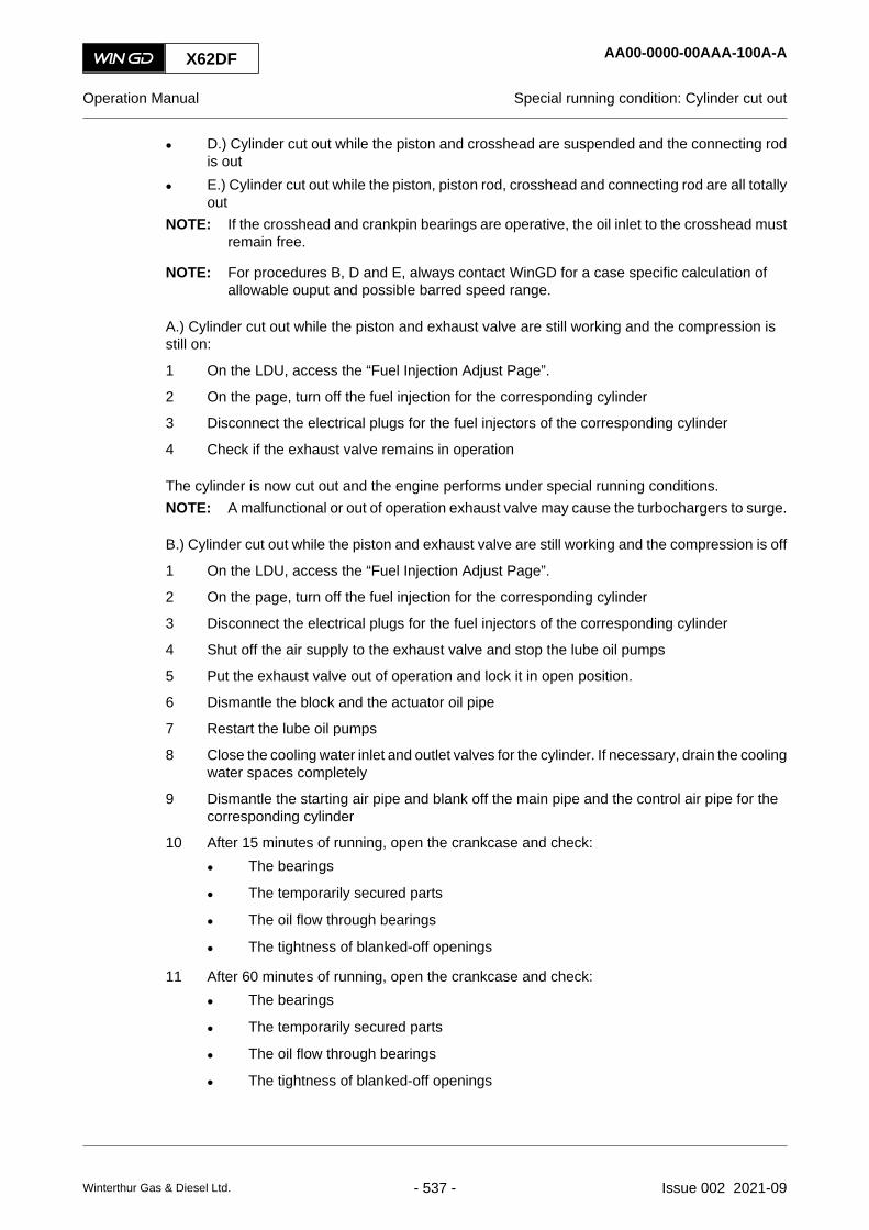
• D.) Cylinder cut out while the piston and crosshead are suspended and the connecting rodis out
• E.) Cylinder cut out while the piston, piston rod, crosshead and connecting rod are all totallyout
NOTE: If the crosshead and crankpin bearings are operative, the oil inlet to the crosshead mustremain free.
NOTE: For procedures B, D and E, always contact WinGD for a case specific calculation ofallowable ouput and possible barred speed range.
A.) Cylinder cut out while the piston and exhaust valve are still working and the compression isstill on:
1 On the LDU, access the “Fuel Injection Adjust Page”.
2 On the page, turn off the fuel injection for the corresponding cylinder
3 Disconnect the electrical plugs for the fuel injectors of the corresponding cylinder
4 Check if the exhaust valve remains in operation
The cylinder is now cut out and the engine performs under special running conditions.NOTE: A malfunctional or out of operation exhaust valve may cause the turbochargers to surge.
B.) Cylinder cut out while the piston and exhaust valve are still working and the compression is off
1 On the LDU, access the “Fuel Injection Adjust Page”.
2 On the page, turn off the fuel injection for the corresponding cylinder
3 Disconnect the electrical plugs for the fuel injectors of the corresponding cylinder
4 Shut off the air supply to the exhaust valve and stop the lube oil pumps
5 Put the exhaust valve out of operation and lock it in open position.
6 Dismantle the block and the actuator oil pipe
7 Restart the lube oil pumps
8 Close the cooling water inlet and outlet valves for the cylinder. If necessary, drain the coolingwater spaces completely
9 Dismantle the starting air pipe and blank off the main pipe and the control air pipe for thecorresponding cylinder
10 After 15 minutes of running, open the crankcase and check:
• The bearings
• The temporarily secured parts
• The oil flow through bearings
• The tightness of blanked-off openings
11 After 60 minutes of running, open the crankcase and check:
• The bearings
• The temporarily secured parts
• The oil flow through bearings
• The tightness of blanked-off openings
X62DF AA00-0000-00AAA-100A-A
Operation Manual Special running condition: Cylinder cut out
Winterthur Gas & Diesel Ltd. - 537 - Issue 002 2021-09

WARNINGWhen operating in this manner, the engine speed must stay 55% of the maximumcontinuous rating speed. Additionally, the over-speed level of the engine must be loweredto 80% of the continuous rating speed.
NOTE: During maneuvers, the engine speed can be raised for 10 minutes to 80% of thecontinuous rating speed.
The cylinder is now cut out and the engine performs under special running conditions.
C.) Cylinder cut out while the piston is still moving but the exhaust valve is closed and thecompression is on
1 Stop the engine
2 On the LDU, access the “Fuel Injection Adjust Page”.
3 On the page, turn of the fuel injection for the corresponding cylinder
4 Disconnect the electrical plugs for the fuel injectors of the corresponding cylinder
5 On the LDU, on the exhaust valve control page, make sure there are no error indicationsshown
6 Make sure that the exhaust valve is completely closed
7 If the exhaust valve isn’t completely closed, disconnect the plug for the cylinder startingvalve
8 After 15 minutes of running, open the crankcase and check:
• The bearings
• The temporarily secured parts
• The oil flow through bearings
• The tightness of blanked-off openings
9 After 60 minutes of running, open the crankcase and check:
• The bearings
• The temporarily secured parts
• The oil flow through bearings
• The tightness of blanked-off openings
WARNINGThe cylinder cooling water and piston cooling oil must not be cut off.
NOTE: A malfunctional or out of operation exhaust valve may cause the turbochargers to surge.
The cylinder is now cut out and the engine performs under special running conditions.
D.) Cylinder cut out while the piston, piston rod and crosshead are suspended in the engine andthe connecting rod is out
1 Stop the engine
2 On the LDU, access the “Fuel Injection Adjust Page”.
3 On the page, turn of the fuel injection for the corresponding cylinder
X62DF AA00-0000-00AAA-100A-A
Operation Manual Special running condition: Cylinder cut out
Winterthur Gas & Diesel Ltd. - 538 - Issue 002 2021-09

4 Disconnect the electrical plugs for the fuel injectors of the corresponding cylinder
5 On the LDU, on the exhaust valve control page, make sure there are no error indicationsshown
6 Make sure that the exhaust valve is completely closed
7 If the exhaust valve isn’t completely closed, disconnect the plug for the cylinder starting airvalve
8 Dismantle the starting air pipe
9 Blank off the main pipe and the control air pipe for the relating cylinder
10 Remove the oil supply lever.
11 Blank off the oil supply with the blind flange.
12 Set the cylinder lubricator for the corresponding cylinder to zero delivery.
13 After 15 minutes of running, open the crankcase and check:
• The bearings
• The temporarily secured parts
• The oil flow through bearings
• The tightness of blanked-off openings
14 After 60 minutes of running, open the crankcase and check:
• The bearings
• The temporarily secured parts
• The oil flow through bearings
• The tightness of blanked-off openings
The cylinder is now cut out and the engine performs under special running conditions.
E.) Cylinder cut out while the piston, piston rod, crosshead and connecting rod are all totally out
1 Stop the engine
2 On the LDU, access the “Fuel Injection Adjust Page”.
3 On the page, turn of the fuel injection for the corresponding cylinder
4 Disconnect the electrical plugs for the fuel injectors of the corresponding cylinder
5 On the LDU, on the exhaust valve control page, make sure there are no error indicationsshown
6 Make sure that the exhaust valve is completely closed
7 If the exhaust valve isn’t completely closed, disconnect the plug for the cylinder starting airvalve
8 Dismantle the starting air pipe
9 Blank off the main pipe and the control air pipe for the relating cylinder
10 Remove the oil supply lever.
11 Blank off the oil supply with the blind flange
12 Blank off the stuffing box opening with two plates
13 Set the cylinder lubricator for the corresponding cylinder to zero delivery.
14 After 15 minutes of running, open the crankcase and check:
X62DF AA00-0000-00AAA-100A-A
Operation Manual Special running condition: Cylinder cut out
Winterthur Gas & Diesel Ltd. - 539 - Issue 002 2021-09

• The bearings
• The temporarily secured parts
• The oil flow through bearings
• The tightness of blanked-off openings
15 After 60 minutes of running, open the crankcase and check:
• The bearings
• The temporarily secured parts
• The oil flow through bearings
• The tightness of blanked-off openings
The cylinder is now cut out and the engine performs under special running conditions.
Fig 10-22 Allowed load during cylinder cut out
X62DF AA00-0000-00AAA-100A-A
Operation Manual Special running condition: Cylinder cut out
Winterthur Gas & Diesel Ltd. - 540 - Issue 002 2021-09

X62DF AA00-0000-00AAA-100A-A
Operation Manual Special running condition: Cylinder cut out
Page left intentionally blank
Winterthur Gas & Diesel Ltd. - 541 - Issue 002 2021-09

10.33 Special running condition: Turbocharger cut out
The engine is designed to run with all its turbochargers working. If a turbocharger stops working,it must be repaired as soon as possible. However, if it is impossible to repair the not workingturbocharger, then the engine can still be run, even with 2 turbochargers not working. This is calledturbocharger cut out operation and it is considered a special running condition.NOTE: If during one of the procedures mentioned in this chapter, an auxiliary blower becomes
inoperative, it will automatically be cut out thanks to the built in non-return valve.
WARNINGRunning the engine under a special running condition will impact the following parametersnegatively:• Increase of Thermal load
• Increase of exhaust temperature
• Increase of torsional vibrations
• Increase of stress on the Crankshaft
• Reduction of engine revolutions
• Reduction of load limit
• occurance of surging
WARNINGRunning the engine under special running conditions for more than 2-5 days can damagethe engine. If the engine is run under special running conditions for more than that, contactthe engine builder to obtain advice.
A turbocharger can be manually taken out of operation. The main reasons to do so are:
• Heavy turbocharger vibrations
• Bearing failure
• Malfunction of the turbocharger
The turbocharger can be taken out of operation while keeping the vessel maneuverable. For this,reduce the load until the turbocharger vibrations are gone.
If reducing the load doesn’t help and the turbocharger has problems running even at reduced load,then proceed like this:
WARNINGTaking the turbocharger out of operation while keeping the vessel maneuverable shouldonly be done if it isn’t possible to run for an extended period with a turbocharger out ofoperation.
A.) For engines with one turbocharger:
1 Stop the engine
2 Open the cover (E)
3 Lock the rotor of the faulty turbocharger (check your turbocharger manual for details)
X62DF AA00-0000-00AAB-100A-A
Operation Manual Special running condition: Turbocharger cut out
Winterthur Gas & Diesel Ltd. - 542 - Issue 002 2021-09

4 Remove the compensator (1) between the compressor outlet and the scavenge air duct.
5 Remove the expansion piece (2) for the air outlet of the turbocharger (F)
6 If there is oil loss, plug the turbocharger
7 Switch on the manual mode of the auxiliary blower
8 Make sure you are within the load restriction
9 Verify the maximum firing pressure
The turbocharger has been cut out successfully. The engine is now running under a special runningcondition.
B.) For engines with two or more turbochargers:
1 Stop the engine
2 Open the cover (E)
3 Lock the rotor of the faulty turbocharger (check your turbocharger manual for details)
4 Remove the compensator (1) between the compressor outlet and the scavenge air duct.
5 Remove the expansion piece (2) for the air outlet of the turbocharger (F)
6 Insert an orifice plate (3, 4) in the compressor outlet
7 If there is oil loss, plug the turbochargers
8 Switch on the manual mode of the auxiliary blower
9 Make sure you are within the load restriction
10 Verify the maximum firing pressureNOTE: The load restriction for 1 out of 2 turbochargers is 40%. The load restriction for 1 out of
3 turbochargers is 55%. The load restriction can be increased considerably, if an orificeplate is also inserted in the turbine inlet.
NOTE: If reducing the load doesn’t help and the turbocharger has problems running even atreduced load, then consult the turbocharger manual for further advice.
The turbocharger has been cut out successfully. The engine is now running under a special runningcondition.
If it is possible to run for an extended period of time with a turbocharger out of operation, thenproceed like this:
C.) For engines with one turbocharger and the exhaust bypass option:
1 Stop the engine
2 Open the cover (E)
3 Lock the rotor of the faulty turbocharger (check your turbocharger manual for details)
4 Remove the blanking plate (T1, T2, T3, T4) from the exhaust bypass pipe
5 Remove the compensator (1) between the compressor outlet and the scavenge air duct.
6 Remove the expansion piece (2) for the air outlet of the turbocharger (F)
7 Insert an orifice plate (3, 4) in the compressor outlet
8 If there is oil loss, plug the turbocharger
9 Switch on the manual mode of the auxiliary blower
X62DF AA00-0000-00AAB-100A-A
Operation Manual Special running condition: Turbocharger cut out
Winterthur Gas & Diesel Ltd. - 543 - Issue 002 2021-09

10 Make sure you are within the load restriction
11 Verify the maximum firing pressure
The turbocharger has been cut out successfully. The engine is now running under a special runningcondition.
D.) For engines with one turbocharger but without the exhaust bypass option:
1 Stop the engine
2 Open the cover (E)
3 Lock the rotor of the faulty turbocharger (check your turbocharger manual for details)
4 Insert the blanking plate (T1, T2, T3, T4) according to your turbocharger manual
5 Remove the compensator (1) between the compressor outlet and the scavenge air duct.
6 Remove the expansion piece (2) for the air outlet of the turbocharger (F)
7 Insert an orifice plate (3, 4) in the compressor outlet
8 If there is oil loss, plug the turbocharger
9 Switch on the manual mode of the auxiliary blower
10 Make sure you are within the load restriction
11 Verify the maximum firing pressure
The turbocharger has been cut out successfully. The engine is now running under a special runningcondition.
E.) For engines with two or more turbochargers:
1 Stop the engine
2 Open the cover (E)
3 Lock the rotor of the faulty turbocharger (check your turbocharger manual for details)
4 Remove the blanking plate (T1, T2, T3, T4) from the exhaust bypass pipe
5 Remove the compensator (1) between the compressor outlet and the scavenge air duct.
6 Remove the expansion piece (2) for the air outlet of the turbocharger (F)
7 Insert an orifice plate (3, 4) in the compressor outlet
8 If there is oil loss, plug the turbochargers
9 Switch on the manual mode of the auxiliary blower
10 Make sure you are within the load restriction
11 Verify the maximum firing pressure
The turbocharger has been cut out successfully. The engine is now running under a special runningcondition.
Turbochargers can be repaired during the voyage. If this is necessary, proceed like this:
E.) For engines with one turbocharger:
1 Stop the engine
2 Open the cover (E)
3 Lock the rotor of the faulty turbocharger (check your turbocharger manual for details)
X62DF AA00-0000-00AAB-100A-A
Operation Manual Special running condition: Turbocharger cut out
Winterthur Gas & Diesel Ltd. - 544 - Issue 002 2021-09

4 Insert the blanking plate (T1, T2, T3, T4) according to your turbocharger manual
5 Remove the compensator (1) between the compressor outlet and the scavenge air duct.
6 Remove the expansion piece (2) for the air outlet of the turbocharger (F)
7 Insert an orifice plate (3, 4) in the compressor outlet
8 If there is oil loss, plug the turbocharger
9 Switch on the manual mode of the auxiliary blower
10 Make sure you are within the load restriction
11 Verify the maximum firing pressure
F.) For engines with two or more turbochargers:
1 Stop the engine
2 Open the cover (E)
3 Lock the rotor of the faulty turbocharger (check your turbocharger manual for details)
4 Insert the blanking plate (T1, T2, T3, T4) according to your turbocharger manual
5 Remove the compensator (1) between the compressor outlet and the scavenge air duct.
6 Remove the expansion piece (2) for the air outlet of the turbocharger (F)
7 Insert an orifice plate (3, 4) in the compressor outlet
8 If there is oil loss, plug the turbochargers
9 Switch on the manual mode of the auxiliary blower
10 Make sure you are within the load restriction
11 Verify the maximum firing pressure
Fig 10-23 Turbocharger cut out procedure: Illustration 1
X62DF AA00-0000-00AAB-100A-A
Operation Manual Special running condition: Turbocharger cut out
Winterthur Gas & Diesel Ltd. - 545 - Issue 002 2021-09

Fig 10-24 Turbocharger cut out procedure: Illustration 2
X62DF AA00-0000-00AAB-100A-A
Operation Manual Special running condition: Turbocharger cut out
Winterthur Gas & Diesel Ltd. - 546 - Issue 002 2021-09
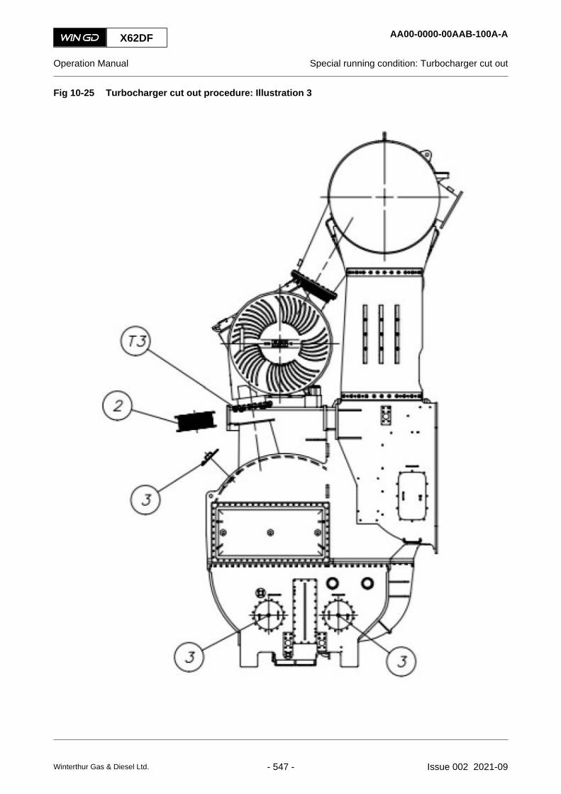
Fig 10-25 Turbocharger cut out procedure: Illustration 3
X62DF AA00-0000-00AAB-100A-A
Operation Manual Special running condition: Turbocharger cut out
Winterthur Gas & Diesel Ltd. - 547 - Issue 002 2021-09

Fig 10-26 Turbocharger cut out procedure: Illustration 4
X62DF AA00-0000-00AAB-100A-A
Operation Manual Special running condition: Turbocharger cut out
Winterthur Gas & Diesel Ltd. - 548 - Issue 002 2021-09

Fig 10-27 Turbocharger cut out procedure: Illustration 5
NOTE: If during the one of the procedures mentioned in this chapter, an auxiliary blowerbecomes inoperative, it will automatically be cut out thanks to the built in non-returnvalve. This will restrict the operation of the engine.
X62DF AA00-0000-00AAB-100A-A
Operation Manual Special running condition: Turbocharger cut out
Winterthur Gas & Diesel Ltd. - 549 - Issue 002 2021-09

X62DF AA00-0000-00AAB-100A-A
Operation Manual Special running condition: Turbocharger cut out
Page left intentionally blank
Winterthur Gas & Diesel Ltd. - 550 - Issue 002 2021-09

11 Technical data11.1 Engine data.............................................................................................................55211.2 List of usual values and safeguard settings - general.............................................55411.3 List of usual values and safeguard settings.............................................................55811.4 Section views...........................................................................................................570
X62DF
Operation Manual
Winterthur Gas & Diesel Ltd. - 551 - Issue 002 2021-09

11.1 Engine data
X62DF AA00-0000-00AAA-030A-A
Operation Manual Engine data
Winterthur Gas & Diesel Ltd. - 552 - Issue 002 2021-09

X62DF AA00-0000-00AAA-030A-A
Operation Manual Engine data
Page left intentionally blank
Winterthur Gas & Diesel Ltd. - 553 - Issue 002 2021-09

11.2 List of usual values and safeguard settings - general
For each system of the engine the tables in the chapter that follows give the values for usualoperation and the trigger values for safeguard settings.
11.2.1 Tables - identification
The tables give the data that follow:
• Description
This list gives the description of the object or of the system.
• Medium / physical value / location
This list gives the data that follow:○ Medium that is monitored
○ Physical parameter and unit
○ Location of the measurement
• Usual operation (value or range)
This list gives the setpoint or the approximate range for usual operation. During operationthe current values can have small differences to the given values.
• Signal number
This list gives the signal number as follows (refer also to Para 11.2.2):○ First two letters (XX) - Function code
○ Four digit number of the signal (for example 10NN)• First two numbers - Function group• Second two numbers - Running number
○ -nn - If more than one signal of the same type is applicable (for example TE2501-nnAis TE2501A, TE2502A, TE2503A)
○ Last letter - Applied system
• Function
This list gives one of the functions that follow:○ ALM - Alarm
○ GTrip - Gas Trip (the ECS changes to diesel mode)
○ SLD - Slowdown
○ SHD - Shutdown
• Level
This list gives one of the levels that follow:○ D - Deviation
○ H - High
○ L - Low
X62DF AA00-0000-00AAA-030K-A
Operation Manual List of usual values and safeguard settings - general
Winterthur Gas & Diesel Ltd. - 554 - Issue 002 2021-09
• Trigger value
This list gives the value at which the related safeguard function starts.
For the analysis elements (AE) of concentration:○ max - maximum concentration
For the level switches (LS) and flow switches (FS):○ min - minimum or no flow
○ max - maximum flow
• Delay
This list gives the delay of the action (in seconds) after the trigger value occurs.
X62DF AA00-0000-00AAA-030K-A
Operation Manual List of usual values and safeguard settings - general
Winterthur Gas & Diesel Ltd. - 555 - Issue 002 2021-09

11.2.2 Signal codes - identification
An example of a signal code is shown in Figure 11-1.
Fig 11-1 Signal codes
PT 1012 C
001 002 003 004
00207
Legend
001 Function code 003 Running number002 Function group 004 Applied system
Tab 11-1 Function code
Code First position Second position
A Analysis n/a
C Control Control
E n/a Element
F Flow n/a
G Gauge n/a
H Hand n/a
I n/a Indication
J Power n/a
L Level n/a
P Pressure n/a
S Speed Switch
T Temperature Transmitter
V n/a Valve
X Unclassified Unclassified
Y Vibration Relay
Z Position (binary) n/a
X62DF AA00-0000-00AAA-030K-A
Operation Manual List of usual values and safeguard settings - general
Winterthur Gas & Diesel Ltd. - 556 - Issue 002 2021-09

Tab 11-2 Function group
Code Signal type System
10 to 19 Signals from the engine Cooling water
20 to 29 Signals from the engine System oil, cooling oil
31 Signals from the engine Cylinder lubrication
33 Signals from the engine Fuel gas
34 Signals from the engine Fuel oil
35 Signals from the engine Fuel gas
37 Signals from the engine Exhaust gas
40 to 49 Signals from the engine Air systems
50 to 59 Signals from the engine Miscellaneous
60 to 69 Signals from the engine Spare
70 to 79 Signals to the engine Miscellaneous
80 to 89 Signals to the engine Miscellaneous
Tab 11-3 Applied system
Code Description
A Alarm and monitoring system
C Control system
L Local
M Measured indication, Local control panel
S Safety system
W Wrong way alarm
X Miscellaneous
X62DF AA00-0000-00AAA-030K-A
Operation Manual List of usual values and safeguard settings - general
Winterthur Gas & Diesel Ltd. - 557 - Issue 002 2021-09

11.3 List of usual values and safeguard settings
On the pages that follow you find the values for usual operation and the trigger values for safeguardsettings as follows:
• Table 11-4 - Cooling water systems (XX10NN to XX19NN)
• Table 11-5 - Oil systems (XX2NNN, part 1)
• Table 11-6 - Oil systems (XX2NNN, part 2)
• Table 11-7 - Oil systems (XX2NNN, part 3 (turbocharger bearing oil))
• Table 11-8 - Oil systems (XX2NNN, part 4)
• Table 11-9 - Gas system (XX33NN and XX39NN)
• Table 11-10 - Fuel system (XX34NN)
• Table 11-11 - Exhaust gas system (XX37NN)
• Table 11-12 - Air systems (XX40NN to XX44NN)
• Table 11-13 - Miscellaneous items (XX45NN to XX52NN)
X62DF AA00-0000-00AAA-033B-A
Operation Manual List of usual values and safeguard settings
Winterthur Gas & Diesel Ltd. - 558 - Issue 002 2021-09
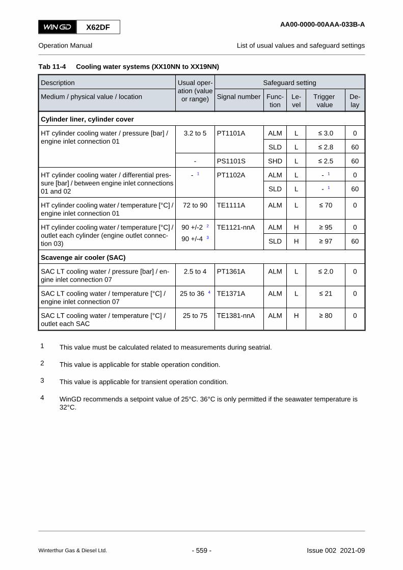
Tab 11-4 Cooling water systems (XX10NN to XX19NN)
Description Usual oper-ation (valueor range)
Safeguard setting
Medium / physical value / location Signal number Func-tion
Le-vel
Trigger value
De-lay
Cylinder liner, cylinder cover
HT cylinder cooling water / pressure [bar] /engine inlet connection 01
3.2 to 5 PT1101A ALM L ≤ 3.0 0
SLD L ≤ 2.8 60
- PS1101S SHD L ≤ 2.5 60
HT cylinder cooling water / differential pres-sure [bar] / between engine inlet connections01 and 02
- 1 PT1102A ALM L - 1 0
SLD L - 1 60
HT cylinder cooling water / temperature [°C] /engine inlet connection 01
72 to 90 TE1111A ALM L ≤ 70 0
HT cylinder cooling water / temperature [°C] /outlet each cylinder (engine outlet connec-tion 03)
90 +/-2 2
90 +/-4 3TE1121-nnA ALM H ≥ 95 0
SLD H ≥ 97 60
Scavenge air cooler (SAC)
SAC LT cooling water / pressure [bar] / en-gine inlet connection 07
2.5 to 4 PT1361A ALM L ≤ 2.0 0
SAC LT cooling water / temperature [°C] /engine inlet connection 07
25 to 36 4 TE1371A ALM L ≤ 21 0
SAC LT cooling water / temperature [°C] /outlet each SAC
25 to 75 TE1381-nnA ALM H ≥ 80 0
1 This value must be calculated related to measurements during seatrial.
2 This value is applicable for stable operation condition.
3 This value is applicable for transient operation condition.
4 WinGD recommends a setpoint value of 25°C. 36°C is only permitted if the seawater temperature is32°C.
X62DF AA00-0000-00AAA-033B-A
Operation Manual List of usual values and safeguard settings
Winterthur Gas & Diesel Ltd. - 559 - Issue 002 2021-09

Tab 11-5 Oil systems (XX2NNN, part 1)
Description Usual oper-ation (valueor range)
Safeguard setting
Medium / physical value / location Signal number Func-tion
Le-vel
Trigger value
De-lay
Lubricating oil supply - system side
Main lubricating oil / pressure [bar] / engineinlet connection 25
4.2 to 5 PT2001A ALM L ≤ 4.0 0
SLD L ≤ 3.8 60
- PS2002S SHD L ≤ 3.3 10
Main lubricating oil / temperature [°C] / en-gine inlet connection 25
45 +/-2 1
45 +/-4 2TE2011A ALM H ≥ 50 0
SLD H ≥ 55 60
External crosshead bearing oil / pressure[bar] / engine inlet connection 30
10.2 to 13 PT2021A ALM L ≤ 10.0 3 10
SLD L ≤ 9.0 3 60
Injector lubricating oil
Injector lubricating oil / pressure [bar] / inletinjectors
4.2 to 5 PT2003A ALM L ≤ 2.6 4 0
Bearing oil
Main bearing oil / temperature [°C] / outleteach main bearing (optional)
45 to 60 TE2101-nnA ALM H ≥ 65 0
SLD H ≥ 70 60
Crank bearing oil / temperature [°C] / outleteach crank bearing (optional)
45 to 60 TE2201-nnA ALM H ≥ 65 0
SLD H ≥ 70 60
Crosshead bearing oil / temperature [°C] /outlet each crosshead bearing (optional)
45 to 60 TE2301-nnA ALM H ≥ 65 0
SLD H ≥ 70 60
1 This value is applicable for stable operation condition.
2 This value is applicable for transient operation condition.
3 The trigger value is only applicable above 40% engine load.
4 The trigger value is not applicable when the engine has stopped.
X62DF AA00-0000-00AAA-033B-A
Operation Manual List of usual values and safeguard settings
Winterthur Gas & Diesel Ltd. - 560 - Issue 002 2021-09

Tab 11-6 Oil systems (XX2NNN, part 2)
Description Usual oper-ation (valueor range)
Safeguard setting
Medium / physical value / location Signal number Func-tion
Le-vel
Trigger value
De-lay
Servo oil
Servo oil / pressure [bar] / distributor pipe(mini rail) 1
60 PT2041A ALM L ≤ 40.0 3
ALM H ≥ 75.0 3
Servo oil / flow / inlet each servo oil pump 2 - FS2061-nnA ALM L min 0
ALM H max 0
Servo oil leakage / flow / servo oil supply unit - LS2055A ALM H max 10
Oil mist
Oil mist / concentration / crankcase (eachcylinder) 3
- AE2401-nnA ALM H max 0
AS2401A ALM H max 0
- AS2401S SLD H max 60
Oil mist / concentration / gearcase - AE2415A ALM H max 0
Oil mist / concentration / fuel supply unit - AE2421A ALM H max 0
Piston cooling oil
Piston cooling oil / temperature [°C] / outleteach cylinder
45 to 75 TE2501-nnA ALM H ≥ 80 0
SLD H ≥ 85 60
Piston cooling oil / flow [l/min] / outlet eachcylinder
- FS2521-nnS SHD H max 15
SHD L min 15
1 The trigger values are not applicable when the engine has stopped.
2 The trigger values are only applicable above 30% engine load.
3 The concentration is related to the lower explosive level (LEL).
X62DF AA00-0000-00AAA-033B-A
Operation Manual List of usual values and safeguard settings
Winterthur Gas & Diesel Ltd. - 561 - Issue 002 2021-09

Tab 11-7 Oil systems (XX2NNN, part 3 (turbocharger bearing oil))
Description Usual oper-ation (valueor range)
Safeguard setting
Medium / physical value / location Signal number Func-tion
Le-vel
Trigger value
De-lay
Bearing oil turbocharger ABB A100/200-L with internal oil
TC bearing oil / pressure [bar] / inlet eachturbocharger
1.5 to 5.0 PT2611-nnA ALM L ≤ 1.0 5
SLD L ≤ 0.8 60
- PS2611-nnS SHD L ≤ 0.6 5
TC bearing oil / temperature [°C] / outlet eachturbocharger
45 to 100 TE2601-nnA ALM H ≥ 110 0
SLD H ≥ 120 60
Bearing oil turbocharger ABB A100/200-L with external oil
TC bearing oil / pressure [bar] / inlet eachturbocharger
1.5 to 5.0 PT2611-nnA ALM L ≤ 1.3 5
SLD L ≤ 1.1 60
- PS2611-nnS SHD L ≤ 0.9 5
TC bearing oil / temperature [°C] / inlet tur-bocharger
45 to 80 TE2621A ALM H ≥ 85 0
SLD H ≥ 90 60
TC bearing oil / temperature [°C] / outlet eachturbocharger
45 to 120 TE2601-nnA ALM H ≥ 130 0
SLD H ≥ 140 60
Bearing oil turbocharger MHI MET with internal oil
TC bearing oil / pressure [bar] / inlet eachturbocharger
1.0 to 5.0 PT2611-nnA ALM L ≤ 0.7 5
SLD L ≤ 0.6 60
- PS2611-nnS SHD L ≤ 0.4 5
TC bearing oil / temperature [°C] / outlet eachturbocharger
45 to 80 TE2601-nnA ALM H ≥ 85 0
SLD H ≥ 90 60
Bearing oil turbocharger MHI MET with external oil
TC bearing oil / pressure [bar] / inlet eachturbocharger
1.0 to 5.0 PT2611-nnA ALM L ≤ 0.7 5
SLD L ≤ 0.6 60
- PS2611-nnS SHD L ≤ 0.4 5
TC bearing oil / temperature [°C] / inlet tur-bocharger
45 to 50 TE2621A ALM H ≥ 60 0
SLD H ≥ 65 60
TC bearing oil / temperature [°C] / outlet eachturbocharger
45 to 80 TE2601-nnA ALM H ≥ 85 0
SLD H ≥ 90 60
X62DF AA00-0000-00AAA-033B-A
Operation Manual List of usual values and safeguard settings
Winterthur Gas & Diesel Ltd. - 562 - Issue 002 2021-09

Tab 11-8 Oil systems (XX2NNN, part 4)
Description Usual oper-ation (valueor range)
Safeguard setting
Medium / physical value / location Signal number Func-tion
Le-vel
Trigger value
De-lay
Damper oil
Damper oil / pressure [bar] / inlet torsional vi-bration damper 1
2.8 to 5.0 PT2711A ALM L ≤ 2.2 0
Damper oil / pressure [bar] / axial vibrationdamper space aft side
1.8 to 5.0 PT2721A ALM L ≤ 1.7 60
Damper oil / pressure [bar] / axial vibrationdamper space fore side
1.8 to 5.0 PT2722A ALM L ≤ 1.7 60
Cylinder oil
Cylinder oil / pressure [bar] / cylinder oil rail2
≥ 0.3 PT3124A ALM L ≤ 0.1 30
Cylinder oil / temperature [°C] / engine inlet 35 to 50 - - - - -
1 The setpoint and trigger values can be different. For the applicable values refer to the specification ofthe damper manufacturer.
2 This value is only applicable if the engine has no iCAT.
X62DF AA00-0000-00AAA-033B-A
Operation Manual List of usual values and safeguard settings
Winterthur Gas & Diesel Ltd. - 563 - Issue 002 2021-09

Tab 11-9 Gas system (XX33NN and XX39NN)
Description Usual oper-ation (valueor range)
Safeguard setting
Medium / physical value / location Signal number Func-tion
Le-vel
Trigger value
De-lay
Gas leakage detection
Gas leakage / concentration [% LEL] / pistonunderside (engine inlet connection 82) 1
- AE3315C ALM H ≥ 20 0
GTrip H ≥ 40 0
Gas supply - iGPR
Gas / pressure [bar] / inlet iGPR (engine inletconnection 78)
10 to 15 PT3941C ALM H ≥ 16.0 0
GTrip H ≥ 17.0 0
Gas / flow [kg/h] / inlet iGPR (engine inletconnection 78)
1000 to1800 3
FT3942C - - - -
Gas / pressure [bar] / outlet flowmeter 10 to 15 PT3901C - - - -
PS3901S GTrip H ≥ 18.0 0
PS3902S GTrip L ≤ 2.0 0
Gas / temperature [°C] / outlet flowmeter 20 to 50 4 TT3901C - - - -
TS3901S GTrip H ≥ 60 3
TS3902S GTrip L ≤ 0 4 3
Gas / underpressure [mbar] / iGPR enclosure 10 to 20 PT3903C - - - -
Inert gas / pressure [bar] / engine inlet con-nection 83
5 to 15 PT3905C - - - -
Gas / pressure [bar] / inlet pressure regula-tion valve
10 to 15 PT3906C - - - -
Gas supply - gas rail
Gas / pressure [bar] / gas rail 2 to 14 5 PT3595CPT3597C
- - - -
Air / flow [l/min] / inlet double wall pipe 41 to 45 FS3904S GTrip L ≤ 40 0
1 LEL - Lower explosive level
2 Related to the GTD requirement for the selected rating and to the LHV of the gas quality
3 Related to the engine load
4 For a mixture of volatile organic compounds (VOC) and liquefied natural gas (LNG) the usual operationrange is 45 to 55°C. The related trigger value is ≤ 40°C.
5 Related to the engine load
X62DF AA00-0000-00AAA-033B-A
Operation Manual List of usual values and safeguard settings
Winterthur Gas & Diesel Ltd. - 564 - Issue 002 2021-09

Tab 11-10 Fuel system (XX34NN)
Description Usual oper-ation (valueor range)
Safeguard setting
Medium / physical value / location Signal number Func-tion
Le-vel
Trigger value
De-lay
Fuel supply - system side
High viscosity fuel which requires heating(HFO, excluding RMA10) / viscosity [cSt] /engine inlet connection 49
13 to 17 - 1 ALM H ≥ 20 0
ALM L ≤ 10 0
Low viscosity fuel which requires no heating(distillates, RMA10, most ULSFO) / viscosity[cSt] / engine inlet connection 49
3 to 14 - 1 ALM H ≥ 17 0
ALM L ≤ 2 0
Fuel supply unit
Fuel / pressure [bar] / inlet fuel supply unit 7.5 to 10 2 PT3421A ALM L ≤ 7 0
Fuel / temperature [°C] / inlet fuel supplyunit 3
20 to 150 TE3411A ALM H ≥ 50 to 160 0
ALM L ≤ 20 to 130 0
Fuel leakage / flow / outlet fuel supply unit - LS3426A ALM H max 10
Fuel leakage / flow / outlet fuel rail items - LS3446A ALM H max 10
Rail unit
Leakage / flow / outlet rail unit - LS3444A ALM H max 10
Pilot fuel filter
Fuel / differential pressure [bar] / pilot fuel fil-ter
- PS3464A ALM H ≥ 2.5 0
1 This measurement is not included in the standard engine supply (the viscometer is a yard supply item).
2 When the engine has stopped, the setpoint is 10 bar. The value decreases when the engine load in-creases.
3 The values are related to the fuel viscosity.
X62DF AA00-0000-00AAA-033B-A
Operation Manual List of usual values and safeguard settings
Winterthur Gas & Diesel Ltd. - 565 - Issue 002 2021-09

Tab 11-11 Exhaust gas system (XX37NN)
Description Usual oper-ation (valueor range)
Safeguard setting
Medium / physical value / location Signal number Func-tion
Le-vel
Trigger value
De-lay
Exhaust pipe / manifold
Exhaust gas / temperature [°C] / outlet eachcylinder
- TE3701-nnA ALM H ≥ 515 0
ALM D ≥ 50 0
SLD H ≥ 530 60
SLD D ≥ 70 60
Exhaust gas / temperature [°C] / inlet eachturbocharger
- TE3721-nnA ALM H ≥ 515 0
SLD H ≥ 530 60
Exhaust gas / temperature [°C] / outlet eachturbocharger
- TE3731-nnA ALM H ≥ 340 0
SLD H ≥ 380 60
X62DF AA00-0000-00AAA-033B-A
Operation Manual List of usual values and safeguard settings
Winterthur Gas & Diesel Ltd. - 566 - Issue 002 2021-09

Tab 11-12 Air systems (XX40NN to XX44NN)
Description Usual oper-ation (valueor range)
Safeguard setting
Medium / physical value / location Signal number Func-tion
Le-vel
Trigger value
De-lay
Scavenge air receiver
Scavenge air / temperature [°C] / outlet eachair cooler
28 to 55 TE4031-nnA ALM L ≤ 25 0
ALM H ≥ 60 0
SLD H ≥ 70 60
Scavenge air / temperature [°C] / piston un-derside each cylinder
28 to 55 TE4081-nnA ALM H ≥ 80 0
SLD H ≥ 120 60
Condensation water / flow / at each waterseparator
- LS4071-nnA ALM H max 10
SLD H max 60
Condensation water / flow / upstream eachwater separator
- LS4075-nnA ALM H max 10
SLD H max 60
Starting air supply
Starting air supply / pressure [bar] / engineinlet connection 40
20 to 30 - - - - -
Control air supply unit
Control air supply / pressure [bar] / engineinlet connection 45
7 to 9 - - - - -
Control air / pressure [bar] / outlet usual sup-ply
6.5 PT4401A ALM L ≤ 6.0 0
Control air / pressure [bar] / outlet stand-bysupply
6.0 PT4411A ALM L ≤ 5.5 0
Control air / pressure [bar] / air tank for safetysupply
6.5 or 6.0 PT4421A ALM L ≤ 5.0 15
Air spring
Air spring air / pressure [bar] / supply to airspring
6.5 or 6.0 PT4341A ALM H ≥ 7.5 0
ALM L ≤ 5.5 0
SLD L ≤ 5.0 60
- PS4341S SHD L ≤ 4.5 0
Oil leakage / flow / air spring at driving end - LS4351A ALM H max 5
Oil leakage / flow / air spring at free end - LS4352A ALM H max 5
X62DF AA00-0000-00AAA-033B-A
Operation Manual List of usual values and safeguard settings
Winterthur Gas & Diesel Ltd. - 567 - Issue 002 2021-09

Tab 11-13 Miscellaneous items (XX45NN to XX52NN)
Description Usual oper-ation (valueor range)
Safeguard setting
Medium / physical value / location Signal number Func-tion
Le-vel
Trigger value
De-lay
Thrust bearing
Pad / temperature [°C] / thrust bearing(AHEAD)
45 to 75 TE4521A ALM H ≥ 80 0
SLD H ≥ 85 60
- TS4521S SHD H ≥ 90 60
Cylinder liner
Wall / temperature [°C] / each cylinder lineraft side
≤ 230 TE4801-nnC ALM H ≥ 250 0
SLD H ≥ 270 60
Wall / temperature [°C] / each cylinder linerfore side
≤ 230 TE4841-nnC ALM H ≥ 250 0
SLD H ≥ 270 60
Powertrain
Crankshaft / speed [% of CMCR] / crankshaft - ST5111-12S SHD H ≥ 110 0
Tachometer turbocharger
Impeller shaft / overspeed [rpm] / each ABBturbocharger
- ST5201-nnA ALM H refer tonote 1
0
Impeller shaft / overspeed [rpm] / each MHIturbocharger
- ST5201-nnA ALM H refer tonote 2
0
1 For ABB TC the alarm value is 0.97 x nMax on rating plate (nMax usually referred to as nMmax in 1/s).
2 For MHI TC the alarm value is 0.95 x nMax on rating plate (nMax usually referred to as overspeed inrpm).
X62DF AA00-0000-00AAA-033B-A
Operation Manual List of usual values and safeguard settings
Winterthur Gas & Diesel Ltd. - 568 - Issue 002 2021-09

Some items are continuously monitored for correct function. If an item becomes defective, theAMS sends a message to the ship alarm system, refer to Table 11-14 - Failure messages.
Tab 11-14 Failure messages
Medium / location Signal number Delay
Failure of oil mist detector XS2411A 0
Failure of fuel heating XS3463A 0
Failure of fuel pump actuator XS5046A 0
X62DF AA00-0000-00AAA-033B-A
Operation Manual List of usual values and safeguard settings
Winterthur Gas & Diesel Ltd. - 569 - Issue 002 2021-09

11.4 Section views
X62DF AA00-0000-00AAA-034A-A
Operation Manual Section views
Winterthur Gas & Diesel Ltd. - 570 - Issue 002 2021-09

12 Operating media12.1 General for operating media....................................................................................57212.2 Compressed air.......................................................................................................57412.3 Scavenge air............................................................................................................57612.4 Gas fuels.................................................................................................................578
X62DF
Operation Manual
Winterthur Gas & Diesel Ltd. - 571 - Issue 002 2021-09

12.1 General for operating media
WinGD has specified the requirements of the operating media for the engine.
On the WinGD website (https://www.wingd.com/) the latest versions of the specifications areavailable for the operating media that follow:
• Fuel
• Lubricants
• Water
NOTE: On the WinGD website go to your engine type, then to “OPERATION &MAINTENANCE”, then to “FUEL LUBRICANTS WATER”.
On the pages that follow the specifications are available for the operating media that follow:
• Compressed air
• Scavenge air
• Gas (if applicable)
X62DF AA00-0000-00AAA-018M-A
Operation Manual General for operating media
Winterthur Gas & Diesel Ltd. - 572 - Issue 002 2021-09

X62DF AA00-0000-00AAA-018M-A
Operation Manual General for operating media
Page left intentionally blank
Winterthur Gas & Diesel Ltd. - 573 - Issue 002 2021-09

12.2 Compressed air
Compressed air has the functions that follow:
• Compressed air is used as starting air for the starting air system.
• Compressed air is used as control air for the control air system.
12.2.1 Requirements for compressed air
The compressed air must have the basic properties that follow:
• Clean and dry
• Purity class 2-4-2 (ISO 8573-1).
12.2.2 Recommended procedures for compressed air
WinGD recommends to regularly do the procedures that follow to prevent explosions:
• Regularly drain the starting air bottles to remove condensation.
• Regularly clean the starting air pipes to remove oil that can come from the air compressors.
• Regularly do the maintenance work for the air compressors to keep the compressed air asclean as possible.
X62DF AA00-0000-00AAA-030E-A
Operation Manual Compressed air
Winterthur Gas & Diesel Ltd. - 574 - Issue 002 2021-09

X62DF AA00-0000-00AAA-030E-A
Operation Manual Compressed air
Page left intentionally blank
Winterthur Gas & Diesel Ltd. - 575 - Issue 002 2021-09

12.3 Scavenge air
The turbocharger compresses the air from the engine room or from outside for the scavenge air.
The air must be as clean as possible to keep the wear of cylinder liner, piston rings, turbochargercompressor etc to a minimum. Silencers are installed to the suction part. The silencers have filtermats in them, which help to keep the air clean.
The filter mats must be serviced and/or cleaned regularly. For this data, refer to the turbochargermanual.
X62DF AA00-0000-00AAA-030D-A
Operation Manual Scavenge air
Winterthur Gas & Diesel Ltd. - 576 - Issue 002 2021-09

X62DF AA00-0000-00AAA-030D-A
Operation Manual Scavenge air
Page left intentionally blank
Winterthur Gas & Diesel Ltd. - 577 - Issue 002 2021-09

12.4 Gas fuels
12.4.1 Gas specifications
WinGD X-DF engines are designed for continuous service in gas or in diesel operating mode. Forsmooth engine operation without decrease in rated output, the gas used as a main fuel in gasoperating mode must obey the quality requirements given in below Table 12-1 - Specifications forgas fuel.
Tab 12-1 Specifications for gas fuel
Parameter Value1
Lower heating value (LHV) ≥ 28 MJ/Nm3
Minimum MN 65 for 100% engine power and 60 for 85% enginepower
Effect of MN on max. engine output See Figure 12-1
Methane content ≥ 70% volume
Hydrogen sulphide (H2S) ≤ 0.05% volume
Hydrogen (H2)2
≤ 3% volume
Ammonia ≤ 25mg/Nm3
Chlorine and fluorine ≤ 50mg/Nm3
Dew point of water ≤ -20°C
Oil (aerosol liquid and vapour) ≤ 1mg/Nm3
Gas cleanliness Gas is considered as sufficiently clean.
Gas temperature at GVU inlet (option: GVU)or engine inlet (option: iGPR)
0-60°C. No condensate is allowed in the annularspace of the ME gas piping.
Gas feed pressure5
According to GTD
Permissible gas pressure fluctuation ± 0.6 bar (across all frequencies)
1 Values given in Nm3 are at 0°C and 101.3 kPa.
2 Hydrogen content higher than 3% volume must be considered on a project-specific basis.
3 Contamination from gas system has to be avoided, e.g. by correct pipe flushing, ensuringcleanliness of bunkering connections, etc.
X62DF AA00-0000-00AAA-030J-A
Operation Manual Gas fuels
Winterthur Gas & Diesel Ltd. - 578 - Issue 002 2021-09

4 If the gas temperature falls below the ambient air temperature (or the ambient air dewpoint), a dedicated dry air supply must be used from one of the below methods:• From control air supply (ISO 8573-1, class x-4-x to be fulfilled, i.e. dew point ≤ 3°C)
• Form air dryer (ISO 8573-1, class x-4-x to be fulfilled, i.e. dew point ≤ 3°C)
• From working air supply (as long as gas temperature is > 20°C)
5 The required gas feed pressure depends on the LHV as well as on the specific enginerating and actual engine load (specified in GTD).
12.4.1.1 Methane number dependent engine output
The methane number (MN) has effect on the maximum available power output.
Fig 12-1 Maximum achievable power
12.4.1.2 Methane number calculation
A software is given by the European Association of Internal Combustion Engine ManufacturerEUROMOT gives the calculation of the methane number in natural gas mixtures. This is freesoftware and can be accessed through below link:
https://www.euromot.eu/wp-content/uploads/2019/07/MWM-MN-Code-for-distribution-2016-04-22.zip
X62DF AA00-0000-00AAA-030J-A
Operation Manual Gas fuels
Winterthur Gas & Diesel Ltd. - 579 - Issue 002 2021-09

12.4.2 Gas supply pressure
12.4.2.1 Layout of gas supply system
The engine and the gas supply system are set down such that unrestricted engine power outputis ensured for all gas qualities down to a lower heating value (LHV) of 28 MJ/Nm3. This is typicallythe lowest value of LNG’s natural boil-off composition with high nitrogen content (approx. 22%)and it can be found on LNG carriers at the beginning of laden voyages.
The design limit of gas pressure regulating equipment is 16 bar(g).
The gas piping class for the specific project is defined according to the design gas pressurespecified in the below paragraphs, with the pressure fluctuations and safety margin for pressurelosses.
12.4.2.2 Design gas supply pressure selection
The Figure 12-2 shows the minimum required design gas presure at GVU inlet (option: GVU) orengine inlet (option: iGPR) for R1-R3 and R2-R4 rated engines as a function of the gas LHV andthe actual engine output.NOTE: The ship owner and the shipyard have the rights and responsibilities to define the ME
rating (CMCR) and the LHV for 100% CMCR output in the ship building specification.
The gas supply design pressure is to be selected according to the 100% CMCR engine output andthe selected LHV with maximum power drop between GVU inlet (option: GVU) or engine inlet(option: iGPR) and gas supply oulet.
A gas fuel with lower LHV than the specified LHV can be used at the specified design gas pressure,but the ME may have power limitations at certain rating levels. Contact WinGD for moreinformation.
X62DF AA00-0000-00AAA-030J-A
Operation Manual Gas fuels
Winterthur Gas & Diesel Ltd. - 580 - Issue 002 2021-09

Fig 12-2 Design gas feed pressure requirements
Rating-specific information is available in WinGD engine layout application GTD.
X62DF AA00-0000-00AAA-030J-A
Operation Manual Gas fuels
Winterthur Gas & Diesel Ltd. - 581 - Issue 002 2021-09

X62DF AA00-0000-00AAA-030J-A
Operation Manual Gas fuels
Page left intentionally blank
Winterthur Gas & Diesel Ltd. - 582 - Issue 002 2021-09

13 Schematic diagrams13.1 Schematic diagrams - general.................................................................................58413.2 List of diagrams.......................................................................................................590
X62DF
Operation Manual
Winterthur Gas & Diesel Ltd. - 583 - Issue 002 2021-09

13.1 Schematic diagrams - generalNOTE: The diagrams below are part of the Engine-Builder Drawing-Set and are not included in
this operation manual. The diagrams below can be referenced directly in the specificEngine-Builder Drawing-Set. Please contact your Engine-Builder, if you need the specificdiagrams.
13.1.1 Engine control diagram
The engine control diagram shows data about the control items of the engine and its systems.
In the sub-sections that follow you find general data about the engine control diagram.
13.1.1.1 Area codes in the engine control diagram
The area codes in the engine control diagram are as follows:
• A - Control air supply unit
• B - Fuel supply
• D - Servo oil supply
• E - Valve unit for start
• K - Local control panel.
13.1.1.2 Line codes in the engine control diagram
The line codes in the engine control diagram are shown in Figure 13-1.
Fig 13-1 Line codes
001002003
004
005006
00700208
Legend
001 Low pressure oil circuits 005 Heating002 High pressure oil circuits 006 Control air circuits003 Low pressure fuel circuits 007 Starting air circuits004 High pressure fuel circuits
X62DF AA00-0000-00AAA-043I-A
Operation Manual Schematic diagrams - general
Winterthur Gas & Diesel Ltd. - 584 - Issue 002 2021-09

13.1.1.3 System codes in the engine control diagram
The system codes in the engine control diagram are as follows:
• Code 10 - Fuel system
• Code 20 - Oil system
• Code 25 - Cylinder oil system
• Code 30 - Starting air system
• Code 35 - Control air system
• Code 40 - HT Cooling water system
• Code 48 - Cylinder cooling water system
• Code 50 - Exhaust gas system
• Code 70 - Miscellaneous systems
• Code 80 - Automation system
• Code 99 - Pipe diagram
• Code 900 - Engine room.
13.1.1.4 Component codes in the engine control diagram
The component codes in the engine control diagram are shown as example in Figure 13-2.
Fig 13-2 Process codes
10-5553_E0_1
001 002 003 004 005
00206
Legend
001 System code 004 CX - Cylinder, eg C5 = for cylinder 5002 Design group 005 Running number003 E0 = for engine
13.1.1.5 Signal codes - identification
The signal codes in the engine control diagram are shown as example in Figure 13-3.
X62DF AA00-0000-00AAA-043I-A
Operation Manual Schematic diagrams - general
Winterthur Gas & Diesel Ltd. - 585 - Issue 002 2021-09

Fig 13-3 Signal codes
PT 1012 C
001 002 003 004
00207
Legend
001 Function code 003 Running number002 Function group 004 Applied system
Tab 13-1 Function code
Code First position Second position
A Analysis n/a
C Control Control
E n/a Element
F Flow n/a
G Gauge n/a
H Hand n/a
I n/a Indication
J Power n/a
L Level n/a
P Pressure n/a
S Speed Switch
T Temperature Transmitter
V n/a Valve
X Unclassified Unclassified
Y Vibration Relay
Z Position (binary) n/a
X62DF AA00-0000-00AAA-043I-A
Operation Manual Schematic diagrams - general
Winterthur Gas & Diesel Ltd. - 586 - Issue 002 2021-09

Tab 13-2 Function group
Code Signal type System
10 to 19 Signals from the engine Cooling water
20 to 29 Signals from the engine System oil, cooling oil
31 Signals from the engine Cylinder lubrication
33 Signals from the engine Fuel gas
34 Signals from the engine Fuel oil
35 Signals from the engine Fuel gas
37 Signals from the engine Exhaust gas
40 to 49 Signals from the engine Air systems
50 to 59 Signals from the engine Miscellaneous
60 to 69 Signals from the engine Spare
70 to 79 Signals to the engine Miscellaneous
80 to 89 Signals to the engine Miscellaneous
Tab 13-3 Applied system
Code Description
A Alarm and monitoring system
C Control system
L Local
M Measured indication, Local control panel
S Safety system
W Wrong way alarm
X Miscellaneous
X62DF AA00-0000-00AAA-043I-A
Operation Manual Schematic diagrams - general
Winterthur Gas & Diesel Ltd. - 587 - Issue 002 2021-09

13.1.2 Electric connection diagram
The electric connection diagram shows data about the bus routing connections (without cylinderrelated signals).
You can find an overview of the used color codes and symbols in Figure 13-4.
Fig 13-4 Color codes and symbols - electric connection diagram
00221
ECR component
Color codes:Power
Option
Diesel
Speed
Bus
CCM-20 A1Cylinder #1
13.1.3 Piping and instrumentation diagram
The piping and instrumentation diagrams show data about the piping and instrumentation of theauxiliary systems of the engine.
X62DF AA00-0000-00AAA-043I-A
Operation Manual Schematic diagrams - general
Winterthur Gas & Diesel Ltd. - 588 - Issue 002 2021-09

X62DF AA00-0000-00AAA-043I-A
Operation Manual Schematic diagrams - general
Page left intentionally blank
Winterthur Gas & Diesel Ltd. - 589 - Issue 002 2021-09

13.2 List of diagrams
Table 13-4 - List of diagrams gives a list of diagrams related to the engine. You find the diagramson the pages that follow.
Tab 13-4 List of diagrams
Item Title
1 Engine control diagram
2 Electric connection diagram
3 Piping and instrumentation diagram, 6 cylinder
4 Piping and instrumentation diagram, 7 cylinder
X62DF AA00-0000-00AAA-050A-A
Operation Manual List of diagrams
Winterthur Gas & Diesel Ltd. - 590 - Issue 002 2021-09