Embed Size (px)
Citation preview
Performance spectra based method for the seismic design ofstructures equipped with passive supplemental damping systems
Jack Wen Wei Guo and Constantin Christopoulos*,†
Department of Civil Engineering, University of Toronto, Canada
SUMMARY
A new direct performance-based design method utilizing design tools called performance-spectra (P-Spectra)for low-rise to medium-rise frame structures incorporating supplemental damping devices is presented.P-Spectra are graphic tools that relate the responses of nonlinear SDOF systems with supplemental dampersto various damping parameters and dynamic system properties that structural designers can control. Thesetools integrate multiple response quantities that are important to the performance of a structure into a singlecompact graphical format to facilitate direct comparison of different potential solutions that satisfy a set ofpredetermined performance objectives under various levels of seismic hazard. An SDOF to MDOF transfor-mation procedure that defines the required supplemental damping properties for the MDOF structure toachieve the response defined by the target SDOF system is also presented for hysteretic, linear viscousand viscoelastic damping devices. Using nonlinear time-history analyses of idealized shear structures, theaccuracy of the transformation procedure is verified. A seismic performance upgrade design example ispresented to demonstrate the usefulness of the proposed method for achieving design performance goalsusing supplemental damping devices. Copyright © 2012 John Wiley & Sons, Ltd.
Received 24 May 2012; Revised 27 August 2012; Accepted 6 September 2012
KEY WORDS: performance-based design; nonlinear response; seismic retrofit; supplemental damping;equivalent SDOF system
1. INTRODUCTION
Recent studies on seismic loss estimations and on the performance-based design of buildings(e.g. [1–4]) have identified the incompleteness of using only maximum-drift based performance metricswithout an explicit consideration of the effects of accelerations and residual drifts that are oftenassociated with high costs related to lost operations, post-earthquake repair and demolition. Theseresults highlight the need for a performance-based design approach that considers multiple responsequantities, and high performance structural systems that achieve these performance objectives.Extensive research conducted over the past few decades has demonstrated the tremendous potentialof passive supplemental dampers for achieving high seismic performance in new and existingstructures. Unlike traditional seismic designs where engineers have limited freedom in adjusting thedynamic properties because of the inherent interdependence of strength and stiffness, buildings withpassive dampers can be designed to achieve a much wider range of dynamic properties for optimalperformance. Furthermore, by diverting the inelastic demand from the main structure into engineeredpassive devices designed to dissipate energy, the risk of main structural element failure can besignificantly reduced while the ability for inspection and repair following a major earthquake can begreatly enhanced.
*Correspondence to: Constantin Christopoulos, Department of Civil Engineering, University of Toronto, Canada.†E-mail: [email protected]
Copyright © 2012 John Wiley & Sons, Ltd.
EARTHQUAKE ENGINEERING & STRUCTURAL DYNAMICSEarthquake Engng Struct. Dyn. 2013; 42:935–952Published online 29 October 2012 in Wiley Online Library (wileyonlinelibrary.com). DOI: 10.1002/eqe.2261
Current North American guidelines (FEMA450) [5] for the design of structures with passivesupplemental dampers rely on an iterative trial-and-error framework described in [6, 7] and [8],which focuses on assessing the performance of a trial structure equipped with dampers. Such anapproach is not instructive on how to select optimal strategies that achieve multiple predeterminedperformance goals. The design of passively damped systems involves tuning structural properties tosatisfy multiple response targets at different seismic hazards. In a retrofit situation, constraints suchas existing strength, stiffness and ductility capacity of the original structure also need to beconsidered. This complex design problem cannot be solved efficiently without a roadmap that linksmultiple response quantities to a set of controllable structural and damping parameters. The lack ofsuch a roadmap in existing guidelines discourages many designers from using supplementaldamping in high performance structures and hinders the wide-scale application of these technologiesin practice.
A number of researchers have studied the behaviour of SDOF systems with supplemental dampers togain insight on how to propose efficient design methods. Filiatrault and Cherry [9, 10] studied hystereticdampers and proposed a design technique based on selecting optimal activation loads that maximize aperformance index related to the absorbed energy and maximum displacement. Using equivalentlinearization techniques, Kasai et al. [11, 12] and Fu and Cherry [13] first proposed performancecurves that show the normalized response of linear SDOFs with hysteretic dampers and elastoplasticSDOFs with hysteretic dampers, respectively. On the basis of the SDOF responses on these curves,damper activation loads are obtained using similar procedures based on code lateral forces as suggestedby these authors. The formulation in [11] was also adopted for systems with viscous [14, 15] andviscoelastic dampers [14, 16]. Using nonlinear time-history analysis, Christopoulos and Mansour [17]produced three-dimensional performance surfaces for displacement and acceleration of linear SDOFsystems with hysteretic dampers. Also using nonlinear time-history analysis, Vargas and Bruneau [18]later produced design charts that reflect the responses to key damping parameters for yielding structuresequipped with friction dampers. More recently, Lago [19] proposed a direct displacement-based designprocedure that uses the spectral displacement spectra for design of structures with hysteretic, viscousand viscoelastic dampers. Although these authors pushed towards more rational design procedures,each has its limitation. In particular, Refs. [13, 17, 18] only deal with hysteretic damping. AlthoughRefs. [11, 12, 14–16] give a consistent procedure for different types of dampers, the assumption oflinear elastic main structure is not realistic in many retrofit situations. Finally, although Ref. [19] allowsone to target the displacement, it does not provide guidance to evaluate whether the targets areachievable or optimal prior to completing a design iteration. To lift these limitations, and to facilitatea direct performance-based design procedure that considers a more complete range of responsequantities and solutions, this paper outlines a proposed new direct design method [20] applicable toyielding low-rise to medium-rise frame structures equipped with supplemental dampers based on theconcept of performance spectra.
2. GENERATION AND USE OF PERFORMANCE SPECTRA FOR DAMPER DESIGN
Building on the concept of performance curves proposed in [11, 13], performance spectra (P-Spectra)are compact graphical design tools that link idealized inelastic SDOF system responses including peakand residual displacement, peak base shear and acceleration to controllable structural and dampingproperties. These spectra allow for a direct comparison and target of different damping strategiesthat achieve a given set of performance goals without completing a full design iteration. Requiredsupplemental damping properties of the MDOF are then obtained from a direct transformationprocedure, which results in an MDOF structure that achieves the response of the targeted SDOFsystem. P-Spectra were initially developed for hysteretic, viscous and viscoelastic devices, but canbe extended to other supplemental damping systems.
The idealized SDOF systems with supplemental dampers shown in Figure 1 are considered. Themain lateral force resisting system excluding dampers, herein referred to as the base frame, isidealized as an elastoplastic SDOF system with mass m, period Tf, inherent damping xo and strengthVf expressed as the ratio of the base shear strength Vbf to the elastic base shear Sa(Tf,xo)m
936 J. W. W. GUO AND C. CHRISTOPOULOS
Copyright © 2012 John Wiley & Sons, Ltd. Earthquake Engng Struct. Dyn. 2013; 42:935–952DOI: 10.1002/eqe
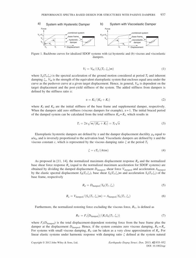
Vf ¼ Vbf= Sa Tf ; xoð Þmð Þ (1)
where Sa(Tf,xo) is the spectral acceleration of the ground motion considered at period Tf and inherentdamping xo. Vbf is the strength of the equivalent elastoplastic system that encloses equal area under thecurve as the pushover curve at a given target displacement. Hence, in general, Vbf is dependent on thetarget displacement and the post-yield stiffness of the system. The added stiffness from dampers isdefined by the stiffness ratio a:
a ¼ Kf= Kd þ Kfð Þ (2)
where Kf and Kd are the initial stiffness of the base frame and supplemental damper, respectively.When the dampers add zero stiffness (viscous dampers for example), a = 1. The initial braced periodof the damped system can be calculated from the total stiffness Kd +Kf, which results in
Ti ¼ 2pffiffiffiffiffiffiffiffiffiffiffiffiffiffiffiffiffiffiffiffiffiffiffiffiffiffim= Kd þ Kfð Þ
p¼ Tf
ffiffiffia
p(3)
Elastoplastic hysteretic dampers are defined by a and the damper displacement ductility md equal tou/ud, and is inversely proportional to the activation load. Viscoelastic dampers are defined by a and theviscous constant c, which is represented by the viscous damping ratio x at the period Tf
x ¼ cTf= 4pmð Þ (4)
As proposed in [11, 14], the normalized maximum displacement response Rd and the normalizedbase shear force response Ra (equal to the normalized maximum acceleration for SDOF systems) areobtained by dividing the damped displacement Ddamped, shear force Vdamped and acceleration Adamped
by the elastic spectral displacement Sd(Tf,xo), base shear Sa(Tf,xo)m and acceleration Sa(Tf,xo) of thebase frame, respectively
Rd ¼ Ddamped=Sd Tf ; xoð Þ (5)
Ra ¼ Vdamped= Sa Tf ; xoð Þmð Þ ¼ Adamped=Sa Tf ; xoð Þ (6)
Furthermore, the normalized restoring force excluding the viscous force, RV, is defined as
RV ¼ Fr Ddamped� �
= KfSd Tf ; xoð Þð Þ (7)
where Fr(Ddamped) is the total displacement-dependent restoring force from the base frame plus thedamper at the displacement Ddamped. Hence, if the system contains zero viscous damping, RV=Ra.For systems with small viscous damping, RV can be taken as a very close approximation of Ra. Forlinear elastic systems under harmonic response with damping ratio x defined at the system natural
System with Hysteretic Damper System with Viscoelastic Dampera) b)
Kfhystereticdamper
base frame
combined system
Kd
Vbf
Vd
Vd+Vbf
Force
Displacementud uf
Kfviscoelastic
damper
base frame
combined system
Kd
Vbf
Kdu+Vbf
Force
Displacementufu u
Figure 1. Backbone curves for idealized SDOF systems with (a) hysteretic and (b) viscous and viscoelasticdampers.
PERFORMANCE SPECTRA BASED DESIGN FOR STRUCTURES WITH PASSIVE DAMPERS 937
Copyright © 2012 John Wiley & Sons, Ltd. Earthquake Engng Struct. Dyn. 2013; 42:935–952DOI: 10.1002/eqe
period, Ra ¼ RV
ffiffiffiffiffiffiffiffiffiffiffiffiffiffiffi1þ 4x2
p. Although this is not true in general for inelastic systems having significant
viscous damping under arbitrary excitation, RV still provides a useful basis to calculate Ra in thesesystems. Finally, the residual displacement ratio Rs is defined as
Rs ¼ RDdamped=Ddamped⩽1 (8)
where RDdamped is the residual displacement of the SDOF system equipped with the dampers. With thisresponse normalization, the ductility of the base frame is given by
mf ¼ u=uf ¼ max 1; Rd=Vfð Þ (9)
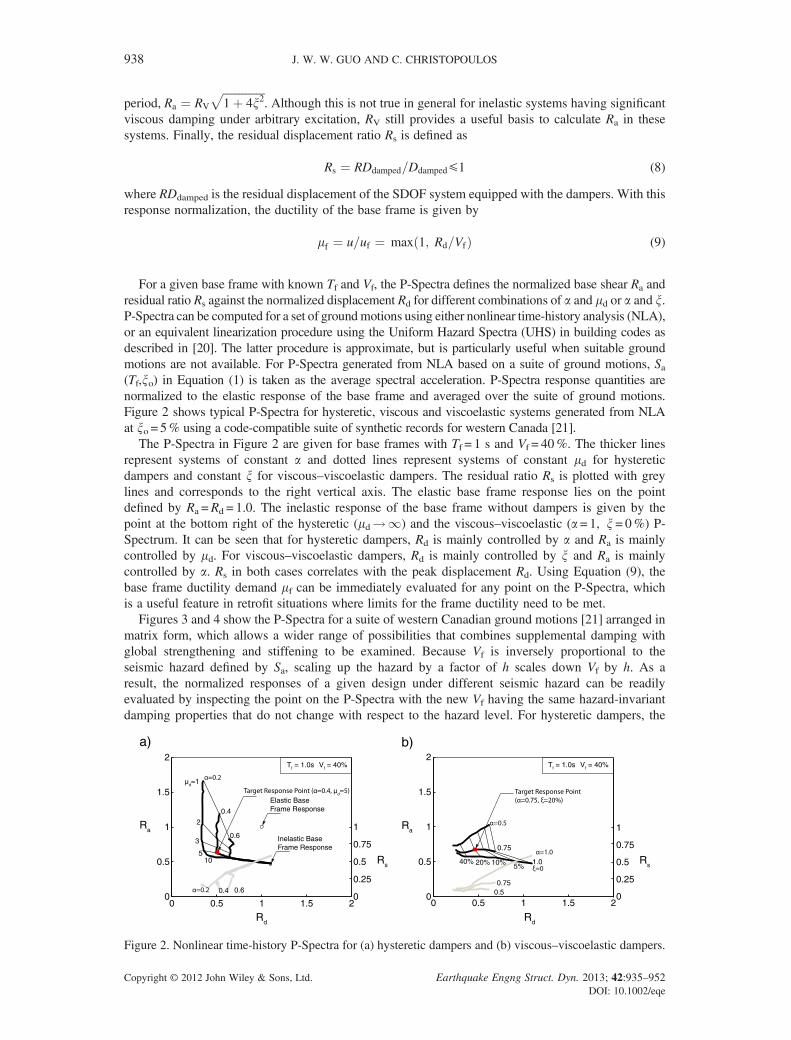
For a given base frame with known Tf and Vf, the P-Spectra defines the normalized base shear Ra andresidual ratio Rs against the normalized displacement Rd for different combinations of a and md or a and x.P-Spectra can be computed for a set of groundmotions using either nonlinear time-history analysis (NLA),or an equivalent linearization procedure using the Uniform Hazard Spectra (UHS) in building codes asdescribed in [20]. The latter procedure is approximate, but is particularly useful when suitable groundmotions are not available. For P-Spectra generated from NLA based on a suite of ground motions, Sa(Tf,xo) in Equation (1) is taken as the average spectral acceleration. P-Spectra response quantities arenormalized to the elastic response of the base frame and averaged over the suite of ground motions.Figure 2 shows typical P-Spectra for hysteretic, viscous and viscoelastic systems generated from NLAat xo = 5% using a code-compatible suite of synthetic records for western Canada [21].
The P-Spectra in Figure 2 are given for base frames with Tf = 1 s and Vf = 40%. The thicker linesrepresent systems of constant a and dotted lines represent systems of constant md for hystereticdampers and constant x for viscous–viscoelastic dampers. The residual ratio Rs is plotted with greylines and corresponds to the right vertical axis. The elastic base frame response lies on the pointdefined by Ra =Rd = 1.0. The inelastic response of the base frame without dampers is given by thepoint at the bottom right of the hysteretic (md!1) and the viscous–viscoelastic (a = 1, x= 0%) P-Spectrum. It can be seen that for hysteretic dampers, Rd is mainly controlled by a and Ra is mainlycontrolled by md. For viscous–viscoelastic dampers, Rd is mainly controlled by x and Ra is mainlycontrolled by a. Rs in both cases correlates with the peak displacement Rd. Using Equation (9), thebase frame ductility demand mf can be immediately evaluated for any point on the P-Spectra, whichis a useful feature in retrofit situations where limits for the frame ductility need to be met.
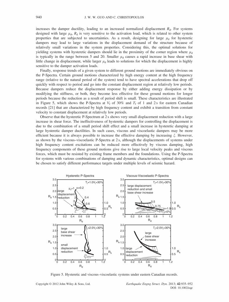
Figures 3 and 4 show the P-Spectra for a suite of western Canadian ground motions [21] arranged inmatrix form, which allows a wider range of possibilities that combines supplemental damping withglobal strengthening and stiffening to be examined. Because Vf is inversely proportional to theseismic hazard defined by Sa, scaling up the hazard by a factor of h scales down Vf by h. As aresult, the normalized responses of a given design under different seismic hazard can be readilyevaluated by inspecting the point on the P-Spectra with the new Vf having the same hazard-invariantdamping properties that do not change with respect to the hazard level. For hysteretic dampers, the
Figure 2. Nonlinear time-history P-Spectra for (a) hysteretic dampers and (b) viscous–viscoelastic dampers.
938 J. W. W. GUO AND C. CHRISTOPOULOS
Copyright © 2012 John Wiley & Sons, Ltd. Earthquake Engng Struct. Dyn. 2013; 42:935–952DOI: 10.1002/eqe
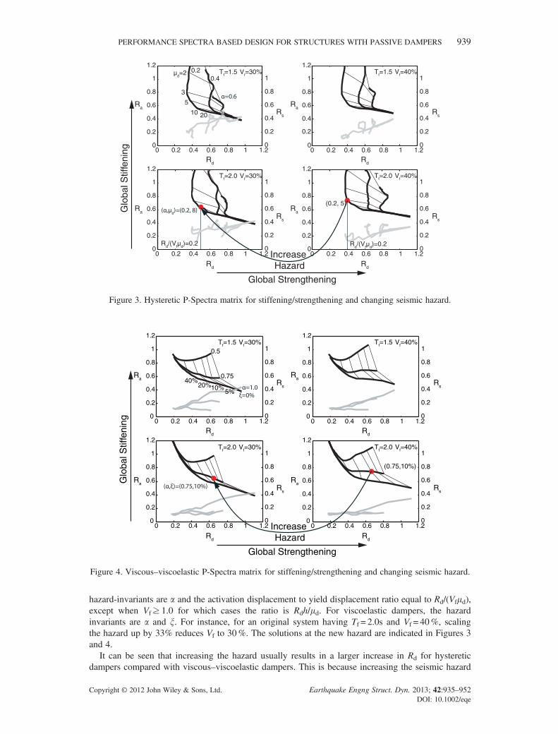
hazard-invariants are a and the activation displacement to yield displacement ratio equal to Rd/(Vfmd),except when Vf≥ 1.0 for which cases the ratio is Rdh/md. For viscoelastic dampers, the hazardinvariants are a and x. For instance, for an original system having Tf = 2.0s and Vf = 40%, scalingthe hazard up by 33% reduces Vf to 30%. The solutions at the new hazard are indicated in Figures 3and 4.
It can be seen that increasing the hazard usually results in a larger increase in Rd for hystereticdampers compared with viscous–viscoelastic dampers. This is because increasing the seismic hazard
0 0.2 0.4 0.6 0.8 1 1.20
0.2
0.4
0.6
0.8
1
1.2
0
0.2 0.2
0.4
0.6
0.8
1
0 0.2 0.4 0.6 0.8 1 1.20
0.4
0.6
0.8
1
1.2
0
0.2
0.4
0.6
0.8
1
0 0.2 0.4 0.6 0.8 1 1.20
0.2
0.4
0.6
0.8
1
1.2
0
0.2
0.4
0.6
0.8
1
0 0.2 0.4 0.6 0.8 1 1.20
0.2
0.4
0.6
0.8
1
1.2
0
0.2
0.4
0.6
0.8
1
Tf=1.5 Vf=30% Tf=1.5 Vf=40%
Tf=2.0 Vf=30% Tf=2.0 Vf=40%
Ra
Rd
Rs
Ra
Rd
Rs
Ra
Rd
Rs
Ra
Rd
Rs
Glo
bal S
tiffe
ning
Global Strengthening
Increase Hazard
(0.2, 5)
Rd/(Vfµd)=0.2 Rd/(Vfµd)=0.2
µd=2
3
5
10
0.40.2
20
Figure 3. Hysteretic P-Spectra matrix for stiffening/strengthening and changing seismic hazard.
0 0.2 0.4 0.6 0.8 1 1.20
0.2
0.4
0.6
0.8
1
1.2
0
0.2
0.4
0.6
0.8
1
0 0.2 0.4 0.6 0.8 1 1.20
0.2
0.4
0.6
0.8
1
1.2
0
0.2
0.4
0.6
0.8
1
0 0.2 0.4 0.6 0.8 1 1.20
0.2
0.4
0.6
0.8
1
1.2
0
0.2
0.4
0.6
0.8
1
0 0.2 0.4 0.6 0.8 1 1.20
0.2
0.4
0.6
0.8
1
1.2
0
0.2
0.4
0.6
0.8
1
Tf=1.5 Vf=30% Tf=1.5 Vf=40%
Tf=2.0 Vf=30% Tf=2.0 Vf=40%
Ra
Rd
Rs
Ra
Rd
Rs
Ra
Rd
Rs
Ra
Rd
Rs
Glo
bal S
tiffe
ning
Global Strengthening
Increase Hazard
(0.75,10%)
5%10%20%
40%0.75
0.5
Figure 4. Viscous–viscoelastic P-Spectra matrix for stiffening/strengthening and changing seismic hazard.
PERFORMANCE SPECTRA BASED DESIGN FOR STRUCTURES WITH PASSIVE DAMPERS 939
Copyright © 2012 John Wiley & Sons, Ltd. Earthquake Engng Struct. Dyn. 2013; 42:935–952DOI: 10.1002/eqe
increases the damper ductility, leading to an increased normalized displacement Rd. For systemsdesigned with large md, Rd is very sensitive to the activation load, which is related to other systemproperties that are subjected to uncertainties. As a result, designing for large md for hystereticdampers may lead to large variations in the displacement demand of the structure because ofrelatively small variations in the system properties. Considering this, the optimal solutions foryielding systems with hysteretic dampers should lie in the proximity of the corner region where mdis typically in the range between 5 and 20. Smaller md causes a rapid increase in base shear withlittle change in displacement, while larger md leads to solutions for which the displacement is highlysensitive to the damper activation loads.
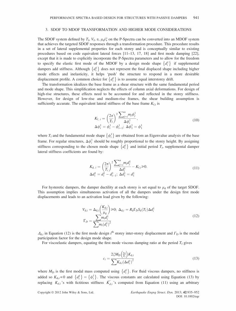
Finally, response trends of a given system to different ground motions are immediately obvious onthe P-Spectra. Certain ground motions characterized by high energy content at the high frequencyrange (relative to the natural period of the system) tend to have spectral accelerations that drop offquickly with respect to period and go into the constant displacement region at relatively low periods.Because dampers reduce the displacement response by either adding energy dissipation or bymodifying the stiffness, or both, they become less effective for these ground motions for longerperiods because the reduction as a result of period shift is small. These characteristics are illustratedin Figure 5, which shows the P-Spectra at Vf of 30% and Tf of 1 and 2 s for eastern Canadianrecords [21] that are characterized by high frequency content and exhibit a transition from constantvelocity to constant displacement at relatively low periods.
Observe that the hysteretic P-Spectrum at 2 s shows very small displacement reduction with a largeincrease in shear force. The ineffectiveness of hysteretic dampers for controlling the displacement isdue to the combination of a small period shift effect and a small increase in hysteretic damping atlarge hysteretic damper ductilities. In such cases, viscous and viscoelastic dampers may be moreefficient because it is always possible to increase the effective damping by increasing x. However,as shown by the viscous–viscoelastic P-Spectra at 2 s, although the displacements of systems underhigh frequency content excitations can be reduced more effectively by viscous damping, highfrequency components of these ground motions give rise to large local velocity peaks and viscousforces, which must be resisted by existing frame members and the foundations. Using the P-Spectrafor systems with various combinations of damping and dynamic characteristics, optimal designs canbe chosen to satisfy different performance targets under multiple levels of seismic hazard.
0 0.2 0.4 0.6 0.8 1 1.20
0.5
1.0
1.5
2.0
2.5
3.0
0
0.5
1.0
Tf=2.0Vf=30%
Tf=1.0Vf=30%
Viscous-Viscoelastic P-SpectraHysteretic P-Spectra
large displacementreduction
0 0.2 0.4 0.6 0.8 1 1.20
0.5
1.0
1.5
2.0
2.5
3.0
0.5
1.0
0 0.2 0.4 0.6 0.8 1 1.20
0.5
1.0
1.5
2.0
2.5
3.0
0
0.5
1.0
0 0.2 0.4 0.6 0.8 1 1.20
0.5
1.0
1.5
2.0
2.5
3.0
0.5
1.0small displacementreduction
large base shearincrease
largedisplacementreduction
largebase shearincrease
large displacementreduction and smallbase shear increase
ξ=0%5%10%20%30%40% α=1.00.75
0.5
α=0.2µd=1
0.4
0.6
23510
Tf=2.0Vf=30%
Tf=1.0Vf=30%
Ra
Rs
Rs
Rd
Ra
Ra
Rs
Rs
Rd
Rd Rd
Ra
Figure 5. Hysteretic and viscous–viscoelastic systems under eastern Canadian records.
940 J. W. W. GUO AND C. CHRISTOPOULOS
Copyright © 2012 John Wiley & Sons, Ltd. Earthquake Engng Struct. Dyn. 2013; 42:935–952DOI: 10.1002/eqe
3. SDOF TO MDOF TRANSFORMATION AND HIGHER MODE CONSIDERATIONS
The SDOF system defined by Tf, Vf, a, md/x on the P-Spectra can be converted into an MDOF systemthat achieves the targeted SDOF responses through a transformation procedure. This procedure resultsin a set of lateral supplemental properties for each storey and is conceptually similar to existingprocedures based on code equivalent lateral forces [11–13, 17, 18] and first mode damping [22],except that it is made to explicitly incorporate the P-Spectra parameters and to allow for the freedomto specify the elastic first mode of the MDOF by a design mode shape d1i
� �if supplemental
dampers add stiffness. Although d1i� �
does not represent the final displaced shape including highermode effects and inelasticity, it helps ‘push’ the structure to respond in a more desirabledisplacement profile. A common choice for d1i
� �is to assume equal interstorey drift.
The transformation idealizes the base frame as a shear structure with the same fundamental periodand mode shape. This simplification neglects the effects of column axial deformations. For design ofhigh-rise structures, these effects need to be accounted for and reflected in the storey stiffness.However, for design of low-rise and medium-rise frames, the shear building assumption issufficiently accurate. The equivalent lateral stiffness of the base frame Kf,i is
Kf; i ¼ 2pTf
� �2Xn
j¼imjf1
j
Δf1i
;
Δf1i ¼ f1
i � f1i�1; Δf
11 ¼ f1
1
(10)
where Tf and the fundamental mode shape f1i
� �are obtained from an Eigenvalue analysis of the base
frame. For regular structures, Δf1i should be roughly proportional to the storey height. By assigning
stiffness corresponding to the chosen mode shape d1i� �
and initial period Ti, supplemental damperlateral stiffness coefficients are found by:
Kd; i ¼ 2pTi
� �2Xn
j¼imjd1j
Δd1i� Kf;i⩾0:
Δd1i ¼ d1i � d1i�1; Δd11 ¼ d11
(11)
For hysteretic dampers, the damper ductility at each storey is set equal to md of the target SDOF.This assumption implies simultaneous activation of all the dampers under the design first modedisplacements and leads to an activation load given by the following:
Vd;i ¼ Δd;iKd;i
md
� �⩾0; Δd;i ¼ RdΓDSd Tfð ÞΔd1i
ΓD ¼X
mid1iXmi d1ið Þ2
(12)
Δd,i in Equation (12) is the first mode design ith storey inter-storey displacement and ΓD is the modalparticipation factor for the design mode shape.
For viscoelastic dampers, equating the first mode viscous damping ratio at the period Tf gives
ci ¼2xMD
2pTf
Kd;iX
Kd;i Δd1ið Þ2(13)
where MD is the first modal mass computed using d1i� �
. For fluid viscous dampers, no stiffness is
added so Kd,i = 0 and d1i� � ¼ f1
i
� �. The viscous constants are calculated using Equation (13) by
replacing Kd;i ’s with fictitious stiffness K^d;i ’s computed from Equation (11) using an arbitrary
PERFORMANCE SPECTRA BASED DESIGN FOR STRUCTURES WITH PASSIVE DAMPERS 941
Copyright © 2012 John Wiley & Sons, Ltd. Earthquake Engng Struct. Dyn. 2013; 42:935–952DOI: 10.1002/eqe
Ti< Tf. Note that K^d;i’s do not represent real stiffness in the viscous dampers, but are numerical toolsused to get stiffness proportional damping in the system as discussed in [22].
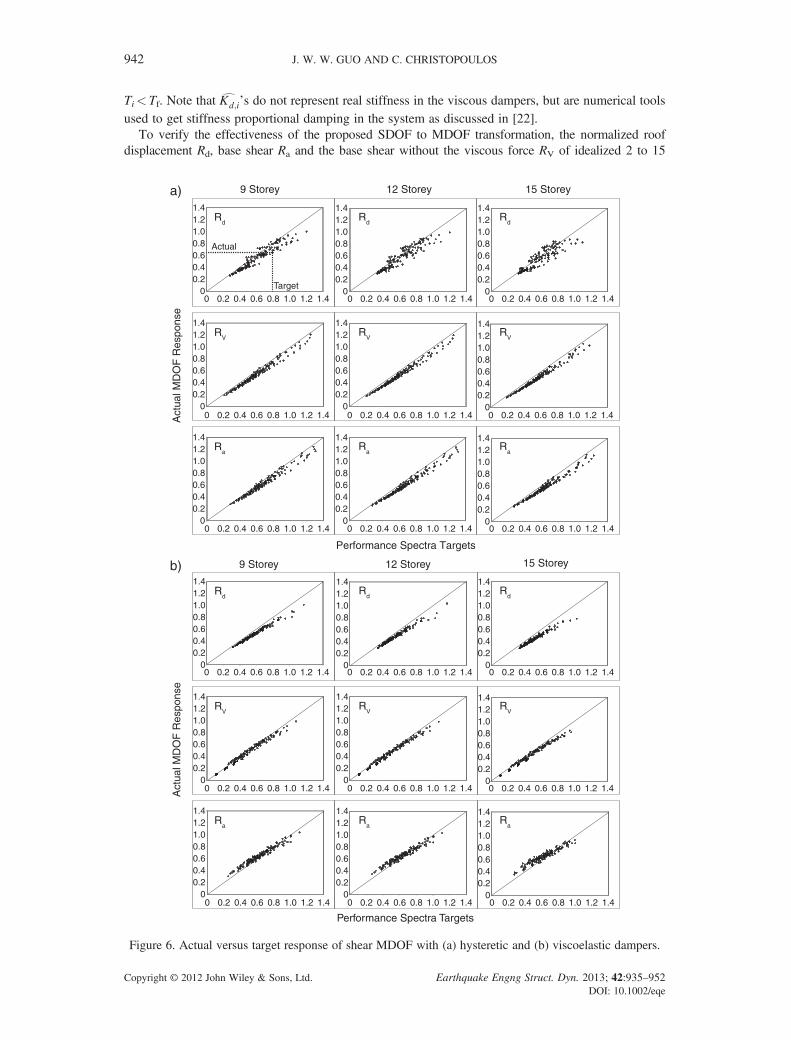
To verify the effectiveness of the proposed SDOF to MDOF transformation, the normalized roofdisplacement Rd, base shear Ra and the base shear without the viscous force RV of idealized 2 to 15
9 StoreyA
ctua
l MD
OF
Res
pons
e12 Storey 15 Storey
Performance Spectra Targets
0 0.2 0.4 1.0 1.40.6 0.8 1.20
0.20.4
1.0
1.4
0.60.8
1.2 Rd
RV
Ra
Target
Actual
0 0.2 0.4 1.0 1.40.6 0.8 1.20
0.20.4
1.0
1.4
0.60.8
1.2
0 0.2 0.4 1.0 1.40.6 0.8 1.20
0.20.4
1.0
1.4
0.60.8
1.2
0 0.2 0.4 1.0 1.40.6 0.8 1.20
0.20.4
1.0
1.4
0.60.8
1.2
0 0.2 0.4 1.0 1.40.6 0.8 1.20
0.20.4
1.0
1.4
0.60.8
1.2
0 0.2 0.4 1.0 1.40.6 0.8 1.20
0.20.4
1.0
1.4
0.60.8
1.2
0 0.2 0.4 1.0 1.40.6 0.8 1.20
0.20.4
1.0
1.4
0.60.8
1.2
0 0.2 0.4 1.0 1.40.6 0.8 1.20
0.20.4
1.0
1.4
0.60.8
1.2
0 0.2 0.4 1.0 1.40.6 0.8 1.20
0.20.4
1.0
1.4
0.60.8
1.2
9 Storey
Act
ual M
DO
F R
espo
nse
Rd
RV
Ra
12 Storey 15 Storey
Performance Spectra Targets
0 0.2 0.4 1.0 1.40.6 0.8 1.20
0.20.4
1.0
1.4
0.60.8
1.2
0 0.2 0.4 1.0 1.40.6 0.8 1.20
0.20.4
1.0
1.4
0.60.8
1.2
0 0.2 0.4 1.0 1.40.6 0.8 1.20
0.20.4
1.0
1.4
0.60.8
1.2
0 0.2 0.4 1.0 1.40.6 0.8 1.20
0.20.4
1.0
1.4
0.60.8
1.2
0 0.2 0.4 1.0 1.40.6 0.8 1.20
0.20.4
1.0
1.4
0.60.8
1.2
0 0.2 0.4 1.0 1.40.6 0.8 1.20
0.20.4
1.0
1.4
0.60.8
1.2
0 0.2 0.4 1.0 1.40.6 0.8 1.20
0.20.4
1.0
1.4
0.60.8
1.2
0 0.2 0.4 1.0 1.40.6 0.8 1.20
0.20.4
1.0
1.4
0.60.8
1.2
0 0.2 0.4 1.0 1.40.6 0.8 1.20
0.20.4
1.0
1.4
0.60.8
1.2
a)
b)
Rd
RV
Ra
Rd
RV
Ra
Rd
RV
Ra
Rd
RV
Ra
Figure 6. Actual versus target response of shear MDOF with (a) hysteretic and (b) viscoelastic dampers.
942 J. W. W. GUO AND C. CHRISTOPOULOS
Copyright © 2012 John Wiley & Sons, Ltd. Earthquake Engng Struct. Dyn. 2013; 42:935–952DOI: 10.1002/eqe
storey shear MDOF designed using Equations (10)–(13) are compared with the target P-Spectra SDOFresponses. The analyses were carried out using 10 records from the ATC-63 project [23] scaled to theLos Angeles (LA) spectrum. For buildings of each height, Tf were set to Tmin, Tmin+0.5, Tmin+1.0 andTmin+1.5, where the minimum period Tmin corresponds to approximately the NBCC2005 empiricalperiod for moment-resisting frames. For 2, 4, 6, 9, 12 and 15-storey shear structures, Tmin were taken as0.5, 0.5, 1.0, 1.0, 1.5 and 2.0 s, respectively. These analyses also considered varying Vf from 10% to40%, a from 0.2 to 0.6 for hysteretic dampers, 0.5 to 1.0 for viscoelastic dampers, md from 2 to 6 and xfrom 10% to 30%. The shear MDOF’s were assigned storey stiffness computed using Equation (10)with the first mode shape having constant interstorey drift along the height. The base shear strength ofthe shear MDOF’s were computed using Equation (1) at the assumed Vf. For simplicity, the verificationstudy assumed that the storey shear strengths are proportional to the storey stiffness. The applicationand verification of this design method to vertically irregular structures is discussed in more detail in[24]. Figure 6 shows examples of the normalized responses Rd, RV and Ra for 9–15 storey shearstructures against the P-Spectra targets for (a) hysteretic and (b) viscous–viscoelastic dampers. Ingeneral, very good agreement on the global responses measured by Rd, RV and Ra were achieved forbuildings of all heights. Furthermore, it was found that the accuracy of the global response estimates isnot sensitive to Tf. As the number of storeys increases, the accuracy of the P-Spectra predictionsdecreases because of complex interaction of yielding storeys and the participation of higher modes,which can also cause local drifts and accelerations of MDOF structures to exceed the SDOF targets.Drift concentrations are more common in systems with hysteretic dampers because local drift demandsare highly sensitive to the relative stiffness of the storeys, which can change as dampers activate andthe frame elements yield. For viscous dampers, the local drifts are less affected because viscousdamping does not contribute to stiffness changes and adds damping to higher modes. Viscoelasticdampers also provide constant stiffness to help redistribute forces to adjacent storeys to prevent localdrift concentration. However, because of the added stiffness, higher modes can increase the forces inviscoelastic systems considerably. A number of previous studies proposed methods to evaluate theeffect of inelastic higher modes using modified modal combination techniques [7, 19, 25–27].However, these methods involve more elaborate spectral or pushover analysis of the damped MDOFstructure, which is not available in the initial design stage. Hence, for simplicity, similar to Kasai et al.[12], a factor fhx is used to relate the target performance goal for quantity x to the peak MDOF storeyresponse accounting for the effect of higher modes
fhx ¼ min xp=
ffiffiffiffiffiffiffiffiffiffiffiffiffiffiffiffiffiffiffiffiffiffiffiffiffiffiffiffiffiffiffiffiffiffiffiffiffiffiffiffiffiffiffiffiffiffiR1xx
1i
� �2 þXnm2
Rmx x
mi
� �2s !⩽1 (14)
where xp is the performance goal set by the designer, x1i and xmi are the first and mth modal responses ofquantity x and R1
x and Rmx are the first and mth modal response modification factors. The factor fhx is the
smallest ratio of the performance goal to the response found by square root of the sum of squares(SRSS) combination of the first nm modes of the upgraded structure. Because the damped structure isnot available, estimates of the modal response xmi are computed from elastic spectral analysis usingproperties of the undamped base frame. The first mode response modification factor R1
x is determinedfrom the P-Spectra based on design performance targets that are discussed in a later section. Highermode response modification factors Rm
x should be set to 1.0 for systems with hysteretic dampersbecause the effect of hysteretic damping in higher modes is not well defined. For viscous damping, thisassumption is too conservative because viscous dampers typically add significant damping to highermodes. Assuming the higher modes are linear elastic, the added higher mode damping can be evaluated as
xmeff ¼Xn
i¼1Wm
D;i
4pWmK
¼TmXn
i¼1ciΔf
m2i
� �4pXn
i¼1mif
m2i
; (15)
where WmD;i and Wm
K are work done by dampers in the ith storey and maximum strain energy in the mth
mode. Tm and fmi are the mth modal period and modal ordinate of the base frame. The factors Rm
x may
PERFORMANCE SPECTRA BASED DESIGN FOR STRUCTURES WITH PASSIVE DAMPERS 943
Copyright © 2012 John Wiley & Sons, Ltd. Earthquake Engng Struct. Dyn. 2013; 42:935–952DOI: 10.1002/eqe
be obtained using P-Spectra at Tm, Vf = 100% and x ¼ xmeff or computed using Equation (16) fordisplacement modification Rm
d and force/acceleration modification Rma
Rmd ¼ exp �1:35xmeff
0:50� �
Rma ¼ Rm
d
ffiffiffiffiffiffiffiffiffiffiffiffiffiffiffiffiffiffi1þ 4xm2eff
q (16)
The expression for Rmd in Equation (16) was obtained by calibrating nonlinear and linear analyses of
SDOF systems equipped with supplemental dampers for the purpose of generating P-Spectra usingequivalent linearization as discussed in [20]. The expression for Rm
a is given for linear elastic highermodes of the base frame under harmonic response. It is assumed that higher mode periods aresufficiently short such that nonharmonic behaviour, which is more important in long period systems,makes a negligible difference to the overall response.
4. PROPOSED DESIGN METHOD
On the basis of the derivation presented above, a design procedure for buildings with supplementaldampers using P-Spectra is proposed:
1. Set preliminary performance targets for drift θt, shear force Vt, acceleration At and residual drift Rθt.2. Evaluate the base frame period Tf from Eigenvalue analysis and strength Vf from either plastic
analysis or pushover analysis. The influence of P�Δ should be accounted for. Note that negativeslope in the pushover curve at the target displacement indicates instability and should be avoidedeither by stiffening the base frame or by adjusting the target displacement.
3. Torsion and vertical irregularity should be checked and accounted for before applying the pro-posed direct design procedure. Some degree of vertical stiffness/strength irregularity can be tol-erated. A more detailed discussion of irregular structures is found in [24].
4. Generate P-Spectra for relevant Tf and Vf using either NLA or a code-compatible equivalent lin-earization approach described in [20]. A quick examination of the P-Spectra provides a generalidea for the feasibility of the initial targets set in Step 1. For a more rigorous check, the first modenormalized targets are first computed as follows:
R1d ¼ Heffθt=Sd Tf ; xoð Þ
Heff ¼Xni¼1
mif1i Hi=
Xni¼1
mif1i
(17)
R1a ¼ min Vt= MeffSa Tfð Þð Þ;At= Γff
1nSa Tfð Þ� �� �
Meff ¼Xni¼1
mif1i
!2
=Xni¼1
mif1i2 (18)
Rs ¼ Rθt=θt⩽1 (19)
where Hi, Heff and Meff are the height of the ith level, effective height and effective mass of the baseframe. Γf is the base frame first modal participation factor and f1
n is the base frame roof ordinate ofthe first mode. Because accelerations and base shears are not directly linked in MDOF systems, R1
ashould be computed from both base shear and accelerations and set to whichever governs. fhx shouldbe computed using Equation (14) and multiplied by the first mode targets to find the reduced designtargets. For systems with viscous damping, fhx can be computed by assuming higher mode dampingof 15%–20%, which should be verified later.
5. Potential solution(s) satisfying the reduced targets are selected by examining the P-Spectra. Insome cases, it may be necessary to revise the initial performance targets because they are notfeasible. On the other hand, there may be cases where revising the target leads to a more efficientuse of dampers even if the initial targets are feasible.
944 J. W. W. GUO AND C. CHRISTOPOULOS
Copyright © 2012 John Wiley & Sons, Ltd. Earthquake Engng Struct. Dyn. 2013; 42:935–952DOI: 10.1002/eqe
6. Perform SDOF to MDOF transformation using Equations (10) to (13). The design mode shaped1i� �
can be selected for damping systems that add stiffness. A common choice is to use aconstant drift profile.
7. Perform detailed design for dampers and supporting elements. Check capacity for existing frame.8. Verify trial design using NLA. The responses are expected to be close to the performance targets.
Minor refinements are usually required to fine-tune the design after a single iteration.
5. DESIGN EXAMPLE FOR 6-STOREY REGULAR MOMENT-RESISTING FRAME
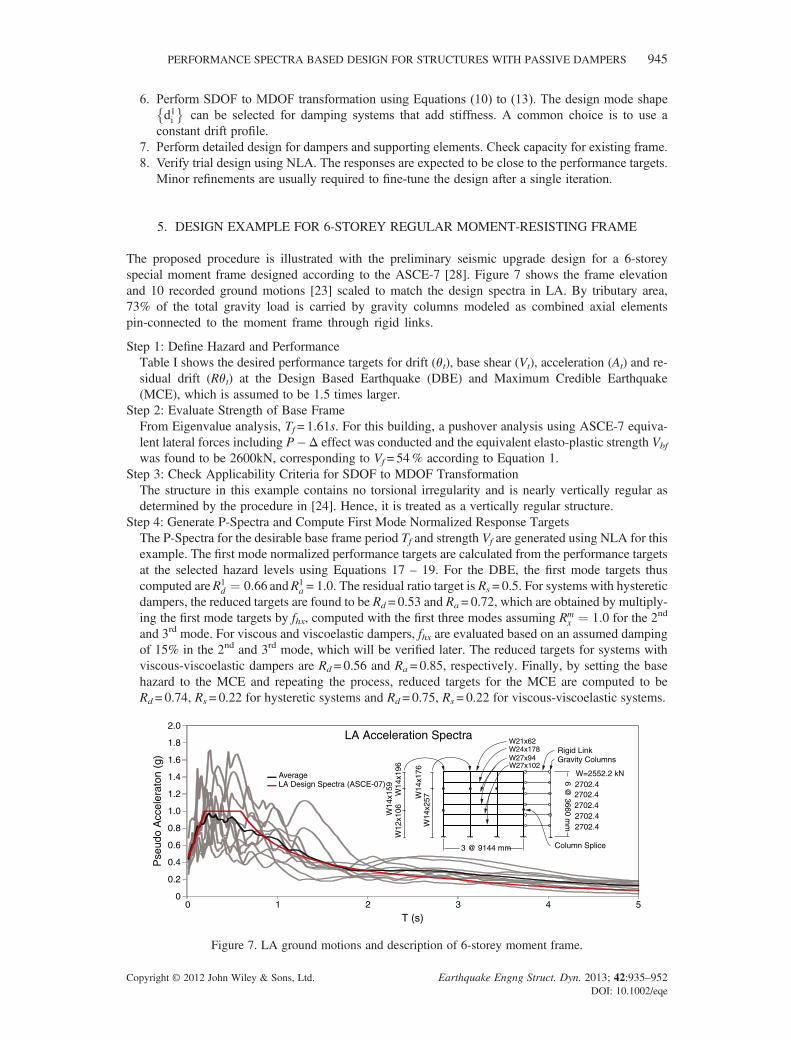
The proposed procedure is illustrated with the preliminary seismic upgrade design for a 6-storeyspecial moment frame designed according to the ASCE-7 [28]. Figure 7 shows the frame elevationand 10 recorded ground motions [23] scaled to match the design spectra in LA. By tributary area,73% of the total gravity load is carried by gravity columns modeled as combined axial elementspin-connected to the moment frame through rigid links.
Step 1: Define Hazard and PerformanceTable I shows the desired performance targets for drift (θt), base shear (Vt), acceleration (At) and re-sidual drift (Rθt) at the Design Based Earthquake (DBE) and Maximum Credible Earthquake(MCE), which is assumed to be 1.5 times larger.
Step 2: Evaluate Strength of Base FrameFrom Eigenvalue analysis, Tf= 1.61s. For this building, a pushover analysis using ASCE-7 equiva-lent lateral forces including P�Δ effect was conducted and the equivalent elasto-plastic strength Vbf
was found to be 2600kN, corresponding to Vf= 54% according to Equation 1.Step 3: Check Applicability Criteria for SDOF to MDOF TransformationThe structure in this example contains no torsional irregularity and is nearly vertically regular asdetermined by the procedure in [24]. Hence, it is treated as a vertically regular structure.
Step 4: Generate P-Spectra and Compute First Mode Normalized Response TargetsThe P-Spectra for the desirable base frame period Tf and strength Vf are generated using NLA for thisexample. The first mode normalized performance targets are calculated from the performance targetsat the selected hazard levels using Equations 17 – 19. For the DBE, the first mode targets thuscomputed areR1
d ¼ 0:66 andR1a = 1.0. The residual ratio target is Rs= 0.5. For systems with hysteretic
dampers, the reduced targets are found to be Rd = 0.53 and Ra= 0.72, which are obtained by multiply-ing the first mode targets by fhx, computed with the first three modes assuming Rm
x ¼ 1:0 for the 2nd
and 3rd mode. For viscous and viscoelastic dampers, fhx are evaluated based on an assumed dampingof 15% in the 2nd and 3rd mode, which will be verified later. The reduced targets for systems withviscous-viscoelastic dampers are Rd = 0.56 and Ra = 0.85, respectively. Finally, by setting the basehazard to the MCE and repeating the process, reduced targets for the MCE are computed to beRd= 0.74, Rs= 0.22 for hysteretic systems and Rd = 0.75, Rs= 0.22 for viscous-viscoelastic systems.
LA Acceleration Spectra
T (s)
Pse
udo
Acc
eler
aton
(g)
0
0.2
0.4
0.6
0.8
1.0
1.2
1.4
1.6
1.8
2.0
0 1 2 3 4 5
AverageLA Design Spectra (ASCE-07)
6 @ 3660 m
m
3 @ 9144 mm
W=2552.2 kN
2702.4 2702.4
2702.4 2702.4 2702.4
Gravity Columns
W14
x196
W14
x159
W12
x106
W14
x257W
14x1
76
W27x94W24x178
W27x102
W21x62Rigid Link
Column Splice
Figure 7. LA ground motions and description of 6-storey moment frame.
PERFORMANCE SPECTRA BASED DESIGN FOR STRUCTURES WITH PASSIVE DAMPERS 945
Copyright © 2012 John Wiley & Sons, Ltd. Earthquake Engng Struct. Dyn. 2013; 42:935–952DOI: 10.1002/eqe
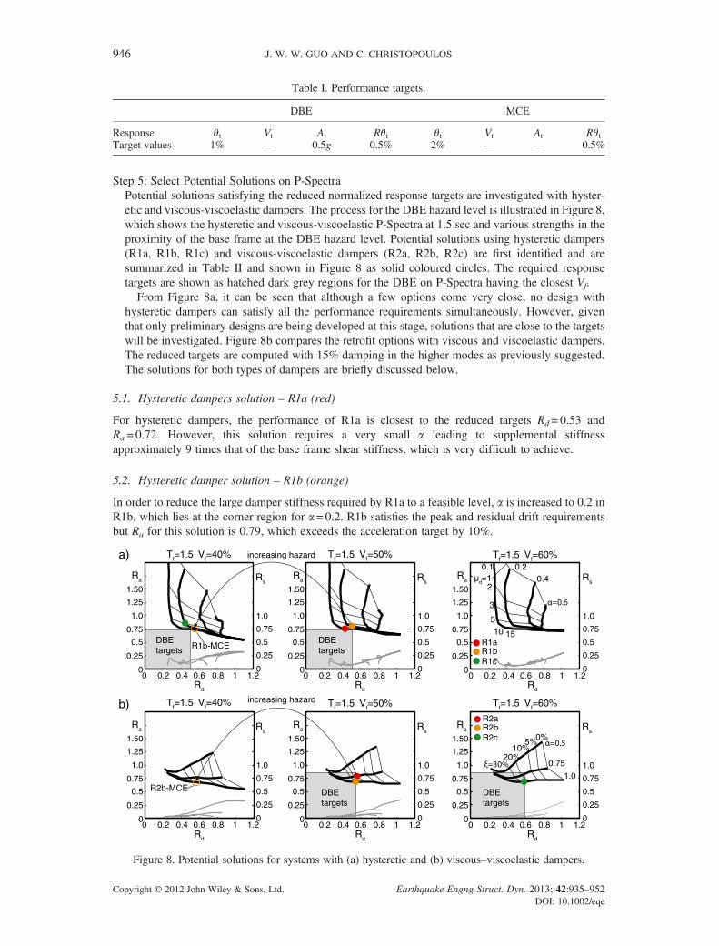
Step 5: Select Potential Solutions on P-SpectraPotential solutions satisfying the reduced normalized response targets are investigated with hyster-etic and viscous-viscoelastic dampers. The process for the DBE hazard level is illustrated in Figure 8,which shows the hysteretic and viscous-viscoelastic P-Spectra at 1.5 sec and various strengths in theproximity of the base frame at the DBE hazard level. Potential solutions using hysteretic dampers(R1a, R1b, R1c) and viscous-viscoelastic dampers (R2a, R2b, R2c) are first identified and aresummarized in Table II and shown in Figure 8 as solid coloured circles. The required responsetargets are shown as hatched dark grey regions for the DBE on P-Spectra having the closest Vf.From Figure 8a, it can be seen that although a few options come very close, no design with
hysteretic dampers can satisfy all the performance requirements simultaneously. However, giventhat only preliminary designs are being developed at this stage, solutions that are close to the targetswill be investigated. Figure 8b compares the retrofit options with viscous and viscoelastic dampers.The reduced targets are computed with 15% damping in the higher modes as previously suggested.The solutions for both types of dampers are briefly discussed below.
5.1. Hysteretic dampers solution – R1a (red)
For hysteretic dampers, the performance of R1a is closest to the reduced targets Rd= 0.53 andRa = 0.72. However, this solution requires a very small a leading to supplemental stiffnessapproximately 9 times that of the base frame shear stiffness, which is very difficult to achieve.
5.2. Hysteretic damper solution – R1b (orange)
In order to reduce the large damper stiffness required by R1a to a feasible level, a is increased to 0.2 inR1b, which lies at the corner region for a = 0.2. R1b satisfies the peak and residual drift requirementsbut Ra for this solution is 0.79, which exceeds the acceleration target by 10%.
Table I. Performance targets.
DBE MCE
Response θt Vt At Rθt θt Vt At RθtTarget values 1% — 0.5g 0.5% 2% — — 0.5%
0 0.2 0.4 0.6 0.8 1 1.2Rd
0
0.25
0.5
0.75
1.0
1.25
Ra Rs
0
0.25
0.5
0.75
1.0
1.50
0 0.2 0.4 0.6 0.8 1 1.2Rd
0
0.25
0.5
0.75
1.0
1.25
Ra Rs
0
0.25
0.5
0.75
1.0
1.50
0 0.2 0.4 0.6 0.8 1 1.2Rd
0
0.25
0.5
0.75
1.0
1.25
Ra Rs
0
0.25
0.5
0.75
1.0
1.50
0 0.2 0.4 0.6 0.8 1 1.2Rd
0
0.25
0.5
0.75
1.0
1.25
Ra Rs
0
0.25
0.5
0.75
1.0
1.50
0 0.2 0.4 0.6 0.8 1 1.2Rd
0
0.25
0.5
0.75
1.0
1.25
Ra Rs
0
0.25
0.5
0.75
1.0
1.50
0 0.2 0.4 0.6 0.8 1 1.2Rd
0
0.25
0.5
0.75
1.0
1.25
Ra Rs
0
0.25
0.5
0.75
1.0
1.50
a)
b)
Tf=1.5 Vf=40% Tf=1.5 Vf=50% Tf=1.5 Vf=60%
Tf=1.5 Vf=40% Tf=1.5 Vf=50% Tf=1.5 Vf=60%
R1b-MCE R1aR1bR1c
R2aR2bR2c
R2b-MCE
0.40.1 0.2
µd=1
510 15
0.75
1.0
5%10%
0%
20%
2
3
DBEtargets
DBEtargets
DBEtargets
DBEtargets
increasing hazard
increasing hazard
Figure 8. Potential solutions for systems with (a) hysteretic and (b) viscous–viscoelastic dampers.
946 J. W. W. GUO AND C. CHRISTOPOULOS
Copyright © 2012 John Wiley & Sons, Ltd. Earthquake Engng Struct. Dyn. 2013; 42:935–952DOI: 10.1002/eqe
5.3. Hysteretic damper solution – R1c (green)
To achieve lower acceleration response in R1b, R1c considers slight weakening of the base frame. Thismay be achieved by providing reduced beam sections, which will likely lengthen the period slightly.For preliminary comparison purpose, the change of period is not considered. As seen by the smallreduction of Ra from 0.79 to 0.78 in Table II, there is no clear advantage in carrying out thepotentially elaborate intervention. This is because weakening only lowers Ra in regions with large mdwhere the base frame yields but it has negligible effect on the response in the region where R1b liesin since the base frame remains elastic or close to elastic.
5.4. Viscoelastic damper solution – R2a (red)
R2a considers viscoelastic dampers having a= 0.75, which meet the drift and base shear targets of 0.56and 0.85, respectively. The use of viscoelastic dampers often leads to reduced residual drift comparedto fluid viscous dampers. However, for the DBE design, the residual drift requirement of Rs= 0.5 doesnot govern, which makes fluid viscous dampers (a = 1.0) more attractive because it allows furtherreduction of Ra.
5.5. Viscous damper solution – R2b (orange)
Using fluid viscous dampers having x = 30%, solution R2b satisfies the peak and residual drift targetswhile reducing Ra by more than 10% compared to R2a.
5.6. Viscous damper solution – R2c (green)
The last potential solution R2c considers using smaller viscous dampers by adding braces to slightlystiffen the frame to decrease Tf from 1.61s to 1.5s. This will increase the strength slightly, to 60%.Stiffening the base frame decreases Sd(Tf,xo) and relaxes the required Rd calculated from Equation17 by 7%, which in turn lowers the required x to 25% according to the P-Spectra for Vf = 60%shown in Figure 8b. However, this decrease in x is not sufficient to justify the stiffening intervention.
Based on these preliminary comparisons, designs R1b and R2b, herein simplified to R1 and R2 arechosen. From Equation 9, the base frame is expected to remain very close to being linear elastic underthe DBE for both R1 and R2.
Both R1 and R2 are checked at the MCE where Vf= 36%. While the MCE responses used for designare interpolated using the appropriate P-Spectra, the approximate responses can be found on theP-Spectra for Vf= 40% shown in Figure 8 as hollow circles using the invariability of a, Rd/(Vfmd) and xas explained previously. From Equation 9, the base frame ductility demand at the MCE for R1 and R2are mf = 1.7 and mf= 1.6, respectively. Both MCE solutions are well within the acceptable range fordisplacement, but R1 exceeds the residual drift target of Rs= 0.22 slightly, which is accepted at thispreliminary design stage.
Step 6: SDOF to MDOF TransformationTable III summarizes the damping property distributions computed according to Equations 10–13.For hysteretic dampers, a design mode shape dHi having constant inter-storey drift is chosen. Since
Table II. Summary of potential solutions.
Hysteretic damper Viscous–viscoelastic damper
R1a R1b R1c R2a R2b R2c
Tf 1.61 1.61 1.61 1.61 1.61 1.5Vf 54% 54% 40% 54% 54% 60%a 0.1 0.2 0.2 0.75 1.0 1.0md/x 10 8 8 20% 30% 25%Rd 0.48 0.52 0.52 0.56 0.55 0.59Ra 0.76 0.79 0.78 0.80 0.69 0.69Rs 0.08 0.09 0.16 0.06 0.10 0.10
PERFORMANCE SPECTRA BASED DESIGN FOR STRUCTURES WITH PASSIVE DAMPERS 947
Copyright © 2012 John Wiley & Sons, Ltd. Earthquake Engng Struct. Dyn. 2013; 42:935–952DOI: 10.1002/eqe
viscous dampers do not add stiffness, dVi is taken as the frame first mode shape. Using Equation 15,the 2nd and 3rd mode of R2 has damping of 73% and 100%, respectively. This implies that the initialassumptions were conservative and no further iteration was carried out.
Step 7: Detailed DesignThe detail designs for connections, braces and the dampers should be carried out so the totalassembly provides the lateral properties computed in step 6. Supporting braces, connections andexisting frame elements should be checked for the maximum expected damper force. In thisexample, dampers are installed in a diagonal brace configuration in the middle bay. Further, it isassumed that the dampers can be sized to exactly match the properties given in Table III.
Step 8: Verification of DesignUsing nonlinear time-history analysis, the roof drift, base shear and accelerations of R1 and R2 aredivided by the corresponding responses in the elastic undamped structure to get global Rd, RV (forhysteretic dampers) and Ra. Base shear of the buildings are computed as the sum of restoring forceand viscous force from damping devices at the ground level. The inherent viscous force is excluded.The normalized residual Rs for R1 and R2 are computed by taking the ratio of residual roof drift tothe damped roof drift. Average accelerations of the storeys are used for comparison of globalresponse since storey accelerations are highly influenced by higher modes and local yielding, whichis briefly discussed later. The average normalized global responses are compared to the nonlineartime-history P-Spectra normalized responses for the selected solutions R1 and R2 in Table IV.In Table IV, both RV (base shear without viscous force) and Ra (base shear/acceleration) for R1
are shown separately for the NLA P-Spectra targets. The base shear responses are compared to RV
while the acceleration responses are compared to Ra. The same is not done for the viscous solutionR2 because RV is not a meaningful prediction of base shear when the viscous force is significant.Good agreement is achieved between the global MDOF responses and SDOF targets using theproposed direct design method based on P-Spectra after the initial trial. Due to the dynamics ofMDOF systems, the normalized acceleration and base shears are not equal as in the case of theSDOF system. For a nonlinear structure, storey softening due to yielding can significantly influencelocal accelerations responses by introducing phase differences between the shear forces of adjacentfloors and by altering higher mode and damping characteristics. Hence, instead of selecting the roofacceleration, the average storey acceleration was chosen as a more indicative value on the overallacceleration reduction in the first mode. From Table IV, P-Spectra give very reasonable normalized
Table III. Summary of properties of base frame and retrofits R1 and R2.
Storey
Base frame R1 R2
dHi ΔHd,i(mm)(12) dVi ΔVd,i(mm)(12) Kf
kNmm
� �(10) Kd
kNmm
� �(11) Vd(kN)
(12) cd kNsmm
� �(13)
6 1.00 28.5 1.00 19.3 33.6 85.1 303 5.25 0.83 28.5 0.88 26.0 48.2 175.1 624 7.44 0.67 28.5 0.72 29.5 59.4 250.4 892 9.13 0.50 28.5 0.54 33.2 63.9 306.0 1091 9.82 0.33 28.5 0.34 33.4 70.6 340.7 1215 10.91 0.17 28.5 0.14 22.3 110.1 322.2 1148 16.9
()Denotes the equation number used for the calculations.
Table IV. Summary of global responses compared with P-Spectra target solutions used for design.
DBE MCE
Rd RV/Ra* Ra Rs Rd RV/Ra* Ra Rs
Hysteretic (R1) Design 0.52 0.76 0.79 0.09 0.62 0.61 0.70 0.26Actual 0.54 0.71 0.80 0.12 0.61 0.54 0.72 0.22
Viscous (R2) Design 0.55 0.69 0.69 0.10 0.59 0.67 0.67 0.21Actual 0.54 0.64 0.49 0.05 0.55 0.59 0.46 0.13
*Normalized base shear for R1 and R2 are given by RV and Ra, respectively.
948 J. W. W. GUO AND C. CHRISTOPOULOS
Copyright © 2012 John Wiley & Sons, Ltd. Earthquake Engng Struct. Dyn. 2013; 42:935–952DOI: 10.1002/eqe
acceleration predictions for systems with hysteretic damping and quite conservative predictions forviscous damping. One reason for the lower normalized acceleration in systems with viscousdamping is the smaller contribution of higher modes compared to the undamped elastic system.Further studies are underway to better understand the acceleration response in MDOF structureswith relation to stiffness, strengths and viscous damping in order to produce more refinedpredictions. Nonetheless, for design purposes, the P-Spectra predictions are still useful indicatorsof the global acceleration response.The average maximum inter-storey displacement, residual displacement, acceleration and base
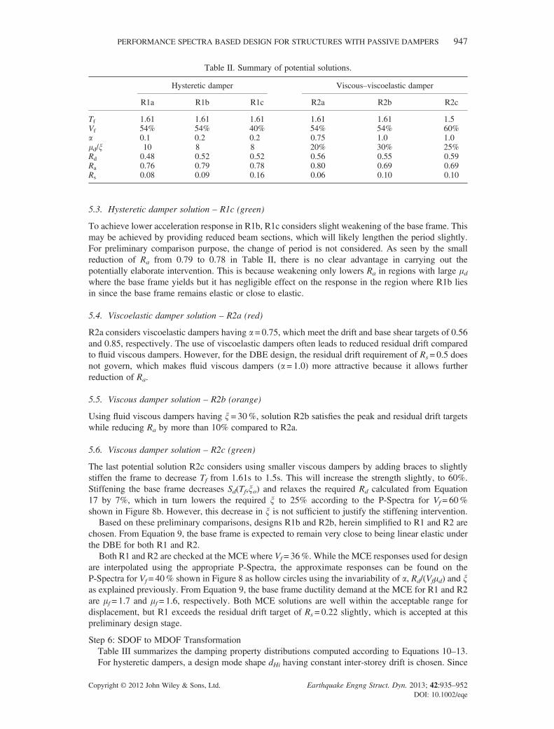
shears for R1, R2 and the undamped base frame labeled “BF” under DBE and MCE are shownin Figures 9 to 12. The applicable performance goals and maximum expected storey responsesamplified by higher modes using the SRSS combination procedure described in Equation 14 arealso shown. In these calculations, R1
x ’s are set equal to Rd and Ra of the solutions R1 and R2.Rmx ’s are set to 1.0 for R1 and are computed using Equation 16 using the higher mode damping
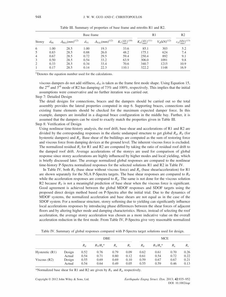
obtained for R2. The maximum storey residual displacements are obtained by multiplying the peakinter-storey displacements obtained from the SRSS procedure by Rs. Time-history analyses showed
Inter-storey Disp. (mm)
Sto
rey
6
5
4
3
2
1
Inter-storey Disp. (mm)
Sto
rey
6
5
4
3
2
1
DBE Inter-storey Disp. MCE Inter-storey Disp.
0 120 140 16080 100
BFR1R2
604020
1% drift/amplified target for R1 and R2
amplified target for R2
amplified target for R1
2% drift
0 60 70 8040 50302010
Figure 9. Interstorey displacement response of R1 and R2 under DBE and MCE.
Inter-storey Res. Disp. (mm)
Sto
rey
6
5
4
3
2
1
Inter-storey Res. Disp. (mm)
Sto
rey
6
5
4
3
2
1
DBE Inter-storey Res. Disp. MCE Inter-storey Res. Disp.
0 20 25 3010 15
BFR1R2
0.5% drift
amplified target for R1
amplified target for R2
0.5% drift
amplified target for R1
amplified target for R2
50 20 25 3010 155
Figure 10. Residual interstorey displacement response of R1 and R2 under DBE and MCE.
Storey Acceleration (g)
Sto
rey
6
5
4
3
2
1
Storey Acceleration (g)
Sto
rey
6
5
4
3
2
1
DBE Storey Accelerations MCE Storey Accelerations
0 0.6 0.8 1.00.2 0.4
BFR1R2
0.5g
amplified target for R2
amplified target for R1
0 0.6 0.8 1.00.2 0.4
Figure 11. Storey acceleration response of R1 and R2 under DBE and MCE.
PERFORMANCE SPECTRA BASED DESIGN FOR STRUCTURES WITH PASSIVE DAMPERS 949
Copyright © 2012 John Wiley & Sons, Ltd. Earthquake Engng Struct. Dyn. 2013; 42:935–952DOI: 10.1002/eqe
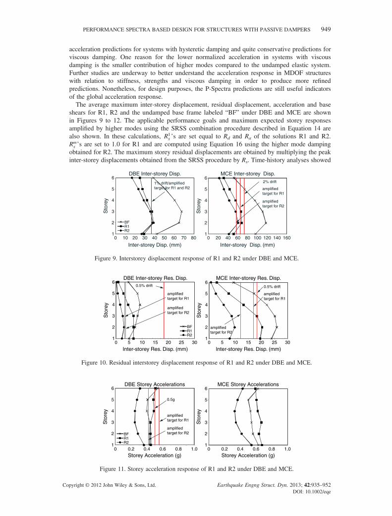
that all storeys satisfy the drift performance goals except for storey 2 under the DBE level, whichslightly exceeds the performance goal. The drift profile is not equal at each storey due to thestiffness irregularity in the frame which was ignored for the design of the dampers. Despite this,the target reduction factor fhx still correctly anticipates the peak storey drift for design. The residualdrift for both retrofits are negligible at the DBE level and fall below the limit of 0.5% for MCEexcept for storey 1 and 2 of R1, which exceeded the performance goal slightly. Accelerations atDBE are at or under the target of 0.5g for all storeys for both retrofits, despite the 10% under-design for acceleration in R1.In general, the predictions of peak inter-storey residual drift and storey accelerations based on
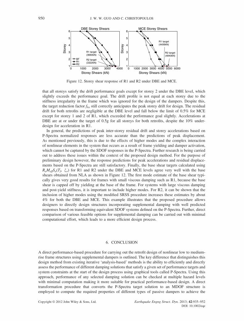
P-Spectra normalized responses are less accurate than the predictions of peak displacement.As mentioned previously, this is due to the effects of higher modes and the complex interactionof nonlinear elements in the system that occurs as a result of frame yielding and damper activation,which cannot be captured by the SDOF responses in the P-Spectra. Further research is being carriedout to address these issues within the context of the proposed design method. For the purpose ofpreliminary design however, the response predictions for peak accelerations and residual displace-ments based on the P-Spectra are still satisfactory. Finally, the base shear targets calculated usingRaMeffSa(Tf, xo) for R1 and R2 under the DBE and MCE levels agree very well with the baseshears obtained from NLA as shown in Figure 12. The first mode estimate of the base shear typi-cally gives very good results for frames with small viscous damping such as R1, because the baseshear is capped off by yielding at the base of the frame. For systems with large viscous dampingand post-yield stiffness, it is important to include higher modes. For R2, it can be shown that theinclusion of higher modes using the modified SRSS procedure increases these estimates by about4% for both the DBE and MCE. This example illustrates that the proposed procedure allowsdesigners to directly design structures incorporating supplemental damping with well predictedresponses based on transforming equivalent SDOF systems defined on the P-Spectra. Further, directcomparison of various feasible options for supplemental damping can be carried out with minimalcomputational effort, which leads to a more efficient design process.
6. CONCLUSION
A direct performance-based procedure for carrying out the retrofit design of nonlinear low to medium-rise frame structures using supplemental dampers is outlined. The key difference that distinguishes thisdesign method from existing iterative ‘analysis-based’ methods is the ability to efficiently and directlyassess the performance of different damping solutions that satisfy a given set of performance targets andsystem constraints at the start of the design process using graphical tools called P-Spectra. Using thisapproach, performance of any selected damping solution can be checked at multiple hazard levelswith minimal computation making it more suitable for practical performance-based design. A directtransformation procedure that converts the P-Spectra target solution to an MDOF structure isemployed to compute the required properties of different types of passive dampers to achieve the
Storey Shears (kN)
Sto
rey
6
5
4
3
2
10 1000 2000 3000
BFR1R2
Storey Shears (kN)
Sto
rey
6
5
4
3
2
1
DBE Storey Shears MCE Storey Shears
0 1000 2000 3000 4000 5000 6000
R1 target(4406kN)
R2 target(4840kN)
R1 target(3660kN)
R2 target(3322kN)
4000
Figure 12. Storey shear response of R1 and R2 under DBE and MCE.
950 J. W. W. GUO AND C. CHRISTOPOULOS
Copyright © 2012 John Wiley & Sons, Ltd. Earthquake Engng Struct. Dyn. 2013; 42:935–952DOI: 10.1002/eqe

predefined target performance. An example retrofit design for a 6-storey building in LA using theproposed design method is presented. Nonlinear time-history results show good agreement of theresponses with the performance targets at both the global and local levels after the first design iteration.
Although the use of the P-Spectra generally results in very good predictions of the displacement andbase shear of damped systems, predictions for acceleration and residual drift are less accurate. Theseresponse quantities are influenced heavily by higher modes and interactions of inelastic elements inthe MDOF that cannot be captured well by an SDOF idealization. To address these issues andimprove the proposed method, further investigations are being carried out.
ACKNOWLEDGEMENTS
Funding for this project was provided by the National Sciences and Engineering Research Council ofCanada, the Canadian Seismic Research Network, and the Ontario Graduate Scholarships.
REFERENCES
1. Miranda E, Ramirez CM. Influence of Residual Displacements on Building Loss Estimation. Proceedings of the9th U.S. National and 10th Canadian Conference on Earthquake Engineering 2010; 1223.
2. Aslani H, Miranda E. Probability-based seismic response analysis. Engineering Structures 2005; 27:1151–1163.3. Bertero RD, Bertero VV. Performance-based seismic engineering: the need for a reliable conceptural comprehensive
approach. Earthquake Engineering and Structural Dynamics 2002; 31:627–652.4. Christopoulos C, Pampanin S. Towards performance-based seismic design of MDOF structures with explicit consid-
eration of residual deformations. ISET Journal of Earthquake Technology 2004; 41(1):53–73.5. FEMA450. NEHRP Recommended Provisions for Seismic Regulations for New buildings and Other Structures.
Building Seismic Safety Council National Institute of Building Sciences: Washington D.C., 2003.6. Ramirez OM, Constantinou MC, Kircher CA, Whittaker AS, Johnson MW, Gomez JD. Development and Evaluation
of Simplified Procedures for Analysis and Design of Buildings with Passive Energy Dissipation Systems. TechnicalReport MCEER-00-0010 2001; Multidisciplinary Center for Earthquake Engineering Research: University of Buf-falo, USA.
7. Ramirez OM, Constantinou MC, Whittaker AS, Kircher CA, Chrysostomou CZ. Elastic and Inelastic Seismic Re-sponse of Buildings with Damping Systems. Earthquake Spectra 2002; 18(3):531–547.
8. Whittaker AS, Constantinou MC, Ramirez OM, Johnson MW, Chrysostomou CZ. Equivalent Lateral Force andModal Analysis Procedures of the 2000 NEHRP Provisions for Buildings with Damping Systems. Earthquake Spec-tra 2003; 19(4):959–980.
9. Filiatrault A, Cherry S. Parameters influencing the design of friction damped structures. Canadian Journal of CivilEngineering 1989; 16(5):753–766.
10. Filiatrault A, Cherry S. Seismic Design Spectra for Friction-damped Structures. Journal of Structural Engineering1990; 116(5):1334–1355.
11. Kasai K, Fu Y, Watanabe A. Passive Control Systems for Seismic Damage Mitigation. Journal of Structural Engi-neering 1998; 124(5):501–502.
12. Kasai K, Ito H. Passive Control Design Method Based on Tuning of Stiffness, Yield Strength, and Ductility ofElasto-Plastic Damper. Journal of Structural and Construction Engineering 2005; 595:44–55. (in Japanese)
13. Fu Y, Cherry S. Design of friction damped structures using lateral force procedure. Earthquake Engineering andStructural Dynamics 2000; 29(7):989–1010.
14. Fu Y, Kasai K. Comparative Study of Frames Using Viscoelastic and Viscous Dampers. Journal of Structural En-gineering 1998; 124(5):513–522.
15. Kasai K, Minato N, Kawanabe Y. Passive Control Design Method Based on Tuning of Equivalent Stiffness of Visco-elastic Damper. Journal of Structural and Construction Engineering 2006; 610:75–83. (in Japanese)
16. Kasai K, Ogura T, Suzuki A. Passive Control Design Method Based on Tuning of Equivalent Stiffness of NonlinearViscous Damper. Journal of Structural and Construction Engineering 2007; 618:97–104. (in Japanese)
17. Christopoulos C, Mansour N. Performance Based Seismic Design of Structures Equipped with Hysteretic Dampers.Structural Engineering Research Report No. UTCE-05/01 2005: University of Toronto, Canada.
18. Vargas B, Bruneau M. Analytical Response and Design of Buildings with Metallic Structural Fuses. I. Journal ofStructural Engineering 2009; 135(4):386–393.
19. Lago A. Seismic Design of Structures with Passive Energy Dissipation Systems. ROSE School PhD Dissertation2011.
20. Guo JWW, Christopoulos C. Performance Spectra-based Design Method for Structures with Supplemental Damping.Structural Engineering Research Report 2012; University of Toronto, Canada.
21. Charette KG. Effets des Mouvement Sismiques sur les Structures en Acier de la Categorie de Constructions Conven-tionelles. Dissertation, Ecole Polytechnique de Montreal. Ecole Polytechnique de Montreal, Canada. (in French)
22. Christopoulos C, Filiatrault A. Principles of Passive Supplemental Damping and Seismic Isolation. IUSS Press:Pavia, Italy, 2006.
PERFORMANCE SPECTRA BASED DESIGN FOR STRUCTURES WITH PASSIVE DAMPERS 951
Copyright © 2012 John Wiley & Sons, Ltd. Earthquake Engng Struct. Dyn. 2013; 42:935–952DOI: 10.1002/eqe

23. Applied Technology Council (ATC). Quantification of Building Seismic Performance Factors. FEMAP695/ATC-63Project Report, 2009.
24. Guo JWW, Christopoulos C. Mitigation of the Seismic Response of Structures with Vertical Stiffness and StrengthIrregularity using Supplemental Dampers. Proc. of the 6th European workshop on the seismic behaviour of irregularand complex structures 2011, CD ROM, Haifa.
25. Chopra A, Goel RK. A modal pushover analysis procedure to estimate seismic demands for unsymmetric-planbuildings. Earthquake Engineering and Structural Dynamics 2004; 33:903–927.
26. Priestley MJN, Calvi GM, Kowalsky MJ. Displacement-Based Seismic Design of Structures. IUSS Press: Pavia,Italy, 2007.
27. Kreslin M, FajFar P. The extended N2 method taking into account higher mode effects in elevation. EarthquakeEngineering and Structural Dynamics 2011; 40(14):1571–1589.
28. Erochko J, Christopoulos C, Tremblay R, Choi H. Residual Drift Response of SMRFs and BRB Frames in SteelBuildings Designed According to ASCE 7–05. Journal of Structural Engineering 2011; 137(5): 589–599.
952 J. W. W. GUO AND C. CHRISTOPOULOS
Copyright © 2012 John Wiley & Sons, Ltd. Earthquake Engng Struct. Dyn. 2013; 42:935–952DOI: 10.1002/eqe