Embed Size (px)
Citation preview
Ver.8.01
2-17-11 Shinyokohama Kohoku-ku Yokohama-shi Kanagawa-ken Japan
Phone: +81-45-472-6441 / Fax: +81-45-472-6432
©2007 M.S.Engineering Co.,Ltd. all rights reserved.
1
Table of Contents
1. Abstract for rework system .......................................................................... 2 2. Rework Process: ........................................................................................... 3 3. The details of the each process: ................................................................... 4
3-1. The board & components check ................................................................................ 4 3-2. Remove ...................................................................................................................... 6 3-3. Solder Cleaning ....................................................................................................... 11 3-4. Solder Printing ........................................................................................................ 12 3-5. Mounting ................................................................................................................. 14 3-6. Soldering (re-soldering) .......................................................................................... 15 3-7. Inspection ................................................................................................................ 18 3-8. Re-balling ................................................................................................................ 20
2
1. Abstract for rework system
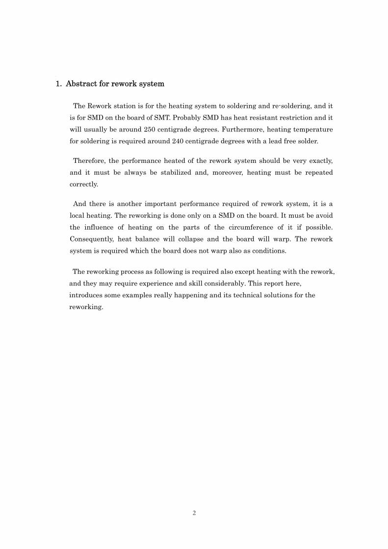
The Rework station is for the heating system to soldering and re-soldering, and it is for SMD on the board of SMT. Probably SMD has heat resistant restriction and it will usually be around 250 centigrade degrees. Furthermore, heating temperature for soldering is required around 240 centigrade degrees with a lead free solder.
Therefore, the performance heated of the rework system should be very exactly, and it must be always be stabilized and, moreover, heating must be repeated correctly.
And there is another important performance required of rework system, it is a local heating. The reworking is done only on a SMD on the board. It must be avoid the influence of heating on the parts of the circumference of it if possible. Consequently, heat balance will collapse and the board will warp. The rework system is required which the board does not warp also as conditions.
The reworking process as following is required also except heating with the rework, and they may require experience and skill considerably. This report here, introduces some examples really happening and its technical solutions for the reworking.
3
2. Rework Process:
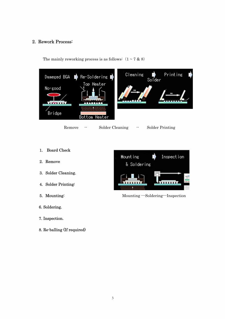
The mainly reworking process is as follows: (1 ~ 7 & 8)
Remove -- Solder Cleaning -- Solder Printing
1. Board Check
2. Remove
3. Solder Cleaning.
4. Solder Printing:
5. Mounting: Mounting ---Soldering---Inspection
6. Soldering.
7. Inspection.
8. Re-balling (If required)
4
3. The details of the each process:
3-1. The board & components check
a) The heated limited to the board & the component should be check first
The reworking have to melt the solder already heated. In this case, probably, the temperature which solder solves will be more highly required than rating. It is because; the surface of the solder may have oxidized. Moreover, two more times heating or more will be added to the board and the component when reworking. Therefore, it should be remove or heart protected, if there is the parts on the board which may break in heating.
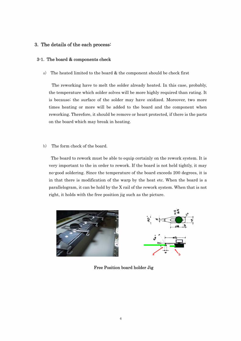
b) The form check of the board.
The board to rework must be able to equip certainly on the rework system. It is very important to the in order to rework. If the board is not held tightly, it may no-good soldering. Since the temperature of the board exceeds 200 degrees, it is in that there is modification of the warp by the heat etc. When the board is a parallelogram, it can be hold by the X rail of the rework system. When that is not right, it holds with the free position jig such as the picture.
Free Position board holder Jig
5
c) Specification check of the parts.
The nozzle must be setup first, and it is suited to the form of the parts for rework. It is important especially when there is other parts are near the parts. It is for no- damaged when heating, to the other near around parts.
It will be possible to rework almost all SMD, if the nozzle is making to the form of the parts to rework. For example, they are also a BGA socket, a shield cover for a package, and a SMD connector, etc.
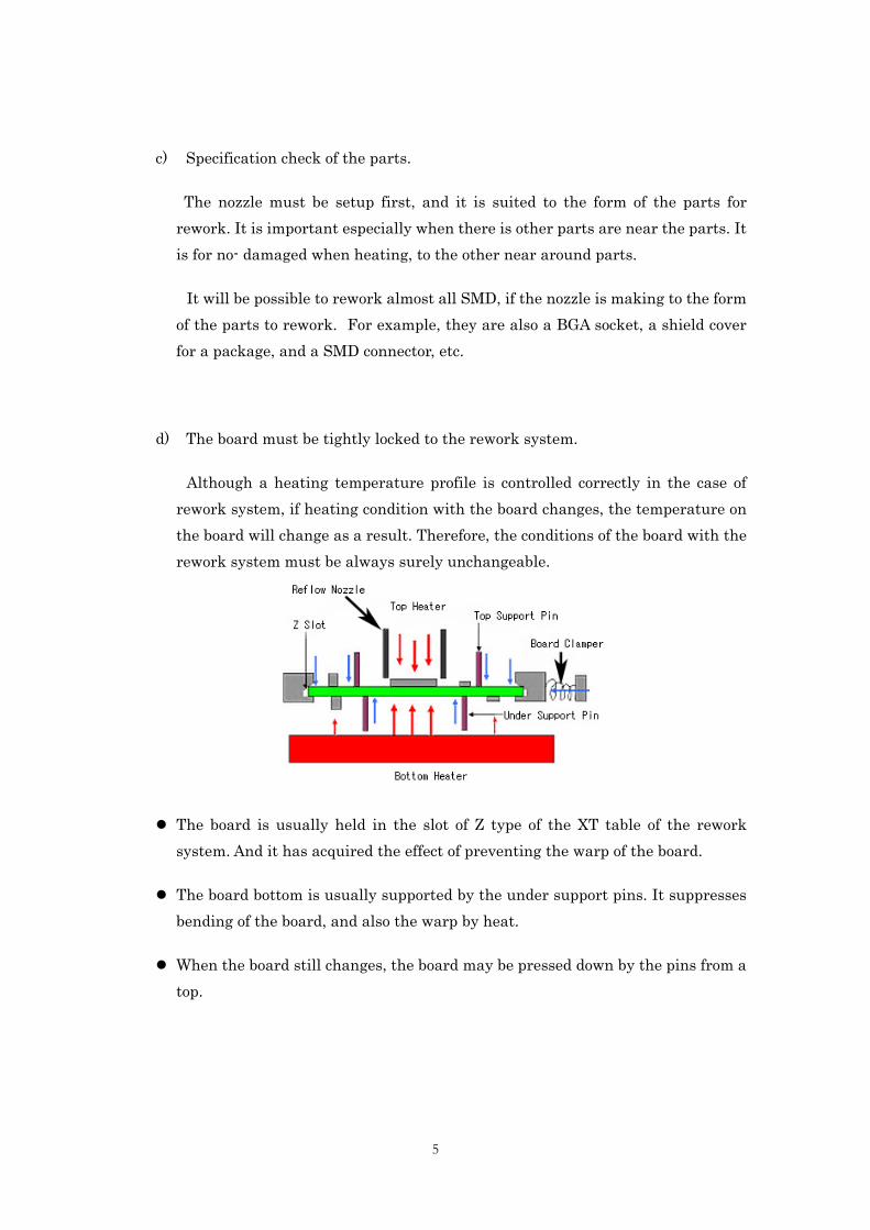
d) The board must be tightly locked to the rework system.
Although a heating temperature profile is controlled correctly in the case of rework system, if heating condition with the board changes, the temperature on the board will change as a result. Therefore, the conditions of the board with the rework system must be always surely unchangeable.
The board is usually held in the slot of Z type of the XT table of the rework system. And it has acquired the effect of preventing the warp of the board.
The board bottom is usually supported by the under support pins. It suppresses bending of the board, and also the warp by heat.
When the board still changes, the board may be pressed down by the pins from a top.
6
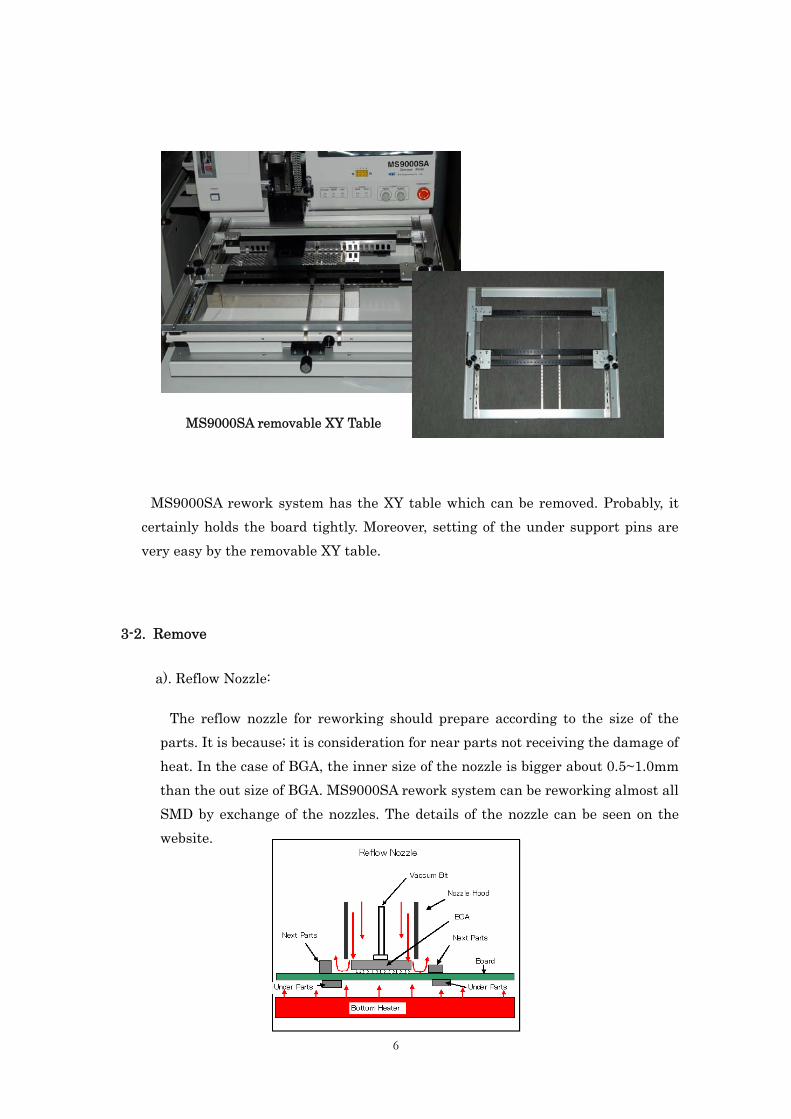
MS9000SA removable XY Table
MS9000SA rework system has the XY table which can be removed. Probably, it certainly holds the board tightly. Moreover, setting of the under support pins are very easy by the removable XY table.
3-2. Remove
a). Reflow Nozzle:
The reflow nozzle for reworking should prepare according to the size of the parts. It is because; it is consideration for near parts not receiving the damage of heat. In the case of BGA, the inner size of the nozzle is bigger about 0.5~1.0mm than the out size of BGA. MS9000SA rework system can be reworking almost all SMD by exchange of the nozzles. The details of the nozzle can be seen on the website.
7
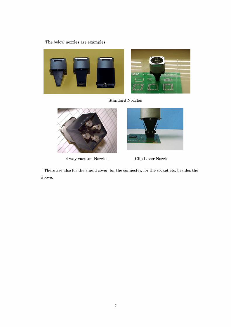
The below nozzles are examples.
Standard Nozzles
4 way vacuum Nozzles Clip Lever Nozzle
There are also for the shield cover, for the connecter, for the socket etc. besides the above.
8
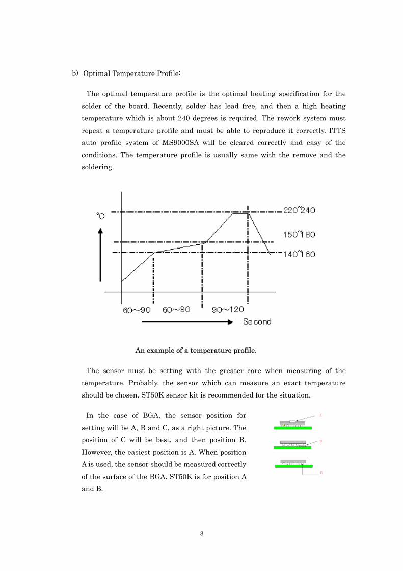
b) Optimal Temperature Profile:
The optimal temperature profile is the optimal heating specification for the solder of the board. Recently, solder has lead free, and then a high heating temperature which is about 240 degrees is required. The rework system must repeat a temperature profile and must be able to reproduce it correctly. ITTS auto profile system of MS9000SA will be cleared correctly and easy of the conditions. The temperature profile is usually same with the remove and the soldering.
An example of a temperature profile.
The sensor must be setting with the greater care when measuring of the temperature. Probably, the sensor which can measure an exact temperature should be chosen. ST50K sensor kit is recommended for the situation.
In the case of BGA, the sensor position for setting will be A, B and C, as a right picture. The position of C will be best, and then position B. However, the easiest position is A. When position A is used, the sensor should be measured correctly of the surface of the BGA. ST50K is for position A and B.
9
When using a sensor for B, it is as shown in a right picture. In this case, the BGA must be removing first, and then the sensor was setting on the board. And the BGA must be mounting again on the sensor. Therefore, the sensor is inserted between of the board and the BGA.
The sensor used in the position C is a wire type. In this case, a hole must be made in the board and the sensor must be correctly inserted in the solder ball. It will be best way to most exact temperature measurement with out of troublesomeness.
MS9000SA is used of sensor position A, and it is almost same as B, the condition is makes automatically by the control system of MS9000SA. (The details will be shown by the next.)
Of course MS9000SA has also 6 zones temperature control system with manual setting, in the case, temperature will be controlled correctly to the output of the sensor.
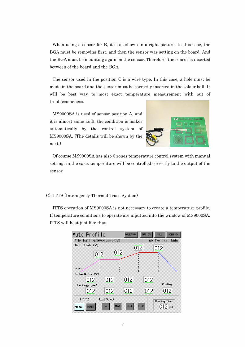
C). ITTS (Interagency Thermal Trace System)
ITTS operation of MS9000SA is not necessary to create a temperature profile. If temperature conditions to operate are inputted into the window of MS9000SA. ITTS will heat just like that.
10
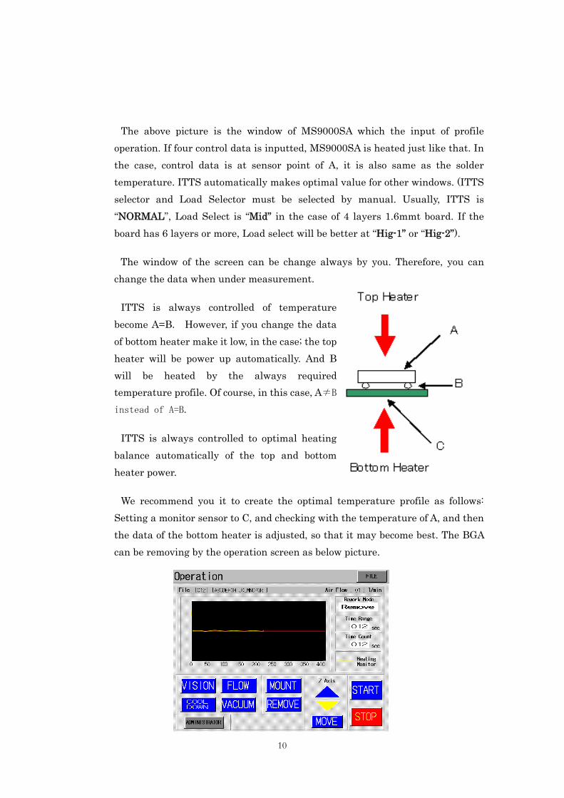
The above picture is the window of MS9000SA which the input of profile operation. If four control data is inputted, MS9000SA is heated just like that. In the case, control data is at sensor point of A, it is also same as the solder temperature. ITTS automatically makes optimal value for other windows. (ITTS selector and Load Selector must be selected by manual. Usually, ITTS is “NORMAL”, Load Select is “Mid” in the case of 4 layers 1.6mmt board. If the board has 6 layers or more, Load select will be better at “Hig-1” or “Hig-2”).
The window of the screen can be change always by you. Therefore, you can change the data when under measurement.
ITTS is always controlled of temperature become A=B. However, if you change the data of bottom heater make it low, in the case; the top heater will be power up automatically. And B will be heated by the always required temperature profile. Of course, in this case, A≠B
instead of A=B.
ITTS is always controlled to optimal heating balance automatically of the top and bottom heater power.
We recommend you it to create the optimal temperature profile as follows: Setting a monitor sensor to C, and checking with the temperature of A, and then the data of the bottom heater is adjusted, so that it may become best. The BGA can be removing by the operation screen as below picture.
11
MS9000SA can be also removing the SMD when there is nothing of the profile data in the system. It can rework even only one board.
3-3. Solder Cleaning
After removing SMD, before re-soldering SMD again, you have to clean the land on the board. Generally, it is working as follows:
a). By the solder wick with a electric iron.
Generally, the solder wick is cut off small, it is placed on the land, and the solder of the land is made to suck up to the solder wick with the heated soldering iron. Although cleaning of a narrow place takes this skill especially, it will be the easiest and, moreover, removal of solder can do it certainly.
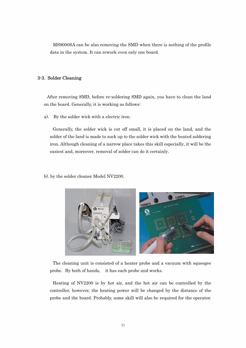
b). by the solder cleaner Model NV2200.
The cleaning unit is consisted of a heater probe and a vacuum with squeegee probe. By both of hands, it has each probe and works.
Heating of NV2200 is by hot air, and the hot air can be controlled by the controller, however, the heating power will be changed by the distance of the probe and the board. Probably, some skill will also be required for the operator.
12
And at the high temperature of 220 centigrade degrees or more, since squeegee cannot be used, it must suck up of the melted solder.
If it use together with Supplementary mode of MS9000SA, the melted solder where temperature controlled of the land on the board will be sucks up by the vacuum probe of NV2200.
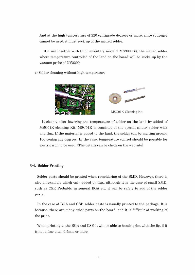
c) Solder cleaning without high temperature:
MSC01K Cleaning Kit
It cleans, after lowering the temperature of solder on the land by added of MSC01K cleaning Kit. MSC01K is consisted of the special solder, solder wick and flux. If the material is added to the land, the solder can be melting around 100 centigrade degrees. In the case, temperature control should be possible for electric iron to be used. (The details can be check on the web site)
3-4. Solder Printing
Solder paste should be printed when re-soldering of the SMD. However, there is also an example which only added by flux, although it is the case of small SMD, such as CSP. Probably, in general BGA etc, it will be safety to add of the solder paste.
In the case of BGA and CSP, solder paste is usually printed to the package. It is because; there are many other parts on the board, and it is difficult of working of the print.
When printing to the BGA and CSP, it will be able to handy print with the jig, if it is not a fine pitch 0.5mm or more.
13
In the case of the fine lead pitch SMD such as CSP, The special jig is prepared. It is used with the function of the vision system of MS9000SA.
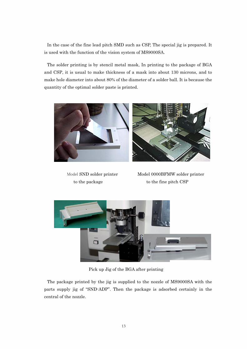
The solder printing is by stencil metal mask, In printing to the package of BGA and CSP, it is usual to make thickness of a mask into about 130 microns, and to make hole diameter into about 80% of the diameter of a solder ball. It is because the quantity of the optimal solder paste is printed.
Model SND solder printer Model 0000BFMW solder printer to the package to the fine pitch CSP
Pick up Jig of the BGA after printing
The package printed by the jig is supplied to the nozzle of MS9000SA with the parts supply jig of “SND-ADP”. Then the package is adsorbed certainly in the central of the nozzle.
14
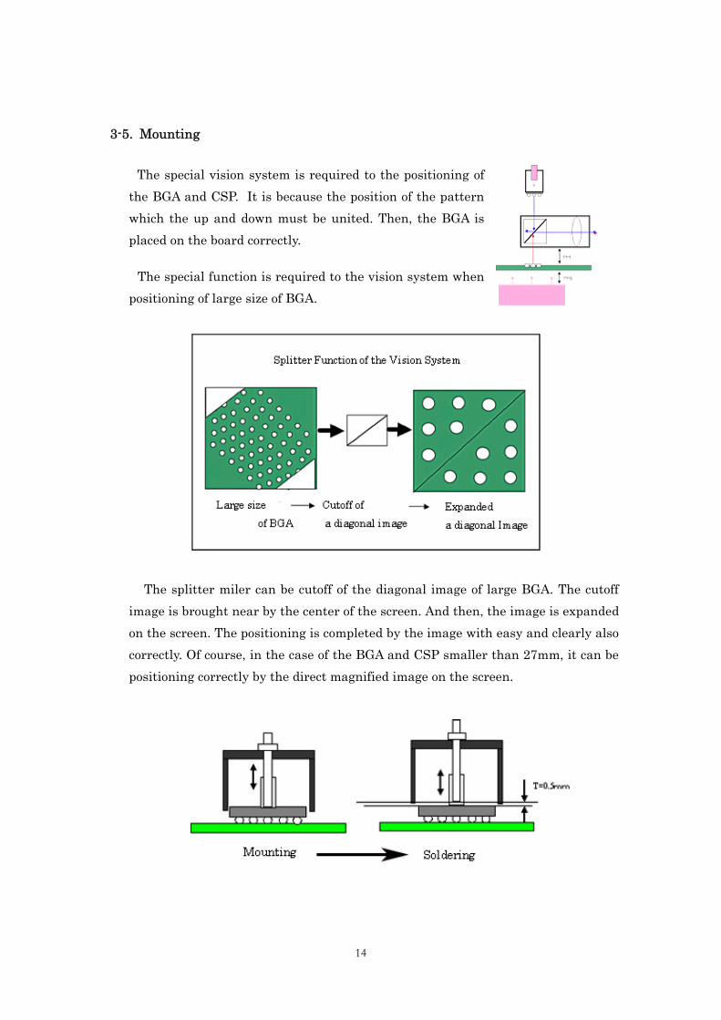
3-5. Mounting
The special vision system is required to the positioning of the BGA and CSP. It is because the position of the pattern which the up and down must be united. Then, the BGA is placed on the board correctly.
The special function is required to the vision system when positioning of large size of BGA.
The splitter miler can be cutoff of the diagonal image of large BGA. The cutoff image is brought near by the center of the screen. And then, the image is expanded on the screen. The positioning is completed by the image with easy and clearly also correctly. Of course, in the case of the BGA and CSP smaller than 27mm, it can be positioning correctly by the direct magnified image on the screen.
15
If positioning is completed, the hood of the nozzle will start heating in a position higher about 0.5mm than the surface of the BGA or CSP. It is because; it can be getting of good heating efficiency and auto centering effect of the BGA and CSP.
The vision system of MS9000SA can be self calibration; therefore, always height precision accuracy is maintained for positioning.
3-6. Soldering (re-soldering)
The optimal temperature profile for soldering is same as the profile for removing. However, it should be more carefully and correctly than time of the removing. It is because; it will be cause of no-good soldering that if there is the merely slight warp of the board, and movements by heating, furthermore, change of a heat balance.
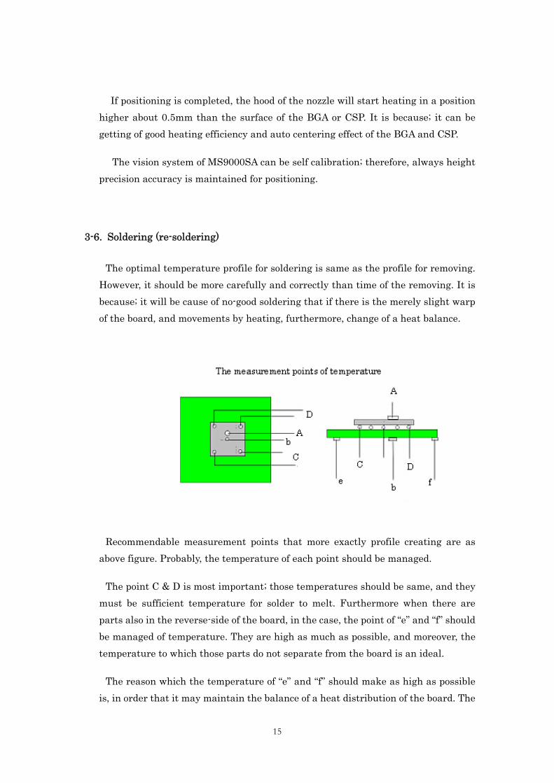
Recommendable measurement points that more exactly profile creating are as above figure. Probably, the temperature of each point should be managed.
The point C & D is most important; those temperatures should be same, and they must be sufficient temperature for solder to melt. Furthermore when there are parts also in the reverse-side of the board, in the case, the point of “e” and “f” should be managed of temperature. They are high as much as possible, and moreover, the temperature to which those parts do not separate from the board is an ideal.
The reason which the temperature of “e” and “f” should make as high as possible is, in order that it may maintain the balance of a heat distribution of the board. The
16
warp by the heat of the board will decrease when there are few differences of temperature of the point of “b” and “e,f”. therefore, the difference of temperature should be small as much as possible.
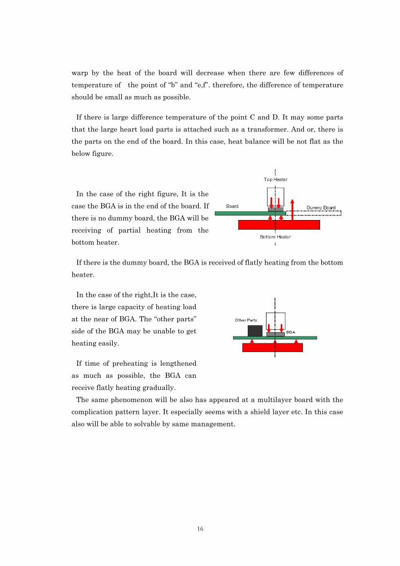
If there is large difference temperature of the point C and D. It may some parts that the large heart load parts is attached such as a transformer. And or, there is the parts on the end of the board. In this case, heat balance will be not flat as the below figure.
In the case of the right figure, It is the case the BGA is in the end of the board. If there is no dummy board, the BGA will be receiving of partial heating from the bottom heater.
If there is the dummy board, the BGA is received of flatly heating from the bottom heater.
In the case of the right,It is the case, there is large capacity of heating load at the near of BGA. The “other parts” side of the BGA may be unable to get heating easily.
If time of preheating is lengthened as much as possible, the BGA can receive flatly heating gradually. The same phenomenon will be also has appeared at a multilayer board with the complication pattern layer. It especially seems with a shield layer etc. In this case also will be able to solvable by same management.
17
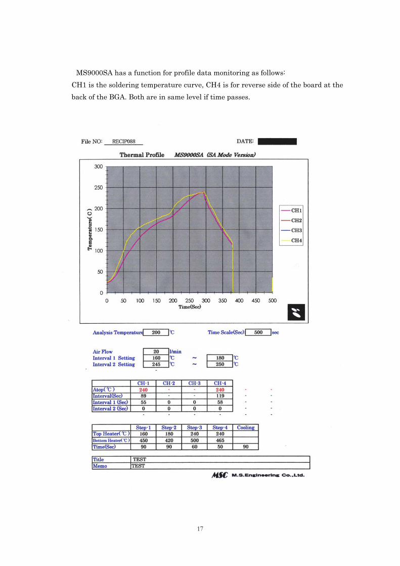
MS9000SA has a function for profile data monitoring as follows: CH1 is the soldering temperature curve, CH4 is for reverse side of the board at the back of the BGA. Both are in same level if time passes.
18
The data report of the above is by SA mode of MS9000SA. MS9000SA can be temperature monitoring of 4CH maximum. However, if you have, we recommend you it to use of a multi-channels recorder system.
The faults of soldering at the reworking of the BGA are mainly an abnormality of the heat balance to the BGA, and warp of the board when heating. Therefore, therefore, management of heat is very important.
3-7. Inspection
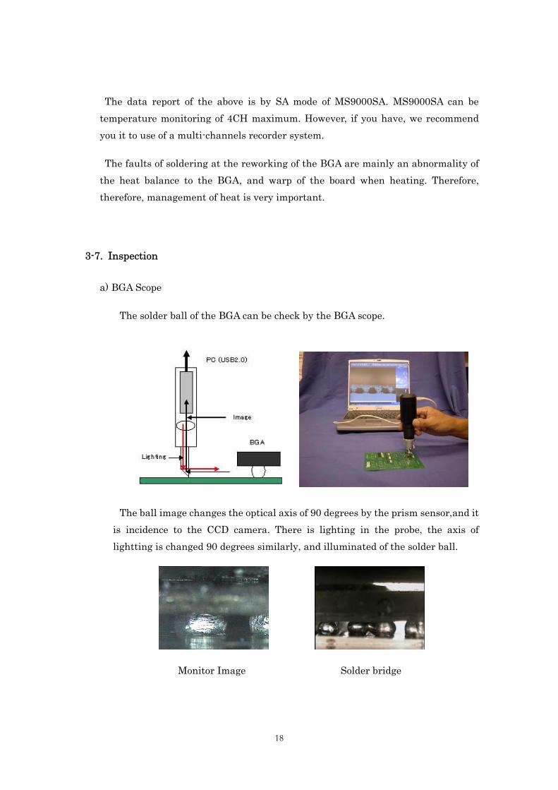
a) BGA Scope
The solder ball of the BGA can be check by the BGA scope.
The ball image changes the optical axis of 90 degrees by the prism sensor,and it is incidence to the CCD camera. There is lighting in the probe, the axis of lightting is changed 90 degrees similarly, and illuminated of the solder ball.
Monitor Image Solder bridge
19
After soldering,the BGA scope could be monitoring and checking easily. However, it will be only out side ball of the BGA. Usually. If the soldering of an outside solder ball is well, probably the whole will be judged that there is no problem.
Then, probably, an internal ball must also be checked with X ray inspection system, when inadequate.
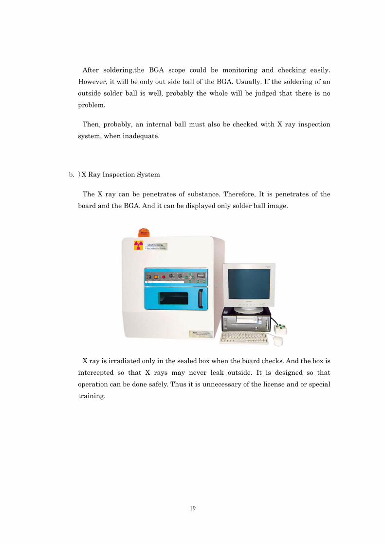
b. )X Ray Inspection System
The X ray can be penetrates of substance. Therefore, It is penetrates of the board and the BGA. And it can be displayed only solder ball image.
Model MSX500 X Ray Inspection System
X ray is irradiated only in the sealed box when the board checks. And the box is intercepted so that X rays may never leak outside. It is designed so that operation can be done safely. Thus it is unnecessary of the license and or special training.
20
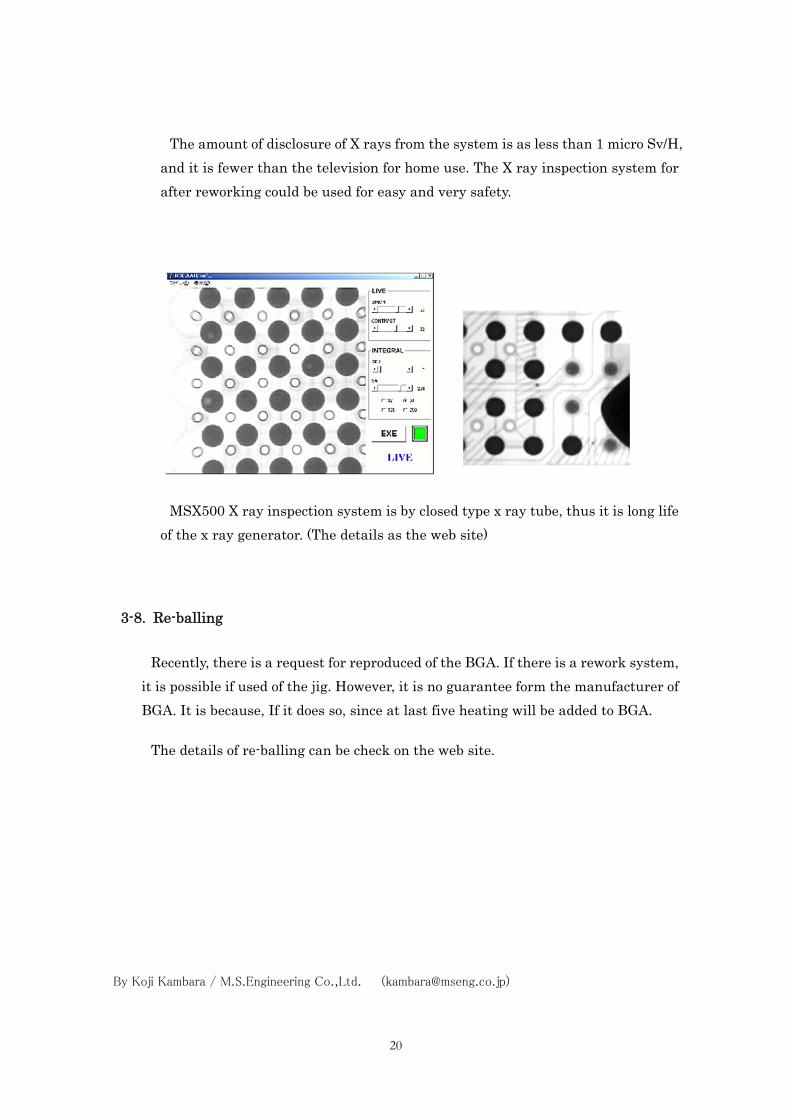
The amount of disclosure of X rays from the system is as less than 1 micro Sv/H, and it is fewer than the television for home use. The X ray inspection system for after reworking could be used for easy and very safety.
MSX500 X ray inspection system is by closed type x ray tube, thus it is long life of the x ray generator. (The details as the web site)
3-8. Re-balling
Recently, there is a request for reproduced of the BGA. If there is a rework system, it is possible if used of the jig. However, it is no guarantee form the manufacturer of BGA. It is because, If it does so, since at last five heating will be added to BGA.
The details of re-balling can be check on the web site.
By Koji Kambara / M.S.Engineering Co.,Ltd. ([email protected])