Embed Size (px)
Citation preview

OPERATION MANUAL
Real Time Thermo Profile Analyzer
RTTS555/6
Manual Version 5.0

1
Table of Contents
1. Safety Precautions and Request ................................................................................... 3 2. Introduction ..................................................................................................................... 7 3. Unpacking RTTS555 Series ........................................................................................... 8 4. Feature of RTTS555 Series ............................................................................................ 9
4-1. Data Transmitter ....................................................................................................... 9 4-2. Data Receiver ........................................................................................................... 9 4-3. Thermal coupler with connector ............................................................................. 9 4-4. The transmitter battery .......................................................................................... 10 4-5. Receiving Antennas ............................................................................................... 10 4-6. Magnetic Stands for Fixing the Antenna .............................................................. 10 4-7. Adjustable Carriers ................................................................................................ 10 4-8. Application software .............................................................................................. 10 4-9. RS-232C cable ........................................................................................................ 11 4-10. Heat-resistance type stick-on tape (15mm x 10m) ............................................ 11 4-11. Cable for charging the battery and how to charge. ........................................... 11
5. Name and Function of Transmitter/Receiver .............................................................. 12 5-1. Connection to the Transmitter .............................................................................. 12 5-2. Connection to the Receiver ................................................................................... 13
6. Computer Requirements. ............................................................................................. 15 6-1. Operational environments condition .................................................................... 15 6-2. Installation .............................................................................................................. 15 6-3. How to set-up the temperature measurement system. ....................................... 16 6-4. File structure .......................................................................................................... 16 6-5. Operational Hints. .................................................................................................. 17 6-6. Expansion of the function ..................................................................................... 17
7. System Operation: ........................................................................................................ 18 7-1. Set-up of the each unit. ......................................................................................... 18 7-2. Operation for PC. ................................................................................................... 18
7-2-1. Main Menu ........................................................................................................ 18 7-2-2. Default Measurement Parameters (Basis Measurement Condition) ........... 19 7-2-3. Build Measurement Parameters ..................................................................... 22 7-2-4. Read Parameters ............................................................................................. 27 7-2-5. Enter the contents of analysis condition ...................................................... 27
2
7-2-6. Enter the contents of reflow oven .................................................................. 27 7-2-7. Real time measurement .................................................................................. 28 7-2-8. Playback the saved file ................................................................................... 31 7-2-9. Indication for the data chart ........................................................................... 38 7-2-10. Confirmation Display for Measurement Condition ..................................... 39 7-2-11. Transmitter Condition Confirm ..................................................................... 40 7-2-12. Information of Software Version .................................................................. 41 7-2-13. Closing ........................................................................................................... 41 7-2-14. Reference for easy use and operation confirm. ......................................... 42
8. Specifications: .............................................................................................................. 43 9. Maintenance .................................................................................................................. 45 10. An example of Measurement Temp. Graph + Reflow Cond. .................................... 46 11. An example of Analysis Result .................................................................................. 47 12. An example of Temperature Chart ............................................................................. 48
3
1.Safety Precautions and Request Thank you for purchasing the Real Time Thermal Profile Analyzer
RTTS555/6. So that you can fully utilize the various features of the system and to ensure correct and safe operation, please carefully read the following Warning/precautions
WARNING: To prevent serious injury or severe damage to the equipment, Please observe the following warming before using the system.
No Decomposing, remodeling or modifying. There is Dangerous high-voltage inside the main body. Do not decompose, remodel or modify it to avoid electric shock, fire
or damage.
Stop using when any emanation of smoke, peculiar smell or noise noticed, or damaged by dropping.
When any emanation of smoke, peculiar smell or noise from main body or AC adapter noticed, or damage by dropping main body, stop using and contact the distributor.
Stop using when the entrance of water or any liquid found. When water or any liquid inserted, electric shock or fire may
generated. In this case, unplug AC to stop using and contact the distributor.
Stop Using when the entrance of metal or foreign object found. When metal or foreign objects found entered, electric shock or fire
may cause. In this instance, unplug AC adapter to stop using and contact the distributor.
Do not use it with the plug connected imperfectly. Please connect each plug such as an AC adapter firmly, to avoid an
electric shock or fire from the heat of defective connection.
4
Do not leave dust on the plug or put, metal closer to the plug. They can lead fire or electric shock from shorted circuit. Remove dust at any time and never put metal closer around.
No modifying or excessive twisting with power cord. Any modifying or excessive twisting with power cord may lead fire
or electric shock.
Unplug each cord by holding the plug firmly. Unplug it by pulling on the cord may cause snapping wire or plug
damage.
Stop using when the power cord of AC adapter has been damaged. A shorted circuit or electric shock may be caused when using
damaged power cord. Stop using to replace a new AC adapter.
Use only required voltage of the power. Using not at required voltage would cause a fire, electric shock or
damage.
Never touch the power plug or AC adapter with wet hand. An electric shock may be caused when touching the power plug
or AC adapter with wet hand.
Stop using when thunders roar. An electric shock may be caused. Stop using and never touch the
metal parts or cords when thunders roar.
Unplug AC adaptor from outlet when not in use. Unplug AC adaptor from outlet when not in use. Residual Heat! Do not overheat during system operating. Never use under temperature and time beyond restriction. Since
the battery in a sensor unit and an electric circuit break in response to a damage.
5
Residual Heat! Avoid burns when unloading the unit. After an operation is completed, the unit remains hot. When
unloading the unit, wear heat resistant globe to prevent burns.
NOTICE FOR FACILITIES AND MAINTENANCE Please use in accordance with following instruction to avoid
injuries or damage of your properties.
Do not place on an unstable surface. To avoid injuries or damage by dropping or falling down, never
place on an unstable surface. Do not allow anything to rest upon the scope.
To avoid injuries or damaged to rest. never allow anything to rest upon the scope.
Keep away from moister or dust. Never leave in a moister or dusty place because a fire or damage
may be caused. Power off and unplug AC adapter before cleaning. Make sure unplugging AC adapter before maintenance.
Use a dry cloth for maintenance. Use a dry cloth for main body and the provided cloth for prism for
normal maintenance.
Replace only with our genuine parts. Use only our genuine parts when replacing the parts. Never use
substitution.
6
Do not give strong impact. This product is a precision instrument. To avoid injuries, never
give any strong impact.
Use only the provided cloth for cleaning prism. A damaged on prism may be caused by using any cloth other
than provided.
Power off and unplug AC adapter from the outlet before cleaning. Make sure the power “off” and unplug from the outlet before
maintenance.
When trouble or damaged mentioned or other than mentioned has been resulted. If this product has been damaged or rendered defective, stop using immediately, turn off the power and contact the distributor. Otherwise the damage or defective may increase the problem and cause an unexpected accident.
7
2.Introduction
Thank you for purchasing the RTTS-555 series. The RTTS-555 series has superb functions that enable you to analyze the
displayed real-time temperature-measurement data inside an oven, right on your computer screen.
The RTTS-555 consists of a Data Transmitter, a Data Receiver and the Application Software. As the transmitter passes through your reflow oven, it measures temperatures, and after
converting that data to a digital signal, it transmits the data on a special FM frequency to a receiver outside the oven.
After the FM radio wave is received, the data is demodulated from the digital
signal to an RS-232C signal, and is then sent to your computer. The RTTS-555 will tell you the temperature inside an oven at any given time and
will analyze the data as it is measured in real time. The receiver also includes a battery charger for the transmitter's battery.
Please read this instruction manual thoroughly so that you may use our product correctly. Precautions About the power supply * Be sure to connect the RTTS-555 series to the power supply specified in the specification section of this manual. You can use the RTTS-555 series with a power frequency of 50 Hz or 60 Hz. * Power cords that are frayed or damaged are very dangerous. Please don't use them. * Do not let water or other liquid, or metal objects such as pins, accidentally get inside the transmitter or receiver; because this may lead to electric shock or damage.
8
3.Unpacking RTTS555 Series
Before connecting the RTTS-555 series, take an inventory of the items in your package. All of the items listed below should be included
Package Contents 1. Data transmitter Model RTTS-555/6 with antenna 1 unit 2. Data receiver Model RTR-555 1 unit 3. Thermal coupler with connector In case of 6 Model RTTS-555/6 6 PCs 4. Battery for the transmitter Ni-Cd IEC R1 type x 3 in series connection 1 PC When the RTTS-555 series is shipped, the charged battery is mounted on the transmitter. 5. Receiving antenna Rod type, 1/4 wavelength, 1 PC 6. Magnet table for fixing antenna with 1.5m cable 1 set 7. Adjustable carrier 1 set When the RTTS-555 series is shipped, the transmitter is mounted on it. 1 set 8. Application software ONDO-MES, Version 5.00 by CD for Windows 2000, XP. 9. R S-232 cable 1.8m, D-sub 25 pin (male) to D-sub 9 pin (female) 1 10. Cable for battery charging 1 11. Heat-resistance type stick-on tape 15mm x 10m 1pc
9
4.Feature of RTTS555 Series 4-1.Data Transmitter
The printed circuit board, the Ni-Cd battery and the small sized wireless transmitter are installed inside the heat-resistance container. The small voltage signal from the thermal coupler is amplified and then converted to the digital signal via 10-bit A/D converter. The wireless transmitter sends it outside using FM radio waves. The standard carrier frequency is 310 MHz. However, if two systems are to be
used at the same location, it is necessary to provide different frequencies for each system. In such a case, please contact M.S Engineering Co., Ltd.
Each thermo-coupler connector must be connected to its socket on the transmitter. There is a possibility that the antenna and other sensitive parts can be damaged
by external impact. Don't expose the transmitter to impacts or heavy vibration. When pressing the metal lever to the case (Chassis) of the heat-resistance container, the transmitter is in the power on mode and the red LED on the printed circuit board of the heat-resistance container will light. After measurement, you must open the lid of the container to allow the inside to cool. When pressing the push button inside of the container, the transmitter switches to “power off” mode.
4-2.Data Receiver This unit receives the FM radio wave sent by the transmitter. Also, the signal is
demodulated (converted) to a digital signal and is applied to your computer by RS-232C. Connect between the receiver and your computer using the supplied RS-232C cable. This unit has a battery-charging function for the Ni-Cd battery used on the transmitter.
Please refer to the section below entitled “Charging the battery”. 4-3.Thermal coupler with connector
A “K-type” (Chromel / Alumel type) thermocouple is used. The red wire is the plus (+) side. The wire size is φ0.2mm, 50cm in length. The tip of the thermal coupler is melt -jointed and rounded.
10
The rounded tip should be attached at the proper area of the subject to be measured, using the supplied heat-resistance tape.
Make sure that there is no air between the tip of thermocouple and the subject measuring point.
If you notice any air bubble in the heat-resistant tape, use a fingernail to flatten it. For an even better attachment, you may use a heat-resistant bonding agent. Be sure not to use too much of the bonding agent.
4-4.The transmitter battery (The charged battery is set inside the transmitter at the factory.) This battery is actually a series connection of 3 Ni-Cd batteries, and the battery
charger provided on the receiver will charge it. When the battery-voltage indication on the top/right side of the computer screen
turns red and indicates 3.5 volts during measurement, it's time to charge the battery. (After the indicator turns red, you'll still have enough power to do a couple of measurements before charging becomes necessary.)
4-5.Receiving Antennas The 1/4 wavelength antenna helps the receiver pull-in the FM radio wave from
the transmitter, which is passing through inside of the oven.
4-6.Magnetic Stands for Fixing the Antenna It is used for fixing the antenna around the carry-in of a reflow oven. The antenna should be mounted horizontally using this stand. Connect between the stand and the BNC connector (ANT) on the receiver using
the supplied coaxial cable.
4-7.Adjustable Carriers (It is mounted with the transmitter at the factory.) Just push the carrier to the width of the printed circuit board. This attaches to
the measuring printed circuit board and carries the transmitter.
4-8.Application software ONDO-MES Version 5.00 3.5 inches 2 HD type floppy Disk for Widows 95/98

11
4-9.RS-232C cable (D-sub 25 pin to D-sub 9 pin, 1.8m length Use between the receiver and a
computer.
4-10.Heat-resistance type stick-on tape (15mm x 10m) It should be used for fixing the thermocouple.
4-11.Cable for charging the battery and how to charge. The Ni-Cd type battery installed inside the transmitter needs charging from
time-to-time. When your computer screen indicates “BATT 3.5 Volt” and the indicator turns red, it is time to charge the battery.
How to charge the battery: There are two ways to charge the battery as follows:
1) Quick charge Connect the power cable of the receiver to an AC outlet and turn on its power switch. The red lamp (Quick charge indication) will light and the battery will be charged immediately. You can use for one or two measurements after 20 to 30 minutes of charging, When the battery has reached the required voltage, the red lamp will extinguish.
2) Normal charge After frequent NiCad battery quick recharges, the charge capacity of the battery could theoretically decrease. Therefore, you should do a normal battery charging sometimes as follows:
*Connect the power cable of the receiver to AC outlet. *After turning on the power switch, press the reset button (Discharge button). During discharging, the indication lamp will light. When the discharging proceeds to the prescribed voltage, the battery charging will start automatically and the red lamp will light. When charging has been finished, the red lamp will turn off.
12
5.Name and Function of Transmitter/Receiver
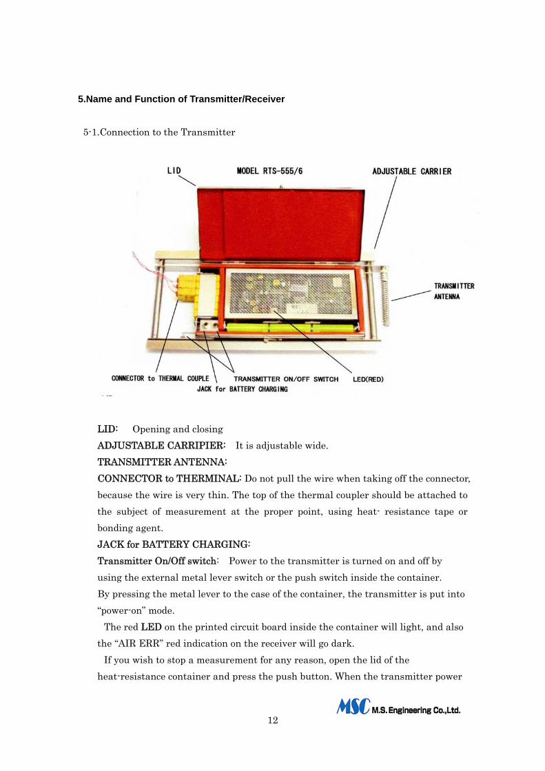
5-1.Connection to the Transmitter
LID: Opening and closing ADJUSTABLE CARRIPIER: It is adjustable wide. TRANSMITTER ANTENNA: CONNECTOR to THERMINAL: Do not pull the wire when taking off the connector, because the wire is very thin. The top of the thermal coupler should be attached to the subject of measurement at the proper point, using heat- resistance tape or bonding agent. JACK for BATTERY CHARGING: Transmitter On/Off switch: Power to the transmitter is turned on and off by using the external metal lever switch or the push switch inside the container. By pressing the metal lever to the case of the container, the transmitter is put into “power-on” mode.
The red LED on the printed circuit board inside the container will light, and also the “AIR ERR” red indication on the receiver will go dark.
If you wish to stop a measurement for any reason, open the lid of the heat-resistance container and press the push button. When the transmitter power
13
is turned off, the FM radio wave will stop and the “AIR ERR” red indicator on the receiver will light.
Transmitter Handling Cautions: 1) Don't use the antenna as a handle to carry the transmitter. It is not strong
enough to support the unit. Use heatproof gloves to avoid severe burns, when you handle the transmitter after it has just passed through an oven!
2) When you want to use the transmitter continuously, take the heat out inside the transmitter
until it is lower than 30℃.
3) For purpose of cooling the inside temperature of the transmitter as soon as possible, you
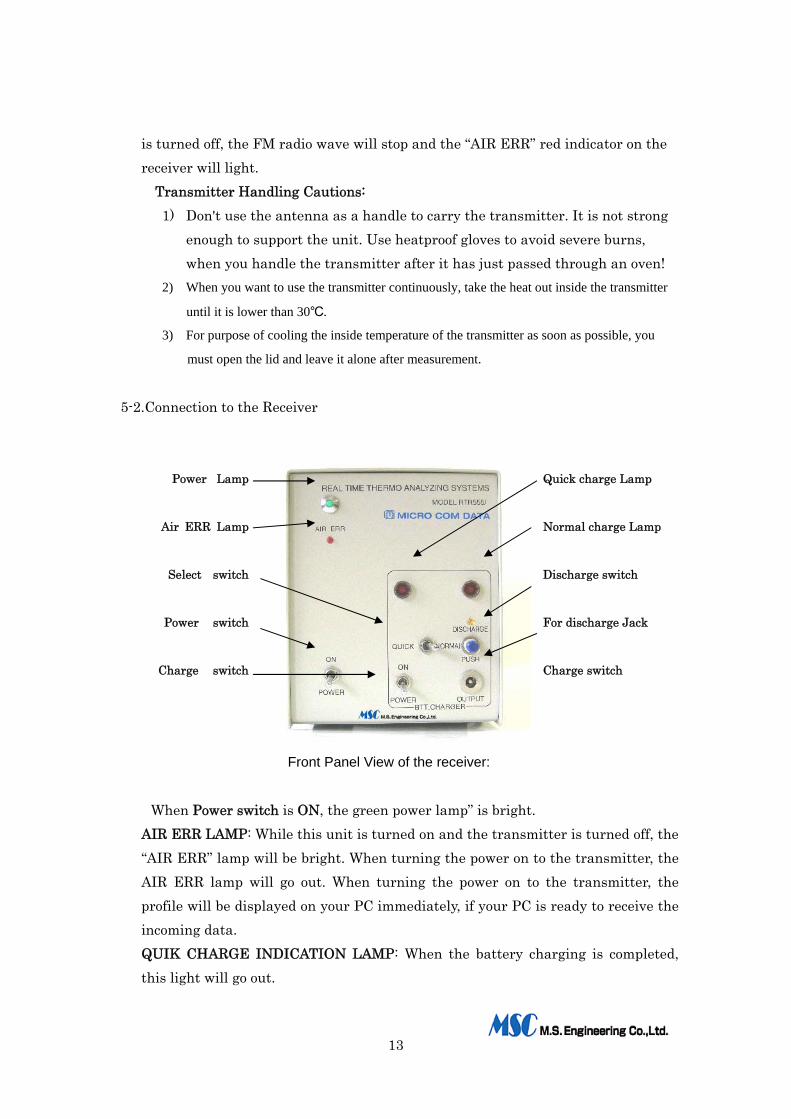
must open the lid and leave it alone after measurement. 5-2.Connection to the Receiver
Power Lamp Quick charge Lamp
Air ERR Lamp Normal charge Lamp
Select switch Discharge switch
Power switch For discharge Jack
Charge switch Charge switch
Front Panel View of the receiver:
When Power switch is ON, the green power lamp” is bright.
AIR ERR LAMP: While this unit is turned on and the transmitter is turned off, the “AIR ERR” lamp will be bright. When turning the power on to the transmitter, the AIR ERR lamp will go out. When turning the power on to the transmitter, the profile will be displayed on your PC immediately, if your PC is ready to receive the incoming data. QUIK CHARGE INDICATION LAMP: When the battery charging is completed, this light will go out.
14
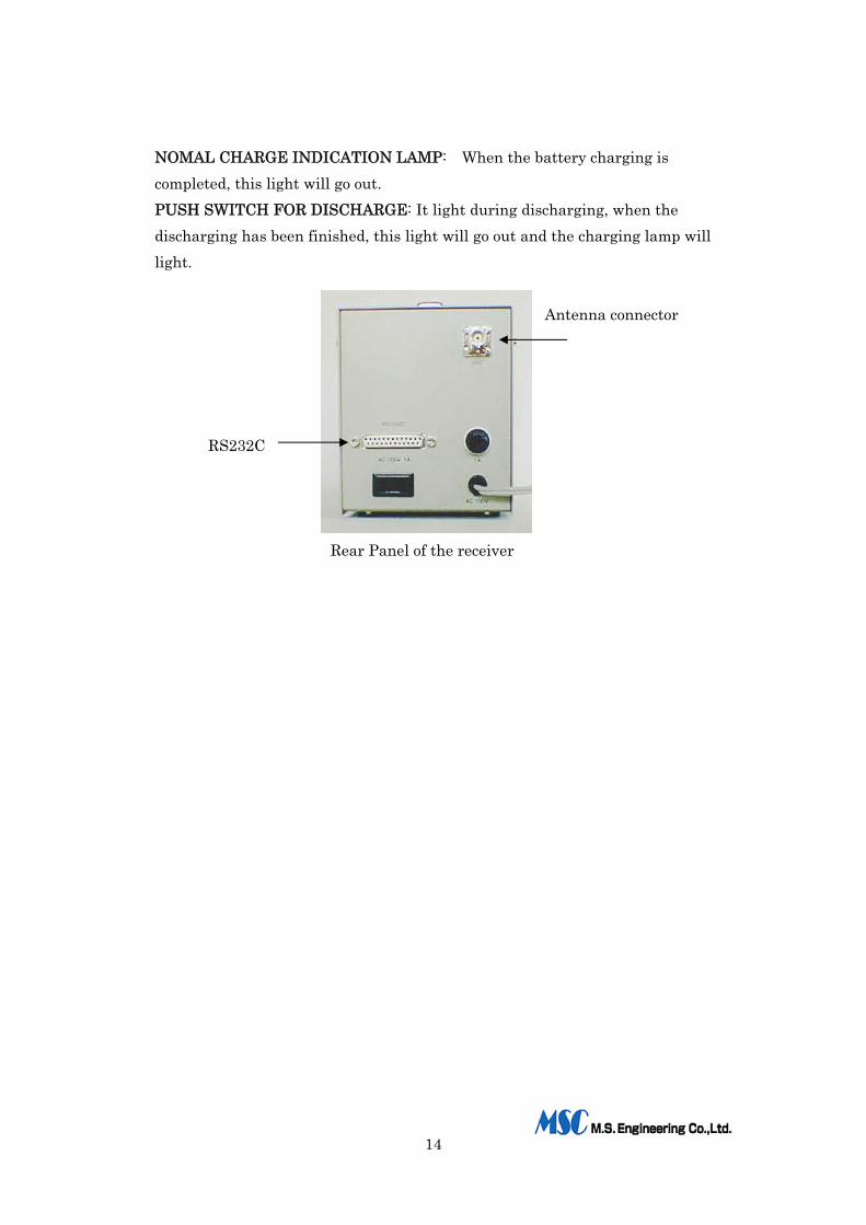
NOMAL CHARGE INDICATION LAMP: When the battery charging is completed, this light will go out. PUSH SWITCH FOR DISCHARGE: It light during discharging, when the discharging has been finished, this light will go out and the charging lamp will light.
Antenna connector
RS232C Rear Panel of the receiver
15
6.Computer Requirements.
6-1.Operational environments condition Your computer must have provided the followings: *Installed Pentium 266MHz or higher CPU and 32MB or bigger RAM *Windows 2000 or XP. *At least 800x600, 256 colors or more resolution is necessary *At least one RS-232C port. If you have only USB port, conversion cable must be prepared. *One CD Rom Reader and HDD (Storage capacity: 10MB or more) *A color printer (Applicable to A4 length or longer size paper) *Operation System should be Windows 2000 or XP and all other application software must work correctly. *A track ball (mouse) has to be connected to the computer and work correctly as a pointing device.
<WARNING>
When you use this application software, you should turn off any automatic operative software like Screen Saver, System Agent and etc, in order to receive data correctly. Do not use other removal Hard Disk Drives. In such a case, operation cannot be guaranteed.
6-2.Installation After turning on the computer, insert the application software into its CD ROM
drive. There are two types of set up procedure as follows: Method 1
*Click on “Start” box. *Click on “Run…” box. *Confirm “A: ¥SETUP.EXE” and press the Return key. Method 2 *Click on “Start” box. *Click on “Programs” box. *Select “Windows Explorer” box. *Click the CD ROM to open. *Confirm “A:¥SETUP.EXE” and press the Return key.
16
After the above procedures, the install program will start and you will see the display as the attached picture. When you can confirm that the install drive is correct, click on the “Execute
Installation” box. 6-3.How to set-up the temperature measurement system.
When starting the system, double-click the “Temperature Measurement” icon on the keyboard to execute. If you wish to know the system operation, double-click the “How to use” con to execute.
6-4.File structure The following files are managed on this system.
*Environment setting file Several things that you set the conditions for (serial port, measurement channel,
display/printing and etc.) on the “Basic Measurement Condition” window are saved on this file.
When the system is re-started, this file will be read into automatically. *Judgment condition file (Measurement Parameter File)
Judgment conditions (measurement parameters), conditions of the reflow-oven, etc. are saved in this file. This file is made out by the “Judgment Condition File” or “Read out Judgment Condition /Edit”.
If you want to use the same measurement parameters as in a previous setting, it is not necessary to regenerate the setting. You just read these settings back into the file.
If you do not read into file or setting file, a measurement task will not be executed.
* Data file This file is saved when the “Real Time Measurement” is finished and the data is
saved. You can use these data and measurement parameters for your observation,
judgment, analysis and printing. * CSV file
This CSV file is saved, when the “Real Time Measurement” is finished and the data is saved.
You can use to read out the measurement data using kind of spreadsheet (EXCEL, Lotus 1.2.3 or etc.). It is a useful file when you manage special data.
17
6-5.Operational Hints. All of this measurement equipment (transmitter, receiver and etc.) should be
used and maintained in the good working order. Also the operational environment for your computer should be kept in the right condition. If you use a foreign made computer, some functions of the application software may not work.
(WARNING) You have to turn off some automatic operative software like “Screen Saver”,
“System Agent” and etc. in order to receive the data correctly. In particularly “Automatic receiving mail software” or “Automatic receiving fax
software” which uses the serial port (RS-232C) should be turned off.
Application software installation reference. *The supplied master disk is the only proper source for the installation of the application software. We cannot guarantee that the measurement will execute/work correctly if copied disks are used.
* If you want to install this application software into your other computer, please contact your dealer. We will help you with this additional installation for a special price.
6-6.Expansion of the function
Please feel free to contact your dealer, if you need to add some functions for your personal application of this software.

18
7.System Operation:
7-1.Set-up of the each unit. Attach the K-type CA sensor Attach the top of thermal CA sensor to the
subject's measurement point by using heat-resistant tape. If you wish to measure every time using the same PCB, the thermal coupler should be attached to the PCB with a bonding agent or heat-resistant solder. You can measure immediately.
Mount the receiving antenna The antenna has to be mounted horizontally using the magnet stand, which is mounted around the mouth of the reflow oven. Connect to the BNC connector (ANT) of the Receiver using the supplied coaxial cable.
Data Transmitter Each connector of the thermal coupler has to be connected to the appropriate socket on the transmitter. Just push the frame of the carrier to the width of PCB. It attaches to the PCB.
Data Receiver Connect the power cable to an AC outlet, and turn the power switch on. At this time, the “AIR ERR” lamp lights. Connect between its D-sub connector and the PC using the supplied RS-232C cable. Connect the antenna cable to the BNC connector. Turn on the external switch for confirming whether the transmitter works correctly or not. If “AIR ERR” lamp goes dark, it works correctly. Open the lid of the transmitter, and press the push button.
Computer Before turning the power on to the computer, it is necessary to turn on the power to the printer. If the computer does not work correctly, you need to "Re-start".
7-2.Operation for PC.
This section explains the setting of each step from the Main Menu.
7-2-1.Main Menu
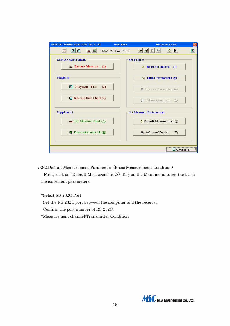
When the system activates, the Main Menu window will be shown. Follow the message on the window to use this system.
19
7-2-2.Default Measurement Parameters (Basis Measurement Condition)
First, click on "Default Measurement (8)" Key on the Main menu to set the basis measurement parameters.
*Select RS-232C Port Set the RS-232C port between the computer and the receiver. Confirm the port number of RS-232C.
*Measurement channel/Transmitter Condition
20
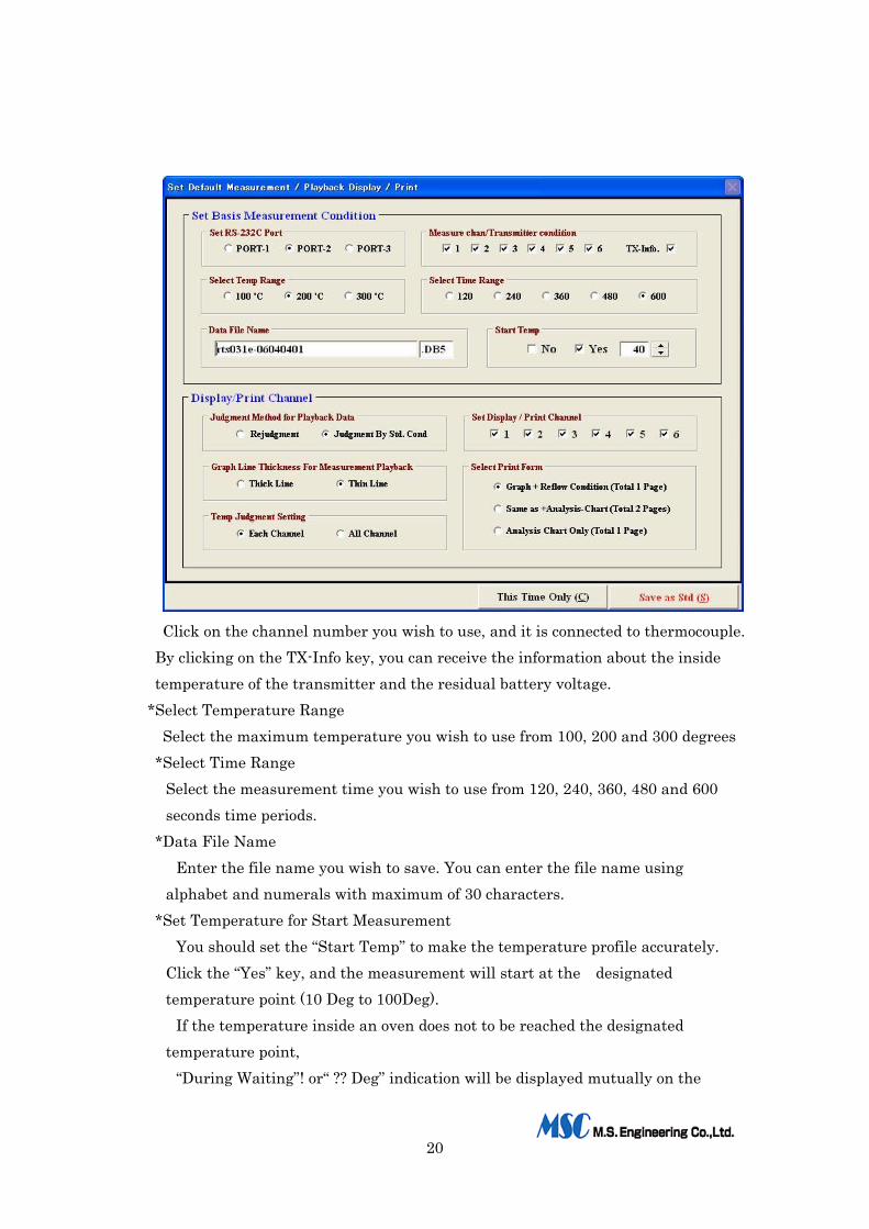
Click on the channel number you wish to use, and it is connected to thermocouple.
By clicking on the TX-Info key, you can receive the information about the inside temperature of the transmitter and the residual battery voltage.
*Select Temperature Range Select the maximum temperature you wish to use from 100, 200 and 300 degrees
*Select Time Range Select the measurement time you wish to use from 120, 240, 360, 480 and 600 seconds time periods.
*Data File Name Enter the file name you wish to save. You can enter the file name using
alphabet and numerals with maximum of 30 characters. *Set Temperature for Start Measurement
You should set the “Start Temp” to make the temperature profile accurately. Click the “Yes” key, and the measurement will start at the designated temperature point (10 Deg to 100Deg).
If the temperature inside an oven does not to be reached the designated temperature point,
“During Waiting”! or“ ?? Deg” indication will be displayed mutually on the
21
under left side of screen until starting the measurement. Click the “No” key, and measurement will start when the transmitter is turned
on. After “Default Measurement” has been set, you should set “Display/Print Channel”.
You can select the display and print condition for the channel for which you wish to see the temperature data and other contents. Both during measurement and playback, profile data can be display by this setting.
*Judgment Method for Playback Data You can choose to use the judgment method, either by using the saved judgment
data or by setting up the new numerical value for judgment, when you playback the saved file.
In case of Judgment using saved parameters: You can see the judgment using the prior value that was used during
measurement. In case of Re-judgment: You can execute the new judgment using new numeral value instead of the
prior value that was used during measuring. If you select “Re-judgment”, you have to run “Read out profile ”or“ Establish
profile” before reading out the temperature data file. *Select channel for display and printing
Click your designated channel when you play back a temperature data file, and the designated channel only will be displayed.
*Select thickness of a line chart You can choose from two line point sizes (thickness) for a chart.
*Judgment zone (+/-) and Automatic setting When you recall a temperature data file to build the judgment file, you can
establish the judgment zone (+/-) on the graph. If you select Each Channel , the zone of judgment will “ ” be set for one channel
only. If you select “All Channel”, the zone of judgment will be set for all of channels.
This setting can be entered on the “Default Measurement” and also can be entered when you build the judgment file.
*Select Print Form You can select the contents of printing for a playback of profile data.
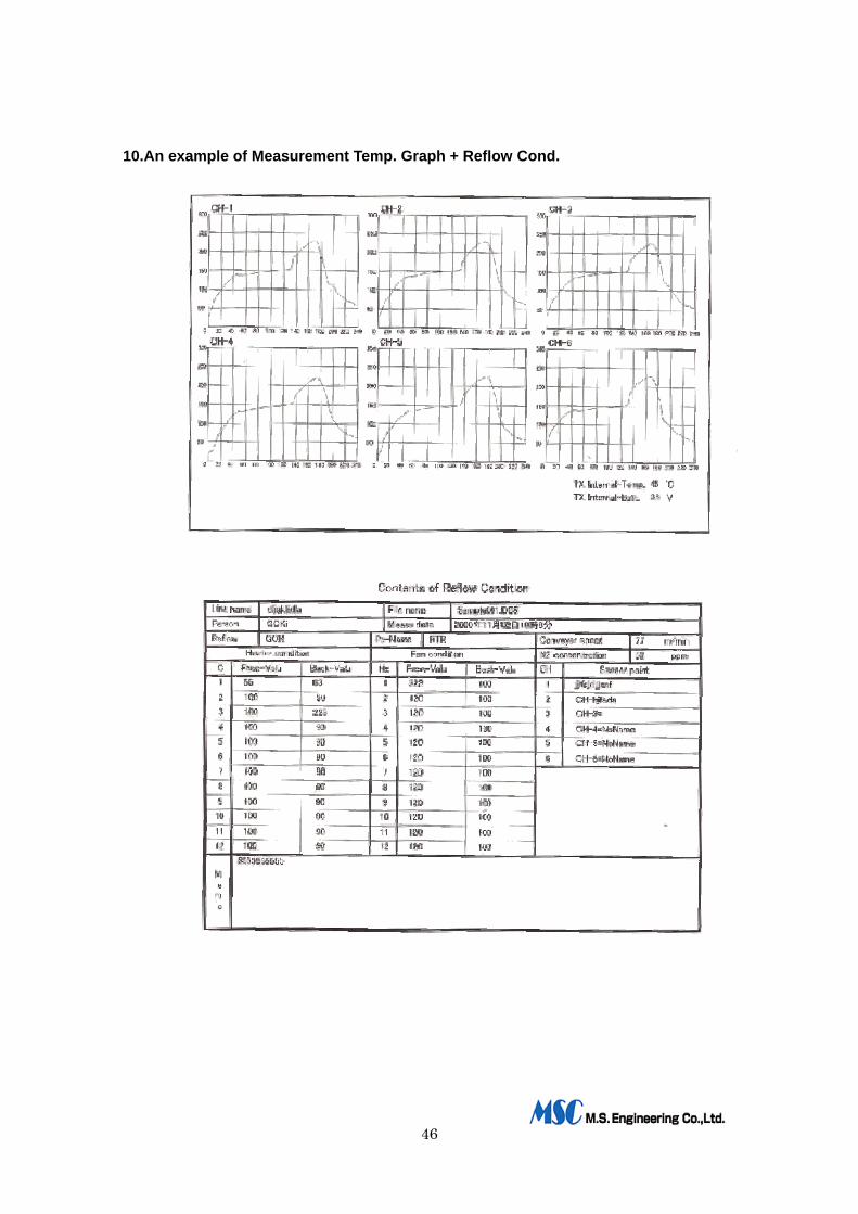
a) Graph + Reflow condition (Total 1page)--------- Print a graph and a reflow b) oven condition.
22
b) Above + Analysis chart (Total 2pages)---------- Print same as a) and an analysis chart
c) Only Analysis chart(Total 1page)-------------- Print an analysis only The first time you use this system, it will be necessary to choose at least once from the above
“Default Measurement ”options. If you click the “Save as Std (S)” key, it will be saved as the basis
measurement condition and will be read out when the measurement runs the next time.
If you wish to use the above setting only once, click “This Time Only (C)”. It will keep all settings until you change the contents of “Default
Measurement” or until you perform either the “Read out the profile”or“Playback profile” functions.
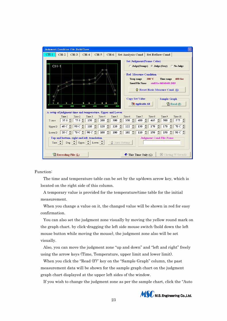
7-2-3.Build Measurement Parameters
Click “Build Parameters (5)” key on the Main Menu. The “Judgment Condition File Build/Save” window will be shown.
If you have kept the Measurement condition/Judgment condition profile, it is not
necessary to build up these conditions for each measurement. Instead, simply read out the Measurement condition/Judgment condition profile and proceed to measure using the parameters stored in memory.
You can enter 10 upper-temperature points and 10 lower-limit temperature points per channel, so for a 6-channel measurement, you can enter up to 120 measurement points.
You can see the judgment zone at a glance. It is displayed at the upper left side of the window.
The table of temperature/time is shown beneath the graph chart, as a numeral value of the judgment for the above graph. The structure of the temperature/time table is as follows:
*The upper first line is the timetable for judgment. *The second line is the upper temperature for judgment. *The third line is the lower temperature for judgment.
23
Function:
The time and temperature table can be set by the up/down arrow key, which is located on the right side of this column.
A temporary value is provided for the temperature/time table for the initial measurement.
When you change a value on it, the changed value will be shown in red for easy confirmation.
You can also set the judgment zone visually by moving the yellow round mark on the graph chart. by click-dragging the left side mouse switch (hold down the left mouse button while moving the mouse), the judgment zone also will be set visually.
Also, you can move the judgment zone “up and down” and “left and right” freely using the arrow keys (Time, Temperature, upper limit and lower limit).
When you click the “Read (F)” key on the “Sample Graph” column, the past measurement data will be shown for the sample graph chart on the judgment graph chart displayed at the upper left sides of the window.
If you wish to change the judgment zone as per the sample chart, click the “Auto
24
Setting” key. You can easily build the new judgment condition file in this manner.
After “Auto Setting”, you can select either one channel only or all channels in a group to apply the new judgment condition. The channel that you designate should be selected by the tab key on the upper part of the screen. When you wish to use the current setting condition for all other channels, click the “Applicable All” key on the “Copy Set Value” column.
Set Judgment (Select either Judgment or not.):
If you select the “Judge (Orange)“key, the judgment range frame on the graphic display will be colored red and show whether the result is good (“OK”) or bad (“NO”).
If you select the “Judge (Gray)“key, the judgment range frame on the graphic display will be colored gray and show whether the result is good (“OK”) or bad (“NO”).
If you select the “NO Judgment” key, the judgment range frame on the graphic display will not show, and the judgment will not execute.
You can see the current measurement condition roughly on the column of “Ref: Measure Condition”.
If you wish to change the measurement condition, click “Reset Basis Measure Cond (S)” key.
When you click the “Re-reading File “(L) key (Brown color), you can read out another judgment condition file. If the new file is similar to the past judgment condition file, it is easy to build the new measurement condition based on it by doing a little editing.
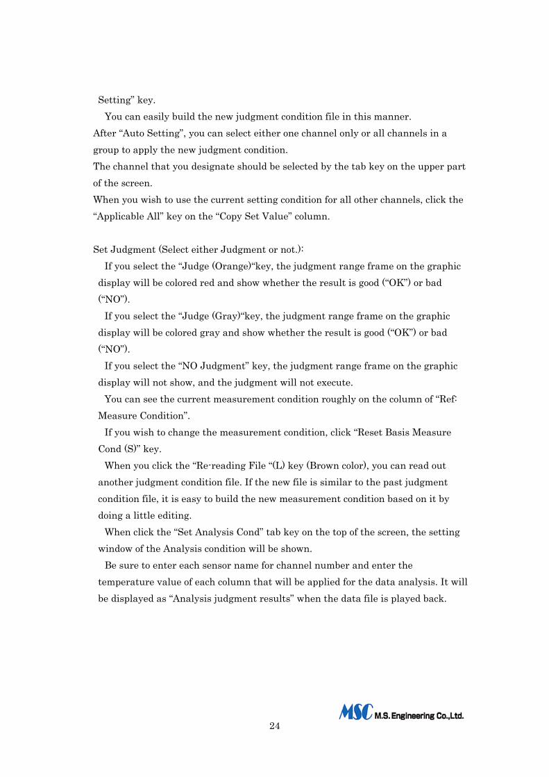
When click the “Set Analysis Cond” tab key on the top of the screen, the setting window of the Analysis condition will be shown.
Be sure to enter each sensor name for channel number and enter the temperature value of each column that will be applied for the data analysis. It will be displayed as “Analysis judgment results” when the data file is played back.
25
*Enter Sensor Name
You should create a sensor name for each channel. *Peak Temperature Range �
Set the judgment range for peak temperature. *Reaching Time until Peak Temp (Time to Peak Temp)
Set the judgment range of reaching time beyond this temperature to peak. *Time of Excess Temperature 1-3 (Excess Temp Time)
Set the judgment range of total time beyond this temperature. *Pre-Heat Time 1-2
Set the pre-heat time that is between the lower and the upper setting temperature before it will reach the peak temperature.
*Overall Temp 1-2 Set the overall time that is between the lower and the upper setting temperature including the peak temperature. When you click the “Set Reflow Cond” tab key on the top of the screen, you can enter the reflow setting condition on the Edit “Reflow Condition” window.

26
You should set the following contents to use a reflow oven. It will be saved when
the measurement is executed, and it should be kept for future reference. *Reflow oven name *Printed circuit board name *Conveyer speed *N2 density *Set fan rotation *Production line name *Measuring person name *Memo (Maximum 240 characters)
If you click on the tab key of the top of the screen, you can move to the “Set
Analysis Cond” window or return to the Main Menu. At the “Judgment Condition File Build/Save” window, you should enter the name
of judgment condition into the “Judgment Cond File Name” box that is located on the right side of the screen at the bottom.
When double clicking the “Closing W/ Save (S)”key, the judgment condition file will be saved.
27
If you click the “This Time Only (C)”key, this file will not be saved and the setting condition will be used for this time only.
When you click the “This Time only (C)” key, return to the “Main Menu” and you can start a measurement.
If you have changed some contents of the judgment condition file, you will be prompted to either save or discard those changes.
If you wish to save it, click “No”, and enter the name of judgment condition. If not, click “OK” and the measurement are ready to start.
When you click the “Closing W/ Save (S)”key, if the same judgment-condition name has already been used, you will be prompted to either change the name of the current file or to overwrite the new data to the old file with the same name.
If necessary, you should change the file’s name when you save the judgment condition file.
If you choose not to change the file name before saving, you will lose the original data in that file and the new data will take its place.
7-2-4.Read Parameters
Click the “Read Parameters (4)”on the Main Menu. The judgment condition that was built /saved on item 7-2-3 will read out. If you wish to change some contents on it, it must be saved using a different file
name. If you wish to use as it is, you should click the “This Time Only (C)”key, and
return to the Main Menu. The “Execute Measure (1)”key will turn blue, and the system will be ready to start a measurement.
7-2-5.Enter the contents of analysis condition
When you have executed the “Build Parameters (5)” or “Read Parameters (4)”, the Edit “Analysis Condition” widow will be shown. If you wish to change some contents and save your changes, click the “Return
Set-up/Finish” tab key, and enter the save file name.
7-2-6.Enter the contents of reflow oven This function can be used, when you have executed the “Build Parameters (5)”or
“Read Parameters (4)”, same as item 7-2-5. If you wish to change some contents and save the changes, click the “Return Set
28
Judgment/Finish” tab, and enter the save file name.
7-2-7.Real time measurement When you click the “Execute Measure (1)”key on the Main Menu, the “Cfm
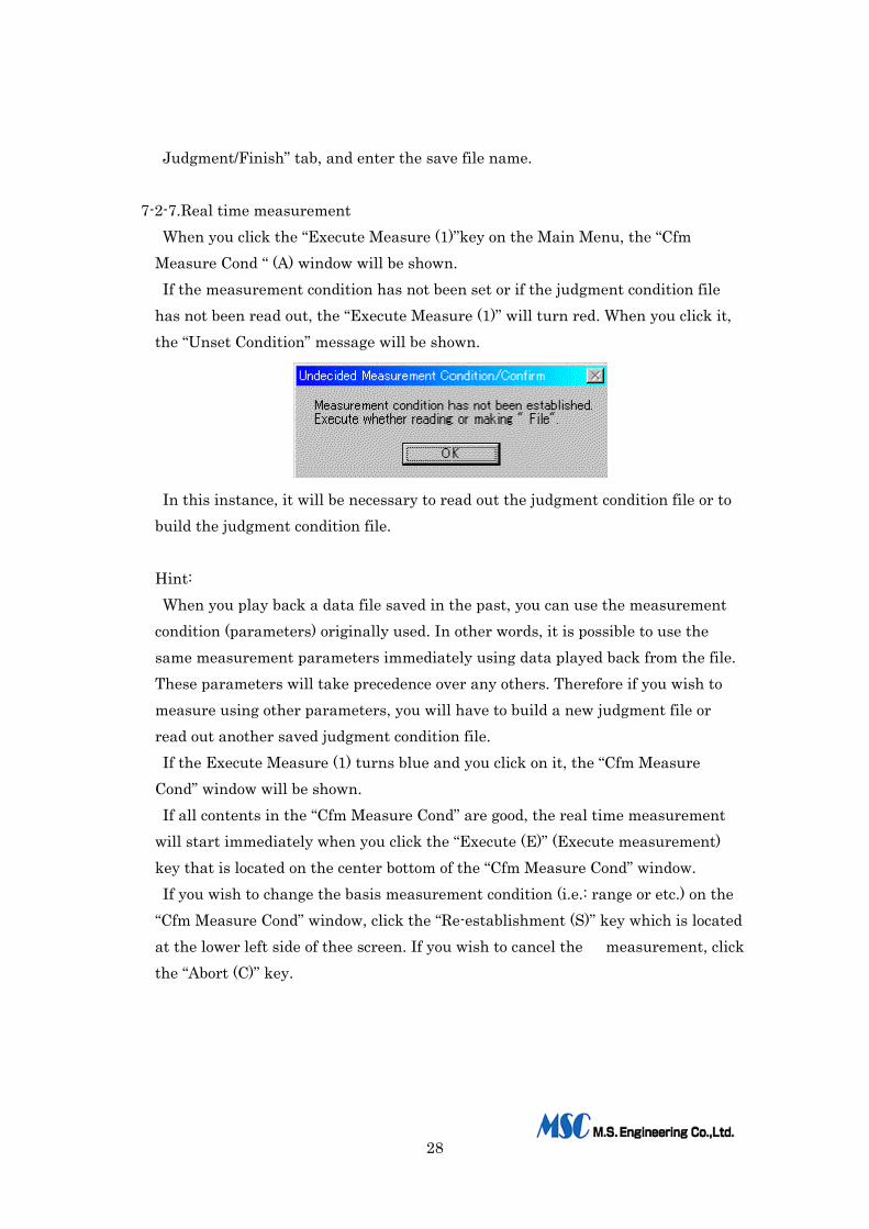
Measure Cond “ (A) window will be shown. If the measurement condition has not been set or if the judgment condition file
has not been read out, the “Execute Measure (1)” will turn red. When you click it, the “Unset Condition” message will be shown.
In this instance, it will be necessary to read out the judgment condition file or to
build the judgment condition file.
Hint: When you play back a data file saved in the past, you can use the measurement
condition (parameters) originally used. In other words, it is possible to use the same measurement parameters immediately using data played back from the file. These parameters will take precedence over any others. Therefore if you wish to measure using other parameters, you will have to build a new judgment file or read out another saved judgment condition file. If the Execute Measure (1) turns blue and you click on it, the “Cfm Measure
Cond” window will be shown. If all contents in the “Cfm Measure Cond” are good, the real time measurement
will start immediately when you click the “Execute (E)” (Execute measurement) key that is located on the center bottom of the “Cfm Measure Cond” window. If you wish to change the basis measurement condition (i.e.: range or etc.) on the
“Cfm Measure Cond” window, click the “Re-establishment (S)” key which is located at the lower left side of thee screen. If you wish to cancel the measurement, click the “Abort (C)” key.

29
*In this instance, if the temperature for start measurement has not been set, the real time measurement will start immediately by clicking the “Execute Measure (M)”key. *If the temperature for start measurement has been set, when the temperature data reaches the designated temperature point for “Start”, the measurement will start. At same time, a buzzer sounds to indicate that the measurement has begun.
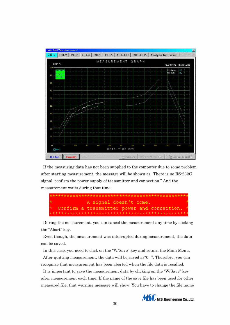
If the “Execute Judgment” of the file has been selected to “Judgment” during the measurement, either “OK” or “NG” of the judgment result will indicate one by one till the end of the designated measuring time. And also the elapsed time of measurement will be indicated inside of “Cond Display” box every 0.1 second. When the measurement has been completed, the buzzer will sound.
During the measurement, you can see whichever display of each channel, the entire channel on one graphic chart or all the channels on a graph divided into six parts.
30
If the measuring data has not been supplied to the computer due to some problem after starting measurement, the message will be shown as “There is no RS-232C signal, confirm the power supply of transmitter and connection.” And the measurement waits during that time.
During the measurement, you can cancel the measurement any time by clicking the “Abort” key. Even though, the measurement was interrupted during measurement, the data
can be saved. In this case, you need to click on the “W/Save” key and return the Main Menu. After quitting measurement, the data will be saved as“0�”. Therefore, you can
recognize that measurement has been aborted when the file data is recalled. It is important to save the measurement data by clicking on the “W/Save” key
after measurement each time. If the name of the save file has been used for other measured file, that warning message will show. You have to change the file name

31
to save the measuring file. If the file name that you wish to enter has been used repeatedly, the previous file
cannot be restored. Therefore, be careful when you using similar file names. The display will return to the “Main Menu” when you click the “Close/Save” key. When you save the data and return to the Main Menu, the measurement data file
and the CSV file will be saved at same time. The CSV file is used to read out the measurement data using a spread sheet (like
EXCEL, Lotus 1,2,3 or etc.). This is a useful way to manage special data. The structure of the CSV file is as follows:
First line “A title of Temperature Chart”,“ Saved File Name” Second line “Passing Time”,“ Channel Number 1-6” Third line and later: The temperature value of 6 channels during
measurement time. After above line: The contents of a reflow oven setting
7-2-8.Playback the saved file When you click the “Playback File (2)” key on the Main Menu, the list of files that
had been saved as data files will be recalled. Choose the file that you wish to use, and click it.
A graph chart devices into six parts for playback file with the judgment.
32
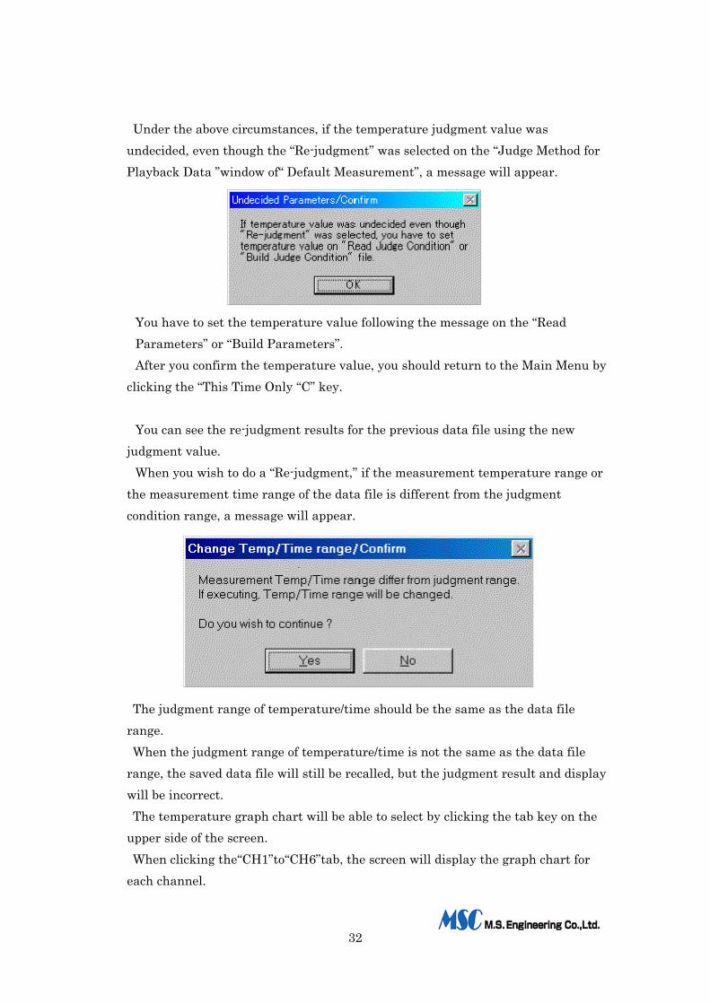
Under the above circumstances, if the temperature judgment value was undecided, even though the “Re-judgment” was selected on the “Judge Method for Playback Data ”window of“ Default Measurement”, a message will appear.
You have to set the temperature value following the message on the “Read Parameters” or “Build Parameters”. After you confirm the temperature value, you should return to the Main Menu by
clicking the “This Time Only “C” key.
You can see the re-judgment results for the previous data file using the new judgment value.
When you wish to do a “Re-judgment,” if the measurement temperature range or the measurement time range of the data file is different from the judgment condition range, a message will appear.
The judgment range of temperature/time should be the same as the data file range. When the judgment range of temperature/time is not the same as the data file
range, the saved data file will still be recalled, but the judgment result and display will be incorrect. The temperature graph chart will be able to select by clicking the tab key on the
upper side of the screen. When clicking the“CH1”to“CH6”tab, the screen will display the graph chart for
each channel.

33
When clicking the“Ch1-CH6”tab, the screen will display the graph chart for the entire channel. When clicking the “ALL-CH” tab, the screen will display the graph chart divided
into six parts.
Designated expansion place for playback graph.
When the graph chart for each channel is displayed, you can use the following
functions. Click on the left mouse button: If you click the left mouse button (or Track ball) inside of the graph chart, a
yellow rectangle will be displayed. By dragging the mouse while holding the left button, you can move the designated
place. The box will stay at its new position and the Enlarge (K) key will “ ” appear when
you release the mouse button. You may enlarge the graph by clicking on it. The enlargement ratio is 5 times
only. After you confirm the enlarged display, the screen will be returned the standard
display by clicking the“ Standard” key located at the bottom of the screen.
34
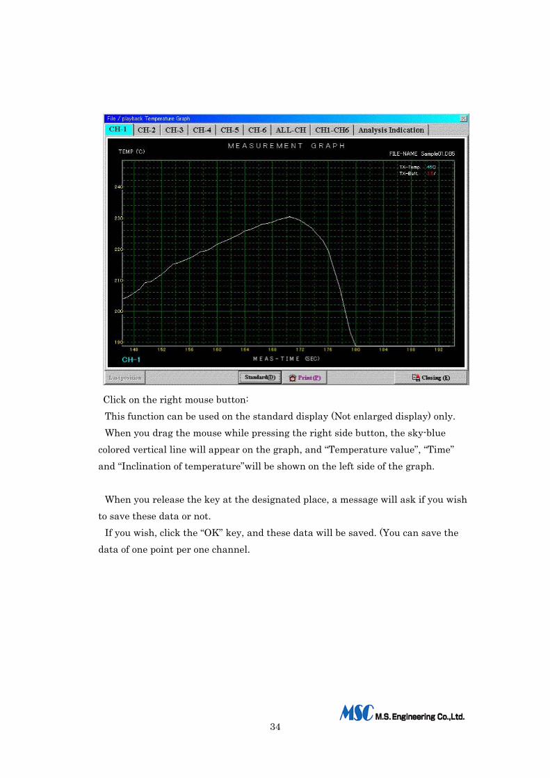
Click on the right mouse button: This function can be used on the standard display (Not enlarged display) only. When you drag the mouse while pressing the right side button, the sky-blue
colored vertical line will appear on the graph, and “Temperature value”, “Time” and “Inclination of temperature”will be shown on the left side of the graph.
When you release the key at the designated place, a message will ask if you wish
to save these data or not. If you wish, click the “OK” key, and these data will be saved. (You can save the
data of one point per one channel.

35
When you click the Analysis indication tab on the upper part of the
“File/Playback Temperature Graph”, the saved analysis data and analysis result chart will be shown.
36
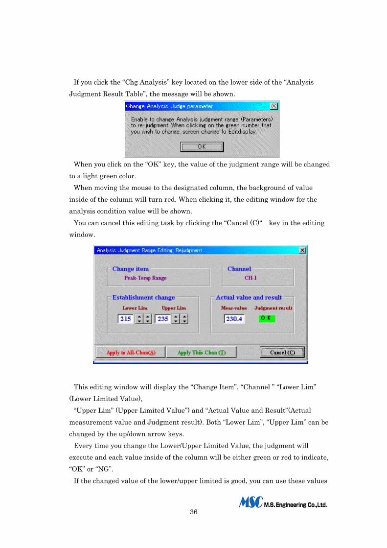
If you click the “Chg Analysis” key located on the lower side of the “Analysis
Judgment Result Table”, the message will be shown.
When you click on the “OK” key, the value of the judgment range will be changed
to a light green color. When moving the mouse to the designated column, the background of value
inside of the column will turn red. When clicking it, the editing window for the analysis condition value will be shown.
You can cancel this editing task by clicking the “Cancel (C)“ key in the editing window.
This editing window will display the “Change Item”, “Channel ” “Lower Lim”
(Lower Limited Value), “Upper Lim” (Upper Limited Value”) and “Actual Value and Result”(Actual
measurement value and Judgment result). Both “Lower Lim”, “Upper Lim” can be changed by the up/down arrow keys.
Every time you change the Lower/Upper Limited Value, the judgment will execute and each value inside of the column will be either green or red to indicate, “OK” or “NG”.
If the changed value of the lower/upper limited is good, you can use these values
37
either for all the channels or for one channel only using “Apply to All Chan (A)”or“Apply This Chan Only (T)”key.
After either key is clicked, the screen will return to the “Analysis Result”. At this time, the “Build parameters” key will appear. If you wish to build the new judgment condition (measurement parameters) file,
click on it. If you name the new file that you wish to save, you can recall it later for use as
the judgment condition (measurement parameters). When click the “Cancel (C)”, the judgment value will return to the original white
color for the “Result Analysis“window. If you wish to change the analysis condition, you should change the judgment
value and execute the re-judgment so that you can adjust the value. You can then save it and use it as the new judgment file.
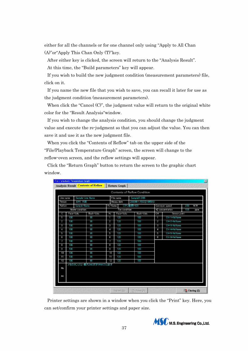
When you click the “Contents of Reflow” tab on the upper side of the “File/Playback Temperature Graph” screen, the screen will change to the reflow-oven screen, and the reflow settings will appear.
Click the “Return Graph” button to return the screen to the graphic chart window.
Printer settings are shown in a window when you click the “Print” key. Here, you can set/confirm your printer settings and paper size.

38
The default printer settings are: Paper size: A4, Color printing on the vertical position Printing Resolution: 360x360 DPI After making the correct printer settings for your printer, click the “OK” button,
and printing will start. In this instance, the contents of printing will be determined by the print settings
for the “Basis Measurement Condition”. a) Graph + Reflow condition -----Print a graph and a reflow oven condition. b) Above + Analysis chart-------------Print same as a) and an analysis chart c) Only Analysis chart-----------------------Print an analysis only
Refer to the following pages for certain specific printing jobs: * Print out of “Profile + Contents of Reflow oven setting”----------Page 32 * Print out of “Analysis Result Chart"-----------------------------Page 33 You can select the printing for the following graph chart.
1) Print each channel individually 2) Print all channels as a group. 3) Print the six-part divided graph.
Some print jobs take longer than others depending upon the number of pages and the printing environment (type of printer, etc.).
Click on the “Closing (E)”, the window will return to the Main Menu.
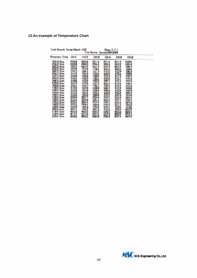
7-2-9.Indication for the data chart When you click the Indicate Data Chart (3) key on the Main Menu, the “ ” data
file list that had been saved as the data file will be recalled as same as item 7-2-8 “Recall Saved file”.
Choose the file that you wish to use, and click it. You can see the display and print out the temperature data precisely using the
numerical value. If you click the channel in the “Display Channel” box that you wish to print, the
designated channel only will be shown. The “Display Time Unit” can be selected from 0.1 second to 10 seconds using the
up/down arrow key, you can see the precise data by choosing the shortest time period

39
.
If the data is beyond the range of “Temperature judgment value”, the “*” mark
will be indicated before the numerical value. When you click the “Print Chart (P)”key, the temperature data chart will be
printed. The numbers of print pages will be changed depend on the “Display Time Unit”,
and total page number will be shown the right side of the “Print Chart (P)” key. The printing time will take 10minutes or more depend on number of printing
paper or environments, sometimes. Please wait till the printing will be finished. The instance of printing: Refer to the page xx for the “Print out temperature
chart”. When you click the “Closing (E)” key, the window will return to the Main Menu.
7-2-10.Confirmation Display for Measurement Condition
When you click the “Cfm Measure Cond (A)” key on the Main Menu, you can confirm the contents of “Default Measurement” that you had set.
When you click the “Re-establishment (S)”key, you can change the contents of the “Default Measurement”. Click the “Return (C)”key, the window will return to the Main Menu.
40
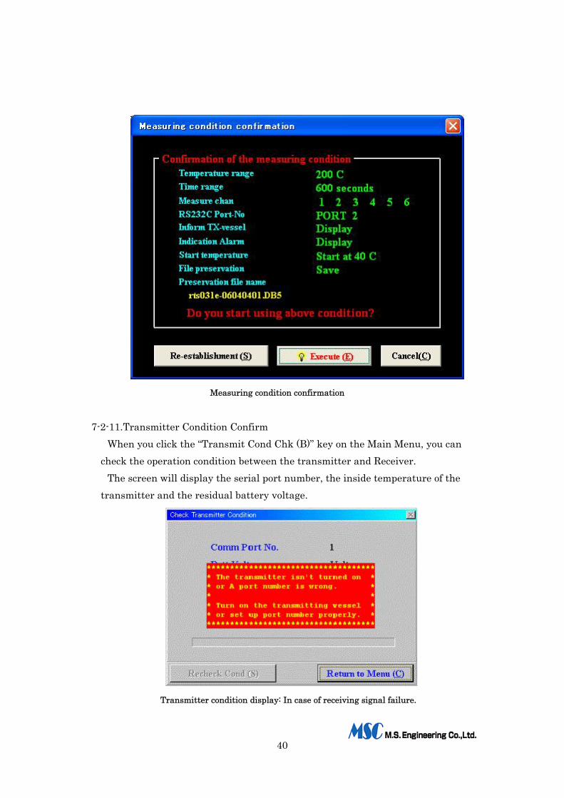
Measuring condition confirmation
7-2-11.Transmitter Condition Confirm When you click the “Transmit Cond Chk (B)” key on the Main Menu, you can
check the operation condition between the transmitter and Receiver. The screen will display the serial port number, the inside temperature of the
transmitter and the residual battery voltage.
Transmitter condition display: In case of receiving signal failure.
41
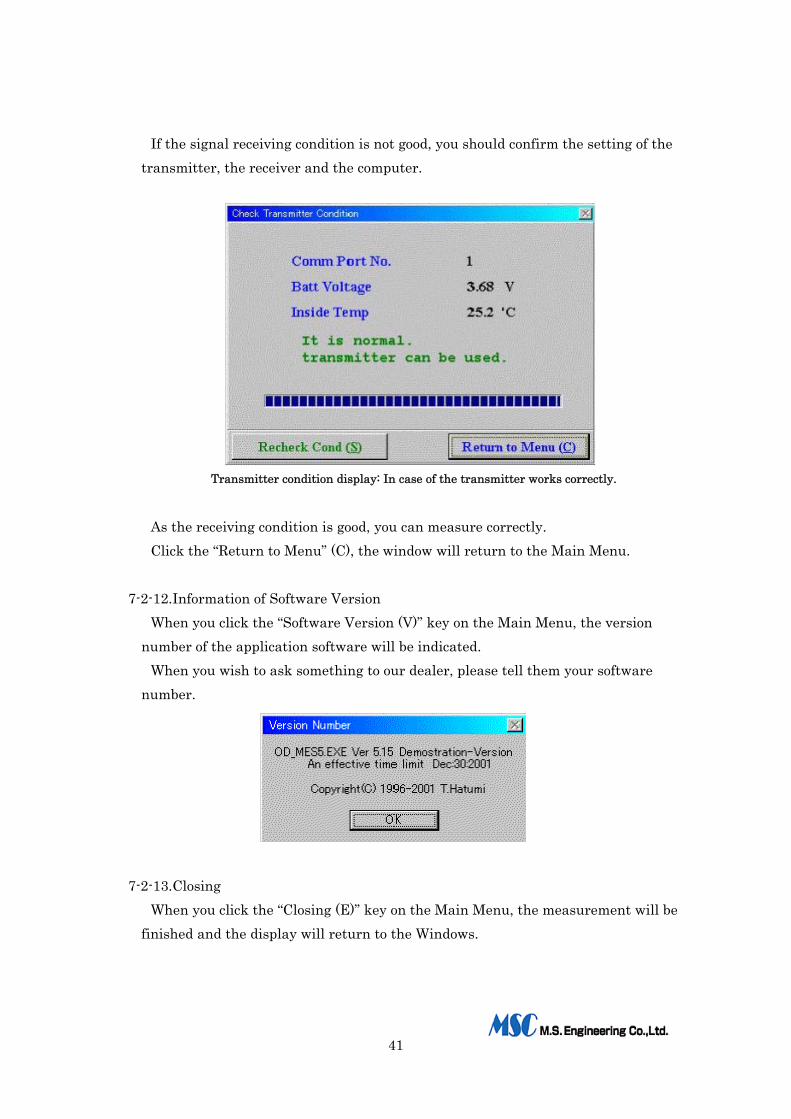
If the signal receiving condition is not good, you should confirm the setting of the transmitter, the receiver and the computer.
Transmitter condition display: In case of the transmitter works correctly.
As the receiving condition is good, you can measure correctly. Click the “Return to Menu” (C), the window will return to the Main Menu.
7-2-12.Information of Software Version
When you click the “Software Version (V)” key on the Main Menu, the version number of the application software will be indicated.
When you wish to ask something to our dealer, please tell them your software number.
7-2-13.Closing When you click the “Closing (E)” key on the Main Menu, the measurement will be
finished and the display will return to the Windows.
42
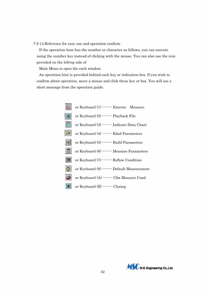
7-2-14.Reference for easy use and operation confirm.
If the operation item has the number or character as follows, you can execute using the number key instead of clicking with the mouse. You can also use the icon provided on the left/up side of
Main Menu to open the each window. An operation hint is provided behind each key or indication box. If you wish to
confirm about operation, move a mouse and click these key or box. You will see a short message from the operation guide.
or Keyboard (1) -------- Execute Measure
or Keyboard (2) -------- Playback File
or Keyboard (3) -------- Indicate Data Chart
or Keyboard (4) -------- Rdad Parameters
or Keyboard (5) -------- Build Parameters
or Keyboard (6) -------- Measure Parameters
or Keyboard (7) -------- Reflow Condition
or Keyboard (8) -------- Default Measurement
or Keyboard (A) -------- Cfm Measure Cond
or Keyboard (E) -------- Closing

43
8.Specifications:
Data Transmitter: Model RTS-555/6channels.
Used thermocouple: K type (Chromel / Alumel type) With heat-resistance type connector
Number of thermal couple 6 pieces
Measurement temperature range: 0 degree to 300 degrees
A/D converter: 10 bit
Sampling cycle: 100m second
Side-band modulation system: MSK
Carrier wave modulation: FM
Carrier frequency: 310MHz (Standard)
Transmitter output: A faint radio wave
Rechargeable Battery: Ni-Cd, IEC R1 type, 1.2V x 3 series connection
Heat-resistance case: Outside: Stainless steel
Inside: Put the special heat-resistance material
Size of heat-resistance case: W89xH25xD258mm
Weight : 750g
Antenna: Helical type
Adjustment ability of carrier width: Minimum: 117 mm, Maximum: 298mm to mount the transmitter Option: Maximum: 510mm
Data Receiver: Model RTR-555
Receiving radio wave: Same wave as the carrier wave from the Transmitter
Receiving system: Super heterodyne
44
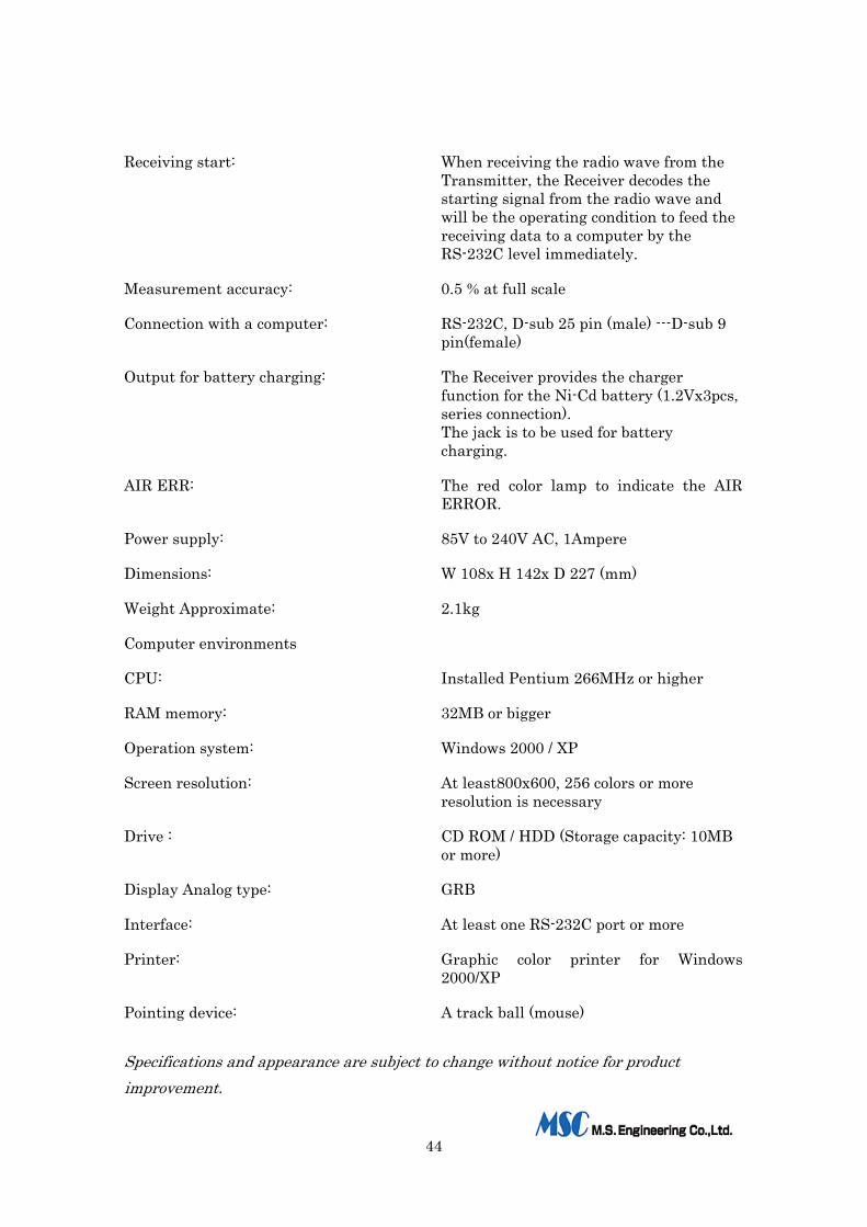
Receiving start: When receiving the radio wave from the Transmitter, the Receiver decodes the starting signal from the radio wave and will be the operating condition to feed the receiving data to a computer by the RS-232C level immediately.
Measurement accuracy: 0.5 % at full scale
Connection with a computer: RS-232C, D-sub 25 pin (male) ---D-sub 9 pin(female)
Output for battery charging: The Receiver provides the charger function for the Ni-Cd battery (1.2Vx3pcs, series connection). The jack is to be used for battery charging.
AIR ERR: The red color lamp to indicate the AIR ERROR.
Power supply: 85V to 240V AC, 1Ampere
Dimensions: W 108x H 142x D 227 (mm)
Weight Approximate: 2.1kg
Computer environments
CPU: Installed Pentium 266MHz or higher
RAM memory: 32MB or bigger
Operation system: Windows 2000 / XP
Screen resolution: At least800x600, 256 colors or more resolution is necessary
Drive : CD ROM / HDD (Storage capacity: 10MB or more)
Display Analog type: GRB
Interface: At least one RS-232C port or more
Printer: Graphic color printer for Windows 2000/XP
Pointing device: A track ball (mouse)
Specifications and appearance are subject to change without notice for product improvement.

45
9.Maintenance
Symptoms Cause Countermeasure
When turning the power on to the transmitter, the "AIR ERR “red lamp does not distinguish.
1)The radio wave from the transmitted may not be transmitted.
1) Need to charge the battery. 2)Check both antenna of Transmitter/receiver work correctly. 3)Check either the breaking down or bad electrical contact of the receiving antenna cable.
During transmitting data, the computer screen is displayed the situation of data waiting.
1)The battery voltage may become lower than 3.6 volts.2)The receiver does not catch the radio wave correctly.
1) Need to charge the battery. 2)Moving the antenna of find the position for receiving, set the antenna at the best position.
Although the AIE ERR lamp of the receiver is distinguished, the profile display is not appeared on a computer screen.
1)The RS-232C cable is not connected to both the receiver and a computer. 2)The RS-232C port is not set or is set other port.
1) Confirm the connection. 2)Click the same port no. of RS-232C as a port no. of computer.
Although the profile is displayed on a screen, the line of temp. Data is not stable or is not rising.
1)The thermal couple has not been stuck turned on the PCB.
2)The thermal couple may be broken.
1)Try again to stick a thermal couple on the PCB. 2)Change to the new thermal couple.
The battery charging does not work correctly.
1)The battery charging switch may be to off position.
2) No connection to the battery.
1)Turn on the battery charging switch. 2)Used the supplied cable to connect the jack.
Although the battery charging switch is turned on, the charging indication lamp does not light.
No connection to the battery. 1)Before switching on the power switch for charging, connect the supplied cable to the battery.
During measuring, the computer screen shows the situation of data waiting before the measurement has not been finished. Also, the "AIR ERR" red lamp light.
1)The battery voltage may become lower than 3.6 volts.
2) The timer was not reset. In other words, the previous measurement is still continuing in spite of the measurement has been done.
1) Need to charge the battery. 2)You must open the lid and press the rest button after finished the measurement at every time.
46
10.An example of Measurement Temp. Graph + Reflow Cond.

47
11.An example of Analysis Result
48
12.An example of Temperature Chart