Embed Size (px)
Citation preview
Introduction to USB Type-C & Power Delivery
TI Literature Number: SLUP360 © 2016, 2017 Texas Instruments Incorporated
Power Seminar topics and online power training modules are available at:ti.com/psds
Power Supply Design Seminar
(Demo Hall Presentation)
Texas Instruments - 2016/17 Power Supply Design Seminar
Deric Waters, System Engineer
Introduction to USB Type-C & Power Delivery
Focus on Charging Applications
Texas Instruments - 2016/17 Power Supply Design Seminar
Agenda • Introduction to USB Type-C and Power Delivery • Detailed discussion of a USB Type-C universal adaptor o Including conceptual schematic of a single and dual port AC/DC adaptor.
2
Texas Instruments - 2016/17 Power Supply Design Seminar
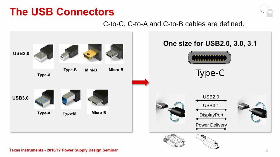
The USB Connectors
USB2.0
USB3.0
Type-A
Type-A
Type-B
Type-B Micro-B
Micro-B Mini-B
One size for USB2.0, 3.0, 3.1
USB2.0
USB3.1
DisplayPort
Power Delivery
C-to-C, C-to-A and C-to-B cables are defined.
3
Texas Instruments - 2016/17 Power Supply Design Seminar
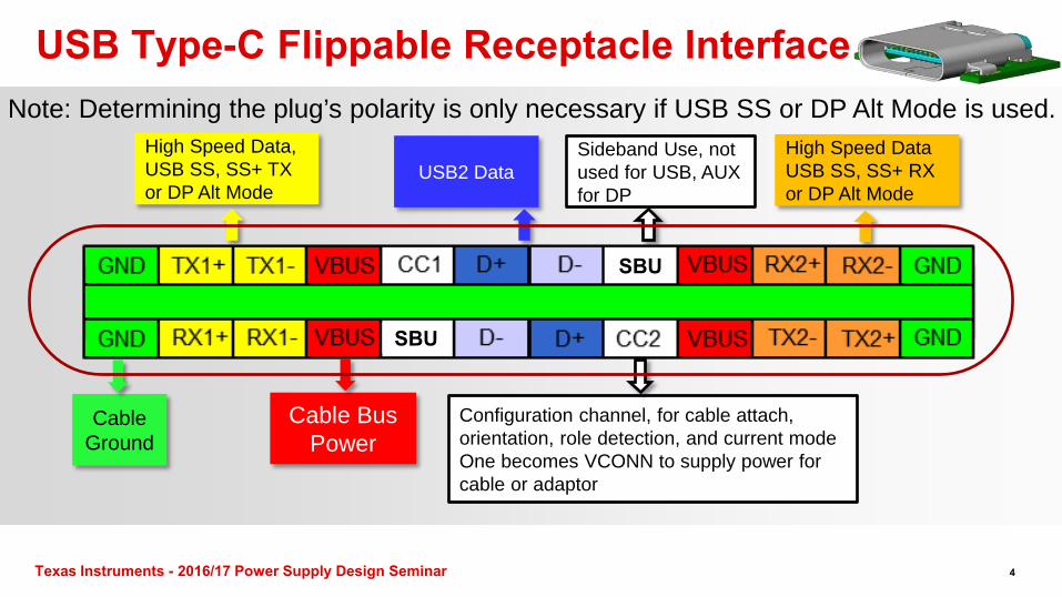
USB Type-C Flippable Receptacle Interface
High Speed Data, USB SS, SS+ TX or DP Alt Mode
High Speed Data USB SS, SS+ RX or DP Alt Mode
USB2 Data
Cable Ground
SBU
SBU
Cable Bus Power
Sideband Use, not used for USB, AUX for DP
Configuration channel, for cable attach, orientation, role detection, and current mode One becomes VCONN to supply power for cable or adaptor
Note: Determining the plug’s polarity is only necessary if USB SS or DP Alt Mode is used.
4
Texas Instruments - 2016/17 Power Supply Design Seminar
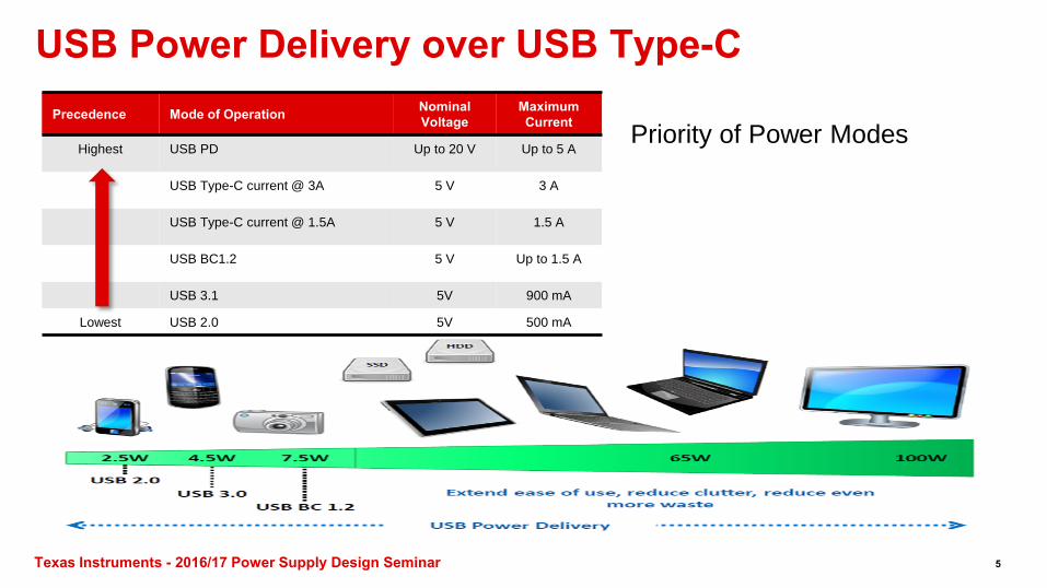
USB Power Delivery over USB Type-C Precedence Mode of Operation Nominal
Voltage Maximum Current
Highest USB PD Up to 20 V Up to 5 A
USB Type-C current @ 3A 5 V 3 A
USB Type-C current @ 1.5A 5 V 1.5 A
USB BC1.2 5 V Up to 1.5 A
USB 3.1 5V 900 mA
Lowest USB 2.0 5V 500 mA
Priority of Power Modes
5
Texas Instruments - 2016/17 Power Supply Design Seminar
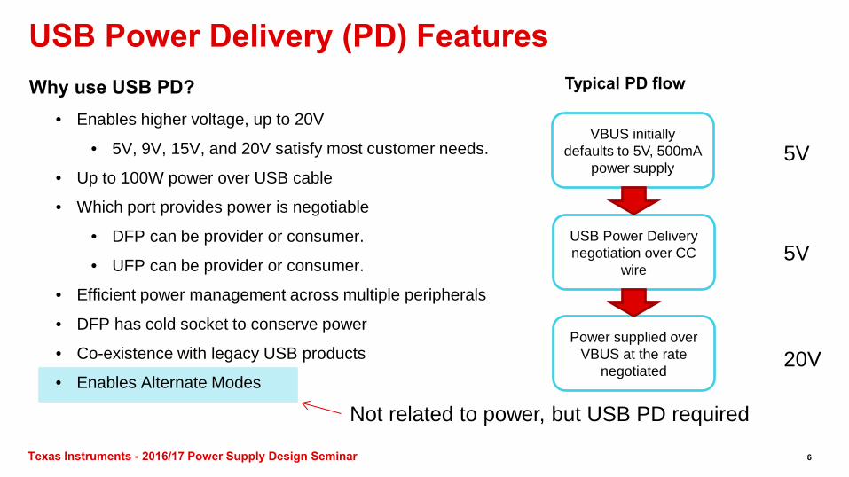
USB Power Delivery (PD) Features
• Enables higher voltage, up to 20V
• 5V, 9V, 15V, and 20V satisfy most customer needs.
• Up to 100W power over USB cable
• Which port provides power is negotiable
• DFP can be provider or consumer.
• UFP can be provider or consumer.
• Efficient power management across multiple peripherals
• DFP has cold socket to conserve power
• Co-existence with legacy USB products
• Enables Alternate Modes
Why use USB PD?
VBUS initially defaults to 5V, 500mA
power supply
USB Power Delivery negotiation over CC
wire
Power supplied over VBUS at the rate
negotiated
Typical PD flow
5V
5V
20V
Not related to power, but USB PD required
6
Texas Instruments - 2016/17 Power Supply Design Seminar
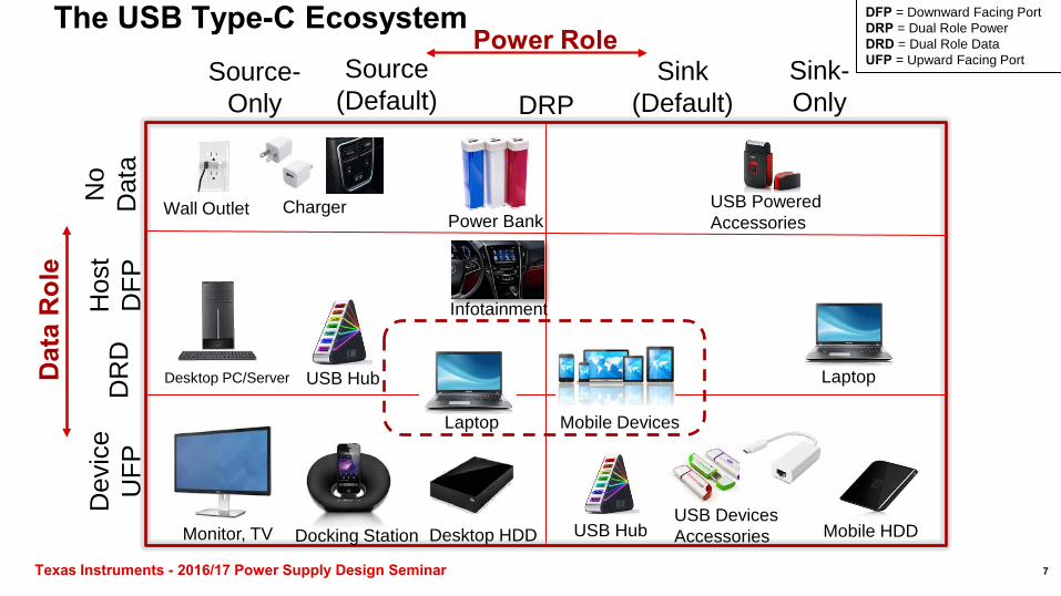
The USB Type-C Ecosystem Power Role
Dat
a R
ole
Dev
ice
UFP
H
ost
DFP
Source-Only
Sink-Only
Desktop PC/Server
Mobile Devices
DR
D
Power Bank
Monitor, TV Docking Station
Infotainment
Wall Outlet Charger
USB Hub USB Devices Accessories
Laptop
Laptop
Desktop HDD Mobile HDD
USB Hub
No
Dat
a USB Powered Accessories
Source (Default)
DFP = Downward Facing Port DRP = Dual Role Power DRD = Dual Role Data UFP = Upward Facing Port Sink
(Default) DRP
7
Texas Instruments - 2016/17 Power Supply Design Seminar
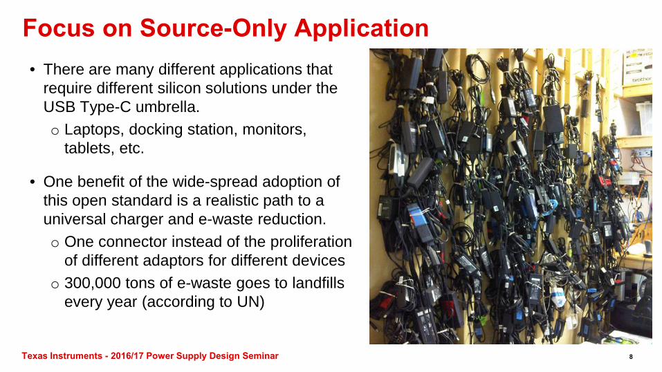
Focus on Source-Only Application • There are many different applications that
require different silicon solutions under the USB Type-C umbrella. o Laptops, docking station, monitors,
tablets, etc.
• One benefit of the wide-spread adoption of this open standard is a realistic path to a universal charger and e-waste reduction. o One connector instead of the proliferation
of different adaptors for different devices o 300,000 tons of e-waste goes to landfills
every year (according to UN)
8
Texas Instruments - 2016/17 Power Supply Design Seminar
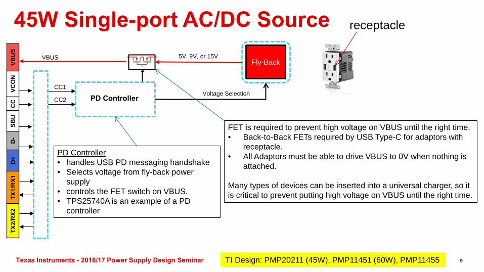
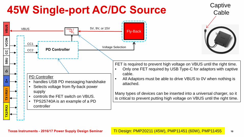
45W Single-port AC/DC Source
Fly-Back
ESD
VBU
S VC
ON
C
C
SBU
D
- D
+ TX
1/R
X1
TX2/
RX2
5V, 9V, or 15V VBUS
PD Controller Voltage Selection
TI Design: PMP20211 (45W), PMP11451 (60W), PMP11455
FET is required to prevent high voltage on VBUS until the right time. • Back-to-Back FETs required by USB Type-C for adaptors with
receptacle. • All Adaptors must be able to drive VBUS to 0V when nothing is
attached. Many types of devices can be inserted into a universal charger, so it is critical to prevent putting high voltage on VBUS until the right time.
receptacle
PD Controller • handles USB PD messaging handshake • Selects voltage from fly-back power
supply • controls the FET switch on VBUS. • TPS25740A is an example of a PD
controller
CC1
CC2
9
Texas Instruments - 2016/17 Power Supply Design Seminar
45W Single-port AC/DC Source
Fly-Back
ESD
VBU
S VC
ON
C
C
SBU
D
- D
+ TX
1/R
X1
TX2/
RX2
5V, 9V, or 15V VBUS
PD Controller Voltage Selection
TI Design: PMP20211 (45W), PMP11451 (60W), PMP11455
FET is required to prevent high voltage on VBUS until the right time. • Only one FET required by USB Type-C for adaptors with captive
cable. • All Adaptors must be able to drive VBUS to 0V when nothing is
attached. Many types of devices can be inserted into a universal charger, so it is critical to prevent putting high voltage on VBUS until the right time.
Captive Cable
PD Controller • handles USB PD messaging handshake • Selects voltage from fly-back power
supply • controls the FET switch on VBUS. • TPS25740A is an example of a PD
controller
CC1
CC2
10
Texas Instruments - 2016/17 Power Supply Design Seminar TI Design: PMP20211 (45W), PMP11451 (60W), PMP11455
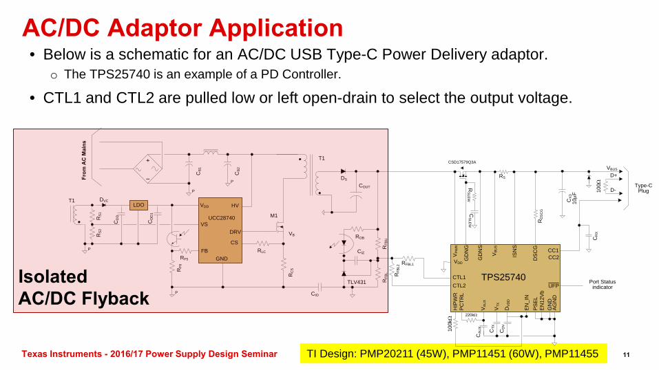
AC/DC Adaptor Application • Below is a schematic for an AC/DC USB Type-C Power Delivery adaptor.
o The TPS25740 is an example of a PD Controller.
• CTL1 and CTL2 are pulled low or left open-drain to select the output voltage.
M1
RC
S
COUT
DRV
VDD
CSFB
VB
DS
CIO
T1
From
AC
Mai
ns
RFBL1
RFB
UR
FBL
TLV431
ROB
CIZ
RFB
L2
CB
2
CB
1
+
–P
P
P
DVCHV
RLC
RS
1R
S2
CD
D1
CD
D
GNDRF5
RF6
LDO
VS
P
UCC28740
T1 CX
310
µF
RD
SC
G
TPS25740
VDDCC2
AG
ND
DV
DD
CC1
CD
V
DS
CG
100kΩ
VTX
CTX
GN
D
CR
X
GD
NG
GD
NS
CTL2CTL1
Type-C Plug10
0Ω D+
D-
VBUS
VP
WR
HIP
WR
PC
TRL
EN
_IN
PS
EL
VA
UX
CA
UX
CS
LEW
Port Status indicator
CSD17579Q3A
ISN
S
VB
US
RS
UFP
220kΩ
EN
12V
b
RS
LEW
Isolated AC/DC Flyback
11
Texas Instruments - 2016/17 Power Supply Design Seminar
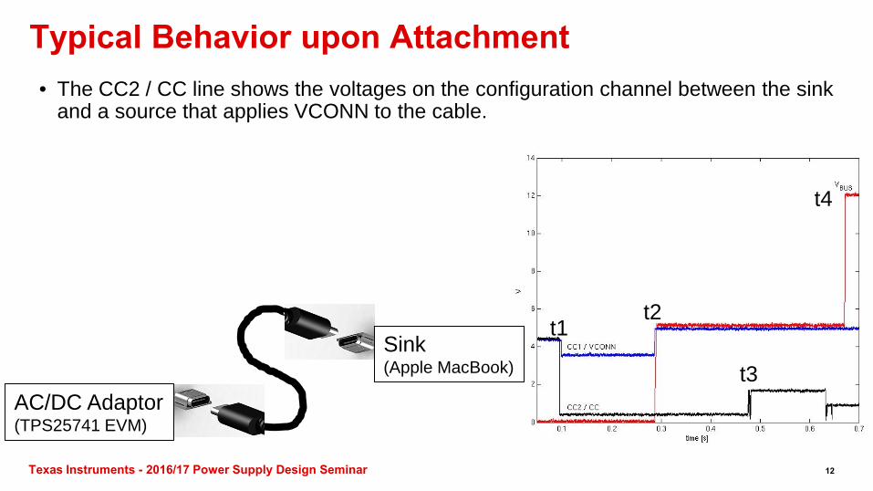
• The CC2 / CC line shows the voltages on the configuration channel between the sink and a source that applies VCONN to the cable.
• t1: the cable is attached. • t2: the source confirms a valid sink is attached,
then applies 5V to VBUS and VCONN. • t3: USB Type-C 3A advertisement begins &
USB PD messaging begins on CC line • t4: VBUS voltage is increased to negotiated level.
Typical Behavior upon Attachment
AC/DC Adaptor (TPS25741 EVM)
Sink (Apple MacBook)
t1 t2
t3
t4
12
Texas Instruments - 2016/17 Power Supply Design Seminar
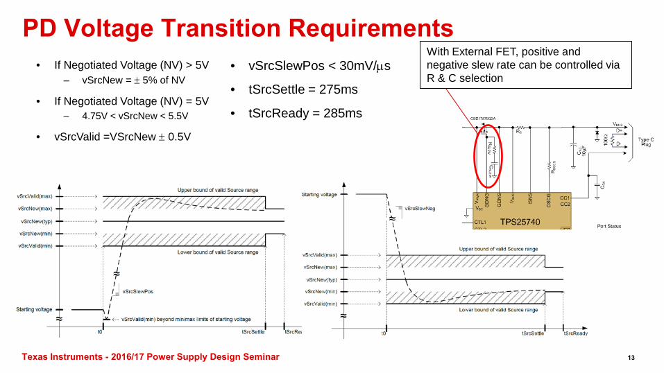
PD Voltage Transition Requirements • vSrcSlewPos < 30mV/µs
• tSrcSettle = 275ms
• tSrcReady = 285ms
• If Negotiated Voltage (NV) > 5V – vSrcNew = ± 5% of NV
• If Negotiated Voltage (NV) = 5V – 4.75V < vSrcNew < 5.5V
• vSrcValid =VSrcNew ± 0.5V
With External FET, positive and negative slew rate can be controlled via R & C selection
13
Texas Instruments - 2016/17 Power Supply Design Seminar
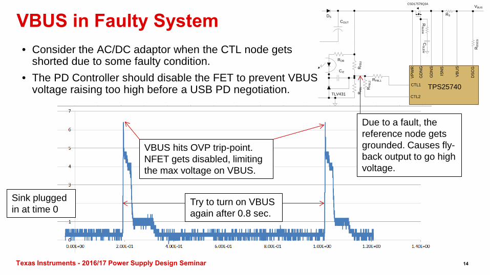
VBUS in Faulty System • Consider the AC/DC adaptor when the CTL node gets
shorted due to some faulty condition. • The PD Controller should disable the FET to prevent VBUS
voltage raising too high before a USB PD negotiation.
COUT
DS
RFBL1
RFB
UR
FBL
TLV431
ROB
CIZ
RFB
L2
RD
SC
G
TPS25740
DS
CG
GD
NG
GD
NS
CTL2
CTL1
VP
WR
CS
LEW
CSD17579Q3A
VB
US
ISN
S
RS
RS
LEW
VBUS
Due to a fault, the reference node gets grounded. Causes fly-back output to go high voltage.
VBUS hits OVP trip-point. NFET gets disabled, limiting the max voltage on VBUS.
Try to turn on VBUS again after 0.8 sec.
Sink plugged in at time 0
14
Texas Instruments - 2016/17 Power Supply Design Seminar
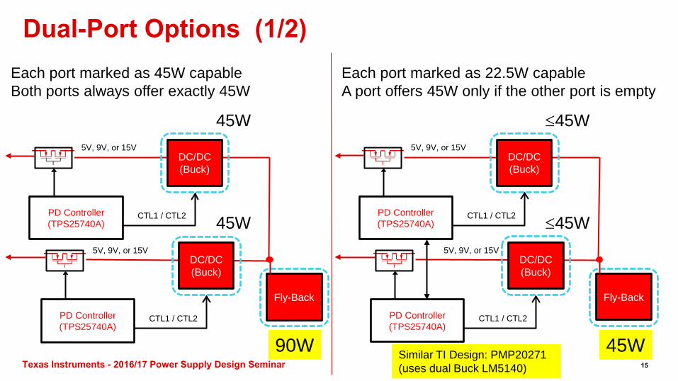
Dual-Port Options (1/2)
Fly-Back
5V, 9V, or 15V
CTL1 / CTL2
DC/DC (Buck)
90W
PD Controller (TPS25740A)
5V, 9V, or 15V
CTL1 / CTL2
DC/DC (Buck)
PD Controller (TPS25740A) 45W
45W
Each port marked as 45W capable Both ports always offer exactly 45W
Fly-Back
5V, 9V, or 15V
CTL1 / CTL2
DC/DC (Buck)
PD Controller (TPS25740A)
5V, 9V, or 15V
CTL1 / CTL2
DC/DC (Buck)
PD Controller (TPS25740A) ≤45W
≤45W
Each port marked as 22.5W capable A port offers 45W only if the other port is empty
45W 15
Similar TI Design: PMP20271 (uses dual Buck LM5140)
Texas Instruments - 2016/17 Power Supply Design Seminar
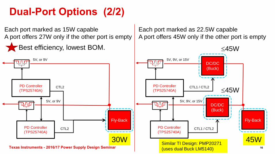
Dual-Port Options (2/2)
Fly-Back
CTL1 / CTL2
DC/DC (Buck)
PD Controller (TPS25740A)
5V, 9V, or 15V
CTL1 / CTL2
DC/DC (Buck)
PD Controller (TPS25740A) ≤45W
≤45W
Each port marked as 22.5W capable A port offers 45W only if the other port is empty
5V, 9V, or 15V
Fly-Back
5V, or 9V
CTL2 PD Controller (TPS25740A)
5V, or 9V
CTL2 PD Controller (TPS25740A)
Each port marked as 15W capable A port offers 27W only if the other port is empty
Best efficiency, lowest BOM.
30W 45W 16
Similar TI Design: PMP20271 (uses dual Buck LM5140)
Texas Instruments - 2016/17 Power Supply Design Seminar
Summary • USB Type-C is bringing major changes to the ubiquitous USB eco-system and has
created a realistic possibility for a universal charger for all consumer electronics.• USB Power Delivery is extending the applicability of USB into non-traditional
applications.• Even for the simplest USB Power Delivery application (charging) there are a number
of options and features that must be tuned per system requirements.
17
Texas Instruments - 2016/17 Power Supply Design Seminar
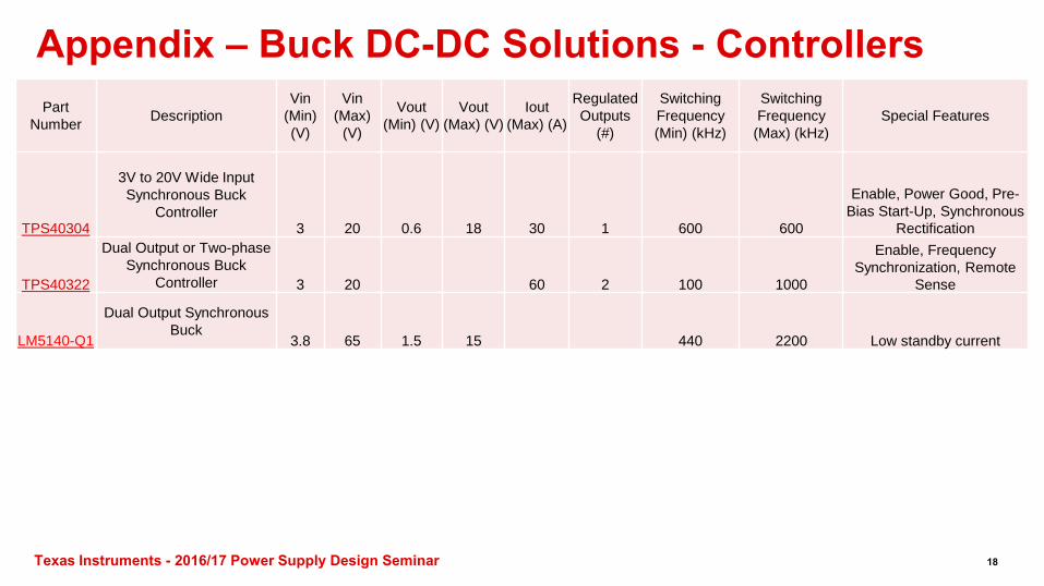
Appendix – Buck DC-DC Solutions - Controllers
18
Part Number Description
Vin (Min) (V)
Vin (Max)
(V)
Vout (Min) (V)
Vout (Max) (V)
Iout (Max) (A)
Regulated Outputs
(#)
Switching Frequency (Min) (kHz)
Switching Frequency (Max) (kHz)
Special Features
TPS40304
3V to 20V Wide Input Synchronous Buck
Controller 3 20 0.6 18 30 1 600 600
Enable, Power Good, Pre-Bias Start-Up, Synchronous
Rectification
TPS40322
Dual Output or Two-phase Synchronous Buck
Controller 3 20 60 2 100 1000
Enable, Frequency Synchronization, Remote
Sense
LM5140-Q1
Dual Output Synchronous Buck
3.8 65 1.5 15 440 2200 Low standby current
The platform bar and E2E are trademarks of Texas Instruments. All other trademarks are the property of their respective owners. SLUP360
TI Worldwide Technical Support
InternetTI Semiconductor Product Information Center Home Pagesupport.ti.comTI E2E™ Community Home Pagee2e.ti.com
Product Information CentersPhone +1(512) 434-1560
Phone
Americas Brazil Mexico Phone
0800-891-2616
0800-670-7544
Fax Internet/Email
+1(972) 927-6377support.ti.com/sc/pic/americas.htm
Europe, Middle East, and AfricaPhone
European Free Call 00800-ASK-TEXAS (00800 275 83927)
International +49 (0) 8161 80 2121
Russian Support +7 (4) 95 98 10 701
Note: The European Free Call (Toll Free) number is not active in all countries. If you have technical difficulty calling the free call number, please use the international number above.
Fax Internet Direct Email
+(49) (0) 8161 80 2045www.ti.com/[email protected]
JapanPhone Domestic 0120-92-3326Fax International
Domestic +81-3-3344-5317
0120-81-0036Internet/Email International
Domestic support.ti.com/sc/pic/japan.htm
www.tij.co.jp/pic
AsiaPhone
+91-80-41381665International Domestic Toll-Free Number
Note: Toll-free numbers do not support mobile and IP phones.
1-800-999-084Australia China Hong Kong India Indonesia Korea Malaysia New Zealand Philippines Singapore
Taiwan Thailand
800-820-8682 800-96-5941000-800-100-8888 001-803-8861-1006 080-551-28041-800-80-3973 0800-446-9341-800-765-7404 800-886-1028 0800-006800001-800-886-0010
International Fax Email Internet
[email protected] or [email protected] support.ti.com/sc/pic/asia.htm
B021014
Important Notice: The products and services of Texas Instruments Incorporated and its subsidiaries described herein are sold subject to TI’s standard terms and conditions of sale. Customers are advised to obtain the most current and complete information about TI products and services before placing orders. TI assumes no liability for applications assistance, customer’s applications or product designs, software performance, or infringement of patents. The publication of information regarding any other company’s products or services does not constitute TI’s approval, warranty or endorsement thereof.
IMPORTANT NOTICE
Texas Instruments Incorporated and its subsidiaries (TI) reserve the right to make corrections, enhancements, improvements and otherchanges to its semiconductor products and services per JESD46, latest issue, and to discontinue any product or service per JESD48, latestissue. Buyers should obtain the latest relevant information before placing orders and should verify that such information is current andcomplete. All semiconductor products (also referred to herein as “components”) are sold subject to TI’s terms and conditions of salesupplied at the time of order acknowledgment.TI warrants performance of its components to the specifications applicable at the time of sale, in accordance with the warranty in TI’s termsand conditions of sale of semiconductor products. Testing and other quality control techniques are used to the extent TI deems necessaryto support this warranty. Except where mandated by applicable law, testing of all parameters of each component is not necessarilyperformed.TI assumes no liability for applications assistance or the design of Buyers’ products. Buyers are responsible for their products andapplications using TI components. To minimize the risks associated with Buyers’ products and applications, Buyers should provideadequate design and operating safeguards.TI does not warrant or represent that any license, either express or implied, is granted under any patent right, copyright, mask work right, orother intellectual property right relating to any combination, machine, or process in which TI components or services are used. Informationpublished by TI regarding third-party products or services does not constitute a license to use such products or services or a warranty orendorsement thereof. Use of such information may require a license from a third party under the patents or other intellectual property of thethird party, or a license from TI under the patents or other intellectual property of TI.Reproduction of significant portions of TI information in TI data books or data sheets is permissible only if reproduction is without alterationand is accompanied by all associated warranties, conditions, limitations, and notices. TI is not responsible or liable for such altereddocumentation. Information of third parties may be subject to additional restrictions.Resale of TI components or services with statements different from or beyond the parameters stated by TI for that component or servicevoids all express and any implied warranties for the associated TI component or service and is an unfair and deceptive business practice.TI is not responsible or liable for any such statements.Buyer acknowledges and agrees that it is solely responsible for compliance with all legal, regulatory and safety-related requirementsconcerning its products, and any use of TI components in its applications, notwithstanding any applications-related information or supportthat may be provided by TI. Buyer represents and agrees that it has all the necessary expertise to create and implement safeguards whichanticipate dangerous consequences of failures, monitor failures and their consequences, lessen the likelihood of failures that might causeharm and take appropriate remedial actions. Buyer will fully indemnify TI and its representatives against any damages arising out of the useof any TI components in safety-critical applications.In some cases, TI components may be promoted specifically to facilitate safety-related applications. With such components, TI’s goal is tohelp enable customers to design and create their own end-product solutions that meet applicable functional safety standards andrequirements. Nonetheless, such components are subject to these terms.No TI components are authorized for use in FDA Class III (or similar life-critical medical equipment) unless authorized officers of the partieshave executed a special agreement specifically governing such use.Only those TI components which TI has specifically designated as military grade or “enhanced plastic” are designed and intended for use inmilitary/aerospace applications or environments. Buyer acknowledges and agrees that any military or aerospace use of TI componentswhich have not been so designated is solely at the Buyer's risk, and that Buyer is solely responsible for compliance with all legal andregulatory requirements in connection with such use.TI has specifically designated certain components as meeting ISO/TS16949 requirements, mainly for automotive use. In any case of use ofnon-designated products, TI will not be responsible for any failure to meet ISO/TS16949.
Products ApplicationsAudio www.ti.com/audio Automotive and Transportation www.ti.com/automotiveAmplifiers amplifier.ti.com Communications and Telecom www.ti.com/communicationsData Converters dataconverter.ti.com Computers and Peripherals www.ti.com/computersDLP® Products www.dlp.com Consumer Electronics www.ti.com/consumer-appsDSP dsp.ti.com Energy and Lighting www.ti.com/energyClocks and Timers www.ti.com/clocks Industrial www.ti.com/industrialInterface interface.ti.com Medical www.ti.com/medicalLogic logic.ti.com Security www.ti.com/securityPower Mgmt power.ti.com Space, Avionics and Defense www.ti.com/space-avionics-defenseMicrocontrollers microcontroller.ti.com Video and Imaging www.ti.com/videoRFID www.ti-rfid.comOMAP Applications Processors www.ti.com/omap TI E2E Community e2e.ti.comWireless Connectivity www.ti.com/wirelessconnectivity
Mailing Address: Texas Instruments, Post Office Box 655303, Dallas, Texas 75265Copyright © 2016, Texas Instruments Incorporated