Embed Size (px)
Citation preview

1772 ieee transactions on ultrasonics, ferroelectrics, and frequency control, vol. 54, no. 9, september 2007
A Computer-Controlled UltrasoundPulser-Receiver System for Transskull Fluid
Detection using a Shear WaveTransmission Technique
Sai Chun Tang, Member, IEEE, Gregory T. Clement, and Kullervo Hynynen
Abstract—The purpose of this study was to evaluate theperformance of a computer-controlled ultrasound pulser-receiver system incorporating a shear mode technique fortransskull fluid detection. The presence of fluid in the si-nuses of an ex vivo human skull was examined using a pulse-echo method by transmitting an ultrasound beam throughthe maxilla bone toward the back wall on the other sideof the sinus cavity. The pulser was programmed to gen-erate bipolar pulse trains with 5 cycles at a frequency of1 MHz, repetition frequency of about 20 Hz, and ampli-tude of 100 V to drive a 1-MHz piezoelectric transducer.Shear and longitudinal waves in the maxilla bone were pro-duced by adjusting the bone surface incident angle to 45
and 0, respectively. Computer tomography (CT) scans ofthe skull were performed to verify the ultrasound experi-ment. Using the shear mode technique, the echo waveformclearly distinguishes the presence of fluid, and the estimateddistance of the ultrasound traveled in the sinus is consis-tent with the measurement from the CT images. Contrar-ily, using the longitudinal mode, no detectable back wallecho was observed under the same conditions. As a con-clusion, this study demonstrated that the proposed pulser-receiver system with the shear mode technique is promisingfor transskull fluid detecting, such as mucus in a sinus.
I. Introduction
Sinusitis, or sinus infection, which can be caused bya number of conditions, is one of the most common
healthcare problems in the U.S., accounting for more than$5.8 billion in direct health care expenditures [1]–[4]. Acutebacterial infection occurs when bacteria colonize and over-grow in trapped fluid in the sinuses, [5]–[7] generally indi-cating the need for treatment with antibiotics. However,up to 98% of sinusitis cases are viral, and can generally betreated with over-the-counter medications. Despite this,primary care physicians prescribe antibiotics for 85 to 98%of patients suspected of having rhinosinusitis [3].
To differentiate between viral and bacterial infection,the presence of an air-fluid level in the maxillary sinus [8],[9], as assessed by puncture or imaging, provides a stan-dard for evaluating the diagnostic reliability of physical
Manuscript received October 31, 2006; accepted April 17, 2007.This research was supported by UltraDiagnostics, Inc. and researchgrant No. R21 EB004353 from the National Institutes of Health.
The authors are with the Department of Radiology, Brigham andWomen’s Hospital, Harvard Medical School, Boston, MA (e-mail:[email protected]).
Digital Object Identifier 10.1109/TUFFC.2007.461
symptoms. The absence of these findings is highly signif-icant for ruling out bacterial infection. Therefore, plainx-ray radiographs or computed tomography (CT) is usedto evaluate the presence of fluid. Unfortunately, the costand inconvenience of both approaches have been obstaclesto their routine use for diagnosis.
The potential for ultrasonic pulse-echo A-scan to detecttransskull fluid, such as mucus in a sinus, has been realizedfor more than three decades [10]–[15]. In ultrasound diag-nosis of sinusitis, a high-amplitude acoustic pulse is trans-mitted through the maxilla bone toward the back wall ofthe sinus cavity on the other side of the bone. The air ina normal sinus prevents the ultrasound propagation; onlyone echo from the front wall of the sinus is produced. Onthe other hand, if the sinus is infected, the sinus will befilled with fluid that conducts the ultrasound, and a secondecho from the back wall will be generated [16].
Unfortunately, significant variability in the method re-sults from strong ultrasound scattering and attenuationcaused by the skull. In previous ultrasonic sinus fluid de-tection studies [17], [18], the ultrasound transducer wasplaced parallel to the maxilla bone, and the incident anglewas approximately zero degree. The problem of using sucha configuration is twofold. First, the ultrasound propaga-tion inside the bone is primarily in longitudinal mode [19],[20]. The speed (∼2820 ms−1) of longitudinal sound prop-agation inside skull bone is almost twice that of the soundspeed in soft tissues and water (∼1500 ms−1). The largediscrepancy in sound speed causes significant impedancemismatch; most of the ultrasound energy is reflected at theboundary between the media. As a result, the ultrasoundenergy transmitted through the bone is greatly reduced.In practice, a very high-amplitude acoustic pulse from thetransducer is required to compensate for the reflection loss.Second, as the transducer is oriented parallel to the bone,multiple reflections between the bone and the transducermay occur. These multiple echoes deteriorate the signal-to-noise ratio (SNR) of the desired back wall echo signal,and therefore decrease the accuracy of the detection.
Yet, a reliable ultrasound method would have clear ad-vantages over existing standard methods for sinusitis di-agnosis, such as sinus puncture and x-ray CT. Ultrasoundrepresents a very compact, low-cost method that is non-invasive and does not involve ionizing radiation [17], [21].It is envisaged that a portable, single-channel ultrasound
0885–3010/$25.00 c© 2007 IEEE
tang et al.: ultrasound pulser-receiver system for transkull fluid detection 1773
modality would provide a convenient and cost-effectiveclinical procedure for sinusitis diagnosis, and follow-up oftreatment results.
The present work examines an improved method forpropagating into the sinuses using a shear mode conver-sion. Recently, it was demonstrated that the use of shearwave propagation, instead of the longitudinal mode, in-side the skull bone can improve ultrasound transmissionsubstantially [19], [20]. The shear wave in skull bone canbe produced by adjusting the incident angle greater thanthe longitudinal critical angle. Unlike that of the longitu-dinal mode, the sound speed of shear wave (∼1400 ms−1)in skull bone is close to that of soft tissues. The simi-larity in speed of sound improves the acoustic impedancematching considerably, and thus increases the transmittedultrasound energy through the bone. The enhanced ultra-sound transmission reduces the required acoustic pressureand also the energy consumption of the pulser system. Fur-thermore, when the shear mode method is used, the trans-ducer is oriented at an angle (> 30) with respect to themaxilla bone; the multiple-reflection issue is naturally re-lieved as a significant portion of the echo from the maxillabone reflects away from the transducer.
In this study, we developed a compact and economi-cal computer-controlled pulser-receiver system and demon-strated the operation of the system incorporating a shearmode technique derived in our prior studies [19], [20]. Thepurpose of this study was to investigate the performance ofthe system using the shear mode method and to compareit with its traditional counterpart, longitudinal mode, fortranscranial fluid detection using an ex vivo human skull.
II. Pulser-Receiver System Design
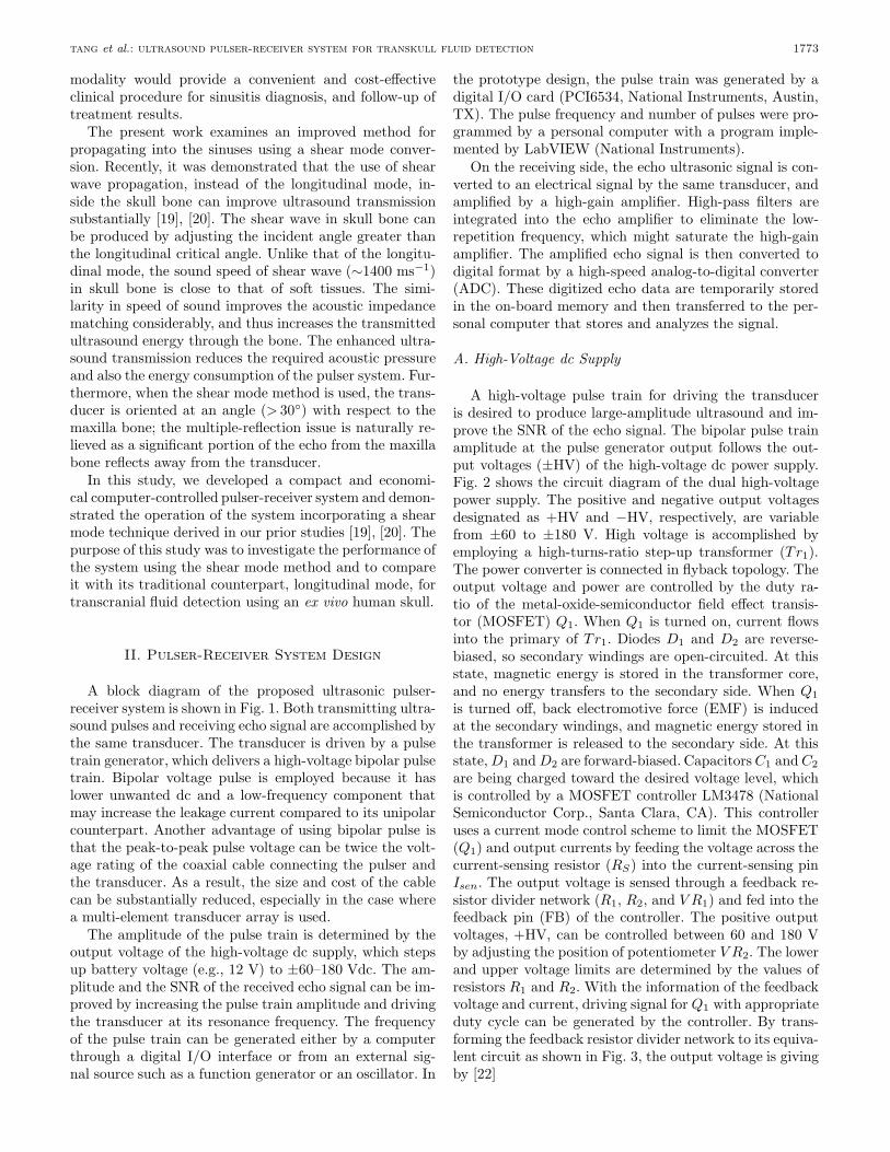
A block diagram of the proposed ultrasonic pulser-receiver system is shown in Fig. 1. Both transmitting ultra-sound pulses and receiving echo signal are accomplished bythe same transducer. The transducer is driven by a pulsetrain generator, which delivers a high-voltage bipolar pulsetrain. Bipolar voltage pulse is employed because it haslower unwanted dc and a low-frequency component thatmay increase the leakage current compared to its unipolarcounterpart. Another advantage of using bipolar pulse isthat the peak-to-peak pulse voltage can be twice the volt-age rating of the coaxial cable connecting the pulser andthe transducer. As a result, the size and cost of the cablecan be substantially reduced, especially in the case wherea multi-element transducer array is used.
The amplitude of the pulse train is determined by theoutput voltage of the high-voltage dc supply, which stepsup battery voltage (e.g., 12 V) to ±60–180 Vdc. The am-plitude and the SNR of the received echo signal can be im-proved by increasing the pulse train amplitude and drivingthe transducer at its resonance frequency. The frequencyof the pulse train can be generated either by a computerthrough a digital I/O interface or from an external sig-nal source such as a function generator or an oscillator. In
the prototype design, the pulse train was generated by adigital I/O card (PCI6534, National Instruments, Austin,TX). The pulse frequency and number of pulses were pro-grammed by a personal computer with a program imple-mented by LabVIEW (National Instruments).
On the receiving side, the echo ultrasonic signal is con-verted to an electrical signal by the same transducer, andamplified by a high-gain amplifier. High-pass filters areintegrated into the echo amplifier to eliminate the low-repetition frequency, which might saturate the high-gainamplifier. The amplified echo signal is then converted todigital format by a high-speed analog-to-digital converter(ADC). These digitized echo data are temporarily storedin the on-board memory and then transferred to the per-sonal computer that stores and analyzes the signal.
A. High-Voltage dc Supply
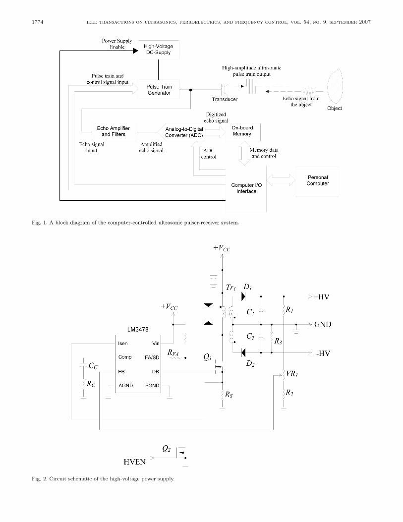
A high-voltage pulse train for driving the transduceris desired to produce large-amplitude ultrasound and im-prove the SNR of the echo signal. The bipolar pulse trainamplitude at the pulse generator output follows the out-put voltages (±HV) of the high-voltage dc power supply.Fig. 2 shows the circuit diagram of the dual high-voltagepower supply. The positive and negative output voltagesdesignated as +HV and −HV, respectively, are variablefrom ±60 to ±180 V. High voltage is accomplished byemploying a high-turns-ratio step-up transformer (Tr1).The power converter is connected in flyback topology. Theoutput voltage and power are controlled by the duty ra-tio of the metal-oxide-semiconductor field effect transis-tor (MOSFET) Q1. When Q1 is turned on, current flowsinto the primary of Tr1. Diodes D1 and D2 are reverse-biased, so secondary windings are open-circuited. At thisstate, magnetic energy is stored in the transformer core,and no energy transfers to the secondary side. When Q1is turned off, back electromotive force (EMF) is inducedat the secondary windings, and magnetic energy stored inthe transformer is released to the secondary side. At thisstate, D1 and D2 are forward-biased. Capacitors C1 and C2are being charged toward the desired voltage level, whichis controlled by a MOSFET controller LM3478 (NationalSemiconductor Corp., Santa Clara, CA). This controlleruses a current mode control scheme to limit the MOSFET(Q1) and output currents by feeding the voltage across thecurrent-sensing resistor (RS) into the current-sensing pinIsen. The output voltage is sensed through a feedback re-sistor divider network (R1, R2, and V R1) and fed into thefeedback pin (FB) of the controller. The positive outputvoltages, +HV, can be controlled between 60 and 180 Vby adjusting the position of potentiometer V R2. The lowerand upper voltage limits are determined by the values ofresistors R1 and R2. With the information of the feedbackvoltage and current, driving signal for Q1 with appropriateduty cycle can be generated by the controller. By trans-forming the feedback resistor divider network to its equiva-lent circuit as shown in Fig. 3, the output voltage is givingby [22]
1774 ieee transactions on ultrasonics, ferroelectrics, and frequency control, vol. 54, no. 9, september 2007
Fig. 1. A block diagram of the computer-controlled ultrasonic pulser-receiver system.
Fig. 2. Circuit schematic of the high-voltage power supply.

tang et al.: ultrasound pulser-receiver system for transkull fluid detection 1775
Fig. 3. Equivalent feedback resistor divider network for the high-voltage power supply.
+HV = 1.26(
1 +RA
RB
).
Because the pulse generator loads the positive and neg-ative outputs symmetrically, the negative voltage ampli-tude follows the positive voltage level, and therefore bothvoltages can be regulated using the same controller. Theresistor, R3, connected to the negative output terminalsis used to discharge the high voltage across C2 when thecircuit is turned off for the sake of safety. It also balancesthe load at the positive and negative outputs in order tokeep the dual voltage amplitude symmetric.
The high-voltage dc supply operates as a switchingmode power converter that could be a significant sourceof electromagnetic interference (EMI) to the very sensitivehigh-gain echo amplifier. For this reason, the high-voltagepower supply is shut down temporarily at the period be-tween sending the pulse train and waiting for the echo sig-nal by applying a logic low-level signal to the high-voltage-enable (HVEN) input. During this period, the output ca-pacitors C1 and C2 supply energy to the pulse generator.In the circuit prototype, ripple voltage of less than 0.1%of the output voltage was measured when both C1 and C2are 1 µF and the idle time is 100 µs.
B. Pulse Generator
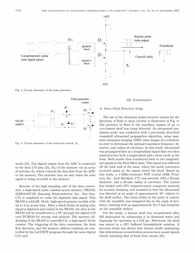
Similar to that of the high-voltage supply, the designof the pulse train generator was configured to operate atswitching mode so as to minimize the power consumptionand heat dissipation. Without the requirement of cool-ing, the cost, size, and weight of the pulse train generatorare significantly reduced. Moreover, reliability and accu-racy can be considerably improved as there is no excessiveheat generated from the circuit. The driving circuit for thetransducer, as shown in Fig. 4, is made of a half-bridgeswitching converter. The dual voltage supply ±HV deter-mines the amplitude of the bipolar pulse train, which isgenerated by switching on and off the N -channel powerMOSFETs Q3 and Q4 complementarily. In the positivehalf-cycle, Q3 is on and Q4 is off, and the generator out-put voltage is equal to +HV. On the contrary, during the
negative half-cycle, Q3 is off and Q4 is on, and the outputvoltage becomes −HV.
In the design of a practical pulse generator, parasiticcapacitors associated with the MOSFETs and the coaxialcable connecting to the transducer have to be considered.These capacitors keep the pulse generator output at highvoltage for a long period that could saturate the high-gainecho amplifier and also increase the leakage current thatmay create safety issues. Thus, at the end of each pulsetrain, discharging the parasitic capacitors to zero poten-tial is essential. The purpose of solid-state switch S1 is todischarge the parasitic capacitors when both Q3 and Q4are in the off state. Fig. 5 illustrates the solid-state switchthat discharges the parasitic capacitor, via MOSFETs Q5and Q6. The operating principle of this solid-state switchis detailed in [23].
The gating signals for Q3, Q4, and S1 are generated bythe computer I/O interface with software control, althoughwe have verified they can be achieved by standalone digitalcircuitry. Because the source terminals of both Q3 andQ4 are not connected to the ground, isolated gate drivecircuits for the MOSFETs are required. In this prototype,isolation is achieved by using a signal transformer Tr2 withtwo secondary windings and turns ratio of 10:15:15.
C. Echo Amplifier
In practical situations, the received echo signal intensitycan be less than 1% of that sent out from the transducer.A high-gain amplifier is required to amplify the echo sig-nal received from the transducer. The echo amplifier beingused consists of four stages of low-noise operational ampli-fiers, OA1 to OA4, as shown in Fig. 6. Each stage providesa voltage gain of 10 times, and 104 times in total. Twofirst-order high-pass filters (HPFs) are integrated into theamplifier circuit to eliminate the low-repetition frequency,which may cause the amplifier to become saturated. Thecoarse and fine gain adjustments of the amplifier are ac-complished by potentiometers V R2 and V R3, respectively.Because the echo amplifier input is connected directly tothe pulse generator output that delivers the high-voltagepulse train, a protection scheme is necessary to preventthe echo amplifier from being damaging by the high volt-age. At the echo amplifier input, the non-inverting inputof OA1 is limited to less than one volt by using two in-expensive small signal diodes (D4 and D5) in anti-parallelconnection.
D. Analog-to-Digital Converter and Memory
The amplified echo signal is converted to digital formatby a high-speed analog-to-digital converter (AD9215, Ana-log Devices, Inc., Norwood, MA) as shown in Fig. 7. Thesampling frequency of data conversion is set to 66.67 Mega-samples per second (MSPS). In order to achieve optimumsignal conversion performance, the single-ended amplifiedecho signal is converted to differential format by a signaltransformer Tr4, and filtered by a pair of RC low-pass net-
1776 ieee transactions on ultrasonics, ferroelectrics, and frequency control, vol. 54, no. 9, september 2007
Fig. 4. Circuit schematic of the pulse generator.
Fig. 5. Circuit schematic of the solid-state switch, S1.
works [24]. The digital output from the ADC is connectedto the data I/O pins (D0–D9) of the memory via an arrayof switches S2, which controls the data flow from the ADCto the memory. The switches turn on only when the echosignal is being recorded to the memory.
Because of the high sampling rate of the data conver-sion, a high-speed static random-access memory (SRAM)(K6R1016V1D, Samsung Semiconductor, Inc., San Jose,CA) is employed to cache the digitized echo signal. ThisSRAM is a 64-kB, 16-bit, high-speed memory module withup to 8 ns access time. After a whole frame of analog echosignal is digitized and cached in the SRAM, the data in theSRAM will be transferred to a PC through the digital I/Ocard PCI6534 for storage and analysis. The memory ad-dressing of the SRAM is controlled by a high-speed 16-bitcounter. The triggering of the data conversion, the dataflow direction, and the memory address counting are con-trolled by the LabVIEW program through the same digitalI/O card.
III. Experiment
A. Sinus Fluid Detection Setup
The use of the ultrasonic pulser-receiver system for thedetection of fluid in sinus cavities is illustrated in Fig. 8.The presence of fluid in the maxillary sinuses of an exvivo human skull was being detected. An ultrasound sim-ulation study was conducted with a previously describedtransskull ultrasound propagation algorithm, using mag-netic resonance imaging (MRI) sinus images of a volunteerin order to determine the optimal transducer frequency, di-ameter, and radius of curvature. In this study, ultrasoundwas propagated first as a longitudinal signal that was thenseparated into both a longitudinal and a shear mode in thebone. Both modes then transferred back to two longitudi-nal signals in the fluid-filled sinus. This signal was reflectedoff the back wall of the sinus, where the mode conversionoccurred again as the signal exited the head. Based onthis study, a 1-MHz-resonance PZT crystal (EBL Prod-ucts, Inc., East Hartford, CT) was selected, with a 20-mmdiameter, and a 40-mm radius of curvature. The crystalwas backed with 25% tungsten-epoxy composite materialfor acoustic damping, and mounted so that the ultrasoundwas directed at an angle of approximately 45 relative tothe skull surface. The beam width at the point of contactwith the mandible was elongated due to the angle of inci-dence, entering with an approximately 10×7 mm footprinton the mandible surface.
For the study, a human skull was reconstituted afterfull desiccation by submersing it in deionized water anddegassing the specimen in a bell jar. Afterward, the skullwas stored in a 10% buffered formaldehyde solution. Aprevious study has shown that human skulls undergoingthis dehydration-reconstitution process have sound speedsclosely matching that of fresh bone tissues [25].

tang et al.: ultrasound pulser-receiver system for transkull fluid detection 1777
Fig. 6. Circuit schematic of the echo amplifier.b
Fig. 7. Circuit schematic of the analog-to-digital converter and memory.
The transducer and human skull were immersed in de-gassed deionized water in a tank filled with padded rubberto reduce reflections from the tank walls. The detections offluid in both left and right maxilla sinus cavities were per-formed. For the experiments of sinus fluid detection, thesinus cavity was first completely filled with water. Con-trol experiments were conducted by inserting a tube intothe sinus cavity and injecting air by means of a syringeattached to the other end of the tube. The skull was ori-ented with the face horizontal in order to trap the air inthe sinus for the control experiments.
The effects of shear and longitudinal propagationthrough the maxilla bone were examined by orienting thetransducer at different angles, as shown in Fig. 9. For themeasurement of the echo signal with shear mode propa-gation through the maxilla bone, the incident angle wasadjusted to approximately 45, which is greater than thelongitudinal critical angle of about 30 [19]. It is notedthat both the transmitted and received waves were longi-tudinal. The propagation involved a mode conversion fromlongitudinal in the skin into a shear wave in the bone, andthen back into longitudinal in the sinus fluid, if present. If

1778 ieee transactions on ultrasonics, ferroelectrics, and frequency control, vol. 54, no. 9, september 2007
Fig. 8. Experimental setup for detecting the presence of fluid in the maxillary sinuses.
Fig. 9. Orientations of the transducer for the echo measurements with (a) shear and (b) longitudinal propagations. Sagittal view of themaxilla bone is shown; the skull was upside down.
the cavity was fluid-filled, the reverse process took placewhere echoes off of the back of the sinus cavity were againconverted to shear waves in the bone and then back tolongitudinal before reaching the transducer. For the echomeasurement associated with longitudinal propagation inbone, the transducer is positioned approximately parallelto the maxilla bone, so that the incident angle (∼0) issmaller than the longitudinal critical angle.
B. Pulser-Receiver System
The computer-controlled ultrasonic pulser-receiver sys-tem described in the previous section was constructed in-house. The pulser-receiver system was used to transmita high-voltage pulse train to and receive echo signal fromthe same transducer. The transducer was connected to thepulser-receiver through a Belden 8216 RG174U 50Ω coax-ial cable of length about 1 m. A bipolar pulse train withamplitude regulated at ±100 V was adopted to excite thetransducer. The pulse train frequency of 1 MHz and five
pulse cycles in each pulse train were set through a soft-ware interface, implemented in LabVIEW code, as shownin Fig. 10. At the end of each pulse train, the pulser outputwas shorted to ground for 10 µs to discharge the undesiredstray capacitor formed by the pulser output MOSFETs,the coaxial cable, and the transducer.
Both pulse train transmission and echo receiving werecontrolled using the same software interface. The voltageacross the transducer terminals was sensed, recorded, andtransmitted to the computer in real time. Data record-ing started when the pulse train was transmitted, and therecord duration was set to 100 µs. The sensed transducervoltage was converted to 10-bit digital offset binary for-mat, buffered in a static RAM, and then transmitted toa PC at a rate of 20 Mbytes/s. Signal processing for thereceived transducer voltage was handled by a sixth-ordersoftware Butterworth low-pass-filter implemented in Lab-VIEW code in order to filter out high- frequency noise.The cut-off frequency was set to 3.4 MHz. The repetitionfrequency of the pulse train and data conversion/recording
tang et al.: ultrasound pulser-receiver system for transkull fluid detection 1779
Fig. 10. Software front panel for the pulser-receiver system.
cycle was approximately 20 Hz. Real-time transducer volt-age waveform was displayed on the software interface forthe measurements of time-of-fight, and hence the distancebetween the objects that the ultrasound beam traveled.The echo waveforms for the experiments were saved in thecomputer hard disk for further analysis.
C. Sinus Imaging
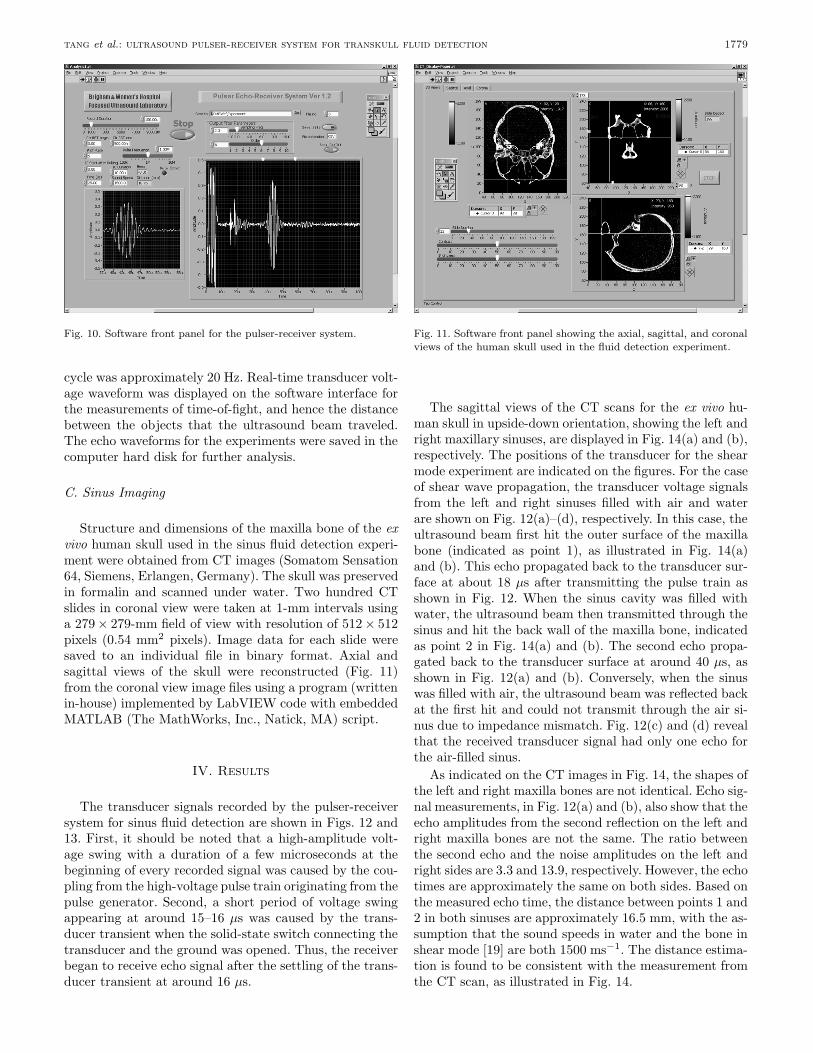
Structure and dimensions of the maxilla bone of the exvivo human skull used in the sinus fluid detection experi-ment were obtained from CT images (Somatom Sensation64, Siemens, Erlangen, Germany). The skull was preservedin formalin and scanned under water. Two hundred CTslides in coronal view were taken at 1-mm intervals usinga 279 × 279-mm field of view with resolution of 512 × 512pixels (0.54 mm2 pixels). Image data for each slide weresaved to an individual file in binary format. Axial andsagittal views of the skull were reconstructed (Fig. 11)from the coronal view image files using a program (writtenin-house) implemented by LabVIEW code with embeddedMATLAB (The MathWorks, Inc., Natick, MA) script.
IV. Results
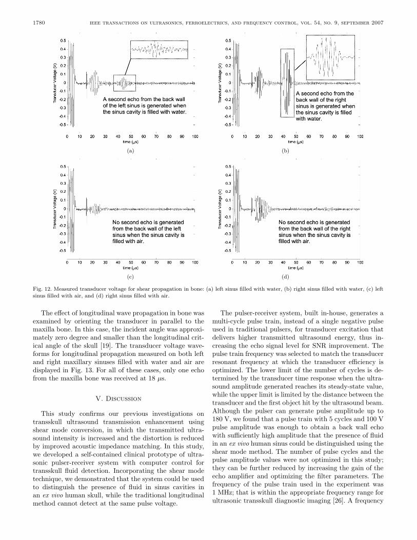
The transducer signals recorded by the pulser-receiversystem for sinus fluid detection are shown in Figs. 12 and13. First, it should be noted that a high-amplitude volt-age swing with a duration of a few microseconds at thebeginning of every recorded signal was caused by the cou-pling from the high-voltage pulse train originating from thepulse generator. Second, a short period of voltage swingappearing at around 15–16 µs was caused by the trans-ducer transient when the solid-state switch connecting thetransducer and the ground was opened. Thus, the receiverbegan to receive echo signal after the settling of the trans-ducer transient at around 16 µs.
Fig. 11. Software front panel showing the axial, sagittal, and coronalviews of the human skull used in the fluid detection experiment.
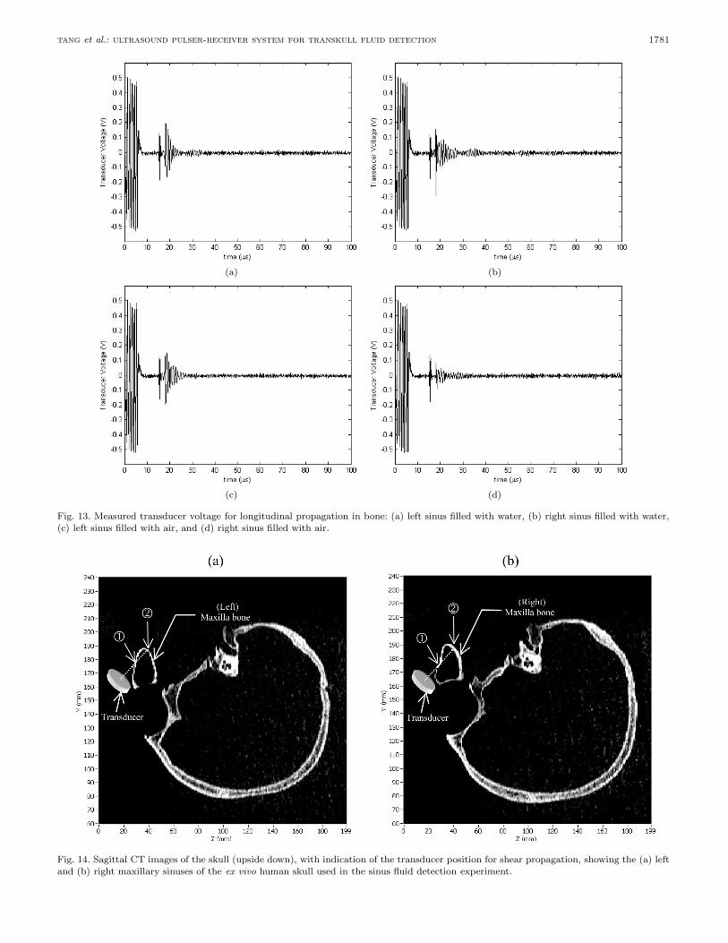
The sagittal views of the CT scans for the ex vivo hu-man skull in upside-down orientation, showing the left andright maxillary sinuses, are displayed in Fig. 14(a) and (b),respectively. The positions of the transducer for the shearmode experiment are indicated on the figures. For the caseof shear wave propagation, the transducer voltage signalsfrom the left and right sinuses filled with air and waterare shown on Fig. 12(a)–(d), respectively. In this case, theultrasound beam first hit the outer surface of the maxillabone (indicated as point 1), as illustrated in Fig. 14(a)and (b). This echo propagated back to the transducer sur-face at about 18 µs after transmitting the pulse train asshown in Fig. 12. When the sinus cavity was filled withwater, the ultrasound beam then transmitted through thesinus and hit the back wall of the maxilla bone, indicatedas point 2 in Fig. 14(a) and (b). The second echo propa-gated back to the transducer surface at around 40 µs, asshown in Fig. 12(a) and (b). Conversely, when the sinuswas filled with air, the ultrasound beam was reflected backat the first hit and could not transmit through the air si-nus due to impedance mismatch. Fig. 12(c) and (d) revealthat the received transducer signal had only one echo forthe air-filled sinus.
As indicated on the CT images in Fig. 14, the shapes ofthe left and right maxilla bones are not identical. Echo sig-nal measurements, in Fig. 12(a) and (b), also show that theecho amplitudes from the second reflection on the left andright maxilla bones are not the same. The ratio betweenthe second echo and the noise amplitudes on the left andright sides are 3.3 and 13.9, respectively. However, the echotimes are approximately the same on both sides. Based onthe measured echo time, the distance between points 1 and2 in both sinuses are approximately 16.5 mm, with the as-sumption that the sound speeds in water and the bone inshear mode [19] are both 1500 ms−1. The distance estima-tion is found to be consistent with the measurement fromthe CT scan, as illustrated in Fig. 14.
1780 ieee transactions on ultrasonics, ferroelectrics, and frequency control, vol. 54, no. 9, september 2007
(a) (b)
(c) (d)
Fig. 12. Measured transducer voltage for shear propagation in bone: (a) left sinus filled with water, (b) right sinus filled with water, (c) leftsinus filled with air, and (d) right sinus filled with air.
The effect of longitudinal wave propagation in bone wasexamined by orienting the transducer in parallel to themaxilla bone. In this case, the incident angle was approxi-mately zero degree and smaller than the longitudinal crit-ical angle of the skull [19]. The transducer voltage wave-forms for longitudinal propagation measured on both leftand right maxillary sinuses filled with water and air aredisplayed in Fig. 13. For all of these cases, only one echofrom the maxilla bone was received at 18 µs.
V. Discussion
This study confirms our previous investigations ontransskull ultrasound transmission enhancement usingshear mode conversion, in which the transmitted ultra-sound intensity is increased and the distortion is reducedby improved acoustic impedance matching. In this study,we developed a self-contained clinical prototype of ultra-sonic pulser-receiver system with computer control fortransskull fluid detection. Incorporating the shear modetechnique, we demonstrated that the system could be usedto distinguish the presence of fluid in sinus cavities inan ex vivo human skull, while the traditional longitudinalmethod cannot detect at the same pulse voltage.
The pulser-receiver system, built in-house, generates amulti-cycle pulse train, instead of a single negative pulseused in traditional pulsers, for transducer excitation thatdelivers higher transmitted ultrasound energy, thus in-creasing the echo signal level for SNR improvement. Thepulse train frequency was selected to match the transducerresonant frequency at which the transducer efficiency isoptimized. The lower limit of the number of cycles is de-termined by the transducer time response when the ultra-sound amplitude generated reaches its steady-state value,while the upper limit is limited by the distance between thetransducer and the first object hit by the ultrasound beam.Although the pulser can generate pulse amplitude up to180 V, we found that a pulse train with 5 cycles and 100 Vpulse amplitude was enough to obtain a back wall echowith sufficiently high amplitude that the presence of fluidin an ex vivo human sinus could be distinguished using theshear mode method. The number of pulse cycles and thepulse amplitude values were not optimized in this study;they can be further reduced by increasing the gain of theecho amplifier and optimizing the filter parameters. Thefrequency of the pulse train used in the experiment was1 MHz; that is within the appropriate frequency range forultrasonic transskull diagnostic imaging [26]. A frequency
tang et al.: ultrasound pulser-receiver system for transkull fluid detection 1781
(a) (b)
(c) (d)
Fig. 13. Measured transducer voltage for longitudinal propagation in bone: (a) left sinus filled with water, (b) right sinus filled with water,(c) left sinus filled with air, and (d) right sinus filled with air.
Fig. 14. Sagittal CT images of the skull (upside down), with indication of the transducer position for shear propagation, showing the (a) leftand (b) right maxillary sinuses of the ex vivo human skull used in the sinus fluid detection experiment.

1782 ieee transactions on ultrasonics, ferroelectrics, and frequency control, vol. 54, no. 9, september 2007
lower than 1 MHz can be used to reduce the attenuationin bone at the expense of lower spatial resolution. In thisstudy, the echo signal was digitized by a high samplingrate (66.67 MSPS) and high resolution (10-bit) ADC andstored in spreadsheet format for clinician’s analysis.
In the pulser-receiver system design, both the highvoltage power supply and the pulse generator operate inswitching mode, which generally results in higher energyefficiency, smaller size, and lighter weight, compared tothose parameters for linear mode circuits. The issues dueto the parasitic capacitor at the pulser output, the trans-ducer, and the coaxial cable connected between them wereconsidered. For reasons of safety, a solid-state switch wasused to discharge the high potential across the capaci-tor after sending pulses. The pulser-receiver system doesnot generate high temperature; it does not require coolingmeans, such as heat sink and cooling fan, and works stablythroughout our experiments.
From the experimental results of fluid detection usingthe shear mode technique, the right sinus gave a higherback wall echo amplitude than the left, though the systemparameters, including pulse amplitude and gain of the echoamplifier, were the same. This result was expected and canbe explained by the CT images that the left and right si-nuses are not symmetric. The area of the right sinus backwall hit by the ultrasound beam and parallel to the trans-ducer surface is larger than the left. Thus, the amount ofultrasound energy reflected back to the transducer fromthe right back wall is higher than that from the left, atwhich a significant portion of ultrasound reflects away fromthe transducer; however, in reality the ultrasound trans-mission is more complicated than the beam illustrated inthe principle diagram in Fig. 9, due to refraction, geome-try, and dispersion of the ultrasonic beam, as well as scat-tered reflection from curved surfaces. In these experiments,the transducer angles for the left and right measurementswere approximately the same. The amount of ultrasoundenergy received by the transducer can be increased by us-ing a transducer with a larger area or adjusting the trans-ducer position and angle so that maximum echo amplitudeis measured. Experimental results also confirm that onlyone echo occurs when the sinus is filled in air in the casesof both shear mode and longitudinal mode propagation.
Our comparison results reveal that ultrasound transmis-sion through the skull bone with shear mode conversionfor sinus fluid detection is more efficient than the longi-tudinal mode in which no detectable back wall echo wasobserved. Although the attenuation coefficient of a shearwave is higher than that of a longitudinal wave [19], [20],from the CT scan, the sinus bone is very thin (∼1 mm);so the reflection loss in this application is more significantthan the loss due to attenuation. Using the shear modetechnique, the back wall echo waveform clearly shows theback wall echo time, and thus the approximate distance be-tween the transducer and the back wall and that betweenthe front and back sinus walls are 30 mm and 16.5 mm, re-spectively, assuming the speed of sound in water and shearwave speed in bone are 1500 ms−1. These results are con-
sistent with the measurements from the CT images andwere expected because the shear wave encounters reducedrefraction and temporal distortion due to the similaritybetween the speed of shear wave in bone and the speed ofsound in water.
VI. Conclusion
A computer-controlled ultrasound pulser-receiver sys-tem incorporating a shear mode technique was proposedand successfully demonstrated for transskull fluid detec-tion. The presence of fluid in sinuses of an ex vivo humanwas clearly distinguished using shear wave propagation inskull bone, but the longitudinal method failed to detectwith the same pulser parameters.
Acknowledgment
The authors would like to thank Jason White for hisassistance in acquiring CT images of the human skull.
References
[1] M. Desrosiers, J. M. Klossek, and M. Benninger, “Managementof acute bacterial rhinosinusitis: Current issues and future per-spectives,” Int. J. Clin. Pract., vol. 60, pp. 190–200, Feb. 2006.
[2] R. Gonzales, J. G. Bartlett, R. E. Besser, R. J. Cooper,J. M. Hickner, J. R. Hoffman, and M. A. Sande, “Principlesof appropriate antibiotic use for treatment of acute respiratorytract infections in adults: Background, specific aims, and meth-ods,” Ann. Intern. Med., vol. 134, pp. 479–486, Mar. 2001.
[3] J. B. Anon, M. R. Jacobs, M. D. Poole, P. G. Ambrose, M. S.Benninger, J. A. Hadley, W. A. Craig, and Sinus and Al-lergy Health Partnership, “Antimicrobial treatment guidelinesfor acute rhino sinusitis,” Otolaryngol. Head Neck Surg., vol.130, (suppl. 1), pp. 1–45, June 2004.
[4] W. Winstead, “Rhinosinusitis,” Primary Care; Clinics in OfficePractice, vol. 30, pp. 137–154, 2003.
[5] J. Garau and R. Dagan, “Accurate diagnosis and appropriatetreatment of acute bacterial rhinosinusitis: Minimizing bacterialresistance,” Clin. Therapeut., vol. 25, pp. 1936–1951, July 2003.
[6] Sinus and Allergy Health Partnership, “Antimicrobial treatmentguidelines for acute rhinosinusitis,” Otolaryngol. Head NeckSurg., vol. 123, pp. 1–4, July 2000.
[7] R. D. Herr and S. M. Joyce, “Upper respiratory tract infec-tions,” in Infectious Disease in Emergency Medicine. 2nd ed.J. C. Brillman and R. W. Quenzer, Eds. Philadelphia, PA:Lippincott-Raven, 1997.
[8] F. R. Melio, “Upper respiratory tract infections: Sinusitis,” inRosen’s Emergency Medicine Concepts and Clinical Practice.5th ed. vol. 2, J. A. Marx, Ed. St. Louis, MO: Mosby, 2002, ch.70, pp. 981–985.
[9] D. E. Low, M. Desrosiers, J. McSherry, G. Garber, J. W.Williams, Jr., H. Remy, R. S. Fenton, V. Forte, M. Balter, C.Rotstein, C. Craft, J. Dubois, G. Harding, M. Schloss, M. Miller,R. A. McIvor, and R. J. Davidson, “A practical guide for the di-agnosis and treatment of acute sinusitis,” Can. Med. Assoc. J.,vol. 156, (suppl. 6), pp. 1–14, 1997.
[10] W. Mann, C. Beck, and T. Apostolidis, “Liability of ultrasoundin maxillary sinus disease,” Eur. Arch. Oto-Rhino-Laryngol.,vol. 215, pp. 67–74, Mar. 1977.
[11] M. Jannert, L. Adreasson, and N. Holmer, “Diagnostic ul-trasonography of paranasal sinuses,” in Proc. IEEE Ultrason.Symp., 1982, pp. 727–728.
[12] H. Varonen, M. Makela, S. Savolainen, E. Laara, and J. Hilden,“Comparison of ultrasound, radiography, and clinical examina-tion in the diagnosis of acute maxillary sinusitis: A systematicreview,” J. Clin. Epidemiol., vol. 53, pp. 940–948, 2000.
tang et al.: ultrasound pulser-receiver system for transkull fluid detection 1783
[13] T. Puhakka, T. Heikkinen, M. J. Makela, A. Alanen, T. Kallio,L. Korsoff, J. Suonpaa, and O. Ruuskanen, “Validity of ultra-sonography in diagnosis of acute maxillary sinusitis,” Arch. Oto-laryngol. Head Neck Surg., vol. 126, pp. 1482–1486, Dec. 2000.
[14] M. Lindbæk and P. Hjortdahl, “The clinical diagnosis of acutepurulent sinusitis in general practice—A review,” Br. J. Gen.Pract., vol. 52, pp. 491–495, June 2002.
[15] T. Jansson, H. W. Persson, N. Holmer, P. Sahlstrand-Johnson,and M. Jannert, “Ultrasound Doppler for improved diagnosisof disease in the paranasal sinuses,” in Proc. IEEE Ultrason.Symp., 2005, pp. 839–841.
[16] F. Lucchin, N. Minicuci, M. A. Ravasi, L. Cordella, M. Palu, M.Cetoli, and P. Borin, “Comparison of A-mode ultrasound andcomputed tomography: Detection of secretion in maxillary andfrontal sinuses in ventilated patients,” Intens. Care Med., vol.22, pp. 1265–1268, Nov. 1996.
[17] M. Revonta and J. Suonpaa, “Diagnosis and follow-up of ultra-sonographical sinus changes in children,” Int. J. Pediatr. Otorhi-nolaryngol., vol. 4, pp. 301–308, Oct. 1982.
[18] M. Luukkala, P. Mattila, and M. Revonta, “Sinuscan, a handheld ultrasonic unit to detect maxillary sinusitis,” in Proc. IEEEUltrason. Symp., 1982, pp. 724–726.
[19] G. T. Clement, P. J. White, and K. Hynynen, “Enhanced ultra-sound transmission through the human skull using shear modeconversion,” J. Acoust. Soc. Amer., vol. 115, pp. 1356–1364,Mar. 2004.
[20] P. J. White, G. T. Clement, and K. Hynynen, “Longitudinal andshear mode ultrasound propagation in human skull bone,” Ul-trasound Med. Biol., vol. 32, pp. 1085–1096, July 2006.
[21] C. H. J. Hauman, N. P. Chandler, and D. C. Tong, “Endodonticimplications of the maxillary sinus: A review,” Int. Endodont.J., vol. 35, pp. 127–141, 2002.
[22] LM3478 High Efficiency Low-Side N-Channel Con-troller for Switching Regulator, National Semiconduc-tor Corporation, Santa Clara, CA, product folder, 2003,http://cache.national.com/ds/LM/LM3478.pdf.
[23] P. Wood, Transformer-isolated gate driver provides verylarge duty cycle ratios, International Rectifier, El Se-gundo, CA, Application Note AN-950B http://www.irf.com/technical-info/appnotes/an-950.pdf.
[24] 10-Bit, 65/80/105 MSPS, 3 V A/D Converter: AD9215, Ana-log Devices, Inc., Data Sheet, 2004, http://www.analog.com/UploadedFiles/Data Sheets/AD9215.pdf.
[25] P. J. White, S. Palchaudhuri, K. Hynynen, and G. T. Clement,“The effects of desiccation on skull bone sound speed,” IEEETrans. Ultrason., Ferroelect., Freq. Contr., vol. 54, pp. 1708–1710, Aug. 2007, to be published.
[26] F. J. Fry and J. E. Barger, “Acoustical properties of the humanskull,” J. Acoust. Soc. Amer., vol. 63, pp. 1576–1590, May 1978.
Sai Chun Tang (S’97–M’01) was born inHong Kong in 1972. He received the B.Eng.degree (with first class honours) and thePh.D. degree in electronic engineering at CityUniversity of Hong Kong in 1997 and 2000, re-spectively. After he graduated, he worked asa research fellow at the same university. Hejoined the National University of Ireland, Gal-way, Ireland, as a visiting academic in 2001,and then the Laboratory for Electromagneticand Electronic Systems at Massachusetts In-stitute of Technology (MIT), Cambridge, MA,
as a postdoc in 2002. Since 2004, he has been working at the FocusedUltrasound Laboratory at Brigham and Women’s Hospital, HarvardMedical School, Boston, MA, responsible for the developments of ul-trasound diagnosis devices and non-invasive treatment systems usingan intensive-focused ultrasound beam. His research interests involvehigh-frequency electromagnetism, low-profile power converter design,and analog electronics.
Dr. Tang is a member of Sigma Xi. He received the Best PaperAward (for posters) at The 16th European Conference on Solid-StateTransducers (Eurosensors XVI) in 2002. He won the championshipof the Institution of Electrical Engineers (IEE) Hong Kong YoungerMember Section Paper Contest 2000, and received the first prize ofIEEE HK Section Student Paper Contest’97. He is the inventor/co-inventor of two U.S. patents.
Kullervo Hynynen received his Ph.D. from the University of Ab-erdeen, United Kingdom, in 1982. After completing his postdoctoraltraining in biomedical ultrasound, also at the University of Aberdeen,he accepted a faculty position at the University of Arizona in 1984,where he developed several ultrasound systems for induction of mod-erate temperature elevations in tumors to sensitize the cells to radia-tion therapy and investigated ultrasound interactions with tissue. Hejoined the faculty at the Harvard Medical School and Brigham andWomen’s Hospital in Boston, MA, in 1993. There he founded and di-rected the Focused Ultrasound Laboratory until 2006 when he movedto University of Toronto. He is currently the Director of Imaging Re-search at the Sunnybrook Health Sciences Centre and a Professorin the Department of Medical Biophysics at University of Toronto,Toronto, Ontario, Canada. His research has focused on the investiga-tion of ultrasound propagation through living tissue and its biologi-cal effects. He is currently investigating the use of ultrasound phasedarrays for therapy (noninvasive surgery, vascular surgery, targeteddrug delivery, and genetherapy) and diagnosis. After demonstratingthat high power ultrasound sources can be made MRI compatibleand that the ultrasound treatments can be done under MR imageguidance, Dr. Hynynen has concentrated on moving MRI guided fo-cused ultrasound surgery into clinical practice. His research involvesconsiderable multi-disciplinary collaboration across institutions andindustry.