Embed Size (px)
Citation preview

AD-E"A2 ' *"6 2
TECHNCAL REPORT BRL-TR-3392
BRLi
MATERIAL MODELING FOR"TERMINAL BALLISTIC SIMULATION
G. HAUVERDT* N. HUFFNGTON
K. KIMSEYE 'Xlh L. MAGNESS
00G0 8 1392 M. RAFTENBERGG. RANDERS-PEHRSON
M. SCHEIDLERS. SEGLETESJ. WALTERT. WRIGHT
EDITED BY J. WALTER
SEPTEMBER 1992
APPROVED POR PUBLIC RELEASEP DISTRIBTMON IS jNLIMTTEr,
U.S. ARMY LABORATORY COMMAND
BALLISTIC RESEARCH LABORATORYABERDEEN PROVING GROUND, MARYLAND
• 04292-26685•~ ~ " 42BESTIII IAlVAILL II COP
BEST AVAILABLE COPY

elk~
.•-'-9"-
THIS\
THIS DOCUME NT IS BESTQUALYIT AVAILABLE. TH COPY
FURNISHED TO DTIC CONTAND
A SIGNIFICANT NUMBER OFPC.,,'E, WHIC H DO NOT
REPRODUCED FROMBEST AVAILABLE COPY

Form ApprovedREPORT DOCUMENTATION PAGE OMS No 0704-0188
~~~~t r;-f s.;es'"' v UCS: 'srjzi.nuq wS ''4~-c IA 11f2:2I3G a-0t U'- Y ' .a-r a- 3c~e 03w ce',cr'. Rec'T'!o Pc- 3-' CA-'St W a ' C 2sý3
1. AGENCY USE ONLY (Le-e bianx) 2. REPORT DATE I. REPORT TYPE AND DATES COVEREDSeptember 1992 Final, Sep 91-June 92
4. TITLE AND SUBTITLE 5. FUNDING NUMBERS
Maferial Modeling for Terminal Ballistic Simulation PR: 1L161102AH43
6. AUTHOR(S)
G. Hauver, N. Huffington, K. Kimsey, L. Magness, M. Raftenberg,G. Randers-Pehrson, M. Scheidler, S. Segletes, J. Walter,T. Wright
7. PERr-OhWfiNC ORGAN'ZATION UAME(S) AND ADDRESSkESj 8, PERFORMING ORGANIZATION- REPORT NUMBER
.%G 't.Q3RVNh, AGENCý NAWIS) AND AD3&ESStES) 10 SPONSOR'G MONITORINGAGENCY REPORT NUMBER
SU.S. Army Ballistic Research Laboratory B 3i ATTN: SLCBR-DD-T BRL-T-3392
Aberdeen Proving Ground, MD 21005-5066
I:. SiZFEv~iT7AF NOTES
Edited by J. Walter
12a DISTRIBUTION AVAlLASILITY STATEMENT 12b. DISTRIBUTION CODE
Approved for public release; distribution is unlimited.
13ý ALSTihACT (Alaswmum 2100WOras)
Numerical simulation of terminal ballistic events requires quantitative modeling of the complexmaterial responses which are observed to occur experimentally. This report discusses currentdeficiencies and future needs for material modeling in this context and suggests some specific effortswhich, in the opinion of the authors.,could substantially improve the utility of simulation as a designand analysis tool for armor/anti-annor systems.
14, SUBJECT T•MiS 15. NUMBER OF PAGES98
terminal ballistics, armor, anti-armor ammunition, numerical methods. 16, PRICE C0ODmaterial modeling
17, SECURITY CLASSIFICATION IS- SECURITY CLASSIFiCATION 1i9, SECURITY CLASSIFICATIO# 20. LIMITATION OF ABSTRACTS---- 01I REPORT _... OF THIS PAGE OF A8STRACT_ ___ -
UNCLASSIFIED UNCLASSIFIED UNCLASSIFIED SAR
NSN 't-U'-ldQ5SOOS#Jr'dJaui ýflrf 19B (Rev 2,89)

Contents
List of Figures vi
Director's Forward vii
Preface (T. Wright) ix
1 Phenomenology of Ballistic Penetration 11.1 Fundamentals of the Penetration Process (L. Magness) .......... 11.2 Phenomenological Observations of Penetration Into
Brittle Materials (G. Hauver) .".................... .... 21.3 Phcnomenological Observations of Penetration Involving Ductile
Materials (L. Magness, NVR.,tenberg, J. Walter) .............. 61.3.1 Observations of ShapeaPCharge Jet Penetration into Steel
Armor. .............................. 81.3.2 Comparison of Uranium Alloys and Tungsten Comp6sities
as Long Rod Penetrator Materials ................... 111.3.3 Conclusions ................................. 13
2 Terminal Effects Codes (K. Kimsey, G. Randers-Pehrson) 14
3 Finite Strain Plasticity (N. Huffington) 203.1 State of Modeling in Current Terminal Ballis.tics Codes ......... 203.2 Current BRL Efforts in Finite Plasticity .......... 233.3 Current Activities Elsewhere . ........................ 243.4 Conclusions...................... .............. .... 25
4 Modeling of Material Response due to Shear Band Formation(M. Raftenberg, J. Walter) 254.1 Modeling of Individual Shear Bands . ..................... 27
4.1.1 Onset of Localization ........ ................. 274.1.2 Localization an *Post-localization ...... . . ....... 28
4.2 -Modeling Laige Scale Terminal Effects due to Shear Bands ... 29
4.3 Conclusions ............................... ........ 32
5 Brittle Failure and Granular Flow of Ceramics(M. Scheidler, S. Segletes) 325.1 Dynamic Failure of Ceramics ............ . ....... ...... 335.2 Granular Flow ............. % ........................ 355.3 Conclusions.. ..................................... 37
1.1

6 Equation of State (S. Segletes) 38
7 Summary of Important Points andPressing Needs (T. Wright) 40
Acmc-.*wnFj
!2!
*i Uu"'no,;r'+ c..Žd.
* c-v.....+r+......,.......ILŽjtu t•zaw! .l
iv

A.
List of Figures
1 Hydrodynamic idealization of the penetration process .......... 592 Penetration prediction of eroding-rod velocity model3 ........ .. 603 Performance trends determined by the analysis of penetration into
ceramic-laminate targets ............................... 614 Increase in target area as a function of time ................. 615 Orthogonal post-test radiographs showing a penetration path mod-
ified by planar failure that resulted from wave interactions..... 626 Orthogonal post-test radiographs showing a symmetrical penetra-
tion path achieved by installing wave traps at the side boundaries. 627, Orthogonal failure planes and radial cracks in a recovered ceramic
target without wave traps. ........................... 638 A shear band near the hole in an RHA plate perforated by a Copper
shaped-mcharge jet. SEM micrograph; 3700x mag.; 2% Nital etch. 649 A shear band in an RHA fragment from a plate perforated by a
Copper shaped-charge jet. Photomicrograph; S0x mag.; 21 Nitaletch ........................................... ... 64
10 Enlargement of the shear band in Figure 9. Photomicrograph; 625x.mag.; 2% Nital etch .... ...... .................. .... 65
11 An RHA fragment with a white-etching boundary region.. Frag-ment s from a plate perforated by a copper shaped-charge jet.Photo nicrograph; 100x mag.; 2% Nital etch. . . ... ......... 65
12 A crack that runs along a shear band in an RHA plate perforated
by a Copper shaped-charge jet. Photomicrograph; 800x mag.; 2%Nital tch. ."........................... 66
13 The c ack in Figure 12 emanates from the holeboundary in theplate. ?hotomicrograph; 80x mag.; 2% Nital etch ............. 66
14 Voids have coalesced to form a crack in an RHA plate perforatedby a c pper shaped-charge jet. SEM micrograph; 4000x mag.; 2%Nital etch. ............................ .......... 67
15 U-3/4% Ti penetrator remnant embedded in steel armor ...... .. 6716 WHA - enetrator remnant embedded in steel armor. . ........ 6817 Behin armor radiograph showing mushroomed nose of WHA resid-
ual pe) etrator ......................... . ..... 6818 Behind armor radiograph showing chiselled nose of Uranium resid- "
ual pe etrator ............. ........................ 6919 Depth of penetration and penetration tunnel profiles-DU and 97%
*WHA ito mild steel ....... .......................... 7020 Extre e bulk deformation (mushrooming) of polycrystal W pene-
trator ........ ......... ......................... 71
v

21 Semi-infinite residual penetrator section for the [1101 orientation.Photomicrograph; lOx mag.; as polished ................... 72
22 Semi-infinite residual penetrator section for the [100] orientation.Photomicrograph; lOx mag.; as polished.. ................. 73
23 Semi-infinite penetration of U-3/4%Ti vs 93%W(Constant 65 gram mass penetrators, L/D = 10) .............. .74
.Vi

Director's Foreward
Several months ago I asked a group of BRL scientists and engineers to put togethera "White Paper" on the knowledge gaps that most seriously deter our ability foranalytical and computational prediction of phenomena in armor, penetration, andwarhead mechanics. My purpose was to gain focus for our internal efforts and toexpress our needs to others who might join our quest. I am optimistic that otherswill do so since our needs are not unique. I am sure that many will recognizethat we will accomplish more by cooperative, focused effort then we could doseparately.
This document is the result of my request. It overwhelmingly exceeds myexpectations which were for a summary list with a brief rationalization for each.It provides focus for specific, priority work and also gives a broad perspective ascontext for these needs.
My hope is that this will be a living document that is nurtured by the BRL andby the community at large confronted with problems involving material responseat extremes of load and deformation and their rates. I am certain it will proveinvaluable if it helps to maintain an evolving focus on our collective needs. I invitecveryone involved in the challenging problems represented here to join with us indefining and maintaining this focus.
vii
-4

INTENTIONALLY LEFT BLANK.
viii

Preface (T. Wright)
Historical Remarks Just over a decade ago the National Materials AdvisoryBoard (NMAB) published a report entitled "Materials Response to Ultra-HighLoading Rates" [1]. This report surveyed the state of material modeling then inexistence, As appropriate for analysis and design of conventional ordnance devices.By way of background, NMAB-356 came into existence because it was widelyrecognized by the mid 1970's that inadequate descxiption of severe deformationand failure in solids constituted a major limitation on the effectiveness of largescale computations in ordnance applications. Three years prior to publicationof the report, at the urging of the Ballistic Research Laboratory (BRL) and theArmy Research Office (ARO), the office of the Director of Defense Research andEngineering (DDR&E, DOD) had requested NMAB to assess the state of the artas it existed at that time, and to recommend future directions for research anddevelopment. Consequently an expert committee, drawn from academia and fromboth private and government reseaich laboratories, was formed, and after a seriesof meetings, NMAB-356 was born.
For various reasons the committee confined itself to a discussion of metals only.At the risk of gross oversimplification, some of the major points that emerged maybe summarized as follows. In decreasing order of importance, limitations in thestate of material modeling were found to be:
1. severe in dynamic material failure;
2. moderate in plastic deformation;
3. trivial for most purposes in equations of state.
Recommended research emphasized: nucleation, growth, and coalescence of voids -in ductile materials and of cracks in brittle materials; all aspects of the -formationand propagation of adiabatic shear bands; and development of the underlyingmicromechanics, thermodynamics, and kinematics of plastic deformation withinthe context, of a consistent, finite deformation theory. The report also suggestedthe development of new test methuds for high rate deformation and failure. Theinterested reader is referred to the, original report for many fascinating details andpartial analyses, which in toto give a vivid snapshot of the state of the art in dy-namic material modeling circa 1980. NMAB-356 served as a catalyst and rationale.for much new work that was initiated in the early years of the decade followingits publication, particularly in the area of adiabatic shear bands. Predictably,
research in the academic and defense communities did not develop preciselyalong-the lines called tor, but on the whole NMAB-356 was a remarkably prescientdocument.
Purpose Today, twelve years later, as the tremendous advances in comput-ing power made during the 1980's continue to' accelerate, it is feasible to devote
- ix

- /
an increasing fraction of the computing cycle to the evaluation of more sophis-ticated constitutive laws. Therefore, it seems appropriate to reassess our needsin the area of material modeling for terminal ballistic computation and analysis.Toward this end, this report presents an overview of the current state of materialmodeling in terminal ballistics codes and, perhaps more importantly, describesthose deficiencies in the state of material modeling which are perceived to imposethe most severe limitations on the capability and reliability of terminal ballisticsimulation. Conversely, this report is not intended to be a comprehensive treatiseon either terminal ballistics or the dynamic response'of solids in general. Thepoint of view expressed is that of a collection of professionals within the TerminalBallistics Division of the Ballistic Research Laboratory, and therefore is by nomeans comprehensive.
User's Guide The report opens with a discussion of certain aspects df ballis-tic penetration from a phenomenological point of view. Extensive ballistic testinghas demonstrated that adiabatic shear banding is a major mechanism for erosion
>kn• etals, and that it can often compete with bulk plastic flow in moving materialaway from the path of penetration. Similarly testing has demonstrated that tran-sient effects from wave propagation must always be considered in brittle materialssuch as ceramics and cermets. The next section describes some of the major codes,as well as the principal material models, that are in use today for simulation ofterminal effects. The next four sections deal with specific research areas that seemto have particular relevance today. Section 3 covers in-house and related effortsin finite plasticity, section 4 describes recent results in modeling adiabatic shearbands, section 5 is concerned with brittle failure and granular flow, and section6 points out some problems with equations of state as they are actually used intodays impact codes. The report closes with a summary of important points thathave arisen in the body of the report and a statement of needs that address thosesame points.
Closure and Call for Comments Clearly the major concerns of NMAB-356 are still of interest today. Failure is still the least understood aspect of materialresponse, and therefore is receiving the mostattention. However, failure in metalsi, preceded by finite plastic deformation, which determines the history and sets the
environment within which damage and failure evolve, Anialogously, transient wavejW propagation creates damage in brittle materials which sets the environment from
which subsequent comminution cvolves. Increased use of ceramics has broughtrecognition that post failure response is also important, hence the interest ingranular flows. Finally, it seenis that even as mature a subject as modeling of-equations of state requires some care and attention.
Interested readers are invited to communicate their views on any and all as-pects of this report to:
x

DircctorBallistic Research Laboratory
Attn: SLCBR-DAberdeen Proving Ground, Maryland 21005-5066.
X2

INTENTIONALLY LEFT BLANK.
fti
1 Phenomenology of Ballistic Penetration
1.1 Fundamentals of the Penetration Process (L. Magness)
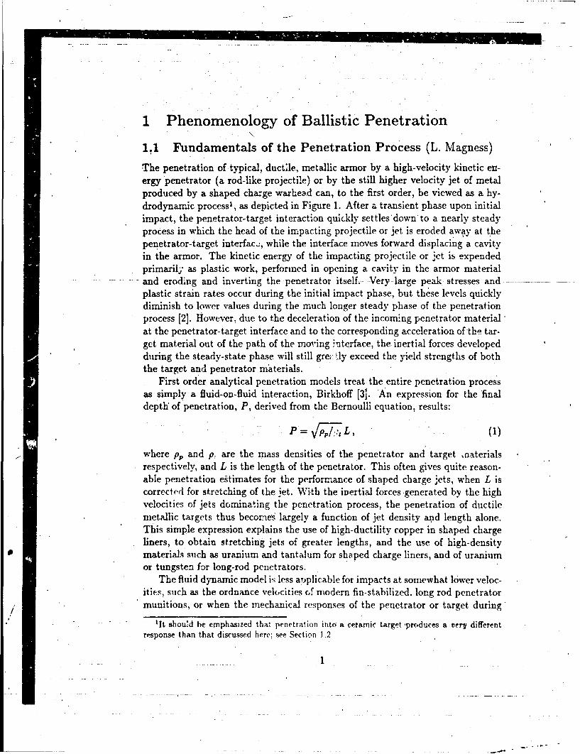
The penetration of typical, ductile, metallic armor by a high-velocity kinetic en-ergy penetrator (a rod-like projectile) or by the still higher velocity jet of metalproduced by a shaped charge warhead can, to the first order, be viewed as a hy-drodynamic process', as depicted in Figure 1. After a transient phase upon initialimpact, the penetrator-target interaction quickly settles'down'to a nearly steadyprocess in which the head of the impacting projectile or jet is eroded away at thepenetrator-target interface, while the interface moves forward displacing a cavityin the armor. The kinetic energy of the impacting projectile or jet is expendedprimarily, as plastic work, performed in opening a cavity in the armor materialand eroding and inverting the penetrator itself.- Very large peak- stresses andplastic strain rates occur during the initial impact phase, but these levels quicklydiminish to lower values during the much longer steady phase of the penetrationprocess [2]. However, due to the deceleration of the incom.ng penetrator material'at the penetrator-target interface and to the corresponding acceleration of the tar-get material out of the path of the moving ;nte~rface, the inertial forces developedduring the steady-state phase will still gre. tly exceed the yield strengths of boththe target and penetrator materials.
First order analytical penetration models treat the entire penetration processas simply a fluid-on-fluid interaction, Birkhoff [31. An expression for the -finaldepth' of penetration, P, derived from the Bernoulli equation, results:
SP = V(1)
where pp and p, are the mass densities of the penetrator and target naterialsrespectively, and L is the length of the penetrator. This often gives quite reason-able penetration estimates for the performance of shaped charge jets, when L iscorrected for stretching of the jet. With the inertial forces generated by the highvelocities of jets dominating the penetration process, the penetration of ductilemetallic targets thus becomes largely a function of jet density aj.d length alone.This simple expression explains the use of high-ductility copper in shaped chargeliners, to obtain stretching jets of greater lengths, and the use of high-densitymaterials such as uranium and tantalum for shaped charge liners, and of uraniumor tungsten for long-rod penetrators.
The fluid dynamic model is less aTplicable for impacts at somewhat lower veloc-ities, such as the ordnance velocities cf modern fin-stabilized, long rod penetratormunitions, or when the mechanical responses of the penetrator or target during
lit shouid be emphasized that penetration into a ceramic target -produces a very differentresponse than that discussed here; see Section 1.2
1

the penetration process are other than ductile erosion and cavity expansion, re-spectively. Additional terms representing the yield strengths of the penetrator andtarget materials are often included in modified versions of the Bernoulli equation toimprove the representation of penetration events by these analytical models. Theeroding-rod models (e.g. Tate [4, 5J, Alekseevski [6], Frank and Zook i71) which in-clude these strength terms reflect the experimentally observed, velocity-dependentpenetration of long-rod projectiles (Figure 2) and, when properly calibrated, cangive reasonably accurate predictions of their overall penetration performance.
In the case of brittle materials (ceramics), the assumptions of the steady-state,hydrodynamic model must be questioned not only from the viewpoint of time-dependent strength degradation but also because experiments indicate a majorcontribution from transient wave interaction effects. This point is considered inmore detail in the next section.
In reality, neither the penetrator nor the target materials behave as fluids ormodified fluids. To better understand the penetration process, finite element orfinite difference numerical simulations are employed. Two- and three-dimensionalhydrocodes, both Eulerian and Lagrangian, attempt to model the actual deforma-tion, flow, and fracture behavior of both penztxator and target materials. Throughconstitutive equations for each material, their rmechanical responses under thehigh stress and high strain rate loading coi it%: s are calculated and followedthrough each time increment of the penetra7 :r- psrocess. The ability of the nu-merical models to simulate the penetration v .•t thus depends on the accuracyand completeness of the materials models ane o;, the computational algorithmsemployed in the hydrocode itself. In the -e.t section, several examples of someof the complexities of penetrator-target iivteactions which have been observedexperimentally are given. Aspects of the mtchartcal responses of penetrator andtarget materials that have been shown to be 'raDortpnt to the understanding andprediction of ballistic test results are illnstr"-d by two phenomenological exam-ples: (1) the penetration of hard ceramics, and (2) penetrations involving ductile'materials, both armor and different high-dent£•y penetrator materials. In the sub-sequent sections, the ability of the computatwonal hydrocodes to model these andother aspects of the penetration process wil1 be reviewed and critiqued.
1.2 Phenomenological Observations of Penetration IntoBrittle Materials (G. Hauver)
Ceramics are commonly assumed to have an inherent resistance to penetrationby a long-rod projectile. However, test results often provide evidence that theballistic performance of a ceramic-larminate target varies with time during thecourse of penetration. For example, increasing the proportion of ceramic in atarget commonly fails to produce a corresponding improvement in its resistance
2

/
to penetration. In recent studies at the Ballistic Research Laboratory (BRL),all available data from_ quarter-scale ballistic tests were analyzed with the aidof a penetration modci [4, 5] using the target resistance term, R, as a measureof ceramic performance. Such steady-state models are not intended to describepenetration when the resistance term is time dependent. However, the steady-state condition was satisfied by using a point-by-point analysis and assumingan average value of resistance from the beginning of penetration to a specificpenetration depth in the ceramic of each test. This approach greatly suppressedthe actual change in resistance during penetration, but it preserved performancetrends which could be related to sources of damage to the ceramic that cause itsR to change. Supporting tests were then conducted to identify features of targetdesign which influenced the dam age. ------ ... . .. . . . ..
The analysis of quarter-scale ballistic tests indicated similar behavior for dif-ferent ceramics, and representative performance trends are shown in Figure 3. Inthis figure, average resistance to penetration, R, is plotted as a function of time,T. With no cover plate at the front of the ceramic, performance typically followedCurve A. The performance was initially low, but it increased with time, passedthrough a maximum, and decreased at later times when different sources of dam-age became dominant. However, the decrease in performance at late times did notalways occur. In one case [8] the performance continued to increase along CurveAA. This trend occurred when the ceramic, without a cover plate, was heavilyconfined at the back and side. With a steel cover plate, performance typicallyfollowed Curve B. The presence of a cover plate suppressed early damage, butthe curve plunged rapidly as other damage sources influenced the perfotmance.However, with efforts to suppress damage in tests at the BRL, performance ofthe same ceramic could follow a higher curve, BB. At present, maximum perfor-mance (highest position of Curve BB) has not been determined. It is known thatif damage is not suppressed and performance follows Curves A or B, the late-timeperformance of most ceramics lies within a narrow range of resistance values. Itis this late-time performance which is often used to rank the ballistic capabilityof ceramics.
- Target performance depends on damage to the ceramic component. Althoughthis damage is influenced by characteristics of the ceramic, it is strongly depen-dent on response of the total target system. Ceramics, in general, are strong incompression but weak in tension. Although high-quality ceramics may respondelastically to compressive stresses above 15 GPa in uniaxial strain, they may failat tensile stresses below 0.5 GPa [9, 10]. The design of targets for ballistic evalu-ations of ceramics or of actual armor packages should minimize conditions whichproduce damage and provide an environment in which the compressive strengthof the ceramic may be exploited for ballistic protection. The damage producedby a long-rod penetrator is found to depend on many aspects of target design andresponse. Current information about target behavior and sources of damage is
3
t •-.

briefly summarized in the following paragraphs.Impact Damage Tests with and without a steel plate in front of the ceramic
reveal a large difference in the resistance to penetration, especially at early timesafter impact. A cover plate is believed to offer two benefits. First, it preventsthe ceramic from experiencing the peak stress which may be 40 to 50 GPa duringdirect impact by a high-density penetrator traveling at current ordnance velocities.Second, a steel covey plate provides confinement which retards the displacementof ceramic miaterial, as a block, from the front of the target; it also suppresses analmost explosive failure which would occur if the highest stresses were relieved ata free boundary of the ceramic.
Confinement Structural support must also be provided at the back andside of a ceramic. When a long-rod penetrator arrives at the ceramic, radialcracks quickly develop, producing wedge-shaped blocks which load the side con-finement. Weakly constructed confinement may fail catastrophically. With moresubstantial confinement, the surrounding ductile material is engraved by eachwedge. Collectively, the radial motion of the wedge-shaped blocks increases thetotal cross-sectional area of the target occupied by the ceramic. Even with whatmay be referred to as heavy confinement, the ceramic cross-sectional area mayincrease by several times the cross-sectional area of the penetrator. Consequently,the interaction of the penetrator's lateral surface with the penetration "tunnel"produced in the target may be much weaker than it would be if radial displace-ment of the wedges did not occur. As an example, Figure 4 shows the increasein area determined during penetration into a target used for ballistic evaluations.Penetration through thte steel cover was complete at time T1 and penetrationreached the steel backing at time T2. By time T2 the total cross-sectional areaoccupied by the ceramic had increased by nearly I1 times the cross-sectional areaof the penetrator. Extrapolation to the abscissa suggested an early developmentof ceramic wedges. Deviation-of the actual curve indicated confinement motionresulting from arrival of the impact shock. Internal stresses also act during pen-etration to displace confinement at the front and back of the ceramic. The coverplate tends to bulge outward and interfaces of a layered target tend to separate,even if the deformation of clamping structures remains within the elastic range.If interfaces extend directly to the side boundary of the target, erosion productsfrom the penetrator and small particles of ceramic are vented t, the exterior.
Wave Propagation and Interaction Most etforts to confine the ceramiccomponent tend to consider structural support while neglecting wave propaga-tion in the finite target. A number of factors influence wave propagation andinteraction.
1. A low-impedance bonding layer is usually present between ceramic tiir- andbetween the ceramic and its confinement. This layer is a source of tensile Ie-lease and associated damage to the ceramic. Thickness of the interface layer
4
// /
may not be well controlled, and air may be entrapped, further contributingto variable damage and performance.
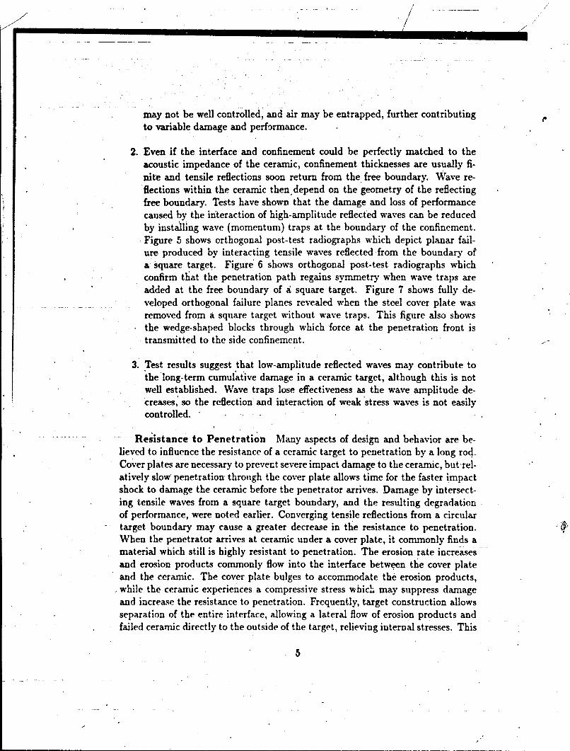
2. Even if the interface and confinement could be perfectly matched to theacoustic impedance of the ceramic, confinement thicknesses are usually fi-nite and tensile reflections soon return from the free boundary. Wave re-flections within the ceramic thendepend on the geometry of the reflectingfree boundary. Tests have shown that the damage and loss of performancecaused by the interaction of high-amplitude reflected waves can be reducedby installing wave (momentum) traps at. the boundary of the confinement.Figure 5 shows orthogonal post-test radiographs which depict planar fail-ure produced by interacting tensile waves reflected from the boundary ofa square target. Figure' 6 shows orthogonal post-test radiographs whichconfirm that the penetration path regains symmetry when wave traps areadded at the free boundary of a square target. Figure 7 shows fully de-
. . veloped orthogonal failure planes revealed when the steel cover plate wasremoved from a square target without wave traps. This figure also showsthe wedge-shaped blocks through which force at the penetration front istransmitted to the side confinement.
3. Test results suggest that low-amplitude reflected waves may contribute tothe long-term cumulative damage in a ceramic target, although this is notwell established. Wave traps lose effectiveness as the wave amplitude de-creases, so the reflection and interaction of weak 'stress waves is not easilycontrolled.
Resistance to Penetration Many aspects of design and behavior are be-lieved to influence the resistance of a ceramic target to penetration by a long rod.Cover plates are necessary to prevent severe impact damage to the ceramic, but-rel-atively slow penetration- through the cover plate allows time for the faster impactshock to damage the ceramic before the penetrator arrives. Damage by intersect-ing tensile waves from a square target boundary, and the resulting degradationof performance, were noted earlier. Converging tensile reflections from a circulartarget boundary may cause a greater decrease in the resistance to penetration.When the penetrator arrives at ceramic under a cover plate, it commonly finds amaterial which still is highly resistant to penetration. The erosion rate increasesand erosion products commonly flow into the interface between the cover plateand the ceramic. The cover plate bulges to accommodate the erosion products,while the ceramic experiences a compressive stress which may suppress damageand increase the resistance to penetration. Frequently, target construction allowsseparation of the entire interface, allowing a lateral flow of erosion products andfailed ceramic directly to the outside of the target, relieving internal stresses. This
5

behavior may promote damage and reduce the resistance of the ceramic to pene-tration. As penetration proceeds into the ceramic, major failure planes develop,freeing blocks of ceramic through which forces at the penetration front are coupledto the confinement. At the side of the penetration path, radial cracks producepie blocks which are forced against the side confinement. As noted before, theincrease in area at the boundary can be many time the cross-sectional aiea of thepenetrator. This may influence granular flow in the penetration path, but it alsomay piovide an alternative means for displacing ceramic from in front of the pen-etrator. Major failure planes, intersecting the penetration axis, further improvethe coupling to confinement at the front and back of the ceramic. This must con-tribute to deformation, separation of interfaces, additional loss of ceramic fromthe target, and a further decrease in resistance to penetration. Sequential failureof the confinement may make a greater contribution to cumulative damage thanlong-term wave interactions. Experimental studies may soon provide an answer.
Summary It is clear that the mechanics of penetration, for an armor contain-ing ceramic elements is very different from the purely metallic case. The conceptof intrinsic resistance is, for ceramic elements, almost completely spurious. Ithas become evident that, due to the mechanisms just disqussed, the *penetrationresistance of a ceramic target depends fundamentally on the response of the totaltarget system. Current studies at the BRL show that modified target configu-rations can produce a significant increase in the resistance to penetration, butthe full potential for improvement has not yet been determined. Current ballistictests clearly do not provide an environment in which the constitutive responseof an individual ceramic material has a major influence. Indeed, a crucial chal-lenge in the analysis of ceramic armors is to understand the basic penetrationmechanics well enough so that armor packages may be designed which do exploitthe behaviors of different ceramics. It is further apparent that to obtain reliablepredictions of ballistic performance, computational simulations must employ moreaccurate modeling of dynamic material behavior than is now the case and musttreat the response of the total target system. Substantial progress will proceedfrom accurate simulation of carefully controlled experiments.
1.3 Phenomenological Observations of Penetration Involv-ing Ductile Materials (L. Magness, M. Raftenberg, J. Walter)
While the hydrodynamic picture of ballistic penetration (Figure 1) is appealingboth for its simplicity and successes, it ignores an essential aspect of the solidstate: internal structure. In mechanical terms the internal structure (microstruc-ture) of solids is expressed as material anisotropy and inhomogeneity. 2 It has
2 Bulk specimens of metals are usually aggregates composed of many crystals which are alwaysanisotropic and may be individually inhomogeneous due to second phases, inclusions, etc. The
6
--- "

long been known that at the intragranular scale, plastic flow of crystalline solidsis a very anisotropic and inhomogeneous process. Undei continued deformation,microscale inhomogeneities may grow in extent and so develop into macroscalefailure mechanisms such as ductile rupture (growth and coalescence of voids) orerosiou/fragmentation by adiabatic shear bands. In addition, the microscale pro-cesses which occur during plastic flow can produce macroscopic strain softeningbehavior. When this occurs shear flow localization (shear bands) may be initiatedby geometric stress concentrations independent of material inhomogeneity. Whileboth ductile voids and shear bands are important failure modes in ballistic impactwe focus primarily on the latter in our discussion here.
Adiabatic shear localization has received increasing attention in recent yearsas it is a principal mode of deformation and failure in a variety of ductile materi-als at moderate-to-high rates of defoimation. The basic mechanism for adiabaticlocalization is an autocatalytic process of local heating (due to plastic work) ac-companied by thermal softening which, if strong enough to overcome strain orstrain rate hardening, causes an increase in the local rate of plastic work andso intensifies the heating. While recognition of thermal softening as a localiza-tion mechanism dates back to Tresca [11] (see Johnson [12]) and more recentlyto Zener and Hollomon [13], it is only 'during the last ten to fifteen years thatthere has been a fairly steady effort to analyze and model this phenomenon. Itis worth noting that the phrase "adiabatic shear" is an historic misnomer sincelocal heat conduction is actually an essential aspect of the micromechanics of thisphenomenon!
During a ballistic impact adiabatic shear bands may occur in either an isolatedor a distributed mode. Isolated shear bands tend to occur when the macroscopicgeometry of the target and penetrator afford a sufficiendly strong concentration ofshear stress and strain rate, but the overall deformation rate (impact velocity) isnot so large as to cause distributed shear band nucleation from micromechanicaldefects. The most striking example of this' mode is the formation of a plug ina monolithic target plate when struck by a blunt-nosed rod [14]. Once the plugboundary (a macroscopic shear band) begins to form it propagates rapidly and,under continued loading, will reach the rear stirface of the plate. Although thematerial inside the thin plug boundary3 is severely deformed it is also thermallysoftened so that far less energy is needed to propagate the plug boundary thanwould be required for-the-penetrator to advance by causing gross plastic flowin the target. Consequently, when plugging occurs the armor plate will displaymuch lower resistance to penetration than wonld be predicted by a hydrodynamicpenetration model which accounts only for the relative mass densities Lnd yieldstrengths of the target and penetrator materials. Post-mortem examination of
interfaces between adjacent crystals are another inhomogeneity in such a material.'In a high-strength steel the plug boundary may be less than ten microns thick.
Py

deep penetration tunnels in high-strength steel monoliths reveals shear bands thatemanate away from the tunnd] in a spiral pattern. The visible bands are the tracein the section plane of two families of (apparently) counter-winding, helical, shearsurfaces which intersect to produce pyramidal fragments. Often, a tube composedof these fragments (welded together because of the high temperatures which occurduring formation of the shear bands) surrounds the penetratot tunnel, which has aroughened wall due to ejection of some of the fragments. Neither feature appearsin targets of lower strength steel.
As suggested above, distributed shear banding tends to occur at higher impactspeeds and in regions (e.g. near the target-penetrator interface) where the macro-scopic rate of deformation is large enough to initiate band growth from preexist-ing or deformation-induced material inhomogeneities. Although not as obvious asplug-boundary formation, distributed shear band formation is no less importantfor the penetration process. In this mode large numbers of bands nucleate in amore or less dense distribution within a region of material. As the bands grow thematerial's macroscopic strength is reduced anisotropically because the bands tendto be oriented in the local directions of maximum shear stress or shear strain rate.Here again the target presumably offers less resistance to the incoming penetratorthan it would if shear bands had not formed. Ultimately, the distributed shearbands may coalesce to form fragments of the target material. Upon perforation,these fragments may comprise most of the behind-armor debris which is one ofthe principal lethal mechanisms of the penetrator. Experimental results of Curranet aL. [15, 16, 17] indicate that adiabatic shear banding is the dominant mode ofplugging, erosion and fragmentation in impacts of 4340 steel or depleted uranium(DU) rods on roiicd homogeneous armor (RHA) plates over a range of velocitiesfrom below to well above the ballistic limit. Thus, in order to estimate the dis-tribution of fragment sizes and velocities (an important capability for terminaleffects codes) it is essential that models be based on the actual damage processesleading to fragmentation.
1.3.1 Observations of Shaped-Charge Jet Penetration into Steel Ar-mor
Shear banding is always observed in rolled homogeneous .armor (RHA) target ma-terial following perforation by a shaped-charge jet. Figure 8 is an SEM micrographshowing a shear bard in a 12.7 mm-thick RHA plate that has been perforated bya jet from a shaped charge warhead. The warhead was fired at a standoff of 12charge diameters4(CD) and the jet tip speed was 7.7 km/s prior to impact. Thisband has been exposed by a diametral section through the perforation hole. Itemanates from that hole's boundary. Three issues suggested by this and other
4 Thrughout this subsection one charge diameter is 81.3 mm.
8. ..

experiments conducted at BRL will be discussed: structure within the band; theoccurrence of a ieproducible, characteristic shear band geometry; and the occur-rence of cracks and/or voids within the band.
Structure Within a Shear Band in Steel'Armor At the magnificationof Figure 8, no structure is apparent inside the shear band. This is in contrast tothe surrounding material which still exhibits the lath structure characteristic ofthe original martensite. (Note however, that these laths clearly have been rotatedin the surrounding material, and have become roughly aligned with the shearbands.) Rogers and Shastry called white-etching bands, such as that of Figure 8,"transformed shear bands", implying a phase transformation that they postulatedto have occurred, involving austenitization and subsequent quenching [18]. Theysupported this hypothesis with measurements of increased microhardness withinthe band. In a recent work, Beatty et a!. [19], presented Selected Area DiffractionPatterns (SADP).within bands and in the surrounding martensite in 4340 steel.The diffraction pattern was found to vary gradually with distance from the centerof the shear band, with no clear discontinuity occurring at the band's periphery.This and their inability to find remaining austenite within the bands casts somedoubt on the assumption of phase transformation. The identity of the structurewithin a shear band and the role of phase transformation in the genesis of theband seem to be unresL !ed at present.
Shear Band Geometry in Steel Armor Our knowledge of the rangeof .• geometrical complexity that shear bands' can exhibit is very limited. Three-dimensional mappings of shear bands in target material would be useful at thistime. The single cross-sectional view of a shear band in Figure 8 has two obvi-ous geometric features: a fairly uniform 6 pm width and the existence of littlecurvature. These two observations have some general validity in that they havebeen found applicable to other shear bands emanating from the target hole andexposed by other radial cuts in this same experiment. However, geometries ofshear bands that formed radially closer to the shot line are difficult to determinein such a ballistic test. The loading history in the steel during its penetrationvaried with position, and it is quite possible that any characteristic features ofshear band geometry could have varied correspondingly.
One approach to the question of the sensitivity of shear band geometry to theambient stress environment during ballistic penetration is to recover fragmentsfrom ballistic tests. Figures 9 and 10 are photomicrographs which display a singleRHA fragment recovered from a second test involving perforation of a 12.7-nun-thick plate by a copper jet. Here the shaped charge warhead was fired at a shorterstandoff of 3 CD. The target plate hole's final diameter is 14 mm, the same asin the first test at the longer standoff. Thus the fragment in Figures 9 and 10indicates the condition of steel radially closer to the shot line than that of Figure8. Figure 9 shows the shear band still to be straight, but Figure 10 shows its widthto be 20 to 30 um. This width is larger than that of the shear band in Figure
9

8 by a factor of 3 to 5. Figure 11 shows a photomicrograph of another RHAfragment from this test involving perforation by a shaped-charge fired at 12 CDstandoff. This fragment's boundary is seen to be lined by a white-etching region,of perhaps 25 to 100 pm width, that bears little geometrical resemblance to theshear band of Figure 8. However, the comparison is marred by the fact that thefragment of Figures 9 and 10 perforated one or more sheets of mild steel beforecoming to rest in the witness pack used for its recovery. This points up the needto develop a non-destructive fragment recovery technique for use in these ballistictests. A desirable but difficult-to-achieve feature of such a technique would bethe preservation of information regarding each fragment's original location on thetarget plate.
A second approach to examining the question of the dependence of shear bandgeometry on original location in the target plate is through laboratory experi-ments. As a promising example, reference [19] documents the application of asplit Hopkinson bar technique to a "hat-shaped" specimen of RHA. Laboratorytechniques such as this offer a distinct advantage over ballistic penetration tests inthat in the former, loading conditions within the specimen can be relatively wellcharacterized. However, if the ultimate goal is to illuminate phenomena pertain-ing to shear bands that occur in ballistic penetrationz, then the loading conditionsproduced in a laboratory experiment should be similar to those occurring at somelocation of interest in a target. As a check, shear bands produced in the laboratoryshould be shown to resemble those displayed in micrographs from ballistic tests.
Shear Band Association with Cracks and Voids in Steel Armor Theability to predict information on fragments produced by a given penetrator-targetinteraction is a current challenge of great practical importance. In this regard,more knowledge of the micromrechanical processes leading to fragmentation isneeded. Micrographs such as that of Figure 12 seem to implicate shear bands.This shows a shear band in the same target plate considered in Figure 8. Acrack clearly extends along part of the sheai band's length. Figure 13 showsthe same shear band and crack at smaller magnification. *The crack is seen tobegin at the hole boundary; the process of fragment formation has apuarentlybeen caught in a state of partial completion. The sequence of events linking shearband localization to inacroscopic cracking is still unclear. Perhaps the increasedmicrohardness within the band provides a clu :.
Spheroidal voids are shown in the same target plate in Figure 14. Thesehave coalesced to form a crack, along which the martensitic laths have becomealigncd. Such voids may constitute a second micromechanical'mechanism forfragmentation. However, it is not yet clear to ,what extent they are indeed aseparate mechanism, independent of shear banding
10

1.3.2 Comparison of Uranium Alloys and Tungsten Composities asLong Rod Penetrator Materials
The importance of both plastic inhomogeneities and material anisotropies to theprocess of penetration is also illustrated by a comparison of the observed phe-nomenology and resulting ballistic performance of uranium alloy, tungsten heavy
alloy composite, and tungsten single crystal penetrators.Depleted uranium (DU) alloys and tungsten heavy alloys (WHA) offer both'
the high material densities (for penetration performance) and useful mechanicalproperties (needed for the integration of the penetrator core in engineered ki-netic energy (KE) long rod projectiles and cartridge assemblies). Metallurgically,however, DU and WHA are very different kinds of materials.
The DU materials are true alloys. The standard DU-3/4Ti alloy can be castand heat-treated in much the same way as iron-carbon (steel) alloys, Eckelmeyer[20]. In contrast, Tungsten is a refractory metal and pure tungsten productsgenerally have poor ductilities and toughnesses, and require very high processingtemperatures. Therefore the WHAs used for KE penetrator applications are actu-ally composites of tungsten particles. in a ductile metal matrix (usually consistingprimarily of nickel' and iron), and usually produced 1y liquid-phase sintering tech-niques. The density of the WHA composite depends on its tungsten content, andthe mechanical properities depend on both its tungsten content (percentage ofductile metal matrix) and on its processing history, Gurwell et al. [21]. BecauseDU and WHA are so very different metallurgically, they also differ significantlyin many fundamental mechanical, thermal, etc. properties.
The ballistic performances of DU and WHA projectiles also differ by a small,but significant, amount. Penetrators of the standard DU-3/4Ti alloy consistentlyrequire lower impact velocities (by approximately 100 m/s)5 to defeat thick steeland steel/ceramic laminate targets than WHA projectiles of equal mass and iden-tical geometry (i.e. equal density) Magness and Farrand [22].
Exam•inations of residual DU and WHA penetrators embedded in steel armor(Figures 15 and 16, respectively) reveal that the two materials display very dif-ferent deformation behaviors during the penetration process. In the case of theWHA penetrator (Figure i6), the relatively smooth erosion and back-extrusionof the material at the penetrator's head is qualitatively consistent with the fluid-dynamic idealization of penetration depicted in Figure 1. The WHA materialundergoes a great deal of plastic deformation as it approaches and is inverted atthe penetrator-target interface. A large mushroomed head is found on the residualpenetrator embedded in the target (Figure 16) and is routinely observed on resid-ual WHA penetrators after exiting finite steel targets (Figure 17). The evojutionof the WHA microstructure in Figure 16, from the originally spherical tungsten
tSThis relatively small velocity difference translates into a significant difference (s. 2 km) in 4
the effective range of such projectiles by virtue of air drag effects.
11
particles to highly elongated stringers, provides further evidence of the large plas-tic strains that occur as the material is inverted. On closer examination, of course,the flow of the penetrator material does differ from fluid behavior. Because theWHA is a solid, small elastic strains and some small plastic strains manage topropagate away from the interface. The 'flaring" of the residual rod as it feedsinto the mushroomed head is evidence of this. Another significant departure fromthe fluid-dynamic ideal is the development of plastic localizations, or small re-gions of larger than average plastic strains, near the periphery of the mushroom.The eventual discard of material from the periphery of the mushroomed headultimately occurs along some of these localizations.
The deformation of the DU-3/4Ti penetrator has a very different appearance(Figure 15). Localizations of the plastic deformation develop very quickly alongplanes of highest local shear stress and at relativeiy small values of strain. Thesubsequent discard of the back-extruding material along these shear planes occursbefoie a large mushroomed head can develop on the penetfator. Aka result,the residual DU penetrators observed exiting the rear face of finite steel'tprgetslack the large mushroomed head of the WHA penetrators. Instead, they displaya pointed nose (Figure 18), shaped by the chiseling action of the local shearfailures occurring during the penetration process. It is'tlle ability of the DU alloypenetrators prevent the build-up of a large mushroomed head which is ultimatelyresponsible for their superior ballistic performance.
A comparison of the penetration cavities formed by DU and WHA projectilespenetrating into thick steel blocks is shown in Figure 19. The hole profiles inFigure 19 reveal that, during much of the penetration process, the DU penetratorcreates a smaller diameter penetration tunnel. Therefore, less of the kinetic energyof the DU projectile is expended laterally, to displace a larger diameter hole intothe target, and more of its kinetic energy is available to penetrate to a greaterdepth in the thick target. Against lesaer thicknesses of armor plate, which boththe DU and WHA projectiles are able to perforate, the DU penetrator does somore efficiently and therefore has a lower ballistic limit.6
The distinct deformation behaviors exhibited by the DU and WHA penetratorsare a result of differences in their thermomechanical properties. Under the veryhigh strain rate loading conditions of the penetration process, there is essentiallyno time for the macroscopic transport of the heat being generated by the defor-mation of the penetrator. The thermal-softening induced by this adiabatic heat-ing overcomes the usual strain-hardening and strain-rate hardening much morequickly in the DU than in the WHA. The result is a net strain-softening behaviorin the DU, under which small perturbations in the plastic strain or temperaturefields can quickly grow into the plastic localizations (adiabatic shear bands) ob-
6For a given penetrator and target, the ballistic limit is defined to be the lowest penetratorvelocity which will produce perforation.
12
1-A,

served in the DU residual penetrators. As evidenced by the smoothly deformedmicrostructures and the large mushroomed heads which develop on the WHApenetrators, the plastic deformation is much more stable in this material.
A related, but distinctly different, illustration of the role of the penetratormaterial's behavior on penetration performiance is the comparison of the behaviorand performance of different orientations of tungsten monocrystal penetrators andpolycrystalline pure tungsten penetrators. Due to the thermomnechanical proper-ties of pure tungs ten (high strain rate sensitivity, relatively low rate of thermalsoftening, etc.) the plastic deformation of the tungsten polycrystal penetrator.is exti erely stable (Figure 20). In fact, the "mushroomning" of the tungstenpolycrystal is more extensive than that of the WHA resulting in poorer ballisticperformance than a WHA penetrator of equivalent mass and geometry, Mag-ness [22]. However, ballistic tests show that, the performance' of monocrystalline
.-- tungsten-penetrators (Bruchey,-Horwath and Kingman [23]) vary with their crys-tallographic orientations. In one case, with the axis of the penietrator parallel tothe <110> direction in the lattice, the mushrooming can be even more exagger-ated than in the pure tungsten polycrystal (Figure 21). As a result, the diameterof the penetration cavity is considerably larger and the projectile achieves verylow depths of penietr-ation. In contrast, if the axis of the rod is parallel to the<100> axis of the crystal, cleavage failures appear in the head of the penetratorafter only small plastic strains (Figure 22) and the deformed material is morequickly discarded. The <100> oriented crystal penetrator creates a much smallerdiameter penetration tunnel and delivers penetration performance approximatingthat of DU. In this case; anisotropies in the strengths and flow behaviors, ratherthan plastic flow localization, lead to the very different modes of deformation anzdballistic performances exhibited by the monocrystalline tungsten penetratorg.
The differing behaviors and ballistic performances of DUJ, WHA, and singlecrystal tung~ten projectiles serve as excellent tests of the ability of ballistic impactsimulation codes to 'accurately represent the response of penetrator and armor ma-terials during the pen~etration event. Conversely, the incorporation into simulation
* codes of state-of-the-art material. models and algorithms should become~a centralgoal for the code development community.
1.3.3 Conclusions
The fundamental reason for- non--hydrodynamric behavior in the penetration ofmetallic targets is the'complex internal microstructure of me: als and its mani-festations as macroscopic strength and localized deformation modes which leadto material failure. The occurrence of ductile faWlure modes depends strongly onseveral aspects of the ballistic impact.
1. The macroscopic thermo-visco.-plstic (TVP) response~ of the -material. --

2. Features of the material microstructure which can serve as nucleation sitesfor shear bend or voids.
3. Features of the macroscopic loading (e.g. hydrodynamic pressure/tension,stress concentrations, etc.) which can encourage or supress localized defor-mation.
The macroscopic TVP response of high strength steels is quite favorable for sbearband formation and in this context some aspects of band morphology and met-"allurgy were discussed in section 1.3.1. Most notable is the severity of the lo-calization in a shear band and tbe fact that bands may serve as nucleators forother failare mechanisms e.g. cracks. Lastly, section 1.3.2 emphasized the degreeto which a material's shear band susceptibility is affected by its TVP response.Moreover, the relative shear band susceptibility of different materials producedmarkedly different penetration performance.
2 Terminal Effects Codes (K. Kimsey, G. Randers-Pehrson)
Computer codes used to study the armor penetration process are usually'known as"?hydrocodes", or more accurately, "wave propagation codesr. Wave propagationcodes fall into two classes: Eulerian •and Lagr gian (a third class, ArbitraryLagrangian Eulerian, is currently emerging). Euh nrian codes used at BRL includeHULL (241, MESA [25J, and CTH [26]. Lagrang ian codes used at BRL include
DYNA2D/3D [27J and EPIC2D/3D !281 and sor ! of their derivatives. CTH andMESA are now being evaluated for modeling ar or/anti-armor problems.
In either approach, the problem is divided into a large number of small compu-tational •cells or elements. The solution to the pr oblem proceeds over small timesteps, typically a tenth or hundredth of a micro second. At each time step thestress state within each computational cell is do ermined from the deformationof. the cell together with the equation of state (pr ýssure-volume relationship) andconstitutive model (describing the thermo-viszo- lastic response) of the materialthat it contains. From the stress state, the equa ion of motion is used to deter-
-- . mine the deformation to be used as input to the ext time step. The Lagrangian
and Eulerian approaches differ in the treatment £f material motion. In the La-grangian codes, the cell's mass is assigned to the nodes at the cell comers, and thenodes move through space according to the equat ion of motion. The Lagrangiancell becomes deformed and moves along with its comer nodes. In the Eulerianapproach, the cell does noLinve, but material from reighboring cells flows in orout according to the equation of motion. All of th . Eulerian codes use a two-stepsolution scheme. The first step is a Lagrangian s! ep in which the cells distort to
14

. .. . .........I -.
follow material motion. The second step is a remesh step where distorted cells aremapped back, i.e. advected, to the Eulerian mesh.
Because of the severe deformations which occur in the penetration process,Lagrangian codes generally cannot treat such problems- unless special measuresare taken. In EPIC and DYNA, "eroding sliding interfaces" are used, whereinseverely deformed cells are removed from the computation according to criteriasuch as accumulated plastic strain. Such special treatments extend the utility ofLagrangian codes for modeling deep penetration problems. Eulerian codes canmodel severe deformation more readily, without resorting to special treatments,but they too have disadvantages, for example difficulties in advec-ting materialstress histories. Eulerian codes generally require much larger amounts of computer-memory and processor time.
Most armor/anti-armor problems are inherently three-dimensional. Some two-dimensional problems such as normal impact and penetration of semi-infinite ar-mor are useful, however, mainly for validation of '. odes Following are briefdescriptions of several three-dimensional wa'L.- ?ropagdtion codes in current usefor penetration mechanics studies at JRL.
HULL is a family of computer programs for solving continuum dynamics prob-lems. The code solves the finite differeL,,e ,n-io, of +he governing partial differen-
Atialequations for two- and three-dimensional Eulerian and Lagrangian formulated-problems as well as coupled Eulerian/Lagrangian solutions. Material advection isbased on a first-order donor-cell algorithm with a heuristic multimaterial diffusionlimiter to preserve material interfaces. Most solids in HULL are modeled with theMie. Gruneisen equation of state. Concrete, geological materials and explotiveproducts equations of state are also available. Material failure models includer-aximum principal stress, maximum principal strain,and the Hancock-Mackenziet:iaxial failure model. Plasticity models include elastic-perfectly plastic with pro-v;ioik for work hardening and thermal softening.
MESA is a new 3D Eulerian code which is being developed for armor/anti-armor work by a team at Los Alamos National Laboratory. This code was writtento take advantage of new high-order accurate advection algorithms and interfacezeconstruction methods. Plasticity models in MESA include the Johnson-Cookand Steinberg-Cochran-Guinan-Lund models, and various simpler ones. The duc-tile fracture model TEPLA-F [29] has also been incorporated in MESA.
CTH is Sandia's new Eulerian code. Like MESA, it incorporates new high-order accurate algorithms. It has its roots in the previous Sandia code, CSQ.CTH solves the finite difference analogs of the governing conservation equationsusing an Eulerian solution scheme. CTH models solid dynamics problems involv-ing shock wave propagation, multiple materials and large deformations in one,two and three dimensions. CTH models elastic-plastic behavior, high explosivedetonation, fracture and motion of fragments smaller than a computatiuaal cell.Plasticity models inciude elastic-perfectly plastic with thermal softening, Johnson-
15

Cook, Zerilli-Armstrong and Steinberg-Guinan-Lund. The Johnson-Holmquist[30] brittle material model has also been incorporated in CTH. Both analytical(Mie-Gruneisen) and tabular equations of state are available for modeling thehydrodynamic behavior of materials. Three types of high explosive burn modelare available; programnmed bum, CJ volume burn and history variable reactiveburn. The Jones-Wilkins-Lee equation of state is available for modeling detona-tion products. Fracture initiation is based on maximum pressure and principalstress.
DYNA3D is a Lagrangian explicit finite element code for analyzing the tran-sient dynamic response of three-dimensional solids and structures. A product ofthe Lawrence Livermore National Liboratory, it has a wide variety of elementtypes and material models and sophisticated treatment of contact/impact inter-faces. A version of the code supported by Dr. John Hallquist, the original author ofthe code and now an independent consultant, incorporates an automatic erodinginterface algorithm. Recently, researchers at LLNL have implemented a slidelineadaptive node definition (SAND), i.e..eroding slidelines, algorithm into LLNL'sDYNA3D code.
EPIC is a Lagrangian explicit finite element code written by Dr. GordonJohnson of Alliant Tech Systems (formerly a division of Honeywell). It incorpo-rates an eroding surface capability, and uses primarily Johnson's material models(Johnson-Cook for metals, Johnson-Holmquist for ceramics, and the JWL equa-tion of state for detonation products). The code uses triangular or tetrahedralfinite elements rather than quadrilateral or brick-shaped ones, and consequentlycan frequently run problems with large deformations more readily than other La-grangian codes.
ALE (Arbitrary Lagrangian Eulerian) codes under development include the 2D"CALE code, written in the C programing language at Livermore, and a 3D mixed-zone code being developed by Livermore. The latter code is written in Fortranand has its roots in the DYNA3D code. Like DYNA3D, it has a wide varietyof plasticity models, including Johnson-Cook, Steinberg- Cochran-Guinan-Lund,power law hardening, crushable foam, geologic models, and various orthotropicmodels. Sandia is also working on a 3D ALE code called RHALE.
In this article, we focus on the material modeling and equation of state mod-eling in present day terminal ballistics codes. The predictive capability of currentwave propagation codes for impact studies is dependent on the material modeland properties that are used in the simulations. Metals, until recentlýr, were thematerials of primary interest. It is common in existing wave propagation codesfor impact studies to divide the deformation behavior of metals into volumetricand deviatoric parts as
a+= -.•,+s, (2)
in which a is the stress tensor, s is its deviatoric part and p is the pressure. The
16

9 9 9
volumetric behavior is obtained from an equation of state which describes the in-terdependence of thermodynamic properties, such as pressure, energy, density andtemperature. For impacts where the striking velocity is below the sonic velocity,some variant of the Mie-Gruneisen equation of state is commonly used. Beyondthis range (hypervelocity impact) the Tillotson equation of state is favored. Somecodes also use tabular equations of state to represent equation of state surfacesof arbitrary complexity which are valid for a wide range of densities and temper-atures. Examples of tabular equations of state include SESAME (Bennett et al.[311, Kerley [32]) and ANEOS (Thompson, [33]). Explosive detonati6n productsare most commonly represented by the well-known JWL analytical equation ofstate. A desirable feature of the analytical equation-of-state models is that theyare easy to use and, for most metals, model parameters can be obtained fromthe literature (van Thiel [34]; Marsh [35]; Kohn [36]; Steinberg [37]; Dobratz andCrawford [38]).
An incremental elastic-plastic formulation is used to describe the deviatoricresponse of metals in'present finite difference and finite element codes. Mostfollow the description first given by Wilkins [39, 40]. The plasticity descriptionsare usually based on the assumed decomposition of the strain rate tensor intoelastic and plastic parts
iij = i•.. + 4i, (3)
together with incompressibility of the plastic part
en (4)
The von Mises yield criterion is commonly used to determine if a material elementis undergoing plastic flow.
Traditionally, the plasticity model, in wave propagation codes for impact stud-ies have begn relatively simple, of the elastic, perfectly-plastic type, and have beenimplemented using the radial return algorithm forniulatcd by Wilkins [39, 40].'More recently viscoplastic models have been implemented in wave propagation,-)des to represent the dependence of the flow stress on strain, strain rate, pres-sure, temperature or some combination thereof. Viscoplastic models for metalsinclude those of Johnson and Cook [41] and Zerilli and Armstrong [42].
The Johnson-Cook model for the von Mises equivalent flow stress is expressed. as
[A + B(eP)"J1 + C In [ - (T-)-], (5)
where oaf is the flow stress, eP is the equivalent plastic strain, •P is the rate of
change of the latter, and T" is the homologous temperature; A, B, n, C and mare constants. The expression in the first pair of brackets represents the depen-dence of the flow stress on (von Mises) equivalent strain. The expressions in the
* 17

second and third brackets represent the dependence-o strain rate and tempera-ture, respectively. The model is based on a numerical fit to torsion and tensiontest data at ambient and elevated temperatures. Use of the model outside therange of the test data may not be warranted. Model parameters for a numberof metals are given by Johnson and Cook [411 and Johnson and Holmquist [43].The Johnson-Cook mdel has been implemented in the EPIC, DYNA, CTH and
' MESA codes.
Figure 23 compares computed semi-infinite penetration depths with quarter-scale test data, Magness [44], for 65 gram, L/D 10, depleted-uranium alloy (U-3/4Ti) and tungsten heavy alloy (WHA) rods impacting semi-infinite RHA targetsat striking velocities between 800 and 1800 m/s. The solid symbols representCTH results using the Johnson-Cook model to describe the flow stress for both,rod and target materials. The CTH results compare well with the test dataand also reflect the observed gap in performance between these two materials.Magness and Farrand [22] conducted ballistic tests and microstructural analysesof the performance of uranium and tungsten heavy alloys and identified the strain-softening behavior developed by the uranium alloys under high rate loading andthe resulting thermo-mechanical (adiabatic shear) instability, as the mechanismresponsible for uranium's superior performance. It is interesting to note that
-while the Johnson-Cook model does not explicitly model adiabatic shear bands, itappears to capture some aspects of the "global" behavior of the two alloys underimpact loading (for the striking velocities studied).
. Zerilli and Armstrong [42] have shown an improved description of copper andiron cylinder impact (Taylor) test results using their dislocation-mechanics-basedconstitutive relations for body centered cubic (bcc) and face centered cubic (fcc)materials. The Zerilli-Armstrong model is based on the observation that eachmaterial structure type (fcc, bcc, hcp) will have its own constitutive behavior,dependent on the dislocation characteristics for a particular structure. Thus,separate relations are required to describe flow stress for bcc and fcc metals. ForOFHC copper (fcc), the flow stress is'given by
a = AG'' + c2e',lexp[(-c 3 + •c4•l)TJ + kt-'l2 , (6)
whereas for Armco iron (bcc) the flow stress is given by
C = A&0' + c1 exp[(--% + c4 In #)T] + ce" + k-t 112; (7)
the constitutive variables have the same interpretation as in (5)except that I isthe grain size. Values for the eight material constants: c1 , ... ,c5, AaG', k, n, forOFHC copper and Armco iron are repurted by Zerilli and Armstrong [42]; thismodel is currently available in EPIC, CTH and MESA.
The Mechanical Threshold Stress, Follansbee j451, and the Steinberg-Cochran-Guinan-Lund, Steinberg et aL. [46, 47], material models relate the macroscopic
18

s-•-tress-strain behavior to -microscopic properties. Material parameters have beenpublished for the latter model for seven metals: beryllium, molybdenum, niobium,niobium alloy fansteel 85, tantalum, tungsten, vanadium, and for some othermaterials (Steinberg [37]). Both models have been implemented in MESA.
Computational failure models for impact loading situations are'discussed inreview articles by Seaman [48] and Zukas [49] and the NMAB Committee re-port on Materials Response to Ultra-Higb Loading Rates [1]. Briefly, empiricalfailure models of varying degrees of complexity exist. Some have been applied suc-.cessfully in high velocity impact simulations. For the most part, though, failurecriteria and models are of an ad-hoc nature, lacking a micromechanical basis tocomprehensively treat problems involving both brittle and ductile failure modes.Different criteria apply for different impact scenarios and there are at present noguidelines for analysts wishing to select a failure criterion appropriate to varyingconditions.
The simplest of the failure initiatioh criteria are based on instantaneous valuesof a field variable, such as p.ressure, stress, strain, plastic work, or some combina-tion thereof. Once the criterion has been satisfied at a given location, failure isconsidered to occur instantaneously. The post-failure behavior of materials canbe described in a number of ways, The failed material may be removed entirelyfrom the calculation or be described by a modified constitutive function.
Time-dependent initiation criteria represent the next level of sophisticationand have been successfully applied in several situations. One of the earliest tirme-de ndent models is attributed to Tuler and Butcher [50]. Failure is assumedto occur instantaneously only after the stres' has remained above a thresholdstr ss level for some length of time, below which no significant damage will occurreg rdless of duration.
riteria in which damage accumulation is a function of field variables have beendev -loped by Davison [51] and Johnson [52] In these models the rate of damageacc tmulation is taken to be a function of strain, temperature, pressure, strainrat( and current damage level. Damage levels are used to degrade a materials'cha acteristics and sometimes trigger instantaneous failure.
lesearchbrs at SRI International (Seaman and Shockey [53], Seaman et al. [54]and Erlich [55]) have been developing "microstatistical" failure models. Ductile
faili re damage is initiated when the average stress exceeds a tensile-pressure cri-teri n. Brittle fracture is -initiated when the maximum normal stress exceeds atensile threshold. Shear banding begins when the maximum plastic shear strainexceds a critical value. After initiation, voids, cracks, and shear bands nucleateand grow according to experimentally determined rate equations. These failuremoc els have not been implemented in many production codes due the limitednu rber of materials which have been charaterized as well as the requirement tocon uct extensive materials tests in order to obtain model parameters for newmat erials.
19

No definite failure model has yet emerged, nor has a library of data to drivethe various models -or materials of practical interest. Therefore, for want ofan adequate data I ise for advanced failure models, most high velocity impactsimulations are performed with the simplest failure models. In many cases, simplefailure models produce results in agreement with experiments.
Brittle material modeling is a topic currently of great interest in the compu-tational penetration mechanics community, primarily because of the interest inceramics as candidate armor materials. Despite the recent surge in activity, theredoes not yet appear to be common agreement in the developer's community onthe correct modeling approach. Nonetheless, the first nmodels intended to addressthe behavior of ceramic materials under ballistic impact are becoming availableto the general user community.
Probably the most notable of these new models is the Johnson-Holmquistmodel [30], which has been implemented in the 1990 version of the EPIC code,Johnson and Stryk [281. The salient features of this model include Mohr-Coulomb-
'like behavior of the yield surface (i.e. yield strength proportional to pressure),and an equation controlling the evolution of a scalar "damage" parameter. Whenthe damage parameter reaches a critical value, failure is modeled by impbsing apressure jump intended to account for shear-induced dilatancy believed to occurin the comminuted ceramic. However, neither the magnitude nor the onset of thepressure jump is a function of material shearing rate, as would be indicated bygranular ,flow theory.
Each of the brittle material models which are beginning to surface in the com-putational penetration mechanics community address issues'of ceramic responsedeemed important by their respective developers. The features of ceramic re-sponse which are being addressed in'various forms by various developers include:volumetric bulking upon failure; shear induced dilatancy; frictional effects in failedceramic rubble; modulus degradation; Mohr-Coulomb-like failure surfaces in ce-ramics; microscopic cracking and void formation; and "damage" evolution. Itremains to be seen which of these model features are necessary to model the bal-listic behavior of ceramic materials. Toward this end Kipp and Grady of Sandiaare conducting experiments (mostly one-dimensional plate impacts) to measurethe dynamic response of ceramics.
3 Finite Strain Plasticity (N. Huffington)
3.1 State of Modeling in Current Terminal Ballistics Codes
It should be understood that the theory of plasticity has not achieved a state ofuniform acceptance comparable to the theory of elsticity, even for relatively smallstrains. Even such basic concepts as 'the plastic potential and use of associated
20

vs. non-associated flow rules are still unsettled. For the historical development ofplasticity theory one may refer to Hill [56] for a condensation of results up to 1950and to Malvern [57] for publications up to 1969. Subsequent publications (verynumerous) are scattered throughout the research literature. Since large plasticstrains are possible only in materials which possess considerable ductility, thediscussion which follows is essentially concerned with various aspects of constitu-tive modeling required for representation of behavior of ductile metals (rubberlikematerials are usually treated using specialized nonlinear elastic constitutive mod-els). No attempt will be made to itemize which of these desirable features arecurrently available in specific codes; this information is usually available in thedocumentation for each code.
Work Hardening Provision for work hardening may vary from none (per-fectly plastic material) to linear hardening (one hardening modulus) to nonlinearhardening: either a particular functional dependence of stress on strain is specifiedor tabular data on stress-strain pairs is used in conjunction with an interpolation
-routine. Linear hardening is usually satisfactory only over a limited strain rangewhere the maximum strain is known in advance. For materials such as copper anonlinear representation is essential since no. portion of the stress-strain curve islinear. For other than uniaxial loading it is necessary to supplement the foregoingwith the concept of an effective stress (usually the von Mises stress) which is afunction of a scalar parameter, usually either the accumulated plastic strain orthe plastic work. This approach leads to the concept of isotropic hardening, inwhich the yield surface maintains its shape while its growth in size depends onthe parameter just cited. Isotropic hardening does not permit modeling of theBauschinger effect, for which recourse may be made to the kinematic hardeningconcept of Prager [58] and Ziegler [59] in which the yield surface (in principal ,stress space) retains its initial size and shape but translates n the direction of theplastic deformation-increment vector. The coordinates of the center of the yieldsurface, usually termed the back stress tensor, must be determined by solution ofevolution equations. Experimental evidence, Hu et al. [60], indicates that hard-ening is neither isotropic nor kinematic. Hodge [61] has discussed a combination
------.. -of kinematic and isotropic hardening, the ratio being controlled by a parametervarying from zero to one; this has been incorporated in the DVNA codes. Es-sentially all terminal ballistics codes assume that the input uniaxial stress-st: uincurve (or data) is an odd function of strain (i.e. equal response in tension andcompression). This can usually be made acceptable for modest strains by use ofan appropriate strain measure (generally logarithmic strain). However, for finitestrains this anti-symmetry is not true for many materials; it would be desirableto generalize the constitutive formulation to permit differing response in tensionand compression.
Rate Effects Stress evaluation for materials which exhibit rate-dependentresistance to deformation, i.e. materials which obey an identifiable elasto-visco-
21
plastic constitutive function, is readily handled by conventional codes which sup-ply the components of the rate-of-deformation tensor to the constitutive modelsubroutine. An example of such a function is the empirical Johuson-Cook model(see equation (5)), which contains a term in the logarithm of the dimensionlessplastic strain rate. In addition to physical material rate effects, artificial viscos-ity terms are frequently employed in numerical simulations to eliminate discon-tinuities at shock fronts and to suppress the development of spurious hourglassdeformation modes. Various constitutive formulations involving strain rates alsoemploy the material time derivative of the Cauchy stress (e.g. the Prandtl-Reussmodel); however this time derivative is not frame-indifferent. Consequently, aformulation involving the Cauchy stress, its tinme derivative, and the time deriva-tive of an orthogonal rotation matrix was sought which would provide the desiredframe-indifference. One such formulation employs the co-rotational stress rate in-troduced by Jaumann [62) which employs the material spin tensor (antisymmetricpart of the velocity gradient) as the rate-of-rotation matrix. Although this stressrate is widely used in current hydrocodes it has been found [63, 64) to result in aspurious prediction of the stress in kinematically hardening (hypoelastic) materi-als at finite shear strains. The Jaumann stress .-ate is not unique in its capabilityto satisfy the frame-indifference requirement. There is an extensive literature con-cerning alternate stress rate formulations and "plastic spin"; in addition to thosejust mentioned, see papers by Green and Naghdi [65), Asaro and Rice [661, Nemat-Nasser [67], Lee [68), Dafalias [69), and Johnson and Bammann [70]. Despite theproliferation of ideas concerning this topic, this writer believes the identik;cationof a stress rate model which can be rigorously justified and which will provideagreement with experiments remains to be accomplished.
Energy balance, Thermal Softening Most hydrocodes compute the plas-tic work at each cycle for use in the equation-of-state but few actually calculatethe temperature field. An exception is the EPIC-2 code as modified by John-son [711, which has an option to compute an incremental temperature change bydividing the local plastic work by the nodal mass and the specific heat. The tem-perature increment is added to the temperature from the previous cycle and theupdated temperature is used in the Johnson-Cook [41] flow law which contains aterm for modeling thermal softening. Between each "mechanical' cycle the EPIC-2 code performs a finite element heat conduction calculation to determine a newtemperature distribution for use in the next cycle.SThe DYNA3D code has no provision for coupled heat transfer calculations but
does contain the Johnson-Cook constitutive model as Material Model 15 (conse-quently its use is only appropriate for adiabatic applications). However, separateheat conductions can be made using TOPAZ [72) to create files 3f temperatures tobe read by the DYNA or NIKE codes, thus permitting thermal stress calculationsto be performed.
The foregoing code capabilities involve numerous assumptions which may not
22

•o , -,- .- •. " ... .-- • IIf
be generalliijaid and which could be avoided by greater complexity of the formu-lation. For example, it is assumed that 100% of theplastic work is converted toheat, that the effect of heating on material properties is instantaneous, and thatthe specific heat is a constant. The writer is not aware of any plasticity model inany code which approaches the generality of the formulation given by Green andNaghdi [65].
Anisotropic Plasticity The writer is not'aware of any hydrocodes whichcurrently provide treatment of generally anisotropic material in the plastic r6-gime. DYNA3D contains a model for crushable honeycomb (Material Model 26)which has been used with some success. Initially isotropic materials may developanisotropy during plastic deformation (texture hardening) but the computationalmodel does not characterize the anisotropic parameters. The current versions ofthe EPIC codes do not appear to have any provision for anisotropy. It should beadded that some of the hydrocode development groups around the country areworking on including some aspects of plastic anisotropy in their codes, but generalrelease -to the user community has not yet occurred.
Failure Modeling There is a very extensive literature on modeling of mate-rial failure from both phenomenological and micromechanical viewpoints, but heremention will only be made of failure models implemented in currently employedcodes. The most widely used failure model for metals is the empirical Johnson-Cook model j73]. This is a cumulative damage model which expresses the strain .........
to fracture as a function of strain, strain rate, temperature, pressure, and equiva-lent stress. Once the fracture criterion has been satisfied the material can supportno shear or tensile stresses but can sustain compressive hydrostatic pressure. Theimplementation of this and other phenomenological models in codes is usually sup-plemented with crifcria based on maximum principal stress or minimum pressure,with options as to post-failure treatment of stresses. The micromechanically-basedSteinberg-Cochran-Guinan-Lund material model [46, 47] also employs a damageaccumulation parameter; this is used to calculate a strength-reduction factor whichis applied to strength moduli and the spall strength.
3.2 Current BRL Efforts in F, rite PlasticityJoint BRL/MTL Program in Constitutive Modeling The BRL has
provided computational support for interpretation of MTL quasi-static torsiontests. This support included modeling of the complete Lindholm-type specimen(which revealed a torsional buckling problem) and the development of a con-strained generic strip model which greatly :educes computer runtimeand memoryreqtirements. The DYNA3D code has been adapted to represent constitutive be-.havior of materials such as copper which exhibit extremely nonlinear stress-straincharacteristics as well as the Bauschinger effect. A study of discrepancy betweenuniaxial and torsion test data has -been completed [741. Further computational
23

/
support for interpretation of MTL torsional Hopkinson bar data and for inelasticheating effects is planned.
BRL Extensions to Constitutive Models in Hydrocodes A new stressevaluation subroutine has been developed for the DYNA3D code which provides:
1. Ctoice of Green-Naghdi or Jaumann stress rate;
2. Mixed kinematic/isotropic hlrdening;
3. Input of tabular stress-strain data;
4. Use of a (J2, J3) yield function;
5. Johnson-Cook failure modeling and thermal softening.
This formulation will be exercised by application to a variety of simple applicationsand for interpretation of data being generated at MTL.
Externally produced constitutive and failure models are on the agenda forincorporation into the BRL DYNA3D and evaluation: the Mechanical Thresh-old Stress model [75], the Steinberg-Cochran-Guinan-Lund model, the Zerilli-Armstrong model 1421b the latest versiin of Bammann's model [76, 77], and thefailure models of J. Johnson [29]. The Nemat-Nasser/Chung plasticity algorithm[78] will also be studied for possible use in certain applications.
3.3 Current Activities Elsewhere
Dept. of Energy The new Eulerian codes MESA and CTH, have been devel-oped at the DOE laboratories to take advantage of new 2nd-order accurate ad-vection algorithms. New material models developed at the DOE labs include the
Mechanical Threshold Stress (MTS) model and the Steinberg-Cochran-Guinan-Lund model. Both of these attempt to relate macroscopic stress-strain to theunderlying microscopic mechanical behavior. Much of the experimental work in-volves observation of wave profiles in plane shock experiments. Work is beingcdnducted at the DOE laboratories to port MESA and CTH to run on massivelyparallel computers including the Connection Machine and the N-Cube. Althoughmassively parallel versions of these codes are still under development, some ofthem have demonsttated impressive speedups compared to current vector pro-cessing machines, when simulating armor/anti-armor problems.
URI Center at Univ. of California, San Diego An potentially impor-tant effort at the USCD-URI is contained in the papers [79, 80, 78] in which anew algorithm for stress increment evaluation during plastic loading is discissed.This algorithm takes advantage of the fact that the plastic strain increment isusually the dominant part of the total strain increment. The claimed advantagefor this rather complex algorithm is that it permits use of large time steps in the
24

temporal integration of a simulation. However, for codes employing a condition-ally convergent explicit integration scheme (as do most terminal ballistics codes)the restriction on step size necessary for numerical stability vitiates this advan-tage. This may suggest the need for less restrictive timestepping schemes thanare currently in use.
3.4 Conclusions
Successful prediction of stress states and material failure in finite strain plasticitywill require advances in many of the areas cited above, particularly in modeling ofstress rates, Bauschinger effect, elastic and plastic volumetric effects, and elasto-thermo-visco-plastic coupling. Development of improved modeling in these areasmust be guided by extensive new experimental techniques and results, especiallyfor nonproportional loading; intermediate and high rate loading, plastically in-duced heating and thermal d- ;adation, and anisotropic plasticity. BRL shouldbe active in acquisition ann ,-valuation of newly proposed constitutive models suchas MTS, Steinberg-Ccd ,,n-Guinan-Lund, Bammann, and Zerilli-Armstrong plusseveral micromech-aically-based failure models and should keep fully abreast ofdevelopments in ALE codes, other relevant advances in finite element / finitedifference technology and massively parallel computing.
4 Modeling ,of Material Response due to ShearBand Formation (M. Raftenberg, J. Walter)
In modeling adiabatic shear band formation, two distinct aspects of the problemare apparent: shear band nucleation and subsequent shear band growth. Ad-dressing the second aspect first, we may say for purposes of discussion that ashear band has nucleated when it has grown to a size7, perhaps one to severalgrain diameters, such that its subsequent growth is governed by the macroscopic(continuum) elastic, thermal, visco-plastic response of the material and the local,macroscopic loading applied to the band. In particular, extant experimental re-sults indicate that once nucleated, adiabatic shear bands are little affected by andoften may completely obliterate any preexisting microstructure. Consequently,moct attempts to model shear band growth have been within a continuum me-chanics framework and have relied on phenomenological thermo-visco-plastic flowlaws. For problems-such as target plugging and, more generally, to explore thepost-nucleation dynamics of band growth and interaction this approach is feasibleand has provided important results.
t Like brittle cracks, adiabatic shear bands are essentially planar entities whose in-plane size_fi__ •._ . may vary.from a few to many thousands of times the band thickness. . . .. ....
25
/

* i
In contrast with shear band growth, distributed shear band nucleation clearlydepends on both the macro- and micro-mechanical response of the material. Es-sentially any local, microscale reduction in material strength or viscosity, whetherpreexisting or deformation-induced, is a potential shear band nucleation site.Moreover, the nucleation mechanism itself need not be thermally activated inorder to give rise to an adiabatic shear band. Indeed, once shear flow localizationstarts, a significant contribution from thermal softening is inevitable provided onlythat deformation continue at a sufficiently high rate. Sorfe postulated nucleationmechanisms include: grain boundary sliding, softening due to microvoid forma-tion around inclusions or second-phase particles, polycrystal textural softening,anisotropic intragranular plastic response, release of dislocation pile-ups at grainb6undaries, phase changes. It is clear that. any complete model for distributedshear band damage must incorporate some description of material* inhomogeneityat the microscale. It is worth noting that the modl of Curran et a. [15, 16, 17Jdoes so although in an indirect manner.
The requirements of large scale terminal effects simulation demand that shearband modeling be accomplished within a continuum formulation. This formulationshould incorportate the effects of relevant micromechanics, yet be applicable atthe length scale of computational discretizationss used in production armor/anti-armor simulations. Section 3.1 will describe a recent effort at BRL towards thisgoal. An alternative approach is that of Curran et aL ibid, described in section3.2. In this approach.a "microstatistical" description of shear band nucleation andgrowth is embedded within a continuum elastic-plastic formulation. Ultimately,models c&pable of handling both isolated and distributed shear bands are needed.For example, a large isolated band (e.g. a plug boundary) might be treated as asingular zone or surface (i.e. a slide line) which would possess a constitutive struc-ture distinct from that of the surrounding material and determined by single-bandmodeling as discussed below. Distributed shear band damage should be amenableto statistical mechanical methods similar to those being developed to treat dis-tributed crack damage in brittle materials by Dienes [81, 82J. The goal of suchanalysis is to obtain continuum formulations which incorporate the relevant mi-crornechanics through an internal state variable structure. As with brittle cracks,the essential prerequisite for a statistical treatment is an adequate understandingof single- and few-band nucleation, growth and interaction problems.
Returning to modeling of shear band growth, we outline some efforts at BRLand elsewhere. Much work to date has focused on a one-dimensional "model prob-lem" in which a slab of finite thickness and infinite in-plane extent is subjectedto simple shearing, perhaps superimposed on uniaxial compression. This is thesimplest geometrical context in which adiabatic shear localization can be studied,
8Typical mesh spacings are 0.01 to 1.0 mm, although for three dimensional simulations largerspacings are usually required.
26
I[j

but accurately simulates several important aspects of the "pressure-shear" testsof Clifton [83] and, somewhat less accurately, the thin-wall tube torsion test (seeHartley et al. [84]; Lindholm et al. [85]). If the velocity at the slab boundariesis held constant, the boundaries are thermally insulated and homogeneous initial
* conditions are imposed, then the system of field equations has a spatially homoge-neous solution in which the mechanical fields are all functions of time alone. Sincefor metals the rate of strain hardening typically decreases with increasing tempera-ture and strain, homogeneous deformation will initially yield monotone increasingshear stress followed by monotone decreasing shear stress after thermal softeningdominates strain hardening. The basic picture of shear band formation whichhas emerged from analysis of the model problem and from related experiments isas follows: slow initial variation of fields (stress, temperature, strain rate, etc.)associated with perturbations or inhomogeneities, followed by relatively suddenlocalization (shear band formation), and then slower post-localization variation.If the region containing the shear band is also subjected to sufficient pressure,material failure may be considerably delayed or suppressed altogether.
4.1 Modeling of Individual Shear Bands
4.1.1 Onset of Localization
Loss of stability of the homogeneous solution (usually interpreted as infinitesi-mal stability) is a necessary (although not sufficient) condition for localizationin tho model problem. Early analyses (see Rogers [14]) focused on identifica-tion of the point on the homogeneous stress strain (s-j') curve at which ds/d-fvanishes, typically by using the flow law to expand 0 = ds and then estimating(or ignoring) various terms on the right hand side. Rigorous analyses of Wrightand Walter [86, 87] and Wright [88] show that 0 = ds is generally not a suffi-cient condition for growth of perturbations, much less for shear band formation.Moreover, even after perturbation growth begins (e.g. the strain field begins todevelop macroscopic inhomogeneity), shear band formation may not occur untilmuch later. This delay in band formation has been observed experimentally byMarchand and Duffy [89]. Stability analysis of the model problem is complicatedby the fact that the homogeneous solution is time-varying and so the linearizedperturbation equations have time-varying coefficients. Many analyses ignore thisand draw questionable conclusions based on constant-coefficient techniques. Todate, no rigorous stability analysis exists for the model problem which includes allthe important macroscopic materlal behavior: local conversion of plastic work toheat, local heat conduction, thermal softening, strain and strain rate hardening,inertia. Moreover, because shear band formation is a highly nonlinear process,linear analyses tend to provide primarily qualitative results. However, in severalspecial cases important scaling laws have been obtained (e.g. Wright [88]) which
27
S. . . . ... . . . . ... ... . .. . . . . . . .

relate various material and problem dependent constants to critical onset param-eters such as: imperfection sensitivity, shear band susceptibility, critical strain ortemperature at shear band formation.
Two ana three-dimensional extensions nf this sort of analysis have also beenpublished by Anand et at. [90, 91] in which (typically) a planar "shear bands-likevelocity perturbation is superposed on a homogeneous shearing. The orientationof the shear band is given by a normal vector n whose value is obtained as partof a linear perturbation analysis. Critical conditions involving the state of homo-geneous deformation, material parameters and band orientation are sought underwhich the perturbation fields grow rather than decay. More complete analysesare needed, especially those which: include nonlinear aspects of the problem (seeWright 192, 93]); pertain to previously unmapped regions of the parameter space(most analysis to date is based on a quasi-static approximation of the field equa-tions); account for underlying deformations arising from nonproportional loadingand anisotropic (e.g. single crystal) response.
4.1.2 Localization and Post-localization
The main objective in the model problem during and following rapid localizition isto relate quantities describing the rapidity and severity of localization (peak strainrates and temperatures, rate of stress collapse, measure(s) of b;uid width, etc.)to material and other pre-localization parameters. However, during rapid local-ization the governing equations are dominated by extremely nonlinear terms andno substantive analytical results exist. It is probable that some methods of com-bustion theory (e.g. activation energy asymptotics) may yield significant insightbut application of these techniques is still in its infancy. Following localizationat nominal strain rates appropriate to ballistic impact, complex wave phenomenaoccur (primarily due to the rapid drop in stress at the band core) which depend onthe inertial, elastic, and thermoviscoplastic response of the material. Indeed, oneof the most pressing needs for improved modeling is flow law data at temperaturesfrom ambient to meiting, strain rates up to 107rS- and strains up to 10 or more,see Walter [94]. Even numerical simulation can be difficult, and most numeri-cal treatments to date have been exploratory or have involved limited parameterstudies on various material parameters aiA the loading rate. The results of Batraand co-workers [95, 96, 97, 98, 99] may be the most extensive. It is clear thataccurate, reliable simulation of single-band and few-band problems will requireadvanced adaptive numerical methods as are now being developed [1001.
Some numerical results have been reported concerning band propagation intwo dimensions; almost nothing has been reported in 3D. Most efforts have em-phasized nucleation in that the band initiates from a defect, inhomogeneity orcorner singularity and grows until stopping or reflecting at the domain boundary.Such studies are most relevant to distributed nucleation when they attempt to
28

*/ /S//
model putative conditions at band nucleation (e.g. single crystat plasticity, st:. sQ
contration at a grain boundary triple point, etc.) It is also essential that accuratenumerical techniques be employed; many extant studies can be criticized becauseof artificial dependence on the computational mesh. Another difficulty is that,even with sufficient mesh refinement, the band structure may rc.-h the domainboundary (ending the computation) well before it is fully dev-Icred. Edgewiseband propagation speeds so obtained may bear little relation to thu::e observedexperimentally for well-formed band structures such as plug bhundari!s '101.An effort is now underway at the BRL to simulate edgewise p.jopagation of plugboundaries.
4.2 Modeling Large Scale Terminal Effects due -to ShearBands.
The previous section has reviewed instances in which deformation localization in'aviscoplastic medium into an individual shear band haz been successfully mod.•lednumerically. The necessary ingredients were seen to be the equations of motion, aflow law that includes explicit thermal softening, and a spatial discretization fineenough to resolve the deformation gradients. As seen in Figure 8, shear bands inRHA exhibit widths as small as 6 pm, and finite element edges in these analyseshave been at least an order of magnitude smaller than this dimension. Since thetotal domain size has been limited to about 1 mm', it was feasible to employ suchsmall elements.
When numerically simulating a macroscopic problem in' terminal ballistics,such as target plate penetration by a long-rod penetrator or a shaped-charge jet,.'monetary cost and computer storage considerations prohibit the use of extremelysmall elements. The goal of explicit modeling of individual shear bands must kereplaced by that of adequately introducing into the simulation the overall effects ofshear banding. This generally involves supplementing the equations of motion andflow law with other ingredients needed to model distributed shear band damage.This section will review two instances of progress in this direction.
First is the modeling by Raftenberg at BRL of 12.7 mm-thick RHA plateperforation by a copper shaped-charge jet produced by a warhead fired at 15.3C.D. standoff [102]. This work involved the insertion into Lagrangian hydrocodeEPIC-2 [103] of an algorithm to model shear band effects. The'algorithm consistsof three parts: (i) a shear band onset criterion, (ii) a post-onset procedure for stressreduction, and (iii) the slideline erosion procedure that is included in EPIC-2 [1041,and that is activated by a critical equivalent plastic strain, erod," All three partsare applied at the element level.
The onset criterion is based on a condition first proposed by Zener and Hol-lomon in 1944 [13], which states that shear banding results from the local excess
29

of the rate of thermal softening over the rate of work hardening. The strengthmodel in EPIC-2 is the. Johnson-Cook flow law [41J, which expresses the flowstress in terms of separable factors involving work hardening, thermal softening,and strain rate hardening or softening as given by (5). At a given time step, in'each element that has not yet satisfied the onset criterion, that is currently un-dergoing plastic flow, and that also underwent plastic flow at the preceding timestep, the product of the first and last factors is compared with its value at thepreceding time step (the factor involving jP is not considered). If this product hasdiminished since the previous time step, the element is deemed to have undergoneshear band initiation. The element's equivalent plastic strain at this time step isdenoted en.ht.
The stress reduction algorithm used in Raftenberg's shear band modeling pro-cedure is discussed next. Deviatoric stresses in an element that has satisfied theshear hand onset criterion are, at all time steps thereafter, reduced from their val-ues as computed without considering element damage. The hydrostatic stress isunaltered. The imposed deviatoric stress reduction is in proportion to the amountby which the element's equivalent plastic strain exceeds 4ort, so that
f - t).L , (8)
where si, is the deviatoric stress tensor and s!, is its value prior to reduction dueto damage. The additional equivalent plastic strain beyond ?,nt correspondingto which the element's deviatoric stress is set to zero, Aefn, is introduced asan input parameter to characterize the material. It is observed that elementsthat have satisfied the onset criterion and that are then subjected to this stressreduction scheme become susceptible to large deformation.
ýSlideline erosion is used to model removal of fragmented target and projectilematerial. Since this removal is activated by a cutoff on equivalent plastic strainin an element on the slideline, elements that have satisfied the shear band onsetcondition and that thereafter experience large deformation become likely candi-dates for future erosion. In this way the connection between shear banding andfragmentation that was noted in Section 1.3 in the context of Figures 5 and 6 isintroduced.
In [102J variation of the input parameters, Ace•! and •,de, and a negativepressure cutoff, p,.,,i (used-to model ductile void formation) affords good agreementwith experiment in terms of final hole geometry and the time history of holeformation. It remains to be seen whether the parameter values that produceagreement with data-for-this particular case of standoff and target plate thicknesswill also produce agreement in other situations.
Workers at SRI International have developed a "microstatistical" approach tothe problem of representing shear band effects in a macroscopic numerical analysis
30

[105, 106]. Their model has the ambitious goal of explicity tracking, by means ofinternal state variables, shear band properties, including their local density, size,and orientations. The material's macroscopic behavior is then related explicitlyto these properties. The SRI model has six components:
1. a "nucleation threshold criterion", which specifies the conditions under whichbands nucleate;
2. an assumed size distribution of shear bands at the time of nucleation;
3. an equation describing the rate of band nucleation;
4. an equation describing the growth rate of shear bands,
5. a model for the coalescence of shear bands to form fragment boundaries;
6. the effect on the stress tensor of the shear band distribution.
A number of micromechanical assumptions are introduced in the course of thedevelopment, and the model contains numerous parameters that characterize amaterial. These parameters have been evaluated for various steels and for DU atSRI by means of a "confined fragmenting cylinder" experiment.
The SRI model has been implemented into their working Lagrangian hy-drocode, C-HEMP. [107], and has been applied to at least two problems of interestto terminal ballisticians. One such problem involves a fragmenting munition [105].The second 'problem involves perforation of an RHA plate by a rod composed of4340 steel, where the geometry and impact velocity of the rod were varied [17].Impact velocities considered were in the range of 500 to 1500 m/s. At the lowervelocities predicted shear band damage was confined to a thin, cylindrical regionpropagating ahead of the penetration interface, consistent with the plugging modeof perforation observed in their accompanying experiments. At higher velocitiesthe plugging mode gave way to more widely distributed damage, again in agree-ment with experiment.
More recently, the SRI model has been implemented into the widely-used La-grangian hydrocode DYNA2D [108, 109]. This code includes an eroding slidelinealgorithm, so that the SRI model can now be'applied to penetration problemsfor a longer duration than was possible with C-HEMP. The manner in which theSRI workers have integrated or replaced parts 5 and 6 of their procedure with theeroding slideline algorithm in DYNA2D has not yet been reported. A comparisonwith experiment of predicted hole geometry and shear band locations obtainedwith the SRI version of DYNA2D has also not beea reported. The SRI approach,with its grounding in the microstatistics of shear bands, offers the promise of aquantitative understanding of the role of shear bands in determining macroscopicbehavior. The need now is a validation of the approach by the application of
31

this version of DYNA2D to a wide range of ballistics problems. These should"include penetrations by both shaped-cbFrge jets and long rods into a wide rangeof materials.
4.3 Conclusions
Modeling the nucleation and growth of individual shear -bands using continuumthermo-visco-plasticity theory his produced important insights into the funda-*mentals of this phenomenon. In l-D, continued analytical work is needed tounderstand the kinetics of rapid localization. Simulations can be used to inexpen-sively explore the post-locAization regime, perform parameter studies, and infersome of the consequences of improved plastic flow laws.
The very complex prnblem of di.--ributed shear band nucleation must be ad-dressed in at least a 2-D context; ultimately, a 3-D treatment will likely be re-quired. Considerable care needs to be tLken to model, to the extent possible, theactual material i'nicrostructures believed to contribute to nucleation. It is also tobe expected that some of the more suibtle aspects of thermo-visco-plasticity mod-els (e.g. textural softening) will play a crucial role in quantitative simulation ofnucleation. Analytika techniques which prove useful in quantifying the rapid lo-calization r'gime in 1-D may be-applicable in 2-D and 3-D as well. Multiple bandinteraction studies are barely into their hnfancy as-yet. Nonetheless, a throughunderstanding of the kinetics of band interaction is essential in order to constructa genuine statistical mechanics of distributed shear band damage and to obtainfully satisfactory continuum molels for distributed damage and fragmentation.
The ability tc simulate tUe, effects of abiabatic shear bands in macroscopicterminal ballistics problems is a goal of great practical importance.' Two reportedapproches have been discussed. The sanctioning of either as a predictive toolawaits further validation with experiment , id the evaluation of input parametersfor a variety of relevant materials.
5 Brittle Failure and Granular Flow of Ceramics(M. Scheidlcer, S. Segletes)
Unlike ductile metals, ceramics can; undergo extensive microcracking when sub-jected to dynamic compressive loads. This compressive fracture degrades theelastic moduli, yield stxtrngth and tensile strength of the ceramic, resulting inmore extensive fragmenta Won ca the arrival of tensile reflections from free bound-aries and material interfrces, %nd in the granular flow and subsequent bulking ofcomminuted material under shearing loads. The phenomenological observationsin Section 1.2 and in Shockey et at [1 0] highlight the influence of these failuremechanisms on the penetration process. These phenomena account, at least in
32
part, for the lack of success in simulating the penetration of* ceramic armor usingtraditional brittle failure models for metals.
Currently, within the DOD community (including DOD, DOE, contractorsand universities) there is substantial experimental and modeling activity in thearea of dynamic behavior of ceramics. The Ceramic Modeling Working Group(CMWG), hosted by Ed Cort of ATAC, Los Alamos National Laboratory, meetsperiodically and provides a forum for modelers to discuss ongoing issues of ceramicmodeling. To date, more effort has been placed on the pre-failure behavior andthe fracturing process ihan on the the post-failure response of rerarnics.
In the sequel, the processes of dynamic fracture and the response of damagedbut intact material are discussed first. This is followed by a discussion of thegranular flow of a comminuted ceramic.
.5.1 Dynamic Failure of Ceramics
Theoretical and experimental studies have identi~.ed a variety of possible mecha-nisms for compressior;-induced microcracking; e.g. crack initiation at grain bound-aries, deformation twinning, axial splitting, shear faulting, and void collapse. Thedominant mechanism may vary with purity, grain size and other microstruc-tural feature s, as well as with temperature, strain rate and confining pressure;cf. [111, 112, 113, 114, 115, 116, 117, 118]. For both compressive and tensilefailure, as strain rate increases the inertial dependence of crack instability andpropagation results in a higher fracture strength and a wider range of crackssizes activated nearly simultaneously. Thus damage tends to be more evenlydistributed and fragment sizes tend to decrease with increasing strain r te; cf.[116, 118, 119, 120, 121', 1221. The extent of microcrack growth depends s ronglyon the ditration of the stress pulse [115], and there is some evidence tha crackinstability is also dependent on pulse duration [123]. Other aspects of d namicfracture are not well understood; e.g. the interaction of growing microcr cks bymeans of stress waves, and the influence of inertial resistance to crack openingon the effective stiffness of microcracked bodies [121]. Even in the stati case,crack interaction is an extremely complex problem. For example, recent ork byKachanov ei al. [124] indicates that the effect of a distribution of microcrac cs on amacrocrack may range from shielding to amplification and cannot be mod led by
- replacing the microcracked material with an "effective" elastic material of rmducedstiffness, a-s-is-offen reported in the damage mechanics literature.
Much of the relevant data on dynamic behavior of ceramics comes from i ormalplate impact experiments., In some ceramics, compression-induced microc ackingis observed below the Hugoniot elastic limit (HEL), while in others it does notoccur until well above the HEL [115, 125]. The measured HEL's of many ceramicsare substantially higher than the values calculated frtxrrtquasi-static uniaxia' straintests (even after the correction for uniaxial strain) [9, 1261. HEL's of 2-3 tit es the
33
- I . *

quasi-static values have been reported for alumina, with the differences attributedto strain rate dependence of yield strength by some authors and to pressure de-pendence of yield by others [126]. Plate impact experiments [9, 10, 127] indicatethat beyond the HEL the shear strength of boron carbide decreases, the shea;strength of alumina and aluminum nitride remains essentially constant, and theshear strength of silicon carbide and titanium diboride increases with increasingshear strain. Because of the high confining pressures, retention of shear strengthand even increases in shear strength may be concurrent with extensive microc-racking, as indicated by the loss of spall strength in AD-85 alumina, aluminumnitride and titanium diboride after sufficiently high shock loading [10, 127].
Constitutive models in production codes typically consist of equation of statemodels, elastic-plastic models for the deviatoric stress, simple failure criteria, andcrude methods for post-failure strength reduction; cf. the discussion in Section2. Even the more sophisticated models, suich as the Hancock-MacKenzie (P/Y)model in HULL and the Johnson-Cook model in EPIC and DYNA, do not realisti-cally treat the post-failure strength reduction. In particular, strength reduction istypically treated as isotropic. An exception is the oriented crack model (Material"Type 17) in DYNA (27]; when a principal tensile stress excedes a critical value,the tensile and shear stresses are reduced on the plane normal to this principaldirection. However, the rate of stress reduction has no physical basis; the modelsimply "reduces the stresses to zero over a small number of time steps". Noneof these models account for failure under overall compressive loads. Of course, itis possible to simulate a restricted class of experiments with a phenomenologicalmodel which does not directly account for compressive fracture. For example, uni-axial strain plate impact experiments have been simulated using a tensile failuremodel (for snail), together with a plasticity model which includes the dependenceof yield strength and elastic moduli on such quantities as temperature, pressure,strain rate, and a scalar damage parameter (which evolves as a function of plasticwork); d. Steinberg [128] and Furlong et al. [129J.9 However, there is no evidencethat such models can also be successfully applied to the dynamic behavior ofceramics under complex triaxial strain histories.
Of some relevance to ceramics are the Mohr-Coulomb type models which havetradt:%nally been applied to geblogical materials and concrete; Material Mod-els 16 and 25 in DYNA 127] and the Johnson-Holmquist model in EPIC [411'are of this type. These phenomenological models account (in a crude way) forfailure under overall compressive as well as tensile stress states; the Johnson-Holmquist model also includes rate dependence of the failure surface. To accountfor the strength of fractured material under pressure, the DYNA Model 16 and theJoinson-Holmquist model incorporate a second pressure dependent yield surface
'Steinberg's simulations indicate that pressure dependence of the elastic shear modulus needsto be included to accurately predict the arrival time of release waves.
34
for failed material. However, shear-induced dilatancy, due initially to the openingof microcracks and later to the granular flow of comminuted ceramic, is not ac-
counted for in a physically realistic way in any of these models; cf. the'discussionin the next section.
None of the constitutive models currently incorporated in production codes
have all the features necessary to predict the response of ceramic targets under
the complex loading histories encountered in a ballistic impact. On the other hand,the problem of determining which features need to be included in a ceramic failure
model has yet to be sorted out. Various brittle material modeling efforts have beenput forward at the 7th CMWG meeting (Segletes, [130]) by Shockey (SRI), Ra-
* jendran (UDRI), Glenn (LLNL), Reaugh (LLNL), and Addessio (LANL). Failuremodels based oLn the nucleation, growth and coalescence of cracks would appearto have a good chance of predicting the time-dependent process of stress wave
induced fracture. One of the earliest examples of this type (for tensile failure* only) is the SRI BFRACT model [131]. Another example is the Statistical Crack
Mechanics, (SCM) model of Dienes [81, 82]. This model permits .crack openingunder tensile loads and crack growth under tension and shear. The growth ofcracks in shear results in microcrack growth under compressive loads, so that themodel directly accounts (at least in a crude way) for compression-induced failure.Strength dcgredation is based on an effective modulus theory, which naturally ac-counts for both rate and orientation dependence of the material strength. Crack
-...... .. -coalescence is modeled by a strictly geometric process; mechanical interactionsare neglected. The BRL is currently supporting further development of the SCMmodel and its implementation in the 3-D HULL code. Some of the features of theSCM model are incorporated in the brittle failure model of Addessio and Johnson[132].
One phenomenon which presents a difficult modeling problem is the formation"of radial cracks under normal impact; cf. Section 1.2. Since this is initiallyan axisymmetric problem, the stress on every radial plane is the same prior tothe formation of these cracks, so that all radial planes are equally likely to fail.The models discussed above would thus predict simultaneous failure on all radialplanes. However, only a discrete number of radial cracks are observed. An energy-based fracture analysis (cf. [120, 122]) might prove useful here.
5.2 Granular Flow
The granular flow of brittle materials under impact is a topic which currently con-cerns experimenters and code denaelopers alike in the ballistics community. Whenconsidering ballistic penetration into ceramics, it becomes clear *hat a significantpercentage of the penetration process takes place into fractured ceramk.. The di-versity of behavior that surely must occur under these circumstances is dauntingto the modeler: dilatancy effects, which cause the rubble to bulk in volume under
35
the effects of shearing; Coulomb frictional behavior which inhibits rubblized flowin a manner directly related to the confining pressure of the rubble; and of coursethe granular flow behavior itself, which we should have no reason to believe followsthe simple coaxial flow laws of metallic plasticity. With this as the situation, itseems a foregone conclusion that the mechanics of dilatancy, friction and granu-lar flow be incorporated into the brittle material models of today's hydrocodes.Unfortunately, the reality of the situation is not so simn!y addressed.
Experimentally, it was only early in 1991 that Grady of SNL [133J devised auniaxial plate impact test to load, unload, then reload a ceramic specimen, inhopes of ascertaining the stress-strain behavior of comminuted ceramic.
the small number of hydrocodes currently possessing an operational ceramicmodel handle the difficult problem of granular flow in a simplistic ad hoc fashion.For example, the Johnson-Holmquist model [411 implemented in the EPIC codeeffects a one-time, instantaneous, pressure increase at the onset of "fracture" (i.e.when a scalar damage parameter equals unity), which is intended to accountfor the dilatancy of comminuted material as a result of granular flow. Scheidlerreports [134J that this model is being modified to avoid the instantaneous stresstransitions which characterized failure in the original model implementation. Notehowever, that this "dilatacy" effect in EPIC is not explicitly related to shearingstrain or its rate, as the classical definition of dilatancy would lead us to believe,but is rather tied to the energy of compressive volumetric deformation. To furtherillu3trate the simplistic nature of current ceramic model development, considerthe presentation of Henninger (of LANL) to the 7th CMWG [130J, in which hedescribed hisefforts to put the Johnson-Holmquist model into the Eulerian MESAcode. The question arose as to how the model's scalar damage parameter, whichtriggers "instant" failure, could be a properly advected quantity. Without specialad hoc provisions made by Henninger and his colleagues, the implementationwould have permitted failed ceramic materia to "unfail", simply by diffusing itsdamage over several cells, thus bringing the damage level below the thresholdv..;ue for "failure".
Segletes [135} has also presented hydrocode modeling efforts that deal withthe "bulking" (i.e. dilatancy) of ceramic rubble upon failure. Yet here again,the evolution of his bulking terms are not tied to shearing rate. The ability ofthis model to adequately address granular flow must thus be called into question.Other recent efforts to model the ballistic behavior of ceramics with hydrocodesignore the mechanics of granular flow altogether. An exception is the modelingre,ýprted at the 7th CMWG meetiug by Shockey (the model is actually that ofCiL.an, Seaman and Cooper [136J).
The granular flow problem is, by no means, an easy one to resolve. Oneobvious difficulty is the need to model the essentially discontinuous process ofgranular flow in the continuum framework 6f the hydrocode. Additionally, existingtreatments of low pressure granular flow (e.g. in the soil mechanics literature),
31
*1--- .. .. n
which might otherwise provide guidance for the the ceramic model developers, >tend to be characterized by a large and "rapidly increasing" number of materialparameters "which defy physical intuition" (Scott, [1371). On the experimentalside, it is difficult to create controlled granular flow conditions under the pr'essuresand strain rates characteristic of ballistic impact.
Micro-mechanical modeling of high pressure granular flow is being done byNemat-Nasser axid Balendrn [1381 at the University of California San Diego(UCSD), by Jenkins [139] at Cornell University, and by Curran, Seaman andCooper [136] of SRI. The UCSD model is based on the frictional effects of slidinggranules, while the Cornell model, because of its analogy to the kinetic theoryof gases, focuses on the collisional behavior of a granular mass. What separatesthese models from others being developed for and implemented in hydrocodes isthe fact that the actual micromechanics of interacting granules are considered inthe derivation of the models, while at the same time the final form of the govern-ing equations are continuum relations amenable to hydrocode implementation. Itstill remains to be seen how easily the material parameters characterizing thesemodels can be measured.
5.3 Conclusions
Models for ceramic materials and their implementation into hydrocodes is cur-rently in a great state of flux, as. noted by Segletes [130j in his trip report fromthe 7th Ceramic Modeling Working Group meeting:
A variety of ceramic models are being proposed and some of them -
are being implemented into. hydrocodes-. What [is striking] was howeach computational result presented seemed different in fundamentalways: some caused damage only under the penetrator while. otherscreated damage only upon tensile reflection at locations distant fromthe penetrator; some created a relatively small zone of damage, whileothers created vast zones of debris; some models propagated damageslowly with others advanced it rapidly; some ccramnic bulked whileother did not; some rubble was frictional while other was not; etc.
As more experiments with detailed records become available, the mettle ofthese new ceramic models can be put to the test. It is tuo early, at this time, to tellhow useful the simpler treatments of ceramic modeling in today's hydrocodes willbe, but it is anticipated that modeling which specifically addresses the mechanicsof compressive frccture and flowing granules might be necessary to provide thepredictive capability sought by today's armor designers.
37
t-- -----
A- I 4 /
I C

6 Equation of State (S. Segletes)
The equation of state (EOS) provides an analytical tool by which the pressure-volume-energy state of a material may be predicted as the result of a thermody-namic -transition of the material. In contrast to tabulated or graphical state data,where hundreds or thousands of data points may be obtained to characterize thestate of a material over a range of states, the equation of state, comprised of semi-empirical functional forns to which experimental data are fit, may require only afew independent parameters to characterize. Correspondingly, relatively few datapoints are typically acquired to characterize the EOS parameters. Often, thesedata are clustered along a particular thermodynamic path (e.g. the Hugoiiot, forhigh pressure behavior), while the behavior off of this path is linearized (e.g. asin the case of the Mie-Grueneiset EOS).
In small strain models, an equation of state is generally not employed. Rather,the hydrostatic component of stress is simply 'computed as the product of thebulk modulus and the volumetric strain. When the pres'gr@e-volume relationshipis known to be non-linear, or when energy becomes coupled with the pressure, asin the case of impact events, an equation of state must be used. In hydrocodes,where event durations to be modeled ate typically in the microsecond timeframe,adiabaticity is a valid and almost universal assumption. However, for cases inter-mediate to small strain and violent impact, neither constant compressibility noradiabatic assumptions are warrented, and heat transfer can become a significantterm, which will affect the pressure calculation. Such intermediate cases are notwell handled by today's hydrocodes, which generally ignore the effects of heattransfer altogether. A heat conduction option was, in fact, tmployed in versionsof EPIC2 through the 1980's, but seems to have been dropped when the EPIC2and EPIC3 codes were combined into a single *(1D, 2D, 3D) EPIC code [28).
Problems may arise in the application of equations of state in hydrocodes, notonly because of the sparse data which was -sed to characterize them, but for avariety of other reasons. Segletes [140) points out a variety of problems which arisein the development and application of many of today's hydrocode EOS models.They include:
1. Permitting the use 6f an EOS model in a m~aer which violates the limita-tions and/or as umptions of the model. Examples of this problem includeEPIC [281 and HUT L [24, 141, 142, 143), which do not limit the compressionrange over which an EOS model may be used to those compressions wherethe data fit is valid.
2. Relying on b' .- istic material models to the extent where the models becomeinstitutionalized and taken as fact by an unknowing user community. Ex-amples of this are the porous material models found in several hydrocodes.
:iS

The HULL code manual does a good job of describing the ad hoc natureof its geological model, going to the extent of warning the user about usingthis Hugoniot model in various stress regimes. The EPIC manual [28] refersto a version of the HULL model for EPIC's "crushable solid" model, butsimply describes the mathematics of the model, and not its heuristic founda-tions. The CTH code [1441 uses a porous material model, and even assignsit the appellation "Snowplow model". No reference or technical descriptionis given, though a warning about not using it for partially crushed states isprovided.
3. Making ad hoc modifications to older, well fou .. ied EOS models, ratherthan rederivation from basic principles. For examp!e, tho EPIC code usesthe same set of pressure-energy equations to handle expansion as well ascompression, and thus makes the (presumably) unintended assumption of a
. . . .. tensile shB6k7.. ..
4. Dissemination of undocumented material libraries. HULL and, to a lesserextent, MESA are offenders in this regard. Such actions promote the unin-formed use of data of unknown origin.
In addition to these problems, EOS models which reference all thermodynamicstates back to a Hugoniot reference curve (e.g. the Mie-Grueneisen EOS), cansuffer from problems which depend on the impact velocity regime of application.For low impact velocities, use of the shock Hugoniot reference curve is not correct,since conditions will tend to be isothermal, rather than adiabatic. As contactvelocity increases, plastic work will increase, tending to move the thermodynamic .state further from the Hugoniot reference curve. Since the Mie-Grueneisen EOSis linearized about this reference, the accuracy in modeling these non-Hugoniotstates is reduced. In the hypervelocity impact r6gime, additional issues need to beconsidered. Material phase changes may play a significant role in the event but arenot addressed by the Mie-Grueneisen EOS. Finally, Segletes [140] has shown thatimproper formulation of the Grueneisen parameter can, in cases of hypervelocityimpact, overdrive the EOS into inaccurate or even unstable' regimes. All codesin his study (i.e. EPIC, HULL, DYNA, MESA, and CALE).were shown to besusceptible to this mode of instability.
The talk here has concentrated on the Mie-Grueneisen EOS, because of itspervasive use in the hydrocode community. Other options in equation of statemodeling are however, available. Probably the second most popular form in hy-drocodes is the Tillotson equation of state [1451 which is generally applicable atmuch higher pressures than is Mie-Grueneisen. Tillotson provides a form whichessentially allows the Grueneisen coefficient to be a function of internal energy,as well as volume. In this manner, behavior at lower pressures can be smoothlytransitioned to Thomas-Fermi-Dirac statistical theories at higher pres'sures.. .. -- ....
_.. .. 39
- - -V

The fundamental understanding of equations of state are very good, in general.However, as applied in today's hydrocodes, several admonitions are applicable:
1. Ad hoc material models serve a need, but are no substitute for a properlyfounded model.
2. 'Characterizing a complicated material behavior in terms of a small handfulof material parameters can lead to thermodynamic inaccuracies and eveninstabilities in various locations in thermodynamic space.
3: As with all models, users must understand and adhere to limitations andassumptions of EOS models as well as material data. These limitations andassumptions are not always known to the code user community, since theyare often ignored or glossed over in code documentation.
4. Code developers have the responsibility to document material properties, ifprovided with the code.
5. Correspondingly, code users have the responsibility to understand and knowthe origin of the material inputs used in the code.
7 Summary of Important Points andPressing Needs (T. Wright)
For the most part, the comments in t ýis section are amplified and illustrated atthe appropriate place in the body of he report, although the emphasis in somecases may reflect only the particular iews and biases of the present writer. In'any case, the intent of this section is to highlight particularly important pointsof the main discussion. These are noted in the boldface paragraphs below. Eachpoint is followed by a few words of ju tification and then by a short bulleted listof tasks that should go far toward ad cing the state-of-the-art in one particulararea.
"Substantial progress will procee from accurate simulation of carefullycontrolled experiments."
This statement, taken from the sun unary of Section 2.2, was intended to applyto the mchanics of penetration of cer ic targets, but it applies equally well topenetration of metallic targets and to material characterization tests of both ce-ramics and me-taF'Thus it may be tak en as a kind of credo underlying this wholereport. There is a hidden requirement, however. Namely, before it is possible to
40
• / •V

4i
achieve accurate numerical simulation of a complex experiment, it is first neces-sary to model the material response accurately. It is usually assumed that thepointwise response of a material is the same as its response to homogeneous de-formation. Consequently the simplest characterization' experiments are-designedto achieve essentially homogeneous deformation over a gauge section that is largeenough to provide access for measurements. When this is achieved, there is no realneed for simulation. However, because of wave propagation, rate effects, complextest sequences, and the difficulty of enforcing (pointwise) boundary conditions forcomplex specimen geometries, it is often not possible to achieve the degree of ho-
a .ogcneity necessary for direct interpretation of measurements. This is especiajlytrue for experiments involving finite and/or high-rate deformations; homogeneityis definitely not available as a simplifying construct in ballistic testing.' Underthese circumstances simulation is essential for all but the crudest interpretationof experiment. . -. .... .
* There is a need for accurae material models for use in numerical simulationof ballistic events. In many cases numerical simulation is also needed to helpinterpret high rate material tests.
Material modeling in ballistics must start with observed phenome-nology.
This statement may seem obvious, but it cannot be overemphasized. Theviolent physical environment of penetrator formation and ballistic impact is farfrom the usual training and experience of most engineers and scientists. In factthe pressures, strains, and strain rates routinely encountered in ballistics (aver-ages of the order of 10 GPa, 1.0, and 104S-1 to 10 5s- 1 , respectively, with muchhigher peaks, [1]) are difficult to reproduce in controlled laboratory experimentsfor material characterization. By answering key phenomenological questions suchas "Where does the material go?", "Where, when, and how does it deform andfail?", or "What forces exist in the material to make these things happen?" theexperimental ballistician can provide the facts that challenge those who developmaterial models.
* There is an overwhelming need for careful,- diagnostic experiments on ballis .tic phenomenology. Time resolved experiments at fixed locations and timesequences of spatially resolved observations are generally more useful thansimple post mortem measurements. Microscopy can be used to determiuethe material mechanisms of deformation and failure.
There are significant differences in the response of metal and ceramictargets.
41
! "

Again this statement may seem obvious, but the differences are often un-derestimated in planning and interpreting ballistic experiments. Because metalscan experience large plastic deformations, they are not greatly altered by 4'epissage of the initial shock wave, and a sort of quasi-steady procesz -vue canform at the penetrator/target interface. This is particularly evident for long rodpenetrators.10 On the other hand, ceramics experience little or no plastic defor-mation before degradation sets in so they are very sensitive to the intensity ofwave fronts and wave interactions. If process zones do form in ceramics, they maybe vastly different from those that form in metals.
* There is a need for Eimple, but realistic, models of penetration into ceramics.
The principal numerical methodologies in use today for large scale nu-merical simulations of ballistic impacts each have characteristic draw-backs.
Since Eulerian schemes average the field quantities over a computational cell,boundaries between different materials tend to become blurred through a kindof numerical diffusion that is wholly artificial. Lagrangian schemes can preservematerial boundaries by suitably locating the grid points, but easily fail throughgrid tangling or excessive distortion, usually near stagnation points. Other kindsof material discontinuities, such as wave fronts, elastic/plastic boundaries, or fail-ure boundaries, tend to become indistinct in either scheme because they will notgenerally lie along predetermined grid lines. Eroding interface algorithms in La-grangian codes achieve significantly longer run times, but at the cost of modelingthe dominant physical process with a numerical artifice. Arbitrary LagrangeanEulerian (ALE) type codes, now coming onstream, would seem to have great po-tential for capturing the best features of both major types while avoiding theirworst drawbacks, but experience with these codes is still limited.
* There is a need for better algorithms to track material boundaries in Eule-rian codes, and to track other kinds of discontinuities in both Eulerian andLagrangean codes.
* There is a need for algorithms to treat flow near a stagnation point in La-grangean codes so as to achieve unlimited run times without sacrificing ac-curate physical modeling.
t0The consequences of this process zone in the penetrator have been explored by Wright andFrank [146] , who noted that "target resistance" involves characteristics of the rod and of thespecific collision under consideration, as well as the flow stress in the target. Thus the conceptof intrinsic target resistance, although often useful, does'not seem to hold strictly for metals anymore than it does for ceramics.
42
/

* There is a need to learn how to control and optimize the grid motion inALE-type codes.
* There is a need for adaptive gridding algorithms that dynamically move,refine, or coarsen the computational grid in response to the deformation soas to achieve the highest resolution in regions with high gradients in thefield quantities.
All computing techniques in current terminal' effects codes fail wherehighly localized deformation occurs.
Physical processes, such as the formation of tensile voids, adiabatic shearbands, or extensive microcracking, can produce strain softening and subsequentlylead to severely localized deformations that are well beyond the resolution of anyreasonable grid scheme. Examples are spall planes or plug boundaries, whichshould form in a calculation as a natural consequence of physical processes. Fail-ure to resebv the deformation adequately in the neighborhood of the localizationalways leads to an overprediction of flow stress. In other words, the finite gridsize itself becomes a (nonphysical) material property.
* There is a need to learn how to simulate the effect of localization withoutresort to ultiafine gridding.
Theories of finite plastic deformation are still under development.
Any continuum theory of material behavior must be based upon sound kine-matics and must be properly invariant under. rigid body rotations. In addition,there are special requirements for a theory in order that it be suitable for appli-cation to termianl ballistics. It must be accurate for finite elastic volume changesbecause of the large pressures that may'be achieved'under impact, but it only.needs to account for small elastic distortions since deviatoric stresses are limitedby the onset of plastic flow or fracture processes. It should also be accurate forlarge, monotonic plastic strain and for one reversal of loading or one large pathchange in stress spaceI1 ; but it need not be accurate for further cylic deformation.The assumption of, plastic incompressibility seems to be adequate for most pur-poses. Although most (but not all) structural alloys are relatively insensitive tostrain fate, the rates experienced in'ballistic events are so large that it is better toinclude the effect. Thermal effects are important both it regions of large elasticvolume change and in regions with large plastic working.
* There is a need for continued theoretical development of finite deformationplasticity that is tailored to the requirements of impact problems. Correct
"lTypical loading and deformation histories, as experienced along a material flow line duringpenetration, have been calculated by Lin and Batra [147].
43

rate equations and the effect o3iarge volume changes seem especially impor-tant. Although it is desirable that theories be motivated by micromechanicalconsiderations, it is only necessary to achieve macroscopic fidelity.
* To achieve widespread acceptance there is a need to develop an exttensivelibrary of physical properties and elementary material response functions.For economic reasons then, the theory should be based only on standardphysical properties, and should require only macroscopic characterization ofmaterials as extensive microscopy is generally too time consuming and tooexpensive for routine use.
* There is a need for high rate testing roughly in the range of 102S-1 to 10 5s'-.Jump tests from one rate to another should be useful for ,discriminatingbetween theories. Quasi-static tests are needed only to establish a baseline.Testing at all rates should extend to strains of order 1.0 or larger. This canoften be obtained, in a sequence of tests, if not in a single test.
* There is a need for testing in an extended temperature range, say from -100OC to 2/3 the melting temperature with most testing taking place within afew hundred degrees of ambient. Tests at elevated temperatures should usethe highest heating rates possible so as to suppress diffusive effects.
. It would be useful to devise high rate tests with nonproportional load paths.It would be particularly useful if those tests simulated a load path charac-teristic of ballistic impact.
Rate effects in the material response, whether in the plastic flow orin the fracture properties of the target or the penetrator, imply thatthere will be scale effects in ballistic testing. .
Either a penetrator or a target will be more effective in small scale than in largescale if its material exhibits a strong strengthening rate effect. This is becauselocal strain rates can be expected to scale as VoiR, the striking velocity divided bythe penetrator radius. Thus at the same impact speed, strain rates will be higherand loading times shorter in the smaller scale experiment. As a consequence thematerial will appear to be stronger in smaller stale.
* There is a need for ballistic testing at different physical scales when eitherof the materials involved has a strong rate effect in its material response.When both penetrator and target materials exhibit rate effects, the relativeincrease in dynamic strength is indeterminate.
Adiabatic shear banding is a major mechanism of damage and materialerosion in ballistic events.
44
-- ----- - -

/
Plugging in metallic targets, which has been known for a long time, and newerevidence on penetrator erosion indicate the truth of this statement. Theoreticaland experimental study of the phenomenon continues as a major research thrusttoday. It is now known from experimental studies [89], confirmed by computa-tional work [96], and explained by theoretical work [88,. 921 that a decrease inthe flow stress does not necessarily indicate incipient localization although local-ization can be expected to occur somewhat later. Rate effects, heat conduction,and inertia all have the effect of delaying catastrophic loss of strength for sometime after thermal softening has overpowertd strain rate and work hardening in aductile material.
There is a continuing need to increase understanding of the fundamentalkinetics of adiabatic shear banding.
* There is a need for developing multidimensional damage models that'usekinetics as understood from more fundamental one dimensional studies.
* Although there is a need for more data on rate and temperature effectsin plastic deformation, it is probably not necessary to obtain data at theextreme rates and temperatures that occur in the core of a fully developedshear band. This is because extreme conditions only occur aftter localization,not before. Furthermore, there is the prospect of describing the effect of theshear band on the surrounding material without resolving the' full structureof the band itself, much as is now done with shock waves.
* There is a need to develop experimental techniques that, in a fundamentalway, will allow comparison of the susceptibility to shear bands in differentmaterials. Of course adiabatic shear bands can be formed in many materialsby many different experimental techniques. The. difficulty here is that shearband formation is an essentially inhomogeneous phenomenon that happensbecause of material instability. Without inhomogeneity no localization canoccur, but in real materials and real loading situations there are always inho-mogeneities of unknown or uncontrolled magnitudes. Consequently currentmeasures of material susceptibility, such as ambient strain just prior to lo-calization, have no value for comparing one material against another.
The inherently brittle nature of ceramics presents difficulties in mate-rial modeling for ballistic applications that are wholly different fromthose in ductile materials.
Ceramics exhibit initiation and extension of microcracking under compressiveloads [112-119]. Since small fractures take time to accelerate, the failuire processis effectively rate dependent. At slow loading rates, the weakest point cracks first
45
I1

and then may dominate subsequent failure. At high loading rates, many pointscan reach critical levels before the weakest point gives way, so that many fracturesites may be activated. At very high loading rates and very high pressures, as inshock waves, massive fracturing and rubblization may occur, especially in reftectedwaves where mode conversion takes place. One major consequence of the ratedependence of compressive failure in ceramics is that ballistic tests are not scaleindependent.
"* There is a need to develop high rate compressive damage and failure modelsfor ceramics.
" In numerical simulation c,' either characterization tests or ballistic tests inceramics there is a need to resolve elastic wave fronts and interactions be-qruse there is little plastic flow before failure.
- *. There is a need for material models for high speed flow of a granular material.Thý important points here are the process of conversion from intact materialto fully comminuted material and the interaction of presure, volume, andshearing in a high speed flow. In some cases the volume expansion thataccompanies comminution can be substantial.
Even though there is a large amount of accurate data and informationavailable concerning equations of state, current codes do not alwaysimplement EOS models correctly.
* There is a need for better documentation and care in applications in numer-ical simulation, rather than a need for new EOS models.
46

References
[1] W. Herrmann. Materials response to ultra-high loading rates. Technical Re-port NMAB-356, National Academy of Sciences, Washington, D. C., 1980.
[2] Thomas W. Wright. A survey of penetration mechanics for long rods. InJagdish Chandra and Joseph E. Flaherty, editors, Computational Aspectsof Penetration Mechanics, volume 3 of Lecture Notes in Engineering, pages85-106. Springer-Verlag, 1983.
[3] Garrett Birkhoff, D. P. MacDougall, E. M. Pugh, and G. I. Taylor. Explo-sives with lined cavities. J. Appl. Phys., 19(6):563-582, 1948.
[4] A. Tate. A theory for the deceleration of long rods after impact. J. Mech.Phys. Solids, 15:387-399, 1967.
[5] A. Tate. Further results in the theory of long rod penetration. J. Mech.Phys. Solids, 17:141-150, 1969.
[61 V. P. Alekseevski. Penetration of a rod into a target at high velocity. InCombustion, Explosion, and Shock Waves, volume 2, pages 99-106. 1966.
[7] Konrad Frank and John Zook. Energy efficient penetration and perforationof targets in the hypervelocity regime. Int. J. Impact Engng, 5:277-284,1897.
[8] B. L. Morris and C. E. Anderson. The ballistic performance of confined ce-ramic tiles. In Proceedings of the 1991 TACOM Combat Vehicle SurvivabilitySymposium. U. S. Army Tank Automotive Commmand, 1991.
[9] Marlin E. Kipp and Dennis E. Grady. Shock compression and release in high-strength ceramics. Tech. Rep. SAN89-1461, Sandia National Laboratories,Albuquerque, NM, 1989.
[10] Dennis E. Grady. Dynamic material properties for armor ceramics. Tech.Rep. SAN91-0147, Sandia National Laboratories, Albuquerque, NM, 1991.
[11] Henri Tresca. On further applications of the flow of solids. Proc. Instn Mech. --
Engrs, 30:301-345, 1878.
[12] W. Johnson. Henri Tresca as the originator of adiabatic heat lines.' Int.J. Mech. Sci., 29:301-310, 1987.
[13] C. Zener and J. H. Holloman. Effect.of ska'n rate upon plastic flow of steel.J. Appl. Phys., 15:22-32, January 1944.
47

[14] Harry C. Rogers. Adiabatic plastic deformation. In R. A. Huggins et al,editors, Ann. Rev. Mater. Sci., volume 9, pages 283-312. Annual Reviews,Inc., 1979.
[15] Donald R. Curran et al. Computational model for armor penetration 1stannual report. Contr. Rep. BRL-CR-584, U. S. Army Ballistic ResevrchLaboratory, Aberdeen Proving Ground, MD 21005-5066, October 1987.
[16] Donald R. Curran et al. Computational model for armor penetration 2ndannual report. Contr. Rep. BRL-CR-5S5, U. S. Army Ballistic ResearchLaboratory, Aberdeen Proving Ground, MD 21005-5066, October 1987.
[17] Donald R. Curran et al.t Computational model for armor penetration 3rdannual report. Contr. Rep. BRL-CR-586, U. S. Army Ballistic Research
SLaboratory, Aberdeen Proving Ground, MD 21005-5066, October 1987.----------------------...
[18] H. C. Rogers and C. V. Shastry. Material factors in adiabatic shear bandsin steels. In Marc A. Meyers and Lawrence E. Murr, editors, Shock Waves& High-Strain-Rate Phenomena in Metals, pages 285-298. Plenum Press,1981.
[19] J. H. Beatty, L. W. Meyer, M. A. Meyers, and S. Nemat-Nasser. Forma-tion of controlled adiabatic shear bands in AISI 4340 high strength steel.Tech. Rep. MTL TR 91-4, U. S. Army Materials Technology Laboratory,Watertown, MA 02172-0001, 1990.
[20] K. Eckelneyer. The Diffusional Transformations, Strengthening Transfor-mations, and Mechanical Behaviors of Uranium Alloys, volume 1, pages129-202. 1981.
[21] W. Gurwell, R. Nelson, G. Dudder, and N. Davis. Fabrication and propertiesof tungsten heavy metal alloys containing 30% to 90% tungsten. Tech. Rep.PNL-5218, Pacific Northwest Laboratory Report, September 1984.
[22] Lee S. Magness and T. Farrand. Deformation behavior and its relationshipto the penetration performance of high-density KE penetrator materials. InProceedings of the 1990 Army Science Conference, West Point, NY, May1990.
[23] William Bruchey, Edward Horwath, and Priscilla Kingman. The effect ofcrystallographic orientation on the performance of single crystal tungstensub-scale penetrators. In Proceedings of the 1990 Army Science Conference,Durham, N.C., May 1990.
48

/
2 D. A. Matuska and J. J. Osborn. HULL Technical Manual, Volume I. Or-lando Technology Incorporated, 1986.
[25] David A. Mandell et al. MESA-3D Input Manual. Los Alamos National'Laboratory, MarCh 1991.
[26] J. Michael McGlaun et al. CTH user's manual and input instructions, ver-sion 1.020. Tech. Rep. SAND88-0523, Sandia National Laboratories, 1988.
[27] Robert G. Whirley and'John 0. Hallquist. DYNA-3D-a nonlinear, explicit,three-dimensional finite element code for solid and structural mechanics-user manual. Technical Report UCRL-MA-107254, Lawrence LivermoreNational Laboratory, May 1991.
[28] Gordon R. Johnson and R. A. Stryk. User instructions for the 1990 versionof the combined (1D, 2D, 3D) EPIC code. Final technical report uindercontract DE-AC04-87AL-42550, DARPA, 1990.
[29] J. N. Johnson and F. L. Addessio. TEPLA-F: Tensile plasticity and ductilefracture. J. Appl. Phys., June 1988.
[30] B. I. Bennett et al. Recent developments in the SESAME equation-of-statelibrary. Tech. Rep. LA-7130, Los Alamos Scientific Laboratory, 1978.
[31] Gerald I. Kerley. CTH reference manual: The equation of state package.Tech. Rep. SAND91-0344, Sandia National Laboratories, May 1991.
[32] S. L. Thompson. Improvements in the CHARTD* radiation-hydrodynamicscode III: Revised analytic equation of state. Tech. Rep. SC-RR-710714,Sandia National Laboratories, March 1972.
[33] M. van Thiel. Compendium of shock wave data, vols 1-3. Tech. Rep.UCRL-50108, Rev. 1, Lawrence Livermore Laboratory, 1977.
[34] S. P. Marsh. LASL Shock Hugoniot Data. University of California Press,Berkeley, CA, 1980.
[35] B. J. Kohn. Compilation of Hugoniot equations of state. Tech. Rep. AFWL-TR-69-38, Air Force Weapons Laboratory, 1969.
[36] D. J. Steinberg. Equation of state and strength properties of selected ma-teriaJs. Tech. Rep. UCRL-MA-106439, Lawrence Livermore National Labo-ratory, 1991.
[371 B. M. Dobratz and P. C. Crawford. LLNL explosives handbook. Tech. Rep.UCRL-52997, Lawrence Livermore Laboratory, 1985.
49

[38] M. L. Wilkins. Calculation of elastic-plastic flow. In B. Adler, S. Fernback,and M. Rotenberg, editors, Methods of Computational Physics, volume 3.Academic Press, 1964.
[39] M. L. Wilkins. Calculation of elastic-plastic flow. Technical Report UCRL-7322, Rev. 1, Lawrence Livermore Laboratory, 1969.
[40) Gordon R. Johnson and W. H. Cook. A constitutive model and data formetals subjected to large strains, high strain rates, and high temperatures.In Proceedings of the Seventh International Symposium on Ballistics, pages541-548, The Hague, The Netherlands, April 1983.
[41) F. J. Zerilli and R. W. Armstrong. Dislocation-mechanics-based constitutiverelations for material dynamics calculations. '1. Appl. Phys., 61:1816-1825,1987.
"[42] Gordon R. Johnson and T. J. Holmquist. Test data and computationalstrength and fracture model constants for 23 materials subjected to largestrains, high strain rates, and high temperatures. Tech. Rep. LA-11463-MS,Los Alamos National Laboratory, January 1989.
[4?] Lee S. Magness, 1991. Private communication.
[44] Paul S. Follansbee. Recent results and continued development of the MTSmodel. Tech. Rep. LA-UR-88-2521, Los Alamos National Laboratory, 1988.
[45] D. J. Steinberg, S. G. Cochran, and M. W. Guinan. A constitutive modelfor metals applicable at high-strain rate. J. Appl. Phys., 51, 1980.
[46] D. J. Steinberg and C. A. Lund. A constitutive model for strain rates from104 to 10 s-1 . J. Appl. Phys.,,65:1528-1533, 1989:
[47] Lynn Seaman. In W. Pilkey and B. Pilkey, editors, Shock and VibrationComputer Programs: Reviemt and Summaries. Shock and Vibration Infor-mation Center, Washingon, D. C., 1975.
{48J J. A. Zukas. Stress waves and fracture. In T. Z. Blazynski, editor, Materialsat High Strain Rates. Elsevier, 1987.
[49] F. R. Tuler and B. M. Butcher. A criterion for the time dependence ofdynamic fracture. &t. J. Fract. Mech., 4, 1968.
[50] Lee Davison and Marlin E. Kipp. Theory of spall damage accumulation inductile metals. J. Mech. Phys. Solids, 25, 1977'.
50

_ -A
[51] Gordon R. Johnson. Status of the EPIC codes, material characterization andnew computing concepts at honeywell. In Jagdish Chandra and Joseph E.Flaherty, editors, Computational Aspects of Penetration Mechanics, vol-ume 3 of Lecture Notes in Engineering, pages 24-35. Springer-Verlag, 1983.
[52] Lynn Seaman and D. A. Shockey. Models for ductile and brittle fracturefor two dimensional'propagation calculations. Technical Report AMMRC-CTR-75-2, Army Materials and Mechanics Research Center, 1975.
[53] Lynn Seaman et a!. J. Appl. Phys., 47:4814, 1976.
[54] D. C. Erlich et al. Further development of a computational shear bandmodel. Tech. Rep. AMMRC-TR-80-3, Army Materials and Mechanics Re-search Center, 1980.
[55] Gordon R. Johnson and T. J. Holmquist. A computational constitutivemodel for brittle materials subjected to' large strains, high strain rates andhigh pressures. In EXPLOMET '90, August 1990.
[56] R. Hill. The Mathematical Theory of Plasticity. Oxford, 1950.
[57] L. E. Malvern. Introduction to the Mechanics of a Continuous Medium.Prentice-Hall, 1969.
[58] W. Prager. A new method of analyzing stresses and strains in work-hardening plastic solids. J. Appl. Mech., 23:494-496, 1956.
[59] H. Ziegler. A modification of Prager's hardening rule. Q. Appl. Math.,17:55-65, 1959.
[601 L. W. Hu, J. Markowitz, and T. A. Bartush. A triaxial-stress experimenton the yield condition in plasticity. Expl Mech., 6:58-64, 1966.
[61] P. G. Hodge, Jr. Discussion of [58]. J. Appl. Mech., 24:482-483, 1957.
[62] G.'Jaumann. Grundlagen der Bewegungslehre. Leipzig, 1905.
[63] John K. Dienes. On the analysis of rotation and stress rate in deformingbodies. Acta Mech., 32:217-232, 1979.
[64] J. C. Nagtegaal and J. E. de Jong. Some aspects of non-isotropic workhaard-ening in finite strain plasticity. In E. H. Lee and R. L. Mallett, editors,Plasticity of Metals at Finite Strain: Theory, Computation and Experiment.Stanford University, 1982.
[65] A. E. Green and P. M. Naghdi. A.general theory of an elastic-plastic con-tinuum. Arch. Rational Mech. Anal., 18:251-281, 1965.
51

V.
[66] R. I. Asaro and I. R. Rice. Strain localization in ductile single crystals.J. Mech. Phys. Solids, 25:309-338, 1977.
[67] Sia Nemat-Nasser. On finite deformation elasto-plasticity. Int. J. SolidsStruct., 18:857-872, 1982.
[68] E. H. Lee aud R. L. Mallett. Stress analysis for anisotropic hardening infinite-deformation plasticity. 1. Appl. Mech., 50:554-560, 1983.
[69] Y. F. Dafalias. Corotational rates for kinematic hardening at large plasticdeformations. J. Appl. Mech., pages 561-565, 1983.
[70] G. C. Johnson and D. I. Bammann. A discussion of stress rates in finitedeformation problems. Jnt. J. Solids Struct., 20:725-737, 1984.
[711 Gordon R. Johnson. Dynamic analysis of a torsion specimen including heatconduction and plastic flow. ASME J. Engnu Mater. Technol., 103:201-206,1981.
[72] A. B. Shapiro. TOPAZ3D-a three dimensional finite element heat transfercode. Tech. Rep. UCID-20484, Lawrence Livermove National Laboratory,1985.
[73] G. R. Johnson and W. B. Cook. Fracture characteristics of three metalssubjected to various strains, strain rates, temperatures and pressures. EngngFract. Mech., 21:31-48, 1985.
[74] N. J. Huffington, Jr. A reey :mnination of the plastic flow criterion for copper.To be published in Proc. Army Syrup. on Solid Mechanics, 1991.
[75] P. S. Follansbee. VCrnparison between the rate and temperature dependentplasticity models of Bammann and of Kocks and Mecking. Tech. Rep. LA-11588-MS, Los Alamos National Laboratory, 1989.
[76] Douglas J. Bammann and Elias C. Aifantis. A model for finite deformationplasticity. Acta Mech., 69:97-117, 1987.
[77] Douglas J. Baxnnann. A micro-mechanically motivated model of finite de-formation plasticity. To be published, 1990.
[78] S. Nemat-Nasser. Rate-independent finite-deformation elastoplasticity: Anew explicit constitutive algorithm. To be published, 1991.
[79] S. Nemat-Nasser and D. T. Chung. An explicit constitutive algorithm forlarge-strain, large-strain-rate elastic-viscoplasticity. To be published, 1991.
52
.0 a

*~~ . ...--' -7 _ 1--
[801 S. Nemat-Nasser, D. T. Chung, and L. M. Taylor. Phenomenological mod-elling of rate- dependent plasticity for high strain rate problems. Mech.Mater., 7:319-344, 1989.
[81] John K. Dienes. Theory of deformation: Part I, kinematics. Report LA-11063-MS, Los Alamos National Laboratory, 1987.
[821 John K. Dienes. Theory of deformation: Part II, physical theory. ReportLA-11063-MS, Los Alamos National Laboratory, 1989.
[83] Rodney J. Clifton. High strain rate behavior of metals. Appl. Mech. Revs,43(5):S9-S22, 1990. Supplement, Part 2.
[84] K. A. Hartley, J. Duffy, and R. H. Hawley. Measurement of the temperatureprofile during shear band formation in steels deforming at high strain rates.
. ............... .-.. J. Mech. Phys. Solids, 35(3):283-301, 1987. ....... ..
[85] Ulrich S. Lindholm, A. Nagy, G. R. Johnson, and J. M. Hoegfeldt. Largestraik, high strain rate testing of copper. ASME J. Engng Mater. Techno.l.,102:376-381, 1980.
[86] Thomas W. Wright and John W. Walter, Jr. On stress collapse in adiabaticshear bands. J. Mech. Phys. Solids, 35(6):701-720, 1987.
[87] Thomas W. Wright and John W. Walter, Jr. Adiabatic shear bands in onedimension. In J. Harding, editor, Mechanical Properties of Materials at HighRates of Strain 1989, number 102 in Institute of Physics Conference Series,pages 119-126. Institute of Physics, Bristol and New York, 1989.
[881 Thomas W. Wright. Shear band susceptibility: Work hardening materials.To appear in International Journal of Plasticity, 1992.
[89] A. Marchand and J. Duffy. An experimental study of the formation pro-.cess of adiabatic shear bands in a structural steel. J. Mech. Phys. Solids,36(3):2517283, 1988.
[90] Lalit Ana'nd, K. H. Kim, and Tarek G. Shawki. Onset of shear localizationin viscoplastic solids. J. Mech. Phys. Solids, 35:407-429, 1987.
[91] Lalit Anand, A. M. Lush, and K. H. Kim. Thermal aspects of shear local-ization in viscoplastic solids. In M. H. Attia and L. Kops, editors, Thermal-Aspects in Manufacturing, volume 30 of PED, pages 89-103. Am. Soc. Mech.Engr., 1988.
[92] Thomas W. Wright. Approximate analysis for the formation of adiabaticshear bands. J. Mech. Phys. Solids, 38(4):515-530, 1990.
53

.....
[93] Thomas W. Wright. Adiabatic shear bands. Appl. Mech. Revs, 43(5):S196-5200, 1990. Supplement, Part 2.
[94] John W. Walter, Jr. Numerical experiments on adiabatic shear band for-mation in one dimension. Submitted to International Journal of Plasticity,1991.
[95] Romesh C. Batra and Thomas W. Wright. A comparison of solutions foradiabatic shear banding by forward-difference and Crank-Nicolson methods.Communs. Appl. Numer. Meths, 4:741-748, 1988.,
[96] Romesh C. Batra. The initiation and growth of, and the interaction amongadiabatic shear bands in simple and dipolar materials. Int. J. Plast., 3:75-89, 1987.
[97] Romesh C. Batra and C. H. Kim. On the interaction among adiabaticshear bands. In W. Soedel and J. F. Hamilton, editors, Developments inMechanics, pages 117-122. Purdue University, 1987.
[98] Romesh C. Batra and C. H. Kim. Effect of material characteristic length onthe initiation, growth,, and band width of adiabatic shear bands in dipolarmaterials. J. Phys. (Paris), 49:41-46, 1988.
[99] Romesh C. Batra. Effect of nominal strain rates on adiabatic shear band-ing in dipolar materials. In Proceedings of the Pan American Congress ofApplied Mechanics, pages 79-82, Rio de Janiero, 1989.
[100] Messaoud Benantar, Rupak Biswas, Joseph E. Flaherty, and Mark S. Shep-hard. Parallel computation with adaptive methods for elliptic and hyperbolicsystems. Comput. Meth. AppI. Mech. Engng, 82:73-93, 1990.,
[101] Gerald L. Moss. Shear strains, strain rates, and temperature changes inadiabatic shear bands. Tech. Rep. ARBRL-TR-2242, U. S. Army Ballistic
.Research Laboratory, Aberdeen Proving Ground, MD 21005-5066, May1980.
[102] Martin N. Raftenberg and Claire D. Krause. RHA plate perforation by ashaped-charge jet; experiment and simulation. In Proceedings of the Inter-national Conference on Shock-Wave and High-Strain-Rate Phenomena ivMaterials. Marcel Dekker, 1991. to appear.
[103] Gordon R. Johnson and R. A. Stryk. User instruction manual for the EPIC-2code. Tech. Rep. AFATL-TR-86-51, Air Force Armament Laboratory, 1986.
54

o /
[1041 F. P. Stecher and Gordon R. Johnson. Lagrangian computations for pro-jectile pent.tration into thick plates. In W. A. Gruver, editor, Computersin'Engineering 1984-Volume Two, pages 292-299. Am. Soc. Mech. Engr.,1984.
[105] Donald R.' Curran. Dynamic fracture. In J. A. Zukas, editcr, Impact Dy.namics, pages 333-366. Wiley, 1982.
[106] Lynn Seaman and Donald R. Curran. Development of a model for shearbanding: SHEAR3. Contr. Rep. BRL-CR-590, U. S. Army Ballistic ResearchLaboratory, Aberdeen Proving Ground, MD 21005-5066, 1987.
[107] Lynn Seaman, T. Cooper, and D. Erlich. User's manual for C-HEMP, a,two-dimensional wave propagation code. Volume I: Description and deriva-tions of the code. Contr. Rep. BRL-CR-587, U. S. Army Ballistic ResearchLaboratory, Aberdeen Proving Ground,. MD 21005-5066, 1987.
[108] J. 0. Hallquist. User's manual for DYNA2D-an explicit two-dimensionalhydrodynamic finite element code with interactive rezoning (rev. 2). Tech.Rep. UCID-18756, Lawrence Livermore Laboratory, January 1984. ,
[1091 Donald R. Curran, 1990. Private communication with M. Ü:aftenberg.
[110] D. A. Shockey et al. Failure phenomenology of confined ceramic targets andimpacting rods. Int. J. Impact Engng, 9:233-275, 1990.
[111] Sia Nemat-Nasser and M. Horii. Void collapse and void growth in crystallinesolids. J. Appl. Phys., 62:2746-2757, 1986.
[112] M. Horii and Sia Nemat-Nasser. Brittle failure in compression: Split-ting, faulting and brittle-ductile transition. Phil. Trans. R. Soc. Lond. A,319:337-374, 1987.
[113] M. F. Ashby and S. D. Hallam. The failure of brittle solids containing smallcracks under compressive stress states. Acta Metall., 34:497-510, 1986.
[1141 C. G. Sammis and M. F. Asby. The failure of brittle porous solids undercompressive stress states. Actý Metall., 34:511-526, 1986.
[1151 L. H. L. Louro and M. A. Meyers. Effect of stress state and microstructuralparameters on impact damagB of alumina-based ceramics. J. Mater. Sci.,24:2516-2532, 1989.
[116] J. Lankford. Temperature-strain rate dependence of compressive strengthand damage mechanisms in aluminum oxide. J. Mater. Sci., 16:1567-1578,1981.
55
, . I
[117] J. Cagnoux. Spherical waves in pure alumina. Effects of grain size on flowand fracture. Conference proceedings.
[118) J. Lankford. Mechanisms responsible for strain-rate-dependent compressivestrength in ceramic materials. Communs. Am. Cer. Soc., pages C33-C34,1981.
[1i9] M. E. Kipp, D. E. Grady, and E. P. Chen. Strain-rate dependent fractureinitiation. Int. J. Fract. Mech., 16:471-478, 1980.
[120] D. E. Grady and M. E. Kipp. Fragmentation of solids under dynamic load-ing. In T. Wierzbickd et al., editors, Structural Failure, pages 1-40. Wiley,1989.
[121] L. B. Freund. Dynamic Fracture Mechanics. Cambridge University Press,1990.
[122] D. E. Grady. The spall strength of condensed matter. J. Mech. Phys. Solids,36:353-384, 1988.
[123] D. A. Shockey, D. C. Erlich, J. F. Kalthoff, and H. Homma. Short-pulsefracture mechanics. Engng Fract. Mech., 23:311-319, 1986.
[124] M. Kachanov, E.L.E. Montagut, and J.P. Laures. Mechanics of crack-microcrack interactions. Mech. Mater., 10:59-71, 1990. "A
[125] F. Longy and J. Cagnoux. Macro and micro-mechanical aspects of shockloading of aluminas. In C. Y. Chiem et a., editors, Impact Loading and"Dynamic Behavior of Materials, volume 1, pages 1001-1008. 1988.
[126] D. Yaziv, Y. Yeshurun, Y. Partom, and Z. Rosenberg. Shock structure andprecursor decay in commercial alumina. In S. C. Schmidt et at., editors,Shock Waves in Condensed Matter, pages 297-300. Elsevier, 1988.
[127] Z. Rosenberg, D. Yaziv, Y. Yeshurun, and S. J. Bless. Shear strength ofshock-loaded alumina as determined with longitudinal and transverse man-ganin gauges. 1. Appl Phys., pages 1120-1122, 1987.
[128] D. J. Steinberg. Computer studies of the dynamic strength of ceramics. Tech.Rep. UCRL-ID-106004, Lawrence Livermore National Laboratory, 1990.
[129] J. R. Furlong, M. L. Alme, and J.F. Davis. Modeling the dynamicload/unload behavior of ceramics under impact loading. Tech. Rep. RDA-TR-0030-0001-001, R&D Associates, 1990.
56
1 I

[130] S. Segletes. Trip report: 7th ceramic modeling working group meeting.Prepared for the USABRL, April 1991.
[1311 D. R. Curran, L. Seaman, and D.A. Shockey. Dynamic failure of solids.Phys. Rep., 147(5-6):253-388, 1987.
[132] F. L. Addessio and J. N. Johnson. A constitutive model for thc dynamicresponse of brittle materials. J. Appl. Phys., 67:3275-3286, 1990.
[133] D. E. Grady, 1991. Personal corrmunication to S. Segletes of USABRL,APG, MD.
[134] Michael J. Scheidler. Trip report: 8th ceramic modeling working groupmeeting. Prepared for the USABRL, December 1991.
1135] S. Segletes. Modeling improvemeats: The post-failure hydrostatic behaviorof brittle materials, May 1990. Presented at the Conference on the Afrplcation of 3-D Hydrocodes to Armor/Anti-Armor Problems, APG, MD. "
[136) D. R. Curran, L. Seaman, and T. Cooper. Micromechanical model for de-formation of aggregates of fragments, grains, or blocks: Application to pen-etration of ceramic armor. Draft report, Stanford Research Inst. Intl., 1991.
[137] R. Scott. Constitutive relations for soil: Present and future. In A. Saada andG. Bianchini, editors, Conctitutive Equations for Granular Non-CohesiveSoils, pages 723-725. A. A. Balkema, Rotterdam, 1988.
[138] Sia Nemat-Nasser. Fourth annual on-site review of the URI center for ul-tradynamic performance materials. Univ. of Calif. San Diego report, March1991.
[139] J. Jenkins, September 1990. Invited presentation at the USABRL, APG,MD.
[140] Steven B. Segletes. Thermodynamic stability of the Mie-Grueneisen equa-tion of state, and its relevance to hydrocode computations. J. Appl. 7'hys70(5), 1991.
[141] D. A. Matuska and J. J. Osborn. .HULL Technical Manual, Volume II.Orlando Technology Incorporated, 1986.
[142] D. A. Matuska, J. J. Osborn, and E. W. ?iburn. HULL DocumentationVolume I: Technical Discussion. Orlando Tecinology Incorporated, August1991.
57

[143] D. A. Matuska, J. J. Osborn, and E. W. Piburn. HULL DocumentationVolume II: Users Manual. Orlando Technology Incorporated, August, 1991.
[144] R. L. Bell et a/. CTH user's manual and input instructions, version 1.023.Internal Report, Sandia National Laboratories, June 1991.
[145] J. H. Tillotson. Metallic equations of state for hypervelocity impact. Tech.Rep. GA-3216, General Atomics, July 1962. [AD486711J.
"[146] Thomas W. Wright and Konrad Frank. Approaches to penetration problems.In W. J. Ammann, W. K. Liu, J. A. Studer, and T. Zimmermann, editors,
Impact: Effects of Fast Transient Loadings. Balkema, 1988.
[147] Romesh C. Batra and Z. G. Zhu. Dynamic shear band development ina thermally softening bimetallic body containing two voids. Acta Mech.,86:31-52, 1991.
58

LL0- -& 59

1 ! I '
1 *4
I -
I1
U -
o U
I,II
00
Iiz
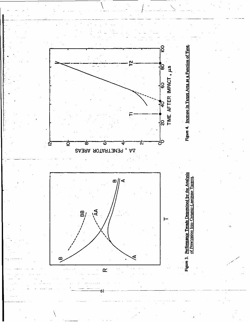
0
00
v LL.<
S -
C-ICu
SV38V 8OiVL3N~d 'VV.
J2
coo
ca
II
61t

Figure 5. Orthogonal Post-Test Radiographs Showing a Penetration PathModified by Planar Failure that Resulted From Wave Interactions.
Figure 6. Orthogonal Post-Test Radiographs Showing a Symmetrical PenetrationPath Achieved by Installing Wave Trans at the Side Boundaries.
62

Figure 7. On aogonaI Failure Planes and Radial Cracks in a Recovered Ceramic Target WithoutWave Trans.
63

4m
< tuo
Pit V
> LS
64

rV 2
L E
~ev
Cu '
bi
1- L u
' E 2
650

ILI
rt d
4*l4fl 4#vtss*~. 9.a .:.j '7?2
* ~s- ~ .r.&Ž rf'~~1~'c~AlF ~ ~ ~ OI rp'1r2rý~Ths * *C
66

Figurc 14. Voids Have Coalesced to Fonn a Crack in an RHA Plate Perforated by. a Comner Shaped-Charge Jet. SEM Micrograph: 4,000x Mag.: 2% Nital Etch.
Y7/
Figure 15. U-3/4% Ti Penetrator Remnant Unbedded in Steel Armor.
67

Figure 16. WHA Penetrator Embedded in Steel Armor.
Figure 17. Behind-Armnor Radiograph Showing Mushroomed Nose of WHA Residual Penetrator.
68

777 p. 7 71
~~ '.
Figure 18 BehndAfno Raigrp shw hsle oeo raimRsda eertr
96

h.,
1 i 1 4 +-i. 1 f 1 1 1 i i- 0
4r
o 1
.. ... ......... .
p170
IM
0 C) 0 C
W~~ v- C0 O L O t) N O C
V4 v-4(Ulm___Dons_____________'U______I __1e __1______u .
I ir I I 1370

Figure 20. Extreme Bulk Defonnation (Mushrtoming) of Polycrystal W Penetrator.
71

FA T
* icisN A i';' k
* 'I r:4~iV~~\j'¶' AtI *VAMA
Al
I I i 9'72

40.7
too -- * ~ ~~
-. \.4- '~ ~ K¶ ic' *1t?"~
ri~
.4S.
73

IA A 40 C)
01
l~co
$9 0%
74~

No. of No. of
S2 Adminiszrator I CommanderDefense Technical Info Center U.S. Army Tank-Automotive CommandATTN: DTIC-DDA ATTN. ASQNC-TAC-DIT (TechnicalCameron tation Information Center)Alexandria, VA 22304-6145 Warren, MI 48397-5000
Commander I DirectorU.S. Army Materiel Command U.S. Army TRADOC Analysis CommandATTN: AMCAM ATTN: ATRC-WSR5001 Eisenhower Ave.' White Sands Missile Range, NM 88002-5502Alexandria, VA 22333-0001
1 CommandantCommander U.S. Army Field Artillery SchoolU.S. Army Laboratory CO'mmand ATN: ATSF-CSIATTN: AMSLC-DL , FL Sill, OK 73503-50002800 Powder Mill Rd.Adelphi, MD 20783-1145 (cM aw)l Commandant
U.S. Army Infantry School2 Commander ATTN: ATSH-CD (Security Mgr.)
U.S. Army Armament Research, Fort Benning, GA 31995-5660Development, and Engineering Center
ATIN: SMCAR-IMI-I (U0MU say) I CommandantPicatinny Arsenal, NJ 07806-5000 U.S. Army Infantry School
ATTN: ATSH-CD-CSO-OR2 Commander Fort Benning, GA 31905-5660
U.S. Army Aiamament Research,Development, and Engineering Center 1 WLIMNOI
ATTN: SMCAR-TDC -. -- - .---Eglin AFB, FL 32542-5000 -Picatinny Arsenal, NJ 07806-5000
I Aberdeen Proving GroundDirectorBenet Weapons Laboratory 2 Dir, USAMSAAU.S. Army Armament Research, ATTN: AMXSY-D
Development, and Engineering Center ' AMXSY-MP, IL CohenATTN: SMCAR-CCB-TLWatervliet, NY 12189-4050 1 Cdr, USATECOM
ATIN: AMSTE-TC(lJnd,- auify) 1 CommanderU.S. Army Rock Island Arsenal 3 Cdr, CRDEC, AMCCOMATIN: SMCRI-TQlTechnical Library ATIN: SMCCR-RSP-ARock Island, IL 61299-5000 SMCCR-MU
SMCCR-MSIDirectorU.S. Army Aviation Research 1 Dir, VLAMO
and Technology Activity ATTN: AMSL.C-VL-DATTN: SAVRT-R (Library)M/S 219-3 10 Dir, USABRLAmes Re-..rch Center ATTN: SLCBR-DD-TMoffen Field, CA 94035-1000
I CommanderU.S. Army Missile CommandATIN: AMSMI-RD-CS-R (DOC)Redstone Arsenal, AL 35898-5010
75

/
No.of No. ofQojje Organization Conies Oranization
7 Director 1 CommanderUS. Army Research Office US. Army Tank-Autonotive CommandATTN: L Chdra ATTN: AMSTA-RSK, 1. Thompson
L Clark Warren, MI 48397-50001, WuK. Iyer 1 1 U.S. Naval AcademyB. Henriksen Department of MathematicsA. Crowson ATTN. R. Malek-MadaniTechnical Library Annapolis, MD 21402
P.O. Box 1211Research Triangle Park, NC 27709-2211 1 Air Force Wright Aeronautical Laboratories
Air Force Systems CommandCommander Materials LaboratoryU.S. Army Re-atch and Standardization ATfN: T. Nicholas
Group (Europe) Wright-Patterson AFB, OH 45433ATTN: F. OertelP.O. Box 65 7 CommanderFPO NY 09510 U.S. Army Armament Research, Development,
and Engineering CenterI .Director AT7N.: SMCAR-AEE-WW, E. Baker
U.S. Army Materials Technology Laboratory SMCAR-AET,ATIN: SLCMT-D B. BusheyWatertown, MA 02172-0001 W. Ebihara
SMCAR-AET-M,Director F. WiuU.S. Army Materials Technology Laboratory S. CytronATTN: SLCMT-MR, G. Bishop .D. KapoorWatertown, MA 02172-0001 )L Willison
Picatinny Arsenal, NJ 07806-50006 Director
U.S. Army Materials Technology Laboratory I CommanderATTN: SLCMT-MRD, U.S. Army Armament Research, Development,
S. Chou and Engineering CenterL. Dandekar ATrN: SMCAR-TDS, V. LindlerA. Rajendran Picatinny Arsenal, NY 07806-5000T. WeerasooriyaC. White 2 CommanderP. Woolsey US. Army Belvoir Research, Development,
Watertown, MA 02172-0001 and Engineering CenterATIN: STRBE, S. Bishop
2 Director STRBE-N, D. HeberleinU.S. Army Materials Technology Laboratory For Belvgir, VA 22060ATThN: SLCMT-EMC,
L. BeattyM. Slavin
Watertown, MA 02172-0001
"76
No. of No. ofgCoies Ortarization Cotir, Organization
2 Director S CommanderU.S. Army Engineer Waterways Experiment Naval Weapons Center
Station ATIN: Code 3266, R. HoffmannATTN: CEWES-SD, Code 3261,
J. 0. Jackson T. GiilB. Bohani R. Lundsummo
3909 Halls Ferry Road Code 32, D. GossVicksburg, MS 391806199 Code 3205, F. Markarian
China Lake, CA 93555.6001CommanderU.S. Army Laboratory Command 4 CommanderATTN: AMSLC-TD, R. Vitali Naval Surface Warfare Center2800 Powder Mill Road ATfN: Code RIO, L. RoslundAdelphi, MD 20783-1145 Code R12,
P. Walter2 Commander L. Hudson
U.S. Army Missile Command H. MairATTN: AMSMI-RD, W. Jennings, Jr. Silver Spring, MD 20903-5000
AMSMI-RD-ST-WF, M. SchexnayderRedstone Arsenal, AL 35898 1 Commander
Naval Surface Warfare CenterCommander ATFN: Code G06, D. BrunsonU.S. Army Tank-Automotive Command Dahlgren, VA 22448-5000Armor Application SectionATTN: AMSTA-RSK, S. Goodman I DirectorWarren, MI 48397-5000 Defense Advanced Resean.h Projects
Agency3 Director ATIN: J. Richardson
U.S. Air Force Armament Technology Armor/Antiarmor Joint Program OfficeLaboratory Rosslyn, VA 22209-2308
ATTN: AD/MNW,J. Foster 2 DirectorJ. Collins Defense Advanced Research ProjectsB. Cook . Agency
Eglin Air Force Base, FL 32542-5434 AT1N: B. WilcoxTech. Info.
Director 3701 North Fairfax Di.U.S. Air Force Armament Technology Arlington, VA 22203-1714
LaboratoryATMN: CA, S. Lambert 1 DirectorEglin Air Force Base, FL 32542-5434 Defense Advanced Research Projects
AgencyDirector Land Systems OfficeU.S. Air Force Weapons Laboratory ATTN: T. PhillipsATTN: NTI, Charles Mulligan 3701 North Fairfax Dr.Kirtland Air Force Base, NM 87185 Arlington, VA 22203-1714 ..
77

Noof No. ofCoijes Oruanizatior, Copies Organization
Director 9 DirectorDefense Nuclear Agency Lawrence Livermore National LaboratoryATIN: DNA/SPSD. M. Giltrud ATTN: L-,11,M. Finger6801 Telegraph Road MS L-35,Alexandria, VA 22310-3398 R Chris.ensen
L- CbuchI Office of Munitions R. Tiptn
ATrN: OUSD(A)irWDOM, A. Holt D. BaumRoonn 3B1060, The Pentagon D. SteinbergWashington, DC 20301 MS L-321, 1. Reaugh
MS L342, D. LassilaCommander C. ClineNaval Postgraduate School P.O. Box 808ATnN: Code 73, J. Sternberg Livermore, Ca 94550Monterey. CA 93943
I5 DirectorS Commander Los Alamos National LaboratoryMCRDAC ATTN: MS K574,A7lN: Code AW, D. Vaughn E. ConQuantico, VA 22134-5080 R. GatesS~B. Hogan
5 Director P. Howe
Sandia National Laboratories S. Skaggs
ATTN: Div 1543, Los Alamos, NM 87454
D. GradyM Kipp 7 Director
W. Herrman Los Alamos National LaboratoryS. Passman AflN: MS F663,M. Forrestal J. Johnson
P.O. Box 5800 R. KarppAlbuquerque, NM 87185-5800 S. Shiferl
T. Adams1 Director D,. Mandell
Sandia National Laboratories P. Mollandbee
ATTN: D. Barnmann P. Hopsonse
Livermore, CA 94550 Los Alamos, NM 87454
National Institute of Science and 6 DirectorTechnology Los Alamos National Laboratory
ATTN: T. Burns ATTN: MS B216, F. AddessioTechnology Building, Rm A151 MS B221,Gaithersburg, MD 20899 D. Tonks
L. DiemesSDirector MS B295, K. HolianU.S. Department of Energy MS E546, W. BlumenthalATTN: DP 242, GTN, R&AT/OMA, MS K557, R. Henninger
G. D'Alessio Los Alamos, NM 87454Washington, DC 20545
78
//
A./

9,- -.--
No. of No. ofC92ie ODanization rlries Organization
9 birector 2 California Institute of TechnologyLos Alamos National Laboratory ATIN: W. KnausaATrN: MS J576, G. Ravichandran
Kv Lewis Mill Code 105-50D. Rabern Pasadena, CA 91125
MS F664, L SchwalbeMS F668, F. Day I Carnegie-Mellon UniversityMS F669, J. Repa Department of MathematicsMS 0771, F. Gac A77TN: M. GurtinMS G787, M. Burkett Pittsburgh, PA 15213MS J960,
L. Hull 1 University of CincinnatiJ. Straight Department of Mathematical Sciences
Los Alamos, NM 87454 ATTN: D. FrenchOld Chemistry Building (ML 25)
7 Director Cincinnati, OH 45221Sandia National LaboratoriesATrN: Div 1420, B. Camp I Corncll University
Div 1533, P. Yarrington Department of Theoretical andDiv 9123, J. Hitchcock Applied MechanicsJ. McGlaun ATTN: J. JenkinsE. Hertel Ithaca, NY 14850V. LukD. Gardner 2 Drexel University
P.O. Box 5800 Department of Materials EngineeringAlbuquerque, NM 87185 ATIN: H.- Rogers
P. Chou2 Brown University Philadelphia, PA 18104
Division of EngineeringATTN: R. Clifton I Harvard University
B. Freund Division of Engineering andProvidence, RI 02912 Applied Physics'
ATN: J. HutchinsonI University of California at Cambridge, MA 02138
Santa BarbaraDepartment of Materials Science 2 University of IllinoisATTN.. A. Evans Department of Theoretical andSanta Barbara, CA 93106 Applied Mechanics
ATIN: D. Carlson4 University of California at T. Shawki
San Diego Urbana, IL 61801Department of Applied Mechanics
and Engineering Sciences 1 University of IlLinois atATIN: R. Asaro Chicago Circle
G. Hegemeier Department of Engineering,M. Meyers Mechanics, and MetallurgyS. Nemat-Nasser ATTN: T. Ting
La Jolla, Ca 92093 P.O. Box 4348Chicago, IL 60680
79
/" /
"Itt
No.of No.ofo vies Ormanization Conies Organization
3 The Johns Hopkins University 3 State University of New YorkDepartment of Mechanical Engineering at Stony BrookLawobe Hall Department of Applied MathematicsATrN: A. Douglas and Statistics
KL Ramesh AflN: J. GlimmW. Sharp J. Grove
34th and Charles Streets B. PlohrBaltimore, MD 21218 Stony Brook, NY 11794
I University of Kentucky 1 North Carolina State UniversityDepartment of Engineering Mechanics Department of Civil EngineeringATTN: 0. Dillon, Jr. ATTN: Y. HorieLexington, KY 40506 Raleigh, NC 27607
2 University of Maryland I North Carolina State UniversityDepartment of Mechanical Engineering Department of MathematicsATTN: R. Armstrong ATIN: Tb!. Shearer
L Dally . Raleigh, NC 27695College Park, MD 20742
1, North Carolina State UniversityUniversity of Maryland Department of Mechanical andBaltimore County Aerospace EngineeringATTN: A. Khan ATTN: M. ZikryBaltimore, MD 21228 Raleigh, NC 27695
Massachusetts Institute of 1 Northwestern UniversityTechnology Department of Applied Mathematics
Department of Mechanical Engineering ATmN: W. OlmsteadATTN: L. Anand Evanston, IL 60208Cambridge, MA 02139
I Northwestern University2 University of Minnesota Department of Civil Engineering
Department of Aerospace Engineering ATrN: T. Belytschko .and Mechanics Evanston, IL 60208
ATTN: R. FosdickR. James , I Rensselaer Polytechnic Institute
110 Union Street SE Department of Mechanical EngineeringMinneapolis, MN 55455 ArmN: E. Krempl
- ~Troy, NY 12181 ,
I University of Missouri-Rolla T........12181Department of ME, AE & EM 1 Rensselaer Polytechnic InstituteATrm: R. Batra Department of Computer Science ,Rolla. MO 65401-0249 ATrN: . Flaherty
Troy, NY 12181 - -University of NebraskaDepartment of Engineering Mechanics 1 University of Texas . .ArTN: M. Beaty Texas Institute for Comp. Mechanics212 Bancroft Hall ATTN: J. OdenLincoln, NE 68588 Austin, TX 78712 ."
80
S/
No. of No. ofCopies Organization Conie Organization
Texas A&M University 21 Alliant Techsystems, Inc.Aerospace Engineering Department ATrN: G. JohnsonAT1NX T. Strouboulis T. HolmquistCollege Station, TX 77843-3141 7225 Northland Dr.
Brooklyn Park, MN 55428I -Washington State University
Department of Physics I Research & Development AssociatesATIN: -Y. Gupta ATTN: J. FurlongPullman, WA 99163 2100 Washington Blvd.
Arlington. VA 22209I Washington State University
Department of Mechanical and I_ Aluminum Company of AmericaMaterials Engineering ATTN: R. Stemler
ATTN: H. Zbib ALCOA Center, PA 15069Pullman, WA 99164
1 E.I. DuPont de NemoursInstitute for Defense Analysis ATTN: M. BernhardtATFN: G. Mayer P.O. Box 807021801 N. Beauregard Street Wilmington, DE 19898Alexandria, VA 22311
I General Dynamics Land Systems Division4 SRI International ATTN: W. Burke
ATIN: D. Curran P.O.-Box 1800R. Shockey Warren, MI 48090 *L SeamanH. Giovanola 2 Kaman Sciences Corporation
333 Ravenswood Avenue ATTN: J. MayMenlo Park, CA 94025 M. Nonnandia
P.O. Box 76433 Southwest Research Institute Colorado Springs, CO 80933
Department of Mechanical Sciences IATIN:' C. Anderson 1 California Research and
J. Lankfrd Technology, Inc.U. Lindholm ARAP Group - A Titan Company
8500 Culebra Road ATTN: R. ThorpeSan Antonio, TX 02912 P.O. Box 2229
Princeton, NJ 085432 California Research and
Tecii-.ology, Inc. 1 BattelleATTN: D. Orphal Ordnance Systems and Technology
P. Schneiwind Department5117 Johnson Dr. ATTN: D. ButzPleasanton, CA 94566 505 King Ave.
Columbus, OH 43201-26932 General Research Corporation
ATTN: A. Charters 2 BattelleT. Menna ATIN: G. Dudder
5383 Hollister Ave. W. GurwellSanta Barbara, CA 93111 P.O. Box 999
Richland, WA 99352
81
*~ /.... -.-. 1,. , / -.. /. . A.

"No. of No. ofCoies Oanization Conies Or anization
Coos Ceramic Compay 1 Dyna East CorporationATTN- R Paroio ATlN:, R. Ciccarelli600 Ninth St. 3201 Archer StLGolden, CO 80401 Philadelphia, PA 19104
DOW Chemical USA 2 Institute for Advanced TechnologyOrdnance Systems ATFN: S. BlessATTN: K. Epstein H. Fair800 Building 4030-2 W. Braker LaneMidland, M! 48667 Austin, TX 78759-5329
SGT Products Corporation 1 Zemnow Technical Services, Inc.Chemical and Metallurgical Division ATTN: L. ZernowA7N: I Gonzalez 425 West Benita, Suite 208Hawes St. San Dimas, CA 91773Towanda, PA 18848
I Orlando Technology, Inc.The Carborundum Company ATrN: D. MatuskaStructural Ceramics Division P.O. Box 855ATTN: M. Leitten Shalimar, FL 3257920422 Beach Blvd., Suite 315Huntington Beach, CA 92648 1 Livermore Software Technology
CorporationI Teledyne-Brow-n Engineering ATN.: J. Hallquist
ATTN: L Smalley, MS 50 2876 Waverly WayP.O. Box 07007 Livermore, CA 94550Huntsville, AL 35807-7007
Failure Analysis AssociatesATN: S. AndrewP.O. Box f015Menlo Park, CA 94025
CERCOM, Inc.ATTN." f. PalickaP.O. Box 70Buena Vista. CA 92083
2 Lanxide Amor Products, Inc.AflN: V. Kelsey
K. LeightonP.O. Box 6077Newark, DE 19714-6077
2 BanelleEdgewood OperationsATTN: R. Jameson
S. Goa.ski2113 Emmorton Park Rd.Edgewood, MD 21040
R2?
-- • - -.. ' .•
S. . •, .o "" (" ' I. ' "
No. Of No. ofC Ortanization Copie Organization
Ruhr-Universitat Bochum I Canadian Arsenals, LTDATTN: J. Kalthoff ATTN: P. PelletierUniversiwtstrasse 150 5 Montee des Arsenaux4360 Bochum 1, Postfach 102148 Villie de Gardeur, PQ, i5Z2GERMANY CANADA
.1 Condat GmbH I Ernst.Mach InstitutATTN: K. Thoma ATTN: A. StilpMaximilianstrasse 28 Eckerstrasse 48069 Scheyem-Fernhag D-7800 Freiburg i. Br.GERMANY GERMANY
IFAM 1 IABG"Materialforschung AT7N: H. RaatschenATTN: L. Meyer Einsteinstrasse 20Lesumer Heerstrasse 36 D.8012 Ottobrun B. Muenchex2820 Bremen 77 GERMANYGERMANY
I Centre d.Etudes de Vajours3 RARDE ATTN: PLOTARD J..P.
ATTN: I. Cullis Boite Postale No. 7P. Church 77181 CountryA. Hopkins FRANCE
Fort Halstead - SevenoaksTN14 7BP Kent 1 PRB S.A.ENGLAND ATTN: M. Vansnick
Avenue de Tervueren 168, Bte. 7Brutel University Brussels, B-1150BICOM BELGIUMATT'l: J. WhitemanUxbridge, Middlesex 1 AB Bofors/Ammunition DivisionUBS 3PH 'ATNr: Jan HasslidENGLAND Box 900
S-691 80 BoforsDefense Research Establishment SWEDEN
SuffieldAT7N: C. WickertRalston, Alberta, TOJ 2NO RalstonCANADA
Defense Research EstablishmentValcarier
ATTN." N. GassP.O. Box 8800Courcellette, PQ, GOA IROCANADA
83

ImmmoNALLY LEFr BLANK.
84