Embed Size (px)
DESCRIPTION
airbus a320 TSM
Citation preview
HIGHLIGHTS __________
REVISION NO. 54 May 01/08
Pages which have been revised are outlined below, together with the Highlights of theRevision
--------------------------------------------------------------------------------------CH/SE/SU C REASON FOR CHANGE EFFECTIVITY PAGES--------------------------------------------------------------------------------------
CHAPTER 00__________
L.E.P. 1- 1 REVISED TO REFLECT THIS REVISION INDICATING NEW,REVISED, AND/OR DELETED PAGES00-INTRO AIRCRAFT TABLE UPDATED ALL 1- 4
00-HIGHLIGHTS Page 1 of 1 REVISION NO. 54 May 01/08
SROS
CHAPTER 00 __________
INTRODUCTION
LIST OF EFFECTIVE PAGES _______________________ N, R or D indicates pages which are New, Revised or Deleted respectively Remove and insert the affected pages and complete the Record of Revisions and the Record of Temporary Revisions as necessary
CH/SE/SU C PAGE DATE CH/SE/SU C PAGE DATE CH/SE/SU C PAGE DATE
RECORD 00-INTRO 30 May01/07 00-INTRO 72 May01/07OF REV. 00-INTRO 31 May01/07 00-INTRO 73 May01/07 00-INTRO 32 May01/07 00-INTRO 74 May01/07RECORD 00-INTRO 33 May01/07 00-INTRO 75 May01/07OF TEMP. 00-INTRO 34 May01/07 00-INTRO 76 May01/07REVISION 00-INTRO 35 May01/07 00-INTRO 77 May01/07 00-INTRO 36 May01/07 00-INTRO 78 May01/07LIST OF 00-INTRO 37 May01/07 00-INTRO 79 May01/07CHAPTERS 00-INTRO 38 May01/07 00-INTRO 80 May01/07 00-INTRO 39 May01/07 00-INTRO 81 May01/07L.E.P. R 1- 1 May01/08 00-INTRO 40 May01/07 00-INTRO 82 Aug01/07T. of C. 1 May01/07 00-INTRO 41 May01/07 00-INTRO 83 Aug01/07 00-INTRO 42 May01/07 00-INTRO 84 Aug01/0700-INTRO R 1 May01/08 00-INTRO 43 May01/07 00-INTRO 85 Aug01/0700-INTRO R 2 May01/08 00-INTRO 44 May01/07 00-INTRO 86 Aug01/0700-INTRO R 3 May01/08 00-INTRO 45 May01/07 00-INTRO 87 Aug01/0700-INTRO R 4 May01/08 00-INTRO 46 May01/07 00-INTRO 88 Aug01/0700-INTRO 5 Aug01/02 00-INTRO 47 Feb01/08 00-INTRO 89 Aug01/0700-INTRO 6 Aug01/02 00-INTRO 48 May01/07 00-INTRO 90 Aug01/0700-INTRO 7 Aug01/02 00-INTRO 49 May01/07 00-INTRO 91 Aug01/0700-INTRO 8 Aug01/02 00-INTRO 50 May01/07 00-INTRO 92 Aug01/0700-INTRO 9 Aug01/02 00-INTRO 51 May01/07 00-INTRO 93 Aug01/0700-INTRO 10 Aug01/02 00-INTRO 52 May01/07 00-INTRO 94 Aug01/0700-INTRO 11 Aug01/02 00-INTRO 53 May01/0700-INTRO 12 Feb01/05 00-INTRO 54 May01/0700-INTRO 13 Feb01/05 00-INTRO 55 May01/0700-INTRO 14 Aug01/07 00-INTRO 56 May01/0700-INTRO 15 May01/07 00-INTRO 57 May01/0700-INTRO 16 May01/07 00-INTRO 58 May01/0700-INTRO 17 May01/07 00-INTRO 59 May01/0700-INTRO 18 May01/07 00-INTRO 60 May01/0700-INTRO 19 May01/07 00-INTRO 61 May01/0700-INTRO 20 May01/07 00-INTRO 62 May01/0700-INTRO 21 May01/07 00-INTRO 63 May01/0700-INTRO 22 May01/07 00-INTRO 64 May01/0700-INTRO 23 May01/07 00-INTRO 65 May01/0700-INTRO 24 May01/07 00-INTRO 66 May01/0700-INTRO 25 May01/07 00-INTRO 67 May01/0700-INTRO 26 May01/07 00-INTRO 68 May01/0700-INTRO 27 May01/07 00-INTRO 69 May01/0700-INTRO 28 May01/07 00-INTRO 70 May01/0700-INTRO 29 May01/07 00-INTRO 71 May01/07
00-L.E.P. Page 1 May 01/08
SROS
CHAPTER 00 __________
INTRODUCTION
TABLE OF CONTENTS _________________
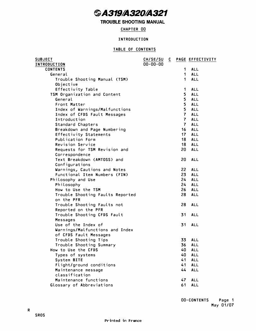
SUBJECT CH/SE/SU C PAGE EFFECTIVITY _______ ________ _ ____ ___________ INTRODUCTION 00-00-00 ____________ CONTENTS 1 ALL General 1 ALL Trouble Shooting Manual (TSM) 1 ALL Objective Effectivity Table 1 ALL TSM Organization and Content 5 ALL General 5 ALL Front Matter 5 ALL Index of Warnings/Malfunctions 5 ALL Index of CFDS Fault Messages 7 ALL Introduction 7 ALL Standard Chapters 7 ALL Breakdown and Page Numbering 16 ALL Effectivity Statements 17 ALL Publication Form 18 ALL Revision Service 18 ALL Requests for TSM Revision and 20 ALL Correspondence Text Breakdown (AMTOSS) and 20 ALL Configurations Warnings, Cautions and Notes 22 ALL Functional Item Numbers (FIN) 23 ALL Philosophy and Use 24 ALL Philosophy 24 ALL How to Use the TSM 26 ALL Trouble Shooting Faults Reported 28 ALL on the PFR Trouble Shooting Faults not 28 ALL Reported on the PFR Trouble Shooting CFDS Fault 31 ALL Messages Use of the Index of 31 ALL Warnings/Malfunctions and Index of CFDS Fault Messages Trouble Shooting Tips 33 ALL Trouble Shooting Summary 36 ALL How to Use the CFDS 40 ALL Types of systems 40 ALL System BITE 41 ALL Flight/ground conditions 41 ALL Maintenance message 44 ALL classification Maintenance functions 47 ALL Glossary of Abbreviations 61 ALL
00-CONTENTS Page 1 May 01/07R SROS

INTRODUCTION - CONTENTS _______________________
1. General _______
A. Trouble Shooting Manual (TSM) Objective
The TSM is provided by AIRBUS to enable the systematic identification, isolation and correction of aircraft warnings and malfunctions reported in flight and on the ground.
B. Effectivity Table
The aircraft identified by an AIRBUS Manufacturer Serial Number (MSN) in the effectivity table are covered in this current TSM issue.
VER: indicates the Aircraft VERsion within the customer fleet. Example: CXN01 corresponds to the first customer version.
STD: Stands for Standard, it corresponds to a production standard for a given range of aircraft technical definition (e.g.: ST1, ST2, etc.).
Version Rank: indicates the �Rank� within the Customer versions. Example: CXN02 0001, corresponds to first aircraft within the second customer version.
NOTE : The standard number and version rank may be useful when ____ consulting/using the SRM and/or the aircraft drawing set.
------------------------------------------------------------------------------- VER |RESTRICT.| MODEL | STD | ENGINE | OPERATOR | EFFECT. | | | | ------------------------------------------------------------------------------- AUA01 0476-0478 321-111 ST2 CFM56-5B1 AUSTRIAN AIRLINES AUA02 0426-0450 320-214 ST1 CFM56-5B4/P AUSTRIAN AIRLINES AUA03 0479-0480 321-211 ST2 CFM56-5B3 AUSTRIAN AIRLINES AUA04 0481-0499 321-211 ST2 CFM56-5B3/P AUSTRIAN AIRLINES AUA05 0451-0475 319-112 ST3 CFM56-5B6 AUSTRIAN AIRLINES AUA05 0451-0475 319-112 ST3 CFM56-5B6/P AUSTRIAN AIRLINES EDW01 0701-0749 320-214 ST1 CFM56-5B4/P EDELWEISS AIR AG I2L22 0254-0275 320-214 ST1 CFM56-5B4/P SWISS INT�L AIR LINES SAB01 0503-0549 321-211 ST2 CFM56-5B3 KIBRIS TURK HAVA YOLLARI LT SAB02 0551-0599 319-112 ST3 CFM56-5B6 BLUE MOON AVIATIONR SAB02 0551-0599 319-112 ST3 CFM56-5B6 BRUSSELS AIRLINESR SAB02 0551-0599 319-112 ST3 CFM56-5B6 KHALIFA AIRWAYSR SAB02 0551-0599 319-112 ST3 CFM56-5B6 MERIDIANA SPAR SAB02 0551-0599 319-112 ST3 CFM56-5B6 NATIONAL AIR SERVICES SAB02 0551-0599 319-112 ST3 CFM56-5B6/P MEXICANA DE AVIACION SWR01 0276-0299 321-111 ST2 CFM56-5B1 AIR MEDITERRANEE SWR01 0276-0299 321-111 ST2 CFM56-5B1 SWISS INT�L AIR LINES SWR01 0276-0299 321-211 ST2 CFM56-5B3/3 AIR MEDITERRANEE SWR02 0227-0227 320-214 ST1 CFM56-5B4 SWISS INT�L AIR LINESR SWR02 0229-0245 320-214 ST1 CFM56-5B4 MEXICANA DE AVIACION
������������������������������������������������� �EFF : ALL � Page 1����������������������������������������������������∞∞00-INTRO∞∞∞∞∞∞∞∞∞∞ � � May 01/08 � � � � SROS

------------------------------------------------------------------------------- VER |RESTRICT.| MODEL | STD | ENGINE | OPERATOR | EFFECT. | | | | -------------------------------------------------------------------------------R SWR02 0229-0245 320-214 ST1 CFM56-5B4 SWISS INT�L AIR LINESR SWR02 0229-0245 320-214 ST1 CFM56-5B4/P SWISS INT�L AIR LINESR SWR02 0229-0245 320-214 ST1 CFM56-5B4/P TRANSPORTES AEREOS PORTUGUER SWR03 0201-0225 319-112 ST3 CFM56-5B6 SWISS INT�L AIR LINES SWR03 0201-0225 319-112 ST3 CFM56-5B6 TRANSPORTES AEREOS PORTUGUE SWR03 0201-0225 319-112 ST3 CFM56-5B6/P AIR IVOIRE, SOCIETER SWR04 0246-0253 320-214 ST1 CFM56-5B4/P INTERJET
Fleet No./MSN Cross-reference table
------------------------------------------------------------------------------- AIRLINE |CUSTOMER FLEET| VERSION | MODEL | MSN | REGISTRATION | SERIAL NUMBER| RANK | | | ------------------------------------------------------------------------------- SROS 0201 SWR03 0001 319-112 0578 HB-IPV SROS 0202 SWR03 0002 319-112 0588 F-OOUA SROS 0203 SWR03 0003 319-112 0612 HB-IPX SROS 0204 SWR03 0004 319-112 0621 HB-IPY SROS 0205 SWR03 0005 319-112 0629 CS-TTQ SROS 0206 SWR03 0006 319-112 0713 HB-IPU SROS 0207 SWR03 0007 319-112 0727 HB-IPT SROS 0208 SWR03 0008 319-112 0734 HB-IPS SROS 0209 SWR03 0009 319-112 1018 HB-IPRR SROS 0227 SWR02 0002 320-214 0545 HB-IJBR SROS 0229 SWR02 0004 320-214 0553 HB-IJDR SROS 0230 SWR02 0005 320-214 0559 HB-IJE SROS 0231 SWR02 0006 320-214 0562 HB-IJF SROS 0232 SWR02 0007 320-214 0566 XA-MXF SROS 0233 SWR02 0008 320-214 0574 HB-IJH SROS 0234 SWR02 0009 320-214 0577 HB-IJI SROS 0235 SWR02 0010 320-214 0585 HB-IJJ SROS 0236 SWR02 0011 320-214 0596 HB-IJK SROS 0237 SWR02 0012 320-214 0603 HB-IJL SROS 0238 SWR02 0013 320-214 0635 HB-IJM SROS 0239 SWR02 0014 320-214 0643 HB-IJN SROS 0240 SWR02 0015 320-214 0673 HB-IJO SROS 0241 SWR02 0016 320-214 0681 HB-IJP SROS 0242 SWR02 0017 320-214 0701 HB-IJQ SROS 0243 SWR02 0018 320-214 0703 HB-IJR SROS 0244 SWR02 0019 320-214 0782 HB-IJS SROS 0245 SWR02 0020 320-214 0870 CS-TQD SROS 0247 SWR04 0002 320-214 1132 XA-IJT SROS 0248 SWR04 0003 320-214 1162 XA-INJ SROS 0249 SWR04 0004 320-214 1179 XA-AIJ SROS 0250 SWR04 0005 320-214 1244 XA-IJA SROS 0251 SWR04 0006 320-214 1259 XA-ITJ SROS 0252 SWR04 0007 320-214 1308 XA-ALM
������������������������������������������������� �EFF : ALL � Page 2����������������������������������������������������∞∞00-INTRO∞∞∞∞∞∞∞∞∞∞ � � May 01/08 � � � � SROS
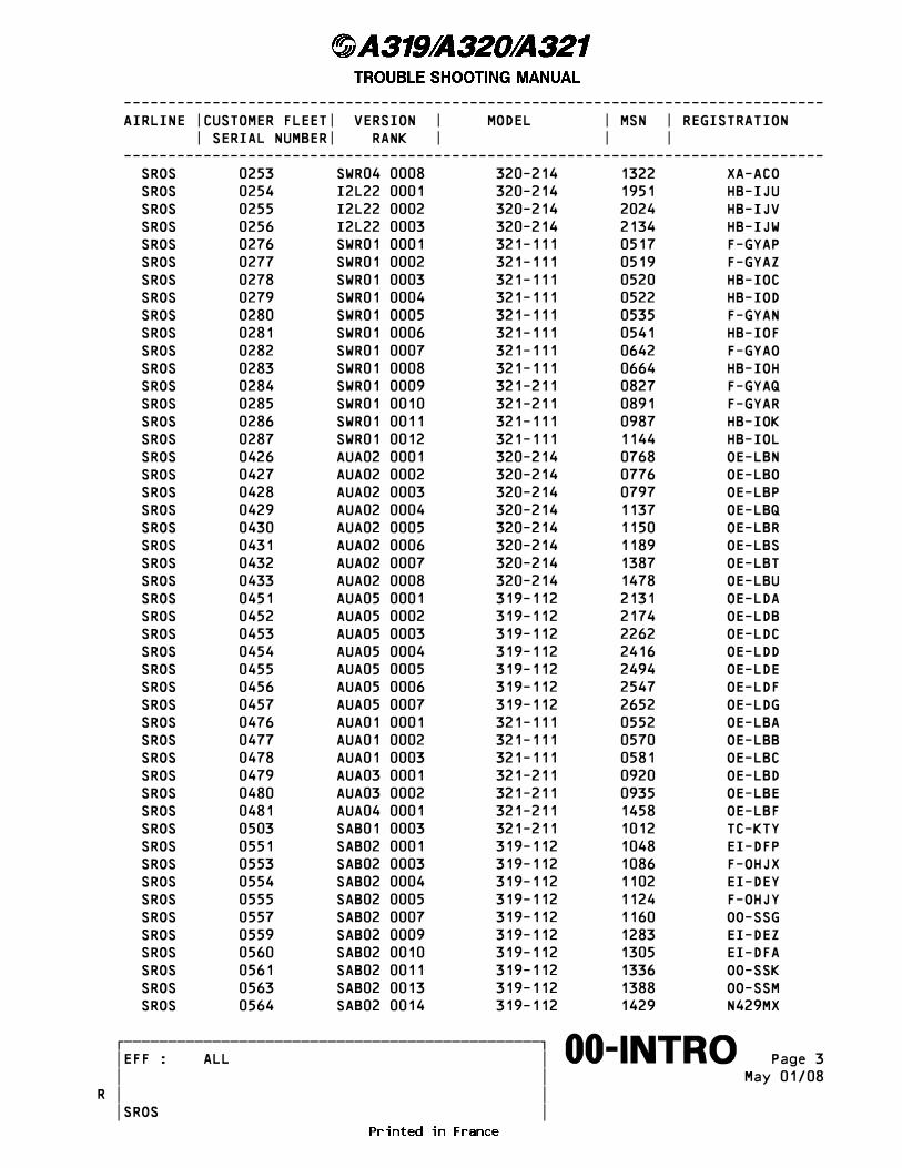
------------------------------------------------------------------------------- AIRLINE |CUSTOMER FLEET| VERSION | MODEL | MSN | REGISTRATION | SERIAL NUMBER| RANK | | | ------------------------------------------------------------------------------- SROS 0253 SWR04 0008 320-214 1322 XA-ACO SROS 0254 I2L22 0001 320-214 1951 HB-IJU SROS 0255 I2L22 0002 320-214 2024 HB-IJV SROS 0256 I2L22 0003 320-214 2134 HB-IJW SROS 0276 SWR01 0001 321-111 0517 F-GYAP SROS 0277 SWR01 0002 321-111 0519 F-GYAZ SROS 0278 SWR01 0003 321-111 0520 HB-IOC SROS 0279 SWR01 0004 321-111 0522 HB-IOD SROS 0280 SWR01 0005 321-111 0535 F-GYAN SROS 0281 SWR01 0006 321-111 0541 HB-IOF SROS 0282 SWR01 0007 321-111 0642 F-GYAO SROS 0283 SWR01 0008 321-111 0664 HB-IOH SROS 0284 SWR01 0009 321-211 0827 F-GYAQ SROS 0285 SWR01 0010 321-211 0891 F-GYAR SROS 0286 SWR01 0011 321-111 0987 HB-IOK SROS 0287 SWR01 0012 321-111 1144 HB-IOL SROS 0426 AUA02 0001 320-214 0768 OE-LBN SROS 0427 AUA02 0002 320-214 0776 OE-LBO SROS 0428 AUA02 0003 320-214 0797 OE-LBP SROS 0429 AUA02 0004 320-214 1137 OE-LBQ SROS 0430 AUA02 0005 320-214 1150 OE-LBR SROS 0431 AUA02 0006 320-214 1189 OE-LBS SROS 0432 AUA02 0007 320-214 1387 OE-LBT SROS 0433 AUA02 0008 320-214 1478 OE-LBU SROS 0451 AUA05 0001 319-112 2131 OE-LDA SROS 0452 AUA05 0002 319-112 2174 OE-LDB SROS 0453 AUA05 0003 319-112 2262 OE-LDC SROS 0454 AUA05 0004 319-112 2416 OE-LDD SROS 0455 AUA05 0005 319-112 2494 OE-LDE SROS 0456 AUA05 0006 319-112 2547 OE-LDF SROS 0457 AUA05 0007 319-112 2652 OE-LDG SROS 0476 AUA01 0001 321-111 0552 OE-LBA SROS 0477 AUA01 0002 321-111 0570 OE-LBB SROS 0478 AUA01 0003 321-111 0581 OE-LBC SROS 0479 AUA03 0001 321-211 0920 OE-LBD SROS 0480 AUA03 0002 321-211 0935 OE-LBE SROS 0481 AUA04 0001 321-211 1458 OE-LBF SROS 0503 SAB01 0003 321-211 1012 TC-KTY SROS 0551 SAB02 0001 319-112 1048 EI-DFP SROS 0553 SAB02 0003 319-112 1086 F-OHJX SROS 0554 SAB02 0004 319-112 1102 EI-DEY SROS 0555 SAB02 0005 319-112 1124 F-OHJY SROS 0557 SAB02 0007 319-112 1160 OO-SSG SROS 0559 SAB02 0009 319-112 1283 EI-DEZ SROS 0560 SAB02 0010 319-112 1305 EI-DFA SROS 0561 SAB02 0011 319-112 1336 OO-SSK SROS 0563 SAB02 0013 319-112 1388 OO-SSM SROS 0564 SAB02 0014 319-112 1429 N429MX
������������������������������������������������� �EFF : ALL � Page 3����������������������������������������������������∞∞00-INTRO∞∞∞∞∞∞∞∞∞∞ � � May 01/08 � �R � � SROS
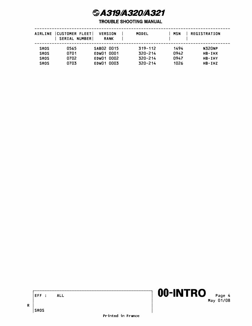
------------------------------------------------------------------------------- AIRLINE |CUSTOMER FLEET| VERSION | MODEL | MSN | REGISTRATION | SERIAL NUMBER| RANK | | | ------------------------------------------------------------------------------- SROS 0565 SAB02 0015 319-112 1494 N320NP SROS 0701 EDW01 0001 320-214 0942 HB-IHX SROS 0702 EDW01 0002 320-214 0947 HB-IHY SROS 0703 EDW01 0003 320-214 1026 HB-IHZ
������������������������������������������������� �EFF : ALL � Page 4����������������������������������������������������∞∞00-INTRO∞∞∞∞∞∞∞∞∞∞ � � May 01/08 � �R � � SROS
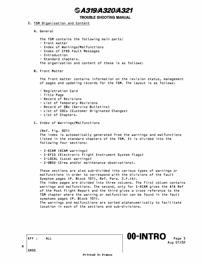
2. TSM Organization and Content ____________________________
A. General
The TSM contains the following main parts: - Front matter - Index of Warnings/Malfunctions - Index of CFDS Fault Messages - Introduction - Standard chapters. The organization and content of these is as follows:
B. Front Matter
The front matter contains information on the revision status, management of pages and updating records for the TSM. The layout is as follows:
- Registration Card - Title Page - Record of Revisions - List of Temporary Revisions - Record of SBs (Service Bulletins) - List of COCs (Customer Originated Changes) - List of Chapters.
C. Index of Warnings/Malfunctions
(Ref. Fig. 001) The index is automatically generated from the warnings and malfunctions listed in the standard chapters of the TSM. It is divided into the following four sections:
- I-ECAM (ECAM warnings) - I-EFIS (Electronic Flight Instrument System flags) - I-LOCAL (Local warnings) - I-OBSV (Crew and/or maintenance observations).
These sections are also sub-divided into various types of warnings or malfunctions in order to correspond with the divisions of the Fault Symptom pages (P. Block 101), Ref. Para. 2.F.(4). The index pages are divided into three columns. The first column contains warnings and malfunctions. The second, only for I-ECAM gives the ATA Ref of the Post Flight Report and the third gives a cross reference to the TSM chapter where the warning or malfunction can be found in the fault symptoms pages (P. Block 101). The warnings and malfunctions are sorted alphanumerically to facilitate location in each of the sections and sub-divisions.
������������������������������������������������� �EFF : ALL � Page 5����������������������������������������������������∞∞00-INTRO∞∞∞∞∞∞∞∞∞∞ � � Aug 01/02 � �R � � SROS
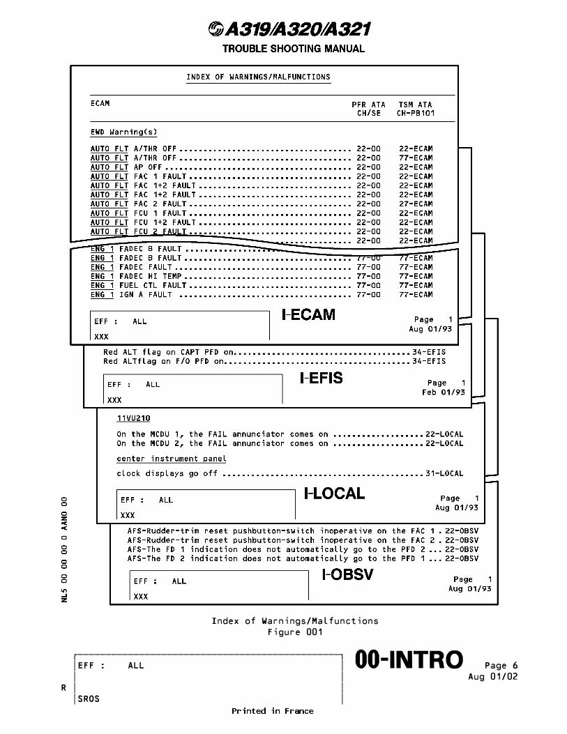
Index of Warnings/Malfunctions Figure 001
������������������������������������������������� �EFF : ALL � Page 6����������������������������������������������������∞∞00-INTRO∞∞∞∞∞∞∞∞∞∞ � � Aug 01/02 � �R � � SROS
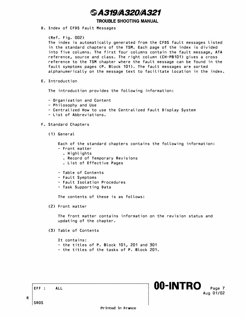
D. Index of CFDS Fault Messages
(Ref. Fig. 002) The index is automatically generated from the CFDS fault messages listed in the standard chapters of the TSM. Each page of the index is divided into five columns. The first four columns contain the fault message, ATA reference, source and class. The right column (CH-PB101) gives a cross reference to the TSM chapter where the fault message can be found in the fault symptoms pages (P. Block 101). The fault messages are sorted alphanumerically on the message text to facilitate location in the index.
E. Introduction
The introduction provides the following information:
- Organization and Content - Philosophy and Use - Centralized How to use the Centralized Fault Display System - List of Abbreviations.
F. Standard Chapters
(1) General
Each of the standard chapters contains the following information: - Front matter . Highlights . Record of Temporary Revisions . List of Effective Pages
- Table of Contents - Fault Symptoms - Fault Isolation Procedures - Task Supporting Data
The contents of these is as follows:
(2) Front matter
The front matter contains information on the revision status and updating of the chapter.
(3) Table of Contents
It contains: - the titles of P. Block 101, 201 and 301 - the titles of the tasks of P. Block 201.
������������������������������������������������� �EFF : ALL � Page 7����������������������������������������������������∞∞00-INTRO∞∞∞∞∞∞∞∞∞∞ � � Aug 01/02 � �R � � SROS
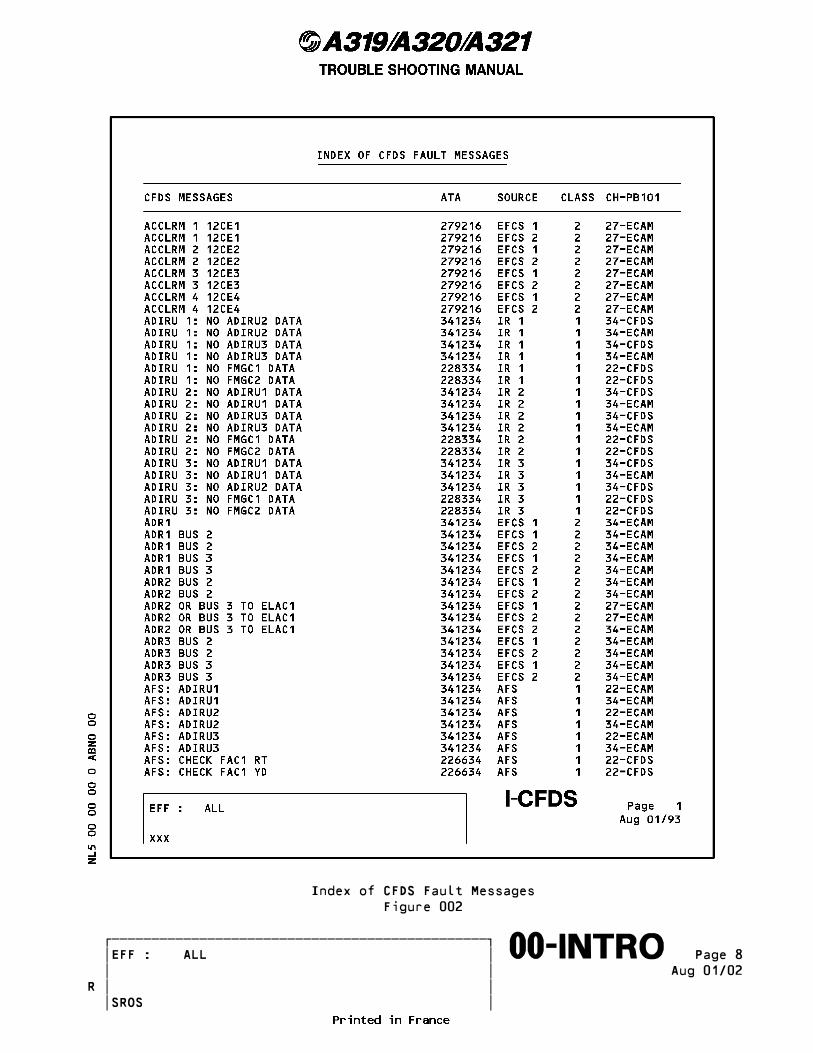
Index of CFDS Fault Messages Figure 002
������������������������������������������������� �EFF : ALL � Page 8����������������������������������������������������∞∞00-INTRO∞∞∞∞∞∞∞∞∞∞ � � Aug 01/02 � �R � � SROS
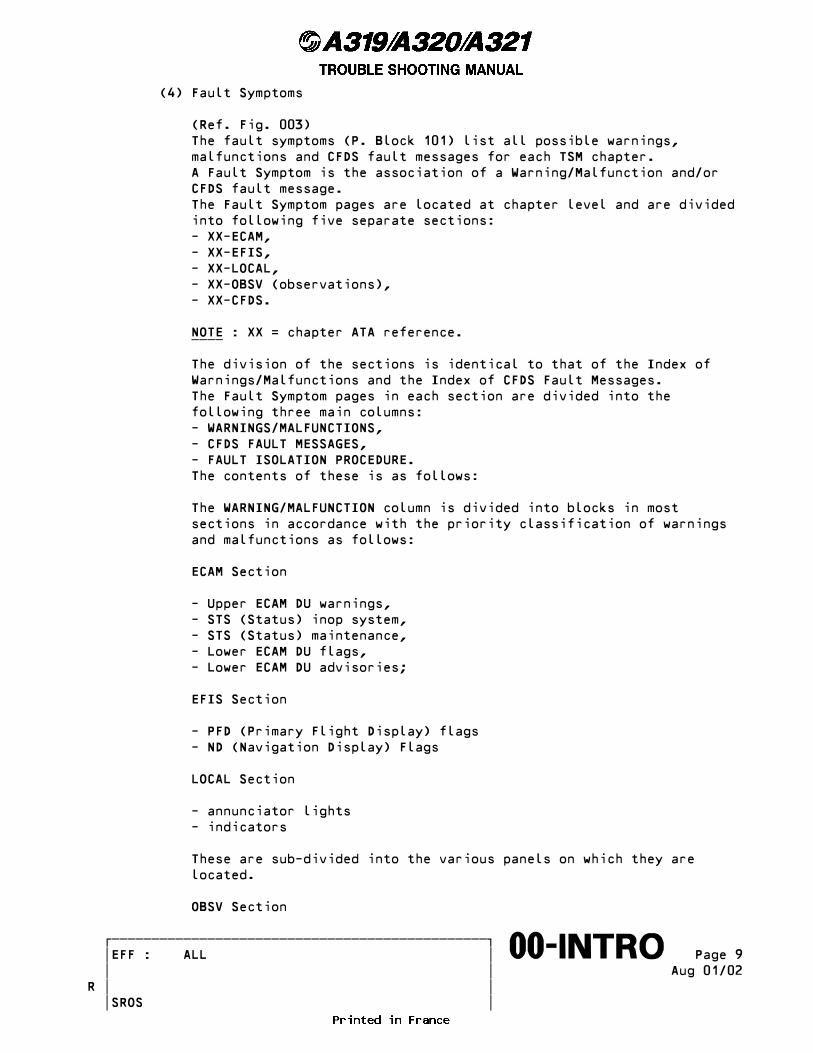
(4) Fault Symptoms
(Ref. Fig. 003) The fault symptoms (P. Block 101) list all possible warnings, malfunctions and CFDS fault messages for each TSM chapter. A Fault Symptom is the association of a Warning/Malfunction and/or CFDS fault message. The Fault Symptom pages are located at chapter level and are divided into following five separate sections: - XX-ECAM, - XX-EFIS, - XX-LOCAL, - XX-OBSV (observations), - XX-CFDS.
NOTE : XX = chapter ATA reference. ____
The division of the sections is identical to that of the Index of Warnings/Malfunctions and the Index of CFDS Fault Messages. The Fault Symptom pages in each section are divided into the following three main columns: - WARNINGS/MALFUNCTIONS, - CFDS FAULT MESSAGES, - FAULT ISOLATION PROCEDURE. The contents of these is as follows:
The WARNING/MALFUNCTION column is divided into blocks in most sections in accordance with the priority classification of warnings and malfunctions as follows:
ECAM Section
- Upper ECAM DU warnings, - STS (Status) inop system, - STS (Status) maintenance, - Lower ECAM DU flags, - Lower ECAM DU advisories;
EFIS Section
- PFD (Primary Flight Display) flags - ND (Navigation Display) Flags
LOCAL Section
- annunciator lights - indicators
These are sub-divided into the various panels on which they are located.
OBSV Section
������������������������������������������������� �EFF : ALL � Page 9����������������������������������������������������∞∞00-INTRO∞∞∞∞∞∞∞∞∞∞ � � Aug 01/02 � �R � � SROS
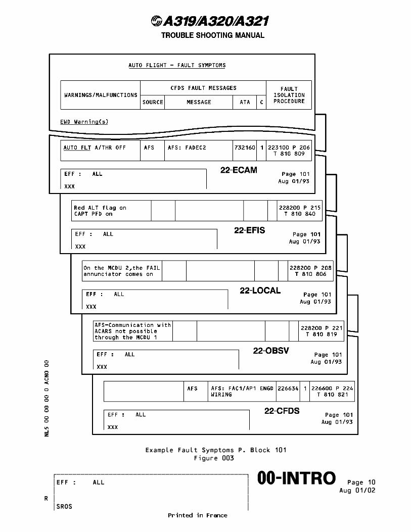
Example Fault Symptoms P. Block 101 Figure 003
������������������������������������������������� �EFF : ALL � Page 10����������������������������������������������������∞∞00-INTRO∞∞∞∞∞∞∞∞∞∞ � � Aug 01/02 � �R � � SROS
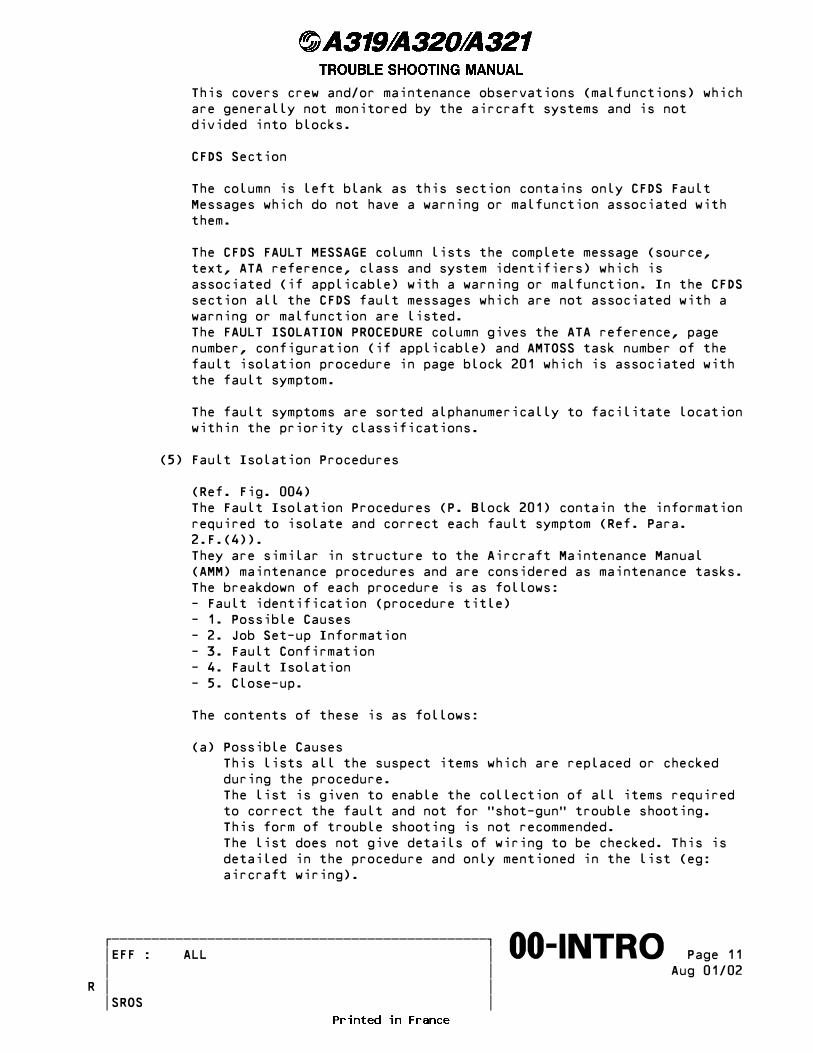
This covers crew and/or maintenance observations (malfunctions) which are generally not monitored by the aircraft systems and is not divided into blocks.
CFDS Section
The column is left blank as this section contains only CFDS Fault Messages which do not have a warning or malfunction associated with them.
The CFDS FAULT MESSAGE column lists the complete message (source, text, ATA reference, class and system identifiers) which is associated (if applicable) with a warning or malfunction. In the CFDS section all the CFDS fault messages which are not associated with a warning or malfunction are listed. The FAULT ISOLATION PROCEDURE column gives the ATA reference, page number, configuration (if applicable) and AMTOSS task number of the fault isolation procedure in page block 201 which is associated with the fault symptom.
The fault symptoms are sorted alphanumerically to facilitate location within the priority classifications.
(5) Fault Isolation Procedures
(Ref. Fig. 004) The Fault Isolation Procedures (P. Block 201) contain the information required to isolate and correct each fault symptom (Ref. Para. 2.F.(4)). They are similar in structure to the Aircraft Maintenance Manual (AMM) maintenance procedures and are considered as maintenance tasks. The breakdown of each procedure is as follows: - Fault identification (procedure title) - 1. Possible Causes - 2. Job Set-up Information - 3. Fault Confirmation - 4. Fault Isolation - 5. Close-up.
The contents of these is as follows:
(a) Possible Causes This lists all the suspect items which are replaced or checked during the procedure. The list is given to enable the collection of all items required to correct the fault and not for �shot-gun� trouble shooting. This form of trouble shooting is not recommended. The list does not give details of wiring to be checked. This is detailed in the procedure and only mentioned in the list (eg: aircraft wiring).
������������������������������������������������� �EFF : ALL � Page 11����������������������������������������������������∞∞00-INTRO∞∞∞∞∞∞∞∞∞∞ � � Aug 01/02 � �R � � SROS

R Example Fault Isolation ProcedureR Figure 004 (SHEET 1)
������������������������������������������������� �EFF : ALL � Page 12����������������������������������������������������∞∞00-INTRO∞∞∞∞∞∞∞∞∞∞ � � Feb 01/05 � � � � SROS

R Example Fault Isolation ProcedureR Figure 004 (SHEET 2)
������������������������������������������������� �EFF : ALL � Page 13����������������������������������������������������∞∞00-INTRO∞∞∞∞∞∞∞∞∞∞ � � Feb 01/05 � � � � SROS

(b) Job Set-up Information This lists any tools, equipment and procedures required to be carried out before commencing the fault isolation and is the same as the AMM job set-up.
(c) Fault Confirmation Any test procedure needed to confirm that the fault is genuine is given here. This is to avoid unjustified LRU removals. Confirmation tests of spurious warnings will also be covered, if applicable.
(d) Fault Isolation Procedure The procedure gives the appropriate actions to isolate and correct the related fault symptom. Before you get access for a wiring check, make sure that you obey the applicable warning(s):
WARNING: PUT THE SAFETY DEVICES AND THE WARNING NOTICES IN POSITION BEFORE YOU START A TASK ON OR NEAR: - THE FLIGHT CONTROLS - THE FLIGHT CONTROL SURFACES - THE LANDING GEAR AND THE RELATED DOORS - COMPONENTS THAT MOVE. MOVEMENT OF COMPONENTS CAN KILL OR INJURE PERSONS.
WARNING:R MAKE SURE THAT YOU DO THE DEACTIVATION OF THE THRUST REVERSERR BEFORE YOU DO MAINTENANCE WORK ON OR AROUND THE THRUST REVERSER. IF YOU DO NOT DO THIS PROCEDURE, THERE IS A RISK OF UNWANTED OPERATION AND THUS OF INJURY TO PERSONS AND DAMAGE TO EQUIPMENT.
WARNING: YOU MUST OBEY ALL THE SAFETY PROCEDURES WHEN YOU DO WORK IN OR NEAR THE FUEL TANK. IF YOU DO NOT OBEY THE SAFETY PROCEDURES, THERE IS A RISK OF: - DEATH OR INJURY TO PERSONS - DAMAGE TO THE AIRCRAFT OR OTHER EQUIPMENT.
Specific instructions for the wiring check are given where necessary. These include values (eg. resistance) and connector/pin numbers where applicable. If no specific instructions are given for the wiring check, the check must include a continuity test (ESPM 20-52-21) and a test for short circuit (ESPM 20-52-22)
(e) Close-up If it is necessary to return the A/C to its initial configuration after fault confirmation or fault isolation, the applicable procedure is given.
������������������������������������������������� �EFF : ALL � Page 14����������������������������������������������������∞∞00-INTRO∞∞∞∞∞∞∞∞∞∞ � � Aug 01/07 � � � � SROS

(6) Task Supporting Data (P. Block 301)
Task Supporting Data are given to show the system layout and interconnections with other systems.
������������������������������������������������� �EFF : ALL � Page 15����������������������������������������������������∞∞00-INTRO∞∞∞∞∞∞∞∞∞∞ � � May 01/07 � �R � � SROS
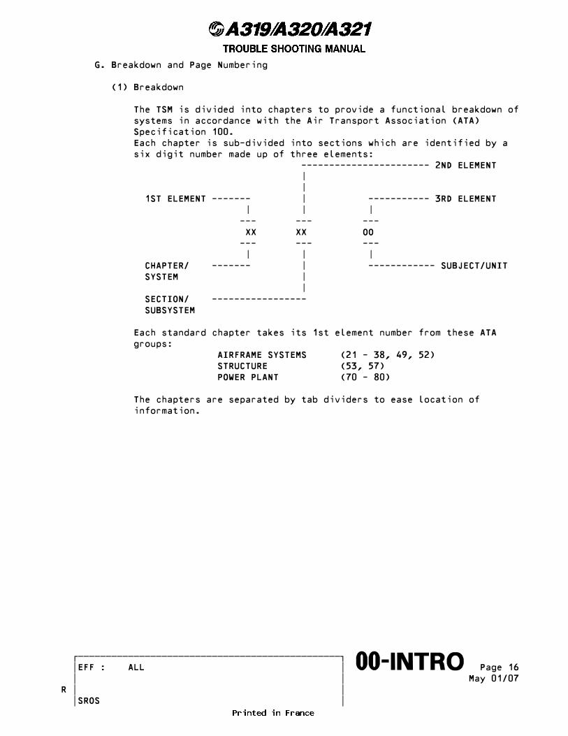
G. Breakdown and Page Numbering
(1) Breakdown
The TSM is divided into chapters to provide a functional breakdown of systems in accordance with the Air Transport Association (ATA) Specification 100. Each chapter is sub-divided into sections which are identified by a six digit number made up of three elements: ----------------------- 2ND ELEMENT | | 1ST ELEMENT ------- | ----------- 3RD ELEMENT | | | --- --- --- XX XX OO --- --- --- | | | CHAPTER/ ------- | ------------ SUBJECT/UNIT SYSTEM | | SECTION/ ----------------- SUBSYSTEM
Each standard chapter takes its 1st element number from these ATA groups: AIRFRAME SYSTEMS (21 - 38, 49, 52) STRUCTURE (53, 57) POWER PLANT (70 - 80)
The chapters are separated by tab dividers to ease location of information.
������������������������������������������������� �EFF : ALL � Page 16����������������������������������������������������∞∞00-INTRO∞∞∞∞∞∞∞∞∞∞ � � May 01/07 � �R � � SROS
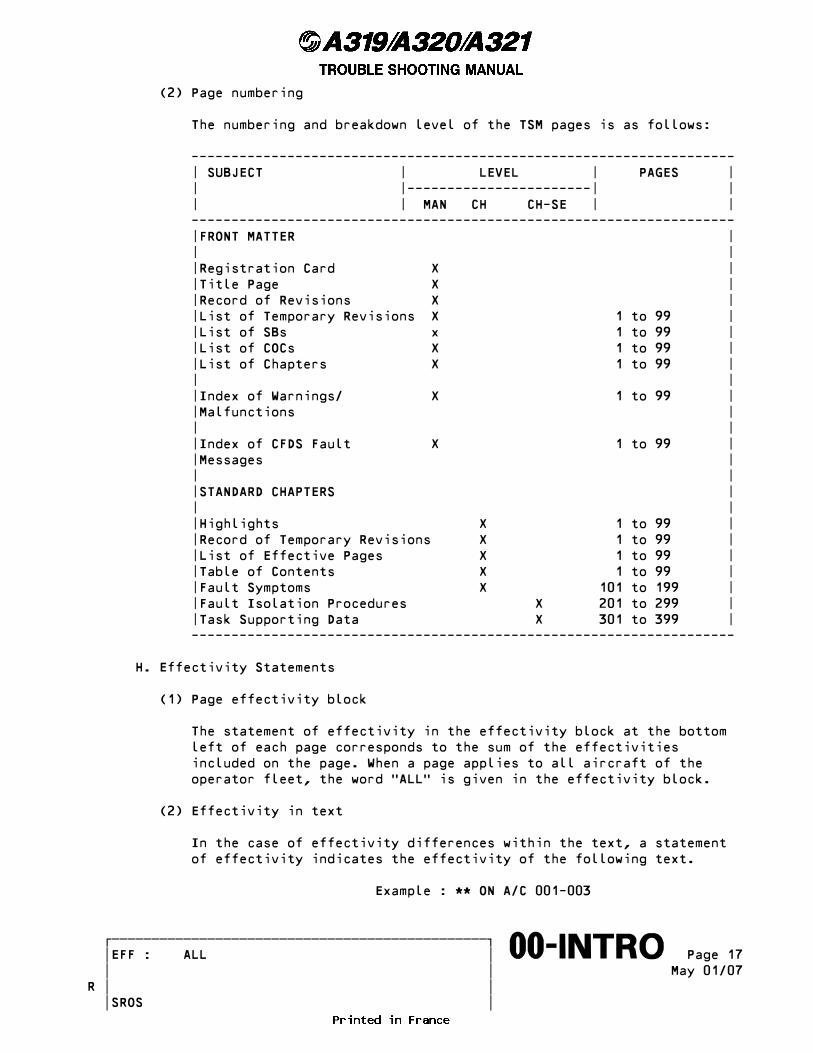
(2) Page numbering
The numbering and breakdown level of the TSM pages is as follows:
-------------------------------------------------------------------- | SUBJECT | LEVEL | PAGES | | |-----------------------| | | | MAN CH CH-SE | | -------------------------------------------------------------------- |FRONT MATTER | | | |Registration Card X | |Title Page X | |Record of Revisions X | |List of Temporary Revisions X 1 to 99 | |List of SBs x 1 to 99 | |List of COCs X 1 to 99 | |List of Chapters X 1 to 99 | | | |Index of Warnings/ X 1 to 99 | |Malfunctions | | | |Index of CFDS Fault X 1 to 99 | |Messages | | | |STANDARD CHAPTERS | | | |Highlights X 1 to 99 | |Record of Temporary Revisions X 1 to 99 | |List of Effective Pages X 1 to 99 | |Table of Contents X 1 to 99 | |Fault Symptoms X 101 to 199 | |Fault Isolation Procedures X 201 to 299 | |Task Supporting Data X 301 to 399 | --------------------------------------------------------------------
H. Effectivity Statements
(1) Page effectivity block
The statement of effectivity in the effectivity block at the bottom left of each page corresponds to the sum of the effectivities included on the page. When a page applies to all aircraft of the operator fleet, the word �ALL� is given in the effectivity block.
(2) Effectivity in text
In the case of effectivity differences within the text, a statement of effectivity indicates the effectivity of the following text.
Example : ** ON A/C 001-003
������������������������������������������������� �EFF : ALL � Page 17����������������������������������������������������∞∞00-INTRO∞∞∞∞∞∞∞∞∞∞ � � May 01/07 � �R � � SROS
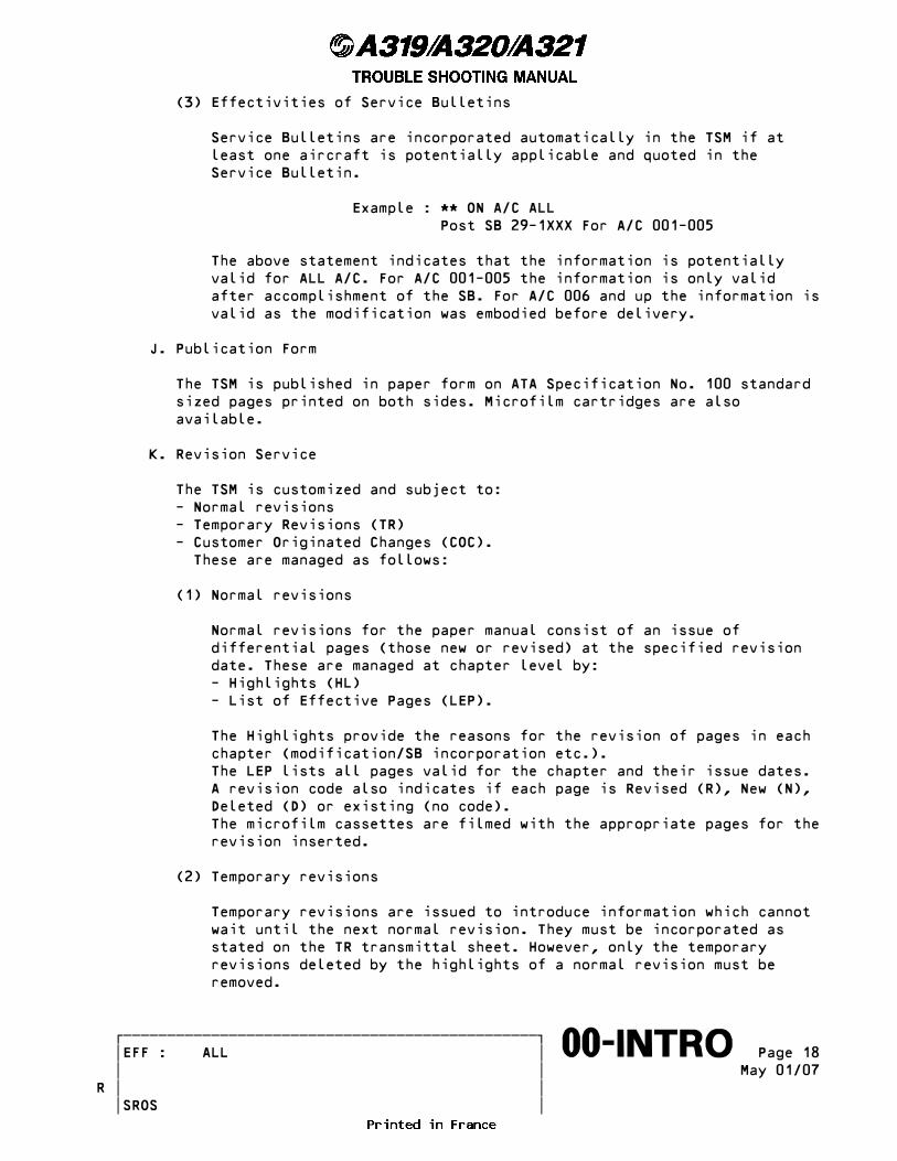
(3) Effectivities of Service Bulletins
Service Bulletins are incorporated automatically in the TSM if at least one aircraft is potentially applicable and quoted in the Service Bulletin.
Example : ** ON A/C ALL Post SB 29-1XXX For A/C 001-005
The above statement indicates that the information is potentially valid for ALL A/C. For A/C 001-005 the information is only valid after accomplishment of the SB. For A/C 006 and up the information is valid as the modification was embodied before delivery.
J. Publication Form
The TSM is published in paper form on ATA Specification No. 100 standard sized pages printed on both sides. Microfilm cartridges are also available.
K. Revision Service
The TSM is customized and subject to: - Normal revisions - Temporary Revisions (TR) - Customer Originated Changes (COC). These are managed as follows:
(1) Normal revisions
Normal revisions for the paper manual consist of an issue of differential pages (those new or revised) at the specified revision date. These are managed at chapter level by: - Highlights (HL) - List of Effective Pages (LEP).
The Highlights provide the reasons for the revision of pages in each chapter (modification/SB incorporation etc.). The LEP lists all pages valid for the chapter and their issue dates. A revision code also indicates if each page is Revised (R), New (N), Deleted (D) or existing (no code). The microfilm cassettes are filmed with the appropriate pages for the revision inserted.
(2) Temporary revisions
Temporary revisions are issued to introduce information which cannot wait until the next normal revision. They must be incorporated as stated on the TR transmittal sheet. However, only the temporary revisions deleted by the highlights of a normal revision must be removed.
������������������������������������������������� �EFF : ALL � Page 18����������������������������������������������������∞∞00-INTRO∞∞∞∞∞∞∞∞∞∞ � � May 01/07 � �R � � SROS
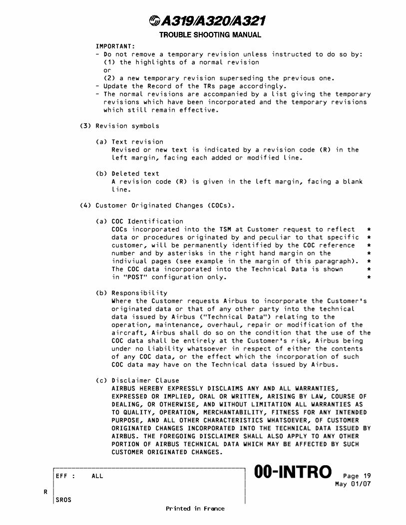
IMPORTANT: - Do not remove a temporary revision unless instructed to do so by: (1) the highlights of a normal revision or (2) a new temporary revision superseding the previous one. - Update the Record of the TRs page accordingly. - The normal revisions are accompanied by a list giving the temporary revisions which have been incorporated and the temporary revisions which still remain effective.
(3) Revision symbols
(a) Text revision Revised or new text is indicated by a revision code (R) in the left margin, facing each added or modified line.
(b) Deleted text A revision code (R) is given in the left margin, facing a blank line.
(4) Customer Originated Changes (COCs).
(a) COC Identification COCs incorporated into the TSM at Customer request to reflect * data or procedures originated by and peculiar to that specific * customer, will be permanently identified by the COC reference * number and by asterisks in the right hand margin on the * indiviual pages (see example in the margin of this paragraph). * The COC data incorporated into the Technical Data is shown * in �POST� configuration only. *
(b) Responsibility Where the Customer requests Airbus to incorporate the Customer�s originated data or that of any other party into the technical data issued by Airbus (�Technical Data�) relating to the operation, maintenance, overhaul, repair or modification of the aircraft, Airbus shall do so on the condition that the use of the COC data shall be entirely at the Customer�s risk, Airbus being under no liability whatsoever in respect of either the contents of any COC data, or the effect which the incorporation of such COC data may have on the Technical data issued by Airbus.
(c) Disclaimer Clause AIRBUS HEREBY EXPRESSLY DISCLAIMS ANY AND ALL WARRANTIES, EXPRESSED OR IMPLIED, ORAL OR WRITTEN, ARISING BY LAW, COURSE OF DEALING, OR OTHERWISE, AND WITHOUT LIMITATION ALL WARRANTIES AS TO QUALITY, OPERATION, MERCHANTABILITY, FITNESS FOR ANY INTENDED PURPOSE, AND ALL OTHER CHARACTERISTICS WHATSOEVER, OF CUSTOMER ORIGINATED CHANGES INCORPORATED INTO THE TECHNICAL DATA ISSUED BY AIRBUS. THE FOREGOING DISCLAIMER SHALL ALSO APPLY TO ANY OTHER PORTION OF AIRBUS TECHNICAL DATA WHICH MAY BE AFFECTED BY SUCH CUSTOMER ORIGINATED CHANGES.
������������������������������������������������� �EFF : ALL � Page 19����������������������������������������������������∞∞00-INTRO∞∞∞∞∞∞∞∞∞∞ � � May 01/07 � �R � � SROS
L. Requests for TSM Revision and Correspondence
(1) An RFI/RFR (Request For Information/Request For Revision) form is provided to expedite AIRBUS responses to TSM questions. It is requested that this form be used for any questions concerning the TSM.
(2) All communications concerning the TSM should be sent to:
AIRBUS S.A.S. Technical Data Support and Services 1 Rond Point Maurice Bellonte 31707 Blagnac Cedex France
M. Text Breakdown (AMTOSS) and Configurations
The fault isolation procedures can generally be considered as corrective maintenance tasks. Therefore, AMTOSS (Aircraft Maintenance Task Oriented Support System ) has been applied to the TSM for the functional arrangement of the data. This also has the advantage of consistency with the AMM (Aircraft Maintenance Manual). Consequently, the fault isolation procedures are broken down into AMTOSS tasks and subtasks. The Task numbers are printed in the TSM and the subtask numbers are omitted ( as an option, the subtask numbers can be printed ). A brief description of the structure of Task numbers follows, for further information please refer to the AMM introduction.
������������������������������������������������� �EFF : ALL � Page 20����������������������������������������������������∞∞00-INTRO∞∞∞∞∞∞∞∞∞∞ � � May 01/07 � �R � � SROS
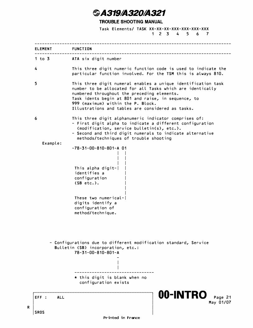
Task Elements/ TASK XX-XX-XX-XXX-XXX-XXX-XXX 1 2 3 4 5 6 7
------------------------------------------------------------------------------- ELEMENT FUNCTION ------------------------------------------------------------------------------- 1 to 3 ATA six digit number
4 This three digit numeric function code is used to indicate the particular function involved. For the TSM this is always 810.
5 This three digit numeral enables a unique identification task number to be allocated for all Tasks which are identically numbered throughout the preceding elements. Task idents begin at 801 and raise, in sequence, to 999 (maximum) within the P. Block. Illustrations and tables are considered as tasks.
6 This three digit alphanumeric indicator comprises of: - First digit alpha to indicate a different configuration (modification, service bulletin(s), etc.). - Second and third digit numerals to indicate alternative methods/techniques of trouble shooting Example: -78-31-00-810-801-A 01 | | | | | | This alpha digit-| | identifies a | configuration | (SB etc.). | | | These two numerical-| digits identify a configuration of method/technique.
- Configurations due to different modification standard, Service Bulletin (SB) incorporation, etc.: 78-31-00-810-801-A - | | -------------------------------- * this digit is blank when no configuration exists
������������������������������������������������� �EFF : ALL � Page 21����������������������������������������������������∞∞00-INTRO∞∞∞∞∞∞∞∞∞∞ � � May 01/07 � �R � � SROS
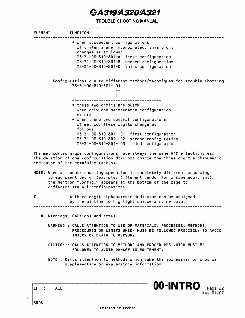
------------------------------------------------------------------------------- ELEMENT FUNCTION ------------------------------------------------------------------------------- * when subsequent configurations of criteria are incorporated, this digit changes as follows: 78-31-00-810-801-A first configuration 78-31-00-810-801-B second configuration 78-31-00-810-801-C third configuration
- Configurations due to different methods/techniques for trouble shooting 78-31-00-810-801- 01 -- | ------------------------------------- * these two digits are blank when only one maintenance configuration exists * when there are several configurations of method, these digits change as follows: 78-31-00-810-801- 01 first configuration 78-31-00-810-801- 02 second configuration 78-31-00-810-801- 03 third configuration
The method/technique configurations have always the same A/C effectivities. The deletion of one configuration does not change the three digit alphanumeric indicator of the remaining task(s).
NOTE: When a trouble shooting operation is completely different according to equipment design (example: Different vendor for a same equipment), the mention �Config.� appears at the bottom of the page to differentiate all configurations.
7 A three digit alphanumeric indicator can be assigned by the airline to highlight unique airline data. ------------------------------------------------------------------------------
N. Warnings, Cautions and Notes
WARNING : CALLS ATTENTION TO USE OF MATERIALS, PROCESSES, METHODS, PROCEDURES OR LIMITS WHICH MUST BE FOLLOWED PRECISELY TO AVOID INJURY OR DEATH TO PERSONS.
CAUTION : CALLS ATTENTION TO METHODS AND PROCEDURES WHICH MUST BE FOLLOWED TO AVOID DAMAGE TO EQUIPMENT.
NOTE : Calls attention to methods which make the job easier or provide supplementary or explanatory information.
������������������������������������������������� �EFF : ALL � Page 22����������������������������������������������������∞∞00-INTRO∞∞∞∞∞∞∞∞∞∞ � � May 01/07 � �R � � SROS
P. Functional Item Numbers (FIN)
The equipment on the A/C is identified by a unique identifier called a Functional Item Number (FIN). The basic element of the FIN is a two letter code indicating to which system/circuit the equipment belongs. To this code are added prefixes and/or suffixes which provide the unique identification for individual items of equipment.
For electrical equipment (any component with an electrical connection) the FIN is of the form 2CA1 where: - 2 = Second component in circuit CA - CA = Circuit two letter code - 1 = Suffix - First of several similar systems (System 1)
NOTE : Several identical components which perform the same function in ____ the same circuit can be differentiated by the suffix number. The general rule is that an even suffix identifies a component on the right hand side and an odd suffix identifies a component on the left hand side.
For mechanical equipment the FIN is of the form 3016GM where M = mechanical equipment and G = corresponding system.
������������������������������������������������� �EFF : ALL � Page 23����������������������������������������������������∞∞00-INTRO∞∞∞∞∞∞∞∞∞∞ � � May 01/07 � �R � � SROS
3. Philosophy and Use __________________ The Maintenance concept is based on the use of CFDS and TSM. (Ref. Fig. 005)
NOTE : The aircraft is equipped with a high number of digital items of ____ equipment. In most of the cases, computers may be recovered after an abnormal behaviour or a detected fault, either by a software reset (reset of microprocessor) or by interrupting the power supply of its processing parts for a short time. This is achieved with the normal cockpit controls (engagement levers, pushbutton switches) by selecting the related control off then on or by action on the corresponding circuit breaker.
A. Philosophy
(1) TSM
The TSM provides coverage of all probable aircraft faults. This includes being a trouble shooting guide to faults monitored and displayed by the aircraft systems. Faults not monitored by the aircraft systems are also covered.
(2) CFDS
The objective of the CFDS is to provide an economic, efficient and easy-to-use means of maintaining the aircraft systems. To do this the CFDS directly monitors and identifies faulty Line Replaceable Units (LRUs) in the aircraft systems and displays items identified as faulty to the maintenance crew. This is essentially achieved by analysis of all cockpit events which are triggered by the monitoring of the aircraft systems. Refer to paragraph 4 for a description of the CFDS and how to use it. The CFDS also takes into account a major objective of the line maintenance which is to avoid unjustified removals of equipment. For these reasons the CFDS makes a detailed analysis to identify the responsible LRUs; this is also to confirm that the event was actually due to a hardware failure and not an intermittent fault. To achieve its purpose, the CFDS has several major functions which supply: - A maintenance Post Flight Report (PFR) which is printed at the end of each flight. The PFR (Ref. Para. 4.E.(1)) allows association of ECAM warnings and CFDS maintenance messages. - Directly usable maintenance messages which identify faulty LRUs. - User-friendly access to tests of the aircraft systems.
������������������������������������������������� �EFF : ALL � Page 24����������������������������������������������������∞∞00-INTRO∞∞∞∞∞∞∞∞∞∞ � � May 01/07 � �R � � SROS
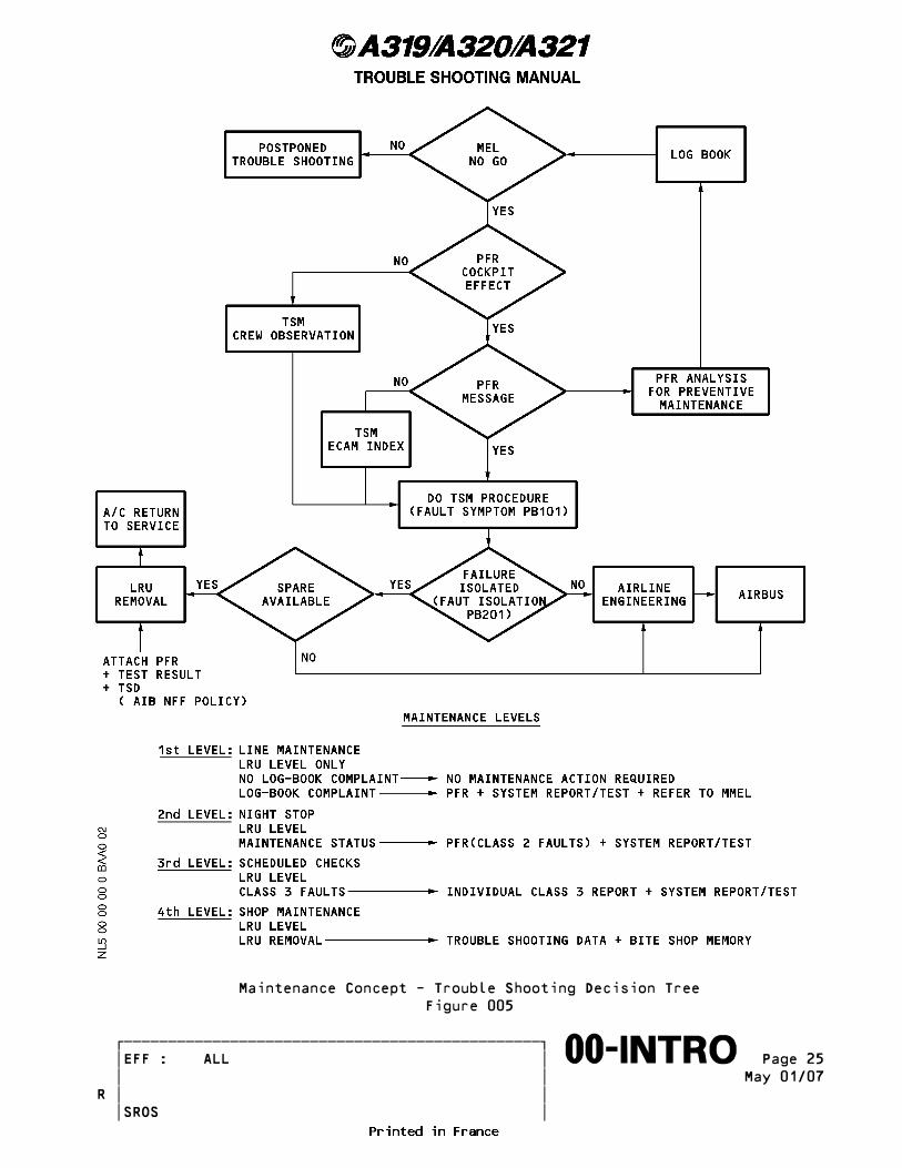
Maintenance Concept - Trouble Shooting Decision Tree Figure 005
������������������������������������������������� �EFF : ALL � Page 25����������������������������������������������������∞∞00-INTRO∞∞∞∞∞∞∞∞∞∞ � � May 01/07 � �R � � SROS

B. How to Use the TSM (Ref. Fig. 006)
(1) Types of faults
In the TSM faults are divided according to the way they are displayed on the aircraft. There are two general divisions of monitored and non-monitored faults. Monitored faults are those which are monitored and displayed by the aircraft systems (mainly ECAM and CFDS). Non-monitored faults are not displayed by the aircraft systems and can be of a general nature, such as: �Nose landing gear doors slow to move�. Within each of these general divisions faults are divided according to the type of system and display:
(a) Monitored faults: - ECAM warnings - EFIS flags - local warnings - CFDS fault messages.
(b) Non-monitored faults - Crew and/or maintenance observations.
NOTE : All these types of fault are used as entry points into the ____ TSM under the titles given above and are summarized in the appropriate indexes.
(2) Entry into the TSM
(Ref. Fig. 006) Entry into a TSM trouble shooting procedure is initiated by a flight crew or maintenance crew report of a fault. The TSM can then be entered with the fault at the Fault Symptoms (P. Block 101), the Index of Warnings/Malfunctions, or the Index of CFDS Fault Messages - depending on the type of fault. From these pages the troubleshooter is directed to the procedure in P. Block 201 to isolate the fault. Three types of monitored faults (ECAM, EFIS and local) reported by the flight crew are usually associated with CFDS fault messages. The association principle of a Warning Malfunction and a CFDS fault message is described in paragraph 4.E.(1)(b). For these the first two digits of the ATA reference given on the PFR are used to enter directly into the appropriate TSM chapter fault symptoms (P. Block 101). CFDS fault messages are not normally reported by the flight crew and are used by maintenance crews. They can be displayed alone without an associated warning or malfunction, in which case they may be the entry point for maintenance related trouble shooting. TSM entry is via the appropriate TSM chapter fault symptoms (P. Block 101) using the ATA reference, or the Index of CFDS Fault Messages using the message text.
������������������������������������������������� �EFF : ALL � Page 26����������������������������������������������������∞∞00-INTRO∞∞∞∞∞∞∞∞∞∞ � � May 01/07 � �R � � SROS
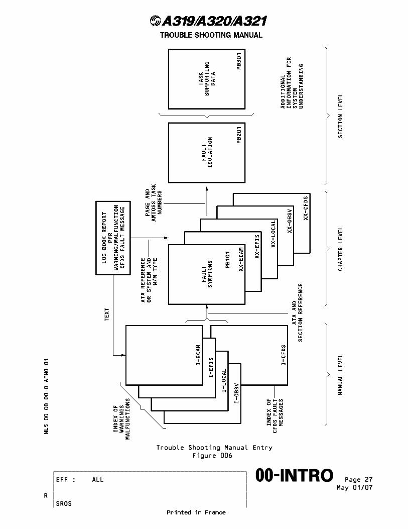
Trouble Shooting Manual Entry Figure 006
������������������������������������������������� �EFF : ALL � Page 27����������������������������������������������������∞∞00-INTRO∞∞∞∞∞∞∞∞∞∞ � � May 01/07 � �R � � SROS

Crew or maintenance observations are usually a single fault without an associated CFDS fault message. TSM entry is via the appropriate TSM chapter fault symptoms (P. Block 101) if the system (ATA reference) is known, or the Index of Warnings/Malfunctions using the fault text. Examples of trouble shooting these faults are given in the following trouble shooting examples.
C. Trouble Shooting Faults Reported on the PFR
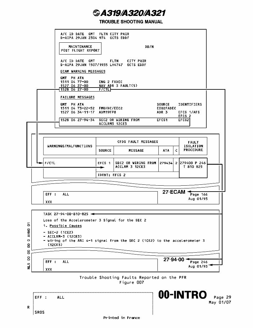
(Ref. Fig. 007) The following general procedure describes trouble shooting of Upper ECAM DU warnings, ECAM STS (Status) Maintenance messages or CFDS fault messages given on the PFR.
(1) Compare the ECAM warning or ECAM STS message with the CFDS fault message (if applicable) on the PFR to obtain the fault symptom and the ATA chapter reference. Alternatively, the user can find the ECAM warning or ECAM STS message alphanumerically in the I-ECAM section which will give the ATA chapter and section reference.
NOTE : A time difference of 1-3 minutes between the fault message and ____ the warning message may occur due to CFDIU internal behaviour.
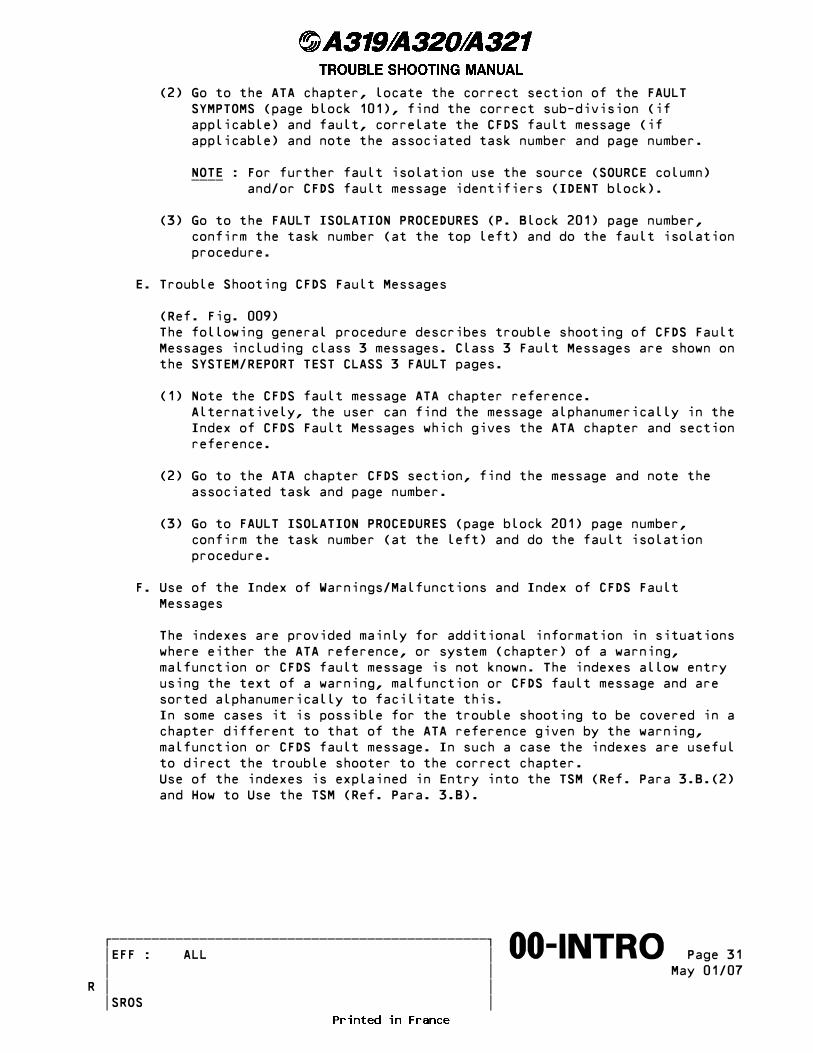
(2) Go to the ATA chapter, locate the correct section of the FAULT SYMPTOMS (page block 101), find the correct sub-division and fault, correlate the CFDS fault message and note the associated task and page number.
NOTE : For further fault isolation use the source (SOURCE column) ____ and/or CFDS fault message identifiers (IDENT block). Due to the number of possible identifier, the fault message identifier in the TSM must be the same as on the PFR.
(3) Go to the FAULT ISOLATION PROCEDURES (P. Block 201) page number, confirm the task number (at the top left) and do the fault isolation procedure.
D. Trouble Shooting Faults not Reported on the PFR
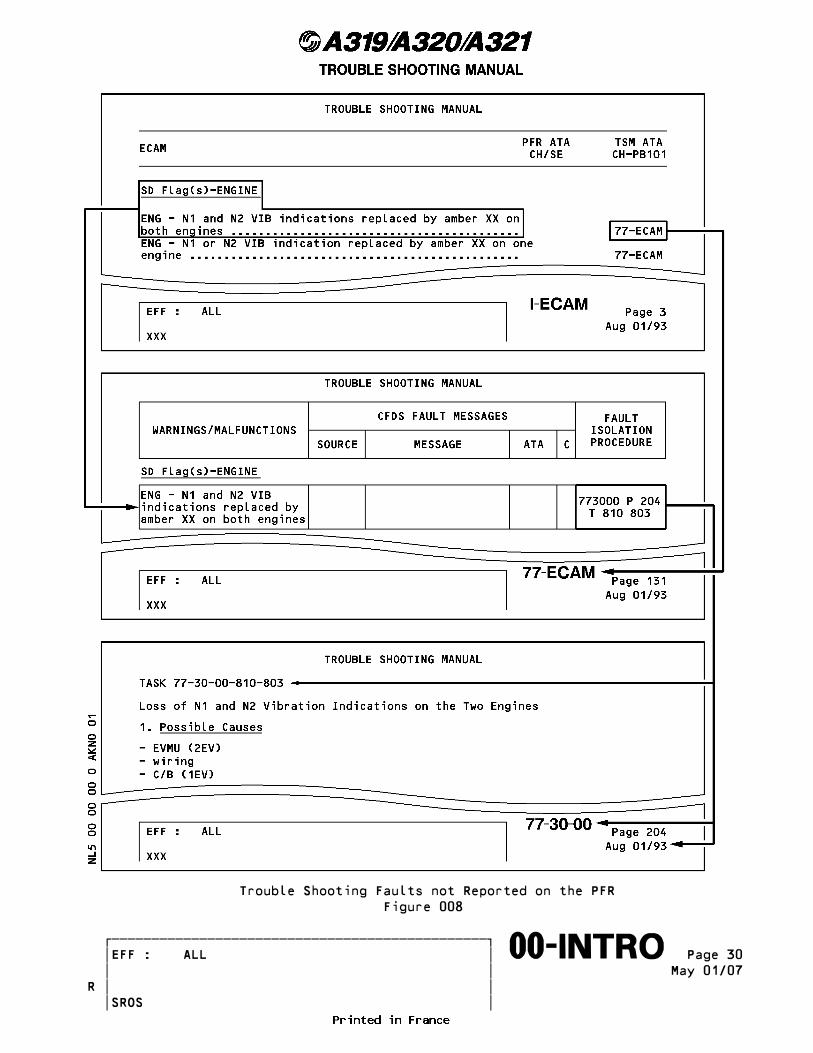
(Ref. Fig. 008) The following general procedure describes trouble shooting of Inop System messages, Lower ECAM DU flags/advisories, local warnings and crew or maintenance observations.
(1) Go to the appropriate section of the Index of Warnings and Malfunctions, find the text of the fault alphanumerically and note the ATA reference and section of the TSM chapter. Alternatively, if the user knows which system has generated the fault this step can be skipped and the trouble shooting started at the next text.
������������������������������������������������� �EFF : ALL � Page 28����������������������������������������������������∞∞00-INTRO∞∞∞∞∞∞∞∞∞∞ � � May 01/07 � �R � � SROS
Trouble Shooting Faults Reported on the PFR Figure 007
������������������������������������������������� �EFF : ALL � Page 29����������������������������������������������������∞∞00-INTRO∞∞∞∞∞∞∞∞∞∞ � � May 01/07 � �R � � SROS
Trouble Shooting Faults not Reported on the PFR Figure 008
������������������������������������������������� �EFF : ALL � Page 30����������������������������������������������������∞∞00-INTRO∞∞∞∞∞∞∞∞∞∞ � � May 01/07 � �R � � SROS
(2) Go to the ATA chapter, locate the correct section of the FAULT SYMPTOMS (page block 101), find the correct sub-division (if applicable) and fault, correlate the CFDS fault message (if applicable) and note the associated task number and page number.
NOTE : For further fault isolation use the source (SOURCE column) ____ and/or CFDS fault message identifiers (IDENT block).
(3) Go to the FAULT ISOLATION PROCEDURES (P. Block 201) page number, confirm the task number (at the top left) and do the fault isolation procedure.
E. Trouble Shooting CFDS Fault Messages
(Ref. Fig. 009) The following general procedure describes trouble shooting of CFDS Fault Messages including class 3 messages. Class 3 Fault Messages are shown on the SYSTEM/REPORT TEST CLASS 3 FAULT pages.
(1) Note the CFDS fault message ATA chapter reference. Alternatively, the user can find the message alphanumerically in the Index of CFDS Fault Messages which gives the ATA chapter and section reference.
(2) Go to the ATA chapter CFDS section, find the message and note the associated task and page number.
(3) Go to FAULT ISOLATION PROCEDURES (page block 201) page number, confirm the task number (at the left) and do the fault isolation procedure.
F. Use of the Index of Warnings/Malfunctions and Index of CFDS Fault Messages
The indexes are provided mainly for additional information in situations where either the ATA reference, or system (chapter) of a warning, malfunction or CFDS fault message is not known. The indexes allow entry using the text of a warning, malfunction or CFDS fault message and are sorted alphanumerically to facilitate this. In some cases it is possible for the trouble shooting to be covered in a chapter different to that of the ATA reference given by the warning, malfunction or CFDS fault message. In such a case the indexes are useful to direct the trouble shooter to the correct chapter. Use of the indexes is explained in Entry into the TSM (Ref. Para 3.B.(2) and How to Use the TSM (Ref. Para. 3.B).
������������������������������������������������� �EFF : ALL � Page 31����������������������������������������������������∞∞00-INTRO∞∞∞∞∞∞∞∞∞∞ � � May 01/07 � �R � � SROS

Trouble Shooting CFDS Fault Messages Figure 009
������������������������������������������������� �EFF : ALL � Page 32����������������������������������������������������∞∞00-INTRO∞∞∞∞∞∞∞∞∞∞ � � May 01/07 � �R � � SROS
G. Trouble Shooting Tips
Tips for using the various TSM page blocks and useful additional information are given in the following paragraphs:
(1) Fault symptoms (P. Block 101) The primary fault only is given in the TSM to avoid confusion with too many associated faults. The list of faults in the Fault Symptoms (P. Block 101) is customized by airline. This means that one fault symptom is effective for at least one aircraft in the fleet.
(a) APU Fault Symptom Peculiarities (Ref. Fig. 010) Whenever the operation of the APU may result in damage to the aircraft, the APU or the Electronic Control Box (ECB) of the APU, the ECB shuts down the APU automatically. The cause of the shutdown and associated LRUs are stored in the ECB memory. This information is available on the APU system related CFDS menu page APU SHUTDOWNS. i.e. NO FLAME (shutdown cause) IGNITION EXCITER P12 (faulty LRU) In parallel the ECB generates a maintenance message with associated ATA Chapter and related Fault Class of the faulty LRU. This maintenance message is available on the Post Flight Report (PFR), which is, in the AIRBUS TSM philosophy, the entry point to the TSM. i.e. ATA 494138 CLASS: 1 IGNITION EXCITER P12 During several operator conferences concerning the APU TSM, it has been shown that likely most operators prefer enter into the TSM with the information of the APU SHUTDOWNS menu, which shows the same faulty LRU as the PFR but additionally the shutdown reason. It has been decided to follow the operators preferences to combine the PFR maintenance message with the Shutdown cause in one Fault Symptom in TSM 49 P. Block 101: i.e. Source Message ATA Class ECB NO FLAME ASD * associated with ECB IGNITION EXCITER P12 494138 1
NOTE : The (*) shown in place of the class denotes that this ____ fault/malfunction is also available in the CFDS APU shutdown menu with its associated shutdown cause.
������������������������������������������������� �EFF : ALL � Page 33����������������������������������������������������∞∞00-INTRO∞∞∞∞∞∞∞∞∞∞ � � May 01/07 � �R � � SROS
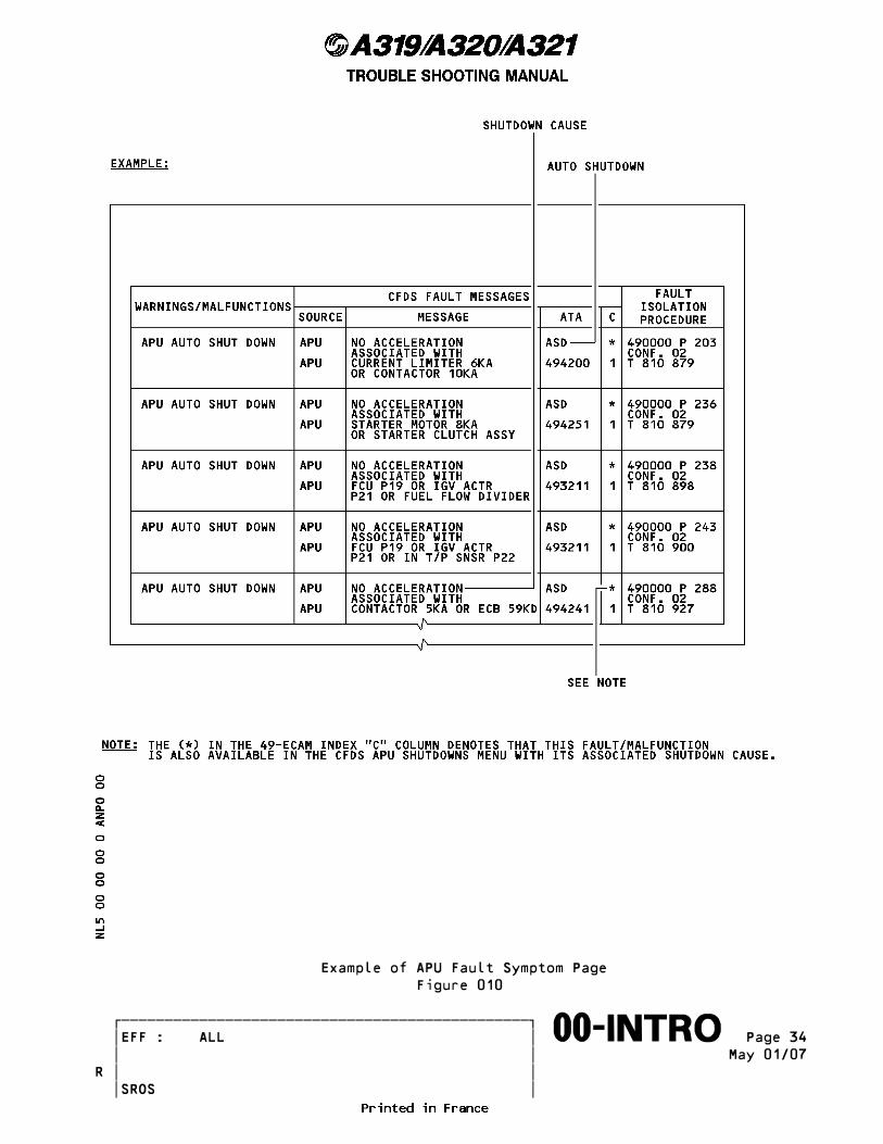
Example of APU Fault Symptom Page Figure 010
������������������������������������������������� �EFF : ALL � Page 34����������������������������������������������������∞∞00-INTRO∞∞∞∞∞∞∞∞∞∞ � � May 01/07 � �R � � SROS

(2) Fault isolation procedures (P. Block 201)
(a) Possible Causes This lists all the suspect items in the fault isolation procedure to allow assembly of all items required to fix the fault. It is not provided for �shotgun� trouble shooting.
(b) Fault confirmation
1 Permanent fault _ The fault is confirmed on ground by performing the test required in the fault confirmation paragraph. Consequently, the procedure must be applied to troubleshoot the A/C.
2 Intermittent fault _ (INTM) is added to the message when an intermittent operation of the system is detected. Example of message : NO BSCU DATA (INTM)
The fault is not confirmed on ground by performing the test required in the fault confirmation paragraph. Faults are sometimes generated by electrical transients or similar events without the aircraft system being faulty. If the confirmation test result is �TEST OK� or equivalent, no further action is required (unless specified in the fault isolation procedure). The aircraft may be dispatched. It is recalled that the TSM has been designed to isolate/troubleshoot hard faults. However depending on the airlines organization, the following can be applied �to trap� intermittent faults: - if test OK (fault not confirmed) dispatch the aircraft, . then perform a monitoring of the reported symptom on the following flights by checking: * the previous leg reports * the PFR/Previous PFRs (if available) * the log book of the previous flights. . after 3 occurrences of the same phenomenon (even though the test is still OK), the other steps of the TSM procedure shall be followed and the LRU involved be removed. In this case, as for all LRUs removed from the aircraft, AIRBUS recommend to provide shop people or suppliers with data related to the removal: PFR, test result, trouble shooting data (if available). - if test NOT OK (fault confirmed), apply the trouble shooting procedure.
(c) Fault isolation procedure
1 Do not replace (swap) LRUs as a trouble shooting step unless _ the TSM tells you to do so. After carrying out the fault isolation in accordance with the TSM, to prevent a NO GO situation in the dispatch of the
������������������������������������������������� �EFF : ALL � Page 35����������������������������������������������������∞∞00-INTRO∞∞∞∞∞∞∞∞∞∞ � � May 01/07 � �R � � SROS
aircraft when no spare is available, swapping of LRUs is permissible in accordance with operator policy. CAUTION : IF YOU SWAP LRUs : - MAKE ONE SWAP AT A TIME - DO NOT SUPPLY THE SUSPECT LRU WITH ELECTRICAL POWER WHEN INSTALLED IN ITS NEW POSITION - FREQUENT DISCONNECTIONS AND CONNECTIONS CAN INCREASE THE RISK OF DAMAGE TO PLUGS AND RECEPTACLES.
CAUTION : WHEN DOING FAULT ISOLATION ON ETOPS IMPORTANT SYSTEMS, IN ACCORDANCE WITH THE TSM, IT MAY REQUIRE THE SWAPPING OF LRUs. THE OPERATOR�S APPROVED MAINTENANCE PROCEDURES MUST BE FOLLOWED TO KEEP THE ETOPS STATUS OF THE AIRCRAFT.
2 The TSM does not give the action to be taken if a suspect unit _ removed from the aircraft during trouble shooting is found to be serviceable rather than failed. This is due to differing replacement policies of airlines on such units (reinstall, or send to the workshop). If such a situation occurs airline internal replacement policy shall be applied.
3 Continuity and isolation checks on LRUs and system wiring made _ on the equipment rack ARINC 600 connectors, should only be done with the use of a breakout box and test cables or equivalent.
4 After a fault isolation procedure action has been completed a _ check must be done to make sure that the reported fault has been corrected.
5 When an AMM LRU replacement procedure is referenced in the _ TSM, the AMM procedure usually specifies a test. This AMM test is to make sure that the replacement unit is installed correctly. It does not always confirm the correction of the fault symptom. In such a case the TSM refers to the appropriate operational or system test procedure.
6 Warnings about static sensitive devices may have to be used to _ prevent damage to sensitive devices.
7 On the ground, a tripped circuit breaker must not be engaged _ without trouble shooting of the associated system.
H. Trouble Shooting Summary
(Ref. Fig. 011) The various possibilities for using the TSM are summarized in the flow chart in the following figure.
������������������������������������������������� �EFF : ALL � Page 36����������������������������������������������������∞∞00-INTRO∞∞∞∞∞∞∞∞∞∞ � � May 01/07 � �R � � SROS

INTENTIONALLY BLANK
�������������������������������������������������R � � Page 37����������������������������������������������������∞∞00-INTRO∞∞∞∞∞∞∞∞∞∞ � � May 01/07 � � � � SROS

Trouble Shooting Flow Figure 011 (SHEET 1)
������������������������������������������������� �EFF : ALL � Page 38����������������������������������������������������∞∞00-INTRO∞∞∞∞∞∞∞∞∞∞ � � May 01/07 � �R � � SROS
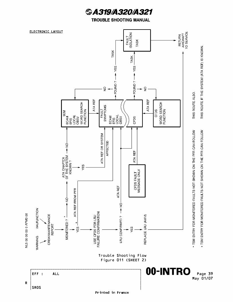
Trouble Shooting Flow Figure 011 (SHEET 2)
������������������������������������������������� �EFF : ALL � Page 39����������������������������������������������������∞∞00-INTRO∞∞∞∞∞∞∞∞∞∞ � � May 01/07 � �R � � SROS
4. How to Use the CFDS ___________________
A. Types of systems
Systems have been divided into three categories in order to limit the complexity: - type 1 - type 2 - type 3 depending on the type of interface that they may have with the CFDIU. This system organization in three types essentially remains transparent for the operator as the CFDIU manages any differences. Nonetheless, their definitions make it possible to understand why certain menus are simplified.
(1) Type 1 systems
These systems are characterized by an input/output interface with the CFDIU of the ARINC 429 bus/ARINC 429 bus type. Most systems are provided with this type of interface. This type of system enables: - output: permanent transmission to the CFDIU of maintenance messages generated during the current flight or during the last flight - input: an operator to dialog on the ground with the BITEs and therefore have access to complementary information (test, ground report, etc.).
(2) Type 2 systems
These systems are characterized by an input/output interface with the CFDIU of the discrete/ARINC 429 bus type. This type of system enables: - output: permanent transmission to the CFDIU of maintenance messages generated during the current flight or during the last flight as well as permanent transmission while on the ground of maintenance messages generated on the ground - input: an operator to launch on the ground the system test and to obtain the results via the output bus.
(3) Type 3 systems
These systems are characterized by an input/output interface with the CFDIU of the discrete/discrete type. This type of system enables: - output: permanent transmission of the operating status (OK, not OK) - input: an operator to launch on the ground the system test and to obtain the result (OK, or not OK) via the discrete output. The CFDIU codes the corresponding maintenance message in plain language.
������������������������������������������������� �EFF : ALL � Page 40����������������������������������������������������∞∞00-INTRO∞∞∞∞∞∞∞∞∞∞ � � May 01/07 � �R � � SROS
B. System BITE
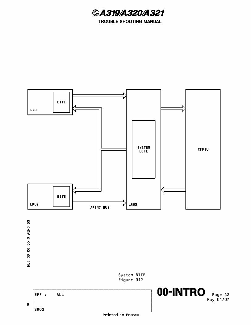
(Ref. Fig. 012) When a system includes several computers, one of the computers collects the maintenance information and provides the link between the system and the CFDIU. It then realises the BITE function and therefore reports on behalf of all system computers. This architecture provides for a better targeted diagnosis by correlating data between system computers as well as reducing bus links with the CFDIU. For the operator, the resulting consequences are minor: - it is the maintenance message itself which identifies, where necessary, the message source in the system example: source = ECAM1; message = SDAC1 : NO DATA FROM BMC1. The SDAC which is part of the Flight Warning System has generated the message.
C. Flight/ground conditions
(Ref. Fig. 013) Information concerning detected faults is generated by the CFDS according to flight/ground conditions. Faults detected on ground may be due to maintenance actions on the aircraft and therefore are not to be taken into account (e.g. loss of a system because the circuit breaker is open). This is the reason why the aircraft systems have 2 types of memorization: - the first one for the faults detected on ground - the second one for the faults detected in flight. The flight/ground condition used by the CFDS is specific and has been selected so as to eliminate the false faults while covering, in the best possible manner, all operations. This is calculated by the CFDIU. The flight condition is located between first engine start up plus three minutes (or eighty knots plus thirty seconds if flight plan is not available in the FMS) and eighty knots plus thirty seconds after touch down.
NOTE : In case of engine run up for maintenance purpose, a flight number ____ (at least one character) must be entered using the MCDU to get a PFR, the eighty knots condition being never reached.
Type 1 systems provided with an ARINC bus from the CFDIU will use this flight/ground condition defined by the CFDIU (correct synchronization, monitored range optimized). Management of messages of type 3 systems (no input or output bus) is via the CFDIU which uses its own flight/ground condition. Type 2 systems cannot receive this information (no input bus) and generate it by default. For these systems, the flight condition is between takeoff and landing. This difference only causes minor consequences for maintainability of type 2 systems. In fact, only:
������������������������������������������������� �EFF : ALL � Page 41����������������������������������������������������∞∞00-INTRO∞∞∞∞∞∞∞∞∞∞ � � May 01/07 � �R � � SROS
System BITE Figure 012
������������������������������������������������� �EFF : ALL � Page 42����������������������������������������������������∞∞00-INTRO∞∞∞∞∞∞∞∞∞∞ � � May 01/07 � �R � � SROS

Flight/Ground Conditions Figure 013
������������������������������������������������� �EFF : ALL � Page 43����������������������������������������������������∞∞00-INTRO∞∞∞∞∞∞∞∞∞∞ � � May 01/07 � �R � � SROS
- the faults which may be detected between startup of the first engine plus three minutes and takeoff are reported on the PFR facing the CLIMB phase - the faults which may be detected between touch down and eighty knots plus thirty seconds are not reported on the PFR on the last flight (Ref. Para. 4.E.(1)). Nonetheless, type 2 systems having no specific function during these phases, the probability of occurrence of these cases is very low. For the CFDS, a cycle is defined as a set of sequences between two ground/flight transitions as defined by the CFDS. Conclusion: Faults detected during flight will generate maintenance messages in the PFR associated with this flight (if class 1 or 2 as defined in Para 4.D.). Other faults, exceptionally detected on the ground after the flight, may generate maintenance messages in a ground report (Ref. Para. 4.E.(3)(b)) of the associated system. However, if no corrections are made, effective faults will still be present in the next cycle and will consequently generate maintenance messages in the next PFR following the ground/flight transition. Maintenance messages are stored only once during a given cycle at the first detection after the beginning of the cycle.
D. Maintenance message classification
(1) General
Maintenance message classification is based on fault consequence. All faults can be divided into three groups: - the faults leading to an operational event in the cockpit - the faults leading to an ECAM MAINTENANCE STATUS - the faults without cockpit events.
NOTE : In each ATA chapter page block 101, the table lists: ____ - all the possible theorical cases. In order to limit the number of cockpit events displayed to the pilots after a single fault, some systems do not generate a cockpit event while they send a class 1 or class 2 fault message because it is already done by another system. This means that in most of the cases, the fault message is associated with a cockpit event (ECAM warning, local warning, flag, maintenance status...). But in specific cases of fault e.g. only a small part of wiring is faulty and only one of the receivers detects the fault, it is possible to find in the PFR only the fault message. - fault messages which are only displayed in a test result page. Some faults can be detected only during a specific test. The associated fault message is therefore only displayed on the MCDU as a test result and will never appear on a PFR.
������������������������������������������������� �EFF : ALL � Page 44����������������������������������������������������∞∞00-INTRO∞∞∞∞∞∞∞∞∞∞ � � May 01/07 � �R � � SROS
- fault messages which need a manual switching in order to generate a cockpit event. For systems which are in standby and which fail, the fault message is immediately available in the PFR but the associated cockpit event is shown in the cockpit only when a manual switching activates this system (example ADIRU3).
(2) Faults with operational cockpit event
This event is also called a cockpit effect. Examples of cockpit effects are: an ECAM warning, a local warning, a flag, or any invalid function such as a missing audio signal, amber crosses on a system page, etc. Some of these faults have consequences on the system safety objective and are NO GO items (i.e.: the failure must be fixed before the next departure) or GO IF items (GO if the conditions given in the MEL are fulfilled). The others are GO without conditions. For some of these faults the cockpit effect does not automatically appear to the crew when it is activated (e.g.: amber crosses on a system page). The status regarding all these faults is given by the MEL. When the crew take notice of a fault through the cockpit effect they must report it into the aircraft LOG BOOK. In order to be able to launch the proper maintenance actions, all faults: - having a cockpit effect and - detected by the systems are covered by a CLASS 1 maintenance message transmitted to the CFDIU. Class 1 maintenance messages are presented in the Post Flight Report at the end of the flight.
NOTE : Some of the system faults having an effect in the cabin are ____ also covered by a CLASS 1 maintenance message transmitted to the CFDIU.
(3) Faults triggering an ECAM MAINTENANCE STATUS
These faults have no consequence on the system operating conditions. They are always GO without any restriction. These faults must be fixed at the first opportunity and not later than the �rectification interval� required as per MMEL section 01-00. The crew must make an entry into the LOG BOOK (Pilot report) because this information is provided by the FWS at the end of the flight, after engines shutdown, through the ECAM MAINTENANCE STATUS. In order to launch at the first opportunity the proper maintenance action it is necessary to provide the information to the maintenance teams. Consequently, these faults are covered by a CLASS 2 maintenance message transmitted to the CFDIU. Class 2 maintenance messages are presented in the Post Flight Report at the end of the flight.
������������������������������������������������� �EFF : ALL � Page 45����������������������������������������������������∞∞00-INTRO∞∞∞∞∞∞∞∞∞∞ � � May 01/07 � �R � � SROS
(4) Faults without cockpit event
(a) General philosophy These faults have no consequence on the system operating conditions and the crew is not aware of them. All faults detected by the systems without cockpit event are covered by a CLASS 3 fault maintenance message. These messages are recorded in each system BITE (class 3 report).
NOTE : For engine system this definition must be completed with ____ the following information.
(b) Engine system The class 3 faults (without cockpit event) have been classified in the two following categories: - the TIME LIMITED dispatch faults: which means that the fault may remain uncorrected within a maximum time frame specified by the Maintenance Planning Document.
- the UNLIMITED TIME dispatch faults: which means that the fault may remain uncorrected within an unlimited time frame.
All these faults are presented by the FADEC BITE in the �Scheduled Maintenance Report� at the aircraft level and classified �S� in the Trouble Shooting Manual. Within class �S� faults, an (*) at the end of the maintenance message will highlight UNLIMITED TIME dispatch faults. Faults without the (*) correspond to TIME LIMITED dispatch faults.
Example: �CFDIU,EIU (FLGT), J3*� is an UNLIMITED TIME dispatch fault and should be treated like any other aircraft system CLASS 3 fault.
�T495L harn (En-4028 KS2)J9/ECU(En-4000Ks)� is a TIME LIMITED dispatch fault and must be corrected in accordance with the Maintenance Planning Document.
(5) Internal fault/external fault
A unique fault may disturb several systems. In this case, it will lead to the generation of several maintenance messages (one per system). One of these messages may be more accurate than the others. Depending on the fault and its effect, it will be the one generated either by a computer which detects itself faulty (self monitoring) or by the computer in charge of the BITE of the system. Under these conditions this message is qualified by the unit generating it as having priority over all messages transmitted by the other systems for the same fault. It will be the one retained by the CFDIU (refer to the PFR). This message is called internal. The other maintenance messages related to the same fault are called external by the other systems. They have less accuracy, have not
������������������������������������������������� �EFF : ALL � Page 46����������������������������������������������������∞∞00-INTRO∞∞∞∞∞∞∞∞∞∞ � � May 01/07 � �R � � SROS
priority and are not recorded in this case by the CFDIU. Only their origins are memorized by the CFDIU as identifiers (refer to the PFR). Therefore, each system has in memory an information linked to every message transmitted to the CFDIU which defines its internal or external attribute so that the CFDIU can give priority to the most accurate one. When no priority messages are received by the CFDIU for the same event it is considered that the accuracy is equal for all messages received. In this case the CFDIU retains the first one received.
Remark: as a general rule, the LRUs incriminated by the maintenance messages shown in the PFR are part of the systems which generated the internal messages.
Example: (Ref. Fig. 014) A fault of the ADM sensor is detected by the ADIRU. The ADIRU sends a fault message (e.g. ADIRU1: NO ADM 19FP1 DATA) to the CFDIU and invalidates some parameters on its output buses (e.g. Airspeed). This fault message is coded as internal by the ADIRU. The users of the ADIRU data (EIS, AFS, ECAM, FADEC, ...) detect the loss of the airspeed parameter. They send fault messages to the CFDIU, coded as external (e.g. EIS1: NO ADIRU1 DATA). The CFDIU stores the fault message from the ADIRU and the name of the systems which have detected the fault. The PFR is: SOURCE IDENTIFIERS
ADIRU1 : NO ADM19 FP1 DATA ADIRU1 EIS, AFS, ECAM FADEC
E. Maintenance functions
(1) First group: the PFR
(a) Description of the PFRR A maintenance report on the last flight is automatically printedR after touch down, 2 minutes and 30 seconds after the aircraftR speed decreases below 80 kts. This document is the Post Flight Report (PFR). The PFR is a result of the CFDS automatic operating mode. This report is the main source of information used to initiate trouble shooting and to decide on the required maintenance actions.
(Ref. Fig. 015) A backup of the printed PFR is available on the MCDU. It should only be used if the printed PFR is not available as the information is less complete and the presentation is not so friendly. Conditional maintenance operations are carried out in response to the observations made by the flight crew in the LOG BOOK.
������������������������������������������������� �EFF : ALL � Page 47����������������������������������������������������∞∞00-INTRO∞∞∞∞∞∞∞∞∞∞ � � Feb 01/08 � � � � SROS
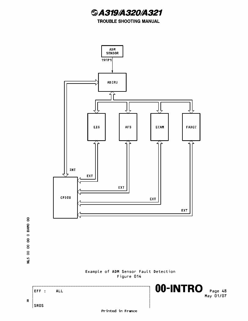
Example of ADM Sensor Fault Detection Figure 014
������������������������������������������������� �EFF : ALL � Page 48����������������������������������������������������∞∞00-INTRO∞∞∞∞∞∞∞∞∞∞ � � May 01/07 � �R � � SROS

POST FLIGHT REPORT Figure 015
������������������������������������������������� �EFF : ALL � Page 49����������������������������������������������������∞∞00-INTRO∞∞∞∞∞∞∞∞∞∞ � � May 01/07 � �R � � SROS
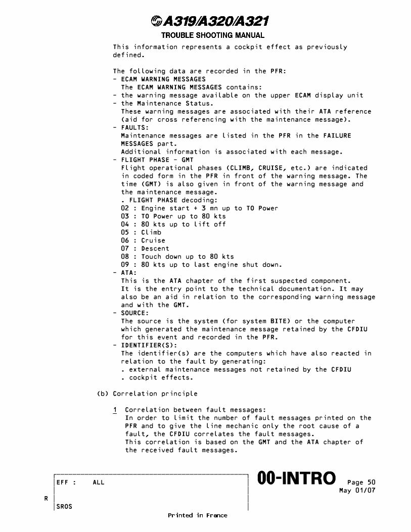
This information represents a cockpit effect as previously defined.
The following data are recorded in the PFR: - ECAM WARNING MESSAGES The ECAM WARNING MESSAGES contains: - the warning message available on the upper ECAM display unit - the Maintenance Status. These warning messages are associated with their ATA reference (aid for cross referencing with the maintenance message). - FAULTS: Maintenance messages are listed in the PFR in the FAILURE MESSAGES part. Additional information is associated with each message. - FLIGHT PHASE - GMT Flight operational phases (CLIMB, CRUISE, etc.) are indicated in coded form in the PFR in front of the warning message. The time (GMT) is also given in front of the warning message and the maintenance message. . FLIGHT PHASE decoding: 02 : Engine start + 3 mn up to TO Power 03 : TO Power up to 80 kts 04 : 80 kts up to lift off 05 : Climb 06 : Cruise 07 : Descent 08 : Touch down up to 80 kts 09 : 80 kts up to last engine shut down. - ATA: This is the ATA chapter of the first suspected component. It is the entry point to the technical documentation. It may also be an aid in relation to the corresponding warning message and with the GMT. - SOURCE: The source is the system (for system BITE) or the computer which generated the maintenance message retained by the CFDIU for this event and recorded in the PFR. - IDENTIFIER(S): The identifier(s) are the computers which have also reacted in relation to the fault by generating: . external maintenance messages not retained by the CFDIU . cockpit effects.
(b) Correlation principle
1 Correlation between fault messages: _ In order to limit the number of fault messages printed on the PFR and to give the line mechanic only the root cause of a fault, the CFDIU correlates the fault messages. This correlation is based on the GMT and the ATA chapter of the received fault messages.
������������������������������������������������� �EFF : ALL � Page 50����������������������������������������������������∞∞00-INTRO∞∞∞∞∞∞∞∞∞∞ � � May 01/07 � �R � � SROS
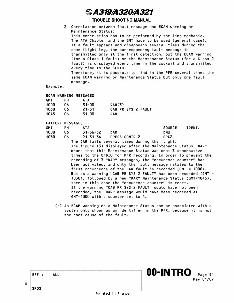
2 Correlation between fault message and ECAM warning or _ Maintenance Status: This correlation has to be performed by the line mechanic. The ATA Chapter and the GMT have to be used (general case). If a fault appears and disappears several times during the same flight leg, the corresponding fault message is transmitted only at the first detection, but the ECAM warning (for a Class 1 fault) or the Maintenance Status (for a Class 2 fault) is displayed every time in the cockpit and transmitted every time to the CFDIU. Therefore, it is possible to find in the PFR several times the same ECAM warning or Maintenance Status but only one fault message. Example:
ECAM WARNING MESSAGES GMT PH ATA 1000 06 31-00 DAR(3) 1030 06 21-31 CAB PR SYS 2 FAULT 1045 06 31-00 DAR
FAILURE MESSAGES GMT PH ATA SOURCE IDENT. 1000 06 31-36-52 DAR DMU 1030 06 21-31-34 PRESS CONTR 2 CPC2 The DAR fails several times during the flight. The figure (3) displayed after the Maintenance Status �DAR� means that this Maintenance Status was sent 3 consecutive times to the CFDIU for PFR recording. In order to prevent the recording of 3 �DAR� messages, the �occurence counter� has been activated, and only the fault message related to the first occurrence of the DAR fault is recorded (GMT = 1000). But as a warning �CAB PR SYS 2 FAULT� has been recorded (GMT = 1030), followed by a new �DAR� Maintenance Status (GMT=1045), then in this case the �occurence counter� is reset. If the warning �CAB PR SYS 2 FAULT� would have not been recorded, the �DAR� message would have been recorded at GMT=1000 with a counter set to 4.
(c) An ECAM warning or a Maintenance Status can be associated with a system only shown as an identifier in the PFR, because it is not the root cause of the fault.
������������������������������������������������� �EFF : ALL � Page 51����������������������������������������������������∞∞00-INTRO∞∞∞∞∞∞∞∞∞∞ � � May 01/07 � �R � � SROS
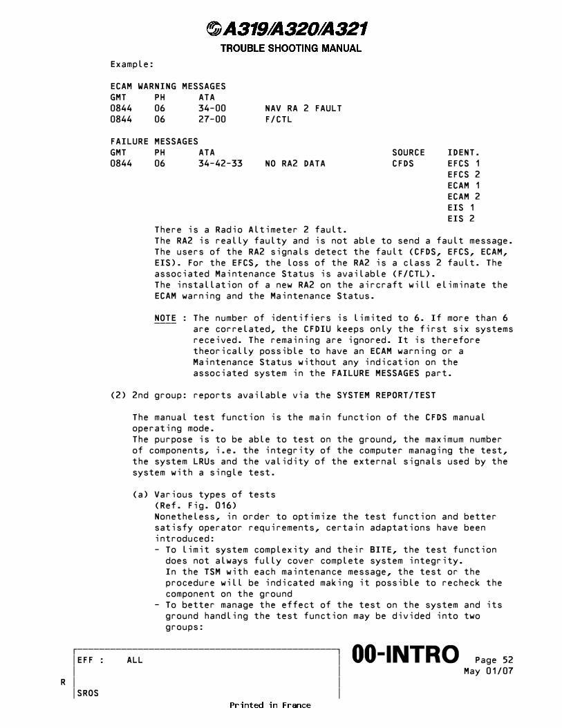
Example:
ECAM WARNING MESSAGES GMT PH ATA 0844 06 34-00 NAV RA 2 FAULT 0844 06 27-00 F/CTL
FAILURE MESSAGES GMT PH ATA SOURCE IDENT. 0844 06 34-42-33 NO RA2 DATA CFDS EFCS 1 EFCS 2 ECAM 1 ECAM 2 EIS 1 EIS 2 There is a Radio Altimeter 2 fault. The RA2 is really faulty and is not able to send a fault message. The users of the RA2 signals detect the fault (CFDS, EFCS, ECAM, EIS). For the EFCS, the loss of the RA2 is a class 2 fault. The associated Maintenance Status is available (F/CTL). The installation of a new RA2 on the aircraft will eliminate the ECAM warning and the Maintenance Status.
NOTE : The number of identifiers is limited to 6. If more than 6 ____ are correlated, the CFDIU keeps only the first six systems received. The remaining are ignored. It is therefore theorically possible to have an ECAM warning or a Maintenance Status without any indication on the associated system in the FAILURE MESSAGES part.
(2) 2nd group: reports available via the SYSTEM REPORT/TEST
The manual test function is the main function of the CFDS manual operating mode. The purpose is to be able to test on the ground, the maximum number of components, i.e. the integrity of the computer managing the test, the system LRUs and the validity of the external signals used by the system with a single test.
(a) Various types of tests (Ref. Fig. 016) Nonetheless, in order to optimize the test function and better satisfy operator requirements, certain adaptations have been introduced: - To limit system complexity and their BITE, the test function does not always fully cover complete system integrity. In the TSM with each maintenance message, the test or the procedure will be indicated making it possible to recheck the component on the ground - To better manage the effect of the test on the system and its ground handling the test function may be divided into two groups:
������������������������������������������������� �EFF : ALL � Page 52����������������������������������������������������∞∞00-INTRO∞∞∞∞∞∞∞∞∞∞ � � May 01/07 � �R � � SROS
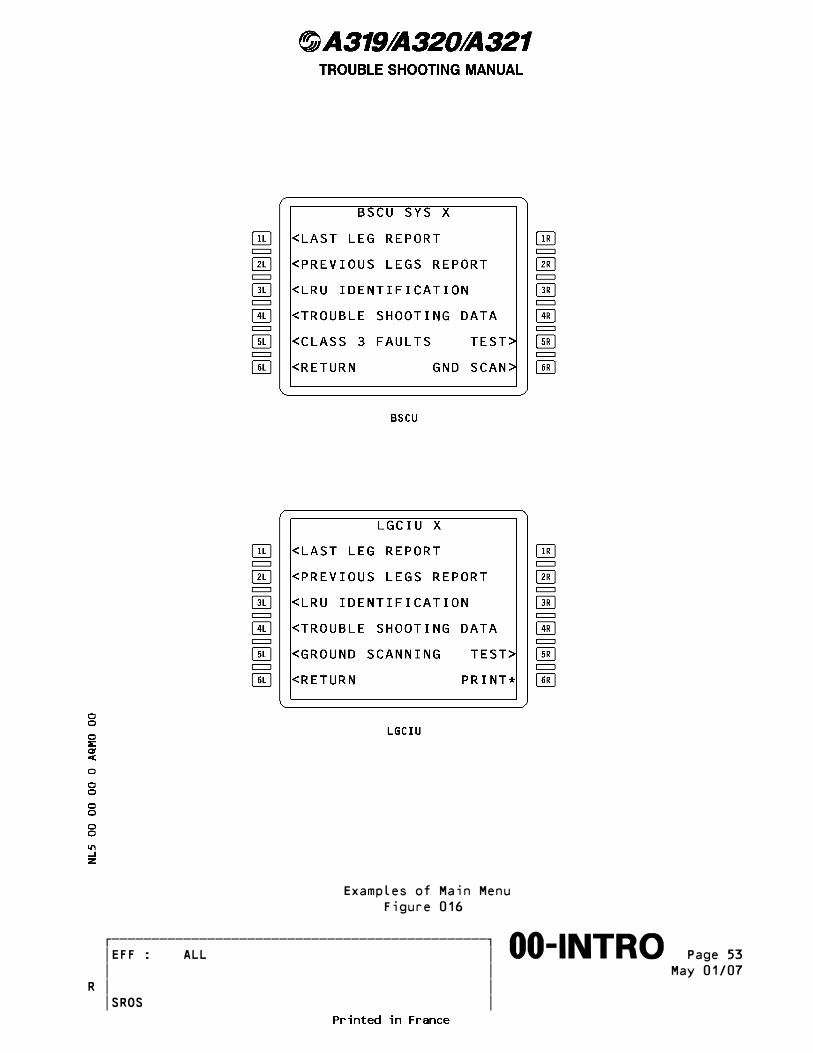
Examples of Main Menu Figure 016
������������������������������������������������� �EFF : ALL � Page 53����������������������������������������������������∞∞00-INTRO∞∞∞∞∞∞∞∞∞∞ � � May 01/07 � �R � � SROS
. BASIC TEST (OR SYSTEM TEST) . COMPLEMENTARY TESTS. This makes it possible to have at least one test available at the terminal gate (the basic test) which is quickly to start-up by a single technician, the other tests making it possible to increase the global coverage level of the tests where useful and possible. All these tests are run on the ground from the MCDU using, first of all, the CFDIU menu (SYSTEM REPORT/TEST) then the system MENU.
* Basic test or system test This test has no effect on the aircraft and does not require that any long or complex actions be performed by the operator. Consequently, this test may be initiated from the cockpit by a single operator whenever required during stopovers. All faults present on ground and actually detected by the system will be analyzed and reported by this test. Furthermore, it must be run before any other test to check the integrity of the computer housing the BITE.
* Complementary tests (Ref. Fig. 017) These tests may affect the aircraft (and may require actions by the operator). In fact these tests send stimuli to various components such as actuators, valves, etc. For this reason, CAUTIONS may be displayed on the MCDU before activation of test. The wording of the cautions is in fact simply a reminder of the consequences on the aircraft following test activation. In fact, the safety procedures associated with these tests are in the AMM. Consequently, normally these tests are not performed during a short stopover. Test names are related to the tested parts.
These tests can also be menu-guided tests. The actions to be taken are displayed in plain language on the MCDU. (Description of the initial configuration, description of the actions, wording of the questions to which the operator must respond). Test names are related to the tested parts.
(b) Presentation of the test pages - Certain information may require several pages. Each page is then numbered and the MCDU NEXT PAGE function key is used to run through the test - In certain cases, the system waits until the operator has performed an action to continue the test. Then there is a limited time out so as not to stop in this configuration when the monitored signals are blocked. This implies that the operator action must be performed before this time out.
������������������������������������������������� �EFF : ALL � Page 54����������������������������������������������������∞∞00-INTRO∞∞∞∞∞∞∞∞∞∞ � � May 01/07 � �R � � SROS

Example of Caution Figure 017
������������������������������������������������� �EFF : ALL � Page 55����������������������������������������������������∞∞00-INTRO∞∞∞∞∞∞∞∞∞∞ � � May 01/07 � �R � � SROS
- A dash may be shown when data is not available. This does not necessarily mean that an effective failure is present. Only maintenance messages indicate possible failures.
(c) Initial aircraft configuration for test activation The general configuration of the aircraft for test activation is basically as follows: - aircraft on ground - engines stopped - all systems power supplied (ADIRS, FADEC may be off) - pushbutton switches and switches in normal configuration. If a test calls for a different configuration, this configuration will be described in the AMM. To limit BITE complexity all these conditions are assumed to be correctly applied by the operator. Consequently, if a difference is detected by a system it is considered as a fault and therefore generates a maintenance message in the test results. In all cases, it is recommended to restart the tests indicating faults in the results to eliminate any possible disturbances or wrong initial conditions.
(d) TEST IN PROGRESS When a test is run without any operator action being requested the TEST IN PROGRESS can be displayed on the MCDU.
(e) Test results The result of a test is one of the following: - The mention TEST OK, PASS, NO FAULT, ...: The test has not detected any faults - The display of maintenance messages on the MCDU: The test has detected at least one fault. In certain multiple fault cases, the test may only indicate the first fault encountered. In fact, certain faults prevent to run the test more extensively. Test re-running after repair of the fault is therefore always necessary to check whether there is another fault or not. Only the mention TEST OK, PASS, NO FAULT ... is proof that the test has not detected any other faults. - No response from the system to the test request or no results displayed: In this case, the test has not been completed.
Return to initial condition is obtained by pressing the MCDU MENU key then CFDS key and selecting the system again. If the same sequence reoccurs then the computer managing the BITE of the system or the wiring from the CFDIU must be the cause.
(f) Test stop In some cases, a key is allocated to stop a test in progress.
������������������������������������������������� �EFF : ALL � Page 56����������������������������������������������������∞∞00-INTRO∞∞∞∞∞∞∞∞∞∞ � � May 01/07 � �R � � SROS
(g) Configuration resetting after a test The operator may be requested to reconfigure after a test if the initial conditions required by the test have had a significant effect on the aircraft (instructions are in the AMM). If the operator wants to repeat the test he is not obliged to apply these instructions on configuration resetting.
(h) Ground handling of the tests As maintenance messages are stored in the PFR or the GROUND REPORT they will not be erased until the next beginning of flight. Therefore, a test is a means of checking whether a fault is still present and a means of isolating a failed LRU. Activation of a test will be requested in the TSM by the fault isolation procedure related to a maintenance message. It will be used to confirm the presence of a fault or to eliminate any ambiguity. As a general rule, the test of the system including the LRU incriminated by the maintenance message (message ATA) will be activated. By default, the test of the system which generated the message (SOURCE) may be activated. The activation of a test may also be part of the removal/installation procedure of an LRU given in the AMM.
(3) 3rd group
(a) AVIONICS STATUS This function displays the identity of the systems detecting a class 1, 2 or 3 internal or external fault when the function is called. The AVIONICS STATUS thus rapidly provides a global overview of the status of all systems. It is a user-friendly monitoring device providing direct access to system menus which detect a fault (for example, flag displayed on the PFD). Furthermore, after aircraft power up, it enables to check that all computers have correctly satisfied the related power up tests. In order to know the reason for which a system is displayed in the AVIONICS STATUS it is recommended to get access to the system menu and to activate the system test (or test).
NOTE : Certain systems are listed in the AVIONICS STATUS due to ____ normal absence of a ground power supply. Therefore, it is recommended to supply all systems prior to gaining access to the AVIONICS STATUS. It shall be noted that when a computer is not supplied it is not directly displayed in the AVIONICS STATUS as it no longer detects, itself, this fault. However, the systems using the signals from this computer appear in the AVIONICS STATUS.
������������������������������������������������� �EFF : ALL � Page 57����������������������������������������������������∞∞00-INTRO∞∞∞∞∞∞∞∞∞∞ � � May 01/07 � �R � � SROS
(b) GROUND REPORT This function displays on ground the class 1, 2 and 3 internal maintenance messages related to new faults detected on ground and which are therefore not recorded in the PFR. The faults detected during flight and which remain present on ground are in the PFR and not in the ground report. It is necessary to confirm all faults of the ground report by activating a test or a procedure described in the TSM.
NOTE : Case related to Type 2 systems: ____ This function is in the LAST LEG/GROUND REPORT section specific to type 2 systems. The messages in this section concern faults detected during flight and on ground, the wording GND preceding the list of messages related to the faults detected on the ground in accordance with the same ground report logic as for type 1 systems. Case related to Type 3 systems: There is no ground report function for Type 3 systems. The test function shall be used in this case.
(c) GROUND SCANNING The GROUND SCANNING enables fault trouble shooting based on ground activation by the operator himself of functions normally performed during a flight. The advantage of this is that it is not restrictive as far as actions are concerned. In fact, the operator decides what type of actions to be performed on the system, which is in GROUND SCANNING, as a function of the problems to be processed. This action may include dynamic phases (for example: engine startup, flight control surface movement, etc.). This is also an aid in trouble shooting faults difficult to resolve. All maintenance messages (class 1, 2 and 3, internal and external) related to all faults detected in real time by the system will be displayed during the GROUND SCANNING. In order to indicate a transient fault source to the operator, the maintenance messages, automatically displayed in GROUND SCANNING, are only erased when exiting from the function. Furthermore, GROUND SCANNING must always be preceded by a system test in order to identify, sooner, the possible static faults. The use of this function may also be requested by the TSM procedures.
(d) LAST LEG REPORT This section presents a portion of the information given in the PFR. It contains the class 1 and 2 fault messages transmitted to the CFDIU during the previous flight.
NOTE : For information purposes, the messages generated by the ____ identifiers are accessible in the last leg report of these
������������������������������������������������� �EFF : ALL � Page 58����������������������������������������������������∞∞00-INTRO∞∞∞∞∞∞∞∞∞∞ � � May 01/07 � �R � � SROS
identifiers. The user who wants to use these messages must do so carefully as the information involved is non-correlated and non-priority information.
(4) 4th group
(a) PREVIOUS LEGS REPORT The PREVIOUS LEGS REPORT function is the history of the LAST LEG REPORT limited to 64 flights. Therefore, it is displayed with the same restrictions.
(b) TROUBLE SHOOTING DATA In most cases, this concerns primary and coded data. The purpose is to supply additional information on conditions prevailing when the maintenance message was generated. In general, these data are read in the case of events which do not result from effective part failure, already covered by the replacement of the failed part. Analysis of this data will be effectively useful in the study which may enable the identification of the cause of an event.
NOTE : In certain cases, this analysis can only be concluded with ____ the designer.
If certain trouble shooting data are required for fault trouble shooting, data readout will be requested by a TSM procedure. Wherever possible, these data will be displayed decoded on the MCDU.
(c) LRU IDENTIFICATION The purpose of this section is to display on ground the part numbers of computers of the selected system and possibly their serial numbers. This section may be consulted to check the interrogated computer standard. This is a configuration management aid.
(5) 5th group
(a) CLASS 3 REPORT All class 3 (internal and external) maintenance messages corresponding to the selected system are grouped under this report. This function enables a quick access to the class 3 messages of a given system.
NOTE : Some systems do not have class 3 reports. ____
������������������������������������������������� �EFF : ALL � Page 59����������������������������������������������������∞∞00-INTRO∞∞∞∞∞∞∞∞∞∞ � � May 01/07 � �R � � SROS

(6) Summary of the functions
Summary of the functions available in ground menu mode (Manual Mode).
---------------------------------------------------------------------- | HISTORY DATA | REAL TIME | ------------------------------------------------------------------------------- | CFDIU | - POST FLIGHT REPORT | - AVIONICS STATUS (at activation) | | driven | | | ------------------------------------------------------------------------------- | | - LAST LEG REPORT | - TEST (all) | | SYSTEM | - PREVIOUS LEGS REPORT | - GROUND SCANNING | | driven | - GROUND REPORT | | | | - CLASS 3 REPORT | | | | - TROUBLE SHOOTING DATA | - LRU IDENTIFICATION | -------------------------------------------------------------------------------
������������������������������������������������� �EFF : ALL � Page 60����������������������������������������������������∞∞00-INTRO∞∞∞∞∞∞∞∞∞∞ � � May 01/07 � �R � � SROS
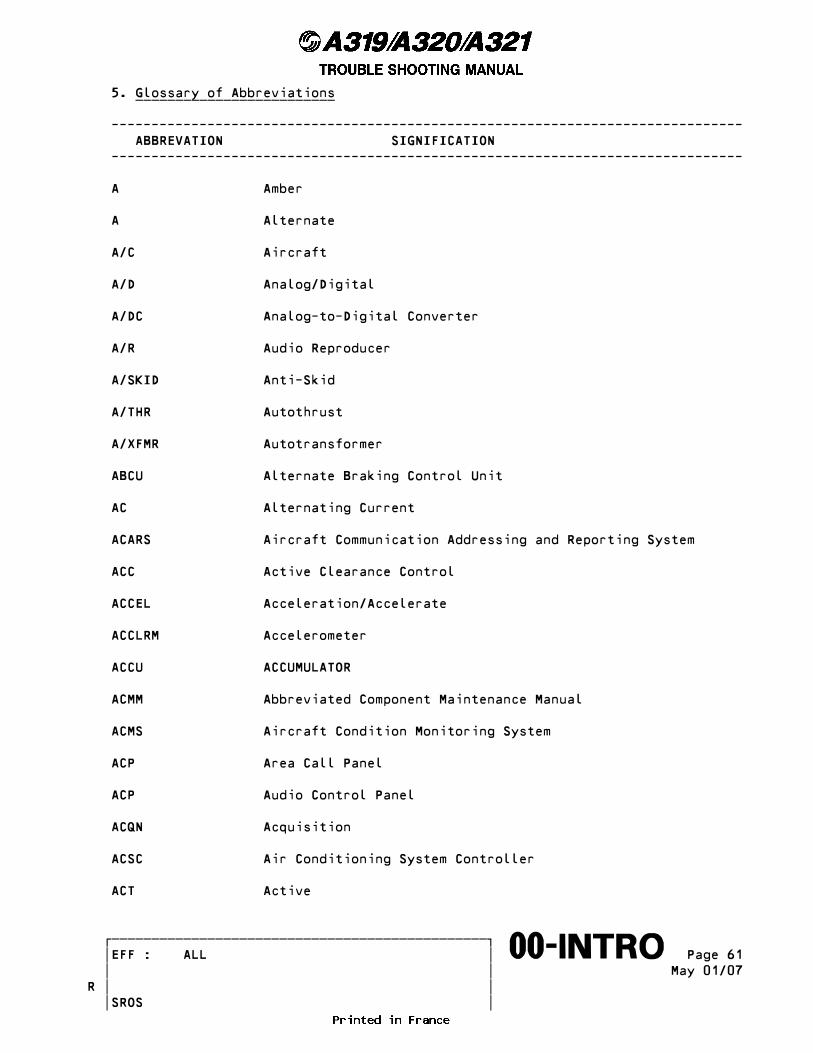
5. Glossary of Abbreviations _________________________
------------------------------------------------------------------------------- ABBREVATION SIGNIFICATION -------------------------------------------------------------------------------
A Amber
A Alternate
A/C Aircraft
A/D Analog/Digital
A/DC Analog-to-Digital Converter
A/R Audio Reproducer
A/SKID Anti-Skid
A/THR Autothrust
A/XFMR Autotransformer
ABCU Alternate Braking Control Unit
AC Alternating Current
ACARS Aircraft Communication Addressing and Reporting System
ACC Active Clearance Control
ACCEL Acceleration/Accelerate
ACCLRM Accelerometer
ACCU ACCUMULATOR
ACMM Abbreviated Component Maintenance Manual
ACMS Aircraft Condition Monitoring System
ACP Area Call Panel
ACP Audio Control Panel
ACQN Acquisition
ACSC Air Conditioning System Controller
ACT Active
������������������������������������������������� �EFF : ALL � Page 61����������������������������������������������������∞∞00-INTRO∞∞∞∞∞∞∞∞∞∞ � � May 01/07 � �R � � SROS
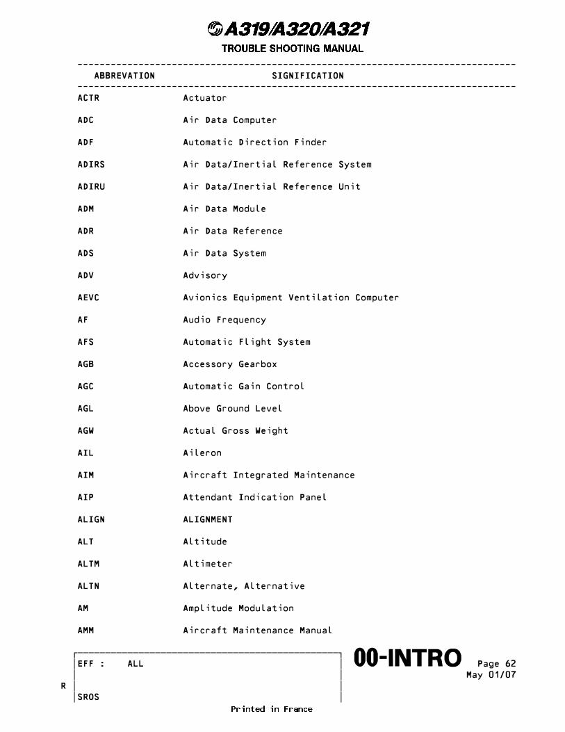
------------------------------------------------------------------------------- ABBREVATION SIGNIFICATION ------------------------------------------------------------------------------- ACTR Actuator
ADC Air Data Computer
ADF Automatic Direction Finder
ADIRS Air Data/Inertial Reference System
ADIRU Air Data/Inertial Reference Unit
ADM Air Data Module
ADR Air Data Reference
ADS Air Data System
ADV Advisory
AEVC Avionics Equipment Ventilation Computer
AF Audio Frequency
AFS Automatic Flight System
AGB Accessory Gearbox
AGC Automatic Gain Control
AGL Above Ground Level
AGW Actual Gross Weight
AIL Aileron
AIM Aircraft Integrated Maintenance
AIP Attendant Indication Panel
ALIGN ALIGNMENT
ALT Altitude
ALTM Altimeter
ALTN Alternate, Alternative
AM Amplitude Modulation
AMM Aircraft Maintenance Manual
������������������������������������������������� �EFF : ALL � Page 62����������������������������������������������������∞∞00-INTRO∞∞∞∞∞∞∞∞∞∞ � � May 01/07 � �R � � SROS
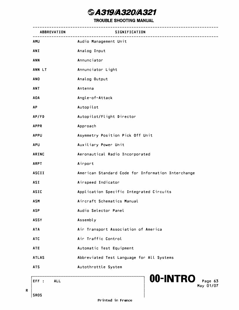
------------------------------------------------------------------------------- ABBREVATION SIGNIFICATION ------------------------------------------------------------------------------- AMU Audio Management Unit
ANI Analog Input
ANN Annunciator
ANN LT Annunciator Light
ANO Analog Output
ANT Antenna
AOA Angle-of-Attack
AP Autopilot
AP/FD Autopilot/Flight Director
APPR Approach
APPU Asymmetry Position Pick Off Unit
APU Auxiliary Power Unit
ARINC Aeronautical Radio Incorporated
ARPT Airport
ASCII American Standard Code for Information Interchange
ASI Airspeed Indicator
ASIC Application Specific Integrated Circuits
ASM Aircraft Schematics Manual
ASP Audio Selector Panel
ASSY Assembly
ATA Air Transport Association of America
ATC Air Traffic Control
ATE Automatic Test Equipment
ATLAS Abbreviated Test Language for All Systems
ATS Autothrottle System
������������������������������������������������� �EFF : ALL � Page 63����������������������������������������������������∞∞00-INTRO∞∞∞∞∞∞∞∞∞∞ � � May 01/07 � �R � � SROS

------------------------------------------------------------------------------- ABBREVATION SIGNIFICATION ------------------------------------------------------------------------------- ATSU Air Traffic Service Unit
ATT Attitude
ATTND Attendant
AUTO Automatic
AUX Auxiliary
AVAIL Available
AVNCS Avionics
AWM Aircraft Wiring Manual
AWY Airway
AZ Azimuth
B Blue
BARO Barometric
BAT Battery
BCD Binary Coded Decimal
BCL Battery Charge Limiter
BFO Beat Frequency Oscillator
BGM Boarding Music
BITE Built-in Test Equipment
BMC Bleed Monitoring Computer
BNR BINARY
BOT Begin of Tape
BP Bottom Plug
BRG Bearing
BRK Brake
BRKR Breaker
������������������������������������������������� �EFF : ALL � Page 64����������������������������������������������������∞∞00-INTRO∞∞∞∞∞∞∞∞∞∞ � � May 01/07 � �R � � SROS
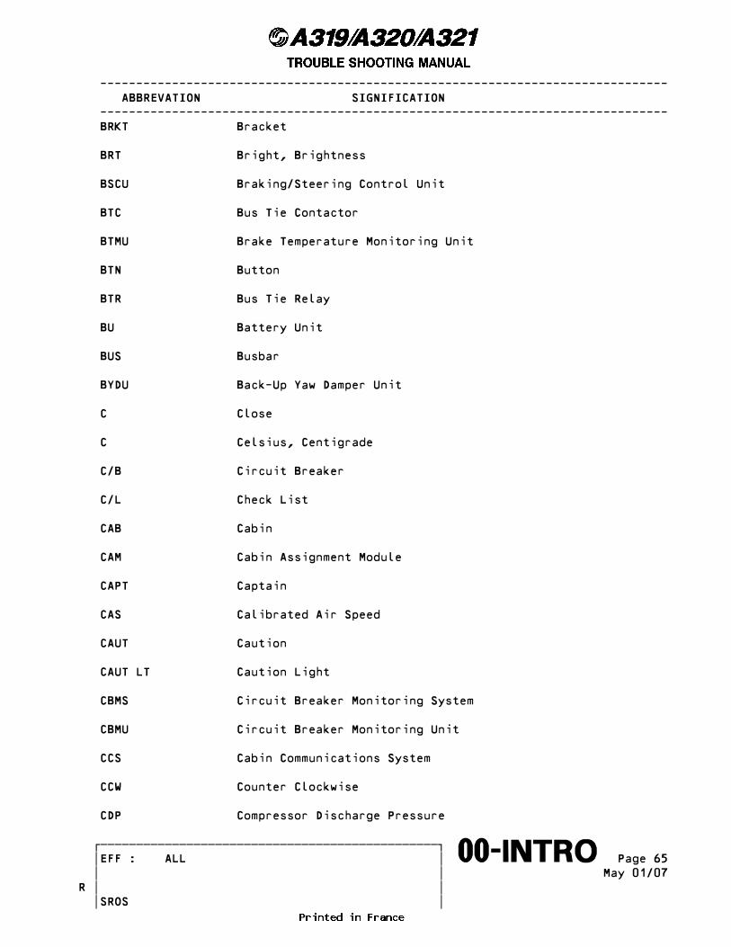
------------------------------------------------------------------------------- ABBREVATION SIGNIFICATION ------------------------------------------------------------------------------- BRKT Bracket
BRT Bright, Brightness
BSCU Braking/Steering Control Unit
BTC Bus Tie Contactor
BTMU Brake Temperature Monitoring Unit
BTN Button
BTR Bus Tie Relay
BU Battery Unit
BUS Busbar
BYDU Back-Up Yaw Damper Unit
C Close
C Celsius, Centigrade
C/B Circuit Breaker
C/L Check List
CAB Cabin
CAM Cabin Assignment Module
CAPT Captain
CAS Calibrated Air Speed
CAUT Caution
CAUT LT Caution Light
CBMS Circuit Breaker Monitoring System
CBMU Circuit Breaker Monitoring Unit
CCS Cabin Communications System
CCW Counter Clockwise
CDP Compressor Discharge Pressure
������������������������������������������������� �EFF : ALL � Page 65����������������������������������������������������∞∞00-INTRO∞∞∞∞∞∞∞∞∞∞ � � May 01/07 � �R � � SROS
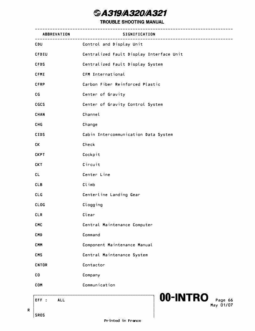
------------------------------------------------------------------------------- ABBREVATION SIGNIFICATION ------------------------------------------------------------------------------- CDU Control and Display Unit
CFDIU Centralized Fault Display Interface Unit
CFDS Centralized Fault Display System
CFMI CFM International
CFRP Carbon Fiber Reinforced Plastic
CG Center of Gravity
CGCS Center of Gravity Control System
CHAN Channel
CHG Change
CIDS Cabin Intercommunication Data System
CK Check
CKPT Cockpit
CKT Circuit
CL Center Line
CLB Climb
CLG Centerline Landing Gear
CLOG Clogging
CLR Clear
CMC Central Maintenance Computer
CMD Command
CMM Component Maintenance Manual
CMS Central Maintenance System
CNTOR Contactor
CO Company
COM Communication
������������������������������������������������� �EFF : ALL � Page 66����������������������������������������������������∞∞00-INTRO∞∞∞∞∞∞∞∞∞∞ � � May 01/07 � �R � � SROS
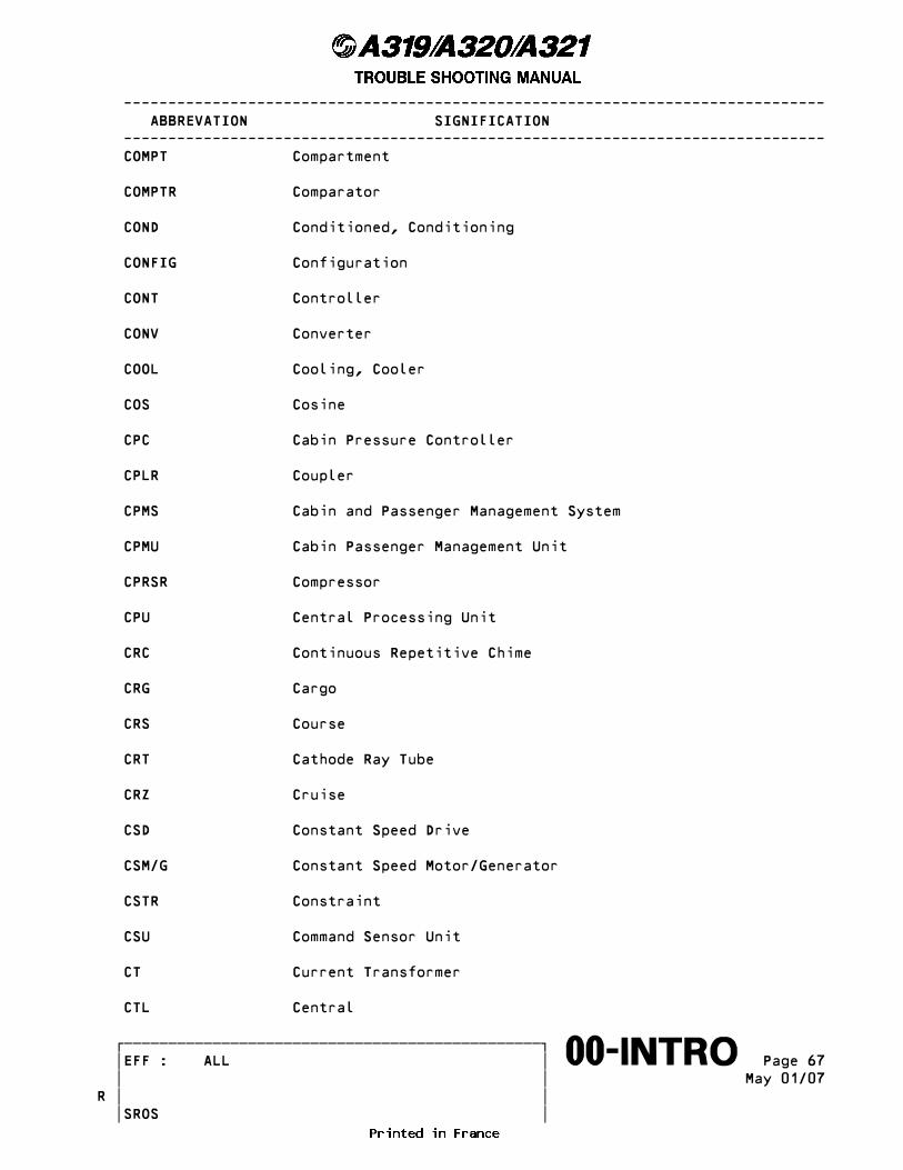
------------------------------------------------------------------------------- ABBREVATION SIGNIFICATION ------------------------------------------------------------------------------- COMPT Compartment
COMPTR Comparator
COND Conditioned, Conditioning
CONFIG Configuration
CONT Controller
CONV Converter
COOL Cooling, Cooler
COS Cosine
CPC Cabin Pressure Controller
CPLR Coupler
CPMS Cabin and Passenger Management System
CPMU Cabin Passenger Management Unit
CPRSR Compressor
CPU Central Processing Unit
CRC Continuous Repetitive Chime
CRG Cargo
CRS Course
CRT Cathode Ray Tube
CRZ Cruise
CSD Constant Speed Drive
CSM/G Constant Speed Motor/Generator
CSTR Constraint
CSU Command Sensor Unit
CT Current Transformer
CTL Central
������������������������������������������������� �EFF : ALL � Page 67����������������������������������������������������∞∞00-INTRO∞∞∞∞∞∞∞∞∞∞ � � May 01/07 � �R � � SROS
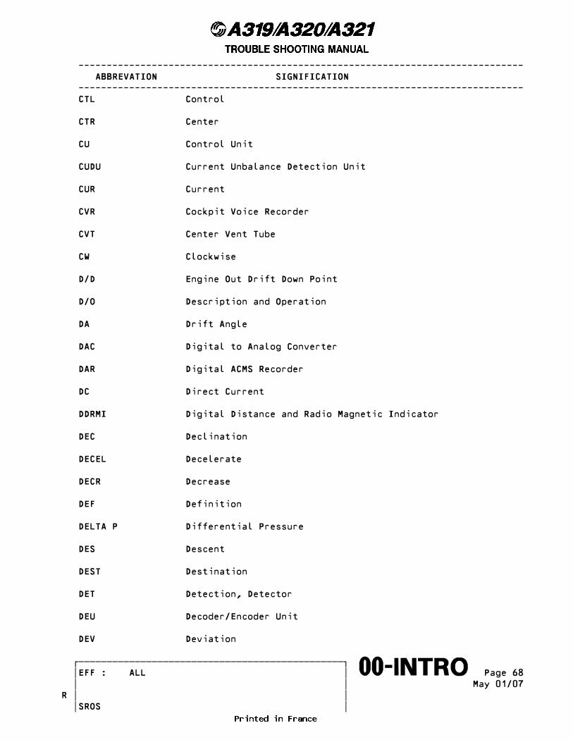
------------------------------------------------------------------------------- ABBREVATION SIGNIFICATION ------------------------------------------------------------------------------- CTL Control
CTR Center
CU Control Unit
CUDU Current Unbalance Detection Unit
CUR Current
CVR Cockpit Voice Recorder
CVT Center Vent Tube
CW Clockwise
D/D Engine Out Drift Down Point
D/O Description and Operation
DA Drift Angle
DAC Digital to Analog Converter
DAR Digital ACMS Recorder
DC Direct Current
DDRMI Digital Distance and Radio Magnetic Indicator
DEC Declination
DECEL Decelerate
DECR Decrease
DEF Definition
DELTA P Differential Pressure
DES Descent
DEST Destination
DET Detection, Detector
DEU Decoder/Encoder Unit
DEV Deviation
������������������������������������������������� �EFF : ALL � Page 68����������������������������������������������������∞∞00-INTRO∞∞∞∞∞∞∞∞∞∞ � � May 01/07 � �R � � SROS
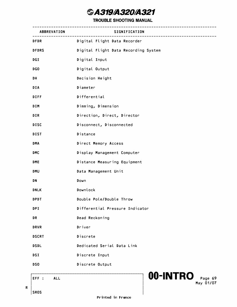
------------------------------------------------------------------------------- ABBREVATION SIGNIFICATION ------------------------------------------------------------------------------- DFDR Digital Flight Data Recorder
DFDRS Digital Flight Data Recording System
DGI Digital Input
DGO Digital Output
DH Decision Height
DIA Diameter
DIFF Differential
DIM Dimming, Dimension
DIR Direction, Direct, Director
DISC Disconnect, Disconnected
DIST Distance
DMA Direct Memory Access
DMC Display Management Computer
DME Distance Measuring Equipment
DMU Data Management Unit
DN Down
DNLK Downlock
DPDT Double Pole/Double Throw
DPI Differential Pressure Indicator
DR Dead Reckoning
DRVR Driver
DSCRT Discrete
DSDL Dedicated Serial Data Link
DSI Discrete Input
DSO Discrete Output
������������������������������������������������� �EFF : ALL � Page 69����������������������������������������������������∞∞00-INTRO∞∞∞∞∞∞∞∞∞∞ � � May 01/07 � �R � � SROS
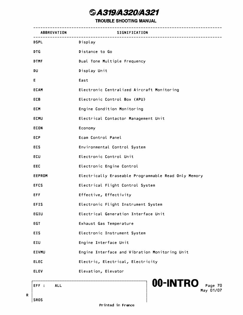
------------------------------------------------------------------------------- ABBREVATION SIGNIFICATION ------------------------------------------------------------------------------- DSPL Display
DTG Distance to Go
DTMF Dual Tone Multiple Frequency
DU Display Unit
E East
ECAM Electronic Centralized Aircraft Monitoring
ECB Electronic Control Box (APU)
ECM Engine Condition Monitoring
ECMU Electrical Contactor Management Unit
ECON Economy
ECP Ecam Control Panel
ECS Environmental Control System
ECU Electronic Control Unit
EEC Electronic Engine Control
EEPROM Electrically Eraseable Programmable Read Only Memory
EFCS Electrical Flight Control System
EFF Effective, Effectivity
EFIS Electronic Flight Instrument System
EGIU Electrical Generation Interface Unit
EGT Exhaust Gas Temperature
EIS Electronic Instrument System
EIU Engine Interface Unit
EIVMU Engine Interface and Vibration Monitoring Unit
ELEC Electric, Electrical, Electricity
ELEV Elevation, Elevator
������������������������������������������������� �EFF : ALL � Page 70����������������������������������������������������∞∞00-INTRO∞∞∞∞∞∞∞∞∞∞ � � May 01/07 � �R � � SROS
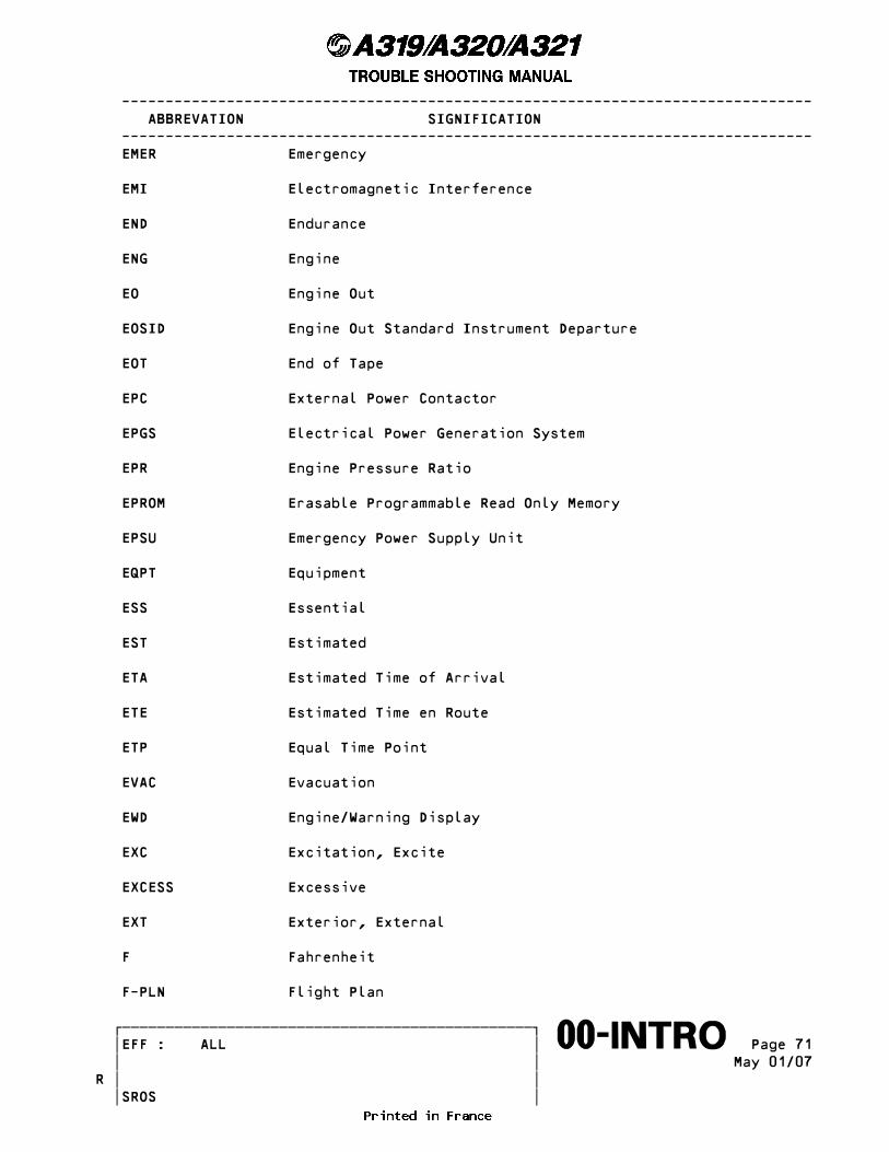
------------------------------------------------------------------------------- ABBREVATION SIGNIFICATION ------------------------------------------------------------------------------- EMER Emergency
EMI Electromagnetic Interference
END Endurance
ENG Engine
EO Engine Out
EOSID Engine Out Standard Instrument Departure
EOT End of Tape
EPC External Power Contactor
EPGS Electrical Power Generation System
EPR Engine Pressure Ratio
EPROM Erasable Programmable Read Only Memory
EPSU Emergency Power Supply Unit
EQPT Equipment
ESS Essential
EST Estimated
ETA Estimated Time of Arrival
ETE Estimated Time en Route
ETP Equal Time Point
EVAC Evacuation
EWD Engine/Warning Display
EXC Excitation, Excite
EXCESS Excessive
EXT Exterior, External
F Fahrenheit
F-PLN Flight Plan
������������������������������������������������� �EFF : ALL � Page 71����������������������������������������������������∞∞00-INTRO∞∞∞∞∞∞∞∞∞∞ � � May 01/07 � �R � � SROS
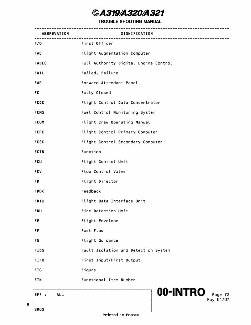
------------------------------------------------------------------------------- ABBREVATION SIGNIFICATION ------------------------------------------------------------------------------- F/O First Officer
FAC Flight Augmentation Computer
FADEC Full Authority Digital Engine Control
FAIL Failed, Failure
FAP Forward Attendant Panel
FC Fully Closed
FCDC Flight Control Data Concentrator
FCMS Fuel Control Monitoring System
FCOM Flight Crew Operating Manual
FCPC Flight Control Primary Computer
FCSC Flight Control Secondary Computer
FCTN Function
FCU Flight Control Unit
FCV Flow Control Valve
FD Flight Director
FDBK Feedback
FDIU Flight Data Interface Unit
FDU Fire Detection Unit
FE Flight Envelope
FF Fuel Flow
FG Flight Guidance
FIDS Fault Isolation and Detection System
FIFO First Input/First Output
FIG Figure
FIN Functional Item Number
������������������������������������������������� �EFF : ALL � Page 72����������������������������������������������������∞∞00-INTRO∞∞∞∞∞∞∞∞∞∞ � � May 01/07 � �R � � SROS

------------------------------------------------------------------------------- ABBREVATION SIGNIFICATION ------------------------------------------------------------------------------- FL Flight Level
FLEX Flexible
FLP Flap
FLT Flight
FM Flight Management
FMA Flight Mode Annunciator
FMC Flight Management Computer
FMGC Flight Management and Guidance Computer
FMGS Flight Management and Guidance System
FMGS Flight Management and Guidance System
FMS Flight Management System
FMV Fuel Metering Valve
FO Fully Open
FOB Fuel On Board
FPA Flight Path Angle
FPEEPMS Floor Proximity Emergency Escape Path Marking System
FPPU Feedback Position Pick-off Unit
FPV Flight Path Vector
FQ Fuel Quantity
FQI Fuel Quantity Indicating/Indication/Indicator
FR Frame
FREQ Frequency
FRU Frequency Reference Unit
FRV Fuel Return Valve
FSB Fasten Seat Belts
������������������������������������������������� �EFF : ALL � Page 73����������������������������������������������������∞∞00-INTRO∞∞∞∞∞∞∞∞∞∞ � � May 01/07 � �R � � SROS

------------------------------------------------------------------------------- ABBREVATION SIGNIFICATION ------------------------------------------------------------------------------- FW Failure Warning
FWC Flight Warning Computer
FWD Forward
FWS Flight Warning System
G Green
G/S Glide Slope
GA Go-Around
GALY
GAPCU Ground Auxiliary Power Control Unit
Galley
GCR Generator Control Relay
GCU Generator Control Unit
GEN Generator
GLC Generator Line Contactor
GLR Generator Line Relay
GMT Greenwich Mean Time
GND Ground
GPCU Ground Power Control Unit
GPS Global Positioning System
GPU Ground Power Unit
GPWC Ground Proximity Warning Computer
GPWS Ground Proximity Warning System
GRP Geographic Reference Point
GRU Ground Refrigeration Unit
GS Ground Speed
������������������������������������������������� �EFF : ALL � Page 74����������������������������������������������������∞∞00-INTRO∞∞∞∞∞∞∞∞∞∞ � � May 01/07 � �R � � SROS

------------------------------------------------------------------------------- ABBREVATION SIGNIFICATION ------------------------------------------------------------------------------- GSE Ground Support Equipment
GW Gross Weight
H Hot (Electrical Point)
HCU Hydraulic Control Unit
HDG Heading
HEGS Hydraulic Electrical Generating System
HF High Frequency
HI High
HLAC High Level Alternating Current Voltage
HLDC High Level Direct Current Voltage
HMU Hydromechanical Unit
HP High Pressure
HPC High Pressure Compressor
HPT High Pressure Turbine
HPTACC High Pressure Turbine Active Clearance Control
HS High Speed
HSI Horizontal Situation Indicator
HSMU Hydraulic System Monitoring Unit
HUDC Head Up Display Computer
HYD Hydraulic
I/O Input/Output
I/P Intercept Profile
I/P Input
IAE International Aero Engines
IAS Indicated Airspeed
������������������������������������������������� �EFF : ALL � Page 75����������������������������������������������������∞∞00-INTRO∞∞∞∞∞∞∞∞∞∞ � � May 01/07 � �R � � SROS

------------------------------------------------------------------------------- ABBREVATION SIGNIFICATION ------------------------------------------------------------------------------- IDENT Identification, Identifier, Identify
IDG Integrated Drive Generator
IGB Inlet Gear Box
IGN Ignition
IGV Inlet Guide Vane
ILS Instrument Landing System (LOC and G/S)
IMM Immediate
INB Inbound
INBD Inboard
INCR Increment
IND Indicator
INFO Information
INHIB Inhibition, Inhibit, Inhibited
INIT Initial(ization)
INOP Inoperative
INR Inner
INT Interrupt
INTCP Intercept
INTFC Interface
INTL Internal
INTRG Interrogate, Interrogator
INV Inverter
IP Intermediate Pressure
IPC Illustrated Parts Catalog
IPPU Instrumentation Position Pick-off Unit
������������������������������������������������� �EFF : ALL � Page 76����������������������������������������������������∞∞00-INTRO∞∞∞∞∞∞∞∞∞∞ � � May 01/07 � �R � � SROS

------------------------------------------------------------------------------- ABBREVATION SIGNIFICATION ------------------------------------------------------------------------------- IR Inertial Reference
IRS Inertial Reference System
ISA International Standard Atmosphere
ISO International Standardization Organisation
ISOL Isolation
IVS Inertial Vertical Speed
JAM Jammed, Jamming
JAR Joint Airworthiness Requirements
L Left
L Length
L/G Landing Gear
LA Linear Accelerometer
LAT Lateral
LAT Latitude
LAV Lavatory
LBP Left Bottom Plug
LCD Liquid Crystal Display
LCIT Load Compressor Inlet Temperature
LDG Landing
LE Leading Edge
LED Light Emitting Diode
LGCIU Landing Gear Control and Interface Unit
LIM Limit, Limitation, Limiting, Limiter
LKD Locked
LL Lat/Long
������������������������������������������������� �EFF : ALL � Page 77����������������������������������������������������∞∞00-INTRO∞∞∞∞∞∞∞∞∞∞ � � May 01/07 � �R � � SROS

------------------------------------------------------------------------------- ABBREVATION SIGNIFICATION ------------------------------------------------------------------------------- LLDC Low Level Direct Current Voltage
LMP Left Middle Plug
LNG Long
LMS Leakage Measurement System
LO Low
LOC Localizer
LONG Longitude
LONGN Longeron
LOP Low Oil Pressure
LP Low Pressure
LPT Low Pressure Turbine
LPTACC Low Pressure Turbine Active Clearance Control
LRU Line Replaceable Unit
LS Loudspeaker
LSB Least Significant Bit
LSI Large Scale Integration
LT Light
LTP Left Top Plug
LV Low Voltage
LVDT Linear Variable Differential Transducer
LVL Level
LW Landing Weight
LWR Lower
MAC Mean Aerodynamic Chord
MAG Magnetic
������������������������������������������������� �EFF : ALL � Page 78����������������������������������������������������∞∞00-INTRO∞∞∞∞∞∞∞∞∞∞ � � May 01/07 � �R � � SROS
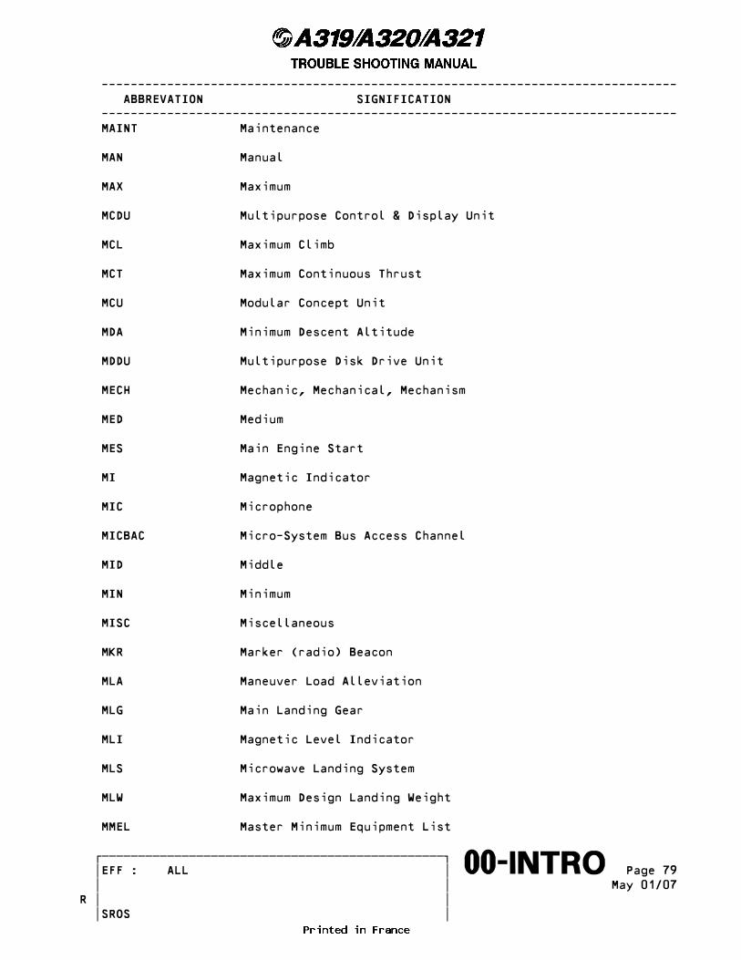
------------------------------------------------------------------------------- ABBREVATION SIGNIFICATION ------------------------------------------------------------------------------- MAINT Maintenance
MAN Manual
MAX Maximum
MCDU Multipurpose Control & Display Unit
MCL Maximum Climb
MCT Maximum Continuous Thrust
MCU Modular Concept Unit
MDA Minimum Descent Altitude
MDDU Multipurpose Disk Drive Unit
MECH Mechanic, Mechanical, Mechanism
MED Medium
MES Main Engine Start
MI Magnetic Indicator
MIC Microphone
MICBAC Micro-System Bus Access Channel
MID Middle
MIN Minimum
MISC Miscellaneous
MKR Marker (radio) Beacon
MLA Maneuver Load Alleviation
MLG Main Landing Gear
MLI Magnetic Level Indicator
MLS Microwave Landing System
MLW Maximum Design Landing Weight
MMEL Master Minimum Equipment List
������������������������������������������������� �EFF : ALL � Page 79����������������������������������������������������∞∞00-INTRO∞∞∞∞∞∞∞∞∞∞ � � May 01/07 � �R � � SROS

------------------------------------------------------------------------------- ABBREVATION SIGNIFICATION ------------------------------------------------------------------------------- MMO Maximum Operating Mach
MMR Multi Mode Receiver
MODLTR Modulator
MON Monitor, Monitored
MONG Monitoring
MORA Minimum Off Route Altitude
MOT Motor, Motorized
MPD Maintenance Planning Document
MSA Minimum Safe Altitude
MSB Most Significant Bit
MSG Message
MSL Mean Sea Level
MSU Mode Selector Unit (IRS)
MSW Microswitch
MTBF Mean Time Between Failure
MTBUR Mean Time Between Unscheduled Removals
MTG Mounting
MTO Maximum Take-Off
MTOGW Maximum Takeoff Gross Weight
MU Management Unit
MUX Multiplex, Multiplexer
MVT Movement
MZFW Maximum Design Zero Fuel Weight
N Normal, North
N/A Not Applicable
������������������������������������������������� �EFF : ALL � Page 80����������������������������������������������������∞∞00-INTRO∞∞∞∞∞∞∞∞∞∞ � � May 01/07 � �R � � SROS

------------------------------------------------------------------------------- ABBREVATION SIGNIFICATION ------------------------------------------------------------------------------- N/P Next Page
N/W Nose Wheel
N/WS Nose Wheel Steering
NAC Nacelle
NAS Navy and Army Standard
NAV Navigation
NAVAID Navigation Aid
NBPT No Break Power Transfer
NC Normally Closed
NCD No Computed Data
ND Navigation Display
NDB Non-Directional Beacon
NEG Negative
NLG Nose Landing Gear
NMI Non Maskable Interrupt
No Number
NO Normally Open
NO Normal Operation in SSM
NORM Normal
NS No Smoking
NUM Numerical
NVM Non-Volatile Memory
N1 Low Pressure Rotor Speed
N2 High Pressure Rotor Speed
O Open
������������������������������������������������� �EFF : ALL � Page 81����������������������������������������������������∞∞00-INTRO∞∞∞∞∞∞∞∞∞∞ � � May 01/07 � �R � � SROS
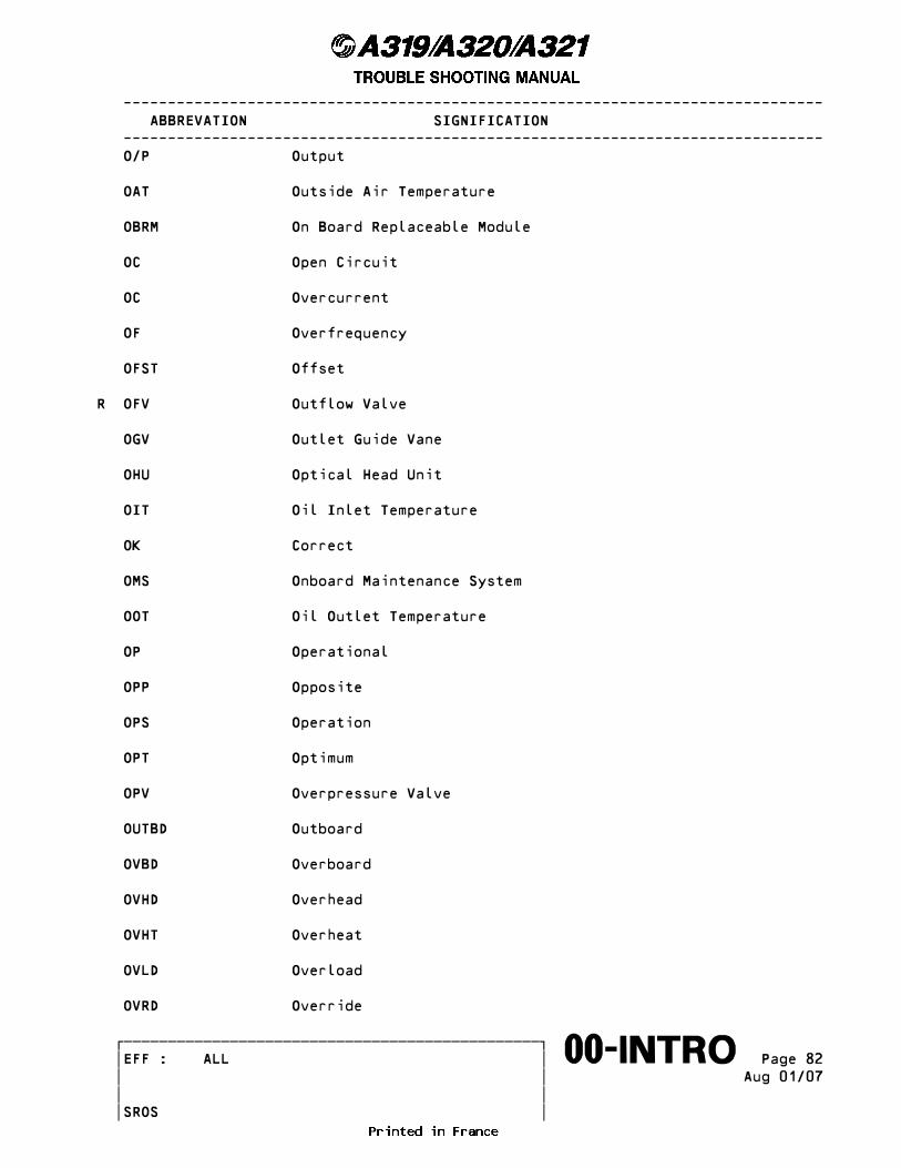
------------------------------------------------------------------------------- ABBREVATION SIGNIFICATION ------------------------------------------------------------------------------- O/P Output
OAT Outside Air Temperature
OBRM On Board Replaceable Module
OC Open Circuit
OC Overcurrent
OF Overfrequency
OFST Offset
R OFV Outflow Valve
OGV Outlet Guide Vane
OHU Optical Head Unit
OIT Oil Inlet Temperature
OK Correct
OMS Onboard Maintenance System
OOT Oil Outlet Temperature
OP Operational
OPP Opposite
OPS Operation
OPT Optimum
OPV Overpressure Valve
OUTBD Outboard
OVBD Overboard
OVHD Overhead
OVHT Overheat
OVLD Overload
OVRD Override
������������������������������������������������� �EFF : ALL � Page 82����������������������������������������������������∞∞00-INTRO∞∞∞∞∞∞∞∞∞∞ � � Aug 01/07 � � � � SROS
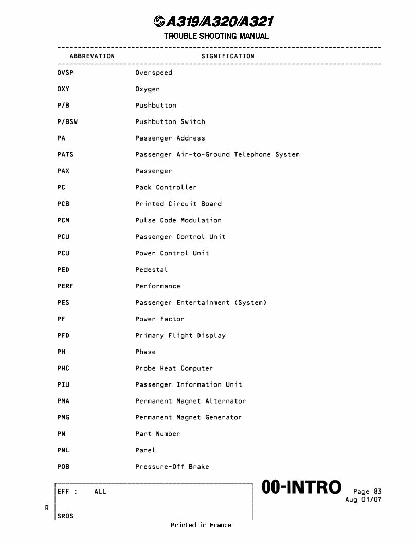
------------------------------------------------------------------------------- ABBREVATION SIGNIFICATION ------------------------------------------------------------------------------- OVSP Overspeed
OXY Oxygen
P/B Pushbutton
P/BSW Pushbutton Switch
PA Passenger Address
PATS Passenger Air-to-Ground Telephone System
PAX Passenger
PC Pack Controller
PCB Printed Circuit Board
PCM Pulse Code Modulation
PCU Passenger Control Unit
PCU Power Control Unit
PED Pedestal
PERF Performance
PES Passenger Entertainment (System)
PF Power Factor
PFD Primary Flight Display
PH Phase
PHC Probe Heat Computer
PIU Passenger Information Unit
PMA Permanent Magnet Alternator
PMG Permanent Magnet Generator
PN Part Number
PNL Panel
POB Pressure-Off Brake
������������������������������������������������� �EFF : ALL � Page 83����������������������������������������������������∞∞00-INTRO∞∞∞∞∞∞∞∞∞∞ � � Aug 01/07 � �R � � SROS

------------------------------------------------------------------------------- ABBREVATION SIGNIFICATION ------------------------------------------------------------------------------- POR Point of Regulation
POS Position
POT Potentiometer
PPOS Present Position
PR Power Ready Relay
PRAM Prerecorded Announcement and Music
PREAMP Preamplifier
PRED Prediction
PRESEL Preselector/Preselection
PRESS Pressure, Pressurization, Pressurize
PREV Previous
PRIM Primary
PROC T Procedure Turn
PROF Profile
PROG Progress
PROM Programmable Read Only Memory
PROT Protection
PROX Proximity
PRR Power Ready Relay
PSCU Proximity Switch Control Unit
PSDU Power Supply Decoupling Unit
PSI Pound per Square Inch
PSS Passenger Services System
PSU Passenger Service Unit
PT Point
������������������������������������������������� �EFF : ALL � Page 84����������������������������������������������������∞∞00-INTRO∞∞∞∞∞∞∞∞∞∞ � � Aug 01/07 � �R � � SROS

------------------------------------------------------------------------------- ABBREVATION SIGNIFICATION ------------------------------------------------------------------------------- PTC Positive Temperature Coefficient
PTT Push to Test
PTT Push-to-Talk
PU Panel Unit
PVI Paravisual Indicating
PVIS Passenger Visual Information System
PWR Power
Q Pitch Rate
QAD Quick-Attach-Detach
QAR Quick Access Recorder
QAT Quadruple ARINC Transmitter
QEC Quick Engine Change
QFE Field Elevation Atmospheric Pressure
QFU Runway Heading
QNE Sea Level Standard Atmosphere Pressure
QNH Sea Level Atmospheric Pressure
QTY Quantity
R Red
R Right
R/I Radio/Inertial
RA Radio Altimeter, Radio Altitude
RAC Rotor Active Clearance
RACC Rotor Active Clearance Control
RACSB Rotor Active Clearance Start Bleed
RAD Radio
������������������������������������������������� �EFF : ALL � Page 85����������������������������������������������������∞∞00-INTRO∞∞∞∞∞∞∞∞∞∞ � � Aug 01/07 � �R � � SROS
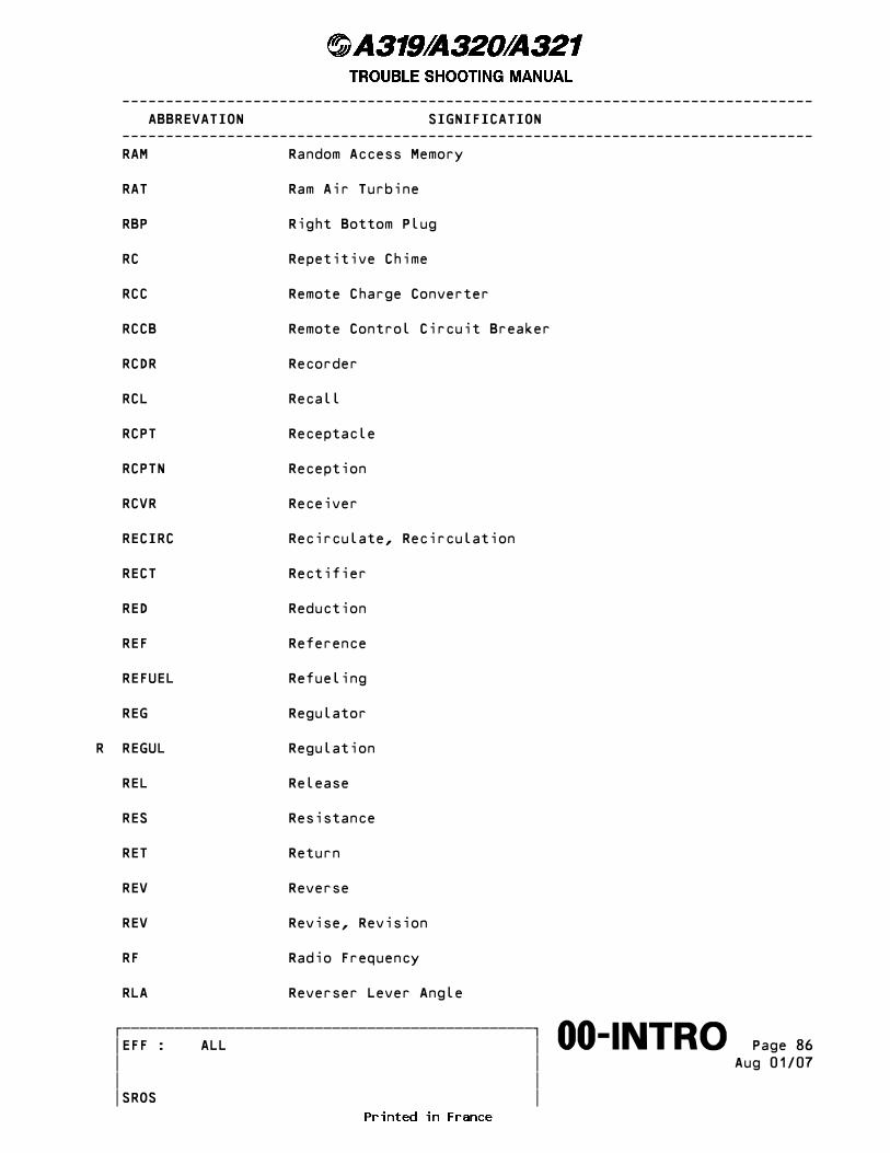
------------------------------------------------------------------------------- ABBREVATION SIGNIFICATION ------------------------------------------------------------------------------- RAM Random Access Memory
RAT Ram Air Turbine
RBP Right Bottom Plug
RC Repetitive Chime
RCC Remote Charge Converter
RCCB Remote Control Circuit Breaker
RCDR Recorder
RCL Recall
RCPT Receptacle
RCPTN Reception
RCVR Receiver
RECIRC Recirculate, Recirculation
RECT Rectifier
RED Reduction
REF Reference
REFUEL Refueling
REG Regulator
R REGUL Regulation
REL Release
RES Resistance
RET Return
REV Reverse
REV Revise, Revision
RF Radio Frequency
RLA Reverser Lever Angle
������������������������������������������������� �EFF : ALL � Page 86����������������������������������������������������∞∞00-INTRO∞∞∞∞∞∞∞∞∞∞ � � Aug 01/07 � � � � SROS
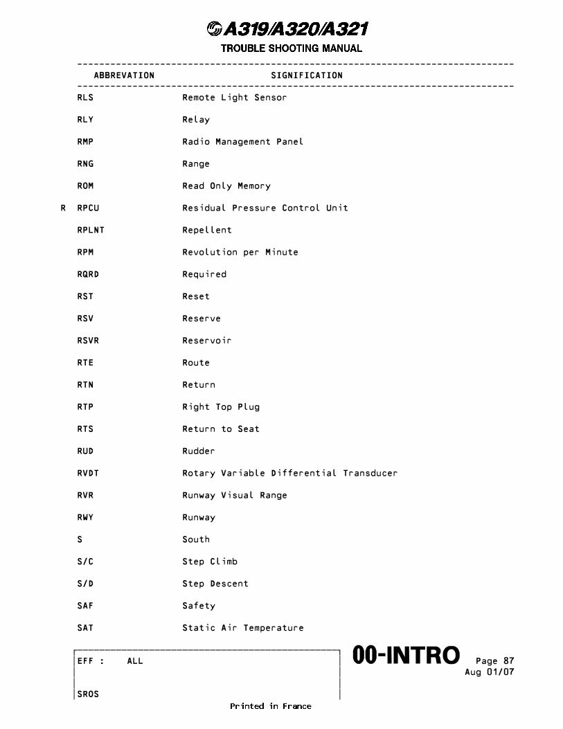
------------------------------------------------------------------------------- ABBREVATION SIGNIFICATION ------------------------------------------------------------------------------- RLS Remote Light Sensor
RLY Relay
RMP Radio Management Panel
RNG Range
ROM Read Only Memory
R RPCU Residual Pressure Control Unit
RPLNT Repellent
RPM Revolution per Minute
RQRD Required
RST Reset
RSV Reserve
RSVR Reservoir
RTE Route
RTN Return
RTP Right Top Plug
RTS Return to Seat
RUD Rudder
RVDT Rotary Variable Differential Transducer
RVR Runway Visual Range
RWY Runway
S South
S/C Step Climb
S/D Step Descent
SAF Safety
SAT Static Air Temperature
������������������������������������������������� �EFF : ALL � Page 87����������������������������������������������������∞∞00-INTRO∞∞∞∞∞∞∞∞∞∞ � � Aug 01/07 � � � � SROS

------------------------------------------------------------------------------- ABBREVATION SIGNIFICATION ------------------------------------------------------------------------------- SC Single Chime
SD System Display
SDAC System Data Acquisition Concentrator
SDCU Smoke Detection Control Unit
SDN System Description Note
SEB Seat Electronic Box
SEC Secondary
SEL Select, Selected, Selector, Selection
SELCAL Selective Calling System
SFCC Slat Flap Control Computer
SH ABS Shock Absorber
SHED Shedding
SHT Short
SIC System Isolation Contactor
SID Standard Instrument Departure
SIG Signal
SLT Slat
SMK Smoke
SN Serial Number
SOL Solenoid
SOV Shut-Off Valve
SPD Speed
SPLY Supply
SQ Squelch
SRU Shop Replaceable Unit
������������������������������������������������� �EFF : ALL � Page 88����������������������������������������������������∞∞00-INTRO∞∞∞∞∞∞∞∞∞∞ � � Aug 01/07 � �R � � SROS
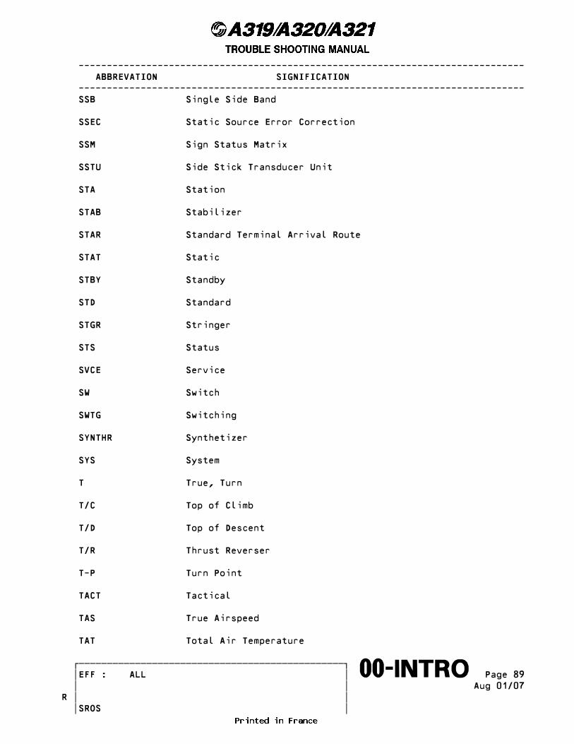
------------------------------------------------------------------------------- ABBREVATION SIGNIFICATION ------------------------------------------------------------------------------- SSB Single Side Band
SSEC Static Source Error Correction
SSM Sign Status Matrix
SSTU Side Stick Transducer Unit
STA Station
STAB Stabilizer
STAR Standard Terminal Arrival Route
STAT Static
STBY Standby
STD Standard
STGR Stringer
STS Status
SVCE Service
SW Switch
SWTG Switching
SYNTHR Synthetizer
SYS System
T True, Turn
T/C Top of Climb
T/D Top of Descent
T/R Thrust Reverser
T-P Turn Point
TACT Tactical
TAS True Airspeed
TAT Total Air Temperature
������������������������������������������������� �EFF : ALL � Page 89����������������������������������������������������∞∞00-INTRO∞∞∞∞∞∞∞∞∞∞ � � Aug 01/07 � �R � � SROS

------------------------------------------------------------------------------- ABBREVATION SIGNIFICATION ------------------------------------------------------------------------------- TBC To Be Confirmed
TBD To be Determined
TCAS Traffic Alert and Collision Avoidance System
T2CAS Traffic and Terrain Collision Avoidance System
TCC Turbine Case Cooling
TDS Technical Data Sheet
TE Trailing Edge
TEC Turbine Exhaust Case
TEMP Temperature
TFU Technical Follow-Up
TGT Target
THR Thrust
THRM Thermal
THS Trimmable Horizontal Stabilizer
TIT Turbine Inlet Temperature
TK Tank
TKE Track Angle Error
TLA Throttle Lever Angle
TLU Travel Limitation Unit
TMR Timer
TO Takeoff
TOGW Takeoff Gross Weight
TOT Total
TPIC Tire Pressure Indicating Computer
TPIS Tire Pressure Indicating System
������������������������������������������������� �EFF : ALL � Page 90����������������������������������������������������∞∞00-INTRO∞∞∞∞∞∞∞∞∞∞ � � Aug 01/07 � �R � � SROS

------------------------------------------------------------------------------- ABBREVATION SIGNIFICATION ------------------------------------------------------------------------------- TR Transformer Rectifier
TRA Throttle Resolver Angle
TRANS Transition
TRDV Thrust Reverser Directional Valve
TRF Turbine Rear Frame
TRIG Trigger
TRK Track (angle)
TROPO Tropopause
TRPV Thrust Reverser Pressurizing Valve
TRV Travel
TSM Trouble Shooting Manual
TTG Time to Go
TTL Transistor Transistor Logic
TTS Trim Tank System
TURB Turbulent, Turbulence
UF Underfrequency
UHF Ultra High Frequency
UNLK Unlock
UNLKD Unlocked, Unlocking
UNSD UNUSED
UPR Upper
UTC Universal Time Coordinated
UV Under Voltage
V/S Vertical Speed
Vc Calibrated Airspeed
������������������������������������������������� �EFF : ALL � Page 91����������������������������������������������������∞∞00-INTRO∞∞∞∞∞∞∞∞∞∞ � � Aug 01/07 � �R � � SROS
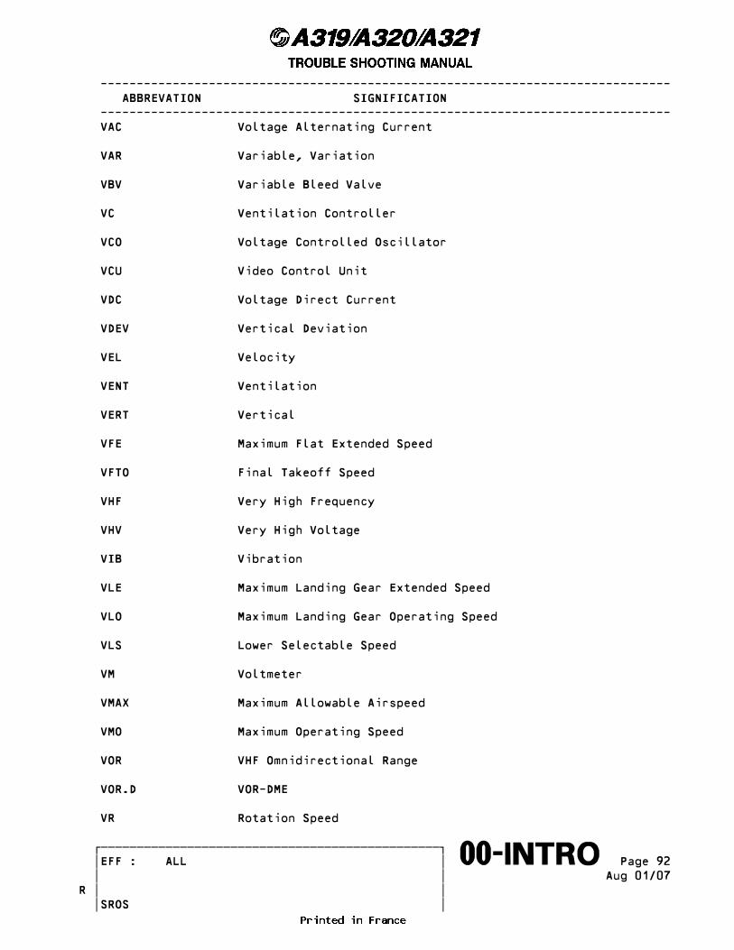
------------------------------------------------------------------------------- ABBREVATION SIGNIFICATION ------------------------------------------------------------------------------- VAC Voltage Alternating Current
VAR Variable, Variation
VBV Variable Bleed Valve
VC Ventilation Controller
VCO Voltage Controlled Oscillator
VCU Video Control Unit
VDC Voltage Direct Current
VDEV Vertical Deviation
VEL Velocity
VENT Ventilation
VERT Vertical
VFE Maximum Flat Extended Speed
VFTO Final Takeoff Speed
VHF Very High Frequency
VHV Very High Voltage
VIB Vibration
VLE Maximum Landing Gear Extended Speed
VLO Maximum Landing Gear Operating Speed
VLS Lower Selectable Speed
VM Voltmeter
VMAX Maximum Allowable Airspeed
VMO Maximum Operating Speed
VOR VHF Omnidirectional Range
VOR.D VOR-DME
VR Rotation Speed
������������������������������������������������� �EFF : ALL � Page 92����������������������������������������������������∞∞00-INTRO∞∞∞∞∞∞∞∞∞∞ � � Aug 01/07 � �R � � SROS

------------------------------------------------------------------------------- ABBREVATION SIGNIFICATION ------------------------------------------------------------------------------- VRMS Volt Root Mean Square
VRS V2500 Repair Scheme
VSC Vacuum System Controller
VSCF Variable Speed Constant Frequency
VSV Variable Stator Vane
VSWR Voltage Standing Wave Ratio
V1 Critical Engine Failure Speed
V2 Takeoff Safety Speed
V3 Flap Retraction Speed
V4 Slat Retraction Speed
W Weight
W White
WARN Warning
WBC Weight & Balance Computer
WBS Weight and Balance System
WD Warning Display
WHC Window Heat Computer
WHL Wheel
WIPCU Water Ice Protection Control Unit
WIPDU Water Ice Protection Data Unit
WPT Waypoint
WTB Wing Tip Brake
WXR Weather Radar
X FEED Crossfeed
X-TALK Cross-Talk
������������������������������������������������� �EFF : ALL � Page 93����������������������������������������������������∞∞00-INTRO∞∞∞∞∞∞∞∞∞∞ � � Aug 01/07 � �R � � SROS
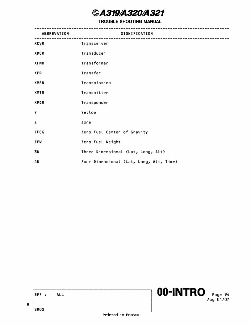
------------------------------------------------------------------------------- ABBREVATION SIGNIFICATION ------------------------------------------------------------------------------- XCVR Transceiver
XDCR Transducer
XFMR Transformer
XFR Transfer
XMSN Transmission
XMTR Transmitter
XPDR Transponder
Y Yellow
Z Zone
ZFCG Zero Fuel Center of Gravity
ZFW Zero Fuel Weight
3D Three Dimensional (Lat, Long, Alt)
4D Four Dimensional (Lat, Long, Alt, Time)
������������������������������������������������� �EFF : ALL � Page 94����������������������������������������������������∞∞00-INTRO∞∞∞∞∞∞∞∞∞∞ � � Aug 01/07 � �R � � SROS