Embed Size (px)
Citation preview
© 2011 Autodesk
Autodesk Moldflow 2012 new feature
Non-zero displacement BC for Warp
How to use it in a good way??
© 2011 Autodesk
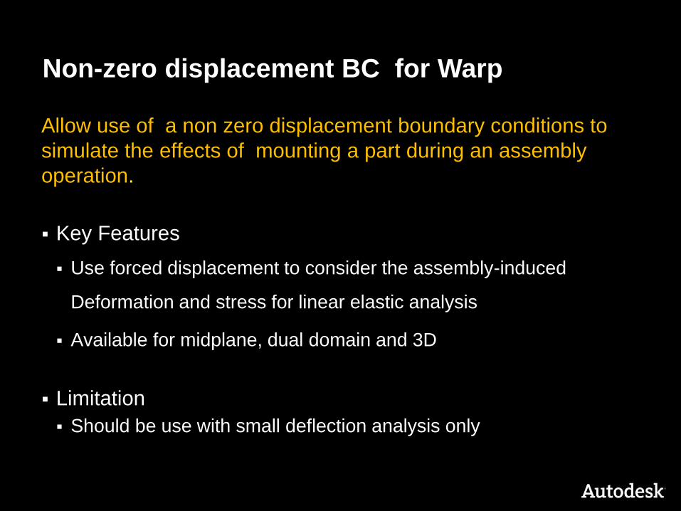
Allow use of a non zero displacement boundary conditions to
simulate the effects of mounting a part during an assembly
operation.
Key Features
Use forced displacement to consider the assembly-induced
Deformation and stress for linear elastic analysis
Available for midplane, dual domain and 3D
Limitation
Should be use with small deflection analysis only
Non-zero displacement BC for Warp
© 2011 Autodesk
Non-zero displacement BC for Warp
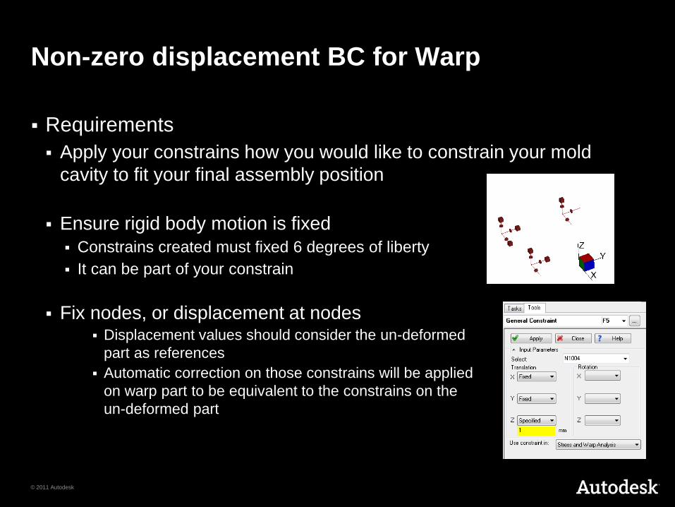
Requirements
Apply your constrains how you would like to constrain your mold
cavity to fit your final assembly position
Ensure rigid body motion is fixed
Constrains created must fixed 6 degrees of liberty
It can be part of your constrain
Fix nodes, or displacement at nodes Displacement values should consider the un-deformed
part as references
Automatic correction on those constrains will be applied
on warp part to be equivalent to the constrains on the
un-deformed part
© 2011 Autodesk
Example how to use it

© 2011 Autodesk
Example Bumber
For the example we use a simplified model
© 2011 Autodesk
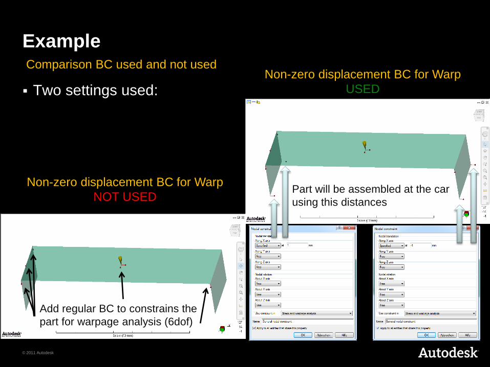
Example
Two settings used: Non-zero displacement BC for Warp
USED
Non-zero displacement BC for Warp
NOT USED
Comparison BC used and not used
Add regular BC to constrains the
part for warpage analysis (6dof)
Part will be assembled at the car
using this distances
© 2011 Autodesk
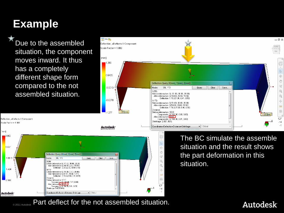
Example
Part deflect for the not assembled situation.
The BC simulate the assemble
situation and the result shows
the part deformation in this
situation.
Due to the assembled
situation, the component
moves inward. It thus
has a completely
different shape form
compared to the not
assembled situation.
© 2011 Autodesk
Example: how to use it in more detail
© 2011 Autodesk
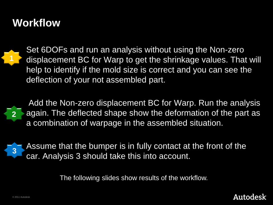
Workflow
Set 6DOFs and run an analysis without using the Non-zero
displacement BC for Warp to get the shrinkage values. That will
help to identify if the mold size is correct and you can see the
deflection of your not assembled part.
Add the Non-zero displacement BC for Warp. Run the analysis
again. The deflected shape show the deformation of the part as
a combination of warpage in the assembled situation.
Assume that the bumper is in fully contact at the front of the
car. Analysis 3 should take this into account.
1
2
3
The following slides show results of the workflow.
© 2011 Autodesk
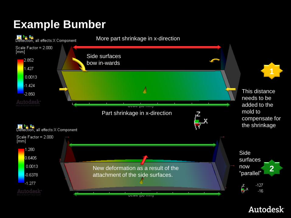
Example Bumber
1
2
Part shrinkage in x-direction
More part shrinkage in x-direction
Side surfaces
bow in-wards
This distance
needs to be
added to the
mold to
compensate for
the shrinkage
Side
surfaces
now
“parallel” New deformation as a result of the
attachment of the side surfaces.
© 2011 Autodesk
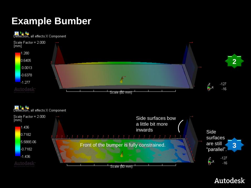
Example Bumber
2
3 Front of the bumper is fully constrained.
Side
surfaces
are still
“parallel”.
Side surfaces bow
a little bit more
inwards
© 2011 Autodesk
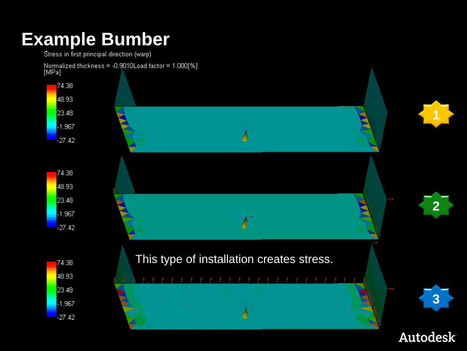
Example Bumber
1
2
3
This type of installation creates stress.
© 2011 Autodesk
Workflow use for
To show the deflection of a part.
Use the assembly situation to show the deformation of a part.
You can identify the amount of stress increase between the
origin deflection and the assembled situation.
That workflow can also be used if a specific measuring device is
used to measure deflection.
This workflow should not be used for non-linear deflection.