Embed Size (px)
Citation preview

Statement of rebuttal evidence of Graham Levy (Hydrology) for the NZ
Transport Agency
Dated: 25 October 2012
REFERENCE: John Hassan ([email protected])
Suzanne Janissen ([email protected])
Before a Board of Inquiry
MacKays to Peka Peka Expressway Proposal
under: the Resource Management Act 1991
in the matter of: Notice of requirement for designation and resource
consent applications by the NZ Transport Agency for the
MacKays to Peka Peka Expressway Proposal
applicant: NZ Transport Agency
Requiring Authority
1
042590992/2520922
TABLE OF CONTENTS
EXECUTIVE SUMMARY .......................................................................... 2
EVIDENCE OF SUBMITTERS .................................................................. 3
Sharyn Westlake for GWRC ...................................................................... 3
Robert van Bentum for KCDC .................................................................... 8
Pranil Wadan for St Heliers Capital Limited ................................................ 14
Vinod Chand for St Heliers Capital Limited................................................. 16
Sue Smith for WOO ............................................................................... 17
David Roil for WOO ............................................................................... 17
Dr Mary McIntyre for APSOC ................................................................... 18
Melanie Dixon for RSRA ......................................................................... 19
Professor Manning ................................................................................ 19
ANNEXURE A: PROPOSED CONSENT CONDITIONS ................................................................. 23
ANNEXURE B: CULVERT BLOCKAGE RISK ASSESSMENT ........................................................... 25
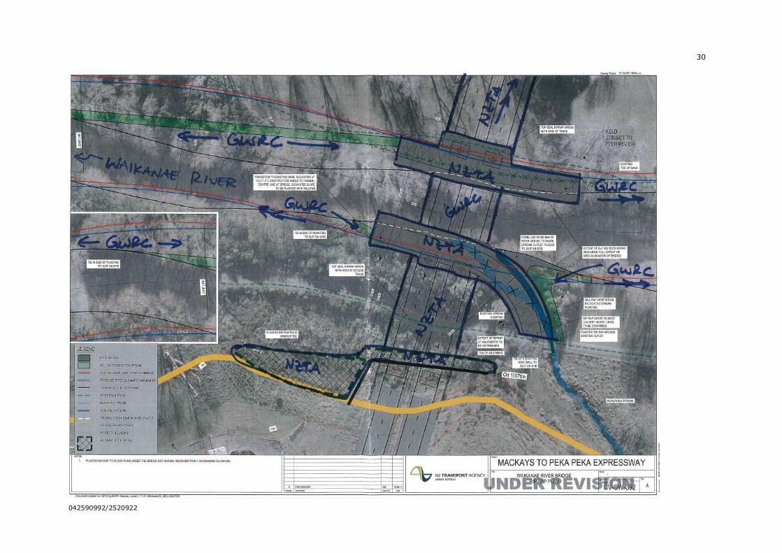
ANNEXURE C: PLAN IDENTIFYING MAINTENANCE RESPONSIBILITIES REGARDING WAIKANAE RIVER
BRIDGE................................................................................................................... 29
2
042590992/2520922
STATEMENT OF REBUTTAL EVIDENCE OF GRAHAM LEVY FOR THE
NZ TRANSPORT AGENCY
1 My full name is Graham John Levy.
2 I have the qualifications and experience set out at paragraphs 2 to 9
of my statement of evidence in chief, dated 30 August 2012 (EIC).
3 I repeat the confirmation given in my EIC that I have read, and
agree to comply with, the Code of Conduct for Expert Witnesses
(Consolidated Practice Note 2011).
4 In this statement of rebuttal evidence, I respond to the evidence of:
4.1 Sharyn Westlake and Richard Percy on behalf of Greater
Wellington Regional Council (GWRC) (submitter number 684);
4.2 Robert van Bentum and Emily Thomson on behalf of
Kāpiti Coast District Council (KCDC) (submitter number 682);
4.3 Pranil Wadan and Vinod Chand on behalf of St Heliers
Capital Limited (submitter number 644);
4.4 Sue Smith on behalf of Waikanae on One (WOO)
(submitter 514);
4.5 Dr Mary McIntyre on behalf of Action to Protect and Sustain
our Communities (APSOC) (submitter number 677);
4.6 Melanie Dixon on behalf of Raumati South Residents
Association (RSRA) (submitter number 707); and
4.7 Professor Martin Manning (submitter number 687).
5 The fact that this rebuttal statement does not respond to every
matter raised in the evidence of submitter witnesses within my area
of expertise should not be taken as acceptance of the matters
raised. Rather, I rely on my earlier technical report,1 my EIC and
this rebuttal statement to set out my opinion on what I consider to
be the key hydrological, hydraulic and stormwater management
matters for this hearing.
6 Consistent with my EIC, I have referred to the MacKays to Peka
Peka Expressway Project as “the Project” in this rebuttal evidence.
EXECUTIVE SUMMARY
7 I have read those statements of evidence provided by submitters
that I have been able to identify as relating to my area of expertise.
1 Technical Report 22 (Assessment of Hydrology and Stormwater Effects).
3
042590992/2520922
The submitters’ evidence has not caused me to depart from the
opinions expressed in my EIC.
8 I remain of the opinion that the stormwater and water crossing
design proposed for the Project has been adequately prepared to
address the potential effects of these activities such that residual
effects will be localised and minor.
EVIDENCE OF SUBMITTERS
Sharyn Westlake for GWRC
9 Over the period of the Project development, I have had extensive
discussions with Ms Westlake and others in the GWRC Flood
Protection team, and we have sought to reach agreement on as
many matters as possible. This process involved several informal
and formal meetings, a joint site visit, exchange of letters, an
agreement regarding use by the Project of the GWRC flood model
for the Waikanae River, and arranging a peer review of the
Waikanae River waterway design by a reviewer agreed with GWRC.2
10 I sought to clarify outstanding issues with GWRC, assisted by their
post-submission publication of a Discussion Document, as described
in paragraphs 141 to 142 of my EIC. The Flood Protection elements
of that Discussion Document and my responses are set out in the
summary table in Annexure B to my EIC. I met again with GWRC
Flood Protection on 29 August 2012 to present these responses to
them (along with a further response to subsequent correspondence)
and to discuss the issues and how to address them. A number of
matters were resolved, and it was left for Ms Westlake to address
any remaining matters in her evidence.
11 My assessment of Ms Westlake’s evidence is that there appears to
be a substantial level of agreement between the NZTA and GWRC on
technical principles, but there remain issues for GWRC about some
matters of detail, and some elements where they would like to see
more information or have a review and certification role.
12 In particular, Ms Westlake is seeking greater certainty of outcome,
and an explicit GWRC review and certification role in future stages,
through the inclusion of a number of additional conditions of
consent. There also remain some specific technical matters. I
respond to these below.
Review and certification issues
13 In the sections of Ms Westlake’s evidence addressing the Waikanae
River Bridge (paragraphs 26 to 29), and Hydraulic modelling
(paragraphs 35 to 38), Ms Westlake seeks conditions requiring the
provision of further information and a review and certification role
for GWRC. In response, I will first discuss some issues with GWRC
review and certification, and then address the specific details of
2 Appendix 22.H of Technical Report 22.
4
042590992/2520922
each matter raised by Ms Westlake (including the requests for
further information).
14 In terms of possible additional conditions relating to GWRC review
and certification, the scope of that review would need to be clearly
delineated, with explicit performance criteria that the review is
conducted against. From what is stated in her evidence,3 the
specific outcomes Ms Westlake seeks to achieve are ones that in
most cases I would agree with, and are consistent with the Project
objectives and performance targets. I address the details below.
15 In my opinion, the complicating factor in any GWRC review and
certification role is that the Flood Protection department of GWRC
has a dual role, both as an advisor to the regulatory arm of GWRC,
and also as the manager of flood assets. As a result, it has a direct
financial interest in the outcome of some of the aspects which
Ms Westlake proposes for review and certification. This raises the
potential for a conflict of interest, unless there are clear limits
placed on any review.
16 An alternative approach, which has been adopted on at least two
recent NZTA projects that I am aware of,4 is for NZTA to obtain an
independent peer review of the stormwater and flood risk
management design. Such review would be against both NZTA’s
required performance criteria and any final conditions of consent,
leading to the issue of PS1 (designer) and PS2 (design reviewer)
producer statements. Such an approach is common practice in the
engineering industry, and would avoid any potential for conflict of
interest.
17 To support such an approach, and meet the points of detail
identified by Ms Westlake and discussed below, a list of appropriate
performance criteria could be added to the conditions of consent.
Such a list would primarily consist of items drawn from Annexure B
of my EIC, as referenced by Ms Westlake in her evidence. In
Annexure A attached to this evidence I have proposed the content
for such a condition, as SW.3.5
18 I propose the following condition SW.2(e) be added to address the
matter of independent peer review:
(e) The stormwater management design and flood risk modelling shall
be independently peer reviewed for compliance with the conditions
of consent.6
3 Paragraphs 25, 28, 35 and 38.
4 Tauranga Eastern Link and Christchurch Southern Motorway (Stage 1)
5 For ease of reference, I have shown in Annexure A the wording of proposed conditions SW.1 and SW.2, updated from that attached to my EIC. I have also
added proposed condition SW.3.
6 This is now shown in Annexure A to this evidence.
5
042590992/2520922
19 In paragraph 28 of her evidence, Ms Westlake comments on the
importance of bridge configuration for flood protection, including
number and shape of bridge piers, span between piers, and bridge
height for the proposed Waikanae River Bridge. Ms Westlake wants
a condition that these not be changed without GWRC review and
certification. I have addressed each of these Waikanae River bridge
configuration matters in the proposed consent condition SW.3(a),
(b), (c) and (e) in Annexure A attached to this evidence. I
therefore do not consider Ms Westlake’s proposed additional
Condition SW.2(f) is necessary.
20 In paragraph 29 of her evidence, Ms Westlake seeks to have a
condition specifying provision for future services in the bridge. In
Annexure B to my EIC I identified a list of future services that have
been provided for in the bridge design. I have included the list of
proposed service ducts from my EIC in proposed condition SW.3(d)
in Annexure A to this evidence. With that provision in place, I do
not consider that Ms Westlake’s proposed additional condition
DC.53(i) is necessary. I note also that conditions need certainty
and an open ended requirement to provide for undefined future
services (as suggested by Ms Westlake) does not achieve that.
21 In paragraph 35 of her evidence, Ms Westlake addresses my culvert
blockage risk assessment. In paragraph 42.5 of my EIC I
mentioned that I have carried out a blockage risk assessment, and
more detail was provided in item 19 of Annexure B of my EIC.
22 I now have summarised that culvert blockage risk assessment, and
included it as Annexure B to this evidence.
23 As outlined earlier in my evidence, I have proposed additional
condition SW.2(e) relating to an independent peer review, and have
included a provision for culvert blockage risk assessment in
proposed condition SW.3(f) in Annexure A to this evidence. This
proposed condition identifies the principal criteria used for the
blockage risk assessment that I undertook, which I propose would
be the criteria for such an assessment at final design. These criteria
are that:
23.1 There shall be a safe secondary flow path that does not
endanger habitable buildings; or
23.2 There shall be provision at the culvert inlet for debris
management such that culvert inlet blockage is avoided.
24 With these provisions in place I consider that this matter will be
adequately addressed, and that Ms Westlake’s proposed condition
SW.2(g) is not necessary.
25 In paragraph 36 of her evidence, Ms Westlake states that she has
not been able to review the hydraulic impacts, because there were
no flood depth difference plots included in Technical Report 22.
6
042590992/2520922
Flood depth difference plots were used in our internal assessment.
They were not included in Technical Report 22 because the raw data
can be misleading without considerable annotation and
interpretation to enable them to be properly understood. In their
raw state such plots show adverse effects wherever project works
are built to provide mitigation, which is not representative of
anticipated effects. The design target was that there should be no
flood level increase outside the designation. Thus, the plots from
modelling of the final design will show significant areas of coloured
flood differences, including within the designation and outside
(where there will be some flood level reductions), but none will be
related to adverse effects outside the designation, except minor
localised effects as identified in proposed condition SW.2(c).
26 It is not necessary to fully re-model every localised area where
there were residual flood risk effects evident from the modelling.
Instead, in each case I have identified the need for additional
storage or alternative mitigation, and included such storage or
mitigation in the AEE. Thus, while the modelling does not provide
the complete picture of mitigation, for every site where the
modelling identified a need for further mitigation appropriate
mitigation has been provided in the design submitted in the AEE.
27 As a consequence of the absence of plots for flood level differences,
Ms Westlake seeks an additional condition SW.2(e) for GWRC to
review and certify the hydraulic performance. I consider that the
alternative independent peer review condition SW.2(e) that I
propose is more appropriate, in combination with other elements of
SW.1 and SW.2 that specify hydraulic neutrality and flood
performance criteria.7
28 In paragraph 37 of her evidence, Ms Westlake expresses concern
that the maps we provided to her on 28 September 2012 to
illustrate the flood risk performance in the Te Moana Road and
Waimeha Stream area show increased flood risk in Puriri Road.
These maps were provided to GWRC to allow them to review the
effects in the Te Moana floodway area. The covering email
specifically alerted Ms Westlake to the fact that they had been
prepared prior to resolving the issues at Puriri Road, and were
therefore not up to date in that particular area. That part of the
Puriri Road area is not directly connected hydraulically to the
Te Moana area, but happens to be in the same flood model.
Subsequent to the preparation of that map, further work has been
undertaken to confirm that the footprint provided for stormwater
management in the vicinity of Puriri Road (around Wetland 9) was
sufficient to avoid any increase in flood risk to the Puriri Road area,
and the required mitigation measures arising from that work are as
described in the AEE8. I am therefore satisfied that the performance
7 SW.1(b), SW.2(a), (b), (c) and (d).
8 Technical Report 22, pages 89-90
7
042590992/2520922
requirements proposed in conditions SW.1 and SW.2 can be met in
this area by the works described in the AEE, and that the proposed
conditions relating to modelling and peer review provide a robust
mechanism for confirming that the final design also achieves
hydraulic neutrality. I therefore consider that Ms Westlake’s
concern about the depiction of flood risk in the plan sent to her
earlier has been addressed, and that her proposed condition
SW.2(e) is not required.
29 In paragraph 38 of her evidence, Ms Westlake seeks to have the
hydraulic modelling peer reviewed. I consider that for the final
design this is appropriate. I have therefore proposed an alternative
condition SW.2(e) earlier in my evidence to provide for that
independent peer review. With such a provision in place I do not
consider that Ms Westlake’s proposed amendment to condition
SW.2(d) is necessary.
Maintenance issues
30 Matters related to Waikanae River bridge maintenance raised in
paragraphs 30 and 33 of Ms Westlake’s evidence are, in my opinion,
details that are more appropriately resolved directly between NZTA
and GWRC, rather than needing to be the subject of consent
conditions. I addressed this issue of maintenance responsibilities in
Item 7 of Annexure B of my EIC, and referenced there the minutes
of a meeting between the Project team and GWRC on 3 November
2011, which included a plan delineating the proposed extent of
NZTA long term maintenance responsibilities. A copy of that plan is
now attached to my evidence as Annexure C.
31 In response to Ms Westlake’s suggested additional conditions, most
of these relate to landscape planting, and are addressed in the
rebuttal evidence of Mr Evans. Ms Westlake also proposes an
additional clause in proposed condition DC.54(d)(vii) relating to
responsibility for post-flood debris clearance, vandalism and graffiti
and berm drainage through a management plan. As I mention
above, I do not consider that this is a matter for resource consent
but rather for direct agreement between the NZTA and GWRC as
occurs with other parts of the State highway network.
32 In summary:
32.1 I acknowledge that while there are many matters of technical
detail that could be included in consent conditions, in my
opinion many of these are not essential. I have nevertheless
proposed some specific performance criteria for inclusion in
proposed condition SW.3, to provide guidance for proposed
independent peer review of the detailed design; and
32.2 I disagree with any provisions for GWRC review and
certification of final design, and instead recommend an
independent peer review process.
8
042590992/2520922
Robert van Bentum for KCDC
33 Mr van Bentum raises a number of points that I will address. Some
of these relate to approval and review processes (particularly
paragraphs 3.3 and 5.12 of his evidence), matters which I have
already addressed in my response to Ms Westlake’s evidence.
34 In paragraph 5.2 of his evidence, Mr van Bentum expresses concern
that one of the flood mitigation options proposed is “removal of
downstream constraints.” As a result, he seeks the deletion of
proposed condition SW.2(a)(iii). I disagree. By way of clarification,
there are no specific proposals to use this option, and no consents
have been sought for such downstream works. However, as KCDC
is a member of the Project Alliance, and as it has related flood
issues to address in some watercourses affected by the Project, the
potential exists that joint works may be identified in the future that
address the flood management needs both of KCDC and of the
Project.
35 Any such works would themselves be subject to resource consent,
so that any combined effects would be properly addressed at that
time. The downstream works would not relieve the Project of the
need to mitigate effects, but could provide an appropriate mitigation
alternative. In my opinion, it is therefore appropriate that such a
possibility be reflected in this consent, so that the Project is able to
participate in such joint works without breaching its own consent
conditions.
36 While I am confident that the Project can successfully mitigate loss
of flood plain storage due to the fill embankment, without the need
to seek further consents or rely on downstream capacity
improvements, in my opinion it makes sense to include the
possibility of a more efficient alternative in conjunction with
Council’s other stormwater works. I therefore support retention of
proposed condition SW.2(a)(iii).
37 In paragraphs 5.3-5.4 of his evidence, Mr van Bentum states that
the proposed conditions do not set out performance criteria in
respect of watercourse scour and erosion. He seeks a new condition
requiring attenuation of flows in swales and wetlands and riprap
protected culverts and outlets at bridges. As a result, Ms Thomson’s
evidence seeks additional wording to be included in SW.2 (a new
subparagraph (b)).9 I do not consider such a condition to be
necessary for the reasons set out below. In addition, I consider the
proposed wording would be too vague for a designer to implement
or to be able to confirm performance against.
38 The design of the Project specifically seeks to minimise discharge to
individual waterways by discharging at every waterway
9 Refer Thomson evidence, paragraph 10.26.
9
042590992/2520922
encountered10, thereby spreading the load. The use of flat-grade
swales and wetlands means that in small storm events (where
increased frequency and magnitude of discharge has the potential to
increase downstream erosion) discharges are significantly
attenuated and downstream erosion issues are addressed. In my
opinion, there is no further hydrological mitigation needed (e.g.
greater attenuation through the use of extended detention).
39 In regard to protection of the waterways from erosion in the vicinity
of stormwater outlets and other structures, the proposed design
includes erosion protection for all bridges, culvert inlets and outlets,
and stormwater discharge outlets.11 I note that it is not explicitly
identified as a design requirement in the proposed consent
conditions, except that proposed condition G.1 requires design in
accordance with the plans, and proposed conditions WS.4(b) and
WS.10(b) require remedy if there is any erosion.
40 In paragraphs 5.5-5.6, Mr van Bentum seeks clarification as to
which new open channels, drains and streams are to be
“naturalised”. In response, I note that all works associated with
diversions and in-stream temporary structures, including localised
diversions to align with culvert inlets and outlets, will involve
restoring the stream bed to resemble natural streams, as sought by
Mr van Bentum. I consider this outcome is already required by
proposed consent conditions WS.1, WS.3, WS.8 and WS.10.
Therefore I do not consider that the conditions proposed by Mr van
Bentum, and detailed at paragraph 10.28 of Ms Thomson’s
evidence, are necessary.
41 I consider that given the all-inclusive nature of the proposed
conditions of consent, and the specific description of design details
provided in paragraph 65 of my EIC for the more substantial
diversions, there is no need for further listing of watercourses in the
conditions of consent as sought by Mr van Bentum. Nor do I
consider that the additional condition sought by Ms Thomson (at
paragraph 10.28) is necessary.12
42 At paragraphs 5.7 to 5.8 of his evidence, Mr van Bentum
recommends a condition that all offset storage, ecological offset and
wetland treatment (excluding offset storage 6A) be included within
the final operational designation. I am not in a position to comment
on the ecological offset. However, as noted in my EIC,13 I agree
10 There are a very few exceptions for site-specific reasons, such as at Landfill
Drain.
11 Refer Drawings CV-SW-203, 212, 232, 303, 304, 391, 392 and 393, Volume 5 of the AEE.
12 Ms Thomson sought a new condition, to follow condition SW.2, reading: “All new, relocated and renovated open channel drains shall be constructed to resemble
notional streams with notional stream bed, riparian planting and refuges.”
13 My EIC, paragraph 133.
10
042590992/2520922
with this recommendation in relation to offset storage and wetland
treatment areas.
43 Mr van Bentum recommends (at paragraph 5.10 of his evidence),
that condition SW.2 be strengthened by the inclusion of three
further criteria, which are that:
43.1 Council’s stormwater requirements and associated accepted
best practice, in particular Council’s Stormwater Management
Strategy and policy of on-side hydraulic neutrality, is adhered
to;
43.2 The flows of stormwater and groundwater from the hills to the
coast (east-west) are not impeded; and
43.3 The natural flows in wetlands are not impeded.
44 The specific condition changes proposed are set out in
Ms Thomson’s evidence (paragraph 10.26), as a proposed addition
to what was SW.2(d), but which she has renumbered to SW.2(e).
45 In response I note that these criteria are high-level objectives that
have already been identified in the Guiding Objectives for the
Alliance Board in the Alliance agreement with KCDC. More
relevantly, they are, in my opinion, too broad to be measureable as
consent conditions, particularly the second and the third criteria.
The first criterion is generally too broad to be suitable as a consent
condition. However, I note that the latter part, relating to hydraulic
neutrality, is already contained in explicit detail in proposed
conditions SW.1(b) and SW.2(a) and (d). Therefore I do not agree
that it would be appropriate or necessary to include these criteria in
consent conditions, and consider that Ms Thomson’s suggested
addition to what she has renumbered as condition SW.2(e) is
unnecessary.
46 Additional information is sought in paragraph 5.13 relating to areas
not included in the modelling. I specifically addressed the areas in
question (in the vicinity of Poplar Ave and north of Peka Peka Road)
in paragraphs 95 and 126 of my EIC, and note that hydraulic
neutrality can be achieved, as demonstrated by manual analysis I
undertook. In terms of confirmation of this at final design, proposed
condition SW.2 adequately covers this matter by requiring effects of
filling to be assessed through the use of hydrological and hydraulic
modelling, and also requiring independent peer review of the design.
47 Mr van Bentum considers that insufficient detail has been provided
in the application around the specific provisions for stormwater
treatment. As a result, he seeks additional information around
proposed treatment in general and in specific locations
(paragraphs 5.14-5.15). In response, I note that the performance
of treatment measures is inherently covered by proposed conditions
11
042590992/2520922
SW.1 and SW.2, which define the requirements for treatment before
discharge for all Expressway runoff.
48 By way of detailed response, I note the following responses to very
specific questions in Mr van Bentum’s evidence around proposed
treatment and ultimate point of discharge of treated stormwater:
48.1 The stormwater layout plans14 show the type of device, the
direction of flow (for swales) and the points where there is
discharge.
48.2 Sub-paragraph (a): The median drainage from chainages
2900 to 4100 will be discharged at regular intervals into the
principal drainage system that runs parallel to it. In the case
of the section south of Drain 7, that will be discharged to the
adjacent swale for treatment before discharge. Drainage
north of Drain 7 will be discharged to the adjacent pipe, which
flows to wetland 0A for treatment before discharge. There is
a short section of Expressway (about 150m) across the top of
Culvert 7 for which treatment will be provided in one or other
of the adjacent devices, a detail that will be resolved in final
design. All of this section discharges to Drain 7.
48.3 Similar comments apply for the two other sections of median
drain noted in sub-paragraph (a). Chainage 4800 to 5400 is
partly discharged to Drain 7, and partly to the Wharemauku
Stream, both via swales. Chainage 8900 to 9200 is
discharged to the Waste Water Treatment Plant Drain.
48.4 Sub-paragraph (b): It is unclear to me which swale “south of
the Drain 7 crossing of the Expressway” is referred to, as
there are two such crossings. However, in both cases they
discharge to Drain 7 at the point where their alignment
reaches the drain.
48.5 Sub-paragraph (c): The Project is not seeking consent for the
possible alternative joint shared wetland noted on CV-SW-
114. This wetland, if it were implemented, would take
advantage of possible efficiencies associated with a future
development on land south of Mazengarb Road. Use of the
joint wetland would be dependent on the developer or NZTA
gaining consent for such a device, and on that device
including capacity for the Expressway runoff. In that event, I
expect that consent holder would be required to maintain the
device under its consent. The location of that discharge is not
defined at this stage, but would need to be confirmed as part
of gaining consent for the device, and is likely to be similar to
that for Wetland 5. If consent is not obtained for the
alternative, then the Expressway would simply build Wetland
14 Drawings CV-SW-100 to CV-SW-132, Appendix 22.A of Technical Report 22, and
included in Volume 5 of the AEE.
12
042590992/2520922
5 (which is the treatment measure the Board of Inquiry is
being asked to approve).
48.6 Sub- paragraph (d): This Type 2 swale discharges to the
450mm diameter pipe that collects all the swale runoff that
flows to Wetland 6.
48.7 Sub-paragraph (e): The small catchments 23.3 and 23.4
currently flow into the existing wetland at this location, and
there is little scope to separate them from this attenuation
area. In fact, controlling flows from these catchments within
Wetland 9 is an important component of achieving hydraulic
neutrality in this area. The intention is to discharge these
culverts to the attenuation part of Wetland 9, with the
Expressway runoff discharging separately to the treatment
area, as described in section 4.5.2(vii.) of the hydrology
report15. I acknowledge this separation is not explicitly shown
on Drawing CV-SW-119.16 The size of the culverts depicted in
Drawing CV-SW-119 could be misleading in regard to
expected flows from the catchments, as they are sized to
allow backflow from Wetland 9 across the wetlands in major
flood events, and to function hydraulically as part of the flood
attenuation area for Wetland 9. The natural flows from these
catchments are relatively small.
48.8 Sub-paragraph (f): The swales shown in Drawing CV-SW-
12817 are Type 1 swales, apart from a short length of Type 2
south of the culvert 34 outlet, with the remainder of that
Type 2 swale discharging south to culvert 33. Following
treatment in each of these swales, stormwater from the
eastern and western swales will discharge to the upstream
and downstream ends of culvert 34 respectively.
49 In paragraphs 5.16 to 5.19 of his evidence, Mr van Bentum
addresses wetlands, and expresses the view that the Project design
should be sufficiently developed at the application stage to enable
confirmation of the extent, size and nature of stormwater treatment
to be provided. I can confirm that the design is sufficiently
developed for that purpose, and does achieve the required
stormwater management performance with the wetland and storage
areas described in Technical Report 22 and the stormwater
drawings. Ongoing optimisation of the design may, however,
achieve the required performance in a more cost-effective manner.
As a result, conditions SW.1 and SW.2 have been proposed in order
to provide for future optimisation of details. These conditions define
the performance basis of the current design, and remain unchanged
for any future optimisation of detail.
15 Technical Report 22.
16 Appendix 22.A of Technical Report 22, and included in Volume 5 of the AEE.
17 Appendix 22.A of Technical Report 22, and included in Volume 5 of the AEE.
13
042590992/2520922
50 I disagree with Mr van Bentum’s suggestion (at paragraph 5.18)
that the specific provision for treatment wetlands set out in
Technical Report 22 be considered a minimum irrespective of
whether optimisation shows it is needed or not. For example,
wetlands 10A and 10B may be able to be combined at detailed
design with no change to water quality outcomes, and this should
not be prevented by the consent conditions.
51 In paragraphs 5.19 and 5.20, Mr van Bentum states that the
wetland swales should be designed to retain minimum quantities of
water to support wetland plants, and if wetlands are required then
there should be swales followed by wetlands. In response, I
consider that Mr van Bentum misunderstands the purpose of the
wetland swales, which are not explicitly to replace wetlands, but
rather to reflect that in low-lying peaty areas grassed swales are not
sustainable because the grass may not survive, and would not be
able to be mowed due to wet soil conditions that will occur for much
of the time. The wetland swales are used to accommodate the soil
conditions, and will be planted with species that can sustain both
inundation and occasional dry conditions. I therefore disagree with
his conclusion and remain of the opinion that the use of wetland
swales in low-lying peat areas, with appropriate planting, is the
most suitable treatment solution.
52 In paragraphs 3.4-3.5 Mr van Bentum suggests that proposed
treatment is insufficient on grounds that “the design approach does
not adequately take into account the way in which the Expressway
stormwater would be positively directed to major watercourses
along the alignment.” He expands on this in paragraphs 5.21 to
5.24, seeking a two stage approach involving the use of swales and
the treatment wetlands. I disagree. Discharges to all streams will
receive BPO treatment, and water quality effects of the discharges
have been assessed as minor.18 The suggestion that any grassed
swale treatment should be followed by wetland treatment is not
justified. Moreover, it would involve additional land footprint and
cost when the effects have already been assessed as minor.
53 Mr van Bentum notes that the “NZTA has proposed a two treatment
train for stormwater treatment in a number of locations, without
confirming the basis for the exclusion of other sites”
(paragraph 5.22). I understand Mr van Bentum is referring to
treatment devices discharging to the Ngarara and Kakariki streams.
The selection of these two watercourses for additional treatment
was made in consultation with the Project ecologists, and was
limited to the Ngarara and Kakariki streams on their advice that
these two were particularly important because of their relatively
direct discharge to Te Harakeke wetland. I do not agree the
additional treatment should be applied to any of the other streams
listed in Mr van Bentum’s evidence (paragraph 5.23). As a result, I
18 Paragraph 85 to 89 of my EIC.
14
042590992/2520922
do not agree with the related amendments to proposed condition
SW.1(a) suggested in Ms Thomson’s evidence (paragraph 10.24).
54 In summary, I do not consider that there is anything in Mr van
Bentum’s evidence that justifies a change to the proposed design, or
to the proposed conditions of consent.
Pranil Wadan for St Heliers Capital Limited
55 Mr Wadan outlines an alternative design for Wetland 4 which has
been proposed by St Heliers, in particular relocating it from a site
adjacent to Kapiti interchange as shown in Drawing CV-SW-110,19 to
a point adjacent to the Wharemauku Stream.20
56 I note that the location proposed in Mr Wadan’s evidence is different
to that shown in the St Heliers submission, with the proposed site
having been moved from what is currently a sand hill, onto what is
currently low-lying flood plain.
57 As I outline later in this evidence, flood risk management
constraints in this area make design of any works in the flood plain
difficult, and time-consuming modelling and design optimisation is
required to confirm hydraulic neutrality. There has been insufficient
time since the evidence was submitted for such an assessment to be
made, either by Mr Wadan or by me.
58 In terms of Expressway stormwater management, the alternative
design will be less efficient hydraulically, and more costly. While
further detailed work would be required (such detail not yet being
available to the NZTA or KCDC), my initial assessment is that it is
possible that this alternative location could be made to work
hydraulically, from the point of view of managing Expressway
runoff, but at some additional cost.
59 However, the more significant outstanding issue is related to effects
on flood risk management in the wider Wharemauku catchment, due
to the relocation of the wetland into a significant flood storage area,
and the consequent loss of that existing flood storage. In this
regard, hydraulic neutrality21 has not yet been demonstrated for St
Heliers’ alternative site.
60 Mr Wadan’s assertion (at paragraph 31) that the two wetland
locations are both flood prone, and therefore “similar’, is incorrect.
61 Caution needs to be used when interpreting the SKM and Connell
Wagner maps published for KCDC (as referenced by Mr Wadan)22
19 Appendix 22.A of Technical Report 22, and included in Volume 5 of the AEE.
20 Drawing 60523-SK-121005-4 attached to Mr Wadan’s evidence.
21 Hydraulic neutrality has been defined to be consistent with KCDC’s application of
the term. It is defined in 4.2.3(iii) (on page 53) of Technical Report 22.
22 Paragraph 31 of Mr Wadan’s evidence.
15
042590992/2520922
because as a matter of policy, the flooding extent plotted for KCDC
includes what KCDC term a “dynamic freeboard” that varies from
300mm to 500mm depending on the specific site locations. This
margin is added on top of the modelled flood level, with the extent
of that higher “flood prone” areas are also mapped. Therefore the
mapped flood extent is wider that the extent that the modelling
identifies as the best estimate of the land that would be subject to
actual inundation with water, and covers any land that would be
flooded if the flood water level reached the freeboard level.
62 It is relevant to note that:
62.1 The general ground level at proposed Wetland 4 is of the
order of 6mRL and slightly above, while the flood level is
about 6.32mRL.
62.2 The general ground level at the alternative site proposed by
St Heliers is about 4mRL, with a flood level of about 5.17mRL.
62.3 Therefore any pond footprint at the St Heliers site will
displace more than 1m of flood water depth, whereas at
proposed Wetland 4 it will displace about 0.3m of flood water.
This means that the alternative pond footprint would displace
more than 3 times as much floodwater as Wetland 4.
63 It is the displaced volume that is significant in terms of effects on
the wider Wharemauku catchment, so the alternative site is clearly
not “similar” to the Wetland 4 site in this regard.
64 In paragraph 31, Mr Wadan states that the St Heliers design
“provides 33,100m3 of additional flood storage”, however, the
location of this storage is unclear. If it is to be achieved on the area
marked as “ONSITE SWMA” in Mr Wadan’s Drawing 4, then it would
require excavation of the full footprint by a depth of 1.2m. This
could potentially cut through the overlying peat layer, and expose
the underlying artesian sand aquifer, which could affect
groundwater levels in the area (as Ms Williams discusses in her
rebuttal evidence). This would need careful geological assessment
before such an option could be confirmed.
65 In paragraph 32, Mr Wadan indicates that KCDC has advised that
approximately 5.5ha of St Heliers Land would need to be used for
wider catchment flood hazard management. Again it is unclear
where that area is. Mr Wadan refers to the “ONSITE SWMP” area as
“a possible location”, but that is only 2.8ha in area. If the
Wharemauku Stream and the St Heliers land to the south of the
stream23 is also included, then the total does add up to about 5.5ha.
However this whole area, plus other St Heliers land not included in
the 5.5ha footprint I have described above, is already identified as
23 Area A, and the south western corner of Area D on Drawing 60523-SK-121005-1
attached to Mr Wadan’s evidence.
16
042590992/2520922
flood prone,24 i.e. it is not available as flood offset storage because
it already serves that function under existing conditions.
66 From my experience of working to address hydraulic neutrality of
the Project in the Wharemauku catchment, I am of the opinion that
there are many complicating matters that would make this difficult
to achieve for the St Heliers alternative design, including the extent
of existing flooding, constraints on excavation in the flood plain
because of subsoil conditions and the effects on local groundwater.
67 During the design phase, I did look at alternative locations for the
stormwater system in this area, including options for a channel
south alongside the proposed expressway. From an engineering
point of view, the NZTA proposed Wetland 4 location is clearly
optimum - it is hydraulically most efficient, it is most cost-effective,
and it is located on land that is substantially flood-free.
68 In my opinion, there is a high risk that hydraulic neutrality would be
difficult to achieve in the alternative location proposed by St Heliers.
Hydraulic neutrality has not yet been demonstrated, and in my
view, the NZTA (and likely KCDC) would be unwilling to adopt such
a design location without robust catchment-wide flood risk
modelling, and careful consideration of groundwater effects. I
certainly would not.
Vinod Chand for St Heliers Capital Limited
69 Mr Chand’s evidence peer reviews Mr Wadan’s proposal.
Unfortunately, Mr Chand does not address the question of wider
catchment flood risk, which is, in my opinion, the key stormwater
management challenge that would govern the acceptability of the
design proposed by Mr Wadan and St Heliers.
70 In paragraph 15, Mr Chand identifies that it would be better to
locate the wetland (and presumably also any excavated flood
storage area) within the lower-lying cohesive soils, rather than the
sand dunes, to reduce the risks associated with leakage.
71 Reference to the geotechnical drawings included in the application,
and in particular Drawing GT-GE-104,25 suggests that in this area,
the peat is relatively thin, and is underlain by sand, (except in the
immediate vicinity of the Wharemauku Stream). As mentioned
earlier in my rebuttal evidence, any excavation in this area is likely
to break through the peat into sand which may result in the
widespread groundwater effects discussed in Ms Williams’ rebuttal
evidence in her response to Mr Wadan’s evidence. Therefore
Mr Chand’s conclusion in regard to avoidance of leakage may be
optimistic.
24 Technical Report 22, Appendix 22.E, page 22.
25 Volume 5 of the AEE.
17
042590992/2520922
72 I therefore remain of the opinion that there would be significant
challenges in designing the alternative pond location in accordance
with Mr Wadan’s concept, and in achieving hydraulic neutrality
without potentially significant collateral effects.
Sue Smith for WOO
73 At paragraph 56 of her evidence, Ms Smith comments that using the
Te Moana Road underpass as an emergency floodway is contrary to
good planning principles. Ms Smith appears to misunderstand the
existing situation, which is that the floodway identified by GWRC
and KCDC crosses Te Moana Road about 200m west of the Project,26
and would only flow in the event of a failure of the Waikanae River
stopbank, or in a flood event well in excess of a 0.5% AEP event.
74 This will not change as a result of the Project. The flow path under
the Expressway runs parallel to and south of Te Moana Road (as
shown on Drawing CV-SW-12027), and would not impinge on the
road, except as it currently does. Therefore, the Project will not
increase the risk of flooding or of closure of Te Moana Road.
David Roil for WOO
75 At paragraph 47 of his evidence, Mr Roil comments on flooding in
2008 in Puriri Avenue, and that it should be taken into account in
the design. There is no question that this area is flood prone, and
this has been taken into account in the design. Irrespective of the
Expressway, there are matters that may need to be addressed in
the KCDC drainage system downstream to address the flood risk
referred to by Mr Roil. This system includes a pump station to
discharge water through the stopbank to the Waikanae River during
major flood events, because the land in this area is so low relative
to the River flood levels.
76 Referring back to my comments earlier in response to Mr van
Bentum’s evidence, this location is a prime example where the
Project achieving precise hydraulic neutrality within the designation
may not be the most cost-effective overall solution. During the
preparation of the AEE, options for joint works with KCDC to
improve downstream capacity and reduce existing flood risk in this
area were considered in some detail, and it is still a possibility that
such joint works might eventuate.
77 However, for the purposes of certainty in the AEE, a self-contained
hydraulically neutral solution for the Project has been proposed.
Flood modelling has been used to optimise the containment of
Expressway runoff along with the provision of offset storage, such
that the Project does not adversely affect flood risk in this area.
One element of this is the attenuation of peak stormwater runoff
26 Drawing CV-SW-027 (Appendix 22.A of Technical Report 22, and included in
Volume 5 of the AEE), and also in Appendix 5 of Ms Westlake’s evidence.
27 Appendix 22.A of Technical Report 22, and included in Volume 5 of the AEE.
18
042590992/2520922
rate from the Expressway footprint to only 9%28 of the pre-
Expressway peak against a target of up to 80% proposed in SW.1.
Put another way, the peak Expressway stormwater discharge
proposed at this site will be a very small fraction of that currently
discharged.
78 At paragraph 55 of his evidence, Mr Roil refers to a series of
extreme events, and questions what would happen were these to
re-occur. There are two aspects to this:
78.1 What would happen during construction period; and
78.2 What would happen in regard to the permanent works.
79 The probability of such an extreme event occurring during the
construction period is statistically much lower than during the much
longer life of the Project. Industry standard practices for
management of that risk during construction will be adequate in this
instance.
80 In regard to the permanent works, these have been designed to
accommodate larger storm events than those Mr Roil expresses
concern about.
81 Therefore, in my opinion the flood risk matters that Mr Roil raises
have been adequately addressed in the AEE.
Dr Mary McIntyre for APSOC
82 Dr McIntyre identifies concerns with potential for increased mosquito
habitat due to the creation of artificial standing water pools. I have
addressed this matter in general terms in my EIC, at
paragraphs 145 to 147.
83 Dr McIntyre specifically refers to three proposed “pools”, at
chainages 10800, 11200–11300, and “11300.5”. By way of
clarification:
83.1 The first is offset storage area 9A, which will normally be dry,
and will only hold water for a matter of hours during storm
events.
83.2 The same applies to a proposed offset flood storage area at
about chainage 11350m.
83.3 The pond and wetland between chainages 11200 and 11300
is Wetland 9. This has substantially the same footprint as an
existing pond at that location, sometimes referred to as
Tocker’s Pond. The principal difference is that the Project
proposes to wetland plant the south western portion of this
28 Technical Report 22, 4.5.2(vii), paragraph 6.
19
042590992/2520922
currently open water body, for enhanced treatment of
stormwater runoff.
Melanie Dixon for RSRA
84 Ms Dixon states at paragraph 46 that there is insufficient
information to assess the effects of flood storage area 0B on the
hydrology of the Raumati Manukau wetland. I disagree. I
addressed this in my EIC at paragraph 97.29 In summary, the
Raumati Manuka Wetland is currently prone to flooding in large
flood events (refer Drawing CV-SW-023).30 This flood risk for the
Wetland will not change as a result of the Project, and flood storage
area 0B will flood in the same way as the Wetland, as a result of
flood water passing into it from the Wetland.
Professor Manning
85 Professor Manning specifically addresses the question of risk
associated with climate change. This is expressed in terms of
potential sea level rise, consequent potential groundwater level rise,
and increased intensity of storm rainfall. While Ms Williams
provides the principal response to the matter of groundwater level
rise in her rebuttal statement, I provide comment below on the
interaction with the surface water drainage system. I also address
sea level rise and increased rainfall intensity in the context of flood
risk management and resilience of the drainage system.
86 I do not propose to comment on the climate change science behind
Professor Manning’s evidence, which is outside my area of expertise.
My response is focussed on discussing the implications for the
Project in the event that the more extreme scenarios described by
Professor Manning were to eventuate. I have covered the matter of
climate change briefly in paragraph 91 of my EIC, and nothing in
Professor Manning’s evidence changes my conclusions as expressed
in my EIC.
87 It is also important to recognise the context of the Expressway
relative to the coast and to sea level. The nearest that the
Expressway reaches to the coast is 1.1km, both south of the
Wharemauku Stream and at the Waimeha Stream. At the Waikanae
River, the distance is closer to 2km. The lowest level on the
Expressway is 6mRL. Between the Expressway and the coast, in
both these areas, there are significant existing urban areas which
are much more vulnerable to effects of sea level rise and coastal
migration than the Expressway.
88 In the above context, the image suggested by Professor Manning at
paragraph 28 of his evidence, that the Expressway could become a
“sea wall on which the road is constructed” appears rather fanciful.
Similarly, the comparison Professor Manning makes (in
paragraphs 38 and 39) to the situation at Haumoana, a small
29 Also described in Technical Report 22, Section 4.3.2(iii).
30 Appendix 22.A of Technical Report 22, and included in Volume 5 of the AEE.
20
042590992/2520922
coastal settlement in Hawke Bay, hard on the edge of an actively
eroding beach, is tenuous in the context of the Project.
89 A fundamental element of the design approach has been to adopt
the climate change standards promulgated by KCDC, GWRC and the
Ministry for the Environment. These include both sea level rise and
increased rainfall intensity, and include consideration of a range of
variability. Some of this has been explicitly documented in the
AEE31, and some has been engineering judgement that I have
applied during the design process, that has not been explicitly
documented for the AEE.
Sea level rise
90 For sea level rise I have adopted the KCDC guide of 0.8m for
design. Professor Manning quotes upper bounds in the range of
2m,32 between 1.2 and 1.9m,33 along with several other values and
time horizons. He does not appear to recommend an upper bound
in the context of a time horizon or probability of occurrence, which
is not helpful. However, he does append extracts from documents
prepared by others, and I have drawn on these.
91 From Figure 8.2 in his Appendix 1, it would appear that a value of
2m might be considered an extreme upper limit. From the
summary on page 57 of that Appendix it would appear that there is
a very low probability of sea level rise in the Wellington Region
reaching 1.3m by 2115, although on page 61 a minimum design
value of 1.5m is also suggested for that horizon.
92 Flood modelling for the rivers, which govern the flood levels in the
vicinity of the Expressway at waterway crossings, is relatively
insensitive to sea level rise in the range being considered. The
backwater effects upstream on rivers from impoundments further
downstream (including the sea) typically decay relatively quickly,
although the rate does depend on river slope and form. On steeper
rivers, and where there is extensive flood plain, the upstream effect
tends to disappear more quickly. I note however, the flood models
have not been tested with the more extreme events that Professor
Manning suggests. However, it should be noted that all the models
have used a sea level boundary condition that includes climate
change, with a 20 year return period high sea event, and river flood
peak coinciding with high tide. 34 Thus the sea level used for the
extreme event models was of the order of 2.9 mRL35.
93 For waterways such as Wharemauku and Waimeha, modelled flood
levels (including provision for 0.8m sea level rise) are 4.75mRL and
31 Technical Report 22, sections 3.1.7, 4.2.3(ii), 5.1.4.
32 Paragraph 27.
33 Paragraph 37.
34 For example Technical Report 22, Appendix 22.E, page 7.
35 For example Technical Report 22, Appendix 22.F, Table 3.
21
042590992/2520922
3.15mRL respectively36. For the Waikanae River, the flood level is
4.9mRL.37 In both the Wharemauku and Waimeha streams there is
significant ponding available downstream of the Expressway which
will mean that the magnitude of increased design flood level
resulting from sea level rise is significantly reduced at the
Expressway. On the Waikanae River the Expressway is further
upstream, further reducing the potential effect.
94 In the low probability event that sea level rise were to be 1.5m
within the life of the Project, then that would be 0.7m higher than
assumed for the flood models. In each case the effects would be
much less at the Expressway. The bridges over principal
watercourses are designed (in accordance with NZTA design
standards) with 1.2m freeboard to allow for uncertainty of flow
estimates, wave action and debris. Therefore the potential effect of
1.5m sea level rise would be to reduce the available freeboard
slightly towards the end of the design life of the bridges.
95 The Project provides gravity surface water drainage from all parts of
the Expressway to the principal waterways described above. The
Expressway is designed with 0.5m freeboard from flood level to the
carriageway. Therefore any changes in flood level adjacent to the
Expressway would similarly be small, and would serve to slightly
reduce that freeboard in an extreme flood event towards the end of
the Project’s economic life.
96 As noted the potential for sea level rise to affect groundwater level
is addressed by Ms Williams. However, I note that the
Expressway’s comprehensive surface drainage system means that
there will always be gravity surface drainage to control the water
level at the Expressway. It is possible, if groundwater levels were
to rise, that some swales would tend to be wetter, and might begin
to flow continuously. The design incorporates wetland swales in all
low-lying areas, which will be well able to cope with increased
wetness.
97 Therefore, from a flood risk and drainage point of view, I remain
confident that the Expressway design is sufficiently robust to be able
to perform as designed even in the event of sea level rise of the
magnitude Professor Manning identifies.
Increased rainfall intensity
98 The design has been based on an estimated increase in rainfall
intensity of 16%, but with a 50% increase also considered, in
accordance with KCDC guidance. It appears from Professor
Manning’s evidence at paragraph 27 that he accepts this is an
appropriate upper bound consideration. He does not appear to
question this aspect of the design any further.
36 Drawings CV-SW 024 and -028 respectively, as included in Volume 5 of the AEE.
37 Drawing CV-SW-027, as included in Volume 5 of the AEE.
22
042590992/2520922
99 Therefore, in summary, I remain of the opinion that the design of
the Expressway is sufficiently robust to cope with the range of
climate change scenarios that are appropriate to the life of the
Project and to the Kāpiti environment.
_______________________
Graham Levy
25 October 2012
23
042590992/2520922
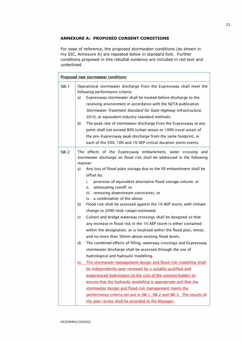
ANNEXURE A: PROPOSED CONSENT CONDITIONS
For ease of reference, the proposed stormwater conditions (as shown in
my EIC, Annexure A) are repeated below in standard font. Further
conditions proposed in this rebuttal evidence are included in red text and
underlined.
Proposed new stormwater conditions
SW.1 Operational stormwater discharge from the Expressway shall meet the
following performance criteria:
a) Expressway stormwater shall be treated before discharge to the
receiving environment in accordance with the NZTA publication
Stormwater Treatment Standard for State Highway infrastructure,
2010, or equivalent industry standard methods.
b) The peak rate of stormwater discharge from the Expressway at any
point shall not exceed 80% (urban areas) or 100% (rural areas) of
the pre-Expressway peak discharge from the same footprint, in
each of the 50%, 10% and 1% AEP critical duration storm events.
SW.2 The effects of the Expressway embankment, water crossing and
stormwater discharge on flood risk shall be addressed in the following
manner:
a) Any loss of flood plain storage due to the fill embankment shall be
offset by:
i. provision of equivalent alternative flood storage volume; or
ii. attenuating runoff; or
iii. removing downstream constraints; or
iv. a combination of the above.
b) Flood risk shall be assessed against the 1% AEP storm, with climate
change to 2090 (mid-range) estimated.
c) Culvert and bridge waterway crossings shall be designed so that
any increase in flood risk in the 1% AEP storm is either contained
within the designation, or is localised within the flood plan, minor,
and no more than 50mm above existing flood levels.
d) The combined effects of filling, waterway crossings and Expressway
stormwater discharge shall be assessed through the use of
hydrological and hydraulic modelling.
e) The stormwater management design and flood risk modelling shall
be independently peer reviewed by a suitably qualified and
experienced hydrologist (at the cost of the consent holder) to
ensure that the hydraulic modelling is appropriate and that the
stormwater design and flood risk management meets the
performance criteria set out in SW.1, SW.2 and SW.3. The results of
the peer review shall be provided to the Manager.
24
042590992/2520922
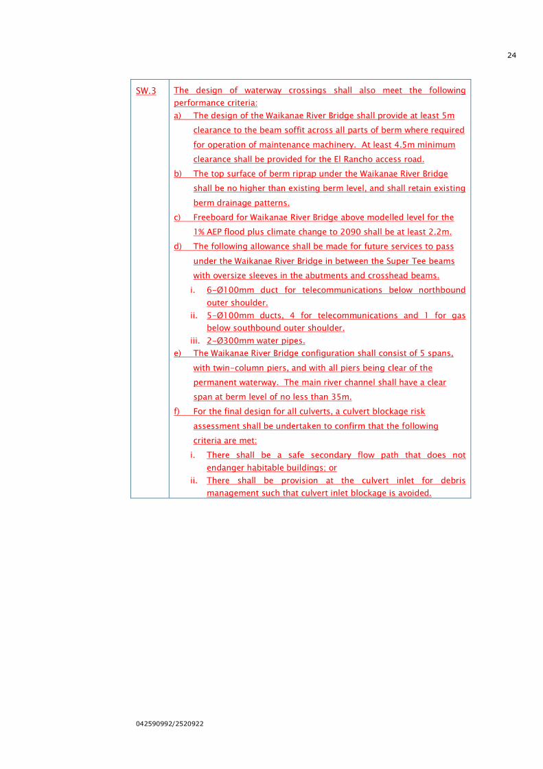
SW.3 The design of waterway crossings shall also meet the following
performance criteria:
a) The design of the Waikanae River Bridge shall provide at least 5m
clearance to the beam soffit across all parts of berm where required
for operation of maintenance machinery. At least 4.5m minimum
clearance shall be provided for the El Rancho access road.
b) The top surface of berm riprap under the Waikanae River Bridge
shall be no higher than existing berm level, and shall retain existing
berm drainage patterns.
c) Freeboard for Waikanae River Bridge above modelled level for the
1% AEP flood plus climate change to 2090 shall be at least 2.2m.
d) The following allowance shall be made for future services to pass
under the Waikanae River Bridge in between the Super Tee beams
with oversize sleeves in the abutments and crosshead beams.
i. 6-Ø100mm duct for telecommunications below northbound
outer shoulder.
ii. 5-Ø100mm ducts, 4 for telecommunications and 1 for gas
below southbound outer shoulder.
iii. 2-Ø300mm water pipes.
e) The Waikanae River Bridge configuration shall consist of 5 spans,
with twin-column piers, and with all piers being clear of the
permanent waterway. The main river channel shall have a clear
span at berm level of no less than 35m.
f) For the final design for all culverts, a culvert blockage risk
assessment shall be undertaken to confirm that the following
criteria are met:
i. There shall be a safe secondary flow path that does not
endanger habitable buildings; or
ii. There shall be provision at the culvert inlet for debris
management such that culvert inlet blockage is avoided.

25
042590992/2520922
ANNEXURE B: CULVERT BLOCKAGE RISK ASSESSMENT
26
042590992/2520922
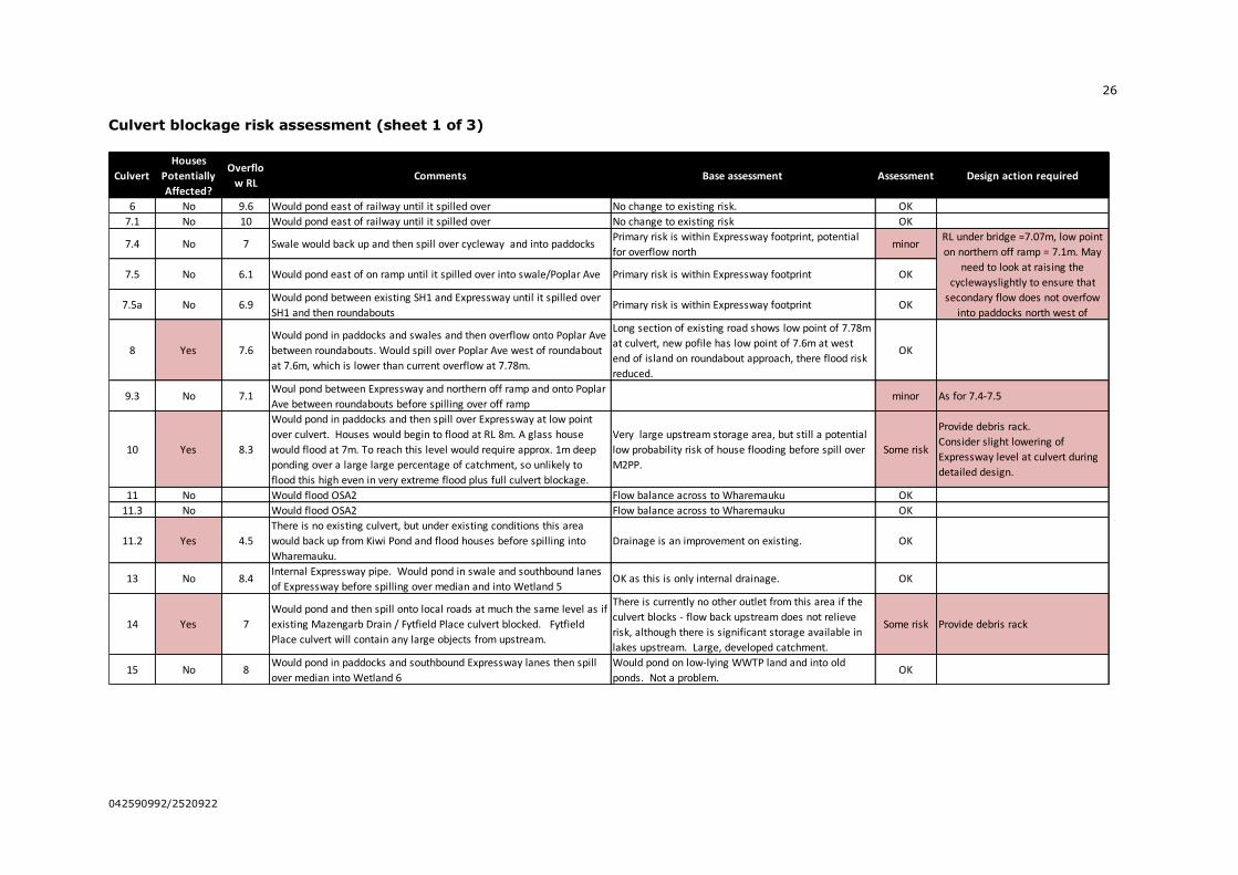
Culvert blockage risk assessment (sheet 1 of 3)
Culvert
Houses
Potentially
Affected?
Overflo
w RLComments Base assessment Assessment Design action required
6 No 9.6 Would pond east of railway until it spilled over No change to existing risk. OK
7.1 No 10 Would pond east of railway until it spilled over No change to existing risk OK
7.4 No 7 Swale would back up and then spill over cycleway and into paddocksPrimary risk is within Expressway footprint, potential
for overflow northminor
7.5 No 6.1 Would pond east of on ramp until it spilled over into swale/Poplar Ave Primary risk is within Expressway footprint OK
7.5a No 6.9Would pond between existing SH1 and Expressway until it spilled over
SH1 and then roundaboutsPrimary risk is within Expressway footprint OK
8 Yes 7.6
Would pond in paddocks and swales and then overflow onto Poplar Ave
between roundabouts. Would spill over Poplar Ave west of roundabout
at 7.6m, which is lower than current overflow at 7.78m.
Long section of existing road shows low point of 7.78m
at culvert, new pofile has low point of 7.6m at west
end of island on roundabout approach, there flood risk
reduced.
OK
9.3 No 7.1Woul pond between Expressway and northern off ramp and onto Poplar
Ave between roundabouts before spilling over off rampminor As for 7.4-7.5
10 Yes 8.3
Would pond in paddocks and then spill over Expressway at low point
over culvert. Houses would begin to flood at RL 8m. A glass house
would flood at 7m. To reach this level would require approx. 1m deep
ponding over a large large percentage of catchment, so unlikely to
flood this high even in very extreme flood plus full culvert blockage.
Very large upstream storage area, but still a potential
low probability risk of house flooding before spill over
M2PP.
Some risk
Provide debris rack.
Consider slight lowering of
Expressway level at culvert during
detailed design.
11 No Would flood OSA2 Flow balance across to Wharemauku OK
11.3 No Would flood OSA2 Flow balance across to Wharemauku OK
11.2 Yes 4.5
There is no existing culvert, but under existing conditions this area
would back up from Kiwi Pond and flood houses before spilling into
Wharemauku.
Drainage is an improvement on existing. OK
13 No 8.4Internal Expressway pipe. Would pond in swale and southbound lanes
of Expressway before spilling over median and into Wetland 5OK as this is only internal drainage. OK
14 Yes 7
Would pond and then spill onto local roads at much the same level as if
existing Mazengarb Drain / Fytfield Place culvert blocked. Fytfield
Place culvert will contain any large objects from upstream.
There is currently no other outlet from this area if the
culvert blocks - flow back upstream does not relieve
risk, although there is significant storage available in
lakes upstream. Large, developed catchment.
Some risk Provide debris rack
15 No 8Would pond in paddocks and southbound Expressway lanes then spill
over median into Wetland 6
Would pond on low-lying WWTP land and into old
ponds. Not a problem.OK
RL under bridge =7.07m, low point
on northern off ramp = 7.1m. May
need to look at raising the
cyclewayslightly to ensure that
secondary flow does not overfow
into paddocks north west of
27
042590992/2520922
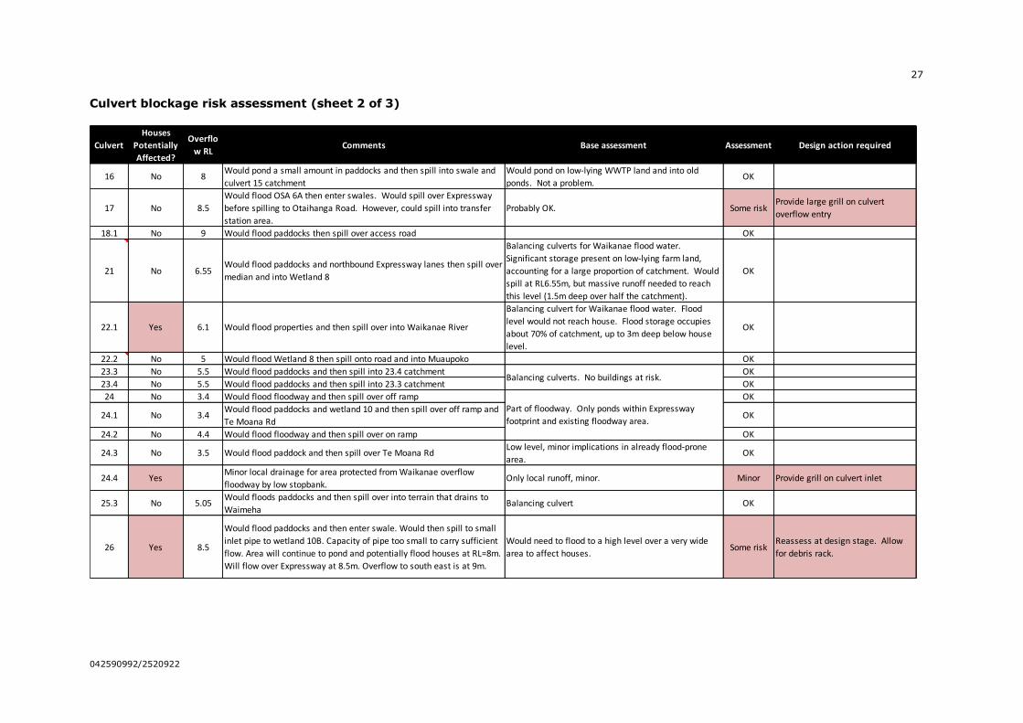
Culvert blockage risk assessment (sheet 2 of 3)
Culvert
Houses
Potentially
Affected?
Overflo
w RLComments Base assessment Assessment Design action required
16 No 8Would pond a small amount in paddocks and then spill into swale and
culvert 15 catchment
Would pond on low-lying WWTP land and into old
ponds. Not a problem.OK
17 No 8.5
Would flood OSA 6A then enter swales. Would spill over Expressway
before spilling to Otaihanga Road. However, could spill into transfer
station area.
Probably OK. Some riskProvide large grill on culvert
overflow entry
18.1 No 9 Would flood paddocks then spill over access road OK
21 No 6.55Would flood paddocks and northbound Expressway lanes then spill over
median and into Wetland 8
Balancing culverts for Waikanae flood water.
Significant storage present on low-lying farm land,
accounting for a large proportion of catchment. Would
spill at RL6.55m, but massive runoff needed to reach
this level (1.5m deep over half the catchment).
OK
22.1 Yes 6.1 Would flood properties and then spill over into Waikanae River
Balancing culvert for Waikanae flood water. Flood
level would not reach house. Flood storage occupies
about 70% of catchment, up to 3m deep below house
level.
OK
22.2 No 5 Would flood Wetland 8 then spill onto road and into Muaupoko OK
23.3 No 5.5 Would flood paddocks and then spill into 23.4 catchment OK
23.4 No 5.5 Would flood paddocks and then spill into 23.3 catchment OK
24 No 3.4 Would flood floodway and then spill over off ramp OK
24.1 No 3.4Would flood paddocks and wetland 10 and then spill over off ramp and
Te Moana RdOK
24.2 No 4.4 Would flood floodway and then spill over on ramp OK
24.3 No 3.5 Would flood paddock and then spill over Te Moana RdLow level, minor implications in already flood-prone
area.OK
24.4 YesMinor local drainage for area protected from Waikanae overflow
floodway by low stopbank.Only local runoff, minor. Minor Provide grill on culvert inlet
25.3 No 5.05Would floods paddocks and then spill over into terrain that drains to
WaimehaBalancing culvert OK
26 Yes 8.5
Would flood paddocks and then enter swale. Would then spill to small
inlet pipe to wetland 10B. Capacity of pipe too small to carry sufficient
flow. Area will continue to pond and potentially flood houses at RL=8m.
Will flow over Expressway at 8.5m. Overflow to south east is at 9m.
Would need to flood to a high level over a very wide
area to affect houses.Some risk
Reassess at design stage. Allow
for debris rack.
Balancing culverts. No buildings at risk.
Part of floodway. Only ponds within Expressway
footprint and existing floodway area.
28
042590992/2520922
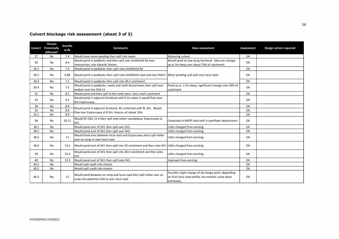
Culvert blockage risk assessment (sheet 3 of 3)
Culvert
Houses
Potentially
Affected?
Overflo
w RLComments Base assessment Assessment Design action required
27 No 7.4 Would have minor ponding then spill into swale Balancing culvert OK
30 No 8.4Would pond in paddocks and then spill over Smithfield Rd near
intersection, into Kakariki Stream
Would pond on low-lying farmland. Massive storage
up to 2m deep over about 70% of catchment. OK
30.1 No 7.3 Would pond in paddocks then spill onto Smithfield Rd OK
30.2 No 6.86 Would pond in paddocks then spill onto Smithfield road and into OSA11 OK
30.3 No 7.1 Would pond in paddocks then spill into 30.2 catchment OK
30.4 No 7.5Would pond in paddocks, swale and north bound lanes then spill over
median and into OSA 11
Pond up to 1.5m deep, significant storage over 50% of
catchment.OK
31 No 8.5 Would pond and then spill to the north west. Very small catchment OK
33 No 9.1Would pond in adjacent farmland until 9.1m when it would flow over
the Expressway.OK
34 No 8.9 OK
35 No 8.9 OK
35.1 No 8.9 OK
38 No 10-11Would fill OSA 13 A then spill onto either roundabout, Expressway or
SH1Contained in M2PP land until it overflows downstream OK
38.1 No Would pond east of SH1 then spill over SH1 Little changed from existing OK
38.2 No Would pond east of SH1 then spill over SH2 Little changed from existing OK
38.3 No 11Would flood area between local road and Expressway then spill either
over on ramp or over local roadLittle changed from existing OK
38.4 No 13.4 Would pond east of SH1 then spill into 39 catchment and then onto SH1 Little changed from existing OK
39 No 13.4Would pond east of SH1 then spill into 38.4 catchment and then onto
SH1Little changed from existing OK
40 No 13.3 Would pond east of SH1 then spill onto SH1 Improved from existing OK
40.1 No Would spill south into stream OK
40.2 No Would spill south into stream OK
40.3 No 11Would pond between on ramp and local road then spill either over on
ramp into potential OSA or over local road
Possible slight change of discharge point, depending
on final local road profile, but reaches same drain
eventually.
OK
Minor ponding and spill over local road.
Would pond in adjacent farmland. All contained until RL 8m. Would
flow over Expressway at 8.3m. Houses all above 10m.
29
042590992/2520922
ANNEXURE C: PLAN IDENTIFYING MAINTENANCE
RESPONSIBILITIES REGARDING WAIKANAE RIVER BRIDGE
Plan attached to minutes of a meeting between Project staff and GWRC
Flood Protection staff held on 3 November 2011.
Note that the channel design details have changed slightly between this
drawing and that finally submitted with the AEE. However, the principles
in regard to the split of responsibilities between GWRC and NZTA would
remain the same, and the details should be resolved through a mutual
agreement between the two parties.
30
042590992/2520922