Embed Size (px)
Citation preview
BGA Placement on Rework StationThe success of ball grid array (BGA) placement on electronicassemblies is as much a matter of proper preparation and planning,as it is technique. In some designs, it is more appropriate to applyBGAs using a rework station that isolates the placement of the device,without subjecting the entire assembly to thermal reflow. This isespecially beneficial in board constructions where the number of BGAsis limited, and the application of the solder paste is difficult, due tosmall pitch features that stretch the limitation of the stencilconstruction. Another application for rework stations, involves verylarge and thermally conductive BGAs, which will not uniformly reflowwith other components on the assembly, and may require specialprocess parameters for their proper placement. The most commonuse of BGA rework stations are for assemblies requiring BGA removaland replacements due to failures in the initial assembly stage.
There are several types of rework stations with different means ofapplying thermal energy to the BGA. Some systems use top convectionheaters for nozzles that are applied directly over the part while bottominfrared (IR) systems heat the entire assembly. There are also reworkstations that apply a direct IR laser onto the part to minimize the heatgradient across adjacent devices. Whichever system is utilized, thereare fundamental guidelines that should be applied to achievemaximum results.
Thermal Profiling
In a manner similar to any surface-mount technology (SMT) reflowprocess, the use of thermocouples, advantageously placed onlocations surrounding the BGA, is a preliminary necessity for settingproper reflow conditions. Unlike standard thermal reflow ovens, whereindiscriminate reflow occurs across all devices, care must be taken todevelop a profile that will not adversely affect adjacent components,including ones directly beneath the BGA. Most systems have thecapacity to accommodate at least four thermocouples. The purposeof the profile is to observe the thermal gradient around thesurrounding area, where temperature, soak, and ramp timeadjustments can be made to optimize the reflow conditions, if
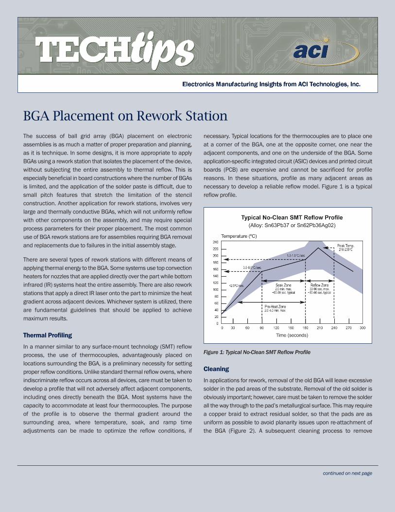
necessary. Typical locations for the thermocouples are to place oneat a corner of the BGA, one at the opposite corner, one near theadjacent components, and one on the underside of the BGA. Someapplication-specific integrated circuit (ASIC) devices and printed circuitboards (PCB) are expensive and cannot be sacrificed for profilereasons. In these situations, profile as many adjacent areas asnecessary to develop a reliable reflow model. Figure 1 is a typicalreflow profile.
Figure 1: Typical No-Clean SMT Reflow Profile
Cleaning
In applications for rework, removal of the old BGA will leave excessivesolder in the pad areas of the substrate. Removal of the old solder isobviously important; however, care must be taken to remove the solderall the way through to the pad’s metallurgical surface. This may requirea copper braid to extract residual solder, so that the pads are asuniform as possible to avoid planarity issues upon re-attachment ofthe BGA (Figure 2). A subsequent cleaning process to remove
continued on next page
ACI Technologies, Inc. 1 International Plaza, Suite 600 Philadelphia, PA 19113 phone: 610.362.1200 web: www.aciusa.org
Training Center phone: 610.362.1295 email: [email protected]
Helpline phone: 610.362.1320 email: [email protected]
excessive flux and other residues will be necessary to prepare the padsurface. Be aware that in many cases, the original surface finish hasbeen consumed, and that additional flux will be needed to reactivatethe pad surface.
Figure 2: Coplanarity – High melt joints with .014 inch/inch board warp.
Note: Care must be taken to not overheat the pad during the removalof the solder. This can cause pad lifting, which will require extensiveand timely repair.
Solder Volume
Whether a new or re-balled device is being placed, it is alwaysadvisable to consider any constraints that would impede theapplication of additional solder paste for the reflowing process. Insome cases, the addition of solder paste is not required for applyinga BGA. The application of a gel flux to the bottom of the BGA issufficient to activate the pad surface and allow proper wetting of theBGA solder balls during reflow. A critical assessment should be madeon the effect of the lower solder volume on reliability. Some designcriteria will require a minimum solder volume to mitigate any potentialstrain applied during the lifetime of the assembly. Many of the higherlevel applications require a more rigorous environmental stressscreening, and therefore the additional solder reinforcement on theBGAs will be a requirement.
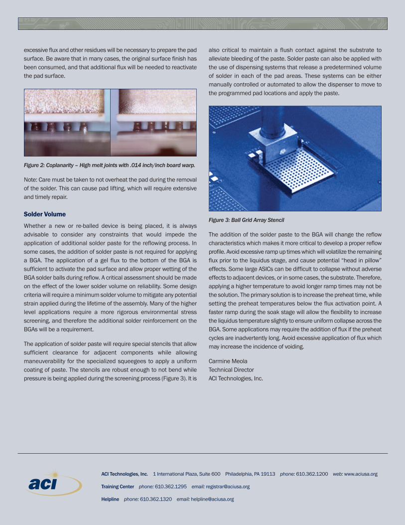
The application of solder paste will require special stencils that allowsufficient clearance for adjacent components while allowingmaneuverability for the specialized squeegees to apply a uniformcoating of paste. The stencils are robust enough to not bend whilepressure is being applied during the screening process (Figure 3). It is
also critical to maintain a flush contact against the substrate toalleviate bleeding of the paste. Solder paste can also be applied withthe use of dispensing systems that release a predetermined volumeof solder in each of the pad areas. These systems can be eithermanually controlled or automated to allow the dispenser to move tothe programmed pad locations and apply the paste.
Figure 3: Ball Grid Array Stencil
The addition of the solder paste to the BGA will change the reflowcharacteristics which makes it more critical to develop a proper reflowprofile. Avoid excessive ramp up times which will volatilize the remainingflux prior to the liquidus stage, and cause potential “head in pillow”effects. Some large ASICs can be difficult to collapse without adverseeffects to adjacent devices, or in some cases, the substrate. Therefore,applying a higher temperature to avoid longer ramp times may not bethe solution. The primary solution is to increase the preheat time, whilesetting the preheat temperatures below the flux activation point. Afaster ramp during the soak stage will allow the flexibility to increasethe liquidus temperature slightly to ensure uniform collapse across theBGA. Some applications may require the addition of flux if the preheatcycles are inadvertently long. Avoid excessive application of flux whichmay increase the incidence of voiding.
Carmine MeolaTechnical DirectorACI Technologies, Inc.