Embed Size (px)
Citation preview
Developed in association with the NSW Vehicle Standards Working Group
Brake Assessment Manual July 2017

THIS PAGE IS LEFT INTENTIONALLY BLANK
Assessing and certifying brakes for modified vehicles and individually constructed vehicles Preface This Brake Assessment Manual is intended to be used to assess the brake systems of modified vehicles and individually constructed vehicles as part of the process for certifying the vehicle for registration in accordance with the Road Transport (Vehicle Registration) Regulation 2007 and the Vehicle Safety Compliance Certification Scheme (VSCCS).
This Manual was developed by an ad hoc focus group convened under the NSW Vehicle Standards Working Group, which was established in 2012 by the NSW Minister for Roads and Ports to ensure industry and user stakeholders are represented in developing vehicle standards and policies in NSW. The Vehicle Standards Working Group is co-chaired by Transport for NSW and the Australian Confederation of Motor Clubs, and the members are:
• Australian Aftermarket Automotive Association
• Australian Confederation of Motor Clubs
• Confederation of Australian Motor Sport Inc
• Institute of Automotive Mechanical Engineers Motorcycle Council of NSW
• Motorcycle Council of NSW
• Motor Traders Association (MTA)
• NRMA Motoring Services
• NSW Police Force
• Roads and Maritime Services (RMS)
• Transport for NSW
• Vehicle Safety Certification Scheme (VSCCS).
This Manual was first published in October 2013. It has been updated and revised based on practical feedback in preparation for gazetting as an authority standard compliance specification. The major changes in this version are:
• Advice about exemptions added
• A new section added about maintaining safety features which includes additional requirements for vehicles fitted with electronic stability control
• Certain features excluded for ICVs.
It remains a live document and subject to change.
Brake assessment manual Scope This brake assessment manual applies to all types of light vehicles, except motorcycles. It is intended to be used to assess the brake systems of modified vehicles and individually constructed vehicles.
Notes: 1. The term ‘vehicle’ used in this Manual refers to light vehicles, being vehicles with a gross
vehicle mass of 4.5 tonnes or less 2. From here on, the term ‘modified vehicle’ also applies to ICVs except where stated
otherwise 3. italicised terms are defined in Appendix 1.
Introduction The Road Transport (Vehicle Registration) Regulation 2007 (the Regulation) requires all registrable vehicles comply with the applicable vehicle standards, and modified vehicles continue to comply with those standards; and the vehicle and its parts and equipment are suitable for safe use and are in a thoroughly serviceable condition.
To assist vehicle owners in meeting these obligations, the Roads and Maritime Services (Roads and Maritime) has created a modification scheme under the Regulation known as the ‘Vehicle Safety Compliance Scheme’ (the VSCCS). This authorises persons with appropriate technical qualifications, training and experience, known as ‘licensed certifiers’, to inspect a modified vehicle and issue a compliance certificate if they are satisfied the vehicle complies with the applicable vehicle standards. Except for purposes relating to compliance certification, a vehicle which has undergone a significant modification (ie one which requires a compliance certificate), must not be used on a road or road related area unless a compliance certificate has been issued for the vehicle. (For more information, refer to clauses 52, 55A, 76AC, 76AD and 76AF of the Regulation.)
A vehicle’s braking system is its singly most important crash avoidance equipment. If a vehicle’s brakes are modified, or if the vehicle is otherwise modified in a manner which affects its braking system, it is essential the effectiveness of its brakes is verified before the vehicle is registered and allowed full access to the road network. Similarly, the brakes fitted to an individually constructed vehicle (ICV) must be assessed to ensure they meet minimum safety standards, regardless from where the brakes were sourced. This Manual identifies thirty-one different types of modifications/ICVs which affect a vehicle’s braking system which require assessing and certification, and these are identified in Table 1.
Note: From hereon, the term ‘‘modifier’ means the owner or the registered operator of a vehicle as used in the Regulation, whether or not the person actually does the modifications themselves.
Standards for brake systems and components are complex, and it requires extensive, expensive testing, some at high speed, to verify a modified vehicle’s compliance with them. The methods outlined in this Manual are intended to provide a licensed certifier with sufficient information to enable them form an opinion where a modified vehicle is safe and may pass the tests specified by the applicable standard if subjected to them.
The level of assessment a vehicle must undergo to obtain a compliance certificate is based on the extent of the modification and the risk they pose to the vehicle’s occupants and other road users. There are a number of options for obtaining a compliance certificate for the modified vehicle, and these are:
• Inspection of approved aftermarket components
• Assessment based on tests previously done on a similar vehicle
• Assessment based on installation checklist and data from a static brake test machine
• Application of a series of road tests.
4
It is intended compliance with this Manual will help ensure the modified vehicle or ICV complies with the applicable standards. If the vehicle does not comply with the standards, an exemption must be obtained before it can be certified, and the certificate must refer to the exemption.
Limits of assessments The assessments detailed in this manual apply to vehicles intended to be registered for use on the road, in normal driving operations at posted speed limits. If it is intended to also use a vehicle for specialised activities, such as track racing, more rigorous assessment and tests may be required to ensure the braking system will withstand the additional stresses imposed on it.
Maintaining vehicle safety features In addition to the provisions for registered vehicles to comply with safety standards, the Regulation requires vehicles to be maintained in a manner which will not cause a danger to any person. This means safety features, even if not covered by an ADR or other applicable standard, must remain functional after the modification. With the introduction of more complex and sensitive safety features into modern vehicles, such as electronic stability control (ESC) and autonomous emergency braking, particular care must be taken to ensure they are not affected by modifications made to a vehicle.
After a significant modification, as identified in this manual, a vehicle must not be issued with a compliance certificate if the modification adversely affects the performance of a safety feature. If a vehicle is equipped with ESC, the ESC must be checked as part of the licensed certifier’s assessment. A compliance certificate can only be issued if the ESC is shown to be operational without adversely affecting the vehicle’s performance. If necessary, the ESC must be reprogrammed to function within that range.
ESC and a brake assist system (BAS) are not required to be fitted to ICVs or vehicles which predated their inclusion in ADR 31/03. However, ICVs must be fitted with an anti-lock braking system (ABS) which complies with the technical specifications outlined in ADR 31/03.
Note: These exclusions are consistent with the requirements for the Low Production Passenger Car Scheme under the Commonwealth Motor Vehicles Standards Act 1989.
Competence of licensed certifiers The Roads and Maritime has assessed the competencies of persons registered as licensed certifiers. The areas of competence for every licensed certifier are published on the Roads and Maritime’s website. Only licensed certifiers identified as being competent in brakes must be engaged in assessing and certifying vehicles with modifications to, or which affect, their brakes.
Changes which do not require assessing or certification The following are not considered to be modifications and do NOT require assessing or certification:
• Replacement of parts or components by identical or equivalent parts or components
• Replacement of parts or components with equivalent functional performance
• Optional parts or components as prescribed by the vehicle’s manufacturer
Modifications which require assessing Table 1 sets out significant modifications which require the vehicle’s brake system to be assessed. The vehicle may be subject to a single modification or a combination of modifications. If the vehicle has been subject to a number of modifications, the assessment must ensure all the modifications are considered.
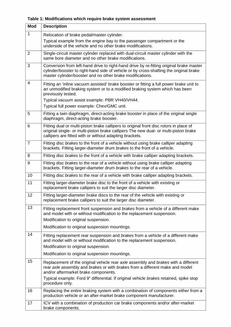
Table 1: Modifications which require brake system assessment Mod Description
1 Relocation of brake pedal/master cylinder. Typical example from the engine bay to the passenger compartment or the underside of the vehicle and no other brake modifications.
2 Single-circuit master cylinder replaced with dual-circuit master cylinder with the same bore diameter and no other brake modifications.
3 Conversion from left-hand drive to right-hand drive by re-fitting original brake master cylinder/booster to right-hand side of vehicle or by cross-shafting the original brake master cylinder/booster and no other brake modifications.
4 Fitting an ‘inline vacuum assisted’ brake booster or fitting a full power brake unit to an unmodified braking system or to a modified braking system which has been previously tested. Typical vacuum assist example: PBR VH40/VH44. Typical full power example: Chev/GMC unit.
5 Fitting a twin diaphragm, direct-acting brake booster in place of the original single diaphragm, direct-acting brake booster.
6 Fitting dual or multi-piston brake callipers to original front disc rotors in place of original single- or multi-piston brake callipers The new dual- or multi-piston brake callipers are fitted with or without adapting brackets.
7 Fitting disc brakes to the front of a vehicle without using brake calliper adapting brackets. Fitting larger-diameter drum brakes to the front of a vehicle.
8 Fitting disc brakes to the front of a vehicle with brake calliper adapting brackets.
9 Fitting disc brakes to the rear of a vehicle without using brake calliper adapting brackets. Fitting larger-diameter drum brakes to the rear of a vehicle.
10 Fitting disc brakes to the rear of a vehicle with brake calliper adapting brackets.
11 Fitting larger-diameter brake disc to the front of a vehicle with existing or replacement brake callipers to suit the larger disc diameter.
12 Fitting larger-diameter brake discs to the rear of the vehicle with existing or replacement brake callipers to suit the larger disc diameter.
13 Fitting replacement front suspension and brakes from a vehicle of a different make and model with or without modification to the replacement suspension. Modification to original suspension.
Modification to original suspension mountings.
14 Fitting replacement rear suspension and brakes from a vehicle of a different make and model with or without modification to the replacement suspension. Modification to original suspension.
Modification to original suspension mountings.
15 Replacement of the original vehicle rear axle assembly and brakes with a different rear axle assembly and brakes or with brakes from a different make and model and/or aftermarket brake components. Typical example: Ford 9” differential. If original vehicle brakes retained, spike stop procedure only.
16 Replacing the entire braking system with a combination of components either from a production vehicle or an after-market brake component manufacturer.
17 ICV with a combination of production car brake components and/or after-market brake components.
6
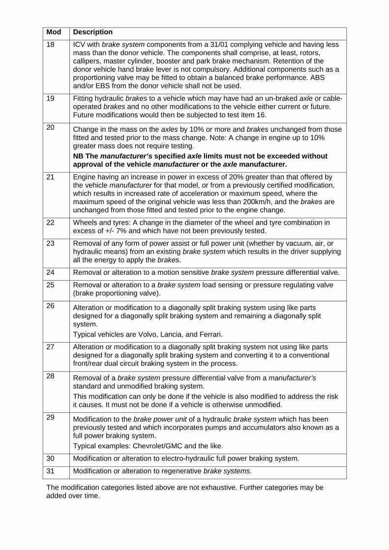
Mod Description 18 ICV with brake system components from a 31/01 complying vehicle and having less
mass than the donor vehicle. The components shall comprise, at least, rotors, callipers, master cylinder, booster and park brake mechanism. Retention of the donor vehicle hand brake lever is not compulsory. Additional components such as a proportioning valve may be fitted to obtain a balanced brake performance. ABS and/or EBS from the donor vehicle shall not be used.
19 Fitting hydraulic brakes to a vehicle which may have had an un-braked axle or cable-operated brakes and no other modifications to the vehicle either current or future. Future modifications would then be subjected to test item 16.
20 Change in the mass on the axles by 10% or more and brakes unchanged from those fitted and tested prior to the mass change. Note: A change in engine up to 10% greater mass does not require testing. NB The manufacturer’s specified axle limits must not be exceeded without approval of the vehicle manufacturer or the axle manufacturer.
21 Engine having an increase in power in excess of 20% greater than that offered by the vehicle manufacturer for that model, or from a previously certified modification, which results in increased rate of acceleration or maximum speed, where the maximum speed of the original vehicle was less than 200km/h, and the brakes are unchanged from those fitted and tested prior to the engine change.
22 Wheels and tyres: A change in the diameter of the wheel and tyre combination in excess of +/- 7% and which have not been previously tested.
23 Removal of any form of power assist or full power unit (whether by vacuum, air, or hydraulic means) from an existing brake system which results in the driver supplying all the energy to apply the brakes.
24 Removal or alteration to a motion sensitive brake system pressure differential valve.
25 Removal or alteration to a brake system load sensing or pressure regulating valve (brake proportioning valve).
26 Alteration or modification to a diagonally split braking system using like parts designed for a diagonally split braking system and remaining a diagonally split system. Typical vehicles are Volvo, Lancia, and Ferrari.
27 Alteration or modification to a diagonally split braking system not using like parts designed for a diagonally split braking system and converting it to a conventional front/rear dual circuit braking system in the process.
28 Removal of a brake system pressure differential valve from a manufacturer’s standard and unmodified braking system. This modification can only be done if the vehicle is also modified to address the risk it causes. It must not be done if a vehicle is otherwise unmodified.
29 Modification to the brake power unit of a hydraulic brake system which has been previously tested and which incorporates pumps and accumulators also known as a full power braking system. Typical examples: Chevrolet/GMC and the like.
30 Modification or alteration to electro-hydraulic full power braking system.
31 Modification or alteration to regenerative brake systems.
The modification categories listed above are not exhaustive. Further categories may be added over time.
Modifications not permitted A vehicle’s hydraulic brake system which incorporates pumps and accumulators (also known as ‘full power braking systems’) must not be modified.
Method 1 – Approved aftermarket components A vehicle may be modified to incorporate manufacturer approved aftermarket components, without the need for detailed testing providing:
• The component manufacturer has stated the component can be installed in the vehicle make and model
• The component manufacturer has done the necessary tests to confirm the component complies with the applicable standards and assessed their compatibility with the nominated model
• All necessary instructions are provided at the point of sale by the component’s manufacturer to ensure the component can be installed correctly in the nominated vehicle
• The instructions are in English and use SI Units
• The modified vehicle is examined by a licensed certifier who verifies:
o The component is compatible with the host vehicle as specified by the component’s manufacturer.
o The component has been installed in accordance with the manufacturer’s instructions.
o The vehicle is roadworthy and is in suitable condition to accommodate the component (eg there are no signs of rusting where the component is secured to the vehicle).
Method 2 – Tests to similar vehicles If a vehicle is modified using a braking system or components identical to those which have been used in a similar vehicle ie if it is within the tolerances listed in Table 2, which has already been assessed and certified, a licensed certifier may issue a certificate of compliance without the need for testing provided the following conditions are satisfied:
• The engines are mounted in equivalent locations
• The components are identical to the ones used in the certified vehicle
• The components are examined to establish they are in good condition
• A detailed examination of the vehicle is done to confirm its suitability for properly accommodating the components, eg load-bearing members display no evidence of structural degradation
• A detailed examination of the vehicle is done to ensure the components have been correctly installed
• Results of the assessment, including test results, done on the similar vehicle is available and referenced in the test report.
The licensed certifier must do the examinations listed above. A record of the examination and the evidence used to determine the two vehicles are similar must be retained.
The results only apply for vehicles which are similar to the tested vehicle and must not be used for a vehicle once-removed. For example, if vehicle X is tested and vehicle Y is similar to vehicle X, the tests obtained for vehicle X can be applied to vehicle Y. If vehicle Z is similar to vehicle Y but not similar to vehicle X (ie it is outside the parameters), the test results cannot be applied to vehicle Z.
NB: This method also applies to standard vehicles manufactured to the Australian Design Rule (ADRs) and supplied to the market in accordance with standard Compliance Plate Approval Scheme administered by the Department of Infrastructure and Regional Development or any of its predecessors and successors.
8
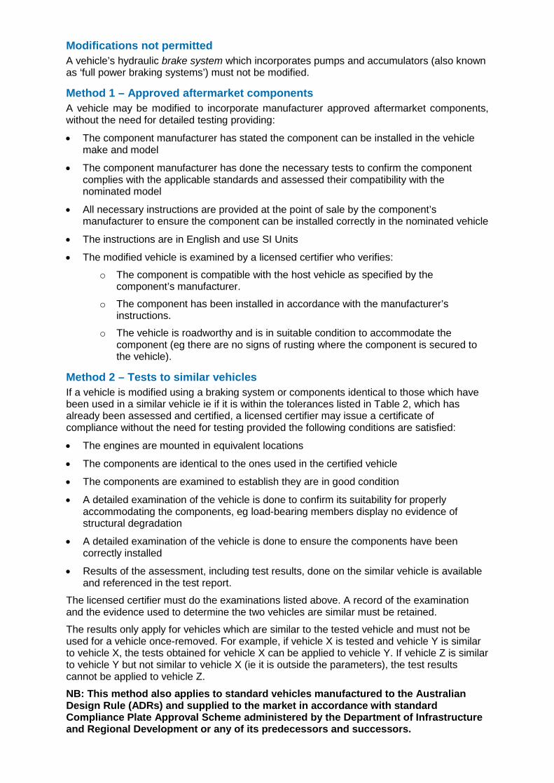
Table 2: Tolerances for determining a similar vehicle
Parameter Tolerance
Individual unladen axle mass + 10%
Wheel base ± 20%
Centre of gravity ± 50 mm
Power + 20% if this results in an increased rate of acceleration or maximum speed where the maximum speed of the original vehicle was less than 200km/h
Tyre size ± 7%
For particular requirements for handbrakes, refer to Appendix 2.
Method 3 – Installation checklist, static brake test and assessment
General The following stages apply:
1. The modifier installs the brake components using the checklist provided at Appendix 3.
2. The modifier takes the modified vehicle to a facility approved by the Roads and Maritime for a series of basic brake tests using a static brake test machine.
Notes:
a) Authorised Inspection Stations who do safety checks (ie ‘pink slip’ tests) are ‘approved facilities’, and many have appropriate static brake test machines
b) Before commencing the tests, it is important to verify the machine is within its certified calibration period.
3. The modifier takes the modified vehicle, the completed installation checklist and the data read-outs from the static brake tests to a licensed certifier for assessment.
4. The vehicle and the associated information is assessed by the licensed certifier who either deems there is sufficient information to issue a compliance certificate or requires additional tests; see below.
Assessment by a licensed certifier Licensed certifiers must assess the modified vehicle and determine whether it:
• Does not present a safety risk
• Would comply with the applicable vehicle standards if it was subjected to the full range of tests specified by the standards.
The initial assessment comprises a detailed inspection of the vehicle taking account of the installation checklist provided by the modifier, the condition of the vehicle, and the condition of the components, and a review of the data produced by the static brake test machine.
Based on this assessment, the licensed certifier may either issue a certificate for the vehicle, or require further tests to be carried out, with the range of tests depending on the type of modification done to the vehicle.
A static test machine may not provide the licensed certifier with sufficient information to form an opinion whether the vehicle complies with these standards, especially for those vehicles which comply with ADR 31/--, ie those manufactured after 1 January 1977.
Additional tests General Based on the results obtained from a static brake test machine and the type of modification being assessed, the licensed certifier may require the modified vehicle to undertake additional tests. Table 3 outlines the range of tests which can be used to verify the modifications listed in Table 1.
Non-road tests A number of the tests listed in Table 3 can be done on the static brake test machines. If tests are done on such a machine, they should be performed by a person who is trained and competent in using the machine. The licensed certifier must be satisfied the tests were done correctly, and relate to the vehicle being assessed. If necessary, the licensed certifier should observe the tests.
Appendix 4 provides an example of how a plate-type brake test machine can be used to do the basic and additional tests. At the time of writing, data was only available for this type of brake test machine. Additional appendices will be developed when data from other machines types become available. A manufacturer or supplier who would like a particular type of machine can make a submission to [email protected]
Other tests can be done statically, namely:
• Test A: Reservoir volume
• Test C: Park brake
The licensed certifier must supervise these tests.
Road tests If the tests required by the licensed certifier need to be done on a road or a road-type test facility, the conditions specified under ‘Method 4 – Road tests’ apply.
Method 4 – Road tests
General There are few details available of the brakes standards which were used before the introduction of ADR 31 Brake systems for passenger cars in 1977. For this reason, the tests specified in Appendix 5 are derived from ADR 31/00 and ADR 31/01 which contain the least onerous tests. The tests have been modified considerably so they can be applied to all vehicles, regardless of their date of manufacture, and to make the tests affordable and practicable while retaining safety. For more information about the rationale used to develop the test schedule, refer to Appendix 6.
The key elements of the test schedule are:
• In most cases, fewer repeat runs are required than otherwise specified in the ADR
• The tests’ speeds have been reduced from those specified in the ADRs, with only the most extensive modifications requiring tests to be done at a maximum speed of 100 km/h. Most tests can be done at 80km/h or as low as 60km/h.
The applicable tests for the different modifications are given in Table 3 and described in Appendix 5. Appendix 7 has variations which apply to N Category and certain M Category vehicles. If a vehicle has been subjected to combination of modifications, some test items may be duplicated; in such circumstances, it is not necessary to duplicate any test item, but the combination of the test items is carried out.
The reduced test speeds and the reduced number of test runs required mean it may be possible to test some modified vehicles on public roads, under controlled conditions. If it is intended to do tests on a public road, approval to do so must first be obtained from the authority responsible for the road: for local roads, this will be the local council, while for state roads it will be the Roads and Maritime. Application to do tests on a public road must identify the stretch of road where it is proposed to do the tests and a risk assessment explaining why it is suitable for the tests. If approval to do the tests is granted by the road authority, it may be
10
subject to conditions, such as the use of accredited traffic controllers. All conditions must be implemented.
For tests which cannot be done on the public road, including those requiring the vehicle to exceed posted speed limits, suitable venues must be used.
Modifying the vehicle The modifier should install the brake component using the checklist provided at Appendix 3.
Competence of drivers The vehicle should be driven by a person capable of efficiently achieving the specified test conditions.
Test equipment Appropriate equipment must be used to measure and record test-critical data. The following types of equipment must be used as a minimum:
• Except for modifications 6-10 (see Table 1), an inertial type direct reading deceleration meter which is capable of reading the mean fully developed deceleration
• A pedal force gauge
• A device such as a fifth wheel or GPS for measuring speed.
Note: The vehicle’s speedometer should not be used for any of the tests as it may not be sufficiently accurate.
The equipment used must function correctly and, where applicable, be correctly calibrated and be within specified calibration periods at the time of testing, and records available to verify this. The equipment must be capable of recording the relevant test data for verification and audit purposes.
Test conditions The following conditions apply:
• If the tests are to be done on a public road, the necessary approval must have been obtained from the applicable road authority. All stipulated controls must be complied with, with pre-test controls implemented before the start of the tests
• Apart from Test I, all dynamic tests must be conducted on a dry and level road which has a sealed surface or which has another surface affording good adhesion, ie with a coefficient of friction of 0.6 or higher for a dry surface
• The road must be sufficiently long and straight to enable the full range of the tests be carried out safely, and must have sufficient run-off to allow for brake failure during testing
• The tyres are to be cold (ie at ambient temperature) and inflated to the recommended pressure required for the vehicle to operate safely at its design load/speed
• Unless otherwise specified, the vehicle must be at its maximum loaded test mass for each test
• The test mass should be distributed in accordance with load conditions defined in Appendix 1 and, where appropriate, be distributed across the axles in accordance with the vehicle's manufacturer’s specifications
• The vehicle’s transmission must be disconnected for each test unless otherwise specified
• When testing, the general behaviour of the vehicle during braking must be checked and, unless otherwise specified, each test result must be obtained without abnormal vibrations and without the vehicle:
– Locking its wheels at speeds exceeding 15 km/h – Deviating from a 3.5 m wide lane – Exceeding a yaw angle of 15 degrees.
• If the maximum speed of the vehicle is lower than the speed prescribed for a particular test, the test shall be performed at the vehicle's maximum speed.
Pre-test check In the interests of road safety and before doing any of the tests described in Appendix 5, the vehicle should be thoroughly examined to ensure it is in a roadworthy condition. The person or persons testing brakes should check the following prior to doing the tests:
• The vehicle is in good repair and the brake lights are functioning correctly
• The type of fluid used is appropriate for the braking system, it is in good condition, and the correct identification symbols are used and affixed in a visible position in indelible form within 100mm of the filling ports of the fluid reservoirs
• The modification to the brake system is complete and free of obvious defects
• The wheels and tyres are appropriate for the vehicle and the tyres inflated to the correct pressure
• The wheel alignment is within specified safety limits
• The vehicle is structurally sound and will withstand the likely stresses induced in the tests
• The vehicle passes a rudimentary brake test as follows:
– With the vehicle in the unladen state, accelerate it to 40 km/h
– Put the transmission into neutral and coast down to 30 km/h
– With both hands on the steering wheel, bring the vehicle to a stop as quickly as possible with one sustained and smooth braking action using the service brake control
– The vehicle must not pull to one side
– The brake pedal pressure must not exceed 885N
– Average deceleration rate for the service brake must be at least 2.9 m/s2
– Peak deceleration rate for the service brake must be at least 3.4 m/s2
If the vehicle does not meet the above requirements, it will be deemed to be in an unacceptable condition and must not be subjected to the tests outlined in Appendix 5.
In addition, it is essential to check the test instrumentation is functioning correctly. This should be done by applying up to 20 decelerations. For vehicles subject to Modification 19, the deceleration shall be done from 40 km/h; for all other vehicles, it shall be conducted from a speed of not more than 65 km/h. In all cases, the actual deceleration must not exceed 3.5 m/s2.
Notes in relation to testing 1. When doing the series of tests, it is important the tests are done correctly to avoid
unnecessary damage to the vehicle, the brake components or the tyres. This includes driving the vehicle at the specified speeds and using the specified force to apply the brake.
2. A licensed certifier must be satisfied the tests specified in Table 3 are sufficient to certify the subject vehicle. The licensed certifier may increase the test speeds if they believe those specified in Table 3 are not sufficient to properly assess the vehicle’s braking performance based on its dynamic capabilities. The test speeds may not be decreased.
3. The test schedule is not necessarily exhaustive and further testing may be required at the discretion of the person or persons carrying out the brake testing.
4. It is not necessary to do a test required for one modification if the test has been done for another modification.
5. Tests done on public roads must comply with the conditions specified by the applicable road authority; and not interfere with or disrupt traffic; pose a risk to the persons doing the tests and other road users; or cause damage to the road and roadside infrastructure.
12
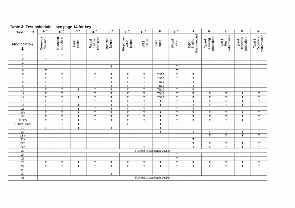
Table 3: Test schedule – see page 14 for key Test A * B + C * D + E + F + G + H I + J K L M N
Res
ervo
ir vo
lum
e
Mou
ntin
g st
ruct
ure
Par
k B
rake
Par
tial
Failu
re
front
rear
Boo
ster
fa
ilure
Pro
porti
on
valv
e fa
ilure
A
BS
Fa
ilure
Spi
ke
stop
s
Whe
el
lock
Type
-0
Eng
ine
disc
onne
cted
Type
-I H
eatin
g pr
oced
ure
Type
-I H
ot
perfo
rman
ce
Type
-I R
ecov
ery
proc
edur
e
Type
-I R
ecov
ery
perfo
rman
ce
Modification 1 T 2 T T 3 4 T T 5 T T 6 T T T T T T T5/10 T T 7 T T T T T T T5/10 T T 8 T T T T T T T5/10 T T 9 T T T T T T T5/10 T T
10 T T T T T T T T5/10 T T 11 T T T T T T T5/10 T T T T T T 12 T T T T T T T T5/10 T T T T T T 13 T T T T T T T T T T T T T 14 T T T T T T T T T T T T T T 15 T T T T T T T T T 16a T T T T T T T T T T T T T T 16b T T T T T T T T T T T T T T
17 ICV T T T T T T T T T T T T T T 18 ICV Donor T T T T T
19 T T T T T T T 20 T T T T T T
21 # T T T T 22a T 22b T T T T T 22c T T T T T T 23 Full test to applicable ADRs 24 T 25 T 26 T T T T T T T T T T T T T T 27 T T T T T T T T T T T T T T 28 T 29 T T 31 Full test to applicable ADRs
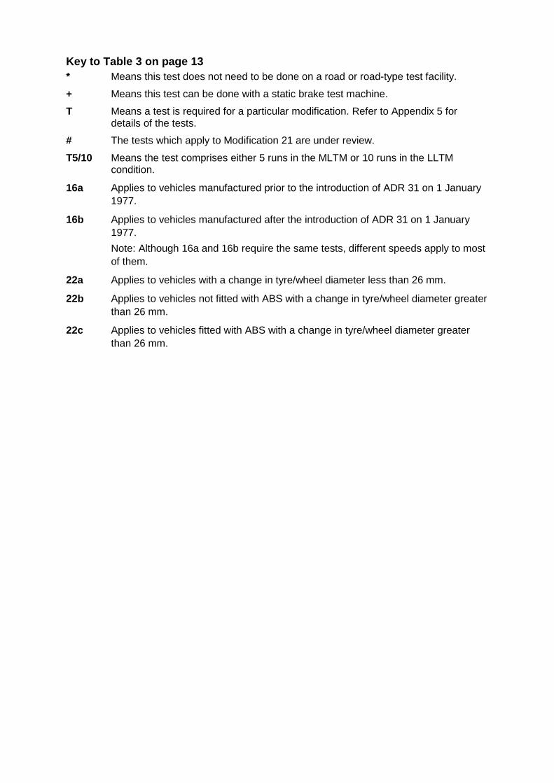
Key to Table 3 on page 13 * Means this test does not need to be done on a road or road-type test facility. + Means this test can be done with a static brake test machine. T Means a test is required for a particular modification. Refer to Appendix 5 for
details of the tests.
# The tests which apply to Modification 21 are under review.
T5/10 Means the test comprises either 5 runs in the MLTM or 10 runs in the LLTM condition.
16a Applies to vehicles manufactured prior to the introduction of ADR 31 on 1 January 1977.
16b Applies to vehicles manufactured after the introduction of ADR 31 on 1 January 1977. Note: Although 16a and 16b require the same tests, different speeds apply to most of them.
22a Applies to vehicles with a change in tyre/wheel diameter less than 26 mm.
22b Applies to vehicles not fitted with ABS with a change in tyre/wheel diameter greater than 26 mm.
22c Applies to vehicles fitted with ABS with a change in tyre/wheel diameter greater than 26 mm.
14
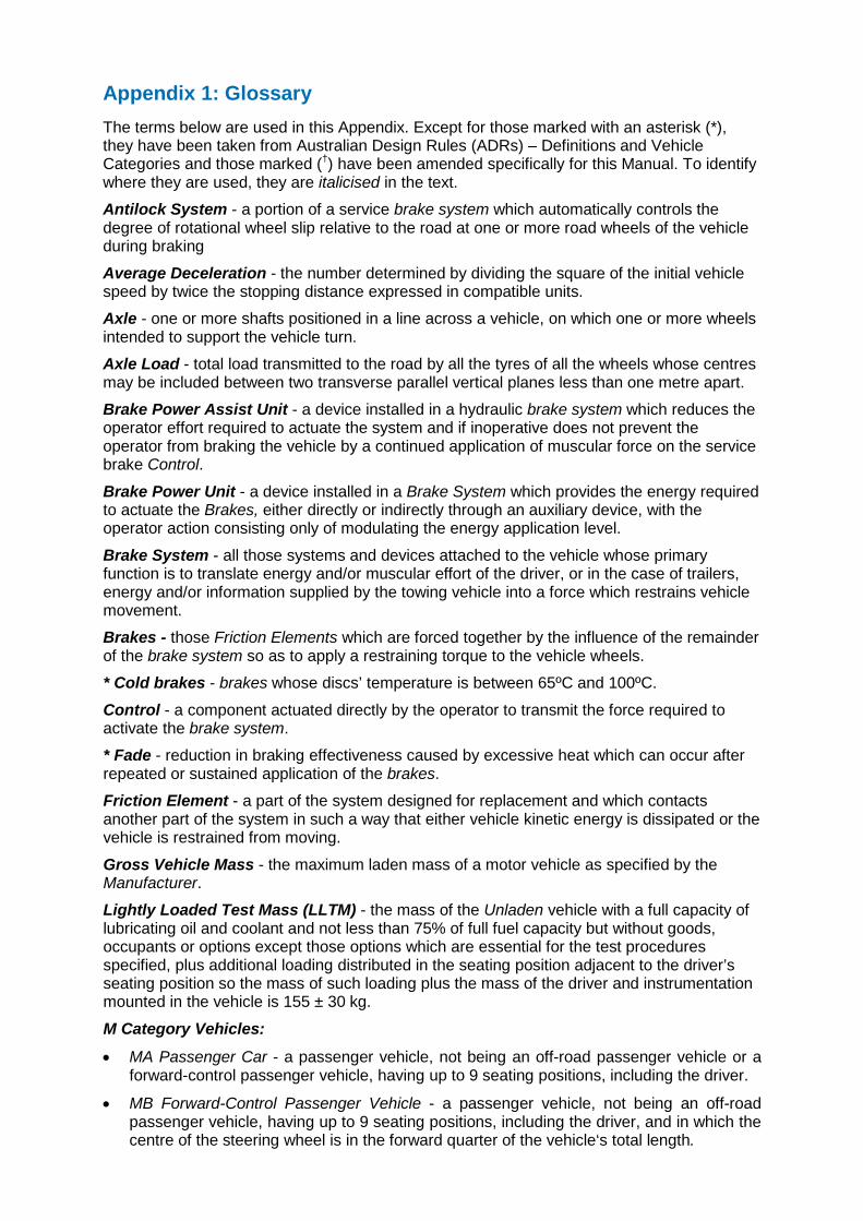
Appendix 1: Glossary The terms below are used in this Appendix. Except for those marked with an asterisk (*), they have been taken from Australian Design Rules (ADRs) – Definitions and Vehicle Categories and those marked (†) have been amended specifically for this Manual. To identify where they are used, they are italicised in the text.
Antilock System - a portion of a service brake system which automatically controls the degree of rotational wheel slip relative to the road at one or more road wheels of the vehicle during braking
Average Deceleration - the number determined by dividing the square of the initial vehicle speed by twice the stopping distance expressed in compatible units.
Axle - one or more shafts positioned in a line across a vehicle, on which one or more wheels intended to support the vehicle turn.
Axle Load - total load transmitted to the road by all the tyres of all the wheels whose centres may be included between two transverse parallel vertical planes less than one metre apart.
Brake Power Assist Unit - a device installed in a hydraulic brake system which reduces the operator effort required to actuate the system and if inoperative does not prevent the operator from braking the vehicle by a continued application of muscular force on the service brake Control.
Brake Power Unit - a device installed in a Brake System which provides the energy required to actuate the Brakes, either directly or indirectly through an auxiliary device, with the operator action consisting only of modulating the energy application level.
Brake System - all those systems and devices attached to the vehicle whose primary function is to translate energy and/or muscular effort of the driver, or in the case of trailers, energy and/or information supplied by the towing vehicle into a force which restrains vehicle movement.
Brakes - those Friction Elements which are forced together by the influence of the remainder of the brake system so as to apply a restraining torque to the vehicle wheels.
* Cold brakes - brakes whose discs’ temperature is between 65ºC and 100ºC.
Control - a component actuated directly by the operator to transmit the force required to activate the brake system.
* Fade - reduction in braking effectiveness caused by excessive heat which can occur after repeated or sustained application of the brakes.
Friction Element - a part of the system designed for replacement and which contacts another part of the system in such a way that either vehicle kinetic energy is dissipated or the vehicle is restrained from moving.
Gross Vehicle Mass - the maximum laden mass of a motor vehicle as specified by the Manufacturer.
Lightly Loaded Test Mass (LLTM) - the mass of the Unladen vehicle with a full capacity of lubricating oil and coolant and not less than 75% of full fuel capacity but without goods, occupants or options except those options which are essential for the test procedures specified, plus additional loading distributed in the seating position adjacent to the driver’s seating position so the mass of such loading plus the mass of the driver and instrumentation mounted in the vehicle is 155 ± 30 kg.
M Category Vehicles:
• MA Passenger Car - a passenger vehicle, not being an off-road passenger vehicle or a forward-control passenger vehicle, having up to 9 seating positions, including the driver.
• MB Forward-Control Passenger Vehicle - a passenger vehicle, not being an off-road passenger vehicle, having up to 9 seating positions, including the driver, and in which the centre of the steering wheel is in the forward quarter of the vehicle‘s total length.
• MC Off-Road Passenger Vehicle - a passenger vehicle having up to 9 seating positions, including the driver and being designed with special features for off-road operation.
• MD Light Omnibus - a passenger vehicle having more than 9 seating positions, including the driver and with a Gross Vehicle Mass not exceeding 5.0 tonnes.
Manufacturer - the name of the person or company who accepts responsibility for compliance with the Australian Design Rules and to whom the ‘Compliance Plate’ approval certificate is issued, or, for an individually constructed vehicle, the person in whose name the vehicle is registered.
† Maximum Loaded Test Mass (MLTM) - the mass of the Unladen vehicle together with a full capacity of lubricating oil and coolant and at least 75% capacity of fuel plus additional mass equivalent to 68 kg located in each unoccupied seating position.
N Category Vehicles
• NA Light Goods Vehicle - a goods vehicle with a Gross Vehicle Mass not exceeding 3.5 tonnes.
• NB1 Medium Goods Vehicle - a goods vehicle with a Gross Vehicle Mass between 3.5 tonnes and 4.5 tonnes.
• Goods Vehicle - a motor vehicle constructed primarily for the carriage of goods and having at least 4 wheels; or 3 wheels and a Gross Vehicle Mass exceeding 1.0 tonne.
Parking Mechanism - a component or sub-system of the drive train which locks the drive train when the transmission control is placed in the ‘park’ position or other gear position and the ignition key is removed.
Pedal Effort - the force applied to the service brake Control. The force may be measured by a force transducer located centrally on the brake pedal pad.
* Restored vehicle - a vehicle being or has been restored to its manufacturer’s specifications, so far as it is reasonably practicable to meet those specifications. Note: This definition is from the Road Transport (Vehicle Registration) Regulation 2007.
Split Service Brake System - a brake system consisting of two or more sub-systems actuated by a single Control and designed so that a leakage-type failure of a pressure component in a single sub-system (except structural failure of a housing common to all sub-systems) shall not impair the operation of any other sub-systems.
Stored Energy - energy stored in a device such as a pressure vessel, vacuum chamber, spring or battery.
† Unladen Mass - the mass of the vehicle in its operational configuration, unoccupied and unladen with all fluid reservoirs filled to nominal capacity including fuel.
Variable Proportioning Brake System - system which automatically adjusts the braking force at the Axles to compensate for vehicle static Axle Load and/or dynamic weight transfer between Axles during deceleration.
In addition, the definitions below apply for the purposes of the tests. These are not italicised in the text.
* May indicates an option is permissible and which does not affect compliance with a test whether or not it is used.
* Must indicates something is an essential part of, or essential to, the test. * Shall indicates something is a mandatory part of a test procedure. * Should indicates something is recommended, but is not necessary to ensure compliance
with a test.
16
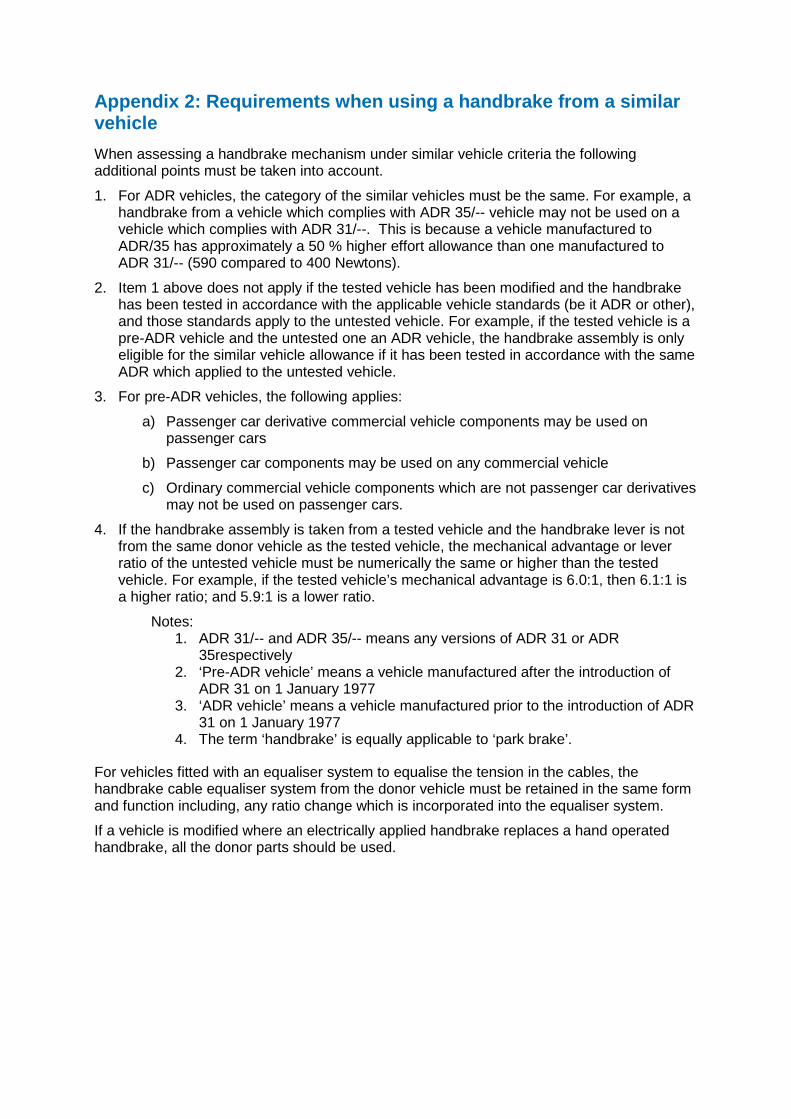
Appendix 2: Requirements when using a handbrake from a similar vehicle When assessing a handbrake mechanism under similar vehicle criteria the following additional points must be taken into account.
1. For ADR vehicles, the category of the similar vehicles must be the same. For example, a handbrake from a vehicle which complies with ADR 35/-- vehicle may not be used on a vehicle which complies with ADR 31/--. This is because a vehicle manufactured to ADR/35 has approximately a 50 % higher effort allowance than one manufactured to ADR 31/-- (590 compared to 400 Newtons).
2. Item 1 above does not apply if the tested vehicle has been modified and the handbrake has been tested in accordance with the applicable vehicle standards (be it ADR or other), and those standards apply to the untested vehicle. For example, if the tested vehicle is a pre-ADR vehicle and the untested one an ADR vehicle, the handbrake assembly is only eligible for the similar vehicle allowance if it has been tested in accordance with the same ADR which applied to the untested vehicle.
3. For pre-ADR vehicles, the following applies:
a) Passenger car derivative commercial vehicle components may be used on passenger cars
b) Passenger car components may be used on any commercial vehicle
c) Ordinary commercial vehicle components which are not passenger car derivatives may not be used on passenger cars.
4. If the handbrake assembly is taken from a tested vehicle and the handbrake lever is not from the same donor vehicle as the tested vehicle, the mechanical advantage or lever ratio of the untested vehicle must be numerically the same or higher than the tested vehicle. For example, if the tested vehicle’s mechanical advantage is 6.0:1, then 6.1:1 is a higher ratio; and 5.9:1 is a lower ratio.
Notes: 1. ADR 31/-- and ADR 35/-- means any versions of ADR 31 or ADR
35respectively 2. ‘Pre-ADR vehicle’ means a vehicle manufactured after the introduction of
ADR 31 on 1 January 1977 3. ‘ADR vehicle’ means a vehicle manufactured prior to the introduction of ADR
31 on 1 January 1977 4. The term ‘handbrake’ is equally applicable to ‘park brake’.
For vehicles fitted with an equaliser system to equalise the tension in the cables, the handbrake cable equaliser system from the donor vehicle must be retained in the same form and function including, any ratio change which is incorporated into the equaliser system.
If a vehicle is modified where an electrically applied handbrake replaces a hand operated handbrake, all the donor parts should be used.
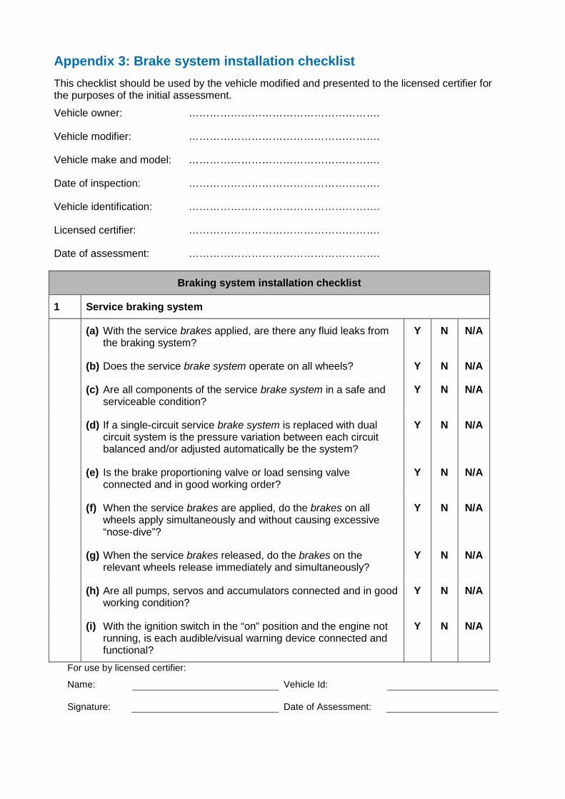
Appendix 3: Brake system installation checklist This checklist should be used by the vehicle modified and presented to the licensed certifier for the purposes of the initial assessment.
Vehicle owner: ……………………………………………….
Vehicle modifier: ……………………………………………….
Vehicle make and model: ……………………………………………….
Date of inspection: ……………………………………………….
Vehicle identification: ……………………………………………….
Licensed certifier: ……………………………………………….
Date of assessment: ……………………………………………….
Braking system installation checklist
1 Service braking system
(a) With the service brakes applied, are there any fluid leaks from the braking system?
Y N N/A
(b) Does the service brake system operate on all wheels? Y N N/A
(c) Are all components of the service brake system in a safe and serviceable condition?
Y N N/A
(d) If a single-circuit service brake system is replaced with dual circuit system is the pressure variation between each circuit balanced and/or adjusted automatically be the system?
Y N N/A
(e) Is the brake proportioning valve or load sensing valve connected and in good working order?
Y N N/A
(f) When the service brakes are applied, do the brakes on all wheels apply simultaneously and without causing excessive “nose-dive”?
Y N N/A
(g) When the service brakes released, do the brakes on the relevant wheels release immediately and simultaneously?
Y N N/A
(h) Are all pumps, servos and accumulators connected and in good working condition?
Y N N/A
(i) With the ignition switch in the “on” position and the engine not running, is each audible/visual warning device connected and functional?
Y N N/A
For use by licensed certifier:
Name: Vehicle Id: Signature:
Date of Assessment:
18
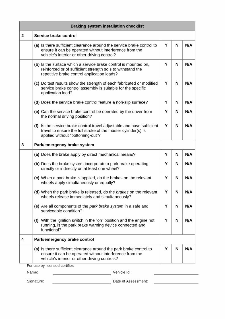
Braking system installation checklist
2 Service brake control
(a) Is there sufficient clearance around the service brake control to ensure it can be operated without interference from the vehicle’s interior or other driving control?
Y N N/A
(b) Is the surface which a service brake control is mounted on, reinforced or of sufficient strength so s to withstand the repetitive brake control application loads?
Y N N/A
(c) Do test results show the strength of each fabricated or modified service brake control assembly is suitable for the specific application load?
Y N N/A
(d) Does the service brake control feature a non-slip surface? Y N N/A
(e) Can the service brake control be operated by the driver from the normal driving position?
Y N N/A
(f) Is the service brake control travel adjustable and have sufficient travel to ensure the full stroke of the master cylinder(s) is applied without “bottoming-out”?
Y N N/A
3 Park/emergency brake system
(a) Does the brake apply by direct mechanical means? Y N N/A
(b) Does the brake system incorporate a park brake operating directly or indirectly on at least one wheel?
Y N N/A
(c) When a park brake is applied, do the brakes on the relevant wheels apply simultaneously or equally?
Y N N/A
(d) When the park brake is released, do the brakes on the relevant wheels release immediately and simultaneously?
Y N N/A
(e) Are all components of the park brake system in a safe and serviceable condition?
Y N N/A
(f) With the ignition switch in the “on” position and the engine not running, is the park brake warning device connected and functional?
Y N N/A
4 Park/emergency brake control
(a) Is there sufficient clearance around the park brake control to ensure it can be operated without interference from the vehicle’s interior or other driving controls?
Y N N/A
For use by licensed certifier:
Name: Vehicle Id: Signature:
Date of Assessment:
Braking system installation checklist
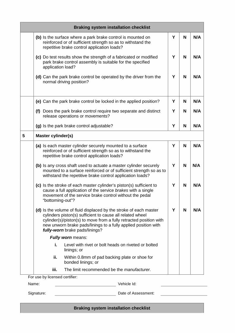
(b) Is the surface where a park brake control is mounted on reinforced or of sufficient strength so as to withstand the repetitive brake control application loads?
Y N N/A
(c) Do test results show the strength of a fabricated or modified park brake control assembly is suitable for the specified application load?
Y N N/A
(d) Can the park brake control be operated by the driver from the normal driving position?
Y N N/A
(e) Can the park brake control be locked in the applied position? Y N N/A
(f) Does the park brake control require two separate and distinct release operations or movements?
Y N N/A
(g) Is the park brake control adjustable? Y N N/A
5 Master cylinder(s)
(a) Is each master cylinder securely mounted to a surface reinforced or of sufficient strength so as to withstand the repetitive brake control application loads?
Y N N/A
(b) Is any cross shaft used to actuate a master cylinder securely mounted to a surface reinforced or of sufficient strength so as to withstand the repetitive brake control application loads?
Y N N/A
(c) Is the stroke of each master cylinder’s piston(s) sufficient to cause a full application of the service brakes with a single movement of the service brake control without the pedal “bottoming-out”?
Y N N/A
(d) Is the volume of fluid displaced by the stroke of each master cylinders piston(s) sufficient to cause all related wheel cylinder(s)/piston(s) to move from a fully retracted position with new unworn brake pads/linings to a fully applied position with fully-worn brake pads/linings?
Fully worn means:
i. Level with rivet or bolt heads on riveted or bolted linings; or
ii. Within 0.8mm of pad backing plate or shoe for bonded linings; or
iii. The limit recommended be the manufacturer.
Y N N/A
For use by licensed certifier:
Name: Vehicle Id: Signature:
Date of Assessment:
Braking system installation checklist
20
Braking system installation checklist
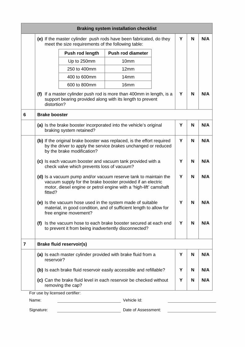
(e) If the master cylinder push rods have been fabricated, do they meet the size requirements of the following table:
Push rod length Push rod diameter
Up to 250mm 10mm
250 to 400mm 12mm
400 to 600mm 14mm
600 to 800mm 16mm
Y N N/A
(f) If a master cylinder push rod is more than 400mm in length, is a support bearing provided along with its length to prevent distortion?
Y N N/A
6 Brake booster
(a) Is the brake booster incorporated into the vehicle’s original braking system retained?
Y N N/A
(b) If the original brake booster was replaced, is the effort required by the driver to apply the service brakes unchanged or reduced by the brake modification?
Y N N/A
(c) Is each vacuum booster and vacuum tank provided with a check valve which prevents loss of vacuum?
Y N N/A
(d) Is a vacuum pump and/or vacuum reserve tank to maintain the vacuum supply for the brake booster provided if an electric motor, diesel engine or petrol engine with a ‘high-lift’ camshaft fitted?
Y N N/A
(e) Is the vacuum hose used in the system made of suitable material, in good condition, and of sufficient length to allow for free engine movement?
Y N N/A
(f) Is the vacuum hose to each brake booster secured at each end to prevent it from being inadvertently disconnected?
Y N N/A
7 Brake fluid reservoir(s)
(a) Is each master cylinder provided with brake fluid from a reservoir?
Y N N/A
(b) Is each brake fluid reservoir easily accessible and refillable? Y N N/A
(c) Can the brake fluid level in each reservoir be checked without removing the cap?
Y N N/A
For use by licensed certifier:
Name: Vehicle Id: Signature:
Date of Assessment:
Braking system installation checklist
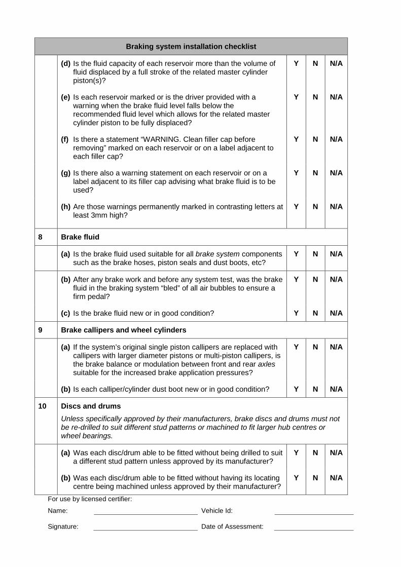
(d) Is the fluid capacity of each reservoir more than the volume of fluid displaced by a full stroke of the related master cylinder piston(s)?
Y N N/A
(e) Is each reservoir marked or is the driver provided with a warning when the brake fluid level falls below the recommended fluid level which allows for the related master cylinder piston to be fully displaced?
Y N N/A
(f) Is there a statement “WARNING. Clean filler cap before removing” marked on each reservoir or on a label adjacent to each filler cap?
Y N N/A
(g) Is there also a warning statement on each reservoir or on a label adjacent to its filler cap advising what brake fluid is to be used?
Y N N/A
(h) Are those warnings permanently marked in contrasting letters at least 3mm high?
Y N N/A
8 Brake fluid
(a) Is the brake fluid used suitable for all brake system components such as the brake hoses, piston seals and dust boots, etc?
Y N N/A
(b) After any brake work and before any system test, was the brake fluid in the braking system “bled” of all air bubbles to ensure a firm pedal?
Y N N/A
(c) Is the brake fluid new or in good condition? Y N N/A
9 Brake callipers and wheel cylinders
(a) If the system’s original single piston callipers are replaced with callipers with larger diameter pistons or multi-piston callipers, is the brake balance or modulation between front and rear axles suitable for the increased brake application pressures?
Y N N/A
(b) Is each calliper/cylinder dust boot new or in good condition? Y N N/A
10 Discs and drums Unless specifically approved by their manufacturers, brake discs and drums must not be re-drilled to suit different stud patterns or machined to fit larger hub centres or wheel bearings.
(a) Was each disc/drum able to be fitted without being drilled to suit a different stud pattern unless approved by its manufacturer?
Y N N/A
(b) Was each disc/drum able to be fitted without having its locating centre being machined unless approved by their manufacturer?
Y N N/A
For use by licensed certifier:
Name: Vehicle Id: Signature:
Date of Assessment:
22
Braking system installation checklist
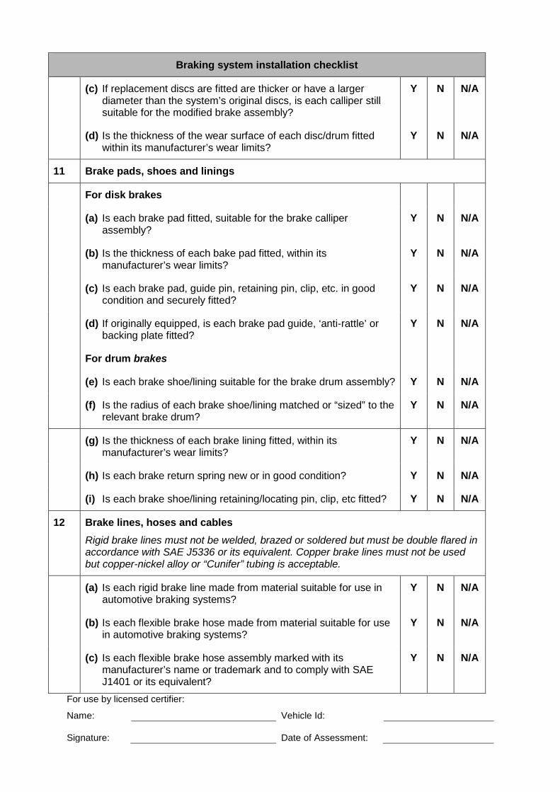
(c) If replacement discs are fitted are thicker or have a larger diameter than the system’s original discs, is each calliper still suitable for the modified brake assembly?
Y N N/A
(d) Is the thickness of the wear surface of each disc/drum fitted within its manufacturer’s wear limits?
Y N N/A
11 Brake pads, shoes and linings
For disk brakes
(a) Is each brake pad fitted, suitable for the brake calliper assembly?
Y N N/A
(b) Is the thickness of each bake pad fitted, within its manufacturer’s wear limits?
Y N N/A
(c) Is each brake pad, guide pin, retaining pin, clip, etc. in good condition and securely fitted?
Y N N/A
(d) If originally equipped, is each brake pad guide, ‘anti-rattle’ or backing plate fitted?
Y N N/A
For drum brakes
(e) Is each brake shoe/lining suitable for the brake drum assembly? Y N N/A
(f) Is the radius of each brake shoe/lining matched or “sized” to the relevant brake drum?
Y N N/A
(g) Is the thickness of each brake lining fitted, within its manufacturer’s wear limits?
Y N N/A
(h) Is each brake return spring new or in good condition? Y N N/A
(i) Is each brake shoe/lining retaining/locating pin, clip, etc fitted? Y N N/A
12 Brake lines, hoses and cables Rigid brake lines must not be welded, brazed or soldered but must be double flared in accordance with SAE J5336 or its equivalent. Copper brake lines must not be used but copper-nickel alloy or “Cunifer” tubing is acceptable.
(a) Is each rigid brake line made from material suitable for use in automotive braking systems?
Y N N/A
(b) Is each flexible brake hose made from material suitable for use in automotive braking systems?
Y N N/A
(c) Is each flexible brake hose assembly marked with its manufacturer’s name or trademark and to comply with SAE J1401 or its equivalent?
Y N N/A
For use by licensed certifier:
Name: Vehicle Id: Signature:
Date of Assessment:
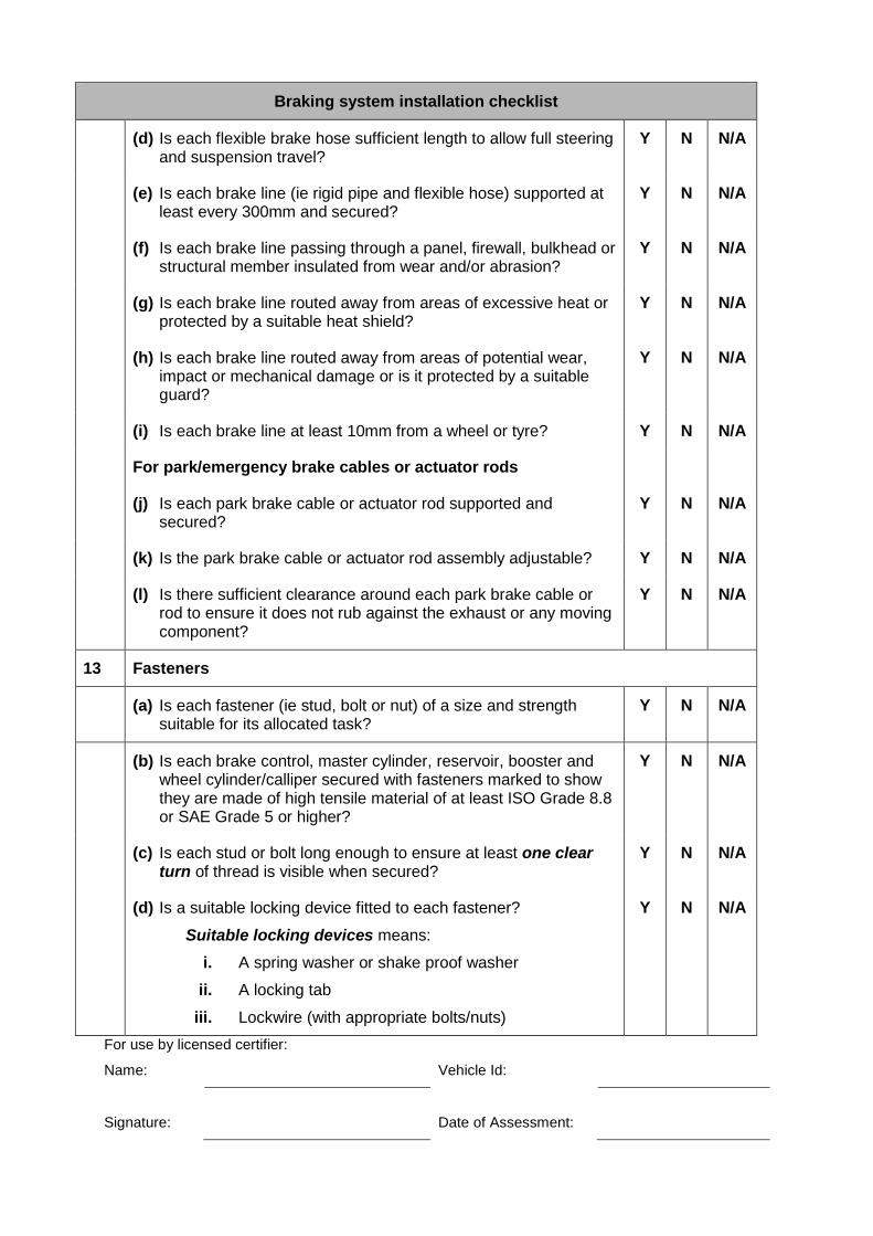
Braking system installation checklist
(d) Is each flexible brake hose sufficient length to allow full steering and suspension travel?
Y N N/A
(e) Is each brake line (ie rigid pipe and flexible hose) supported at least every 300mm and secured?
Y N N/A
(f) Is each brake line passing through a panel, firewall, bulkhead or structural member insulated from wear and/or abrasion?
Y N N/A
(g) Is each brake line routed away from areas of excessive heat or protected by a suitable heat shield?
Y N N/A
(h) Is each brake line routed away from areas of potential wear, impact or mechanical damage or is it protected by a suitable guard?
Y N N/A
(i) Is each brake line at least 10mm from a wheel or tyre? Y N N/A
For park/emergency brake cables or actuator rods
(j) Is each park brake cable or actuator rod supported and secured?
Y N N/A
(k) Is the park brake cable or actuator rod assembly adjustable? Y N N/A
(l) Is there sufficient clearance around each park brake cable or rod to ensure it does not rub against the exhaust or any moving component?
Y N N/A
13 Fasteners
(a) Is each fastener (ie stud, bolt or nut) of a size and strength suitable for its allocated task?
Y N N/A
(b) Is each brake control, master cylinder, reservoir, booster and wheel cylinder/calliper secured with fasteners marked to show they are made of high tensile material of at least ISO Grade 8.8 or SAE Grade 5 or higher?
Y N N/A
(c) Is each stud or bolt long enough to ensure at least one clear turn of thread is visible when secured?
Y N N/A
(d) Is a suitable locking device fitted to each fastener?
Suitable locking devices means:
i. A spring washer or shake proof washer
ii. A locking tab
iii. Lockwire (with appropriate bolts/nuts)
Y N N/A
For use by licensed certifier:
Name: Vehicle Id:
Signature:
Date of Assessment:
24
Braking system installation checklist
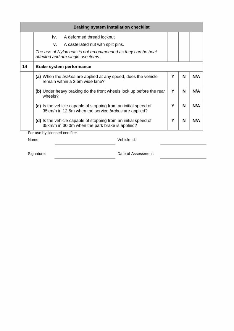
iv. A deformed thread locknut
v. A castellated nut with split pins.
The use of Nyloc nots is not recommended as they can be heat affected and are single use items.
14 Brake system performance
(a) When the brakes are applied at any speed, does the vehicle remain within a 3.5m wide lane?
Y N N/A
(b) Under heavy braking do the front wheels lock up before the rear wheels?
Y N N/A
(c) Is the vehicle capable of stopping from an initial speed of 35km/h in 12.5m when the service brakes are applied?
Y N N/A
(d) Is the vehicle capable of stopping from an initial speed of 35km/h in 30.0m when the park brake is applied?
Y N N/A
For use by licensed certifier:
Name: Vehicle Id:
Signature:
Date of Assessment:
Appendix 4: Using a Plate-Type Test Machine A plate-type brake test machine may be used to do a basic determination of the performance of the brakes, and some of the tests specified in Table 3. The tests are listed below, with applicable pass criteria; and examples of data and read-outs obtained from a plate-type brake test machine are provided for some of the tests. The tests are:
Basic performance test – see data and read-outs for 4.1 This gives a general assessment of the brakes and how they perform, namely:
• Left to right brake imbalance for both front and rear brakes
• Front to rear brake imbalance
• Brake pedal force applied
• Peak deceleration rate
• Average deceleration rate
• Handbrake/park brake imbalance
• Peak handbrake/park brake deceleration rate
• Wheel alignment.
Test D Test with front brakes disconnected – see data and read-outs for 4.2 The read-out should indicate the brakes are capable of exerting sufficient force to bring the vehicle to a stop. To pass this test, the peak deceleration must have a minimum rate of 20%.
Test D Test with rear brakes disconnected – see data and read-outs for 4.3 This corresponds to Test D in Table 3. The read-out should indicate the brakes are capable of exerting sufficient force to bring the vehicle to a stop. To pass this test, the peak deceleration must have a minimum rate of 50%.
Test E Test with booster disconnected – see data and read-outs for 4.4 The read-out should indicate the brakes are capable of exerting sufficient force to bring the vehicle to a stop. To pass this test, the peak deceleration must have a minimum rate of 50% applied with a pedal force pressure of 500 N.
Test B To pass this test, the mounting structure must remain rigid with the following loads applied:
• 500 N for vehicles in Modification Category 19
• 885 N for vehicles manufactured prior to the introduction of ADR 31 on 1 January 1977
• 1000 N for vehicles manufactured after the introduction of ADR 31 on 1 January 1977.
Test F To pass this test, the front axle brake force must be between 55% minimum and 90% maximum, while the rear axle brake force must be between 10% minimum and 45% maximum.
Test G To pass this test, with the ABS disconnected, the front axle brake force must be between 55% minimum and 90% maximum, while the rear axle brake force must be between 10% minimum and 45% maximum.
Test I To pass this test, the front axle brake force must be between 55% minimum and 90% maximum, while the rear axle brake force must be between 10% minimum and 45% maximum; and the front wheels must lock before the rear wheels, which can be determined from the graph in Test 4.1.

For all the tests, the vehicle should be tested in the unladen condition with just the driver, and it should be in neutral gear.
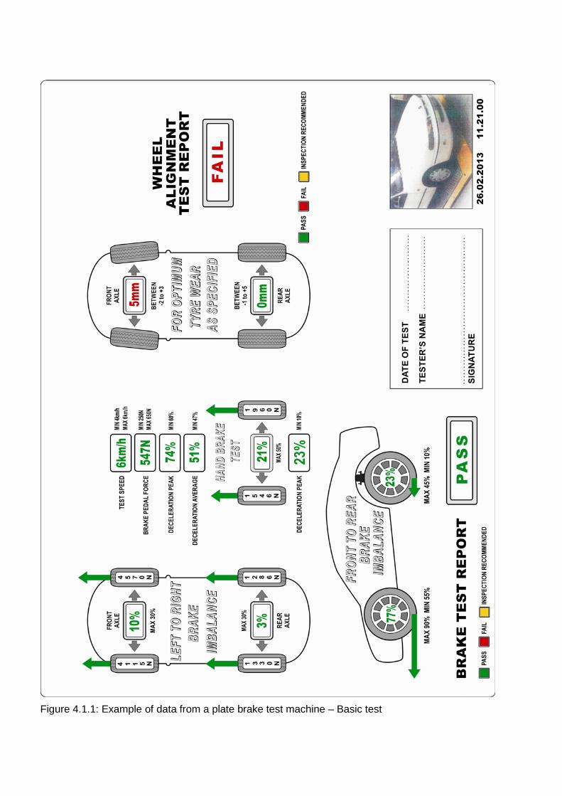
Figure 4.1.1: Example of data from a plate brake test machine – Basic test
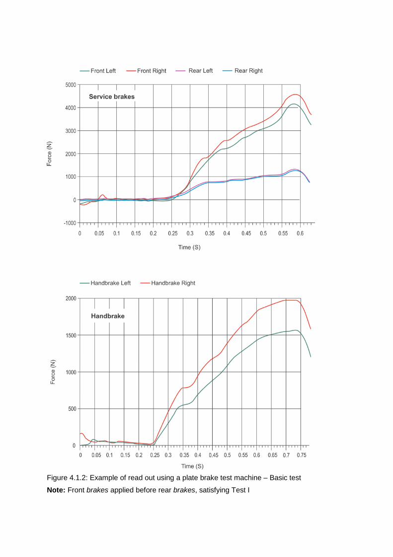
Figure 4.1.2: Example of read out using a plate brake test machine – Basic test
Note: Front brakes applied before rear brakes, satisfying Test I
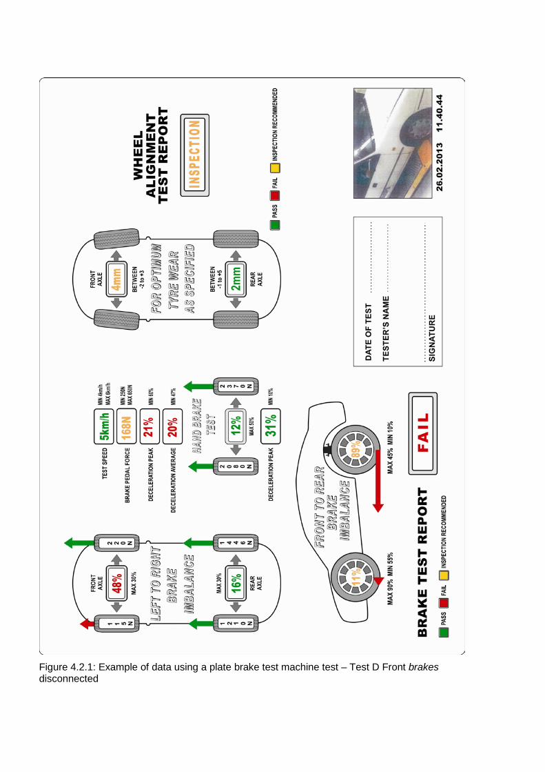
Figure 4.2.1: Example of data using a plate brake test machine test – Test D Front brakes disconnected
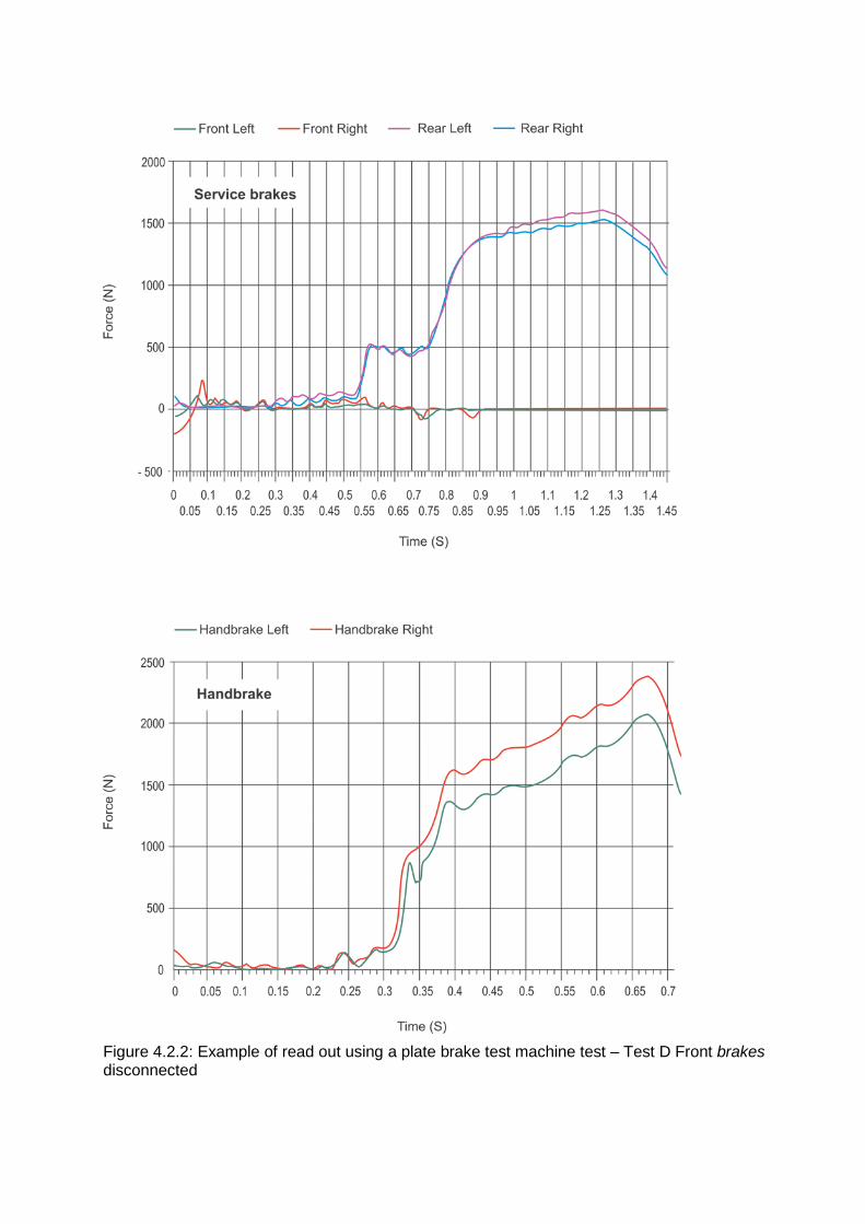
Figure 4.2.2: Example of read out using a plate brake test machine test – Test D Front brakes disconnected
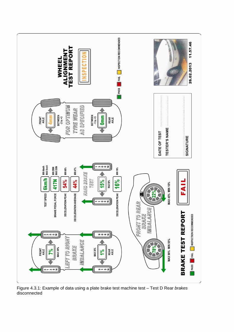
Figure 4.3.1: Example of data using a plate brake test machine test – Test D Rear brakes disconnected
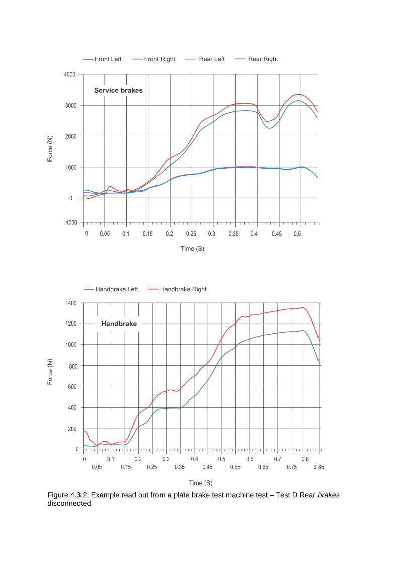
Figure 4.3.2: Example read out from a plate brake test machine test – Test D Rear brakes disconnected
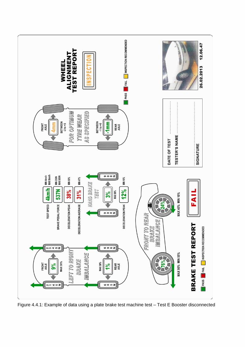
Figure 4.4.1: Example of data using a plate brake test machine test – Test E Booster disconnected
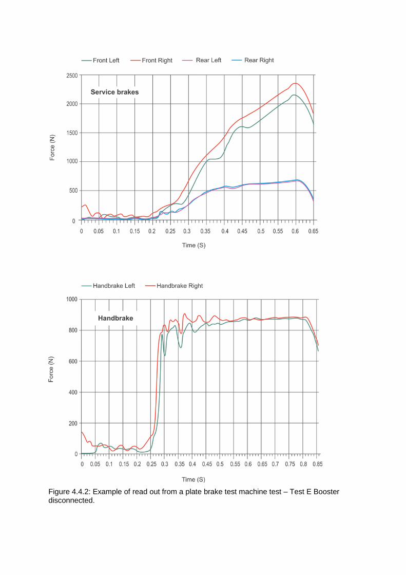
Figure 4.4.2: Example of read out from a plate brake test machine test – Test E Booster disconnected.
Appendix 5: Description of tests
Order of tests The tests should be done in the order presented, but may be varied at the discretion of the supervising licensed certifier. However, Tests C, E & F and Test D should be done as early as possible as these indicate the likelihood of the vehicle passing the other tests.
Test speed The test speed shall be the vehicle speed registered on the test instrumentation, not on the vehicle’s speedometer.
Test A: Reservoir volume [Based on: ADR 31/00, Clause 31.2.5.]
Where the service brake system incorporates a master cylinder, all service brake subsystems serviced by the master cylinder must have either:
• A reservoir which contains fluid exclusively for the use of the service brake sub-system
• A reservoir which contains fluid for the use of two or more service brake sub-systems in which case part of the reservoir capacity provided exclusively for the use of each service brake sub-system must be not less than the volume displaced by the master cylinder piston servicing the sub-system, during a full stroke of the piston.
The capacity of each reservoir must be not less than the fluid displacement resulting when all the wheel cylinders or calliper pistons serviced by the reservoir move from a new-lining, fully-retracted position, as adjusted according to the Manufacturer’s recommendations to a fully-worn, fully applied position. For the purposes of this test, ‘fully-worn’ means the lining is worn to whichever of the following conditions allows the greatest shoe or pad movement:
1. Level with rivet or bolt heads on riveted or bolted linings
2. Within 0.8 mm of shoe or pad mounting surface on bonded linings or pads
3. The limit recommended by the Manufacturer.
Each Brake Power Unit must have a device for storing energy of capacity not less than the total capacity of the reservoirs required above plus the fluid displacement necessary to charge the piston(s) or accumulator(s) provided for the purpose of storing energy.
A statement specifying the type of fluid to be used in the brake system and displaying at least the words in letters not less than 3 mm high ‘WARNING. Clean filler cap before removing’ must be permanently affixed either on, or partially within 150 mm of, one brake fluid reservoir filler plug or cap, and totally within 300 mm of all reservoir filler plugs or caps. The statement must be stamped, engraved or embossed, or comprise lettering of a contrasting colour of the background.
Test B: Mounting structure This test is required to ensure the firewall and mounting brackets for the brake pedal, master cylinder and/or booster are structurally adequate.
A load shall be applied to the brake pedal with the vehicle stationary and the engine off. An observation of the mounting structure shall be made for local deformation. The mounting structure shall be rigid.
Loading shall be:
• 500 N for vehicles in Modification Category 19;
• 885 N for vehicles manufactured prior to the introduction of ADR 31 on 1 January 1977;
• 1000 N for vehicles manufactured after the introduction of ADR 31 on 1 January 1977.
Test C: Park brake The park brake efficiency shall be tested as follows:
a) With the vehicle is stationary, apply the park brake
b) Start the engine and engage low gear
c) Attempt to move the vehicle forward under light throttle
d) Engage reverse gear
e) Attempt to move the vehicle backward.
The park brake shall be deemed to have passed the test if the vehicle remains stationary. When doing this test on a transmission handbrake, the throttle should be applied smoothly and gradually to prevent damage to the transmission.
This function test should only apply to a modified vehicle if the donor vehicle park brake system components are from a vehicle which has been tested and known to comply with the ADR or other applicable standard, and the modified vehicle is of a lesser mass than the donor vehicle.
The components comprise the foundation park brake assemblies, equalisers, cables and the like. The park brake lever may be either from the donor vehicle or one of the same ratio equivalent.
Cables manufactured by a recognised park brake cable manufacturer either OEM or aftermarket may be used.
If the components do not meet the above criteria, the modified vehicle must be tested in accordance with the ADR which applies to the modified vehicle, or a later version of the ADR. For pre-ADR vehicles, the vehicle must be tested in accordance with any version of ADR 31 or ADR 35 as applicable.
For more information, see Appendix 2.
Tests D, F & G: Partial failure test front and rear; proportional valve failure; and ABS failure [Based on: ADR 31/00, Clause 31.3.2, Item 8 and Clause 31.5.8.]
Test D checks the master cylinder in a Split Service Brake System has enough displacement to operate an individual circuit if of one of the circuits fail. Clamping off a brake hose does not simulate a failure in one circuit. Tests F and G are required to ensure the vehicle can be safely brought to rest if the ABS fails.
The vehicle shall be tested in both the MLTM and LLTM condition at a test speed of 55 km/h for vehicles subject to Modification 19, and 80 km/h for all other vehicles, with the gear selected in the ‘Drive’ position. It must obtain a minimum Average Deceleration of 2.55 m/s2.
In the case of a vehicle having a Split Service Brake System a minimum Average Deceleration of 2.55 m/s2 must be obtained by operation of the service brake Control on at least one deceleration mode within a number of deceleration modes which must not exceed four for each single type of potential failure, including:
• Failure of each sub-system of the split system
• Inoperative Antilock System
• Inoperative Variable Proportioning Brake System if fitted.
In addition, one single failure must be induced prior to each set of deceleration modes and the vehicle restored at the completion of the set.
In the case of a vehicle not having a Split Service Brake System a minimum Average Deceleration of 2.55 m/s2 must be obtained by operation of the service brake Control on each of 10 consecutive stops for each single type of potential failure, including:
• Rupture or leakage of any component of the brake system other than a structural failure of a housing common to two or more sub-systems
• Inoperative Antilock System
• Inoperative Variable Proportioning Brake System.
In addition, one single failure must be induced prior to each set of deceleration modes and the vehicle restored at the completion of the set.
In the case of a vehicle not having a Split Service Brake System but having a service brake system using Stored Energy the pressure and volume of the working fluid in the brake system (including any energy storage devices) must not exceed the minimum levels specified by the vehicle Manufacture’ or achievable by adjustment of Control s accessible to the driver for initiation of the failure mode prior to the commencement of any partial failure test sequence.
Test E: Booster failure [Based on: ADR 31/00, Clause 31.3.2, Item 9 and Clause 31.5.9.]
Test E is required to ensure the vehicle can be safely brought to rest if the booster fails.
For vehicles subject to Modification 19, this test must be done at 55 km/h; for all other vehicles, the test must be done at 80 km/h. In all cases, the vehicle must be in the MLTM condition and the gears in the ‘drive’ position. The vehicle must meet one of the following:
Condition D1 It must attain a minimum Average Deceleration of 2.55 m/s2 for one deceleration mode within a maximum of four deceleration modes when any one Brake Power Assist Unit or Brake Power Unit is inoperative and depleted of all reserve capability. One single failure must be induced prior to each set of deceleration modes and the vehicle restored at the completion of the set.
Condition D2 If fitted with one or more Brake Power Assist Units, with any one Brake Power Assist Unit inoperative, the Average Decelerations set out in Table D must be attained on the first six consecutive stops with the inoperative unit not initially depleted of reserve capability, and the Average Deceleration specified for the final seventh stop is attained with the inoperative unit depleted of reserve capability.
Condition D3 If fitted with a Brake Power Unit incorporating an accumulator-type reserve system, with any one Brake Power Unit inoperative the following Average Decelerations set out in Table D must be attained on the first ten consecutive stops with the inoperative unit not initially depleted of reserve capability, and the Average Deceleration specified for the final eleventh stop is attained with the inoperative unit depleted of reserve capability.
Condition D4 If fitted with a Brake Power Unit incorporating a backup type system, with any one Brake Power Unit inoperative the Average Deceleration set out in Table D must be attained for each of the 15 consecutive stops.
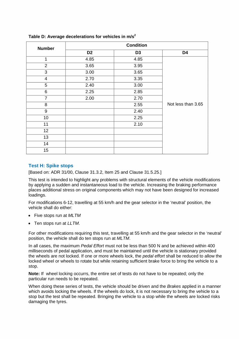
Table D: Average decelerations for vehicles in m/s2
Number Condition
D2 D3 D4 1 4.85 4.85
Not less than 3.65
2 3.65 3.95 3 3.00 3.65 4 2.70 3.35 5 2.40 3.00 6 2.25 2.85 7 2.00 2.70 8 2.55 9 2.40
10 2.25 11 2.10 12 13 14 15
Test H: Spike stops [Based on: ADR 31/00, Clause 31.3.2, Item 25 and Clause 31.5.25.]
This test is intended to highlight any problems with structural elements of the vehicle modifications by applying a sudden and instantaneous load to the vehicle. Increasing the braking performance places additional stress on original components which may not have been designed for increased loadings.
For modifications 6-12, travelling at 55 km/h and the gear selector in the ‘neutral’ position, the vehicle shall do either:
• Five stops run at MLTM
• Ten stops run at LLTM.
For other modifications requiring this test, travelling at 55 km/h and the gear selector in the ‘neutral’ position, the vehicle shall do ten stops run at MLTM.
In all cases, the maximum Pedal Effort must not be less than 500 N and be achieved within 400 milliseconds of pedal application, and must be maintained until the vehicle is stationary provided the wheels are not locked. If one or more wheels lock, the pedal effort shall be reduced to allow the locked wheel or wheels to rotate but while retaining sufficient brake force to bring the vehicle to a stop.
Note: If wheel locking occurrs, the entire set of tests do not have to be repeated; only the particular run needs to be repeated.
When doing these series of tests, the vehicle should be driven and the Brakes applied in a manner which avoids locking the wheels. If the wheels do lock, it is not necessary to bring the vehicle to a stop but the test shall be repeated. Bringing the vehicle to a stop while the wheels are locked risks damaging the tyres.
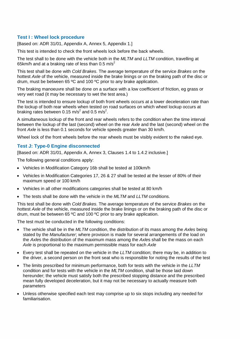
Test I: Wheel lock procedure [Based on: ADR 31/01, Appendix A, Annex 5, Appendix 1.]
This test is intended to check the front wheels lock before the back wheels.
The test shall to be done with the vehicle both in the MLTM and LLTM condition, travelling at 65km/h and at a braking rate of less than 0.5 m/s2
This test shall be done with Cold Brakes. The average temperature of the service Brakes on the hottest Axle of the vehicle, measured inside the brake linings or on the braking path of the disc or drum, must be between 65 ºC and 100 ºC prior to any brake application.
The braking manoeuvre shall be done on a surface with a low coefficient of friction, eg grass or very wet road (it may be necessary to wet the test area.)
The test is intended to ensure lockup of both front wheels occurs at a lower deceleration rate than the lockup of both rear wheels when tested on road surfaces on which wheel lockup occurs at braking rates between 0.15 m/s2 and 0.5 m/s2.
A simultaneous lockup of the front and rear wheels refers to the condition when the time interval between the lockup of the last (second) wheel on the rear Axle and the last (second) wheel on the front Axle is less than 0.1 seconds for vehicle speeds greater than 30 km/h.
Wheel lock of the front wheels before the rear wheels must be visibly evident to the naked eye.
Test J: Type-0 Engine disconnected [Based on: ADR 31/01, Appendix A, Annex 3, Clauses 1.4 to 1.4.2 inclusive.]
The following general conditions apply:
• Vehicles in Modification Category 16b shall be tested at 100km/h
• Vehicles in Modification Categories 17, 26 & 27 shall be tested at the lesser of 80% of their maximum speed or 100 km/h
• Vehicles in all other modifications categories shall be tested at 80 km/h
• The tests shall be done with the vehicle in the MLTM and LLTM conditions.
This test shall be done with Cold Brakes. The average temperature of the service Brakes on the hottest Axle of the vehicle, measured inside the brake linings or on the braking path of the disc or drum, must be between 65 ºC and 100 ºC prior to any brake application.
The test must be conducted in the following conditions:
• The vehicle shall be in the MLTM condition, the distribution of its mass among the Axles being stated by the Manufacturer; where provision is made for several arrangements of the load on the Axles the distribution of the maximum mass among the Axles shall be the mass on each Axle is proportional to the maximum permissible mass for each Axle
• Every test shall be repeated on the vehicle in the LLTM condition; there may be, in addition to the driver, a second person on the front seat who is responsible for noting the results of the test
• The limits prescribed for minimum performance, both for tests with the vehicle in the LLTM condition and for tests with the vehicle in the MLTM condition, shall be those laid down hereunder; the vehicle must satisfy both the prescribed stopping distance and the prescribed mean fully developed deceleration, but it may not be necessary to actually measure both parameters
• Unless otherwise specified each test may comprise up to six stops including any needed for familiarisation.
For a vehicle to pass the test, the stopping distance must be within (0.1v + 0.0060v2) metres, where v = the test speed in km/h, with a mean fully developed deceleration of at least 6.43 m/s2, and the braking force between 65 N and 500 N. Note: For vehicles tested at 80km/h and 100km/h, the stopping distances must be within 46.4m and 70m respectively.
Test K: Type-I Heating procedure [Based on: ADR 31/01, Appendix A, Annex 3, Clause 1.5.1.]
This test is intended to heat the brakes until the onset of fade to verify the brakes can function when hot.
The service Brakes of all vehicles shall be tested by successively applying and releasing the Brakes until the onset of fade but not more than 15 times, with the vehicle in the MLTM condition. The speed of the vehicle shall be reduced from 80 km/h to 40 km/h, with 45 seconds between the start of each braking cycle ie the time elapsing between the initiation of one brake application and the initiation of the next.
If the characteristics of the vehicle make it impossible to abide by the prescribed braking cycle, the duration may be increased; in any event, in addition to the time necessary for braking and accelerating the vehicle, a period of 10 seconds must be allowed in each cycle for stabilizing the speed at 80 km/h.
In these tests, the force applied to the Control must be so adjusted as to attain a mean deceleration of 3 m/s2 during every brake application; two preliminary tests may be carried out to determine the appropriate Control force.
During brake applications, the highest gear ratio (excluding overdrive, etc) must be continuously engaged.
For regaining speed after braking, the gearbox must be used in such a way as to attain a speed of 80 km/h in the shortest possible time (maximum acceleration allowed by the engine and gearbox).
For electric vehicles not having a sufficient autonomy to carry out the cycles of heating, the tests shall be carried out by respecting speed during the first braking application then by using the maximum acceleration of the vehicle, and brake successively at the speed reached at the end of each 45 seconds cycle duration.
Test L: Type-I Hot performance [Based on: ADR 31/01, Appendix A, Annex 3, Clause 1.5.2.]
This test is intended to check the performance of the brakes when hot.
The following general conditions apply:
• Vehicles in Modification Category 16b shall be tested at 100 km/h
• Vehicles in Modification Categories 17, 26 & 27 shall be tested at the lesser of 80% of their maximum speed or 100 km/h
• Vehicles in all other modifications categories shall be tested at 80 km/h
• The tests shall be done with the vehicle in the MLTM and LLTM conditions.
At the end of the Test K Type-I Heating Procedure, the hot performance of the service braking system shall be measured in the same conditions (and in particular at a mean control force no greater than the mean force actually used) as for the Test J (Type-0 Engine Disconnected) although the temperature conditions may be different.
This hot performance must not be less than the prescribed 75%, nor less than 60% of the figure recorded for Test J.
Note: 75% corresponds to a stopping distance of 0.1v + 0.0080v2 and a mean fully developed deceleration of 4.82 m/s2.
In the case of a vehicle which satisfies the 60% requirement, but which cannot comply with the 75% requirement, a further hot performance test may be carried out using a control force not exceeding 500 N. The results of both tests must be entered in the report.
For electric vehicles fitted with an electric regenerative braking system which is not part of the service braking system, during brake applications, the highest gear shall be continuously engaged and the separate electric braking Control, if any, not used.
In the case of the electric vehicles having carried out the cycles of heating, according to Test K (Type-I Heating procedure), the performance tests shall be carried out at the speed prescribed for the subject modification by the vehicle at the end of the cycles of heating.
Test M: Type-I Recovery procedure [Based on: ADR 31/01, Appendix A, Annex 3, Clause 1.5.3.]
This test is intended to check the performance of the brakes when hot.
This test shall take place immediately after Test L (Type-I Hot performance). The vehicle shall be stopped four stops from 50 km/h with the engine connected, at a mean deceleration of 3 m/s2.
The interval between the start of successive stops should be 1.5 km. A lesser interval may be used to suit the test location, but this results in a more onerous test as the brakes have less time to recover between tests. In extreme cases, too short an interval may cause the brakes to overheat.
Immediately after each stop, the vehicle shall be accelerated at maximum rate to 50 km/h, and speed shall be maintained until making the next stop.
Test N: Type-I Recovery performance [Based on: ADR 31/01, Appendix A, Annex 3, Clause 1.5.4.]
This test is intended to check the performance of the brakes when hot.
The following general conditions apply:
• Vehicles in Modification Category 16b shall be tested at 100 km/h
• Vehicles in Modification Categories 17, 26 & 27 shall be tested at the lesser of 80% of their maximum speed or 100 km/h
• Vehicles in all other modifications categories shall be tested at 80 km/h
• The tests shall be done with the vehicle in the MLTM and LLTM conditions.
At the end of Test M (Type-I Recovery procedure) the recovery performance of the service braking system shall be measured in the same conditions as for the Test J, Type-0 Engine disconnected, (the temperature conditions may be different), using a mean force on the Control, which is not more than the mean control force used in the corresponding Test J (Type-0 Engine disconnected).
This recovery performance must not be less than 70%, nor more than 150%, of the figure recorded for Test J.
Appendix 6: Rationale for the brake tests in Appendix 5 The Regulation specifies the applicable vehicle standards are those contained in its Schedule 2. For vehicles manufactured after 1972, those standards are the Australian Design Rules (ADRs), and for brake systems, the applicable ADRs are ADR 31 Brake systems for passenger cars, and ADR 35 Commercial Vehicle Brake Systems. This Manual is primarily concerned with ADR 31.
Before the introduction of ADR 31 in 1977, there was no uniform national standard which applied to brake systems. Instead, manufacturers largely based the performance and reliability of brakes on their own specifications or a standard approved by a recognised standards writing organisation or technical body. The tests specified in clause 136 to Schedule 2 in the Regulation which apply to pre-ADR vehicles are intended to check the roadworthiness of a registered vehicle, and not to determine the effectiveness of a modified brake system or the brakes in a modified vehicle. This means there are no standards and tests in the Regulation which can be applied to pre-ADR vehicles to assess their modified brake systems.
As these vehicles are being modified – as opposed to restored or simply maintained – in a similar manner and to achieve the same performance outcomes as later ADR vehicles, it is appropriate all modified vehicles be subjected to the same tests regardless of their date of manufacture. This means the modification should be done, as far as is reasonably practicable, in accordance with current standards, namely ADR 31/-- using the specified tests. A review of the tests specified in the different editions and versions of ADR 31/-- showed the easiest set of tests to do are those in ADR 31/00 and ADR 31/01. The tests outlined in Appendix 5 are based on these tests.
Most of the tests have been modified to take into account the tests specified in ADR 31/-- are intended to verify the effectiveness of a new braking system in a new, mass produced vehicle model; in contrast, in the majority of cases, the vehicles are subject to the brake test schedule are existing, registered vehicles which have previously been proven to comply with the applicable vehicle standards, and many are being modified with components sourced from existing vehicles or have otherwise been approved. To allow for this, typically, both the number of repeats necessary and the test speeds have been reduced. In some extreme cases, however, a full ADR test will be required.
Appendix 7: Variations for N Category vehicles and certain M Category vehicles
N Category vehicles subject to ADR 35/-- Commercial Vehicle Brake Systems must comply with the design requirements of that ADR. The performance requirements specified in Table 3 and Appendix 5 of this brake test schedule apply with the following amendments:
Lightly Loaded Test Mass 35/… - the mass of the unladen vehicle with a full capacity of lubricating oil and coolant and not less than 75 percent of full fuel capacity, but without goods, occupants or options except those options which are essential for the test procedures specified, plus additional loading distributed in the seating position adjacent to the driver‘s seating position so the mass of such loading plus the mass of the driver and instrumentation mounted in the vehicle is 1 55±30kg. In the case of a vehicle in "cab and chassis" condition an additional load not exceeding 7.5 percent of the ‘GVM’ shall be located with its centre of mass within 200 mm of the ‘Manufacturer(s)’ designated load centre, measured in a horizontal plane.
Maximum Loaded Test Mass 35/… - The mass of the laden vehicle loaded to GVM rating with the load so distributed over the load bearing area of the vehicle as not to exceed the ‘Manufacturer’s’ nominated individual Axle Loads.
Test C: Park brake: The applicable test gradient shall be 18%.

Month Year RMS XX.XXX
ISBN: XXX-X-XXXXXX-XX-X
rms.nsw.gov.au/xxxxxx
13 22 13
Customer feedback Roads and Maritime Locked Bag 928, North Sydney NSW 2059