Embed Size (px)
Citation preview

Bravura Adhesive Melters
Customer Product ManualPart 1052743D03
Issued 2/10
NORDSON CORPORATION • DULUTH, GEORGIA • USAwww.nordson.com

Part 1052743D03 � 2010 Nordson CorporationAll rights reserved
Nordson Corporation welcomes requests for information, comments, and inquiries about its products. General informationabout Nordson can be found on the Internet using the following address: http://www.nordson.com.
Address all correspondence to:
Nordson CorporationAttn: Customer Service11475 Lakefield Drive
Duluth, GA 30097
Notice
This is a Nordson Corporation publication which is protected by copyright. Original copyright date 2004.No part of this document may be photocopied, reproduced, or translated to another language without the prior written
consent of Nordson Corporation. The information contained in this publication is subject to change without notice.
Trademarks
AccuJet, AeroCharge, Apogee, AquaGuard, Asymtek, Automove, Baitgun, Blue Box, CanWorks, Century, CF, Clean Coat, CleanSleeve, CleanSpray,ColorMax, Control Coat, Coolwave, Cross-Cut, Cyclo-Kinetic, Dispensejet, DispenseMate, DuraBlue, Durafiber, Dura-Screen, Durasystem, Easy Coat,Easymove Plus, Ecodry, Econo-Coat, e.dot, EFD, e stylized, ETI, Excel 2000, Fillmaster, FlexiCoat, Flexi-Spray, Flex-O-Coat, Flow Sentry, Fluidmove,
FoamMelt, FoamMix, HDLV, Heli-flow, Helix, Horizon, Hot Shot, iControl, iFlow, Isocoil, Isocore, Iso-Flo, iTRAX, Kinetix, Little Squirt, LogiComm,Magnastatic, March, Maverick, MEG, Meltex, Microcoat, Micromark, MicroSet, Millennium, Mini Squirt, Mountaingate, MultiScan, Nordson, OptiMix,Package of Values, Pattern View, PermaFlo, Plasmod, Porous Coat, PowderGrid, Powderware, Printplus, Prism, ProBlue, Prodigy, Pro-Flo, ProLink,
Pro-Meter, Pro-Stream, RBX, Rhino, Saturn, Scoreguard, Seal Sentry, Select Charge, Select Coat, Select Cure, Slautterback, Smart-Coat, Solder Plus,Spectrum, Speed-Coat, SureBead, Sure Clean, Sure Coat, Sure-Max, Tracking Plus, TRAK, Trends, Tribomatic, TrueBlue, Ultra, Ultrasaver, UpTime,
Vantage, Veritec, VersaBlue, Versa-Coat, Versa-Screen, Versa-Spray, Walcom, Watermark, and When you expect more. are registered trademarks of Nordson Corporation.
Accubar, Advanced Plasma Systems, AeroDeck, AeroWash, AltaBlue, AquaCure, ATS, Auto-Flo, AutoScan, Best Choice, Blue Series, Check Mate,Classicblue, Color-on-Demand, Controlled Fiberization, Control Weave, CPX, CScan, DispensLink, Dry Cure, DuraBraid, DuraCoat, DuraDrum, DuraPail,Easy Clean, EasyOn, Eclipse, E-Nordson, Equi=Bead, ESP, FillEasy, Fill Sentry, FluxPlus, G−Net, G−Site,, iON, Iso-Flex, iTrend, Lacquer Cure, Lean Cell,
Maxima, MicroFin, MicroMax, Mikros, MiniBlue, MiniEdge, Minimeter, Multifil, Myritex, OptiStroke, Partnership+Plus, PatternJet, PatternPro, PCI,Powder Pilot, Powercure, Precise Coat, Primarc, Process Sentry, Pulse Spray, Quad Cure, Ready Coat, Royal Blue, Select Series, Sensomatic, Shaftshield,
SheetAire, Smart, SolidBlue, Spectral, Spectronic, SpeedKing, Spray Works, Summit, Sure Brand, SureMix, SureSeal, Sure Wrap, Swirl Coat, Tempus,Trade Plus, ThruWave, Ultrasmart, Universal, ValveMate, VersaDrum, VersaPail, Vista, Web Cure, and 2 Rings (Design)
are trademarks of Nordson Corporation.
Designations and trademarks stated in this document may be brands that, when used by third parties for their own purposes, could lead to violation of the owners’ rights.
Table of Contents i
Part 1052743D03� 2010 Nordson Corporation
Table of Contents
Safety 1-1. . . . . . . . . . . . . . . . . . . . . . . . . . . . . . . . . . . . . . . . . . . . . . . . . . . . . Safety Alert Symbols 1-1. . . . . . . . . . . . . . . . . . . . . . . . . . . . . . . . . . . . . . . . . Responsibilities of the Equipment Owner 1-2. . . . . . . . . . . . . . . . . . . . . . .
Safety Information 1-2. . . . . . . . . . . . . . . . . . . . . . . . . . . . . . . . . . . . . . . . Instructions, Requirements, and Standards 1-2. . . . . . . . . . . . . . . . . . User Qualifications 1-3. . . . . . . . . . . . . . . . . . . . . . . . . . . . . . . . . . . . . . .
Applicable Industry Safety Practices 1-3. . . . . . . . . . . . . . . . . . . . . . . . . . . Intended Use of the Equipment 1-3. . . . . . . . . . . . . . . . . . . . . . . . . . . . . Instructions and Safety Messages 1-3. . . . . . . . . . . . . . . . . . . . . . . . . . Installation Practices 1-4. . . . . . . . . . . . . . . . . . . . . . . . . . . . . . . . . . . . . . Operating Practices 1-4. . . . . . . . . . . . . . . . . . . . . . . . . . . . . . . . . . . . . . . Maintenance and Repair Practices 1-5. . . . . . . . . . . . . . . . . . . . . . . . . .
Equipment Safety Information 1-5. . . . . . . . . . . . . . . . . . . . . . . . . . . . . . . . Equipment Shutdown 1-6. . . . . . . . . . . . . . . . . . . . . . . . . . . . . . . . . . . . .
Relieving System Hydraulic Pressure 1-6. . . . . . . . . . . . . . . . . . . . . De-energizing the System 1-6. . . . . . . . . . . . . . . . . . . . . . . . . . . . . . . Disabling the Guns 1-6. . . . . . . . . . . . . . . . . . . . . . . . . . . . . . . . . . . . .
General Safety Warnings and Cautions 1-7. . . . . . . . . . . . . . . . . . . . . . Other Safety Precautions 1-9. . . . . . . . . . . . . . . . . . . . . . . . . . . . . . . . . . First Aid 1-10. . . . . . . . . . . . . . . . . . . . . . . . . . . . . . . . . . . . . . . . . . . . . . . . .
Safety Labels and Tags 1-10. . . . . . . . . . . . . . . . . . . . . . . . . . . . . . . . . . . . . .
Description 2-1. . . . . . . . . . . . . . . . . . . . . . . . . . . . . . . . . . . . . . . . . . . . . . . . Intended Use 2-1. . . . . . . . . . . . . . . . . . . . . . . . . . . . . . . . . . . . . . . . . . . . . . . Overview 2-1. . . . . . . . . . . . . . . . . . . . . . . . . . . . . . . . . . . . . . . . . . . . . . . . . . Functional Description 2-2. . . . . . . . . . . . . . . . . . . . . . . . . . . . . . . . . . . . . . .
Startup Mode 2-3. . . . . . . . . . . . . . . . . . . . . . . . . . . . . . . . . . . . . . . . . . . . Operating Mode 2-3. . . . . . . . . . . . . . . . . . . . . . . . . . . . . . . . . . . . . . . . . . Standby Mode 2-3. . . . . . . . . . . . . . . . . . . . . . . . . . . . . . . . . . . . . . . . . . .
Major Components 2-5. . . . . . . . . . . . . . . . . . . . . . . . . . . . . . . . . . . . . . . . . . Tank 2-6. . . . . . . . . . . . . . . . . . . . . . . . . . . . . . . . . . . . . . . . . . . . . . . . . . . . Pump 2-7. . . . . . . . . . . . . . . . . . . . . . . . . . . . . . . . . . . . . . . . . . . . . . . . . . . Manifold 2-8. . . . . . . . . . . . . . . . . . . . . . . . . . . . . . . . . . . . . . . . . . . . . . . . .
Manifold Block and Hose Connectors 2-8. . . . . . . . . . . . . . . . . . . . . Manifold Filter 2-8. . . . . . . . . . . . . . . . . . . . . . . . . . . . . . . . . . . . . . . . . Drain Valve 2-8. . . . . . . . . . . . . . . . . . . . . . . . . . . . . . . . . . . . . . . . . . . . Pressure Relief Valve 2-9. . . . . . . . . . . . . . . . . . . . . . . . . . . . . . . . . . .
Air Pressure Regulator 2-9. . . . . . . . . . . . . . . . . . . . . . . . . . . . . . . . . . . . Operator Panel 2-9. . . . . . . . . . . . . . . . . . . . . . . . . . . . . . . . . . . . . . . . . . .
Table of Contentsii
Part 1052743D03 � 2010 Nordson Corporation
Description (contd)Control System 2-10. . . . . . . . . . . . . . . . . . . . . . . . . . . . . . . . . . . . . . . . . . . . .
Operator Panel 2-10. . . . . . . . . . . . . . . . . . . . . . . . . . . . . . . . . . . . . . . . . . . Fault and Ready Lights 2-11. . . . . . . . . . . . . . . . . . . . . . . . . . . . . . . . . . . . Displays and Keys 2-12. . . . . . . . . . . . . . . . . . . . . . . . . . . . . . . . . . . . . . . .
Selector Display and Up Key 2-12. . . . . . . . . . . . . . . . . . . . . . . . . . . . Multipurpose Display and Up/Down Keys 2-12. . . . . . . . . . . . . . . . . . Actual Temperature Display 2-12. . . . . . . . . . . . . . . . . . . . . . . . . . . . . Enter Key 2-12. . . . . . . . . . . . . . . . . . . . . . . . . . . . . . . . . . . . . . . . . . . . .
Tank, Hose, and Gun Lights 2-12. . . . . . . . . . . . . . . . . . . . . . . . . . . . . . . . System Controls 2-13. . . . . . . . . . . . . . . . . . . . . . . . . . . . . . . . . . . . . . . . . .
Monitor/Scan Key and Light 2-13. . . . . . . . . . . . . . . . . . . . . . . . . . . . . Standby Key and LIght 2-13. . . . . . . . . . . . . . . . . . . . . . . . . . . . . . . . . . Clock Key and Light 2-14. . . . . . . . . . . . . . . . . . . . . . . . . . . . . . . . . . . . Celsius/Fahrenheit Key 2-14. . . . . . . . . . . . . . . . . . . . . . . . . . . . . . . . . Overtemperature Key 2-14. . . . . . . . . . . . . . . . . . . . . . . . . . . . . . . . . . . Ready Delay Key 2-14. . . . . . . . . . . . . . . . . . . . . . . . . . . . . . . . . . . . . . POWER Switch 2-14. . . . . . . . . . . . . . . . . . . . . . . . . . . . . . . . . . . . . . . .
Installation 3-1. . . . . . . . . . . . . . . . . . . . . . . . . . . . . . . . . . . . . . . . . . . . . . . . . Introduction 3-1. . . . . . . . . . . . . . . . . . . . . . . . . . . . . . . . . . . . . . . . . . . . . . . . Unpacking 3-1. . . . . . . . . . . . . . . . . . . . . . . . . . . . . . . . . . . . . . . . . . . . . . . . . Inspection 3-1. . . . . . . . . . . . . . . . . . . . . . . . . . . . . . . . . . . . . . . . . . . . . . . . . . Installation Requirements 3-2. . . . . . . . . . . . . . . . . . . . . . . . . . . . . . . . . . . .
Location Requirements 3-2. . . . . . . . . . . . . . . . . . . . . . . . . . . . . . . . . . . . Wiring Requirements 3-3. . . . . . . . . . . . . . . . . . . . . . . . . . . . . . . . . . . . . . Hose/Gun Power Requirements 3-3. . . . . . . . . . . . . . . . . . . . . . . . . . . .
Mechanical Installation 3-3. . . . . . . . . . . . . . . . . . . . . . . . . . . . . . . . . . . . . . Mount the Melter 3-4. . . . . . . . . . . . . . . . . . . . . . . . . . . . . . . . . . . . . . . . . Install the Tank Strainer 3-4. . . . . . . . . . . . . . . . . . . . . . . . . . . . . . . . . . . Connect the Air Supply 3-5. . . . . . . . . . . . . . . . . . . . . . . . . . . . . . . . . . . . Install the Guns 3-6. . . . . . . . . . . . . . . . . . . . . . . . . . . . . . . . . . . . . . . . . .
Air-Operated Gun 3-7. . . . . . . . . . . . . . . . . . . . . . . . . . . . . . . . . . . . . . Electric Gun 3-7. . . . . . . . . . . . . . . . . . . . . . . . . . . . . . . . . . . . . . . . . . . Hand-Operated Gun 3-7. . . . . . . . . . . . . . . . . . . . . . . . . . . . . . . . . . . .
Install the Hoses 3-8. . . . . . . . . . . . . . . . . . . . . . . . . . . . . . . . . . . . . . . . . Electrical Installation 3-11. . . . . . . . . . . . . . . . . . . . . . . . . . . . . . . . . . . . . . . .
Connect Gun and Hose Cordsets 3-12. . . . . . . . . . . . . . . . . . . . . . . . . . . Open the Electrical Enclosure 3-13. . . . . . . . . . . . . . . . . . . . . . . . . . . . . . Connect a Triggering Device for the Pump Solenoid Valve(10:1 Pump) 3-14. . . . . . . . . . . . . . . . . . . . . . . . . . . . . . . . . . . . . . . . . . . . . Connect Output Contacts (Optional) 3-16. . . . . . . . . . . . . . . . . . . . . . . . Connect the Electrical Service 3-20. . . . . . . . . . . . . . . . . . . . . . . . . . . . . .
Connect a Power Cable 3-20. . . . . . . . . . . . . . . . . . . . . . . . . . . . . . . . . Connect a Voltage Plug 3-24. . . . . . . . . . . . . . . . . . . . . . . . . . . . . . . . . Connect a Contactor Harness(Bravura 14 5/6 Hose/Gun Melters) 3-25. . . . . . . . . . . . . . . . . . . . . . .
Close the Electrical Enclosure 3-26. . . . . . . . . . . . . . . . . . . . . . . . . . . . . .
Table of Contents iii
Part 1052743D03� 2010 Nordson Corporation
Installation (contd)System Setup 3-26. . . . . . . . . . . . . . . . . . . . . . . . . . . . . . . . . . . . . . . . . . . . . .
Operator Panel Components 3-27. . . . . . . . . . . . . . . . . . . . . . . . . . . . . . . Programmable Settings 3-28. . . . . . . . . . . . . . . . . . . . . . . . . . . . . . . . . . . Powering On in the Administrator Mode 3-29. . . . . . . . . . . . . . . . . . . . . Setting On/Off and Enter Standby/Exit Standby Times 3-30. . . . . . . . . Setting the Clock 3-32. . . . . . . . . . . . . . . . . . . . . . . . . . . . . . . . . . . . . . . . . Selecting Celsius or Fahrenheit Degrees 3-33. . . . . . . . . . . . . . . . . . . . Setting the Ready Delay 3-34. . . . . . . . . . . . . . . . . . . . . . . . . . . . . . . . . . . Setting Temperature Setpoints 3-36. . . . . . . . . . . . . . . . . . . . . . . . . . . . . Setting the Overtemperature Setpoint 3-38. . . . . . . . . . . . . . . . . . . . . . . Setting the Standby Temperature Setpoint 3-39. . . . . . . . . . . . . . . . . . .
System Preparation 3-40. . . . . . . . . . . . . . . . . . . . . . . . . . . . . . . . . . . . . . . . . Fill the Tank with Adhesive 3-40. . . . . . . . . . . . . . . . . . . . . . . . . . . . . . . . . Flush the System 3-40. . . . . . . . . . . . . . . . . . . . . . . . . . . . . . . . . . . . . . . . .
Record of System Settings 3-42. . . . . . . . . . . . . . . . . . . . . . . . . . . . . . . . . . . System Settings 3-42. . . . . . . . . . . . . . . . . . . . . . . . . . . . . . . . . . . . . . . . . . Individual Zone Temperature Settings 3-43. . . . . . . . . . . . . . . . . . . . . . . Air Pressure Settings 3-43. . . . . . . . . . . . . . . . . . . . . . . . . . . . . . . . . . . . .
Operation 4-1. . . . . . . . . . . . . . . . . . . . . . . . . . . . . . . . . . . . . . . . . . . . . . . . . . Introduction 4-1. . . . . . . . . . . . . . . . . . . . . . . . . . . . . . . . . . . . . . . . . . . . . . . . Turning the Clock On and Off 4-3. . . . . . . . . . . . . . . . . . . . . . . . . . . . . . . . . Automatically Starting the Unit 4-3. . . . . . . . . . . . . . . . . . . . . . . . . . . . . . . . Manually Starting the Unit 4-3. . . . . . . . . . . . . . . . . . . . . . . . . . . . . . . . . . . . Checking the Adhesive Level and Filling the Tank 4-4. . . . . . . . . . . . . . . Monitoring the Zone Temperatures 4-5. . . . . . . . . . . . . . . . . . . . . . . . . . . . Using the Standby Mode 4-5. . . . . . . . . . . . . . . . . . . . . . . . . . . . . . . . . . . . . Automatically Shutting Down the Unit 4-5. . . . . . . . . . . . . . . . . . . . . . . . . . Manually Shutting Down the Unit 4-5. . . . . . . . . . . . . . . . . . . . . . . . . . . . . . Procedure for Changing Adhesives 4-6. . . . . . . . . . . . . . . . . . . . . . . . . . . .
Maintenance 5-1. . . . . . . . . . . . . . . . . . . . . . . . . . . . . . . . . . . . . . . . . . . . . . . Introduction 5-1. . . . . . . . . . . . . . . . . . . . . . . . . . . . . . . . . . . . . . . . . . . . . . . . Maintenance Schedule 5-2. . . . . . . . . . . . . . . . . . . . . . . . . . . . . . . . . . . . . . Maintenance Procedures 5-3. . . . . . . . . . . . . . . . . . . . . . . . . . . . . . . . . . . .
Relieving System Pressure 5-3. . . . . . . . . . . . . . . . . . . . . . . . . . . . . . . . Replacing Hose Connector or Plug O-Rings 5-4. . . . . . . . . . . . . . . . . . Flushing a Standard Manifold Filter 5-7. . . . . . . . . . . . . . . . . . . . . . . . . Cleaning a Standard Manifold Filter 5-8. . . . . . . . . . . . . . . . . . . . . . . . . Flushing the System 5-11. . . . . . . . . . . . . . . . . . . . . . . . . . . . . . . . . . . . . .
To Prepare for Flushing the System 5-11. . . . . . . . . . . . . . . . . . . . . . To Flush the System with Hot Melt Material 5-14. . . . . . . . . . . . . . . . To Flush the System with a Flushing Material 5-15. . . . . . . . . . . . . . To Flush the System with Type-R Fluid 5-17. . . . . . . . . . . . . . . . . . . . To Restore the Unit to Normal Operation 5-18. . . . . . . . . . . . . . . . . .
Table of Contentsiv
Part 1052743D03 � 2010 Nordson Corporation
Control 6-1. . . . . . . . . . . . . . . . . . . . . . . . . . . . . . . . . . . . . . . . . . . . . . . . . . . . Introduction 6-1. . . . . . . . . . . . . . . . . . . . . . . . . . . . . . . . . . . . . . . . . . . . . . . . Overview of the Control System 6-2. . . . . . . . . . . . . . . . . . . . . . . . . . . . . . .
Control Assembly 6-2. . . . . . . . . . . . . . . . . . . . . . . . . . . . . . . . . . . . . . . . . Unit-Specific Boards 6-3. . . . . . . . . . . . . . . . . . . . . . . . . . . . . . . . . . . . . .
Troubleshooting Tables 6-4. . . . . . . . . . . . . . . . . . . . . . . . . . . . . . . . . . . . . . Electrical Safety During Troubleshooting 6-4. . . . . . . . . . . . . . . . . . . . . Opening and Closing the Electrical Enclosure 6-5. . . . . . . . . . . . . . . . Tank, Hose, or Gun Zone Not Heating 6-6. . . . . . . . . . . . . . . . . . . . . . . Settings Changed or Lost 6-7. . . . . . . . . . . . . . . . . . . . . . . . . . . . . . . . . . Unit Not Powering On 6-8. . . . . . . . . . . . . . . . . . . . . . . . . . . . . . . . . . . . . Control System Indicating a Fault 6-11. . . . . . . . . . . . . . . . . . . . . . . . . . .
Overtemperature (OT) Fault 6-12. . . . . . . . . . . . . . . . . . . . . . . . . . . . . RTD Fault 6-13. . . . . . . . . . . . . . . . . . . . . . . . . . . . . . . . . . . . . . . . . . . . . Fault-Code Fault (F1−F7) 6-14. . . . . . . . . . . . . . . . . . . . . . . . . . . . . . .
Troubleshooting Procedures 6-15. . . . . . . . . . . . . . . . . . . . . . . . . . . . . . . . . . Checking the Power Switch 6-15. . . . . . . . . . . . . . . . . . . . . . . . . . . . . . . . Checking the Voltage Plug and Contactor Board Harness 6-16. . . . . . Checking a Surge Guard 6-17. . . . . . . . . . . . . . . . . . . . . . . . . . . . . . . . . . Checking the Transformer 6-18. . . . . . . . . . . . . . . . . . . . . . . . . . . . . . . . . Checking a Heater or Heater Circuit 6-19. . . . . . . . . . . . . . . . . . . . . . . . . Checking a Thermostat 6-20. . . . . . . . . . . . . . . . . . . . . . . . . . . . . . . . . . . . Checking an RTD or RTD Circuit 6-21. . . . . . . . . . . . . . . . . . . . . . . . . . .
Repair Procedures 6-25. . . . . . . . . . . . . . . . . . . . . . . . . . . . . . . . . . . . . . . . . . Replacing a Surge Guard 6-25. . . . . . . . . . . . . . . . . . . . . . . . . . . . . . . . . . Replacing a Fuse 6-27. . . . . . . . . . . . . . . . . . . . . . . . . . . . . . . . . . . . . . . . . Replacing a Control Assembly Board 6-30. . . . . . . . . . . . . . . . . . . . . . . .
Preparation for Removal 6-30. . . . . . . . . . . . . . . . . . . . . . . . . . . . . . . . Power Board Removal 6-30. . . . . . . . . . . . . . . . . . . . . . . . . . . . . . . . . . Power Board Installation 6-31. . . . . . . . . . . . . . . . . . . . . . . . . . . . . . . . Control Board Removal 6-32. . . . . . . . . . . . . . . . . . . . . . . . . . . . . . . . . Control Board Installation 6-32. . . . . . . . . . . . . . . . . . . . . . . . . . . . . . . Display Board Removal 6-33. . . . . . . . . . . . . . . . . . . . . . . . . . . . . . . . . Display Board Installation 6-33. . . . . . . . . . . . . . . . . . . . . . . . . . . . . . . System Restoration 6-33. . . . . . . . . . . . . . . . . . . . . . . . . . . . . . . . . . . .
Replacing the Control Assembly 6-34. . . . . . . . . . . . . . . . . . . . . . . . . . . . Control Assembly Removal 6-34. . . . . . . . . . . . . . . . . . . . . . . . . . . . . . Control Assembly Installation 6-36. . . . . . . . . . . . . . . . . . . . . . . . . . . .
Replacing a Unit-Specific Board 6-36. . . . . . . . . . . . . . . . . . . . . . . . . . . . Replacing an RTD or a Thermostat 6-37. . . . . . . . . . . . . . . . . . . . . . . . .
RTD or Thermostat Removal 6-37. . . . . . . . . . . . . . . . . . . . . . . . . . . . RTD or Thermostat Installation 6-38. . . . . . . . . . . . . . . . . . . . . . . . . . .

Table of Contents v
Part 1052743D03� 2010 Nordson Corporation
Hydraulics 7-1. . . . . . . . . . . . . . . . . . . . . . . . . . . . . . . . . . . . . . . . . . . . . . . . . Introduction 7-1. . . . . . . . . . . . . . . . . . . . . . . . . . . . . . . . . . . . . . . . . . . . . . . . Overview of the Hydraulic System 7-2. . . . . . . . . . . . . . . . . . . . . . . . . . . . . Troubleshooting Table 7-3. . . . . . . . . . . . . . . . . . . . . . . . . . . . . . . . . . . . . . . Troubleshooting Procedures 7-6. . . . . . . . . . . . . . . . . . . . . . . . . . . . . . . . . .
Checking for Manifold Blockage 7-6. . . . . . . . . . . . . . . . . . . . . . . . . . . . Checking the Internal Solenoid Valve (Dual-Acting Pump) 7-6. . . . . . Checking the Internal Solenoid Valve (Single-Acting Pump) 7-7. . . . Checking the Triggering Solenoid Valve (Single-Acting Pump) 7-8. . Testing Solenoid Valve Voltage 7-8. . . . . . . . . . . . . . . . . . . . . . . . . . . . . Checking the Pump Air Section (Dual-Acting Pump) 7-9. . . . . . . . . . . Checking the Actuator (Dual-Acting Pump) 7-11. . . . . . . . . . . . . . . . . . . Checking the Pump Siphon Ball Seat (Dual-Acting Pump) 7-11. . . . . Checking the Pump Siphon Ball Seat (Single-Acting Pump) 7-12. . . .
Dual-Acting Pump Repair Procedures 7-13. . . . . . . . . . . . . . . . . . . . . . . . . Servicing the Pump 7-13. . . . . . . . . . . . . . . . . . . . . . . . . . . . . . . . . . . . . . .
Preparation for Pump Removal 7-13. . . . . . . . . . . . . . . . . . . . . . . . . . Pump Removal 7-13. . . . . . . . . . . . . . . . . . . . . . . . . . . . . . . . . . . . . . . . Actuator Removal 7-14. . . . . . . . . . . . . . . . . . . . . . . . . . . . . . . . . . . . . . Pump Air Section Disassembly 7-15. . . . . . . . . . . . . . . . . . . . . . . . . . . Pump Hydraulic Section Disassembly 7-17. . . . . . . . . . . . . . . . . . . . . Pump Component Cleaning 7-21. . . . . . . . . . . . . . . . . . . . . . . . . . . . . Pump Hydraulic Section Assembly 7-21. . . . . . . . . . . . . . . . . . . . . . . Pump Air Section Assembly 7-22. . . . . . . . . . . . . . . . . . . . . . . . . . . . . Actuator Installation 7-23. . . . . . . . . . . . . . . . . . . . . . . . . . . . . . . . . . . . Pump Installation 7-23. . . . . . . . . . . . . . . . . . . . . . . . . . . . . . . . . . . . . . . System Restoration 7-23. . . . . . . . . . . . . . . . . . . . . . . . . . . . . . . . . . . .
Repositioning or Replacing the Shifter Fork 7-24. . . . . . . . . . . . . . . . . . Dual-Acting Pump Actuator Repair Procedures 7-26. . . . . . . . . . . . . . . . .
Replacing the Actuator 7-26. . . . . . . . . . . . . . . . . . . . . . . . . . . . . . . . . . . . Actuator Removal 7-26. . . . . . . . . . . . . . . . . . . . . . . . . . . . . . . . . . . . . . Actuator Installation 7-27. . . . . . . . . . . . . . . . . . . . . . . . . . . . . . . . . . . .
Cleaning or Replacing the Magnet Assembly 7-27. . . . . . . . . . . . . . . . . Magnet Assembly Removal 7-27. . . . . . . . . . . . . . . . . . . . . . . . . . . . . . Magnet Assembly Installation 7-29. . . . . . . . . . . . . . . . . . . . . . . . . . . .
Cleaning or Replacing the Air Valve 7-30. . . . . . . . . . . . . . . . . . . . . . . . . Air Valve Removal 7-30. . . . . . . . . . . . . . . . . . . . . . . . . . . . . . . . . . . . . . Air Valve Installation 7-32. . . . . . . . . . . . . . . . . . . . . . . . . . . . . . . . . . . .
Replacing the Bumper Assembly 7-33. . . . . . . . . . . . . . . . . . . . . . . . . . . Single-Acting Pump Repair Procedures 7-34. . . . . . . . . . . . . . . . . . . . . . . .
Preparing for Pump Removal 7-34. . . . . . . . . . . . . . . . . . . . . . . . . . . . . . Removing the Pump 7-34. . . . . . . . . . . . . . . . . . . . . . . . . . . . . . . . . . . . . . Replacing the Crossover Tube, O-Ring, or Backup Ring 7-35. . . . . . . Replacing the Check Valve Ball and Seat 7-36. . . . . . . . . . . . . . . . . . . . Replacing the Siphon Ball Cage and Seat Components 7-36. . . . . . . . Installing the Pump 7-36. . . . . . . . . . . . . . . . . . . . . . . . . . . . . . . . . . . . . . . Restoring the System to Normal Operation 7-36. . . . . . . . . . . . . . . . . . .
Table of Contentsvi
Part 1052743D03 � 2010 Nordson Corporation
Hydraulics (contd)Pump Solenoid Valve Repair Procedures 7-38. . . . . . . . . . . . . . . . . . . . . .
Replacing the Solenoid Valve (Dual-Acting Pump) 7-38. . . . . . . . . . . . Solenoid Valve Removal 7-38. . . . . . . . . . . . . . . . . . . . . . . . . . . . . . . . Solenoid Valve Installation 7-39. . . . . . . . . . . . . . . . . . . . . . . . . . . . . . .
Replacing the Internal Solenoid Valve (Single-Acting Pump) 7-40. . . . Solenoid Valve Removal 7-40. . . . . . . . . . . . . . . . . . . . . . . . . . . . . . . . Solenoid Valve Installation 7-41. . . . . . . . . . . . . . . . . . . . . . . . . . . . . . .
Replacing the Triggering Solenoid Valve (Single-Acting Pump) 7-42. Solenoid Valve Removal 7-42. . . . . . . . . . . . . . . . . . . . . . . . . . . . . . . . Solenoid Valve Installation 7-43. . . . . . . . . . . . . . . . . . . . . . . . . . . . . . .
Manifold Repair Procedures 7-44. . . . . . . . . . . . . . . . . . . . . . . . . . . . . . . . . . Replacing the Pressure Relief Valve 7-44. . . . . . . . . . . . . . . . . . . . . . . . Replacing the Drain Valve 7-45. . . . . . . . . . . . . . . . . . . . . . . . . . . . . . . . . Replacing the Manifold 7-45. . . . . . . . . . . . . . . . . . . . . . . . . . . . . . . . . . . .
Tank 8-1. . . . . . . . . . . . . . . . . . . . . . . . . . . . . . . . . . . . . . . . . . . . . . . . . . . . . . . Introduction 8-1. . . . . . . . . . . . . . . . . . . . . . . . . . . . . . . . . . . . . . . . . . . . . . . . Overview of the Tank 8-1. . . . . . . . . . . . . . . . . . . . . . . . . . . . . . . . . . . . . . . . Tank and Manifold Replacement 8-2. . . . . . . . . . . . . . . . . . . . . . . . . . . . . .
Preparing to Replace the Tank or Manifold 8-2. . . . . . . . . . . . . . . . . . . Disassembling the Tank and Manifold 8-2. . . . . . . . . . . . . . . . . . . . . . . Reassembling the Tank and Manifold 8-5. . . . . . . . . . . . . . . . . . . . . . . Restoring the Unit to Normal Operation 8-6. . . . . . . . . . . . . . . . . . . . . .
Parts 9-1. . . . . . . . . . . . . . . . . . . . . . . . . . . . . . . . . . . . . . . . . . . . . . . . . . . . . . Introduction 9-1. . . . . . . . . . . . . . . . . . . . . . . . . . . . . . . . . . . . . . . . . . . . . . . .
Using the Illustrated Parts Lists 9-1. . . . . . . . . . . . . . . . . . . . . . . . . . . . . Melter Assembly Part Numbers 9-3. . . . . . . . . . . . . . . . . . . . . . . . . . . . . . . Tank and Frame Assembly Parts Lists 9-4. . . . . . . . . . . . . . . . . . . . . . . . .
Bravura 4 Tank Parts 9-4. . . . . . . . . . . . . . . . . . . . . . . . . . . . . . . . . . . . . . Bravura 4 Frame Parts 9-6. . . . . . . . . . . . . . . . . . . . . . . . . . . . . . . . . . . . Bravura 6 Tank Parts 9-8. . . . . . . . . . . . . . . . . . . . . . . . . . . . . . . . . . . . . . Bravura 6 Frame Parts 9-10. . . . . . . . . . . . . . . . . . . . . . . . . . . . . . . . . . . . Bravura 9 Tank Parts 9-12. . . . . . . . . . . . . . . . . . . . . . . . . . . . . . . . . . . . . . Bravura 9 Frame Parts 9-14. . . . . . . . . . . . . . . . . . . . . . . . . . . . . . . . . . . . Bravura 14 Tank Parts 9-16. . . . . . . . . . . . . . . . . . . . . . . . . . . . . . . . . . . . Bravura 14 Frame Parts 9-18. . . . . . . . . . . . . . . . . . . . . . . . . . . . . . . . . . . Ground Stud Parts 9-20. . . . . . . . . . . . . . . . . . . . . . . . . . . . . . . . . . . . . . . .
Manifold Assembly Parts Lists 9-22. . . . . . . . . . . . . . . . . . . . . . . . . . . . . . . . Manifold Parts 9-22. . . . . . . . . . . . . . . . . . . . . . . . . . . . . . . . . . . . . . . . . . . Manifold Filter Parts 9-24. . . . . . . . . . . . . . . . . . . . . . . . . . . . . . . . . . . . . .
Pump Assembly Parts Lists 9-26. . . . . . . . . . . . . . . . . . . . . . . . . . . . . . . . . . 14:1 Dual-Acting Pump UpTime Pack Parts 9-26. . . . . . . . . . . . . . . . . . 14:1 Dual-Acting Pump Parts 9-28. . . . . . . . . . . . . . . . . . . . . . . . . . . . . . 21:1 Dual-Acting Pump UpTime Pack Parts 9-30. . . . . . . . . . . . . . . . . . 21:1 Dual-Acting Pump Parts 9-32. . . . . . . . . . . . . . . . . . . . . . . . . . . . . . Actuator Parts (Dual-Acting Pump) 9-34. . . . . . . . . . . . . . . . . . . . . . . . . . 10:1 Single-Acting Pump Parts 9-36. . . . . . . . . . . . . . . . . . . . . . . . . . . . .
Table of Contents vii
Part 1052743D03� 2010 Nordson Corporation
Parts (contd)Solenoid Valve Assembly Parts Lists 9-38. . . . . . . . . . . . . . . . . . . . . . . . . .
Internal Solenoid Valve Parts (14:1 Dual-Acting Pump) 9-38. . . . . . . . Internal Solenoid Valve Parts (21:1 Dual-Acting Pump) 9-40. . . . . . . . Triggering and Internal Solenoid Valve Parts(10:1 Single-Acting Pump) 9-42. . . . . . . . . . . . . . . . . . . . . . . . . . . . . . . . .
Air Pressure Regulator Parts 9-44. . . . . . . . . . . . . . . . . . . . . . . . . . . . . . . . . Electrical Assembly Parts Lists 9-46. . . . . . . . . . . . . . . . . . . . . . . . . . . . . . .
Control Assembly Parts 9-46. . . . . . . . . . . . . . . . . . . . . . . . . . . . . . . . . . . Bravura 14 5/6 Hose/Gun Board Parts 9-48. . . . . . . . . . . . . . . . . . . . . . Bravura 4 Tank Board Parts 9-48. . . . . . . . . . . . . . . . . . . . . . . . . . . . . . . .
Recommended Spare Parts 9-50. . . . . . . . . . . . . . . . . . . . . . . . . . . . . . . . . . Major Assemblies 9-50. . . . . . . . . . . . . . . . . . . . . . . . . . . . . . . . . . . . . . . . Standard Circuit Boards and Fuses 9-50. . . . . . . . . . . . . . . . . . . . . . . . . Bravura 14 5/6 Hose/Gun and Bravura 4 400 VACBoards and Fuses 9-51. . . . . . . . . . . . . . . . . . . . . . . . . . . . . . . . . . . . . . . . Consumables and Wear Items 9-51. . . . . . . . . . . . . . . . . . . . . . . . . . . . . Software Upgrade Kit 9-52. . . . . . . . . . . . . . . . . . . . . . . . . . . . . . . . . . . . . Test Plugs 9-52. . . . . . . . . . . . . . . . . . . . . . . . . . . . . . . . . . . . . . . . . . . . . . . Supplies and Tools 9-52. . . . . . . . . . . . . . . . . . . . . . . . . . . . . . . . . . . . . . .
Technical Data 10-1. . . . . . . . . . . . . . . . . . . . . . . . . . . . . . . . . . . . . . . . . . . . . General Hot Melt Material Processing Instructions 10-1. . . . . . . . . . . . . . .
Storage 10-1. . . . . . . . . . . . . . . . . . . . . . . . . . . . . . . . . . . . . . . . . . . . . . . . . Preparation for Material/Application Coating 10-1. . . . . . . . . . . . . . . . . . Processing Temperature 10-1. . . . . . . . . . . . . . . . . . . . . . . . . . . . . . . . . . . Danger of Burns 10-2. . . . . . . . . . . . . . . . . . . . . . . . . . . . . . . . . . . . . . . . . . Mixing Hot Melt Materials 10-2. . . . . . . . . . . . . . . . . . . . . . . . . . . . . . . . . . Disposal of Hot Melt Material 10-2. . . . . . . . . . . . . . . . . . . . . . . . . . . . . . .
Melter Configurations 10-3. . . . . . . . . . . . . . . . . . . . . . . . . . . . . . . . . . . . . . . . Melter Specifications 10-4. . . . . . . . . . . . . . . . . . . . . . . . . . . . . . . . . . . . . . . .
Bravura 4 Melter 10-4. . . . . . . . . . . . . . . . . . . . . . . . . . . . . . . . . . . . . . . . . Bravura 6 Melter 10-5. . . . . . . . . . . . . . . . . . . . . . . . . . . . . . . . . . . . . . . . . Bravura 9 Melter 10-6. . . . . . . . . . . . . . . . . . . . . . . . . . . . . . . . . . . . . . . . . Bravura 14 Melter 10-7. . . . . . . . . . . . . . . . . . . . . . . . . . . . . . . . . . . . . . . .
Hose Specifications 10-7. . . . . . . . . . . . . . . . . . . . . . . . . . . . . . . . . . . . . . . . . Melter Dimensions 10-8. . . . . . . . . . . . . . . . . . . . . . . . . . . . . . . . . . . . . . . . . .
Bravura 4 Melter 10-8. . . . . . . . . . . . . . . . . . . . . . . . . . . . . . . . . . . . . . . . . Bravura 6 Melter 10-9. . . . . . . . . . . . . . . . . . . . . . . . . . . . . . . . . . . . . . . . . Bravura 9 Melter 10-10. . . . . . . . . . . . . . . . . . . . . . . . . . . . . . . . . . . . . . . . . Bravura 14 Melter 10-11. . . . . . . . . . . . . . . . . . . . . . . . . . . . . . . . . . . . . . . .
Torque Specifications 10-12. . . . . . . . . . . . . . . . . . . . . . . . . . . . . . . . . . . . . . . . Mechanical 10-12. . . . . . . . . . . . . . . . . . . . . . . . . . . . . . . . . . . . . . . . . . . . . . Electrical 10-16. . . . . . . . . . . . . . . . . . . . . . . . . . . . . . . . . . . . . . . . . . . . . . . .
Procedure for Calculating Hose/Gun Capacity 10-17. . . . . . . . . . . . . . . . . . Calculating Hose/Gun Capacity 10-17. . . . . . . . . . . . . . . . . . . . . . . . . . . . Power Data Tables 10-21. . . . . . . . . . . . . . . . . . . . . . . . . . . . . . . . . . . . . . .
Wiring Diagrams 10-23. . . . . . . . . . . . . . . . . . . . . . . . . . . . . . . . . . . . . . . . . . . .

Table of Contentsviii
Part 1052743D03 � 2010 Nordson Corporation
Safety 1-1
A1EN−01−[XX−SAFE]−10� 2010 Nordson Corporation Issued 4-02
Section 1Safety
Read this section before using the equipment. This section containsrecommendations and practices applicable to the safe installation,operation, and maintenance (hereafter referred to as “use”) of the productdescribed in this document (hereafter referred to as “equipment”). Additionalsafety information, in the form of task-specific safety alert messages,appears as appropriate throughout this document.
WARNING! Failure to follow the safety messages, recommendations, andhazard avoidance procedures provided in this document can result inpersonal injury, including death, or damage to equipment or property.
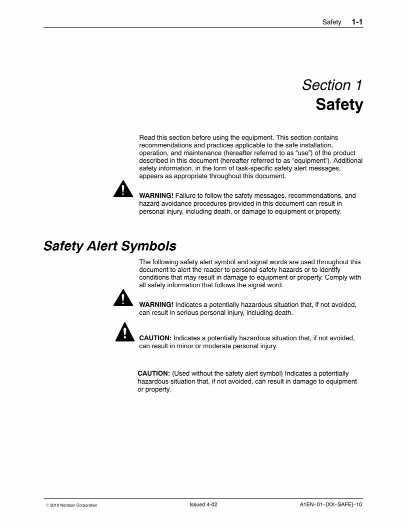
Safety Alert SymbolsThe following safety alert symbol and signal words are used throughout thisdocument to alert the reader to personal safety hazards or to identifyconditions that may result in damage to equipment or property. Comply withall safety information that follows the signal word.
WARNING! Indicates a potentially hazardous situation that, if not avoided,can result in serious personal injury, including death.
CAUTION: Indicates a potentially hazardous situation that, if not avoided,can result in minor or moderate personal injury.
CAUTION: (Used without the safety alert symbol) Indicates a potentiallyhazardous situation that, if not avoided, can result in damage to equipmentor property.

Safety1-2
A1EN−01−[XX−SAFE]−10 � 2010 Nordson CorporationIssued 4-02
Responsibilities of the Equipment Owner Equipment owners are responsible for managing safety information,ensuring that all instructions and regulatory requirements for use of theequipment are met, and for qualifying all potential users.
Safety Information � Research and evaluate safety information from all applicable sources,
including the owner-specific safety policy, best industry practices,governing regulations, material manufacturer’s product information, andthis document.
� Make safety information available to equipment users in accordancewith governing regulations. Contact the authority having jurisdiction forinformation.
� Maintain safety information, including the safety labels affixed to theequipment, in readable condition.
Instructions, Requirements, and Standards � Ensure that the equipment is used in accordance with the information
provided in this document, governing codes and regulations, and bestindustry practices.
� If applicable, receive approval from your facility’s engineering or safetydepartment, or other similar function within your organization, beforeinstalling or operating the equipment for the first time.
� Provide appropriate emergency and first aid equipment.
� Conduct safety inspections to ensure required practices are beingfollowed.
� Re-evaluate safety practices and procedures whenever changes aremade to the process or equipment.
Safety 1-3
A1EN−01−[XX−SAFE]−10� 2010 Nordson Corporation Issued 4-02
User Qualifications Equipment owners are responsible for ensuring that users:
� receive safety training appropriate to their job function as directed bygoverning regulations and best industry practices
� are familiar with the equipment owner’s safety and accidentprevention policies and procedures
� receive, equipment- and task-specific training from another qualifiedindividual
NOTE: Nordson can provide equipment-specific installation,operation, and maintenance training. Contact your Nordsonrepresentative for information
� possess industry- and trade-specific skills and a level of experienceappropriate to their job function
� are physically capable of performing their job function and are notunder the influence of any substance that degrades their mentalcapacity or physical capabilities
Applicable Industry Safety Practices The following safety practices apply to the use of the equipment in themanner described in this document. The information provided here is notmeant to include all possible safety practices, but represents the best safetypractices for equipment of similar hazard potential used in similar industries.
Intended Use of the Equipment � Use the equipment only for the purposes described and within the limits
specified in this document.
� Do not modify the equipment.
� Do not use incompatible materials or unapproved auxiliary devices.Contact your Nordson representative if you have any questions onmaterial compatibility or the use of non-standard auxiliary devices.
Instructions and Safety Messages � Read and follow the instructions provided in this document and other
referenced documents.
� Familiarize yourself with the location and meaning of the safety warninglabels and tags affixed to the equipment. Refer to Safety Labels andTags at the end of this section.
� If you are unsure of how to use the equipment, contact your Nordsonrepresentative for assistance.
Safety1-4
A1EN−01−[XX−SAFE]−10 � 2010 Nordson CorporationIssued 4-02
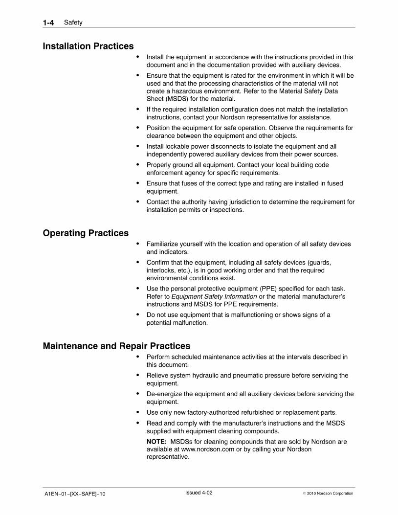
Installation Practices � Install the equipment in accordance with the instructions provided in this
document and in the documentation provided with auxiliary devices.
� Ensure that the equipment is rated for the environment in which it will beused and that the processing characteristics of the material will notcreate a hazardous environment. Refer to the Material Safety DataSheet (MSDS) for the material.
� If the required installation configuration does not match the installationinstructions, contact your Nordson representative for assistance.
� Position the equipment for safe operation. Observe the requirements forclearance between the equipment and other objects.
� Install lockable power disconnects to isolate the equipment and allindependently powered auxiliary devices from their power sources.
� Properly ground all equipment. Contact your local building codeenforcement agency for specific requirements.
� Ensure that fuses of the correct type and rating are installed in fusedequipment.
� Contact the authority having jurisdiction to determine the requirement forinstallation permits or inspections.
Operating Practices � Familiarize yourself with the location and operation of all safety devices
and indicators.
� Confirm that the equipment, including all safety devices (guards,interlocks, etc.), is in good working order and that the requiredenvironmental conditions exist.
� Use the personal protective equipment (PPE) specified for each task.Refer to Equipment Safety Information or the material manufacturer’sinstructions and MSDS for PPE requirements.
� Do not use equipment that is malfunctioning or shows signs of apotential malfunction.
Maintenance and Repair Practices � Perform scheduled maintenance activities at the intervals described in
this document.
� Relieve system hydraulic and pneumatic pressure before servicing theequipment.
� De-energize the equipment and all auxiliary devices before servicing theequipment.
� Use only new factory-authorized refurbished or replacement parts.
� Read and comply with the manufacturer’s instructions and the MSDSsupplied with equipment cleaning compounds.
NOTE: MSDSs for cleaning compounds that are sold by Nordson areavailable at www.nordson.com or by calling your Nordsonrepresentative.
Safety 1-5
A1EN−01−[XX−SAFE]−10� 2010 Nordson Corporation Issued 4-02
� Confirm the correct operation of all safety devices before placing theequipment back into operation.
� Dispose of waste cleaning compounds and residual process materialsaccording to governing regulations. Refer to the applicable MSDS orcontact the authority having jurisdiction for information.
� Keep equipment safety warning labels clean. Replace worn or damagedlabels.
Equipment Safety Information This equipment safety information is applicable to the following types ofNordson equipment:
� hot melt and cold adhesive application equipment and all relatedaccessories
� pattern controllers, timers, detection and verification systems, and allother optional process control devices
Equipment Shutdown To safely complete many of the procedures described in this document, theequipment must first be shut down. The level of shut down required variesby the type of equipment in use and the procedure being completed. If required, shut down instructions are specified at the start of theprocedure. The levels of shut down are:
Relieving System Hydraulic Pressure Completely relieve system hydraulic pressure before breaking any hydraulicconnection or seal. Refer to the melter-specific product manual forinstructions on relieving system hydraulic pressure.
Safety1-6
A1EN−01−[XX−SAFE]−10 � 2010 Nordson CorporationIssued 4-02
De-energizing the System Isolate the system (melter, hoses, guns, and optional devices) from allpower sources before accessing any unprotected high-voltage wiring orconnection point.
1. Turn off the equipment and all auxiliary devices connected to theequipment (system).
2. To prevent the equipment from being accidentally energized, lock andtag the disconnect switch(es) or circuit breaker(s) that provide inputelectrical power to the equipment and optional devices.
NOTE: Government regulations and industry standards dictate specificrequirements for the isolation of hazardous energy sources. Refer to theappropriate regulation or standard.
Disabling the Guns All electrical or mechanical devices that provide an activation signal to theguns, gun solenoid valve(s), or the melter pump must be disabled beforework can be performed on or around a gun that is connected to apressurized system.
1. Turn off or disconnect the gun triggering device (pattern controller, timer,PLC, etc.).
2. Disconnect the input signal wiring to the gun solenoid valve(s).
3. Reduce the air pressure to the gun solenoid valve(s) to zero; thenrelieve the residual air pressure between the regulator and the gun.
Safety 1-7
A1EN−01−[XX−SAFE]−10� 2010 Nordson Corporation Issued 4-02
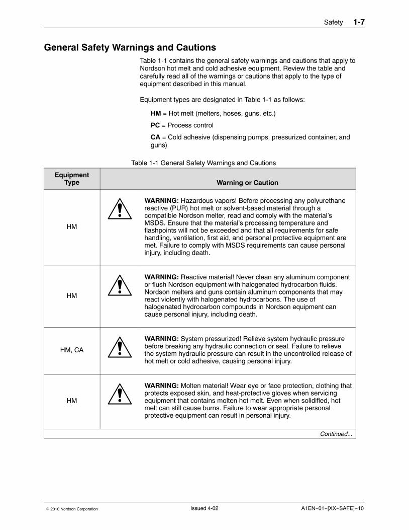
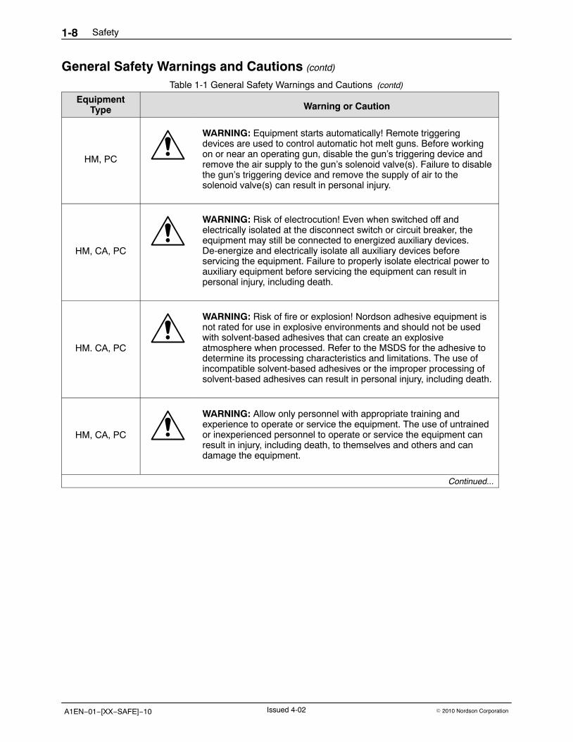
General Safety Warnings and CautionsTable 1-1 contains the general safety warnings and cautions that apply toNordson hot melt and cold adhesive equipment. Review the table andcarefully read all of the warnings or cautions that apply to the type ofequipment described in this manual.
Equipment types are designated in Table 1-1 as follows:
HM = Hot melt (melters, hoses, guns, etc.)
PC = Process control
CA = Cold adhesive (dispensing pumps, pressurized container, andguns)
Table 1-1 General Safety Warnings and Cautions
EquipmentType Warning or Caution
HM
WARNING: Hazardous vapors! Before processing any polyurethanereactive (PUR) hot melt or solvent-based material through acompatible Nordson melter, read and comply with the material’sMSDS. Ensure that the material’s processing temperature andflashpoints will not be exceeded and that all requirements for safehandling, ventilation, first aid, and personal protective equipment aremet. Failure to comply with MSDS requirements can cause personalinjury, including death.
HM
WARNING: Reactive material! Never clean any aluminum componentor flush Nordson equipment with halogenated hydrocarbon fluids.Nordson melters and guns contain aluminum components that mayreact violently with halogenated hydrocarbons. The use ofhalogenated hydrocarbon compounds in Nordson equipment cancause personal injury, including death.
HM, CA
WARNING: System pressurized! Relieve system hydraulic pressurebefore breaking any hydraulic connection or seal. Failure to relievethe system hydraulic pressure can result in the uncontrolled release ofhot melt or cold adhesive, causing personal injury.
HM
WARNING: Molten material! Wear eye or face protection, clothing thatprotects exposed skin, and heat-protective gloves when servicingequipment that contains molten hot melt. Even when solidified, hotmelt can still cause burns. Failure to wear appropriate personalprotective equipment can result in personal injury.
Continued...
Safety1-8
A1EN−01−[XX−SAFE]−10 � 2010 Nordson CorporationIssued 4-02
General Safety Warnings and Cautions (contd)
Table 1-1 General Safety Warnings and Cautions (contd)
EquipmentType Warning or Caution
HM, PC
WARNING: Equipment starts automatically! Remote triggeringdevices are used to control automatic hot melt guns. Before workingon or near an operating gun, disable the gun’s triggering device andremove the air supply to the gun’s solenoid valve(s). Failure to disablethe gun’s triggering device and remove the supply of air to thesolenoid valve(s) can result in personal injury.
HM, CA, PC
WARNING: Risk of electrocution! Even when switched off andelectrically isolated at the disconnect switch or circuit breaker, theequipment may still be connected to energized auxiliary devices.De-energize and electrically isolate all auxiliary devices beforeservicing the equipment. Failure to properly isolate electrical power toauxiliary equipment before servicing the equipment can result inpersonal injury, including death.
HM. CA, PC
WARNING: Risk of fire or explosion! Nordson adhesive equipment isnot rated for use in explosive environments and should not be usedwith solvent-based adhesives that can create an explosiveatmosphere when processed. Refer to the MSDS for the adhesive todetermine its processing characteristics and limitations. The use ofincompatible solvent-based adhesives or the improper processing ofsolvent-based adhesives can result in personal injury, including death.
HM, CA, PC
WARNING: Allow only personnel with appropriate training andexperience to operate or service the equipment. The use of untrainedor inexperienced personnel to operate or service the equipment canresult in injury, including death, to themselves and others and candamage the equipment.
Continued...
Safety 1-9
A1EN−01−[XX−SAFE]−10� 2010 Nordson Corporation Issued 4-02
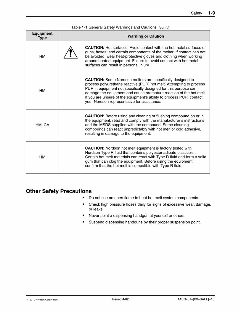
Table 1-1 General Safety Warnings and Cautions (contd)
EquipmentType Warning or Caution
HM
CAUTION: Hot surfaces! Avoid contact with the hot metal surfaces ofguns, hoses, and certain components of the melter. If contact can notbe avoided, wear heat-protective gloves and clothing when workingaround heated equipment. Failure to avoid contact with hot metalsurfaces can result in personal injury.
HM
CAUTION: Some Nordson melters are specifically designed toprocess polyurethane reactive (PUR) hot melt. Attempting to processPUR in equipment not specifically designed for this purpose candamage the equipment and cause premature reaction of the hot melt.If you are unsure of the equipment’s ability to process PUR, contactyour Nordson representative for assistance.
HM, CA
CAUTION: Before using any cleaning or flushing compound on or inthe equipment, read and comply with the manufacturer’s instructionsand the MSDS supplied with the compound. Some cleaningcompounds can react unpredictably with hot melt or cold adhesive,resulting in damage to the equipment.
HM
CAUTION: Nordson hot melt equipment is factory tested withNordson Type R fluid that contains polyester adipate plasticizer.Certain hot melt materials can react with Type R fluid and form a solidgum that can clog the equipment. Before using the equipment,confirm that the hot melt is compatible with Type R fluid.
Other Safety Precautions � Do not use an open flame to heat hot melt system components.
� Check high pressure hoses daily for signs of excessive wear, damage,or leaks.
� Never point a dispensing handgun at yourself or others.
� Suspend dispensing handguns by their proper suspension point.
Safety1-10
A1EN−01−[XX−SAFE]−10 � 2010 Nordson CorporationIssued 4-02
First Aid If molten hot melt comes in contact with your skin:
1. Do NOT attempt to remove the molten hot melt from your skin.
2. Immediately soak the affected area in clean, cold water until the hot melta has cooled.
3. Do NOT attempt to remove the solidified hot melt from your skin.
4. In case of severe burns, treat for shock.
5. Seek expert medical attention immediately. Give the MSDS for the hotmelt to the medical personnel providing treatment.
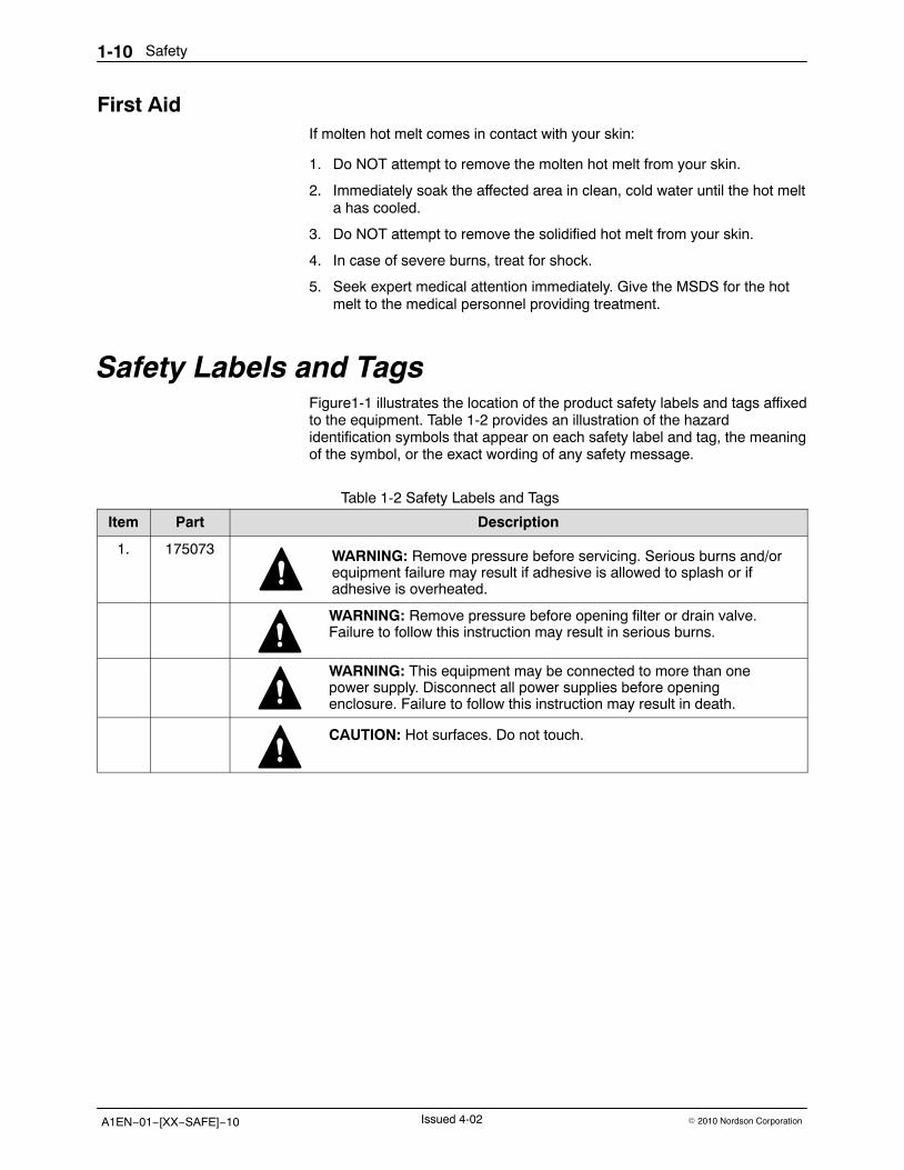
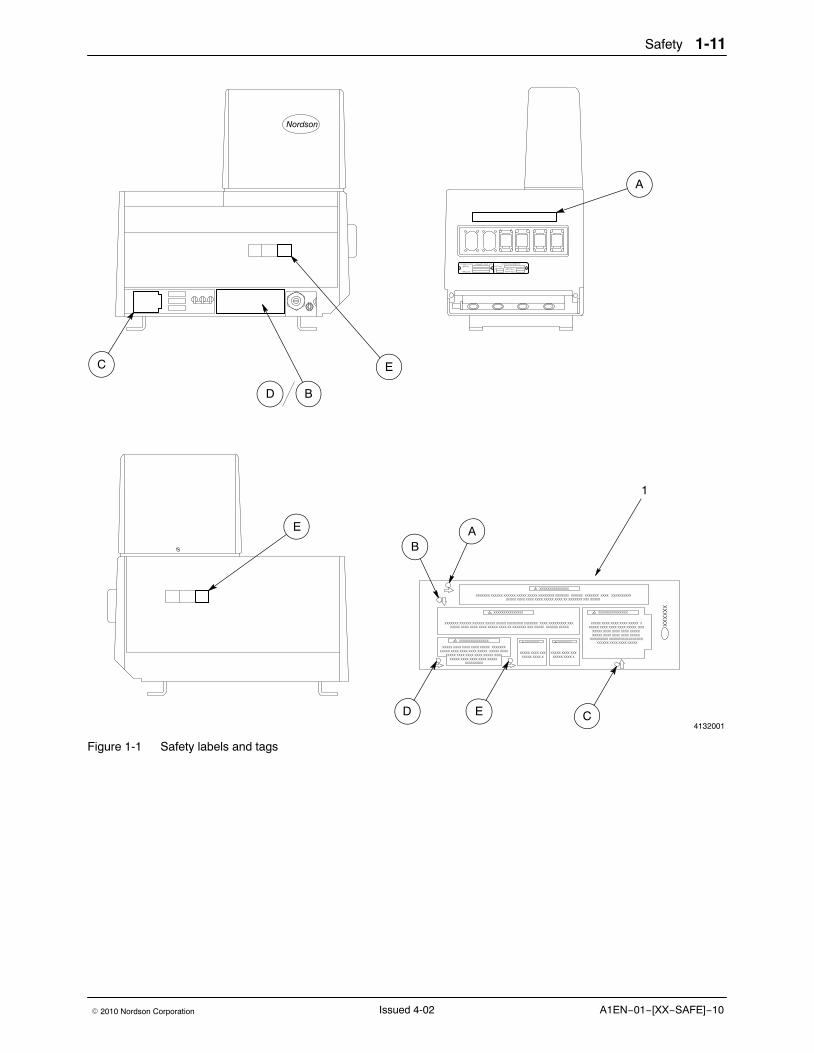
Safety Labels and Tags Figure1-1 illustrates the location of the product safety labels and tags affixedto the equipment. Table 1-2 provides an illustration of the hazardidentification symbols that appear on each safety label and tag, the meaningof the symbol, or the exact wording of any safety message.
Table 1-2 Safety Labels and Tags
Item Part Description
1. 175073 WARNING: Remove pressure before servicing. Serious burns and/orequipment failure may result if adhesive is allowed to splash or ifadhesive is overheated.
WARNING: Remove pressure before opening filter or drain valve.Failure to follow this instruction may result in serious burns.
WARNING: This equipment may be connected to more than onepower supply. Disconnect all power supplies before openingenclosure. Failure to follow this instruction may result in death.
CAUTION: Hot surfaces. Do not touch.
Safety 1-11
A1EN−01−[XX−SAFE]−10� 2010 Nordson Corporation Issued 4-02
4132001
E
B
C
A
E
D
A
D
B
E C
1
Figure 1-1 Safety labels and tags
Safety1-12
A1EN−01−[XX−SAFE]−10 � 2010 Nordson CorporationIssued 4-02
Description 2-1
Part 1052743D03� 2010 Nordson Corporation
Section 2Description
Intended Use Bravura melters may be used only to melt and pump hot melt material. Theyare not intended for use with polyurethane-reactive hot melt material. Usethe melters only as described in this manual.
Overview This manual describes how to install, operate, and service a Bravura melter.It also explains how the melter works with other major components of a hotmelt system.
This section of the manual describes the key parts of the melter and howthey work. It includes the following topics:
� Functional Description� Major Components� Control System
Description2-2
Part 1052743D03 � 2010 Nordson Corporation
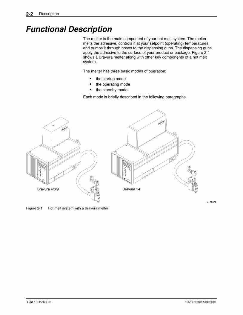
Functional Description The melter is the main component of your hot melt system. The meltermelts the adhesive, controls it at your setpoint (operating) temperatures,and pumps it through hoses to the dispensing guns. The dispensing gunsapply the adhesive to the surface of your product or package. Figure 2-1shows a Bravura melter along with other key components of a hot meltsystem.
The melter has three basic modes of operation:
� the startup mode� the operating mode� the standby mode
Each mode is briefly described in the following paragraphs.
4132002
Bravura 4/6/9 Bravura 14
Figure 2-1 Hot melt system with a Bravura melter
Description 2-3
Part 1052743D03� 2010 Nordson Corporation
Startup Mode During a sequential startup, when the clock timer or an operator turns thesystem on, the tank and hoses begin to heat first. After the temperatures ofthe tank and hoses are all within 19.5 �C (35 �F) of their setpointtemperatures, the guns begin to heat. When the tank, hoses, and guns arewithin 3 �C (5 �F) of their setpoint temperatures, a time delay begins. Thetime delay, which you can adjust, provides additional time for the material inthe tank to melt. At the end of the time delay, the green Ready light turns on,indicating that the system is ready for operation. You can program thesystem so the pump starts automatically, either when the Ready light turnson or when the tank reaches the temperature you have specified. Or youcan program the system so the pump must be started manually.
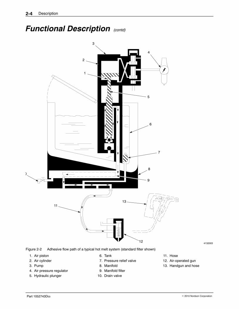
Operating Mode When you trigger a gun, the pump draws in the melted adhesive and sendsit through a manifold, a filter, and a hose to the gun, which then applies theadhesive to the product or package surface. Figure 2-2 shows thecomponents of a typical hot melt system and the path that melted adhesivefollows when being pumped through the system. In most systems, anair-operated automatic gun is used to apply the melted adhesive. Anelectrically driven gun or a handgun (shown in dotted lines in Figure 2-2)may also be used to apply adhesive.
Standby Mode When you place the melter in the standby mode, the control systemdisables the pump and reduces the temperature of all heating zones to thestandby temperature setpoints you have selected. You can use the standbymode to keep the adhesive warm when normal operation must beinterrupted for a while. The lower temperature reduces char formation andconserves energy.
Description2-4
Part 1052743D03 � 2010 Nordson Corporation
Functional Description (contd)
4132003
ÇÇÇÇÇÇ
2
ÇÇÇÇÇÇÇÇÇÇÇÇÇÇÇÇÇÇÇÇÇÇÇÇÇÇÇÇÇÇÇÇÇÇÇÇÇÇÇÇÇÇÇÇ
3
4
5
6
7
8
9
1113
12
0
1
Figure 2-2 Adhesive flow path of a typical hot melt system (standard filter shown)
1. Air piston2. Air cylinder3. Pump4. Air pressure regulator5. Hydraulic plunger
6. Tank7. Pressure relief valve8. Manifold9. Manifold filter
10. Drain valve
11. Hose12. Air-operated gun13. Handgun and hose
Description 2-5
Part 1052743D03� 2010 Nordson Corporation
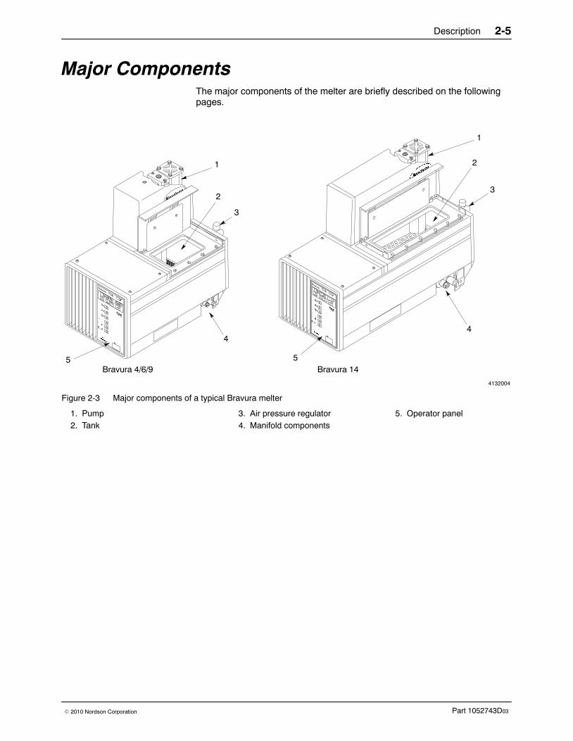
Major Components The major components of the melter are briefly described on the followingpages.
4132004
1
2
3
5
44
1
2
3
5Bravura 4/6/9 Bravura 14
Figure 2-3 Major components of a typical Bravura melter
1. Pump2. Tank
3. Air pressure regulator4. Manifold components
5. Operator panel
Description2-6
Part 1052743D03 � 2010 Nordson Corporation
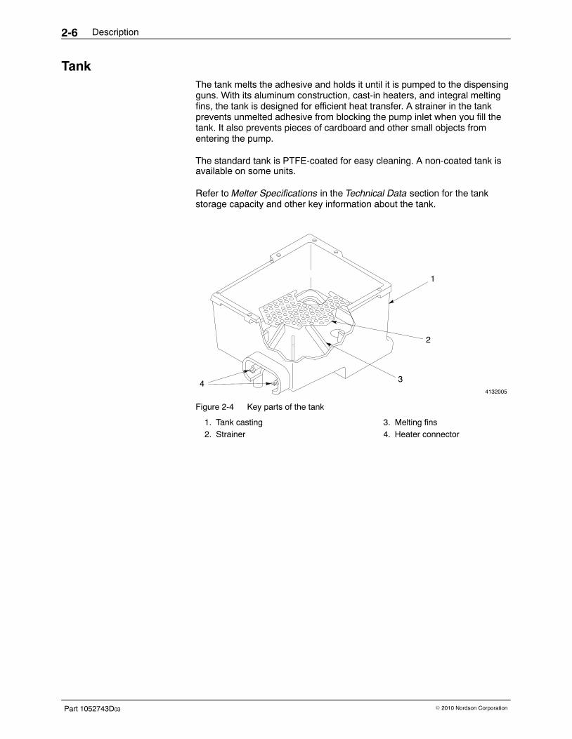
Tank The tank melts the adhesive and holds it until it is pumped to the dispensingguns. With its aluminum construction, cast-in heaters, and integral meltingfins, the tank is designed for efficient heat transfer. A strainer in the tankprevents unmelted adhesive from blocking the pump inlet when you fill thetank. It also prevents pieces of cardboard and other small objects fromentering the pump.
The standard tank is PTFE-coated for easy cleaning. A non-coated tank is available on some units.
Refer to Melter Specifications in the Technical Data section for the tankstorage capacity and other key information about the tank.
4132005
1
2
34
Figure 2-4 Key parts of the tank
1. Tank casting2. Strainer
3. Melting fins4. Heater connector
Description 2-7
Part 1052743D03� 2010 Nordson Corporation
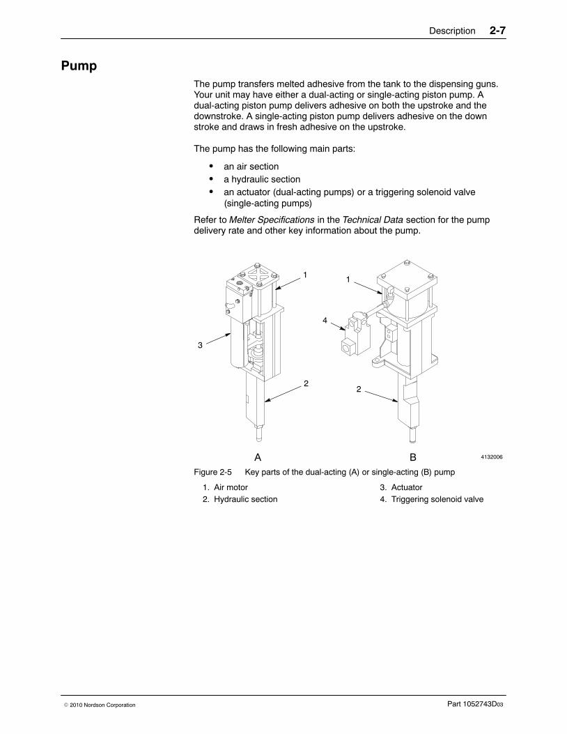
Pump The pump transfers melted adhesive from the tank to the dispensing guns.Your unit may have either a dual-acting or single-acting piston pump. Adual-acting piston pump delivers adhesive on both the upstroke and thedownstroke. A single-acting piston pump delivers adhesive on the downstroke and draws in fresh adhesive on the upstroke.
The pump has the following main parts:
� an air section� a hydraulic section� an actuator (dual-acting pumps) or a triggering solenoid valve
(single-acting pumps)
Refer to Melter Specifications in the Technical Data section for the pumpdelivery rate and other key information about the pump.
4132006
1
2
3
1
2
4
A BFigure 2-5 Key parts of the dual-acting (A) or single-acting (B) pump
1. Air motor2. Hydraulic section
3. Actuator4. Triggering solenoid valve
Description2-8
Part 1052743D03 � 2010 Nordson Corporation
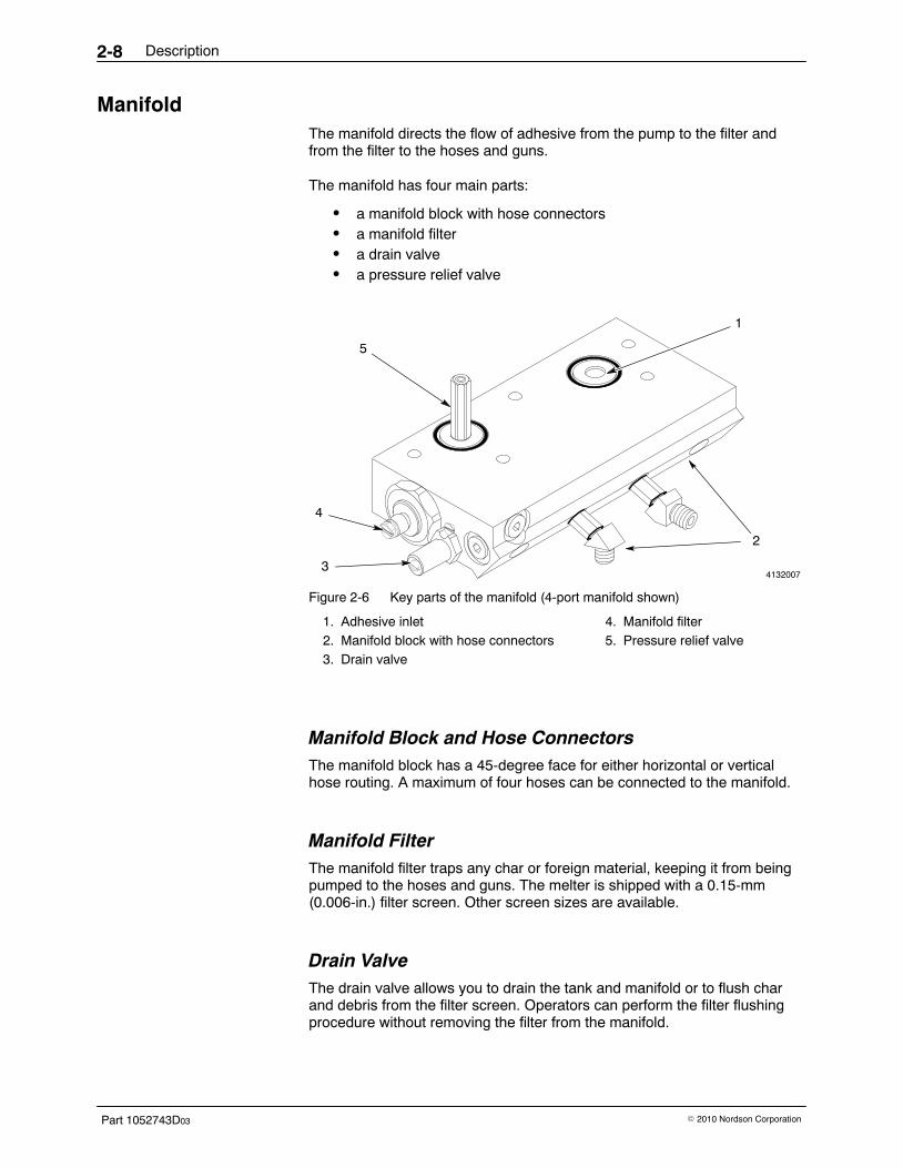
Manifold The manifold directs the flow of adhesive from the pump to the filter andfrom the filter to the hoses and guns.
The manifold has four main parts:
� a manifold block with hose connectors� a manifold filter� a drain valve� a pressure relief valve
4132007
5
1
4
3
2
Figure 2-6 Key parts of the manifold (4-port manifold shown)
1. Adhesive inlet2. Manifold block with hose connectors3. Drain valve
4. Manifold filter5. Pressure relief valve
Manifold Block and Hose Connectors The manifold block has a 45-degree face for either horizontal or verticalhose routing. A maximum of four hoses can be connected to the manifold.
Manifold Filter The manifold filter traps any char or foreign material, keeping it from beingpumped to the hoses and guns. The melter is shipped with a 0.15-mm(0.006-in.) filter screen. Other screen sizes are available.
Drain Valve The drain valve allows you to drain the tank and manifold or to flush charand debris from the filter screen. Operators can perform the filter flushingprocedure without removing the filter from the manifold.

Description 2-9
Part 1052743D03� 2010 Nordson Corporation
Pressure Relief Valve The pressure relief valve prevents system hydraulic pressure fromexceeding 103.4 bar (10342 kPa, 1500 psi). At this pressure, the valveopens and returns adhesive to the tank.
Air Pressure Regulator The air pressure regulator allows you to adjust the system air pressure,which controls the hydraulic pressure.
The regulator assembly has three main parts:
� a regulator� a filter� a gauge
The gauge indicates the air pressure and the filter removes contaminantsfrom the plant air supply.
4132008
1
23
Figure 2-7 Key parts of the air pressure regulator
1. Regulator2. Filter
3. Air pressure gauge
Operator Panel The operator panel provides the controls and indicators you need toprogram, operate, and monitor your hot melt system. The key functions ofthe operator panel are described in the next part of this section, ControlSystem.
Description2-10
Part 1052743D03 � 2010 Nordson Corporation
Control System The control system regulates all temperature settings and controls how theunit functions. Heated zones are controlled individually, giving you moreflexibility in setting up your system, and the clock feature allows you to tailorthe unit’s on/off and enter standby/exit standby times to your operationalneeds. The control system is designed so that a brownout or power failurewill not cause a loss of your programmed settings.
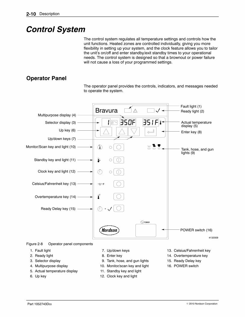
Operator Panel The operator panel provides the controls, indicators, and messages neededto operate the system.
4132009
Ready light (2)Multipurpose display (4)
Up/down keys (7)
Fault light (1)
Actual temperaturedisplay (5)
Tank, hose, and gunlights (9)
POWER switch (16)
Monitor/Scan key and light (10)
Standby key and light (11)
Clock key and light (12)
Celsius/Fahrenheit key (13)
Overtemperature key (14)
Ready Delay key (15)
Up key (6)
Selector display (3)
Enter key (8)
Figure 2-8 Operator panel components
1. Fault light2. Ready light3. Selector display4. Multipurpose display5. Actual temperature display6. Up key
7. Up/down keys8. Enter key9. Tank, hose, and gun lights
10. Monitor/scan key and light11. Standby key and light12. Clock key and light
13. Celsius/Fahrenheit key14. Overtemperature key15. Ready Delay key16. POWER switch
Description 2-11
Part 1052743D03� 2010 Nordson Corporation
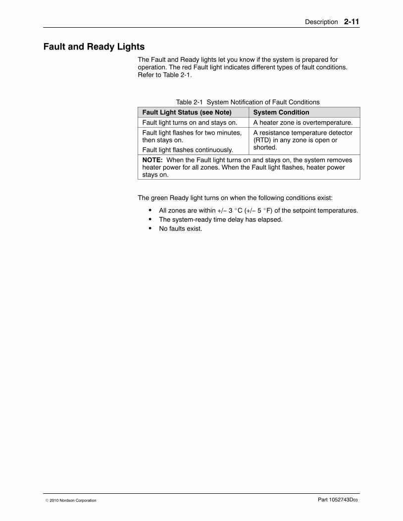
Fault and Ready Lights The Fault and Ready lights let you know if the system is prepared foroperation. The red Fault light indicates different types of fault conditions.Refer to Table 2-1.
Table 2-1 System Notification of Fault Conditions
Fault Light Status (see Note) System Condition
Fault light turns on and stays on. A heater zone is overtemperature.
Fault light flashes for two minutes,then stays on.
Fault light flashes continuously.
A resistance temperature detector(RTD) in any zone is open orshorted.
NOTE: When the Fault light turns on and stays on, the system removesheater power for all zones. When the Fault light flashes, heater powerstays on.
The green Ready light turns on when the following conditions exist:
� All zones are within +/− 3 �C (+/− 5 �F) of the setpoint temperatures.� The system-ready time delay has elapsed.� No faults exist.
Description2-12
Part 1052743D03 � 2010 Nordson Corporation
Displays and Keys The Selector, Multipurpose, and Actual Temperature displays give youdetailed information about the status of your system. When you are runningthe system, they show the status of each heating zone. When you arecustomizing the system, they show your current system setup. The keysbelow the displays are used to program the system.
Selector Display and Up Key The Selector display allows you to access information about the status ofyour system during operation and system setup. The display
� shows the selected zone number when programming temperaturesetpoints and when scanning zones
� shows a code for entering times for automatic settings when usedwith Clock
The up key, which is located below the Selector display, changes the valueof a setting in the Selector display when you are programming the unit.
Multipurpose Display and Up/Down Keys During normal operation, the Multipurpose display shows the setpointtemperature for a selected zone. This allows you to compare the actualtemperature of the displayed zone with its targeted temperature.
The up/down keys, which are located below the Multipurpose display,changes the value of a setting in the Multipurpose display when you areprogramming the unit.
Actual Temperature Display The Actual Temperature display shows the actual temperature of the heatedzone. When the scan mode is enabled, each zone is displayed in sequence.When the scan mode is disabled, only the temperature for the selectedzone is displayed.
Enter Key The Enter key saves the number shown in the Multipurpose display.
Tank, Hose, and Gun Lights These lights are used in conjunction with the Selector and Multipurposedisplays to indicate the current selected heating zone. There are three typesof heating zone: tank, hose, and gun.
Description 2-13
Part 1052743D03� 2010 Nordson Corporation
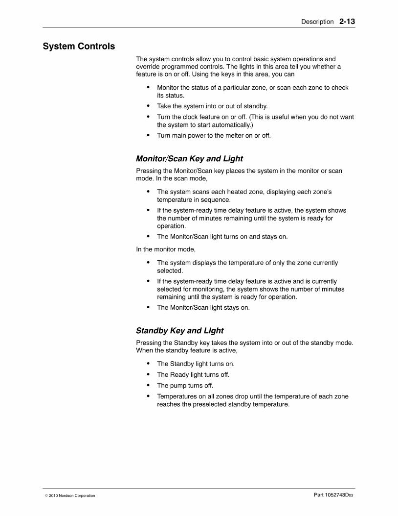
System Controls The system controls allow you to control basic system operations andoverride programmed controls. The lights in this area tell you whether afeature is on or off. Using the keys in this area, you can
� Monitor the status of a particular zone, or scan each zone to checkits status.
� Take the system into or out of standby.
� Turn the clock feature on or off. (This is useful when you do not wantthe system to start automatically.)
� Turn main power to the melter on or off.
Monitor/Scan Key and Light Pressing the Monitor/Scan key places the system in the monitor or scanmode. In the scan mode,
� The system scans each heated zone, displaying each zone’stemperature in sequence.
� If the system-ready time delay feature is active, the system showsthe number of minutes remaining until the system is ready foroperation.
� The Monitor/Scan light turns on and stays on.
In the monitor mode,
� The system displays the temperature of only the zone currentlyselected.
� If the system-ready time delay feature is active and is currentlyselected for monitoring, the system shows the number of minutesremaining until the system is ready for operation.
� The Monitor/Scan light stays on.
Standby Key and LIght Pressing the Standby key takes the system into or out of the standby mode.When the standby feature is active,
� The Standby light turns on.
� The Ready light turns off.
� The pump turns off.
� Temperatures on all zones drop until the temperature of each zonereaches the preselected standby temperature.
Description2-14
Part 1052743D03 � 2010 Nordson Corporation
Standby Key and LIght (contd)
When the standby feature is disabled,
� The Standby light turns off.
� The heaters turn on and all zones begin heating.
� The pump turns on either when the system reaches the readycondition or when the tank reaches the temperature you havespecified.
� After all zones have reached their preselected setpoint temperature,the Ready light turns on.
Clock Key and Light Pressing the Clock key turns the clock on and off. When the clock is on, thesystem is controlled by any clock settings (unit on/off or enter standby/exitstandby) you have entered.
The Clock light turns on when this feature is active.
NOTE: If the clock feature is enabled when the POWER switch is turnedoff, it will automatically be enabled when the switch is turned back on. TheClock light will turn on to show that the clock feature is enabled.
Celsius/Fahrenheit Key Pressing the Celsius/Fahrenheit key toggles the display of setpoint andactual temperatures between degrees Celsius and degrees Fahrenheit.
Overtemperature Key Pressing the Overtemperature key allows you to set a globalovertemperature setpoint. When this setpoint is reached:
� The pump stops� The heaters turn off
Ready Delay Key Pressing the Ready Delay key allows you to specify the amount ofadditional time needed for the adhesive to melt after all zones have reachedtheir setpoint temperatures. At the end of the ready delay, the Ready lightturns on.
POWER Switch Pressing the POWER switch turns power to the melter on or off.
Installation 3-1
Part 1052743D03� 2010 Nordson Corporation
Section 3Installation
WARNING! Allow only personnel with appropriate training and experienceto operate or service the equipment. The use of untrained or inexperiencedpersonnel to operate or service the equipment can result in injury, includingdeath, to themselves and others, and damage to the equipment.
Introduction This section of the manual describes how to
� install the melter, hoses, and guns� program system settings� prepare the melter for operation
If you have purchased optional features with your unit, such as a low-levelindicator, refer to the documentation supplied with the equipment forinstallation instructions.
Unpacking Besides using normal care, you need no special instructions to unpack theunit or the equipment you purchased with it. All hoses and guns are shippedin separate packages.
Inspection After unpacking the equipment, inspect it for any damage that may haveoccurred during shipping. Look for dents and scratches and make sure allfasteners are tight. Report any damage to your Nordson representative.
Installation3-2
Part 1052743D03 � 2010 Nordson Corporation
Installation Requirements This part of the installation section gives you the installation requirementsand recommendations that you need to know before installing your unit. Itincludes
� Location Requirements� Wiring Requirements� Hose/Gun Power Requirements
Other requirements and recommendations are provided in the installationprocedures when they are needed.
Location Requirements Carefully select the location for the unit and its associated guns and hoses.Make sure that the location meets the following requirements:
� There is enough room to open the tank lid, open the electricalenclosure, remove the filter assembly, remove the pump enclosure,and make electrical connections for the hoses. For unit dimensionsand recommended clearances, refer to Melter Dimensions in theTechnical Data section of this manual.
� An operator can reach all controls.
� Maintenance personnel have room to service and repair the unit.
� Installers can route the hoses without bending them. The minimumbend radius for hoses is shown in Figure 3-7.
� The mounting surface can support the weight of the unit when theunit is filled with adhesive. Refer to Melter Specifications in theTechnical Data section of this manual.
� The mounting surface is level.
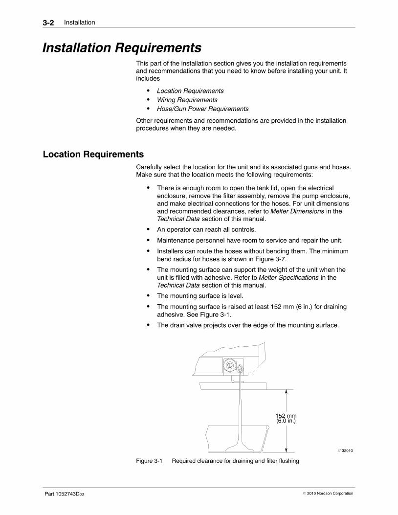
� The mounting surface is raised at least 152 mm (6 in.) for drainingadhesive. See Figure 3-1.
� The drain valve projects over the edge of the mounting surface.
4132010
152 mm(6.0 in.)
Figure 3-1 Required clearance for draining and filter flushing

Installation 3-3
Part 1052743D03� 2010 Nordson Corporation
Wiring Requirements Follow these guidelines when installing wiring to the unit:
� Allow enough room to route your electrical service line to the unit.You can use either of the two access holes in the base of the unit forelectrical service. One hole is for rear access and the other is forbottom access.
� Route any wires away from AC power lines, solenoid output lines,and electrical equipment such as motors, contacts, and relays.
� Make connections with the minimum length of wire needed. A longwire can act as an antenna for electrical noise.
Hose/Gun Power Requirements The power requirements of your hoses and guns must be determined tomake sure that you do not overload the unit. If your Nordson representativehas not already checked to see that your unit can support all of the hosesand guns you plan to install, you need to calculate your hose/gun powerrequirements now. You also need to check your calculations if you changeyour system configuration or add new hoses and guns.
To determine your hose/gun power requirements, refer to CalculatingHose/Gun Capacity in the Technical Data section of this manual. If you needhelp with this procedure, contact your Nordson representative.
Mechanical Installation This part of the installation section gives you the procedures for installingthe unit mechanically. It includes
� Mount the Melter� Install the Tank Strainer� Connect the Air Supply� Install the Guns� Install the Hoses
On some units, you will not be required to complete all of these procedures.For electrical installation procedures, refer to Electrical Installation later inthis section.
Installation3-4
Part 1052743D03 � 2010 Nordson Corporation
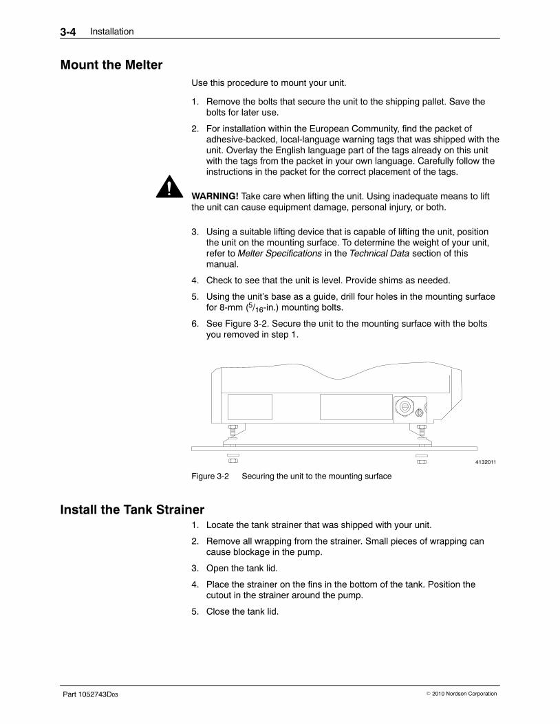
Mount the Melter Use this procedure to mount your unit.
1. Remove the bolts that secure the unit to the shipping pallet. Save thebolts for later use.
2. For installation within the European Community, find the packet ofadhesive-backed, local-language warning tags that was shipped with theunit. Overlay the English language part of the tags already on this unitwith the tags from the packet in your own language. Carefully follow theinstructions in the packet for the correct placement of the tags.
WARNING! Take care when lifting the unit. Using inadequate means to liftthe unit can cause equipment damage, personal injury, or both.
3. Using a suitable lifting device that is capable of lifting the unit, positionthe unit on the mounting surface. To determine the weight of your unit,refer to Melter Specifications in the Technical Data section of thismanual.
4. Check to see that the unit is level. Provide shims as needed.
5. Using the unit’s base as a guide, drill four holes in the mounting surfacefor 8-mm (5/16-in.) mounting bolts.
6. See Figure 3-2. Secure the unit to the mounting surface with the boltsyou removed in step 1.
4132011
Figure 3-2 Securing the unit to the mounting surface
Install the Tank Strainer 1. Locate the tank strainer that was shipped with your unit.
2. Remove all wrapping from the strainer. Small pieces of wrapping cancause blockage in the pump.
3. Open the tank lid.
4. Place the strainer on the fins in the bottom of the tank. Position thecutout in the strainer around the pump.
5. Close the tank lid.
Installation 3-5
Part 1052743D03� 2010 Nordson Corporation
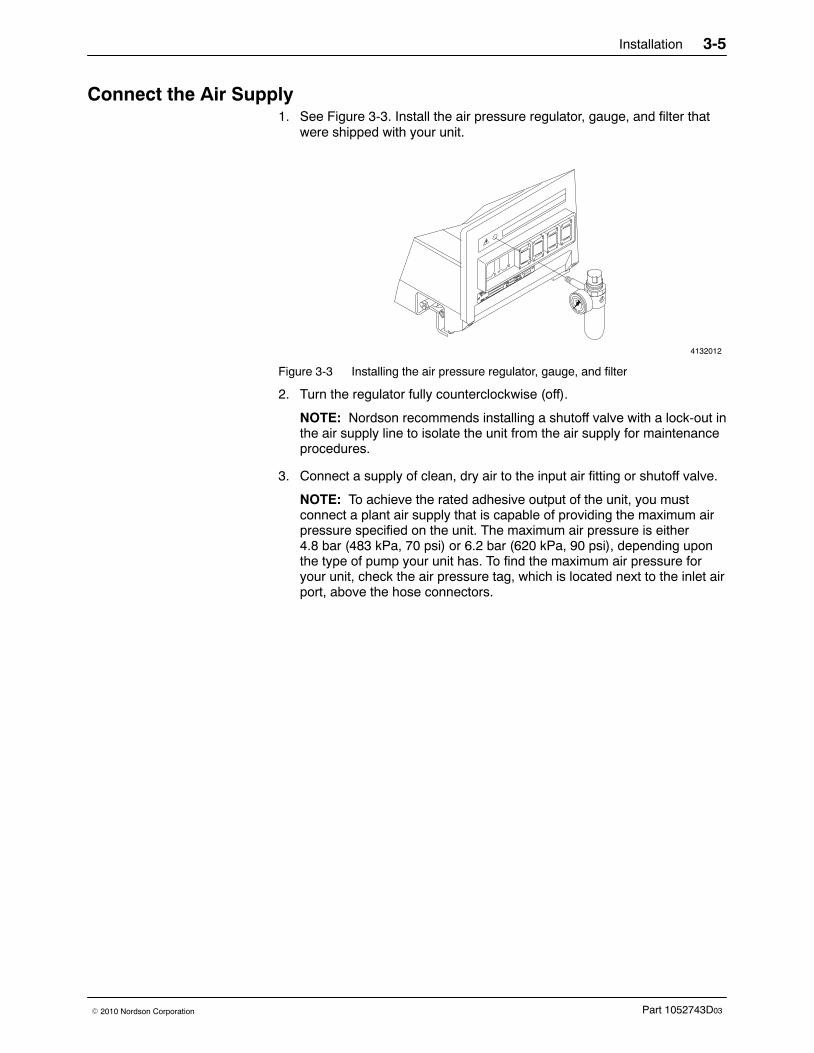
Connect the Air Supply 1. See Figure 3-3. Install the air pressure regulator, gauge, and filter that
were shipped with your unit.
4132012
Figure 3-3 Installing the air pressure regulator, gauge, and filter
2. Turn the regulator fully counterclockwise (off).
NOTE: Nordson recommends installing a shutoff valve with a lock-out inthe air supply line to isolate the unit from the air supply for maintenanceprocedures.
3. Connect a supply of clean, dry air to the input air fitting or shutoff valve.
NOTE: To achieve the rated adhesive output of the unit, you mustconnect a plant air supply that is capable of providing the maximum airpressure specified on the unit. The maximum air pressure is either4.8 bar (483 kPa, 70 psi) or 6.2 bar (620 kPa, 90 psi), depending uponthe type of pump your unit has. To find the maximum air pressure foryour unit, check the air pressure tag, which is located next to the inlet airport, above the hose connectors.
Installation3-6
Part 1052743D03 � 2010 Nordson Corporation
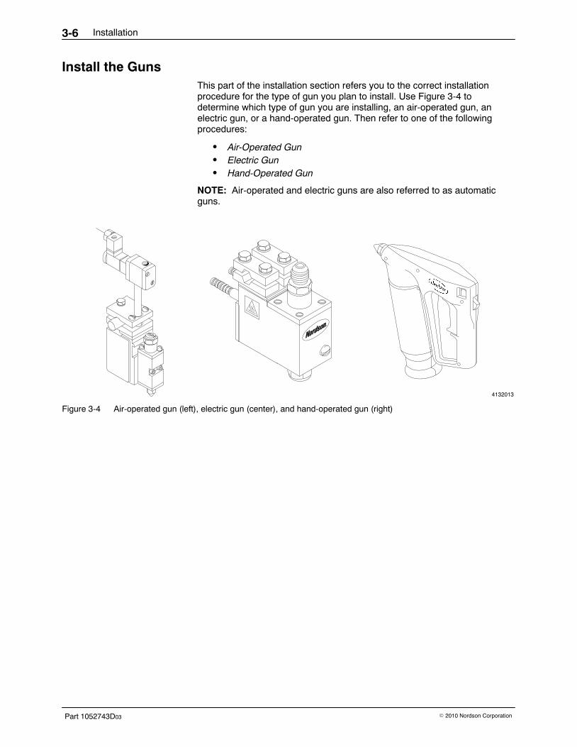
Install the Guns This part of the installation section refers you to the correct installationprocedure for the type of gun you plan to install. Use Figure 3-4 todetermine which type of gun you are installing, an air-operated gun, anelectric gun, or a hand-operated gun. Then refer to one of the followingprocedures:
� Air-Operated Gun� Electric Gun� Hand-Operated Gun
NOTE: Air-operated and electric guns are also referred to as automaticguns.
4132013
Figure 3-4 Air-operated gun (left), electric gun (center), and hand-operated gun (right)
Installation 3-7
Part 1052743D03� 2010 Nordson Corporation
Air-Operated Gun Follow the instructions in the manual shipped with the gun to completethese procedures:
� Mount the gun on the production line.� Install the gun solenoid valve.� Connect air to the solenoid valve.� Connect a triggering device to the solenoid valve.� Connect a hose to the gun.
Instructions for connecting the hose and gun cordsets are given later in thissection. Refer to Connect Gun and Hose Cordsets.
Electric Gun Follow the instructions in the manual shipped with the gun to complete thefollowing procedures:
� Mount the gun on the production line.� Install the gun driver.� Connect power to the driver.� Connect a triggering device to the driver.� Connect a hose to the gun.
Instructions for connecting the hose and gun cordsets are given later in thissection. Refer to Connect Gun and Hose Cordsets.
Hand-Operated Gun Follow the instructions in the manual shipped with the gun to connect thehose to the hand-operated gun. One end of the hose is wired to the gun; theother end connects to the unit. Instructions for connecting the hose and guncordsets are given later in this section. Refer to Connect Gun and HoseCordsets.
Installation3-8
Part 1052743D03 � 2010 Nordson Corporation
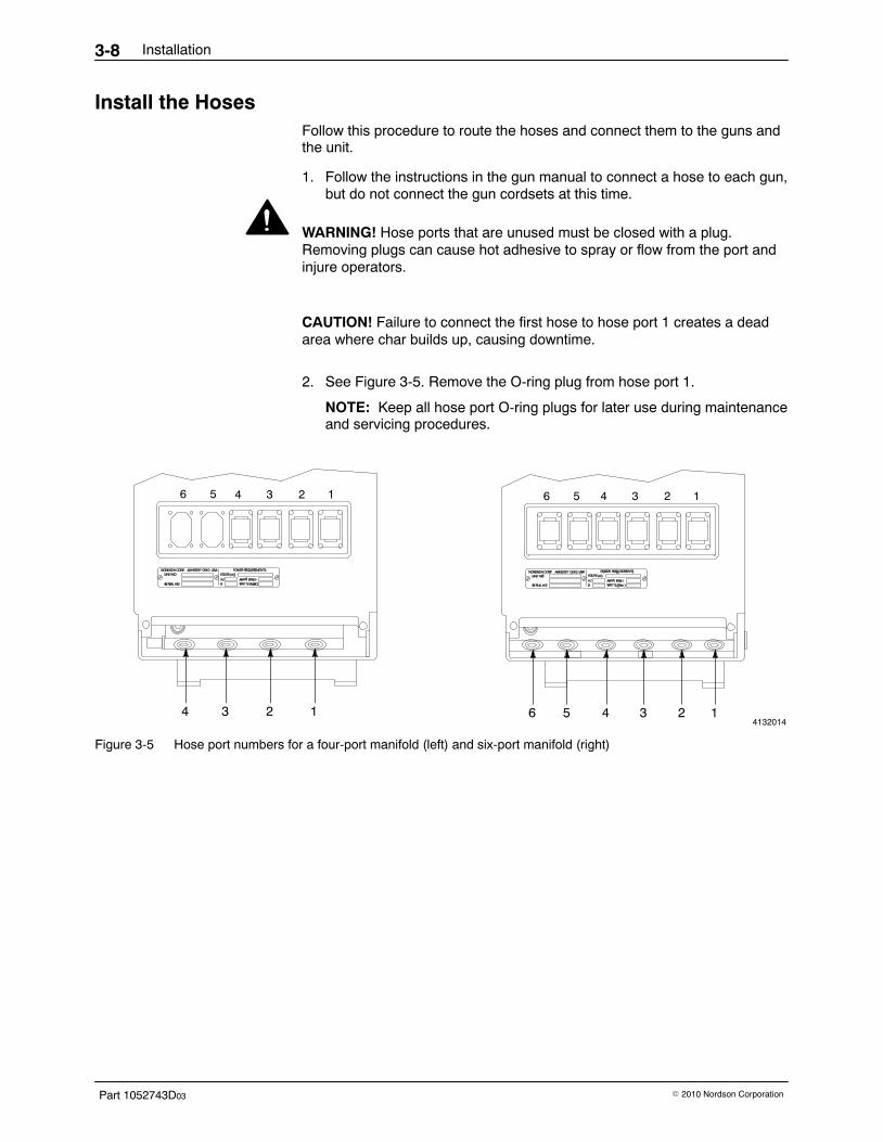
Install the Hoses Follow this procedure to route the hoses and connect them to the guns andthe unit.
1. Follow the instructions in the gun manual to connect a hose to each gun,but do not connect the gun cordsets at this time.
WARNING! Hose ports that are unused must be closed with a plug.Removing plugs can cause hot adhesive to spray or flow from the port andinjure operators.
CAUTION! Failure to connect the first hose to hose port 1 creates a deadarea where char builds up, causing downtime.
2. See Figure 3-5. Remove the O-ring plug from hose port 1.
NOTE: Keep all hose port O-ring plugs for later use during maintenanceand servicing procedures.
4132014
6 5 4 3 2 14 3 2 1
6 5 4 3 24 3 2 1
6 5
1
Figure 3-5 Hose port numbers for a four-port manifold (left) and six-port manifold (right)
Installation 3-9
Part 1052743D03� 2010 Nordson Corporation
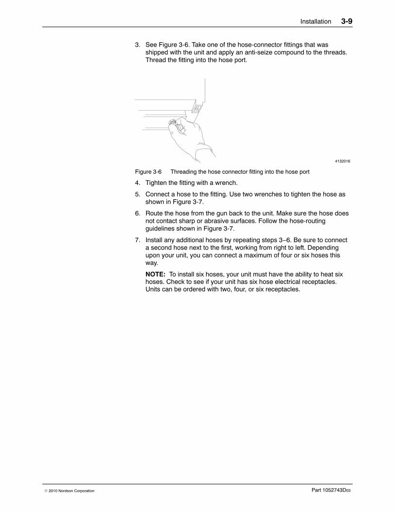
3. See Figure 3-6. Take one of the hose-connector fittings that wasshipped with the unit and apply an anti-seize compound to the threads.Thread the fitting into the hose port.
4132016
Figure 3-6 Threading the hose connector fitting into the hose port
4. Tighten the fitting with a wrench.
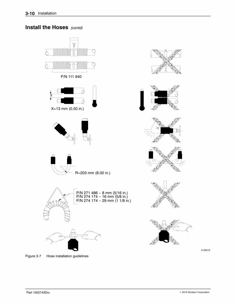
5. Connect a hose to the fitting. Use two wrenches to tighten the hose asshown in Figure 3-7.
6. Route the hose from the gun back to the unit. Make sure the hose doesnot contact sharp or abrasive surfaces. Follow the hose-routingguidelines shown in Figure 3-7.
7. Install any additional hoses by repeating steps 3−6. Be sure to connecta second hose next to the first, working from right to left. Dependingupon your unit, you can connect a maximum of four or six hoses thisway.
NOTE: To install six hoses, your unit must have the ability to heat sixhoses. Check to see if your unit has six hose electrical receptacles.Units can be ordered with two, four, or six receptacles.
Installation3-10
Part 1052743D03 � 2010 Nordson Corporation
Install the Hoses (contd)
4132015
ÎÎÎÎÎÎÎÎÎÎÎÎÎÎÎÎÎÎÎÎÎÎÎÎÎÎÎÎÎÎ
ÎÎÎÎÎÎÎÎÎÎÎÎÎÎÎÎÎÎÎÎÎÎÎÎÎÎÎÎÎÎÎÎÎÎÎÎÎÎÎÎÎÎÎÎÎÎÎÎÎÎÎÎÎÎÎÎÎÎÎÎÎÎÎÎÎÎÎÎÎÎÎÎÎÎÎÎÎÎÎÎÎÎÎÎÎÎÎÎÎÎÎÎÎÎÎÎÎÎÎÎÎÎÎÎÎÎÎÎÎÎÎÎÎÎÎÎÎÎÎÎÎÎÎÎÎÎÎÎÎÎÎÎÎÎÎÎÎÎ
ÎÎÎÎÎÎÎÎÎÎÎÎÎÎÎÎÎÎÎÎÎÎÎÎÎÎÎÎÎÎ
P/N 111 940
X=13 mm (0.50 in.)
R=203 mm (8.00 in.)
P/N 271 486 − 8 mm (5/16 in.)P/N 274 174 − 16 mm (5/8 in.)
X
P/N 274 174 − 29 mm (1 1/8 in.)
Figure 3-7 Hose installation guidelines
Installation 3-11
Part 1052743D03� 2010 Nordson Corporation
Electrical Installation This part of the installation section includes procedures that requireinstalling wiring or making electrical connections. Before making anyelectrical connections, first make the required mechanical connections.Refer to Mechanical Installation in this section.
WARNING! Allow only qualified personnel to perform electrical connections.Observe the safety instructions.
CAUTION! If you are adding hoses and guns to an existing system, makesure that you do not exceed the maximum power capabilities of your unit.Refer to Calculating Hose/Gun Capacity in the Technical Data section of thismanual.
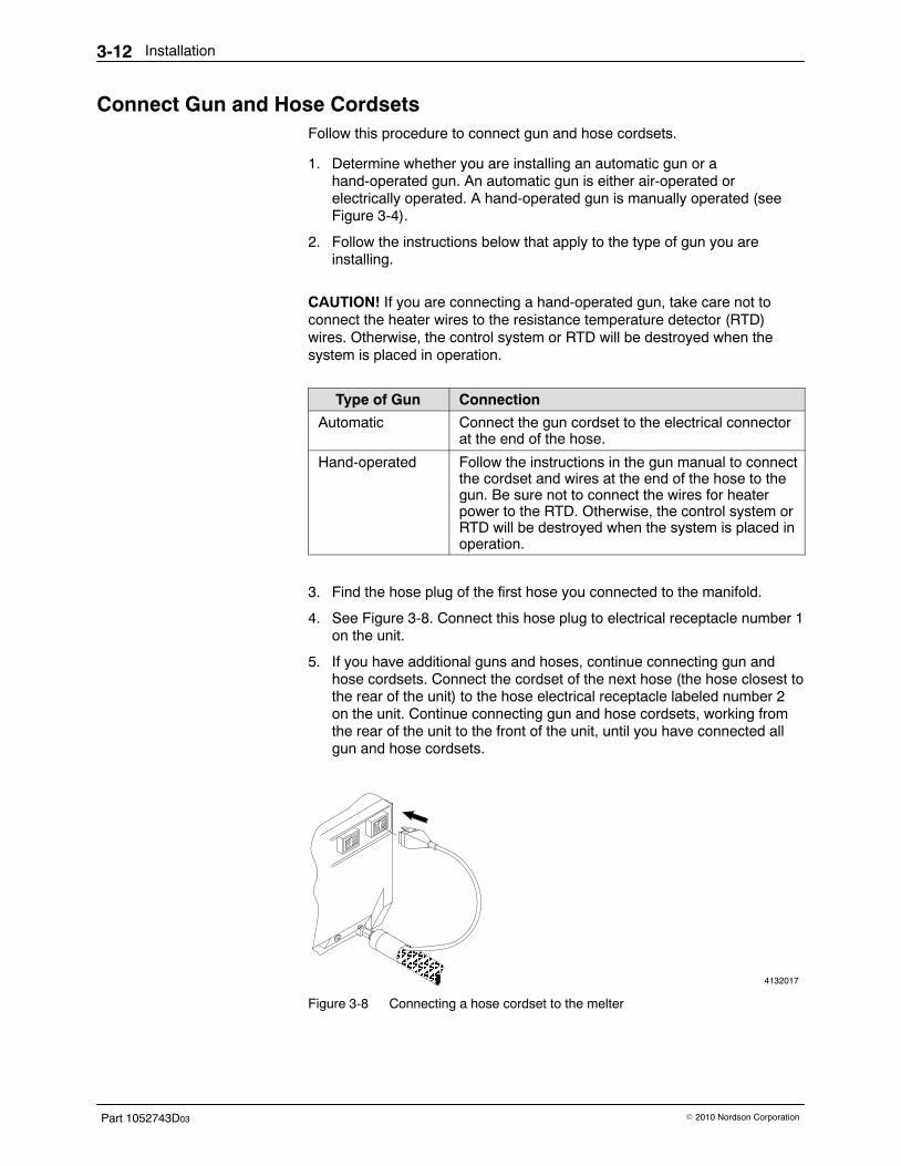
Installation3-12
Part 1052743D03 � 2010 Nordson Corporation
Connect Gun and Hose Cordsets Follow this procedure to connect gun and hose cordsets.
1. Determine whether you are installing an automatic gun or ahand-operated gun. An automatic gun is either air-operated orelectrically operated. A hand-operated gun is manually operated (seeFigure 3-4).
2. Follow the instructions below that apply to the type of gun you areinstalling.
CAUTION! If you are connecting a hand-operated gun, take care not toconnect the heater wires to the resistance temperature detector (RTD)wires. Otherwise, the control system or RTD will be destroyed when thesystem is placed in operation.
Type of Gun Connection
Automatic Connect the gun cordset to the electrical connectorat the end of the hose.
Hand-operated Follow the instructions in the gun manual to connectthe cordset and wires at the end of the hose to thegun. Be sure not to connect the wires for heaterpower to the RTD. Otherwise, the control system orRTD will be destroyed when the system is placed inoperation.
3. Find the hose plug of the first hose you connected to the manifold.
4. See Figure 3-8. Connect this hose plug to electrical receptacle number 1on the unit.
5. If you have additional guns and hoses, continue connecting gun andhose cordsets. Connect the cordset of the next hose (the hose closest tothe rear of the unit) to the hose electrical receptacle labeled number 2on the unit. Continue connecting gun and hose cordsets, working fromthe rear of the unit to the front of the unit, until you have connected allgun and hose cordsets.
4132017ÂÂÂÂÂÂÂ
ÂÂÂÂ
Â
ÂÂ
Figure 3-8 Connecting a hose cordset to the melter

Installation 3-13
Part 1052743D03� 2010 Nordson Corporation
Open the Electrical Enclosure To make the electrical connections inside the melter, follow this procedure toopen the unit and access the electrical enclosure.
WARNING! Risk of equipment damage, personal injury, or death.Disconnect and lock out electrical power to the unit.
1. Place the unit’s POWER switch in the off position and disconnect andlock out electrical power to the unit at the branch circuit disconnectswitch.
2. See Figure 3-9. Loosen the captive screws on the electrical enclosurelid, lift the lid from the unit, and prop it against the pump cover. Takecare not to disconnect the ground wire.
3. Make sure the support strap is not wrapped around any boardcomponents. Untangle the strap if necessary.
4. Loosen the two captive screws on either side of the control-end frameand lower the frame. You may need to pull the front and rear panelsapart to release the frame.
5. Avoid direct contact with internal electrical connections, components, orwiring.
6. Make sure all ground wires are securely connected.
4132018
ÎÎÎÎÎÎÎÎÎÎÎÎÎÎÎÎÎÎÎÎÎÎÎÎÎÎÎÎÎÎ
Figure 3-9 Opening the electrical enclosure
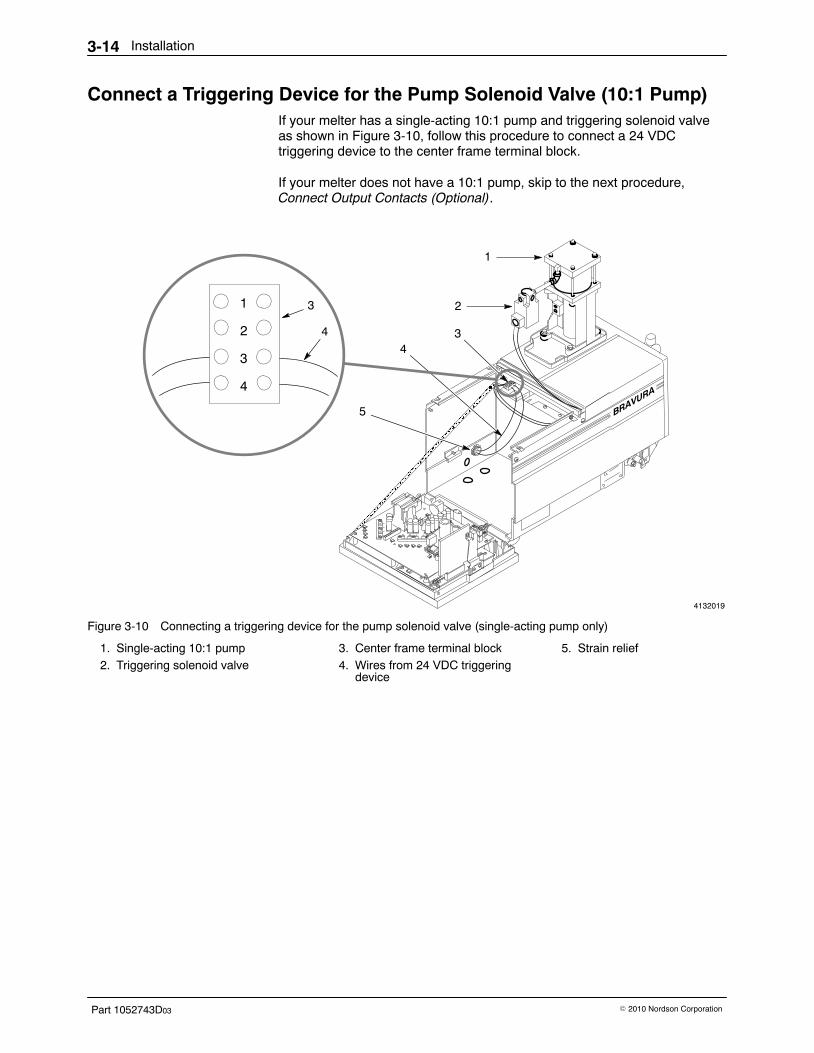
Installation3-14
Part 1052743D03 � 2010 Nordson Corporation
Connect a Triggering Device for the Pump Solenoid Valve (10:1 Pump) If your melter has a single-acting 10:1 pump and triggering solenoid valveas shown in Figure 3-10, follow this procedure to connect a 24 VDCtriggering device to the center frame terminal block.
If your melter does not have a 10:1 pump, skip to the next procedure,Connect Output Contacts (Optional).
4132019
ÎÎÎÎÎÎÎÎÎÎÎÎÎÎÎÎÎÎÎÎÎÎÎÎÎÎÎÎÎÎÎÎÎÎÎÎÎÎÎÎÎÎÎÎÎÎÎÎÎÎÎÎÎÎÎÎÎÎÎÎÎÎÎÎÎÎÎÎÎÎÎÎ
2
34
5
1
2
3
4
3
4
1
Figure 3-10 Connecting a triggering device for the pump solenoid valve (single-acting pump only)
1. Single-acting 10:1 pump2. Triggering solenoid valve
3. Center frame terminal block4. Wires from 24 VDC triggering
device
5. Strain relief

Installation 3-15
Part 1052743D03� 2010 Nordson Corporation
WARNING! Risk of equipment damage, personal injury or death. Install astrain relief to protect wires from being damaged by the edges of theknockout hole.
CAUTION! Circuit boards can be easily damaged. Avoid any contact withcircuit boards when removing a knockout hole plug.
1. See Figure 3-10. Remove and discard the plug from a knockout hole oneither the back side or the bottom of the unit (whichever is mostconvenient for your operation) and install a strain relief (5) in the hole.Refer to the following table for the appropriate size strain relief.
NOTE: Your unit may have several knockout holes. You should routeyour triggering device wires through a larger hole.
Size of Knockout Size of Strain Relief to Install
23 mm (15/16 in.) PG-16 or 1/2-in. trade size
29.5 mm (15/32 in.) PG-21
35 mm (13/8 in.) 1-in. trade size
CAUTION! Use 0.34−0.25 mm2 (22−24 AWG) wire. Using a different wiresize can cause internal stress-related damage to the unit.
2. Route the wires from a 24 VDC triggering device (3) through the strainrelief and connect them to terminals 3 and 4 on the center frameterminal block (2).
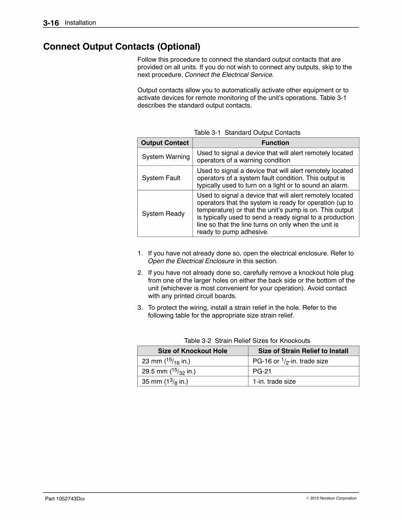
Installation3-16
Part 1052743D03 � 2010 Nordson Corporation
Connect Output Contacts (Optional) Follow this procedure to connect the standard output contacts that areprovided on all units. If you do not wish to connect any outputs, skip to thenext procedure, Connect the Electrical Service.
Output contacts allow you to automatically activate other equipment or toactivate devices for remote monitoring of the unit’s operations. Table 3-1describes the standard output contacts.
Table 3-1 Standard Output Contacts
Output Contact Function
System Warning Used to signal a device that will alert remotely locatedoperators of a warning condition
System FaultUsed to signal a device that will alert remotely locatedoperators of a system fault condition. This output istypically used to turn on a light or to sound an alarm.
System Ready
Used to signal a device that will alert remotely locatedoperators that the system is ready for operation (up totemperature) or that the unit’s pump is on. This outputis typically used to send a ready signal to a productionline so that the line turns on only when the unit isready to pump adhesive.
1. If you have not already done so, open the electrical enclosure. Refer toOpen the Electrical Enclosure in this section.
2. If you have not already done so, carefully remove a knockout hole plugfrom one of the larger holes on either the back side or the bottom of theunit (whichever is most convenient for your operation). Avoid contactwith any printed circuit boards.
3. To protect the wiring, install a strain relief in the hole. Refer to thefollowing table for the appropriate size strain relief.
Table 3-2 Strain Relief Sizes for Knockouts
Size of Knockout Hole Size of Strain Relief to Install
23 mm (15/16 in.) PG-16 or 1/2-in. trade size
29.5 mm (15/32 in.) PG-21
35 mm (13/8 in.) 1-in. trade size
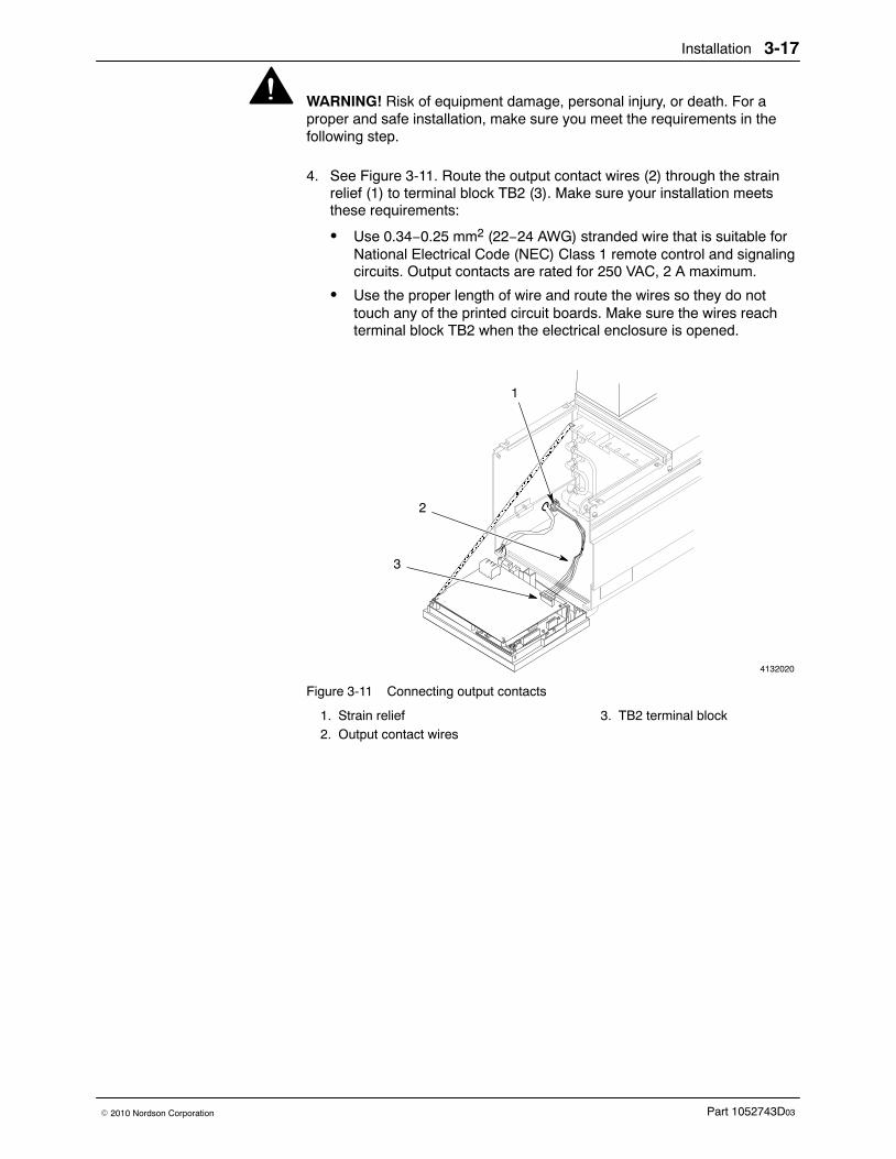
Installation 3-17
Part 1052743D03� 2010 Nordson Corporation
WARNING! Risk of equipment damage, personal injury, or death. For aproper and safe installation, make sure you meet the requirements in thefollowing step.
4. See Figure 3-11. Route the output contact wires (2) through the strainrelief (1) to terminal block TB2 (3). Make sure your installation meetsthese requirements:
� Use 0.34−0.25 mm2 (22−24 AWG) stranded wire that is suitable forNational Electrical Code (NEC) Class 1 remote control and signalingcircuits. Output contacts are rated for 250 VAC, 2 A maximum.
� Use the proper length of wire and route the wires so they do nottouch any of the printed circuit boards. Make sure the wires reachterminal block TB2 when the electrical enclosure is opened.
4132020
ÎÎÎÎÎÎÎÎÎÎÎÎÎÎÎÎÎÎÎÎÎÎÎÎÎÎÎÎÎÎÎÎÎÎÎÎÎÎÎÎÎÎÎÎÎÎÎÎÎÎÎÎÎÎÎÎÎÎÎÎÎÎÎ
1
2
3
Figure 3-11 Connecting output contacts
1. Strain relief2. Output contact wires
3. TB2 terminal block
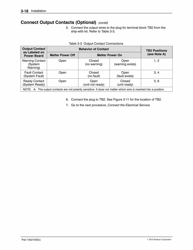
Installation3-18
Part 1052743D03 � 2010 Nordson Corporation
Connect Output Contacts (Optional) (contd)
5. Connect the output wires to the plug for terminal block TB2 from theship-with kit. Refer to Table 3-3.
Table 3-3 Output Contact Connections
Output Contactas Labeled onPower Board
Behavior of Contact TB2 Positions(see Note A)Melter Power Off Melter Power On
Warning Contact(SystemWarning)
Open Closed(no warning)
Open(warning exists)
1, 2
Fault Contact(System Fault)
Open Closed(no fault)
Open(fault exists)
3, 4
Ready Contact(System Ready)
Open Open(unit not ready)
Closed(unit ready)
5, 6
NOTE A: The output contacts are not polarity sensitive. It does not matter which wire is inserted into a position.
6. Connect the plug to TB2. See Figure 3-11 for the location of TB2.
7. Go to the next procedure, Connect the Electrical Service.

Installation 3-19
Part 1052743D03� 2010 Nordson Corporation
This page intentionally left blank.
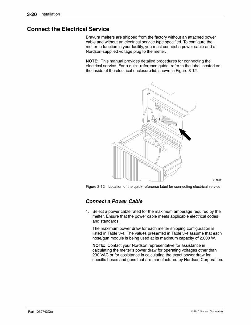
Installation3-20
Part 1052743D03 � 2010 Nordson Corporation
Connect the Electrical Service Bravura melters are shipped from the factory without an attached powercable and without an electrical service type specified. To configure themelter to function in your facility, you must connect a power cable and aNordson-supplied voltage plug to the melter.
NOTE: This manual provides detailed procedures for connecting theelectrical service. For a quick-reference guide, refer to the label located onthe inside of the electrical enclosure lid, shown in Figure 3-12.
4132021
Figure 3-12 Location of the quick-reference label for connecting electrical service
Connect a Power Cable
1. Select a power cable rated for the maximum amperage required by themelter. Ensure that the power cable meets applicable electrical codesand standards.
The maximum power draw for each melter shipping configuration islisted in Table 3-4. The values presented in Table 3-4 assume that eachhose/gun module is being used at its maximum capacity of 2,000 W.
NOTE: Contact your Nordson representative for assistance incalculating the melter’s power draw for operating voltages other than230 VAC or for assistance in calculating the exact power draw forspecific hoses and guns that are manufactured by Nordson Corporation.

Installation 3-21
Part 1052743D03� 2010 Nordson Corporation
Table 3-4 Melter Power Requirements
Melter Number ofHose/Guns
1-Phase PowerDraw (Amps)
3-Phase Power Draw (Amps)
230 VACWith Neutral
240 VACWithoutNeutral
400 VACWithoutNeutral
B42 17 9 14 4
4 25 17 22 Not applicable
B62 18 9 15 Not applicable
4 27 17 23 Not applicable
B9 4 30 17 26 Not applicable
B144 35 17 30 Not applicable
6 Not applicable 25 38 Not applicable
WARNING! Risk of electrocution! Install a lockable power disconnect switchbetween the electrical service and the melter. Failure to install or properlyuse the disconnect switch when servicing the melter can result in personalinjury, including death.
2. If applicable, open the electrical enclosure. Refer to Open the ElectricalEnclosure earlier in this section as needed.
3. If you have not already done so, remove and discard the plug from aknockout hole on either the back side or the bottom of the melter(whichever is most convenient for your operation) and install a strainrelief in the hole. Refer to the following table for the appropriate sizestrain relief.
NOTE: Your melter may have several knockout holes. You should routeyour electrical service wiring through a smaller hole.
Table 3-5 Strain Relief Sizes for Knockouts
Size of Knockout Hole Size of Strain Relief to Install
23 mm (15/16 in.) PG-16 or 1/2-in. trade size
29.5 mm (15/32 in.) PG-21
35 mm (13/8 in.) 1-in. trade size
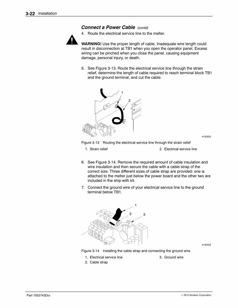
Installation3-22
Part 1052743D03 � 2010 Nordson Corporation
Connect a Power Cable (contd)
4. Route the electrical service line to the melter.
WARNING! Use the proper length of cable. Inadequate wire length couldresult in disconnection at TB1 when you open the operator panel. Excesswiring can be pinched when you close the panel, causing equipmentdamage, personal injury, or death.
5. See Figure 3-13. Route the electrical service line through the strainrelief, determine the length of cable required to reach terminal block TB1and the ground terminal, and cut the cable.
4132022
1
2
Figure 3-13 Routing the electrical service line through the strain relief
1. Strain relief 2. Electrical service line
6. See Figure 3-14. Remove the required amount of cable insulation andwire insulation and then secure the cable with a cable strap of thecorrect size. Three different sizes of cable strap are provided: one isattached to the melter just below the power board and the other two areincluded in the ship-with kit.
7. Connect the ground wire of your electrical service line to the groundterminal below TB1.
4132023
1
2 3
Figure 3-14 Installing the cable strap and connecting the ground wire
1. Electrical service line2. Cable strap
3. Ground wire

Installation 3-23
Part 1052743D03� 2010 Nordson Corporation
8. Connect the remaining wires of the electrical service line to TB1 asappropriate for your electrical service type. Refer to Table 3-6.
Table 3-6 Connecting the Electrical Service
FigureNo. If the Electrical Service Type is..
Use Electrical ConnectorTerminals.. Use Voltage
Plug..L1 L2 L3 N
1400/230 VAC 3-phase (4-wire service, including aneutral) See Note.
3/N/PE AC400/230V • • • • 227569
Red/yellow labelWhite trace wiring
2230 VAC 1-phase(2-wire service, including aneutral) See Note.
1/N/PE AC200–240V • • 232617
Blue/yellow labelGray trace wiring
3200 to 240 VAC 3-phase(3-wire service without aneutral)
3/PE AC200–240V • • • 227568
Red/green labelBlack trace wiring
3400 VAC 3-phase(3-wire service without aneutral)
3/PE AC400V • • • Not applicable.
Plug is factory-installed.
4200 to 240 VAC 1-phase(2-wire service without aneutral)
1/PE AC200–240V • • 227567
Blue/green labelRed trace wiring
NOTE: The 400/230 VAC 3-phase service (4-wire service including neutral) includes the 415/240 VAC 3-phase (4-wire service,including neutral) voltage. The 230 VAC 1-phase service (2-wire service, including a neutral) includes the 240 VAC 1-phase (2-wireservice, including a neutral) voltage.
L1 L2 L3 NL1 L2 L3 NL1 L2 L3 N
1 2 3 4
L1 L2 L3 N
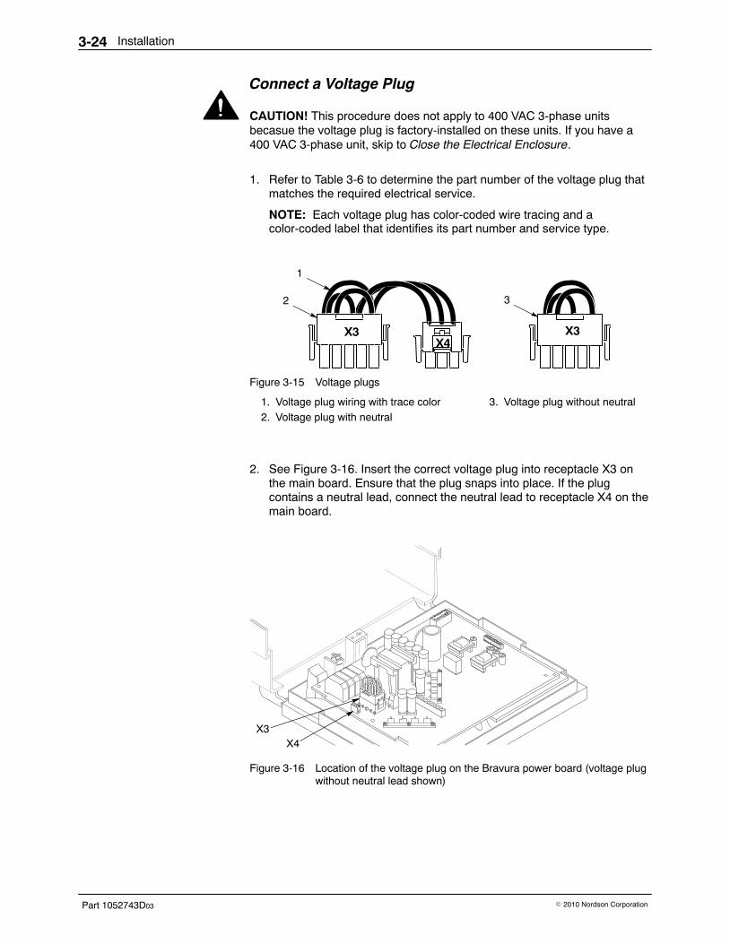
Installation3-24
Part 1052743D03 � 2010 Nordson Corporation
Connect a Voltage Plug
CAUTION! This procedure does not apply to 400 VAC 3-phase unitsbecasue the voltage plug is factory-installed on these units. If you have a400 VAC 3-phase unit, skip to Close the Electrical Enclosure.
1. Refer to Table 3-6 to determine the part number of the voltage plug thatmatches the required electrical service.
NOTE: Each voltage plug has color-coded wire tracing and acolor-coded label that identifies its part number and service type.
X3X4
X3
1
2 3
Figure 3-15 Voltage plugs
1. Voltage plug wiring with trace color2. Voltage plug with neutral
3. Voltage plug without neutral
2. See Figure 3-16. Insert the correct voltage plug into receptacle X3 onthe main board. Ensure that the plug snaps into place. If the plugcontains a neutral lead, connect the neutral lead to receptacle X4 on themain board.
X3X4
Figure 3-16 Location of the voltage plug on the Bravura power board (voltage plugwithout neutral lead shown)
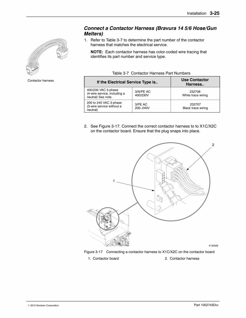
Contactor harness
Installation 3-25
Part 1052743D03� 2010 Nordson Corporation
Connect a Contactor Harness (Bravura 14 5/6 Hose/GunMelters) 1. Refer to Table 3-7 to determine the part number of the contactor
harness that matches the electrical service.
NOTE: Each contactor harness has color-coded wire tracing thatidentifies its part number and service type.
Table 3-7 Contactor Harness Part Numbers
If the Electrical Service Type is.. Use ContactorHarness..
400/230 VAC 3-phase (4-wire service, including aneutral) See note.
3/N/PE AC400/230V
232708White trace wiring
200 to 240 VAC 3-phase(3-wire service without aneutral)
3/PE AC200–240V
232707Black trace wiring
2. See Figure 3-17. Connect the correct contactor harness to to X1C/X2Con the contactor board. Ensure that the plug snaps into place.
4132026
2
1
Figure 3-17 Connecting a contactor harness to X1C/X2C on the contactor board
1. Contactor board 2. Contactor harness
Installation3-26
Part 1052743D03 � 2010 Nordson Corporation
Close the Electrical Enclosure 1. Reconnect any ground wires that may have become disconnected
during electrical installation.
2. Raise the control-end frame into place and tighten the captive screws oneach side of the frame. You may need to pull the front and rear panelsapart to position the frame.
3. Position the electrical enclosure lid on top of the unit and secure it withthe captive screws.
4. Remove the lock-out and turn on the power at the branch circuitdisconnect switch.
System Setup Before running your unit, follow the procedures in this part of the Installationsection to program the unit for your operations. All programming is donefrom the operator panel, where you can set
� the units in which temperature is displayed (Celsius or Fahrenheit)� the ready delay time period� the temperature at which each zone operates� the global standby temperature� the temperature at which the melter is overtemperature� when the system operates (turns on/off or enters/exits standby)
You will probably find it helpful to read Control System in the Descriptionsection of this manual before programming any system controls. ControlSystem briefly describes the function of each control you will program.
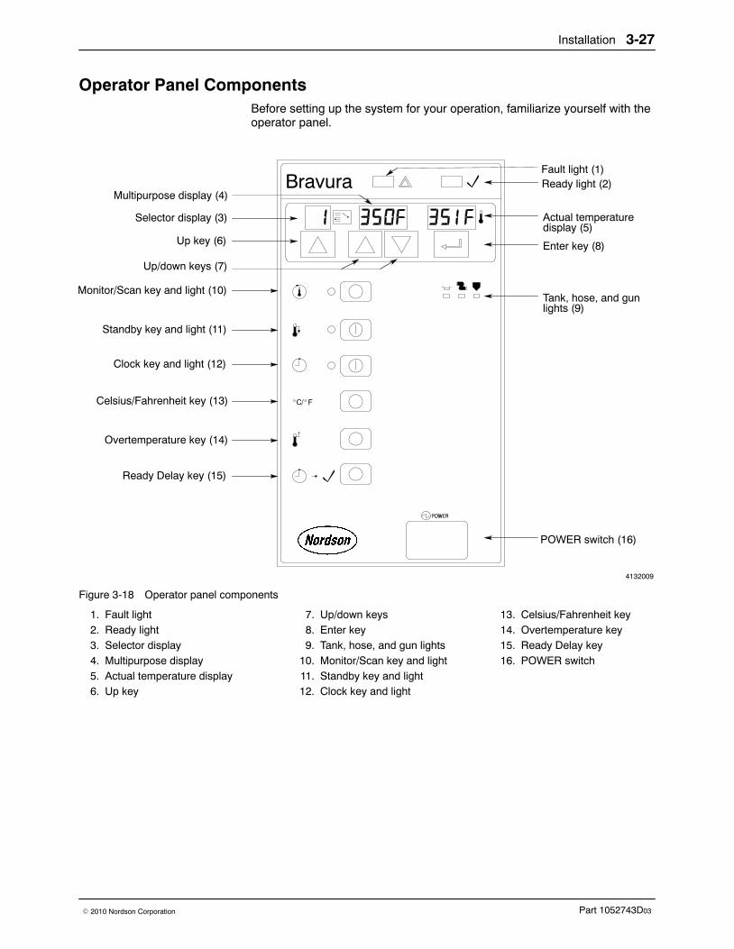
Installation 3-27
Part 1052743D03� 2010 Nordson Corporation
Operator Panel Components Before setting up the system for your operation, familiarize yourself with theoperator panel.
4132009
Ready light (2)Multipurpose display (4)
Up/down keys (7)
Fault light (1)
Actual temperaturedisplay (5)
Tank, hose, and gunlights (9)
POWER switch (16)
Monitor/Scan key and light (10)
Standby key and light (11)
Clock key and light (12)
Celsius/Fahrenheit key (13)
Overtemperature key (14)
Ready Delay key (15)
Up key (6)
Selector display (3)
Enter key (8)
Figure 3-18 Operator panel components
1. Fault light2. Ready light3. Selector display4. Multipurpose display5. Actual temperature display6. Up key
7. Up/down keys8. Enter key9. Tank, hose, and gun lights
10. Monitor/Scan key and light11. Standby key and light12. Clock key and light
13. Celsius/Fahrenheit key14. Overtemperature key15. Ready Delay key16. POWER switch
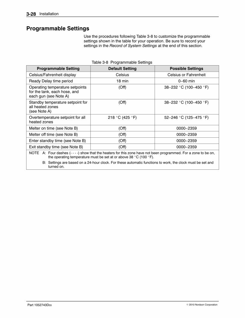
Installation3-28
Part 1052743D03 � 2010 Nordson Corporation
Programmable Settings Use the procedures following Table 3-8 to customize the programmablesettings shown in the table for your operation. Be sure to record yoursettings in the Record of System Settings at the end of this section.
Table 3-8 Programmable Settings
Programmable Setting Default Setting Possible Settings
Celsius/Fahrenheit display Celsius Celsius or Fahrenheit
Ready Delay time period 18 min 0−60 min
Operating temperature setpointsfor the tank, each hose, andeach gun (see Note A)
(Off) 38−232 �C (100−450 �F)
Standby temperature setpoint forall heated zones(see Note A)
(Off) 38−232 �C (100−450 �F)
Overtemperature setpoint for allheated zones
218 �C (425 �F) 52−246 �C (125−475 �F)
Melter on time (see Note B) (Off) 0000−2359
Melter off time (see Note B) (Off) 0000−2359
Enter standby time (see Note B) (Off) 0000−2359
Exit standby time (see Note B) (Off) 0000−2359
NOTE A: Four dashes (- - - -) show that the heaters for this zone have not been programmed. For a zone to be on,the operating temperature must be set at or above 38 �C (100 �F).
B: Settings are based on a 24-hour clock. For these automatic functions to work, the clock must be set andturned on.
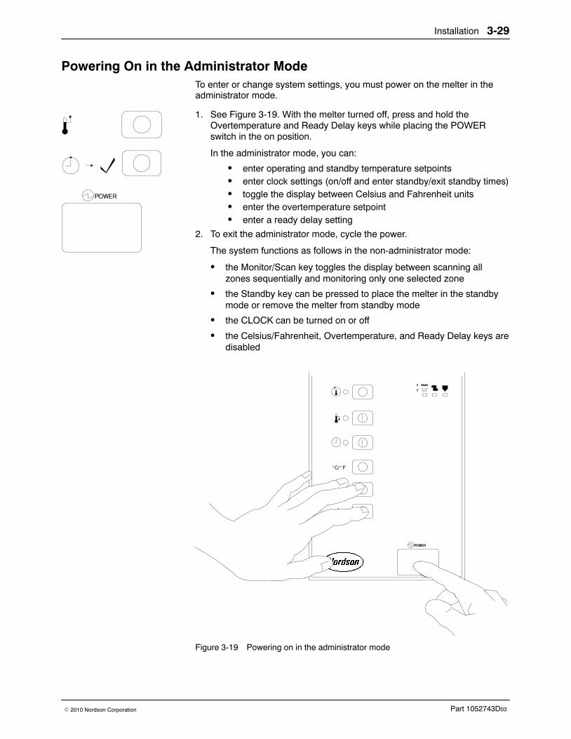
Installation 3-29
Part 1052743D03� 2010 Nordson Corporation
Powering On in the Administrator Mode To enter or change system settings, you must power on the melter in theadministrator mode.
1. See Figure 3-19. With the melter turned off, press and hold theOvertemperature and Ready Delay keys while placing the POWERswitch in the on position.
In the administrator mode, you can:
� enter operating and standby temperature setpoints� enter clock settings (on/off and enter standby/exit standby times)� toggle the display between Celsius and Fahrenheit units� enter the overtemperature setpoint� enter a ready delay setting
2. To exit the administrator mode, cycle the power.
The system functions as follows in the non-administrator mode:
� the Monitor/Scan key toggles the display between scanning allzones sequentially and monitoring only one selected zone
� the Standby key can be pressed to place the melter in the standbymode or remove the melter from standby mode
� the CLOCK can be turned on or off
� the Celsius/Fahrenheit, Overtemperature, and Ready Delay keys aredisabled
Figure 3-19 Powering on in the administrator mode
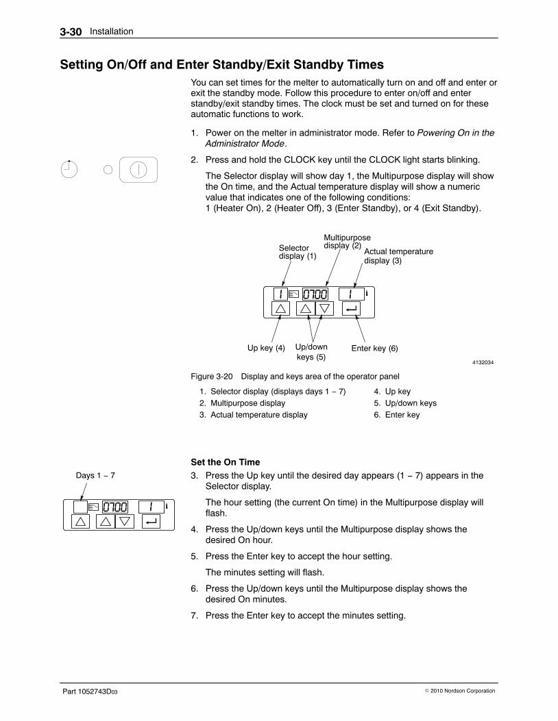
Days 1 − 7
Installation3-30
Part 1052743D03 � 2010 Nordson Corporation
Setting On/Off and Enter Standby/Exit Standby Times You can set times for the melter to automatically turn on and off and enter orexit the standby mode. Follow this procedure to enter on/off and enterstandby/exit standby times. The clock must be set and turned on for theseautomatic functions to work.
1. Power on the melter in administrator mode. Refer to Powering On in theAdministrator Mode.
2. Press and hold the CLOCK key until the CLOCK light starts blinking.
The Selector display will show day 1, the Multipurpose display will showthe On time, and the Actual temperature display will show a numericvalue that indicates one of the following conditions: 1 (Heater On), 2 (Heater Off), 3 (Enter Standby), or 4 (Exit Standby).
4132034
Selectordisplay (1)
Multipurposedisplay (2)
Actual temperaturedisplay (3)
Up key (4) Up/downkeys (5)
Enter key (6)
Figure 3-20 Display and keys area of the operator panel
1. Selector display (displays days 1 − 7)2. Multipurpose display3. Actual temperature display
4. Up key5. Up/down keys6. Enter key
Set the On Time 3. Press the Up key until the desired day appears (1 − 7) appears in the
Selector display.
The hour setting (the current On time) in the Multipurpose display willflash.
4. Press the Up/down keys until the Multipurpose display shows thedesired On hour.
5. Press the Enter key to accept the hour setting.
The minutes setting will flash.
6. Press the Up/down keys until the Multipurpose display shows thedesired On minutes.
7. Press the Enter key to accept the minutes setting.
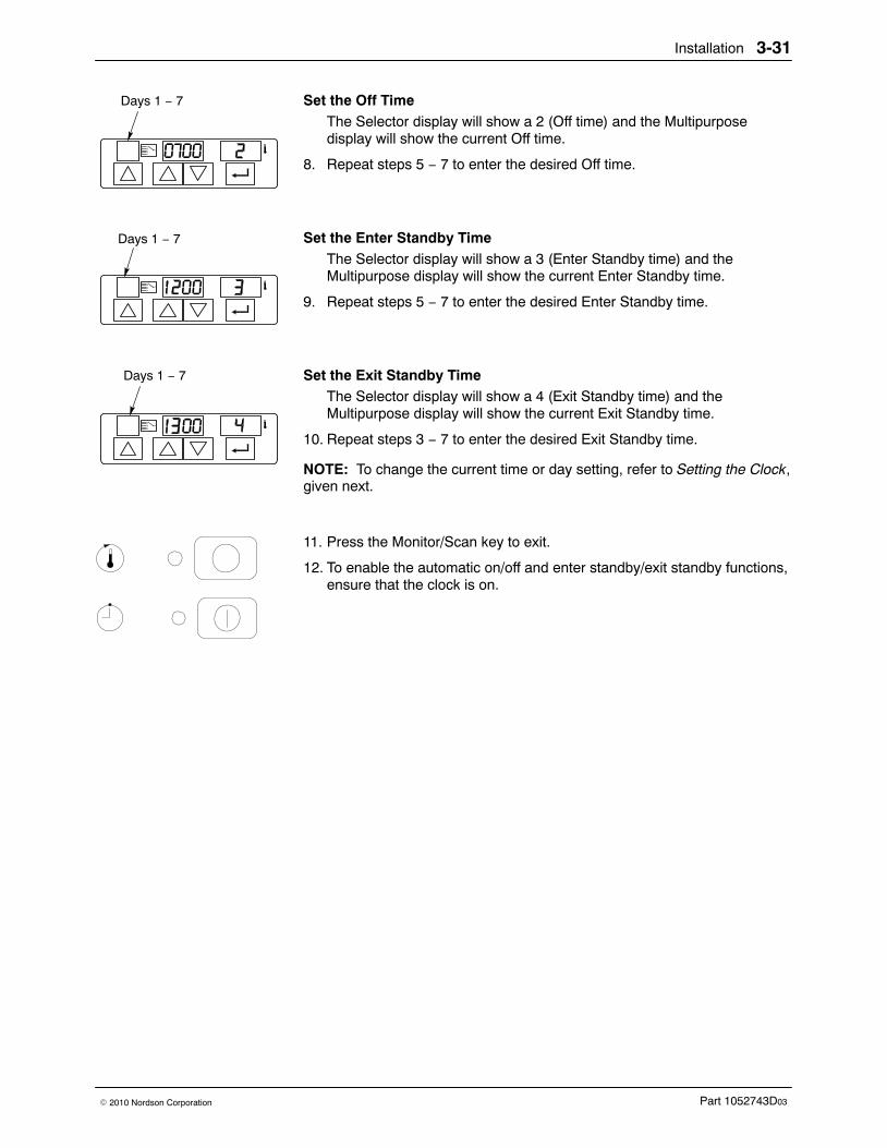
Days 1 − 7
Days 1 − 7
Days 1 − 7
Installation 3-31
Part 1052743D03� 2010 Nordson Corporation
Set the Off Time The Selector display will show a 2 (Off time) and the Multipurposedisplay will show the current Off time.
8. Repeat steps 5 − 7 to enter the desired Off time.
Set the Enter Standby Time The Selector display will show a 3 (Enter Standby time) and theMultipurpose display will show the current Enter Standby time.
9. Repeat steps 5 − 7 to enter the desired Enter Standby time.
Set the Exit Standby Time The Selector display will show a 4 (Exit Standby time) and theMultipurpose display will show the current Exit Standby time.
10. Repeat steps 3 − 7 to enter the desired Exit Standby time.
NOTE: To change the current time or day setting, refer to Setting the Clock,given next.
11. Press the Monitor/Scan key to exit.
12. To enable the automatic on/off and enter standby/exit standby functions,ensure that the clock is on.
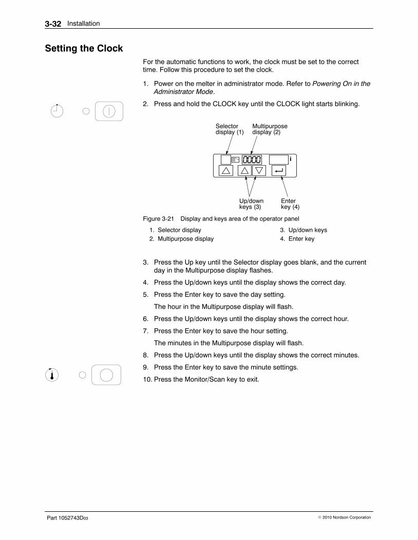
Installation3-32
Part 1052743D03 � 2010 Nordson Corporation
Setting the Clock For the automatic functions to work, the clock must be set to the correcttime. Follow this procedure to set the clock.
1. Power on the melter in administrator mode. Refer to Powering On in theAdministrator Mode.
2. Press and hold the CLOCK key until the CLOCK light starts blinking.
Selector
Up/down
display (1)Multipurposedisplay (2)
keys (3)Enterkey (4)
Figure 3-21 Display and keys area of the operator panel
1. Selector display2. Multipurpose display
3. Up/down keys4. Enter key
3. Press the Up key until the Selector display goes blank, and the currentday in the Multipurpose display flashes.
4. Press the Up/down keys until the display shows the correct day.
5. Press the Enter key to save the day setting.
The hour in the Multipurpose display will flash.
6. Press the Up/down keys until the display shows the correct hour.
7. Press the Enter key to save the hour setting.
The minutes in the Multipurpose display will flash.
8. Press the Up/down keys until the display shows the correct minutes.
9. Press the Enter key to save the minute settings.
10. Press the Monitor/Scan key to exit.
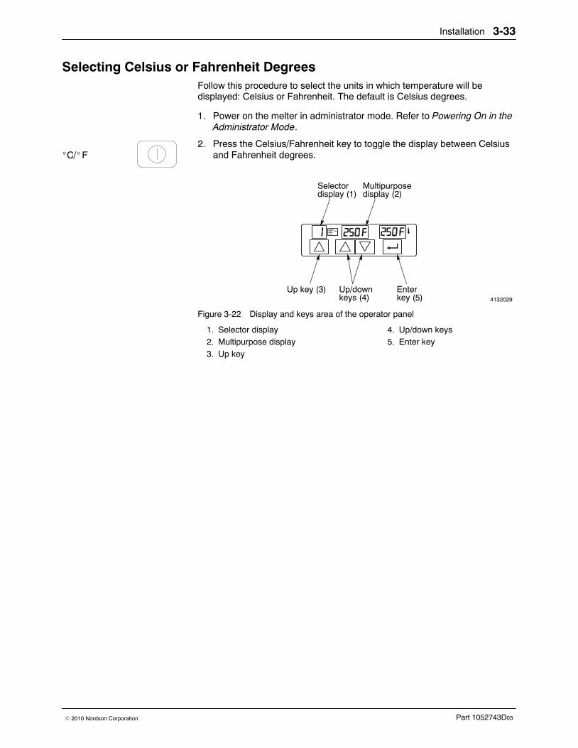
Installation 3-33
Part 1052743D03� 2010 Nordson Corporation
Selecting Celsius or Fahrenheit Degrees Follow this procedure to select the units in which temperature will bedisplayed: Celsius or Fahrenheit. The default is Celsius degrees.
1. Power on the melter in administrator mode. Refer to Powering On in theAdministrator Mode.
2. Press the Celsius/Fahrenheit key to toggle the display between Celsiusand Fahrenheit degrees.
4132029
Selector
Up key (3) Up/down
display (1)Multipurposedisplay (2)
keys (4)Enterkey (5)
Figure 3-22 Display and keys area of the operator panel
1. Selector display2. Multipurpose display3. Up key
4. Up/down keys5. Enter key
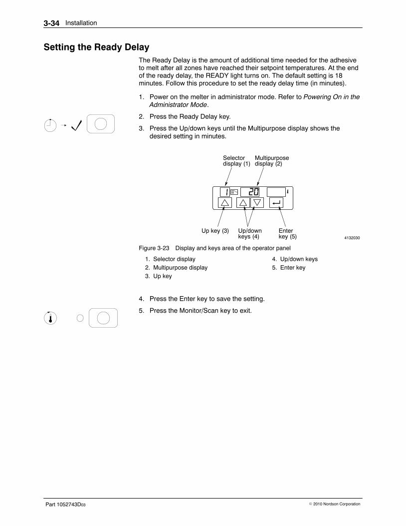
Installation3-34
Part 1052743D03 � 2010 Nordson Corporation
Setting the Ready Delay The Ready Delay is the amount of additional time needed for the adhesiveto melt after all zones have reached their setpoint temperatures. At the endof the ready delay, the READY light turns on. The default setting is 18minutes. Follow this procedure to set the ready delay time (in minutes).
1. Power on the melter in administrator mode. Refer to Powering On in theAdministrator Mode.
2. Press the Ready Delay key.
3. Press the Up/down keys until the Multipurpose display shows thedesired setting in minutes.
4132030
Selector
Up key (3) Up/down
display (1)Multipurposedisplay (2)
keys (4)Enterkey (5)
Figure 3-23 Display and keys area of the operator panel
1. Selector display2. Multipurpose display3. Up key
4. Up/down keys5. Enter key
4. Press the Enter key to save the setting.
5. Press the Monitor/Scan key to exit.

Installation 3-35
Part 1052743D03� 2010 Nordson Corporation
This page intentionally left blank.
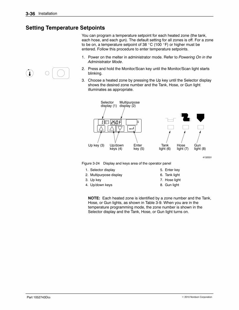
Installation3-36
Part 1052743D03 � 2010 Nordson Corporation
Setting Temperature Setpoints You can program a temperature setpoint for each heated zone (the tank,each hose, and each gun). The default setting for all zones is off. For a zoneto be on, a temperature setpoint of 38 �C (100 �F) or higher must beentered. Follow this procedure to enter temperature setpoints.
1. Power on the melter in administrator mode. Refer to Powering On in theAdministrator Mode.
2. Press and hold the Monitor/Scan key until the Monitor/Scan light startsblinking.
3. Choose a heated zone by pressing the Up key until the Selector displayshows the desired zone number and the Tank, Hose, or Gun lightilluminates as appropriate.
4132031
Selector
Up key (3) Up/down
display (1)Multipurposedisplay (2)
keys (4)Enterkey (5)
Tanklight (6)
Hoselight (7)
Gun light (8)
Figure 3-24 Display and keys area of the operator panel
1. Selector display2. Multipurpose display3. Up key4. Up/down keys
5. Enter key6. Tank light7. Hose light8. Gun light
NOTE: Each heated zone is identified by a zone number and the Tank,Hose, or Gun lights, as shown in Table 3-9. When you are in thetemperature programming mode, the zone number is shown in theSelector display and the Tank, Hose, or Gun light turns on.
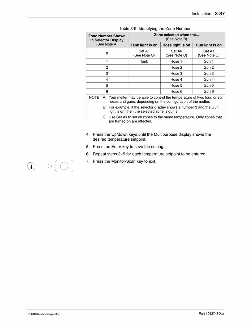
Installation 3-37
Part 1052743D03� 2010 Nordson Corporation
Table 3-9 Identifying the Zone Number
Zone Number Shownin Selector Display
(See Note A)
Zone selected when the...(See Note B)
Tank light is on Hose light is on Gun light is on
0Set All
(See Note C)Set All
(See Note C)Set All
(See Note C)
1 Tank Hose 1 Gun 1
2 Hose 2 Gun 2
3 Hose 3 Gun 3
4 Hose 4 Gun 4
5 Hose 5 Gun 5
6 Hose 6 Gun 6
NOTE A: Your melter may be able to control the temperature of two, four, or sixhoses and guns, depending on the configuration of the melter.
B: For example, if the selector display shows a number 3 and the Gunlight is on, then the selected zone is gun 3.
C: Use Set All to set all zones to the same temperature. Only zones thatare turned on are affected.
4. Press the Up/down keys until the Multipurpose display shows thedesired temperature setpoint.
5. Press the Enter key to save the setting.
6. Repeat steps 3−5 for each temperature setpoint to be entered.
7. Press the Monitor/Scan key to exit.
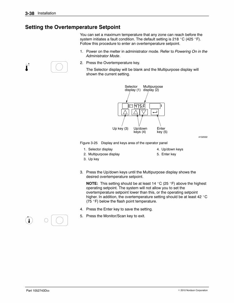
Installation3-38
Part 1052743D03 � 2010 Nordson Corporation
Setting the Overtemperature Setpoint You can set a maximum temperature that any zone can reach before thesystem initiates a fault condition. The default setting is 218 �C (425 �F).Follow this procedure to enter an overtemperature setpoint.
1. Power on the melter in administrator mode. Refer to Powering On in theAdministrator Mode.
2. Press the Overtemperature key.
The Selector display will be blank and the Multipurpose display willshown the current setting.
4132032
Selector
Up key (3) Up/down
display (1)Multipurposedisplay (2)
keys (4)Enterkey (5)
Figure 3-25 Display and keys area of the operator panel
1. Selector display2. Multipurpose display3. Up key
4. Up/down keys5. Enter key
3. Press the Up/down keys until the Multipurpose display shows thedesired overtemperature setpoint.
NOTE: This setting should be at least 14 �C (25 �F) above the highestoperating setpoint. The system will not allow you to set theovertemperature setpoint lower than this, or the operating setpointhigher. In addition, the overtemperature setting should be at least 42 �C(75 �F) below the flash point temperature.
4. Press the Enter key to save the setting.
5. Press the Monitor/Scan key to exit.
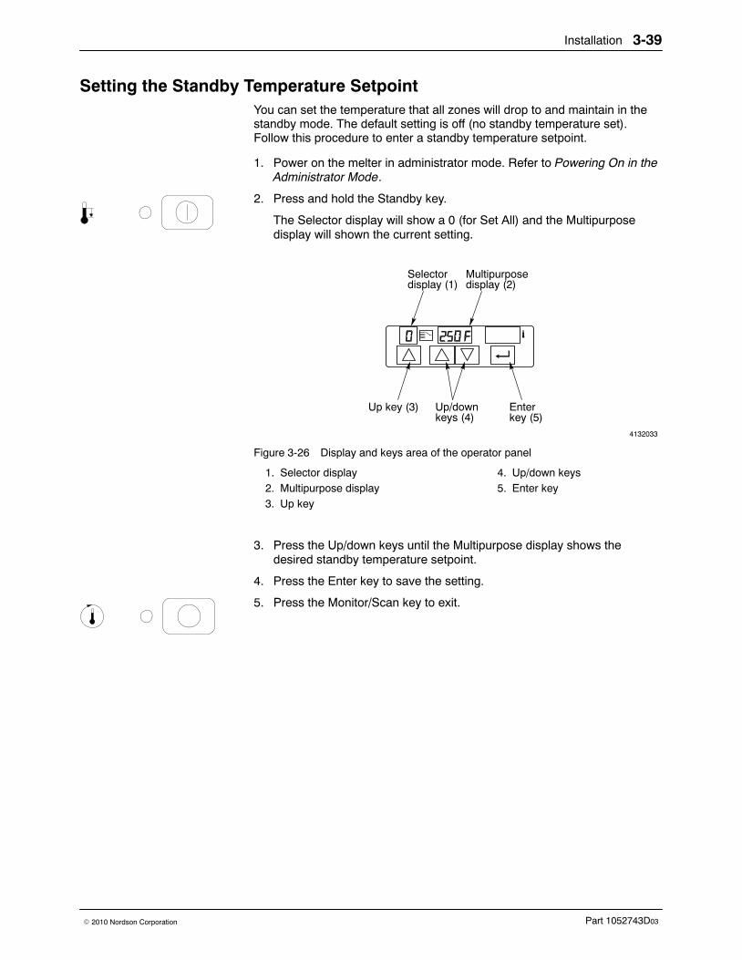
Installation 3-39
Part 1052743D03� 2010 Nordson Corporation
Setting the Standby Temperature Setpoint You can set the temperature that all zones will drop to and maintain in thestandby mode. The default setting is off (no standby temperature set).Follow this procedure to enter a standby temperature setpoint.
1. Power on the melter in administrator mode. Refer to Powering On in theAdministrator Mode.
2. Press and hold the Standby key.
The Selector display will show a 0 (for Set All) and the Multipurposedisplay will shown the current setting.
4132033
Selector
Up key (3) Up/down
display (1)Multipurposedisplay (2)
keys (4)Enterkey (5)
Figure 3-26 Display and keys area of the operator panel
1. Selector display2. Multipurpose display3. Up key
4. Up/down keys5. Enter key
3. Press the Up/down keys until the Multipurpose display shows thedesired standby temperature setpoint.
4. Press the Enter key to save the setting.
5. Press the Monitor/Scan key to exit.
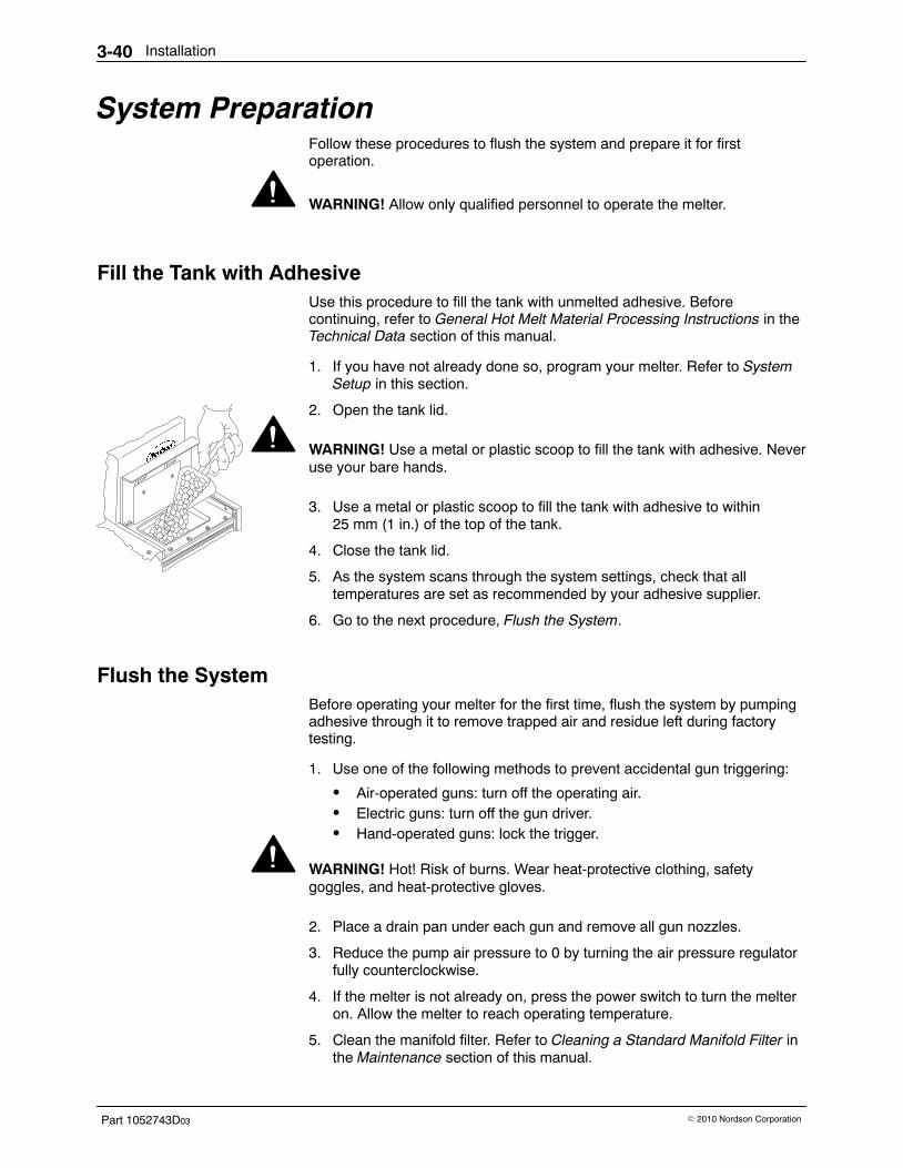
Installation3-40
Part 1052743D03 � 2010 Nordson Corporation
System Preparation Follow these procedures to flush the system and prepare it for firstoperation.
WARNING! Allow only qualified personnel to operate the melter.
Fill the Tank with Adhesive Use this procedure to fill the tank with unmelted adhesive. Beforecontinuing, refer to General Hot Melt Material Processing Instructions in theTechnical Data section of this manual.
1. If you have not already done so, program your melter. Refer to SystemSetup in this section.
2. Open the tank lid.
WARNING! Use a metal or plastic scoop to fill the tank with adhesive. Neveruse your bare hands.
3. Use a metal or plastic scoop to fill the tank with adhesive to within25 mm (1 in.) of the top of the tank.
4. Close the tank lid.
5. As the system scans through the system settings, check that alltemperatures are set as recommended by your adhesive supplier.
6. Go to the next procedure, Flush the System.
Flush the System Before operating your melter for the first time, flush the system by pumpingadhesive through it to remove trapped air and residue left during factorytesting.
1. Use one of the following methods to prevent accidental gun triggering:
� Air-operated guns: turn off the operating air.� Electric guns: turn off the gun driver.� Hand-operated guns: lock the trigger.
WARNING! Hot! Risk of burns. Wear heat-protective clothing, safetygoggles, and heat-protective gloves.
2. Place a drain pan under each gun and remove all gun nozzles.
3. Reduce the pump air pressure to 0 by turning the air pressure regulatorfully counterclockwise.
4. If the melter is not already on, press the power switch to turn the melteron. Allow the melter to reach operating temperature.
5. Clean the manifold filter. Refer to Cleaning a Standard Manifold Filter inthe Maintenance section of this manual.
Installation 3-41
Part 1052743D03� 2010 Nordson Corporation
6. Prepare each gun in your system for operation as follows:
� Air-operated guns: increase the operating air pressure to 2.4 bar(240 kPa, 35 psi).
� Electric guns: turn on the gun driver.
� Hand-operated guns: unlock the trigger.
WARNING! Trapped air may still be in the hoses and guns. Shield the areaand operator from splashing adhesive.
7. Trigger the guns, keeping them open so that no pressure builds up.
NOTE: You may need to adjust the gun air pressure depending on theviscosity of the adhesive and the gun response.
8. Gradually increase the air pressure to the pump by turning the airpressure regulator clockwise. Allow adhesive to flow out of the guns untilall trapped air, cleaning solution, and impurities are flushed out of thesystem. If the pump slows noticeably or stops, increase pump airpressure slightly.
9. Stop triggering the guns.
10. Reduce pump air pressure to 0 by turning the air pressure regulator fullycounterclockwise.
11. Trigger the guns momentarily to relieve trapped hydraulic pressure.
WARNING! Hot! Risk of burns. Wear heat-protective clothing, safetygoggles, and heat-protective gloves.
12. Attach the nozzles to the guns.
13. Adjust the pump air pressure regulator until the air pressure is at thedesired operating setting. Test adhesive patterns as necessary.
14. Air-operated guns only: adjust the gun air pressure regulator until the airpressure is at the desired operating setting. Test adhesive patterns asnecessary.
15. If your system has an air-operated pump or gun, record the initial airpressure settings in the Record of System Settings at the end of thissection.
16. Refer to the gun product manual for additional setup information for thespecific gun.
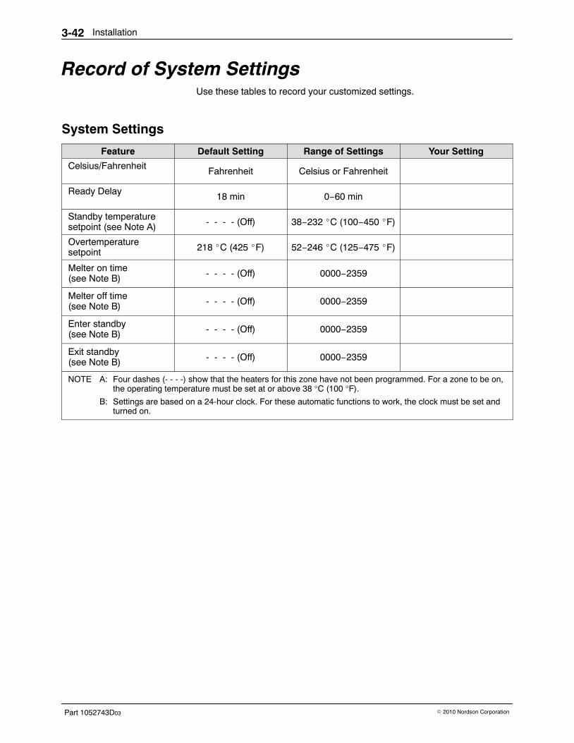
Installation3-42
Part 1052743D03 � 2010 Nordson Corporation
Record of System Settings Use these tables to record your customized settings.
System Settings
Feature Default Setting Range of Settings Your Setting
Celsius/Fahrenheit Fahrenheit Celsius or Fahrenheit
Ready Delay 18 min 0−60 min
Standby temperaturesetpoint (see Note A) - - - - (Off) 38−232 �C (100−450 �F)
Overtemperaturesetpoint 218 �C (425 �F) 52−246 �C (125−475 �F)
Melter on time(see Note B) - - - - (Off) 0000−2359
Melter off time(see Note B) - - - - (Off) 0000−2359
Enter standby(see Note B) - - - - (Off) 0000−2359
Exit standby(see Note B) - - - - (Off) 0000−2359
NOTE A: Four dashes (- - - -) show that the heaters for this zone have not been programmed. For a zone to be on,the operating temperature must be set at or above 38 °C (100 °F).
B: Settings are based on a 24-hour clock. For these automatic functions to work, the clock must be set andturned on.
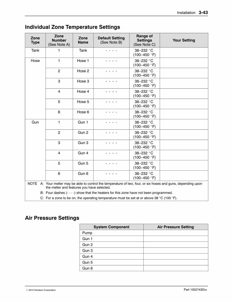
Installation 3-43
Part 1052743D03� 2010 Nordson Corporation
Individual Zone Temperature Settings
ZoneType
ZoneNumber
(See Note A)
ZoneName
Default Setting(See Note B)
Range ofSettings
(See Note C)Your Setting
Tank 1 Tank - - - - 38−232 �C (100−450 �F)
Hose 1 Hose 1 - - - - 38−232 �C (100−450 �F)
2 Hose 2 - - - - 38−232 �C (100−450 �F)
3 Hose 3 - - - - 38−232 �C (100−450 �F)
4 Hose 4 - - - - 38−232 �C (100−450 �F)
5 Hose 5 - - - - 38−232 �C (100−450 �F)
6 Hose 6 - - - - 38−232 �C (100−450 �F)
Gun 1 Gun 1 - - - - 38−232 �C (100−450 �F)
2 Gun 2 - - - - 38−232 �C (100−450 �F)
3 Gun 3 - - - - 38−232 �C (100−450 �F)
4 Gun 4 - - - - 38−232 �C (100−450 �F)
5 Gun 5 - - - - 38−232 �C (100−450 �F)
6 Gun 6 - - - - 38−232 �C (100−450 �F)
NOTE A: Your melter may be able to control the temperature of two, four, or six hoses and guns, depending uponthe melter and features you have selected.
B: Four dashes (- - - -) show that the heaters for this zone have not been programmed.
C: For a zone to be on, the operating temperature must be set at or above 38 °C (100 °F).
Air Pressure Settings
System Component Air Pressure Setting
Pump
Gun 1
Gun 2
Gun 3
Gun 4
Gun 5
Gun 6

Installation3-44
Part 1052743D03 � 2010 Nordson Corporation
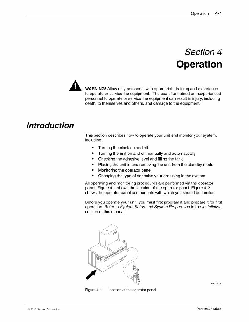
Operation 4-1
Part 1052743D03� 2010 Nordson Corporation
Section 4Operation
WARNING! Allow only personnel with appropriate training and experienceto operate or service the equipment. The use of untrained or inexperiencedpersonnel to operate or service the equipment can result in injury, includingdeath, to themselves and others, and damage to the equipment.
Introduction This section describes how to operate your unit and monitor your system,including:
� Turning the clock on and off� Turning the unit on and off manually and automatically� Checking the adhesive level and filling the tank� Placing the unit in and removing the unit from the standby mode� Monitoring the operator panel� Changing the type of adhesive your are using in the system
All operating and monitoring procedures are performed via the operatorpanel. Figure 4-1 shows the location of the operator panel. Figure 4-2shows the operator panel components with which you should be familiar.
Before you operate your unit, you must first program it and prepare it for firstoperation. Refer to System Setup and System Preparation in the Installationsection of this manual.
4132035
Figure 4-1 Location of the operator panel
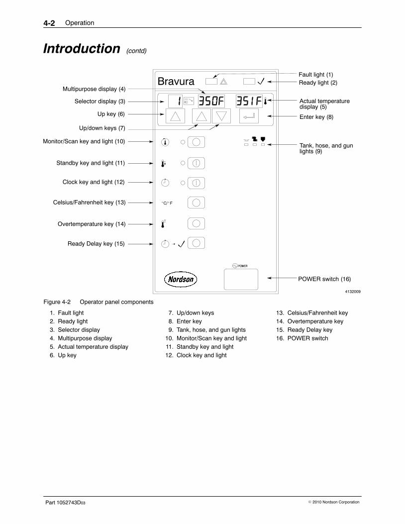
Operation4-2
Part 1052743D03 � 2010 Nordson Corporation
Introduction (contd)
4132009
Ready light (2)Multipurpose display (4)
Up/down keys (7)
Fault light (1)
Actual temperaturedisplay (5)
Tank, hose, and gunlights (9)
POWER switch (16)
Monitor/Scan key and light (10)
Standby key and light (11)
Clock key and light (12)
Celsius/Fahrenheit key (13)
Overtemperature key (14)
Ready Delay key (15)
Up key (6)
Selector display (3)
Enter key (8)
Figure 4-2 Operator panel components
1. Fault light2. Ready light3. Selector display4. Multipurpose display5. Actual temperature display6. Up key
7. Up/down keys8. Enter key9. Tank, hose, and gun lights
10. Monitor/Scan key and light11. Standby key and light12. Clock key and light
13. Celsius/Fahrenheit key14. Overtemperature key15. Ready Delay key16. POWER switch
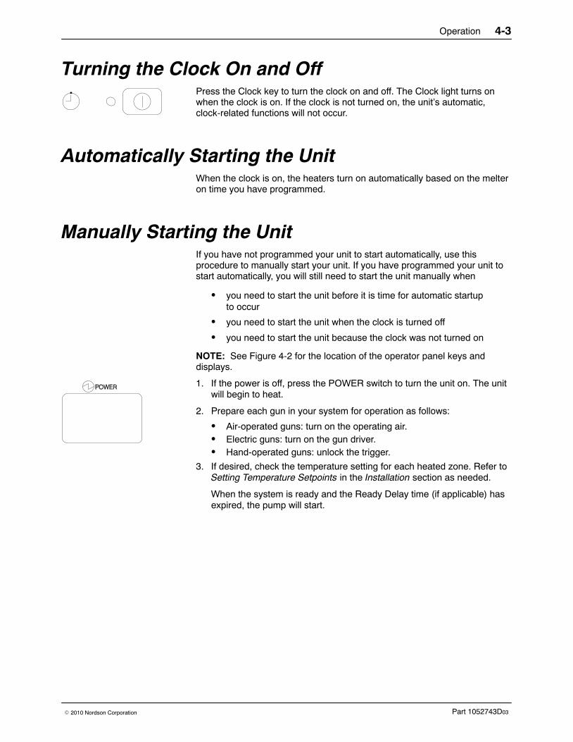
Operation 4-3
Part 1052743D03� 2010 Nordson Corporation
Turning the Clock On and Off Press the Clock key to turn the clock on and off. The Clock light turns onwhen the clock is on. If the clock is not turned on, the unit’s automatic,clock-related functions will not occur.
Automatically Starting the Unit When the clock is on, the heaters turn on automatically based on the melteron time you have programmed.
Manually Starting the Unit If you have not programmed your unit to start automatically, use thisprocedure to manually start your unit. If you have programmed your unit tostart automatically, you will still need to start the unit manually when
� you need to start the unit before it is time for automatic startupto occur
� you need to start the unit when the clock is turned off
� you need to start the unit because the clock was not turned on
NOTE: See Figure 4-2 for the location of the operator panel keys anddisplays.
1. If the power is off, press the POWER switch to turn the unit on. The unitwill begin to heat.
2. Prepare each gun in your system for operation as follows:
� Air-operated guns: turn on the operating air.� Electric guns: turn on the gun driver.� Hand-operated guns: unlock the trigger.
3. If desired, check the temperature setting for each heated zone. Refer toSetting Temperature Setpoints in the Installation section as needed.
When the system is ready and the Ready Delay time (if applicable) hasexpired, the pump will start.
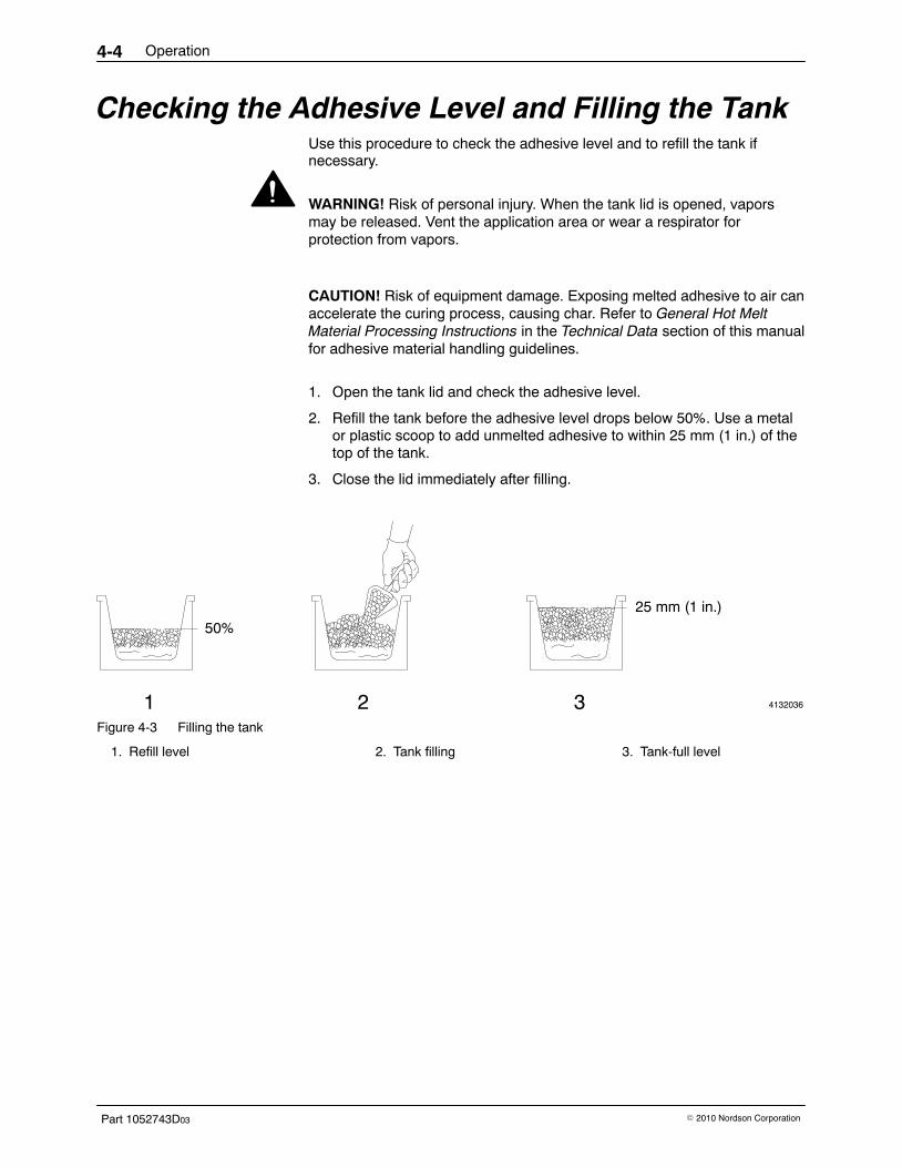
Operation4-4
Part 1052743D03 � 2010 Nordson Corporation
Checking the Adhesive Level and Filling the Tank Use this procedure to check the adhesive level and to refill the tank ifnecessary.
WARNING! Risk of personal injury. When the tank lid is opened, vaporsmay be released. Vent the application area or wear a respirator forprotection from vapors.
CAUTION! Risk of equipment damage. Exposing melted adhesive to air canaccelerate the curing process, causing char. Refer to General Hot MeltMaterial Processing Instructions in the Technical Data section of this manualfor adhesive material handling guidelines.
1. Open the tank lid and check the adhesive level.
2. Refill the tank before the adhesive level drops below 50%. Use a metalor plastic scoop to add unmelted adhesive to within 25 mm (1 in.) of thetop of the tank.
3. Close the lid immediately after filling.
4132036
50%
25 mm (1 in.)
1 2 3Figure 4-3 Filling the tank
1. Refill level 2. Tank filling 3. Tank-full level
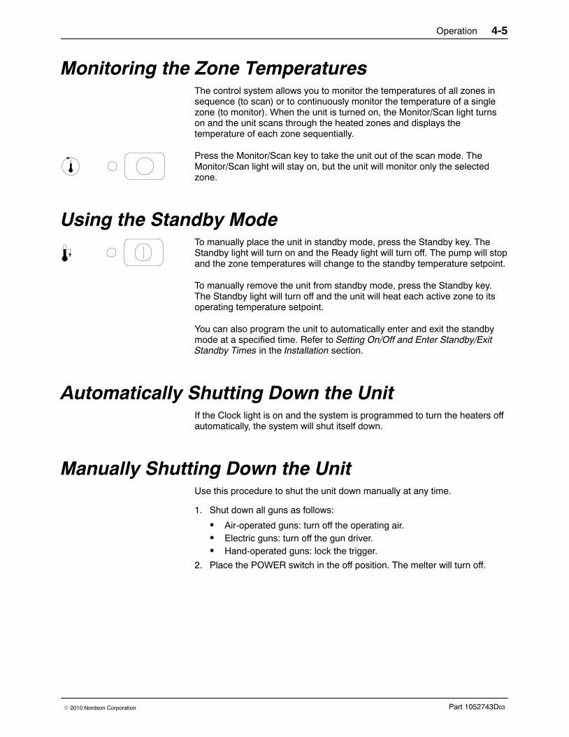
Operation 4-5
Part 1052743D03� 2010 Nordson Corporation
Monitoring the Zone Temperatures The control system allows you to monitor the temperatures of all zones insequence (to scan) or to continuously monitor the temperature of a singlezone (to monitor). When the unit is turned on, the Monitor/Scan light turnson and the unit scans through the heated zones and displays thetemperature of each zone sequentially.
Press the Monitor/Scan key to take the unit out of the scan mode. TheMonitor/Scan light will stay on, but the unit will monitor only the selectedzone.
Using the Standby Mode To manually place the unit in standby mode, press the Standby key. TheStandby light will turn on and the Ready light will turn off. The pump will stopand the zone temperatures will change to the standby temperature setpoint.
To manually remove the unit from standby mode, press the Standby key.The Standby light will turn off and the unit will heat each active zone to itsoperating temperature setpoint.
You can also program the unit to automatically enter and exit the standbymode at a specified time. Refer to Setting On/Off and Enter Standby/ExitStandby Times in the Installation section.
Automatically Shutting Down the Unit If the Clock light is on and the system is programmed to turn the heaters offautomatically, the system will shut itself down.
Manually Shutting Down the Unit Use this procedure to shut the unit down manually at any time.
1. Shut down all guns as follows:
� Air-operated guns: turn off the operating air.� Electric guns: turn off the gun driver.� Hand-operated guns: lock the trigger.
2. Place the POWER switch in the off position. The melter will turn off.
Operation4-6
Part 1052743D03 � 2010 Nordson Corporation
Procedure for Changing Adhesives Contact your material supplier about the compatibility of the old and newmaterials. If the old and new adhesives are compatible, add the newadhesive to the tank. If the new adhesive is not compatible with the old one,ask your supplier for an acceptable flushing material to thoroughly clean thesystem.
Use this procedure to clean the system before changing to an adhesive thatis incompatible with the old one.
1. Ensure that the unit is at operating temperature.
WARNING! System or material pressurized. Relieve system pressure.Failure to observe may result in serious burns.
2. Relieve system pressure. Refer to Relieving System Pressure in theMaintenance section of this manual.
3. Drain the unit by pumping as much adhesive from the tank as possibleusing one of the following methods.
Method of Draining Description
Gun Place a suitable container under each gunnozzle. Remove each nozzle from its gun.Turn on the pump by pressing the PUMP keyand pump the adhesive out through the gun.
Manifold Pump the adhesive out through the manifold.Refer to the filter flushing procedure in theMaintenance section of this manual.
Hose Disconnect a hose from its gun. Replace thedust cover, which was removed duringinstallation, on the hose electrical receptacle.Position the hose over a suitable wastecontainer and secure it. Turn the pump on bypressing the PUMP key and pump theadhesive out through the hose.

Operation 4-7
Part 1052743D03� 2010 Nordson Corporation
4132037
Figure 4-4 Methods of draining the unit
1. Draining through the gun 2. Draining through the manifold(typical manifold shown)
3. Draining through the hose
4. If you have not already done so, disconnect each hose in the systemfrom its gun.
5. Clean each automatic gun and hand-operated gun as needed. Refer tothe gun manual for information on gun disassembly, cleaning, andrebuilding.
6. Flush the system with the flushing material recommended by youradhesive supplier. Refer to Flushing the System in the Maintenancesection of this manual.
7. Check the Material Safety Data Sheet (MSDS) for the recommendedoperating temperature of the new adhesive. If the temperature isdifferent from the old adhesive, reprogram your unit’s temperaturesettings. Refer to Table 4-1.
Table 4-1 Temperature Programming Procedures
Type of Temperature Setting Programming Procedure
Temperature setpoint Refer to Setting Temperature Setpointsin the Installation section of this manual.
Overtemperature setpoint Refer to Setting the OvertemperatureSetpoint in the Installation section of thismanual.
The unit is ready for routine operation.

Operation4-8
Part 1052743D03 � 2010 Nordson Corporation

Maintenance 5-1
Part 1052743D03� 2010 Nordson Corporation
Section 5Maintenance
WARNING! Allow only personnel with appropriate training and experienceto operate or service the equipment. The use of untrained or inexperiencedpersonnel to operate or service the equipment can result in injury, includingdeath, to themselves and others, and damage to the equipment.
Introduction Performing routine maintenance can extend the life of your unit anddecrease the downtime caused by repairs. This section of the manualdescribes how to
� schedule maintenance activities� relieve system pressure� replace the O-rings on hose connectors and plugs� flush the manifold filter� clean the manifold filter� flush the system
For information on repairing your unit, refer to the repair procedures in theControl, Hydraulics, or Tank sections of this manual.
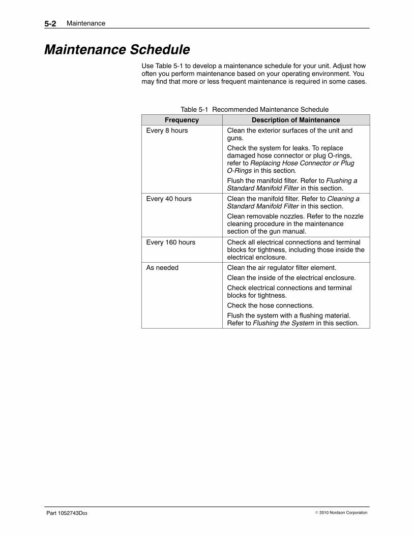
Maintenance5-2
Part 1052743D03 � 2010 Nordson Corporation
Maintenance Schedule Use Table 5-1 to develop a maintenance schedule for your unit. Adjust howoften you perform maintenance based on your operating environment. Youmay find that more or less frequent maintenance is required in some cases.
Table 5-1 Recommended Maintenance Schedule
Frequency Description of Maintenance
Every 8 hours Clean the exterior surfaces of the unit andguns.
Check the system for leaks. To replacedamaged hose connector or plug O-rings,refer to Replacing Hose Connector or PlugO-Rings in this section.
Flush the manifold filter. Refer to Flushing aStandard Manifold Filter in this section.
Every 40 hours Clean the manifold filter. Refer to Cleaning aStandard Manifold Filter in this section.
Clean removable nozzles. Refer to the nozzlecleaning procedure in the maintenancesection of the gun manual.
Every 160 hours Check all electrical connections and terminalblocks for tightness, including those inside theelectrical enclosure.
As needed Clean the air regulator filter element.
Clean the inside of the electrical enclosure.
Check electrical connections and terminalblocks for tightness.
Check the hose connections.
Flush the system with a flushing material.Refer to Flushing the System in this section.
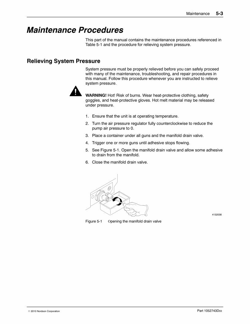
Maintenance 5-3
Part 1052743D03� 2010 Nordson Corporation
Maintenance Procedures This part of the manual contains the maintenance procedures referenced inTable 5-1 and the procedure for relieving system pressure.
Relieving System Pressure System pressure must be properly relieved before you can safely proceedwith many of the maintenance, troubleshooting, and repair procedures inthis manual. Follow this procedure whenever you are instructed to relievesystem pressure.
WARNING! Hot! Risk of burns. Wear heat-protective clothing, safetygoggles, and heat-protective gloves. Hot melt material may be releasedunder pressure.
1. Ensure that the unit is at operating temperature.
2. Turn the air pressure regulator fully counterclockwise to reduce thepump air pressure to 0.
3. Place a container under all guns and the manifold drain valve.
4. Trigger one or more guns until adhesive stops flowing.
5. See Figure 5-1. Open the manifold drain valve and allow some adhesiveto drain from the manifold.
6. Close the manifold drain valve.
4132038
Figure 5-1 Opening the manifold drain valve
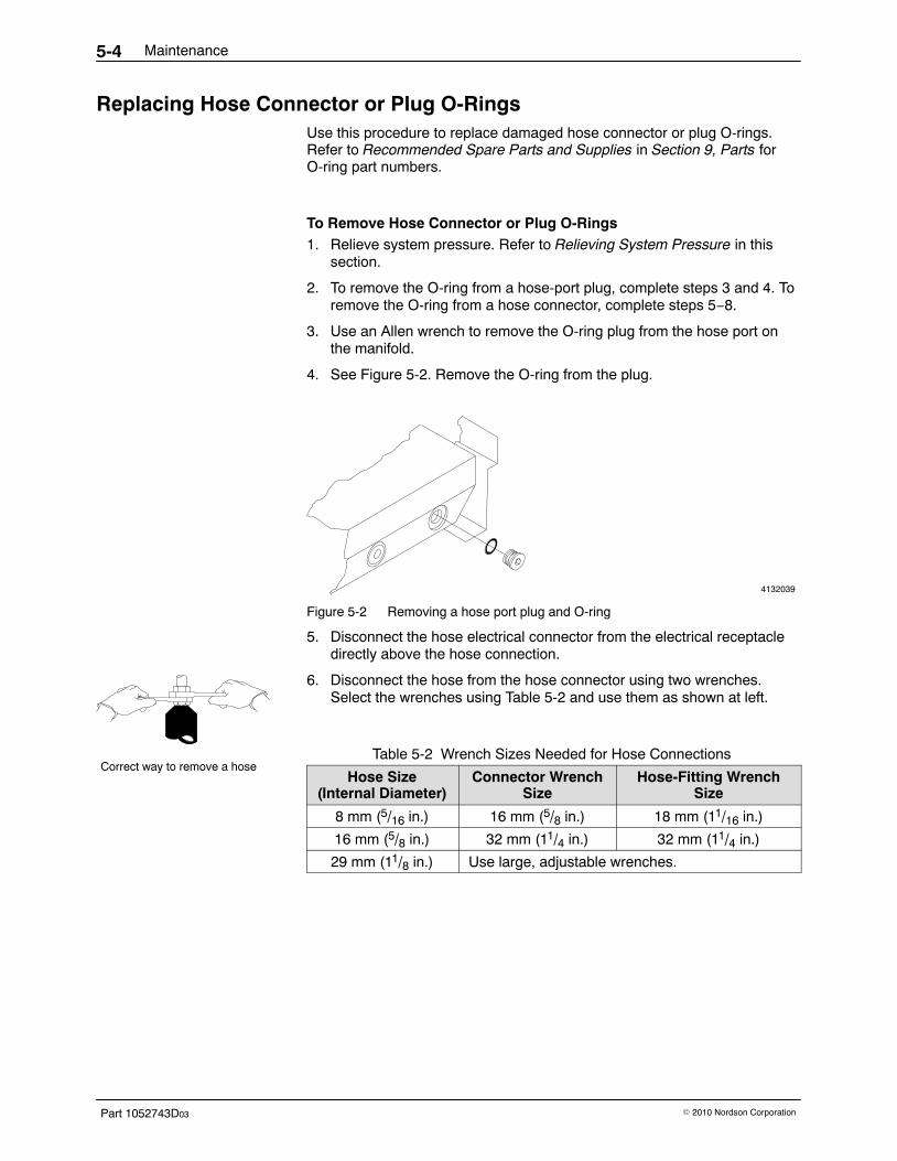
Correct way to remove a hose
Maintenance5-4
Part 1052743D03 � 2010 Nordson Corporation
Replacing Hose Connector or Plug O-Rings Use this procedure to replace damaged hose connector or plug O-rings.Refer to Recommended Spare Parts and Supplies in Section 9, Parts forO-ring part numbers.
To Remove Hose Connector or Plug O-Rings 1. Relieve system pressure. Refer to Relieving System Pressure in this
section.
2. To remove the O-ring from a hose-port plug, complete steps 3 and 4. Toremove the O-ring from a hose connector, complete steps 5−8.
3. Use an Allen wrench to remove the O-ring plug from the hose port onthe manifold.
4. See Figure 5-2. Remove the O-ring from the plug.
4132039
Figure 5-2 Removing a hose port plug and O-ring
5. Disconnect the hose electrical connector from the electrical receptacledirectly above the hose connection.
6. Disconnect the hose from the hose connector using two wrenches.Select the wrenches using Table 5-2 and use them as shown at left.
Table 5-2 Wrench Sizes Needed for Hose Connections
Hose Size(Internal Diameter)
Connector WrenchSize
Hose-Fitting WrenchSize
8 mm (5/16 in.) 16 mm (5/8 in.) 18 mm (11/16 in.)
16 mm (5/8 in.) 32 mm (11/4 in.) 32 mm (11/4 in.)
29 mm (11/8 in.) Use large, adjustable wrenches.
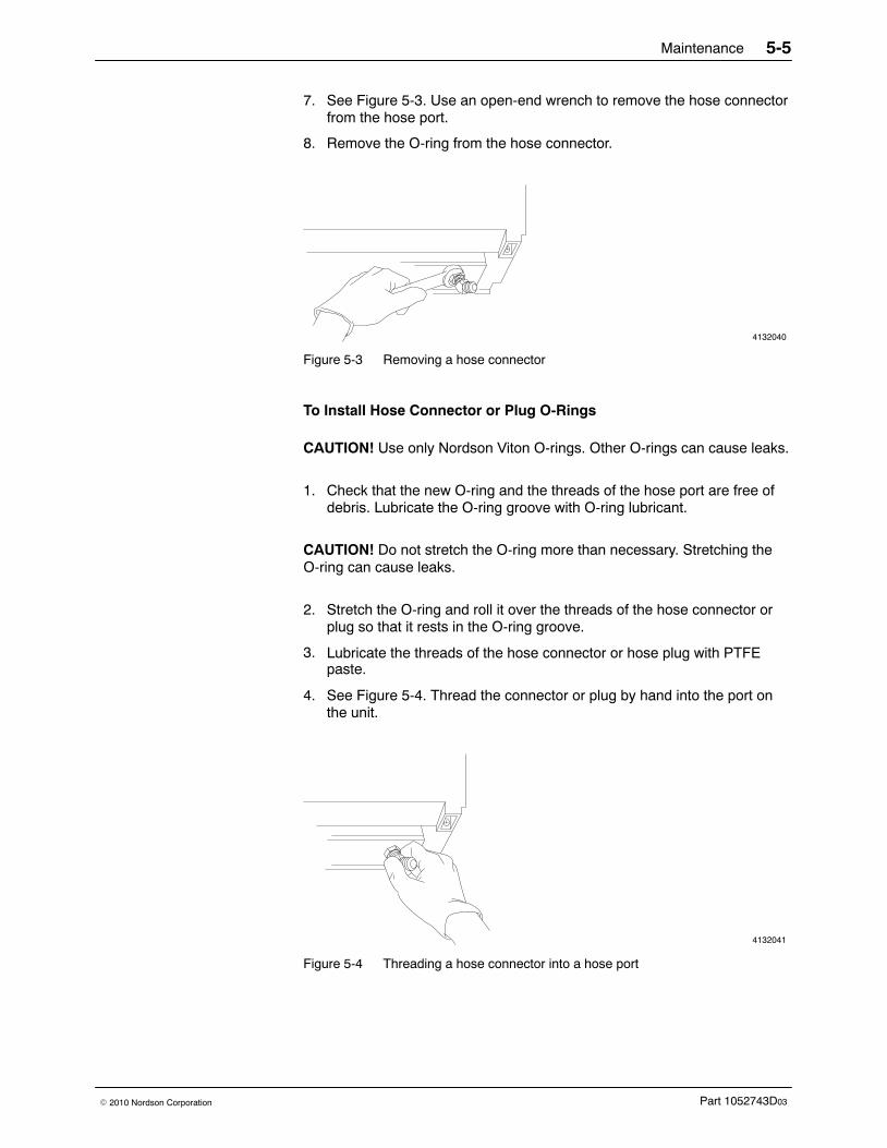
Maintenance 5-5
Part 1052743D03� 2010 Nordson Corporation
7. See Figure 5-3. Use an open-end wrench to remove the hose connectorfrom the hose port.
8. Remove the O-ring from the hose connector.
4132040
Figure 5-3 Removing a hose connector
To Install Hose Connector or Plug O-Rings
CAUTION! Use only Nordson Viton O-rings. Other O-rings can cause leaks.
1. Check that the new O-ring and the threads of the hose port are free ofdebris. Lubricate the O-ring groove with O-ring lubricant.
CAUTION! Do not stretch the O-ring more than necessary. Stretching theO-ring can cause leaks.
2. Stretch the O-ring and roll it over the threads of the hose connector orplug so that it rests in the O-ring groove.
3. Lubricate the threads of the hose connector or hose plug with PTFE paste.
4. See Figure 5-4. Thread the connector or plug by hand into the port onthe unit.
4132041
Figure 5-4 Threading a hose connector into a hose port
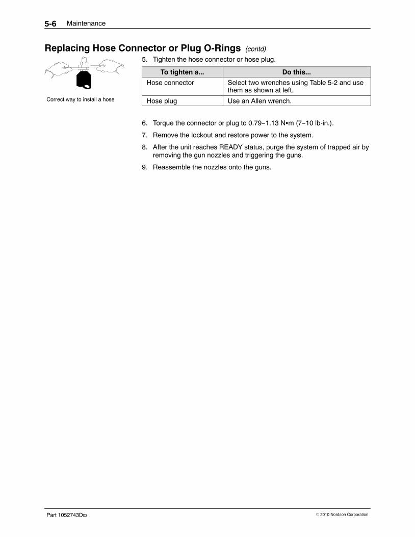
Correct way to install a hose
Maintenance5-6
Part 1052743D03 � 2010 Nordson Corporation
Replacing Hose Connector or Plug O-Rings (contd)
5. Tighten the hose connector or hose plug.
To tighten a... Do this...
Hose connector Select two wrenches using Table 5-2 and usethem as shown at left.
Hose plug Use an Allen wrench.
6. Torque the connector or plug to 0.79−1.13 N�m (7−10 lb-in.).
7. Remove the lockout and restore power to the system.
8. After the unit reaches READY status, purge the system of trapped air byremoving the gun nozzles and triggering the guns.
9. Reassemble the nozzles onto the guns.
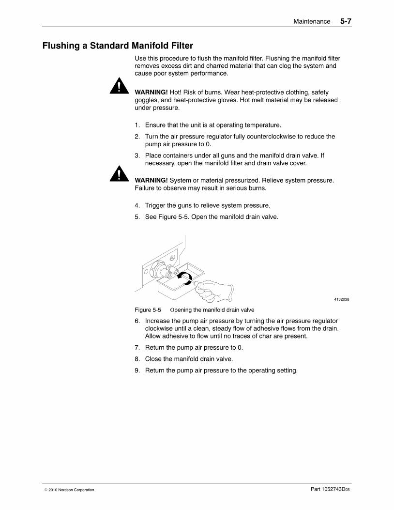
Maintenance 5-7
Part 1052743D03� 2010 Nordson Corporation
Flushing a Standard Manifold Filter Use this procedure to flush the manifold filter. Flushing the manifold filterremoves excess dirt and charred material that can clog the system andcause poor system performance.
WARNING! Hot! Risk of burns. Wear heat-protective clothing, safetygoggles, and heat-protective gloves. Hot melt material may be releasedunder pressure.
1. Ensure that the unit is at operating temperature.
2. Turn the air pressure regulator fully counterclockwise to reduce thepump air pressure to 0.
3. Place containers under all guns and the manifold drain valve. Ifnecessary, open the manifold filter and drain valve cover.
WARNING! System or material pressurized. Relieve system pressure.Failure to observe may result in serious burns.
4. Trigger the guns to relieve system pressure.
5. See Figure 5-5. Open the manifold drain valve.
4132038
Figure 5-5 Opening the manifold drain valve
6. Increase the pump air pressure by turning the air pressure regulatorclockwise until a clean, steady flow of adhesive flows from the drain.Allow adhesive to flow until no traces of char are present.
7. Return the pump air pressure to 0.
8. Close the manifold drain valve.
9. Return the pump air pressure to the operating setting.
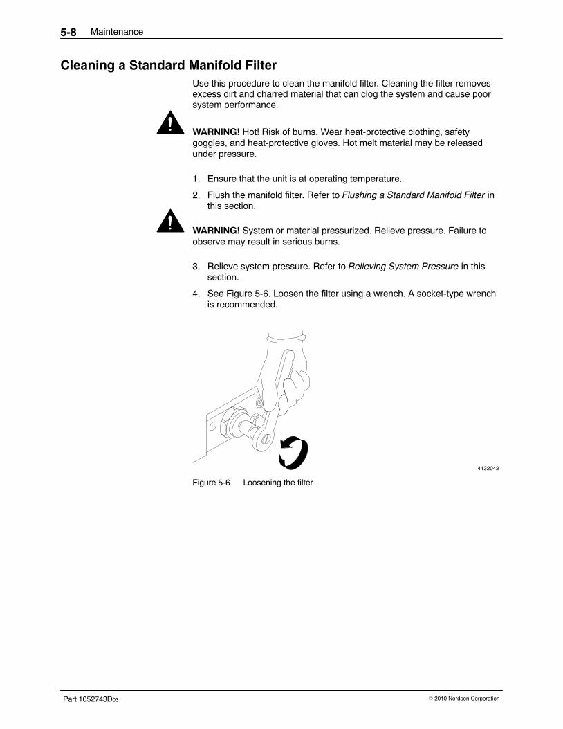
Maintenance5-8
Part 1052743D03 � 2010 Nordson Corporation
Cleaning a Standard Manifold Filter Use this procedure to clean the manifold filter. Cleaning the filter removesexcess dirt and charred material that can clog the system and cause poorsystem performance.
WARNING! Hot! Risk of burns. Wear heat-protective clothing, safetygoggles, and heat-protective gloves. Hot melt material may be releasedunder pressure.
1. Ensure that the unit is at operating temperature.
2. Flush the manifold filter. Refer to Flushing a Standard Manifold Filter inthis section.
WARNING! System or material pressurized. Relieve pressure. Failure toobserve may result in serious burns.
3. Relieve system pressure. Refer to Relieving System Pressure in thissection.
4. See Figure 5-6. Loosen the filter using a wrench. A socket-type wrenchis recommended.
4132042
Figure 5-6 Loosening the filter
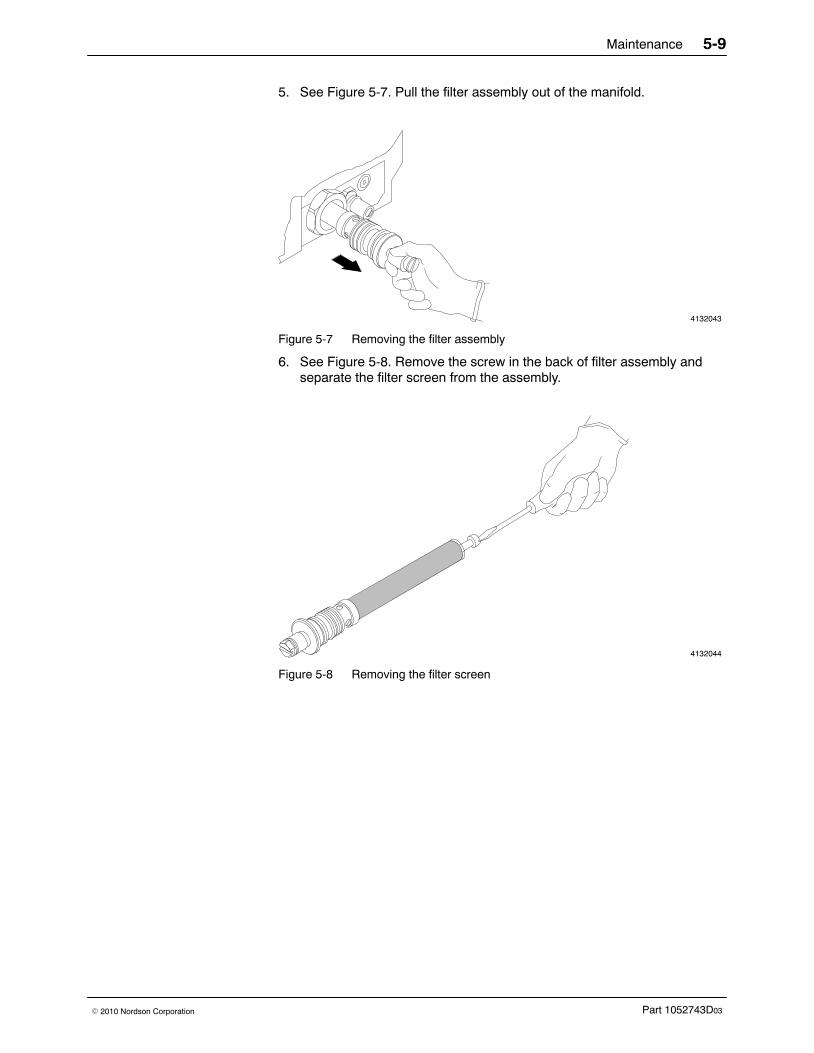
Maintenance 5-9
Part 1052743D03� 2010 Nordson Corporation
5. See Figure 5-7. Pull the filter assembly out of the manifold.
4132043
Figure 5-7 Removing the filter assembly
6. See Figure 5-8. Remove the screw in the back of filter assembly andseparate the filter screen from the assembly.
4132044
Figure 5-8 Removing the filter screen
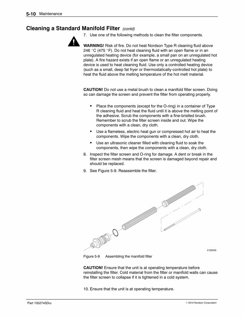
Maintenance5-10
Part 1052743D03 � 2010 Nordson Corporation
Cleaning a Standard Manifold Filter (contd)
7. Use one of the following methods to clean the filter components.
WARNING! Risk of fire. Do not heat Nordson Type R cleaning fluid above246 �C (475 �F). Do not heat cleaning fluid with an open flame or in anunregulated heating device (for example, a small pan on an unregulated hotplate). A fire hazard exists if an open flame or an unregulated heatingdevice is used to heat cleaning fluid. Use only a controlled heating device(such as a small, deep fat fryer or thermostatically-controlled hot plate) toheat the fluid above the melting temperature of the hot melt material.
CAUTION! Do not use a metal brush to clean a manifold filter screen. Doingso can damage the screen and prevent the filter from operating properly.
� Place the components (except for the O-ring) in a container of TypeR cleaning fluid and heat the fluid until it is above the melting point ofthe adhesive. Scrub the components with a fine-bristled brush.Remember to scrub the filter screen inside and out. Wipe thecomponents with a clean, dry cloth.
� Use a flameless, electric heat gun or compressed hot air to heat thecomponents. Wipe the components with a clean, dry cloth.
� Use an ultrasonic cleaner filled with cleaning fluid to soak thecomponents, then wipe the components with a clean, dry cloth.
8. Inspect the filter screen and O-ring for damage. A dent or break in thefilter screen mesh means that the screen is damaged beyond repair andshould be replaced.
9. See Figure 5-9. Reassemble the filter.
4132045
Figure 5-9 Assembling the manifold filter
CAUTION! Ensure that the unit is at operating temperature beforereinstalling the filter. Cold material from the filter or manifold walls can causethe filter screen to collapse if it is tightened in a cold system.
10. Ensure that the unit is at operating temperature.
Maintenance 5-11
Part 1052743D03� 2010 Nordson Corporation
11. Slide the filter assembly into the manifold and tighten it until it isfinger-tight only.
12. Follow these steps to flush the manifold again:
a. Open the manifold drain valve.
b. Turn the air pressure regulator fully counterclockwise to reduce thepump air pressure to 0.
c. Increase the pump air pressure by turning the air pressure regulatorclockwise until a clean, steady flow of adhesive flows from the drain.Drain approximately 0.25 l (8 oz) of adhesive.
d. Return the pump air pressure to 0.
e. Close the manifold drain valve.
13. Tighten the filter assembly until it seats. Do not overtighten.
14. Return the pump air pressure to the normal operating setting.
Flushing the System Use this procedure to periodically flush the system with hot melt material, aflushing material, or Type R cleaning fluid. System flushing removes excessdirt and charred material that can clog the system and cause poor systemperformance. You should also flush the system when you switch to a newtype of hot melt material that is incompatible with the old material. If you areunsure whether the materials are compatible, contact your material supplier.
To Prepare for Flushing the System 1. Ensure that the unit is at operating temperature.
WARNING! System or material pressurized. Relieve system pressure.Failure to observe may result in serious burns.
2. Relieve system pressure. Refer to Relieving System Pressure in thissection.
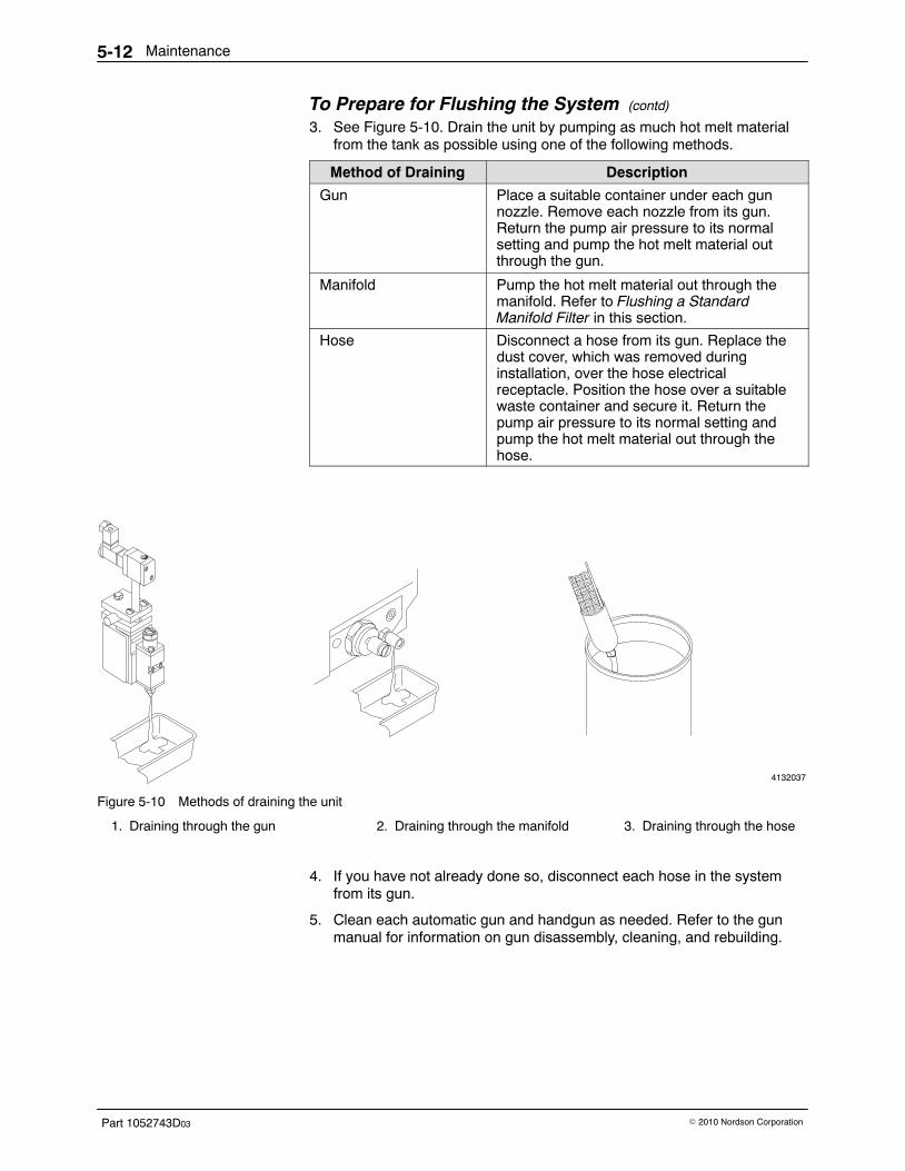
Maintenance5-12
Part 1052743D03 � 2010 Nordson Corporation
To Prepare for Flushing the System (contd)
3. See Figure 5-10. Drain the unit by pumping as much hot melt materialfrom the tank as possible using one of the following methods.
Method of Draining Description
Gun Place a suitable container under each gunnozzle. Remove each nozzle from its gun.Return the pump air pressure to its normalsetting and pump the hot melt material outthrough the gun.
Manifold Pump the hot melt material out through themanifold. Refer to Flushing a StandardManifold Filter in this section.
Hose Disconnect a hose from its gun. Replace thedust cover, which was removed duringinstallation, over the hose electricalreceptacle. Position the hose over a suitablewaste container and secure it. Return thepump air pressure to its normal setting andpump the hot melt material out through thehose.
4132037
Figure 5-10 Methods of draining the unit
1. Draining through the gun 2. Draining through the manifold 3. Draining through the hose
4. If you have not already done so, disconnect each hose in the systemfrom its gun.
5. Clean each automatic gun and handgun as needed. Refer to the gunmanual for information on gun disassembly, cleaning, and rebuilding.
Maintenance 5-13
Part 1052743D03� 2010 Nordson Corporation
6. Refer to Table 5-3 to determine which method of flushing the system isbest for your operation.
Table 5-3 Advantages and Disadvantages of System Flushing Procedures
Flushing Procedure Time Needed(See Note A)
Best Used for...(See Note B)
Advantages andDisadvantages
Using hot melt material About 1 hour Routine cleaning whenthe system is relativelyfree of char.
The advantage of thismethod is that itrequires less downtime.However, it is not asthorough as the othertwo methods.
Using a flushingmaterial recommendedby your adhesivesupplier and approvedby your Nordsonrepresentative
From 21/2 to 5 hours Occasional cleaningwhen there is some charbuildup.
Although this methodrequires moredowntime, it does agood job of removingchar buildup from thesystem. However, toremove all char you mayneed to scrub the tank.You will also need topurchase and storeflushing material, whichmay have specialstorage and disposalrequirements.
Using Type R fluid From 3 to 13 hours Thorough cleaningwhen there is significantchar buildup.
This procedure is themost thorough way toremove char. You mayalso need to scrub thetank to remove all char.Disadvantages are thatyou cannot flush Type Rfluid through the hoses;accidentally doing socan cause laterdowntime. Type R fluidis expensive but can bereused several times ifthe used fluid is strainedinto a storage container.The fluid is considered aregulated waste.
NOTE A: Time needed varies depending on how much char must be removed.
B: Because operating conditions vary from plant to plant, you may find that more or less frequent flushing isrequired.
7. Refer to the appropriate procedure for the flushing method you haveselected:
� To Flush the System with Hot Melt Material� To Flush the System with a Flushing Material� To Flush the System with Type R Fluid
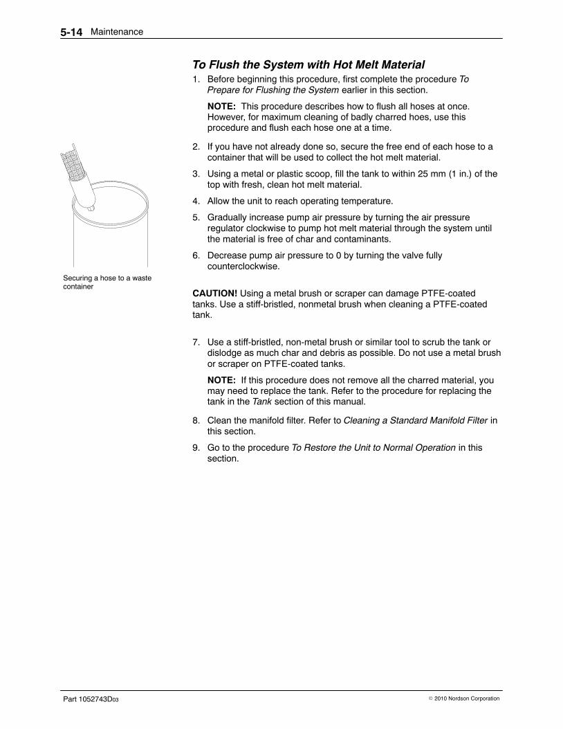
Securing a hose to a wastecontainer
Maintenance5-14
Part 1052743D03 � 2010 Nordson Corporation
To Flush the System with Hot Melt Material 1. Before beginning this procedure, first complete the procedure To
Prepare for Flushing the System earlier in this section.
NOTE: This procedure describes how to flush all hoses at once.However, for maximum cleaning of badly charred hoes, use thisprocedure and flush each hose one at a time.
2. If you have not already done so, secure the free end of each hose to acontainer that will be used to collect the hot melt material.
3. Using a metal or plastic scoop, fill the tank to within 25 mm (1 in.) of thetop with fresh, clean hot melt material.
4. Allow the unit to reach operating temperature.
5. Gradually increase pump air pressure by turning the air pressureregulator clockwise to pump hot melt material through the system untilthe material is free of char and contaminants.
6. Decrease pump air pressure to 0 by turning the valve fullycounterclockwise.
CAUTION! Using a metal brush or scraper can damage PTFE-coated tanks. Use a stiff-bristled, nonmetal brush when cleaning a PTFE-coated tank.
7. Use a stiff-bristled, non-metal brush or similar tool to scrub the tank or dislodge as much char and debris as possible. Do not use a metal brush or scraper on PTFE-coated tanks.
NOTE: If this procedure does not remove all the charred material, youmay need to replace the tank. Refer to the procedure for replacing thetank in the Tank section of this manual.
8. Clean the manifold filter. Refer to Cleaning a Standard Manifold Filter inthis section.
9. Go to the procedure To Restore the Unit to Normal Operation in thissection.
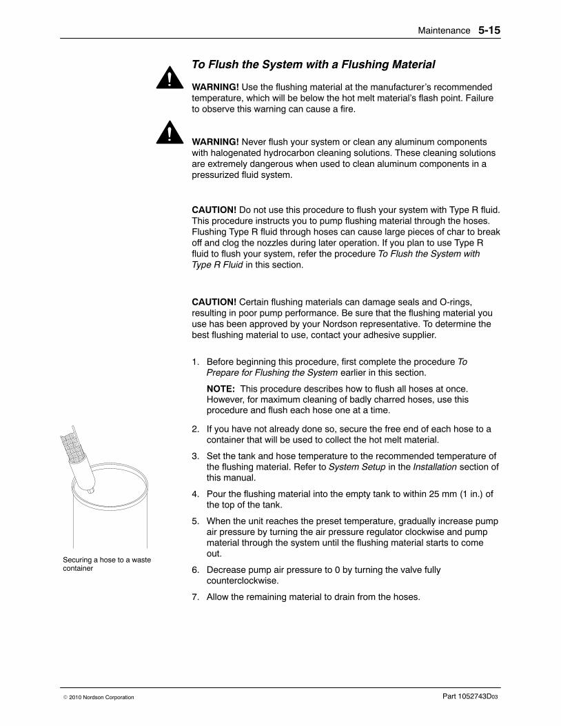
Securing a hose to a wastecontainer
Maintenance 5-15
Part 1052743D03� 2010 Nordson Corporation
To Flush the System with a Flushing Material
WARNING! Use the flushing material at the manufacturer’s recommendedtemperature, which will be below the hot melt material’s flash point. Failureto observe this warning can cause a fire.
WARNING! Never flush your system or clean any aluminum componentswith halogenated hydrocarbon cleaning solutions. These cleaning solutionsare extremely dangerous when used to clean aluminum components in apressurized fluid system.
CAUTION! Do not use this procedure to flush your system with Type R fluid.This procedure instructs you to pump flushing material through the hoses.Flushing Type R fluid through hoses can cause large pieces of char to breakoff and clog the nozzles during later operation. If you plan to use Type Rfluid to flush your system, refer the procedure To Flush the System withType R Fluid in this section.
CAUTION! Certain flushing materials can damage seals and O-rings,resulting in poor pump performance. Be sure that the flushing material youuse has been approved by your Nordson representative. To determine thebest flushing material to use, contact your adhesive supplier.
1. Before beginning this procedure, first complete the procedure ToPrepare for Flushing the System earlier in this section.
NOTE: This procedure describes how to flush all hoses at once.However, for maximum cleaning of badly charred hoses, use thisprocedure and flush each hose one at a time.
2. If you have not already done so, secure the free end of each hose to acontainer that will be used to collect the hot melt material.
3. Set the tank and hose temperature to the recommended temperature ofthe flushing material. Refer to System Setup in the Installation section ofthis manual.
4. Pour the flushing material into the empty tank to within 25 mm (1 in.) ofthe top of the tank.
5. When the unit reaches the preset temperature, gradually increase pumpair pressure by turning the air pressure regulator clockwise and pumpmaterial through the system until the flushing material starts to comeout.
6. Decrease pump air pressure to 0 by turning the valve fullycounterclockwise.
7. Allow the remaining material to drain from the hoses.
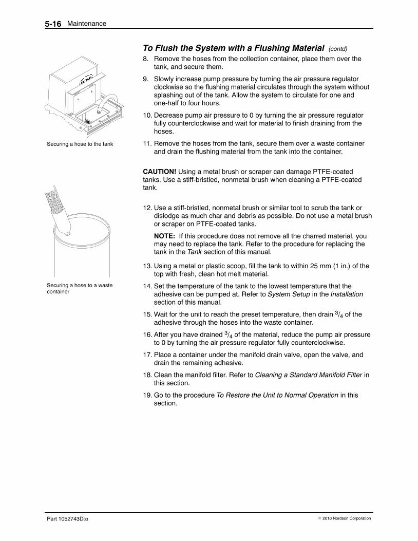
Securing a hose to the tank
Securing a hose to a wastecontainer
Maintenance5-16
Part 1052743D03 � 2010 Nordson Corporation
To Flush the System with a Flushing Material (contd)
8. Remove the hoses from the collection container, place them over thetank, and secure them.
9. Slowly increase pump pressure by turning the air pressure regulatorclockwise so the flushing material circulates through the system withoutsplashing out of the tank. Allow the system to circulate for one andone-half to four hours.
10. Decrease pump air pressure to 0 by turning the air pressure regulatorfully counterclockwise and wait for material to finish draining from thehoses.
11. Remove the hoses from the tank, secure them over a waste containerand drain the flushing material from the tank into the container.
CAUTION! Using a metal brush or scraper can damage PTFE-coated tanks. Use a stiff-bristled, nonmetal brush when cleaning a PTFE-coated tank.
12. Use a stiff-bristled, nonmetal brush or similar tool to scrub the tank or dislodge as much char and debris as possible. Do not use a metal brush or scraper on PTFE-coated tanks.
NOTE: If this procedure does not remove all the charred material, youmay need to replace the tank. Refer to the procedure for replacing thetank in the Tank section of this manual.
13. Using a metal or plastic scoop, fill the tank to within 25 mm (1 in.) of thetop with fresh, clean hot melt material.
14. Set the temperature of the tank to the lowest temperature that theadhesive can be pumped at. Refer to System Setup in the Installationsection of this manual.
15. Wait for the unit to reach the preset temperature, then drain 3/4 of theadhesive through the hoses into the waste container.
16. After you have drained 3/4 of the material, reduce the pump air pressureto 0 by turning the air pressure regulator fully counterclockwise.
17. Place a container under the manifold drain valve, open the valve, anddrain the remaining adhesive.
18. Clean the manifold filter. Refer to Cleaning a Standard Manifold Filter inthis section.
19. Go to the procedure To Restore the Unit to Normal Operation in thissection.
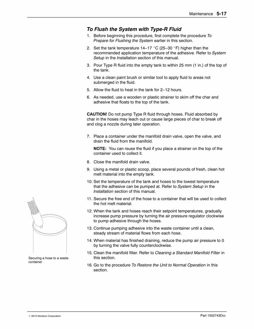
Securing a hose to a wastecontainer
Maintenance 5-17
Part 1052743D03� 2010 Nordson Corporation
To Flush the System with Type-R Fluid 1. Before beginning this procedure, first complete the procedure To
Prepare for Flushing the System earlier in this section.
2. Set the tank temperature 14−17 �C (25−30 �F) higher than therecommended application temperature of the adhesive. Refer to SystemSetup in the Installation section of this manual.
3. Pour Type R fluid into the empty tank to within 25 mm (1 in.) of the top ofthe tank.
4. Use a clean paint brush or similar tool to apply fluid to areas notsubmerged in the fluid.
5. Allow the fluid to heat in the tank for 2−12 hours.
6. As needed, use a wooden or plastic strainer to skim off the char andadhesive that floats to the top of the tank.
CAUTION! Do not pump Type R fluid through hoses. Fluid absorbed bychar in the hoses may leach out or cause large pieces of char to break offand clog a nozzle during later operation.
7. Place a container under the manifold drain valve, open the valve, anddrain the fluid from the manifold.
NOTE: You can reuse the fluid if you place a strainer on the top of thecontainer used to collect it.
8. Close the manifold drain valve.
9. Using a metal or plastic scoop, place several pounds of fresh, clean hotmelt material into the empty tank.
10. Set the temperature of the tank and hoses to the lowest temperaturethat the adhesive can be pumped at. Refer to System Setup in theInstallation section of this manual.
11. Secure the free end of the hose to a container that will be used to collectthe hot melt material.
12. When the tank and hoses reach their setpoint temperatures, graduallyincrease pump pressure by turning the air pressure regulator clockwiseto pump adhesive through the hoses.
13. Continue pumping adhesive into the waste container until a clean,steady stream of material flows from each hose.
14. When material has finished draining, reduce the pump air pressure to 0by turning the valve fully counterclockwise.
15. Clean the manifold filter. Refer to Cleaning a Standard Manifold Filter inthis section.
16. Go to the procedure To Restore the Unit to Normal Operation in thissection.
Maintenance5-18
Part 1052743D03 � 2010 Nordson Corporation
To Restore the Unit to Normal Operation After flushing your system with hot melt material, a flushing material, orType R fluid, follow this procedure to restore your unit to normal operation.
1. Disconnect and lock out electrical power to the unit.
2. Reconnect each gun to its hose both electrically and mechanically. Referto Mechanical Installation and Electrical Installation in the Installationsection of this manual.
3. Remove the lock-out and restore power to the unit.
4. If you have changed the unit’s temperature setpoints or if therecommended operating temperature of the new adhesive is differentfrom the previous adhesive, reprogram the temperature settings. Referto System Setup in the Installation section of this manual.
5. Use a metal or plastic scoop to fill the tank with adhesive. Refer to Fillthe Tank with Adhesive in the Installation section of this manual.
6. Return the pump air pressure to the operating setting.
7. Resume normal operation.
Control 6-1
Part 1052743D03� 2010 Nordson Corporation
Section 6Control
WARNING! Allow only personnel with appropriate training and experienceto operate or service the equipment. The use of untrained or inexperiencedpersonnel to operate or service the equipment can result in injury, includingdeath, to themselves and others, and damage to the equipment.
Introduction This section includes control system troubleshooting and repair procedures.Refer to the parts lists for the part number of any component that needs tobe replaced.
If you try all the troubleshooting suggestions in this section and still needassistance solving control system problems, call your Nordsonrepresentative
The following sections of this manual contain additional information on thecontrol system:
� Description includes an overview of the operator panel.
� Installation includes procedures for connecting output contacts,connecting electrical service, and programming your unit.
� Technical Data includes a wiring diagram for your system.
Refer to the Hydraulics section for troubleshooting procedures, repairprocedures, and parts lists for the unit’s pump and manifold assemblies.
If you have purchased optional features with your unit, such as a low-levelindicator, refer to the documentation supplied with the equipment fortroubleshooting and repair procedures.
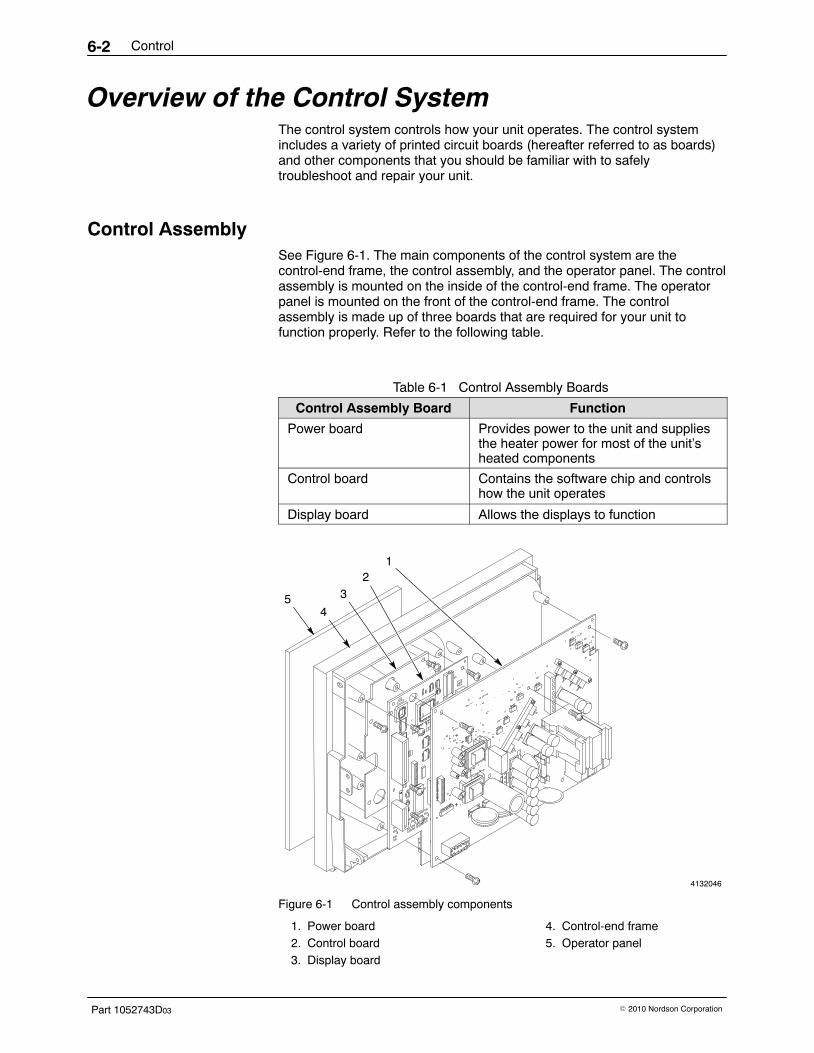
Control6-2
Part 1052743D03 � 2010 Nordson Corporation
Overview of the Control System The control system controls how your unit operates. The control systemincludes a variety of printed circuit boards (hereafter referred to as boards)and other components that you should be familiar with to safelytroubleshoot and repair your unit.
Control Assembly See Figure 6-1. The main components of the control system are thecontrol-end frame, the control assembly, and the operator panel. The controlassembly is mounted on the inside of the control-end frame. The operatorpanel is mounted on the front of the control-end frame. The controlassembly is made up of three boards that are required for your unit tofunction properly. Refer to the following table.
Table 6-1 Control Assembly Boards
Control Assembly Board Function
Power board Provides power to the unit and suppliesthe heater power for most of the unit’sheated components
Control board Contains the software chip and controlshow the unit operates
Display board Allows the displays to function
4132046
1
+
12
3
45
Figure 6-1 Control assembly components
1. Power board2. Control board3. Display board
4. Control-end frame5. Operator panel
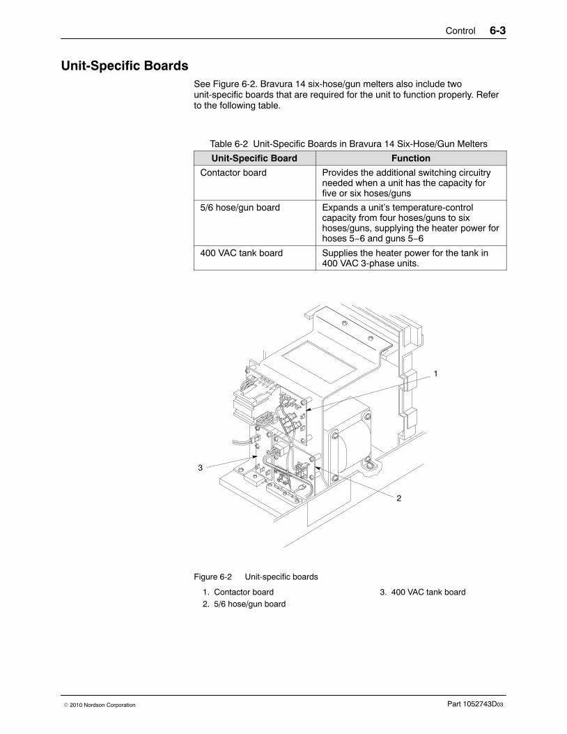
Control 6-3
Part 1052743D03� 2010 Nordson Corporation
Unit-Specific Boards See Figure 6-2. Bravura 14 six-hose/gun melters also include twounit-specific boards that are required for the unit to function properly. Referto the following table.
Table 6-2 Unit-Specific Boards in Bravura 14 Six-Hose/Gun Melters
Unit-Specific Board Function
Contactor board Provides the additional switching circuitryneeded when a unit has the capacity forfive or six hoses/guns
5/6 hose/gun board Expands a unit’s temperature-controlcapacity from four hoses/guns to sixhoses/guns, supplying the heater power forhoses 5−6 and guns 5−6
400 VAC tank board Supplies the heater power for the tank in400 VAC 3-phase units.
1
3
2
Figure 6-2 Unit-specific boards
1. Contactor board2. 5/6 hose/gun board
3. 400 VAC tank board
Control6-4
Part 1052743D03 � 2010 Nordson Corporation
Troubleshooting Tables The following troubleshooting tables describe the kinds of control systemproblems you may encounter and provide corrective actions for handlingthose problems. When necessary, the tables refer to more detailedtroubleshooting procedures.
Refer to the appropriate troubleshooting table for the type of problem youare experiencing:
� Tank, Hose, or Gun Zone Not Heating� Settings Changed or Lost� Unit Not Powering On� Control System Indicating a Fault
- Overtemperature (OT) Fault- RTD Fault- Fault-Code Fault (F1−F7)
Electrical Safety During Troubleshooting Before performing troubleshooting activities inside the unit’s electricalenclosure, you should exhaust all methods of troubleshooting the problemwith the electrical enclosure closed or with the power off. Thetroubleshooting tables and procedures in this section are organized usingthis methodology. In general, you should perform troubleshooting activitiesas follows:
� Check the displays and lights for warnings, faults, and other statusinformation.
� Check your programmed settings to make sure they haven’t beenchanged. Refer to Records of System Settings in the Installationsection.
� Check for continuity and grounding between system components(unit, guns, hoses, and other equipment).
� Make sure your branch circuit disconnect switch is properly installed.
� Make sure your power supply is supplying the proper voltage.
� Prioritize troubleshooting activities to limit exposure to live power.Perform troubleshooting activities involving live power last.
� Understand your system electrically and mechanically beforeopening the electrical enclosure. Pay special attention to systempower distribution and to I/O interfaces with other equipment.
� Identify and eliminate potential electrical shock hazards in theenvironment surrounding your unit.
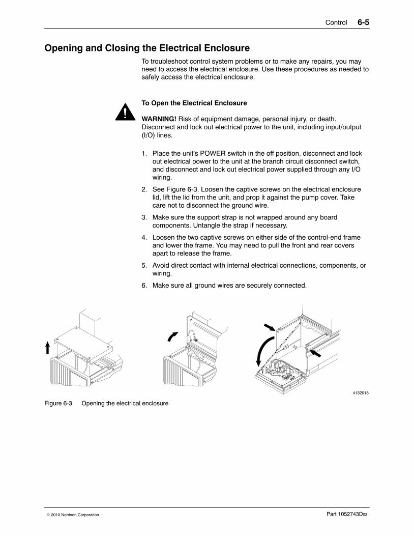
Control 6-5
Part 1052743D03� 2010 Nordson Corporation
Opening and Closing the Electrical Enclosure To troubleshoot control system problems or to make any repairs, you mayneed to access the electrical enclosure. Use these procedures as needed tosafely access the electrical enclosure.
To Open the Electrical Enclosure
WARNING! Risk of equipment damage, personal injury, or death.Disconnect and lock out electrical power to the unit, including input/output(I/O) lines.
1. Place the unit’s POWER switch in the off position, disconnect and lockout electrical power to the unit at the branch circuit disconnect switch,and disconnect and lock out electrical power supplied through any I/Owiring.
2. See Figure 6-3. Loosen the captive screws on the electrical enclosurelid, lift the lid from the unit, and prop it against the pump cover. Takecare not to disconnect the ground wire.
3. Make sure the support strap is not wrapped around any boardcomponents. Untangle the strap if necessary.
4. Loosen the two captive screws on either side of the control-end frameand lower the frame. You may need to pull the front and rear coversapart to release the frame.
5. Avoid direct contact with internal electrical connections, components, orwiring.
6. Make sure all ground wires are securely connected.
4132018
ÎÎÎÎÎÎÎÎÎÎÎÎÎÎÎÎÎÎÎÎÎÎÎÎÎÎÎÎÎÎ
Figure 6-3 Opening the electrical enclosure
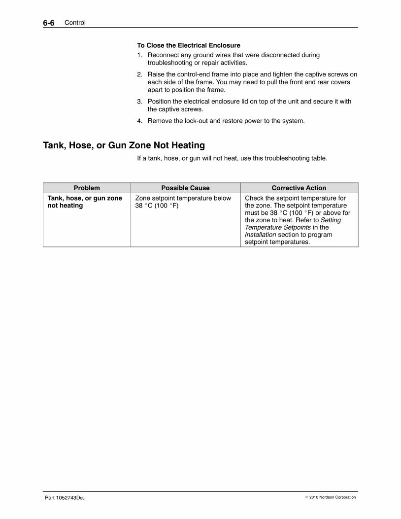
Control6-6
Part 1052743D03 � 2010 Nordson Corporation
To Close the Electrical Enclosure 1. Reconnect any ground wires that were disconnected during
troubleshooting or repair activities.
2. Raise the control-end frame into place and tighten the captive screws oneach side of the frame. You may need to pull the front and rear coversapart to position the frame.
3. Position the electrical enclosure lid on top of the unit and secure it withthe captive screws.
4. Remove the lock-out and restore power to the system.
Tank, Hose, or Gun Zone Not Heating If a tank, hose, or gun will not heat, use this troubleshooting table.
Problem Possible Cause Corrective Action
Tank, hose, or gun zonenot heating
Zone setpoint temperature below38 �C (100 �F)
Check the setpoint temperature forthe zone. The setpoint temperaturemust be 38 �C (100 �F) or above forthe zone to heat. Refer to SettingTemperature Setpoints in theInstallation section to programsetpoint temperatures.
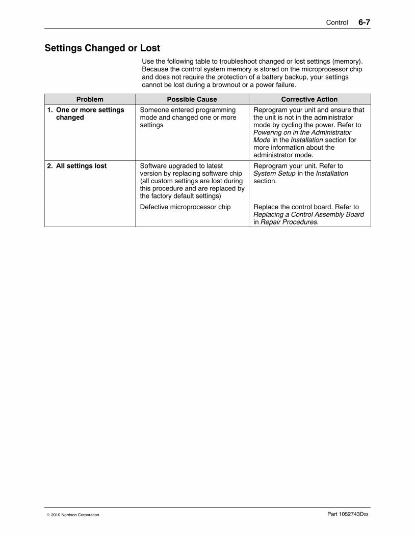
Control 6-7
Part 1052743D03� 2010 Nordson Corporation
Settings Changed or Lost Use the following table to troubleshoot changed or lost settings (memory).Because the control system memory is stored on the microprocessor chipand does not require the protection of a battery backup, your settingscannot be lost during a brownout or a power failure.
Problem Possible Cause Corrective Action
1. One or more settingschanged
Someone entered programmingmode and changed one or moresettings
Reprogram your unit and ensure thatthe unit is not in the administratormode by cycling the power. Refer toPowering on in the AdministratorMode in the Installation section formore information about theadministrator mode.
2. All settings lost Software upgraded to latestversion by replacing software chip(all custom settings are lost duringthis procedure and are replaced bythe factory default settings)
Reprogram your unit. Refer toSystem Setup in the Installationsection.
Defective microprocessor chip Replace the control board. Refer toReplacing a Control Assembly Boardin Repair Procedures.
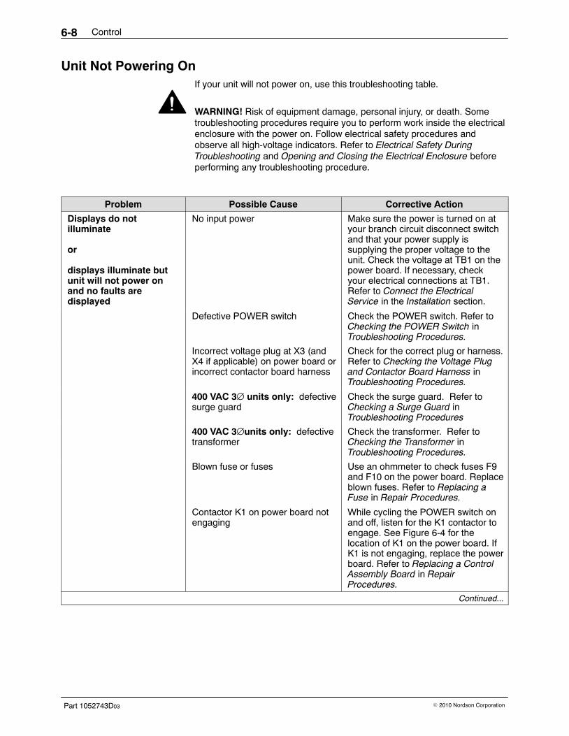
Control6-8
Part 1052743D03 � 2010 Nordson Corporation
Unit Not Powering On If your unit will not power on, use this troubleshooting table.
WARNING! Risk of equipment damage, personal injury, or death. Sometroubleshooting procedures require you to perform work inside the electricalenclosure with the power on. Follow electrical safety procedures andobserve all high-voltage indicators. Refer to Electrical Safety DuringTroubleshooting and Opening and Closing the Electrical Enclosure beforeperforming any troubleshooting procedure.
Problem Possible Cause Corrective Action
Displays do notilluminate
or
displays illuminate butunit will not power onand no faults aredisplayed
No input power Make sure the power is turned on atyour branch circuit disconnect switchand that your power supply issupplying the proper voltage to theunit. Check the voltage at TB1 on thepower board. If necessary, checkyour electrical connections at TB1.Refer to Connect the ElectricalService in the Installation section.
Defective POWER switch Check the POWER switch. Refer toChecking the POWER Switch inTroubleshooting Procedures.
Incorrect voltage plug at X3 (andX4 if applicable) on power board orincorrect contactor board harness
Check for the correct plug or harness.Refer to Checking the Voltage Plugand Contactor Board Harness inTroubleshooting Procedures.
400 VAC 3∅ units only: defectivesurge guard
Check the surge guard. Refer toChecking a Surge Guard inTroubleshooting Procedures
400 VAC 3∅units only: defectivetransformer
Check the transformer. Refer toChecking the Transformer inTroubleshooting Procedures.
Blown fuse or fuses Use an ohmmeter to check fuses F9and F10 on the power board. Replaceblown fuses. Refer to Replacing aFuse in Repair Procedures.
Contactor K1 on power board notengaging
While cycling the POWER switch onand off, listen for the K1 contactor toengage. See Figure 6-4 for thelocation of K1 on the power board. IfK1 is not engaging, replace the powerboard. Refer to Replacing a ControlAssembly Board in RepairProcedures.
Continued...
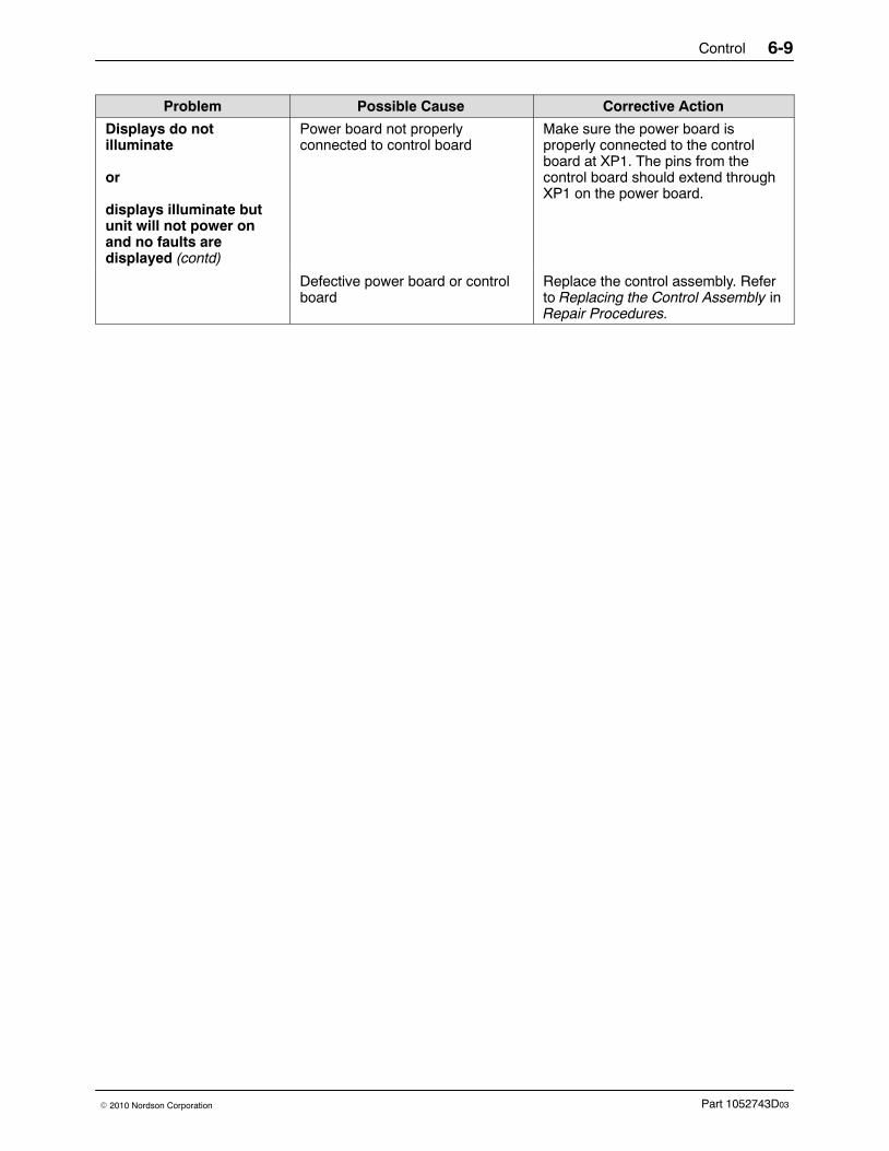
Control 6-9
Part 1052743D03� 2010 Nordson Corporation
Corrective ActionPossible CauseProblem
Displays do notilluminate
or
displays illuminate butunit will not power onand no faults aredisplayed (contd)
Power board not properlyconnected to control board
Make sure the power board isproperly connected to the controlboard at XP1. The pins from thecontrol board should extend throughXP1 on the power board.
Defective power board or controlboard
Replace the control assembly. Referto Replacing the Control Assembly inRepair Procedures.
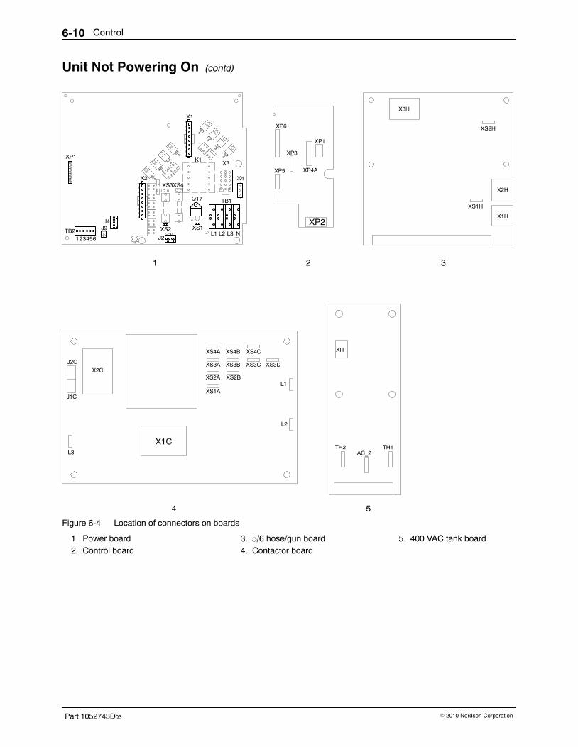
Control6-10
Part 1052743D03 � 2010 Nordson Corporation
Unit Not Powering On (contd)
TB1
L1 L2 L3 NJ2
TB2123456
J4
X2
X1
XS2 XS1J9
Q17
X3
X4
XP1
XS4XS3
X3H
XS2H
XS1H
X2H
X2C
J2C
J1C
X1C
XS4A XS4B XS4C
XS3A XS3B XS3C XS3D
XS2A XS2B
XS1AL1
L2
L3
XIT
TH2AC_2
TH1
1 3
4 5
X1H
2
XP6
XP4A
XP1
XP5
XP3
XP2
K1
Figure 6-4 Location of connectors on boards
1. Power board2. Control board
3. 5/6 hose/gun board4. Contactor board
5. 400 VAC tank board
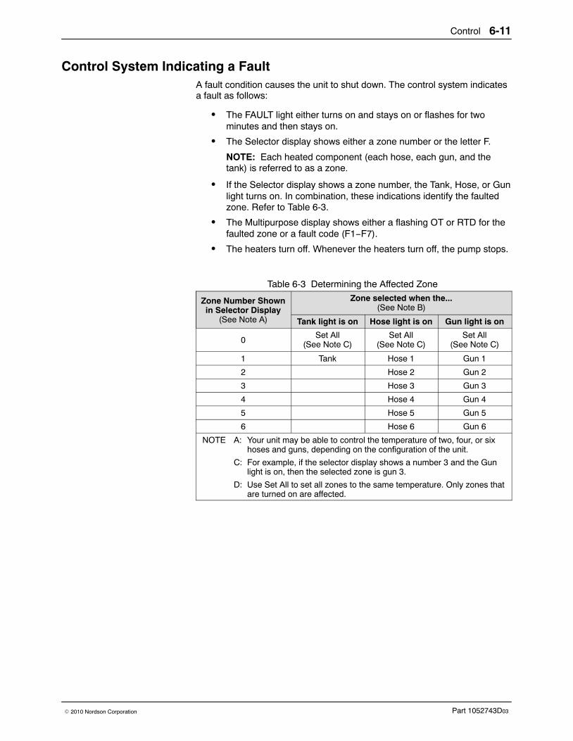
Control 6-11
Part 1052743D03� 2010 Nordson Corporation
Control System Indicating a Fault A fault condition causes the unit to shut down. The control system indicatesa fault as follows:
� The FAULT light either turns on and stays on or flashes for twominutes and then stays on.
� The Selector display shows either a zone number or the letter F.
NOTE: Each heated component (each hose, each gun, and thetank) is referred to as a zone.
� If the Selector display shows a zone number, the Tank, Hose, or Gunlight turns on. In combination, these indications identify the faultedzone. Refer to Table 6-3.
� The Multipurpose display shows either a flashing OT or RTD for thefaulted zone or a fault code (F1−F7).
� The heaters turn off. Whenever the heaters turn off, the pump stops.
Table 6-3 Determining the Affected Zone
Zone Number Shownin Selector Display
(See Note A)
Zone selected when the...(See Note B)
Tank light is on Hose light is on Gun light is on
0Set All
(See Note C)Set All
(See Note C)Set All
(See Note C)
1 Tank Hose 1 Gun 1
2 Hose 2 Gun 2
3 Hose 3 Gun 3
4 Hose 4 Gun 4
5 Hose 5 Gun 5
6 Hose 6 Gun 6
NOTE A: Your unit may be able to control the temperature of two, four, or sixhoses and guns, depending on the configuration of the unit.
C: For example, if the selector display shows a number 3 and the Gunlight is on, then the selected zone is gun 3.
D: Use Set All to set all zones to the same temperature. Only zones thatare turned on are affected.
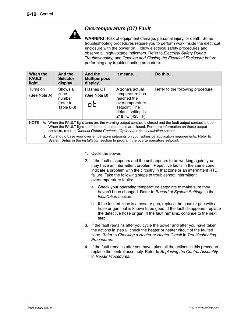
Control6-12
Part 1052743D03 � 2010 Nordson Corporation
Overtemperature (OT) Fault
WARNING! Risk of equipment damage, personal injury, or death. Sometroubleshooting procedures require you to perform work inside the electricalenclosure with the power on. Follow electrical safety procedures andobserve all high-voltage indicators. Refer to Electrical Safety DuringTroubleshooting and Opening and Closing the Electrical Enclosure beforeperforming any troubleshooting procedure.
When theFAULTlight…
And theSelectordisplay…
And theMultipurposedisplay…
It means… Do this…
Turns on
(See Note A)
Shows azonenumber(refer toTable 6-3)
Flashes OT
(See Note B)
A zone’s actualtemperature hasreached theovertemperaturesetpoint. Thedefault setting is218 �C (425 �F).
Refer to the following procedure.
NOTE A: When the FAULT light turns on, the warning output contact is closed and the fault output contact is open.When the FAULT light is off, both output contacts are closed. For more information on these outputcontacts, refer to Connect Output Contacts (Optional) in the Installation section.
B: You should base your overtemperature setpoints on your adhesive application requirements. Refer toSystem Setup in the Installation section to program the overtemperature setpoint.
1. Cycle the power.
2. If the fault disappears and the unit appears to be working again, youmay have an intermittent problem. Repetitive faults in the same zoneindicate a problem with the circuitry in that zone or an intermittent RTDfailure. Take the following steps to troubleshoot intermittentovertemperature faults:
a. Check your operating temperature setpoints to make sure theyhaven’t been changed. Refer to Record of System Settings in theInstallation section.
b. If the faulted zone is a hose or gun, replace the hose or gun with ahose or gun that is known to be good. If the fault disappears, replacethe defective hose or gun. If the fault remains, continue to the nextstep.
3. If the fault remains after you cycle the power and after you have takenthe actions in step 2, check the heater or heater circuit of the faultedzone. Refer to Checking a Heater or Heater Circuit in TroubleshootingProcedures.
4. If the fault remains after you have taken all the actions in this procedure,replace the control assembly. Refer to Replacing the Control Assemblyin Repair Procedures.
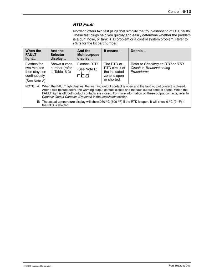
Control 6-13
Part 1052743D03� 2010 Nordson Corporation
RTD Fault Nordson offers two test plugs that simplify the troubleshooting of RTD faults.These test plugs help you quickly and easily determine whether the problemis a gun, hose, or tank RTD problem or a control system problem. Refer toParts for the kit part number.
When theFAULTlight…
And theSelectordisplay…
And theMultipurposedisplay…
It means… Do this…
Flashes fortwo minutesthen stays oncontinuously
(See Note A)
Shows a zonenumber (referto Table 6-3)
Flashes RTD
(See Note B)
The RTD orRTD circuit ofthe indicatedzone is openor shorted.
Refer to Checking an RTD or RTDCircuit in TroubleshootingProcedures.
NOTE A: When the FAULT light flashes, the warning output contact is open and the fault output contact is closed.After a two-minute delay, the warning output contact closes and the fault output contact opens. When theFAULT light is off, both output contacts are closed. For more information on these output contacts, refer toConnect Output Contacts (Optional) in the Installation section.
B: The actual-temperature display will show 260 �C (500 �F) if the RTD is open. It will show 0 �C (0 �F) ifthe RTD is shorted.
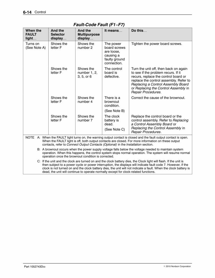
Control6-14
Part 1052743D03 � 2010 Nordson Corporation
Fault-Code Fault (F1−F7) When theFAULTlight…
And theSelectordisplay…
And theMultipurposedisplay…
It means… Do this…
Turns on(See Note A)
Shows theletter F
Shows thenumber 2
The powerboard screwsare loose,causing afaulty groundconnection.
Tighten the power board screws.
Shows theletter F
Shows thenumber 1, 2,3, 5, or 6
The controlboard isdefective.
Turn the unit off, then back on againto see if the problem recurs. If itrecurs, replace the control board orreplace the control assembly. Refer toReplacing a Control Assembly Boardor Replacing the Control Assembly inRepair Procedures.
Shows theletter F
Shows thenumber 4
There is abrownoutcondition.
(See Note B)
Correct the cause of the brownout.
Shows theletter F
Shows thenumber 7
The clockbattery isdead.
(See Note C)
Replace the control board or thecontrol assembly. Refer to Replacinga Control Assembly Board orReplacing the Control Assembly inRepair Procedures.
NOTE A: When the FAULT light turns on, the warning output contact is closed and the fault output contact is open.When the FAULT light is off, both output contacts are closed. For more information on these outputcontacts, refer to Connect Output Contacts (Optional) in the Installation section.
B: A brownout occurs when the power supply voltage falls below the voltage needed to maintain systemoperation. When this happens, the control system stops normal operation. The system will resume normaloperation once the brownout condition is corrected.
C: If the unit and the clock are turned on and the clock battery dies, the Clock light will flash. If the unit isthen subject to a power cycle or power interruption, the displays will indicate fault code 7. However, if theclock is not turned on and the clock battery dies, the unit will not indicate a fault. When the clock battery isdead, the unit will continue to operate normally except for clock-related functions.
Control 6-15
Part 1052743D03� 2010 Nordson Corporation
Troubleshooting Procedures Use these procedures as directed in Troubleshooting Tables to furthertroubleshoot control system problems.
Checking the Power Switch Follow this procedure to check the POWER switch.
WARNING! Risk of equipment damage, personal injury, or death. Thisprocedure requires you to perform electrical troubleshooting with the poweron. Use extreme caution and refer to Electrical Safety DuringTroubleshooting and Opening and Closing the Electrical Enclosure forinstructions on safely working inside the electrical enclosure.
1. Turn on power to the unit at the branch circuit disconnect switch.
2. With the unit’s POWER switch in the off position, measure the voltageacross J4 positions 1 and 4 on the power board.
� Voltage does not measure approximately 230 VAC: replace thePOWER switch and harness.
� Voltage measures approximately 230 VAC: normal indication.Continue to the next step.
3. With the unit’s POWER switch in the on position, measure the voltageacross J4 positions 2 and 5 on the power board.
� Voltage does not measure approximately 230 VAC: replace thePOWER switch and harness.
� Voltage measures approximately 230 VAC: normal indication. Returnto the Unit Not Powering On troubleshooting table.
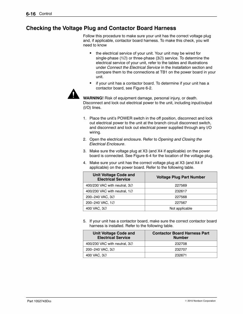
Control6-16
Part 1052743D03 � 2010 Nordson Corporation
Checking the Voltage Plug and Contactor Board Harness Follow this procedure to make sure your unit has the correct voltage plugand, if applicable, contactor board harness. To make this check, you willneed to know
� the electrical service of your unit. Your unit may be wired forsingle-phase (1∅) or three-phase (3∅) service. To determine theelectrical service of your unit, refer to the tables and illustrationsunder Connect the Electrical Service in the Installation section andcompare them to the connections at TB1 on the power board in yourunit.
� if your unit has a contactor board. To determine if your unit has acontactor board, see Figure 6-2.
WARNING! Risk of equipment damage, personal injury, or death.Disconnect and lock out electrical power to the unit, including input/output(I/O) lines.
1. Place the unit’s POWER switch in the off position, disconnect and lockout electrical power to the unit at the branch circuit disconnect switch,and disconnect and lock out electrical power supplied through any I/Owiring.
2. Open the electrical enclosure. Refer to Opening and Closing theElectrical Enclosure.
3. Make sure the voltage plug at X3 (and X4 if applicable) on the powerboard is connected. See Figure 6-4 for the location of the voltage plug.
4. Make sure your unit has the correct voltage plug at X3 (and X4 ifapplicable) on the power board. Refer to the following table.
Unit Voltage Code andElectrical Service Voltage Plug Part Number
400/230 VAC with neutral, 3∅ 227569
400/230 VAC with neutral, 1∅ 232617
200−240 VAC, 3∅ 227568
200−240 VAC, 1∅ 227567
400 VAC, 3∅ Not applicable
5. If your unit has a contactor board, make sure the correct contactor boardharness is installed. Refer to the following table.
Unit Voltage Code andElectrical Service
Contactor Board Harness PartNumber
400/230 VAC with neutral, 3∅ 232708
200−240 VAC, 3∅ 232707
400 VAC, 3∅ 232671
Control 6-17
Part 1052743D03� 2010 Nordson Corporation
Checking a Surge Guard Follow this procedure to check a surge guard on a 400 VAC 3∅ unit.
WARNING! Risk of equipment damage, personal injury, or death.Disconnect and lock out electrical power to the unit, including input/output(I/O) lines.
1. Place the unit’s POWER switch in the off position, disconnect and lockout electrical power to the unit at the branch circuit disconnect switch,and disconnect and lock out electrical power supplied through any I/Owiring.
2. Open the electrical enclosure. Refer to Opening and Closing theElectrical Enclosure.
WARNING! Risk of burns. Surge guards can reach temperatures as high as81 �C (177 �F). Wear heat-protective gloves and do not touch the surgeguards.
3. Connect an ohmmeter set on the highest resistance scale across thesurge guard. See the illustration in the Parts section for the location ofthe surge guards.
NOTE: The unit has two surge guards.
4. If you measure infinite resistance, the surge guard is defective. Refer toReplacing a Surge Guard in Repair Procedures.
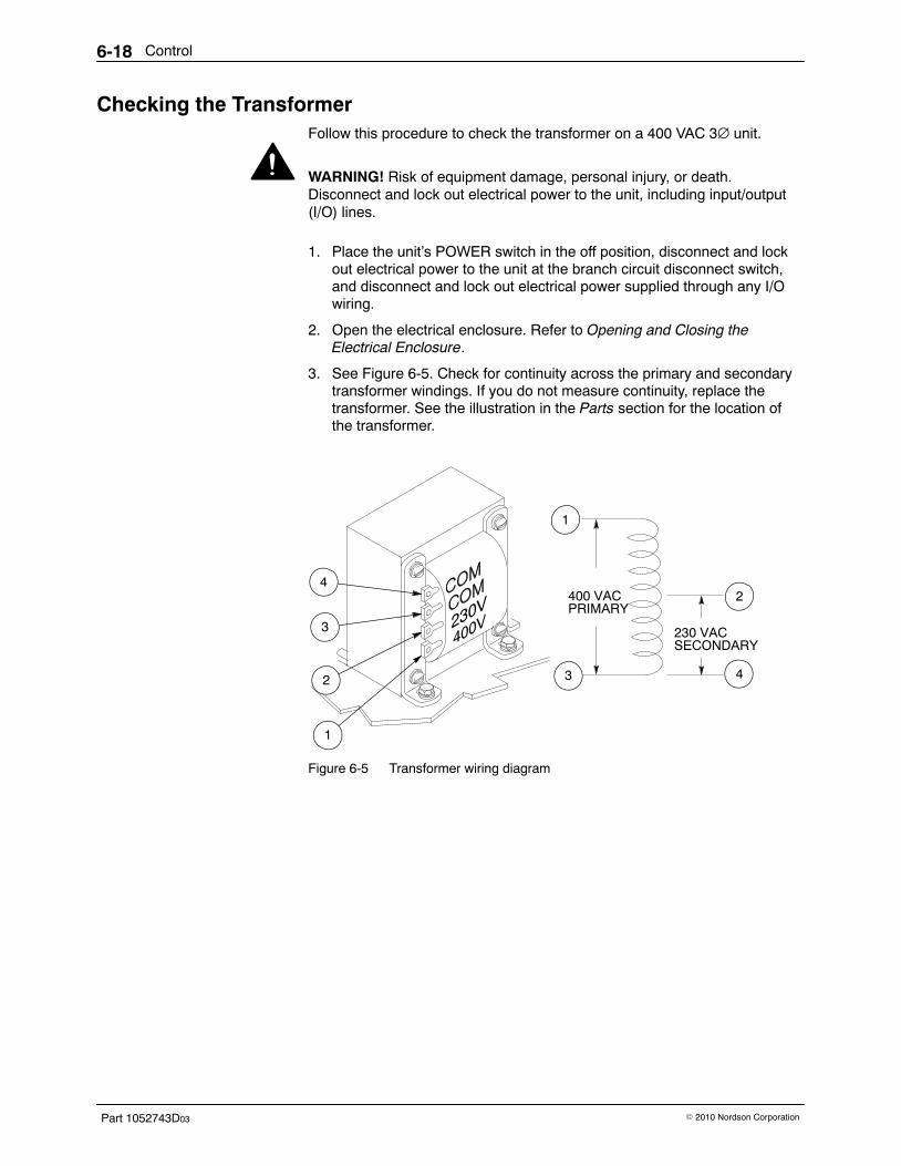
Control6-18
Part 1052743D03 � 2010 Nordson Corporation
Checking the Transformer Follow this procedure to check the transformer on a 400 VAC 3∅ unit.
WARNING! Risk of equipment damage, personal injury, or death.Disconnect and lock out electrical power to the unit, including input/output(I/O) lines.
1. Place the unit’s POWER switch in the off position, disconnect and lockout electrical power to the unit at the branch circuit disconnect switch,and disconnect and lock out electrical power supplied through any I/Owiring.
2. Open the electrical enclosure. Refer to Opening and Closing theElectrical Enclosure.
3. See Figure 6-5. Check for continuity across the primary and secondarytransformer windings. If you do not measure continuity, replace thetransformer. See the illustration in the Parts section for the location ofthe transformer.
400 VACPRIMARY
230 VACSECONDARY
4
3
2
1
1
3 4
2
Figure 6-5 Transformer wiring diagram
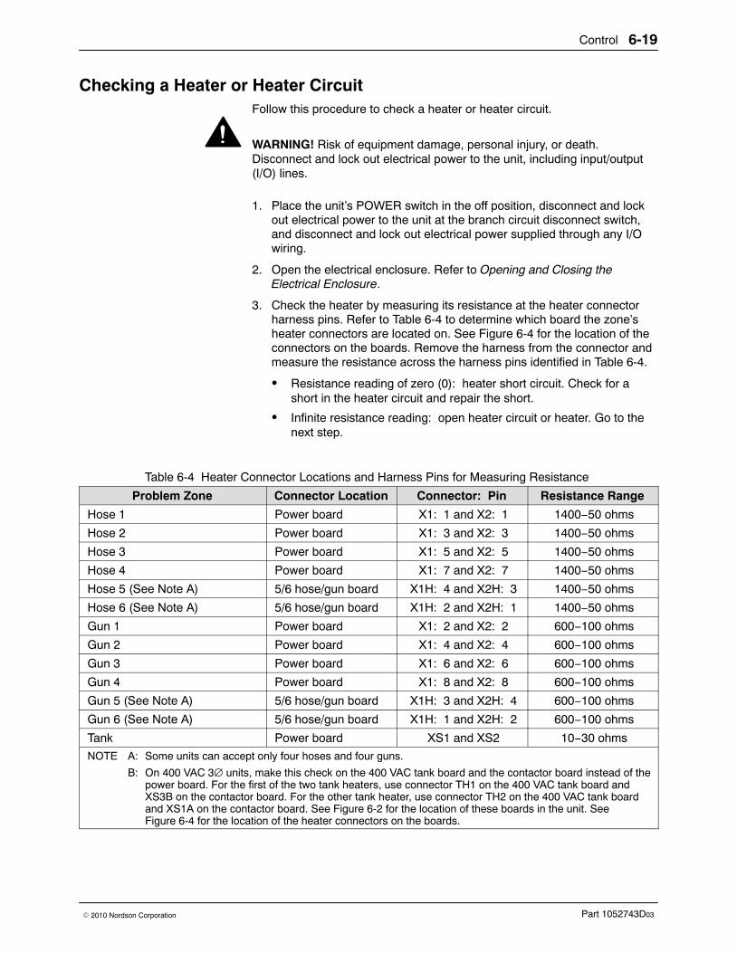
Control 6-19
Part 1052743D03� 2010 Nordson Corporation
Checking a Heater or Heater Circuit Follow this procedure to check a heater or heater circuit.
WARNING! Risk of equipment damage, personal injury, or death.Disconnect and lock out electrical power to the unit, including input/output(I/O) lines.
1. Place the unit’s POWER switch in the off position, disconnect and lockout electrical power to the unit at the branch circuit disconnect switch,and disconnect and lock out electrical power supplied through any I/Owiring.
2. Open the electrical enclosure. Refer to Opening and Closing theElectrical Enclosure.
3. Check the heater by measuring its resistance at the heater connectorharness pins. Refer to Table 6-4 to determine which board the zone’sheater connectors are located on. See Figure 6-4 for the location of theconnectors on the boards. Remove the harness from the connector andmeasure the resistance across the harness pins identified in Table 6-4.
� Resistance reading of zero (0): heater short circuit. Check for ashort in the heater circuit and repair the short.
� Infinite resistance reading: open heater circuit or heater. Go to thenext step.
Table 6-4 Heater Connector Locations and Harness Pins for Measuring Resistance
Problem Zone Connector Location Connector: Pin Resistance Range
Hose 1 Power board X1: 1 and X2: 1 1400−50 ohms
Hose 2 Power board X1: 3 and X2: 3 1400−50 ohms
Hose 3 Power board X1: 5 and X2: 5 1400−50 ohms
Hose 4 Power board X1: 7 and X2: 7 1400−50 ohms
Hose 5 (See Note A) 5/6 hose/gun board X1H: 4 and X2H: 3 1400−50 ohms
Hose 6 (See Note A) 5/6 hose/gun board X1H: 2 and X2H: 1 1400−50 ohms
Gun 1 Power board X1: 2 and X2: 2 600−100 ohms
Gun 2 Power board X1: 4 and X2: 4 600−100 ohms
Gun 3 Power board X1: 6 and X2: 6 600−100 ohms
Gun 4 Power board X1: 8 and X2: 8 600−100 ohms
Gun 5 (See Note A) 5/6 hose/gun board X1H: 3 and X2H: 4 600−100 ohms
Gun 6 (See Note A) 5/6 hose/gun board X1H: 1 and X2H: 2 600−100 ohms
Tank Power board XS1 and XS2 10−30 ohms
NOTE A: Some units can accept only four hoses and four guns.
B: On 400 VAC 3∅ units, make this check on the 400 VAC tank board and the contactor board instead of thepower board. For the first of the two tank heaters, use connector TH1 on the 400 VAC tank board andXS3B on the contactor board. For the other tank heater, use connector TH2 on the 400 VAC tank boardand XS1A on the contactor board. See Figure 6-2 for the location of these boards in the unit. SeeFigure 6-4 for the location of the heater connectors on the boards.
Control6-20
Part 1052743D03 � 2010 Nordson Corporation
Checking a Heater or Heater Circuit (contd)
4. Check the continuity of the heater circuit by measuring the heaterresistance at a point in the circuit that is closer to the heater.
� If the faulted zone is a hose or gun, measure the resistance at thehose or gun electrical plug. Refer to your hose or gun manual for adiagram of the electrical plug and for procedures for replacing thegun heater. If a hose heater is defective, replace the hose.
� If the faulted zone is the tank, measure the resistance at the tankheater connectors (refer to Table 6-4). If you measure infinite orzero (0) resistance at the tank heater connectors, you must install anew tank. Refer to the Tank section.
5. If you do not find a continuity problem, replace the control board or thecontrol assembly. Refer to Replacing a Control Assembly Board orReplacing the Control Assembly in Repair Procedures.
Checking a Thermostat Use this procedure to check a thermostat.
WARNING! System or material pressurized. Relieve pressure. Failure toobserve this warning may result in serious burns.
1. Relieve system pressure. Refer to Relieving System Pressure in theMaintenance section.
WARNING! Risk of equipment damage, personal injury, or death.Disconnect and lock out electrical power to the unit, including input/output(I/O) lines.
2. Place the unit’s POWER switch in the off position, disconnect and lockout electrical power to the unit at the branch circuit disconnect switch,and disconnect and lock out electrical power supplied through any I/Owiring.
3. Open the electrical enclosure. Refer to Opening and Closing theElectrical Enclosure.
4. Remove the thermostat. Refer to RTD or Thermostat Removal in RepairProcedures.
5. Connect an ohmmeter set on the lowest resistance scale across thethermostat; then heat the thermostat with a flameless electric heat gun.
� Short circuit before thermostat reaches temperature and open circuitwhen thermostat reaches temperature: normal indication. Return tothe appropriate troubleshooting table.
� Short circuit or low resistance at high temperature: defectivethermostat. Replace the thermostat. Refer to Replacing an RTD or aThermostat in Repair Procedures.
Control 6-21
Part 1052743D03� 2010 Nordson Corporation
Checking an RTD or RTD Circuit Follow this procedure to check an RTD or RTD circuit.
NOTE: If the faulted zone is a hose or a gun, you can remove the hose orgun and replace it with a hose or gun that is known to be good. If the faultdisappears, then the problem is in the hose or gun, not inside the unit. Asan alternative to using this procedure, you can refer to your hose or gunmanual for instructions on checking the hose or gun RTD and replacing thegun RTD.
WARNING! Risk of equipment damage, personal injury, or death.Disconnect and lock out electrical power to the unit, including input/output(I/O) lines.
1. Place the unit’s POWER switch in the off position, disconnect and lockout electrical power to the unit at the branch circuit disconnect switch,and disconnect and lock out electrical power supplied through any I/Owiring.
2. Open the electrical enclosure. Refer to Opening and Closing theElectrical Enclosure.
3. Check the RTD by measuring its resistance. Refer to Table 6-5.
� If the RTD is defective, replace the RTD. If a hose RTD is defective,you must replace the hose. To replace a gun RTD, refer to your gunmanual. To replace a tank RTD, refer to Replacing an RTD or aThermostat in Repair Procedures.
NOTE: Flex the hose when you are checking a hose RTD. Somehose RTDs exhibit problems intermittently.
� If the RTD is good, go to the next step.
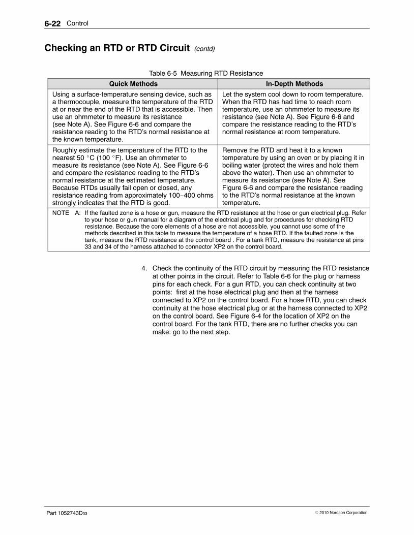
Control6-22
Part 1052743D03 � 2010 Nordson Corporation
Checking an RTD or RTD Circuit (contd)
Table 6-5 Measuring RTD Resistance
Quick Methods In-Depth Methods
Using a surface-temperature sensing device, such asa thermocouple, measure the temperature of the RTDat or near the end of the RTD that is accessible. Thenuse an ohmmeter to measure its resistance(see Note A). See Figure 6-6 and compare theresistance reading to the RTD’s normal resistance atthe known temperature.
Let the system cool down to room temperature.When the RTD has had time to reach roomtemperature, use an ohmmeter to measure itsresistance (see Note A). See Figure 6-6 andcompare the resistance reading to the RTD’snormal resistance at room temperature.
Roughly estimate the temperature of the RTD to thenearest 50 �C (100 �F). Use an ohmmeter tomeasure its resistance (see Note A). See Figure 6-6and compare the resistance reading to the RTD’snormal resistance at the estimated temperature.Because RTDs usually fail open or closed, anyresistance reading from approximately 100−400 ohmsstrongly indicates that the RTD is good.
Remove the RTD and heat it to a knowntemperature by using an oven or by placing it inboiling water (protect the wires and hold themabove the water). Then use an ohmmeter tomeasure its resistance (see Note A). SeeFigure 6-6 and compare the resistance readingto the RTD’s normal resistance at the knowntemperature.
NOTE A: If the faulted zone is a hose or gun, measure the RTD resistance at the hose or gun electrical plug. Referto your hose or gun manual for a diagram of the electrical plug and for procedures for checking RTDresistance. Because the core elements of a hose are not accessible, you cannot use some of themethods described in this table to measure the temperature of a hose RTD. If the faulted zone is thetank, measure the RTD resistance at the control board . For a tank RTD, measure the resistance at pins33 and 34 of the harness attached to connector XP2 on the control board.
4. Check the continuity of the RTD circuit by measuring the RTD resistanceat other points in the circuit. Refer to Table 6-6 for the plug or harnesspins for each check. For a gun RTD, you can check continuity at twopoints: first at the hose electrical plug and then at the harnessconnected to XP2 on the control board. For a hose RTD, you can checkcontinuity at the hose electrical plug or at the harness connected to XP2on the control board. See Figure 6-4 for the location of XP2 on thecontrol board. For the tank RTD, there are no further checks you canmake: go to the next step.
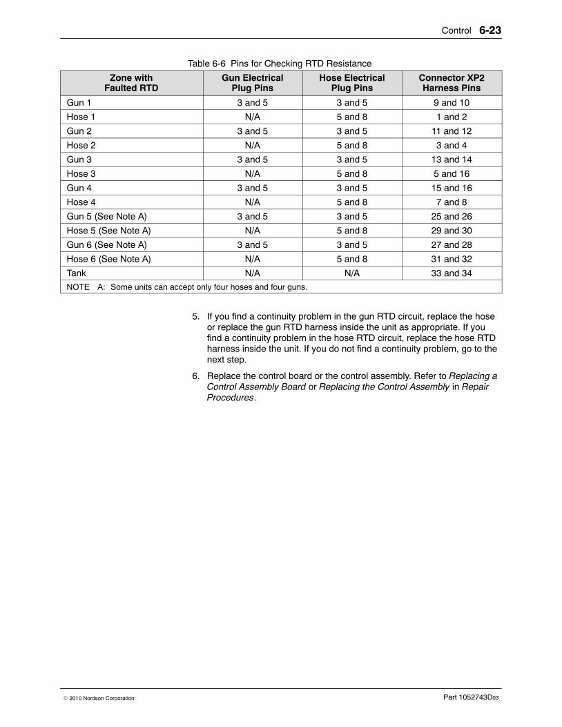
Control 6-23
Part 1052743D03� 2010 Nordson Corporation
Table 6-6 Pins for Checking RTD Resistance
Zone withFaulted RTD
Gun ElectricalPlug Pins
Hose ElectricalPlug Pins
Connector XP2Harness Pins
Gun 1 3 and 5 3 and 5 9 and 10
Hose 1 N/A 5 and 8 1 and 2
Gun 2 3 and 5 3 and 5 11 and 12
Hose 2 N/A 5 and 8 3 and 4
Gun 3 3 and 5 3 and 5 13 and 14
Hose 3 N/A 5 and 8 5 and 16
Gun 4 3 and 5 3 and 5 15 and 16
Hose 4 N/A 5 and 8 7 and 8
Gun 5 (See Note A) 3 and 5 3 and 5 25 and 26
Hose 5 (See Note A) N/A 5 and 8 29 and 30
Gun 6 (See Note A) 3 and 5 3 and 5 27 and 28
Hose 6 (See Note A) N/A 5 and 8 31 and 32
Tank N/A N/A 33 and 34
NOTE A: Some units can accept only four hoses and four guns.
5. If you find a continuity problem in the gun RTD circuit, replace the hoseor replace the gun RTD harness inside the unit as appropriate. If youfind a continuity problem in the hose RTD circuit, replace the hose RTDharness inside the unit. If you do not find a continuity problem, go to thenext step.
6. Replace the control board or the control assembly. Refer to Replacing aControl Assembly Board or Replacing the Control Assembly in RepairProcedures.
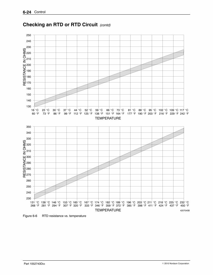
Control6-24
Part 1052743D03 � 2010 Nordson Corporation
Checking an RTD or RTD Circuit (contd)
4207045B
250
240
230
220
210
200
190
180
170
160
150
140
130
RE
SIS
TAN
CE
IN O
HM
S
310
300
290
280
270
260
250
240
230
350
340
330
320
RE
SIS
TAN
CE
IN O
HM
S
TEMPERATURE
TEMPERATURE
16 �C 23 �C 30 �C 37 �C 44 �C 52 �C 59 �C 66 �C 73 �C 81 �C 88 �C 95 �C 102 �C 109 �C 117 �C60 �F 73 �F 86 �F 99 �F 112 �F 125 �F 138 �F 151 �F 164 �F 177 �F 190 �F 203 �F 216 �F 229 �F 242 �F
268 �F 281 �F 294 �F 307 �F 320 �F 333 �F 346 �F 359 �F 372 �F 411 �F 424 �F 437 �F 450 �F385 �F 398 �F131 �C 138 �C 146 �C 153 �C 160 �C 167 �C 174 �C 182 �C 189 �C 196 �C 203 �C 211 �C 218 �C 225 �C 232 �C
Figure 6-6 RTD resistance vs. temperature
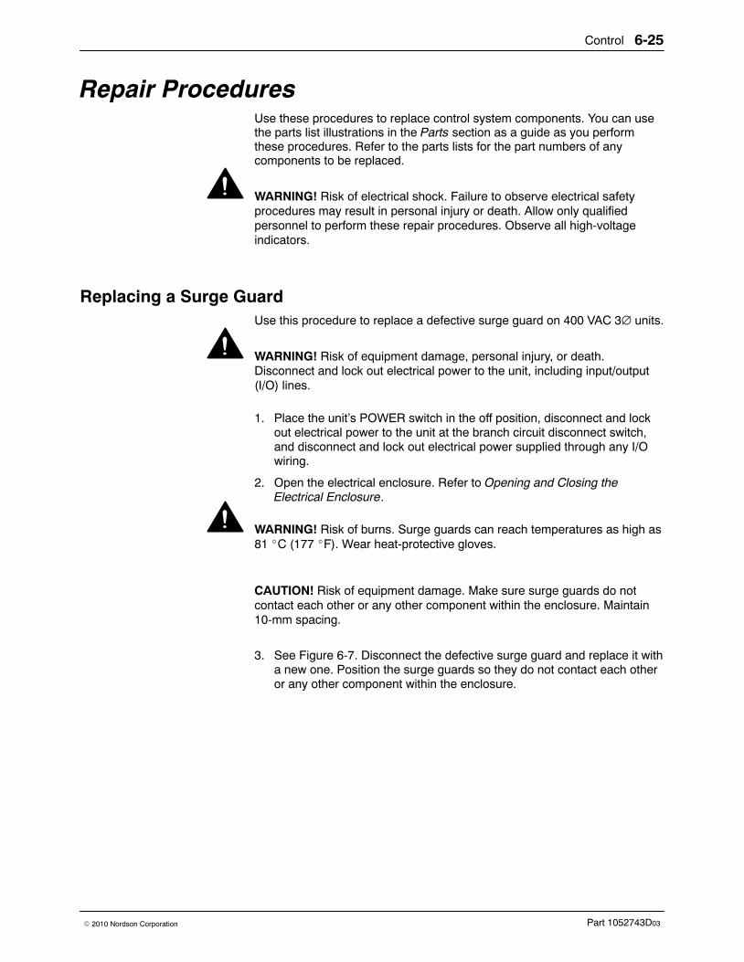
Control 6-25
Part 1052743D03� 2010 Nordson Corporation
Repair Procedures Use these procedures to replace control system components. You can usethe parts list illustrations in the Parts section as a guide as you performthese procedures. Refer to the parts lists for the part numbers of anycomponents to be replaced.
WARNING! Risk of electrical shock. Failure to observe electrical safetyprocedures may result in personal injury or death. Allow only qualifiedpersonnel to perform these repair procedures. Observe all high-voltageindicators.
Replacing a Surge Guard Use this procedure to replace a defective surge guard on 400 VAC 3∅ units.
WARNING! Risk of equipment damage, personal injury, or death.Disconnect and lock out electrical power to the unit, including input/output(I/O) lines.
1. Place the unit’s POWER switch in the off position, disconnect and lockout electrical power to the unit at the branch circuit disconnect switch,and disconnect and lock out electrical power supplied through any I/Owiring.
2. Open the electrical enclosure. Refer to Opening and Closing theElectrical Enclosure.
WARNING! Risk of burns. Surge guards can reach temperatures as high as81 �C (177 �F). Wear heat-protective gloves.
CAUTION! Risk of equipment damage. Make sure surge guards do notcontact each other or any other component within the enclosure. Maintain10-mm spacing.
3. See Figure 6-7. Disconnect the defective surge guard and replace it witha new one. Position the surge guards so they do not contact each otheror any other component within the enclosure.
Control6-26
Part 1052743D03 � 2010 Nordson Corporation
Replacing a Surge Guard (contd)
2
1
1
Figure 6-7 Surge guards
1. Surge guard 2. Transformer
4. Close and secure the electrical enclosure. Refer to Opening and Closingthe Electrical Enclosure.
Control 6-27
Part 1052743D03� 2010 Nordson Corporation
Replacing a Fuse Follow this procedure to replace a fuse. A fuse may be secured by a verticalor horizontal fuse holder.
WARNING! Risk of equipment damage, personal injury, or death.Disconnect and lock out electrical power to the unit, including input/output(I/O) lines.
1. Place the unit’s POWER switch in the off position, disconnect and lockout electrical power to the unit at the branch circuit disconnect switch,and disconnect and lock out electrical power supplied through any I/Owiring.
2. Open the electrical enclosure. Refer to Opening and Closing theElectrical Enclosure.
3. See Figure 6-8 and Table 6-7 to locate the fuse to be replaced.
Table 6-7 Board Fuses
Board Fuse for Fuse NumbersPower board Hose 1, gun 1 F1, F5
Hose 2, gun 2 F2, F6
Hose 3, gun 3 F3, F7
Hose 4, gun 4 F4, F8
Tank F11, F12
Control power F9, F10
5/6 hose/gun board(5/6 hose/gun units only)
Hose 5, gun 5 F1, F3
Hose 6, gun 6 F2, F4
Contactor board[200−240 VAC 1-phase or 3-phase or230 VAC (with neutral) 1-phase units]
Hoses 5−6, guns 5−6 F1, F2
Contactor board[400/230 VAC (with neutral) 3-phase units]
Hoses 5−6, guns 5−6 F1
Contactor board(400 VAC 3-phase units)
Tank heater 1 F1, F3
Tank heater 2 F2, F3
Hoses 1−2, guns 1−2 F1, F2
Control power F1, F2
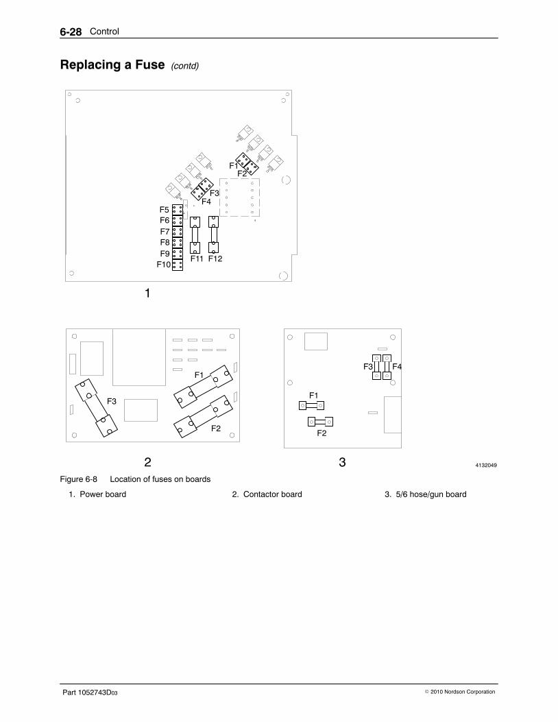
Control6-28
Part 1052743D03 � 2010 Nordson Corporation
Replacing a Fuse (contd)
4132049
F1F2
F3F4
F5F6F7F8F9
F10F11 F12
1
3
F2
F1
F3 F4F1
F2
F3
2Figure 6-8 Location of fuses on boards
1. Power board 2. Contactor board 3. 5/6 hose/gun board
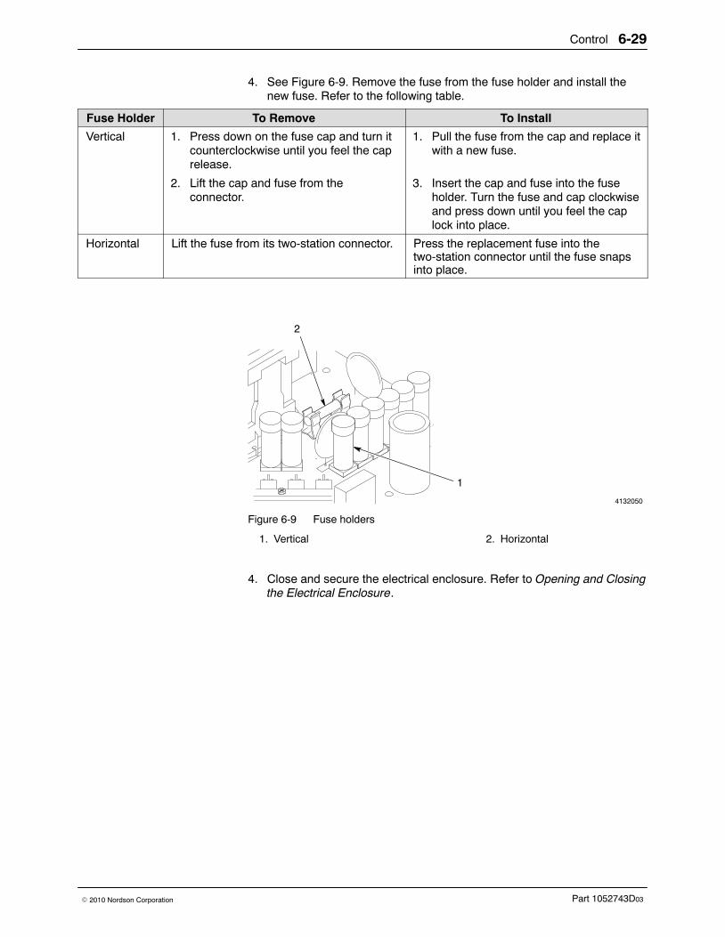
Control 6-29
Part 1052743D03� 2010 Nordson Corporation
4. See Figure 6-9. Remove the fuse from the fuse holder and install thenew fuse. Refer to the following table.
Fuse Holder To Remove To Install
Vertical 1. Press down on the fuse cap and turn itcounterclockwise until you feel the caprelease.
1. Pull the fuse from the cap and replace itwith a new fuse.
2. Lift the cap and fuse from theconnector.
3. Insert the cap and fuse into the fuseholder. Turn the fuse and cap clockwiseand press down until you feel the caplock into place.
Horizontal Lift the fuse from its two-station connector. Press the replacement fuse into thetwo-station connector until the fuse snapsinto place.
4132050
2
1
Figure 6-9 Fuse holders
1. Vertical 2. Horizontal
4. Close and secure the electrical enclosure. Refer to Opening and Closingthe Electrical Enclosure.
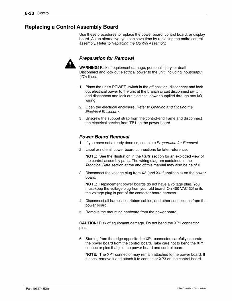
Control6-30
Part 1052743D03 � 2010 Nordson Corporation
Replacing a Control Assembly Board Use these procedures to replace the power board, control board, or displayboard. As an alternative, you can save time by replacing the entire controlassembly. Refer to Replacing the Control Assembly.
Preparation for Removal
WARNING! Risk of equipment damage, personal injury, or death.Disconnect and lock out electrical power to the unit, including input/output(I/O) lines.
1. Place the unit’s POWER switch in the off position, disconnect and lockout electrical power to the unit at the branch circuit disconnect switch,and disconnect and lock out electrical power supplied through any I/Owiring.
2. Open the electrical enclosure. Refer to Opening and Closing theElectrical Enclosure.
3. Unscrew the support strap from the control-end frame and disconnectthe electrical service from TB1 on the power board.
Power Board Removal 1. If you have not already done so, complete Preparation for Removal.
2. Label or note all power board connections for later reference.
NOTE: See the illustration in the Parts section for an exploded view ofthe control assembly parts. The wiring diagram contained in theTechnical Data section at the end of this manual may also be helpful.
3. Disconnect the voltage plug from X3 (and X4 if applicable) on the powerboard.
NOTE: Replacement power boards do not have a voltage plug. Youmust keep the voltage plug from your old board. On 400 VAC 3∅ unitsthe voltage plug is part of the contactor board harness.
4. Disconnect all harnesses, ribbon cables, and other connections from thepower board.
5. Remove the mounting hardware from the power board.
CAUTION! Risk of equipment damage. Do not bend the XP1 connectorpins.
6. Starting from the edge opposite the XP1 connector, carefully separatethe power board from the control board. Take care not to bend the XP1connector pins that join the power board and control board.
NOTE: The XP1 connector may remain attached to the power board. Ifit does, remove it and attach it to connector XP3 on the control board.

Control 6-31
Part 1052743D03� 2010 Nordson Corporation
Power Board Installation 1. Remove the new board from its static-safe container. Handle the board
by its edges without touching any pins, wires, or circuitry.
2. See Figure 6-10. Align XP1 on the new power board with the connectorpins on the control board. Press the board into place, making sure theconnector pins are properly inserted into their sockets.
4132051
1
Figure 6-10 Aligning the XP1 connector pins
3. Install the mounting screws and lock washers you removed earlier. Besure to use lock washers on the three screws located at the threeground pads on the power board. Tighten all screws to1.1−1.4 N�m (10−12 in.-lb).
4. Install the large triac (Q17) screw, which is to the left of TB1. Tighten thescrew to 0.8−0.9 N�m (7−8 in.-lb).
5. Install the two triac clamps and, starting with the center screw, tightenthe securing screws to 1.1−1.4 N�m (10−12 in.-lb).
6. Connect the voltage plug you kept from your old board to X3 (and X4 ifapplicable) on the power board.
NOTE: On 400 VAC 3∅ units the voltage plug is part of the contactorboard harness.
7. Connect all other harnesses, ribbon cables, and other connections tothe power board.
8. Go to System Restoration.
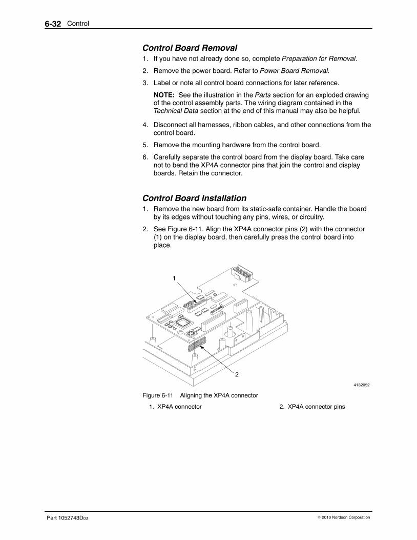
Control6-32
Part 1052743D03 � 2010 Nordson Corporation
Control Board Removal 1. If you have not already done so, complete Preparation for Removal.
2. Remove the power board. Refer to Power Board Removal.
3. Label or note all control board connections for later reference.
NOTE: See the illustration in the Parts section for an exploded drawingof the control assembly parts. The wiring diagram contained in theTechnical Data section at the end of this manual may also be helpful.
4. Disconnect all harnesses, ribbon cables, and other connections from thecontrol board.
5. Remove the mounting hardware from the control board.
6. Carefully separate the control board from the display board. Take carenot to bend the XP4A connector pins that join the control and displayboards. Retain the connector.
Control Board Installation 1. Remove the new board from its static-safe container. Handle the board
by its edges without touching any pins, wires, or circuitry.
2. See Figure 6-11. Align the XP4A connector pins (2) with the connector(1) on the display board, then carefully press the control board intoplace.
4132052
1
1
2
Figure 6-11 Aligning the XP4A connector
1. XP4A connector 2. XP4A connector pins
Control 6-33
Part 1052743D03� 2010 Nordson Corporation
3. Reinstall the mounting hardware. Be sure to use lock washers on thetwo screws located at the two ground pads on the control board. Tightenall screws to 1.1−1.4 N�m (10−12 in.-lb).
NOTE: See the illustration in the Parts section for an exploded drawingof the control assembly parts.
4. Connect all other harnesses, ribbon cables, and other connections tothe control board.
5. Install the power board. Go to step 2 in Power Board Installation.
Display Board Removal 1. If you have not already done so, complete Preparation for Removal.
2. Remove the power board and control board. Refer to Control BoardRemoval.
3. Remove the mounting hardware that secures the display board to thecontrol-end frame and remove the display board.
NOTE: See the illustration in the Parts section for an exploded drawingof the control assembly parts.
Display Board Installation 1. Remove the new board from its static-safe container. Handle the board
by its edges without touching any pins, wires, or circuitry.
2. Align the display board with the control-end frame and attach it with themounting hardware. Tighten all screws to 1.1−1.4 N�m(10−12 in.-lb).
3. Install the control board and power board. Go to step 2 in Control BoardInstallation.
System Restoration 1. Reattach the support strap to the control-end frame. Tighten the screw
to 1.1−1.4 N�m (10−12 in.-lb).
2. Make sure the electrical service connections at TB1 on the power boardare correct. If necessary, refer to Connect the Electrical Service in theInstallation section.
3. Close and secure the electrical enclosure. Refer to Opening and Closingthe Electrical Enclosure.
4. If you replaced the control board, re-enter your customized systemsettings, if any. Refer to System Setup and Record of System Settings inthe Installation section.
Control6-34
Part 1052743D03 � 2010 Nordson Corporation
Replacing the Control Assembly Follow this procedure to replace the control assembly. The control assemblyincludes the following components:
� power board� control board� display board� control-end frame� operator panel
Control Assembly Removal
WARNING! Risk of equipment damage, personal injury, or death.Disconnect and lock out electrical power to the unit, including input/output(I/O) lines.
1. Place the unit’s POWER switch in the off position, disconnect and lockout electrical power to the unit at the branch circuit disconnect switch,and disconnect and lock out electrical power supplied through any I/Owiring.
2. Open the electrical enclosure. Refer to Opening and Closing theElectrical Enclosure.
3. Disconnect the electrical service wiring from TB1 on the power boardand remove the wiring from the cable strap.
4. Disconnect the ground wire.
5. Taking care not to cut any electrical wires, cut the cable ties that securethe harnesses at the bottom of the control-end frame.
6. Disconnect the voltage plug from X3 (and X4 if applicable) on the powerboard.
NOTE: Replacement power boards do not have a voltage plug. Youmust keep the voltage plug from your old board. On 400 VAC 3∅ unitsthe voltage plug is part of the contactor board harness.
7. Label or note all power board connections for later reference.
NOTE: See the illustration in the Parts section exploded drawing of thecontrol assembly parts. The wiring diagram contained in the TechnicalData section at the end of this manual may also be helpful.
8. Disconnect all harnesses, ribbon cables, and other connections from thepower board.
9. Disconnect the plug from XP2 on the control board.
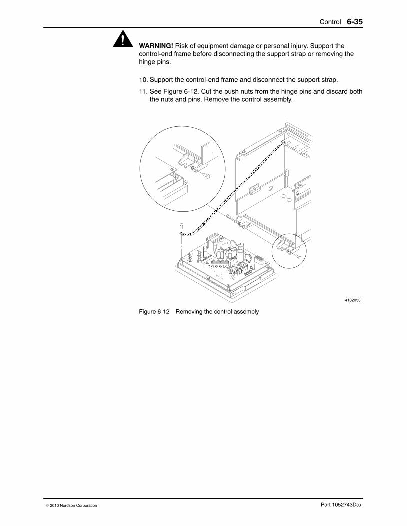
Control 6-35
Part 1052743D03� 2010 Nordson Corporation
WARNING! Risk of equipment damage or personal injury. Support thecontrol-end frame before disconnecting the support strap or removing thehinge pins.
10. Support the control-end frame and disconnect the support strap.
11. See Figure 6-12. Cut the push nuts from the hinge pins and discard boththe nuts and pins. Remove the control assembly.
4132053
+
ÎÎÎÎÎÎÎÎÎÎÎÎÎÎÎÎÎÎÎÎÎÎÎÎÎÎÎÎÎÎÎÎÎÎÎÎÎÎÎÎÎÎÎÎÎÎÎÎÎÎÎÎÎÎÎÎÎÎÎÎÎÎÎÎÎÎÎÎÎÎÎÎÎÎÎÎÎÎÎÎÎÎÎÎÎÎÎÎÎÎÎÎÎÎÎÎÎÎÎÎÎÎÎÎÎÎÎÎÎÎÎÎÎÎÎÎÎÎÎÎÎÎÎÎÎÎÎÎÎÎÎÎ
Figure 6-12 Removing the control assembly
Control6-36
Part 1052743D03 � 2010 Nordson Corporation
Control Assembly Installation 1. Remove the new control assembly from its static-safe container. Avoid
touching any pins, wires, or circuitry.
2. Support the control-end frame, align the control assembly with the baseof the unit, and insert the new hinge pins through the holes in thecontrol-end frame and unit base. Install the pins so the head of each pinis on the outside of the front or rear panel.
3. Using an appropriate tool, press new push nuts over the hinge pins.
4. Reattach the support strap to the control-end frame. Tighten the screwto 1.1−1.4 N�m (10−12 in.-lb).
5. Connect the XP2 plug to the control board.
6. Connect all other harnesses, ribbon cables, and other connections tothe power board.
7. Connect the voltage plug you kept from your old board to X3 (and X4 ifapplicable) on the power board.
NOTE: On 400 VAC 3∅ units the voltage plug is part of the contactorboard harness.
8. Secure the electrical service wiring with the cable strap. Tighten thescrew to 2.48−2.93 N�m (22−26 in.-lb).
9. Connect the electrical service wiring. If necessary, refer to Connect theElectrical Service in the Installation section.
10. Secure the harnesses with new cable ties and secure the cable ties tothe bottom of the control-end frame.
11. Connect the ground wire.
12. Close and secure the electrical enclosure. Refer to Opening and Closingthe Electrical Enclosure.
13. Re-enter your customized system settings, if any. Refer to System Setupand Record of System Settings in the Installation section.
Replacing a Unit-Specific Board Your unit may include one or more unit-specific boards, depending on theconfiguration of the unit. Instructions for replacing unit-specific boards aresupplied with the replacement board repair kits. Refer to Parts for the repairkit part numbers.
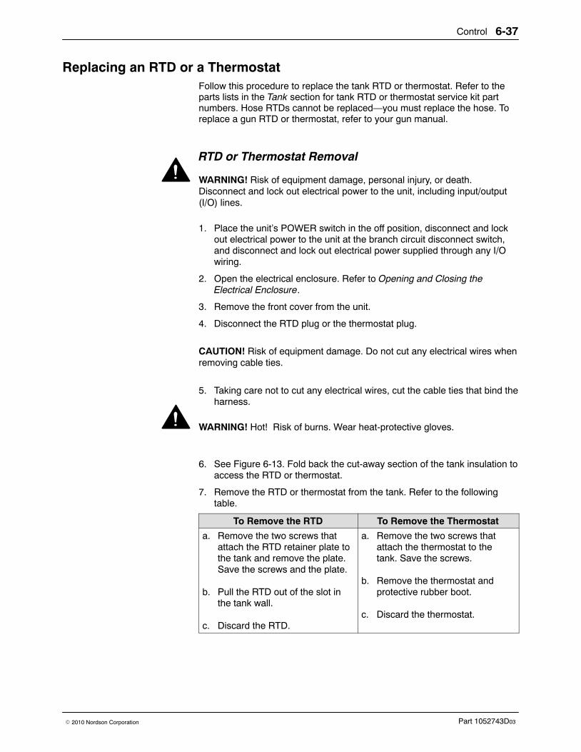
Control 6-37
Part 1052743D03� 2010 Nordson Corporation
Replacing an RTD or a Thermostat Follow this procedure to replace the tank RTD or thermostat. Refer to theparts lists in the Tank section for tank RTD or thermostat service kit partnumbers. Hose RTDs cannot be replaced—you must replace the hose. Toreplace a gun RTD or thermostat, refer to your gun manual.
RTD or Thermostat Removal
WARNING! Risk of equipment damage, personal injury, or death.Disconnect and lock out electrical power to the unit, including input/output(I/O) lines.
1. Place the unit’s POWER switch in the off position, disconnect and lockout electrical power to the unit at the branch circuit disconnect switch,and disconnect and lock out electrical power supplied through any I/Owiring.
2. Open the electrical enclosure. Refer to Opening and Closing theElectrical Enclosure.
3. Remove the front cover from the unit.
4. Disconnect the RTD plug or the thermostat plug.
CAUTION! Risk of equipment damage. Do not cut any electrical wires whenremoving cable ties.
5. Taking care not to cut any electrical wires, cut the cable ties that bind theharness.
WARNING! Hot! Risk of burns. Wear heat-protective gloves.
6. See Figure 6-13. Fold back the cut-away section of the tank insulation toaccess the RTD or thermostat.
7. Remove the RTD or thermostat from the tank. Refer to the followingtable.
To Remove the RTD To Remove the Thermostat
a. Remove the two screws thatattach the RTD retainer plate tothe tank and remove the plate.Save the screws and the plate.
b. Pull the RTD out of the slot inthe tank wall.
c. Discard the RTD.
a. Remove the two screws thatattach the thermostat to thetank. Save the screws.
b. Remove the thermostat andprotective rubber boot.
c. Discard the thermostat.
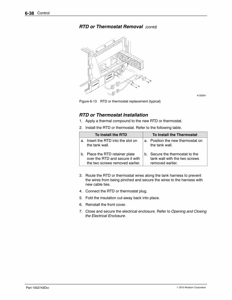
Control6-38
Part 1052743D03 � 2010 Nordson Corporation
RTD or Thermostat Removal (contd)
4132054
ÏÏÏÏÏÏÏÏÏÏÏÏÏÏÏ
ÎÎÎÎÎÎÎÎÎÎÎÎÎÎÎÎÎÎÎÎÎÎÎÎÎ
ÏÏÏÏÏÏÏÏÏÏÏÏÏÏÏÏÏÏÏÏÏÏÏÏÏ
Ï
ÏÏÏÏÏÏÏÏÏÏÏÏÏÏÏÏÏÏÏÏÏÏÏÏ
Figure 6-13 RTD or thermostat replacement (typical)
RTD or Thermostat Installation 1. Apply a thermal compound to the new RTD or thermostat.
2. Install the RTD or thermostat. Refer to the following table.
To Install the RTD To Install the Thermostat
a. Insert the RTD into the slot onthe tank wall.
b. Place the RTD retainer plateover the RTD and secure it withthe two screws removed earlier.
a. Position the new thermostat onthe tank wall.
b. Secure the thermostat to thetank wall with the two screwsremoved earlier.
3. Route the RTD or thermostat wires along the tank harness to preventthe wires from being pinched and secure the wires to the harness withnew cable ties.
4. Connect the RTD or thermostat plug.
5. Fold the insulation cut-away back into place.
6. Reinstall the front cover.
7. Close and secure the electrical enclosure. Refer to Opening and Closingthe Electrical Enclosure.
Hydraulics 7-1
Part 1052743D03� 2010 Nordson Corporation
Section 7Hydraulics
WARNING! Allow only personnel with appropriate training and experienceto operate or service the equipment. The use of untrained or inexperiencedpersonnel to operate or service the equipment can result in injury, includingdeath, to themselves and others, and damage to the equipment.
Introduction This section of the manual describes how to troubleshoot and repair thehydraulic system. It includes
� an overview of the unit’s hydraulic system� troubleshooting guidelines and procedures� pump, actuator, solenoid valve, and manifold repair procedures
Refer to the parts lists in the Parts section for the part numbers of anycomponents that need to be replaced.
If you try all the suggestions in this section and still need assistance solvinghydraulic system problems, call your Nordson representative.
Refer to the following sections of this manual for additional information onthe hydraulic system:
� Installation includes the procedures for connecting the air supply tothe pump and installing hoses.
� Technical Data includes pump specifications.
To replace the tank and manifold, refer to Tank.

Hydraulics7-2
Part 1052743D03 � 2010 Nordson Corporation
Overview of the Hydraulic System Two major assemblies make up the hydraulic system: an air-driven pistonpump and a manifold.
Your unit may have either a 14:1 or 21:1 dual-acting or 10:1 single-actingpiston pump. A dual-acting pump delivers adhesive on both the upstrokeand the downstroke. A single-acting pump delivers adhesive on the downstroke and draws in fresh adhesive on the upstroke. The pump assemblyincludes an air section, a hydraulic section, and either an actuator(dual-acting pumps) or a triggering solenoid valve (single-acting pumps).
The manifold assembly, which is indirectly heated by the tank, includes analuminum manifold with hose ports, a filter assembly, a drain valve, and apressure relief valve.
4132055
1
2
3
4
14:1 or 21:1 10:1
4
1
2
3
Figure 7-1 Key parts of the hydraulic system (shown with a typical tank and manifold)
1. Pump air section2. Pump hydraulic section
3. Manifold4. Actuator (dual-acting pumps only)
5. Triggering solenoid valve(single-acting pumps only)
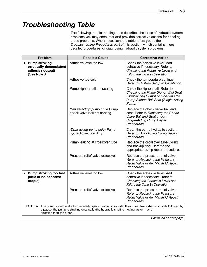
Hydraulics 7-3
Part 1052743D03� 2010 Nordson Corporation
Troubleshooting Table The following troubleshooting table describes the kinds of hydraulic systemproblems you may encounter and provides corrective actions for handlingthose problems. When necessary, the table refers you to theTroubleshooting Procedures part of this section, which contains moredetailed procedures for diagnosing hydraulic system problems.
Problem Possible Cause Corrective Action
1. Pump strokingerratically (inconsistentadhesive output)(See Note A)
Adhesive level too low Check the adhesive level. Addadhesive if necessary. Refer toChecking the Adhesive Level andFilling the Tank in Operation.
Adhesive too cold Check the temperature settings.Refer to System Setup in Installation.
Pump siphon ball not seating Check the siphon ball. Refer toChecking the Pump Siphon Ball Seat(Dual-Acting Pump) or Checking thePump Siphon Ball Seat (Single-ActingPump).
(Single-acting pump only) Pumpcheck valve ball not seating
Replace the check valve ball andseat. Refer to Replacing the CheckValve Ball and Seat underSingle-Acting Pump RepairProcedures.
(Dual-acting pump only) Pumphydraulic section dirty
Clean the pump hydraulic section.Refer to Dual-Acting Pump RepairProcedures.
Pump leaking at crossover tube Replace the crossover tube O-ringand backup ring. Refer to theappropriate pump repair procedures.
Pressure relief valve defective Replace the pressure relief valve.Refer to Replacing the PressureRelief Valve under Manifold RepairProcedures.
2. Pump stroking too fast(little or no adhesiveoutput)
Adhesive level too low Check the adhesive level. Addadhesive if necessary. Refer toChecking the Adhesive Level andFilling the Tank in Operation.
Pressure relief valve defective Replace the pressure relief valve.Refer to Replacing the PressureRelief Valve under Manifold RepairProcedures.
NOTE A: The pump should make two regularly spaced exhaust sounds. If you hear two exhaust sounds followed bya pause, the pump is stroking erratically (the hydraulic shaft is moving faster in onedirection than the other).
Continued on next page
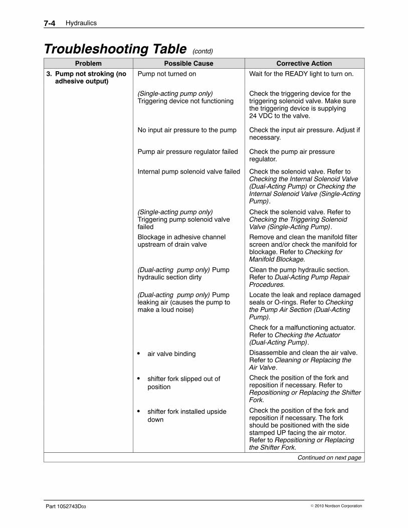
Hydraulics7-4
Part 1052743D03 � 2010 Nordson Corporation
Troubleshooting Table (contd)
Problem Possible Cause Corrective Action
3. Pump not stroking (noadhesive output)
Pump not turned on Wait for the READY light to turn on.
(Single-acting pump only)Triggering device not functioning
Check the triggering device for thetriggering solenoid valve. Make surethe triggering device is supplying24 VDC to the valve.
No input air pressure to the pump Check the input air pressure. Adjust ifnecessary.
Pump air pressure regulator failed Check the pump air pressureregulator.
Internal pump solenoid valve failed Check the solenoid valve. Refer toChecking the Internal Solenoid Valve(Dual-Acting Pump) or Checking theInternal Solenoid Valve (Single-ActingPump).
(Single-acting pump only)Triggering pump solenoid valvefailed
Check the solenoid valve. Refer toChecking the Triggering SolenoidValve (Single-Acting Pump).
Blockage in adhesive channelupstream of drain valve
Remove and clean the manifold filterscreen and/or check the manifold forblockage. Refer to Checking forManifold Blockage.
(Dual-acting pump only) Pumphydraulic section dirty
Clean the pump hydraulic section.Refer to Dual-Acting Pump RepairProcedures.
(Dual-acting pump only) Pumpleaking air (causes the pump tomake a loud noise)
Locate the leak and replace damagedseals or O-rings. Refer to Checkingthe Pump Air Section (Dual-ActingPump).
Check for a malfunctioning actuator.Refer to Checking the Actuator(Dual-Acting Pump).
� air valve binding Disassemble and clean the air valve.Refer to Cleaning or Replacing theAir Valve.
� shifter fork slipped out ofposition
Check the position of the fork andreposition if necessary. Refer toRepositioning or Replacing the ShifterFork.
� shifter fork installed upsidedown
Check the position of the fork andreposition if necessary. The forkshould be positioned with the sidestamped UP facing the air motor.Refer to Repositioning or Replacingthe Shifter Fork.
Continued on next page
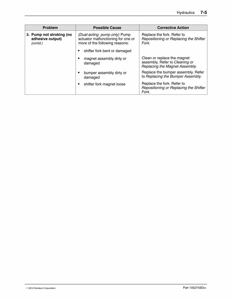
Hydraulics 7-5
Part 1052743D03� 2010 Nordson Corporation
Corrective ActionPossible CauseProblem
3. Pump not stroking (noadhesive output)(contd.)
(Dual-acting pump only) Pumpactuator malfunctioning for one ormore of the following reasons:
� shifter fork bent or damaged
Replace the fork. Refer toRepositioning or Replacing the ShifterFork.
� magnet assembly dirty ordamaged
Clean or replace the magnetassembly. Refer to Cleaning orReplacing the Magnet Assembly.
� bumper assembly dirty ordamaged
Replace the bumper assembly. Referto Replacing the Bumper Assembly.
� shifter fork magnet loose Replace the fork. Refer toRepositioning or Replacing the ShifterFork.
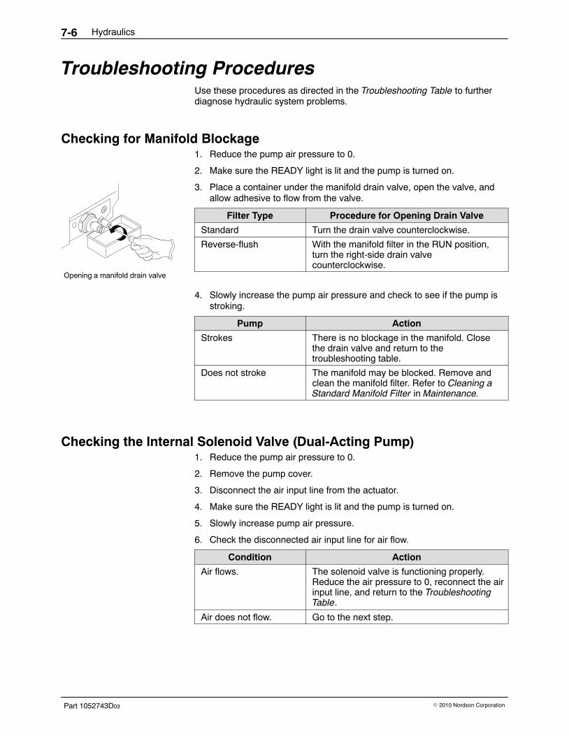
Opening a manifold drain valve
Hydraulics7-6
Part 1052743D03 � 2010 Nordson Corporation
Troubleshooting Procedures Use these procedures as directed in the Troubleshooting Table to furtherdiagnose hydraulic system problems.
Checking for Manifold Blockage 1. Reduce the pump air pressure to 0.
2. Make sure the READY light is lit and the pump is turned on.
3. Place a container under the manifold drain valve, open the valve, andallow adhesive to flow from the valve.
Filter Type Procedure for Opening Drain Valve
Standard Turn the drain valve counterclockwise.
Reverse-flush With the manifold filter in the RUN position,turn the right-side drain valvecounterclockwise.
4. Slowly increase the pump air pressure and check to see if the pump isstroking.
Pump Action
Strokes There is no blockage in the manifold. Closethe drain valve and return to thetroubleshooting table.
Does not stroke The manifold may be blocked. Remove andclean the manifold filter. Refer to Cleaning aStandard Manifold Filter in Maintenance.
Checking the Internal Solenoid Valve (Dual-Acting Pump) 1. Reduce the pump air pressure to 0.
2. Remove the pump cover.
3. Disconnect the air input line from the actuator.
4. Make sure the READY light is lit and the pump is turned on.
5. Slowly increase pump air pressure.
6. Check the disconnected air input line for air flow.
Condition Action
Air flows. The solenoid valve is functioning properly.Reduce the air pressure to 0, reconnect the airinput line, and return to the TroubleshootingTable.
Air does not flow. Go to the next step.
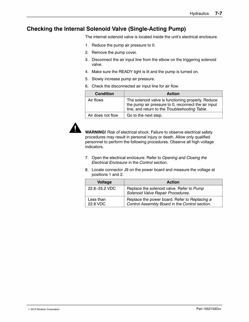
Hydraulics 7-7
Part 1052743D03� 2010 Nordson Corporation
Checking the Internal Solenoid Valve (Single-Acting Pump) The internal solenoid valve is located inside the unit’s electrical enclosure.
1. Reduce the pump air pressure to 0.
2. Remove the pump cover.
3. Disconnect the air input line from the elbow on the triggering solenoidvalve.
4. Make sure the READY light is lit and the pump is turned on.
5. Slowly increase pump air pressure.
6. Check the disconnected air input line for air flow.
Condition Action
Air flows The solenoid valve is functioning properly. Reducethe pump air pressure to 0, reconnect the air inputline, and return to the Troubleshooting Table.
Air does not flow Go to the next step.
WARNING! Risk of electrical shock. Failure to observe electrical safetyprocedures may result in personal injury or death. Allow only qualifiedpersonnel to perform the following procedures. Observe all high voltageindicators.
7. Open the electrical enclosure. Refer to Opening and Closing theElectrical Enclosure in the Control section.
8. Locate connector J9 on the power board and measure the voltage atpositions 1 and 2.
Voltage Action
22.8−25.2 VDC Replace the solenoid valve. Refer to PumpSolenoid Valve Repair Procedures.
Less than22.8 VDC
Replace the power board. Refer to Replacing aControl Assembly Board in the Control section.
Hydraulics7-8
Part 1052743D03 � 2010 Nordson Corporation
Checking the Triggering Solenoid Valve (Single-Acting Pump) The triggering solenoid valve is connected to the pump and is located underthe pump cover.
1. Reduce the pump air pressure to 0.
2. Remove the pump cover.
3. Disconnect the triggering solenoid valve from the pump.
4. Apply a 24 VDC trigger to the solenoid valve.
5. Slowly increase pump air pressure.
Condition Action
Air flows from thesolenoid valve
The solenoid valve is functioning properly.Reduce the pump air pressure to 0, reconnectthe solenoid valve to the pump, and return tothe Troubleshooting Table.
Air does not flow fromthe solenoid valve
Defective solenoid valve. Replace thesolenoid valve. Refer to Pump Solenoid ValveRepair Procedures.
Testing Solenoid Valve Voltage
WARNING! Risk of electrical shock. Failure to observe electrical safetyprocedures may result in personal injury or death. Allow only qualifiedpersonnel to perform the following procedures. Observe all high voltageindicators.
1. Open the electrical enclosure. Refer to Opening the Electrical Enclosurein the Control section.
2. Locate connector J9 on the power board and measure the voltage atpositions 1 and 2.
Voltage Action
22.8−25.2 VDC Replace the solenoid valve. Refer to PumpSolenoid Valve Repair Procedures.
Less than 22.8 VDC Replace the power board. Refer to Replacingthe Power Board in Control.
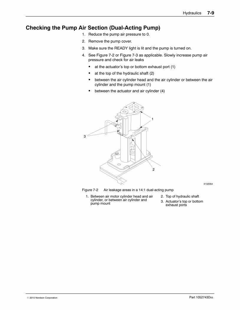
Hydraulics 7-9
Part 1052743D03� 2010 Nordson Corporation
Checking the Pump Air Section (Dual-Acting Pump) 1. Reduce the pump air pressure to 0.
2. Remove the pump cover.
3. Make sure the READY light is lit and the pump is turned on.
4. See Figure 7-2 or Figure 7-3 as applicable. Slowly increase pump airpressure and check for air leaks
� at the actuator’s top or bottom exhaust port (1)
� at the top of the hydraulic shaft (2)
� between the air cylinder head and the air cylinder or between the aircylinder and the pump mount (1)
� between the actuator and air cylinder (4)
4132054
3
2
1
Figure 7-2 Air leakage areas in a 14:1 dual-acting pump
1. Between air motor cylinder head and aircylinder, or between air cylinder andpump mount
2. Top of hydraulic shaft3. Actuator’s top or bottom
exhaust ports
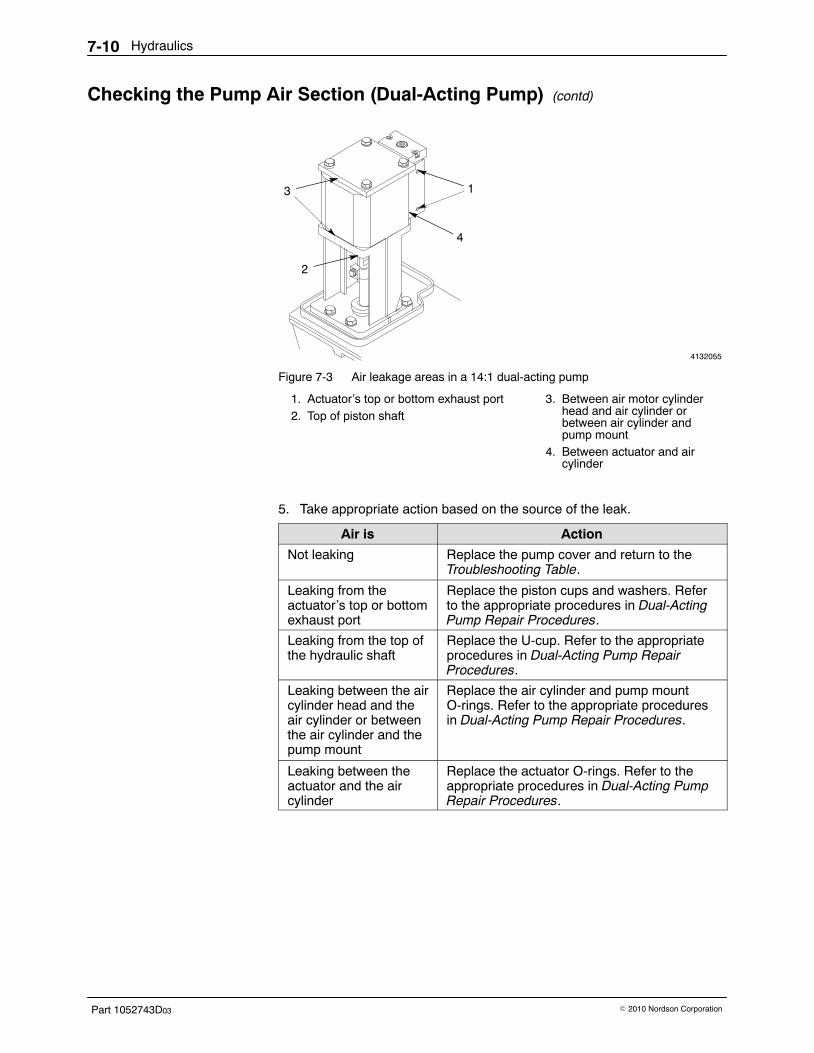
Hydraulics7-10
Part 1052743D03 � 2010 Nordson Corporation
Checking the Pump Air Section (Dual-Acting Pump) (contd)
4132055
1
4
3
2
Figure 7-3 Air leakage areas in a 14:1 dual-acting pump
1. Actuator’s top or bottom exhaust port2. Top of piston shaft
3. Between air motor cylinderhead and air cylinder orbetween air cylinder andpump mount
4. Between actuator and aircylinder
5. Take appropriate action based on the source of the leak.
Air is Action
Not leaking Replace the pump cover and return to theTroubleshooting Table.
Leaking from theactuator’s top or bottomexhaust port
Replace the piston cups and washers. Referto the appropriate procedures in Dual-ActingPump Repair Procedures.
Leaking from the top ofthe hydraulic shaft
Replace the U-cup. Refer to the appropriateprocedures in Dual-Acting Pump RepairProcedures.
Leaking between the aircylinder head and theair cylinder or betweenthe air cylinder and thepump mount
Replace the air cylinder and pump mountO-rings. Refer to the appropriate proceduresin Dual-Acting Pump Repair Procedures.
Leaking between theactuator and the aircylinder
Replace the actuator O-rings. Refer to theappropriate procedures in Dual-Acting PumpRepair Procedures.
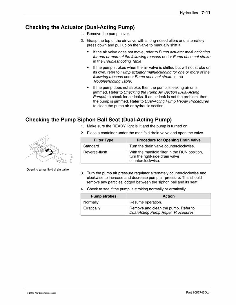
Opening a manifold drain valve
Hydraulics 7-11
Part 1052743D03� 2010 Nordson Corporation
Checking the Actuator (Dual-Acting Pump) 1. Remove the pump cover.
2. Grasp the top of the air valve with a long-nosed pliers and alternatelypress down and pull up on the valve to manually shift it.
� If the air valve does not move, refer to Pump actuator malfunctioningfor one or more of the following reasons under Pump does not strokein the Troubleshooting Table.
� If the pump strokes when the air valve is shifted but will not stroke onits own, refer to Pump actuator malfunctioning for one or more of thefollowing reasons under Pump does not stroke in theTroubleshooting Table.
� If the pump does not stroke, then the pump is leaking air or isjammed. Refer to Checking the Pump Air Section (Dual-ActingPumps) to check for air leaks. If an air leak is not the problem, thenthe pump is jammed. Refer to Dual-Acting Pump Repair Proceduresto clean the pump air or hydraulic section.
Checking the Pump Siphon Ball Seat (Dual-Acting Pump) 1. Make sure the READY light is lit and the pump is turned on.
2. Place a container under the manifold drain valve and open the valve.
Filter Type Procedure for Opening Drain Valve
Standard Turn the drain valve counterclockwise.
Reverse-flush With the manifold filter in the RUN position,turn the right-side drain valvecounterclockwise.
3. Turn the pump air pressure regulator alternately counterclockwise andclockwise to increase and decrease pump air pressure. This shouldremove any particles lodged between the siphon ball and its seat.
4. Check to see if the pump is stroking normally or erratically.
Pump strokes Action
Normally Resume operation.
Erratically Remove and clean the pump. Refer toDual-Acting Pump Repair Procedures.
Hydraulics7-12
Part 1052743D03 � 2010 Nordson Corporation
Checking the Pump Siphon Ball Seat (Single-Acting Pump) 1. Make sure the READY light is lit and the pump is turned on.
2. Place a container under the manifold drain valve and open the valve.
Filter Type Procedure for Opening Drain Valve
Standard Turn the drain valve counterclockwise.
Reverse-flush With the manifold filter in the RUN position, turn theright-side drain valve counterclockwise.
3. Apply a 24 VDC trigger to the triggering solenoid valve.
4. Turn the pump air pressure regulator alternately counterclockwise andclockwise to increase and decrease pump air pressure. This shouldremove any particles lodged between the siphon ball and its seat.
5. Check to see if the pump is stroking normally or erratically.
Pump strokes… ActionNormally Resume operation.
Erratically Replace the siphon ball cage and seat assembly.Refer to Replacing the Siphon Ball Cage and SeatAssembly in Single-Acting Pump RepairProcedures.
Hydraulics 7-13
Part 1052743D03� 2010 Nordson Corporation
Dual-Acting Pump Repair Procedures Use these procedures to replace a dual-acting piston pump, to replace anypump component, or to clean pump components. Refer to Section 9, Partsas a guide as you perform the following disassembly and reassemblyprocedures.
NOTE: If you are replacing only the actuator, you do not need to removethe pump. To replace only the actuator, refer to Replacing the Actuator inDual-Acting Pump Actuator Repair Procedures.
NOTE: The pump components vary in appearance depending on the typeof pump. The illustration in this section are representative of the mostcommon type of pump.
Servicing the Pump Use these procedures to disassemble the pump, to clean or replace pumpcomponents, and to reassemble the pump.
Preparation for Pump Removal 1. Make sure the melter is at operating temperature.
2. Reduce the pump air pressure to 0.
3. Relieve system pressure. Refer to Relieving System Pressure inMaintenance.
4. Remove the pump cover.
5. Disconnect the air input line from the actuator.
Pump Removal 1. Remove the screws and washers that secure the pump to the melter.
2. Make sure the adhesive around the pump is melted (the READY lightshould be on).
3. Rotate the pump slightly to break the suction and pull the pump straightup to remove it. Lay the pump on a clean, flat work surface.
NOTE: To install the pump and actuator assembly, go to PumpInstallation.

Hydraulics7-14
Part 1052743D03 � 2010 Nordson Corporation
Actuator Removal 1. Move the hydraulic shaft up or down until the shifter fork is centered in
the pump mount.
2. See Figure 7-4. Remove the screws and washers that secure theactuator and pump bracket; then remove the actuator and bracket.
3. Inspect the O-rings in the face of the air cylinder for damage. Replace ifnecessary.
4132056
3 42
11
Figure 7-4 Removing the actuator (21:1 pump shown)
1. Screw and washer2. Pump cover bracket
3. Actuator4. O-ring
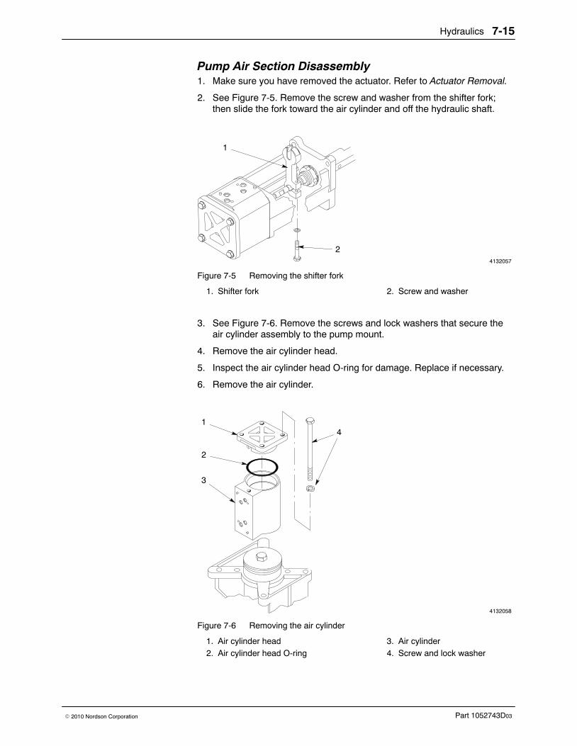
Hydraulics 7-15
Part 1052743D03� 2010 Nordson Corporation
Pump Air Section Disassembly 1. Make sure you have removed the actuator. Refer to Actuator Removal.
2. See Figure 7-5. Remove the screw and washer from the shifter fork;then slide the fork toward the air cylinder and off the hydraulic shaft.
4132057
1
2
Figure 7-5 Removing the shifter fork
1. Shifter fork 2. Screw and washer
3. See Figure 7-6. Remove the screws and lock washers that secure theair cylinder assembly to the pump mount.
4. Remove the air cylinder head.
5. Inspect the air cylinder head O-ring for damage. Replace if necessary.
6. Remove the air cylinder.
4132058
1
2
3
44
Figure 7-6 Removing the air cylinder
1. Air cylinder head2. Air cylinder head O-ring
3. Air cylinder4. Screw and lock washer
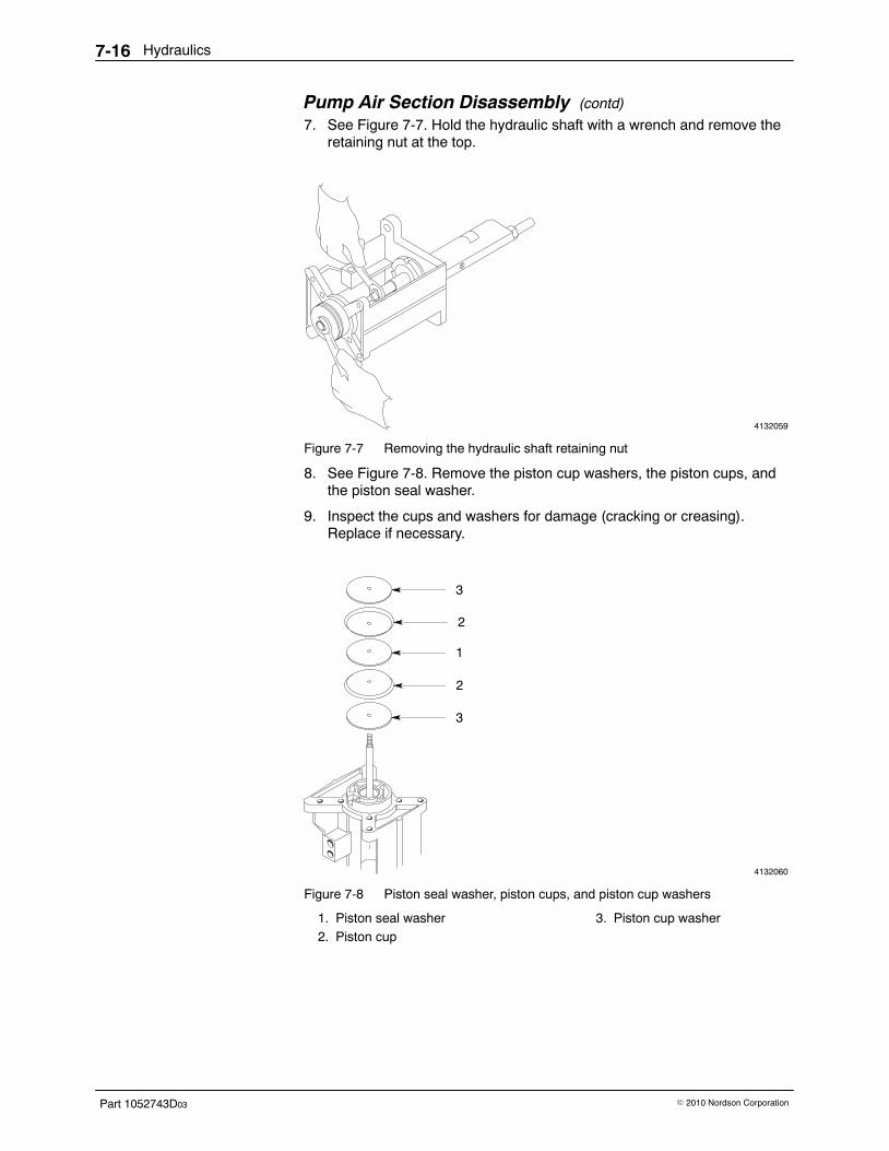
Hydraulics7-16
Part 1052743D03 � 2010 Nordson Corporation
Pump Air Section Disassembly (contd)
7. See Figure 7-7. Hold the hydraulic shaft with a wrench and remove theretaining nut at the top.
4132059
Figure 7-7 Removing the hydraulic shaft retaining nut
8. See Figure 7-8. Remove the piston cup washers, the piston cups, andthe piston seal washer.
9. Inspect the cups and washers for damage (cracking or creasing).Replace if necessary.
4132060
3
2
3
2
1
Figure 7-8 Piston seal washer, piston cups, and piston cup washers
1. Piston seal washer2. Piston cup
3. Piston cup washer
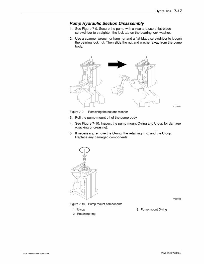
Hydraulics 7-17
Part 1052743D03� 2010 Nordson Corporation
Pump Hydraulic Section Disassembly 1. See Figure 7-9. Secure the pump with a vise and use a flat-blade
screwdriver to straighten the lock tab on the bearing lock washer.
2. Use a spanner wrench or hammer and a flat-blade screwdriver to loosenthe bearing lock nut. Then slide the nut and washer away from the pumpbody.
4132061
Figure 7-9 Removing the nut and washer
3. Pull the pump mount off of the pump body.
4. See Figure 7-10. Inspect the pump mount O-ring and U-cup for damage(cracking or creasing).
5. If necessary, remove the O-ring, the retaining ring, and the U-cup.Replace any damaged components.
4132062
Figure 7-10 Pump mount components
1. U-cup2. Retaining ring
3. Pump mount O-ring

Hydraulics7-18
Part 1052743D03 � 2010 Nordson Corporation
Pump Hydraulic Section Disassembly (contd)
6. See Figure 7-11. Inspect the pump seal for damage (cracking,hardening, or creasing).
7. If necessary, use snap-ring pliers to remove the retaining ring. Thenmanually stroke the hydraulic shaft up and down to loosen the washerand pump seal. Replace any damaged components.
4132063
12
3
4
Figure 7-11 Hydraulic shaft components
1. Retaining ring2. Washer
3. Pump seal4. Hydraulic shaft
8. See Figure 7-12. Secure the pump body with a vise or wrench andremove the crossover tube, the O-ring, and the backup ring.
9. Inspect the O-ring and backup ring for damage. Replace if necessary.
4132064
1 2
3
Figure 7-12 Crossover tube, O-ring, and backup ring
1. Crossover tube2. O-ring
3. Backup ring
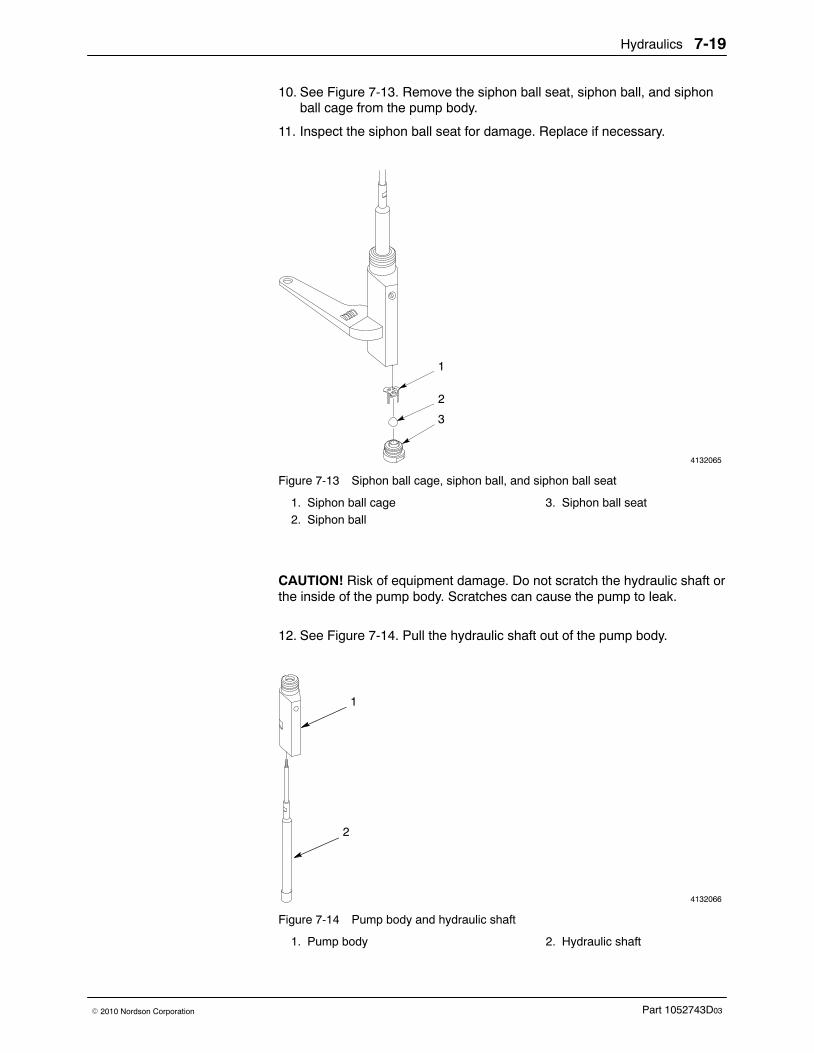
Hydraulics 7-19
Part 1052743D03� 2010 Nordson Corporation
10. See Figure 7-13. Remove the siphon ball seat, siphon ball, and siphonball cage from the pump body.
11. Inspect the siphon ball seat for damage. Replace if necessary.
4132065
1
2
3
Figure 7-13 Siphon ball cage, siphon ball, and siphon ball seat
1. Siphon ball cage2. Siphon ball
3. Siphon ball seat
CAUTION! Risk of equipment damage. Do not scratch the hydraulic shaft orthe inside of the pump body. Scratches can cause the pump to leak.
12. See Figure 7-14. Pull the hydraulic shaft out of the pump body.
4132066
1
2
Figure 7-14 Pump body and hydraulic shaft
1. Pump body 2. Hydraulic shaft
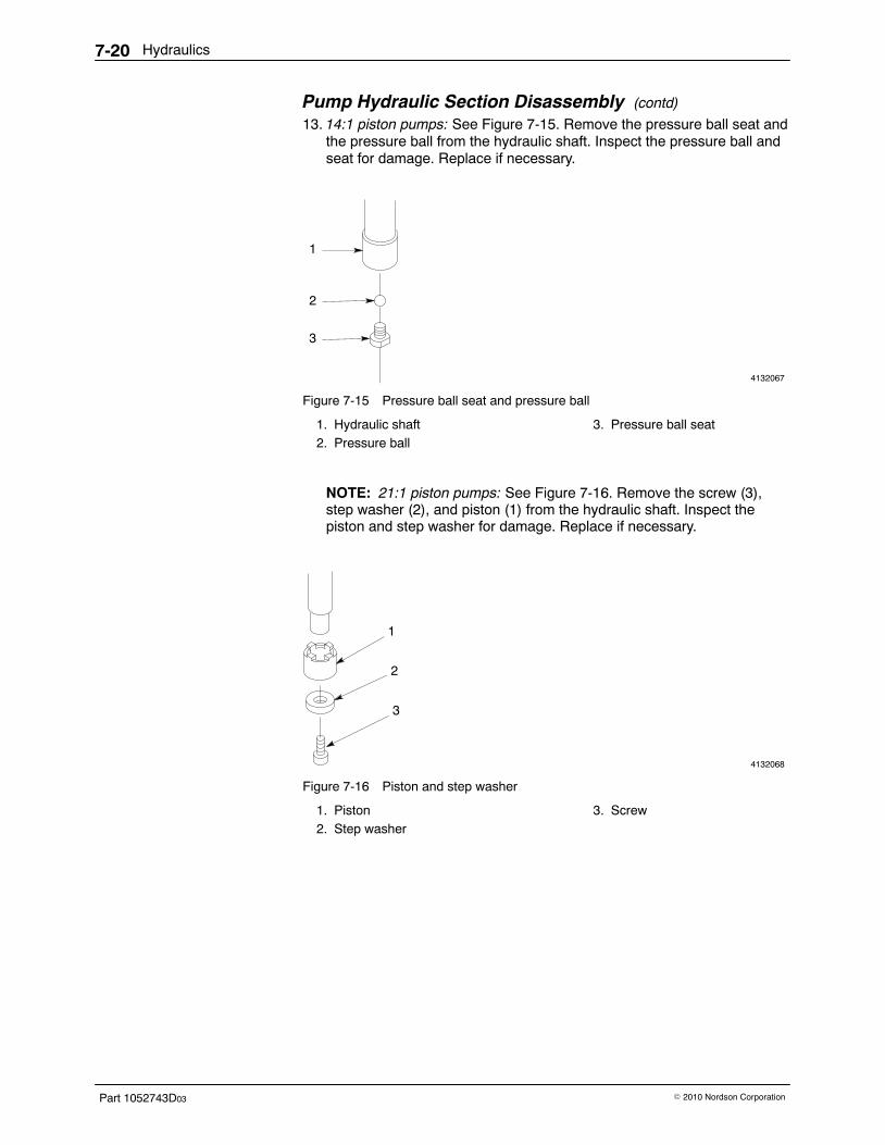
Hydraulics7-20
Part 1052743D03 � 2010 Nordson Corporation
Pump Hydraulic Section Disassembly (contd)
13. 14:1 piston pumps: See Figure 7-15. Remove the pressure ball seat andthe pressure ball from the hydraulic shaft. Inspect the pressure ball andseat for damage. Replace if necessary.
4132067
1
2
3
Figure 7-15 Pressure ball seat and pressure ball
1. Hydraulic shaft2. Pressure ball
3. Pressure ball seat
NOTE: 21:1 piston pumps: See Figure 7-16. Remove the screw (3),step washer (2), and piston (1) from the hydraulic shaft. Inspect thepiston and step washer for damage. Replace if necessary.
4132068
1
2
3
Figure 7-16 Piston and step washer
1. Piston2. Step washer
3. Screw
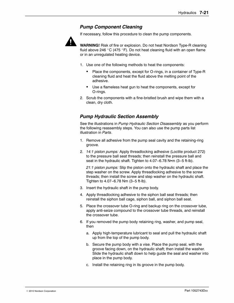
Hydraulics 7-21
Part 1052743D03� 2010 Nordson Corporation
Pump Component Cleaning If necessary, follow this procedure to clean the pump components.
WARNING! Risk of fire or explosion. Do not heat Nordson Type-R cleaningfluid above 246 �C (475 �F). Do not heat cleaning fluid with an open flameor in an unregulated heating device.
1. Use one of the following methods to heat the components:
� Place the components, except for O-rings, in a container of Type-Rcleaning fluid and heat the fluid above the melting point of theadhesive.
� Use a flameless heat gun to heat the components, except forO-rings.
2. Scrub the components with a fine-bristled brush and wipe them with aclean, dry cloth.
Pump Hydraulic Section Assembly See the illustrations in Pump Hydraulic Section Disassembly as you performthe following reassembly steps. You can also use the pump parts listillustration in Parts.
1. Remove all adhesive from the pump seal cavity and the retaining-ringgroove.
2. 14:1 piston pumps: Apply threadlocking adhesive (Loctite product 272)to the pressure ball seat threads; then reinstall the pressure ball andseat in the hydraulic shaft. Tighten to 4.07−6.78 N�m (3−5 ft-lb).
21:1 piston pumps: Slip the piston onto the hydraulic shaft and place thestep washer on the screw. Apply threadlocking adhesive to the screwthreads; then install the screw and step washer on the hydraulic shaft.Tighten to 4.07−6.78 Nm (3−5 ft-lb).
3. Insert the hydraulic shaft in the pump body.
4. Apply threadlocking adhesive to the siphon ball seat threads; thenreinstall the siphon ball cage, siphon ball, and siphon ball seat.
5. Place the crossover tube O-ring and backup ring on the crossover tube,apply anti-seize compound to the crossover tube threads, and reinstallthe crossover tube.
6. If you removed the pump body retaining ring, washer, and pump seal,then
a. Apply high-temperature lubricant to seal and pull the hydraulic shaftup from the top of the pump body.
b. Secure the pump body with a vise. Place the pump seal, with thegroove facing down, on the hydraulic shaft; then install the washer.Slide the hydraulic shaft down to help guide the seal and washer intoplace in the pump body.
c. Install the retaining ring in its groove in the pump body.
Hydraulics7-22
Part 1052743D03 � 2010 Nordson Corporation
Pump Hydraulic Section Assembly (contd)
7. If you removed the pump mount O-ring, retaining ring, and U-cup, then
a. Insert the U-cup in the upper face of the pump mount with thegroove facing up.
b. Press the retaining ring in the upper face to secure the U-cup.
c. Apply high-temperature lubricant to the pump mount O-ring andplace the O-ring on the upper surface of the pump mount.
8. Apply high-temperature lubricant to the hydraulic shaft at the pointwhere it passes through the U-cup.
9. Guide the upper part of the pump body and the hydraulic shaft throughthe bottom hole in the pump mount.
10. Place the bearing lock washer and nut over the hydraulic shaft and slidethe hydraulic shaft through the hole in the top of the pump mount.
11. Rotate the pump body clockwise until you feel it rest against the stop inthe bottom of the pump mount. Secure the pump body to the pumpmount by tightening the bearing lock nut.
12. Using a flat-blade screwdriver, lock the bearing lock washer by bendingone tab into one of the slots on the bearing lock nut.
13. Slide the fork onto the hydraulic shaft until it sits on the shoulder. Makesure the side stamped UP is facing the air cylinder. Install the screw andwasher and tighten to 8−10 N�m (6−7 ft-lb).
Pump Air Section Assembly See the illustrations in Pump Air Section Disassembly as you perform thefollowing reassembly steps. You can also use the pump parts list illustrationin Parts.
1. Pull the hydraulic shaft up as far as possible and install the followingparts onto the shaft in this order:
� one piston cup washer� one piston cup with the curved edge facing down� the piston seal washer
2. Slide the air cylinder over the hydraulic shaft and onto the pump mount.Be careful not to damage the piston cup.
3. Use the shifter fork to move the hydraulic shaft up to the top of the aircylinder.
4. Install the remaining piston cup, with the curved edge facing up, andpiston cup washer on the hydraulic shaft.
5. Hold the hydraulic shaft with a wrench and replace the retaining nut.Tighten to 11.30−13.56 N�m (8−10 ft-lb).
6. Apply high-temperature lubricant to the air cylinder O-ring and rollthe O-ring into place on the air cylinder head.
7. Position the air cylinder head on the air cylinder so that the shouldercut-out is facing the actuator. Apply anti-seize compound to the aircylinder screws and use the screws and lock washers to secure the aircylinder to the pump mount. Tighten to 5−6 N�m (45−55 in.-lb).
Hydraulics 7-23
Part 1052743D03� 2010 Nordson Corporation
Actuator Installation See the illustrations in Actuator Removal as you perform the followingreassembly steps. You can also use the pump parts list illustration in Parts.
1. Install the pump cover bracket.
2. If you removed the O-rings from the air cylinder face, coat four newO-rings with high-temperature lubricant and install them on the aircylinder.
3. Move the hydraulic shaft up or down until the shifter fork is in the centerof the pump mount.
4. Carefully align the actuator with the shifter fork and the locating pins onthe air cylinder.
5. Install the actuator with the screws and washers removed previously.Tighten to 3−4 N�m (28−36 in.-lb).
Pump Installation NOTE: If you are replacing an old pump with a new pump, remove thepump cover bracket and install it on the new pump.
1. Make sure the pump pan is positioned correctly.
2. Lower the pump into the melter until the crossover tube seats in themanifold.
3. Secure the pump to the melter with the screws and washers removedpreviously. Tighten to 12.20−13.56 N�m (9−10 ft-lb).
4. Connect the air input line to the actuator.
System Restoration 1. Replace the pump cover.
2. Place the melter circuit breaker in the ON position and wait for theREADY light to turn on.
3. Place a container under the manifold drain valve or valves.
4. Standard manifold filter: Open the drain valve.
NOTE: Reverse-flush manifold filter: With the manifold filter in the RUNposition, open the right-side drain valve.
5. Start the pump.
6. Allow adhesive to flow from the drain valve until it is free of trapped airand impurities.
7. Stop the pump.
8. Close the drain valve.
9. Restore the system to normal operation.
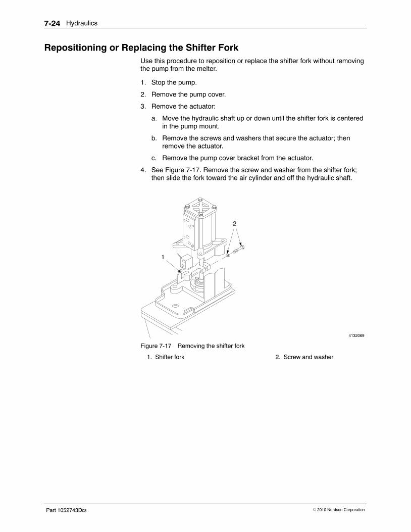
Hydraulics7-24
Part 1052743D03 � 2010 Nordson Corporation
Repositioning or Replacing the Shifter Fork Use this procedure to reposition or replace the shifter fork without removingthe pump from the melter.
1. Stop the pump.
2. Remove the pump cover.
3. Remove the actuator:
a. Move the hydraulic shaft up or down until the shifter fork is centeredin the pump mount.
b. Remove the screws and washers that secure the actuator; thenremove the actuator.
c. Remove the pump cover bracket from the actuator.
4. See Figure 7-17. Remove the screw and washer from the shifter fork;then slide the fork toward the air cylinder and off the hydraulic shaft.
4132069
1
22
Figure 7-17 Removing the shifter fork
1. Shifter fork 2. Screw and washer
Hydraulics 7-25
Part 1052743D03� 2010 Nordson Corporation
5. Reposition the shifter fork or install a new shifter fork. Make sure theside of the fork stamped UP faces up.
6. Slide the fork down onto the hydraulic shaft shoulder.
7. Install the screw and washer. Tighten the screw to8−10 N�m (71−89 in.-lb).
8. Install the actuator:
a. Install the pump cover bracket on the actuator.
b. Move the hydraulic shaft up or down until the shifter fork is in thecenter of the pump mount.
c. Carefully align the actuator with the shifter fork and the locating pinson the air cylinder.
d. Install the actuator with the screws and washers removed previously.Tighten to 3−4 N�m (28−36 in.-lb).
9. Reinstall the pump cover and restore the system to normal operation.
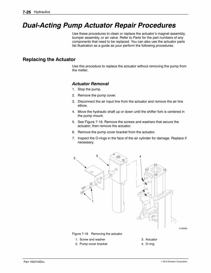
Hydraulics7-26
Part 1052743D03 � 2010 Nordson Corporation
Dual-Acting Pump Actuator Repair Procedures Use these procedures to clean or replace the actuator’s magnet assembly,bumper assembly, or air valve. Refer to Parts for the part numbers of anycomponents that need to be replaced. You can also use the actuator partslist illustration as a guide as your perform the following procedures.
Replacing the Actuator Use this procedure to replace the actuator without removing the pump fromthe melter.
Actuator Removal 1. Stop the pump.
2. Remove the pump cover.
3. Disconnect the air input line from the actuator and remove the air lineelbow.
4. Move the hydraulic shaft up or down until the shifter fork is centered inthe pump mount.
5. See Figure 7-18. Remove the screws and washers that secure theactuator; then remove the actuator.
6. Remove the pump cover bracket from the actuator.
7. Inspect the O-rings in the face of the air cylinder for damage. Replace ifnecessary.
4132056
3 42
11
Figure 7-18 Removing the actuator
1. Screw and washer2. Pump cover bracket
3. Actuator4. O-ring

Hydraulics 7-27
Part 1052743D03� 2010 Nordson Corporation
Actuator Installation 1. If you removed the O-rings from the air cylinder face, coat four new
O-rings with high-temperature lubricant and install them on the aircylinder.
2. Install the pump cover bracket on the actuator.
3. Move the hydraulic shaft up or down until the shifter fork is in the centerof the pump mount.
4. Carefully align the actuator with the shifter fork and the locating pins onthe air cylinder.
5. Install the actuator with the screws and washers removed previously.Tighten to 3−4 N�m (28−36 in.-lb).
6. Apply PTFE paste or tape to the air line elbow threads; then install the elbow in the actuator.
7. Connect the air input line to the actuator.
8. Reinstall the pump cover and restore the system to normal operation.
Cleaning or Replacing the Magnet Assembly Use this procedure to clean or replace the magnet assembly. The magnetassembly is located inside the actuator.
Magnet Assembly Removal 1. Stop the pump.
2. Remove the pump cover.
3. Disconnect the air input line from the actuator.
4. Remove the actuator:
a. Move the hydraulic shaft up or down until the shifter fork is centeredin the pump mount.
b. Remove the screws and washers that secure the actuator; thenremove and the actuator.
c. Remove the pump cover bracket from the actuator.
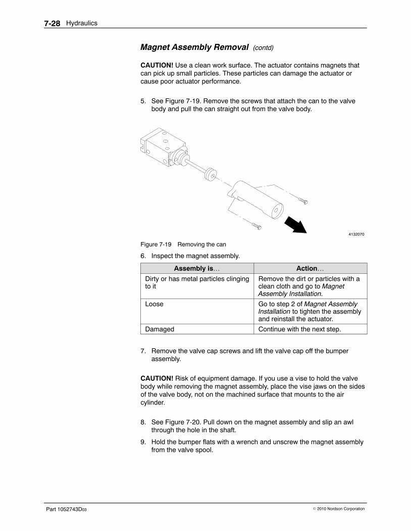
Hydraulics7-28
Part 1052743D03 � 2010 Nordson Corporation
Magnet Assembly Removal (contd)
CAUTION! Use a clean work surface. The actuator contains magnets thatcan pick up small particles. These particles can damage the actuator orcause poor actuator performance.
5. See Figure 7-19. Remove the screws that attach the can to the valvebody and pull the can straight out from the valve body.
4132070
Figure 7-19 Removing the can
6. Inspect the magnet assembly.
Assembly is… Action…Dirty or has metal particles clingingto it
Remove the dirt or particles with aclean cloth and go to MagnetAssembly Installation.
Loose Go to step 2 of Magnet AssemblyInstallation to tighten the assemblyand reinstall the actuator.
Damaged Continue with the next step.
7. Remove the valve cap screws and lift the valve cap off the bumperassembly.
CAUTION! Risk of equipment damage. If you use a vise to hold the valvebody while removing the magnet assembly, place the vise jaws on the sidesof the valve body, not on the machined surface that mounts to the aircylinder.
8. See Figure 7-20. Pull down on the magnet assembly and slip an awlthrough the hole in the shaft.
9. Hold the bumper flats with a wrench and unscrew the magnet assemblyfrom the valve spool.
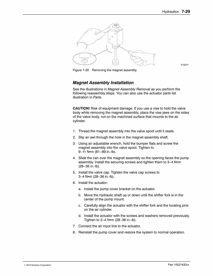
Hydraulics 7-29
Part 1052743D03� 2010 Nordson Corporation
4132071
Figure 7-20 Removing the magnet assembly
Magnet Assembly Installation See the illustrations in Magnet Assembly Removal as you perform thefollowing reassembly steps. You can also use the actuator parts listillustration in Parts.
CAUTION! Risk of equipment damage. If you use a vise to hold the valvebody while removing the magnet assembly, place the vise jaws on the sidesof the valve body, not on the machined surface that mounts to the aircylinder.
1. Thread the magnet assembly into the valve spool until it seats.
2. Slip an awl through the hole in the magnet assembly shaft.
3. Using an adjustable wrench, hold the bumper flats and screw themagnet assembly into the valve spool. Tighten to9−11 N�m (81−99 in.-lb).
4. Slide the can over the magnet assembly so the opening faces the pumpassembly. Install the securing screws and tighten them to 3−4 N�m(28−36 in.-lb).
5. Install the valve cap. Tighten the valve cap screws to3−4 N�m (28−36 in.-lb).
6. Install the actuator:
a. Install the pump cover bracket on the actuator.
b. Move the hydraulic shaft up or down until the shifter fork is in thecenter of the pump mount.
c. Carefully align the actuator with the shifter fork and the locating pinson the air cylinder.
d. Install the actuator with the screws and washers removed previously.Tighten to 3−4 N�m (28−36 in.-lb).
7. Connect the air input line to the actuator.
8. Reinstall the pump cover and restore the system to normal operation.
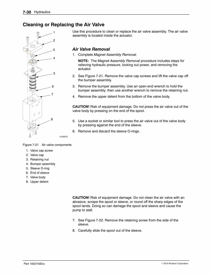
4132072
1
2
3
4
5
6
7
8
Hydraulics7-30
Part 1052743D03 � 2010 Nordson Corporation
Cleaning or Replacing the Air Valve Use this procedure to clean or replace the air valve assembly. The air valveassembly is located inside the actuator.
Air Valve Removal 1. Complete Magnet Assembly Removal.
NOTE: The Magnet Assembly Removal procedure includes steps forrelieving hydraulic pressure, locking out power, and removing theactuator.
2. See Figure 7-21. Remove the valve cap screws and lift the valve cap offthe bumper assembly.
3. Remove the bumper assembly. Use an open-end wrench to hold thebumper assembly; then use another wrench to remove the retaining nut.
4. Remove the upper detent from the bottom of the valve body.
CAUTION! Risk of equipment damage. Do not press the air valve out of thevalve body by pressing on the end of the spool.
5. Use a socket or similar tool to press the air valve out of the valve bodyby pressing against the end of the sleeve.
6. Remove and discard the sleeve O-rings.
Figure 7-21 Air valve components
1. Valve cap screw2. Valve cap3. Retaining nut4. Bumper assembly5. Sleeve O-ring6. End of sleeve7. Valve body8. Upper detent
CAUTION! Risk of equipment damage. Do not clean the air valve with anabrasive, scrape the spool or sleeve, or round off the sharp edges of thespool lands. Doing so can damage the spool and sleeve and cause thepump to stall.
7. See Figure 7-22. Remove the retaining screw from the side of thesleeve.
8. Carefully slide the spool out of the sleeve.
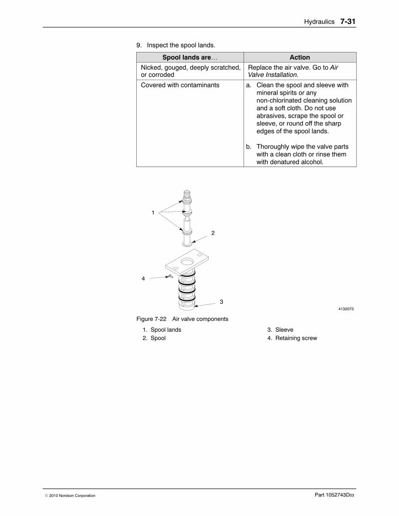
Hydraulics 7-31
Part 1052743D03� 2010 Nordson Corporation
9. Inspect the spool lands.
Spool lands are… Action
Nicked, gouged, deeply scratched,or corroded
Replace the air valve. Go to AirValve Installation.
Covered with contaminants a. Clean the spool and sleeve withmineral spirits or anynon-chlorinated cleaning solutionand a soft cloth. Do not useabrasives, scrape the spool orsleeve, or round off the sharpedges of the spool lands.
b. Thoroughly wipe the valve partswith a clean cloth or rinse themwith denatured alcohol.
4132073
1
4
2
3
Figure 7-22 Air valve components
1. Spool lands2. Spool
3. Sleeve4. Retaining screw
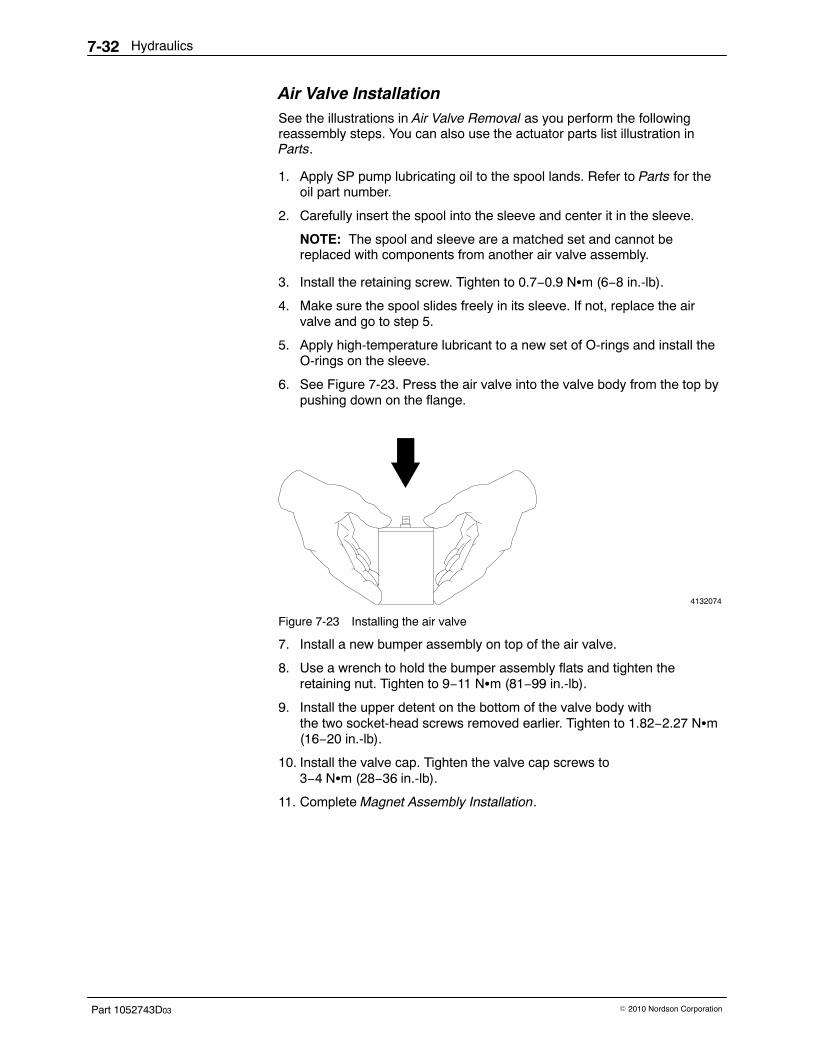
Hydraulics7-32
Part 1052743D03 � 2010 Nordson Corporation
Air Valve Installation See the illustrations in Air Valve Removal as you perform the followingreassembly steps. You can also use the actuator parts list illustration inParts.
1. Apply SP pump lubricating oil to the spool lands. Refer to Parts for theoil part number.
2. Carefully insert the spool into the sleeve and center it in the sleeve.
NOTE: The spool and sleeve are a matched set and cannot bereplaced with components from another air valve assembly.
3. Install the retaining screw. Tighten to 0.7−0.9 N�m (6−8 in.-lb).
4. Make sure the spool slides freely in its sleeve. If not, replace the airvalve and go to step 5.
5. Apply high-temperature lubricant to a new set of O-rings and install theO-rings on the sleeve.
6. See Figure 7-23. Press the air valve into the valve body from the top bypushing down on the flange.
4132074
Figure 7-23 Installing the air valve
7. Install a new bumper assembly on top of the air valve.
8. Use a wrench to hold the bumper assembly flats and tighten theretaining nut. Tighten to 9−11 N�m (81−99 in.-lb).
9. Install the upper detent on the bottom of the valve body withthe two socket-head screws removed earlier. Tighten to 1.82−2.27 N�m(16−20 in.-lb).
10. Install the valve cap. Tighten the valve cap screws to3−4 N�m (28−36 in.-lb).
11. Complete Magnet Assembly Installation.
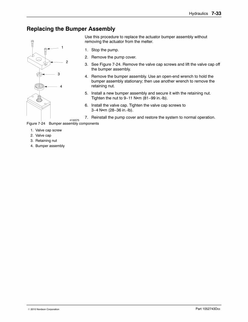
4132075
2
1
3
4
Hydraulics 7-33
Part 1052743D03� 2010 Nordson Corporation
Replacing the Bumper Assembly Use this procedure to replace the actuator bumper assembly withoutremoving the actuator from the melter.
1. Stop the pump.
2. Remove the pump cover.
3. See Figure 7-24. Remove the valve cap screws and lift the valve cap offthe bumper assembly.
4. Remove the bumper assembly. Use an open-end wrench to hold thebumper assembly stationary; then use another wrench to remove theretaining nut.
5. Install a new bumper assembly and secure it with the retaining nut.Tighten the nut to 9−11 N�m (81−99 in.-lb).
6. Install the valve cap. Tighten the valve cap screws to3−4 N�m (28−36 in.-lb).
7. Reinstall the pump cover and restore the system to normal operation.
Figure 7-24 Bumper assembly components
1. Valve cap screw2. Valve cap3. Retaining nut4. Bumper assembly
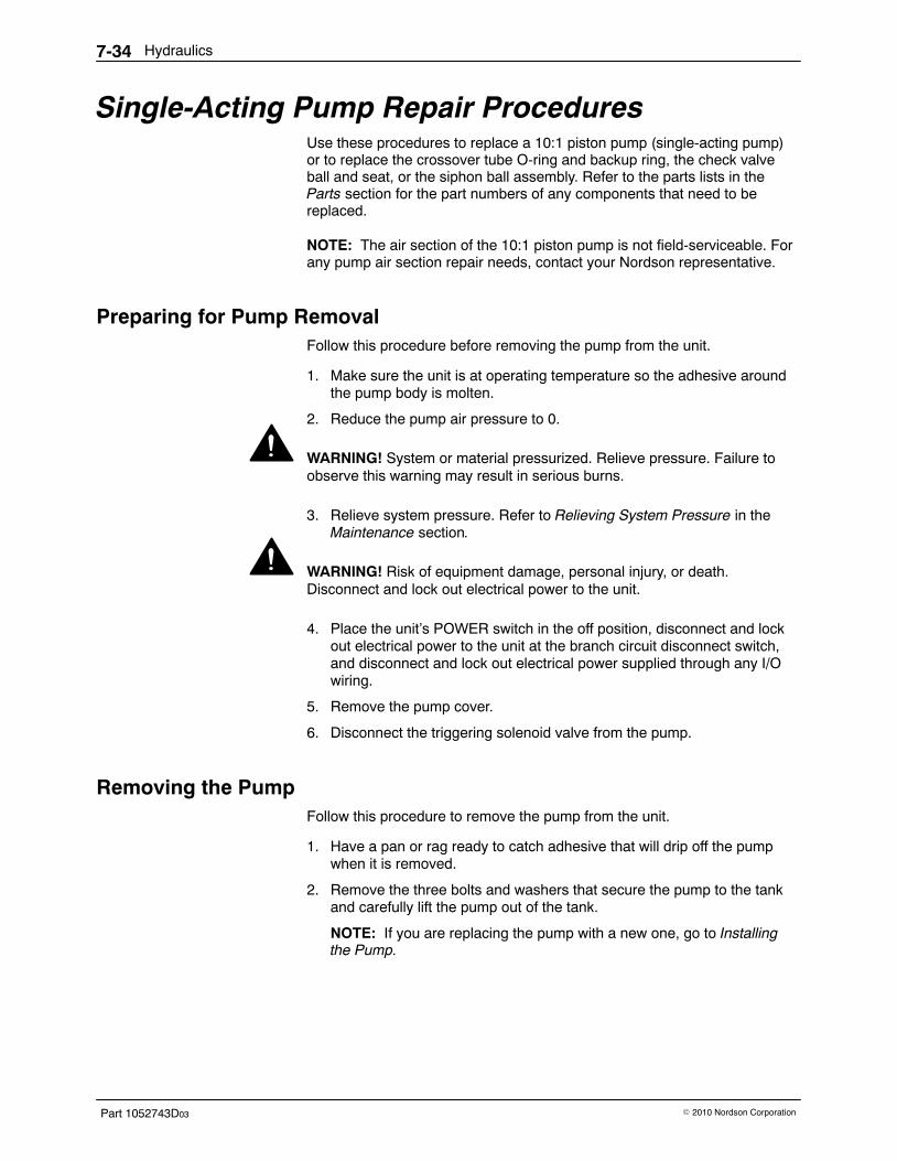
Hydraulics7-34
Part 1052743D03 � 2010 Nordson Corporation
Single-Acting Pump Repair Procedures Use these procedures to replace a 10:1 piston pump (single-acting pump)or to replace the crossover tube O-ring and backup ring, the check valveball and seat, or the siphon ball assembly. Refer to the parts lists in theParts section for the part numbers of any components that need to bereplaced.
NOTE: The air section of the 10:1 piston pump is not field-serviceable. Forany pump air section repair needs, contact your Nordson representative.
Preparing for Pump Removal Follow this procedure before removing the pump from the unit.
1. Make sure the unit is at operating temperature so the adhesive aroundthe pump body is molten.
2. Reduce the pump air pressure to 0.
WARNING! System or material pressurized. Relieve pressure. Failure toobserve this warning may result in serious burns.
3. Relieve system pressure. Refer to Relieving System Pressure in theMaintenance section.
WARNING! Risk of equipment damage, personal injury, or death.Disconnect and lock out electrical power to the unit.
4. Place the unit’s POWER switch in the off position, disconnect and lockout electrical power to the unit at the branch circuit disconnect switch,and disconnect and lock out electrical power supplied through any I/Owiring.
5. Remove the pump cover.
6. Disconnect the triggering solenoid valve from the pump.
Removing the Pump Follow this procedure to remove the pump from the unit.
1. Have a pan or rag ready to catch adhesive that will drip off the pumpwhen it is removed.
2. Remove the three bolts and washers that secure the pump to the tankand carefully lift the pump out of the tank.
NOTE: If you are replacing the pump with a new one, go to Installingthe Pump.
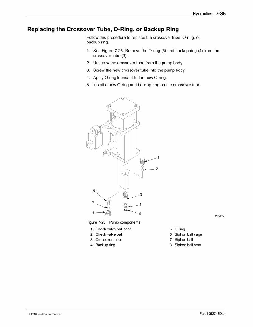
Hydraulics 7-35
Part 1052743D03� 2010 Nordson Corporation
Replacing the Crossover Tube, O-Ring, or Backup Ring Follow this procedure to replace the crossover tube, O-ring, orbackup ring.
1. See Figure 7-25. Remove the O-ring (5) and backup ring (4) from thecrossover tube (3).
2. Unscrew the crossover tube from the pump body.
3. Screw the new crossover tube into the pump body.
4. Apply O-ring lubricant to the new O-ring.
5. Install a new O-ring and backup ring on the crossover tube.
4132076
1
2
3
5
47
6
8
Figure 7-25 Pump components
1. Check valve ball seat2. Check valve ball3. Crossover tube4. Backup ring
5. O-ring6. Siphon ball cage7. Siphon ball8. Siphon ball seat
Opening a manifold drain valve
Hydraulics7-36
Part 1052743D03 � 2010 Nordson Corporation
Replacing the Check Valve Ball and Seat Follow this procedure to replace the check valve ball or seat.
1. See Figure 7-25. Remove the check valve ball (2) and ball seat (1) fromthe pump body.
2. Install a new check valve ball and ball seat.
Replacing the Siphon Ball Cage and Seat Components Follow this procedure to replace the siphon ball, siphon ball cage, or siphonball seat.
1. See Figure 7-25. Remove the siphon ball seat (8), siphon ball (7), andsiphon ball cage (6) from the bottom of the pump body.
2. Install a new siphon ball seat, siphon ball, and siphon ball cage.
Installing the Pump Follow this procedure to install a new pump or to reinstall a pump after ithas been serviced.
NOTE: If you are replacing an old pump with a new, complete pump andyour old pump has a pump cover bracket, remove the bracket and install iton the new pump.
1. Make sure the pump pan is positioned correctly.
2. Lower the pump into the unit until the crossover tube seats in themanifold.
3. Secure the pump to the unit with the screws and washers you removedearlier. Tighten to 12.20−13.56 N�m (9−10 ft-lb).
4. Connect the triggering solenoid valve to the pump.
Restoring the System to Normal Operation Follow this procedure to restore the unit to normal operation.
1. Reinstall the pump cover.
2. Remove the lockout and restore power to the unit, turn the unit on, andallow it to reach operating temperature.
3. Place a container under the manifold drain valve and open the valve(turn the drain valve counterclockwise).
4. Increase pump air pressure and switch the 24 VDC signal to thetriggering solenoid valve on and off until clean adhesive flows from thedrain valve. This will purge the system of trapped air.
5. Reduce the pump air pressure to 0.
6. Close the drain valve.
7. Return the air pressure to the normal operating setting and resumeoperation.

Hydraulics 7-37
Part 1052743D03� 2010 Nordson Corporation
This page intentionally left blank.
Hydraulics7-38
Part 1052743D03 � 2010 Nordson Corporation
Pump Solenoid Valve Repair Procedures Use these procedures to replace either an internal or a triggering solenoidvalve. Refer to Section 9, Parts as a guide if you need to replace othersolenoid valve assembly components.
Replacing the Solenoid Valve (Dual-Acting Pump) Use these procedures to replace the pump solenoid valve on dual-actingpump units.
Solenoid Valve Removal Follow this procedure to remove the solenoid valve. The solenoid valve islocated inside the electrical enclosure.
WARNING! Disconnect and lock out line voltage to the unit. Failure toobserve this warning can result in personal injury or death.
1. Turn the unit off; then disconnect and lock out power to the unit.
2. Reduce the pump air pressure to 0.
WARNING! Risk of electrical shock. Failure to observe electrical safetyprocedures may result in personal injury or death. Allow only qualifiedpersonnel to perform the following procedures. Observe all high voltageindicators.
3. Open the electrical enclosure. Refer to Opening the Electrical Enclosurein the Control section.
4. See Figure 7-26. Unplug (1) the solenoid valve.
5. Disconnect the air lines (5) from the solenoid valve elbows (4).
6. Remove the screws (3) that secure the solenoid valve mountingblock (2); then remove the solenoid valve from the unit.
7. Disconnect the elbows from the solenoid valve.
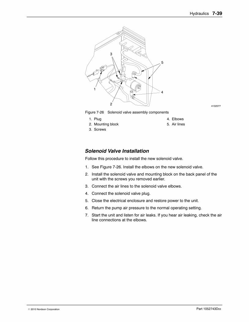
Hydraulics 7-39
Part 1052743D03� 2010 Nordson Corporation
4132077
1
2
3
35
44
3
Figure 7-26 Solenoid valve assembly components
1. Plug2. Mounting block3. Screws
4. Elbows5. Air lines
Solenoid Valve Installation Follow this procedure to install the new solenoid valve.
1. See Figure 7-26. Install the elbows on the new solenoid valve.
2. Install the solenoid valve and mounting block on the back panel of theunit with the screws you removed earlier.
3. Connect the air lines to the solenoid valve elbows.
4. Connect the solenoid valve plug.
5. Close the electrical enclosure and restore power to the unit.
6. Return the pump air pressure to the normal operating setting.
7. Start the unit and listen for air leaks. If you hear air leaking, check the airline connections at the elbows.
Hydraulics7-40
Part 1052743D03 � 2010 Nordson Corporation
Replacing the Internal Solenoid Valve (Single-Acting Pump) Follow this procedure to replace the solenoid valve that is located inside theelectrical enclosure.
Solenoid Valve Removal
WARNING! Risk of equipment damage, personal injury, or death.Disconnect and lock out electrical power to the unit.
1. Place the unit’s POWER switch in the off position, disconnect and lockout electrical power to the unit at the branch circuit disconnect switch,and disconnect and lock out electrical power supplied through any I/Owiring.
2. Reduce the pump air pressure to 0.
WARNING! Risk of electrical shock. Failure to observe electrical safetyprocedures may result in personal injury or death. Allow only qualifiedpersonnel to perform the following procedures. Observe all high voltageindicators.
3. Open the electrical enclosure. Refer to Opening and Closing theElectrical Enclosure in the Control section.
4. See Figure 7-27. Unplug (1) the solenoid valve.
5. Disconnect the air lines (3) from the elbows (2) on the solenoid valve.
6. Remove the screws that secure the solenoid valve mounting bracket (4)to the unit; then remove the valve and bracket from the unit.
7. Remove the screws (5) that secure the mounting bracket to the solenoidvalve and disconnect the bracket from the valve.
8. Remove the elbows from the solenoid valve.
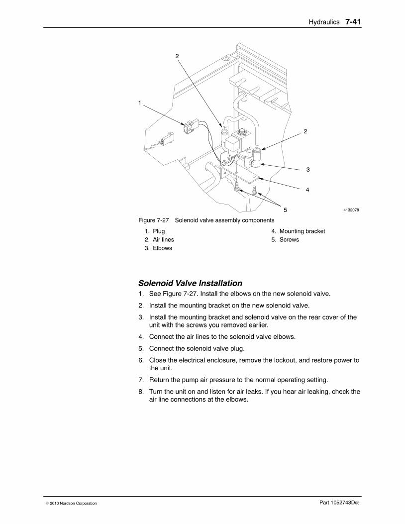
Hydraulics 7-41
Part 1052743D03� 2010 Nordson Corporation
4132078
4
2
2
1
3
5
Figure 7-27 Solenoid valve assembly components
1. Plug2. Air lines3. Elbows
4. Mounting bracket5. Screws
Solenoid Valve Installation 1. See Figure 7-27. Install the elbows on the new solenoid valve.
2. Install the mounting bracket on the new solenoid valve.
3. Install the mounting bracket and solenoid valve on the rear cover of theunit with the screws you removed earlier.
4. Connect the air lines to the solenoid valve elbows.
5. Connect the solenoid valve plug.
6. Close the electrical enclosure, remove the lockout, and restore power tothe unit.
7. Return the pump air pressure to the normal operating setting.
8. Turn the unit on and listen for air leaks. If you hear air leaking, check theair line connections at the elbows.
Hydraulics7-42
Part 1052743D03 � 2010 Nordson Corporation
Replacing the Triggering Solenoid Valve (Single-Acting Pump) Follow this procedure to replace the triggering solenoid valve that isconnected to the pump.
Solenoid Valve Removal
WARNING! Risk of equipment damage, personal injury, or death.Disconnect and lock out electrical power to the unit.
1. Place the unit’s POWER switch in the off position, disconnect and lockout electrical power to the unit at the branch circuit disconnect switch,and disconnect and lock out electrical power supplied through any I/Owiring.
2. Reduce the pump air pressure to 0.
3. Remove the electrical enclosure lid and the pump cover.
4. Disconnect the air line from the triggering solenoid valve elbow (1).
5. See Figure 7-28. Disconnect the solenoid valve wires (2) from terminals3 and 4 on the center frame terminal block. Do not disconnect the wiresfrom your triggering device.
6. Disconnect the solenoid valve ground wire (3) from the ground stud onthe unit’s base.
7. Unscrew the solenoid valve (4) and bushing (5) from the pipe nipple (6).
8. Remove the elbow and bushing from the solenoid valve.
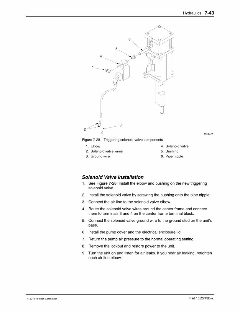
Hydraulics 7-43
Part 1052743D03� 2010 Nordson Corporation
4132079
4
23
5
6
1
2
Figure 7-28 Triggering solenoid valve components
1. Elbow2. Solenoid valve wires3. Ground wire
4. Solenoid valve5. Bushing6. Pipe nipple
Solenoid Valve Installation 1. See Figure 7-28. Install the elbow and bushing on the new triggering
solenoid valve.
2. Install the solenoid valve by screwing the bushing onto the pipe nipple.
3. Connect the air line to the solenoid valve elbow.
4. Route the solenoid valve wires around the center frame and connectthem to terminals 3 and 4 on the center frame terminal block.
5. Connect the solenoid valve ground wire to the ground stud on the unit’sbase.
6. Install the pump cover and the electrical enclosure lid.
7. Return the pump air pressure to the normal operating setting.
8. Remove the lockout and restore power to the unit.
9. Turn the unit on and listen for air leaks. If you hear air leaking, retighteneach air line elbow.
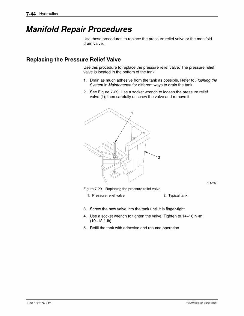
Hydraulics7-44
Part 1052743D03 � 2010 Nordson Corporation
Manifold Repair Procedures Use these procedures to replace the pressure relief valve or the manifolddrain valve.
Replacing the Pressure Relief Valve Use this procedure to replace the pressure relief valve. The pressure reliefvalve is located in the bottom of the tank.
1. Drain as much adhesive from the tank as possible. Refer to Flushing theSystem in Maintenance for different ways to drain the tank.
2. See Figure 7-29. Use a socket wrench to loosen the pressure reliefvalve (1); then carefully unscrew the valve and remove it.
4132080
1
2
Figure 7-29 Replacing the pressure relief valve
1. Pressure relief valve 2. Typical tank
3. Screw the new valve into the tank until it is finger-tight.
4. Use a socket wrench to tighten the valve. Tighten to 14−16 N�m(10−12 ft-lb).
5. Refill the tank with adhesive and resume operation.
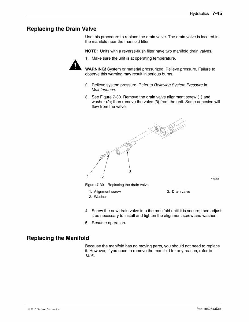
Hydraulics 7-45
Part 1052743D03� 2010 Nordson Corporation
Replacing the Drain Valve Use this procedure to replace the drain valve. The drain valve is located inthe manifold near the manifold filter.
NOTE: Units with a reverse-flush filter have two manifold drain valves.
1. Make sure the unit is at operating temperature.
WARNING! System or material pressurized. Relieve pressure. Failure toobserve this warning may result in serious burns.
2. Relieve system pressure. Refer to Relieving System Pressure inMaintenance.
3. See Figure 7-30. Remove the drain valve alignment screw (1) andwasher (2); then remove the valve (3) from the unit. Some adhesive willflow from the valve.
41320811 2
3
Figure 7-30 Replacing the drain valve
1. Alignment screw2. Washer
3. Drain valve
4. Screw the new drain valve into the manifold until it is secure; then adjustit as necessary to install and tighten the alignment screw and washer.
5. Resume operation.
Replacing the Manifold Because the manifold has no moving parts, you should not need to replaceit. However, if you need to remove the manifold for any reason, refer toTank.

Hydraulics7-46
Part 1052743D03 � 2010 Nordson Corporation
Tank 8-1
Part 1052743D03� 2010 Nordson Corporation
Section 8Tank
WARNING! Allow only personnel with appropriate training and experienceto operate or service the equipment. The use of untrained or inexperiencedpersonnel to operate or service the equipment can result in injury, includingdeath, to themselves and others, and damage to the equipment.
Introduction This section describes how to replace the tank and manifold. It includes
� an overview of the tank assembly� procedures for replacing the tank and manifold
Refer to the following sections for additional information on the tank andmanifold:
� Operation gives the procedure for filling the tank with adhesive.
� Maintenance gives procedures for flushing the tank and manifoldand for draining adhesive from the tank.
� Control includes procedures for replacing the tank resistancetemperature detector (RTD) or thermostat.
� Parts includes parts lists and illustrations for the tank assembly andunit frame
� Technical Data gives tank specifications, including the tank capacity,the tank volume, and the dimensions of the tank lid opening.
Overview of the Tank The tank holds a supply of adhesive and melts it before it is pumped to thehoses and guns. An RTD and overtemperature thermostat sense the tanktemperature and provide input to the control system. The tank is heated bycast-in heating elements.
Tank8-2
Part 1052743D03 � 2010 Nordson Corporation
Tank and Manifold Replacement Because the tank and manifold have no moving parts, you should not needto replace them. However, if you need to remove them from the unit for anyreason, follow these procedures. Refer to the parts lists in the Parts sectionfor the part numbers of any components that need to be replaced. You canuse the parts list illustrations as a guide as you perform the followingdisassembly and reassembly procedures.
To replace both the tank and the manifold, you must complete all of thefollowing procedures:
� Preparing to Replace the Tank or Manifold� Disassembling the Tank and Manifold� Reassembling the Tank and Manifold� Restoring the Unit to Normal Operation
These instructions can also be used to replace just one part of the tankassembly.
Preparing to Replace the Tank or Manifold Complete this procedure before you perform any tank repairs.
1. Heat the unit to operating temperature to aid disassembly and toprepare for draining as much adhesive as possible from the tank.
2. Drain the tank. For information about different ways to drain the tank,refer to Flushing the System in the Maintenance section.
3. Turn the pump air pressure regulator to 0; then disconnect the airregulator from the unit.
NOTE: Remove the pump from the unit. Refer to the appropriate pumpremoval procedure in the Hydraulics section.
NOTE: The procedure for removing the pump includes steps forrelieving system pressure and locking out electrical power to the unit.
Disassembling the Tank and Manifold Follow this procedure to remove the tank and manifold and to disassemblethem.
1. If you have not already done so, complete Preparing to Replace theTank or Manifold.
2. Remove the unit’s front and back panels. To do so, you will need to
� remove the electrical enclosure lid� loosen some of the tank lid screws� disconnect any ground wires
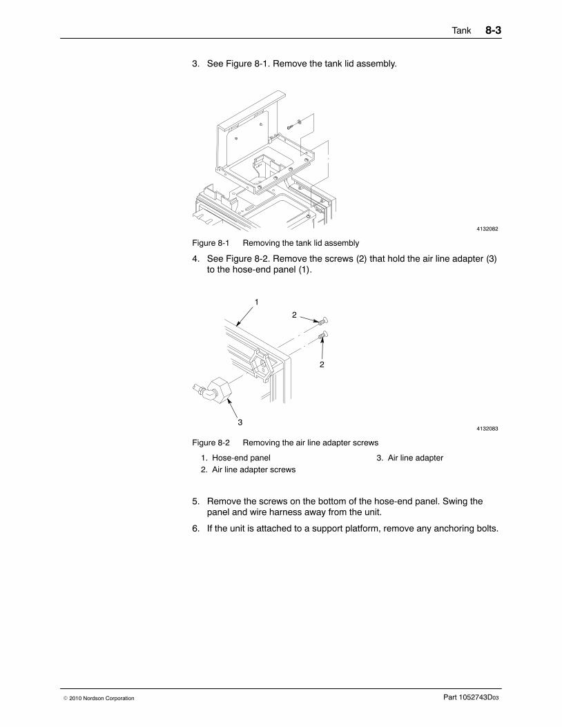
Tank 8-3
Part 1052743D03� 2010 Nordson Corporation
3. See Figure 8-1. Remove the tank lid assembly.
4132082
Figure 8-1 Removing the tank lid assembly
4. See Figure 8-2. Remove the screws (2) that hold the air line adapter (3)to the hose-end panel (1).
4132083
1
2
2
3
Figure 8-2 Removing the air line adapter screws
1. Hose-end panel2. Air line adapter screws
3. Air line adapter
5. Remove the screws on the bottom of the hose-end panel. Swing thepanel and wire harness away from the unit.
6. If the unit is attached to a support platform, remove any anchoring bolts.
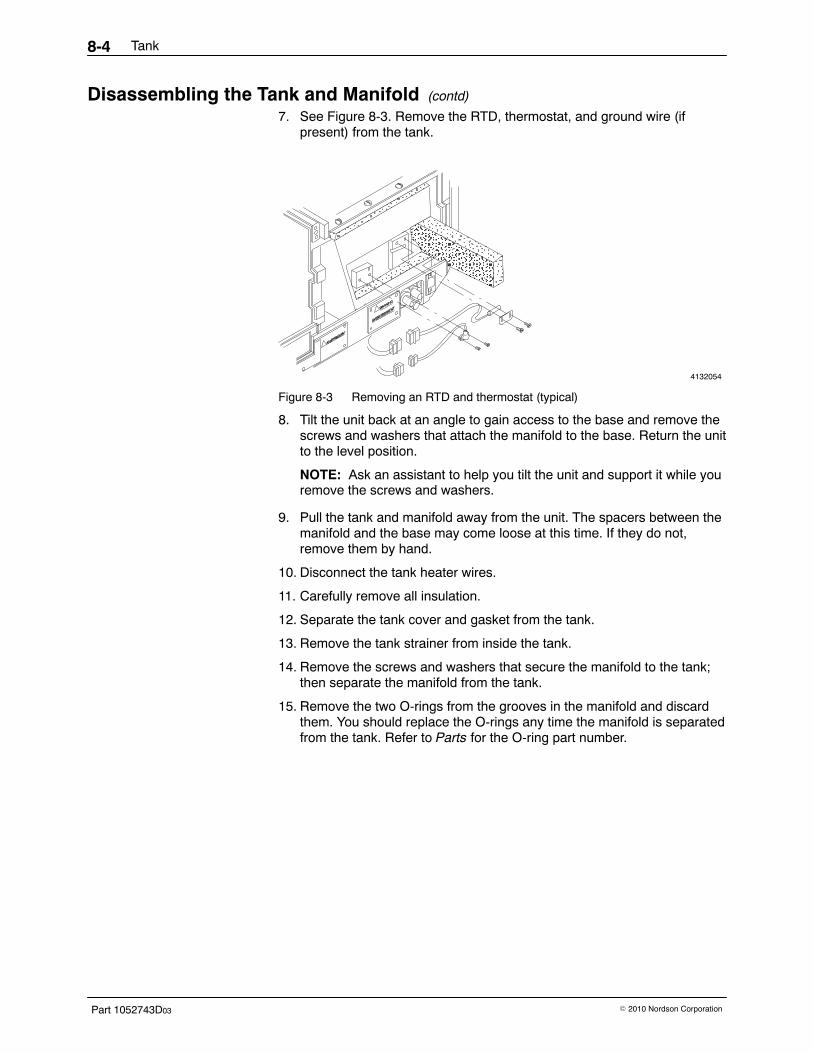
Tank8-4
Part 1052743D03 � 2010 Nordson Corporation
Disassembling the Tank and Manifold (contd)
7. See Figure 8-3. Remove the RTD, thermostat, and ground wire (ifpresent) from the tank.
4132054
ÎÎÎÎÎÎÎÎÎÎÎÎÎÎÎ
ÏÏÏÏÏÏÏÏÏÏÏÏÏÏÏÏÏÏÏÏ
ÎÎÎÎÎÎÎÎÎÎÎÎÎÎÎÎÎÎÎÎÎÎÎÎÎ
Î
ÎÎÎÎÎÎÎÎÎÎÎÎÎÎÎÎÎÎÎÎÎÎÎÎ
Figure 8-3 Removing an RTD and thermostat (typical)
8. Tilt the unit back at an angle to gain access to the base and remove thescrews and washers that attach the manifold to the base. Return the unitto the level position.
NOTE: Ask an assistant to help you tilt the unit and support it while youremove the screws and washers.
9. Pull the tank and manifold away from the unit. The spacers between themanifold and the base may come loose at this time. If they do not,remove them by hand.
10. Disconnect the tank heater wires.
11. Carefully remove all insulation.
12. Separate the tank cover and gasket from the tank.
13. Remove the tank strainer from inside the tank.
14. Remove the screws and washers that secure the manifold to the tank;then separate the manifold from the tank.
15. Remove the two O-rings from the grooves in the manifold and discardthem. You should replace the O-rings any time the manifold is separatedfrom the tank. Refer to Parts for the O-ring part number.
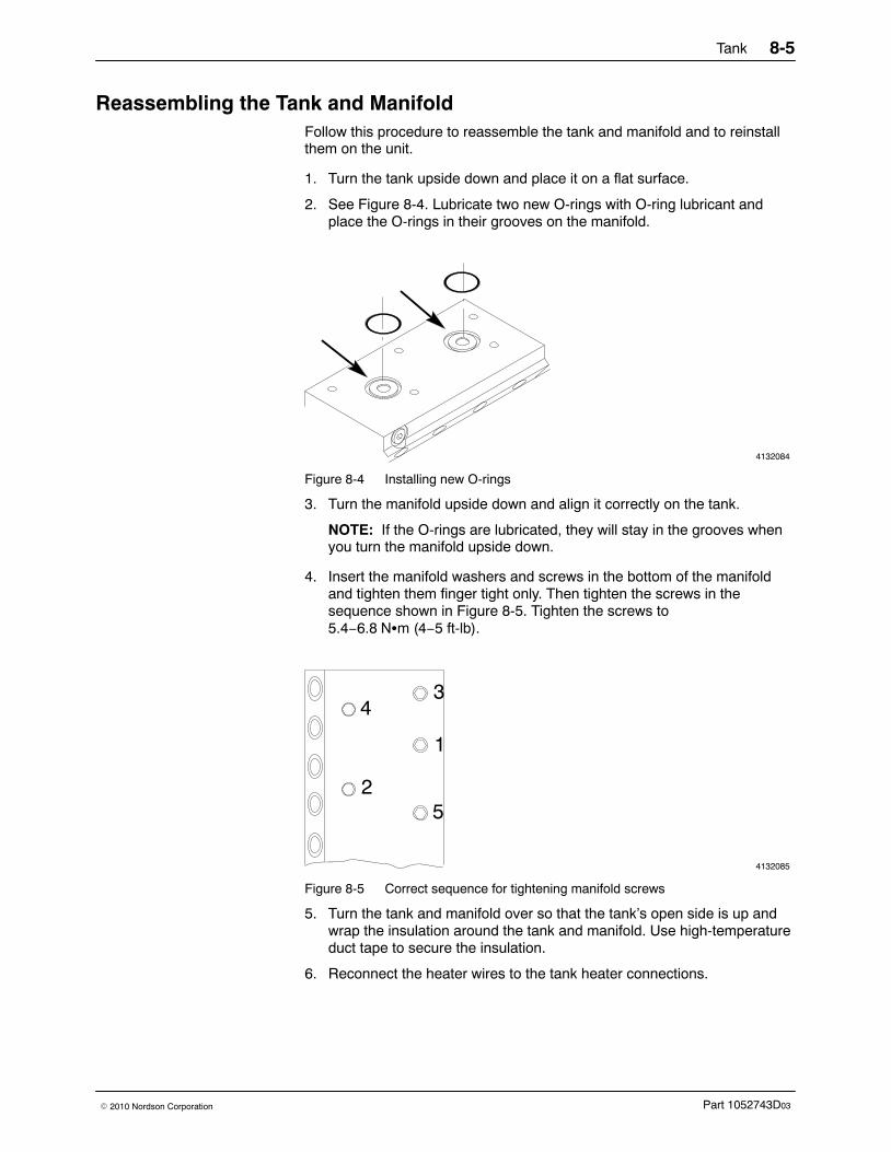
Tank 8-5
Part 1052743D03� 2010 Nordson Corporation
Reassembling the Tank and Manifold Follow this procedure to reassemble the tank and manifold and to reinstallthem on the unit.
1. Turn the tank upside down and place it on a flat surface.
2. See Figure 8-4. Lubricate two new O-rings with O-ring lubricant andplace the O-rings in their grooves on the manifold.
4132084
Figure 8-4 Installing new O-rings
3. Turn the manifold upside down and align it correctly on the tank.
NOTE: If the O-rings are lubricated, they will stay in the grooves whenyou turn the manifold upside down.
4. Insert the manifold washers and screws in the bottom of the manifoldand tighten them finger tight only. Then tighten the screws in thesequence shown in Figure 8-5. Tighten the screws to5.4−6.8 N�m (4−5 ft-lb).
4132085
1
2
34
5
Figure 8-5 Correct sequence for tightening manifold screws
5. Turn the tank and manifold over so that the tank’s open side is up andwrap the insulation around the tank and manifold. Use high-temperatureduct tape to secure the insulation.
6. Reconnect the heater wires to the tank heater connections.
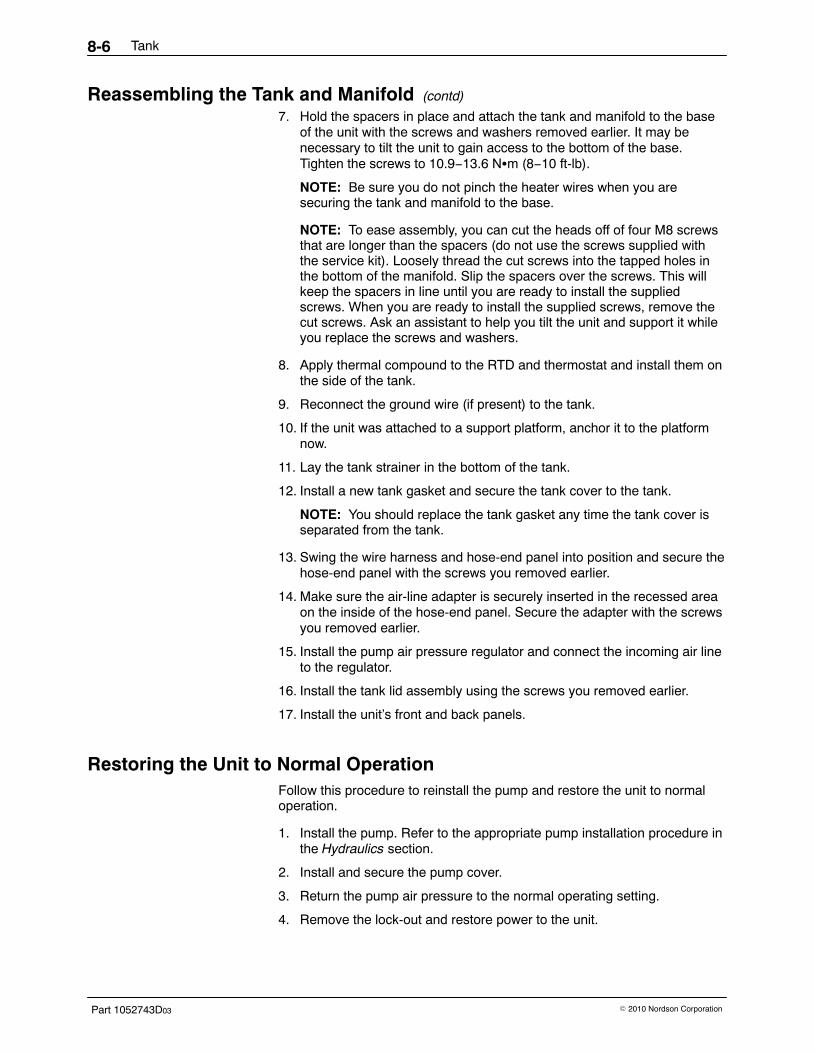
Tank8-6
Part 1052743D03 � 2010 Nordson Corporation
Reassembling the Tank and Manifold (contd)
7. Hold the spacers in place and attach the tank and manifold to the baseof the unit with the screws and washers removed earlier. It may benecessary to tilt the unit to gain access to the bottom of the base.Tighten the screws to 10.9−13.6 N�m (8−10 ft-lb).
NOTE: Be sure you do not pinch the heater wires when you aresecuring the tank and manifold to the base.
NOTE: To ease assembly, you can cut the heads off of four M8 screwsthat are longer than the spacers (do not use the screws supplied withthe service kit). Loosely thread the cut screws into the tapped holes inthe bottom of the manifold. Slip the spacers over the screws. This willkeep the spacers in line until you are ready to install the suppliedscrews. When you are ready to install the supplied screws, remove thecut screws. Ask an assistant to help you tilt the unit and support it whileyou replace the screws and washers.
8. Apply thermal compound to the RTD and thermostat and install them onthe side of the tank.
9. Reconnect the ground wire (if present) to the tank.
10. If the unit was attached to a support platform, anchor it to the platformnow.
11. Lay the tank strainer in the bottom of the tank.
12. Install a new tank gasket and secure the tank cover to the tank.
NOTE: You should replace the tank gasket any time the tank cover isseparated from the tank.
13. Swing the wire harness and hose-end panel into position and secure thehose-end panel with the screws you removed earlier.
14. Make sure the air-line adapter is securely inserted in the recessed areaon the inside of the hose-end panel. Secure the adapter with the screwsyou removed earlier.
15. Install the pump air pressure regulator and connect the incoming air lineto the regulator.
16. Install the tank lid assembly using the screws you removed earlier.
17. Install the unit’s front and back panels.
Restoring the Unit to Normal Operation Follow this procedure to reinstall the pump and restore the unit to normaloperation.
1. Install the pump. Refer to the appropriate pump installation procedure inthe Hydraulics section.
2. Install and secure the pump cover.
3. Return the pump air pressure to the normal operating setting.
4. Remove the lock-out and restore power to the unit.
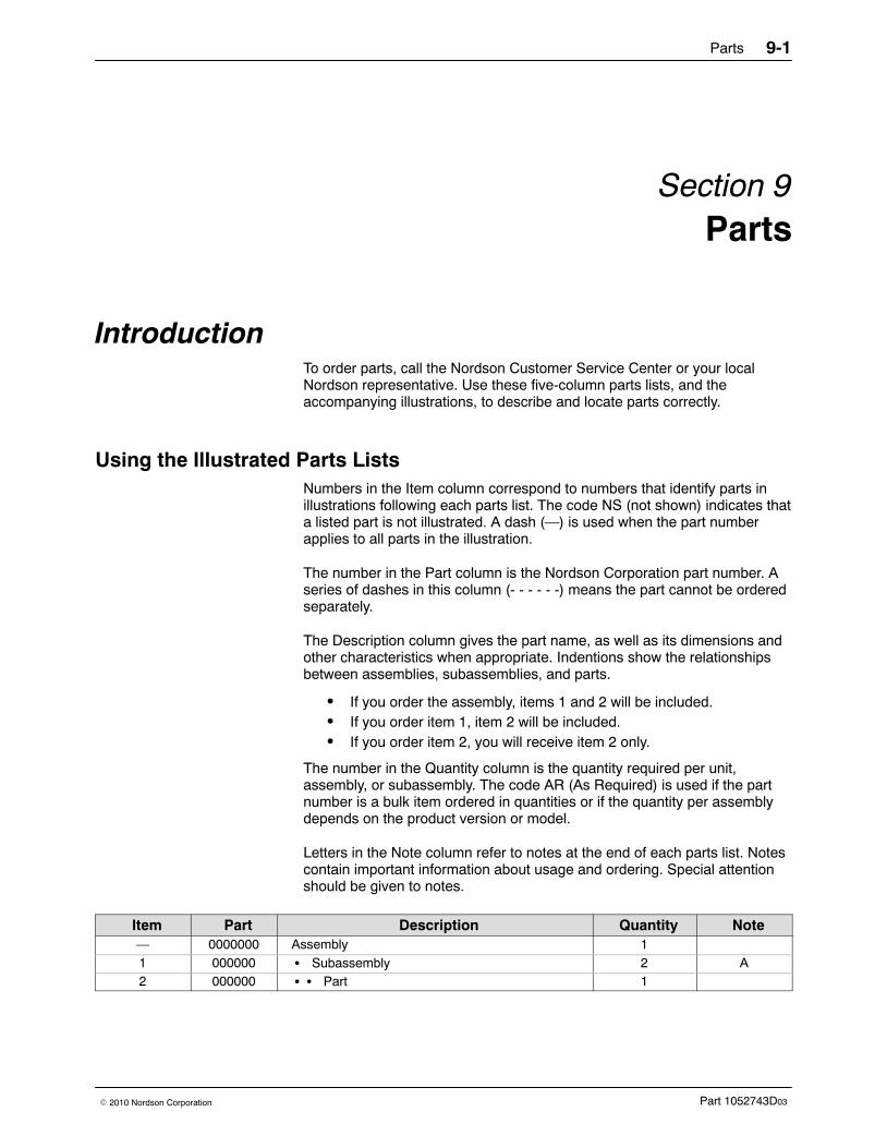
Parts 9-1
Part 1052743D03� 2010 Nordson Corporation
Section 9Parts
Introduction To order parts, call the Nordson Customer Service Center or your localNordson representative. Use these five-column parts lists, and theaccompanying illustrations, to describe and locate parts correctly.
Using the Illustrated Parts Lists Numbers in the Item column correspond to numbers that identify parts inillustrations following each parts list. The code NS (not shown) indicates thata listed part is not illustrated. A dash (—) is used when the part numberapplies to all parts in the illustration.
The number in the Part column is the Nordson Corporation part number. Aseries of dashes in this column (- - - - - -) means the part cannot be orderedseparately.
The Description column gives the part name, as well as its dimensions andother characteristics when appropriate. Indentions show the relationshipsbetween assemblies, subassemblies, and parts.
� If you order the assembly, items 1 and 2 will be included.� If you order item 1, item 2 will be included.� If you order item 2, you will receive item 2 only.
The number in the Quantity column is the quantity required per unit,assembly, or subassembly. The code AR (As Required) is used if the partnumber is a bulk item ordered in quantities or if the quantity per assemblydepends on the product version or model.
Letters in the Note column refer to notes at the end of each parts list. Notescontain important information about usage and ordering. Special attentionshould be given to notes.
Item Part Description Quantity Note— 0000000 Assembly 11 000000 � Subassembly 2 A2 000000 � � Part 1
Parts9-2
Part 1052743D03 � 2010 Nordson Corporation
This page intentionally left blank.
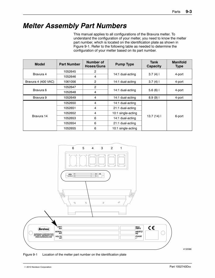
Parts 9-3
Part 1052743D03� 2010 Nordson Corporation
Melter Assembly Part Numbers This manual applies to all configurations of the Bravura melter. Tounderstand the configuration of your melter, you need to know the melterpart number, which is located on the identification plate as shown inFigure 9-1. Refer to the following table as needed to determine theconfiguration of your melter based on its part number.
Model Part Number Number ofHoses/Guns Pump Type Tank
CapacityManifold
Type
Bravura 41052645 2
14:1 dual-acting 3.7 (4) l 4-port1052646 4
Bravura 4 (400 VAC) 1061056 2 14:1 dual-acting 3.7 (4) l 4-port
Bravura 61052647 2
14:1 dual-acting 5.6 (6) l 4-port1052648 4
Bravura 9 1052649 4 14:1 dual-acting 8.9 (9) l 4-port
Bravura 14
1052650 4 14:1 dual-acting
13.7 (14) l 6-port
1052651 4 21:1 dual-acting
1052652 4 10:1 single-acting
1052653 6 14:1 dual-acting
1052654 6 21:1 dual-acting
1052655 6 10:1 single-acting
4132086
123456
Figure 9-1 Location of the melter part number on the identification plate
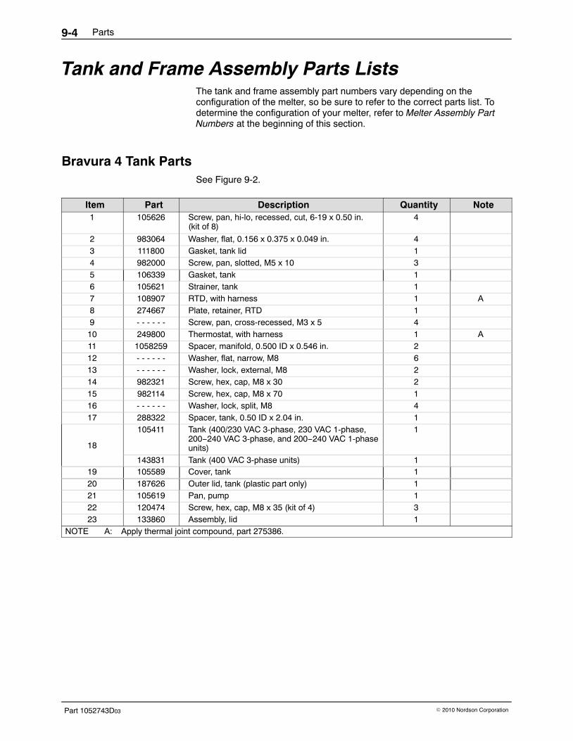
Parts9-4
Part 1052743D03 � 2010 Nordson Corporation
Tank and Frame Assembly Parts Lists The tank and frame assembly part numbers vary depending on theconfiguration of the melter, so be sure to refer to the correct parts list. Todetermine the configuration of your melter, refer to Melter Assembly PartNumbers at the beginning of this section.
Bravura 4 Tank Parts See Figure 9-2.
Item Part Description Quantity Note1 105626 Screw, pan, hi-lo, recessed, cut, 6-19 x 0.50 in.
(kit of 8)4
2 983064 Washer, flat, 0.156 x 0.375 x 0.049 in. 43 111800 Gasket, tank lid 14 982000 Screw, pan, slotted, M5 x 10 35 106339 Gasket, tank 16 105621 Strainer, tank 17 108907 RTD, with harness 1 A8 274667 Plate, retainer, RTD 19 - - - - - - Screw, pan, cross-recessed, M3 x 5 410 249800 Thermostat, with harness 1 A11 1058259 Spacer, manifold, 0.500 ID x 0.546 in. 212 - - - - - - Washer, flat, narrow, M8 613 - - - - - - Washer, lock, external, M8 214 982321 Screw, hex, cap, M8 x 30 215 982114 Screw, hex, cap, M8 x 70 116 - - - - - - Washer, lock, split, M8 417 288322 Spacer, tank, 0.50 ID x 2.04 in. 1
18
105411 Tank (400/230 VAC 3-phase, 230 VAC 1-phase,200−240 VAC 3-phase, and 200−240 VAC 1-phaseunits)
1
143831 Tank (400 VAC 3-phase units) 119 105589 Cover, tank 120 187626 Outer lid, tank (plastic part only) 121 105619 Pan, pump 122 120474 Screw, hex, cap, M8 x 35 (kit of 4) 323 133860 Assembly, lid 1
NOTE A: Apply thermal joint compound, part 275386.
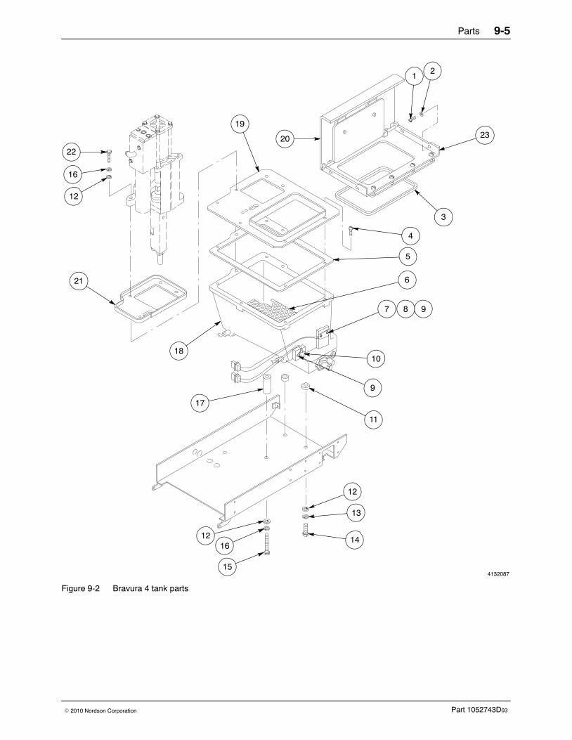
Parts 9-5
Part 1052743D03� 2010 Nordson Corporation
4132087
20
12
23
3
4
5
6
7 8 9
10
9
11
17
12
13
141216
15
18
21
16
22
12
19
Figure 9-2 Bravura 4 tank parts
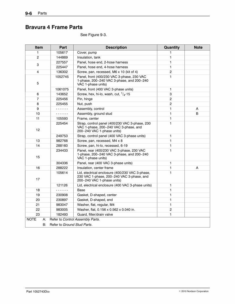
Parts9-6
Part 1052743D03 � 2010 Nordson Corporation
Bravura 4 Frame Parts See Figure 9-3.
Item Part Description Quantity Note1 105617 Cover, pump 12 144869 Insulation, tank 1
3227557 Panel, hose end, 2-hose harness 1225447 Panel, hose end, 4-hose harness 1
4 136302 Screw, pan, recessed, M6 x 10 (kit of 4) 2
5
1052745 Panel, front (400/230 VAC 3-phase, 230 VAC1-phase, 200−240 VAC 3-phase, and 200−240VAC 1-phase units)
1
1061075 Panel, front (400 VAC 3-phase units) 16 143652 Screw, hex, hi-lo, wash, cut, 1/4-15 37 225456 Pin, hinge 28 225455 Nut, push 29 - - - - - - Assembly, control 1 A10 - - - - - - Assembly, ground stud 1 B11 105593 Frame, center 1
12
225454 Strap, control panel (400/230 VAC 3-phase, 230VAC 1-phase, 200−240 VAC 3-phase, and200−240 VAC 1-phase units)
1
249753 Strap, control panel (400 VAC 3-phase units) 113 982768 Screw, pan, recessed, M4 x 8 114 288160 Screw, pan, hi-lo, recessed, 6-19 1
15
234433 Panel, rear (400/230 VAC 3-phase, 230 VAC1-phase, 200−240 VAC 3-phase, and 200−240VAC 1-phase units)
1
304336 Panel, rear (400 VAC 3-phase units) 116 288222 Insulation, center frame 1 A
17
105614 Lid, electrical enclosure (400/230 VAC 3-phase,230 VAC 1-phase, 200−240 VAC 3-phase, and200−240 VAC 1-phase units)
1
121126 Lid, electrical enclosure (400 VAC 3-phase units) 118 - - - - - - Base 119 230908 Gasket, D-shaped, center 120 230897 Gasket, D-shaped, end 121 983047 Washer, flat, regular, M4 122 983005 Washer, flat, 0.156 x 0.562 x 0.040 in. 223 182493 Guard, filter/drain valve 1
NOTE A: Refer to Control Assembly Parts.
B: Refer to Ground Stud Parts.
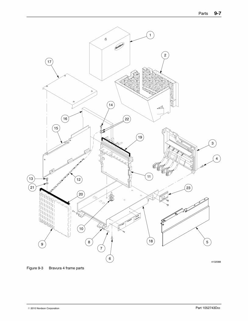
Parts 9-7
Part 1052743D03� 2010 Nordson Corporation
ÎÎÎÎÎÎÎÎÎÎÎÎÎÎÎÎÎÎÎÎÎÎÎÎÎÎÎÎÎÎÎÎÎÎÎÎÎÎÎÎÎÎ
ÎÎÎÎÎÎÎÎÎÎÎÎÎÎÎÎÎÎÎÎÎÎÎÎÎÎÎÎÎÎÎÎÎÎÎÎÎÎÎÎÎÎÎÎÎÎÎÎÎ
ÎÎÎÎÎÎÎÎÎÎÎÎÎÎÎÎÎÎÎÎÎÎÎÎÎÎÎÎÎÎÎÎÎÎÎÎÎÎÎÎÎÎ
ÏÏÏÏÏÏÏÏÏÏÏÏÏÏÏÌÌÌÌÌÌÌ
ÌÌÌÌÌÌÌÌÌÌÌÌÌÌÌÌÌÌÌÌÌ
ÏÏÏÏÏÏÏÏÏÏÏÏÏÏÏÏ
ÏÏÏÏÏÏÏÏÏÏÏÏÏÏÏÏÏÏÏÏÏÏÏÏÏÏÏÏÏÏÏÏÏÏÏÏÏÏÏÏÏÏÏÏÏÏÏÏÏÏ
ÎÎÎÎÎÎÎÎÎÎÎÎÎÎÎÎÎÎÎÎ
ÌÌÎÎÎÎ
4132088
20
1
2
23
3
4
5
6
10
9
1113 12
16
15
21
17
14
7
8 18
22
19
Figure 9-3 Bravura 4 frame parts
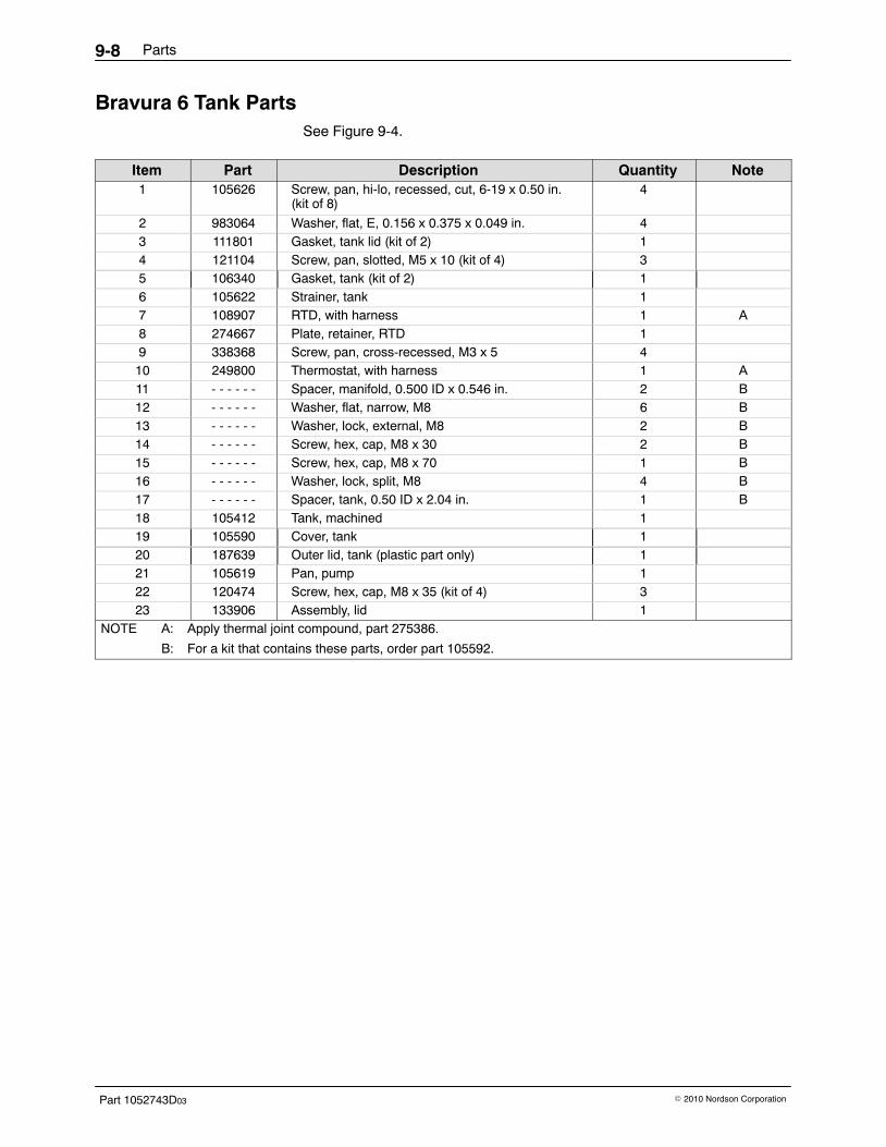
Parts9-8
Part 1052743D03 � 2010 Nordson Corporation
Bravura 6 Tank Parts See Figure 9-4.
Item Part Description Quantity Note1 105626 Screw, pan, hi-lo, recessed, cut, 6-19 x 0.50 in.
(kit of 8)4
2 983064 Washer, flat, E, 0.156 x 0.375 x 0.049 in. 43 111801 Gasket, tank lid (kit of 2) 14 121104 Screw, pan, slotted, M5 x 10 (kit of 4) 35 106340 Gasket, tank (kit of 2) 16 105622 Strainer, tank 17 108907 RTD, with harness 1 A8 274667 Plate, retainer, RTD 19 338368 Screw, pan, cross-recessed, M3 x 5 410 249800 Thermostat, with harness 1 A11 - - - - - - Spacer, manifold, 0.500 ID x 0.546 in. 2 B12 - - - - - - Washer, flat, narrow, M8 6 B13 - - - - - - Washer, lock, external, M8 2 B14 - - - - - - Screw, hex, cap, M8 x 30 2 B15 - - - - - - Screw, hex, cap, M8 x 70 1 B16 - - - - - - Washer, lock, split, M8 4 B17 - - - - - - Spacer, tank, 0.50 ID x 2.04 in. 1 B18 105412 Tank, machined 119 105590 Cover, tank 120 187639 Outer lid, tank (plastic part only) 121 105619 Pan, pump 122 120474 Screw, hex, cap, M8 x 35 (kit of 4) 323 133906 Assembly, lid 1
NOTE A: Apply thermal joint compound, part 275386.
B: For a kit that contains these parts, order part 105592.
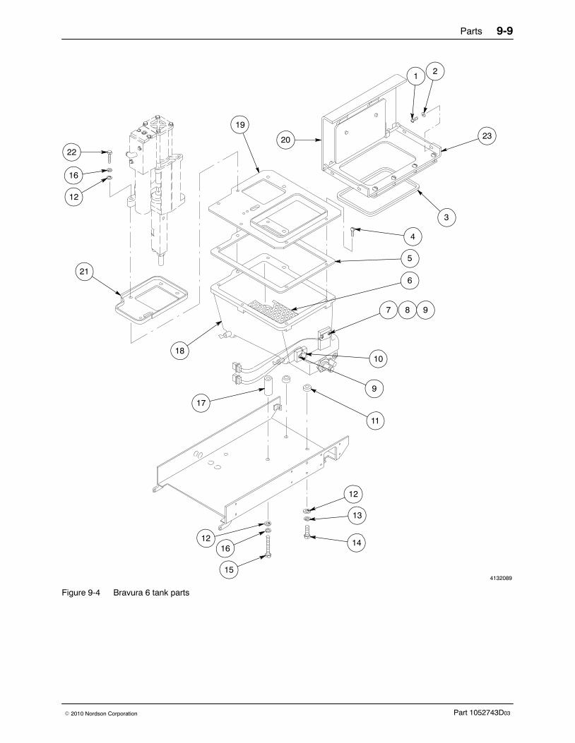
Parts 9-9
Part 1052743D03� 2010 Nordson Corporation
4132089
20
12
23
3
4
5
6
7 8 9
10
9
11
17
12
13
141216
15
18
21
16
22
12
19
Figure 9-4 Bravura 6 tank parts
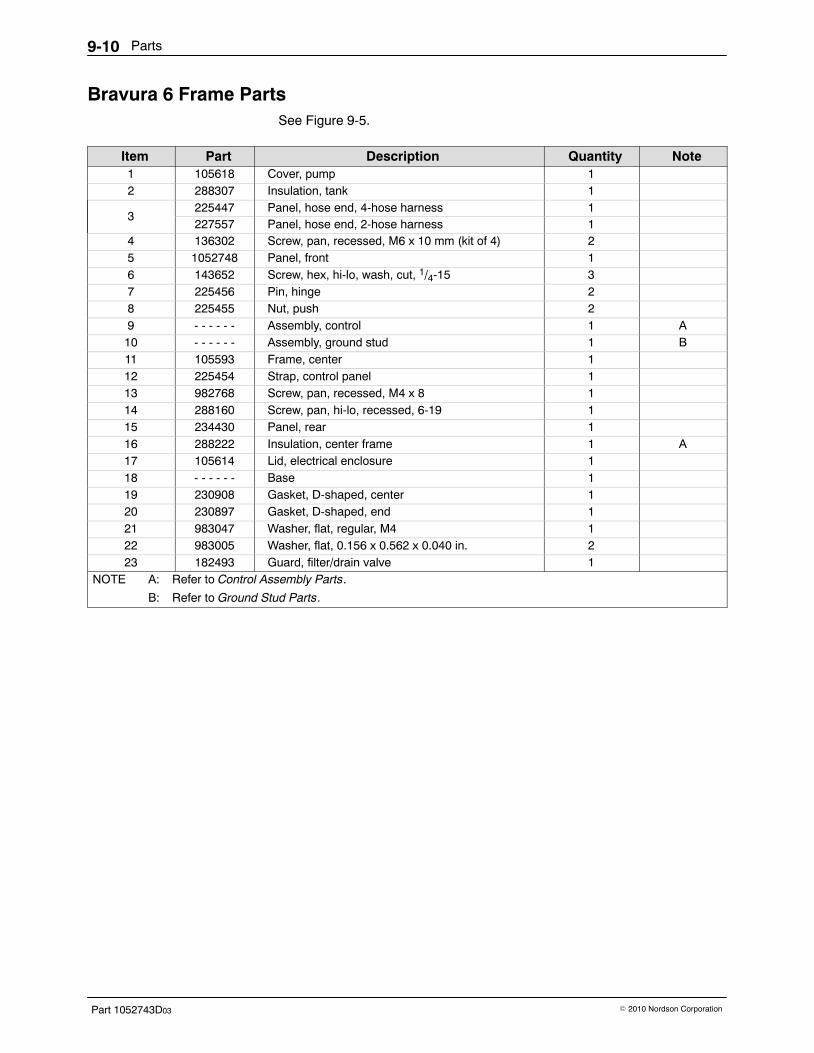
Parts9-10
Part 1052743D03 � 2010 Nordson Corporation
Bravura 6 Frame Parts See Figure 9-5.
Item Part Description Quantity Note1 105618 Cover, pump 12 288307 Insulation, tank 1
3225447 Panel, hose end, 4-hose harness 1227557 Panel, hose end, 2-hose harness 1
4 136302 Screw, pan, recessed, M6 x 10 mm (kit of 4) 25 1052748 Panel, front 16 143652 Screw, hex, hi-lo, wash, cut, 1/4-15 37 225456 Pin, hinge 28 225455 Nut, push 29 - - - - - - Assembly, control 1 A10 - - - - - - Assembly, ground stud 1 B11 105593 Frame, center 112 225454 Strap, control panel 113 982768 Screw, pan, recessed, M4 x 8 114 288160 Screw, pan, hi-lo, recessed, 6-19 115 234430 Panel, rear 116 288222 Insulation, center frame 1 A17 105614 Lid, electrical enclosure 118 - - - - - - Base 119 230908 Gasket, D-shaped, center 120 230897 Gasket, D-shaped, end 121 983047 Washer, flat, regular, M4 122 983005 Washer, flat, 0.156 x 0.562 x 0.040 in. 223 182493 Guard, filter/drain valve 1
NOTE A: Refer to Control Assembly Parts.
B: Refer to Ground Stud Parts.

Parts 9-11
Part 1052743D03� 2010 Nordson Corporation
4132090
ÎÎÎÎÎÎÎÎÎÎÎÎÎÎÎÎÎÎÎÎÎÎÎÎÎÎÎÎÎÎÎÎÎÎÎÎÎÎÎÎÎÎ
ÎÎÎÎÎÎÎÎÎÎÎÎÎÎÎÎÎÎÎÎÎÎÎÎÎÎÎÎÎÎÎÎÎÎÎÎÎÎÎÎÎÎÎÎÎÎÎÎÎ
ÎÎÎÎÎÎÎÎÎÎÎÎÎÎÎÎÎÎÎÎÎÎÎÎÎÎÎÎÎÎÎÎÎÎÎÎÎÎÎÎÎÎÎÎÎÎÎÎ
ÏÏÏÏÏÏÏÏÏÏÏÏÏÏÏÌÌÌÌÌÌÌ
ÌÌÌÌÌÌÌÌÌÌÌÌÌÌÌÌÌÌÌÌÌ
ÏÏÏÏÏÏÏÏÏÏÏÏÏÏÏÏ
ÏÏÏÏÏÏÏÏÏÏÏÏÏÏÏÏÏÏÏÏÏÏÏÏÏÏÏÏÏÏÏÏÏÏÏÏÏÏÏÏÏÏÏÏÏÏÏÏÏÏ
ÎÎÎÎÎÎÎÎÎÎÎÎÎÎÎÎ
ÌÌÎÎÎÎ
20
1
2
23
3
4
5
6
10
9
1113 12
16
15
21
17
14
7
8 18
22
19
Figure 9-5 Bravura 6 frame parts
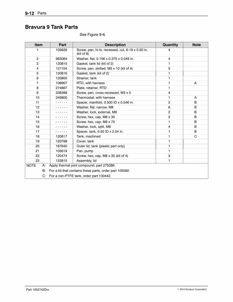
Parts9-12
Part 1052743D03 � 2010 Nordson Corporation
Bravura 9 Tank Parts See Figure 9-6.
Item Part Description Quantity Note1 105626 Screw, pan, hi-lo, recessed, cut, 6-19 x 0.50 in.
(kit of 8)4
2 983064 Washer, flat, 0.156 x 0.375 x 0.049 in. 43 120815 Gasket, tank lid (kit of 2) 14 121104 Screw, pan, slotted, M5 x 10 (kit of 4) 55 120816 Gasket, tank (kit of 2) 16 120800 Strainer, tank 17 108907 RTD, with harness 1 A8 274667 Plate, retainer, RTD 19 338368 Screw, pan, cross-recessed, M3 x 5 410 249800 Thermostat, with harness 1 A11 - - - - - - Spacer, manifold, 0.500 ID x 0.546 in. 2 B12 - - - - - - Washer, flat, narrow, M8 6 B13 - - - - - - Washer, lock, external, M8 2 B14 - - - - - - Screw, hex, cap, M8 x 30 2 B15 - - - - - - Screw, hex, cap, M8 x 70 1 B16 - - - - - - Washer, lock, split, M8 4 B17 - - - - - - Spacer, tank, 0.50 ID x 2.04 in. 1 B18 120817 Tank, machined 1 C19 120798 Cover, tank 120 187640 Outer lid, tank (plastic part only) 121 105619 Pan, pump 122 120474 Screw, hex, cap, M8 x 35 (kit of 4) 323 133915 Assembly, lid 1
NOTE A: Apply thermal joint compound, part 275386.
B: For a kit that contains these parts, order part 105592. C: For a non-PTFE tank, order part 130442.
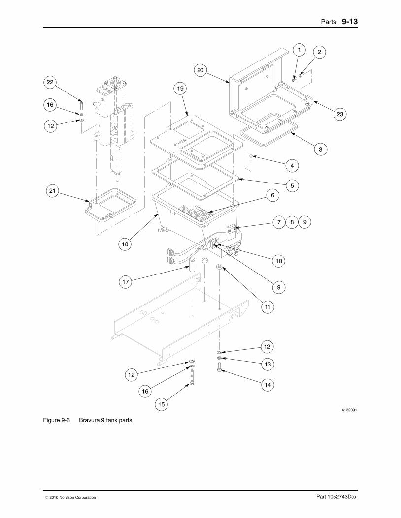
Parts 9-13
Part 1052743D03� 2010 Nordson Corporation
4132091
23
22
16
12
21
18
19
20
3
4
5
6
7
10
21
917
11
12
13
14
12
16
15
8 9
Figure 9-6 Bravura 9 tank parts
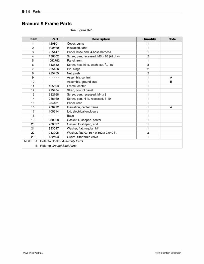
Parts9-14
Part 1052743D03 � 2010 Nordson Corporation
Bravura 9 Frame Parts See Figure 9-7.
Item Part Description Quantity Note1 120801 Cover, pump 12 109560 Insulation, tank 13 225447 Panel, hose end, 4-hose harness 14 136302 Screw, pan, recessed, M6 x 10 (kit of 4) 25 1052752 Panel, front 16 143652 Screw, hex, hi-lo, wash, cut, 1/4-15 37 225456 Pin, hinge 28 225455 Nut, push 29 - - - - - - Assembly, control 1 A10 - - - - - - Assembly, ground stud 1 B11 105593 Frame, center 112 225454 Strap, control panel 113 982768 Screw, pan, recessed, M4 x 8 114 288160 Screw, pan, hi-lo, recessed, 6-19 115 234431 Panel, rear 116 288222 Insulation, center frame 1 A17 105614 Lid, electrical enclosure 118 - - - - - - Base 119 230908 Gasket, D-shaped, center 120 230897 Gasket, D-shaped, end 121 983047 Washer, flat, regular, M4 122 983005 Washer, flat, 0.156 x 0.562 x 0.040 in. 223 182493 Guard, filter/drain valve 1
NOTE A: Refer to Control Assembly Parts.
B: Refer to Ground Stud Parts.

Parts 9-15
Part 1052743D03� 2010 Nordson Corporation
4132092
ÎÎÎÎÎÎÎÎÎÎÎÎÎÎÎÎÎÎÎÎÎÎÎÎÎÎÎÎÎÎÎÎÎÎÎÎÎÎÎÎÎÎ
ÎÎÎÎÎÎÎÎÎÎÎÎÎÎÎÎÎÎÎÎÎÎÎÎÎÎÎÎÎÎÎÎÎÎÎÎÎÎÎÎÎÎÎÎÎÎÎÎÎ
ÎÎÎÎÎÎÎÎÎÎÎÎÎÎÎÎÎÎÎÎÎÎÎÎÎÎÎÎÎÎÎÎÎÎÎÎÎÎÎÎÎÎÎÎÎÎÎÎ
ÏÏÏÏÏÏÏÏÏÏÏÏÏÏÏÌÌÌÌÌÌÌ
ÌÌÌÌÌÌÌÌÌÌÌÌÌÌÌÌÌÌÌÌÌ
ÏÏÏÏÏÏÏÏÏÏÏÏÏÏÏÏ
ÏÏÏÏÏÏÏÏÏÏÏÏÏÏÏÏÏÏÏÏÏÏÏÏÏÏÏÏÏÏÏÏÏÏÏÏÏÏÏÏÏÏÏÏÏÏÏÏÏÏ
ÎÎÎÎÎÎÎÎÎÎÎÎÎÎÎÎ
ÌÌÎÎÎÎ
20
1
2
23
3
4
5
6
10
9
1113 12
16
15
21
17
14
7
8 18
22
19
Figure 9-7 Bravura 9 frame parts

Parts9-16
Part 1052743D03 � 2010 Nordson Corporation
Bravura 14 Tank Parts See Figure 9-8.
Item Part Description Quantity Note1 105626 Screw, pan, hi-lo, recessed, cut, 6-19 x 0.50 in.
(kit of 8)4
2 983064 Washer, flat, 0.156 x 0.375 x 0.049 in. 43 111807 Gasket, tank lid (kit of 2) 14 121104 Screw, pan, slotted, M5 x 10 (kit of 4) 65 110584 Gasket, tank (kit of 2) 16 111804 Strainer, tank, small 17 108907 RTD, with harness 18 274667 Plate, retainer, RTD 19 338368 Screw, pan, cross-recessed, M3 x 5 410 249800 Thermostat, with harness 1 A11 - - - - - - Spacer, manifold, 0.358 in. long 2 B12 - - - - - - Washer, flat, narrow, M8 6 B13 - - - - - - Washer, lock, external, M8 2 B14 - - - - - - Screw, hex, cap, M8 x 30 2 B15 - - - - - - Screw, hex, cap, M8 x 70 1 B16 - - - - - - Washer, lock, split, M8 4 B17 - - - - - - Spacer, tank, 3.046 in. long 1 B18 105435 Tank 119 111808 Cover, tank 120 133818 Lid, tank (plastic part only) 121 105619 Pan, pump 122 120474 Screw, hex, cap, M8 x 35 (kit of 4) 3
NOTE A: Apply thermal joint compound, part 275386.
B: For a kit that contains these parts, order part 105592.
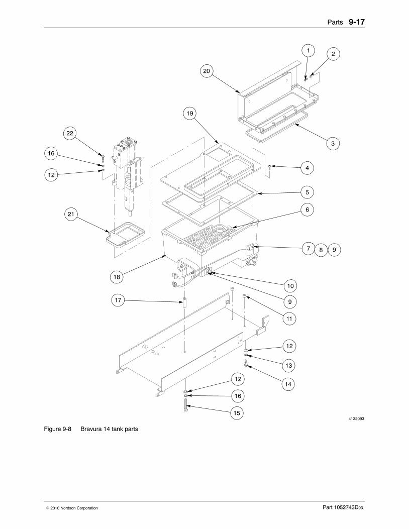
Parts 9-17
Part 1052743D03� 2010 Nordson Corporation
4132093
22
16
12
21
18
17
19
20
1 2
3
4
5
6
7
11
9
10
12
13
14
16
15
12
8 9
Figure 9-8 Bravura 14 tank parts
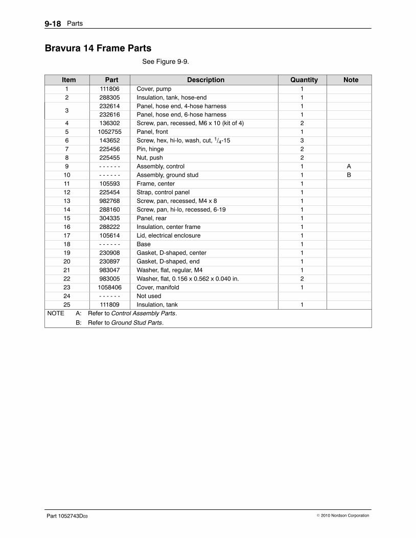
Parts9-18
Part 1052743D03 � 2010 Nordson Corporation
Bravura 14 Frame Parts See Figure 9-9.
Item Part Description Quantity Note1 111806 Cover, pump 12 288305 Insulation, tank, hose-end 1
3232614 Panel, hose end, 4-hose harness 1232616 Panel, hose end, 6-hose harness 1
4 136302 Screw, pan, recessed, M6 x 10 (kit of 4) 25 1052755 Panel, front 16 143652 Screw, hex, hi-lo, wash, cut, 1/4-15 37 225456 Pin, hinge 28 225455 Nut, push 29 - - - - - - Assembly, control 1 A10 - - - - - - Assembly, ground stud 1 B11 105593 Frame, center 112 225454 Strap, control panel 113 982768 Screw, pan, recessed, M4 x 8 114 288160 Screw, pan, hi-lo, recessed, 6-19 115 304335 Panel, rear 116 288222 Insulation, center frame 117 105614 Lid, electrical enclosure 118 - - - - - - Base 119 230908 Gasket, D-shaped, center 120 230897 Gasket, D-shaped, end 121 983047 Washer, flat, regular, M4 122 983005 Washer, flat, 0.156 x 0.562 x 0.040 in. 223 1058406 Cover, manifold 124 - - - - - - Not used25 111809 Insulation, tank 1
NOTE A: Refer to Control Assembly Parts.
B: Refer to Ground Stud Parts.
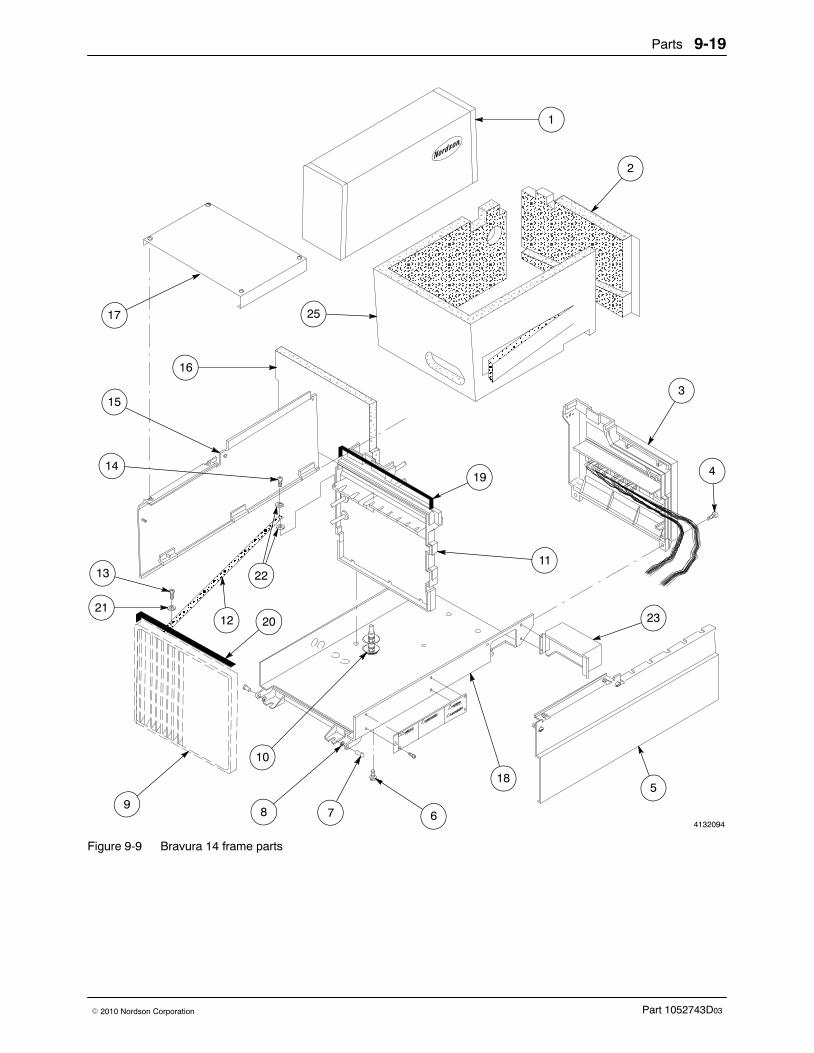
Parts 9-19
Part 1052743D03� 2010 Nordson Corporation
4132094
ÎÎÎÎÎÎÎÎÎÎÎÎÎÎÎÎÎÎÎÎÎÎÎÎÎÎÎÎÎÎÎÎÎÎÎÎÎÎÎÎÎÎ
ÎÎÎÎÎÎÎÎÎÎÎÎÎÎÎÎÎÎÎÎÎÎÎÎÎÎÎÎÎÎÎÎÎÎÎÎÎÎÎÎÎÎ
ÏÏÏÏÏÏÏÏÏÏÏÏ
ÌÌÌÌÌÌÌÌÌÌÌÌÌÌÌÌÌÌ
ÎÎÎÎÎÎÎÎÎÎÎÎÎÎÎÎÎÎÎÎÎÎÎÎÎÎÎÎÎÎÎÎÎÎÎÎÎÎÎÎÎÎÎÎÎÎÎÎÎ
ÏÏÏÏÏÏÏÏÏÏÏÏÏÏÏÏÏÏÏÏÏÏÏÏÏÏÏÏÏÏÏÏÏÏÏÏÏÏÏÏÏÏÏÏÏÏÏÏÏÏÏÏÏÏÏÏÏÏÏÏÏÏÏÏÏÏÏÏÏÏÏÏÏÏÏÏÏÏÏÏÏÏÏÏ
ÎÎÎÎÎÎÎÎÎÎÎÎÎÎÎÎÎÎÎÎÎÎÎÎÎÎÎÎÎÎÎÎÎÎÎÎ
ÌÌÌÌÌÌÌÌÌÌÌÌÌÌÌÌÌÌÌÌÌÌÌÌÎÎÎÎ
ÌÌÌÌÌÌ
ÏÏÏÏÏÏÏÏÏÏÏÏÏÏÏÏÏÏÏÏÏÏÏÏÏÏÏÏÏÏÏÏÏÏÏÏ
1
2
17 25
15
16
3
4
23
5
11
19
20
22
12
14
13
21
9
10
8 6
18
7
Figure 9-9 Bravura 14 frame parts
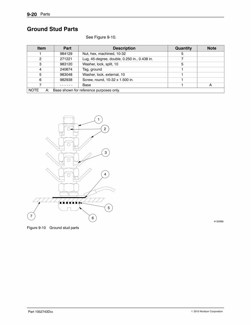
Parts9-20
Part 1052743D03 � 2010 Nordson Corporation
Ground Stud Parts See Figure 9-10.
Item Part Description Quantity Note1 984129 Nut, hex, machined, 10-32 52 271221 Lug, 45-degree, double, 0.250 in., 0.438 in. 73 983120 Washer, lock, split, 10 54 240674 Tag, ground 15 983048 Washer, lock, external, 10 16 982938 Screw, round, 10-32 x 1.500 in. 17 - - - - - - Base 1 A
NOTE A: Base shown for reference purposes only.
4132095
ËËËË
1
2
3
4
5
7 6
Figure 9-10 Ground stud parts

Parts 9-21
Part 1052743D03� 2010 Nordson Corporation
This page intentionally left blank.
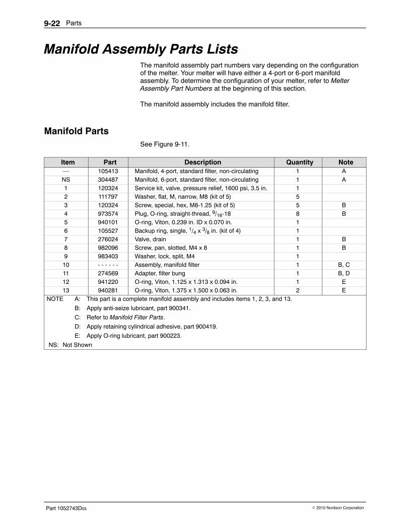
Parts9-22
Part 1052743D03 � 2010 Nordson Corporation
Manifold Assembly Parts Lists The manifold assembly part numbers vary depending on the configurationof the melter. Your melter will have either a 4-port or 6-port manifoldassembly. To determine the configuration of your melter, refer to MelterAssembly Part Numbers at the beginning of this section.
The manifold assembly includes the manifold filter.
Manifold Parts See Figure 9-11.
Item Part Description Quantity Note— 105413 Manifold, 4-port, standard filter, non-circulating 1 ANS 304487 Manifold, 6-port, standard filter, non-circulating 1 A1 120324 Service kit, valve, pressure relief, 1600 psi, 3.5 in. 12 111797 Washer, flat, M, narrow, M8 (kit of 5) 53 120324 Screw, special, hex, M8-1.25 (kit of 5) 5 B4 973574 Plug, O-ring, straight-thread, 9/16-18 8 B5 940101 O-ring, Viton, 0.239 in. ID x 0.070 in. 16 105527 Backup ring, single, 1/4 x 3/8 in. (kit of 4) 17 276024 Valve, drain 1 B8 982096 Screw, pan, slotted, M4 x 8 1 B9 983403 Washer, lock, split, M4 110 - - - - - - Assembly, manifold filter 1 B, C11 274569 Adapter, filter bung 1 B, D12 941220 O-ring, Viton, 1.125 x 1.313 x 0.094 in. 1 E13 940281 O-ring, Viton, 1.375 x 1.500 x 0.063 in. 2 E
NOTE A: This part is a complete manifold assembly and includes items 1, 2, 3, and 13.
B: Apply anti-seize lubricant, part 900341.
C: Refer to Manifold Filter Parts.
D: Apply retaining cylindrical adhesive, part 900419.
E: Apply O-ring lubricant, part 900223.
NS: Not Shown
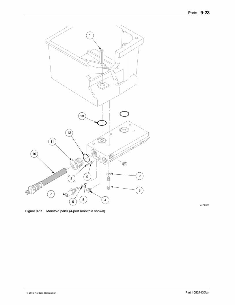
Parts 9-23
Part 1052743D03� 2010 Nordson Corporation
4132096
13
1
12
11
10
82
3
4
7
65
9
Figure 9-11 Manifold parts (4-port manifold shown)

Parts9-24
Part 1052743D03 � 2010 Nordson Corporation
Manifold Filter Parts See Figure 9-12.
Item Part Description Quantity Note— 105432 Service kit, manifold filter 1 A1 274578 � Screen, filter, 0.006 mesh, 5.38 in. long 12 981747 � Screw, round, 10-32 x 6.250 in. 1 B3 274513 � Bung, filter 14 941172 � O-ring, Viton, 0.813 x 1.000 x 0.094 in. 15 274579 � Core, filter, 5.718 in. long 1
NOTE A: Order this part for a complete filter assembly.
B: Apply anti-seize lubricant, part 900341.
4132097
ÌÌÌÌÌÌÌÌÌÌÌÌÌÌÌÌÌÌÌÌÌÌÌÌÌÌÌÌÌÌÌÌÌÌÌÌÌÌÌÌ
1
5
4
3 2
Figure 9-12 Manifold filter parts
Parts 9-25
Part 1052743D03� 2010 Nordson Corporation
This page intentionally left blank.
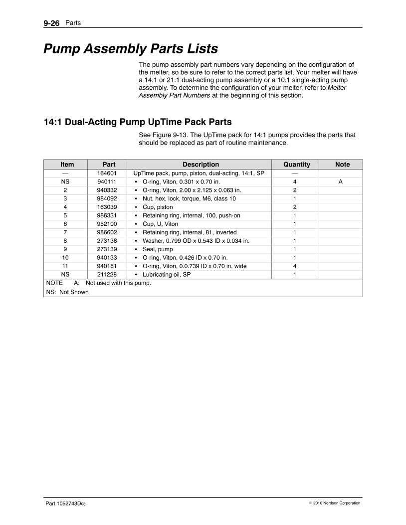
Parts9-26
Part 1052743D03 � 2010 Nordson Corporation
Pump Assembly Parts Lists The pump assembly part numbers vary depending on the configuration ofthe melter, so be sure to refer to the correct parts list. Your melter will havea 14:1 or 21:1 dual-acting pump assembly or a 10:1 single-acting pumpassembly. To determine the configuration of your melter, refer to MelterAssembly Part Numbers at the beginning of this section.
14:1 Dual-Acting Pump UpTime Pack Parts See Figure 9-13. The UpTime pack for 14:1 pumps provides the parts thatshould be replaced as part of routine maintenance.
Item Part Description Quantity Note— 164601 UpTime pack, pump, piston, dual-acting, 14:1, SP —NS 940111 � O-ring, Viton, 0.301 x 0.70 in. 4 A2 940332 � O-ring, Viton, 2.00 x 2.125 x 0.063 in. 23 984092 � Nut, hex, lock, torque, M6, class 10 14 163039 � Cup, piston 25 986331 � Retaining ring, internal, 100, push-on 16 952100 � Cup, U, Viton 17 986602 � Retaining ring, internal, 81, inverted 18 273138 � Washer, 0.799 OD x 0.543 ID x 0.034 in. 19 273139 � Seal, pump 110 940133 � O-ring, Viton, 0.426 ID x 0.70 in. 111 940181 � O-ring, Viton, 0.0.739 ID x 0.70 in. wide 4NS 211228 � Lubricating oil, SP 1
NOTE A: Not used with this pump.
NS: Not Shown
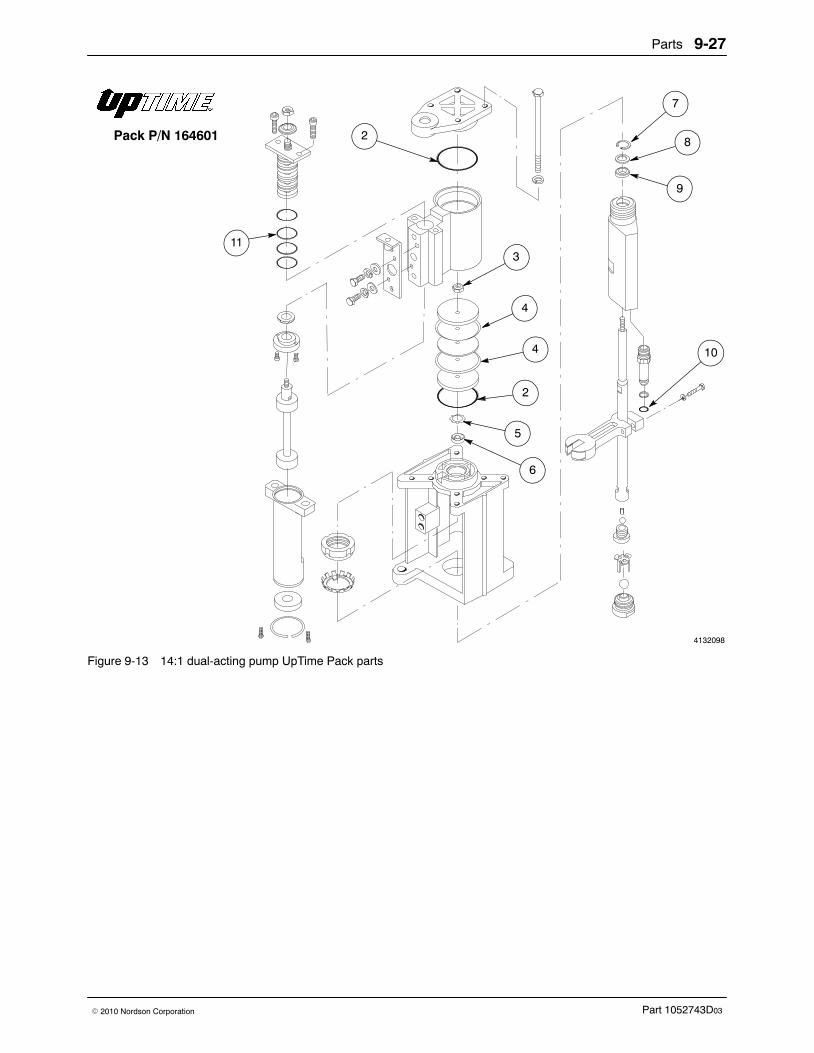
Parts 9-27
Part 1052743D03� 2010 Nordson Corporation
4132098
7
8
9
10
6
3
4
4
2
5
2
11
Pack P/N 164601
Figure 9-13 14:1 dual-acting pump UpTime Pack parts

Parts9-28
Part 1052743D03 � 2010 Nordson Corporation
14:1 Dual-Acting Pump Parts See Figure 9-14.
Item Part Description Quantity Note— 161424 Pump, piston, dual-acting, 14:1, SP1 1005247 � Bracket, pump cover 12 982059 � Screw, socket, M4 x 8 23 983402 � Washer, flat, narrow, M4 24 983403 � Washer, lock, split, M4 25 1006027 � Valve, SP 16 900493 � Lubricant, Parker, hi-temp AR7 333560 � Spring, wave, SP pump 18 155057 � Detent, upper, SP 19 166880 � Fork, magnetic 110 164606 � Actuator, magnetic, SP 111 155068 � Can, SP 112 155067 � Detent, lower, SP 113 986714 � Retaining ring, internal, 156, bowed 114 155059 � Piston pump, 14:1, SP 115 985302 � Pin, roll, 0.125 x 0.500 in. 116 900000 � Ball, 440 stainless, 0.375 in., 50 117 503709 � Seat, ball, pressure 118 900470 � Adhesive, threadlocking, Loctite 272 AR19 503696 � Cage, ball, siphon 120 105451 � Kit, tube, crossover, pump (includes items 20,
22, and 23)1
21 900344 � Lubricant, Never Seez, 8 oz can AR22 954013 � Backup ring, single, 7/16 x 9/16 in. 123 940133 � O-ring, Viton, 0.426 ID x 0.070 in. wide 124 503695 � Seat, ball, siphon 125 900001 � Ball, 440 stainless, 0.500 in., 50 126 288028 � Body, pump, hydraulic 127 973402 � Plug, pipe, socket, flush, 1/8 in. 128 120599 � Kit, pump mount, machined (includes items 28,
29, 30, 33, 34, and 35)1
29 983184 � Washer, lock, bearing, W-08, 130 984545 � Nut, lock, bearing, PN-08 131 982135 � Screw, hex, cap, M6 x 30 132 983410 � Washer, flat, narrow, M6 133 940332 � O-ring, Viton, 2.000 x 2.125 x 0.063 in. 234 952100 � U-cup, Viton 135 986331 � Retaining ring, internal, 100, push-on 136 309822 � Manifold, air, SP 137 984092 � Nut, hex, lock, torque, M6, class 10 138 333137 � Head, cylinder, SP, machined 139 983445 � Washer, piston seal, SP 140 983446 � Washer, piston cup, SP 241 163039 � Cup, piston, SP 242 986602 � Retaining ring, internal, inverted 143 273138 � Washer, 0.799 OD x 0.543 ID x 0.034 in. thick 144 273139 � Seal, pump 1
Continued on next page

Parts 9-29
Part 1052743D03� 2010 Nordson Corporation
NoteQuantityDescriptionPartItem45 982147 � Screw, hex, cap, M6 x 120 446 983409 � Washer, lock, split, M6 447 982028 � Screw, socket, M5 x 20 448 211228 � SP lubricating oil AR49 982308 � Screw, pan, M4 x 10 2
AR: As Required
4132099
38 45
46
42
43
44
27
26
20 21
2223
3132
9
14
15
17 1816
19
25
24
28
34 6
37
40
41
39
40
41
33
35
30
29
13
12
11
47
10
8
7
493
4
1
6
47
5
36
48
33
2
Figure 9-14 14:1 dual-acting pump parts
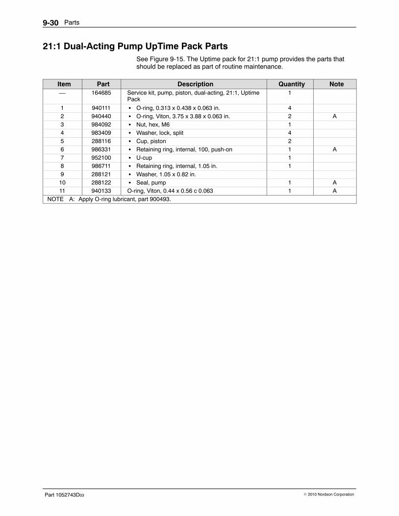
Parts9-30
Part 1052743D03 � 2010 Nordson Corporation
21:1 Dual-Acting Pump UpTime Pack Parts See Figure 9-15. The Uptime pack for 21:1 pump provides the parts thatshould be replaced as part of routine maintenance.
Item Part Description Quantity Note— 164685 Service kit, pump, piston, dual-acting, 21:1, Uptime
Pack1
1 940111 � O-ring, 0.313 x 0.438 x 0.063 in. 42 940440 � O-ring, Viton, 3.75 x 3.88 x 0.063 in. 2 A3 984092 � Nut, hex, M6 14 983409 � Washer, lock, split 45 288116 � Cup, piston 26 986331 � Retaining ring, internal, 100, push-on 1 A7 952100 � U-cup 18 986711 � Retaining ring, internal, 1.05 in. 19 288121 � Washer, 1.05 x 0.82 in.10 288122 � Seal, pump 1 A11 940133 O-ring, Viton, 0.44 x 0.56 c 0.063 1 A
NOTE A: Apply O-ring lubricant, part 900493.
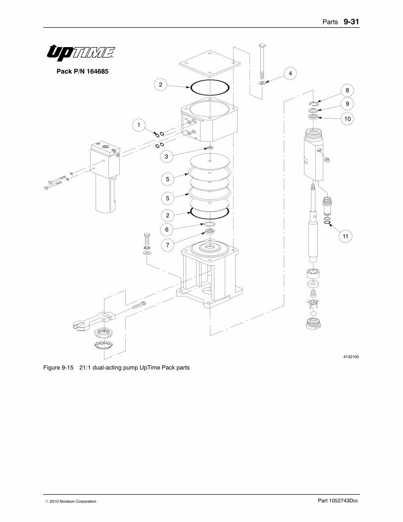
Parts 9-31
Part 1052743D03� 2010 Nordson Corporation
4132100
2
1
3
5
5
2
6
7
4
8
9
10
11
Pack P/N 164685
Figure 9-15 21:1 dual-acting pump UpTime Pack parts
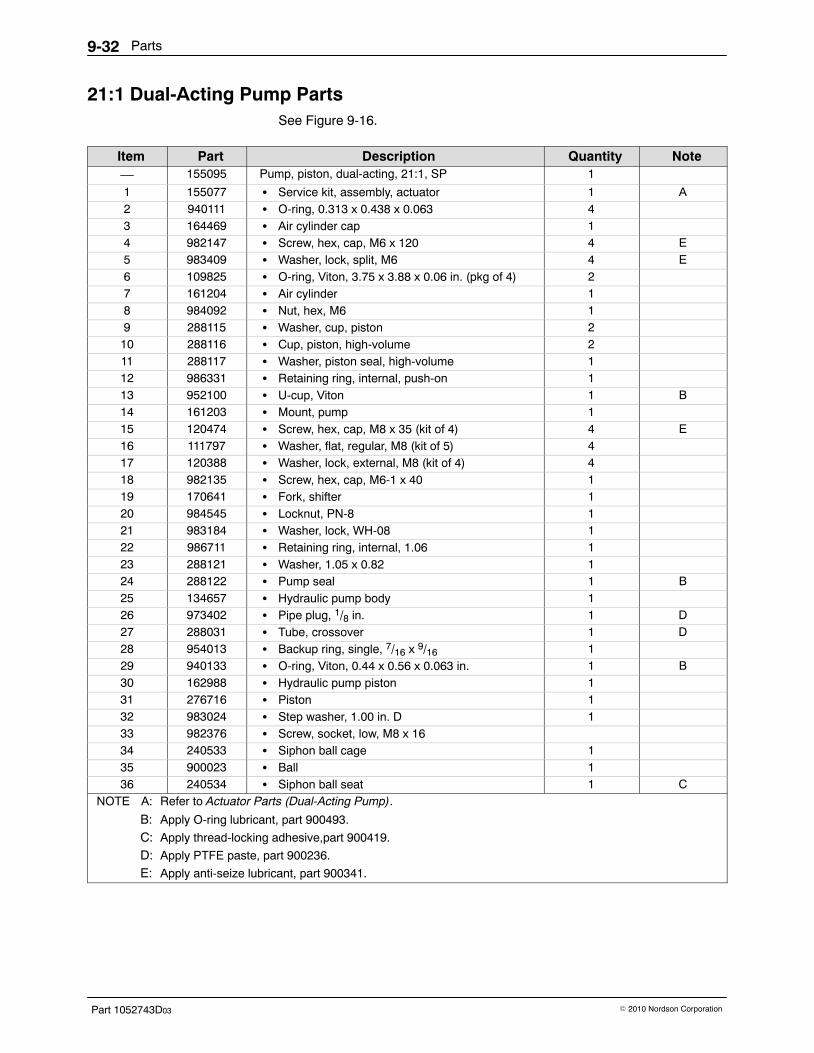
Parts9-32
Part 1052743D03 � 2010 Nordson Corporation
21:1 Dual-Acting Pump Parts See Figure 9-16.
Item Part Description Quantity Note— 155095 Pump, piston, dual-acting, 21:1, SP 1
1 155077 � Service kit, assembly, actuator 1 A2 940111 � O-ring, 0.313 x 0.438 x 0.063 43 164469 � Air cylinder cap 14 982147 � Screw, hex, cap, M6 x 120 4 E5 983409 � Washer, lock, split, M6 4 E6 109825 � O-ring, Viton, 3.75 x 3.88 x 0.06 in. (pkg of 4) 27 161204 � Air cylinder 18 984092 � Nut, hex, M6 19 288115 � Washer, cup, piston 210 288116 � Cup, piston, high-volume 211 288117 � Washer, piston seal, high-volume 112 986331 � Retaining ring, internal, push-on 113 952100 � U-cup, Viton 1 B14 161203 � Mount, pump 115 120474 � Screw, hex, cap, M8 x 35 (kit of 4) 4 E16 111797 � Washer, flat, regular, M8 (kit of 5) 417 120388 � Washer, lock, external, M8 (kit of 4) 418 982135 � Screw, hex, cap, M6-1 x 40 119 170641 � Fork, shifter 120 984545 � Locknut, PN-8 121 983184 � Washer, lock, WH-08 122 986711 � Retaining ring, internal, 1.06 123 288121 � Washer, 1.05 x 0.82 124 288122 � Pump seal 1 B25 134657 � Hydraulic pump body 126 973402 � Pipe plug, 1/8 in. 1 D27 288031 � Tube, crossover 1 D28 954013 � Backup ring, single, 7/16 x 9/16 129 940133 � O-ring, Viton, 0.44 x 0.56 x 0.063 in. 1 B30 162988 � Hydraulic pump piston 131 276716 � Piston 132 983024 � Step washer, 1.00 in. D 133 982376 � Screw, socket, low, M8 x 1634 240533 � Siphon ball cage 135 900023 � Ball 136 240534 � Siphon ball seat 1 C
NOTE A: Refer to Actuator Parts (Dual-Acting Pump).
B: Apply O-ring lubricant, part 900493.
C: Apply thread-locking adhesive,part 900419. D: Apply PTFE paste, part 900236.
E: Apply anti-seize lubricant, part 900341.
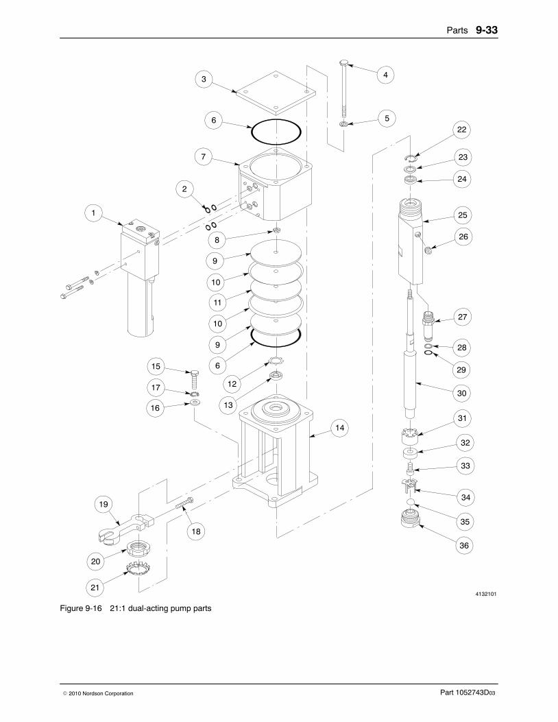
Parts 9-33
Part 1052743D03� 2010 Nordson Corporation
4132101
3
6
1
4
5
7
2
8
9
10
11
10
9
6
12
15
17
16
19
20
21
18
14
22
23
24
25
26
27
28
29
30
31
32
33
34
35
36
13
Figure 9-16 21:1 dual-acting pump parts
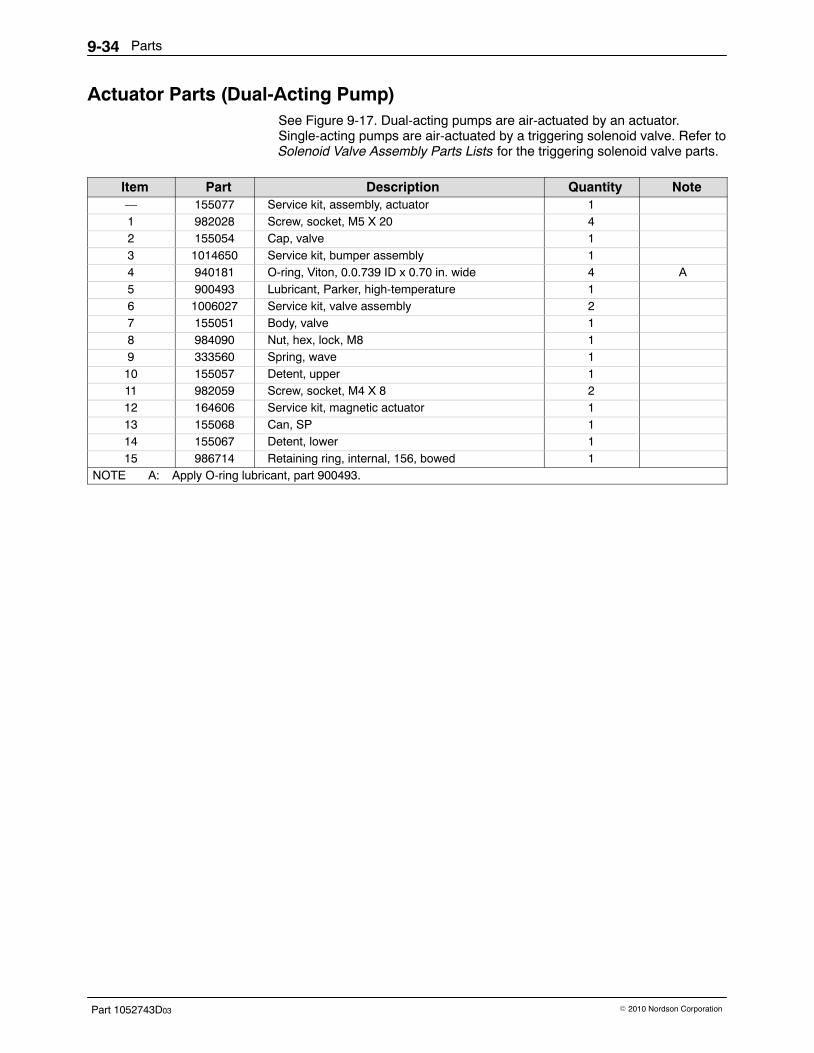
Parts9-34
Part 1052743D03 � 2010 Nordson Corporation
Actuator Parts (Dual-Acting Pump) See Figure 9-17. Dual-acting pumps are air-actuated by an actuator.Single-acting pumps are air-actuated by a triggering solenoid valve. Refer toSolenoid Valve Assembly Parts Lists for the triggering solenoid valve parts.
Item Part Description Quantity Note— 155077 Service kit, assembly, actuator 11 982028 Screw, socket, M5 X 20 42 155054 Cap, valve 13 1014650 Service kit, bumper assembly 14 940181 O-ring, Viton, 0.0.739 ID x 0.70 in. wide 4 A5 900493 Lubricant, Parker, high-temperature 16 1006027 Service kit, valve assembly 27 155051 Body, valve 18 984090 Nut, hex, lock, M8 19 333560 Spring, wave 110 155057 Detent, upper 111 982059 Screw, socket, M4 X 8 212 164606 Service kit, magnetic actuator 113 155068 Can, SP 114 155067 Detent, lower 115 986714 Retaining ring, internal, 156, bowed 1
NOTE A: Apply O-ring lubricant, part 900493.
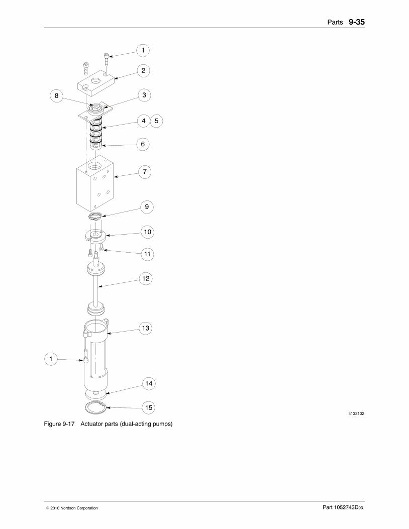
Parts 9-35
Part 1052743D03� 2010 Nordson Corporation
4132102
1
2
4
10
11
13
14
15
1
3
7
9
12
8
5
6
Figure 9-17 Actuator parts (dual-acting pumps)

Parts9-36
Part 1052743D03 � 2010 Nordson Corporation
10:1 Single-Acting Pump Parts See Figure 9-18.
Item Part Description Quantity Note1 336936 Service kit, pump, piston, single-acting, 10:1, with
solenoid valve1 A
NS 336934 Service kit, pump, piston, single-acting, 10:1,without solenoid valve
1 B
— 138163 Service kit, check valve and ball —2 102324 � Seat, ball check valve 13 900000 � Ball, 440 stainless steel, 0.375 in., 50 1— 105451 Service kit, crossover tube, backup ring, and
O-ring—
4 - - - - - - � Tube, crossover 15 954013 � Backup ring, single, 7/16 x 9/16 in. 16 940133 � O-ring, Viton, 0.426 in. ID x 0.70 in. wide 1— 138177 Service kit, siphon ball, seat, and cage —7 240533 � Cage, ball, siphon 18 900023 � Ball, 440 stainless steel, 0.750 in., 50 19 240534 � Seat, siphon ball 1
NS 1011323 Tool, air cylinder service kit 1NOTE A: For a complete pump and solenoid valve assembly, order this part. For a solenoid valve only, order
part 336935.
B: For a complete pump only (without the solenoid valve), order this part.
NS: Not Shown
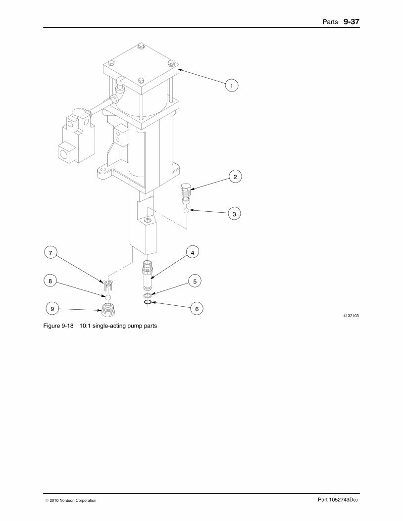
Parts 9-37
Part 1052743D03� 2010 Nordson Corporation
4132103
3
5
4
2
1
6
8
9
7
Figure 9-18 10:1 single-acting pump parts
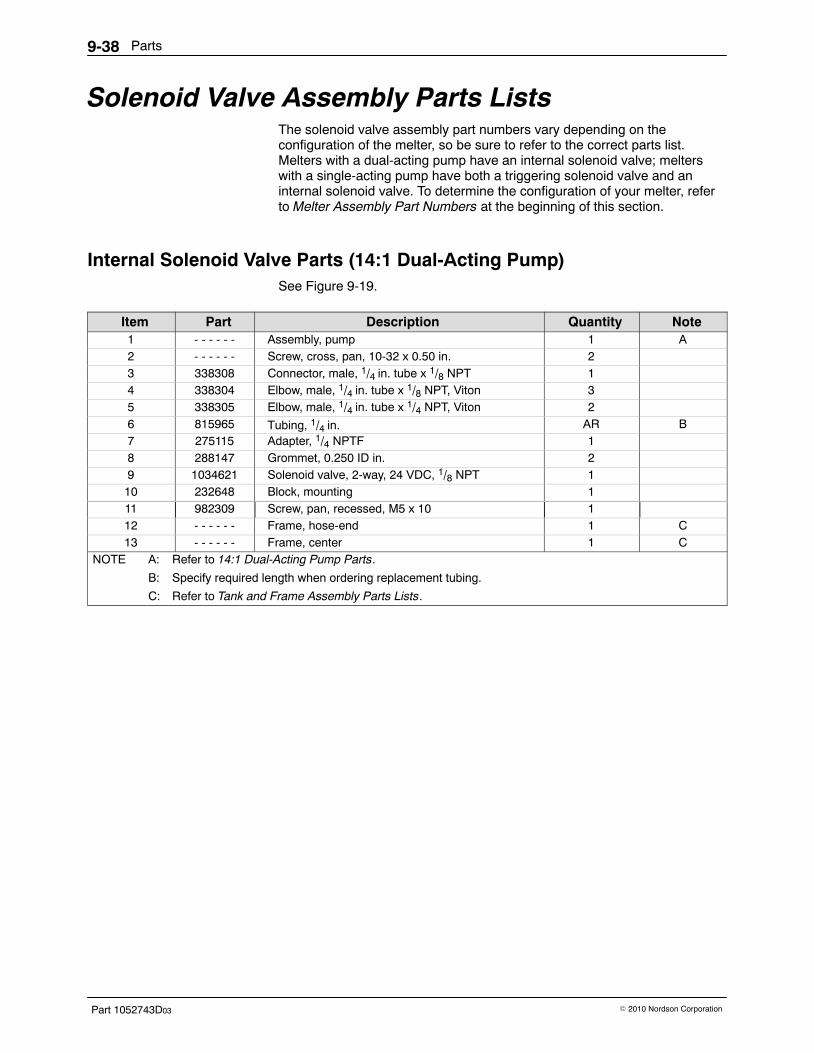
Parts9-38
Part 1052743D03 � 2010 Nordson Corporation
Solenoid Valve Assembly Parts Lists The solenoid valve assembly part numbers vary depending on theconfiguration of the melter, so be sure to refer to the correct parts list.Melters with a dual-acting pump have an internal solenoid valve; melterswith a single-acting pump have both a triggering solenoid valve and aninternal solenoid valve. To determine the configuration of your melter, referto Melter Assembly Part Numbers at the beginning of this section.
Internal Solenoid Valve Parts (14:1 Dual-Acting Pump) See Figure 9-19.
Item Part Description Quantity Note1 - - - - - - Assembly, pump 1 A2 - - - - - - Screw, cross, pan, 10-32 x 0.50 in. 23 338308 Connector, male, 1/4 in. tube x 1/8 NPT 14 338304 Elbow, male, 1/4 in. tube x 1/8 NPT, Viton 35 338305 Elbow, male, 1/4 in. tube x 1/4 NPT, Viton 26 815965 Tubing, 1/4 in. AR B7 275115 Adapter, 1/4 NPTF 18 288147 Grommet, 0.250 ID in. 29 1034621 Solenoid valve, 2-way, 24 VDC, 1/8 NPT 110 232648 Block, mounting 111 982309 Screw, pan, recessed, M5 x 10 112 - - - - - - Frame, hose-end 1 C13 - - - - - - Frame, center 1 C
NOTE A: Refer to 14:1 Dual-Acting Pump Parts.
B: Specify required length when ordering replacement tubing.
C: Refer to Tank and Frame Assembly Parts Lists.
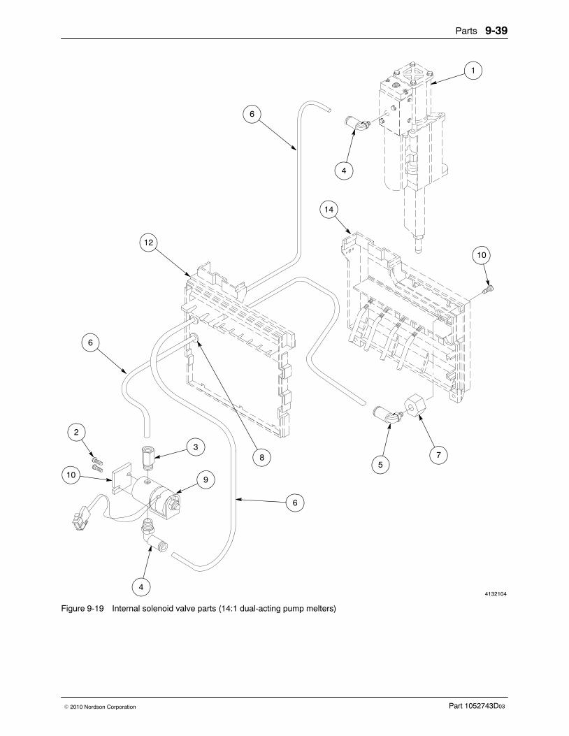
Parts 9-39
Part 1052743D03� 2010 Nordson Corporation
4132104
1
4
6
6
12
14
6
578
3
4
10
2
9
10
Figure 9-19 Internal solenoid valve parts (14:1 dual-acting pump melters)
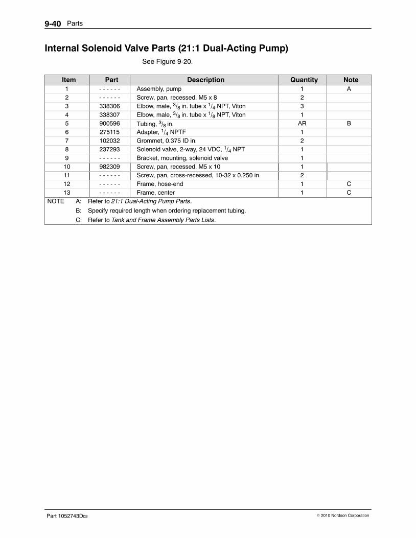
Parts9-40
Part 1052743D03 � 2010 Nordson Corporation
Internal Solenoid Valve Parts (21:1 Dual-Acting Pump) See Figure 9-20.
Item Part Description Quantity Note1 - - - - - - Assembly, pump 1 A2 - - - - - - Screw, pan, recessed, M5 x 8 23 338306 Elbow, male, 3/8 in. tube x 1/4 NPT, Viton 34 338307 Elbow, male, 3/8 in. tube x 1/8 NPT, Viton 15 900596 Tubing, 3/8 in. AR B6 275115 Adapter, 1/4 NPTF 17 102032 Grommet, 0.375 ID in. 28 237293 Solenoid valve, 2-way, 24 VDC, 1/4 NPT 19 - - - - - - Bracket, mounting, solenoid valve 110 982309 Screw, pan, recessed, M5 x 10 111 - - - - - - Screw, pan, cross-recessed, 10-32 x 0.250 in. 212 - - - - - - Frame, hose-end 1 C13 - - - - - - Frame, center 1 C
NOTE A: Refer to 21:1 Dual-Acting Pump Parts.
B: Specify required length when ordering replacement tubing.
C: Refer to Tank and Frame Assembly Parts Lists.
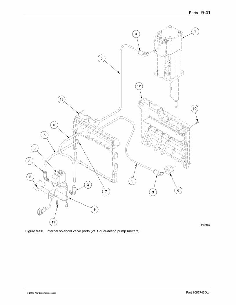
Parts 9-41
Part 1052743D03� 2010 Nordson Corporation
4132105
14
5
5
13
9
3 67
11
3
2
3
10
8
5
12
5
Figure 9-20 Internal solenoid valve parts (21:1 dual-acting pump melters)
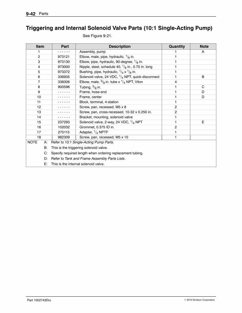
Parts9-42
Part 1052743D03 � 2010 Nordson Corporation
Triggering and Internal Solenoid Valve Parts (10:1 Single-Acting Pump) See Figure 9-21.
Item Part Description Quantity Note1 - - - - - - Assembly, pump 1 A2 973121 Elbow, male, pipe, hydraulic, 1/8 in. 13 973130 Elbow, pipe, hydraulic, 90-degree, 1/8 in. 14 973000 Nipple, steel, schedule 40, 1/8 in., 0.75 in. long 15 973372 Bushing, pipe, hydraulic, 1/4 x 1/8 in. 16 336935 Solenoid valve, 24 VDC, 1/4 NPT, quick-disconnect 1 B7 338306 Elbow, male, 3/8 in. tube x 1/4 NPT, Viton 48 900596 Tubing, 3/8 in. 1 C9 - - - - - - Frame, hose-end 1 D10 - - - - - - Frame, center 1 D11 - - - - - - Block, terminal, 4-station 112 - - - - - - Screw, pan, recessed, M5 x 8 213 - - - - - - Screw, pan, cross-recessed, 10-32 x 0.250 in. 214 - - - - - - Bracket, mounting, solenoid valve 115 237293 Solenoid valve, 2-way, 24 VDC, 1/4 NPT 1 E16 102032 Grommet, 0.375 ID in. 217 275115 Adapter, 1/4 NPTF 118 982309 Screw, pan, recessed, M5 x 10 1
NOTE A: Refer to 10:1 Single-Acting Pump Parts.
B: This is the triggering solenoid valve.
C: Specify required length when ordering replacement tubing.
D: Refer to Tank and Frame Assembly Parts Lists.
E: This is the internal solenoid valve.
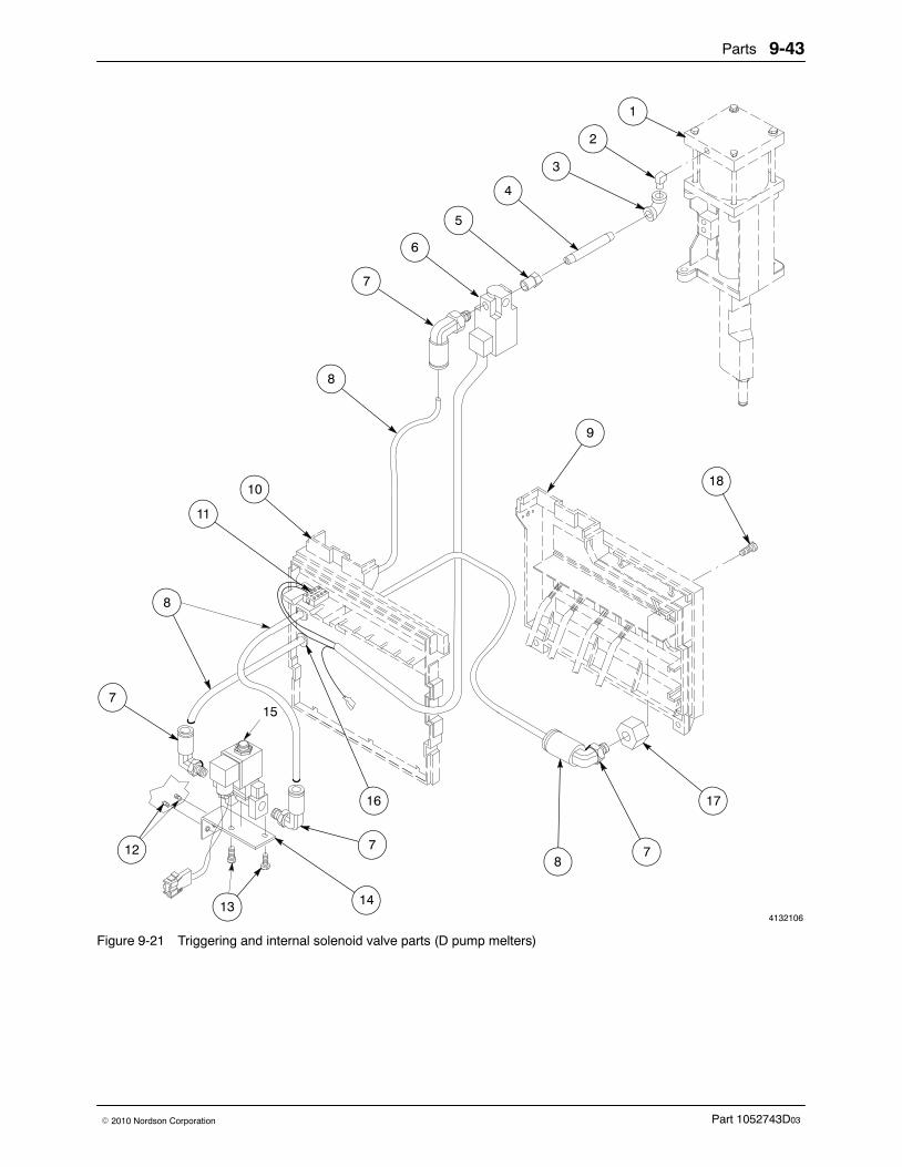
Parts 9-43
Part 1052743D03� 2010 Nordson Corporation
4132106
8
15
1
2
3
8
11
4
5
6
7
10
8
18
17
78
9
7
16
7
14
12
13
Figure 9-21 Triggering and internal solenoid valve parts (D pump melters)
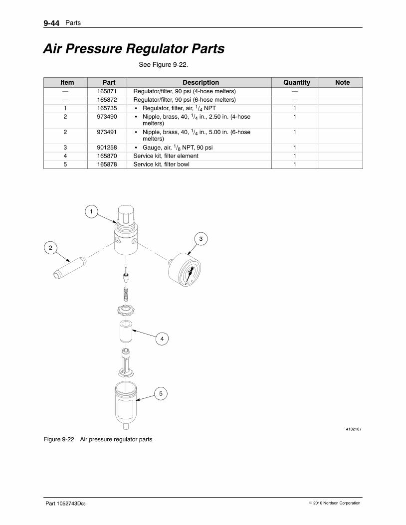
Parts9-44
Part 1052743D03 � 2010 Nordson Corporation
Air Pressure Regulator Parts See Figure 9-22.
Item Part Description Quantity Note— 165871 Regulator/filter, 90 psi (4-hose melters) —— 165872 Regulator/filter, 90 psi (6-hose melters) —1 165735 � Regulator, filter, air, 1/4 NPT 12 973490 � Nipple, brass, 40, 1/4 in., 2.50 in. (4-hose
melters)1
2 973491 � Nipple, brass, 40, 1/4 in., 5.00 in. (6-hosemelters)
1
3 901258 � Gauge, air, 1/8 NPT, 90 psi 14 165870 Service kit, filter element 15 165878 Service kit, filter bowl 1
4132107
1
2
3
4
5
Figure 9-22 Air pressure regulator parts
Parts 9-45
Part 1052743D03� 2010 Nordson Corporation
This page intentionally left blank.
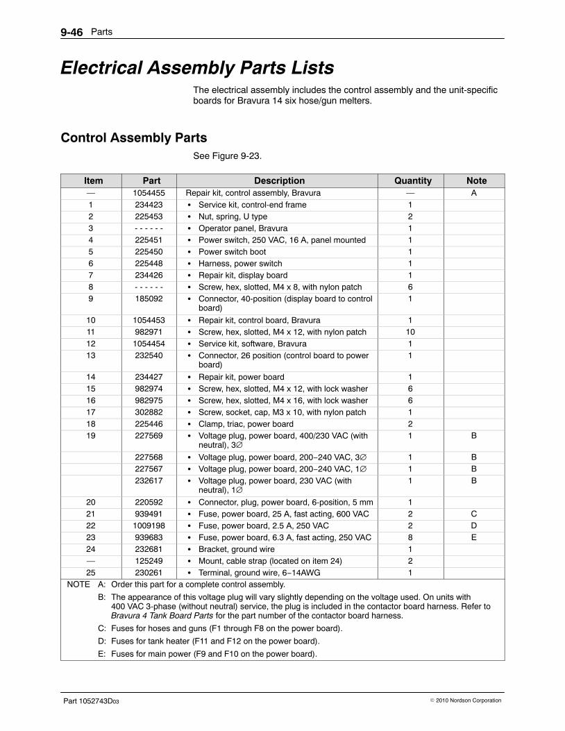
Parts9-46
Part 1052743D03 � 2010 Nordson Corporation
Electrical Assembly Parts Lists The electrical assembly includes the control assembly and the unit-specificboards for Bravura 14 six hose/gun melters.
Control Assembly Parts See Figure 9-23.
Item Part Description Quantity Note— 1054455 Repair kit, control assembly, Bravura — A1 234423 � Service kit, control-end frame 12 225453 � Nut, spring, U type 23 - - - - - - � Operator panel, Bravura 14 225451 � Power switch, 250 VAC, 16 A, panel mounted 15 225450 � Power switch boot 16 225448 � Harness, power switch 17 234426 � Repair kit, display board 18 - - - - - - � Screw, hex, slotted, M4 x 8, with nylon patch 69 185092 � Connector, 40-position (display board to control
board)1
10 1054453 � Repair kit, control board, Bravura 111 982971 � Screw, hex, slotted, M4 x 12, with nylon patch 1012 1054454 � Service kit, software, Bravura 113 232540 � Connector, 26 position (control board to power
board)1
14 234427 � Repair kit, power board 115 982974 � Screw, hex, slotted, M4 x 12, with lock washer 616 982975 � Screw, hex, slotted, M4 x 16, with lock washer 617 302882 � Screw, socket, cap, M3 x 10, with nylon patch 118 225446 � Clamp, triac, power board 219 227569 � Voltage plug, power board, 400/230 VAC (with
neutral), 3∅1 B
227568 � Voltage plug, power board, 200−240 VAC, 3∅ 1 B227567 � Voltage plug, power board, 200−240 VAC, 1∅ 1 B232617 � Voltage plug, power board, 230 VAC (with
neutral), 1∅1 B
20 220592 � Connector, plug, power board, 6-position, 5 mm 121 939491 � Fuse, power board, 25 A, fast acting, 600 VAC 2 C22 1009198 � Fuse, power board, 2.5 A, 250 VAC 2 D23 939683 � Fuse, power board, 6.3 A, fast acting, 250 VAC 8 E24 232681 � Bracket, ground wire 1— 125249 � Mount, cable strap (located on item 24) 225 230261 � Terminal, ground wire, 6−14AWG 1
NOTE A: Order this part for a complete control assembly.
B: The appearance of this voltage plug will vary slightly depending on the voltage used. On units with400 VAC 3-phase (without neutral) service, the plug is included in the contactor board harness. Refer toBravura 4 Tank Board Parts for the part number of the contactor board harness.
C: Fuses for hoses and guns (F1 through F8 on the power board).
D: Fuses for tank heater (F11 and F12 on the power board).
E: Fuses for main power (F9 and F10 on the power board).
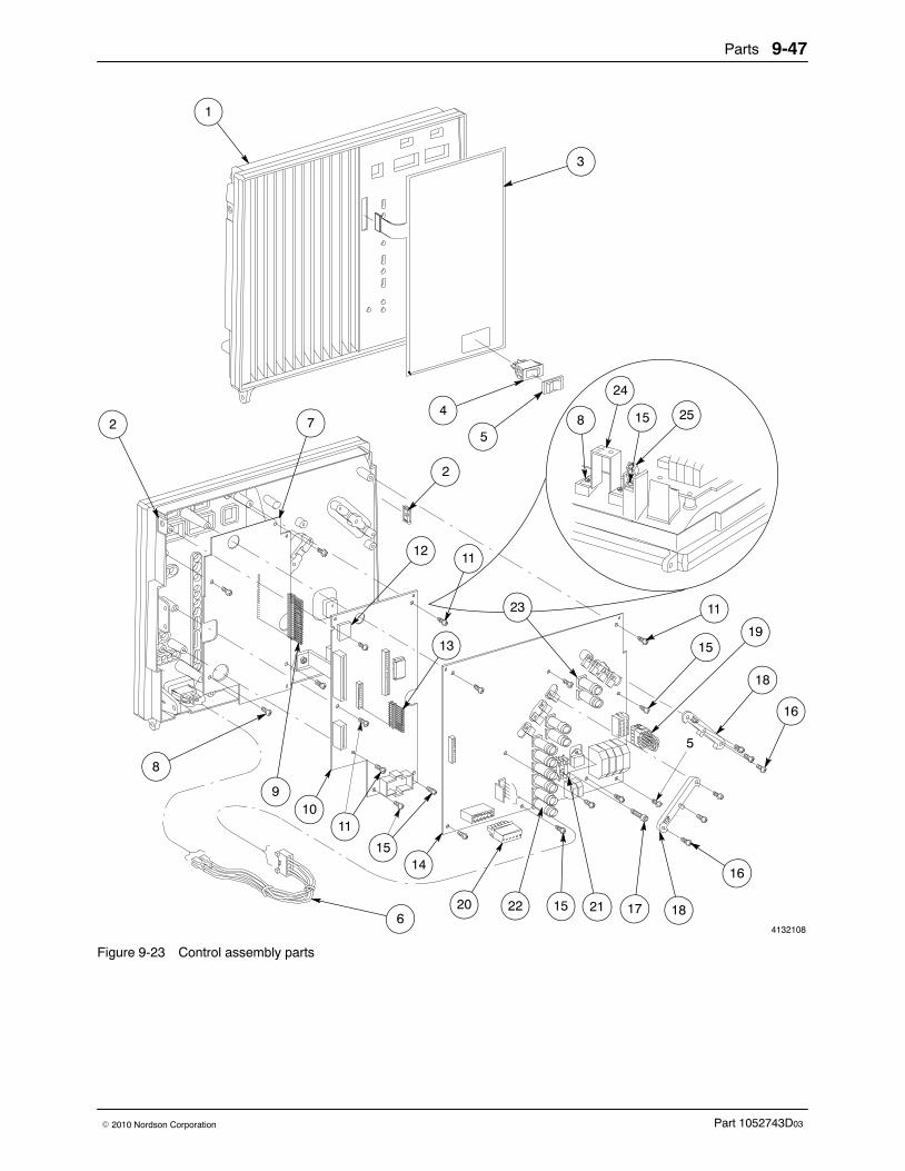
Parts 9-47
Part 1052743D03� 2010 Nordson Corporation
4132108
5
1
3
4
52 7 8 15
24
25
8
9
2
19
11
16
18
15
16
1011
1415
2220 15 21 186
17
23
11
13
12
Figure 9-23 Control assembly parts
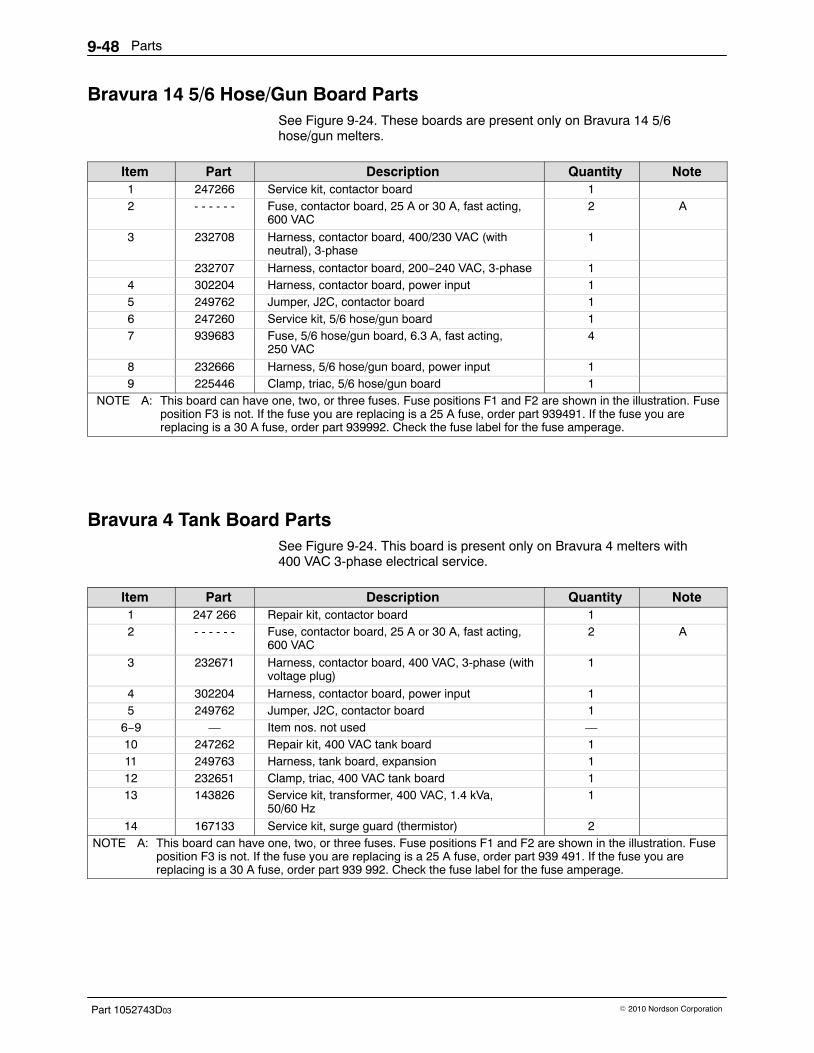
Parts9-48
Part 1052743D03 � 2010 Nordson Corporation
Bravura 14 5/6 Hose/Gun Board Parts See Figure 9-24. These boards are present only on Bravura 14 5/6hose/gun melters.
Item Part Description Quantity Note1 247266 Service kit, contactor board 12 - - - - - - Fuse, contactor board, 25 A or 30 A, fast acting,
600 VAC2 A
3 232708 Harness, contactor board, 400/230 VAC (withneutral), 3-phase
1
232707 Harness, contactor board, 200−240 VAC, 3-phase 14 302204 Harness, contactor board, power input 15 249762 Jumper, J2C, contactor board 16 247260 Service kit, 5/6 hose/gun board 17 939683 Fuse, 5/6 hose/gun board, 6.3 A, fast acting,
250 VAC4
8 232666 Harness, 5/6 hose/gun board, power input 19 225446 Clamp, triac, 5/6 hose/gun board 1
NOTE A: This board can have one, two, or three fuses. Fuse positions F1 and F2 are shown in the illustration. Fuseposition F3 is not. If the fuse you are replacing is a 25 A fuse, order part 939491. If the fuse you arereplacing is a 30 A fuse, order part 939992. Check the fuse label for the fuse amperage.
Bravura 4 Tank Board Parts See Figure 9-24. This board is present only on Bravura 4 melters with400 VAC 3-phase electrical service.
Item Part Description Quantity Note1 247 266 Repair kit, contactor board 12 - - - - - - Fuse, contactor board, 25 A or 30 A, fast acting,
600 VAC2 A
3 232671 Harness, contactor board, 400 VAC, 3-phase (withvoltage plug)
1
4 302204 Harness, contactor board, power input 15 249762 Jumper, J2C, contactor board 1
6−9 — Item nos. not used —10 247262 Repair kit, 400 VAC tank board 111 249763 Harness, tank board, expansion 112 232651 Clamp, triac, 400 VAC tank board 113 143826 Service kit, transformer, 400 VAC, 1.4 kVa,
50/60 Hz1
14 167133 Service kit, surge guard (thermistor) 2NOTE A: This board can have one, two, or three fuses. Fuse positions F1 and F2 are shown in the illustration. Fuse
position F3 is not. If the fuse you are replacing is a 25 A fuse, order part 939 491. If the fuse you arereplacing is a 30 A fuse, order part 939 992. Check the fuse label for the fuse amperage.
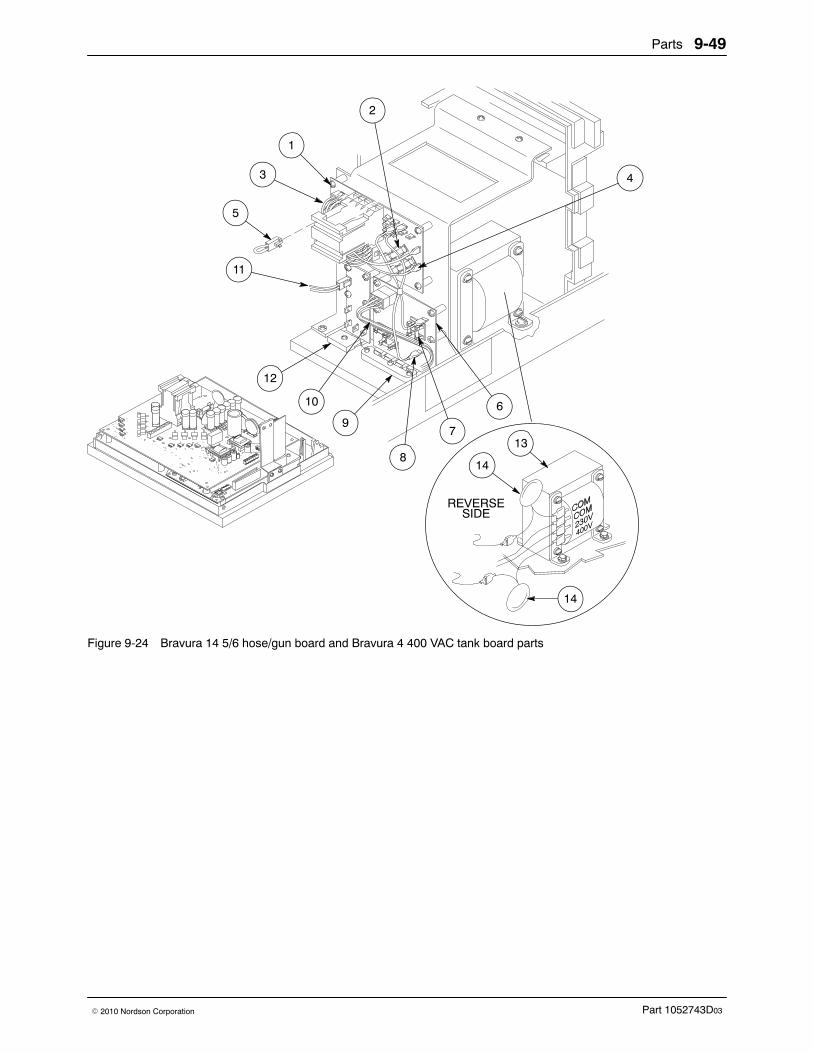
Parts 9-49
Part 1052743D03� 2010 Nordson Corporation
+
REVERSESIDE
713
814
69
10
12
11
5
3
1
2
4
14
Figure 9-24 Bravura 14 5/6 hose/gun board and Bravura 4 400 VAC tank board parts
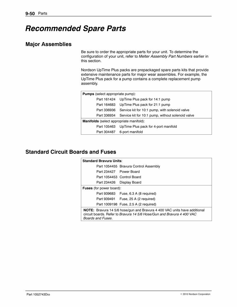
Parts9-50
Part 1052743D03 � 2010 Nordson Corporation
Recommended Spare Parts
Major Assemblies Be sure to order the appropriate parts for your unit. To determine theconfiguration of your unit, refer to Melter Assembly Part Numbers earlier inthis section.
Nordson UpTime Plus packs are prepackaged spare parts kits that provideextensive maintenance parts for major wear assembles. For example, theUpTime Plus pack for a pump contains a complete replacement pumpassembly.
Pumps (select appropriate pump):
Part 161424 UpTime Plus pack for 14:1 pump
Part 164683 UpTime Plus pack for 21:1 pump
Part 336936 Service kit for 10:1 pump, with solenoid valve
Part 336934 Service kit for 10:1 pump, without solenoid valve
Manifolds (select appropriate manifold):
Part 105463 UpTime Plus pack for 4-port manifold
Part 304487 6-port manifold
Standard Circuit Boards and Fuses
Standard Bravura Units:
Part 1054455 Bravura Control Assembly
Part 234427 Power Board
Part 1054453 Control Board
Part 234426 Display Board
Fuses (for power board):
Part 939683 Fuse, 6.3 A (8 required)
Part 939491 Fuse, 25 A (2 required)
Part 1009198 Fuse, 2.5 A (2 required)
NOTE: Bravura 14 5/6 hose/gun and Bravura 4 400 VAC units have additionalcircuit boards. Refer to Bravura 14 5/6 Hose/Gun and Bravura 4 400 VACBoards and Fuses.

Parts 9-51
Part 1052743D03� 2010 Nordson Corporation
Bravura 14 5/6 Hose/Gun and Bravura 4 400 VAC Boards and Fuses
Circuit Boards:
Part 247266 Contactor Board
Part 247260 5/6 Hose/Gun Board
Part 247262 400 VAC Tank Board
Fuses:
Contactor Board:
Part 939491 Fuse, 25 A (2 required)
Part 939992 Fuse, 30 A (1 required)
5/6 Hose/Gun Board:
Part 939683 Fuse, 6.3 A (4 required)
Consumables and Wear Items
RTD or Thermostat (tank, reservoir, or grid):
Part 249800 Thermostat service kit
Part 108907 RTD service kit
O-Rings:
Manifold:
Part 105521 Viton O-ring, 0.250 x 0.375 x 0.063 in. (four of 940101)
Part 105525 Viton O-ring, 1.125 X 1.313 X 0.094 in. (four of 941220)
Part 105523 Viton O-ring, 1.375 X 1.500 X 0.063 in. (five of 940281)
Part 105527 Backup ring, 0.25 x 0.38 in. (four of 954036)
Part 105524 O-ring for filter assembly (four of 941172)
Pump:
Part 940332 Viton O-ring, 2.000 x 2.125 x 0.063 in. (dual-acting pumps)
Part 940133 Viton O-ring, 0.426 x 0.070 in. (all pumps)
Pump Parts (other than O-rings):
Part 163039 Piston cup (14:1 pump)
Part 288116 Piston cup (21:1 pump)
Part 952100 Viton cup (14:1 and 21:1 pumps)
Part 986331 Push-on retaining ring (14:1 and 21:1 pumps)
Part 954013 Single back-up ring (14:1 and 21:1 pumps)
Part 138163 Service kit, check valve and ball (10:1 pump)
Part 105451 Service kit, crossover tube, backup ring, and O-ring(10:1 pump)
Part 138177 Service kit, siphon ball, seat, and cage (10:1 pump)
Part 1011323 Service kit, air cylinder (10:1 pump)
Manifold Filter Screen:
Part 274578 Filter screen, 0.006-in. mesh
Regulator/Filter Assembly:
Part 165870 Filter element kit
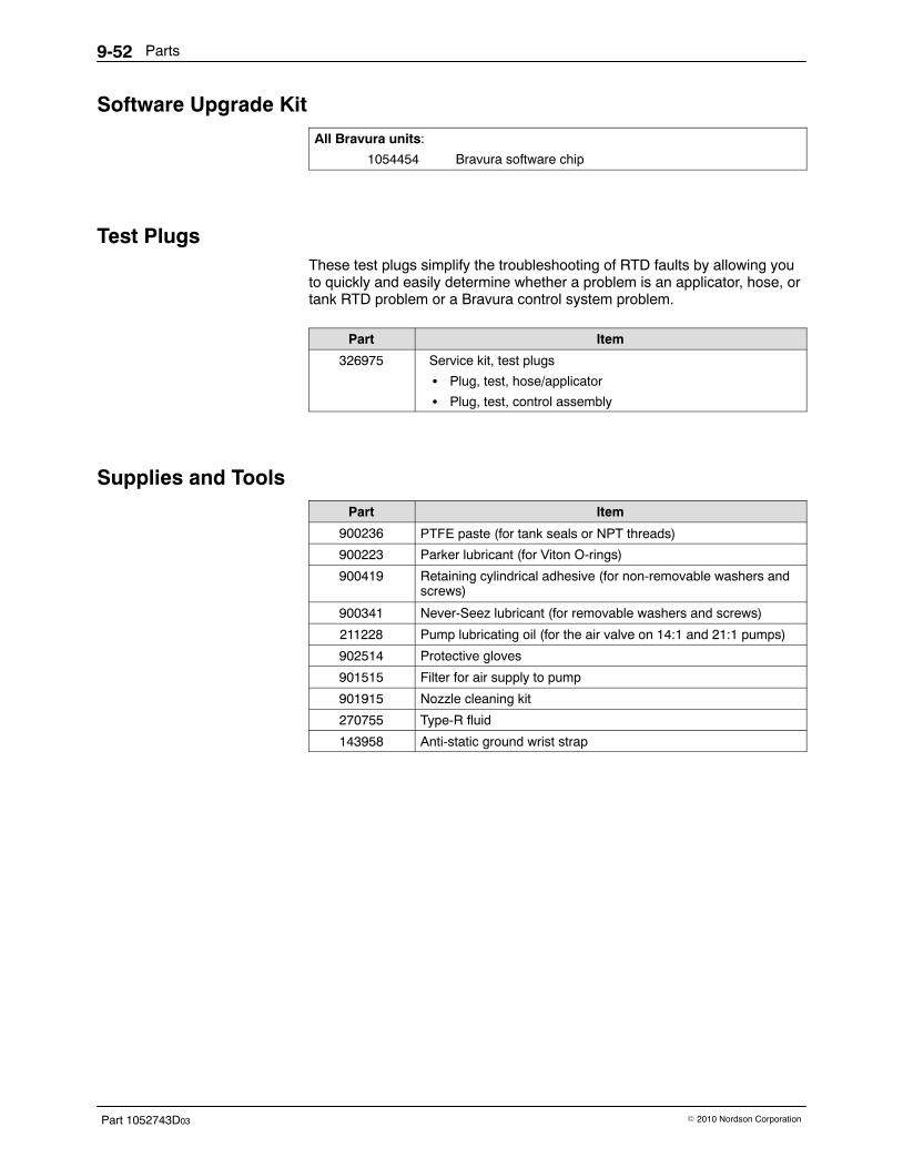
Parts9-52
Part 1052743D03 � 2010 Nordson Corporation
Software Upgrade Kit
All Bravura units:
1054454 Bravura software chip
Test Plugs These test plugs simplify the troubleshooting of RTD faults by allowing youto quickly and easily determine whether a problem is an applicator, hose, ortank RTD problem or a Bravura control system problem.
Part Item
326975 Service kit, test plugs
� Plug, test, hose/applicator
� Plug, test, control assembly
Supplies and Tools
Part Item
900236 PTFE paste (for tank seals or NPT threads)
900223 Parker lubricant (for Viton O-rings)
900419 Retaining cylindrical adhesive (for non-removable washers andscrews)
900341 Never-Seez lubricant (for removable washers and screws)
211228 Pump lubricating oil (for the air valve on 14:1 and 21:1 pumps)
902514 Protective gloves
901515 Filter for air supply to pump
901915 Nozzle cleaning kit
270755 Type-R fluid
143958 Anti-static ground wrist strap
Technical Data 10-1
Part 1052743D03� 2010 Nordson Corporation
Section 10Technical Data
General Hot Melt Material Processing Instructions NOTE: Before processing hot melt material, carefully read the materialmanufacturer’s Material Safety Data Sheet (MSDS) or material informationsheet. Nordson supplies only general processing instructions and is notliable for hazards associated with or damage caused by the use of hot meltmaterial.
Storage Store the material in dry areas at room temperature. Keep it in covered,dust-protected containers.
Preparation for Material/Application Coating Keep the substrate at room temperature, dry, and free of dust and grease.Perform tests to determine the suitable hot melt material, optimum operatingconditions, and preliminary treatment of the substrate for the application.
Some substrates contain plasticizers and other ingredients which dissipateover time. In some cases, surfaces are treated with waxes, anti-stick oils,etc. Without adequate pretreatment, the hot melt bond in these applicationsmay be defective at the time of dispensing.
Processing Temperature The application temperature of the hot melt material at the nozzle is crucialfor effective bonds.
Refer to the material manufacturer’s MSDS or material information sheet.
Avoid unnecessary thermal stress. If the work is interrupted, reduce themelting temperature.
Avoid heating the hot melt material above the prescribed processingtemperature. Higher temperatures may cause charring of the hot meltmaterial. This results in downtime. In addition, material may generatedangerous vapors at excessively high temperatures. Remove these vaporsby using appropriate exhaust systems.
Technical Data10-2
Part 1052743D03 � 2010 Nordson Corporation
Danger of Burns Be careful when using hot melt materials. These materials are solid at roomtemperature. For proper application, they may be heated to temperatures ofup to 230 �C (450 �F). Refer to the safety instructions in the Safety section.
Mixing Hot Melt Materials Avoid mixing different hot melt materials. Refer to the procedure forchanging adhesive in the Operation section.
Disposal of Hot Melt Material Refer to the supplier’s MSDS or material information sheet.

Technical Data 10-3
Part 1052743D03� 2010 Nordson Corporation
Melter Configurations This manual applies to all configurations of the Bravura melter. Tounderstand the configuration of your melter, you need to know the melterpart number, which is located on the identification plate as shown inFigure 10-1. Refer to the following table as needed to determine theconfiguration of your melter based on its part number.
Model Part Number Number ofHoses/Guns Pump Type Tank
CapacityManifold
Type
Bravura 41052645 2 14:1 dual-acting 3.7 (4) l 4-port
1052646 4 14:1 dual-acting 3.7 (4) l 4-port
Bravura 4 (400 VAC) 1061056 2 14:1 dual-acting 3.7 (4) l 4-port
Bravura 61052647 2
14:1 dual-acting 5.6 (6) l 4-port1052648 4
Bravura 9 1052649 4 14:1 dual-acting 8.9 (9) l 4-port
Bravura 14
1052650 4 14:1 dual-acting
13.7 (14) l 6-port
1052651 4 21:1 dual-acting
1052652 4 10:1 single-acting
1052653 6 14:1 dual-acting
1052654 6 21:1 dual-acting
1052655 6 10:1 single-acting
4132086
123456
Figure 10-1 Location of the melter part number on the identification plate
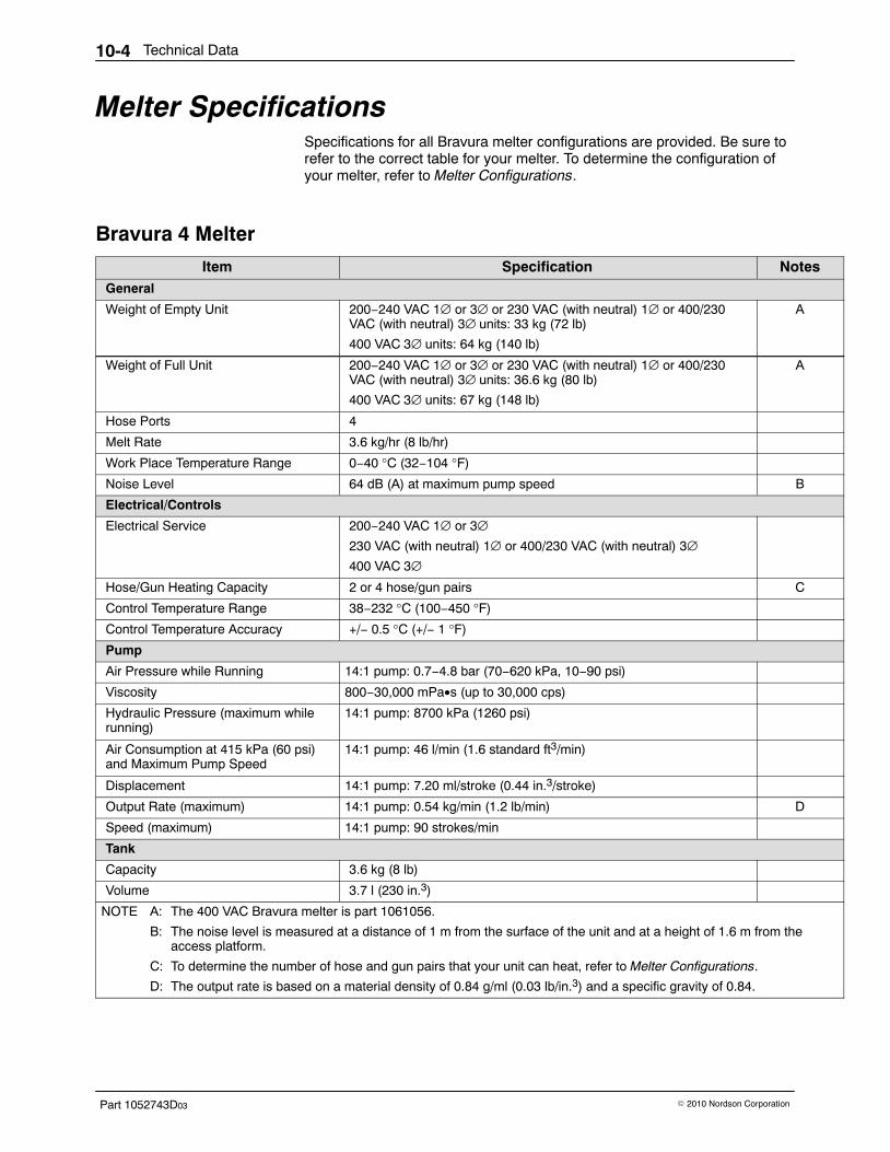
Technical Data10-4
Part 1052743D03 � 2010 Nordson Corporation
Melter Specifications Specifications for all Bravura melter configurations are provided. Be sure torefer to the correct table for your melter. To determine the configuration ofyour melter, refer to Melter Configurations.
Bravura 4 Melter
Item Specification NotesGeneral
Weight of Empty Unit 200−240 VAC 1∅ or 3∅ or 230 VAC (with neutral) 1∅ or 400/230VAC (with neutral) 3∅ units: 33 kg (72 lb)
400 VAC 3∅ units: 64 kg (140 lb)
A
Weight of Full Unit 200−240 VAC 1∅ or 3∅ or 230 VAC (with neutral) 1∅ or 400/230VAC (with neutral) 3∅ units: 36.6 kg (80 lb)
400 VAC 3∅ units: 67 kg (148 lb)
A
Hose Ports 4
Melt Rate 3.6 kg/hr (8 lb/hr)
Work Place Temperature Range 0−40 °C (32−104 °F)
Noise Level 64 dB (A) at maximum pump speed B
Electrical/Controls
Electrical Service 200−240 VAC 1∅ or 3∅230 VAC (with neutral) 1∅ or 400/230 VAC (with neutral) 3∅400 VAC 3∅
Hose/Gun Heating Capacity 2 or 4 hose/gun pairs C
Control Temperature Range 38−232 °C (100−450 °F)
Control Temperature Accuracy +/− 0.5 °C (+/− 1 °F)
Pump
Air Pressure while Running 14:1 pump: 0.7−4.8 bar (70−620 kPa, 10−90 psi)
Viscosity 800−30,000 mPa•s (up to 30,000 cps)
Hydraulic Pressure (maximum whilerunning)
14:1 pump: 8700 kPa (1260 psi)
Air Consumption at 415 kPa (60 psi)and Maximum Pump Speed
14:1 pump: 46 l/min (1.6 standard ft3/min)
Displacement 14:1 pump: 7.20 ml/stroke (0.44 in.3/stroke)
Output Rate (maximum) 14:1 pump: 0.54 kg/min (1.2 lb/min) D
Speed (maximum) 14:1 pump: 90 strokes/min
Tank
Capacity 3.6 kg (8 lb)
Volume 3.7 l (230 in.3)
NOTE A: The 400 VAC Bravura melter is part 1061056.
B: The noise level is measured at a distance of 1 m from the surface of the unit and at a height of 1.6 m from theaccess platform.
C: To determine the number of hose and gun pairs that your unit can heat, refer to Melter Configurations.
D: The output rate is based on a material density of 0.84 g/ml (0.03 lb/in.3) and a specific gravity of 0.84.

Technical Data 10-5
Part 1052743D03� 2010 Nordson Corporation
Bravura 6 Melter
Item Specification NotesGeneral
Weight of Empty Unit 38 kg (83 lb)
Weight of Full Unit 43.4 kg (95 lb)
Hose Ports 4
Melt Rate 6.8 kg/hr (15 lb/hr)
Work Place Temperature Range 0−40 °C (32−104 °F)
Noise Level 64 dB (A) at maximum pump speed A
Electrical/Controls
Electrical Service 200−240 VAC 1∅ or 3∅230 VAC (with neutral) 1∅ or 400/230 VAC (with neutral) 3∅
Hose/Gun Heating Capacity 2 or 4 hose/gun pairs B
Control Temperature Range 38−232 °C (100−450 °F)
Control Temperature Accuracy +/− 0.5 °C (+/− 1 °F)
Pump
Air Pressure while Running 14:1 pump: 0.7−4.8 bar (70−620 kPa, 10−90 psi)
Viscosity 800−30,000 mPa•s (up to 30,000 cps)
Hydraulic Pressure (maximum whilerunning)
14:1 pump: 8700 kPa (1260 psi)
Air Consumption at 415 kPa (60 psi)and Maximum Pump Speed
14:1 pump: 46 l/min (1.6 standard ft3/min)
Displacement 14:1 pump: 7.20 ml/stroke (0.44 in.3/stroke)
Output Rate (maximum) 14:1 pump: 0.54 kg/min (1.2 lb/min) C
Speed (maximum) 14:1 pump: 90 strokes/min
Tank
Capacity 5.4 kg (12 lb)
Volume 5.6 liters (340 in.3)
NOTE A: The noise level is measured at a distance of 1 m from the surface of the unit and at a height of 1.6 m from theaccess platform.
B: To determine the number of hose and gun pairs that your unit can heat, refer to Melter Configurations.
C: The output rate is based on a material density of 0.84 g/ml (0.03 lb/in.3) and a specific gravity of 0.84.
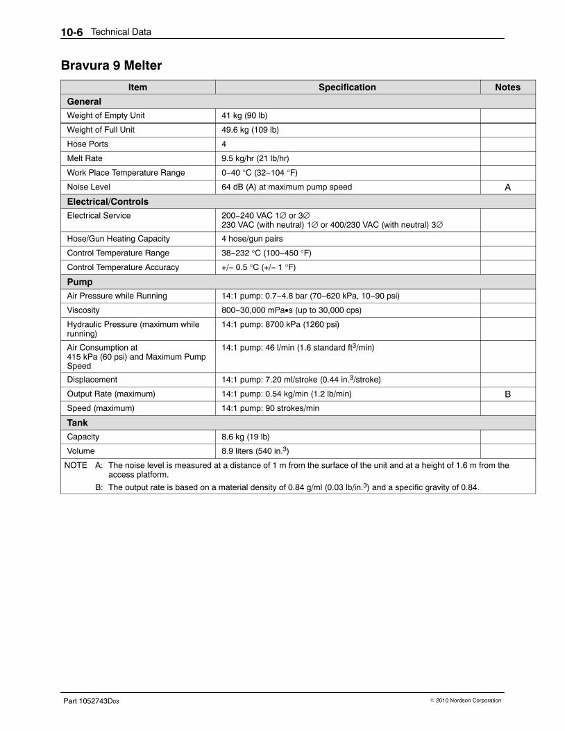
Technical Data10-6
Part 1052743D03 � 2010 Nordson Corporation
Bravura 9 Melter
Item Specification Notes
GeneralWeight of Empty Unit 41 kg (90 lb)
Weight of Full Unit 49.6 kg (109 lb)
Hose Ports 4
Melt Rate 9.5 kg/hr (21 lb/hr)
Work Place Temperature Range 0−40 °C (32−104 °F)
Noise Level 64 dB (A) at maximum pump speed A
Electrical/ControlsElectrical Service 200−240 VAC 1∅ or 3∅
230 VAC (with neutral) 1∅ or 400/230 VAC (with neutral) 3∅
Hose/Gun Heating Capacity 4 hose/gun pairs
Control Temperature Range 38−232 °C (100−450 °F)
Control Temperature Accuracy +/− 0.5 °C (+/− 1 °F)
PumpAir Pressure while Running 14:1 pump: 0.7−4.8 bar (70−620 kPa, 10−90 psi)
Viscosity 800−30,000 mPa•s (up to 30,000 cps)
Hydraulic Pressure (maximum whilerunning)
14:1 pump: 8700 kPa (1260 psi)
Air Consumption at415 kPa (60 psi) and Maximum PumpSpeed
14:1 pump: 46 l/min (1.6 standard ft3/min)
Displacement 14:1 pump: 7.20 ml/stroke (0.44 in.3/stroke)
Output Rate (maximum) 14:1 pump: 0.54 kg/min (1.2 lb/min) B
Speed (maximum) 14:1 pump: 90 strokes/min
TankCapacity 8.6 kg (19 lb)
Volume 8.9 liters (540 in.3)
NOTE A: The noise level is measured at a distance of 1 m from the surface of the unit and at a height of 1.6 m from theaccess platform.
B: The output rate is based on a material density of 0.84 g/ml (0.03 lb/in.3) and a specific gravity of 0.84.
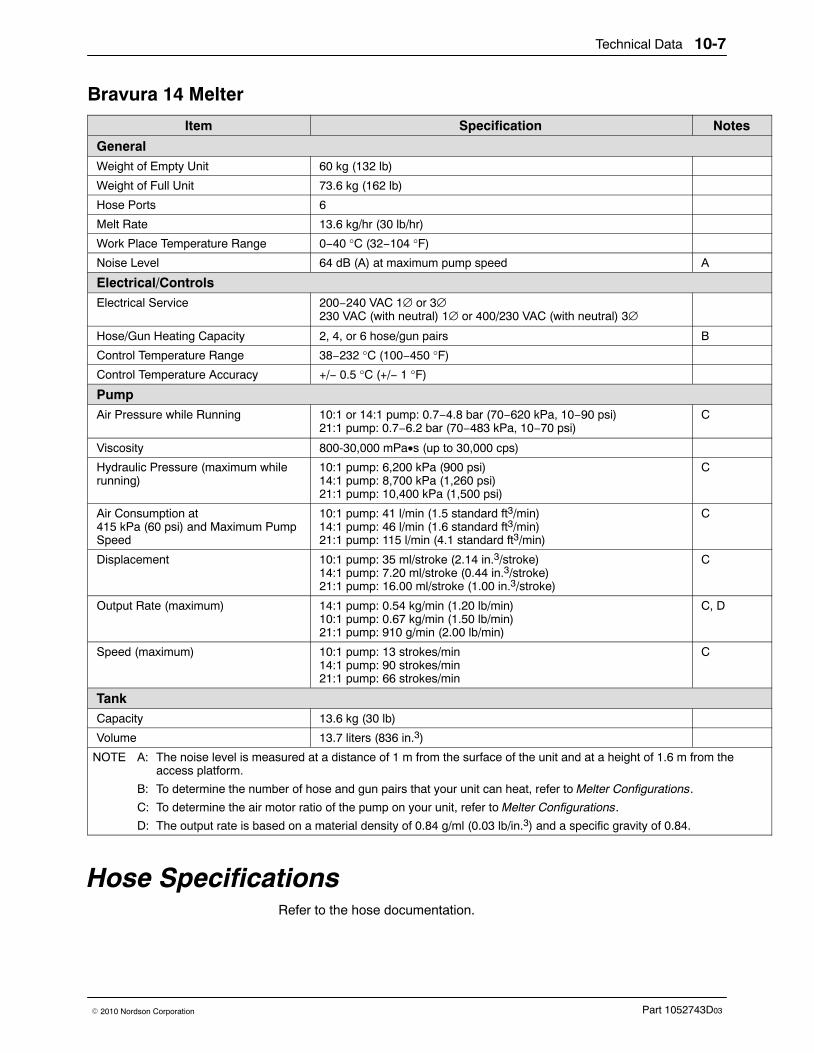
Technical Data 10-7
Part 1052743D03� 2010 Nordson Corporation
Bravura 14 Melter
Item Specification Notes
GeneralWeight of Empty Unit 60 kg (132 lb)
Weight of Full Unit 73.6 kg (162 lb)
Hose Ports 6
Melt Rate 13.6 kg/hr (30 lb/hr)
Work Place Temperature Range 0−40 °C (32−104 °F)
Noise Level 64 dB (A) at maximum pump speed A
Electrical/ControlsElectrical Service 200−240 VAC 1∅ or 3∅
230 VAC (with neutral) 1∅ or 400/230 VAC (with neutral) 3∅
Hose/Gun Heating Capacity 2, 4, or 6 hose/gun pairs B
Control Temperature Range 38−232 °C (100−450 °F)
Control Temperature Accuracy +/− 0.5 °C (+/− 1 °F)
PumpAir Pressure while Running 10:1 or 14:1 pump: 0.7−4.8 bar (70−620 kPa, 10−90 psi)
21:1 pump: 0.7−6.2 bar (70−483 kPa, 10−70 psi)C
Viscosity 800-30,000 mPa•s (up to 30,000 cps)
Hydraulic Pressure (maximum whilerunning)
10:1 pump: 6,200 kPa (900 psi)14:1 pump: 8,700 kPa (1,260 psi)21:1 pump: 10,400 kPa (1,500 psi)
C
Air Consumption at 415 kPa (60 psi) and Maximum PumpSpeed
10:1 pump: 41 l/min (1.5 standard ft3/min)14:1 pump: 46 l/min (1.6 standard ft3/min)21:1 pump: 115 l/min (4.1 standard ft3/min)
C
Displacement 10:1 pump: 35 ml/stroke (2.14 in.3/stroke)14:1 pump: 7.20 ml/stroke (0.44 in.3/stroke)21:1 pump: 16.00 ml/stroke (1.00 in.3/stroke)
C
Output Rate (maximum) 14:1 pump: 0.54 kg/min (1.20 lb/min)10:1 pump: 0.67 kg/min (1.50 lb/min)21:1 pump: 910 g/min (2.00 lb/min)
C, D
Speed (maximum) 10:1 pump: 13 strokes/min14:1 pump: 90 strokes/min21:1 pump: 66 strokes/min
C
TankCapacity 13.6 kg (30 lb)
Volume 13.7 liters (836 in.3)
NOTE A: The noise level is measured at a distance of 1 m from the surface of the unit and at a height of 1.6 m from theaccess platform.
B: To determine the number of hose and gun pairs that your unit can heat, refer to Melter Configurations.
C: To determine the air motor ratio of the pump on your unit, refer to Melter Configurations.
D: The output rate is based on a material density of 0.84 g/ml (0.03 lb/in.3) and a specific gravity of 0.84.
Hose Specifications Refer to the hose documentation.
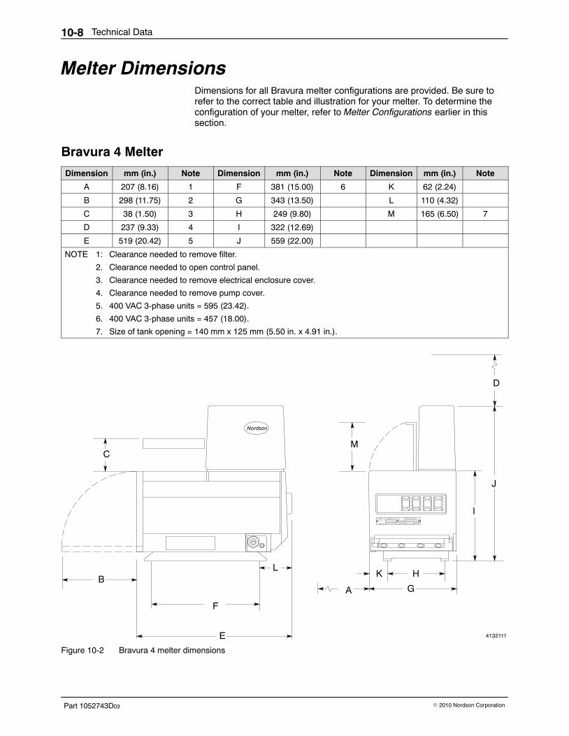
Technical Data10-8
Part 1052743D03 � 2010 Nordson Corporation
Melter Dimensions Dimensions for all Bravura melter configurations are provided. Be sure torefer to the correct table and illustration for your melter. To determine theconfiguration of your melter, refer to Melter Configurations earlier in thissection.
Bravura 4 Melter
Dimension mm (in.) Note Dimension mm (in.) Note Dimension mm (in.) Note
A 207 (8.16) 1 F 381 (15.00) 6 K 62 (2.24)
B 298 (11.75) 2 G 343 (13.50) L 110 (4.32)
C 38 (1.50) 3 H 249 (9.80) M 165 (6.50) 7
D 237 (9.33) 4 I 322 (12.69)
E 519 (20.42) 5 J 559 (22.00)
NOTE 1: Clearance needed to remove filter.
2. Clearance needed to open control panel.
3. Clearance needed to remove electrical enclosure cover.
4. Clearance needed to remove pump cover.
5. 400 VAC 3-phase units = 595 (23.42).
6. 400 VAC 3-phase units = 457 (18.00).
7. Size of tank opening = 140 mm x 125 mm (5.50 in. x 4.91 in.).
4132111
B
C
D
E
H
I
J
KL
G
M
A
F
Figure 10-2 Bravura 4 melter dimensions
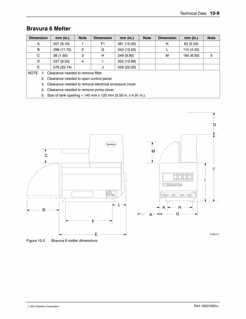
Technical Data 10-9
Part 1052743D03� 2010 Nordson Corporation
Bravura 6 Melter
Dimension mm (in.) Note Dimension mm (in.) Note Dimension mm (in.) Note
A 207 (8.16) 1 F1 381 (15.00) K 62 (2.24)
B 298 (11.75) 2 G 343 (13.50) L 110 (4.32)
C 38 (1.50) 3 H 249 (9.80) M 165 (6.50) 5
D 237 (9.33) 4 I 322 (12.69)
E 578 (22.74) J 559 (22.00)
NOTE 1: Clearance needed to remove filter.
2. Clearance needed to open control panel.
3. Clearance needed to remove electrical enclosure cover.
4. Clearance needed to remove pump cover.
5. Size of tank opening = 140 mm x 125 mm (5.50 in. x 4.91 in.).
4132111
B
C
D
E
H
I
J
KL
G
M
A
F
Figure 10-3 Bravura 6 melter dimensions
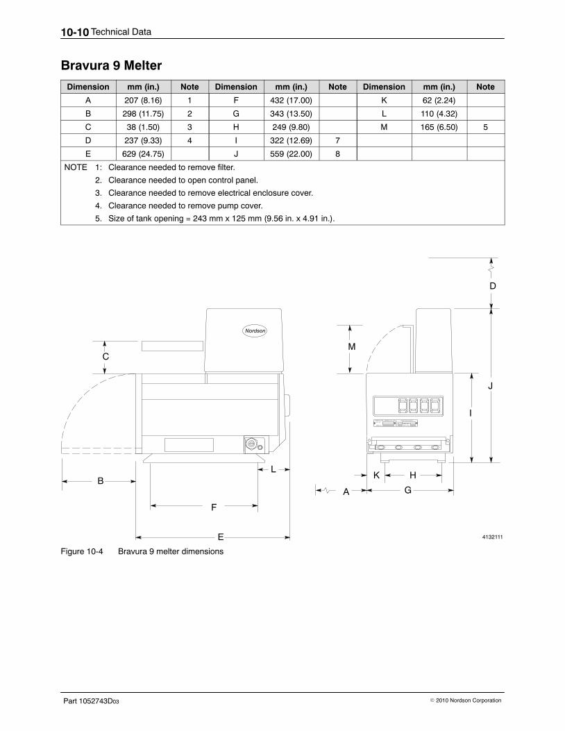
Technical Data10-10
Part 1052743D03 � 2010 Nordson Corporation
Bravura 9 Melter
Dimension mm (in.) Note Dimension mm (in.) Note Dimension mm (in.) Note
A 207 (8.16) 1 F 432 (17.00) K 62 (2.24)
B 298 (11.75) 2 G 343 (13.50) L 110 (4.32)
C 38 (1.50) 3 H 249 (9.80) M 165 (6.50) 5
D 237 (9.33) 4 I 322 (12.69) 7
E 629 (24.75) J 559 (22.00) 8
NOTE 1: Clearance needed to remove filter.
2. Clearance needed to open control panel.
3. Clearance needed to remove electrical enclosure cover.
4. Clearance needed to remove pump cover.
5. Size of tank opening = 243 mm x 125 mm (9.56 in. x 4.91 in.).
4132111
B
C
D
E
H
I
J
KL
G
M
A
F
Figure 10-4 Bravura 9 melter dimensions
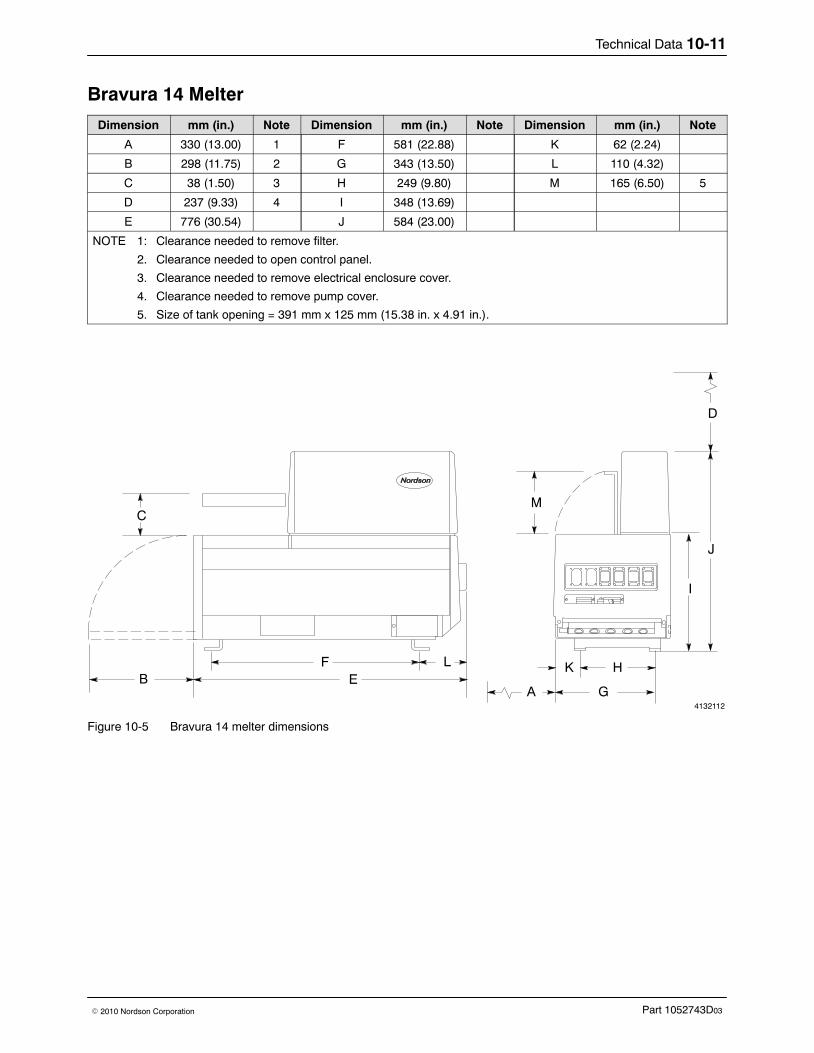
Technical Data 10-11
Part 1052743D03� 2010 Nordson Corporation
Bravura 14 Melter
Dimension mm (in.) Note Dimension mm (in.) Note Dimension mm (in.) Note
A 330 (13.00) 1 F 581 (22.88) K 62 (2.24)
B 298 (11.75) 2 G 343 (13.50) L 110 (4.32)
C 38 (1.50) 3 H 249 (9.80) M 165 (6.50) 5
D 237 (9.33) 4 I 348 (13.69)
E 776 (30.54) J 584 (23.00)
NOTE 1: Clearance needed to remove filter.
2. Clearance needed to open control panel.
3. Clearance needed to remove electrical enclosure cover.
4. Clearance needed to remove pump cover.
5. Size of tank opening = 391 mm x 125 mm (15.38 in. x 4.91 in.).
4132112
B
C
D
EF H
I
J
KL
GA
M
Figure 10-5 Bravura 14 melter dimensions
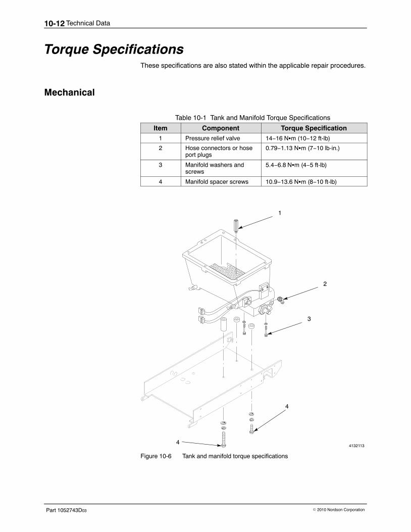
Technical Data10-12
Part 1052743D03 � 2010 Nordson Corporation
Torque Specifications These specifications are also stated within the applicable repair procedures.
Mechanical
Table 10-1 Tank and Manifold Torque Specifications
Item Component Torque Specification1 Pressure relief valve 14−16 N�m (10−12 ft-lb)
2 Hose connectors or hoseport plugs
0.79−1.13 N�m (7−10 lb-in.)
3 Manifold washers andscrews
5.4−6.8 N�m (4−5 ft-lb)
4 Manifold spacer screws 10.9−13.6 N�m (8−10 ft-lb)
4132113
4
4
1
3
2
Figure 10-6 Tank and manifold torque specifications
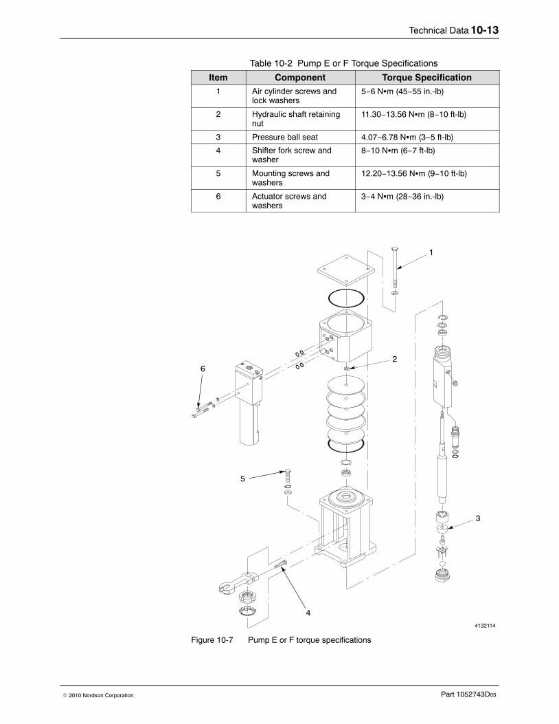
Technical Data 10-13
Part 1052743D03� 2010 Nordson Corporation
Table 10-2 Pump E or F Torque Specifications
Item Component Torque Specification1 Air cylinder screws and
lock washers5−6 N�m (45−55 in.-lb)
2 Hydraulic shaft retainingnut
11.30−13.56 N�m (8−10 ft-lb)
3 Pressure ball seat 4.07−6.78 N�m (3−5 ft-lb)
4 Shifter fork screw andwasher
8−10 N�m (6−7 ft-lb)
5 Mounting screws andwashers
12.20−13.56 N�m (9−10 ft-lb)
6 Actuator screws andwashers
3−4 N�m (28−36 in.-lb)
4132114
6
5
1
2
4
3
Figure 10-7 Pump E or F torque specifications
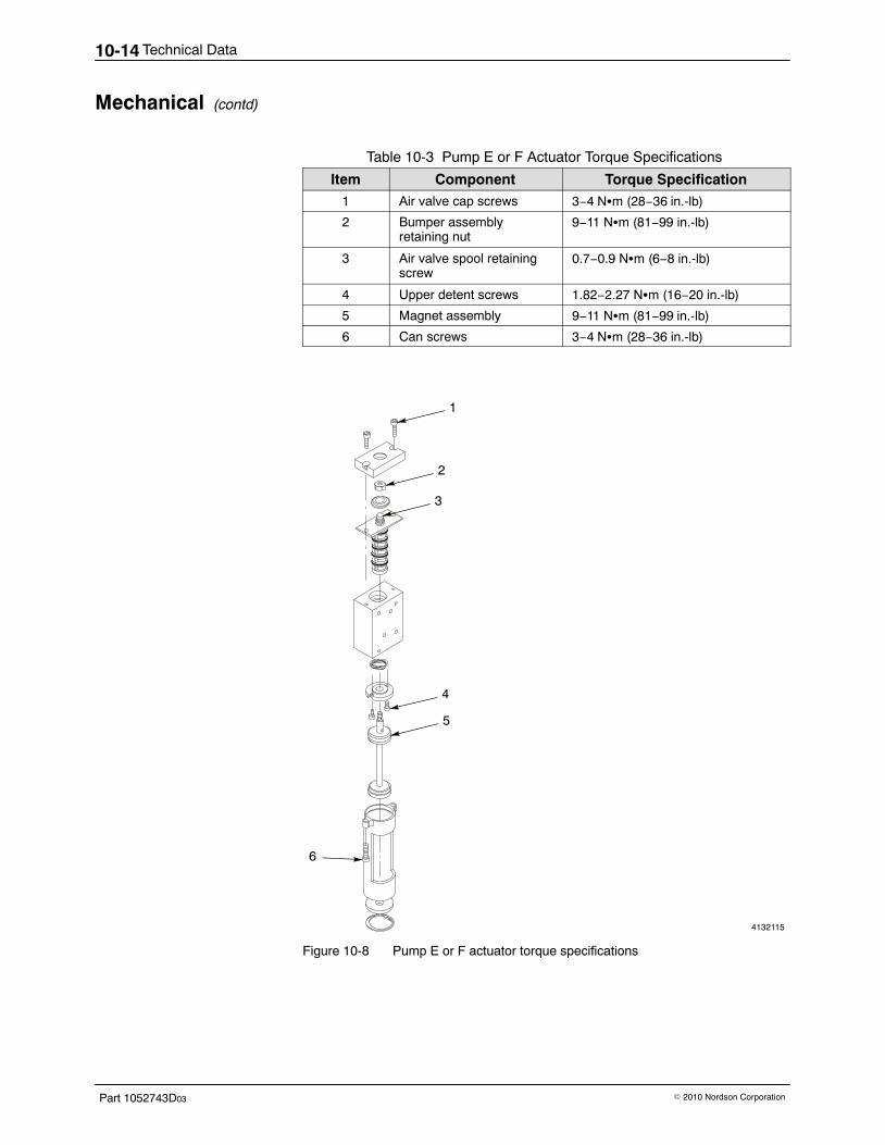
Technical Data10-14
Part 1052743D03 � 2010 Nordson Corporation
Mechanical (contd)
Table 10-3 Pump E or F Actuator Torque Specifications
Item Component Torque Specification1 Air valve cap screws 3−4 N�m (28−36 in.-lb)
2 Bumper assemblyretaining nut
9−11 N�m (81−99 in.-lb)
3 Air valve spool retainingscrew
0.7−0.9 N�m (6−8 in.-lb)
4 Upper detent screws 1.82−2.27 N�m (16−20 in.-lb)
5 Magnet assembly 9−11 N�m (81−99 in.-lb)
6 Can screws 3−4 N�m (28−36 in.-lb)
4132115
1
3
5
6
4
2
Figure 10-8 Pump E or F actuator torque specifications
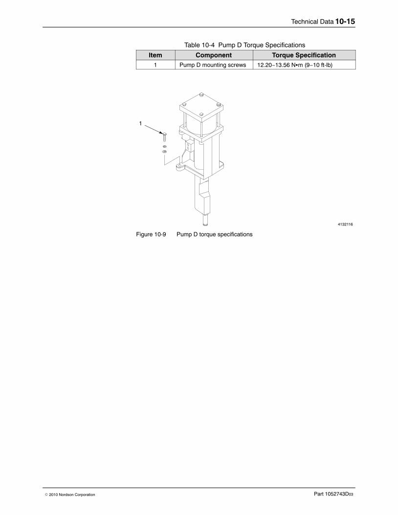
Technical Data 10-15
Part 1052743D03� 2010 Nordson Corporation
Table 10-4 Pump D Torque Specifications
Item Component Torque Specification1 Pump D mounting screws 12.20−13.56 N�m (9−10 ft-lb)
4132116
1
Figure 10-9 Pump D torque specifications
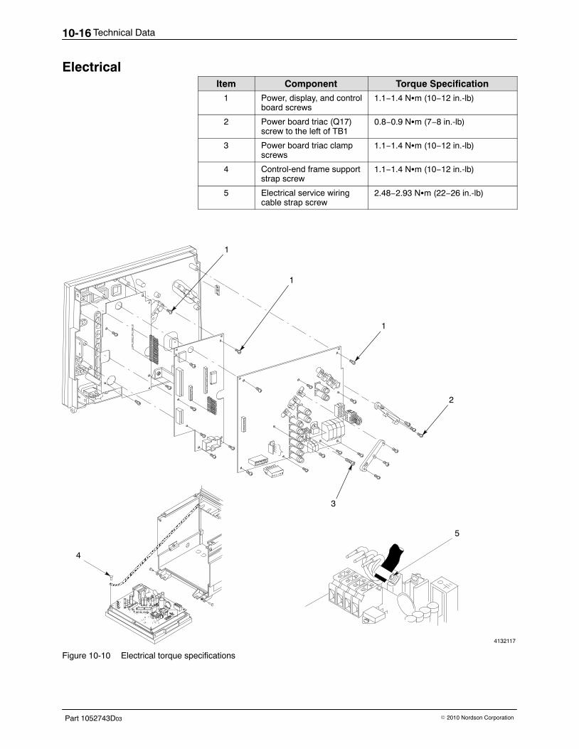
Technical Data10-16
Part 1052743D03 � 2010 Nordson Corporation
Electrical Item Component Torque Specification
1 Power, display, and controlboard screws
1.1−1.4 N�m (10−12 in.-lb)
2 Power board triac (Q17)screw to the left of TB1
0.8−0.9 N�m (7−8 in.-lb)
3 Power board triac clampscrews
1.1−1.4 N�m (10−12 in.-lb)
4 Control-end frame supportstrap screw
1.1−1.4 N�m (10−12 in.-lb)
5 Electrical service wiringcable strap screw
2.48−2.93 N�m (22−26 in.-lb)
4132117
1
1
1
2
3
5
+
ÎÎÎÎÎÎÎÎÎÎÎÎÎÎÎÎÎÎÎÎÎÎÎÎÎÎÎÎÎÎÎÎÎÎÎÎÎÎÎÎÎÎÎÎÎÎÎÎÎ
4
Figure 10-10 Electrical torque specifications
Technical Data 10-17
Part 1052743D03� 2010 Nordson Corporation
Procedure for Calculating Hose/Gun Capacity When you connect hoses and guns to your hot melt unit, you must makesure the electrical power requirements of those hoses and guns do notexceed the maximum wattages allowed for your system. Exceeding theallowed maximum wattage can damage your equipment or keep yoursystem from functioning properly.
For every Bravura melter system, there are three maximum wattages youmust not exceed:
� The single-component maximum wattage: the wattage of anysingle hose or gun connected to your unit must not exceed thiswattage.
� The hose/gun pair maximum wattage: the wattage of any hoseand gun (hose/gun pair) connected to your unit must not exceed thiswattage.
� The total hose/gun maximum wattage: the wattage of all hosesand guns connected to your unit must not exceed this wattage.
To make sure your system does not exceed any of these maximumwattages, someone (either you or your Nordson representative) mustcalculate the hose/gun capacity for your system. If your Nordsonrepresentative has already made this calculation for the actual hoses andguns you plan to use, you do not need to repeat the calculation now.However, you must make this calculation
� if the hose/gun capacity has not been calculated for your system
� if you have reconfigured your system since the calculations weremade
� whenever you add new hoses or guns to an existing system
� whenever you replace an existing hose with a longer one or anexisting gun with a larger one
Calculating Hose/Gun Capacity Use this procedure to calculate the hose/gun capacity for your system.Throughout this procedure there are places for you to record importantinformation. These records provide you with a quick reference and makerecalculations easier.
1. Refer to Melter Configurations earlier in this section to determine themodel (Bravura 4, 6, 9, or 14) of your melter. Record the model below.
Model:
2. Refer to Melter Configurations earlier in this section to determine thehose/gun capacity (2, 4 or 6) of your melter. Record the hose/guncapacity below.
Hose/gun capacity (2, 4, or 6):
Technical Data10-18
Part 1052743D03 � 2010 Nordson Corporation
Calculating Hose/Gun Capacity (contd)
3. Determine the the type of electrical service supplied to your melter. Ifnecessary, refer to Section 3, Installation, and compare the electricalinstallation instructions to the electrical connections inside your melter.The electrical service will be one of the following:
� 400/230 VAC 3-phase (with neutral)� 230 VAC 1-phase (with neutral)� 200−240 VAC 3-phase (without neutral)� 200−240 VAC 1-phase (without neutral)� 400 VAC 3-phase (without neutral)
Record the electrical service below.
Electrical service:
4. The single-component maximum wattage for all Bravura melters is1,000 W. This information is recorded for you in Table 10-5.
Table 10-5 Single-Component Maximum Wattage
Record of Single-ComponentMaximum Wattage: 1,000 W
5. The hose/gun pair maximum wattage for all Bravura melters is 1,200 W.This information is recorded for you in Table 10-6.
Table 10-6 Hose/Gun Pair Maximum Wattage
Record of Hose/Gun PairMaximum Wattage: 1,200 W
6. Using the electrical service information you recorded in step 3., refer toTable 10-7 to determine which table in the Power Data Tables portion ofthis procedure you will use to determine the maximum wattage of allhoses and guns you can use in your system. Record the correct tablefor your system in the last column of the table.
Table 10-7 Correct Table in Power Data Tables for Your System
Electrical Service Table in Power DataTables
Record of Correct Table in Power DataTables for Your System
230 VAC 1-phase (with neutral)Table 10-11
400/230 VAC 3-phase (with neutral)
200−240 VAC 1-phase (without neutral)Table 10-12
200−240 VAC 3-phase (without neutral)
400 VAC 3-phase (without neutral) Table 10-13
Technical Data 10-19
Part 1052743D03� 2010 Nordson Corporation
7. Using the information you recorded in steps 1., 2., and Table 10-7, referto Power Data Tables and obtain the value listed in the Total Hose/GunMaximum Wattage column for your system. Record the total hose/gunmaximum wattage for your system in the space below:
NOTE: You do not need to use the data in the remaining columns of thetable. This data is for reference only.
Table 10-8 Total Hose/Gun Maximum Wattage for Your System
Record of Total Hose/Gun Maximum Wattage for Your System
8. In the table below, record the total maximum wattages you recorded inTables 10-5, 10-6, and 10-8.
Table 10-9 Maximum Wattages for Your System
Type of Maximum Wattage Refer to…Record of MaximumWattages for Your
System
Single-component maximumwattage Table 10-5
Hose/gun pair maximumwattage Table 10-6
Total hose/gun maximumwattage Table 10-8
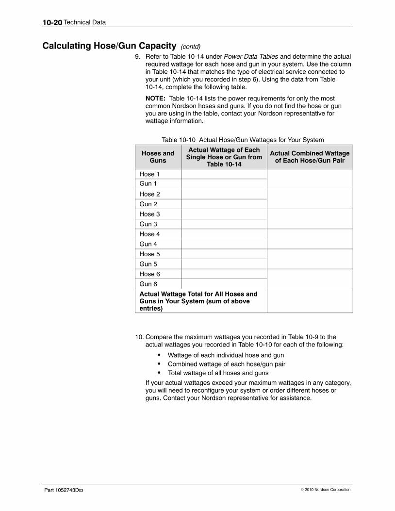
Technical Data10-20
Part 1052743D03 � 2010 Nordson Corporation
Calculating Hose/Gun Capacity (contd)
9. Refer to Table 10-14 under Power Data Tables and determine the actualrequired wattage for each hose and gun in your system. Use the columnin Table 10-14 that matches the type of electrical service connected toyour unit (which you recorded in step 6). Using the data from Table10-14, complete the following table.
NOTE: Table 10-14 lists the power requirements for only the mostcommon Nordson hoses and guns. If you do not find the hose or gunyou are using in the table, contact your Nordson representative forwattage information.
Table 10-10 Actual Hose/Gun Wattages for Your System
Hoses andGuns
Actual Wattage of EachSingle Hose or Gun from
Table 10-14
Actual Combined Wattageof Each Hose/Gun Pair
Hose 1
Gun 1
Hose 2
Gun 2
Hose 3
Gun 3
Hose 4
Gun 4
Hose 5
Gun 5
Hose 6
Gun 6
Actual Wattage Total for All Hoses andGuns in Your System (sum of aboveentries)
10. Compare the maximum wattages you recorded in Table 10-9 to theactual wattages you recorded in Table 10-10 for each of the following:
� Wattage of each individual hose and gun� Combined wattage of each hose/gun pair� Total wattage of all hoses and guns
If your actual wattages exceed your maximum wattages in any category,you will need to reconfigure your system or order different hoses orguns. Contact your Nordson representative for assistance.
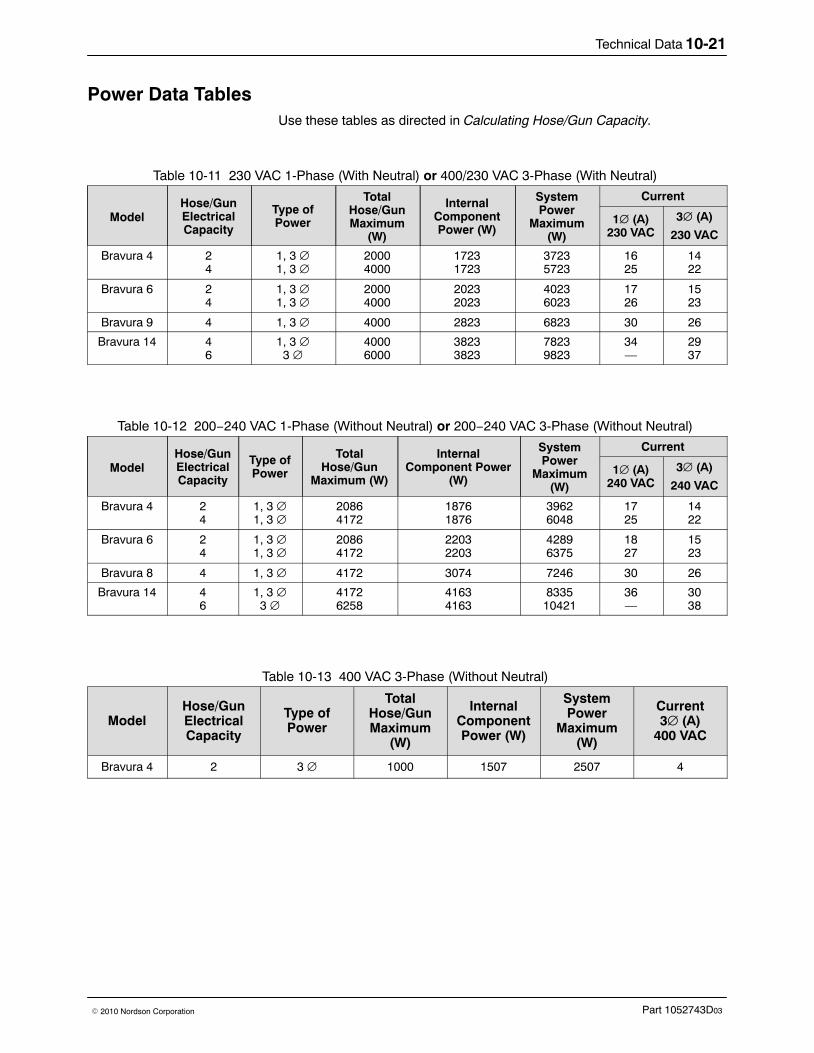
Technical Data 10-21
Part 1052743D03� 2010 Nordson Corporation
Power Data Tables Use these tables as directed in Calculating Hose/Gun Capacity.
Table 10-11 230 VAC 1-Phase (With Neutral) or 400/230 VAC 3-Phase (With Neutral)
ModelHose/GunElectricalCapacity
Type ofPower
TotalHose/GunMaximum
(W)
InternalComponentPower (W)
SystemPower
Maximum(W)
Current
1� (A)230 VAC
3� (A)
230 VAC
Bravura 4 24
1, 3 ∅1, 3 ∅
20004000
17231723
37235723
1625
1422
Bravura 6 24
1, 3 ∅1, 3 ∅
20004000
20232023
40236023
1726
1523
Bravura 9 4 1, 3 ∅ 4000 2823 6823 30 26
Bravura 14 46
1, 3 ∅3 ∅
40006000
38233823
78239823
34—
2937
Table 10-12 200−240 VAC 1-Phase (Without Neutral) or 200−240 VAC 3-Phase (Without Neutral)
ModelHose/GunElectricalCapacity
Type ofPower
TotalHose/Gun
Maximum (W)
InternalComponent Power
(W)
SystemPower
Maximum(W)
Current
1∅ (A)240 VAC
3∅ (A)
240 VAC
Bravura 4 24
1, 3 ∅1, 3 ∅
20864172
18761876
39626048
1725
1422
Bravura 6 24
1, 3 ∅1, 3 ∅
20864172
22032203
42896375
1827
1523
Bravura 8 4 1, 3 ∅ 4172 3074 7246 30 26
Bravura 14 46
1, 3 ∅3 ∅
41726258
41634163
833510421
36—
3038
Table 10-13 400 VAC 3-Phase (Without Neutral)
ModelHose/GunElectricalCapacity
Type ofPower
TotalHose/GunMaximum
(W)
InternalComponentPower (W)
SystemPower
Maximum(W)
Current3∅ (A)
400 VAC
Bravura 4 2 3 ∅ 1000 1507 2507 4
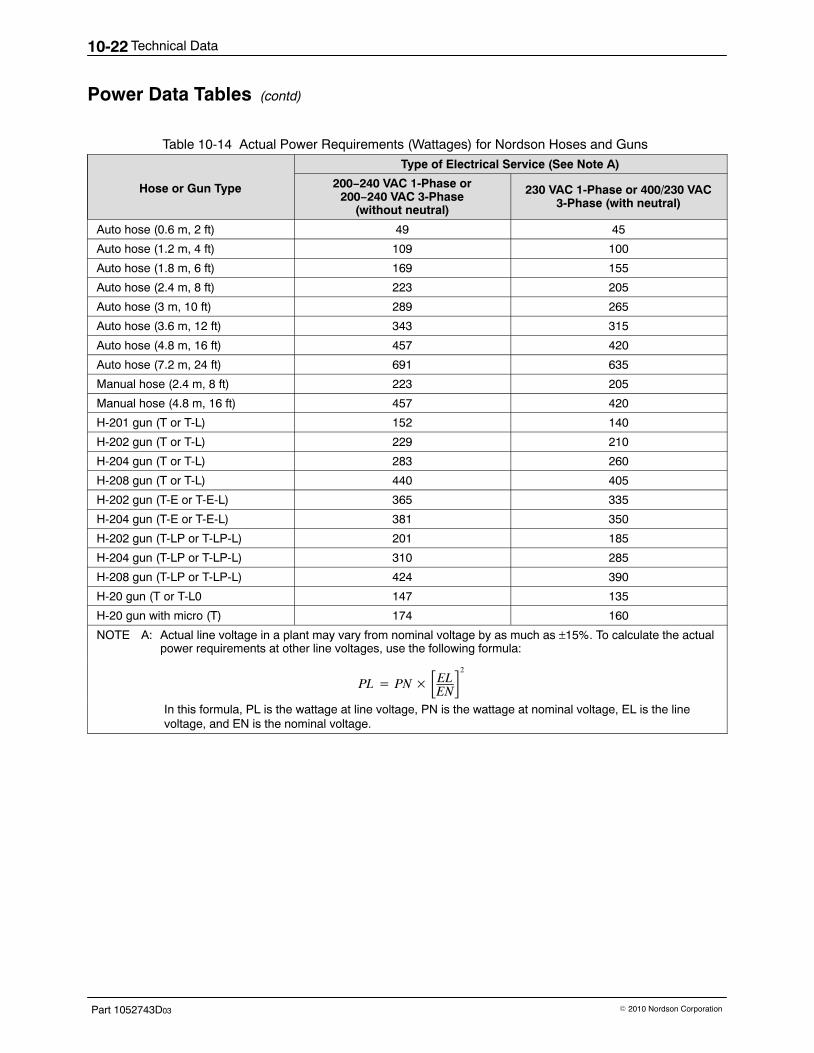
Technical Data10-22
Part 1052743D03 � 2010 Nordson Corporation
Power Data Tables (contd)
Table 10-14 Actual Power Requirements (Wattages) for Nordson Hoses and Guns
Hose or Gun Type
Type of Electrical Service (See Note A)
200−240 VAC 1-Phase or200−240 VAC 3-Phase
(without neutral)
230 VAC 1-Phase or 400/230 VAC3-Phase (with neutral)
Auto hose (0.6 m, 2 ft) 49 45
Auto hose (1.2 m, 4 ft) 109 100
Auto hose (1.8 m, 6 ft) 169 155
Auto hose (2.4 m, 8 ft) 223 205
Auto hose (3 m, 10 ft) 289 265
Auto hose (3.6 m, 12 ft) 343 315
Auto hose (4.8 m, 16 ft) 457 420
Auto hose (7.2 m, 24 ft) 691 635
Manual hose (2.4 m, 8 ft) 223 205
Manual hose (4.8 m, 16 ft) 457 420
H-201 gun (T or T-L) 152 140
H-202 gun (T or T-L) 229 210
H-204 gun (T or T-L) 283 260
H-208 gun (T or T-L) 440 405
H-202 gun (T-E or T-E-L) 365 335
H-204 gun (T-E or T-E-L) 381 350
H-202 gun (T-LP or T-LP-L) 201 185
H-204 gun (T-LP or T-LP-L) 310 285
H-208 gun (T-LP or T-LP-L) 424 390
H-20 gun (T or T-L0 147 135
H-20 gun with micro (T) 174 160
NOTE A: Actual line voltage in a plant may vary from nominal voltage by as much as ±15%. To calculate the actualpower requirements at other line voltages, use the following formula:
PL � PN� �ELEN�
2
In this formula, PL is the wattage at line voltage, PN is the wattage at nominal voltage, EL is the linevoltage, and EN is the nominal voltage.
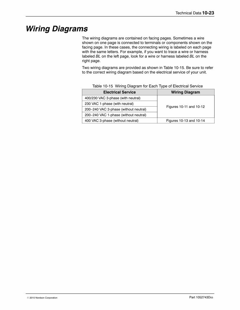
Technical Data 10-23
Part 1052743D03� 2010 Nordson Corporation
Wiring Diagrams The wiring diagrams are contained on facing pages. Sometimes a wireshown on one page is connected to terminals or components shown on thefacing page. In these cases, the connecting wiring is labeled on each pagewith the same letters. For example, if you want to trace a wire or harnesslabeled BL on the left page, look for a wire or harness labeled BL on theright page.
Two wiring diagrams are provided as shown in Table 10-15. Be sure to referto the correct wiring diagram based on the electrical service of your unit.
Table 10-15 Wiring Diagram for Each Type of Electrical Service
Electrical Service Wiring Diagram400/230 VAC 3-phase (with neutral)
Figures 10-11 and 10-12230 VAC 1-phase (with neutral)
200−240 VAC 3-phase (without neutral)
200−240 VAC 1-phase (without neutral)
400 VAC 3-phase (without neutral) Figures 10-13 and 10-14
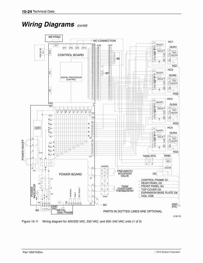
Technical Data10-24
Part 1052743D03 � 2010 Nordson Corporation
Wiring Diagrams (contd)
4132118
2
BF5
4
1
16
17
18
19
20
21
22
23
16
17
18
19
20
21
22
23 3
HEATER
8
36
2
3
1
12
3
1
1
2
CONTROL BOARD
F12
F11
F8
F7
F6
F5 123456
8
X2
F4
F3
F2
F1
1
X3
1 3
L1
TB11 2 3 4 65T
B2
WA
RN
ING
FAU
LT
NO
T R
EA
DY
J2
1
2
3
4
GND(PE)L2 L3 N
TB
1AT
B1B
TB
1CT
B1D
X4
15
PO
WE
R O
N/O
FF
J4
2
3
4
K1
12345678
X1
POWER BOARD
2
TSTAT
SOLENOID
BC
J9
PNEUMATICSOLENOID
VALVE
TANKOVERTEMP
THERMOSTAT
1
2
3
4
5
6
7
8
9
10
11
12
13
14
15
24
25
26
27
28
29
30
31
32
33
34
35
DIGITAL PROCESSORCONTROL
XP
4A
XP2
2
3
1
3
1
2
POWERSUPPLY
PL1
DIS
PLA
Y B
D
7
XP10
XP3
XP1
BA
XP
5X
P6
XP9
NO CONNECTION
36
1
2
3
4
5
6
7
8
9
10
11
12
13
14
15
24
25
26
27
28
29
30
31
32
33
34
35
36
1
2
3
4
5
6
7
8
9
10
11
12
13
14
15
16
17
18
19
20
21
22
23
24
25
26
27
28
29
30
31
32
33
34
35
6
7
1
2
3
4
5
XS1
XS2
101
4
611859312
27
HEATER
RTD
HEATER
RTD
5 5
3 34 41 1
2 2G G
HC1
GUN1
101
4
611859312
27
RTD
HEATER
RTD
5 5
3 34 41 1
2 2G G
HC2
GUN2
101
4
611859312
27
HEATER
RTD
HEATER
RTD
5 5
3 34 41 1
2 2G G
HC3
GUN3
101
4
611859312
27
HEATER
RTD
HEATER
RTD
5 5
3 34 41 1
2 2G G
HC4
GUN4
HG1
HG2
HG3
HG4
BD
CONTROL FRAME G1REAR PANEL G2FRONT PANEL G4 TOP COVER G5EXPANSION BASE PLATE G6
G3
GND
XP8XP7
HEATER
RTD
TANKTANK RTD1 1
2 2
XP2B XP2A
F9
F10
HG5, HG6
PARTS IN DOTTED LINES ARE OPTIONAL
XP1
KEYPAD
PO
WE
R
IND
ICA
TO
R
METAL
5
GND FRAME
(PE)
Figure 10-11 Wiring diagram for 400/230 VAC, 230 VAC, and 200−240 VAC units (1 of 2)
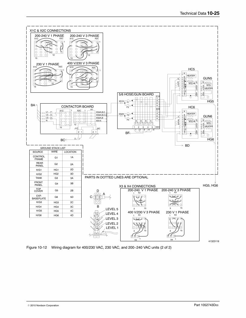
Technical Data 10-25
Part 1052743D03� 2010 Nordson Corporation
41323119
XS3A,B,C,DXS2A,B
BA
L1L2L3N
F1
F2
F3
X1C 1
15
X2C
12
XS4A,B,C
XS1A
K1
J1C J2C
12
BC
CONTACTOR BOARD
12
12
HG5, HG6
101
4
611859312
27
HEATER
RTD
HEATER
RTD
5 5
3 34 41 1
2 2G G
HC5
GUN5
HG5
F3
F4
4321
F1
F2
4321
1 2 3 4 5 X3H
X1H
X2H
XS1H
XS2H
1 2 3 4 5 101
4
611859312
27
HEATER
RTD
HEATER
RTD
5 5
3 34 41 1
2 2G G
HC6
GUN6
HG6
BD
5/6 HOSE/GUN BOARD
BF
SOURCE WIRE LOCATION
GROUND STACK LIST
CONTROLFRAME
REAR
H/G1
H/G2
TANK
FRONT
TOPCOVER
EXP.BASEPLATE
H/G3
H/G4
PANEL
PANEL
G1
G2
HG1
HG2
G3
G4
G5
G6
HG3
HG4
1A
2A
2D
3D
3A
3B
2B
5D
2C
3CLEVEL 5LEVEL 4
LEVEL 3
LEVEL 2LEVEL 1
A
B
C
D
H/G5
H/G6
HG5
HG6
4C
4D
43
8
7
5
621
1
PARTS IN DOTTED LINES ARE OPTIONAL
X1C
1
15
X2C
12
1
200-240 V 1 PHASEX1C
1
15
X2C
12
1
200-240 V 3 PHASE
X1C
1
15
X2C
12
1
230 V 1 PHASEX1C
1
15
X2C
12
1
400 V/230 V 3 PHASE
X1C & X2C CONNECTIONS
X31
15
200-240 V 3 PHASE
3
X41
X31
153
X4 1
X31
153
X31
153
200-240 V 1 PHASE
230 V 1 PHASE400 V/230 V 3 PHASE
X3 & X4 CONNECTIONS
Figure 10-12 Wiring diagram for 400/230 VAC, 230 VAC, and 200−240 VAC units (2 of 2)
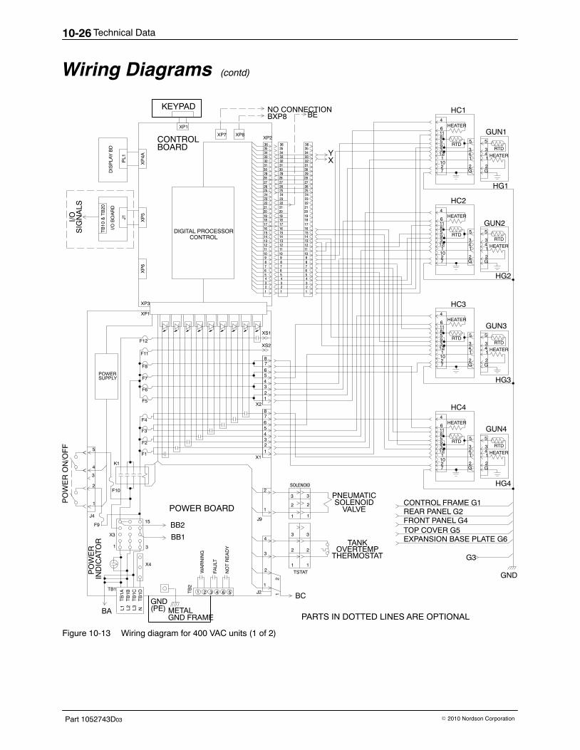
Technical Data10-26
Part 1052743D03 � 2010 Nordson Corporation
Wiring Diagrams (contd)
36
2
3
1
12
3
1
1
2
CONTROL
F12
F11
F8
F7
F6
F5 123456
8
X2
F4
F3
F2
F1
X3
1 3
L1
TB11 2 3 4 56T
B2
WA
RN
ING
FAU
LT
NO
T R
EA
DY
J2
1
2
3
4BB1
BB2
L2 L3 N
TB
1AT
B1B
TB
1CT
B1D
X4
15
PO
WE
R O
N/O
FF
K1
12345678
X1
POWER BOARD
2
TSTAT
SOLENOID
BC
J9
PNEUMATICSOLENOID
VALVE
TANKOVERTEMP
THERMOSTAT
1
2
3
4
5
6
7
8
9
10
11
12
13
14
15
16
17
18
19
20
21
22
23
24
25
26
27
28
29
30
31
32
33
34
35
DIGITAL PROCESSORCONTROL
XP
4AXP2
2
3
1
3
1
2
POWERSUPPLY
PL1
DIS
PLA
Y B
D
7
XP8
BXP8
XP3
XP1
BA
XP
5
J1
I/O B
OA
RD
XP
6
XP7
NO CONNECTION
36
1
2
3
4
5
6
7
8
9
10
11
12
13
14
15
16
17
18
19
20
21
22
23
24
25
26
27
28
29
30
31
32
33
34
35
36
1
2
3
4
5
6
7
8
9
10
11
12
13
14
15
16
17
18
19
20
21
22
23
24
25
26
27
28
29
30
31
32
33
34
35
TB
10 &
TB
20
I/OS
IGN
ALS
BOARD
XS1
XS2
101
4
611859312
27
HEATER
RTD
HEATER
RTD
5 5
3 34 41 1
2 2G G
HC1
GUN1
101
4
611859312
27
HEATER
RTD
HEATER
RTD
5 5
3 34 41 1
2 2G G
HC2
GUN2
101
4
611859312
27
HEATER
RTD
HEATER
RTD
5 5
3 34 41 1
2 2G G
HC3
GUN3
101
4
611859312
27
HEATER
RTD
HEATER
RTD
5 5
3 34 41 1
2 2G G
HC4
GUN4
HG1
HG2
HG3
HG4
BE
XY
CONTROL FRAME G1REAR PANEL G2FRONT PANEL G4 TOP COVER G5EXPANSION BASE PLATE G6
G3
GND
XP1
KEYPAD
1
J4
2
3
4
F9
F10
PO
WE
R
IND
ICA
TO
R
5
METAL GND FRAME PARTS IN DOTTED LINES ARE OPTIONAL
GND(PE)
Figure 10-13 Wiring diagram for 400 VAC units (1 of 2)
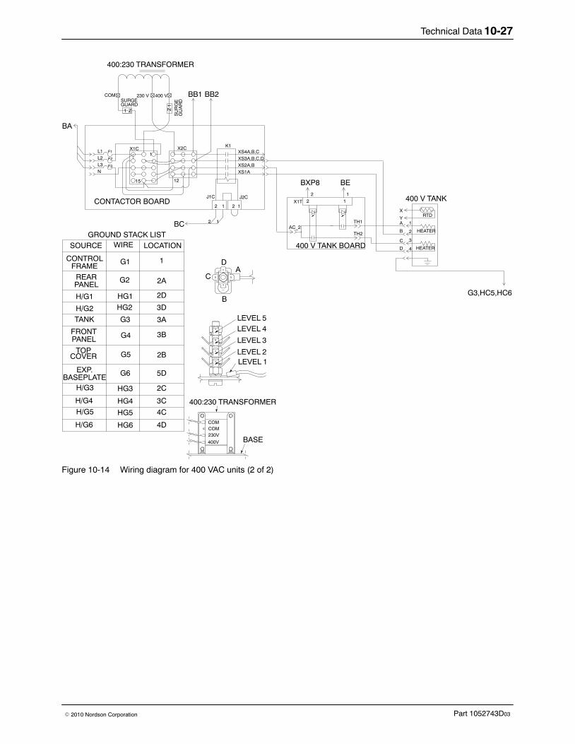
Technical Data 10-27
Part 1052743D03� 2010 Nordson Corporation
SOURCE WIRE LOCATION
GROUND STACK LIST
CONTROLFRAME
REAR
H/G1
H/G2
TANK
FRONT
TOPCOVER
EXP.BASEPLATE
H/G3
H/G4
PANEL
PANEL
G1
G2
HG1
HG2
G3
G4
G5
G6
HG3
HG4
1
2A
2D
3D
3A
3B
2B
5D
2C
3C
LEVEL 5LEVEL 4
LEVEL 3
LEVEL 2LEVEL 1
A
B
C
D
COMCOM
230V
400V
400:230 TRANSFORMER
BA
L1L2L3N
F1
F2
F3
X1C1
15
X2C
12
HEATER
RTD
HEATER
XS4A,B,CXS3A,B,C,DXS2A,BXS1A
K1
J1C J2C
12
BC
BB2BB1SURGEGUARD
COM 230 V 400 V
1 Z
CONTACTOR BOARD12
12
SU
RG
EG
UA
RD
400:230 TRANSFORMER
BXP8 BE
X1T 12
AC_2TH1
TH2
400 V TANK BOARD
X
YA
B
C
D
1
2
3
4
400 V TANK
G3,HC5,HC6
12
BASE
H/G5
H/G6
HG5
HG6
4C
4D
Z 1
Figure 10-14 Wiring diagram for 400 VAC units (2 of 2)
Technical Data10-28
Part 1052743D03 � 2010 Nordson Corporation
EC Declaration of Conformityfor Adhesive and Sealant Application Equipment
conforming to European Council Directives
PRODUCT:
Bravura� Melters
APPLICABLE DIRECTIVES:
Machinery Directive: 2006/42/ECLow Voltage Directive: 2006/95/ECElectromagnetic Compatibility Directive: 2004/108/EC
STANDARDS USED TO VERIFY COMPLIANCE:
EN ISO 12100 EN 60204-1EN ISO 13732-1 EN 61000-6-2EN 55011
PRINCIPLES:This product has been manufactured according to good engineering practice.
The product specified conforms to the directives and standards described above.
Technical File Contact:
Dieter Ziesmer
Nordson Engineering GmbH
Lilienthalstrasse 6
21337 Lueneburg
GERMANY
Date: 10/June/2010
Peter Lambert, Vice PresidentAdhesives Dispensing Systems
DOC042R5
Nordson Corporation � 28601 Clemens Road � Westlake, Ohio


Bravura AdhesiveMelters
Customer Product Manual − 1052743D03
Bravura AdhesiveMelters
Customer Product Manual − 1052743D03
Bravura AdhesiveMelters
Customer Product Manual − 1052743D03
Bravura AdhesiveMelters
Customer Product Manual − 1052743D03
Bravura AdhesiveMelters
Customer Product Manual − 1052743D03
Bravura AdhesiveMelters
Customer Product Manual − 1052743D03
Bravura AdhesiveMelters
Customer Product Manual − 1052743D03
Bravura AdhesiveMelters
Customer Product Manual − 1052743D03
Bravura AdhesiveMelters
Customer Product Manual − 1052743D03
Bravura AdhesiveMelters
Customer Product Manual − 1052743D03
Bravura AdhesiveMelters
Customer Product Manual − 1052743D03
Bravura AdhesiveMelters
Customer Product Manual − 1052743D03
Bravura AdhesiveMelters
Customer Product Manual − 1052743D03
Bravura AdhesiveMelters
Customer Product Manual − 1052743D03