Embed Size (px)
Citation preview
24 �
�
2650-613X-10Rev. B
BVA-300 Operator’s Manual
Hand Held-Accuracy with a 40 Amp Load
The BVA-300 is the a hand-held tester that is the auto industry’s answer to portability in a professionally accurate battery load tester and system analyzer.
Test Equipment Auto Meter Products Inc.
413 West Elm Street Sycamore, IL 60178
Toll Free (866) 883-TEST (8378)
Fax (815)-815-895-6786 www.autometer.com
2 23
CONGRATULATIONS!
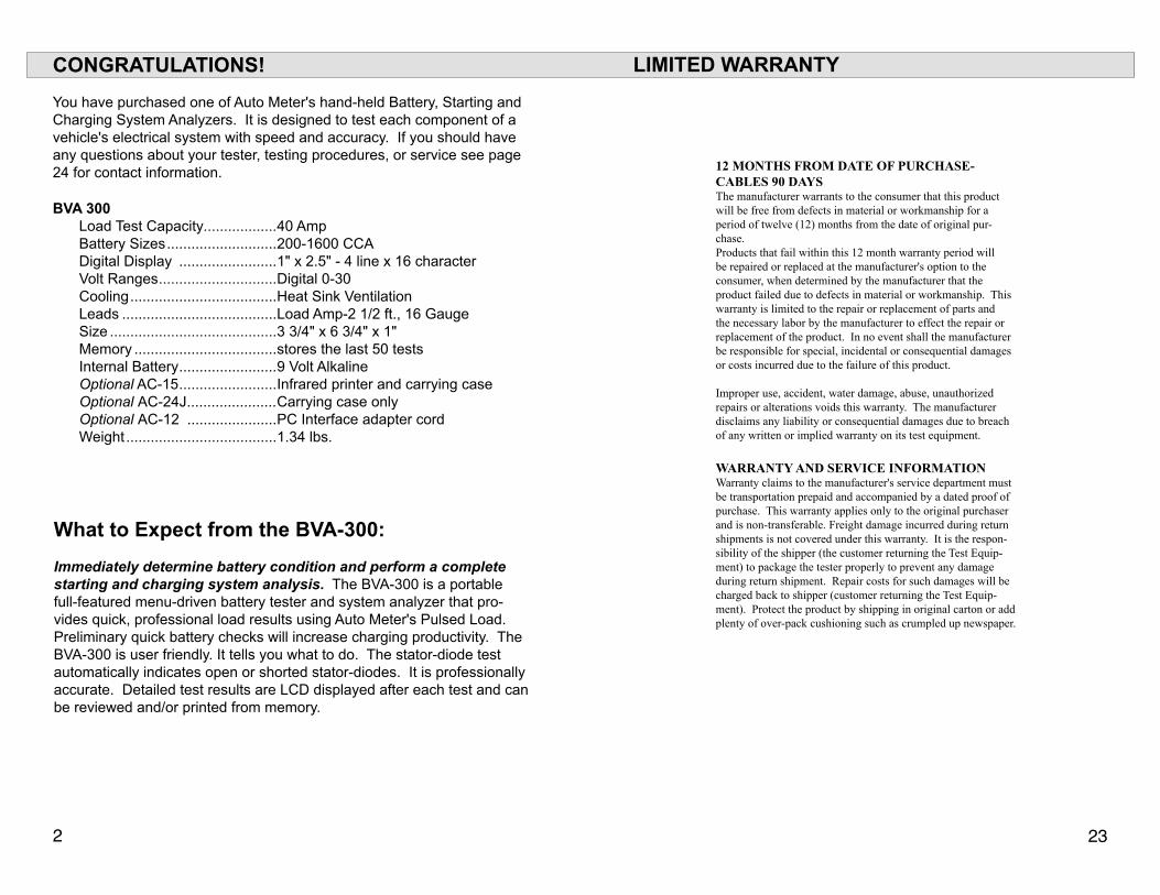
You have purchased one of Auto Meter's hand-held Battery, Starting and Charging System Analyzers. It is designed to test each component of a vehicle's electrical system with speed and accuracy. If you should have any questions about your tester, testing procedures, or service see page 24 for contact information.
BVA 300Load Test Capacity..................40 AmpBattery Sizes ...........................200-1600 CCADigital Display ........................1" x 2.5" - 4 line x 16 characterVolt Ranges .............................Digital 0-30Cooling ....................................Heat Sink VentilationLeads ......................................Load Amp-2 1/2 ft., 16 GaugeSize .........................................3 3/4" x 6 3/4" x 1"Memory ...................................stores the last 50 testsInternal Battery ........................9 Volt AlkalineOptional AC-15 ........................Infrared printer and carrying caseOptional AC-24J ......................Carrying case onlyOptional AC-12 ......................PC Interface adapter cordWeight .....................................1.34 lbs.
What to Expect from the BVA-300:
Immediately determine battery condition and perform a complete starting and charging system analysis. The BVA-300 is a portable full-featured menu-driven battery tester and system analyzer that pro-vides quick, professional load results using Auto Meter's Pulsed Load. Preliminary quick battery checks will increase charging productivity. The BVA-300 is user friendly. It tells you what to do. The stator-diode test automatically indicates open or shorted stator-diodes. It is professionally accurate. Detailed test results are LCD displayed after each test and can be reviewed and/or printed from memory.
LIMITED WARRANTY
12 MONTHS FROM DATE OF PURCHASE-CABLES 90 DAYSThe manufacturer warrants to the consumer that this product will be free from defects in material or workmanship for a period of twelve (12) months from the date of original pur-chase. Products that fail within this 12 month warranty period will be repaired or replaced at the manufacturer's option to the consumer, when determined by the manufacturer that the product failed due to defects in material or workmanship. This warranty is limited to the repair or replacement of parts and the necessary labor by the manufacturer to effect the repair or replacement of the product. In no event shall the manufacturer be responsible for special, incidental or consequential damages or costs incurred due to the failure of this product.
Improper use, accident, water damage, abuse, unauthorized repairs or alterations voids this warranty. The manufacturer disclaims any liability or consequential damages due to breach of any written or implied warranty on its test equipment.
WARRANTY AND SERVICE INFORMATIONWarranty claims to the manufacturer's service department must be transportation prepaid and accompanied by a dated proof of purchase. This warranty applies only to the original purchaser and is non-transferable. Freight damage incurred during return shipments is not covered under this warranty. It is the respon-sibility of the shipper (the customer returning the Test Equip-ment) to package the tester properly to prevent any damage during return shipment. Repair costs for such damages will be charged back to shipper (customer returning the Test Equip-ment). Protect the product by shipping in original carton or add plenty of over-pack cushioning such as crumpled up newspaper.
22 3
TABLE OF CONTENTS
Page
Specifications -------------------------------------------------------3Safety -----------------------------------------------------------------4Cause of Battery Failure -----------------------------------------4Inspection and Visual Check ------------------------------------5Controls and Functions -------------------------------------------6Maintenance --------------------------------------------------------7Clamp Replacement ----------------------------------------------7Internal Battery Replacement -----------------------------------7
Test Sections1. Hook Up ----------------------------------------------------------8
2. Battery Preliminary Check -----------------------------------9
3. Battery Load Test ---------------------------------------10 -11
4. Starter Draw Test ----------------------------------------12 -13
5. Alternator Test --------------------------------------------14 -15
6. Other Menu Items Review Tests -------------------------------------------16 Optional Printer and Case ----------------------16-17 Printing Test Results ---------------------------------17 Voltmeter ------------------------------------------------18 Setup -----------------------------------------------------18 PC Interface --------------------------------------------19 Download Test Information -------------------------20 Capturing Text into Microsoft Excel ---------------21 Warranty Information --------------------------------------------23Contact Information ---------------------------------------------24
Note: The BVA-300 performs a preliminary check, load tests 6 volt and 12 volt batteries and tests 12 Volt and 24 Volt starting and charging systems. The following examples illustrated are for a 12 Volt system. The BVA-300 automatically identifies the appropriate voltage and displays the menu selection and instruc-tions needed for that system.
NOTES
FinalEst. CCA
4 2�
SAFETY
Carefully read all operating instructions before using the BVA-300
Wear proper protection when working around batteries.
Be sure each test is complete before removing load clamps to prevent arcing and potential explosion from battery gases. Keep sparks flames, or ciga-rettes away from batteries.
Keep hair, hands, and clothing as well as tester leads and cords away from moving blades and belts.
Provide adequate ventilation to remove car exhaust.
In extremely cold temperatures, check for frozen electrolytic fluid before applying load. Do not attempt to Load Test or charge a bat-tery under 20 degrees. Allow the battery to warm to room tempera-ture before testing or charging.
Warning! Never attach the BVA-300 to a battery that is connected to any other tester or charging unit. Damage may result.
CAUSE OF BATTERY FAILURE
Incorrect Application: Wrong size battery may have inadequate cold cranking Amp rating for original vehicle specifications.
Incorrect Installation: Loose battery hold-downs cause excessive vibration, which can result in damage to the battery plates.
Improper Maintenance: Low electrolytic fluid and corrosion on bat-tery connections can greatly reduce battery life and affect battery per-formance.
Age of Battery: If the date code on the battery indicates it is old, the failure may be caused by natural causes.
Overcharging: Overcharging caused by a high voltage regulator setting or incorrect battery charging can cause excessive gassing, heat and water loss.
Undercharging: Undercharging caused by a faulty charging system or low voltage regulation can cause lead sulfate to gradually build up and crystallize on the plates greatly reducing the battery’s capacity and ability to be charged.
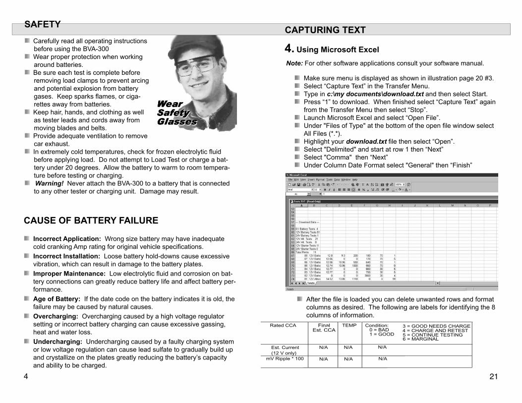
CAPTURING TEXT
Note: For other software applications consult your software manual.
After the file is loaded you can delete unwanted rows and format columns as desired. The following are labels for identifying the 8 columns of information.
4. Using Microsoft Excel
Make sure menu is displayed as shown in illustration page 20 #3. Select “Capture Text” in the Transfer Menu. Type in c:\my documents\download.txt and then select Start. Press “1” to download. When finished select “Capture Text” again from the Transfer Menu then select “Stop”.
Launch Microsoft Excel and select “Open File”. Under "Files of Type" at the bottom of the open file window select All Files (*.*).
Highlight your download.txt file then select “Open”. Select "Delimited" and start at row 1 then “Next” Select "Comma" then “Next” Under Column Date Format select "General" then “Finish”
FinalEst. CCA
20 �
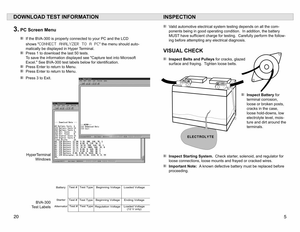
INSPECTION
Valid automotive electrical system testing depends on all the com-ponents being in good operating condition. In addition, the battery MUST have sufficient charge for testing. Carefully perform the follow-ing before attempting any electrical diagnosis.
VISUAL CHECK Inspect Belts and Pulleys for cracks, glazed
surface and fraying. Tighten loose belts.
Inspect Battery for terminal corrosion, loose or broken posts, cracks in the case, loose hold-downs, low electrolyte level, mois-ture and dirt around the terminals.
Inspect Starting System. Check starter, solenoid, and regulator for loose connections, loose mounts and frayed or cracked wires.
Important Note: A known defective battery must be replaced before proceeding.
DOWNLOAD TEST INFORMATION
3. PC Screen Menu
If the BVA-300 is properly connected to your PC and the LCD
shows "CONNECT ANALYZER TO A PC" the menu should auto-matically be displayed in Hyper Terminal.
Press 1 to download the last 50 tests. To save the information displayed see "Capture text into Microsoft Excel." See BVA-300 test labels below for identification.
Press Enter to return to Menu. Press Enter to return to Menu.
Press 3 to Exit.
HyperTerminal Windows
BVA-300 Test Labels
AUTO METERBVA-300
SYSTEM ANALYZERREADY TO CONNECT
� �9
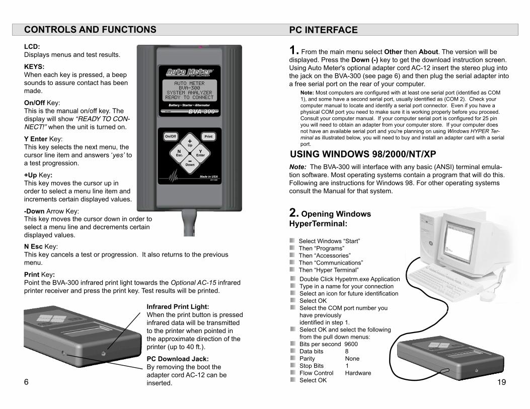
CONTROLS AND FUNCTIONS
LCD: Displays menus and test results.
KEYS: When each key is pressed, a beep sounds to assure contact has been made.
On/Off Key: This is the manual on/off key. The display will show “Ready to Con-neCt!” when the unit is turned on.
Y Enter Key: This key selects the next menu, the cursor line item and answers ‘yes’ to a test progression.
+Up Key: This key moves the cursor up in order to select a menu line item and increments certain displayed values.
-Down Arrow Key:
N Esc Key: This key cancels a test or progression. It also returns to the previous menu.
Print Key: Point the BVA-300 infrared print light towards the Optional AC-15 infrared printer receiver and press the print key. Test results will be printed.
Infrared Print Light: When the print button is pressed infrared data will be transmitted to the printer when pointed in the approximate direction of the printer (up to 40 ft.).
PC Download Jack: By removing the boot the adapter cord AC-12 can be inserted.
USING WINDOWS 98/2000/NT/XP
2. Opening Windows HyperTerminal:
Select Windows “Start” Then “Programs” Then “Accessories” Then “Communications” Then “Hyper Terminal”
Double Click Hypetrm.exe Application Type in a name for your connection Select an icon for future identification Select OK Select the COM port number you
have previously identified in step 1.
Select OK and select the following from the pull down menus:
Bits per second 9600 Data bits 8 Parity None Stop Bits 1 Flow Control Hardware Select OK
PC INTERFACE
1. From the main menu select Other then About. The version will be displayed. Press the Down (-) key to get the download instruction screen. Using Auto Meter's optional adapter cord AC-12 insert the stereo plug into the jack on the BVA-300 (see page 6) and then plug the serial adapter into a free serial port on the rear of your computer.
Note: Most computers are configured with at least one serial port (identified as COM 1), and some have a second serial port, usually identified as (COM 2). Check your computer manual to locate and identify a serial port connector. Even if you have a physical COM port you need to make sure it is working properly before you proceed. Consult your computer manual. If your computer serial port is configured for 25 pin you will need to obtain an adapter from your computer store. If your computer does not have an available serial port and you're planning on using Windows HYPER Ter-minal as illustrated below, you will need to buy and install an adapter card with a serial port.
Note: The BVA-300 will interface with any basic (ANSI) terminal emula-tion software. Most operating systems contain a program that will do this. Following are instructions for Windows 98. For other operating systems consult the Manual for that system.
This key moves the cursor down in order to select a menu line and decrements certain displayed values.
�8 �
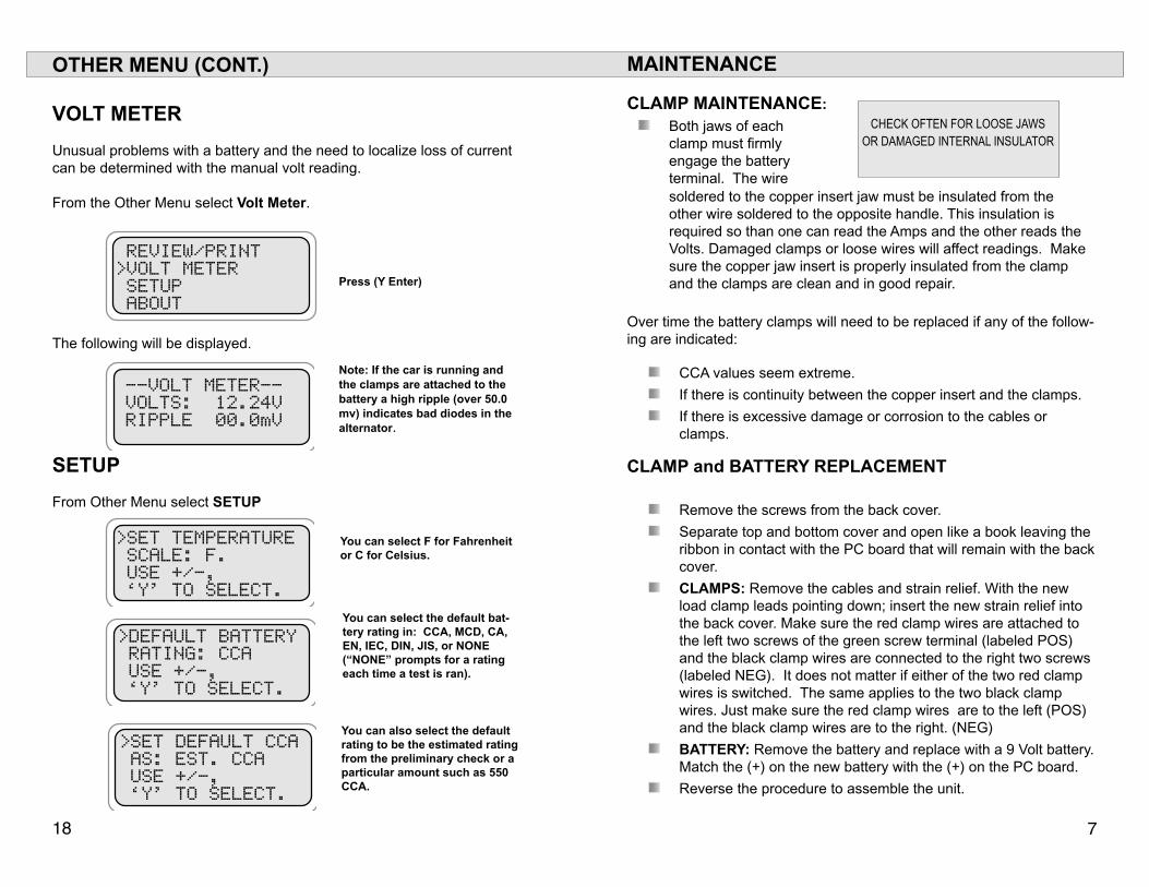
MAINTENANCE
CLAMP MAINTENANCE:
Both jaws of each clamp must firmly engage the battery terminal. The wire
CHECK OFTEN FOR LOOSE JAWS OR DAMAGED INTERNAL INSULATOR
Over time the battery clamps will need to be replaced if any of the follow-ing are indicated:
CCA values seem extreme.
If there is continuity between the copper insert and the clamps.
If there is excessive damage or corrosion to the cables or clamps.
CLAMP and BATTERY REPLACEMENT
Remove the screws from the back cover.
Separate top and bottom cover and open like a book leaving the ribbon in contact with the PC board that will remain with the back cover.
CLAMPS: Remove the cables and strain relief. With the new load clamp leads pointing down; insert the new strain relief into the back cover. Make sure the red clamp wires are attached to the left two screws of the green screw terminal (labeled POS) and the black clamp wires are connected to the right two screws (labeled NEG). It does not matter if either of the two red clamp wires is switched. The same applies to the two black clamp wires. Just make sure the red clamp wires are to the left (POS) and the black clamp wires are to the right. (NEG)
BATTERY: Remove the battery and replace with a 9 Volt battery. Match the (+) on the new battery with the (+) on the PC board.
Reverse the procedure to assemble the unit.
soldered to the copper insert jaw must be insulated from the other wire soldered to the opposite handle. This insulation is required so than one can read the Amps and the other reads the Volts. Damaged clamps or loose wires will affect readings. Make sure the copper jaw insert is properly insulated from the clamp and the clamps are clean and in good repair.
OTHER MENU (CONT.)
VOLT METER
Unusual problems with a battery and the need to localize loss of current can be determined with the manual volt reading.
From the Other Menu select Volt Meter.
Press (Y Enter)
The following will be displayed.
Note: If the car is running and the clamps are attached to the battery a high ripple (over 50.0 mv) indicates bad diodes in the alternator.
REVIEW/PRINT >VOLT METER SETUP ABOUT
--VOLT METER--VOLTS: 12.24VRIPPLE 00.0mV
SETUP
From Other Menu select SETUP
You can select F for Fahrenheit or C for Celsius.
You can select the default bat-tery rating in: CCA, MCD, CA, EN, IEC, DIN, JIS, or NONE (“NONE” prompts for a rating each time a test is ran).
You can also select the default rating to be the estimated rating from the preliminary check or a particular amount such as 550 CCA.
>SET TEMPERATURE SCALE: F. USE +/-, ‘Y’ TO SELECT.
>DEFAULT BATTERY RATING: CCA USE +/-, ‘Y’ TO SELECT.
>SET DEFAULT CCA AS: EST. CCA USE +/-, ‘Y’ TO SELECT.
8 ��
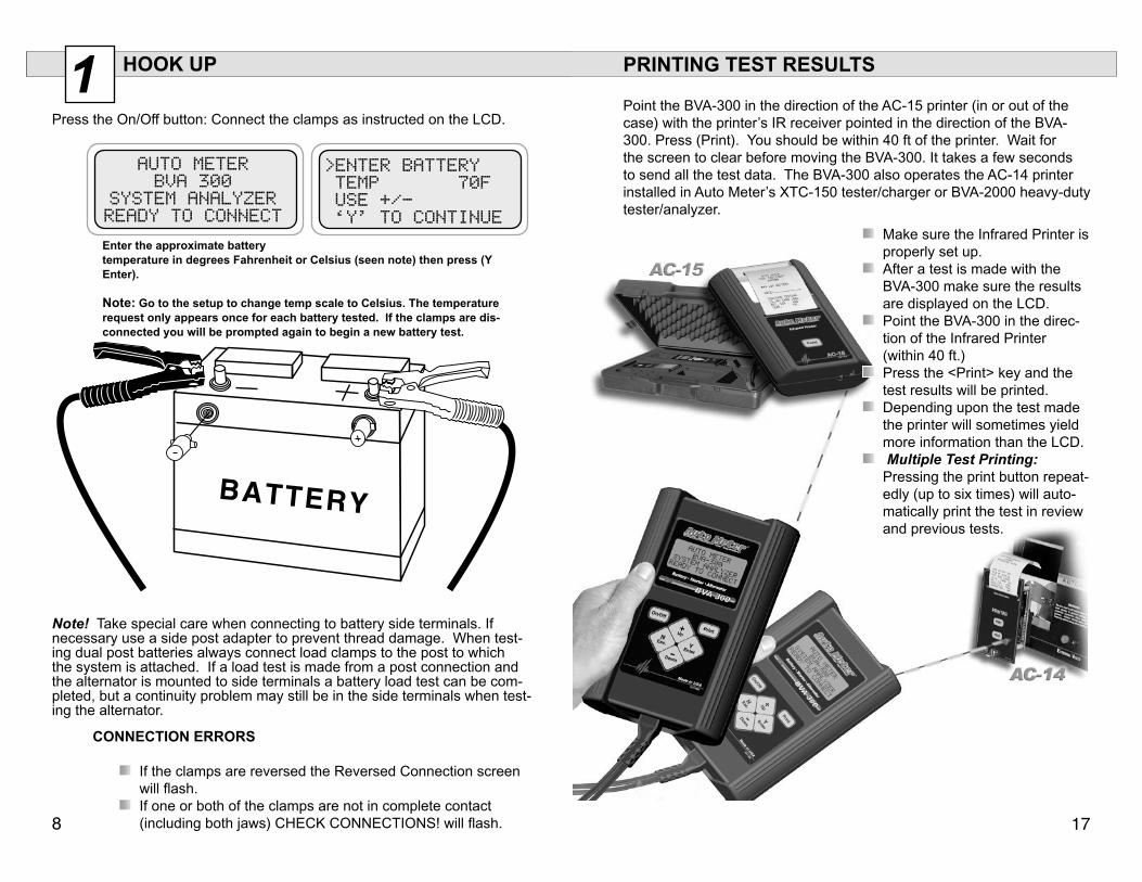
1 HOOK UP
Press the On/Off button: Connect the clamps as instructed on the LCD.
Enter the approximate battery temperature in degrees Fahrenheit or Celsius (seen note) then press (Y Enter).
Note: Go to the setup to change temp scale to Celsius. The temperature request only appears once for each battery tested. If the clamps are dis-connected you will be prompted again to begin a new battery test.
Note! Take special care when connecting to battery side terminals. If necessary use a side post adapter to prevent thread damage. When test-ing dual post batteries always connect load clamps to the post to which the system is attached. If a load test is made from a post connection and the alternator is mounted to side terminals a battery load test can be com-pleted, but a continuity problem may still be in the side terminals when test-ing the alternator.
CONNECTION ERRORS
If the clamps are reversed the Reversed Connection screen will flash.
If one or both of the clamps are not in complete contact (including both jaws) CHECK CONNECTIONS! will flash.
Make sure the Infrared Printer is properly set up.
After a test is made with the BVA-300 make sure the results are displayed on the LCD.
Point the BVA-300 in the direc-tion of the Infrared Printer (within 40 ft.)
Press the <Print> key and the test results will be printed.
Depending upon the test made the printer will sometimes yield more information than the LCD.
Multiple Test Printing: Pressing the print button repeat-edly (up to six times) will auto-matically print the test in review and previous tests.
PRINTING TEST RESULTS Point the BVA-300 in the direction of the AC-15 printer (in or out of the case) with the printer’s IR receiver pointed in the direction of the BVA-300. Press (Print). You should be within 40 ft of the printer. Wait for the screen to clear before moving the BVA-300. It takes a few seconds to send all the test data. The BVA-300 also operates the AC-14 printer installed in Auto Meter’s XTC-150 tester/charger or BVA-2000 heavy-duty tester/analyzer.
AUTO METERBVA 300
SYSTEM ANALYZER READY TO CONNECT
>ENTER BATTERY TEMP 70F USE +/- ‘Y’ TO CONTINUE
�� 9
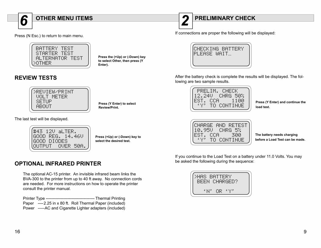
2 PRELIMINARY CHECK
If connections are proper the following will be displayed:
After the battery check is complete the results will be displayed. The fol-lowing are two sample results.
Press (Y Enter) and continue the
load test.
The battery needs charging
before a Load Test can be made.
6 OTHER MENU ITEMS
Press (N Esc.) to return to main menu.
Press the (+Up) or (-Down) key to select Other, then press (Y Enter).
REVIEW TESTS
Press (Y Enter) to select Review/Print.
The last test will be displayed.
Press (+Up) or (-Down) key to select the desired test.
The optional AC-15 printer. An invisible infrared beam links the BVA-300 to the printer from up to 40 ft away. No connection cords are needed. For more instructions on how to operate the printer consult the printer manual.
Printer Type ------------------------------------ Thermal PrintingPaper ----2.25 in x 80 ft. Roll Thermal Paper (included)Power -----AC and Cigarette Lighter adapters (included)
OPTIONAL INFRARED PRINTER
If you continue to the Load Test on a battery under 11.0 Volts. You may be asked the following during the sequence:
CHECKING BATTERY PLEASE WAIT…
PRELIM. CHECK 12.24V CHRG 50% EST. CCA 1100 ‘Y’ TO CONTINUE
CHARGE AND RETEST 10.95V CHRG 5% EST. CCA 300 ‘Y’ TO CONTINUE
BATTERY TEST STARTER TEST ALTERNATOR TEST >OTHER
>REVIEW/PRINT VOLT METER SETUP ABOUT
#43 12V aLTER.GOOD REG. 14.46VGOOD DIODES OUTPUT OVER 50A.
>HAS BATTERY BEEN CHARGED? ‘N’ OR ‘Y’
�0 ��
3 BATTERY LOAD TEST
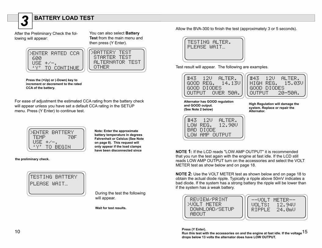
After the Preliminary Check the fol-lowing will appear:
You can also select Battery Test from the main menu and then press (Y Enter).
Note: Enter the approximate battery temperature in degrees Fahrenheit or Celsius (See Note on page 8). This request will only appear if the load clamps have been disconnected since
the preliminary check.
During the test the following will appear.
Wait for test results.
Allow the BVA-300 to finish the test (approximately 3 or 5 seconds).
Test result will appear. The following are examples.
Alternator has GOOD regulation and GOOD output. (See Note 2 below)
High Regulation will damage the system. Replace or repair the
NOTE 1: If the LCD reads "LOW AMP OUTPUT" it is recommended that you run the test again with the engine at fast idle. If the LCD still reads LOW AMP OUTPUT turn on the accessories and select the VOLT METER test as show below and on page 18.
NOTE 2: Use the VOLT METER test as shown below and on page 18 to obtain the actual diode ripple. Typically a ripple above 50mV indicates a bad diode. If the system has a strong battery the ripple will be lower than if the system has a weak battery.
Press (Y Enter).Run this test with the accessories on and the engine at fast idle. If the voltage drops below 13 volts the alternator does have LOW OUTPUT.
Alternator.
For ease of adjustment the estimated CCA rating from the battery check will appear unless you have set a default CCA rating in the SETUP menu. Press (Y Enter) to continue test.
Press the (+Up) or (-Down) key to increment or decrement to the rated CCA of the battery.
>BATTERY TEST STARTER TEST ALTERNATOR TEST OTHER
>ENTER RATED CCA 600 USE +/-. ‘Y’ TO CONTINUE
>ENTER BATTERY TEMP 70F USE +/-. ‘Y’ TO BEGIN
TESTING BATTERY PLEASE WAIT…
TESTING ALTER. PLEASE WAIT…
#43 12V ALTER. GOOD REG. 14.13V GOOD DIODES OUTPUT OVER 50A.
#43 12V ALTER. LOW REG. 12.90V BAD DIODE LOW AMP OUTPUT
REVIEW/PRINT >VOLT METER DOWNLOAD/SETUP ABOUT
#43 12V ALTER. HIGH REG. 15.03V GOOD DIODES OUTPUT 20-50A.
--VOLT METER-- VOLTS: 12.94V RIPPLE 24.0mV
�4 ��
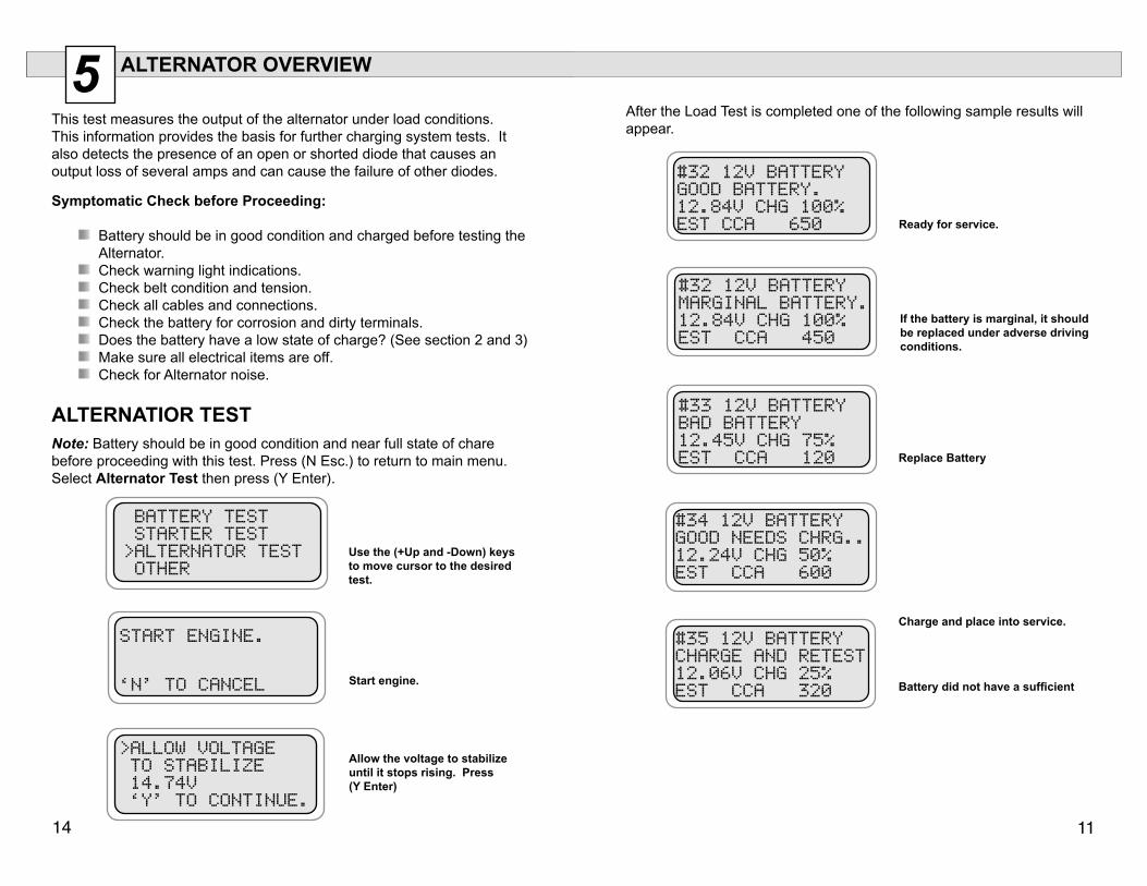
After the Load Test is completed one of the following sample results will appear.
Ready for service.
If the battery is marginal, it should be replaced under adverse driving conditions.
Replace Battery
Charge and place into service.
Battery did not have a sufficient
5 ALTERNATOR OVERVIEW
This test measures the output of the alternator under load conditions. This information provides the basis for further charging system tests. It also detects the presence of an open or shorted diode that causes an output loss of several amps and can cause the failure of other diodes.
Symptomatic Check before Proceeding:
Battery should be in good condition and charged before testing the Alternator.
Check warning light indications. Check belt condition and tension. Check all cables and connections. Check the battery for corrosion and dirty terminals. Does the battery have a low state of charge? (See section 2 and 3) Make sure all electrical items are off. Check for Alternator noise.
ALTERNATIOR TEST
Use the (+Up and -Down) keys to move cursor to the desired test.
Start engine.
Allow the voltage to stabilize until it stops rising. Press (Y Enter)
Note: Battery should be in good condition and near full state of chare before proceeding with this test. Press (N Esc.) to return to main menu. Select Alternator Test then press (Y Enter).
#32 12V BATTERYGOOD BATTERY.12.84V CHG 100%EST CCA 650
#33 12V BATTERYBAD BATTERY12.45V CHG 75%EST CCA 120
#34 12V BATTERYGOOD NEEDS CHRG..12.24V CHG 50%EST CCA 600
#35 12V BATTERYCHARGE AND RETEST12.06V CHG 25%EST CCA 320
#32 12V BATTERYMARGINAL BATTERY.12.84V CHG 100%EST CCA 450
BATTERY TEST STARTER TEST >ALTERNATOR TEST OTHER
>ALLOW VOLTAGE TO STABILIZE 14.74V ‘Y’ TO CONTINUE.
START ENGINE.
‘N’ TO CANCEL
�2 �3
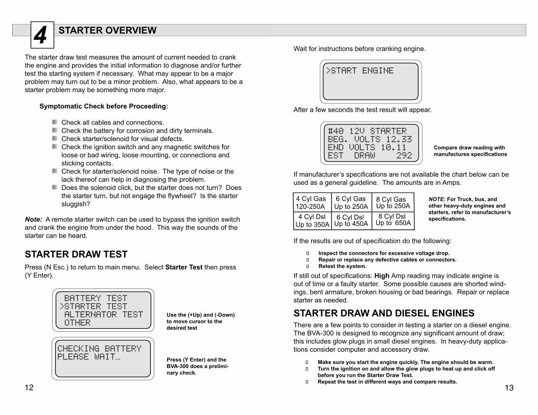
4 STARTER OVERVIEW
The starter draw test measures the amount of current needed to crank the engine and provides the initial information to diagnose and/or further test the starting system if necessary. What may appear to be a major problem may turn out to be a minor problem. Also, what appears to be a starter problem may be something more major.
Symptomatic Check before Proceeding:
Check all cables and connections. Check the battery for corrosion and dirty terminals. Check starter/solenoid for visual defects. Check the ignition switch and any magnetic switches for loose or bad wiring, loose mounting, or connections and sticking contacts.
Check for starter/solenoid noise. The type of noise or the lack thereof can help in diagnosing the problem.
Does the solenoid click, but the starter does not turn? Does the starter turn, but not engage the flywheel? Is the starter sluggish?
Note: A remote starter switch can be used to bypass the ignition switch and crank the engine from under the hood. This way the sounds of the starter can be heard.
STARTER DRAW TESTPress (N Esc.) to return to main menu. Select Starter Test then press (Y Enter).
Press (Y Enter) and the BVA-300 does a prelimi-nary check.
Use the (+Up) and (-Down) to move cursor to the desired test
Wait for instructions before cranking engine.
After a few seconds the test result will appear.
Compare draw reading with manufactures specifications
If manufacturer’s specifications are not available the chart below can be used as a general guideline. The amounts are in Amps.
NOTE: For Truck, bus, and other heavy-duty engines and starters, refer to manufacturer’s specifications.
If still out of specifications: High Amp reading may indicate engine is out of time or a faulty starter. Some possible causes are shorted wind-ings, bent armature, broken housing or bad bearings. Repair or replace starter as needed.
If the results are out of specification do the following:
Inspect the connectors for excessive voltage drop. Repair or replace any defective cables or connectors. Retest the system.
STARTER DRAW AND DIESEL ENGINES There are a few points to consider in testing a starter on a diesel engine. The BVA-300 is designed to recognize any significant amount of draw; this includes glow plugs in small diesel engines. In heavy-duty applica-tions consider computer and accessory draw.
Make sure you start the engine quickly. The engine should be warm. Turn the ignition on and allow the glow plugs to heat up and click off
before you run the Starter Draw Test. Repeat the test in different ways and compare results.
BATTERY TEST>STARTER TEST ALTERNATOR TEST OTHER
CHECKING BATTERYPLEASE WAIT…
650A
>START ENGINE
#40 12V STARTERBEG. VOLTS 12.33END VOLTS 10.11EST DRAW 292