Embed Size (px)
Citation preview

Dockingline | Connectors for Automatic Systems
Connectors for robot tool changers
2 Connectors for robot tool changers
Content
Page 3 The concept
Page 4 High Power
■ FL3...2+PE-RF-ECO
■ FL3...2+PE...
Page 8 Signal
■ FL3...24+PE...
■ FL3...36+PE...
Page 10 BUS
■ FL3...BUS...
■ BUS signal transmission in Cu technology
■ Derating diagrams
Page 14 Assembly tool
Accessories
Special tool
Installation conditions
Copyright
The use of this catalogue for any other
purpose, in whatever form, without our prior
written consent is not permitted.
Explanation of symbols
MAIch bin eine Montageanleitung.
Man sollte mich unbedingt le-
sen, bevor man das Produkt ver-
wendet! Ich beinhalte wertvolle
Hinweise zur korrekten Montage
und zum richtigen Einsatz des
Produktes. Im Moment ist die
Schrift zwar ein bischen klein,
aber später geht das dann ganz
gut zu lesen, da die MA dann
The assembly instruction MA000 is
available for this product
Surface Ag
Surface Au

Connectors for robot tool changers 3
FL3-BUS-VT-36+PE-S
FL3-VT-2+PE-SD8 PA
HTC 300
Stäubli FL3 plug connectors are designed
for use in automatic tool changers.
FL3-High Power and FL3-BUS are extremely
service friendly due to the rapid contact
carrier changing system.
The concept
Interchangeable contact inserts (rapid changing)
With metric threads or PG
Principal characteristics:
■ Low profile construction
■ Small dimensions
■ Uniform housing standard
■ Rapid changing of contact inserts
■ Wide range of applications
4 Connectors for robot tool changers
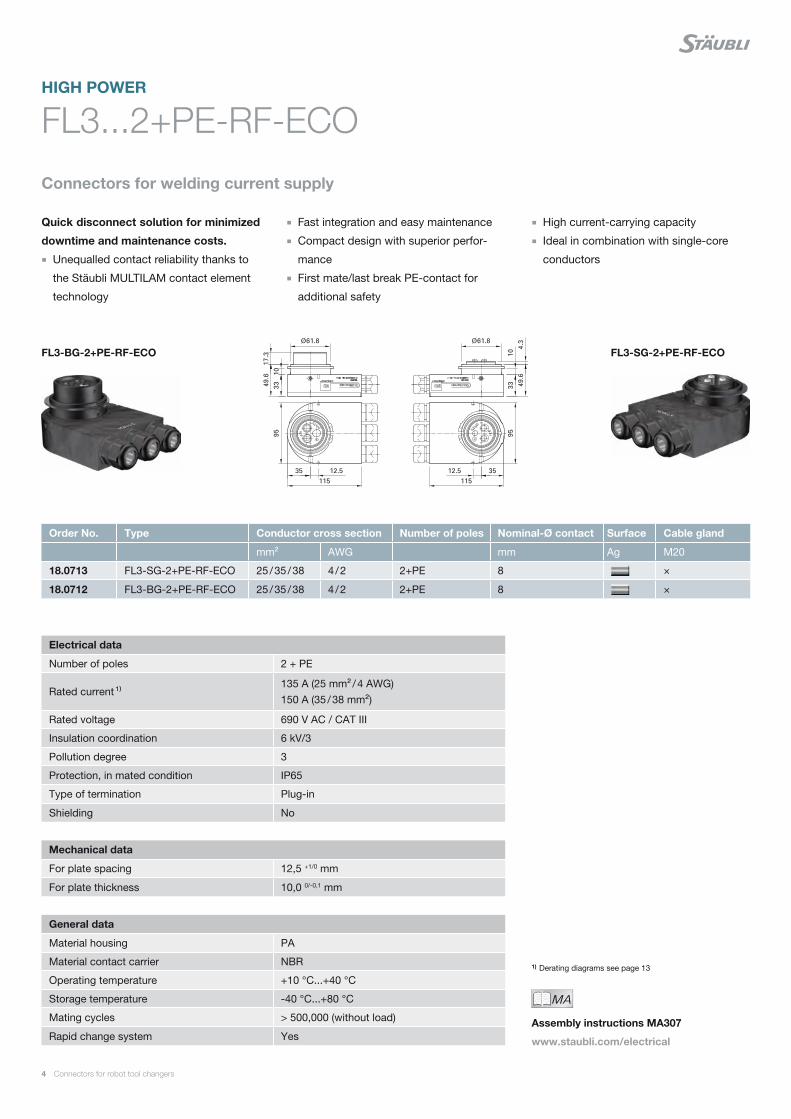
FL3...2+PE-RF-ECO
Quick disconnect solution for minimized
downtime and maintenance costs.
■ Unequalled contact reliability thanks to
the Stäubli MULTILAM contact element
technology
1) Derating diagrams see page 13
HIGH POWER
Electrical data
Number of poles 2 + PE
Rated current ¹⁾135 A (25 mm² / 4 AWG) 150 A (35 / 38 mm²)
Rated voltage 690 V AC / CAT III
Insulation coordination 6 kV/3
Pollution degree 3
Protection, in mated condition IP65
Type of termination Plug-in
Shielding No
Mechanical data
For plate spacing 12,5 +1/0 mm
For plate thickness 10,0 0/-0,1 mm
General data
Material housing PA
Material contact carrier NBR
Operating temperature +10 °C...+40 °C
Storage temperature -40 °C...+80 °C
Mating cycles > 500,000 (without load)
Rapid change system Yes
Order No. Type Conductor cross section Number of poles Nominal-Ø contact Surface Cable gland
mm² AWG mm Ag M20
18.0713 FL3-SG-2+PE-RF-ECO 25 / 35 / 38 4 / 2 2+PE 8 ×
18.0712 FL3-BG-2+PE-RF-ECO 25 / 35 / 38 4 / 2 2+PE 8 ×
Connectors for welding current supply
■ Fast integration and easy maintenance
■ Compact design with superior perfor-
mance
■ First mate/last break PE-contact for
additional safety
■ High current-carrying capacity
■ Ideal in combination with single-core
conductors
FL3-BG-2+PE-RF-ECO FL3-SG-2+PE-RF-ECO
MAIch bin eine Montageanleitung.
Man sollte mich unbedingt le-
sen, bevor man das Produkt ver-
wendet! Ich beinhalte wertvolle
Hinweise zur korrekten Montage
und zum richtigen Einsatz des
Produktes. Im Moment ist die
Schrift zwar ein bischen klein,
aber später geht das dann ganz
gut zu lesen, da die MA dann
Assembly instructions MA307
www.staubli.com/electrical
Connectors for robot tool changers 5
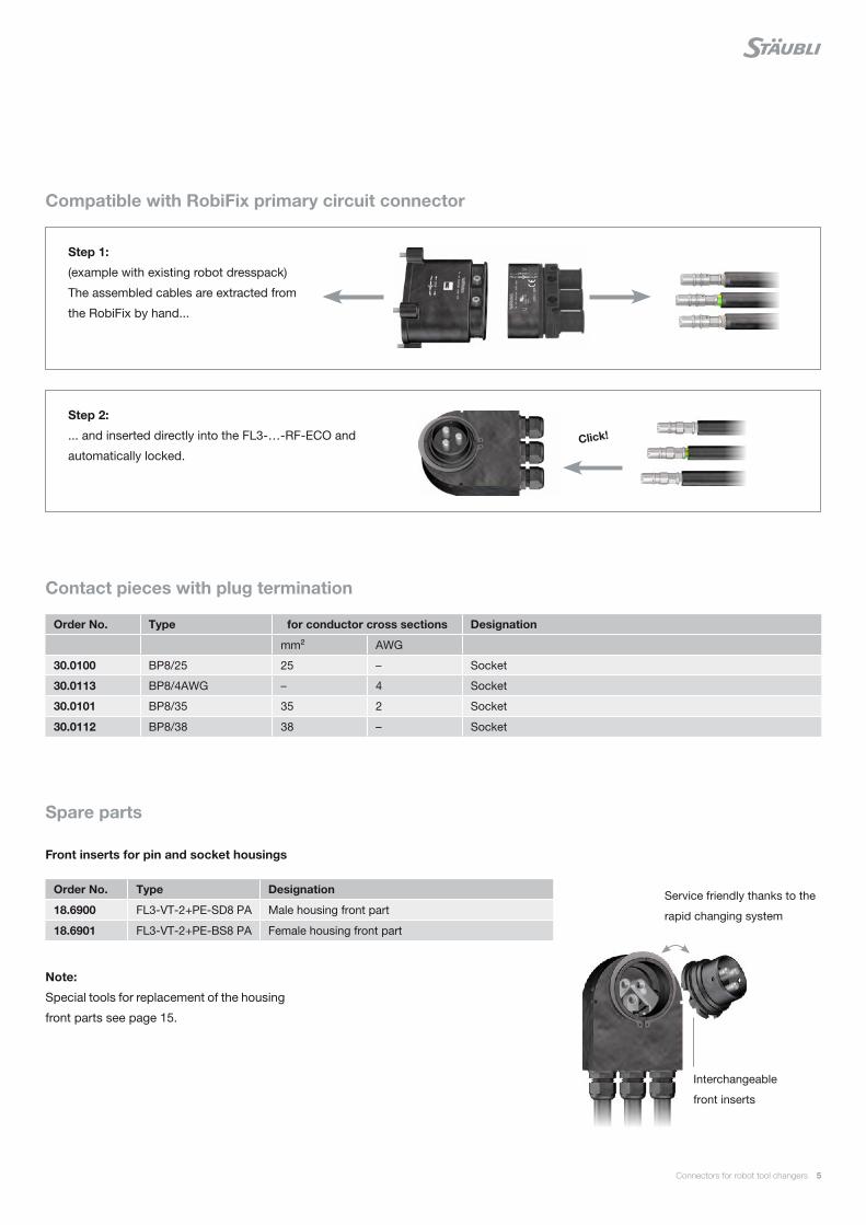
Compatible with RobiFix primary circuit connector
Contact pieces with plug termination
Spare parts
Front inserts for pin and socket housings
Note:
Special tools for replacement of the housing
front parts see page 15.
Order No. Type for conductor cross sections Designation
mm² AWG
30.0100 BP8/25 25 – Socket
30.0113 BP8/4AWG – 4 Socket
30.0101 BP8/35 35 2 Socket
30.0112 BP8/38 38 – Socket
Order No. Type Designation
18.6900 FL3-VT-2+PE-SD8 PA Male housing front part
18.6901 FL3-VT-2+PE-BS8 PA Female housing front part
Step 1:
(example with existing robot dresspack)
The assembled cables are extracted from
the RobiFix by hand...
Step 2:
... and inserted directly into the FL3-…-RF-ECO and
automatically locked.
Service friendly thanks to the
rapid changing system
Interchangeable
front inserts
Click!
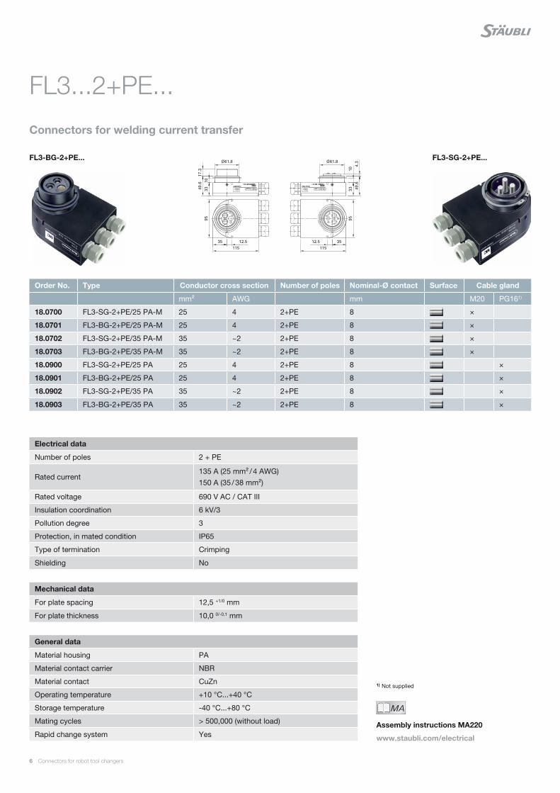
6 Connectors for robot tool changers
FL3-BG-2+PE... FL3-SG-2+PE...
Connectors for welding current transfer
Order No. Type Conductor cross section Number of poles Nominal-Ø contact Surface Cable gland
mm² AWG mm M20 PG161)
18.0700 FL3-SG-2+PE/25 PA-M 25 4 2+PE 8 ×
18.0701 FL3-BG-2+PE/25 PA-M 25 4 2+PE 8 ×
18.0702 FL3-SG-2+PE/35 PA-M 35 ~2 2+PE 8 ×
18.0703 FL3-BG-2+PE/35 PA-M 35 ~2 2+PE 8 ×
18.0900 FL3-SG-2+PE/25 PA 25 4 2+PE 8 ×
18.0901 FL3-BG-2+PE/25 PA 25 4 2+PE 8 ×
18.0902 FL3-SG-2+PE/35 PA 35 ~2 2+PE 8 ×
18.0903 FL3-BG-2+PE/35 PA 35 ~2 2+PE 8 ×
FL3...2+PE...
1) Not supplied
Electrical data
Number of poles 2 + PE
Rated current135 A (25 mm² / 4 AWG) 150 A (35 / 38 mm²)
Rated voltage 690 V AC / CAT III
Insulation coordination 6 kV/3
Pollution degree 3
Protection, in mated condition IP65
Type of termination Crimping
Shielding No
Mechanical data
For plate spacing 12,5 +1/0 mm
For plate thickness 10,0 0/-0,1 mm
General data
Material housing PA
Material contact carrier NBR
Material contact CuZn
Operating temperature +10 °C...+40 °C
Storage temperature -40 °C...+80 °C
Mating cycles > 500,000 (without load)
Rapid change system Yes
MAIch bin eine Montageanleitung.
Man sollte mich unbedingt le-
sen, bevor man das Produkt ver-
wendet! Ich beinhalte wertvolle
Hinweise zur korrekten Montage
und zum richtigen Einsatz des
Produktes. Im Moment ist die
Schrift zwar ein bischen klein,
aber später geht das dann ganz
gut zu lesen, da die MA dann
Assembly instructions MA220
www.staubli.com/electrical
Connectors for robot tool changers 7
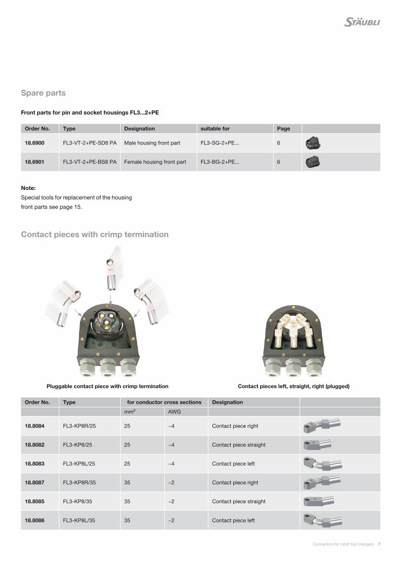
Front parts for pin and socket housings FL3...2+PE
Contact pieces with crimp termination
Note:
Special tools for replacement of the housing
front parts see page 15.
Order No. Type Designation suitable for Page
18.6900 FL3-VT-2+PE-SD8 PA Male housing front part FL3-SG-2+PE... 6
18.6901 FL3-VT-2+PE-BS8 PA Female housing front part FL3-BG-2+PE... 6
Order No. Type for conductor cross sections Designation
mm² AWG
18.8084 FL3-KP8R/25 25 ~4 Contact piece right
18.8082 FL3-KP8/25 25 ~4 Contact piece straight
18.8083 FL3-KP8L/25 25 ~4 Contact piece left
18.8087 FL3-KP8R/35 35 ~2 Contact piece right
18.8085 FL3-KP8/35 35 ~2 Contact piece straight
18.8086 FL3-KP8L/35 35 ~2 Contact piece left
Contact pieces left, straight, right (plugged)Pluggable contact piece with crimp termination
Spare parts
8 Connectors for robot tool changers
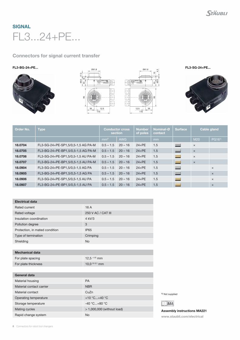
Connectors for signal current transfer
FL3...24+PE...
1) Not supplied
Electrical data
Rated current 16 A
Rated voltage 250 V AC / CAT III
Insulation coordination 4 kV/3
Pollution degree 3
Protection, in mated condition IP65
Type of termination Crimping
Shielding No
Mechanical data
For plate spacing 12,5 +1/0 mm
For plate thickness 10,0 0/-0,1 mm
General data
Material housing PA
Material contact carrier NBR
Material contact CuZn
Operating temperature +10 °C...+40 °C
Storage temperature -40 °C...+80 °C
Mating cycles > 1,000,000 (without load)
Rapid change system No
SIGNAL
Order No. Type Conductor cross section
Number of poles
Nominal-Ø contact
Surface Cable gland
mm² AWG mm M20 PG161)
18.0704 FL3-SG-24+PE-SP1,5/0,5-1,5 AG PA-M 0.5 – 1.5 20 – 16 24+PE 1.5 ×
18.0705 FL3-BG-24+PE-BP1,5/0,5-1,5 AG PA-M 0.5 – 1.5 20 – 16 24+PE 1.5 ×
18.0706 FL3-SG-24+PE-SP1,5/0,5-1,5 AU PA-M 0.5 – 1.5 20 – 16 24+PE 1.5 ×
18.0707 FL3-BG-24+PE-BP1,5/0,5-1,5 AU PA-M 0.5 – 1.5 20 – 16 24+PE 1.5 ×
18.0904 FL3-SG-24+PE-SP1,5/0,5-1,5 AG PA 0.5 – 1.5 20 – 16 24+PE 1.5 ×
18.0905 FL3-BG-24+PE-BP1,5/0,5-1,5 AG PA 0.5 – 1.5 20 – 16 24+PE 1.5 ×
18.0906 FL3-SG-24+PE-SP1,5/0,5-1,5 AU PA 0.5 – 1.5 20 – 16 24+PE 1.5 ×
18.0907 FL3-BG-24+PE-BP1,5/0,5-1,5 AU PA 0.5 – 1.5 20 – 16 24+PE 1.5 ×
FL3-BG-24+PE... FL3-SG-24+PE...
MAIch bin eine Montageanleitung.
Man sollte mich unbedingt le-
sen, bevor man das Produkt ver-
wendet! Ich beinhalte wertvolle
Hinweise zur korrekten Montage
und zum richtigen Einsatz des
Produktes. Im Moment ist die
Schrift zwar ein bischen klein,
aber später geht das dann ganz
gut zu lesen, da die MA dann
Assembly instructions MA221
www.staubli.com/electrical
Connectors for robot tool changers 9
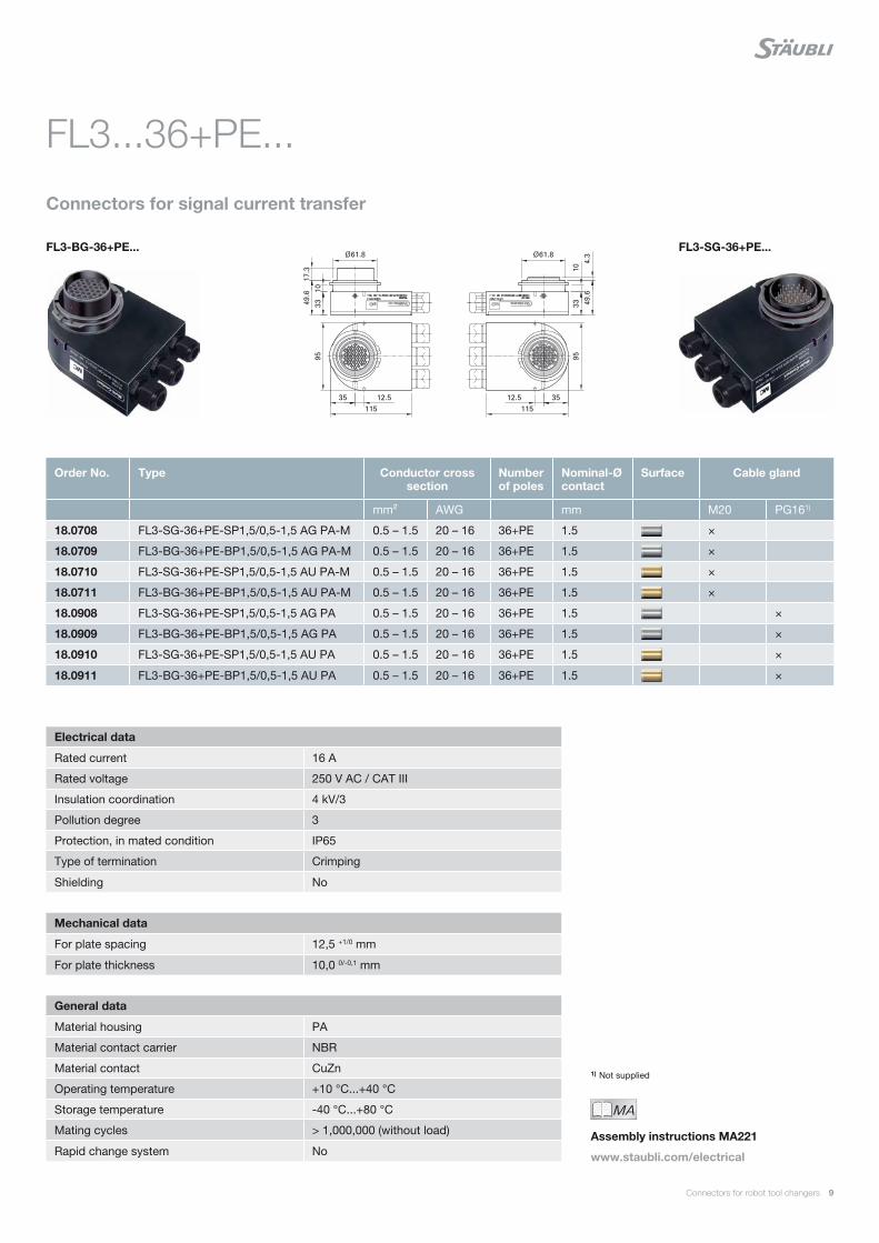
Connectors for signal current transfer
FL3...36+PE...
1) Not supplied
Electrical data
Rated current 16 A
Rated voltage 250 V AC / CAT III
Insulation coordination 4 kV/3
Pollution degree 3
Protection, in mated condition IP65
Type of termination Crimping
Shielding No
Mechanical data
For plate spacing 12,5 +1/0 mm
For plate thickness 10,0 0/-0,1 mm
General data
Material housing PA
Material contact carrier NBR
Material contact CuZn
Operating temperature +10 °C...+40 °C
Storage temperature -40 °C...+80 °C
Mating cycles > 1,000,000 (without load)
Rapid change system No
Order No. Type Conductor cross section
Number of poles
Nominal-Ø contact
Surface Cable gland
mm² AWG mm M20 PG161)
18.0708 FL3-SG-36+PE-SP1,5/0,5-1,5 AG PA-M 0.5 – 1.5 20 – 16 36+PE 1.5 ×
18.0709 FL3-BG-36+PE-BP1,5/0,5-1,5 AG PA-M 0.5 – 1.5 20 – 16 36+PE 1.5 ×
18.0710 FL3-SG-36+PE-SP1,5/0,5-1,5 AU PA-M 0.5 – 1.5 20 – 16 36+PE 1.5 ×
18.0711 FL3-BG-36+PE-BP1,5/0,5-1,5 AU PA-M 0.5 – 1.5 20 – 16 36+PE 1.5 ×
18.0908 FL3-SG-36+PE-SP1,5/0,5-1,5 AG PA 0.5 – 1.5 20 – 16 36+PE 1.5 ×
18.0909 FL3-BG-36+PE-BP1,5/0,5-1,5 AG PA 0.5 – 1.5 20 – 16 36+PE 1.5 ×
18.0910 FL3-SG-36+PE-SP1,5/0,5-1,5 AU PA 0.5 – 1.5 20 – 16 36+PE 1.5 ×
18.0911 FL3-BG-36+PE-BP1,5/0,5-1,5 AU PA 0.5 – 1.5 20 – 16 36+PE 1.5 ×
FL3-BG-36+PE... FL3-SG-36+PE...
MAIch bin eine Montageanleitung.
Man sollte mich unbedingt le-
sen, bevor man das Produkt ver-
wendet! Ich beinhalte wertvolle
Hinweise zur korrekten Montage
und zum richtigen Einsatz des
Produktes. Im Moment ist die
Schrift zwar ein bischen klein,
aber später geht das dann ganz
gut zu lesen, da die MA dann
Assembly instructions MA221
www.staubli.com/electrical
10 Connectors for robot tool changers
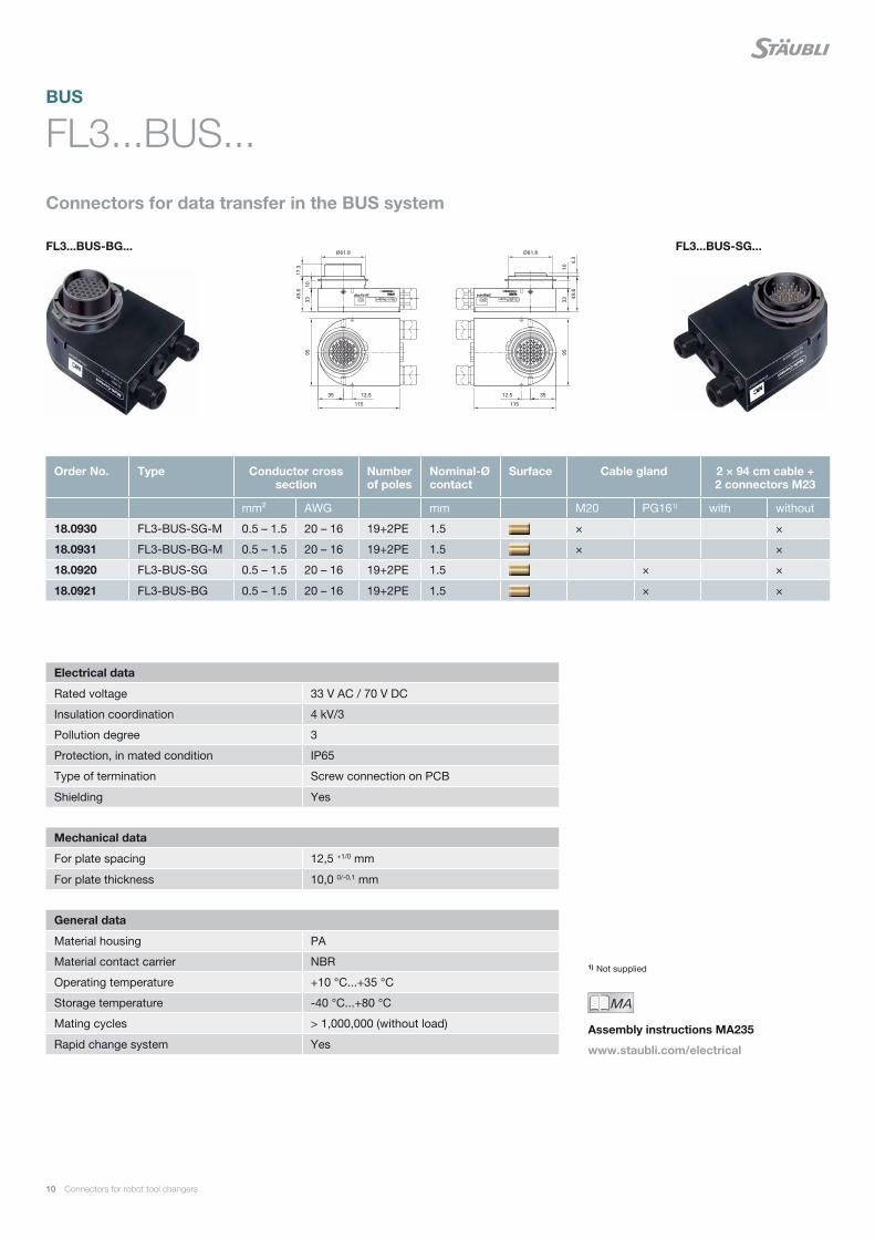
FL3...BUS-BG... FL3...BUS-SG...
Connectors for data transfer in the BUS system
FL3...BUS...
1) Not supplied
Electrical data
Rated voltage 33 V AC / 70 V DC
Insulation coordination 4 kV/3
Pollution degree 3
Protection, in mated condition IP65
Type of termination Screw connection on PCB
Shielding Yes
Mechanical data
For plate spacing 12,5 +1/0 mm
For plate thickness 10,0 0/-0,1 mm
General data
Material housing PA
Material contact carrier NBR
Operating temperature +10 °C...+35 °C
Storage temperature -40 °C...+80 °C
Mating cycles > 1,000,000 (without load)
Rapid change system Yes
BUS
Order No. Type Conductor cross section
Number of poles
Nominal-Ø contact
Surface Cable gland 2 × 94 cm cable + 2 connectors M23
mm² AWG mm M20 PG161) with without
18.0930 FL3-BUS-SG-M 0.5 – 1.5 20 – 16 19+2PE 1.5 × ×
18.0931 FL3-BUS-BG-M 0.5 – 1.5 20 – 16 19+2PE 1.5 × ×
18.0920 FL3-BUS-SG 0.5 – 1.5 20 – 16 19+2PE 1.5 × ×
18.0921 FL3-BUS-BG 0.5 – 1.5 20 – 16 19+2PE 1.5 × ×
MAIch bin eine Montageanleitung.
Man sollte mich unbedingt le-
sen, bevor man das Produkt ver-
wendet! Ich beinhalte wertvolle
Hinweise zur korrekten Montage
und zum richtigen Einsatz des
Produktes. Im Moment ist die
Schrift zwar ein bischen klein,
aber später geht das dann ganz
gut zu lesen, da die MA dann
Assembly instructions MA235
www.staubli.com/electrical
* *
*
Connectors for robot tool changers 11
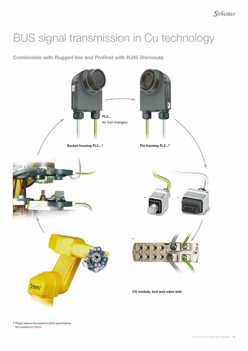
Combinable with Rugged line and Profinet with RJ45 (Variosub)
BUS signal transmission in Cu technology
1) Please observe the respective BUS-specifications* Not supplied by Stäubli
FL3...
for tool changers
Socket housing FL3...1)
I/O module, tool and robot side
Pin housing FL3...1)
12 Connectors for robot tool changers
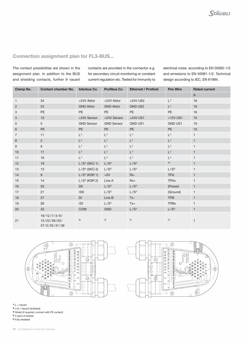
The contact possibilities are shown in the
assignment plan. In addition to the BUS
and shielding contacts, further 9 vacant
Clamp No. Contact chamber No. Interbus Cu Profibus Cu Ethernet / Profinet Fire Wire Rated current
A
1 34 +24V Aktor +24V Aktor +24V US2 L1) 16
2 23 GND Aktor GND Aktor GND US2 L1) 16
3 PE PE PE PE PE 16
4 10 +24V Sensor +24V Sensor +24V US1 +12V US1 10
5 5 GND Sensor GND Sensor GND US1 GND US1 10
6 PE PE PE PE PE 10
7 11 L1) L1) L1) L1) 1
8 2 L1) L1) L1) L1) 1
9 6 L1) L1) L1) L1) 1
10 17 L1) L1) L1) L1) 1
11 16 L1) L1) L1) L1) 1
12 19 L / S2) (SKÜ 1) L / S2) L / S2) ⁴⁾ 1
13 13 L / S2) (SKÜ 2) L / S2) L / S2) L / S2) 1
14 8 L / S2) (KSR 1) +5V Rx- TPA 1
15 14 L / S2) (KSR 2) Line A Rx+ TPAx 1
16 20 D0 L / S2) L / S2) (Power) 1
17 21 /D0 L / S2) L / S2) (Ground) 1
18 27 DI Line B Tx- TPB 1
19 26 /DI L / S2) Tx+ TPBx 1
20 32 COM GND L / S2) L / S2) 1
2118 / 12 / 7 / 4 / 9 / 15 / 22 / 28 / 33 / 37 / 3 / 25 / 31 / 36
³⁾ ³⁾ ³⁾ ⁵⁾ 1
Connection assignment plan for FL3-BUS...
contacts are provided in the connector e.g.
for secondary circuit monitoring or constant
current regulation etc. Tested for immunity to
electrical noise, according to EN 50082-1/2
and emissions to EN 50081-1/2. Technical
design according to IEC, EN 61984.
1) L = Vacant2) L/S = Vacant (shielded)3) Shield (if required, connect with PE contact)4) 2 pairs of shields5) Fully shielded
0
50
100
150
200
250
300
350
400
100 85 80 60 35 20 8
25 mm² 35 mm²
0
50
100
150
200
250
300
350
100 85 80 60 35 20 8
25 mm² 35 mm²
Connectors for robot tool changers 13
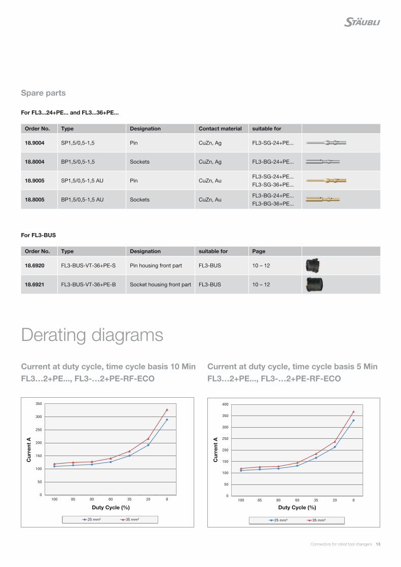
For FL3-BUS
For FL3...24+PE... and FL3...36+PE...
Order No. Type Designation Contact material suitable for
18.9004 SP1,5/0,5-1,5 Pin CuZn, Ag FL3-SG-24+PE...
18.8004 BP1,5/0,5-1,5 Sockets CuZn, Ag FL3-BG-24+PE...
18.9005 SP1,5/0,5-1,5 AU Pin CuZn, AuFL3-SG-24+PE... FL3-SG-36+PE...
18.8005 BP1,5/0,5-1,5 AU Sockets CuZn, AuFL3-BG-24+PE... FL3-BG-36+PE...
Order No. Type Designation suitable for Page
18.6920 FL3-BUS-VT-36+PE-S Pin housing front part FL3-BUS 10 – 12
18.6921 FL3-BUS-VT-36+PE-B Socket housing front part FL3-BUS 10 – 12
Derating diagrams
Current at duty cycle, time cycle basis 5 Min FL3…2+PE..., FL3-…2+PE-RF-ECO
Spare parts
Current at duty cycle, time cycle basis 10 Min FL3…2+PE..., FL3-…2+PE-RF-ECO
Cur
rent
A
Duty Cycle (%)
Cur
rent
A
Duty Cycle (%)
14 Connectors for robot tool changers
Order No. Type Conductor cross section Designation MAIch bin eine Montageanleitung.
Man sollte mich unbedingt le-
sen, bevor man das Produkt ver-
wendet! Ich beinhalte wertvolle
Hinweise zur korrekten Montage
und zum richtigen Einsatz des
Produktes. Im Moment ist die
Schrift zwar ein bischen klein,
aber später geht das dann ganz
gut zu lesen, da die MA dann
mm² AWG
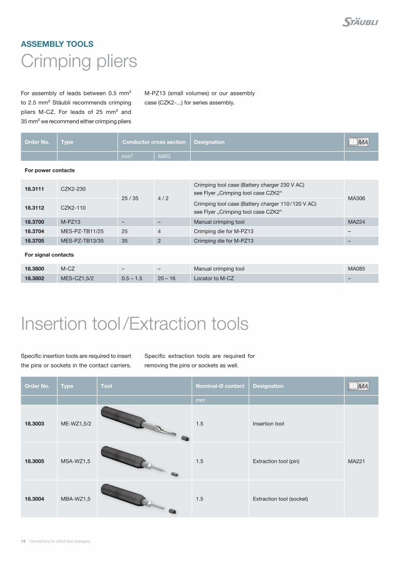
For power contacts
18.3111 CZK2-230
25 / 35 4 / 2
Crimping tool case (Battery charger 230 V AC)see Flyer „Crimping tool case CZK2“
MA306
18.3112 CZK2-110Crimping tool case (Battery charger 110 / 120 V AC)see Flyer „Crimping tool case CZK2“
18.3700 M-PZ13 – – Manual crimping tool MA224
18.3704 MES-PZ-TB11/25 25 4 Crimping die for M-PZ13 –
18.3705 MES-PZ-TB13/35 35 2 Crimping die for M-PZ13 –
For signal contacts
18.3800 M-CZ – – Manual crimping tool MA085
18.3802 MES-CZ1,5/2 0.5 – 1.5 20 – 16 Locator to M-CZ –
Order No. Type Tool Nominal-Ø contact Designation MAIch bin eine Montageanleitung.
Man sollte mich unbedingt le-
sen, bevor man das Produkt ver-
wendet! Ich beinhalte wertvolle
Hinweise zur korrekten Montage
und zum richtigen Einsatz des
Produktes. Im Moment ist die
Schrift zwar ein bischen klein,
aber später geht das dann ganz
gut zu lesen, da die MA dann
mm
18.3003 ME-WZ1,5/2 1.5 Insertion tool
MA22118.3005 MSA-WZ1,5 1.5 Extraction tool (pin)
18.3004 MBA-WZ1,5 1.5 Extraction tool (socket)
For assembly of leads between 0.5 mm²
to 2.5 mm² Stäubli recommends crimping
pliers M-CZ. For leads of 25 mm² and
35 mm² we recommend either crimping pliers
Specific insertion tools are required to insert
the pins or sockets in the contact carriers.
Crimping pliers
Insertion tool /Extraction tools
M-PZ13 (small volumes) or our assembly
case (CZK2-...) for series assembly.
ASSEMBLY TOOLS
Specific extraction tools are required for
removing the pins or sockets as well.
Connectors for robot tool changers 15
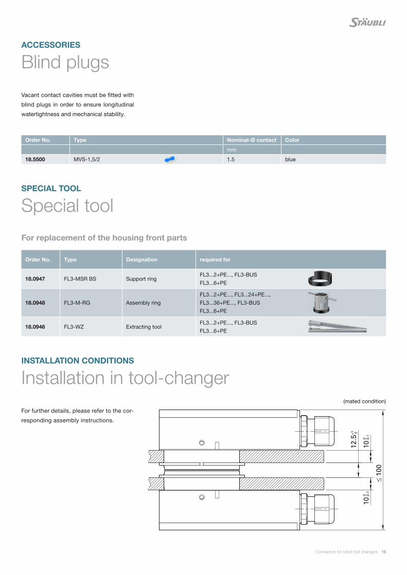
For replacement of the housing front parts
(mated condition)
Order No. Type Designation required for
18.0947 FL3-MSR BS Support ringFL3...2+PE..., FL3-BUS FL3...6+PE
18.0948 FL3-M-RG Assembly ringFL3...2+PE..., FL3...24+PE..., FL3...36+PE..., FL3-BUS FL3...6+PE
18.0946 FL3-WZ Extracting toolFL3...2+PE..., FL3-BUS FL3...6+PE
Order No. Type Nominal-Ø contact Color
mm
18.5500 MVS-1,5/2 1.5 blue
Vacant contact cavities must be fitted with
blind plugs in order to ensure longitudinal
watertightness and mechanical stability.
For further details, please refer to the cor-
responding assembly instructions.
Blind plugs
Special tool
Installation in tool-changer
ACCESSORIES
SPECIAL TOOL
INSTALLATION CONDITIONS

Global presenceof the Stäubli Group
Stäubli Units Agents
Staubli is a trademark of Stäubli International AG, registered in Switzerland and other countries.We reserve the right to modify product specifi cations without prior notice. © Stäubli [email protected] | Photo credits: Stäubli
www.staubli.com
AT D
L M
ain-
Tool
Cha
nger
11
0140
73-e
n A
11
.201
7
Printed in Switzerland