Embed Size (px)
Citation preview
DESIGN AND EVALUATION OP A NEW X-RAYDIFFRACTION TOPOGRAPH CAMERA
by
MARK JEROME DREILINO
B. 3., Kansas State University, 1962
A MASTER' S THESIS
submitted in partial fulfillment of the
requirements for the degree
MASTER OP SCIENCE
>
Department of Physics
KANSAS STATE UNIVERSITYManhattan, Kansas
1961^
Approved by;
Major Professor^
brought to you by COREView metadata, citation and similar papers at core.ac.uk
provided by K-State Research Exchange
LD .
TV\9(,^ li
D77
^ ^J
TABLE OF CONTENTS
INTRODUCTION ^,
LANG METHOD ^
OBJECTIVES IN THE DESIGN OP A CAMERA 12
ACTUAL DESIGN OF THE CAMERA 13
CONSTRUCTION OF THE CAMERA 19
EXPERIMENTAL RESULTS , . , » » 2$
CONCLUSIONS AND EVALUATION OF THE CAMERA 33
ACKNOWLEDGMENT • 36
REFERENCES 37
I
INTRODUCTION
In this research an attempt was made to construct an
x-ray diffraction topograph camera. The camera was to be
especially suited for use with the microfocus x-ray source
and have several characteristics which are Improvements over
existing units.
An x-ray diffraction topograph may be described as a
mapping of the point to point variations of reflecting power
by a nearly perfect single crystal. These variations are
caused by changes in Interplanar spacing or cuj?vature of the
lattice planes. Effects of this type are to be expected in
the strain fields around dislocations, grain boundaries, slip
planes, precipitates and other imperfections in the crystal-
line lattice.
The variations in Intensity may be seen when a single
crystal is aligned in a divergent beam. This is shown on
Plate I, Fig. 1. Figure la shows the crystal as viewed
parallel to the diffracting planes and perpendicular to the
direction of the Incident beam. Planes in one portion of the
crystal are in position for diffraction. These are the planes
which are set at the proper angle to satisfy the Bragg equation.
Assuming monochromatic radiation and a perfect crystal, the
diffracted image will appear as a trapezoid on the film. This
is shown on Plate I, Pig. lb. If the diffracting planes are
nearly perpendicular to the surface of the crystal the paths
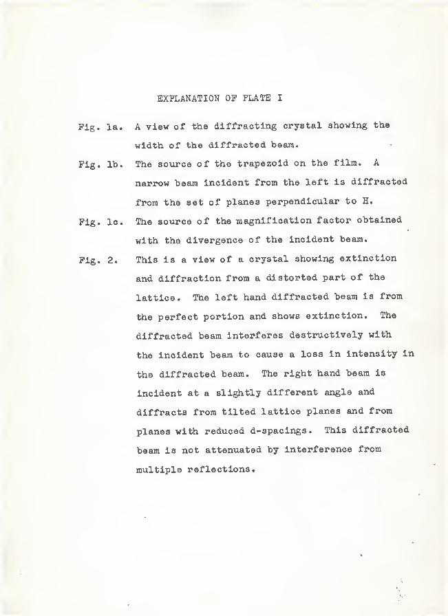
EXPLANATION OF PLATE I
Pig. la. A view of the diffracting crystal showing the
width, of the diffracted beam.
Fig. lb. The sovirce of the trapezoid on the film. A
narrow beam incident from the left is diffracted
from the set of planes perpendicular to H.
Fig. lo. The sovirce of the magnification factor obtained
with the divergence of the incident beam.
Pig. 2. This is a view of a crystal showing extinction
and diffraction from a distorted part of the
lattice. The left hand diffracted beam is from
the perfect portion and shows extinction. The
diffracted beam interferes destructively with
the incident beam to cause a loss in intensity in
the diffracted beam. The right hand beam is
incident at a slightly different angle and
diffracts from tilted lattice planes and from
planes with reduced d-spacings. This diffracted
beam is not attenuated by interference from
multiple reflections.
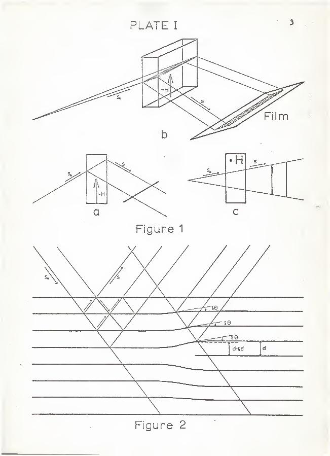
PLATE I3
Figure 2
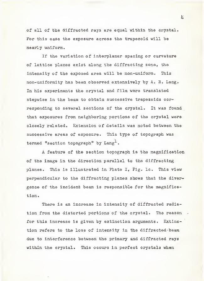
of all of the diffracted rays are equal within the crystal.
For this case the exposure across the trapezoid will be
nearly uniform.
If the variation of interplanar spacing or curvature
of lattice planes exist along the diffracting zone, the
intensity of the exposed area will be non-uniform. This
non-viniformity has been observed extensively by A, R. Lang.
In his experiments the crystal and film were translated
stepwise in the beam to obtain successive trapezoids cor-
responding to several sections of the crystal. It was found
that exposures from neighboring portions of the crystal were
closely related. Extension of details was noted between the
successive areas of exposure. This type of topograph was
termed "section topograph" by Lang^.
A feature of the section topograph is the roagnlfloation
of the image in the direction parallel to the diffracting
planes. This is illustrated in Plate I, Pig. Ic. This view
perpendicular to the diffracting planes shows that the diver-
gence of the incident beam is responsible for the magnifica-
tion.
There is an increase in intensity of diffracted radia-
tion from the distorted portions of the crystal. The reason
for this increase is given by extinction arguments. Extinc-
tion refers to the loss of intensity in the diffracted beam
due to Interference between the primary and diffracted rays
within the crystal* This occurs In perfect crystals when
5
the incident beam is in position for diffraction. The dif-
fracted beam sets up multiple reflections within the lattice
which may interfere destructively with the incident and
Initially diffracted beams. This is shown on the left side
of Plate I, Fig. 2. The right side of Pig. 2 shows the dif-
fraction from a distorted part of the lattice. The incident
beam, which is slightly divergent, has components which are
in position to diffract from the perfect portions of the
crystal. This diffracted beam is lowered in intensity due
to extinction. Other components, however, will enter the
crystal at an angle slightly different than the Bragg angle.
These will not diffract from the perfect portion but may be
in position to diffract from the distorted region. In this
region the distortion may take the form of cvirvature of
lattice planes or variation of interplanar spacing. Either
of these may satisfy the Bragg condition for the incident
components. If this is true, the diffracted beam will pass
through the crystal to the film without setting up multiple
reflections. As a result the diffracted beam from the dis-
torted portion of the crystal will be more intense than that
from the perfect portion.
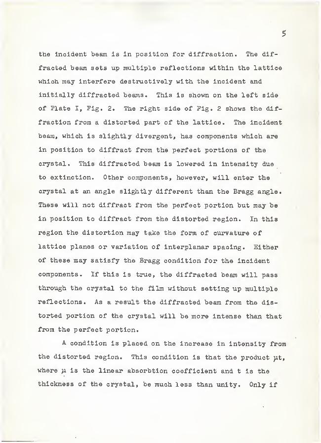
A condition is placed on the increase in intensity from
the distorted region. This condition is that the product ^t,
where )x is the linear absorbtion coefficient and t is the
thickness of the crystal, be much less than unity. Only if
this condition is fulfilled can there be sufficient contrast
from imperfect regions. If the value of )it is greater than
or equal to unity the contrast vdll be lowered or eliminated.
For large values of )it the anomalous absorbtion effect will
develop and the contrast variations will reverse to give less
intensity from the distorted regions.
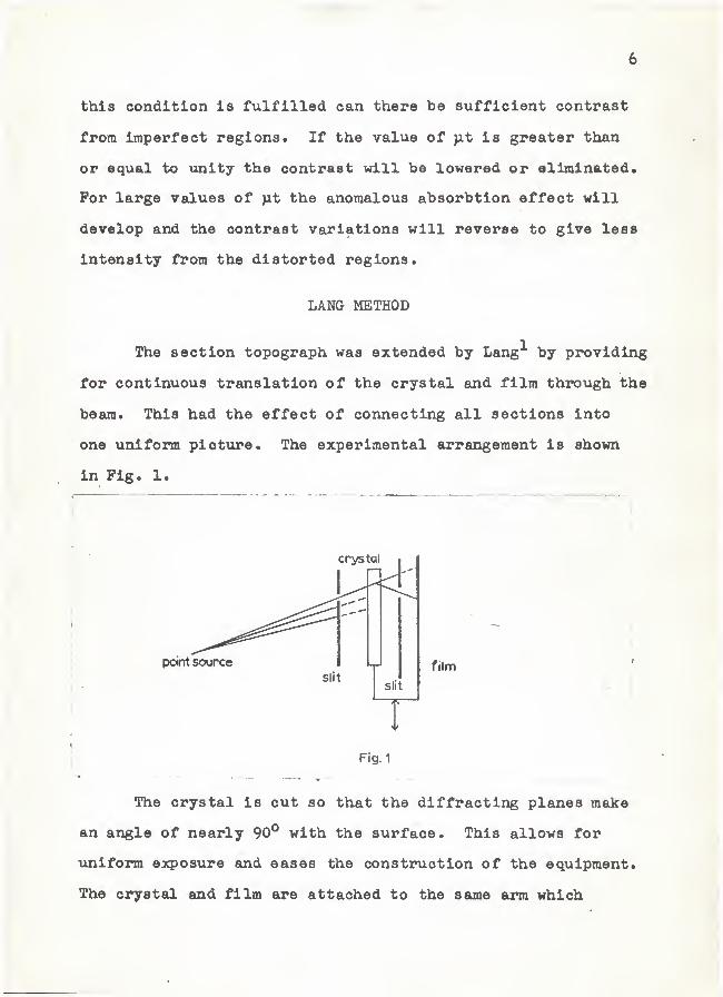
LANG METHOD
The section topograph was extended by Lang^ by providing
for continuous translation of the crystal and film through the
beam. This had the effect of connecting all sections into
one uniform picture. The experimental arrangement is shown
in Pig. 1.
point source
crystal
Fig. 1
film
The crystal is cut so that the diffracting planes make
an angle of nearly 90° with the surface. This allows for
uniform expostxre and eases the construction of the equipmenti
The crystal and film are attached to the same arm which
7
translates back and forth in the incident beam so that the
crystal is always in position for diffraction. A stationary
(with respect to the x-ray source) system of slits is employed
to eliminate the unwanted characteristic radiations such as
the Kot^and . The first slit is used to limit horizontal
divergence of the incident beam. This is discussed later when
resolution is considered. The slit after the crystal is used
to stop the transmitted beam and to allow only the desired
diffracted wavelengths to reach the film. The first slit,
in conjunction with the crystal, acts to select the desired
wavelengths
.
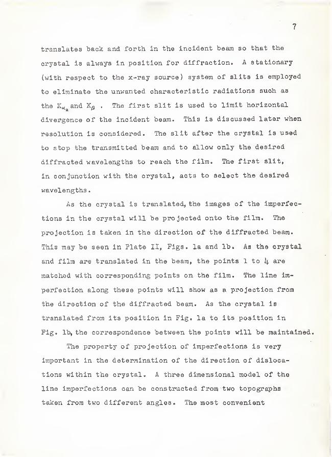
As the crystal is translated, the images of the imperfec-
tions in the crystal will be projected onto the film. The
projection is taken in the direction of the diffracted beam.
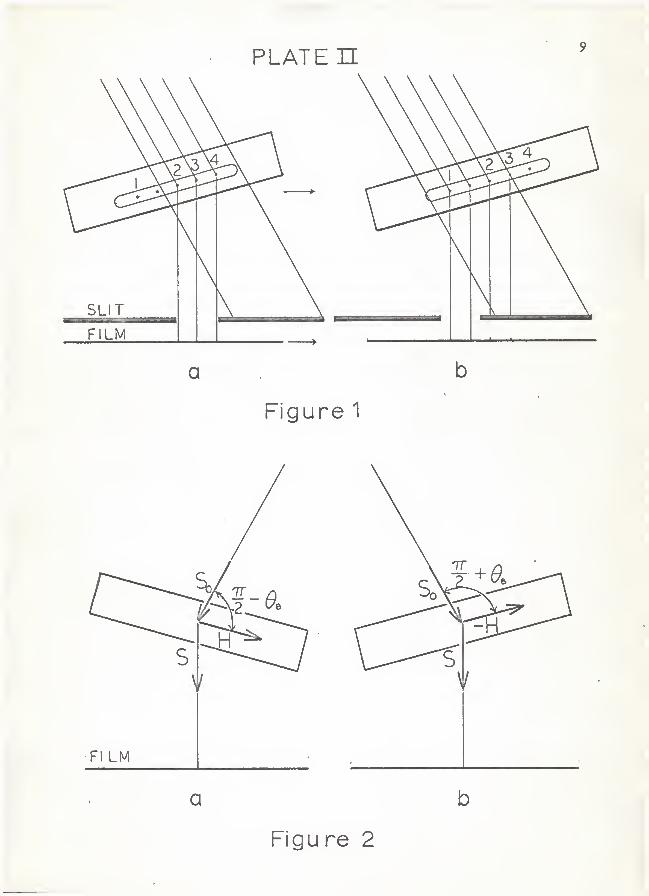
This may be seen in Plate II, Figs, la and lb. As the crystal
and film are translated in the beam, the points 1 to i; are
matched with corresponding points on the film. The line im-
perfection along these points will show as a projection from
the direction of the diffracted beam. As the crystal is
translated from its position in Fig. la to its position in
Pig. Ib,^ the correspondence between the points will be maintained.
The property of projection of imperfections is very
important in the determination of the direction of disloca-
tions within the crystal. A three dimensional model of the
line imperfections can be constructed from two topographs
taken from two different angles. The most convenient
EXPLANATION OP PLATE II
Fig. la Points on a line imperfection in a crystal
being projected onto the film by diffraction.
Pig. lb The same crystal after being translated with
the film. The point to point relationship
between crystal and film is maintained.
Pig. 2a The crystal in position for diffraction from
one set of planes.
Fig. 2b The same crystal rotated through twice the Bragg
angle to diffract off of the opposite side of
the same set of planes. Two different projections
are obtained.
I
PLATE
n
FILM
a
Figure 1
V
Fl LM
a
Figu re
10
way to do this is to rotate the crystal through twice the
Bragg angle to obtain the (hkl) reflection. This is shown
in Plate II, Figs. 2a and 2b. Here H represents the normal
and the diffracting planes. It is seen that two projections
are obtained which differ from each other in viewing angle
by twice the Bragg angle. If the Bragg angle is small the
images may be viewed with a stereo viewer. Otherwise a
geometrical construction may be used.
Resolution is important because the images of single
dislocations range in size from $ microns to 20 microns.
The resolution obtained depends principally upon two factors;
the horizontal divergence and the vertical divergence of the
x-ray beam incident on the crystal.
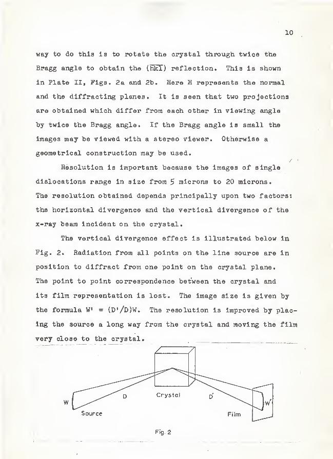
The vertical divergence effect is illustrated below in
Pig. 2. Radiation from all points on the line source are in
position to diffract from one point on the crystal plane.
The point to point correspondence between the crystal and
its film representation is lost. The image size is given by
the formula W = (D'/D)W. The resolution is improved by plac-
ing the source a long way from the crystal and moving the film
very close to the crystal.
/
71
w
Source Film
Fig. 2
11
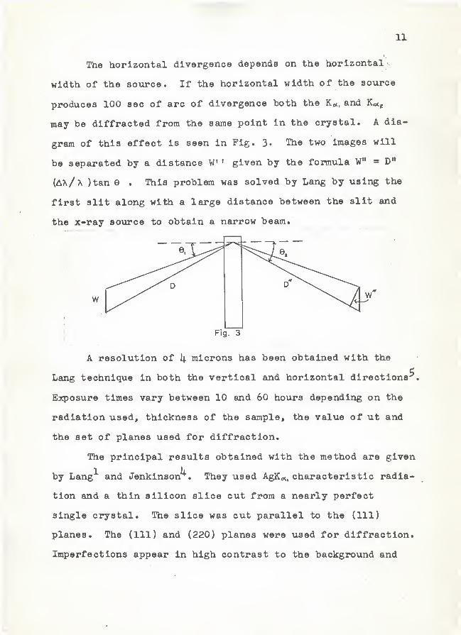
The horizontal divergence depends on the horizontal
width of the source. If the horizontal width of the source
produces 100 sec of arc of divergence both the Ko(, and Kotg
may be diffracted from the same point in the crystal. A dia-
gram of this effect is seen in Fig. 3. The two images will
be separated by a distance W' given by the formula W" » D"
(AA/a )tan e . This problem was solved by Lang by using the
first slit along with a large distance between the slit and
the x-ray source to obtain a narrow beam.
1
w
Fig. 3
A resolution of i; microns has been obtained with the
Lang technique in both the vertical and horizontal directions^
Exposure times vary between 10 and 60 ho\xrs depending on the
radiation used, thickness of the sample, the value of ut and
the set of planes used for diffraction.
The principal results obtained with the method are given
by Lang^ and Jenkinson^. They used AgKo^, characteristic radia-
tion and a thin silicon slice cut from a nearly perfect
single crystal. The slice was cut parallel to the (111)
planes. The (111) and (220) planes wore used for diffraction.
Imperfections appear in high contrast to the background and
12
were positively identified as slip planes and dislocations.
Specific types of dislocation interactions were observed in
these topographs
.
There are difficulties in aligning the Lang camera and
results are difficult to reproduce. The Lang translation
method is very sensitive to curvature of the sample^. The
crystal generally must be remounted to obtain a stereo pair.
OBJECTIVES IN THE DESIGN OP A CAMERA
In consideration of these factors involving resolution
and exposure time it was decided to design a topograph camera
which would use to advantage the characteristics of the Hilger
raicrofocus x-ray source.
The first objective of this work was to use the high
specific intensity of the raicrofocus x-ray beam to obtain
shorter exposure times. This higher intensity could also be
used to advantage in alignment since adjustment can be checked
quicker with the shorter exposvire times available. The fact
that the radiation from the raicrofocus xinit is divergent and
originates in a nearly point source was to be utilized alsa.
The divergence of the beam may be used to select planes of
diffraction and to obtain a magnification factor in one di-
mension. The small size of the source reduces the problem
of horizontal divergence considerably. The general objective
was to design a camera which would rotate the crystal in a
13
divergent beam to select successive sections. This is the
same as the Lang experiment except that rotation instead of
translation is used to scan the crystal. The need for a
narrow incident beam is eliminated because of the small size
of the source.
ACTUAL DESIGN OP THE CAMERA
A method for obtaining topographs of crystals using a
divergent beam was conceived by Dr. Dragsdorf . This section
is concerned with the geometrical design of the camera.
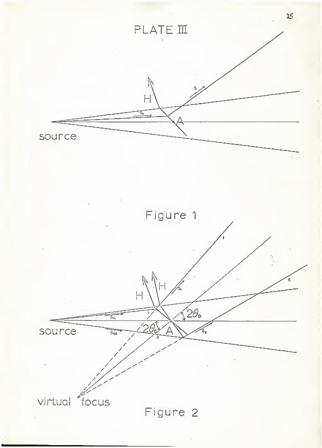
The most important feature of the camera is the selection
of planes in the divergent beam. This is illustrated in Plate
III, Fig. 1. A crystal, with the plane normal H in the plane
of the paper, is set to rotate about the axis A. The position
of the diffracting region will be determined by the position
of the crystal in its rotation about A.
If the diffracted beam is traced back through the
crystal from any two diffraction positions, a virtual focus
will be located. This virtual focus will remain nearly
stationary for small angles of rotation of the crystal. The
position of the virtual source is shown in Plate III, Fig. 2.
The stationary virtual source is invaluable in the design
of the camera. It provides a reference point for the angular
motion of the diffracted beam. The diffracted beam moves
throxigh an angle of 2%e for a rotation of the crystal of 50
about the axis A. This indicates that the motion of the
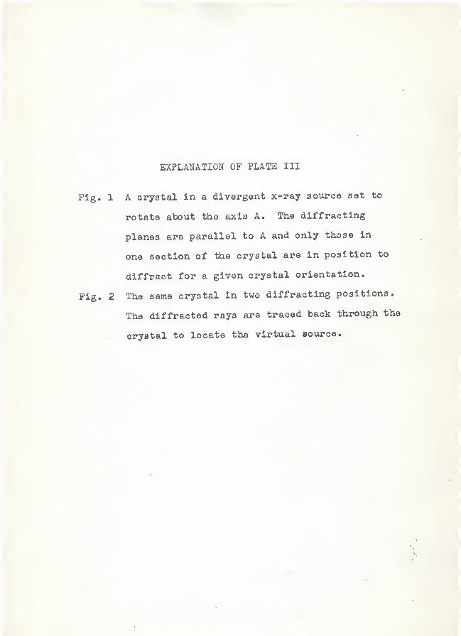
EXPLANATION OF PLATE III
Pig. 1 A crystal in a divergent x-ray source set to
rotate about the axis A. The diffracting
planes are parallel to A and only those in
one section of the crystal are in position to
diffract for a given crystal orientation.
Pig. 2 The same crystal in two diffracting positions.
The diffracted rays are traced back through the
^ crystal to locate the virtual source.
2$
virtual focusFigure 2
16
crystal about its axis and the motion of the diffracted beam
about the virtual source can be mechanically connected. A
system of slits may be set to rotate about the virtual source
through an angle equal to that of rotation of the crystal.
The slits would accurately track the diffracted beam for small
angles of rotation. Such slits could be used to cut out back-
ground and possibly extraneous characteristic radiations.
There will be a magnification factor applying to the
topograph arising from the rotation of the sample. This is
in addition to the magnification already existing in the
direction parallel to the diffracting planes. The factor
arising in the rotation is perpendicular to the diffracting
planes. These combine to provide an overall magnification of
the image. The magnification factor due to rotation depends
on the angle the diffracting planes make with the surface and
the distance to the film.
Stereo pairs may be taken easily with the idealized
apparatus shown in Plate III. The opposite side of the same
set of planes may be used. The only change in apparatus in-
volved is a rotation of the crystal and a change in position of
the film.
The resolution of the camera is limited by two principal,
factors. These are the vertical divergence and the focusing
of the diffracted beam. The vertical divergence has been dis-
cussed as it applied to the Lang experiment. The same effect
holds true for this camera. The camera was constructed so
17
that the film to crystal distance was equal to the source to
crystal distance. The size of the image of the source at the
film position will be equal to the size of the source itself.
A more serious resolution problem is that of the focus-
ing of the diffracted beam. If the sample is large enough two
of the characteristic radiations may diffract from different
positions in the crystal. For a crystal with the diffracting
planes oriented perpendicular to the face, all of the diffracted
radiation will converge to a point. The point is at a distance
behind the crystal equal to the source to crystal distance. The
focusing also makes it difficult to eliminate vmwanted charac-
teristic radiations by using slits. In general the will be
filtered out and the K^, and K^^ will be allowed to reach the
film. The separation of the two diffracting positions within
the crystal is on the order of 20 to $0 microns.
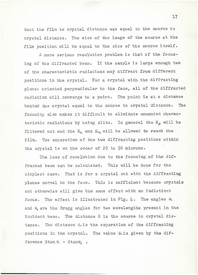
The loss of resolution due to the focusing of the dif-
fracted beam can be calculated. This will be done for the
simplest case. That is for a crystal cut with the diffracting
planes normal to the face. This is sufficient because crystals
cut otherwise will give the same effect with an indistinct
focus. The effect is illustrated in Fig. 1|. The angles e,
and are the Bragg angles for two wavelengths present in the
incident beam. The distance R is the source to crystal dis-
tance. The distance do is the separation of the diffracting
positions in the crystal. The value d.is given by the dif-
ference Rtan e, - RtanGj .
18
Source
Fig. 4
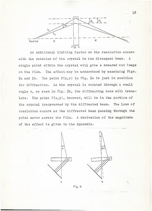
An additional limiting factor on the resolution occurs
with the rotation of the crystal in the divergent beam. A
single point within the ci^-stal will give a smeared out image
on the film. The effect may be understood by examining Figs.
5a and 5t>. The point P(x,y) in Fig. $a is just in position
for diffraction. As the crystal is rotated through a small
angle n, as seen in Fig. 5b, the diffracting zone will trans-
late. The point P{x,y), however, will be in the portion of
the crystal transversed by the diffracted beam. The loss of
resolution occurs as the diffracted beam passing through the
point moves across the film. A derivation of the magnitude
of the effect is given in the Appendix.
r
1
•
a b
19
CONSTRUCTION OF THE CAMERA
The unit was constructed as shown in Plate IV. This is
a graphic drawing of the camera showing the principal features.
Plate V shows two photographs of the apparatus. An associated
component was constructed for alignment purposes. It includes
a mount for a GM tube which pivots on a small table below the
center of symmetry of the camera. Diffraction angles may be
measured on the table. A collimating slit system and shutter
are movinted on the table.
The crystal is mounted on a single crystal goniometer
which is attached to a sleeve. This sleeve can be rotated
about a shaft which is attached to a central wheel. The
sleeve and goniometer can be raised and lowered by means of
a central screw. The position desired is maintained by a lock-
ing screw through the sleeve. The goniometer mount, including
shaft, sleeve and wheel, is free to rotate about a vertical
axis through the plate. The plate and goniometer may then be
mounted so that the crystal is in the direct beam of the micro-
focus unit. >•
The open semicircle has its center at the goniometer
mount and serves as the guide for the film holder. The film
holder locks in position by means of two one inch screws pass-
ing through the plate. The film is held in a light tight pack
and is slipped into the slot in the film holder.
The slit system is mo\mted on the closed semicircle. The
unit is positioned so that both the sotirce point focus and the
EXPLANATION OF PLATE IV
Pig. 1 A si.de view of the camera described in this
report shovfing the cam holder, goniometer
mount, film holder and slit.
Pig. 2 A top view of the camera showing the cam, drive
belt, and position of the film holder.
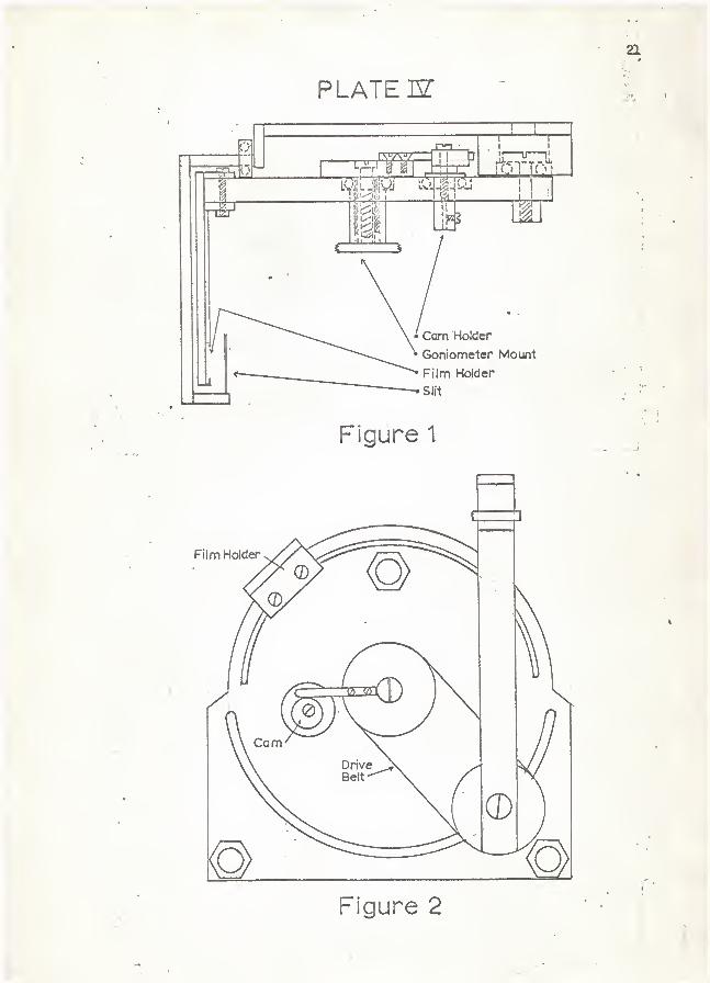
PLATE m
Figure 1
, i
Figure 2
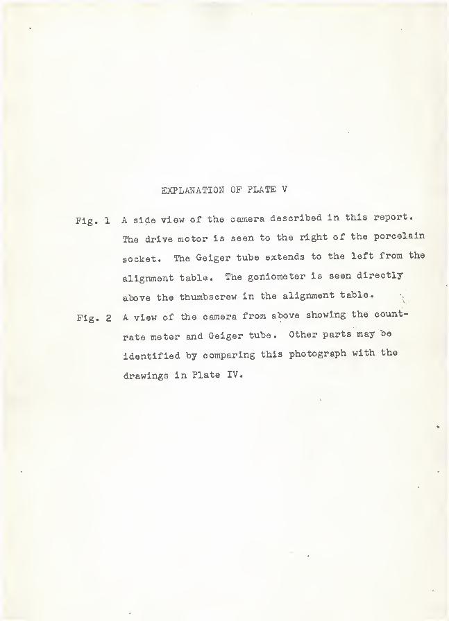
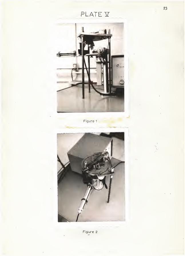
EXPLANATION OP PLATE V
Pig. 1 A side view of the camera described In this report.
The drive motor Is seen to the right of the porcelain
socket. The Gelger tube extends to the left from the
alignment table. The goniometer is seen directly
above the thumbscrew In the alignment table. v.
Pig. 2 A view of the camera from above showing the co\int-
rate meter and Gelger tube. Other parts may be
identified by comparing this photograph with the
drawings in Plate IV.
23
PLATE ¥
Figure 2
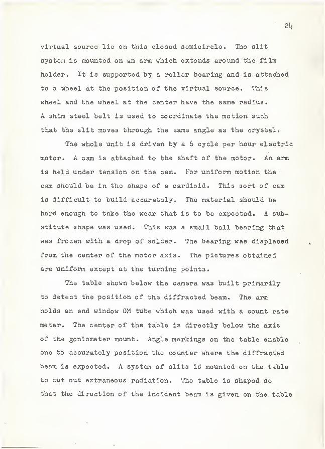
2k
virtual source lie on this closed semicircle. The slit
system is mounted on an arm which extends aroxmd the film
holder. It is supported by a roller bearing and is attached
to a wheel at the position of the virtual source. This
wheel and the wheel at the center have the same radius.
A shim steel belt is used to coordinate the motion such
that the slit moves through the same angle as the crystal.
The whole unit is driven by a 6 cycle per hour electric
motor. A cam is attached to the shaft of the motor. An arm
is held under tension on the cam. For uniform motion the •
cam should be in the shape of a cardioid. This sort of cam
is difficult to build accxirately. The material should be
hard enough to take the wear that is to be expected. A sub-
stitute shape was used. This was a small ball bearing that
was frozen with a drop of solder. The bearing was displaced
from the center of the motor axis. The pictures obtained
are uniform except at the turning points.
The table shown below the camera was built primarily
to detect the position of the diffracted beam. The arm
holds an end window GM tube which was used with a covint rate
meter. The center of the table is directly below the axis
of the goniometer mount. Angle markings on the table enable
one to accurately position the counter where the diffracted
beam is expected. A system of slits is mounted on the table
to cut out extraneous radiation. The table is shaped so
that the direction of the incident beam is given on the table
25
when the table is mounted flush to the face of the x-ray-
tube. The slit system also includes a shutter which may
be operated from a safe distance.
The alignment for a small crystal will be described.
Once the orientation of the crystal is known it is mounted
on the single crystal goniometer and the unit is placed
over the center of the alignment table. The crystal can
be adjusted to the same level as the source and film pack.
The counter is positioned at the expected angle of emergence
of the diffracted beam. The 6 cycle/hr motor is turned on
and the diffracted beam is allowed to scan a piece of low
resolution x-ray film for one cycle. This is developed and
the width of the scan is measured. If it is not more than
twice the width of the whole sample the whole sample will
not be in the topograph. The cam is displaced more from
its axis to obtain a wider scan. Generally only part of the
crystal is in position to diffract during the scan. The
alignment topograph will show only part of the crystal.
The crystal is then properly aligned by rotating it slightly
into the beam and taking another one cycle scan. This is
continued until the crystal image is centered on the topograph.
A high resolution film such as Kodak AA is used for the final.
exposure.
EXPERIMENTAL RESULTS
The focusing of the diffracted beam, which is a major
cause of loss of resolution, was detected and measured*
26
Plate VI shows a series of exposures taken at equal inter-
vals of distance from the crystal through the film position.
The crystal used was a calcium carbonate (calcite) cleavage
plate. The radiation used was the continuous band of Ag.
Each exposure was taken for 10 minutes. The series shows
clearly how all wavelengths converge at the proper film
position as designed for this unit.
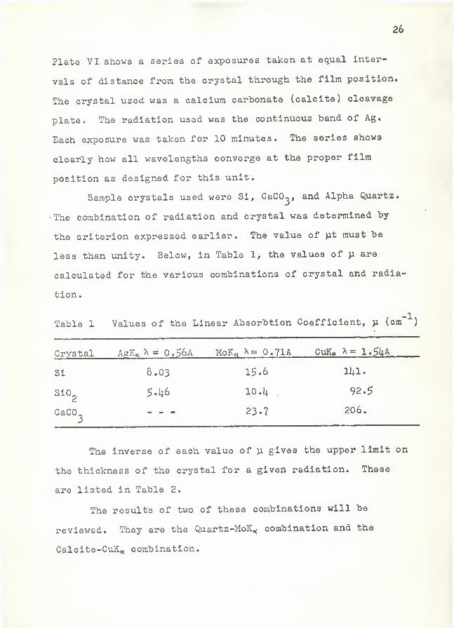
Sample crystals used were Si, CaCO^, and Alpha Quartz.
•The combination of radiation and crystal was deteinnined by
the criterion expressed earlier. The value of )xt must be
less than unity. Below, in Table 1, the values of >a are
calculated for the various combinations of crystal and radia-
tion.
Table 1 Values of the Linear Absorbtion Coefficient, )x (cm"''')
Crystal AgK« A = 0.$6A MoKc( 0.71A CvJC A= l.SkA-
Si 8.03 1^-6 11+1.
SiO^ 10.k .92.5
CaCO. 23.7 206,
The inverse of each value of ja gives the upper limit on
the thickness of the crystal for a given radiation. These
are listed in Table 2.
The results of two of these combinations will be
reviewed. They are the Quartz-MoK^ combination and the
Calcite-CuKo< combination.
EXPLANATION OP PLATE VI
Plate VI The divergence of the diffracted beam.
The photographs are 3»7X enlargements
of ten minute exposures taken at equal
intervals of distance along the beam.
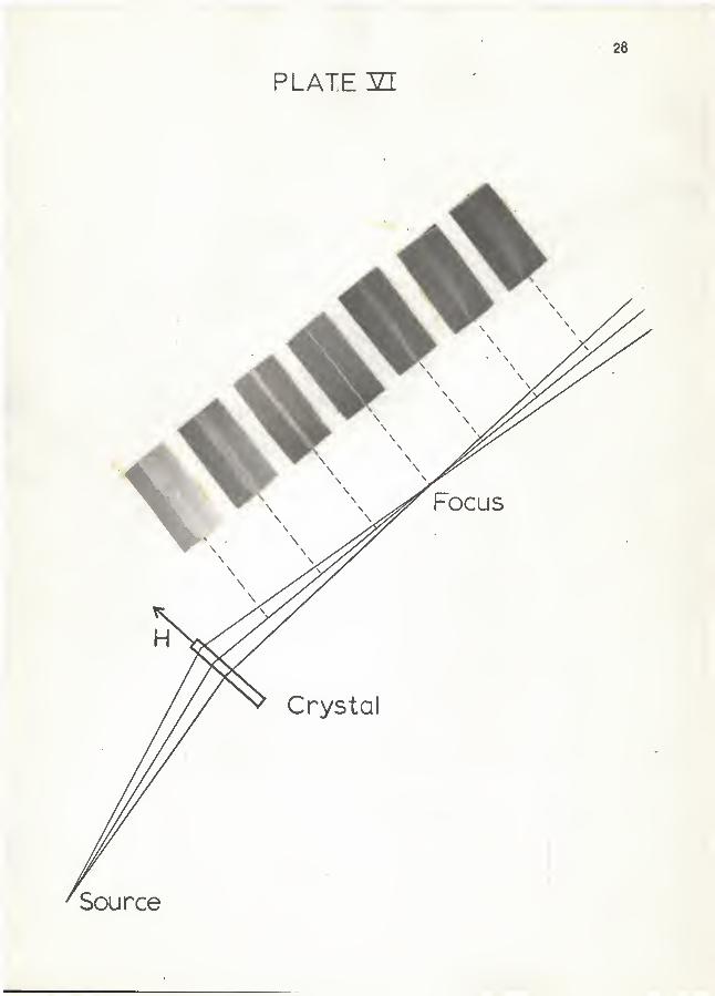
PLATE YI
28
29
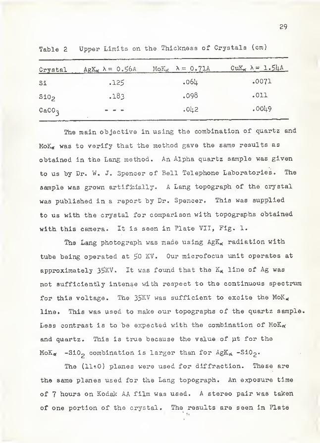
Table 2 Upper Limits on the Thickness of Crystals (era)
Crystal MoK.^ ^ = O.7IA CuK^ A= 1»^UA
Si .125 .0071
Si02 .183 .098 .011
CaCO'3 .0i|2 .00i|9
The main objective in using the combination of quartz and
MoKit was to verify that the method gave the same results as
obtained in the Lang method. An Alpha quartz sample was given
to us by Dr. W. J. Spencer of Bell Telephone Laboratories. The
sample was grown artifjcially. A Lang topograph of the crystal
was published in a report by Dr. Spencer. This was supplied
to us with the crystal for comparison with topographs obtained
with this camera. It is seen in Plate VII, Fig. 1.
The Lang photograph was made using AgK^i radiation with
tube being operated at 50 KV. Our microfocus unit operates at
approximately 35KV. It was found that the line of Ag was
not sufficiently intense with respect to the continuous spectrum
for this voltage. The 35KV was sufficient to excite the MoK.<
line. This was used to make our topographs of the quartz sample.
Less contrast is to be expected with the combination of MoKof
and quartz. This is true because the value of }it for the
KoKc( -Si02 combination is larger than for AgKe^ -SiOg-
The (ll'O) planes were used for diffraction. These are
the same planes used for the Lang topograph. An exposure time
of 7 hovirs on Kodak AA film was used. A stereo pair was taken
of one portion of the crystal. The results are seen in Plate
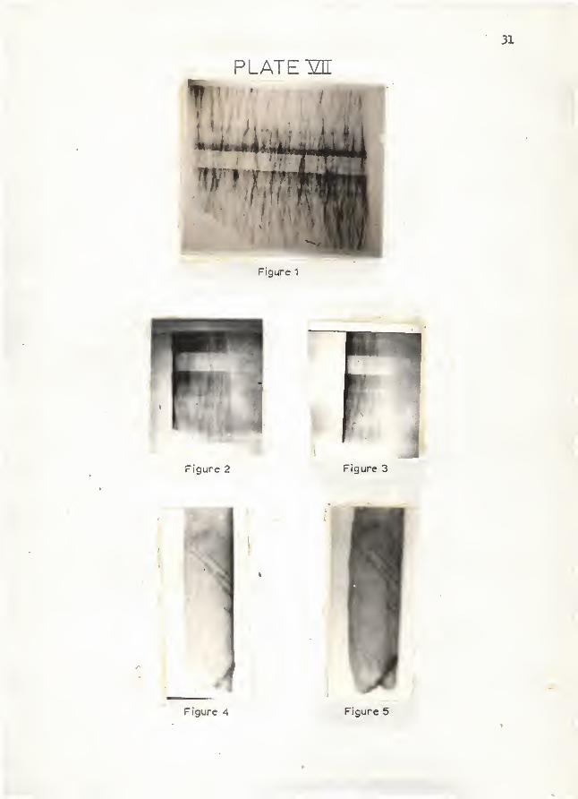
EXPLANATION OP PLATE VII
Fig. 1 The topograph of the quartz plate made by the
Lang method. Published in a Bell Telephone
Laboratories Report.
Fig. 2 A topograph of the same quartz plate made by the
camera described in this report. The magnifica-
tion is 3.6X the crystal.
Fig. 3 The other half to the stereo pair of the section
of crystal shown in Fig. 2. The magnification is
3.6X the crystal.
Fig. 1|. and Fig. 5 A stereo pair of a very thin calcite
single crystal. The magnification is 10.8X the
crystal.
4
31
PLATE IZE
¥ a
Figure 1
Figure 2 Figure 3
Figure 4 Figure 5
*
32
VII, Flg3. 2 and 3. Enough similarity between the Lang topo-
graph and the one obtained by rotation can be found to verify
that the camera is capable of obtaining x-ray diffraction topo-
graphs. The stereo pair was viewed in a stereo viewer. No
outstanding three dimensional effect was seen. This is due to
the large viewing angle (about 17°) and the lack of sharp detail.
The calcite-CuKo( combination was used because calcite is
nearly dislocation free, can be prepared very thin, and because
CuKo( radiation is excited very strongly at 35KV. Results of
calcite topographs have been published by Lang"^. These can be
used as a check on the camera.
A cleavage slice of calcite was sanded and etched in
dilute HCl lintil it was less than .O^mm in thickness. The
cleavage planes were used for diffraction. They make an
angle of 75.$° with the surface. This has the effect of moving
the focus out of the plane of the film. The K.^, and K,<, will
give two slightly displaced images at the film position.
A stereo pair was taken. They are shown in Plate VII,
'pigs. I4. and 5» The double images may be seen. Details very
similar to those observed in the ones obtained by Lang are seen.
The heavy dark lines are identified as dislocations. The series
of fine lines above the heavy ones were seen by Lang but not
identified. These seem to be peculiar to calcite. The differ-
ence between the two topographs in the pair is easily seen.
They are difficult to view in a stereo because of the large
viewing angle involved. This angle is 28.i;° for the calcite-
GuKti combination.
33
CONCLUSIONS AND EVALUATION OP THE CAMERA
The technique of rotating the crystal in a divergent
beam to obtain a topograph has several advantages over the
translation method. The alignment is simple if the orienta-
tion of the crystal is known. The principal advantage in
alignment is the insensitivity of the technique to curvatxire
of the sample. The Lang technique is very sensitive to
curvature of the sample. The strain between two crystal
mounts is often enough to cause part of the topograph to be
lost. This does not occur in the rotation method because
of the method of . plane selection by the divergent beam. If
the crystal was curved before moxinting a topograph could still
be obtained. The method may be useful in the examination of
deliberately bent crystals. An adjustment on the moving slit
mechanism would have to be made.
The magnification factor which is inherent in the rota-
ting system does not exist in the translation method. A
magnification factor could be obtained in the translation
method by placing the film at a larger distance from the
crystal. This would result In decreased resolution and
increased exposure times. Also, the magnification would only
be in one dimension. For low Bragg angles the rotation method
provides the same magnification factor in both dimensions of
the film.
There are disadvantages in the rotating crystal technique
31^
The loss of resolution due to the siraultanQous diffraction
of the K^, and lines is the principal drawback. Although
detail is not lost the topographs give less Information
because each line gives a picture. These are superimposed
on the film. This is effectively a loss of resolution and
l3 the principal cause of low resolution in the camera. This
is serious enough to prevent the use of the camera for high
resolution studies of individual dislocations.
The loss of resolution due to rotation of the crystal
in a divergent beam does not appear to be a serious problem.
This effect would have to be investigated further for thicker
crystals. As is shown in the Appendix the effect depends in
a specified way on the Bragg angle and the thickness of the
crystal. The resolution should increase for a smaller Bragg
angle and for thinner samples.
The size of the sample is limited for short wavelengths.
For short wavelengths the Bragg angle is small and may be less
than twice the angle of divergence of the incident beam. For
this case the diffracted will remain in the path of the inci-
dent beam and it will be impossible to obtain a topograph.
To avoid this the angular divergence of the incident beam
must be limited. This limits the area of the crystal which
can be viewed at these small Bragg angles.
Stereo pairs can be taken more easily with the rotation
camera. There is no need to remount the crystal for a second
plctxire. This is a problem in the Lang method because of the
3$
chance of breakage during remounting.
A comparison of exposure times is difficult to make.
The microfocus unit was operated at 35KV. The 35KV was not
sufficient to excite the Ag lines strongly ovet the continuous
background spectra. This is the radiation used most fre4uently
by other investigators. If the camera was to be used effec-
tively, careful calculations should be made on the loss of
resolution due to rotation of the sample. This would have
to be done for thick samples. A strong source of short
wavelength radiation is needed to improve resolution and con-
trast. If the alignment procedure was very simple and if
exposure times were small, the method could be used for rapid
testing of perfection of crystals.
36
ACKNOWLEDGMENT
The author wishes to express his gratitude to
Dr. R. Dean Dragsdorf for initiation of the problem and
for his guidance through the problem. Appreciation is
also expressed to Dr. Glen E. Harland for instruction
in the use of the microfocus unit, to Mr. L. W. Philips
for his assistance in the construction of the camera and
to Dr. W. J, Spencer for use of his quartz crystal.
This research was sponsored by the Bureau of General
Research, Kansas State University. The author wishes to
thank this group for the research asslstantship under which
this work was carried out.
37
REFERENCES
(1) Lang, A. R.Studies of Individual Dislocations in Crystals byX-Ray Diffraction Microradiography. J. Appl.
Phys., 30:17U8. 1959.
(2) Lang, A. R.The Projection Topography: A New Method in X-RayDiffraction Microradiography. Acta Cryst., 12:2U91959.
(3) Lang, A. R."
Direct Observation of Individual Dislocations byX-Ray Diffraction. J. Appl. Phys., 29:^98. 19b8.
Jenkinson, A. E.Projection Topographs of Dislocations,Philips Tech. Rev., 23:82 1961/62
(5) Newkirk, J. B., and J. H. Wernick, EditorsDirect Observations of Imperfectiona in Crystal ,
Intersclence Publishers, New lork, 1962.

38
APPENDIX
59
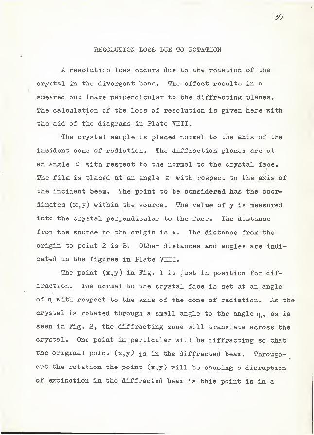
jRESOLUOJION LOSS DUE a?0 ROTATION
A resolution loss occurs due to the rotation of the
crystal in the divergent beam. The effect results in a
smeared out image perpendicular to the diffracting planes.
The calculation of the loss of resolution is given here with
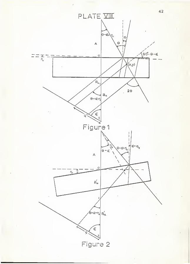
the aid of the diagrams in Plate VIII.
The crystal sample is placed normal to the axis of the
incident cone of radiation. The diffraction planes are at
an angle cc with respect to the normal to the crystal face.
The film is placed at an angle e with respect to the axis of
the incident beam. The point to be considered has the coor-
dinates (x,y) within the source. The value of y is measured
into the crystal perpendicular to the face. The distance
from the source to the origin is A. The distance from the
origin to point 2 is B, Other distances and angles are indi-
cated in the figures in Plate VIII.
The point (x,y) in Fig. 1 is just in position for dif-
fraction. The normal to the crystal face is set at an angle
of r\, with respect to the axis of the cone of radiation. As the
crystal is rotated through a small angle to the angle r^^, as is
seen in Fig. 2, the diffracting zone will translate across the
crystal. One point in particular will be diffracting so that
the original point (x,y) is in the diffracted beam. Through-
out the rotation the point (x,y) will be causing a disruption
of extinction in the diffracted beam is this point is in a
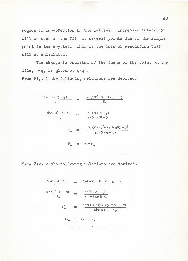
region of imperfection in the lattice. Increased intensity
will be seen on the film at several points due to the single
point in the crystal. This is the loss of resolution that
will be calculated.
The change in position of the image of the point on the
film, Aq, is given by q-q» .
From Fig. 1 the following relations are derived.
sin(e + q- r\,) sind&o'-e -c(*n, - e)
sinOo'-e-cQB,.
sin(e4-a-a)x*yXade*a.)
cos(e+ cO[x*y tan(e*(l)]
sin(e + ct-n.)
B. B -B,.
Prom Fig. 2 the following relations are derived.
sin(6* (X-nj
q
sin(iao° - e - g; g,— e)
sin(90°- 9 -q)b;.
sinQf q- r\J
X y tan(e + cl)
cosO* ct)[x y tanO* g)
sin(e * d. - r|j)
B,a. — B — B,,
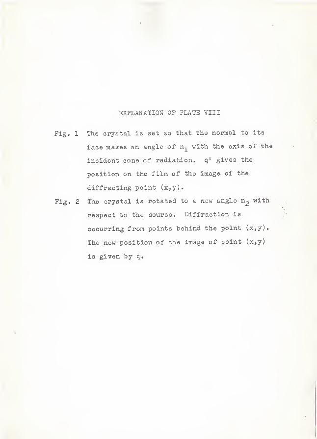
EXPLANATION OF PLATE VIII
Pig. 1 The crystal is set so that the normal to its
face makes an angle of n^ with the axis of the
incident cone of radiation, q' gives the
position on the film of the image of the
diffracting point (x,y).
Pig. 2 The crystal is rotated to a new angle n2 with;
respect to the source. Diffraction is
occurring from points behind the point (x,y).
The new position of the image of point (x,y)
is given by q.
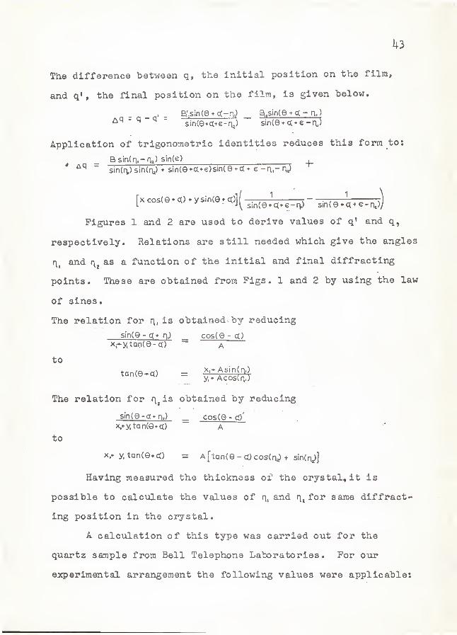
U3
The difference between q, the initial position on the film,
and q» , the final position on the film, is given below.
B:,sin(et c(-nj _ Bi.sin(9*ct- q.) i
' ^ ^ "sin(G*ct+e-aj) sinO e -r\,)
Application of trigonometric identities reduces this form to:
Bsin(n.-aj) sin(e),
* ~sin(n,) sin(t\) sin(e + a*€)sin(e + a+ e -r\.-rv) i
rxcos(e*<X) y since <?)][-— r/ o \ ^
Figures 1 and 2 are used to derive values of q' and q,
respectively. Relations are still needed which give the angles
and r^^ as a function of the initial and final diffracting
points. These are obtained from Pigs. 1 and 2 by using the law
of sines.
The relation for r\, is obtained by reducing
sinCe - r\) _ cosCe - ct)
\-^y,taoCe-c() ~ A
to• tance^a) = ^'^f^^'^i^-j '
•
The relation for i^^is obtained by reducing
since -g* n,) _. cosCe - cp'
x,+ ytanCe*a) a •
to
x,» y. tanCQ*cC) = A[tanCe - a) cosCn^ + sinCn^]
Having measured the thickness of the crystal, it is
possible to calculate the values of Hi He ^'^r same diffract-
ing position in the C3?ystal.
A calculation of this type was carried out for the
quartz sample from Bell Telephone Laboratories. For our
experimental arrangement the following values were applicable:
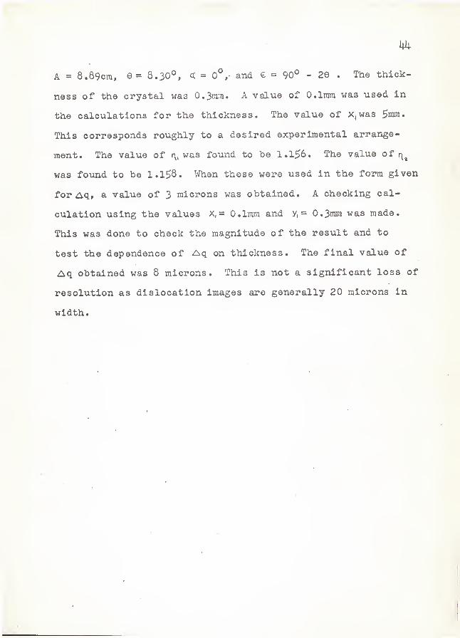
A = 8.89cm, G= 8.30°, = 0°,- and € = 90° - 29 . The thick-
ness of the crystal was 0.3tnm. A value of 0.1mm was used in
the calculations for the thickness. The value of X,was
This corresponds roughly to a desired experimental arrange-
ment. The value of r\, was found to be 1.156. The value of
was found to be 1.1^8. When these were used in the form given
for Aq» a value of 3 microns was obtained. A checking cal-
culation using the values x,= 0.1mm and y, = 0.3mra was made.
This was done to check the magnitude of the result and to
test the dependence of Aq on thickness. The final value of
Aq obtained was 8 microns. This is not a significant loss of
resolution as dislocation images are generally 20 microns in
width.
DESIGN AND EVALUATION OP A NEW X-RAYDIFFRACTION TOPOGRAPH CAMERA
by
MARK JEROME DREILING
B. S., Kansas State University, 1962
AN ABSTRACT OP A THESIS
submitted in partial fulfillment of the
requirements for the degree
MASTER OP SCIENCE
Department of Physics
.KANSAS STATE UNIVERSITYManhattan, Kansas
1
An x-ray diffraction topograph camera is designed
which uses to advantage the divergent beam available in a
microfocus unit. A single crystal is rotated about an
axis perpendicular to the axis of the incident cone of radi-
ation. A system of slits, which is linked mechanically to
the rotation of the crystal, tracks the diffracted beam.
A manification factor in both dimensions of the topograph
image is inherent in the system. Remounting of the sample
is vinnecessary to obtain stereo pairs because of the rotational
symmetry. A rotation of the crystal thro\igh twice the Bragg
angle and a change in position of the film pack is necessary
to obtain the stereo pair. The camera is insensitive to
curvature in the sample. This is a result of the method of
plane selection. The planes are selected by the divergent
beam originating at a point source.
The resolution is limited by three factors. The vertical
divergence occurs in the same manner as in the Lang method.
The resolution in the vertical direction is limited to 20
microns by the vertical divergence. The resolution is limited
because the whole crystal is exposed to the divergent beam.
The Koi, and K^^ characteristic radiations diffract from two
closely spaced positions in the crystal. The two diffracted .
beams focus to a point behind the crystal. The loss of
resolution depends on the crystal used, the wavelength, and
the difference in wavelength of the Kp^^ and Kgc^ . A third
cause of loss of resolution occurs in the rotation of the
2
crystal in the divergent beam. A single point In th6 crystal
is in the diffracted beam over a certain arc of rotation.
During this rotation the diffracted beam is affected by the
loss of extinction at the point. A line on the film
corresponds to a point in the crystal. The magnitude of
this effect has been calculated. It is not significant
for the samples used in this experiment. The loss of
resolution due to rotation increases with the thickness of
the sample and may be critical for samples which have a thick
ness greater than one centimeter. Loss of resolution due to
horizontal divergence is negligible because of the small size
of the source.
A topograph was made of an alpha quartz plate. This
topograph was compared with a topograph of the same crystal
made with the Lang method. The similarity between the two
topographs justified further investigation of the rotation
method. Limitations in the x-ray equipment prevented a care-
ful comparison of the results of the two methods. Silver
characteristic radiation was used for the Lang topograph. A
limitation on the accelerating voltage required that MoK.(
characteristic radiation be used for the rotation topograph.
Contrast and resolution are improved for the shorter wave-
length. Exposure times were dependent on the wavelengths
used and the thickness of the crystal. A satisfactory topo-
graph was obtained of a 0.36ram thick, 3.5ram wide section of

3
the quartz sample. The exposure time was 7 hours with MoKo<
radiation and an accelerating voltage of 35KV.
Further work is In progress to determine camera oonfigur
tlons which provide improved resolution and shorter exposure
times
.