Embed Size (px)
Citation preview
Permanent Magnet DC Machine
Electricity and New Energy
LabVolt Series
Student Manual
579362
en
Festo Didactic
Permanent M
agnet DC M
achineStudent M
anual
www.festo-didactic.com
Germany
Festo Didactic SE
Rechbergstr. 3
73770 Denkendorf
Tel.: +49 711 3467-0Fax: +49 711 347-54-88500
United States
Festo Didactic Inc.
607 Industrial Way WestEatontown, NJ 07724
Tel.: +1 732 938-2000
Toll Free: +1-800-522-8658
Fax: +1 732 [email protected]
CanadaFesto Didactic Ltée/Ltd
675, rue du Carbone
Québec (Québec) G2N 2K7
Tel.: +1 418 849-1000Toll Free: +1-800-522-8658
Fax: +1 418 849-1666
0000
5793
6200
0000
0001
00
Electricity and New Energy
Permanent Magnet DC Motor
Student Manual 579362

Order no.: 579362
Revision level: 12/2014
By the staff of Festo Didactic
© Festo Didactic Ltée/Ltd, Quebec, Canada 2011
Internet: www.festo-didactic.com
e-mail: [email protected]
Printed in Canada
All rights reserved
ISBN 978-2-89640-504-6 (Printed version)
ISBN 978-2-89747-238-2 (CD-ROM)
Legal Deposit – Bibliothèque et Archives nationales du Québec, 2011
Legal Deposit – Library and Archives Canada, 2011
The purchaser shall receive a single right of use which is non-exclusive, non-time-limited and limited
geographically to use at the purchaser's site/location as follows.
The purchaser shall be entitled to use the work to train his/her staff at the purchaser's site/location and
shall also be entitled to use parts of the copyright material as the basis for the production of his/her own
training documentation for the training of his/her staff at the purchaser's site/location with
acknowledgement of source and to make copies for this purpose. In the case of schools/technical
colleges, training centers, and universities, the right of use shall also include use by school and college
students and trainees at the purchaser's site/location for teaching purposes.
The right of use shall in all cases exclude the right to publish the copyright material or to make this
available for use on intranet, Internet and LMS platforms and databases such as Moodle, which allow
access by a wide variety of users, including those outside of the purchaser's site/location.
Entitlement to other rights relating to reproductions, copies, adaptations, translations, microfilming and
transfer to and storage and processing in electronic systems, no matter whether in whole or in part, shall
require the prior consent of Festo Didactic GmbH & Co. KG.
Information in this document is subject to change without notice and does not represent a commitment on
the part of Festo Didactic. The Festo materials described in this document are furnished under a license
agreement or a nondisclosure agreement.
Festo Didactic recognizes product names as trademarks or registered trademarks of their respective
holders.
All other trademarks are the property of their respective owners. Other trademarks and trade names may
be used in this document to refer to either the entity claiming the marks and names or their products.
Festo Didactic disclaims any proprietary interest in trademarks and trade names other than its own.
© Festo Didactic 579362 III
Safety and Common Symbols
The following safety and common symbols may be used in this manual and on the equipment:
Symbol Description
DANGER indicates a hazard with a high level of risk which, if not avoided, will result in death or serious injury.
WARNING indicates a hazard with a medium level of risk which, if not avoided, could result in death or serious injury.
CAUTION indicates a hazard with a low level of risk which, if not avoided, could result in minor or moderate injury.
CAUTION used without the Caution, risk of danger sign , indicates a hazard with a potentially hazardous situation which, if not avoided, may result in property damage.
Caution, risk of electric shock
Caution, hot surface
Caution, risk of danger
Caution, lifting hazard
Caution, hand entanglement hazard
Notice, non-ionizing radiation
Direct current
Alternating current
Both direct and alternating current
Three-phase alternating current
Earth (ground) terminal
Safety and Common Symbols
IV © Festo Didactic 579362
Symbol Description
Protective conductor terminal
Frame or chassis terminal
Equipotentiality
On (supply)
Off (supply)
Equipment protected throughout by double insulation or reinforced insulation
In position of a bi-stable push control
Out position of a bi-stable push control
© Festo Didactic 579362 V
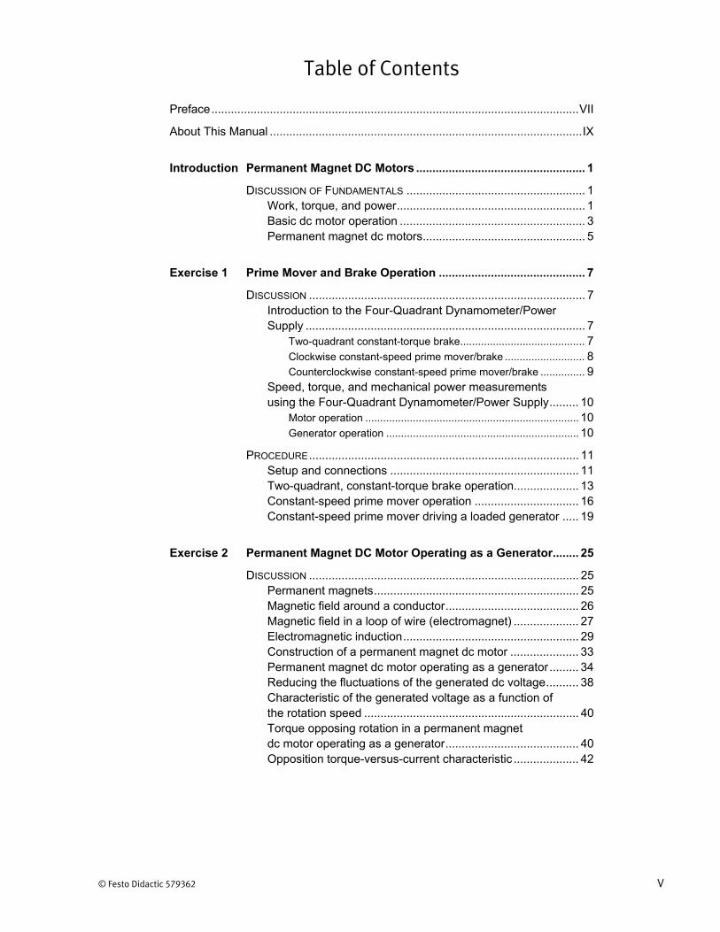
Table of Contents
Preface ................................................................................................................. VII
About This Manual ................................................................................................ IX
Introduction Permanent Magnet DC Motors .................................................... 1
DISCUSSION OF FUNDAMENTALS ....................................................... 1 Work, torque, and power .......................................................... 1 Basic dc motor operation ......................................................... 3 Permanent magnet dc motors .................................................. 5
Exercise 1 Prime Mover and Brake Operation ............................................. 7
DISCUSSION ..................................................................................... 7 Introduction to the Four-Quadrant Dynamometer/Power Supply ...................................................................................... 7
Two-quadrant constant-torque brake .......................................... 7 Clockwise constant-speed prime mover/brake ........................... 8 Counterclockwise constant-speed prime mover/brake ............... 9
Speed, torque, and mechanical power measurements using the Four-Quadrant Dynamometer/Power Supply ......... 10
Motor operation ........................................................................ 10 Generator operation ................................................................. 10
PROCEDURE ................................................................................... 11 Setup and connections .......................................................... 11 Two-quadrant, constant-torque brake operation .................... 13 Constant-speed prime mover operation ................................ 16 Constant-speed prime mover driving a loaded generator ..... 19
Exercise 2 Permanent Magnet DC Motor Operating as a Generator ........ 25
DISCUSSION ................................................................................... 25 Permanent magnets ............................................................... 25 Magnetic field around a conductor ......................................... 26 Magnetic field in a loop of wire (electromagnet) .................... 27 Electromagnetic induction ...................................................... 29 Construction of a permanent magnet dc motor ..................... 33 Permanent magnet dc motor operating as a generator ......... 34 Reducing the fluctuations of the generated dc voltage .......... 38 Characteristic of the generated voltage as a function of the rotation speed .................................................................. 40 Torque opposing rotation in a permanent magnet dc motor operating as a generator ......................................... 40 Opposition torque-versus-current characteristic .................... 42
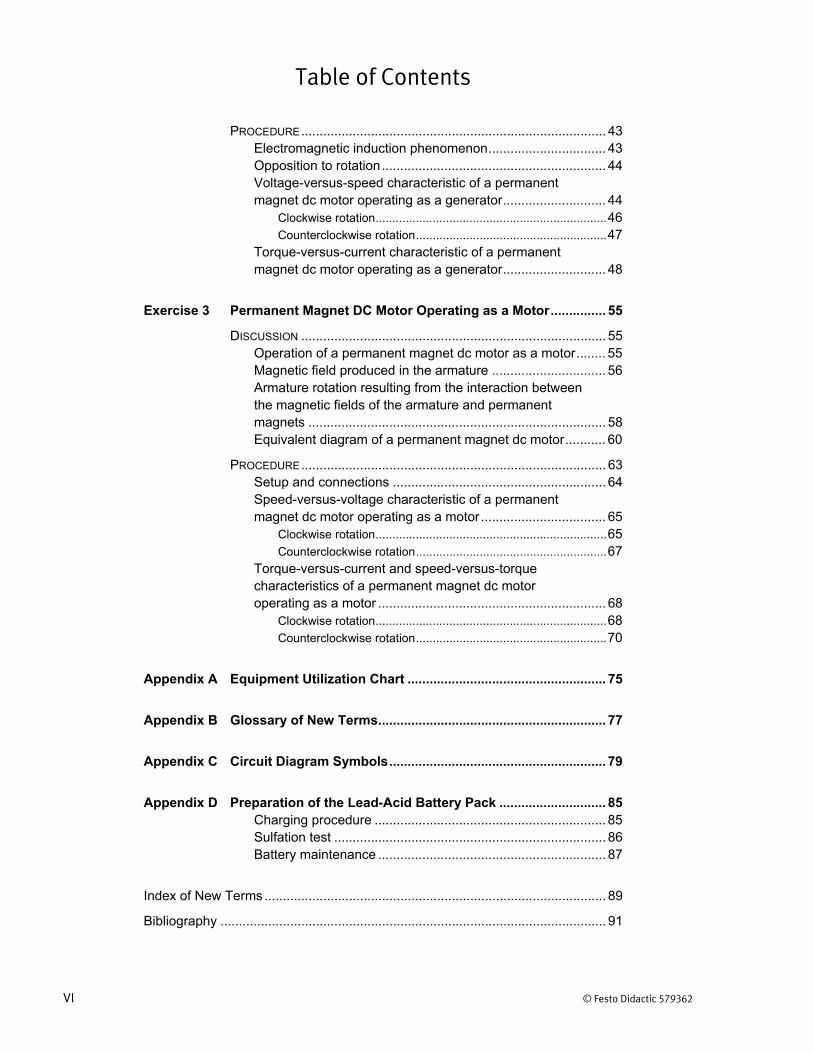
Table of Contents
VI © Festo Didactic 579362
PROCEDURE ................................................................................... 43 Electromagnetic induction phenomenon ................................ 43 Opposition to rotation ............................................................. 44 Voltage-versus-speed characteristic of a permanent magnet dc motor operating as a generator ............................ 44
Clockwise rotation ..................................................................... 46 Counterclockwise rotation ......................................................... 47
Torque-versus-current characteristic of a permanent magnet dc motor operating as a generator ............................ 48
Exercise 3 Permanent Magnet DC Motor Operating as a Motor ............... 55
DISCUSSION ................................................................................... 55 Operation of a permanent magnet dc motor as a motor ........ 55 Magnetic field produced in the armature ............................... 56 Armature rotation resulting from the interaction between the magnetic fields of the armature and permanent magnets ................................................................................. 58 Equivalent diagram of a permanent magnet dc motor ........... 60
PROCEDURE ................................................................................... 63 Setup and connections .......................................................... 64 Speed-versus-voltage characteristic of a permanent magnet dc motor operating as a motor .................................. 65
Clockwise rotation ..................................................................... 65 Counterclockwise rotation ......................................................... 67
Torque-versus-current and speed-versus-torque characteristics of a permanent magnet dc motor operating as a motor .............................................................. 68
Clockwise rotation ..................................................................... 68 Counterclockwise rotation ......................................................... 70
Appendix A Equipment Utilization Chart ...................................................... 75
Appendix B Glossary of New Terms .............................................................. 77
Appendix C Circuit Diagram Symbols ........................................................... 79
Appendix D Preparation of the Lead-Acid Battery Pack ............................. 85 Charging procedure ............................................................... 85 Sulfation test .......................................................................... 86 Battery maintenance .............................................................. 87
Index of New Terms ............................................................................................. 89
Bibliography ......................................................................................................... 91
© Festo Didactic 579362 VII
Preface
The production of energy using renewable natural resources such as wind, sunlight, rain, tides, geothermal heat, etc., has gained much importance in recent years as it is an effective means of reducing greenhouse gas (GHG) emissions. The need for innovative technologies to make the grid smarter has recently emerged as a major trend, as the increase in electrical power demand observed worldwide makes it harder for the actual grid in many countries to keep up with demand. Furthermore, electric vehicles (from bicycles to cars) are developed and marketed with more and more success in many countries all over the world.
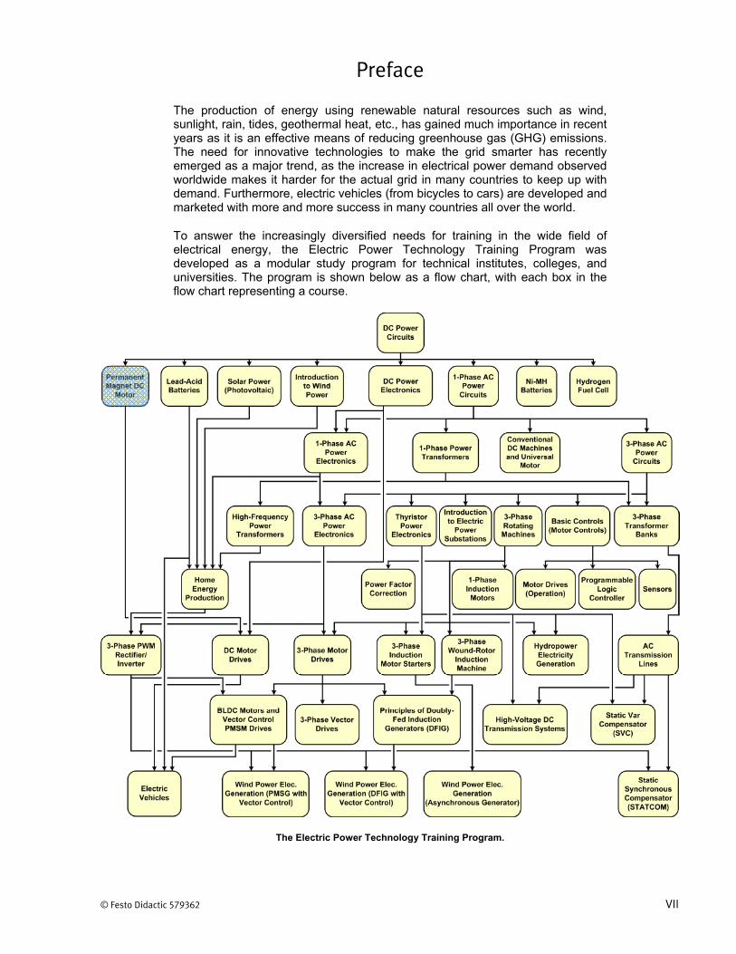
To answer the increasingly diversified needs for training in the wide field of electrical energy, the Electric Power Technology Training Program was developed as a modular study program for technical institutes, colleges, and universities. The program is shown below as a flow chart, with each box in the flow chart representing a course.
The Electric Power Technology Training Program.
Preface
VIII © Festo Didactic 579362
The program starts with a variety of courses providing in-depth coverage of basic topics related to the field of electrical energy such as ac and dc power circuits, power transformers, rotating machines, ac power transmission lines, and power electronics. The program then builds on the knowledge gained by the student through these basic courses to provide training in more advanced subjects such as home energy production from renewable resources (wind and sunlight), large-scale electricity production from hydropower, large-scale electricity production from wind power (doubly-fed induction generator [DFIG], synchronous generator, and asynchronous generator technologies), smart-grid technologies (SVC, STATCOM, HVDC transmission, etc.), storage of electrical energy in batteries, and drive systems for small electric vehicles and cars.
Do you have suggestions or criticism regarding this manual?
If so, send us an e-mail at [email protected].
The authors and Festo Didactic look forward to your comments.
© Festo Didactic 579362 IX
About This Manual
Rotating machines such as electrical motors and generators (or alternators) are found in almost every sector of the industry. The basic principles of operation of rotating machines have been known for almost two centuries. Rotating machines operate due to the interaction between magnetic fields and current-carrying conductors, and are split into two basic categories: motors and generators.
Permanent magnet dc motors are rotating machines that operate using direct current (i.e., they are dc powered). They can be used as either generators or motors. Permanent magnet dc motors are rugged components that are easy to connect and require little maintenance. They are found in a variety of applications, such as battery charging, small electric vehicles, windmill technology, mobility scooters, pumps, machine tools, kitchen appliances, optical equipment, etc.
The present course introduces the student to permanent magnet dc motors used as either generators or motors. The course covers the construction, operating principles, and characteristic curves of permanent magnet dc motors related to each of these two operating modes.
The equipment for the course mainly consists of the Permanent Magnet DC Motor and the Four-Quadrant Dynamometer/Power Supply. The operation of the motor is controlled using the LVDAC-EMS software, which also provides the instrumentation required to record the experimental data and plot characteristic curves.
Safety considerations
Safety symbols that may be used in this manual and on the equipment are listed in the Safety Symbols table at the beginning of the manual.
Safety procedures related to the tasks that you will be asked to perform are indicated in each exercise.
Make sure that you are wearing appropriate protective equipment when performing the tasks. You should never perform a task if you have any reason to think that a manipulation could be dangerous for you or your teammates.
Prerequisite
As a prerequisite to this course, you should have read the manual titled DC Power Circuits, p.n. 86350.
Systems of units
Units are expressed using the International System of Units (SI) followed by the units expressed in the U.S. customary system of units (between parentheses).

© Festo Didactic 579362 1
When you have completed this manual, you will be familiar with the construction and operation of permanent magnet dc motors used as either generators or motors. You will be familiar with the characteristic curves of permanent magnet dc motors related to each of these two operating modes.
The Discussion of Fundamentals covers the following points:
Work, torque, and power Basic dc motor operation Permanent magnet dc motors
Work, torque, and power
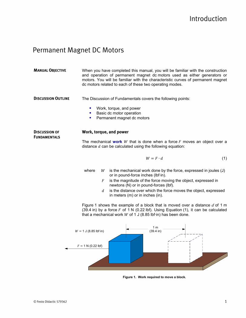
The mechanical work that is done when a force moves an object over a distance can be calculated using the following equation:
∙ (1)
where is the mechanical work done by the force, expressed in joules (J) or in pound-force inches (lbf·in). is the magnitude of the force moving the object, expressed in newtons (N) or in pound-forces (lbf). is the distance over which the force moves the object, expressed in meters (m) or in inches (in).
Figure 1 shows the example of a block that is moved over a distance d of 1 m (39.4 in) by a force of 1 N (0.22 lbf). Using Equation (1), it can be calculated that a mechanical work of 1 J (8.85 lbf·in) has been done.
Figure 1. Work required to move a block.
Permanent Magnet DC Motors
Introduction
MANUAL OBJECTIVE
DISCUSSION OUTLINE
DISCUSSION OF
FUNDAMENTALS
1 m (39.4 in)
1 N (0.22 lbf)
1 J (8.85 lbf·in)
Introduction – Permanent Magnet DC Motors Discussion of Fundamentals
2 © Festo Didactic 579362
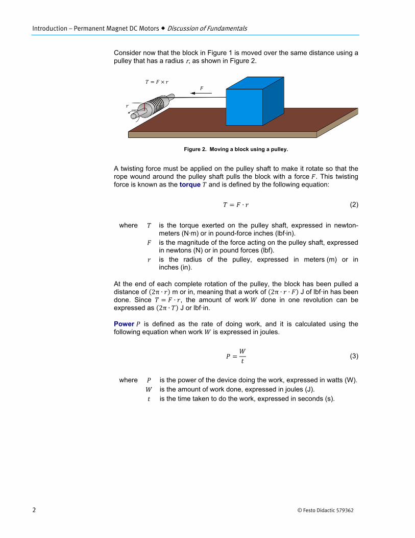
Consider now that the block in Figure 1 is moved over the same distance using a pulley that has a radius r, as shown in Figure 2.
Figure 2. Moving a block using a pulley.
A twisting force must be applied on the pulley shaft to make it rotate so that the rope wound around the pulley shaft pulls the block with a force . This twisting force is known as the torque and is defined by the following equation:
∙ (2)
where is the torque exerted on the pulley shaft, expressed in newton-meters (N·m) or in pound-force inches (lbf∙in).
is the magnitude of the force acting on the pulley shaft, expressed in newtons (N) or in pound forces (lbf).
is the radius of the pulley, expressed in meters (m) or in inches (in).
At the end of each complete rotation of the pulley, the block has been pulled a distance of 2π ∙ m or in, meaning that a work of 2π ∙ ∙ J of lbf·in has been done. Since ∙ , the amount of work done in one revolution can be expressed as 2π ∙ J or lbf·in.
Power is defined as the rate of doing work, and it is calculated using the following equation when work is expressed in joules.
(3)
where is the power of the device doing the work, expressed in watts (W). is the amount of work done, expressed in joules (J). is the time taken to do the work, expressed in seconds (s).
Introduction – Permanent Magnet DC Motors Discussion of Fundamentals
© Festo Didactic 579362 3
When work is expressed in pound-force inches (lbf·in), the following equation must be used to calculate the power :
∙1
8.85 8.85(4)
where is the amount of work done, expressed in pound-force inches (lbf·in).
Since power is work done per unit of time, the power of a motor turning at a speed can be found using the following equation when the torque is expressed in newton-meters (N∙m).
∙1 min60 s
∙ 2π ∙1 min9.55 s
∙∙
9.55(5)
where is the motor speed of rotation, expressed in revolutions per minute (r/min).
When torque is expressed in pound-force inches (lbf·in), the power of the motor can be found using the following equation:
∙1 min60 s
∙ 2π ∙1
8.85∙ ∙
1min84.5s
∙84.5
(6)
It is possible to obtain the power , expressed in horsepower (hp), for any given power , expressed in watts (W), by dividing the power value in watts by 746.
Basic dc motor operation
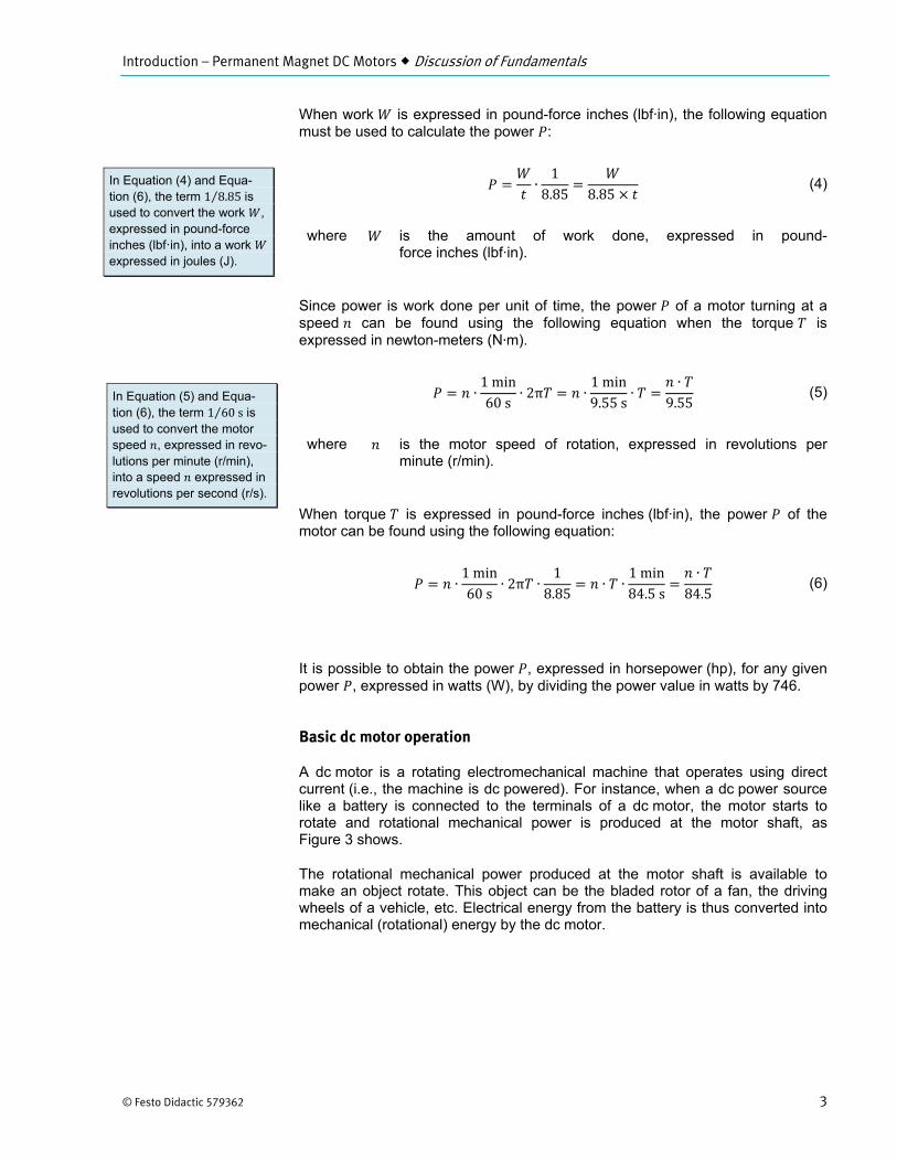
A dc motor is a rotating electromechanical machine that operates using direct current (i.e., the machine is dc powered). For instance, when a dc power source like a battery is connected to the terminals of a dc motor, the motor starts to rotate and rotational mechanical power is produced at the motor shaft, as Figure 3 shows.
The rotational mechanical power produced at the motor shaft is available to make an object rotate. This object can be the bladed rotor of a fan, the driving wheels of a vehicle, etc. Electrical energy from the battery is thus converted into mechanical (rotational) energy by the dc motor.
In Equation (4) and Equa-tion (6), the term 1 8.85⁄ is used to convert the work , expressed in pound-force inches (lbf·in), into a work expressed in joules (J).
In Equation (5) and Equa-tion (6), the term 1 60s⁄ is used to convert the motor speed , expressed in revo-lutions per minute (r/min), into a speed expressed in revolutions per second (r/s).
Introduction – Permanent Magnet DC Motors Discussion of Fundamentals
4 © Festo Didactic 579362
Figure 3. Operation as a motor: the dc motor converts electrical power into rotational mechanical power that makes the fan turn.
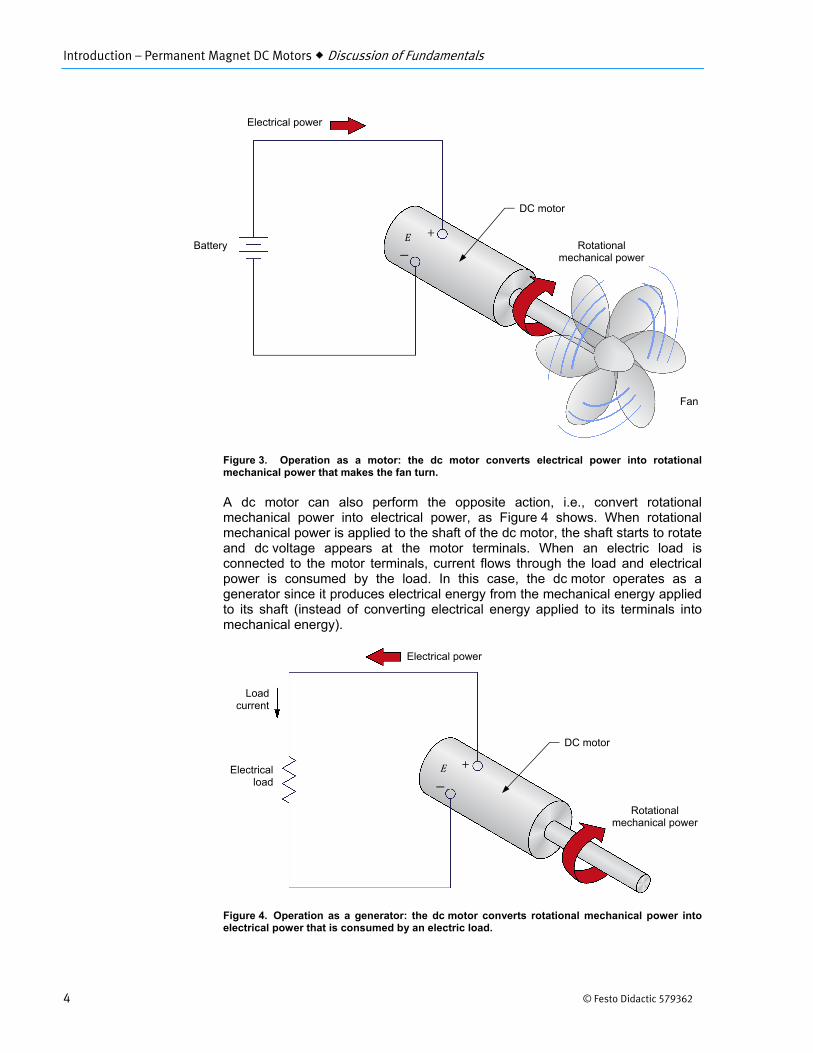
A dc motor can also perform the opposite action, i.e., convert rotational mechanical power into electrical power, as Figure 4 shows. When rotational mechanical power is applied to the shaft of the dc motor, the shaft starts to rotate and dc voltage appears at the motor terminals. When an electric load is connected to the motor terminals, current flows through the load and electrical power is consumed by the load. In this case, the dc motor operates as a generator since it produces electrical energy from the mechanical energy applied to its shaft (instead of converting electrical energy applied to its terminals into mechanical energy).
Figure 4. Operation as a generator: the dc motor converts rotational mechanical power into electrical power that is consumed by an electric load.
Electrical power
Battery Rotational mechanical power
Fan
Electrical power
Electricalload
E
Rotational mechanical power
Loadcurrent
DC motor
DC motor
Introduction – Permanent Magnet DC Motors Discussion of Fundamentals
© Festo Didactic 579362 5
Permanent magnet dc motors
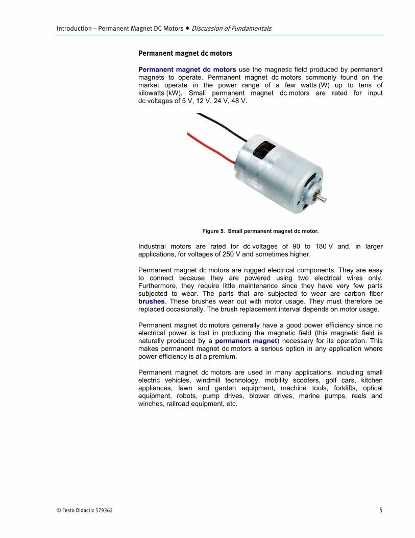
Permanent magnet dc motors use the magnetic field produced by permanent magnets to operate. Permanent magnet dc motors commonly found on the market operate in the power range of a few watts (W) up to tens of kilowatts (kW). Small permanent magnet dc motors are rated for input dc voltages of 5 V, 12 V, 24 V, 48 V.
Figure 5. Small permanent magnet dc motor.
Industrial motors are rated for dc voltages of 90 to 180 V and, in larger applications, for voltages of 250 V and sometimes higher.
Permanent magnet dc motors are rugged electrical components. They are easy to connect because they are powered using two electrical wires only. Furthermore, they require little maintenance since they have very few parts subjected to wear. The parts that are subjected to wear are carbon fiber brushes. These brushes wear out with motor usage. They must therefore be replaced occasionally. The brush replacement interval depends on motor usage.
Permanent magnet dc motors generally have a good power efficiency since no electrical power is lost in producing the magnetic field (this magnetic field is naturally produced by a permanent magnet) necessary for its operation. This makes permanent magnet dc motors a serious option in any application where power efficiency is at a premium.
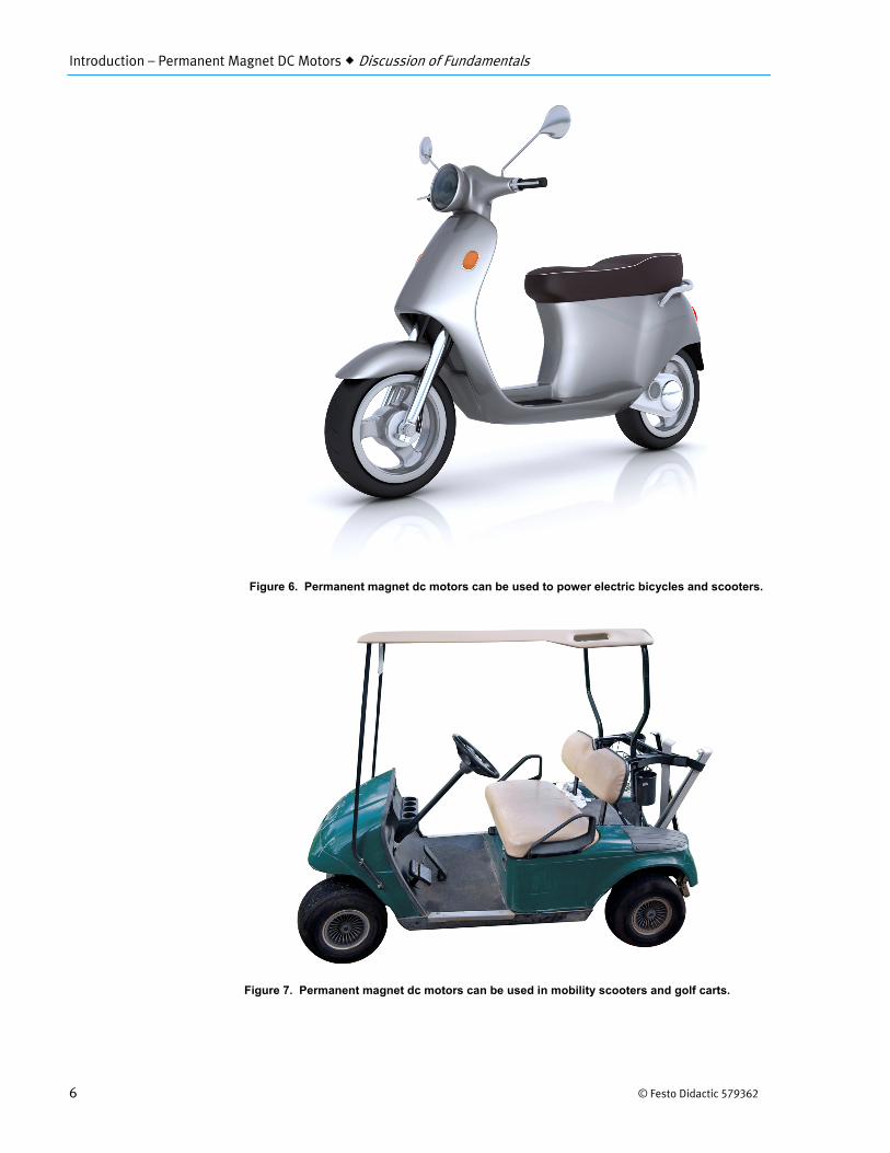
Permanent magnet dc motors are used in many applications, including small electric vehicles, windmill technology, mobility scooters, golf cars, kitchen appliances, lawn and garden equipment, machine tools, forklifts, optical equipment, robots, pump drives, blower drives, marine pumps, reels and winches, railroad equipment, etc.
Introduction – Permanent Magnet DC Motors Discussion of Fundamentals
6 © Festo Didactic 579362
Figure 6. Permanent magnet dc motors can be used to power electric bicycles and scooters.
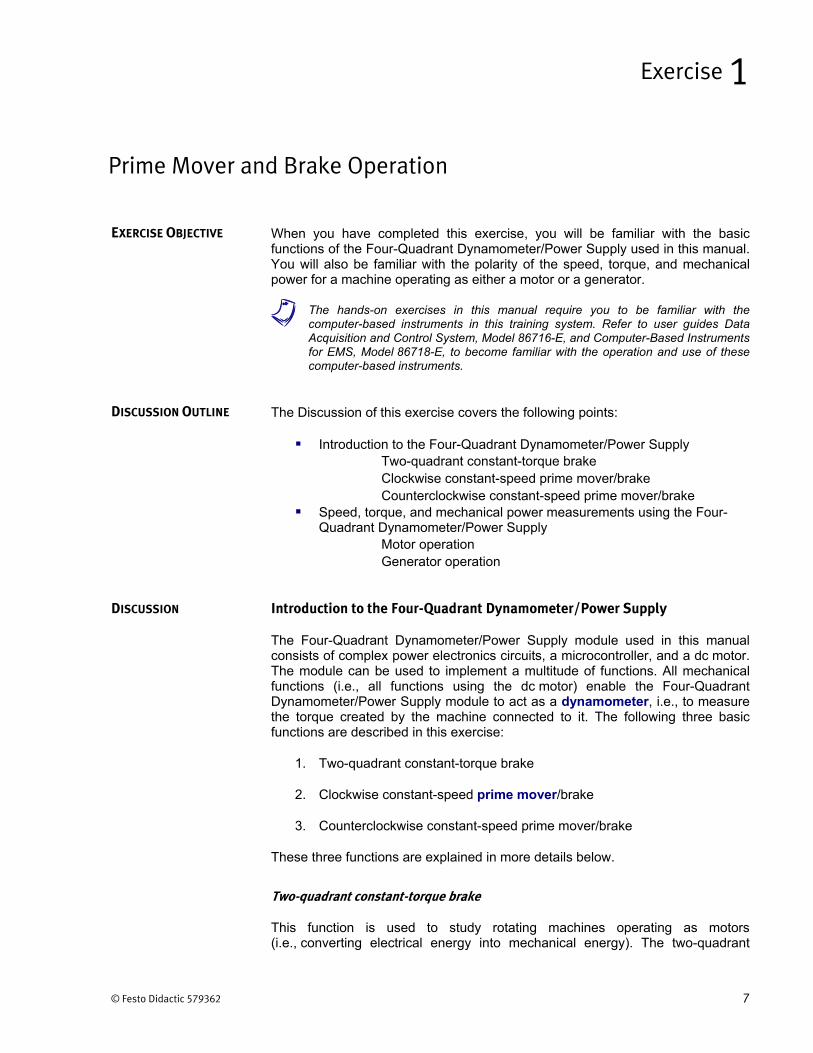
Figure 7. Permanent magnet dc motors can be used in mobility scooters and golf carts.
© Festo Didactic 579362 7
When you have completed this exercise, you will be familiar with the basic functions of the Four-Quadrant Dynamometer/Power Supply used in this manual. You will also be familiar with the polarity of the speed, torque, and mechanical power for a machine operating as either a motor or a generator.
a The hands-on exercises in this manual require you to be familiar with thecomputer-based instruments in this training system. Refer to user guides Data Acquisition and Control System, Model 86716-E, and Computer-Based Instruments for EMS, Model 86718-E, to become familiar with the operation and use of these computer-based instruments.
The Discussion of this exercise covers the following points:
Introduction to the Four-Quadrant Dynamometer/Power SupplyTwo-quadrant constant-torque brake Clockwise constant-speed prime mover/brake Counterclockwise constant-speed prime mover/brake
Speed, torque, and mechanical power measurements using the Four-Quadrant Dynamometer/Power Supply
Motor operation Generator operation
Introduction to the Four-Quadrant Dynamometer/Power Supply
The Four-Quadrant Dynamometer/Power Supply module used in this manual consists of complex power electronics circuits, a microcontroller, and a dc motor. The module can be used to implement a multitude of functions. All mechanical functions (i.e., all functions using the dc motor) enable the Four-Quadrant Dynamometer/Power Supply module to act as a dynamometer, i.e., to measure the torque created by the machine connected to it. The following three basic functions are described in this exercise:
1. Two-quadrant constant-torque brake
2. Clockwise constant-speed prime mover/brake
3. Counterclockwise constant-speed prime mover/brake
These three functions are explained in more details below.
Two-quadrant constant-torque brake
This function is used to study rotating machines operating as motors (i.e., converting electrical energy into mechanical energy). The two-quadrant
Prime Mover and Brake Operation
Exercise 1
EXERCISE OBJECTIVE
DISCUSSION OUTLINE
DISCUSSION
Exercise 1 – Prime Mover and Brake Operation Discussion
8 © Festo Didactic 579362
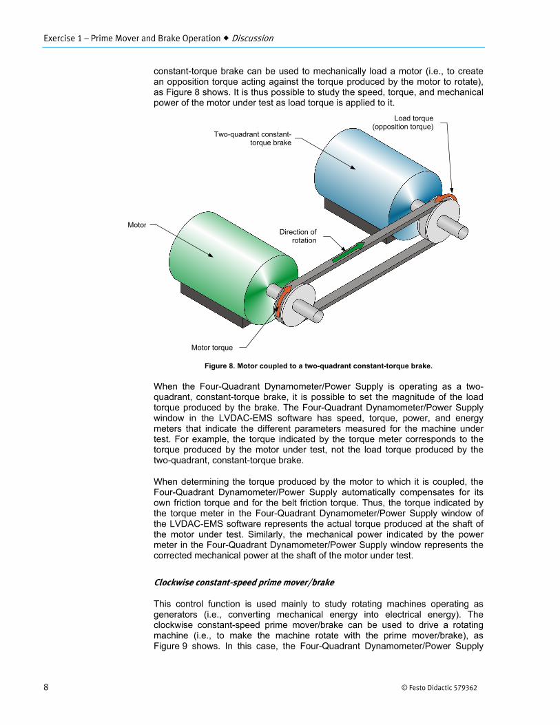
constant-torque brake can be used to mechanically load a motor (i.e., to create an opposition torque acting against the torque produced by the motor to rotate), as Figure 8 shows. It is thus possible to study the speed, torque, and mechanical power of the motor under test as load torque is applied to it.
Figure 8. Motor coupled to a two-quadrant constant-torque brake.
When the Four-Quadrant Dynamometer/Power Supply is operating as a two-quadrant, constant-torque brake, it is possible to set the magnitude of the load torque produced by the brake. The Four-Quadrant Dynamometer/Power Supply window in the LVDAC-EMS software has speed, torque, power, and energy meters that indicate the different parameters measured for the machine under test. For example, the torque indicated by the torque meter corresponds to the torque produced by the motor under test, not the load torque produced by the two-quadrant, constant-torque brake.
When determining the torque produced by the motor to which it is coupled, the Four-Quadrant Dynamometer/Power Supply automatically compensates for its own friction torque and for the belt friction torque. Thus, the torque indicated by the torque meter in the Four-Quadrant Dynamometer/Power Supply window of the LVDAC-EMS software represents the actual torque produced at the shaft of the motor under test. Similarly, the mechanical power indicated by the power meter in the Four-Quadrant Dynamometer/Power Supply window represents the corrected mechanical power at the shaft of the motor under test.
Clockwise constant-speed prime mover/brake
This control function is used mainly to study rotating machines operating as generators (i.e., converting mechanical energy into electrical energy). The clockwise constant-speed prime mover/brake can be used to drive a rotating machine (i.e., to make the machine rotate with the prime mover/brake), as Figure 9 shows. In this case, the Four-Quadrant Dynamometer/Power Supply
Direction of rotation
Motor torque
Load torque (opposition torque)
Motor
Two-quadrant constant-torque brake
Exercise 1 – Prime Mover and Brake Operation Discussion
© Festo Didactic 579362 9
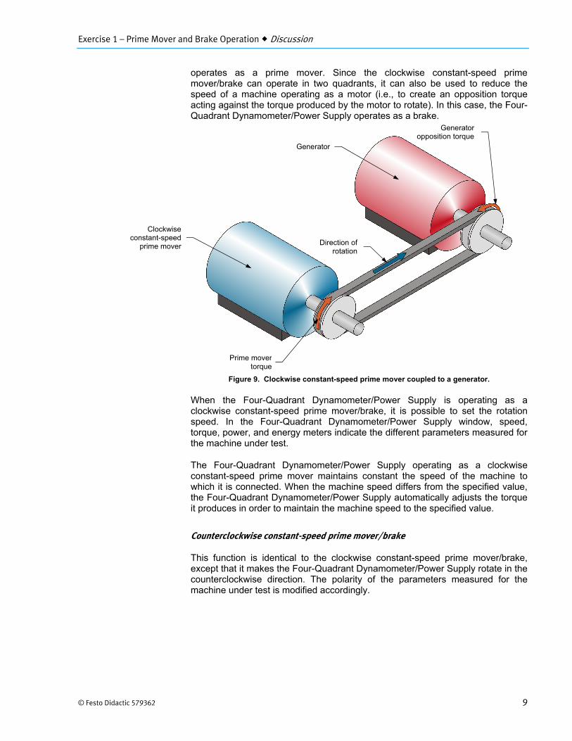
operates as a prime mover. Since the clockwise constant-speed prime mover/brake can operate in two quadrants, it can also be used to reduce the speed of a machine operating as a motor (i.e., to create an opposition torque acting against the torque produced by the motor to rotate). In this case, the Four- Quadrant Dynamometer/Power Supply operates as a brake.
Figure 9. Clockwise constant-speed prime mover coupled to a generator.
When the Four-Quadrant Dynamometer/Power Supply is operating as a clockwise constant-speed prime mover/brake, it is possible to set the rotation speed. In the Four-Quadrant Dynamometer/Power Supply window, speed, torque, power, and energy meters indicate the different parameters measured for the machine under test.
The Four-Quadrant Dynamometer/Power Supply operating as a clockwise constant-speed prime mover maintains constant the speed of the machine to which it is connected. When the machine speed differs from the specified value, the Four-Quadrant Dynamometer/Power Supply automatically adjusts the torque it produces in order to maintain the machine speed to the specified value.
Counterclockwise constant-speed prime mover/brake
This function is identical to the clockwise constant-speed prime mover/brake, except that it makes the Four-Quadrant Dynamometer/Power Supply rotate in the counterclockwise direction. The polarity of the parameters measured for the machine under test is modified accordingly.
Direction of rotation
Prime movertorque
Generator opposition torque
Clockwise constant-speed
prime mover
Generator
Exercise 1 – Prime Mover and Brake Operation Discussion
10 © Festo Didactic 579362
Speed, torque, and mechanical power measurements using the Four-Quadrant Dynamometer/Power Supply
The polarity of the torque and mechanical power measured for the machine connected to the Four-Quadrant Dynamometer/Power Supply depends on the machine’s mode of operation. There are two modes of operation: motor and generator.
Motor operation
As Figure 8 shows, when a machine operates as a motor, the motor torque is in the same direction as the motor’s direction of rotation, i.e., the speed at which the motor rotates is of the same polarity as the torque produced by the motor. Consequently, the mechanical power produced by the motor, which is proportional to the product of the motor speed and torque, is always positive, regardless of the motor’s direction of rotation (i.e., regardless of whether the motor speed and torque are positive or negative). This is consistent with the definition of a motor, which states that a motor uses electrical energy to produce mechanical energy, thus resulting in a positive mechanical power value.
Any load torque applied to the motor (such as the load torque created by the brake in Figure 8) acts against the torque produced by the motor, and thus has a polarity that is opposite to the polarity of the motor torque and speed.
Generator operation
As Figure 9 shows, when a machine operates as a generator, the generator torque is in the direction opposite to the direction of rotation, i.e., the speed at which the generator rotates has a polarity opposite to the polarity of the torque produced by the generator. Consequently, the mechanical power at the shaft of the generator, which is proportional to the product of the motor speed and torque, is always negative, regardless of the generator’s direction of rotation (i.e., regardless of whether the generator speed is positive or negative). This is consistent with the definition of a generator, which states that a generator uses mechanical energy to produce electrical energy, thus resulting in a negative mechanical power value.
The torque produced by the machine driving the generator (such as the prime mover torque in Figure 9) acts against the generator torque and thus has the same polarity as the generator speed.
By convention, the speed of a machine rotating in the clockwise direction is of positive polarity while the speed of a machine rotating in the counterclockwise direction is of negative polarity.
Exercise 1 – Prime Mover and Brake Operation Procedure Outline
© Festo Didactic 579362 11
The Procedure is divided into the following sections:
Setup and connections Two-quadrant, constant-torque brake operation Constant-speed prime mover operation Constant-speed prime mover driving a loaded generator
High voltages are present in this laboratory exercise. Do not make or modify any banana jack connections with the power on unless otherwise specified
Setup and connections
a Before performing this exercise, measure the open-circuit voltage across theLead-Acid Battery Pack (Model 8802), using a multimeter. If the open-circuit voltage is lower than 51.2 V, ask your instructor for assistance as the Lead-Acid Battery Pack is probably not fully charged. Appendix D of this manual indicates how to fully charge the Lead-Acid Battery Pack before a lab period.
In this section, you will mechanically couple the Permanent Magnet DC Motor to the Four-Quadrant Dynamometer/Power Supply. You will then set the equipment to study the two-quadrant, constant-torque brake operation.
1. Refer to the Equipment Utilization Chart in Appendix A to obtain the list ofequipment required to perform the exercise.
Install the equipment in the Workstation.
Mechanically couple the Permanent Magnet DC Motor to the Four-QuadrantDynamometer/Power Supply using a timing belt.
Before coupling rotating machines, make absolutely sure that power is turned offto prevent any machine from starting inadvertently.
2. Make sure that the main power switch on the Four-QuadrantDynamometer/Power Supply is set to the O (off) position, then connect itsPower Input to an ac power wall outlet.
3. Connect the USB port of the Four-Quadrant Dynamometer/Power Supply toa USB port of the host computer.
4. On the Permanent Magnet DC Motor, make sure that switch S1 is set to theO (off) position.
PROCEDURE OUTLINE
PROCEDURE
Exercise 1 – Prime Mover and Brake Operation Procedure
12 © Festo Didactic 579362
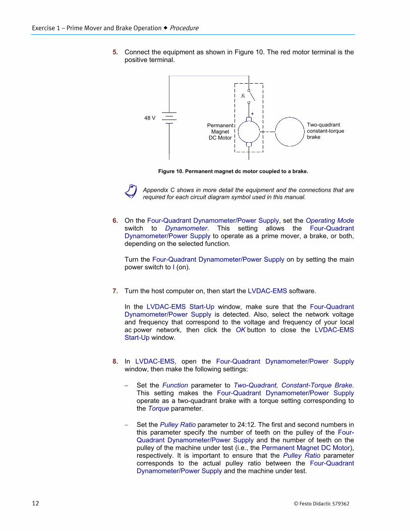
5. Connect the equipment as shown in Figure 10. The red motor terminal is thepositive terminal.
Figure 10. Permanent magnet dc motor coupled to a brake.
a Appendix C shows in more detail the equipment and the connections that arerequired for each circuit diagram symbol used in this manual.
6. On the Four-Quadrant Dynamometer/Power Supply, set the Operating Modeswitch to Dynamometer. This setting allows the Four-QuadrantDynamometer/Power Supply to operate as a prime mover, a brake, or both,depending on the selected function.
Turn the Four-Quadrant Dynamometer/Power Supply on by setting the mainpower switch to I (on).
7. Turn the host computer on, then start the LVDAC-EMS software.
In the LVDAC-EMS Start-Up window, make sure that the Four-QuadrantDynamometer/Power Supply is detected. Also, select the network voltageand frequency that correspond to the voltage and frequency of your localac power network, then click the OK button to close the LVDAC-EMSStart-Up window.
8. In LVDAC-EMS, open the Four-Quadrant Dynamometer/Power Supplywindow, then make the following settings:
Set the Function parameter to Two-Quadrant, Constant-Torque Brake.This setting makes the Four-Quadrant Dynamometer/Power Supply operate as a two-quadrant brake with a torque setting corresponding to the Torque parameter.
Set the Pulley Ratio parameter to 24:12. The first and second numbers in this parameter specify the number of teeth on the pulley of the Four-Quadrant Dynamometer/Power Supply and the number of teeth on the pulley of the machine under test (i.e., the Permanent Magnet DC Motor), respectively. It is important to ensure that the Pulley Ratio parameter corresponds to the actual pulley ratio between the Four-Quadrant Dynamometer/Power Supply and the machine under test.
Permanent Magnet
DC Motor
48 V Two-quadrant constant-torque brake
S1
Exercise 1 – Prime Mover and Brake Operation Procedure
© Festo Didactic 579362 13
Make sure that the Torque Control parameter is set to Knob. This allows the torque of the two-quadrant brake to be controlled manually.
Set the Torque parameter to the minimum value (0.0 N·m or 0.0 lbf·in) by entering this value in the field next to this parameter. This sets the torque command of the Two-Quadrant, Constant-Torque Brake to 0.0 N·m (0.0 lbf·in).
a The torque command can also be set by using the Torque control knob in theFour-Quadrant Dynamometer/Power Supply window.
Two-quadrant, constant-torque brake operation
In this section, you will make the Permanent Magnet DC Motor rotate in the clockwise direction and observe what happens to the torque produced by the motor when you increase the load torque applied to it. You will observe the polarity of the torque and the mechanical power produced by the Permanent Magnet DC Motor, and confirm that this machine is operating as a motor. You will then make the Permanent Magnet DC Motor rotate in the counterclockwise direction and observe what happens to the torque produced by the motor when you increase the load torque applied to it. You will observe the polarity of the torque and mechanical power produced by the Permanent Magnet DC Motor, and confirm that the machine can operate as a motor, in either direction of rotation (clockwise or counterclockwise).
9. In the Four-Quadrant Dynamometer/Power Supply window, start the Two-Quadrant, Constant-Torque Brake by setting the Status parameter to Startedor by clicking the Start/Stop button.
On the Permanent Magnet DC Motor, set switch S1 to the I (on) position.Observe that the motor starts rotating. This is because the Lead-Acid BatteryPack acts as a dc power source supplying power to the Permanent MagnetDC Motor to make it rotate.
The Speed meter in the Four-Quadrant Dynamometer/Power Supply windowindicates the rotation speed of the Permanent Magnet DC Motor. Is thisspeed positive, indicating that the motor is rotating in the clockwise direction?
Yes No
10. In the Four-Quadrant Dynamometer/Power Supply window, slowly increasethe value of the Torque parameter to 0.5 N·m (4.4 lbf·in). While you do so,observe the torque produced by the Permanent Magnet DC Motor(indicated by the Torque meter in the Four-Quadrant Dynamometer/PowerSupply window).
What happens to the torque produced by the Permanent Magnet DC Motoras the load torque applied to the motor by the Two-Quadrant, Constant-Torque Brake increases?
Exercise 1 – Prime Mover and Brake Operation Procedure
14 © Festo Didactic 579362
11. What is the polarity of the torque produced by the Permanent MagnetDC Motor?
What is the polarity of the Permanent Magnet DC Motor speed ?
Is the torque of the same polarity as the motor speed ?
Yes No
12. Is the polarity of the motor mechanical power positive (indicated by thePower meter in the Four-Quadrant Dynamometer/Power Supply window)?
Yes No
Does this confirm that the Permanent Magnet DC Motor currently operates as a motor? Explain.
13. Stop the Permanent Magnet DC Motor by setting its power switch S1 tothe O (off) position.
In the Four-Quadrant Dynamometer/Power Supply window, set the Torqueparameter to 0.0 N·m (0.0 lbf·in).
14. On the Lead-Acid Battery Pack, reverse the battery connections to reversethe polarity of the voltage applied to the Permanent Magnet DC Motor.
a Reversing the power supply connections at the two terminals of a dc motorreverses the direction of rotation of the motor.
Start the Permanent Magnet DC Motor by setting its power switch S1 tothe I (on) position. Is the Permanent Magnet DC Motor speed negative,indicating that the direction of rotation of the motor has been reversed andthat the motor is rotating in the counterclockwise direction?
Yes No
15. In the Four-Quadrant Dynamometer/Power Supply window, slowly increasethe value of the Torque parameter to 0.5 N·m (4.4 lbf·in). While you do so,observe the torque produced by the Permanent Magnet DC Motor.
Exercise 1 – Prime Mover and Brake Operation Procedure
© Festo Didactic 579362 15
What happens to the torque produced by the Permanent Magnet DC Motor as the braking torque applied to the motor by the Two-Quadrant, Constant-Torque Brake increases?
16. Is the torque produced by the Permanent Magnet DC Motor of the samepolarity as the motor speed ?
Yes No
17. Is the polarity of the motor mechanical power positive?
Yes No
Does this confirm that the Permanent Magnet DC Motor currently operates as a motor?
Yes No
18. Stop the Permanent Magnet DC Motor by setting its power switch S1 tothe O (off) position.
In the Four-Quadrant Dynamometer/Power Supply window, stop the Two-Quadrant, Constant-Torque Brake by setting the Status parameter toStopped or by clicking the Start/Stop button.
19. From your observations, does the direction of rotation of the PermanentMagnet DC Motor determine the polarity (positive or negative) of the motorspeed and torque ? Explain.
Can the Permanent Magnet DC Motor operate as a motor in either direction of rotation (clockwise or counterclockwise)? Explain.
Exercise 1 – Prime Mover and Brake Operation Procedure
16 © Festo Didactic 579362
Constant-speed prime mover operation
In this section, you will set up a circuit containing a prime mover (implemented using the Four-Quadrant Dynamometer/Power Supply) mechanically coupled to the Permanent Magnet DC Motor. You will make the prime mover rotate in the clockwise direction and confirm that the Permanent Magnet DC Motor rotates at the specified speed determined by the prime mover speed and the pulley ratio. You will also confirm that the torque produced by the machine is virtually zero. You will make the prime mover rotate in the counterclockwise direction and confirm that the speed of the Permanent Magnet DC Motor is negative when it rotates in the counterclockwise direction. You will also confirm that the torque produced by the machine is virtually zero.
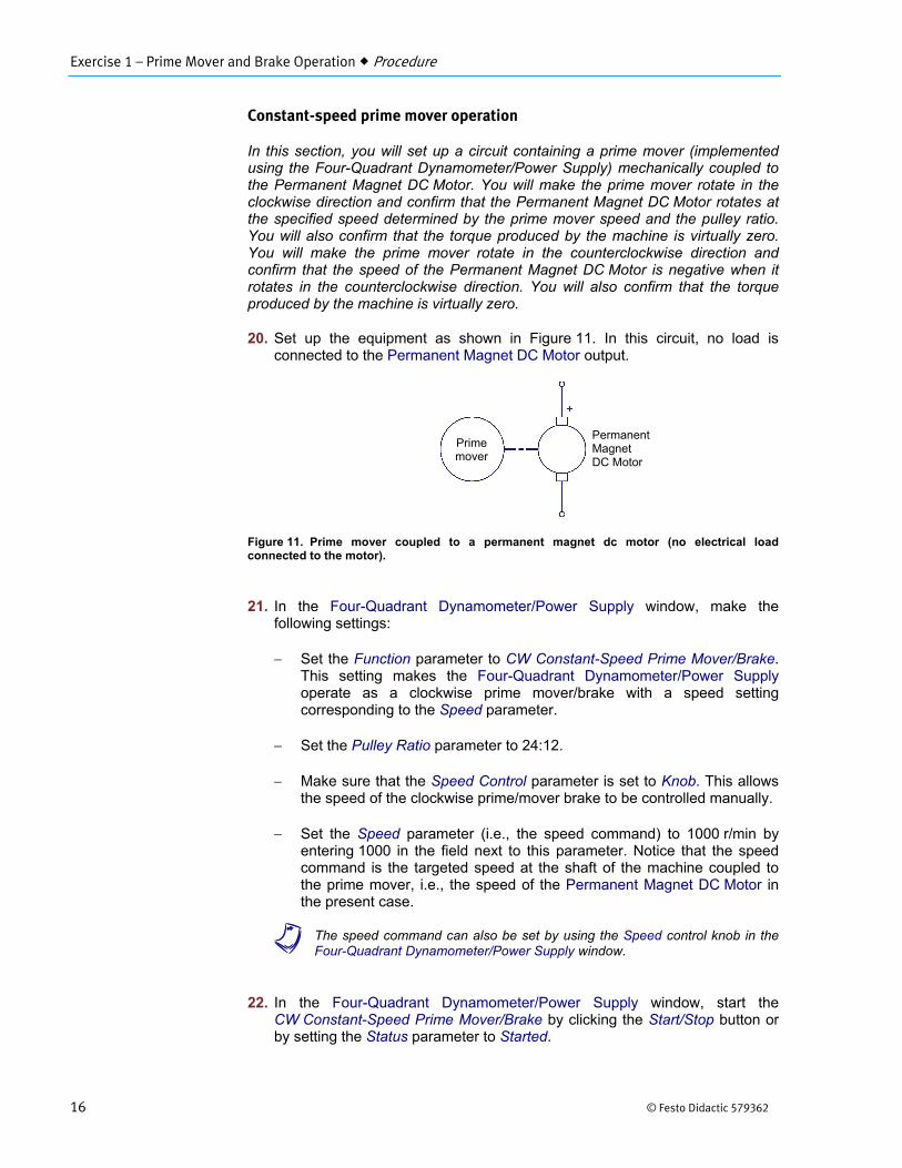
20. Set up the equipment as shown in Figure 11. In this circuit, no load isconnected to the Permanent Magnet DC Motor output.
Figure 11. Prime mover coupled to a permanent magnet dc motor (no electrical load connected to the motor).
21. In the Four-Quadrant Dynamometer/Power Supply window, make thefollowing settings:
Set the Function parameter to CW Constant-Speed Prime Mover/Brake.This setting makes the Four-Quadrant Dynamometer/Power Supply operate as a clockwise prime mover/brake with a speed setting corresponding to the Speed parameter.
Set the Pulley Ratio parameter to 24:12.
Make sure that the Speed Control parameter is set to Knob. This allows the speed of the clockwise prime/mover brake to be controlled manually.
Set the Speed parameter (i.e., the speed command) to 1000 r/min by entering 1000 in the field next to this parameter. Notice that the speed command is the targeted speed at the shaft of the machine coupled to the prime mover, i.e., the speed of the Permanent Magnet DC Motor in the present case.
a The speed command can also be set by using the Speed control knob in theFour-Quadrant Dynamometer/Power Supply window.
22. In the Four-Quadrant Dynamometer/Power Supply window, start theCW Constant-Speed Prime Mover/Brake by clicking the Start/Stop button orby setting the Status parameter to Started.
Permanent Magnet DC Motor
Prime mover
Exercise 1 – Prime Mover and Brake Operation Procedure
© Festo Didactic 579362 17
Observe that the prime mover starts to rotate, thereby driving the shaft of the Permanent Magnet DC Motor.
In the Four-Quadrant Dynamometer/Power Supply window, observe that the Pulley Ratio parameter is now grayed out as it cannot be changed while the prime mover is rotating. The Speed meter indicates the rotation speed of the Permanent Magnet DC Motor. Record this speed below.
Rotation speed of the permanent magnet dc motor = r/min
Is the rotation speed of the Permanent Magnet DC Motor approximately equal to the value of the Speed parameter?
Yes No
Is the rotation speed positive, indicating that the Permanent Magnet DC Motor is rotating in the clockwise direction?
Yes No
23. Observe the rotation speed indicated on the front panel display of the Four-Quadrant Dynamometer/Power Supply module. It corresponds to the rotationspeed of the prime mover. Notice that this speed is approximately half(≅ 500 r/min) the speed of the Permanent Magnet DC Motor. This is becausethe pulley ratio of 24:12 causes the prime mover to make ½ (12 24)revolution for every revolution of the Permanent Magnet DC Motor. Is thisyour observation?
Yes No
24. In the Four-Quadrant Dynamometer/Power Supply window, observe thetorque of the Permanent Magnet DC Motor.
Is the torque virtually zero, indicating that no torque is produced by thePermanent Magnet DC Motor?
Yes No
25. In the Four-Quadrant Dynamometer/Power Supply window, increase theSpeed parameter to 1500 r/min.
Does the speed of the Permanent Magnet DC Motor increase with theSpeed parameter of the CW Constant-Speed Prime Mover/Brake?
Yes No
Does the motor torque remain virtually zero as the speed increases?
Yes No
Exercise 1 – Prime Mover and Brake Operation Procedure
18 © Festo Didactic 579362
26. In the Four-Quadrant Dynamometer/Power Supply window, stop theCW Constant-Speed Prime Mover/Brake by clicking the Start/Stop button orby setting the Status parameter to Stopped, then make the following settings:
Set the Function parameter to CCW Constant-Speed PrimeMover/Brake. This setting makes the Four-Quadrant Dynamometer/Power Supply operate as a counterclockwise prime mover/brake with a speed setting corresponding to the Speed parameter.
Set the Pulley Ratio parameter to 24:12.
Make sure that the Speed Control parameter is set to Knob. This allows the speed of the counterclockwise prime/mover brake to be controlled manually.
Set the Speed parameter to 1000 r/min.
27. In the Four-Quadrant Dynamometer/Power Supply window, start theCCW Constant-Speed Prime Mover/Brake by clicking the Start/Stop buttonor by setting the Status parameter to Started.
28. Wait a few seconds, then observe the Permanent Magnet DC Motor speedand torque.
Is the rotation speed of the Permanent Magnet DC Motor approximatelyequal to the value of the Speed parameter?
Yes No
Is the motor speed negative, indicating that the Permanent Magnet DC Motor is rotating in the counterclockwise direction?
Yes No
Is the motor torque virtually zero, indicating that no torque is produced by the Permanent Magnet DC Motor?
Yes No
29. In the Four-Quadrant Dynamometer/Power Supply window, increase theSpeed parameter to 1500 r/min.
Does the speed of the Permanent Magnet DC Motor increase (with anegative polarity) as the Speed parameter of the CCW Constant-SpeedPrime Mover/Brake increases?
Yes No
Does the motor torque remain virtually zero as the speed increases?
Yes No
Exercise 1 – Prime Mover and Brake Operation Procedure
© Festo Didactic 579362 19
30. In the Four-Quadrant Dynamometer/Power Supply window, stop theCCW Constant-Speed Prime Mover/Brake by clicking the Start/Stop buttonor by setting the Status parameter to Stopped.
Constant-speed prime mover driving a loaded generator
In this section, you will set up a circuit containing a prime mover (implemented using the Four-Quadrant Dynamometer/Power Supply) mechanically coupled to the Permanent Magnet DC Motor operating as a generator. The output of the generator will be short circuited. You will make the generator rotate in the clockwise direction and confirm that the generator speed and torque are of opposite polarity, and that the generator mechanical power is negative, thus indicating that the machine is operating as a generator. You will then make the generator rotate in the counterclockwise direction and verify that the generator speed and torque are of opposite polarity, and that the generator mechanical power is negative. Finally, you will confirm that the machine can operate as a generator, regardless of the direction of rotation.
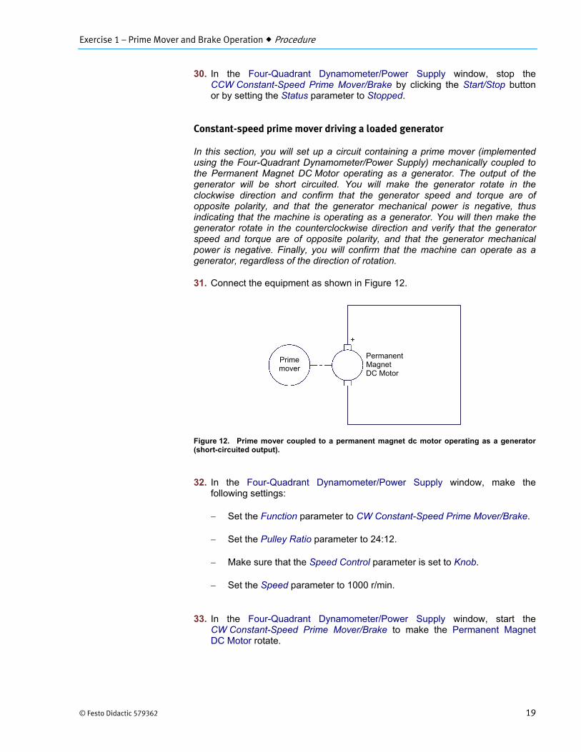
31. Connect the equipment as shown in Figure 12.
Figure 12. Prime mover coupled to a permanent magnet dc motor operating as a generator (short-circuited output).
32. In the Four-Quadrant Dynamometer/Power Supply window, make thefollowing settings:
Set the Function parameter to CW Constant-Speed Prime Mover/Brake.
Set the Pulley Ratio parameter to 24:12.
Make sure that the Speed Control parameter is set to Knob.
Set the Speed parameter to 1000 r/min.
33. In the Four-Quadrant Dynamometer/Power Supply window, start theCW Constant-Speed Prime Mover/Brake to make the Permanent MagnetDC Motor rotate.
Permanent Magnet DC Motor
Prime mover
Exercise 1 – Prime Mover and Brake Operation Procedure
20 © Festo Didactic 579362
34. What is the polarity of the torque produced by the Permanent MagnetDC Motor?
What is the polarity of the Permanent Magnet DC Motor speed ?
Are the speed and torque of opposite polarity?
Yes No
35. Is the polarity of the motor mechanical power negative?
Yes No
Does this confirm that the Permanent Magnet DC Motor currently operates as a generator? Explain.
36. Slowly increase the Speed parameter to 1500 r/min. While you do so,observe the speed , torque , and mechanical power of the PermanentMagnet DC Motor on the meters in the Four-Quadrant Dynamometer/PowerSupply.
Describe what happens to the torque and mechanical power as the speedincreases.
37. Observe the rotation speed indicated on the front panel display of the Four-Quadrant Dynamometer/Power Supply module. It corresponds to the rotationspeed of the prime mover. Notice that this speed is approximately half(≅ 750 r/min) the generator speed. This is because the pulley ratio of 24:12causes the prime mover to make ½ (12 24) revolution for every revolutionof the generator. Is this your observation?
Yes No
Also, observe the torque indicated on the front panel display of the Four-Quadrant Dynamometer/Power Supply module. It corresponds to the torque of the prime mover. Notice that this torque is approximately twice the generator torque. This is because the pulley ratio of 24:12 causes the prime mover torque to be 2 times (24 12) greater than the generator torque. Is this your observation?
Yes No
Exercise 1 – Prime Mover and Brake Operation Procedure
© Festo Didactic 579362 21
38. In the Four-Quadrant Dynamometer/Power Supply window, stop theCW Constant-Speed Prime Mover/Brake, then make the following setting:
Set the Function parameter to CCW Constant-Speed Prime Mover/Brake.
Set the Pulley Ratio parameter to 24:12.
Make sure that the Speed Control parameter is set to Knob.
Set the Speed parameter to 1000 r/min.
Start the CCW Constant-Speed Prime Mover/Brake to make the Permanent Magnet DC Motor rotate.
39. Slowly increase the Speed parameter to -1500 r/min. Describe what happensto the torque as the speed increases.
Are the generator speed and torque of opposite polarity?
Yes No
40. Is the polarity of the motor mechanical power negative?
Yes No
Does this confirm that the Permanent Magnet DC Motor currently operates as a generator?
Yes No
41. In the Four-Quadrant Dynamometer/Power Supply window, stop theCCW Constant-Speed Prime Mover/Brake by setting the Status parameter toStopped or by clicking the Start/Stop button.
42. From your observations, does the direction of rotation determine the polarityof the generator speed and torque ? Explain.
Exercise 1 – Prime Mover and Brake Operation Conclusion
22 © Festo Didactic 579362
Can the Permanent Magnet DC Motor operate as a generator in either direction of rotation (clockwise or counterclockwise)?
Yes No
43. Turn the Four-Quadrant Dynamometer/Power Supply off by setting the mainpower switch to O (off). Close the LVDAC-EMS software. Disconnect allleads and return them to their storage location.
In this exercise, you familiarized yourself with the basic functions of the Four-Quadrant Dynamometer/Power Supply used in this manual. You observed the polarity of the speed, torque, and mechanical power for a rotating machine operating either as a motor or a generator.
1. Calculate the power of a motor rotating at a speed of 2000 r/min andproducing a torque of 1.2 N·m (10.6 lbf·in).
2. Briefly describe a brake and a prime mover.
3. Briefly describe the energy conversion occurring in a motor, as well as theenergy conversion occurring in a generator.
4. Consider a motor rotating in the clockwise direction that is coupled to a brakeapplying a load torque to the motor. Determine the polarity of the motorspeed and torque, as well as the polarity of the braking torque. Also,determine the polarity of the motor mechanical power.
CONCLUSION
REVIEW QUESTIONS

Exercise 1 – Prime Mover and Brake Operation Review Questions
© Festo Didactic 579362 23
5. Consider a prime mover making a generator rotate in the clockwise direction.Determine the polarity of the prime mover torque, as well as the polarity ofthe generator speed and torque. Also, determine the polarity of the generatormechanical power.

© Festo Didactic 579362 25
When you have completed this exercise, you will be familiar with the construction of permanent magnet dc motors as well as their operation as generators.
The Discussion of this exercise covers the following points:
Permanent magnets Magnetic field around a conductor Magnetic field in a loop of wire (electromagnet) Electromagnetic induction Construction of a permanent magnet dc motor Permanent magnet dc motor operating as a generator Reducing the fluctuations of the generated dc voltage Characteristic of the generated voltage as a function of the rotation
speed Torque opposing rotation in a permanent magnet dc motor operating as
a generator Opposition torque-versus-current characteristic
Permanent magnets
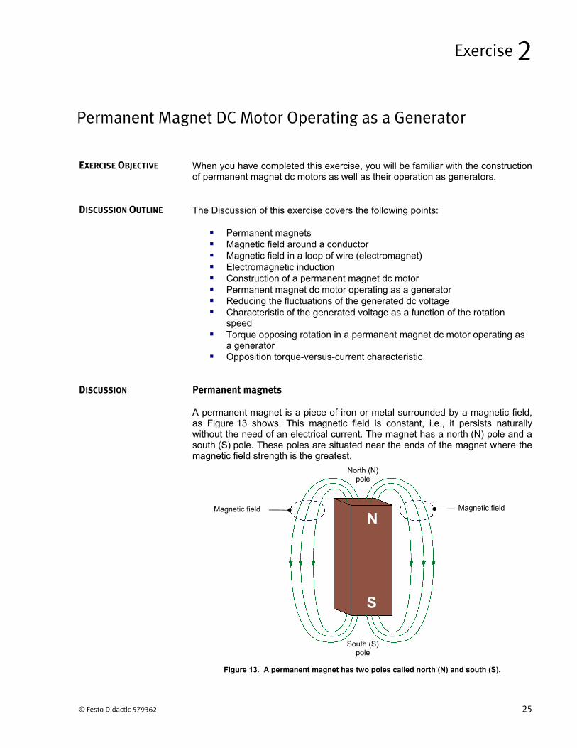
A permanent magnet is a piece of iron or metal surrounded by a magnetic field, as Figure 13 shows. This magnetic field is constant, i.e., it persists naturally without the need of an electrical current. The magnet has a north (N) pole and a south (S) pole. These poles are situated near the ends of the magnet where the magnetic field strength is the greatest.
Figure 13. A permanent magnet has two poles called north (N) and south (S).
Permanent Magnet DC Motor Operating as a Generator
Exercise 2
EXERCISE OBJECTIVE
DISCUSSION OUTLINE
DISCUSSION
South (S) pole
North (N) pole
Magnetic fieldMagnetic field
N
S
Exercise 2 – Permanent Magnet DC Motor Operating as a Generator Discussion
26 © Festo Didactic 579362
The direction of the magnetic field is indicated by the line arrows: from north to south outside the magnet, and from south to north within the magnet.
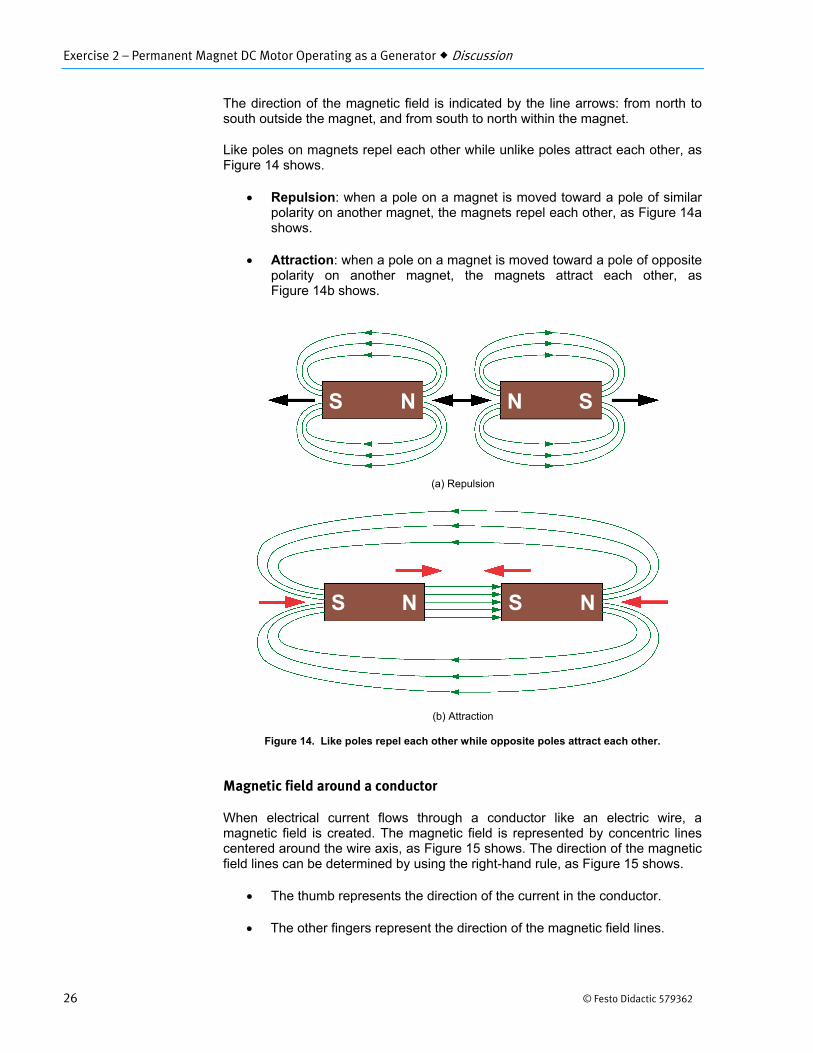
Like poles on magnets repel each other while unlike poles attract each other, as Figure 14 shows.
Repulsion: when a pole on a magnet is moved toward a pole of similarpolarity on another magnet, the magnets repel each other, as Figure 14ashows.
Attraction: when a pole on a magnet is moved toward a pole of oppositepolarity on another magnet, the magnets attract each other, asFigure 14b shows.
Figure 14. Like poles repel each other while opposite poles attract each other.
Magnetic field around a conductor
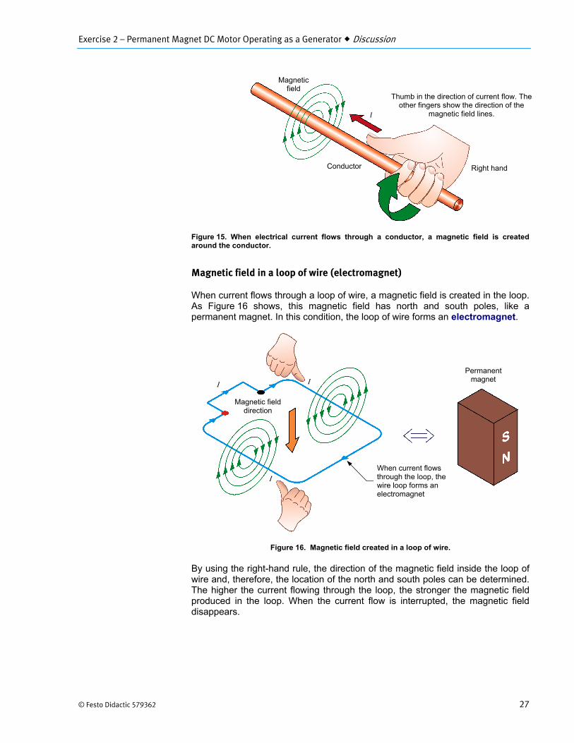
When electrical current flows through a conductor like an electric wire, a magnetic field is created. The magnetic field is represented by concentric lines centered around the wire axis, as Figure 15 shows. The direction of the magnetic field lines can be determined by using the right-hand rule, as Figure 15 shows.
The thumb represents the direction of the current in the conductor.
The other fingers represent the direction of the magnetic field lines.
(a) Repulsion
(b) Attraction
N N
S
SS
S NN
Exercise 2 – Permanent Magnet DC Motor Operating as a Generator Discussion
© Festo Didactic 579362 27
Figure 15. When electrical current flows through a conductor, a magnetic field is created around the conductor.
Magnetic field in a loop of wire (electromagnet)
When current flows through a loop of wire, a magnetic field is created in the loop. As Figure 16 shows, this magnetic field has north and south poles, like a permanent magnet. In this condition, the loop of wire forms an electromagnet.
Figure 16. Magnetic field created in a loop of wire.
By using the right-hand rule, the direction of the magnetic field inside the loop of wire and, therefore, the location of the north and south poles can be determined. The higher the current flowing through the loop, the stronger the magnetic field produced in the loop. When the current flow is interrupted, the magnetic field disappears.
Thumb in the direction of current flow. The other fingers show the direction of the
magnetic field lines.
Magnetic field
Right handConductor
I
I I
Magnetic field direction
Permanent magnet
When current flows through the loop, the wire loop forms an electromagnet
Exercise 2 – Permanent Magnet DC Motor Operating as a Generator Discussion
28 © Festo Didactic 579362
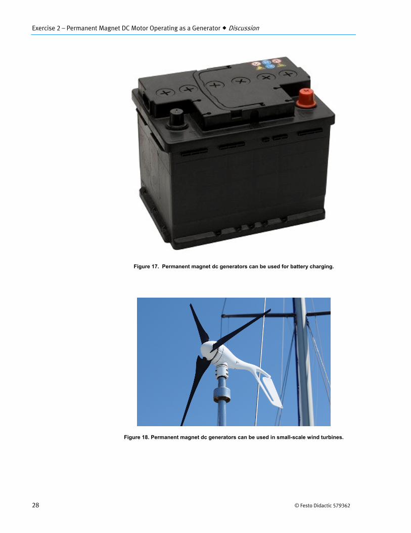
Figure 17. Permanent magnet dc generators can be used for battery charging.
Figure 18. Permanent magnet dc generators can be used in small-scale wind turbines.
Exercise 2 – Permanent Magnet DC Motor Operating as a Generator Discussion
© Festo Didactic 579362 29
Electromagnetic induction
The operation of various electric devices (transformers, generators, alternators, motors, etc.) is based on Faraday’s law of electromagnetic induction, which states the following:
1. A voltage is induced across the terminals of a wire loop if the magneticflux passing through the loop varies as a function of time.
2. The value of the induced voltage is proportional to the rate of change ofthe magnetic flux.
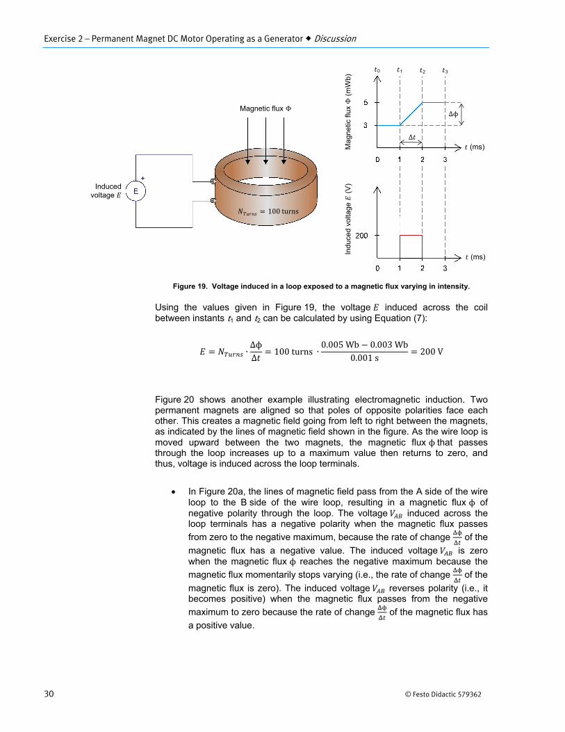
The voltage induced across the terminals of a wire loop when the magnetic flux passing through the loop varies can be calculated using the following equation:
∙ΔϕΔ
(7)
where is the voltage induced across the terminals of the wire loop, expressed in volts (V). is the number of turns of wire in the loop.
Δϕ is the variation in intensity of the magnetic flux passing through the wire loop, expressed in Webers (Wb).
Δ is the time interval during which the magnetic flux variation occurs, expressed in seconds (s).
Figure 19 gives an example of the voltage induced across a wire loop that is exposed to a magnetic flux varying in intensity. Between instants and , the intensity of the magnetic flux ϕremains constant (3 mWb), and thus, the induced voltage is zero. Between instants and , the intensity of the magnetic flux ϕ increases at a constant rate, and thus, a constant voltage is induced in the wire loop. Between instants and , the intensity of the magnetic ϕ flux remains constant (5 mWb), and thus, the induced voltage is zero.
Exercise 2 – Permanent Magnet DC Motor Operating as a Generator Discussion
30 © Festo Didactic 579362
Figure 19. Voltage induced in a loop exposed to a magnetic flux varying in intensity.
Using the values given in Figure 19, the voltage induced across the coil between instants t1 and t2 can be calculated by using Equation (7):
∙ΔϕΔ
100 turns ∙0.005 Wb 0.003 Wb
0.001 s200V
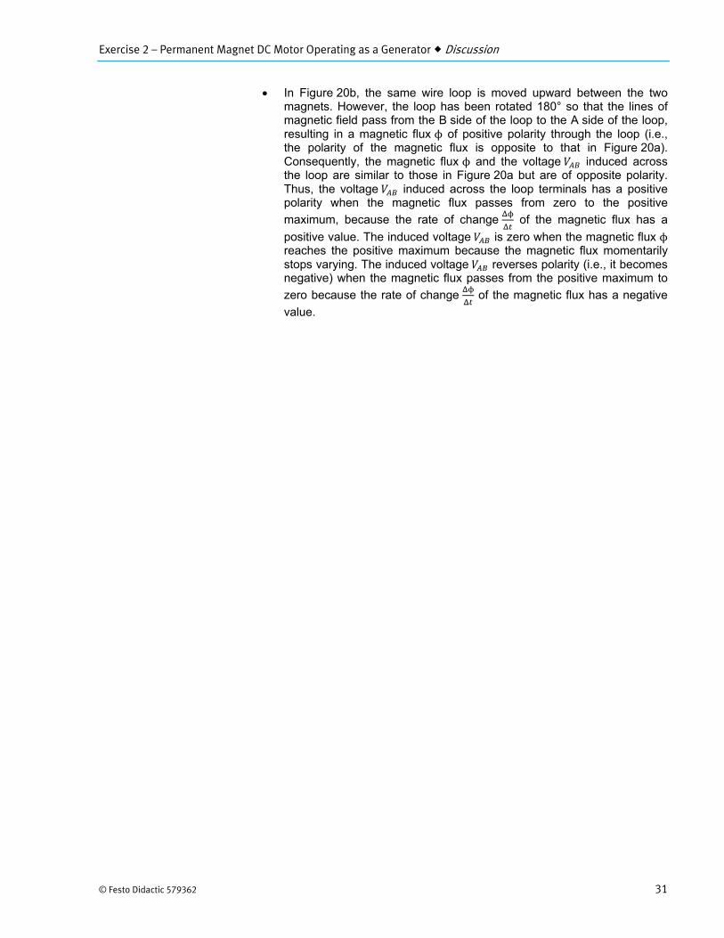
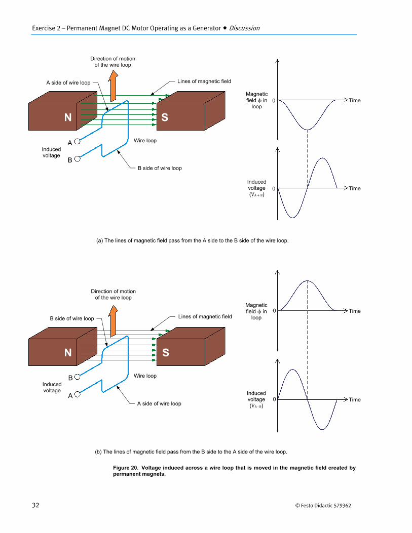
Figure 20 shows another example illustrating electromagnetic induction. Two permanent magnets are aligned so that poles of opposite polarities face each other. This creates a magnetic field going from left to right between the magnets, as indicated by the lines of magnetic field shown in the figure. As the wire loop is moved upward between the two magnets, the magnetic flux ϕthat passes through the loop increases up to a maximum value then returns to zero, and thus, voltage is induced across the loop terminals.
In Figure 20a, the lines of magnetic field pass from the A side of the wireloop to the B side of the wire loop, resulting in a magnetic flux ϕ ofnegative polarity through the loop. The voltage induced across theloop terminals has a negative polarity when the magnetic flux passes
from zero to the negative maximum, because the rate of change of the
magnetic flux has a negative value. The induced voltage is zerowhen the magnetic flux ϕ reaches the negative maximum because the
magnetic flux momentarily stops varying (i.e., the rate of change of the
magnetic flux is zero). The induced voltage reverses polarity (i.e., itbecomes positive) when the magnetic flux passes from the negative
maximum to zero because the rate of change of the magnetic flux has
a positive value.
Inducedvoltage
Magnetic flux Φ
100 turns
(ms)
(ms)
Indu
ced
volta
ge
(V
) M
agne
tic fl
ux Φ
(m
Wb)
0 1 2 3
Δ
Δϕ
Exercise 2 – Permanent Magnet DC Motor Operating as a Generator Discussion
© Festo Didactic 579362 31
In Figure 20b, the same wire loop is moved upward between the twomagnets. However, the loop has been rotated 180° so that the lines ofmagnetic field pass from the B side of the loop to the A side of the loop,resulting in a magnetic flux ϕ of positive polarity through the loop (i.e.,the polarity of the magnetic flux is opposite to that in Figure 20a).Consequently, the magnetic flux ϕ and the voltage induced acrossthe loop are similar to those in Figure 20a but are of opposite polarity.Thus, the voltage induced across the loop terminals has a positivepolarity when the magnetic flux passes from zero to the positive
maximum, because the rate of change of the magnetic flux has a
positive value. The induced voltage is zero when the magnetic flux ϕreaches the positive maximum because the magnetic flux momentarilystops varying. The induced voltage reverses polarity (i.e., it becomesnegative) when the magnetic flux passes from the positive maximum to
zero because the rate of change of the magnetic flux has a negative
value.
Exercise 2 – Permanent Magnet DC Motor Operating as a Generator Discussion
32 © Festo Didactic 579362
Figure 20. Voltage induced across a wire loop that is moved in the magnetic field created by permanent magnets.
Time
Time
Induced voltage (VA ‐ B)
0
Magnetic field ϕ in
loop 0
(a) The lines of magnetic field pass from the A side to the B side of the wire loop.
(b) The lines of magnetic field pass from the B side to the A side of the wire loop.
Time
Time
Induced voltage (VA B)
0
Magnetic field ϕ in
loop 0
Direction of motion of the wire loop
Wire loop
Direction of motion of the wire loop
B
A
A
B
Lines of magnetic field
SN
Wire loop
Lines of magnetic field
SN
Induced voltage
Induced voltage
B side of wire loop
A side of wire loop
B side of wire loop
A side of wire loop
Exercise 2 – Permanent Magnet DC Motor Operating as a Generator Discussion
© Festo Didactic 579362 33
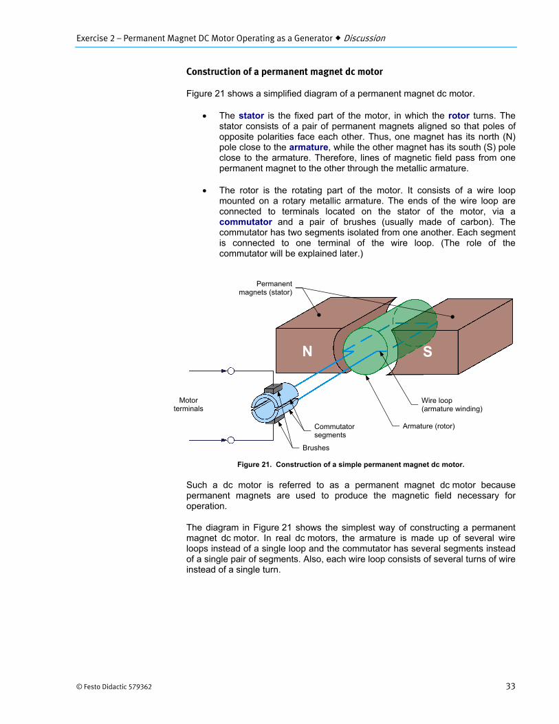
Construction of a permanent magnet dc motor
Figure 21 shows a simplified diagram of a permanent magnet dc motor.
The stator is the fixed part of the motor, in which the rotor turns. Thestator consists of a pair of permanent magnets aligned so that poles ofopposite polarities face each other. Thus, one magnet has its north (N)pole close to the armature, while the other magnet has its south (S) poleclose to the armature. Therefore, lines of magnetic field pass from onepermanent magnet to the other through the metallic armature.
The rotor is the rotating part of the motor. It consists of a wire loopmounted on a rotary metallic armature. The ends of the wire loop areconnected to terminals located on the stator of the motor, via acommutator and a pair of brushes (usually made of carbon). Thecommutator has two segments isolated from one another. Each segmentis connected to one terminal of the wire loop. (The role of thecommutator will be explained later.)
Figure 21. Construction of a simple permanent magnet dc motor.
Such a dc motor is referred to as a permanent magnet dc motor because permanent magnets are used to produce the magnetic field necessary for operation.
The diagram in Figure 21 shows the simplest way of constructing a permanent magnet dc motor. In real dc motors, the armature is made up of several wire loops instead of a single loop and the commutator has several segments instead of a single pair of segments. Also, each wire loop consists of several turns of wire instead of a single turn.
N S
Motor terminals
Wire loop (armature winding)
Armature (rotor)Commutator segments
Brushes
Permanentmagnets (stator)
Exercise 2 – Permanent Magnet DC Motor Operating as a Generator Discussion
34 © Festo Didactic 579362
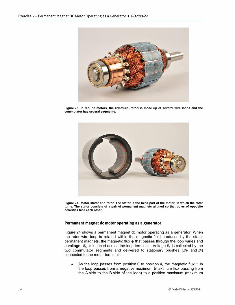
Figure 22. In real dc motors, the armature (rotor) is made up of several wire loops and the commutator has several segments.
Figure 23. Motor stator and rotor. The stator is the fixed part of the motor, in which the rotor turns. The stator consists of a pair of permanent magnets aligned so that poles of opposite polarities face each other.
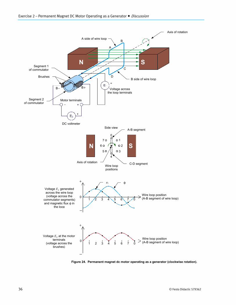
Permanent magnet dc motor operating as a generator
Figure 24 shows a permanent magnet dc motor operating as a generator. When the rotor wire loop is rotated within the magnetic field produced by the stator permanent magnets, the magnetic flux ϕ that passes through the loop varies and a voltage, E1, is induced across the loop terminals. Voltage is collected by the two commutator segments and delivered to stationary brushes (B and B-) connected to the motor terminals.
As the loop passes from position 0 to position 4, the magnetic flux ϕ inthe loop passes from a negative maximum (maximum flux passing fromthe A side to the B side of the loop) to a positive maximum (maximum
Exercise 2 – Permanent Magnet DC Motor Operating as a Generator Discussion
© Festo Didactic 579362 35
flux passing from the B side to the A side of the loop). During this 180° interval of rotation, the voltage induced across the loop has a
positive polarity because the rate of change of the magnetic flux has a
positive value.
When the loop reaches position 4, the connections of the twocommutator segments to brushes B‐ and B are reversed.Consequently, this reverses the connections between the wire loopterminals and the motor terminals.
As the loop passes from position 4 to position 0, the magnetic flux ϕ inthe loop passes from a positive maximum (maximum flux passing fromthe B side to the A side of the loop) to a negative maximum (maximumflux passing from the A side to the B side of the loop). During this180° interval of rotation, the voltage induced across the loop has a
negative polarity because the rate of change of the magnetic flux has
a negative value.
When the loop reaches position 0, the connections of the twocommutator segments to brushes B‐and B are reversed again, therebyreversing the connections between the wire loop terminals and the motorterminals.
This cycles repeats as long as the rotor continues to rotate, so that the polarity of the voltage generated across the rotor wire loop continually alternates: it is positive for half a turn, then negative for the next half turn, then positive for the next half turn, and so on. Because of this, the voltage generated across the rotor wire loop is referred to as an alternating-current (ac) voltage. Because the commutator reverses the connections between the wire loop terminals and the motor terminals at wire loop positions 0 and 4, the voltage at the motor terminals always has the same polarity (positive), as is shown in Figure 24. The voltage at the motor terminals is thus a pulsating positive direct-current (dc) voltage (two pulses per rotation).
Exercise 2 – Permanent Magnet DC Motor Operating as a Generator Discussion
36 © Festo Didactic 579362
Figure 24. Permanent magnet dc motor operating as a generator (clockwise rotation).
Segment 1of commutator
Brushes
Segment 2of commutator
Motor terminals
DC voltmeter
A
B
C
D
Axis of rotation
Axis of rotation
Wire loop positions
Voltage 2 at the motor terminals
(voltage across the brushes)
Voltage 1 generated across the wire loop (voltage across the
commutator segments) and magnetic flux ϕin
the loop
1 2 3 4 5 6 7 00
Wire loop position (A-B segment of wire loop)
B B
1 2 3 4 5 6 7 00
A-B segment
C-D segment
0
1
2
3
4
5
6
7
Wire loop position (A-B segment of wire loop)
Side view
Voltage across the loop terminals
N
N
S
S
ϕe1
A side of wire loop
B side of wire loop
Exercise 2 – Permanent Magnet DC Motor Operating as a Generator Discussion
© Festo Didactic 579362 37
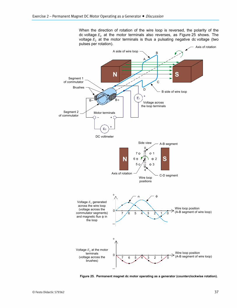
When the direction of rotation of the wire loop is reversed, the polarity of the dc voltage at the motor terminals also reverses, as Figure 25 shows. The voltage at the motor terminals is thus a pulsating negative dc voltage (two pulses per rotation).
Figure 25. Permanent magnet dc motor operating as a generator (counterclockwise rotation).
B
C
D
Axis of rotation
Axis of rotation
Voltage 2 at the motor terminals
(voltage across the brushes)
Voltage 1 generated across the wire loop (voltage across the
commutator segments) and magnetic flux ϕ in
the loop
7 6 5 4 3 2 1 0 0
Wire loop position (A-B segment of wire loop)
7 6 5 4 3 2 1 0 0
A-B segment
C-D segment
0
1
2
3
4
5
6
7
Wire loop position (A-B segment of wire loop)
Side view
Voltage across the loop terminals
B side of wire loop
A
B
N
N S
S
Wire loop positions
ϕe1
Segment 1of commutator
Brushes
Segment 2of commutator
Motor terminals
DC voltmeter
B
A side of wire loop
Exercise 2 – Permanent Magnet DC Motor Operating as a Generator Discussion
38 © Festo Didactic 579362
Reducing the fluctuations of the generated dc voltage
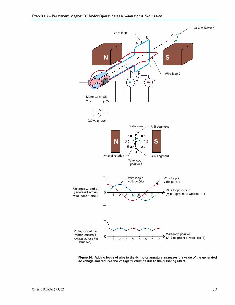
All permanent magnet dc motors have an armature made of several wire loops and commutator segments. Increasing the number of wire loops and commutator segments reduces the fluctuation of the voltage at the dc motor terminals that is due to the pulsating effect (i.e., the generated voltage is a nearly pure dc voltage). Figure 26 shows an example of the voltage generated at the terminals of a dc motor when a second loop of wire is added to the armature. Two extra segments are also added to the commutator to connect the additional wire loop of the armature to the motor terminals via the brushes.
As Figure 26 shows:
Two alternating-current (ac) voltages and are generated, oneacross each wire loop.
However, the voltage at the motor terminals always has the samepolarity. This voltage consists of four pulses per rotation of the armatureinstead of only two pulses per rotation. Consequently, the fluctuation ofthe generated dc voltage caused by the pulsating effect is reduced.
The higher the number of wire loops at the armature, the higher the number of segments on the commutator and thus, the higher the number of pulses per rotation and the lower the voltage fluctuation at the dc motor terminals.
Exercise 2 – Permanent Magnet DC Motor Operating as a Generator Discussion
© Festo Didactic 579362 39
Figure 26. Adding loops of wire to the dc motor armature increases the value of the generated dc voltage and reduces the voltage fluctuation due to the pulsating effect.
DC voltmeter
Wire loop 2
A
B
C
D
Axis of rotation
Voltage 3 at the motor terminals
(voltage across the brushes)
Voltages E1 and E2 generated across wire loops 1 and 2 1 2 3 4 5 6 7 0
0Wire loop position (A-B segment of wire loop 1)
1 2 3 4 5 6 7 00
Wire loop position (A-B segment of wire loop 1)
Side view
Motor terminals
Wire loop 1
Axis of rotation
Wire loop 1 positions
A-B segment
C-D segment
0
1
2
3
4
5
6
7
Wire loop 2 voltage (E2)
Wire loop 1 voltage (E1)
S
S
N
N
Exercise 2 – Permanent Magnet DC Motor Operating as a Generator Discussion
40 © Festo Didactic 579362
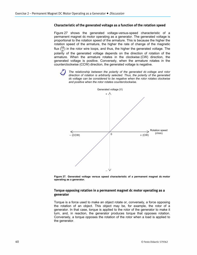
Characteristic of the generated voltage as a function of the rotation speed
Figure 27 shows the generated voltage-versus-speed characteristic of a permanent magnet dc motor operating as a generator. The generated voltage is proportional to the rotation speed of the armature. This is because the higher the rotation speed of the armature, the higher the rate of change of the magnetic
flux ( ) in the rotor wire loops, and thus, the higher the generated voltage. The
polarity of the generated voltage depends on the direction of rotation of the armature. When the armature rotates in the clockwise (CW) direction, the generated voltage is positive. Conversely, when the armature rotates in the counterclockwise (CCW) direction, the generated voltage is negative.
a The relationship between the polarity of the generated dc voltage and rotordirection of rotation is arbitrarily selected. Thus, the polarity of the generated dc voltage can be considered to be negative when the rotor rotates clockwise and positive when the rotor rotates counterclockwise.
Figure 27. Generated voltage versus speed characteristic of a permanent magnet dc motor operating as a generator.
Torque opposing rotation in a permanent magnet dc motor operating as a generator
Torque is a force used to make an object rotate or, conversely, a force opposing the rotation of an object. This object may be, for example, the rotor of a generator. In that case, torque is applied to the rotor of the generator to make it turn, and, in reaction, the generator produces torque that opposes rotation. Conversely, a torque opposes the rotation of the rotor when a load is applied to the generator.
Rotation speed (r/min)
Generated voltage (V)
(CW) (CCW) 0
Exercise 2 – Permanent Magnet DC Motor Operating as a Generator Discussion
© Festo Didactic 579362 41
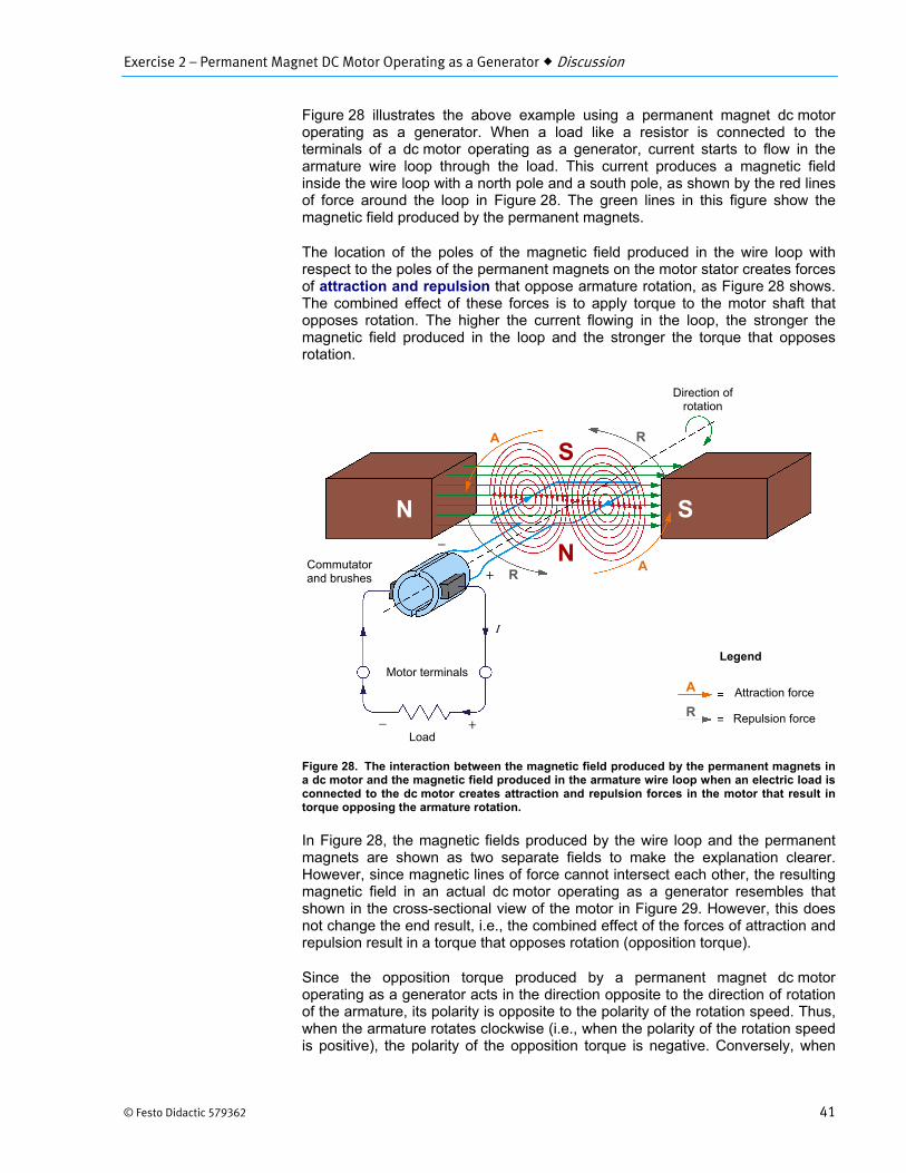
Figure 28 illustrates the above example using a permanent magnet dc motor operating as a generator. When a load like a resistor is connected to the terminals of a dc motor operating as a generator, current starts to flow in the armature wire loop through the load. This current produces a magnetic field inside the wire loop with a north pole and a south pole, as shown by the red lines of force around the loop in Figure 28. The green lines in this figure show the magnetic field produced by the permanent magnets.
The location of the poles of the magnetic field produced in the wire loop with respect to the poles of the permanent magnets on the motor stator creates forces of attraction and repulsion that oppose armature rotation, as Figure 28 shows. The combined effect of these forces is to apply torque to the motor shaft that opposes rotation. The higher the current flowing in the loop, the stronger the magnetic field produced in the loop and the stronger the torque that opposes rotation.
Figure 28. The interaction between the magnetic field produced by the permanent magnets in a dc motor and the magnetic field produced in the armature wire loop when an electric load is connected to the dc motor creates attraction and repulsion forces in the motor that result in torque opposing the armature rotation.
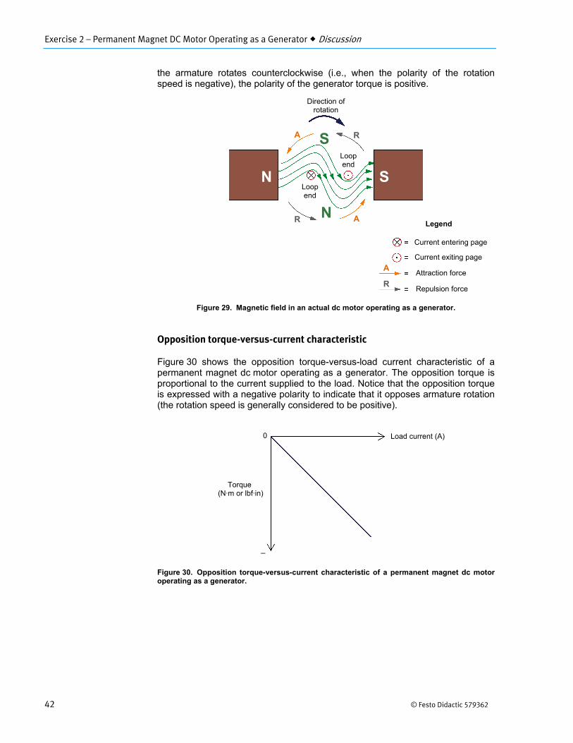
In Figure 28, the magnetic fields produced by the wire loop and the permanent magnets are shown as two separate fields to make the explanation clearer. However, since magnetic lines of force cannot intersect each other, the resulting magnetic field in an actual dc motor operating as a generator resembles that shown in the cross-sectional view of the motor in Figure 29. However, this does not change the end result, i.e., the combined effect of the forces of attraction and repulsion result in a torque that opposes rotation (opposition torque).
Since the opposition torque produced by a permanent magnet dc motor operating as a generator acts in the direction opposite to the direction of rotation of the armature, its polarity is opposite to the polarity of the rotation speed. Thus, when the armature rotates clockwise (i.e., when the polarity of the rotation speed is positive), the polarity of the opposition torque is negative. Conversely, when
Motor terminals
Load
I
Direction of rotation
N
S
Commutator and brushes
Attraction force
Repulsion force
Legend
A
A
R
R
A
R
S N
Exercise 2 – Permanent Magnet DC Motor Operating as a Generator Discussion
42 © Festo Didactic 579362
the armature rotates counterclockwise (i.e., when the polarity of the rotation speed is negative), the polarity of the generator torque is positive.
Figure 29. Magnetic field in an actual dc motor operating as a generator.
Opposition torque-versus-current characteristic
Figure 30 shows the opposition torque-versus-load current characteristic of a permanent magnet dc motor operating as a generator. The opposition torque is proportional to the current supplied to the load. Notice that the opposition torque is expressed with a negative polarity to indicate that it opposes armature rotation (the rotation speed is generally considered to be positive).
Figure 30. Opposition torque-versus-current characteristic of a permanent magnet dc motor operating as a generator.
Direction of rotation
N
S
Loop end
Loop end
Current entering page
Current exiting page
Legend
Attraction force
Repulsion force
Torque (N·m or lbf·in)
0 Load current (A)
A
R
R
A
A
R
SN
Exercise 2 – Permanent Magnet DC Motor Operating as a Generator Procedure Outline
© Festo Didactic 579362 43
The Procedure is divided into the following sections:
Electromagnetic induction phenomenon Opposition to rotation Voltage-versus-speed characteristic of a permanent magnet dc motor
operating as a generatorClockwise rotation Counterclockwise rotation
Torque-versus-current characteristic of a permanent magnet dc motoroperating as a generator
High voltages are present in this laboratory exercise. Do not make or modify anybanana jack connections with the power on unless otherwise specified.
Electromagnetic induction phenomenon
In this section of the exercise, you will connect a dc voltmeter across the motor terminals and observe the voltage developed across these terminals when the motor shaft is rotated manually.
1. Place the Permanent Magnet DC Motor on your work surface. Connect adc voltmeter to the terminals of the Permanent Magnet DC Motor. The redmotor terminal is the positive terminal.
2. Make the shaft of the Permanent Magnet DC Motor rotate clockwise withyour hands. Notice that a dc voltage of positive polarity appears across themotor terminals. Explain why a dc voltage is developed at the motorterminals when its shaft is rotated.
3. Make the shaft of the Permanent Magnet DC Motor rotate counterclockwisewith your hands. Does a dc voltage of negative polarity appear across themotor terminals? Why?
4. Disconnect the dc voltmeter from the Permanent Magnet DC Motor.
PROCEDURE OUTLINE
PROCEDURE
Exercise 2 – Permanent Magnet DC Motor Operating as a Generator Procedure
44 © Festo Didactic 579362
Opposition to rotation
In this section, you will observe the opposition to rotation of the Permanent Magnet DC Motor when the terminals of the motor are not short-circuited and when they are.
5. Make the shaft of the Permanent Magnet DC Motor rotate with your hands.Notice that it is easy to make the motor shaft rotate. Explain why.
6. Short-circuit the two terminals of the Permanent Magnet DC Motor with alead.
Make the motor shaft rotate clockwise with your hands, then make it rotatecounterclockwise. Notice that it is less easy to make the motor shaft rotatewhen the motor terminals are short-circuited. Explain why.
7. Remove the lead short-circuiting the motor terminals.
Voltage-versus-speed characteristic of a permanent magnet dc motor operating as a generator
In this section, you will use a prime mover to drive the Permanent Magnet DC Motor and make it operate as a generator. You will vary the rotation speed of the prime mover by steps and measure the dc voltage generated across the motor terminals.
8. Refer to the Equipment Utilization Chart in Appendix A to obtain the list ofequipment required to perform the rest of this exercise.
Install the equipment in the Workstation.
Mechanically couple the Four-Quadrant Dynamometer/Power Supply to thePermanent Magnet DC Motor using a timing belt.
Before coupling rotating machines, make absolutely sure that power is turned offto prevent any machine from starting inadvertently.
Exercise 2 – Permanent Magnet DC Motor Operating as a Generator Procedure
© Festo Didactic 579362 45
9. Make sure that the main power switch on the Four-Quadrant Dynamometer/Power Supply is set to the O (off) position, then connect its Power Input to anac power wall outlet.
Connect the Power Input of the Data Acquisition and Control Interface(DACI) to a 24 V ac power supply. Turn the 24 V ac power supply on.
10. Connect the USB port of the Four-Quadrant Dynamometer/Power Supply toa USB port of the host computer.
Connect the USB port of the Data Acquisition and Control Interface to aUSB port of the host computer.
11. On the Four-Quadrant Dynamometer/ Power Supply, set the Operating Modeswitch to Dynamometer. This setting allows the Four-QuadrantDynamometer/Power Supply to operate as a prime mover, a brake, or both,depending on the selected function.
Turn the Four-Quadrant Dynamometer/Power Supply on by setting the mainpower switch to I (on).
12. Turn the host computer on, then start the LVDAC-EMS software.
In the LVDAC-EMS Start-Up window, make sure that the Data Acquisitionand Control Interface and the Four-Quadrant Dynamometer/Power Supplyare detected. Make sure that the Computer-Based Instrumentation functionfor the Data Acquisition and Control Interface is available. Also, selectthe network voltage and frequency that correspond to the voltage andfrequency of your local ac power network, then click the OK buttonto close the LVDAC-EMS Start-Up window.
13. Connect the equipment as shown in Figure 31. In this circuit, the PermanentMagnet DC Motor is driven, via a belt, by the motor in the Four-QuadrantDynamometer/Power Supply. E1 is a voltage input of the Data Acquisitionand Control Interface.
a Appendix C shows in more detail the equipment and the connections requiredfor the circuit diagram below.
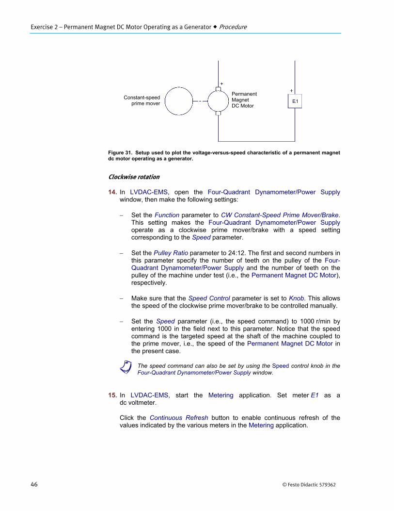
Exercise 2 – Permanent Magnet DC Motor Operating as a Generator Procedure
46 © Festo Didactic 579362
Figure 31. Setup used to plot the voltage-versus-speed characteristic of a permanent magnet dc motor operating as a generator.
Clockwise rotation
14. In LVDAC-EMS, open the Four-Quadrant Dynamometer/Power Supplywindow, then make the following settings:
Set the Function parameter to CW Constant-Speed Prime Mover/Brake.This setting makes the Four-Quadrant Dynamometer/Power Supply operate as a clockwise prime mover/brake with a speed setting corresponding to the Speed parameter.
Set the Pulley Ratio parameter to 24:12. The first and second numbers in this parameter specify the number of teeth on the pulley of the Four-Quadrant Dynamometer/Power Supply and the number of teeth on the pulley of the machine under test (i.e., the Permanent Magnet DC Motor), respectively.
Make sure that the Speed Control parameter is set to Knob. This allows the speed of the clockwise prime mover/brake to be controlled manually.
Set the Speed parameter (i.e., the speed command) to 1000 r/min by entering 1000 in the field next to this parameter. Notice that the speed command is the targeted speed at the shaft of the machine coupled to the prime mover, i.e., the speed of the Permanent Magnet DC Motor in the present case.
a The speed command can also be set by using the Speed control knob in theFour-Quadrant Dynamometer/Power Supply window.
15. In LVDAC-EMS, start the Metering application. Set meter E1 as adc voltmeter.
Click the Continuous Refresh button to enable continuous refresh of thevalues indicated by the various meters in the Metering application.
Constant-speedprime mover
Permanent Magnet DC Motor
Exercise 2 – Permanent Magnet DC Motor Operating as a Generator Procedure
© Festo Didactic 579362 47
16. In the Four-Quadrant Dynamometer/Power Supply window, start theCW Constant-Speed Prime Mover/Brake by clicking the Start/Stop button orby setting the Status parameter to Started.
Observe that the prime mover starts to rotate, thereby driving the shaft of thePermanent Magnet DC Motor.
The Speed meter in the Four-Quadrant Dynamometer/Power Supply windowindicates the rotation speed of the Permanent Magnet DC Motor. Is thisspeed approximately equal to the value of the Speed parameter(1000 r/min)?
Yes No
Meter E1 in the Metering window indicates the dc voltage generated across the Permanent Magnet DC Motor terminals. Record this voltage below.
DC voltage generated V
17. In LVDAC-EMS, open the Data Table window. Set the Data Table to recordthe rotation speed of the Permanent Magnet DC Motor (indicated by theSpeed meter in the Four-Quadrant Dynamometer/Power Supply) and thedc voltage generated across the motor terminals (indicated by meter E1 inthe Metering window).
a To select the parameters to be recorded in the Data Table, click the Optionsmenu of the Data Table and then click Record Settings. In the Settings list,select Four-Quadrant Dynamometer/Power Supply, then check the Speed box.In the Settings list, select Metering, then check the box of meter E1. Click OKto close the Record Settings box.
18. Make the rotation speed of the Permanent Magnet DC Motor vary from 0 to4000 r/min in steps of 500 r/min by adjusting the Speed parameter. For eachspeed setting, record the motor rotation speed (indicated by the Speedmeter) and the dc voltage (meter E1) generated across the motor terminalsin the Data Table by clicking the Record Data button in this table.
Counterclockwise rotation
19. In the Four-Quadrant Dynamometer/Power Supply window, stop the CWConstant-Speed Prime Mover/Brake by clicking the Start/Stop button or bysetting the Status parameter to Stopped. Then, make the following settings:
Set the Function parameter to CCW Constant-Speed PrimeMover/Brake. This setting makes the Four-Quadrant Dynamometer/Power Supply operate as a counterclockwise prime mover/brake with a speed setting corresponding to the Speed parameter.
Set the Pulley Ratio parameter to 24:12.
Make sure that the Speed Control parameter is set to Knob.
Exercise 2 – Permanent Magnet DC Motor Operating as a Generator Procedure
48 © Festo Didactic 579362
Set the Speed parameter to 0 r/min.
Start the CCW Constant-Speed Prime Mover/Brake by clicking the Start/Stop button or by setting the Status parameter to Started.
20. Make the rotation speed of the Permanent Magnet DC Motor vary from 0 to-4000 r/min in steps of about -500 r/min by adjusting the Speed parameter inthe Four-Quadrant Dynamometer/Power Supply window. For each speedsetting, record the motor rotation speed and the dc voltage (meter E1)generated across the motor terminals in the Data Table.
21. In the Four-Quadrant Dynamometer/Power Supply window, stop the CCWConstant-Speed Prime Mover/Brake by clicking the Start/Stop button or bysetting the Status parameter to Stopped.
22. From the results recorded in the Data Table, plot the curve of the dc voltagegenerated across the motor terminals versus the motor rotation speed.
According to the obtained curve, is the voltage generated across apermanent magnet dc motor operating as a generator proportional to therotation speed?
Yes No
Does the polarity of the generated dc voltage depend on the direction of rotation, thereby confirming what has been observed at the beginning of this exercise when you turned the motor shaft manually and measured the generated voltage with a dc voltmeter? Explain.
Save the data recorded in the Data Table, then close this table.
Torque-versus-current characteristic of a permanent magnet dc motor operating as a generator
In this section, you will use a prime mover to drive the Permanent Magnet DC Motor and make it operate as a generator. You will vary the opposition torque developed at the motor shaft and measure the current flowing through the generator armature.
23. Connect the equipment as shown in Figure 32. Use the high-current (40 A)terminal of current input I1 on the Data Acquisition and Control Interface.
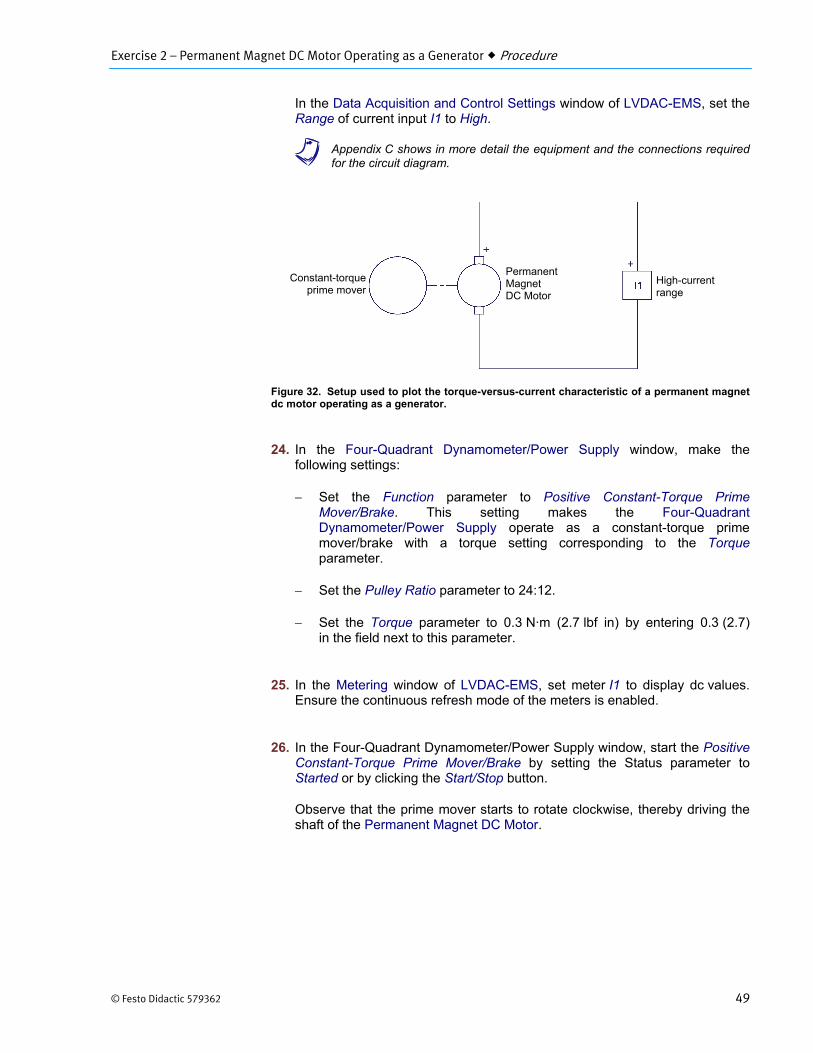
Exercise 2 – Permanent Magnet DC Motor Operating as a Generator Procedure
© Festo Didactic 579362 49
In the Data Acquisition and Control Settings window of LVDAC-EMS, set the Range of current input I1 to High.
a Appendix C shows in more detail the equipment and the connections requiredfor the circuit diagram.
Figure 32. Setup used to plot the torque-versus-current characteristic of a permanent magnet dc motor operating as a generator.
24. In the Four-Quadrant Dynamometer/Power Supply window, make thefollowing settings:
Set the Function parameter to Positive Constant-Torque PrimeMover/Brake. This setting makes the Four-Quadrant Dynamometer/Power Supply operate as a constant-torque prime mover/brake with a torque setting corresponding to the Torque parameter.
Set the Pulley Ratio parameter to 24:12.
Set the Torque parameter to 0.3 N·m (2.7 lbf in) by entering 0.3 (2.7) in the field next to this parameter.
25. In the Metering window of LVDAC-EMS, set meter I1 to display dc values.Ensure the continuous refresh mode of the meters is enabled.
26. In the Four-Quadrant Dynamometer/Power Supply window, start the PositiveConstant-Torque Prime Mover/Brake by setting the Status parameter toStarted or by clicking the Start/Stop button.
Observe that the prime mover starts to rotate clockwise, thereby driving theshaft of the Permanent Magnet DC Motor.
Permanent Magnet DC Motor
High-current range
Constant-torqueprime mover
Exercise 2 – Permanent Magnet DC Motor Operating as a Generator Procedure
50 © Festo Didactic 579362
The Speed and Torque meters in the Four-Quadrant Dynamometer/Power Supply indicate the rotation speed and torque at the shaft of the Permanent Magnet DC Motor. Notice that the torque is of negative polarity, i.e., opposite to the polarity (positive) of the rotation speed. This is because the Permanent Magnet DC Motor is operating as a generator. Is the torque (absolute value) indicated by the Torque meter approximately equal to the value of the Torque parameter?
Yes No
Meter I1 in the Metering window indicates the dc current flowing in the armature of the Permanent Magnet DC Motor. Record this current below.
DC current flowing in the motor A
27. In LVDAC-EMS, open the Data Table and make the settings required torecord the torque developed the shaft of this motor (indicated by the Torquemeter in the Four-Quadrant Dynamometer/Power Supply) and the dc currentflowing in the armature of the Permanent Magnet DC Motor (indicated bymeter I1 in the Metering window).
a To select the parameters to be recorded in the Data Table, click the Optionsmenu of the Data Table and then click Record Settings. In the Settings list,select Four-Quadrant Dynamometer/Power Supply, then check theTorque box. In the Settings list, select Metering, then check the box ofmeter I1. Click OK to close the Record Settings box.
28. Make the torque developed at the shaft of the Permanent Magnet DC Motorvary from 0 to -0.7 N·m (or from 0 to -6.0 lbf·in) in steps of -0.1 N·m(or -1 lbf·in) by adjusting the Torque parameter. For each torque setting,record the current flowing in the armature of the dc motor (meter I1) and thetorque developed at the motor shaft (indicated by the Torque meter) in theData Table.
Since the output of the Permanent Magnet DC Motor is short circuited by current input I1, high currents can flow in the motor at low torques and rotation speeds. Make sure not to exceed the current rating of the Permanent Magnet DC Motor. Perform the remainder of this manipulation in less than 5 minutes.
29. In the Four-Quadrant Dynamometer/Power Supply window, stop the PositiveConstant-Torque Prime Mover/Brake.
30. From the results recorded in the Data Table, plot a curve of the torquedeveloped at the motor shaft as a function of the current flowing in thearmature of the dc motor.
Exercise 2 – Permanent Magnet DC Motor Operating as a Generator Conclusion
© Festo Didactic 579362 51
According to the obtained curve, is the torque developed at the shaft of a permanent magnet dc motor operating as a generator proportional to the current flowing in the motor armature?
Yes No
31. Save the data recorded in the Data Table, then close this table. Turn theFour-Quadrant Dynamometer/Power Supply off by setting the main powerswitch to O (off). Close the LVDAC-EMS software. Disconnect all leads andreturn them to their storage location.
In this exercise, you familiarized yourself with a permanent magnet dc motor. You learned that this motor consists of a rotor (armature) made of several loops of wire, and a stator made of permanent magnets that produce a fixed magnetic field. When the rotor is rotated by a prime mover, it cuts the lines of force of the stator magnetic field, which produces a dc voltage across the motor terminals: the dc motor operates as a dc generator. The magnitude of the generated voltage is proportional to the rotation speed, while the polarity of this voltage depends on the direction of rotation. For instance, when the rotor rotates clockwise, the dc voltage is positive, and vice-versa. You learned that when a load is connected across the motor terminals, a force (torque) opposing rotor rotation is produced. This torque is in the direction opposite to the direction of rotation. The higher the current supplied to the load, the stronger the torque opposing rotation.
1. By referring to Figure 21, describe the construction of a simple permanentmagnet dc motor.
CONCLUSION
REVIEW QUESTIONS
Exercise 2 – Permanent Magnet DC Motor Operating as a Generator Review Questions
52 © Festo Didactic 579362
2. By referring to Figure 24, describe the operation of a simple permanentmagnet dc motor used as a generator. Explain how an alternating-current (ac) voltage is induced across the armature wire loop, and why thisvoltage is unipolar (i.e., why it always has the same polarity) at the motorterminals.
3. What effect does increasing the number of wire loops and commutatorsegments have on the voltage generated by a permanent magnet dc motoroperating as a generator? Explain.
4. Describe the relationship between the voltage generated by a dc motoroperating as a generator as a function of the armature rotation speed. Whenis the generated voltage of positive polarity? When is this voltage of negativepolarity?
Exercise 2 – Permanent Magnet DC Motor Operating as a Generator Review Questions
© Festo Didactic 579362 53
5. Explain why a force (torque) opposes the rotation of a dc motor operating asa generator when an electrical load like a resistor is connected to thedc motor terminals. When is this force of positive polarity? When is this forceof negative polarity?

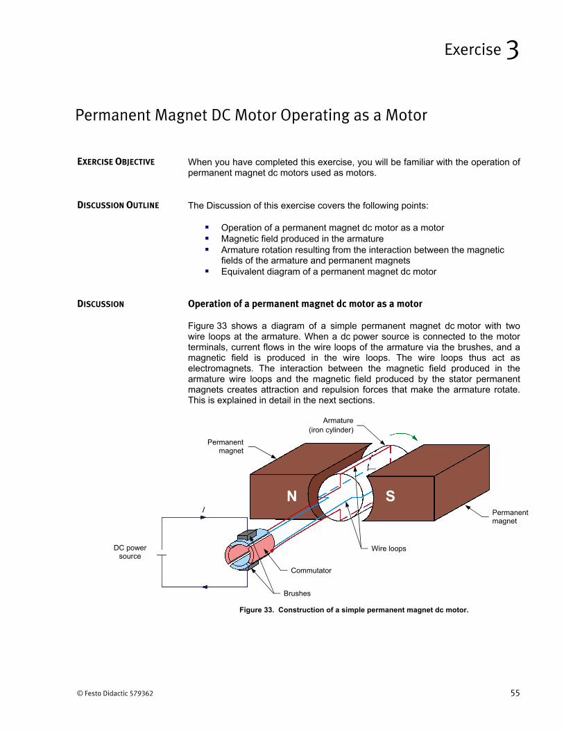
© Festo Didactic 579362 55
When you have completed this exercise, you will be familiar with the operation of permanent magnet dc motors used as motors.
The Discussion of this exercise covers the following points:
Operation of a permanent magnet dc motor as a motor Magnetic field produced in the armature Armature rotation resulting from the interaction between the magnetic
fields of the armature and permanent magnets Equivalent diagram of a permanent magnet dc motor
Operation of a permanent magnet dc motor as a motor
Figure 33 shows a diagram of a simple permanent magnet dc motor with two wire loops at the armature. When a dc power source is connected to the motor terminals, current flows in the wire loops of the armature via the brushes, and a magnetic field is produced in the wire loops. The wire loops thus act as electromagnets. The interaction between the magnetic field produced in the armature wire loops and the magnetic field produced by the stator permanent magnets creates attraction and repulsion forces that make the armature rotate. This is explained in detail in the next sections.
Figure 33. Construction of a simple permanent magnet dc motor.
Permanent Magnet DC Motor Operating as a Motor
Exercise 3
EXERCISE OBJECTIVE
DISCUSSION OUTLINE
DISCUSSION
N S
DC power source
Armature (iron cylinder)
Permanent magnet
Permanent magnet
Brushes
I
Wire loops
Commutator
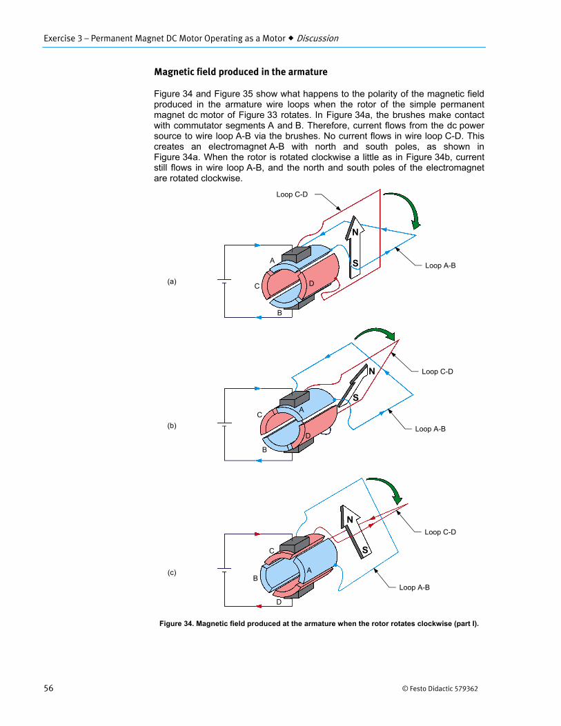
Exercise 3 – Permanent Magnet DC Motor Operating as a Motor Discussion
56 © Festo Didactic 579362
Magnetic field produced in the armature
Figure 34 and Figure 35 show what happens to the polarity of the magnetic field produced in the armature wire loops when the rotor of the simple permanent magnet dc motor of Figure 33 rotates. In Figure 34a, the brushes make contact with commutator segments A and B. Therefore, current flows from the dc power source to wire loop A-B via the brushes. No current flows in wire loop C-D. This creates an electromagnet A-B with north and south poles, as shown in Figure 34a. When the rotor is rotated clockwise a little as in Figure 34b, current still flows in wire loop A-B, and the north and south poles of the electromagnet are rotated clockwise.
Figure 34. Magnetic field produced at the armature when the rotor rotates clockwise (part I).
Loop A-B
Loop C-D
N
S
N
S
N
S
A
B
C D
A
B
C
DLoop A-B
Loop C-D
Loop A-B
Loop C-D
AB
C
D
(b)
(a)
(c)
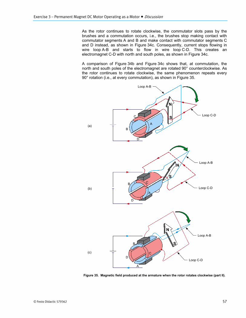
Exercise 3 – Permanent Magnet DC Motor Operating as a Motor Discussion
© Festo Didactic 579362 57
As the rotor continues to rotate clockwise, the commutator slots pass by the brushes and a commutation occurs, i.e., the brushes stop making contact with commutator segments A and B and make contact with commutator segments C and D instead, as shown in Figure 34c. Consequently, current stops flowing in wire loop A-B and starts to flow in wire loop C-D. This creates an electromagnet C-D with north and south poles, as shown in Figure 34c.
A comparison of Figure 34b and Figure 34c shows that, at commutation, the north and south poles of the electromagnet are rotated 90° counterclockwise. As the rotor continues to rotate clockwise, the same phenomenon repeats every 90° rotation (i.e., at every commutation), as shown in Figure 35.
Figure 35. Magnetic field produced at the armature when the rotor rotates clockwise (part II).
Loop C-D
Loop A-B
N
S
N
S
N
S
C
D
B
A
C
D
B
A
Loop C-D
Loop A-B
Loop C-D
Loop A-B
CD
B
A
(c)
(b)
(a)
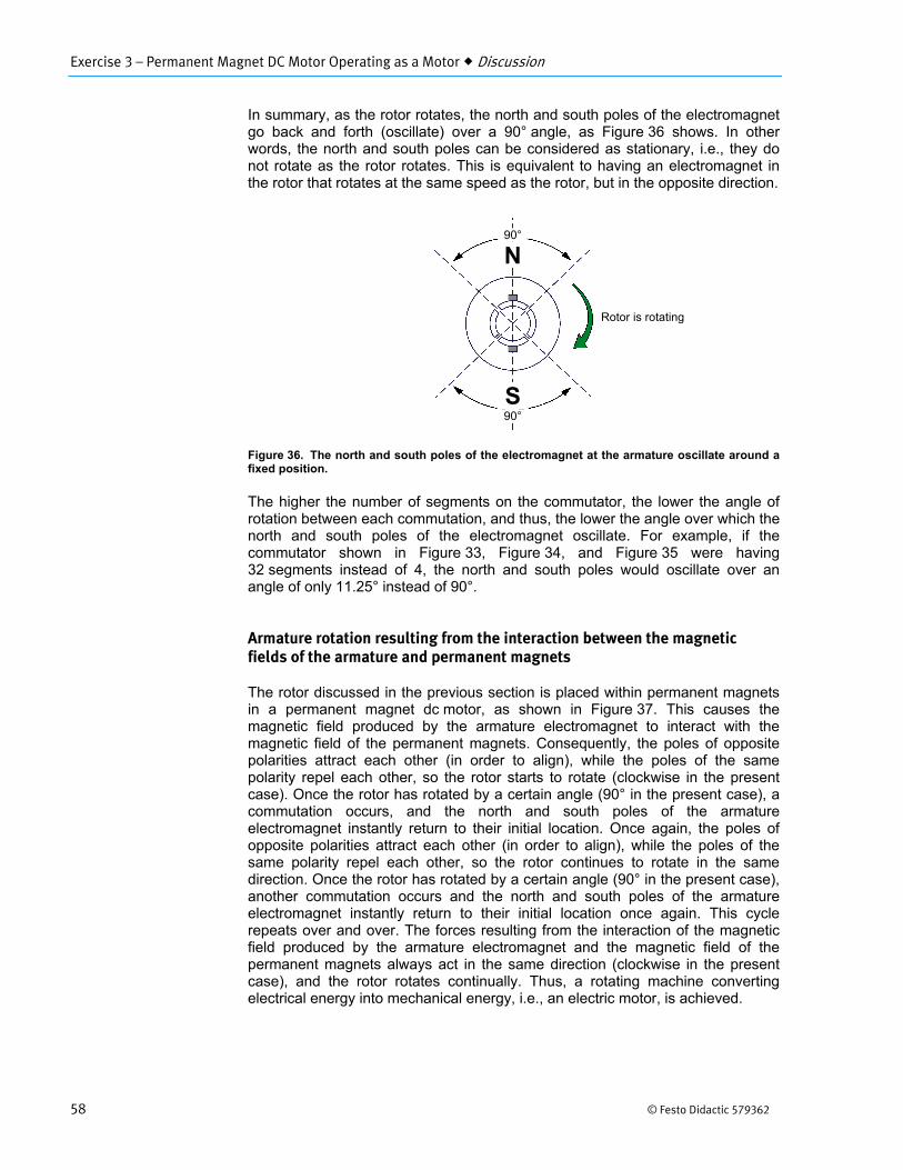
Exercise 3 – Permanent Magnet DC Motor Operating as a Motor Discussion
58 © Festo Didactic 579362
In summary, as the rotor rotates, the north and south poles of the electromagnet go back and forth (oscillate) over a 90° angle, as Figure 36 shows. In other words, the north and south poles can be considered as stationary, i.e., they do not rotate as the rotor rotates. This is equivalent to having an electromagnet in the rotor that rotates at the same speed as the rotor, but in the opposite direction.
Figure 36. The north and south poles of the electromagnet at the armature oscillate around a fixed position.
The higher the number of segments on the commutator, the lower the angle of rotation between each commutation, and thus, the lower the angle over which the north and south poles of the electromagnet oscillate. For example, if the commutator shown in Figure 33, Figure 34, and Figure 35 were having 32 segments instead of 4, the north and south poles would oscillate over an angle of only 11.25° instead of 90°.
Armature rotation resulting from the interaction between the magnetic fields of the armature and permanent magnets
The rotor discussed in the previous section is placed within permanent magnets in a permanent magnet dc motor, as shown in Figure 37. This causes the magnetic field produced by the armature electromagnet to interact with the magnetic field of the permanent magnets. Consequently, the poles of opposite polarities attract each other (in order to align), while the poles of the same polarity repel each other, so the rotor starts to rotate (clockwise in the present case). Once the rotor has rotated by a certain angle (90° in the present case), a commutation occurs, and the north and south poles of the armature electromagnet instantly return to their initial location. Once again, the poles of opposite polarities attract each other (in order to align), while the poles of the same polarity repel each other, so the rotor continues to rotate in the same direction. Once the rotor has rotated by a certain angle (90° in the present case), another commutation occurs and the north and south poles of the armature electromagnet instantly return to their initial location once again. This cycle repeats over and over. The forces resulting from the interaction of the magnetic field produced by the armature electromagnet and the magnetic field of the permanent magnets always act in the same direction (clockwise in the present case), and the rotor rotates continually. Thus, a rotating machine converting electrical energy into mechanical energy, i.e., an electric motor, is achieved.
Rotor is rotating
90°
N
S90°
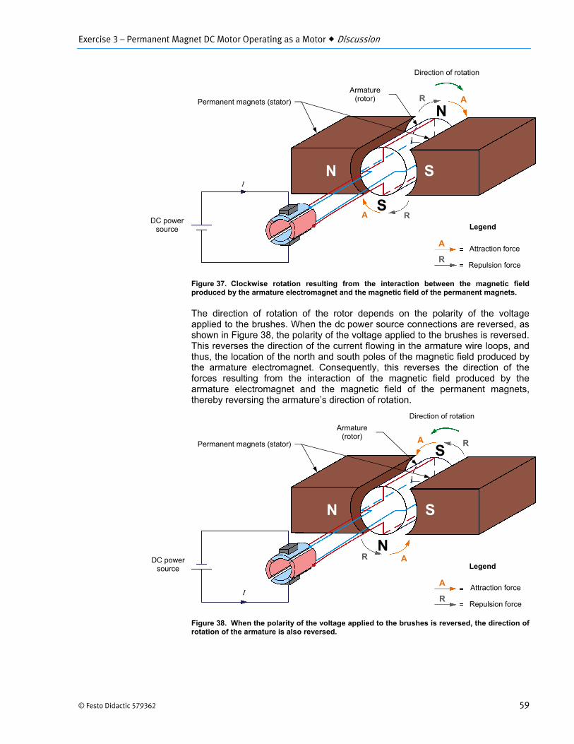
Exercise 3 – Permanent Magnet DC Motor Operating as a Motor Discussion
© Festo Didactic 579362 59
Figure 37. Clockwise rotation resulting from the interaction between the magnetic field produced by the armature electromagnet and the magnetic field of the permanent magnets.
The direction of rotation of the rotor depends on the polarity of the voltage applied to the brushes. When the dc power source connections are reversed, as shown in Figure 38, the polarity of the voltage applied to the brushes is reversed. This reverses the direction of the current flowing in the armature wire loops, and thus, the location of the north and south poles of the magnetic field produced by the armature electromagnet. Consequently, this reverses the direction of the forces resulting from the interaction of the magnetic field produced by the armature electromagnet and the magnetic field of the permanent magnets, thereby reversing the armature’s direction of rotation.
Figure 38. When the polarity of the voltage applied to the brushes is reversed, the direction of rotation of the armature is also reversed.
DC power source
N S
Armature (rotor)
I
Permanent magnets (stator)
Direction of rotation
N
S
Attraction force
Repulsion force
Legend
A
R
R
A
R
A
DC power source
N S
Armature (rotor)
I
Direction of rotation
S
N
Attraction force
Repulsion force
LegendA
R
R
A
R
A Permanent magnets (stator)
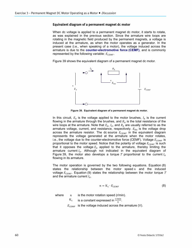
Exercise 3 – Permanent Magnet DC Motor Operating as a Motor Discussion
60 © Festo Didactic 579362
Equivalent diagram of a permanent magnet dc motor
When dc voltage is applied to a permanent magnet dc motor, it starts to rotate, as was explained in the previous section. Since the armature wire loops are rotating in the magnetic field produced by the permanent magnets, a voltage is induced at the armature, as when the motor operates as a generator. In the present case (i.e., when speaking of a motor), the voltage induced across the armature is due to the counter-electromotive force (CEMF), and is commonly represented by the following variable: .
Figure 39 shows the equivalent diagram of a permanent magnet dc motor.
Figure 39. Equivalent diagram of a permanent magnet dc motor.
In this circuit, is the voltage applied to the motor brushes, is the current flowing in the armature through the brushes, and is the total resistance of the wire loops at the armature. Note that , , and are usually referred to as the armature voltage, current, and resistance, respectively. is the voltage drop across the armature resistor. The dc source in the equivalent diagram represents the voltage generated at the armature when the motor rotates, i.e., the voltage due to the counter-electromotive force (CEMF). Voltage isproportional to the motor speed. Notice that the polarity of voltage is suchthat it opposes the voltage applied to the armature, thereby limiting thearmature current . Although not indicated in the equivalent diagram ofFigure 39, the motor also develops a torque T proportional to the current flowing in its armature.
The motor operation is governed by the two following equations. Equation (8) states the relationship between the motor speed and the induced voltage . Equation (9) states the relationship between the motor torque T and the armature current .
K ∙ (8)
where is the motor rotation speed (r/min).
K is a constant expressed in /
.
is the voltage induced across the armature (V).
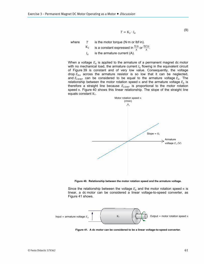
Exercise 3 – Permanent Magnet DC Motor Operating as a Motor Discussion
© Festo Didactic 579362 61
K ∙ (9)
where is the motor torque (N·m or lbf·in).
K is a constant expressed in ∙
or ∙
.
is the armature current (A).
When a voltage is applied to the armature of a permanent magnet dc motor with no mechanical load, the armature current flowing in the equivalent circuit of Figure 39 is constant and of very low value. Consequently, the voltage drop across the armature resistor is so low that it can be neglected, and can be considered to be equal to the armature voltage . The relationship between the motor rotation speed and the armature voltage is therefore a straight line because is proportional to the motor rotation speed . Figure 40 shows this linear relationship. The slope of the straight line equals constant K1.
Figure 40. Relationship between the motor rotation speed and the armature voltage.
Since the relationship between the voltage and the motor rotation speed is linear, a dc motor can be considered a linear voltage-to-speed converter, as Figure 41 shows.
Figure 41. A dc motor can be considered to be a linear voltage-to-speed converter.
Motor rotation speed (r/min)
Armature
voltage (V)
Slope K1
Output motor rotation speed Input armature voltage K1
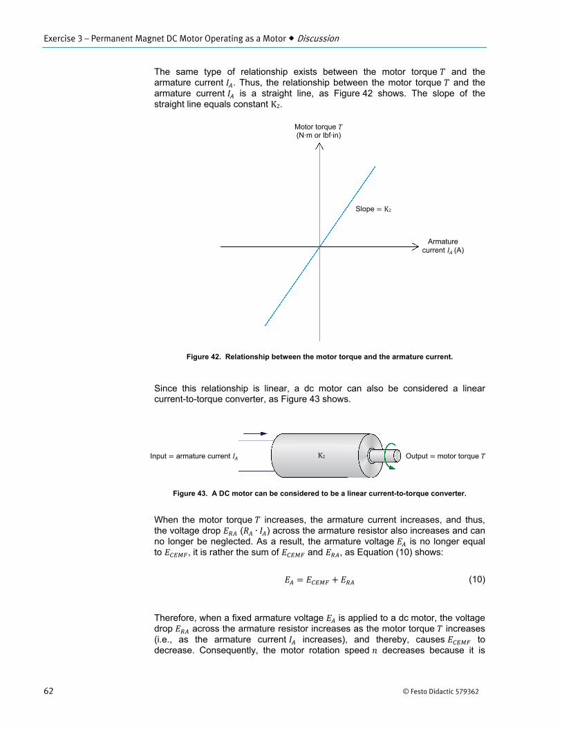
Exercise 3 – Permanent Magnet DC Motor Operating as a Motor Discussion
62 © Festo Didactic 579362
The same type of relationship exists between the motor torque and the armature current . Thus, the relationship between the motor torque and the armature current is a straight line, as Figure 42 shows. The slope of the straight line equals constant K2.
Figure 42. Relationship between the motor torque and the armature current.
Since this relationship is linear, a dc motor can also be considered a linear current-to-torque converter, as Figure 43 shows.
Figure 43. A DC motor can be considered to be a linear current-to-torque converter.
When the motor torque increases, the armature current increases, and thus, the voltage drop ( ∙ ) across the armature resistor also increases and can no longer be neglected. As a result, the armature voltage is no longer equal to , it is rather the sum of and , as Equation (10) shows:
(10)
Therefore, when a fixed armature voltage is applied to a dc motor, the voltage drop across the armature resistor increases as the motor torque increases (i.e., as the armature current increases), and thereby, causes to decrease. Consequently, the motor rotation speed decreases because it is
Motor torque (N·m or lbf·in)
Armature current (A)
Slope K2
Output motor torque Input armature current K2
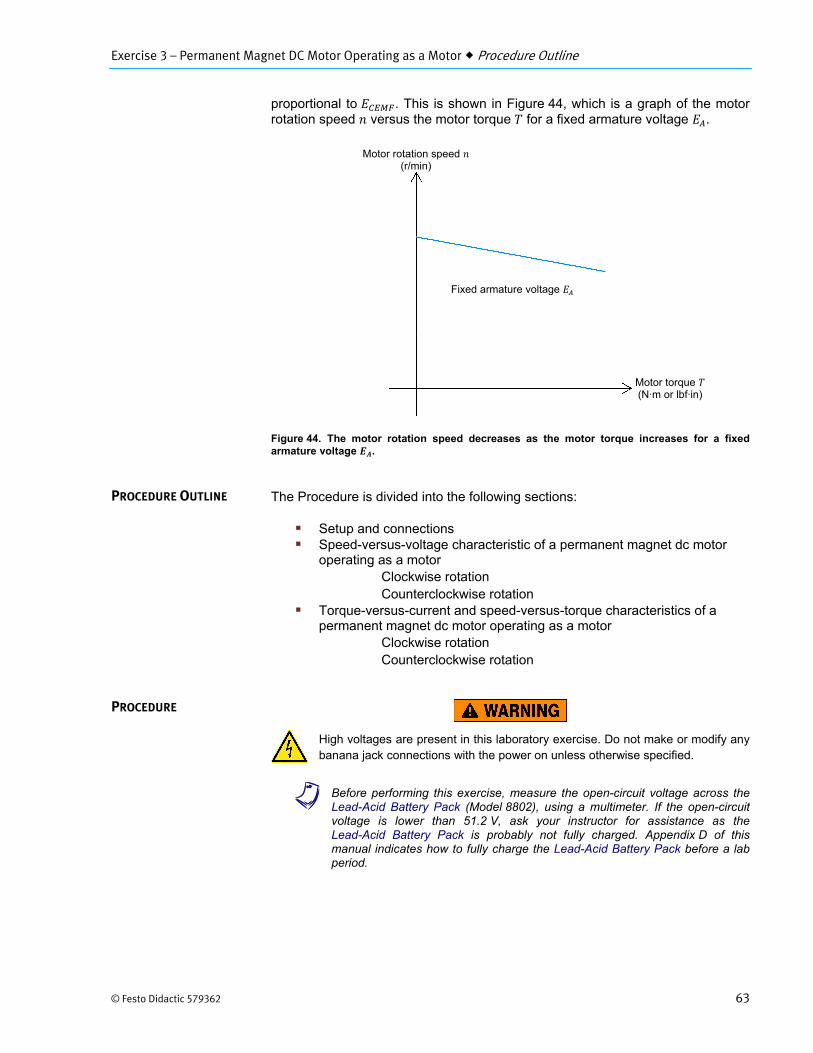
Exercise 3 – Permanent Magnet DC Motor Operating as a Motor Procedure Outline
© Festo Didactic 579362 63
proportional to . This is shown in Figure 44, which is a graph of the motor rotation speed versus the motor torque for a fixed armature voltage .
Figure 44. The motor rotation speed decreases as the motor torque increases for a fixed armature voltage .
The Procedure is divided into the following sections:
Setup and connections Speed-versus-voltage characteristic of a permanent magnet dc motor
operating as a motorClockwise rotation Counterclockwise rotation
Torque-versus-current and speed-versus-torque characteristics of apermanent magnet dc motor operating as a motor
Clockwise rotation Counterclockwise rotation
High voltages are present in this laboratory exercise. Do not make or modify anybanana jack connections with the power on unless otherwise specified.
a Before performing this exercise, measure the open-circuit voltage across theLead-Acid Battery Pack (Model 8802), using a multimeter. If the open-circuit voltage is lower than 51.2 V, ask your instructor for assistance as the Lead-Acid Battery Pack is probably not fully charged. Appendix D of this manual indicates how to fully charge the Lead-Acid Battery Pack before a lab period.
PROCEDURE OUTLINE
PROCEDURE
Motor torque (N·m or lbf·in)
Motor rotation speed (r/min)
Fixed armature voltage
Exercise 3 – Permanent Magnet DC Motor Operating as a Motor Procedure
64 © Festo Didactic 579362
Setup and connections
In this part of the exercise, you will set up and connect the equipment.
1. Refer to the Equipment Utilization Chart in Appendix A to obtain the list ofequipment required to perform this exercise.
Install the equipment in the Workstation.
Mechanically couple the Four-Quadrant Dynamometer/Power Supply to thePermanent Magnet DC Motor using a timing belt.
Before coupling rotating machines, make absolutely sure that power is turned off to prevent any machine from starting inadvertently.
2. Make sure that the main power switch of the Four-QuadrantDynamometer/Power Supply is set to the O (off) position, then connect itsPower Input to an ac power outlet.
Connect the Power Input of the Data Acquisition and Control Interface to a24 V ac power supply. Turn the 24 V ac power supply on.
3. Connect the USB port of the Four-Quadrant Dynamometer/Power Supply toa USB port of the host computer.
Connect the USB port of the Data Acquisition and Control Interface to aUSB port of the host computer.
4. On the Four-Quadrant Dynamometer/ Power Supply, set the Operating Modeswitch to Power Supply. This setting allows the Four-QuadrantDynamometer/Power Supply to operate as a voltage source, current source,battery charger, or battery discharger, depending on the selected function.
Turn the Four-Quadrant Dynamometer/Power Supply on by setting the mainpower switch to I (on).
5. Turn the host computer on, then start the LVDAC-EMS software.
In the LVDAC-EMS Start-Up window, make sure that the Data Acquisitionand Control Interface and the Four-Quadrant Dynamometer/Power Supplyare detected. Make sure that the Computer-Based Instrumentation functionfor the Data Acquisition and Control Interface is available. Also, selectthe network voltage and frequency that correspond to the voltage andfrequency of your local ac power network, then click the OK buttonto close the LVDAC-EMS Start-Up window.
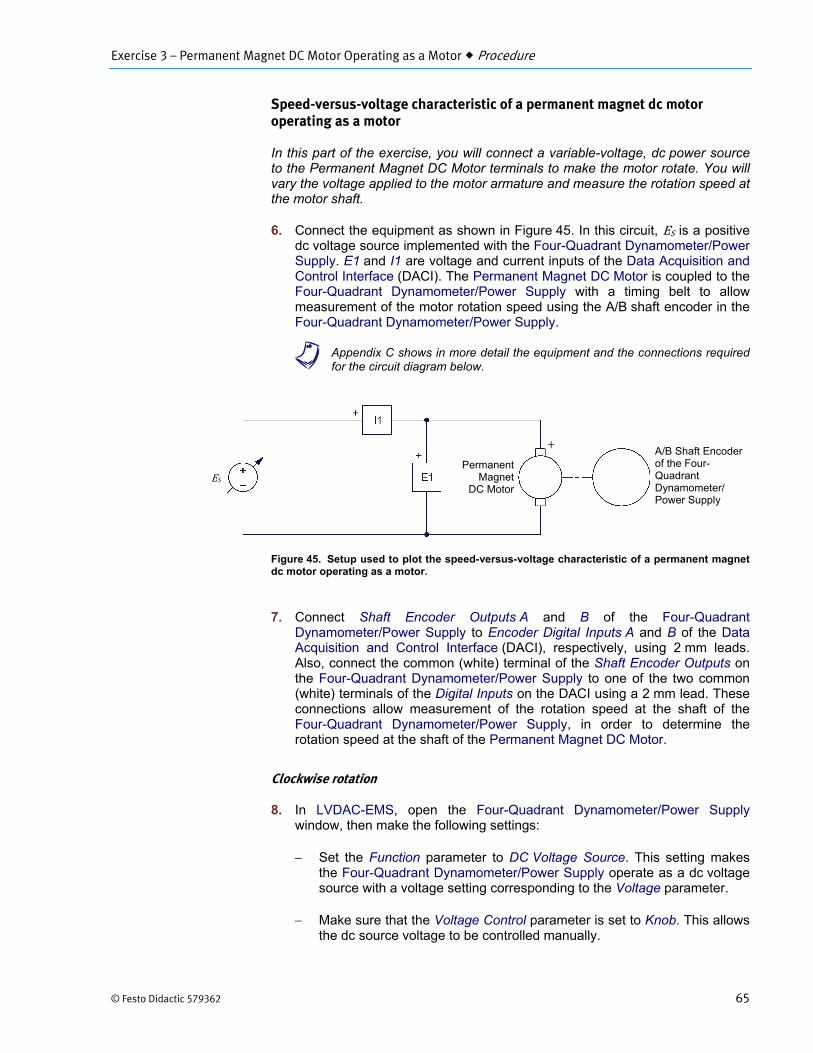
Exercise 3 – Permanent Magnet DC Motor Operating as a Motor Procedure
© Festo Didactic 579362 65
Speed-versus-voltage characteristic of a permanent magnet dc motor operating as a motor
In this part of the exercise, you will connect a variable-voltage, dc power source to the Permanent Magnet DC Motor terminals to make the motor rotate. You will vary the voltage applied to the motor armature and measure the rotation speed at the motor shaft.
6. Connect the equipment as shown in Figure 45. In this circuit, ES is a positivedc voltage source implemented with the Four-Quadrant Dynamometer/PowerSupply. E1 and I1 are voltage and current inputs of the Data Acquisition andControl Interface (DACI). The Permanent Magnet DC Motor is coupled to theFour-Quadrant Dynamometer/Power Supply with a timing belt to allowmeasurement of the motor rotation speed using the A/B shaft encoder in theFour-Quadrant Dynamometer/Power Supply.
a Appendix C shows in more detail the equipment and the connections requiredfor the circuit diagram below.
Figure 45. Setup used to plot the speed-versus-voltage characteristic of a permanent magnet dc motor operating as a motor.
7. Connect Shaft Encoder Outputs A and B of the Four-QuadrantDynamometer/Power Supply to Encoder Digital Inputs A and B of the DataAcquisition and Control Interface (DACI), respectively, using 2 mm leads.Also, connect the common (white) terminal of the Shaft Encoder Outputs onthe Four-Quadrant Dynamometer/Power Supply to one of the two common(white) terminals of the Digital Inputs on the DACI using a 2 mm lead. Theseconnections allow measurement of the rotation speed at the shaft of theFour-Quadrant Dynamometer/Power Supply, in order to determine therotation speed at the shaft of the Permanent Magnet DC Motor.
Clockwise rotation
8. In LVDAC-EMS, open the Four-Quadrant Dynamometer/Power Supplywindow, then make the following settings:
Set the Function parameter to DC Voltage Source. This setting makesthe Four-Quadrant Dynamometer/Power Supply operate as a dc voltage source with a voltage setting corresponding to the Voltage parameter.
Make sure that the Voltage Control parameter is set to Knob. This allows the dc source voltage to be controlled manually.
ESPermanent
MagnetDC Motor
A/B Shaft Encoder of the Four-Quadrant Dynamometer/ Power Supply
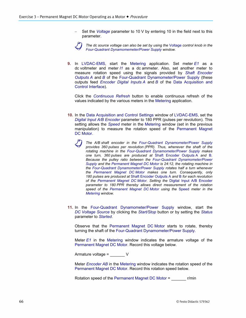
Exercise 3 – Permanent Magnet DC Motor Operating as a Motor Procedure
66 © Festo Didactic 579362
Set the Voltage parameter to 10 V by entering 10 in the field next to this parameter.
a The dc source voltage can also be set by using the Voltage control knob in theFour-Quadrant Dynamomemeter/Power Supply window.
9. In LVDAC-EMS, start the Metering application. Set meter E1 as adc voltmeter and meter I1 as a dc ammeter. Also, set another meter tomeasure rotation speed using the signals provided by Shaft EncoderOutputs A and B of the Four-Quadrant Dynamometer/Power Supply (theseoutputs feed Encoder Digital Inputs A and B of the Data Acquisition andControl Interface).
Click the Continuous Refresh button to enable continuous refresh of thevalues indicated by the various meters in the Metering application.
10. In the Data Acquisition and Control Settings window of LVDAC-EMS, set theDigital Input A/B Encoder parameter to 180 PPR (pulses per revolution). Thissetting allows the Speed meter in the Metering window (set in the previousmanipulation) to measure the rotation speed of the Permanent MagnetDC Motor.
a The A/B shaft encoder in the Four-Quadrant Dynamometer/Power Supplyprovides 360 pulses per revolution (PPR). Thus, whenever the shaft of therotating machine in the Four-Quadrant Dynamometer/Power Supply makesone turn, 360 pulses are produced at Shaft Encoder Outputs A and B.Because the pulley ratio between the Four-Quadrant Dynamometer/PowerSupply and the Permanent Magnet DC Motor is 24:12, the rotating machine inthe Four-Quadrant Dynamometer/Power Supply rotates half a turn wheneverthe Permanent Magnet DC Motor makes one turn. Consequently, only180 pulses are produced at Shaft Encoder Outputs A and B for each revolutionof the Permanent Magnet DC Motor. Setting the Digital Input A/B Encoderparameter to 180 PPR thereby allows direct measurement of the rotationspeed of the Permanent Magnet DC Motor using the Speed meter in theMetering window.
11. In the Four-Quadrant Dynamometer/Power Supply window, start theDC Voltage Source by clicking the Start/Stop button or by setting the Statusparameter to Started.
Observe that the Permanent Magnet DC Motor starts to rotate, therebyturning the shaft of the Four-Quadrant Dynamometer/Power Supply.
Meter E1 in the Metering window indicates the armature voltage of thePermanent Magnet DC Motor. Record this voltage below.
Armature voltage = V
Meter Encoder AB in the Metering window indicates the rotation speed of thePermanent Magnet DC Motor. Record this rotation speed below.
Rotation speed of the Permanent Magnet DC Motor = r/min
Exercise 3 – Permanent Magnet DC Motor Operating as a Motor Procedure
© Festo Didactic 579362 67
12. In LVDAC-EMS, open the Data Table window. Set the Data Table to recordthe armature voltage of the Permanent Magnet DC Motor (indicated bymeter E1 in the Metering window) and the rotation speed of the PermanentMagnet DC Motor (indicated by meter Encoder AB in the Metering window).
a To select the parameters to be recorded in the Data Table, open the RecordSettings dialog box then select meter E1 and meter Encoder AB. Click OK toclose the Record Settings dialog box.
13. Make the armature voltage of the Permanent Magnet DC Motor vary from 0to +48 V in about 8 to 10 steps by adjusting the Voltage parameter in theFour-Quadrant Dynamometer/Power Supply window. For each voltagesetting, record the motor armature voltage and the motor rotation speed ofthe Permanent Magnet DC Motor in the Data Table by clicking theRecord Data button in this table.
Counterclockwise rotation
14. In the Four-Quadrant Dynamometer/Power Supply window, set theVoltage parameter to 0 V to stop the motor.
Make the armature voltage of the Permanent Magnet DC Motor vary from 0to -48 V in about 8 to 10 steps by adjusting the Voltage parameter in theFour-Quadrant Dynamometer/Power Supply window. For each voltagesetting, record the motor armature voltage and the rotation speed of thePermanent Magnet DC Motor in the Data Table by clicking the Record Databutton in this table.
15. In the Four-Quadrant Dynamometer/Power Supply window, set theVoltage parameter to 0 V to stop the motor. Stop the DC Voltage Source byclicking the Start/Stop button or by setting the Status parameter to Stopped.
Save the data recorded in the Data Table.
16. From the results recorded in the Data Table, plot the curve of the rotationspeed at the shaft of the Permanent Magnet DC Motor as a function of themotor armature voltage.
According to the obtained curve, is the rotation speed of a permanentmagnet dc motor operating as a motor proportional to the voltage applied tothe motor armature?
Yes No
Does the direction of rotation of the permanent magnet dc motor depend on the polarity of the voltage applied to the motor armature? Explain.
Exercise 3 – Permanent Magnet DC Motor Operating as a Motor Procedure
68 © Festo Didactic 579362
17. In LVDAC-EMS, close the Data Table.
Torque-versus-current and speed-versus-torque characteristics of a permanent magnet dc motor operating as a motor
In this section of the exercise, you will use a battery to make the Permanent Magnet DC Motor rotate. You will vary the opposition (load) torque applied to the shaft of the Permanent Magnet DC Motor and measure the armature voltage and current, as well as the rotation speed and torque at the motor shaft.
18. On the Permanent Magnet DC Motor, make sure that switch S1 is set to theO (off) position.
On the Four-Quadrant Dynamometer/Power Supply, set the Operating Modeswitch to Dynamometer.
19. Connect the equipment as shown in Figure 46. Use the high-current (40 A) terminal of input I1 on the Data Acquisition and ControlInterface (DACI).
In the Data Acquisition and Control Settings window of LVDAC-EMS, set theRange of current input I1 to High.
Figure 46. Setup used to plot the torque-versus-current and speed-versus-torque characteristics of a permanent magnet dc motor operating as a motor.
Clockwise rotation
20. In the Four-Quadrant Dynamometer/Power Supply window, make thefollowing settings:
Set the Function parameter to Negative Constant-Torque PrimeMover/Brake. This setting makes the Four-Quadrant Dynamometer/Power Supply operate as a rotating machine producing negative constant torque, i.e., constant torque in the counterclockwise direction, the constant torque setting corresponding to the Torque parameter. Consequently, the Four-Quadrant Dynamometer/Power Supply is set to oppose rotation of the Permanent Magnet DC Motor (i.e., apply load torque to this motor).
PermanentMagnet
DC Motor
48 V
Constant-torque prime mover/brake
S1
High-current range
Exercise 3 – Permanent Magnet DC Motor Operating as a Motor Procedure
© Festo Didactic 579362 69
Set the Pulley Ratio parameter to 24:12. The first and second numbers in this parameter specify the number of teeth on the pulley of the Four-Quadrant Dynamometer/Power Supply and the number of teeth on the pulley of the machine under test (i.e., the Permanent Magnet DC Motor), respectively.
Make sure that the Torque Control parameter is set to Knob. This allows the torque of the Negative Constant-Torque Prime Mover/Brake to be controlled manually.
Set the Torque parameter to -0.1 N·m (or -0.9 lbf·in) by entering this value in the field next to this parameter. This sets the torque command of the Negative Constant-Torque Prime Mover/Brake to -0.1 N·m (or -0.9 lbf·in).
21. In the Four-Quadrant Dynamometer/Power Supply window, start theNegative Constant-Torque Prime Mover/Brake by setting the Statusparameter to Started or by clicking the Start/Stop button.
On the Permanent Magnet DC Motor, set switch S1 to the I (on) position tostart the motor.
In the Four-Quadrant Dynamometer/Power Supply window, the Speed meterindicates the rotation speed of the Permanent Magnet DC Motor, while theTorque meter indicates the torque developed at the shaft of the motor.Observe that the motor rotation speed and torque are of positive polarity,indicating that the motor is rotating in the clockwise direction. Record themotor rotation speed and torque below.
Motor rotation speed r/min
Motor torque N·m or lbf·in
In the Metering window, meter E1 indicates the dc voltage applied to the armature of the Permanent Magnet DC Motor, while meter I1 indicates the dc current flowing in the armature of the motor. Record the armature voltage and current below.
Motor armature voltage V
Motor armature current A
22. In LVDAC-EMS, open the Data Table window. Set the Data Table to recordthe motor rotation speed and torque (indicated by the Speed and Torquemeters in the Four-Quadrant Dynamometer/Power Supply window), as wellas the motor armature voltage and current (indicated by meters E1 and I1 inthe Metering window).
23. Make the torque produced by the Negative Constant-Torque PrimeMover/Brake vary from 0 to -0.6 N·m (or from 0 to about -5.0 lbf·in) in stepsof 0.1 N·m (or about 1 lbf·in) by adjusting the Torque parameter in the Four-Quadrant Dynamometer/Power Supply window. For each torque setting,
Exercise 3 – Permanent Magnet DC Motor Operating as a Motor Procedure
70 © Festo Didactic 579362
record the motor armature voltage and current, as well as the motor rotation speed and torque in the Data Table.
Make sure not to exceed the current rating of the Permanent Magnet DC Motor for extended periods of time. Perform this manipulation in less than 5 minutes.
Save the data recorded in the Data Table.
Counterclockwise rotation
24. In the Four-Quadrant Dynamometer/Power Supply window, stop theNegative Constant-Torque Prime Mover/Brake by clicking the Start/Stopbutton or by setting the Status parameter to Stopped.
On the Permanent Magnet DC Motor, set switch S1 to the O (off) position tostop the motor.
On the Lead-Acid Battery Pack, reverse the battery connections toreverse the polarity of the voltage applied to the Permanent MagnetDC Motor.
a Reversing the power supply connections at the two terminals of a dc motorreverses the direction of rotation of the motor.
25. In the Four-Quadrant Dynamometer/Power Supply window, make thefollowing settings:
Set the Function parameter to Positive Constant-Torque PrimeMover/Brake. This setting makes the Four-Quadrant Dynamometer/Power Supply operate as a rotating machine producing positive constant torque, i.e., constant torque in the clockwise direction, the constant torque setting corresponding to the Torque parameter. Consequently, the Four-Quadrant Dynamometer/Power Supply is once again set to oppose rotation of the Permanent Magnet DC Motor (i.e., apply load torque to this motor).
Set the Pulley Ratio parameter to 24:12.
Make sure that the Torque Control parameter is set to Knob.
Set the Torque parameter to the minimum value (0.0 N·m or 0.0 lbf·in). This sets the torque command of the Positive Constant-Torque Prime Mover/Brake to 0.0 N·m (0.0 lbf·in).
Start the Positive Constant-Torque Prime Mover/Brake by clicking the Start/Stop button or by setting the Status parameter to Started.
26. Start the Permanent Magnet DC Motor by setting its power switch S1 tothe I (on) position.
Exercise 3 – Permanent Magnet DC Motor Operating as a Motor Procedure
© Festo Didactic 579362 71
Make the torque produced by the Positive Constant-Torque Prime Mover/Brake vary from 0 to 0.6 N·m (or from 0 to about 5.0 lbf·in) in steps of 0.1 N·m (or about 1 lbf·in) by adjusting the Torque parameter in the Four-Quadrant Dynamometer/Power Supply window. For each torque setting, record the motor armature voltage and current, as well as the motor rotation speed and torque in the Data Table.
Make sure not to exceed the current rating of the Permanent Magnet DC Motor for extended periods of time. Perform this manipulation in less than 5 minutes.
Save the data recorded in the Data Table.
27. In the Four-Quadrant Dynamometer/Power Supply window, stop the PositiveConstant-Torque Prime Mover/Brake by clicking the Start/Stop button or bysetting the Status parameter to Stopped.
On the Permanent Magnet DC Motor, set switch S1 to the O (off) position tostop the motor
28. From the results recorded in the Data Table, plot the curve of the motortorque as a function of the motor armature current.
According to the obtained curve, is the torque developed at the shaft of apermanent magnet dc motor operating as a motor proportional to the currentflowing in the motor armature?
Yes No
Does the direction of the torque developed at the shaft of the motor reverse when the polarity of the armature current is reversed? Explain.
29. From the results recorded in the Data Table, plot the curve of the motorrotation speed as a function of the motor torque.
According to the obtained curve, does the motor speed decrease as thetorque developed at the motor shaft increases? Explain why.
Exercise 3 – Permanent Magnet DC Motor Operating as a Motor Conclusion
72 © Festo Didactic 579362
30. Close the Data Table. Turn the Four-Quadrant Dynamometer/Power Supplyoff by setting the main power switch to O (off). Close the LVDAC-EMSsoftware. Disconnect all leads and return them to their storage location.
In this exercise, you familiarized yourself with the operation of a permanent magnet dc motor used as a motor. You learned that when a dc power source is connected to the motor terminals, current flows in the wire loops of the armature and a magnetic field is produced in the wire loops. The interaction between the magnetic field produced in the armature wire loops and the magnetic field of the stator permanent magnets results in forces that produce torque that makes the rotor rotates continually in the same direction. The rotation speed of the rotor is proportional to the voltage applied to the motor armature, while the direction of rotation depends on the polarity of this voltage. For instance, when the voltage applied is of positive polarity, the rotor rotates clockwise, and vice-versa. When a load (opposition) torque is applied to the dc motor, a torque is developed at the shaft of the motor. This torque is in the same direction as the direction of rotation. When the load torque applied increases, the current flowing in the motor armature increases and, thus, the torque developed at the motor shaft increases. For a fixed armature voltage, the motor rotation speed decreases as the torque developed at the motor shaft increases.
1. By referring to Figure 34, Figure 35, and Figure 36, briefly describe themagnetic field produced by the armature of a dc motor when the rotorrotates.
2. Refer to Figure 37. Explain why the rotor starts to rotate when it is placedwithin the permanent magnets at the stator of a dc motor.
CONCLUSION
REVIEW QUESTIONS
Exercise 3 – Permanent Magnet DC Motor Operating as a Motor Review Questions
© Festo Didactic 579362 73
3. Refer to Figure 37. Explain why the rotor rotates continually in the samedirection.
4. What happens to the direction of rotation of the dc motor in Figure 37 whenthe dc power source connections are reversed? Explain.
5. When a fixed armature voltage is applied to a permanent magnet dc motor,what happens to the current flowing in the armature, the torque developed atthe motor shaft, and the motor rotation speed as the load (opposition) torqueapplied to the motor increases?

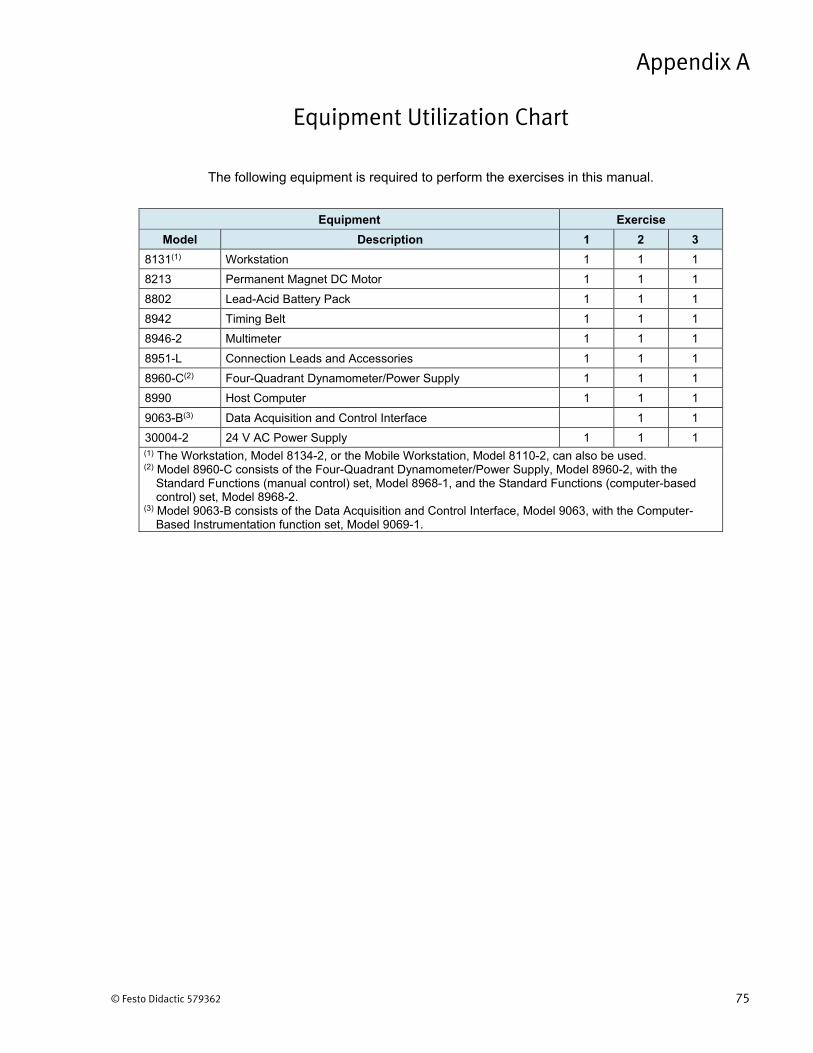
© Festo Didactic 579362 75
The following equipment is required to perform the exercises in this manual.
Equipment Exercise
Model Description 1 2 3
8131(1) Workstation 1 1 1
8213 Permanent Magnet DC Motor 1 1 1
8802 Lead-Acid Battery Pack 1 1 1
8942 Timing Belt 1 1 1
8946-2 Multimeter 1 1 1
8951-L Connection Leads and Accessories 1 1 1
8960-C(2) Four-Quadrant Dynamometer/Power Supply 1 1 1
8990 Host Computer 1 1 1
9063-B(3) Data Acquisition and Control Interface 1 1
30004-2 24 V AC Power Supply 1 1 1 (1) The Workstation, Model 8134-2, or the Mobile Workstation, Model 8110-2, can also be used.(2) Model 8960-C consists of the Four-Quadrant Dynamometer/Power Supply, Model 8960-2, with the
Standard Functions (manual control) set, Model 8968-1, and the Standard Functions (computer-basedcontrol) set, Model 8968-2.
(3) Model 9063-B consists of the Data Acquisition and Control Interface, Model 9063, with the Computer-Based Instrumentation function set, Model 9069-1.
Equipment Utilization Chart
Appendix A

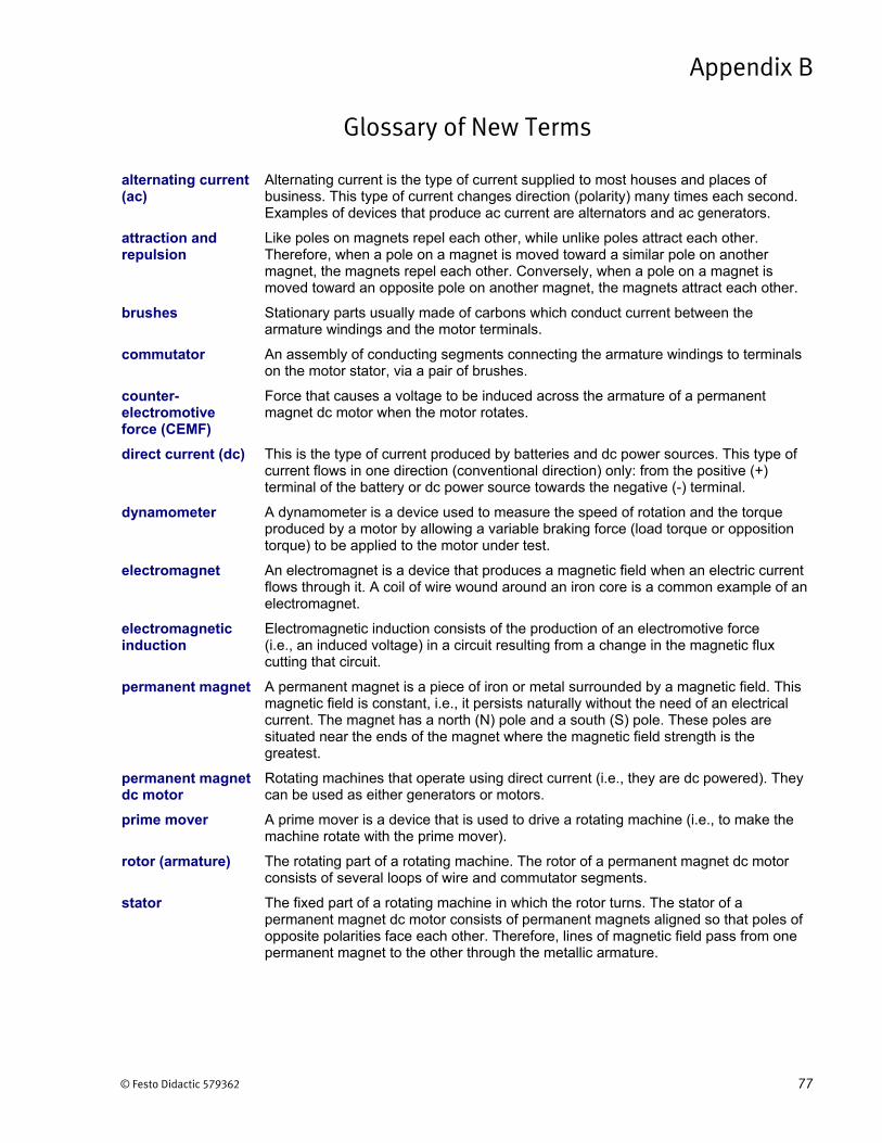
© Festo Didactic 579362 77
alternating current (ac)
Alternating current is the type of current supplied to most houses and places of business. This type of current changes direction (polarity) many times each second. Examples of devices that produce ac current are alternators and ac generators.
attraction and repulsion
Like poles on magnets repel each other, while unlike poles attract each other. Therefore, when a pole on a magnet is moved toward a similar pole on another magnet, the magnets repel each other. Conversely, when a pole on a magnet is moved toward an opposite pole on another magnet, the magnets attract each other.
brushes Stationary parts usually made of carbons which conduct current between the armature windings and the motor terminals.
commutator An assembly of conducting segments connecting the armature windings to terminals on the motor stator, via a pair of brushes.
counter-electromotive force (CEMF)
Force that causes a voltage to be induced across the armature of a permanent magnet dc motor when the motor rotates.
direct current (dc) This is the type of current produced by batteries and dc power sources. This type of current flows in one direction (conventional direction) only: from the positive (+) terminal of the battery or dc power source towards the negative (-) terminal.
dynamometer A dynamometer is a device used to measure the speed of rotation and the torque produced by a motor by allowing a variable braking force (load torque or opposition torque) to be applied to the motor under test.
electromagnet An electromagnet is a device that produces a magnetic field when an electric current flows through it. A coil of wire wound around an iron core is a common example of an electromagnet.
electromagnetic induction
Electromagnetic induction consists of the production of an electromotive force (i.e., an induced voltage) in a circuit resulting from a change in the magnetic flux cutting that circuit.
permanent magnet A permanent magnet is a piece of iron or metal surrounded by a magnetic field. This magnetic field is constant, i.e., it persists naturally without the need of an electrical current. The magnet has a north (N) pole and a south (S) pole. These poles are situated near the ends of the magnet where the magnetic field strength is the greatest.
permanent magnet dc motor
Rotating machines that operate using direct current (i.e., they are dc powered). They can be used as either generators or motors.
prime mover A prime mover is a device that is used to drive a rotating machine (i.e., to make the machine rotate with the prime mover).
rotor (armature) The rotating part of a rotating machine. The rotor of a permanent magnet dc motor consists of several loops of wire and commutator segments.
stator The fixed part of a rotating machine in which the rotor turns. The stator of a permanent magnet dc motor consists of permanent magnets aligned so that poles of opposite polarities face each other. Therefore, lines of magnetic field pass from one permanent magnet to the other through the metallic armature.
Glossary of New Terms
Appendix B

Appendix B Glossary of New Terms
78 © Festo Didactic 579362
torque The torque produced by a rotating machine indicates the magnitude of the twisting force that the machine applies to an object in rotation. Torque can be expressed in newton-meters (N·m) or in pound-force inches (lbf∙in). A motor rotates due to the torque produced by the motor when electrical power is supplied to it, while a generator rotates due to the torque applied to the generator shaft by an external force (e.g., a prime mover).
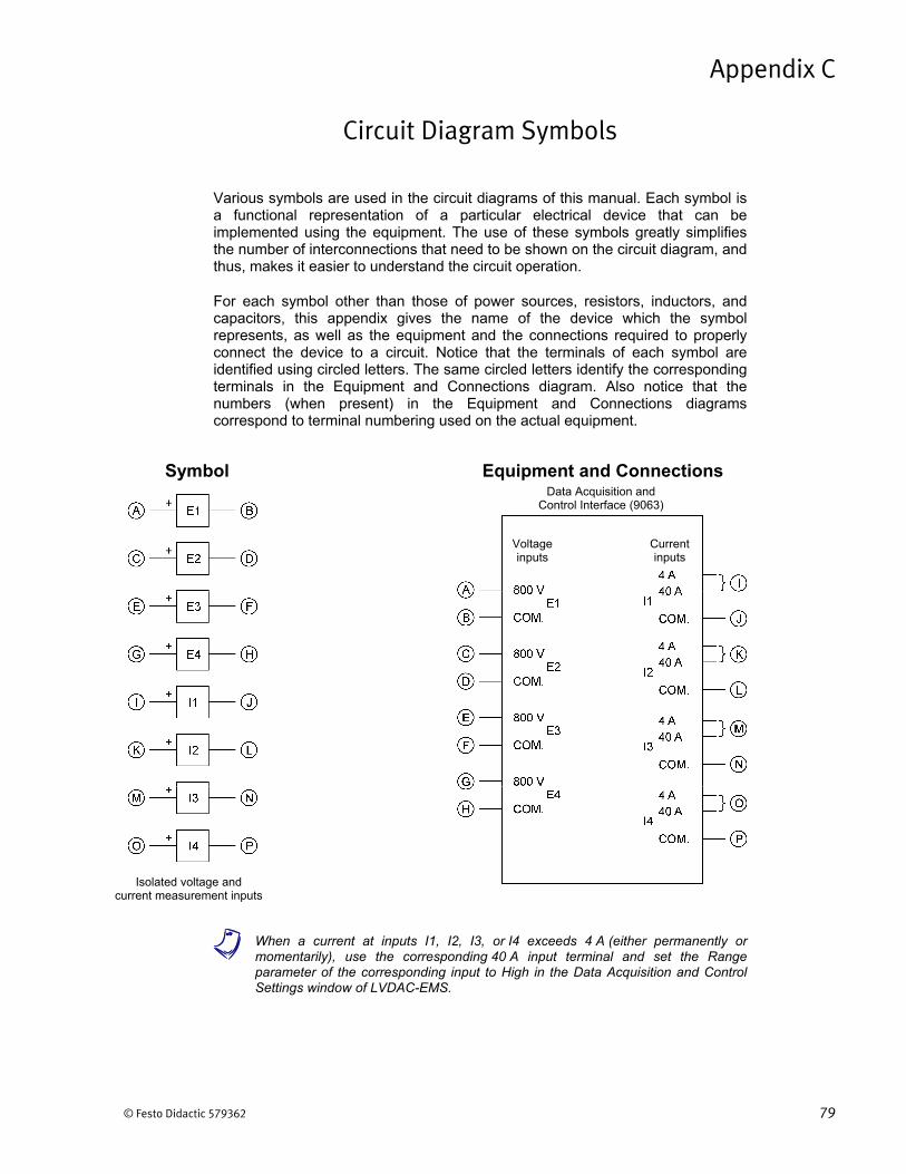
© Festo Didactic 579362 79
Various symbols are used in the circuit diagrams of this manual. Each symbol is a functional representation of a particular electrical device that can be implemented using the equipment. The use of these symbols greatly simplifies the number of interconnections that need to be shown on the circuit diagram, and thus, makes it easier to understand the circuit operation.
For each symbol other than those of power sources, resistors, inductors, and capacitors, this appendix gives the name of the device which the symbol represents, as well as the equipment and the connections required to properly connect the device to a circuit. Notice that the terminals of each symbol are identified using circled letters. The same circled letters identify the corresponding terminals in the Equipment and Connections diagram. Also notice that the numbers (when present) in the Equipment and Connections diagrams correspond to terminal numbering used on the actual equipment.
a When a current at inputs I1, I2, I3, or I4 exceeds 4 A (either permanently ormomentarily), use the corresponding 40 A input terminal and set the Range parameter of the corresponding input to High in the Data Acquisition and Control Settings window of LVDAC-EMS.
Circuit Diagram Symbols
Appendix C
Equipment and ConnectionsSymbol
Isolated voltage and current measurement inputs
Data Acquisition and Control Interface (9063)
Voltage inputs
Current inputs
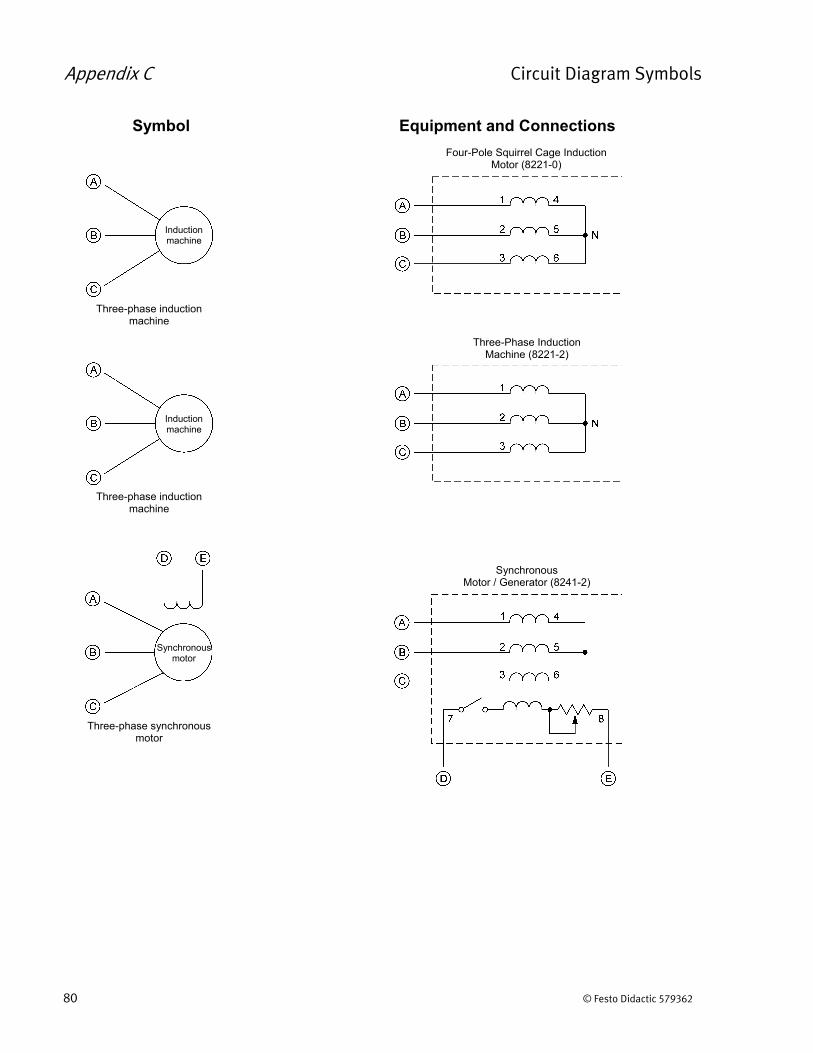
Appendix C Circuit Diagram Symbols
80 © Festo Didactic 579362
Three-phase induction machine
Four-Pole Squirrel Cage Induction Motor (8221-0)
Induction machine
Three-phase synchronous motor
Equipment and ConnectionsSymbol
Synchronous Motor / Generator (8241-2)
Synchronous motor
Three-phase induction machine
Three-Phase Induction Machine (8221-2)
Induction machine
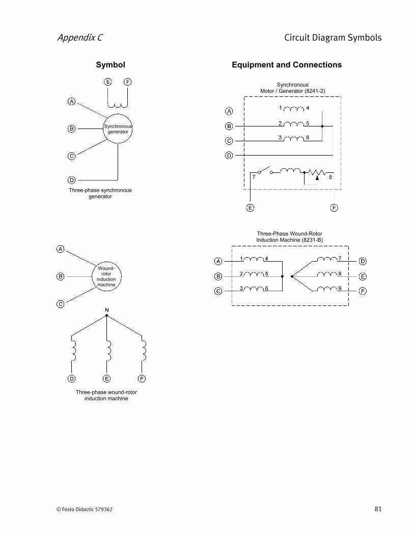
Appendix C Circuit Diagram Symbols
© Festo Didactic 579362 81
Three-phase synchronous generator
Synchronous generator
Synchronous Motor / Generator (8241-2)
Wound-rotor
induction machine
Three-phase wound-rotor induction machine
Three-Phase Wound-Rotor Induction Machine (8231-B)
Equipment and ConnectionsSymbol
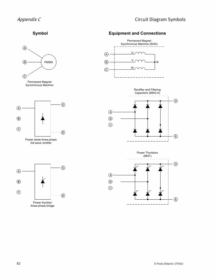
Appendix C Circuit Diagram Symbols
82 © Festo Didactic 579362
Power diode three-phase full-wave rectifier
Rectifier and Filtering Capacitors (8842-A)
Power thyristor three-phase bridge
Power Thyristors (8841)
Equipment and ConnectionsSymbol
Permanent Magnet Synchronous Machine (8245)
Permanent Magnet Synchronous Machine
PMSM
U
V
W
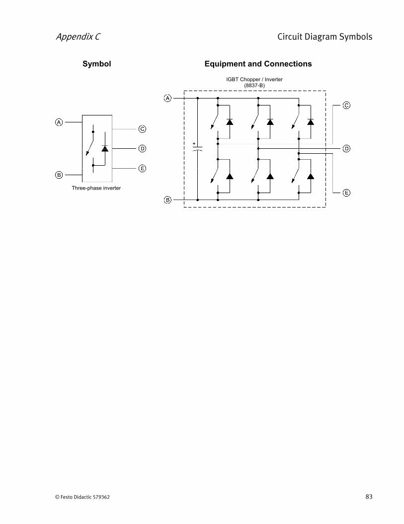
Appendix C Circuit Diagram Symbols
© Festo Didactic 579362 83
Three-phase inverter
IGBT Chopper / Inverter (8837-B)
Equipment and ConnectionsSymbol

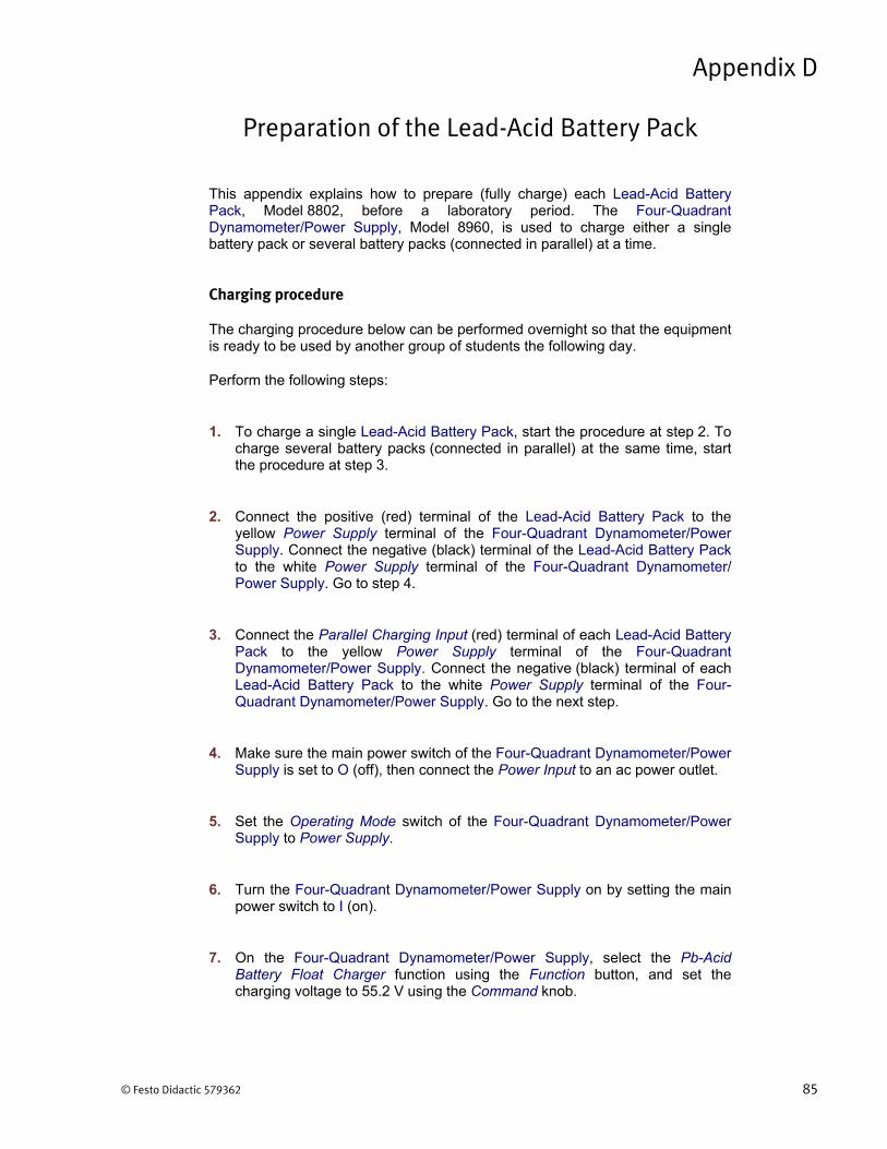
© Festo Didactic 579362 85
This appendix explains how to prepare (fully charge) each Lead-Acid Battery Pack, Model 8802, before a laboratory period. The Four-Quadrant Dynamometer/Power Supply, Model 8960, is used to charge either a single battery pack or several battery packs (connected in parallel) at a time.
Charging procedure
The charging procedure below can be performed overnight so that the equipment is ready to be used by another group of students the following day.
Perform the following steps:
1. To charge a single Lead-Acid Battery Pack, start the procedure at step 2. Tocharge several battery packs (connected in parallel) at the same time, startthe procedure at step 3.
2. Connect the positive (red) terminal of the Lead-Acid Battery Pack to theyellow Power Supply terminal of the Four-Quadrant Dynamometer/PowerSupply. Connect the negative (black) terminal of the Lead-Acid Battery Packto the white Power Supply terminal of the Four-Quadrant Dynamometer/Power Supply. Go to step 4.
3. Connect the Parallel Charging Input (red) terminal of each Lead-Acid BatteryPack to the yellow Power Supply terminal of the Four-QuadrantDynamometer/Power Supply. Connect the negative (black) terminal of eachLead-Acid Battery Pack to the white Power Supply terminal of the Four-Quadrant Dynamometer/Power Supply. Go to the next step.
4. Make sure the main power switch of the Four-Quadrant Dynamometer/PowerSupply is set to O (off), then connect the Power Input to an ac power outlet.
5. Set the Operating Mode switch of the Four-Quadrant Dynamometer/PowerSupply to Power Supply.
6. Turn the Four-Quadrant Dynamometer/Power Supply on by setting the mainpower switch to I (on).
7. On the Four-Quadrant Dynamometer/Power Supply, select the Pb-AcidBattery Float Charger function using the Function button, and set thecharging voltage to 55.2 V using the Command knob.
Preparation of the Lead-Acid Battery Pack
Appendix D
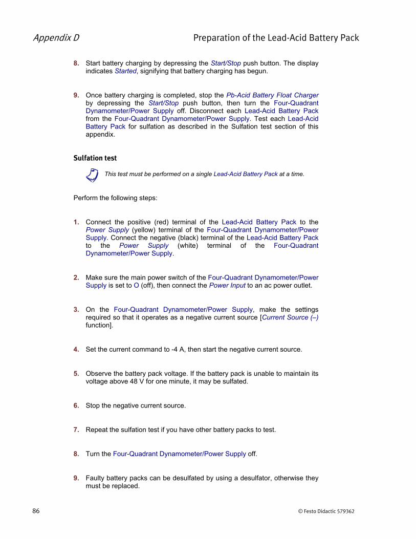
Appendix D Preparation of the Lead-Acid Battery Pack
86 © Festo Didactic 579362
8. Start battery charging by depressing the Start/Stop push button. The displayindicates Started, signifying that battery charging has begun.
9. Once battery charging is completed, stop the Pb-Acid Battery Float Chargerby depressing the Start/Stop push button, then turn the Four-QuadrantDynamometer/Power Supply off. Disconnect each Lead-Acid Battery Packfrom the Four-Quadrant Dynamometer/Power Supply. Test each Lead-AcidBattery Pack for sulfation as described in the Sulfation test section of thisappendix.
Sulfation test
a This test must be performed on a single Lead-Acid Battery Pack at a time.
Perform the following steps:
1. Connect the positive (red) terminal of the Lead-Acid Battery Pack to thePower Supply (yellow) terminal of the Four-Quadrant Dynamometer/PowerSupply. Connect the negative (black) terminal of the Lead-Acid Battery Packto the Power Supply (white) terminal of the Four-QuadrantDynamometer/Power Supply.
2. Make sure the main power switch of the Four-Quadrant Dynamometer/PowerSupply is set to O (off), then connect the Power Input to an ac power outlet.
3. On the Four-Quadrant Dynamometer/Power Supply, make the settingsrequired so that it operates as a negative current source [Current Source (–)function].
4. Set the current command to -4 A, then start the negative current source.
5. Observe the battery pack voltage. If the battery pack is unable to maintain itsvoltage above 48 V for one minute, it may be sulfated.
6. Stop the negative current source.
7. Repeat the sulfation test if you have other battery packs to test.
8. Turn the Four-Quadrant Dynamometer/Power Supply off.
9. Faulty battery packs can be desulfated by using a desulfator, otherwise theymust be replaced.

Appendix D Preparation of the Lead-Acid Battery Pack
© Festo Didactic 579362 87
Battery maintenance
In order to optimize the cycle life of the batteries in the Lead-Acid Battery Pack and to prevent sulfation, the battery pack should be charged as soon as possible after a discharge cycle (e.g., after completion of a laboratory exercise). The Lead-Acid Battery Pack should never be stored with the batteries discharged for an extended period of time.

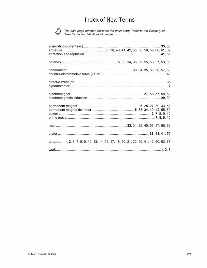
© Festo Didactic 579362 89
Index of New Terms
a The bold page number indicates the main entry. Refer to the Glossary ofNew Terms for definitions of new terms.
alternating-current (ac) ................................................................................... 35, 38 armature ............................................ 33, 38, 40, 41, 42, 55, 56, 58, 59, 60, 61, 62 attraction and repulsion .................................................................................. 41, 55
brushes ............................................................ 5, 33, 34, 35, 38, 55, 56, 57, 59, 60
commutator ...................................................................... 33, 34, 35, 38, 56, 57, 58 counter-electromotive force (CEMF) .................................................................... 60
direct-current (dc) ................................................................................................. 35 dynamometer ......................................................................................................... 7
electromagnet .............................................................................. 27, 56, 57, 58, 59 electromagnetic induction .............................................................................. 29, 30
permanent magnet ................................................................... 5, 25, 27, 30, 33, 58 permanent magnet dc motor .............................................. 5, 33, 34, 40, 42, 55, 60 power ................................................................................................... 2, 7, 8, 9, 10 prime mover ............................................................................................. 7, 8, 9, 10
rotor ............................................................................ 33, 34, 35, 40, 56, 57, 58, 59
stator .................................................................................................. 33, 34, 41, 55
torque .......... 2, 3, 7, 8, 9, 10, 13, 14, 15, 17, 18, 20, 21, 22, 40, 41, 42, 60, 62, 78
work ................................................................................................................ 1, 2, 3


© Festo Didactic 579362 91
Bibliography
Wildi, Theodore, Electrical Machines, Drives, and Power Systems, 2nd edition, New Jersey, Prentice Hall, 1991. ISBN 0-13-251547-4.