Embed Size (px)
Citation preview
EncoreControl System
Release Notes
SOFTWARE VERSION 1.6.5.1
071815305July 2004
2 Encore Release Notes
Contacting Grass Valley
Copyright © Thomson Broadcast and Media Solutions All rights reserved.
Grass Valley Web Site The www.thomsongrassvalley.com web site offers the following:
Online User Documentation — Current versions of product catalogs, bro-chures, data sheets, ordering guides, planning guides, manuals, and release notes in .pdf format can be downloaded.
FAQ Database — Solutions to problems and troubleshooting efforts can be found by searching our Frequently Asked Questions (FAQ) database.
Software Downloads — Software updates, drivers, and patches can be downloaded.
Region Voice Fax Address Web Site
North America (800) 547-8949Support: 530-478-4148
Sales: (530) 478-3347Support: (530) 478-3181
Grass ValleyP.O. Box 599000Nevada City, CA 95959-7900 USA
www.thomsongrassvalley.com
Pacific Operations +852-2585-6688Support: 852-2585-6579
+852-2802-2996
U.K., Europe, Asia, Middle East +44 1753 218 777 +44 1753 218 757
France +33 1 45 29 73 00
Germany +49 221 1791 234 +49 221 1791 235
Contents
ContentsPurpose . . . . . . . . . . . . . . . . . . . . . . . . . . . . . . . . . . . . . . . . . . . . . . . . . . . . . . . . . . . . . . . 7
Release 1.6.5.1 Enhancements . . . . . . . . . . . . . . . . . . . . . . . . . . . . . . . . . . . . . . . . 7Materials Supplied . . . . . . . . . . . . . . . . . . . . . . . . . . . . . . . . . . . . . . . . . . . . . . . . . . . . . 8Related Software . . . . . . . . . . . . . . . . . . . . . . . . . . . . . . . . . . . . . . . . . . . . . . . . . . . . . . . 9
NetCentral/SNMP Monitoring . . . . . . . . . . . . . . . . . . . . . . . . . . . . . . . . . . . . . . . 9SoftPanels . . . . . . . . . . . . . . . . . . . . . . . . . . . . . . . . . . . . . . . . . . . . . . . . . . . . . . . . . 9Windows NT Support Expiration . . . . . . . . . . . . . . . . . . . . . . . . . . . . . . . . . . . . . 9
System Requirements . . . . . . . . . . . . . . . . . . . . . . . . . . . . . . . . . . . . . . . . . . . . . . . . . . 10SCB Modifications . . . . . . . . . . . . . . . . . . . . . . . . . . . . . . . . . . . . . . . . . . . . . . . . . . . 10Concerto Applications . . . . . . . . . . . . . . . . . . . . . . . . . . . . . . . . . . . . . . . . . . . . . . . 10
Port Router Modification . . . . . . . . . . . . . . . . . . . . . . . . . . . . . . . . . . . . . . . . . . . 10Matrix Controller Requirements . . . . . . . . . . . . . . . . . . . . . . . . . . . . . . . . . . . . . 10
Trinix/Apex Applications . . . . . . . . . . . . . . . . . . . . . . . . . . . . . . . . . . . . . . . . . . . . 10System PC Requirements . . . . . . . . . . . . . . . . . . . . . . . . . . . . . . . . . . . . . . . . . . . . . 11Redundant Automation Serial Control Cables . . . . . . . . . . . . . . . . . . . . . . . . . . . 11
Panel Grouping . . . . . . . . . . . . . . . . . . . . . . . . . . . . . . . . . . . . . . . . . . . . . . . . . . . . . . . 12BPS + 48B Grouping . . . . . . . . . . . . . . . . . . . . . . . . . . . . . . . . . . . . . . . . . . . . . . . . . 12
Configuration . . . . . . . . . . . . . . . . . . . . . . . . . . . . . . . . . . . . . . . . . . . . . . . . . . . . . 12XY + 48B Grouping . . . . . . . . . . . . . . . . . . . . . . . . . . . . . . . . . . . . . . . . . . . . . . . . . . 14
Configuration . . . . . . . . . . . . . . . . . . . . . . . . . . . . . . . . . . . . . . . . . . . . . . . . . . . . . 14Trinix Support . . . . . . . . . . . . . . . . . . . . . . . . . . . . . . . . . . . . . . . . . . . . . . . . . . . . . . . . 16
CPL Control . . . . . . . . . . . . . . . . . . . . . . . . . . . . . . . . . . . . . . . . . . . . . . . . . . . . . . 16Multi-chassis control . . . . . . . . . . . . . . . . . . . . . . . . . . . . . . . . . . . . . . . . . . . . . . . 17Trinix NetConfig 2.0 Support. . . . . . . . . . . . . . . . . . . . . . . . . . . . . . . . . . . . . . . . 19
Apex (Via Trinix) Support . . . . . . . . . . . . . . . . . . . . . . . . . . . . . . . . . . . . . . . . . . . . . . 207500 Router Enhancements . . . . . . . . . . . . . . . . . . . . . . . . . . . . . . . . . . . . . . . . . . . . . 22
7500 SNMP Monitoring. . . . . . . . . . . . . . . . . . . . . . . . . . . . . . . . . . . . . . . . . . . . . 227500 Web Configuration (NetConfig 2.0 Support) . . . . . . . . . . . . . . . . . . . . . . 22
Concerto Enhancements. . . . . . . . . . . . . . . . . . . . . . . . . . . . . . . . . . . . . . . . . . . . . . . . 22Time Code Matrix . . . . . . . . . . . . . . . . . . . . . . . . . . . . . . . . . . . . . . . . . . . . . . . . . 22Data Matrix . . . . . . . . . . . . . . . . . . . . . . . . . . . . . . . . . . . . . . . . . . . . . . . . . . . . . . . 22Audio Matrix TDM Expansion . . . . . . . . . . . . . . . . . . . . . . . . . . . . . . . . . . . . . . 2264 x 64 Matrix . . . . . . . . . . . . . . . . . . . . . . . . . . . . . . . . . . . . . . . . . . . . . . . . . . . . . 22SNMP Monitoring . . . . . . . . . . . . . . . . . . . . . . . . . . . . . . . . . . . . . . . . . . . . . . . . . 23Concerto TDM Expansion - Installation and Configuration . . . . . . . . . . . . . . 23
Output Monitoring . . . . . . . . . . . . . . . . . . . . . . . . . . . . . . . . . . . . . . . . . . . . . . . . . . . . 26To Configure and Use Destination Monitors. . . . . . . . . . . . . . . . . . . . . . . . . . . 27
SNMP Monitoring. . . . . . . . . . . . . . . . . . . . . . . . . . . . . . . . . . . . . . . . . . . . . . . . . . . . . 32Encore System Controller – SNMP Agent . . . . . . . . . . . . . . . . . . . . . . . . . . . . . 32Matrix – SNMP Agents . . . . . . . . . . . . . . . . . . . . . . . . . . . . . . . . . . . . . . . . . . . . . 33SNMP Agent Licensing. . . . . . . . . . . . . . . . . . . . . . . . . . . . . . . . . . . . . . . . . . . . . 33Agent Installation. . . . . . . . . . . . . . . . . . . . . . . . . . . . . . . . . . . . . . . . . . . . . . . . . . 34
NetCentral SNMP Manager . . . . . . . . . . . . . . . . . . . . . . . . . . . . . . . . . . . . . . . . . . . 34NetCentral Capabilities. . . . . . . . . . . . . . . . . . . . . . . . . . . . . . . . . . . . . . . . . . . . . 34NetCentral Installation . . . . . . . . . . . . . . . . . . . . . . . . . . . . . . . . . . . . . . . . . . . . . 35
License Installation . . . . . . . . . . . . . . . . . . . . . . . . . . . . . . . . . . . . . . . . . . . . . . . . . . . . 36SNMP and SoftPanels License Entry. . . . . . . . . . . . . . . . . . . . . . . . . . . . . . . . . . 36Router Matrix SNMP Agent License Entry . . . . . . . . . . . . . . . . . . . . . . . . . . . . 36Further Information. . . . . . . . . . . . . . . . . . . . . . . . . . . . . . . . . . . . . . . . . . . . . . . . 37
Deterministic (Frame Accurate) Switching . . . . . . . . . . . . . . . . . . . . . . . . . . . . . . . . 38NetConfig 2.0 Support . . . . . . . . . . . . . . . . . . . . . . . . . . . . . . . . . . . . . . . . . . . . . . . . . 39
Auto Discovery. . . . . . . . . . . . . . . . . . . . . . . . . . . . . . . . . . . . . . . . . . . . . . . . . . . . 39
Encore Release Notes 3
Version 1.6.5.1
Backward Compatibility Notes . . . . . . . . . . . . . . . . . . . . . . . . . . . . . . . . . . . . . . 39Multi-Area Support . . . . . . . . . . . . . . . . . . . . . . . . . . . . . . . . . . . . . . . . . . . . . . . . . . . 40
Example of 2-Area Application. . . . . . . . . . . . . . . . . . . . . . . . . . . . . . . . . . . . . . 40Creating an Area . . . . . . . . . . . . . . . . . . . . . . . . . . . . . . . . . . . . . . . . . . . . . . . . . . . . 42
Hardware Installation. . . . . . . . . . . . . . . . . . . . . . . . . . . . . . . . . . . . . . . . . . . . . . 42Software Configuration . . . . . . . . . . . . . . . . . . . . . . . . . . . . . . . . . . . . . . . . . . . . 42Assigning a User to an Area . . . . . . . . . . . . . . . . . . . . . . . . . . . . . . . . . . . . . . . . 42Assigning Engines and Applications to an Area . . . . . . . . . . . . . . . . . . . . . . . 43Assigning an SCB to an Area. . . . . . . . . . . . . . . . . . . . . . . . . . . . . . . . . . . . . . . . 43Assigning a Router to an Area . . . . . . . . . . . . . . . . . . . . . . . . . . . . . . . . . . . . . . 44Configuring Control Panels for Control in Specific Area(s) . . . . . . . . . . . . . . 45Operating a PMB Panel in a Multi-area System . . . . . . . . . . . . . . . . . . . . . . . . 46Operating an XY Panel in a Multi-area System . . . . . . . . . . . . . . . . . . . . . . . . 46Changing Area Assignments. . . . . . . . . . . . . . . . . . . . . . . . . . . . . . . . . . . . . . . . 47
Misc. Control Panel Enhancements . . . . . . . . . . . . . . . . . . . . . . . . . . . . . . . . . . . . . . 48BPS Panels . . . . . . . . . . . . . . . . . . . . . . . . . . . . . . . . . . . . . . . . . . . . . . . . . . . . . . . 4848B Panel. . . . . . . . . . . . . . . . . . . . . . . . . . . . . . . . . . . . . . . . . . . . . . . . . . . . . . . . . 49XY Panel . . . . . . . . . . . . . . . . . . . . . . . . . . . . . . . . . . . . . . . . . . . . . . . . . . . . . . . . . 49PMB Panel . . . . . . . . . . . . . . . . . . . . . . . . . . . . . . . . . . . . . . . . . . . . . . . . . . . . . . . 51
Changes to Router Control Application Menus . . . . . . . . . . . . . . . . . . . . . . . . . . . 52New Options Menu. . . . . . . . . . . . . . . . . . . . . . . . . . . . . . . . . . . . . . . . . . . . . . . . 52Changes to Configuration Screen . . . . . . . . . . . . . . . . . . . . . . . . . . . . . . . . . . . . 53New Load Screen. . . . . . . . . . . . . . . . . . . . . . . . . . . . . . . . . . . . . . . . . . . . . . . . . . 54New Save Screen . . . . . . . . . . . . . . . . . . . . . . . . . . . . . . . . . . . . . . . . . . . . . . . . . . 54
Changes to CP Server Menus . . . . . . . . . . . . . . . . . . . . . . . . . . . . . . . . . . . . . . . . . . . 55Main Menu. . . . . . . . . . . . . . . . . . . . . . . . . . . . . . . . . . . . . . . . . . . . . . . . . . . . . . . . . 55Panel configuration/Template select screen. . . . . . . . . . . . . . . . . . . . . . . . . . . . . 56Button Configuration Screen - Assignment Mode. . . . . . . . . . . . . . . . . . . . . . . . 57
BPS Panel Menu. . . . . . . . . . . . . . . . . . . . . . . . . . . . . . . . . . . . . . . . . . . . . . . . . . . 57PMB Panel Menu. . . . . . . . . . . . . . . . . . . . . . . . . . . . . . . . . . . . . . . . . . . . . . . . . . 57XY Panel Menu . . . . . . . . . . . . . . . . . . . . . . . . . . . . . . . . . . . . . . . . . . . . . . . . . . . 5948B Panel Menu . . . . . . . . . . . . . . . . . . . . . . . . . . . . . . . . . . . . . . . . . . . . . . . . . . . 60
Configuration Flags and Attributes Menu . . . . . . . . . . . . . . . . . . . . . . . . . . . . . . 6048B Panel. . . . . . . . . . . . . . . . . . . . . . . . . . . . . . . . . . . . . . . . . . . . . . . . . . . . . . . . . 60BPS Panel . . . . . . . . . . . . . . . . . . . . . . . . . . . . . . . . . . . . . . . . . . . . . . . . . . . . . . . . 60PMB Panel and XY Panel . . . . . . . . . . . . . . . . . . . . . . . . . . . . . . . . . . . . . . . . . . . 61
Definition of Flags and Attributes . . . . . . . . . . . . . . . . . . . . . . . . . . . . . . . . . . . . . 61Salvos Enable Button . . . . . . . . . . . . . . . . . . . . . . . . . . . . . . . . . . . . . . . . . . . . . . . . . . 65Non-Display of Excluded Destinations. . . . . . . . . . . . . . . . . . . . . . . . . . . . . . . . . . . 65Default OMN Database . . . . . . . . . . . . . . . . . . . . . . . . . . . . . . . . . . . . . . . . . . . . . . . . 65Software Installation . . . . . . . . . . . . . . . . . . . . . . . . . . . . . . . . . . . . . . . . . . . . . . . . . . 67
Upgrading from Version 1.x to Version 1.6.5.1. . . . . . . . . . . . . . . . . . . . . . . . . 67Support for Microsoft Windows XP Professional . . . . . . . . . . . . . . . . . . . . . . . . . . 71
Release Sharer . . . . . . . . . . . . . . . . . . . . . . . . . . . . . . . . . . . . . . . . . . . . . . . . . . . . 71Debug Sharer . . . . . . . . . . . . . . . . . . . . . . . . . . . . . . . . . . . . . . . . . . . . . . . . . . . . . 71System Manager . . . . . . . . . . . . . . . . . . . . . . . . . . . . . . . . . . . . . . . . . . . . . . . . . . 71Encore OUI . . . . . . . . . . . . . . . . . . . . . . . . . . . . . . . . . . . . . . . . . . . . . . . . . . . . . . . 72
4 Encore Release Notes
Contents
Appendix A — RCL EnhancementsRCL Servers OUI Screen . . . . . . . . . . . . . . . . . . . . . . . . . . . . . . . . . . . . . . . . . . . . . . . 77RCL Server – Flags and Parameters . . . . . . . . . . . . . . . . . . . . . . . . . . . . . . . . . . . . . . 78
Area . . . . . . . . . . . . . . . . . . . . . . . . . . . . . . . . . . . . . . . . . . . . . . . . . . . . . . . . . . . . . 78Flags . . . . . . . . . . . . . . . . . . . . . . . . . . . . . . . . . . . . . . . . . . . . . . . . . . . . . . . . . . . . . 79
Appendix B — Input/Output AttributesConcerto Settings. . . . . . . . . . . . . . . . . . . . . . . . . . . . . . . . . . . . . . . . . . . . . . . . . . . . . . 81
Video Outputs . . . . . . . . . . . . . . . . . . . . . . . . . . . . . . . . . . . . . . . . . . . . . . . . . . . . 81Digital Audio Inputs . . . . . . . . . . . . . . . . . . . . . . . . . . . . . . . . . . . . . . . . . . . . . . . 81Digital Audio Outputs . . . . . . . . . . . . . . . . . . . . . . . . . . . . . . . . . . . . . . . . . . . . . 81Analog Audio Inputs. . . . . . . . . . . . . . . . . . . . . . . . . . . . . . . . . . . . . . . . . . . . . . . 82Analog Audio Outputs . . . . . . . . . . . . . . . . . . . . . . . . . . . . . . . . . . . . . . . . . . . . . 82
Trinix Settings . . . . . . . . . . . . . . . . . . . . . . . . . . . . . . . . . . . . . . . . . . . . . . . . . . . . . . . . 82Outputs . . . . . . . . . . . . . . . . . . . . . . . . . . . . . . . . . . . . . . . . . . . . . . . . . . . . . . . . . . 82
Apex Settings . . . . . . . . . . . . . . . . . . . . . . . . . . . . . . . . . . . . . . . . . . . . . . . . . . . . . . . . . 82Inputs . . . . . . . . . . . . . . . . . . . . . . . . . . . . . . . . . . . . . . . . . . . . . . . . . . . . . . . . . . . . 82Outputs . . . . . . . . . . . . . . . . . . . . . . . . . . . . . . . . . . . . . . . . . . . . . . . . . . . . . . . . . . 82
7500 Wideband Settings . . . . . . . . . . . . . . . . . . . . . . . . . . . . . . . . . . . . . . . . . . . . . . . . 82Wideband I/O Outputs . . . . . . . . . . . . . . . . . . . . . . . . . . . . . . . . . . . . . . . . . . . . 82Wideband SDV Outputs . . . . . . . . . . . . . . . . . . . . . . . . . . . . . . . . . . . . . . . . . . . . 82
7500 Narrowband Settings. . . . . . . . . . . . . . . . . . . . . . . . . . . . . . . . . . . . . . . . . . . . . . 83Inputs . . . . . . . . . . . . . . . . . . . . . . . . . . . . . . . . . . . . . . . . . . . . . . . . . . . . . . . . . . . . 83Outputs . . . . . . . . . . . . . . . . . . . . . . . . . . . . . . . . . . . . . . . . . . . . . . . . . . . . . . . . . . 83
Glossary . . . . . . . . . . . . . . . . . . . . . . . . . . . . . . . . . . . . . . . . . . . . . . . . . . . . . . . . . . . . . 83
Appendix C — Monitoring with Third-party SNMP ManagersRegistering other SNMP Managers in the agent database . . . . . . . . . . . . . . . 85Adding new SNMP Managers . . . . . . . . . . . . . . . . . . . . . . . . . . . . . . . . . . . . . . . 85Deleting SNMP Managers . . . . . . . . . . . . . . . . . . . . . . . . . . . . . . . . . . . . . . . . . . 86
Encore Release Notes 5

Version 1.6.5.1
6 Encore Release Notes
Version 1.6.5.1July 2004
Encore Control System Release Notes
PurposeThis document describes the product enhancements provided by Encore software release 1.6.5.1. This information, along with the release notes for Encore 1.6 and Encore 1.6.1, supplements the existing Encore 1.5 User Manual.
Also described is the installation procedure used to upgrade the system from 1.x to 1.6.5.1 (page 67).
Release 1.6.5.1 Enhancements• Panel grouping: BPS + 48B and XY + 48B (page 12)
• Trinix support (page 16)
• Apex (via Trinix) support (page 20)
• Multiple output monitoring (page 26)
• Deterministic (frame accurate) switching (page 38)
• 7500 router enhancements (page 22)
• Concerto enhancements (page 22)
• SNMP monitoring (page 32)
• NetConfig 2.0 support (page 39)
• SoftPanels 1.0 (page 10)
(License installation - page 36)
• Multi-area support (page 40)
• Miscellaneous control panel enhancements (page 48)
• Changes to Router Control application menu (page 52)
Encore Release Notes 7
Version 1.6.5.1
• Salvos Enable button (page 65)
• Non-display of excluded destinations (page 65)
• Default OMN database (page 65)
• Support for Microsoft Windows XP OS (page 71)
• RCL enhancements (page 73)
This document also contains a summary of input/outputs attributes and how they are assigned (page 81).
Materials SuppliedThe Encore Control System Software Version 1.6.5.1 includes:
• A software CD-ROM that contains all Encore system and application files needed for software installation or upgrade (including SoftPanels 1.0)
• These release notes, and
• A CD-ROM that contains electronic copies of routing products docu-mentation.
8 Encore Release Notes
Related Software
Related Software
NetCentral/SNMP Monitoring
NetCentral monitoring of Encore System Control Boards and Encore-con-trolled matrix routers requires installation of the NetCentral Simple Network Management Protocol manager application on the monitoring PC. This Grass Valley product is supplied on a separate CD.
If desired, a third-party SNMP management application can be used in place of NetCentral.
SNMP monitoring also requires a specific “agent” application to be installed in each target device.
For more information see SNMP Monitoring on page 32.
SoftPanelsSoftPanels are virtual (GUI) versions of the four Encore physical control panels (48B, BPS, PMB, and XY). They are sold separately from the Encore system itself and are individually licensed; i.e., customers will be allowed to use any of the different Encore panel types as long as the total number of SoftPanels signed onto the Control Panel Server application does not exceed the purchased license number.
The SoftPanels software is included on the Encore 1.6.5.1 CD. It is also available for download from the Grass Valley web site.
To run SoftPanels, a license must be purchased (ENC-SOFTPAN1). One license is required for each simultaneously running instance. License instal-lation is described on page 36.
SoftPanels can be operated on PCs with Windows 2000 or Windows XP. Windows NT, ME, and 95/98 PCs are not supported.
For more information, refer to the SoftPanels manual, part no. 0718332xx.
Windows NT Support ExpirationWindows NT will not be supported by Encore releases beyond 1.6.5.1.
Encore Release Notes 9
Version 1.6.5.1
System Requirements
SCB ModificationsFor proper deterministic (frame accurate) operation, the Encore System Controller Board (SCB) must be upgraded to Encore version 1.6.5.1 and a new PROM (part no.l 163825201) must be ordered from Technical Support and installed on the System Controller motherboard. Refer to Engineering Change Order 013 and Field Modification Note 075076000.
Concerto Applications
Port Router ModificationThere is an update to the time code/port router board (671637400). Current boards in the field are at level E1. These will work properly with the Encore 1.6.5.1 release (T/C or Port both switch properly). However, if configured for Port Routing the red “Error” LED will remain on. If the board is at level "F1" then there will be no false Error indication.
Please contact Technical Support for update information.
Matrix Controller Requirements
The SNMP agent (used with NetCentral) supplied with this release is sup-ported only by the CRS-2001 Fast Controller (6716434xx) and CRS-MC-C2 Controller (6716495xx). These are both 100BaseT boards. The original 10BaseT CRS-2001 Controller (6716381xx) does not support this agent. The 10BaseT controller can be identified by the presence of eight LEDs along the front edge of the board; the newer controllers both have only seven LEDs along the edge.
In addition, for the "Bridge" Systems, if a “combo” MC (671649500) is installed the boot PROM must be at level 07 (i.e. 080829907) in order for Encore to control it.
Trinix/Apex ApplicationsTrinix and/or Apex systems must be operating with Broadlinx (NR-33000) version 2.2.0 or newer when controlled by Encore version 1.6.5.1.
10 Encore Release Notes
System Requirements
System PC RequirementsMinimum PC requirements for running the Encore Sharer and the Encore Operational User Interface (OUI) applications include:
• Network connection (and running the Encore Sharer application if you want to make system configuration changes)
Note Only one Encore Sharer can be running on the network, and Thomson rec-ommends that the Sharer PC be left running with the Sharer applica-tion active.
• 1.3 GHz Pentium 4 CPU
• 512 MB RAM
• 10 GB available hard disk space
• 100BaseT Ethernet Network Interface Card
• 15-inch monitor with a screen resolution of 1024 x 768
• NT 4.0 (SP 6), Windows 2000 (SP 2), or XP Professional workstation
• Internet Explorer version 5.5 or later
Redundant Automation Serial Control CablesRedundant automation serial control requires dual Category 5 UTP cables connected to the SCB rear panel SIO ports operated in RS-422 mode. The two cables are combined to form a “Y” connection to the automation com-puter.
Hardware issues
1. Problem: The current serial interface will not work on a serial bus in its present state without causing data interruption when one of the boards on the bus is powered on. On the Encore SIO ISA board, the transmitters need to be disabled by default if the serial ports from each system controller are to be connected (for redundancy) to a single port of an external device through a 'Y' cable connection or connected together on an RS-488 serial bus (see CR 30602).
Solution: ECO 403K: Replace “671631700 BRD, SIO ISA” with “671631701 BRD, SIO ISA” Note: Not all customers will experience this problem. It will depend upon their configuration. If a customer does experience this problem, they will need to exchange their old board for a new one through Technical Support.
Encore Release Notes 11

Version 1.6.5.1
2. When connecting to early-model SCBs, the RJ45s connected to the Encore ports must be wired with “crossover” pinouts; when connecting to late-model SCBs “pin-to-pin” wiring is used. A factory-built Y cable kit is available, and provides all parts and instructions needed for both backplane types. For more information, refer to the “Serial Interface Y Cable Option Instruction Manual,” publication number 071827900.
Panel GroupingControl Panel Grouping allows configuration of two or more control panels to operate as a single panel, e.g. increasing the number of direct access Sources and Destinations. Encore version 1.6.1 provided 48B + 48B grouping; Encore 1.6.5.1 provides additional combinations of BPS + 48B and XY + 48B as described below.
BPS + 48B Grouping
Figure 1. BPS panel (top) and 48B panel (below).
In a BPS + 48B configuration, the buttons of the 48B panel are treated as 48 extra buttons added to the 32 assignable buttons of the BPS panel.
The BPS feature which allows the operator to assign dynamically (from the panel itself) sources to buttons is supported by the 32 buttons of the BPS panel and the 48 buttons of the 48B panel.
Operational and diagnostic messages (e.g. in case of Lock or Protect) will only show the Master panel name, which in this case is the BPS panel.
Configuration
1. Log in to the CP Server application.
2. Configure the BPS panel:
a. Go to Encore Panels > BPS > Select. Select the BPS panel that will be the main unit.
Destination Status
Prot
Lvl 1
Chop
Lvl 2 Lvl 3 Lvl 5
Next
Lvl 6Lvl 4
Prev
All Lvls
Config
Tally
ID
12 Encore Release Notes
Panel Grouping
b. Go to Configure BPS Flags > Panel Group Name. This will display the Panel Groups names list. Select the name of this BPS panel.
c. Configure the individual buttons as desired.
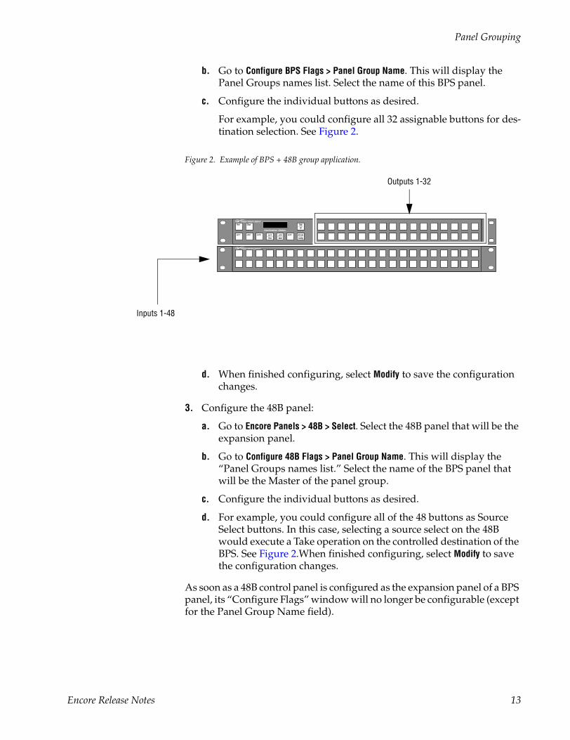
For example, you could configure all 32 assignable buttons for des-tination selection. See Figure 2.
Figure 2. Example of BPS + 48B group application.
d. When finished configuring, select Modify to save the configuration changes.
3. Configure the 48B panel:
a. Go to Encore Panels > 48B > Select. Select the 48B panel that will be the expansion panel.
b. Go to Configure 48B Flags > Panel Group Name. This will display the “Panel Groups names list.” Select the name of the BPS panel that will be the Master of the panel group.
c. Configure the individual buttons as desired.
d. For example, you could configure all of the 48 buttons as Source Select buttons. In this case, selecting a source select on the 48B would execute a Take operation on the controlled destination of the BPS. See Figure 2.When finished configuring, select Modify to save the configuration changes.
As soon as a 48B control panel is configured as the expansion panel of a BPS panel, its “Configure Flags” window will no longer be configurable (except for the Panel Group Name field).
Destination Status
ProtProt
Lvl 1Lvl 1
ChopChop
Lvl 2Lvl 2 Lvl 3Lvl 3 Lvl 5Lvl 5
NextNext
Lvl 6Lvl 6Lvl 4Lvl 4
PrevPrev
All LvlsAll Lvls
ConfigConfig
Tallyally
IDID
Inputs 1-48
Outputs 1-32
Encore Release Notes 13
Version 1.6.5.1
The expansion panel button configuration screen will now show the fol-lowing message: “48B Expansion panel of Panel Group BPS<BPS name>.” “Assignment” and “Selection” menus will have the same functionality as for the BPS 32 assignable buttons. All the BPS control panel attributes and flags will apply to the panel group.
XY + 48B Grouping
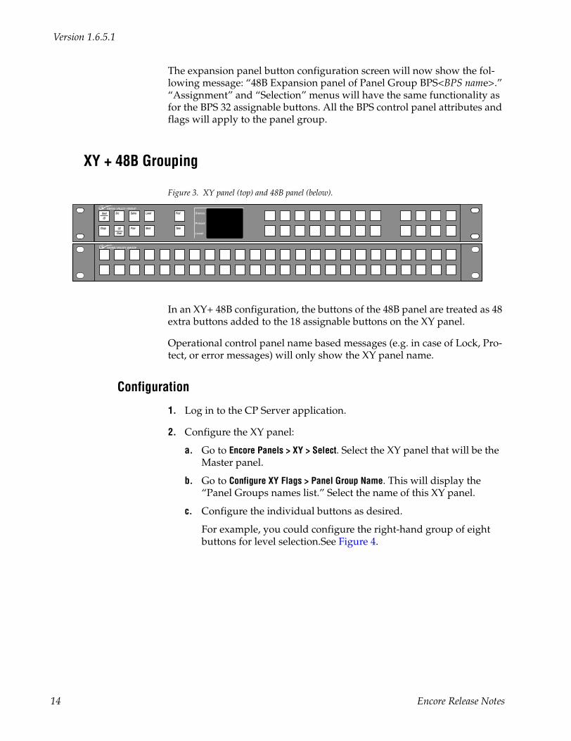
Figure 3. XY panel (top) and 48B panel (below).
In an XY+ 48B configuration, the buttons of the 48B panel are treated as 48 extra buttons added to the 18 assignable buttons on the XY panel.
Operational control panel name based messages (e.g. in case of Lock, Pro-tect, or error messages) will only show the XY panel name.
Configuration
1. Log in to the CP Server application.
2. Configure the XY panel:
a. Go to Encore Panels > XY > Select. Select the XY panel that will be the Master panel.
b. Go to Configure XY Flags > Panel Group Name. This will display the “Panel Groups names list.” Select the name of this XY panel.
c. Configure the individual buttons as desired.
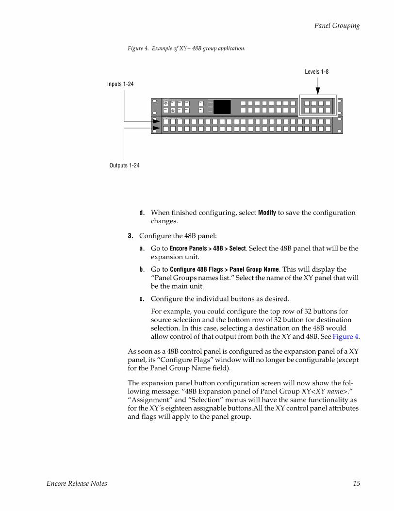
For example, you could configure the right-hand group of eight buttons for level selection.See Figure 4.
Status
Preset
Level
Dest
ID
Chop
Src
CE
Clear
Salvo
Prev
Level
Next
Prot
Take
14 Encore Release Notes
Panel Grouping
Figure 4. Example of XY+ 48B group application.
d. When finished configuring, select Modify to save the configuration changes.
3. Configure the 48B panel:
a. Go to Encore Panels > 48B > Select. Select the 48B panel that will be the expansion unit.
b. Go to Configure 48B Flags > Panel Group Name. This will display the “Panel Groups names list.” Select the name of the XY panel that will be the main unit.
c. Configure the individual buttons as desired.
For example, you could configure the top row of 32 buttons for source selection and the bottom row of 32 button for destination selection. In this case, selecting a destination on the 48B would allow control of that output from both the XY and 48B. See Figure 4.
As soon as a 48B control panel is configured as the expansion panel of a XY panel, its “Configure Flags” window will no longer be configurable (except for the Panel Group Name field).
The expansion panel button configuration screen will now show the fol-lowing message: “48B Expansion panel of Panel Group XY<XY name>.” “Assignment” and “Selection” menus will have the same functionality as for the XY’s eighteen assignable buttons.All the XY control panel attributes and flags will apply to the panel group.
Status
Preset
Level
DestDest
IDID
ChopChop
SrSrc
CECE
ClearClear
SalvoSalvo
PrevPrev
LevelLevel
NextNext
ProtProt
Takeake
Outputs 1-24
Levels 1-8
Inputs 1-24
Encore Release Notes 15
Version 1.6.5.1
Trinix SupportThe following discussion assumes that the Trinix NR-33000 (Broadlinx) board is running Broadlinx 2.2.0 or newer.
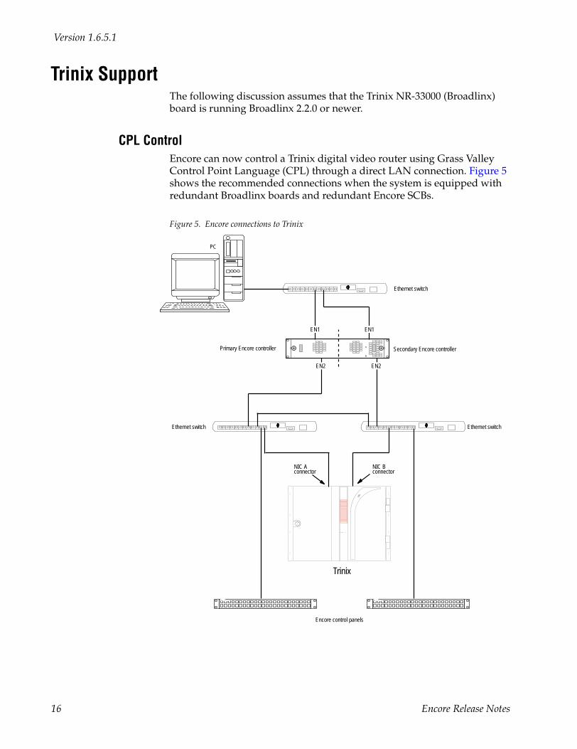
CPL Control Encore can now control a Trinix digital video router using Grass Valley Control Point Language (CPL) through a direct LAN connection. Figure 5 shows the recommended connections when the system is equipped with redundant Broadlinx boards and redundant Encore SCBs.
Figure 5. Encore connections to Trinix
NIC Aconnector
Trinix
PC
Ethernet switch
Ethernet switch
Ethernet switch
Secondary Encore controllerPrimary Encore controller
EN2
EN1
EN2
NIC Bconnector
Encore control panels
EN1
16 Encore Release Notes
Trinix Support
Multi-chassis control
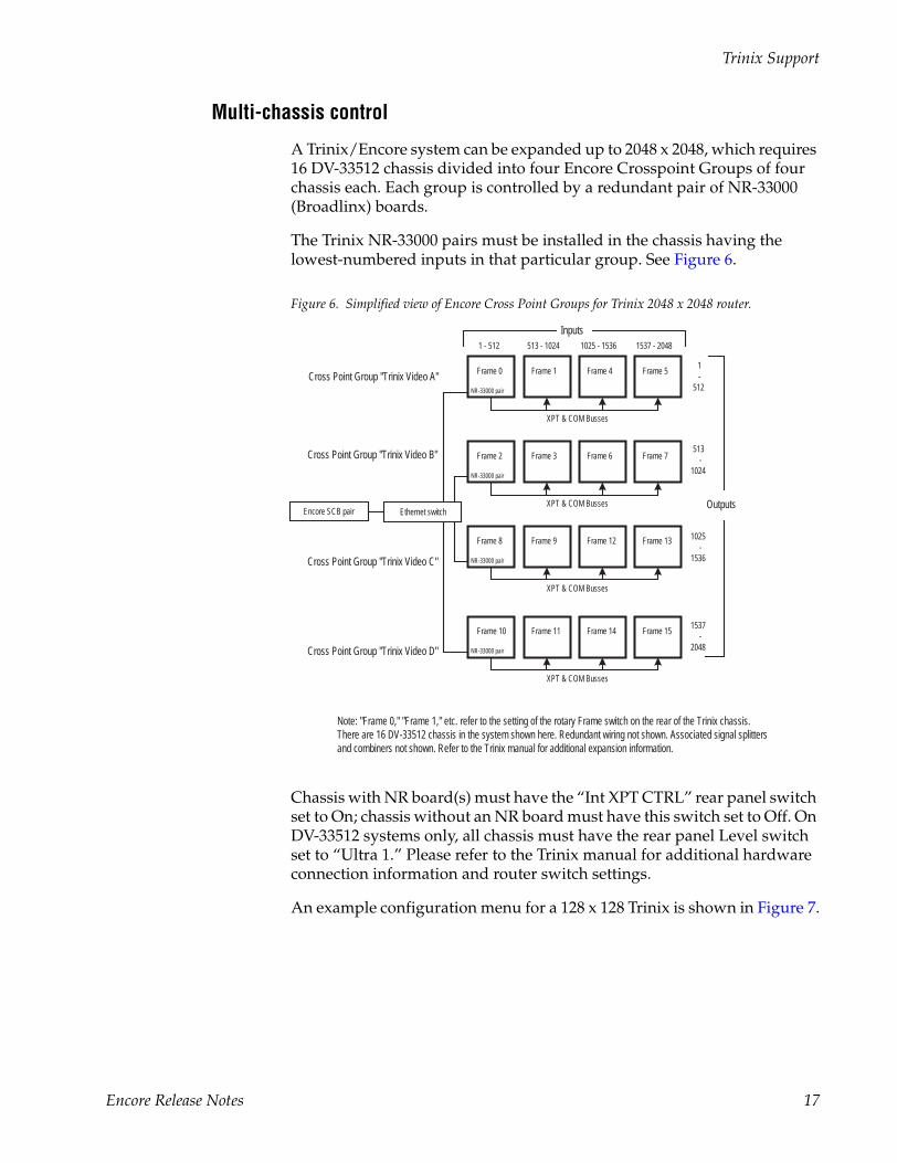
A Trinix/Encore system can be expanded up to 2048 x 2048, which requires 16 DV-33512 chassis divided into four Encore Crosspoint Groups of four chassis each. Each group is controlled by a redundant pair of NR-33000 (Broadlinx) boards.
The Trinix NR-33000 pairs must be installed in the chassis having the lowest-numbered inputs in that particular group. See Figure 6.
Figure 6. Simplified view of Encore Cross Point Groups for Trinix 2048 x 2048 router.
Chassis with NR board(s) must have the “Int XPT CTRL” rear panel switch set to On; chassis without an NR board must have this switch set to Off. On DV-33512 systems only, all chassis must have the rear panel Level switch set to “Ultra 1.” Please refer to the Trinix manual for additional hardware connection information and router switch settings.
An example configuration menu for a 128 x 128 Trinix is shown in Figure 7.
Frame 0
NR-33000 pair
Frame 1 Frame 4 Frame 5
1 - 512 513 - 1024 1025 - 1536 1537 - 2048
1-
512
513 -
1024
1025 -
1536
1537 -
2048
Outputs
Inputs
XPT & COM Busses
Ethernet switch
Cross Point Group "Trinix Video A"
Frame 2
NR-33000 pair
Frame 3 Frame 6 Frame 7
XPT & COM Busses
Cross Point Group "Trinix Video B"
Frame 8
NR-33000 pair
Frame 9 Frame 12 Frame 13
XPT & COM Busses
Cross Point Group "Trinix Video C"
Frame 10
NR-33000 pair
Frame 11 Frame 14 Frame 15
XPT & COM Busses
Cross Point Group "Trinix Video D"
Note: "Frame 0," "Frame 1," etc. refer to the setting of the rotary Frame switch on the rear of the Trinix chassis. There are 16 DV-33512 chassis in the system shown here. Redundant wiring not shown. Associated signal splittersand combiners not shown. Refer to the Trinix manual for additional expansion information.
Encore SCB pair
Encore Release Notes 17
Version 1.6.5.1
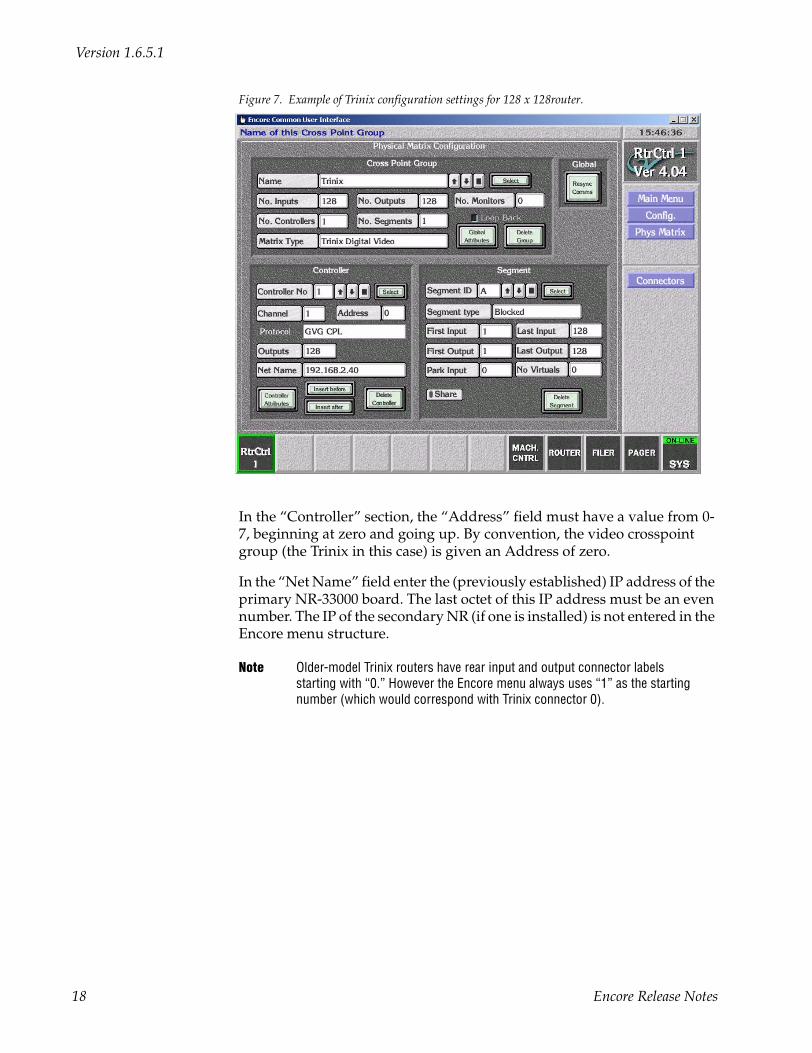
Figure 7. Example of Trinix configuration settings for 128 x 128router.
In the “Controller” section, the “Address” field must have a value from 0-7, beginning at zero and going up. By convention, the video crosspoint group (the Trinix in this case) is given an Address of zero.
In the “Net Name” field enter the (previously established) IP address of the primary NR-33000 board. The last octet of this IP address must be an even number. The IP of the secondary NR (if one is installed) is not entered in the Encore menu structure.
Note Older-model Trinix routers have rear input and output connector labels starting with “0.” However the Encore menu always uses “1” as the starting number (which would correspond with Trinix connector 0).
18 Encore Release Notes
Trinix Support
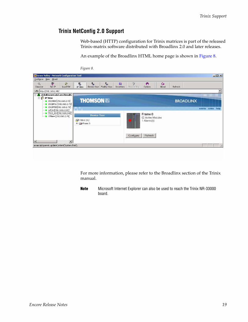
Trinix NetConfig 2.0 Support
Web-based (HTTP) configuration for Trinix matrices is part of the released Trinix-matrix software distributed with Broadlinx 2.0 and later releases.
An example of the Broadlinx HTML home page is shown in Figure 8.
Figure 8.
For more information, please refer to the Broadlinx section of the Trinix manual.
Note Microsoft Internet Explorer can also be used to reach the Trinix NR-33000 board.
Encore Release Notes 19
Version 1.6.5.1
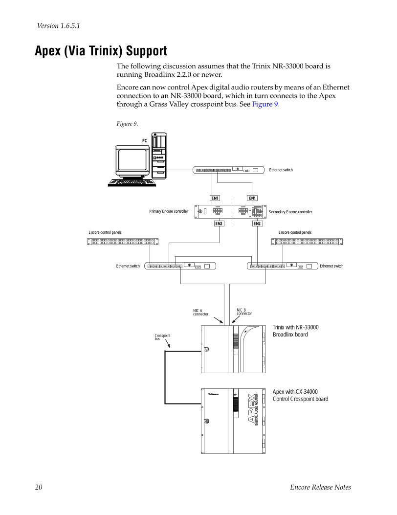
Apex (Via Trinix) SupportThe following discussion assumes that the Trinix NR-33000 board is running Broadlinx 2.2.0 or newer.
Encore can now control Apex digital audio routers by means of an Ethernet connection to an NR-33000 board, which in turn connects to the Apex through a Grass Valley crosspoint bus. See Figure 9.
Figure 9.
PC
Ethernet switch
Ethernet switch
Ethernet switch
Secondary Encore controllerPrimary Encore controller
EN2EN2
Encore control panels Encore control panels
EN1EN1
NIC Bconnector
NIC Aconnector
Trinix with NR-33000 Broadlinx board
Apex with CX-34000Control Crosspoint board
Crosspointbus
20 Encore Release Notes
Apex (Via Trinix) Support
The maximum Apex/Trinix matrix size controlled via the Trinix Broadlinx controller is 1280 x 1280 (Apex) and 2048 x 2048 (Apex Plus).
The Encore/Trinix/Apex interface supports the configuration of the fol-lowing static input and output audio attributes: stereo, sum, swap, left only, right only, invert left, invert right, and mute.
The Apex rear panel Level switch must be set to “Ultra 32.” Please refer to the Apex manual for additional hardware connection information and router switch settings.
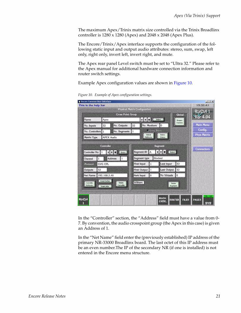
Example Apex configuration values are shown in Figure 10.
Figure 10. Example of Apex configuration settings.
In the “Controller” section, the “Address” field must have a value from 0-7. By convention, the audio crosspoint group (the Apex in this case) is given an Address of 1.
In the “Net Name” field enter the (previously established) IP address of the primary NR-33000 Broadlinx board. The last octet of this IP address must be an even number.The IP of the secondary NR (if one is installed) is not entered in the Encore menu structure.
Encore Release Notes 21
Version 1.6.5.1
7500 Router Enhancements
7500 SNMP MonitoringSee page 32.
7500 Web Configuration (NetConfig 2.0 Support)Web-based (HTTP) configuration for 7500 matrices is part of the released 7500-matrix software distributed with Encore 1.6.5.1. The web software is installed during the 1.6.5.1 upgrade process.
Concerto Enhancements
Time Code MatrixSupported up to 128 x 128.
Data MatrixSupported for up to 128 ports. Control is point-to-point only, not point-to-multipoint (used in dubbing scenarios).
Note If the Physical Matrix Type is a Concerto Port Router then the Park Input must be set to 0.
Audio Matrix TDM ExpansionSupported up to 256 x 256 (stereo).
Note TDM Redundancy is not supported in this release.
64 x 64 MatrixEncore 1.6.5.1 supports the configuration and control of Concerto 64 x 64 Matrices for the following matrix types and sizes:
• HD Video 32 x 32, 64 x 64
• SD Video 32 x 32, 64 x 64
• AV Video 32 x 32, 64 x 64
• AES Audio 32 x 32, 64 x64
• Analog Audio, 32 x 32, 64 x 64
• Mixed AES/Analog 64 x 64
22 Encore Release Notes
Concerto Enhancements
• Data (Port) Matrix 32 x 32, 64 x 64
Any combination of the above is supported in either card slot.
SNMP MonitoringSee page 32.
Concerto TDM Expansion - Installation and Configuration
1. Use the TDM Card Marked “Grass Valley Group Audio Expansion 671638200B.” Screw this on to the solder side of the card AES/Analog Board.
2. The AES board with the TDM card should be placed in the first slot of the Concerto frame. This is true for both the Concerto frames in expansion.
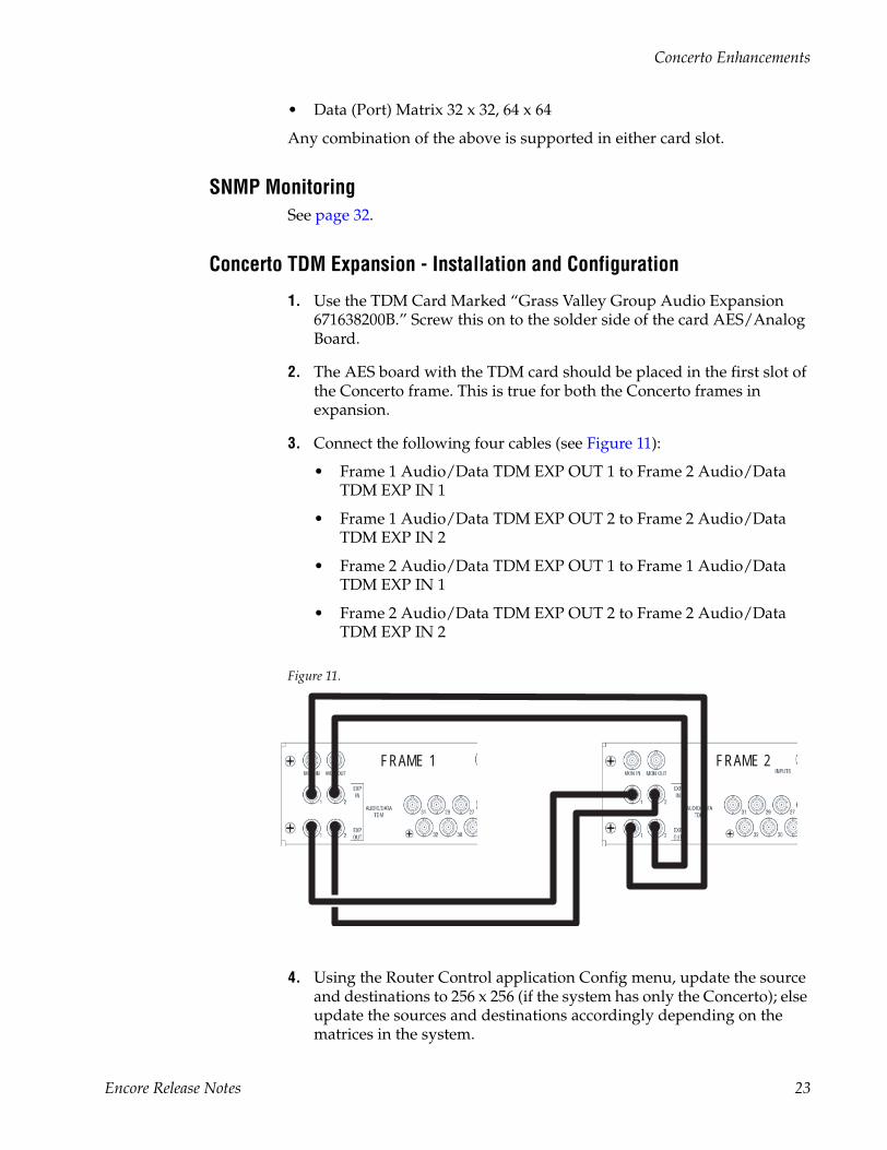
3. Connect the following four cables (see Figure 11):
• Frame 1 Audio/Data TDM EXP OUT 1 to Frame 2 Audio/Data TDM EXP IN 1
• Frame 1 Audio/Data TDM EXP OUT 2 to Frame 2 Audio/Data TDM EXP IN 2
• Frame 2 Audio/Data TDM EXP OUT 1 to Frame 1 Audio/Data TDM EXP IN 1
• Frame 2 Audio/Data TDM EXP OUT 2 to Frame 2 Audio/Data TDM EXP IN 2
Figure 11.
4. Using the Router Control application Config menu, update the source and destinations to 256 x 256 (if the system has only the Concerto); else update the sources and destinations accordingly depending on the matrices in the system.
FRAME 1 FRAME 2
Encore Release Notes 23
Version 1.6.5.1
5. Using the Router Control Config menu, configure the level. If the setup desired has different boards like AES and Analog Audio, chose AES as the level for both the boards.
6. Set the Channel Protocol to GVG CPL.
7. Program the Physical Matrix. Update the matrix for 256 x 256. Select Concerto Audio for the Matrix Type and select Re-Sync Comms to apply the changes to the database.
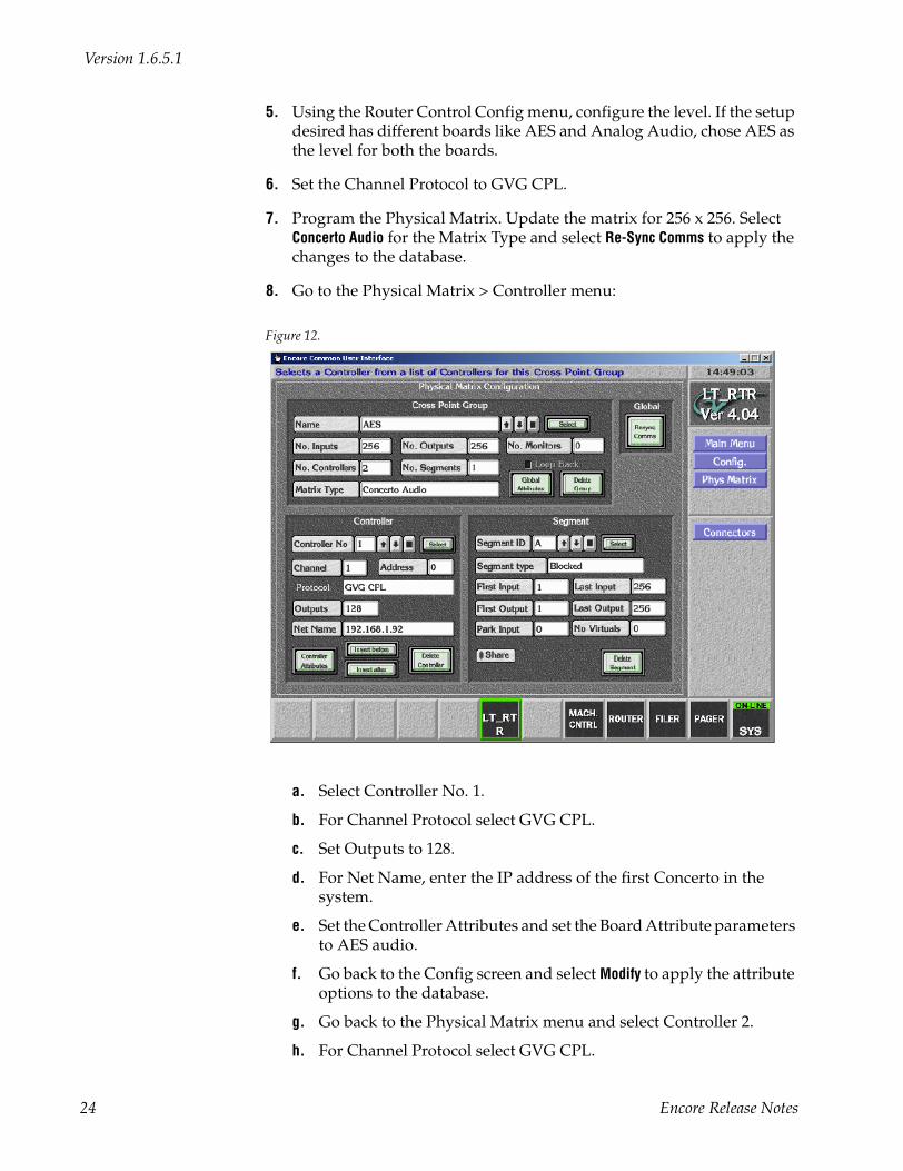
8. Go to the Physical Matrix > Controller menu:
Figure 12.
a. Select Controller No. 1.
b. For Channel Protocol select GVG CPL.
c. Set Outputs to 128.
d. For Net Name, enter the IP address of the first Concerto in the system.
e. Set the Controller Attributes and set the Board Attribute parameters to AES audio.
f. Go back to the Config screen and select Modify to apply the attribute options to the database.
g. Go back to the Physical Matrix menu and select Controller 2.
h. For Channel Protocol select GVG CPL.
24 Encore Release Notes

Concerto Enhancements
i. Set Outputs to 128.
j. For Net Name, enter the IP address of the second Concerto in the system.
k. Set the Controller Attributes and set the Board Attribute parameters to AES audio. If Analog Audio Boards are used, set the Attributes to Analog Audio.
l. Go back to the Config screen and select Modify to apply the attribute options to the database.
9. Using the Router Control Config menus, program the Logical Matrix to AES, i.e., the level desired.
10. Program the sources and destinations.
11. Go back to the Main Config screen and save the changes to the database by clicking Modify..
Encore Release Notes 25
Version 1.6.5.1
Output MonitoringNote Before attempting to configure the Encore for monitoring, monitor wiring and
switch settings for the particular router must be understood and completed. Please refer to the installation manual for the specific router for more infor-mation.
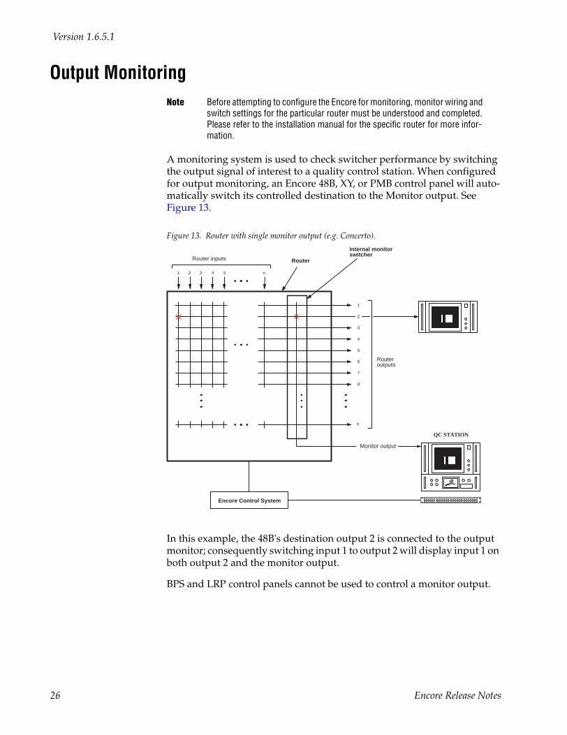
A monitoring system is used to check switcher performance by switching the output signal of interest to a quality control station. When configured for output monitoring, an Encore 48B, XY, or PMB control panel will auto-matically switch its controlled destination to the Monitor output. See Figure 13.
Figure 13. Router with single monitor output (e.g. Concerto).
In this example, the 48B's destination output 2 is connected to the output monitor; consequently switching input 1 to output 2 will display input 1 on both output 2 and the monitor output.
BPS and LRP control panels cannot be used to control a monitor output.
QC STATION
Router
2 3 41
5
1
2
3
4
6
7
8
n
n
Router inputs
Routeroutputs
Monitor output
Internal monitor switcher
5
Encore Control System
26 Encore Release Notes
Output Monitoring
To Configure and Use Destination Monitors
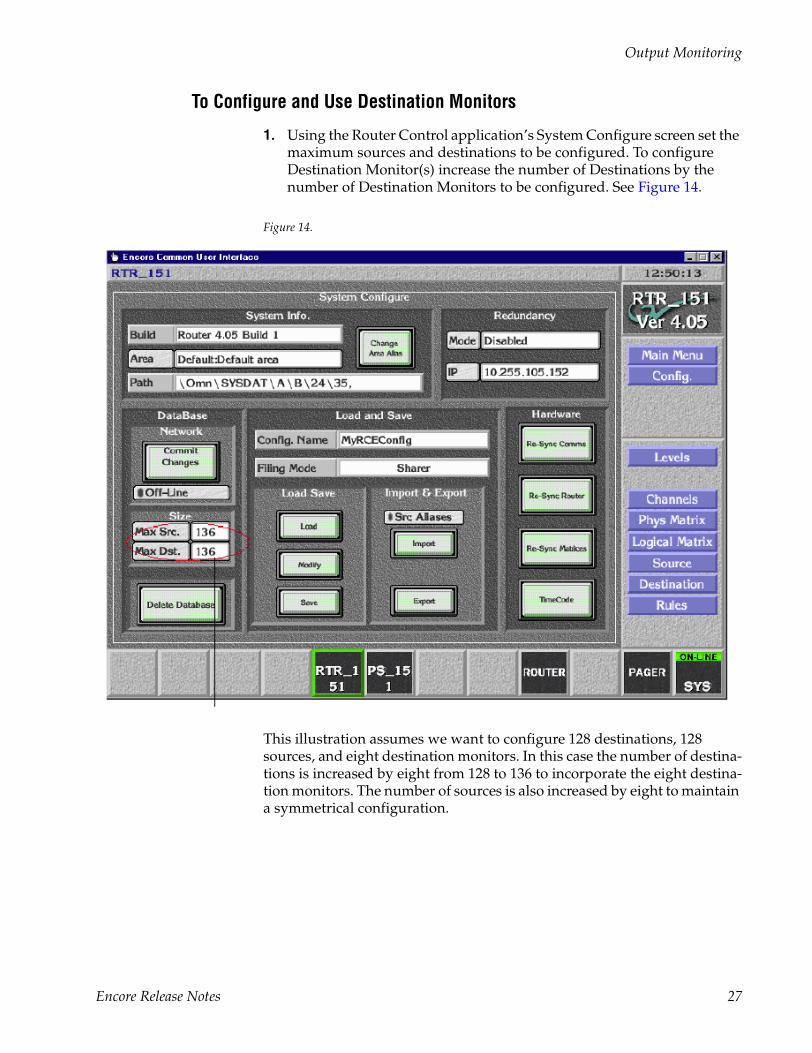
1. Using the Router Control application’s System Configure screen set the maximum sources and destinations to be configured. To configure Destination Monitor(s) increase the number of Destinations by the number of Destination Monitors to be configured. See Figure 14.
Figure 14.
This illustration assumes we want to configure 128 destinations, 128 sources, and eight destination monitors. In this case the number of destina-tions is increased by eight from 128 to 136 to incorporate the eight destina-tion monitors. The number of sources is also increased by eight to maintain a symmetrical configuration.
Encore Release Notes 27
Version 1.6.5.1
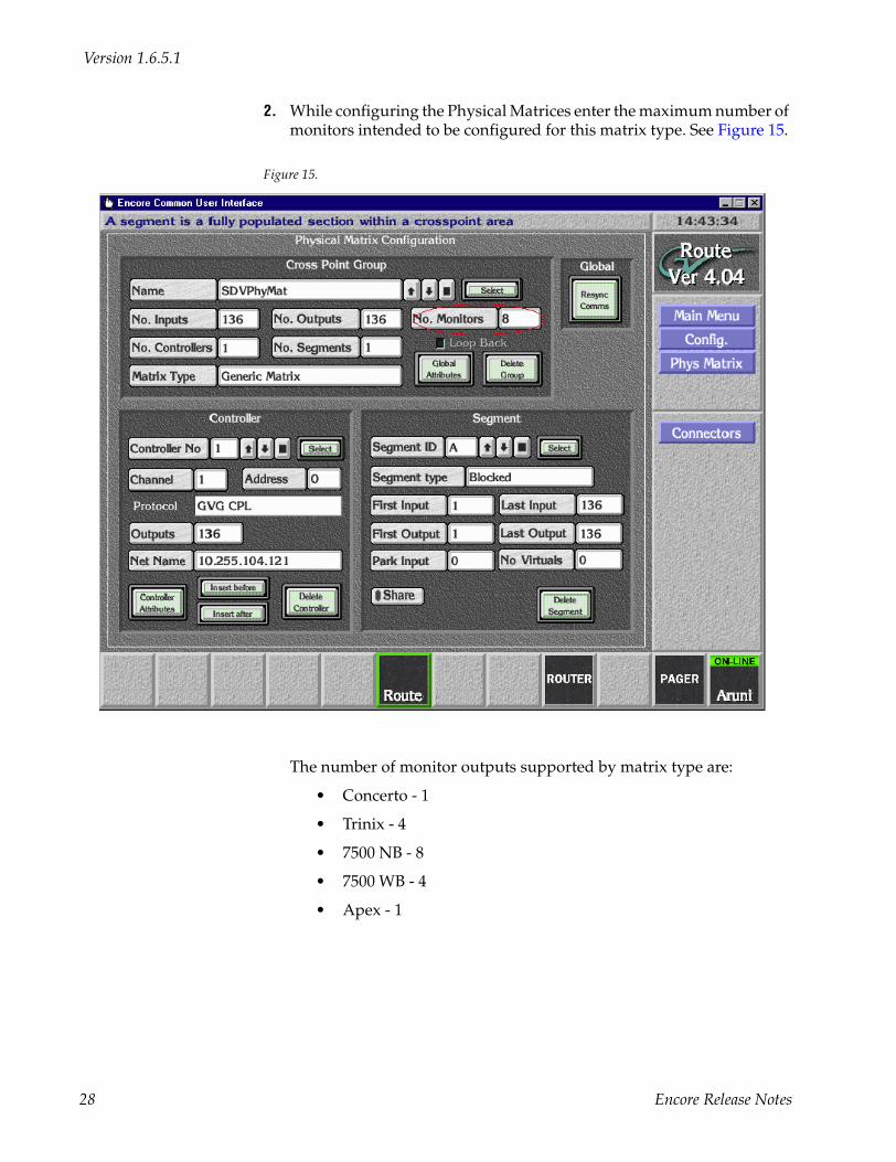
2. While configuring the Physical Matrices enter the maximum number of monitors intended to be configured for this matrix type. See Figure 15.
Figure 15.
The number of monitor outputs supported by matrix type are:
• Concerto - 1
• Trinix - 4
• 7500 NB - 8
• 7500 WB - 4
• Apex - 1
28 Encore Release Notes
Output Monitoring
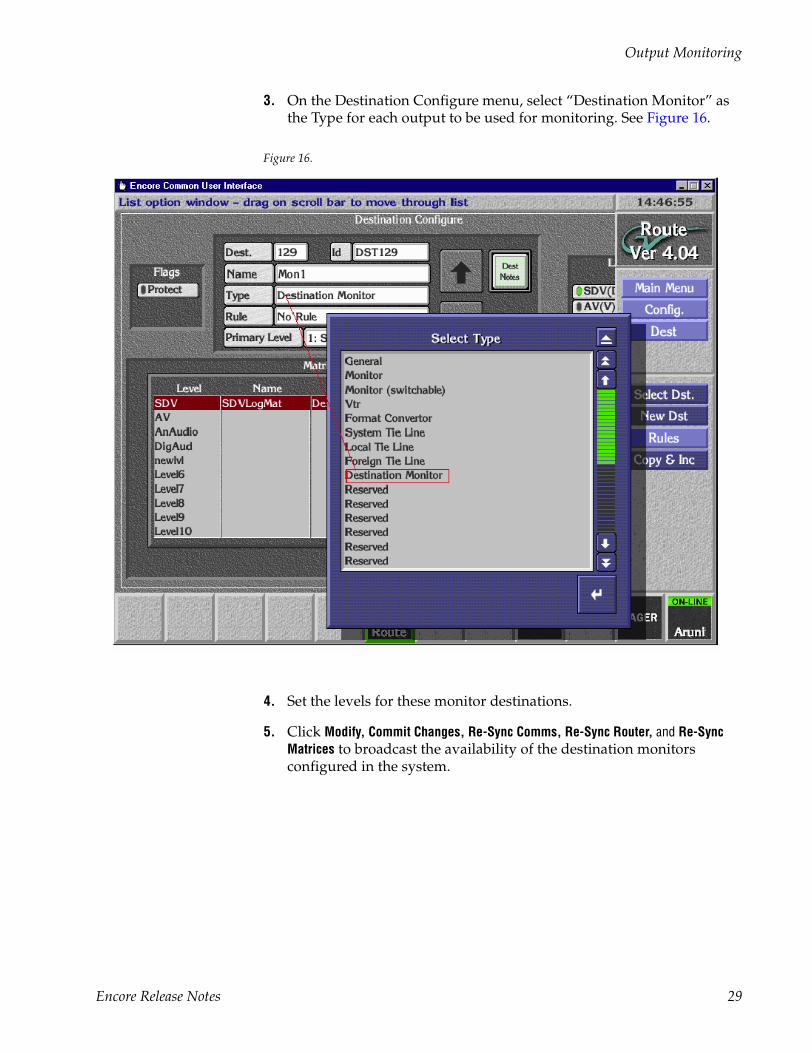
3. On the Destination Configure menu, select “Destination Monitor” as the Type for each output to be used for monitoring. See Figure 16.
Figure 16.
4. Set the levels for these monitor destinations.
5. Click Modify, Commit Changes, Re-Sync Comms, Re-Sync Router, and Re-Sync Matrices to broadcast the availability of the destination monitors configured in the system.
Encore Release Notes 29
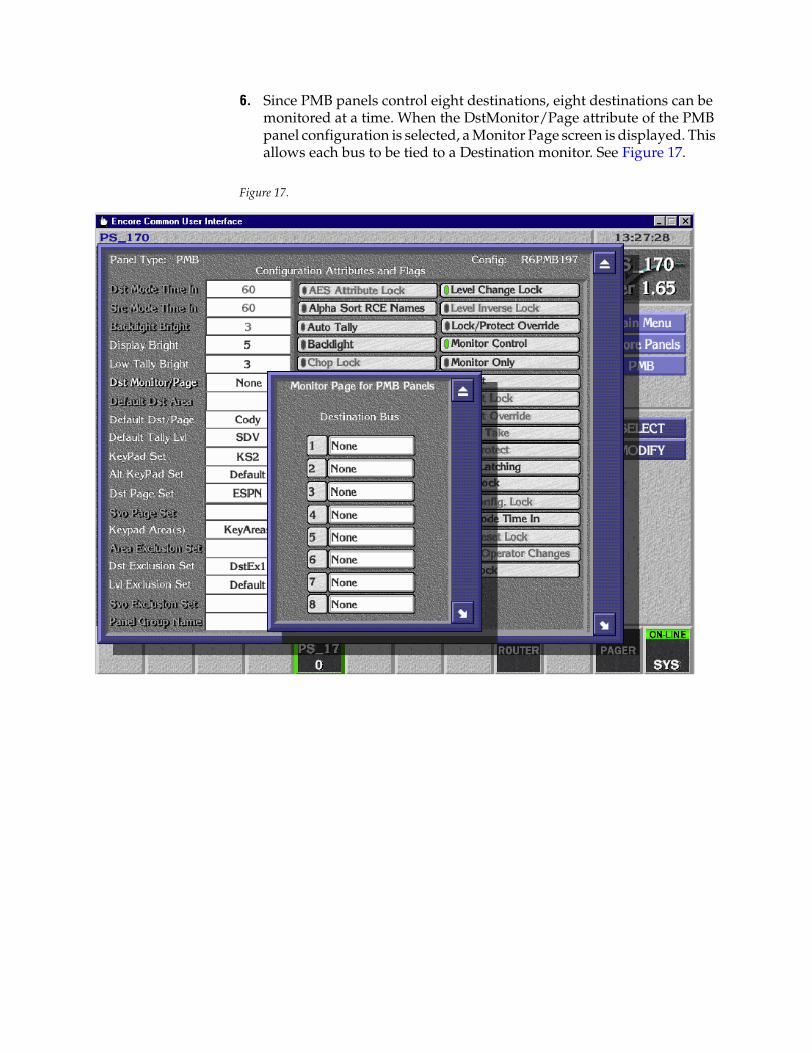
6. Since PMB panels control eight destinations, eight destinations can be monitored at a time. When the DstMonitor/Page attribute of the PMB panel configuration is selected, a Monitor Page screen is displayed. This allows each bus to be tied to a Destination monitor. See Figure 17.
Figure 17.
Output Monitoring
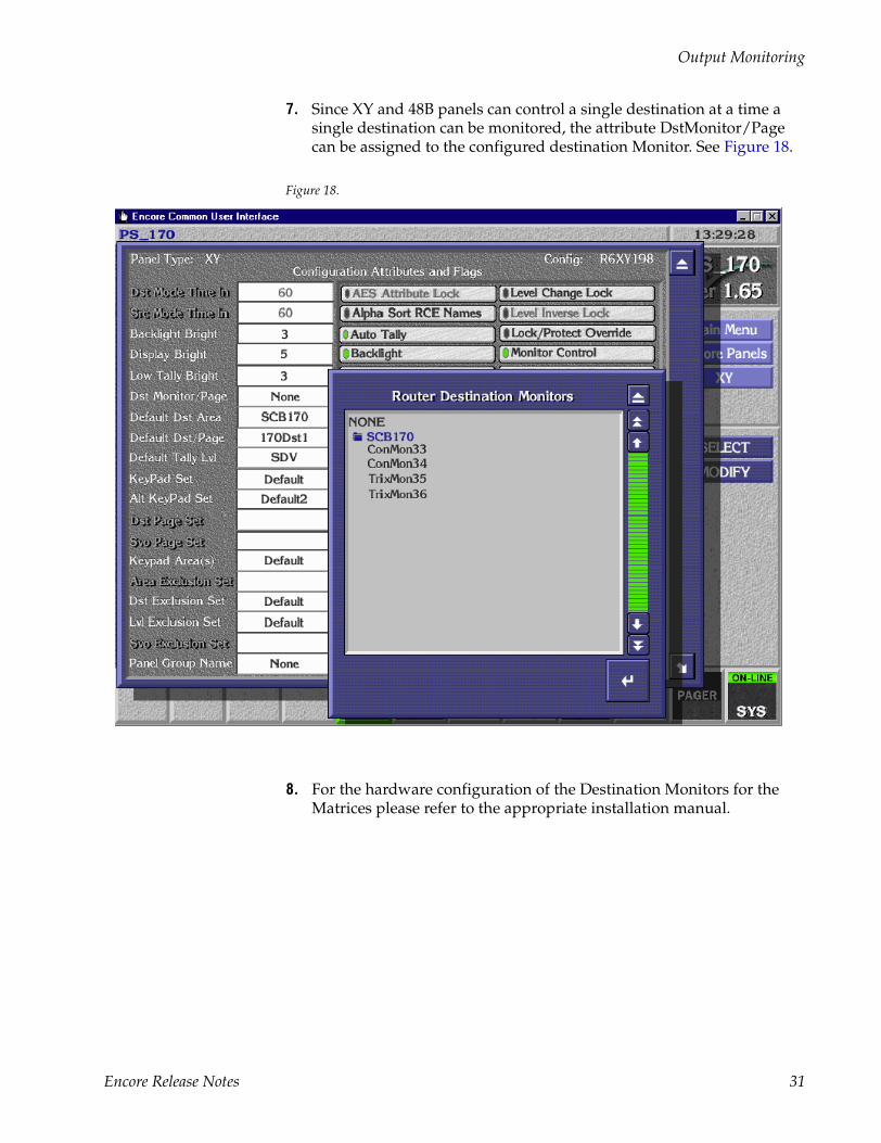
7. Since XY and 48B panels can control a single destination at a time a single destination can be monitored, the attribute DstMonitor/Page can be assigned to the configured destination Monitor. See Figure 18.
Figure 18.
8. For the hardware configuration of the Destination Monitors for the Matrices please refer to the appropriate installation manual.
Encore Release Notes 31
Version 1.6.5.1
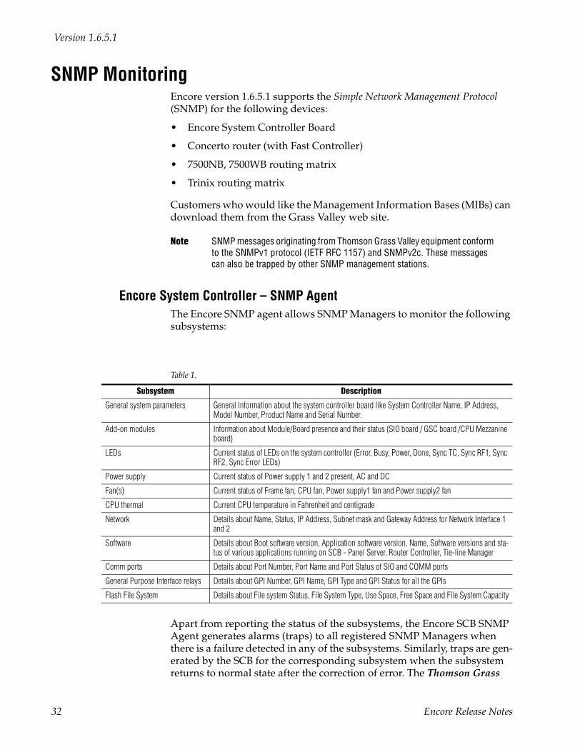
SNMP MonitoringEncore version 1.6.5.1 supports the Simple Network Management Protocol (SNMP) for the following devices:
• Encore System Controller Board
• Concerto router (with Fast Controller)
• 7500NB, 7500WB routing matrix
• Trinix routing matrix
Customers who would like the Management Information Bases (MIBs) can download them from the Grass Valley web site.
Note SNMP messages originating from Thomson Grass Valley equipment conform to the SNMPv1 protocol (IETF RFC 1157) and SNMPv2c. These messages can also be trapped by other SNMP management stations.
Encore System Controller – SNMP AgentThe Encore SNMP agent allows SNMP Managers to monitor the following subsystems:
Apart from reporting the status of the subsystems, the Encore SCB SNMP Agent generates alarms (traps) to all registered SNMP Managers when there is a failure detected in any of the subsystems. Similarly, traps are gen-erated by the SCB for the corresponding subsystem when the subsystem returns to normal state after the correction of error. The Thomson Grass
Table 1.
Subsystem Description
General system parameters General Information about the system controller board like System Controller Name, IP Address, Model Number, Product Name and Serial Number.
Add-on modules Information about Module/Board presence and their status (SIO board / GSC board /CPU Mezzanine board)
LEDs Current status of LEDs on the system controller (Error, Busy, Power, Done, Sync TC, Sync RF1, Sync RF2, Sync Error LEDs)
Power supply Current status of Power supply 1 and 2 present, AC and DC
Fan(s) Current status of Frame fan, CPU fan, Power supply1 fan and Power supply2 fan
CPU thermal Current CPU temperature in Fahrenheit and centigrade
Network Details about Name, Status, IP Address, Subnet mask and Gateway Address for Network Interface 1 and 2
Software Details about Boot software version, Application software version, Name, Software versions and sta-tus of various applications running on SCB - Panel Server, Router Controller, Tie-line Manager
Comm ports Details about Port Number, Port Name and Port Status of SIO and COMM ports
General Purpose Interface relays Details about GPI Number, GPI Name, GPI Type and GPI Status for all the GPIs
Flash File System Details about File system Status, File System Type, Use Space, Free Space and File System Capacity
32 Encore Release Notes
SNMP Monitoring
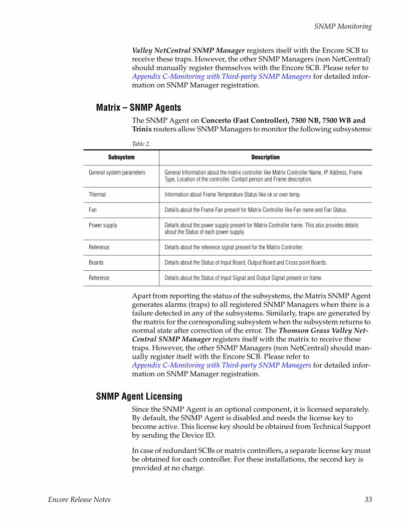
Valley NetCentral SNMP Manager registers itself with the Encore SCB to receive these traps. However, the other SNMP Managers (non NetCentral) should manually register themselves with the Encore SCB. Please refer to Appendix C-Monitoring with Third-party SNMP Managers for detailed infor-mation on SNMP Manager registration.
Matrix – SNMP AgentsThe SNMP Agent on Concerto (Fast Controller), 7500 NB, 7500 WB and Trinix routers allow SNMP Managers to monitor the following subsystems:
Table 2.
Apart from reporting the status of the subsystems, the Matrix SNMP Agent generates alarms (traps) to all registered SNMP Managers when there is a failure detected in any of the subsystems. Similarly, traps are generated by the matrix for the corresponding subsystem when the subsystem returns to normal state after correction of the error. The Thomson Grass Valley Net-Central SNMP Manager registers itself with the matrix to receive these traps. However, the other SNMP Managers (non NetCentral) should man-ually register itself with the Encore SCB. Please refer to Appendix C-Monitoring with Third-party SNMP Managers for detailed infor-mation on SNMP Manager registration.
SNMP Agent LicensingSince the SNMP Agent is an optional component, it is licensed separately. By default, the SNMP Agent is disabled and needs the license key to become active. This license key should be obtained from Technical Support by sending the Device ID.
In case of redundant SCBs or matrix controllers, a separate license key must be obtained for each controller. For these installations, the second key is provided at no charge.
Subsystem Description
General system parameters General Information about the matrix controller like Matrix Controller Name, IP Address, Frame Type, Location of the controller, Contact person and Frame description.
Thermal Information about Frame Temperature Status like ok or over temp.
Fan Details about the Frame Fan present for Matrix Controller like Fan name and Fan Status.
Power supply Details about the power supply present for Matrix Controller frame. This also provides details about the Status of each power supply.
Reference Details about the reference signal present for the Matrix Controller.
Boards Details about the Status of Input Board, Output Board and Cross point Boards.
Reference Details about the Status of Input Signal and Output Signal present on frame.
Encore Release Notes 33
Version 1.6.5.1
Upon obtaining the license key from Technical Support the key can be acti-vated using the respective device’s web page. For details on activating the SNMP Agent refer to License Installation on page 36.
Agent Installation• The SCB agent is installed automatically during the Encore upgrade
process.
• The Concerto agent is installed automatically during the Concerto upgrade process.
Note The original Concerto 10BaseT CRS-2001 Controller (671-6381-xx) does not support SNMP. See Concerto Applications on page 10.
• The 7500 Matrix SNMP Agent is part of the 7500 software release 1.6.5.1.
• The Trinix agent is supplied with Broadlinx version 2.2.0 (Broadlinx software runs on the NR-33000 Sync/NIC/OPM board).
NetCentral SNMP ManagerThe NetCentral III/IV system is a suite of software modules residing on one or more centrally located computers. These modules work together to monitor and report the operational status of devices (broadcast equipment such as an Encore SCB or a 7500NB/WB frame, Concerto Fast Controller, Trinix etc.), using Simple Network Management Protocol (SNMP).
The Encore SNMP Agents provide support for NetCentral, but do not include the actual NetCentral product, which is available separately. Once the Encore SNMP Agent is installed and configured, it can be monitored by NetCentral, or by any other SNMP manager.
NetCentral CapabilitiesWhen the Encore SNMP Agent is installed and configured, it automatically sends trap messages to the NetCentral Monitoring Station, reporting the device status. The NetCentral Monitoring Station can be configured to listen to and respond to these trap messages. Each trap message is assigned a severity status and a response. The responses can range from “sound an alarm,” or “send E-mail,” or “call someone on the phone/ pager” or “log the status.”
For detailed information please refer to the NetCentral documentation.
34 Encore Release Notes
SNMP Monitoring
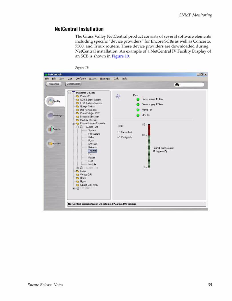
NetCentral InstallationThe Grass Valley NetCentral product consists of several software elements including specific “device providers” for Encore SCBs as well as Concerto, 7500, and Trinix routers. These device providers are downloaded during NetCentral installation. An example of a NetCentral IV Facility Display of an SCB is shown in Figure 19.
Figure 19.
Encore Release Notes 35
Version 1.6.5.1
License InstallationAs described earlier, Encore 1.6.5.1 introduces license management for the following chargeable options:
• Encore SCB: SNMP agent option and SoftPanels option
• Concerto: SNMP agent
• 7500NB/WB: SNMP agent
• Trinix: SNMP agent
The license management scheme allows a single key to permanently enable multiple features for a device (note that each device in a redundant device pair requires a separate key).
SNMP and SoftPanels License Entry
1. Obtain a license key from Thomson.
Licenses are purchased through Sales and the keys are issued by Tech-nical Support.
You’ll be asked to provide the Device ID from the SCB NetConfig web access display.
2. Go to the web access display and Select Application Configuration. The following will be displayed in the bottom area of the window:
SNMP Service : DisabledSoft Panels : N
...where N is the number of enabled floating SoftPanel licenses; N = 0 if no SoftPanel licenses have been enabled.
3. Select Enter License Key.
4. Enter the Thomson-supplied key and select Submit.
Router Matrix SNMP Agent License Entry
This process is similar to that just described for SCB license entry.
A “Matrix Applications” menu has been added to the Concerto, 7500WB/NB and Trinix web access displays containing the following:
SNMP Agent: enabled (or disabled)
An “Enter License Key” button has also been added; when pressed a pop-up dialog box will allow entry of the Thomson-supplied key.
In the Concerto and 7500NB/WB matrix controllers and in the Encore SCBs, each license is stored in the frame serial EEPROM.
36 Encore Release Notes
License Installation
In Trinix (Broadlinx) matrix controllers, the license is stored in the Broad-linx controller flash memory. Since the MAC address is contained in the Broadlinx controller, not in the frame, a new key will have to be obtained if the controller is ever replaced with a new card. However, in the case of redundant Broadlinx installations, if one board is replaced the existing license will automatically be provided to the new board.
Further Information
For additional NetCentral information, please refer to the NetCentral manual and the release notes for Encore version 1.6.1.
For additional SoftPanels information, please refer to the SoftPanels manual, part no. 0718332xx.
Encore Release Notes 37
Version 1.6.5.1
Deterministic (Frame Accurate) SwitchingDeterminism is defined as a guaranteed 6 frame fixed latency for serial and Ethernet Automation (simple or redundant) control of Encore.
A Frame Accurate flag has been added to the Router Control Language /Native Protocol (RCL/NP) client configuration screen; when this flag is enabled the RCL/NP Server will add a +6 frame timestamp (relative to the current time) to incoming RCL/NP Take requests. When the Frame Accu-rate flag is disabled the RCL/NP Server will issue an immediate Take request for each incoming Native Protocol Take request (i.e. no timestamp will be added). The Frame Accurate flag is independently configurable for each RCL/NP client.
Note that six frames is guaranteed from the time the Encore receives the Take command (not from the time the client sends it). Hence, this does not include the time required for the Message to reach the Encore from the Client. Though this time is negligible most of the time, it becomes signifi-cant for serial connections with low baud rates.
Under normal operating conditions deterministic/frame accurate switching will occur. Exceptions to this would be if configuration changes are being saved, if a reboot occurs on a redundant pair, if resync comms or resync router operations are taking place, or any similar non-normal oper-ating condition.The RCL/NP Protocol also supports Time-stamped Takes: Take requests can be time-stamped and sent up to 100 frames in advance for frame-accurate execution.
Refer to the RCL/NP manual for a configuration description.
For system requirements specifically relating to Encore 1.6.5.1 see SCB Modifications on page 10.
38 Encore Release Notes
NetConfig 2.0 Support
NetConfig 2.0 SupportNetConfig upgrade to 2.0 is part of the Encore 1.6.0, 1.6.1, and 1.6.5.1 releases.
Note Encore software upgrade from version 1.6.1 (or older) to 1.6.5.1 (or newer) has to be done by mapping the Encore SCB flash on to the PC Using the “map network drive” facility of the Windows Explorer. However, once version 1.6.5.1 or later is installed, the next software upgrade can be achieved via the NetConfig “Load SW” tool.
Auto Discovery
The Encore-controlled routers, SCBs, and all control panels (10Mb and 100Mb versions) support the NetConfig 2.0 protocol for device discovery and device networking parameter configuration.
In Encore software versions prior to 1.6.5.1, when a new device signed on, a manual 'discovery' operation from the user was required to have the Net-Config tool update its list of devices. With 1.6.5.1, the NetConfig Program automatically discovers new devices that sign onto the network.
Similar support is now provided by the 7500WB/NB, Concerto, and Trinix.
Backward Compatibility Notes
The Encore 1.6.5.1 SCB software supports only NetConfig 2.0 protocol and will NOT respond to NetConfig 1.0 messages. Hence if NetConfig 1.0 is used for some reason, the SCB will no longer be seen in the NetConfig application.
However, SCB software version 1.6.5.1 will relay NetConfig 1.0 as well as NetConfig 2.0 messages between the PC running the NetConfig tool (con-nected to EN1 network) and the Panels and Matrixes (connected to EN2). Hence, any device supporting either NetConfig 1.0 or NetConfig 2.0 or both protocols can be connected to EN2 network of the SCB. The NetConfig tool will continue to discover such devices via the SCB relay agent. For example, Trinix matrix controllers connected to the EN2 network of an SCB can now be seen in the NetConfig tool.
For more information about NetConfig, please refer to the NetConfig Instruction Manual. An electronic copy is available on the Routing Products Documentation CD-ROM.
Encore Release Notes 39
Version 1.6.5.1
Multi-Area SupportIn large installations, an Encore-controlled routing system can be parti-tioned into multiple routing areas, with each area having its own router controller and matrices. This arrangement gives each area autonomy in configuration and operation without sacrificing inter-area connectivity. For example, assume the following conditions:
• Two studios, A and B.
• Each studio has its own router.
• Each studio has five VTRs named “VTR 1” through “VTR 5.”
By assigning each studio and its components to a different area, the Encore control system can be divided to provide area access restrictions, user access restrictions and router control restrictions. If the areas are named “Studio A” and “Studio B”, then
• The PMB and XY control panels' Prev and Next keys can be used to scroll through sources and destinations one area at a time. Control Panel keypad access to specific areas can be managed by using the “keypad areas” parameter to specify which areas are allowed.
The panel will always indicate to which area the selected source or des-tination belongs.
• The XY panel Prev and Next keys can be used in the same manner. The difference is that the XY panel will only show the area name when the source is in a remote area.
Up to 32 areas can be configured.
Panels in one area can still control destinations in another. If this is not desirable, a destination exclusion set can be created and assigned to indi-vidual panels to restrict specific destinations or all destinations in an area.
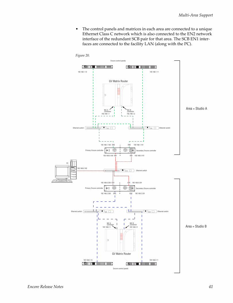
Example of 2-Area ApplicationPlease refer to Figure 20, which shows a large, highly-redundant system. Note the following:
• Each routing area has its own dedicated SCB running the Router Control and CP Server applications.
Note Only one Router Control application (or redundant pair) is permitted in each area.
• Each control panel can be configured to restrict the area(s) in which des-tinations are controlled.
40 Encore Release Notes
Multi-Area Support
• The control panels and matrices in each area are connected to a unique Ethernet Class C network which is also connected to the EN2 network interface of the redundant SCB pair for that area. The SCB EN1 inter-faces are connected to the facility LAN (along with the PC).
Figure 20.
NIC Aconnector
GV Matrix Router
PC
Ethernet switch
Ethernet switch
Ethernet switch
Secondary Encore controllerPrimary Encore controller
EN2
EN1
EN2
NIC Bconnector
Encore control panels
Encore control panels
EN1
Secondary Encore controllerPrimary Encore controller
EN1
EN2 EN2
Ethernet switchEthernet switch
EN1 192.168.0.101192.168.0.100
192.168.1.10 192.168.1.11
192.168.0.201192.168.0.200
192.168.2.200 192.168.2.201
192.168.0.102
192.168.1.100 192.168.1.101
NIC Aconnector
GV Matrix Router
NIC Bconnector
192.168.1.1 192.168.1.2
192.168.2.1 192.168.2.2
192.168.2.10 192.168.2.11
Area = Studio A
Area = Studio B
Status
Preset
Level
DestDest
IDID
ChopChop
SrcSrc
CECE
ClearClear
SalvoSalvo
PrevPrev
LevelLevel
NextNext
ProtProt
TakeTake
Status
Preset
Level
DestDest
IDID
ChopChop
SrcSrc
CECE
ClearClear
SalvoSalvo
PrevPrev
LevelLevel
NextNext
ProtProt
TakeTake
Status
Preset
Level
DestDest
IDID
ChopChop
SrcSrc
CECE
ClearClear
SalvoSalvo
PrevPrev
LevelLevel
NextNext
ProtProt
TakeTake
Status
Preset
Level
DestDest
IDID
ChopChop
SrcSrc
CECE
ClearClear
SalvoSalvo
PrevPrev
LevelLevel
NextNext
ProtProt
TakeTake
Encore Release Notes 41
Version 1.6.5.1
Creating an AreaThe following discussion assumes that Encore 1.6.5.1 has already been installed (as described on page 67).
Hardware InstallationPlease refer to Figure 20 for an example system.
1. Install the matrix router, SCB(s), and control panel(s) in the new area.
2. Use NetConfig to configure the IP addresses of the new SCB(s) and control panels.
If you’re not familiar with using NetConfig for this purpose, please refer to the release notes for Encore 1.6.1.
Software Configuration
1. Use the OUI and System Manager to Add an Area: Launch the Sharer, System Manager and OUI (if not running already).
2. Log into the OUI with your User ID (e.g. SYS).
3. Select System.
4. Select Areas.
5. Select Add area and enter new area name (e.g., StudioA).
A maximum of seven characters is recommended. (Seven is the maximum for the Area Alias, described below.)
Note You can’t rename or delete “Default Area” although you may define an Area Alias for it.
6. Add the next area. Etc.
Assigning a User to an AreaIf desired, individual users can be assigned to an area (able to control des-tinations only in that one area).
1. Select Users.
2. Click on Select and select the individual user.
3. Select the Area field and select the desired area.
To assign a user to all areas, select Default Area.
42 Encore Release Notes

Multi-Area Support
Assigning Engines and Applications to an AreaOnce the decision is made to divide the system into areas, the System Manager is used to assign all engines and applications to a given area. Assigning engines and applications to areas affects access to application Log-in; if an application is placed in an area other the default and the Off-line/Local/All Areas flag is set to Local, that application will only be acces-sible from OUIs and users configured for the same area.
This technique is useful in very large systems where different users have administrative rights for specific subsets of the system. If such is not required, the recommended practice is to assign all engines and applica-tions to the default area.
If you are adding new SCBs, you will need to create new instances of these applications to run on the new hardware. If you are not familiar with this process, please refer to the release notes for Encore 1.6.1.
1. Go to System Manager > Apps.
2. Assign each CP Server application to the desired area.
3. The Off-line / Local / All Areas flag should be set to All Areas if unrestricted log-in access is desired; if restricted access is required the flag should be set to Local.
4. Select Modify.
Note The Router Control application is not assigned to an area using the System Manager. This assignment is made within the Router Control application itself, as described below under “Assigning a Router to an Area.”
Assigning an SCB to an AreaIn multi-area systems, the System Manager is used to assign all SCBs to a default area.
If you are adding new SCBs, you will need to add these “engines,” their IP addresses, and their applications. If you are not familiar with this process, please refer to the release notes for Encore 1.6.1.
1. Go to System Manager > Engines > Area.
2. Select an engine.
3. Select a default area on the pop-up menu.
4. The Availability flag should be set to All Areas if unrestricted log-in access is desired; if restricted access is required the flag should be set to Local.
5. Select Modify.
Encore Release Notes 43
Version 1.6.5.1
Assigning a Router to an AreaUsing the Router Control application, each router is assigned to one area. For example, “Router A” could be assigned to “StudioA.”
Note Do not assign more than one Router Control application (or redundant Router Control pair, i.e., more than one router) to the same area.
Note The area of the Router Control application can only be changed from the application. Changing the area of the engine on which the Router Control application is running or changing the area of this application from the System Manager does not get reflected on the Router Control application even if System Manager, Sharer, or the SCB (engine on which the Router Control application is running) is rebooted.
Log in to Encore and open the Router Control application (if not open already):
1. Launch the OUI and select Start.
2. Enter your User ID (e.g. sys).
3. Press Enter to close the “Welcome to Encore” window.
4. Select the first Router Control application.
Configure the Router Control Application:
1. Select Config.
2. Select Area.
Answer Yes to the warning message.
3. Select the desired area (e.g. “StudioA”).
4. If you want the name of the area (not just the number) to be visible to the CP Server application, use the Change Area Alias button to enter the name.
5. Select Modify.
Answer Yes to warning message. If this is a redundant SCB installation, answer Yes to update mirror with changes.
6. Select Commit Changes.
7. Repeat this process for each Router Control application.
44 Encore Release Notes
Multi-Area Support
Configuring Control Panels for Control in Specific Area(s)
1. Select Encore Panels.
2. Select the target panel type.
3. Select the individual panel.
For BPS, XY, and 48B panels: on the button configuration screen, select the desired Area.If the panel has source, destination or salvo select buttons ensure they are configured in the area you desire. For BPS and 48B panels restriction of area(s) is controlled by assigning specific sources and destinations to the control panel buttons. For BPS and 48B panels, after configuring the button areas select Modify and exit the panel configuration. This completes BPS and 48B configuration.
4. Select Configure Flags.
5. For XY and PMB panels select the Destination Exclusion attribute. Configure only the destinations in specific areas you want the panel to control; this will prevent access to destinations in other areas.The following is only for XY and PMB control panels when it is desired to restrict source name keypad searches:
a. Disable the Keypad Local Source flag in order to configure the Keypad Searchable Areas attribute.
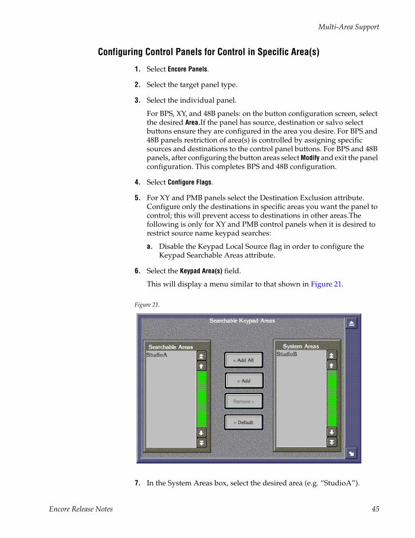
6. Select the Keypad Area(s) field.
This will display a menu similar to that shown in Figure 21.
Figure 21.
7. In the System Areas box, select the desired area (e.g. “StudioA”).
Encore Release Notes 45

Version 1.6.5.1
8. Select Add to move the selection to the Searchable Areas box.
9. If there are areas where the panel should not be able to search, remove them.
This will only affect keypad prefix/suffix entered searches for preset-ting sources and destinations. Using the prev/next button without a keypad entered prefix/suffix will access all sources in all areas in source mode and only destinations not excluded in destination mode.
10. If you would like keypad-entered source searches to only search the controlled destination areas, re-enable the “Keypad Local Source” flag. Otherwise keypad-entered prefix/suffix source names will search the currently controlled destination area(s) and the areas defined in the “Keypad Area(s)” attribute.
Note The Default Dst Area and Area Exclusion Set fields are not supported on the PMB panel. The default destination area on the PMB is set inside the default destination page. Area exclu-sion sets are not implemented.
Remote Sources are indicated when the Take button(s) are illuminated at the Low Tally brightness setting. (A “remote source” is one that is in a different RCE area and requires a tie line manager to perform the Take operation.) However if the “Flashing LED Indication” flag is enabled the Take button(s) will flash whenever a preset source is a remote source.
11. Close the windows and select Modify.
Operating a PMB Panel in a Multi-area SystemWhen configured as described above, the PMB front panel display indi-cates the area that applies to the source or destination shown.
The panel can still display inputs assigned to other areas but unless tie lines are installed there can be no “cross-boundary switching”; i.e.,a remote preset source can be switched to the controlled destination only if a tieline has been configured. This condition is indicated by illuminating the Take button at low tally. If the flag “Flashing LED Indication” is enabled then the Take button will flash from high to low tally to indicate a remote source has been preset.
Operating an XY Panel in a Multi-area SystemWhen configured as described above, the XY front panel display, when Dest is pressed, indicates the currently controlled destination area and the current tallied source area connected to the destination.
46 Encore Release Notes
Multi-Area Support
The panel can still display inputs assigned to other areas but unless tie lines are installed there can be no “cross-boundary switching”; i.e., a remote preset source can be switched to the controlled destination only if a tie line has been configured. This condition is indicated by illuminating the Take button at low tally. If the flag “Flashing LED Indication” is enabled then the Take button will flash from high to low tally to indicate a remote source has been preset.
Changing Area Assignments• To assign a router to a different area, use the Router Control application
as described above (Assigning a Router to an Area on page 44).
• To give a control panel access to a different area, use the CP Server application as described above (Configuring Control Panels for Control in Specific Area(s) on page 45).
Note It isn’t necessary to return to the System Manager application to modify the area assignment of the SCB or Router Control application.
Encore Release Notes 47
Version 1.6.5.1
Misc. Control Panel Enhancements
BPS Panels
Figure 22.
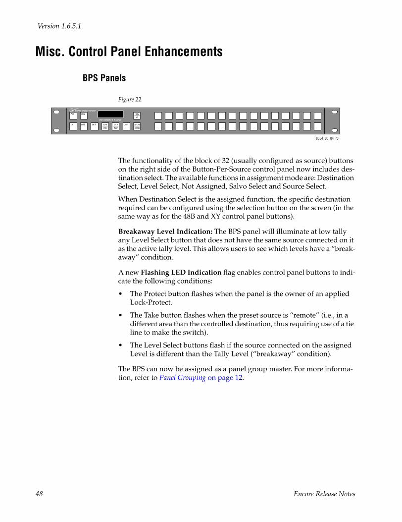
The functionality of the block of 32 (usually configured as source) buttons on the right side of the Button-Per-Source control panel now includes des-tination select. The available functions in assignment mode are: Destination Select, Level Select, Not Assigned, Salvo Select and Source Select.
When Destination Select is the assigned function, the specific destination required can be configured using the selection button on the screen (in the same way as for the 48B and XY control panel buttons).
Breakaway Level Indication: The BPS panel will illuminate at low tally any Level Select button that does not have the same source connected on it as the active tally level. This allows users to see which levels have a “break-away” condition.
A new Flashing LED Indication flag enables control panel buttons to indi-cate the following conditions:
• The Protect button flashes when the panel is the owner of an applied Lock-Protect.
• The Take button flashes when the preset source is “remote” (i.e., in a different area than the controlled destination, thus requiring use of a tie line to make the switch).
• The Level Select buttons flash if the source connected on the assigned Level is different than the Tally Level (“breakaway” condition).
The BPS can now be assigned as a panel group master. For more informa-tion, refer to Panel Grouping on page 12.
8054_00_04_r0
Destination Status
Prot
Lvl 1
Chop
Lvl 2 Lvl 3 Lvl 5
Next
Lvl 6Lvl 4
Prev
All Lvls
Config
Tally
ID
48 Encore Release Notes
Misc. Control Panel Enhancements
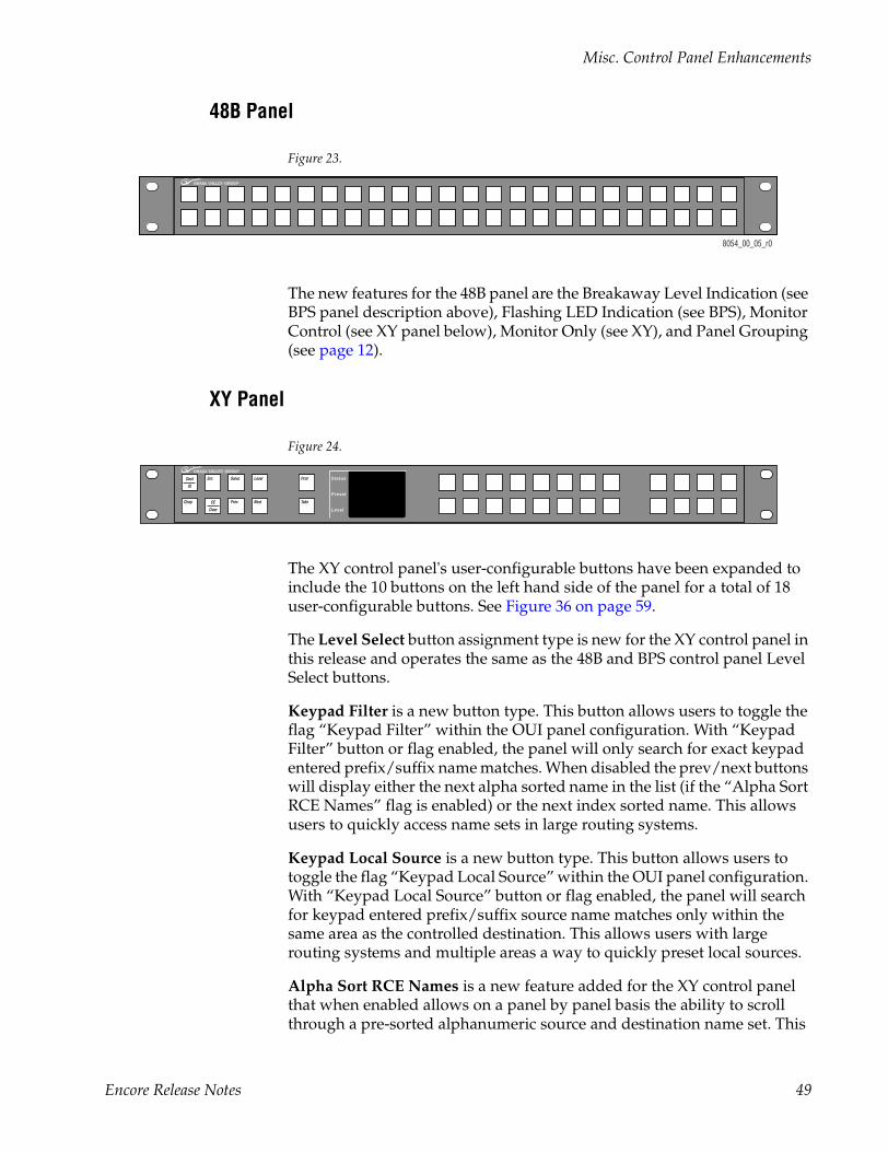
48B Panel
Figure 23.
The new features for the 48B panel are the Breakaway Level Indication (see BPS panel description above), Flashing LED Indication (see BPS), Monitor Control (see XY panel below), Monitor Only (see XY), and Panel Grouping (see page 12).
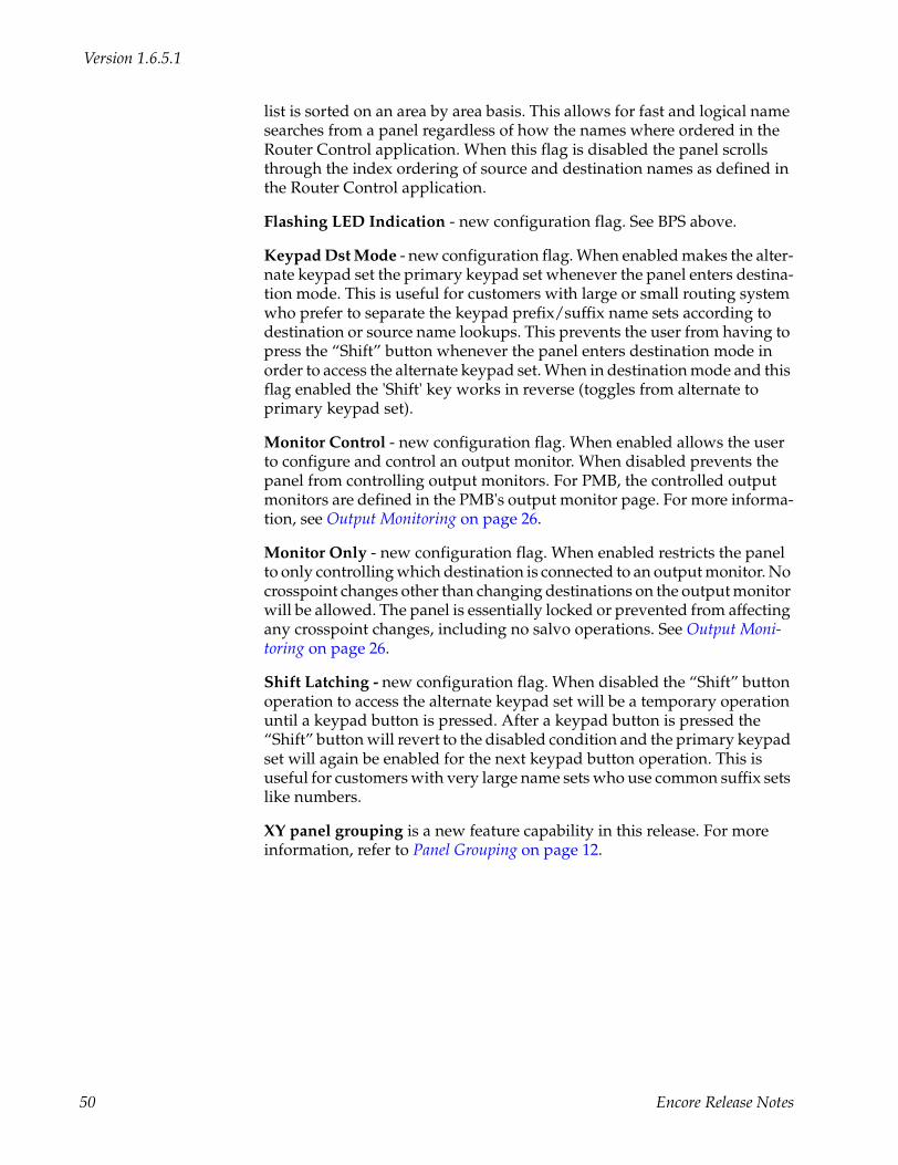
XY Panel
Figure 24.
The XY control panel's user-configurable buttons have been expanded to include the 10 buttons on the left hand side of the panel for a total of 18 user-configurable buttons. See Figure 36 on page 59.
The Level Select button assignment type is new for the XY control panel in this release and operates the same as the 48B and BPS control panel Level Select buttons.
Keypad Filter is a new button type. This button allows users to toggle the flag “Keypad Filter” within the OUI panel configuration. With “Keypad Filter” button or flag enabled, the panel will only search for exact keypad entered prefix/suffix name matches. When disabled the prev/next buttons will display either the next alpha sorted name in the list (if the “Alpha Sort RCE Names” flag is enabled) or the next index sorted name. This allows users to quickly access name sets in large routing systems.
Keypad Local Source is a new button type. This button allows users to toggle the flag “Keypad Local Source” within the OUI panel configuration. With “Keypad Local Source” button or flag enabled, the panel will search for keypad entered prefix/suffix source name matches only within the same area as the controlled destination. This allows users with large routing systems and multiple areas a way to quickly preset local sources.
Alpha Sort RCE Names is a new feature added for the XY control panel that when enabled allows on a panel by panel basis the ability to scroll through a pre-sorted alphanumeric source and destination name set. This
8054_00_05_r0
Status
Preset
Level
Dest
ID
Chop
Src
CE
Clear
Salvo
Prev
Level
Next
Prot
Take
Encore Release Notes 49
Version 1.6.5.1
list is sorted on an area by area basis. This allows for fast and logical name searches from a panel regardless of how the names where ordered in the Router Control application. When this flag is disabled the panel scrolls through the index ordering of source and destination names as defined in the Router Control application.
Flashing LED Indication - new configuration flag. See BPS above.
Keypad Dst Mode - new configuration flag. When enabled makes the alter-nate keypad set the primary keypad set whenever the panel enters destina-tion mode. This is useful for customers with large or small routing system who prefer to separate the keypad prefix/suffix name sets according to destination or source name lookups. This prevents the user from having to press the “Shift” button whenever the panel enters destination mode in order to access the alternate keypad set. When in destination mode and this flag enabled the 'Shift' key works in reverse (toggles from alternate to primary keypad set).
Monitor Control - new configuration flag. When enabled allows the user to configure and control an output monitor. When disabled prevents the panel from controlling output monitors. For PMB, the controlled output monitors are defined in the PMB's output monitor page. For more informa-tion, see Output Monitoring on page 26.
Monitor Only - new configuration flag. When enabled restricts the panel to only controlling which destination is connected to an output monitor. No crosspoint changes other than changing destinations on the output monitor will be allowed. The panel is essentially locked or prevented from affecting any crosspoint changes, including no salvo operations. See Output Moni-toring on page 26.
Shift Latching - new configuration flag. When disabled the “Shift” button operation to access the alternate keypad set will be a temporary operation until a keypad button is pressed. After a keypad button is pressed the “Shift” button will revert to the disabled condition and the primary keypad set will again be enabled for the next keypad button operation. This is useful for customers with very large name sets who use common suffix sets like numbers.
XY panel grouping is a new feature capability in this release. For more information, refer to Panel Grouping on page 12.
50 Encore Release Notes
Misc. Control Panel Enhancements
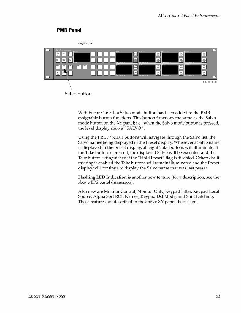
PMB Panel
Figure 25.
With Encore 1.6.5.1, a Salvo mode button has been added to the PMB assignable button functions. This button functions the same as the Salvo mode button on the XY panel; i.e., when the Salvo mode button is pressed, the level display shows ^SALVO^.
Using the PREV/NEXT buttons will navigate through the Salvo list, the Salvo names being displayed in the Preset display. Whenever a Salvo name is displayed in the preset display, all eight Take buttons will illuminate. If the Take button is pressed, the displayed Salvo will be executed and the Take button extinguished if the “Hold Preset” flag is disabled. Otherwise if this flag is enabled the Take buttons will remain illuminated and the Preset display will continue to display the Salvo name that was last preset.
Flashing LED Indication is another new feature (for a description, see the above BPS panel discussion).
Also new are Monitor Control, Monitor Only, Keypad Filter, Keypad Local Source, Alpha Sort RCE Names, Keypad Dst Mode, and Shift Latching. These features are described in the above XY panel discussion.
Status 1
Destination 1
Preset
Level
Status 2
Destination 2
Status 3
Destination 3
Status 4
Destination 4
Status 5
Destination 5
Status 6
Destination 6
Status 7
Destination 7
Status 8
Destination 8
8054_00_01_r0
Dest
ID
Level Src
DestPage
LevelPage
SrcPage
SalvoPage
Chop
CE
Clear
ShiftA
Store Prev Next
Prot
Hold
Take
Load
Prot
Hold
Take
Load
Prot
Hold
Take
Load
Prot
Hold
Take
Load
Prot
Hold
Take
Load
Prot
Hold
Take
Load
Prot
Hold
Take
Load
Prot
Hold
Take
Load
Salvo button
Encore Release Notes 51
Version 1.6.5.1
Changes to Router Control Application Menus
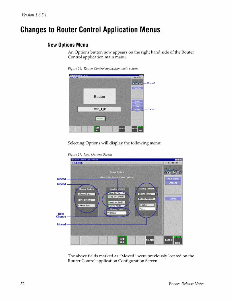
New Options MenuAn Options button now appears on the right hand side of the Router Control application main menu.
Figure 26. Router Control application main screen
Selecting Options will display the following menu:
Figure 27. New Options Screen
The above fields marked as “Moved” were previously located on the Router Control application Configuration Screen.
52 Encore Release Notes
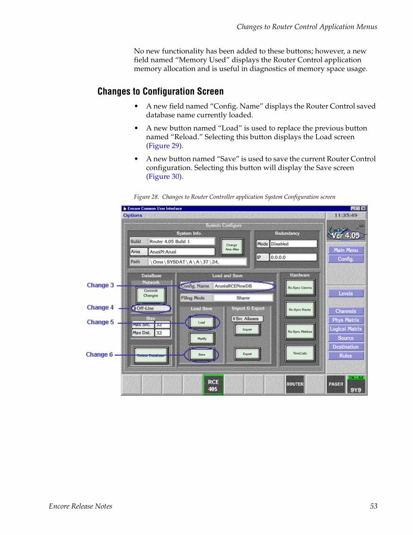
Changes to Router Control Application Menus
No new functionality has been added to these buttons; however, a new field named “Memory Used” displays the Router Control application memory allocation and is useful in diagnostics of memory space usage.
Changes to Configuration Screen• A new field named “Config. Name” displays the Router Control saved
database name currently loaded.
• A new button named “Load” is used to replace the previous button named “Reload.” Selecting this button displays the Load screen (Figure 29).
• A new button named “Save” is used to save the current Router Control configuration. Selecting this button will display the Save screen (Figure 30).
Figure 28. Changes to Router Controller application System Configuration screen
Encore Release Notes 53
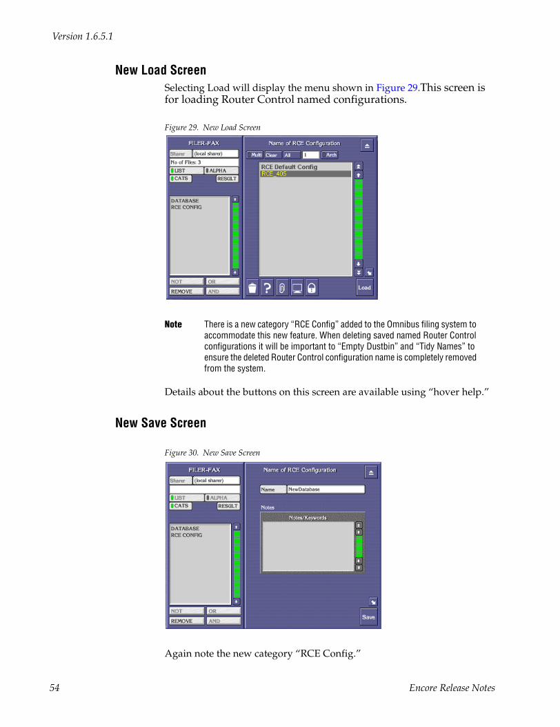
Version 1.6.5.1
New Load ScreenSelecting Load will display the menu shown in Figure 29.This screen is for loading Router Control named configurations.
Figure 29. New Load Screen
Note There is a new category “RCE Config” added to the Omnibus filing system to accommodate this new feature. When deleting saved named Router Control configurations it will be important to “Empty Dustbin” and “Tidy Names” to ensure the deleted Router Control configuration name is completely removed from the system.
Details about the buttons on this screen are available using “hover help.”
New Save Screen
Figure 30. New Save Screen
Again note the new category “RCE Config.”
54 Encore Release Notes
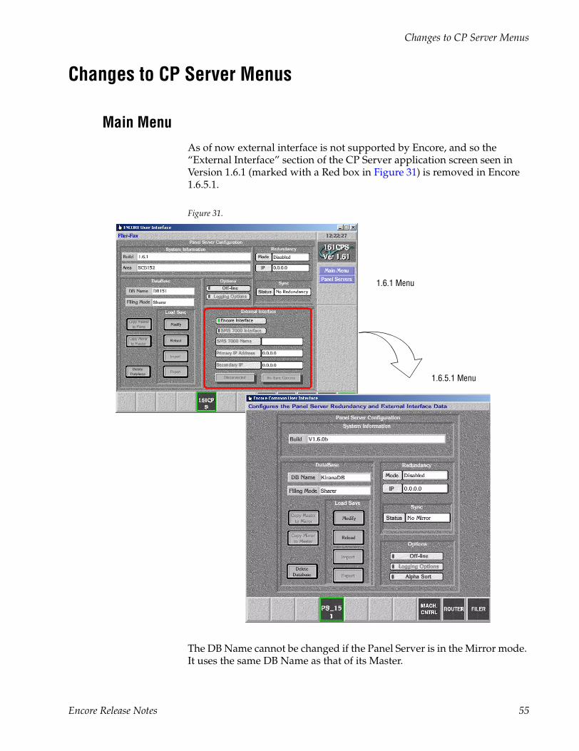
Changes to CP Server Menus
Changes to CP Server Menus
Main MenuAs of now external interface is not supported by Encore, and so the “External Interface” section of the CP Server application screen seen in Version 1.6.1 (marked with a Red box in Figure 31) is removed in Encore 1.6.5.1.
Figure 31.
The DB Name cannot be changed if the Panel Server is in the Mirror mode. It uses the same DB Name as that of its Master.
1.6.1 Menu
1.6.5.1 Menu
Encore Release Notes 55
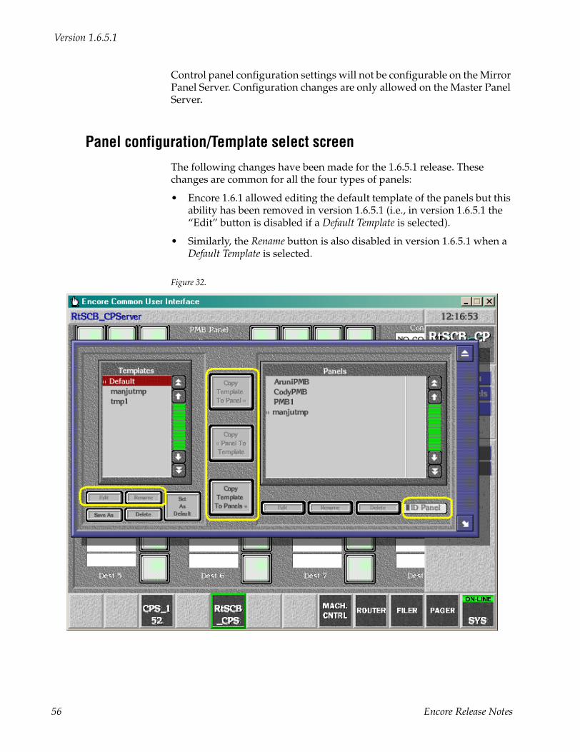
Version 1.6.5.1
Control panel configuration settings will not be configurable on the Mirror Panel Server. Configuration changes are only allowed on the Master Panel Server.
Panel configuration/Template select screenThe following changes have been made for the 1.6.5.1 release. These changes are common for all the four types of panels:
• Encore 1.6.1 allowed editing the default template of the panels but this ability has been removed in version 1.6.5.1 (i.e., in version 1.6.5.1 the “Edit” button is disabled if a Default Template is selected).
• Similarly, the Rename button is also disabled in version 1.6.5.1 when a Default Template is selected.
Figure 32.
56 Encore Release Notes
Changes to CP Server Menus
• In version 1.6.1, the buttons Copy Template to Panel, Copy Panel To Tem-plate and Copy Template to Panels were enabled by default. But in version 1.6.5.1, until an appropriate panel and/or template is selected for copy, these buttons are disabled (i.e., when only a Default Template is selected, the Copy Template to Panels button is enabled. When a panel and a tem-plate are selected, the other two buttons get enabled).
• In version 1.6.5.1, ID Panel is enabled only when an existing physical or soft active panel is selected.
• The Panels section in the “Panel configuration / Template select” screen is modified in version 1.6.5.1 for Panel Grouping so as to denote when an active panel or panel configuration belongs to a panel group and to which group and whether the panel is a master or an expansion panel of the group. For more information about panel grouping, see page 12.
• In version 1.6.5.1, in the Mirror Panel Server, the user can go to the load screen as shown above. The screen lists the available panels and tem-plates. However, it does not allow the user to select or open a panel for editing/viewing the configuration.
Button Configuration Screen - Assignment ModeThe changes common to all panels in the “Button configuration screen” of version 1.6.5.1 are:
• In version 1.6.5.1, certain buttons in the Button Assignment screen like SrcSel, LvlSel, and DstSel are renamed as Source Select, Level Select and Destination Select respectively for easier understanding. These changes are common for all the panels.
• The ability to alpha sort various OUI lists has been modified to enable it for all CP Server screens or disable it by default and allow the user to select alpha sorting capability as a screen by screen choice.
BPS Panel Menu • PnlLock has been removed.
• Destination Select has been added. This allows customers to control more than one destination from a BPS panel. Users can configure one or more buttons to switch between the destinations being controlled.
Encore Release Notes 57
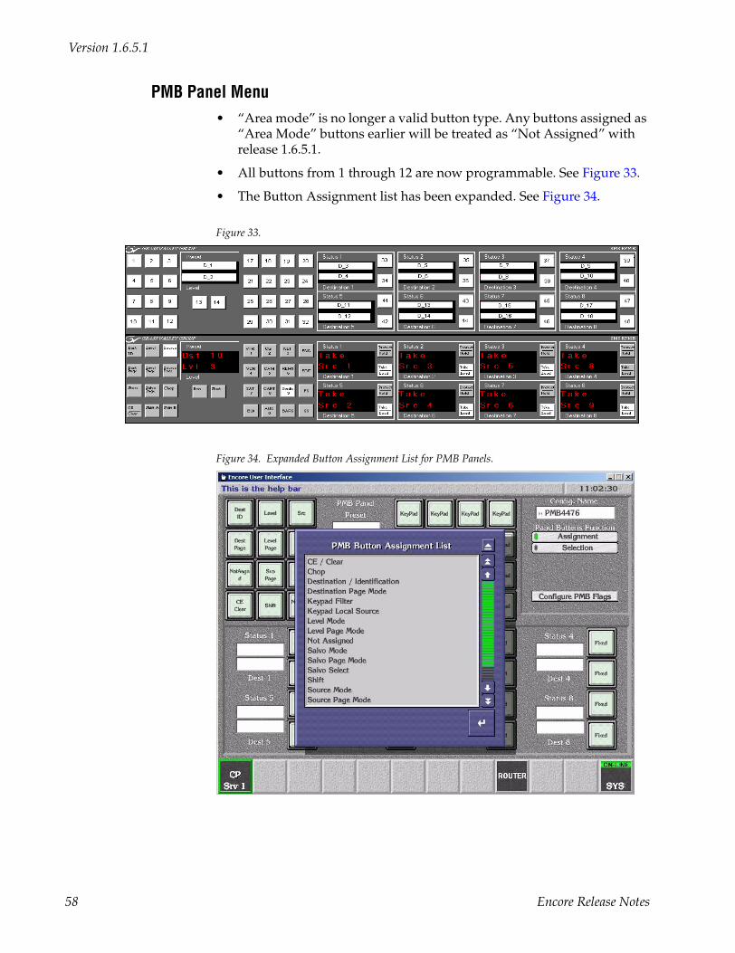
Version 1.6.5.1
PMB Panel Menu• “Area mode” is no longer a valid button type. Any buttons assigned as
“Area Mode” buttons earlier will be treated as “Not Assigned” with release 1.6.5.1.
• All buttons from 1 through 12 are now programmable. See Figure 33.
• The Button Assignment list has been expanded. See Figure 34.
Figure 33.
Figure 34. Expanded Button Assignment List for PMB Panels.
58 Encore Release Notes
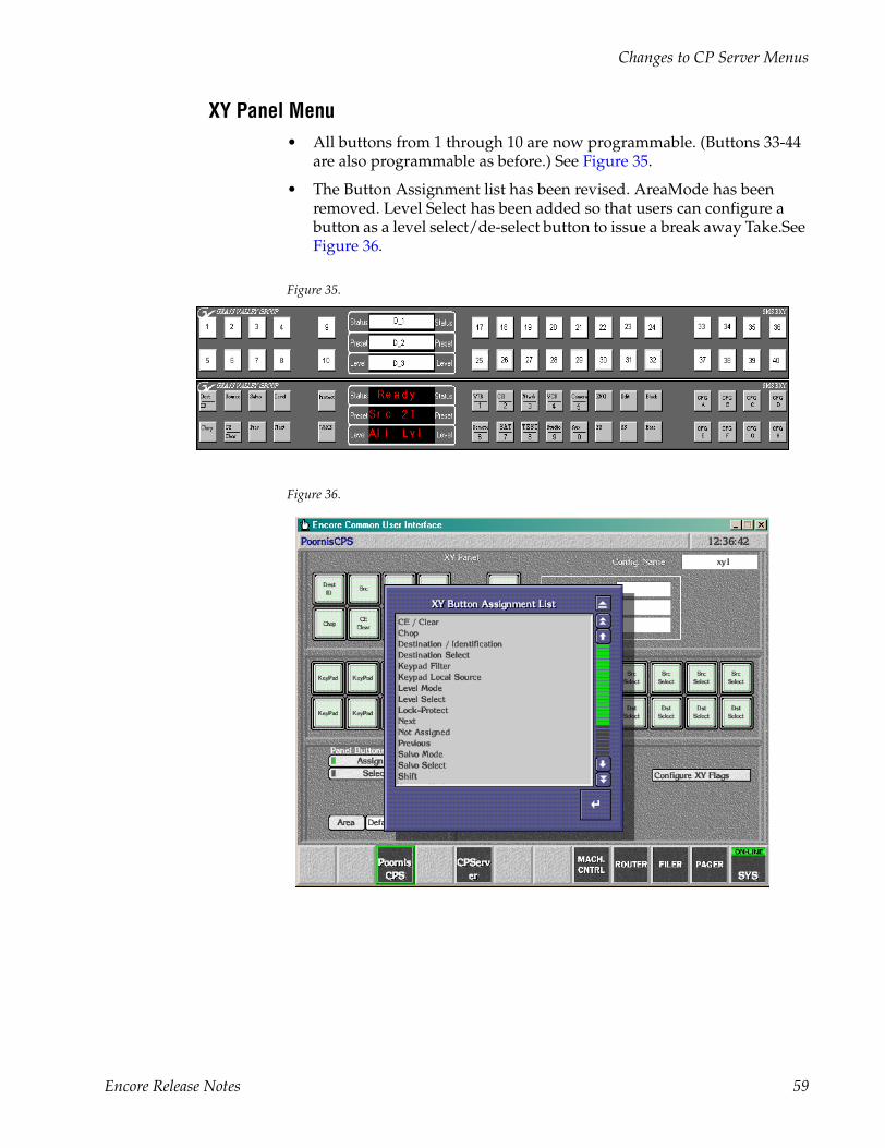
Changes to CP Server Menus
XY Panel Menu• All buttons from 1 through 10 are now programmable. (Buttons 33-44
are also programmable as before.) See Figure 35.
• The Button Assignment list has been revised. AreaMode has been removed. Level Select has been added so that users can configure a button as a level select/de-select button to issue a break away Take.See Figure 36.
Figure 35.
Figure 36.
Encore Release Notes 59
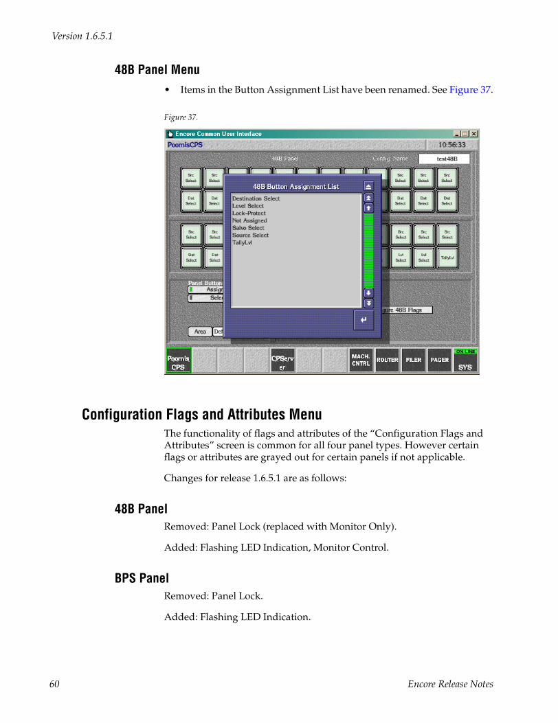
Version 1.6.5.1
48B Panel Menu• Items in the Button Assignment List have been renamed. See Figure 37.
Figure 37.
Configuration Flags and Attributes MenuThe functionality of flags and attributes of the “Configuration Flags and Attributes” screen is common for all four panel types. However certain flags or attributes are grayed out for certain panels if not applicable.
Changes for release 1.6.5.1 are as follows:
48B PanelRemoved: Panel Lock (replaced with Monitor Only).
Added: Flashing LED Indication, Monitor Control.
BPS PanelRemoved: Panel Lock.
Added: Flashing LED Indication.
60 Encore Release Notes

Changes to CP Server Menus
PMB Panel and XY Panel
Removed: Panel Lock (replaced with Monitor Only).
Added: Alpha Sort RCE Names, Flashing LED Indication, Keypad Dst-Mode, Keypad Local Source, Keypad SearchFilter, Shift Latching, Monitor Control, Monitor Only.
Definition of Flags and Attributes The functionality of the Flags and Attributes of the Configuration Attributes and Flags screen in Encore 1.6.1 and 1.6.5.1 is explained in the following table.
Flags
Table 3.
Flag Caption (v1.6.1) Flag Caption (v1.6.5.1) Description
AES Attribute Lock AES Attribute Lock If enabled, the panel is prevented from initiating AES attribute changes. Future use.
Alpha Sort RCE Names If the alpha sort flag is enabled, pressing the prev/next buttons will retrieve the previous or next Destination/Source name in the alphabetically sorted manner. If this flag is disabled, pressing the prev/next buttons will retrieve the previous or next Destination/Source name in order of their indexes.This flag is used by PMB and XY panels. (CR 40789)
Auto Tally Auto Tally If enabled, enables the tally on the first available non-excluded level for each destination.
Back Light Back Light If enabled, configures the panel to back light all valid buttons for the current mode of operation. This feature is intended for low ambient lighting that will require the buttons to be backlit in order to read the button text.
Chop Lock Chop Lock If enabled, the panel is prevented from initiating chops. Future use.
Display Alias Name Display Alias Name Display Source and Area Alias rather than Source and Area Names. Future use.
Dst Change Lock Dst Change Lock If enabled, locks out panel destination changes. This flag is used by 48B, PMB, and XY panels.
Dst Mode Time In Dst Mode Time In If enabled, the panel is returned to Destination Mode after the specified length of time of no button activity. The time can be specified in 1/10 of a second increment from 1/10 – 120 seconds.This flag is only available for the XY and PMB control panels.Dst Mode Time In and Dst change Lock flags are mutually exclusive.
Force Unlock / Unprotect Force Unlock / Unprotect If enabled, provide the user with the ability to forcibly remove a Lock or Protect from a specific Resource regardless of the point of control that initiated the Lock or Protect.
Encore Release Notes 61
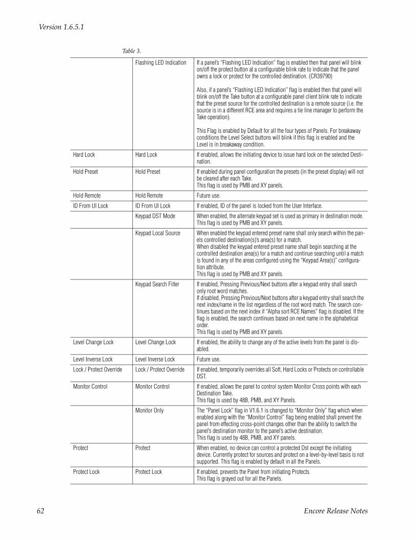
Version 1.6.5.1
Flashing LED Indication If a panel’s “Flashing LED Indication” flag is enabled then that panel will blink on/off the protect button at a configurable blink rate to indicate that the panel owns a lock or protect for the controlled destination. (CR39790)
Also, if a panel’s “Flashing LED Indication” flag is enabled then that panel will blink on/off the Take button at a configurable panel client blink rate to indicate that the preset source for the controlled destination is a remote source (i.e. the source is in a different RCE area and requires a tie line manager to perform the Take operation).
This Flag is enabled by Default for all the four types of Panels. For breakaway conditions the Level Select buttons will blink if this flag is enabled and the Level is in breakaway condition.
Hard Lock Hard Lock If enabled, allows the initiating device to issue hard lock on the selected Desti-nation.
Hold Preset Hold Preset If enabled during panel configuration the presets (in the preset display) will not be cleared after each Take.This flag is used by PMB and XY panels.
Hold Remote Hold Remote Future use.
ID From UI Lock ID From UI Lock If enabled, ID of the panel is locked from the User Interface.
Keypad DST Mode When enabled, the alternate keypad set is used as primary in destination mode. This flag is used by PMB and XY panels.
Keypad Local Source When enabled the keypad entered preset name shall only search within the pan-els controlled destination(s)’s area(s) for a match.When disabled the keypad entered preset name shall begin searching at the controlled destination area(s) for a match and continue searching until a match is found in any of the areas configured using the “Keypad Area(s)” configura-tion attribute. This flag is used by PMB and XY panels.
Keypad Search Filter If enabled, Pressing Previous/Next buttons after a keypad entry shall search only root word matches. If disabled, Pressing Previous/Next buttons after a keypad entry shall search the next index/name in the list regardless of the root word match. The search con-tinues based on the next index if “Alpha sort RCE Names” flag is disabled. If the flag is enabled, the search continues based on next name in the alphabetical order.This flag is used by PMB and XY panels.
Level Change Lock Level Change Lock If enabled, the ability to change any of the active levels from the panel is dis-abled.
Level Inverse Lock Level Inverse Lock Future use.
Lock / Protect Override Lock / Protect Override If enabled, temporarily overrides all Soft, Hard Locks or Protects on controllable DST.
Monitor Control Monitor Control If enabled, allows the panel to control system Monitor Cross points with each Destination Take.This flag is used by 48B, PMB, and XY Panels.
Monitor Only The “Panel Lock” flag in V1.6.1 is changed to “Monitor Only” flag which when enabled along with the “Monitor Control” flag being enabled shall prevent the panel from effecting cross-point changes other than the ability to switch the panel’s destination monitor to the panel’s active destination. This flag is used by 48B, PMB, and XY panels.
Protect Protect When enabled, no device can control a protected Dst except the initiating device. Currently protect for sources and protect on a level-by-level basis is not supported. This flag is enabled by default in all the Panels.
Protect Lock Protect Lock If enabled, prevents the Panel from initiating Protects.This flag is grayed out for all the Panels.
Table 3.
62 Encore Release Notes
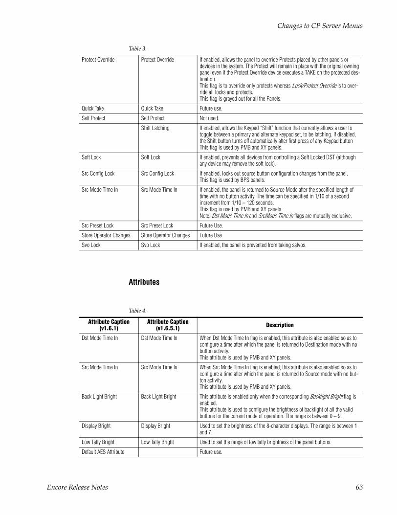
Changes to CP Server Menus
Attributes
Protect Override Protect Override If enabled, allows the panel to override Protects placed by other panels or devices in the system. The Protect will remain in place with the original owning panel even if the Protect Override device executes a TAKE on the protected des-tination.This flag is to override only protects whereas Lock/Protect Override is to over-ride all locks and protects.This flag is grayed out for all the Panels.
Quick Take Quick Take Future use.
Self Protect Self Protect Not used.
Shift Latching If enabled, allows the Keypad “Shift” function that currently allows a user to toggle between a primary and alternate keypad set, to be latching. If disabled, the Shift button turns off automatically after first press of any Keypad button This flag is used by PMB and XY panels.
Soft Lock Soft Lock If enabled, prevents all devices from controlling a Soft Locked DST (although any device may remove the soft lock).
Src Config Lock Src Config Lock If enabled, locks out source button configuration changes from the panel. This flag is used by BPS panels.
Src Mode Time In Src Mode Time In If enabled, the panel is returned to Source Mode after the specified length of time with no button activity. The time can be specified in 1/10 of a second increment from 1/10 – 120 seconds.This flag is used by PMB and XY panels.Note: Dst Mode Time In and SrcMode Time In flags are mutually exclusive.
Src Preset Lock Src Preset Lock Future Use.
Store Operator Changes Store Operator Changes Future Use.
Svo Lock Svo Lock If enabled, the panel is prevented from taking salvos.
Table 4.
Attribute Caption (v1.6.1)
Attribute Caption (v1.6.5.1) Description
Dst Mode Time In Dst Mode Time In When Dst Mode Time In flag is enabled, this attribute is also enabled so as to configure a time after which the panel is returned to Destination mode with no button activity.This attribute is used by PMB and XY panels.
Src Mode Time In Src Mode Time In When Src Mode Time In flag is enabled, this attribute is also enabled so as to configure a time after which the panel is returned to Source mode with no but-ton activity.This attribute is used by PMB and XY panels.
Back Light Bright Back Light Bright This attribute is enabled only when the corresponding Backlight Bright flag is enabled.This attribute is used to configure the brightness of backlight of all the valid buttons for the current mode of operation. The range is between 0 – 9.
Display Bright Display Bright Used to set the brightness of the 8-character displays. The range is between 1 and 7.
Low Tally Bright Low Tally Bright Used to set the range of low tally brightness of the panel buttons.
Default AES Attribute Future use.
Table 3.
Encore Release Notes 63
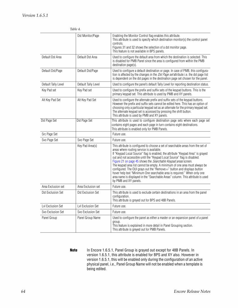
Version 1.6.5.1
Note In Encore 1.6.5.1, Panel Group is grayed out except for 48B Panels. In version 1.6.5.1, this attribute is enabled for BPS and XY also. However in version 1.6.5.1, this will be enabled only during the configuration of an active physical panel, i.e., Panel Group Name will not be enabled when a template is being edited.
Dst Monitor/Page Enabling the Monitor Control flag enables this attribute.This attribute is used to specify which destination monitor(s) the control panel controls.Figures 31 and 32 shows the selection of a dst monitor page.This feature is not available in BPS panels.
Default Dst Area Default Dst Area Used to configure the default area from which the destination is selected. This is disabled for PMB Panel since the area is configured from within the PMB destination page(s).
Default Dst/Page Default Dst/Page Used to configure a default destination or page. In case of PMB, this configura-tion is affected by the changes in the Dst Page set attribute i.e. the dst page list is dependent on the dst pages in the destination page set chosen for the panel.
Default Tally Level Default Tally Level Used to configure the panel’s default Tally Level for reporting destination status.
Key Pad set Key Pad set Used to configure the prefix and suffix sets of the keypad buttons. This is the primary keypad set. This attribute is used by PMB and XY panels.
Alt Key Pad Set Alt Key Pad Set Used to configure the alternate prefix and suffix sets of the keypad buttons. However the prefix and suffix sets cannot be edited here. This has an option of choosing only a particular keypad set as an alternate for the primary keypad set. The alternate keypad set is accessed by pressing the shift button.This attribute is used by PMB and XY panels.
Dst Page Set Dst Page Set This attribute is used to configure destination page sets where each page setcontains eight pages and each page in turn contains eight destinations.This attribute is enabled only for PMB Panels.
Src Page Set Future use.
Svo Page Set Svo Page Set Future use.
Key Pad Area(s) This attribute is configured to choose a set of searchable areas from the set of areas where routing service is available.If “Keypad Local Source” flag is enabled, the attribute “Keypad Area” is grayed out and not accessible until the “Keypad Local Source” flag is disabled. Figure 21 on page 45 shows the Searchable Keypad areas screen.The keypad area list cannot be empty. A minimum of one area must always be configured. The OUI grays out the “Remove>>” button and displays button hover help text “Minimum One searchable area is required.” When only one area name is displayed in the “Searchable Areas” column. This attribute is used by PMB and XY panels.
Area Exclusion set Area Exclusion set Future use.
Dst Exclusion Set Dst Exclusion Set This attribute is used to exclude certain destinations in an area from the panel configuration.This attribute is greyed out for BPS and 48B Panels.
Lvl Exclusion Set Lvl Exclusion Set Future use.
Svo Exclusion Set Svo Exclusion Set Future use.
Panel Group Panel Group Name Used to configure the panel as either a master or an expansion panel of a panel group. This feature is explained in more detail in Panel Grouping section.This attribute is greyed out for PMB Panels.
Table 4.
64 Encore Release Notes
Salvos Enable Button
Salvos Enable ButtonTo display the Salvos Enable menu, use the Local Router Panel (“Router”) application, go to Options > Config Mode, then return to Salvos again.
The Salvos Enable button applies to salvos accessed from the LRP and all other control panels in the system.
Non-Display of Excluded DestinationsWith this release, excluded destinations are no longer shown in Preset dis-plays.
For this function to be effective, a Destination Exclusion Set must be created (the Default set has no effect since it does not exclude any destinations).
For more information about Destination Exclusion Sets, please see Config-uring Control Panels for Control in Specific Area(s) on page 45.
Default OMN DatabaseA default OMN database can now be selected during the installation pro-cess. This database, which is intended for use when Encore is being installed for the first time, will provide basic configuration settings, such as PC and System Controller Board registration; and Router Control, CP Server, Tie Line Manager and System Manager application registration. A simple test router configuration using the “Dummy Matrix” (loopback) driver is also included.
The purpose of the default OMN database is to minimize the configuration required to get the system up and running.
The default database uses the factory default IP addresses for the Encore SCBs and the Sharer PC. The Sharer PC IP address should be set to 192.168.0.102, the factory default IP addresses for the Master and Mirror SCBs are 192.168.0.100 and 192.168.0.101 respectively.
To use the default database, first install it on the Sharer PC, connect the PC and SCBs to the Ethernet network. With everything powered up, start the Sharer, System Manager and OUI applications on the PC. Log into the OUI and click on an empty box on the task bar; a list of applications will pop up the “>>” to the left of each application indicates that it is active and avail-able.
Encore Release Notes 65

Version 1.6.5.1
Any control panels connected to the system will be active and should display the source and destination names used in the test router configura-tion. Use of the “Dummy Matrix” driver allows Takes to be executed from the control panels without the need for matrix hardware to be connected; this allows the user to quickly verify that the control system is operational.
If Destination Exclusion Sets are used in your system, you must now open and re-save them.
66 Encore Release Notes
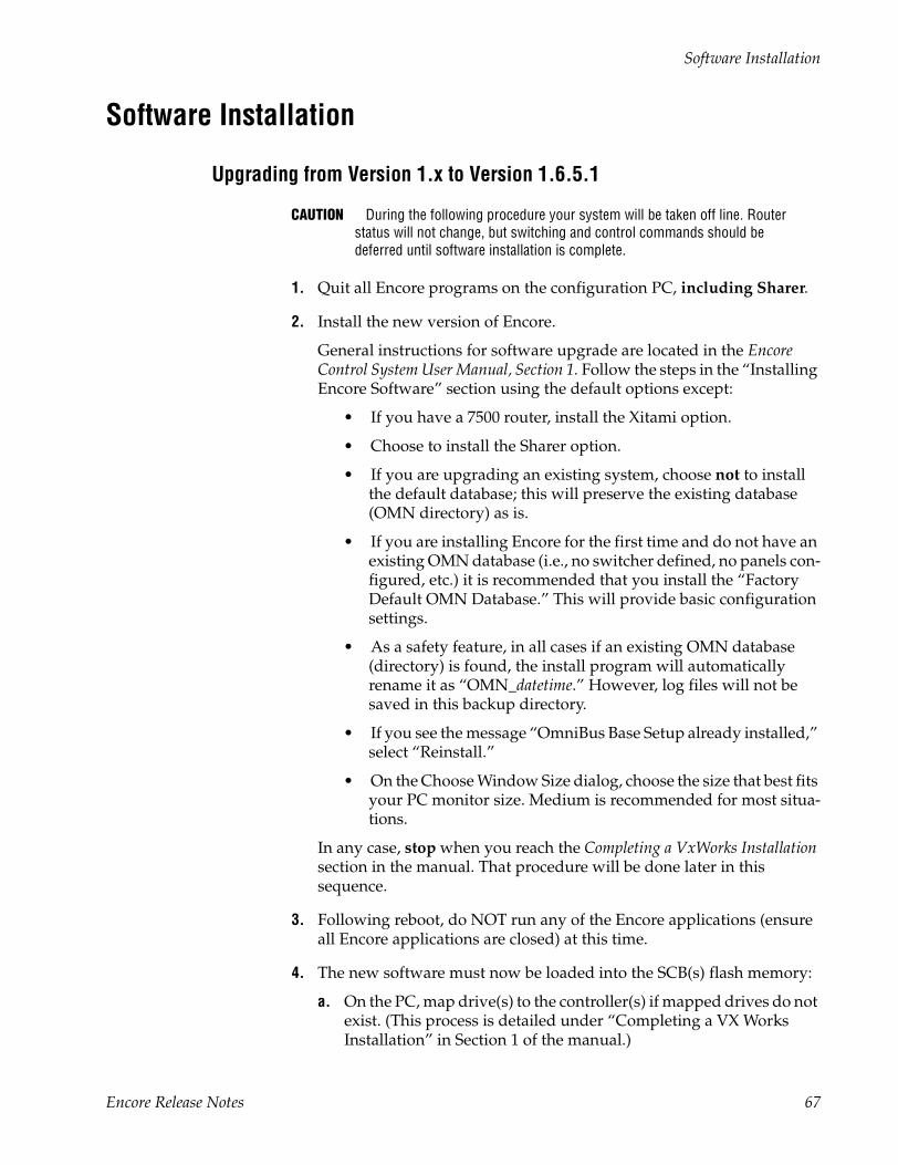
Software Installation
Software Installation
Upgrading from Version 1.x to Version 1.6.5.1
CAUTION During the following procedure your system will be taken off line. Router status will not change, but switching and control commands should be deferred until software installation is complete.
1. Quit all Encore programs on the configuration PC, including Sharer.
2. Install the new version of Encore.
General instructions for software upgrade are located in the Encore Control System User Manual, Section 1. Follow the steps in the “Installing Encore Software” section using the default options except:
• If you have a 7500 router, install the Xitami option.
• Choose to install the Sharer option.
• If you are upgrading an existing system, choose not to install the default database; this will preserve the existing database (OMN directory) as is.
• If you are installing Encore for the first time and do not have an existing OMN database (i.e., no switcher defined, no panels con-figured, etc.) it is recommended that you install the “Factory Default OMN Database.” This will provide basic configuration settings.
• As a safety feature, in all cases if an existing OMN database (directory) is found, the install program will automatically rename it as “OMN_datetime.” However, log files will not be saved in this backup directory.
• If you see the message “OmniBus Base Setup already installed,” select “Reinstall.”
• On the Choose Window Size dialog, choose the size that best fits your PC monitor size. Medium is recommended for most situa-tions.
In any case, stop when you reach the Completing a VxWorks Installation section in the manual. That procedure will be done later in this sequence.
3. Following reboot, do NOT run any of the Encore applications (ensure all Encore applications are closed) at this time.
4. The new software must now be loaded into the SCB(s) flash memory:
a. On the PC, map drive(s) to the controller(s) if mapped drives do not exist. (This process is detailed under “Completing a VX Works Installation” in Section 1 of the manual.)
Encore Release Notes 67
Version 1.6.5.1
b. Copy the contents of the “Encore Image” folder to flash memory (if prompted to overwrite existing files choose “Yes to All”—files such as “GUI data” and “GUI token” must be overwritten).
In the case of redundant SCBs, files must be copied to the flash memories of both units.
5. Update the software on the control panels (this process is detailed under Loading or Updating Panel and Concerto Software in Section 1 of the manual):
a. Run NetConfig.
b. Select Configure > Load Software.
c. Select the control panel software to be loaded. This selection is based on the type of control panel (10BaseT or 100BaseT) and the version of software presently installed on the panel.
To verify which version of software is presently installed, select Device Type “Encore Panel s19 (10BaseT)” or “Encore Panel s19 (100BaseT)” as appropriate for the panel type. In the right-hand window you should see the Client Name of the panel(s) and the version of software presently installed.
If panels are missing, see IP Address Assignments in the Encore 1.6.1 release notes before continuing. (You must see a panel in this list before you can update its software.)
— If the software presently installed is version 1.6.2 or older, soft-ware type “s19” should be selected for the upgrade to version 1.6.5.1 or newer. For example, if V1.6.1 is presently installed, and the upgrade is to version 1.6.5.1 (the usual case), “s19” should be selected.
— If the software presently installed is version 1.6.5.1 or newer, soft-ware type “bin” should be selected for the upgrade. For example, if version 1.6.5b3 (a beta version of 1.6.5.1) is presently installed, and the upgrade is to V1.6.5.1 (the release version of v), “bin” should be selected. (Note: this menu has a provision for downgrade from1.6.5.1 to 1.6.1 in which case type “bin” is always used.)
d. Check the boxes for the panel(s) to be updated.
Note If you are upgrading a multi-area system (i.e., a multi-network system), and a panel is reported as offline, uncheck that panel(s) and complete Step e below for the online panels. Then, check the gateway setting for the configu-ration PC. The gateway setting must point to the SCB that will be used to reach the control panels being updated. In the case of redundant SCBs, you may need to try both before the panels will update. It may be helpful to check the IP View to see which panels are visible (green light) to the SCB selected as the gateway.
e. Select Re-Boot when complete and Load.
68 Encore Release Notes
Software Installation
Note The Update Devices menu may not indicate the new version number properly. To verify the version number, close the Update Devices window, select the panel under IP View, and select Panel Description. The version will be shown under “Panel Application Software Version.”
6. If your system includes a Concerto matrix, the Matrix Application software is also updated using NetConfig (this process is detailed under Loading or Updating Panel and Concerto Software in Section 1 of the manual):
a. Run NetConfig.
b. Select Configure > Load Software.
c. Select the Concerto software to be loaded. This selection is based on the type of matrix controller board (10BaseT or 100BaseT) and the version of software presently installed on the board.
Matrix controller board types are discussed under Concerto Applica-tions on page 10.
To verify which version of software is presently installed, select Device Type “Concerto Matrix s19 (10BaseT)” or “Concerto Matrix s19 (100BaseT)” as appropriate for the controller board type. In the right-hand window you should see the Client Name of the con-troller board(s) and the version of software presently installed.
— If the software presently installed is version 1.6.2 or older, soft-ware type “s19” should be selected for the upgrade to version 1.6.5.1 or newer. For example, if version 1.6.1 is presently installed, and the upgrade is to version 1.6.5.1 (the usual case), “s19” should be selected.
— If the software presently installed is version 1.6.5.1 or newer, soft-ware type “bin” should be selected for the upgrade. For example, if version 1.6.5b3 (a beta version of 1.6.5.1) is presently installed, and the upgrade is to version 1.6.5.1 (the release version of 1.6.5.1), “bin” should be selected. (Note: this menu has a provision for downgrade from 1.6.5.1to 1.6.1 in which case type “bin” is always used.)
d. Check the matrix controller(s) to be updated.
e. Select Re-Boot when complete and Load.
If you are updating a multi-area system, and the router can’t be updated because it’s offline, refer to the Note under Step 5 above.
7. If your system includes a 7500 router, refer to Updating/Upgrading Matrix Controller Software via FTP on page 257 of the Encore 1.5 User Manual.
Once 1.6.5.1 is installed, NetConfig can be used to update the 7500.
8. Reboot the SCB(s) using the white Reset push button on the front left area of the boards.
Encore Release Notes 69
Version 1.6.5.1
9. On the PC, run the Release Sharer and OUI applications.
10. After installing this release, if no salvo has ever been created before, and a salvo is created on a Local Router Panel, it does not get updated to the Control Panel Server. To avoid this problem, create a dummy salvo and reboot the system. Salvos that are entered after that are immediately seen on the CP Server.
11. Verify that the new Salvos Enable button is On by going to the Local Router Panel (“Router” application) and selecting Options > Config Mode. Then, while the Config menu is still being displayed, select Salvos on the bottom of the main Router screen.You should see the Salvos Enable button.
12. If Destination Exclusion Sets are used in your system, you must now open and re-save them. This will ensure that all panels will have control of the same destinations as before.
After installing 1.6.5.1, any destinations previously listed in the “Inhib-ited Dst” box will no longer appear in that position; instead, the desti-nations that were (and are) available will now appear in the “Available Dst” box.
This change has been made because, in most cases, using the Available Dst box simplifies the configuration process as new sources, destina-tions, and panels are added. For example, if a new studio is added, existing panels in other studios would likely require only a few entries (or none) to the Available Dst box.
In any case, it is still possible to exclude or include control of any desti-nation on a panel-by-panel basis.
13. The Router Control application now allows configuration settings to be saved in a named file for later recall (as described under Changes to Configuration Screen on page 53). Following 1.6.5.1 installation, the Router Control configuration screen should be opened, Save selected, a name created for the present settings, and the configuration saved. This should be repeated for any additional instances of the Router Control application, with a unique name created for each saved configuration.
14. If NetCentral is to be used to monitor the Encore system, please refer to the NetCentral manual for further instructions.
15. If the file server PC is running Windows XP, please refer to Support for Microsoft Windows XP on page 71 for application configuration instructions.
16. This completes the upgrade process.
If you wish to create Areas for your system, refer to page 40.
70 Encore Release Notes
Support for Microsoft Windows XP Professional
Support for Microsoft Windows XP ProfessionalTo set the compatibility mode for Encore applications running on a Windows XP Server platform do the following:
Release Sharer
1. Using Windows Explorer, navigate to
C:\OmniBus\Sharer3\RelNtMt\
2. Right-click on sharer3.exe.
3. Select Properties.
4. Select Compatibility.
5. Click the Check box for “Run this program in compatibility mode for.”
6. Select Windows 2000 drop the drop-down menu.
7. Click “OK.”
Debug Sharer
1. Using Windows Explorer, navigate to
C:\OmniBus\Sharer3\dbgntmt\
2. Right-click on sharer3.exe.
3. Select Properties.
4. Select Compatibility.
5. Click the Check box for “Run this program in compatibility mode for.”
6. Select Windows 2000 drop the drop-down menu.
7. Click “OK.”
System Manager
1. Using Windows Explorer, navigate to
C:\OmniBus\SysMan3\DebugNT\
2. Right-click on sysman3.exe.
3. Select Properties.
4. Select Compatibility.
Encore Release Notes 71

Version 1.6.5.1
5. Click the Check box for “Run this program in compatibility mode for.”
6. Select Windows 2000 drop the drop-down menu.
7. Click “OK.”
Encore OUI
1. Using Windows Explorer, navigate to
C:\OmniBus\OUI43020\wincui\
Note 43020 is the OUI version number, it may be different in your installation; if so, navigate to the current OUI version directory.
2. Right-click on WinCui.exe.
3. Select Properties.
4. Select Compatibility.
5. Click the Check box for “Run this program in compatibility mode for.”
6. Select Windows 2000 drop the drop-down menu.
7. Click “OK.”
72 Encore Release Notes
Appendix ARCL Enhancements
This document describes Router Control Language enhancements that have been implemented for Encore 1.6.5.1. For more information about the RCL protocol, refer to Section 2 (Router Control Language) of the Routing Products Protocol Manual.
Following is a summary o f the RCL features that apply to router control.
• Message Identifiers
Each RCL message has a message identifier. The message identifier is copied in any RCL Server response to that message. The RCL client uses the message identifier to associate the response with the message that trig-gered it.
• Session Identifiers
Each RCL session uses a session identifier. If a session is terminated and a new session started using the same interface parameters (e.g. client IP address and port number), the new session will have a new session identi-fier thus differentiating it from the previous session.
• Message Responses
All RCL commands will generate level 4 responses. All responses are iden-tified with the message ID from the client request. Provision is made for the client to disable responses by sending a BK, E, OFF message. Even if responses are disabled in this way, this will apply only to operations com-mands, not to queries. Additionally, any live subscriptions will continue to return notifications.
• Multiple Response Support
When an RCL request generates multiple responses (e.g. Query Destina-tion status), the sequence flag in the RCL will reflect the order of each message in the sequence. The sequence flag “1” will indicate the first mes-sage. The sequence flag will be incremented by 1 for each successive message in the sequence. The penultimate message in the sequence will have the sequence flag “n-1” (where n is the total number of messages in the sequence). The last message has a sequence flag of “0.”
• Protect/Unprotect
Encore Release Notes 73
Appendix A — RCL Enhancements
Native Protocol and RCL Protect and Unprotect commands are mapped to the Encore Protect function. Encore Soft and Hard locks are not supported via the NP/RCL interface.
• Protect Refresh
In general, Protects will remain in force until removed by the client (unpro-tect) or until the RCL session is closed. Both normal and forced termination of the session (i.e. the RCL client is unresponsive) are considered as a session closure. For Ethernet clients, protects are dropped if the TCP/IP connection is lost. For serial clients, protects are dropped if the client exits gracefully or if it reconnects without closing an earlier connection. An addi-tional configuration option has been added to the RCL server (client-spe-cific) configuration that, if enabled, will leave any destinations (protected by that client) protected even if the session is terminated for any reason.
Encore Native Protocol (NP) and RCL require protects to be periodically refreshed by the RCL client. The refresh interval is configurable in the NP/RCL client settings. The refresh interval can be disabled (= 0), or set = 255 seconds. If a level 4 command (any level 4 command) is not received with at least this periodicity, the RCL Server will drop any protects owned by that client.
• Query for Protect
Query for Protect n returns the protecting device name but not the lock type (i.e. “H” for hard locks, “P” for protects). In the case of soft locks, the device name returned will be null.
Protect Override
RCL supports the protect override function if the interface is so configured. A configuration flag in the (client-specific) RCL configuration interface is provided for this purpose.
• True Tally
In Encore NP all status query commands will return true tally (i.e. both QJ and Qj). In RCL, only QJ will be supported; it returns true tally. Tally for a Take response is generated by the matrix driver acknowledgement; this occurs when the matrix driver receives the take request and if the matrix driver and matrix controller are communicating normally. To guarantee true tally the RCL client should subscribe for status on the destinations of interest; this will enable the client to receive all status updates without the need to query.
• Subscription support
A subscription mechanism provides a means for clients to register their interest in certain events and receive event-driven status updates without the need for polling. RCL provides a subscription mechanism for destina-tion status, configuration changes (by area), level changes and salvo data-base changes. In the case of destination status, a client may subscribe on a
74 Encore Release Notes
destination-by-destination basis, or all destinations in a given area, or all destinations in all areas. Destination status includes the currently-con-nected source (for each level of the destination), and protect status.
• Time-stamped commands support (Connects and Salvos only)
RCL supports time-stamped requests for takes and salvos only (not Protects or dynamic attribute changes). Time-stamped commands are received by the RCL server and sent to the Router Controller (via the Panel Server Router Proxy) for processing. The specific actions taken by the RCL server depend on the time-stamp value as described below:
• For time-stamps in the past up to and including +5 frames in the future (relative to the current time), the RCL server will issue an immediate connect request to the Router Proxy and, if the connect succeeds, return a “time stamp out of range – immediate connect issued” error code to the client once the RCL Server receives a des-tination status update from the Router Controller via the Router Proxy. If the request fails for reasons other than the time-stamp out of range, the error code of the other failure will take precedence over the time-stamp out of range error (i.e. a single response will be sent with the error code of the other error).
• For time-stamps from +6 to +100 frames in the future (relative to the current time), the RCL server will issue a time-stamped connect request. The time-stamp value used will be that received in the incoming message (i.e. do not add 6 frames).
• For time-stamps greater or equal to +100 frames in the future (rela-tive to the current time), the RCL server will not issue a connect request. The time-stamped request will be acknowledged with an error message: “time-stamp out of range – connect aborted” error code.
• Dynamic audio attribute support (simple)
In order to avoiding adding extra commands which would entail addi-tional development effort from Automation Vendors, switch requests involving audio mode with non default setting are configured as another instance of the Source (with a different source name) in Encore but with dif-ferent audio attribute settings. This scheme is supported by both Native Protocol and RCL.
• Multiple Area support
RCL supports Encore systems containing multiple routing areas. RCL com-mands use fully qualified source and destination names, i.e. areaName:sourceName, areaName:destinationName. Additional com-mands are provided as needed to support multiple areas: e.g. Query Area Names.
• Output Monitor Control
Encore Release Notes 75
Appendix A — RCL Enhancements
Encore 1.6.5.1 does not support Output Monitor control in either Encore NP or RCL.
• Tie-line related commands
There is no support for any tie-line related commands in either Encore NP or RCL.
• RCL protocol reformatting
All enhancements pertain to RCL only unless otherwise specified.
• NP/RCL Command Console Logging
To aid in the troubleshooting of NP/RCL interfaces, a NP/RCL Tx/Rx console logging function has been added. When enabled, the transmitted and received Native Protocol commands will be displayed on the system controller console.
The displayed messages contains the following information:
1. Time
2. Client Name
3. Direction (transmitted or received)
4. NP/RCL message string
It is possible to enable/disable the NP/RCL console logging function on a client-by-client basis as well as select either (or both) transmitted or received messages.
Each client has “RCL Debug Tx” and “RCL Debug Rx” flags added to the NP/RCL client configuration flags. The default state of these flags is “OFF”.
76 Encore Release Notes
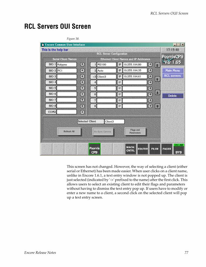
RCL Servers OUI Screen
RCL Servers OUI Screen
Figure 38.
This screen has not changed. However, the way of selecting a client (either serial or Ethernet) has been made easier. When user clicks on a client name, unlike in Encore 1.6.1, a text entry window is not popped up. The client is just selected (indicated by '->' prefixed to the name) after the first click. This allows users to select an existing client to edit their flags and parameters without having to dismiss the text entry pop up. If users have to modify or enter a new name to a client, a second click on the selected client will pop up a text entry screen.
Encore Release Notes 77
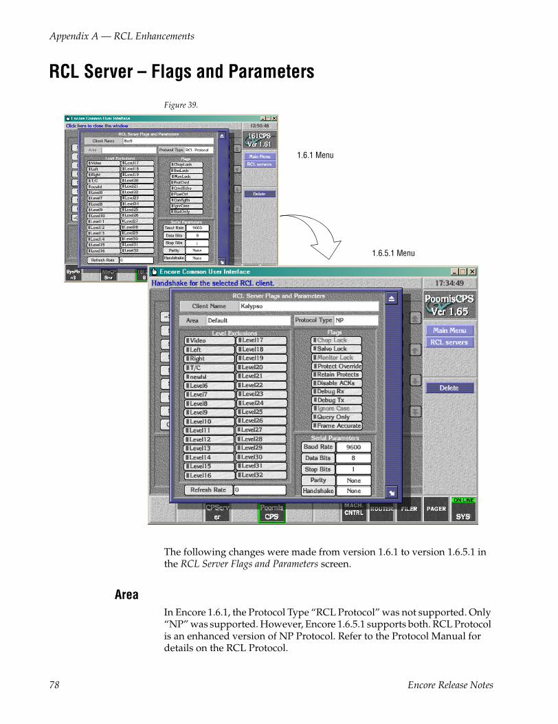
Appendix A — RCL Enhancements
RCL Server – Flags and Parameters
Figure 39.
The following changes were made from version 1.6.1 to version 1.6.5.1 in the RCL Server Flags and Parameters screen.
AreaIn Encore 1.6.1, the Protocol Type “RCL Protocol” was not supported. Only “NP” was supported. However, Encore 1.6.5.1 supports both. RCL Protocol is an enhanced version of NP Protocol. Refer to the Protocol Manual for details on the RCL Protocol.
1.6.1 Menu
1.6.5.1 Menu
78 Encore Release Notes
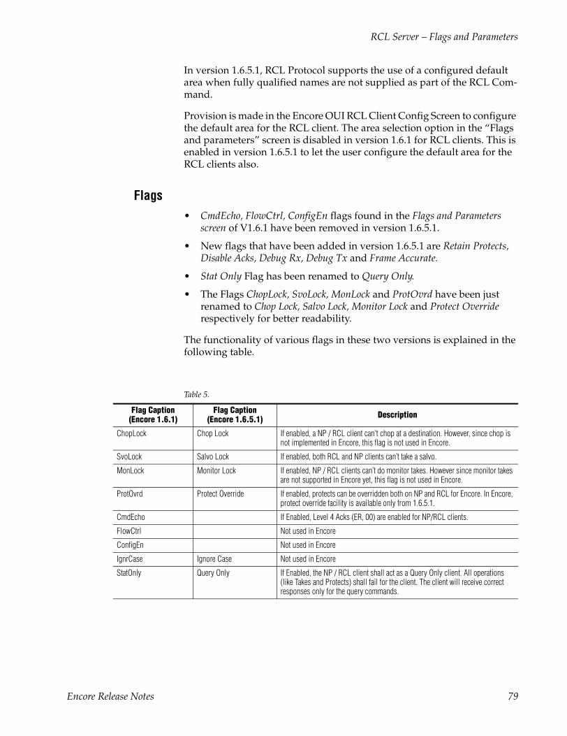
RCL Server – Flags and Parameters
In version 1.6.5.1, RCL Protocol supports the use of a configured default area when fully qualified names are not supplied as part of the RCL Com-mand.
Provision is made in the Encore OUI RCL Client Config Screen to configure the default area for the RCL client. The area selection option in the “Flags and parameters” screen is disabled in version 1.6.1 for RCL clients. This is enabled in version 1.6.5.1 to let the user configure the default area for the RCL clients also.
Flags• CmdEcho, FlowCtrl, ConfigEn flags found in the Flags and Parameters
screen of V1.6.1 have been removed in version 1.6.5.1.
• New flags that have been added in version 1.6.5.1 are Retain Protects, Disable Acks, Debug Rx, Debug Tx and Frame Accurate.
• Stat Only Flag has been renamed to Query Only.
• The Flags ChopLock, SvoLock, MonLock and ProtOvrd have been just renamed to Chop Lock, Salvo Lock, Monitor Lock and Protect Override respectively for better readability.
The functionality of various flags in these two versions is explained in the following table.
Table 5.
Flag Caption (Encore 1.6.1)
Flag Caption (Encore 1.6.5.1) Description
ChopLock Chop Lock If enabled, a NP / RCL client can't chop at a destination. However, since chop is not implemented in Encore, this flag is not used in Encore.
SvoLock Salvo Lock If enabled, both RCL and NP clients can’t take a salvo.
MonLock Monitor Lock If enabled, NP / RCL clients can’t do monitor takes. However since monitor takes are not supported in Encore yet, this flag is not used in Encore.
ProtOvrd Protect Override If enabled, protects can be overridden both on NP and RCL for Encore. In Encore, protect override facility is available only from 1.6.5.1.
CmdEcho If Enabled, Level 4 Acks (ER, 00) are enabled for NP/RCL clients.
FlowCtrl Not used in Encore
ConfigEn Not used in Encore
IgnrCase Ignore Case Not used in Encore
StatOnly Query Only If Enabled, the NP / RCL client shall act as a Query Only client. All operations (like Takes and Protects) shall fail for the client. The client will receive correct responses only for the query commands.
Encore Release Notes 79

Appendix A — RCL Enhancements
Note The CmdEcho Flag in version 1.6.1 if enabled, is used for enabling Level 4 Acks for NP/RCL Clients where as Disable Ack Flag in version 1.6.5.1 if enabled, disables the Level 4 Acks for NP/RCL Clients.
The changes in the Flags are common to both serial and Ethernet Clients.
Retain Protects If enabled, protects are retained even if the NP/RCL client that issued the pro-tects, disconnects.
Disable ACKs If enabled, Level 4 Acks (ER, 00) are disabled for NP/RCL clients.
Debug Rx If enabled, all received messages received from the NP/RCL client are printed on the console.
Debug Tx If enabled, all messages sent to the NP/RCL client are printed on the console.
Frame Accurate If enabled, all non-time stamped takes are deterministic. This is used only for RCL clients in Encore.
Table 5.
80 Encore Release Notes
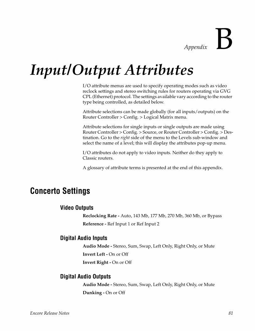
Appendix BInput/Output Attributes
I/O attribute menus are used to specify operating modes such as video reclock settings and stereo switching rules for routers operating via GVG CPL (Ethernet) protocol. The settings available vary according to the router type being controlled, as detailed below.
Attribute selections can be made globally (for all inputs/outputs) on the Router Controller > Config. > Logical Matrix menu.
Attribute selections for single inputs or single outputs are made using Router Controller > Config. > Source, or Router Controller > Config. > Des-tination. Go to the right side of the menu to the Levels sub-window and select the name of a level; this will display the attributes pop-up menu.
I/O attributes do not apply to video inputs. Neither do they apply to Classic routers.
A glossary of attribute terms is presented at the end of this appendix.
Concerto Settings
Video OutputsReclocking Rate - Auto, 143 Mb, 177 Mb, 270 Mb, 360 Mb, or Bypass
Reference - Ref Input 1 or Ref Input 2
Digital Audio InputsAudio Mode - Stereo, Sum, Swap, Left Only, Right Only, or Mute
Invert Left - On or Off
Invert Right - On or Off
Digital Audio OutputsAudio Mode - Stereo, Sum, Swap, Left Only, Right Only, or Mute
Dunking - On or Off
Encore Release Notes 81
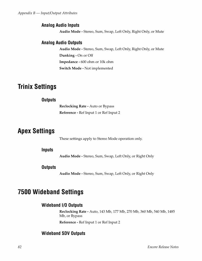
Appendix B — Input/Output Attributes
Analog Audio InputsAudio Mode - Stereo, Sum, Swap, Left Only, Right Only, or Mute
Analog Audio OutputsAudio Mode - Stereo, Sum, Swap, Left Only, Right Only, or Mute
Dunking - On or Off
Impedance - 600 ohm or 10k ohm
Switch Mode - Not implemented
Trinix Settings
OutputsReclocking Rate - Auto or Bypass
Reference - Ref Input 1 or Ref Input 2
Apex SettingsThese settings apply to Stereo Mode operation only.
InputsAudio Mode - Stereo, Sum, Swap, Left Only, or Right Only
OutputsAudio Mode - Stereo, Sum, Swap, Left Only, or Right Only
7500 Wideband Settings
Wideband I/O OutputsReclocking Rate - Auto, 143 Mb, 177 Mb, 270 Mb, 360 Mb, 540 Mb, 1485 Mb, or Bypass
Reference - Ref Input 1 or Ref Input 2
Wideband SDV Outputs
82 Encore Release Notes
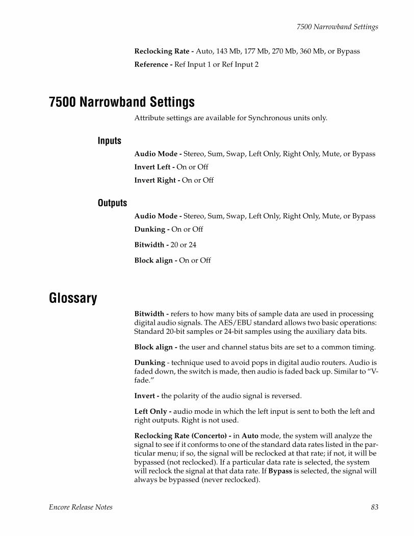
7500 Narrowband Settings
Reclocking Rate - Auto, 143 Mb, 177 Mb, 270 Mb, 360 Mb, or Bypass
Reference - Ref Input 1 or Ref Input 2
7500 Narrowband SettingsAttribute settings are available for Synchronous units only.
InputsAudio Mode - Stereo, Sum, Swap, Left Only, Right Only, Mute, or Bypass
Invert Left - On or Off
Invert Right - On or Off
OutputsAudio Mode - Stereo, Sum, Swap, Left Only, Right Only, Mute, or Bypass
Dunking - On or Off
Bitwidth - 20 or 24
Block align - On or Off
GlossaryBitwidth - refers to how many bits of sample data are used in processing digital audio signals. The AES/EBU standard allows two basic operations: Standard 20-bit samples or 24-bit samples using the auxiliary data bits.
Block align - the user and channel status bits are set to a common timing.
Dunking - technique used to avoid pops in digital audio routers. Audio is faded down, the switch is made, then audio is faded back up. Similar to “V-fade.”
Invert - the polarity of the audio signal is reversed.
Left Only - audio mode in which the left input is sent to both the left and right outputs. Right is not used.
Reclocking Rate (Concerto) - in Auto mode, the system will analyze the signal to see if it conforms to one of the standard data rates listed in the par-ticular menu; if so, the signal will be reclocked at that rate; if not, it will be bypassed (not reclocked). If a particular data rate is selected, the system will reclock the signal at that data rate. If Bypass is selected, the signal will always be bypassed (never reclocked).
Encore Release Notes 83

Appendix B — Input/Output Attributes
Reclocking Rate (Trinix) - in Auto mode, the system will analyze the signal to see if it conforms to one of the standard* data rates; if so, the signal will be reclocked at that rate; if not, it will be bypassed (not reclocked). If Bypass is selected, the signal will always be bypassed (never reclocked). *Available data rates depend on the output board type installed; refer to the Trinix manual for details.
Reference - refers to the sync signal used to time switch point properly, i.e., to provide a smooth transition from one source to another.
Right Only - audio mode in which the right input is sent to both the left and right outputs. Left is not used.
Sum - audio mode in which left and right are added and the result placed on both the left and the right outputs.
Swap - audio mode in which left and right channels are exchanged.
84 Encore Release Notes
Appendix CMonitoring with Third-party SNMP Managers
Apart from Thomson Grass Valley’s NetCentral SNMP Management plat-form, any other industry-standard SNMP Manager can monitor Encore devices (Encore SCB).
For general installation and configuration instructions, please contact your SNMP Manager Software vendor. When used with Encore, the SNMP agents should be configured to send alarms to the corresponding SNMP Manager. The Encore installation CD comes with the following MIBs:
a. GVG-ELEMENT-MIB
b. GVG-REG-MIB
c. ENCORE-SCB-MIB
Add all the above MIB files to the MIB repository of the SNMP Manager you use.
Registering other SNMP Managers in the agent database
In the GVG-ELEMENT-MIB, a trap target table is defined to store the IP Addresses and community names of the SNMP Managers intended to receive Traps from Encore devices. To add SNMP Manager to SCB SNMP agent, please follow these steps:
Adding new SNMP Managers• Send a GET request for gvgTtCfgTableNextIndex variable defined in
GVG-ELEMENT-MIB e.g.: if it returns 2.
• Create a new Row in the Trap target table by sending a SET request for the gvgTtCfgEntryStatus(1.3.6.1.4.1.4947.2.1.3.3.1.4).index, where index is the value returned in the step 1 above.
E.g.: in this case generate a SET request for 1.3.6.1.4.1.4947.2.1.3.3.1.4.2 wherein 2 is the next available index, syntax is INTEGER32 and set the value as 5 (create and wait), if the SET request is successful proceed to next step.
Encore Release Notes 85
Appendix C — Monitoring with Third-party SNMP Managers
• SET request could be unsuccessful:
• If the row for the above index already exists.
• If the number of registered Managers count in SNMP Agent data-base has reached the maximum allowed number. A maximum of 5 managers can be registered at any point of time. All the subsequent attempts to register additional managers will fail unless existing managers are deleted from it’s database.
• Send a SET request for gvgTtCfgIpAddress (1.3.6.1.4.1.4947.2.1.3.3.1.2).index, where index is the value returned in the step 1 above.
E.g.: in this case generate a SET request for 1.3.6.1.4.1.4947.2.1.3.3.1.2.2 wherein 2 is the next available index, syntax is IPADDRES and enter the IP Address of the SNMP Manager to be registered, if the SET request is successful proceed to next step.
• SET request could be unsuccessful:
• If the above IP Address is already present in the Trap target table.
• Send a SET request for gvgTtCfgCommunity (1.3.6.1.4.1.4947.2.1.3.3.1.3).index, where index is the value returned in Step 1 above.
E.g.: in this case generate a SET request for 1.3.6.1.4.1.4947.2.1.3.3.1.3.2 wherein 2 is the next available index, syntax is OCTET STRING and enter the community string that would be used for the communication between SCB and SNMP Managers. If the SET request is successful proceed to the next step; you are all set to receive the Traps.
Deleting SNMP Managers
You may wish to delete the SNMP Managers:
1. If the Machine running the SNMP manager’s IP Address is changed.
2. If you no longer wish to monitor the SCB from some of the SNMP managers.
3. If you wish to add more SNMP managers but the SNMP agent does not allow you to add additional SNMP Manager’s as the Maximum managers are already registered. You may want to delete some of the SNMP managers which you no longer use.
86 Encore Release Notes
If you find yourself in any of the above situations please follow the steps given below:
• Walk through the gvgTtCfgIpAddress and note the index of the row you would like to delete.
• Delete the above selected Row from the Trap target table by sending a SET request for the gvgTtCfgEntryStatus (1.3.6.1.4.1.4947.2.1.3.3.1.4).index, where index is the value returned in Step 1 above, syntax is INTEGER32 and set the value as 6(destroy). If the SET request is successful then you may add new SNMP Managers as described above.
SET request could be unsuccessful:
If the above row is already deleted from the Trap target table.
Encore Release Notes 87

Appendix C — Monitoring with Third-party SNMP Managers
88 Encore Release Notes