Embed Size (px)
Citation preview
Procedia Engineering 100 ( 2015 ) 1582 – 1590
1877-7058 © 2015 The Authors. Published by Elsevier Ltd. This is an open access article under the CC BY-NC-ND license (http://creativecommons.org/licenses/by-nc-nd/4.0/).Peer-review under responsibility of DAAAM International Viennadoi: 10.1016/j.proeng.2015.01.531
ScienceDirectAvailable online at www.sciencedirect.com
25th DAAAM International Symposium on Intelligent Manufacturing and Automation, DAAAM 2014
Evaluation of the Surface Small Holes Drilled by Unconventional Methods
Libor Suchánek*, Ivana Zetková University of West Bohemia, Univerzitni 8, 306 14 Plzen, Czech republic
Abstract
The purpose of this research is to study holes surface quality drilled by unconventional methods. Tested technologies were Laser, Water Jet and EDM. As a reference bores were used two holes drilled by regular HSS drill. The surface quality is rated by microscopic images taken from two sides – Entering and Outputting side. Further evaluation consists of the hole inside surface quality taken from the scanned texture, deviations from the ideal cylindrical shape and measured areal roughness Sa, Sq, Sz. © 2015 The Authors. Published by Elsevier Ltd. Peer-review under responsibility of DAAAM International Vienna.
Keywords: drilling; unconventional methods; small hole; surface quality
1. Introduction
When drilling holes using unconventional methods classic metal chips aren´t produced like when drilling with a drill. The removal of material is not used force action on the workpiece. The material is not removed by force action on the workpiece. Instead, it is removed by the effects of thermal, chemical, abrasive or their combination[1, 2]. The unconventional machining methods include: EDM, electrochemical and chemical machining, laser machining, water jet machining, ultrasonic machining, plasma machining, electron beam machining[3]. The importance of unconventional machining methods significantly increases. This is due to the use of difficult-to-machine materials. These materials are used in the engineering industry very often. Other reasons are: machining of difficult shapes, production of small components and the ability to fully automate machining [2].
* Corresponding author. Libor Suchánek , Tel.: +420 602 339 739; fax: +420 377 638 8501.
E-mail address: [email protected]
© 2015 The Authors. Published by Elsevier Ltd. This is an open access article under the CC BY-NC-ND license (http://creativecommons.org/licenses/by-nc-nd/4.0/).Peer-review under responsibility of DAAAM International Vienna
1583 Libor Suchánek and Ivana Zetková / Procedia Engineering 100 ( 2015 ) 1582 – 1590
Nomenclature
EDM electric discharge machining HAZ heat affected zone HSS height speed steel Laser light amplification by stimulated emission of radiation LMJ laser micro-jet Sa average height of selected area Sz maximum height of selected area Sq root-mean-square height of selected area Ra average roughness of profile Rz mean peak to valley height of roughness profile Rq root-mean-square roughness of profile v cutting feed t time
Another reason for the expansion of unconventional methods is the ability to drill very small holes. Conventional
methods were possible produce a hole with a minimum size as a human hair – 0.074mm. However, advances in the fields of medical devices, communications, optics, electronics, computers and others have created a need for holes that are straighter, more accurate, better defined - and in many cases much smaller in diameter than a human hair. Such small holes can be implemented unconventional methods (Laser Microdrilling, EDM Microdrilling and other)[4].
The proof that very small holes are drilled presents the experiment of Mr. Romoli and other scientists. It was drilled by EDM and LMJ(the combined technology of water jet and laser). The holes were drilled into a material AISI 440C(pre-hardened and tempered) material. This stainless steel is commonly used in automotive industries for the fabrication of fuel injectors since it combines high hardness and good resistance to chemical corrosion. The holes with a nominal diameter of 180μm are performed on 300μm thick samples. Values of the areal roughness Sq were about 0.5μm by EDM and about 0.15μm by LMJ[5]. These values are interesting for comparing.
2. Experiment
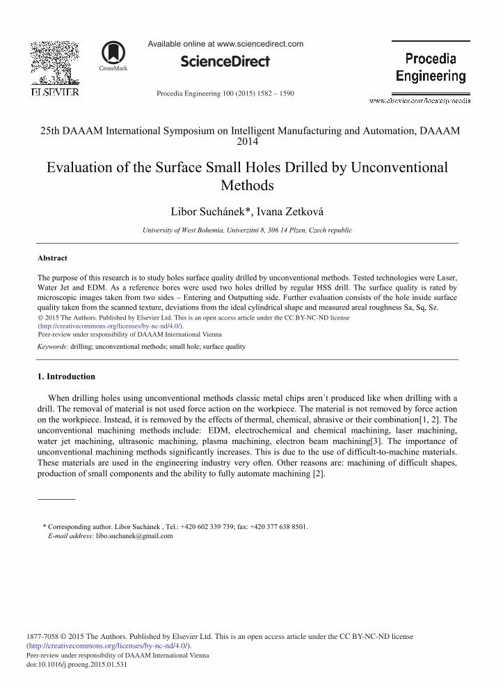
The workpiece material was etalon steel 12050. Consequently the test results will be compared with the new experimental study using hardened tool steels or martensitic steels as a workpiece material. Bore diameter was 3mm and workpiece thickness was 6.2mm. There were always two holes drilled by each method to decrease measurement errors. Cutting conditions were set-up by companies conducting the drilling tests with the purpose to get the holes of the best quality.
Fig. 1. The workpiece.
2.1. Water Jet
Aquacut machine was used. Water Jet pressure was 3800bar. Abrasive was “garnet MASH80” with dose 350g/min. Diameter of the jet was 0.8mm. The first test failed due to the wrong water jet feed set-up to maximum.
1584 Libor Suchánek and Ivana Zetková / Procedia Engineering 100 ( 2015 ) 1582 – 1590
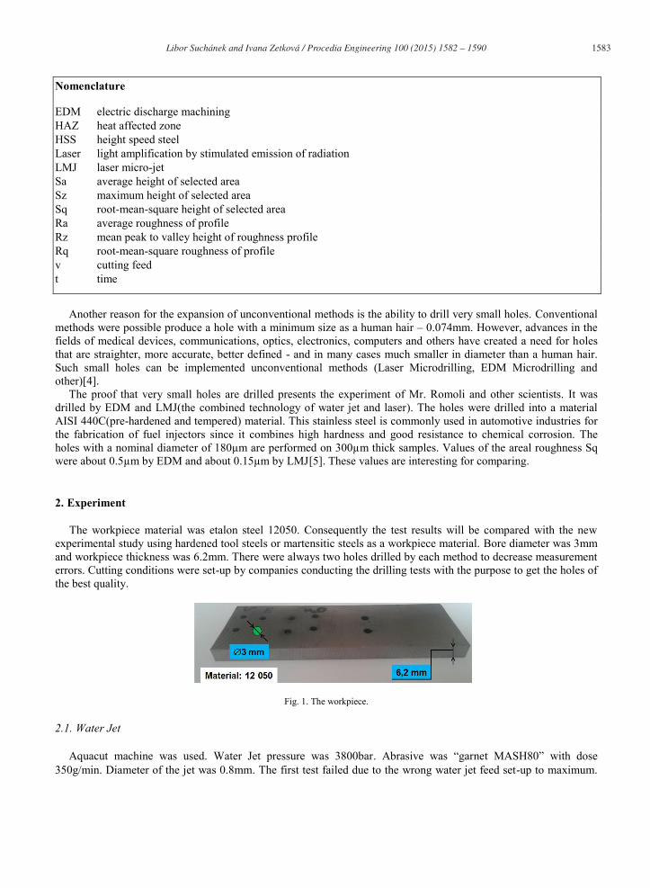
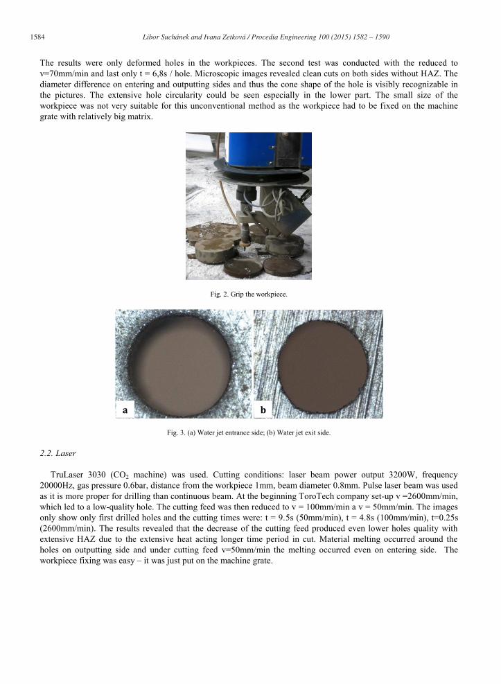
The results were only deformed holes in the workpieces. The second test was conducted with the reduced to v=70mm/min and last only t = 6,8s / hole. Microscopic images revealed clean cuts on both sides without HAZ. The diameter difference on entering and outputting sides and thus the cone shape of the hole is visibly recognizable in the pictures. The extensive hole circularity could be seen especially in the lower part. The small size of the workpiece was not very suitable for this unconventional method as the workpiece had to be fixed on the machine grate with relatively big matrix.
Fig. 2. Grip the workpiece.
Fig. 3. (a) Water jet entrance side; (b) Water jet exit side.
2.2. Laser
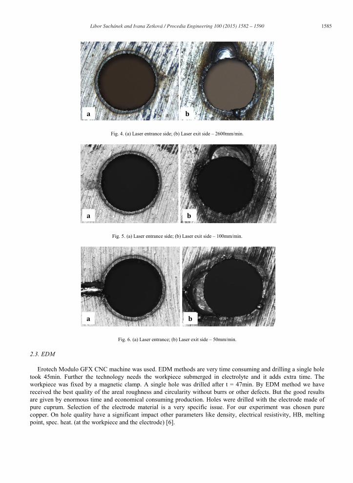
TruLaser 3030 (CO2 machine) was used. Cutting conditions: laser beam power output 3200W, frequency 20000Hz, gas pressure 0.6bar, distance from the workpiece 1mm, beam diameter 0.8mm. Pulse laser beam was used as it is more proper for drilling than continuous beam. At the beginning ToroTech company set-up v =2600mm/min, which led to a low-quality hole. The cutting feed was then reduced to v = 100mm/min a v = 50mm/min. The images only show only first drilled holes and the cutting times were: t = 9.5s (50mm/min), t = 4.8s (100mm/min), t=0.25s (2600mm/min). The results revealed that the decrease of the cutting feed produced even lower holes quality with extensive HAZ due to the extensive heat acting longer time period in cut. Material melting occurred around the holes on outputting side and under cutting feed v=50mm/min the melting occurred even on entering side. The workpiece fixing was easy – it was just put on the machine grate.
b a
1585 Libor Suchánek and Ivana Zetková / Procedia Engineering 100 ( 2015 ) 1582 – 1590
Fig. 4. (a) Laser entrance side; (b) Laser exit side – 2600mm/min.
Fig. 5. (a) Laser entrance side; (b) Laser exit side – 100mm/min.
Fig. 6. (a) Laser entrance; (b) Laser exit side – 50mm/min.
2.3. EDM
Erotech Modulo GFX CNC machine was used. EDM methods are very time consuming and drilling a single hole took 45min. Further the technology needs the workpiece submerged in electrolyte and it adds extra time. The workpiece was fixed by a magnetic clamp. A single hole was drilled after t = 47min. By EDM method we have received the best quality of the areal roughness and circularity without burrs or other defects. But the good results are given by enormous time and economical consuming production. Holes were drilled with the electrode made of pure cuprum. Selection of the electrode material is a very specific issue. For our experiment was chosen pure copper. On hole quality have a significant impact other parameters like density, electrical resistivity, HB, melting point, spec. heat. (at the workpiece and the electrode) [6].
a b
a b
a b
1586 Libor Suchánek and Ivana Zetková / Procedia Engineering 100 ( 2015 ) 1582 – 1590
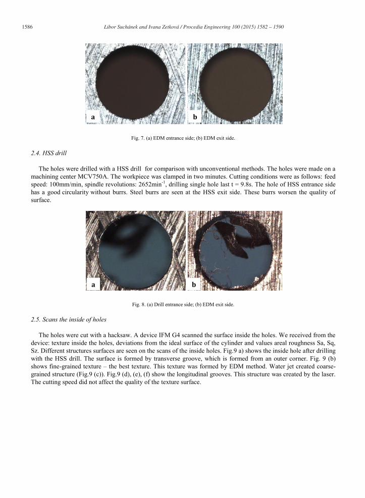
Fig. 7. (a) EDM entrance side; (b) EDM exit side.
2.4. HSS drill
The holes were drilled with a HSS drill for comparison with unconventional methods. The holes were made on a machining center MCV750A. The workpiece was clamped in two minutes. Cutting conditions were as follows: feed speed: 100mm/min, spindle revolutions: 2652min-1, drilling single hole last t = 9.8s. The hole of HSS entrance side has a good circularity without burrs. Steel burrs are seen at the HSS exit side. These burrs worsen the quality of surface.
Fig. 8. (a) Drill entrance side; (b) EDM exit side.
2.5. Scans the inside of holes
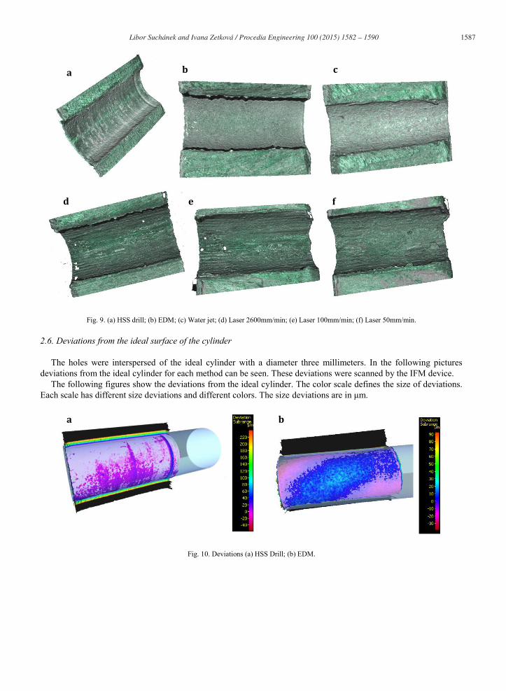
The holes were cut with a hacksaw. A device IFM G4 scanned the surface inside the holes. We received from the device: texture inside the holes, deviations from the ideal surface of the cylinder and values areal roughness Sa, Sq, Sz. Different structures surfaces are seen on the scans of the inside holes. Fig.9 a) shows the inside hole after drilling with the HSS drill. The surface is formed by transverse groove, which is formed from an outer corner. Fig. 9 (b) shows fine-grained texture – the best texture. This texture was formed by EDM method. Water jet created coarse-grained structure (Fig.9 (c)). Fig.9 (d), (e), (f) show the longitudinal grooves. This structure was created by the laser. The cutting speed did not affect the quality of the texture surface.
b a
a b
1587 Libor Suchánek and Ivana Zetková / Procedia Engineering 100 ( 2015 ) 1582 – 1590
Fig. 9. (a) HSS drill; (b) EDM; (c) Water jet; (d) Laser 2600mm/min; (e) Laser 100mm/min; (f) Laser 50mm/min.
2.6. Deviations from the ideal surface of the cylinder
The holes were interspersed of the ideal cylinder with a diameter three millimeters. In the following pictures deviations from the ideal cylinder for each method can be seen. These deviations were scanned by the IFM device.
The following figures show the deviations from the ideal cylinder. The color scale defines the size of deviations. Each scale has different size deviations and different colors. The size deviations are in μm.
Fig. 10. Deviations (a) HSS Drill; (b) EDM.
a b c
d e f
a b
1588 Libor Suchánek and Ivana Zetková / Procedia Engineering 100 ( 2015 ) 1582 – 1590
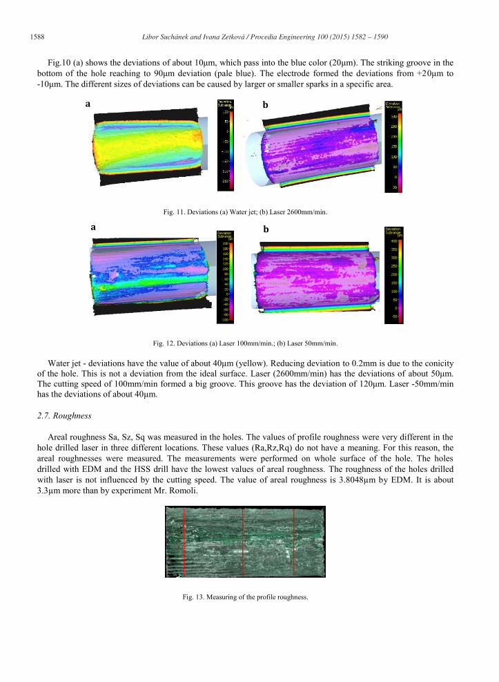
Fig.10 (a) shows the deviations of about 10μm, which pass into the blue color (20μm). The striking groove in the bottom of the hole reaching to 90μm deviation (pale blue). The electrode formed the deviations from +20μm to -10μm. The different sizes of deviations can be caused by larger or smaller sparks in a specific area.
Fig. 11. Deviations (a) Water jet; (b) Laser 2600mm/min.
Fig. 12. Deviations (a) Laser 100mm/min.; (b) Laser 50mm/min.
Water jet - deviations have the value of about 40μm (yellow). Reducing deviation to 0.2mm is due to the conicity of the hole. This is not a deviation from the ideal surface. Laser (2600mm/min) has the deviations of about 50μm. The cutting speed of 100mm/min formed a big groove. This groove has the deviation of 120μm. Laser -50mm/min has the deviations of about 40μm.
2.7. Roughness
Areal roughness Sa, Sz, Sq was measured in the holes. The values of profile roughness were very different in the hole drilled laser in three different locations. These values (Ra,Rz,Rq) do not have a meaning. For this reason, the areal roughnesses were measured. The measurements were performed on whole surface of the hole. The holes drilled with EDM and the HSS drill have the lowest values of areal roughness. The roughness of the holes drilled with laser is not influenced by the cutting speed. The value of areal roughness is 3.8048μm by EDM. It is about 3.3μm more than by experiment Mr. Romoli.
Fig. 13. Measuring of the profile roughness.
a
a b
b
1589 Libor Suchánek and Ivana Zetková / Procedia Engineering 100 ( 2015 ) 1582 – 1590
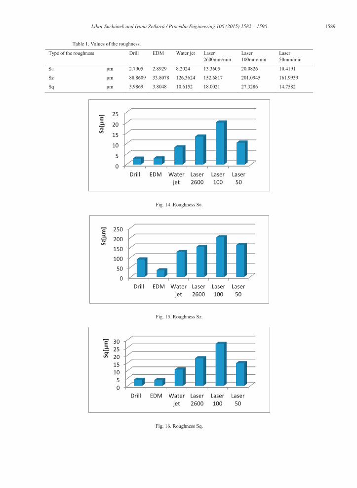
Table 1. Values of the roughness.
Type of the roughness Drill EDM Water jet Laser 2600mm/min
Laser 100mm/min
Laser 50mm/min
Sa μm 2.7905 2.8929 8.2024 13.3605 20.0826 10.4191
Sz μm 88.8609 33.8078 126.3624 152.6817 201.0945 161.9939
Sq μm 3.9869 3.8048 10.6152 18.0021 27.3286 14.7582
Fig. 14. Roughness Sa.
Fig. 15. Roughness Sz.
Fig. 16. Roughness Sq.
0 5
10 15 20 25
Drill EDM Water jet
Laser 2600
Laser 100
Laser 50
Sa[μ
m]
0 50
100 150 200 250
Drill EDM Water jet
Laser 2600
Laser 100
Laser 50
Sz[μ
m]
0 5
10 15 20 25 30
Drill EDM Water jet
Laser 2600
Laser 100
Laser 50
Sq[μ
m]
1590 Libor Suchánek and Ivana Zetková / Procedia Engineering 100 ( 2015 ) 1582 – 1590
3. Conclusions
The problem was how to efficiently drill small holes with high surface quality. For the experiment were used three unconventional methods (EDM, Laser, Water jet) and one conventional method (HSS drill). The holes (diametr 3mm) were drilled to a standard material 12050. The surface quality was assessed using: the images from a microscope, values of the areal roughness, the deviations from the ideal surface of the cylinder, the scans the inside of holes.
The best surface roughness both inside the hole and outside on the workpiece were received using EDM method. Overall surface quality is clearly best with EDM, but on the other hand also the most expensive and time consuming method. EDM is suitable for drilling precise holes in small doses. Water Jet method also produced good surface roughness both inside the hole and outside on the workpiece with considerably shorter production time than EDM. The disadvantage was enormous cone shape of the hole even visually noticeable. Water Jet method would be suitable for drilling holes of thinner thicknesses. Laser drilling produced pure surface quality with HAZ and bad surface roughness. Cutting feed decrease had a negative effect on surface roughness. Drilling with HSS drill led to good surface quality on the entering side and inside the hole, but the outputting side had burses deteriorating surface quality.
Overall, it can be said that conventional drilling(HSS drill) is the best for the drilling of this material. The holes have good surface quality. The burrs can be removed with a file. Another factor for the use of HSS drill is drilling speed. It is effective for drilling many holes. EDM can be used for the holes which require higher surface quality.
A next plan is to drill holes into a difficult-cutting-steel (tool steel or martensitic steel). These methods again used and evaluated which method is best suitable for drilling holes into the hard materials.
Acknowledgements
This paper is based upon work sponsored by project SGS-2013-031.
References
[1] Řasa, J., Karečaninová, Z. Unconventional machining methods, Nekonvenční metody obrábění (in Czech language), Available from: http://www.mmspektrum.com/clanek/nekonvencni-metody-obrabeni.html.
[2] Unconventional machining methods, Nekonvenční metody obrábění (in Czech language), Available from: http://coptel.coptkm.cz/reposit.php?action=0&id=33789&instance=2.
[3] Physical (unconventional) machining technology, Fyzikální (nekonvenční) technologie obrábění (in Czech language), Available from: http://www.strojnilyceum.wz.cz/maturita/tep/tep5.pdf.
[4] Rakowski, L. Non-Traditional Methods For Making SMALL HOLES, Available from: http://www.coherent.com/Downloads/NonTraditionalMethodsforMakingSmallHolesRev2.pdf.
[5] C.A.A. Rashed, L. Romoli, F. Tantussi, F. Fuso, M. Burgener, G. Cusanelli, M. Allegrini, G. Dini, Water jet guided laser as an alternative to EDM for micro-drilling of fuel injector nozzles: A comparison of machined surfaces, Journal of Manufacturing Processes 15, 2013, Pages 524-534.
[6] G. D’Urso, C. Merla, Workpiece and electrode influence on micro-EDM drilling performance, Precision Engineering 38, 2014, Pages 903-914.


![Tot ce aveţi nevoie.prokcssmedia.blob.core.windows.net/sys-master-images/hb2/... · 2015. 9. 16. · TruLaser 3030 Lean Edition[1] TruLaser 3030 [2] Zona de lucru 3,000 x 1,500 mm](https://img.pdfslide.net/doc/110x75/6147e87ca830d0442101bd6d/tot-ce-avei-2015-9-16-trulaser-3030-lean-edition1-trulaser-3030-2-zona.jpg)