Embed Size (px)
Citation preview
NORDSON ENGINEERING GMBH � LÜNEBURG � GERMANY
Extruder EEXEconomic Series
Manual P/N 7169667_03- English -
Edition 05/14
P/N 7169667_03 � 2014 Nordson CorporationEEX
Note
This document applies to the entire series.
Order numberP/N = Order number for Nordson articles
NoteThis is a Nordson corporation publication which is protected by copyright. Copyright � 2012.
No part of this document may be photocopied, reproduced or translated to another languagewithout the prior written consent of Nordson Corporation.
The information contained in this publication is subject to change without notice.
� 2014 All rights reserved.- Translation of Original -
TrademarksAccuJet, AeroCharge, Apogee, AquaGuard, Asymtek, Automove, Autotech, Baitgun, Blue Box, Bowtie, Build-A-Part, CanWorks, Century, CF, CleanSleeve,CleanSpray, Color-on-Demand, ColorMax, Control Coat, Coolwave, Cross-Cut, cScan+, Dage, Dispensejet, DispenseMate, DuraBlue, DuraDrum, Durafiber,DuraPail, Dura-Screen, Durasystem, Easy Coat, Easymove Plus, Ecodry, Econo-Coat, e.DOT, EFD, Emerald, Encore, ESP, e stylized, ETI-stylized, Excel 2000,Fibrijet, Fillmaster, FlexiCoat, Flexi-Spray, Flex-O-Coat, Flow Sentry, Fluidmove, FoamMelt, FoamMix, Fulfill, GreenUV, HDLV, Heli-flow, Helix, Horizon, HotShot, iControl, iDry, iFlow, Isocoil, Isocore, Iso-Flo, iTRAX, JR, KB30, Kinetix, KISS, Lean Cell, Little Squirt, LogiComm, Magnastatic, March, Maverick, MEG,Meltex, Microcoat, Micromark, Micromedics, Micro-Meter, MicroSet, Microshot, Millenium, Mini Blue, Mini Squirt, Moist-Cure, Mountaingate, MultiScan, NexJet,No-Drip, Nordson, Optimum, Package of Values, Paragon, PatternView, PermaFlo, PICO, PicoDot, PluraFoam, Porous Coat, PowderGrid, Powderware,Precisecoat, PRIMARC, Printplus, Prism, ProBlue, Prodigy, Pro-Flo, Program-A-Bead, Program-A-Shot, Program-A-Stream, Program-A-Swirl, ProLink,Pro-Meter, Pro-Stream, RBX, Rhino, Saturn, Saturn with rings, Scoreguard, SC5, S. design stylized, Seal Sentry, Sealant Equipment & Engineering, Inc., SEEand design, See-Flow, Select Charge, Select Coat, Select Cure, Servo-Flo, Shot-A-Matic, Signature, Slautterback, Smart-Coat, Smart-Gun, Solder Plus,Spectrum, Speed-Coat, Spraymelt, Spray Squirt, Super Squirt, SureBead, Sure Clean, Sure Coat, Sure-Max, Sure Wrap, Tela-Therm, Tip-Seal, Tracking Plus,TRAK, Trends, Tribomatic, TrueBlue, TrueCoat, Tubesetter, Ultra, UniScan, UpTime, u-TAH, Value Plastics, Vantage, Veritec, VersaBlue, Versa-Coat,VersaDrum, VersaPail, Versa-Screen, Versa-Spray, VP Quick Fit, Walcom, Watermark, When you expect more., X-Plane are registered trademarks - - ofNordson Corporation.
Accubar, Active Nozzle, Advanced Plasma Systems, AeroDeck, AeroWash, Allegro, AltaBlue, AltaSlot, Alta Spray, AquaCure, Artiste, ATS, Auto-Flo, AutoScan,Axiom, Best Choice, BetterBook, Blue Series, Bravura, CanNeck, CanPro, Celero, Chameleon, Champion, Check Mate, ClassicBlue, Classic IX, Clean Coat,Cobalt, ContourCoat, Controlled Fiberization, Control Weave, CPX, cSelect, Cyclo-Kinetic, DispensLink, DropCure, Dry Cure, DuraBraid, DuraCoat, e.dot+,E-Nordson, Easy Clean, EasyOn, EasyPW, Eclipse, Equalizer, Equi=Bead, Exchange Plus, FillEasy, Fill Sentry, Flow Coat, Fluxplus, Freedom, G-Net, G-Site,Genius, Get Green With Blue, Gluie, Ink-Dot, IntelliJet, iON, Iso-Flex, iTrend, KVLP, Lacquer Cure, Maxima, Mesa, MicroFin, MicroMax, Mikros, MiniEdge,Minimeter, MonoCure, Multifil, MultiScan, Myritex, Nano, OmniScan, OptiMix, OptiStroke, Optix, Origin, Partnership+Plus, PatternJet, PatternPro, PCI,PharmaLok, Pinnacle, Plasmod, PluraMix, Powder Pilot, Powder Port, Powercure, Process Sentry, Pulse Spray, PURBlue, PURJet, PurTech, Quad Cure,Quantum, Ready Coat, RediCoat, RollVIA, Royal Blue, Select Series, Sensomatic, Shaftshield, SheetAire, Smart, Smartfil, SolidBlue, Spectral, Spectronic,SpeedKing, Spray Works, StediFlo, StediTherm, Summit, Sure Brand, SureFoam, SureMix, SureSeal, Swirl Coat, TAH, Tempus, ThruWave, TinyCure, TradePlus, Trilogy, Ultra FoamMix, UltraMax, Ultrasaver, Ultrasmart, Universal, ValueMate, Versa, Viper, Vista, WebCure, YESTECH, 2 Rings (Design) are trademarks-� - of the Nordson Corporation.
Designations and trademarks stated in this document may be brands that, when used by third parties for their ownpurposes, could lead to violation of the owners' right.
Table of Contents I
P/N 7169667_03� 2014 Nordson Corporation EEX
Table of Contents
Nordson International O-1. . . . . . . . . . . . . . . . . . . . . . . . . . . . . . . . . .Europe O-1. . . . . . . . . . . . . . . . . . . . . . . . . . . . . . . . . . . . . . . . . . . . . . . . .
Distributors in Eastern & Southern Europe O-1. . . . . . . . . . . . . . . . .Outside Europe O-2. . . . . . . . . . . . . . . . . . . . . . . . . . . . . . . . . . . . . . . . . .
Africa / Middle East O-2. . . . . . . . . . . . . . . . . . . . . . . . . . . . . . . . . . . .Asia / Australia / Latin America O-2. . . . . . . . . . . . . . . . . . . . . . . . . .China O-2. . . . . . . . . . . . . . . . . . . . . . . . . . . . . . . . . . . . . . . . . . . . . . . .Japan O-2. . . . . . . . . . . . . . . . . . . . . . . . . . . . . . . . . . . . . . . . . . . . . . . .North America O-2. . . . . . . . . . . . . . . . . . . . . . . . . . . . . . . . . . . . . . . .
Safety 1-1. . . . . . . . . . . . . . . . . . . . . . . . . . . . . . . . . . . . . . . . . . . . . . . . .Safety Alert Symbols 1-1. . . . . . . . . . . . . . . . . . . . . . . . . . . . . . . . . . . . .Responsibilities of the Equipment Owner 1-2. . . . . . . . . . . . . . . . . . . .
Safety Information 1-2. . . . . . . . . . . . . . . . . . . . . . . . . . . . . . . . . . . . .Instructions, Requirements, and Standards 1-2. . . . . . . . . . . . . . . .User Qualifications 1-3. . . . . . . . . . . . . . . . . . . . . . . . . . . . . . . . . . . . .
Applicable Industry Safety Practices 1-3. . . . . . . . . . . . . . . . . . . . . . . .Intended Use of the Equipment 1-3. . . . . . . . . . . . . . . . . . . . . . . . . .Instructions and Safety Messages 1-4. . . . . . . . . . . . . . . . . . . . . . .Installation Practices 1-4. . . . . . . . . . . . . . . . . . . . . . . . . . . . . . . . . . .Operating Practices 1-4. . . . . . . . . . . . . . . . . . . . . . . . . . . . . . . . . . . .Maintenance and Repair Practices 1-5. . . . . . . . . . . . . . . . . . . . . . .
Equipment Safety Information 1-5. . . . . . . . . . . . . . . . . . . . . . . . . . . . .Equipment Shutdown 1-6. . . . . . . . . . . . . . . . . . . . . . . . . . . . . . . . . .
Relieving System Hydraulic Pressure 1-6. . . . . . . . . . . . . . . . . .De-energizing the System 1-6. . . . . . . . . . . . . . . . . . . . . . . . . . . .Disabling the Applicators 1-6. . . . . . . . . . . . . . . . . . . . . . . . . . . . .
General Safety Warnings and Cautions 1-7. . . . . . . . . . . . . . . . . . .Other Safety Precautions 1-10. . . . . . . . . . . . . . . . . . . . . . . . . . . . . . .First Aid 1-10. . . . . . . . . . . . . . . . . . . . . . . . . . . . . . . . . . . . . . . . . . . . . .
Safety Labels and Tags 1-11. . . . . . . . . . . . . . . . . . . . . . . . . . . . . . . . . . .
Table of ContentsII
P/N 7169667_03 � 2014 Nordson CorporationEEX
Introduction 2-1. . . . . . . . . . . . . . . . . . . . . . . . . . . . . . . . . . . . . . . . . . . .Intended Use 2-1. . . . . . . . . . . . . . . . . . . . . . . . . . . . . . . . . . . . . . . . . . . .
Area of Use (EMC) 2-1. . . . . . . . . . . . . . . . . . . . . . . . . . . . . . . . . . . . .Operating Restrictions 2-1. . . . . . . . . . . . . . . . . . . . . . . . . . . . . . .
Unintended Use - Examples - 2-1. . . . . . . . . . . . . . . . . . . . . . . . . . .Restricted Use 2-2. . . . . . . . . . . . . . . . . . . . . . . . . . . . . . . . . . . . . . . .
Residual Risks 2-2. . . . . . . . . . . . . . . . . . . . . . . . . . . . . . . . . . . . . . . . . .Note on Manual 2-2. . . . . . . . . . . . . . . . . . . . . . . . . . . . . . . . . . . . . . . . . .
EMERGENCY OFF / EMERGENCY STOP 2-3. . . . . . . . . . . . . . . .ID Plate 2-3. . . . . . . . . . . . . . . . . . . . . . . . . . . . . . . . . . . . . . . . . . . . . . . . .Configuration Code 2-4. . . . . . . . . . . . . . . . . . . . . . . . . . . . . . . . . . . . . . .Function 2-5. . . . . . . . . . . . . . . . . . . . . . . . . . . . . . . . . . . . . . . . . . . . . . . .Description of Components 2-6. . . . . . . . . . . . . . . . . . . . . . . . . . . . . . . .
Illustration of EEX200 2-6. . . . . . . . . . . . . . . . . . . . . . . . . . . . . . . . . .Illustration of EEX10 2-8. . . . . . . . . . . . . . . . . . . . . . . . . . . . . . . . . . .Protective Devices 2-10. . . . . . . . . . . . . . . . . . . . . . . . . . . . . . . . . . . . .
Protective Covers 2-10. . . . . . . . . . . . . . . . . . . . . . . . . . . . . . . . . . .Covers 2-10. . . . . . . . . . . . . . . . . . . . . . . . . . . . . . . . . . . . . . . . . . . . .Safety Guard 2-10. . . . . . . . . . . . . . . . . . . . . . . . . . . . . . . . . . . . . . .Overtemperature Protection 2-10. . . . . . . . . . . . . . . . . . . . . . . . . .Pneumatic Assembly and Pneumatic Bypass 2-10. . . . . . . . . . . .Pressure Control / Pressure Monitoring 2-11. . . . . . . . . . . . . . . . .
Drive 2-11. . . . . . . . . . . . . . . . . . . . . . . . . . . . . . . . . . . . . . . . . . . . . . . . .Hopper 2-11. . . . . . . . . . . . . . . . . . . . . . . . . . . . . . . . . . . . . . . . . . . . . . .Filling Area 2-12. . . . . . . . . . . . . . . . . . . . . . . . . . . . . . . . . . . . . . . . . . .Worm Conveyor 2-12. . . . . . . . . . . . . . . . . . . . . . . . . . . . . . . . . . . . . . .Worm Cylinder 2-12. . . . . . . . . . . . . . . . . . . . . . . . . . . . . . . . . . . . . . . .
Heating Cuff 2-12. . . . . . . . . . . . . . . . . . . . . . . . . . . . . . . . . . . . . . . .Cylinder Feed Cooling 2-13. . . . . . . . . . . . . . . . . . . . . . . . . . . . . . . . . .Extruder Flange 2-13. . . . . . . . . . . . . . . . . . . . . . . . . . . . . . . . . . . . . . .Main Switch 2-14. . . . . . . . . . . . . . . . . . . . . . . . . . . . . . . . . . . . . . . . . .
Black Main Switch (Special Model) 2-14. . . . . . . . . . . . . . . . . . . .EMERGENCY OFF Button (Special Model) 2-14. . . . . . . . . . . . . . .Receptacle 2-14. . . . . . . . . . . . . . . . . . . . . . . . . . . . . . . . . . . . . . . . . . .Light Tower (Option) 2-14. . . . . . . . . . . . . . . . . . . . . . . . . . . . . . . . . . .Door Lock 2-15. . . . . . . . . . . . . . . . . . . . . . . . . . . . . . . . . . . . . . . . . . . .Control Panel for Temperature Controller FP 13(Standard Model) 2-15. . . . . . . . . . . . . . . . . . . . . . . . . . . . . . . . . . . . . .Reducing Temperature Inside Electrical Cabinet 2-15. . . . . . . . . . .
Electrical cabinet ventilation 2-15. . . . . . . . . . . . . . . . . . . . . . . . . .Cooling element 2-15. . . . . . . . . . . . . . . . . . . . . . . . . . . . . . . . . . . . .
Interfaces 2-15. . . . . . . . . . . . . . . . . . . . . . . . . . . . . . . . . . . . . . . . . . . .Metering Station (Option) 2-16. . . . . . . . . . . . . . . . . . . . . . . . . . . . . . . . .
Piston Pressure Switch 2-16. . . . . . . . . . . . . . . . . . . . . . . . . . . . . . . . .Overtemperature Fuse (Behind the Electrical Cabinet Cover) 2-16
Table of Contents III
P/N 7169667_03� 2014 Nordson Corporation EEX
Installation 3-1. . . . . . . . . . . . . . . . . . . . . . . . . . . . . . . . . . . . . . . . . . . . .Unpacking 3-1. . . . . . . . . . . . . . . . . . . . . . . . . . . . . . . . . . . . . . . . . . . . . .Storage 3-1. . . . . . . . . . . . . . . . . . . . . . . . . . . . . . . . . . . . . . . . . . . . . . . . .Removal 3-1. . . . . . . . . . . . . . . . . . . . . . . . . . . . . . . . . . . . . . . . . . . . . . . .Disposal 3-1. . . . . . . . . . . . . . . . . . . . . . . . . . . . . . . . . . . . . . . . . . . . . . . .Transport 3-2. . . . . . . . . . . . . . . . . . . . . . . . . . . . . . . . . . . . . . . . . . . . . . .
Lifting (Unpacked Unit) 3-2. . . . . . . . . . . . . . . . . . . . . . . . . . . . . . . . .Mounting 3-3. . . . . . . . . . . . . . . . . . . . . . . . . . . . . . . . . . . . . . . . . . . . . . .Installation Requirements 3-4. . . . . . . . . . . . . . . . . . . . . . . . . . . . . . . . .
Space Requirement 3-4. . . . . . . . . . . . . . . . . . . . . . . . . . . . . . . . . . . .Exhausting Adhesive Vapors 3-4. . . . . . . . . . . . . . . . . . . . . . . . . . . .
Installation Personnel's Experience 3-4. . . . . . . . . . . . . . . . . . . . . . . . .Electrical Connections 3-5. . . . . . . . . . . . . . . . . . . . . . . . . . . . . . . . . . . .
Use of Residual Current Circuit Breakers 3-5. . . . . . . . . . . . . . . . . .Laying Cable 3-5. . . . . . . . . . . . . . . . . . . . . . . . . . . . . . . . . . . . . . . . . .Line Voltage 3-6. . . . . . . . . . . . . . . . . . . . . . . . . . . . . . . . . . . . . . . . . .Protective Ground and Fuse Protection 3-6. . . . . . . . . . . . . . . . . . .External Control/Signal Circuits 3-6. . . . . . . . . . . . . . . . . . . . . . . . . .
Pneumatic Connection 3-6. . . . . . . . . . . . . . . . . . . . . . . . . . . . . . . . . . . .Pneumatic Bypass (Pressure Relief) 3-6. . . . . . . . . . . . . . . . . . . . .
Connecting Interfaces 3-7. . . . . . . . . . . . . . . . . . . . . . . . . . . . . . . . . . . .Standard I/O 3-7. . . . . . . . . . . . . . . . . . . . . . . . . . . . . . . . . . . . . . . . . .
External EMERGENCY OFF Chain 3-7. . . . . . . . . . . . . . . . . . . .Pilot Voltage Input 3-7. . . . . . . . . . . . . . . . . . . . . . . . . . . . . . . . . . . . .
Connecting Heated Hose 3-8. . . . . . . . . . . . . . . . . . . . . . . . . . . . . . . . .Using Second Open-end Wrench 3-8. . . . . . . . . . . . . . . . . . . . . . . .Connecting 3-8. . . . . . . . . . . . . . . . . . . . . . . . . . . . . . . . . . . . . . . . . . .Disconnecting 3-8. . . . . . . . . . . . . . . . . . . . . . . . . . . . . . . . . . . . . . . . .
Relieving Adhesive Pressure 3-8. . . . . . . . . . . . . . . . . . . . . . . . . . . . . .Connecting Water Chiller (Option) 3-9. . . . . . . . . . . . . . . . . . . . . . . . . .Water Installation 3-10. . . . . . . . . . . . . . . . . . . . . . . . . . . . . . . . . . . . . . . .
Observe When Using Own Cooling Water Supply 3-10. . . . . . . . . .Water specification 3-10. . . . . . . . . . . . . . . . . . . . . . . . . . . . . . . . . . . . . . .
Corrosion Protection 3-10. . . . . . . . . . . . . . . . . . . . . . . . . . . . . . . . . . .Piston Pressure Switch KDS 05/120 3-11. . . . . . . . . . . . . . . . . . . . . . . .Metering Station (Option) 3-11. . . . . . . . . . . . . . . . . . . . . . . . . . . . . . . . .Measurement and Control Diagram 3-12. . . . . . . . . . . . . . . . . . . . . . . . .
Table of ContentsIV
P/N 7169667_03 � 2014 Nordson CorporationEEX
Operation 4-1. . . . . . . . . . . . . . . . . . . . . . . . . . . . . . . . . . . . . . . . . . . . . .Remaining Dampness of Granulate 4-1. . . . . . . . . . . . . . . . . . . . . . . . .Important Upon Initial Startup 4-1. . . . . . . . . . . . . . . . . . . . . . . . . . . . . .Description of Symbols 4-3. . . . . . . . . . . . . . . . . . . . . . . . . . . . . . . . . . .Initial Startup 4-4. . . . . . . . . . . . . . . . . . . . . . . . . . . . . . . . . . . . . . . . . . . .
Set temperatures 4-5. . . . . . . . . . . . . . . . . . . . . . . . . . . . . . . . . . . . . .Creating Setpoint Program (e.g. for Standby) 4-6. . . . . . . . . . . . . .
Calibrating Pressure Sensor (Output Pressure Extruder) 4-8. . . . . . .Resetting to Zero 4-8. . . . . . . . . . . . . . . . . . . . . . . . . . . . . . . . . . . .Optional: Setting Fixed Value to 80% of Measuring Range 4-8.
Selecting Pressure Control or Speed Control 4-9. . . . . . . . . . . . . . . . .Pressure Control 4-9. . . . . . . . . . . . . . . . . . . . . . . . . . . . . . . . . . . .Speed Control 4-9. . . . . . . . . . . . . . . . . . . . . . . . . . . . . . . . . . . . . .
Setting Code C0037 with Lenze Keypad 4-10. . . . . . . . . . . . . . . . . . . . .Note on C0003 4-10. . . . . . . . . . . . . . . . . . . . . . . . . . . . . . . . . . . . . . . .C0037 4-10. . . . . . . . . . . . . . . . . . . . . . . . . . . . . . . . . . . . . . . . . . . . . . .
* If the drive controller is blocked. 4-10. . . . . . . . . . . . . . . . . . . . . .Operation in Automatic Mode 4-11. . . . . . . . . . . . . . . . . . . . . . . . . . . . . .
As an Independent Unit 4-11. . . . . . . . . . . . . . . . . . . . . . . . . . . . . . . . .Depending on the Parent Machine (External Triggering) 4-11. . . . .
System Starts Automatically When theParent Machine Starts 4-11. . . . . . . . . . . . . . . . . . . . . . . . . . . . . . .Triggering Applicator Solenoid Valves 4-11. . . . . . . . . . . . . . . . . .Key-to-line Mode 4-11. . . . . . . . . . . . . . . . . . . . . . . . . . . . . . . . . . . .
Setting Automatic Mode 4-11. . . . . . . . . . . . . . . . . . . . . . . . . . . . . . . .Upon Initial Startup: Setting Extruder Setpoint Pressure(Preliminary Pressure Pumps) 4-12. . . . . . . . . . . . . . . . . . . . . . . . .
Operation in Manual Mode (Service Mode) 4-12. . . . . . . . . . . . . . . . . .Selecting Continuous or Intermittent Application 4-13. . . . . . . . . . . . . .During Production 4-14. . . . . . . . . . . . . . . . . . . . . . . . . . . . . . . . . . . . . . . .
Notes on Temperature Setting 4-14. . . . . . . . . . . . . . . . . . . . . . . . . . .Standby During Breaks 4-14. . . . . . . . . . . . . . . . . . . . . . . . . . . . . . . . .Level Monitoring (Hopper) 4-14. . . . . . . . . . . . . . . . . . . . . . . . . . . . . .
Indication Lamp "Hopper Almost Empty" 4-14. . . . . . . . . . . . . . . .Dry Run Protection 4-14. . . . . . . . . . . . . . . . . . . . . . . . . . . . . . . . . .
Acknowledging Fault Indications 4-15. . . . . . . . . . . . . . . . . . . . . . . . .Pressure Monitoring 4-15. . . . . . . . . . . . . . . . . . . . . . . . . . . . . . . . . . .Temperature Monitoring 4-15. . . . . . . . . . . . . . . . . . . . . . . . . . . . . . . .
Undertemperature Interlock 4-15. . . . . . . . . . . . . . . . . . . . . . . . . . .Overtemperature Indication 4-16. . . . . . . . . . . . . . . . . . . . . . . . . . .Overtemperature Shutdown 4-16. . . . . . . . . . . . . . . . . . . . . . . . . .
Overtemperature Shutdown by Thermal Fuse Elements 4-16. . . . .Switching System ON/OFF 4-17. . . . . . . . . . . . . . . . . . . . . . . . . . . . . . . .
Daily Startup 4-17. . . . . . . . . . . . . . . . . . . . . . . . . . . . . . . . . . . . . . . . . .Daily Shutdown (Model A) 4-18. . . . . . . . . . . . . . . . . . . . . . . . . . . . . .Daily Shutdown (Model B) 4-18. . . . . . . . . . . . . . . . . . . . . . . . . . . . . .Emergency Shutdown 4-18. . . . . . . . . . . . . . . . . . . . . . . . . . . . . . . . . .
Table of Contents V
P/N 7169667_03� 2014 Nordson Corporation EEX
Maintenance 5-1. . . . . . . . . . . . . . . . . . . . . . . . . . . . . . . . . . . . . . . . . . .Risk of burns 5-1. . . . . . . . . . . . . . . . . . . . . . . . . . . . . . . . . . . . . . . . . . . .Relieving Adhesive Pressure 5-1. . . . . . . . . . . . . . . . . . . . . . . . . . . . . .Shutdown 5-2. . . . . . . . . . . . . . . . . . . . . . . . . . . . . . . . . . . . . . . . . . . . . . .Starting Up System Again 5-2. . . . . . . . . . . . . . . . . . . . . . . . . . . . . . . . .Changing Type of Adhesive 5-3. . . . . . . . . . . . . . . . . . . . . . . . . . . . . . .Processing Materials 5-3. . . . . . . . . . . . . . . . . . . . . . . . . . . . . . . . . . . . .Regular Maintenance 5-4. . . . . . . . . . . . . . . . . . . . . . . . . . . . . . . . . . . . .
Lubricating Plan 5-5. . . . . . . . . . . . . . . . . . . . . . . . . . . . . . . . . . . . . . .Visual Inspection for External Damage 5-6. . . . . . . . . . . . . . . . . . . . . .External Cleaning 5-6. . . . . . . . . . . . . . . . . . . . . . . . . . . . . . . . . . . . . . . .General Electrical Inspection 5-6. . . . . . . . . . . . . . . . . . . . . . . . . . . . . .Ongoing Checks 5-7. . . . . . . . . . . . . . . . . . . . . . . . . . . . . . . . . . . . . . . . .Heater Cartridges 5-8. . . . . . . . . . . . . . . . . . . . . . . . . . . . . . . . . . . . . . . .
Measuring Heater Cartridges 5-8. . . . . . . . . . . . . . . . . . . . . . . . . . . .Replacing Heater Cartridges 5-8. . . . . . . . . . . . . . . . . . . . . . . . . . . .
Electrical Cabinet Ventilation 5-8. . . . . . . . . . . . . . . . . . . . . . . . . . . . . .Gear Pump 5-9. . . . . . . . . . . . . . . . . . . . . . . . . . . . . . . . . . . . . . . . . . . . .
Retightening Fixing Screws 5-9. . . . . . . . . . . . . . . . . . . . . . . . . . . . .Retightening Gland 5-9. . . . . . . . . . . . . . . . . . . . . . . . . . . . . . . . . . . .
Motor / Gear Box 5-10. . . . . . . . . . . . . . . . . . . . . . . . . . . . . . . . . . . . . . . . .Replacing Motor 5-10. . . . . . . . . . . . . . . . . . . . . . . . . . . . . . . . . . . . . . .Changing Lubricant 5-10. . . . . . . . . . . . . . . . . . . . . . . . . . . . . . . . . . . .
Compression Bearings (On Models with Lubricating Nipple) 5-11. . . .Greasing Compression Bearing 5-11. . . . . . . . . . . . . . . . . . . . . . . . . .
Heating Cuffs 5-12. . . . . . . . . . . . . . . . . . . . . . . . . . . . . . . . . . . . . . . . . . . .Ceramic Heating Cuffs 5-12. . . . . . . . . . . . . . . . . . . . . . . . . . . . . . . . .Micanite Heating Cuffs 5-12. . . . . . . . . . . . . . . . . . . . . . . . . . . . . . . . .
Pressure Sensor 5-13. . . . . . . . . . . . . . . . . . . . . . . . . . . . . . . . . . . . . . . . .Cleaning Adhesive Bore 5-13. . . . . . . . . . . . . . . . . . . . . . . . . . . . . . . .Cleaning Separating Membrane 5-13. . . . . . . . . . . . . . . . . . . . . . . . .
Screwing In 5-13. . . . . . . . . . . . . . . . . . . . . . . . . . . . . . . . . . . . . . . . .
Troubleshooting 6-1. . . . . . . . . . . . . . . . . . . . . . . . . . . . . . . . . . . . . . . .Troubleshooting / Corrective Action 6-1. . . . . . . . . . . . . . . . . . . . . . . . .
Acknowledging Fault Indications 6-1. . . . . . . . . . . . . . . . . . . . . . . . .Some Tips 6-2. . . . . . . . . . . . . . . . . . . . . . . . . . . . . . . . . . . . . . . . . . . . . .Troubleshooting with the Help of the FP13 6-2. . . . . . . . . . . . . . . . . . .Light Tower (Option) 6-2. . . . . . . . . . . . . . . . . . . . . . . . . . . . . . . . . . . . . .Troubleshooting Tables 6-3. . . . . . . . . . . . . . . . . . . . . . . . . . . . . . . . . . .
General Alarm: Red Indication Lamp is Lit 6-3. . . . . . . . . . . . . . . . .System not Functioning 6-3. . . . . . . . . . . . . . . . . . . . . . . . . . . . . . . . .No Adhesive (Motor does not Rotate) 6-4. . . . . . . . . . . . . . . . . . . . .Motor overheated 6-4. . . . . . . . . . . . . . . . . . . . . . . . . . . . . . . . . . . . . .No Pilot Voltage 6-4. . . . . . . . . . . . . . . . . . . . . . . . . . . . . . . . . . . . . . .Incorrect Motor Rotation in Automatic Mode 6-5. . . . . . . . . . . . . . .No Adhesive (Motor Rotating) 6-5. . . . . . . . . . . . . . . . . . . . . . . . . . .Too Little Adhesive 6-5. . . . . . . . . . . . . . . . . . . . . . . . . . . . . . . . . . . .One Channel (Heating Zone) does not Heat 6-6. . . . . . . . . . . . . . .Optional water chiller faulty 6-6. . . . . . . . . . . . . . . . . . . . . . . . . . . . .
Table of ContentsVI
P/N 7169667_03 � 2014 Nordson CorporationEEX
Repair 7-1. . . . . . . . . . . . . . . . . . . . . . . . . . . . . . . . . . . . . . . . . . . . . . . . .General Information 7-1. . . . . . . . . . . . . . . . . . . . . . . . . . . . . . . . . . . . . .Relieving Adhesive Pressure 7-1. . . . . . . . . . . . . . . . . . . . . . . . . . . . . .Replacing Level Sensor 7-1. . . . . . . . . . . . . . . . . . . . . . . . . . . . . . . . . . .Cleaning Extruder with Cleaning Granulate 7-2. . . . . . . . . . . . . . . . . .Worm Assembly and Disassembly 7-4. . . . . . . . . . . . . . . . . . . . . . . . .
Disassembly (with Flange-mounted Metering Station) 7-4. . . . . . .With Ejector 7-4. . . . . . . . . . . . . . . . . . . . . . . . . . . . . . . . . . . . . . . .
Disassembly (without Flange-mounted Metering Station) 7-5. . . .With Ejector 7-6. . . . . . . . . . . . . . . . . . . . . . . . . . . . . . . . . . . . . . . .
Cleaning Worm 7-7. . . . . . . . . . . . . . . . . . . . . . . . . . . . . . . . . . . . . . . .Assembly 7-7. . . . . . . . . . . . . . . . . . . . . . . . . . . . . . . . . . . . . . . . . . . .
Checking Assignment of Temperature Channel toTemperature Sensors 7-8. . . . . . . . . . . . . . . . . . . . . . . . . . . . . . . . . . . .
Heating Cuffs 7-8. . . . . . . . . . . . . . . . . . . . . . . . . . . . . . . . . . . . . . . . .Replacing Overtemperature Protection 7-8. . . . . . . . . . . . . . . . . . . . . .Replacing Piston Pressure Switches 7-8. . . . . . . . . . . . . . . . . . . . . . . .Replacing Pressure Sensor 7-9. . . . . . . . . . . . . . . . . . . . . . . . . . . . . . . .Replacing Pressure Sensor Measuring Transducer 7-10. . . . . . . . . . .
Parts 8-1. . . . . . . . . . . . . . . . . . . . . . . . . . . . . . . . . . . . . . . . . . . . . . . . . .Ordering Spare Parts Using Parts Lists 8-1. . . . . . . . . . . . . . . . . . . . . .
Information Required 8-1. . . . . . . . . . . . . . . . . . . . . . . . . . . . . . . . . . .
Technical Data 9-1. . . . . . . . . . . . . . . . . . . . . . . . . . . . . . . . . . . . . . . . .General Data 9-1. . . . . . . . . . . . . . . . . . . . . . . . . . . . . . . . . . . . . . . . . . . .Electrical Data 9-2. . . . . . . . . . . . . . . . . . . . . . . . . . . . . . . . . . . . . . . . . . .Cooling Agent Data 9-2. . . . . . . . . . . . . . . . . . . . . . . . . . . . . . . . . . . . . . .Temperatures 9-2. . . . . . . . . . . . . . . . . . . . . . . . . . . . . . . . . . . . . . . . . . .Dimensions 9-3. . . . . . . . . . . . . . . . . . . . . . . . . . . . . . . . . . . . . . . . . . . . .Hopper volume 9-3. . . . . . . . . . . . . . . . . . . . . . . . . . . . . . . . . . . . . . . . . .
Tach Generator Adjustment Board A-1. . . . . . . . . . . . . . . . . . . . . . .Safety Instructions A-1. . . . . . . . . . . . . . . . . . . . . . . . . . . . . . . . . . . . . . .Description A-1. . . . . . . . . . . . . . . . . . . . . . . . . . . . . . . . . . . . . . . . . . . . . .Setting Input Voltage A-2. . . . . . . . . . . . . . . . . . . . . . . . . . . . . . . . . . . . .
Pressure Sensor with Integrated Evaluation Electronics B-1. .Replacing Pressure Sensor B-1. . . . . . . . . . . . . . . . . . . . . . . . . . . . . . . .
Transport and Storage Instructions B-1. . . . . . . . . . . . . . . . . . . . . . .Screwing Out B-1. . . . . . . . . . . . . . . . . . . . . . . . . . . . . . . . . . . . . . . . .Screwing In B-2. . . . . . . . . . . . . . . . . . . . . . . . . . . . . . . . . . . . . . . . . . .
Important for Pressure Sensors with Capillary B-2. . . . . . . . . . .When a Brass Washer Has Been or Will Be Used B-2. . . . . . . .
Calibration B-3. . . . . . . . . . . . . . . . . . . . . . . . . . . . . . . . . . . . . . . . . . . .Calibration Using Magnetic Pin B-3. . . . . . . . . . . . . . . . . . . . . . . .Calibrating the Zero Point B-3. . . . . . . . . . . . . . . . . . . . . . . . . . . . .Resetting Zero Point B-3. . . . . . . . . . . . . . . . . . . . . . . . . . . . . . . . .Resetting Zero Point and End Value to Default B-3. . . . . . . . . . .
Maintenance B-4. . . . . . . . . . . . . . . . . . . . . . . . . . . . . . . . . . . . . . . . . . . .Cleaning Separating Membrane B-4. . . . . . . . . . . . . . . . . . . . . . . . .Performance Check B-4. . . . . . . . . . . . . . . . . . . . . . . . . . . . . . . . . . . .
Checking Measuring Performance B-4. . . . . . . . . . . . . . . . . . . . .
Instructions on Aligning Level Compensating Element(Special Feature) C-2. . . . . . . . . . . . . . . . . . . . . . . . . . . . . . . . . . . . . . .

O-1Introduction
� 2012 Nordson CorporationAll rights reserved
NI_Q-1112-MX
Nordson International
http://www.nordson.com/Directory
Country Phone Fax
EuropeAustria 43-1-707 5521 43-1-707 5517
Belgium 31-13-511 8700 31-13-511 3995
Czech Republic 4205-4159 2411 4205-4124 4971
Denmark Hot Melt 45-43-66 0123 45-43-64 1101
Finishing 45-43-200 300 45-43-430 359
Finland 358-9-530 8080 358-9-530 80850
France 33-1-6412 1400 33-1-6412 1401
Germany Erkrath 49-211-92050 49-211-254 658
Lüneburg 49-4131-8940 49-4131-894 149
Nordson UV 49-211-9205528 49-211-9252148
EFD 49-6238 920972 49-6238 920973
Italy 39-02-216684-400 39-02-26926699
Netherlands 31-13-511 8700 31-13-511 3995
Norway Hot Melt 47-23 03 6160 47-23 68 3636
Poland 48-22-836 4495 48-22-836 7042
Portugal 351-22-961 9400 351-22-961 9409
Russia 7-812-718 62 63 7-812-718 62 63
Slovak Republic 4205-4159 2411 4205-4124 4971
Spain 34-96-313 2090 34-96-313 2244
Sweden 46-40-680 1700 46-40-932 882
Switzerland 41-61-411 3838 41-61-411 3818
UnitedKingdom
Hot Melt 44-1844-26 4500 44-1844-21 5358
IndustrialCoatingSystems
44-161-498 1500 44-161-498 1501
Distributors in Eastern & Southern Europe
DED, Germany 49-211-92050 49-211-254 658
O-2 Introduction
� 2012Nordson CorporationAll rights reserved
NI_Q-1112-MX
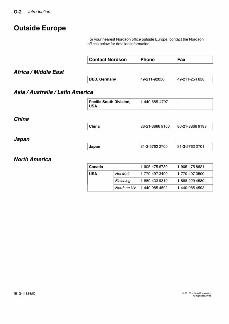
Outside Europe
For your nearest Nordson office outside Europe, contact the Nordsonoffices below for detailed information.
Contact Nordson Phone Fax
Africa / Middle East
DED, Germany 49-211-92050 49-211-254 658
Asia / Australia / Latin America
Pacific South Division,USA
1-440-685-4797 -
China
China 86-21-3866 9166 86-21-3866 9199
Japan
Japan 81-3-5762 2700 81-3-5762 2701
North America
Canada 1-905-475 6730 1-905-475 8821
USA Hot Melt 1-770-497 3400 1-770-497 3500
Finishing 1-880-433 9319 1-888-229 4580
Nordson UV 1-440-985 4592 1-440-985 4593
Safety 1-1
� 2014 Nordson Corporation Safe_PPA1011LUE_EN
Section 1
Safety
Read this section before using the equipment. This section containsrecommendations and practices applicable to the safe installation, operation,and maintenance (hereafter referred to as “use”) of the product described inthis document (hereafter referred to as “equipment”). Additional safetyinformation, in the form of task-specific safety alert messages, appears asappropriate throughout this document.
WARNING! Failure to follow the safety messages, recommendations, andhazard avoidance procedures provided in this document can result inpersonal injury, including death, or damage to equipment or property.
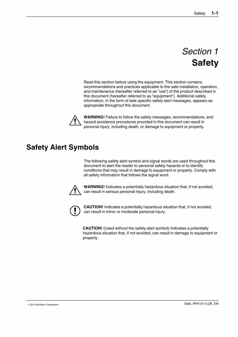
Safety Alert Symbols
The following safety alert symbol and signal words are used throughout thisdocument to alert the reader to personal safety hazards or to identifyconditions that may result in damage to equipment or property. Comply withall safety information that follows the signal word.
WARNING! Indicates a potentially hazardous situation that, if not avoided,can result in serious personal injury, including death.
CAUTION! Indicates a potentially hazardous situation that, if not avoided,can result in minor or moderate personal injury.
CAUTION! (Used without the safety alert symbol) Indicates a potentiallyhazardous situation that, if not avoided, can result in damage to equipment orproperty.
Safety1-2
� 2014 Nordson CorporationSafe_PPA1011LUE_EN
Responsibilities of the Equipment Owner
Equipment owners are responsible for managing safety information, ensuringthat all instructions and regulatory requirements for use of the equipment aremet, and for qualifying all potential users.
Safety Information� Research and evaluate safety information from all applicable sources,
including the owner-specific safety policy, best industry practices,governing regulations, material manufacturer's product information, andthis document.
� Make safety information available to equipment users in accordance withgoverning regulations. Contact the authority having jurisdiction forinformation.
� Maintain safety information, including the safety labels affixed to theequipment, in readable condition.
Instructions, Requirements, and Standards� Ensure that the equipment is used in accordance with the information
provided in this document, governing codes and regulations, and bestindustry practices.
� If applicable, receive approval from your facility's engineering or safetydepartment, or other similar function within your organization, beforeinstalling or operating the equipment for the first time.
� Provide appropriate emergency and first aid equipment.
� Conduct safety inspections to ensure required practices are beingfollowed.
� Re-evaluate safety practices and procedures whenever changes aremade to the process or equipment.
Safety 1-3
� 2014 Nordson Corporation Safe_PPA1011LUE_EN
User Qualifications
Equipment owners are responsible for ensuring that users:
� receive safety training appropriate to their job function as directed bygoverning regulations and best industry practices
� are familiar with the equipment owner's safety and accidentprevention policies and procedures
� receive equipment- and task-specific training from another qualifiedindividual
NOTE: Nordson can provide equipment-specific installation,operation, and maintenance training. Contact your Nordsonrepresentative for information
� possess industry- and trade-specific skills and a level of experienceappropriate to their job function
� are physically capable of performing their job function and are notunder the influence of any substance that degrades their mentalcapacity or physical capabilities
Applicable Industry Safety Practices
The following safety practices apply to the use of the equipment in themanner described in this document. The information provided here is notmeant to include all possible safety practices, but represents the best safetypractices for equipment of similar hazard potential used in similar industries.
Intended Use of the Equipment� Use the equipment only for the purposes described and within the limits
specified in this document.
� Do not modify the equipment.
� Do not use incompatible materials or unapproved auxiliary devices.Contact your Nordson representative if you have any questions onmaterial compatibility or the use of non-standard auxiliary devices.
Safety1-4
� 2014 Nordson CorporationSafe_PPA1011LUE_EN
Instructions and Safety Messages� Read and follow the instructions provided in this document and other
referenced documents.
� Familiarize yourself with the location and meaning of the safety warninglabels and tags affixed to the equipment. Refer to Safety Labels and Tagsat the end of this section.
� If you are unsure of how to use the equipment, contact your Nordsonrepresentative for assistance.
Installation Practices� Install the equipment in accordance with the instructions provided in this
document and in the documentation provided with auxiliary devices.
� Ensure that the equipment is rated for the environment in which it will beused. This equipment has not been certified for compliance with theATEX directive nor as nonincendive and should not be installed inpotentially explosive environments.
� Ensure that the processing characteristics of the material will not create ahazardous environment. Refer to the Material Safety Data Sheet (MSDS)for the material.
� If the required installation configuration does not match the installationinstructions, contact your Nordson representative for assistance.
� Position the equipment for safe operation. Observe the requirements forclearance between the equipment and other objects.
� Install lockable power disconnects to isolate the equipment and allindependently powered auxiliary devices from their power sources.
� Properly ground all equipment. Contact your local building codeenforcement agency for specific requirements.
� Ensure that fuses of the correct type and rating are installed in fusedequipment.
� Contact the authority having jurisdiction to determine the requirement forinstallation permits or inspections.
Operating Practices� Familiarize yourself with the location and operation of all safety devices
and indicators.
� Confirm that the equipment, including all safety devices (guards,interlocks, etc.), is in good working order and that the requiredenvironmental conditions exist.
� Use the personal protective equipment (PPE) specified for each task.Refer to Equipment Safety Information or the material manufacturer'sinstructions and MSDS for PPE requirements.
� Do not use equipment that is malfunctioning or shows signs of a potentialmalfunction.

Safety 1-5
� 2014 Nordson Corporation Safe_PPA1011LUE_EN
Maintenance and Repair Practices� Allow only personnel with appropriate training and experience to operate
or service the equipment.
� Perform scheduled maintenance activities at the intervals described inthis document.
� Relieve system hydraulic and pneumatic pressure before servicing theequipment.
� De-energize the equipment and all auxiliary devices before servicing theequipment.
� Use only new Nordson-authorized refurbished or replacement parts.
� Read and comply with the manufacturer's instructions and the MSDSsupplied with equipment cleaning compounds.
NOTE: MSDSs for cleaning compounds that are sold by Nordson areavailable at www.nordson.com or by calling your Nordson representative.
� Confirm the correct operation of all safety devices before placing theequipment back into operation.
� Dispose of waste cleaning compounds and residual process materialsaccording to governing regulations. Refer to the applicable MSDS orcontact the authority having jurisdiction for information.
� Keep equipment safety warning labels clean. Replace worn or damagedlabels.
Equipment Safety Information
This equipment safety information is applicable to the following types ofNordson equipment:
� hot melt and cold adhesive application equipment and all relatedaccessories
� pattern controllers, timers, detection and verification systems, and allother optional process control devices
Safety1-6
� 2014 Nordson CorporationSafe_PPA1011LUE_EN
Equipment Shutdown
To safely complete many of the procedures described in this document, theequipment must first be shut down. The level of shut down required varies bythe type of equipment in use and the procedure being completed.If required, shut down instructions are specified at the start of the procedure.The levels of shut down are:
Relieving System Hydraulic Pressure
Completely relieve system hydraulic pressure before breaking any hydraulicconnection or seal. Refer to the melter-specific product manual forinstructions on relieving system hydraulic pressure.
De-energizing the System
Isolate the system (melter, hoses, applicators, and optional devices) from allpower sources before accessing any unprotected high-voltage wiring orconnection point.
1. Turn off the equipment and all auxiliary devices connected to theequipment (system).
2. To prevent the equipment from being accidentally energized, lock andtag the disconnect switch(es) or circuit breaker(s) that provide inputelectrical power to the equipment and optional devices.
NOTE: Government regulations and industry standards dictate specificrequirements for the isolation of hazardous energy sources. Refer to theappropriate regulation or standard.
Disabling the Applicators
NOTE: Adhesive dispensing applicators are referred to as “guns” in someprevious publications.
All electrical or mechanical devices that provide an activation signal to theapplicators, applicator solenoid valve(s), or the melter pump must bedisabled before work can be performed on or around an applicator that isconnected to a pressurized system.
1. Turn off or disconnect the applicator triggering device (pattern controller,timer, PLC, etc.).
2. Disconnect the input signal wiring to the applicator solenoid valve(s).
3. Reduce the air pressure to the applicator solenoid valve(s) to zero; thenrelieve the residual air pressure between the regulator and the applicator.
Safety 1-7
� 2014 Nordson Corporation Safe_PPA1011LUE_EN
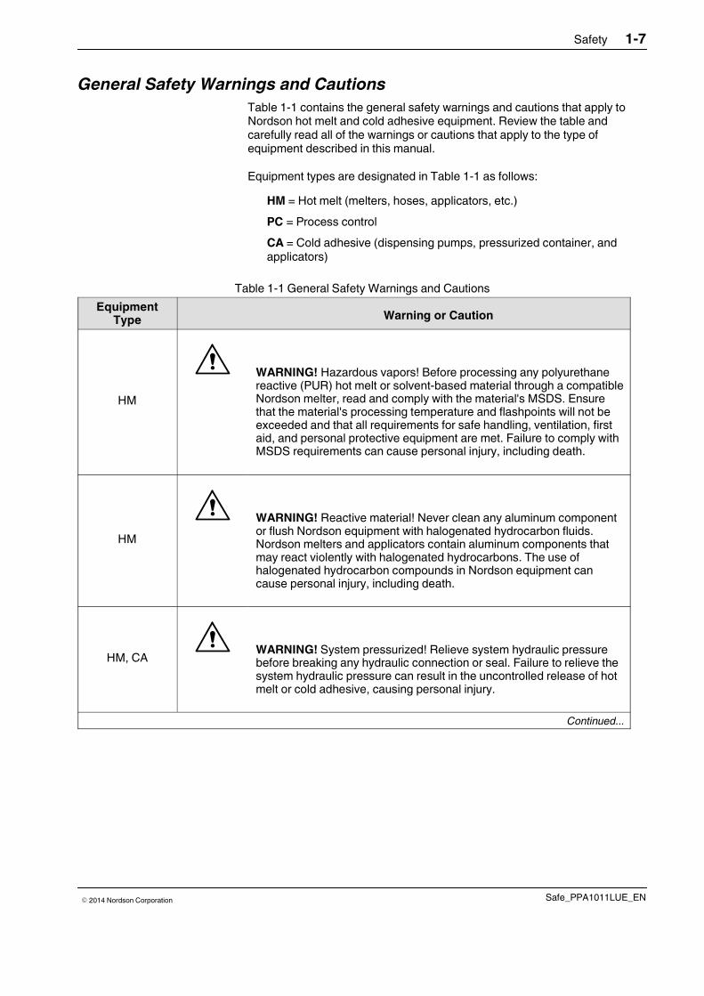
General Safety Warnings and Cautions
Table 1-1 contains the general safety warnings and cautions that apply toNordson hot melt and cold adhesive equipment. Review the table andcarefully read all of the warnings or cautions that apply to the type ofequipment described in this manual.
Equipment types are designated in Table 1-1 as follows:
HM = Hot melt (melters, hoses, applicators, etc.)
PC = Process control
CA = Cold adhesive (dispensing pumps, pressurized container, andapplicators)
Table 1-1 General Safety Warnings and Cautions
EquipmentType Warning or Caution
HM
WARNING! Hazardous vapors! Before processing any polyurethanereactive (PUR) hot melt or solvent-based material through a compatibleNordson melter, read and comply with the material's MSDS. Ensurethat the material's processing temperature and flashpoints will not beexceeded and that all requirements for safe handling, ventilation, firstaid, and personal protective equipment are met. Failure to comply withMSDS requirements can cause personal injury, including death.
HM
WARNING! Reactive material! Never clean any aluminum componentor flush Nordson equipment with halogenated hydrocarbon fluids.Nordson melters and applicators contain aluminum components thatmay react violently with halogenated hydrocarbons. The use ofhalogenated hydrocarbon compounds in Nordson equipment cancause personal injury, including death.
HM, CAWARNING! System pressurized! Relieve system hydraulic pressurebefore breaking any hydraulic connection or seal. Failure to relieve thesystem hydraulic pressure can result in the uncontrolled release of hotmelt or cold adhesive, causing personal injury.
Continued...

Safety1-8
� 2014 Nordson CorporationSafe_PPA1011LUE_EN
General Safety Warnings and Cautions (contd.)
Table 1-1 General Safety Warnings and Cautions (contd)
EquipmentType Warning or Caution
HMWARNING! Molten material! Wear eye or face protection, clothing thatprotects exposed skin, and heat-protective gloves when servicingequipment that contains molten hot melt. Even when solidified, hot meltcan still cause burns. Failure to wear appropriate personal protectiveequipment can result in personal injury.
HM, PC
WARNING! Equipment starts automatically! Remote triggering devicesare used to control automatic hot melt applicators. Before working onor near an operating applicator, disable the applicator's triggeringdevice and remove the air supply to the applicator's solenoid valve(s).Failure to disable the applicator's triggering device and remove thesupply of air to the solenoid valve(s) can result in personal injury.
HM, CA, PC
WARNING! Risk of electrocution! Even when switched off andelectrically isolated at the disconnect switch or circuit breaker, theequipment may still be connected to energized auxiliary devices.De-energize and electrically isolate all auxiliary devices beforeservicing the equipment. Failure to properly isolate electrical power toauxiliary equipment before servicing the equipment can result inpersonal injury, including death.
HM, CA, PC
WARNING! Risk of fire or explosion! Nordson adhesive equipment isnot rated for use in explosive environments and has not been cerfifiedfor the ATEX directive or as nonincendive. In addition, this equipmentshould not be used with solvent-based adhesives that can create anexplosive atmosphere when processed. Refer to the MSDS for theadhesive to determine its processing characteristics and limitations.The use of incompatible solvent-based adhesives or the improperprocessing of solvent-based adhesives can result in personal injury,including death.
Continued...
Safety 1-9
� 2014 Nordson Corporation Safe_PPA1011LUE_EN
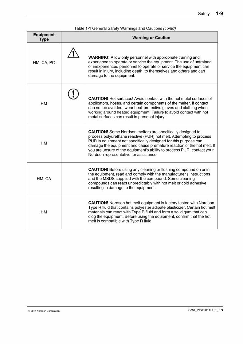
Table 1-1 General Safety Warnings and Cautions (contd)
EquipmentType Warning or Caution
HM, CA, PCWARNING! Allow only personnel with appropriate training andexperience to operate or service the equipment. The use of untrainedor inexperienced personnel to operate or service the equipment canresult in injury, including death, to themselves and others and candamage to the equipment.
HMCAUTION! Hot surfaces! Avoid contact with the hot metal surfaces ofapplicators, hoses, and certain components of the melter. If contactcan not be avoided, wear heat-protective gloves and clothing whenworking around heated equipment. Failure to avoid contact with hotmetal surfaces can result in personal injury.
HM
CAUTION! Some Nordson melters are specifically designed toprocess polyurethane reactive (PUR) hot melt. Attempting to processPUR in equipment not specifically designed for this purpose candamage the equipment and cause premature reaction of the hot melt. Ifyou are unsure of the equipment's ability to process PUR, contact yourNordson representative for assistance.
HM, CA
CAUTION! Before using any cleaning or flushing compound on or inthe equipment, read and comply with the manufacturer's instructionsand the MSDS supplied with the compound. Some cleaningcompounds can react unpredictably with hot melt or cold adhesive,resulting in damage to the equipment.
HM
CAUTION! Nordson hot melt equipment is factory tested with NordsonType R fluid that contains polyester adipate plasticizer. Certain hot meltmaterials can react with Type R fluid and form a solid gum that canclog the equipment. Before using the equipment, confirm that the hotmelt is compatible with Type R fluid.
Safety1-10
� 2014 Nordson CorporationSafe_PPA1011LUE_EN
Other Safety Precautions� Do not use an open flame to heat hot melt system components.
� Check high pressure hoses daily for signs of excessive wear, damage, orleaks.
� Never point a dispensing handgun at yourself or others.
� Suspend dispensing handguns by their proper suspension point.
First Aid
If molten hot melt comes in contact with your skin:
1. Do NOT attempt to remove the molten hot melt from your skin.
2. Immediately soak the affected area in clean, cold water until the hot melthas cooled.
3. Do NOT attempt to remove the solidified hot melt from your skin.
4. In case of severe burns, treat for shock.
5. Seek expert medical attention immediately. Give the MSDS for the hotmelt to the medical personnel providing treatment.
Safety Instructions 1-11
P/N 7169667_03� 2014 Nordson Corporation EEX
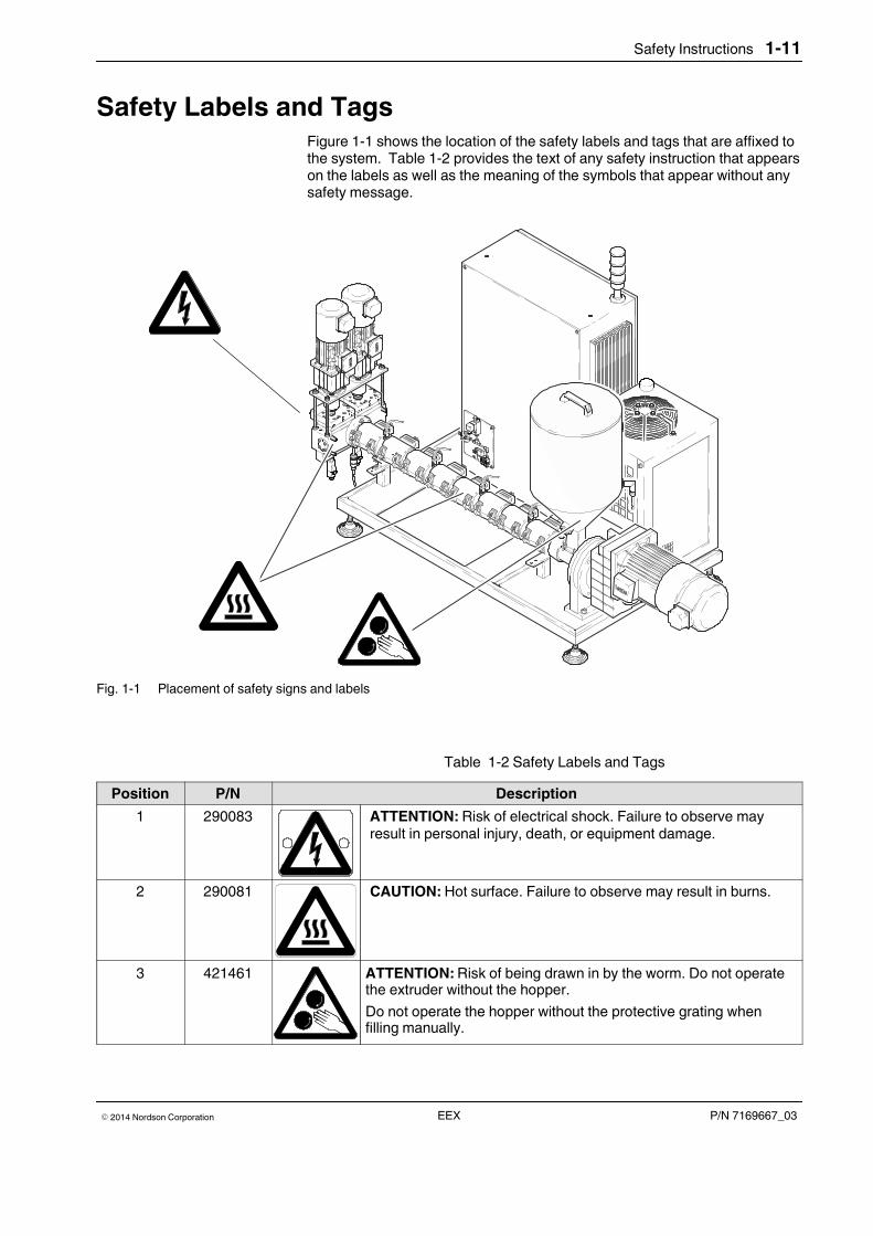
Safety Labels and TagsFigure 1-1 shows the location of the safety labels and tags that are affixed tothe system. Table 1-2 provides the text of any safety instruction that appearson the labels as well as the meaning of the symbols that appear without anysafety message.
Achtung!Verbrennungsgefahr!
Achtung!Einzugsgefahr!
Fig. 1-1 Placement of safety signs and labels
Table 1-2 Safety Labels and Tags
Position P/N Description
1 290083 ATTENTION: Risk of electrical shock. Failure to observe mayresult in personal injury, death, or equipment damage.
2 290081 CAUTION: Hot surface. Failure to observe may result in burns.
3 421461 ATTENTION: Risk of being drawn in by the worm. Do not operatethe extruder without the hopper.
Do not operate the hopper without the protective grating whenfilling manually.
Safety Instructions1-12
P/N 7169667_03 � 2014 Nordson CorporationEEX
Introduction 2-1
P/N 7169667_03� 2014 Nordson Corporation EEX
Section 2
Introduction
Intended UseExtruders in the series EEX, hereafter also referred to as System, may beused only to melt and feed thermoplastic hot melt adhesives or thermoplasticraw material used to produce adhesives.
Any other use is considered to be unintended. Nordson will not be liable forpersonal injury and/or property damage resulting from unintended use.
Intended use includes the observance of Nordson safety instructions.Nordson recommends obtaining detailed information on the materials to beused.
Area of Use (EMC)
The electromagnetic compatibility of the system is such that it is intended tobe used in industrial areas.
Operating Restrictions
When using in residential, business or industrial areas, the system maycause interference with other units, e.g. radios.
Unintended Use - Examples -
The extruder may not be used under the following conditions:
� In defective condition
� When changes or modifications have been made by the customer
� Without safety guard, hoods and protective covers
� With electrical cabinet door open
� When the hopper lid is open
� In a potentially explosive atmosphere
� When the values stated under Technical Data are not complied with.
The extruder may not be used to process the following materials:
� Explosive and flammable materials
� Erosive and corrosive materials
� Food products.
Introduction2-2
P/N 7169667_03 � 2014 Nordson CorporationEEX
Restricted Use
When abrasive or chemically aggressive materials are used, the serviceablelife of wearing parts, particularly pumps, is greatly reduced.
When hot melt adhesives are used that are highly viscous and/or that containadditives, the built-in standard pumps are subjected to greater wear. As analternative, specially hardened pumps with relatively longer serviceable livescan be supplied.
When in doubt, please contact your Nordson representative.
Residual RisksIn the design of the unit, every measure was taken to protect personnel frompotential danger. However, some residual risks cannot be avoided:
� Risk of burns from hot adhesive
� Risk of burns from hot system components
� Risk of burns when filling the hopper
� Risk of burns when conducting maintenance and repair work for whichthe system must be heated up
� Risk of burns from heated accessories such as heated hoses andapplicators
� Risk of being drawn in by the worm! The extruder may not be operatedwithout the hopper.
� Material fumes can be hazardous. Avoid inhalation.
Note on Manual
� The actual extruder model can deviate from the illustrations.
� An application head is referred to as an applicator in newer Nordsonliterature. Pilot voltage is also referred to as key-to-line.
� Depending on the size and type of the extruder, some configurations maynot be permitted or they may be mutually exclusive.
� CAUTION: The extruder is intended for Automatic mode. Manual mode isto be equated with service mode (setup/testing) here. Operation inmanual mode means lock-free. For this reason, only specially authorizedpersonnel may operate the extruder in manual mode.
Introduction 2-3
P/N 7169667_03� 2014 Nordson Corporation EEX
EMERGENCY OFF / EMERGENCY STOP
EMERGENCY STOP is generally implemented. Refer to the system wiringdiagram.
EMERGENCY STOP, category 0: All drives are immediately shut downwhen the button is pressed.EMERGENCY OFF: When the button is pressed, all drives are immediatelyswitched off and the power supply to the system's heating circuits is stopped.
Both variations will hereafter be referred to as EMERGENCY OFF.
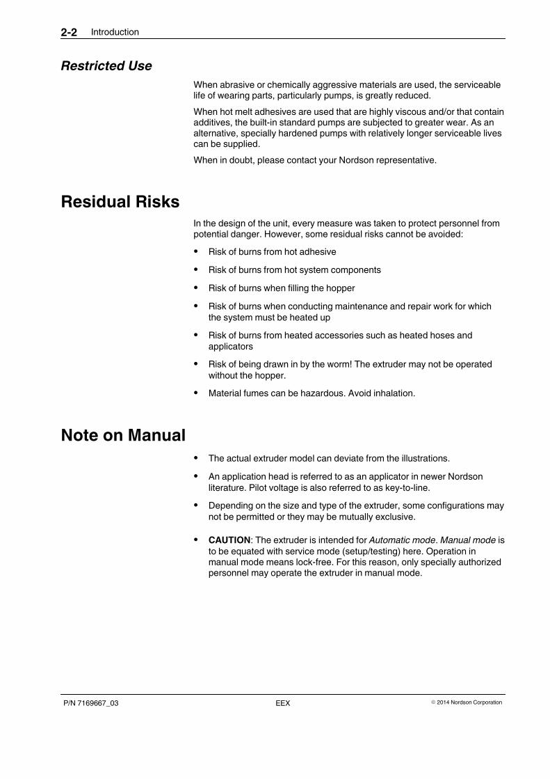
ID Plate
There are two ID plates. One is on the outside of the system, the other in theelectrical cabinet.
6
ADHESIVE MELTEREEX200
Nordson Engineering GmbHLilienthalstr. 6D 21337 Lüneburg - Germany
www.nordson.comSerial No:
3
4
5
1 2
Year
LISTEDUSC
UL
Fig. 2-1 Example
1 Designation for Nordson extruder
2 Order number
3 Configuration code
4 Electrical connection, operating voltage, line voltage frequency, melter fuse protection
5 Serial number
...
G July
H August
J September
K October
...LU10J01234
MonthYear
NOTE: The year and month of production are indicated within the serial number.
6 Year of construction
Introduction2-4
P/N 7169667_03 � 2014 Nordson CorporationEEX
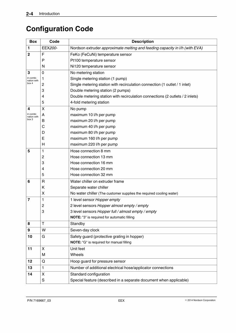
Configuration Code
Box Code Description
1 EEX200- Nordson extruder approximate melting and feeding capacity in l/h (with EVA)
2 F
P
N
FeKo (FeCuNi) temperature sensor
Pt100 temperature sensor
Ni120 temperature sensor
3
in combi-nation withbox 4
0
1
2
3
4
5
No metering station
Single metering station (1 pump)
Single metering station with recirculation connection (1 outlet / 1 inlet)
Double metering station (2 pumps)
Double metering station with recirculation connections (2 outlets / 2 inlets)
4-fold metering station
4
in combi-nation withbox 3
X
A
B
C
D
E
H
No pump
maximum 10 l/h per pump
maximum 20 l/h per pump
maximum 40 l/h per pump
maximum 80 l/h per pump
maximum 160 l/h per pump
maximum 220 l/h per pump
5 1
2
3
4
5
Hose connection 8 mm
Hose connection 13 mm
Hose connection 16 mm
Hose connection 20 mm
Hose connection 32 mm
6 R
K
X
Water chiller on extruder frame
Separate water chiller
No water chiller (The customer supplies the required cooling water)
7 1
2
3
1 level sensor Hopper empty
2 level sensors Hopper almost empty / empty
3 level sensors Hopper full / almost empty / empty
NOTE: "3" is required for automatic filling
8 T Standby
9 W Seven-day clock
10 G Safety guard (protective grating in hopper)
NOTE: "G" is required for manual filling
11 X
M
Unit feet
Wheels
12 Q Hoop guard for pressure sensor
13 1 Number of additional electrical hose/applicator connections
14 X
S
Standard configuration
Special feature (described in a separate document when applicable)
Introduction 2-5
P/N 7169667_03� 2014 Nordson Corporation EEX
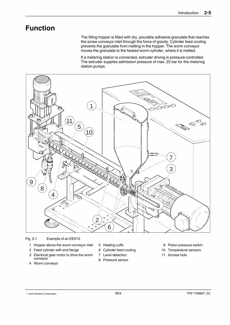
FunctionThe filling hopper is filled with dry, pourable adhesive granulate that reachesthe screw conveyor inlet through the force of gravity. Cylinder feed coolingprevents the granulate from melting in the hopper. The worm conveyormoves the granulate to the heated worm cylinder, where it is melted.
If a metering station is connected, extruder driving is pressure-controlled.The extruder supplies admission pressure of max. 25 bar for the meteringstation pumps.
98
4
26
1
115
10
3
7
Fig. 2-1 Example of an EEX10
1 Hopper above the worm conveyor inlet
2 Feed cylinder with end flange
3 Electrical gear motor to drive the wormconveyor
4 Worm conveyor
5 Heating cuffs
6 Cylinder feed cooling
7 Level detection
8 Pressure sensor
9 Piston pressure switch
10 Temperature sensors
11 Access hole
Introduction2-6
P/N 7169667_03 � 2014 Nordson CorporationEEX
Description of Components
Illustration of EEX200
15
76
5
43
21
17
18
21
14
13
12
11
10
9
16
20
198
22
23
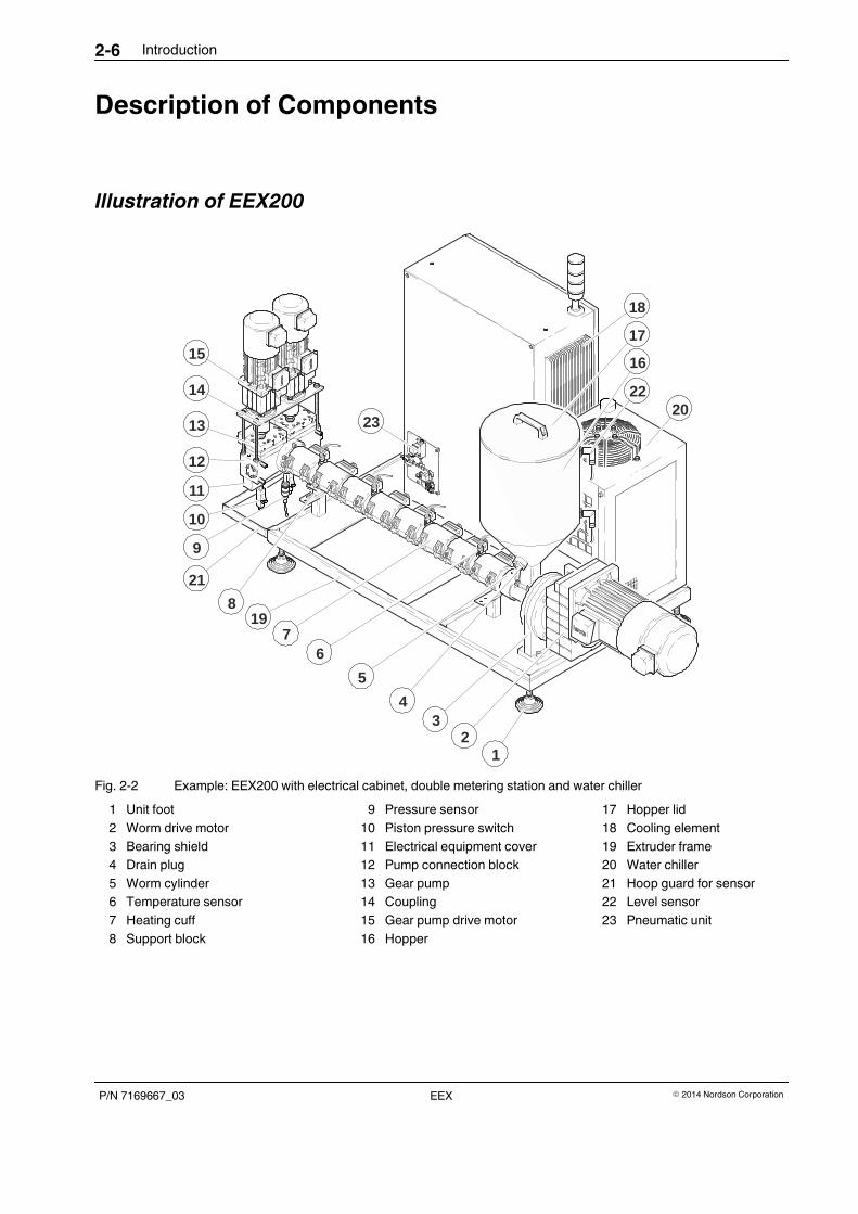
Fig. 2-2 Example: EEX200 with electrical cabinet, double metering station and water chiller
1 Unit foot
2 Worm drive motor
3 Bearing shield
4 Drain plug
5 Worm cylinder
6 Temperature sensor
7 Heating cuff
8 Support block
9 Pressure sensor
10 Piston pressure switch
11 Electrical equipment cover
12 Pump connection block
13 Gear pump
14 Coupling
15 Gear pump drive motor
16 Hopper
17 Hopper lid
18 Cooling element
19 Extruder frame
20 Water chiller
21 Hoop guard for sensor
22 Level sensor
23 Pneumatic unit
Introduction 2-7
P/N 7169667_03� 2014 Nordson Corporation EEX
40
26
25
24
44
29
32
30
34
33
31
28
2736
37
38
39
41
35
45
46
42
43
48
49
47
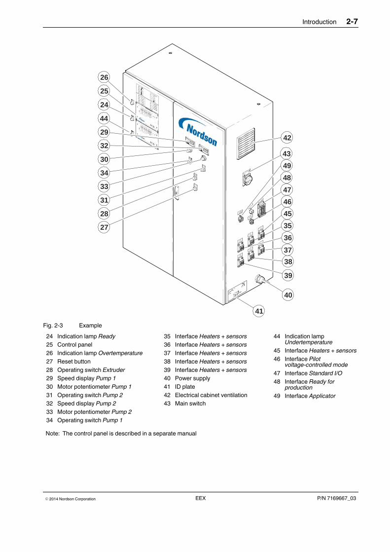
Fig. 2-3 Example
24 Indication lamp Ready
25 Control panel
26 Indication lamp Overtemperature
27 Reset button
28 Operating switch Extruder
29 Speed display Pump 1
30 Motor potentiometer Pump 1
31 Operating switch Pump 2
32 Speed display Pump 2
33 Motor potentiometer Pump 2
34 Operating switch Pump 1
35 Interface Heaters + sensors
36 Interface Heaters + sensors
37 Interface Heaters + sensors
38 Interface Heaters + sensors
39 Interface Heaters + sensors
40 Power supply
41 ID plate
42 Electrical cabinet ventilation
43 Main switch
44 Indication lampUndertemperature
45 Interface Heaters + sensors
46 Interface Pilotvoltage-controlled mode
47 Interface Standard I/O
48 Interface Ready forproduction
49 Interface Applicator
Note: The control panel is described in a separate manual
Introduction2-8
P/N 7169667_03 � 2014 Nordson CorporationEEX
Illustration of EEX10
15
11
1413
12
10
9
23
17
16
22
18
19
5
4
3
2
1
,6,7
8
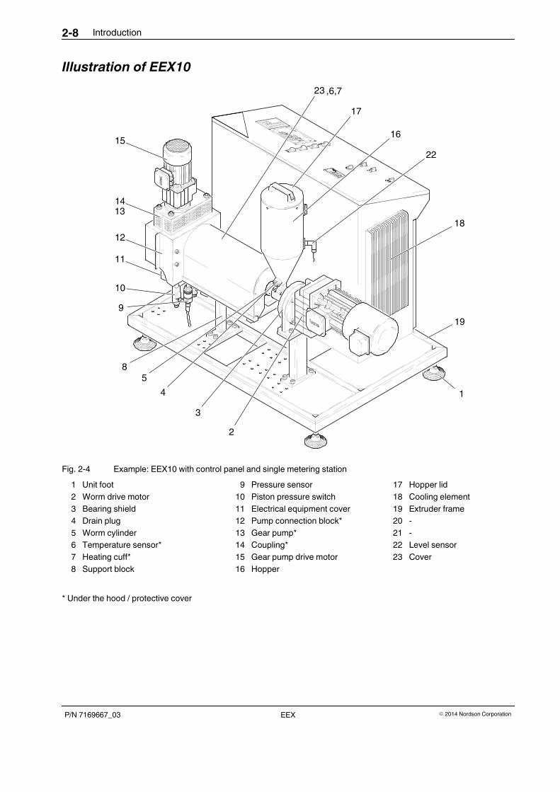
Fig. 2-4 Example: EEX10 with control panel and single metering station
1 Unit foot
2 Worm drive motor
3 Bearing shield
4 Drain plug
5 Worm cylinder
6 Temperature sensor*
7 Heating cuff*
8 Support block
9 Pressure sensor
10 Piston pressure switch
11 Electrical equipment cover
12 Pump connection block*
13 Gear pump*
14 Coupling*
15 Gear pump drive motor
16 Hopper
17 Hopper lid
18 Cooling element
19 Extruder frame
20 -
21 -
22 Level sensor
23 Cover
* Under the hood / protective cover
Introduction 2-9
P/N 7169667_03� 2014 Nordson Corporation EEX
3031
3233
34
24
2928
2726
25
36
37
38
39
40
41
42
43
35
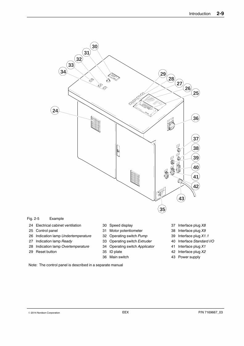
Fig. 2-5 Example
24 Electrical cabinet ventilation
25 Control panel
26 Indication lamp Undertemperature
27 Indication lamp Ready
28 Indication lamp Overtemperature
29 Reset button
30 Speed display
31 Motor potentiometer
32 Operating switch Pump
33 Operating switch Extruder
34 Operating switch Applicator
35 ID plate
36 Main switch
37 Interface plug X8
38 Interface plug X9
39 Interface plug X1.1
40 Interface Standard I/O
41 Interface plug X1
42 Interface plug X2
43 Power supply
Note: The control panel is described in a separate manual
Introduction2-10
P/N 7169667_03 � 2014 Nordson CorporationEEX
Protective Devices
Protective Covers
CAUTION: Hot. Risk of burns. Wear goggles and heat-resistant gloves.
The protective covers can be removed for repair and maintenance purposes.
Covers
CAUTION: Do not operate the extruder without the covers.
The covers protect from the heated worm cylinder.
The covers have to be removed to tighten the heating cuffs or to remove theworm. On some models the covers are secured with a screw (arrow), whichmust be released before the cover can be removed.
Safety Guard
There is a protective grating in the hopper for manual filling. It preventsreaching into the hopper during filling.
Overtemperature Protection
The system is protected from overheating.
When the trigger temperature is exceeded, the heating circuit is interrupted.The fuses are mounted on each controlled heating circuit, with the exceptionof the worm.
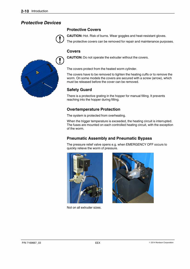
Pneumatic Assembly and Pneumatic Bypass
The pressure relief valve opens e.g. when EMERGENCY OFF occurs toquickly relieve the worm of pressure.
Not on all extruder sizes.
1
2
1
Introduction 2-11
P/N 7169667_03� 2014 Nordson Corporation EEX
Pressure Control / Pressure Monitoring
Electronic Pressure Control and Switchoff
The pressure sensor (1) continuously compiles the current adhesivepressure. The electronic pressure control regulates the worm speedaccording to the digitally set setpoint pressure.
If the actual pressure exceeds the setpoint pressure by an adjustable value,the software switches all drives off.
NOTE: Information on the pressure sensor with integrated evaluationelectronics can be found in Appendix B.
Piston Pressure Switch
The piston pressure switch (2) constantly monitors the current adhesivepressure and switches off the drive at the preset limit.
Fig. 2-6 Example without metering station
Drive
The system is driven electromechanically by a pressure or speed controlledthree-phase current drive consisting of a three-phase gear motor with motorcontroller.
The motor causes the worm conveyor to turn. The channels along the wormconveyor feed the granulate.
With its high heating capacity, the motor contributes significantly to heatgeneration.
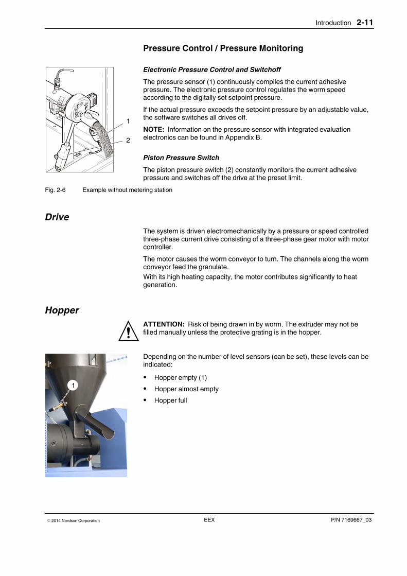
Hopper
ATTENTION: Risk of being drawn in by worm. The extruder may not befilled manually unless the protective grating is in the hopper.
Depending on the number of level sensors (can be set), these levels can beindicated:
� Hopper empty (1)
� Hopper almost empty
� Hopper full
Introduction2-12
P/N 7169667_03 � 2014 Nordson CorporationEEX
Filling Area
The filling area consists of a water-cooled filling piece and a filling hopper.The granulate is supplied through the hopper. The hopper is release coated.
Worm Conveyor
The geometry of the worm conveyor generates a defined compression. Heatenergy and frictional heat work together to melt the granulate.
The worm conveyor is divided into three different zones:
1. Feed zone
2. Compression zone
3. Pumping zone
Proper, homogenous melting is achieved with a good balance of heat energyand frictional heat.
Since the frictional heat is also a factor of the worm conveyor speed, anoptimal speed can often be found for a parameter set. The optimal speed isdetermined upon initial startup using the adhesive granulate supplied.
Because there are so many different adhesives available for extruders, atemperature profile for the material is created based on the specificgranulate.
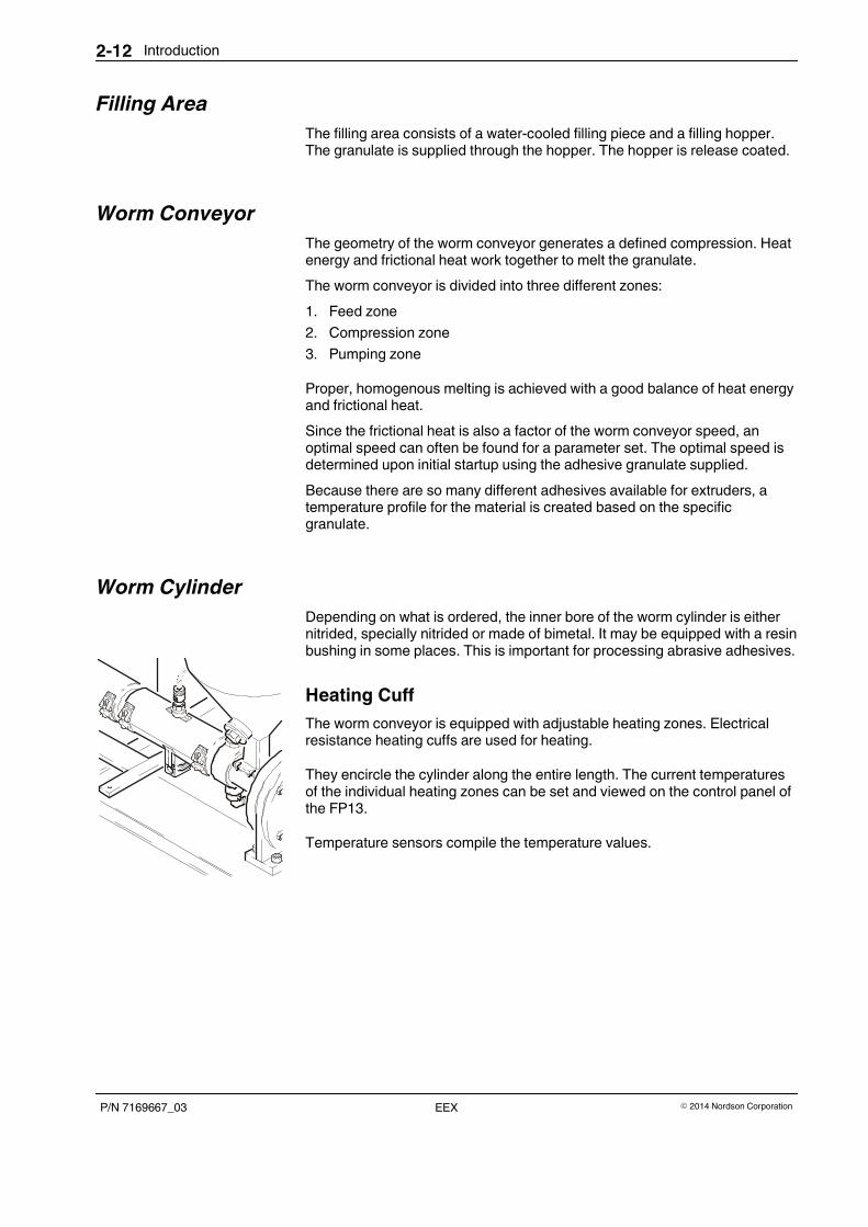
Worm Cylinder
Depending on what is ordered, the inner bore of the worm cylinder is eithernitrided, specially nitrided or made of bimetal. It may be equipped with a resinbushing in some places. This is important for processing abrasive adhesives.
Heating Cuff
The worm conveyor is equipped with adjustable heating zones. Electricalresistance heating cuffs are used for heating.
They encircle the cylinder along the entire length. The current temperaturesof the individual heating zones can be set and viewed on the control panel ofthe FP13.
Temperature sensors compile the temperature values.

Introduction 2-13
P/N 7169667_03� 2014 Nordson Corporation EEX
Cylinder Feed Cooling
The temperature in the feeding section depends on the heat spreading fromcylinder zone 1 and on the frictional heat generated by the worm.
The cylinder is cooled below the hopper in the draw-in area to ensure that thematerial remains pourable and to prevent an undesired reaction of theadhesive before processing.
Cooling can occur with a water chiller, or the customer can connect theextruder to his own cooling water circuit.
There is hose connecting piece for each water supply and water draining.
Cylinder feed cooling affects the output, which can differ by product andadhesive. Cooling intensity is controlled electronically by the water chiller.
Before the extruder is started up, it must be decided whether the feedingsection should be operated Hot or Cold. This depends on the material to beprocessed.
Hot means approx. 40 to 60 °C.Cold means approx. 15 to 20 °C.
Extruder Flange
If there is no metering station connected, the hose connection is located onthe extruder flange. The pressure sensor and piston pressure switch areresponsible for pressure display and/or pressure control as well as foroverpressure shutdown.
Introduction2-14
P/N 7169667_03 � 2014 Nordson CorporationEEX
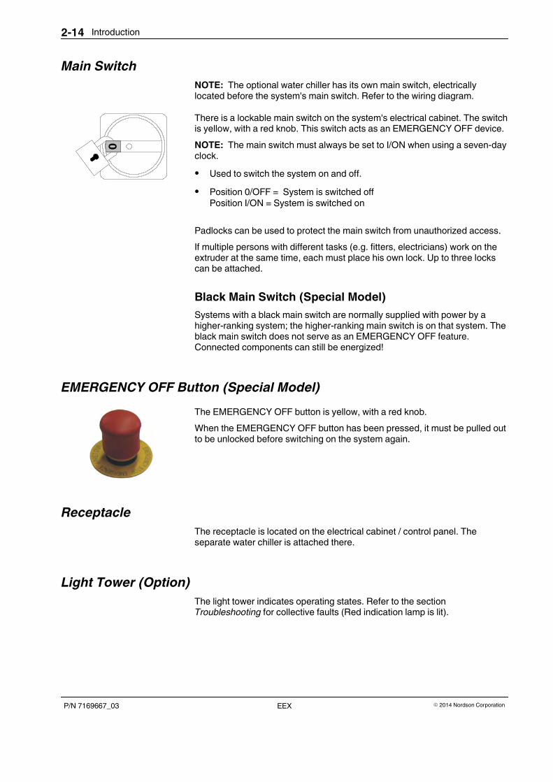
Main Switch
NOTE: The optional water chiller has its own main switch, electricallylocated before the system's main switch. Refer to the wiring diagram.
There is a lockable main switch on the system's electrical cabinet. The switchis yellow, with a red knob. This switch acts as an EMERGENCY OFF device.
NOTE: The main switch must always be set to I/ON when using a seven-dayclock.
� Used to switch the system on and off.
� Position 0/OFF = System is switched offPosition I/ON = System is switched on
Padlocks can be used to protect the main switch from unauthorized access.
If multiple persons with different tasks (e.g. fitters, electricians) work on theextruder at the same time, each must place his own lock. Up to three lockscan be attached.
Black Main Switch (Special Model)
Systems with a black main switch are normally supplied with power by ahigher-ranking system; the higher-ranking main switch is on that system. Theblack main switch does not serve as an EMERGENCY OFF feature.Connected components can still be energized!
EMERGENCY OFF Button (Special Model)
The EMERGENCY OFF button is yellow, with a red knob.
When the EMERGENCY OFF button has been pressed, it must be pulled outto be unlocked before switching on the system again.
Receptacle
The receptacle is located on the electrical cabinet / control panel. Theseparate water chiller is attached there.
Light Tower (Option)
The light tower indicates operating states. Refer to the sectionTroubleshooting for collective faults (Red indication lamp is lit).
ZONE SOLLWERT / W ISRWERT / X
FWATCHDOGC
Introduction 2-15
P/N 7169667_03� 2014 Nordson Corporation EEX
Door Lock
ATTENTION: Risk of electrical shock. Failure to observe may result inpersonal injury, death, or equipment damage.
The electrical cabinet can be opened for installation, maintenance and repair.Store the included key such that it is accessible only to qualified andauthorized personnel. The system may not be operated when the electricalcabinet is open.
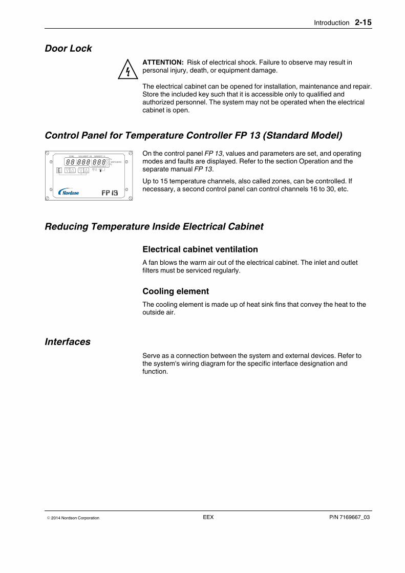
Control Panel for Temperature Controller FP 13 (Standard Model)
On the control panel FP 13, values and parameters are set, and operatingmodes and faults are displayed. Refer to the section Operation and theseparate manual FP 13.
Up to 15 temperature channels, also called zones, can be controlled. Ifnecessary, a second control panel can control channels 16 to 30, etc.
Reducing Temperature Inside Electrical Cabinet
Electrical cabinet ventilation
A fan blows the warm air out of the electrical cabinet. The inlet and outletfilters must be serviced regularly.
Cooling element
The cooling element is made up of heat sink fins that convey the heat to theoutside air.
Interfaces
Serve as a connection between the system and external devices. Refer tothe system's wiring diagram for the specific interface designation andfunction.
1
3
5
4
6
7
8
10
9
2
Introduction2-16
P/N 7169667_03 � 2014 Nordson CorporationEEX
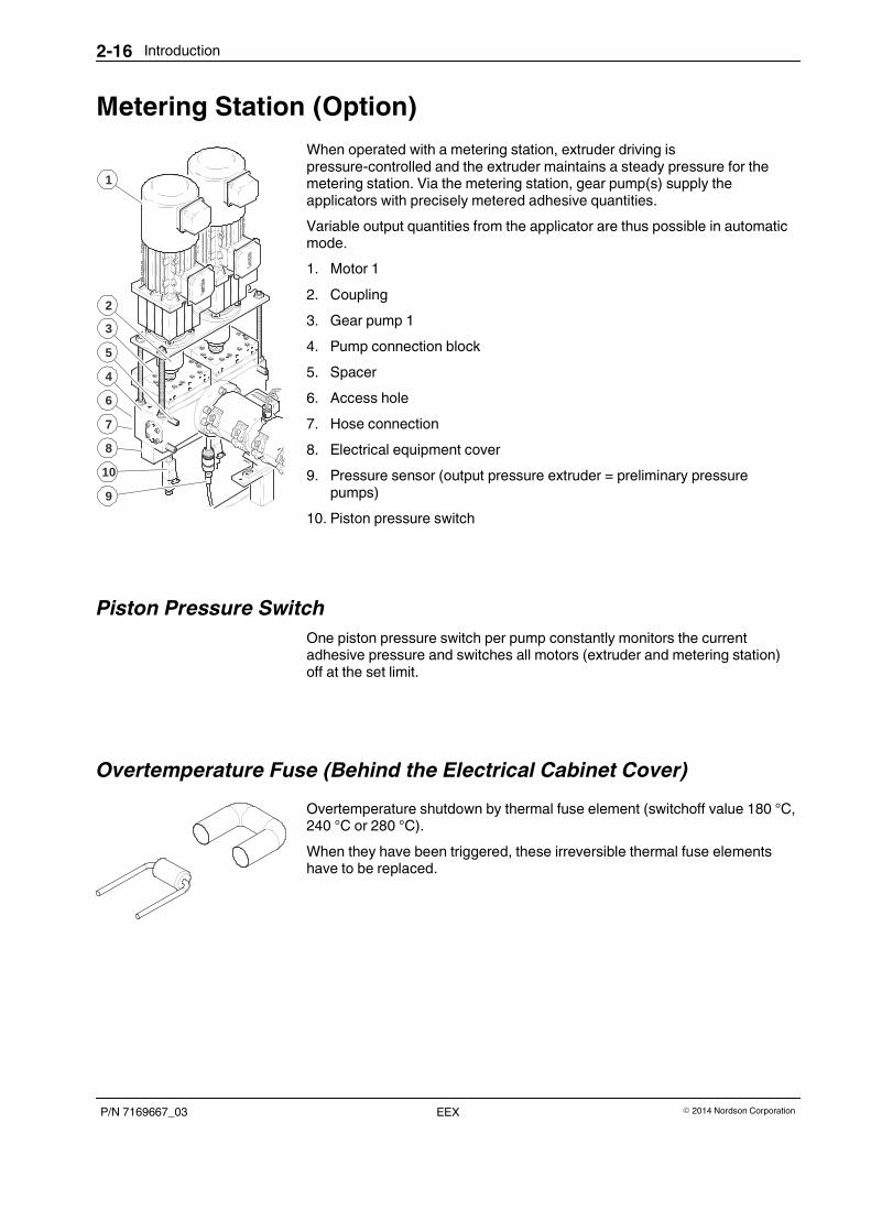
Metering Station (Option)
When operated with a metering station, extruder driving ispressure-controlled and the extruder maintains a steady pressure for themetering station. Via the metering station, gear pump(s) supply theapplicators with precisely metered adhesive quantities.
Variable output quantities from the applicator are thus possible in automaticmode.
1. Motor 1
2. Coupling
3. Gear pump 1
4. Pump connection block
5. Spacer
6. Access hole
7. Hose connection
8. Electrical equipment cover
9. Pressure sensor (output pressure extruder = preliminary pressurepumps)
10. Piston pressure switch
Piston Pressure Switch
One piston pressure switch per pump constantly monitors the currentadhesive pressure and switches all motors (extruder and metering station)off at the set limit.
Overtemperature Fuse (Behind the Electrical Cabinet Cover)
Overtemperature shutdown by thermal fuse element (switchoff value 180 °C,240 °C or 280 °C).
When they have been triggered, these irreversible thermal fuse elementshave to be replaced.

Installation 3-1
P/N 7169667_03� 2014 Nordson Corporation EEX
Section 3
Installation
ATTENTION: Allow only qualified personnel to perform the following tasks.Observe and follow the safety instructions in this document and all otherrelated documentation.
Before it leaves the factory, every extruder is set up, aligned and adjusted asit will be for production.
The extruder is normally delivered with the worm inside of the cylinder.
The base frame is sufficiently resistant to warping. Damage within the systemis virtually impossible.
Unpacking
Unpack carefully. Then check for any damage caused during shipping.Transport damage must be documented by the shipper and immediatelyreported to Nordson.
Save the pallet and angle brackets for later use. Reuse packaging materialsor dispose of properly according to local regulations.
StorageDo not store system outside! Protect from humidity, dust and extremetemperature fluctuations (formation of condensation).
Removal1. Empty the system.
2. If the extruder is to be out or service for an extended period, clean it withcleaning granulate (Refer to section Maintenance).
3. Disconnect all lines to the system, and allow the system to cool.
DisposalProperly dispose of the system according to local regulations.
Installation3-2
P/N 7169667_03 � 2014 Nordson CorporationEEX
TransportCAUTION: Observe with the option Casters: The base frame must besupported during transport. To prevent uncontrolled motion, the extruder maynot rest on the casters.
� The system must be transported in a position that is suitable toproduction. Use transport protection if available.
� Use only suitable transport devices. Also refer to Lifting (Unpacked Unit).
� If possible, use the pallet on which the system was delivered, and fastenthe system to the pallet
� Protect from damage, moisture and dust with suitable packing material
� Avoid jolts and vibrations.
Lifting (Unpacked Unit)
Lift only at the melter frame using suitable lifting equipment or a forklift. Referto delivery note for weight.
Installation 3-3
P/N 7169667_03� 2014 Nordson Corporation EEX
Mounting
� Refer to Appendix C of the unit has a level compensating element.
� The light tower (option) must be screwed onto the electrical cabinet (Itwas removed before delivery).
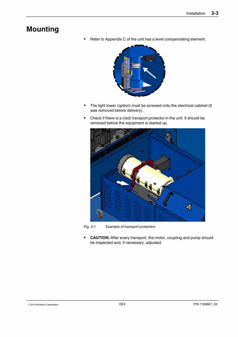
� Check if there is a (red) transport protector in the unit. It should beremoved before the equipment is started up.
Fig. 3-1 Example of transport protection
� CAUTION: After every transport, the motor, coupling and pump shouldbe inspected and, if necessary, adjusted.
Installation3-4
P/N 7169667_03 � 2014 Nordson CorporationEEX
Installation Requirements
A horizontal surface is required for setting up the equipment.
� Set up only in an environment that corresponds to the stated Degree ofProtection (Refer to section Technical Data).
� Do not set up in a potentially explosive atmosphere.
� Protect from vibration
� Remove transport protection (if present)
� Check that plug and screw connections are secure
� Provide sufficient clearance around the melter.
NOTE: Customers' accessories (e.g. tools) attached to the extruder shouldbe supported or braced with appropriate devices. The supporting force of thesupport or brace should only act vertically. No shear forces that could causethe worm conveyor to warp should occur.
Space Requirement
Refer to the section Technical Data for the dimensions of standard systems.
Exhausting Adhesive Vapors
Ensure that adhesive vapors do not exceed the prescribed limits. Alwaysobserve the safety data sheet (MSDS) for the material to be processed.
If necessary, exhaust adhesive vapors and/or provide sufficient ventilation ofthe location of the system.
Installation Personnel's ExperienceThe instructions contained in this section are intended for personnel withexperience/authorization in the following fields:
� Application methods with hot melt adhesive or similar materials
� Industrial electrical wiring of power and control lines
� Industrial mechanical installation
� General knowledge of process control.
Installation 3-5
P/N 7169667_03� 2014 Nordson Corporation EEX
Electrical ConnectionsATTENTION: Risk of electrical shock. Failure to observe may result inpersonal injury, death, or equipment damage.
Before beginning installation work, the trained personnel should be madefamiliar with the circuit diagrams. The customer is responsible for correctdimensioning and design of the power cables.
Use of Residual Current Circuit Breakers
NOTE: There are local regulations applying to the use of a residual currentcircuit breaker in some countries and for some applications.
Then observe the following:
� It is imperative to install the residual current circuit breaker between themains power supply and the system.
� Only residual current circuit breakers that react to pulsed currents or to allcurrents (> 30 mA) may be used.
Laying Cable
ATTENTION: Use only temperature resistant cable in the heating part of thesystem. Ensure that cables do not touch rotating and/or hot parts. Do notpinch cables and check regularly for damage. Replace damaged cablesimmediately!
CAUTION: Risk of stumbling. Place the cable that is outside of the system inchannels.
All energy cables should be laid separately from the signal lines around thecable channels and cable ways. Energy cables and signal lines are identifiedaccordingly. In the electrical cabinets, the cables should be properly fastenedto the connection terminals on the intended cable catch rails and protectedfrom tensile load.
The included connecting cables are used for electrical connection to theelectrical cabinet.
The individual leads should be connected as indicated by the labels. A tightand secure clamp connection is essential.

Installation3-6
P/N 7169667_03 � 2014 Nordson CorporationEEX
Line Voltage
ATTENTION: Operate only with the line voltage stated on the ID plate.
NOTE: Permitted deviation from the rated line voltage is �10%.
NOTE: The cross-section of the power cable must correspond to the ratedcurrent. Refer to ID plate for rated current.
The mains terminals are located in the electrical cabinet. Refer to wiringdiagram for connecting arrangement.
Protective Ground and Fuse Protection
Ground the system and protect from short-circuiting according to the totalpower consumption (Refer to the ID plate). Voltage deviations within a rangeof + / - 5% can be tolerated.
The cables and plugs are connected at the customer's facility according toplant regulations.
External Control/Signal Circuits
ATTENTION: Connect external control and signal circuits with suitablecable in accordance with the NEC, class 1. To avoid short-circuiting, lay andconnect the cables according to the electronic specifications.
Pneumatic Connection
Pneumatic Bypass (Pressure Relief)
NOTE: Not on all extruder sizes.
� Compressed air connection: 6 bar (max. 8 bar)
� Air quality: oil-free
� Filter size: 40 µm
When the inlet pressure is too low (<2 bar), the system is switched off.
Installation 3-7
P/N 7169667_03� 2014 Nordson Corporation EEX
Connecting InterfacesThe connecting arrangements are shown in the wiring diagram.
Standard I/O
Serves as a connection between the system and external devices.
� Use only shielded cables/lines. The shield must be connected to groundin compliance with the standard regarding electromagnetic compatibility.
� Inductive loads (e.g. solenoid valves) connected to the system may beequipped with a protective device (e.g. recovery diode) that disables theinductive voltage generated when an inductive load is switched off.
External EMERGENCY OFF Chain
The signal triggered by the safety relay (EMERGENCY OFF module) issupplied at the interface.
Pilot Voltage Input
In key-to-line the motor/pump speed is regulated proportionately to the linespeed.
Pilot voltage must be connected for key-to-line. The pilot voltage can besupplied e.g. by a tach generator (accessory) driven by the parent machine.
Some models with multiple pump drives have separate pilot voltage inputsfor the two pump drives.
CAUTION: Pilot voltages of 0 - 10 VDC are standard. Pilot voltages >12 VDCcan destroy the input assemblies.
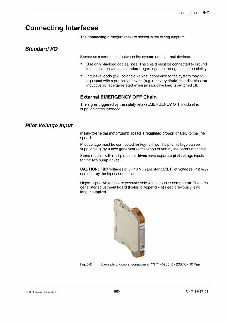
Higher signal voltages are possible only with a coupler component. The tachgenerator adjustment board (Refer to Appendix A) used previously is nolonger supplied.
Fig. 3-2 Example of coupler component P/N 7140205: 0 - 200 / 0 - 10 VDC
1 32
Installation3-8
P/N 7169667_03 � 2014 Nordson CorporationEEX
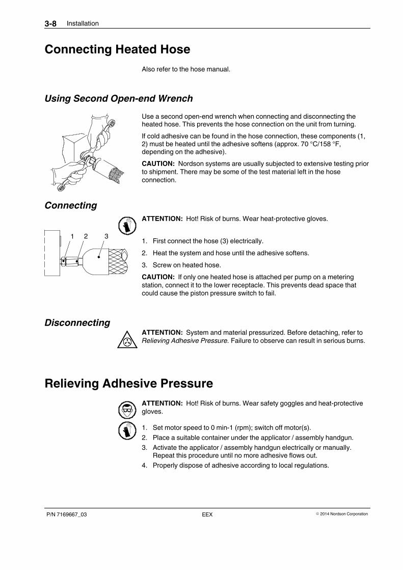
Connecting Heated Hose
Also refer to the hose manual.
Using Second Open-end Wrench
Use a second open-end wrench when connecting and disconnecting theheated hose. This prevents the hose connection on the unit from turning.
If cold adhesive can be found in the hose connection, these components (1,2) must be heated until the adhesive softens (approx. 70 °C/158 °F,depending on the adhesive).
CAUTION: Nordson systems are usually subjected to extensive testing priorto shipment. There may be some of the test material left in the hoseconnection.
Connecting
ATTENTION: Hot! Risk of burns. Wear heat-protective gloves.
1. First connect the hose (3) electrically.
2. Heat the system and hose until the adhesive softens.
3. Screw on heated hose.
CAUTION: If only one heated hose is attached per pump on a meteringstation, connect it to the lower receptacle. This prevents dead space thatcould cause the piston pressure switch to fail.
DisconnectingATTENTION: System and material pressurized. Before detaching, refer toRelieving Adhesive Pressure. Failure to observe can result in serious burns.
Relieving Adhesive Pressure
ATTENTION: Hot! Risk of burns. Wear safety goggles and heat-protectivegloves.
1. Set motor speed to 0 min-1 (rpm); switch off motor(s).
2. Place a suitable container under the applicator / assembly handgun.
3. Activate the applicator / assembly handgun electrically or manually.Repeat this procedure until no more adhesive flows out.
4. Properly dispose of adhesive according to local regulations.
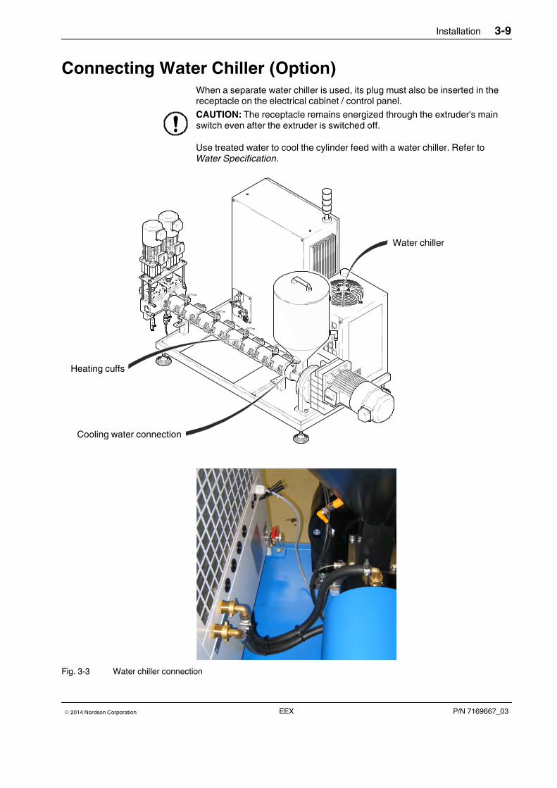
Installation 3-9
P/N 7169667_03� 2014 Nordson Corporation EEX
Connecting Water Chiller (Option)When a separate water chiller is used, its plug must also be inserted in thereceptacle on the electrical cabinet / control panel.
CAUTION: The receptacle remains energized through the extruder's mainswitch even after the extruder is switched off.
Use treated water to cool the cylinder feed with a water chiller. Refer toWater Specification.
Heizbänder
Kühlwasseranschluss
Wasserrückkühlgerät
Heating cuffs
Cooling water connection
Water chiller
Fig. 3-3 Water chiller connection
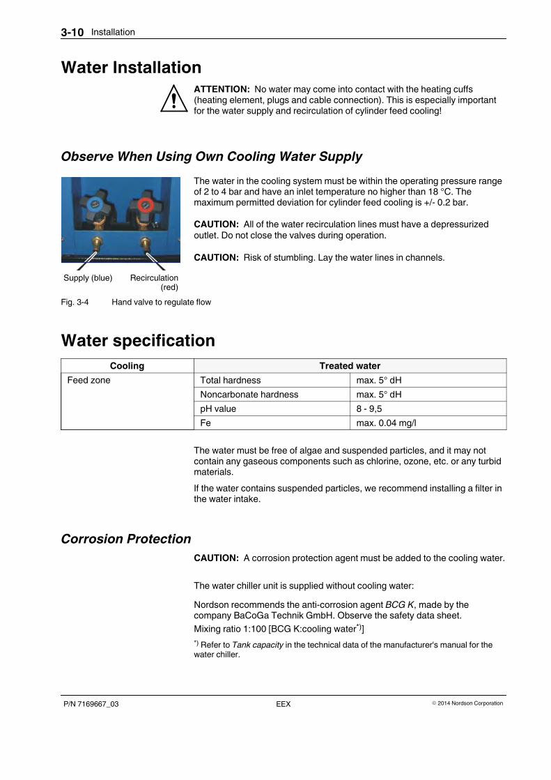
Recirculation(red)
Supply (blue)
Installation3-10
P/N 7169667_03 � 2014 Nordson CorporationEEX
Water InstallationATTENTION: No water may come into contact with the heating cuffs(heating element, plugs and cable connection). This is especially importantfor the water supply and recirculation of cylinder feed cooling!
Observe When Using Own Cooling Water Supply
The water in the cooling system must be within the operating pressure rangeof 2 to 4 bar and have an inlet temperature no higher than 18 °C. Themaximum permitted deviation for cylinder feed cooling is +/- 0.2 bar.
CAUTION: All of the water recirculation lines must have a depressurizedoutlet. Do not close the valves during operation.
CAUTION: Risk of stumbling. Lay the water lines in channels.
Fig. 3-4 Hand valve to regulate flow
Water specification
Cooling Treated water
Feed zone Total hardness max. 5° dH
Noncarbonate hardness max. 5° dH
pH value 8 - 9,5
Fe max. 0.04 mg/l
The water must be free of algae and suspended particles, and it may notcontain any gaseous components such as chlorine, ozone, etc. or any turbidmaterials.
If the water contains suspended particles, we recommend installing a filter inthe water intake.
Corrosion Protection
CAUTION: A corrosion protection agent must be added to the cooling water.
The water chiller unit is supplied without cooling water:
Nordson recommends the anti-corrosion agent BCG K, made by thecompany BaCoGa Technik GmbH. Observe the safety data sheet.
Mixing ratio 1:100 [BCG K:cooling water*)]
*) Refer to Tank capacity in the technical data of the manufacturer's manual for thewater chiller.
Installation 3-11
P/N 7169667_03� 2014 Nordson Corporation EEX
Piston Pressure Switch KDS 05/120With the pressure switch P/N 7056368 (yellow), absolute pressure valuesbetween 30 and 400 bar can be compiled, at temperatures up to 250 °C.
Factory setting:120 bar
CAUTION: Do not adjust the setting screw.
Handle the shock-sensitive flange on the sensor membrane with care wheninstalling/removing. Extract only by grasping the intended hexagonal head(size 19).
To insert it, lubricate the thread with high temperature grease and first screwit in by hand. Tighten in steps of a quarter of a revolution: Torque: 12-15 Nm.
Metering Station (Option)
When attaching the metering station to the extruder, it is essential to properlyalign the connecting piece to the screw cylinder. The sealing surface of theconnecting piece must be parallel to the end of the cylinder, and precisecentering (height and lateral offset) is important.
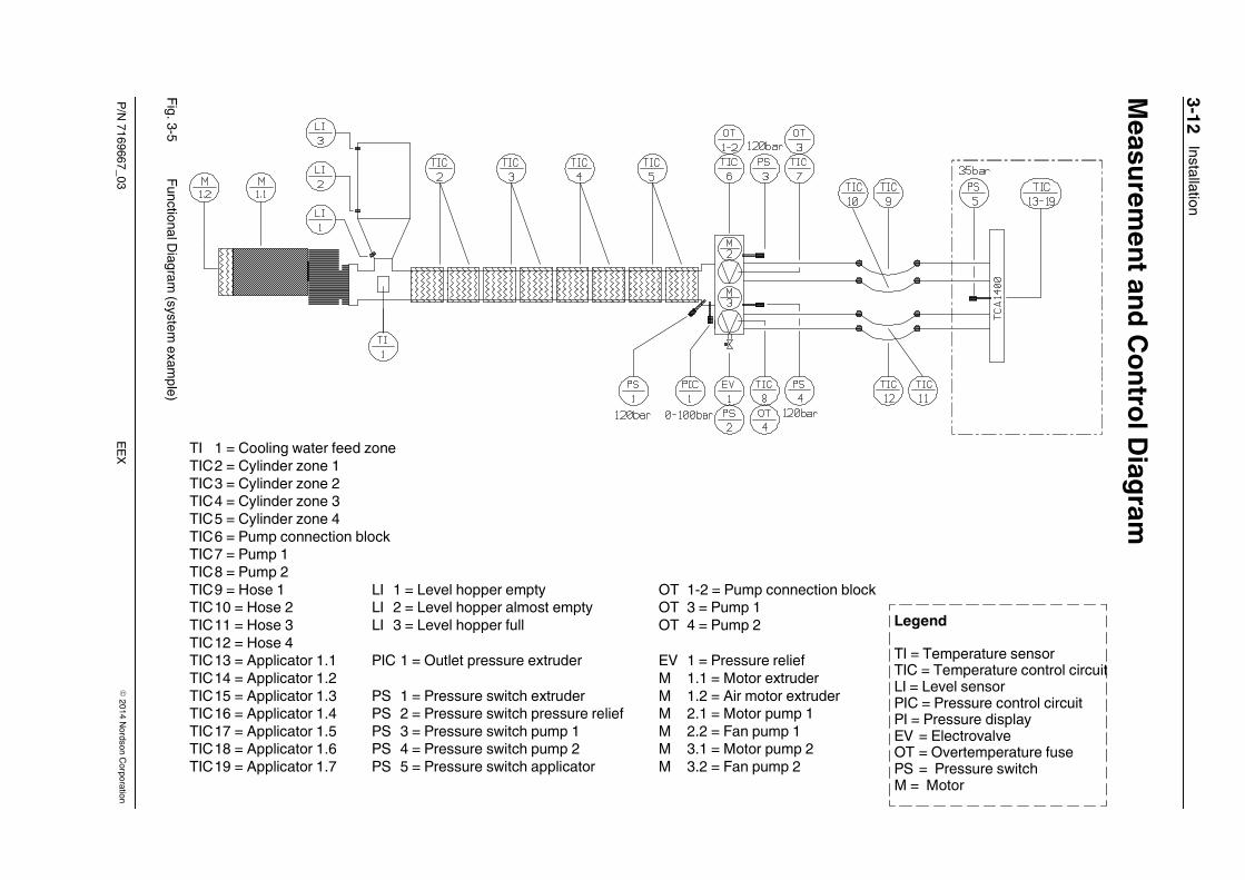
Installation3-12
P/N
7169667_03�
2014N
ordsonC
orporationE
EX
MeasurementandContro
lDiagram
TI 1 = Kühlwasser Zylinderzone
TIC 2 = Zylinderzone 1
TIC 3 = Zylinderzone 2
TIC 4 = Zylinderzone 3
TIC 5 = Zylinderzone 4
TIC 6 = Pumpenanschlussblock
TIC 7 = Pumpe 1
TIC 8 = Pumpe 2
TIC 9 = Schlauch 1
TIC 10 = Schlauch 2
TIC 11 = Schlauch 3
TIC 12 = Schlauch 4
TIC 13 = Auftragskopf 1.1
TIC 14 = Auftragskopf 1.2
TIC 15 = Auftragskopf 1.3
TIC 16 = Auftragskopf 1.4
TIC 17 = Auftragskopf 1.5
TIC 18 = Auftragskopf 1.6
TIC 19 = Auftragskopf 1.7
LI 1 = Füllstand Trichter leer
LI 2 = Füllstand Trichter fast leer
LI 3 = Füllstand Trichter voll
PIC 1 = Ausgangsdruck Extruder
PS 1 = Druckschalter Extruder
PS 2 = Druckschalter Druckentlastung
PS 3 = Druckschalter Pumpe 1
PS 4 = Druckschalter Pumpe 2
PS 5 = Druckschalter PWIII
OT 1-2 =Pumpenanschlussblock
OT 3 = Pumpe 1
OT 4 = Pumpe 2
EV 1 = Druckentlastung
M 1.1 = Motor Extruder
M 1.2 = Lüftermotor Extruder
M 2.1 = Motor Pumpe 1
M 2.2 = Lüfter Pumpe 1
M 3.1 = Motor Pumpe 2
M 3.2 = Lüfter Pumpe 2
Legende
Druckanzeige
:
TITICLIPICPIEVOTPSM
= Temperaturfühler
= Temperaturregelkreis
= Füllstandsensor
= Druckregelkreis
== Elektroventil
= Übertemperatursicherung
= Druckschalter
= Motor
OT 1-2 = Pump connection blockOT 3 = Pump 1OT 4 = Pump 2
EV 1 = Pressure reliefM 1.1 = Motor extruderM 1.2 = Air motor extruderM 2.1 = Motor pump 1M 2.2 = Fan pump 1M 3.1 = Motor pump 2M 3.2 = Fan pump 2
LI 1 = Level hopper emptyLI 2 = Level hopper almost emptyLI 3 = Level hopper full
PIC 1 = Outlet pressure extruder
PS 1 = Pressure switch extruderPS 2 = Pressure switch pressure reliefPS 3 = Pressure switch pump 1PS 4 = Pressure switch pump 2PS 5 = Pressure switch applicator
TI 1 = Cooling water feed zoneTIC2 = Cylinder zone 1TIC3 = Cylinder zone 2TIC4 = Cylinder zone 3TIC5 = Cylinder zone 4TIC6 = Pump connection blockTIC7 = Pump 1TIC8 = Pump 2TIC9 = Hose 1TIC10 = Hose 2TIC11 = Hose 3TIC12 = Hose 4TIC13 = Applicator 1.1TIC14 = Applicator 1.2TIC15 = Applicator 1.3TIC16 = Applicator 1.4TIC17 = Applicator 1.5TIC18 = Applicator 1.6TIC19 = Applicator 1.7
Legend
TI = Temperature sensorTIC = Temperature control circuitLI = Level sensorPIC = Pressure control circuitPI = Pressure displayEV = ElectrovalveOT = Overtemperature fusePS = Pressure switchM = Motor
Fig.3-5
FunctionalD
iagram(system
examp
le)
Operation 4-1
P/N 7169667_03� 2014 Nordson Corporation EEX
Section 4
Operation
ATTENTION: Allow only qualified personnel to perform the following tasks.Observe and follow the safety instructions in this document and all otherrelated documentation.
Remaining Dampness of GranulateTo prevent undesired adhesive foaming, the remaining dampness of thegranulate should be� 0.05 % for extruders without a foam station.
Special PA (polyamides) quickly extract moisture from the ambient air. Forthis reason, do not open the bag of granulate until it is needed. Immediatelyseal damaged bags with aluminum tape.
Smaller quantities of granulate can be dried in an oven at 60 - 70 °C for 3 h ifnecessary.
Always close the hopper lid immediately after filling, and store granulate notyet in the tank in a cool, dry place.
Important Upon Initial Startup
� All drives are designed for clockwise rotary field.
� Check direction of worm conveyor rotation. The worm conveyor must turnto the left when viewed in operating direction. The wrong direction ofrotation will destroy the equipment.
If the system was run with the customer's original adhesive before delivery,the next two steps are omitted.
� All heating elements on the extruder should be tightened after initialstartup. Use particular caution when tightening ceramic heating cuffs.
Continued...
Operation4-2
P/N 7169667_03 � 2014 Nordson CorporationEEX
� Electrical overpressure fuses should be adjusted according to proceduralspecifications before initial startup (For the maximum adhesive pressurepermitted, refer to the section Technical Data).
� Do not damage the pressure sensor when assembling the worm cylinder.
If a pressure sensor is defective, it should be replaced with an intactpressure sensor of the same type and pressure measuring range. Neveruse a plug to replace a defective pressure sensor.
� Compare the customer's connections to the wiring diagram
� Verify that the EMERGENCY OFF and safety switchoff devices, e.g.electrical overpressure fuses, function properly.
� Adjust the warning and shutdown limits according to the process-relatedcircumstances.
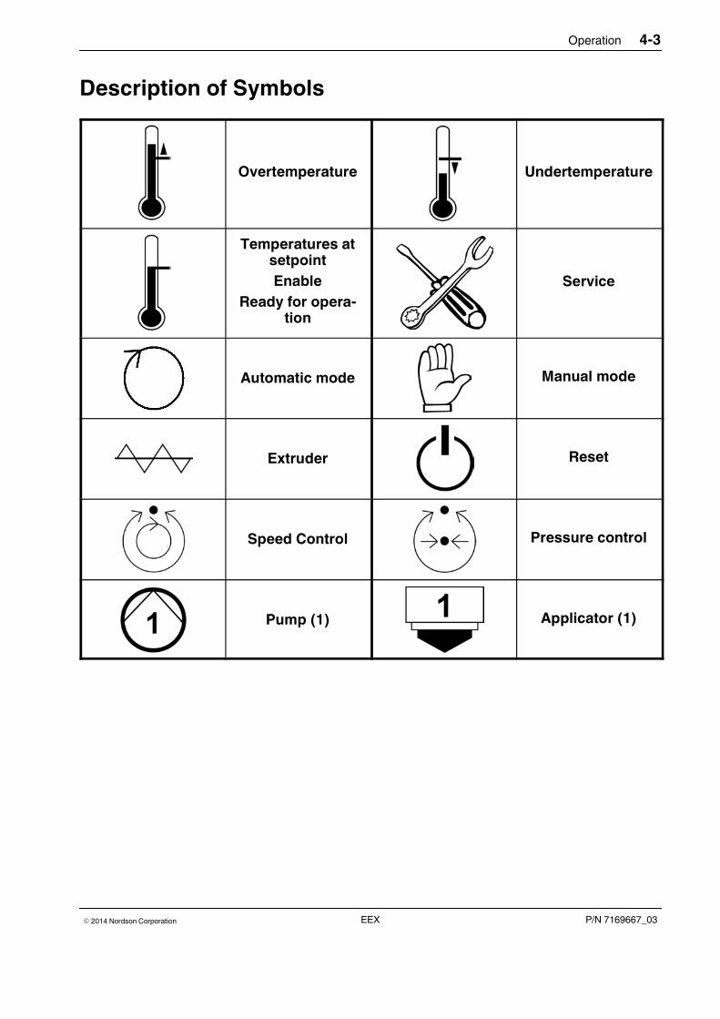
Operation 4-3
P/N 7169667_03� 2014 Nordson Corporation EEX
Description of Symbols
Overtemperature Undertemperature
Temperatures atsetpoint
Enable
Ready for opera-tion
Service
Automatic mode Manual mode
Extruder Reset
Speed Control Pressure control
Pump (1) Applicator (1)

When Using the WaterChiller
When Using Own CoolingWater Supply
Operation4-4
P/N 7169667_03 � 2014 Nordson CorporationEEX
Initial StartupThe filling area consists of a water-cooled filling piece and a filling hopper.The adhesive granulate is fed through the filling hopper. The granulate mustbe pourable.
CAUTION: Cylinder feed cooling must always be switched on beforecylinder heating is activated. The temperature in the feed zone may notexceed 40 °C at this time.
A. Fill the water chiller with water until the water level reaches the mark.Refer to the manual, section Installation, for the water specification.
B. Switch the water chiller off/on with main switch.
NOTE: The circulation pump for the cooling agent begins to run as soonas the extruder and heaters are switched on.
C. Press the keys Arrow up and Arrow down simultaneously until C1(temperature setpoint) appears. Setting range 15 °C to 25 °C.Recommended: max. 18 °C.
Press the keys Arrow up and Arrow down simultaneously to leave theparameter level.
D. Check the water level.
A. Open the inlet for cylinder feed cooling: Open the water shutoff valve andset the required flow with the hand valve.
The flow rate can seen on the meter.
1. Read the current temperature in the inlet zone on control panel FP13:
Temperature Course
The temperature in the feed zone will increase slightly during heatup.Once production has begun, increase the temperature again dependingon the product and the frictional heat of the worm. During production thetemperature stabilizes and remains relatively steady, as do speed, waterquantity and water temperature.
If the temperature in the cooling zone rises (overtemperature indication),immediately check why the temperature has risen. If the increase is dueto a lack of water, apparent on the water meter, adjust immediately. If thecause cannot be directly remedied or if no water at all is flowing and thetemperature has risen another 20 °C, the system must be switched offand the fault remedied.
2. Pour granulate into the hopper.
CAUTION: Keep all metal pieces away from the filling area. Risk ofdestroying the worm conveyor. Put the lid back into place after filling.
Continued ...
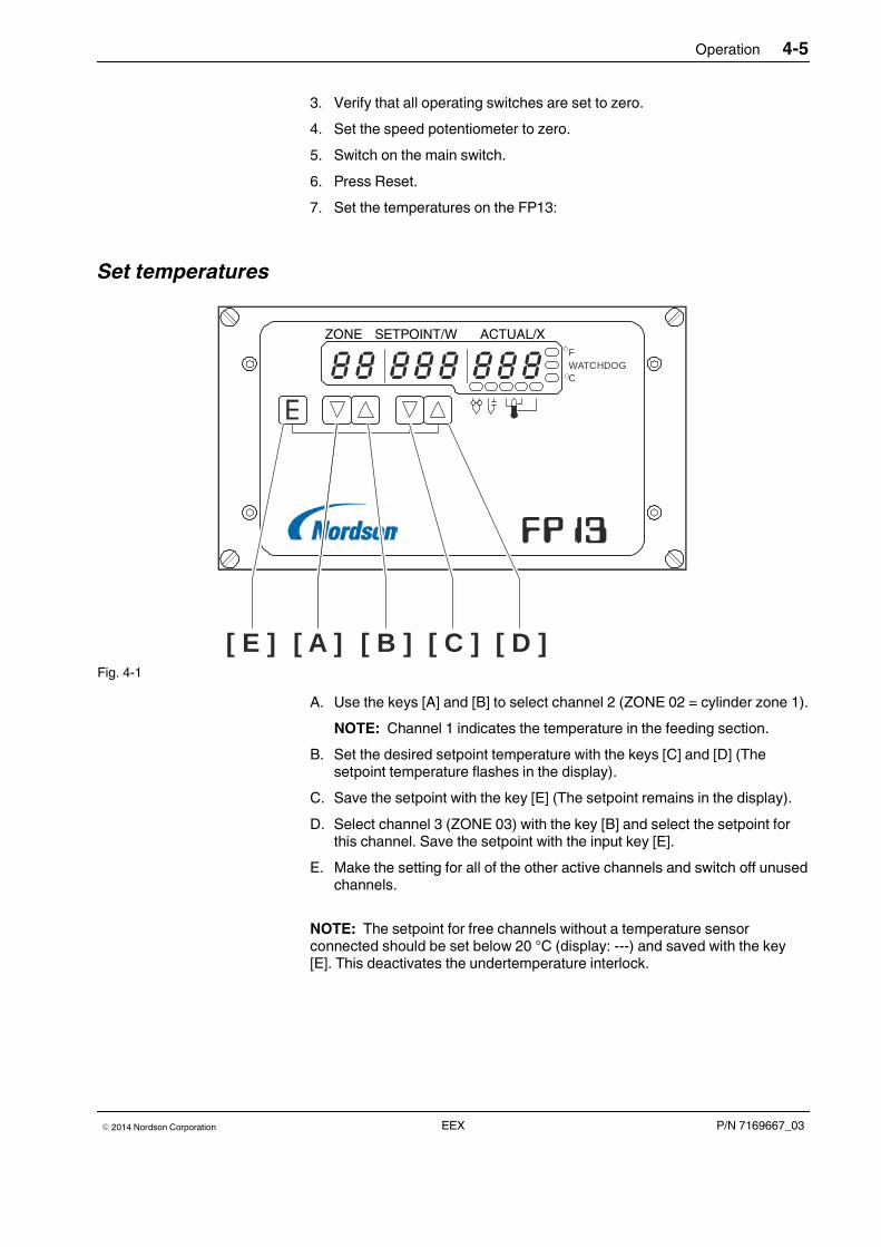
Operation 4-5
P/N 7169667_03� 2014 Nordson Corporation EEX
3. Verify that all operating switches are set to zero.
4. Set the speed potentiometer to zero.
5. Switch on the main switch.
6. Press Reset.
7. Set the temperatures on the FP13:
Set temperatures
ZONE SOLLWERT / W ISRWERT / X
FWATCHDOGC
[ E ] [ A ] [ B ] [ C ] [ D ]
ZONE SETPOINT/W ACTUAL/X
Fig. 4-1
A. Use the keys [A] and [B] to select channel 2 (ZONE 02 = cylinder zone 1).
NOTE: Channel 1 indicates the temperature in the feeding section.
B. Set the desired setpoint temperature with the keys [C] and [D] (Thesetpoint temperature flashes in the display).
C. Save the setpoint with the key [E] (The setpoint remains in the display).
D. Select channel 3 (ZONE 03) with the key [B] and select the setpoint forthis channel. Save the setpoint with the input key [E].
E. Make the setting for all of the other active channels and switch off unusedchannels.
NOTE: The setpoint for free channels without a temperature sensorconnected should be set below 20 °C (display: ---) and saved with the key[E]. This deactivates the undertemperature interlock.
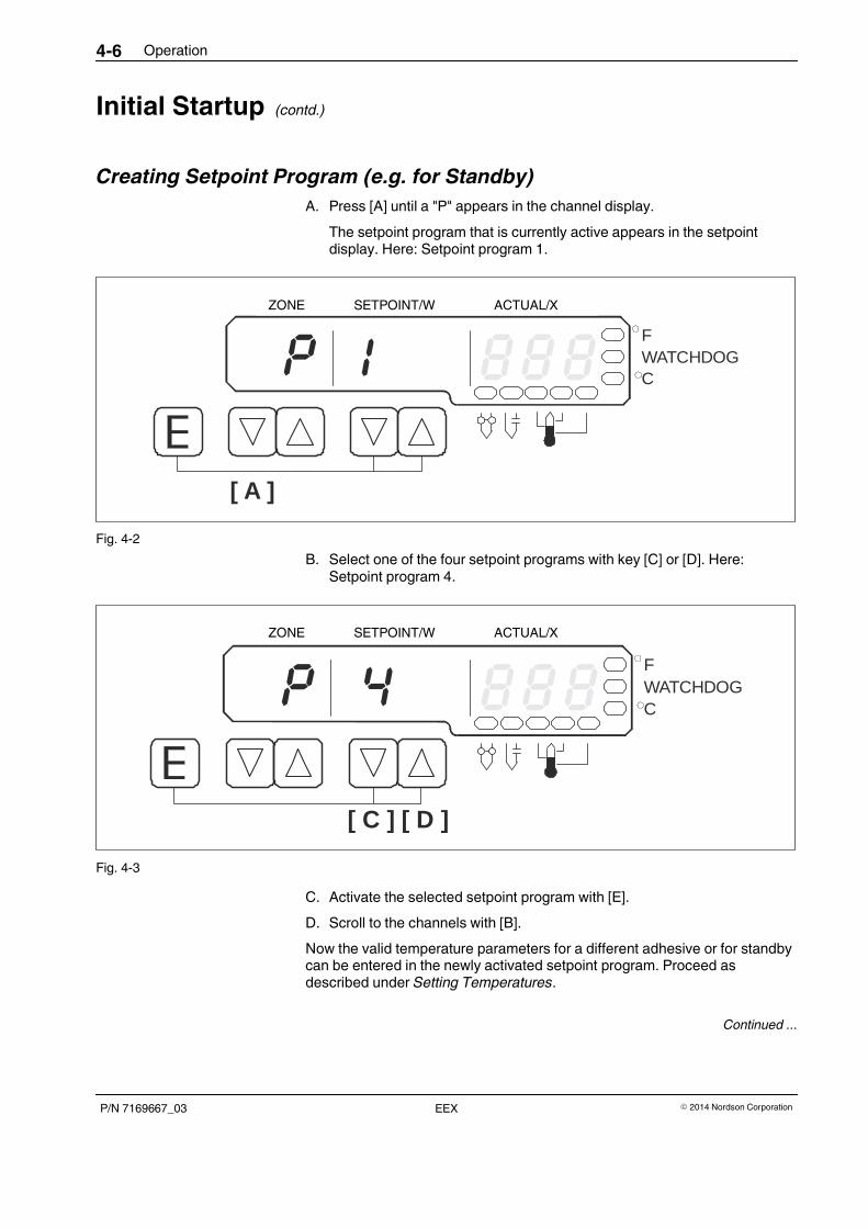
Operation4-6
P/N 7169667_03 � 2014 Nordson CorporationEEX
Initial Startup (contd.)
Creating Setpoint Program (e.g. for Standby)
A. Press [A] until a "P" appears in the channel display.
The setpoint program that is currently active appears in the setpointdisplay. Here: Setpoint program 1.
ZONE SOLLWERT / W ISRWERT / X
FWATCHDOGC
[ A ]
ZONE SETPOINT/W ACTUAL/X
Fig. 4-2
B. Select one of the four setpoint programs with key [C] or [D]. Here:Setpoint program 4.
ZONE SOLLWERT / W ISRWERT / X
FWATCHDOGC
[ C ] [ D ]
ZONE SETPOINT/W ACTUAL/X
Fig. 4-3
C. Activate the selected setpoint program with [E].
D. Scroll to the channels with [B].
Now the valid temperature parameters for a different adhesive or for standbycan be entered in the newly activated setpoint program. Proceed asdescribed under Setting Temperatures.
Continued ...
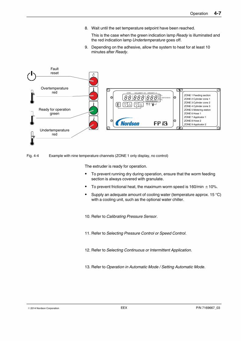
Operation 4-7
P/N 7169667_03� 2014 Nordson Corporation EEX
8. Wait until the set temperature setpoint have been reached.
This is the case when the green indication lamp Ready is illuminated andthe red indication lamp Undertemperature goes off.
9. Depending on the adhesive, allow the system to heat for at least 10minutes after Ready.
ZONE SOLLWERT / W ISRWERT / X
FWATCHDOGC
Störung Reset
Übertemperaturrot
Betriebsbereitgrün
UntertemperaturRot
Faultreset
Overtemperaturered
Ready for operationgreen
Undertemperaturered
ZONE 1 Feeding section
ZONE 2 Cylinder zone 1
ZONE 3 Cylinder zone 2
ZONE 4 Cylinder zone 3
ZONE 5 Metering station
ZONE 6 Hose 1
ZONE 7 Applicator 1
ZONE 8 Hose 2
ZONE 9 Applicator 2
Fig. 4-4 Example with nine temperature channels (ZONE 1 only display, no control)
The extruder is ready for operation.
� To prevent running dry during operation, ensure that the worm feedingsection is always covered with granulate.
� To prevent frictional heat, the maximum worm speed is 160/min ±10%.
� Supply an adequate amount of cooling water (temperature approx. 15 °C)with a cooling unit, such as the optional water chiller.
10. Refer to Calibrating Pressure Sensor.
11. Refer to Selecting Pressure Control or Speed Control.
12. Refer to Selecting Continuous or Intermittent Application.
13. Refer to Operation in Automatic Mode / Setting Automatic Mode.
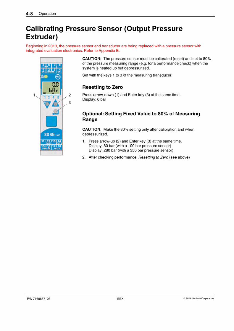
1 2
3
Operation4-8
P/N 7169667_03 � 2014 Nordson CorporationEEX
Calibrating Pressure Sensor (Output PressureExtruder)Beginning in 2013, the pressure sensor and transducer are being replaced with a pressure sensor withintegrated evaluation electronics. Refer to Appendix B.
CAUTION: The pressure sensor must be calibrated (reset) and set to 80%of the pressure measuring range (e.g. for a performance check) when thesystem is heated up but depressurized.
Set with the keys 1 to 3 of the measuring transducer.
Resetting to Zero
Press arrow-down (1) and Enter key (3) at the same time.Display: 0 bar
Optional: Setting Fixed Value to 80% of MeasuringRange
CAUTION: Make the 80% setting only after calibration and whendepressurized.
1. Press arrow-up (2) and Enter key (3) at the same time.Display: 80 bar (with a 100 bar pressure sensor)Display: 280 bar (with a 350 bar pressure sensor)
2. After checking performance, Resetting to Zero (see above)
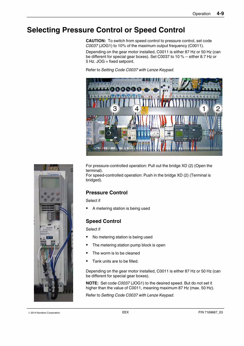
Operation 4-9
P/N 7169667_03� 2014 Nordson Corporation EEX
Selecting Pressure Control or Speed Control
CAUTION: To switch from speed control to pressure control, set codeC0037 (JOG1) to 10% of the maximum output frequency (C0011).
Depending on the gear motor installed, C0011 is either 87 Hz or 50 Hz (canbe different for special gear boxes). Set C0037 to 10 % -- either 8.7 Hz or5 Hz. JOG = fixed setpoint.
Refer to Setting Code C0037 with Lenze Keypad.
For pressure-controlled operation: Pull out the bridge XD (2) (Open theterminal).For speed-controlled operation: Push in the bridge XD (2) (Terminal isbridged).
Pressure Control
Select if
� A metering station is being used
Speed Control
Select if
� No metering station is being used
� The metering station pump block is open
� The worm is to be cleaned
� Tank units are to be filled.
Depending on the gear motor installed, C0011 is either 87 Hz or 50 Hz (canbe different for special gear boxes).
NOTE: Set code C0037 (JOG1) to the desired speed. But do not set ithigher than the value of C0011, meaning maximum 87 Hz (max. 50 Hz).
Refer to Setting Code C0037 with Lenze Keypad.
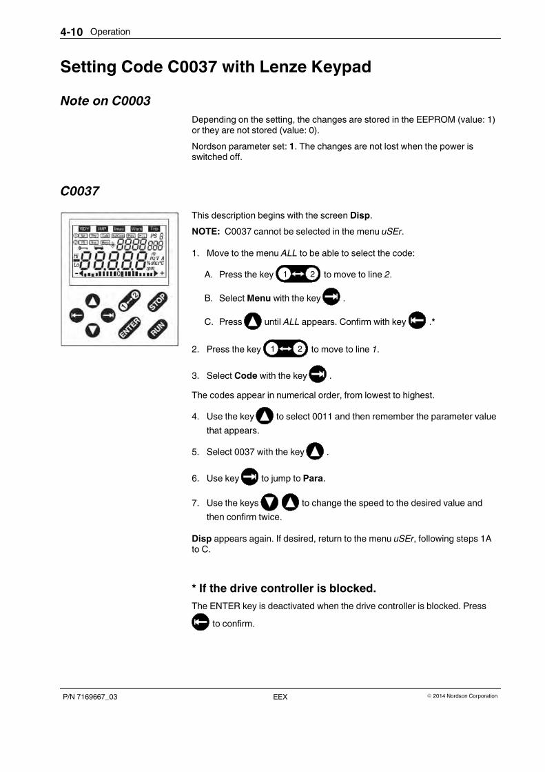
Operation4-10
P/N 7169667_03 � 2014 Nordson CorporationEEX
Setting Code C0037 with Lenze Keypad
Note on C0003
Depending on the setting, the changes are stored in the EEPROM (value: 1)or they are not stored (value: 0).
Nordson parameter set: 1. The changes are not lost when the power isswitched off.
C0037
This description begins with the screen Disp.
NOTE: C0037 cannot be selected in the menu uSEr.
1. Move to the menu ALL to be able to select the code:
A. Press the key 1 2 to move to line 2.
B. Select Menu with the key .
C. Press until ALL appears. Confirm with key .*
2. Press the key 1 2 to move to line 1.
3. Select Code with the key .
The codes appear in numerical order, from lowest to highest.
4. Use the key to select 0011 and then remember the parameter value
that appears.
5. Select 0037 with the key .
6. Use key to jump to Para.
7. Use the keys to change the speed to the desired value and
then confirm twice.
Disp appears again. If desired, return to the menu uSEr, following steps 1Ato C.
* If the drive controller is blocked.
The ENTER key is deactivated when the drive controller is blocked. Press
to confirm.
Operation 4-11
P/N 7169667_03� 2014 Nordson Corporation EEX
Operation in Automatic Mode
As an Independent Unit
The pump and applicator can each be switched separately. The solenoidvalves are triggered via the heated hose.
Depending on the Parent Machine (External Triggering)
System Starts Automatically When the Parent MachineStarts
The start/stop signals for the extruder, pumps and applicators are activatedby the parent machine. Refer to the wiring diagram for interface assignment.Observe the switching sequence.
Triggering Applicator Solenoid Valves
On the interface there are contacts for triggering the solenoid valves.Observe the voltage for the magnetic coils. Triggering is standardly via theheated hose.
Key-to-line Mode
When the substrate speed of the parent machine varies, the gear pumpspeed can be adapted to the production speed with a tach generator. Forthis, the tach control voltage and the motor controller must be attuned to oneanother.
Setting Automatic Mode
1. Set the operating switch for the extruder, pump and applicator to theposition Auto.
2. Set the speed potentiometer on the electrical cabinet / control panel tothe maximum speed (all the way to the right).
3. Set the pressure potentiometer in the electrical cabinet / control panel (3,Fig. 4-5) such that the desired adhesive quantity is fed.
4. Feed the desired adhesive quantity via external pilot voltage (0 to 10 V).
The quantity must be adjusted when the parent machine is runningconstantly. As the production speed falls, the application quantitydecreases, to pump standstill when the machine stops.
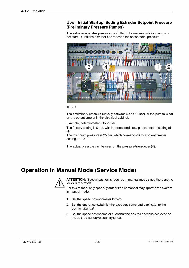
Operation4-12
P/N 7169667_03 � 2014 Nordson CorporationEEX
Upon Initial Startup: Setting Extruder Setpoint Pressure(Preliminary Pressure Pumps)
The extruder operates pressure-controlled. The metering station pumps donot start up until the extruder has reached the set setpoint pressure.
Fig. 4-5
The preliminary pressure (usually between 5 and 15 bar) for the pumps is seton the potentiometer in the electrical cabinet.
Example, potentiometer 0 to 25 bar
The factory setting is 5 bar, which corresponds to a potentiometer setting of-2-The maximum pressure is 25 bar, which corresponds to a potentiometersetting of -10-
The actual pressure can be seen on the pressure transducer (4).
Operation in Manual Mode (Service Mode)
ATTENTION: Special caution is required in manual mode since there are nolocks in this mode.
For this reason, only specially authorized personnel may operate the systemin manual mode.
1. Set the speed potentiometer to zero.
2. Set the operating switch for the extruder, pump and applicator to theposition Manual.
3. Set the speed potentiometer such that the desired speed is achieved orthe desired adhesive quantity is fed.
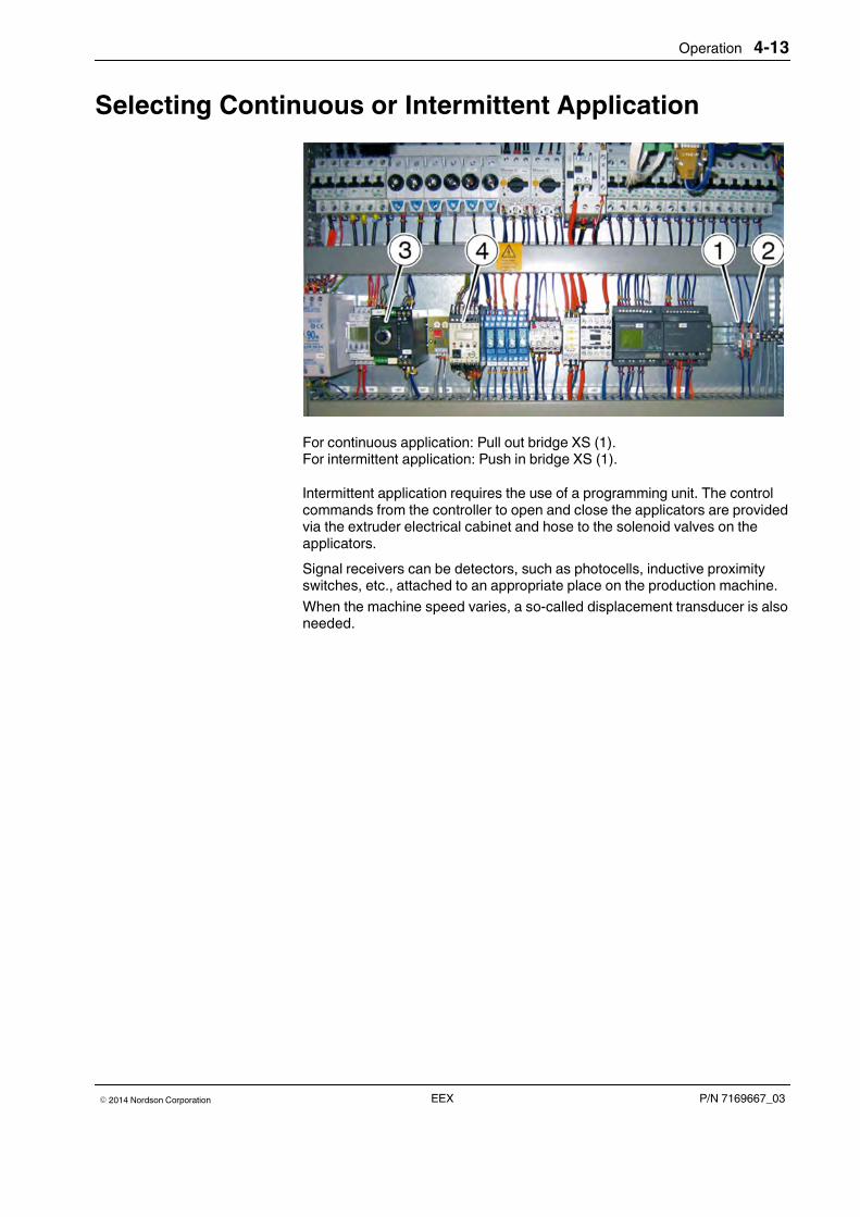
Operation 4-13
P/N 7169667_03� 2014 Nordson Corporation EEX
Selecting Continuous or Intermittent Application
For continuous application: Pull out bridge XS (1).For intermittent application: Push in bridge XS (1).
Intermittent application requires the use of a programming unit. The controlcommands from the controller to open and close the applicators are providedvia the extruder electrical cabinet and hose to the solenoid valves on theapplicators.
Signal receivers can be detectors, such as photocells, inductive proximityswitches, etc., attached to an appropriate place on the production machine.
When the machine speed varies, a so-called displacement transducer is alsoneeded.
Operation4-14
P/N 7169667_03 � 2014 Nordson CorporationEEX
During ProductionCAUTION: Keep the area surrounding the equipment clean. There is a risk ofaccidents - slipping, stumbling or falling - from adhesive granulate on thefloor as well as from hoses and cables for electrical and water installations.
Notes on Temperature Setting
Do not allow temperature ranges to be exceeded or fallen below; regulartemperature checks are essential. If the temperature is too high, the adhesivewill give off an odor and the quality will decrease.
Temperatures that are too low are also detrimental to quality. If satisfactoryresults are achieved only by deviating from the stated processingtemperature, please promptly contact a Nordson representative.
Standby During Breaks
Serves to protect the adhesive and to save energy during breaks inproduction. The standby temperatures can be compiled in one of the foursetpoint programs.
CAUTION: After extended standstill and depending on how low the standbytemperature is, allow the system to heat for at least 10 minutes after Ready.
Level Monitoring (Hopper)
1. Hopper empty – triggers Protection from dry running
2. Hopper almost empty – warning
3. Hopper full – warning (e.g. during automatic filling)
Indication Lamp "Hopper Almost Empty"
The indication lamp is illuminated when the granulate level in the hopper isbelow the level sensor. The indication lamp goes off as soon as the hopper isfilled again.
Dry Run Protection
If the adhesive flow is interrupted during operation and the pressure is notreached during the set time, the extruder switches off (all drives).
Operation 4-15
P/N 7169667_03� 2014 Nordson Corporation EEX
Acknowledging Fault Indications
General faults of the drive controllers, pressure sensors, overtemperaturefuses and dry run protection are shown over the reset key and have to beacknowledged by pressing the key after the faults have been remedied.
Pressure Monitoring
ATTENTION: Risk of bursting. The extruder may not be operated withoutthe overpressure valve.
Alarm Alarm value Effect
Underpressure warning Any threshold value Only indication; The systemremains ready for operation.
Underpressure fault Limit determined by the system Machine stops: Drives areswitched off
Temperature Monitoring
Refer to the separate manual Temperature Controller FP13.
Undertemperature Interlock
CAUTION: To prevent damage to the system by starting it when it is toocold, the temperatures in the heating zones have to be checked andcompared to the setpoint temperatures.
After extended standstill the system has to heat for at least 10 minutes(depending on the adhesive) even after the setpoint temperatures arereached.
The undertemperature alarm threshold (parameter 2 on the FP13) isintended to set a range below the setpoint at which, when the value fallsbelow it, an alarm is triggered.
The drives are switched off when an alarm occurs. Indications occur via theindication lamp, the FP13 display and to the interface for evaluation by thecustomer.
To ensure that the corresponding FP13 relay contact can still be used whenthe machine is enabled, undertemperature is indicated automatically when
� The unit is switched on
� Sensor short-circuit (Pt 100)
� Broken sensor
The undertemperature interlock prevents the system from being started up. Itlocks the motor, when appropriate the solenoid valves and, in some cases,other components of the system. Which components are locked can bedetermined individually.
Operation4-16
P/N 7169667_03 � 2014 Nordson CorporationEEX
Overtemperature Indication
The overtemperature alarm threshold (parameter 1 on the FP13) is intendedto set a range above the setpoint at which, when the value exceeds it, analarm is triggered. It is triggered in the display as well as by the potential-freerelay contact on the FP13.
If one of the connected control circuits (also applies to channels that aredeactivated) reaches the HI value (set on the FP13), overtemperature isindicated immediately.
The system remains ready for operation.
Overtemperature Shutdown
Independently operating overtemperature shutdown (by the software orthermal fuse elements) protects the system and adhesive from overheating.
If one of the connected control circuits rises to the HI value plus 10 °K, thewatchdog alarm is immediately triggered. It is triggered in the display as wellas by the potential-free relay contact on the FP13, which switches off themain contactor.
Overtemperature Shutdown by Thermal Fuse Elements
Overtemperature shutdown by thermal fuse element (switchoff value 180 °C,240 °C or 280 °C).
When they have been triggered, these irreversible fuse elements have to bereplaced.
Operation 4-17
P/N 7169667_03� 2014 Nordson Corporation EEX
Switching System ON/OFF
CAUTION: To prevent the adhesive from clumping in the feeding section,the cooling water must continue to run for about an hour after the extruder isswitched off.
With an optional water chiller, this is ensured with the timer relay ETR4. Referto the extruder wiring diagram for the set time.
There are two ways to connect the optional water chiller:
A. Switching off the extruder with the main switch does not turn off the timerrelay.
B. Switching off the extruder with the main switch would also turn off thetimer relay. So with this version, program the switchon and switchofftimes with the optional seven-day clock.
NOTE: The main switch must be set to I/ON (switched on) when usingthe week timer.
Daily Startup
NOTE: Gear pumps may not be operated without adhesive. Beforeswitching on the motor, ensure that there is granulate in the hopper.
1. Wen using your own cooling water supply: Open the cooling watersupply.
2. Set the main switch on the extruder and on the optional water chiller toI/ON if necessary.
3. Wait until the system is ready.
4. Switch on the motor(s).
Operation4-18
P/N 7169667_03 � 2014 Nordson CorporationEEX
Daily Shutdown (Model A)
1. Switch off the motor(s).
2. Set the main switch on the extruder to 0/OFF.
CAUTION: The cooling water has to continue to run for about one hour afterthe extruder is switched off.
3. Set the main switch of the water chiller to to 0/OFF or stop the coolingwater supply.
4. If necessary, secure the main switch with padlocks against unauthorizedaccess.
5. Perform daily maintenance.
Daily Shutdown (Model B)
1. Switch off the motor(s).
CAUTION: The cooling water has to continue to run for about one hour afterthe extruder is switched off.
2. When the time has elapsed and when the customer uses his own coolingwater supply: Stop the cooling water supply.
When the timer relay has elapsed the main switch can be turned off andprotected with padlocks from unauthorized access, if maintenance andrepair work so require.
3. Perform daily maintenance.
Emergency Shutdown
ATTENTION: Switch off the unit immediately in any emergency situation.
1. Set the main switch to 0/OFF.
2. After standstill and before switching the unit on again, have themalfunction remedied by qualified personnel.
Black Main Switch (Special Model)
The black main switch does not serve as an EMERGENCY OFF feature.Connected components can still be switched on!
Maintenance 5-1
P/N 7169667_03� 2014 Nordson Corporation EEX
Section 5
Maintenance
ATTENTION: Allow only qualified personnel to perform the following tasks.Observe and follow the safety instructions in this document and all otherrelated documentation.
Maintenance is an important preventive measure for maintaining operatingsafety and extending the service life of the unit. It should never be neglected.
Hazard areas of the system are generally secured with suitable protectivedevices.
If a protective device has to be removed, e.g. for maintenance or cleaning, itshould be properly put into place again upon completion of the work.
Risk of burnsSome maintenance work can only be done when the system is heated up.
ATTENTION: Hot! Risk of burns. Wear appropriate protectiveclothing/equipment.
Relieving Adhesive Pressure
ATTENTION: System and adhesive pressurized. Relieve the system ofadhesive pressure before disconnecting pressurized components (e.g.hoses, pressure sensors). Failure to observe can result in serious burns.
1. Set motor speed to 0 min-1 (rpm); switch off motor(s).
2. Place a suitable container under the applicator / assembly handgun.
3. Activate the applicator / assembly handgun electrically or manually.Repeat this procedure until no more adhesive flows out.
4. Properly dispose of adhesive according to local regulations.
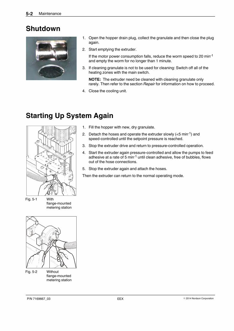
Maintenance5-2
P/N 7169667_03 � 2014 Nordson CorporationEEX
Shutdown1. Open the hopper drain plug, collect the granulate and then close the plug
again.
2. Start emptying the extruder.
If the motor power consumption falls, reduce the worm speed to 20 min-1
and empty the worm for no longer than 1 minute.
3. If cleaning granulate is not to be used for cleaning: Switch off all of theheating zones with the main switch.
NOTE: The extruder need be cleaned with cleaning granulate onlyrarely. Then refer to the section Repair for information on how to proceed.
4. Close the cooling unit.
Starting Up System Again
1. Fill the hopper with new, dry granulate.
2. Detach the hoses and operate the extruder slowly (<5 min-1) andspeed-controlled until the setpoint pressure is reached.
3. Stop the extruder drive and return to pressure-controlled operation.
4. Start the extruder again pressure-controlled and allow the pumps to feedadhesive at a rate of 5 min-1 until clean adhesive, free of bubbles, flowsout of the hose connections.
5. Stop the extruder again and attach the hoses.
Then the extruder can return to the normal operating mode.
Fig. 5-1 Withflange-mountedmetering station
Fig. 5-2 Withoutflange-mountedmetering station
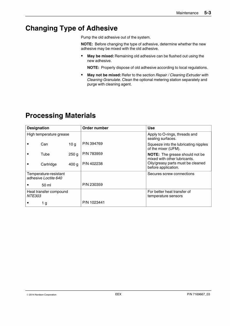
Maintenance 5-3
P/N 7169667_03� 2014 Nordson Corporation EEX
Changing Type of AdhesivePump the old adhesive out of the system.
NOTE: Before changing the type of adhesive, determine whether the newadhesive may be mixed with the old adhesive.
� May be mixed: Remaining old adhesive can be flushed out using thenew adhesive.
NOTE: Properly dispose of old adhesive according to local regulations.
� May not be mixed: Refer to the section Repair / Cleaning Extruder with
Cleaning Granulate. Clean the optional metering station separately andpurge with cleaning agent.
Processing Materials
Designation Order number Use
High temperature grease Apply to O-rings, threads andsealing surfaces.
Squeeze into the lubricating nipplesof the mixer (UFM).
NOTE: The grease should not bemixed with other lubricants.Oily/greasy parts must be cleanedbefore application.
� Can 10 g P/N 394769
� Tube 250 g P/N 783959
� Cartridge 400 g P/N 402238
Temperature-resistantadhesive Loctite 640
Secures screw connections
� 50 ml P/N 230359
Heat transfer compoundNTE303
For better heat transfer oftemperature sensors
� 1 g P/N 1023441
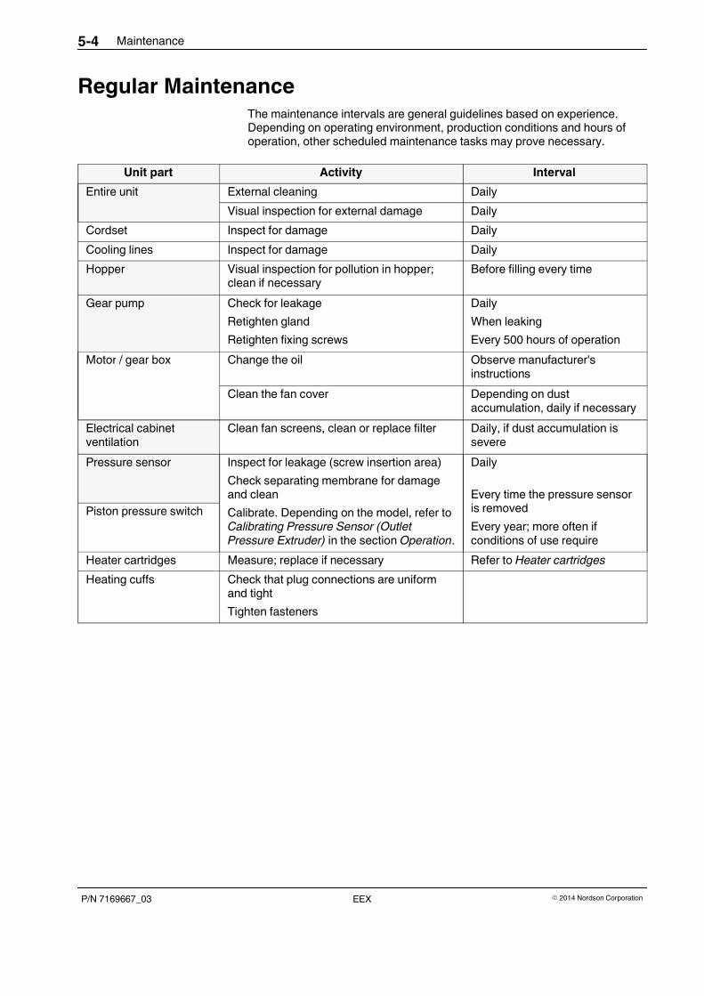
Maintenance5-4
P/N 7169667_03 � 2014 Nordson CorporationEEX
Regular MaintenanceThe maintenance intervals are general guidelines based on experience.Depending on operating environment, production conditions and hours ofoperation, other scheduled maintenance tasks may prove necessary.
Unit part Activity Interval
Entire unit External cleaning Daily
Visual inspection for external damage Daily
Cordset Inspect for damage Daily
Cooling lines Inspect for damage Daily
Hopper Visual inspection for pollution in hopper;clean if necessary
Before filling every time
Gear pump Check for leakage
Retighten gland
Retighten fixing screws
Daily
When leaking
Every 500 hours of operation
Motor / gear box Change the oil Observe manufacturer'sinstructions
Clean the fan cover Depending on dustaccumulation, daily if necessary
Electrical cabinetventilation
Clean fan screens, clean or replace filter Daily, if dust accumulation issevere
Pressure sensor Inspect for leakage (screw insertion area)
Check separating membrane for damageand clean
Calibrate. Depending on the model, refer toCalibrating Pressure Sensor (OutletPressure Extruder) in the section Operation.
Daily
Every time the pressure sensoris removed
Every year; more often ifconditions of use require
Piston pressure switch
Heater cartridges Measure; replace if necessary Refer to Heater cartridges
Heating cuffs Check that plug connections are uniformand tight
Tighten fasteners
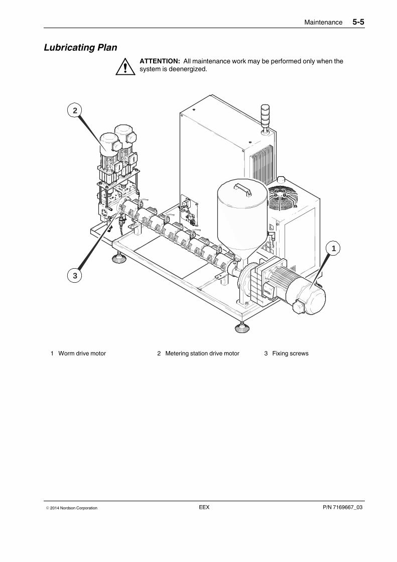
Maintenance 5-5
P/N 7169667_03� 2014 Nordson Corporation EEX
Lubricating Plan
ATTENTION: All maintenance work may be performed only when thesystem is deenergized.
2
3
1
1 Worm drive motor 2 Metering station drive motor 3 Fixing screws

Maintenance5-6
P/N 7169667_03 � 2014 Nordson CorporationEEX
Visual Inspection for External Damage
ATTENTION: When damaged parts endanger the operating safety and/orthe safety of personnel, switch off the system and have the damaged partsreplaced by qualified personnel. Use only original Nordson spare parts.
External CleaningExternal cleaning prevents pollution created by production from causing thesystem to malfunction.
ATTENTION: Observe the system's Degree of Protection when cleaning(Refer to section Technical Data.
CAUTION: Do not damage or remove warning labels. Damaged or removedwarning labels must be replaced by new ones.
1. Only remove hot melt adhesive residue with a cleaning agentrecommended by the adhesive supplier.
2. Heat with an air heater if necessary.
3. Remove dust, flakes etc. with a vacuum cleaner or a soft cloth.
General Electrical Inspection
� Check all connections and tighten terminals when needed
� The power supply must have a clockwise rotary field; check with a phasesequence indicator.
� Permitted line voltage deviation at 400 V +6% / 10%
� Check the switch state of all circuit breakers
� Check the state of the controller and the fault indication
� Check all fuses for continuity.
ATTENTION: Do not replace special fuses for semiconductors with normalfuses. Check the motor connections in the terminal box.
Maintenance 5-7
P/N 7169667_03� 2014 Nordson Corporation EEX
Ongoing Checks
� Check that protective devices function properly. The electrical cabinetdoor must be closed.
� Check the water flow for all water cooling devices. Check connections forleakage.
� Check the oil level in the gear box.
� Check that all cable connections are firmly attached to the terminals andthat all fuses are help securely in place by the clips. Heat caused by poorcontact damages the fuses as well as the clips.
CAUTION: Loose clamping leads to overheating and may cause a cablefire.
� Check the fit of the thermal elements
� Check all heating zones for electrical flow resistance. Insulationresistance should be above 1000 Ohm/Volt.
� Under load conditions, check the symmetrical power consumption in thethree phases of the electrical cabinet with a measuring device.
The values of the symmetrical power consumption in the three phasesshould not deviate more than 10 % from one another.
� Inspect the heater contactors and thyristor contacts and checkfunctioning. Worn contacts should be replaced promptly to preventsubsequent damage.
� Check the condition of all connecting cables for the nozzle or tool. Makesure that the ground terminal has a lower resistance than 0.1 Ohm to thesteel of the tool.
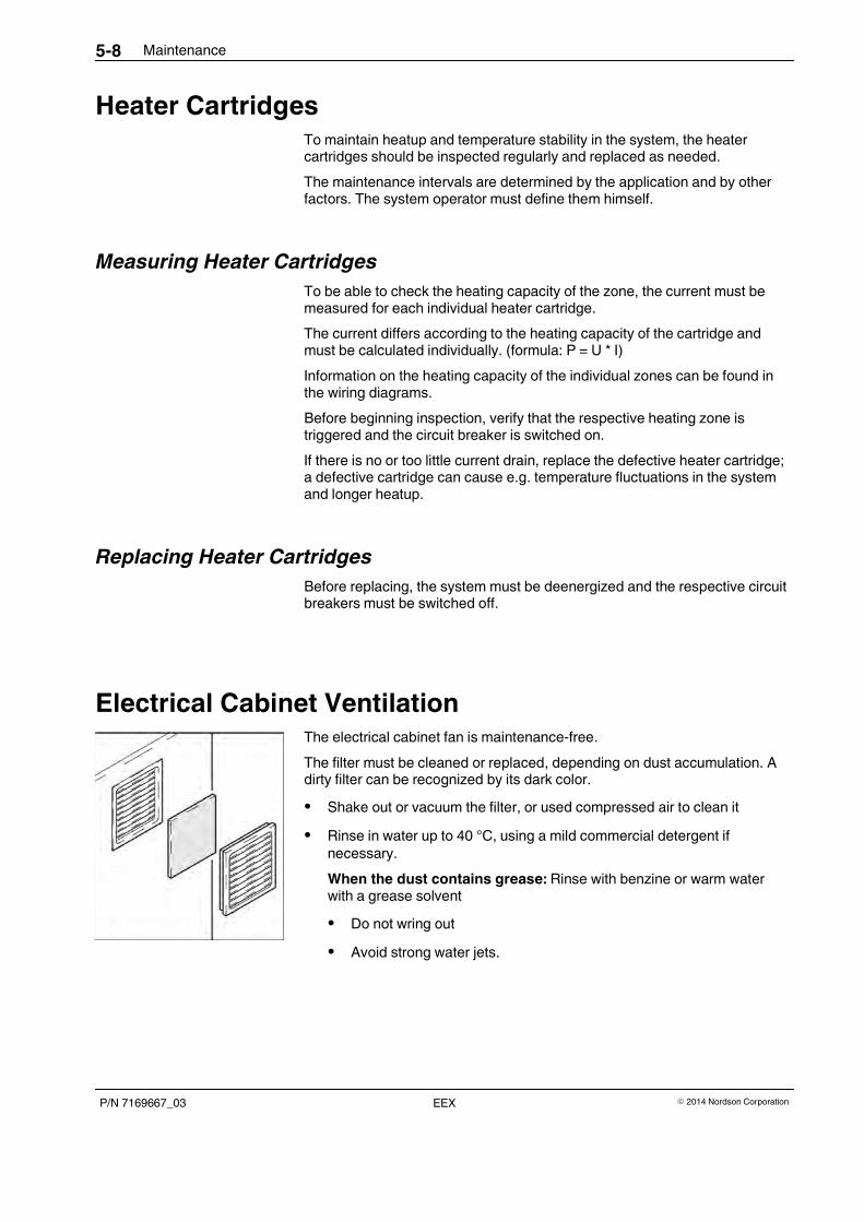
Maintenance5-8
P/N 7169667_03 � 2014 Nordson CorporationEEX
Heater CartridgesTo maintain heatup and temperature stability in the system, the heatercartridges should be inspected regularly and replaced as needed.
The maintenance intervals are determined by the application and by otherfactors. The system operator must define them himself.
Measuring Heater Cartridges
To be able to check the heating capacity of the zone, the current must bemeasured for each individual heater cartridge.
The current differs according to the heating capacity of the cartridge andmust be calculated individually. (formula: P = U * I)
Information on the heating capacity of the individual zones can be found inthe wiring diagrams.
Before beginning inspection, verify that the respective heating zone istriggered and the circuit breaker is switched on.
If there is no or too little current drain, replace the defective heater cartridge;a defective cartridge can cause e.g. temperature fluctuations in the systemand longer heatup.
Replacing Heater Cartridges
Before replacing, the system must be deenergized and the respective circuitbreakers must be switched off.
Electrical Cabinet VentilationThe electrical cabinet fan is maintenance-free.
The filter must be cleaned or replaced, depending on dust accumulation. Adirty filter can be recognized by its dark color.
� Shake out or vacuum the filter, or used compressed air to clean it
� Rinse in water up to 40 °C, using a mild commercial detergent ifnecessary.
When the dust contains grease: Rinse with benzine or warm waterwith a grease solvent
� Do not wring out
� Avoid strong water jets.
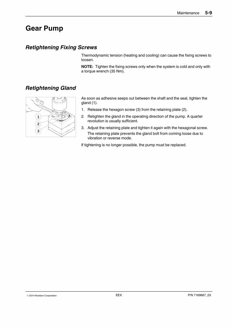
1
2
3
Maintenance 5-9
P/N 7169667_03� 2014 Nordson Corporation EEX
Gear Pump
Retightening Fixing Screws
Thermodynamic tension (heating and cooling) can cause the fixing screws toloosen.
NOTE: Tighten the fixing screws only when the system is cold and only witha torque wrench (35 Nm).
Retightening Gland
As soon as adhesive seeps out between the shaft and the seal, tighten thegland (1).
1. Release the hexagon screw (3) from the retaining plate (2).
2. Retighten the gland in the operating direction of the pump. A quarterrevolution is usually sufficient.
3. Adjust the retaining plate and tighten it again with the hexagonal screw.
The retaining plate prevents the gland bolt from coming loose due tovibration or reverse mode.
If tightening is no longer possible, the pump must be replaced.
Maintenance5-10
P/N 7169667_03 � 2014 Nordson CorporationEEX
Motor / Gear BoxThe extruder drive motor is equipped with bearings - some of which requirere-lubrication, some of which do not - that have to be replaced when there isa defect or when the motor is extensively overhauled (Refer tomanufacturer's documentation).
Replacing Motor
NOTE: The drive may only be started up by trained personnel!
Check before switching on for the first time
� Is mechanical fastening correct?
� Are the electrical connections all right?
� Are rotating parts and surfaces that can get very hot protected fromcontact?
During operation, be aware of
� Unusual noises or temperatures
� Leakage
� Loose fastening elements
� The condition of electrical lines.
Changing Lubricant
The installed gear box and gear motor are delivered ready for operation; theyare filled with a lubricant suited to the drive and design. This initial lubricant isone stated in the column for the manufacturer's respective type of gear box.
� Refer to the manufacturer's information for maintenance intervals
NOTE: The lubricant should be changed regularly with gear boxes ofdesign size 05 and larger.
� The lubricant type is indicated on the ID plate. Use only the samelubricant. Do not mix.
� Refer to the manufacturer's instructions for the lubricant quantity. Ensurethat the upper gears and rolling bearings are properly lubricated.
The manufacturer recommends replacing the bearing grease and the radialshaft seals every time the lubricant is changed.

Maintenance 5-11
P/N 7169667_03� 2014 Nordson Corporation EEX
Compression Bearings (On Models with LubricatingNipple)
2
1
Fig. 5-3
Order number Designation
Rolling bearing grease SKF LGHB2 (-20 °C to +150 °C bearingtemperature)
P/N 7107443 � 5 kg
The compression bearing has to be greased. The grease used to lubricatethe bearing at the factory is that indicated above.
Interval: Every 3 months
Greasing Compression Bearing
Grease during operation.
CAUTION: Slowly and carefully force in the grease. Pressing in too muchgrease too quickly bridges the gap to the worm and is transported by theworm forward and into the adhesive feeding section.
1. Place a rag underneath to collect the old grease.
2. Place the grease gun on the lubricating nipple (1, Fig. 5-3) and carefullyinject grease until the old grease has been completely ejected by the newgrease.
First the old grease then the excess grease is forced out of the bore (2,Fig. 5-3).
3. If necessary, remove grease residue from the extruder and/or floor.
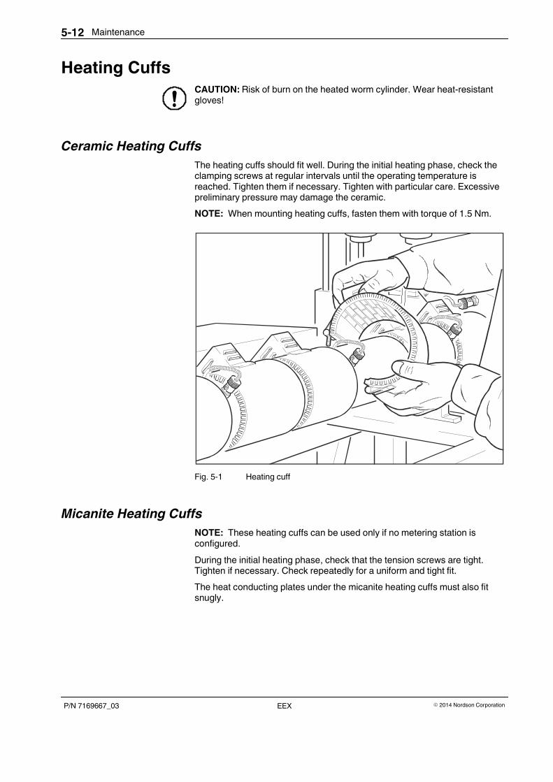
Maintenance5-12
P/N 7169667_03 � 2014 Nordson CorporationEEX
Heating CuffsCAUTION: Risk of burn on the heated worm cylinder. Wear heat-resistantgloves!
Ceramic Heating Cuffs
The heating cuffs should fit well. During the initial heating phase, check theclamping screws at regular intervals until the operating temperature isreached. Tighten them if necessary. Tighten with particular care. Excessivepreliminary pressure may damage the ceramic.
NOTE: When mounting heating cuffs, fasten them with torque of 1.5 Nm.
Fig. 5-1 Heating cuff
Micanite Heating Cuffs
NOTE: These heating cuffs can be used only if no metering station isconfigured.
During the initial heating phase, check that the tension screws are tight.Tighten if necessary. Check repeatedly for a uniform and tight fit.
The heat conducting plates under the micanite heating cuffs must also fitsnugly.
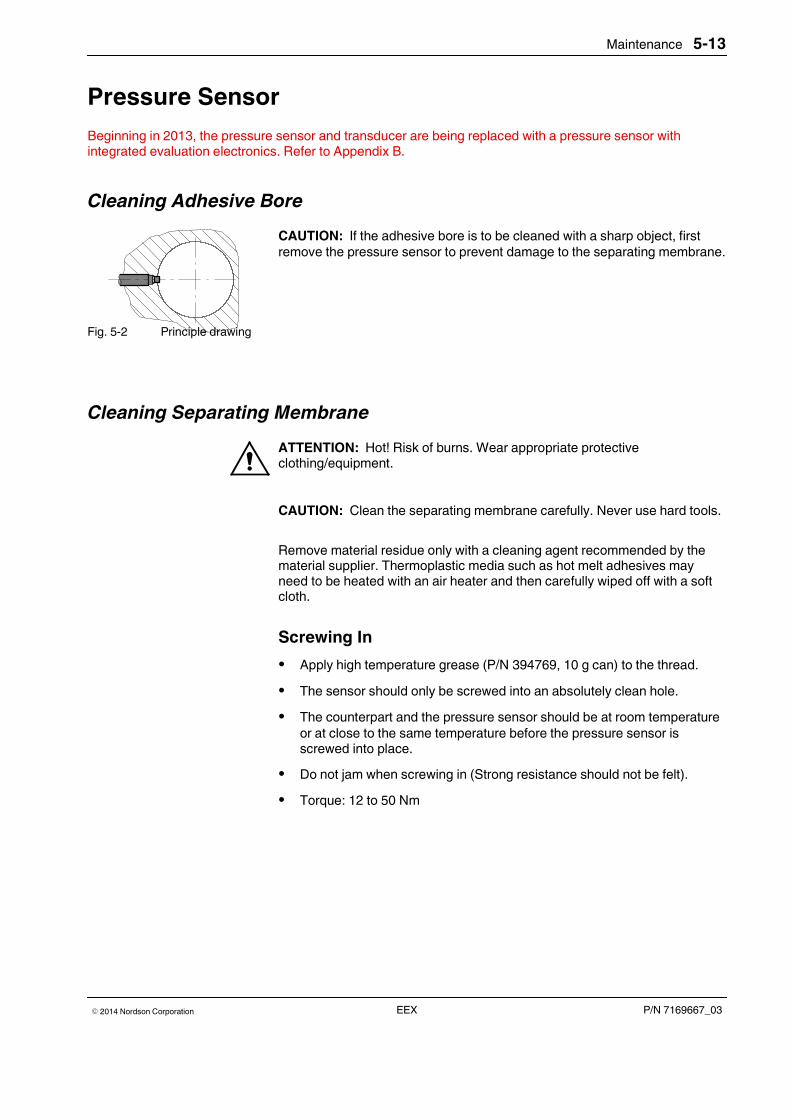
Maintenance 5-13
P/N 7169667_03� 2014 Nordson Corporation EEX
Pressure Sensor
Beginning in 2013, the pressure sensor and transducer are being replaced with a pressure sensor withintegrated evaluation electronics. Refer to Appendix B.
Cleaning Adhesive Bore
CAUTION: If the adhesive bore is to be cleaned with a sharp object, firstremove the pressure sensor to prevent damage to the separating membrane.
Fig. 5-2 Principle drawing
Cleaning Separating Membrane
ATTENTION: Hot! Risk of burns. Wear appropriate protectiveclothing/equipment.
CAUTION: Clean the separating membrane carefully. Never use hard tools.
Remove material residue only with a cleaning agent recommended by thematerial supplier. Thermoplastic media such as hot melt adhesives mayneed to be heated with an air heater and then carefully wiped off with a softcloth.
Screwing In
� Apply high temperature grease (P/N 394769, 10 g can) to the thread.
� The sensor should only be screwed into an absolutely clean hole.
� The counterpart and the pressure sensor should be at room temperatureor at close to the same temperature before the pressure sensor isscrewed into place.
� Do not jam when screwing in (Strong resistance should not be felt).
� Torque: 12 to 50 Nm

Maintenance5-14
P/N 7169667_03 � 2014 Nordson CorporationEEX

Troubleshooting 6-1
P/N 7169667_03� 2014 Nordson Corporation EEX
Section 6
Troubleshooting
ATTENTION: Allow only qualified personnel to perform the following tasks.Observe and follow the safety instructions in this document and all otherrelated documentation.
ATTENTION: Troubleshooting activities may sometimes have to be carriedout when the system is energized. Observe all safety instructions andregulations concerning energized unit components (active parts). Failure toobserve may result in an electric shock.
Troubleshooting / Corrective Action
ATTENTION: Always follow the safety instructions when remedying faults.
When a fault has occurred, the system may not be started up again until thecause has been determined and the fault remedied.
This section contains instructions on troubleshooting. The proceduresdescribed here cover only the most commonly occurring problems. If theproblem can not be solved with the information stated here, contactNordson's representative.
Please keep the following information handy:
� Complete type designation and serial number. Refer to the system's IDplate.
� Precise information on the effect of faults, e.g. the switching states ofindication lamps and measured values.
Acknowledging Fault Indications
Acknowledge fault indications with the Reset key. Acknowledgement isessential for further operation.

Troubleshooting6-2
P/N 7169667_03 � 2014 Nordson CorporationEEX
Some TipsBefore systematic troubleshooting is begun, the following should bechecked:
� Are all parameters set correctly?
� Are the interfaces wired correctly?
� During key-to-line: Is pilot voltage present?
� Do all plug connections have sufficient contact?
� Have circuit breakers tripped?
� Could the fault have been caused by an external PLC?
� Are external, inductive loads (e.g. solenoid valves) equipped withrecovery diodes? The recovery diodes must be directly allocated to theinductive load, e.g. through luminous seals.
Troubleshooting with the Help of the FP13The FP13 offers the following troubleshooting aids, described in the separatemanual:
� Display of the individual temperature channels and parameters/values
� Scan mode
� LEDs
� Diagnosis program
Light Tower (Option)
Possible message
(Refer to system wiring diagram for specific information)
Red General alarm
Refer to General Alarm: Red Indication Lamp is Lit
Red flashing System in standby
Yellow Automatic mode: System not running
Manual mode: At least one pump running
Green Ready for operation
All channels have reached their setpoint temperature AND the follow-up time haselapsed
Green flashing Hopper almost empty
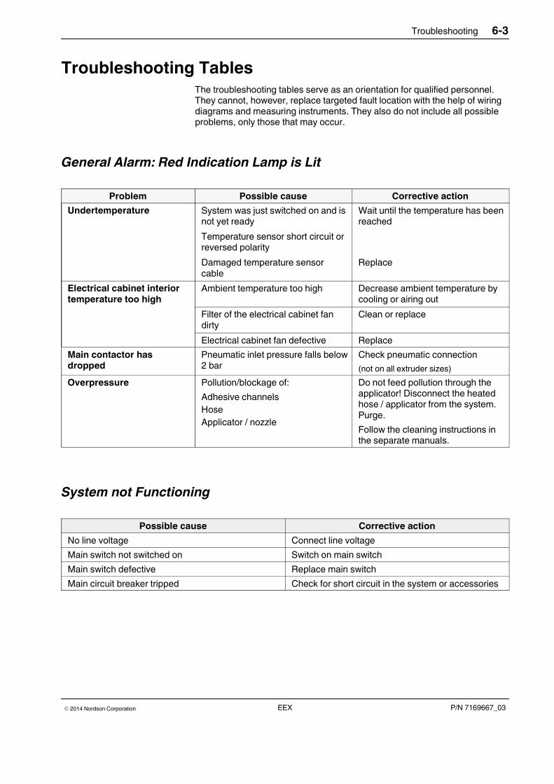
Troubleshooting 6-3
P/N 7169667_03� 2014 Nordson Corporation EEX
Troubleshooting TablesThe troubleshooting tables serve as an orientation for qualified personnel.They cannot, however, replace targeted fault location with the help of wiringdiagrams and measuring instruments. They also do not include all possibleproblems, only those that may occur.
General Alarm: Red Indication Lamp is Lit
Problem Possible cause Corrective action
Undertemperature System was just switched on and isnot yet ready
Wait until the temperature has beenreached
Temperature sensor short circuit orreversed polarity
Damaged temperature sensorcable
Replace
Electrical cabinet interiortemperature too high
Ambient temperature too high Decrease ambient temperature bycooling or airing out
Filter of the electrical cabinet fandirty
Clean or replace
Electrical cabinet fan defective Replace
Main contactor hasdropped
Pneumatic inlet pressure falls below2 bar
Check pneumatic connection
(not on all extruder sizes)
Overpressure Pollution/blockage of:
Adhesive channelsHoseApplicator / nozzle
Do not feed pollution through theapplicator! Disconnect the heatedhose / applicator from the system.Purge.
Follow the cleaning instructions inthe separate manuals.
System not Functioning
Possible cause Corrective action
No line voltage Connect line voltage
Main switch not switched on Switch on main switch
Main switch defective Replace main switch
Main circuit breaker tripped Check for short circuit in the system or accessories
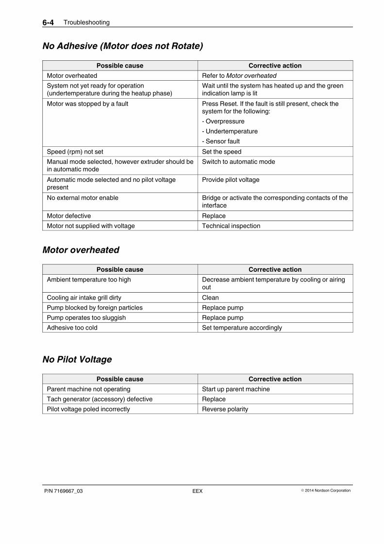
Troubleshooting6-4
P/N 7169667_03 � 2014 Nordson CorporationEEX
No Adhesive (Motor does not Rotate)
Possible cause Corrective action
Motor overheated Refer to Motor overheated
System not yet ready for operation(undertemperature during the heatup phase)
Wait until the system has heated up and the greenindication lamp is lit
Motor was stopped by a fault Press Reset. If the fault is still present, check thesystem for the following:
- Overpressure
- Undertemperature
- Sensor fault
Speed (rpm) not set Set the speed
Manual mode selected, however extruder should bein automatic mode
Switch to automatic mode
Automatic mode selected and no pilot voltagepresent
Provide pilot voltage
No external motor enable Bridge or activate the corresponding contacts of theinterface
Motor defective Replace
Motor not supplied with voltage Technical inspection
Motor overheated
Possible cause Corrective action
Ambient temperature too high Decrease ambient temperature by cooling or airingout
Cooling air intake grill dirty Clean
Pump blocked by foreign particles Replace pump
Pump operates too sluggish Replace pump
Adhesive too cold Set temperature accordingly
No Pilot Voltage
Possible cause Corrective action
Parent machine not operating Start up parent machine
Tach generator (accessory) defective Replace
Pilot voltage poled incorrectly Reverse polarity
Troubleshooting 6-5
P/N 7169667_03� 2014 Nordson Corporation EEX
Incorrect Motor Rotation in Automatic Mode
Possible cause Corrective action
Pilot voltage fluctuation despite constant machinespeed
Drive element (e.g. belt) slips. Eliminate slip
No Adhesive (Motor Rotating)
Possible cause Corrective action
Worm is turning in completely melted adhesive:
The temperature in the cylinder feed zone is toohigh (overtemperature in zones 1 and 2) due toEMERGENCY OFF or feeding too long at theextruder's maximum capacity.
If available, open the pneumatic bypass for anextended time so that the granulate can be fed tothe middle of the worm and the excess heattransferred to the melting process.
Feed sufficient fresh material to reduce thetemperature to the normal range.
Hopper empty
Dry run protection was not triggered
Fill hopper
Check level sensor position and function. It shouldnot be flush with the surface Maintain switchingdistance. Refer to section Repair
Option metering station: Adhesive feed bore to thepump or suction bore of the pump clogged
Remove pump and clean feed bore or suction bore
Option metering station: Pump does not turn,because coupling screws are loose
Tighten
Too Little Adhesive
Possible cause Corrective action
Adhesive feed bore to the pump or suction bore ofthe pump partly clogged
Remove pump and clean feed bore or suction bore
Gear pump is worn Replace pump
Processing temperature set too low Change temperature setting
Extruder operating pressure (preliminary pressure)too low
- Correct operating pressure with potentiometer
- Check extruder temperature
- Clean worm

Troubleshooting6-6
P/N 7169667_03 � 2014 Nordson CorporationEEX
One Channel (Heating Zone) does not Heat
Possible cause Corrective action
Channel is switched off Switch on by setting the setpoint temperature of thechannel above 20 °C.
Channel/heating zone defective / broken sensor Repair defect
Optional water chiller faulty
Problem Corrective action
Unit does not run
Refer to separate manufacturer manual
Insufficient cooling
(check water level first!)
Compressor or pump switched off
Shutdown caused by overpressure orunderpressure
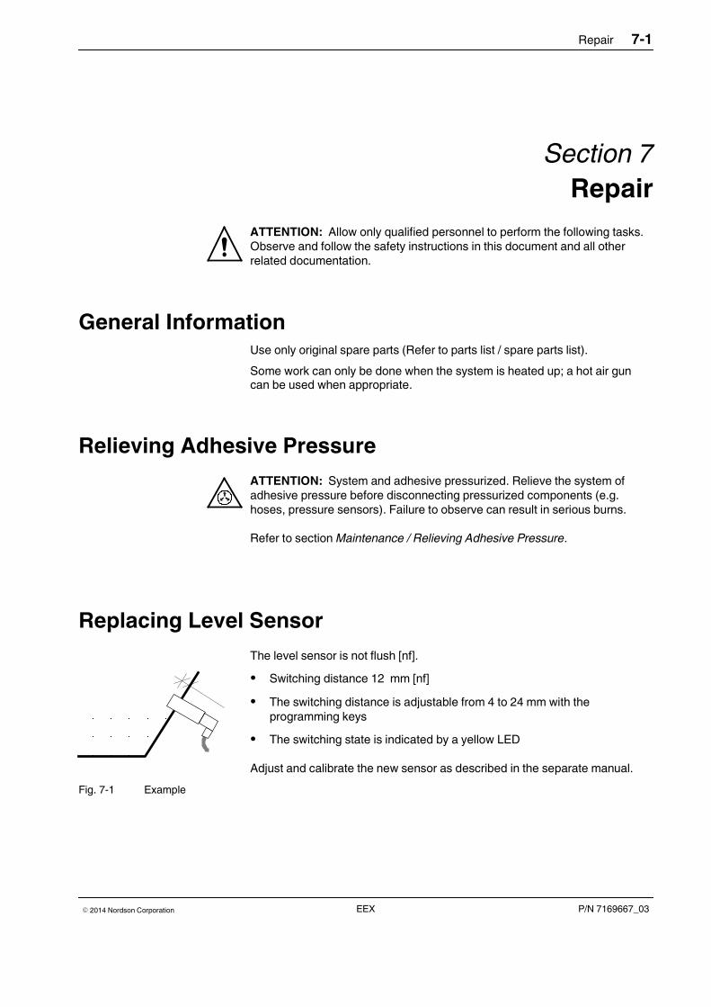
Repair 7-1
P/N 7169667_03� 2014 Nordson Corporation EEX
Section 7
Repair
ATTENTION: Allow only qualified personnel to perform the following tasks.Observe and follow the safety instructions in this document and all otherrelated documentation.
General InformationUse only original spare parts (Refer to parts list / spare parts list).
Some work can only be done when the system is heated up; a hot air guncan be used when appropriate.
Relieving Adhesive Pressure
ATTENTION: System and adhesive pressurized. Relieve the system ofadhesive pressure before disconnecting pressurized components (e.g.hoses, pressure sensors). Failure to observe can result in serious burns.
Refer to section Maintenance / Relieving Adhesive Pressure.
Replacing Level Sensor
The level sensor is not flush [nf].
� Switching distance 12 mm [nf]
� The switching distance is adjustable from 4 to 24 mm with theprogramming keys
� The switching state is indicated by a yellow LED
Adjust and calibrate the new sensor as described in the separate manual.
Fig. 7-1 Example
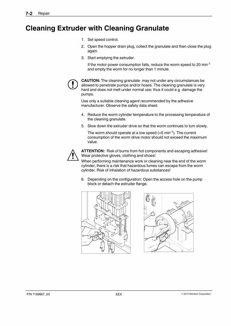
Repair7-2
P/N 7169667_03 � 2014 Nordson CorporationEEX
Cleaning Extruder with Cleaning Granulate
1. Set speed control.
2. Open the hopper drain plug, collect the granulate and then close the plugagain.
3. Start emptying the extruder.
If the motor power consumption falls, reduce the worm speed to 20 min-1
and empty the worm for no longer than 1 minute.
CAUTION: The cleaning granulate may not under any circumstances beallowed to penetrate pumps and/or hoses. The cleaning granulate is veryhard and does not melt under normal use; thus it could e.g. damage thepumps.
Use only a suitable cleaning agent recommended by the adhesivemanufacturer. Observe the safety data sheet.
4. Reduce the worm cylinder temperature to the processing temperature ofthe cleaning granulate.
5. Slow down the extruder drive so that the worm continues to turn slowly.
The worm should operate at a low speed (<5 min-1). The currentconsumption of the worm drive motor should not exceed the maximumvalue.
ATTENTION: Risk of burns from hot components and escaping adhesive!Wear protective gloves, clothing and shoes!
When performing maintenance work or cleaning near the end of the wormcylinder, there is a risk that hazardous fumes can escape from the wormcylinder. Risk of inhalation of hazardous substances!
6. Depending on the configuration: Open the access hole on the pumpblock or detach the extruder flange.
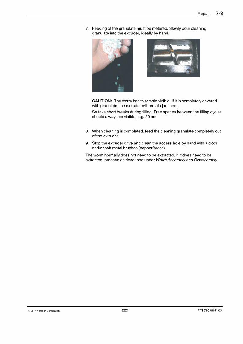
Repair 7-3
P/N 7169667_03� 2014 Nordson Corporation EEX
7. Feeding of the granulate must be metered. Slowly pour cleaninggranulate into the extruder, ideally by hand.
CAUTION: The worm has to remain visible. If it is completely coveredwith granulate, the extruder will remain jammed.
So take short breaks during filling. Free spaces between the filling cyclesshould always be visible, e.g. 30 cm.
8. When cleaning is completed, feed the cleaning granulate completely outof the extruder.
9. Stop the extruder drive and clean the access hole by hand with a clothand/or soft metal brushes (copper/brass).
The worm normally does not need to be extracted. If it does need to beextracted, proceed as described under Worm Assembly and Disassembly.
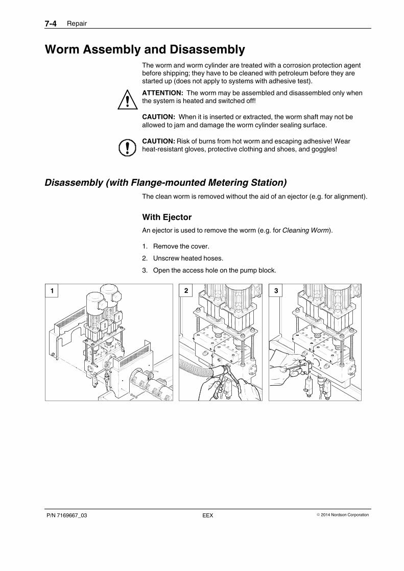
Repair7-4
P/N 7169667_03 � 2014 Nordson CorporationEEX
Worm Assembly and DisassemblyThe worm and worm cylinder are treated with a corrosion protection agentbefore shipping; they have to be cleaned with petroleum before they arestarted up (does not apply to systems with adhesive test).
ATTENTION: The worm may be assembled and disassembled only whenthe system is heated and switched off!
CAUTION: When it is inserted or extracted, the worm shaft may not beallowed to jam and damage the worm cylinder sealing surface.
CAUTION: Risk of burns from hot worm and escaping adhesive! Wearheat-resistant gloves, protective clothing and shoes, and goggles!
Disassembly (with Flange-mounted Metering Station)
The clean worm is removed without the aid of an ejector (e.g. for alignment).
With Ejector
An ejector is used to remove the worm (e.g. for Cleaning Worm).
1. Remove the cover.
2. Unscrew heated hoses.
3. Open the access hole on the pump block.
1 2 3
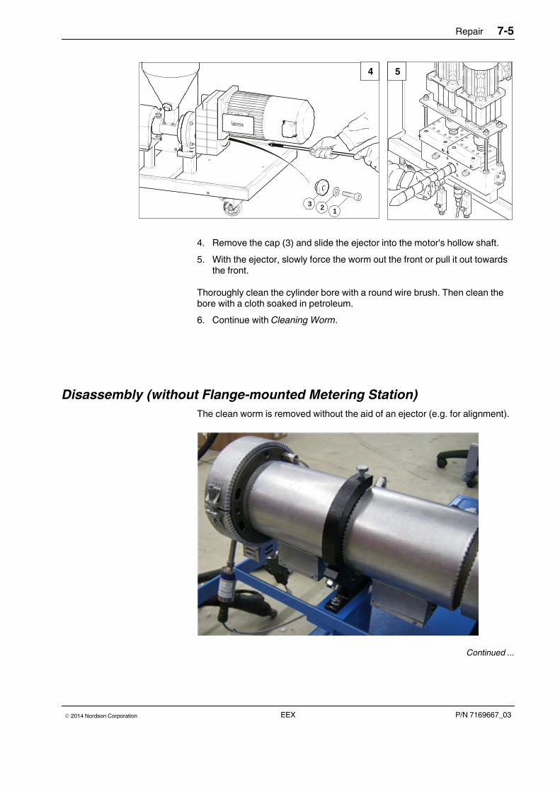
Repair 7-5
P/N 7169667_03� 2014 Nordson Corporation EEX
3 2 1
4 5
4. Remove the cap (3) and slide the ejector into the motor's hollow shaft.
5. With the ejector, slowly force the worm out the front or pull it out towardsthe front.
Thoroughly clean the cylinder bore with a round wire brush. Then clean thebore with a cloth soaked in petroleum.
6. Continue with Cleaning Worm.
Disassembly (without Flange-mounted Metering Station)
The clean worm is removed without the aid of an ejector (e.g. for alignment).
Continued ...
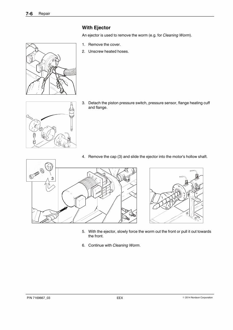
Repair7-6
P/N 7169667_03 � 2014 Nordson CorporationEEX
With Ejector
An ejector is used to remove the worm (e.g. for Cleaning Worm).
1. Remove the cover.
2. Unscrew heated hoses.
3. Detach the piston pressure switch, pressure sensor, flange heating cuffand flange.
4. Remove the cap (3) and slide the ejector into the motor's hollow shaft.
3
5. With the ejector, slowly force the worm out the front or pull it out towardsthe front.
6. Continue with Cleaning Worm.
Repair 7-7
P/N 7169667_03� 2014 Nordson Corporation EEX
Cleaning Worm
Use a brass scraper and brush to remove adhesive residue from the worm.Never use hard or sharp-edged tools.
Finally, polish the worm with a soft cloth and fine-grained polishing paste. Ifthe worm is stored for an extended period of time, it should be coated withVaseline or sprayed with a protective varnish.
Assembly
CAUTION: Ensure that there are no impurities or residue of the cleaningmaterial in the cylinder when putting the worm back into place. The cleaninggranulate is very hard and does not melt under normal use; thus it could e.g.damage the pumps.
The worm and worm cylinder have to be at room temperature for assembly.They may not be heated up together until then.
1. Clean the worm shaft and lubricate it with rolling bearing grease.
ATTENTION: Risk of injury from shearing when inserting the worm in thecylinder. Fingers and hands can be injured due to carelessness. Wearprotective gloves!
2. Guide the worm into the worm cylinder without force and slide it all theway into the worm drive shaft.
Work very carefully to prevent damage to the worm, the worm drive shaftand the worm cylinder sealing surfaces.
3. Perform disassembly steps 1. to 4. in reverse order.
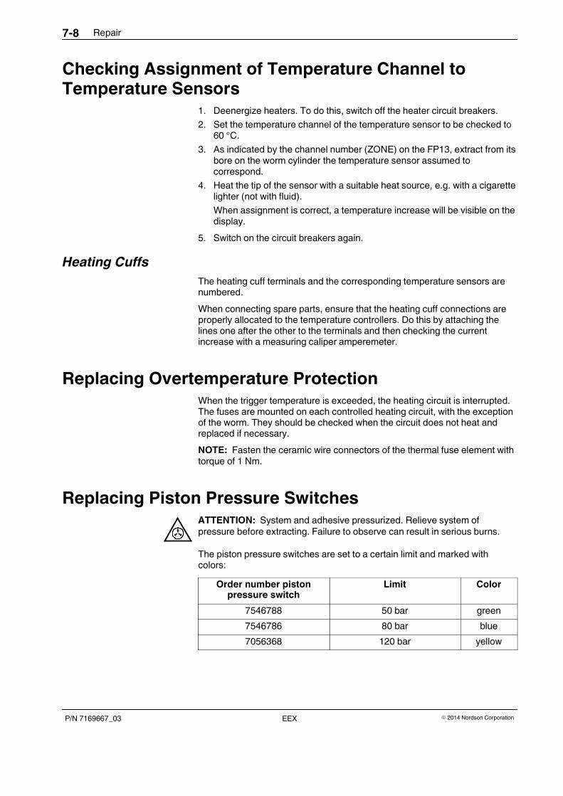
Repair7-8
P/N 7169667_03 � 2014 Nordson CorporationEEX
Checking Assignment of Temperature Channel toTemperature Sensors
1. Deenergize heaters. To do this, switch off the heater circuit breakers.
2. Set the temperature channel of the temperature sensor to be checked to60 °C.
3. As indicated by the channel number (ZONE) on the FP13, extract from itsbore on the worm cylinder the temperature sensor assumed tocorrespond.
4. Heat the tip of the sensor with a suitable heat source, e.g. with a cigarettelighter (not with fluid).
When assignment is correct, a temperature increase will be visible on thedisplay.
5. Switch on the circuit breakers again.
Heating Cuffs
The heating cuff terminals and the corresponding temperature sensors arenumbered.
When connecting spare parts, ensure that the heating cuff connections areproperly allocated to the temperature controllers. Do this by attaching thelines one after the other to the terminals and then checking the currentincrease with a measuring caliper amperemeter.
Replacing Overtemperature ProtectionWhen the trigger temperature is exceeded, the heating circuit is interrupted.The fuses are mounted on each controlled heating circuit, with the exceptionof the worm. They should be checked when the circuit does not heat andreplaced if necessary.
NOTE: Fasten the ceramic wire connectors of the thermal fuse element withtorque of 1 Nm.
Replacing Piston Pressure SwitchesATTENTION: System and adhesive pressurized. Relieve system ofpressure before extracting. Failure to observe can result in serious burns.
The piston pressure switches are set to a certain limit and marked withcolors:
Order number pistonpressure switch
Limit Color
7546788 50 bar green
7546786 80 bar blue
7056368 120 bar yellow
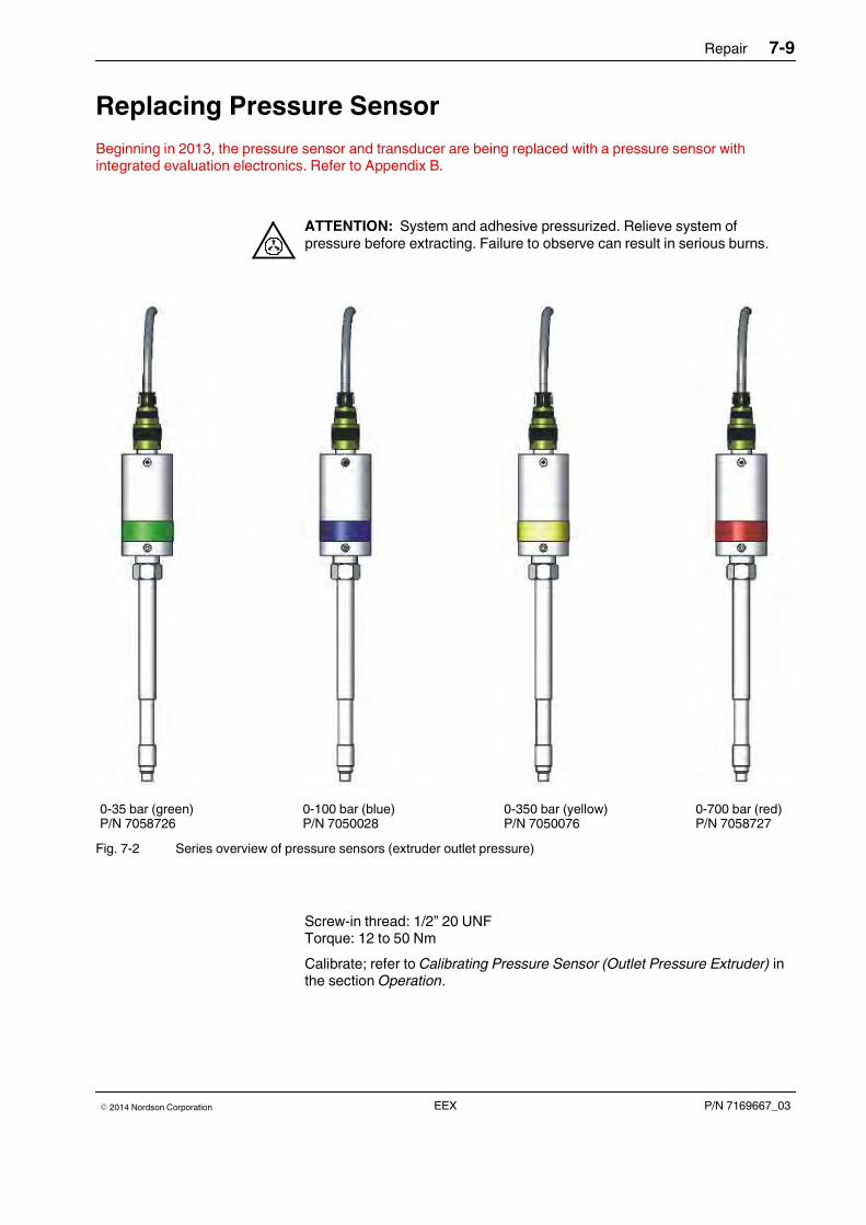
Repair 7-9
P/N 7169667_03� 2014 Nordson Corporation EEX
Replacing Pressure Sensor
Beginning in 2013, the pressure sensor and transducer are being replaced with a pressure sensor withintegrated evaluation electronics. Refer to Appendix B.
ATTENTION: System and adhesive pressurized. Relieve system ofpressure before extracting. Failure to observe can result in serious burns.
0-35 bar (green)P/N 7058726
0-100 bar (blue)P/N 7050028
0-350 bar (yellow)P/N 7050076
0-700 bar (red)P/N 7058727
Fig. 7-2 Series overview of pressure sensors (extruder outlet pressure)
Screw-in thread: 1/2” 20 UNFTorque: 12 to 50 Nm
Calibrate; refer to Calibrating Pressure Sensor (Outlet Pressure Extruder) inthe section Operation.
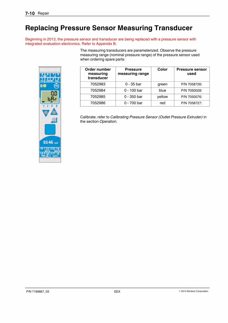
Repair7-10
P/N 7169667_03 � 2014 Nordson CorporationEEX
Replacing Pressure Sensor Measuring Transducer
Beginning in 2013, the pressure sensor and transducer are being replaced with a pressure sensor withintegrated evaluation electronics. Refer to Appendix B.
The measuring transducers are parameterized. Observe the pressuremeasuring range (nominal pressure range) of the pressure sensor usedwhen ordering spare parts:
Order numbermeasuringtransducer
Pressuremeasuring range
Color Pressure sensorused
7052983 0 - 35 bar green P/N 7058726:
7052984 0 - 100 bar blue P/N 7050028:
7052985 0 - 350 bar yellow P/N 7050076:
7052986 0 - 700 bar red P/N 7058727:
Calibrate; refer to Calibrating Pressure Sensor (Outlet Pressure Extruder) inthe section Operation.
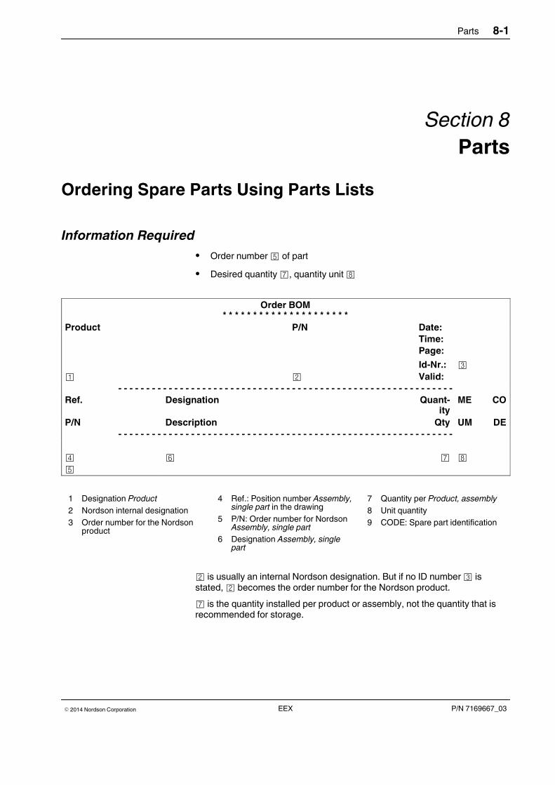
Parts 8-1
P/N 7169667_03� 2014 Nordson Corporation EEX
Section 8
Parts
Ordering Spare Parts Using Parts Lists
Information Required
� Order number¤ of part
� Desired quantity¦, quantity unit§
Order BOM* * * * * * * * * * * * * * * * * * * * *
Product P/N Date:
Time:
Page:
Id-Nr.: ¢
¡ © Valid:
- - - - - - - - - - - - - - - - - - - - - - - - - - - - - - - - - - - - - - - - - - - - - - - - - - - - - - - - - - - -
Ref. Designation Quant-ity
ME CO
P/N Description Qty UM DE
- - - - - - - - - - - - - - - - - - - - - - - - - - - - - - - - - - - - - - - - - - - - - - - - - - - - - - - - - - - -
£ ¥ ¦ §
¤
1 Designation Product
2 Nordson internal designation
3 Order number for the Nordsonproduct
4 Ref.: Position number Assembly,single part in the drawing
5 P/N: Order number for NordsonAssembly, single part
6 Designation Assembly, singlepart
7 Quantity per Product, assembly
8 Unit quantity
9 CODE: Spare part identification
© is usually an internal Nordson designation. But if no ID number¢ isstated, © becomes the order number for the Nordson product.
¦ is the quantity installed per product or assembly, not the quantity that isrecommended for storage.

Parts8-2
P/N 7169667_03 � 2014 Nordson CorporationEEX
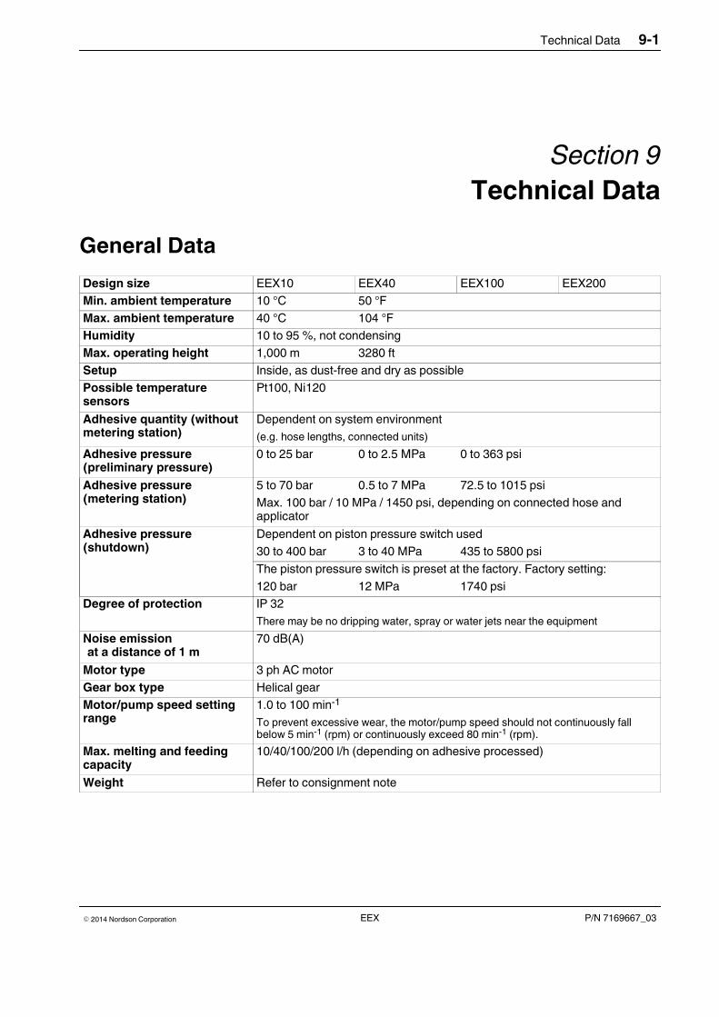
Technical Data 9-1
P/N 7169667_03� 2014 Nordson Corporation EEX
Section 9
Technical Data
General Data
Design size EEX10 EEX40 EEX100 EEX200
Min. ambient temperature 10 °C 50 °F
Max. ambient temperature 40 °C 104 °F
Humidity 10 to 95 %, not condensing
Max. operating height 1,000 m 3280 ft
Setup Inside, as dust-free and dry as possible
Possible temperaturesensors
Pt100, Ni120
Adhesive quantity (withoutmetering station)
Dependent on system environment
(e.g. hose lengths, connected units)
Adhesive pressure(preliminary pressure)
0 to 25 bar 0 to 2.5 MPa 0 to 363 psi
Adhesive pressure(metering station)
5 to 70 bar 0.5 to 7 MPa 72.5 to 1015 psi
Max. 100 bar / 10 MPa / 1450 psi, depending on connected hose andapplicator
Adhesive pressure(shutdown)
Dependent on piston pressure switch used
30 to 400 bar 3 to 40 MPa 435 to 5800 psi
The piston pressure switch is preset at the factory. Factory setting:
120 bar 12 MPa 1740 psi
Degree of protection IP 32
There may be no dripping water, spray or water jets near the equipment
Noise emissionat a distance of 1 m
70 dB(A)
Motor type 3 ph AC motor
Gear box type Helical gear
Motor/pump speed settingrange
1.0 to 100 min-1
To prevent excessive wear, the motor/pump speed should not continuously fallbelow 5 min-1 (rpm) or continuously exceed 80 min-1 (rpm).
Max. melting and feedingcapacity
10/40/100/200 l/h (depending on adhesive processed)
Weight Refer to consignment note
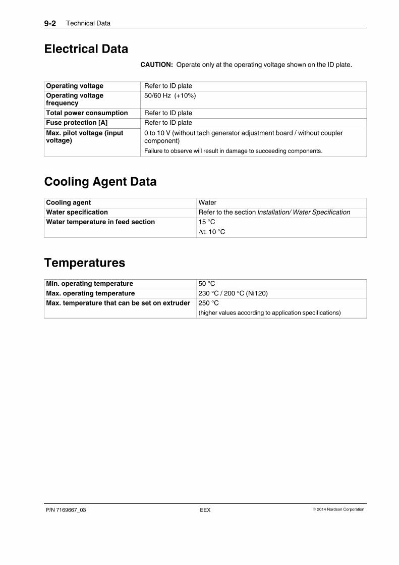
Technical Data9-2
P/N 7169667_03 � 2014 Nordson CorporationEEX
Electrical DataCAUTION: Operate only at the operating voltage shown on the ID plate.
Operating voltage Refer to ID plate
Operating voltagefrequency
50/60 Hz (+10%)
Total power consumption Refer to ID plate
Fuse protection [A] Refer to ID plate
Max. pilot voltage (inputvoltage)
0 to 10 V (without tach generator adjustment board / without couplercomponent)
Failure to observe will result in damage to succeeding components.
Cooling Agent Data
Cooling agent Water
Water specification Refer to the section Installation/ Water Specification
Water temperature in feed section 15 °C
∆t: 10 °C
Temperatures
Min. operating temperature 50 °C
Max. operating temperature 230 °C / 200 °C (Ni120)
Max. temperature that can be set on extruder 250 °C
(higher values according to application specifications)
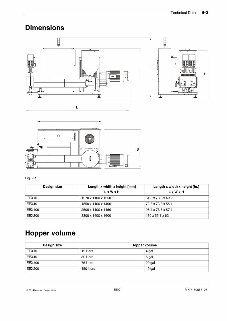
Technical Data 9-3
P/N 7169667_03� 2014 Nordson Corporation EEX
Dimensions
ca. 3299
ca.1
595
ca.1
935
ca.1
530
ca. 2030
ca.1
250
L
B
H
Fig. 9-1
Design size Length x width x height [mm]
L x W x H
Length x width x height [in.]
L x W x H
EEX10 1570 x 1100 x 1250 61.8 x 73.3 x 49.2
EEX40 1850 x 1100 x 1400 72.8 x 73.3 x 55.1
EEX100 2500 x 1100 x 1450 98.4 x 73.3 x 57.1
EEX200 3300 x 1400 x 1600 130 x 55.1 x 63
Hopper volume
Design size Hopper volume
EEX10 15 liters 4 gal
EEX40 30 liters 8 gal
EEX100 75 liters 20 gal
EEX200 150 liters 40 gal

Technical Data9-4
P/N 7169667_03 � 2014 Nordson CorporationEEX
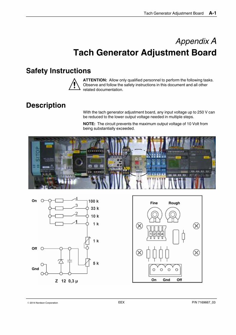
Tach Generator Adjustment Board A-1
P/N 7169667_03� 2014 Nordson Corporation EEX
Appendix A
Tach Generator Adjustment Board
Safety InstructionsATTENTION: Allow only qualified personnel to perform the following tasks.Observe and follow the safety instructions in this document and all otherrelated documentation.
DescriptionWith the tach generator adjustment board, any input voltage up to 250 V canbe reduced to the lower output voltage needed in multiple steps.
NOTE: The circuit prevents the maximum output voltage of 10 Volt frombeing substantially exceeded.
On
Off
Gnd
Fine Rough
On OffGnd
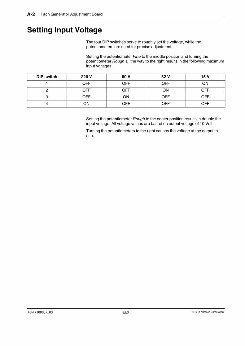
Tach Generator Adjustment BoardA-2
P/N 7169667_03 � 2014 Nordson CorporationEEX
Setting Input Voltage
The four DIP switches serve to roughly set the voltage, while thepotentiometers are used for precise adjustment.
Setting the potentiometer Fine to the middle position and turning thepotentiometer Rough all the way to the right results in the following maximuminput voltages:
DIP switch 220 V 80 V 32 V 15 V
1 OFF OFF OFF ON
2 OFF OFF ON OFF
3 OFF ON OFF OFF
4 ON OFF OFF OFF
Setting the potentiometer Rough to the center position results in double theinput voltage. All voltage values are based on output voltage of 10 Volt.
Turning the potentiometers to the right causes the voltage at the output torise.
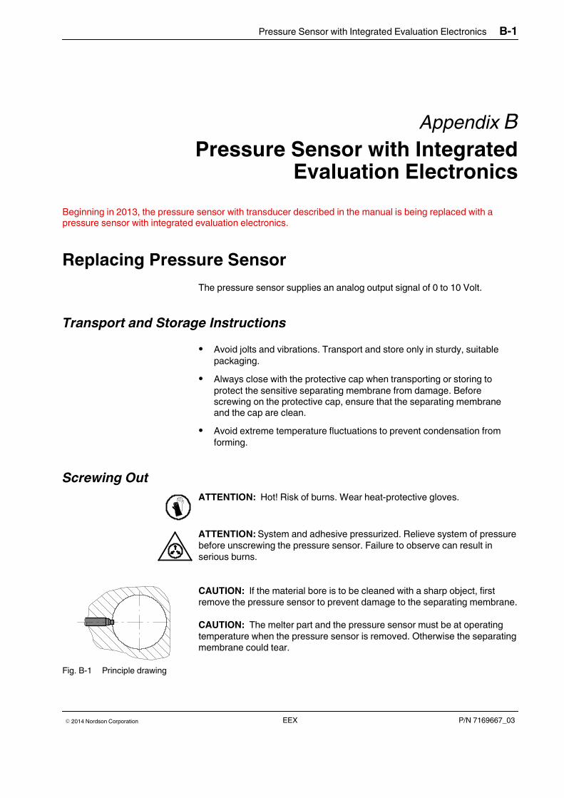
Pressure Sensor with Integrated Evaluation Electronics B-1
P/N 7169667_03� 2014 Nordson Corporation EEX
Appendix B
Pressure Sensor with IntegratedEvaluation Electronics
Beginning in 2013, the pressure sensor with transducer described in the manual is being replaced with apressure sensor with integrated evaluation electronics.
Replacing Pressure Sensor
The pressure sensor supplies an analog output signal of 0 to 10 Volt.
Transport and Storage Instructions
� Avoid jolts and vibrations. Transport and store only in sturdy, suitablepackaging.
� Always close with the protective cap when transporting or storing toprotect the sensitive separating membrane from damage. Beforescrewing on the protective cap, ensure that the separating membraneand the cap are clean.
� Avoid extreme temperature fluctuations to prevent condensation fromforming.
Screwing Out
ATTENTION: Hot! Risk of burns. Wear heat-protective gloves.
ATTENTION: System and adhesive pressurized. Relieve system of pressurebefore unscrewing the pressure sensor. Failure to observe can result inserious burns.
CAUTION: If the material bore is to be cleaned with a sharp object, firstremove the pressure sensor to prevent damage to the separating membrane.
CAUTION: The melter part and the pressure sensor must be at operatingtemperature when the pressure sensor is removed. Otherwise the separatingmembrane could tear.
Fig. B-1 Principle drawing
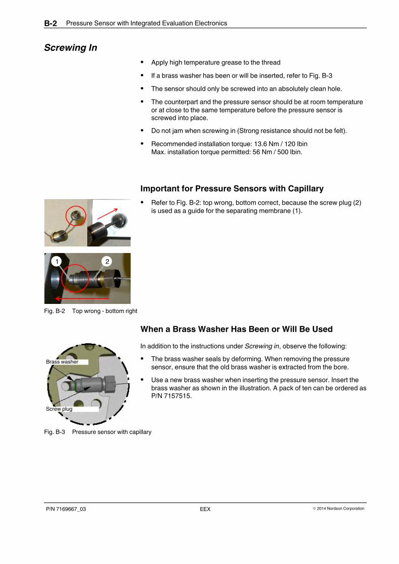
1 2
Screw plug
Brass washer
Pressure Sensor with Integrated Evaluation ElectronicsB-2
P/N 7169667_03 � 2014 Nordson CorporationEEX
Screwing In
� Apply high temperature grease to the thread
� If a brass washer has been or will be inserted, refer to Fig. B-3
� The sensor should only be screwed into an absolutely clean hole.
� The counterpart and the pressure sensor should be at room temperatureor at close to the same temperature before the pressure sensor isscrewed into place.
� Do not jam when screwing in (Strong resistance should not be felt).
� Recommended installation torque: 13.6 Nm / 120 lbinMax. installation torque permitted: 56 Nm / 500 lbin.
Important for Pressure Sensors with Capillary
� Refer to Fig. B-2: top wrong, bottom correct, because the screw plug (2)is used as a guide for the separating membrane (1).
Fig. B-2 Top wrong - bottom right
When a Brass Washer Has Been or Will Be Used
In addition to the instructions under Screwing in, observe the following:
� The brass washer seals by deforming. When removing the pressuresensor, ensure that the old brass washer is extracted from the bore.
� Use a new brass washer when inserting the pressure sensor. Insert thebrass washer as shown in the illustration. A pack of ten can be ordered asP/N 7157515.
Fig. B-3 Pressure sensor with capillary
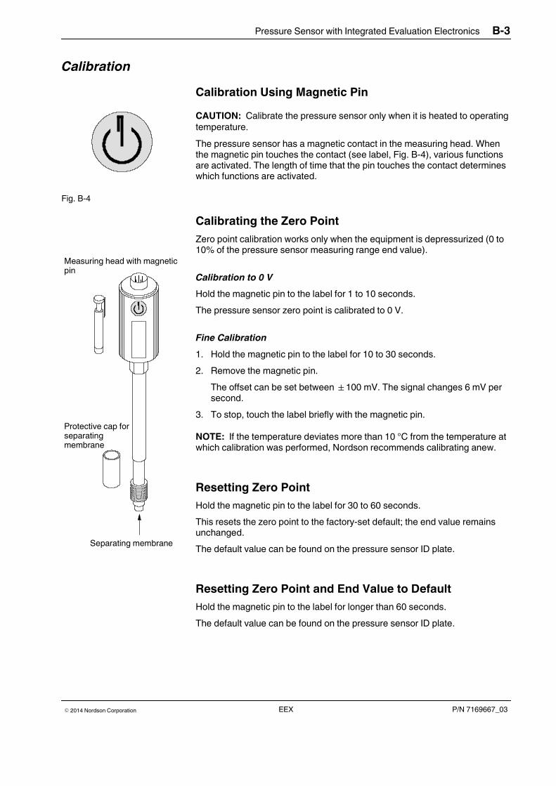
Protective cap forseparatingmembrane
Separating membrane
Measuring head with magneticpin
Pressure Sensor with Integrated Evaluation Electronics B-3
P/N 7169667_03� 2014 Nordson Corporation EEX
Calibration
Calibration Using Magnetic Pin
CAUTION: Calibrate the pressure sensor only when it is heated to operatingtemperature.
The pressure sensor has a magnetic contact in the measuring head. Whenthe magnetic pin touches the contact (see label, Fig. B-4), various functionsare activated. The length of time that the pin touches the contact determineswhich functions are activated.
Fig. B-4
Calibrating the Zero Point
Zero point calibration works only when the equipment is depressurized (0 to10% of the pressure sensor measuring range end value).
Calibration to 0 V
Hold the magnetic pin to the label for 1 to 10 seconds.
The pressure sensor zero point is calibrated to 0 V.
Fine Calibration
1. Hold the magnetic pin to the label for 10 to 30 seconds.
2. Remove the magnetic pin.
The offset can be set between �100 mV. The signal changes 6 mV persecond.
3. To stop, touch the label briefly with the magnetic pin.
NOTE: If the temperature deviates more than 10 °C from the temperature atwhich calibration was performed, Nordson recommends calibrating anew.
Resetting Zero Point
Hold the magnetic pin to the label for 30 to 60 seconds.
This resets the zero point to the factory-set default; the end value remainsunchanged.
The default value can be found on the pressure sensor ID plate.
Resetting Zero Point and End Value to Default
Hold the magnetic pin to the label for longer than 60 seconds.
The default value can be found on the pressure sensor ID plate.

Pressure Sensor with Integrated Evaluation ElectronicsB-4
P/N 7169667_03 � 2014 Nordson CorporationEEX
Maintenance1. Relieve adhesive pressure.
2. Refer to Replacing Pressure Sensor for information on removal andinstallation.
Cleaning Separating Membrane
NOTE: Clean the separating membrane carefully. Never use hard tools.
ATTENTION: Hot! Risk of burns. Wear heat-protective gloves.
Remove material residue only with a cleaning agent recommended by thematerial supplier. Thermoplastic materials such as hot melt adhesives mayneed to be heated with an air heater and then carefully wiped off with a softcloth.
Performance Check
Connect pressure sensor electrically for performance check; do not screw in.
CAUTION: Never check performance with objects that could damage theseparating membrane. The separating membrane must be absolutely clean.Apply pressure to the separating membrane. If possible, use a suitablepressure instrument; otherwise use a finger or a flexible object.
Checking Measuring Performance
Pin Connection
A Signal output 0 to 10 VDC
B Signal output 0 VDC
C Operating voltage 15 to 30 VDC
D Operating voltage 0 VDC
E Calibration function (bridge E and F)
F
Fig. B-5 7116902
1. Connect a suitable display unit, e.g. DC-Voltmeter. Supply the pressuresensor with operating voltage (15 to 30 VDC).
2. When pressure is applied to the separating membrane, there should bean output signal, proportional to the pressure, at the signal output.
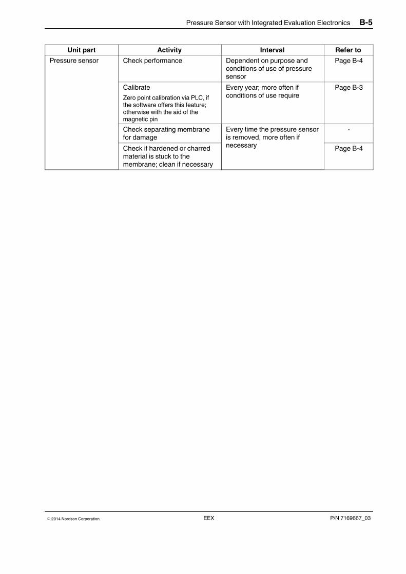
Pressure Sensor with Integrated Evaluation Electronics B-5
P/N 7169667_03� 2014 Nordson Corporation EEX
Unit part Activity Interval Refer to
Pressure sensor Check performance Dependent on purpose andconditions of use of pressuresensor
Page B-4
Calibrate
Zero point calibration via PLC, ifthe software offers this feature;otherwise with the aid of themagnetic pin
Every year; more often ifconditions of use require
Page B-3
Check separating membranefor damage
Every time the pressure sensoris removed, more often ifnecessary
-
Check if hardened or charredmaterial is stuck to themembrane; clean if necessary
Page B-4

Pressure Sensor with Integrated Evaluation ElectronicsB-6
P/N 7169667_03 � 2014 Nordson CorporationEEX
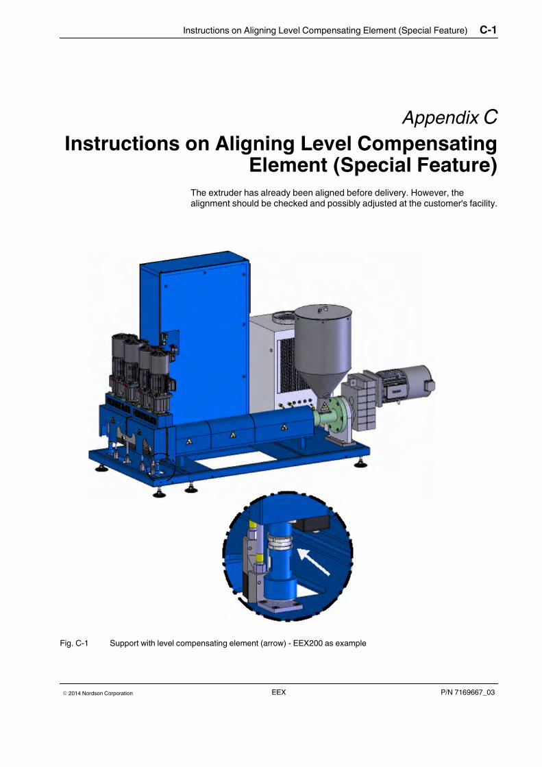
Instructions on Aligning Level Compensating Element (Special Feature) C-1
P/N 7169667_03� 2014 Nordson Corporation EEX
Appendix C
Instructions on Aligning Level CompensatingElement (Special Feature)
The extruder has already been aligned before delivery. However, thealignment should be checked and possibly adjusted at the customer's facility.
Fig. C-1 Support with level compensating element (arrow) - EEX200 as example
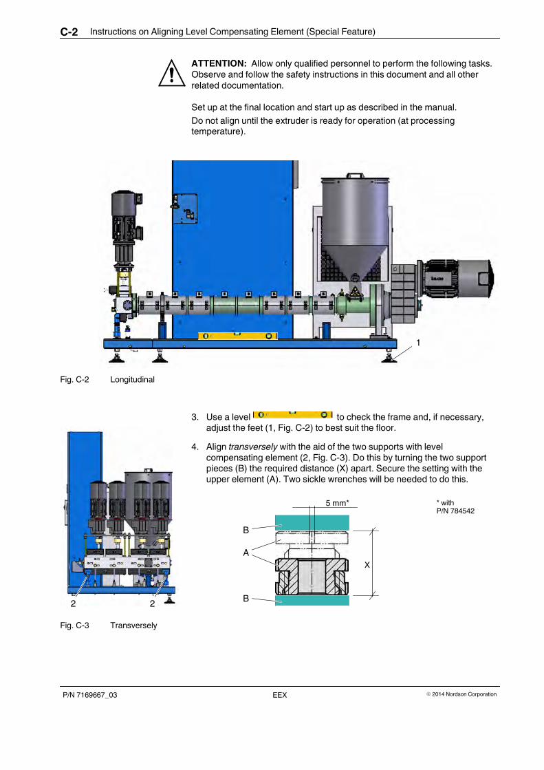
2 2
Instructions on Aligning Level Compensating Element (Special Feature)C-2
P/N 7169667_03 � 2014 Nordson CorporationEEX
ATTENTION: Allow only qualified personnel to perform the following tasks.Observe and follow the safety instructions in this document and all otherrelated documentation.
Set up at the final location and start up as described in the manual.
Do not align until the extruder is ready for operation (at processingtemperature).
1
Fig. C-2 Longitudinal
3. Use a level to check the frame and, if necessary,adjust the feet (1, Fig. C-2) to best suit the floor.
4. Align transversely with the aid of the two supports with levelcompensating element (2, Fig. C-3). Do this by turning the two supportpieces (B) the required distance (X) apart. Secure the setting with theupper element (A). Two sickle wrenches will be needed to do this.
5 mm* * withP/N 784542
AA
B
X
B
Fig. C-3 Transversely