Embed Size (px)
Citation preview

Fuji Electric France S.A.S.
INSTRUCTIONS MANUAL and SERVICE INSTRUCTIONS"FCX-AII-V5" SERIES TRANSMITTERS
Type : FKC...5
FKG...5, FKP...5
FKA...5, FKH...5
FKE...F
FKD, FKB, FKM...F
FKP, FKH...F
DATE March 2018TN5FCXA2V5h-E


TN5FCXA2V5h-E 1
CAUTION :Rotating the upper assembly part :The upper assembly (housing and electronic unit) can be rotated by 90° left or right just by remo-ving the 3 hexagonal screws.
If the assembly parts must be turned over than 90°, or if the position is already amended since the delevery by Fuji, it's necessary to remove the electronic unit from the housing
cell before turn the housing.
-
cable, which is not covered by the manufacturer's warranty.

2 TN5FCXA2V5h-E
INTRODUCTION
First read this instruction manual carefully until an adequate understanding is required, and then proceed to installation, operation and maintenance of the FCX-AIIV5 series transmitter.
-provement.
This instruction manual should be kept by a person who is actually using the transmitter. After reading this manual, keep it at a place easier to access. This manual should be delivered to the end user without fail.
Our pressure transmitters have been designed to meet international standards and directives. It is necessary to read carefully the manual before use these transmitters, to familiarize yourself with the installation, wiring processes, wiring and all operations and maintenance.
transmitters.Carefully read the instructions ATEX "HD FCXAII 102" for any use of sensors in dangerous areas.
The instrument nameplate as shown below is attached on the housing of this transmitter.
1
2
34
567
10 11
89
12
1 Tag number 2 Model 3 Transmitter type (see corresponding "technical datasheet") 4 Range 5 Power supply 6 Output 7 Maximum working pressure (MWP) 8 Serial number 9 Manufacturing date 10 Hazardous locations description (See the "safety instruction" for the Pressure transmitter localised in the dangerous area)11 2014/68/EU G1 TAMB. MIN. -40°C/ MAX. +85°C WITHOUT OPTIONS.
12 Order Acknowlegment Number

TN5FCXA2V5h-E 3
ELECTROMAGNETIC COMPATIBILITY
EMC Directive (2014/30/UE)All models of FCX series transmitters type FCX-AII are in accordance with :• The harmonized standards: - EN 61326-1 (Electrical equipment for measurement, control and laboratory use - EMC requirements).
for tranducers with integrated or remote signal conditioning)
Emission limits : EN 61326-1 Frequency range (MHz) Limits Basic standard 30 to 230 40 dB (μV/m) quasi peak, measured at 10m distance EN 55011 / CISPR 11 Group 1 Class A 230 to 1000 47 dB (μV/m) quasi peak, measured at 10m distance
Immunity requirements : EN 61326-1 (Table 2) Phenomenon Test value Basic standard Performance criteria Electrostatic discharge (ESD) 4 kV (Contact) EN 61000-4-2 B 8 kV (Air) IEC 61000-4-2
3 V/m (1.4 to 2.0 GHz) IEC 61000-4-3 A 1 V/m (2.0 to 2.7 GHz) Rated power frequency 30 A/m (50Hz, 60 Hz) EN 61000-4-8 A
Burst 2 kV (5/50 ns, 5 kHz) EN 61000-4-4 B IEC 61000-4-4 Surge 1 kV Line to line EN 61000-4-5 B 2 kV Line to ground IEC61000-4-5 Conducted RF 3 V (150 kHz to 80 MHz) EN 61000-4-6 A disturbances IEC61000-4-6 Performance criteria (A and B) : According EN 61326-1, EN 61326-2-3 subclauses 6.4.
4 TN5FCXA2V5h-E
First of all, read carrefully the “Safety instructions” for your own safety and for correct use of the transmitter.
• The risks related to a non-respect of the instructions are priorized as follow :
Risk of death or sever injury if the safety instructions are not fol-lowed.In case of wrong handling probable injury or physical damage can happen.
Important instructions to be respected.
General observations concerning the product, product handling and correct use of the transmitter.
CLASSIFICATION OF SAFETY INSTRUCTIONS
DANGER
INDICATION
CAUTION
PROHIBTION

TN5FCXA2V5h-E 5
Storage for a long period
For installation, select an appropriate place
At a place allowing an adequate space for check-up
Mounting position
Attention to overload
Others
If the Pressure transmitter is not mounted rapidly on site after the delivery, please store the transmitter in a dry room at normal temperature and humidity (25°c and 60% RH).Keep it on the originaly packaging if possible.
Site at location with minimal vibration, dust and corrosive gas
Site at location large enough to allow maintenance and chec-king.
Mount to a pipe horizontally or vertically.
Besides the above, be sure to observe the cautions given in this manual.
IMPORTANT RECOMMENDATIONS

6 TN5FCXA2V5h-E
INTRODUCTION ...................................................................................................................................2ELECTROMAGNETIC COMPATIBILITY .............................................................................................3CLASSIFICATION OF SAFETY INSTRUCTIONS ...............................................................................4IMPORTANT RECOMMENDATIONS ...................................................................................................5
1. OUTLINE ...........................................................................................................................................7
2. OPERATING PARTS AND THEIR FUNCTIONS ..............................................................................8
3. INSTALLATION AND PIPING .........................................................................................................11 3.1 Installation .........................................................................................................................12 3.2 Piping ................................................................................................................................16
(FKC) ........................................16 3.2-2 Piping of gauge and absolute pressure tranmitters (FKG/FKP or FKA/FKH) ........20 3.2-3 Piping of direct mount : absolute (FKH) and gauge pressure tranmitters (FKP) ......22 3.2-4 Piping of level transmitter (FKE) ...............................................................................24 3.2-5 Piping of remote seal(s) type transmitters (FKD, FKM, FKB) .................................27 3.2-6 Piping of remote seal types absolute and gauge transmitters ...................................30
4. WIRING ............................................................................................................................................32 4.1 Wiring procedure ...............................................................................................................33 4.2 Power voltage and load resitance .....................................................................................35 4.3 Grounding ..........................................................................................................................35
5. START UP AND SHUTDOWN ........................................................................................................36 5.1 Preparation for Start up ....................................................................................................36 5.2 Operation ............................................................................................................................37 5.3 Shutdown ...........................................................................................................................38
6. ADJUSTMENT ................................................................................................................................39 6.1 Adjustment procedure using the external adjusting screw ..................................................39 6.1-1 Zero adjustment by the screw .................................................................................39 6.1-2 Span adjustment by the screw .................................................................................40
.....................................41 6.2-1 Menu list ....................................................................................................................42 6.2-2 Switching menus ......................................................................................................43 6.2-3 Operating procedure ..................................................................................................44 6.3 Adjustment with hand held communicator FXW ..................................................................70 6.3-1 Connection of FXW ...................................................................................................70 6.3-2 Start up of the FXW ...................................................................................................71
7. MAINTENANCE ...............................................................................................................................92..........................................92
7.2 Troubleshooting ..................................................................................................................93 7.3 Replacement of defective parts ..........................................................................................94
...........................................101
A1. BUILT-IN ARRESTOR ...............................................................................................................102A2. CALIBRATION ..........................................................................................................................104A3. PARAMETER SETTING PRIOR TO DELIVERY ......................................................................106A4. HART® COMMUNICATION FUNCTION ...................................................................................107A5. SPARE PARTS ............................................................................................................................ 111
CONTENTS

TN5FCXA2V5h-E 7
EEPROMSensorparameters
Analog to DigitalConverter
Digital to AnalogConverter
Micro Processor• Signal conditioning• Reranging• Diagnostics• Communication
EEPROMTransmittersParameters Communication
FUJI/HART®
Manual Zero/SpanAdjustment
25.08.00 kPa
FXW
0 Y
1
4
7 8 9
65
2 3
M N O
SRQ
U V W
Z. [
HHC
Hand held Communicator
{
HPLP
Controlsystem
Analog indicator(option)
4-20 mA signal
LCD digital indicator(option)
Mic
roC
apac
itanc
eS
ilico
n S
enso
r
Sensor Unit Electronics Unit
OUTLINE1The FCX-A2 V5 series transmitter accurately measures the differential pressure, level of liquid, gauge pressure or absolute pressure, and transmits a proportional current signal of 4 to 20mA DC.
differential pressure measurement.The transmitter utilizes a unique micromachined capacitive silicon sensor with state-of-the-art microprocessor technology to provide exceptional performances and functionnalities.The transmitter is compact and light, provide high accuracy and reliability.Transmitter settings (such as range and damping time constant, etc.) can be changed from an HHC (Hand Held Communicator) or with an optional LCD digital display.Local digital adjustment of zero and span are possible from outside screw on the electronic housing.
Measuring principle
The operating principle of the FCX-A2 V5 serie transmitters is shown in the below block diagram.The input pressure is changed into an electrostatic capacitance in the detecting unit.
-mission unit, and is then output as a current of 4 to 20mA DC

8 TN5FCXA2V5h-E
Terminals
Symbol Description
Connects the output cable.
Used for checking the output or connecting an analogic indicator or a remote indicator
An external terminal used for grounding.
OPERATING PARTS AND THEIR FUNCTIONS2
Description of FCX-A2 V5 serie transmitters
Part name DescriptionDetecting unit Detects pressure, differential pressure or level of liquid.
Converts the detected signal into an output signal.Vent/drain plug Used for gas discharge or draining.Process connection Connects impulse pipes from the process.Electrical connection Connects the output cable.Zero Adjusting screw Used for adjustment.Connection unit Connects an input-output line and ground wire
Part name DescriptionAnalog indicator connector Used for connecting an analog indicator.LCD unit connector
Indicator (option)be mounted.
Zero/Span adjustment se-lector switch
Used to select the function (zero/span) to be adjusted by the external adjusting screw.
%0
20 40 60 80100
Z S
FIX
OUTDISP
ZEROSPAN
abs
% FIX
OUTDISP
ZEROSPAN
abs
%
MODE
(Local configurator unitwith LCD display)
(Digital) (Analog)Indicator
Analog indicator connector
LCD unit connector
Amplifier unitTerminal unit
Zero/Span adjustmentselector switchProcess
connectionDetecting
unit
Ampliferunit
Adjusting screw Vent/drainplug

TN5FCXA2V5h-E 9
Mode indicating function of digital indicator
FIX
OUTDISP
ZEROSPAN
abs
%
Mode indication
Mode When indicated When not indicated% % output Actual scale
ZERO Possible external zero adjustment External zero adjustment not possibleSPAN Possible external span adjustment External span adjustment not possible.
DISP Digital indicator display Digital indicator LIN displayOUT output LIN output
FIX Fixed current mode Measurement modeThe transmitter is in operation (blinking).
The transmitter is not in operation.
abs Absolute pressure Gauge pressureOutput value < Zero
(a part of unit indicator)

10 TN5FCXA2V5h-E
Normal mode (normal mode for indicating a measured value)
* For status indication in the normal mode, refer to the previous section “Mode indicating function of digital indicator.”
Setting mode (functions of the 3 push button key switches)
Functions of the 3 push button key switchesName Main function
Mode key Switches between the normal and setting modes. Minus key Changes an item No. or item name to the minus (decrease) direction. Plus key Changes an item No. or item name to the plus (increase) direction.
FIX
OUT DISP
ZERO SPAN
abs
%
MODE
Minus key Plus key
Mode key
SPAN%
Blicking(Transmitter is running)
Measurement value
Lighting
(The setting of
the transmitter is
being adjusted.)
Item No. Item name
TN5FCXA2V5h-E 11
INSTALLATION AND PIPING 3
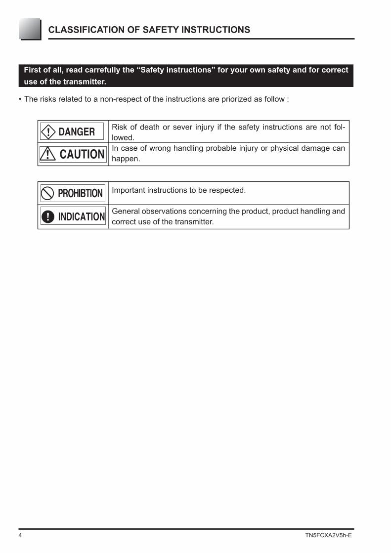
Type Ambient Process Span Static pressure Technical temperature temperature limit limit datasheets limit limit Differential -40 to 85°C -40 to 120°C 10 mbar -1 to 32 barpressure (silicone oil) 60 mbar -1 to 100 bar 320 mbar -1 to 160 bar -20 to 80°C (option : 420 bar) EDSF6-134
(option : 420 bar) 5 bar -1 to 160 bar (option : 420 bar) 30 bar -1 to 160 bar (option : 300 bar) 200 bar -1 to 300 barGauge -40 to 85°C -40 to 100°C 1,3 bar -1 to 1,3 barPressure (silicone oil) 5 bar -1 to 5 bar EDSF5-92 30 bar -1 to 30 bar and -20 to 80°C 100 bar -1 to 100 bar EDSF5-98
Absolute -40 to 85°C -40 to 85°C 0,16 bar abs 0 to 0,16 bar absPressure 1,3 bar abs 0 to 1,3 bar abs EDSF5-91 5 bar abs 0 to 5 bar abs and 30 bar abs 0 to 30 bar abs EDSF5-97 100 bar abs 0 to 100 bar abs Level and -40 to 85°C 60 mbar According PN/lbs EDSF7-68remote seal(s) See note* 320 mbar of remote seal EDSF6-05 1300 mbar and 5000 mbar EDSF6-06 30000 mbar 100 bar 200 bar 500 bar
* Refer to "technical datasheets" about details of process temperature limits of the transmitters.
Protect the transmitter with a security device when the existing application conditions require it. The transmitter should be installed remote from the measuring point in the case that the process temperature is too high.
INDICATION

12 TN5FCXA2V5h-E
3.1 InstallationDuring the unpacking of the transmitter, check the conformity of the transmitter and all the ac-cessories.Before installation, the customer must check the compatibility of the wetted parts for the applica-
The transmitter can be installed on a 2” tube or wall mounted.
Note : For the wall mounting, the customer has to supply the M8 bolting.Please refer to the data sheets for the outline dimension drawings of the transmitters.
DANGER
If the transmitter is not used soon after delivery, then leave it packed and store it in INDICATION
Transmitter
Bracket
Plain washer
Spring washer
Mounting bolt
(M8 12)
Process flangeBracket
Plain washerSpring washer
Mounting bolt(M8x12)
Transmitter
FKC, FKG and FKA models FKD, FKB and FKM models
Mount the bracket on the transmitter as shown below.
Bracket mounting
- The transmitter is heavy. Be careful when handling it.- The indicated installation and the wiring conditions of the transmitter must
be strictly followed.- A wrong manipulation can be the reason of a disfunction of the transmitter.- During installation, make sure that no part which could be the reason of the
disfunction or a danger is located inside the electronics housing.
The local indicator position must not be changed The position of the electronics housing must not be changed- The isolating valves and manifold must correspond to the maximum pres-
sure in the pipe. If the valves and the connections do not correspond to the
- The pipes need to be according the process temperature and the pressure standards.
- Membrane are very sensitive. Be careful during the manipulation. - Do not bend excessiviely the capillary
DANGER

TN5FCXA2V5h-E 13
Transmitter
Nut
Spring washer
Plain washerBolt
U-Bolt
• Pipe mounting FKC, FKG and FKA models FKD, FKB and FKM models
(1) Fasten the transmitter to a vertical or horizontal pipe using the supplied U-bolt (Tightening
(2) Use a pipe of outside diameter 2” (ø60.3 mm)
• Flange mountingPosition the remote seal of the transmitter in front
boltings
Process mounting
FKP and FKH models
• Wall mountingFasten the transmitter to the wall with M8 bolts.
FKP and FKH models
Bracket
Plain washerSpring washer
Mounting bolt
(M4×10)Adaptor (Option)
Transmitter

14 TN5FCXA2V5h-E
-
again
plug.
Never turn the electronic housing over than 90° without disconnect the
cable from the electronic measuring cell).If the transmission unit has been turned excessively without removing the elec-
which connects the electronics unit in the transmission unit and the detecting unit, and set the transmission unit again.
0Change of electronics housing position
DANGER
PROHIBTION
DANGER
Avoid the following procedure in an explosionproof area.
Avoid the following procedure in an explosionproof area.
Change of indicator position
TN5FCXA2V5h-E 15
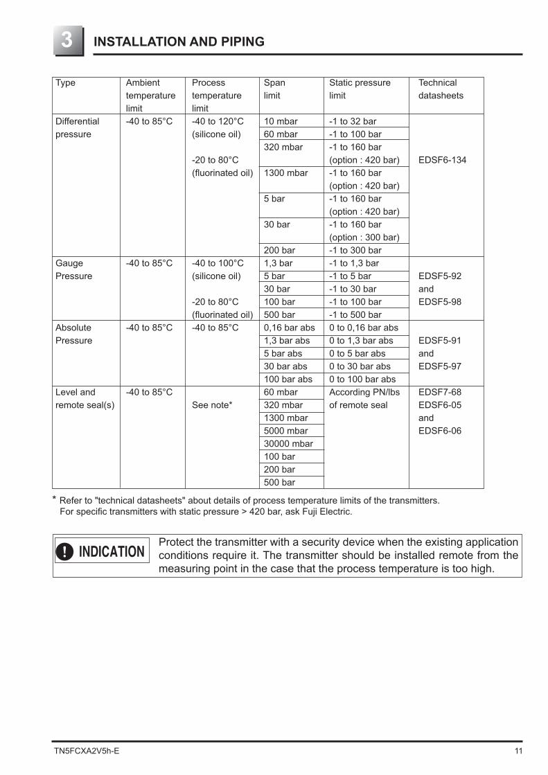
Ensure a space of about 500mm against the cover in order to facilitate he maintenance.
Unscrew slowly grasp the hexagon part of vent/drain plug with an allen key.Put a new seal tape (4 to 8 rounds) and mount the vent/drain plugs in the position you want applying the tightening torque :
500500
500
Check space
Change of vent/drain plug position

16 TN5FCXA2V5h-E
Gas measurement Liquid measurement Steam measurementUpper
Lower
Upper
Lower
0 to 45° up from the vertical 0 to 45° up from the vertical0 to 45° down from the vertical
3.2 Process piping
Check of "High" and "Low" pressure sides of transmitter The "High" Pressure side is indicated by "H" and the "Low" pres-sure side by "L" on the cell neck
Removal the protective cap The process connection ports of the transmitter and manifold
remove the caps. When removing the caps, carefully protect the threaded portion and sealing face from damage.
Connect the transmitter to impulse pipes
the manifold valve. Tightening torque of 7/16-20UNF mounting bolt should be 30 to 40 Nm (3 to 4 kgf m).
(2) If a manifold is not used, the impulse pipes can directly be screwed into the transmitter.
should be used.
Position of process connection The position of the process connection is determined by the relationship between the condi-
Follow the process position according to the process :
The piping connection must respect some rules to have an accurate measurement :
General recognitions are :1) Transmitter must be mounted below the process piping for liquid and steam measurement. 2) Transmitter must be mounted above the process piping for gaz measurement.
Main valve or manifold used for piping should be selected with the maxi-mum pressure of the process taken into account (piping parts such as main valve, etc. should be furnished by user). If the main valve and other parts do not meet the rating, it may result in leakage of gas or liquid which could lead to a hazard.
CAUTION
L H

TN5FCXA2V5h-E 17
Manifold
Impulse pipe
Isolating valve
Process pipe
Orifice plate
Impulse pipe
Manifold
isolating valve
Differential pressure source (orifice)
Process pipe
Isolating valve Process pipe
condensatechamber
ManifoldImpulse pipe
Recommandation for process connection
3- Place the transmitter above the process pipe. If the pro-
cess temperature is high, please use a condensate cham-ber like for steam
2- Set two condensers at the same height between the
transmitter and the primary element. Fill the pipe between the condensers and transmitter with
water. Installation of a drain is necessary
1- Liquid Place the transmitter below the process pipe
Make piping so that gas in the impulse pipe is not delivered to the transmitter, and incorporate gas res-ervoirs as required..
Isolating valveProcess pipe
Pressure tap
Impulse pipeManifold
Atmospheric air inlet
4- Pressure measurement for liquid The transmitter must be below the process pipe.
(1) During valves and manifold installation, please make sur that no dust enter through the atmospheric air inlet.
(2) If pressure measurement is low (below 10kPa (1000mmH2O), the fol-lowing should be considered.
• Pressure variation due to wind around atmospheric air inlet • Temperature variation near process connection • Difference in atmospheric pressure between process connection and transmitter location. To overcome this, provide atmospheric pressure-side pipe with a
-spheric air inlet in a box.
CAUTION

18 TN5FCXA2V5h-E
5- Pressure measurement for gas Place the transmitter above the process pipes to pre-venting condensation in the impulse pipe and in the measuring
6- Level measurement
For measurement, connect the highest liquid level of tank with the low pressure side of transmitter, and the lowest liquid level of tank with the high pressure side of transmitter.
The reference column (connected to the high-
Level calculation formula 2 0H1
2 1 0H1
0 1: Density H1, H2: Liquid level, h: Liquid level change
H1 H2
ρ0 ρ
h
ρ1
Max. liquid levelMin. liquid level
Condensate chamber
High pressureside
Manifold
Low pressureside
Isolating valveProcess pipe
Impulse pipeManifold
Pressure tap
Atmospheric air inlet
H1
ρ
hρ1
Max. liquid level
Min. liquid levelAtmospheric
air inlet
Manifold
High pressure side
Low pressure
side
(2) Reference column empty For an open tank, leave the low pressure side of transmitter open to atmosphere. Level calculation formula
1
1 1h
1: Density H1: Liquid level, h : Liquid level change

TN5FCXA2V5h-E 19
Cautions on impulse piping
• For liquid, the impulse pipes should have an downward slope of 1/10 or more between the pro-cess connection and the transmitter to prevent accumulation of gas, etc. in the detecting unit.
• For gas, the impulse pipes should have a upward slope of 1/10 or more between the process connection and transmitter to prevent accumulation of liquid or condensat, etc. in the detecting unit.
• Avoid any sharp bends in impulse pipe which may cause gas or liquid to accumulate in the impulse pipe.
• Do not apply an excessive force to impulse pipe during the connection.
• Install condensate chambers or vent drain when impulse pipes can not be inclined.
• The impulse pipes used should be suitable for the working temperature, pressure standards.
• During installation, avoid mechanical constrains of the transmitter connections.
-ned transmitter must be checked before commissioning.
• To avoid the deterioration of the transmitter mounted externally, it will be mounted in a box protection.
need to be checked before started up. The transmitter must not be reused if it has been partially
• Freeze protection.
heater. Do not exceed the temperature limits (measuring cell: 120°C maxi and transmitter: 85°C). Even when the installations shut down the heat must be maintained, if not the transmitter and
impulse pipes must be drained to prevent freezing.

20 TN5FCXA2V5h-E
3.2.2 Gauge and absolute pressure transmitters (types: FKG and FKA)
Remove the protective cap
protective cap. Before piping, be sure to remove the cap. When removing the cap, carefully protect the threaded portion and seal-ing face from damage.
Connect the transmitter to impulse pipes
valve. Tightening torque of 7/16-20UNF mounting bolt should be 30 to 40 Nm (3 to 4 kgf m).• If manifold is not used, the inpulse pipes can directly screwed into the transmitter. If thread size
4 kgf m).• For an absolute pressure measurement, make sure that isolating valves or manifold can be
designed for vaccum service.
Position of process connection The position of the process connection is determined by the relationship between condition,
Follow the process position according to the process :Gas measurement Liquid measurement Steam measurement
Upper
Lower
Upper
Lower
0 to 45° up from the vertical 0 to 45° up from the vertical0 to 45° down from the vertical
Pressure tap
Impulse pipe
Vent valve
Process pipeIsolatingvalve
1- Liquid measurement Place the transmitter below the process pipe. Make piping so that gas in the impulse pipe is not delivered to
the transmitter and incorporate gas reservoir as required.
Recommandation for process connection

TN5FCXA2V5h-E 21
Impulse pipeVent valve
Pressure tap
Isolating valve
2- Steam measurement A condensate chamber must be mounted between trans-
mitter and process connection. Fill the pipe between the condensate chamber and the
transmimitter with water. The installation of a drain is necessary.
Impulse pipeIsolating valve
Process pipe
Vent valve
Pressure tap
3- Gas measurement Place the transmitter above the pressure source. If high temperature, use condensate chamber like for steam.
Cautions on impulse piping
• For liquid, the impulse pipes should have an downward slope of 1/10 or more between the pro-cess connection and the transmitter to prevent accumulation of gas, etc. in the detecting unit.
• For gas, the impulse pipes should have a upward slope of 1/10 or more between the process connection and transmitter to prevent accumulation of liquid or condensat, etc. in the detecting unit.
• Avoid any sharp bends in impulse pipe which may cause gas or liquid to accumulate in the impulse pipe.
• Do not apply an excessive force to impulse pipe during the connection.
• Install condensate chambers or vent drain when impulse pipes can not be inclined.
• The impulse pipes used should be suitable for the working temperature, pressure standards.
• During installation, avoid mechanical constrains of the transmitter connections.
-ned transmitter must be checked before commissioning.
• To avoid the deterioration of the transmitter mounted externally, it will be mounted in a box protection.
need to be checked before started up. The transmitter must not be reused if it has been partially
• Freeze protection.
heater. Do not exceed the temperature limits (measuring cell: 120°C maxi and transmitter: 85°C). Even when the installations shut down the heat must be maintained, if not the transmitter and
impulse pipes must be drained to prevent freezing.

22 TN5FCXA2V5h-E
(2) Steam measurementA condensate chamber must be mounted between transmitter and process connection. Fill the pipe between the condensate chamber and the transmimitter with water. The installation of a drain is necessary.
Impulse pipe
Manual valve
Pressure source
Stop valve
Recommandation for process connection
(1) Liquid measurementPlace the transmitter below the the process pipe.Make piping so that gas in the impulse pipe is not delivered to the transmitter, and incorporate gas reservoirs as required.
3.2.3 Absolute pressure (FKH) and gauge pressure transmitters (FKP)
Remove the protective cap
protective cap. Before piping, be sure to remove the cap. When removing the cap, carefully protect the threaded portion and seal-ing face from damage.
Connect the transmitter to impulse pipesThe piping can be connected directly to the process connection of the transmitter or via an
objects from entering. For an absolute pressure measurement, make sure that isolating valves or manifold can
be designed for vaccum service.
Position of process connection The position of the process connection is determined by the relationship between condition,
Follow the process position according to the process :
Gas measurement Liquid measurement Steam measurementUpper
Lower
Upper
Lower
0 to 45° up from the vertical 0 to 45° up from the vertical0 to 45° down from the vertical
Impulse pipe
Vent valve
Process pipe
Isolating valve
Pressure tap
TN5FCXA2V5h-E 23
Impulse pipe
Stop valve
Process pipePressure source
Manual valve
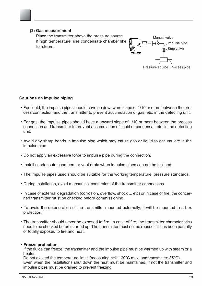
Cautions on impulse piping
• For liquid, the impulse pipes should have an downward slope of 1/10 or more between the pro-cess connection and the transmitter to prevent accumulation of gas, etc. in the detecting unit.
• For gas, the impulse pipes should have a upward slope of 1/10 or more between the process connection and transmitter to prevent accumulation of liquid or condensat, etc. in the detecting unit.
• Avoid any sharp bends in impulse pipe which may cause gas or liquid to accumulate in the impulse pipe.
• Do not apply an excessive force to impulse pipe during the connection.
• Install condensate chambers or vent drain when impulse pipes can not be inclined.
• The impulse pipes used should be suitable for the working temperature, pressure standards.
• During installation, avoid mechanical constrains of the transmitter connections.
-ned transmitter must be checked before commissioning.
• To avoid the deterioration of the transmitter mounted externally, it will be mounted in a box protection.
need to be checked before started up. The transmitter must not be reused if it has been partially
• Freeze protection.
heater. Do not exceed the temperature limits (measuring cell: 120°C maxi and transmitter: 85°C). Even when the installations shut down the heat must be maintained, if not the transmitter and
impulse pipes must be drained to prevent freezing.
(2) Gas measurementPlace the transmitter above the pressure source. If high temperature, use condensate chamber like for steam.

24 TN5FCXA2V5h-E
3.2.4 Level transmitter (type: FKE)
Check of "High" and "Low" pressure sides of transmitterThe "High" Pressure side is indicated by "H" and the "Low" pressure side by "L" on the cell neck
with H letter on the label.
plug. Upon request, the low pressure can be connect with a seal (or remote seal).
pressure side, a gasket should be insert-
L H
Gasket
Transmitter flange Process side flange
Standard dimension of the diaphragme seal are :
Flange size Ø diaphragm seal (mm) DN80 / 3" Stainless steel : 73 special material : 89 DN100 / 3" Stainless steel : 96 special material : 89
The internal diameter must be greater or equal to the diaphragm seal to not press it and effect the measure.Be careful to a potential leak who can effect the measure.
CAUTION

TN5FCXA2V5h-E 25
cycles using the tightening torque corresponding to the screw used and according to the
Remove the protective cap from process connection port -
tective cap. Before piping, be sure to remove the cap.When removing the cap, carefully protect the threaded portion and sealing face from damage.
Connection of low pressure side and impulse pipeThe piping can be connected directly to the process connection of the transmitter or via an
objects from entering.
Level measurement
(1) Level measurement on open tank Leave the low pressure side of transmitter open to atmosphere. Level calculation formula : LRV : H1 URV : (H1 + h)
: Measuring liquid density H1
mini level h : Liquid level change
(2) Level measurement on close tank 1- In case of reference column
Connect the highest liquid level connection of tank to the low pressure side of transmit-ter, and the lowest liquid level connection
side) of transmitter.
Level calculation formula: 1 0H2
1 0H2
0: Seal liquid density H1
h: Liquid level change
H1
h
Max. liquid level
Min. liquid level
H1
h H2
0
Drain portStop valve
Max. liquid level
Min. liquid level

26 TN5FCXA2V5h-E
2- In case of reference column Connect the highest liquid level connection
of tank to the low pressure side of transmit-ter, and the lowest liquid level connection of
of transmitter.
Level calculation formula1
1 + h)
H1
h : Liquid level change
Cautions on installation• H1 must be more than half of the remote seal diaphragm diameter. Otherwise the measure
wil not be linear to the level as far as the diaphragm is not totally submerged• In order to prevent vibration of the transmitter body and capillary from interfering with
output, the transmitter body should be installed at a vibration-free place and the capillary
• Do not scratch or shock the seal diaphragm by hitting hard object against it, for example.
-ening torque according to pipie standard).
Freeze protection.
or a heater. Do not exceed the temperature limits (measuring cell: 120°C maxi and transmitter: 85°C). Even when the installations shut down the heat must be maintained, if not the transmitter and
impulse pipes must be drained to prevent freezing.
H1
Max. liquid level
Min. liquid level
h
Stop valve

TN5FCXA2V5h-E 27
GasketProcess side�flange
Transmitter flange
3.2.5 Remote seal(s) type transmitter (FKB, FKD and FKM)
(1) Remote seal type differential pressure transmitter (FKD)
Check of high/low pressure sides of transmitter The "High" Pressure side is indicated by "H" and the "Low" pressure side by "L" on the cell neck. High pressure side is always with a capillary or a rigid seal (direct mounting) allowing a remote seal connection.
tank. Be careful to a potential leak who can effect the
measure.
Flange size Ø diaphragm seal (mm) DN80 / 3" SS : 73 Special material : 89 DN100 / 4" SS : 96 Special material : 89
cycles using the tightening torque corresponding to the screw used and according to the
H L
The internal diameter must be greater or equal to the diaphragm seal to not press it and effect the measure.Be careful to a potential leak who can effect the measure.
CAUTION
Standard dimension of the diaphragme seal are :

28 TN5FCXA2V5h-E
Level measurement
(1) Level measurement on open tank
The low pressure side is open to atmosphere. Level calculation formula:
(2) Level measurement on close tank
Connect the highest liquid level connection of tank to the low pressure side of transmitter, and the low liquid level connection of tank to the high pressure side of transmitter
Level calculation formula:
diphragme liquid density
The transmitter body should be installed below the remote seal unit. This is mandatory where process pressure may become vacuum. PROHIBTION
h
h’
ρ
ρ
E
High
pressure
side
Low
pressure
side
Max. liquid level
Min. liquid level
h ρ
ρ
E
h’
High pressure side
Low pressure side
Max. liquid level
Min. liquid level

TN5FCXA2V5h-E 29
The oil density of the diaphragme seal can be done by Fuji Electric.For information, the current values are as follows :
0
20 40 60 80100
10
H H
0H
0
20 40 60 80100
0HT
0
20 40 60 80100
0HT
0
Caution when vacuum measurement
When process pressure is nearly vacuum pressure, the transmitter must be
H0connection. In this case, it is imperative to check that the resulting pressure of measure-ment cell of transmitter is greater than minimum pressure service (refer the
When in doubt, please consult Fuji Electric France.
Caution on installation• In order to prevent vibration of the transmitter body and capillary from interfering with
output, the transmitter body should be installed at a vibration free place and the capillary
• Avoid to locate capillaries (high and low pressure) in a place where ambiant temperature
please put a warm up system to maintain a constant temperature. • Do not scratch or shock the seal diaphragm by hitting hard object against it, for example.
tightening torque according to pipie standard).
Freeze protection.
heater. Do not exceed the temperature limits (measuring cell: 120°C maxi and transmitter: 85°C). Even when the installations shut down the heat must be maintained, if not the transmitter and
impulse pipes must be drained to prevent freezing.
1 2 3
PROHIBTION
Filling oil Density ApplicationsSilicone 0,934 générales Haigh temperature, high temperature and 1,07 et vaccum service, high temperature and absolute vaccum serviceFluorinated 1,84 Oxygen measurement

30 TN5FCXA2V5h-E
3.2.6 Remote seal type absolute and gauge transmitter (FKB and FKM)
GasketProcess sideflange
Transmitter flange
tank. Be careful to a potential leak who can effect the
measure.
Flange size Ø diaphragm seal (mm) DN80 / 3" SS : 73 Special material : 89 DN100 / 4" ISS : 96 Special material : 89
cycles using the tightening torque corresponding to the screw used and according to the
The internal diameter must be greater or equal to the diaphragm seal to not press it and effect the measure.Be careful to a potential leak who can effect the measure.
CAUTION
Standard dimension of the diaphragme seal are :

TN5FCXA2V5h-E 31
Recommandation for process connection
(1) Gas measurement Locate the process tap above the pressure source
(2) liquid measurement Locate the process connection below the pressure
tap and the remote seal must be located below this one.
(3) Level measurement on open tank H1 must be more than half of the remote seal diaphragm diameter. Otherwise the measure will not be linear to the level as far as the diaphragm is not totally submerged.
Isolatingvalve
Remote seal
Atmospheric air leak valve
Process connection
Pressure tap
Transmitter
H 1
h
D
ρ
ρ
Max. liquidlevel
Min. liquidlevel
Isolatingvalve
Remote seal
Transmitter
Pressure tap
Isolating valve
Transmitter
Process connection
Atmospheric air leak valve
remote seal
It is recommanded to install the transmitter below the remote seal(s). it becomes necessary if process pressure is less than atmospheric pressure.
In order to prevent vibration of the transmitter body and capillary from in-terfering with output, the transmitter body should be installed at a vibration
PROHIBTION

32 TN5FCXA2V5h-E
WIRING4
(1) Application of a voltage exceeding 60 V DC or 40 V AC (exceeding 33 V DC or 23 V AC when arrester equipped) between “+” and “–” terminals may result damage to the transmit-ter.
(2) Use a shielded cable for the transmission line where possible. (3) Avoid installing signal and power cable in thev same conduit or cable tray in order to avoid
electromagnetic interferences..
In case of explosion proof, wiring shall be made in accordance with the
Improper wir -dents.
Cautions on wiring
DANGER
• Before making wiring work, be sure to turn OFF the main power to prevent electrical shocks.
• Use wiring materials of correct rating to prevent accidents.
• Field ground according the recommendations of electrical connections.
protect the transmitter agains water ingress.
CAUTION

TN5FCXA2V5h-E 33
Take care to respect the polarity when connecting the terminals
10.5 to
45 V DC
Output DC
4 to 20mA
Terminal
Converter
-+
Terminal 4 to 20mA DC
10.5 to
45 V DC
Output DC
4 to 20mA
Converter
Terminal block connection diagram
Tighten the terminal screws (M4x10) to a torque of ap-
will not loosen. After connection, fasten the cover until it does not turn.
When using an external indicator
-nect the “+” and “–CK– of the transmitter as shown below.
4.1 Wiring procedure :
Sealing of conduit connectionTo insure air tightness of the connection box, use sealing tape with metal pipe screw coupling or rubber gasket fastening gland
1. If the conduit connection is located on the top side of the transmitter when using a protective tube for the wiring, then water may enter into the protective tube and have an adverse effect on the transmitter.
2. The thread of tube connection should match with the transmitter con-duit thread.
INDICATION
INDICATION
Metal pipe
TransmitterLoad resistance
DC power supply
Wiring diagram

34 TN5FCXA2V5h-E
Hexagon keywrench
Threaded plug
Caution on wiring
Two conduit connection are available and one is closed. If the closed conduit connection must be used, please follow procedure below :
to ensure the sealing(2) Insert the cable through the free terminal connection and connect it.
water prevention.• When performing an insulation check after wiring, use a megohmmeter
of 250 V DC or less and avoid applying a high voltage. If an arrester is equipped, avoid the insulation resistance test and the dielectric strength measurement.
DANGER
4.2 Power voltage and load resistance
Make sure the load resistance of the wiring connected to the loop is within the range shown below.
Note :
is required
600
250
0
1533
Operating zone
10.5 16.1 24 45
Power voltage (VDC)
Load
resi
stan
ce (
)
Note)

TN5FCXA2V5h-E 35
Terminal unit
External grounding
terminal
4.3 Grounding
The transmitter must be grounded as below:
1- Standard location use Grounding terminals are provided at two places (at the inside of terminal box and on the
side of conduit connection). By any of the methods given below, ground the transmitter in compliance with the relevant
stipulation in the standard on explosion proof installation (for example, grounding resis-
Grounding of transmitter casing Grounding from ground terminal
2- Hazardous location use
for grounding.

36 TN5FCXA2V5h-E
START UP AND SHUTDOWN5
After adjustment, the transmitter must be kept energized for at least 10 seconds data recording completion into memory.
electronics housing without opening the covers of this external housing.• Power on the transmitter and wait for at least 10 minutes.• Check the output signal of the transmitter by connecting a DC milliampermeter across CK+ and
CK- of the terminal block.• After 10 sec or longer, adjust the transmitter output current at 4 mA (zero adjustment).
5.1 Installation : After installation (refer to chapter 3.1) and before start up of the transmitter, be sure to perform
the following checks and procedures.
Preparation :
(1) Check for liquid or gas leakage of the process connection by applying soapy water or similare.
(2) Check of the electrical connection according to the “Terminal block connection diagram” shown in 4.1.
(3) Vent the process covers of the transmitter.
The compatibility of process with the transmitter, has to be checked and ensured by skilled people from customer side.
(4) Perform zero point adjustment.
Zero point check
Zero adjustment :The zero adjustment can be done : (1) With the external screw Refer to chap.6.1 "Adjustment procedure using
an external adjusting screw" (2) With LCD indicator Refer to chap.6.2 "Adjustment procedure by local
(3) With Fuji Hand Held communicator Refer to to chap.6.3 "Adjustment with hand held
communicator"
When the plant requires chemical cleaning at the start up operation, be sure to close the isolating valves of the transmitter to avoid that cleaning liquid or particules are introduced to the transmitter wetted parts.
fully the technical instruction note ATEX Ref.HDFCX-AII V5 002.
INDICATION
DANGER
CAUTION
Increase
Decrease
Fine adjustment : turning slowly (approximately 5sec per turn)Rough adjustment : turning quickly (approximately 1sec per turn)

TN5FCXA2V5h-E 37
5.2 Operation
(1) Gauge (FKG) and absolute (FKA) pressure transmitter :
Open the valve slowly to apply a pressure. When pressure is applied, the transmitter is set in the operating status.
Set the operating status by manipulating the isolating valve.
Open
Open
Close the isolating valve the LP side
close isolating valve on the HP sideEqualizing
valve
Close
Make sure the equalizing valve is open and make the zero adjustement (0%)
Open the isolating valve on the HP side slowly.
Close the equalizing valve.
Open
Open the isolating valve on the LP side slowly
Open

38 TN5FCXA2V5h-E
Use a local indicator, receiving instrument or HHC to check the operating status.
5.3 Shutdown Follow the procedures
Close
Close the valve slowly to stop applying a pressure. The transmitter is set in the measurement stop status.
(1) Absolute (FKA/FKH) and gauge (FKG/FKP) pressure transmitters :
Check of operating status
(2) Flow and differential pressure transmitter (FKC) :
Close the stop valve on the high pressure side (HP side) slowly.
Open the equalizing valve.
Close the stop valve on the low pressure side (LP side) slowly
Close
Open
Close
the transmitter.This is to protect the transmitter from freeze, corrosion, etc...PROHIBTION

TN5FCXA2V5h-E 39
using :
- External screw,
- LCD display with push buttons,
- Hand Held communicator,
- Hart Explorer software (if zero adjustment is performed after span adjustment, the 100% point may not be adjusted correctly).
Zero point is 4 mA output signal (LRV) and span is 20 mA output signal (URV). To adjust and specify these values, display the measured values (LRV, URV) with the portable communicator
6.1 Adjustment procedure with the external screw
6.1-1 Zero adjustmentZero point of the transmitter is adjustable by the external
Note : If the transmitter has an indicator, remove it to access the setting switch.
(1) Select ZERO position
(2) Apply standard input pressure corresponding to Lower Range Value (LRV).
(3) Adjust zero point (4 mA) by turning the external screw
ADJUSTMENT AND SETTING6
case to make following adjustments with active DC power supply.DANGER
For zero suppression or elevation ranges,
the 4/20 mA output signal using the external adjustment screw.
Note :1)
adjusted by the external adjustment screw.
2) When a digital indicator is attached to the transmitter, make sure that the LCD lamp “ZERO” is ON.
Increase
Decrease
Fine adjustment : turning slowly (approximately 5sec per turn)Rough adjustment : turning quickly (approximately 1sec per turn)
After adjustment, the transmitter must be kept energized for at least 10 seconds data recording completion into memory.INDICATION
External adjustment screw
Set switch to “ZERO” position for zero calibration
ORE
Z
NAP
S

40 TN5FCXA2V5h-E
After adjustment, the transmitter should be kept energized at about 10 seconds to write the adjustment results into memory.
(4) Then return to applying input pressure of zero again and make sure output is 4 mA.
INDICATION
Note :1)
by the external adjustment screw.
2) When a digital indicator is attached to the transmitter, make sure that the LCD lamp “ZERO” is OFF during the span adjustment and ON
Increase
Decrease
Fine adjustment : turning slowly (approximately 5sec per turn)Rough adjustment : turning quickly (approximately 1sec per turn)
ZERO
SPAN
6.1-2 Span adjustment by the screw
The measuring range for each transmitter is determinated according to its type.Span is changed by the outside screw with the mode setting
below is an example of “Mode setting switch” is attached.
Note : If the transmitter has an indicator, remove it to access the setting switch.
(1) Set the mode setting switch to span position.
(2) Apply standard input pressure corresponding to Upper Range Value (URV).
(3) Adjust output to 20mA by turning the outside screw
Min Span
Min SpanMax Span
Max Span
+100%-100%
Input signal%URLZero suppressionZero elevation
Outputsignal
100%(20mA)
0%(4mA)
Max Zero suppression withMax Zero elevation with :For zero suppression or elevation ranges, apply the
advance and adjust the output signal to 4.00 mA using the external adjust-ment screw.
After adjustment the span, reset the mode setting switch to Zero positionINDICATION
External adjustment screw
Set switch to “SPAN” position for span calibration
ORE
Z
NAP
S
TN5FCXA2V5h-E 41
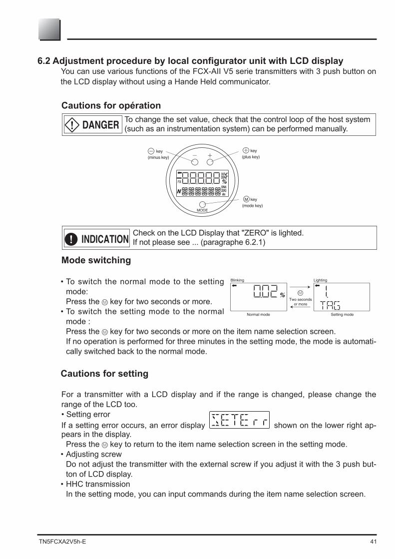
You can use various functions of the FCX-AII V5 serie transmitters with 3 push button on the LCD display without using a Hande Held communicator.
Cautions for opération
Mode switching
• To switch the normal mode to the setting mode: Press the key for two seconds or more.
• To switch the setting mode to the normal mode : Press the key for two seconds or more on the item name selection screen. If no operation is performed for three minutes in the setting mode, the mode is automati-cally switched back to the normal mode.
Cautions for setting
For a transmitter with a LCD display and if the range is changed, please change the range of the LCD too.• Setting errorIf a setting error occurs, an error display shown on the lower right ap-pears in the display. Press the key to return to the item name selection screen in the setting mode.• Adjusting screw
Do not adjust the transmitter with the external screw if you adjust it with the 3 push but-ton of LCD display.
• HHC transmission In the setting mode, you can input commands during the item name selection screen.
To change the set value, check that the control loop of the host system (such as an instrumentation system) can be performed manually.
Check on the LCD Display that "ZERO" is lighted.If not please see ... (paragraphe 6.2.1)
DANGER
INDICATION
FIX
OUTDISP
ZEROSPAN
abs
%
MODE
key(plus key)
key(minus key)
key(mode key)
M

42 TN5FCXA2V5h-E
6.2.1 Menu listThe following are the menu items. Adjust each setting as required.
Item Item name Description Page
1 TAG No. 1. TAG Display and setting of TAG No. (*1) 442 Model code 2. TYPE Display and setting of type (*1) 45
3 Serial No. 3-1. SERIAL N Display of serial No. 463-2. VER Display of transmitter software version 46
4 Engineering unit 4. UNIT Display and change of engineering unit (*1) 475 Range limit 5. URL Display of maximum measuring range 47
6 Measuring range6-1. LRV Change of LRV 48
6-2. URV (*1) 49
7 Damping 7. DAMP Change of damping time constant (*1) 50
8 Output mode8-1. OUT Md Change of output mode (*3) (*1) 518-2. CUT Pt 518-3. CUT Md 52
9 Direction and value of burnout
9-1. BURNOT Change of burnout direction (*1) 53
9-2. OVER OVERSCALE (*4) (*1) 53
9-3. UNDER UNDERSCALE (*5) (*1) 54
A Zero/span calibration A-1. ZERO Zero calibration (*6) (*2) 55A-2. SPAN Span calibration (*6) (*2) 56
B Output circuit calibrationb-1. 4mAAdj 4 mA calibration (*8) (*2) 57b-2. 20mAAdj 20 mA calibration (*8) (*2) 57b-3. FIXcur Constant current output (*8) 57
D Self-diagnosis d-1. AMPTMP Display of internal temperature of transmitter 58d-2. ALMCHK Display of self diagnosis. 58
F Locking of adjustment functions F. LOCK Locking and unlocking of the adjusting screw and the adjustment func-
tion in the setting mode (*1) 59
G LCD display range setting
G-1. LDV LDV (Lower Display Value) setting (*1) 60G-2. UDV UDV (Upper Display Value) setting (*1) 61G-3. DP DP (number of digit after Decimal Point) setting (*1) 61G-4. LcdUnit LcdUnit (LCD Unit Code) setting (*1) 62G-5. LcdoOpt LcdOpt (LCD Option) setting (*1) 62
I Input-output range ad-justment
I-1. LRVAdj Zero adjustment by range (LRV) change (*6) (*2) 63I-2. URVAdj Span adjustment by range (URV) change (*6) (*2) 64
J Value and specification of saturation current
J-1. SAT LO Change of saturation current value (lower limit) (*7) (*1) 65J-2. SAT HI Change of saturation current value (upper limit) (*7) (*1) 65
J-3. SPEC Selection (Nomal specification/expanded specification) of specifica-tions of burnout & saturation current (*1) 66
K Protective function of set value K. GUARD Setting and cancellation of set value protection (write protect) (*9) 67
L History information
L-1. HisZERO Display of zero calibration data for users 68L-2. HisSPAN Display of span calibration data for users 68L-3. HisCLEAR Clearing of zero/span calibration data (*1) 68L-4. HisAMP 69L-5. HisCELL Display of min/max of cell temperature history information 69
*1: If the write protect is selected at “K. GUARD,” the display for selecting whether the setting will be performed does not ap-pear, but “GUARD” appears. You cannot change the value in this condition.
*2: If the adjustment function is locked at “F.Lock” or the write protect is selected at “K. GUARD,” the item names is not displayed.*3: Only differential pressure transmitters have this function. Other transmitters do not display the item name.
*6: This item is valid only if polygonal line correction is invalid. If the polygonal line correction is valid or the equipment is de-fective, the item name is not displayed.
*8: In the multidrop mode, this item is invalid and the item name is not displayed.*9: If the write protect function (with a password) is selected by the HHC, the item name is not displayed.

TN5FCXA2V5h-E 43
6.2.2 Switching menusSetting mode with the button to select and display the differents menus.Press the key for a few seconds to switch the normal mode to the setting mode.Press the key for a few seconds to switch the setting mode to the normal mode.After selecting an item with the / keys, press the ) key to acess to the menu selected.
Normal mode(A measured value is displayed.)
Setting modeItem name selection screen
Press the key for two seconds or more.
Setting modeDisplay and setting of each itemkey
1. TAG2. TYPE3-1. SERIAL N3-2. VER4. UNIT5. URL6-1. LRV6-2. URV7. DAMP8-1. OUT Md8-2. CUT Pt8-3. CUT Md9-1. BURNOT9-2. OVER9-3. UNDERA-1. ZEROA-2. SPANB-1. 4mAAdjB-2. 20mAAdjB-3. FIXcurD-1. AMPTMPD-2. ALMCHKF. LOCKG-1. LDVG-2. UDVG-3. dPG-4. LcdUnitG-5. LcdOptI-1. LRVAdjI-2. URVAdjJ-1. SAT LOJ-2. SAT HIJ-3. SPECK. GUARDL-1. HisZEROL-2. HisSPANL-3. HisCLEARL-4. HisAMPL-5. HisCELL
1. Display and setting of TAG No.2. Display and setting of type3-1. Display of serial No.3-2. Display of transmitter software version4. Display and change of engineering unit5. Display of maximum measuring range6-1. Change of LRV (lower range value of measuring range = 0% point)6-2. Change of URV (upper range value of measuring range = 100% point)7. Change of damping time constant8-1. Change of output mode8-2. Setting of low flow rate cut point8-3. Setting of low flow rate cut mode9-1. Change of burnout direction9-2. Chang of output value when burnout direction = OVERSCALE9-3. Chang of output value when burnout direction = UNDERSCALEA-1. Zero calibrationA-2. Span calibrationB-1. 4 mA calibrationB-2. 20 mA calibrationB-3. Constant current outputD-1. Display of internal temperature of transmitterD-2. Display of self-diagnosis.F. Locking and unlocking of the adjusting screw and the adjustment function in the setting modeG-1. LDV (Lower Display Value) settingG-2. UDV (Upper Display Value) settingG-3. DP (Digit Number Under Decimal Point) settingG-4. LcdUnit (LCD Unit Code) settingG-5. LcdOpt (LCD Option) settingI-1. Zero adjustment by range (LRV) changeI-2. Span adjustment by range (URV) changeJ-1. Change of saturation current value (lower limit)J-2. Change of saturation current value (upper limit)J-3. Selection (nomal specification/expanded specification) of specifications of burnout & saturation currentK. Setting and cancellation of set value protection (write protect)L-1. Display of zero calibration data for usersL-2. Display of span calibration data for usersL-3. Clearing of zero/span calibration dataL-4. Display of min/max of amplifier temperature history informationL-5. Display of min/max of cell temperature history information
You can move to a next lower item with the key.
You can move to a next upper item with the key.

44 TN5FCXA2V5h-E
6.2.3 Operating procedure
Menu 1 : TAG N° (1-TAG)To set the TAG No. of the transmitter, use the proce-dures shown in the following diagram. TAG NO. can be inputted up to 26 character of alphanumeric codes.• Press the key on the screen to display the TAG
No. setting ( ).• Input alphanumeric characters as required with the
and keys on the screen . Functions of the keys:
key: To input characters at the cursor position (0 to 9, space, A to Z, –)
key: To move the cursor position to the next (1 2 3 ... 26 1)
Note) Characters other than numerical characters, capi-
tal letters of the alphabet, space, and “–” are dis-played as “*.”
Initial six characters are displayed. (The cursor position is displayed by a vertical bar.)
To display the seventh and following characters, scroll the characters to the left. (The cursor posi-tion (far right) is displayed as a number.)
The cursor position is 1 in the example . (Num-
The cursor position is 8 in the example . (Num-ber 8 is input as the eighth character.)
If HART is selected, the initial eight characters are treated as TAG information.
• Select whether the TAG No. on the screen . Press the key to save the TAG No. setting. Press the or key to cancel the setting.
* Description of the displays on the first line on the item name selection screen ( )
: Differential pressure transmitter : Pressure (gauge pressure) transmitter : Absolute pressure transmitter
M
M
① ②
③
④
M

TN5FCXA2V5h-E 45
M
① ②
③
④
M
M
Menu 2 : Model code (TYPE)
(example of differential pressure transmitter).• Press the key on the screen to display the
model code setting screen ( ).• Input alphanumeric characters as required with the
and keys on the screen . Functions of the keys:
key: to input characters at the cursor position. (0 to 9, space, A to Z, –)
key: to move the cursor position to the next. (1 2 3 ... 16 1)
Note)Characters can be input up 24.Characters other than numerical characters, capital letters of the alphabet, space, and “–” are displayed as “*.”Initial six characters are displayed. (The cursor posi-tion is displayed by a vertical bar.)To display the seventh and following characters, scroll the characters to the left. (The cursor position (far right) is displayed as a number.)The cursor position is 2 in the example . (“K” is in-put as the second character.)The cursor position is 8 in the example . (“5” is in-put as the eighth character.)
• Select whether the type setting is saved on the screen .
Press the key to save the type setting. Press the or key to cancel the setting.
* Description of the displays on the first line on the item name selection screen ( )
: Differential pressure transmitter : Pressure (gauge pressure) transmitter : Absolute pressure transmitter
46 TN5FCXA2V5h-E
① ②
M
M
④ ⑤
M
M
③
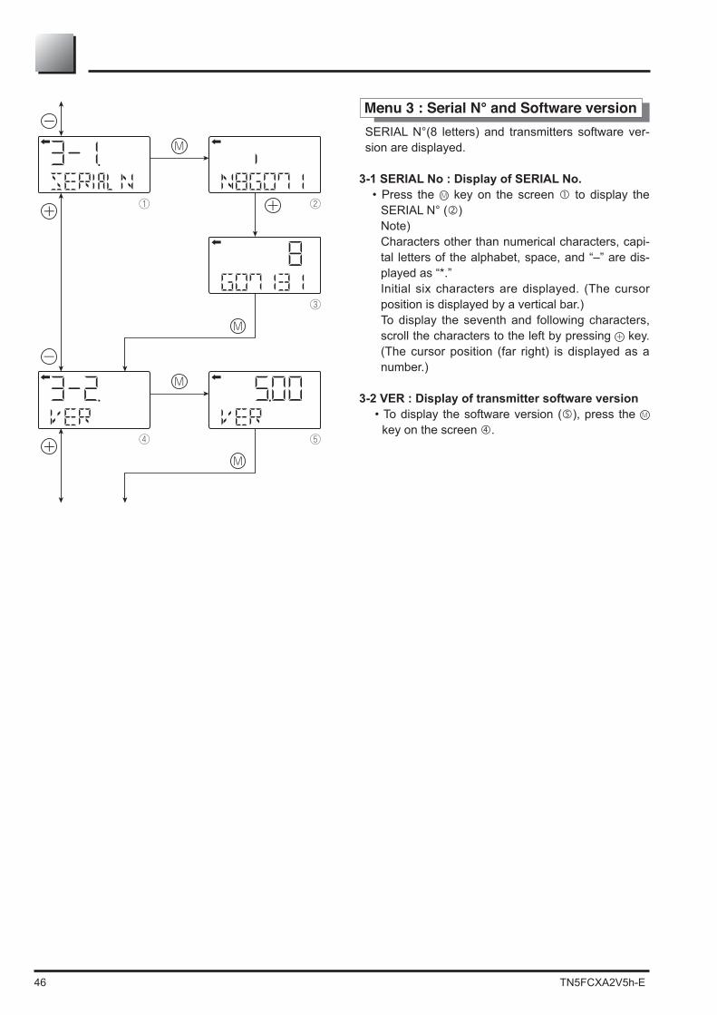
Menu 3 : Serial N° and Software versionSERIAL N°(8 letters) and transmitters software ver-sion are displayed.
3-1 SERIAL No : Display of SERIAL No.• Press the key on the screen to display the
SERIAL N° ( ) Note) Characters other than numerical characters, capi-
tal letters of the alphabet, space, and “–” are dis-played as “*.”
Initial six characters are displayed. (The cursor position is displayed by a vertical bar.)
To display the seventh and following characters, scroll the characters to the left by pressing key. (The cursor position (far right) is displayed as a number.)
3-2 VER : Display of transmitter software version• To display the software version ( ), press the
key on the screen .

TN5FCXA2V5h-E 47
M
① ②
④
②① M
M
M
M
③
Menu 4 : Engineering unit• To display the screen for changing the engineering
unit ( ), press the key on the screen .• Select an engineering unit with the and keys on
the screen .
Available units for FCX-AIIV5
mmH O2 cmH O2 mH O2 g/cm 2
Pa
inH O2
psi
ftH O2
< Torr >
kg/cm 2
< atm >
hPakPaMPambarbar
mmAq
mmHg
cmAqmAq
mmWCcmWCmWC
inHg
cmHgmHg
only.
Menu 5 : Range limitIndicates the maximum measuring range of this trans-mitter.• To display the range limit value ( ), press the key
on the screen .
Note) If “setERROR” is displayed as a URL value, the
unit is not supported.
48 TN5FCXA2V5h-E
ZERO
ZERO
ZERO
M
① ②
③
④
⑤
M
M
M
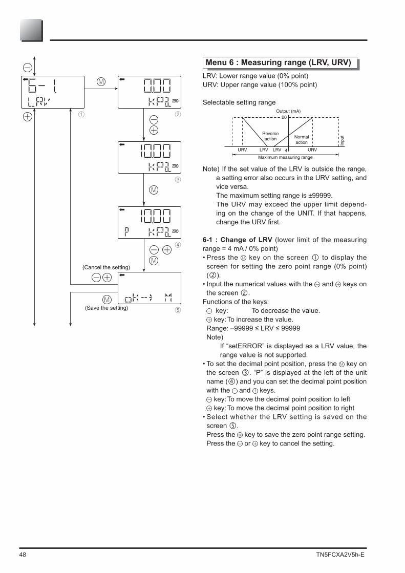
Menu 6 : Measuring range (LRV, URV)LRV: Lower range value (0% point)URV: Upper range value (100% point)
Selectable setting range
Note) If the set value of the LRV is outside the range, a setting error also occurs in the URV setting, and vice versa.
The maximum setting range is ±99999. The URV may exceed the upper limit depend-
ing on the change of the UNIT. If that happens,
6-1 : Change of LRV (lower limit of the measuring
• Press the key on the screen to display the screen for setting the zero point range (0% point) ( ).
• Input the numerical values with the and keys on the screen .
Functions of the keys: key: To decrease the value. key: To increase the value.
Note) If “setERROR” is displayed as a LRV value, the
range value is not supported.• To set the decimal point position, press the key on
the screen . “P” is displayed at the left of the unit name ( ) and you can set the decimal point position with the and keys.
key: To move the decimal point position to left key: To move the decimal point position to right
• Select whether the LRV setting is saved on the screen .
Press the key to save the zero point range setting. Press the or key to cancel the setting.

TN5FCXA2V5h-E 49
SPAN
SPAN
SPAN
M
① ②
③
④
⑤
M
M
M
6-2 : Change of URV (upper limit of the measuring
• Press the key on the screen to display the screen for setting the 100% point ( ).
• Input the numerical values with the and keys on the screen .
Functions of the keys: key: To decrease the value. key: To increase the value.
Note) If “UUUUU” is displayed as a URV value, the
unit is not supported.
• To set the decimal point position, press the key on the screen . “P” is displayed at the left of the unit name ( ) and you can set the decimal point position with the and keys.
key: To move the decimal point position to left key: To move the decimal point position to right
• Select whether the URV setting is saved on the screen .
Press the key to save the 100% point setting. Press the or key to cancel the setting.
The setting range of the transmitter is independant ot the setting range of the indicator. After changing the range in this menu, it is neces-sary to change the range in the LCD indicator (menu G). Using an analog indicator and if the transmitter range is changed, replacement of the analog indi-cator is required.
Impor tant

50 TN5FCXA2V5h-E
① ②
④
M
M
M③
Menu 7 : Damping
vibration of the installation site is important, it is re-quired to set appropriate damping time to avoid the
• Press the key on the screen to display the screen for changing the damping time constant ( ).
• Input the damping time constant with the and keys on the screen . Press the key to decrease the value and press the key to increase the value.
Settable range: 0.06 to 32.0 sec• Select whether the damping time constant setting is
saved on the screen . Press the key to save the damping time constant
setting. Press the or key to cancel the setting
-
crease. Since the transmitter uses oil as internal pressure transmitting medium, if acceleration is caused by vibration, internal pressure is generated in accordance with the acceleration value, thus resulting in the output
Oscillation frequency: 10 to 150 HzWithin ±0.25% of URL/(9.8m/s2)
2) Damping
setting appropriate damping time constant. The following table shows the effect of damping on the vibration of
Damping set value [sec] Damping of output oscillation Remarks1.2 1/3 or lower4.8 1/5 or lower19.2 1/10 or lower
10Hz, that is, the lowest frequency.

TN5FCXA2V5h-E 51
Menu 8 : Output mode
The output mode is used to select the proportional mode (proportional to input differential pressure) or
for the output signal (4 to 20 mA) of the differential pressure transmitter only.In the square root extraction mode, you can set the cut point of low cut and the modes below the cut point.
8-1 oUT Md : Change of output mode• Press the key on the screen to display the
screen for changing output mode ( ).• You can select the proportional or square root extrac-
tion mode on the screen . Select LIN (proportional mode) or SQR (square root
extraction mode) with the or key and press the key.
• Select whether the output mode setting is saved on the screen .
Press the key to save the output mode setting. Press the or key to cancel the setting.
8-2 CUT Pt : Low cut point setting If you select the square root mode, you can set the
low cut point.
Cut point is adjustable within the range of 0.00 to 20.00%. Note that if the cut point is set to a small value around 0%, even a minute differential pressure
point is used for improving the measurement in case
• Press the key on the screen to display the screen for setting the low cut point ( ).
• You can set and change the low cut point by inputting the numerical values with the and keys on the screen .
Settable range: 0.00 to 20.0%• Select whether the cut point setting is saved on the
screen . Press the key to save the cut point setting.
Press the or key to cancel the setting.
%
%
M
M
① ②
②③
M
④ ⑤
⑦
M
M⑥
M

52 TN5FCXA2V5h-E
M
M
⑧ ⑨
⑨⑩M
8-3 CUT Md : Low cut mode settingThere are two modes :
A)
• Press the key on the screen to display the screen for changing the outputs below the cut point ( ).
• Select LIN (linear) or ZERO on the screen with the or key and press the key.
• Select whether the low cut point setting is saved on the screen .
Press the key to save the low cut point setting. Press the or key to cancel the setting.

TN5FCXA2V5h-E 53
M
M
① ②
②
②
M
③
M
④ ⑤
⑦
See the next page for the procedure when UNdER is
selected.
M
M
M
⑥
(Cancel the setting)
(Save the setting)
(Cancel the setting)
(Save the setting)
Menu 9 : Burnout direction
Used for selecting output at occurrence of a fault in the detecting unit.
9-1 bURNoT : Change of burnout
• For NAMUR specification, press the key on the screen to display the screen for changing the burnout ( ).
• Select NotUse, OVER or UNDER on the screen (2) with the or key and press the key.
• Select whether the burnout setting is saved on the screen .
Press the key to save the burnout setting. Press the or key to cancel the setting.
9-2 OVER : Change of burnout current when OVER (OVERSCALE) This display appears if you select “OVER” for the
burnout.• Press the key on the screen to display the
screen for changing the burnout current for OVER-SCALE ( ).
• You can change the burnout current with the and keys on the screen .
Settable range:For NAMUR specification, 21.6, 21.8, 22.0, 22.2, 22.4, 22.5 can be selectedNote) You can change the saturation current value
-tion of saturation current.”
• Select whether the burnout current setting is saved on the screen .
Press the key to save the burnout current setting for OVERSCALE.
Press the or key to cancel the setting.

54 TN5FCXA2V5h-E
M
⑧ ⑨
⑪
M
M
⑩
9-3 UNDER : Change of burnout current when UN-DER (UNDERSCALE) is selected.
This display appears if you select “UNDER” for the burnout direction.• Press the key on the screen to display the
screen for changing the burnout current for UN-DERSCALE ( ).
• You can change the burnout current with the and keys on the screen .
Settable range: -
• Select whether the burnout current setting is saved on the screen .
Press the key to save the burnout current setting for UNDERSCALE.
Press the or key to cancel the setting.
Note)You can change the saturation current value (lower
of saturation current.”

TN5FCXA2V5h-E 55
ZERO
%
ZERO
%
ZERO
%
M
① ②
③
⑤
M
M
M
④
M
Menu A : Zero/span calibration
This menu gives the poissibility to calibrate Zero (LRV) and span (URV) of the transmitter.The ranging of the transmitter needs to be done in the "Range" menu 6. PLease use menu A "CALIBRATE"
menu.It is absolutely necessary to the zero or LRV point as welle as the span or URV point when making a cali-bration.
INDICATION1. After performing a zero calibration, perform a
span calibration.2. If you input the value that exceeds the adjustable
range, the setting will not be changed even after the setting is saved.
Adjustable rangeZero calibration: within ±40% of the max spanSpan calibration: within ±20% of the set span
A-1 Zero (LRV) calibration• Press the key on the screen to select the zero
calibration mode. The measured value and unit on the screen ( ) are
“ZERO” light up.• Apply the actual input pressure on the screen . Af-
ter checking the measured value, press the key.• “ZERO” blinks on the screen . Press the key on
the screen to perform a zero calibration at the in-put pressure at the time.
To perform a zero calibration at a point other than 0%, input an appropriate set value (%) ( ) with the and
keys, and press the key.
• Select whether the zero calibration value setting is saved on the screen .
Press the key to save the zero calibration value setting and return to the screen .
Press the or key to cancel the setting and return to the screen .
• Check that the zero calibration was performed as in-tended.
Press the key to perform a zero calibration again. Press the or key to move to the next screen for
item name selection.

56 TN5FCXA2V5h-E
SPAN%
SPAN%
SPAN%
M
⑥ ⑦
⑧
⑩
M
M
M
⑨
M
A-2 Span (URV) calibration• Press the key on the screen to select the span
calibration mode. The measured value and unit on the screen ( ) are
“SPAN” light up.• Apply the actual input pressure on the screen . Af-
ter checking the measured value, press the key.• “SPAN” blinks on the screen . Press the key on
the screen to perform a span calibration at the in-put pressure at the time.
To perform a span calibration at a point other than 100%, input an appropriate set value (%) ( ) with the and keys, and press the key.
Setting range• Select whether the span calibration value setting is
saved on the screen . Press the key to save the span calibration value
setting and return to the screen . Press the or key to cancel the setting and return
to the screen .• Check that the span calibration was performed as in-
tended. Press the key to perform a span calibration again. Press the or key to move to the next screen for
item name selection.
TN5FCXA2V5h-E 57
(Calibration)
(Calibration)
(Setting)
Lighting
'
'
① ②
⑧
⑦
M
M
⑤ ⑥
M
③ ④
M
M
⑨
M
M
M
Blinking
LightingFIX
LightingFIX
FIX
FIX
*When a display
other than EXITFIX
is selected.
*Press the key
when EXIT FIX is displayed.
M
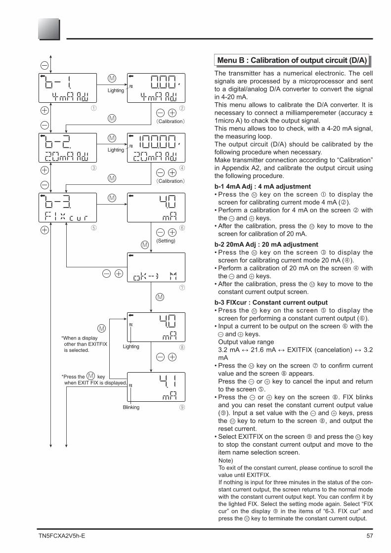
Menu B : Calibration of output circuit (D/A)The transmitter has a numerical electronic. The cell signals are processed by a microprocessor and sent to a digital/analog D/A converter to convert the signal in 4-20 mA.This menu allows to calibrate the D/A converter. It is necessary to connect a milliamperemeter (accuracy ± 1micro A) to chack the output signal. This menu allows too to check, with a 4-20 mA signal, the measuring loop.The output circuit (D/A) should be calibrated by the following procedure when necessary.Make transmitter connection according to “Calibration” in Appendix A2, and calibrate the output circuit using the following procedure.b-1 4mA Adj : 4 mA adjustment• Press the key on the screen to display the
screen for calibrating current mode 4 mA ( ).• Perform a calibration for 4 mA on the screen with
the and keys.• After the calibration, press the key to move to the
screen for calibration of 20 mA.b-2 20mA Adj : 20 mA adjustment• Press the key on the screen to display the
screen for calibrating current mode 20 mA ( ).• Perform a calibration of 20 mA on the screen with
the and keys.• After the calibration, press the key to move to the
constant current output screen.b-3 FIXcur : Constant current output• Press the key on the screen to display the
screen for performing a constant current output ( ).• Input a current to be output on the screen with the
and keys. Output value range
mA• Press the key on the screen
value and the screen appears. Press the or key to cancel the input and return
to the screen .• Press the or key on the screen . FIX blinks
and you can reset the constant current output value ( ). Input a set value with the and keys, press the key to return to the screen , and output the reset current.
• Select EXITFIX on the screen and press the key to stop the constant current output and move to the item name selection screen.Note)To exit of the constant current, please continue to scroll the value until EXITFIX. If nothing is input for three minutes in the status of the con-stant current output, the screen returns to the normal mode
the lighted FIX. Select the setting mode again. Select “FIX cur” on the display in the items of “6-3. FIX cur” and press the key to terminate the constant current output.

58 TN5FCXA2V5h-E
① ②
M
③ ④
M
M
M
[Contents of message]As a result of self-diagnosis, the message below is appeared on the LCD display, when there are trouble in the transmitter. For each error, its cause and remedy are suggested.
Error display of self-diagnosis
Display in normal mode Cause Remedy
C1 ERR~
C9 ERRFL-1 Error of detecting unit
Check the wiring between the de-tecting unit and transmitter.If the error is not recovered, re-place the detecting unit.
RAM ERFL-1
Calculation parameter (RAM) error
PAR ER Error of magnitude relation of tem-perature data
AMP EP FL-2CEL EP FL-3 EEPROM error on cell side Replacement of detecting unit
AMP TMP T. ALm Transmitter temperature is normal-ized.CEL TMP T. ALm Cell temperature error
OVER Input pressure: J-2, saturation cur-rent (Hi) or higher Correction of input pressure
UNDER Input pressure: J-1, saturation cur-rent (Lo) or lower Correction of input pressure
Menu D : Self-diagnosis
Self-diagnosis display shows the internal temperature of the transmitter and the failure description.
d-1 AMPTMP : Internal temperature of the transmit-ter• Press the key on the screen to display the
screen of internal temperature of the transmitter ( ). When a temperature alarm is issued, “TEMP” is
changed to “ALM.” (This corresponds to “AMP TMP” of “Error display of
self-diagnosis” in the following table.) If the temperature cannot be measured due to defec-
tive internal data, “IMPOSS” is displayed. (This corresponds to any of “RAM ER”, “PAR ER” or
“AMP EP” of “Error display of self-diagnosis” in the following table.)
d-2 ALMCHK : Display of self-diagnosis results• Press the key on the screen to show the self-di-
agnosis results ( ). Press the and keys to display errors sequential-
ly.
See the following table “Contents of message” for the errors of the transmitter.

TN5FCXA2V5h-E 59
M
M
① ②
②③M
Menu F : Lock of adjustment functionsYou can lock/unlock the adjustment function of the lo-
INDICATIONWhen the adjustment functions are locked, the exter-nal adjusting screw is also locked.
• Press the key on the screen to display the lock selection screen of adjusting functions ( ).
• Select the locking/unlocking of the adjustment func-tions on the screen with the and keys.
Select the locking to lock the adjustment functions of
Select the UnLock to cancel the lock of the adjust-
display.• Select whether the locking/unlocking of the adjust-
ment functions are saved on the screen . After selecting the locking/unlocking, press the key
to save the setting. Press the or key to cancel the setting and return
to the screen .
List of adjustment functions locked/unlocked
A. Zero/span calibration A-1. ZEROA-2. SPAN
B Output circuit calibration b-1. 4mA Adjb-2. 20mA Adj
I. Input/Output range ad-justment
I-1. LRV AdjI-2. URV Adj

60 TN5FCXA2V5h-E
④
③
① ②
M
M
M
M
Menu G : Setting of LCD display
The LCD display is independant of the transmitter set-ting. So the LDC display must be set. In this menu, it is possible to change the range (0%-100%), the unit and the value type displayed.
G-1 LDV : LCD setting for the 0% (4mA)• Press the key on the screen to display the
screen for setting the indicated value corresponding to 0% ( ).
• Input the indicated value corresponding to 0% of the actual scale on the screen with the and keys.
Functions of the keys: key: To decrease the value key: To increase the value
• To set the decimal point position, press the key on the screen . “P” is displayed at the right of the unit name ( ) and you can set the decimal point position with the and keys.
key: To move the decimal point position to left key: To move the decimal point position to right
• Select whether the indicated value setting of 0% is saved on the screen .
Press the key to save the indicated value setting. Press the or key to cancel the setting.

TN5FCXA2V5h-E 61
⑧
⑦
⑤ ⑥
M
⑪
⑨ ⑩
M
M
M
M
M
M
G-2 UDV : LCD setting for the 100% (20mA)• Press the key on the screen to display the
screen for setting the indicated value corresponding to 100% ( ).
• Input the indicated value corresponding to 100% of the actual scale on the screen with the and keys.
• Functions of the keys: key: To decrease the value key: To increase the value
• To set the decimal point position, press the key on the screen . “P” is displayed at the right of the unit name ( ) and you can set the decimal point position with the and keys.
key: To move the decimal point position to left key: To move the decimal point position to right
• Select whether the indicated value setting of 100% is saved on the screen .
Press the key to save the indicated value setting. Press the or key to cancel the setting.
Note : The following scale can be set :
and
G-3 DP : Decimal point settingSet the number of digits after decimal point for the LCD indicated value.• Press the key on the screen to display the
screen for setting the DP ( ).• Input the DP on the screen (10) with the and
keys. Setting range:
Display rangeSee note below-9999.9 ~ 9999.9-999.99 ~ 999.99-99.999 ~ 99.999-9.9999 ~ 9.9999
• Select whether the DP setting is saved on the screen .
Press the key to save the DP setting. Press the or key to cancel the setting.

62 TN5FCXA2V5h-E
G-4 LcdUnit : Settintg of the LCD value displayed• Press the key on the screen to display the screen
for setting the unit ( ).• Input the unit on the screen with the and keys.• Select whether the unit setting is saved on the screen
. Press the key to save the unit setting. Press the or key to cancel the setting.
Available unit for FCX-AII
(a)%(LIN)NONE(LIN)MPakPahPaPabarmbarkg/cm2
g/cm2
mmH2O cmH2OmH2OinH2OftH2OmmAqcmAqmAqmmWCcmWCmWCmmHgcmHgmHginHgPSI<atm><Torr>
(b)mmcmminft
(c)%(SQR)NONE(SQR)Nm3/sNm3/minNm3/hNm3/dm3/sm3/minm3/hm3/dNl/sNl/minNl/hNl/dl/sl/minl/hl/dgal/sgal/mingal/hgal/dft3/sft3/minft3/hft3/dbbl/sbbl/minbbl/hbbl/dkg/skg/minkg/hkg/dt/st/mint/ht/d
The units in parentheses < > are displayed only when the absolute pressure transmitter is used.
The flow units in the column (c) can be set only for the group of differential pressure transmitters.
G-5 LcdOPT : LCD unit setting• Press the key on the screen to display the
screen for setting the LCD option ( ).• Input the option No. on the screen to set the LCD
option with the and keys. Setting range:
LCD Option Function
0 Normal display (Display set at G1 to G4)
1 Alternate display (Display set at G1 to G4 and % display [in increments of 1%])
2 Alternate display (Display set at G1 to G4 and % display [in increments of 0.1%]
3 Alternate display (Display set at G1 to G4 and % display [in increments of 0.01%]
• Select whether the option setting is saved on the screen .
Press the key to save the option setting. Press the or key to cancel the setting.
⑭
⑫ ⑬
M
M
M
⑰
⑮ ⑯
M
M
M

TN5FCXA2V5h-E 63
ZERO
%
ZERO
%
ZERO
%
M
① ②
③
⑤
M
M
M
④
M
Menu I : Rerange: adjustment by LRV/URV change
(Specially for application to level measurement) The input-output range adjustment enables you to change automatically the measurement range by re-adjusting the lower limit of the measurement (LRV) or the upper limit of the measurement (URV).
I-1 LRV Adj : Zero adjustment by changing the range (LRV) (LRV adjustment)• Press the key on the screen to select the LRV
adjustment mode. The measured value and unit on the screen are
“ZERO” light up.• Apply the reference pressure for LRV (4mA) on the
screen . After checking the measured value corre-sponding to 4 mA, press the key.
• “ZERO” blinks on the screen . Press the key on the screen to perform a zero adjustment at the in-put pressure.
Settable range:
• Select whether the LRV adjustment value setting is saved on the screen .
Press the key to save the LRV adjustment value setting and return to the screen .
Press the or key to cancel the setting and return to the screen .
• Check that the zero adjustment (LRV) was performed as intended on the screen .
Press the key to perform a zero adjustment again. Press the or key to move to the next screen for
item name selection.
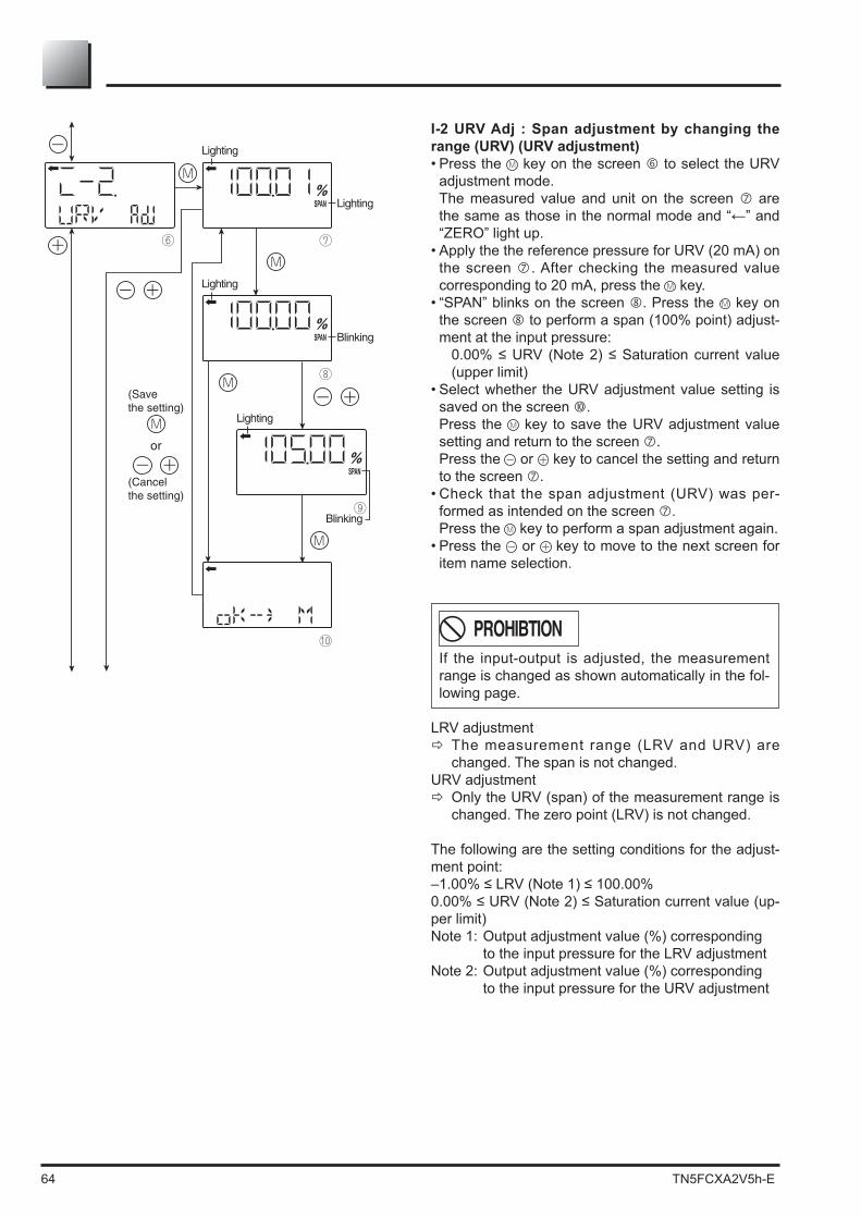
64 TN5FCXA2V5h-E
I-2 URV Adj : Span adjustment by changing the range (URV) (URV adjustment)• Press the key on the screen to select the URV
adjustment mode. The measured value and unit on the screen are
“ZERO” light up.• Apply the the reference pressure for URV (20 mA) on
the screen . After checking the measured value corresponding to 20 mA, press the key.
• “SPAN” blinks on the screen . Press the key on the screen to perform a span (100% point) adjust-ment at the input pressure:
(upper limit)• Select whether the URV adjustment value setting is
saved on the screen . Press the key to save the URV adjustment value
setting and return to the screen . Press the or key to cancel the setting and return
to the screen .• Check that the span adjustment (URV) was per-
formed as intended on the screen . Press the key to perform a span adjustment again.• Press the or key to move to the next screen for
item name selection.
PROHIBTIONIf the input-output is adjusted, the measurement range is changed as shown automatically in the fol-lowing page.
LRV adjustment The measurement range (LRV and URV) are changed. The span is not changed.
URV adjustment Only the URV (span) of the measurement range is changed. The zero point (LRV) is not changed.
The following are the setting conditions for the adjust-ment point:
-per limit)Note 1: Output adjustment value (%) corresponding
to the input pressure for the LRV adjustmentNote 2: Output adjustment value (%) corresponding
to the input pressure for the URV adjustment
SPAN%
SPAN%
SPAN%
M
⑥ ⑦
⑧
⑩
M
M
M
⑨
M

TN5FCXA2V5h-E 65
④
③
① ②
M
⑧
⑤ ⑥
M
M
⑦M
M
M
Menu J :
You cannot change the saturation current setting if
To change the saturation current setting, select “EXP (expanded specification)” at “J-3” as shown in the following page.
J-1 SAT Lo : Change of the saturation current value (lower limit) (available only when the expanded speci-
• Press the key on the screen to display the screen for setting the lower limit of the saturation cur-rent ( ).
• Input the lower limit on the screen with the and keys.
Setting range:
above the saturation current value (lower limit)• Select whether the lower limit setting of the satura-
tion current is saved on the screen . Press the key to save the lower limit setting. Press the or key to cancel the setting.
J-2 SAT HI : Change of the saturation current value (upper limit) (available only when the expanded
• Press the key on the screen to display the screen for setting the upper limit of the saturation current ( ).
• Input the upper limit on the screen with the and keys.
Setting range:-
rent value (lower limit)• Select whether the upper limit setting of the satura-
tion current is saved on the screen . Press the key to save the upper limit setting. Press the or key to cancel the setting.
* You can change the burnout current setting at “9: Di-rection and value of burnout.”

66 TN5FCXA2V5h-E
(Save the setting)
(Cancel the setting)
M
M
⑨ ⑩
⑩⑪
M
J-3 SPEC : Selection of the burnout & saturation cur--
• Press the key on the screen to display the screen for selecting the burnout & saturation current
).-
panded specification)” on the screen with the and keys.
Select “NoRMAL” for the normal setting. Select “EXP” for the expanded setting.
* To change the saturation current value (upper limit,
Normal
Saturation current value (lower limit)
3.8 mA 3.2 mA to 4.0 mASettable in increments of
0.1 mA
Saturation current value (upper limit)
20.8 mA 20.0 mA to 21.6 mASettable in increments of
0.1 mA
The table below lists the output current value for burnout (OVER, UNDER).
-cation
Burnout (UNDER)
3.2 to 3.8 mA 3.2 mA to saturation current value (lower limit)
Burnout (OVER)
20.8 to 21.6 mA Saturation current value (upper limit) to 21.6 mA
The values in the table above can be set in increments
of 0.1 mA.• Select whether the NoRMAL/EXP setting is saved on
the screen . Press the key to save the NoRMAL/EXP setting. Press the or key to cancel the setting and return
to the screen .

TN5FCXA2V5h-E 67
(Save the setting)
(Cancel the setting)
M
M
① ②
②③
M
Menu K : Protective function of set value (Write protect)
This function sets and cancels the write protect after password. The object of write protect are adjustment and setting parameters (including adjustment of external adjust-ment screw). After cancelling write protect, it will automatically re-turn to write protect state by setting time.
K-1 GUARD : Setting and canceling write protect• Press the key on the screen to display the
screen for setting/canceling write protect ( ).• Select oN (setting)/oFF (canceling) on the screen
with the and keys. To enable write protect, select “ON.” To disable write protect, select “OFF.”• Select whether the selection of oN (setting)/oFF
(canceling) is saved on the screen . After selecting oN/oFF, press the key to save the
setting. Press the or key to cancel the setting and return
to the screen .Note:
• If you enable write protect and set a password by the HHC, you cannot cancel the setting with the 3 push buttons and the item name of “K. GUARD” does not appear.
• If you enable write protect by setting the protective function of set value (GUARD) with the 3 push but-tons, you can cancel the setting by the HHC.
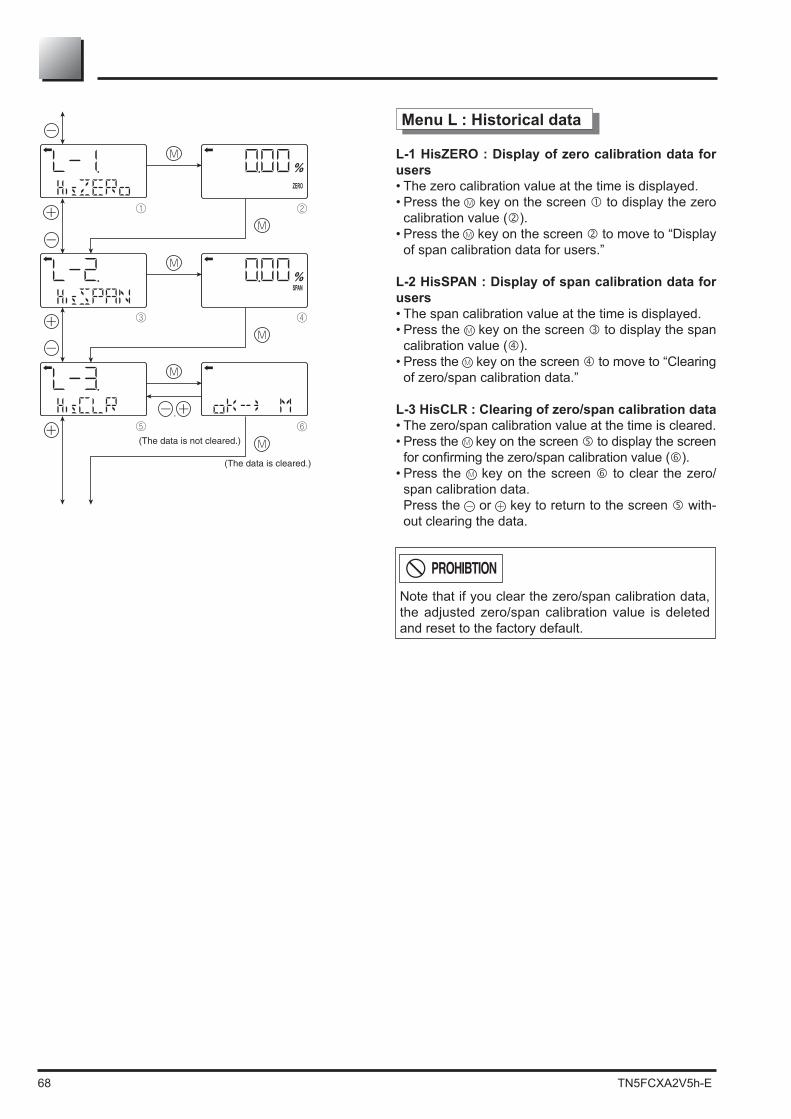
68 TN5FCXA2V5h-E
,
ZERO
%
SPAN%
① ②
M
③ ④
M
⑤ ⑥
M
M
M
M
Menu L : Historical data
L-1 HisZERO : Display of zero calibration data for users• The zero calibration value at the time is displayed.• Press the key on the screen to display the zero
calibration value ( ).• Press the key on the screen to move to “Display
of span calibration data for users.”
L-2 HisSPAN : Display of span calibration data for users• The span calibration value at the time is displayed.• Press the key on the screen to display the span
calibration value ( ).• Press the key on the screen to move to “Clearing
of zero/span calibration data.”
L-3 HisCLR : Clearing of zero/span calibration data• The zero/span calibration value at the time is cleared.• Press the key on the screen to display the screen
).• Press the key on the screen to clear the zero/
span calibration data. Press the or key to return to the screen with-
out clearing the data.
Note that if you clear the zero/span calibration data, the adjusted zero/span calibration value is deleted and reset to the factory default.
PROHIBTION
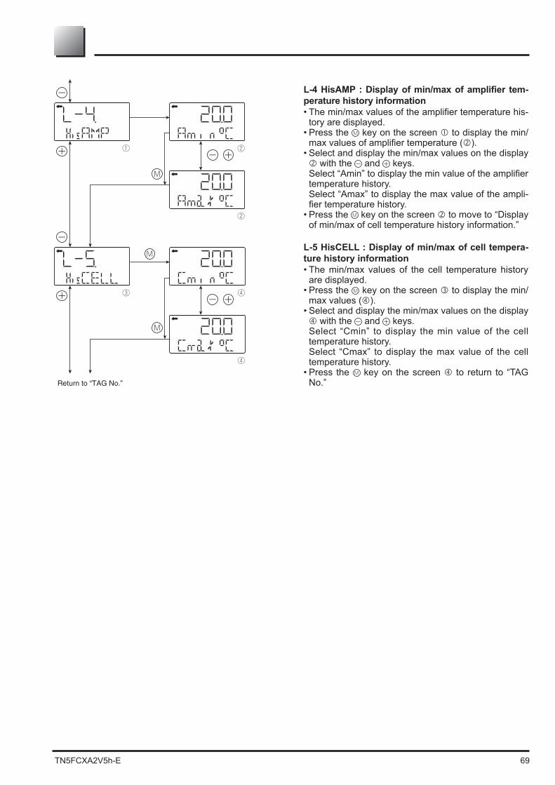
TN5FCXA2V5h-E 69
-perature history information
-tory are displayed.
• Press the key on the screen to display the min/).
• Select and display the min/max values on the display with the and keys.
temperature history. Select “Amax” to display the max value of the ampli-
• Press the key on the screen to move to “Display of min/max of cell temperature history information.”
L-5 HisCELL : Display of min/max of cell tempera-ture history information• The min/max values of the cell temperature history
are displayed.• Press the key on the screen to display the min/
max values ( ).• Select and display the min/max values on the display
with the and keys. Select “Cmin” to display the min value of the cell
temperature history. Select “Cmax” to display the max value of the cell
temperature history.• Press the key on the screen to return to “TAG
No.”
① ②
②
M
③ ④
④
M
M

70 TN5FCXA2V5h-E
Field device
To junctionterminal orinstrumentroomTo HHC
Explosion-proof area Non-explosion-proof area
Zener barrier
Instrument room
Terminal block
DC power supply16.1 to 45V DC
Junction terminal
Fuji HHC Fuji HHC
Note) See 7.2 “Power voltage and load resistance.
Load resistor250 or more
6.3 Adjustment with Hand Held Commnicator (HHC)
The span adjustment of the transmitter can be done by using the HHC without applying a refe--
ters. For the use and the start up of the HHC, please refer to the instructions of FXW (HHC).
Remarks : * The HHC must be on "OFF" position during the connection.
+ and -" of the transmitter. * The HHC has no polarity. (It is possible to connect either the red or black electrical wire to the
terminals + or - of the transmitter or on the wires of the loop).
6.3.1 Connection of HHC
The HHC can be connected in any point of the loop.
Refer the following diagram connection of the HHC (hand Held Communicator).
After adjustment of the transmitter, it should be kept energized for about 10 seconds.
the junction box located outside the hazardous area.DANGER
-minal block of the transmitter in hazardous area installations.DANGER
INDICATION

TN5FCXA2V5h-E 71
6.3.2 Start up of the HHC
• Put on/off switch of the HHC on “ON” position. Put on the enclosed “key” in the corresponding location of the HHC. Without the key and
with the key in vertical position, you can just read the transmitter parameters. To write new parameters in the transmitter, the key needs to be in horizontal position. Othe-
rwise, you will have an inscription on the HHC screen "INHIBIT KEY OK ?" to let you know that the key needs to be turned to enable the programming of new parameters in the trans-mitter.
Nota : "INHIBIT KEY" means that the key permits or inhibits (prohibited) writing parameters in the transmitter
• The transmitter version and the revision of the HHC software are indicated on the screen during the start up.
After around 4 seconds the inscription "PUSH MENU KEY" appears (please push menu key) HHC with the optional printer will have the inscription "PAPER FEED". Please push on <INC
key. By pushing on <INC "PUSH MENU KEY" will be indicated on the screen by if you push on the clear <CL On the screen appears the inscription "RECEIVING START". The HHC reads out the data
In case of a connection problem, "NO CONNECTION" will appear on the screen. The "PUSH MENU KEY" appears again if you push the clear <CL
The reasons of a communication problem can be : - The 4-20 mA output is not powered. - The 4-20 mA is disconnected.
supply. - The HHC is not connected to the correct terminals
steps are indicated on the bottom line of the screen inside following signs ( < INC (increase
N+1), or the DEC (decrease The most important menus can be
The <CHNG
ALHAthe letter. To add a space between caracters, you have to push the keys <ALHA
To delete caracters, please use the clear key <CL . ENT
a second time by replying on the question "CHNG OK ?time on the enter < ENT
At this moment the new programmed information are written in the transmitter memory, "WRITE" indication will appear on the screen of the HHC

72 TN5FCXA2V5h-E
(FXW 1-A4).FXW prior to Version 7.0 are not available of operation of FCX-A2 V5 serie transmitters.
Classification Display symbol Key symbol Referentialpage
1
2
3
4
5
6
7
8
9
A
B
C
D
E
G
F
H
I
TAG No.
Type
Display of serial No.
Industrial value unit
Range limit
Range change (LRV,URV)
Damping adjustment
Output mode and value
Burnout direction
Calibration of the zero/span
Calibration of output circuit
Indication of measured data
Self-diagnosis
Printer function
Lock of adjustment functions
Indication of digitalindicator
Programmable linearizationfunction
Rerange (Set LRV/URV calibration)
INC
INC
INC
INC
INC
INC
INC
INC
INC
INC
INC
INC
INC
INC
INC
INC
INC
INC
1 : TAG No.
2 : TYPE
3 : SERIAL No.
4 : UNIT
5 : RANGE LIMIT
6 : RANGE
7 : DAMPING
8 : OUTPUT MODE
9 : BURNOUT
A : CALIBRATE
B : OUTPUT ADJ
C : DATA
D : SELF CHECK
E : PRINT
F : XMTR EXT.SW
G : XMTR DISPLAY
H : LINEARIZE
I : RERANGE
73
73
74
74
75
75
76
77
78
79
80
81
81
82
82
83
86
88 INC INC
INC
INCDATA INC INC INC
INC INC INCDATA INC
INCDATA INC INC INC
MENU
MENU INC
MENU INC INC
UNIT
INCUNIT
RANG
DAMP
LIN/ ?
LIN/ ? INC
CALB
OUT
DATA
INCDATA
INC INCDATA
INC INC INCDATA
J Saturation current valueand specification setting
INC J : SATURATE CUR 89 INC INC
INCDATA INC INC INC
INC
K Write protect INC K : WRITE PROTCT 90 INC INC
INCDATA INC INC INC
INC INC
L History information INC L : HISTORY 91 INC INC
INCDATA INC INC INC
INC
INC INC

TN5FCXA2V5h-E 73
Menu 2 : Type
-ged (ex. of differential pressure transmitter).
• After TAG N° is displayed, press the <INCto display TYPE image.
• To make changes press the <CHNGdisplay and the cursor will be displayed under display .
• Set the alphanumeric keys as necessary under display . To set the alphabet, press the <CHNG ALHA
Using < moved.
• At the completion of setting, press the <ENTkey and a prompt is displayed check entry under display .
• If the entry is correct, press the <ENT and and
the initial image is displayed. Otherwise press <CL
• To display SERIAL N°, press the <INCdisplay .
Menu 1 : Tag N°
To set the TAG N° of the transmitter, use the pro-cedures shown in the following diagram. TAG N° can be inputted up to 26 characters of alphanumeric codes.
• After PUSH MENU KEY is displayed, press the <MENU
• To make changes press the <CHNG> key and the cursor will be displayed under display .
• Set the alphanumeric keys as necessary under display .
To set the alphabet, press the <CHNG ALHA
Using < moved.
• At the completion of setting, press the <ENT• If the entry is correct, press the <ENT
and and the initial image is displayed. Otherwise press <CL .
• To display TYPE display, press the <INCunder display .
1: TAG No FICRA-1234 xxxxxxxxx xxxxxxxxxxxxxxxxxxx < INC > < CHANGE >
1-1: TAG CHANGE FICRA-1234 xxxxxxxxx xxxxxxxxxxxxxxxxxxx < ENT > < CL >
1-1: TAG CHANGE FICRA-4321 xxxxxxxxx xxxxxxxxxxxxxxxxxxx CHNG OK?< ENT/CL >
1-2: TAG WRITE FICRA-4321 xxxxxxxxx xxxxxxxxxxxxxxxxxxx
To menu 2 : TYPE
0: PUSH MENU KEY
CL
INC
CHNG
MENU
CL
ENT
ENTafter setting
1 2
3
4
2: TYPE FKCXXXXX-XXXXX < INC > < CHANGE >
2-1: TYPE CHANGE FKCXXXXX-XXXXX
< ENT > < CL >
2-1: TYPE CHANGE FKCXXXXX-XXXXX CHNG OK?< ENT/CL >
2-2: TYPE WRITE FKCXXXXX-XXXXX
To Menu 3 : SERIAL No. and Software version
Menu 1 : TAG No.
CL
INC
INC
CHNG
CL
ENT
ENTafter setting
1 2
3
4

74 TN5FCXA2V5h-E
Menu 3 : Serial N°
SERIAL N° and transmitters software version are displayed.
• After setting TYPE, press the <INCSERIAL N° and software version of transmitter.
• By pressing the <INCis displayed.
3: SERIAL No. N8G07131 VERSION 1.1 < INC >
2 : TYPE
INC
INC
To menu 4 : ENGINEERING UNIT
Menu 4 : Engineering unit
26 industrial units can be used by the operator (see below).
-sure transmitter only.
• When pressing <CHNG , the display for changing the engineering unit appears.
• The desired engineering unit is selectable by using <INC DECdisplay .
• Display -ming your change.
• Display is for registering the engineering unit.
< UNIT CHANG >
4-1: UNIT CHANGE kPa
< INC > < ENT > < CL >
4-1: UNIT CHANGE
CHNG OK? < ENT/CL >
4-1: UNIT WRITE
< INC >
4: UNIT
To menu 5 : RANGE LIMIT
kPa
< CHNG >
(NEXT MPa)
(NEXT MPa)kPa
kPa
4-1: UNIT WRITE
UNIT < CL >NOT SUITABLE
Not suitable unit display
Pa
Menu 3 : SERIAL N°
CL
CL
CL
INC
INC
CHNG
ENT
ENT
1
2
3
4
INC
DECINC
mmH O2 cmH O2 mH O2 g/cm 2
Pa
inH O2
psi
ftH O2
< Torr >
kg/cm 2
< atm >
hPakPaMPambarbar
mmAq
mmHg
cmAqmAq
mmWCcmWCmWC
inHg
cmHgmHg
The unit of industrial value is set according to the range as ordered, but the display resolution lowers depending on the unit being set.When
is displayed upon changing the unit of industrial value, output cannot be dis-played in the engineering unit selected.
In this case, press the key and change the engineering unit to a different one.
4-1:UNIT CHANGE Pa
NOT SUITABLE
Important

TN5FCXA2V5h-E 75
Menu 6 : Range change (LRV, URV)
LRV: Lower range value (0% point - 4 mA) URV: Upper range value (100% point - 20 mA)
Note) If the set value of the LRV is outside the range, an error also occurs (SetERROR) in the URV setting, and vice versa.
The maximum setting range is ± 9999. The URV may excedd the upper limit depending
on the change of the Unit. If that happens change
• When pressing <CHNG , display changes to the LRV and URV selection screen.
• Press <LRVthe zero point range (display ).
• Press <URVthe span range (display ).
• Under displays or , input zero point or span values. Press <ENT
Note : when pressing <+ - or , negative value is available.
Note : if the set value of the LRV is outsidethe range, an error ("setting error") also occurs in the URV setting, and vice versa.The maximum setting range is ±99999.The URV may exceed the upper limit depending on the change of the UNIT.
Menu 5 : Range Limit
Indicates the maximum measuring range of this transmitter.
• After setting engineering unit, press <INCto display RANGE LIMIT.
• By pressing the <INCis displayed.INC
INC
INCCL
CHNG
LRV CL
URV CL
ENT CL
ENT
6-3: RANGE WRITE
6-1: RANGE CHANGE LRV XXX . X kPa
< LRV > < URV > < CL > URV XXX . X kPa
LRV XXX . X kPa
< LRV > < URV > < CL > URV XXX . X kPa
LRV XXX . X kPa
< LRV > < URV > < CL > URV XXX . X kPa
LRV XXX . X kPa URV XXX . X kPa
LRV XXX . X kPa URV XXX . X kPa
2
6-2: RANGE CHANGE
3
6-2: RANGE CHANGE
4
CHNG OK? < ENT/CL >
6-2: RANGE CHANGE
5
6
1
6: RANGE LRV XXX . X kPa
< INC > < CHANGE >
5: RANGE LIMITXXX kPa
< INC >
URV XXX . X kPa
Menu 4 : UNIT
To menu 7 : DAMPING
Output (mA)
URVMaximum measuring range
InputNormalaction
Reverseaction
4LRV LRV URV
20
Selectable setting range
The setting range of the transmitter is independant of the setting range of the indicator. After changing the range in this menu, it is necessary to change the range in the LCD indicator (menu G). Using an analog indicator and the transmitter range is changed, replacement of the analog indicator is required.
Important

76 TN5FCXA2V5h-E
Menu 7 : Damping Adjustment
the vibration of the installation site is important, it is required to set appropriate damping time to
• Input time constant value under display , dam-ing can be changed.
• Press <ENT• Press <CL to to come back to
.
Selectable time constant value :
Note 1) In the case of FCX-AII series transmit-ters with safety function, when there are no damping, then 0.12 sec is appeared on HHC.
Note 2) The above damping constants are used only for the electronics unit. The detecting unit has its own constants independent of the electronics unit (for details, refer to the data sheet).
CHNG
ENTCL
7: DAMPING0.3SEC
< INC >2
ENT
< CHANGE >CL1
7-1: DAMP CHANGE
after setting
0.3SEC
7-1: DAMP CHANGE 1.2SEC
CHNG OK? < ENT/CL >3
7-2: DAMP WRITE 1.2SEC
4
< ENT > < CL >
INC
Menu 6 : RANGE
To menu 8 : OUTPUT MODE

TN5FCXA2V5h-E 77
The output mode is used to select the proportional mode (proportional to input differential pressure) or square root extraction mode (proportinal to
differential pressure transmitter only.
8-1 Change the output mode In case of square root extraction mode, the cut
point and the mode below the cut point can be set.
• Under display , press <INC DECselection of the square root extraction mode ("SQR") or linear mode ("LIN").
8-3 Low cut point setting The square root extraction mode is selected,
the display is presented and the low cut point should be set..
Note that if the cut point is set to a small value around 0%, even a minute differential pressure
cut point is used for improving the measurement
There are two modes :
• On display , press "CHANGE" to set the low cut mode
• Under display , linear or zero output is selec-table for output below the cut point.
Menu 8 : Output Mode
8: OUTPUT MODE XMTR:DP OUT=LIN
< INC > < CHANGE >
8-1: MODE CHANGE XMTR : DP OUT=LIN
< INC > < ENT > < CL >
8-1: MODE CHANGE XMTR : GP OUT=LIN
< ENT > < CL >
8-1: MODE CHANGE XMTR:DP OUT=SQRCHNG OK? < ENT/CL >
8 : OUTPUT MODE XMTR:GP OUT=LIN
< INC > < CHANGE >
8-2: MODE WRITEXMTR:DPOUT=SQR
8-3: LOW CUTPOINT=XX.XX%FLOWMODE=
< CHANGE > < CL >
< ENT > < CL >
8-5: POINT WRITEXX.XX%FLOW
8-7: LOW CUT MODE< 1 > LINEAR < 2 > ZERO< 1 > < 2 > <CL >
8-7: MODE CHANGELINEAR
CHNG OK? < ENT/CL >
8-8: MODE WRITE LINEAR
8-1: MODE CHANGE XMTR:DP OUT=LIN
CHNG OK? < ENT/CL >
*1<OUTPUT MODE CHANGE>
8-4: POINT CHANGE XX.XX%FLOW
8-4: POINT CHANGE XX.XX%FLOW
8-6: LOW CUT MODEZERO
< CHANGE > < CL >
8-7: MODE CHANGEZERO
CHNG OK? < ENT/CL >
8-8: MODE WRITE ZERO
OUT=LIN
8-2: MODE WRITE XMTR:DP OUT=LIN
INC 11 INC
(a)
(DP) GP, AP, LL (Liquid Level)
2 CLENT
ENT 5 CL ENT 3 CL
CL
4 ENT 6
CHNG CL
CHNG CHNG
7
ENT CL
ENT CL
CL
8
1OUT=SQR2
9
CHNG
10
8-6: LOW CUT MODE LINEAR
< CHANGE > < CL >11 CL 12
CL 16ENT
13CL21
ENT CL 14
15 17
< INC >*1
*2 0.00% Cut Point 20.00% FLOW Note) GP, AP, LL : OUT = LIN only
< DEC > Available Mode
In case of OUT= SQR In case of OUT=LIN
CHNG
Menu 9
(a)
*2
CHNG OK? < ENT/CL >
= LINEAR or ZERO
Output
Low cutpoint
Low cutpoint
Output
Differentialinput
Differentialinput
Fig. A: With linear output selected in low cut mode
Fig. B: With zero output selected in low cut mode

78 TN5FCXA2V5h-E
Used for selecting output at occurrence of a fault in the detecting unit.
• Burnout direction is selectable under display
condition above is as follows. • NOT USED Not used (Output hold)
Note) Output value just before the occurrence of trouble is given in the output hold mode.
• OVER SCALE Over scale (Output 20.8 to 21.6mA)
• UNDER SCALE Under scale (Output 3.2 to 3.8 mA)
Change of burnout current for OVERSCALE and UNDERSCALE
• On display (5), press "CHANGE" to set the bur-nout current.
• Press "DEC" or "INC" to change the burnout current (settable in increments of 0.1 mA) on display .
press "CL" to cancel the setting on display .• Display with saturate current appears.
Note :
(Upper limit and Lower limit) is changeable accor-ding to the Menu "J : Saturation current value"The ower limit value ofsaturation valuer is set-
mA to 4.0 mA)Display symbol of Menu 9 is : "9 : BURNOUT
Menu 9 : Burnout directionCHNG
3
9-2: BURNOUT CHANGE
CHNG OK? < ENT/CL >4
56
2
9:BURNOUTNOT USED(HOLD)< INC > < CHANGE >
1
9-2: BURNOUTCHANGE
Selection ofburnout direction
(ex)
< ENT > < CL >
CL
CL
CL
CHNG
CHNG
ENT
INC
CL
CL
or or21 3
3
9-1: BURNOUT< 1 > NOT USED< 2 > OVER SCALE< 3 > UNDER SCALE
UNDER SCALE
9-4: BURNOUT
< CHANGE > < CL >
UNDER SCALEY.YmA
9-5: BURNOUT
< CL >
Saturate Current3.8-20.8mA
9-5: BURNOUT CHNG
< DEC > <ENT > < CL >
UNDER SCALE
UNDER SCALE (burnout current)
Y.YmA
UNDER SCALE
ENT
ENT
ENT
INC
7
8
9
10
CL
CL
9-5: BURNOUT CHNG
CHNG OK? < ENT/CL >
UNDER SCALEY.YmA
9: BURNOUT
< INC > < CHANGE >
UNDER SCALEY.YmA
Upon pressing <DEC> or <INC>burnout current can be changed.(See above.)
9-7: BURNOUT
< CL >
Saturate Current3.8-20.8mA
INC DEC
Y.YmA3.8mA3.7mA3.6mA3.5mA3.4mA3.3mA3.2mA
A : CALIBRATE
A : CALIBRATE Change of Over scale current21.6mA21.5mA21.4mA21.3mA21.2mA21.1mA21.0mA20.9mA20.8mA
INC DEC

TN5FCXA2V5h-E 79
Menu A : Zero/span calibration
-sibility to calibrate zero and span of the transmitter (LRV and URV). The ranging of the transmitter needs to be done in the “RANGE” menu 6.Please use menu A “CALIBRATE” only when the LRV
necessary to apply an accurate reference pressure corresponding to the zero or LRV point as well as the span or URV point when making a calibration.
Calibration of the Low Range Value (LRV)• In the display , press "LRV" to reach display • Press "ENT" to make the LRV calibration (at 0% - 4mA) Reference pressure for 0% (4mA) must be applied on
the transmitter at this moment. For example : LRV range : 0 bar gauge. Open the transmitter drain to the atmosphere and
make a LRV calibrate.
Calibration of the Upper Range Value (LRV) • In the display 1, press "URV" to reach display • Press "ENT" to make the URV calibration (at 100% -
20mA) Reference pressure for 100% (20 mA) must be applied
on the transmitter at this moment.
Calibration at any point other than 0 and 100%• In the display 1, press "LRV" or "URV" to reach display
or • Enter the pressure value at that point in the display
or • Press "ENT" to make the calibration while applying a
corresponding pressure to the transmitter.
INC
A: CALIBRATE
< INC > < LRV >1
CL
ENT
2
A-1: CALIBRATE LRV XXX.XX%
CHNG OK? < ENT/CL > 3
A-2: CALIBRATINGLRV XXX.XX%
4
A-1: CALIBRATELRV XXX.XX%
< ENT > < CL >
ENT
XXX.X kPa
XXX.X kPa
XXX.X kPa
5
A-3: CALIBRATE URV XXX.XX%
CHNG OK? < ENT/CL > 6
A-4: CALIBRATINGURV XXX.XX%
7
A-3: CALIBRATEURV XXX.XX%
< ENT > < CL >XXX.X kPa
XXX.X kPa
XXX.X kPa
LRV
CLCL
ENTCL
ENT
URV
< URV >
< Zero adjustment >
< Span adjustment >
Menu B : OUTPUT ADJ
Press LRV or URV at display of .When the following is displayed, it means that calibration can not be made because Menu No. H: LINEARIZE is effective. In this case, set INVALID on the panel of No. H: LINEARIZE.
1. Span adjustment should be performed after zero adjustment is completed.
In this case, adjustment is required again.Adjustable range Zero adjustment : Within ±40% of maximum span Span adjustment : Within ±20% of calibrated span 3.When the adjustment point does not meet the following condition,
Adjustment point setting condition –1.000%CS (*) (*) (*)
(Lower adjustment point) - LRV
URV - LRV (Higher adjustment point) - LRV
URV - LRV (*) : CS (Calibrated Span) is equal to measuring range.
Impor tant A-1:CALIBRATE
Set Linearize

80 TN5FCXA2V5h-E
Menu B : Calibration of output circuit D/A
The transmitter has a numerical electronic. The cell signals are processed by a microprocessor and sent to a digital/analog D/A converter to con-vert the signal in 4-20 mA.This menu allows to calibrate the D/A converter. It is necessary to connect a milliamperemeter (ac-curacy +- 1micro A) to chack the output signal. This menu allows too to check, with a 4-20 mA signal, the measuring loop.The output circuit (D/A) should be calibrated by the following procedure when necessary.
Make transmitter connection according to "Cali-bration" in appendix A2, and calibrate the output circuit using the following procedure.
, the display for 4mA current output and its calibration will appear on the screen.
During this phase, a 4mA constant current is generated.
- Press "CALB" for the calibration - Press "CHNG" or "CL" to cancel
for 20mA current output and its calibration will appear on the screen.
-ated.
- Press "CALB" for the calibration - Press "CHNG" or "CL" to cancel
Under display , input a desired value within a
to generat a constant current. - Press "CHANGE" or "CL" to cancel. Under display , input digital values measured
by digital voltmeter.
Under display , the output circuit is calibrated
The transmitter will calculate automatically the gap between the theoritical and the measured values. It will rectify in the D/A converter.
B: OUTPUT ADJ
C: DATA
< INC > < CHANGE >
B-1: OUTPUT SET 0mA
< LRV/URV/ENT/CL >
B-2: OUTPUT MODE XX.XXXmA CURRENT CONST.
< CALB > < CHNG > < CL >
B-3: OUTPUT CALIB XX.XXXmA CONST. 0mA (EXT.mA)
< ENT > < CL >
B-3: OUTPUT CALIB XX.XXXmA CONST. YY.YYYmA (EXT.mA)
CHANGE OK? < ENT/CL >
< CHANGE > < CL >
B-2: OUTPUT MODE XX.XXXmA CURRENT CONST.
B-4: OUTPUT XX.XXXmA CONST. YY.YYYmA (EXT.mA)
CALIBRATING
B-4: OUTPUT XX.XXXmA CONST. YY.YYYmA (EXT.mA)
NOT CAL1B. < CL >
(Input of XX.XXXmA at )
Calibrationimpossible
GOUT
(OTHERS)
B-1: OUTPUT SET 4.000mA
CHANGE OK? < ENT/CL >
B-1: OUTPUT SET 20.000mA
CHANGE OK? < ENT/CL >
B-1: OUTPUT SET XX.XXXmA
CHANGE OK? < ENT/CL >
1 1
9
72 8
3
4
5
6
10
10 appears when theadjustable range isexceeded.
INC CHNG
LRV URV ENT CL
ENT CL ENT CL ENT CL
< OTHERS >
CALB CHNG CL CHNG CL
ENT CL
ENT CL
CL
(4 , 20mA)
After setting and calibrating the constant current output, be sure to reset the HHC display to cancel with the inital display of menu B.
It should be noted that if HHC is removed from the transmitter loop or the HHC power is turned OFF when the constant current output has been set, the transmitter output is retained at the constant current output.
�
B:� OUTPUT ADJ
<INC> <CHANGE>Impor tant

TN5FCXA2V5h-E 81
Menu D : Self-diagnosis
Use for displaying the measured temperature in the transmitter and the alarm information.
, the tempera-
about transmitter (ALM CHECK) is displayed.
Result of diagnosis
When temperature alarm is detected:
When no error has occurred:
When an error has occurred:
For contents of error, refer to "Contents of mes-sage".
Menu C : Indication of measuring data
The measured value is indicated.Flashing "*" indicates the transmisstion of the mea-surement valu to the HCC.the digital number for the "%" can be set pressing "CHNG".The HCC will be in stand by after 10 min without any operation. Press "CL" to avoid the stand by and come back to the display with the measuring data...
C-1: DATA
STANDBY PUSH CL KEY
XXX. X %FLOWC: DATA
< INC > < ENT >XXXXX kPa
< CHANGE > < CL >CL
CL
D-1: SELF CHECK
D-2: SELF CHECK ALM CHECK
< 1 > AMP TEMP
D: SELF CHECK
< INC > < ENT >< 2 > ALM CHECK< 1 > < 2 > <CL >
< CL > GOOD
D-2: SELF CHECKTEMP=XXX.X C (YYY.Y F)
< CL > <INC>
D-2: SELF CHECK CELL FAULT (C1)
< CL > < INC >
D-2: SELF CHECKTEMP=XXX.X CTEMP.ALARM
Temperature is displayed in C and F alternately at each press of the <INC> key.
1 CL1 2 2
CL
CL
3
4
5
6
BDATA
C-1: DATAXXX. XX %FLOWXXXXX kPa
< CHANGE > < CL >CL
:"FLOW" is displayedwhen output mode issquare root extractionmode.
:" flicker" is displayedwhen the communica-tion between transmitterand HHC is normal.
(HHC is not used for 10 minutes)
CHNGINC
CHNG
ENT
INC
ENT
(Temperature alarm is displayed)
INC
CL
(Trouble in transmitter)
E: PRINT
D-2: SELF CHECK
D-2: SELF CHECK CELL FAULT (C1)
D-2: SELF CHECK ALM CHECK GOOD
D-2: SELF CHECK
TEMP. ALARM
[Contents of message]As a result of self-diagnosis, the message below is appeared on the LCD display of HHC, when there are trouble in the transmitter. For each error, its cause and remedy are suggested.
Indication on digital indicatorCELL FAULT (C1)
CELL FAULT (C9)(*1)
EEPROM (AMP) FLT
EEPROM (CELL) FLT
TEMP. ALARM
XMTR FAULT
Error of detecting unit
EEPROM error on cell side
Transmitter temperature is not within the allowable range (–40 to 85°C).
Input pressure is 105% or higher of setting range. Input pressure is –1.25% or lower of setting range.
Replacement of detecting unit
Replacement of detecting unit
Transmitter temperature is normalized.
Properly controlled. Properly controlled.
Message RemedyCause
FL-1
FL-2
FL-3
T.ALM
FL-1
OVER Under
ZERO
ZERO
ZERO
(*1)
(*1)
(*1)
(*1) Real indication

82 TN5FCXA2V5h-E
Menu E : Printer function
Usable only when a printer is connected.
All transmitter setting can be print with the printer connected to HHC. If the printer is not connected, "NO CONNEC-TION" appears on the display.
• Press <ENTthe Year/ Month/Date and Time. • Press <ENT• "PRINT OUT" is displayed and the printing be-ginsAt the end, "PRINT OUT END" is displayed.• Press <INCpress <CL
Note : 10 parameters are printed : TAG, SN, TYPE, URL, RANGE, DAMPING, BURNOUT, DAT, TEMP and RAS)
E-2: PRINT OUT
E: PRINT
< INC >
E-1: PRINTDATETIME
< CL >
E-3: PRINT OUTPRINT OUT END< INC >PAPER FEED< CL >
CL
INC
INC
CL
ENT
INC
ENT(Indicated when the printer unit is active)
YY : MM : DDHH : MM
Paper Feed (Printer)
Without Printer UnitE: PRINT
< INC >
NO CONNECTION
With Printer Unit
< ENT >
< ENT >
Time (Hour, Minute)Set Year/Month/Date
F : XMTR EXT.SW
This menu alloys to lock and unlock the adjust-
and by external screw.
When pressing <1 , the external switch lock function is activated and all adjustment function of the transmitter by LCD are locked and it is released when pressing <2(ENABLE).
Menu F : Lock of adjustment function
2
F-1: XMTR EXT. SW
F-2: XMTR EXT. SWCHANGE
3
F-2: XMTR EXT. SW CHANGE
4
< 1 > INHIBIT
< ENT >
INHIBIT
INC
F: XMTR EXT. SW
1
< INC > < CHANGE >
CL
CL
1
< 2 > ENABLE< 1 > < 2 > < CL >
CHNG OK? < ENT/CL >
F-3: XMTR EXT. SWWRITE
5 INHIBIT
CHNG
CL
ENT
ENT
ENABLE
INHIBIT< CL >
F : XMTR DISPLAY

TN5FCXA2V5h-E 83
G-3: DISP. CHANGE< 1 > 0.00-100.00%< 2 > 0.0-100.0%< 3 > 0-100% < CL >
G : XMTR DISPLAY % DISPLAYX.XX-XXX.XX%YYYY< INC > < CHANGE >
G : XMTR DISPLAYYYYYYY/ZZZZZZUUUUUUU
< INC > < CHANGE >
G-1: DISP. CHANGE< 1 > % DISPLAY< 2 >ACTUAL DISP.< 1 > < 2 > < CL >
G-2: DISP. CHANGE< 1 > % LIN< 2 > % FLOW< 1 > < 2 > < CL >
YYYYYY=XMTR DISPLAY at 4mAZZZZZZ=XMTR DISPLAY at 20mAUUUUUUU=XTMR DISPLAY UNIT
1 2
1 2
2
3
4
5
6
7
8
9
10
1
4
G-4: DISP. CHANGEX.XX-XXX.XX%LIN
CHNG OK?<ENT/CL>
4
INC
ENT
INC CHNG
CL1
123
1 2 CL
CL
CL
CHNG
or
or
Note 1
Note1) 0.00-100.00%LIN 0.0-100.0% LIN 0-100% LIN 0.00-100.00%FLOW 0.0-100.0% FLOW 0-100% FLOW
A
<2> % FLOW
<1> % LIN DPGP, AP, LL(liquid Level)
G-4: DISP. WRITEX.XX-XXX.XX%LIN
G-3: DISP. CHANGE< 1 > 0.00-100.00%< 2 > 0.0-100.0%< 3 > 0-100% < CL >
B
4
G-4: DISP. CHANGEX.XX-XXX.XX%FLOW
CHNG OK?<ENT/CL>
4ENT
123
CL
G-3: DISP. CHANGECan't proceed.XMTR doesn'tsupport. < CL >
4CL
CL
G-4: DISP. WRITEX.XX-XXX.XX%FLOW
0.00-100.00%or 0.0-100.0%or 0-100%
H : LINEARISE
Menu G : Setting of LCD display
The LCD display is independant of the trans-mitter setting. So the LDC display must be set.
For digital indicator, either % display or actual-scale display is selectable. In display on the actual scale, display values corresponding to 0% (4mA) and 100% (20mA) are settable.
Linear / Flow settingThen linear mode and square root extraction mode is selectable as shown in .
<1in % in the linear mode<2
Note : in case of pressure transmitter, absolute pressure transmitter and level transmitter,
<2 .
• Display 5 alloys to set the decimal point of the value on the digital indicator.
2 3 ENTCL

84 TN5FCXA2V5h-E
Range setting for linear modeAfter choosing <2 , the LCD range is shown.If the LCD range is different of the transmitter range, it is necessary to change the LCD range.
• Press <LRV URVURV range of the digital indicator• Enter the LRV and the URV on displays or
.• Press <ENT CLto cancel.
Note :• The following scale can be set :
• When entering the range in the displays or , do not forget to enter the number with the
% Display .
Unit setting for linear modeAfter setting the LCD range, the display 16 is shown to set the unit.
• Press <CHANGE• Choose the unit type on display (PRESS, LEVEL, FLOW)• Choose the unit on display • Press <ENTpress "CL" to cancel. Data is written in the Digital indicator of the trans-mitter.
Note : In case of pressure transmitter, absolute pres-
units cannot be set.
G-2 : DISP. CHANGELRV: 4mA=YYYYYYURV: 20mA=ZZZZZZ< LRV >< URV ><CL>
11
12
3
1113
1 2 3
CLURVLRV
CL
11CL
URVENT
ENT
GP, AP, LL(liquid Level)
G-2: DISP. CHANGECan’t proceed.XMTR doesn'tsupport. < CL >
CL
A
G-2 : DISP. CHANGELRV: 4mA=YYYYYYURV: 20mA=ZZZZZZ< ENT >< URV ><CL>
Already set value of transmitter
Already set value of transmitter = PRESS./LEVEL/FLOW
16
1119CLENTCHNG
G-3 : DISP. CHANGEDispUNIT=UUUUUUU ( )<CHNG><ENT><CL>
18
17CLENTINC
G-5 : DISP. CHANGEDispUNIT=UUUUUUU(NEXT XXXXXXX)<INC><ENT><CL>
17
16CL
G-4 : DISP. CHANGE<1>PRESS.<3>FLOW<2>LEVEL<1><2><3><CL>
14G-2 : DISP. CHANGELRV: 4mA=YYYYYYURV: 20mA=ZZZZZZSET OK?< ENT ><CL>
11CL
15G-2 : DISP. CHANGELRV: 4mA=YYYYYYURV: 20mA=ZZZZZZSETTING ERR <CL>
13
1112CLURVENT
G-2 : DISP. CHANGELRV: 4mA=YYYYYYURV: 20mA=ZZZZZZ< ENT >< URV ><CL>
<1>PRESS
(a)
18
17CLENTINC
G-5 : DISP. CHANGEDispUNIT=UUUUUUU(NEXT XXXXXXX)<INC><ENT><CL>
19
17CLENT
G-5 : DISP. CHANGEDispUNIT=UUUUUUU
SET OK?<ENT><CL>
20
11CLENT
G-6 : DISP. CHANGEYYYYYY/ZZZZZZUUUUUUUCHNG OK?<ENT/CL>
21
2
G-7 : DISP. CHANGEYYYYYY/ZZZZZZUUUUUUU
<2>LEVEL
<3>FLOW
(b)
18
17
17
40
40
CLENTINC
G-5 : DISP. CHANGEDispUNIT=UUUUUUU(NEXT XXXXXXX)<INC><ENT><CL>
19
17CLENT
G-5 : DISP. CHANGEDispUNIT=UUUUUUU
SET OK?<ENT><CL>
20
11CLENT
G-6 : DISP. CHANGEYYYYYY/ZZZZZZUUUUUUUCHNG OK?<ENT/CL>
21
B ( )
G-7 : DISP. CHANGEYYYYYY/ZZZZZZUUUUUUU
DP
(c)
(UNIT=PRESS. LEVEL) (UNIT=FLOW)
<DISP. UNIT CHANGE>(a)mmH2OcmH2OmH2Og/cm2
kg/cm2
PahPakPaMPambarbarpsiinH2OftH2OmmAqcmAqmAqmmWCcmWCmWCmmHgcmHgmHginHg(Torr)(atm)
(b)mmcmminft
(c)Nm3/sNm3/minNm3/hNm3/dm3/sm3/minm3/hm3/dt/st/mint/ht/dl/sl/minl/hl/dgal/sgal/mingal/hgal/dft3/sft3/minft3/hft3/dbbl/sbbl/minbbl/hbbl/d( ) is available
for GP and AP.
(C) is available for DP.
INC DEC
Indication of the transmitter digi-tal indicator may have ±1 digit error against the setting by HCCCAUTION

TN5FCXA2V5h-E 85
1 2
ENT
G-8 : LOW CUTPOINT=XX.XX%FLOWMODE=YYYYYY<CHANGE><CL>
22
B
CHNG1 2
CL
G-9 : POINT CHANGE XX.XX%FLOW
<ENT><CL>
24
22CL
ENT28
CL ENT28
CL
or
G-C : MODE CHANGE<1>LINEAR<2>ZERO<1><2><CL>
28
27CL
ENT
G-9 : POINT CHANGE XX.XX%FLOW
CHNG OK?<ENT/CL>
25
G-A : POINT WRITE XX.XX%FLOW
2624
CL
G-B : LOW CUT MODELINEAR
<CHANGE><CL>
27
CHNG CHNG1 2
CLor
G-B : LOW CUT MODEZERO
<CHANGE><CL>
27
G-D : MODE CHANGELINEAR
CHNG OK?<ENT/CL>
29 G-B : MODE CHANGEZERO
CHNG OK?<ENT/CL>
29
G-D : MODE WRITELINEAR
30 G-B : MODE WRITEZERO
30
1 2CL
or
Note2) CUT POINT and CUT MODE are set at Menu No.8YYYYYY=LINEAR or ZERO
Low cut point setting for square root mode
After choosing <2 (actual display 2
display (Flow mode choosen)
• Press <CHANGECut point is adjustable within the range of 0.00 to 20.00 %.
Note : If the cut point is set to small value around 0% even a minute differential pressur change causes
The cut point is used for improving the measure-
• Press <ENT CLto cancel.
Low cut mode setting for square root mode
After setting the low cut point, it is possible to set the low cut mode : Linear or Zero.
There are two modes :
• Press <1 2• Press <ENT CLto cancel.
Output
Low cutpoint
Low cutpoint
Output
Differentialinput
Differentialinput
Fig. A: With linear output selected in low cut mode
Fig. B: With zero output selected in low cut mode

86 TN5FCXA2V5h-E
for display 11
19
H-2: LINEARIZE
H-3: LINEARIZECHANGE
20
H-3: LINEARIZESet Output ModeLIN-LIN or SQR-SQR
21
< 1 > INVALID
CHNG OK? < ENT/CL >
INC
2
3
4
5
1
CL
2
< 2 > EFFECTIVE< 1 > < 2 > < CL >
< CL >
CHNG
CHNG
CHNG
CHNG
CL
CL
CL
CL
CL
CL
CL
CL
6CL
CL
ENT
INC
1 2
INC
ENT
INC
Nextparameter 15
INCINC
INC
16
9
15 16
7
CL
H: LINEARIZE
< INC > < CHNG >
INVALID
H-1: LINEARIZE
< INC > < CHNG > < CL >
INVALID
EFFECTIVE
H-2: LINEARIZE
< INC > < CHNG > < CL >POINT 0
H-2: LINEARIZE
< INC > < CHNG > < CL >POINT XX
H-3: LINEARIZE
< ENT > < CL >POINT 0
H-3: LINEARIZE
< 1 > < 2 > < CL >< 2 >Comp value:CV< 1 >Lin. point:LP
H-4: LINEARIZE
< INC > < CNG/ENT/CL >LP1 XXX.XX%
H-4: LINEARIZE
< INC > < CNG/ENT/CL >LP3 XXX.XX%
for displayfor display15
INC
7 16
10
15
I : Rerange
16
8
H-4: LINEARIZE
< INC > < CNG/ENT/CL >LP2 XXX.XX%
H-4: LINEARIZE
< INC > < CNG/ENT/CL >LP14 XXX.XX%
CHANGE
Input the value ofpoint and pressENT (POINT XX)
In the casewhere POINTXX has beenset
For DP
CL
LP1LP2LP3
LP14
INC DEC
Change of compensatedpoint for LP
Menu H : Linearization function
The linearization function is used for level measurment in open or closed tank. This function can be used only if the tank shape can-
example : spherical tank or horizontal cylindric tank...)14 compensation points are available corresponding to 15 line segments, (X1, Y1), (X2, Y2)…(X14, Y14). Each compensation value between (Xn, Yn) and (Xn+1,
.Functions for LINEARIZE are available for FXW Ver-sion 6.0 and upward.
• By pressing <INC , the display is shifted to the setting of LINEARIZE POINT .
• Press <CHNG and input POINT XX to be compensated. Then press <ENTdisplay will be shifted to .
• Press <INC and the display will be shifted to y for selection of <1<2
• Select <1XXX.XX% to each point (LP1-LP ).
At the completion of input to all the compensated points, press ENT twice and the write of LP will be
At this time, the display is shifted to . and in-
put XXX.XX% to each point (CV1-CV ) in the same way as noted in <1
At the completion of input to all the compensated points, press ENT twice and the write of CV will be
At the completion of write of compensated program for LP/CV, press CL twice at the display of for shifting to .
• Then, press CHNG for selection of <1<2 . At display of , press <2and the display will be changed to EFFECTIVE.
Note) In the key stroke for Linearization, please set each parameter in the below sequence.
1. Set the number of compensation points in the range of 2 to 14.
2. Set each linearization option point (LP*) cor-rectly, and write them.
3. Set each compensation value (CV*) cor-rectly, and write them.
4. Set linearization option into EFFECTIVE and write.

TN5FCXA2V5h-E 87
CL
CL
CL
CL
CL2
Nextparameter 17
INC
INC
INC
18
13
17 18
11
H-4: LINEARIZE
< INC> < CNG/ENT/CL >CV1 XXX.XX%
H-4: LINEARIZE
< INC> < CNG/ENT/CL >CV3 XXX.XX%
for displayfor display17
INC
11 18
14
17 18
8
H-4: LINEARIZE
< INC> < CNG/ENT/CL >CV2 XXX.XX%
H-4: LINEARIZE
< INC> < CNG/ENT/CL >CV14 XXX.XX%
CL
ENT
for display
ENT
8
1615
6
H-5: LINEARIZECHANGE CHANGECHANGE
< ENT > <CL >LPM XXX.XX%
H-5: LINEARIZE
CHNG OK? < ENT/CL >LP1-14
for display 7 , 8 , 9 , 10
for display 7 , 8 , 9 , 10
CL
CL
ENT
for display
ENT
8
1817
H-5: LINEARIZECHANGE CHANGECHANGE
< ENT > <CL >CVM XXX.XX%
H-5: LINEARIZE
CHNG OK? < ENT/CL >CV1-14
for display 11, 12 , 13, 14
for display 11, 12 , 13, 14
Before performing the LINEARIZE setting, set either of the following equations in the OUTPUT mode (Menu No.8) and XMTR DISPLAY (Menu No. G):
Note 1)
FLOW in % display or of FLOW units in actual scale display.
CV1CV2CV3
CV14
INC DEC
Change of compensatedpoint for CV
When ENT is pressed at display of , the follow-ing is displayed,
Requirement of setting1.LP LP2 LP3…LP8 LP9…LP13 LP14 (In
be set enable)
Note1) a, b show next numeral such as
or the following is displayed.
H-3: LINEARIZESet LINEARIZEPoint, LP and CV
H-3: LINEARIZESet OUTPUT MODELIN-LIN or
When <INC , the following is displayed,
orWhen <ENT , the following is displayed,
To change according to following setting conditions
When <ENT , the follow-ing is displayed,
To change according to following setting conditions Requirement of setting
When <ENT , the follow-ing is displayed,
To change according to following setting conditions
H-2: LINEARIZE
POINT 0
H-3: LINEARIZE POINT 15 POINT SET
H-5: LINEARIZE CHANGELP 150.01%
H-5: LINEARIZE CHANGECV 100.01%
Impor tant

88 TN5FCXA2V5h-E
I-2: RERANGE
6
< ENT > < CL >
INC
2
3
4
1
CL
CHNG
CLCLLRV URV
I: RERANGE
< INC > < CHNG >
I-1: RERANGE
< LRV >< URV > < CL >
URV 100.00%
CLENT
I-3: RERANGECHANGE
CHNG OK? < ENT/CL >LRV . %
7
CL
CL CL
ENT
I-3: RERANGECHANGE
CHNG OK? < ENT/CL >URV %
5
ENT
I-5: RERANGE
< CL >LRV kPaLRV kPa
Menu J : SATURATE CUR
8
ENT
I-5: RERANGE
< CL >URV kPaLRV kPa
I-2: RERANGE
< ENT > < CL >LRV 0.00%
Adjustment point setting condition
In the case that point is out of setting limit. (Ex)
digital indicator provided, if the range is changed, indicator display might not match. So, setting is re-quired again in response to the display in the digital indicator (G:XMTR DISPLAY).
-alog indicator provided, if the range is changed, the scale for indicator might not ensure exact reading.• When CHNG is pressed at display or , the fol-lowing is displayed.
MENU N° H:LINEARIZE is set in EFFECTIVE. In this case, press the CL key and set in INVALID on the panel of N° H:LINEARIZE.
1-1: RERANGE
Set Linearize
1-2: RERANGE
LRV 100.01%
Impor tant
Menu I : Adjustment by LRV/URV range
The Rerange functionality can be used when zero ad-justment (suppression or elevation) is necessary (for example : Level measurement).Functions of RERANGE can be made with FXW Ver-sion 6.0 or upward.
When the lower range value (LRV) and upper range value (URV) need to be adjusted again during mea-surement of tank level, the measurement levels can be changed at the same time by setting the LRV with rerange.
LRV RerangeApply an input pressure required for rerange of LRV at display of and press ENT twice.
In this way, the rerange of LRV is completed, then the new measurement range LRV and URV, which con-forms to the actual input pressure, is displayed.
URV Rerange Apply an input pressure required for rerange of URV at display of and press ENT twice. The rerange of URV is completed, then the new measurement range LRV and URV corresponding to the actual input pressure is displayed.
Note) The unit of LRV/URV at and are displayed in the unit selected by Menu N° 4:UNIT.
This rerange function adjusts imput and output by range change.Upon implementation of rerange, the measure-ment range changes as follows : If RERANGE LRV is implemented :
Measurement range (LRV and URV) changes. However, span remains unchanged.
If RERANGE URV is implemented : Only URV (spam) of measurment range
changes. Zero POint (LRV) remains the same.
CAUTION

TN5FCXA2V5h-E 89
1CL
J: SATURATE CUR
< 1 >SAT LO Y.YmA
< 2 >SAT HI YY.YmA
< 3 >SPEC XXXXXX 2
ENT
SATURATE LO
2 SATURATE HI
3 SPEC
1
J-1: SATURATE CUR
SATURATE LO
Y.YmA
J-2: SATURAT CHNG
SATURATE LO
Y.YmA3
J-2: SATURAT CHNG
SATURATE LO
Y.YmA
CHNG OK?< ENT/CL > 4
INC
INC
< CHANGE >< CL >
SATURATE LO
(Lower limit value of
saturation current)
Press <INC> or <DEC> to change the saturation current value.
(See above)
< INC > < ENT> < CL >
DECINC
Y.YmA4.0mA
3.9mA
3.7mA
3.8mA
3.6mA
3.5mA
3.4mA
3.3mA
3.2mA
CL
1
CHNG
CL
CL
J: SATURATE CUR
< 1 >SAT LO Y.YmA
< 2 >SAT HI YY.YmA
< 3 >SPEC XXXXXX 5
ENT
1
J-1: SATURATE CUR
SELECT SPEC
XXXXXX
J-1: SATURATE CUR
SELECT SPEC
XXXXXX
CHNG OK?< ENT/CL> 6
INC
INC
SPEC
XXXXXX part:NORMAL=Standard spec.
EXP.=Extended spec.
DECINC
NORMAL
EXP.
CL
3
Menu No.K
< INC> < ENT> < CL>
Menu J : Saturation current value and
-
Change of saturation current value (Lower limit) (Changeable only on "SPEC EXP")
cancel
but above the burnout current (UNDER SCALE)
Change of saturation current value (Upper limit value) Make a setting as same as the setting of the lower
limit value by input 2 on display .
SCALE)
* Burnout current is settable according to "9. Burnout direction and value".
-lectable.
Refer to "J-3" in "J. Saturation current value and -
play for details.
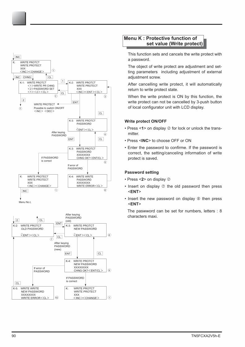
90 TN5FCXA2V5h-E
Menu K : Protective function of set value (Write protect)
This function sets and cancels the write protect with a password.
The object of write protect are adjustment and set-ting parameters including adjustment of external adjustment screw.
After cancelling write protect, it will automatically return to write protect state.
When the write protect is ON by this function, the write protect can not be cancelled by 3-push button
Write protect ON/OFF• Press <1 for lock or unlock the trans-
mitter.
• Press <INC
correct, the setting/canceling information of write protect is saved.
Password setting• Press <2• Insert on display the old password then press
<ENT• Insert the new password on display then press
<ENTThe paswword can be set for numbers, letters : 8 characters maxi.
CL
K-1: WRITE PROTCT <1>WRITE PR CHNG <2>PASSWORD SET <1><2><CL>
3
ENT
2
K-2: WRITE PROTCT WRITE PROTECT XXX
K-3: WRITE PROTCT PASSWORD _
4
K-3: WRITE PROTCT PASSWORD XXXXXXXX CHNG OK?<ENT/CL>
5
K-4: WRITE WRITE PASSWORD XXXXXXXX WRITE ERROR<CL>
61
INC
K: WRITE PROTCT WRITE PROTECT XXX
INC
If error ofPASSWORD
ENTWRITE PROTECTPossible to switch ON/OFF<INC> <DEC>
<ENT><CL>
<INC><ENT><CL>CL
1
CL
INC
Menu No.L
<INC><CHANGE>
CHNG CL
2
7
If PASSWORD is correct
K: WRITE PROTECT WRITE PROTECT XXX
<INC><CHANGE>
After keyingPASSWORD
1
CL
K-2: WRITE PROTCT OLD PASSWORD _
8
ENT
2
7
K-3: WRITE PROTCT NEW PASSWORD _
K-4: WRITE PROTCT NEW PASSWORD XXXXXXXX CHNG OK?<ENT/CL> 9
K: WRITE PROTCT WRITE PROTECT XXX
K-5: WRITE WRITE NEW PASSWORD XXXXXXXX WRITE ERROR<CL> 110
CL
CL
<ENT><CL> <ENT><CL>
<INC><CHANGE>
After keying PASSWORD (old)
After keying PASSWORD (new)
ENT
CL
If error of PASSWORD
If PASSWORDis correct

TN5FCXA2V5h-E 91
Menu L : Historical data
Display of ZERO/SPAN
.
ZERO means ZERO calibration value (4mA).
SPAN means SPAN calibration value (20 mA).
• Clear of ZERO/SPAN calibration data for users
.
• Press <1temperature
• Press <2 for MIN/MAX cell tempera-ture
CL
L: HISTORY <1>CALIBRATION <2>TEMPERATURE <INC><1><2> 2
ENT1
L-1: HISTORY ZERO -XXX.XX%URL SPAN -XXX.XX%CS
L-2: HISTORY ZERO -XXX.XX%URL SPAN -XXX.XX%CS RSET OK?<ENT/CL> 3
L-2: HISTORY
<CL>
L-1: HISTORY <1>AMP. TEMP <2>CELL TEMP <1><2><CL> 5
CL<1.RESET><CL>
CL
INC
INC1
CL
1
L-2: HISTORY
<CL> 6CL
2
12
4
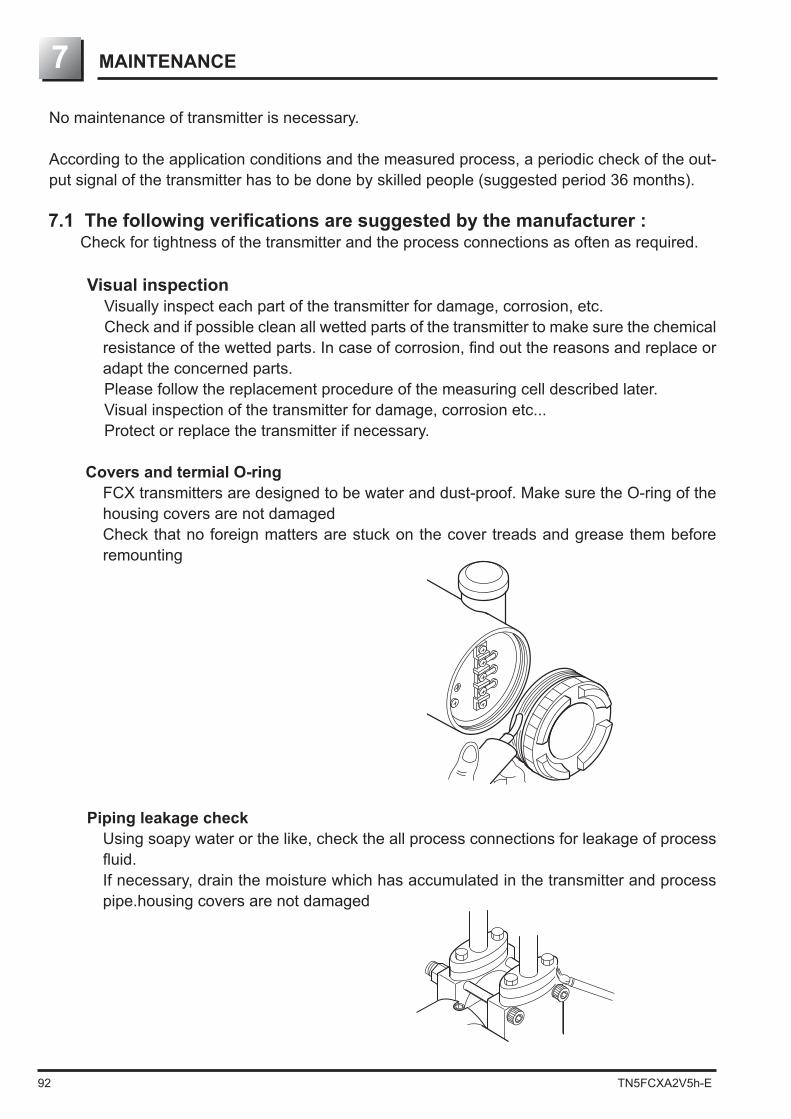
92 TN5FCXA2V5h-E
No maintenance of transmitter is necessary.
According to the application conditions and the measured process, a periodic check of the out-put signal of the transmitter has to be done by skilled people (suggested period 36 months).
Check for tightness of the transmitter and the process connections as often as required.
Visual inspectionVisually inspect each part of the transmitter for damage, corrosion, etc.Check and if possible clean all wetted parts of the transmitter to make sure the chemical
adapt the concerned parts.Please follow the replacement procedure of the measuring cell described later.Visual inspection of the transmitter for damage, corrosion etc...Protect or replace the transmitter if necessary.
Covers and termial O-ringFCX transmitters are designed to be water and dust-proof. Make sure the O-ring of the housing covers are not damagedCheck that no foreign matters are stuck on the cover treads and grease them before remounting
Piping leakage checkUsing soapy water or the like, check the all process connections for leakage of process
If necessary, drain the moisture which has accumulated in the transmitter and process pipe.housing covers are not damaged
MAINTENANCE7
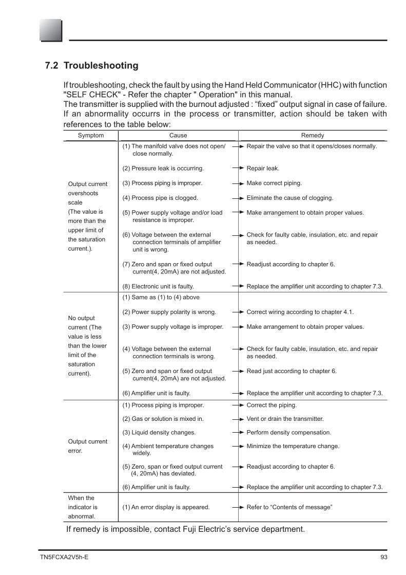
TN5FCXA2V5h-E 93
7.2 Troubleshooting
If troubleshooting, check the fault by using the Hand Held Communicator (HHC) with function "SELF CHECK" - Refer the chapter " Operation" in this manual.The transmitter is supplied with the burnout adjusted : “fixed” output signal in case of failure.If an abnormality occurrs in the process or transmitter, action should be taken with references to the table below:
Symptom Cause Remedy
Output current overshoots scale(The value is more than the upper limit of the saturation current.).
(1) The manifold valve does not open/close normally.
(2) Pressure leak is occurring.
(3) Process piping is improper.
(4) Process pipe is clogged.
(5) Power supply voltage and/or load resistance is improper.
(6) Voltage between the external
unit is wrong.
current(4, 20mA) are not adjusted.
(8) Electronic unit is faulty.
Repair the valve so that it opens/closes normally.
Repair leak.
Make correct piping.
Eliminate the cause of clogging.
Make arrangement to obtain proper values.
Check for faulty cable, insulation, etc. and repair as needed.
Readjust according to chapter 6.
No output current (The value is less than the lower limit of the saturation current).
(1) Same as (1) to (4) above
(2) Power supply polarity is wrong.
(3) Power supply voltage is improper.
(4) Voltage between the external connection terminals is wrong.
current(4, 20mA) are not adjusted.
Correct wiring according to chapter 4.1.
Make arrangement to obtain proper values.
Check for faulty cable, insulation, etc. and repair as needed.
Read just according to chapter 6.
Output current error.
(1) Process piping is improper.
(2) Gas or solution is mixed in.
(3) Liquid density changes.
(4) Ambient temperature changes widely.
(4, 20mA) has deviated.
Correct the piping.
Vent or drain the transmitter.
Perform density compensation.
Minimize the temperature change.
Readjust according to chapter 6.
When the indicator is abnormal.
(1) An error display is appeared. Refer to “Contents of message”

94 TN5FCXA2V5h-E
7.3 Replacement of defective parts
the transmitter and bring it into the instrumentation workshop.
(6) After completion of replacement, perform zero and span adjustments.
(1) Turn off the power supply.(2) Remove the indicator.
(4) Unplug each connector carefully.
housing and connect the connectors. Assemble all parts in the reversing way than de-
scribed before. Check all the screws are correctly tightened, and screw the electronics housing cover on
the transmitter
When installing the electronics unit, make sure that the zero adjust screw end is in front of the groove in
failure is detected, please replace the concerned part.l
When removing an explosion-proof transmitter, turn OFF the main power, then disconnect the piping and wiring. Do not remove it when the power is ON to prevent serious accident
DANGER
Groove
Zero adjustment
The electronics unit should be removed carefully so as not to damage the internal wiring.
PROHIBTION
PROHIBTION
Indicator
Amplifer

TN5FCXA2V5h-E 95
Replacement of detecting unit
Detecting unit
Hexagon socket bolt
Amplifer
Flatcable
(1) Remove the electronics unit according to "Replacement of electronics unit"(2) Remove the 2 hexagon socket bolts from the electronic housing. Pull the electronics housing straight forward and away from the detecting unit. (3) Replace the detecting unit with a new one of the same type. (4) Check if the O-ring of the cell neck and all the surfaces in contact between the electronics
housing and the cell neck not damaged. Assemble measuring cell and electronics housing. Tighten the 2 screws
(7) After assembly, perform zero and span adjustment
as the original by comparing nameplates.• When removing the transmitter case, pay attention not to damage
PROHIBTION

96 TN5FCXA2V5h-E
Bolt size Bolt material Tightening torque Maximum working pressure
M10 Cr-Mo steel 50 N.m 420 bar M10 SUS 316 40 N.m 100 bar
M10 SUS 630 50 N.m 420 bar
M12 Cr-Mo steel 60 N.m 420 bar
M12 SUS 660 60 N.m 420 bar
M16 SUS 660 110 N.m 500 bar
M20 SUS 660 260 N.m 1035 bar
Replacement of the internal parts of detecting unit
Nut Gasket
Seal diaphragm
Oval flange surface
Measurementchamber cover
Bolt
Seal tape
Caution!Remember !
To avoid any damage of the measuring cell, do not exceed the test pressure of the different cells (please refer to the technical datasheets of the concerned transmitter)
(1) Remove the 4 hexagon socket head bolts. (2) The process covers, the O-ring and the bolts and nuts can now be removed. (3) After disassembly, replace the faulty part with a new ones.(4) Before reassembling, clean carefully the O ring groove of the process cover with a soft
cloth immersed with water, alcohol, Freon TF or similar.(5) Reassemble the detecting unit by reversing the disassembling procedure. Please check the correct position of the process covers to avoid that the diaphragms of the
measuring cell are damaged. The torque for the bolts of the process covers are indicated in the following table.
(6) After assembly, carry out a pressure test. Apply a pressure equal to 150% of the maximum working pressure to both high pressure (H) and low pressure (L) measurement chambers of the transmitter simultaneously during 15 minutes, and make sure that there is no leakage.

TN5FCXA2V5h-E 97
In case of absolute and gauge pressure transmitter (FKA and FKG)
Absolute pressure transmitter FKA :
Gauge pressure transmitter FKG :
Bolt size Bolt material Tightening torque Maximum working pressure
M10 Cr-Mo steel 50 N.m 500 bar M10 SS 316 30 N.m 100 bar
M12 Cr-Mo steel 60 N.m 500 bar
M12 SS 660 60 N.m 500 bar
M16 SS 660 110 N.m 500 bar
Bolt size Bolt material Tightening torque Maximum working pressure
M10 Cr-Mo steel 50 N.m 30 bar M10 SS 316 30 N.m 30 bar
M10 SS 630 50 N.m 30 bar
To avoid any damage of the measuring cell, do not exceed the test pressure of the different cells (please refer to the technical datasheets of the concerned transmitter)
(1) Remove the 4 hexagon sockets head bolts
(2) The process covers, the O-ring and the bolts and nuts can now be removed
(3) After disassembly, replace the faulty part with a new one
(4) Before reassembly, clean carefully the O-ring face of casing cover with the soft cloth immersed in water, al-cohol, or similar
(5) Reassemble the detecting unit by reversing the disassembling procedure. The torque of the bols of the process covers are indicated in the following table :
(6) After assembly, carry out a pressure test. Apply a pressure equal to 150% of the maximum -
surement chamber of the transmitter simultaneously during 15 minutes, and make sure there is no leakage.
Caution!Remember !
NutSeal diaphragm
GasketOval flange sureface
Measurementchamber cover
Bolt

98 TN5FCXA2V5h-E
In case of level transmitter (FKE)
To avoid any damage of the measuring cell, do not exceed the test pressure of different cells (please refer to the technical datasheets of the concern trans-mitter)
Caution!Remember !
(6) After assembly, carry out a pressure test. Apply a pressure equal to 150% of the maximum -
surement chamber of the transmitter simultaneously during 15 minutes, and make sure there is no leakage.
(1) Remove four hexagon socket head bolts with a torque wrench, etc..
(2) The process covers, the O-ring and the bolts and nuts can now be removed
(3) After disassembly, replace the faulty part with a new one.
(4) Before reassembly, clean carefully the O-ring face of casing cover with the soft cloth immersed in water, alcohol, Freon TF or similar.
(5) Reassemble the detecting unit by reversing the disassembling procedure. The torque of the bols of the process covers are indicated in the following table.
Bolt size Bolt material Tightening torque Maximum working pressure
Seal tape
Bolt Measurementchamber cover
Gasket
Seal diaphragm

TN5FCXA2V5h-E 99
Replacement of the analog indicator
(1) Unscrew the electron-ics housing cover on indicator side.
(2) Remove the analog indicator.
(3) Pull out the connec-tor extending from the analog indicator.
(4) Connect the connector of a new analog indica-tor to the electronics
below.)(5) Mount the analog indicator by reversing the dissembling
procedure.(6) Assemble the electronics housing cover.
Analog indicator
Transmitter cover
Amplifier

100 TN5FCXA2V5h-E
(1) Unscrew the electronics housing cover on indicator side.
(3) Remove the connector pin connecting
unit. However, if you replace only the digital indicator, you need not remove the connector pin.
(4) Connect a new digital indicator following the reverse order of disassembly procedure.
Before tightening, make sure a small recess on the surface is positioned at the top as shown below.
(6) Assemble the electronics housing cover.
Replacement of the digital indicator
Digital indicatorplugin port
Pin plug
Digital indicator
Amplifer
Transmitter cover

TN5FCXA2V5h-E 101
7.4
Adjustment
After completion of the assembly work mentioned above, use the following procedures for adjustment and setting. Adjustment should be performed using the HHC.
(1) After replacement of electronics unit (including replacement of internal parts)
No. Item
Display symbol -
rator unit with LCD display
(Relevant page)
Display symbol of HCC
(Relevant page) Contens of setting adjustment
1 TAG No. 1: TAG (P44) 1: TAG No. (P73) Set the previous data before replacement of amp unit.
2 Model code 2: TYPE (P45) 2: TYPE (P73) Set the previous data before replacement of amp unit.
3 Serial No. 3-1: SERIAL No.3-2: VER (P46) 3: SERIAL No. (P74) Not necessary for operation
4 Engineering unit 4: UNIT (P47) 4: UNIT (P74) Set the previous data before replacement of amp unit.
5 Range limit 5: URL (P47) 5: RANGE LIMIT (P75) Not necessary for operation
6 Measuring range 6-1: LRV6-2: URV (P48) 6: RANGE (P75) Set the previous data before replacement of
amp unit.
7 Damping 7: DAMP (P50) 7: DAMPING (P76) Set the previous data before replacement of amp unit.
8 Output mode8-1: OUT Md8-2: CUT Pt8-3: CUT Md
(P51) 8: OUTPUT MODE (P77) Set the previous data before replacement of amp unit.
9 Burnout direction9-1: BURNOUT9-2: OVER9-3: UNDER
(P53) 9: BURNOUT (P78) Set the previous data before replacement of amp unit.
10 Zero/span calibration
A-1: ZEROA-2: SPAN (P55) A: CALIBRATE (P879) Implement span calibration after zero calibra-
tion.
11 Calibration output circuit
b-1: 4mAAdjb-2: 20mAAdjb-3: FIXcur
(P57) B: OUTPUT ADJ (P80) Loop check & calibrate fixed output current (4mA,20mA)
12 M e a s u r e m e n t data (Normal mode) C:DATA (P81) Check the measurement data.
13 Self-diagnosis d1: AMPTMPd2: ALMCHK (P58) D: SELF CHECK (P81) Check, if it is necessary.
14 Printer function - E: PRINT (P82) In case of HHC with printer option, print if it is necessary.
15 Lock of adjust-ment functions F: LOCK (P59) F: XMTR EXT.SW (P82) Set the previous data before replacement of
amp unit
16 Indication of digital indicator
G-1: LDVG-2: UDVG-3: DPG-4: LcdUnitG-5: LcdOpt
(P60) G: XMTR DISPLAY (P83) Set the previous data before replacement of amp unit.
17Programmable linearization function
- H: LINEARIZE (P86) Set the previous data before replacement of amp unit.
18 I n p u t - o u t p u t range adjustment
I-1: LRVAdjI-2: URVAdj (P63) I: RERANGE (P88) Adjust the input-output range (RERANGE) as
required.
19 Change of saturation current
J-1: SAT LOJ-2: SAT HIJ-3: SPEC
(P65) J: SATURE CUR (P89) Set the previous data before replacement of amp unit.
20 Protective func-tion of set value K: GUARD (P67) K: WRITE PROTCT (P90) Set the previous data before replacement of
amp unit.
21 History informa-tion
L-1: His ZEROL-2: His SPANL-3: His CLEARL-4: His AMPL-5: His CELL
(P68) L: WRITE PROTCT (P91) Check data as necessary
(2) After replacement of detecting unit (including replacement of internal parts) 1 Zero/span
calibrationA-1: ZEROA-2: SPAN (P55) A: CALIBRATE (P79) Implement span calibration after zero calibration

102 TN5FCXA2V5h-E
Grounding
Since transmitter and arrester groundings are internally connected together, user have only to connect the external grounding terminals to ground.Grounding terminal must be used, in case of the explosion proof or intrinsic safety type trans-mitter.
+
- +
-
BUILT-IN ARRESTERA1
Avoid common grounding with a lightning rod.In case of a transmitter with arrester, maximum power supply is 32 V DC.
INDICATION
An arrester is used to protect a transmitter or receiver from an abnormal voltage such as light-ning surges induced into signal lines. A built-in type arrester is mounted in the terminal unit.A nameplate marked “with arrester” is attached to the terminal unit of transmitter.
Installation
If surges are likely to appear on the loop 4-20 mA, for example because of lightning, it is advis-able to install a built-in arrester should be used in combination with panel mounting type arrester (type PXC) for distributor protection

TN5FCXA2V5h-E 103
Digital voltmeter
To (–)
terminalTo (+)
terminal
Standard resistor
(1 or 10 )
Maintenance
Check of arrester :Measure output current from the transmitter on the current loop 4/20mA and CK+/- of the transmitter.
If the measured two output current are the same, the arrester is normal. In case the measured values have a difference of 0.1% (0.016mA) or more, the arrester is not functioning. In the above case, the arrester unit (terminal unit) should be replaced with a new one.
Limitation of insulation resistance and dielectric strength test An insulation resistance and dielectric strength test should be avoided as a rule, since it may damage the arrester.
Output measurement at check terminals (CK+ and CK-)
Output measurement on the current loop (4/20 mA)* Disconnect the wire from the "-" terminal and connect the measurement device a shown
below.
Standard resistance(1 or 10 )
To (+) side wiring
To (+) terminal
To (–) terminal
To (–) side wiring
DC power supply
Digital voltmeter
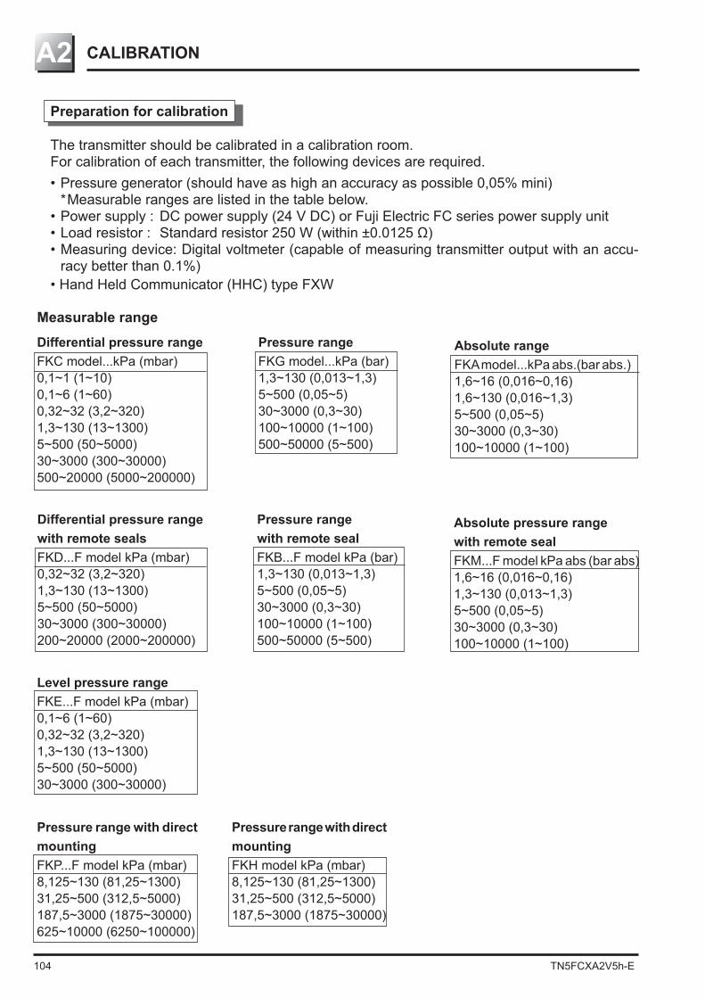
104 TN5FCXA2V5h-E
CALIBRATIONA2
Level pressure rangeFKE...F model kPa (mbar)0,1~6 (1~60)0,32~32 (3,2~320)1,3~130 (13~1300)5~500 (50~5000)30~3000 (300~30000)
Pressure range with remote sealFKB...F model kPa (bar)1,3~130 (0,013~1,3)5~500 (0,05~5)30~3000 (0,3~30)100~10000 (1~100)500~50000 (5~500)
Absolute pressure range with remote sealFKM...F model kPa abs (bar abs)1,6~16 (0,016~0,16)1,3~130 (0,013~1,3)5~500 (0,05~5)30~3000 (0,3~30)100~10000 (1~100)
Differential pressure range with remote sealsFKD...F model kPa (mbar)0,32~32 (3,2~320)1,3~130 (13~1300)5~500 (50~5000)30~3000 (300~30000)200~20000 (2000~200000)
Preparation for calibration
The transmitter should be calibrated in a calibration room.For calibration of each transmitter, the following devices are required. • Pressure generator (should have as high an accuracy as possible 0,05% mini)
* Measurable ranges are listed in the table below. • Power supply : DC power supply (24 V DC) or Fuji Electric FC series power supply unit
• Measuring device: Digital voltmeter (capable of measuring transmitter output with an accu-racy better than 0.1%)
• Hand Held Communicator (HHC) type FXW
Differential pressure rangeFKC model...kPa (mbar)0,1~1 (1~10)0,1~6 (1~60)0,32~32 (3,2~320)1,3~130 (13~1300)5~500 (50~5000)30~3000 (300~30000)500~20000 (5000~200000)
Pressure rangeFKG model...kPa (bar)1,3~130 (0,013~1,3)5~500 (0,05~5)30~3000 (0,3~30)100~10000 (1~100)500~50000 (5~500)
Absolute rangeFKA model...kPa abs.(bar abs.)1,6~16 (0,016~0,16)1,6~130 (0,016~1,3)5~500 (0,05~5)30~3000 (0,3~30)100~10000 (1~100)
Measurable range
Pressure range with direct mountingFKP...F model kPa (mbar)8,125~130 (81,25~1300)31,25~500 (312,5~5000)187,5~3000 (1875~30000)625~10000 (6250~100000)
Pressure range with direct mountingFKH model kPa (mbar)8,125~130 (81,25~1300)31,25~500 (312,5~5000)187,5~3000 (1875~30000)

TN5FCXA2V5h-E 105
HHC
Digital voltmeter
Standard resistanceLoad resistancePower supply
Localconfigurator unit
Calibration procedure
(1) Make wiring according to the diagram below When current is measured with an amperemeter connected to CK+ and CK – terminals, the
(2) Calibration of output circuit (D/A) :This menu has to be used to change the output signal values corresponding to zero and 100% of the output signal. No pressure generator is required.
"Adjustment" in Chapter 4 and HHC : Calibrate with reference to "Calibration of output circuit"
(3) Zero/span adjustment :
Adjustment with HHC : Calibrate with reference to "Zero/span adjustment"
(4) Accuracy test Apply input pressures in the order of 0%, 25%, 50%, 75%, 100%, 75%, 50%, 25% and 0%, and read output at each input pressure. Make sure the difference between each output value and input pressure (%) is within the accuracy rating listed in the table below. The voltage values in the table are dependent on use of “DC power supply + standard resis-
For communicate correctly with the hand held communicator (HHC), a load INDICATION
Measurement category Reference Accuracy (according type) value Accuracy : 0,065% Accuracy : 0,2%Percent display % Current 0, 25, 50, 75, 100 ±0,065 ±0,2measurement (mA) 4, 8, 12, 16, 20 ±0,0112 ±0,032Voltage measurement (V) 1, 2, 3, 4, 5 ±0,0028 ±0,008

106 TN5FCXA2V5h-E
A3 PARAMETER SETTING PRIOR TO DELEVERY
N° Item contents of parameter
1 Damping value 0,06sec (time constant)
2 External adjustment function Adjustable (ENABLE) of the transmitter
3 Current output mode Linear (Could be set in factory when ordering (note 2))
Digital indicator scale Could be set in factory (9th digit of code symbol) when ordering
4 Cut point 7.07% (square root extraction mode setting)
5 Mode below cut point Linear (square root setting)
6 Burnout Hold (note 3)
7 Polygonal line correction Not corrected (INVALID)
9 Protective function of set value Canceled (OFF) (write protect)
“7: Polygonal line correction,” which can be changed only by the HHC.Note 2) In both the differential pressure transmitter (Type: FKC) and remote seal type (Type: FKD), the output
current mode is set in linear unless it is designated.
The damping value (time constant), function of zero/span adjust screw, output current mode, indicator scale, cut point, mode below cut point and burnout, have been set prior to delivery as shown in the following. Each parameter is changed by using HHC or the 3 push button of the LCD display.

TN5FCXA2V5h-E 107
HART® COMMUNICATION FUNCTION
1. HART® communication function
1.1 HART ® communicationThe FCX-AII V5 smart type transmitters are used for communication with Fuji HHC (Handheld Communicator) or HART® 1) master device such as HART® communicator. For details, refer to the instruction manual for HART® master device.Note1)
HART® (Highway Addressable Remote Transducer) is a trademark of Rosemount Inc.
1.2 HART ® Universal Handheld communicatorThe HART® universal handheld communicator (hereinafter referred to as HART®) is a communicator capable of using for communication with various type of HART®
A user in possession of HART® master device is ready for communication with the FCX-AII V5 transmitters. For details, refer to the instruction manual for HART® communicator.
1.3 DD (Device Description)®
communication functions. By saving DD in the memory of HART® communicator, the
Even when FCX-AII series / FCX-AII V5 series DD is not saved in the memory of HART® communicator, it can be used in Generic mode 2). For details, refer to the instruction manual for HART® communicator.
® communicator. In this mode, functions which can be sued are limited to general-use functions.
A4

108 TN5FCXA2V5h-E
Field device
To junctionterminal orinstrumentroomTo HHC
Explosion-proof area Non-explosion-proof area
Zener barrier
Instrument room
Terminal block
DC power supply
Junction terminal
HART communicator (Intrinsic safety specification)
HHC(Non-Intrinsic safety specification)
2. Connection
Connection of HART® communicator
the junction box located outside the hazardous area.
When using Fuji HCC and HART communicator alternately, turn OFF the power for the communicator after changing from one to another, then restart the communication. At this time, old data may be left in the communicator.
Fuji HHC and HART® communicator can not be used at the same time.Be sure to connect individually.
DANGER
INDICATION
INDICATION

TN5FCXA2V5h-E 109
3. Function and operation (example) 3.1 HART® Communicator Menu Tree 3.1.1 Menu Tree 1 - Generic -
Example on HC-475 Hand Held Communicator
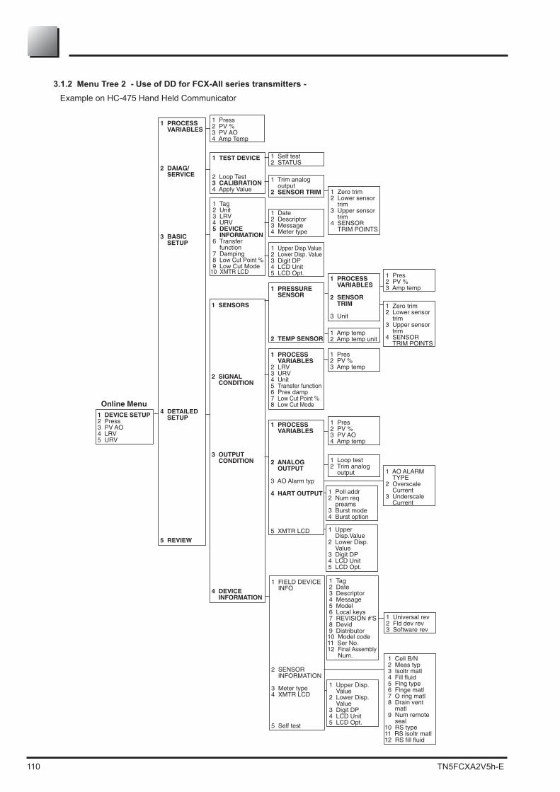
110 TN5FCXA2V5h-E
3.1.2 Menu Tree 2 - Use of DD for FCX-AII series transmitters - Example on HC-475 Hand Held Communicator
1 DEVICE SETUP 2 Press 3 PV AO 4 LRV 5 URV
1 PROCESS VARIABLES
2 DAIAG/ SERVICE
1 Press 2 PV % 3 PV AO 4 Amp Temp
1 TEST DEVICE 2 Loop Test 3 CALIBRATION 4 Apply Value
1 Trim analog output
2 SENSOR TRIM
1 Self test 2 STATUS
1 Tag 2 Unit 3 LRV 4 URV 5 DEVICE
INFORMATION 6 Transfer
function 7 Damping 8 Low Cut Point % 9 Low Cut Mode
1 Date 2 Descriptor 3 Message 4 Meter type
1 SENSORS
2 SIGNAL CONDITION
1 PRESSURE SENSOR
2 TEMP SENSOR
1 PROCESS VARIABLES
2 LRV 3 URV 4 Unit 5 Transfer function 6 Pres damp 7 Low Cut Point % 8 Low Cut Mode
1 PROCESS VARIABLES
2 ANALOG
OUTPUT 3 AO Alarm typ 4 HART OUTPUT 5 XMTR LCD
1 Pres 2 PV % 3 PV AO 4 Amp temp
1 Loop test 2 Trim analog
output
1 PROCESS VARIABLES
2 SENSOR
TRIM 3 Unit
1 Zero trim 2 Lower sensor
trim 3 Upper sensor
trim 4 SENSOR
TRIM POINTS
Online Menu
3 BASIC SETUP
4 DETAILED SETUP
5 REVIEW
1 Upper Disp.Value 2 Lower Disp. Value 3 Digit DP 4 LCD Unit 5 LCD Opt.
1 Amp temp 2 Amp temp unit
1 Pres 2 PV % 3 Amp temp
1 Zero trim 2 Lower sensor
trim 3 Upper sensor
trim 4 SENSOR
TRIM POINTS
1 AO ALARM TYPE
2 Overscale Current
3 Underscale Current
1 Pres 2 PV % 3 Amp temp
3 OUTPUT CONDITION
1 Poll addr 2 Num req
preams 3 Burst mode 4 Burst option
1 Upper Disp.Value
2 Lower Disp. Value
3 Digit DP 4 LCD Unit 5 LCD Opt.
4 DEVICE INFORMATION
10 XMTR LCD
1 Universal rev2 Fld dev rev3 Software rev
1 Cell B/N 2 Meas typ3 Isoltr matl4 Fill fluid5 Flng type6 Flnge matl7 O ring matl8 Drain vent matl9 Num remote seal
1 FIELD DEVICE INFO
2 SENSOR INFORMATION
3 Meter type4 XMTR LCD
5 Self test
1 Tag2 Date3 Descriptor4 Message5 Model6 Local keys7 REVISION #'S8 Devid9 Distributor10 Model code11 Ser No.12 Final Assembly Num.
10 RS type11 RS isoltr matl12 RS fill fluid
1 Upper Disp. Value2 Lower Disp. Value3 Digit DP4 LCD Unit5 LCD Opt.

TN5FCXA2V5h-E 111
A5 SPARE PARTS
For more details about these parts, please contact Fuji Electric France.
BLOCK A
1
3
5
5
6
4
5
10
39
40
28
12
4
12A
12
15
4
31A
2

112 TN5FCXA2V5h-E
BLOCK B : FKC15
9
8
17
8
16 9 13A
14
13A
13 12
12
13
14
9
12A
12A
17
19
18
4139
37
35
3331

TN5FCXA2V5h-E 113
BLOCK C & D : FKG & FKA15
10
1~5
6
16
14
7
13A
1312
13A1213
12A
7
14
12A
17
19
18
4139
37
35
3331

114 TN5FCXA2V5h-E
direct mount type
2
1
5
6
4
3
9
10
8
7
12
11

TN5FCXA2V5h-E 115


Fuji Electric can accept no responsibility for possible errors in catalogues, brochures and other printed material. Fuji Electric reserves the right to alter its products without notice. This also applies to products already on order provided that such alterations can be made without subsequential changes being
Fuji Electric France S.A.S.46 rue Georges Besse - ZI du brézet - 63039 Clermont ferrandTél : 04 73 98 26 98 - Fax : 04 73 98 26 99Mail : [email protected] - web : www.fujielectric.fr