Embed Size (px)
Citation preview
ERJ Engineering Research Journal
Faculty of Engineering Menoufiya University
Engineering Research Journal, Vol. 38, No. 4, October 2015, PP: 269-284
© Faculty of Engineering, Menoufiya University, Egypt
269
FUTURE SUSTAINABLE CONCENTRATING SOLAR POWER
TECHNOLOGIES: A REVIEW A.M.K. El-Ghonemy
High Institute of Engineering and Textile Technology, Egypt Email: [email protected]
Abstract: Concentrating solar thermal power is a renewable energy (RE) technology which
converts solar irradiation into heat energy at high temperature and in a successive step into
electricity. The core part is a number of mirrors which reflects direct normal irradiance (DNI) to a
focal line or point, called a receiver. Temperatures up to 1000 oC can be achieved. These plants
make use of conventional steam cycles, in which hybrid operation with fossil fuels is applicable.
The key advantage of CSP in comparison to other RE technologies is that the need for fossil fuel
can be reduced by over sizing the solar collector field and storing the extra heat. This paper is
directed to provide a comprehensive review of CSP technologies that are sustainable for
applications in MENA region. More focus was directed to the performance data with emphasis on
technologies, economics and costs. A comparative study between different CSP technologies as
well as performance and economics has been done. Finally, some general guidelines are given for
the selection CSP systems and the parameters that are needed to be considered for decision
makers.
انًهخص:
حيث تؼًم –ًتجذدة انطبقت احذٍ أنٌاع ان )انًجًؼبث انشًظيت( تؼتبز تقنيت تٌنيذ انطبقت انحزاريت ين انطبقت انشًظيت انًزكشة
ثى يتى تحٌيهيب انَ – ػنذ درجبث حزارة يزتفؼت انًزكشاث انشًظيت ػهَ تحٌيم الاشؼبع انشًظَ انَ طبقت حزاريتأنظًت
قٌو بذًره فَ ػًهيت ي ذٍ( انؼنصز انزئيظَ ًانيجًٌػبث ين انًجًغ انشًظَث يًثم انًجبل انشًظَ )يح .كًزحهت تبنيتكيزببء
ين انجذيز ببنذكز أنو ببطتخذاو .ًتجًيؼيب ػهَ خظ انبؤرة ًىٌ يبيظًَ ببنًظقبم يببشزة وأشؼت انشًض اانتَ تظقظ ػهي انؼكبص
انًزكشاث انشًظيت ىذه ًىٌ يبيؼنَ ايكبنيت تكبيم –درجت يئٌيت 1000َ ىذه انتقنيت يًكن انٌصٌل انَ درجبث حزارة تصم ان
أيضب تًتبس ىذه انًحطبث انشًظيت ببيكبنيت اطتخذاو .لاطتفبدة بزبظ ىذه اننظى ببنشبكت انكيزبيتًايغ يحطبث انتٌنيذ انتقهيذيت
.انٌقٌد الأحفٌرٍ كًصذر يظبػذ ًاضبفَ ػنذ انضزًرة )درًة ييجنت(
يًكن تًيش بو ىذا اننٌع ين انًحطبث انشًظيت ػن ببقَ أنٌاع انطبقت انًتجذدة ىٌ أنويجذر الاشبرة انَ أنو ين أىى يبكًب أنو ت
نتقهيم اطتيلاك فَ صٌرة حزاريت تخشين ىذه انطبقت انشائذة ً -لادارة انًٌنذ انتزبينَ تانًطهٌب ًؼبث انشًظيتيضبػت حجى انًج
.انٌقٌد الأحفٌرٍ
ت انًظتذايت ين أشؼت قانًتؼهقت بتطبيقبث اطتخذاو انطبتقنيبث نه يص ىذه انٌرقت انبحثيت نؼًم يزاجؼت نقذيت شبيهت تخص تىًقذ
هتقنيبث انًختهفت ًالاقتصبديبث نبيبنبث الأداء قذ تى انتزكيش ػهَ ً .فَ اقهيى انشزق الأًطظ ًشًبل أفزيقيبانشًض انحزاريت
ين حيث الأداء يختهف تقنيبث انطبقت انًظتذايت ين أشؼت انشًض انحزاريت بين تيقبرن دراطت أيضب تى اجزاء .ًانتكبنيف
بؼض الارشبداث انؼبيت انًفيذ اتببػيب ػنذ اختيبر نظى الاطتفبدة ين انطبقت انًظتذايت انَ تى الاشبرة ًفَ اننيبيت .ًالاقتصبديبث
-أخذىب فَ الاػتببر ػنذ اختيبر ىذا اننٌع ين انًحطبث انٌاجب انيبيتانًؤشزاث انَ جبنب -ين أشؼت انشًض انحزاريت
.صنبػت انقزارجيٌد ًتزشيذ انظيبطبث تٌجيوفَ يىًانتَ تظ
Keywords: Concentrated Solar Power (CSP) Plant, Concentrated Solar Collectors (CSCs),
Power Generation.
1. Introduction
1.1. Principle of concentrating solar power (CSP)
The main element is a field of large mirrors
reflecting the incident sun rays onto a small receiver
element, thus concentrating the solar radiation
intensity by 80 to several 100 times and producing
high temperature heat at several 100 to over 1000 °C.
This heat can be either used directly in a thermal
power cycle (based on steam turbines, gas turbines or
Stirling engines), or stored (in molten salt, concrete
or phase-change material) to be delivered later to the
power cycle for night-time operation [1].
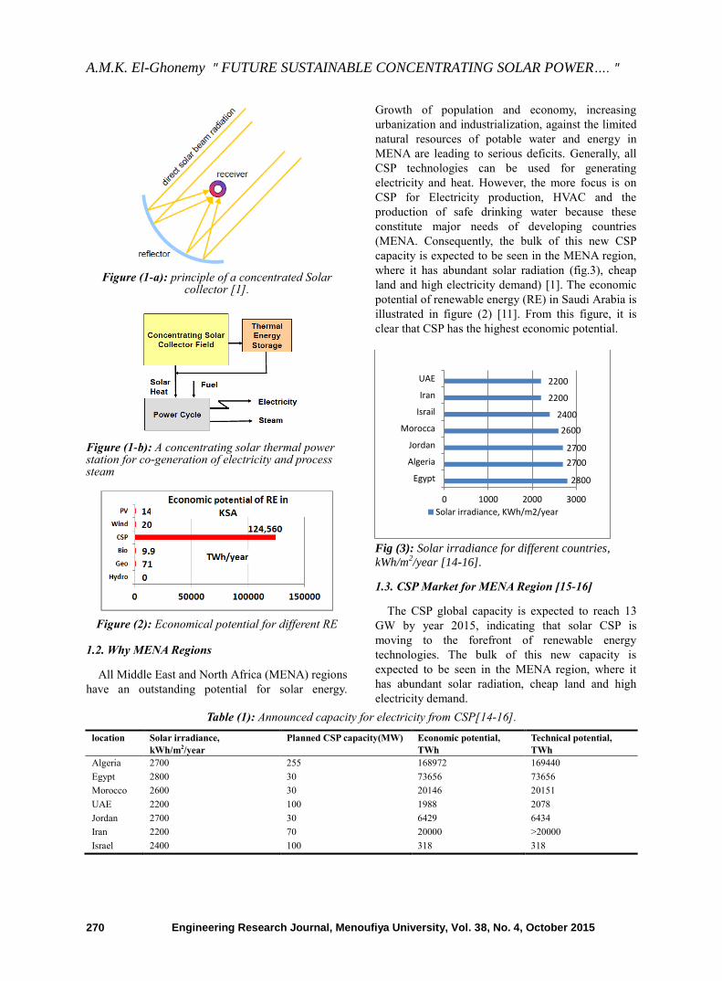
The principle of operation of a concentrating solar
power (CSP) plant is drafted in Figures (1), showing
the different options for combined generation of heat
and power.
CSP plants can be designed from 5 MW up to
several 100 MW of capacity [1].
A.M.K. El-Ghonemy " FUTURE SUSTAINABLE CONCENTRATING SOLAR POWER…. "
Engineering Research Journal, Menoufiya University, Vol. 38, No. 4, October 2015 270
Figure (1-a): principle of a concentrated Solar
collector [1].
Figure (1-b): A concentrating solar thermal power station for co-generation of electricity and process steam
Figure (2): Economical potential for different RE
1.2. Why MENA Regions
All Middle East and North Africa (MENA) regions
have an outstanding potential for solar energy.
Growth of population and economy, increasing
urbanization and industrialization, against the limited
natural resources of potable water and energy in
MENA are leading to serious deficits. Generally, all
CSP technologies can be used for generating
electricity and heat. However, the more focus is on
CSP for Electricity production, HVAC and the
production of safe drinking water because these
constitute major needs of developing countries
(MENA. Consequently, the bulk of this new CSP
capacity is expected to be seen in the MENA region,
where it has abundant solar radiation (fig.3), cheap
land and high electricity demand) [1]. The economic
potential of renewable energy (RE) in Saudi Arabia is
illustrated in figure (2) [11]. From this figure, it is
clear that CSP has the highest economic potential.
Fig (3): Solar irradiance for different countries,
kWh/m2/year [14-16].
1.3. CSP Market for MENA Region [15-16]
The CSP global capacity is expected to reach 13
GW by year 2015, indicating that solar CSP is
moving to the forefront of renewable energy
technologies. The bulk of this new capacity is
expected to be seen in the MENA region, where it
has abundant solar radiation, cheap land and high
electricity demand.
Table (1): Announced capacity for electricity from CSP[14-16].
location Solar irradiance,
kWh/m2/year
Planned CSP capacity(MW) Economic potential,
TWh
Technical potential,
TWh
Algeria 2700 255 168972 169440
Egypt 2800 30 73656 73656
Morocco 2600 30 20146 20151
UAE 2200 100 1988 2078
Jordan 2700 30 6429 6434
Iran 2200 70 20000 >20000
Israel 2400 100 318 318
2800
2700
2700
2600
2400
2200
2200
0 1000 2000 3000
Egypt
Algeria
Jordan
Morocca
Israil
Iran
UAE
Solar irradiance, KWh/m2/year
A.M.K. El-Ghonemy " FUTURE SUSTAINABLE CONCENTRATING SOLAR POWER…. "
Engineering Research Journal, Menoufiya University, Vol. 39, No. 4, October 2015 271
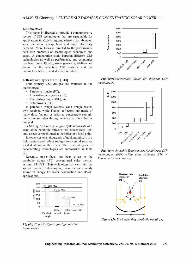
1.4. Objectives
This paper is directed to provide a comprehensive
review of CSP technologies that are sustainable for
applications in MENA regions, where it has abundant
solar radiation, cheap land and high electricity
demand.. More focus is directed to the performance
data with emphasis on technologies economics and
costs.. A comparative study between different CSP
technologies as well as performance and economics
has been done. Finally, some general guidelines are
given for the selection CSP systems and the
parameters that are needed to be considered.
2. Basics and Types of CSP [1-18]
Four primary CSP designs are available in the
market today:
Parabolic troughs (PT),
Linear-Fresnel systems (LF),
The Stirling engine (SE), and
Solar towers (ST).
In parabolic trough systems, each trough has its
own receiver, while Fresnel reflectors are made of
many thin, flat mirror strips to concentrate sunlight
onto common tubes through which a working fluid is
pumped.
A Stirling dish or dish engine system consists of a
stand-alone parabolic reflector that concentrates light
onto a receiver positioned at the reflector's focal point.
In tower systems, thousands of tracking mirrors in a
field capture and reflect sunlight to a central receiver
located at top of the tower. The different types of
concentrating technologies are summarized in table
(2).
Recently, more focus has been given to the
parabolic trough (PT) concentrated solar thermal
system (PT-CST). This technology fits well with the
special needs of developing countries as a ready
source of energy for water desalination and HVAC
applications.
Fig.(4a):Capacity figures for different CSP
technologies
Fig.(4b):Concentration factor for different CSP
technologies.
Fig.(4c):Achievable Temperatures for different CSP
technologies (FPC =Flat plate collector, ETC =
Evacuated tube collector).
Figure (5): Back reflecting parabolic trough [4].
0
50
100
150
200
250
300
Parabolictrough
Linearfresnel
solartower
solar dish
size
, M
W
0.1 -1 MW
10 -100 MW
5 -200 MW
10 -200 MW
0
500
1000
1500
2000
2500
3000
3500
Co
nce
ntr
atio
n
0
200
400
600
800
1000
1200
1400
T, C
A.M.K. El-Ghonemy " FUTURE SUSTAINABLE CONCENTRATING SOLAR POWER…. "
Engineering Research Journal, Menoufiya University, Vol. 39, No. 4, October 2015 272
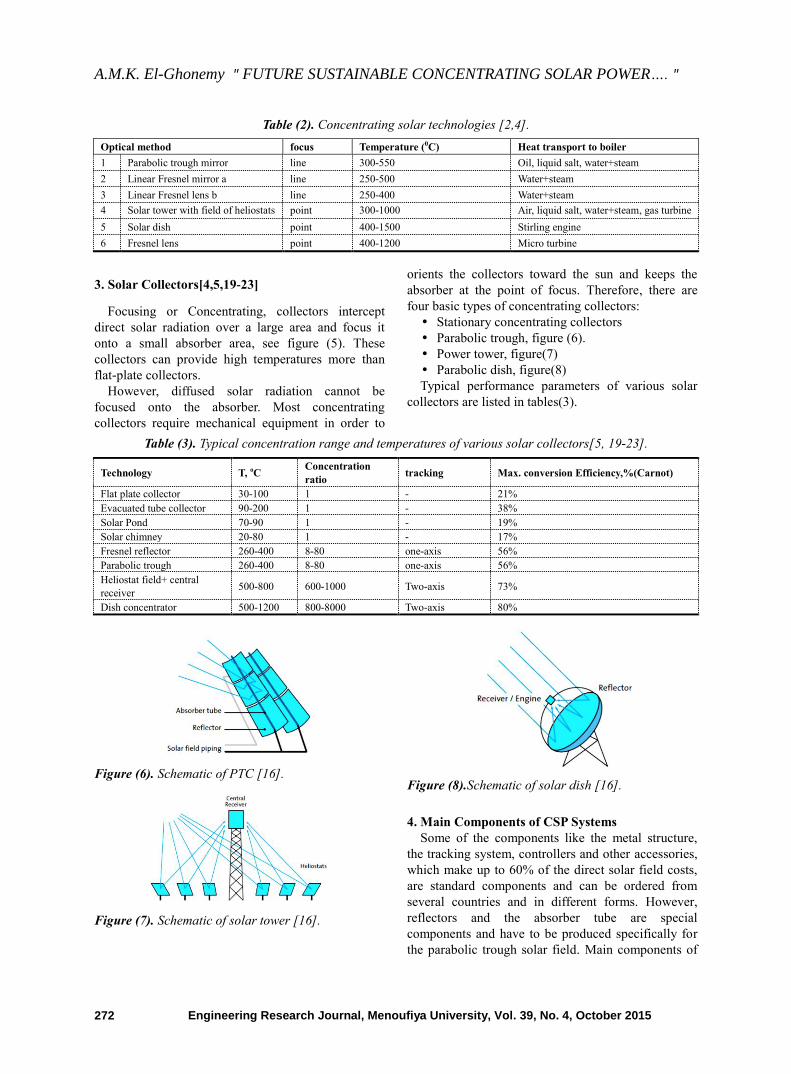
Table (2). Concentrating solar technologies [2,4].
Optical method focus Temperature (0C) Heat transport to boiler
1 Parabolic trough mirror line 300-550 Oil, liquid salt, water+steam
2 Linear Fresnel mirror a line 250-500 Water+steam
3 Linear Fresnel lens b line 250-400 Water+steam
4 Solar tower with field of heliostats point 300-1000 Air, liquid salt, water+steam, gas turbine
5 Solar dish point 400-1500 Stirling engine
6 Fresnel lens point 400-1200 Micro turbine
3. Solar Collectors[4,5,19-23]
Focusing or Concentrating, collectors intercept
direct solar radiation over a large area and focus it
onto a small absorber area, see figure (5). These
collectors can provide high temperatures more than
flat-plate collectors.
However, diffused solar radiation cannot be
focused onto the absorber. Most concentrating
collectors require mechanical equipment in order to
orients the collectors toward the sun and keeps the
absorber at the point of focus. Therefore, there are
four basic types of concentrating collectors:
Stationary concentrating collectors
Parabolic trough, figure (6).
Power tower, figure(7)
Parabolic dish, figure(8)
Typical performance parameters of various solar
collectors are listed in tables(3).
Table (3). Typical concentration range and temperatures of various solar collectors[5, 19-23].
Technology T, oC Concentration
ratio tracking Max. conversion Efficiency,%(Carnot)
Flat plate collector 30-100 1 - 21%
Evacuated tube collector 90-200 1 - 38%
Solar Pond 70-90 1 - 19%
Solar chimney 20-80 1 - 17%
Fresnel reflector 260-400 8-80 one-axis 56%
Parabolic trough 260-400 8-80 one-axis 56%
Heliostat field+ central
receiver 500-800 600-1000 Two-axis 73%
Dish concentrator 500-1200 800-8000 Two-axis 80%
Figure (6). Schematic of PTC [16].
Figure (7). Schematic of solar tower [16].
Figure (8).Schematic of solar dish [16].
4. Main Components of CSP Systems
Some of the components like the metal structure,
the tracking system, controllers and other accessories,
which make up to 60% of the direct solar field costs,
are standard components and can be ordered from
several countries and in different forms. However,
reflectors and the absorber tube are special
components and have to be produced specifically for
the parabolic trough solar field. Main components of
A.M.K. El-Ghonemy " FUTURE SUSTAINABLE CONCENTRATING SOLAR POWER…. "
Engineering Research Journal, Menoufiya University, Vol. 39, No. 4, October 2015 273
CSP system are listed below, (figure (9)):
1 Solar field collectors
2 Absorber/receiver
3 Heat transfer medium
4 Tracking system (single or double axis)
5 Balance of System
6 In case of power generation, the following
components are included:
7 Steam turbine
8 Generator
a. Reflectors (concentrators)
The concentrators consist of a heat formed glass
cake. Glass, which is used in solar applications, must
have very low iron content for getting a transmissivity
in the solar spectrum of about 91%. The iron content
of a so-called ―White Glass‖ is about 0.015%
compared to normal glass with an iron content of
around 0.13%. The binding of the reflectors is done
under heat conditions. Several safety layer coatings
are added, giving additional protection for the mirror.
Finally the contour accuracy is tested using a laser
beam.
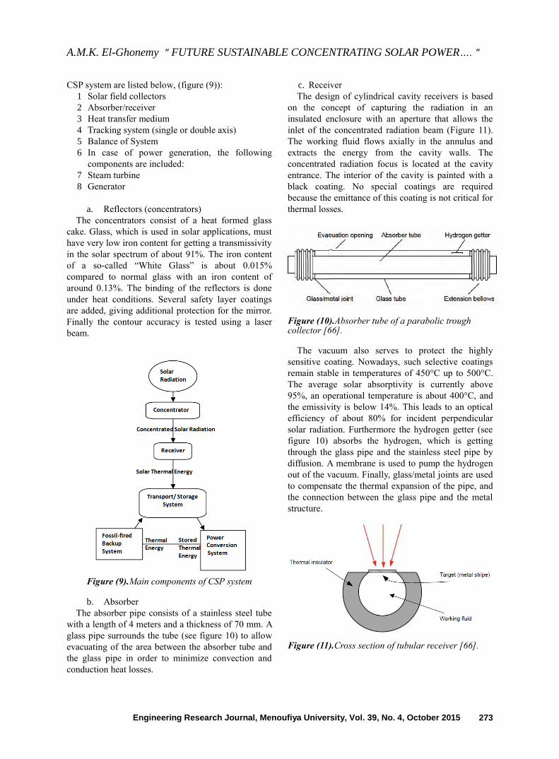
Figure (9).Main components of CSP system
b. Absorber
The absorber pipe consists of a stainless steel tube
with a length of 4 meters and a thickness of 70 mm. A
glass pipe surrounds the tube (see figure 10) to allow
evacuating of the area between the absorber tube and
the glass pipe in order to minimize convection and
conduction heat losses.
c. Receiver
The design of cylindrical cavity receivers is based
on the concept of capturing the radiation in an
insulated enclosure with an aperture that allows the
inlet of the concentrated radiation beam (Figure 11).
The working fluid flows axially in the annulus and
extracts the energy from the cavity walls. The
concentrated radiation focus is located at the cavity
entrance. The interior of the cavity is painted with a
black coating. No special coatings are required
because the emittance of this coating is not critical for
thermal losses.
Figure (10).Absorber tube of a parabolic trough collector [66].
The vacuum also serves to protect the highly
sensitive coating. Nowadays, such selective coatings
remain stable in temperatures of 450°C up to 500°C.
The average solar absorptivity is currently above
95%, an operational temperature is about 400°C, and
the emissivity is below 14%. This leads to an optical
efficiency of about 80% for incident perpendicular
solar radiation. Furthermore the hydrogen getter (see
figure 10) absorbs the hydrogen, which is getting
through the glass pipe and the stainless steel pipe by
diffusion. A membrane is used to pump the hydrogen
out of the vacuum. Finally, glass/metal joints are used
to compensate the thermal expansion of the pipe, and
the connection between the glass pipe and the metal
structure.
Figure (11).Cross section of tubular receiver [66].
A.M.K. El-Ghonemy " FUTURE SUSTAINABLE CONCENTRATING SOLAR POWER…. "
Engineering Research Journal, Menoufiya University, Vol. 39, No. 4, October 2015 274
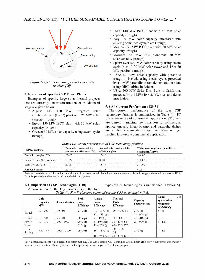
Figure (12).Cross section of cylindrical cavity
receiver [66]
5. Examples of Specific CSP Power Plants
Examples of specific large solar thermal projects
that are currently under construction or in advanced
stage are given below:
Algeria: 140 -150 MW, Integrated solar
combined cycle (ISCC) plant with 25 MW solar
capacity (trough)
Egypt: 150 MW ISCC plant with 30 MW solar
capacity (trough)
Greece: 50 MW solar capacity using steam cycle
(trough)
India: 140 MW ISCC plant with 30 MW solar
capacity (trough)
Italy: 40 MW solar capacity integrated into
existing combined cycle plant (trough)
Mexico: 291 MW ISCC plant with 30 MW solar
capacity (trough)
Morocco: 220 MW ISCC plant with 30 MW
solar capacity (trough)
Spain: over 500 MW solar capacity using steam
cycle (4 x 10-20 MW solar tower and 12 x 50
MW parabolic trough)
USA: 50 MW solar capacity with parabolic
trough in Nevada using steam cycle, preceded
by a 1 MW parabolic trough demonstration plant
using ORC turbine in Arizona
USA: 500 MW Solar Dish Park in California,
preceded by a 1 MW(40 x 25 kW) test and demo
installation
6. CSP Current Performance [29-34]
The current performance of the four CSP
technology families is summarized in Table (4). PT
plants are in use of commercial application. ST plants
are currently making the transition to commercial
application, and linear Fresnel and parabolic dishes
are at the demonstration stage, and have not yet
reached large-scale commercial application.
Table (4).Current performance of CSP technology families.
CSP technology Peak solar to electricity
conversion efficiency (%)
Annual solar-to electricity
efficiency (%)
Water consumption, for wet/dry
cooling (m3/MWh)
Parabolic troughs (PT) 23–27 15–16 3–4/0.2 Linear Fresnel (LF) systems 18–22 8–10 3–4/0.2 Solar Towers (ST) 20–27 15–17 3–4/0.2 Parabolic dishes 20–30 20–25 <0.1 Performance data for PT, LF and ST are obtained from commercial plants based on a Rankine cycle and using synthetic oil or steam as HTF. Data for parabolic dishes are based on dish-Stirling systems.
7. Comparison of CSP Technologies [1-10]
A comparison of the key parameters of the four
types of CSP technologies is summarized in tables (5).
Table (5). Key Performance data of various CSP technologies [3,6]
Unit
Capacity
MW
Concentration
Peak
Solar
Efficiency
Annual
Solar
Efficiency
Thermal
Cycle
Efficiency
Capacity
Factor (solar)
Land Use
(generation
weighted)
m²/MWh/y
Trough 10 – 200 70 - 80 21% (d) 10 – 15% (d) 30 – 40 % ST 24% (d) 6 – 8
17 – 18% (p) 25 – 90% (p)
Fresnel 10 - 200 25 - 100 20% (p) 9 - 11% (p) 30 - 40 % ST 25 - 90% (p) 4 - 6
Power
Tower
10 – 150 300 – 1000 20% (d) 8 – 10 % (d) 30 – 40 % ST 25 – 90% (p) 8 - 12
35 % (p) 15 – 25% (p) 45 – 55 % CC
Dish-
Stirling 0.01 – 0.4 1000 – 3000 29% (d) 16 – 18 % (d)
30 – 40 %
Stirl. 25% (p) 8 - 12
18 – 23% (p) 20 – 30 % GT
(d) = demonstrated, (p) = projected, ST: steam turbine, GT: Gas Turbine, CC: Combined Cycle. Solar efficiency = net power generation /
incident beam radiation, Capacity factor = solar operating hours per year / 8760 hours per year.
A.M.K. El-Ghonemy " FUTURE SUSTAINABLE CONCENTRATING SOLAR POWER…. "
Engineering Research Journal, Menoufiya University, Vol. 39, No. 4, October 2015 275
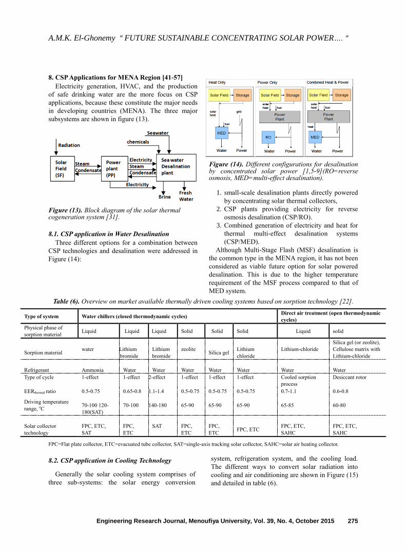
8. CSP Applications for MENA Region [41-57]
Electricity generation, HVAC, and the production
of safe drinking water are the more focus on CSP
applications, because these constitute the major needs
in developing countries (MENA). The three major
subsystems are shown in figure (13).
Figure (13). Block diagram of the solar thermal cogeneration system [31].
8.1. CSP application in Water Desalination Three different options for a combination between
CSP technologies and desalination were addressed in
Figure (14):
Figure (14). Different configurations for desalination by concentrated solar power [1,5-9](RO=reverse osmosis, MED=multi-effect desalination).
1. small-scale desalination plants directly powered
by concentrating solar thermal collectors,
2. CSP plants providing electricity for reverse
osmosis desalination (CSP/RO).
3. Combined generation of electricity and heat for
thermal multi-effect desalination systems
(CSP/MED).
Although Multi-Stage Flash (MSF) desalination is
the common type in the MENA region, it has not been
considered as viable future option for solar powered
desalination. This is due to the higher temperature
requirement of the MSF process compared to that of
MED system.
Table (6). Overview on market available thermally driven cooling systems based on sorption technology [22].
Type of system Water chillers (closed thermodynamic cycles) Direct air treatment (open thermodynamic
cycles)
Physical phase of
sorption material Liquid Liquid Liquid Solid Solid Solid Liquid solid
Sorption material water
Lithium
bromide
Lithium
bromide
zeolite
Silica gel
Lithium
chloride
Lithium-chloride
Silica gel (or zeolite),
Cellulose matrix with
Lithium-chloride
Refrigerant
Ammonia
Water
Water
Water
Water
Water
Water
Water
Type of cycle 1-effect 1-effect 2-effect 1-effect 1-effect 1-effect Cooled sorption
process
Desiccant rotor
EERthermal ratio 0.5-0.75 0.65-0.8 1.1-1.4 0.5-0.75 0.5-0.75 0.5-0.75 0.7-1.1 0.6-0.8
Driving temperature
range, oC
70-100 120-
180(SAT)
70-100 140-180 65-90 65-90 65-90 65-85 60-80
Solar collector
technology
FPC, ETC,
SAT
FPC,
ETC
SAT
FPC,
ETC
FPC,
ETC
FPC, ETC
FPC, ETC,
SAHC
FPC, ETC,
SAHC
FPC=Flat plate collector, ETC=evacuated tube collector, SAT=single-axis tracking solar collector, SAHC=solar air heating collector.
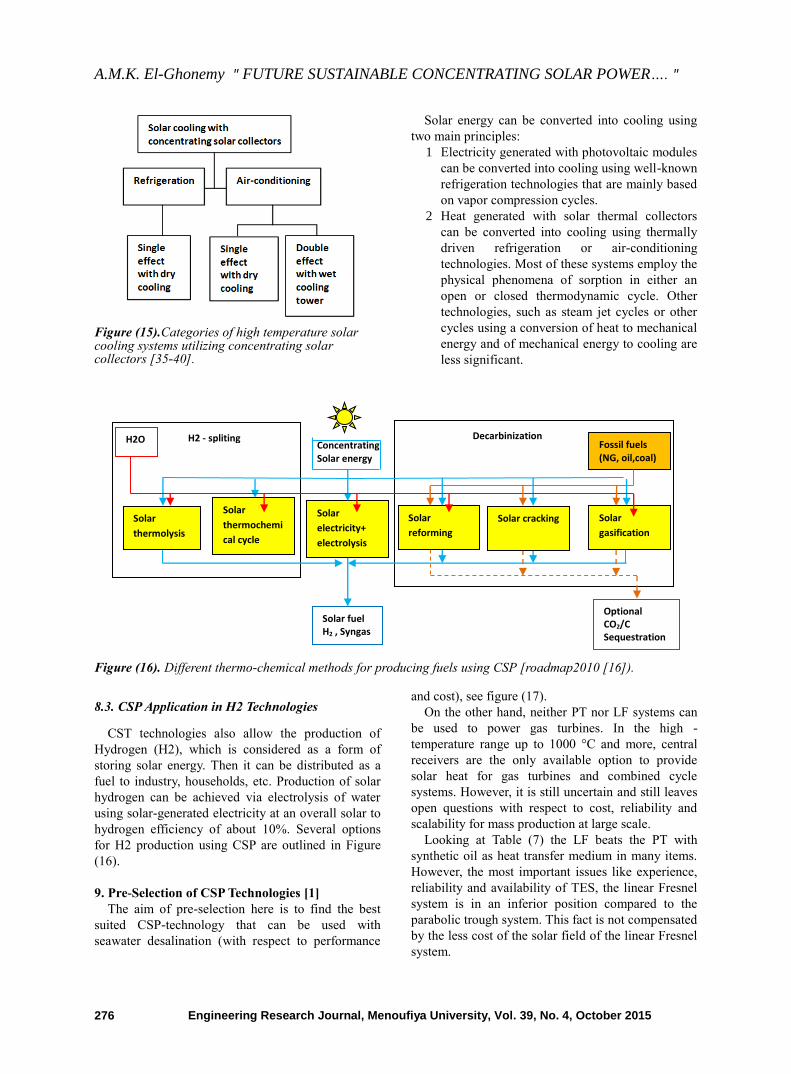
8.2. CSP application in Cooling Technology
Generally the solar cooling system comprises of
three sub-systems: the solar energy conversion
system, refrigeration system, and the cooling load.
The different ways to convert solar radiation into
cooling and air conditioning are shown in Figure (15)
and detailed in table (6).
A.M.K. El-Ghonemy " FUTURE SUSTAINABLE CONCENTRATING SOLAR POWER…. "
Engineering Research Journal, Menoufiya University, Vol. 39, No. 4, October 2015 276
Figure (15).Categories of high temperature solar cooling systems utilizing concentrating solar collectors [35-40].
Solar energy can be converted into cooling using
two main principles:
1 Electricity generated with photovoltaic modules
can be converted into cooling using well-known
refrigeration technologies that are mainly based
on vapor compression cycles.
2 Heat generated with solar thermal collectors
can be converted into cooling using thermally
driven refrigeration or air-conditioning
technologies. Most of these systems employ the
physical phenomena of sorption in either an
open or closed thermodynamic cycle. Other
technologies, such as steam jet cycles or other
cycles using a conversion of heat to mechanical
energy and of mechanical energy to cooling are
less significant.
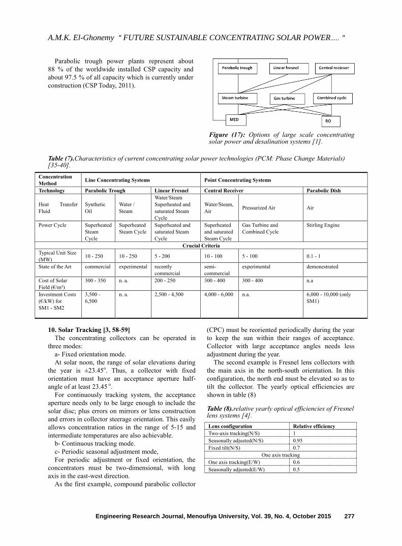
Figure (16). Different thermo-chemical methods for producing fuels using CSP [roadmap2010 [16]).
8.3. CSP Application in H2 Technologies
CST technologies also allow the production of
Hydrogen (H2), which is considered as a form of
storing solar energy. Then it can be distributed as a
fuel to industry, households, etc. Production of solar
hydrogen can be achieved via electrolysis of water
using solar-generated electricity at an overall solar to
hydrogen efficiency of about 10%. Several options
for H2 production using CSP are outlined in Figure
(16).
9. Pre-Selection of CSP Technologies [1]
The aim of pre-selection here is to find the best
suited CSP-technology that can be used with
seawater desalination (with respect to performance
and cost), see figure (17).
On the other hand, neither PT nor LF systems can
be used to power gas turbines. In the high -
temperature range up to 1000 °C and more, central
receivers are the only available option to provide
solar heat for gas turbines and combined cycle
systems. However, it is still uncertain and still leaves
open questions with respect to cost, reliability and
scalability for mass production at large scale.
Looking at Table (7) the LF beats the PT with
synthetic oil as heat transfer medium in many items.
However, the most important issues like experience,
reliability and availability of TES, the linear Fresnel
system is in an inferior position compared to the
parabolic trough system. This fact is not compensated
by the less cost of the solar field of the linear Fresnel
system.
Concentrating Solar energy
H2O
Optional CO2/C Sequestration
Solar fuel H2 , Syngas
Decarbinization H2 - spliting
Solar
thermolysis
Solar
thermochemi
cal cycle
Solar
electricity+
electrolysis
Solar
reforming
Solar cracking Solar
gasification
Fossil fuels (NG, oil,coal)
A.M.K. El-Ghonemy " FUTURE SUSTAINABLE CONCENTRATING SOLAR POWER…. "
Engineering Research Journal, Menoufiya University, Vol. 39, No. 4, October 2015 277
Parabolic trough power plants represent about
88 % of the worldwide installed CSP capacity and
about 97.5 % of all capacity which is currently under
construction (CSP Today, 2011).
Figure (17): Options of large scale concentrating solar power and desalination systems [1].
Table (7).Characteristics of current concentrating solar power technologies (PCM: Phase Change Materials) [35-40].
Concentration
Method Line Concentrating Systems Point Concentrating Systems
Technology Parabolic Trough Linear Fresnel Central Receiver Parabolic Dish
Heat Transfer
Fluid
Synthetic
Oil
Water /
Steam
Water/Steam
Superheated and
saturated Steam
Cycle
Water/Steam,
Air Pressurized Air Air
Power Cycle Superheated
Steam
Cycle
Superheated
Steam Cycle
Superheated and
saturated Steam
Cycle
Superheated
and saturated
Steam Cycle
Gas Turbine and
Combined Cycle
Stirling Engine
Crucial Criteria
Typical Unit Size
(MW) 10 - 250 10 - 250 5 - 200 10 - 100 5 - 100 0.1 - 1
State of the Art commercial experimental recently
commercial
semi-
commercial
experimental demonestrated
Cost of Solar
Field (€/m²)
300 - 350 n. a. 200 - 250 300 - 400 300 - 400 n.a
Investment Costs
(€/kW) for
SM1 - SM2
3,500 -
6,500
n. a. 2,500 - 4,500 4,000 - 6,000 n.a. 6,000 - 10,000 (only
SM1)
10. Solar Tracking [3, 58-59]
The concentrating collectors can be operated in
three modes:
a- Fixed orientation mode.
At solar noon, the range of solar elevations during
the year is ±23.45o. Thus, a collector with fixed
orientation must have an acceptance aperture half-
angle of at least 23.45 o.
For continuously tracking system, the acceptance
aperture needs only to be large enough to include the
solar disc; plus errors on mirrors or lens construction
and errors in collector steerage orientation. This easily
allows concentration ratios in the range of 5-15 and
intermediate temperatures are also achievable.
b- Continuous tracking mode.
c- Periodic seasonal adjustment mode,
For periodic adjustment or fixed orientation, the
concentrators must be two-dimensional, with long
axis in the east-west direction.
As the first example, compound parabolic collector
(CPC) must be reoriented periodically during the year
to keep the sun within their ranges of acceptance.
Collector with large acceptance angles needs less
adjustment during the year.
The second example is Fresnel lens collectors with
the main axis in the north-south orientation. In this
configuration, the north end must be elevated so as to
tilt the collector. The yearly optical efficiencies are
shown in table (8)
Table (8).relative yearly optical efficiencies of Fresnel lens systems [4].
Lens configuration Relative efficiency
Two-axis tracking(N/S) 1
Seasonally adjusted(N/S) 0.95
Fixed tilt(N/S) 0.7
One axis tracking
One axis tracking(E/W) 0.6
Seasonally adjusted(E/W) 0.5

A.M.K. El-Ghonemy " FUTURE SUSTAINABLE CONCENTRATING SOLAR POWER…. "
Engineering Research Journal, Menoufiya University, Vol. 39, No. 4, October 2015 278
Figure (18).PTC with long axis in the N-S
direction [4].
The third example is parabolic trough collector
(PTC). It can be mounted in several different ways.
The most common method is to mount the collector
horizontally with the long axis in the east-west
direction as shown in figure(18).it can also be
mounted with the long axis with the north-south
direction. The tilt angle is a very important parameter
for north-south direction. East-west orientation
collects roughly equal amount of on clear days for all
days of the year. While, north-south orientation
collects very strongly in the summer and very weekly
in the winter, as indicated in figure(19)
Figure (19).Estimated heat collection of a horizontal PTC per day per unit area of aperture on clear days [4].
10.1. Solar Tracking Methods
Solar tracking methods are passive, using an open-
loop approach or active using a closed loop [6].
Passive tracking methods employ Astronomical
algorithms (AA) and compute the solar position as a
function of position and time. This type of positioning
is limited in precision and depends only on the
precision of the algorithms, provided that electro-
mechanic precision is acceptable. For this type of
positioning, the azimuth axis vertical alignment and
zenith horizontal alignment is of crucial importance to
the overall tracking accuracy [6].
Active tracking methods use light sensitive
electronics to see the sun and position themselves in a
very dynamic way to the best position. Restrictions
applying to this type of tracking are in the sensitivity
of the sensors and the level of intelligence of the
control system.
Active tracking methods work in the approach of
brightest point in the-sky. Thus, unwanted movement
of the device in cloudy conditions can be expected,
leading to increased power consumption, mechanical
wear. The precision range of active tracked systems is
between 0.2 to several degrees, depending on the
system design.
Figure (20). Daily tracking of PT collectors [60,61].
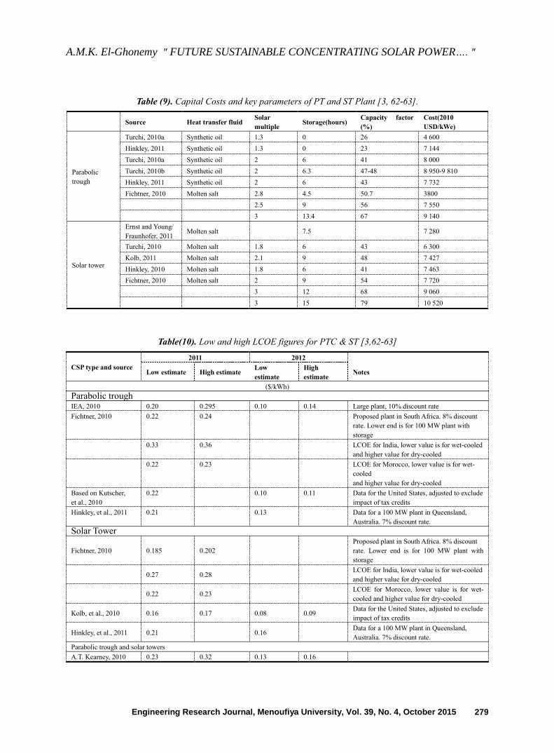
11. Economics [1-10, 3, 60, 61]
11.1. The current cost of CSP [3]
According to the International Energy Agency
(IEA, 2010) and National renewable energy
Laboratory (NREL), costs of CSP plants can be
grouped into three categories:
Investment costs (also called capital cost or
CAPEX),
Operation and maintenance costs (O&M) which
is so called OPEX.
Financing costs.
The cost of PT and ST plants with thermal energy
storage is generally between $ 5000 and $ 10500/kW
as listed in Table (9). The current levelized cost of
electricity (LCOE) from CSP technology are listed in
table(10). The other cost data are represented in
figures (21.a, b, c, d, e and f).
A.M.K. El-Ghonemy " FUTURE SUSTAINABLE CONCENTRATING SOLAR POWER…. "
Engineering Research Journal, Menoufiya University, Vol. 39, No. 4, October 2015 279
Table (9). Capital Costs and key parameters of PT and ST Plant [3, 62-63].
Source Heat transfer fluid Solar
multiple Storage(hours)
Capacity factor
(%)
Cost(2010
USD/kWe)
Parabolic
trough
Turchi, 2010a Synthetic oil 1.3 0 26 4 600
Hinkley, 2011 Synthetic oil 1.3 0 23 7 144
Turchi, 2010a Synthetic oil 2 6 41 8 000
Turchi, 2010b Synthetic oil 2 6.3 47-48 8 950-9 810
Hinkley, 2011 Synthetic oil 2 6 43 7 732
Fichtner, 2010 Molten salt 2.8 4.5 50.7 3800
2.5 9 56 7 550
3 13.4 67 9 140
Solar tower
Ernst and Young/
Fraunhofer, 2011 Molten salt 7.5 7 280
Turchi, 2010 Molten salt 1.8 6 43 6 300
Kolb, 2011 Molten salt 2.1 9 48 7 427
Hinkley, 2010 Molten salt 1.8 6 41 7 463
Fichtner, 2010 Molten salt 2 9 54 7 720
3 12 68 9 060
3 15 79 10 520
Table(10). Low and high LCOE figures for PTC & ST [3,62-63]
CSP type and source
2011 2012
Low estimate High estimate Low
estimate
High
estimate Notes
($/kWh)
Parabolic trough IEA, 2010 0.20 0.295 0.10 0.14 Large plant, 10% discount rate
Fichtner, 2010 0.22 0.24 Proposed plant in South Africa. 8% discount
rate. Lower end is for 100 MW plant with
storage
0.33 0.36 LCOE for India, lower value is for wet-cooled
and higher value for dry-cooled
0.22 0.23 LCOE for Morocco, lower value is for wet-
cooled
and higher value for dry-cooled
Based on Kutscher,
et al., 2010
0.22 0.10 0.11 Data for the United States, adjusted to exclude
impact of tax credits
Hinkley, et al., 2011 0.21 0.13 Data for a 100 MW plant in Queensland,
Australia. 7% discount rate.
Solar Tower
Fichtner, 2010 0.185 0.202
Proposed plant in South Africa. 8% discount
rate. Lower end is for 100 MW plant with
storage
0.27 0.28 LCOE for India, lower value is for wet-cooled
and higher value for dry-cooled
0.22 0.23 LCOE for Morocco, lower value is for wet-
cooled and higher value for dry-cooled
Kolb, et al., 2010 0.16 0.17 0.08 0.09 Data for the United States, adjusted to exclude
impact of tax credits
Hinkley, et al., 2011 0.21 0.16 Data for a 100 MW plant in Queensland,
Australia. 7% discount rate.
Parabolic trough and solar towers
A.T. Kearney, 2010 0.23 0.32 0.13 0.16
A.M.K. El-Ghonemy " FUTURE SUSTAINABLE CONCENTRATING SOLAR POWER…. "
Engineering Research Journal, Menoufiya University, Vol. 39, No. 4, October 2015 280
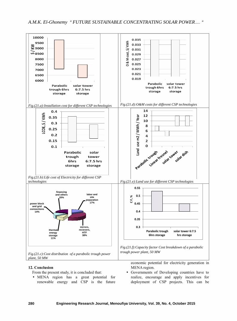
Fig.(21.a):Installation cost for different CSP technologies
Fig.(21.d):O&M costs for different CSP technologies
Fig.(21.b):Life cost of Electricity for different CSP
technologies
Fig.(21.e):Land use for different CSP technologies
Fig.(21.c):Cost distribution of a parabolic trough power
plant, 50 MW
Fig.(21.f):Capacity factor Cost breakdown of a parabolic
trough power plant, 50 MW
12. Conclusion
From the present study, it is concluded that:
MENA region has a great potential for
renewable energy and CSP is the future
economic potential for electricity generation in
MENA region.
Governments of Developing countries have to
realize, encourage and apply incentives for
deployment of CSP projects. This can be
labor and site
peparation 17%
mirrors, recievers,
HTF 38%
thermal energy storage
11%
power block and grid
connections 14%
financing and others
20%
0.3
0.35
0.4
0.45
0.5
0.55
Parabolic trough6hrs storage
solar tower 6:7.5hrs storage
C F
, %
A.M.K. El-Ghonemy " FUTURE SUSTAINABLE CONCENTRATING SOLAR POWER…. "
Engineering Research Journal, Menoufiya University, Vol. 39, No. 4, October 2015 281
achieved through investment and researches.
To produce power from solar heat energy, high
temperature is needed, so concentration of
incoming solar radiation is necessary using solar
concentrators. Radiation needs to be focused
onto a small target. So, concentrator optics and
orientation needs to be accurate.
Only beam radiation can be concentrated. Solar
tracking is necessary (small cos 𝜃).
Concentration ratio (C) =60-100 can give up to
400 C, while C ≥ 200 can give temperature of
600-1000 0C.
Concentration ratio is 25:100, 70:80, 300:1000,
1000-3000 for PT, ST, LF and Dish Stirling
respectively.
For PT, the ideal solar concentration ratio,
Cideal,2D =
Where 2D denotes to two dimensional (i.e
PT collector).
. Taking sun’s angular width = 32’
(0.5333
deg/2=𝜃.). Then Cideal,2D = 214. If higher Cideal,2D
is required, a secondary mirror may be
necessary.
Yearly efficiency is 15: 25% for power
generation from CSP power plants.
Using heat storage, 5:7 hrs more operational
time per day can be achieved.
Land area requirement: based on generation
weighted are 4:6, 6:8, 8:12, 8:12 m2/MWh/year
for LF, PT, ST and Dish Stirling respectively.
CSP plants are capital intensive, but have zero
fuel costs. PT plant without TES has capital
costs as low as $4600/KW, but low capacity
factors of 0.2: 0.25. Adding of 6 hours of TES
increases capital costs to $7100: 9800/kW, but
the capacity factors will be doubled.
For ST plants, capital costs are $6300,
10500/kW when TES is 6 and 15 hrs
respectively. The corresponding capacity factors
are 0.4 and 0.8 respectively.
For CSP plants, O&M costs are
$0.02:0.035/kWh, which is relatively considered
high.
The LCOE is mainly depending on capital costs
and the local solar resource. For instance, for a
given CSP plant, the LCOE will be around one
quarter lower for a DNI of 2700KWh/m2/year
than for a site with 2100 kWh/m2/year.
For CSP plants, the LCOE is currently high.
Today, the LCOE is $0.2:0.36/kWh and
$0.17:0.29 kWh for PT and ST plants
respectively (at 10% cost of capitals). However
for areas with excellent solar resources [MENA
regions), it could be as low as $0.14:0.18$/kWh.
Potential for Cost reduction is possible. For
instance, for 1.9 GW of installed capacity, by
year 2015, the LCOE will decline to
$0.18:0.32/kWh and $0.15: 0.24/kWh for PT
and ST plants respectively.
ST plants might become the choice in future.
Because it can achieve a very high temperatures
with manageable losses using molten salt as a
heat transfer fluid.
Typical capacity is 10:300, 10:200, 10:200 and
0.01:0.025 MW for PT, ST, LF and Dish Stirling
respectively.
Operating temperature is 350:550, 250:565, 390,
550:750 0C for PT, ST, LF and Dish Stirling
respectively.
Plant peak efficiency is 14:20, 23:35, 18 and
30% for PT, ST, LF and Dish Stirling
respectively.
Annual solar to electric efficiency (net) is
11:16%, 7:20%, 13%, 12:25% for PT, ST, LF
and Dish Stirling respectively.
Annual capacity factor is 29:43(7h TES), 55(10h
TES), 22:24, 25:28% for PT, ST, LF and Dish
Stirling respectively.
Collector concentration is 70-
80, >1000, >60, >1300 suns for PT, ST, LF and
Dish Stirling respectively.
Steam conditions (T in Co and P in bar) are
(380:540 oC)/100 bar, 540/100 to 160:260/50,
N/A for PT, ST, LF and Dish Stirling
respectively.
Water requirement in m3/ MW of plant capacity
is given below
PT
plant ST plant LF plant
Dish-
Stirling
3(wet
cooling)
0.3(dry
cooling)
2-3(wet
cooling)
0.25(dry
cooling)
3(wet
cooling)
0.2(dry
cooling)
0.05-0.1
(mirror
washing)
Labor represents 17% of the project cost and is
an area where local resources can help to reduce
costs in developing countries. Based on
experience with Andasol 1, the site
improvements, installation of the plant
components and completion of the plant will
require manpower of around 500 people.
The most promising components that could be
locally manufactured or provided by developing
A.M.K. El-Ghonemy " FUTURE SUSTAINABLE CONCENTRATING SOLAR POWER…. "
Engineering Research Journal, Menoufiya University, Vol. 39, No. 4, October 2015 282
countries are support structures, mirrors and
receivers.
Effect of orientation for 1-axis tracking:
The performance of concentrated solar
collectors (CSCs) depends on their orientation.
Comparing north-south against east-west
oriented collectors; it will have higher output
over the year (roughly 5: 8%). While east-west
oriented collectors have longer operating hours
and therefore higher output in winter times.
Nomenclature
CAPEX
DNI
HVAC
PT
Capital Expenditure
Direct normal insolation, kwh/m2
Heating, ventilating and air conditioning
Parabolic trough
S T Solar tower
LCOE Levelized cost of energy,$/kWhe
CSP
MENA
Concentrated solar power
Middle east and north Africa
MWht
MWhe
Megawatt hour thermal power
Megawatt hour electric power
TES Thermal energy storage
Subscripts
e
t
electric
thermal
Greek Symbols
η Efficiency
References [1] Dascomb,J 2009 ―Low-cost concentrating solar
collector for steam generation‖ MSc thesis, Florida
state university.
[2] International Renewable energy Agency(IRENA),
2012‖CSP cost analysis‖
[3] Donal Rapp, 1981 ‖Solar energy book: Solar
collectors‖.
[4] Yidnekachew Messele, 2012‖ Thermal Analysis,
Design and Experimental Investigation of Parabolic
Trough Solar Collector ‖MSc thesis, Addis Ababa
University.
[5] Incropera & DeWitt, 1996‖Heat transfer‖
[6] Radu D. Rugescu, 2010‖ Solar Energy ‖
WWW.intechweb.org.
[7] Hammons,T.J., 2009 ‖Renewable Energy ‖
WWW.intechweb.org
[8] Elisha B. Babatunde, 2012‖ Solar radiation‖
www.intechopen.com.
[9] Intech book, 2012―Renewable Energy‖ Intecweb.org.
[10] Trieb, F., 2005‖Concentrating solar power for the
Mediterranean region‖ German Aero Space center.
[11] Solar thermal power –the basics, European Solar
Thermal Industry Association, 2005.
[12] Thomas Stoffel, Daryl Myers, David Renne, Stephen
Wilcox, Ray George and Craig
Turchi,2010‖Introducing NREL’S best practices
handbook for collection and use of solar resource data
for CSP‖ NREL/TP-550-47465.
[13] 13]CSP today, 2013 ―CSP projects & prospects guide
USA 2013‖ WWW.csptoday.com/USA
[14] CSP today,2008‖An overview of CSP in Europe
andMENA‖MENASOL2013,WWW.CSPtoday.com/m
ena
[15] http://www.iea.org/publications/freepublications/publi
cation/csp_roadmap.pdf
[16] Arif Hepbasli, Zeyad Alsuhaibani, 2011‖ A key
review on present status and future directions of solar
energy studies and applications in Saudi Arabia‖
Renewable and Sustainable Energy Reviews 15 (2011)
5021– 5050.
[17] European Academies Science Advisory Council(EA-
SAC), 2011―Concentrating solar power: its potential
contribution to a sustainable energy future‖
www.easac.eu.
[18] M.C. Barbato, Ph. Haueter, R. Bader, A. Steinfeld, A.
Pedretti, 2008‖ Solar innovative solar collectors for
efficient and cost-effective solar thermal power
generation‖ Umwelt, Verkehr, Energie und
Kommunikation UVEK.
[19] R. Bose, D.J. Farrell, C. Pardo-Sanchez, M.
Pravettoni,M. Mazzer,A.J. Chatten, and K.W.J.
Barnham, ―luminescent solar concentrators:
cylindrical design‖[email protected].
[20] Tongxin Wang, Jun Zhang, Wei Ma, Yanhua Luo,
Lijuan Wang, Zhijia Hu,2011‖ Luminescent solar
concentrator employing rare earth complex with zero
self-absorption loss‖ Solar Energy 85 (2011) 2571–
2579.
[21] Ayadi, 2011‖Solar cooling systems, utilizing
concentrated solar collectors, design, experimental
evaluation & optimization ‖PhD thesis Politeccico DI,
MILANO.
[22] Zurich, E, 2011‖ Optical and thermal analysis of an
air-based solar trough concentrating system ‖PhD
thesis, ETH ZURICH.
[23] NREL Concentrating Power Research
www.nrel.gov/csp
[24] David C. Miller, Sarah R. Kurtz,2011 ―Durability of
Fresnel lenses: A review specific to the concentrating
photovoltaic application‖ Solar Energy Materials &
Solar Cells 95 (2011) 2037–2068.
[25] Nadejda Komendantova, Anthony Patt, Keith
Williges, 2011‖ Solar power investment in North
Africa: Reducing perceived risks‖ Renewable and
Sustainable Energy Reviews 15 (2011) 4829– 4835.
[26] Newton,C.C., 2007‖ A concentrated solar thermal
energy system‖ the Florida State University FAMU-
FSU College of engineering.
[27] Valenzuela,J.M., 2011‖ Performance of A 50 MW
concentrating Solar Power Plant ‖Politecnico DI
BARI.
[28] Sargent & Lundy LLC Consulting Group Chicago,
Illinois,2003‖ Assessment of Parabolic Trough and
Power Tower Solar Technology Cost and Performance
Forecasts‖ NREL/SR-550-34440.
[29] Abdulrahim A. T, Diso I. S.,and Abdulraheem A. S,
2012 ‖Design analysis of solar bi-focal collectors‖
Journal of Mechanical Engineering Research Vol.
4(4), pp. 136-141, April 2012.
[30] Daniel Horst,2012‖ Performance Simulation For
Parabolic Trough Concentrating Solar Power Plants
A.M.K. El-Ghonemy " FUTURE SUSTAINABLE CONCENTRATING SOLAR POWER…. "
Engineering Research Journal, Menoufiya University, Vol. 39, No. 4, October 2015 283
And Export Scenario Analysis For North Africa ‖MSc
thesis, FACULTY OF ENGINEERING, CAIRO
UNIVERSITY GIZA, EGYPT.
[31] Andrew James Marston,2010‖ Geometric
Optimization of Solar Concentrating Collectors using
Quasi-Monte Carlo Simulation ‖MSc ,University of
Waterloo, Waterloo, Ontario, Canada, 2010.
[32] Ahmad Khaled, ―TECHNICAL AND ECONOMIC
PERFORMANCE OF PARABOLIC TROUGH IN
JORDAN‖ M.Sc. thesis, University of Kassel,
Germany., Faculty of Engineering at Cairo University,
Egypt.
[33] Thermal Storage and Advanced Heat Transfer Fluids,
NREL/FS-550-48660 • August 2010.
[34] Roman Adinberg,2011‖ Simulation analysis of
thermal storage for concentrating solar power‖
Applied Thermal Engineering 31 (2011) 3588e3594.
[35] Paul Denholm and Mark Mehos,2011 ―Enabling
Greater Penetration of Solar Power via the Use of CSP
with Thermal Energy Storage‖ NREL/TP-6A20-
52978.
[36] Zhao, C.Y. Wu, Z.G., 2011‖ Thermal property
characterization of a low melting-temperature ternary
nitrate salt mixture for thermal energy storage
systems‖ Solar Energy Materials & Solar Cells 95
(2011) 3341–3346.
[37] Christopher W. Robak, Theodore L. Bergman, Amir
Faghri,2011‖ Economic evaluation of latent heat
thermal energy storage using embedded thermo-
siphons for concentrating solar power applications‖
Solar Energy 85 (2011) 2461–2473.
[38] Zhiwen Ma, Greg Glatzmaier, Craig Turchi, and Mike
Wagner, ―THERMAL ENERGY STORAGE
PERFORMANCE METRICS AND USE IN
THERMAL ENERGY STORAGE DESIGN‖
[39] AQUA-CSP 2007: Trieb, F., Schillings, C., Viebahn,
P., Paul, C., Altowaie, H., Sufian, T., Alnaser, W.,
Kabariti, M., Shahin, W., Bennouna, A., Nokraschy,
H., Kern, J., Knies, G., El Bassam, N., Hasairi, I.,
Haddouche, A., Glade, H., Aliewi, A., "Concentrating
Solar Power for Seawater Desalination" German
Aerospace Center (DLR), Study for the German
Ministry of Environment, Nature Conversation and
Nuclear Safety, Stuttgart 2007, (www.dlr.de/tt/aqua-
csp)
[40] Daniel Chemisana, JesúsLópez-Villada, Alberto
Coronas, Joan IgnasiRosell, Chiara Lodi, 2012‖
Building integration of concentrating systems for solar
cooling applications ―Applied Thermal Engineering
(2012) 1-8.
[41] Shamseen,A.M.1993‖ simulation study of reverse
osmosis desalination system powered by combined
solar and wind power plants optimization of the
dimensions of wind and solar subsystems‖ University
of Athens.
[42] Hazim Mohameed Qiblawey, Fawzi Banat‖ Solar
thermal desalination technologies‖ Desalination 220
(2008) 633–644.
[43] MENA Regional Water Outlook Part II Desalination
Using Renewable Energy Task 2 – Energy
Requirement, 6543P07/FICHT-6971711-v4.
[44] Ummadisingu, A., Soni, M.S., 2011 ―Concentrating
solar power– Technology, potential and policy in
India‖ Renewable and Sustainable Energy Reviews 15
(2011) 5169– 5175.
[45] Muhammad Tauha Ali, Hassan E.S. Fath, Peter R.
Armstrong,2011‖ A comprehensive techno-
economical review of indirect solar desalination‖
Renewable and Sustainable Energy Reviews 15 (2011)
4187–4199.
[46] Regina Wilde, 2005‖ Case Study of a Concentrating
Solar Power Plant for the Cogeneration of Water and
Electricity‖ Diploma thesis, DLR.
[47] Concentrating Solar Power Commercial Application
Study: Reducing Water Consumption of Concentrating
Solar Power Electricity Generation, Report to
Congress U.S. Department of Energy,2001
[48] IORDANOU, GRIGORIOS,2009‖ Flat-Plate Solar
Collectors for Water Heating with Improved Heat
Transfer for Application in Climatic Conditions of the
Mediterranean Region‖ School of Engineering and
Computing Science Durham University.
[49] MENA Regional Water Outlook,2011, Part II
Desalination Using Renewable Energy Task 2 –
Energy Requirement, [email protected].
[50] X.Q. ZhaiM. Qu, Yue. Li, R.Z. Wang,2011‖ A review
for research and new design options of solar
absorption cooling systems‖ Renewable and
Sustainable Energy Reviews 15 (2011) 4416– 4423.
[51] Z.F. Li, K. Sumathy, 2000‖ Technology development
in the solar absorption air-conditioning systems‖
Renewable and Sustainable Energy Reviews 4 (2000)
267-293.
[52] Patricia Palenzuela, Guillermo Zaragoza, Diego C.
Alarcón-Padilla, Julián Blanco,2011‖ Evaluation of
cooling technologies of concentrated solar power
plants and their combination with desalination in the
Mediterranean area‖ Applied Thermal Engineering
xxx (2011) 1-8.
[53] Lucier RE. Apparatus for converting solar to electrical
energy. US. Patent; 1979.
[54] Robert Y. Ning, 2012 ―Advancing Desalination‖
www.intechopen.com
[55] Trieb, Moser, Fichter, DLR, Verdier, 2011 ―MENA
Regional Water Outlook Part II , Desalination Using
Renewable Energy Task 2 – Energy Requirement,
FICHTNER, DLR, www.fichtner.de
[56] Lapetrov, 2011‖ Solar tracking strategies― BSc
Dissertation, DUNDEE university.
[57] Khademul Islam Majumder, Raied Hasan and Raquib
Ahmed, 2010‖ Improvement Of efficiency For solar
PHOTOVOLTAIC Cell Application‖ BRAC
University, Dhaka, Bangladesh.
[58] Justin Matthew Hallas,2011‖ Automated Micro-
Tracking Planar Solar Concentrators ‖MSc thesis,
UNIVERSITY OF CALIFORNIA, SAN DIEGO.
[59] L A Petrov,2011‖ Solar tracking strategies ―BSc
Dissertation , DUNDEE university.
[60] C. Turchi,2010‖Parabolic Trough Reference Plant for
Cost Modeling with the Solar Advisor Model (SAM)‖
Technical Report NREL/TP-550-47605July 2010.
[61] Sargent & Lundy LLC Consulting Group Chicago,
A.M.K. El-Ghonemy " FUTURE SUSTAINABLE CONCENTRATING SOLAR POWER…. "
Engineering Research Journal, Menoufiya University, Vol. 39, No. 4, October 2015 284
Illinois,2003” Assessment of Parabolic Trough and
Power Tower Solar Technology Cost and Performance
Forecasts‖ NREL/SR-550-34440.
[62] Advanced Reflector and Absorber Materials, NREL.
[63] David Barlev, RuxandraVidu, Pieter Stroeve, 2011‖
Innovation in concentrated solar power‖ Solar Energy
Materials & Solar Cells 95 (2011) 2703–2725.
[64] Angela, M., 2006 ‖Simulation and Performance
Evaluation of Parabolic Trough Solar Power Plants‖
MSc thesis, university of wisconsin-madison.
[65] R.H. French, J.M. Rodrı´guez-Parada, M.K. Yang,
R.A. Derryberry, N.T. Pfeiffenberger, 2011‖ Optical
properties of polymeric materials for concentrator
photovoltaic systems‖ Solar Energy Materials & Solar
Cells 95 (2011) 2077–2086.
[66] John Chung-Ling Chien, Noam Lior, 2011‖
Concentrating solar thermal power as a viable
alternative in China’s electricity supply‖ Energy
Policy 39 (2011) 7622–7636.
[67] Javier Munoz, Alberto Abnades, 2011‖ Analysis of
internal helically finned tubes for parabolic trough
design by CFD tools‖ Applied Energy 88 (2011)
4139–4149.
[68] Gui-Long Dai, Xin-Lin Xia, Chuang Sun, Hao-Chun
Zhang,2011‖ Numerical investigation of the solar
concentrating characteristics of 3D CPC and CPC-
DC‖ Solar Energy 85 (2011) 2833–2842.
[69] Aqeel Ahmed Bazmi, GholamrezaZahedi,2011‖
Sustainable energy systems: Role of optimization
modeling techniques in power generation and
supply—A review‖ Renewable and Sustainable
Energy Reviews 15 (2011) 3480–3500.
[70] Modeling and Analysis of CSP Systems, National
Renewable Energy Laboratory, NREL/FS-550-48661
• August 2010.
[71] Roman Badr, 2011‖ Optical and thermal analysis Of
an air-Based Solar Trough Concentrating
System ‖PhD thesis, DISS. ETH NO. 19772.
[72] Dustin F. Howard, 2010‖ Modeling Concentrated
Dish-Stirling Solar Power Plants ‖MSc thesis, Georgia
Institute of Technology.
[73] Newtonian off-axis aberrations, http://www.telescope-
optics.net/newtonian_off_axis_aberrations.htm.
[74] Michael J. Wagner,2012 ―Results and Comparison
from the SAM Linear Fresnel Technology
Performance Model‖ World Renewable Energy Forum
Denver, Colorado May 13–17, 2012.
[75] NREL Solar Data and Tools.
[76] Intech book,2012 ―Modeling and Optimization of
renewable energy systems‖Intechopen.com.
[77] Intech book, 2012―Numerical Modeling‖
Intechopen.com
[78] Yidnekachew Messele, 2012‖ Thermal Analysis,
Design and Experimental Investigation of Parabolic
Trough Solar Collector ‖MSc thesis, Addis Ababa
University.
[79] solar thermal power system, chapter ten:
www.powersolar.com
[80] Expert group meeting-Emerging Renewable Energy
technologies for India,2010.
[81] Adesten,M, 2002‖design and performance of non
tracking concentrators ‖PhD thesis, Uppsala
university.
[82] Solar thermal power system, chapter eight:
www.powersolar.com
[83] A bdulkarim Mayere, BEng, PgDip, 2011‖ Solar
Powered Desalination‖ PhD thesis, University of
Nottingham