Embed Size (px)
Citation preview
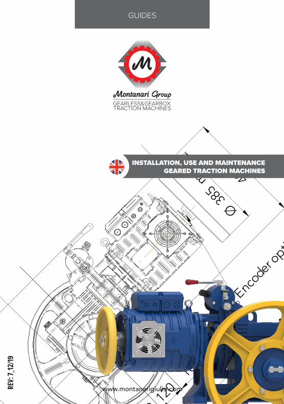
www.montanarigiulio.com
3012
012
018
5
30
485
15054
6
150,5
Encod
er optio
nal
733
max38
5
Ø
max 491
REV:
7_12
/19GUIDES
INSTALLATION, USE AND MAINTENANCEGEARED TRACTION MACHINES

Pag.
37
37www.montanarigiulio.com
GEARBOX ENGLISH
Index
This manual does not cover the procedure for disenabling the entire plant: it con-tains only the instructions relative to the lift gear. Consequently, before beginning installation operations for the lift gear you must obey the instructions given in the use and maintenance manual for the plant and adopt all precautions laid down by current safety legislation.
SCOPE
IMPORTANT - WARNING:
The scope of this lift gears manual is to supply instructions for:• Installation.• Use.• Maintenance.
1. STANDARD REFERENCE .................................... 432. GENERAL NOTES ................................................ 433. TRANSPORT ....................................................... 44
3.1 UNLOAD ....................................................................... 444. WAREHOUSE STORAGE ..................................... 445.INSTALLATION .................................................... 45
5.1 HANDLING ................................................................... 455.2 ASSEMBLY ON THE BASE ...................................... 465.3 LUBRICATION ............................................................ 565.3.1 LUBRICATION PENTA - PENTA 830 .................. 575.4 ELECTRICAL WIRINGS ............................................. 585.5 COMMISSIONING ..................................................... 635.6 BRAKE SHOE ADJUSTMENT ................................. 64
6. USE...................................................................... 647. MAINTENANCE ................................................... 64
7.1 Axial Clearance Check On Thrust Bearing .......... 647.2 Crown and Worm Clearance Check ..................... 657.3 BRAKE: brake Shoe Wear ........................................ 657.4 OIL: replacement and level check......................... 667.5 OIL: Seals Check ........................................................ 667.6 TRACTION PULLEY: Groove Wear check ........... 667.7 REPLACEMENT OF COMPONENTS ...................... 667.8 TIGHTENING MOMENT ........................................... 66
8. COMPLIANCE DECLARATION ........................... 68
38
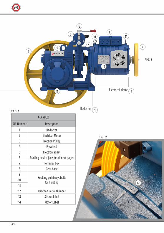
GEARBOX
Rif. Number Description1 Reductor2 Electrical Motor3 Traction Pulley4 Flywheel5 Electromagnet6 Braking device (see detail next page)7 Terminal box8 Gear base9
Hooking points/eyeboltsfor hoisting10
1112 Punched Serial Number13 Sticker label14 Motor Label
1Reductor
12
FIG. 2
TAB. 1
Electrical Motor 2
43
7
129
1110
6
8
14
FIG. 1
5
39www.montanarigiulio.com
GEARBOX ENGLISH
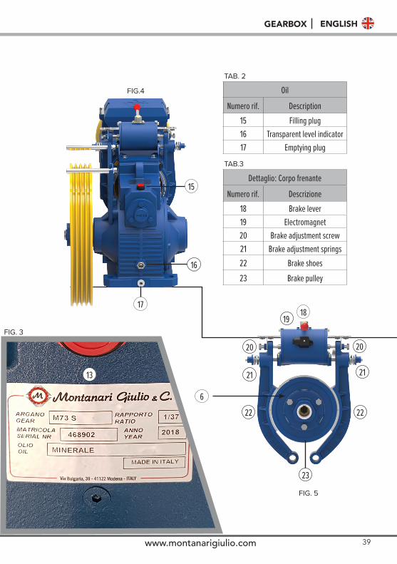
Dettaglio: Corpo frenante
Numero rif. Descrizione18 Brake lever19 Electromagnet20 Brake adjustment screw21 Brake adjustment springs22 Brake shoes23 Brake pulley
Oil
Numero rif. Description15 Filling plug16 Transparent level indicator17 Emptying plug
15
16
1718
19
23
2222
2121
2020
13
TAB.3
FIG. 3
FIG.4
FIG. 5
TAB. 2
6
40
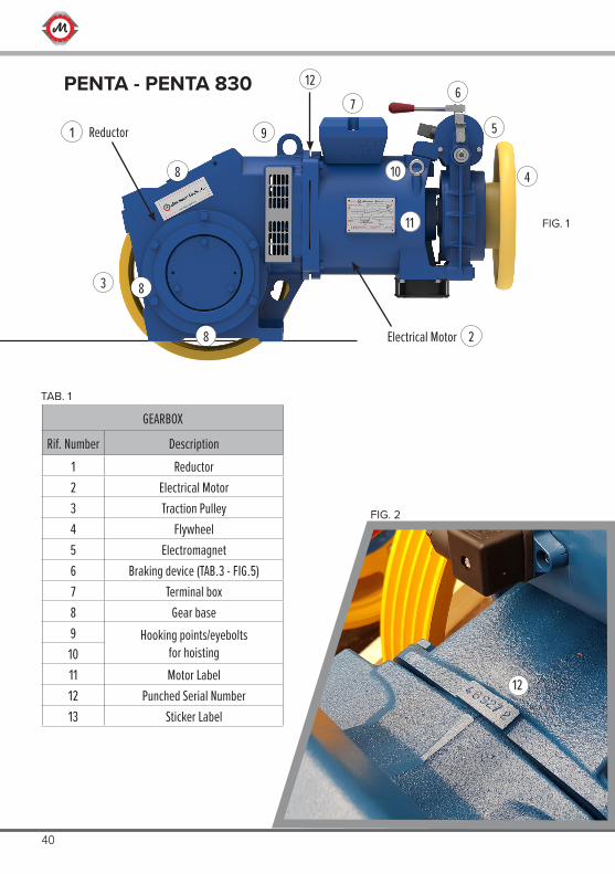
GEARBOX
Rif. Number Description1 Reductor2 Electrical Motor3 Traction Pulley4 Flywheel5 Electromagnet6 Braking device (TAB.3 - FIG.5)7 Terminal box8 Gear base9 Hooking points/eyebolts
for hoisting1011 Motor Label12 Punched Serial Number13 Sticker Label
12
FIG. 2
TAB. 1
1 Reductor
Electrical Motor
4
3
7
9
6
8
11
10
FIG. 1
5
2
8
8
12PENTA - PENTA 830
41www.montanarigiulio.com
GEARBOX ENGLISH
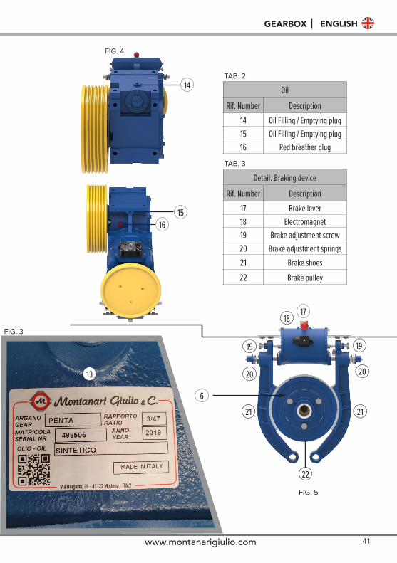
Detail: Braking device
Rif. Number Description17 Brake lever18 Electromagnet19 Brake adjustment screw20 Brake adjustment springs21 Brake shoes22 Brake pulley
Oil
Rif. Number Description14 Oil Filling / Emptying plug15 Oil Filling / Emptying plug16 Red breather plug
13
TAB. 3
FIG. 3
TAB. 214
1516
FIG. 4
1718
22
2121
2020
1919
FIG. 5
6
42
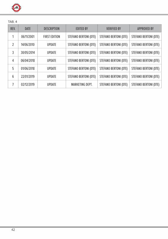
REV. DATE DESCRIPTION EDITED BY VERIFIED BY APPROVED BY
1 06/11/2001 FIRST EDITION STEFANO BERTONI (DTE) STEFANO BERTONI (DTE) STEFANO BERTONI (DTE)
2 14/06/2010 UPDATE STEFANO BERTONI (DTE) STEFANO BERTONI (DTE) STEFANO BERTONI (DTE)
3 30/05/2014 UPDATE STEFANO BERTONI (DTE) STEFANO BERTONI (DTE) STEFANO BERTONI (DTE)
4 06/04/2018 UPDATE STEFANO BERTONI (DTE) STEFANO BERTONI (DTE) STEFANO BERTONI (DTE)
5 01/06/2018 UPDATE STEFANO BERTONI (DTE) STEFANO BERTONI (DTE) STEFANO BERTONI (DTE)
6 22/01/2019 UPDATE STEFANO BERTONI (DTE) STEFANO BERTONI (DTE) STEFANO BERTONI (DTE)
7 02/12/2019 UPDATE MARKETING DEPT. STEFANO BERTONI (DTE) STEFANO BERTONI (DTE)
TAB. 4
43www.montanarigiulio.com
GEARBOX ENGLISH
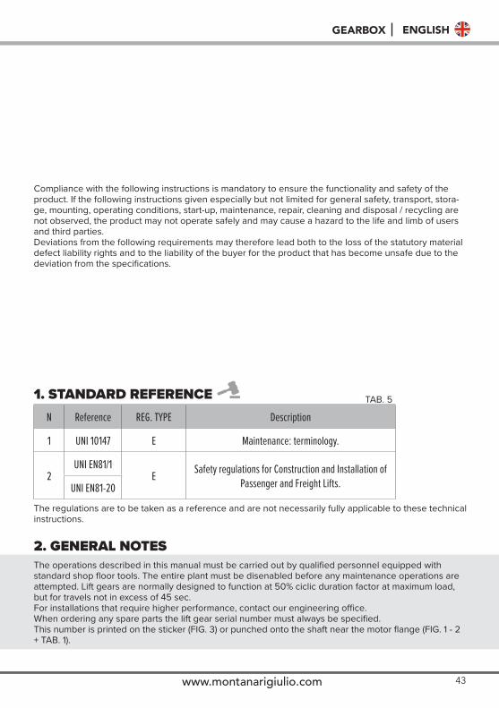
1. STANDARD REFERENCEN Reference REG. TYPE Description
1 UNI 10147 E Maintenance: terminology.
2UNI EN81/1
E Safety regulations for Construction and Installation of Passenger and Freight Lifts.UNI EN81-20
The regulations are to be taken as a reference and are not necessarily fully applicable to these technical instructions.
2. GENERAL NOTESThe operations described in this manual must be carried out by qualified personnel equipped with standard shop floor tools. The entire plant must be disenabled before any maintenance operations are attempted. Lift gears are normally designed to function at 50% ciclic duration factor at maximum load, but for travels not in excess of 45 sec.For installations that require higher performance, contact our engineering office.When ordering any spare parts the lift gear serial number must always be specified.This number is printed on the sticker (FIG. 3) or punched onto the shaft near the motor flange (FIG. 1 - 2 + TAB. 1).
TAB. 5
Compliance with the following instructions is mandatory to ensure the functionality and safety of the product. If the following instructions given especially but not limited for general safety, transport, stora-ge, mounting, operating conditions, start-up, maintenance, repair, cleaning and disposal / recycling are not observed, the product may not operate safely and may cause a hazard to the life and limb of users and third parties.Deviations from the following requirements may therefore lead both to the loss of the statutory material defect liability rights and to the liability of the buyer for the product that has become unsafe due to the deviation from the specifications.
44
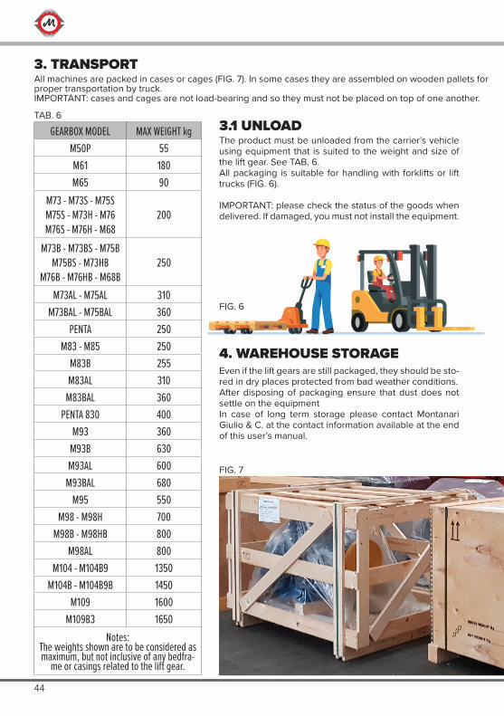
4. WAREHOUSE STORAGEEven if the lift gears are still packaged, they should be sto-red in dry places protected from bad weather conditions.After disposing of packaging ensure that dust does not settle on the equipmentIn case of long term storage please contact Montanari Giulio & C. at the contact information available at the end of this user’s manual.
3.1 UNLOADThe product must be unloaded from the carrier’s vehicle using equipment that is suited to the weight and size of the lift gear. See TAB. 6.All packaging is suitable for handling with forklifts or lift trucks (FIG. 6).
IMPORTANT: please check the status of the goods when delivered. If damaged, you must not install the equipment.
3. TRANSPORTAll machines are packed in cases or cages (FIG. 7). In some cases they are assembled on wooden pallets for proper transportation by truck.IMPORTANT: cases and cages are not load-bearing and so they must not be placed on top of one another.
TAB. 6
FIG. 6
FIG. 7
GEARBOX MODEL MAX WEIGHT kgM50P 55M61 180M65 90
M73 - M73S - M75SM75S - M73H - M76M76S - M76H - M68
200
M73B - M73BS - M75BM75BS - M73HB
M76B - M76HB - M68B250
M73AL - M75AL 310M73BAL - M75BAL 360
PENTA 250M83 - M85 250
M83B 255M83AL 310
M83BAL 360PENTA 830 400
M93 360M93B 630M93AL 600
M93BAL 680M95 550
M98 - M98H 700M98B - M98HB 800
M98AL 800M104 - M104B9 1350
M104B - M104B9B 1450M109 1600
M109B3 1650Notes:
The weights shown are to be considered as maximum, but not inclusive of any bedfra-
me or casings related to the lift gear.
45www.montanarigiulio.com
GEARBOX ENGLISH
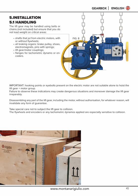
5.INSTALLATION5.1 HANDLING
IMPORTANT: hooking points or eyebolts present on the electric motor are not suitable alone to hoist the lift gear + motor group.Failure to observe these indications may create dangerous situations and moreover damage the lift gear irreparably.
Disassembling any part of the lift gear, including the motor, without authorisation, for whatever reason, will invalidate any form of guarantee.
Take special care not to subject the lift gear to collision.The flywheels and encoders or any tachometric dynamos applied are especially sensitive to collision.
FIG. 8
The lift gear may be handled using belts or chains (not included) but ensure that you do not load weight on critical areas:
• shafts that jut from electric motors, with or without flywheels;
• all braking organs: brake pulley, shoes, electromagnets, pins with springs;
• lift gear/motor couplings;• flanges for tachometric dynamo or en-
coders.
46
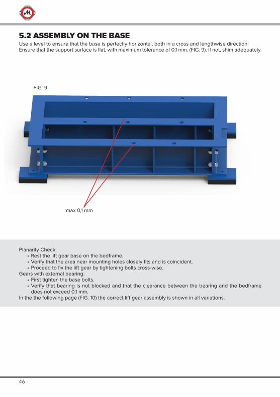
5.2 ASSEMBLY ON THE BASEUse a level to ensure that the base is perfectly horizontal, both in a cross and lengthwise direction.Ensure that the support surface is flat, with maximum tolerance of 0,1 mm. (FIG. 9). If not, shim adequately.
Planarity Check: • Rest the lift gear base on the bedframe.• Verify that the area near mounting holes closely fits and is coincident.• Proceed to fix the lift gear by tightening bolts cross-wise.
Gears with external bearing: • First tighten the base bolts.• Verify that bearing is not blocked and that the clearance between the bearing and the bedframe
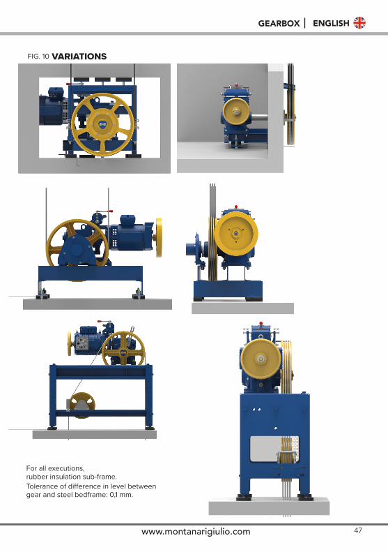
does not exceed 0,1 mm.In the the following page (FIG. 10) the correct lift gear assembly is shown in all variations.
max 0,1 mm
FIG. 9
47www.montanarigiulio.com
GEARBOX ENGLISH
For all executions,rubber insulation sub-frame.
VARIATIONS
Tolerance of difference in level betweengear and steel bedframe: 0,1 mm.
FIG. 10
48
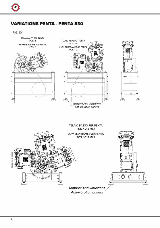
TELAIO ALTO PER PENTA POS. 2
HIGH BEDFRAME FOR PENTAPOS. 2
TELAIO ALTO PER PENTA POS. 1-3
HIGH BEDFRAME FOR PENTAPOS. 1-3
Tamponi Anti-vibrazioneAnti-vibration bu�ers
TELAIO BASSO PER PENTA POS. 1-2-3 MLA
LOW BEDFRAME FOR PENTAPOS. 1-2-3 MLA
Tamponi Anti-vibrazioneAnti-vibration bu�ers
VARIATIONS PENTA - PENTA 830
FIG. 10
49www.montanarigiulio.com
GEARBOX ENGLISH
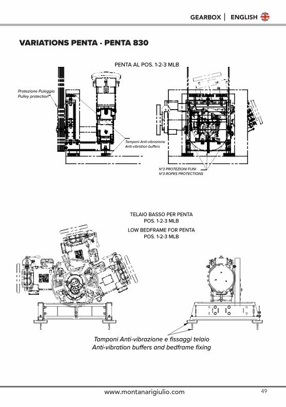
TELAIO BASSO PER PENTA POS. 1-2-3 MLB
LOW BEDFRAME FOR PENTAPOS. 1-2-3 MLB
Tamponi Anti-vibrazione e fissaggi telaioAnti-vibration buers and bedframe fixing
Protezione PuleggiaPulley protection
Tamponi Anti-vibrazioneAnti-vibration buers
N°3 PROTEZIONI FUNIN°3 ROPES PROTECTIONS
PENTA AL POS. 1-2-3 MLB
VARIATIONS PENTA - PENTA 830
50
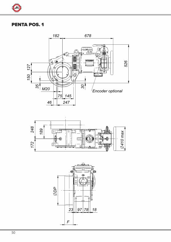
M20
75 14546 247
182 678
3035
150
127 52
6
Encoder optional
OD
P
F
97 7823 18
189248
172
O41
0 m
ax
PENTA POS. 1
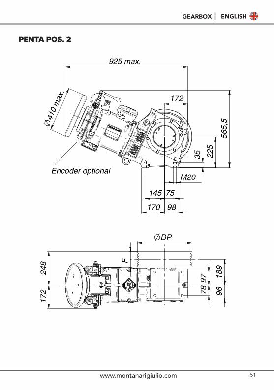
M20
35 225
565,
5
172
925 max.
O41
0 m
ax.
Encoder optional
145 75
170 98
ODP
F
7897
9618
9
172
248
51www.montanarigiulio.com
GEARBOX ENGLISH
M20
35 225
565,
5
172
925 max.
O41
0 m
ax.
Encoder optional
145 75
170 98
ODP
F
7897
9618
9
172
248
PENTA POS. 2
52
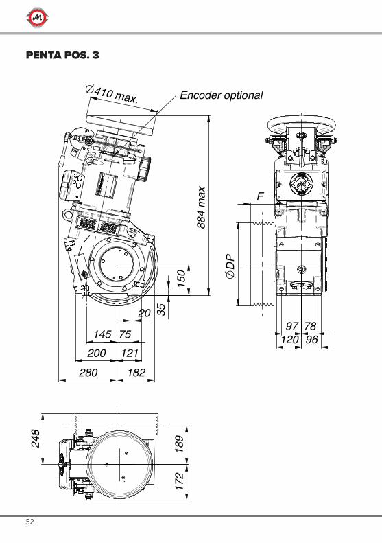
145 75
20 35
200 121280
150
884
max
O410 max.
F
97 78120 96
OD
P
248
189
172
Encoder optional
182
PENTA POS. 3
53www.montanarigiulio.com
GEARBOX ENGLISH
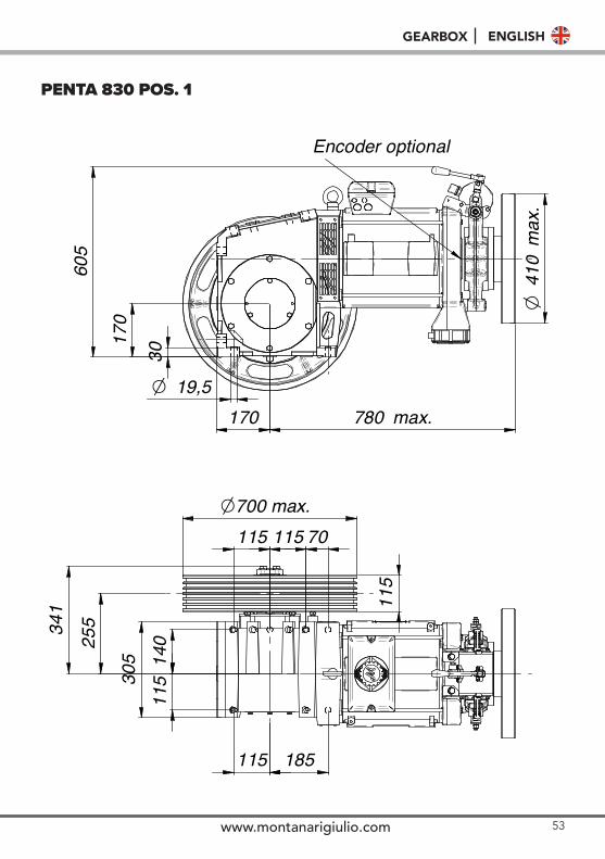
170
605
410
Om
ax.
19,5O
170 780 max.
140
115
115 185
305
255
115 70115O700 max.
115
Encoder optional30
341
PENTA 830 POS. 1
54
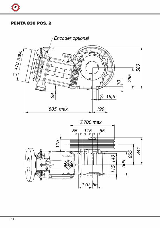
170 65
199835 max.
410
Om
ax.
19,5O
30 265
520
28
55 115 65
115
O700 max.
115
140
305
255 34
1
Encoder optional
PENTA 830 POS. 2
55www.montanarigiulio.com
GEARBOX ENGLISH
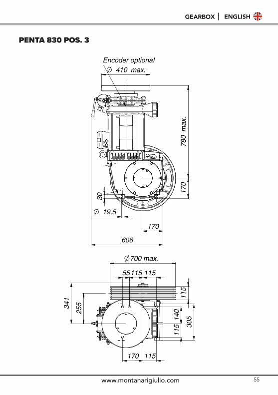
30
19,5O
170
170
780
max
.
410O max.
115
140
305
170 115
55115 115
115
25534
1
O700 max.
Encoder optional
606
PENTA 830 POS. 3
56
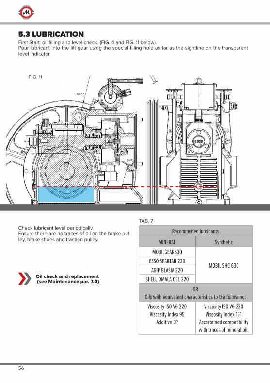
5.3 LUBRICATIONFirst Start: oil filling and level check. (FIG. 4 and FIG. 11 below).Pour lubricant into the lift gear using the special filling hole as far as the sightline on the transparent level indicator.
Recommened lubricants
MINERAL SyntheticMOBILGEAR630
MOBIL SHC 630ESSO SPARTAN 220
AGIP BLASIA 220SHELL OMALA OEL 220
OROils with equivalent characteristics to the following:
Viscosity ISO VG 220Viscosity Index 95
Additive EP
Viscosity ISO VG 220Viscosity Index 151
Ascertained compatibility with traces of mineral oil.
Oil check and replacement (see Maintenance par. 7.4)
Check lubricant level periodically.Ensure there are no traces of oil on the brake pul-ley, brake shoes and traction pulley.
FIG. 11
TAB. 7
57www.montanarigiulio.com
GEARBOX ENGLISH
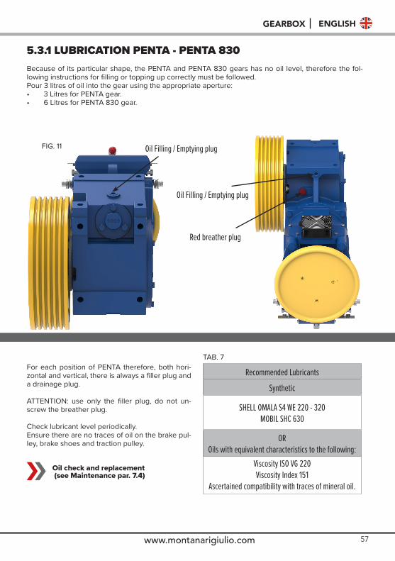
5.3.1 LUBRICATION PENTA - PENTA 830Because of its particular shape, the PENTA and PENTA 830 gears has no oil level, therefore the fol-lowing instructions for filling or topping up correctly must be followed.Pour 3 litres of oil into the gear using the appropriate aperture:• 3 Litres for PENTA gear.• 6 Litres for PENTA 830 gear.
Recommended Lubricants
Synthetic
SHELL OMALA S4 WE 220 - 320MOBIL SHC 630
OROils with equivalent characteristics to the following:
Viscosity ISO VG 220Viscosity Index 151
Ascertained compatibility with traces of mineral oil.
Oil check and replacement (see Maintenance par. 7.4)
For each position of PENTA therefore, both hori-zontal and vertical, there is always a filler plug and a drainage plug.
ATTENTION: use only the filler plug, do not un-screw the breather plug.
Check lubricant level periodically.Ensure there are no traces of oil on the brake pul-ley, brake shoes and traction pulley.
FIG. 11
TAB. 7
Oil Filling / Emptying plug
Oil Filling / Emptying plug
Red breather plug
58
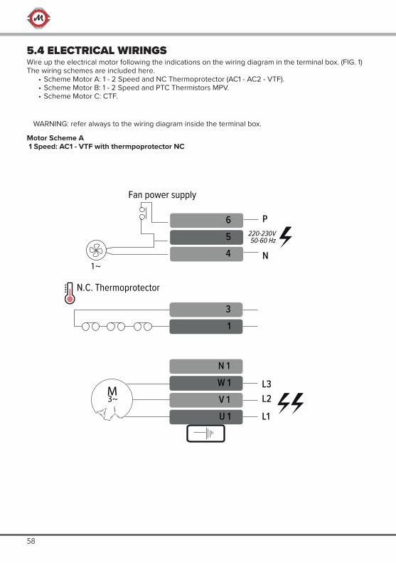
5.4 ELECTRICAL WIRINGSWire up the electrical motor following the indications on the wiring diagram in the terminal box. (FIG. 1)The wiring schemes are included here.
• Scheme Motor A: 1 - 2 Speed and NC Thermoprotector (AC1 - AC2 - VTF).• Scheme Motor B: 1 - 2 Speed and PTC Thermistors MPV.• Scheme Motor C: CTF.
N 1W 1V 1U 1
L3L2
L1
31
1~
654
P
N
220-230V50-60 Hz
N.C. Thermoprotector
Fan power supply
M3~
Motor Scheme A 1 Speed: AC1 - VTF with thermpoprotector NC
WARNING: refer always to the wiring diagram inside the terminal box.
59www.montanarigiulio.com
GEARBOX ENGLISH
N 1W 1V 1U 1
N 2W 2V 2U 2
L3L
L2L
L1L
L3H
L2H
L1H
1
23
654
P
N1~
220-230V50-60 Hz
N.C. Thermoprotector
Fan power supply
HIGH
LOWspeed
speed
M3~
M3~
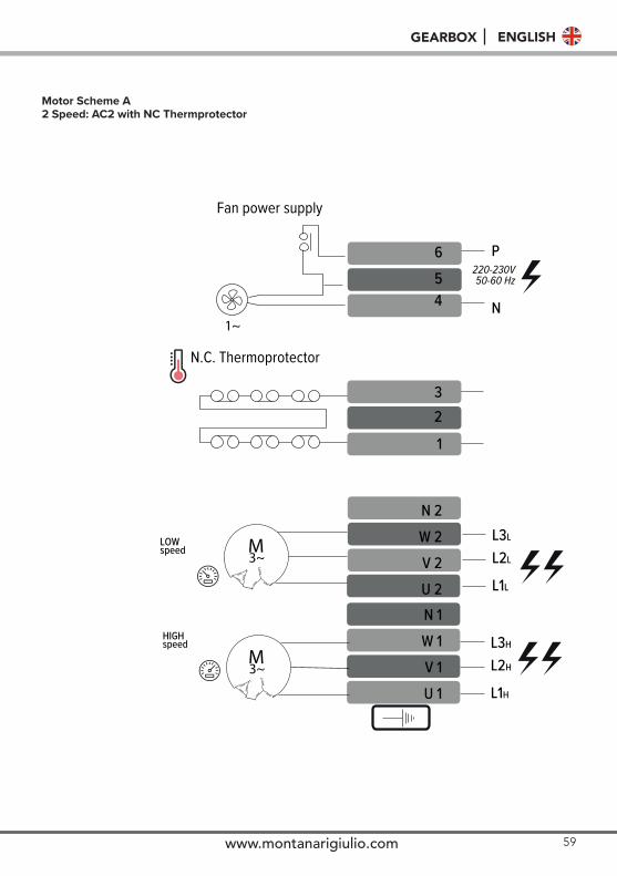
Motor Scheme A 2 Speed: AC2 with NC Thermprotector
60
765
N1~ 4
N 1W 1V 1U 1
L3L2
L1
31
NA Contact for fan power supply
PTC* Thermistors- don’t apply > 2,5V tension
Capacitor
L1
M3~
220-230V50-60 Hz
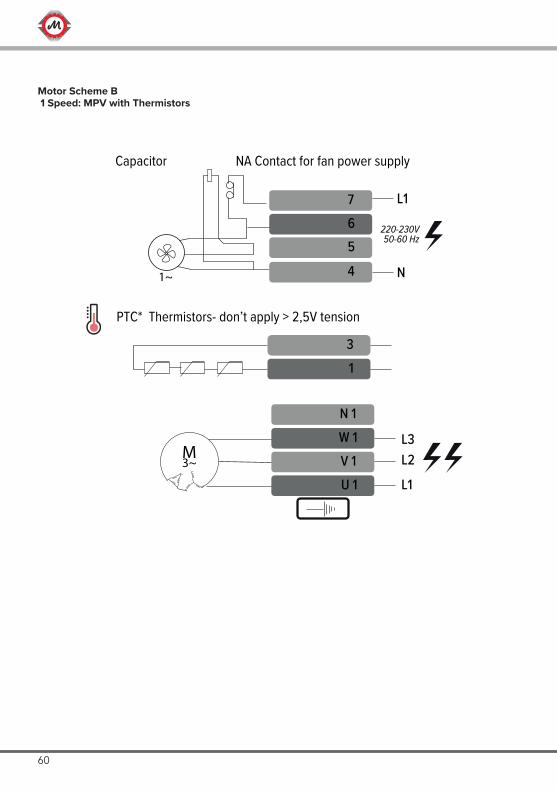
Motor Scheme B 1 Speed: MPV with Thermistors
61www.montanarigiulio.com
GEARBOX ENGLISH
N 1W 1V 1U 1
N 2W 2V 2U 2
L3L2
L1
L3L2
L1
21
3
4
765
N
L1
1~
LOW speed
HIGHspeed
PTC* Thermistors- don’t apply > 2,5V tension
Capacitor NA Contact for fan power supply
M3~
M3~
220-230V50-60 Hz
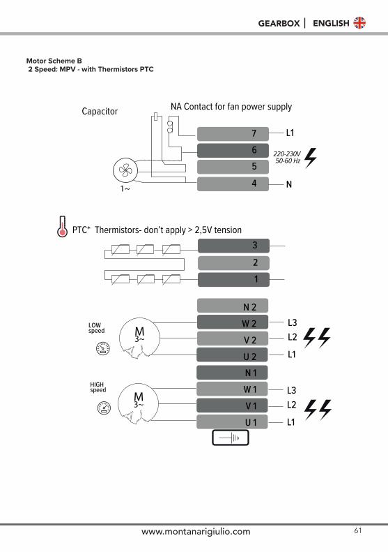
Motor Scheme B 2 Speed: MPV - with Thermistors PTC
62
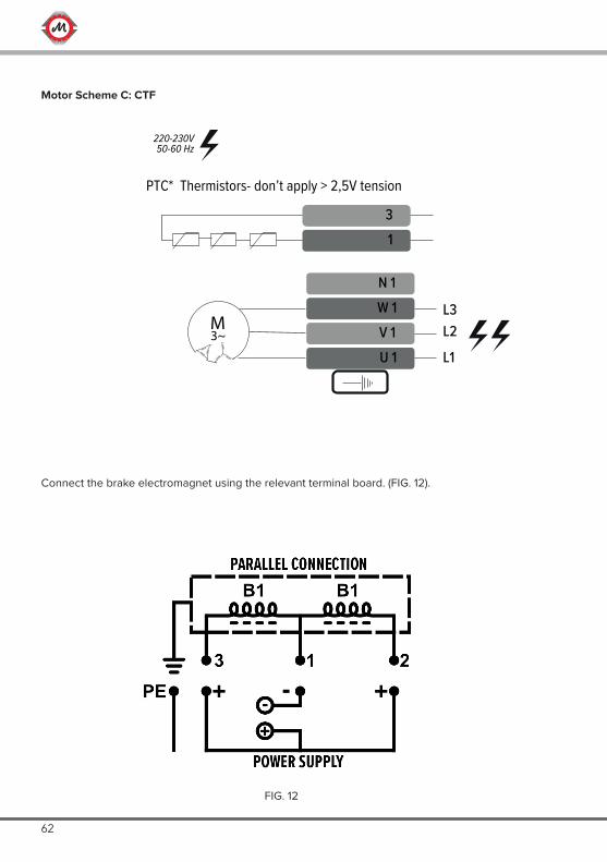
N 1W 1V 1U 1
L3L2
L1
31
PTC* Thermistors- don’t apply > 2,5V tension
220-230V50-60 Hz
M3~
Motor Scheme C: CTF
Connect the brake electromagnet using the relevant terminal board. (FIG. 12).
FIG. 12
63www.montanarigiulio.com
GEARBOX ENGLISH
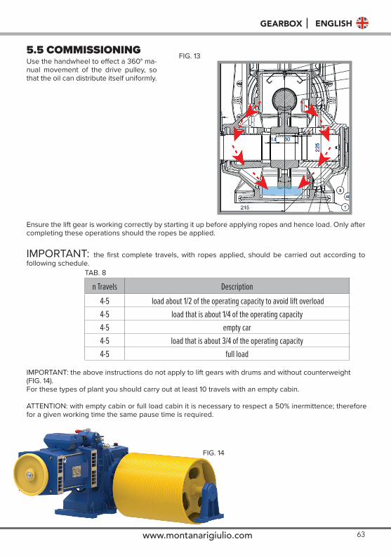
5.5 COMMISSIONINGUse the handwheel to effect a 360° ma-nual movement of the drive pulley, so that the oil can distribute itself uniformly.
Ensure the lift gear is working correctly by starting it up before applying ropes and hence load. Only after completing these operations should the ropes be applied.
IMPORTANT: the first complete travels, with ropes applied, should be carried out according to following schedule.
n Travels Description4-5 load about 1/2 of the operating capacity to avoid lift overload4-5 load that is about 1/4 of the operating capacity4-5 empty car4-5 load that is about 3/4 of the operating capacity4-5 full load
IMPORTANT: the above instructions do not apply to lift gears with drums and without counterweight(FIG. 14).For these types of plant you should carry out at least 10 travels with an empty cabin.
ATTENTION: with empty cabin or full load cabin it is necessary to respect a 50% inermittence; therefore for a given working time the same pause time is required.
FIG. 13
TAB. 8
FIG. 14
64
5.6 BRAKE SHOE ADJUSTMENTLift gears are normally supplied with brake shoe openings already adjusted.If further fine-tuning is required, proceed as follows (FIG. 5).
The brake shoes should open with the least possible run.
• Use the brake lever to open the brake shoes.• Tighten or loosen the special adjusting screws to ensure that between the brake shoes and the
brake pulley is at a min.• Make different test in order to verify there is no friction between the brake shoes and brake pulley.• In case of friction, tighten the regulation screw of a quarter turn each time until friction disappears.
The stopping distance will depend on how springs are tuned and they require adjustment from timeto time according to load and in compliance with regulation EN81-20 par. 5.9.2.2.2.1 and 6.3 .1.Ensure that during normal functioning the brake shoes open at the same time.
Check brake shoe(see maintenance par. 7.3)
Lift gears are designed and built to serve as hoisting apparatus for Passenger Lifts and Freight Lifts in compliance with the relative standards (EN81/1 - EN81-20) and therefore any other use is to be considered improper. The lift gears may not be used in plants with features that differ from those specified at the time of orde-ring the lift gear (e.g. capacity, speed, etc.). The lift gears must not be used for manually hoisting the cab after engagement of the safety gears in order to disengage them.Any trial, inspection or manoeuvre that should become necessary shall be carried out by personnel who have been trained to comply with the EN81/1 - EN81-20 standards.
6. USE
7. MAINTENANCE7.1 Axial Clearance Check On Thrust Bearing
• Normally all lift gears do not require any adjustment and indeed cannot be adjusted. Checking procedure:
• Bearing clearance can be seen with the naked eye during reverse movement by watching the axial movement of the brake pulley compared to the brake blocks.
• Inform Montanari Giulio &C. Srl engineering office when this clearance appears on lift gears for whi-ch there is no adjustment possibility, to decide whether the bearing should be replaced.
65www.montanarigiulio.com
GEARBOX ENGLISH
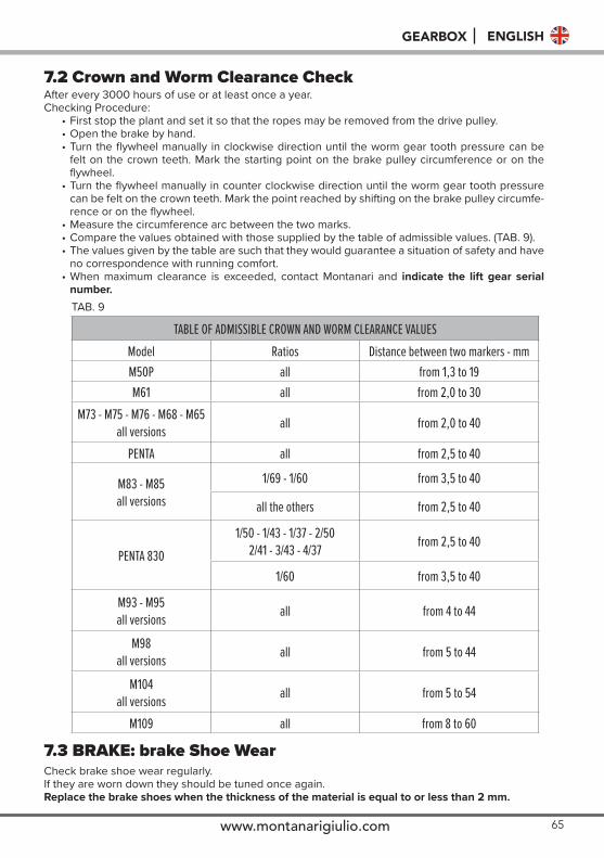
7.2 Crown and Worm Clearance CheckAfter every 3000 hours of use or at least once a year.Checking Procedure:
• First stop the plant and set it so that the ropes may be removed from the drive pulley.• Open the brake by hand.• Turn the flywheel manually in clockwise direction until the worm gear tooth pressure can be
felt on the crown teeth. Mark the starting point on the brake pulley circumference or on theflywheel.
• Turn the flywheel manually in counter clockwise direction until the worm gear tooth pressurecan be felt on the crown teeth. Mark the point reached by shifting on the brake pulley circumfe-rence or on the flywheel.
• Measure the circumference arc between the two marks.• Compare the values obtained with those supplied by the table of admissible values. (TAB. 9).• The values given by the table are such that they would guarantee a situation of safety and have
no correspondence with running comfort.• When maximum clearance is exceeded, contact Montanari and indicate the lift gear serial
number.
7.3 BRAKE: brake Shoe WearCheck brake shoe wear regularly.If they are worn down they should be tuned once again.Replace the brake shoes when the thickness of the material is equal to or less than 2 mm.
TAB. 9
TABLE OF ADMISSIBLE CROWN AND WORM CLEARANCE VALUES Model Ratios Distance between two markers - mmM50P all from 1,3 to 19M61 all from 2,0 to 30
M73 - M75 - M76 - M68 - M65all versions all from 2,0 to 40
PENTA all from 2,5 to 40
M83 - M85all versions
1/69 - 1/60 from 3,5 to 40
all the others from 2,5 to 40
PENTA 8301/50 - 1/43 - 1/37 - 2/50
2/41 - 3/43 - 4/37 from 2,5 to 40
1/60 from 3,5 to 40
M93 - M95all versions all from 4 to 44
M98all versions all from 5 to 44
M104all versions all from 5 to 54
M109 all from 8 to 60
66
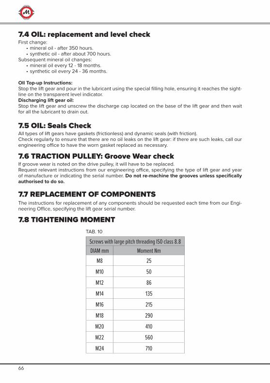
7.4 OIL: replacement and level checkFirst change:
• mineral oil - after 350 hours.• synthetic oil - after about 700 hours.
Subsequent mineral oil changes:• mineral oil every 12 - 18 months.• synthetic oil every 24 - 36 months.
OIl Top-up Instructions:Stop the lift gear and pour in the lubricant using the special filling hole, ensuring it reaches the sight-line on the transparent level indicator.Discharging lift gear oil:Stop the lift gear and unscrew the discharge cap located on the base of the lift gear and then wait for all the lubricant to drain out.
7.6 TRACTION PULLEY: Groove Wear checkIf groove wear is noted on the drive pulley, it will have to be replaced.Request relevant instructions from our engineering office, specifying the type of lift gear and year of manufacture or indicating the serial number. Do not re-machine the grooves unless specifically authorised to do so.
7.5 OIL: Seals CheckAll types of lift gears have gaskets (frictionless) and dynamic seals (with friction).Check regularly to ensure that there are no oil leaks on the lift gear: if there are such leaks, call our engineering office to have the worn gasket replaced as necessary.
7.7 REPLACEMENT OF COMPONENTSThe instructions for replacement of any components should be requested each time from our Engi-neering Office, specifying the lift gear serial number.
7.8 TIGHTENING MOMENT
Screws with large pitch threading ISO class 8.8DIAM mm Moment Nm
M8 25
M10 50
M12 86
M14 135
M16 215
M18 290
M20 410
M22 560
M24 710
TAB. 10
67www.montanarigiulio.com
GEARBOX ENGLISH
68
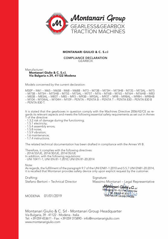
Manufacturer:Montanari Giulio & C. S.r.l.Via Bulgaria n.39, 41122 Modena
Models concerned by the current declaration:
M50P – M61 – M65 – M65B - M68 – M68B - M73 – M73B – M73H – M73HB - M73S – M73AL – M75 – M75B – M75H – M75HB – M75S – M75AL – M75T – M76 – M76B – M76S – M76H – M76HB – M83 – M83B – M83AL – M83T – M85 – M93 – M93B – M93AL – M93T – M98 – M98AL – M98H – M98HB– M104 – M104AL – M104H – M109 – PENTA – PENTA B – PENTA T – PENTA 830 – PENTA 830 B – PENTA 830 T.
It is stated that the gearboxes in question comply with the Machines Directive 2006/42/CE as re-gards its relevant aspects and meets the following essential safety requirements as set out in Annex 1 of the directive:- 1.3.2 risk of damage during the functioning;- 1.5.1 electricity;- 1.5.4 assembly errors;- 1.5.8 noise;- 1.5.9 vibration;- 1.6 maintenance;- 1.7.4 instructions.
The related technical documentation has been drafted in compliance with the Annex VII B.
Therefore, it complies with the following directives:- 2014/33/UE, 2014/30/UE, 2014/35/UEIn addition, with the following regulations:- UNI 10411-1; UNI EN 81-1:2010; UNI EN 81-20:2014
Note:As regards, the fulfillment of the paragraph 9.7 of the UNI EN81-1:2010 and 5.5.7 UNI EN81-20:2014, it is recalled that Montanari provides safety device only upon explicit request by the customer.
MONTANARI GIULIO & C. S.r.l
COMPLIANCE DECLARATIONGEARBOX
Drafting:Stefano Bertoni – Technical Director
Signature:Massimo Montanari – Legal Representative
MODENA 01/01/2019
Montanari Giulio & C. Srl - Montanari Group HeadquarterVia Bulgaria, 39 - 41122 - Modena - ItaliaTel: +39 059 453611 - Fax: +39 059 315890 - [email protected]
69www.montanarigiulio.com
GEARBOX ENGLISH
© CopyrightThis manual is propriety of Montanari Giulio &C. Srl.
These Operating Instructions must not be wholly or partly reproduced in any unauthorised way or made available to third parties without our agreement.
Technical request should be addressed to: [email protected]

MONTANARI GROUP HEADQUARTERMontanari Giulio & C. Srl
Via Bulgaria, 39 - 41122 - Modena - ItaliaTel: +39 059 453611 - Fax: +39 059 315890 - [email protected]
www.montanarigiulio.com