Embed Size (px)
Citation preview
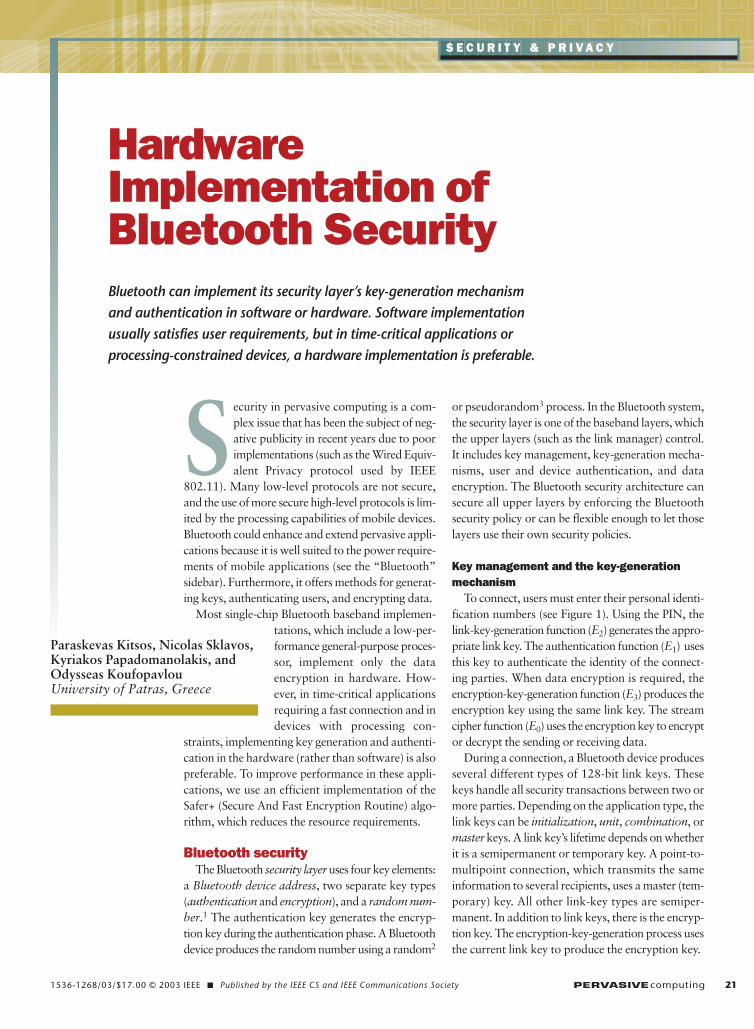
1536-1268/03/$17.00 © 2003 IEEE � Published by the IEEE CS and IEEE Communications Society PERVASIVEcomputing 21
S E C U R I T Y & P R I V A C Y
HardwareImplementation ofBluetooth Security
Security in pervasive computing is a com-plex issue that has been the subject of neg-ative publicity in recent years due to poorimplementations (such as the Wired Equiv-alent Privacy protocol used by IEEE
802.11). Many low-level protocols are not secure,and the use of more secure high-level protocols is lim-ited by the processing capabilities of mobile devices.Bluetooth could enhance and extend pervasive appli-cations because it is well suited to the power require-ments of mobile applications (see the “Bluetooth”sidebar). Furthermore, it offers methods for generat-ing keys, authenticating users, and encrypting data.
Most single-chip Bluetooth baseband implemen-tations, which include a low-per-formance general-purpose proces-sor, implement only the dataencryption in hardware. How-ever, in time-critical applicationsrequiring a fast connection and indevices with processing con-
straints, implementing key generation and authenti-cation in the hardware (rather than software) is alsopreferable. To improve performance in these appli-cations, we use an efficient implementation of theSafer+ (Secure And Fast Encryption Routine) algo-rithm, which reduces the resource requirements.
Bluetooth securityThe Bluetooth security layer uses four key elements:
a Bluetooth device address, two separate key types(authentication and encryption), and a random num-ber.1 The authentication key generates the encryp-tion key during the authentication phase. A Bluetoothdevice produces the random number using a random2
or pseudorandom3 process. In the Bluetooth system,the security layer is one of the baseband layers, whichthe upper layers (such as the link manager) control.It includes key management, key-generation mecha-nisms, user and device authentication, and dataencryption. The Bluetooth security architecture cansecure all upper layers by enforcing the Bluetoothsecurity policy or can be flexible enough to let thoselayers use their own security policies.
Key management and the key-generationmechanism
To connect, users must enter their personal identi-fication numbers (see Figure 1). Using the PIN, thelink-key-generation function (E2) generates the appro-priate link key. The authentication function (E1) usesthis key to authenticate the identity of the connect-ing parties. When data encryption is required, theencryption-key-generation function (E3) produces theencryption key using the same link key. The streamcipher function (E0) uses the encryption key to encryptor decrypt the sending or receiving data.
During a connection, a Bluetooth device producesseveral different types of 128-bit link keys. Thesekeys handle all security transactions between two ormore parties. Depending on the application type, thelink keys can be initialization, unit, combination, ormaster keys. A link key’s lifetime depends on whetherit is a semipermanent or temporary key. A point-to-multipoint connection, which transmits the sameinformation to several recipients, uses a master (tem-porary) key. All other link-key types are semiper-manent. In addition to link keys, there is the encryp-tion key. The encryption-key-generation process usesthe current link key to produce the encryption key.
Bluetooth can implement its security layer’s key-generation mechanismand authentication in software or hardware. Software implementationusually satisfies user requirements, but in time-critical applications orprocessing-constrained devices, a hardware implementation is preferable.
Paraskevas Kitsos, Nicolas Sklavos,Kyriakos Papadomanolakis, andOdysseas KoufopavlouUniversity of Patras, Greece
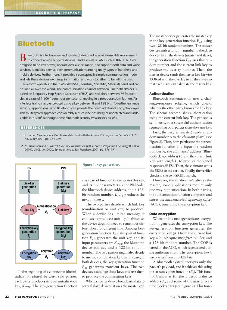
In the beginning of a connection (the ini-tialization phase) between two parties,each party produces its own initializationkey, KINIT. The key-generation function
E22 (part of function E2) generates this key,and its input parameters are the PIN code,the Bluetooth device address, and a 128-bit random number. KINIT produces thenext link keys.
The two parties decide which link key(combination or unit key) to produce.When a device has limited memory, itchooses to produce a unit key. In this case,the device does not need to remember dif-ferent keys for different links. Another key-generation function, E21 (also part of func-tion E2), generates the unit key, and itsinput parameters are KINIT, the Bluetoothdevice address, and a 128-bit randomnumber. The two parties might also decideto use the combination key. In this case, inboth devices, the key-generation functionE21 generates transient keys. The twodevices exchange these keys and use themto produce the combination keys.
When a master device broadcasts data toseveral slave devices, it uses the master key.
The master device generates the master keyin the key-generation function E22 usingtwo 128-bit random numbers. The masterdevice sends a random number to the slavedevices. In all the devices (master and slave),the generation function E22 uses this ran-dom number and the current link key toproduce the overlay number. Then, themaster device sends the master key bitwiseXORed with the overlay to all the slaves sothat each slave can calculate the master key.
AuthenticationBluetooth authentication uses a chal-
lenge–response scheme, which checkswhether the other party knows the link key.The scheme accomplishes authenticationusing the current link key. The process issymmetric, so a successful authenticationrequires that both parties share the same key.
First, the verifier (master) sends a ran-dom number A to the claimant (slave) (seeFigure 2). Then, both parties use the authen-tication function and input the randomnumber A, the claimants’ address (Blue-tooth device address B), and the current linkkey, with length L, to produce the signedresponse (SRES). Then, the claimant sendsthe SRES to the verifier. Finally, the verifierchecks if the two SRESs match.
However, the verifier isn’t always themaster; some applications require onlyone-way authentication. In both parties,the authentication function computes andstores the authenticated ciphering offset(ACO), generating the encryption key.
Data encryptionWhen the link manager activates encryp-
tion, it generates the encryption key. Thekey-generation function generates theencryption key (Kc) from the current linkkey, a 96-bit ciphering offset number, anda 128-bit random number. The COF isbased on the ACO, which is generated dur-ing authentication. The encryption key’ssize varies from 8 to 128 bits.
A Bluetooth system encrypts only thepacket’s payload, and it achieves this usingthe stream-cipher function (E0). This func-tion’s input is Kc, the Bluetooth deviceaddress A, and some of the master real-time clock’s data (see Figure 2). This func-
22 PERVASIVEcomputing http://computer.org/pervasive
S E C U R I T Y & P R I V A C Y
B luetooth is a technology and standard, designed as a wireless-cable replacement
to connect a wide range of devices. Unlike wireless LANs such as 802.11b, it was
designed to be low power, operate over a short range, and support both data and voice
services. It enables peer-to-peer communications among many types of handheld and
mobile devices. Furthermore, it provides a conceptually simple communication model
and lets these devices exchange information and work together to benefit the user.
Bluetooth operates in the 2.45-GHz ISM (Industrial, Scientific, Medical) band and can
be used all over the world. The communication channel between Bluetooth devices is
based on Frequency Hop Spread Spectrum (FHSS) and switches between 79 frequen-
cies at a rate of 1,600 frequencies per second, moving in a pseudorandom fashion. Air
interface traffic is also encrypted using a key between 8 and 128 bits. To further enhance
security, applications using Bluetooth can provide their own additional encryption layer.
This multilayered approach considerably reduces the possibility of undetected and unde-
sirable intrusion1 (although some Bluetooth security weaknesses exist2).
REFERENCES
1. R. Barber, “Security in a Mobile World–Is Bluetooth the Answer?” Computers & Security, vol. 20,no. 5, July 2001, pp. 374–379.
2. M. Jakobsson and S. Wetzel, “Security Weaknesses in Bluetooth,” Progress in Cryptology (CT-RSA2001), LNCS, vol. 2020, Springer-Verlag, San Francisco, 2001, pp. 176–191.
Bluetooth
Authentication
E1
Encryption
E0
Link-keygeneration
(E2)
Encryption-keygeneration
(E3)
Link key
Encryptionkey
PIN
Link-keygeneration
(E2)
Encryption-keygeneration
(E3)
Link key
Encryptionkey
PINFigure 1. Key generation.

tion consists of the payload key generator,the key stream generator, and the encryp-tion/decryption part.1
The payload key generator combines thestream-cipher function’s input bits in anappropriate order and leads them to thekey stream generator’s4 four linear feed-back shift registers (LFSR). The generatoruses different encryption modes depend-ing on the party link-key type. It doesn’tencrypt the broadcast traffic when using acombination or unit key. However, whenusing a master key, it can use one of threepossible encryption modes. In encryptionmode 1, the generator doesn’t encrypt any-thing. In encryption mode 2, it uses themaster key to encrypt the individuallyaddressed traffic but doesn’t encryptbroadcast traffic. In encryption mode 3, ituses the master key to encrypt all traffic.
Bluetooth implementationsCommercial chipsets are available that
implement Bluetooth. Many companies(including Cambridge Silicon Radio,Philips, Ericsson, Atmel, and Zeevo) haveintegrated the basic Bluetooth basebandfunctions in hardware. Other companies,such as Silicon Wave, Oki Semiconductor,and Intel, provide a Host Control Interfacethat can be controlled, for example, acrossa USB interface. An ARM (Advanced RiskMachines) embedded processor core, forthe appropriate firmware execution, sup-ports the Bluetooth controller’s hardwarecomponents (see Figure 3). We can imple-ment the security protocol in these hard-ware components.
For an ARM-based system to workproperly, it generally needs many RAM andROM blocks, instruction cache memory,and sophisticated control logic. On theother hand, hardware implementationslimit the silicon area and consume less ofthe chip’s power. In addition, the softwareimplementation requires multiply instruc-tions and more clock cycles to execute thepartial operation, reducing the system timeperformance.
The cryptography algorithms demandhigh processing capabilities. Implementingeither a public-key encryption or a private-key algorithm, with a typical microcon-troller instruction set, leads to large codesize and high power requirements. Thechallenge is to include appropriate hard-ware primitives that make these operationsmore efficient in all these dimensions whileletting the security algorithms evolve.5
Security hardwareimplementation
As we stated earlier, most single-chip Blue-tooth baseband implementations implement
data encryption (the stream cipher functionunit) in hardware. This removes the contin-uous load from the processor across thewireless link during data transfer. In addi-tion, implementing the key-generation
JANUARY–MARCH 2003 PERVASIVEcomputing 23
S E C U R I T Y & P R I V A C Y
Master clock data
Encryption key Kc
Device A (master) Device B (slave)
DataEncryption
(E0)
Data A–>B
Data B–>A
Data A–>B
Data B–>A
Kstream Kstream
Bluetooth deviceaddress A
Randomnumber A
Master clock data
Encryption key Kc
Bluetooth deviceaddress AEncryption
(E0)
Random number A
Link key
Device A (master) Device B (slave)
Signedresponse(SRES)
Authentication(E1)
ACOSRES' = SRES
Bluetooth deviceaddress B
Randomnumber A
Random number A
Link key
Bluetooth deviceaddress B
L L
Authentication(E1)
? ACOSRES
Figure 2. The authentication and encryption process.
ARM
Bluetoothcontroller
RAM
I/O
Bluetoothbaseband
ROM
Radiofrequencymodule
Figure 3. Bluetooth system hardwareimplementation.
mechanism and authentication in hardware(rather than software) offers faster connec-tion times and lower power consumption.
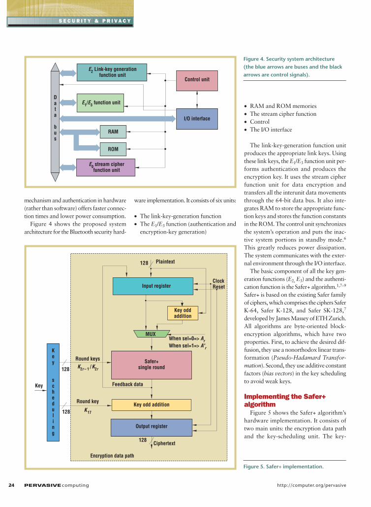
Figure 4 shows the proposed systemarchitecture for the Bluetooth security hard-
ware implementation. It consists of six units:
• The link-key-generation function• The E1/E3 function (authentication and
encryption-key generation)
• RAM and ROM memories • The stream cipher function • Control • The I/O interface
The link-key-generation function unitproduces the appropriate link keys. Usingthese link keys, the E1/E3 function unit per-forms authentication and produces theencryption key. It uses the stream cipherfunction unit for data encryption andtransfers all the interunit data movementsthrough the 64-bit data bus. It also inte-grates RAM to store the appropriate func-tion keys and stores the function constantsin the ROM. The control unit synchronizesthe system’s operation and puts the inac-tive system portions in standby mode.6
This greatly reduces power dissipation.The system communicates with the exter-nal environment through the I/O interface.
The basic component of all the key gen-eration functions (E2, E3) and the authenti-cation function is the Safer+ algorithm.1,7–9
Safer+ is based on the existing Safer familyof ciphers, which comprises the ciphers SaferK-64, Safer K-128, and Safer SK-128,7
developed by James Massey of ETH Zurich.All algorithms are byte-oriented block-encryption algorithms, which have twoproperties. First, to achieve the desired dif-fusion, they use a nonorthodox linear trans-formation (Pseudo-Hadamard Transfor-mation). Second, they use additive constantfactors (bias vectors) in the key schedulingto avoid weak keys.
Implementing the Safer+algorithm
Figure 5 shows the Safer+ algorithm’shardware implementation. It consists oftwo main units: the encryption data pathand the key-scheduling unit. The key-
24 PERVASIVEcomputing http://computer.org/pervasive
S E C U R I T Y & P R I V A C Y
E0 stream cipherfunction unit
E2 Link-key generationfunction unit
E1/E3 function unitData
bus
RAM
ROM
I/O interface
Control unit
Figure 4. Security system architecture(the blue arrows are buses and the blackarrows are control signals).
Safer+single round
Input register
Key oddaddition
Key odd addition
Plaintext
Ciphertext
When sel=0=> ArWhen sel=1=> A'r
K2r – 1 /K2r
K17
Key
scheduling
Key
ClockReset
128
128
128
128
MUX
Round keys
Round key
Feedback data
Encryption data path
Output register
Figure 5. Safer+ implementation.
scheduling unit allows on-the-fly compu-tation of the round keys. To reduce the sil-icon area, we used eight loops of a key-scheduling single-round implementation.We implemented the bias vectors using 17-by 16-byte ROM blocks.
In the proposed design, round keys areapplied in parallel in the encryption datapath. The full Safer+ algorithm executionrequires eight loops of the single round. Wechose the single-round hardware imple-mentation solution because, with this min-imum silicon area, we could achieve therequired throughput.
The encryption data path’s first compo-nent is an input register, which combinesthe plaintext and the feedback data pro-duced in the previous round. The input reg-ister feeds the Safer+ single round.
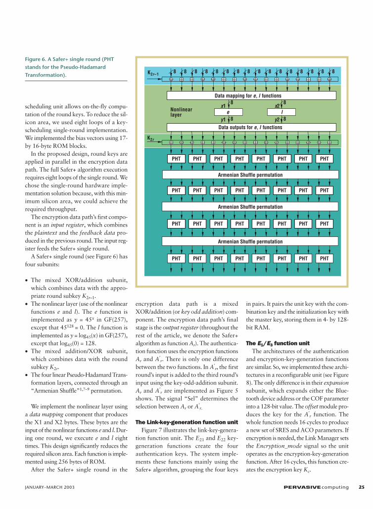
A Safer+ single round (see Figure 6) hasfour subunits:
• The mixed XOR/addition subunit,which combines data with the appro-priate round subkey K2r–1.
• The nonlinear layer (use of the nonlinearfunctions e and l). The e function isimplemented as y = 45x in GF(257),except that 45128 = 0. The l function isimplemented as y = log45(x) in GF(257),except that log45(0) = 128.
• The mixed addition/XOR subunit,which combines data with the roundsubkey K2r.
• The four linear Pseudo-Hadamard Trans-formation layers, connected through an“Armenian Shuffle”1,7–9 permutation.
We implement the nonlinear layer usinga data mapping component that producesthe X1 and X2 bytes. These bytes are theinput of the nonlinear functions e and l. Dur-ing one round, we execute e and l eighttimes. This design significantly reduces therequired silicon area. Each function is imple-mented using 256 bytes of ROM.
After the Safer+ single round in the
encryption data path is a mixedXOR/addition (or key odd addition) com-ponent. The encryption data path’s finalstage is the output register (throughout therest of the article, we denote the Safer+algorithm as function Ar). The authentica-tion function uses the encryption functionsAr and A′
r. There is only one differencebetween the two functions. In A′
r, the firstround’s input is added to the third round’sinput using the key-odd-addition subunit.Ar and A′
r are implemented as Figure 5shows. The signal “Sel” determines theselection between Ar or A′
r.
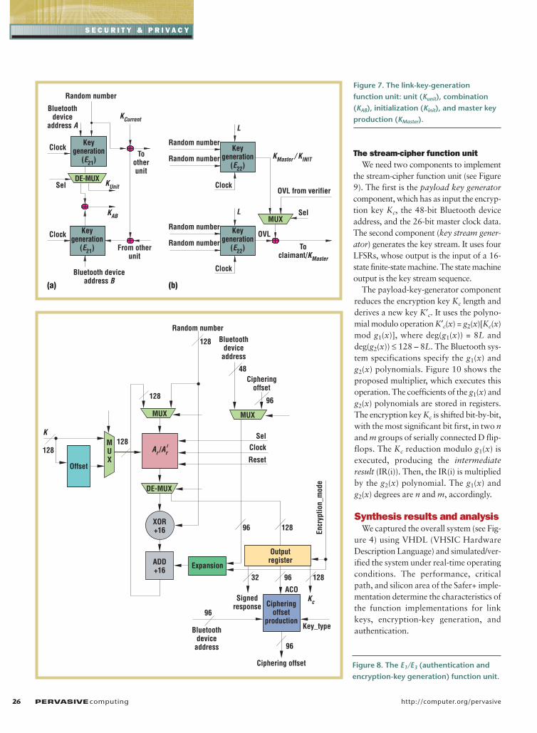
The Link-key-generation function unitFigure 7 illustrates the link-key-genera-
tion function unit. The E21 and E22 key-generation functions create the fourauthentication keys. The system imple-ments these functions mainly using theSafer+ algorithm, grouping the four keys
in pairs. It pairs the unit key with the com-bination key and the initialization key withthe master key, storing them in 4- by 128-bit RAM.
The E1/E3 function unitThe architectures of the authentication
and encryption-key-generation functionsare similar. So, we implemented these archi-tectures in a reconfigurable unit (see Figure8). The only difference is in their expansionsubunit, which expands either the Blue-tooth device address or the COF parameterinto a 128-bit value. The offset module pro-duces the key for the A′
r function. Thewhole function needs 16 cycles to producea new set of SRES and ACO parameters. Ifencryption is needed, the Link Manager setsthe Encryption_mode signal so the unitoperates as the encryption-key-generationfunction. After 16 cycles, this function cre-ates the encryption key Kc.
JANUARY–MARCH 2003 PERVASIVEcomputing 25
S E C U R I T Y & P R I V A C Y
e l
K2r–1
K2r
Armenian Shuffle permutation
Armenian Shuffle permutation
Armenian Shuffle permutation
PHT
PHT
PHT
PHT
Data mapping for e, l functions
Data outputs for e, l functions
8 8 8 8 8 8 8 8 8 8 8 8 8 8 88
8 8
8 8Nonlinearlayer
x1
y1
x2
y2
PHT
PHT
PHT
PHT
PHT
PHT
PHT
PHT
PHT
PHT
PHT
PHT
PHT
PHT
PHT
PHT
PHT
PHT
PHT
PHT
PHT
PHT
PHT
PHT
PHT
PHT
PHT
PHT
Figure 6. A Safer+ single round (PHTstands for the Pseudo-Hadamard Transformation).
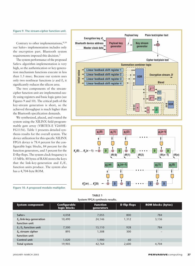
The stream-cipher function unit We need two components to implement
the stream-cipher function unit (see Figure9). The first is the payload key generatorcomponent, which has as input the encryp-tion key Kc, the 48-bit Bluetooth deviceaddress, and the 26-bit master clock data.The second component (key stream gener-ator) generates the key stream. It uses fourLFSRs, whose output is the input of a 16-state finite-state machine. The state machineoutput is the key stream sequence.
The payload-key-generator componentreduces the encryption key Kc length andderives a new key K′c. It uses the polyno-mial modulo operation K′c(x) = g2(x)[Kc(x)mod g1(x)], where deg(g1(x)) = 8L anddeg(g2(x)) ≤ 128 – 8L. The Bluetooth sys-tem specifications specify the g1(x) andg2(x) polynomials. Figure 10 shows theproposed multiplier, which executes thisoperation. The coefficients of the g1(x) andg2(x) polynomials are stored in registers.The encryption key Kc is shifted bit-by-bit,with the most significant bit first, in two nand m groups of serially connected D flip-flops. The Kc reduction modulo g1(x) isexecuted, producing the intermediateresult (IR(i)). Then, the IR(i) is multipliedby the g2(x) polynomial. The g1(x) andg2(x) degrees are n and m, accordingly.
Synthesis results and analysisWe captured the overall system (see Fig-
ure 4) using VHDL (VHSIC HardwareDescription Language) and simulated/ver-ified the system under real-time operatingconditions. The performance, criticalpath, and silicon area of the Safer+ imple-mentation determine the characteristics ofthe function implementations for linkkeys, encryption-key generation, andauthentication.
26 PERVASIVEcomputing http://computer.org/pervasive
S E C U R I T Y & P R I V A C Y
(b)(a)
KAB
Clock
KUnitSel
KCurrent
Tootherunit
From otherunit
DE-MUX
Bluetoothdevice
address A
Random number
Random number
Random numberClock
Random number
Random number
Bluetooth deviceaddress B
L
L
Clock
Clock
KMaster / KINIT
OVL
OVL from verifier
Sel
Toclaimant/KMaster
MUX
Keygeneration
(E22)
Keygeneration
(E22)
Keygeneration
(E21)
Keygeneration
(E21)
Figure 7. The link-key-generationfunction unit: unit (Kunit), combination(KAB), initialization (Kinit), and master keyproduction (KMaster).
Offset
K
128 Ar /Ar
Expansion
ACO
MUX
Clock
Reset
Encr
yptio
n_m
ode
Sel
Cipheringoffset
128
96
48
DE-MUX
Outputregister
128
1289632
Signedresponse
Kc
96
128
Cipheringoffset
production
Ciphering offset
96
96
Key_type
128
Random numberBluetooth
deviceaddress
Bluetoothdevice
address
MUXMUX
ADD+16
XOR+16
Figure 8. The E1/E3 (authentication andencryption-key generation) function unit.
Contrary to other implementations,9,10
our Safer+ implementation includes onlythe encryption part. Bluetooth systemrequirements imposed this decision.1
The system performance of the proposedSafer+ algorithm implementation is veryhigh, so the authentication or key-genera-tion mechanism functions execute in lessthan 1.5 msec. Because our system usesonly two nonlinear functions (e and l), itsignificantly reduces the silicon area.
The two components of the stream-cipher function unit are implemented eas-ily using registers and basic logic gates (seeFigures 9 and 10). The critical path of thekey-stream generation is short, so theachieved throughput is much higher thanthe Bluetooth specification demands.
We synthesized, placed, and routed thesystem using the XILINX field-program-mable gate array (VIRTEX-E V2600E-FG1156). Table 1 presents detailed syn-thesis results for the overall system. Thedevice utilization for this specific XILINXFPGA device is 78.4 percent for the con-figurable logic blocks, 84 percent for thefunction generators, and 5 percent for theD flip-flops. The system clock frequency is15 MHz. 80 bytes of RAM stores the keysthat the link-key-generation and E1/E3
function units produce. The system alsohas a 4,704-byte ROM.
JANUARY–MARCH 2003 PERVASIVEcomputing 27
Master clock data
Plain text/cipher text
Cipher text/plain text
Payload key
XOR
Linear feedback shift register 1
+/2
Z –1 T 1
T 2Z –1
XOR
Encryption stream ZtIn
itial
val
ue
Summation combiner logic
Blend
Linear feedback shift register 2
Linear feedback shift register 3
Linear feedback shift register 4
Bluetooth device address
Encryption key Kc
Payload keygenerator
Key streamgenerator
+
Figure 9. The stream-cipher function unit.
DDDD D
g1(n-1)g1(2)g1(1)g1(0)
Kc(0) ... Kc(n – 1)
DD D D
g2(1)g2(m –1)g2(m) g2(0)
Kc (m) ... Kc (0)
IR(0) IR(1) IR(2) IR(n-1) IR(n)
Figure 10. A proposed modulo multiplier.
TABLE 1 System FPGA synthesis results.
System component Configurable Function D flip-flops ROM blocks (bytes)logic blocks generators
Safer+ 4,058 7,055 800 784
E2 link-key-generation 10,490 24,146 1,312 3,136
function unitE1/E3 function unit 7,500 15,110 928 784
E0 stream cipher 895 1,508 300 –
function unitControl unit 1,020 1,900 60 –
Total system 19,905 42,764 2,600 4,704
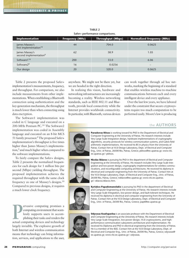
Table 2 presents the proposed Safer+implementation’s measurements, frequency,and throughput. For comparison, we alsoinclude measurements from other imple-mentations. When establishing a Bluetoothconnection using authentication and thekey-generation mechanism, the throughputis much lower than when connecting usingdata encryption.
The Software1 implementation wascoded in C language and executed on a200-MHz Pentium PC.10 The Software2implementation was coded in Assemblylanguage and executed on an 8-bit MCS51 family processor.9 The proposed Safer+implementation’s throughput is five timeshigher than James Massey’s implementa-tion,9 and much higher when compared tothe software implementations.
To fairly compare the Safer+ designs,Table 2 presents the normalized frequen-cies for each design for 1 million bits persecond (Mbps) yielding throughput. Theproposed implementation achieves therequired throughput with the same clockfrequency as one of Massey’s designs.10
Compared to previous designs, it requiresa much lower clock frequency.
P ervasive computing promises acomputing environment that seam-lessly supports users in accom-plishing their tasks and renders the
actual computing devices and technologylargely invisible. The explosive growth ofboth Internet and wireless communicationmeans that technology can bring informa-tion, services, and applications to the user,
anywhere. We might not be there yet, butwe are headed in the right direction.
In realizing this vision, hardware andnetworking infrastructures are increasinglybecoming a reality. Wireless networkingstandards, such as IEEE 802.11 and Blue-tooth, provide local connectivity while theInternet provides worldwide connectivity.In particular, with Bluetooth, various devices
can work together through ad hoc net-works, marking the beginning of a standardthat enables wireless machine-to-machinecommunications between each and everyintelligent device and every appliance.
Over the last few years, we have laboredunder the constraint that secure cryptosys-tems require too much computation to beperformed easily. Moore’s law is producing
28 PERVASIVEcomputing http://computer.org/pervasive
S E C U R I T Y & P R I V A C Y
the AUTHORS
Paraskevas Kitsos is working toward his PhD in the Department of Electrical andComputer Engineering at the University of Patras. His research interests include Very Large Scale Integration design, hardware implementations of cryptographyalgorithms, security protocols for wireless communication systems, and Galois fieldarithmetic implementations. He received his BS in physics from the University ofPatras. Contact him at VLSI Design Laboratory, Dept. of Electrical and ComputerEng., Univ. of Patras, 26500 Rio, Patras, Greece; [email protected]; www.vlsi.ee.upatras.gr/~pkitsos.
Nicolas Sklavos is pursuing his PhD in the department of Electrical and ComputerEngineering at the University of Patras. His research includes Very Large Scale Inte-gration and low-power design, cryptography implementations for wireless commu-nications, and reconfigurable computing architectures. He received his diploma inelectrical and computer engineering from the University of Patras. Contact him atthe VLSI Design Laboratory, Dept. of Electrical and Computer Eng., Univ. of Patras,26500 Rio, Patras, Greece; [email protected]; www.vlsi.ee.upatras.gr/~sklavos/sklavos.htm.
Kyriakos Papadomanolakis is pursuing his PhD in the department of Electricaland Computer Engineering at the University of Patras. His research interests includeVery Large Scale Integration, low-power design, and fault-tolerant techniques. Hereceived his diploma in electrical and computer engineering from the University ofPatras. Contact him at the VLSI Design Laboratory, Dept. of Electrical and ComputerEng., Univ. of Patras, 26500 Rio, Patras, Greece; [email protected].
Odysseas Koufopavlou is an associate professor with the Department of Electricaland Computer Engineering at the University of Patras. His research interests includeVery Large Scale Integration, low-power design, VLSI cryptosystems, and high-performance communication subsystems architecture and implementation. Hereceived his Diploma and PhD in electrical engineering from the University of Patras.He is a member of the IEEE. Contact him at the VLSI Design Laboratory, Dept. ofElectrical and Computer Eng., Univ. of Patras, 26500 Rio, Patras, Greece; [email protected]; www.vlsi.ee.upatras.gr/~odysseas.
TABLE 2Safer+ performance comparisons.
Implementation Frequency (MHz) Throughput (Mbps) Normalized frequency (MHz)
James Massey’s 44 704.0 0.0625first implementation10
James Massey’s 62 58.9 1.05second implementation9
Software110 200 33.0 6.06
Software29 16 0.0256 –
Our design 20 320.0 0.0625
JANUARY–MARCH 2003 PERVASIVEcomputing 29
general-purpose processors that can han-dle the necessary crypto functions in a neg-ligible fraction of their capacity. In recentyears, we have also been able to build cus-tom circuits that inexpensively fulfill thecrypto demands of specialized applications.However, the cost and power requirementsof high-performance general-purpose pro-cessors still make their use in mobile devicesimpractical. Therefore, at least for the fore-seeable future, hardware support for low-power microprocessors will play a signifi-cant role in the security implementationsfor Bluetooth solutions.
REFERENCES1. Specification of the Bluetooth System, vol.
1.1, 22 Feb. 2001; www.bluetooth.com/dev/specifications.asp.
2. N. Sklavos et al., “Random Number Gen-erator Architecture and VLSI Implementa-tion,” Proc. IEEE Int’l Symp. Circuits &Systems (ISCAS 02), IEEE Circuits and Sys-tems Soc. Press, Piscataway, N.J., 2002, pp.854–857.
3. M. Abramovici, M.A. Breuer, and A.D. Fried-man, Digital Systems Testing and TestableDesign, IEEE Press, Piscataway, N.J., 1990.
4. J.L. Massey and R. Rueppel, “LinearCiphers and Random Sequence Generatorswith Multiple Clocks,” Advances in Cryp-tology: Proc. Eurocrypt 84, Lecture Notesin Computer Science, vol. 209, Springer-Verlag, Berlin, 1984, pp. 74–87.
5. R. Want et al., “Disappearing Hardware,”IEEE Pervasive Computing, vol. 1, no. 1,Jan.–Mar. 2002, pp. 36–47.
6. P. Chandrakasan, S. Sheng, and R.W.Brodersen, “Low Power CMOS DigitalDesign,” IEEE J. Solid-State Circuits, vol.27, no. 4, Apr. 1992, pp. 473–484.
7. A. Schneier, Applied Cryptography, Proto-
cols, Algorithms, and Source Code in C,John Wiley & Sons, New York, 1994.
8. J.L. Massey, G.H. Khachatrian, and M.K.Kuregian, “Nomination of SAFER+ as Can-didate Algorithm for the Advance Encryp-tion Standard,” Proc. 1st Advanced Encryp-tion Standard Candidate Conf., 1998; www.ee.princeton.edu/~rblee/safer+.
9. J.L. Massey, G.H. Khachatrian, and M.K.Kuregian, “SAFER+ Cylink Corporation’sSubmission for the Advanced EncryptionStandard,” Proc. 1st Advanced EncryptionStandard Candidate Conf., 1998; http://csrc.nist.gov/CryptoToolkit/aes/round1/conf1/saferpls-slides.pdf.
10. J.L. Massey, “On the Optimality of SAFER+Diffusion,” Proc. 2nd Advanced EncryptionStandard Candidate Conf. (AES2), 1999;http://csrc.nist.gov/CryptoToolkit/aes/round1/conf2/papers/massey.pdf.
For more information on this or any other comput-ing topic, please visit our Digital Library at http://computer.org/publications/dlib.
PAPERS
CALL
FORFORIEEE PERVASIVE COMPUTINGSENSOR AND ACTUATOR NETWORKS
IEEE Pervasive Computing invites articles relating to the design of distributed systems coupled withthe physical world. Such systems face tight constraints on energy, computation, and communicationyet must last for long periods of time without human intervention.Their studyis thus central to ubiquitous/pervasive computing.We especially welcomepapers that lie at the intersection of distributed control systems, sensornetworks, and robotics and offer useful insights to one or more of thoseresearch communities.
Example topics include (but are not limited to):
• Sensor/actuator networks• Robotic sensor networks• Distributed control• Signal processing in sensor/actuator networks• New distributed sensor/actuator technologies• Applications and case studies
Submission Deadline: 7 July 2003 Submission address: [email protected]
Publication date: November 2003
Submissions should be 4,000 to 6,000 words and should follow the magazine’s guidelineson style and presentation (see http://computer.org/pervasive/author.htm). All submissions will beanonymously reviewed in accordance with normal practice for scientific publications. In addition to full-lengthsubmissions, we also invite work-in-progress submissions of 250 words or less.The deadline for those submissions is 1October 2003. Please contact Lead Editor Shani Murray ([email protected]), Editor-in-Chief M. Satyanarayanan([email protected]) , or the Guest Editors, Gaurav Sukhatme ([email protected]) and Deborah Estrin ([email protected]),for more information.