Embed Size (px)
Citation preview
Hummer’s Meritor Wabco ABS Modulator
The code 2-6 gives a shuttle valve switch failure as the cause and the fix is to replace the entire modulator assembly. Following the service manual it is not too difficult to remove the modulator: Unplug battery, Remove drivers side splash shield, 3 bolts. Remove horn bracket/disconnect horns, 2 bolts. Disconnect hard lines from modulator, 4 lines to brakes, 2 from master cylinder. Remove the modulator bracket from frame, 4 bolts. Turn and twist contraption to pull bracket/modulator out from the top. Pull the leading edge up the bracket up and out first allowed the rest to come out behind it. Remove modulator from bracket, 4 bolts.
After talking to people, it was determined that Land Rover Discovery Series IIs use an identical modulator. You will see two different mounting holes on the pump motor side, one is for Hummer and one is for land rover.
We can install a modulator from a Land Rover Disco Series Two into our trucks, these can be had used for around $100 the on the internet. These are supposedly tested but further down you will see how you can efficiently test the shuttle valve. This led me to my next conclusion, if the modulator is the same then the shuttle valve is the same.
The shuttle valves can be purchased separately from Land Rover. It’s referred to as the shuttle valve repair kit and can be ordered for any Disco from 99'-04'. The shuttle valve repair kit is under $100 from Land Rover.
Once I removed the modulator I could jump the pins on the connector to test the shuttle valve. When connecting pins 6 and 9 (IIRC its connector C1, 13 pins) on the back of the modulator with an ohm meter I was getting nothing. There should be a resisted connection between the two pins.
Page 1 of 17
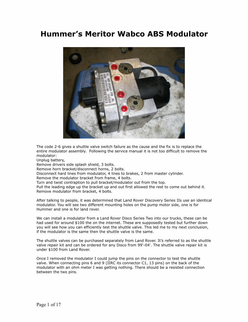
This is part of AM General’s test procedure that verifies that the shuttle valve is bad, except you can do theirs directly at the ABS ECU connector (pins 25 and 27). Okay so back on track this gave me no connection between pin 6 and 9. The shuttle valve is located on the bottom of the modulator, it’s a piece of black plastic that runs the span of the modulator and is held in with three Allen head screws.
I took the side of my ratchet/socket wrench and tapped on that box with the ohm meter hooked to the pins. There in lies my problem, I would tap it and the connection would open up allowing current to pass through, tap again and it’s gone, and so on.
Page 2 of 17
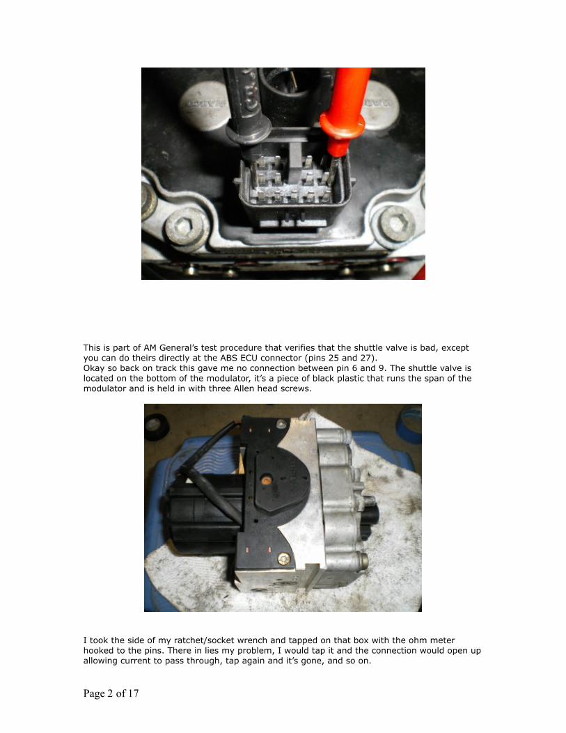
I removed the three Allen head screws that hold the shuttle valve onto the modulator and pulled the shuttle valve off, it is a press fit so it may take a slight force.
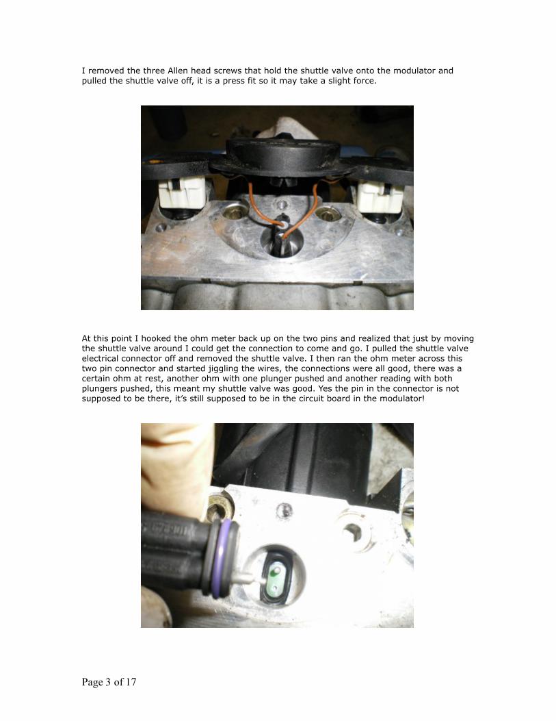
At this point I hooked the ohm meter back up on the two pins and realized that just by moving the shuttle valve around I could get the connection to come and go. I pulled the shuttle valve electrical connector off and removed the shuttle valve. I then ran the ohm meter across this two pin connector and started jiggling the wires, the connections were all good, there was a certain ohm at rest, another ohm with one plunger pushed and another reading with both plungers pushed, this meant my shuttle valve was good. Yes the pin in the connector is not supposed to be there, it’s still supposed to be in the circuit board in the modulator!
Page 3 of 17
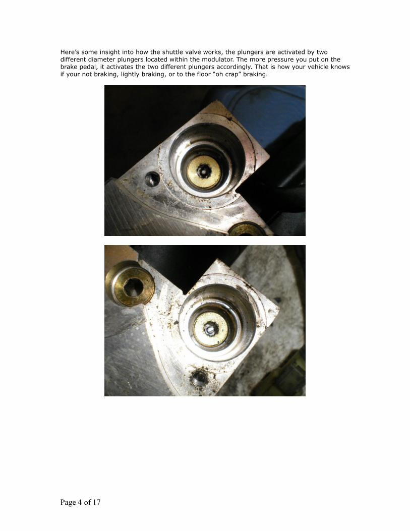
Here’s some insight into how the shuttle valve works, the plungers are activated by two different diameter plungers located within the modulator. The more pressure you put on the brake pedal, it activates the two different plungers accordingly. That is how your vehicle knows if your not braking, lightly braking, or to the floor “oh crap” braking.
Page 4 of 17
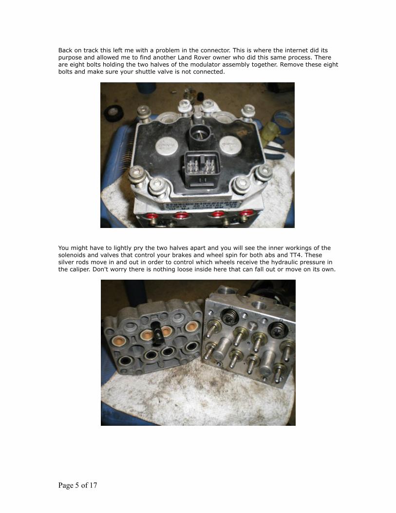
Back on track this left me with a problem in the connector. This is where the internet did its purpose and allowed me to find another Land Rover owner who did this same process. There are eight bolts holding the two halves of the modulator assembly together. Remove these eight bolts and make sure your shuttle valve is not connected.
You might have to lightly pry the two halves apart and you will see the inner workings of the solenoids and valves that control your brakes and wheel spin for both abs and TT4. These silver rods move in and out in order to control which wheels receive the hydraulic pressure in the caliper. Don't worry there is nothing loose inside here that can fall out or move on its own.
Page 5 of 17
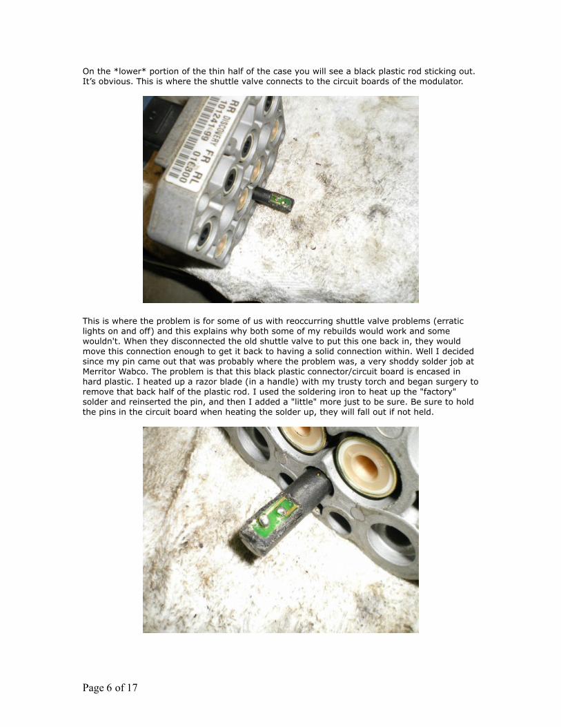
On the *lower* portion of the thin half of the case you will see a black plastic rod sticking out. It’s obvious. This is where the shuttle valve connects to the circuit boards of the modulator.
This is where the problem is for some of us with reoccurring shuttle valve problems (erratic lights on and off) and this explains why both some of my rebuilds would work and some wouldn't. When they disconnected the old shuttle valve to put this one back in, they would move this connection enough to get it back to having a solid connection within. Well I decided since my pin came out that was probably where the problem was, a very shoddy solder job at Merritor Wabco. The problem is that this black plastic connector/circuit board is encased in hard plastic. I heated up a razor blade (in a handle) with my trusty torch and began surgery to remove that back half of the plastic rod. I used the soldering iron to heat up the "factory" solder and reinserted the pin, and then I added a "little" more just to be sure. Be sure to hold the pins in the circuit board when heating the solder up, they will fall out if not held.
Page 6 of 17
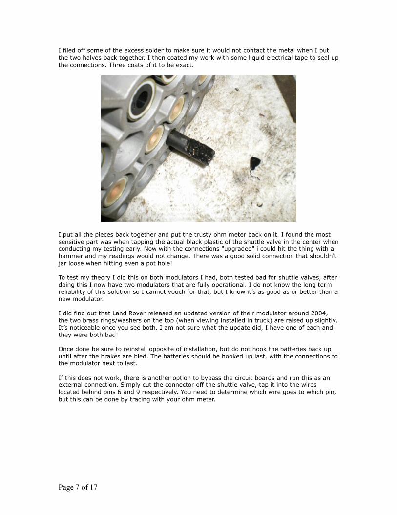
I filed off some of the excess solder to make sure it would not contact the metal when I put the two halves back together. I then coated my work with some liquid electrical tape to seal up the connections. Three coats of it to be exact.
I put all the pieces back together and put the trusty ohm meter back on it. I found the most sensitive part was when tapping the actual black plastic of the shuttle valve in the center when conducting my testing early. Now with the connections "upgraded" i could hit the thing with a hammer and my readings would not change. There was a good solid connection that shouldn't jar loose when hitting even a pot hole!
To test my theory I did this on both modulators I had, both tested bad for shuttle valves, after doing this I now have two modulators that are fully operational. I do not know the long term reliability of this solution so I cannot vouch for that, but I know it’s as good as or better than a new modulator.
I did find out that Land Rover released an updated version of their modulator around 2004, the two brass rings/washers on the top (when viewing installed in truck) are raised up slightly. It’s noticeable once you see both. I am not sure what the update did, I have one of each and they were both bad!
Once done be sure to reinstall opposite of installation, but do not hook the batteries back up until after the brakes are bled. The batteries should be hooked up last, with the connections to the modulator next to last.
If this does not work, there is another option to bypass the circuit boards and run this as an external connection. Simply cut the connector off the shuttle valve, tap it into the wires located behind pins 6 and 9 respectively. You need to determine which wire goes to which pin, but this can be done by tracing with your ohm meter.
Page 7 of 17
Finally, I have a spare broken half of a modulator sitting here. If anyone else here is like me they are asking how do these things work anyway? I saved the other half of my modulator, the one with the shuttle valve connector intact. I figure if this goes wrong again and I can't get the pins back in I will use that half to fix it!
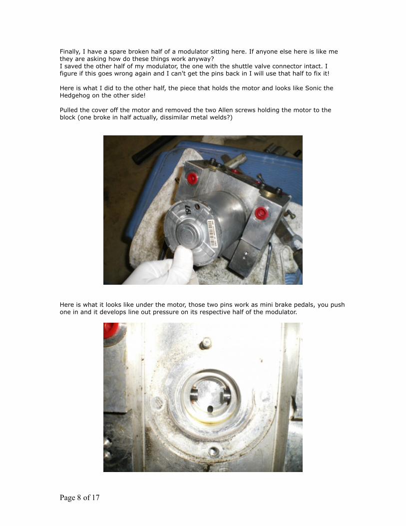
Here is what I did to the other half, the piece that holds the motor and looks like Sonic the Hedgehog on the other side!
Pulled the cover off the motor and removed the two Allen screws holding the motor to the block (one broke in half actually, dissimilar metal welds?)
Here is what it looks like under the motor, those two pins work as mini brake pedals, you push one in and it develops line out pressure on its respective half of the modulator.
Page 8 of 17
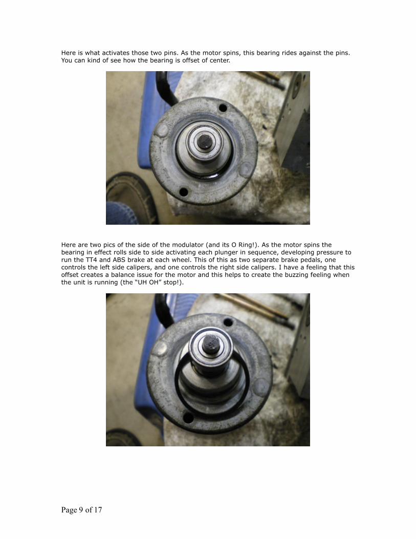
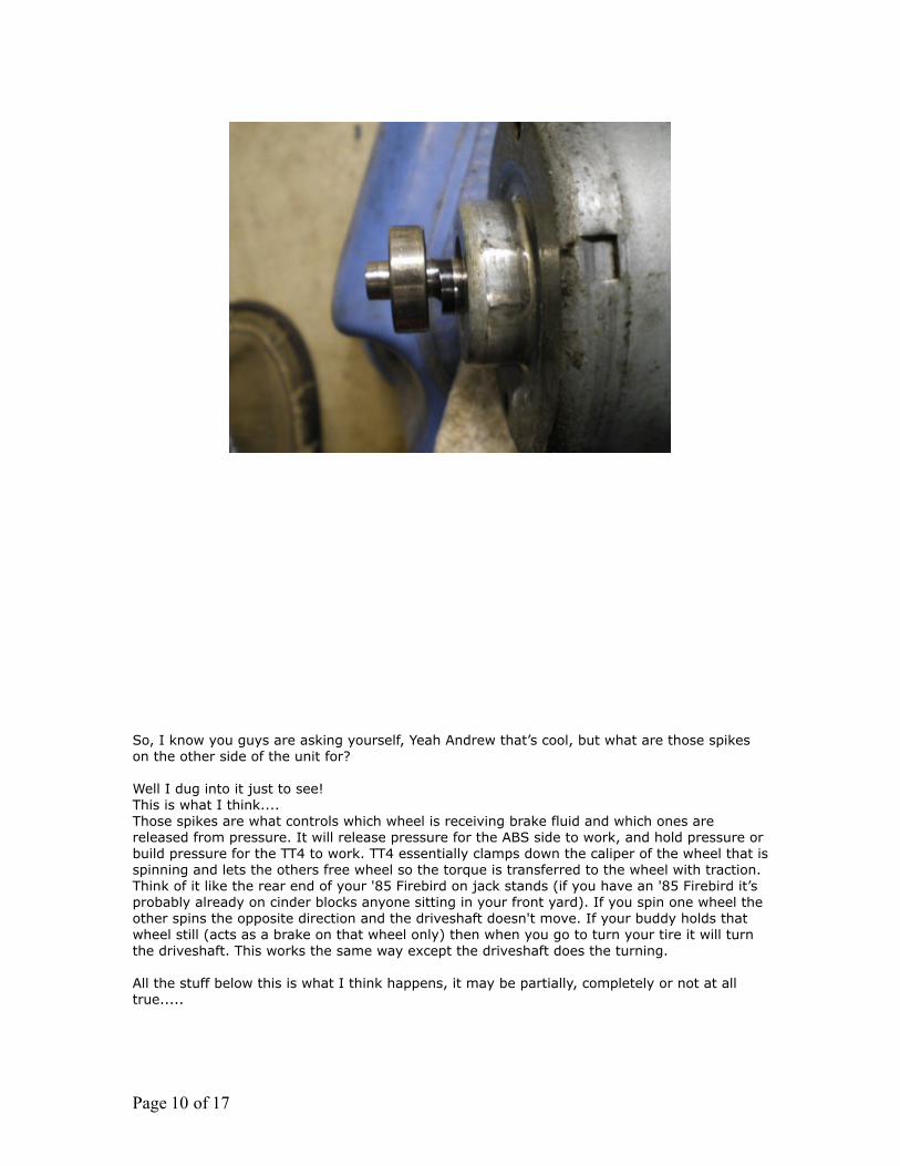
Here is what activates those two pins. As the motor spins, this bearing rides against the pins. You can kind of see how the bearing is offset of center.
Here are two pics of the side of the modulator (and its O Ring!). As the motor spins the bearing in effect rolls side to side activating each plunger in sequence, developing pressure to run the TT4 and ABS brake at each wheel. This of this as two separate brake pedals, one controls the left side calipers, and one controls the right side calipers. I have a feeling that this offset creates a balance issue for the motor and this helps to create the buzzing feeling when the unit is running (the “UH OH” stop!).
Page 9 of 17
So, I know you guys are asking yourself, Yeah Andrew that’s cool, but what are those spikes on the other side of the unit for?
Well I dug into it just to see! This is what I think.... Those spikes are what controls which wheel is receiving brake fluid and which ones are released from pressure. It will release pressure for the ABS side to work, and hold pressure or build pressure for the TT4 to work. TT4 essentially clamps down the caliper of the wheel that is spinning and lets the others free wheel so the torque is transferred to the wheel with traction. Think of it like the rear end of your '85 Firebird on jack stands (if you have an '85 Firebird it’s probably already on cinder blocks anyone sitting in your front yard). If you spin one wheel the other spins the opposite direction and the driveshaft doesn't move. If your buddy holds that wheel still (acts as a brake on that wheel only) then when you go to turn your tire it will turn the driveshaft. This works the same way except the driveshaft does the turning.
All the stuff below this is what I think happens, it may be partially, completely or not at all true.....
Page 10 of 17
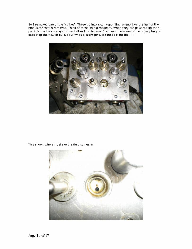
So I removed one of the "spikes". These go into a corresponding solenoid on the half of the modulator that is removed. Think of those as big magnets. When they are powered up they pull this pin back a slight bit and allow fluid to pass. I will assume some of the other pins pull back stop the flow of fluid. Four wheels, eight pins, it sounds plausible.....
This shows where I believe the fluid comes in
Page 11 of 17
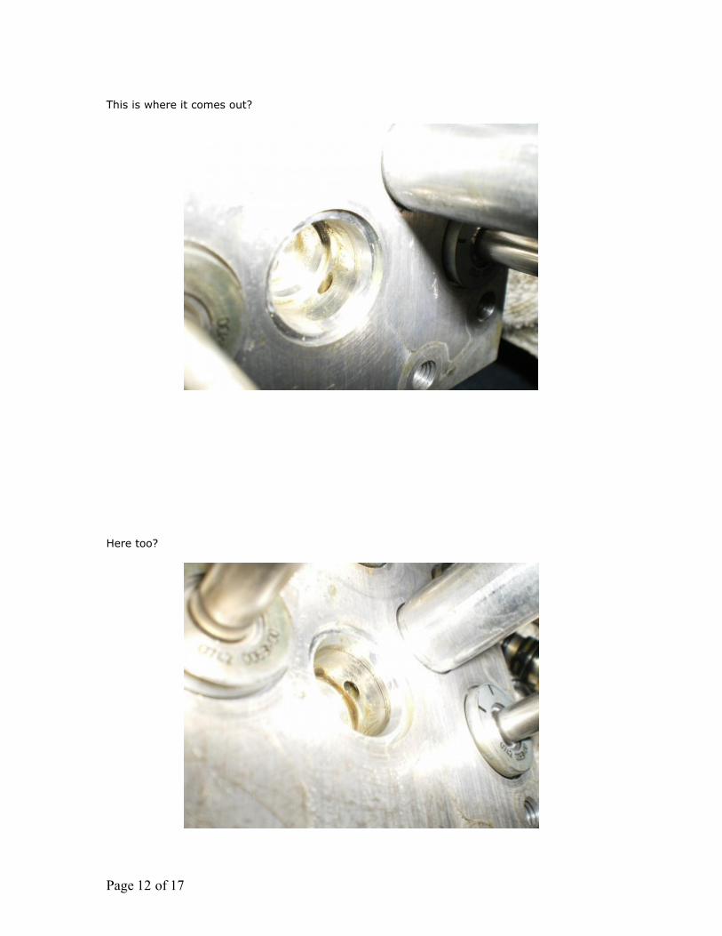
This is where it comes out?
Here too?
Page 12 of 17
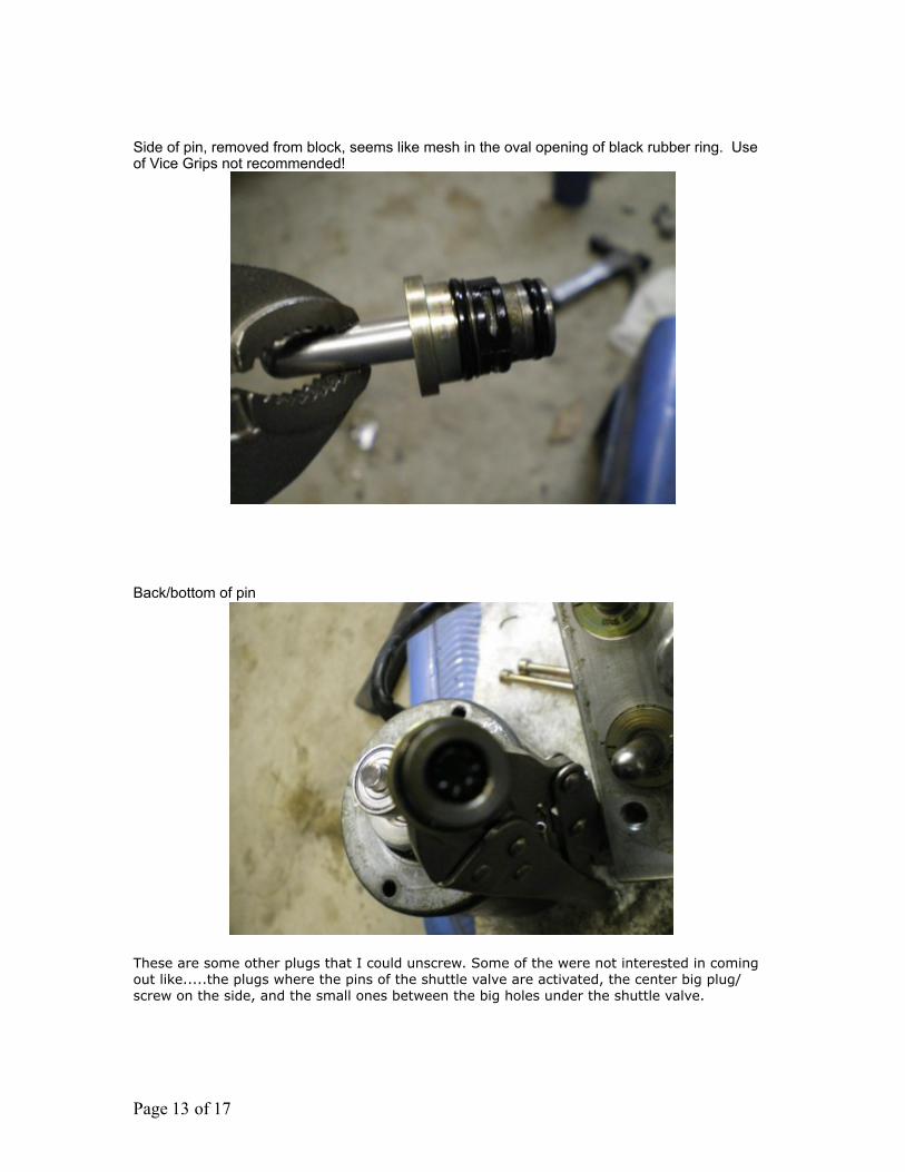
Side of pin, removed from block, seems like mesh in the oval opening of black rubber ring. Use of Vice Grips not recommended!
Back/bottom of pin
These are some other plugs that I could unscrew. Some of the were not interested in coming out like.....the plugs where the pins of the shuttle valve are activated, the center big plug/screw on the side, and the small ones between the big holes under the shuttle valve.
Page 13 of 17
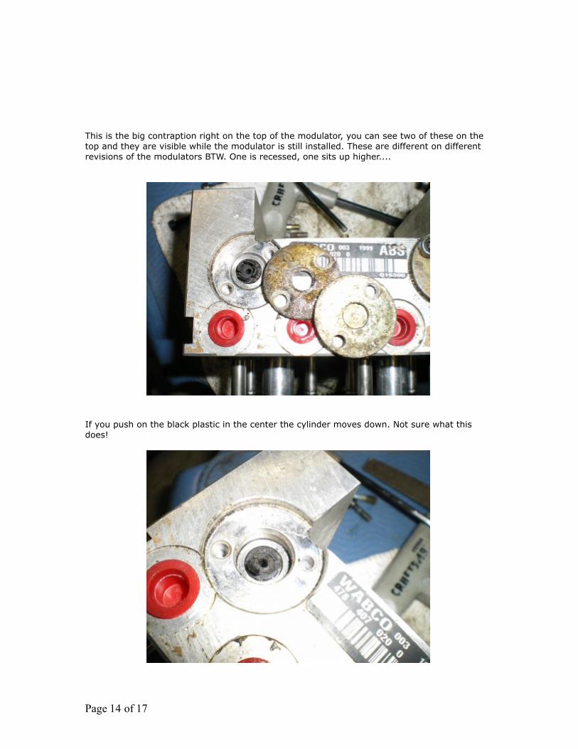
This is the big contraption right on the top of the modulator, you can see two of these on the top and they are visible while the modulator is still installed. These are different on different revisions of the modulators BTW. One is recessed, one sits up higher....
If you push on the black plastic in the center the cylinder moves down. Not sure what this does!
Page 14 of 17
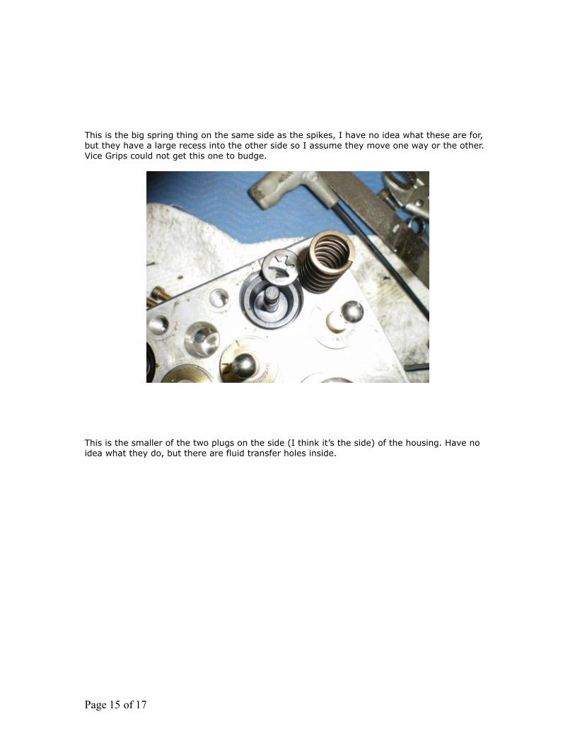
This is the big spring thing on the same side as the spikes, I have no idea what these are for, but they have a large recess into the other side so I assume they move one way or the other. Vice Grips could not get this one to budge.
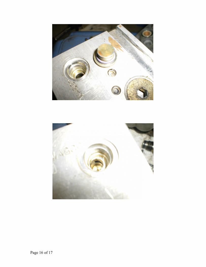
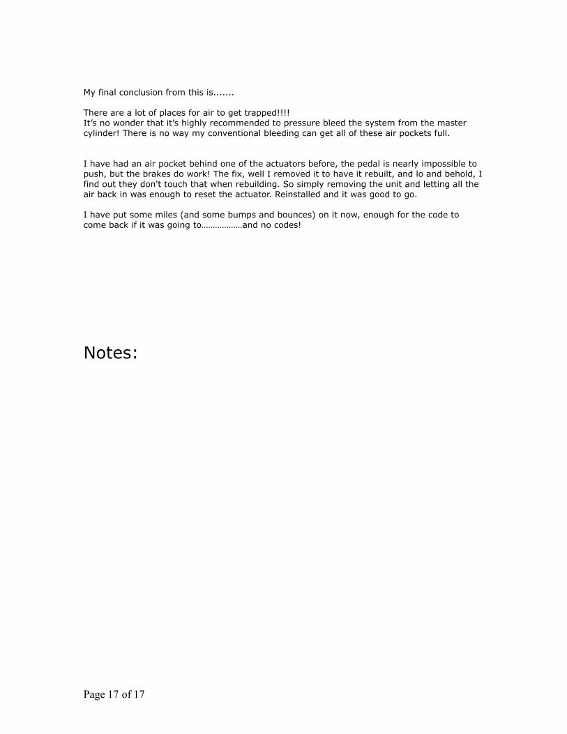
This is the smaller of the two plugs on the side (I think it’s the side) of the housing. Have no idea what they do, but there are fluid transfer holes inside.
Page 15 of 17
Page 16 of 17
My final conclusion from this is.......
There are a lot of places for air to get trapped!!!! It’s no wonder that it’s highly recommended to pressure bleed the system from the master cylinder! There is no way my conventional bleeding can get all of these air pockets full.
I have had an air pocket behind one of the actuators before, the pedal is nearly impossible to push, but the brakes do work! The fix, well I removed it to have it rebuilt, and lo and behold, I find out they don't touch that when rebuilding. So simply removing the unit and letting all the air back in was enough to reset the actuator. Reinstalled and it was good to go.
I have put some miles (and some bumps and bounces) on it now, enough for the code to come back if it was going to………………and no codes!
Notes:
Page 17 of 17