Embed Size (px)
Citation preview

ICRM-‐915-‐SER User’s Guide
V2.0 -‐May 2015 www.aarcomm.com 1/12
ICRM-‐915-‐SER User’s Guide Introduction The ICRM-‐915-‐SER is a high performance serial wireless modem designed to provide reliable long-‐range communications for SCADA systems. It is supplied in a compact DIN rail mountable enclosure and operates in the license-‐free ISM band (902-‐928MHz) using frequency hopping spread spectrum. With adjustable data rates of up to 200 kbps, the modem supports a variety of industrial protocols such as Modbus RTU/ASCII and Allen-‐Bradley DF1 through the RS-‐232 and RS-‐422/485 interfaces. The radio can be quickly configured using a graphical wizard via the USB port. A MicroSD card slot is available to save or load configuration settings.
Features -‐ 902 to 928 MHz FHSS -‐ 1W RF output -‐ Dry contact relay to indicate a valid radio link -‐ RSSI voltage output for setup and troubleshooting -‐ Adjustable data rate up to 200 kbps -‐ MicroSD card slot for saving or loading configuration settings -‐ DIN rail mountable -‐ Remote slave configuration -‐ Password protection -‐ Reverse battery protection -‐ compatible with Windows, Mac, Linux -‐ CSA/UL Approved Class 1 Div 2
ICRM-‐915-‐SER User’s Guide
V2.0 -‐May 2015 www.aarcomm.com 2/12
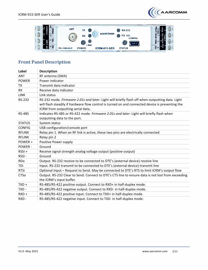
Front Panel Description
Label Description ANT RF antenna (SMA) POWER Power indicator TX Transmit data indicator RX Receive data indicator LINK Link status RS-‐232 RS-‐232 mode. Firmware 2.01s and later: Light will briefly flash off when outputting data. Light
will flash steadily if hardware flow control is turned on and connected device is preventing the ICRM from outputting serial data.
RS-‐485 Indicates RS-‐485 or RS-‐422 mode. Firmware 2.01s and later: Light will briefly flash when outputting data to the port.
STATUS System status CONFIG USB configuration/console port RFLINK Relay pin 1. When an RF link is active, these two pins are electrically connected RFLINK Relay pin 2 POWER + Positive Power supply POWER -‐ Ground RSSI + Receive signal strength analog voltage output (positive output) RSSI -‐ Ground RDo Output. RS-‐232 receive to be connected to DTE’s (external device) receive line TDi Input. RS-‐232 transmit to be connected to DTE’s (external device) transmit line RTSi Optional Input – Request to Send. May be connected to DTE’s RTS to limit ICRM’s output flow CTSo Output. RS-‐232 Clear to Send. Connect to DTE’s CTS line to ensure data is not lost from exceeding
the ICRM’s input buffer. TXD + RS-‐485/RS-‐422 positive output. Connect to RXD+ in half-‐duplex mode. TXD -‐ RS-‐485/RS-‐422 negative output. Connect to RXD-‐ in half-‐duplex mode. RXD + RS-‐485/RS-‐422 positive input. Connect to TXD+ in half-‐duplex mode. RXD -‐ RS-‐485/RS-‐422 negative input. Connect to TXD-‐ in half-‐duplex mode.
ICRM-‐915-‐SER User’s Guide
V2.0 -‐May 2015 www.aarcomm.com 3/12
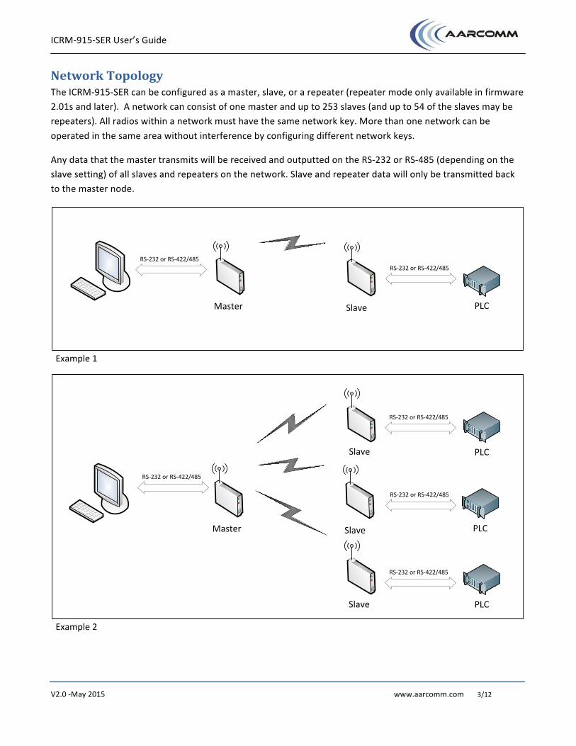
Network Topology The ICRM-‐915-‐SER can be configured as a master, slave, or a repeater (repeater mode only available in firmware 2.01s and later). A network can consist of one master and up to 253 slaves (and up to 54 of the slaves may be repeaters). All radios within a network must have the same network key. More than one network can be operated in the same area without interference by configuring different network keys.
Any data that the master transmits will be received and outputted on the RS-‐232 or RS-‐485 (depending on the slave setting) of all slaves and repeaters on the network. Slave and repeater data will only be transmitted back to the master node.
Master Slave
Example 1
PLC
RS-‐232 or RS-‐422/485
Master Slave
Example 2
PLC
PLC
PLC
Slave
Slave
RS-‐232 or RS-‐422/485
RS-‐232 or RS-‐422/485
RS-‐232 or RS-‐422/485
RS-‐232 or RS-‐422/485
RS-‐232 or RS-‐422/485

ICRM-‐915-‐SER User’s Guide
V2.0 -‐May 2015 www.aarcomm.com 4/12
Repeater Mode With firmware version 2.01s and later, radios may be configured as a special type of slave called a repeater. Slaves and repeaters may be linked to a master or a repeater (called their “upstream node”). A repeater will act like a slave (allowing it to be directly connected to a PLC) in addition to retransmitting any packets that it hears from its upstream node to slaves/repeaters that are linked to it, and retransmitting any communication from its slaves/repeaters back to its upstream node.
Master
Example 3
Slave
RS-‐232 or RS-‐422/485
PLC
Repeater
RS-‐232 or RS-‐422/485
PLCRS-‐232 or RS-‐422/485
PLC
Repeater
RS-‐232 or RS-‐422/485
PLC
Slave
RS-‐232 or RS-‐422/485
Repeaters must have a node number from 200 to 254. If a slave or repeater is connecting to a repeater, it is recommended that the upstream node number be set to avoid linking to a non-‐optimal radio.
Note: To use a radio in repeater mode, the master node of the network and any slaves linking to the repeater node must also have firmware 2.01s or later.
ICRM-‐915-‐SER User’s Guide
V2.0 -‐May 2015 www.aarcomm.com 5/12
General Operation Software and drivers for the ICRM are available at http://www.aarcomm.com/products/icrm-‐915/
1. Determine the appropriate interface for the connection to your equipment (RS-‐232 or RS-‐485) 2. Connect the interface wiring to your equipment or network 3. Connect the power wires:
a. “Power -‐“ to Ground b. “Power +” to 12V-‐24V
4. The “POWER” LED will briefly turn on red, and then should turn green. Do not connect USB cable yet. 5. Install the ICRM Windows USB drivers (ICRM_driver_32bit.exe or ICRM_driver_64bit.exe). Administrator
access will likely be necessary – Right click the application and select “Run as Administrator”. 6. Connect to the CONFIG USB port of the ICRM. The STATUS LED should turn on green to indicate a USB
connection. This may take a minute as the computer initializes the driver. 7. Run the ICRM Configuration wizard, “ICRM Config.exe” to configure the radio.
a. Select a unique node number for the radio (see Local Node in Configuration section for restrictions on node number).
b. Determine a network key to use for all the radios in your network c. Select the Mode (Master, Slave, or Repeater). There must only be one Master in the network. d. Select a Data Rate for the radio. This is the over-‐the-‐air data rate that all radios will
communicate with each other. All radios must have the same data rate in order to communicate. `
e. Select the Interface (RS-‐232 or RS-‐485). For RS-‐422, select RS-‐485. f. Select the appropriate Protocol. See configuration wizard help for descriptions of the different
protocol options g. Recommended: Set the upstream node number to specify the node for a slave or repeater to
link to. 8. Save settings and send to ICRM 9. If the unit is a master, the “LINK” LED will turn green. If the unit is a slave or repeater and no master is
within range, the link LED will be red 10. One interface LED – either the RS-‐232 or RS-‐485 – will turn on green
Notes: − At least two ICRM-‐915 radios (one master and one slave) must be configured and powered up to
achieve a link − One radio in a network must be configured as a master and all others as slaves/repeaters − Two master radios cannot communicate to each other − When a slave is properly configured, powered up, and within range of a matching master or repeater,
the “LINK” LED should be green indicating that the radios are now communicating
ICRM-‐915-‐SER User’s Guide
V2.0 -‐May 2015 www.aarcomm.com 6/12
Configuration The Aarcomm ICRM radio has a number of user configurable parameters that can be saved and read in from a configuration file on a MicroSD card inserted into the unit, or the onboard flash memory.
ICRM Configuration Wizard The ICRM Configuration Wizard application provides an easy method to configure the settings of the ICRM. It also allows you to save and open configuration files that can be stored on the SD Card. It is designed to work in Windows and requires the Aarcomm ICRM USB Serial driver. For other operating systems, please refer to the Advanced Configuration section for information on how to use the USB console.
MicroSD Card Configuration If a MicroSD card is inserted into the ICRM unit prior to start-‐up and no password is set, the ICRM will automatically load any configuration parameters included in the “icrm.cfg” file when it boots. If a password is set on the radio, the user must use the ICRM Configuration Wizard or the advanced USB interface to select “Load configuration parameters from SD card” and then “Save settings” after entering the correct password.
The ICRM configuration file is a text file consisting of individual lines, each with a parameter name followed by an equals sign “=”, followed by the desired value. For example:
nodeid = 2 key = 10.11 interface = RS232
The last line of the configuration file must be blank. Please see “Summary of user configurable settings” for a list of all user configurable parameters.
Advanced USB Interface The Aarcomm ICRM radio also provides a text console which is accessible via a USB virtual COM port. This console allows the user to set and save settings to onboard flash memory and an SD card (if present). Power up the ICRM unit BEFORE connecting it to a computer using the Mini USB port on the front of the ICRM. For Windows, refer to the driver section for instructions on how to install the Aarcomm ICRM USB driver.
When the USB is plugged in, the status light should turn green indicating that the console is connected. The first time connecting to the device the light may stay off for a minute as Windows initializes the drivers. A red power light indicates that the serial console is not connected and that the ICRM was incorrectly powered up after the USB port was connected. Disconnect the USB and restart the ICRM to fix this problem.
Connect to the COM port using a serial terminal program of your choice such as HyperTerminal , RealTerm, PuTTY, or Tera Term. Mac or Linux users can use GNU screen.
Press the <ENTER> key to display the main menu.
ICRM-‐915-‐SER User’s Guide
V2.0 -‐May 2015 www.aarcomm.com 7/12
Advanced USB Interface Commands <ENTER> Submit entered characters, or if no characters have been typed – display current
menu again. <ESC> If any characters have been entered, erase them. Otherwise takes the user back a
menu. At the main menu it will re-‐display the main menu. 1 – 7 Select a menu option
After making changes to the settings, you must choose “5. Save and apply settings” to apply any changes made to the ICRM. Select “6. Revert local changes” to discard any changes and revert back to the previous settings. The radio link will be briefly broken as the unit reconfigures the settings.
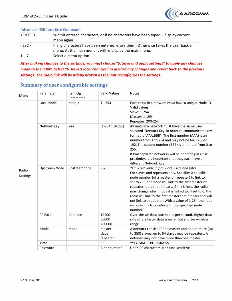
Summary of user configurable settings
Menu Parameter icrm.cfg Parameter
Valid Values Notes
Radio Settings
Local Node nodeid 1 -‐ 254 Each radio in a network must have a unique Node ID. Valid values: Slave: 1-‐254 Master: 1-‐199 Repeater: 200-‐254
Network Key key [1-‐254].[0-‐255] All units in a network must have the same user selected 'Network Key' in order to communicate. Key format is "AAA.BBB". The first number (AAA) is an number from 1 to 254 and may not be 64, 128, or 192. The second number (BBB) is a number from 0 to 255. If two separate networks will be operating in close proximity, it is important that they each have a different Network Key.
Upstream Node upstreamnode 0-‐255 *Only available in firmware 2.01s and later For slaves and repeaters only. Specifies a specific node number (of a master or repeater) to link to. If set to 255, the node will link to the first master or repeater radio that it hears. If link is lost, the radio may change which node it is linked to. If set to 0, the radio will link to the first master that it hears and will not link to a repeater. With a value of 1-‐254 the node will only link to a radio with the specified node number.
RF Rate datarate 19200 50000 200000
Over-‐the-‐air data rate in bits per second. Higher data rate offers faster data transfer but shorter wireless range.
Mode mode master slave repeater
A network consist of one master and one or more (up to 253) slaves, up to 54 slaves may be repeaters. A network may not have more than one master.
Time 0-‐9 YYYY-‐MM-‐DD:HH:MM:SS Password Alphanumeric Up to 20 characters. Not case sensitive
ICRM-‐915-‐SER User’s Guide
V2.0 -‐May 2015 www.aarcomm.com 8/12
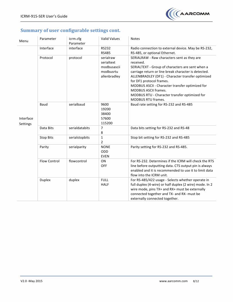
Summary of user configurable settings cont.
Menu Parameter icrm.cfg Parameter
Valid Values Notes
Interface Settings
Interface interface RS232 RS485
Radio connection to external device. May be RS-‐232, RS-‐485, or optional Ethernet.
Protocol protocol serialraw serialtext modbusascii modbusrtu allenbradley
SERIALRAW -‐ Raw characters sent as they are received. SERIALTEXT -‐ Group of characters are sent when a carriage return or line break character is detected. ALLENBRADLEY (DF1) -‐ Character transfer optimized for DF1 protocol frames. MODBUS ASCII -‐ Character transfer optimized for MODBUS ASCII frames. MODBUS RTU -‐ Character transfer optimized for MODBUS RTU frames.
Baud serialbaud 9600 19200 38400 57600 115200
Baud rate setting for RS-‐232 and RS-‐485
Data Bits serialdatabits 7 8
Data bits setting for RS-‐232 and RS-‐48
Stop Bits serialstopbits 1 2
Stop bit setting for RS-‐232 and RS-‐485
Parity serialparity NONE ODD EVEN
Parity setting for RS-‐232 and RS-‐485.
Flow Control flowcontrol ON OFF
For RS-‐232. Determines if the ICRM will check the RTS line before outputting data. CTS output pin is always enabled and it is recommended to use it to limit data flow into the ICRM unit.
Duplex duplex FULL HALF
For RS-‐485/422 usage -‐ Selects whether operate in full duplex (4-‐wire) or half duplex (2 wire) mode. In 2 wire mode, pins TX+ and RX+ must be externally connected together and TX-‐ and RX-‐ must be externally connected together.

ICRM-‐915-‐SER User’s Guide
V2.0 -‐May 2015 www.aarcomm.com 9/12
Summary of user configurable settings cont.
Menu Parameter icrm.cfg Parameter
Valid Values Notes
Advanced Settings
Sequence wait time
sequencewait 0-‐255 Specifies how many hops a node will wait for out-‐of-‐order packets.
Link Timeout linktimeout varies *Only available in firmware 2.01s and later Slave and Repeater only. Time in milliseconds that the radio will maintain link without receiving any packets. After the time expires without any incoming packets, the link indicator LED will turn red and the radio will search for a new link. 1007-‐30210 (datarate = 19200) 463-‐28340 (datarate = 50000) 141-‐30033 (datarate = 200000)
Smart Repeat smartrepeat ON OFF
Optimizes a radio's repeat packet sending. If Smart Repeat is enabled, the radio will stop sending repeat packets if it receives acknowledgement that the packet was received by another radio. Recommended setting: OFF for master, ON for slave
Maximum packet repeat
maxrepeat 0 -‐ 40 Specifies the maximum additional number of times a packet will be sent. A setting 0 will always send each packet only once. If Smart Repeat is disabled, the radio will always transmit the maximum number of repeats.
Repeat Delay repeatdelay 0 -‐ 255 If Smart Repeat is disabled, Repeat Delay specifies the maximum number of hops a radio will wait before resending a packet. Not used when Smart Repeat is on.
Repeater Smart Repeat
altsmartrepeat ON OFF
*Only available in firmware 2.01s and later For a repeater’s secondary/downstream transmitting. Optimizes a radio's repeat packet sending. If Smart Repeat is enabled, the radio will stop sending repeat packets if it receives acknowledgement that the packet was received by another radio. Recommended setting: OFF
Maximum packet repeat
altmaxrepeat 0 -‐ 40 *Only available in firmware 2.01s and later For a repeater’s secondary/downstream transmitting. Specifies the maximum additional number of times a packet will be sent. A setting 0 will always send each packet only once. If Smart Repeat is disabled, the radio will always transmit the maximum number of repeats.
Repeat Delay altrepeatdelay 0 -‐ 255 *Only available in firmware 2.01s and later For a repeater’s secondary/downstream transmitting. If Smart Repeat is disabled, Repeat Delay specifies the maximum number of hops a radio will wait before resending a packet. Not used when Smart Repeat is on.

ICRM-‐915-‐SER User’s Guide
V2.0 -‐May 2015 www.aarcomm.com 10/12
Log in to Remote Node It is possible to remotely log in to a node to configure it if it is not convenient to connect through USB or MicroSD Card. Remote login currently can only be done through the Advanced USB interface. To configure a slave or repeater, the controlling node must be the master and must be connected through USB. Slaves and repeaters cannot configure other slaves, but they can configure the master radio of their network. One can verify that they are logged in to a remote node by noting that the command prompt will read “NODE000>” (where 000 is the number of the remote node) instead of the usual “localnode>”.
To initiate a remote login, you will need to connect to the ICRM USB console on the master and choose #7 from the main menu.
Remote configuration mode will automatically time out after 2 minutes of inactivity.
A unit will not respond to a direct USB connection while it is being remotely controlled.
Password Protection A password can be set in order to prevent changes to the configuration. If a password is set, the ICRM will not read the MicroSD card on start-‐up.
If a password is set on the radio, the user must use the ICRM Configuration Wizard or the advanced USB interface to select “Load configuration parameters from SD card” and then “Save settings” after entering the correct password.
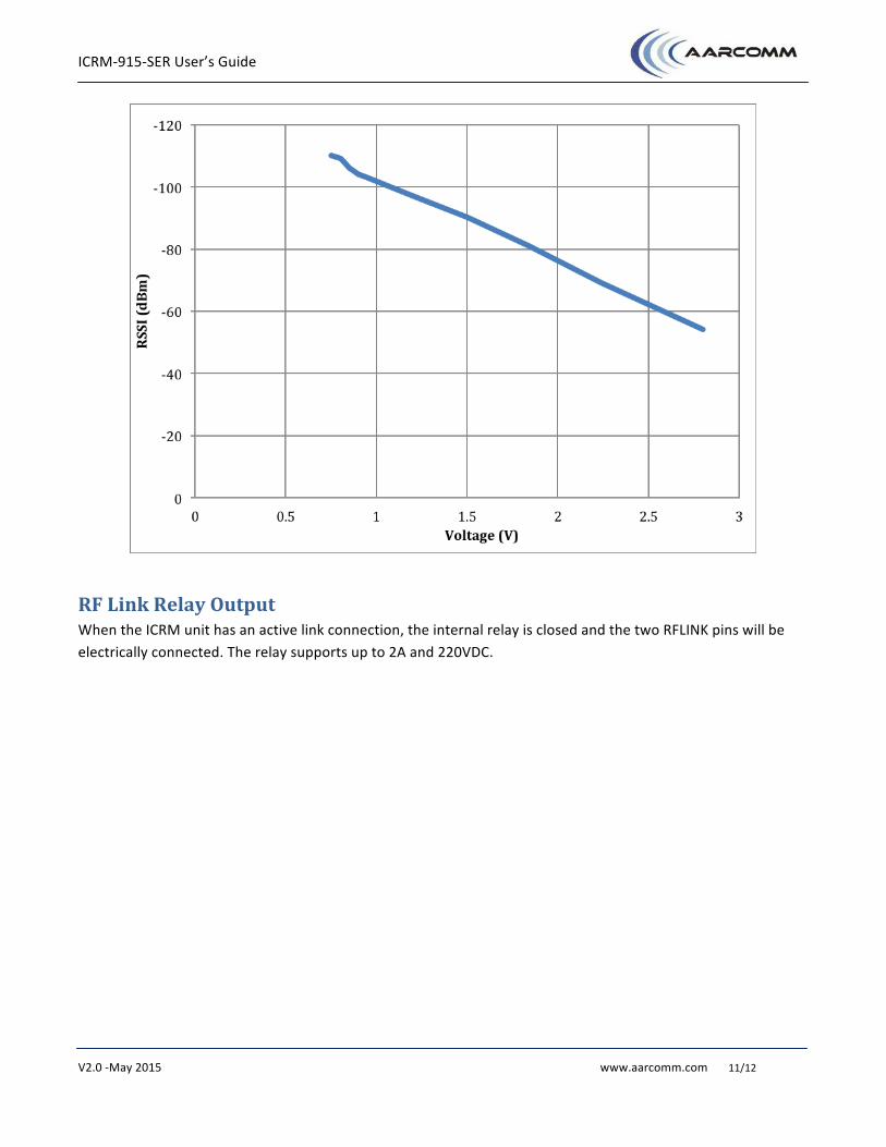
RSSI Output The analogue RSSI output is available for system setup and troubleshooting. This can be used to determine the signal strength of the link. Use a voltage meter to measure the voltage on across the two RSSI pins. The chart below to shows the typical values at room temperature (25C).
ICRM-‐915-‐SER User’s Guide
V2.0 -‐May 2015 www.aarcomm.com 11/12
RF Link Relay Output When the ICRM unit has an active link connection, the internal relay is closed and the two RFLINK pins will be electrically connected. The relay supports up to 2A and 220VDC.
ICRM-‐915-‐SER User’s Guide
V2.0 -‐May 2015 www.aarcomm.com 12/12
Troubleshooting Q: On start-‐up, the power LED stays red A: The most likely cause is that the unit had a USB cable plugged in during boot-‐up and has gone into firmware upgrade mode. Disconnect the USB cable and power cycle the unit. If the power LED still stays red, the unit may be damaged and the manufacturer should be contacted for further information.
Another possible cause is that the power has been applied to the incorrect port. Verify that the power connector is the back, black connector on the side of the radio closest to the antenna connector.
Q: The “LINK” light is staying red after start-‐up A: If the unit is a slave, there is not a compatible master node within range. Check settings to ensure the master node and slave node both have the same hopping mode, class, network key. Verify that the slave’s “Upstream Node” setting is appropriate for the node it is linking to (either set to the node number of the upstream node, 0 for any master, or 255 for any master or repeater that it can hear).
Q: The ICRM is not reading the configuration file from the SD Card A: This can occur in several different situations:
− The ICRM only reads the SD Card configuration once during start-‐up. If the card is inserted after the ICRM has already started, the configuration file will not be read. Either turn off the power to the ICRM and turn it back on again with the SD card already inserted, or manually load the configuration through the USB interface.
− If a password is set on the device, the configuration file will not be read on startup. To manually load the configuration file, connect to the ICRM’s USB port and use the ICRM Config application to load the SD card (File > Get config from SD card in ICRM)
− The configuration file may not be properly named. The ICRM radio will only read a configuration file named “icrm.cfg”. In Windows, make sure “hide extensions of known file types” is not enabled under folder options.
Q: Driver installation fails with an error message “The requested operation requires elevation”. A: Windows requires administrator rights in order to install drivers. This can be accomplished by right clicking on the file and choosing “Run as administrator”.


![ICRM Care Staff Train 24-28 July 2011 [Compatibility Mode]](https://img.pdfslide.net/doc/110x75/577d26f61a28ab4e1ea2a8db/icrm-care-staff-train-24-28-july-2011-compatibility-mode.jpg)