Embed Size (px)
Citation preview
R. C. Thool Prof., Department of Information
Technology Engg., SGGSIE&T, Nanded
Nanded,(MS) India-431606 [email protected]
Abstract - Crop farming in India is labour intensive and obsolete. Farming is still dependent on techniques which were evolved hundreds of years ago and doesn't take care of conservation of resources. The newer scenario of decreasing water tables, drying up of rivers and tanks, unpredictable environment present an urgent need of proper utilization of water. We have the technology to bridge the gap between water usage and water wastage. Technology used in some developed countries is too expensive and complicated for a common farmer to understand. Our project is to give cheap, reliable, cost efficient and easy to use technology which would help in conservation of resources such as water and also in automatizing farms. We proposed use of temperature and moisture sensor at suitable locations for monitoring of crops. The sensing system is based on a feedback control mechanism with a centralized control unit which regulates the flow of water on to the field in the real time based on the instantaneous temperature and moisture values. The sensor data would be collected in a central processing unit which would take further action. Thus by providing right amount of water we would increase the efficiency of the farm. The farmer can also look at the sensory data and decide course of action himself. We have made the interface of our project keeping in view the educational and financial background of average Indian farmer. In this paper we are proposed a low cost and efficient wireless sensor network technique to acquire the soil moisture and temperature from various locations of farm and as per the need of crop controller take the decision to make irrigation ON or OFF. Keywords: Soil moisture sensor, temperature sensor, wireless sensor network, Microcontroller
I. INTRODUCTION Irrigation is one of the fundamental problems of agriculture in developing countries. In a country like India, where the economy is mainly based on agriculture and the climatic conditions are isotropic, still we are not able to make full use of agricultural resources. The main reason is the lack of rains and
scarcity of land reservoir water. The continuous extraction of water from earth is reducing the water level due to which lot of land is coming slowly in the zones of un-irrigated land. Another very important reason of this is due to unplanned use of water due to which a significant amount of water goes waste. In the modern drip irrigation systems, the most significant advantage is that water is supplied near the root zone of the plants drip by drip due to which a large quantity of water is saved. At the present era, the farmers have been using irrigation technique in India through the manual control in which the farmers irrigate the land at the regular intervals. This process sometimes consumes more water or sometimes the water reaches late due to which the crops get dried. Water deficiency can be detrimental to plants before visible wilting occurs. Slowed growth rate, lighter weight fruit follows slight water deficiency. This problem can be perfectly rectified if we use automatic drip irrigation system in which the irrigation will take place only when there will be intense requirement of water. Irrigation system uses solenoid valves to turn irrigation ON and OFF. These valves easily automated by using controllers. Automating farm or nursery irrigation allows farmers to apply the right amount of water at the right time, regardless of the availability of labour to turn valves ON and OFF. In addition, farmers using automation equipment are able to reduce run off from over watering saturated soils, avoid irrigating at the wrong time of day, which will improve crop performance by ensuring adequate water and nutrients when needed. Automatic Drip Irrigation is a valuable tool for accurate soil moisture control in highly specialized production and it is a simple, precise method for irrigation. It also helps in time saving, removal of human error in adjusting available soil moisture levels and to maximize their net profits. The entire automation work can be divided in two sections, the field station and central station. Temperature sensors that are currently being used are linear with temperature, 0.05 mV/0C scale factor, with 0.5 0C accuracy guarantee able (at +25 0C). Low cost is assured by trimming and calibration at the wafer level. It works on the principal of conductance of electricity. When two electrodes A and B are placed parallel to each other in a medium and electric
Design and Development of Precision Agriculture System Using Wireless Sensor Network
S. R. Nandurkar Lecturer, Department of Instrumentation Engg., SGGSIE&T, Nanded
Nanded,(MS) India-431606 [email protected]
V. R. Thool Associate Prof., Department of
Instrumentation Engg., SGGSIE&T, Nanded
Nanded ,(MS) India-431606 [email protected]
IEEE International Conference on Automation, Control, Energy and Systems (ACES), Feb 2014
978-1-4799-3732-5/14/$31.00 ©2014 IEEE Print ISBN: 978-1-4799-3893-3
current is passed, the resistance to the flow of electricity is proportional to the moisture content in the medium.� As the moisture level increases, conductivity decreases and the sensor is calibrated to output the moisture level. Since the probes have direct contact with the soil, there is no buffer against salt and fertilizer affects on the measured conductivity. The current work aims to develop a Wireless Sensor Network based low cost soil temperature and moisture monitoring system that can track the soil temperature and moisture of the field in real time and thereby allow water to be Dripped on to the field if the soil temperature goes above and/or the soil moisture falls below a prescribed limit depending in the nature of crop grown in the soil. The sensors take the inputs like moisture, temperature and provide these inputs to the microcontroller. The microcontroller converts these inputs into its desired form with the program that is running on it and gives outputs in the mode of regulation of water flow according to the present input conditions. The complete system is implementing for Smart Irrigation Application Using RF 433 MHz modules. The system is designed using a microcontroller and RF 433MHz module. The system can control several valves for irrigation.
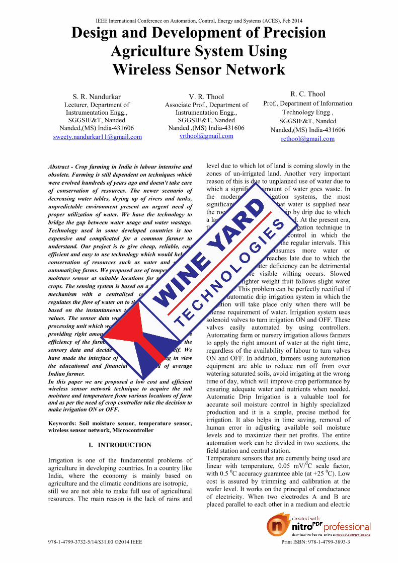
II. HARDWARE DESIGN A. TEMPERATURE SENSOR The current work uses temperature sensors for monitoring the soil temperature. For temperature measurement, LM-35DZ sensors have been used. The soil temperature is one of the important environmental factor with a change of climate, topography, vegetation, soil type, planting form and other factors. The soil temperature is closely related with some processes, such as crop planting time, tillering Growth and wintering safety etc. Above Figure 1 Shows Photograph of a LM-35 Temperature Sensor. The change of soil temperature directly impact on soil nutrient absorption and soil moisture keep and sport. The soil temperature plays a certain role on many of the physical processes of soil. The soil water and heat migration is an important research problem. Therefore, the observation of soil temperature real time and Understanding of variation of soil temperature has vital significance to agricultural production and scientific research. The temperature sensor LM-35DZ has an output voltage that is proportional to the temperature being measured. The scale factor is 0.01 V/ 0C. The LM-35DZ does not require any external calibration or trimming and maintains an accuracy of 0.4 0C at room temperature and ± 0.8 0C over a range of 0 0C to +100 0C. Another important characteristic of the LM-35DZ is that it draws only 60 μA of current from its supply and possesses a low self-heating
capability, the sensor self-heating causes less than 0.1 0C temperature rise in still air.
Fig.1: Photograph of a LM- 35 Temperature Sensor
B. MOISTURE SENSOR
1. PROBES-
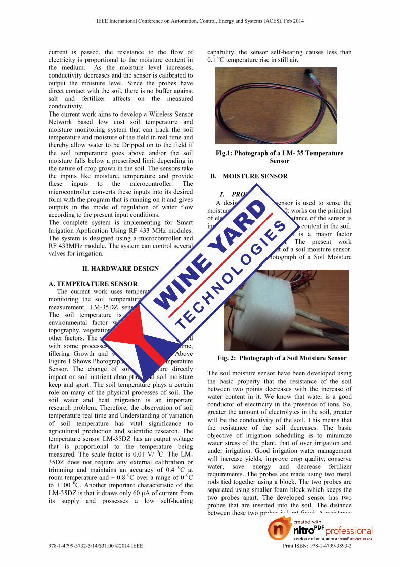
A designed resistive sensor is used to sense the moisture content in the soil. It works on the principal of electrical conductivity. Resistance of the sensor is inversely proportional to moisture content in the soil. Moisture content of the soil is a major factor determining plant growth. The present work Comprises of development of a soil moisture sensor. Figure 2 shows the Photograph of a Soil Moisture Sensor.
Fig. 2: Photograph of a Soil Moisture Sensor
The soil moisture sensor have been developed using the basic property that the resistance of the soil between two points decreases with the increase of water content in it. We know that water is a good conductor of electricity in the presence of ions. So, greater the amount of electrolytes in the soil, greater will be the conductivity of the soil. This means that the resistance of the soil decreases. The basic objective of irrigation scheduling is to minimize water stress of the plant, that of over irrigation and under irrigation. Good irrigation water management will increase yields, improve crop quality, conserve water, save energy and decrease fertilizer requirements. The probes are made using two metal rods tied together using a block. The two probes are separated using smaller foam block which keeps the two probes apart. The developed sensor has two probes that are inserted into the soil. The distance between these two probes is kept fixed. A resistance
IEEE International Conference on Automation, Control, Energy and Systems (ACES), Feb 2014
978-1-4799-3732-5/14/$31.00 ©2014 IEEE Print ISBN: 978-1-4799-3893-3
is connected in series with the probe and current passed through it.
2. SIGNAL CONDITIONING CIRCUIT OF MOISTURE SENSOR-
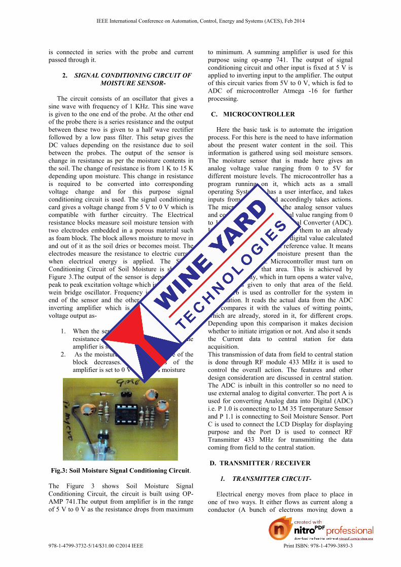
The circuit consists of an oscillator that gives a sine wave with frequency of 1 KHz. This sine wave is given to the one end of the probe. At the other end of the probe there is a series resistance and the output between these two is given to a half wave rectifier followed by a low pass filter. This setup gives the DC values depending on the resistance due to soil between the probes. The output of the sensor is change in resistance as per the moisture contents in the soil. The change of resistance is from 1 K to 15 K depending upon moisture. This change in resistance is required to be converted into corresponding voltage change and for this purpose signal conditioning circuit is used. The signal conditioning card gives a voltage change from 5 V to 0 V which is compatible with further circuitry. The Electrical resistance blocks measure soil moisture tension with two electrodes embedded in a porous material such as foam block. The block allows moisture to move in and out of it as the soil dries or becomes moist. The electrodes measure the resistance to electric current when electrical energy is applied. The Signal Conditioning Circuit of Soil Moisture is shown in Figure 3.The output of the sensor is depends on the peak to peak excitation voltage which is applied from wein bridge oscillator. Frequency is fed to the one end of the sensor and the other end is as input to inverting amplifier which is designed to give the voltage output as-
1. When the sensor is dry (0 % moisture), the resistance of the sensor is around 15 K, the amplifier is set to 5 V for 0 % moisture.
2. As the moisture increases, resistance of the block decreases. The voltages of the amplifier is set to 0 V for 100 % moisture
Fig.3: Soil Moisture Signal Conditioning Circuit.
The Figure 3 shows Soil Moisture Signal Conditioning Circuit, the circuit is built using OP-AMP 741.The output from amplifier is in the range of 5 V to 0 V as the resistance drops from maximum
to minimum. A summing amplifier is used for this purpose using op-amp 741. The output of signal conditioning circuit and other input is fixed at 5 V is applied to inverting input to the amplifier. The output of this circuit varies from 5V to 0 V, which is fed to ADC of microcontroller Atmega -16 for further processing. C. MICROCONTROLLER
Here the basic task is to automate the irrigation process. For this here is the need to have information about the present water content in the soil. This information is gathered using soil moisture sensors. The moisture sensor that is made here gives an analog voltage value ranging from 0 to 5V for different moisture levels. The microcontroller has a program running on it, which acts as a small operating System. It has a user interface, and takes inputs from the user and accordingly takes actions. The microcontroller takes the analog sensor values and converts them into a digital value ranging from 0 to 1023using its Analog to Digital Converter (ADC). It uses these values to compare them to an already known reference value. If the digital value calculated for a sensor is less than its reference value. It means that there is less soil moisture present than the required in that area. Microcontroller must turn on water supply for that area. This is achieved by turning on a relay, which in turn opens a water valve, and water is given to only that area of the field. Atmega 16 is used as controller for the system in field station. It reads the actual data from the ADC and compares it with the values of witting points, which are already, stored in it, for different crops. Depending upon this comparison it makes decision whether to initiate irrigation or not. And also it sends the Current data to central station for data acquisition. This transmission of data from field to central station is done through RF module 433 MHz it is used to control the overall action. The features and other design consideration are discussed in central station. The ADC is inbuilt in this controller so no need to use external analog to digital converter. The port A is used for converting Analog data into Digital (ADC) i.e. P 1.0 is connecting to LM 35 Temperature Sensor and P 1.1 is connecting to Soil Moisture Sensor. Port C is used to connect the LCD Display for displaying purpose and the Port D is used to connect RF Transmitter 433 MHz for transmitting the data coming from field to the central station. D. TRANSMITTER / RECEIVER
1. TRANSMITTER CIRCUIT-
Electrical energy moves from place to place in one of two ways. It either flows as current along a conductor (A bunch of electrons moving down a
IEEE International Conference on Automation, Control, Energy and Systems (ACES), Feb 2014
978-1-4799-3732-5/14/$31.00 ©2014 IEEE Print ISBN: 978-1-4799-3893-3
metal wire), or it travels in the air as invisible waves. In a typical wireless system, the electrical energy starts out as current owing along a conductor, gets changed into waves travelling in the air, and then gets changed back into current owing along conductor again. Now travelling at the speed of light, the airborne signal reaches to the "Receiver". Here it converts the airborne waves into an electrical signal as a current owing along a conductor. Here, we use the RF module 433 MHz for transmission and reception of soil moisture data. RF 433 MHz is a microcontroller compatible IC. Only three pins are used for interfacing in transmission and receiving mode. When attaching an external antenna to an RF Module, superior performance can be achieved by selecting an antenna length related to the wavelength of the carrier frequency. For a RF 433 MHz, 18 cm antenna is use.
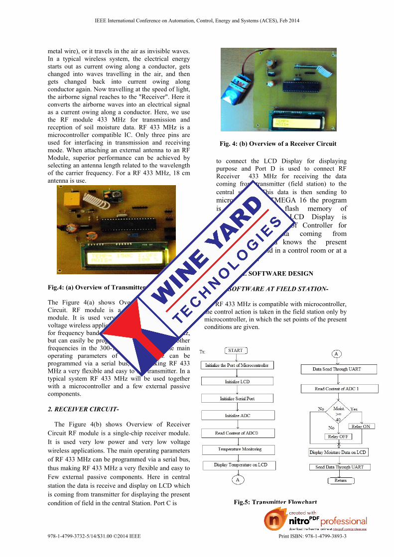
Fig.4: (a) Overview of Transmitter Circuit The Figure 4(a) shows Overview of Transmitter Circuit. RF module is a single chip transmitter module. It is used very low power and very low voltage wireless applications. This is mainly intended for frequency bands at 315, 433, 868 and 915 MHz, but can easily be programmed for operation at other frequencies in the 300-1000 MHz range. The main operating parameters of RF 433 MHz can be programmed via a serial bus, thus making RF 433 MHz a very flexible and easy to use transmitter. In a typical system RF 433 MHz will be used together with a microcontroller and a few external passive components. 2. RECEIVER CIRCUIT- The Figure 4(b) shows Overview of Receiver Circuit RF module is a single-chip receiver module. It is used very low power and very low voltage wireless applications. The main operating parameters of RF 433 MHz can be programmed via a serial bus, thus making RF 433 MHz a very flexible and easy to Few external passive components. Here in central station the data is receive and display on LCD which is coming from transmitter for displaying the present condition of field in the central Station. Port C is
Fig. 4: (b) Overview of a Receiver Circuit to connect the LCD Display for displaying purpose and Port D is used to connect RF Receiver 433 MHz for receiving the data coming from transmitter (field station) to the central station. This data is then sending to microcontroller ATMEGA 16 the program is store in the flash memory of microcontroller. The LCD Display is connected to Port C of Controller for displaying the data coming from microcontroller and knows the� present condition of a field in a control room or at a central station.
III. SOFTWARE DESIGN
A. SOFTWARE AT FIELD STATION-
As RF 433 MHz is compatible with microcontroller, the control action is taken in the field station only by microcontroller, in which the set points of the present conditions are given.
Fig.5: Transmitter Flowchart
IEEE International Conference on Automation, Control, Energy and Systems (ACES), Feb 2014
978-1-4799-3732-5/14/$31.00 ©2014 IEEE Print ISBN: 978-1-4799-3893-3
Here the data coming from field is given to the microcontroller and this controller sends the data to the transmitter and displays this on LCD at a field station. The Figure 5 shows Transmitter Flowchart. Here the electrical waves are converted into airborne waves and transmit that data to the receiver in the central station and again this is display on the LCD. In this if the data coming from field is less than 40 % then the irrigation is start and the display shows the present moisture contents and the "I.ON "(Irrigation ON).If the moisture contents in the soil is 80 above 80% then the irrigation is OFF and display shows "I.OFF" (Irrigation OFF) on the screen. In the decision routine current soil moisture of signal is continuously compared with selected set points. If this signed is less than wilting point valve get open or valve gets closed when signal is greater than maximum set point.
B. SOFTWARE AT CENTRAL STATION-
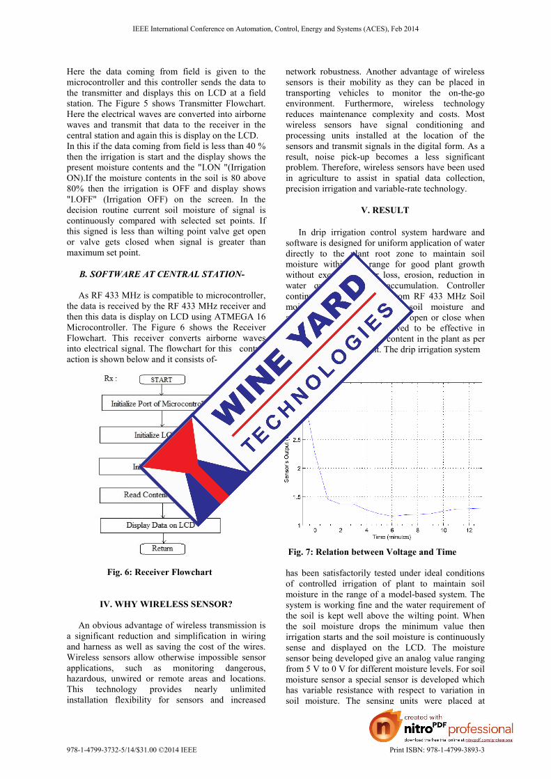
As RF 433 MHz is compatible to microcontroller, the data is received by the RF 433 MHz receiver and then this data is display on LCD using ATMEGA 16 Microcontroller. The Figure 6 shows the Receiver Flowchart. This receiver converts airborne waves into electrical signal. The flowchart for this�control action is shown below and it consists of-
Fig. 6: Receiver Flowchart
IV. WHY WIRELESS SENSOR?
An obvious advantage of wireless transmission is a significant reduction and simplification in wiring and harness as well as saving the cost of the wires. Wireless sensors allow otherwise impossible sensor applications, such as monitoring dangerous, hazardous, unwired or remote areas and locations. This technology provides nearly unlimited installation flexibility for sensors and increased
network robustness. Another advantage of wireless sensors is their mobility as they can be placed in transporting vehicles to monitor the on-the-go environment. Furthermore, wireless technology reduces maintenance complexity and costs. Most wireless sensors have signal conditioning and processing units installed at the location of the sensors and transmit signals in the digital form. As a result, noise pick-up becomes a less significant problem. Therefore, wireless sensors have been used in agriculture to assist in spatial data collection, precision irrigation and variable-rate technology.
V. RESULT In drip irrigation control system hardware and software is designed for uniform application of water directly to the plant root zone to maintain soil moisture within the range for good plant growth without excessive water loss, erosion, reduction in water quality, or salt accumulation. Controller continuously acquires data from RF 433 MHz Soil moisture sensor senses the soil moisture and accordingly solenoid valve gets open or close when needed. The controllers proved to be effective in maintaining the soil water content in the plant as per the set points of the plant. The drip irrigation system
Fig. 7: Relation between Voltage and Time has been satisfactorily tested under ideal conditions of controlled irrigation of plant to maintain soil moisture in the range of a model-based system. The system is working fine and the water requirement of the soil is kept well above the wilting point. When the soil moisture drops the minimum value then irrigation starts and the soil moisture is continuously sense and displayed on the LCD. The moisture sensor being developed give an analog value ranging from 5 V to 0 V for different moisture levels. For soil moisture sensor a special sensor is developed which has variable resistance with respect to variation in soil moisture. The sensing units were placed at
IEEE International Conference on Automation, Control, Energy and Systems (ACES), Feb 2014
978-1-4799-3732-5/14/$31.00 ©2014 IEEE Print ISBN: 978-1-4799-3893-3
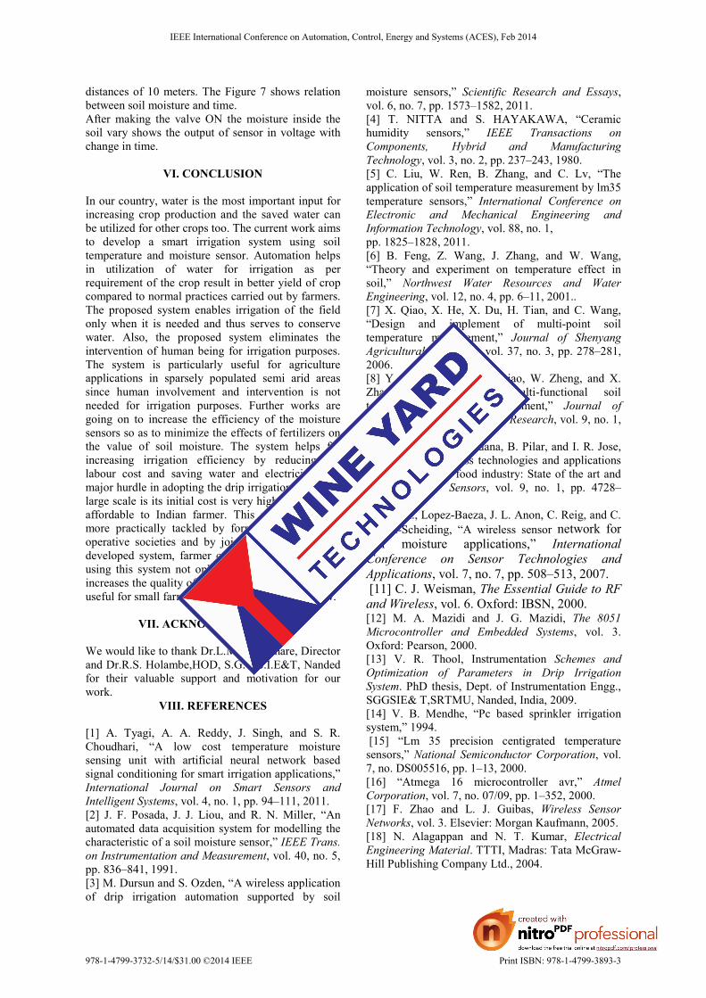
distances of 10 meters. The Figure 7 shows relation between soil moisture and time. After making the valve ON the moisture inside the soil vary shows the output of sensor in voltage with change in time.
VI. CONCLUSION
In our country, water is the most important input for increasing crop production and the saved water can be utilized for other crops too. The current work aims to develop a smart irrigation system using soil temperature and moisture sensor. Automation helps in utilization of water for irrigation as per requirement of the crop result in better yield of crop compared to normal practices carried out by farmers. The proposed system enables irrigation of the field only when it is needed and thus serves to conserve water. Also, the proposed system eliminates the intervention of human being for irrigation purposes. The system is particularly useful for agriculture applications in sparsely populated semi arid areas since human involvement and intervention is not needed for irrigation purposes. Further works are going on to increase the efficiency of the moisture sensors so as to minimize the effects of fertilizers on the value of soil moisture. The system helps for increasing irrigation efficiency by reducing the labour cost and saving water and electricity. The major hurdle in adopting the drip irrigation system in large scale is its initial cost is very high which is not affordable to Indian farmer. This problem can be more practically tackled by forming irrigation co-operative societies and by joint ventures. With the developed system, farmer can grow their crops .By using this system not only saves the water but also increases the quality of the yield. This system is very useful for small farmer as the initial cost is very low.
VII. ACKNOWLEDGMENT We would like to thank Dr.L.M. Waghmare, Director and Dr.R.S. Holambe,HOD, S.G.G.S.I.E&T, Nanded for their valuable support and motivation for our work.
VIII. REFERENCES
[1] A. Tyagi, A. A. Reddy, J. Singh, and S. R. Choudhari, “A low cost temperature moisture sensing unit with artificial neural network based signal conditioning for smart irrigation applications,” International Journal on Smart Sensors and Intelligent Systems, vol. 4, no. 1, pp. 94–111, 2011. [2] J. F. Posada, J. J. Liou, and R. N. Miller, “An automated data acquisition system for modelling the characteristic of a soil moisture sensor,” IEEE Trans. on Instrumentation and Measurement, vol. 40, no. 5, pp. 836–841, 1991. [3] M. Dursun and S. Ozden, “A wireless application of drip irrigation automation supported by soil
moisture sensors,” Scientific Research and Essays, vol. 6, no. 7, pp. 1573–1582, 2011. [4] T. NITTA and S. HAYAKAWA, “Ceramic humidity sensors,” IEEE Transactions on Components, Hybrid and Manufacturing Technology, vol. 3, no. 2, pp. 237–243, 1980. [5] C. Liu, W. Ren, B. Zhang, and C. Lv, “The application of soil temperature measurement by lm35 temperature sensors,” International Conference on Electronic and Mechanical Engineering and Information Technology, vol. 88, no. 1, pp. 1825–1828, 2011. [6] B. Feng, Z. Wang, J. Zhang, and W. Wang, “Theory and experiment on temperature effect in soil,” Northwest Water Resources and Water Engineering, vol. 12, no. 4, pp. 6–11, 2001.. [7] X. Qiao, X. He, X. Du, H. Tian, and C. Wang, “Design and implement of multi-point soil temperature measurement,” Journal of Shenyang Agricultural University, vol. 37, no. 3, pp. 278–281, 2006. [8] Y. Song, J. Wang, X. Qiao, W. Zheng, and X. Zhang,“Development of multi-functional soil temperature measuring instrument,” Journal of Agricul- tural Mechanization Research, vol. 9, no. 1, pp. 80–84, 2010. [9] R. G. Luis, L. Loradana, B. Pilar, and I. R. Jose, “A review of wireless technologies and applications in agriculture and food industry: State of the art and current trends,” Sensors, vol. 9, no. 1, pp. 4728–4750, 2009. [10] C. A., Lopez-Baeza, J. L. Anon, C. Reig, and C. Millan-Scheiding, “A wireless sensor network for soil moisture applications,” International Conference on Sensor Technologies and Applications, vol. 7, no. 7, pp. 508–513, 2007. [11] C. J. Weisman, The Essential Guide to RF and Wireless, vol. 6. Oxford: IBSN, 2000. [12] M. A. Mazidi and J. G. Mazidi, The 8051 Microcontroller and Embedded Systems, vol. 3. Oxford: Pearson, 2000. [13] V. R. Thool, Instrumentation Schemes and Optimization of Parameters in Drip Irrigation System. PhD thesis, Dept. of Instrumentation Engg., SGGSIE& T,SRTMU, Nanded, India, 2009. [14] V. B. Mendhe, “Pc based sprinkler irrigation system,” 1994. [15] “Lm 35 precision centigrated temperature sensors,” National Semiconductor Corporation, vol. 7, no. DS005516, pp. 1–13, 2000. [16] “Atmega 16 microcontroller avr,” Atmel Corporation, vol. 7, no. 07/09, pp. 1–352, 2000. [17] F. Zhao and L. J. Guibas, Wireless Sensor Networks, vol. 3. Elsevier: Morgan Kaufmann, 2005. [18] N. Alagappan and N. T. Kumar, Electrical Engineering Material. TTTI, Madras: Tata McGraw-Hill Publishing Company Ltd., 2004.
IEEE International Conference on Automation, Control, Energy and Systems (ACES), Feb 2014
978-1-4799-3732-5/14/$31.00 ©2014 IEEE Print ISBN: 978-1-4799-3893-3