Embed Size (px)
Citation preview
ContentsPage noitpircseD
Introduction . . . .. . . . . . . .. . . . . . . .. . . . . . . .. . . . .2Installation . . . . .. . . . . . . .. . . . . . . .. . . . . . . .. . . . 3Replacement of Existing Eaton Circuit Breakers
Types DA, JA, KA, HKA, LB, LBB, HLB . . 6 Manual Operation and Thermal Magnetic Trip Unit Adjustment . . . . . . . . . . . . . . . . . .7Inspection and Field Testing . . . . . . . .. . . . . . . .. . 8
Effective February 2015Supersedes IL 29C104D Dated 02/12 Instruction Leaflet IL 29C104E
Installation Instructions for DK, KDB, KD, HKD, KDC, KW, HKW, KWC, CKD, CHKD Circuit Breakers and Molded Case Switches
2
Installation Instructions for DK, KDB, KD, HKD, KDC, KW, HKW, KWC, CKD, CHKD Circuit Breakers and Molded Case Switches
EATON CORPORATION www.eaton.com
The recommendations and information contained hereinare based on Eaton experience and judgment, but should not be considered to be all-inclusive or coveringevery application or circumstance which may arise. If any questions arise, contact Eaton for further informa- tion or instructions.
1. INTRODUCTION
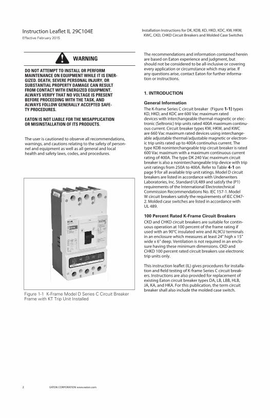
General InformationThe K-frame Series C circuit breaker (Figure 1-1) typesKD, HKD, and KDC are 600 Vac maximum rateddevices with interchangeable thermal-magnetic or elec-tronic (Seltronic) trip units rated 400A maximum continu-ous current. Circuit breaker types KW, HKW, and KWCare 660 Vac maximum rated devices using interchange-able adjustable thermal/adjustable magnetic or electron-ic trip units rated up to 400A continuous current. Thetype KDB noninterchangeable trip circuit breaker is rated600 Vac maximum with a maximum continuous currentrating of 400A. The type DK 240 Vac maximum circuitbreaker is also a noninterchangeable trip device with tripunit ratings from 250A to 400A. Refer to Table 4-1 onpage 9 for all available trip unit ratings. Model D circuitbreakers are listed in accordance with UnderwritersLaboratories, Inc. Standard UL489 and satisfy the (P1)requirements of the International ElectrotechnicalCommission Recommendations No. IEC 157-1. ModelW circuit breakers satisfy the requirements of IEC C947-2. Molded case switches are listed in accordance withUL 489.
100 Percent Rated K-Frame Circuit BreakersCKD and CHKD circuit breakers are suitable for contin-uous operation at 100 percent of the frame rating ifused with an 90°C insulated wire and AL9CU terminalsin an enclosure which measures at least 24” high x 15”wide x 6” deep. Ventilation is not required in an enclo-sure having these minimum dimensions. CKD andCHKD 100 percent rated circuit breakers use electronictrip units only.
ers. Instructions are also provided for replacement ofexisting Eaton circuit breaker types DA, LB, LBB, HLB,JA, KA, and HKA. For this publication, the term circuitbreaker shall also include the molded case switch.
DO NOT ATTEMPT TO INSTALL OR PERFORMMAINTENANCE ON EQUIPMENT WHILE IT IS ENER-GIZED. DEATH, SEVERE PERSONAL INJURY, ORSUBSTANTIAL PROPERTY DAMAGE CAN RESULTFROM CONTACT WITH ENERGIZED EQUIPMENT.ALWAYS VERIFY THAT NO VOLTAGE IS PRESENTBEFORE PROCEEDING WITH THE TASK, ANDALWAYS FOLLOW GENERALLY ACCEPTED SAFE-TY PROCEDURES.
EATON IS NOT LIABLE FOR THE MISAPPLICATIONOR MISINSTALLATION OF ITS PRODUCTS.
The user is cautioned to observe all recommendations,warnings, and cautions relating to the safety of person-nel and equipment as well as all general and localhealth and safety laws, codes, and procedures.
Figure 1-1 K-Frame Model D Series C Circuit BreakerFrame with KT Trip Unit Installed
WARNING
Effective February 2015
3
Installation Instructions for DK, KDB, KD, HKD, KDC, KW, HKW,KWC, CKD, CHKD Circuit Breaker and Molded Case Switches
EATONON CORPORATION www.eaton.com
2. INSTALLATION
The installation procedure consist of inspecting the cir-cuit breaker and, as applicable, installing the trip unit andrating plug, accessories, interphase barriers, and termi-nals; mounting the circuit breaker; connecting the lineand load conductors; torquing terminals; and attachingterminal shields. Circuit breaker frames, trip units, ratingplugs, accesories, mounting hardware, and unmountedterminals may be supplied in separate packages. Toinstall the circuit breaker, perform the following steps.
e installation procedure consists of ,
If circuit breaker is replacing a DA, JA, KA, HKA, LB,LBB, or HLB circuit breaker, refer to section 3 of
DK and KDB circuit breakers are factory sealed forreverse feed applications under UL489. UL requiresthat internal accessories be installed at the factoryin these types of circuit breakers.
If required, internal accessory installation in anytype of circuit breaker should be done before the
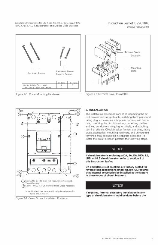
Figure 2-1 Cover Mounting Hardware
Figure 2-2 Cover Screw Installation Positions
Figure 2-3 Terminal Cover Installation
Terminal CoverDovetails
MountingSlots
NOTICE
NOTICE
1
2
1
3
24P
3P
1
2
Screw, No. 8x 1.63 Inch, Flat Head, Cross-Recessed,Thread Forming.Screw .190-32 x 3.125 Inch Pan Head, Cross-Recessed.
Note: Hatched lines show additional pole and screw for 4-pole circuit breaker.
3 - Pole 4 - PoleNo. 8 x 1.63 in, Flat - Head 6 3.190 - 32 x 3.125 in, Pan - Head 2 7
Pan Head ScrewsFlat Head, ThreadForming Screws
Effective February 2015
2
1
24P
13P
2
13P
2
1 3P
4P
4
Instruction Leaft IL 29C104E Installation Instructions for DK, KDB, KD, HKD, KDC, KW, KWC, CKD, CHKD Circuit Breakers and Molded Case Switches
EATON CORPORATION www.eaton.com
circuit breaker is mounted and connected. Refer to
2-1. Make sure that the circuit breaker is suitable for theintended installation by comparing nameplate data withexisting equipment ratings and system requirements.Inspect the circuit breaker for completeness, and checkfor damage before mounting. Uninstalled cover mount-ing hardware is supplied in a plastic bag with the circuitbreaker frame. (See Figure 2-1.)
2-2. Remove installed cover screws and cover.
The circuit breaker handle must be in the tripped orOFF position to remove the cover. Instructions forinstalling the trip unit and accessories are suppliedwith the devices.
2-3. If not already installed, mount trip unit and acces-sories (if required) in circuit breaker frame. Rating plugmust be installed in Seltronic trip units.
WHEN REMOVED AND REINSTALLED, THREAD-FORMING SCREWS WILL TRY TO REFORM THETHREADS IN THE BASE. CARE SHOULD BE TAKENEVERY TIME A THREAD-FORMING SCREW IS USEDTO ENSURE THE SCREW STARTS IN THE ORIGINALTHREADS. DAMAGED THREADS CAN RESULT INIMPROPER CIRCUIT BREAKER COVER RETENTION.
2-4. Replace cover and install pan-head screws fol-lowed by thread-forming screws as shown in Figure 2-2.Torque cover screws to 18-23 lb-in (2-2.6 N.m.).
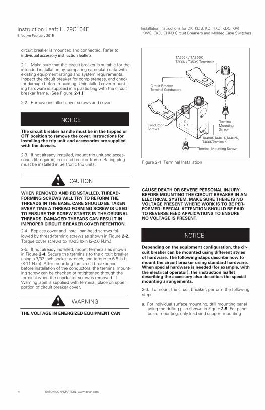
2-5. If not already installed, mount terminals as shownin Figure 2-4. Secure the terminals to the circuit breakerusing a 7/32-inch socket wrench, and torque to 6-8 lb-ft(8-11 N.m). After mounting the circuit breaker andbefore installation of the conductors, the terminal mount-ing screw can be checked or retightened through theterminal when the conductor screw is removed. IfWarning label is supplied with terminal, place on upperportion of circuit breaker cover.
THE VOLTAGE IN ENERGIZED EQUIPMENT CAN
CAUSE DEATH OR SEVERE PERSONAL INJURY.BEFORE MOUNTING THE CIRCUIT BREAKER IN ANELECTRICAL SYSTEM, MAKE SURE THERE IS NOVOLTAGE PRESENT WHERE WORK IS TO BE PER-FORMED. SPECIAL ATTENTION SHOULD BE PAIDTO REVERSE FEED APPLICATIONS TO ENSURENO VOLTAGE IS PRESENT.
Depending on the equipment configuration, the cir-cuit breaker can be mounted using different stylesof hardware. The following steps describe how tomount the circuit breaker using standard hardware.When special hardware is needed (for example, withthe electrical operator), the instruction leafletdescribing the accessory also describes the specialmounting arrangements.
2-6. To mount the circuit breaker, perform the followingsteps:
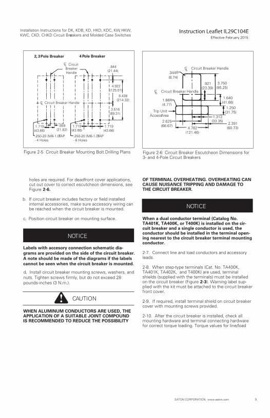
a. For individual surface mounting, drill mounting panelusing the drilling plan shown in Figure 2-5. For panel-board mounting, only load end support mounting
NOTICE
CAUTION
WARNING
Figure 2-4 Terminal Installation
TA300K / TA350KT300K / T350K Terminals
Circuit BreakerTerminal Conductors
ConductorScrews
TerminalMountingScrew
TA400K, TA401K, TA402K,T400K Terminals
Terminal Mounting Screw
NOTICE
Effective February 2015
5
Installation Instructions for DK, KDB, KD, HKD, KDC, KW HKW,, KWC, CKD, CHKD Circuit Breakers and Molded Case Switchese
EATON CORPORATION www.eaton.com
holes are required. For deadfront cover applications,cut out cover to correct escutcheon dimensions, seeFigure 2-6.
internal accessories, make sure accessory wiring canbe reached when the circuit breaker is mounted.
c
b. If circuit breaker includes factory or field installed
. Position circuit breaker on mounting surface.
Labels with accesory connection schematic dia-grams are provided on the side of the circuit breaker.A note should be made of the diagrams if the labelscannot be seen when the circuit breaker is mounted.
.d. Install circuit breaker mounting screws, washers, andnuts. Tighten screws firmly, but do not exceed 28pounds-inches (3 N.m.).
WHEN ALUMINUM CONDUCTORS ARE USED, THEAPPLICATION OF A SUITABLE JOINT COMPOUNDIS RECOMMENDED TO REDUCE THE POSSIBILITY
OF TERMINAL OVERHEATING. OVERHEATING CANCAUSE NUISANCE TRIPPING AND DAMAGE TOTHE CIRCUIT BREAKER.
When a dual conductor terminal (Catalog No.TA401K, TA400K, or T400K) is installed on the cir-cuit breaker and a single conductor is used, theconductor should be installed in the terminal open-ing nearest to the circuit breaker terminal mountingconductor.
2-7. Connect line and load conductors and accessoryleads.
2-8. When step-type terminals (Cat. No. TA400K,TA401K, TA402K, and T400K) are used, terminalshields (supplied with the terminals) must be installedon the circuit breaker (Figure 2-3). Warning label sup-plied with the kit must be attached to the circuit breakerfront cover.
2-9. If required, install terminal shield on circuit breakercover with mounting screws provided.
2-10. After the circuit breaker is installed, check allmounting hardware and terminal connecting hardwarefor correct torque loading. Torque values for line/load
Figure 2-5 Circuit Breaker Mounting Bolt Drilling Plans
2, 3 Pole Breaker 4 Pole Breaker
Circuit BreakerHandle
CL
CL Circuit Breaker Handle
.844(21.44)
8.438(214.32)
4.922(125.01)
3.516(89.31)
1.719(43.66)
1.719(43.66)
.859(21.82)
1.719(43.66)
.250-20 (M6-1.0) TAP- 4 Holes
.250-20 (M6-1.0) TAP- 6 Holes
Figure 2-6 Circuit Breaker Escutcheon Dimensions for3- and 4-Pole Circuit Breakers
Circuit Breaker HandleCL
Circuit Breaker HandleCL
Trip UnitAccess Area
.344R(8.74)
.921(23.39)
3.750(95.25)
1.640(41.66)
1.250(31.75)
1.313(33.35)
1.88R(4.77)
4.782(121.46)
2.625(66.67)
2.391(60.73)
CAUTION
NOTICE
NOTICE
Effective February 2015
6
Installation Instructions for DK, KDB, KD, HKD, KDC, KW, HKW KWC, CKD, CHKD Circuit Breakers and Molded Case Switchese
EATON CORPORATION www.eaton.com
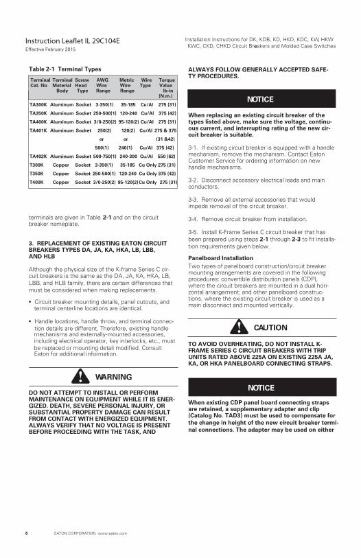
terminals are given in Table 2-1 and on the circuitbreaker nameplate.
3. REPLACEMENT OF EXISTING EATON CIRCUITBREAKERS TYPES DA, JA, KA, HKA, LB, LBB, AND HLB
Although the physical size of the K-frame Series C cir-cuit breakers is the same as the DA, JA, KA, HKA, LB,LBB, and HLB family, there are certain differences thatmust be considered when making replacements.
Circuit breaker mounting details, panel cutouts, andterminal centerline locations are identical.
Handle locations, handle throw, and terminal connec-tion details are different. Therefore, existing handlemechanisms and externally-mounted accessories,including electrical operator, key interlocks, etc., mustbe replaced or mounting detail modified. ConsultEaton for additional information.
DO NOT ATTEMPT TO INSTALL OR PERFORMMAINTENANCE ON EQUIPMENT WHILE IT IS ENER-GIZED. DEATH, SEVERE PERSONAL INJURY, ORSUBSTANTIAL PROPERTY DAMAGE CAN RESULTFROM CONTACT WITH ENERGIZED EQUIPMENT.ALWAYS VERIFY THAT NO VOLTAGE IS PRESENTBEFORE PROCEEDING WITH THE TASK, AND
ALWAYS FOLLOW GENERALLY ACCEPTED SAFE-TY PROCEDURES.
When replacing an existing circuit breaker of thetypes listed above, make sure the voltage, continu-ous current, and interrupting rating of the new cir-cuit breaker is suitable.
3-1. If existing circuit breaker is equipped with a handlemechanism, remove the mechanism. Contact EatonCustomer Service for ordering information on newhandle mechanisms.
3-2. Disconnect accessory electrical leads and mainconductors.
3-3. Remove all external accessories that wouldimpede removal of the circuit breaker.
3-4. Remove circuit breaker from installation.
3-5. Install K-Frame Series C circuit breaker that hasbeen prepared using steps 2-1 through 2-3 to fit installa-tion requirements given below.
Panelboard InstallationTwo types of panelboard construction/circuit breakermounting arrangements are covered in the followingprocedures: convertible distribution panels (CDP),where the circuit breakers are mounted in a dual hori-zontal arrangement; and other panelboard construc-tions, where the existing circuit breaker is used as amain disconnect and mounted vertically.
TO AVOID OVERHEATING, DO NOT INSTALL K-FRAME SERIES C CIRCUIT BREAKERS WITH TRIPUNITS RATED ABOVE 225A ON EXISTING 225A JA,KA, OR HKA PANELBOARD CONNECTING STRAPS.
When existing CDP panel board connecting straps are retained, a supplementary adapter and clip (Catalog No. TAD3) must be used to compensate forthe change in height of the new circuit breaker termi-nal connections. The adapter may be used on either
WARNING
NOTICE
CAUTION
NOTICE
Table 2-1 Terminal Types
Terminal Terminal Screw AWG Metric Wire TorqueCat. No. Material Head Wire Wire Type Value
Body Type Range Range lb-in (N.m.)
TA300K Aluminum Socket 3-350(1) 35-185 Cu/Al 275 (31)
TA350K Aluminum Socket 250-500(1) 120-240 Cu/Al 375 (42)
TA400K Aluminum Socket 3/0-250(2) 95-120(2) Cu/Al 275 (31)
TA401K Aluminum Socket 250(2) 120(2) Cu/Al 275 & 375
or or (31 &42)
500(1) 240(1) Cu/Al 375 (42)
TA402K Aluminum Socket 500-750(1) 240-300 Cu/Al 550 (62)
T300K Copper Socket 3-350(1) 35-185 Cu Only 275 (31)
T350K Copper Socket 250-500(1) 120-240 Cu Only 375 (42)
T400K Copper Socket 3/0-250(2) 95-120(2)Cu Only 275 (31)
Effective February 2015
7
Installation Instructions for DK, KDB, KD, HKD, KDC, KW, HKW,KWC, CKD, CHKD Circuit Breakers and Molded Cases Switches
EATON CORPORATION www.eaton.com
side of the circuit breaker terminal mounting con-ductor permitting continued use of top or bottommounted connecting straps. If series C panelboardconnecting straps that mount from the rear of thecircuit breaker are used, the adapter is not required.
3-6. When required, position the TAD3 adapter underthose circuit breaker terminal connectors that will bebolted to the panelboard connecting straps. Secureadapters with the spring clips supplied. Refer to instruc-tions supplied with adapter.
3-7. Position circuit breaker in correct location on panel-board chassis.
3-8. Install socket-head bolts through circuit breakerterminal connectors and screw into panelboard connect-ing straps. Torque to 120 pound-inches (16.9 N.m).
3-9. Install circuit breaker mounting screws, washers,and nuts in load end of circuit breaker. Tighten screws
3-10. After mounting the circuit breaker, refer to section2 for instructions how to connect main conductors andaccessory leads, as required.
Individually Mounted DevicesWith the change in height of the circuit breaker terminalconnector, K-frame Series C circuit breakers can beused to replace individually mounted existing types DA,JA, KA, HKA, LB, LBB, and HLB circuit breakers onlywhen the following conditions are considered:
Fixed Rear Connecting Studs
Contact Eaton Customer Service for ordering information.
Plug-In Support BlocksNew male plug-in adapters will be required. Existing sta-tionary support block receptacles can be used with newSeries C male plug-in adapters. Contact Eaton Custom-er Service for ordering information.
Front or Rear Connected Bus BarsUse existing connecting details coupled with K-Frameterminal adapter kit (Catalog No. TAD3).
4. MANUAL OPERATION, AND THERMAL-MAGNETIC TRIP UNIT ADJUSTMENT
Manual OperationManual operation of the circuit breaker is controlled bythe circuit breaker handle and the PUSH-TO-TRIP but-
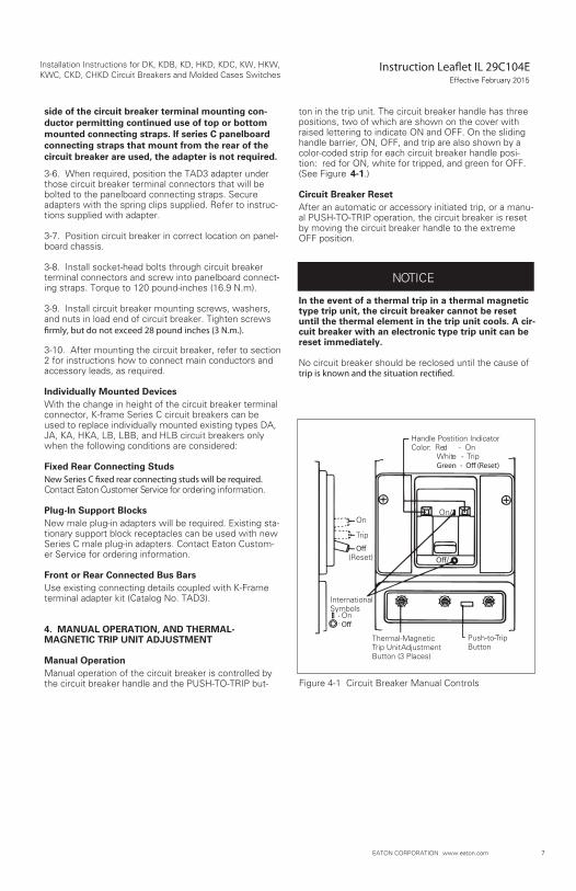
ton in the trip unit. The circuit breaker handle has threepositions, two of which are shown on the cover withraised lettering to indicate ON and OFF. On the slidinghandle barrier, ON, OFF, and trip are also shown by acolor-coded strip for each circuit breaker handle posi-tion: red for ON, white for tripped, and green for OFF.(See Figure 4-1.)
Circuit Breaker ResetAfter an automatic or accessory initiated trip, or a manu-al PUSH-TO-TRIP operation, the circuit breaker is resetby moving the circuit breaker handle to the extremeOFF position.
In the event of a thermal trip in a thermal magnetictype trip unit, the circuit breaker cannot be resetuntil the thermal element in the trip unit cools. A cir-cuit breaker with an electronic type trip unit can bereset immediately.
No circuit breaker should be reclosed until the cause of
NOTICE
Figure 4-1 Circuit Breaker Manual Controls
Handle Postition IndicatorColor: Red - On
White - Trip
On
Trip
(Reset)
On
InternationalSymbols
Thermal-MagneticTrip Unit AdjustmentButton (3 Places)
Push-to-TripButton
On/
Effective February 2015
8
Installation Instructions for DK, KDB, KD, HKD, KDC, KW, HKW,KWC, CKD, CHKD Circuit Breakers and Molded Case Switches
EATON CORPORATION www.eaton.com
PUSH-TO-TRIP ButtonThe PUSH-TO-TRIP button checks the circuit breakertripping function and is used to periodically exercise theoperating mechanism in thermal-magnetic trip units. Thebutton is designed to be operated by a small screwdriver.The rating plug in Electronic trip Units is the PUSH-TO-TRIP button and is operated by finger pressure. There isno PUSH-TO-TRIP button in the molded case switch.
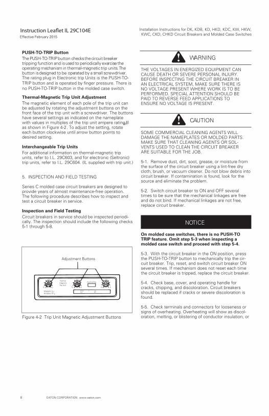
Thermal-Magnetic Trip Unit AdjustmentThe magnetic element of each pole of the trip unit canbe adjusted by rotating the adjustment buttons on thefront face of the trip unit with a screwdriver. The buttonshave several settings as indicated on the nameplatewith values in multiples of the trip unit ampere rating (I h)as shown in Figure 4-2. To adjust the setting, rotateeach button clockwise until arrow button points todesired setting.
Interchangeable Trip UnitsFor additional information on thermal-magnetic tripunits, refer to I.L. 29C603, and for electronic (Seltronic)trip units, refer to I.L. 29C604. (IL supplied with trip unit.)
5. INSPECTION AND FIELD TESTING
Series C molded case circuit breakers are designed toprovide years of almost maintenance-free operation.The following procedure describes how to inspect andtest a circuit breaker in service.
Inspection and Field TestingCircuit breakers in service should be inspected periodi-cally. The inspection should include the following checks5-1 through 5-8.
THE VOLTAGES IN ENERGIZED EQUIPMENT CANCAUSE DEATH OR SEVERE PERSONAL INJURY.BEFORE INSPECTING THE CIRCUIT BREAKER INAN ELECTRICAL SYSTEM, MAKE SURE THERE ISNO VOLTAGE PRESENT WHERE WORK IS TO BEPERFORMED. SPECIAL ATTENTION SHOULD BEPAID TO REVERSE FEED APPLICATIONS TOENSURE NO VOLTAGE IS PRESENT.
SOME COMMERCIAL CLEANING AGENTS WILLDAMAGE THE NAMEPLATES OR MOLDED PARTS.MAKE SURE THAT CLEANING AGENTS OR SOL-VENTS USED TO CLEAN THE CIRCUIT BREAKERARE SUITABLE FOR THE JOB.
5-1. Remove dust, dirt, soot, grease, or moisture fromthe surface of the circuit breaker using a lint-free drycloth, brush, or vacuum cleaner. Do not blow debris intocircuit breaker. If contamination is found, look for thesource and eliminate the problem.
5-2. Switch circuit breaker to ON and OFF severaltimes to be sure that the mechanical linkages are freeand do not bind. If mechanical linkages are not free,replace circuit breaker.
On molded case switches, there is no PUSH-TOTRIP feature. Omit step 5-3 when inspecting amolded case switch and proceed with step 5-4.
5-3. With the circuit breaker in the ON position, pressthe PUSH-TO-TRIP button to mechanically trip the cir-cuit breaker. Trip, reset, and switch circuit breaker ONseveral times. If mechanism does not reset each timethe circuit breaker is tripped, replace the circuit breaker.
5-4. Check base, cover, and operating handle forcracks, chipping, and discoloration. Circuit breakersshould be replaced if cracks or severe discoloration isfound.
5-5. Check terminals and connectors for looseness orsigns of overheating. Overheating will show as discol-oration, melting, or blistering of conductor insulation, or
WARNING
CAUTION
NOTICE
Figure 4-2 Trip Unit Magnetic Adjustment Buttons
Adjustment Buttons
7.5
10 5
7.5
10 5
7.5
10 5
ThermalMagneticTrip Unit
Push-to-Trip
Amps(Ith)
C CatNo.
Magnetic (Im)Multiples Of Ith
t
Effective February 2015
9
Installation Instructions for DK, KDB, KD, HKD, KDC, KW, HKW,KWC, CKD, CHKD Circuit Breakers and Molded Case Switches
EATON CORPORATION www.eaton.com
as pitting or melting of conductor surfaces due to arcing.If there is no evidence of overheating or looseness, donot disturb or tighten the connections. If there is evi-dence of overheating, terminations should be cleaned orreplaced. Before re-energizing the circuit breaker, allterminations and cable should be refurbished to the con-dition when originally installed.
5-6. Check circuit breaker mounting hardware, andtighten if necessary.
5-7. Check area where circuit breaker is installed for
hazards. Exposure to certain types of chemicals cancause deterioration of electrical connections.
5-8. The operation of circuit breakers with Seltronic trip
test kit.
Field Testing
applicable NEMA Standard.
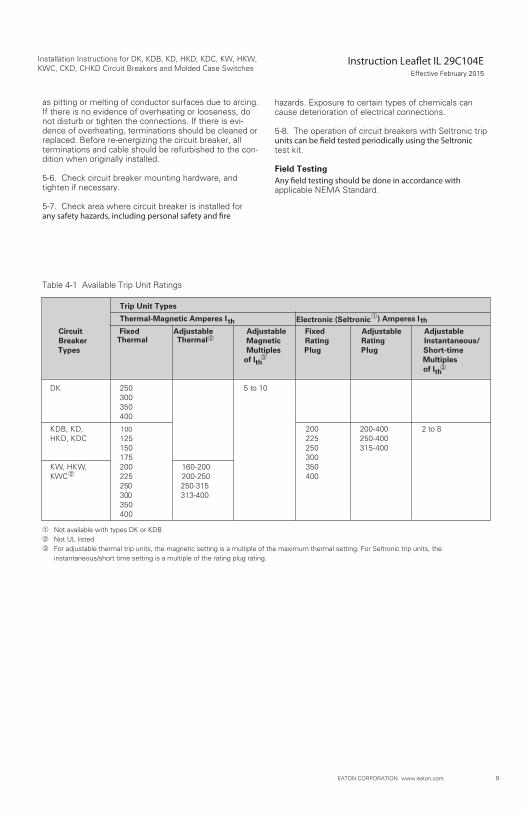
Trip Unit Types
Thermal-Magnetic Amperes I th Electronic (Seltronic ) Amperes I th
Circuit Fixed Adjustable Adjustable Fixed Adjustable AdjustableBreaker Thermal Thermal Magnetic Rating Rating Instantaneous/
Short-timegulPgulPMultiplessepyTof Ith Multiples
of Ith
01 ot 5052KD300350400
8 ot 2004-002002 ,DK ,BDK004-052522521CDK ,DKH004-513052051
003571053002-061002,WKH ,WK
KWC 004052-002522250 250-315300 313-400350400
Table 4-1 Available Trip Unit Ratings
Not available with types DK or KDBNot UL listedFor adjustable thermal trip units, the magnetic setting is a multiple of the maximum thermal setting. For Seltronic trip units, theinstantaneous/short time setting is a multiple of the rating plug rating.
100
Effective February 2015
Instruction leaflet IL 29C104EEffective February 2015
Installation Instructions for DK, KDB, KD, HKD, KDC, KW, HKW,KWC, CKD, CHKD Circuit Breakers and Molded Case Switches
Eaton CorporationElectrical Group1000 Cherrington Parkway Moon Township, PA 15108United States877-ETN-CARE (877-386-2273)Eaton.com
© 2013 Eaton CorporationAll Rights ReservedPrinted in Dominican RepublicPublication No. IL 29C104E / TBG000518 Part No. 6632C41H06February 2015
The instructions for installation, testing, maintenance, or repair herein are provided for the use of the product in general commercial applications and may not be appropriate for use in nuclear applica-tions. Additional instructions may be available upon specific request to replace, amend, or supplement these instructions to qualify them for use with the product in safety-related applications in a nuclear facility.
The information, recommendations,descriptions,and safety nota-tions in this document are based on Eaton’s experience and judg-ment with respect to Retrofitting of Power Breakers. This instruction- al literature is published solely for information purposes and should not be considered all-inclusive. If further information is required, you should consult an authorized Eaton sales representative.
The sale of the product shown in this literature is subject to the terms and conditions outlined in appropriate Eaton selling policies or other contractual agreement between the parties. This literature is not intended to and does not enlarge or add to any such contract. The sole source governing the rights and remedies of any purchaser of this equipment is the contract between the purchaser and Eaton.
NO WARRANTIES, EXPRESSED OR IMPLIED, INCLUDINGWARRANTIES OF FITNESS FOR A PARTICULAR PURPOSE ORMERCHANTABILITY, OR WARRANTIES ARISING FROM COURSEOF DEALING OR USAGE OF TRADE, ARE MADE REGARDINGTHE INFORMATION, RECOMMENDATIONS, AND DESCRIPTIONSCONTAINED HEREIN,
In no event will Eaton be responsible to the
purchaser or user in contract, in tort (including negligence), strict liability or otherwise for any special, indirect, incidental or conse-quential damage or loss whatsoever,including but not limited to damage or loss of use of equipment, plant or power system, cost of capital, loss of power, additional expenses in the use of existing power facilities, or claims against the purchaser or user by its cus-tomers resulting from the use of the information, recommendations and description contained herein.