Embed Size (px)
Citation preview
Instruction Set Architecture
CSA 221
Chapter 4
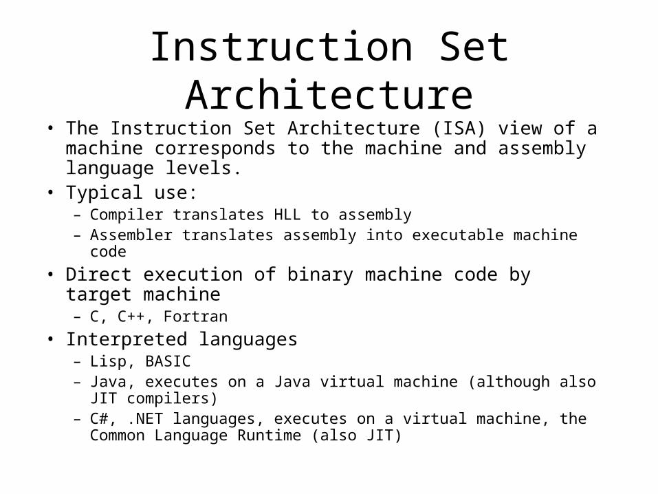
Instruction Set Architecture• The Instruction Set Architecture (ISA) view of a machine
corresponds to the machine and assembly language levels.• Typical use:
– Compiler translates HLL to assembly– Assembler translates assembly into executable machine code
• Direct execution of binary machine code by target machine– C, C++, Fortran
• Interpreted languages– Lisp, BASIC– Java, executes on a Java virtual machine (although also JIT
compilers)– C#, .NET languages, executes on a virtual machine, the Common
Language Runtime (also JIT)
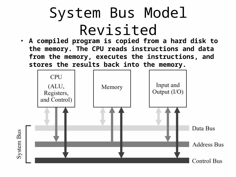
System Bus Model Revisited• A compiled program is copied from a hard disk to the memory. The
CPU reads instructions and data from the memory, executes the instructions, and stores the results back into the memory.
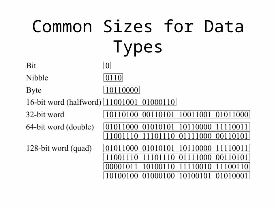
Common Sizes for Data Types
Big Endian vs. Little Endian
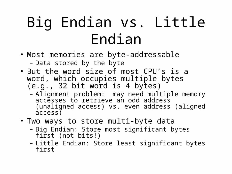
• Most memories are byte-addressable– Data stored by the byte
• But the word size of most CPU’s is a word, which occupies multiple bytes (e.g., 32 bit word is 4 bytes)– Alignment problem: may need multiple memory
accesses to retrieve an odd address (unaligned access) vs. even address (aligned access)
• Two ways to store multi-byte data– Big Endian: Store most significant bytes first (not bits!)– Little Endian: Store least significant bytes first
Endian Byte Order
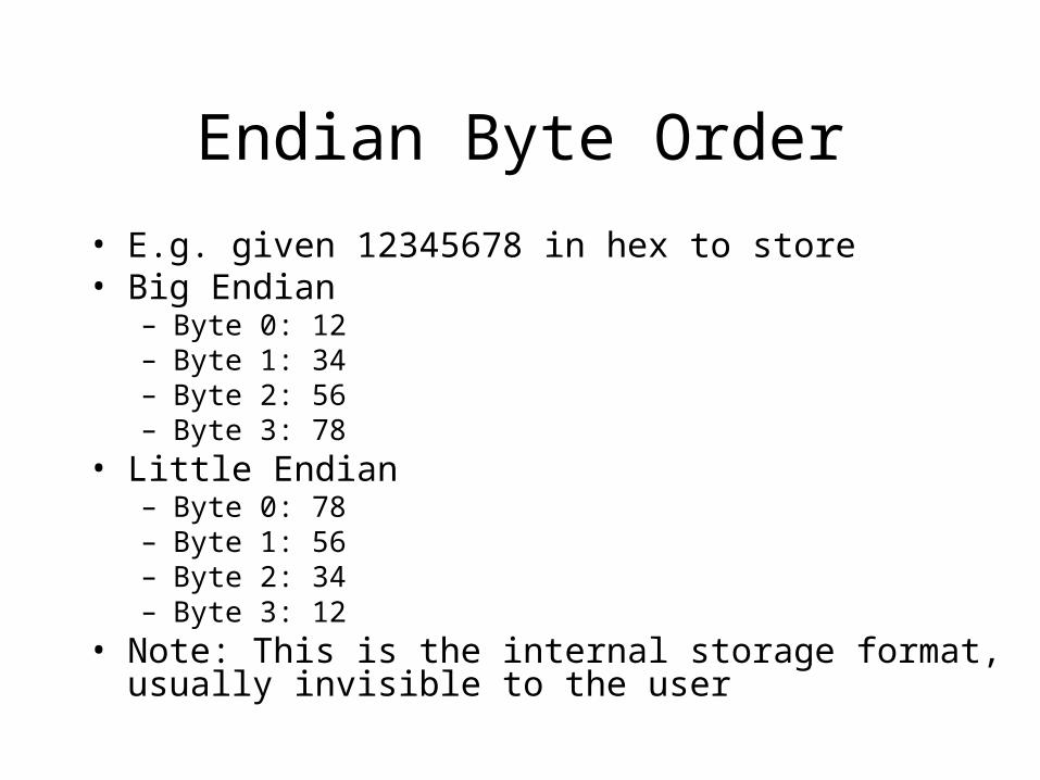
• E.g. given 12345678 in hex to store• Big Endian
– Byte 0: 12– Byte 1: 34– Byte 2: 56– Byte 3: 78
• Little Endian– Byte 0: 78– Byte 1: 56– Byte 2: 34– Byte 3: 12
• Note: This is the internal storage format, usually invisible to the user
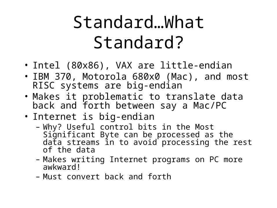
Standard…What Standard?• Intel (80x86), VAX are little-endian• IBM 370, Motorola 680x0 (Mac), and most RISC
systems are big-endian• Makes it problematic to translate data back and
forth between say a Mac/PC• Internet is big-endian
– Why? Useful control bits in the Most Significant Byte can be processed as the data streams in to avoid processing the rest of the data
– Makes writing Internet programs on PC more awkward!– Must convert back and forth
ARC Computer
• Next we present a model computer architecture, the ARC machine
• Simplification of the commercial SPARC architecture from Sun Microsystems– Still fairly complex, however – there is enough
here to make a real system– ARC uses a shared system bus, big-endian
memory format
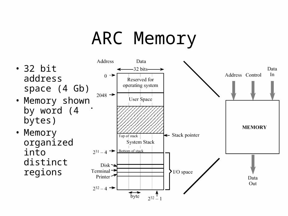
ARC Memory
• 32 bit address space (4 Gb)
• Memory shown by word (4 bytes)
• Memory organized into distinct regions
Address vs. Data
• In ARC, addresses are 32 bits and data also 32 bits
• But these two could be different sizes– We could use 20 bits for addresses, 16 bits for
data (8086)– How much memory could we address?– How many bits should the PC be?– How many bits should general registers be?
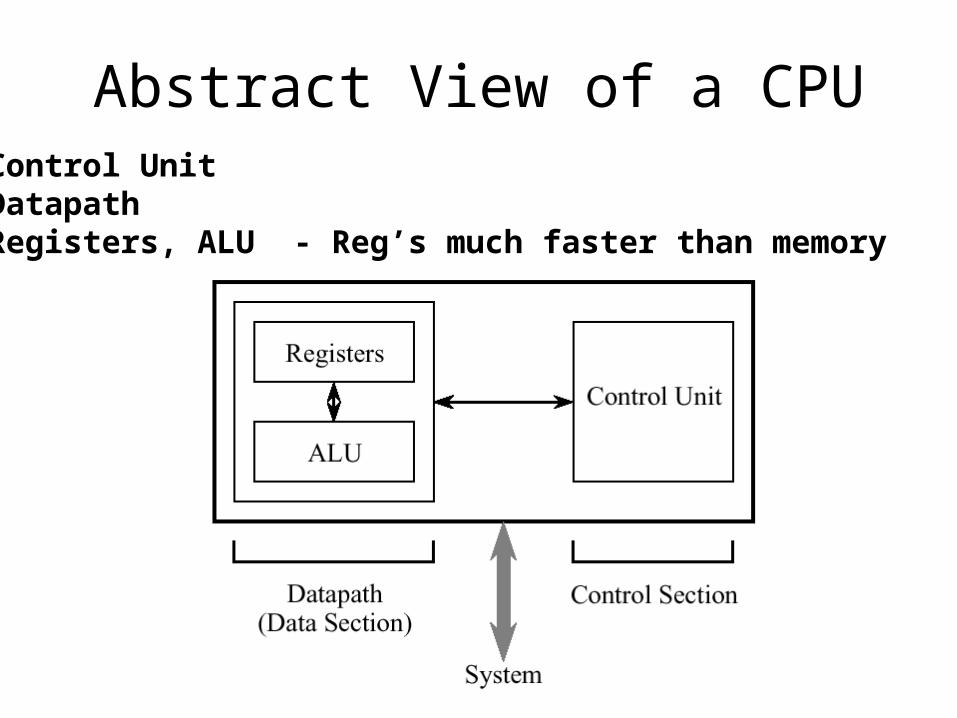
Abstract View of a CPUControl UnitDatapathRegisters, ALU - Reg’s much faster than memory
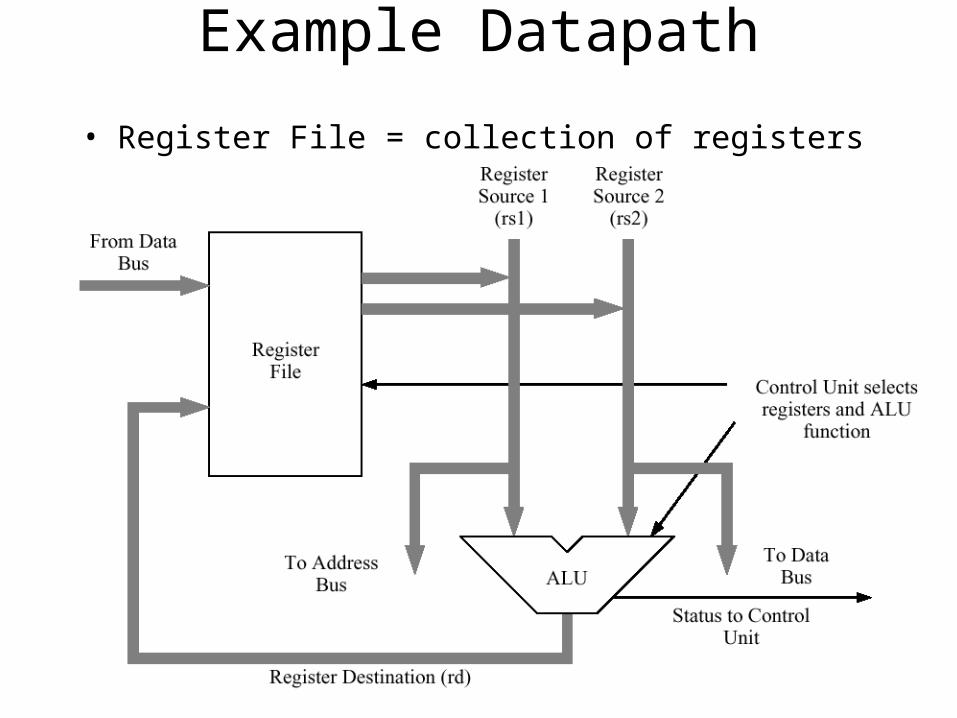
Example Datapath
• Register File = collection of registers on the CPU
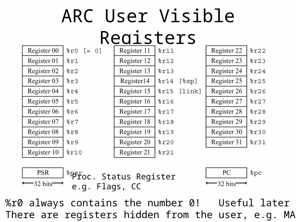
ARC User Visible Registers
%r0 always contains the number 0! Useful laterThere are registers hidden from the user, e.g. MAR
Proc. Status Registere.g. Flags, CC
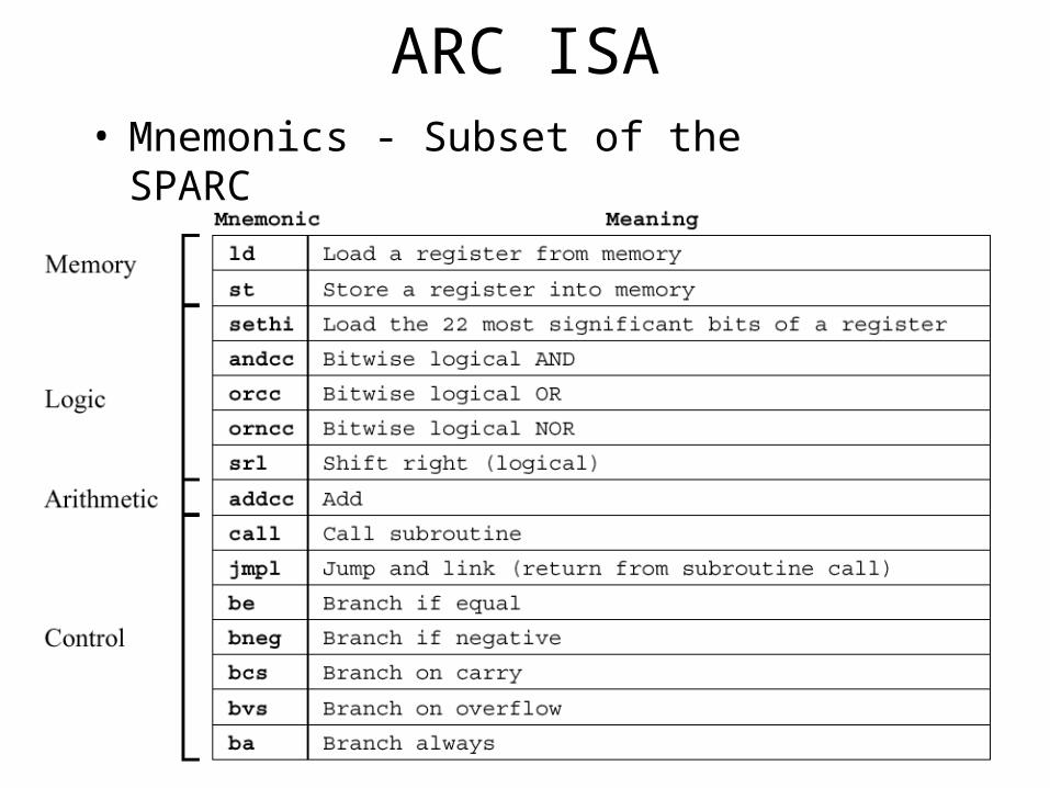
ARC ISA• Mnemonics - Subset of the SPARC
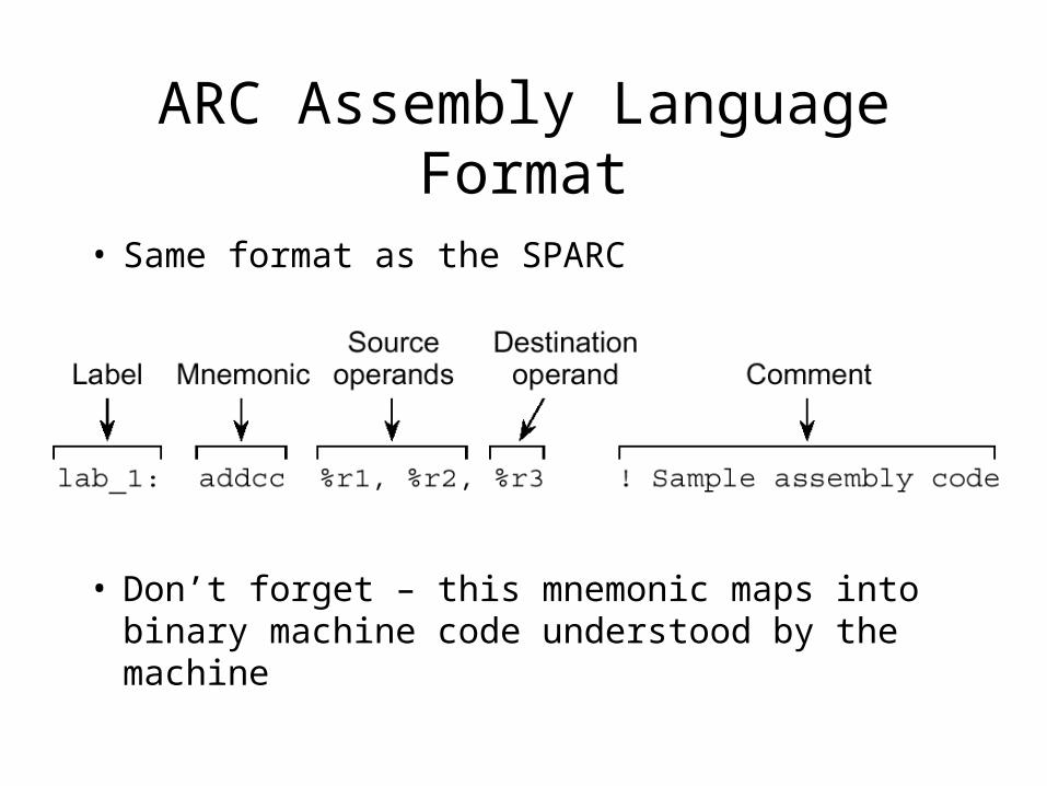
ARC Assembly Language Format
• Same format as the SPARC
• Don’t forget – this mnemonic maps into binary machine code understood by the machine
Addressing Modes– Addressing refers to how an operand refers to
the data we are interested in for a particular instruction
– In the Fetch part of the instruction cycle, there are generally three ways to handle addressing in the instruction• Immediate Addressing• Direct Addressing• Indirect Addressing
Immediate Addressing
• The operand directly contains the value we are interested in working with– E.g. ADD 5
• Means add the number 5 to something
– This uses immediate addressing for the value 5– The two’s complement representation for the
number 5 is directly stored in the ADD instruction
– Must know value at assembly time
Direct Addressing
• The operand contains an address with the data– E.g. ADD 100h
• Means to add (Contents of Memory Location 100) to something– Downside: Need to fit entire address in the instruction, may
limit address space• E.g. 32 bit word size and 32 bit addresses. Do we have a problem
here?• Some solutions: specify offset only, use implied segment
– Must know address at assembly time• The address could also be a register
– E.g. ADD %r5• Means to add (Contents of Register 5) to something
– Upside: Not that many registers, don’t have previous problem
Indirect Addressing• The operand contains an address, and that address
contains the address of the data– E.g. Add [100h]
• Means “The data at memory location 100 is an address. Go to the address stored there and get that data and add it to the Accumulator”
– Downside: Requires additional memory access– Upside: Can store a full address at memory location 100
• First address must be fixed at assembly time, but second address can change during runtime! This is very useful for dynamically accessing different addresses in memory (e.g., traversing an array)
• Can also do Indirect Addressing with registers– E.g. Add [%r3]
• Means “The data in register 3 is an address. Go to that address in memory, get the data, and add it to the Accumulator”
• Indirect Addressing can be thought of as additional instruction subcycle
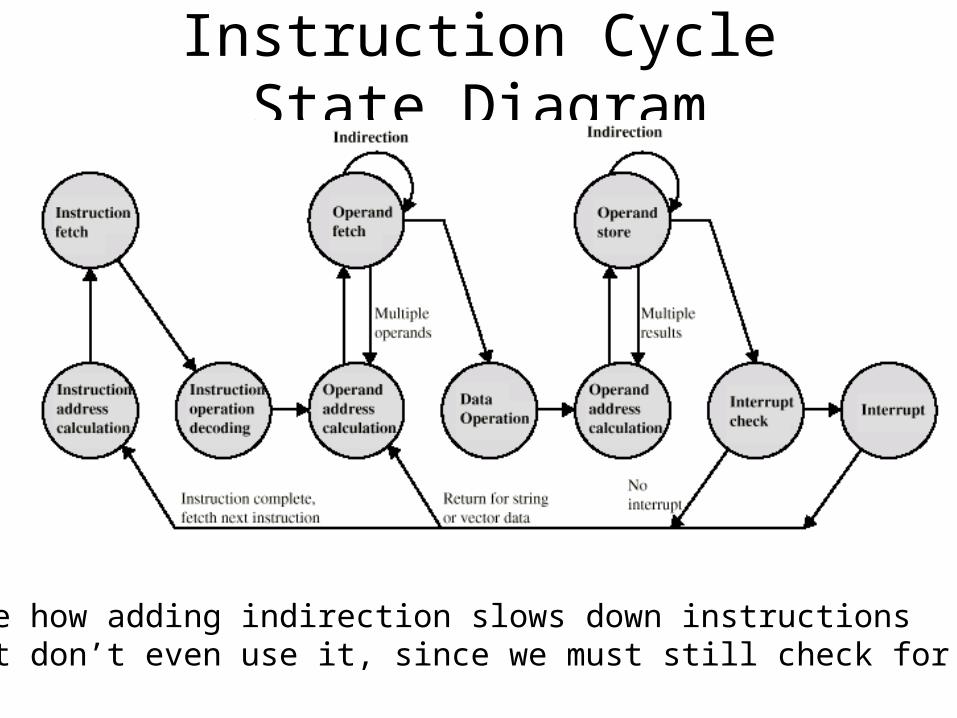
Instruction Cycle State Diagram
Note how adding indirection slows down instructionsthat don’t even use it, since we must still check for it
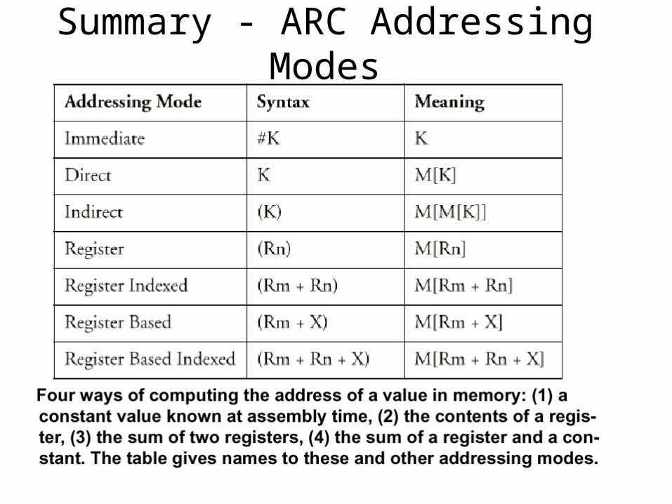
Summary - ARC Addressing Modes
ARC Machine Code
• The opcode mnemonics and the operands must all be translated into a binary machine code that the hardware can understand
• E.g., instruction:– ADDCC %r1, %r3, %r4
• Is converted by the assembler into some binary machine code
• Let’s see this binary machine code format next
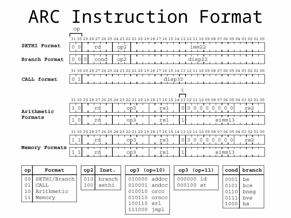
ARC Instruction Format
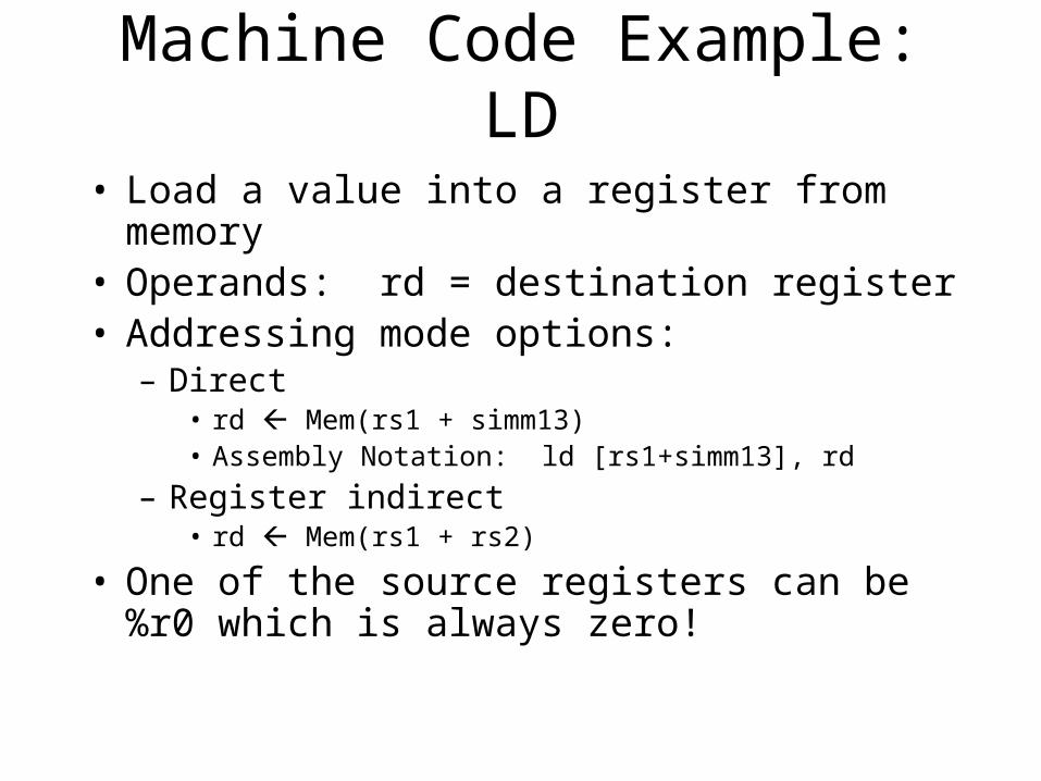
Machine Code Example: LD
• Load a value into a register from memory• Operands: rd = destination register• Addressing mode options:
– Direct• rd Mem(rs1 + simm13)• Assembly Notation: ld [rs1+simm13], rd
– Register indirect• rd Mem(rs1 + rs2)
• One of the source registers can be %r0 which is always zero!
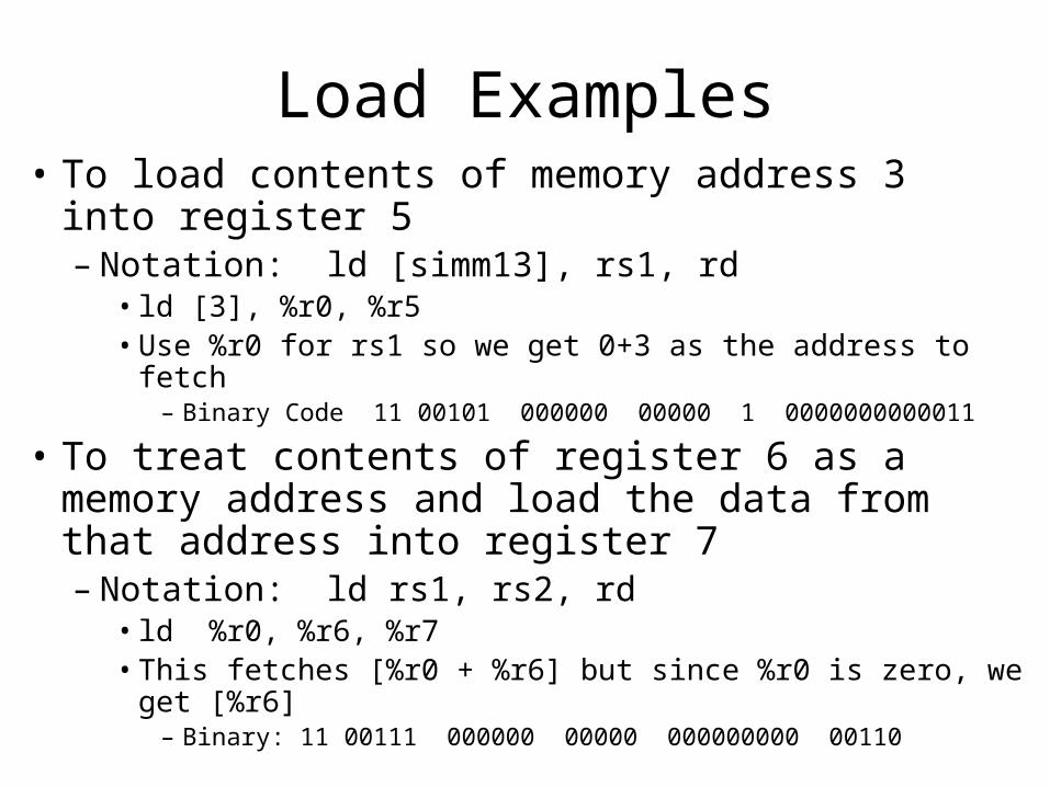
Load Examples• To load contents of memory address 3 into register
5– Notation: ld [simm13], rs1, rd
• ld [3], %r0, %r5• Use %r0 for rs1 so we get 0+3 as the address to fetch
– Binary Code 11 00101 000000 00000 1 0000000000011
• To treat contents of register 6 as a memory address and load the data from that address into register 7– Notation: ld rs1, rs2, rd
• ld %r0, %r6, %r7• This fetches [%r0 + %r6] but since %r0 is zero, we get [%r6]
– Binary: 11 00111 000000 00000 000000000 00110
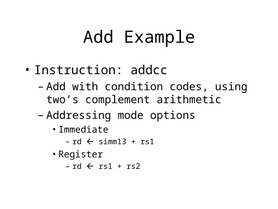
Add Example
• Instruction: addcc– Add with condition codes, using two’s
complement arithmetic– Addressing mode options
• Immediate– rd simm13 + rs1
• Register– rd rs1 + rs2
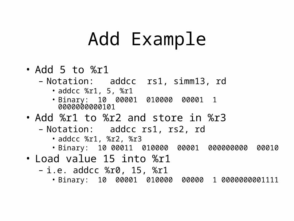
Add Example
• Add 5 to %r1– Notation: addcc rs1, simm13, rd
• addcc %r1, 5, %r1• Binary: 10 00001 010000 00001 1 0000000000101
• Add %r1 to %r2 and store in %r3– Notation: addcc rs1, rs2, rd
• addcc %r1, %r2, %r3• Binary: 10 00011 010000 00001 000000000 00010
• Load value 15 into %r1– i.e. addcc %r0, 15, %r1
• Binary: 10 00001 010000 00000 1 0000000001111
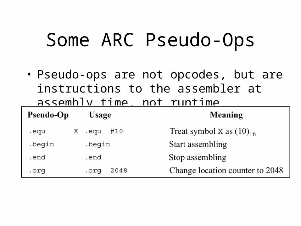
Some ARC Pseudo-Ops
• Pseudo-ops are not opcodes, but are instructions to the assembler at assembly time, not runtime
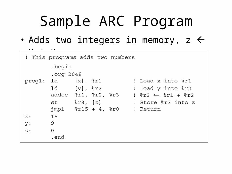
Sample ARC Program• Adds two integers in memory, z x + y
Switching later to x86• Studying the ARC format helps to understand how
the machine pieces together• Later we will switch to x86 assembly programming
– Different pseudo-ops– Different instruction format
• E.g., destination register usually the first operand, not the last one
– Will revisit with the x86 some of the other concepts in chapter 4
• Using the stack and linking subroutines• Memory mapped I/O• Skipping case study on Java Virtual Machine (but an interesting
read!)