Embed Size (px)
DESCRIPTION
Intel D845EPI ProductGuide English
Citation preview
Intel® Desktop Board D845EPI Product Guide
Order Number: C46205-001
Revision History Revision Revision History Date
-001 First release of the Intel® Desktop Board D845EPI Product Guide. July 2003
If an FCC declaration of conformity marking is present on the board, the following statement applies:
FCC Declaration of Conformity
This device complies with Part 15 of the FCC Rules. Operation is subject to the following two conditions: (1) this device may not cause harmful interference, and (2) this device must accept any interference received, including interference that may cause undesired operation.
For questions related to the EMC performance of this product, contact:
Intel Corporation 5200 N.E. Elam Young Parkway Hillsboro, OR 97124 1-800-628-8686
This equipment has been tested and found to comply with the limits for a Class B digital device, pursuant to Part 15 of the FCC Rules. These limits are designed to provide reasonable protection against harmful interference in a residential installation. This equipment generates, uses, and can radiate radio frequency energy and, if not installed and used in accordance with the instructions, may cause harmful interference to radio communications. However, there is no guarantee that interference will not occur in a particular installation. If this equipment does cause harmful interference to radio or television reception, which can be determined by turning the equipment off and on, the user is encouraged to try to correct the interference by one or more of the following measures: • Reorient or relocate the receiving antenna.
• Increase the separation between the equipment and the receiver.
• Connect the equipment to an outlet on a circuit other than the one to which the receiver is connected.
• Consult the dealer or an experienced radio/TV technician for help.
Any changes or modifications to the equipment not expressly approved by Intel Corporation could void the user’s authority to operate the equipment.
Canadian Department of Communications Compliance Statement
This digital apparatus does not exceed the Class B limits for radio noise emissions from digital apparatus set out in the Radio Interference Regulations of the Canadian Department of Communications.
Le présent appareil numerique német pas de bruits radioélectriques dépassant les limites applicables aux appareils numériques de la classe B prescrites dans le Réglement sur le broullage radioélectrique édicté par le ministére des Communications du Canada.
Disclaimer
Information in this document is provided in connection with Intel® products. No license, express or implied, by estoppel or otherwise, to any intellectual property rights is granted by this document. Except as provided in Intel’s Terms and Conditions of Sale for such products, Intel assumes no liability whatsoever, and Intel disclaims any express or implied warranty, relating to sale and/or use of Intel products including liability or warranties relating to fitness for a particular purpose, merchantability, or infringement of any patent, copyright or other intellectual property right. Intel products are not intended for use in medical, life saving, or life sustaining applications. Intel may make changes to specifications and product descriptions at any time, without notice.
Desktop Board D845EPI may contain design defects or errors known as errata which may cause the product to deviate from published specifications. Current characterized errata are available on request.
Contact your local Intel sales office or your distributor to obtain the latest specifications and before placing your product order.
Copies of documents which have an ordering number and are referenced in this document, or other Intel literature, may be obtained from Intel Corporation by going to the World Wide Web site at: http://www.intel.com/ or by calling 1-800-548-4725.
Intel, Celeron, and Pentium are trademarks or registered trademarks of Intel Corporation or its subsidiaries in the United States and other countries.
* Other names and brands may be claimed as the property of others.
Copyright © 2003, Intel Corporation. All rights reserved.
iii
Preface This Product Guide gives information about board layout, component installation, BIOS Setup menus, and regulatory requirements for Intel® Desktop Board D845EPI.
Intended Audience The Product Guide is intended for technically qualified personnel.
Information Layout The chapters in this Product Guide are arranged as follows:
1 Desktop Board Features: a summary of product features.
2 Installing and Replacing Desktop Board Components: instructions on how to install the desktop board and other hardware components.
3 Updating the BIOS: instructions on how to update the BIOS.
4 Using the BIOS Setup Program: contents of the BIOS Setup menus and submenus.
5 Desktop Board Resources: information about desktop board resources.
A Error Messages and Indicators: information about BIOS error messages and beep codes.
B Regulatory Compliance: safety and EMC regulations, product certification.
Conventions The following conventions are used in this manual:
WARNING Warnings indicate conditions that, if not observed, can cause personal injury.
CAUTION Cautions warn the user about how to prevent damage to hardware or loss of data.
NOTE Notes call attention to important information.
Intel Desktop Board D845EPI Product Guide
iv
Terminology The table below gives descriptions to some common terms used in the product guide.
Term Description
GB Gigabyte (1,073,741,824 bytes)
GHz Gigahertz (one billion hertz)
KB Kilobyte (1024 bytes)
MB Megabyte (1,048,576 bytes)
Mbit Megabit (1,048,576 bits)
MHz Megahertz (one million hertz)
Box Contents • Intel desktop board
• I/O shield
• One IDE cable (ATA66/100)
• One diskette drive cable
• Quick Reference Guide
• Configuration and battery caution statement label
• Intel® Express Installer CD-ROM
v
Contents
1 Desktop Board Features Desktop Board Components ...............................................................................................11 Processor ............................................................................................................................13 Main Memory ......................................................................................................................14 Intel® 845E Chipset .............................................................................................................15 Audio Subsystem ................................................................................................................15 LAN Subsystem (Optional) ..................................................................................................16
LAN Subsystem Software...........................................................................................16 RJ-45 LAN Connector LEDs.......................................................................................16
Accelerated Graphics Port (AGP)........................................................................................16 Hi-Speed USB 2.0 Support..................................................................................................17 Enhanced IDE Interface ......................................................................................................17 Expansion Slots...................................................................................................................17 BIOS ...................................................................................................................................17
PCI Auto Configuration...............................................................................................17 IDE Auto Configuration...............................................................................................18 Security Passwords ....................................................................................................18
Power Management Features .............................................................................................18 Speaker...............................................................................................................................20 Battery.................................................................................................................................20 Real-Time Clock..................................................................................................................20
2 Installing and Replacing Desktop Board Components Before You Begin ................................................................................................................21 Installation Precautions .......................................................................................................22 Installation Instructions........................................................................................................22 Installing the I/O Shield .......................................................................................................24 Installing and Removing the Desktop Board........................................................................25 Installing and Removing a Processor ..................................................................................26
Installing a Processor .................................................................................................26 Installing the Processor Fan Heatsink ........................................................................26 Connecting the Processor Fan Heatsink Cable ..........................................................27 Removing a Processor ...............................................................................................27
Installing and Removing Memory ........................................................................................28 Installing DIMMs.........................................................................................................28 Removing DIMMs.......................................................................................................29
Installing and Removing an AGP Card ................................................................................30 Installing an AGP Card ...............................................................................................30 Removing the AGP Card ............................................................................................30
Connecting the IDE Cable ...................................................................................................31 Connecting Internal Headers...............................................................................................33
Installing a Front Panel Audio Solution .......................................................................34 Connecting the Front Panel Header ...........................................................................35 Installing a USB 2.0 Solution ......................................................................................35
Intel Desktop Board D845EPI Product Guide
vi
Connecting Hardware Control and Power Cables ...............................................................36 Connecting Hardware Control Cables.........................................................................37 Connecting Power Cables ..........................................................................................37
Connecting Add-In Card and Peripheral Interface Connectors ............................................38 Setting the BIOS Configuration Jumper Block .....................................................................39 Clearing Passwords ............................................................................................................40 Back Panel Connectors.......................................................................................................41 Replacing the Battery ..........................................................................................................42
3 Updating the BIOS Updating the BIOS with the Intel® Express BIOS Update Utility ..........................................47 Updating the BIOS with the Intel® Iflash BIOS Update Utility...............................................47
Obtaining the BIOS Update File..................................................................................47 Updating the BIOS......................................................................................................48 Recovering the BIOS..................................................................................................48
4 Using the BIOS Setup Program Maintenance Menu..............................................................................................................52 Main Menu ..........................................................................................................................53 Advanced Menu ..................................................................................................................54
PCI Configuration Submenu .......................................................................................55 Boot Configuration Submenu......................................................................................56 Peripheral Configuration Submenu.............................................................................57 IDE Configuration Submenu .......................................................................................59 Primary/Secondary IDE Master/Slave Submenus.......................................................60 Diskette Configuration Submenu ................................................................................62 Event Log Configuration Submenu .............................................................................63 Video Configuration Submenu....................................................................................64 USB Configuration Submenu......................................................................................65 Chipset Configuration Submenu .................................................................................66
Security Menu .....................................................................................................................68 Power Menu ........................................................................................................................69
ACPI Submenu...........................................................................................................70 Boot Menu...........................................................................................................................71
Boot Device Priority Submenu....................................................................................72 Hard Disk Drives Submenu ........................................................................................73 Removable Devices Submenu....................................................................................74 ATAPI CD-ROM Drives ..............................................................................................75
Exit Menu ............................................................................................................................76
5 Desktop Board Resources Memory Map .......................................................................................................................77 DMA Channels ....................................................................................................................77 Interrupts.............................................................................................................................78
A Error Messages and Indicators BIOS Beep Codes...............................................................................................................79 BIOS Error Messages .........................................................................................................80
Contents
vii
B Regulatory Compliance Safety Regulations ..............................................................................................................83 European Union Declaration of Conformity Statement ........................................................83 Product Ecology Statements ...............................................................................................84 EMC Regulations ................................................................................................................85 Product Certification Markings (Board Level) ......................................................................86
Figures 1. Desktop Board Components .........................................................................................11 2. Location of Standby Power Indicator.............................................................................19 3. Installing the I/O Shield .................................................................................................24 4. Desktop Board Mounting Screw Holes..........................................................................25 5. Installing a Processor....................................................................................................26 6. Connecting the Processor Fan Heatsink Cable to the Processor Fan Header ..............27 7. Installing Memory..........................................................................................................28 8. Removing the AGP Card ..............................................................................................30 9. Connecting the IDE Cable.............................................................................................32 10. Internal Headers ...........................................................................................................33 11. Location of Hardware Control and Power Connectors ..................................................36 12. Add-in Card and Peripheral Interface Connectors.........................................................38 13. Location of the BIOS Configuration Jumper Block ........................................................39 14. Back Panel Connectors ................................................................................................41 15. Removing the Battery from the Desktop Board.............................................................46
Intel Desktop Board D845EPI Product Guide
viii
Tables 1. Feature Summary .......................................................................................................... 9 2. Desktop Board Components .........................................................................................12 3. Processors Supported by the Desktop Board ...............................................................13 4. Memory Support ...........................................................................................................14 5. RJ-45 LAN Connector LEDs .........................................................................................16 6. Front Panel Audio Header Signal Names (J8A1) ..........................................................34 7. Front Panel Header (J9G1)...........................................................................................35 8. USB 2.0 Header (J9F2) ................................................................................................35 9. Jumper Settings for the BIOS Setup Program Modes (J9H2) .......................................39 10. BIOS Setup Program Menu Bar....................................................................................51 11. BIOS Setup Program Function Keys.............................................................................52 12. Maintenance Menu .......................................................................................................52 13. Main Menu....................................................................................................................53 14. Advanced Menu............................................................................................................54 15. PCI Configuration Submenu .........................................................................................55 16. Boot Configuration Submenu ........................................................................................56 17. Peripheral Configuration Submenu ...............................................................................57 18. IDE Configuration Submenu .........................................................................................59 19. Primary/Secondary IDE Master/Slave Submenus.........................................................60 20. Diskette Configuration Submenu ..................................................................................62 21. Event Log Configuration Submenu ...............................................................................63 22. Video Configuration Submenu ......................................................................................64 23. USB Configuration Submenu ........................................................................................65 24. Chipset Configuration Submenu ...................................................................................66 25. Security Menu...............................................................................................................68 26. Power Menu..................................................................................................................69 27. ACPI Submenu .............................................................................................................70 28. Boot Menu ....................................................................................................................71 29. Boot Device Priority Submenu ......................................................................................72 30. Hard Disk Drives Submenu...........................................................................................73 31. Removable Devices Submenu......................................................................................74 32. ATAPI CD-ROM Drives Submenu.................................................................................75 33. Exit Menu......................................................................................................................76 34. System Memory Map....................................................................................................77 35. DMA Channels..............................................................................................................77 36. Interrupts ......................................................................................................................78 37. Beep Codes..................................................................................................................79 38. BIOS Error Messages...................................................................................................80 39. Safety Regulations........................................................................................................83 40. EMC Regulations..........................................................................................................85 41. Product Certification Markings ......................................................................................86
9
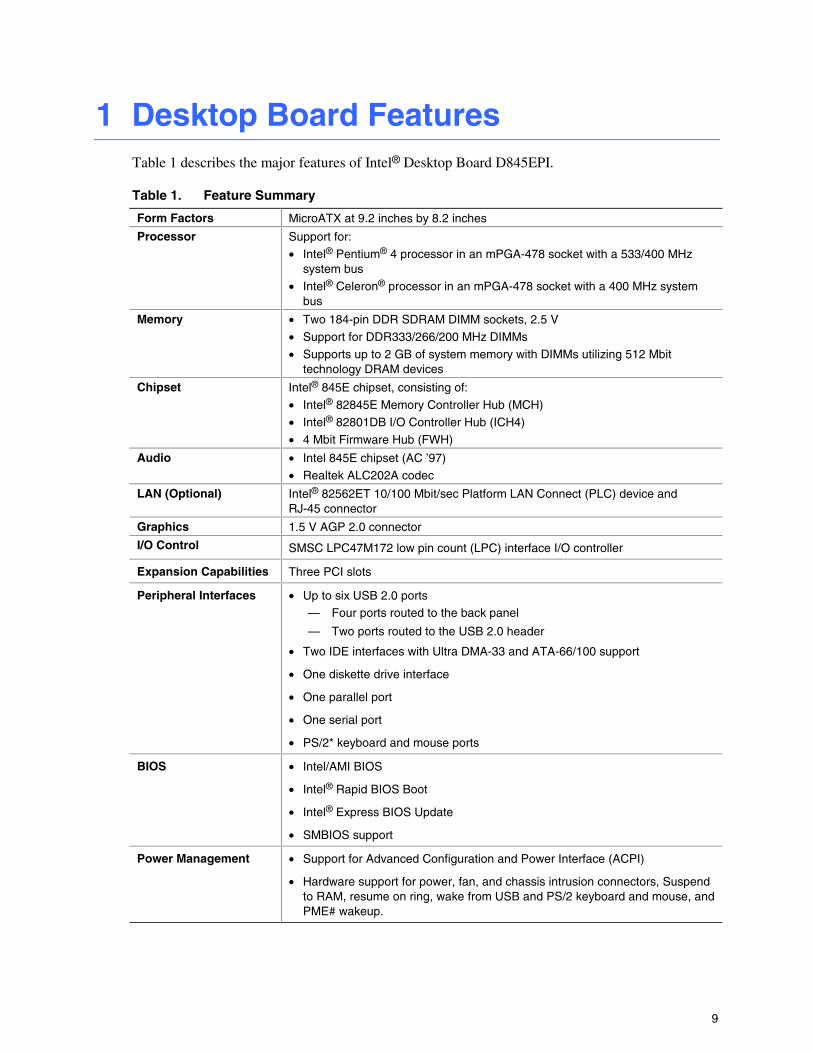
1 Desktop Board Features Table 1 describes the major features of Intel® Desktop Board D845EPI.
Table 1. Feature Summary
Form Factors MicroATX at 9.2 inches by 8.2 inches
Processor Support for:
• Intel® Pentium® 4 processor in an mPGA-478 socket with a 533/400 MHz system bus
• Intel® Celeron® processor in an mPGA-478 socket with a 400 MHz system bus
Memory • Two 184-pin DDR SDRAM DIMM sockets, 2.5 V
• Support for DDR333/266/200 MHz DIMMs
• Supports up to 2 GB of system memory with DIMMs utilizing 512 Mbit technology DRAM devices
Chipset Intel® 845E chipset, consisting of:
• Intel® 82845E Memory Controller Hub (MCH)
• Intel® 82801DB I/O Controller Hub (ICH4)
• 4 Mbit Firmware Hub (FWH)
Audio • Intel 845E chipset (AC ’97)
• Realtek ALC202A codec
LAN (Optional) Intel® 82562ET 10/100 Mbit/sec Platform LAN Connect (PLC) device and RJ-45 connector
Graphics 1.5 V AGP 2.0 connector
I/O Control SMSC LPC47M172 low pin count (LPC) interface I/O controller
Expansion Capabilities Three PCI slots
Peripheral Interfaces • Up to six USB 2.0 ports — Four ports routed to the back panel
— Two ports routed to the USB 2.0 header
• Two IDE interfaces with Ultra DMA-33 and ATA-66/100 support
• One diskette drive interface
• One parallel port
• One serial port
• PS/2* keyboard and mouse ports
BIOS • Intel/AMI BIOS
• Intel® Rapid BIOS Boot
• Intel® Express BIOS Update
• SMBIOS support
Power Management • Support for Advanced Configuration and Power Interface (ACPI)
• Hardware support for power, fan, and chassis intrusion connectors, Suspend to RAM, resume on ring, wake from USB and PS/2 keyboard and mouse, and PME# wakeup.

Intel Desktop Board D845EPI Product Guide
10
NOTE
For information about this Intel desktop board, including the Technical Product Specification (TPS), BIOS updates, and device drivers, go to the Intel World Wide Web site at:
http://support.intel.com/support/motherboards/desktop
Supported Operating Systems The desktop board supports the following operating systems:
• Microsoft Windows* 98 SE
• Microsoft Windows Me
• Microsoft Windows 2000
• Microsoft Windows XP
Desktop Board Features
11
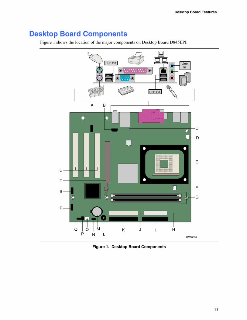
Desktop Board Components Figure 1 shows the location of the major components on Desktop Board D845EPI.
OM16286
E
C
D
HIJKL
MN
O
G
PQ
S
T
BA
F
R
U
LineIn
USB 2.0
USB 2.0
Figure 1. Desktop Board Components
Intel Desktop Board D845EPI Product Guide
12
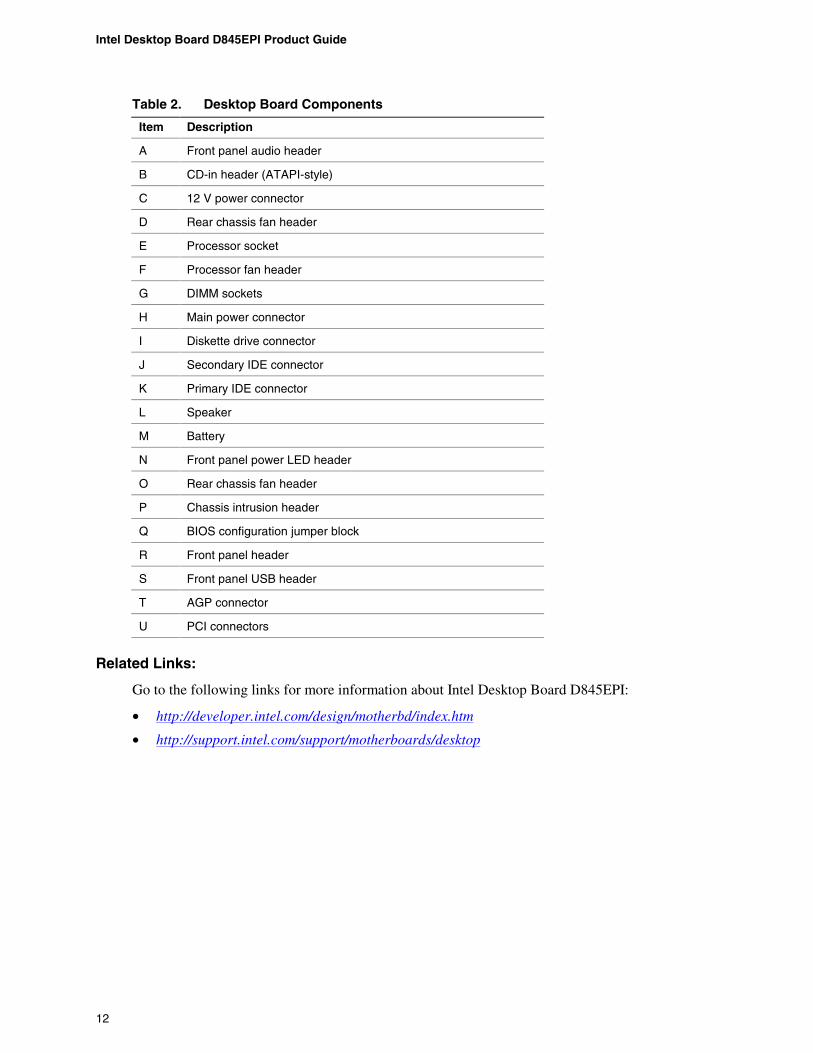
Table 2. Desktop Board Components
Item Description
A Front panel audio header
B CD-in header (ATAPI-style)
C 12 V power connector
D Rear chassis fan header
E Processor socket
F Processor fan header
G DIMM sockets
H Main power connector
I Diskette drive connector
J Secondary IDE connector
K Primary IDE connector
L Speaker
M Battery
N Front panel power LED header
O Rear chassis fan header
P Chassis intrusion header
Q BIOS configuration jumper block
R Front panel header
S Front panel USB header
T AGP connector
U PCI connectors
Related Links:
Go to the following links for more information about Intel Desktop Board D845EPI:
• http://developer.intel.com/design/motherbd/index.htm
• http://support.intel.com/support/motherboards/desktop
Desktop Board Features
13
Processor
CAUTION Failure to use an ATX12V or SFX-12V power supply, or not connecting the additional power supply lead to Desktop Board D845EPI may result in damage to the desktop board and/or power supply.
Desktop Board D845EPI supports a single Intel Pentium 4 processor or Intel Celeron processor. Processors are not included with the desktop board and must be purchased separately.
The processor connects to the desktop board through the mPGA-478-pin socket. The Intel Pentium 4 processor or Intel Celeron processor may be removed and replaced with supported higher speed processors.
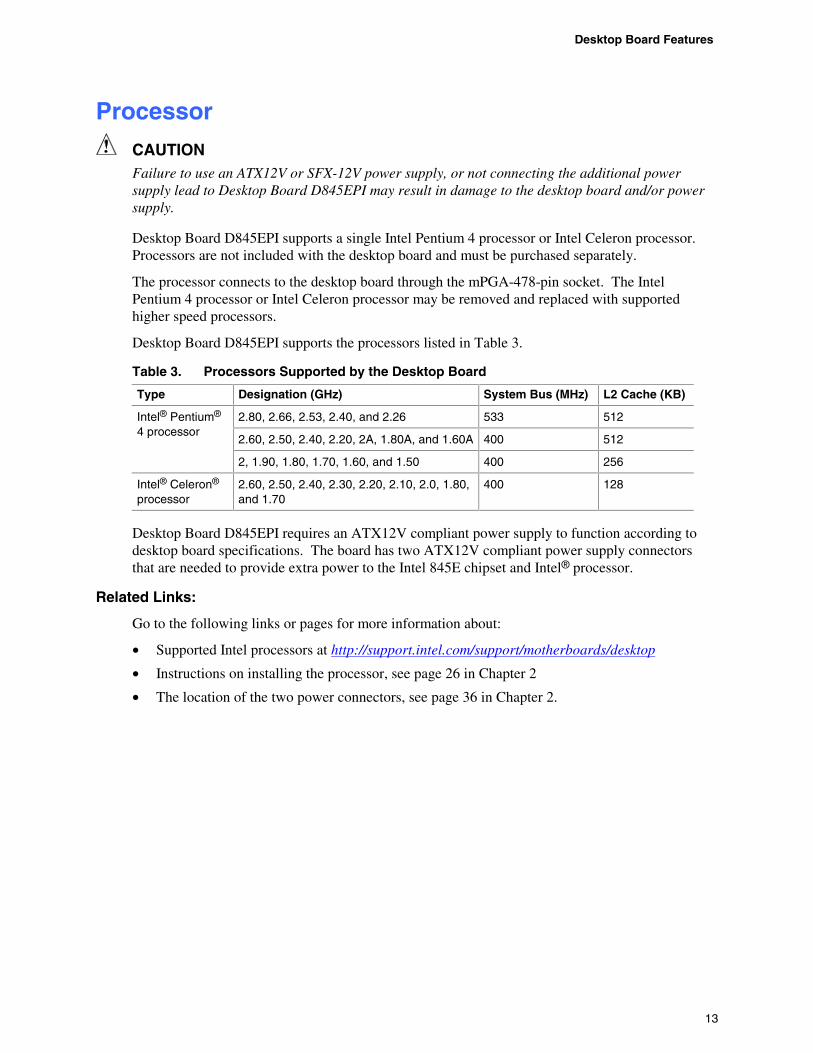
Desktop Board D845EPI supports the processors listed in Table 3.
Table 3. Processors Supported by the Desktop Board
Type Designation (GHz) System Bus (MHz) L2 Cache (KB)
2.80, 2.66, 2.53, 2.40, and 2.26 533 512
2.60, 2.50, 2.40, 2.20, 2A, 1.80A, and 1.60A 400 512
Intel® Pentium® 4 processor
2, 1.90, 1.80, 1.70, 1.60, and 1.50 400 256
Intel® Celeron® processor
2.60, 2.50, 2.40, 2.30, 2.20, 2.10, 2.0, 1.80, and 1.70
400 128
Desktop Board D845EPI requires an ATX12V compliant power supply to function according to desktop board specifications. The board has two ATX12V compliant power supply connectors that are needed to provide extra power to the Intel 845E chipset and Intel® processor.
Related Links:
Go to the following links or pages for more information about:
• Supported Intel processors at http://support.intel.com/support/motherboards/desktop
• Instructions on installing the processor, see page 26 in Chapter 2
• The location of the two power connectors, see page 36 in Chapter 2.
Intel Desktop Board D845EPI Product Guide
14
Main Memory NOTE
To be fully compliant with all applicable Intel® SDRAM memory specification addendums, the desktop board should be populated with DIMMs that support the Serial Presence Detect (SPD) data structure. If your memory modules do not support SPD, you will see a notification to this effect on the screen at power up. The BIOS will attempt to configure the memory controller for normal operation.
NOTE
All memory components and DIMMs used with the desktop board must comply with the PC SDRAM specifications. These include the PC SDRAM Specification (memory component specific) and the PC Unbuffered DIMM Specification.
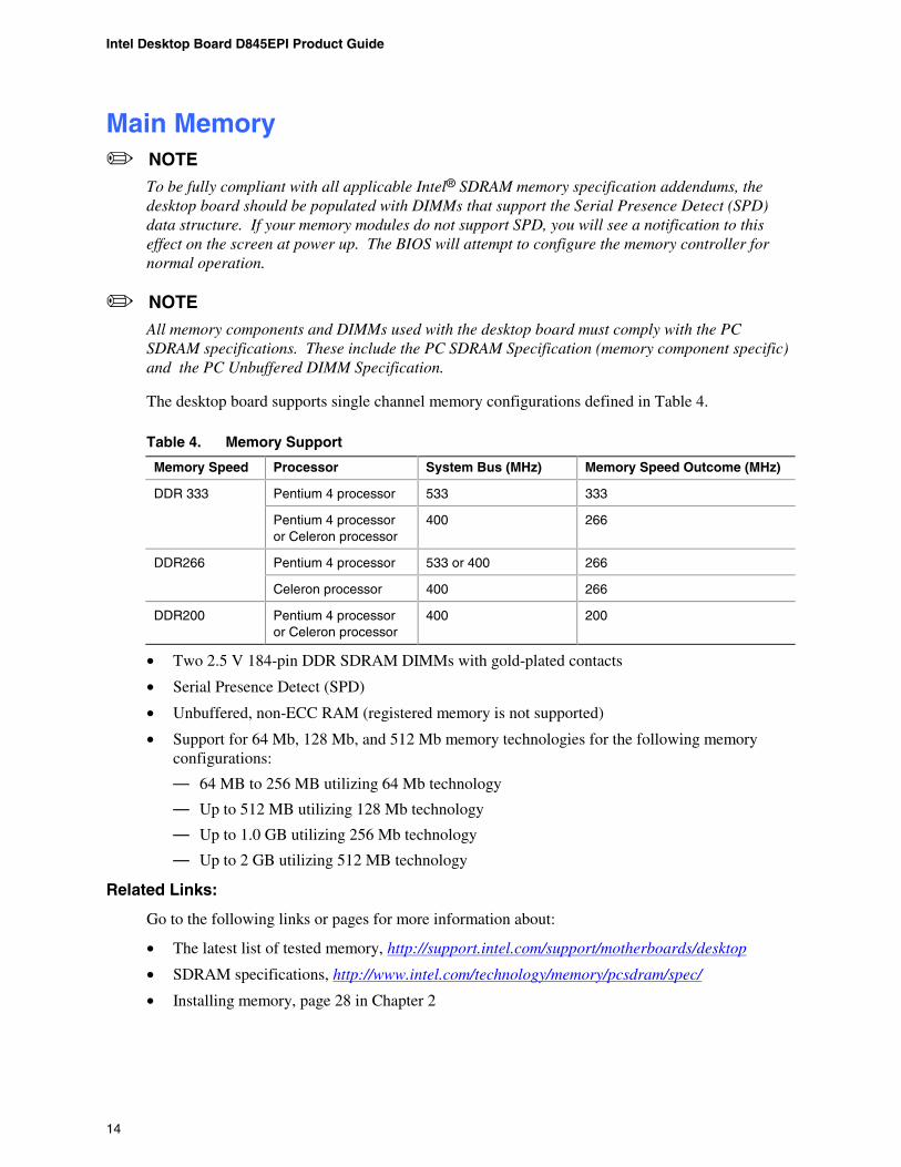
The desktop board supports single channel memory configurations defined in Table 4.
Table 4. Memory Support
Memory Speed Processor System Bus (MHz) Memory Speed Outcome (MHz)
Pentium 4 processor 533 333 DDR 333
Pentium 4 processor or Celeron processor
400 266
Pentium 4 processor 533 or 400 266 DDR266
Celeron processor 400 266
DDR200 Pentium 4 processor or Celeron processor
400 200
• Two 2.5 V 184-pin DDR SDRAM DIMMs with gold-plated contacts
• Serial Presence Detect (SPD)
• Unbuffered, non-ECC RAM (registered memory is not supported)
• Support for 64 Mb, 128 Mb, and 512 Mb memory technologies for the following memory configurations:
— 64 MB to 256 MB utilizing 64 Mb technology
— Up to 512 MB utilizing 128 Mb technology
— Up to 1.0 GB utilizing 256 Mb technology
— Up to 2 GB utilizing 512 MB technology
Related Links:
Go to the following links or pages for more information about:
• The latest list of tested memory, http://support.intel.com/support/motherboards/desktop
• SDRAM specifications, http://www.intel.com/technology/memory/pcsdram/spec/
• Installing memory, page 28 in Chapter 2
Desktop Board Features
15
Intel® 845E Chipset The Intel 845E chipset consists of the following:
• Intel 82845E Memory Controller Hub (MCH) with AHA bus
• Intel 82801DB I/O Controller Hub (ICH4) with AHA bus
• Firmware Hub (FWH)
Related Link:
Go to the following link for more information about the Intel 845E chipset:
http://developer.intel.com/design/nav/pcserver.htm
Audio Subsystem The audio subsystem features the following:
• Intel 845E chipset (AC ’97)
• Realtek ALC202A codec
The audio subsystem supports the following audio interfaces:
• ATAPI-style CD-ROM connector
• Front panel audio connector
• Back panel connectors:
— Line out
— Line in
— Mic in
NOTE
The line out connector, located on the back panel, is designed to power either headphones or amplified speakers only. Poor audio quality may occur if passive (non-amplified) speakers are connected to this output.
Related Links:
Go to the following link or pages for more information about:
• Audio drivers and utilities http://support.intel.com/support/motherboards/desktop
• Installing a front panel audio solution, page 34 in Chapter 2
• PCI power management support
Intel Desktop Board D845EPI Product Guide
16
LAN Subsystem (Optional) The optional Intel 82562ET (with the Intel 82801DB ICH4) provides a Fast PCI LAN subsystem providing both 10Base-T and 100Base-TX connectivity. The Intel 82562ET provides the following functions:
• Basic 10/100 Ethernet LAN connectivity
• Support for RJ-45 connector with status indicator LEDs
• Programmable transit threshold
• Configurable EEPROM that contains the MAC address
LAN Subsystem Software
For LAN software and drivers, refer to the D845EPI link on Intel’s World Wide Web site at:
http://support.intel.com/support/motherboards/desktop
RJ-45 LAN Connector LEDs
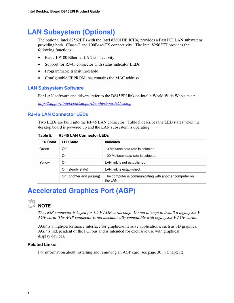
Two LEDs are built into the RJ-45 LAN connector. Table 5 describes the LED states when the desktop board is powered up and the LAN subsystem is operating.
Table 5. RJ-45 LAN Connector LEDs
LED Color LED State Indicates
Off 10 Mbit/sec data rate is selected. Green
On 100 Mbit/sec data rate is selected.
Off LAN link is not established.
On (steady state) LAN link is established.
Yellow
On (brighter and pulsing) The computer is communicating with another computer on the LAN.
Accelerated Graphics Port (AGP)
NOTE The AGP connector is keyed for 1.5 V AGP cards only. Do not attempt to install a legacy 3.3 V AGP card. The AGP connector is not mechanically compatible with legacy 3.3 V AGP cards.
AGP is a high-performance interface for graphics-intensive applications, such as 3D graphics. AGP is independent of the PCI bus and is intended for exclusive use with graphical display devices.
Related Links:
For information about installing and removing an AGP card, see page 30 in Chapter 2.
Desktop Board Features
17
Hi-Speed USB 2.0 Support
NOTE
Computer systems that have an unshielded cable attached to a USB port might not meet FCC Class B requirements, even if no device or a low-speed USB device is attached to the cable. Use a shielded cable that meets the requirements for a full-speed USB device.
This desktop board supports up to six USB 2.0 ports via ICH4; four ports routed to the back panel and two routed to a USB front panel header. USB 2.0 ports are backward compatible with USB 1.1 devices. USB 1.1 devices will function normally at USB 1.1 speeds.
Disabling Hi-Speed USB in the BIOS reverts all USB 2.0 ports to USB 1.1 operation. This may be required to accommodate operating systems that do not support USB 2.0.
Enhanced IDE Interface The ICH4’s IDE interface handles the exchange of information between the processor and peripheral devices like hard disks, CD-ROM drives, and Iomega Zip* drives inside the computer. The interface supports:
• Up to four IDE devices (such as hard drives)
• ATAPI devices (such as CD-ROM drives)
• Older PIO Mode devices
• Ultra DMA-33 and ATA-66/100 protocols
• Laser Servo (LS-120) drives
Expansion Slots Desktop Board D845EPI has three PCI bus add-in card connectors.
BIOS The BIOS provides the Power-On Self-Test (POST), the BIOS Setup program, the PCI and IDE auto-configuration utilities, and the video BIOS. The BIOS is stored in the Firmware Hub.
Related Links:
For information about:
• The BIOS Setup menus, go to Chapter 4 on page 51.
• Instructions about updating the BIOS, go to Chapter 3 on page 47.
PCI Auto Configuration
If you install a PCI add-in card in your computer, the PCI auto-configuration utility in the BIOS automatically detects and configures the resources (IRQs, DMA channels, and I/O space) for that add-in card. You do not need to run the BIOS Setup program after you install a PCI add-in card.
Intel Desktop Board D845EPI Product Guide
18
IDE Auto Configuration
If you install an IDE device (such as a hard drive) in your computer, the IDE auto-configuration utility in the BIOS automatically detects and configures the device for your computer. You do not need to run the BIOS Setup program after installing an IDE device. You can override the auto-configuration options by specifying manual configuration in the BIOS Setup program.
To use ATA-66/100 features, the following items are required:
• An ATA-66/100 peripheral device
• An ATA-66/100 compatible cable
• ATA-66/100 operating system device drivers
Security Passwords
The BIOS includes security features that restrict whether the BIOS Setup program can be accessed and who can boot the computer. A supervisor password and a user password can be set for the Setup and for booting the computer, with the following restrictions:
• The supervisor password gives unrestricted access to view and change all Setup options. If only the supervisor password is set, pressing <Enter> at the password prompt of Setup gives the user restricted access to Setup.
• If both the supervisor and user passwords are set, you must enter either the supervisor password or the user password to access Setup. Setup options are then available for viewing and changing depending on whether the supervisor or user password was entered.
• Setting a user password restricts who can boot the computer. The password prompt is displayed before the computer is booted. If only the supervisor password is set, the computer boots without asking for a password. If both passwords are set, you can enter either password to boot the computer.
Power Management Features • Advanced Configuration and Power Interface (ACPI)
• Hardware support:
— Power connectors
— Fan connectors
— Chassis intrusion
— Suspend to RAM (Instantly Available PC technology)
— Wake from USB
— Wake from PS/2 keyboard/mouse
— PME# wakeup support
ACPI
ACPI gives the operating system direct control over the power management and Plug & Play functions of a computer. The use of ACPI with the desktop board requires an operating system that provides full ACPI support.
Desktop Board Features
19
Power Connectors
The desktop board has two power connectors. See Figure 11 on page 36 for the location of the power connectors.
Fan Headers
The desktop board has two chassis fan headers and one processor fan header. See Figure 11 on page 36 for the location of the fan headers.
Chassis Intrusion
The board supports a chassis security feature that detects if the chassis cover has been removed. The security feature uses a mechanical switch (not included) on the chassis that can be connected to the chassis intrusion header on the desktop board. See Figure 11 on page 36 for the location of the chassis intrusion header.
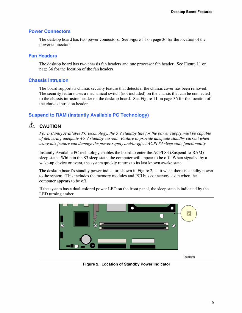
Suspend to RAM (Instantly Available PC Technology)
CAUTION For Instantly Available PC technology, the 5 V standby line for the power supply must be capable of delivering adequate +5 V standby current. Failure to provide adequate standby current when using this feature can damage the power supply and/or effect ACPI S3 sleep state functionality.
Instantly Available PC technology enables the board to enter the ACPI S3 (Suspend-to-RAM) sleep state. While in the S3 sleep state, the computer will appear to be off. When signaled by a wake-up device or event, the system quickly returns to its last known awake state.
The desktop board’s standby power indicator, shown in Figure 2, is lit when there is standby power to the system. This includes the memory modules and PCI bus connectors, even when the computer appears to be off.
If the system has a dual-colored power LED on the front panel, the sleep state is indicated by the LED turning amber.
OM16287
Figure 2. Location of Standby Power Indicator
Intel Desktop Board D845EPI Product Guide
20
CAUTION Power supplies used with this desktop board must be able to provide enough standby current to support the standard Instantly Available (ACPI S3 sleep state) configuration. If the standby current necessary to support multiple wake events from the PCI and/or USB buses exceeds power supply capacity, the desktop board may lose register settings stored in memory.
Related Links:
For more information about standby current requirements for the desktop board, navigate to the Technical Product Specification by selecting the desktop board from the link below and then selecting Product Documents:
http://support.intel.com/support/motherboards/desktop
Wake from USB
USB bus activity wakes the computer from an ACPI S1 or S3 state.
NOTE Wake from USB requires the use of a USB peripheral that supports Wake from USB..
Wake from PS/2 Keyboard/Mouse
PS/2 keyboard/mouse activity wakes the computer from an ACPI S1 or S3 state.
PME# Wakeup Support
When the PME# signal on the PCI bus is asserted, the computer wakes from an ACPI S1, S3, or S5 state.
Speaker A speaker is mounted on the desktop board. The speaker provides audible error code (beep code) information during the Power-On Self-Test (POST).
Battery A battery on the desktop board keeps the values in CMOS RAM and the clock current when the computer is turned off. See Chapter 2 starting on page 21 for instructions on how to replace the battery.
Real-Time Clock The desktop board has a time-of-day clock and 100-year calendar. The battery on the desktop board keeps the clock current when the computer is turned off.
21
2 Installing and Replacing Desktop Board Components This chapter tells you how to:
• Install the I/O shield
• Install and remove the desktop board
• Install and remove a processor
• Install and remove memory
• Connect the IDE cable
• Instal and remove an AGP card
• Connect internal headers
• Connect hardware control and power cables
• Connect add-in card and peripheral interface connectors
• Set the BIOS configuration jumper block
• Clear passwords
• Connect back panel connectors
• Replace the battery
Before You Begin
WARNINGS The procedures in this chapter assume familiarity with the general terminology associated with personal computers and with the safety practices and regulatory compliance required for using and modifying electronic equipment.
Disconnect the computer from its power source and from any telecommunications links, networks, or modems before performing any of the procedures described in this chapter. Failure to disconnect power, telecommunications links, networks, or modems before you open the computer or perform any procedures can result in personal injury or equipment damage. Some circuitry on the board can continue to operate even though the front panel power button is off.
CAUTION Many of the midboard and front panel connectors provide operating voltage (+5 V dc and +12 V dc, for example) to devices inside the computer chassis, such as fans and internal peripherals. These connectors are not overcurrent protected. Do not use these connectors for powering devices external to the computer chassis. A fault in the load presented by the external devices could cause damage to the computer, the interconnecting cable, and the external devices themselves.

Intel Desktop Board D845EPI Product Guide
22
Follow these guidelines before you begin:
• Always follow the steps in each procedure in the correct order.
• Set up a log to record information about your computer, such as model, serial numbers, installed options, and configuration information.
• Electrostatic discharge (ESD) can damage components. Perform the procedures described in this chapter only at an ESD workstation using an antistatic wrist strap and a conductive foam pad. If such a station is not available, you can provide some ESD protection by wearing an antistatic wrist strap and attaching it to a metal part of the computer chassis.
Installation Precautions When you install and test the Intel desktop board, observe all warnings and cautions in the installation instructions.
To avoid injury, be careful of:
• Sharp pins on connectors
• Sharp pins on printed circuit assemblies
• Rough edges and sharp corners on the chassis
• Hot components (like processors, voltage regulators, and heat sinks)
• Damage to wires that could cause a short circuit
Observe all warnings and cautions that instruct you to refer computer servicing to qualified technical personnel.
Installation Instructions
CAUTION Follow these guidelines to meet safety and regulatory requirements when installing this board.
Read and adhere to all of these instructions and the instructions supplied with the chassis and associated modules. If the instructions for the chassis are inconsistent with these instructions or the instructions for associated modules, contact the supplier’s technical support to find out how you can ensure that your computer meets safety and regulatory requirements. If you do not follow these instructions and the instructions provided by chassis and module suppliers, you increase safety risk and the possibility of noncompliance with regional laws and regulations.
Ensure Electromagnetic Compatibility (EMC) Compliance
Before computer integration, make sure that the power supply and other modules or peripherals, as applicable, have passed Class B EMC testing and are marked accordingly.
Pay close attention to the following when reading the installation instructions for the host chassis, power supply, and other modules:
• Product certifications or lack of certifications
• External I/O cable shielding and filtering
Installing and Replacing Desktop Board Components
23
• Mounting, grounding, and bonding requirements
• Keying connectors when mating the wrong connectors could be hazardous
If the power supply and other modules or peripherals, as applicable, are not Class B EMC compliant before integration, then EMC testing is required on a representative sample of the newly completed computer.
Chassis and Component Certifications
Ensure that the chassis and certain components; such as the power supply, peripheral drives, wiring, and cables; are components certified for the country or market where used. Agency certification marks on the product are proof of certification. Typical product certifications include:
• Europe The CE marking signifies compliance with all applicable European requirements. If the chassis and other components are not properly CE marked, a supplier’s Declaration of Conformity statement to the European EMC directive and Low Voltage directive (as applicable), should be obtained. Additionally, other directives, such as the Radio and Telecommunications Terminal Equipment (R&TTE) directive may also apply depending on product features.
• United States A certification mark by a Nationally Recognized Testing Laboratory (NRTL) such as UL, CSA, or ETL signifies compliance with safety requirements. Wiring and cables must also be UL listed or recognized and suitable for the intended use. The FCC Class B logo for home or office use signifies compliance with electromagnetic interference (EMI) requirements.
• Canada A nationally recognized certification mark such as CSA or cUL signifies compliance with safety requirements. The Industry Canada statement at the front of this product guide demonstrates compliance with Canadian EMC regulations.
Prevent Power Supply Overload
Do not overload the power supply output. To avoid overloading the power supply, make sure that the calculated total current loads of all the modules within the computer are less than the output current rating of each of the power supplies’ output circuits.
Place Battery Marking
There is insufficient space on this desktop board to provide instructions for replacing and disposing of the Lithium ion coin cell battery. For system safety certification, the following statement or equivalent statement is required to be permanently and legibly marked on the chassis near the battery.
CAUTION Risk of explosion if the battery is replaced with an incorrect type. Batteries should be recycled where possible. Disposal of used batteries must be in accordance with local environmental regulations.
Intel Desktop Board D845EPI Product Guide
24
Related Links:
For information about replacing the battery, go to page 42 in this chapter.
Use Only for Intended Applications
All Intel desktop boards are evaluated as Information Technology Equipment (I.T.E.) for use in personal computers for installation in homes, offices, schools, computer rooms, and similar locations. The suitability of this product for other applications or environments, such as medical, industrial, alarm systems, test equipment, etc. may require further evaluation.
Related Links:
For information about regulatory compliance, go to Appendix B on page 83.
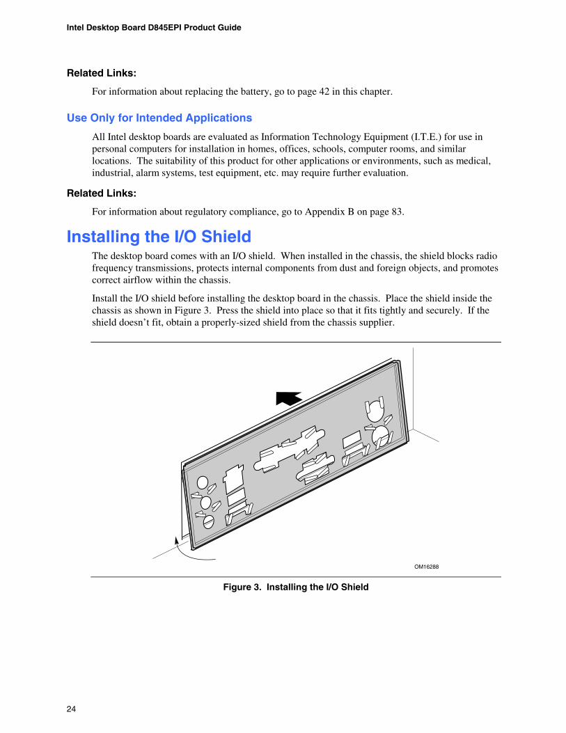
Installing the I/O Shield The desktop board comes with an I/O shield. When installed in the chassis, the shield blocks radio frequency transmissions, protects internal components from dust and foreign objects, and promotes correct airflow within the chassis.
Install the I/O shield before installing the desktop board in the chassis. Place the shield inside the chassis as shown in Figure 3. Press the shield into place so that it fits tightly and securely. If the shield doesn’t fit, obtain a properly-sized shield from the chassis supplier.
OM16288
Figure 3. Installing the I/O Shield
Installing and Replacing Desktop Board Components
25
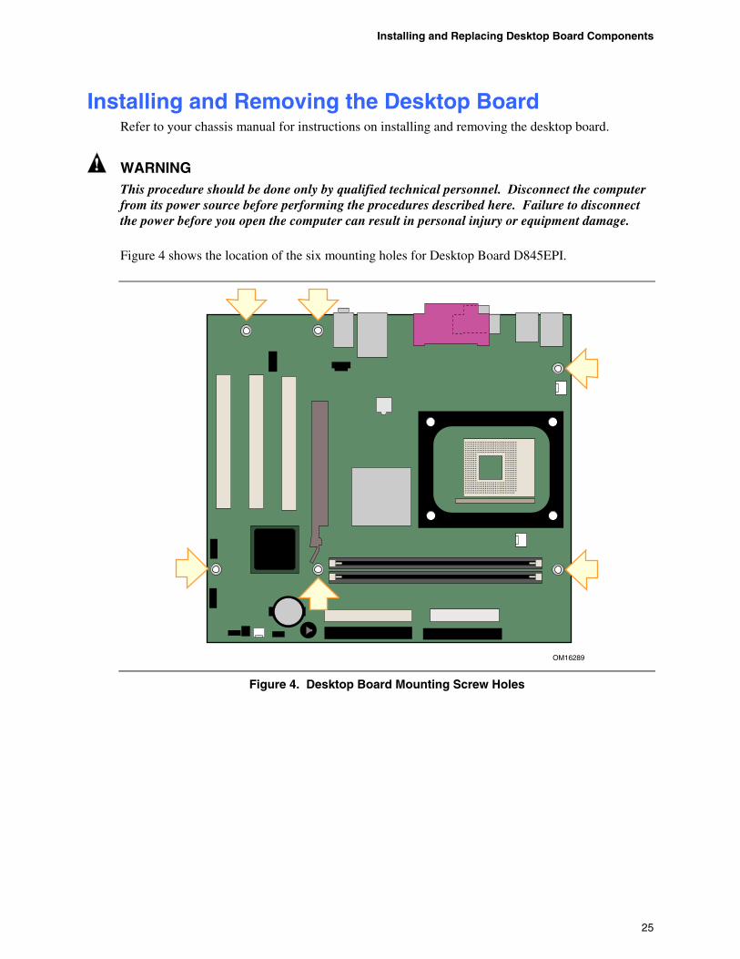
Installing and Removing the Desktop Board Refer to your chassis manual for instructions on installing and removing the desktop board.
WARNING This procedure should be done only by qualified technical personnel. Disconnect the computer from its power source before performing the procedures described here. Failure to disconnect the power before you open the computer can result in personal injury or equipment damage.
Figure 4 shows the location of the six mounting holes for Desktop Board D845EPI.
OM16289
Figure 4. Desktop Board Mounting Screw Holes
Intel Desktop Board D845EPI Product Guide
26
Installing and Removing a Processor Instructions on how to install the processor to the desktop board are given below.
Installing a Processor
CAUTION Before installing or removing the processor, make sure that AC power has been removed by unplugging the power cord from the computer; the standby power LED should not be lit (see Figure 2 on page 19). Failure to do so could damage the processor and the desktop board.
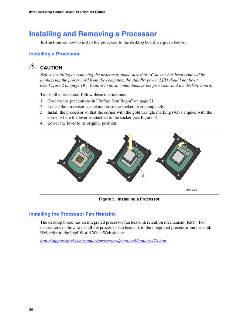
To install a processor, follow these instructions:
1. Observe the precautions in ”Before You Begin” on page 21. 2. Locate the processor socket and raise the socket lever completely. 3. Install the processor so that the corner with the gold triangle marking (A) is aligned with the
corner where the lever is attached to the socket (see Figure 5). 4. Lower the lever to its original position.
OM15228
mPGA478B
mPGA478B
A
mPGA478B
Figure 5. Installing a Processor
Installing the Processor Fan Heatsink
The desktop board has an integrated processor fan heatsink retention mechanism (RM). For instructions on how to install the processor fan heatsink to the integrated processor fan heatsink RM, refer to the Intel World Wide Web site at:
http://support.intel.com/support/processors/pentium4/intnotes478.htm
Installing and Replacing Desktop Board Components
27
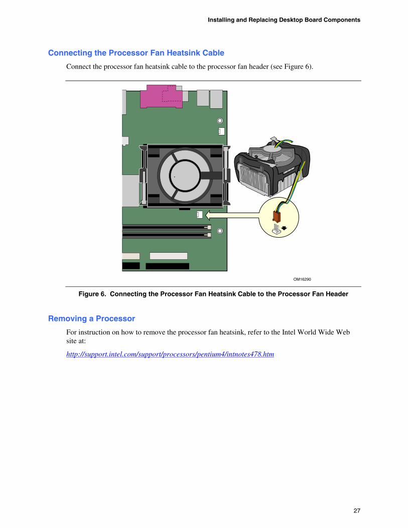
Connecting the Processor Fan Heatsink Cable
Connect the processor fan heatsink cable to the processor fan header (see Figure 6).
OM16290
Figure 6. Connecting the Processor Fan Heatsink Cable to the Processor Fan Header
Removing a Processor
For instruction on how to remove the processor fan heatsink, refer to the Intel World Wide Web site at:
http://support.intel.com/support/processors/pentium4/intnotes478.htm
Intel Desktop Board D845EPI Product Guide
28
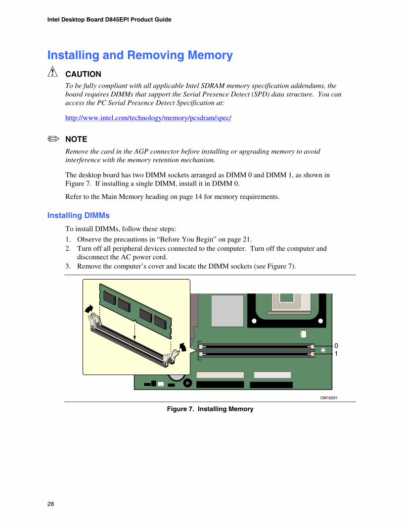
Installing and Removing Memory
CAUTION To be fully compliant with all applicable Intel SDRAM memory specification addendums, the board requires DIMMs that support the Serial Presence Detect (SPD) data structure. You can access the PC Serial Presence Detect Specification at:
http://www.intel.com/technology/memory/pcsdram/spec/
NOTE
Remove the card in the AGP connector before installing or upgrading memory to avoid interference with the memory retention mechanism.
The desktop board has two DIMM sockets arranged as DIMM 0 and DIMM 1, as shown in Figure 7. If installing a single DIMM, install it in DIMM 0.
Refer to the Main Memory heading on page 14 for memory requirements.
Installing DIMMs
To install DIMMs, follow these steps:
1. Observe the precautions in “Before You Begin” on page 21. 2. Turn off all peripheral devices connected to the computer. Turn off the computer and
disconnect the AC power cord. 3. Remove the computer’s cover and locate the DIMM sockets (see Figure 7).
OM16291
01
Figure 7. Installing Memory

Installing and Replacing Desktop Board Components
29
4. Make sure the clips at either end of the DIMM socket(s) are pushed outward to the open position.
5. Position the DIMM above the socket. Align the small notche in the bottom edge of the DIMM with the key in the socket (see inset in Figure 7).
6. Insert the bottom edge of the DIMM into the socket. 7. When the DIMM is inserted, push down on the top edge of the DIMM until the retaining clips
snap into place. Make sure the clips are firmly in place (see inset in Figure 7). 8. Replace the computer’s cover and reconnect the AC power cord.
Removing DIMMs
To remove a memory module, follow these steps:
1. Observe the precautions in “Before You Begin” on page 21. 2. Turn off all peripheral devices connected to the computer. Turn off the computer. 3. Remove the AC power cord from the computer. 4. Remove the computer’s cover. 5. Remove the AGP card, if necessary. 6. Gently spread the retaining clips at each end of the DIMM socket. The DIMM pops out of
the socket. 7. Hold the DIMM by the edges, lift it away from the socket, and store it in an anti-static package. 8. Reinstall and reconnect any parts you removed or disconnected to reach the DIMM sockets. 9. Replace the computer’s cover and reconnect the AC power cord.
Intel Desktop Board D845EPI Product Guide
30
Installing and Removing an AGP Card
CAUTION When installing any AGP card in the desktop board, ensure that it is fully seated in the AGP connector before you power on the system. If the card is not fully seated in the AGP connector, an electrical short may result across the AGP slot pins. Depending on the over-current protection of the power supply, certain board components and/or traces may be damaged.
The AGP connector supports 1.5 V (4x and 2x) AGP cards. The desktop board has an integrated AGP card retention mechanism (RM).
Installing an AGP Card
Follow these instructions to install an AGP card:
1. Observe the precautions in “Before You Begin” on page 21. 2. Place the card in the AGP connector. 3. Press down on the card until it is completely seated in the AGP connector and the card
retention notch snaps into place around the RM pin. 4. Secure the card’s metal bracket to the chassis back panel with a screw.
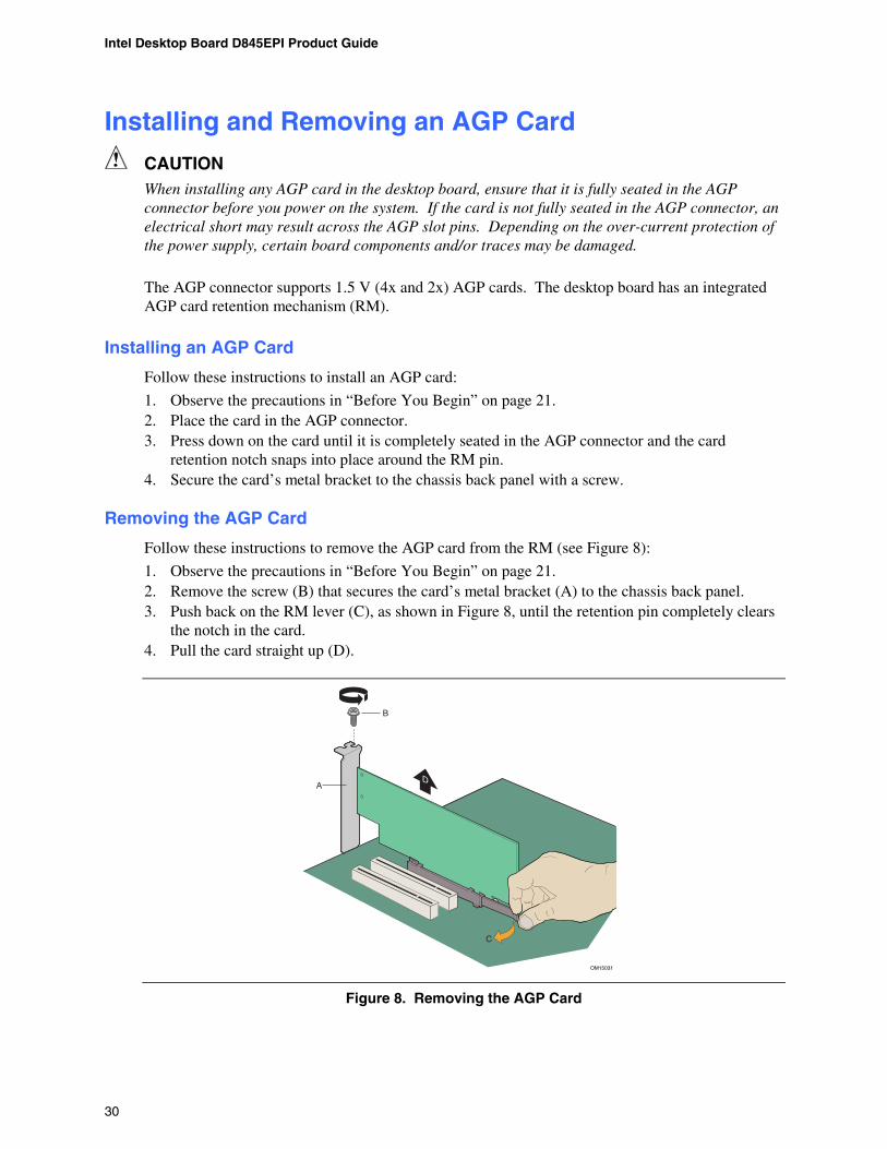
Removing the AGP Card
Follow these instructions to remove the AGP card from the RM (see Figure 8):
1. Observe the precautions in “Before You Begin” on page 21. 2. Remove the screw (B) that secures the card’s metal bracket (A) to the chassis back panel. 3. Push back on the RM lever (C), as shown in Figure 8, until the retention pin completely clears
the notch in the card. 4. Pull the card straight up (D).
OM15031
A
B
C
D
Figure 8. Removing the AGP Card
Installing and Replacing Desktop Board Components
31
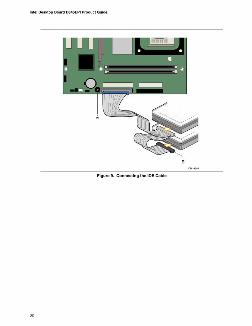
Connecting the IDE Cable The Intel® boxed desktop board package includes an IDE cable. The cable connects two drives to the desktop board. The cable supports both ATA-66 and ATA-100 transfer protocols and is backward compatible with drives using slower IDE transfer protocols. Figure 9 shows the correct installation of the cable.
NOTE
ATA-66/100 compatible cables are backward compatible with drives using slower IDE transfer protocols. If an ATA-66/100 disk drive and a disk drive using any other IDE transfer protocol are attached to the same cable, the maximum transfer rate between the drives may be reduced to that of the slowest drive.
NOTE
Do not connect an ATA device as a slave on the same IDE cable as an ATAPI master device. For example, do not connect an ATA hard drive as a slave to an ATAPI CD-ROM drive.
For correct function of the cable:
1. Attach the cable end with the single blue connector to the desktop board (see Figure 9, A).
2. Attach the cable end with the two closely spaced black and gray connectors to the drives (see Figure 9, B).
Intel Desktop Board D845EPI Product Guide
32
OM16292
A
B
Figure 9. Connecting the IDE Cable
Installing and Replacing Desktop Board Components
33
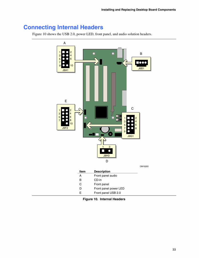
Connecting Internal Headers Figure 10 shows the USB 2.0, power LED, front panel, and audio solution headers.
OM16293
213 45 67
10
B
J9F2
8
C
1 3
J8H3
A
213 45 67
10
J8A1
9
213 45 679
8
J9G1
D
E
J6B1
Item Description A Front panel audio
B CD-in
C Front panel
D Front panel power LED
E Front panel USB 2.0
Figure 10. Internal Headers
Intel Desktop Board D845EPI Product Guide
34
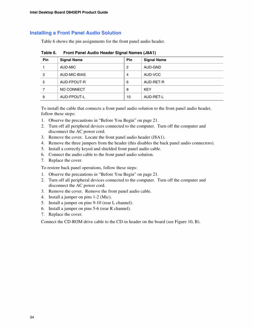
Installing a Front Panel Audio Solution
Table 6 shows the pin assignments for the front panel audio header.
Table 6. Front Panel Audio Header Signal Names (J8A1)
Pin Signal Name Pin Signal Name
1 AUD-MIC 2 AUD-GND
3 AUD-MIC-BIAS 4 AUD-VCC
5 AUD-FPOUT-R 6 AUD-RET-R
7 NO CONNECT 8 KEY
9 AUD-FPOUT-L 10 AUD-RET-L
To install the cable that connects a front panel audio solution to the front panel audio header, follow these steps:
1. Observe the precautions in “Before You Begin” on page 21. 2. Turn off all peripheral devices connected to the computer. Turn off the computer and
disconnect the AC power cord. 3. Remove the cover. Locate the front panel audio header (J8A1). 4. Remove the three jumpers from the header (this disables the back panel audio connectors). 5. Install a correctly keyed and shielded front panel audio cable. 6. Connect the audio cable to the front panel audio solution. 7. Replace the cover.
To restore back panel operations, follow these steps:
1. Observe the precautions in “Before You Begin” on page 21. 2. Turn off all peripheral devices connected to the computer. Turn off the computer and
disconnect the AC power cord. 3. Remove the cover. Remove the front panel audio cable. 4. Install a jumper on pins 1-2 (Mic). 5. Install a jumper on pins 9-10 (rear L channel). 6. Install a jumper on pins 5-6 (rear R channel). 7. Replace the cover.
Connect the CD-ROM drive cable to the CD-in header on the board (see Figure 10, B).
Installing and Replacing Desktop Board Components
35
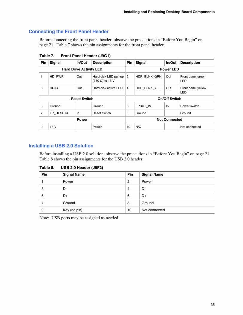
Connecting the Front Panel Header
Before connecting the front panel header, observe the precautions in “Before You Begin” on page 21. Table 7 shows the pin assignments for the front panel header.
Table 7. Front Panel Header (J9G1)
Pin Signal In/Out Description Pin Signal In/Out Description
Hard Drive Activity LED Power LED
1 HD_PWR Out Hard disk LED pull-up (330 Ω) to +5 V
2 HDR_BLNK_GRN Out Front panel green LED
3 HDA# Out Hard disk active LED 4 HDR_BLNK_YEL Out Front panel yellow LED
Reset Switch On/Off Switch
5 Ground Ground 6 FPBUT_IN In Power switch
7 FP_RESET# In Reset switch 8 Ground Ground
Power Not Connected
9 +5 V Power 10 N/C Not connected
Installing a USB 2.0 Solution
Before installing a USB 2.0 solution, observe the precautions in “Before You Begin” on page 21. Table 8 shows the pin assignments for the USB 2.0 header.
Table 8. USB 2.0 Header (J9F2)
Pin Signal Name Pin Signal Name
1 Power 2 Power
3 D- 4 D-
5 D+ 6 D+
7 Ground 8 Ground
9 Key (no pin) 10 Not connected
Note: USB ports may be assigned as needed.
Intel Desktop Board D845EPI Product Guide
36
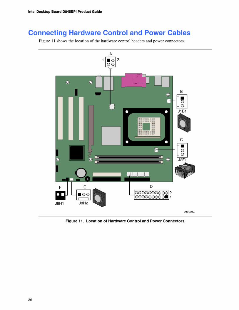
Connecting Hardware Control and Power Cables Figure 11 shows the location of the hardware control headers and power connectors.
OM16294
J2F1
J8H2
J1B1
1 2
J8H1
A
B
C
12
DEF
Figure 11. Location of Hardware Control and Power Connectors

Installing and Replacing Desktop Board Components
37
Connecting Hardware Control Cables
See Figure 11 for fan and chassis intrusion header locations. Connect the processor’s fan heatsink cable to the processor fan header on the board (see Figure 11, C). Connect chassis fan cables to the board fan headers (see Figure 11, B and E). Connect the chassis intrusion cable to the respective header on the board (see Figure 11, F).
Connecting Power Cables
CAUTION Failure to use an ATX12V power supply, or not connecting the 12 V processor core voltage power supply connector to the desktop board may result in damage to the desktop board and/or power supply.
Figure 11 shows the location of the power connectors.
1. Observe the precautions in “Before You Begin” on page 21. 2. Connect the 12 V processor core voltage power supply cable to the 2x2 connector
(see Figure 11, A). 3. Connect the main power supply cable to the 2x10 connector (see Figure 11, D).
Intel Desktop Board D845EPI Product Guide
38
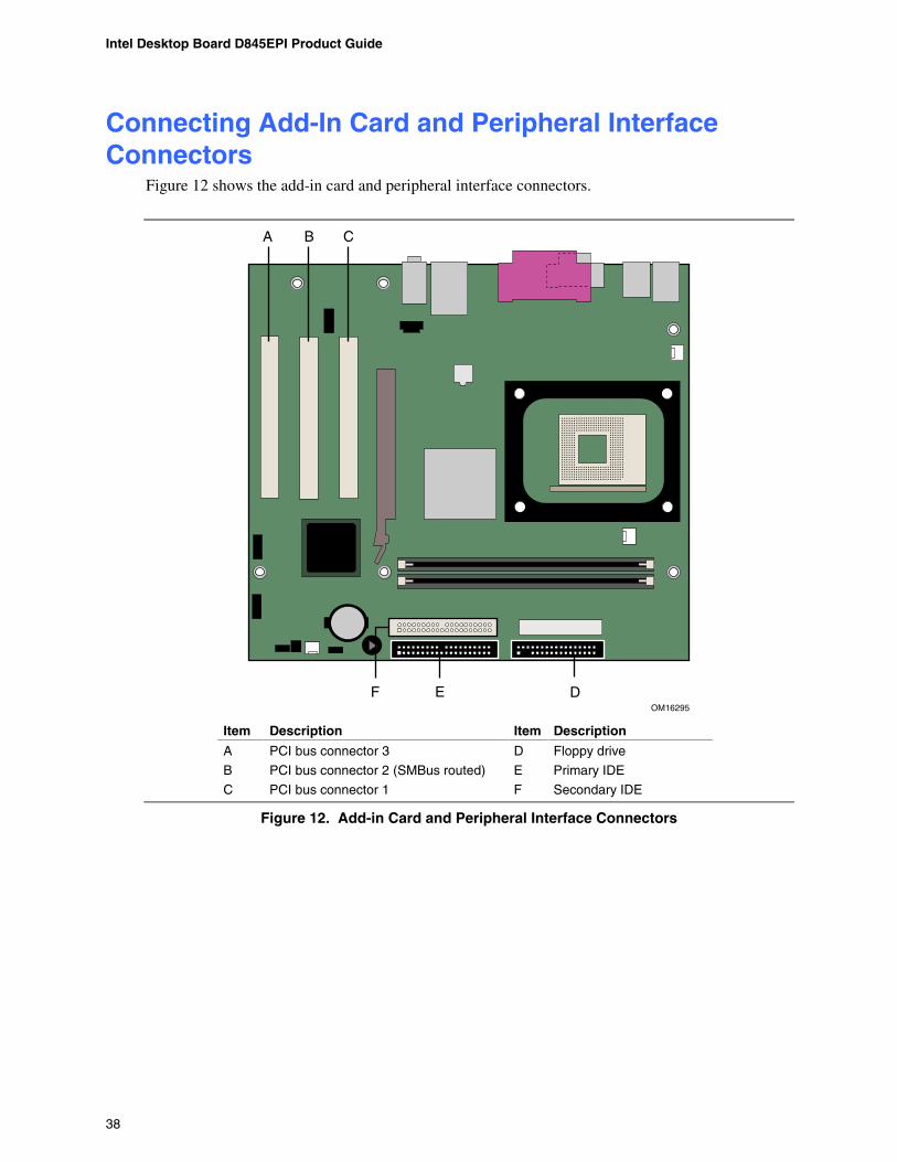
Connecting Add-In Card and Peripheral Interface Connectors
Figure 12 shows the add-in card and peripheral interface connectors.
OM16295
EF
A B C
D
Item Description Item Description
A PCI bus connector 3 D Floppy drive
B PCI bus connector 2 (SMBus routed) E Primary IDE
C PCI bus connector 1 F Secondary IDE
Figure 12. Add-in Card and Peripheral Interface Connectors
Installing and Replacing Desktop Board Components
39
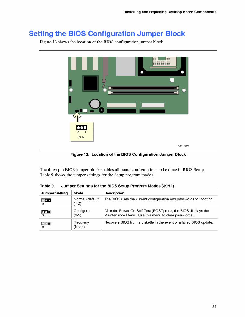
Setting the BIOS Configuration Jumper Block Figure 13 shows the location of the BIOS configuration jumper block.
OM16296
13
J9H2
Figure 13. Location of the BIOS Configuration Jumper Block
The three-pin BIOS jumper block enables all board configurations to be done in BIOS Setup. Table 9 shows the jumper settings for the Setup program modes.
Table 9. Jumper Settings for the BIOS Setup Program Modes (J9H2)
Jumper Setting Mode Description
3 1
Normal (default) (1-2)
The BIOS uses the current configuration and passwords for booting.
3 1
Configure (2-3)
After the Power-On Self-Test (POST) runs, the BIOS displays the Maintenance Menu. Use this menu to clear passwords.
3 1
Recovery (None)
Recovers BIOS from a diskette in the event of a failed BIOS update.

Intel Desktop Board D845EPI Product Guide
40
Clearing Passwords This procedure assumes that the board is installed in the computer and the configuration jumper block is set to normal mode.
1. Observe the precautions in “Before You Begin” on on page 21. 2. Turn off all peripheral devices connected to the computer. Turn off the computer. Disconnect
the computer’s power cord from the AC power source (wall outlet or power adapter). 3. Remove the computer cover. 4. Find the configuration jumper block (see Figure 13). 5. Place the jumper on pins 2-3 as shown below.
3 1 6. Replace the cover, plug in the computer, turn on the computer, and allow it to boot. 7. The computer starts the Setup program. Setup displays the maintenance menu. 8. Use the arrow keys to select Clear Passwords. Press <Enter> and Setup displays a pop-up
screen requesting that you confirm clearing the password. Select Yes and press <Enter>. Setup displays the maintenance menu again.
9. Press <F10> to save the current values and exit Setup. 10. Turn off the computer. Disconnect the computer’s power cord from the AC power source. 11. Remove the computer cover. 12. To restore normal operation, place the jumper on pins 1-2 as shown below.
3 1 13. Replace the cover, plug in the computer, and turn on the computer.
Installing and Replacing Desktop Board Components
41
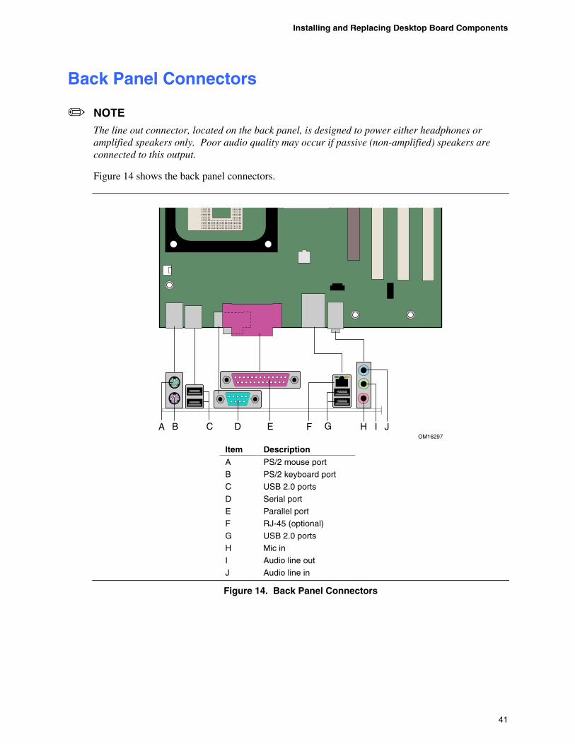
Back Panel Connectors
NOTE
The line out connector, located on the back panel, is designed to power either headphones or amplified speakers only. Poor audio quality may occur if passive (non-amplified) speakers are connected to this output.
Figure 14 shows the back panel connectors.
OM16297
A B D F G I JE HC
Item Description A PS/2 mouse port
B PS/2 keyboard port
C USB 2.0 ports
D Serial port
E Parallel port
F RJ-45 (optional)
G USB 2.0 ports
H Mic in
I Audio line out
J Audio line in
Figure 14. Back Panel Connectors
Intel Desktop Board D845EPI Product Guide
42
Replacing the Battery A coin-cell battery (CR2032) powers the real-time clock and CMOS memory. When the computer is not plugged into a wall socket, the battery has an estimated life of three years. When the computer is plugged in, the standby current from the power supply extends the life of the battery. The clock is accurate to ± 13 minutes/year at 25 ºC with 3.3 VSB applied.
When the voltage drops below a certain level, the BIOS Setup program settings stored in CMOS RAM (for example, the date and time) might not be accurate. Replace the battery with an equivalent one. Figure 15 shows the location of the battery.
Risk of explosion if the battery is replaced with an incorrect type. Batteries should be recycled where possible. Disposal of used batteries must be in accordance with local environmental regulations.
Risque d'explosion si la pile usagée est remplacée par une pile de type incorrect. Les piles usagées doivent être recyclées dans la mesure du possible. La mise au rebut des piles usagées doit respecter les réglementations locales en vigueur en matière de protection de l'environnement.
Eksplosionsfare, hvis batteriet erstattes med et batteri af en forkert type. Batterier bør om muligt genbruges. Bortskaffelse af brugte batterier bør foregå i overensstemmelse med gældende miljølovgivning.
Det kan oppstå eksplosjonsfare hvis batteriet skiftes ut med feil type. Brukte batterier bør kastes i henhold til gjeldende miljølovgivning.
Risk för explosion om batteriet ersätts med felaktig batterityp. Batterier ska kasseras enligt de lokala miljövårdsbestämmelserna.
Räjähdysvaara, jos pariston tyyppi on väärä. Paristot on kierrätettävä, jos se on mahdollista. Käytetyt paristot on hävitettävä paikallisten ympäristömääräysten mukaisesti.
Bei falschem Einsetzen einer neuen Batterie besteht Explosionsgefahr. Die Batterie darf nur durch denselben oder einen entsprechenden, vom Hersteller empfohlenen Batterietyp ersetzt werden. Entsorgen Sie verbrauchte Batterien den Anweisungen des Herstellers entsprechend.
Installing and Replacing Desktop Board Components
43
Esiste il pericolo di un esplosione se la pila non viene sostituita in modo corretto. Utilizzare solo pile uguali o di tipo equivalente a quelle consigliate dal produttore. Per disfarsi delle pile usate, seguire le istruzioni del produttore.
Existe peligro de explosión si la pila no se cambia de forma adecuada. Utilice solamente pilas iguales o del mismo tipo que las recomendadas por el fabricante del equipo. Para deshacerse de las pilas usadas, siga igualmente las instrucciones del fabricante.
Er bestaat ontploffingsgevaar als de batterij wordt vervangen door een onjuist type batterij. Batterijen moeten zoveel mogelijk worden gerecycled. Houd u bij het weggooien van gebruikte batterijen aan de plaatselijke milieuwetgeving.
Haverá risco de explosão se a bateria for substituída por um tipo de bateria incorreto. As baterias devem ser recicladas nos locais apropriados. A eliminação de baterias usadas deve ser feita de acordo com as regulamentações ambientais da região.
Je- být recyklovány. Baterie je t
! "!# újra kell hasznosítani. A használt $ ! kiselejtezni.
Intel Desktop Board D845EPI Product Guide
44
Risiko letupan wujud jika bateri digantikan dengan jenis yang tidak betul. Bateri sepatutnya dikitar semula jika boleh. Pelupusan bateri terpakai mestilah mematuhi peraturan alam sekitar tempatan.
% && & &&' & ( & & &) & &
Risc de explo * + ,
Ak batériu vymeníte za nesprávny typ, hrozí- + . v súlade s
( - - / -0okoljevarstvenimi predpisi.
Installing and Replacing Desktop Board Components
45
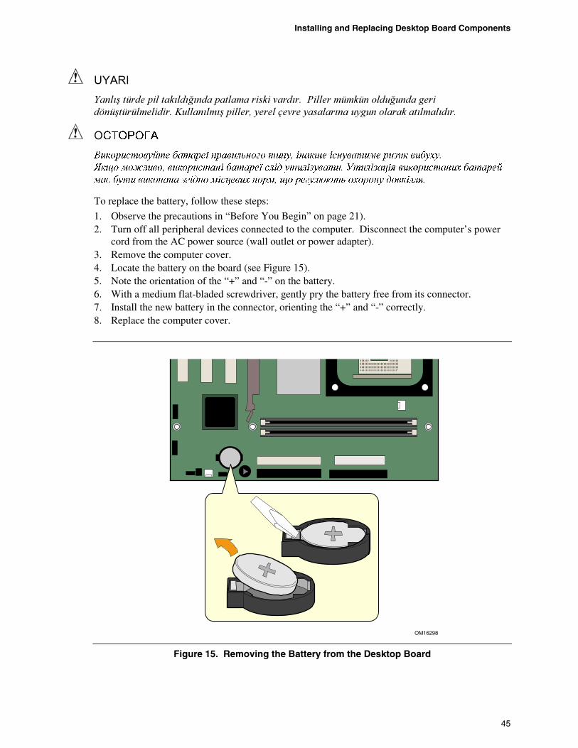
To replace the battery, follow these steps:
1. Observe the precautions in “Before You Begin” on page 21). 2. Turn off all peripheral devices connected to the computer. Disconnect the computer’s power
cord from the AC power source (wall outlet or power adapter). 3. Remove the computer cover. 4. Locate the battery on the board (see Figure 15). 5. Note the orientation of the “+” and “-” on the battery. 6. With a medium flat-bladed screwdriver, gently pry the battery free from its connector. 7. Install the new battery in the connector, orienting the “+” and “-” correctly. 8. Replace the computer cover.
OM16298
Figure 15. Removing the Battery from the Desktop Board

Intel Desktop Board D845EPI Product Guide
46
47
3 Updating the BIOS This chapter tells you how to update the BIOS by either using the Intel Express BIOS Update utility or the Intel® Flash Memory Update Utility, and how to recover the BIOS if an update fails.
Updating the BIOS with the Intel® Express BIOS Update Utility
With the Intel Express BIOS Update utility you can update the system BIOS while in the Windows* environment. The BIOS file is included in an automated update utility that combines the functionality of the Intel Flash Memory Update Utility and the ease-of use of Windows-based installation wizards.
To update the BIOS with the Intel Express BIOS Update utility:
1. Go to the Intel World Wide Web site:
http://support.intel.com/support/motherboards/desktop/ 2. Navigate to the D845EPI page, click “[view] Latest BIOS updates”, and select the
Express BIOS Update utility file. 3. Download the file to your hard drive. (You can also save this file to a diskette. This is useful
if you are updating the BIOS for multiple identical systems.) 4. Close all other applications. This step is required. Your system will be rebooted at the last
Express BIOS Update window. 5. Double-click the executable file from the location on your hard drive where it was saved. This
runs the update program. 6. Follow the instructions provided in the dialog boxes to complete the BIOS update.
Updating the BIOS with the Intel® Iflash BIOS Update Utility
With the Intel® Iflash BIOS update utility you can update the system BIOS from a floppy disk or other bootable media. The utility available from the Web provides a simple method for creating a bootable flash memory update floppy that will automatically update your BIOS.
Obtaining the BIOS Update File
You can update to a new version of the BIOS by using the BIOS update file. The BIOS update file is a compressed self-extracting archive that contains all the files you need to update the BIOS. The BIOS update file contains:
• New BIOS files
• BIOS recovery files
• Intel Flash Memory Update Utility
Intel Desktop Board D845EPI Product Guide
48
You can obtain the BIOS update file through your computer supplier or by navigating to the D845EPI page on the Intel World Wide Web site at:
http://support.intel.com/support/motherboards/desktop/
Navigate to the D845EPI page, click “[view] Latest BIOS updates”, and select the Intel Iflash BIOS Update utility file.
NOTE
Review the instructions distributed with the update utility before attempting a BIOS update.
The Intel Iflash BIOS update utility allows you to:
• Update the BIOS in flash memory
• Update the language section of the BIOS
Updating the BIOS
CAUTION The AUTOEXEC.BAT file provided with the update files updates the BIOS. Do not interrupt the process or the system may not function.
1. Boot the computer with the BIOS update diskette in drive A. During system boot, the AUTOEXEC.BAT file provided with the update files will automatically run the BIOS update process.
2. When the update process is complete, the monitor will display a message telling you to remove the diskette and to reboot the system.
3. As the computer boots, check the BIOS identifier (version number) to make sure the update was successful. If a logo appears, press <Esc> to view the POST messages.
Recovering the BIOS
It is unlikely that anything will interrupt the BIOS update, however, if an interruption occurs, the BIOS could be damaged. The following steps explain how to recover the BIOS if an update fails. The following procedure uses recovery mode for the Setup program. See page 39 for more information on Setup modes.
NOTE
Because of the small amount of code available in the boot block area, there is no video support. You will not see anything on the screen during this procedure. Monitor the procedure by listening to the speaker and looking at the diskette drive LED.
Updating the BIOS
49
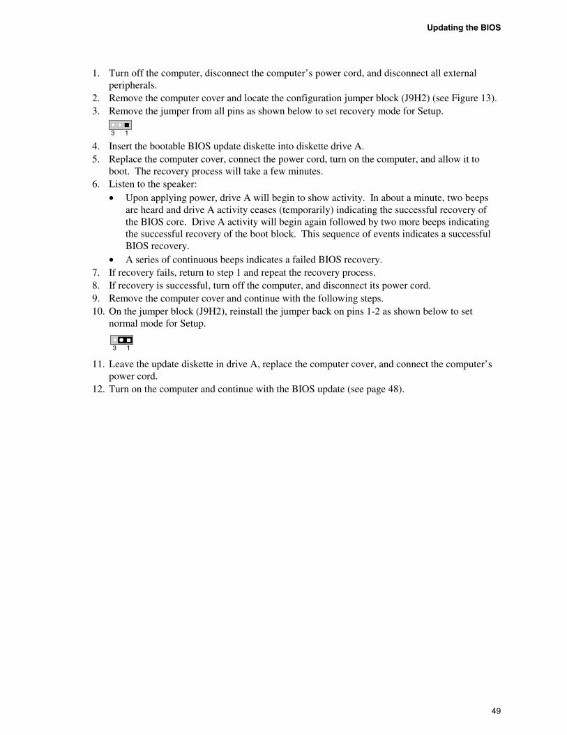
1. Turn off the computer, disconnect the computer’s power cord, and disconnect all external peripherals.
2. Remove the computer cover and locate the configuration jumper block (J9H2) (see Figure 13). 3. Remove the jumper from all pins as shown below to set recovery mode for Setup.
3 1
4. Insert the bootable BIOS update diskette into diskette drive A. 5. Replace the computer cover, connect the power cord, turn on the computer, and allow it to
boot. The recovery process will take a few minutes. 6. Listen to the speaker:
• Upon applying power, drive A will begin to show activity. In about a minute, two beeps are heard and drive A activity ceases (temporarily) indicating the successful recovery of the BIOS core. Drive A activity will begin again followed by two more beeps indicating the successful recovery of the boot block. This sequence of events indicates a successful BIOS recovery.
• A series of continuous beeps indicates a failed BIOS recovery. 7. If recovery fails, return to step 1 and repeat the recovery process. 8. If recovery is successful, turn off the computer, and disconnect its power cord. 9. Remove the computer cover and continue with the following steps. 10. On the jumper block (J9H2), reinstall the jumper back on pins 1-2 as shown below to set
normal mode for Setup.
3 1
11. Leave the update diskette in drive A, replace the computer cover, and connect the computer’s power cord.
12. Turn on the computer and continue with the BIOS update (see page 48).

Intel Desktop Board D845EPI Product Guide
50
51
4 Using the BIOS Setup Program The BIOS Setup program can be used to view and change the BIOS settings for the computer. The BIOS Setup program is accessed by pressing the <F2> key after the Power-On Self-Test (POST) memory test begins and before the operating system boot begins.
NOTE
The BIOS Setup menus described in this section may not show the latest settings. For the latest BIOS settings, refer to the Intel Desktop Board D845EPI Technical Product Specification or the Intel World Wide Web site at:
http://support.intel.com/support/motherboards/desktop/
NOTE
For reference purposes, you should write down the current Setup settings. When you make changes to the settings, update this record.
NOTE
The Setup menus described in this section apply to the desktop board with BIOS identifier VA84510A.86A. Desktop boards with other BIOS identifiers might have differences in some of the Setup menu screens.
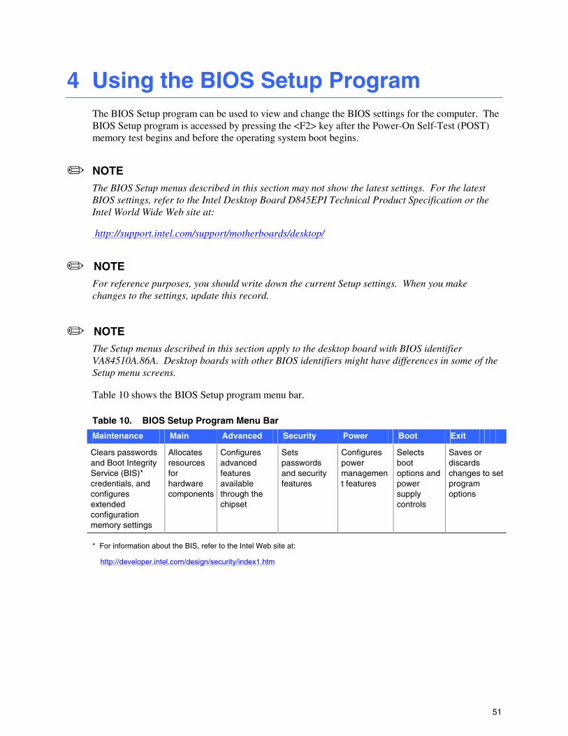
Table 10 shows the BIOS Setup program menu bar.
Table 10. BIOS Setup Program Menu Bar
Maintenance Main Advanced Security Power Boot Exit
Clears passwords and Boot Integrity Service (BIS)* credentials, and configures extended configuration memory settings
Allocates resources for hardware components
Configures advanced features available through the chipset
Sets passwords and security features
Configures power management features
Selects boot options and power supply controls
Saves or discards changes to set program options
* For information about the BIS, refer to the Intel Web site at:
http://developer.intel.com/design/security/index1.htm
Intel Desktop Board D845EPI Product Guide
52
Table 11 shows the function keys available for menu screens.
Table 11. BIOS Setup Program Function Keys
BIOS Setup Program Function Key Description
<←> or <→> Selects a different menu screen
<↑> or <↓> Moves cursor up or down
<Tab> Moves cursor to the next field
<Enter> Executes command or selects the submenu
<F9> Load the default configuration values for the current menu
<F10> Save the current values and exits the BIOS Setup program
<Esc> Exits the menu
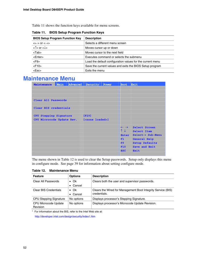
Maintenance Menu Maintenance Main Advanced Security Power Boot Exit
Clear All Passwords
Clear BIS credentials
CPU Stepping Signature [F29]
CPU Microcode Update Rev. [<none loaded>]
Select Screen Select Item Enter Select Sub-Menu
F1 General Help P9 Setup Defaults F10 Save and Exit ESC Exit
The menu shown in Table 12 is used to clear the Setup passwords. Setup only displays this menu in configure mode. See page 39 for information about setting configure mode.
Table 12. Maintenance Menu
Feature Options Description
Clear All Passwords • Ok
• Cancel
Clears both the user and supervisor passwords.
Clear BIS Credentials • Ok
• Cancel
Clears the Wired for Management Boot Integrity Service (BIS) credentials.
CPU Stepping Signature No options Displays processor’s Stepping Signature.
CPU Microcode Update Revision
No options Displays processor’s Microcode Update Revision.
* For information about the BIS, refer to the Intel Web site at:
http://developer.intel.com/design/security/index1.htm
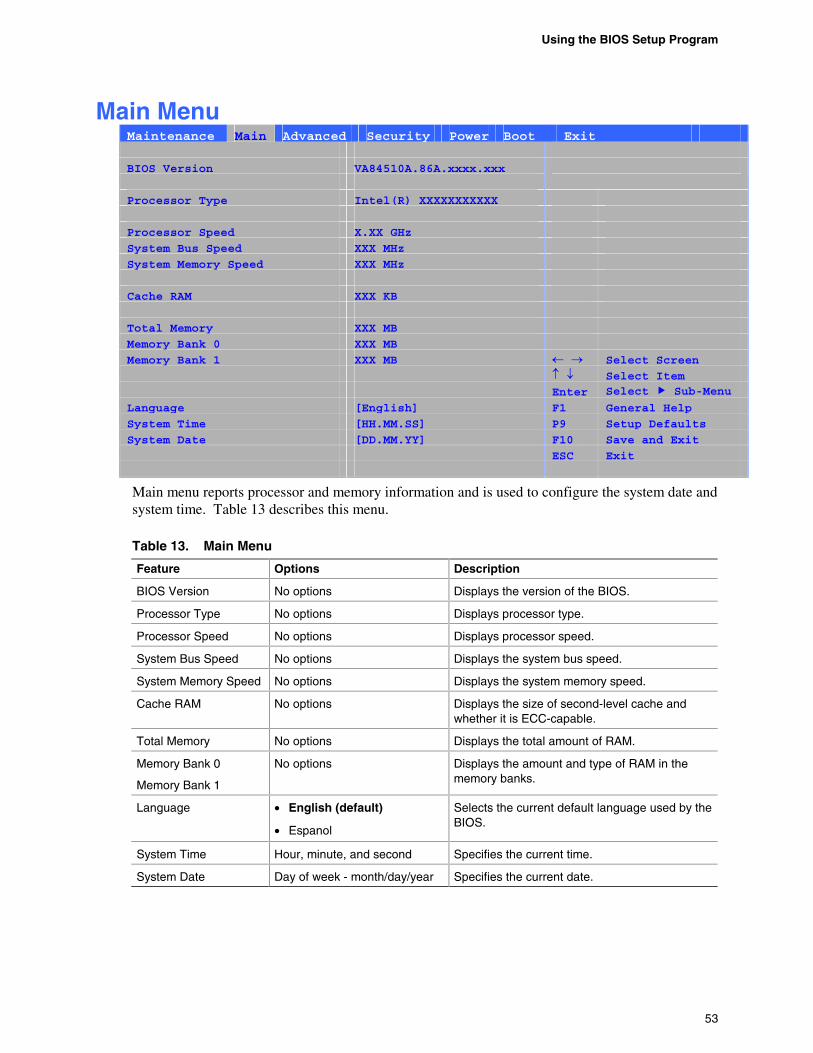
Using the BIOS Setup Program
53
Main Menu Maintenance Main Advanced Security Power Boot Exit
BIOS Version VA84510A.86A.xxxx.xxx
Processor Type Intel(R) XXXXXXXXXXX
Processor Speed X.XX GHz
System Bus Speed XXX MHz
System Memory Speed XXX MHz
Cache RAM XXX KB
Total Memory XXX MB
Memory Bank 0 XXX MB
Memory Bank 1 XXX MB Select Screen
Select Item Enter Select Sub-Menu
Language [English] F1 General Help
System Time [HH.MM.SS] P9 Setup Defaults
System Date [DD.MM.YY] F10 Save and Exit
ESC Exit
Main menu reports processor and memory information and is used to configure the system date and system time. Table 13 describes this menu.
Table 13. Main Menu
Feature Options Description
BIOS Version No options Displays the version of the BIOS.
Processor Type No options Displays processor type.
Processor Speed No options Displays processor speed.
System Bus Speed No options Displays the system bus speed.
System Memory Speed No options Displays the system memory speed.
Cache RAM No options Displays the size of second-level cache and whether it is ECC-capable.
Total Memory No options Displays the total amount of RAM.
Memory Bank 0
Memory Bank 1
No options Displays the amount and type of RAM in the memory banks.
Language • English (default)
• Espanol
Selects the current default language used by the BIOS.
System Time Hour, minute, and second Specifies the current time.
System Date Day of week - month/day/year Specifies the current date.
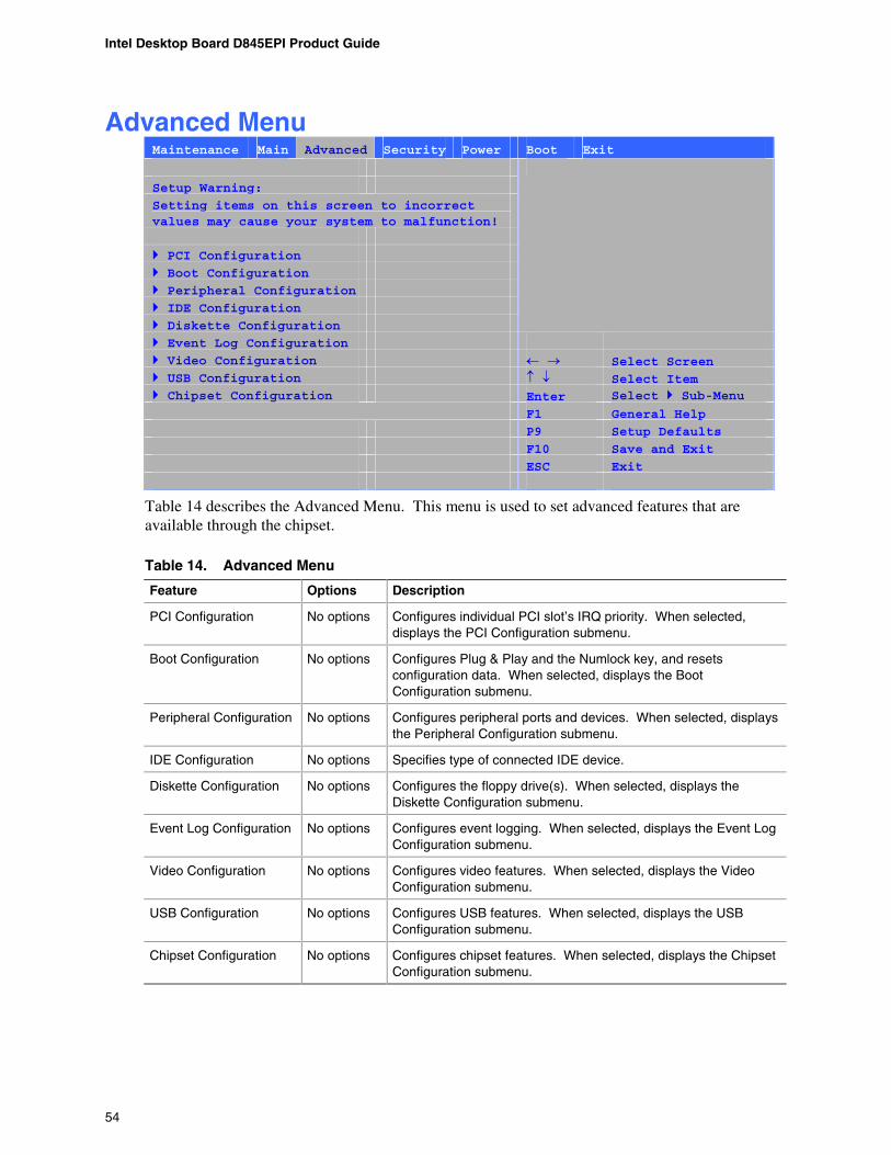
Intel Desktop Board D845EPI Product Guide
54
Advanced Menu Maintenance Main Advanced Security Power Boot Exit
Setup Warning:
Setting items on this screen to incorrect values may cause your system to malfunction!
PCI Configuration Boot Configuration Peripheral Configuration IDE Configuration Diskette Configuration
Event Log Configuration Video Configuration Select Screen USB Configuration Select Item Chipset Configuration Enter Select Sub-Menu F1 General Help
P9 Setup Defaults
F10 Save and Exit
ESC Exit
Table 14 describes the Advanced Menu. This menu is used to set advanced features that are available through the chipset.
Table 14. Advanced Menu
Feature Options Description
PCI Configuration No options Configures individual PCI slot’s IRQ priority. When selected, displays the PCI Configuration submenu.
Boot Configuration No options Configures Plug & Play and the Numlock key, and resets configuration data. When selected, displays the Boot Configuration submenu.
Peripheral Configuration No options Configures peripheral ports and devices. When selected, displays the Peripheral Configuration submenu.
IDE Configuration No options Specifies type of connected IDE device.
Diskette Configuration No options Configures the floppy drive(s). When selected, displays the Diskette Configuration submenu.
Event Log Configuration No options Configures event logging. When selected, displays the Event Log Configuration submenu.
Video Configuration No options Configures video features. When selected, displays the Video Configuration submenu.
USB Configuration No options Configures USB features. When selected, displays the USB Configuration submenu.
Chipset Configuration No options Configures chipset features. When selected, displays the Chipset Configuration submenu.
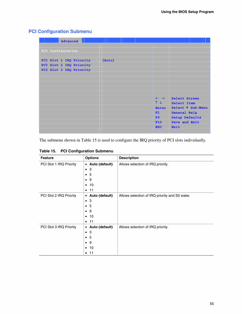
Using the BIOS Setup Program
55
PCI Configuration Submenu
Main Advanced Security Power Boot Exit PCI Configuration
PCI Slot 1 IRQ Priority [Auto]
PCI Slot 2 IRQ Priority
PCI Slot 3 IRQ Priority
Select Screen Select Item Enter Select Sub-Menu F1 General Help P9 Setup Defaults F10 Save and Exit ESC Exit
The submenu shown in Table 15 is used to configure the IRQ priority of PCI slots individually.
Table 15. PCI Configuration Submenu
Feature Options Description
PCI Slot 1 IRQ Priority • Auto (default) • 3
• 5
• 9
• 10
• 11
Allows selection of IRQ priority.
PCI Slot 2 IRQ Priority • Auto (default) • 3
• 5
• 9
• 10
• 11
Allows selection of IRQ priority and S5 wake.
PCI Slot 3 IRQ Priority • Auto (default) • 3
• 5
• 9
• 10
• 11
Allows selection of IRQ priority.
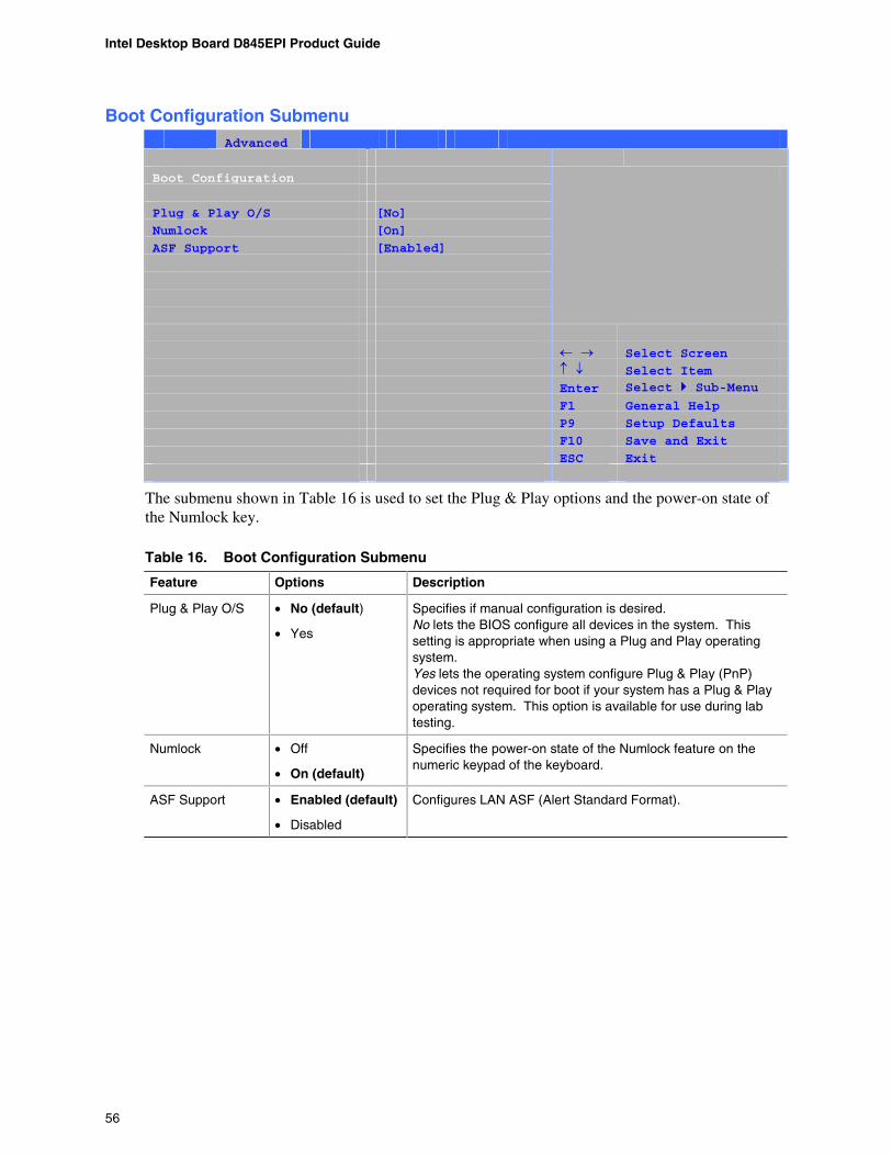
Intel Desktop Board D845EPI Product Guide
56
Boot Configuration Submenu Main Advanced Security Power Boot Exit
Boot Configuration
Plug & Play O/S [No]
Numlock [On]
ASF Support [Enabled]
Select Screen
Select Item Enter Select Sub-Menu F1 General Help
P9 Setup Defaults
F10 Save and Exit
ESC Exit
The submenu shown in Table 16 is used to set the Plug & Play options and the power-on state of the Numlock key.
Table 16. Boot Configuration Submenu
Feature Options Description
Plug & Play O/S • No (default)
• Yes
Specifies if manual configuration is desired. No lets the BIOS configure all devices in the system. This setting is appropriate when using a Plug and Play operating system. Yes lets the operating system configure Plug & Play (PnP) devices not required for boot if your system has a Plug & Play operating system. This option is available for use during lab testing.
Numlock • Off
• On (default)
Specifies the power-on state of the Numlock feature on the numeric keypad of the keyboard.
ASF Support • Enabled (default)
• Disabled
Configures LAN ASF (Alert Standard Format).
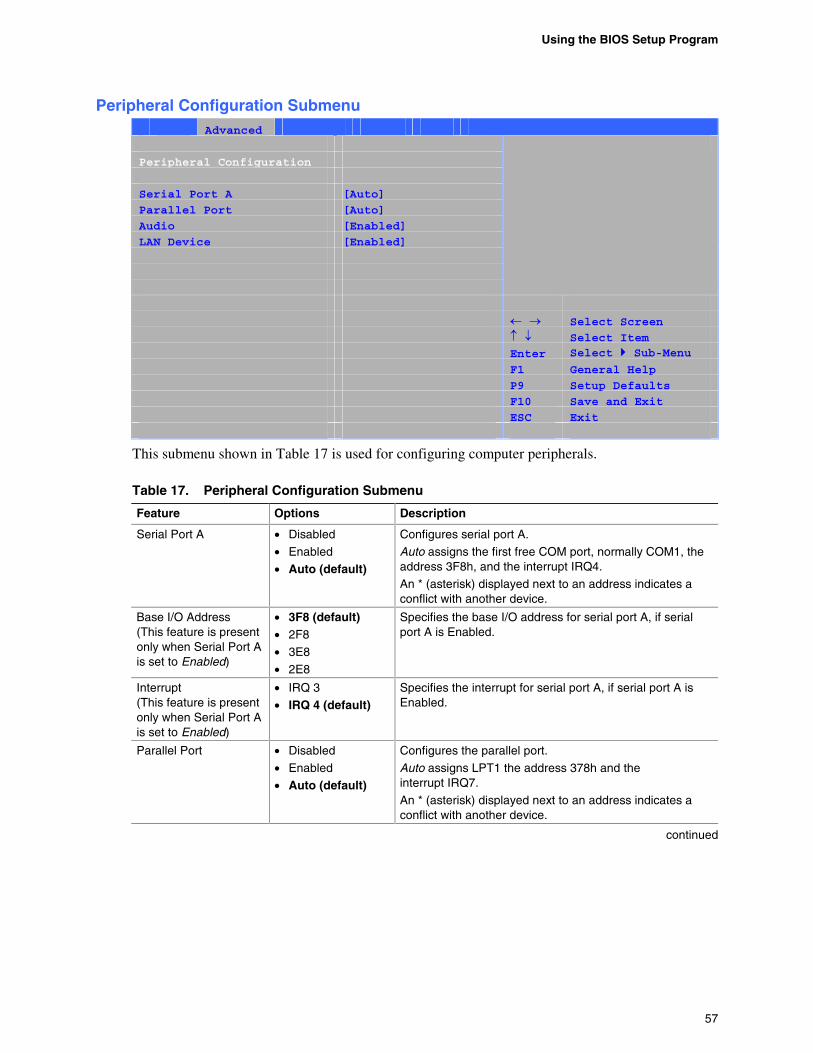
Using the BIOS Setup Program
57
Peripheral Configuration Submenu Main Advanced Security Power Boot Exit
Peripheral Configuration
Serial Port A [Auto]
Parallel Port [Auto]
Audio [Enabled]
LAN Device [Enabled]
Select Screen
Select Item Enter Select Sub-Menu F1 General Help
P9 Setup Defaults
F10 Save and Exit
ESC Exit
This submenu shown in Table 17 is used for configuring computer peripherals.
Table 17. Peripheral Configuration Submenu
Feature Options Description
Serial Port A • Disabled
• Enabled
• Auto (default)
Configures serial port A.
Auto assigns the first free COM port, normally COM1, the address 3F8h, and the interrupt IRQ4.
An * (asterisk) displayed next to an address indicates a conflict with another device.
Base I/O Address (This feature is present only when Serial Port A is set to Enabled)
• 3F8 (default) • 2F8
• 3E8
• 2E8
Specifies the base I/O address for serial port A, if serial port A is Enabled.
Interrupt (This feature is present only when Serial Port A is set to Enabled)
• IRQ 3
• IRQ 4 (default) Specifies the interrupt for serial port A, if serial port A is Enabled.
Parallel Port • Disabled
• Enabled
• Auto (default)
Configures the parallel port.
Auto assigns LPT1 the address 378h and the interrupt IRQ7.
An * (asterisk) displayed next to an address indicates a conflict with another device.
continued
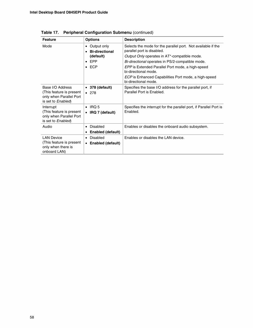
Intel Desktop Board D845EPI Product Guide
58
Table 17. Peripheral Configuration Submenu (continued)
Feature Options Description
Mode • Output only
• Bi-directional (default)
• EPP
• ECP
Selects the mode for the parallel port. Not available if the parallel port is disabled.
Output Only operates in AT*-compatible mode.
Bi-directional operates in PS/2-compatible mode.
EPP is Extended Parallel Port mode, a high-speed bi-directional mode.
ECP is Enhanced Capabilities Port mode, a high-speed bi-directional mode.
Base I/O Address (This feature is present only when Parallel Port is set to Enabled)
• 378 (default) • 278
Specifies the base I/O address for the parallel port, if Parallel Port is Enabled.
Interrupt (This feature is present only when Parallel Port is set to Enabled)
• IRQ 5
• IRQ 7 (default) Specifies the interrupt for the parallel port, if Parallel Port is Enabled.
Audio • Disabled
• Enabled (default) Enables or disables the onboard audio subsystem.
LAN Device (This feature is present only when there is onboard LAN)
• Disabled
• Enabled (default) Enables or disables the LAN device.
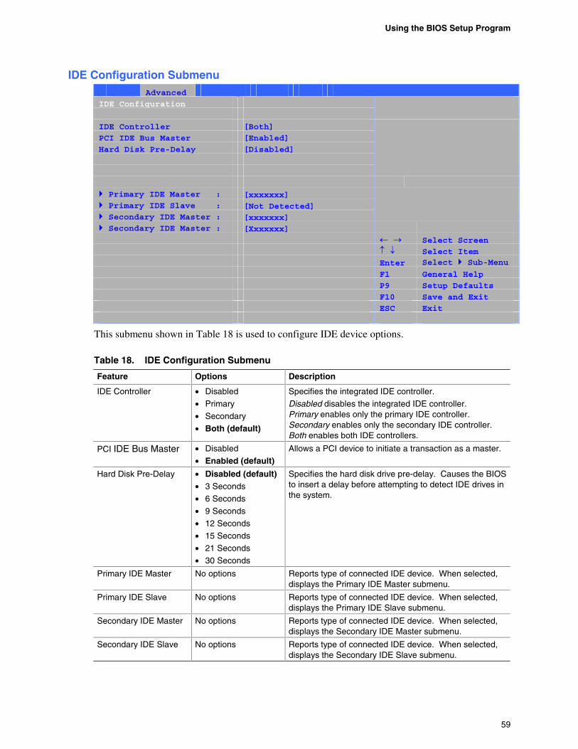
Using the BIOS Setup Program
59
IDE Configuration Submenu Main Advanced Security Power Boot Exit
IDE Configuration
IDE Controller [Both]
PCI IDE Bus Master [Enabled]
Hard Disk Pre-Delay [Disabled]
Primary IDE Master : [xxxxxxx] Primary IDE Slave : [Not Detected] Secondary IDE Master : [xxxxxxx]
Secondary IDE Master : [Xxxxxxx]
Select Screen
Select Item Enter Select Sub-Menu F1 General Help
P9 Setup Defaults
F10 Save and Exit
ESC Exit
This submenu shown in Table 18 is used to configure IDE device options.
Table 18. IDE Configuration Submenu
Feature Options Description
IDE Controller • Disabled
• Primary
• Secondary
• Both (default)
Specifies the integrated IDE controller.
Disabled disables the integrated IDE controller. Primary enables only the primary IDE controller. Secondary enables only the secondary IDE controller. Both enables both IDE controllers.
PCI IDE Bus Master • Disabled
• Enabled (default) Allows a PCI device to initiate a transaction as a master.
Hard Disk Pre-Delay • Disabled (default) • 3 Seconds
• 6 Seconds
• 9 Seconds
• 12 Seconds
• 15 Seconds
• 21 Seconds
• 30 Seconds
Specifies the hard disk drive pre-delay. Causes the BIOS to insert a delay before attempting to detect IDE drives in the system.
Primary IDE Master No options Reports type of connected IDE device. When selected, displays the Primary IDE Master submenu.
Primary IDE Slave No options Reports type of connected IDE device. When selected, displays the Primary IDE Slave submenu.
Secondary IDE Master No options Reports type of connected IDE device. When selected, displays the Secondary IDE Master submenu.
Secondary IDE Slave No options Reports type of connected IDE device. When selected, displays the Secondary IDE Slave submenu.
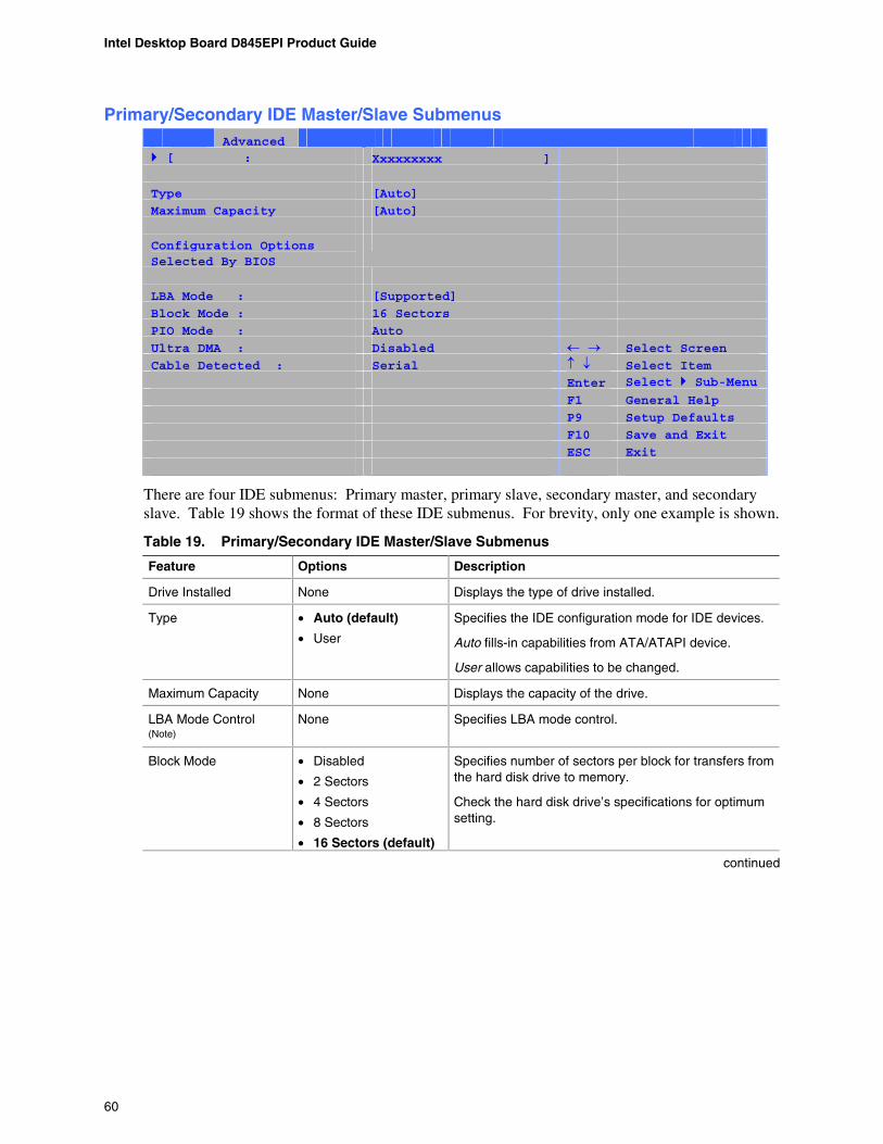
Intel Desktop Board D845EPI Product Guide
60
Primary/Secondary IDE Master/Slave Submenus Main Advanced Security Power Boot Exit [ : Xxxxxxxxx ]
Type [Auto]
Maximum Capacity [Auto]
Configuration Options Selected By BIOS
LBA Mode : [Supported]
Block Mode : 16 Sectors
PIO Mode : Auto
Ultra DMA : Disabled Select Screen
Cable Detected : Serial Select Item Enter Select Sub-Menu F1 General Help
P9 Setup Defaults
F10 Save and Exit
ESC Exit
There are four IDE submenus: Primary master, primary slave, secondary master, and secondary slave. Table 19 shows the format of these IDE submenus. For brevity, only one example is shown.
Table 19. Primary/Secondary IDE Master/Slave Submenus
Feature Options Description
Drive Installed None Displays the type of drive installed.
Type • Auto (default)
• User
Specifies the IDE configuration mode for IDE devices.
Auto fills-in capabilities from ATA/ATAPI device.
User allows capabilities to be changed.
Maximum Capacity None Displays the capacity of the drive.
LBA Mode Control (Note)
None Specifies LBA mode control.
Block Mode
• Disabled
• 2 Sectors
• 4 Sectors
• 8 Sectors
• 16 Sectors (default)
Specifies number of sectors per block for transfers from the hard disk drive to memory.
Check the hard disk drive’s specifications for optimum setting.
continued
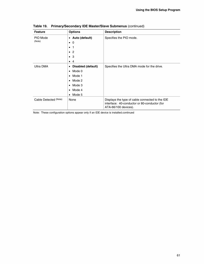
Using the BIOS Setup Program
61
Table 19. Primary/Secondary IDE Master/Slave Submenus (continued)
Feature Options Description
PIO Mode (Note)
• Auto (default)
• 0
• 1
• 2
• 3
• 4
Specifies the PIO mode.
Ultra DMA
• Disabled (default)
• Mode 0
• Mode 1
• Mode 2
• Mode 3
• Mode 4
• Mode 5
Specifies the Ultra DMA mode for the drive.
Cable Detected (Note) None Displays the type of cable connected to the IDE interface: 40-conductor or 80-conductor (for ATA-66/100 devices).
Note: These configuration options appear only if an IDE device is installed.continued
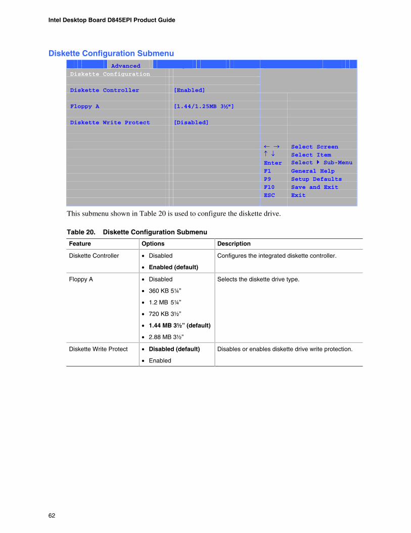
Intel Desktop Board D845EPI Product Guide
62
Diskette Configuration Submenu Main Advanced Security Power Boot Exit
Diskette Configuration
Diskette Controller [Enabled]
Floppy A [1.44/1.25MB 3½"]
Diskette Write Protect [Disabled]
Select Screen
Select Item Enter Select Sub-Menu F1 General Help
P9 Setup Defaults
F10 Save and Exit
ESC Exit
This submenu shown in Table 20 is used to configure the diskette drive.
Table 20. Diskette Configuration Submenu
Feature Options Description
Diskette Controller • Disabled
• Enabled (default)
Configures the integrated diskette controller.
Floppy A • Disabled
• 360 KB 5¼”
• 1.2 MB 5¼”
• 720 KB 3½”
• 1.44 MB 3½” (default)
• 2.88 MB 3½”
Selects the diskette drive type.
Diskette Write Protect • Disabled (default)
• Enabled
Disables or enables diskette drive write protection.
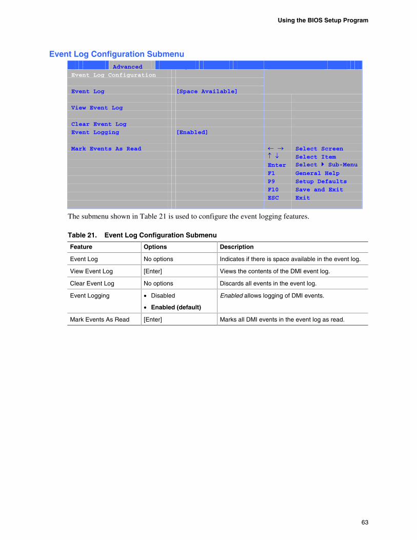
Using the BIOS Setup Program
63
Event Log Configuration Submenu Main Advanced Security Power Boot Exit
Event Log Configuration
Event Log [Space Available]
View Event Log
Clear Event Log
Event Logging [Enabled]
Mark Events As Read Select Screen
Select Item Enter Select Sub-Menu F1 General Help
P9 Setup Defaults
F10 Save and Exit
ESC Exit
The submenu shown in Table 21 is used to configure the event logging features.
Table 21. Event Log Configuration Submenu
Feature Options Description
Event Log No options Indicates if there is space available in the event log.
View Event Log [Enter] Views the contents of the DMI event log.
Clear Event Log No options Discards all events in the event log.
Event Logging • Disabled
• Enabled (default)
Enabled allows logging of DMI events.
Mark Events As Read [Enter] Marks all DMI events in the event log as read.
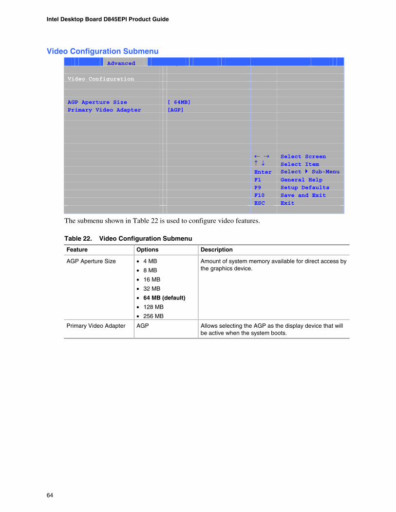
Intel Desktop Board D845EPI Product Guide
64
Video Configuration Submenu Main Advanced Security Power Boot Exit
Video Configuration
AGP Aperture Size [ 64MB]
Primary Video Adapter [AGP]
Select Screen
Select Item Enter Select Sub-Menu F1 General Help
P9 Setup Defaults
F10 Save and Exit
ESC Exit
The submenu shown in Table 22 is used to configure video features.
Table 22. Video Configuration Submenu
Feature Options Description
AGP Aperture Size • 4 MB
• 8 MB
• 16 MB
• 32 MB
• 64 MB (default)
• 128 MB
• 256 MB
Amount of system memory available for direct access by the graphics device.
Primary Video Adapter AGP Allows selecting the AGP as the display device that will be active when the system boots.
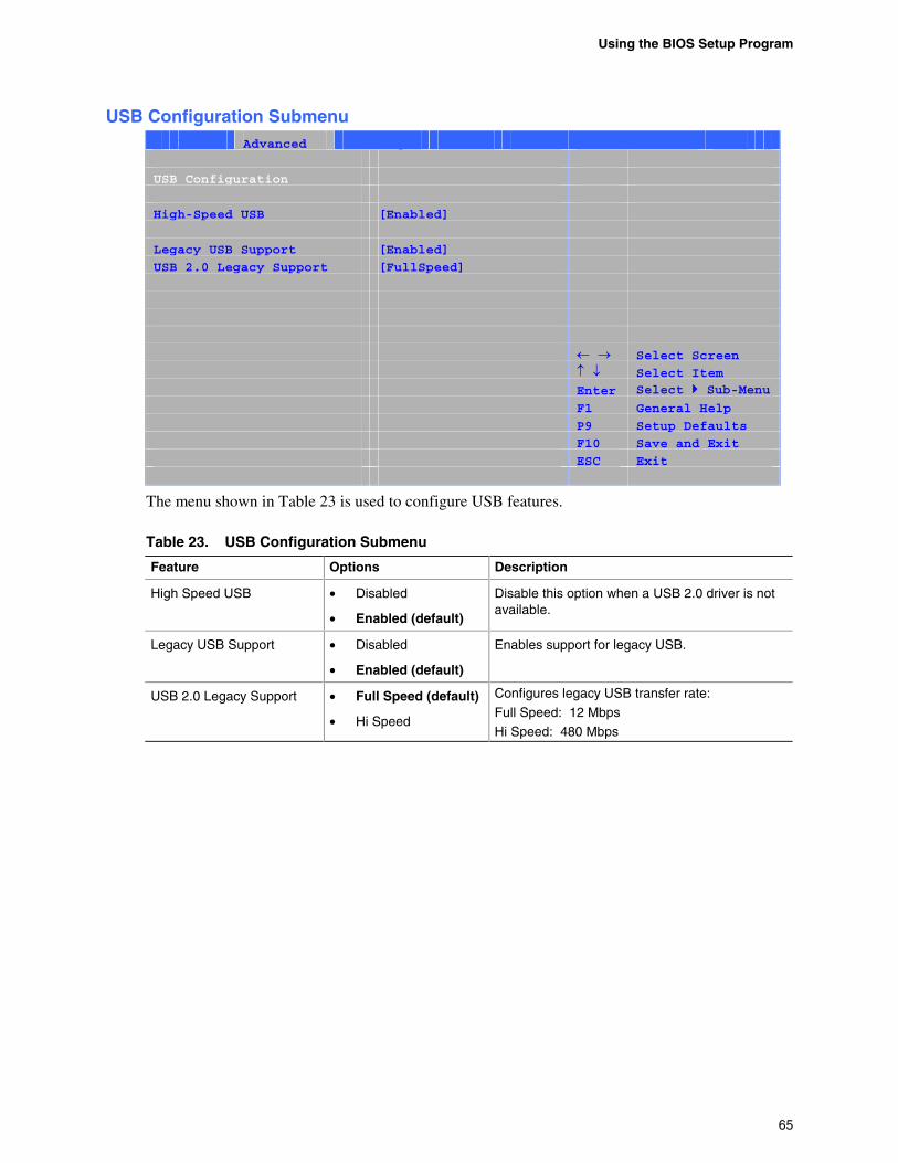
Using the BIOS Setup Program
65
USB Configuration Submenu Main Advanced Security Power Boot Exit
USB Configuration
High-Speed USB [Enabled]
Legacy USB Support [Enabled]
USB 2.0 Legacy Support [FullSpeed]
Select Screen
Select Item Enter Select Sub-Menu F1 General Help
P9 Setup Defaults
F10 Save and Exit
ESC Exit
The menu shown in Table 23 is used to configure USB features.
Table 23. USB Configuration Submenu
Feature Options Description
High Speed USB • Disabled
• Enabled (default)
Disable this option when a USB 2.0 driver is not available.
Legacy USB Support • Disabled
• Enabled (default)
Enables support for legacy USB.
USB 2.0 Legacy Support • Full Speed (default)
• Hi Speed
Configures legacy USB transfer rate:
Full Speed: 12 Mbps
Hi Speed: 480 Mbps
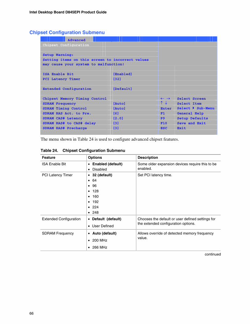
Intel Desktop Board D845EPI Product Guide
66
Chipset Configuration Submenu Main Advanced Security Power Boot Exit
Chipset Configuration
Setup Warning:
Setting items on this screen to incorrect values may cause your system to malfunction!
ISA Enable Bit [Enabled]
PCI Latency Timer [32]
Extended Configuration [Default]
Chipset Memory Timing Control Select Screen
SDRAM Frequency [Auto] Select Item SDRAM Timing Control [Auto] Enter Select Sub-Menu SDRAM RAS Act. to Pre. [6] F1 General Help
SDRAM CAS# Latency [2.0] P9 Setup Defaults
SDRAM RAS# to CAS# delay [3] F10 Save and Exit
SDRAM RAS# Precharge [3] ESC Exit
The menu shown in Table 24 is used to configure advanced chipset features.
Table 24. Chipset Configuration Submenu
Feature Options Description
ISA Enable Bit • Enabled (default) • Disabled
Some older expansion devices require this to be enabled.
PCI Latency Timer • 32 (default) • 64
• 96
• 128
• 160
• 192
• 224
• 248
Set PCI latency time.
Extended Configuration • Default (default)
• User Defined
Chooses the default or user defined settings for the extended configuration options.
SDRAM Frequency • Auto (default)
• 200 MHz
• 266 MHz
Allows override of detected memory frequency value.
continued
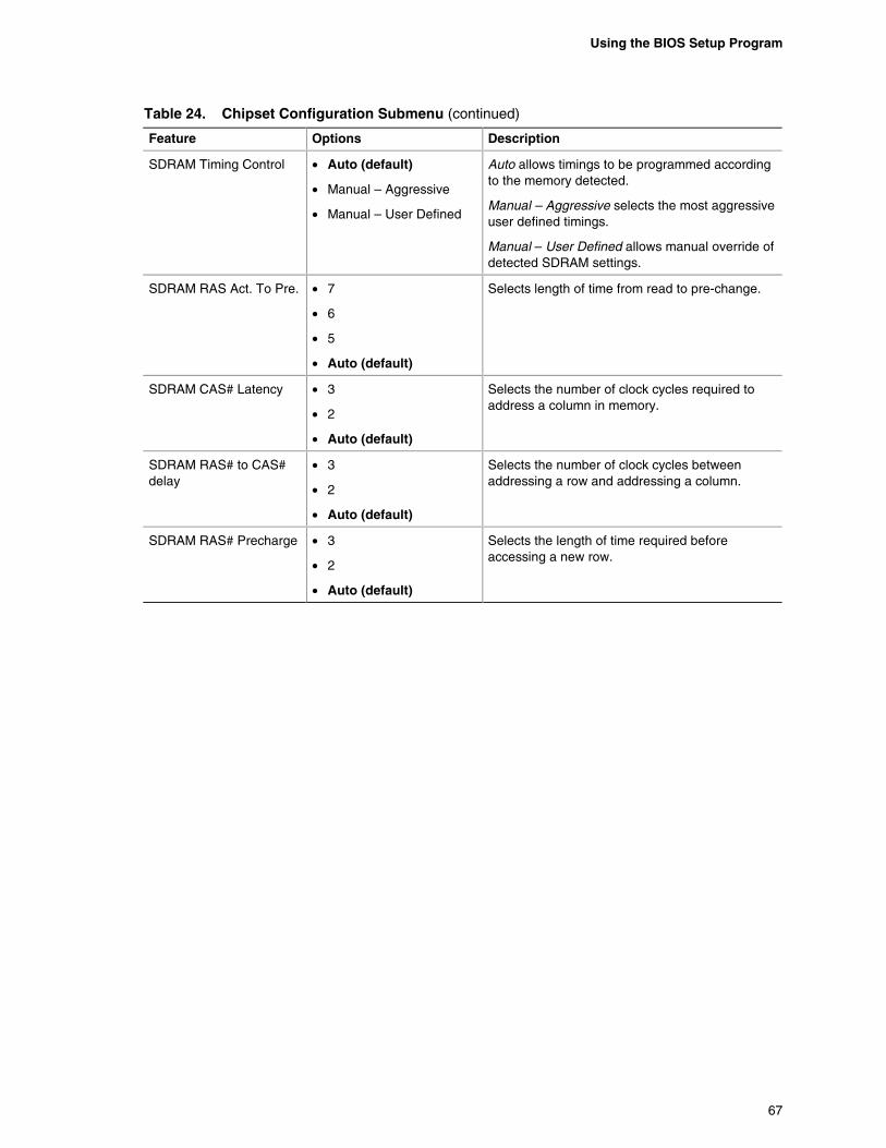
Using the BIOS Setup Program
67
Table 24. Chipset Configuration Submenu (continued)
Feature Options Description
SDRAM Timing Control • Auto (default)
• Manual – Aggressive
• Manual – User Defined
Auto allows timings to be programmed according to the memory detected.
Manual – Aggressive selects the most aggressive user defined timings.
Manual – User Defined allows manual override of detected SDRAM settings.
SDRAM RAS Act. To Pre. • 7
• 6
• 5
• Auto (default)
Selects length of time from read to pre-change.
SDRAM CAS# Latency • 3
• 2
• Auto (default)
Selects the number of clock cycles required to address a column in memory.
SDRAM RAS# to CAS# delay
• 3
• 2
• Auto (default)
Selects the number of clock cycles between addressing a row and addressing a column.
SDRAM RAS# Precharge • 3
• 2
• Auto (default)
Selects the length of time required before accessing a new row.
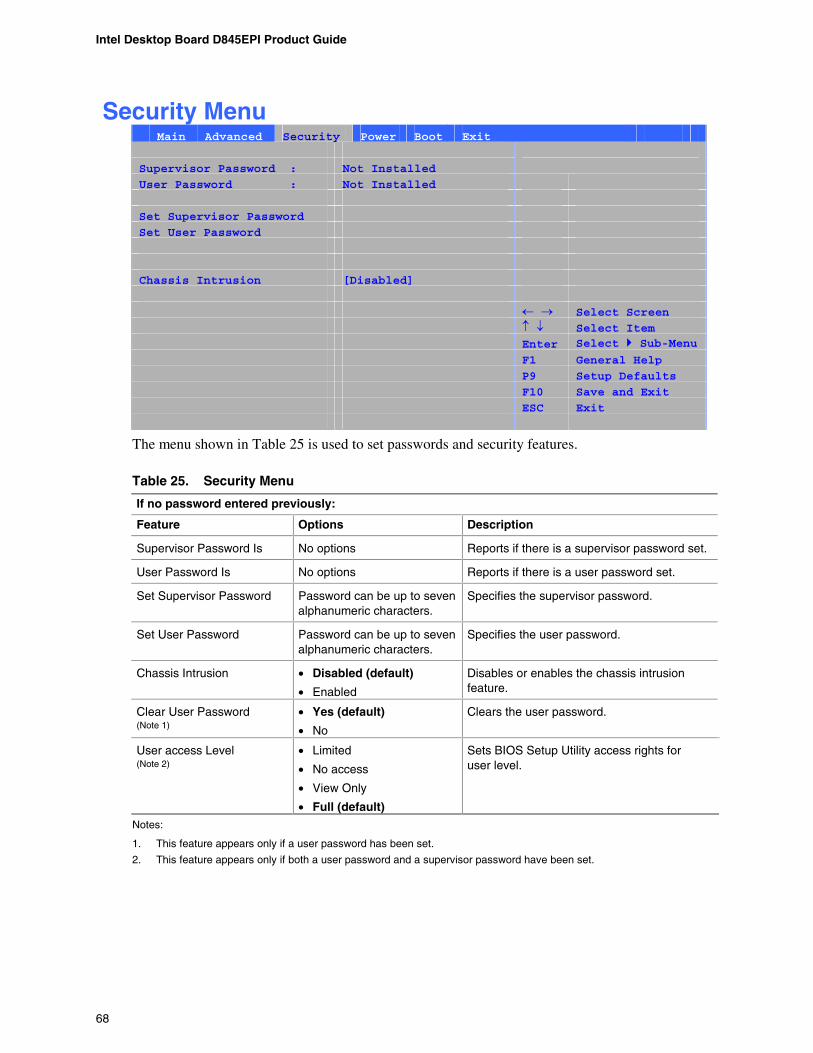
Intel Desktop Board D845EPI Product Guide
68
Security Menu Main Advanced Security Power Boot Exit
Supervisor Password : Not Installed
User Password : Not Installed
Set Supervisor Password
Set User Password
Chassis Intrusion [Disabled]
Select Screen
Select Item Enter Select Sub-Menu F1 General Help
P9 Setup Defaults
F10 Save and Exit
ESC Exit
The menu shown in Table 25 is used to set passwords and security features.
Table 25. Security Menu
If no password entered previously:
Feature Options Description
Supervisor Password Is No options Reports if there is a supervisor password set.
User Password Is No options Reports if there is a user password set.
Set Supervisor Password Password can be up to seven alphanumeric characters.
Specifies the supervisor password.
Set User Password Password can be up to seven alphanumeric characters.
Specifies the user password.
Chassis Intrusion • Disabled (default)
• Enabled
Disables or enables the chassis intrusion feature.
Clear User Password (Note 1)
• Yes (default)
• No
Clears the user password.
User access Level (Note 2)
• Limited
• No access
• View Only
• Full (default)
Sets BIOS Setup Utility access rights for user level.
Notes:
1. This feature appears only if a user password has been set.
2. This feature appears only if both a user password and a supervisor password have been set.
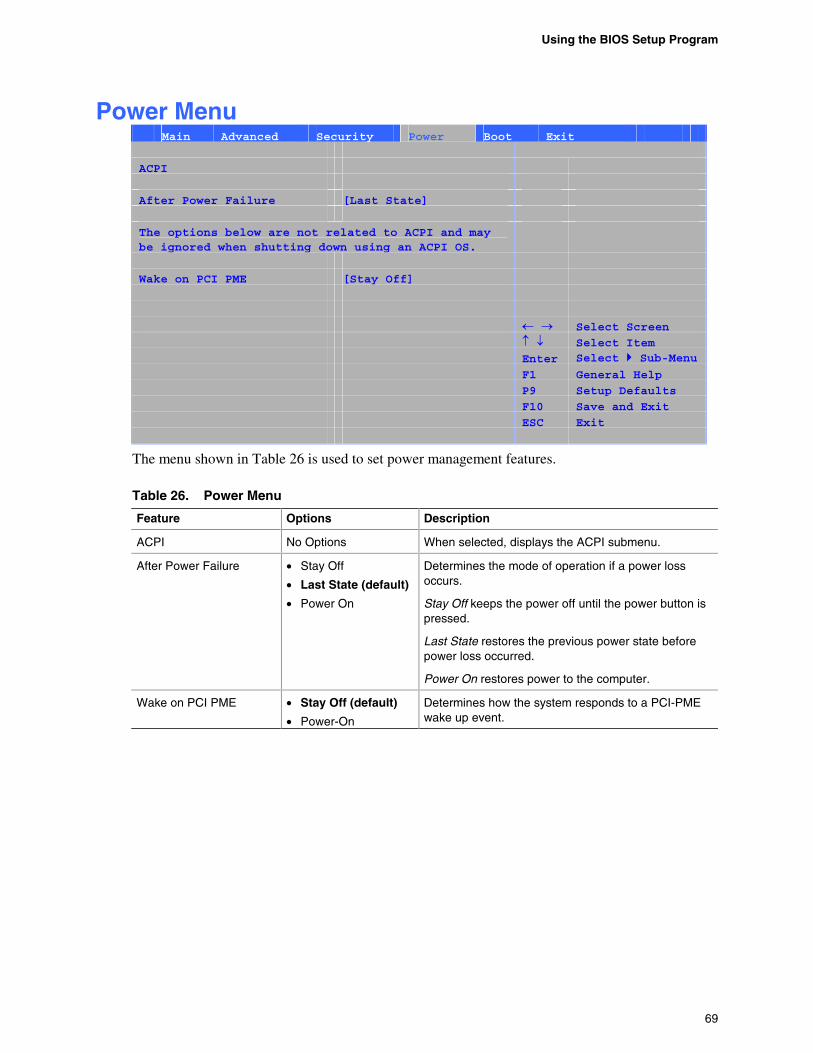
Using the BIOS Setup Program
69
Power Menu Main Advanced Security Power Boot Exit
ACPI
After Power Failure [Last State]
The options below are not related to ACPI and may be ignored when shutting down using an ACPI OS.
Wake on PCI PME [Stay Off]
Select Screen
Select Item Enter Select Sub-Menu F1 General Help
P9 Setup Defaults
F10 Save and Exit
ESC Exit
The menu shown in Table 26 is used to set power management features.
Table 26. Power Menu
Feature Options Description
ACPI No Options When selected, displays the ACPI submenu.
After Power Failure • Stay Off
• Last State (default)
• Power On
Determines the mode of operation if a power loss occurs.
Stay Off keeps the power off until the power button is pressed.
Last State restores the previous power state before power loss occurred.
Power On restores power to the computer.
Wake on PCI PME • Stay Off (default)
• Power-On
Determines how the system responds to a PCI-PME wake up event.
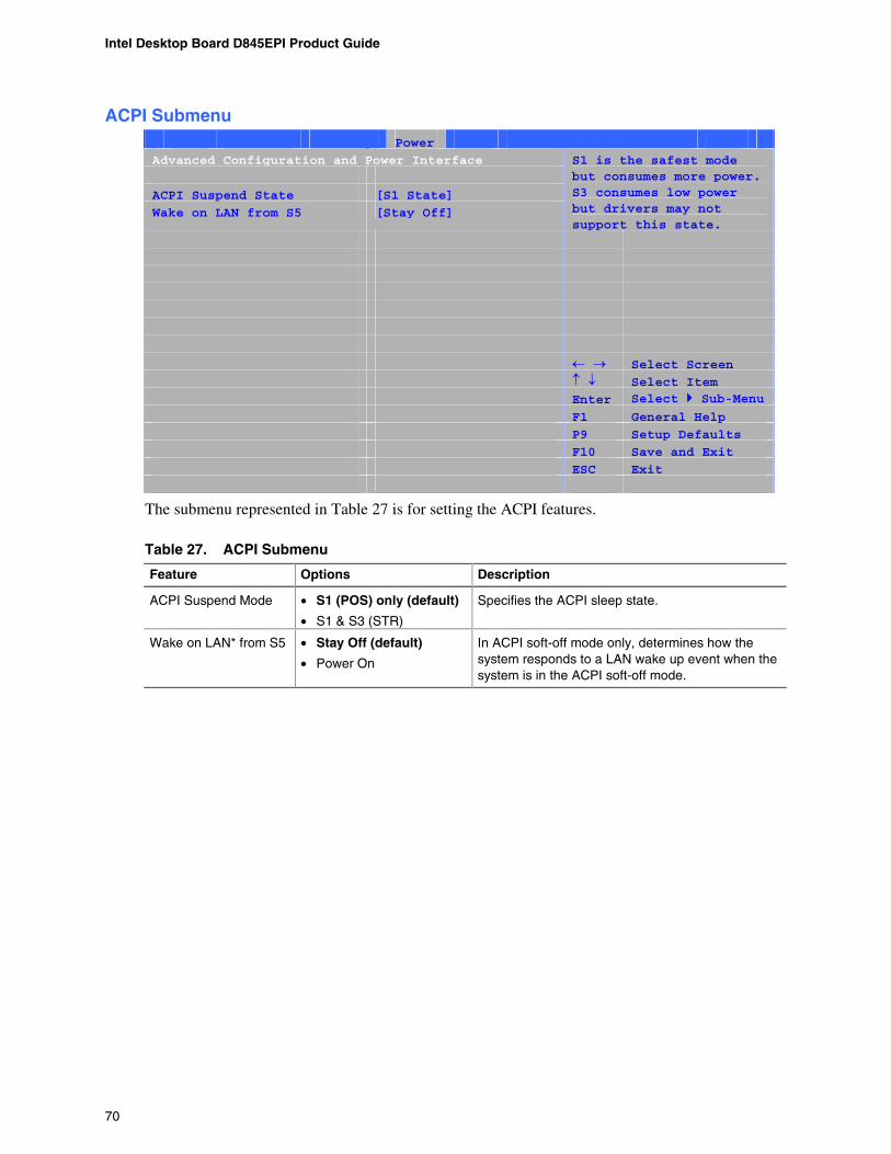
Intel Desktop Board D845EPI Product Guide
70
ACPI Submenu Main Advanced Security Power Boot Exit
Advanced Configuration and Power Interface
ACPI Suspend State [S1 State]
Wake on LAN from S5 [Stay Off]
S1 is the safest mode but consumes more power. S3 consumes low power but drivers may not support this state.
Select Screen
Select Item Enter Select Sub-Menu F1 General Help
P9 Setup Defaults
F10 Save and Exit
ESC Exit
The submenu represented in Table 27 is for setting the ACPI features.
Table 27. ACPI Submenu
Feature Options Description
ACPI Suspend Mode • S1 (POS) only (default)
• S1 & S3 (STR)
Specifies the ACPI sleep state.
Wake on LAN* from S5 • Stay Off (default)
• Power On
In ACPI soft-off mode only, determines how the system responds to a LAN wake up event when the system is in the ACPI soft-off mode.
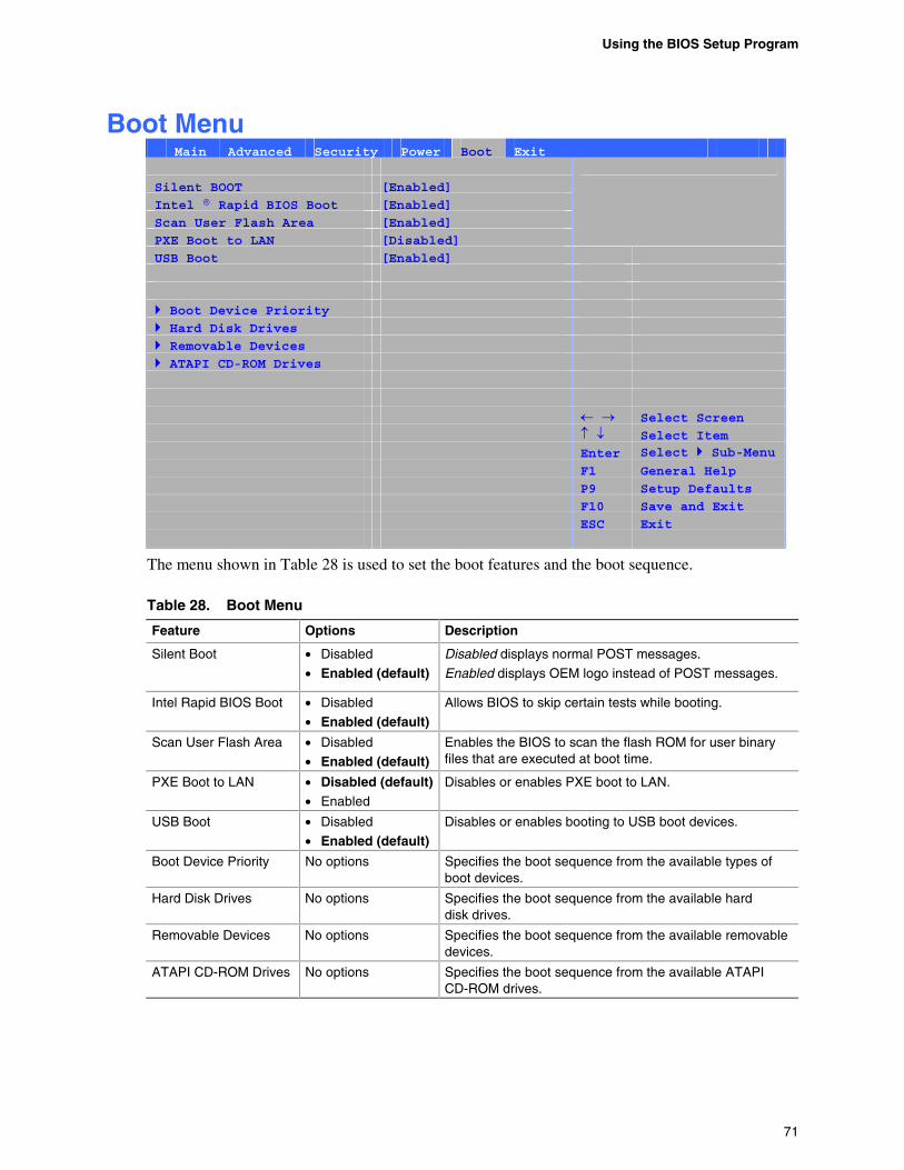
Using the BIOS Setup Program
71
Boot Menu Main Advanced Security Power Boot Exit
Silent BOOT [Enabled]
Intel ® Rapid BIOS Boot [Enabled]
Scan User Flash Area [Enabled]
PXE Boot to LAN [Disabled]
USB Boot [Enabled]
Boot Device Priority Hard Disk Drives Removable Devices ATAPI CD-ROM Drives
Select Screen
Select Item Enter Select Sub-Menu F1 General Help
P9 Setup Defaults
F10 Save and Exit
ESC Exit
The menu shown in Table 28 is used to set the boot features and the boot sequence.
Table 28. Boot Menu
Feature Options Description
Silent Boot • Disabled
• Enabled (default) Disabled displays normal POST messages.
Enabled displays OEM logo instead of POST messages.
Intel Rapid BIOS Boot • Disabled
• Enabled (default) Allows BIOS to skip certain tests while booting.
Scan User Flash Area • Disabled • Enabled (default)
Enables the BIOS to scan the flash ROM for user binary files that are executed at boot time.
PXE Boot to LAN • Disabled (default) • Enabled
Disables or enables PXE boot to LAN.
USB Boot • Disabled
• Enabled (default) Disables or enables booting to USB boot devices.
Boot Device Priority No options Specifies the boot sequence from the available types of boot devices.
Hard Disk Drives No options Specifies the boot sequence from the available hard disk drives.
Removable Devices No options Specifies the boot sequence from the available removable devices.
ATAPI CD-ROM Drives No options Specifies the boot sequence from the available ATAPI CD-ROM drives.
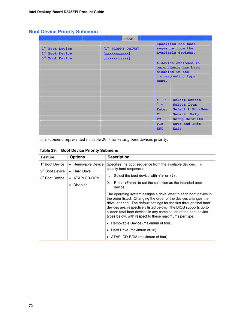
Intel Desktop Board D845EPI Product Guide
72
Boot Device Priority Submenu Main Advanced Security Power Boot Exit
1st Boot Device [1st FLOPPY DRIVE]
2nd Boot Device [xxxxxxxxxxx]
Specifies the boot sequence from the available devices.
3rd Boot Device [xxxxxxxxxxx]
A device enclosed in parenthesis has been disabled in the corresponding type menu.
Select Screen
Select Item Enter Select Sub-Menu F1 General Help
P9 Setup Defaults
F10 Save and Exit
ESC Exit
The submenu represented in Table 29 is for setting boot devices priority.
Table 29. Boot Device Priority Submenu
Feature Options Description
1st Boot Device
2nd Boot Device
3rd Boot Device
• Removable Device
• Hard Drive
• ATAPI CD-ROM
• Disabled
Specifies the boot sequence from the available devices. To specify boot sequence:
1. Select the boot device with <↑> or <↓>.
2. Press <Enter> to set the selection as the intended boot device.
The operating system assigns a drive letter to each boot device in the order listed. Changing the order of the devices changes the drive lettering. The default settings for the first through final boot devices are, respectively listed below. The BIOS supports up to sixteen total boot devices in any combination of the boot device types below, with respect to these maximums per type.
• Removable Device (maximum of four).
• Hard Drive (maximum of 12).
• ATAPI CD-ROM (maximum of four).
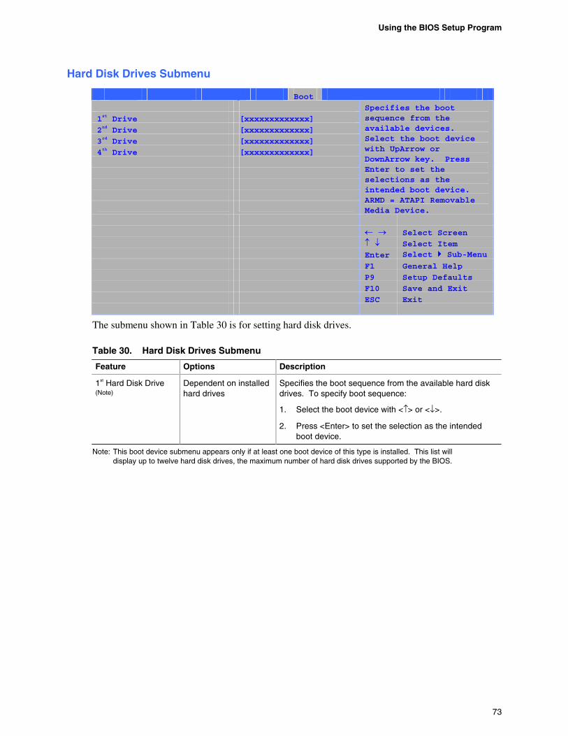
Using the BIOS Setup Program
73
Hard Disk Drives Submenu
Main Advanced Security Power Boot Exit
1st Drive [xxxxxxxxxxxxx]
2nd Drive [xxxxxxxxxxxxx]
3rd Drive [xxxxxxxxxxxxx]
4th Drive [xxxxxxxxxxxxx]
Specifies the boot sequence from the available devices. Select the boot device with UpArrow or DownArrow key. Press Enter to set the selections as the intended boot device. ARMD = ATAPI Removable Media Device.
Select Screen
Select Item Enter Select Sub-Menu F1 General Help
P9 Setup Defaults
F10 Save and Exit
ESC Exit
The submenu shown in Table 30 is for setting hard disk drives.
Table 30. Hard Disk Drives Submenu
Feature Options Description
1st Hard Disk Drive (Note)
Dependent on installed hard drives
Specifies the boot sequence from the available hard disk drives. To specify boot sequence:
1. Select the boot device with <↑> or <↓>.
2. Press <Enter> to set the selection as the intended boot device.
Note: This boot device submenu appears only if at least one boot device of this type is installed. This list will display up to twelve hard disk drives, the maximum number of hard disk drives supported by the BIOS.
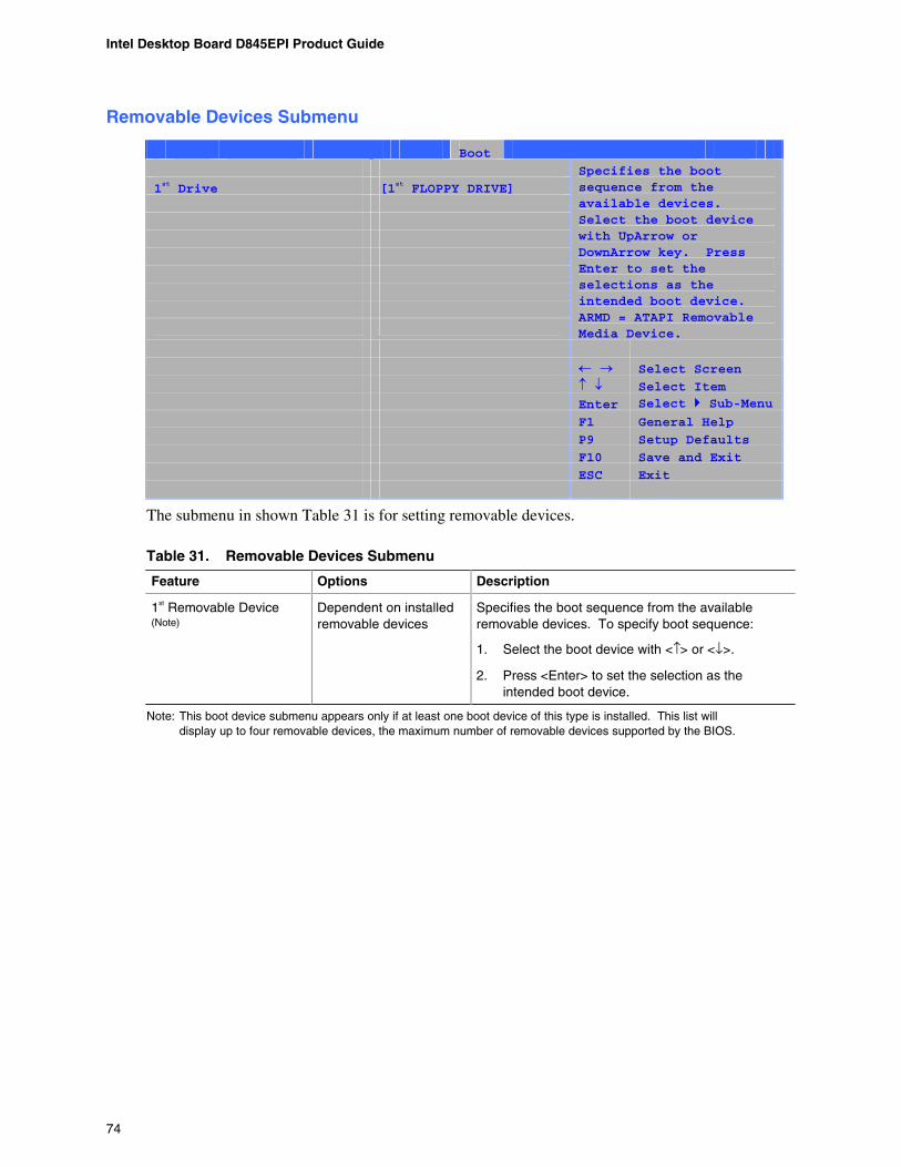
Intel Desktop Board D845EPI Product Guide
74
Removable Devices Submenu
Main Advanced Security Power Boot Exit
1st Drive [1st FLOPPY DRIVE]
Specifies the boot sequence from the available devices. Select the boot device with UpArrow or DownArrow key. Press Enter to set the selections as the intended boot device. ARMD = ATAPI Removable Media Device.
Select Screen
Select Item Enter Select Sub-Menu F1 General Help
P9 Setup Defaults
F10 Save and Exit
ESC Exit
The submenu in shown Table 31 is for setting removable devices.
Table 31. Removable Devices Submenu
Feature Options Description
1st Removable Device (Note)
Dependent on installed removable devices
Specifies the boot sequence from the available removable devices. To specify boot sequence:
1. Select the boot device with <↑> or <↓>.
2. Press <Enter> to set the selection as the intended boot device.
Note: This boot device submenu appears only if at least one boot device of this type is installed. This list will display up to four removable devices, the maximum number of removable devices supported by the BIOS.
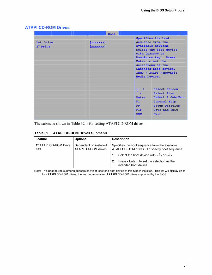
Using the BIOS Setup Program
75
ATAPI CD-ROM Drives Main Advanced Security Power Boot Exit
1st Drive [xxxxxxx]
2nd Drive [xxxxxxx]
Specifies the boot sequence from the available devices. Select the boot device with UpArrow or DownArrow key. Press Enter to set the selections as the intended boot device. ARMD = ATAPI Removable Media Device.
Select Screen
Select Item Enter Select Sub-Menu F1 General Help
P9 Setup Defaults
F10 Save and Exit
ESC Exit
The submenu shown in Table 32 is for setting ATAPI CD-ROM drives.
Table 32. ATAPI CD-ROM Drives Submenu
Feature Options Description
1st ATAPI CD-ROM Drive (Note)
Dependent on installed ATAPI CD-ROM drives
Specifies the boot sequence from the available ATAPI CD-ROM drives. To specify boot sequence:
1. Select the boot device with <↑> or <↓>.
2. Press <Enter> to set the selection as the intended boot device.
Note: This boot device submenu appears only if at least one boot device of this type is installed. This list will display up to four ATAPI CD-ROM drives, the maximum number of ATAPI CD-ROM drives supported by the BIOS.
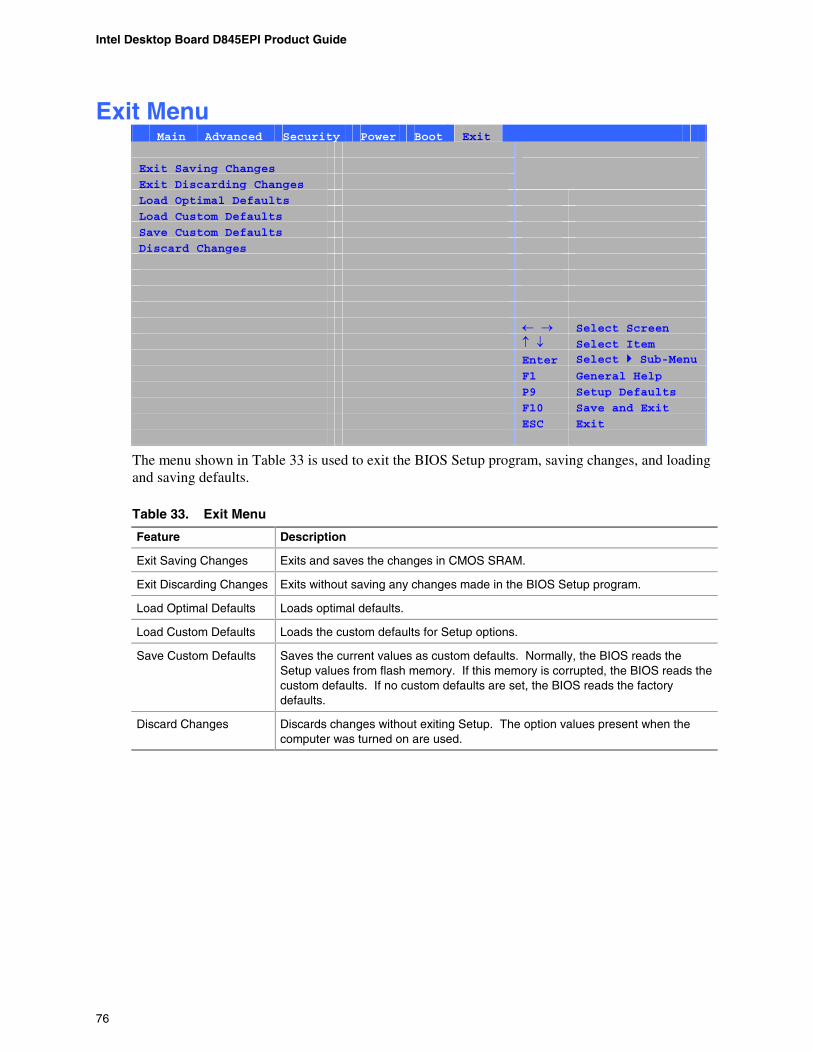
Intel Desktop Board D845EPI Product Guide
76
Exit Menu Main Advanced Security Power Boot Exit
Exit Saving Changes
Exit Discarding Changes
Load Optimal Defaults
Load Custom Defaults
Save Custom Defaults
Discard Changes
Select Screen
Select Item Enter Select Sub-Menu F1 General Help
P9 Setup Defaults
F10 Save and Exit
ESC Exit
The menu shown in Table 33 is used to exit the BIOS Setup program, saving changes, and loading and saving defaults.
Table 33. Exit Menu
Feature Description
Exit Saving Changes Exits and saves the changes in CMOS SRAM.
Exit Discarding Changes Exits without saving any changes made in the BIOS Setup program.
Load Optimal Defaults Loads optimal defaults.
Load Custom Defaults Loads the custom defaults for Setup options.
Save Custom Defaults Saves the current values as custom defaults. Normally, the BIOS reads the Setup values from flash memory. If this memory is corrupted, the BIOS reads the custom defaults. If no custom defaults are set, the BIOS reads the factory defaults.
Discard Changes Discards changes without exiting Setup. The option values present when the computer was turned on are used.
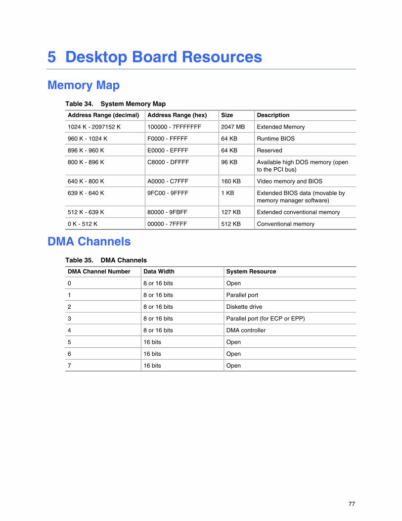
77
5 Desktop Board Resources
Memory Map Table 34. System Memory Map
Address Range (decimal) Address Range (hex) Size Description
1024 K - 2097152 K 100000 - 7FFFFFFF 2047 MB Extended Memory
960 K - 1024 K F0000 - FFFFF 64 KB Runtime BIOS
896 K - 960 K E0000 - EFFFF 64 KB Reserved
800 K - 896 K C8000 - DFFFF 96 KB Available high DOS memory (open to the PCI bus)
640 K - 800 K A0000 - C7FFF 160 KB Video memory and BIOS
639 K - 640 K 9FC00 - 9FFFF 1 KB Extended BIOS data (movable by memory manager software)
512 K - 639 K 80000 - 9FBFF 127 KB Extended conventional memory
0 K - 512 K 00000 - 7FFFF 512 KB Conventional memory
DMA Channels Table 35. DMA Channels
DMA Channel Number Data Width System Resource
0 8 or 16 bits Open
1 8 or 16 bits Parallel port
2 8 or 16 bits Diskette drive
3 8 or 16 bits Parallel port (for ECP or EPP)
4 8 or 16 bits DMA controller
5 16 bits Open
6 16 bits Open
7 16 bits Open
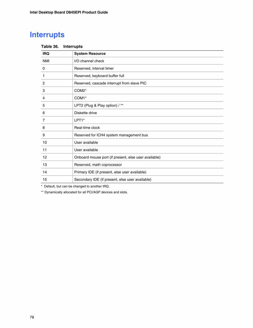
Intel Desktop Board D845EPI Product Guide
78
Interrupts Table 36. Interrupts
IRQ System Resource
NMI I/O channel check
0 Reserved, interval timer
1 Reserved, keyboard buffer full
2 Reserved, cascade interrupt from slave PIC
3 COM2*
4 COM1*
5 LPT2 (Plug & Play option) / **
6 Diskette drive
7 LPT1*
8 Real-time clock
9 Reserved for ICH4 system management bus
10 User available
11 User available
12 Onboard mouse port (if present, else user available)
13 Reserved, math coprocessor
14 Primary IDE (if present, else user available)
15 Secondary IDE (if present, else user available)
* Default, but can be changed to another IRQ.
** Dynamically allocated for all PCI/AGP devices and slots.
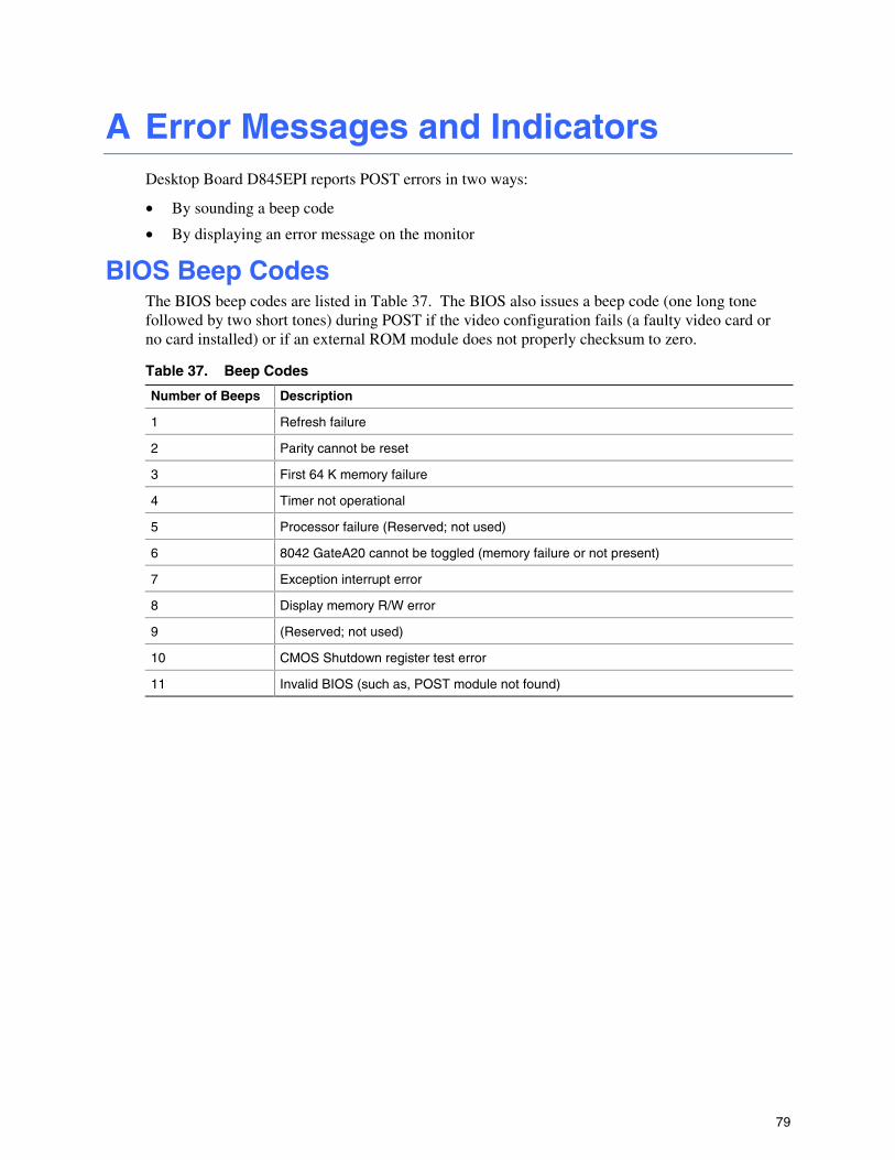
79
A Error Messages and Indicators Desktop Board D845EPI reports POST errors in two ways:
• By sounding a beep code
• By displaying an error message on the monitor
BIOS Beep Codes The BIOS beep codes are listed in Table 37. The BIOS also issues a beep code (one long tone followed by two short tones) during POST if the video configuration fails (a faulty video card or no card installed) or if an external ROM module does not properly checksum to zero.
Table 37. Beep Codes
Number of Beeps Description
1 Refresh failure
2 Parity cannot be reset
3 First 64 K memory failure
4 Timer not operational
5 Processor failure (Reserved; not used)
6 8042 GateA20 cannot be toggled (memory failure or not present)
7 Exception interrupt error
8 Display memory R/W error
9 (Reserved; not used)
10 CMOS Shutdown register test error
11 Invalid BIOS (such as, POST module not found)
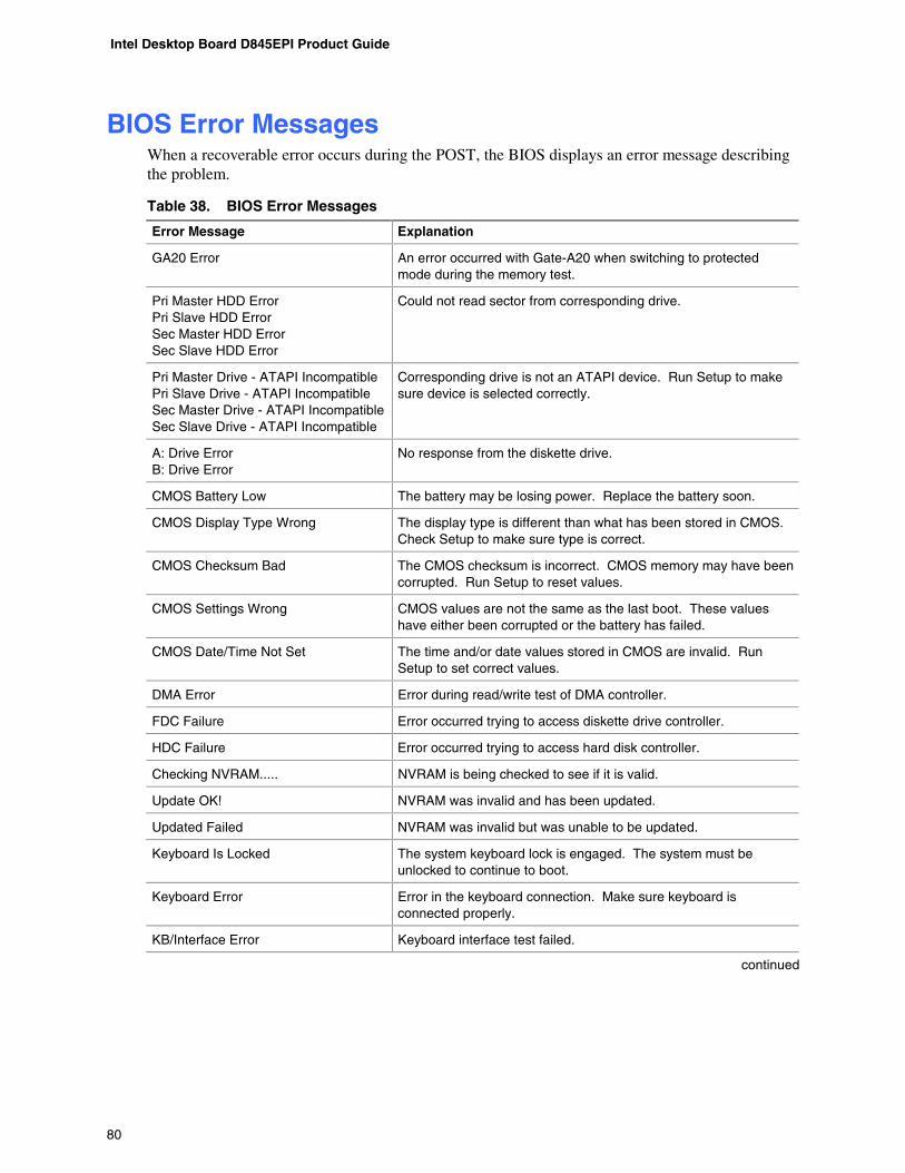
Intel Desktop Board D845EPI Product Guide
80
BIOS Error Messages When a recoverable error occurs during the POST, the BIOS displays an error message describing the problem.
Table 38. BIOS Error Messages
Error Message Explanation
GA20 Error An error occurred with Gate-A20 when switching to protected mode during the memory test.
Pri Master HDD Error Pri Slave HDD Error Sec Master HDD Error Sec Slave HDD Error
Could not read sector from corresponding drive.
Pri Master Drive - ATAPI Incompatible Pri Slave Drive - ATAPI Incompatible Sec Master Drive - ATAPI Incompatible Sec Slave Drive - ATAPI Incompatible
Corresponding drive is not an ATAPI device. Run Setup to make sure device is selected correctly.
A: Drive Error B: Drive Error
No response from the diskette drive.
CMOS Battery Low The battery may be losing power. Replace the battery soon.
CMOS Display Type Wrong The display type is different than what has been stored in CMOS. Check Setup to make sure type is correct.
CMOS Checksum Bad The CMOS checksum is incorrect. CMOS memory may have been corrupted. Run Setup to reset values.
CMOS Settings Wrong CMOS values are not the same as the last boot. These values have either been corrupted or the battery has failed.
CMOS Date/Time Not Set The time and/or date values stored in CMOS are invalid. Run Setup to set correct values.
DMA Error Error during read/write test of DMA controller.
FDC Failure Error occurred trying to access diskette drive controller.
HDC Failure Error occurred trying to access hard disk controller.
Checking NVRAM..... NVRAM is being checked to see if it is valid.
Update OK! NVRAM was invalid and has been updated.
Updated Failed NVRAM was invalid but was unable to be updated.
Keyboard Is Locked The system keyboard lock is engaged. The system must be unlocked to continue to boot.
Keyboard Error Error in the keyboard connection. Make sure keyboard is connected properly.
KB/Interface Error Keyboard interface test failed.
continued
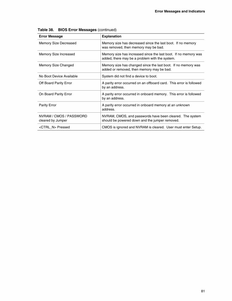
Error Messages and Indicators
81
Table 38. BIOS Error Messages (continued)
Error Message Explanation
Memory Size Decreased Memory size has decreased since the last boot. If no memory was removed, then memory may be bad.
Memory Size Increased Memory size has increased since the last boot. If no memory was added, there may be a problem with the system.
Memory Size Changed Memory size has changed since the last boot. If no memory was added or removed, then memory may be bad.
No Boot Device Available System did not find a device to boot.
Off Board Parity Error A parity error occurred on an offboard card. This error is followed by an address.
On Board Parity Error A parity error occurred in onboard memory. This error is followed by an address.
Parity Error A parity error occurred in onboard memory at an unknown address.
NVRAM / CMOS / PASSWORD cleared by Jumper
NVRAM, CMOS, and passwords have been cleared. The system should be powered down and the jumper removed.
<CTRL_N> Pressed CMOS is ignored and NVRAM is cleared. User must enter Setup.

Intel Desktop Board D845EPI Product Guide
82

83
B Regulatory Compliance This appendix contains the following regulatory compliance information for Desktop Board D845EPI:
• Safety standards
• European Union Declaration of Conformity statement
• Product Ecology statements
• Electromagnetic Compatibility (EMC) regulations
• Product certification markings
Safety Regulations Desktop Board D845EPI complies with the safety regulations stated in Table 39 when correctly installed in a compatible host system.
Table 39. Safety Regulations
Regulation Title
UL 60950 3rd ed., 2000/CSA C22.2 No. 60950-00
Bi-National Standard for Safety of Information Technology Equipment including Electrical Business Equipment. (USA and Canada)
EN 60950:2000 The Standard for Safety of Information Technology Equipment including Electrical Business Equipment. (European Union)
IEC 60950, 3rd Edition, 1999 The Standard for Safety of Information Technology Equipment including Electrical Business Equipment. (International)
European Union Declaration of Conformity Statement We, Intel Corporation, declare under our sole responsibility that the product Intel® Desktop Board D845EPI is in conformity with all applicable essential requirements necessary for CE marking, following the provisions of the European Council Directive 89/336/EEC (EMC Directive) and Council Directive 73/23/EEC (Safety/Low Voltage Directive).
The product is properly CE marked demonstrating this conformity and is for distribution within all member states of the EU with no restrictions.
This product follows the provisions of the European Directives 89/336/EEC and 73/23/EEC.

Intel Desktop Board D845EPI Product Guide
84
%BOTLDette produkt er i overensstemmelse med det europæiske direktiv 89/336/EEC & 73/23/EEC.
%VUDIDit product is in navolging van de bepalingen van Europees Directief 89/336/EEC & 73/23/EEC.
4VPNJTämä tuote noudattaa EU-direktiivin 89/336/EEC & 73/23/EEC määräyksiä.
'SBOÎBJTCe produit est conforme aux exigences de la Directive Européenne 89/336/EEC & 73/23/EEC.
%FVUTDIDieses Produkt entspricht den Bestimmungen der Europäischen Richtlinie 89/336/EEC & 73/23/EEC.
*DFMBOEJDÞessi vara stenst reglugerð Evrópska Efnahags Bandalagsins númer 89/336/ EEC & 73/23/EEC.
*UBMJBOPQuesto prodotto è conforme alla Direttiva Europea 89/336/EEC & 73/23/EEC.
/PSTLDette produktet er i henhold til bestemmelsene i det europeiske direktivet 89/336/ EEC & 73/23/EEC.
1PSUVHVFTFEste produto cumpre com as normas da Diretiva Européia 89/336/EEC & 73/23/EEC.
&TQB×PMEste producto cumple con las normas del Directivo Europeo 89/336/EEC & 73/23/EEC.
4WFOTLBDenna produkt har tillverkats i enlighet med EG-direktiv 89/336/EEC & 73/23/EEC.
Product Ecology Statements The following information is provided to address worldwide product ecology concerns and regulations.
Disposal Considerations
This product contains the following materials that may be regulated upson disposal: lead solder on the printed wiring board assembly.
Recycling Considerations
Intel encourages its customers to recycle its products and their components (e.g., batteries, circuit boards, plastic enclosures, etc.) whenever possible. In the U.S., a list of recyclers in your area can be found at:
http://www.eiae.org
In the absence of a viable recycling option, products and their components must be disposed of in accordance with all applicable local environmental regulations.
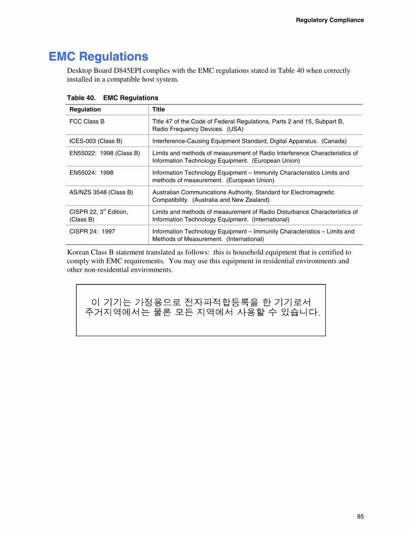
Regulatory Compliance
85
EMC Regulations Desktop Board D845EPI complies with the EMC regulations stated in Table 40 when correctly installed in a compatible host system.
Table 40. EMC Regulations
Regulation Title
FCC Class B Title 47 of the Code of Federal Regulations, Parts 2 and 15, Subpart B, Radio Frequency Devices. (USA)
ICES-003 (Class B) Interference-Causing Equipment Standard, Digital Apparatus. (Canada)
EN55022: 1998 (Class B) Limits and methods of measurement of Radio Interference Characteristics of Information Technology Equipment. (European Union)
EN55024: 1998 Information Technology Equipment – Immunity Characteristics Limits and methods of measurement. (European Union)
AS/NZS 3548 (Class B) Australian Communications Authority, Standard for Electromagnetic Compatibility. (Australia and New Zealand)
CISPR 22, 3rd Edition, (Class B)
Limits and methods of measurement of Radio Disturbance Characteristics of Information Technology Equipment. (International)
CISPR 24: 1997 Information Technology Equipment – Immunity Characteristics – Limits and Methods of Measurement. (International)
Korean Class B statement translated as follows: this is household equipment that is certified to comply with EMC requirements. You may use this equipment in residential environments and other non-residential environments.

Intel Desktop Board D845EPI Product Guide
86
Product Certification Markings (Board Level) Desktop Board D845EPI has the following product certification markings:
Table 41. Product Certification Markings
Description Mark
UL joint US/Canada Recognized Component mark. Includes adjacent UL file number for Intel desktop boards: E210882 (component side).
FCC Declaration of Conformity logo mark for Class B equipment; includes Intel name and D845EPI model designation (component side).
CE mark. Declares compliance to Euopean Union (EU) EMC directive (89/336/EEC) and Low Voltage directive (73/23/EEC) (component side). The CE mark should also be on the shipping container.
Australian Communications Authority (ACA) C-tick mark. Includes adjacent Intel supplier code number, N-232. The C-tick mark should also be on the shipping container.
Printed wiring board manufaturer’s recognition mark: consists of a unique UL recognized manufacturer’s logo, along with a flammability rating (solder side).
94V-0