Embed Size (px)
Citation preview
Inter-spikes-intervals exponential and gamma distributions studyof neuron firing rate for SVITE motor control model on FPGA
Fernando Pérez-Peña a, Arturo Morgado-Estévez a, Alejandro Linares-Barranco ba Computer Architecture and Technology Area, Universidad de Cádiz, School of Engineering, Calle Chile, 1, Cadiz 11002, Spainb Robotic and Technology of Computers Lab (RTC), Universidad de Sevilla, ETSI Informática, Avd. Reina Mercedes s/n, Seville 41012, Spain
Keywords:Bio-inspiredNeuro-inspiredAERLFSRPoissonFPGA
a b s t r a c t
This paper presents a statistical study on a neuro-inspired spike-based implementation of the Vector-Integration-To-End-Point motor controller (SVITE) and compares its deterministic neuron-model streamof spikes with a proposed modification that converts the model, and thus the controller, in a Poisson likespike stream distribution. A set of hardware pseudo-random numbers generators, based on a LinearFeedback Shift Register (LFSR), have been introduced in the neuron-model so that they reach a closerbiological neuron behavior. To validate the new neuron-model behavior a comparison between the Inter-Spikes-Interval empirical data and the Exponential and Gamma distributions has been carried out usingthe Kolmogorov–Smirnoff test. An in-hardware validation of the controller has been performed in aSpartan6 FPGA to drive directly with spikes DC motors from robotics to study the behavior and viabilityof the modified controller with random components.
The results show that the original deterministic spikes distribution of the controller blocks can beswapped with Poisson distributions using 30-bit LFSRs. The comparative between the usable controllingsignals such as the trajectory and the speed profile using a deterministic and the new controller show astandard deviation of 11.53 spikes/s and 3.86 spikes/s respectively. These rates do not affect our systembecause, within Pulse Frequency Modulation, in order to drive the motors, time length can be fixed tospread the spikes. Tuning this value, the slow rates could be filtered by the motor. Therefore, this SVITEneuro-inspired controller can be integrated within complex neuromorphic architectures with Poisson-like neurons.
1. Introduction
The main goal of the neuromorphic engineering research field is to develop hardware devices based on the principles of the human nervous system [1]. The term “Neuromorphic Engineering” was first coined by Caver Mead in the late eighties [2]. He started mimicking the behavior of neuron cells by using Very-Large-Scale-Integration (VLSI) chips. Then, Sivilotti [3] defined the commu-nication protocol to be used between those devices: Address Event Representation (AER). AER enables the communication of thou-sands of neurons from one chip to another. Within AER, each neuron is given an address to identify along the architecture. All the devices were expected to be connected with that AER bus.
The most popular options to implement the end neuromorphic devices into hardware are these three: the use of a full custom VLSI design application-specific integrated circuit (ASIC) [4], a Field
Programmable Gate Array (FPGA) [5,6] or a Field-ProgrammableAnalog Array (FPAA) [7]. Up to these days, many neuron models [8],large scale architectures [9] and sensory devices such as vision [10]or cochlea sensors [11] have been developed. However, the chal-lenge today is to bridge the gap between sensors and largearchitectures to reach an accurate spiking motor control.
An FPGA design based on neurons known as Integrate andGenerate (I&G) which is described in [12] was used in this study.I&G neuron includes one pre and postsynaptic connection and anintegrator which computes the ongoing spikes. It models theactivity level of the neuron; its firing rate depends on theintegrated value. In its basic model, the integrated value is updatedfor each incoming spike by an increment or a decrement of themembrane potential (MP), modeled by a counter, depending of thepolarity of the received spike. If the spike is positive MP isincremented, but it is decremented when the spike is negative.Current MP is continuously translated into an output stream ofspikes. The distribution of these output stream is deterministic inthe basic model, but it can be easily modified to obtain newdistributions. This model is similar to LIF model but it allowsto modify the distribution over time of the outgoing spikes.
The behavior is currently described in VHDL and implemented forFPGA. This model has a completely deterministic output firing rate(Eq. 4), without any random component, which fits with the aim ofspike based motor controlling [13].
In principle, for motor controlling it does not seem feasible tohave random spikes distributions inside the controller. However,in this paper we present a study where pseudo-random distribu-tions of spikes have replaced deterministic ones in the motorcontroller. Statistical models are presented and the results showthat random distributions can be used for spike-based motorcontrol.
There are in-vivo experiments that show variability at the firingrate pattern if a constant stimulus is presented within differenttests at different times [14]. This behavior is extremely proble-matic if the current trend is to match the neuron response pereach stimulus presented to elaborate a map between stimuli andfiring patterns. Regarding this view, [15] points out that if thestimulus presented is fluctuating, the neuron will produce aprecise spike timing response.
For a deterministic spike distribution motor controller, if weconsider this controller as an isolated part of the architecture,there would not be any noisy or random spikes. However, if weconsider this controller as part of large neuromorphic architec-tures, we must face these different possible distributions of spikesand try to minimize their effects or at least predict the behavior ofthe motor controller and act in accordance with them.
The next paragraphs include a review on the current spike-based neuro-inspired motor controller.
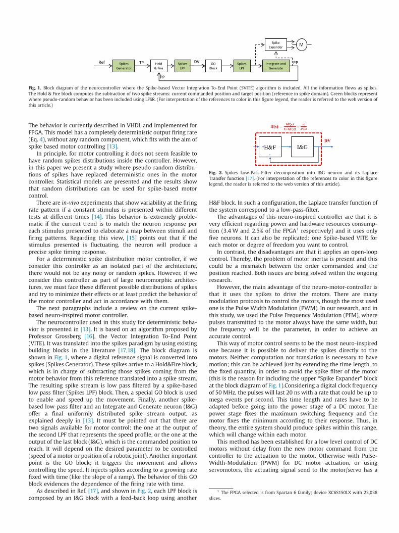
The neurocontroller used in this study for deterministic beha-vior is presented in [13]. It is based on an algorithm proposed byProfessor Grossberg [16], the Vector Integration To-End Point(VITE). It was translated into the spikes paradigm by using existingbuilding blocks in the literature [17,18]. The block diagram isshown in Fig. 1, where a digital reference signal is converted intospikes (Spikes Generator). These spikes arrive to a Hold&Fire block,which is in charge of subtracting those spikes coming from themotor behavior from this reference translated into a spike stream.The resulting spike stream is low pass filtered by a spike-basedlow pass filter (Spikes LPF) block. Then, a special GO block is usedto enable and speed up the movement. Finally, another spike-based low-pass filter and an Integrate and Generate neuron (I&G)offer a final uniformly distributed spike stream output, asexplained deeply in [13]. It must be pointed out that there aretwo signals available for motor control: the one at the output ofthe second LPF that represents the speed profile, or the one at theoutput of the last block (I&G), which is the commanded position toreach. It will depend on the desired parameter to be controlled(speed of a motor or position of a robotic joint). Another importantpoint is the GO block; it triggers the movement and allowscontrolling the speed. It injects spikes according to a growing ratefixed with time (like the slope of a ramp). The behavior of this GOblock evidences the dependence of the firing rate with time.
As described in Ref. [17], and shown in Fig. 2, each LPF block iscomposed by an I&G block with a feed-back loop using another
H&F block. In such a configuration, the Laplace transfer function ofthe system correspond to a low-pass-filter.
The advantages of this neuro-inspired controller are that it isvery efficient regarding power and hardware resources consump-tion (3.4 W and 2.5% of the FPGA1 respectively) and it uses onlyfive neurons. It can also be replicated: one Spike-based VITE foreach motor or degree of freedom you want to control.
In contrast, the disadvantages are that it applies an open-loopcontrol. Thereby, the problem of motor inertia is present and thiscould be a mismatch between the order commanded and theposition reached. Both issues are being solved within the ongoingresearch.
However, the main advantage of the neuro-motor-controller isthat it uses the spikes to drive the motors. There are manymodulation protocols to control the motors, though the most usedone is the Pulse Width Modulation (PWM). In our research, and inthis study, we used the Pulse Frequency Modulation (PFM), wherepulses transmitted to the motor always have the same width, butthe frequency will be the parameter, in order to achieve anaccurate control.
This way of motor control seems to be the most neuro-inspiredone because it is possible to deliver the spikes directly to themotors. Neither computation nor translation is necessary to havemotion; this can be achieved just by extending the time length, tothe fixed quantity, in order to avoid the spike filter of the motor(this is the reason for including the upper “Spike Expander” blockat the block diagram of Fig. 1).Considering a digital clock frequencyof 50 MHz, the pulses will last 20 ns with a rate that could be up tomega events per second. This time length and rates have to beadapted before going into the power stage of a DC motor. Thepower stage fixes the maximum switching frequency and themotor fixes the minimum according to their response. Thus, intheory, the entire system should produce spikes within this range,which will change within each motor.
This method has been established for a low level control of DCmotors without delay from the new motor command from thecontroller to the actuation to the motor. Otherwise with Pulse-Width-Modulation (PWM) for DC motor actuation, or usingservomotors, the actuating signal send to the motor/servo has a
Fig. 1. Block diagram of the neurocontroller where the Spike-based Vector Integration To-End Point (SVITE) algorithm is included. All the information flows as spikes.The Hold & Fire block computes the subtraction of two spike streams: current commanded position and target position (reference in spike domain). Green blocks representwhere pseudo-random behavior has been included using LFSR. (For interpretation of the references to color in this figure legend, the reader is referred to the web version ofthis article.)
Fig. 2. Spikes Low-Pass-Filter decomposition into I&G neuron and its LaplaceTransfer function [17]. (For interpretation of the references to color in this figurelegend, the reader is referred to the web version of this article).
1 The FPGA selected is from Spartan 6 family; device XC6S150LX with 23,038slices.
fixed period in the order of 20 ms, so we should integrate theoutput spikes of the neuro-motor controller during a fixed time(those 20 ms) before actuating. Therefore, you were setting a delayfrom the side of the controller in the system. This delay can havesome side effects as over dumped responses [12].
Once the controller is defined, we now propose how we caninclude the random components inside the blocks of the algorithmto get closer to a more realistic model or at least how they can beincluded as the edge of large neuromorphic architectures.
As we used deterministic firing patterns, if we include somerandom elements to enforce the variability at the firing rates, weneed to manage the expected spike signal. Several previous studiesestablished that neuron firing rates can often be modeled by ahomogeneous Poisson distribution [19,20]. In such kind of process,the average firing rate is constant over time and its times betweenspikes fit in an exponential distribution. A Poisson distribution isdescribed by the following formula:
Pnðt ¼ TÞ ¼ ðλTÞnn!
eλT ð1Þ
However, that homogeneous Poisson process is at the front lineof our case, in which the algorithm injects spikes in a timedependent manner [15] and a feedback is included. For thesecases, there are two options: an inhomogeneous Poisson processwhere the firing rate varies with time or a renewal process wherealso time dependence with only the previous spike fired isincluded [19]. Looking through the inter spike interval, it shouldfollow an exponential or gamma distribution, respectively (2) and(3). We present a methodology to check this.
f ðxÞ ¼ λe� λx ð2Þ
f ðxÞ ¼ βαxα�1e�βx
ΓðαÞ ð3Þ
The rest of the paper is structured as follows: In the methodol-ogy section, the hardware implementation is briefly explained andthe tests performed are exhaustively described. Then, the resultsand discussion section shows and discusses the results obtained.Finally, the conclusion section sets up the novelties and advan-tages shown in this study.
2. Methodology
2.1. Introduction
Two methodologies were used: (1) a statistical hypothesis testto check if the inter spike interval (ISI) of the information-carryingsignals could be fitted into any well-known and largely studiedneuronal distributions like gamma or exponential [19,20]; and(2) a comparison between the signals used for motor controlling[15] to check how long they can be used for their original purpose:motor controlling.
The base line is set as the SVITE algorithm running within arobotic platform [15] shown in Fig. 1. As long as the algorithm usesonly deterministic neurons, it is necessary to include randomcomponents [21] to reach different behaviors along the tests.
2.2. Setup components: hardware
The algorithm was implemented using the AER Node board.This board includes a Xilinx Spartan-6 LXT 1500 FPGA. It wasdeveloped by RTC lab under the VULCANO project2 and it allows
high speed serial AER communications over Rocket IO transcei-vers, and adaptation to particular scenarios through daughterboards connected on the top. For these tests, the setup includesa daughter board with an USB microcontroller that communicateswith the FPGA over Serial Peripheral Interface (SPI). This interfaceis used to send the parameters needed for each block [12] and tomanage the tests.
This main board also runs a massive spikes monitor [22] thataddresses each block of the algorithm and does the handshake tocommunicate, using the AER protocol, with a monitor board [23].The monitor board receives the spikes and allows them to beprocessed by the computer using jAER [24] or MATLAB.
2.3. Running tests
Once the system with pseud-random behavior is implementedon the Spartan 6 board, a PC with MATLAB is used to deliver thetarget position to the algorithm. This position can arrive to thecontroller in the form of AER coming from a PC or from anhardware AER visual system (cortex inspired) [25]. It is a spatialcoordinate, for instance, x¼5 (we used only one dimension,although it can be replicated to control more complex roboticstructures by replicating one SVITE motor-controller per joint inthe robot).
This coordinate is feed into the “Spikes Generator” (first blockon the left in Fig. 1) and it plays the role of reference. A spikestream is then produced by this block for stimulating the wholecontroller. The firing behavior produced here is very importantsince it will determine the spike distribution. Original firing rate(using a deterministic “Spikes Generator” [26]) is described byEq. (4),
r¼ f CLK2NBITS� 1 � input ð4Þ
where fCLK is the clock frequency (50 MHz in our tests), NBITS isthe amount of bits used to implement the internal spikes counterof the “Spikes Generator” and input is the parameter receivedthrough the SPI interface (16 bits). For this clock frequency wedefine as time bin the period of the clock (20 ns) as the minimumupdate period for neurons’ state.
The output of this block has a constant firing rate for a fixedinput reference. Thus, this was the main block to be modified inorder to include a non-deterministic behavior. The other greenblocks of Fig. 1 must also be modified because they include a firingelement like the Integrate and Generate (I&G) or LPF block. Thefiring pattern of these blocks is the same as Eq. (4), but inputbecomes the spikes fired by the previous block.
So, to modify that behavior, we have included a linear feedbackshift register (LFSR) for both: “Spikes Generator” and I&G. Thiscomponent, with the proper XOR feedback, generates a uniformsequence of different pseudo-random values within a range thatdepends on the number of bits used to implement it. Once all thepossible numbers have been generated, this LFSR will repeat thesame random sequence over and over again. Also, a time-slice orbin to trigger the output can be configured. With this component,the probability to fire a spike at T will be:
P ðspike¼ 1jTÞ ¼ input
2NBITSLFSR �1ð5Þ
Some specific details depend on the type of block
a. Spikes GeneratorWhen the time bin is reached the value from the LFSR will becompared with the reference and only if it is lower, the blockwill fire a spike. Usually, the digital input reference for thespikes generation has 16 bits, so we took this initial number of
2 VULCANO Project: Ultra-Fast Frame-less Vision by Events. Application toAutomation and Anthropomorphic Cognitive Robotics. (TEC 2009-10639-C04-02).
bits to build the LFSR register. From Eq. (5), one can see thatthere is an inversely proportional relationship between thereference (input) and the number of bits of the LFSR (NBITSLFSR).A trade-off should be reached. Later on we will measuredifferent behaviors for different LFSR lengths.
b. Integrate & Generate (I&G)In this case, the comparison with LFSR will be made with thenumber of spikes counted and only if it is lower, the block willfire a spike.
If we consider Eq. (5) and the algorithm architecture, one cansee that if we fix the same LFSR register for each I&G neuronincluded at the algorithm (one at each spikes low-pass-filter andlast I&G), the firing rate will decrease along the blocks because theevents (firing a spike) are not independent from the previous one,it is a conditional probability. Furthermore, we have to manage anadequate amount of spikes to allow the motors to run. To reachthis behavior, we considered a gradual increase of the LFSRresolution which provokes higher rates of spikes for the usefulsignals.
2.4. Data processing
At the end of the tests, we have a set of firing rates or spikesignals belonging to each block of Fig. 1 for all the combinationsperformed. First, they are split and each inter spike interval (ISI) iscalculated. Second, for each ISI, we get the empirical cumulativedistribution function (CDF) that can be compared with the idealdistribution’s CDF. This is the first comparison, the CDF plotted one.
On the other hand, the second comparison is carried out withthe Kolmogorov–Smirnov test (KS test) and chi-square test tovalidate the distribution fitness. We have applied this test tocompare how well the observed distribution of ISIs follows thetheoretical exponential and gamma distributions. These tests givethe p-value that allows rejecting or not the null hypothesis.We have considered a p-value between 0.05 and 0.1 as reasonableand above 0.1 to accept the hypothesis. Additionally, if thestatistical test result is below 5% one can assume that the sampledata fitness is good enough. All these statistical studies wereconducted using the Statgraphics Centurion software package.
We performed these two comparisons because the K–S testdoes not show a good performance at Null-hypothesis and p-valuewhen the CDF for the theoretical distribution is made up from
empirical data [27]. In such cases, the K–S is an alternative statisticavailable in the test results. It shows the biggest differencebetween both distributions. Furthermore, with this value and theplotting comparison, a right conclusion can be drawn.
In view of this comparison, it cannot be forgotten that thesesignals are used for motor control purposes. Therefore, for eachmodification done to include the random element, we must checkif the motor controller performance and accuracy are not lost.
3. Results and discussion
All the results shown in this section were measured on realhardware. There are no simulation results.
3.1. Spikes Generator
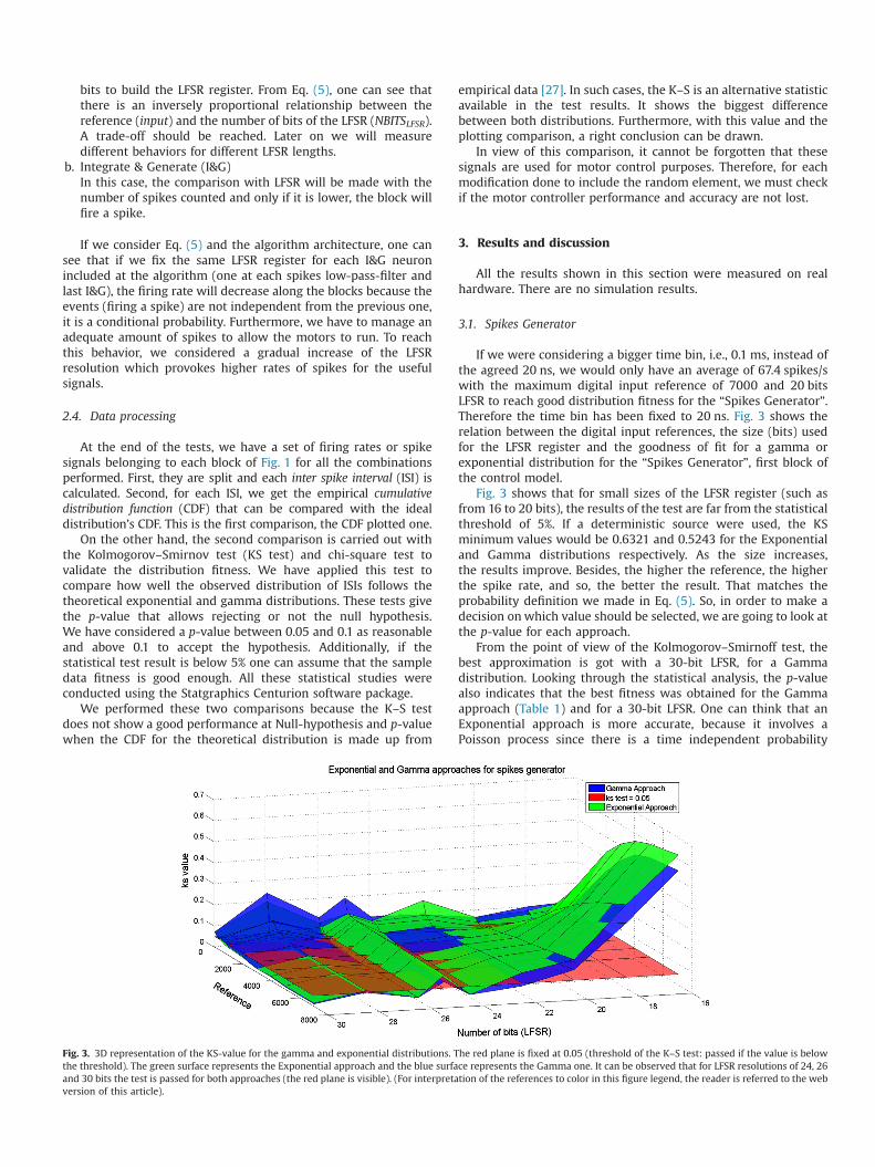
If we were considering a bigger time bin, i.e., 0.1 ms, instead ofthe agreed 20 ns, we would only have an average of 67.4 spikes/swith the maximum digital input reference of 7000 and 20 bitsLFSR to reach good distribution fitness for the “Spikes Generator”.Therefore the time bin has been fixed to 20 ns. Fig. 3 shows therelation between the digital input references, the size (bits) usedfor the LFSR register and the goodness of fit for a gamma orexponential distribution for the “Spikes Generator”, first block ofthe control model.
Fig. 3 shows that for small sizes of the LFSR register (such asfrom 16 to 20 bits), the results of the test are far from the statisticalthreshold of 5%. If a deterministic source were used, the KSminimum values would be 0.6321 and 0.5243 for the Exponentialand Gamma distributions respectively. As the size increases,the results improve. Besides, the higher the reference, the higherthe spike rate, and so, the better the result. That matches theprobability definition we made in Eq. (5). So, in order to make adecision onwhich value should be selected, we are going to look atthe p-value for each approach.
From the point of view of the Kolmogorov–Smirnoff test, thebest approximation is got with a 30-bit LFSR, for a Gammadistribution. Looking through the statistical analysis, the p-valuealso indicates that the best fitness was obtained for the Gammaapproach (Table 1) and for a 30-bit LFSR. One can think that anExponential approach is more accurate, because it involves aPoisson process since there is a time independent probability
Fig. 3. 3D representation of the KS-value for the gamma and exponential distributions. The red plane is fixed at 0.05 (threshold of the K–S test: passed if the value is belowthe threshold). The green surface represents the Exponential approach and the blue surface represents the Gamma one. It can be observed that for LFSR resolutions of 24, 26and 30 bits the test is passed for both approaches (the red plane is visible). (For interpretation of the references to color in this figure legend, the reader is referred to the webversion of this article).
definition for each event (spike in our case). However, the resultsshow that the value produced by the LFSR register is not purelyrandom, but pseudo-random. Therefore, both approaches are quitesimilar, as shown in Fig. 3. The final decision is to take a 30-bitLFSR based on the p-value and KS statistical value. Fig. 4 showsalso the accuracy for a 24-bit LFSR.
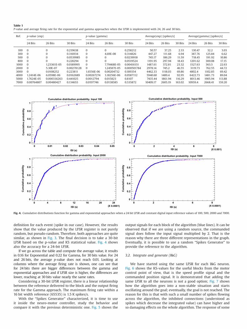
If we go across the table and compute the average value, it resultsin 0.16 for Exponential and 0.22 for Gamma, for 30 bits value. For 24and 26 bits, the average p-value does not reach 0.01. Looking atcolumns where the average firing rate is shown, one can see thatfor 24 bits there are bigger differences between the gamma andexponential approaches and if LFSR size is higher, the differences arelower, reaching at 30 bits value nearly the same rates.
Considering a 30-bit LFSR register, there is a linear relationshipbetween the reference delivered to the block and the output firingrate for the Gamma approach. The maximum firing rate within a16 bit width reference (65535) is 1.5 K spikes/s.
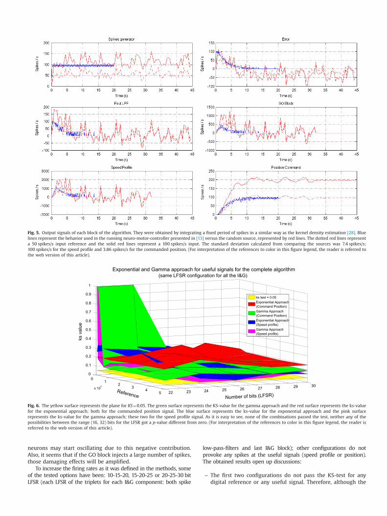
With the “Spikes Generator” characterized, it is time to useit inside the neuro-motor controller, study the behavior andcompare it with the previous deterministic one. Fig. 5 shows the
output signals for each block of the algorithm (blue lines). It can beobserved that if we are using a random source, the commandedsignal does follow the input signal multiplied by 2. That is thereason why there are three different representations in the graph.Eventually, it is possible to use a random “Spikes Generator” toprovide the reference to the algorithm.
3.2. Integrate and generate (I&G)
We have started using the same LFSR for each I&G neuron.Fig. 6 shows the KS-values for the useful blocks from the motorcontrol point of view, that is the speed profile signal and thecommanded position signal. It is demonstrated that adding thesame LFSR to all the neurons is not a good option; Fig. 7 showshow the algorithm goes into a non-stable situation and startsoscillating around the goal; eventually, the goal is not reached. Thereason for this is that with such a small number of spikes flowingacross the algorithm, the inhibited connections (understood asspikes which decrease the integrated value) can have higher andso damaging effects on the whole algorithm. The response of some
Table 1P-value and average firing rate for the exponential and gamma approaches when the LFSR is implemented with 24, 26 and 30 bits.
Ref. p-value (exp) p-value (gamma) Average(exp) [spikes/s] Average(gamma) [spikes/s]
24 Bits 26 Bits 30 Bits 24 Bits 26 Bits 30 Bits 24 Bits 26 Bits 30 Bits 24 Bits 26 Bits 30 Bits
100 0 0 0.219638 0 0 0.258212 50.57 37.25 2.33 130.47 32.2 3.03300 0 0 0.316934 0 4.69E-08 0.314826 447.27 111.68 6.94 387.76 125.84 6.62500 0 0 0.0539985 0 0 0.0239918 745.17 186.29 11.59 718.45 191.92 10.86800 0 0 0.228294 0 0 0.0519524 1191.95 297.94 18.43 1201.62 300.08 17.15
1000 0 1.23361E-05 0.0189995 0 7.79468E-05 0.00416151 1487.61 372.81 23.32 1527.63 363.5 22.632000 0 5.30E-07 0.00278128 0 1.24587E-05 0.000501784 2978.14 745.2 46.55 3119.73 762.55 44.723000 0 0.0108252 0.223811 1.6556E-06 0.00204732 0.189354 4462.33 1118.03 69.86 4802.4 1102.85 69.424000 1.2414E-06 6.0598E-06 0.0162689 0.00267274 3.18256E-06 0.0587112 5940.60 1489.4 92.95 6422.73 1481.73 89.045000 1.7624E-05 0.000336263 0.441025 0.0012794 0.015823 0.8107 7435.44 1861.94 116.29 8013.46 1905.94 113.887000 0.00764807 0.00480427 0.134655 0.0197746 0.0138585 0.535872 10409.17 2605.19 163.02 10959.4 2668.41 159.20
ISI (s)
Cum
ulat
ive
prob
abili
ty
Cumulative distribution probability. Input 100
0 0.01 0.02 0.03 0.04 0.050
0.2
0.4
0.6
0.8
1
ISI (s)
Cum
ulat
ive
prob
abili
ty
Cumulative distribution probability. Input 500
0 2 4 6 8(X 0.001)
0
0.2
0.4
0.6
0.8
1
ISI (s)
Cum
ulat
ive
prob
abili
ty
Cumulative distribution probability. Input 2000
0 4 8 12 16 20 24(X 0.0001)
0
0.2
0.4
0.6
0.8
1
ISI (s)
Cum
ulat
ive
prob
abili
ty
Cumulative distribution probability. Input 7000
0 2 4 6 8(X 0.0001)
0
0.2
0.4
0.6
0.8
1
Fig. 4. Cumulative distributions function for gamma and exponential approaches when a 24 bit LFSR and constant digital input reference values of 100, 500, 2000 and 7000.
neurons may start oscillating due to this negative contribution.Also, it seems that if the GO block injects a large number of spikes,those damaging effects will be amplified.
To increase the firing rates as it was defined in the methods, someof the tested options have been: 10-15-20, 15-20-25 or 20-25-30 bitLFSR (each LFSR of the triplets for each I&G component: both spike
low-pass-filters and last I&G block); other configurations do notprovoke any spikes at the useful signals (speed profile or position).The obtained results open up discussions:
– The first two configurations do not pass the KS-test for anydigital reference or any useful signal. Therefore, although the
Fig. 5. Output signals of each block of the algorithm. They were obtained by integrating a fixed period of spikes in a similar way as the kernel density estimation [28]. Bluelines represent the behavior used in the running neuro-motor-controller presented in [13] versus the random source, represented by red lines. The dotted red lines representa 50 spikes/s input reference and the solid red lines represent a 100 spikes/s input. The standard deviation calculated from comparing the sources was 7.4 spikes/s;100 spikes/s for the speed profile and 3.86 spikes/s for the commanded position. (For interpretation of the references to color in this figure legend, the reader is referred tothe web version of this article).
Fig. 6. The yellow surface represents the plane for KS¼0.05. The green surface represents the KS-value for the gamma approach and the red surface represents the ks-valuefor the exponential approach; both for the commanded position signal. The blue surface represents the ks-value for the exponential approach and the pink surfacerepresents the ks-value for the gamma approach; these two for the speed profile signal. As it is easy to see, none of the combinations passed the test, neither any of thepossibilities between the range (16, 32) bits for the LFSR got a p-value different from zero. (For interpretation of the references to color in this figure legend, the reader isreferred to the web version of this article).
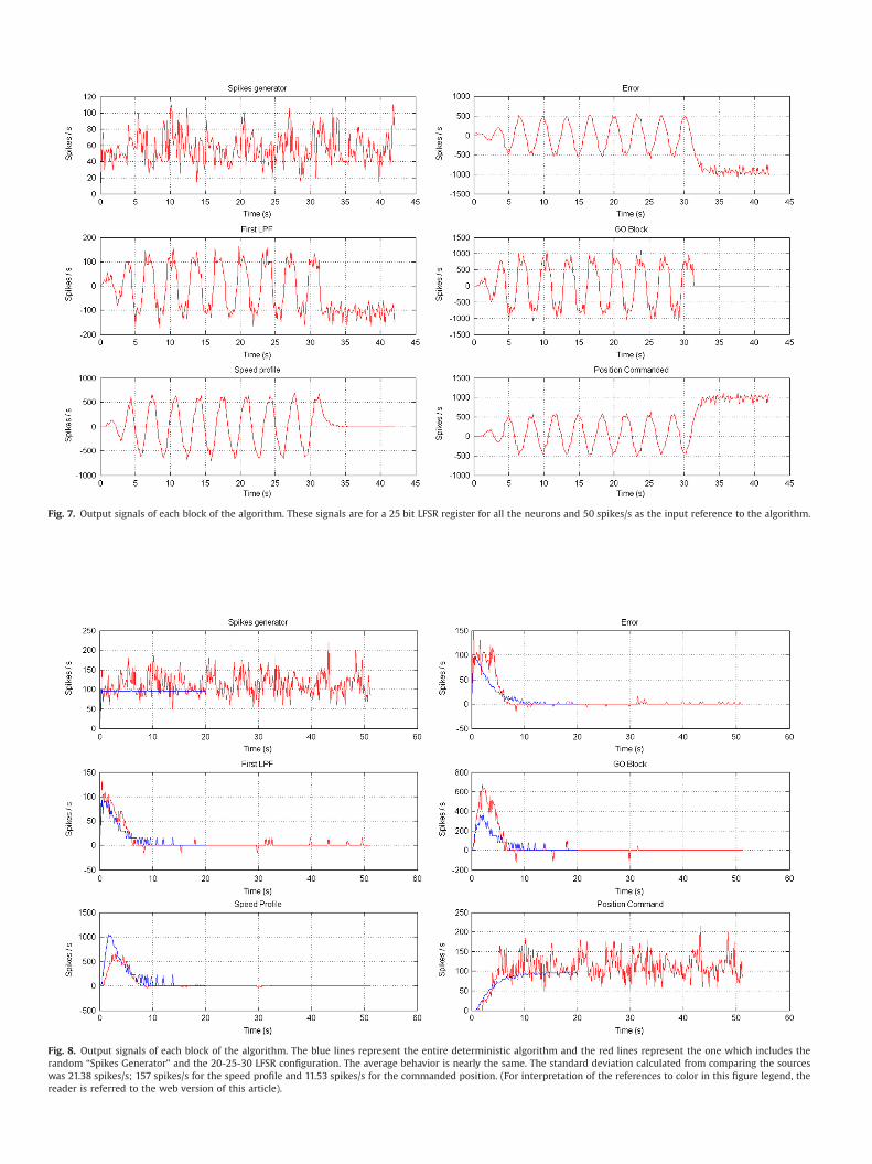
Fig. 7. Output signals of each block of the algorithm. These signals are for a 25 bit LFSR register for all the neurons and 50 spikes/s as the input reference to the algorithm.
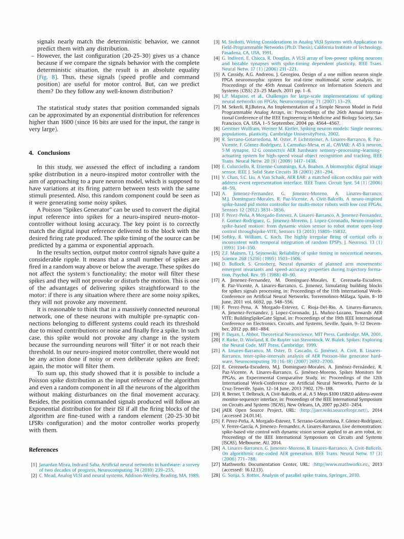
Fig. 8. Output signals of each block of the algorithm. The blue lines represent the entire deterministic algorithm and the red lines represent the one which includes therandom “Spikes Generator” and the 20-25-30 LFSR configuration. The average behavior is nearly the same. The standard deviation calculated from comparing the sourceswas 21.38 spikes/s; 157 spikes/s for the speed profile and 11.53 spikes/s for the commanded position. (For interpretation of the references to color in this figure legend, thereader is referred to the web version of this article).
signals nearly match the deterministic behavior, we cannotpredict them with any distribution.
– However, the last configuration (20-25-30) gives us a chancebecause if we compare the signals behavior with the completedeterministic situation, the result is an absolute equality(Fig. 8). Thus, these signals (speed profile and commandposition) are useful for motor control. But, can we predictthem? Do they follow any well-known distribution?
The statistical study states that position commanded signalscan be approximated by an exponential distribution for referenceshigher than 1600 (since 16 bits are used for the input, the range isvery large).
4. Conclusions
In this study, we assessed the effect of including a randomspike distribution in a neuro-inspired motor controller with theaim of approaching to a pure neuron model, which is supposed tohave variations at its firing pattern between tests with the samestimuli presented. Also, this random component could be seen asit were generating some noisy spikes.
A Poisson “Spikes Generator” can be used to convert the digitalinput reference into spikes for a neuro-inspired neuro-motor-controller without losing accuracy. The key point is to correctlymatch the digital input reference delivered to the block with thedesired firing rate produced. The spike timing of the source can bepredicted by a gamma or exponential approach.
In the results section, output motor control signals have quite aconsiderable ripple. It means that a small number of spikes arefired in a randomway above or below the average. These spikes donot affect the system´s functionality; the motor will filter thesespikes and they will not provoke or disturb the motion. This is oneof the advantages of delivering spikes straightforward to themotor: if there is any situation where there are some noisy spikes,they will not provoke any movement.
It is reasonable to think that in a massively connected neuronalnetwork, one of these neurons with multiple pre-synaptic con-nections belonging to different systems could reach its thresholddue to mixed contributions or noise and finally fire a spike. In suchcase, this spike would not provoke any change in the systembecause the surrounding neurons will ‘filter’ it or not reach theirthreshold. In our neuro-inspired motor controller, there would notbe any action done if noisy or even deliberate spikes are fired;again, the motor will filter them.
To sum up, this study showed that it is possible to include aPoisson spike distribution as the input reference of the algorithmand even a random component in all the neurons of the algorithmwithout making disturbances on the final movement accuracy.Besides, the position commanded signals produced will follow anExponential distribution for their ISI if all the firing blocks of thealgorithm are fine-tuned with a random element (20-25-30 bitLFSRs configuration) and the motor controller works properlywith them.
References
[1] Janardan Misra, Indranil Saha, Artificial neural networks in hardware: a surveyof two decades of progress, Neurocomputing 74 (2010) 239–255.
[2] C. Mead, Analog VLSI and neural systems, Addison-Wesley, Reading, MA, 1989.
[3] M. Sivilotti, Wiring Considerations in Analog VLSI Systems with Application toField-Programmable Networks (Ph.D. Thesis), California Institute of Technology,Pasadena, CA, USA, 1991.
[4] G. Indiveri, E. Chicca, R. Douglas, A VLSI array of low-power spiking neuronsand bistable synapses with spike-timing dependent plasticity, IEEE Trans.Neural Netw. 17 (1) (2006) 211–221.
[5] A. Cassidy, A.G. Andreou, J. Georgiou, Design of a one million neuron singleFPGA neuromorphic system for real-time multimodal scene analysis, in:Proceedings of the 45th Annual Conference on Information Sciences andSystems (CISS) 23–25 March, 2011 pp. 1–6.
[6] L.P. Maguire, et al., Challenges for large-scale implementations of spikingneural networks on FPGAs, Neurocomputing 71 (2007) 13–29.
[7] M. Sekerli, R.J.Butera, An Implementation of a Simple Neuron Model in FieldProgrammable Analog Arrays, in: Proceedings of the 26th Annual Interna-tional Conference of the IEEE Engineering in Medicine and Biology Society, SanFrancisco, CA, USA, 1–5 September, 2004 pp. 4564–4567.
[8] Gerstner Wulfram, Werner M. Kistler, Spiking neuron models: Single neurons,populations, plasticity, Cambridge UniversityPress, 2002.
[9] R. Serrano-Gotarredona, M. Oster, P. Lichtsteiner, A. Linares-Barranco, R. Paz-Vicente, F. Gómez-Rodríguez, L Camuñas-Mesa, et al., CAVIAR: A 45 k neuron,5 M synapse, 12 G connects/s AER hardware sensory–processing–learning–actuating system for high-speed visual object recognition and tracking, IEEETrans. Neural Netw. 20 (9) (2009) 1417–1438.
[10] E. Culurciello, R. Etienne-Cummings, K.A. Boahen, A biomorphic digital imagesensor, IEEE J. Solid State Circuits 38 (2003) 281–294.
[11] V. Chan, S.C. Liu, A Van Schaik, AER EAR: a matched silicon cochlea pair withaddress event representation interface, IEEE Trans. Circuit Syst. 54 (1) (2006)48–59.
[12] A. Jimenez-Fernandez, G. Jimenez-Moreno, A. Linares-Barranco,M.J. Dominguez-Morales, R. Paz-Vicente, A. Civit-Balcells, A neuro-inspiredspike-based pid motor controller for multi-motor robots with low cost FPGAs,Sensors 12 (2012) 3831–3856.
[13] F. Perez-Peña, A Morgado-Estevez, A. Linares-Barranco, A. Jimenez-Fernandez,F. Gomez-Rodriguez, G. Jimenez-Moreno, J. Lopez-Coronado, Neuro-inspiredspike-based motion: from dynamic vision sensor to robot motor open-loopcontrol throughspike-VITE, Sensors 13 (2013) 15805–15832.
[14] Softky, R. William, C. Koch, The highly irregular firing of cortical cells isinconsistent with temporal integration of random EPSPs, J. Neurosci. 13 (1)(1993) 334–350.
[15] Z.F. Mainen, T.J. Sejnowski, Reliability of spike timing in neocortical neurons,Science 268 (5216) (1995) 1503–1506.
[16] D. Bullock, S. Grossberg, Neural dynamics of planned arm movements:emergent invariants and speed-accuracy properties during trajectory forma-tion, Psychol. Rev. 95 (1988) 49–90.
[17] A. Jimenez-Fernandez, M. Domínguez-Morales, E. Cerezuela-Escudero,R. Paz-Vicente, A. Linares-Barranco, G. Jimenez, Simulating building blocksfor spikes signals processing, in: Proceedings of the 11th International Work-Conference on Artificial Neural Networks, Torremolinos-Málaga, Spain, 8–10June, 2011 vol. 6692, pp. 548–556.
[18] F. Perez-Pena, A. Morgado-Estevez, C. Rioja-Del-Rio, A. Linares-Barranco,A. Jimenez-Fernandez, J. Lopez-Coronado, J.L. Muñoz-Lozano, Towards AERVITE: BuildingSpikeGate Signal, in: Proceedings of the 19th IEEE InternationalConference on Electronics, Circuits, and Systems, Seville, Spain, 9–12 Decem-ber, 2012 pp. 881–884.
[19] P. Dayan, L. Abbot, Theoretical Neuroscience, MIT Press, Cambridge, MA, 2001.[20] F. Rieke, D. Worland, R. De Ruyter van Steveninck, W. Bialek, Spikes: Exploring
the Neural Code, MIT Press, Cambridge, 1999.[21] A. Linares-Barranco, M. Oster, D. Cascado, G. Jiménez, A. Civit, B. Linares-
Barranco, Inter-spike-intervals analysis of AER Poisson-like generator hard-ware, Neurocomputing 70 (16-18) (2007) 2692–2700.
[22] E. Cerezuela-Escudero, M.J. Dominguez-Morales, A. Jiménez-Fernández, R.Paz-Vicente, A. Linares-Barranco, G. Jiménez-Moreno, Spikes Monitors forFPGAs, an Experimental Comparative Study, in: Proceedings of the 12thInternational Work-Conference on Artificial Neural Networks, Puerto de laCruz-Tenerife, Spain, 12–14 June, 2013 7902, 179–188.
[23] R. Berner, T. Delbruck, A. Civit-Balcells, et al., A 5 Meps $100 USB2.0 address-eventmonitor-sequencer interface, in: Proceedings of the IEEE International Symposiumon Circuits and Systems (ISCAS), New Orleans, LA, 2007 pp.2451–2454.
[24] jAER Open Source Project, URL: ⟨http://jaer.wiki.sourceforge.net/⟩, 2014(accessed 24.01.14).
[25] F. Perez-Peña, A. Morgado-Estevez, T. Serrano-Gotarredona, F. Gómez-Rodríguez,V. Ferrer-García, A. Jimenez- Fernandez, A. Linares-Barranco, Live demonstration:spike-based vite control with dynamic vision sensor applied to an arm robot, in:Proceedings of the IEEE International Symposium on Circuits and Systems(ISCAS), Melbourne, AU, 2014.
[26] A. Linares-Barranco, G. Jimenez-Moreno, B. Linares-Barranco, A. Civit-Ballcels,On algorithmic rate-coded AER generation, IEEE Trans. Neural Netw. 17 (3)(2006) 771–788.
[27] Mathworks Documentation Center, URL: ⟨http//www.mathworks.es⟩, 2013(accessed: 16.12.13).
[28] G. Sonja, S. Rotter, Analysis of parallel spike trains, Springer, 2010.