Embed Size (px)
Citation preview
Introduction to EmissionTomography
Tom Lewellen
June 2006
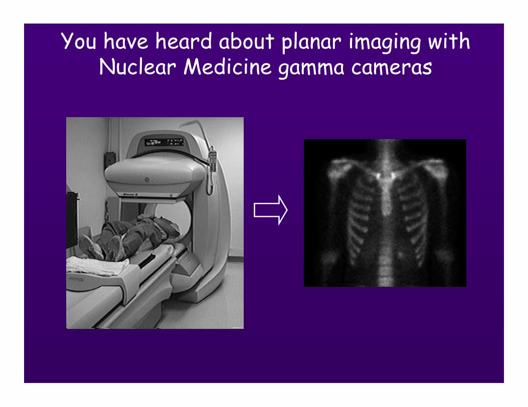
You have heard about planar imaging withNuclear Medicine gamma cameras
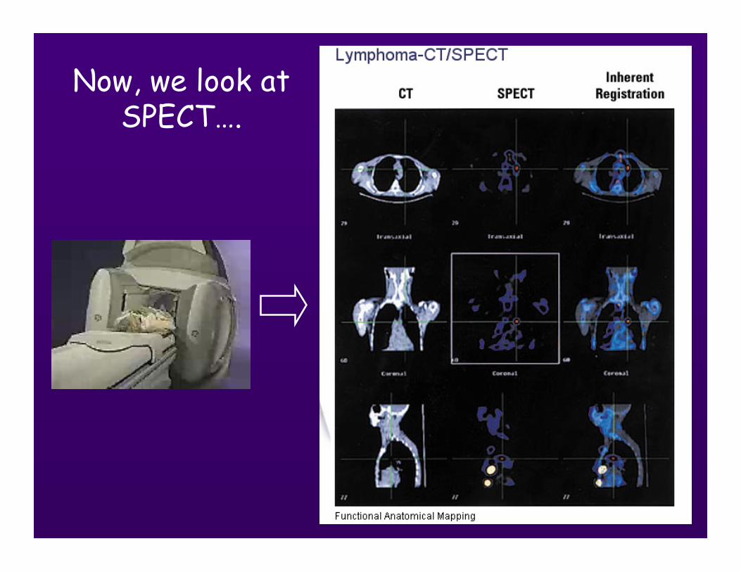
Now, we look atSPECT….
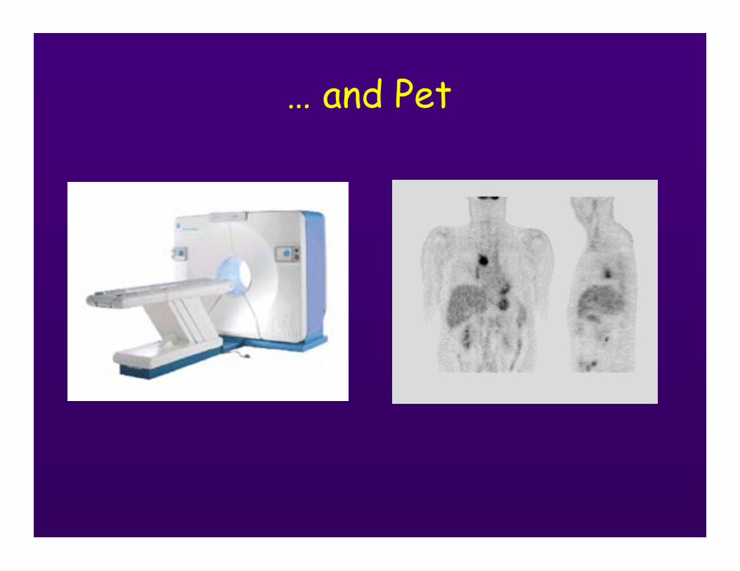
… and Pet
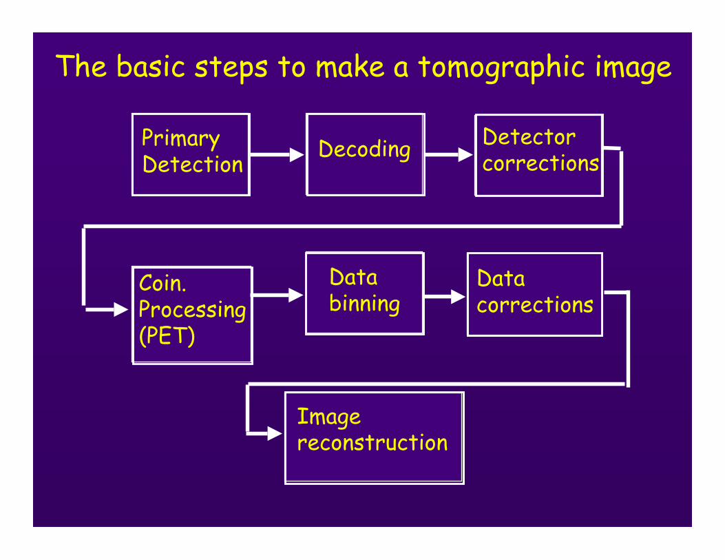
The basic steps to make a tomographic image
Decoding Detector corrections
PrimaryDetection
Coin.Processing(PET)
Databinning
Datacorrections
Imagereconstruction
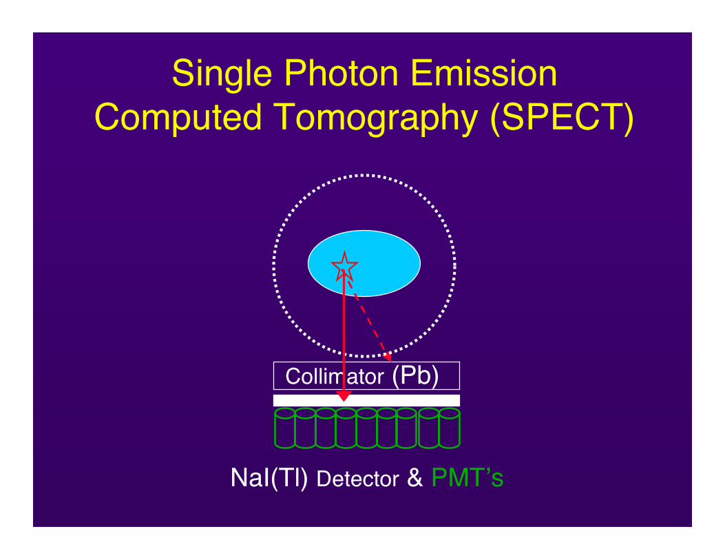
Single Photon EmissionComputed Tomography (SPECT)
Collimator (Pb)
NaI(Tl) Detector & PMT’s
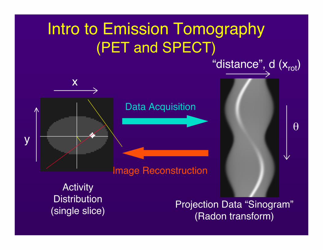
Intro to Emission Tomography(PET and SPECT)
Data Acquisition
Image ReconstructionActivity
Distribution(single slice) Projection Data “Sinogram”
(Radon transform)
“distance”, d (xrot)
θ
x
y
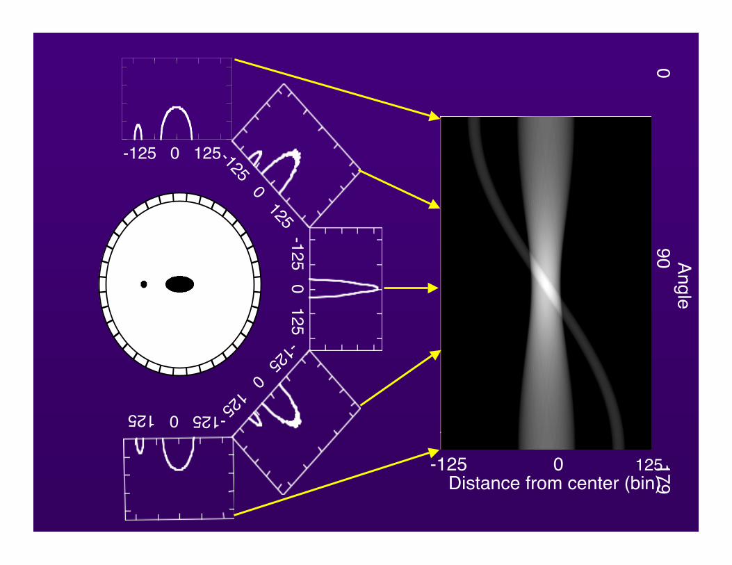
Distance from center (bin)-125 0 125
0 90 179
Angle
-125 0 125-125 0 125-125 0 125
-125 0 125-125 0 125
Sinogram
AB
D
xr
φC
Source Objects
A
BC
D
Scanner
p(xr,φ)
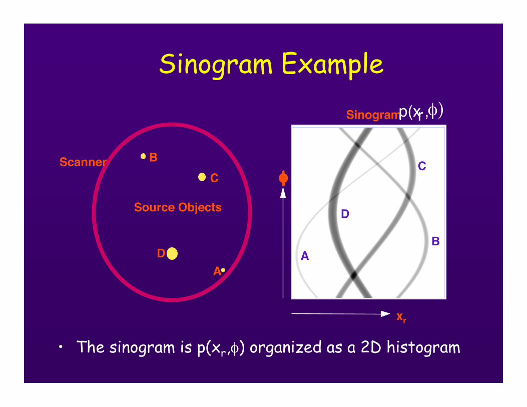
Sinogram Example
• The sinogram is p(xr,φ) organized as a 2D histogram
Real world detection
• Imaging systems are not perfect
• Several aspects of photon transportneed to be considered and in somecases corrected ….
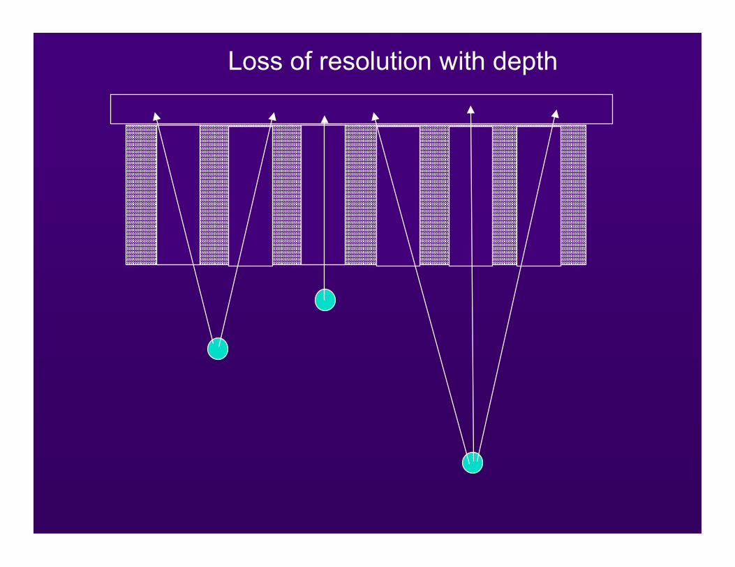
Loss of resolution with depth
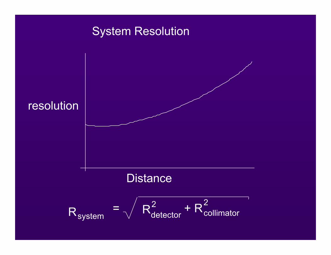
System Resolution
resolution
Distance
Rsystem= Rdetector
2 + Rcollimator2
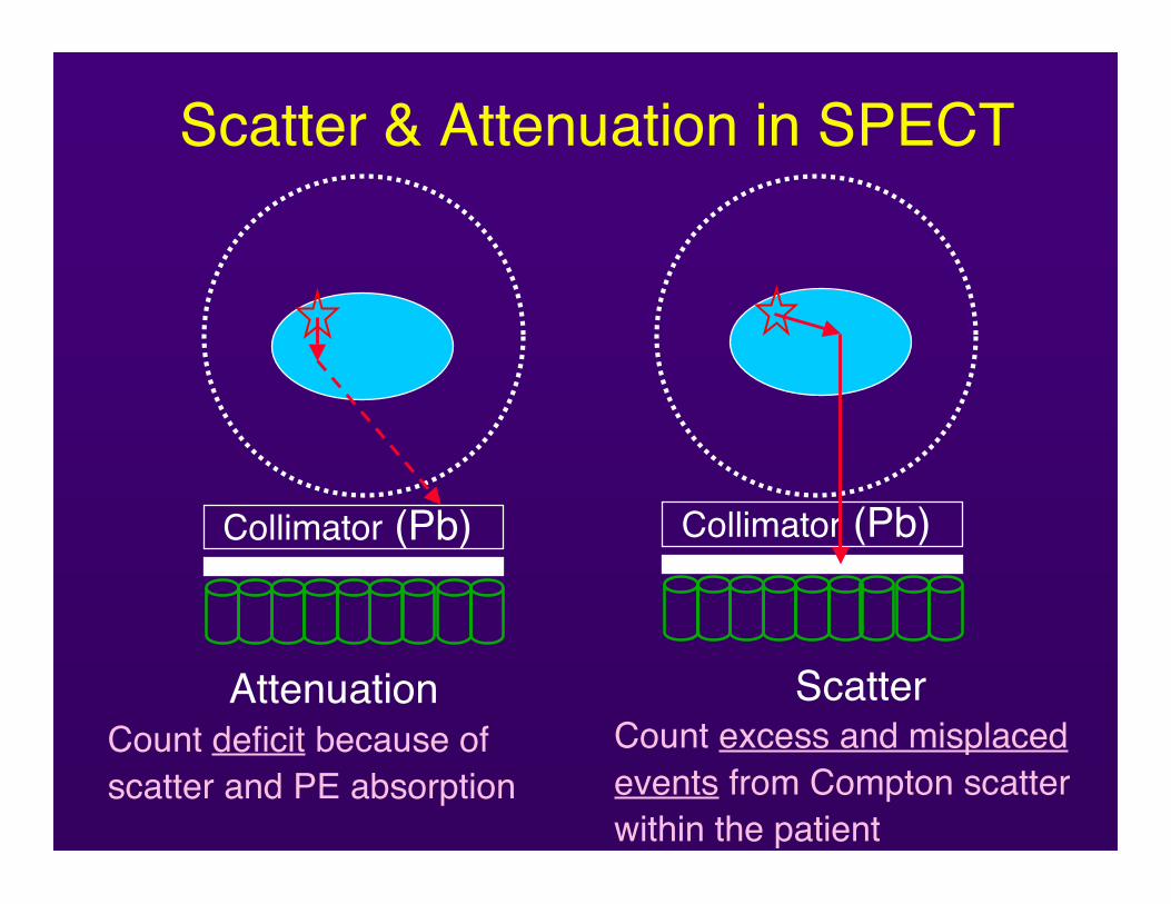
Scatter & Attenuation in SPECT
AttenuationCount deficit because ofscatter and PE absorption
Collimator (Pb) Collimator (Pb)
ScatterCount excess and misplacedevents from Compton scatterwithin the patient
Energy Windowing
• Partial discriminationbetween scatter andnon-scatter (true)events.
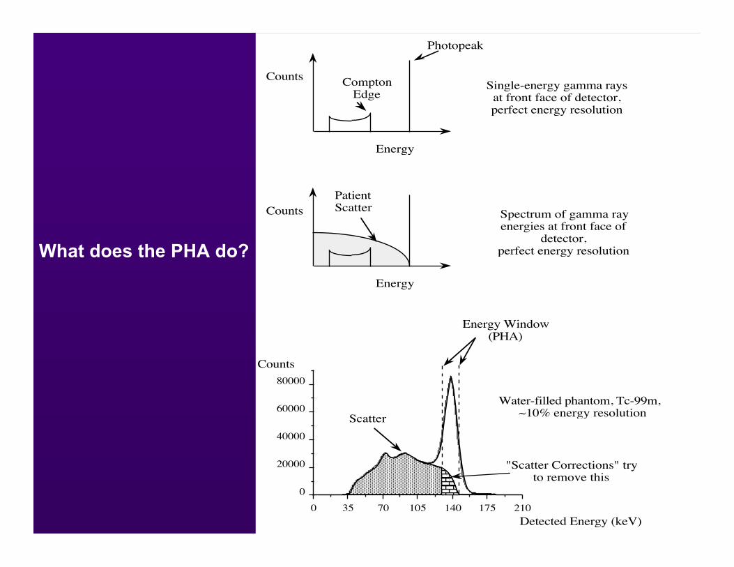
What does the PHA do?
ComptonEdge
Photopeak
Counts
Energy
Single-energy gamma raysat front face of detector,perfect energy resolution
Counts
Energy
PatientScatter
Spectrum of gamma rayenergies at front face of
detector,perfect energy resolution
21017514010570350
0
20000
40000
60000
80000
Counts
Detected Energy (keV)
Water-filled phantom, Tc-99m, ~10% energy resolution
Energy Window(PHA)
Scatter
"Scatter Corrections" tryto remove this

What about attenuation?
Need an attenuation map and areconstruction algorithm
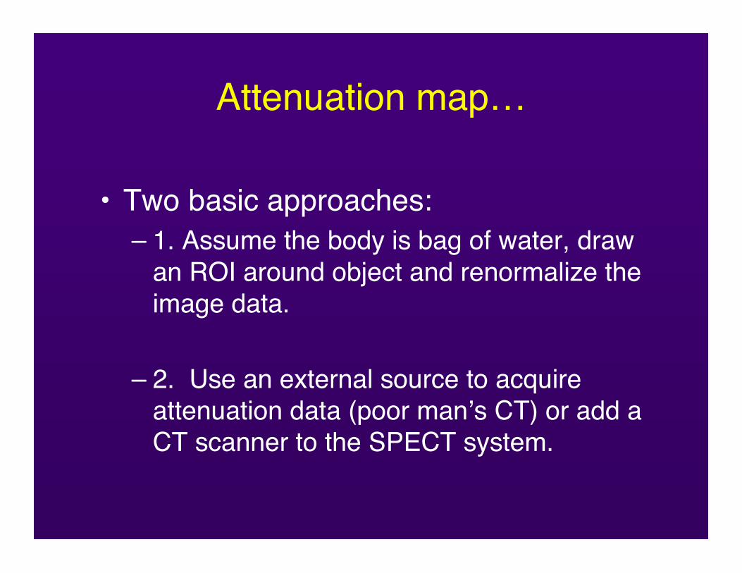
Attenuation map…
• Two basic approaches:– 1. Assume the body is bag of water, draw
an ROI around object and renormalize theimage data.
– 2. Use an external source to acquireattenuation data (poor man’s CT) or add aCT scanner to the SPECT system.
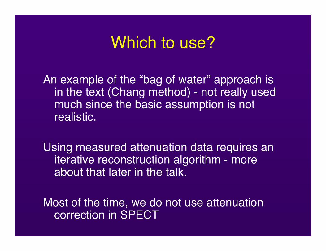
Which to use?
An example of the “bag of water” approach isin the text (Chang method) - not really usedmuch since the basic assumption is notrealistic.
Using measured attenuation data requires aniterative reconstruction algorithm - moreabout that later in the talk.
Most of the time, we do not use attenuationcorrection in SPECT
What is different about PET?
Gamma rays in coincidence!
NN
N P
PP P
P N NN
NN
N P
PP P
P P NN
ν
e-e+
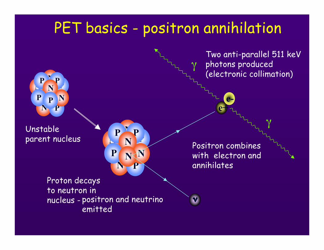
Proton decaysto neutron innucleus -
Positron combineswith electron andannihilates
γ
γ
Two anti-parallel 511 keVphotons produced(electronic collimation)
Unstableparent nucleus
positron and neutrinoemitted
PET basics - positron annihilation
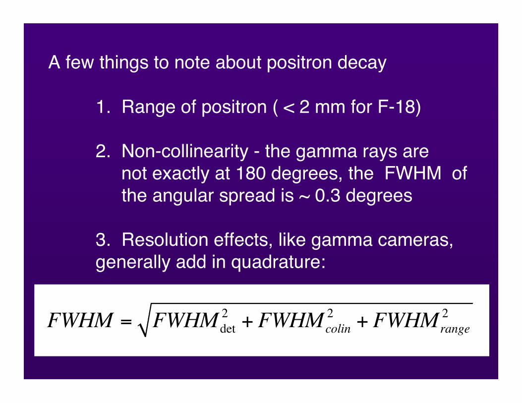
A few things to note about positron decay
1. Range of positron ( < 2 mm for F-18)
2. Non-collinearity - the gamma rays are not exactly at 180 degrees, the FWHM of the angular spread is ~ 0.3 degrees
3. Resolution effects, like gamma cameras,generally add in quadrature:
FWHM = FWHMdet
2+ FWHMcolin
2+ FWHMrange
2
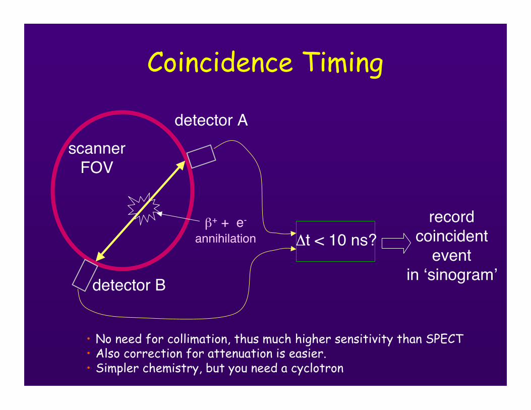
Coincidence Timing
Δt < 10 ns?
detector A
detector B
recordcoincident
eventin ‘sinogram’
scannerFOV
β+ + e-
annihilation
• No need for collimation, thus much higher sensitivity than SPECT• Also correction for attenuation is easier.• Simpler chemistry, but you need a cyclotron
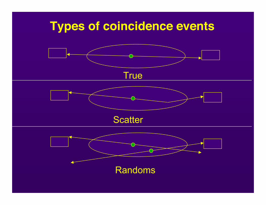
True
Scatter
Randoms
Types of coincidence events
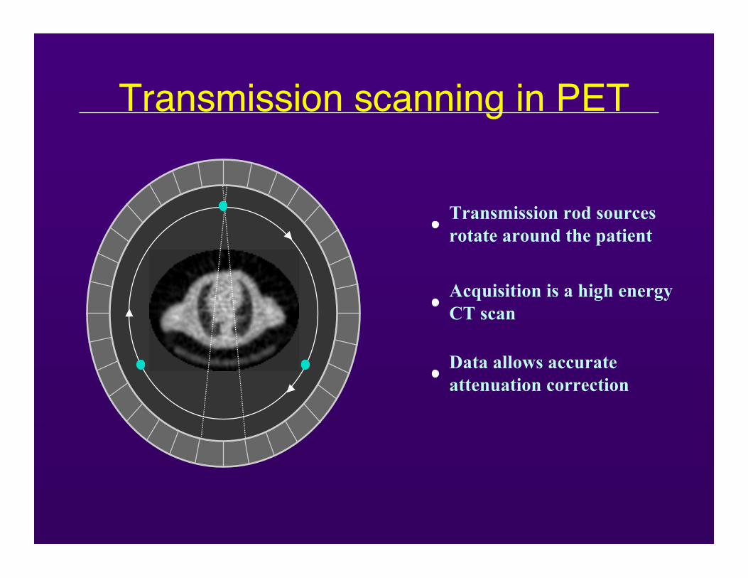
Transmission rod sourcesrotate around the patient
Acquisition is a high energy CT scan
Data allows accurate attenuation correction
Transmission scanning in PET
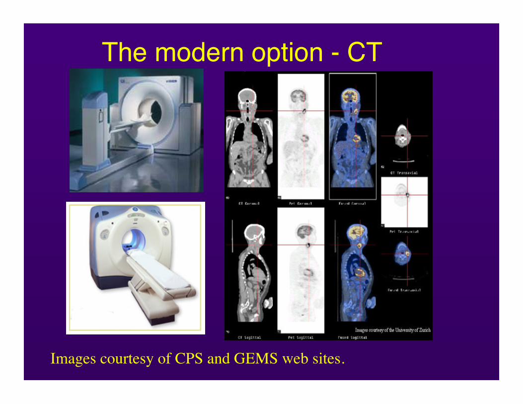
Images courtesy of CPS and GEMS web sites.
The modern option - CT
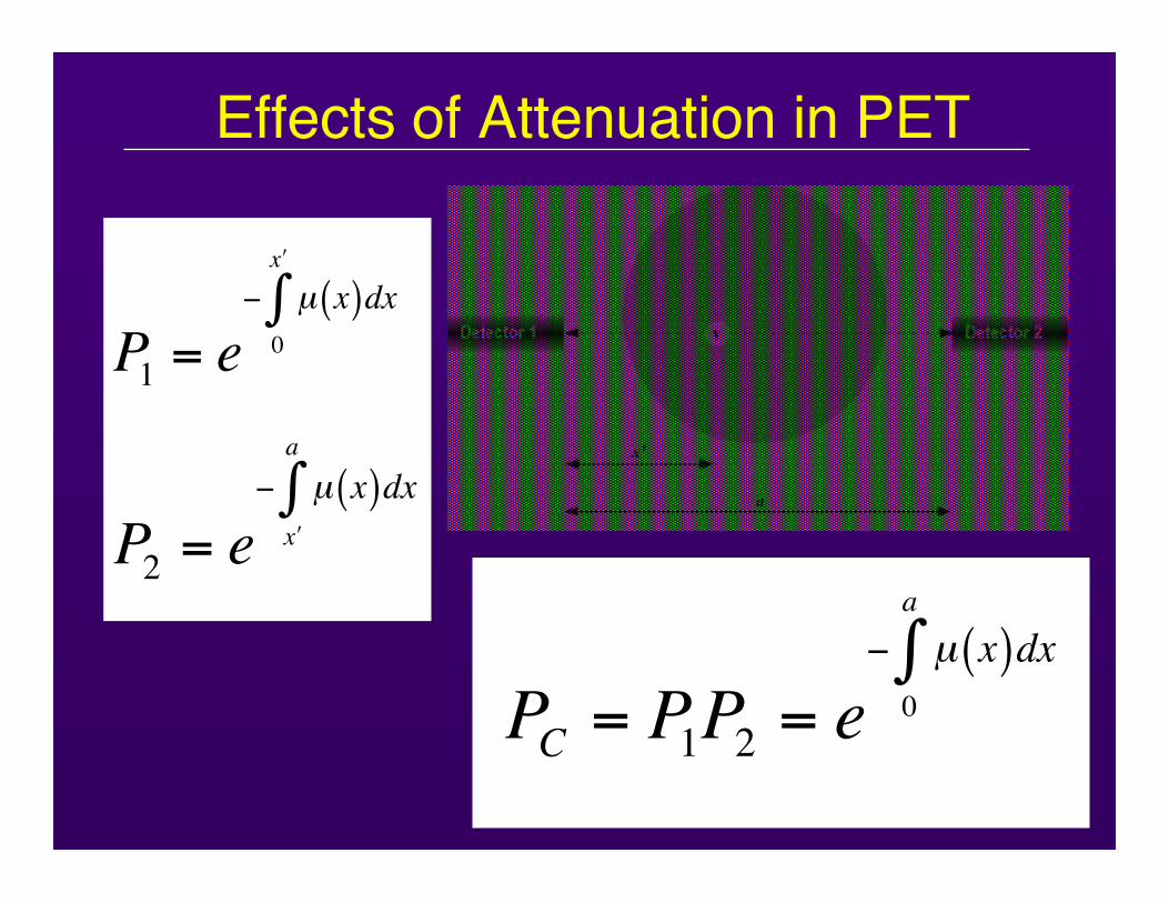
Effects of Attenuation in PET
P1= e
! µ x( )dx0
"x
#
P2= e
! µ x( )dx"x
a
#
PC= P
1P2= e
! µ x( )dx0
a
"
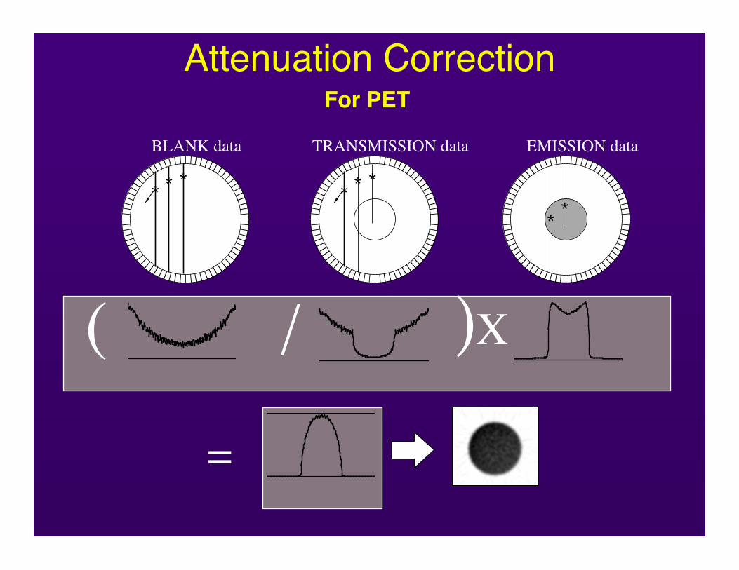
Attenuation Correction
0100200300400500600700800
200300400500600700800
0 50 100150200250300
050100150200250300
0 50 100150200250300
( / )X
***
BLANK data
** *
TRANSMISSION data
**
EMISSION data
02004006008001000120014001600
=
For PET
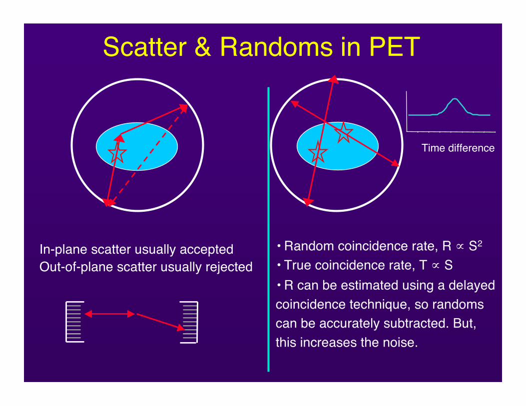
Scatter & Randoms in PET
In-plane scatter usually acceptedOut-of-plane scatter usually rejected
• Random coincidence rate, R ∝ S2
• True coincidence rate, T ∝ S• R can be estimated using a delayedcoincidence technique, so randomscan be accurately subtracted. But,this increases the noise.
Time difference
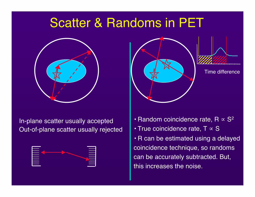
What is the differencebetween “2D” and “3D”
modes of operation
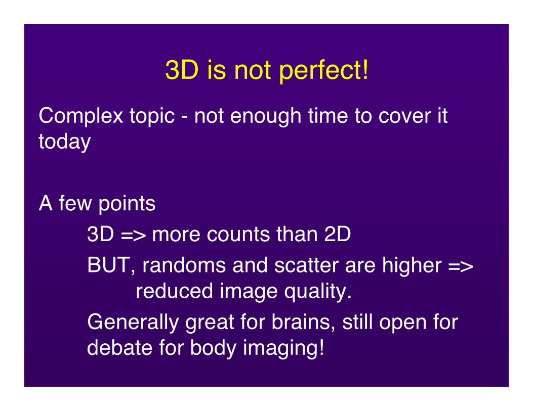
3D is not perfect!Complex topic - not enough time to cover ittoday
A few points3D => more counts than 2DBUT, randoms and scatter are higher =>
reduced image quality.Generally great for brains, still open for debate for body imaging!

So, we have binned the data- now what?
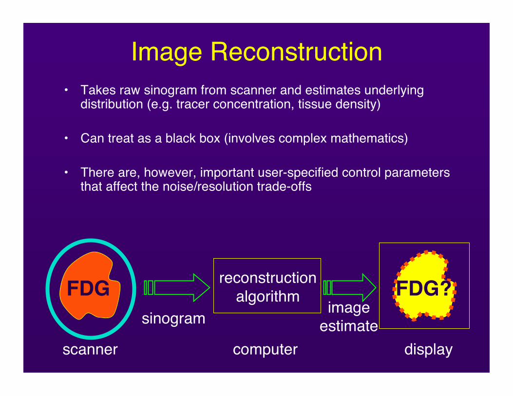
Image Reconstruction• Takes raw sinogram from scanner and estimates underlying
distribution (e.g. tracer concentration, tissue density)
• Can treat as a black box (involves complex mathematics)
• There are, however, important user-specified control parametersthat affect the noise/resolution trade-offs
FDG reconstructionalgorithm
sinogramFDG?
imageestimate
scanner computer display
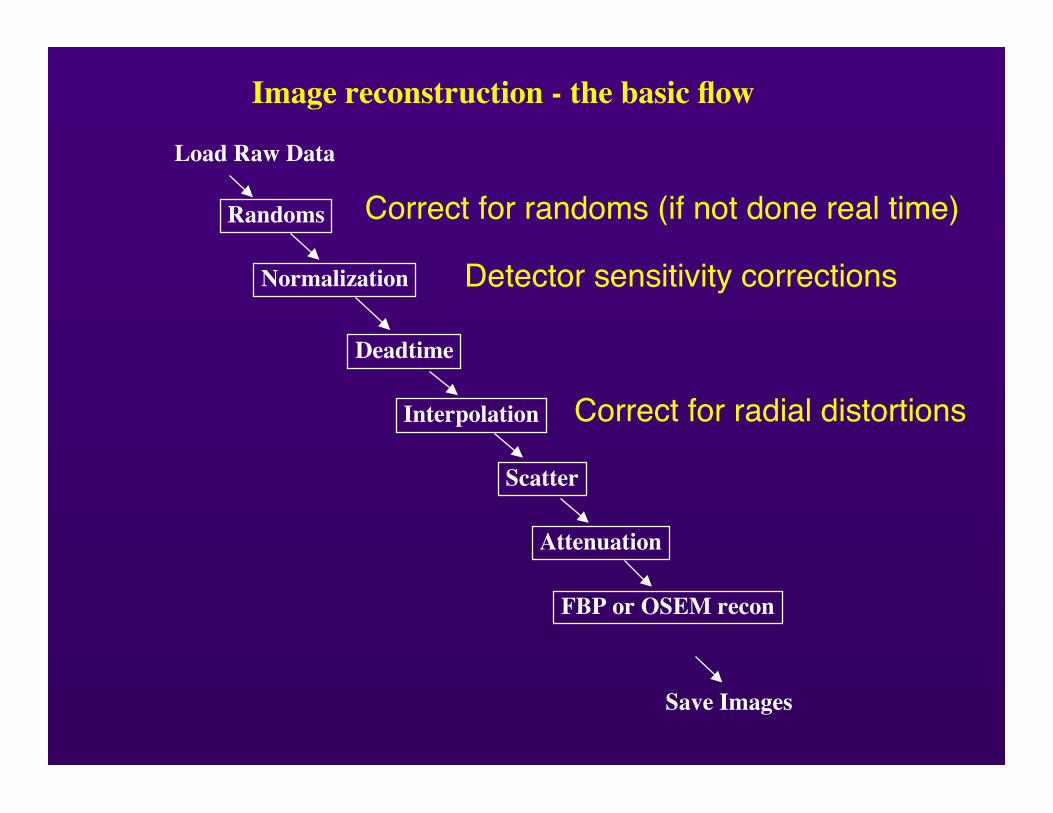
Randoms
Normalization
Deadtime
Interpolation
Scatter
Attenuation
FBP or OSEM recon
Load Raw Data
Save Images
Image reconstruction - the basic flow
Correct for randoms (if not done real time)
Detector sensitivity corrections
Correct for radial distortions
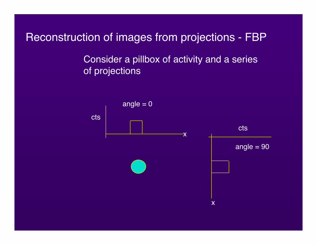
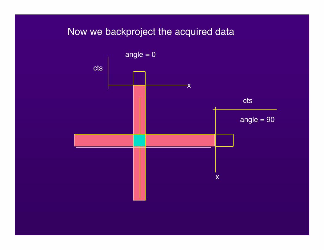
Reconstruction of images from projections - FBP
Consider a pillbox of activity and a seriesof projections
cts
x
angle = 0
angle = 90
cts
x
cts
x
angle = 0
angle = 90
cts
x
Now we backproject the acquired data
cts
x
angle = 0
angle = 90
cts
x
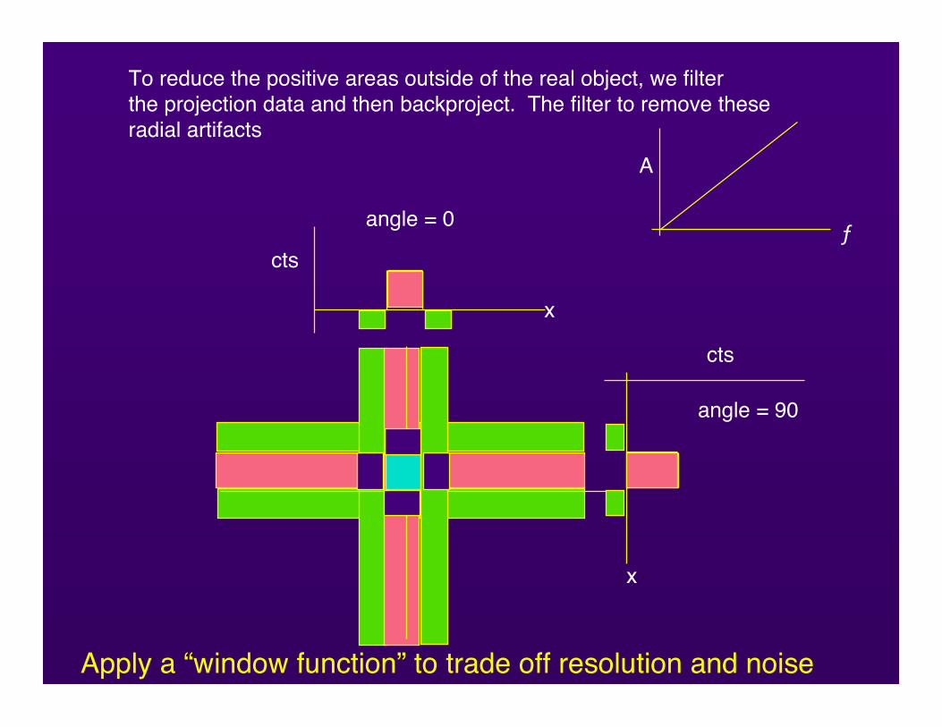
To reduce the positive areas outside of the real object, we filterthe projection data and then backproject. The filter to remove theseradial artifacts
ƒ
A
Apply a “window function” to trade off resolution and noise
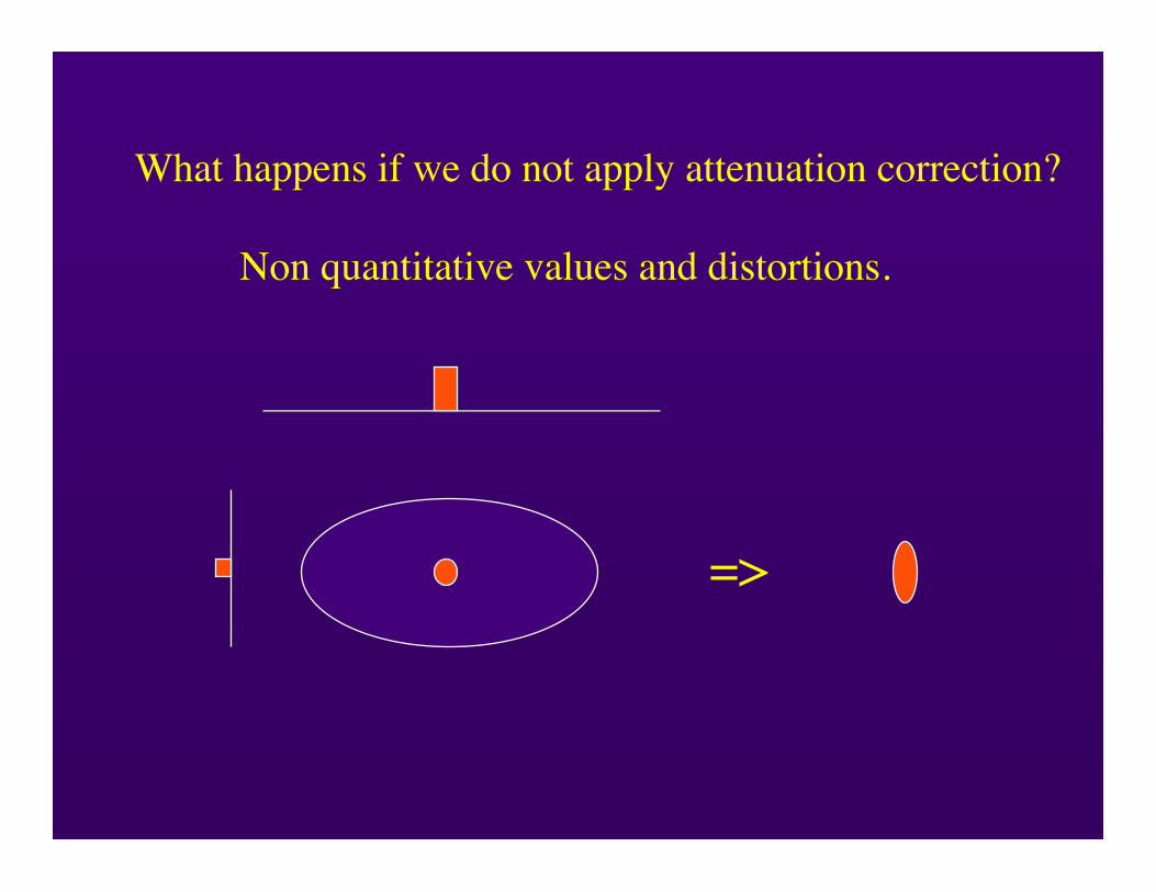
What happens if we do not apply attenuation correction?
Non quantitative values and distortions.
=>
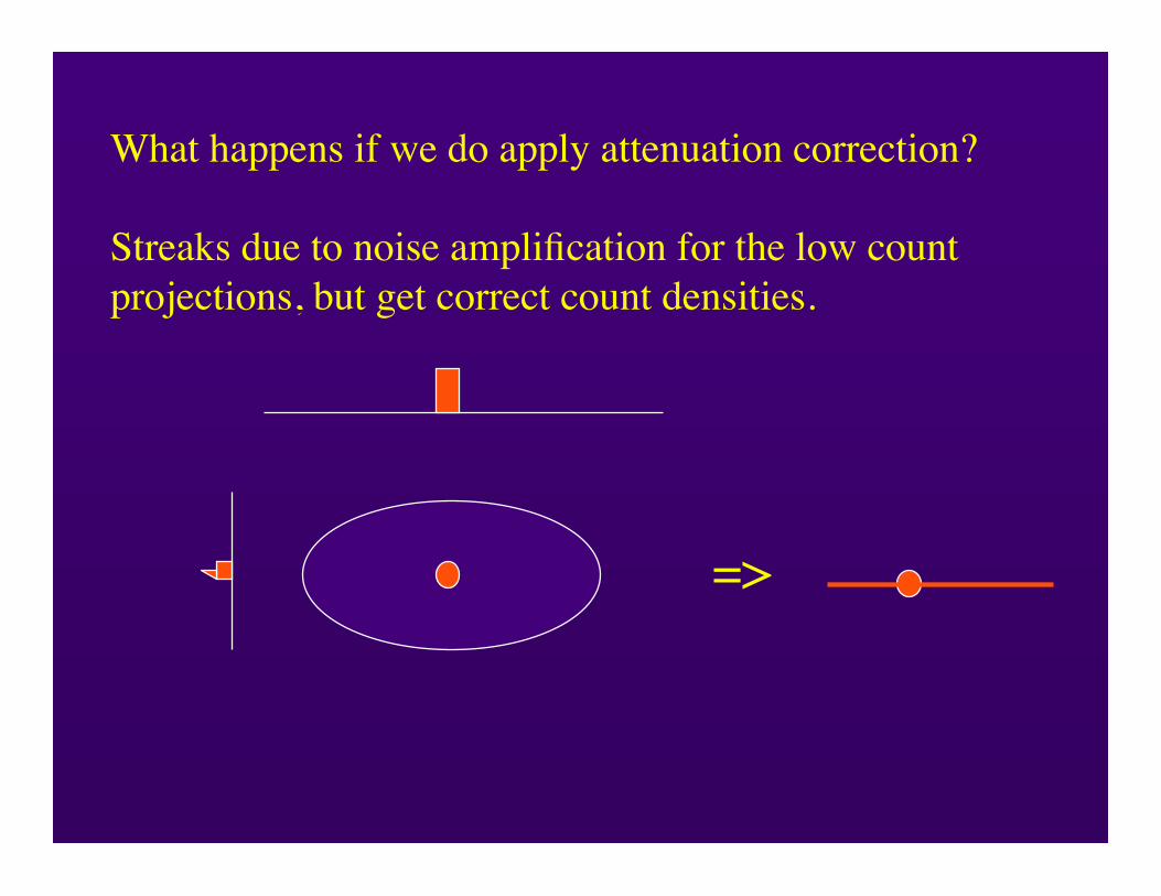
What happens if we do apply attenuation correction?
Streaks due to noise amplification for the low countprojections, but get correct count densities.
=>
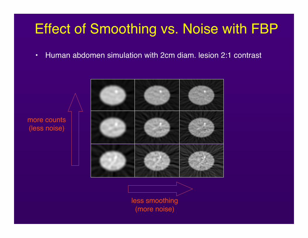
Effect of Smoothing vs. Noise with FBP• Human abdomen simulation with 2cm diam. lesion 2:1 contrast
more counts(less noise)
less smoothing(more noise)
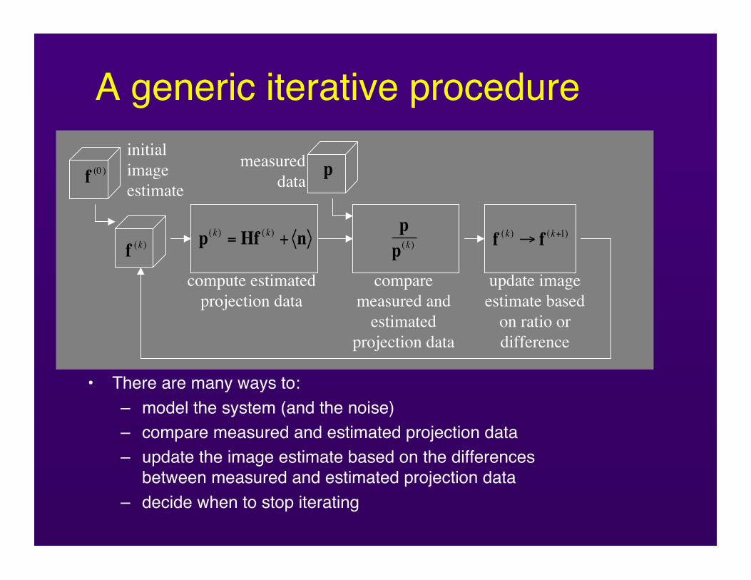
A generic iterative procedure
• There are many ways to:– model the system (and the noise)– compare measured and estimated projection data– update the image estimate based on the differences
between measured and estimated projection data– decide when to stop iterating
measureddata
!
p(k )
= Hf(k )
+ n
compute estimatedprojection data
!
f(k )
comparemeasured and
estimatedprojection data
!
f(0 )
initialimageestimate
!
p
!
p
p(k )
!
f(k )" f
(k+1)
update imageestimate based
on ratio ordifference
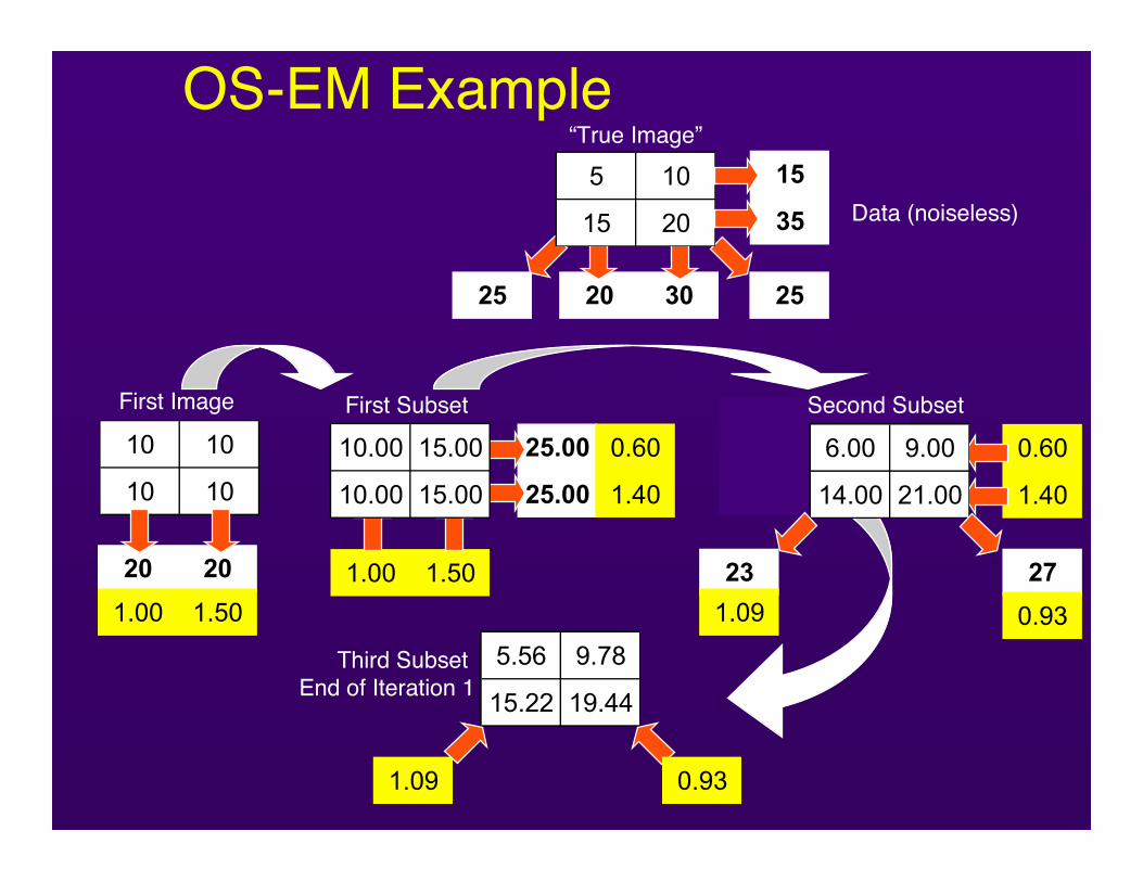
OS-EM Example
0.60
1.40
0.60 0.60
1.40 1.40
20 30 2525
5 10
15 20
“True Image”15
35 Data (noiseless)
10 10
10 10
First Image
20 20
1.00 1.50
1.00 1.50
1.00 1.50
1.00 1.50
25.00
25.00
0.60
1.40
10.00 15.00
10.00 15.00
First Subset
6.00 9.00
14.00 21.00
Second Subset
23 27
1.09 0.93
0.93 1.09
1.09 0.93
1.09 0.93
Third Subset End of Iteration 1
5.56 9.78
15.22 19.44

How many counts do we really need?
As many as we can get!!
A final thought
Some test questions
D68. Positron cameras detect:
A. Positrons of the same energy in coincidence.B. Positrons and electrons in coincidence.C. Photons of different energies in coincidence.D. Annihilation photons in coincidence.E. Annihilation photons in anticoincidence.
D69. Spatial resolution of PET systems isdetermined by:
A. Detector size.B. The ring diameter of the system.C. The detector material.D. Energy of the positron emitter in use.E. All of the above.
D76. The spatial resolution of a SPECT image vs. astationary image with the same camera is:
A. Much worse.B. Slightly worse.C. The same.D. Slightly better.E. Much better.
What about contrast resolution?SameWorseBetter
D77. The major limitation on the resolution of an FDG scanon a modern whole body PET scanner is:
A. Range of the positron.B. Image matrix size.C. The physical size of the individual detectors.D. The non-collinearity between the annihilation photons.E. Attenuation correction.
Why? Camera res ~ 5 mm, positron range ~ 2mmNon-collinearity (100 cm diameter) ~ 3.5 mm.Range + non-collinearity ~ 4 mm
D78. A nuclear medicine resident discovers, justprior to injecting a Tc-99m bone scan agent, thatthe patient had a PET scan 3 hours ago at 9 a.m.in another hospital. When should the residentrecommend that the bone scan be performed?
A. Straight away. There is no interference betweenthe Tc-99m and F-18, since they can bedistinguished by energy discrimination.B. Wait until 3 p.m. allowing a 6-hour intervalbetween tests (>3 half lives of F-18).C. Wait until the next day to ensure completedecay of the F-18.D. Postpone for one week, to ensure any residuallong lived F- 18 daughters have decayed.
D77. Some dedicated PET scanners can performboth 2-D and 3-D scans. The difference is:
A. 2-D scans acquire transaxiai images and cannotdisplay coronal or sagittal images.B. 3-D scans acquire the data directly in coronal orsagittal planes.C. 2-D scans acquire the data one slice at a time,whereas 3D scans acquire all slicessimultaneously.D. Only 3-D scans can be corrected forattenuation.E. 2-D scans have septa in front of the detectors toreduce events from scattered photons.
D78. Positron cameras detect:
A. Positrons of the same energy in coincidence.B. Positrons and electrons in coincidence.C. Photons of different energies in coincidence.D. Annihilation photons in coincidence.
D79. The assigned values in each pixel in thereconstructed image of SPECT represent:
A. Densities.B. Absorption factors.C. Attenuation factors.D. Radioisotope concentrations.
D85. All of the following are true statements aboutPET scanning, except:
A. Radioisotopes are cyclotron produced.B. Positrons are not detected directly.C. Coincident detection at 180° is required.D. Images are generally axial tomograms.E. The detector photopeak is centered at 1.02 MeV.